RU2712348C2 - Improved extractor for aerosol generating device - Google Patents
Improved extractor for aerosol generating deviceDownload PDFInfo
- Publication number
- RU2712348C2 RU2712348C2RU2017130917ARU2017130917ARU2712348C2RU 2712348 C2RU2712348 C2RU 2712348C2RU 2017130917 ARU2017130917 ARU 2017130917ARU 2017130917 ARU2017130917 ARU 2017130917ARU 2712348 C2RU2712348 C2RU 2712348C2
- Authority
- RU
- Russia
- Prior art keywords
- aerosol forming
- aerosol
- extractor
- article
- heater
- Prior art date
Links
- 239000000443aerosolSubstances0.000titleclaimsabstractdescription256
- 239000000758substrateSubstances0.000claimsabstractdescription106
- 238000010438heat treatmentMethods0.000claimsabstractdescription58
- 238000000605extractionMethods0.000claimsabstractdescription13
- 241000208125NicotianaSpecies0.000claimsdescription23
- 235000002637Nicotiana tabacumNutrition0.000claimsdescription23
- 238000009825accumulationMethods0.000claimsdescription6
- 238000004140cleaningMethods0.000claimsdescription5
- 230000000391smoking effectEffects0.000abstractdescription62
- 239000000126substanceSubstances0.000abstract1
- 239000003570airSubstances0.000description79
- 239000002699waste materialSubstances0.000description25
- 239000000463materialSubstances0.000description14
- 229910052751metalInorganic materials0.000description12
- 239000002184metalSubstances0.000description12
- 239000008275solid aerosolSubstances0.000description9
- 239000008263liquid aerosolSubstances0.000description8
- 239000012876carrier materialSubstances0.000description6
- 239000007787solidSubstances0.000description6
- PXHVJJICTQNCMI-UHFFFAOYSA-NNickelChemical compound[Ni]PXHVJJICTQNCMI-UHFFFAOYSA-N0.000description5
- 229910045601alloyInorganic materials0.000description5
- 239000000956alloySubstances0.000description5
- 239000002775capsuleSubstances0.000description5
- 239000000919ceramicSubstances0.000description5
- 150000001875compoundsChemical class0.000description4
- 238000005485electric heatingMethods0.000description4
- 239000012634fragmentSubstances0.000description4
- 239000007788liquidSubstances0.000description4
- 239000002245particleSubstances0.000description4
- -1platinum group metalsChemical class0.000description4
- 230000000717retained effectEffects0.000description4
- OKTJSMMVPCPJKN-UHFFFAOYSA-NCarbonChemical compound[C]OKTJSMMVPCPJKN-UHFFFAOYSA-N0.000description3
- DNIAPMSPPWPWGF-UHFFFAOYSA-NPropylene glycolChemical compoundCC(O)CODNIAPMSPPWPWGF-UHFFFAOYSA-N0.000description3
- 150000001491aromatic compoundsChemical class0.000description3
- 230000015572biosynthetic processEffects0.000description3
- 239000002131composite materialSubstances0.000description3
- 239000000835fiberSubstances0.000description3
- 150000002739metalsChemical class0.000description3
- 229910052759nickelInorganic materials0.000description3
- 230000035807sensationEffects0.000description3
- 235000019615sensationsNutrition0.000description3
- 238000011144upstream manufacturingMethods0.000description3
- 238000005406washingMethods0.000description3
- XLYOFNOQVPJJNP-UHFFFAOYSA-NwaterSubstancesOXLYOFNOQVPJJNP-UHFFFAOYSA-N0.000description3
- 229920000049Carbon (fiber)Polymers0.000description2
- PEDCQBHIVMGVHV-UHFFFAOYSA-NGlycerineChemical compoundOCC(O)COPEDCQBHIVMGVHV-UHFFFAOYSA-N0.000description2
- XEEYBQQBJWHFJM-UHFFFAOYSA-NIronChemical compound[Fe]XEEYBQQBJWHFJM-UHFFFAOYSA-N0.000description2
- WHXSMMKQMYFTQS-UHFFFAOYSA-NLithiumChemical compound[Li]WHXSMMKQMYFTQS-UHFFFAOYSA-N0.000description2
- UFWIBTONFRDIAS-UHFFFAOYSA-NNaphthaleneChemical compoundC1=CC=CC2=CC=CC=C21UFWIBTONFRDIAS-UHFFFAOYSA-N0.000description2
- RTAQQCXQSZGOHL-UHFFFAOYSA-NTitaniumChemical compound[Ti]RTAQQCXQSZGOHL-UHFFFAOYSA-N0.000description2
- QCWXUUIWCKQGHC-UHFFFAOYSA-NZirconiumChemical compound[Zr]QCWXUUIWCKQGHC-UHFFFAOYSA-N0.000description2
- 229910052782aluminiumInorganic materials0.000description2
- XAGFODPZIPBFFR-UHFFFAOYSA-NaluminiumChemical compound[Al]XAGFODPZIPBFFR-UHFFFAOYSA-N0.000description2
- 239000012080ambient airSubstances0.000description2
- 229910052799carbonInorganic materials0.000description2
- 239000004917carbon fiberSubstances0.000description2
- 229910010293ceramic materialInorganic materials0.000description2
- 235000019504cigarettesNutrition0.000description2
- 229910017052cobaltInorganic materials0.000description2
- 239000010941cobaltSubstances0.000description2
- GUTLYIVDDKVIGB-UHFFFAOYSA-Ncobalt atomChemical compound[Co]GUTLYIVDDKVIGB-UHFFFAOYSA-N0.000description2
- 239000006260foamSubstances0.000description2
- 239000008187granular materialSubstances0.000description2
- 238000005338heat storageMethods0.000description2
- 239000011810insulating materialSubstances0.000description2
- 229910052744lithiumInorganic materials0.000description2
- 210000004072lungAnatomy0.000description2
- 229910001092metal group alloyInorganic materials0.000description2
- 238000000034methodMethods0.000description2
- 239000004745nonwoven fabricSubstances0.000description2
- BASFCYQUMIYNBI-UHFFFAOYSA-NplatinumChemical compound[Pt]BASFCYQUMIYNBI-UHFFFAOYSA-N0.000description2
- 229920000642polymerPolymers0.000description2
- 239000000843powderSubstances0.000description2
- 230000002441reversible effectEffects0.000description2
- 150000003839saltsChemical class0.000description2
- 229910001220stainless steelInorganic materials0.000description2
- 239000010935stainless steelSubstances0.000description2
- 239000011232storage materialSubstances0.000description2
- 239000000725suspensionSubstances0.000description2
- 229910052715tantalumInorganic materials0.000description2
- GUVRBAGPIYLISA-UHFFFAOYSA-Ntantalum atomChemical compound[Ta]GUVRBAGPIYLISA-UHFFFAOYSA-N0.000description2
- 229910052719titaniumInorganic materials0.000description2
- 239000010936titaniumSubstances0.000description2
- 230000007704transitionEffects0.000description2
- WFKWXMTUELFFGS-UHFFFAOYSA-NtungstenChemical compound[W]WFKWXMTUELFFGS-UHFFFAOYSA-N0.000description2
- 229910052721tungstenInorganic materials0.000description2
- 239000010937tungstenSubstances0.000description2
- 229910052726zirconiumInorganic materials0.000description2
- 229910000967As alloyInorganic materials0.000description1
- 229920003043Cellulose fiberPolymers0.000description1
- VYZAMTAEIAYCRO-UHFFFAOYSA-NChromiumChemical compound[Cr]VYZAMTAEIAYCRO-UHFFFAOYSA-N0.000description1
- GYHNNYVSQQEPJS-UHFFFAOYSA-NGalliumChemical compound[Ga]GYHNNYVSQQEPJS-UHFFFAOYSA-N0.000description1
- HBBGRARXTFLTSG-UHFFFAOYSA-NLithium ionChemical compound[Li+]HBBGRARXTFLTSG-UHFFFAOYSA-N0.000description1
- ZOKXTWBITQBERF-UHFFFAOYSA-NMolybdenumChemical compound[Mo]ZOKXTWBITQBERF-UHFFFAOYSA-N0.000description1
- 229910018487Ni—CrInorganic materials0.000description1
- 229920003171Poly (ethylene oxide)Polymers0.000description1
- 239000004743PolypropyleneSubstances0.000description1
- VYPSYNLAJGMNEJ-UHFFFAOYSA-NSilicium dioxideChemical compoundO=[Si]=OVYPSYNLAJGMNEJ-UHFFFAOYSA-N0.000description1
- VMHLLURERBWHNL-UHFFFAOYSA-MSodium acetateChemical compound[Na+].CC([O-])=OVMHLLURERBWHNL-UHFFFAOYSA-M0.000description1
- 229920004933Terylene®Polymers0.000description1
- ATJFFYVFTNAWJD-UHFFFAOYSA-NTinChemical compound[Sn]ATJFFYVFTNAWJD-UHFFFAOYSA-N0.000description1
- 238000010521absorption reactionMethods0.000description1
- 230000002411adverseEffects0.000description1
- PNEYBMLMFCGWSK-UHFFFAOYSA-Naluminium oxideInorganic materials[O-2].[O-2].[O-2].[Al+3].[Al+3]PNEYBMLMFCGWSK-UHFFFAOYSA-N0.000description1
- 125000003118aryl groupChemical group0.000description1
- 239000011805ballSubstances0.000description1
- 239000011324beadSubstances0.000description1
- YXTPWUNVHCYOSP-UHFFFAOYSA-Nbis($l^{2}-silanylidene)molybdenumChemical compound[Si]=[Mo]=[Si]YXTPWUNVHCYOSP-UHFFFAOYSA-N0.000description1
- 230000000903blocking effectEffects0.000description1
- OJIJEKBXJYRIBZ-UHFFFAOYSA-Ncadmium nickelChemical compound[Ni].[Cd]OJIJEKBXJYRIBZ-UHFFFAOYSA-N0.000description1
- 230000015556catabolic processEffects0.000description1
- 229920002678cellulosePolymers0.000description1
- 239000001913celluloseSubstances0.000description1
- 229920002301cellulose acetatePolymers0.000description1
- 229910052804chromiumInorganic materials0.000description1
- 239000011651chromiumSubstances0.000description1
- VNNRSPGTAMTISX-UHFFFAOYSA-Nchromium nickelChemical compound[Cr].[Ni]VNNRSPGTAMTISX-UHFFFAOYSA-N0.000description1
- CKFRRHLHAJZIIN-UHFFFAOYSA-Ncobalt lithiumChemical compound[Li].[Co]CKFRRHLHAJZIIN-UHFFFAOYSA-N0.000description1
- 238000002485combustion reactionMethods0.000description1
- 239000004020conductorSubstances0.000description1
- 238000006731degradation reactionMethods0.000description1
- 230000005611electricityEffects0.000description1
- 239000000374eutectic mixtureSubstances0.000description1
- 239000011152fibreglassSubstances0.000description1
- 239000011888foilSubstances0.000description1
- 229910052733galliumInorganic materials0.000description1
- 239000000499gelSubstances0.000description1
- 239000011521glassSubstances0.000description1
- 235000011187glycerolNutrition0.000description1
- 239000010439graphiteSubstances0.000description1
- 229910002804graphiteInorganic materials0.000description1
- 229910052735hafniumInorganic materials0.000description1
- VBJZVLUMGGDVMO-UHFFFAOYSA-Nhafnium atomChemical compound[Hf]VBJZVLUMGGDVMO-UHFFFAOYSA-N0.000description1
- 230000006698inductionEffects0.000description1
- 229910052500inorganic mineralInorganic materials0.000description1
- 238000003780insertionMethods0.000description1
- 230000037431insertionEffects0.000description1
- 238000009413insulationMethods0.000description1
- 229910052742ironInorganic materials0.000description1
- DALUDRGQOYMVLD-UHFFFAOYSA-Niron manganeseChemical compound[Mn].[Fe]DALUDRGQOYMVLD-UHFFFAOYSA-N0.000description1
- 229910001416lithium ionInorganic materials0.000description1
- GELKBWJHTRAYNV-UHFFFAOYSA-Klithium iron phosphateChemical compound[Li+].[Fe+2].[O-]P([O-])([O-])=OGELKBWJHTRAYNV-UHFFFAOYSA-K0.000description1
- 238000007726management methodMethods0.000description1
- 239000011159matrix materialSubstances0.000description1
- 239000000155meltSubstances0.000description1
- 229910052987metal hydrideInorganic materials0.000description1
- 239000007769metal materialSubstances0.000description1
- VNWKTOKETHGBQD-UHFFFAOYSA-NmethaneChemical compoundCVNWKTOKETHGBQD-UHFFFAOYSA-N0.000description1
- 239000011707mineralSubstances0.000description1
- 229910052750molybdenumInorganic materials0.000description1
- 239000011733molybdenumSubstances0.000description1
- 229910021343molybdenum disilicideInorganic materials0.000description1
- 229910052758niobiumInorganic materials0.000description1
- 239000010955niobiumSubstances0.000description1
- GUCVJGMIXFAOAE-UHFFFAOYSA-Nniobium atomChemical compound[Nb]GUCVJGMIXFAOAE-UHFFFAOYSA-N0.000description1
- 229920001778nylonPolymers0.000description1
- 235000019645odorNutrition0.000description1
- 230000003287optical effectEffects0.000description1
- 239000012188paraffin waxSubstances0.000description1
- 230000035515penetrationEffects0.000description1
- 229920003023plasticPolymers0.000description1
- 239000004033plasticSubstances0.000description1
- 229910052697platinumInorganic materials0.000description1
- 239000005020polyethylene terephthalateSubstances0.000description1
- 229920001155polypropylenePolymers0.000description1
- 238000000197pyrolysisMethods0.000description1
- 238000007790scrapingMethods0.000description1
- 239000004065semiconductorSubstances0.000description1
- 238000000926separation methodMethods0.000description1
- 239000000741silica gelSubstances0.000description1
- 229910002027silica gelInorganic materials0.000description1
- 229910010271silicon carbideInorganic materials0.000description1
- 229910052709silverInorganic materials0.000description1
- 239000004332silverSubstances0.000description1
- 239000000779smokeSubstances0.000description1
- 235000017281sodium acetateNutrition0.000description1
- 239000001632sodium acetateSubstances0.000description1
- 229910000601superalloyInorganic materials0.000description1
- 229910052718tinInorganic materials0.000description1
- 210000003462veinAnatomy0.000description1
- 239000001993waxSubstances0.000description1
- 230000003313weakening effectEffects0.000description1
Images


Classifications
- A—HUMAN NECESSITIES
- A24—TOBACCO; CIGARS; CIGARETTES; SIMULATED SMOKING DEVICES; SMOKERS' REQUISITES
- A24F—SMOKERS' REQUISITES; MATCH BOXES; SIMULATED SMOKING DEVICES
- A24F40/00—Electrically operated smoking devices; Component parts thereof; Manufacture thereof; Maintenance or testing thereof; Charging means specially adapted therefor
- A24F40/40—Constructional details, e.g. connection of cartridges and battery parts
- A—HUMAN NECESSITIES
- A24—TOBACCO; CIGARS; CIGARETTES; SIMULATED SMOKING DEVICES; SMOKERS' REQUISITES
- A24B—MANUFACTURE OR PREPARATION OF TOBACCO FOR SMOKING OR CHEWING; TOBACCO; SNUFF
- A24B3/00—Preparing tobacco in the factory
- A24B3/14—Forming reconstituted tobacco products, e.g. wrapper materials, sheets, imitation leaves, rods, cakes; Forms of such products
- A—HUMAN NECESSITIES
- A24—TOBACCO; CIGARS; CIGARETTES; SIMULATED SMOKING DEVICES; SMOKERS' REQUISITES
- A24D—CIGARS; CIGARETTES; TOBACCO SMOKE FILTERS; MOUTHPIECES FOR CIGARS OR CIGARETTES; MANUFACTURE OF TOBACCO SMOKE FILTERS OR MOUTHPIECES
- A24D1/00—Cigars; Cigarettes
- A24D1/20—Cigarettes specially adapted for simulated smoking devices
- A—HUMAN NECESSITIES
- A24—TOBACCO; CIGARS; CIGARETTES; SIMULATED SMOKING DEVICES; SMOKERS' REQUISITES
- A24F—SMOKERS' REQUISITES; MATCH BOXES; SIMULATED SMOKING DEVICES
- A24F40/00—Electrically operated smoking devices; Component parts thereof; Manufacture thereof; Maintenance or testing thereof; Charging means specially adapted therefor
- A24F40/40—Constructional details, e.g. connection of cartridges and battery parts
- A24F40/42—Cartridges or containers for inhalable precursors
- A—HUMAN NECESSITIES
- A24—TOBACCO; CIGARS; CIGARETTES; SIMULATED SMOKING DEVICES; SMOKERS' REQUISITES
- A24F—SMOKERS' REQUISITES; MATCH BOXES; SIMULATED SMOKING DEVICES
- A24F40/00—Electrically operated smoking devices; Component parts thereof; Manufacture thereof; Maintenance or testing thereof; Charging means specially adapted therefor
- A24F40/40—Constructional details, e.g. connection of cartridges and battery parts
- A24F40/46—Shape or structure of electric heating means
- A—HUMAN NECESSITIES
- A24—TOBACCO; CIGARS; CIGARETTES; SIMULATED SMOKING DEVICES; SMOKERS' REQUISITES
- A24F—SMOKERS' REQUISITES; MATCH BOXES; SIMULATED SMOKING DEVICES
- A24F40/00—Electrically operated smoking devices; Component parts thereof; Manufacture thereof; Maintenance or testing thereof; Charging means specially adapted therefor
- A24F40/40—Constructional details, e.g. connection of cartridges and battery parts
- A24F40/48—Fluid transfer means, e.g. pumps
- A24F40/485—Valves; Apertures
- A—HUMAN NECESSITIES
- A24—TOBACCO; CIGARS; CIGARETTES; SIMULATED SMOKING DEVICES; SMOKERS' REQUISITES
- A24F—SMOKERS' REQUISITES; MATCH BOXES; SIMULATED SMOKING DEVICES
- A24F40/00—Electrically operated smoking devices; Component parts thereof; Manufacture thereof; Maintenance or testing thereof; Charging means specially adapted therefor
- A24F40/50—Control or monitoring
- A24F40/51—Arrangement of sensors
- A—HUMAN NECESSITIES
- A24—TOBACCO; CIGARS; CIGARETTES; SIMULATED SMOKING DEVICES; SMOKERS' REQUISITES
- A24F—SMOKERS' REQUISITES; MATCH BOXES; SIMULATED SMOKING DEVICES
- A24F40/00—Electrically operated smoking devices; Component parts thereof; Manufacture thereof; Maintenance or testing thereof; Charging means specially adapted therefor
- A24F40/85—Maintenance, e.g. cleaning
- A—HUMAN NECESSITIES
- A61—MEDICAL OR VETERINARY SCIENCE; HYGIENE
- A61M—DEVICES FOR INTRODUCING MEDIA INTO, OR ONTO, THE BODY; DEVICES FOR TRANSDUCING BODY MEDIA OR FOR TAKING MEDIA FROM THE BODY; DEVICES FOR PRODUCING OR ENDING SLEEP OR STUPOR
- A61M15/00—Inhalators
- A61M15/0001—Details of inhalators; Constructional features thereof
- A61M15/0021—Mouthpieces therefor
- A61M15/0023—Mouthpieces therefor retractable
- A—HUMAN NECESSITIES
- A61—MEDICAL OR VETERINARY SCIENCE; HYGIENE
- A61M—DEVICES FOR INTRODUCING MEDIA INTO, OR ONTO, THE BODY; DEVICES FOR TRANSDUCING BODY MEDIA OR FOR TAKING MEDIA FROM THE BODY; DEVICES FOR PRODUCING OR ENDING SLEEP OR STUPOR
- A61M15/00—Inhalators
- A61M15/06—Inhaling appliances shaped like cigars, cigarettes or pipes
- A—HUMAN NECESSITIES
- A24—TOBACCO; CIGARS; CIGARETTES; SIMULATED SMOKING DEVICES; SMOKERS' REQUISITES
- A24F—SMOKERS' REQUISITES; MATCH BOXES; SIMULATED SMOKING DEVICES
- A24F40/00—Electrically operated smoking devices; Component parts thereof; Manufacture thereof; Maintenance or testing thereof; Charging means specially adapted therefor
- A24F40/20—Devices using solid inhalable precursors
- A—HUMAN NECESSITIES
- A61—MEDICAL OR VETERINARY SCIENCE; HYGIENE
- A61M—DEVICES FOR INTRODUCING MEDIA INTO, OR ONTO, THE BODY; DEVICES FOR TRANSDUCING BODY MEDIA OR FOR TAKING MEDIA FROM THE BODY; DEVICES FOR PRODUCING OR ENDING SLEEP OR STUPOR
- A61M15/00—Inhalators
- A61M15/0091—Inhalators mechanically breath-triggered
- A—HUMAN NECESSITIES
- A61—MEDICAL OR VETERINARY SCIENCE; HYGIENE
- A61M—DEVICES FOR INTRODUCING MEDIA INTO, OR ONTO, THE BODY; DEVICES FOR TRANSDUCING BODY MEDIA OR FOR TAKING MEDIA FROM THE BODY; DEVICES FOR PRODUCING OR ENDING SLEEP OR STUPOR
- A61M2205/00—General characteristics of the apparatus
- A61M2205/33—Controlling, regulating or measuring
- A61M2205/3331—Pressure; Flow
Landscapes
- Health & Medical Sciences (AREA)
- Engineering & Computer Science (AREA)
- General Health & Medical Sciences (AREA)
- Public Health (AREA)
- Anesthesiology (AREA)
- Biomedical Technology (AREA)
- Heart & Thoracic Surgery (AREA)
- Hematology (AREA)
- Life Sciences & Earth Sciences (AREA)
- Animal Behavior & Ethology (AREA)
- Bioinformatics & Cheminformatics (AREA)
- Pulmonology (AREA)
- Veterinary Medicine (AREA)
- Cigarettes, Filters, And Manufacturing Of Filters (AREA)
- Chemical & Material Sciences (AREA)
- Materials Engineering (AREA)
- Resistance Heating (AREA)
- Catching Or Destruction (AREA)
- Containers And Packaging Bodies Having A Special Means To Remove Contents (AREA)
- Manufacture Of Tobacco Products (AREA)
Abstract
Description
Translated fromRussianНастоящее описание относится к удлиненному образующему аэрозоль устройству для использования с образующим аэрозоль изделием, содержащим образующий аэрозоль субстрат. Указанное образующее аэрозоль изделие может быть размещено в образующем аэрозоль устройстве. Устройство содержит экстрактор для помощи в удалении образующего аэрозоль изделия после употребления.The present description relates to an elongated aerosol forming device for use with an aerosol forming article comprising an aerosol forming substrate. Said aerosol forming article may be placed in an aerosol forming device. The device comprises an extractor to aid in removing the aerosol forming article after use.
В ряде документов уровня техники раскрыты образующие аэрозоль устройства, которые содержат, например, нагреваемые курительные системы и курительные системы с электрическим нагревом. Одно из преимуществ этих систем состоит в том, что они значительно уменьшают побочный поток дыма, обеспечивая при этом возможность для курильщика выборочно приостанавливать и возобновлять курение. В патенте США № 5144962 раскрыт пример нагреваемой курительной системы, которая в одном варианте осуществления содержит ароматизирующий носитель, находящийся в контакте с нагревателем. В случае израсходования указанного носителя заменяют как его, так и нагреватель. Желательно иметь такое образующее аэрозоль устройство, в котором субстрат может быть заменен без необходимости в удалении нагревательного элемента.A number of documents of the prior art disclose aerosol forming devices that comprise, for example, heated smoking systems and electrically heated smoking systems. One of the advantages of these systems is that they significantly reduce the sidestream smoke, while providing the opportunity for the smoker to selectively suspend and resume smoking. US Pat. No. 5,144,962 discloses an example of a heated smoking system which, in one embodiment, comprises an aromatic carrier in contact with the heater. If the specified carrier is used up, both it and the heater are replaced. It is desirable to have an aerosol forming device in which the substrate can be replaced without the need to remove the heating element.
В WO2013/076098 раскрыто образующее аэрозоль устройство, имеющее нагреватель, который имеет возможность вставки внутрь образующего аэрозоль субстрата образующего аэрозоль устройства, и экстрактор для облегчения удаления образующего аэрозоль изделия после использования. Хотя экстрактор согласно WO2013/076098 успешно поддерживает целостность образующего аэрозоль изделия во время удаления, была обнаружена проблема. Отломавшиеся фрагменты образующего аэрозоль субстрата и другой мусор из образующего аэрозоль изделия имеют тенденцию к выпадению из экстрактора и к накоплению в образующем аэрозоль устройстве. Это может негативно повлиять на воздушный тракт, который обеспечивает возможность прохождения воздуха по образующему аэрозоль субстрату, поскольку эффективная очистка области устройства вокруг основания нагревателя является затруднительной.WO2013 / 076098 discloses an aerosol forming device having a heater that can insert an aerosol forming device inside an aerosol forming substrate, and an extractor to facilitate removal of the aerosol forming article after use. Although the extractor according to WO2013 / 076098 successfully maintains the integrity of the aerosol forming article during removal, a problem has been discovered. Broken off fragments of the aerosol forming substrate and other debris from the aerosol forming article tend to fall out of the extractor and to accumulate in the aerosol forming device. This can adversely affect the air path, which allows air to pass through the aerosol forming substrate, since it is difficult to efficiently clean the area of the device around the base of the heater.
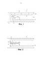
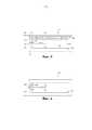
Настоящее изобретение относится к удлиненному образующему аэрозоль устройству, в котором может быть размещено образующее аэрозоль изделие. Образующее аэрозоль устройство содержит нагреватель для нагрева образующего аэрозоль изделия и экстрактор для извлечения образующего аэрозоль изделия, размещенного в образующем аэрозоль устройстве. Нагреватель проходит в продольном направлении относительно удлиненного образующего аэрозоль устройства и выполнен с возможностью проникновения во внутреннюю область образующего аэрозоль изделия. Экстрактор соединен с образующим аэрозоль устройством с возможностью перемещения между первым положением и вторым положением, из которых первое положение представляет собой рабочее положение, задаваемое нагревателем, находящемся в контакте с образующим аэрозоль изделием, а второе положение представляет собой положение извлечения, задаваемое нагревателем, отделенным от образующего аэрозоль изделия. Экстрактор содержит полость для размещения образующего аэрозоль изделия. В торцевой стенке указанной полости образовано первое отверстие для обеспечения возможности проникновения нагревателя в полость, когда экстрактор перемещают между вторым положением и первым положением. Экстрактор дополнительно образует воздушный канал для обеспечения возможности потока воздушного потока в указанную полость, причем впускное отверстие указанного воздушного канала расположено в точке, находящейся с внешней в радиальном направлении стороны относительно первого отверстия.The present invention relates to an elongated aerosol forming device in which an aerosol forming article can be placed. The aerosol forming device comprises a heater for heating the aerosol forming article and an extractor for extracting the aerosol forming article housed in the aerosol forming device. The heater extends in a longitudinal direction with respect to the elongated aerosol forming device and is configured to penetrate into the inner region of the aerosol forming product. The extractor is connected to the aerosol forming device with the ability to move between the first position and the second position, of which the first position is the operating position defined by the heater in contact with the aerosol forming article, and the second position is the extraction position defined by the heater separated from the generating aerosol products. The extractor contains a cavity for accommodating an aerosol forming article. A first hole is formed in the end wall of said cavity to allow the heater to penetrate into the cavity when the extractor is moved between the second position and the first position. The extractor additionally forms an air channel to allow air to flow into the specified cavity, the inlet of the specified air channel being located at a point located on the radially outer side of the side relative to the first hole.
При использовании пользователь осуществляет затяжку на том конце образующего аэрозоль изделия, который размещен в указанной полости. Образующее аэрозоль изделие содержит образующий аэрозоль субстрат, который нагревают нагревателем. Воздух втягивают в указанную полость через указанный воздушный канал и он протекает по образующему аэрозоль субстрату. Летучие компоненты, выделяющиеся из нагретого образующего аэрозоль субстрата, захватываются воздушным потоком и конденсируются с образованием вдыхаемого аэрозоля.In use, the user tightens at the end of the aerosol forming article that is placed in the cavity. The aerosol forming article contains an aerosol forming substrate which is heated by a heater. Air is drawn into said cavity through said air channel and it flows along the aerosol forming substrate. Volatile components released from the heated aerosol forming substrate are captured by the air stream and condense to form an inhaled aerosol.
В образующем аэрозоль устройстве, раскрытом в WO2013/076098, воздух втекает внутрь полости экстрактора через то же самое отверстие, которое обеспечивает возможность проникновения нагревателя внутрь указанной полости. Воздушный тракт внутри устройства обеспечивает, чтобы воздух имел возможность достижения нижней стороны торцевой стенки указанной полости, и отсюда воздух протекает через указанное отверстие вдоль боковой стороны нагревателя внутрь указанной полости. Необходимость в протекании воздуха через указанную полость означает, что указанное отверстие должно быть выполнено с такими размерами, чтобы присутствовал достаточный промежуток для обеспечения возможности протекания необходимого воздушного потока, когда нагреватель находится на своем месте. В результате многократного использования мусор из используемых одно за другим образующих аэрозоль изделий падает через указанное отверстие и накапливается вокруг основания нагревателя и в указанном воздушном тракте устройства. Этот мусор может быть липким и он может накапливаться, затрудняя проходимость или блокируя воздушный тракт, проходящий через устройство, и ослабляя таким образом ощущения потребителя. Очистка от мусора, который накапливается в устройстве снаружи от полости экстрактора, является затруднительной.In the aerosol forming device disclosed in WO2013 / 076098, air flows into the extractor cavity through the same opening, which allows the heater to penetrate into the cavity. The air path inside the device ensures that the air can reach the lower side of the end wall of the cavity, and from here air flows through the hole along the side of the heater into the cavity. The need for air to flow through said cavity means that said hole must be dimensioned so that a sufficient gap is present to allow the necessary airflow to flow when the heater is in place. As a result of repeated use, garbage from used one after another aerosol forming products falls through the specified hole and accumulates around the base of the heater and in the specified air path of the device. This garbage can be sticky and it can accumulate, making it difficult to pass or blocking the air path passing through the device, and thus weakening the consumer’s sensations. Cleaning debris that accumulates in the device from the outside of the extractor cavity is difficult.
В настоящем изобретении первое отверстие, предназначенное для размещения нагревателя, не совпадает по местоположению с впускным воздушным отверстием экстрактора. Впускное воздушное отверстие расположено на удалении от первого отверстия с внешней в радиальном направлении стороны. Предпочтительно, впускные воздушные отверстия образованы в боковой стенке экстрактора или на боковом участке торцевой стенки экстрактора. Например, впускное отверстие воздушного канала может быть образовано на самом внешнем в радиальном направлении участке торцевой стенки. По меньшей мере часть воздушного канала может проходить в радиальном направлении внутри торцевой стенки, т.е. между внутренней и внешней поверхностями торцевой стенки.In the present invention, the first opening for accommodating the heater does not coincide in location with the extractor air inlet. The air inlet is located away from the first hole on the radially outer side. Preferably, the inlet air holes are formed in the side wall of the extractor or on the side portion of the end wall of the extractor. For example, an air channel inlet may be formed in a radially outermost portion of the end wall. At least a portion of the air passage may extend radially inside the end wall, i.e. between the inner and outer surfaces of the end wall.
Предпочтительно, воздушный тракт через экстрактор захватывает воздух, протекающий радиально в направлении нагревателя, в пределах по меньшей части этого воздушного тракта. Таким образом, мусор, падающий через первое отверстие, не будет блокировать воздушный тракт. Мусор может заблокировать воздушный тракт изнутри, однако предпочтительно, чтобы экстрактор мог быть извлечен из устройства для обеспечения возможности легкого удаления любого подобного мусора, например, путем промывки водой.Preferably, the air path through the extractor captures the air flowing radially in the direction of the heater, within at least part of this air path. Thus, debris falling through the first hole will not block the air path. Debris can block the airway from the inside, however, it is preferable that the extractor can be removed from the device to allow easy removal of any such debris, for example by washing with water.
Предпочтительно, первое отверстие выполнено с такими размерами, чтобы обеспечить возможность образования промежутка величиной 0,5 мм или менее с нагревателем. Промежуток величиной 0,5 мм или менее обеспечивает возможность прохождения части нагревателя через указанное отверстие таким образом, чтобы он вошел в указанную полость и проник в образующее аэрозоль изделие внутри этой полости, но при этом способствовал предотвращению выхода частиц образующего аэрозоль субстрата или другого мусора из указанной полости. Может быть предпочтительно, чтобы первое отверстие имело размеры, идентичные размерам поперечного сечения нагревателя, с тем, чтобы нагреватель совершал скобление стенок этого отверстия при прохождении внутрь указанной полости и из нее. Таким образом дополнительно обеспечивается возможность предотвращения выхода мусора из указанной полости через первое отверстие.Preferably, the first hole is dimensioned to allow a gap of 0.5 mm or less with the heater. An interval of 0.5 mm or less allows a part of the heater to pass through the hole so that it enters the cavity and penetrates the aerosol forming article inside this cavity, but helps to prevent particles of the aerosol forming substrate or other debris from escaping from the specified cavities. It may be preferable that the first hole has dimensions identical to the dimensions of the cross section of the heater so that the heater scrapes the walls of this hole as it passes into and out of the cavity. In this way, it is further possible to prevent the exit of debris from said cavity through the first opening.
Воздушный тракт, проходящий от впускного отверстия воздушного канала, может быть соединен с первым отверстием.An air passage extending from the inlet of the air channel may be connected to the first hole.
Экстрактор предпочтительно выполнен таким образом, что частицы образующего аэрозоль субстрата или другой мусор, который может создаваться образующим аэрозоль изделием, улавливаются или удерживаются внутри экстракторного участка образующего аэрозоль устройства, когда образующее аэрозоль изделие извлечено. Затем экстрактор может быть извлечен из устройства и очищен обычным образом для поддержания уровня ощущений потребителя.The extractor is preferably configured such that particles of the aerosol forming substrate or other debris that may be generated by the aerosol forming article are trapped or retained within the extractor portion of the aerosol forming device when the aerosol forming article is removed. Then the extractor can be removed from the device and cleaned in the usual way to maintain the level of consumer sensations.
В предпочтительных вариантах осуществления внешняя поверхность указанной торцевой стенки может упираться в участок или торец образующего аэрозоль устройства, когда экстрактор находится в первом положении, так что исключается возможность накопления мусора из образующего аэрозоль изделия в образующем аэрозоль устройстве. Иначе говоря, отсутствует промежуток для прохождения мусора между экстрактором и остальными участками образующего аэрозоль устройства. Это может помочь в обеспечении удержания любого мусора внутри экстрактора.In preferred embodiments, the outer surface of said end wall may abut against a portion or end of the aerosol forming device when the extractor is in the first position, so that the possibility of accumulation of debris from the aerosol forming article in the aerosol forming device is eliminated. In other words, there is no gap for the passage of debris between the extractor and the rest of the aerosol forming device. This can help ensure that any debris is trapped inside the extractor.
Экстрактор может содержать первый воздушный канал и второй воздушный канал, причем впускные отверстия первого и второго воздушных каналов расположены на противоположных сторонах экстрактора. Количество воздушных каналов может составлять более двух.The extractor may comprise a first air channel and a second air channel, the inlets of the first and second air channels being located on opposite sides of the extractor. The number of air channels can be more than two.
Воздух может втекать в указанную полость через выпускные отверстия из воздушных каналов, которые образованы во внутренней поверхности торцевой стенки. Воздух может втекать в указанную полость через выпускные отверстия из воздушных каналов, которые соединены с первым отверстием, так что воздух, втекающий в указанную полость, направляется по нагревателю или вблизи него.Air can flow into said cavity through the outlet openings from the air channels that are formed in the inner surface of the end wall. Air can flow into the specified cavity through the outlet openings from the air channels that are connected to the first hole, so that the air flowing into the specified cavity is directed along or near the heater.
Настоящее изобретение может также относиться к образующей аэрозоль системе, содержащей удлиненное образующее аэрозоль устройство, описанное выше, и образующее аэрозоль изделие, содержащее образующий аэрозоль субстрат для выделения вдыхаемого аэрозоля при нагреве с помощью нагревателя. Образующий аэрозоль субстрат может содержать лист из гомогенизированного табака.The present invention may also relate to an aerosol forming system comprising an elongated aerosol forming device described above and an aerosol forming article comprising an aerosol forming substrate for releasing an inhaled aerosol when heated by a heater. The aerosol forming substrate may comprise a sheet of homogenized tobacco.
Когда образующее аэрозоль изделие размещено внутри полости экстрактора, экстрактор может иметь возможность позиционирования образующего аэрозоль субстрата в контакте с нагревателем.When the aerosol forming article is placed inside the cavity of the extractor, the extractor may be able to position the aerosol forming substrate in contact with the heater.
В контексте данного документа термин «позиционирование» относится к перемещению образующего аэрозоль изделия или образующего аэрозоль субстрата относительно нагревателя образующего аэрозоль устройства. Таким образом можно сказать, что экстрактор имеет возможность перемещения образующего аэрозоль субстрата относительно нагревателя с целью облегчения извлечения образующего аэрозоль субстрата из образующего аэрозоль устройства.In the context of this document, the term “positioning” refers to the movement of an aerosol forming article or an aerosol forming substrate relative to a heater of an aerosol forming device. Thus, it can be said that the extractor has the ability to move the aerosol forming substrate relative to the heater in order to facilitate the extraction of the aerosol forming substrate from the aerosol forming device.
В контексте данного документа термин «образующее аэрозоль устройство» относится к устройству, которое взаимодействует с образующим аэрозоль субстратом образующего аэрозоль изделия для образования аэрозоля. Образующий аэрозоль субстрат представляет собой часть образующего аэрозоль изделия, например часть курительного изделия. Образующее аэрозоль устройство может содержать один или более компонентов, используемых для подачи энергии от источника питания на образующий аэрозоль субстрат для образования аэрозоля. Например, образующее аэрозоль устройство может представлять собой нагреваемое образующее аэрозоль устройство. Образующее аэрозоль устройство может представлять собой образующее аэрозоль устройство с электрическим нагревом или образующее аэрозоль устройство с газовым нагревом. Образующее аэрозоль устройство может представлять собой курительное устройство, которое взаимодействует с образующим аэрозоль субстратом образующего аэрозоль изделия для образования аэрозоля, непосредственно вдыхаемого в легкие пользователя через рот пользователя. Образующее аэрозоль устройство может представлять собой держатель для образующего аэрозоль изделия.As used herein, the term “aerosol forming device” refers to a device that interacts with an aerosol forming substrate of an aerosol forming article to form an aerosol. The aerosol forming substrate is part of an aerosol forming article, for example a part of a smoking article. The aerosol forming device may comprise one or more components used to supply energy from a power source to the aerosol forming substrate to form an aerosol. For example, the aerosol forming device may be a heated aerosol forming device. The aerosol forming device may be an aerosol forming device with electric heating or an aerosol forming device with gas heating. The aerosol forming device may be a smoking device that interacts with the aerosol forming substrate of the aerosol forming article to form an aerosol directly inhaled into the user's lungs through the user's mouth. The aerosol forming device may be a holder for the aerosol forming product.
В контексте данного документа термин «образующий аэрозоль субстрат» относится к субстрату, способному высвобождать летучие соединения, которые могут образовывать аэрозоль. Такие летучие соединения могут высвобождаться в результате нагрева образующего аэрозоль субстрата. Образующий аэрозоль субстрат может с удобством использоваться как часть образующего аэрозоль изделия или курительного изделия.In the context of this document, the term "aerosol forming substrate" refers to a substrate capable of releasing volatile compounds that may form an aerosol. Such volatile compounds can be released by heating the aerosol forming substrate. The aerosol forming substrate can conveniently be used as part of an aerosol forming article or a smoking article.
В контексте данного документа термины «образующее аэрозоль изделие» и «курительное изделие» относятся к изделию, содержащему образующий аэрозоль субстрат, способный высвобождать летучие соединения, которые могут образовывать аэрозоль. Например, образующее аэрозоль изделие может представлять собой курительное изделие, которое образует аэрозоль, непосредственно вдыхаемый в легкие пользователя через рот пользователя. Образующее аэрозоль изделие может быть одноразовым. Здесь и далее, как правило, используется термин «курительное изделие».In the context of this document, the terms "aerosol forming article" and "smoking article" refer to an article containing an aerosol forming substrate capable of releasing volatile compounds that may form an aerosol. For example, the aerosol forming article may be a smoking article that forms an aerosol directly inhaled into the lungs of the user through the mouth of the user. The aerosol forming article may be disposable. Hereinafter, as a rule, the term “smoking article” is used.
Предпочтительно, курительное изделие представляет собой нагреваемое курительное изделие, которое представляет собой курительное изделие, содержащее образующий аэрозоль субстрат, подлежащий нагреву, а не сжиганию, с целью высвобождения летучих соединений, которые могут образовывать аэрозоль. Аэрозоль, образующийся в результате нагрева образующего аэрозоль субстрата, может содержать меньше известных вредных компонентов, чем образовалось бы в результате сгорания или пиролитической деградации образующего аэрозоль субстрата. Курительное изделие может представлять собой или может содержать табачную палочку.Preferably, the smoking article is a heated smoking article, which is a smoking article containing an aerosol forming substrate to be heated rather than incinerated in order to release volatile compounds that can form an aerosol. The aerosol generated by heating the aerosol forming substrate may contain less known harmful components than would result from the combustion or pyrolytic degradation of the aerosol forming substrate. The smoking article may be or may comprise a tobacco stick.
В одном варианте осуществления экстрактор позиционирует курительное изделие, содержащее образующий аэрозоль субстрат, в первом положении и во втором положении, из которых первое положение представляет собой рабочее положение, задаваемое нагревателем, находящемся в контакте с образующим аэрозоль субстратом, а второе положение представляет собой положение извлечения, задаваемое образующим аэрозоль субстратом, отделенным от нагревателя. Таким образом, экстрактор может быть подвижно соединен с образующим аэрозоль устройством, и он может иметь возможность перемещения между первым положением, в котором образующий аэрозоль субстрат находится в контакте с нагревателем образующего аэрозоль устройства, и вторым положением, в котором образующий аэрозоль субстрат отделен от нагревателя. Предпочтительно, экстрактор остается соединенным с образующим аэрозоль устройством при нахождении в первом положении, во втором положении и в любом промежуточном положении между первым положением и вторым положением. Экстрактор может быть с возможностью извлечения соединен с образующим аэрозоль устройством, и в случае, когда экстрактор извлекается из устройства, он не находится ни в первом положении, ни во втором положении.In one embodiment, the extractor positions the smoking article containing the aerosol forming substrate in a first position and a second position, of which the first position is the operating position defined by the heater in contact with the aerosol forming substrate, and the second position is the extraction position, defined by the aerosol forming substrate separated from the heater. Thus, the extractor may be movably connected to the aerosol forming device, and it may be able to move between the first position in which the aerosol forming substrate is in contact with the heater of the aerosol forming device and the second position in which the aerosol forming substrate is separated from the heater. Preferably, the extractor remains connected to the aerosol forming device while in the first position, in the second position, and in any intermediate position between the first position and the second position. The extractor may be removably connected to the aerosol forming device, and when the extractor is removed from the device, it is neither in the first position nor in the second position.
Экстрактор может иметь возможность скольжения между первым положением и вторым положением.The extractor may be able to slide between the first position and the second position.
Первое положение экстрактора представляет собой рабочее положение, в котором нагреватель может нагревать образующий аэрозоль субстрат курительного изделия для образования аэрозоля. Как известно специалистам с обычной квалификацией в данной области техники, аэрозоль представляет собой суспензию твердых частиц и/или капель жидкости в газе, таком как воздух. Второе положение экстрактора представляет собой положение изввлечения, которое облегчает извлечение курительного изделия из образующего аэрозоль устройства. Расположенные раньше по ходу потока и дальше по ходу потока концы образующего аэрозоль изделия определены относительно воздушного потока, когда пользователь осуществляет затяжку. Обычно впускной воздух поступает в образующее аэрозоль изделие на расположенном раньше по ходу потока конце, смешивается с аэрозолем и переносит аэрозоль в воздушном потоке в направлении рта пользователя на расположенном дальше по ходу потока конце.The first position of the extractor is the operating position in which the heater can heat the aerosol forming substrate of the smoking article to form an aerosol. As known to those of ordinary skill in the art, an aerosol is a suspension of solid particles and / or liquid droplets in a gas, such as air. The second position of the extractor is the extraction position, which facilitates the extraction of the smoking article from the aerosol forming device. The ends of the aerosol forming article located earlier upstream and downstream are defined relative to the air flow when the user puffs. Typically, inlet air enters the aerosol forming article at an upstream end, mixes with the aerosol, and transfers the aerosol in the air stream toward the mouth of the user at the downstream end.
Экстрактор обеспечивает возможность по существу поддержания целостности образующего аэрозоль субстрата, когда курительное изделие извлекают из образующего аэрозоль устройства.The extractor provides the ability to essentially maintain the integrity of the aerosol forming substrate when the smoking article is removed from the aerosol forming device.
Образующее аэрозоль устройство может дополнительно содержать стопор для предотвращения выскальзывания экстрактора из образующего аэрозоль устройства, когда экстрактор перемещают в первое положение. Стопор может быть выполнен с возможностью взаимодействия со средствами приема стопора, например надрезом или выемкой для приема стопора. Стопор может быть выполнен на экстракторе. Средства приема стопора могут быть выполнены на другом участке образующего аэрозоль устройства.The aerosol forming device may further comprise a stopper to prevent the extractor from slipping out of the aerosol forming device when the extractor is moved to the first position. The stopper may be configured to interact with stopper receiving means, for example, an incision or a recess for receiving the stopper. The stopper can be performed on the extractor. Means for receiving the stopper may be performed on another portion of the aerosol forming device.
Образующее аэрозоль устройство может дополнительно содержать направляющий штырь для направления экстрактора, когда экстрактор перемещают между первым и вторым положениями. Направляющий штырь по существу предотвращает поворот экстрактора относительно образующего аэрозоль устройства. Направляющий штырь может быть выполнен с возможностью взаимодействия с щелью или канавкой. Направляющий штырь может быть выполнен, например, на экстракторе. Указанная щель или канавка может быть выполнена на другом участке образующего аэрозоль устройства.The aerosol forming device may further comprise a guide pin for guiding the extractor when the extractor is moved between the first and second positions. The guide pin essentially prevents the extractor from rotating relative to the aerosol generating device. The guide pin may be configured to interact with a slot or groove. The guide pin can be made, for example, on the extractor. The specified slot or groove may be made in another area of the aerosol forming device.
Экстрактор может содержать изоляционный материал для обеспечения изоляции от тепла нагревателя.The extractor may contain insulating material to provide insulation from the heat of the heater.
Образующее аэрозоль устройство может представлять собой курительную систему с электрическим нагревом, содержащую электрический нагреватель. В других вариантах осуществления образующее аэрозоль устройство может представлять собой курительную систему с нагревателем, содержащую газовую горелку или какой-либо источник тепла, отличный от электрического. Термин «электрический нагреватель» относится к одному или более электрическим нагревательным элементам. Электрический нагреватель может содержать внутренний электрический нагревательный элемент для по меньшей мере частичного вставки внутрь образующего аэрозоль субстрата курительного изделия. «Внутренний нагревательный элемент» представляет собой элемент, пригодный для вставки внутрь образующего аэрозоль материала. Настоящее изобретение особенно полезно в случае его использования в сочетании с внутренним нагревательным элементом, поскольку в этом случае может иметь место тенденция к прилипанию образующего аэрозоль субстрата к нагревательному элементу и, как следствие, к поломке во время отделения образующего аэрозоль субстрата от нагревательного элемента.The aerosol forming device may be an electrically heated smoking system comprising an electric heater. In other embodiments, the aerosol forming device may be a smoking smoking system with a heater containing a gas burner or some other heat source other than electric. The term "electric heater" refers to one or more electric heating elements. The electric heater may comprise an internal electric heating element for at least partially inserting into the aerosol forming substrate a smoking article. An “internal heating element” is an element suitable for insertion into an aerosol forming material. The present invention is particularly useful when used in combination with an internal heating element, since in this case there may be a tendency for the aerosol forming substrate to adhere to the heating element and, as a consequence, to breakage during separation of the aerosol forming substrate from the heating element.
Электрический нагреватель может содержать один нагревательный элемент. В качестве альтернативы, электрический нагреватель может содержать более одного нагревательного элемента. Нагревательный элемент или нагревательные элементы могут быть расположены надлежащим образом для наиболее эффективного нагрева образующего аэрозоль субстрата.An electric heater may comprise one heating element. Alternatively, an electric heater may comprise more than one heating element. The heating element or heating elements can be arranged appropriately for the most efficient heating of the aerosol forming substrate.
Электрический нагреватель может содержать электрорезистивный материал. Подходящие электрорезистивные материалы включают в себя, но без ограничения: полупроводники, такие как легированная керамика, электрически «проводящая» керамика (например такая, как дисилицид молибдена), углерод, графит, металлы, сплавы металлов и композитные материалы, изготовленные из керамического материала и металлического материала. Такие композитные материалы могут содержать легированную или нелегированную керамику. Примеры подходящей легированной керамики включают в себя легированные карбиды кремния. Примеры подходящих металлов включают в себя титан, цирконий, тантал и металлы из платиновой группы. Примеры подходящих сплавов металлов включают в себя нержавеющую сталь, никель-, кобальт-, хром-, алюминий-, титан-, цирконий-, гафний-, ниобий-, молибден-, тантал-, вольфрам-, олово-, галлий-, марганец- и железосодержащие сплавы, суперсплавы на основе никеля, железа, кобальта, нержавеющей стали, Timetal® и сплавы на основе железа-марганца-алюминия. В композитных материалах указанный электрорезистивный материал может быть при необходимости встроен в изолирующий материал, инкапсулирован в него или покрыт им, или наоборот, в зависимости от кинетики переноса энергии и требуемых внешних физико-химических свойств. В качестве альтернативы, электрический нагреватель может содержать инфракрасный нагревательный элемент, фотонный источник или индукционный нагревательный элемент.The electric heater may contain electrically resistive material. Suitable electroresistive materials include, but are not limited to: semiconductors such as alloy ceramics, electrically conductive ceramics (such as molybdenum disilicide), carbon, graphite, metals, metal alloys, and composite materials made from ceramic material and metallic material. Such composite materials may contain doped or undoped ceramics. Examples of suitable doped ceramics include doped silicon carbides. Examples of suitable metals include titanium, zirconium, tantalum and platinum group metals. Examples of suitable metal alloys include stainless steel, nickel, cobalt, chromium, aluminum, titanium, zirconium, hafnium, niobium, molybdenum, tantalum, tungsten, tin, gallium, manganese - and iron-containing alloys, superalloys based on nickel, iron, cobalt, stainless steel, Timetal® and alloys based on iron-manganese-aluminum. In composite materials, said electroresistive material can, if necessary, be embedded in an insulating material, encapsulated in it or coated with it, or vice versa, depending on the kinetics of energy transfer and the required external physicochemical properties. Alternatively, the electric heater may comprise an infrared heating element, a photon source, or an induction heating element.
Электрический нагреватель может иметь любую подходящую форму. Например, электрический нагреватель может быть выполнен в виде нагревательного лезвия. В качестве альтернативы, электрический нагреватель может иметь форму корпуса или подложки, имеющей различные электропроводные участки, или форму электрорезистивной металлической трубки. В качестве альтернативы, возможны одна или более нагревательных игл или стержней, которые проходят через центр образующего аэрозоль субстрата, как уже было описано. В качестве альтернативы, электрический нагреватель может представлять собой дисковый (концевой) нагреватель или сочетание дискового нагревателя с нагревательными иглами или стержнями. Другие альтернативные варианты включают в себя нагревательную проволоку или нить, например Ni-Cr (хромоникелевую), платиновую, вольфрамовую проволоку, или проволоку из сплава, или нагревательную пластину. При необходимости, нагревательный элемент может быть выполнен путем нанесения внутри или снаружи на жесткий несущий материал.The electric heater may have any suitable shape. For example, an electric heater may be in the form of a heating blade. Alternatively, the electric heater may be in the form of a housing or substrate having various electrically conductive portions, or in the form of an electroresistive metal tube. Alternatively, one or more heating needles or rods are possible that extend through the center of the aerosol forming substrate, as already described. Alternatively, the electric heater may be a disk (end) heater or a combination of a disk heater with heating needles or rods. Other alternatives include a heating wire or filament, for example Ni-Cr (chromium-nickel), platinum, tungsten, or alloy wire, or a heating plate. If necessary, the heating element can be made by applying it internally or externally to a rigid carrier material.
Электрический нагреватель может содержать теплоотвод или тепловой резервуар, содержащий материал, способный поглощать и сохранять тепло и впоследствии высвобождать тепло с течением времени в образующий аэрозоль субстрат. Теплоотвод может быть выполнен из любого подходящего материала, такого как подходящий металлический или керамический материал. В одном варианте осуществления указанный материал имеет высокую теплоемкость (чувствительный теплоаккумулирующий материал) или он представляет собой материал, способный поглощать и впоследствии высвобождать тепло в результате обратимого процесса, такого как высокотемпературный фазовый переход. Подходящие чувствительные теплоаккумулирующие материалы включают в себя силикагель, оксид алюминия, углерод, стеклянный мат, стекловолокно, минеральные вещества, металл или сплав металлов, таких как алюминий, серебро или свинец, и целлюлозный материал, такой как бумага. Другие подходящие материалы, которые высвобождают тепло в результате обратимого фазового перехода, включают в себя парафин, ацетат натрия, нафталин, воск, оксид полиэтилена, металл, металлическую соль, эвтектическую смесь солей или сплав.The electric heater may comprise a heat sink or a heat reservoir containing material capable of absorbing and retaining heat and subsequently releasing heat over time into the aerosol forming substrate. The heat sink may be made of any suitable material, such as a suitable metal or ceramic material. In one embodiment, said material has a high heat capacity (sensitive heat storage material) or it is a material capable of absorbing and subsequently releasing heat as a result of a reversible process, such as a high temperature phase transition. Suitable sensitive heat storage materials include silica gel, alumina, carbon, glass mat, fiberglass, minerals, metal or an alloy of metals such as aluminum, silver or lead, and cellulosic material such as paper. Other suitable materials that release heat through a reversible phase transition include paraffin, sodium acetate, naphthalene, wax, polyethylene oxide, metal, metal salt, a eutectic mixture of salts, or an alloy.
Теплоотвод или тепловой резервуар может быть выполнен таким образом, чтобы он непосредственно контактировал с образующим аэрозоль субстратом и имел возможность передачи аккумулированного тепла непосредственно на субстрат. В качестве альтернативы тепло, аккумулированное в теплоотводе или тепловом резервуаре, может быть передано на образующий аэрозоль субстрат посредством проводника тепла, такого как металлическая трубка.The heat sink or heat reservoir can be designed so that it is in direct contact with the aerosol forming substrate and has the ability to transfer stored heat directly to the substrate. Alternatively, the heat accumulated in the heat sink or heat reservoir may be transferred to the aerosol forming substrate by means of a heat conductor, such as a metal tube.
Электрический нагреватель может нагревать образующий аэрозоль субстрат за счет проводимости. Электрический нагреватель может по меньшей мере частично находиться в контакте с субстратом или носителем, на который нанесен субстрат. В качестве альтернативы, тепло от электрического нагревателя может передаваться на субстрат посредством теплопроводного элемента.An electric heater can heat the aerosol forming substrate due to conductivity. The electric heater may be at least partially in contact with the substrate or carrier on which the substrate is applied. Alternatively, heat from an electric heater may be transferred to the substrate by means of a heat-conducting element.
В качестве альтернативы, электрический нагреватель может передавать тепло в поступающий окружающий воздух, втягиваемый через электрически нагреваемую курительную систему во время использования, и этот воздух, в свою очередь, нагревает образующий аэрозоль субстрат за счет конвекции. Окружающий воздух может быть нагрет до того, как он пройдет через образующий аэрозоль субстрат.Alternatively, the electric heater can transfer heat to the incoming ambient air drawn in through the electrically heated smoking system during use, and this air, in turn, heats the aerosol forming substrate by convection. Ambient air can be heated before it passes through the aerosol forming substrate.
В одном варианте осуществления электроэнергию подают на электрический нагреватель до тех пор, пока нагревательный элемент или элементы электрического нагревателя не достигнут температуры примерно от 250°C до 440 °C. Для управления нагревом нагревательного элемента или элементов с целью достижения температуры примерно от 250°C до 440°C, могут использоваться любые подходящие датчик температуры и схема управления. В этом состоит отличие от обычных сигарет, в которых температура горения табака и сигаретной бумаги может достигать 800°C.In one embodiment, electricity is supplied to the electric heater until the heating element or elements of the electric heater reaches a temperature of about 250 ° C to 440 ° C. To control the heating of the heating element or elements in order to reach a temperature of about 250 ° C to 440 ° C, any suitable temperature sensor and control circuit may be used. This is different from regular cigarettes, in which the burning temperature of tobacco and cigarette paper can reach 800 ° C.
В одном варианте осуществления экстрактор содержит зажимные средства для зажима курительного изделия, когда это курительное изделие размещено в экстракторе.In one embodiment, the extractor comprises clamping means for clamping the smoking article when the smoking article is housed in the extractor.
Зажимные средства могут обеспечивать правильное позиционирование курительного изделия с тем, чтобы нагреватель имел возможность нагрева образующего аэрозоль субстрата курительного изделия, когда пользователь осуществляет затяжку. В дополнение, зажимные средства обеспечивают, чтобы курительное изделие не выпадало из образующего аэрозоль устройства, если курительная система ориентирована с отклонением от вертикали или с отклонением от рабочей ориентации. Зажимные средства могут быть выполнены с возможностью зажима курительного изделия, когда это курительное изделие размещено в экстракторе, независимо от того, находится экстрактор в первом положении или во втором положении. В качестве альтернативы, зажимные средства могут быть выполнены с возможностью зажима курительного изделия, когда это курительное изделие размещено в экстракторе, лишь в том случае, если скользящий приемник находится в первом положении.The clamping means can ensure the correct positioning of the smoking article so that the heater is able to heat the aerosol forming substrate of the smoking article when the user tightens. In addition, the clamping means ensures that the smoking article does not fall out of the aerosol forming device if the smoking system is oriented with a deviation from the vertical or with a deviation from the working orientation. The clamping means can be adapted to clamp the smoking article when the smoking article is placed in the extractor, regardless of whether the extractor is in a first position or a second position. Alternatively, the clamping means may be configured to clamp the smoking article when the smoking article is placed in the extractor, only if the sliding receptacle is in the first position.
Как было указано выше, извлечение курительного изделия из образующего аэрозоль устройства может быть осуществлено в два этапа. На первом этапе курительное изделие и экстрактор перемещают, предпочтительно путем скольжения, относительно компонентов образующего аэрозоль устройства. На втором этапе курительное изделие, теперь отделенное от нагревателя, может быть извлечено из экстрактора. Зажимные средства, при их наличии, могут быть выполнены с возможностью высвобождения курительного изделия во время второго этапа.As indicated above, the extraction of the smoking article from the aerosol forming device can be carried out in two stages. In a first step, the smoking article and extractor are moved, preferably by sliding, relative to the components of the aerosol forming device. In a second step, the smoking article, now separated from the heater, can be removed from the extractor. The clamping means, if any, can be configured to release the smoking article during the second step.
В одном варианте осуществления образующее аэрозоль устройство дополнительно содержит перемещающие средства для перемещения экстрактора между первым и вторым положениями.In one embodiment, the aerosol forming device further comprises moving means for moving the extractor between the first and second positions.
Перемещающие средства могут содержать моторизованные перемещающие средства. Перемещение экстрактора между первым и вторым положениями может осуществляться автоматически, когда пользователь прикладывает усилие к курительному изделию для извлечения этого курительного изделия из образующего аэрозоль устройства. В качестве альтернативы, перемещение экстрактора между первым и вторым положениями может осуществляться автоматически, когда пользователь нажимает на переключатель. В качестве альтернативы, перемещающие средства могут отсутствовать, и перемещение экстрактора между первым и вторым положениями может осуществляться вручную пользователем.Moving means may contain motorized moving means. The extractor can be moved between the first and second positions automatically when the user exerts a force on the smoking article to remove the smoking article from the aerosol forming device. Alternatively, moving the extractor between the first and second positions can be done automatically when the user presses the switch. Alternatively, moving means may be absent, and the movement of the extractor between the first and second positions may be carried out manually by the user.
Во время работы курительное изделие, содержащее образующий аэрозоль субстрат, может быть полностью заключено внутри образующего аэрозоль устройства. В этом случае пользователь может осуществлять затяжку на мундштуке образующего аэрозоль устройства. В качестве альтернативы, во время работы курительное изделие, содержащее образующий аэрозоль субстрат, может быть частично заключено внутри образующего аэрозоль устройства. В этом случае пользователь может осуществлять затяжку непосредственно на курительном изделии.During operation, the smoking article containing the aerosol forming substrate can be completely enclosed within the aerosol forming device. In this case, the user can tighten on the mouthpiece of the aerosol forming device. Alternatively, during operation, the smoking article containing the aerosol forming substrate may be partially enclosed within the aerosol forming device. In this case, the user can tighten directly on the smoking article.
Курительное изделие может иметь по существу цилиндрическую форму. Курительное изделие может быть по существу удлиненным. Курительное изделие может иметь направление длины и окружное направление, по существу перпендикулярное направлению длины. Образующий аэрозоль субстрат может иметь по существу цилиндрическую форму. Образующий аэрозоль субстрат может быть по существу удлиненным. Образующий аэрозоль субстрат также может иметь направление длины и окружное направление, по существу перпендикулярную направлению длины. Образующий аэрозоль субстрат может быть размещен в экстракторе образующего аэрозоль устройства таким образом, чтобы направление длины образующего аэрозоль субстрата было по существу параллельно направлению воздушного потока в образующем аэрозоль устройстве.The smoking article may have a substantially cylindrical shape. The smoking article may be substantially elongated. The smoking article may have a length direction and a circumferential direction substantially perpendicular to the length direction. The aerosol forming substrate may have a substantially cylindrical shape. The aerosol forming substrate may be substantially elongated. The aerosol forming substrate may also have a length direction and a circumferential direction substantially perpendicular to the length direction. The aerosol forming substrate can be placed in the extractor of the aerosol forming device so that the length direction of the aerosol forming substrate is substantially parallel to the direction of the air flow in the aerosol forming device.
Курительное изделие может иметь общую длину от примерно 30 мм до примерно 100 мм. Курительное изделие может иметь внешний диаметр от примерно 5 мм до примерно 12 мм, например примерно 7 мм. Курительное изделие может содержать фильтрующую заглушку. Фильтрующая заглушка может быть расположена на дальнем по ходу потока конце курительного изделия. Фильтрующая заглушка может представлять собой ацетилцеллюлозную фильтрующую заглушку. Фильтрующая заглушка в одном варианте осуществления имеет длину примерно 7 мм, однако она может иметь длину от примерно 5 мм до примерно 10 мм.The smoking article may have a total length of from about 30 mm to about 100 mm. The smoking article may have an outer diameter of from about 5 mm to about 12 mm, for example, about 7 mm. The smoking article may comprise a filter plug. The filter plug may be located at the far upstream end of the smoking article. The filter plug may be a cellulose acetate filter plug. The filter plug in one embodiment has a length of about 7 mm, however, it can have a length of from about 5 mm to about 10 mm.
В одном варианте осуществления курительное изделие имеет общую длину примерно 45 мм. Курительное изделие может иметь внешний диаметр примерно 7,2 мм. Кроме того, образующий аэрозоль субстрат может иметь длину примерно 10 мм. В качестве альтернативы, образующий аэрозоль субстрат может иметь длину примерно 12 мм. Кроме того, диаметр образующего аэрозоль субстрата может составлять от примерно 5 мм до примерно 12 мм. Курительное изделие может содержать внешнюю бумажную обертку. Кроме того, курительное изделие может содержать разделитель между образующим аэрозоль субстратом и фильтрующей заглушкой. Указанный разделитель может иметь размер примерно 18 мм, однако он может иметь размер в диапазоне от примерно 5 мм до примерно 25 мм.In one embodiment, the smoking article has a total length of about 45 mm. The smoking article may have an outer diameter of about 7.2 mm. In addition, the aerosol forming substrate may have a length of about 10 mm. Alternatively, the aerosol forming substrate may have a length of about 12 mm. In addition, the diameter of the aerosol forming substrate may be from about 5 mm to about 12 mm. The smoking article may comprise an outer paper wrapper. In addition, the smoking article may comprise a separator between the aerosol forming substrate and the filter plug. The specified separator may have a size of about 18 mm, however, it can have a size in the range from about 5 mm to about 25 mm.
Образующий аэрозоль субстрат может представлять собой твердый образующий аэрозоль субстрат. В качестве альтернативы, образующий аэрозоль субстрат может содержать как твердые, так и жидкие компоненты. Образующий аэрозоль субстрат может содержать табакосодержащий материал, содержащий летучие ароматические соединения табака, которые высвобождаются из субстрата при нагреве. В качестве альтернативы, образующий аэрозоль субстрат может содержать нетабачный материал. Образующий аэрозоль субстрат может дополнительно содержать образователь аэрозоля. Примерами подходящих образователей аэрозоля являются глицерин и пропиленгликоль.The aerosol forming substrate may be a solid aerosol forming substrate. Alternatively, the aerosol forming substrate may contain both solid and liquid components. The aerosol forming substrate may contain a tobacco-containing material containing volatile tobacco aromatic compounds that are released from the substrate upon heating. Alternatively, the aerosol forming substrate may contain non-tobacco material. The aerosol forming substrate may further comprise an aerosol former. Examples of suitable aerosol formers are glycerin and propylene glycol.
Если образующий аэрозоль субстрат представляет собой твердый образующий аэрозоль субстрат, то этот твердый образующий аэрозоль субстрат может содержать, например, одно или более из следующего: порошок, гранулы, шарики, крупицы, тонкие трубки, полоски или листы, содержащие одно или более из следующего: травяные листья, табачные листья, фрагменты табачных жилок, восстановленный табак, гомогенизированный табак, экструдированный табак и расширенный табак. Твердый образующий аэрозоль субстрат может иметь рассыпную форму или он может быть обеспечен в подходящей таре или картридже. При необходимости, твердый образующий аэрозоль субстрат может содержать дополнительные табачные или нетабачные летучие ароматические соединения, высвобождаемые при нагреве субстрата. Твердый образующий аэрозоль субстрат может также содержать капсулы, которые содержат, например, дополнительные табачные или нетабачные летучие ароматические соединения, и такие капсулы могут плавиться во время нагрева твердого образующего аэрозоль субстрата.If the aerosol-forming substrate is a solid aerosol-forming substrate, then this solid aerosol-forming substrate may contain, for example, one or more of the following: powder, granules, balls, particles, thin tubes, strips or sheets containing one or more of the following: herbal leaves, tobacco leaves, tobacco vein fragments, reconstituted tobacco, homogenized tobacco, extruded tobacco and expanded tobacco. The solid aerosol forming substrate may be loose in shape or it may be provided in a suitable container or cartridge. If necessary, the solid aerosol forming substrate may contain additional tobacco or non-tobacco volatile aromatic compounds released upon heating of the substrate. The solid aerosol forming substrate may also contain capsules that contain, for example, additional tobacco or non-tobacco volatile aromatic compounds, and such capsules may melt during heating of the solid aerosol forming substrate.
При необходимости, твердый образующий аэрозоль субстрат может быть размещен на термостабильном носителе или встроен в него. Носитель может иметь форму порошка, гранул, шариков, крупиц, тонких трубочек, полосок или листов. В качестве альтернативы, носитель может представлять собой трубчатый носитель, имеющий тонкий слой твердого субстрата, нанесенный на его внутреннюю поверхность и/или на его внешнюю поверхность. Такой трубчатый носитель может быть выполнен, например, из бумаги или бумагообразного материала, нетканого мата из углеродных волокон, легкой металлической сетки с открытыми ячейками, или перфорированной металлической фольги, или любой другой термостабильной полимерной матрицы.If necessary, the solid aerosol forming substrate can be placed on or integrated into a thermostable carrier. The carrier may be in the form of powder, granules, beads, grains, thin tubes, strips or sheets. Alternatively, the carrier may be a tubular carrier having a thin layer of solid substrate deposited on its inner surface and / or on its outer surface. Such a tubular carrier can be made, for example, of paper or paper-like material, a carbon fiber nonwoven mat, open-mesh lightweight metal mesh, or perforated metal foil, or any other thermostable polymer matrix.
Твердый образующий аэрозоль субстрат может быть нанесен на поверхность носителя в виде, например, листа, пены, геля или суспензии. Твердый образующий аэрозоль субстрат может быть нанесен на всю поверхность носителя или, в качестве альтернативы, он может быть нанесен в виде рисунка с целью обеспечения неоднородной доставки аромата во время использования.The solid aerosol forming substrate may be applied to the surface of the carrier in the form of, for example, a sheet, foam, gel or suspension. The solid aerosol forming substrate can be applied to the entire surface of the carrier or, alternatively, it can be applied in the form of a pattern in order to ensure non-uniform delivery of aroma during use.
Хотя выше приведена ссылка на твердые образующие аэрозоль субстраты, специалисту с обычной квалификацией в данной области техники будет понятно, что в другие варианты осуществления настоящего изобретения могут быть включены другие виды образующего аэрозоль субстрата. Например, образующий аэрозоль субстрат, может представлять собой жидкий образующий аэрозоль субстрат. Если используется жидкий образующий аэрозоль субстрат, то образующее аэрозоль устройство предпочтительно содержит средства для удержания жидкости. Например, жидкий образующий аэрозоль субстрат может удерживаться в таре. В качестве альтернативы или дополнительно, жидкий образующий аэрозоль субстрат может быть абсорбирован внутри пористого несущего материала. Пористый несущий материал может быть изготовлен из любой подходящей абсорбционной заглушки или тела, например из вспененного материала или пластмассового материала, полипропилена, терилена, нейлоновых волокон или керамики. Жидкий образующий аэрозоль субстрат может удерживаться в пористом несущем материале перед использованием образующего аэрозоль устройства или, в качестве альтернативы, материал жидкого образующего аэрозоль субстрата может высвобождаться в пористый несущий материал во время использования или непосредственно перед ним. Например, жидкий образующий аэрозоль субстрат может быть обеспечен в капсуле. Оболочка указанной капсулы предпочтительно плавится при нагреве и высвобождает жидкий образующий аэрозоль субстрат внутрь пористого несущего материала. Указанная капсула может при необходимости содержать твердое вещество в сочетании с жидкостью.Although reference is made above to solid aerosol forming substrates, one of ordinary skill in the art will understand that other types of aerosol forming substrate may be included in other embodiments of the present invention. For example, the aerosol forming substrate may be a liquid aerosol forming substrate. If a liquid aerosol forming substrate is used, the aerosol forming device preferably comprises means for holding the liquid. For example, a liquid aerosol forming substrate may be retained in a container. Alternatively or additionally, the liquid aerosol forming substrate may be absorbed within the porous carrier material. The porous carrier material may be made of any suitable absorption plug or body, for example, foam or plastic, polypropylene, terylene, nylon fibers or ceramic. The liquid aerosol forming substrate may be retained in the porous carrier material prior to use of the aerosol forming device or, alternatively, the material of the liquid aerosol forming substrate may be released into the porous carrier material during use or immediately in front of it. For example, a liquid aerosol forming substrate may be provided in a capsule. The shell of said capsule preferably melts when heated and releases a liquid aerosol forming substrate into the porous carrier material. Said capsule may optionally contain a solid in combination with a liquid.
В качестве альтернативы, носитель может представлять собой нетканое полотно или пучок волокон, в которые включены табачные компоненты. Указанное нетканое полотно или пучок волокон может содержать, например, углеродные волокна, натуральные целлюлозные волокна или волокна из производных целлюлозы.Alternatively, the carrier may be a nonwoven fabric or a bundle of fibers in which tobacco components are included. The specified non-woven fabric or bundle of fibers may contain, for example, carbon fibers, natural cellulose fibers or fibers from cellulose derivatives.
В случае, если образующее аэрозоль устройство представляет собой курительную систему с электрическим нагревом, эта курительная система с электрическим нагревом может дополнительно содержать источник питания для подачи питания на электрический нагреватель. Источник питания может представлять собой любой подходящий источник питания, например источник напряжения постоянного тока. В одном варианте осуществления источник питания представляет собой литий-ионную батарею. В качестве альтернативы, источник питания может представлять собой никель-металлогидридную батарею, никель-кадмиевую батарею или батарею на основе лития, например литий-кобальтовую, литий-железо-фосфатную или литий-полимерную батарею.If the aerosol forming device is an electrically heated smoking system, this electrically heated smoking system may further comprise a power source for supplying power to the electric heater. The power source may be any suitable power source, such as a DC voltage source. In one embodiment, the power source is a lithium ion battery. Alternatively, the power source may be a nickel metal hydride battery, a nickel cadmium battery or a lithium battery, for example a lithium cobalt, lithium iron phosphate or lithium polymer battery.
Курительная система с электрическим нагревом может дополнительно содержать электронную схему, выполненную с возможностью соединения с указанным источником питания и электрическим нагревателем. В случае использования более чем одного нагревательного элемента, указанная электронная схема может обеспечивать возможность независимо управления нагревательными элементами. Электронная схема может быть программируемой.A smoking system with electric heating may further comprise an electronic circuit configured to be connected to said power source and electric heater. In the case of using more than one heating element, said electronic circuit may provide the ability to independently control the heating elements. The electronic circuit may be programmable.
В одном варианте осуществления образующее аэрозоль устройство дополнительно содержит датчик для обнаружения воздушного потока, указывающего на осуществление затяжки пользователем, что обеспечивает возможность активации электрического нагревателя в соответствии с затяжками или возможность улучшенного управления питанием электрического нагревателя. Указанный датчик может представлять собой любое из следующего: механическое устройство, оптическое устройство, оптико-механическое устройство и датчик на основе микроэлектромеханических систем (MEMS). В данном варианте осуществления указанный датчик может быть соединен с источником питания, и система выполнена с возможностью активации электрического нагревателя, когда датчик обнаруживает осуществление затяжки пользователем. В альтернативном варианте осуществления система дополнительно содержит приводимый вручную переключатель для инициирования затяжки пользователем или для обеспечения возможности получения продолжительных курительных ощущений.In one embodiment, the aerosol forming device further comprises a sensor for detecting an air flow indicative of a puff by the user, which makes it possible to activate the electric heater in accordance with the puffs or the possibility of improved power management of the electric heater. The specified sensor may be any of the following: a mechanical device, an optical device, an optical-mechanical device and a sensor based on microelectromechanical systems (MEMS). In this embodiment, said sensor may be connected to a power source, and the system is configured to activate an electric heater when the sensor detects a puff by the user. In an alternative embodiment, the system further comprises a manually actuated switch to initiate a puff by the user or to allow for a long smoking sensation.
Конкретные варианты осуществления будут далее описаны лишь на примерах, со ссылками на сопроводительные чертежи, на которых:Specific embodiments will be further described only by way of example, with reference to the accompanying drawings, in which:
на фиг. 1 показан схематичный чертеж поперечного сечения участка образующего аэрозоль устройства уровня техники; в частности, показаны нагреватель, экстрактор и воздушный канал в устройстве;in FIG. 1 is a schematic cross-sectional drawing of a portion of an aerosol forming apparatus of the prior art; in particular, a heater, an extractor, and an air duct in a device are shown;
на фиг. 2 показан схематичный чертеж образующего аэрозоль устройства уровня техники, изображенного на фиг. 1; показаны места внутри устройства, в которых обычно скапливаются табачный мусор и отходы.in FIG. 2 is a schematic drawing of the aerosol forming apparatus of the prior art shown in FIG. 1; places inside the device where tobacco waste and waste typically accumulate are shown.
на фиг. 3 показан перспективный вид экстрактора для использования в образующем аэрозоль устройстве согласно одному варианту осуществления настоящего изобретения;in FIG. 3 shows a perspective view of an extractor for use in an aerosol forming device according to one embodiment of the present invention;
на фиг. 4 показан вид сбоку экстрактора по фиг. 3;in FIG. 4 shows a side view of the extractor of FIG. 3;
на фиг. 5 показан схематичный чертеж в поперечном сечении участка образующего аэрозоль устройства согласно одному варианту осуществления настоящего изобретения; в частности, показаны нагреватель, экстрактор и воздушный тракт в устройстве;in FIG. 5 is a schematic cross-sectional view of a portion of an aerosol forming device according to one embodiment of the present invention; in particular, a heater, an extractor and an air path in a device are shown;
на фиг. 6 показан схематичный чертеж образующего аэрозоль устройства, изображенного на фиг. 5; показаны места внутри устройства, в которых обычно скапливаются табачный мусор и отходы.in FIG. 6 is a schematic drawing of the aerosol forming device of FIG. 5; places inside the device where tobacco waste and waste typically accumulate are shown.
на фиг. 7 показан схематичный чертеж образующего аэрозоль устройства по фиг. 5, когда оно соединено с образующим аэрозоль изделием;in FIG. 7 is a schematic drawing of the aerosol forming device of FIG. 5 when it is connected to an aerosol forming article;
на фиг. 8 показан схематичный чертеж образующего аэрозоль устройства и образующего аэрозоль изделия по фиг. 7 с экстрактором, расположенным в положении извлечения;in FIG. 8 is a schematic drawing of an aerosol forming device and an aerosol forming article of FIG. 7 with an extractor located in the extraction position;
на фиг. 9 показан схематичный чертеж в поперечном сечении участка образующего аэрозоль устройства согласно одному варианту осуществления настоящего изобретения в состоянии, когда это образующее аэрозоль устройство соединено с образующим аэрозоль изделием в рабочем положении; иin FIG. 9 is a schematic cross-sectional view of a portion of an aerosol forming device according to one embodiment of the present invention in a state where this aerosol forming device is connected to the aerosol forming article in the operating position; and
на фиг. 10 показан схематичный чертеж образующего аэрозоль устройства и образующего аэрозоль изделия по фиг. 9 с экстрактором в положении извлечения.in FIG. 10 is a schematic drawing of an aerosol forming device and an aerosol forming article of FIG. 9 with the extractor in the extraction position.
На фиг. 1 показан участок образующего аэрозоль устройства уровня техники, содержащего экстрактор того типа, который раскрыт, например, в WO 2013/076098. Устройство 1 содержит нагревательное лезвие 10, закрепленное с помощью держателя 20 нагревателя и выступающее от него наружу. Устройство 1 дополнительно содержит экстрактор 30, который закреплен с возможностью скольжения таким образом, чтобы он мог перемещаться относительно нагревателя 10. Экстрактор 30 имеет полость 35 для размещения образующего аэрозоль изделия. Ближний конец указанной полости открыт для обеспечения возможности размещения образующего аэрозоль изделия. Дальний конец полости 36 заканчивается торцевой стенкой 37, которая служит в качестве держателя дальнего конца образующего аэрозоль изделия в полости 35. Отверстие 38, образованное по толщине торцевой стенки 37 экстрактора 30, обеспечивает возможность проникновения нагревательного лезвия 10 внутрь полости 35.In FIG. 1 shows a portion of an aerosol forming apparatus of the prior art comprising an extractor of the type disclosed, for example, in WO 2013/076098. The
На фиг. 1 показан экстрактор в первом или рабочем положении относительно нагревательного лезвия. В этом положении нагревательное лезвие 10 может проникать в образующее аэрозоль изделие, размещенное в полости 35, и таким образом обеспечивается возможность нагрева нагревательным лезвием 10 образующего аэрозоль субстрата в образующем аэрозоль изделии. Воздушный тракт 40 образован каналами, проходящими между внешними стенками образующего аэрозоль устройства 50 и боковыми стенками 31 экстрактора. Стрелками на фиг. 1 показано прохождение воздушного потока в воздушном тракте; сначала воздушный поток проходит по каналу между боковыми стенками 50 устройства и боковыми стенками 31 экстрактора, затем меняет направление, протекая между держателем 20 нагревателя и торцевой стенкой 37 на дальнем конце экстрактора, и в завершение еще раз меняет направление, протекая через отверстие 38 в торцевой стенке внутрь полости 35. Воздушный поток проходит вблизи нагревателя, и таким образом обеспечивается возможность участия воздуха в образовании аэрозоля.In FIG. 1 shows an extractor in a first or working position relative to a heating blade. In this position, the
Образующие аэрозоль изделия предпочтительно представляют собой курительные изделия, содержащие табак. В процессе последовательного потребления образующих аэрозоль изделий фрагменты образующего аэрозоль субстрата и другой мусор и отходы, образующиеся из образующего аэрозоль субстрата, налипают на нагревательное лезвие и оседают на нем. Некоторая часть этого мусора и отходов проходит через отверстие 38 в дальней торцевой стенке 37 экстрактора и накапливается в промежутке 21, образованном между держателем 20 нагревателя и дальней торцевой стенкой 37 экстрактора. Благодаря наличию указанного промежутка обеспечивается возможность прохождения воздуха через отверстие 38 в указанную полость.Aerosol forming articles are preferably smoking articles containing tobacco. During the sequential consumption of aerosol-forming articles, fragments of the aerosol-forming substrate and other debris and waste generated from the aerosol-forming substrate are adhered to and deposited on the heating blade. Some of this debris and waste passes through an
Были проведены испытания для определения уровня накопления мусора и отходов, образующихся из субстрата, в устройстве при многократном использовании. На фиг. 2 показано типовое скопление указанных отходов, которое образуется после употребления примерно 40 образующих аэрозоль изделий с помощью устройства. Как можно видеть на схематичном чертеже на фиг. 2, некоторая часть мусора и отходов 61 прилипает к нагревательному лезвию 10, в то время как другая часть мусора и отходов 62 накапливается в промежутке 21 между держателем нагревателя и экстрактором и внутри отверстия 38, образованного в экстракторе. Помимо того, что они способствуют образованию нежелательных аэрозольных продуктов и запахов, эти мусор и отходы влияют также на воздушный поток, поступающий внутрь устройства и, следовательно, они влияют на образование аэрозоля с течением времени. По мере того, как мусор и отходы 61, 62 образуются на лезвии и накапливаются вокруг основания лезвия, эффективная очистка от них становится все более затруднительной. Указанные мусор и отходы обладают высокой липкостью и устойчивы к легкой механической очистке с помощью щетки. Более резкая механическая очистка с помощью щетки является нежелательной, поскольку она легко может повредить нагревательное лезвие 10. Мусор 62 в основном накапливается на основании нагревательного лезвия 10 и, поскольку этот участок нагревательного лезвия имеет тенденцию к отсутствию нагрева или к нагреву до более низкой температуры, чем рабочий конец нагревательного лезвия, этот мусор трудно удалить с помощью пиролиза. Иначе говоря, трудно удалить мусор и отходы, накапливающиеся вокруг основания нагревательного лезвия, путем нагрева лезвия до высокой температуры с целью пиролиза этого мусора и отходов, поскольку данный участок нагревательного лезвия должен поддерживаться при низкой температуре. Кроме того, участок устройства, на котором происходит накопление мусора, представляет собой участок образующего аэрозоль устройства, который содержит электронные компоненты. Следовательно, трудно очистить этот участок устройства без риска повредить указанные электронные компоненты.Tests were conducted to determine the level of accumulation of debris and waste generated from the substrate in the device during repeated use. In FIG. Figure 2 shows a typical accumulation of these wastes, which is formed after the use of approximately 40 aerosol forming products using the device. As can be seen in the schematic drawing in FIG. 2, some of the debris and
На фиг. 3 и 4 соответственно показаны перспективный вид и вид сбоку экстрактора 130 для образующего аэрозоль устройства. Экстрактор представляет собой по существу трубчатую структуру, имеющую трубчатую боковую стенку 131, образующую полость (не показана) для размещения образующего аэрозоль изделия, причем дальний конец указанной полости заканчивается торцевой стенкой 137. В торцевой стенке 137 образовано щелевое отверстие 138 для обеспечения возможности проникновения нагревательного лезвия в полость экстрактора 130. Внешняя поверхность торцевой стенки 137 выполнена с возможностью соединения заподлицо с соответствующей поверхностью держателя нагревателя без образования промежутка. Экстрактор 130 содержит ориентирующее кольцо 153, содержащее множество ориентирующих выступов 151. Ориентирующие выступы взаимодействуют с соответствующими канавками на части образующего аэрозоль устройства с целью надлежащего ориентирования экстрактора 130 и отверстия 138 таким образом, чтобы они взаимодействовали с нагревательным лезвием.In FIG. 3 and 4 respectively show a perspective view and a side view of an
В боковой стенке 131 экстрактора 130 образовано впускное воздушное отверстие 170 воздушного канала 171. Воздушный канал 171 обеспечивает возможность потока воздуха внутрь указанной полости. Расположение воздушного канала 171 можно лучше рассмотреть на схематичных чертежах на фиг. 5 и 6.An
Образующее аэрозоль устройство 100 по фиг. 5 показано в схематичном поперечном сечении. Устройство 100 содержит нагревательное лезвие 110, закрепленное с помощью держателя 120 нагревателя и выступающее от него. Устройство 100 дополнительно содержит экстрактор 130 того типа, который показан на фиг. 3 и 4. Экстрактор образует полость 135 для размещения образующего аэрозоль изделия. Указанная полость образована боковыми стенками 131 и торцевой стенкой 137. В торцевой стенке 137 образовано отверстие 138 для обеспечения возможности проникновения нагревателя 110 внутрь полости 135. Внешняя поверхность 139 торцевой стенки 137 является плоской и упирается в плоскую поверхность 129 держателя 120 нагревателя. Промежуток между внешней поверхностью 139 торцевой стенки 137 и поверхностью 129 держателя 120 нагревателя по существу отсутствует. В пределах толщины торцевой стенки 137 образован воздушный канал 171 в виде радиально проходящего канала. В боковой стенке 131 экстрактора образовано впускное отверстие 170 воздушного канала 171. Воздушный канал 171 проходит радиально внутрь в направлении отверстия нагревательного лезвия. Воздушный канал 171 соединен с отверстием 138, обеспечивая таким образом возможность потока воздуха внутрь полости 135 экстрактора 130. Воздушный тракт показан стрелками на фиг. 5. Стрелки показывают, что воздушный тракт 140 образован между внешней стенкой 150 устройства 100 и боковыми стенками 131 экстрактора. Затем воздушный тракт меняет направление, проходя через впускное воздушное отверстие 170, образованное в боковой стенке 131 экстрактора, далее проходит вдоль воздушного канала 171, образованного внутри торцевой стенки 137 экстрактора, и выходит внутрь полости 135 экстрактора через отверстие 138, через которое проходит нагреватель 110.The
На фиг. 6 показано типовое скопление отходов после использования. Отходы 161, 162 могут образовываться в широких пределах внутри воздушного канала 171. Поскольку основная часть мусора и отходов 162 удерживается внутри экстрактора 130, устройство легко поддерживать в чистоте. Например, экстрактор 130 может быть извлечен из устройства 100 и промыт в проточной воде для удаления указанного мусора и отходов. Таким образом обеспечивается простой способ сохранения внутренних частей устройства в чистоте. Кроме того, отверстие 138, через которое проходит нагревательное лезвие 110, может выполнено узким по меньшей мере в части этого отверстия таким образом, чтобы нагревательное лезвие 110 проходило через это отверстие без промежутка. Указанное отверстие может быть выполнено с такими размерами, чтобы нагревательное лезвие физически взаимодействовало с экстрактором при прохождении через отверстие 138. Таким образом, указанное отверстие может быть выполнено с такими размерами, чтобы происходило скобление или протирка нагревательного лезвия во время перемещения экстрактора из рабочего положения в положение извлечения, вследствие чего будет происходить очистка лезвия от мусора и отходов, и эти мусор и отходы будут оставаться внутри экстрактора.In FIG. Figure 6 shows a typical waste collection after use.
Таким образом, благодаря перемещению впускного воздушного отверстия 170 в положение, которое находится с внешней в радиальном направлении стороны от отверстия 138, обеспечивается возможность конфигурирования устройства таким образом, чтобы указанные мусор и отходы по существу удерживалась внутри экстрактора. В результате нагревательное лезвие и устройство поддерживаются в относительной чистоте. Мусор и отходы внутри экстрактора могут быть легко и с удобством удалены путем промывки экстрактора. Настоящее изобретение упрощает поддержание устройства в чистоте и, следовательно, обеспечивает более приятные ощущения пользователя от устройства.Thus, by moving the
Далее со ссылками на фиг. 7 и 8 будет описан способ управления устройством 100. На фиг. 7 показано образующее аэрозоль устройство 100 по фиг. 5 и 6, взаимодействующее с образующим аэрозоль изделием 190. Образующее аэрозоль изделие 190 имеет ближний или мундштучный конец 191, на котором пользователь может осуществлять затяжку во время использования для получения аэрозоля. Образующее аэрозоль изделие 190 дополнительно содержит образующий аэрозоль субстрат 192, расположенный в направлении дальнего конца изделия 190. На фиг. 7 образующее аэрозоль изделие 190 показано размещенным внутри полости 135 экстрактора 130. Экстрактор находится в первом положении или в рабочем положении, в котором нагреватель 110 проникает внутрь образующего аэрозоль изделия 190. Нагреватель активируют для нагрева образующего аэрозоль изделия. Когда пользователь осуществляет затяжку на ближнем конце образующего аэрозоль изделия, воздух втягивается внутрь образующего аэрозоль устройства и проходит через образующий аэрозоль субстрат 192. Летучие компоненты, выделяющиеся из образующего аэрозоль субстрата, захватываются воздушным потоком и конденсируются с образованием вдыхаемого аэрозоля.Next, with reference to FIG. 7 and 8, a method for controlling the
После того, как образующее аэрозоль изделие 190 потреблено пользователем, экстрактор 130 перемещают во второе положение, представляющее собой положение извлечения. В этом положении торцевая стенка 137 экстрактора взаимодействует с образующим аэрозоль изделием и выталкивает образующее аэрозоль изделие с нагревательного лезвия 110. После этого образующее аэрозоль изделие может быть с легкостью извлечено из указанной полости. Мусор, такой как фрагменты табака, удерживается внутри экстрактора.After the
После того, как образующее аэрозоль устройство было использовано несколько раз, накопление мусора и отходов внутри экстрактора может начать влиять на воздушный поток внутри экстрактора. В этот момент весь экстрактор 130 извлекают из образующего аэрозоль устройства и чистят путем промывки водой.After the aerosol forming device has been used several times, the accumulation of debris and waste inside the extractor can begin to affect the air flow inside the extractor. At this point, the
Образующее аэрозоль изделие 190 предпочтительно представляет собой курительное изделие, и образующий аэрозоль субстрат предпочтительно представляет собой гомогенизированный табак. В предпочтительном варианте осуществления курительное изделие имеет удлиненную цилиндрическую форму и содержит образующий аэрозоль субстрат и фильтрующую заглушку, расположенные последовательно и выровненные по оси. Образующий аэрозоль субстрат и фильтрующая заглушка обернуты снаружи во внешнюю бумажную обертку. В курительное изделие могут быть включены другие компоненты.The
На фиг. 9 и 10 показан еще один вариант осуществления образующего аэрозоль устройства 200, взаимодействующего с образующим аэрозоль изделием 190. Как было описано выше, образующее аэрозоль устройство содержит экстрактор 230. Экстрактор имеет полость 235, образованную боковыми стенками 231 и предназначенную для размещения образующего аэрозоль изделия 190. Дальний конец полости 235 заканчивается торцевой стенкой 237. В торцевой стенке образовано отверстие 238 для обеспечения возможности прохождения нагревательного лезвия. Когда экстрактор 230 находится в рабочем положении, внешняя поверхность 239 торцевой стенки 237 упирается в поверхность 229 держателя нагревательного лезвия. Промежуток между экстрактором и держателем нагревателя по существу отсутствует. В боковой стенке 231 экстрактора 230 образовано впускное воздушное отверстие 270. При использовании воздух проходит внутрь полости 235 через впускные воздушные отверстия 270.In FIG. 9 and 10 show yet another embodiment of an
Отличие варианта осуществления про фиг. 9 от варианта осуществления по фиг. 5 состоит в том, что впускные воздушные отверстия образованы в боковой стенке экстрактора, и воздух втекает внутрь указанной полости непосредственно через эти впускные отверстия. Внутри указанной торцевой стенки могут быть образованы канавки для протекания воздушного потока в направлении нагревательного лезвия, однако внутри собственно торцевой стенки в данном варианте осуществления отсутствуют каналы, проходящие радиально.The difference between the embodiment of FIG. 9 from the embodiment of FIG. 5 consists in the fact that the air inlets are formed in the side wall of the extractor, and air flows into the cavity directly through these air inlets. Grooves may be formed inside said end wall for air flow in the direction of the heating blade, however, there are no radially extending channels inside the end wall itself in this embodiment.
На фиг. 10 показано устройство 200 по фиг. 9 с экстрактором 230, перемещающимся в направлении его второго положения, представляющего собой положение извлечения.In FIG. 10 shows the
Claims (11)
Translated fromRussianApplications Claiming Priority (3)
| Application Number | Priority Date | Filing Date | Title |
|---|---|---|---|
| EP15154218.0 | 2015-02-06 | ||
| EP15154218 | 2015-02-06 | ||
| PCT/EP2016/052088WO2016124550A1 (en) | 2015-02-06 | 2016-02-01 | Improved extractor for an aerosol-generating device |
Publications (3)
| Publication Number | Publication Date |
|---|---|
| RU2017130917A RU2017130917A (en) | 2019-03-12 |
| RU2017130917A3 RU2017130917A3 (en) | 2019-05-07 |
| RU2712348C2true RU2712348C2 (en) | 2020-01-28 |
Family
ID=52462195
Family Applications (1)
| Application Number | Title | Priority Date | Filing Date |
|---|---|---|---|
| RU2017130917ARU2712348C2 (en) | 2015-02-06 | 2016-02-01 | Improved extractor for aerosol generating device |
Country Status (10)
| Country | Link |
|---|---|
| US (3) | US11246342B2 (en) |
| EP (3) | EP4309527A3 (en) |
| JP (1) | JP6567680B2 (en) |
| KR (5) | KR102370640B1 (en) |
| CN (2) | CN111772243B (en) |
| CA (1) | CA2975654A1 (en) |
| IL (1) | IL252641B (en) |
| MX (1) | MX2017009957A (en) |
| RU (1) | RU2712348C2 (en) |
| WO (1) | WO2016124550A1 (en) |
Cited By (1)
| Publication number | Priority date | Publication date | Assignee | Title |
|---|---|---|---|---|
| RU2799806C1 (en)* | 2020-07-14 | 2023-07-12 | Филип Моррис Продактс С.А. | Electronic device with movable battery heating configuration |
Families Citing this family (139)
| Publication number | Priority date | Publication date | Assignee | Title |
|---|---|---|---|---|
| KR102370640B1 (en)* | 2015-02-06 | 2022-03-04 | 필립모리스 프로덕츠 에스.에이. | Improved extractor for an aerosol-generating device |
| RU2750465C2 (en) | 2016-12-16 | 2021-06-28 | Кей Ти Энд Джи Корпорейшн | Aerosol-generating apparatus |
| RU2728529C1 (en)* | 2017-01-25 | 2020-07-30 | Бритиш Америкэн Тобэкко (Инвестментс) Лимитед | Device for smoking material heating |
| RU2737855C1 (en) | 2017-03-30 | 2020-12-03 | Кей Ти Энд Джи Корпорейшн | Aerosol generation device and holder to accommodate device thereof |
| JP6930687B2 (en) | 2017-04-11 | 2021-09-01 | ケーティー・アンド・ジー・コーポレーション | Aerosol generator |
| EP3610746A4 (en)* | 2017-04-11 | 2021-04-28 | KT & G Coporation | AEROSOL GENERATING DEVICE |
| JP7180947B2 (en) | 2017-04-11 | 2022-11-30 | ケーティー アンド ジー コーポレイション | AEROSOL GENERATING DEVICES AND METHODS OF PROVIDING SMOKING RESTRICTION FEATURES IN AEROSOL GENERATING DEVICES |
| JP6930802B2 (en)* | 2017-04-11 | 2021-09-01 | ケーティー・アンド・ジー・コーポレーション | Aerosol generator |
| CN115708600A (en) | 2017-04-11 | 2023-02-24 | 韩国烟草人参公社 | Aerosol generating device |
| US11432593B2 (en) | 2017-04-11 | 2022-09-06 | Kt&G Corporation | Device for cleaning smoking member, and smoking member system |
| JP6974822B2 (en)* | 2017-04-11 | 2021-12-01 | 暮らし創研株式会社 | Smoking equipment |
| CN115024512B (en)* | 2017-04-11 | 2025-09-19 | 韩国烟草人参公社 | Aerosol generating device |
| US12102131B2 (en) | 2017-04-11 | 2024-10-01 | Kt&G Corporation | Aerosol generating device and method for providing adaptive feedback through puff recognition |
| US11622582B2 (en) | 2017-04-11 | 2023-04-11 | Kt&G Corporation | Aerosol generating device and method for providing adaptive feedback through puff recognition |
| KR102035313B1 (en) | 2017-05-26 | 2019-10-22 | 주식회사 케이티앤지 | Heater assembly and aerosol generating apparatus having the same |
| TW201902372A (en)* | 2017-05-31 | 2019-01-16 | 瑞士商菲利浦莫里斯製品股份有限公司 | Heating member of aerosol generating device |
| JP6878684B2 (en)* | 2017-08-09 | 2021-06-02 | フィリップ・モーリス・プロダクツ・ソシエテ・アノニム | Aerosol generator with removable and insertable heating compartment |
| WO2019031871A1 (en) | 2017-08-09 | 2019-02-14 | 주식회사 케이티앤지 | Electronic cigarette control method and device |
| CN116172276A (en) | 2017-08-09 | 2023-05-30 | 韩国烟草人参公社 | Aerosol generating device and aerosol generating device control method |
| JP6959429B2 (en) | 2017-09-06 | 2021-11-02 | ケーティー・アンド・ジー・コーポレーション | Aerosol generator |
| CN109645568A (en)* | 2017-10-10 | 2019-04-19 | 深圳瑞祥居科技发展有限公司 | A kind of smoking set |
| EP3700369B1 (en)* | 2017-10-24 | 2022-08-03 | Philip Morris Products S.A. | Aerosol-generating device having holding mechanism |
| US10517332B2 (en) | 2017-10-31 | 2019-12-31 | Rai Strategic Holdings, Inc. | Induction heated aerosol delivery device |
| GB201719579D0 (en)* | 2017-11-24 | 2018-01-10 | British American Tobacco Investments Ltd | Removable member for an aerosol provision device |
| TW201928255A (en) | 2017-12-18 | 2019-07-16 | 瑞士商傑太日煙國際股份有限公司 | Heating assembly for a vapour generating device |
| JP7680121B2 (en)* | 2017-12-22 | 2025-05-20 | フィリップ・モーリス・プロダクツ・ソシエテ・アノニム | Aerosol generator with an easy-to-clean heated chamber |
| KR102692378B1 (en)* | 2017-12-22 | 2024-08-07 | 필립모리스 프로덕츠 에스.에이. | Aerosol-generating device with removably insertable residue collector |
| CN119014593A (en)* | 2018-01-22 | 2024-11-26 | 上海新型烟草制品研究院有限公司 | Release mechanism and aerosol generating device |
| KR20190093024A (en)* | 2018-01-31 | 2019-08-08 | 주식회사 케이티앤지 | An apparatus for generating aerosols |
| US11986025B2 (en) | 2018-02-28 | 2024-05-21 | Philip Morris Products S.A. | Tool for cleaning an aerosol-generating device |
| TWI803585B (en)* | 2018-03-09 | 2023-06-01 | 瑞士商菲利浦莫里斯製品股份有限公司 | An aerosol-generating device and an aerosol-generating system |
| CN108158043B (en)* | 2018-03-09 | 2023-07-11 | 广东中烟工业有限责任公司 | Cigarette electric heating device that separates cigarettes from heating elements and cleans heating elements in one step |
| WO2019175102A1 (en)* | 2018-03-13 | 2019-09-19 | Philip Morris Products S.A. | Cleaning tool for heating element using suction effect |
| JP7096895B2 (en) | 2018-03-13 | 2022-07-06 | フィリップ・モーリス・プロダクツ・ソシエテ・アノニム | Cleaning tool with prongs for heating elements |
| CN108618205A (en)* | 2018-03-23 | 2018-10-09 | 绿烟实业(深圳)有限公司 | Non-burning smoking set with extractor |
| KR102447360B1 (en)* | 2018-04-25 | 2022-09-26 | 주식회사 케이티앤지 | aerosol generating device |
| KR102586323B1 (en)* | 2018-04-26 | 2023-10-10 | 니뽄 다바코 산교 가부시키가이샤 | Heater assembly and container |
| CN110547507B (en)* | 2018-05-30 | 2020-11-24 | 深圳御烟实业有限公司 | Aerosol generating device |
| CN108618201A (en)* | 2018-06-04 | 2018-10-09 | 绿烟实业(深圳)有限公司 | Non-burning smoking set |
| KR102074934B1 (en)* | 2018-06-04 | 2020-02-07 | 주식회사 케이티앤지 | Apparatus for generating aerosols |
| EP3804545B1 (en)* | 2018-06-04 | 2025-01-01 | Cig-Green Industrial (Shenzen) Co., Ltd. | Non-combustion vaporizer device |
| US11963551B2 (en) | 2018-06-07 | 2024-04-23 | Philip Morris Products S.A. | Aerosol-generating device with adjustable aerosol-generating cavity |
| RU2753909C1 (en)* | 2018-06-14 | 2021-08-24 | Филип Моррис Продактс С.А. | Performed with the possibility of draining heater for aerosol generating device |
| US11930849B2 (en) | 2018-06-14 | 2024-03-19 | Philip Morris Products S.A. | Aerosol-generating device with heating coating |
| WO2019238815A1 (en) | 2018-06-15 | 2019-12-19 | Philip Morris Products S.A. | Dirt-repellent, heat-reflective coating for aerosol-generating device |
| CN112314053A (en)* | 2018-06-20 | 2021-02-02 | Jt 国际公司 | Aerosol-generating device with removable chamber |
| US11857717B2 (en)* | 2018-06-29 | 2024-01-02 | Philip Morris Products S.A. | Aerosol generating system with enhanced aerosol delivery |
| KR102330296B1 (en)* | 2018-07-05 | 2021-11-24 | 주식회사 케이티앤지 | Apparatus for generating aerosols |
| CN209090043U (en)* | 2018-07-05 | 2019-07-12 | 深圳市艾维普思科技有限公司 | Electronic cigarette |
| KR102389829B1 (en)* | 2018-07-09 | 2022-04-22 | 주식회사 케이티앤지 | Aerosol generating device having driver |
| EP3823476B1 (en)* | 2018-07-17 | 2025-09-03 | Philip Morris Products S.A. | Cleaning tool for heating element with rotation prevention |
| GB201812498D0 (en)* | 2018-07-31 | 2018-09-12 | Nicoventures Holdings Ltd | Aerosol generation |
| EP3829357B1 (en)* | 2018-08-01 | 2024-06-26 | Philip Morris Products S.A. | Extractor for an aerosol-generating device |
| CN112384091B (en)* | 2018-08-02 | 2024-04-12 | 菲利普莫里斯生产公司 | System comprising an aerosol-generating device and an adapter element |
| CN108851248B (en)* | 2018-08-07 | 2024-09-03 | 上海新型烟草制品研究院有限公司 | An aerosol generating device |
| CN110870588A (en)* | 2018-08-21 | 2020-03-10 | 湖南中烟工业有限责任公司 | Rotating and disengaging low-temperature smoking device with heating element and method for removing smoke |
| CN110859326A (en)* | 2018-08-21 | 2020-03-06 | 湖南中烟工业有限责任公司 | A kind of low-temperature smoking set and smoke-removing method convenient for smoking cessation |
| CA3112582A1 (en)* | 2018-09-14 | 2020-03-19 | Jt International Sa | Consumable retaining mechanism |
| CN109123807B (en)* | 2018-09-27 | 2024-05-31 | 湖北中烟工业有限责任公司 | Electric heating device |
| CA3114380A1 (en)* | 2018-10-03 | 2020-04-09 | Jt International Sa | Vapour generating device |
| CN111053290B (en)* | 2018-10-16 | 2025-08-22 | 上海新型烟草制品研究院有限公司 | Aerosol generating device and aerosol generating system |
| CN109077366B (en)* | 2018-10-25 | 2024-06-07 | 常州市派腾电子技术服务有限公司 | Electronic cigarette smoking device and electronic cigarette |
| PL4212039T3 (en)* | 2018-10-26 | 2025-09-01 | Japan Tobacco Inc. | Aerosol generation device, method for heating a smoking article, and aerosol generation system |
| US12108808B2 (en)* | 2018-12-17 | 2024-10-08 | Philip Morris Products S.A. | Extractor for an aerosol-generating device |
| RU2764095C1 (en)* | 2019-01-15 | 2022-01-13 | Филип Моррис Продактс С.А. | Aerosol generating device with moving top cover |
| EP3692842A1 (en)* | 2019-02-07 | 2020-08-12 | Nerudia Ltd. | A substrate |
| US20220022537A1 (en)* | 2019-02-07 | 2022-01-27 | Nerudia Limited | Smoking substitute apparatus |
| PL3923754T3 (en) | 2019-02-15 | 2025-03-17 | Philip Morris Products S.A. | Aerosol-generating device having capacitance based power control |
| GB201903536D0 (en) | 2019-03-15 | 2019-05-01 | Nicoventures Trading Ltd | Heater for a vapour provision system |
| EP3711525A1 (en)* | 2019-03-22 | 2020-09-23 | Nerudia Limited | Smoking substitute system |
| EP3711586A1 (en)* | 2019-03-22 | 2020-09-23 | Nerudia Limited | Stopper for a smoking substitute device |
| US12329201B2 (en) | 2019-03-22 | 2025-06-17 | Imperial Tobacco Limited | Smoking substitute system |
| CN109846095B (en)* | 2019-04-02 | 2024-05-31 | 深圳市康柏特科技开发有限公司 | Multifunctional separating device of cigarette heater |
| KR20210151197A (en)* | 2019-04-18 | 2021-12-13 | 니뽄 다바코 산교 가부시키가이샤 | heated tobacco |
| CN113710108A (en)* | 2019-04-18 | 2021-11-26 | 日本烟草产业株式会社 | Heating type cigarette |
| KR102253047B1 (en) | 2019-05-08 | 2021-05-17 | 주식회사 케이티앤지 | Aerosol generating device and system |
| KR102271275B1 (en) | 2019-05-14 | 2021-06-30 | 주식회사 케이티앤지 | Aerosol generating device, Cleaning kit for Aerosol generating device and Aerosol generating system |
| KR102253049B1 (en)* | 2019-06-13 | 2021-05-17 | 주식회사 케이티앤지 | Aerosol generating device |
| CN110301676A (en) | 2019-06-27 | 2019-10-08 | 广东中烟工业有限责任公司 | A kind of heating for preventing pipe tobacco from falling is not burnt tobacco matrixes and its application |
| CN110279147A (en) | 2019-06-28 | 2019-09-27 | 广东中烟工业有限责任公司 | A kind of cigarette heating device |
| CN111493367A (en)* | 2019-07-04 | 2020-08-07 | 青岛颐中科技有限公司 | Cigarette clamping device of low-temperature smoking set, low-temperature smoking set and low-temperature smoking set assembly |
| KR102480482B1 (en)* | 2019-07-05 | 2022-12-23 | 주식회사 케이티앤지 | Aerosol generating device |
| US20220287376A1 (en)* | 2019-08-23 | 2022-09-15 | Philip Morris Products S.A. | Temperature detection in peripherally heated aerosol-generating device |
| CN112535320A (en)* | 2019-09-05 | 2021-03-23 | 深圳市合元科技有限公司 | Aerosol generator |
| JP2022548445A (en)* | 2019-09-12 | 2022-11-21 | ジェイティー インターナショナル エス.エイ. | Holder for Non-Combustion Heated Aerosol-Generating Articles |
| EP4030938B1 (en)* | 2019-09-20 | 2023-11-01 | Philip Morris Products S.A. | Cleaning tool with additional cleaning elements for an aerosol-generating device |
| KR102317841B1 (en)* | 2019-10-11 | 2021-10-26 | 주식회사 케이티앤지 | Vaporizer and aerosol generating device comprising the same |
| KR102363396B1 (en)* | 2019-10-16 | 2022-02-15 | 주식회사 케이티앤지 | Aerosol generating device including extractor |
| KR102423896B1 (en)* | 2019-11-22 | 2022-07-21 | 주식회사 케이티앤지 | Aerosol generating device |
| BR112022008161A2 (en)* | 2019-12-02 | 2022-08-16 | Philip Morris Products Sa | AEROSOL GENERATING DEVICE WITH CARTRIDGE RELEASE SYSTEM |
| WO2021110736A1 (en)* | 2019-12-03 | 2021-06-10 | Jt International S.A. | An aerosol generation device having a heating chamber with a thermal guard |
| CN110786555A (en)* | 2019-12-09 | 2020-02-14 | 南通金源新材料有限公司 | Heating device convenient for extracting and heating non-combustible cigarettes |
| JP7676405B2 (en)* | 2019-12-23 | 2025-05-14 | フィリップ・モーリス・プロダクツ・ソシエテ・アノニム | Aerosol generating device having a ventilated chamber |
| US20230337747A1 (en)* | 2019-12-23 | 2023-10-26 | Philip Morris Products S.A. | Aerosol-generating system having a ventilation chamber |
| WO2021151986A1 (en)* | 2020-01-28 | 2021-08-05 | Nerudia Limited | Smoking substitute device, cap removal device, and system |
| EP3858165A1 (en)* | 2020-01-28 | 2021-08-04 | Nerudia Limited | Smoking substitute device |
| CN212279897U (en)* | 2020-03-30 | 2021-01-05 | 深圳市合元科技有限公司 | Aerosol generating device |
| GB202004704D0 (en)* | 2020-03-31 | 2020-05-13 | Nicoventures Trading Ltd | Delivery system |
| US11304452B2 (en)* | 2020-04-08 | 2022-04-19 | Shenzhen TopGreen Technology Co. Ltd. | Direct heating vaporizer |
| WO2021224878A1 (en)* | 2020-05-08 | 2021-11-11 | R.J. Reynolds Tobacco Company | Aerosol delivery device |
| KR20230011323A (en)* | 2020-05-15 | 2023-01-20 | 제이티 인터내셔널 소시에떼 아노님 | aerosol generating device |
| KR20230015378A (en)* | 2020-05-22 | 2023-01-31 | 제이티 인터내셔널 소시에떼 아노님 | aerosol generating device |
| KR102535305B1 (en)* | 2020-06-17 | 2023-05-22 | 주식회사 케이티앤지 | Aerosol generating device |
| KR102533743B1 (en)* | 2020-06-18 | 2023-05-17 | 주식회사 케이티앤지 | Aerosol generating apparatus |
| WO2022003946A1 (en)* | 2020-07-03 | 2022-01-06 | 日本たばこ産業株式会社 | Heating device and heating system |
| CN111972712B (en)* | 2020-07-07 | 2024-08-27 | 深圳麦时科技有限公司 | Aerosol generating device |
| CN111820476A (en)* | 2020-08-04 | 2020-10-27 | 深圳市康柏特科技开发有限公司 | Infrared heating tube and aerosol generating device |
| CN116709938A (en)* | 2020-10-09 | 2023-09-05 | 菲利普莫里斯生产公司 | Aerosol generating system with low resistance to draw and improved flavor delivery |
| GB202016480D0 (en)* | 2020-10-16 | 2020-12-02 | Nicoventures Trading Ltd | Aerosol provision device |
| GB202016481D0 (en)* | 2020-10-16 | 2020-12-02 | Nicoventures Holdings Ltd | Aerosol provision device |
| GB202016478D0 (en)* | 2020-10-16 | 2020-12-02 | Nicoventures Trading Ltd | Aerosol provision device |
| KR102637742B1 (en)* | 2020-11-25 | 2024-02-19 | 주식회사 케이티앤지 | Aerosol generating device |
| CN214629887U (en)* | 2020-11-26 | 2021-11-09 | 深圳麦时科技有限公司 | Heater and heating atomization device |
| WO2022123769A1 (en)* | 2020-12-11 | 2022-06-16 | 日本たばこ産業株式会社 | Flavor inhaler |
| EP4260721A1 (en)* | 2020-12-11 | 2023-10-18 | Japan Tobacco Inc. | Flavor aspirator |
| KR20230111232A (en)* | 2020-12-11 | 2023-07-25 | 니뽄 다바코 산교 가부시키가이샤 | flavor inhaler |
| KR102589998B1 (en)* | 2021-01-29 | 2023-10-16 | 주식회사 케이티앤지 | Aerosol generating device |
| US11801370B2 (en)* | 2021-02-17 | 2023-10-31 | Funai Electric Co., Ltd. | Gas management for jetting cartridge |
| JPWO2022180726A1 (en)* | 2021-02-25 | 2022-09-01 | ||
| CN112890290A (en)* | 2021-04-07 | 2021-06-04 | 上海烟草集团有限责任公司 | Extractor and aerial fog generating device |
| US20250057255A1 (en)* | 2021-04-09 | 2025-02-20 | Philip Morris Products S.A. | Moving between consumption position and storage position in aerosol-generating device |
| KR102545832B1 (en)* | 2021-04-28 | 2023-06-20 | 주식회사 케이티앤지 | Device for generating aerosol |
| CN115486561A (en)* | 2021-06-04 | 2022-12-20 | 中国烟草总公司郑州烟草研究院 | Aerosol generating equipment |
| CN114128924B (en)* | 2021-11-02 | 2024-07-05 | 深圳麦时科技有限公司 | Electronic atomization device and electronic atomization system |
| KR102688713B1 (en)* | 2021-11-23 | 2024-07-29 | 주식회사 케이티앤지 | Device for generating aerosol |
| JP2024540661A (en)* | 2021-11-25 | 2024-10-31 | フィリップ・モーリス・プロダクツ・ソシエテ・アノニム | Cleaning tools for aerosol generators |
| CN113995174A (en)* | 2021-12-07 | 2022-02-01 | 云南中烟工业有限责任公司 | Electrical heating type aerosol delivery device and delivery method |
| MX2024007421A (en)* | 2021-12-22 | 2024-09-04 | Nicoventures Trading Ltd | AEROSOL GENERATING DEVICE. |
| AU2022418029A1 (en)* | 2021-12-22 | 2024-07-04 | Nicoventures Trading Limited | Aerosol provision device |
| JP2024543692A (en)* | 2021-12-28 | 2024-11-21 | ケーティー アンド ジー コーポレイション | Extractor and aerosol generating device including the same |
| KR102808191B1 (en)* | 2021-12-28 | 2025-05-16 | 주식회사 케이티앤지 | Extractor and aerosol generating device with the same |
| CN217592037U (en)* | 2022-02-24 | 2022-10-18 | 比亚迪精密制造有限公司 | Electromagnetic induction piece, heating device and electron cigarette |
| CN217885102U (en)* | 2022-03-01 | 2022-11-25 | 索图电子(惠州)有限公司 | Bottom support for heating non-combustion smoking set and smoking set using same |
| EP4498847A1 (en)* | 2022-03-31 | 2025-02-05 | Philip Morris Products S.A. | Aerosol-generating device for use with an aerosol-generating article |
| JP7721787B2 (en)* | 2022-04-18 | 2025-08-12 | ケーティー アンド ジー コーポレイション | Accessory for aerosol generating device and aerosol generating system including the same |
| WO2023208963A1 (en)* | 2022-04-29 | 2023-11-02 | Nicoventures Trading Limited | Aerosol provision device |
| CN115226952A (en)* | 2022-05-16 | 2022-10-25 | 深圳麦时科技有限公司 | aerosol generating device |
| CN116172256A (en)* | 2023-03-08 | 2023-05-30 | 立讯精密工业股份有限公司 | Atomization device and electronic cigarette |
| CN222486177U (en)* | 2023-11-23 | 2025-02-18 | 深圳麦时科技有限公司 | A containing tube, aerosol generating device and system |
Citations (4)
| Publication number | Priority date | Publication date | Assignee | Title |
|---|---|---|---|---|
| US4461308A (en)* | 1981-06-12 | 1984-07-24 | Leslie N. Aikman | Tobacco smoke filters |
| EP2319334A1 (en)* | 2009-10-27 | 2011-05-11 | Philip Morris Products S.A. | A smoking system having a liquid storage portion |
| WO2013076098A2 (en)* | 2011-11-21 | 2013-05-30 | Philip Morris Products S.A. | Extractor for an aerosol-generating device |
| WO2013102609A2 (en)* | 2012-01-03 | 2013-07-11 | Philip Morris Products S.A. | An aerosol generating device and system with improved airflow |
Family Cites Families (16)
| Publication number | Priority date | Publication date | Assignee | Title |
|---|---|---|---|---|
| US1527991A (en) | 1922-07-26 | 1925-03-03 | Collins James F | Cigarette holder |
| JPS62119948A (en) | 1985-11-20 | 1987-06-01 | Hitachi Ltd | Semiconductor device |
| JPS62119948U (en)* | 1986-01-21 | 1987-07-30 | ||
| US4947874A (en)* | 1988-09-08 | 1990-08-14 | R. J. Reynolds Tobacco Company | Smoking articles utilizing electrical energy |
| US5144962A (en) | 1989-12-01 | 1992-09-08 | Philip Morris Incorporated | Flavor-delivery article |
| US5388594A (en)* | 1991-03-11 | 1995-02-14 | Philip Morris Incorporated | Electrical smoking system for delivering flavors and method for making same |
| US5240012A (en) | 1991-11-13 | 1993-08-31 | Philip Morris Incorporated | Carbon heat smoking article with reusable body |
| US5878752A (en)* | 1996-11-25 | 1999-03-09 | Philip Morris Incorporated | Method and apparatus for using, cleaning, and maintaining electrical heat sources and lighters useful in smoking systems and other apparatuses |
| US5954979A (en)* | 1997-10-16 | 1999-09-21 | Philip Morris Incorporated | Heater fixture of an electrical smoking system |
| JP3327826B2 (en)* | 1997-12-05 | 2002-09-24 | 日本たばこ産業株式会社 | Flavor producing articles and flavor producing instruments |
| MY170381A (en)* | 2011-12-30 | 2019-07-27 | Philip Morris Products Sa | Smoking article with front-plug and aerosol-forming substrate and method |
| EP2797445B1 (en) | 2011-12-30 | 2016-05-04 | Philip Morris Products S.a.s. | Aerosol generating device with improved temperature distribution |
| TWI608805B (en)* | 2012-12-28 | 2017-12-21 | 菲利浦莫里斯製品股份有限公司 | Heated aerosol-generating device and method for generating aerosol with consistent properties |
| US10779570B2 (en) | 2013-01-30 | 2020-09-22 | Philip Morris Products S.A. | Aerosol from tobacco |
| TWI669073B (en)* | 2014-06-24 | 2019-08-21 | 瑞士商菲利浦莫里斯製品股份有限公司 | Aerosol-generating system, aerosol-generating article, aerosol-generating device and method of controlling the reaction stoichiometry |
| KR102370640B1 (en)* | 2015-02-06 | 2022-03-04 | 필립모리스 프로덕츠 에스.에이. | Improved extractor for an aerosol-generating device |
- 2016
- 2016-02-01KRKR1020197007243Apatent/KR102370640B1/enactiveActive
- 2016-02-01KRKR1020227006845Apatent/KR102575024B1/enactiveActive
- 2016-02-01EPEP23214564.9Apatent/EP4309527A3/enactivePending
- 2016-02-01MXMX2017009957Apatent/MX2017009957A/enunknown
- 2016-02-01KRKR1020177019809Apatent/KR101959503B1/enactiveActive
- 2016-02-01KRKR1020247026737Apatent/KR20240124442A/enactivePending
- 2016-02-01CNCN202010832993.4Apatent/CN111772243B/enactiveActive
- 2016-02-01KRKR1020237029802Apatent/KR102694916B1/enactiveActive
- 2016-02-01USUS15/546,315patent/US11246342B2/enactiveActive
- 2016-02-01CACA2975654Apatent/CA2975654A1/ennot_activeAbandoned
- 2016-02-01WOPCT/EP2016/052088patent/WO2016124550A1/ennot_activeCeased
- 2016-02-01JPJP2017541607Apatent/JP6567680B2/enactiveActive
- 2016-02-01CNCN201680007197.9Apatent/CN107205494B/enactiveActive
- 2016-02-01EPEP20207982.8Apatent/EP3804540B1/enactiveActive
- 2016-02-01RURU2017130917Apatent/RU2712348C2/enactive
- 2016-02-01EPEP16702537.8Apatent/EP3253234B1/enactiveActive
- 2017
- 2017-06-04ILIL252641Apatent/IL252641B/ennot_activeIP Right Cessation
- 2022
- 2022-01-05USUS17/569,090patent/US11910828B2/enactiveActive
- 2024
- 2024-01-18USUS18/416,209patent/US20240196967A1/enactivePending
Patent Citations (4)
| Publication number | Priority date | Publication date | Assignee | Title |
|---|---|---|---|---|
| US4461308A (en)* | 1981-06-12 | 1984-07-24 | Leslie N. Aikman | Tobacco smoke filters |
| EP2319334A1 (en)* | 2009-10-27 | 2011-05-11 | Philip Morris Products S.A. | A smoking system having a liquid storage portion |
| WO2013076098A2 (en)* | 2011-11-21 | 2013-05-30 | Philip Morris Products S.A. | Extractor for an aerosol-generating device |
| WO2013102609A2 (en)* | 2012-01-03 | 2013-07-11 | Philip Morris Products S.A. | An aerosol generating device and system with improved airflow |
Cited By (2)
| Publication number | Priority date | Publication date | Assignee | Title |
|---|---|---|---|---|
| RU2799806C1 (en)* | 2020-07-14 | 2023-07-12 | Филип Моррис Продактс С.А. | Electronic device with movable battery heating configuration |
| RU2822419C2 (en)* | 2021-03-29 | 2024-07-05 | Филип Моррис Продактс С.А. | Aerosol generating device with photonic heating means |
Also Published As
| Publication number | Publication date |
|---|---|
| US20180049472A1 (en) | 2018-02-22 |
| RU2017130917A (en) | 2019-03-12 |
| IL252641A0 (en) | 2017-07-31 |
| EP3804540B1 (en) | 2024-01-10 |
| US11910828B2 (en) | 2024-02-27 |
| US20220125105A1 (en) | 2022-04-28 |
| US20240196967A1 (en) | 2024-06-20 |
| KR20170115492A (en) | 2017-10-17 |
| US11246342B2 (en) | 2022-02-15 |
| CN107205494B (en) | 2020-09-01 |
| KR101959503B1 (en) | 2019-03-18 |
| KR20240124442A (en) | 2024-08-16 |
| RU2017130917A3 (en) | 2019-05-07 |
| IL252641B (en) | 2020-08-31 |
| CA2975654A1 (en) | 2016-08-11 |
| KR20190029780A (en) | 2019-03-20 |
| EP3804540C0 (en) | 2024-01-10 |
| EP3804540A1 (en) | 2021-04-14 |
| CN111772243B (en) | 2023-08-04 |
| MX2017009957A (en) | 2017-10-19 |
| KR102575024B1 (en) | 2023-09-07 |
| JP6567680B2 (en) | 2019-08-28 |
| KR102370640B1 (en) | 2022-03-04 |
| EP4309527A3 (en) | 2024-03-27 |
| CN111772243A (en) | 2020-10-16 |
| CN107205494A (en) | 2017-09-26 |
| EP4309527A2 (en) | 2024-01-24 |
| JP2018504134A (en) | 2018-02-15 |
| KR102694916B1 (en) | 2024-08-16 |
| EP3253234B1 (en) | 2020-12-23 |
| WO2016124550A1 (en) | 2016-08-11 |
| EP3253234A1 (en) | 2017-12-13 |
| KR20230130171A (en) | 2023-09-11 |
| KR20220031943A (en) | 2022-03-14 |
Similar Documents
| Publication | Publication Date | Title |
|---|---|---|
| RU2712348C2 (en) | Improved extractor for aerosol generating device | |
| RU2604012C2 (en) | Extractor for aerosol-generating device | |
| RU2611487C2 (en) | Aerosol generating device with improved temperature distribution | |
| NZ624969B2 (en) | Ejector for an aerosol-generating device | |
| HK1197865B (en) | Ejector for an aerosol-generating device |