RU2709485C1 - Device for smoking material heating and method of heater formation - Google Patents
Device for smoking material heating and method of heater formationDownload PDFInfo
- Publication number
- RU2709485C1 RU2709485C1RU2018139838ARU2018139838ARU2709485C1RU 2709485 C1RU2709485 C1RU 2709485C1RU 2018139838 ARU2018139838 ARU 2018139838ARU 2018139838 ARU2018139838 ARU 2018139838ARU 2709485 C1RU2709485 C1RU 2709485C1
- Authority
- RU
- Russia
- Prior art keywords
- heater
- smoking material
- plastic
- layer
- heating
- Prior art date
Links
- 239000000463materialSubstances0.000titleclaimsabstractdescription76
- 230000000391smoking effectEffects0.000titleclaimsabstractdescription70
- 238000010438heat treatmentMethods0.000titleclaimsabstractdescription43
- 238000000034methodMethods0.000titleclaimsdescription15
- 230000015572biosynthetic processEffects0.000titledescription2
- 239000000853adhesiveSubstances0.000claimsabstractdescription5
- 230000001070adhesive effectEffects0.000claimsabstractdescription5
- 238000001704evaporationMethods0.000claimsabstractdescription3
- 239000004033plasticSubstances0.000claimsdescription20
- 229920003023plasticPolymers0.000claimsdescription20
- 239000012212insulatorSubstances0.000claimsdescription8
- 239000004642PolyimideSubstances0.000claimsdescription6
- 229920001721polyimidePolymers0.000claimsdescription6
- 239000010409thin filmSubstances0.000claimsdescription6
- 239000004821Contact adhesiveSubstances0.000claimsdescription3
- 238000000605extractionMethods0.000claimsdescription2
- 230000000694effectsEffects0.000abstractdescription3
- 238000007789sealingMethods0.000abstractdescription3
- 230000008020evaporationEffects0.000abstractdescription2
- 238000004519manufacturing processMethods0.000abstractdescription2
- 239000000126substanceSubstances0.000abstractdescription2
- 241000208125NicotianaSpecies0.000description12
- 235000002637Nicotiana tabacumNutrition0.000description12
- 238000005192partitionMethods0.000description10
- 238000000926separation methodMethods0.000description8
- 239000000443aerosolSubstances0.000description6
- 239000004020conductorSubstances0.000description6
- 229920001971elastomerPolymers0.000description5
- 229920000642polymerPolymers0.000description5
- 229920001296polysiloxanePolymers0.000description5
- SNICXCGAKADSCV-JTQLQIEISA-N(-)-NicotineChemical compoundCN1CCC[C@H]1C1=CC=CN=C1SNICXCGAKADSCV-JTQLQIEISA-N0.000description4
- -1for exampleSubstances0.000description4
- 229960002715nicotineDrugs0.000description4
- SNICXCGAKADSCV-UHFFFAOYSA-NnicotineNatural productsCN1CCCC1C1=CC=CN=C1SNICXCGAKADSCV-UHFFFAOYSA-N0.000description4
- 229920002635polyurethanePolymers0.000description4
- 239000004814polyurethaneSubstances0.000description4
- 238000001816coolingMethods0.000description3
- 239000007788liquidSubstances0.000description3
- 230000008569processEffects0.000description3
- 230000008016vaporizationEffects0.000description3
- PXHVJJICTQNCMI-UHFFFAOYSA-NNickelChemical compound[Ni]PXHVJJICTQNCMI-UHFFFAOYSA-N0.000description2
- 239000004696Poly ether ether ketoneSubstances0.000description2
- 230000008901benefitEffects0.000description2
- 238000004140cleaningMethods0.000description2
- 239000003571electronic cigaretteSubstances0.000description2
- 239000003292glueSubstances0.000description2
- 238000001746injection mouldingMethods0.000description2
- 238000009413insulationMethods0.000description2
- 238000002955isolationMethods0.000description2
- 239000000203mixtureSubstances0.000description2
- 229920002530polyetherether ketonePolymers0.000description2
- 239000003566sealing materialSubstances0.000description2
- 239000000779smokeSubstances0.000description2
- 239000000758substrateSubstances0.000description2
- 235000019505tobacco productNutrition0.000description2
- HBBGRARXTFLTSG-UHFFFAOYSA-NLithium ionChemical compound[Li+]HBBGRARXTFLTSG-UHFFFAOYSA-N0.000description1
- 239000004677NylonSubstances0.000description1
- 239000004676acrylonitrile butadiene styreneSubstances0.000description1
- 239000002390adhesive tapeSubstances0.000description1
- OJIJEKBXJYRIBZ-UHFFFAOYSA-Ncadmium nickelChemical compound[Ni].[Cd]OJIJEKBXJYRIBZ-UHFFFAOYSA-N0.000description1
- 235000019506cigarNutrition0.000description1
- 235000019504cigarettesNutrition0.000description1
- 230000003749cleanlinessEffects0.000description1
- 238000002485combustion reactionMethods0.000description1
- 238000011109contaminationMethods0.000description1
- 238000005516engineering processMethods0.000description1
- 238000001914filtrationMethods0.000description1
- 239000006260foamSubstances0.000description1
- 239000000499gelSubstances0.000description1
- 239000011521glassSubstances0.000description1
- 239000011810insulating materialSubstances0.000description1
- 229910001416lithium ionInorganic materials0.000description1
- 230000007246mechanismEffects0.000description1
- 238000012986modificationMethods0.000description1
- 230000004048modificationEffects0.000description1
- 229910052759nickelInorganic materials0.000description1
- 229920001778nylonPolymers0.000description1
- 239000006072pasteSubstances0.000description1
- 230000009467reductionEffects0.000description1
- 238000005096rolling processMethods0.000description1
- 239000007787solidSubstances0.000description1
- 229910001220stainless steelInorganic materials0.000description1
- 239000010935stainless steelSubstances0.000description1
- 239000007858starting materialSubstances0.000description1
- 229920001169thermoplasticPolymers0.000description1
- 239000004416thermosoftening plasticSubstances0.000description1
Images


Classifications
- A—HUMAN NECESSITIES
- A24—TOBACCO; CIGARS; CIGARETTES; SIMULATED SMOKING DEVICES; SMOKERS' REQUISITES
- A24F—SMOKERS' REQUISITES; MATCH BOXES; SIMULATED SMOKING DEVICES
- A24F40/00—Electrically operated smoking devices; Component parts thereof; Manufacture thereof; Maintenance or testing thereof; Charging means specially adapted therefor
- A24F40/20—Devices using solid inhalable precursors
- H—ELECTRICITY
- H05—ELECTRIC TECHNIQUES NOT OTHERWISE PROVIDED FOR
- H05B—ELECTRIC HEATING; ELECTRIC LIGHT SOURCES NOT OTHERWISE PROVIDED FOR; CIRCUIT ARRANGEMENTS FOR ELECTRIC LIGHT SOURCES, IN GENERAL
- H05B3/00—Ohmic-resistance heating
- H05B3/40—Heating elements having the shape of rods or tubes
- H05B3/42—Heating elements having the shape of rods or tubes non-flexible
- H05B3/46—Heating elements having the shape of rods or tubes non-flexible heating conductor mounted on insulating base
- A—HUMAN NECESSITIES
- A24—TOBACCO; CIGARS; CIGARETTES; SIMULATED SMOKING DEVICES; SMOKERS' REQUISITES
- A24F—SMOKERS' REQUISITES; MATCH BOXES; SIMULATED SMOKING DEVICES
- A24F40/00—Electrically operated smoking devices; Component parts thereof; Manufacture thereof; Maintenance or testing thereof; Charging means specially adapted therefor
- A24F40/40—Constructional details, e.g. connection of cartridges and battery parts
- A24F40/46—Shape or structure of electric heating means
- A—HUMAN NECESSITIES
- A24—TOBACCO; CIGARS; CIGARETTES; SIMULATED SMOKING DEVICES; SMOKERS' REQUISITES
- A24F—SMOKERS' REQUISITES; MATCH BOXES; SIMULATED SMOKING DEVICES
- A24F40/00—Electrically operated smoking devices; Component parts thereof; Manufacture thereof; Maintenance or testing thereof; Charging means specially adapted therefor
- A24F40/50—Control or monitoring
- A—HUMAN NECESSITIES
- A24—TOBACCO; CIGARS; CIGARETTES; SIMULATED SMOKING DEVICES; SMOKERS' REQUISITES
- A24F—SMOKERS' REQUISITES; MATCH BOXES; SIMULATED SMOKING DEVICES
- A24F40/00—Electrically operated smoking devices; Component parts thereof; Manufacture thereof; Maintenance or testing thereof; Charging means specially adapted therefor
- A24F40/70—Manufacture
- A—HUMAN NECESSITIES
- A61—MEDICAL OR VETERINARY SCIENCE; HYGIENE
- A61M—DEVICES FOR INTRODUCING MEDIA INTO, OR ONTO, THE BODY; DEVICES FOR TRANSDUCING BODY MEDIA OR FOR TAKING MEDIA FROM THE BODY; DEVICES FOR PRODUCING OR ENDING SLEEP OR STUPOR
- A61M11/00—Sprayers or atomisers specially adapted for therapeutic purposes
- A61M11/04—Sprayers or atomisers specially adapted for therapeutic purposes operated by the vapour pressure of the liquid to be sprayed or atomised
- A61M11/041—Sprayers or atomisers specially adapted for therapeutic purposes operated by the vapour pressure of the liquid to be sprayed or atomised using heaters
- H—ELECTRICITY
- H05—ELECTRIC TECHNIQUES NOT OTHERWISE PROVIDED FOR
- H05B—ELECTRIC HEATING; ELECTRIC LIGHT SOURCES NOT OTHERWISE PROVIDED FOR; CIRCUIT ARRANGEMENTS FOR ELECTRIC LIGHT SOURCES, IN GENERAL
- H05B3/00—Ohmic-resistance heating
- H05B3/02—Details
- H05B3/04—Waterproof or air-tight seals for heaters
- H—ELECTRICITY
- H05—ELECTRIC TECHNIQUES NOT OTHERWISE PROVIDED FOR
- H05B—ELECTRIC HEATING; ELECTRIC LIGHT SOURCES NOT OTHERWISE PROVIDED FOR; CIRCUIT ARRANGEMENTS FOR ELECTRIC LIGHT SOURCES, IN GENERAL
- H05B2203/00—Aspects relating to Ohmic resistive heating covered by group H05B3/00
- H05B2203/013—Heaters using resistive films or coatings
- H—ELECTRICITY
- H05—ELECTRIC TECHNIQUES NOT OTHERWISE PROVIDED FOR
- H05B—ELECTRIC HEATING; ELECTRIC LIGHT SOURCES NOT OTHERWISE PROVIDED FOR; CIRCUIT ARRANGEMENTS FOR ELECTRIC LIGHT SOURCES, IN GENERAL
- H05B2203/00—Aspects relating to Ohmic resistive heating covered by group H05B3/00
- H05B2203/017—Manufacturing methods or apparatus for heaters
Landscapes
- Health & Medical Sciences (AREA)
- General Health & Medical Sciences (AREA)
- Engineering & Computer Science (AREA)
- Biomedical Technology (AREA)
- Heart & Thoracic Surgery (AREA)
- Hematology (AREA)
- Life Sciences & Earth Sciences (AREA)
- Anesthesiology (AREA)
- Public Health (AREA)
- Animal Behavior & Ethology (AREA)
- Veterinary Medicine (AREA)
- Resistance Heating (AREA)
- Surface Heating Bodies (AREA)
- Furnace Details (AREA)
- Pipe Accessories (AREA)
- Lining Or Joining Of Plastics Or The Like (AREA)
Abstract
Description
Translated fromRussianОбласть техникиTechnical field
Изобретение относится к устройству для нагревания курительного материала и способу формирования нагревателя для такого устройства.The invention relates to a device for heating smoking material and a method for forming a heater for such a device.
Уровень техникиState of the art
В курительных изделиях, таких как сигареты, сигары и т.п. для создания табачного дыма используется процесс сжигания табака. Предпринимались попытки создания альтернативных средств, в которых генерирование вдыхаемой среды осуществлялось бы без использования процесса сжигания. Примерами таких средств являются так называемые устройства для нагрева без сжигания, также известные под названием устройств для нагрева табака или табаконагревательных устройств, процесс генерирования дыма в которых осуществляется не путем сжигания, а посредством нагрева исходного материала. В качестве материала могут использоваться табачные или нетабачные продукты, или их комбинация, например, смесь, которая может содержать, а может и не содержать никотин. Аналогично, в настоящее время на рынке имеются так называемые электронные сигареты, в которых осуществляется процесс испарения жидкости, которая может содержать никотин, а может и не содержать его.In smoking articles such as cigarettes, cigars, etc. To create tobacco smoke, the process of burning tobacco is used. Attempts have been made to create alternative means in which the generation of an inhaled medium would be carried out without using the combustion process. Examples of such means are so-called non-burning heating devices, also known as tobacco heating devices or tobacco-heating devices, in which smoke is generated not by burning, but by heating the starting material. The material may be tobacco or non-tobacco products, or a combination thereof, for example, a mixture that may or may not contain nicotine. Similarly, currently on the market there are so-called electronic cigarettes, in which the process of evaporation of a liquid is carried out, which may or may not contain nicotine.
Раскрытие изобретенияDisclosure of invention
Первым объектом изобретения является устройство для нагревания курительного материала с целью испарения по меньшей мере одного компонента этого курительного материала, содержащее корпус для приема курительного материала и по меньшей мере один нагреватель, расположенный внутри корпуса для нагревания курительного материала, вставляемого при использовании в указанный корпус с возможностью извлечения, при этом нагреватель имеет первый и второй концы, и полую центральную часть, в которую при использовании вставлен курительный материал, выполненную из свернутого в трубку и уплотненного по длине листа для предотвращения выхода воздуха из нагревателя или попадания воздуха в нагреватель каким-либо иным путем, кроме как через первый и/или второй конец.The first object of the invention is a device for heating smoking material to vaporize at least one component of this smoking material, comprising a housing for receiving smoking material and at least one heater located inside the housing for heating smoking material, which can be inserted into the housing for use extraction, while the heater has first and second ends, and a hollow central part into which, when used, smoking material is inserted, made of rolled up into a tube and sealed along the length of the sheet to prevent air from leaving the heater or air entering the heater in any other way, except through the first and / or second end.
Такое выполнение устройства позволяет предотвратить возможность попадания воздуха, находящегося в других частях устройства, в полую центральную часть нагревателя, тем самым предотвращая возможность загрязнения воздуха, проходящего по пути, образованному полой центральной частью нагревателя, в котором во время использования устройства присутствует (присутствуют) испаренный (испаренные) компонент (компоненты) из курительного материала. Кроме того, это также помогает предотвратить попадание воздуха, протекающего по полой центральной части нагревателя, в другие части устройства.This embodiment of the device allows you to prevent the possibility of air in other parts of the device getting into the hollow central part of the heater, thereby preventing the possibility of contamination of air passing along the path formed by the hollow central part of the heater, in which evaporated (are) present during use of the device vaporized) component (s) of a smoking material. In addition, it also helps to prevent air flowing through the hollow central portion of the heater to other parts of the device.
В одном из возможных вариантов выполнения лист содержит слой пластика, в частности, стой полиимида.In one possible embodiment, the sheet comprises a layer of plastic, in particular a polyimide stand.
В одном из возможных вариантов выполнения устройство содержит по меньшей мере одну токопроводящую дорожку, расположенную на указанном слое и образующую нагревательный элемент нагревателя.In one possible embodiment, the device comprises at least one conductive path located on the specified layer and forming a heating element of the heater.
В одном из возможных вариантов выполнения устройство содержит дополнительный слой пластика на токопроводящей дорожке, так что эта дорожка находится между слоями пластика. В конкретном варианте осуществления изобретения в основном плоский лист материала, сворачиваемого при формировании нагревателя, представляет собой многослойный лист, состоящий из нескольких наложенных друг на друга слоев полиимида и токопроводящих дорожек.In one of the possible embodiments, the device contains an additional layer of plastic on the conductive path, so that this path is between the layers of plastic. In a specific embodiment, the substantially flat sheet of material that is rolled up during the formation of the heater is a multilayer sheet consisting of several layers of polyimide and conductive tracks superimposed on one another.
В одном из возможных вариантов выполнения нагреватель является тонкопленочным.In one possible embodiment, the heater is thin film.
В одном из возможных вариантов выполнения устройство содержит теплоизолятор, окружающий нагреватель, для уменьшения потери тепла от нагревателя в окружающую среду вокруг устройства.In one possible embodiment, the device comprises a heat insulator surrounding the heater to reduce heat loss from the heater to the environment around the device.
Вторым объектом изобретения является способ формирования нагревателя для устройства нагревания курительного материала с целью испарения по меньшей мере одного компонента этого курительного материала, включающий в себя этапы, на которых сворачивают лист в полую трубку, имеющую первый и второй концы; и уплотняют трубку по ее длине, чтобы при использовании предотвратить попадание воздуха в нагреватель или выход воздуха из нагревателя каким-либо другим путем, кроме как через первый и/или второй конец.A second object of the invention is a method of forming a heater for a device for heating smoking material to vaporize at least one component of this smoking material, comprising the steps of folding a sheet into a hollow tube having first and second ends; and the tube is sealed along its length in order to prevent air from entering the heater or air from the heater in any other way, except through the first and / or second end.
Лист может содержать слой пластика, в частности, стой полиимида.The sheet may comprise a layer of plastic, in particular a polyimide stand.
В одном из возможных вариантов осуществления изобретения способ включает в себя этап, на котором перед закатыванием листа в полую трубку на указанном слое формируют по меньшей мере одну токопроводящую дорожку.In one possible embodiment of the invention, the method includes the step of forming at least one conductive path on the layer before rolling the sheet into the hollow tube.
В одном из возможных вариантов осуществления изобретения способ включает в себя этап, на котором формируют дополнительный слой пластика на токопроводящей дорожке, так чтобы токопроводящая дорожка находилась между слоями пластика.In one possible embodiment of the invention, the method includes the step of forming an additional layer of plastic on the conductive path so that the conductive path is between the layers of plastic.
В одном из возможных вариантов осуществления изобретения нагреватель является тонкопленочным нагреватель.In one possible embodiment, the heater is a thin film heater.
Далее приведено подробное описание различных вариантов осуществления изобретения со ссылками на чертежи.The following is a detailed description of various embodiments of the invention with reference to the drawings.
Краткое описание чертежейBrief Description of the Drawings
На фиг. 1 приведено первое изображение устройства для нагревания курительного материала;In FIG. 1 shows a first image of a device for heating smoking material;
на фиг. 2 - второе изображение устройства, показанного на фиг. 1, вид в перспективе;in FIG. 2 is a second image of the device shown in FIG. 1 is a perspective view;
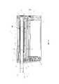
на фиг. 3 - устройство, показанное на фиг. 1, со вставленным курительным материалом, вид в разрезе;in FIG. 3 - the device shown in FIG. 1, with inserted smoking material, sectional view;
на фиг. 4 - устройство, показанное на фиг. 1, без курительного материала, вид в разрезе;in FIG. 4 - the device shown in FIG. 1, without smoking material, sectional view;
на фиг. 5 - увеличенное изображение области 5 на фиг. 4;in FIG. 5 is an enlarged view of
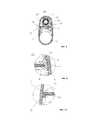
на фиг. 6 - увеличенное изображение области 6 на фиг. 4;in FIG. 6 is an enlarged view of
на фиг. 7 - увеличенное изображение области 7 на фиг. 4;in FIG. 7 is an enlarged view of region 7 in FIG. 4;
на фиг. 8 - устройство, показанное на фиг. 1, вид в поперечном разрезе;in FIG. 8 - the device shown in FIG. 1 is a cross-sectional view;
на фиг. 9 - увеличенное изображение области 9 на фиг. 4; иin FIG. 9 is an enlarged view of region 9 in FIG. 4; and
на фиг. 10 - увеличенное изображение области 10 на фиг. 4.in FIG. 10 is an enlarged view of
Осуществление изобретенияThe implementation of the invention
Используемый в настоящем описании термин «курительный материал» обозначает материалы, обеспечивающие создание испаренных компонентов при нагревании, как правило, в форме аэрозоля. «Курительный материал» включает в себя любой табакосодержащий материал и может, например, содержать один или несколько из следующих компонентов: табак, производные табака, экспандированный табак, восстановленный табак или заменители табака. Кроме того, «курительный материал» может включать в себя и другие, не содержащие табак продукты, которые в зависимости от типа продукта могут содержать никотин или не содержать его. «Курительный материал», например, может представлять собой вещество в виде твердого тела, жидкости, геля, пасты и т.п. Кроме того, «курительный материал» может представлять собой, например, сочетание или смесь различных материалов.Used in the present description, the term "smoking material" refers to materials that provide the creation of vaporized components when heated, usually in the form of an aerosol. “Smoking material” includes any tobacco-containing material and may, for example, contain one or more of the following components: tobacco, tobacco derivatives, expanded tobacco, reconstituted tobacco, or tobacco substitutes. In addition, the “smoking material” may include other non-tobacco products which, depending on the type of product, may or may not contain nicotine. A “smoking material”, for example, may be a substance in the form of a solid, liquid, gel, paste, or the like. In addition, the “smoking material” may be, for example, a combination or mixture of various materials.
Известны устройства, которые нагревают курительный материал с целью испарения по меньшей мере одного компонента курительного материала, как правило, для формирования аэрозоля, который может вдыхать пользователь, без сжигания этого курительного материала. Такие устройства называются устройствами «нагрева без сжигания», «устройства для нагрева табака», «табаконагревательные устройства», и т.п. Аналогичным образом, в настоящее время на рынке имеются так называемые электронные сигареты, в которых, как правило, осуществляется процесс испарения курительного материала в виде жидкости, которая может содержать никотин, а может его и не содержать. Курительный материал может использоваться в виде части вставляемого в устройство стержня, картриджа, кассеты и т.п. Нагреватель для нагревания и испарения курительного материала может представлять собой «постоянную» часть устройства, или быть частью курительного изделия или расходного материала, утилизируемого и заменяемого после использования. «Курительное изделие» в данном контексте представляет собой устройство, элемент или другой компонент, включающий в себя или содержащий курительный материал, нагреваемый во время использования с целью испарения курительного материала, и при необходимости, других компонентов.Known devices that heat the smoking material in order to vaporize at least one component of the smoking material, typically to form an aerosol that can be inhaled by the user, without burning this smoking material. Such devices are called “heating without burning” devices, “tobacco heating devices”, “tobacco heating devices”, etc. Similarly, currently there are so-called electronic cigarettes on the market, in which, as a rule, the process of vaporizing smoking material in the form of a liquid, which may or may not contain nicotine, is carried out. Smoking material can be used as part of a rod, cartridge, cartridge, etc. inserted into the device. A heater for heating and vaporizing the smoking material can be a “permanent” part of the device, or can be part of a smoking article or consumable material that can be recycled and replaced after use. A “smoking article” in this context is a device, element or other component comprising or containing smoking material heated during use to vaporize the smoking material and, if necessary, other components.
На фиг. 1-4 показано устройство 10 для нагревания курительного материала с целью испарения по меньшей мере одного компонента этого курительного материала, как правило, для образования аэрозоля, вдыхаемого пользователем, в соответствии с одним из вариантов осуществления изобретения. На фиг. 3 показано устройство 10 со вставленным в него курительным материалом, а на фиг. 4 - устройство 10 без курительного материала. Устройство 10 представляет собой нагревательное устройство, высвобождающее компоненты курительного материала путем его нагревания, а не сжигания. Первый конец 11 устройства в дальнейшем называется ротовым или ближним концом 11, а второй конец 12 - дальним концом 12. Устройство 10 содержит кнопку Вкл./Выкл. (не показана), позволяющую включать или выключать устройство 10 по желанию пользователя.In FIG. 1-4 show a
Устройство 10 содержит корпус для расположения и защиты различных внутренних компонентов. В рассматриваемом примере устройство 10 содержит один или несколько «каркасных» элементов, а также один или несколько элементов внешнего футляра. В рассматриваемом примере устройство 10 содержит цельный, единый внешний футляр или корпус 14 и внутренний каркас 16. Внутренний каркас может состоять из двух половинок, и, при необходимости, может содержать и другие детали каркаса. При сборке устройства 10 внутри каркаса 16 располагаются и/или крепятся к нему различные внутренние компоненты, после чего эти внутренние компоненты с каркасом 16 вставляются в корпус 14. Каркас или его элементы 16 могут быть прикреплены к корпусу 14 с возможностью отсоединения с целью обеспечения простого доступа к внутренней части устройства 10, или могут быть прикреплены к каркасу 16 без возможности отсоединения, например, для ограничения доступа пользователя внутрь устройства 10. В рассматриваемом примере каркас 16 является опорой, по меньшей мере, частично, для передней стенки устройства 10 на первом или ротовом конце 11, а также выполняет функцию, по меньшей мере, частично, задней стенки 18 устройства на втором или дальнем конце 12. В рассматриваемом примере каркас 16 выполнен из пластика, например, из стеклонаполненного нейлона, созданного методом инжекционного формования, хотя также могут использоваться другие материалы и технологии.The
В корпусе 14 содержатся расположенные или закрепленные в нем нагреватель 20, схема управления 21 и источник питания 22. В рассматриваемом примере нагреватель 20, схема управления 21 и источник питания 22 расположены последовательно в боковом направлении (т.е. расположены друг за другом при взгляде с торца), так что схема управления 21 расположена в целом между нагревателем 20 и источником питания 22, хотя возможны и другие варианты их расположения. Схема управления 21 может включать в себя контроллер, например, микропроцессор, для управления нагревом курительного материала, как будет более подробно описано ниже. В качестве источника питания 22 может использоваться, например, батарея, которая может представлять собой незаряжаемую батарею или аккумулятор. Примерами подходящих аккумуляторов являются, например, ионно-литиевый аккумулятор, никелевый аккумулятор (такой как никель-кадмиевый аккумулятор), щелочной аккумулятор и т.п. Аккумулятор 22 электрически соединен с нагревателем 20 для подачи при необходимости и под контролем схемы управления 21 электроэнергии для нагревания курительного материала (т.е., как было указано выше, для испарения курительного материала без его сжигания). Преимущество расположения источника питания 22 рядом с нагревателем 20 и сбоку от него заключается в том, что при этом может использоваться физически большой источник питания 22, не делая устройство 20 в целом неоправданно длинным. Понятно, что физически большой источник питания 22 обычно обладает большей емкостью (т.е. общей величиной электрической энергии, которую он может обеспечить, часто измеряемой в Ампер-часах и т.п.), и, следовательно, срок службы аккумулятора в устройстве 10 будет больше.The
В одном из возможных вариантов выполнения нагреватель 20 в целом выполнен в форме полой цилиндрической трубки, содержащей внутреннюю полую нагревательную камеру 23, в которую помещается курительный материал для нагревания в процессе курения. Возможны различные конфигурации нагревателя 20. Например, нагреватель 20 может быть выполнен в виде единичного нагревателя, или может представлять собой несколько нагревателей, расположенных вдоль продольной оси нагревателя 20. (В целях упрощения подразумевается, что используемый здесь термин «нагреватель» включает в себя также несколько нагревателей, если только не указано иное). Нагреватель 20 может быть кольцевым или трубчатым, или по меньшей мере частично кольцевым или частично трубчатым по окружности. В рассматриваемом примере нагреватель 20 может быть тонкопленочным. В конкретном примере нагреватель 20 поддерживается опорной трубкой из нержавеющей стали. Размеры нагревателя 20 выбираются так, чтобы при вставке курительного материала практически весь курительный материал помещался в пределах нагревательного элемента/элементов нагревателя 20, и при использовании устройства осуществляется нагревание практически всего курительного материала. Нагреватель 20 может быть выполнен таким образом, чтобы определенные зоны курительного материала по желанию пользователя могли нагреваться по отдельности, например, по очереди, или совместно (одновременно).In one of the possible embodiments, the
В рассматриваемом примере нагреватель 20 по меньшей мере на части своей длины окружен теплоизолятором 24. Теплоизолятор 24 помогает уменьшить количество тепла, поступающего от нагревателя 20 во внешнюю от устройства 10 среду. Это помогает снизить мощность, требуемую для нагревателя 20, поскольку уменьшает тепловые потери в целом. Теплоизолятор 24 помогает также сохранять холодной внешнюю поверхность устройства 10 во время работы нагревателя 20. Теплоизолятор 24 может быть выполнен в виде двустенной гильзы, между стенками которой находится область пониженного давления. Таким образом, теплоизолятор 24 может быть выполнен, например, в виде вакуумной трубки, т.е. трубки, между стенками которой удален, по меньшей мере частично, воздух с целью сведения к минимуму теплопередачи за счет теплопроводности и/или конвекции. Возможны и другие конструкции теплоизолятора 24, в том числе, с использованием теплоизоляционных материалов, например, подходящих пеноматериалов, в дополнение к двустенной гильзе или взамен нее.In this example, the
В передней части каркаса 16 имеется отверстие 30 на ротовом конце 11 устройства 10, через которое пользователь может вставить в устройство 10 извлечь из него курительный материал. На ротовом конце 11 установлена крышка 31. Крышка 31 может открываться, чтобы курительный материал мог проходить сквозь отверстие 30 при введении его в устройство 10 и извлечении из него, и закрываться, чтобы закрывать отверстие 30 с целью обеспечения чистоты внутри устройства 10 в периоды, когда устройство 10 не используется, и предотвращения повреждения внутренней части устройства 10. В рассматриваемом примере крышка 31 выполнена сдвижной и может скользить, закрывая и открывая отверстие 30. В других вариантах выполнения крышка 31 может быть шарнирной; возможны и другие варианты выполнения. В рассматриваемом примере крышка 31 выполнена совместно с передним компонентом 32.In front of the
Передний компонент 32 имеет по меньшей мере одну часть. В показанном примере передний компонент 32 содержит три части: передний элемент 32a, промежуточный элемент 32b и задний элемент 32c. Промежуточный элемент 32b может быть прикреплен к заднему элементу 32c, например, с помощью клея, в том числе посредством двухсторонней самоклеящейся ленты.The
Передняя крышка 31 устройства 10 соединена с передним компонентом 32 с возможностью скольжения. Передняя крышка 31 может скользить и соединяться с передним компонентом 32 с помощью комбинации выступов и вырезов. В показанном примере передняя крышка 31 имеет с тыльной стороны выступ 31', который входит в прорезь или канал 32' в переднем компоненте 32. Передняя крышка 31 может быть прикреплена с помощью винта 32'', который, тем не менее, позволяет передней крышке 31 скользить вверх-вниз по каналу 32'.The
На фиг. 3 показан стержень 50 с курительным материалом 51, вставленный частично через переднее отверстие 30 таким образом, что (по меньшей мере) курительный материал 51 располагается в нагревательной камере 23 нагревателя 20, и при активации нагревателя 20 курительный материал 51 нагревается. В рассматриваемом примере стержень 50 на ротовом конце имеет мундштук, содержащий один или несколько фильтров для фильтрации аэрозоля и/или охлаждающий элемент 52 для охлаждения аэрозоля. Фильтрующий/охлаждающий элемент 52 отделен от курительного материала пространством 53, а от ротового конца стержня 50 - еще одним пространством 54.In FIG. 3 shows a
В задней стенке 18 корпуса 14 на дальнем конце 12 устройства 10 выполнено отверстие 35. На дальнем конце 12 также установлена крышка 36. Крышка 36 может открываться, обеспечивая доступ к отверстию 35 на дальнем конце 12, и закрываться, закрывая отверстие 35 на этом конце 12. Крышка 36 в данном примере является откидной. В других вариантах крышка 36 может быть сдвижной; возможны и другие варианты выполнения. Если крышка 36 на дальнем конце 12 является откидной, она может быть выполнена в виде крышки с «гибким шарниром». Более предпочтительно, если крышка 36 является отдельным компонентом, а шарнир для крышки 36 является пружинным.An
В собранном устройстве 10 нагреватель 20, как правило, выполнен в виде полой цилиндрической трубки и расположен внутри каркаса 16, так что один конец полой трубки по текучей среде соединен с отверстием 30 на ротовом конце 11, а другой конец полой трубки - с отверстием 35 на дальнем конце.In the assembled
При использовании устройства пользователь закрывает крышку 36 на дальнем конце 12, чтобы закрыть отверстие 35, и открывает крышку 30 на ротовом конце 11. Затем пользователь вставляет стержень 50 с курительным материалом 51 через отверстие 30 на ротовом конце 11 в нагревательную камеру 23 нагревателя 20, активирует устройство 10, чтобы нагреть курительный материал 51 для генерирования аэрозоля для вдыхания, а затем извлекает стержень 50 с использованным курительным материалом 51 из устройства 10 через отверстие 30 на ротовом конце 11. После использования устройства 10 пользователь может открыть крышку 36 на дальнем конце 12, чтобы открыть отверстие 35 на дальнем конце 12. Отверстие 35 на дальнем конце 12 обеспечивает пользователю доступ внутрь устройства 10, в частности, в области отверстия 35 на дальнем конце 12. Это дает пользователю возможность произвести очистку внутренней части устройства 10 в области отверстия 35 на дальнем конце 12, когда это бывает необходимо и по желанию. Этот доступ на дальнем конце 12 частично дает пользователю возможность очистки внутренней части нагревателя 20 и нагревательной камеры 23 на дальнем конце 12. Действительно, поскольку нагреватель 20 расположен между отверстиями 30 и 35 на ротовом и дальнем концах 11 и 12, соответственно, а полый нагреватель 20 представляет собой фактически прямое сквозное отверстие, проходящее сквозь все устройство 10 от отверстия 30 до отверстия 35, пользователь может свободно вычистить практически всю внутреннюю поверхность нагревательной камеры 23. Для этого пользователь может «войти» в нагревательную камеру 23 на выбор через отверстие 30 или 35. С этой целью пользователь может использовать одно или несколько различных очищающих устройств, например, таких как классический ершик для чистки трубок, щетка и другие аналогичные устройства.When using the device, the user closes the
В рассматриваемом варианте осуществления изобретения нагревательная камера 23 имеет участок с уменьшенным внутренним диаметром, расположенный ближе к дальнему концу 12. Уменьшение внутреннего диаметра обеспечивает торцовый упор для курительного материала, вставляемого через первое отверстие 30 на ротовом конце 11, и предотвращает возможность выпадения курительного материала из второго отверстия 35 на дальнем конце 12. В рассматриваемом примере этот участок уменьшенного внутреннего диаметра образован с помощью полой трубки 40, расположенной в конце нагревательной камеры 23 рядом с дальним концом 12. Полая трубка 40 в данном примере имеет головку или фланец 41 большего диаметра. Полая трубка 40 может быть изготовлена из пластика, например, из полиэфирэфиркетона (ПЭЭК). Полая трубка 40 может быть зафиксирована на своем месте, например, с помощью клея или поворотно-запорного механизма.In the present embodiment, the
При изготовлении устройства 10 полую трубку 40 вставляют снаружи в отверстие 35 на дальнем конце 12 так, чтобы головка или фланец 41 упирался в каркас 16, фиксируя полую трубку 40 в заданном положении. Нагреватель 20 расположен внутри каркаса 16, и полая трубка 40 входит в дальний конец внутренней камеры 23 нагревателя 20. Таким образом, в данном случае полая трубка 40 образует внутри нагревательной камеры 23 участок уменьшенного внутреннего диаметра, выполняющий функцию упора для курительного материала, вставляемого во внутреннюю камеру 23 нагревателя 20, а также поддерживающий и фиксирующий нагреватель 20 в устройстве 10 на дальнем конце 12. Следует отметить, что на ротовом конце 11 выполнен трубчатый раструб 33, образующий опору для переднего конца нагревателя 20 и его фиксацию.In the manufacture of the
Установлено, что важным требованием для устройства 10 является изоляция (или по меньшей мере частичная изоляция) проходящего через внутреннюю камеру 23 нагревателя 20 воздушного потока от остальных частей устройства 10. Это необходимо для того, чтобы предотвратить или по меньшей мере свести к минимуму загрязнение воздушного потока, проходящего по внутренней камере 23 нагревателя 20, воздухом, прошедшим через схему управления и/или источник питания 22 и т.д. Аналогичным образом, это необходимо также для того, чтобы предотвратить или по меньшей мере свести к минимуму загрязнение воздуха, проходящего через схему управления и/или источник питания 22 и т.д., воздушным потоком, прошедшим по внутренней камере 23 нагревателя 20.It has been found that an important requirement for the
Как показано на фиг. 3 и 4, нагреватель 20 устройства 10 может быть выполнен из листа, т.е. в целом из плоского листового материала, скатанного в трубку и уплотненного по длине. Скатанный нагреватель 20 имеет форму трубки с первым и вторым концами и полой центральной частью. В полую центральную часть может вставляться курительный материал. Курительный материал вставляется в полую центральную часть через один из концов. Трубка уплотнена по всей своей длине, так что во время использования предотвращается поступление воздуха в нагреватель или выход воздуха из нагревателя каким-либо другим путем, кроме как через первый и/или второй конец. Уплотнение трубки может быть осуществлено с помощью адгезива или специального контактного клея. Нагреватель 20 может быть тонкопленочным.As shown in FIG. 3 and 4, the
Трубчатый нагреватель 20 может быть изготовлен в виде подложки с выполненной на ней по меньшей мере одной токопроводящей дорожкой. Подложка может быть выполнена в форме листа и может содержать, например, слой пластика. В конкретном примере слой пластика представляет собой слой полиимида. Токопроводящая дорожка может быть напечатана или каким-либо иным способом нанесена на указанный слой. Трубчатый нагреватель 20 может содержать еще один слой пластика, расположенный на токопроводящей дорожке или над ней. В рассматриваемом примере токопроводящая дорожка расположена между двумя слоями пластика.The
Как показано на фиг. 3 и 4, трубчатый нагреватель 20 расположен в первом отсеке 38, который можно называть нагревательным отсеком устройства 10. Устройство 10 может содержать также второй отсек 60, который можно называть отсеком электроники 60, содержащий по меньшей мере один из следующих компонентов: схему управления 21 и источник питания 22. В примере, показанном на фиг. 3 и 4, отсек электроники 60 содержит как схему управления 21, так и источник питания 22. Первый (нагревательный) отсек 38 может быть изолирован от второго отсека 60 (отсека электроники), таким образом, чтобы оба этих отсека были практически герметично отделены друг от друга с целью сведения к минимуму или предотвращения воздухо- или парообмена между указанными отсеками 38, 60. Герметичное уплотнение или изоляция отсеков 38, 60 может быть такой, чтобы только пренебрежимо малое количество воздуха протекало между ними. В рассматриваемом конкретном примере изоляция отсеков 38, 60 выполнена таким образом, что количество воздуха или пара, проходящего между отсеками 38, 60, составляет менее 1% общего расхода воздуха, проходящего через нагревательную камеру 23, предпочтительно, 0%. (Как видно из чертежей, между указанными отсеками 38, 60 имеется канал 62, по которому проходит конец проводника 64 нагревателя. Конец проводника 64 соединяет нагреватель 20 со схемой управления 21 и источником питания 22 в отсеке 60 электроники. Этот элемент будет рассмотрен ниже.)As shown in FIG. 3 and 4, the
Как показано на фиг. 3 и 4, устройство 10 в рассматриваемом примере содержит разделительную стенку 66 между первым отсеком 38, нагревательным и вторым отсеком 60, отсеком электроники. Разделительная стенка 66 может быть отдельным элементом или может быть выполнена в виде единой детали с каркасом 16 или каркасными элементами. В показанном примере разделительная стенка 66 расположена между передней частью устройства 10 и его задней стенкой 18. Разделительная стенка 66 может частично образовывать один или оба из нижеуказанных элементов, а именно, первый, нагревательный отсек 38 и второй отсек 60, отсек электроники. Разделительная стенка 66 может быть выполнена из термопластика, такого как акрилонитрил-бутадиен-стирол (АБС), поскольку разделительная стенка 66 может испытывать непрямое тепловое воздействие от нагревателя 20 и должна выдерживать такое тепловое воздействие. Разделительная стенка 66 может быть покрыта уплотнительным материалом, например, термополиуретаном (ТПУ), для герметизации возможных каналов прохождения воздуха из отсека электроники в область снаружи каркаса 16.As shown in FIG. 3 and 4, the
В рассматриваемом примере передняя кромка разделительной стенки 66 входит в углубление 67 в каркасе 16, образуя соединение типа шпунтового для упрощения конструкции и сборки устройства 10. Задняя кромка разделительной стенки 66 в рассматриваемом примере входит в уплотнение 68, также образуя шпунтовое соединение. Уплотнение 68, в которое входит разделительная стенка 66, является упругим. Уплотнение 68 может быть выполнено, например, из одного или нескольких полимеров, таких как силикон или резина, и может быть изготовлено, например, в форме прокладки или манжетного уплотнения литьем под давлением. В других, не показанных примерах, передняя кромка разделительной стенки 66 также может входить в уплотнение, аналогичное уплотнению 68 для задней кромки.In this example, the leading edge of the
На фиг. 5-7 приведены увеличенные изображения конкретных областей устройства 10, показанного на фиг. 4. Каждая из фиг. 5-7 демонстрирует по меньшей мере одно уплотнение в устройстве 10, обеспечивающее практически герметичное соединение нагревательного отсека 38 с отсеком 60 электроники. Разумеется, в конкретных примерах выполнения устройства возможно использование целого ряда различных уплотнений, и не все они могут одновременно присутствовать в вариантах реализации изобретения. Иными словами, устройства в некоторых вариантах осуществления изобретения могут содержать только одно описываемое здесь уплотнение, несколько описываемых уплотнений, а также все описываемые уплотнения.In FIG. 5-7 are enlarged images of specific areas of the
На фиг. 5 показано уплотнение 72 между корпусом 14 устройства 10 и передним элементом 32a переднего компонента 32. Уплотнение 72 расположено в канавке или углублении 80, выполненном либо в переднем элементе 32' переднего компонента 32, либо в корпусе 14, либо в обоих указанных элементах. Уплотнение 72 может сжиматься, образуя плотное соединение корпуса 14 с передним компонентом 32. Уплотнение 72 представляет собой упругий элемент. Уплотнение 72 может быть выполнено из одного или нескольких полимеров, например, из силикона или резины. На уплотнение 72 может быть нанесен уплотнительный материал, например, термополиуретан.In FIG. 5 shows a
На фиг. 6 показано уплотнение 74 между корпусом 14 устройства 10 и задней стенкой 18. Уплотнение 74 расположено в канавке или углублении 82, выполненном либо в задней стенке 18, либо в корпусе 14, либо в обоих указанных элементах. Уплотнение 74 может сжиматься, образуя плотное соединение корпуса 14 с задней стенкой 18. Уплотнение 74 представляет собой упругий элемент. Уплотнение 74 может быть выполнено из одного или нескольких полимеров, например, из силикона или резины. На уплотнение 74 может быть нанесен уплотнительный материал, например, термополиуретан.In FIG. 6 shows a
На фиг. 7 показано уплотнение 68, в которое входит второй конец разделительной стенки 66. На фиг. 7 показано также уплотнение 70, расположенное напротив уплотнения 68, в которое входит второй конец разделительной стенки 66. Два показанных уплотнения 68, 70 расположены между первым отсеком 38 и вторым отсеком 60. Уплотнения 68, 70 упираются друг в друга, таким образом, что соединение между уплотнениями 68, 70 является практически герметичным. Уплотнение 70 в данном примере является упругим элементом. Уплотнение 70 может быть выполнено из одного или нескольких полимеров, таких как силикон или резина.In FIG. 7 shows a
Как указано выше, в рассматриваемом примере между отсеками 38, 60 имеется канал 62, по которому проходит конец проводника 64 нагревателя 20, обеспечивающий соединение нагревателя 20 по меньшей мере с источником питания 22. В рассматриваемом примере конец проводника 64 нагревателя соединяет нагреватель 20 со схемой управления 21 и с источником питания 22 в отсеке 60 электроники.As indicated above, in the example under consideration, there is a channel 62 between the
На фиг. 7 в увеличенном масштабе показана область вокруг канала 62 между отсеками 38 и 60. Конец проводника 64 нагревателя занимает канал 62 и расположен между уплотнением 68, в которое входит второй конец разделительной стенки 66, и уплотнением 70, расположенным напротив уплотнения 68, в которое входит второй конец разделительной стенки 66. Уплотнения 68 и 70 прижаты к концу проводника 64 нагревателя, обеспечивая практически герметичное соединение между отсеками 38 и 60.In FIG. 7 shows on an enlarged scale the area around the channel 62 between the
На фиг. 8 приведен вид устройства 10 в поперечном разрезе. На фиг. 9 и 10 показаны увеличенные изображения двух областей устройства 10, показанного на фиг. 8.In FIG. 8 is a cross-sectional view of the
Как показано на фиг. 8-10, разделительная стенка 66 расположена между стенками каркаса 16 устройства 10. Первая кромка разделительной стенки 66 входит в углубление 16' в каркасе 16 устройства 10, образуя шпунтовое соединение. Первая кромка разделительной стенки 66 может быть закреплена в углублении 16' каркаса 16, например, с помощью адгезива или просто за счет прессовой посадки или посадки с натягом.As shown in FIG. 8-10, the dividing
Показанная разделительная стенка 66 содержит канавку 84 вдоль второй кромки разделительной стенки 66. В канавке 84 разделительной стенки 66 расположено уплотнение 76. Уплотнение 76 прижато к каркасу 16 устройства 10. Конструкция уплотнения 76 и канавки 84 обеспечивает практически герметичное соединение по второй кромке разделительной стенки 66. Уплотнение 76 представляет собой упругий элемент. Уплотнение 76 может быть выполнено из одного или нескольких полимеров, таких как силикон или резина. На уплотнение 76 может быть нанесен уплотнительный материал, например, термополиуретан в канавке 84.The
На фиг. 9 приведено увеличенное изображение области устройства 10, показанного на фиг. 8. Здесь имеется дополнительное уплотнение 78 между корпусом устройства и боковой панелью для обеспечения герметичного соединения между каналом прохождения воздуха и электронным отсеком. Дополнительное уплотнение 78 расположено в канавке 86, и на него нанесен уплотнительный материал, например, термополиуретан, который зажат между корпусом 14 и каркасом 16.In FIG. 9 is an enlarged view of a region of the
Рассмотренные выше различные варианты осуществления изобретения были показаны только в целях упрощения понимания и иллюстрации особенностей настоящего изобретения. Эти варианты приведены лишь в качестве иллюстративных примеров и не являются исчерпывающими или исключительными. Следует иметь в виду, что описанные выше преимущества, варианты осуществления изобретения, примеры, функции, особенности, конструкции и/или другие аспекты настоящего изобретения никоим образом не ограничивают объем настоящего изобретения, который определяется формулой изобретения, и что могут использоваться другие варианты осуществления изобретения, и могут производиться модификации без выхода за объем формулы изобретения. Различные варианты осуществления изобретения могут соответствующим образом содержать, состоять или состоять в целом из соответствующих комбинаций описанных элементов, компонентов, особенностей, деталей, операций, средств и т.д., отличных от представленных в настоящем описании.The various embodiments of the invention discussed above have been shown only to facilitate understanding and illustration of the features of the present invention. These options are for illustrative purposes only and are not exhaustive or exclusive. It should be borne in mind that the above advantages, embodiments of the invention, examples, functions, features, designs and / or other aspects of the present invention in no way limit the scope of the present invention, which is defined by the claims, and that other embodiments of the invention can be used, and modifications may be made without departing from the scope of the claims. Various embodiments of the invention may suitably comprise, consist of or consist generally of appropriate combinations of the described elements, components, features, parts, operations, means, etc., other than those presented in the present description.
Claims (17)
Translated fromRussianApplications Claiming Priority (3)
| Application Number | Priority Date | Filing Date | Title |
|---|---|---|---|
| US201662336275P | 2016-05-13 | 2016-05-13 | |
| US62/336,275 | 2016-05-13 | ||
| PCT/EP2017/061518WO2017194762A1 (en) | 2016-05-13 | 2017-05-12 | Apparatus arranged to heat smokable material and method of forming a heater |
Related Child Applications (1)
| Application Number | Title | Priority Date | Filing Date |
|---|---|---|---|
| RU2019140780ADivisionRU2728533C2 (en) | 2016-05-13 | 2017-05-12 | Device for smoking material heating and method of heater formation |
Publications (1)
| Publication Number | Publication Date |
|---|---|
| RU2709485C1true RU2709485C1 (en) | 2019-12-18 |
Family
ID=58794043
Family Applications (2)
| Application Number | Title | Priority Date | Filing Date |
|---|---|---|---|
| RU2019140780ARU2728533C2 (en) | 2016-05-13 | 2017-05-12 | Device for smoking material heating and method of heater formation |
| RU2018139838ARU2709485C1 (en) | 2016-05-13 | 2017-05-12 | Device for smoking material heating and method of heater formation |
Family Applications Before (1)
| Application Number | Title | Priority Date | Filing Date |
|---|---|---|---|
| RU2019140780ARU2728533C2 (en) | 2016-05-13 | 2017-05-12 | Device for smoking material heating and method of heater formation |
Country Status (11)
| Country | Link |
|---|---|
| US (3) | US11438972B2 (en) |
| EP (2) | EP3456149B1 (en) |
| JP (5) | JP6833156B2 (en) |
| CN (2) | CN114652019A (en) |
| ES (1) | ES2953537T3 (en) |
| HU (1) | HUE063356T2 (en) |
| LT (1) | LT3456149T (en) |
| PL (1) | PL3456149T3 (en) |
| PT (1) | PT3456149T (en) |
| RU (2) | RU2728533C2 (en) |
| WO (1) | WO2017194762A1 (en) |
Families Citing this family (41)
| Publication number | Priority date | Publication date | Assignee | Title |
|---|---|---|---|---|
| GB201207039D0 (en)* | 2012-04-23 | 2012-06-06 | British American Tobacco Co | Heating smokeable material |
| GB201423315D0 (en) | 2014-12-29 | 2015-02-11 | British American Tobacco Co | Apparatus for heating smokable material |
| KR102604176B1 (en) | 2015-06-26 | 2023-11-17 | 니코벤처스 트레이딩 리미티드 | Apparatus for heating smokable material |
| USD843052S1 (en) | 2015-09-21 | 2019-03-12 | British American Tobacco (Investments) Limited | Aerosol generator |
| TW201742555A (en) | 2016-05-13 | 2017-12-16 | 英美煙草(投資)有限公司 | Device for heating smoking materials (2) |
| TW201742556A (en) | 2016-05-13 | 2017-12-16 | British American Tobacco Investments Ltd | Apparatus for heating smokable material |
| GB201612945D0 (en) | 2016-07-26 | 2016-09-07 | British American Tobacco Investments Ltd | Method of generating aerosol |
| TW201932031A (en) | 2017-12-29 | 2019-08-16 | 瑞士商傑太日煙國際股份有限公司 | A smoking device |
| TWI799518B (en) | 2018-03-09 | 2023-04-21 | 瑞士商菲利浦莫里斯製品股份有限公司 | An aerosol-generating device and an aerosol-generating system |
| US12102118B2 (en) | 2018-03-09 | 2024-10-01 | Rai Strategic Holdings, Inc. | Electronically heated heat-not-burn smoking article |
| EP3801088B1 (en) | 2018-06-07 | 2022-05-25 | Philip Morris Products S.A. | Electrical heating assembly for heating an aerosol-forming substrate |
| GB201814197D0 (en) | 2018-08-31 | 2018-10-17 | Nicoventures Trading Ltd | Aerosol generating material characteristic determination |
| UA128068C2 (en)* | 2018-10-12 | 2024-03-27 | Джейті Інтернешнл С.А. | Aerosol generation device, and heating chamber therefor |
| USD945695S1 (en) | 2018-10-15 | 2022-03-08 | Nicoventures Trading Limited | Aerosol generator |
| USD924473S1 (en) | 2018-10-15 | 2021-07-06 | Nicoventures Trading Limited | Aerosol generator |
| WO2020084760A1 (en) | 2018-10-26 | 2020-04-30 | 日本たばこ産業株式会社 | Heating assembly and flavor inhaler provided with same |
| CN109512029A (en)* | 2018-11-09 | 2019-03-26 | 深圳市麦格米特控制技术有限公司 | A kind of electronic cigarette |
| US11174051B2 (en) | 2019-02-15 | 2021-11-16 | Samuel, Son & Co. (Usa) Inc. | Hand held strapping tool |
| ES2969612T3 (en) | 2019-03-11 | 2024-05-21 | Nicoventures Trading Ltd | Aerosol dispensing device |
| USD953613S1 (en) | 2019-03-13 | 2022-05-31 | Nicoventures Trading Limited | Aerosol generator |
| EP3711586A1 (en)* | 2019-03-22 | 2020-09-23 | Nerudia Limited | Stopper for a smoking substitute device |
| US12329201B2 (en) | 2019-03-22 | 2025-06-17 | Imperial Tobacco Limited | Smoking substitute system |
| GB201904748D0 (en)* | 2019-04-04 | 2019-05-22 | Nicoventures Trading Ltd | Apparatus for aerosol generating device |
| GB201907702D0 (en)* | 2019-05-30 | 2019-07-17 | Nicoventures Trading Ltd | Aerosol generation |
| GB201908194D0 (en)* | 2019-06-07 | 2019-07-24 | Nicoventures Trading Ltd | Aerosol provision device |
| WO2020248103A1 (en)* | 2019-06-10 | 2020-12-17 | Nicoventures Trading Limited | Aerosol provision device |
| USD1005572S1 (en) | 2019-07-30 | 2023-11-21 | Nicoventures Trading Limited | Circular interface for aerosol generator |
| JP7620615B2 (en)* | 2019-08-08 | 2025-01-23 | ジェイティー インターナショナル エスエイ | Aerosol generating device |
| US20230337747A1 (en)* | 2019-12-23 | 2023-10-26 | Philip Morris Products S.A. | Aerosol-generating system having a ventilation chamber |
| USD926367S1 (en) | 2020-01-30 | 2021-07-27 | Nicoventures Trading Limited | Accessory for aerosol generator |
| KR102455535B1 (en)* | 2020-06-16 | 2022-10-17 | 주식회사 케이티앤지 | Aerosol generating apparatus and method for operating the same |
| CN213344346U (en)* | 2020-07-14 | 2021-06-04 | 深圳市合元科技有限公司 | Aerosol generator |
| JP1714443S (en) | 2020-10-30 | 2022-05-10 | Smoking aerosol generator | |
| JP1715888S (en) | 2020-10-30 | 2022-05-25 | Smoking aerosol generator | |
| JP1714441S (en) | 2020-10-30 | 2022-05-10 | Smoking aerosol generator | |
| USD990765S1 (en) | 2020-10-30 | 2023-06-27 | Nicoventures Trading Limited | Aerosol generator |
| JP1714442S (en) | 2020-10-30 | 2022-05-10 | Smoking aerosol generator | |
| JP1714440S (en) | 2020-10-30 | 2022-05-10 | Smoking aerosol generator | |
| USD989384S1 (en) | 2021-04-30 | 2023-06-13 | Nicoventures Trading Limited | Aerosol generator |
| US20240423269A1 (en)* | 2021-10-20 | 2024-12-26 | Kt&G Corporation | Aerosol-generating device |
| US20230189404A1 (en)* | 2021-12-14 | 2023-06-15 | Inno-It Co., Ltd. | Surface Heating Heater Pipe and Aerosol Generating Device Including the Same |
Citations (6)
| Publication number | Priority date | Publication date | Assignee | Title |
|---|---|---|---|---|
| DE19854005A1 (en)* | 1998-11-12 | 2000-05-18 | Reemtsma H F & Ph | Inhalable aerosol delivery system |
| US20070074734A1 (en)* | 2005-09-30 | 2007-04-05 | Philip Morris Usa Inc. | Smokeless cigarette system |
| EP2316286A1 (en)* | 2009-10-29 | 2011-05-04 | Philip Morris Products S.A. | An electrically heated smoking system with improved heater |
| US20160007652A1 (en)* | 2014-07-11 | 2016-01-14 | R.J. Reynolds Tobacco Company | Heater for an aerosol delivery device and methods of formation thereof |
| US20160081395A1 (en)* | 2013-05-21 | 2016-03-24 | Philip Morris Products S.A. | Electrically heated aerosol delivery system |
| RU2600092C2 (en)* | 2011-12-08 | 2016-10-20 | Филип Моррис Продактс С.А. | Aerosol generating device with internal heater |
Family Cites Families (71)
| Publication number | Priority date | Publication date | Assignee | Title |
|---|---|---|---|---|
| US3599646A (en)* | 1969-04-30 | 1971-08-17 | American Filtrona Corp | Cigarette filter |
| JPS5426741B2 (en)* | 1974-02-21 | 1979-09-05 | ||
| US4253473A (en) | 1979-07-13 | 1981-03-03 | International Flavors & Fragrances Inc. | Process for augmenting or enhancing the aroma or taste of smoking tobacco or a smoking tobacco article by adding thereto a suspended flavoring composition |
| US4955399A (en)* | 1988-11-30 | 1990-09-11 | R. J. Reynolds Tobacco Company | Smoking article |
| US5665262A (en) | 1991-03-11 | 1997-09-09 | Philip Morris Incorporated | Tubular heater for use in an electrical smoking article |
| ATE121909T1 (en)* | 1991-03-11 | 1995-05-15 | Philip Morris Prod | FLAVOR PRODUCING ITEMS. |
| US5322075A (en) | 1992-09-10 | 1994-06-21 | Philip Morris Incorporated | Heater for an electric flavor-generating article |
| CR4906A (en) | 1993-09-10 | 1994-09-09 | Philip Morris Prod | ELECTRIC SMOKING SYSTEM TO DISTRIBUTE FLAVORS AND METHOD FOR ITS MANUFACTURE |
| GB9609177D0 (en) | 1996-05-02 | 1996-07-03 | Ontario Inc 1149235 | Hand-held smoker's device for sidestream smoke control |
| US6125853A (en) | 1996-06-17 | 2000-10-03 | Japan Tobacco, Inc. | Flavor generation device |
| US5954979A (en) | 1997-10-16 | 1999-09-21 | Philip Morris Incorporated | Heater fixture of an electrical smoking system |
| US6376816B2 (en)* | 2000-03-03 | 2002-04-23 | Richard P. Cooper | Thin film tubular heater |
| CA2403378C (en) | 2000-03-23 | 2010-01-05 | Philip Morris Products Inc. | Electrical smoking system and method |
| US6615840B1 (en) | 2002-02-15 | 2003-09-09 | Philip Morris Incorporated | Electrical smoking system and method |
| GB0328644D0 (en) | 2003-12-11 | 2004-01-14 | Souza Cruz Sa | Smoking article |
| US9675109B2 (en) | 2005-07-19 | 2017-06-13 | J. T. International Sa | Method and system for vaporization of a substance |
| US7810507B2 (en) | 2006-02-10 | 2010-10-12 | R. J. Reynolds Tobacco Company | Smokeless tobacco composition |
| US7726320B2 (en)* | 2006-10-18 | 2010-06-01 | R. J. Reynolds Tobacco Company | Tobacco-containing smoking article |
| US20080302376A1 (en) | 2007-06-08 | 2008-12-11 | Philip Morris Usa Inc. | Smoking article with controlled flavor release |
| TW201023769A (en)* | 2008-10-23 | 2010-07-01 | Japan Tobacco Inc | Non-burning type flavor inhalation article |
| US8262550B2 (en) | 2009-03-19 | 2012-09-11 | R. J. Reynolds Tobacco Company | Apparatus for inserting objects into a filter component of a smoking article |
| EP2253233A1 (en) | 2009-05-21 | 2010-11-24 | Philip Morris Products S.A. | An electrically heated smoking system |
| EP2327318A1 (en) | 2009-11-27 | 2011-06-01 | Philip Morris Products S.A. | An electrically heated smoking system with internal or external heater |
| CN101843368A (en)* | 2010-04-02 | 2010-09-29 | 陈志平 | Suction nozzle of electronic atomizer |
| US9439455B2 (en) | 2010-04-30 | 2016-09-13 | Fontem Holdings 4 B.V. | Electronic smoking device |
| CN102326869B (en) | 2011-05-12 | 2013-04-03 | 陈志平 | Atomization nozzle of electronic atomization inhaler |
| RU110608U1 (en)* | 2011-08-12 | 2011-11-27 | Сергей Павлович Кузьмин | ELECTRONIC CIGARETTE |
| CN103826481B (en) | 2011-09-06 | 2016-08-17 | 英美烟草(投资)有限公司 | Heating smokeable material |
| US10729176B2 (en)* | 2011-09-06 | 2020-08-04 | British American Tobacco (Investments) Limited | Heating smokeable material |
| US20140202476A1 (en) | 2011-09-06 | 2014-07-24 | British American Tobacco (Investments) Limited | Heating smokeable material |
| RU2608712C2 (en) | 2011-09-06 | 2017-01-23 | Бритиш Америкэн Тобэкко (Инвестментс) Лимитед | Insulation |
| US9854839B2 (en) | 2012-01-31 | 2018-01-02 | Altria Client Services Llc | Electronic vaping device and method |
| US20130255702A1 (en) | 2012-03-28 | 2013-10-03 | R.J. Reynolds Tobacco Company | Smoking article incorporating a conductive substrate |
| GB201207039D0 (en) | 2012-04-23 | 2012-06-06 | British American Tobacco Co | Heating smokeable material |
| US9687025B2 (en)* | 2012-09-10 | 2017-06-27 | Healthier Choices Managment Corp. | Electronic pipe |
| US9854840B2 (en) | 2012-09-29 | 2018-01-02 | Shuigen Liu | Tobacco vaporizer |
| CN202907797U (en) | 2012-09-29 | 2013-05-01 | 吴昌明 | Electronic smoking device |
| TW201446291A (en) | 2013-03-15 | 2014-12-16 | Philip Morris Products Sa | Aerosol-generating system with differential heating |
| WO2014166079A1 (en) | 2013-04-10 | 2014-10-16 | 吉瑞高新科技股份有限公司 | Electronic cigarette built in power supply rod |
| US20140355969A1 (en) | 2013-05-28 | 2014-12-04 | Sis Resources, Ltd. | One-way valve for atomizer section in electronic cigarettes |
| CN203662020U (en) | 2013-11-27 | 2014-06-25 | 石世波 | Electronic cigarette atomizer with glass tube atomization seat |
| DE202014011260U1 (en) | 2013-12-23 | 2018-11-13 | Juul Labs Uk Holdco Limited | Systems for an evaporation device |
| WO2015097187A1 (en) | 2013-12-24 | 2015-07-02 | Philip Morris Products S.A. | Flavourant containing material |
| US9974334B2 (en) | 2014-01-17 | 2018-05-22 | Rai Strategic Holdings, Inc. | Electronic smoking article with improved storage of aerosol precursor compositions |
| CN203913377U (en) | 2014-01-27 | 2014-11-05 | 深圳市施美乐科技有限公司 | A kind of unitary disposable electronic cigarette |
| US9839238B2 (en) | 2014-02-28 | 2017-12-12 | Rai Strategic Holdings, Inc. | Control body for an electronic smoking article |
| CN203828069U (en) | 2014-03-06 | 2014-09-17 | 刘秋明 | Electronic cigarette |
| GB201407642D0 (en)* | 2014-04-30 | 2014-06-11 | British American Tobacco Co | Aerosol-cooling element and arrangements for apparatus for heating a smokable material |
| CN203952426U (en) | 2014-05-16 | 2014-11-26 | 申敏良 | The electronic smoke atomizer of storage smog |
| US9955726B2 (en) | 2014-05-23 | 2018-05-01 | Rai Strategic Holdings, Inc. | Sealed cartridge for an aerosol delivery device and related assembly method |
| CN203933990U (en) | 2014-06-13 | 2014-11-05 | 深圳市福联达电热电器有限公司 | Polyimides Electric radiant Heating Film |
| CN104095293B (en) | 2014-07-28 | 2016-08-24 | 川渝中烟工业有限责任公司 | For heating the Electromagnetic Heating type aspirator of the Medicated cigarette that do not burns |
| US9451792B1 (en) | 2014-09-05 | 2016-09-27 | Atmos Nation, LLC | Systems and methods for vaporizing assembly |
| KR101736445B1 (en) | 2014-09-15 | 2017-05-31 | 주식회사 제이에프티 | Electronic cigarette |
| CN105795503A (en) | 2014-12-31 | 2016-07-27 | 普瑞斯生物科技(湖南)有限公司 | Traditional Chinese medicinal health care electronic cigarette liquid containing tangerine peel extract |
| US9814271B2 (en) | 2015-01-13 | 2017-11-14 | Haiden Goggin | Multiple chamber vaporizer |
| CN204499486U (en) | 2015-04-01 | 2015-07-29 | 深圳市欧比斯科技有限公司 | Electronic smoke atomizer |
| KR102604176B1 (en) | 2015-06-26 | 2023-11-17 | 니코벤처스 트레이딩 리미티드 | Apparatus for heating smokable material |
| CN104957779B (en) | 2015-07-23 | 2017-11-14 | 云南中烟工业有限责任公司 | A kind of radial distribution formula multi-temperature zone electronic cigarette |
| US10492528B2 (en) | 2015-08-11 | 2019-12-03 | Altria Client Services Llc | Power supply section configuration for an electronic vaping device and electronic vaping device |
| USD843052S1 (en) | 2015-09-21 | 2019-03-12 | British American Tobacco (Investments) Limited | Aerosol generator |
| CN205337599U (en)* | 2015-10-22 | 2016-06-29 | 深圳麦克韦尔股份有限公司 | Electron cigarette and atomization component and atomizing component thereof |
| CN105559151B (en) | 2016-03-21 | 2019-05-24 | 湖南中烟工业有限责任公司 | A kind of ultrasonic ultrasonic delay line memory and electronic cigarette |
| GB201605103D0 (en) | 2016-03-24 | 2016-05-11 | Nicoventures Holdings Ltd | Vapour provision device |
| GB201605100D0 (en) | 2016-03-24 | 2016-05-11 | Nicoventures Holdings Ltd | Vapour provision system |
| GB201607475D0 (en) | 2016-04-29 | 2016-06-15 | British American Tobacco Co | Article for generating an inhalable medium and method of heating a smokable material |
| TW201742554A (en) | 2016-05-13 | 2017-12-16 | 英美煙草(投資)有限公司 | Device for accommodating smoking materials |
| GB201608928D0 (en)* | 2016-05-20 | 2016-07-06 | British American Tobacco Co | Article for use in apparatus for heating smokable material |
| GB201608943D0 (en) | 2016-05-20 | 2016-07-06 | British American Tobacco Co | Capsule for tobacco industry product |
| GB201907702D0 (en)* | 2019-05-30 | 2019-07-17 | Nicoventures Trading Ltd | Aerosol generation |
| GB201917469D0 (en)* | 2019-11-29 | 2020-01-15 | Nicoventures Trading Ltd | Aerosol generation |
- 2017
- 2017-05-12PLPL17726217.7Tpatent/PL3456149T3/enunknown
- 2017-05-12CNCN202210491702.9Apatent/CN114652019A/enactivePending
- 2017-05-12RURU2019140780Apatent/RU2728533C2/enactive
- 2017-05-12EPEP17726217.7Apatent/EP3456149B1/enactiveActive
- 2017-05-12CNCN201780028361.9Apatent/CN109076649B/enactiveActive
- 2017-05-12RURU2018139838Apatent/RU2709485C1/enactive
- 2017-05-12ESES17726217Tpatent/ES2953537T3/enactiveActive
- 2017-05-12EPEP23182510.0Apatent/EP4245177A3/enactivePending
- 2017-05-12PTPT177262177Tpatent/PT3456149T/enunknown
- 2017-05-12JPJP2018554501Apatent/JP6833156B2/enactiveActive
- 2017-05-12LTLTEPPCT/EP2017/061518Tpatent/LT3456149T/enunknown
- 2017-05-12HUHUE17726217Apatent/HUE063356T2/enunknown
- 2017-05-12WOPCT/EP2017/061518patent/WO2017194762A1/ennot_activeCeased
- 2017-05-12USUS16/099,294patent/US11438972B2/enactiveActive
- 2020
- 2020-11-05JPJP2020185086Apatent/JP7102486B2/enactiveActive
- 2022
- 2022-07-06JPJP2022108981Apatent/JP7176825B2/enactiveActive
- 2022-07-18USUS17/813,195patent/US12167512B2/enactiveActive
- 2022-11-08JPJP2022178840Apatent/JP2023022052A/ennot_activeWithdrawn
- 2024
- 2024-01-26USUS18/423,551patent/US20240314890A1/enactivePending
- 2024-12-24JPJP2024227514Apatent/JP2025038220A/enactivePending
Patent Citations (6)
| Publication number | Priority date | Publication date | Assignee | Title |
|---|---|---|---|---|
| DE19854005A1 (en)* | 1998-11-12 | 2000-05-18 | Reemtsma H F & Ph | Inhalable aerosol delivery system |
| US20070074734A1 (en)* | 2005-09-30 | 2007-04-05 | Philip Morris Usa Inc. | Smokeless cigarette system |
| EP2316286A1 (en)* | 2009-10-29 | 2011-05-04 | Philip Morris Products S.A. | An electrically heated smoking system with improved heater |
| RU2600092C2 (en)* | 2011-12-08 | 2016-10-20 | Филип Моррис Продактс С.А. | Aerosol generating device with internal heater |
| US20160081395A1 (en)* | 2013-05-21 | 2016-03-24 | Philip Morris Products S.A. | Electrically heated aerosol delivery system |
| US20160007652A1 (en)* | 2014-07-11 | 2016-01-14 | R.J. Reynolds Tobacco Company | Heater for an aerosol delivery device and methods of formation thereof |
Also Published As
| Publication number | Publication date |
|---|---|
| EP3456149A1 (en) | 2019-03-20 |
| CN109076649A (en) | 2018-12-21 |
| RU2019140780A (en) | 2020-01-27 |
| EP3456149B1 (en) | 2023-08-02 |
| US20190208815A1 (en) | 2019-07-11 |
| JP2023022052A (en) | 2023-02-14 |
| ES2953537T3 (en) | 2023-11-14 |
| US20240314890A1 (en) | 2024-09-19 |
| CN109076649B (en) | 2022-06-28 |
| JP7176825B2 (en) | 2022-11-22 |
| US20220369427A1 (en) | 2022-11-17 |
| EP4245177A2 (en) | 2023-09-20 |
| WO2017194762A1 (en) | 2017-11-16 |
| JP6833156B2 (en) | 2021-02-24 |
| PL3456149T3 (en) | 2023-10-30 |
| JP7102486B2 (en) | 2022-07-19 |
| JP2025038220A (en) | 2025-03-18 |
| HUE063356T2 (en) | 2024-01-28 |
| LT3456149T (en) | 2023-09-11 |
| CN114652019A (en) | 2022-06-24 |
| RU2728533C2 (en) | 2020-07-30 |
| JP2021045132A (en) | 2021-03-25 |
| US11438972B2 (en) | 2022-09-06 |
| RU2019140780A3 (en) | 2020-06-02 |
| JP2019518429A (en) | 2019-07-04 |
| PT3456149T (en) | 2023-08-21 |
| EP4245177A3 (en) | 2024-05-15 |
| US12167512B2 (en) | 2024-12-10 |
| JP2022133404A (en) | 2022-09-13 |
Similar Documents
| Publication | Publication Date | Title |
|---|---|---|
| RU2709485C1 (en) | Device for smoking material heating and method of heater formation | |
| JP7663631B2 (en) | Apparatus for receiving smoking material | |
| RU2671615C1 (en) | Device for heating of smokeable material | |
| RU2794453C2 (en) | Apparatus for heating smoking material |
Legal Events
| Date | Code | Title | Description |
|---|---|---|---|
| PC41 | Official registration of the transfer of exclusive right | Effective date:20210408 |