RU2706493C1 - Device for electric cleaning of oral cavity - Google Patents
Device for electric cleaning of oral cavityDownload PDFInfo
- Publication number
- RU2706493C1 RU2706493C1RU2018146309ARU2018146309ARU2706493C1RU 2706493 C1RU2706493 C1RU 2706493C1RU 2018146309 ARU2018146309 ARU 2018146309ARU 2018146309 ARU2018146309 ARU 2018146309ARU 2706493 C1RU2706493 C1RU 2706493C1
- Authority
- RU
- Russia
- Prior art keywords
- electrodes
- cleaning
- head
- oral cavity
- radio frequency
- Prior art date
Links
Images

Classifications
- A—HUMAN NECESSITIES
- A61—MEDICAL OR VETERINARY SCIENCE; HYGIENE
- A61C—DENTISTRY; APPARATUS OR METHODS FOR ORAL OR DENTAL HYGIENE
- A61C17/00—Devices for cleaning, polishing, rinsing or drying teeth, teeth cavities or prostheses; Saliva removers; Dental appliances for receiving spittle
- A61C17/16—Power-driven cleaning or polishing devices
- A61C17/22—Power-driven cleaning or polishing devices with brushes, cushions, cups, or the like
- A61C17/224—Electrical recharging arrangements
- A—HUMAN NECESSITIES
- A46—BRUSHWARE
- A46B—BRUSHES
- A46B15/00—Other brushes; Brushes with additional arrangements
- A46B15/0002—Arrangements for enhancing monitoring or controlling the brushing process
- A46B15/0016—Arrangements for enhancing monitoring or controlling the brushing process with enhancing means
- A46B15/0022—Arrangements for enhancing monitoring or controlling the brushing process with enhancing means with an electrical means
- A—HUMAN NECESSITIES
- A46—BRUSHWARE
- A46B—BRUSHES
- A46B15/00—Other brushes; Brushes with additional arrangements
- A46B15/0002—Arrangements for enhancing monitoring or controlling the brushing process
- A46B15/0016—Arrangements for enhancing monitoring or controlling the brushing process with enhancing means
- A46B15/0024—Arrangements for enhancing monitoring or controlling the brushing process with enhancing means with means generating ions
- A—HUMAN NECESSITIES
- A61—MEDICAL OR VETERINARY SCIENCE; HYGIENE
- A61N—ELECTROTHERAPY; MAGNETOTHERAPY; RADIATION THERAPY; ULTRASOUND THERAPY
- A61N1/00—Electrotherapy; Circuits therefor
- A61N1/02—Details
- A61N1/04—Electrodes
- A61N1/05—Electrodes for implantation or insertion into the body, e.g. heart electrode
- A61N1/0526—Head electrodes
- A61N1/0548—Oral electrodes
- A—HUMAN NECESSITIES
- A46—BRUSHWARE
- A46B—BRUSHES
- A46B2200/00—Brushes characterized by their functions, uses or applications
- A46B2200/10—For human or animal care
- A46B2200/1066—Toothbrush for cleaning the teeth or dentures
- A—HUMAN NECESSITIES
- A61—MEDICAL OR VETERINARY SCIENCE; HYGIENE
- A61N—ELECTROTHERAPY; MAGNETOTHERAPY; RADIATION THERAPY; ULTRASOUND THERAPY
- A61N1/00—Electrotherapy; Circuits therefor
- A61N1/18—Applying electric currents by contact electrodes
- A61N1/32—Applying electric currents by contact electrodes alternating or intermittent currents
- A61N1/322—Electromedical brushes, combs, massage devices
Landscapes
- Health & Medical Sciences (AREA)
- Animal Behavior & Ethology (AREA)
- Veterinary Medicine (AREA)
- Public Health (AREA)
- General Health & Medical Sciences (AREA)
- Life Sciences & Earth Sciences (AREA)
- Radiology & Medical Imaging (AREA)
- Nuclear Medicine, Radiotherapy & Molecular Imaging (AREA)
- Biomedical Technology (AREA)
- Engineering & Computer Science (AREA)
- Cardiology (AREA)
- Heart & Thoracic Surgery (AREA)
- Dentistry (AREA)
- Epidemiology (AREA)
- Brushes (AREA)
- Sink And Installation For Waste Water (AREA)
- Dry Shavers And Clippers (AREA)
Abstract
Description
Translated fromRussianОбласть техники, к которой относится изобретениеFIELD OF THE INVENTION
Настоящее изобретение относится в целом к устройствам для очистки полости рта, более точно, к устройству для очистки полости рта, такому как зубная щетка, которое генерирует реактив на месте путем приложения радиочастотной энергии к электродам в устройстве для очистки в присутствии веществ во рту пользователя.The present invention relates generally to devices for cleaning the oral cavity, and more specifically, to a device for cleaning the oral cavity, such as a toothbrush, which generates a reagent in place by applying radio frequency energy to the electrodes in the cleaning device in the presence of substances in the user's mouth.
Предпосылки создания изобретенияBACKGROUND OF THE INVENTION
Средства по уходу за полостью рта включают разнообразные реактивы, которые выполняют целый ряд функций. Например, зубные пасты, жидкости для полоскания рта и отбеливающие средства содержат реактивы, которые помогают чистить зубы, уничтожать бактерии, освежать дыхание и/или отбеливать зубы. Эти средства обычно взаимодействуют с устройством, таким как зубная щетка, аппликатор или скребок для языка, с целью выполнения своих предполагаемых функций. Кроме того, реактивы в этих средствах могут обеспечить дополнительные преимущества, такие как обеспечение приятных ароматов или запахов.Oral care products include a variety of reagents that perform a variety of functions. For example, toothpastes, mouthwashes, and whitening products contain reagents that help brush your teeth, kill bacteria, freshen your breath, and / or whiten your teeth. These agents typically interact with a device, such as a toothbrush, applicator, or tongue scraper, to perform their intended functions. In addition, the reagents in these products can provide additional benefits, such as providing pleasant aromas or odors.
Средства для ухода за полостью рта, предназначенные для отбеливания зубов, содержат окислитель в качестве основного действующего ингредиента, такой как перекись водорода. Эти средства выпускаются в форме жидкостей, паст или гелей для нанесения на зубы. При хранении эти средства со временем они теряют свою отбеливающую эффективность. Кроме того, эти средства имеют малое время действия при нанесении на зубы в полости рта. Например, в слюне содержится фермент каталаза в высоких концентрациях, который при контакте быстро разлагает перекись водорода на газообразный кислород и воду, в результате перекисное отбеливающее средство лишь кратковременно контактирует с зубами. Кроме того, низкая вязкость водных перекисных растворов не позволяет перекисному отбеливающему средству оставаться в контакте с зубами в течение необходимого времени для обеспечения существенного отбеливания из-за постоянного смывающего действия слюнных секретов. По существу, желательно, чтобы окислители или эффективные окислители в высоких концентрациях наносились непосредственно на зубы.Oral care products for whitening teeth contain an oxidizing agent as the main active ingredient, such as hydrogen peroxide. These products come in the form of liquids, pastes or gels for application to teeth. When stored, these products lose their whitening effectiveness over time. In addition, these funds have a short duration of action when applied to the teeth in the oral cavity. For example, saliva contains the catalase enzyme in high concentrations, which upon contact quickly decomposes hydrogen peroxide into gaseous oxygen and water, as a result, the peroxide whitening agent only comes into contact with the teeth for a short time. In addition, the low viscosity of aqueous peroxide solutions does not allow the peroxide bleaching agent to remain in contact with the teeth for the necessary time to ensure significant whitening due to the constant flushing action of salivary secrets. Essentially, it is desirable that oxidizing agents or effective oxidizing agents in high concentrations be applied directly to the teeth.
В патенте US 8156602 на имя Jiminez и др. описано устройство для генерирования реактива на месте по мере необходимости посредством приложения электрического потенциала к паре проводников, связанных с электролитом. Устройство представляет собой зубную щетку, которая генерирует реактивы во рту пользователя путем приложения электрического потенциала к находящемуся в нем электролиту, такому как слюна и/или средство для очистки зубов. Реактивы включают озон, перекись водорода, перекись хлора и/или гипохлорит. Зубная щетка содержит источник напряжения и первый набор электродов для приложения электрического потенциала к электролиту. Зубная щетка содержит второй набор электродов, расположенных вокруг анода первого набора электродов. Первый и второй наборы взаимодействуют с целью генерирования ионов, перекисей, озона и/или других реактивов приложения электрического потенциала к электролиту.US Pat. No. 8,156,602 to Jiminez et al. Describes a device for generating a reagent in place as necessary by applying an electric potential to a pair of conductors connected to an electrolyte. The device is a toothbrush that generates reagents in the mouth of a user by applying an electric potential to an electrolyte contained therein, such as saliva and / or dentifrice. Reagents include ozone, hydrogen peroxide, chlorine peroxide and / or hypochlorite. The toothbrush contains a voltage source and a first set of electrodes for applying an electric potential to the electrolyte. The toothbrush contains a second set of electrodes located around the anode of the first set of electrodes. The first and second sets interact to generate ions, peroxides, ozone and / or other reagents for applying an electric potential to the electrolyte.
Краткое изложение сущности изобретенияSummary of the invention
В основу настоящего изобретения положена задача создания устройства для очистки полости рта, такого как зубная щетка, которое генерирует реактив на месте, прилагая радиочастотную энергию и/или микроток к проводящей поверхности и/или к электродам на устройстве для очистки в присутствии веществ во рту пользователя, как подробнее описано далее.The present invention is based on the task of creating a device for cleaning the oral cavity, such as a toothbrush, which generates a reagent in place by applying radio frequency energy and / or microcurrent to the conductive surface and / or to the electrodes on the cleaning device in the presence of substances in the user's mouth, as described in more detail below.
Таким образом, в одном из вариантов осуществления настоящего изобретения предложено устройство для очистки полости рта, содержащее головку, на которую опираются чистящие элементы, рукоятку, отходящую от головки, радиочастотный генератор, расположенный в рукоятке и соединенный с электродами, расположенными на головке, и расположенный на головке непроводящий барьер, который отделяет электроды друг от друга. В качестве альтернативы или дополнительно, в рукоятке расположен источник микротока, соединенный с проводящей поверхностью, находящейся на рукоятке, и с одним из электродов, расположенных на головке.Thus, in one embodiment of the present invention, there is provided a device for cleaning an oral cavity, comprising a head, on which cleaning elements rest, a handle extending from the head, an RF generator located in the handle and connected to electrodes located on the head, and located on the head is a non-conductive barrier that separates the electrodes from each other. Alternatively or additionally, a microcurrent source is located in the handle, connected to a conductive surface located on the handle, and to one of the electrodes located on the head.
В одном из вариантов осуществления настоящего изобретения источник напряжения в рукоятке соединен с радиочастотным генератором и источником микротока.In one embodiment of the present invention, the handle voltage source is connected to a radio frequency generator and a micro current source.
В одном из вариантов осуществления настоящего изобретения электроды расположены на противоположных сторонах головки.In one embodiment of the present invention, electrodes are located on opposite sides of the head.
В одном из вариантов осуществления настоящего изобретения проводящая поверхность находится на наружной поверхности рукоятки.In one embodiment of the present invention, the conductive surface is on the outer surface of the handle.
В одном из вариантов осуществления настоящего изобретения чистящие элементы расположены между непроводящим барьером и каждым из электродов.In one embodiment of the present invention, the cleaning elements are located between the non-conductive barrier and each of the electrodes.
В одном из вариантов осуществления настоящего изобретения чистящие элементы окружают непроводящий барьер.In one embodiment of the present invention, cleaning elements surround a non-conductive barrier.
В одном из вариантов осуществления настоящего изобретения источник микротоков, проводящая поверхность и электроды действуют в гальваническом режиме.In one of the embodiments of the present invention, the source of microcurrents, conductive surface and electrodes operate in galvanic mode.
В одном из вариантов осуществления настоящего изобретения радиочастотный генератор и электроды действуют в биполярном режиме.In one embodiment of the present invention, the radio frequency generator and electrodes operate in a bipolar mode.
В одном из вариантов осуществления настоящего изобретения радиочастотный генератор, источник микротока, проводящая поверхность и электроды действуют комбинированном биполярном и гальваническом режиме.In one embodiment of the present invention, a radio frequency generator, a microcurrent source, a conductive surface, and electrodes operate in a combined bipolar and galvanic mode.
Краткое описание чертежейBrief Description of the Drawings
Настоящее изобретение будет лучше и полнее понято из следующего подробного описания в сочетании с чертежами, на которых:The present invention will be better and more fully understood from the following detailed description in combination with the drawings, in which:
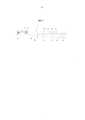
на фиг. 1 показан перспективный вид в сбоку устройства для очистки полости рта, например, зубной щетки, в соответствии с одним из неограничивающих вариантов осуществления изобретения,in FIG. 1 shows a perspective side view of an apparatus for cleaning an oral cavity, for example, a toothbrush, in accordance with one non-limiting embodiment of the invention,
на фиг. 2 показан вид спереди вблизи головки устройства со щетиной в соответствии с одним из неограничивающих вариантов осуществления изобретения,in FIG. 2 shows a front view near the head of a device with bristles in accordance with one non-limiting embodiment of the invention,
на фиг. 3 показан вид сбоку вблизи головки устройства со щетиной устройства со щетиной в соответствии с одним из неограничивающих вариантов осуществления изобретения,in FIG. 3 shows a side view in the vicinity of the head of a device with a bristle device with a bristle in accordance with one non-limiting embodiment of the invention,
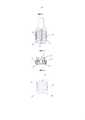
на фиг. 4 показан вид спереди головки со щетиной с двумя электродами и непроводящим барьером между ними в соответствии с одним из дополнительных неограничивающих вариантов осуществления изобретения,in FIG. 4 is a front view of a head with a bristle with two electrodes and a non-conductive barrier between them, in accordance with one additional non-limiting embodiment of the invention,
на фиг. 5 показан вид спереди головки со щетиной с четырьмя электродами и непроводящим барьером между ними в соответствии с одним из дополнительных неограничивающих вариантов осуществления изобретения,in FIG. 5 is a front view of a head with a bristle with four electrodes and a non-conductive barrier between them in accordance with one additional non-limiting embodiment of the invention,
на фиг. 6 показан вид спереди головки со щетиной с тремя электродами и непроводящим барьером между ними в соответствии с одним из дополнительных неограничивающих вариантов осуществления изобретения,in FIG. 6 is a front view of a head with a bristle with three electrodes and a non-conductive barrier between them in accordance with one further non-limiting embodiment of the invention,
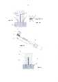
на фиг. 7А-7С показаны упрощенные иллюстрации головки со щетиной с электродами и непроводящим барьером между ними в соответствии с одним из дополнительных неограничивающих вариантов осуществления изобретения, при этом на фиг. 7А показан вид сбоку головки, на фиг. 7В показан вид сверху щетки, а на фиг. 1С показан вид щетки по частям,in FIG. 7A-7C show simplified illustrations of a bristle head with electrodes and a non-conductive barrier between them in accordance with one additional non-limiting embodiment of the invention, with FIG. 7A shows a side view of the head, in FIG. 7B shows a top view of the brush, and in FIG. 1C shows a view of the brush in parts,
на фиг. 8 показан вид сбоку головки со щетиной с электродами и непроводящим барьером между ними в соответствии с одним из дополнительных неограничивающих вариантов осуществления изобретения.in FIG. 8 is a side view of a head with bristles with electrodes and a non-conductive barrier between them in accordance with one further non-limiting embodiment of the invention.
Подробное описание вариантов осуществленияDetailed Description of Embodiments
Рассмотрим фиг. 1, на которой проиллюстрировано устройство 1 для очистки полости рта, сконструированное и действующее в соответствии с одним из неограничивающих вариантов осуществления настоящего изобретения.Consider FIG. 1, which illustrates an oral cleaning device 1 constructed and operable in accordance with one non-limiting embodiment of the present invention.
Устройство 1 содержит головку 10, на которую опираются чистящие элементы, такие как щетина 11, на одном конце и рукоятку 50 на противоположном конце. Рукоятка 50 может содержать источник 53 напряжения, такой как аккумулятор (например, перезаряжаемый). В рукоятке 50 также может быть предусмотрено зарядное устройство 52 для зарядки батареи 53. В рукоятке 50 предусмотрен генератор 51 радиочастотной энергии 51, питающийся от источника 53 напряжения (батареи), для генерирования радиочастотной энергии в диапазоне частот обычно, но не без ограничения от 500 кГц до 30 МГц. В качестве альтернативы или дополнительно, в рукоятке 50 предусмотрен источник 57 микротока, питающийся от источника 53 напряжения (батареи), для генерирования гальванической энергии в диапазоне обычно, но без ограничения от 50 мкА до 250 мкА и в диапазоне частот обычно, но без ограничения от 1 Гц до 500 Гц. Все эти компоненты могут быть установлены на печатной плате 54 и управляться с одной или несколькими кнопками 55 управления. Печатная плата 54 также может содержать схему управления для управления работой радиочастотного генератора 51, источник 57 микротока, или схемы управления могут быть встроены в радиочастотный генератор 51 и/или в источник 57 микротока.The device 1 comprises a
Радиочастотный генератор 51 электрически соединен с электродами 13 и 14 (показанными на фиг. 2) радиочастотными соединительными проводами 56. Электроды 13 и 14 расположены на противоположных сторонах головки 10 и разделены непроводящим барьером 12. Между непроводящим барьером 12 и каждым из электродов 13 и 14 расположена щетина 11. Как видно на фиг. 2, щетина 11 может окружать непроводящий барьер 12. Как видно на фиг. 3, щетина 11 может быть установлена на сменном корпусе 15.The
Источник 57 микротока электрически соединен с электродом 13 (показанным на фиг. 2) и с проводящей поверхностью 58 радиочастотными соединительными проводами 56 и проводящими микроток соединительными проводами 59. Проводящая поверхность 58 находится на наружной поверхности рукоятки 50.The
Электроды 13 и 14 также называются первым радиочастотным полюсом 13 и вторым радиочастотным полюсом 14, соответственно.The
Электрод 13 и проводящая поверхность 58 также называются первым полюсом 13 источника микротока и вторым полюсом 58 источника микротока, соответственно.The
Электроды 13 и 14 в качестве радиочастотных полюсов способны вступать в контакт с электролитом во рту пользователя и генерировать реактивы на месте их применения. Электрод 13 в качестве полюса микротока способен вступать в контакт с электролитом во рту пользователя, а проводящая поверхность 58 в качестве полюса микротока способна вступать в контакт с телом пользователя и генерировать реактивы на месте их применения. Электролит может содержать только слюну, средство для ухода за зубами в присутствии слюны и/или смесь слюны, средства для ухода за зубами и агентов проводимости, таких как соли, которые повышают проводимость водного раствора.The
Хотя устройство 1 показано как зубная щетка с неподвижной головкой, ясно, что оно может иметь подвижную головку и разнообразные конфигурации.Although the device 1 is shown as a toothbrush with a fixed head, it is clear that it can have a movable head and a variety of configurations.
Радиочастотный генератор 51 электрически соединен с электродами 13 и 14 для подачи радиочастотной энергии на электроды 13 и 14. Источник 57 микротока электрически соединен с электродом 13 и с проводящей поверхностью 58 для подачи гальванической энергии на электрод 13 и проводящую поверхность 58. Электроды 13, 14 и проводящая поверхность 58 могут действовать в гальваническом режиме, биполярном режиме или комбинированном гальваническом и биполярном режиме. Радиочастотная и гальваническая энергии повышают эффективность реактивов во рту пользователя.The
Устройство 1 может генерировать реактивы разнообразными способами в зависимости от таких факторов, как конфигурация зубной щетки, радиочастотная энергия (такая как без ограничения, частота 1 МГц и максимальная амплитуда 11 В), подаваемая на электроды, и гальваническая энергия (такая как без ограничения частота 10 Гц и микроток 50 микроампер), подаваемая на электроды и проводящую поверхность, состав электролита, состав электродов и другие факторы. Например, в присутствии только слюны устройство 1 может генерировать водород, кислород, перекись и озон; в присутствии ионных соединений, таких как хлорид натрия, хлорид калия или карбонат кальция, которые могут содержаться в водном средства для ухода за зубами, могут образовываться такие реактивы, как хлор или кальций; в другом примере в присутствии средства ухода за зубами, содержащего активируемый реактив, который хранится в неактивном состоянии, реактив может генерироваться путем его активации посредством радиочастотной энергии и/или гальванической энергии.Device 1 can generate reagents in a variety of ways, depending on factors such as toothbrush configuration, radio frequency energy (such as without limitation, frequency 1 MHz and maximum amplitude of 11 V) supplied to the electrodes, and galvanic energy (such as without
В соответствии с изобретением возможно множество конфигураций радиочастотных полюсов и щетины (чистящих элементов). Их неограничивающие примеры приведены на фиг. 4-6.In accordance with the invention, many configurations of radio frequency poles and bristles (cleaning elements) are possible. Non-limiting examples thereof are shown in FIG. 4-6.
На фиг. 4 проиллюстрирован один из вариантов осуществления головки 20 с двумя радиочастотными электродами 22 и 23 и непроводящим барьером 24 между ними. Между непроводящим барьером 24 и каждым из электродов 22 и 23 расположена щетина 21.In FIG. 4 illustrates one embodiment of a
На фиг. 5 проиллюстрирован один из вариантов осуществления головки 30 с четырьмя радиочастотными электродами (двумя парами электродов 32 и 33) и непроводящим барьером 34 между каждым из электродов. В проиллюстрированном варианте осуществления барьер 34 является барьером в форме креста, который отделяет все электроды друг от друга. Между непроводящим барьером 34 и каждым из электродов 32 и 33 расположена щетина 31.In FIG. 5 illustrates one embodiment of a
На фиг. 6 проиллюстрирован один из вариантов осуществления головки 40 с тремя радиочастотными электродами (двумя наружными электродами 42 и промежуточным электродом 43) и непроводящими барьерами 44 между промежуточным электродом 43 и каждым из наружных электродов 42. Между непроводящим барьером 44 и каждым из электродов 42 и 43 расположена щетина 41.In FIG. 6 illustrates one embodiment of a
На фиг. 7А-7С проиллюстрирован один из вариантов осуществления головки 70 с радиочастотными электродами 72 (показаны два электрода, но изобретение не ограничено только двумя электродами) и непроводящим барьером 74 между электродами 72 (при использовании более двух электродов могут использоваться несколько непроводящих барьеров). Между непроводящим барьером 74 и каждым из электродов 72 расположена щетина 71 (чистящие элементы).In FIG. 7A-7C illustrate one embodiment of a
В этом варианте осуществления, а также в любом из других вариантов осуществления на головке 70 и/или непроводящем барьере 74 может находиться датчик 76 температуры. Датчик 76 температуры может быть связан со схемой управления работой радиочастотного генератора (показанного на фиг. 1), расположенного в рукоятке 50. Датчик 76 температуры может служить элементом безопасности, который измеряет температуру зубной пасты во время очистки полости рта. Если температура поднимается выше небезопасной температуры (например, 41°C), датчик 76 выключает радиочастотную энергию.In this embodiment, as well as in any of the other embodiments, a
На фиг. 8 проиллюстрирован один из вариантов осуществления головки 80 с радиочастотными электродами 82 (показаны два электрода, но изобретение не ограничено только двумя электродами) и непроводящим барьером 84 между электродами 82 (при использовании более двух электродов могут использоваться несколько непроводящих барьеров). Между непроводящим барьером 84 и каждым из электродов 82 расположена щетина 81 (чистящие элементы). Поскольку электроды 82 находятся на одном уровне с головкой 80, они не выступают между щетинками 81.In FIG. 8 illustrates one embodiment of a
За счет электродов различной высоты в проиллюстрированных вариантах осуществления создаются различные электрические и электромагнитные поля вблизи головки щетки и барьера.Due to the electrodes of different heights in the illustrated embodiments, various electric and electromagnetic fields are created near the brush head and the barrier.
Claims (17)
Translated fromRussianApplications Claiming Priority (1)
| Application Number | Priority Date | Filing Date | Title |
|---|---|---|---|
| PCT/IB2016/053501WO2017216606A1 (en) | 2016-06-14 | 2016-06-14 | Oral electrical cleaning device |
Publications (1)
| Publication Number | Publication Date |
|---|---|
| RU2706493C1true RU2706493C1 (en) | 2019-11-19 |
Family
ID=56411829
Family Applications (1)
| Application Number | Title | Priority Date | Filing Date |
|---|---|---|---|
| RU2018146309ARU2706493C1 (en) | 2016-06-14 | 2016-06-14 | Device for electric cleaning of oral cavity |
Country Status (12)
| Country | Link |
|---|---|
| EP (1) | EP3386346B1 (en) |
| JP (1) | JP6727346B2 (en) |
| KR (1) | KR102250540B1 (en) |
| CN (2) | CN107496044B (en) |
| AU (1) | AU2016411250B2 (en) |
| CA (1) | CA3022662A1 (en) |
| DK (1) | DK3386346T3 (en) |
| ES (1) | ES2749660T3 (en) |
| PL (1) | PL3386346T3 (en) |
| PT (1) | PT3386346T (en) |
| RU (1) | RU2706493C1 (en) |
| WO (1) | WO2017216606A1 (en) |
Families Citing this family (15)
| Publication number | Priority date | Publication date | Assignee | Title |
|---|---|---|---|---|
| CA3022662A1 (en)* | 2016-06-14 | 2017-12-21 | Benzion Levi | Oral electrical cleaning device |
| KR102238983B1 (en)* | 2019-09-25 | 2021-04-12 | 주식회사 프록시헬스케어 | Device for removing dental plaque |
| KR102195771B1 (en)* | 2020-04-06 | 2020-12-28 | 주식회사 프록시헬스케어 | Electric toothbrush |
| EP3915432A1 (en)* | 2020-05-28 | 2021-12-01 | Koninklijke Philips N.V. | Cleaning unit for an oral cleaning and/or treatment device |
| EP3915433A1 (en)* | 2020-05-28 | 2021-12-01 | Koninklijke Philips N.V. | Oral cleaning and/or treatment device and method of configuring the same |
| EP3915515A1 (en)* | 2020-05-28 | 2021-12-01 | Koninklijke Philips N.V. | Cleaning and/or treatment unit for an oral cleaning and/or treatment device |
| KR102356822B1 (en)* | 2020-09-14 | 2022-02-07 | 주식회사 프록시헬스케어 | Electric toothbrush |
| EP3970663A1 (en)* | 2020-09-21 | 2022-03-23 | Koninklijke Philips N.V. | Oral care device with sensing functionality |
| EP3970559A1 (en)* | 2020-09-22 | 2022-03-23 | Koninklijke Philips N.V. | Oral care system with sanitization function |
| CN112336489A (en)* | 2020-11-11 | 2021-02-09 | 慈溪赛嘉电子有限公司 | Electric toothbrush device |
| CN112370199B (en)* | 2020-11-11 | 2022-03-18 | 慈溪赛嘉电子有限公司 | Electric toothbrush device |
| EP4018881A1 (en)* | 2020-12-22 | 2022-06-29 | Koninklijke Philips N.V. | Cleaning and/or treatment unit for an oral care device |
| EP4019078A1 (en) | 2020-12-22 | 2022-06-29 | Koninklijke Philips N.V. | Personal care device |
| KR102596325B1 (en)* | 2021-03-31 | 2023-10-31 | 주식회사 프록시헬스케어 | Electric toothbrush for companion animal |
| KR102628014B1 (en)* | 2021-09-08 | 2024-01-23 | 주식회사 프록시헬스케어 | Electric toothbrush |
Citations (5)
| Publication number | Priority date | Publication date | Assignee | Title |
|---|---|---|---|---|
| RU12509U1 (en)* | 1999-09-17 | 2000-01-20 | Касаткин Михаил Александрович | TOOTHBRUSH |
| RU2200446C2 (en)* | 2000-05-26 | 2003-03-20 | Измайлов Игорь Вячеславович | Toothbrush |
| WO2006119376A2 (en)* | 2005-05-03 | 2006-11-09 | Ultreo, Inc. | Oral hygiene devices employing an acoustic waveguide |
| CN204336163U (en)* | 2014-10-24 | 2015-05-20 | 傅敏 | Can electrolysis toothbrush |
| US20150230593A1 (en)* | 2013-12-24 | 2015-08-20 | Braun Gmbh | Position detection of an oral care implement |
Family Cites Families (15)
| Publication number | Priority date | Publication date | Assignee | Title |
|---|---|---|---|---|
| CN87101867A (en)* | 1987-03-09 | 1988-09-21 | 王龄 | Miniature ionic oral therapeutic device |
| ES2199866T3 (en)* | 1999-09-17 | 2004-03-01 | Unilever N.V. | TOOTHBRUSH. |
| JP2001190336A (en)* | 1999-10-26 | 2001-07-17 | Richter Corporation:Kk | brush |
| KR200243868Y1 (en)* | 2001-05-16 | 2001-10-15 | 세인전자 주식회사 | a toothbrush for curing the mouth |
| JP4642422B2 (en)* | 2004-10-05 | 2011-03-02 | ライオン株式会社 | Oral cleaning tool |
| US8156602B2 (en)* | 2005-10-14 | 2012-04-17 | Colgate-Palmolive Company | Generating a chemical agent in situ |
| JP2007167527A (en)* | 2005-12-26 | 2007-07-05 | Lion Corp | Denture cleaning tool |
| US7947037B1 (en)* | 2007-01-22 | 2011-05-24 | Ellman International, Inc. | Cosmetic RF surgery |
| JP2010124905A (en)* | 2008-11-25 | 2010-06-10 | Panasonic Electric Works Co Ltd | Oral cavity care instrument |
| GB0920112D0 (en)* | 2009-11-17 | 2009-12-30 | Linde Ag | Treatment device |
| KR20140049550A (en)* | 2011-08-09 | 2014-04-25 | 시네론 뷰티 리미티드 | A method and apparatus for cosmetic skin care |
| US20130071806A1 (en)* | 2011-09-20 | 2013-03-21 | Alexander Franz Doll | Iontophoretic oral care devices and methods |
| EP2617319A1 (en)* | 2012-01-17 | 2013-07-24 | Braun GmbH | Head portion and handle portion of an oral care device |
| JP2014030602A (en)* | 2012-08-03 | 2014-02-20 | Panasonic Corp | Oral cavity sanitary device |
| CA3022662A1 (en)* | 2016-06-14 | 2017-12-21 | Benzion Levi | Oral electrical cleaning device |
- 2016
- 2016-06-14CACA3022662Apatent/CA3022662A1/enactivePending
- 2016-06-14DKDK16738869.3Tpatent/DK3386346T3/enactive
- 2016-06-14JPJP2018564830Apatent/JP6727346B2/enactiveActive
- 2016-06-14KRKR1020187031760Apatent/KR102250540B1/enactiveActive
- 2016-06-14AUAU2016411250Apatent/AU2016411250B2/enactiveActive
- 2016-06-14PTPT167388693Tpatent/PT3386346T/enunknown
- 2016-06-14EPEP16738869.3Apatent/EP3386346B1/enactiveActive
- 2016-06-14ESES16738869Tpatent/ES2749660T3/enactiveActive
- 2016-06-14WOPCT/IB2016/053501patent/WO2017216606A1/ennot_activeCeased
- 2016-06-14PLPL16738869Tpatent/PL3386346T3/enunknown
- 2016-06-14RURU2018146309Apatent/RU2706493C1/enactive
- 2017
- 2017-03-02CNCN201710191988.8Apatent/CN107496044B/enactiveActive
- 2017-03-02CNCN201720309506.XUpatent/CN207949926U/enactiveActive
Patent Citations (5)
| Publication number | Priority date | Publication date | Assignee | Title |
|---|---|---|---|---|
| RU12509U1 (en)* | 1999-09-17 | 2000-01-20 | Касаткин Михаил Александрович | TOOTHBRUSH |
| RU2200446C2 (en)* | 2000-05-26 | 2003-03-20 | Измайлов Игорь Вячеславович | Toothbrush |
| WO2006119376A2 (en)* | 2005-05-03 | 2006-11-09 | Ultreo, Inc. | Oral hygiene devices employing an acoustic waveguide |
| US20150230593A1 (en)* | 2013-12-24 | 2015-08-20 | Braun Gmbh | Position detection of an oral care implement |
| CN204336163U (en)* | 2014-10-24 | 2015-05-20 | 傅敏 | Can electrolysis toothbrush |
Also Published As
| Publication number | Publication date |
|---|---|
| KR102250540B1 (en) | 2021-05-13 |
| DK3386346T3 (en) | 2019-10-21 |
| JP2019523677A (en) | 2019-08-29 |
| CA3022662A1 (en) | 2017-12-21 |
| KR20190018618A (en) | 2019-02-25 |
| JP6727346B2 (en) | 2020-07-22 |
| CN107496044B (en) | 2021-12-28 |
| BR112018074720A2 (en) | 2019-03-12 |
| AU2016411250A1 (en) | 2018-11-29 |
| ES2749660T3 (en) | 2020-03-23 |
| CN207949926U (en) | 2018-10-12 |
| EP3386346B1 (en) | 2019-07-24 |
| WO2017216606A1 (en) | 2017-12-21 |
| PL3386346T3 (en) | 2020-01-31 |
| AU2016411250B2 (en) | 2022-07-28 |
| EP3386346A1 (en) | 2018-10-17 |
| PT3386346T (en) | 2019-10-29 |
| CN107496044A (en) | 2017-12-22 |
Similar Documents
| Publication | Publication Date | Title |
|---|---|---|
| RU2706493C1 (en) | Device for electric cleaning of oral cavity | |
| US10201701B2 (en) | Oral electrical cleaning device | |
| US10660736B2 (en) | Oral care device | |
| JP2001513345A (en) | Effective drug release brush | |
| US20210330068A1 (en) | Oral electrical cleaning device | |
| US20170367472A1 (en) | Oral toothpaste and electrical cleaning device | |
| BR112018074720B1 (en) | ORAL CLEANING DEVICE | |
| HK1183777A (en) | Oral care device with an electrical potential | |
| JP2008212350A (en) | Electronic toothbrush |