RU2706267C1 - Device for cleaning hulls of ships - Google Patents
Device for cleaning hulls of shipsDownload PDFInfo
- Publication number
- RU2706267C1 RU2706267C1RU2019111036ARU2019111036ARU2706267C1RU 2706267 C1RU2706267 C1RU 2706267C1RU 2019111036 ARU2019111036 ARU 2019111036ARU 2019111036 ARU2019111036 ARU 2019111036ARU 2706267 C1RU2706267 C1RU 2706267C1
- Authority
- RU
- Russia
- Prior art keywords
- electromagnets
- rigid frame
- frame
- hull
- ship
- Prior art date
Links
Images
Classifications
- B—PERFORMING OPERATIONS; TRANSPORTING
- B25—HAND TOOLS; PORTABLE POWER-DRIVEN TOOLS; MANIPULATORS
- B25J—MANIPULATORS; CHAMBERS PROVIDED WITH MANIPULATION DEVICES
- B25J13/00—Controls for manipulators
- B—PERFORMING OPERATIONS; TRANSPORTING
- B63—SHIPS OR OTHER WATERBORNE VESSELS; RELATED EQUIPMENT
- B63B—SHIPS OR OTHER WATERBORNE VESSELS; EQUIPMENT FOR SHIPPING
- B63B59/00—Hull protection specially adapted for vessels; Cleaning devices specially adapted for vessels
- B63B59/06—Cleaning devices for hulls
- B63B59/08—Cleaning devices for hulls of underwater surfaces while afloat
Landscapes
- Engineering & Computer Science (AREA)
- Mechanical Engineering (AREA)
- Robotics (AREA)
- Chemical & Material Sciences (AREA)
- Combustion & Propulsion (AREA)
- Ocean & Marine Engineering (AREA)
- Cleaning In General (AREA)
Abstract
Description
Translated fromRussianИзобретение относится к робототехнике и может быть использовано при создании роботов, используемых для очистки внешней поверхности корпусов судов.The invention relates to robotics and can be used to create robots used to clean the outer surface of ship hulls.
Известен притапливаемый роботизированный комплекс для осуществления измерительных и подводно-технических работ, характеризуемый тем, что он содержит телеуправляемую платформу, выполненную с возможностью изменения плавучести, на которой размещены винтовые движители, обеспечивающие ее прижим и фиксацию, в том числе, к вертикальной поверхности исследуемого объекта, колесно-гусеничные движители, закрепленные на платформе с обеспечением возможности ее перемещения по поверхности объекта, в том числе, в зоне переменного смачивания, при этом на платформе дополнительно закреплены средства навигации, обеспечивающие точное позиционирование платформы при выполнении работ, средство освещения места проведения работ, средства демпфирования кабельной системы, передающей электрическое питание и информацию, при этом комплекс дополнительно содержит, по меньшей мере, силовые спускоподъемные лебедки с собственной системой управления для спуска-подъема и позиционирования сменных спускаемых измерительных и исполнительных устройств под воду, а также кабельную систему, предназначенную для передачи электрической энергии и управляющих команд на платформу, а также информации от платформы, при этом комплекс дополнительно содержит, по меньшей мере, один контейнер для хранения, эксплуатации и перевозки компонентов этого комплекса (см. патент РФ №2468959, БИ №34, 2012 г.).A well-known recessed robotic complex for measuring and underwater technical operations, characterized in that it contains a telecontrol platform made with the possibility of changing buoyancy, on which there are screw propellers providing its clamp and fixation, including to the vertical surface of the studied object, wheel-caterpillar movers mounted on the platform with the possibility of its movement on the surface of the object, including in the zone of variable wetting, at m on the platform there are additionally fixed navigation aids providing accurate positioning of the platform when performing work, a means of lighting the work site, damping means for a cable system transmitting electrical power and information, the complex additionally containing at least power hoisting winches with its own control system for lowering, raising and positioning interchangeable lowering measuring and actuating devices under water, as well as the cable system, for data for the transmission of electrical energy and control commands to the platform, as well as information from the platform, while the complex additionally contains at least one container for storing, operating and transporting the components of this complex (see RF patent No. 2468959, BI No. 34, 2012).
Недостатком этого устройства является то, что он не предназначен для очистки внешних корпусов судов и не может эту очистку реализовать.The disadvantage of this device is that it is not intended for cleaning the outer hulls of ships and cannot implement this cleaning.
Известен также тросовый робот, содержащий жесткую раму, в углах которой закреплены лебедки с намотанными на них тросами. Свободные концы тросов прикреплены к подвижной платформе, на которой может быть смонтировано различное технологическое оборудование. Тросы переброшены через направляющие ролики с поворотным основанием. Ролики под воздействием троса автоматически поворачиваются так, чтобы их плоскость была ориентирована в плоскости, образованной участками троса, идущими от лебедки к ролику и от ролика к подвижной платформе. Таким образом обеспечивается близкий к постоянному угол схода троса с барабана лебедки, не зависящий от текущего положения мобильной платформы. Согласованно управляя приводами лебедок, удается перемещать подвижную платформу внутри рамы робота. Ослабляя или натягивая тросы можно управлять перемещением ориентацией платформы, а также жестко ее фиксировать в заданном положении (Tobias Bruckmann, Dieter Schramm, Lars Mikelsons, Manfred Hiller, and Thorsten Brandt. Wire Robots Part I: Kinematics, Analysis & Design. INTECH Open Access Publisher, 2008, pp. 109-132.).A cable robot is also known, containing a rigid frame, in the corners of which winches with ropes wound around them are fixed. The free ends of the cables are attached to a movable platform on which various technological equipment can be mounted. The cables are thrown through the guide rollers with a swivel base. The rollers under the influence of the cable automatically rotate so that their plane is oriented in the plane formed by the sections of the cable going from the winch to the roller and from the roller to the movable platform. This ensures a close to constant angle of descent of the cable from the winch drum, independent of the current position of the mobile platform. Consistently controlling the winch drives, it is possible to move the movable platform inside the robot frame. By loosening or pulling the cables, you can control the movement of the platform's orientation, as well as firmly fixing it in a given position (Tobias Bruckmann, Dieter Schramm, Lars Mikelsons, Manfred Hiller, and Thorsten Brandt. Wire Robots Part I: Kinematics, Analysis & Design. INTECH Open Access Publisher 2008, pp. 109-132.).
Этот робот по своей технической сущности является наиболее близким к предлагаемому изобретению. Но в нем не решены вопросы перемещения рамы вдоль борта судна и ее жесткого закрепления на этом борту при выполнении механических операций. Кроме того, этот робот не содержит перемещаемых внутри рамы рабочих органов, обеспечивающих очистку внешних поверхностей корпусов судов.This robot in its technical essence is the closest to the proposed invention. But it does not solve the issues of moving the frame along the side of the vessel and its rigid fastening on this side when performing mechanical operations. In addition, this robot does not contain the working bodies that are moved inside the frame, which ensure the cleaning of the outer surfaces of the hulls.
Задачей, на решение которой направлено заявляемое техническое решение, является использование кабельного робота для быстрой механической очистки надводной и подводной поверхностей корпусов судов без дорогостоящей постановки этих судов в сухие доки и без использования человеческого труда.The task to which the claimed technical solution is directed is the use of a cable robot for quick mechanical cleaning of the surface and underwater surfaces of ship hulls without costly placing these ships in dry docks and without the use of human labor.
Технический результат, который может быть получен при реализации заявляемого технического решения, выражается в установке внутри рамы рабочего органа, перемещаемого с помощью тросов вдоль и поперек очищаемой поверхности борта судна и (при необходимости) прижимаемого к этой поверхности с заданным усилием.The technical result that can be obtained by implementing the claimed technical solution is expressed in the installation inside the frame of the working body, which is moved with the help of cables along and across the surface of the side of the vessel being cleaned and (if necessary) pressed to this surface with a given force.
Поставленная задача решается тем, в устройстве для очистки корпусов судов, содержащем жесткую раму в форме прямоугольного параллелепипеда, ребрами которой могут являться любые полые конструкции, шесть внутренних управляемых приводами лебедок с намотанными на них тросами, свободные концы которых прикреплены к корпусу рабочего механизма, перемещаемого в пространстве рамы с их помощью, все тросы натянуты и переброшены через соответствующие им направляющие ролики, каждый из которых закреплен на горизонтальных конструкциях жесткой рамы с помощью вертикальных стоек с возможностью вращения вокруг них для поворота направляющих роликов таким образом, чтобы плоскость каждого из роликов всегда совпадала с проходящим через них тросом, идущими от соответствующей внутренней лебедки к рабочему механизму, обеспечивая надежное наматывание или разматывания троса с барабана каждой внутренней лебедки при любом текущем положении рабочего механизма, к верхней горизонтальной конструкции ребра рамы, расположенной вдоль борта судна, прикреплены два троса, которые намотаны на барабан тяговой лебедки, расположенной на борту судна и имеющей механизм перемещения ее вдоль этого борта, четыре внутренние лебедки закреплены, соответственно, на четырех вертикальных ребрах рамы в ее верхней части, а две остальные - на вертикальных ребрах рамы, расположенных у борта судна ниже первых, в корпус рабочего механизма помещен привод вращения, выходной вал которого жестко связан с вращающимся рабочим инструментом, в нижней части рамы на двух удаленных от борта судна ее вертикальных конструкциях ребер установлены управляемые шарниры, с внешней стороны к этим шарнирам с возможностью вращения относительно продольных осей конструкций указанных ребер прикреплены движители, на двух ближайших от борта судна вертикальных конструкциях ребер закреплены электромагниты, расположенные между этими конструкциями и бортом судна, причем каждый из электромагнитов первой пары, расположенной в горизонтальной плоскости, прикреплен к самой верхней части рамы, соответствующим ему стержнем, каждый из этих стержней имеет возможность телескопического изменения их длины посредством встроенных в них электроприводов и соединяется со своим электромагнитом шарнирно, а вторая горизонтально расположенная пара электромагнитов установлена на одинаковом расстоянии по вертикали от соответствующих магнитов первой пары, но выше нижней горизонтальной плоскости рамы, и жестко закреплена на соответствующих вертикальных конструкциях рамы, приводы всех шести внутренних лебедок, рабочего инструмента, двух движителей, двух управляемых шарниров, двух стержней, а также все четыре электромагнита подключены электрокабелями к соответствующим источникам питания с возможностью управления входными сигналами этих электроприводов и электромагнитов, причем рабочий инструмент может быть любым, а рабочий механизм может содержать любой источник механического воздействия на внешнюю очищаемую поверхность корпуса судна.The problem is solved in that in a device for cleaning ship hulls, containing a rigid frame in the form of a rectangular parallelepiped, the ribs of which can be any hollow structure, six internal winch-driven drives with cables wound around them, the free ends of which are attached to the body of the working mechanism, which is moved to the frame space with their help, all the cables are stretched and thrown through the corresponding guide rollers, each of which is fixed to the horizontal structures of the rigid frame with using vertical racks with the possibility of rotation around them to rotate the guide rollers so that the plane of each of the rollers always coincides with the cable passing through them, coming from the corresponding internal winch to the working mechanism, ensuring reliable winding or unwinding of the cable from the drum of each internal winch for any the current position of the working mechanism, two cables are attached to the upper horizontal structure of the frame rib located along the side of the vessel, which are wound on a drum t of a yagovy winch located on board the vessel and having a mechanism for moving it along this side, four inner winches are fixed, respectively, on the four vertical edges of the frame in its upper part, and the other two on the vertical edges of the frame located at the side of the vessel below the first, the housing of the working mechanism is placed a rotation drive, the output shaft of which is rigidly connected with the rotating working tool, in the lower part of the frame on the two edges of its vertical structures remote from the side of the vessel are mounted controlled hinges, with on the outer side, pivots are attached to these hinges with the possibility of rotation relative to the longitudinal axes of the structures of these ribs, electromagnets are mounted on the two vertical ribs nearest to the side of the vessel, located between these structures and the side of the vessel, each of the electromagnets of the first pair located in the horizontal plane is attached to the very top of the frame, the corresponding rod, each of these rods has the possibility of telescoping changes in their length by means of of electric drives in them and pivotally connected to its electromagnet, and the second horizontally arranged pair of electromagnets is installed at the same vertical distance from the corresponding magnets of the first pair, but above the lower horizontal plane of the frame, and is rigidly fixed to the corresponding vertical frame structures, the drives of all six internal winches , a working tool, two propulsors, two controlled hinges, two rods, as well as all four electromagnets are connected by electric cables to the corresponding power sources with the ability to control the input signals of these electric drives and electromagnets, moreover, the working tool can be any, and the working mechanism can contain any source of mechanical impact on the external cleaned surface of the ship's hull.
Сопоставительный анализ существенных признаков предлагаемого технического решения и существенных признаков аналога и прототипа свидетельствует о его соответствии критерию "новизна".A comparative analysis of the essential features of the proposed technical solution and the essential features of the analogue and prototype indicates its compliance with the criterion of "novelty."
При этом отличительные признаки формулы изобретения обеспечивают расширение функциональных возможностей робота, позволяя ему очищать внешние поверхности бортов судна от устаревшей краски, а также наростов морских водорослей и организмов, без постановки судов в сухие доки.At the same time, the distinguishing features of the claims provide the extension of the robot's functionality, allowing it to clean the outer surfaces of the ship's sides from obsolete paint, as well as growths of algae and organisms, without placing vessels in dry docks.
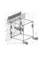
На чертеже представлена конструкция устройства для очистки корпусов судов, уже установленного на борту судна.The drawing shows the design of a device for cleaning hulls already installed on board the vessel.
Устройство для очистки корпусов судов содержит жесткую раму 1 в форме прямоугольного параллелепипеда, ребрами которой могут являться любые полые конструкции, шесть внутренних управляемых приводами лебедок 2-7 с намотанными на них тросами 8, свободные концы которых прикреплены к корпусу рабочего механизма 9, перемещаемого в пространстве рамы 1 с их помощью, все тросы 8 натянуты и переброшены через соответствующие им направляющие ролики 10, каждый из которых закреплен на горизонтальных конструкциях жесткой рамы 1 с помощью вертикальных стоек 11 с возможностью вращения вокруг них для поворота направляющих роликов 10 таким образом, чтобы плоскость каждого из роликов 10 всегда совпадала с проходящим через них тросом 8, идущими от соответствующей внутренней лебедки к рабочему механизму 9, обеспечивая надежное наматывание или разматывания троса с барабана каждой внутренней лебедки при любом текущем положении рабочего механизма 9. К верхней горизонтальной конструкции ребра рамы 1, расположенной вдоль борта судна, прикреплены два троса 12, которые намотаны на барабан тяговой лебедки 13, расположенной на борту судна и имеющей механизм перемещения ее вдоль этого борта. Четыре внутренние лебедки 2,4 и 6,7 закреплены, соответственно, на четырех вертикальных ребрах рамы 1 в ее верхней части, а две остальные 3 и 5 - на вертикальных ребрах рамы 1, расположенных у борта судна ниже первых. В корпус рабочего механизма 9 помещен привод вращения, выходной вал 14 которого жестко связан с вращающимся рабочим инструментом 15. В нижней части рамы 1 на двух удаленных от борта судна ее вертикальных конструкциях ребер установлены управляемые шарниры 16, с внешней стороны к этим шарнирам с возможностью вращения относительно продольных осей конструкций указанных ребер прикреплены движители 17. На двух ближайших от борта судна вертикальных конструкциях ребер закреплены электромагниты 18-21, расположенные между этими конструкциями и бортом судна, причем каждый из электромагнитов 18, 19 первой пары, расположенной в горизонтальной плоскости, прикреплен к самой верхней части рамы, соответствующим ему стержнем, каждый из этих стержней 22, 23 имеет возможность телескопического изменения их длины посредством встроенных в них электроприводов и соединяется со своим электромагнитом шарнирно, а вторая горизонтально расположенная пара электромагнитов 20 и 21 установлена на одинаковом расстоянии по вертикали от соответствующих электромагнитов первой пары, но выше нижней горизонтальной плоскости рамы 1, и жестко закреплена на соответствующих вертикальных конструкциях рамы 1. Приводы всех шести внутренних лебедок 2-7, рабочего инструмента 15, двух движителей 17, двух управляемых шарниров 16, двух стержней 22, 23, а также все четыре электромагнита 18-21 подключены электрокабелями к соответствующим источникам питания с возможностью управления входными сигналами этих электроприводов и электромагнитов. Рабочий инструмент 15 может быть любым, например, щетка, или любым другим устройством очистки, а рабочий механизм 9 может содержать любой источник механического воздействия на внешнюю очищаемую поверхность корпуса судна, например, кавитационная пушка.A device for cleaning the hulls of ships contains a
Вся конструкция устройства для очистки корпусов судов с помощью двух тросов 12, которые намотаны на барабан тяговой лебедки 13, может располагаться в любом месте по борту судна, которое требует очистки от старой краски и органических наростов подводной части. Эта лебедка 13 имеет возможность вручную или автоматически перемещаться вдоль борта судна по направляющим, установленным в верхней части его корпуса, одновременно обеспечивая смещение всего предлагаемого устройства очистки вдоль этого корпуса. Текущая длина размотанной части тросов 12 лебедки 13 определяет расположение устройства очистки по вертикали вдоль борта судна.The entire design of the device for cleaning the hulls using two
Рассматриваемое устройство для очистки корпусов судов работает следующим образом. В начале рама 1 с помощью лебедки 13 устанавливается на направляющие в любую исходную верхнюю часть очищаемого борта судна, так как эта часть обычно является чище нижней и обеспечивает более прочное исходное закрепление рамы 1 с помощью электромагнитов 18-21 на очищаемом участке борта. При этом стержни 22 и 23 имеют минимальную исходную длину. Затем включаются все электромагниты 18-21. Поскольку верхняя часть борта судна является более плоской, чем нижняя, то обычно сразу все четыре электромагнита обеспечивают прочную фиксацию рамы 1 на корпусе судна. Если очищаемый участок борта не является плоским, то один из электромагнитов может не вступить в контакт с бортом. Тогда после кратковременного включения маломощных электроприводов телескопических стержней 22 и 23 обеспечивается перемещение несработавшего электромагнита в сторону борта судна до его примагничивания. Ввиду малой мощности указанных электроприводов они обеспечивают только свободное перемещение электромагнита к борту, но не могут смещать раму от борта судна, если электромагнит уже сработал. Шарнирное крепление электромагнитов 18 и 19, соответственно, к стержням 22 и 23 необходимо для того, чтобы позволить этим электромагнитам занять наилучшую позицию даже на неровной (выпуклой) поверхности борта судна при изменяемой длине стержня 22 или 23.Consider a device for cleaning hulls works as follows. At the beginning, the
После срабатывания всех электромагнитов 18-21 рама 1 жестко фиксируется на заданном участке борта судна и приводы стержней 22 и 23 отключаются. После этого по типовой программе начинают работать внутренние лебедки 2-7, обеспечивая программное изменение длин соответствующих тросов 8 и требуемое перемещение корпуса рабочего механизма 9 с рабочим инструментом 15 к очищаемому борту судна. Очистка начинается из самого верхнего положения механизма 9 в раме 1.After the operation of all the electromagnets 18-21, the
Поскольку верхняя - надводная часть судна является более чистой, плоской и вертикальной, чем нижняя-подводная, то усилия прижатия рабочего инструмента 15 к борту, обеспечиваемые натянутыми тросами 8 лебедок 2-5, являются достаточными для качественной очистки борта.Since the upper - surface part of the vessel is cleaner, flat and vertical than the lower - underwater, the efforts of pressing the
Для продолжения очистки механизм 9 смещается тросами 8 лебедок 2-7 в горизонтальном направлении вдоль борта судна. После очистки одной горизонтальной полосы борта в пределах рамы 1 механизм 9 смещается тросами 8 в новое нижнее положение, и горизонтальное смещение этого механизма тросами 8 продолжается в противоположную сторону внутри рамы 1. Это продолжается до тех пор, пока в уже описанной последовательности не будет очищен участок борта в пределах используемой рамы 1.To continue cleaning, the
Для очистки соседних участков борта вначале с помощью лебедок 2-7 и их тросов 8 механизм 9 перемещается внутрь рамы 1 и удерживается в этом положении тросами 8 лебедок 6 и 7. Затем отключаются электромагниты 18-21, а стержни 22 и 23 приводятся их приводами в исходной положение. Рама 1 с помощью тросов 12 лебедки 13 смещается ниже предыдущего положения или вдоль борта вместе с лебедкой 13.To clean adjacent sections of the side, first with the help of winches 2-7 and their
После очистки надводной части борта судна только нижняя часть рамы 1 опускается под воду для продолжения очистки вначале верхних слоев подводной части борта. Поскольку электромагниты 20 и 21 взаимодействуют только с уже очищенной или слабо загрязненной поверхностью, а всегда сильно загрязненная подводная часть судна не позволяет этим электромагнитам прочно закрепиться на борту, то в начале очистки подводной части судна электромагниты 20, 21 должны закрепляться на уже очищенной надводной поверхности борта. Поскольку нижняя часть судна имеет большую кривизну (отклонение от вертикали к продольной оси судна), чем верхняя, то с помощью включаемых приводов движителей 17, продольные оси которых исходно находятся в вертикальной плоскости, перпендикулярной борту судна, а тяги их винтов направлены в сторону борта, нижняя часть рамы 1 прижимается к этому борту для прочной стыковки нижней пары электромагнитов 20, 21 с этим бортом после их включения.After cleaning the surface of the side of the vessel, only the lower part of the
После очистки с помощью рабочего инструмента 15 первого подводного участка корпуса судна в пределах рамы 1 по уже указанной выше последовательности и технологии все электромагниты 20-21 отключаются, а рама 1 под действием своего веса немного отходит от борта судна. После этого движители 17 разворачиваются с помощью приводов управляемых шарниров 16 в противоположных направлениях так (см.чертеж), чтобы их продольные оси располагались в одной вертикальной плоскости, совпадающей с вертикальной гранью рамы 1, а сама рама располагалась между этими движителями. После включения приводов движителей 17 так, чтобы их тяги были направлены в одну сторону, рама 1 с их помощью вместе с лебедкой 13 смещается в горизонтальном направлении в нужную сторону вдоль борта судна для очистки его следующего подводного участка. Затем движители 17 с помощью приводов управляемых шарниров 16 опять разворачиваются в свое исходное положение. После включения всех электромагнитов 20-21 и приводов движителей 17 опять обеспечивается закрепление рамы 1 на борту судна. Этот процесс продолжается до полной очистки первой горизонтальной подводной полосы борта судна.After cleaning with the help of a
После завершения очистки указанной полосы электромагниты 20-21 отключаются, движители 17 находятся в исходном положении, а рама 1 с помощью тросов 12 лебедки 13 опускается вниз в положение, позволяющее нижней паре электромагнитов 20 и 21 соприкасаться с уже очищенной полосой подводной части судна и начать очистку следующей горизонтальной полосы подводной части борта. Процесс последующей очистки подводной части борта в горизонтальном, но противоположном направлении повторяется в уже описанной выше последовательности, чередуясь с вертикальным перемещением рамы 1 вниз, для начала очистки очередной ниже расположенной горизонтальной полосы борта судна. Работа по указанной схеме продолжается до полной очистки одного борта. Тот же самый процесс будет повторяться и при очистке другого борта судна в уже описанной выше последовательности.After completing the cleaning of this strip, the electromagnets 20-21 are turned off, the
Техническая реализация предложенного устройства не вызывает затруднения, так как при его реализации используются только типовые и уже хорошо отработанные элементы.The technical implementation of the proposed device does not cause difficulties, since its implementation uses only typical and already well-developed elements.
Claims (9)
Translated fromRussianPriority Applications (1)
| Application Number | Priority Date | Filing Date | Title |
|---|---|---|---|
| RU2019111036ARU2706267C1 (en) | 2019-04-11 | 2019-04-11 | Device for cleaning hulls of ships |
Applications Claiming Priority (1)
| Application Number | Priority Date | Filing Date | Title |
|---|---|---|---|
| RU2019111036ARU2706267C1 (en) | 2019-04-11 | 2019-04-11 | Device for cleaning hulls of ships |
Publications (1)
| Publication Number | Publication Date |
|---|---|
| RU2706267C1true RU2706267C1 (en) | 2019-11-15 |
Family
ID=68579925
Family Applications (1)
| Application Number | Title | Priority Date | Filing Date |
|---|---|---|---|
| RU2019111036ARU2706267C1 (en) | 2019-04-11 | 2019-04-11 | Device for cleaning hulls of ships |
Country Status (1)
| Country | Link |
|---|---|
| RU (1) | RU2706267C1 (en) |
Cited By (2)
| Publication number | Priority date | Publication date | Assignee | Title |
|---|---|---|---|---|
| RU210639U1 (en)* | 2021-12-29 | 2022-04-25 | Федеральное государственное бюджетное учреждение науки Институт машиноведения им. А.А. Благонравова Российской академии наук (ИМАШ РАН) | CABLE DRIVE MECHANISM |
| RU2810207C1 (en)* | 2022-12-21 | 2023-12-22 | Автономная некоммерческая организация высшего образования "Университет Иннополис" | System for catching falling objects based on cable robot |
Citations (4)
| Publication number | Priority date | Publication date | Assignee | Title |
|---|---|---|---|---|
| US4149345A (en)* | 1975-12-29 | 1979-04-17 | Atsuchi Tekko Co., Ltd. | Wall blaster |
| SU770923A1 (en)* | 1977-01-05 | 1980-10-15 | Предприятие П/Я А-1080 | Apparatus for automatic cleaning and painting ship hull |
| US4236477A (en)* | 1979-06-04 | 1980-12-02 | Water Front Products, Inc. | Boat hull cleaning device |
| US20140076226A1 (en)* | 2012-09-14 | 2014-03-20 | Raytheon Company | Hull Cleaning Robot |
- 2019
- 2019-04-11RURU2019111036Apatent/RU2706267C1/enactive
Patent Citations (4)
| Publication number | Priority date | Publication date | Assignee | Title |
|---|---|---|---|---|
| US4149345A (en)* | 1975-12-29 | 1979-04-17 | Atsuchi Tekko Co., Ltd. | Wall blaster |
| SU770923A1 (en)* | 1977-01-05 | 1980-10-15 | Предприятие П/Я А-1080 | Apparatus for automatic cleaning and painting ship hull |
| US4236477A (en)* | 1979-06-04 | 1980-12-02 | Water Front Products, Inc. | Boat hull cleaning device |
| US20140076226A1 (en)* | 2012-09-14 | 2014-03-20 | Raytheon Company | Hull Cleaning Robot |
Non-Patent Citations (1)
| Title |
|---|
| Tobias Bruckmann and all. Wire Robots Part I: Kinematics, Analysis & Design. INTECH Open Access Publisher, 2008, p. 109-132.* |
Cited By (3)
| Publication number | Priority date | Publication date | Assignee | Title |
|---|---|---|---|---|
| RU210639U1 (en)* | 2021-12-29 | 2022-04-25 | Федеральное государственное бюджетное учреждение науки Институт машиноведения им. А.А. Благонравова Российской академии наук (ИМАШ РАН) | CABLE DRIVE MECHANISM |
| RU2810207C1 (en)* | 2022-12-21 | 2023-12-22 | Автономная некоммерческая организация высшего образования "Университет Иннополис" | System for catching falling objects based on cable robot |
| RU2812163C1 (en)* | 2022-12-22 | 2024-01-24 | Автономная некоммерческая организация высшего образования "Университет Иннополис" | System for catching large-sized massive objects based on cable robot |
Similar Documents
| Publication | Publication Date | Title |
|---|---|---|
| US10844562B2 (en) | Deployment apparatus having a tether arm for an inspection vehicle | |
| US3268091A (en) | Reaction thrust operated manipulator | |
| CN108045532A (en) | A kind of underwater electric machinery arm operation gondola and application method | |
| NO833215L (en) | ROBOT WITH CLOTH FOOTS | |
| CN109080795B (en) | A gliding turbulence profiler deployment device and operation method thereof | |
| RU2706267C1 (en) | Device for cleaning hulls of ships | |
| KR20150040059A (en) | A winch for cable and a launching system of robot for working on ship | |
| CN112896471B (en) | Multifunctional suspended underwater robot and base station system thereof | |
| KR20180094608A (en) | Underwater robot system based surface craft | |
| US20230406680A1 (en) | An Article Handling System | |
| CN110040628A (en) | A kind of latent device folding and unfolding method | |
| JP2022549421A (en) | Water gate sealing surface Marine organism underwater cleaning equipment, equipment set and cleaning method | |
| KR101516558B1 (en) | Guiding device for underwater cleaning robot | |
| CN110001895B (en) | Submersible vehicle winding and unwinding device | |
| CN113044172A (en) | Honeycomb AUV cluster laying and recycling system | |
| WO2016053123A1 (en) | Robot for over-ceiling space inspection | |
| KR20160000111U (en) | Fittings moving system for work underwater using a cable winch robot | |
| JP2018075647A (en) | Manipulator device | |
| CN115771856A (en) | Integrated container winch system | |
| RU2585181C1 (en) | Launching and lifting device | |
| CN210235269U (en) | Portable ship water gauge image acquisition device | |
| JP2001058599A (en) | Thruster elevator | |
| CN116812116A (en) | Underwater structure cleaning and detecting operation robot | |
| CN111361709B (en) | An underwater detection and salvage robot | |
| KR101540309B1 (en) | Underwater cleaning robot |