RU2705659C2 - Plate bearing device guide for diaphragm fitting - Google Patents
Plate bearing device guide for diaphragm fittingDownload PDFInfo
- Publication number
- RU2705659C2 RU2705659C2RU2017137952ARU2017137952ARU2705659C2RU 2705659 C2RU2705659 C2RU 2705659C2RU 2017137952 ARU2017137952 ARU 2017137952ARU 2017137952 ARU2017137952 ARU 2017137952ARU 2705659 C2RU2705659 C2RU 2705659C2
- Authority
- RU
- Russia
- Prior art keywords
- fitting
- diaphragm
- insert
- diaphragm plate
- carrier
- Prior art date
Links
- 238000000034methodMethods0.000claimsabstractdescription8
- 230000003993interactionEffects0.000claimsabstractdescription5
- 238000007789sealingMethods0.000claimsdescription7
- 239000000126substanceSubstances0.000abstract1
- 238000004519manufacturing processMethods0.000description3
- 238000012986modificationMethods0.000description2
- 230000004048modificationEffects0.000description2
- 238000005266castingMethods0.000description1
- 238000004891communicationMethods0.000description1
- 238000013461designMethods0.000description1
- 239000012530fluidSubstances0.000description1
- 238000003780insertionMethods0.000description1
- 230000037431insertionEffects0.000description1
- 239000007788liquidSubstances0.000description1
- 239000000463materialSubstances0.000description1
- 238000000465mouldingMethods0.000description1
- 238000003466weldingMethods0.000description1
Images


Classifications
- G—PHYSICS
- G01—MEASURING; TESTING
- G01F—MEASURING VOLUME, VOLUME FLOW, MASS FLOW OR LIQUID LEVEL; METERING BY VOLUME
- G01F15/00—Details of, or accessories for, apparatus of groups G01F1/00 - G01F13/00 insofar as such details or appliances are not adapted to particular types of such apparatus
- G—PHYSICS
- G01—MEASURING; TESTING
- G01F—MEASURING VOLUME, VOLUME FLOW, MASS FLOW OR LIQUID LEVEL; METERING BY VOLUME
- G01F1/00—Measuring the volume flow or mass flow of fluid or fluent solid material wherein the fluid passes through a meter in a continuous flow
- G01F1/05—Measuring the volume flow or mass flow of fluid or fluent solid material wherein the fluid passes through a meter in a continuous flow by using mechanical effects
- G01F1/34—Measuring the volume flow or mass flow of fluid or fluent solid material wherein the fluid passes through a meter in a continuous flow by using mechanical effects by measuring pressure or differential pressure
- G01F1/36—Measuring the volume flow or mass flow of fluid or fluent solid material wherein the fluid passes through a meter in a continuous flow by using mechanical effects by measuring pressure or differential pressure the pressure or differential pressure being created by the use of flow constriction
- G01F1/40—Details of construction of the flow constriction devices
- G01F1/42—Orifices or nozzles
Landscapes
- Physics & Mathematics (AREA)
- Fluid Mechanics (AREA)
- General Physics & Mathematics (AREA)
- Measuring Volume Flow (AREA)
- Rotary Pumps (AREA)
- General Details Of Gearings (AREA)
- Automatic Assembly (AREA)
- Infusion, Injection, And Reservoir Apparatuses (AREA)
- Fuel-Injection Apparatus (AREA)
- Dental Tools And Instruments Or Auxiliary Dental Instruments (AREA)
- Actuator (AREA)
Abstract
Description
Translated fromRussianПЕРЕКРЕСТНАЯ ССЫЛКА НА РОДСТВЕННЫЕ ЗАЯВКИCROSS REFERENCE TO RELATED APPLICATIONS
[0001] Данная заявка испрашивает приоритет по предварительной патентной заявке США 62/149,256, поданной 17 апреля 2015 г. под названием "Plate Carrier Guide for an Orifice Fitting", которая полностью включена в данный документ посредством ссылки.[0001] This application claims priority to provisional patent application US 62 / 149,256, filed April 17, 2015 under the name "Plate Carrier Guide for an Orifice Fitting", which is fully incorporated herein by reference.
ИНФОРМАЦИЯ ПО ФИНАНСИРОВАНИЮ НИОКР ИЗ ФЕДЕРАЛЬНОГО БЮДЖЕТАINFORMATION ON FINANCING R&D FROM THE FEDERAL BUDGET
[0002] Не применимо.[0002] Not applicable.
УРОВЕНЬ ТЕХНИКИBACKGROUND
[0003] В эксплуатации трубопроводов и других вариантах промышленного применения применяют расходомеры для измерения объемного расхода газообразного или жидкого потока, перемещающегося через сечение трубной системы. Расходомеры могут включать в себя диафрагменный фитинг, который ориентирует и поддерживает диафрагменную пластину в несущем устройстве пластины, которое проходит по сечению трубной системы, перпендикулярному направлению струи потока. Двухкамерный диафрагменный фитинг обеспечивает удаление несущего устройства пластины без прерывания струи потока, проходящего через сечение трубной системы.[0003] In the operation of pipelines and other industrial applications, flow meters are used to measure the volumetric flow rate of a gaseous or liquid stream moving through a section of a pipe system. Flowmeters may include a diaphragm fitting that orientates and supports the diaphragm plate in a plate support device that extends over a section of the pipe system perpendicular to the direction of flow of the stream. A two-chamber diaphragm fitting allows removal of the carrier of the plate without interrupting the jet of flow passing through the cross section of the pipe system.
РАСКРЫТИЕ СУЩНОСТИ ИЗОБРЕТЕНИЯSUMMARY OF THE INVENTION
[0004] В варианте осуществления, устройство для позиционирования диафрагменной пластины в диафрагменном фитинге содержит вставку, имеющую сквозной проход, проходящий от первого конца до второго конца, причем второй конец имеет удлинения, выполненные с возможностью скрепления устройства с внутренним участком диафрагменного фитинга. Устройство дополнительно включает в себя первую сторону, имеющую первое отверстие для обеспечения доступа в проход, и вторую сторону, имеющую второе отверстие, для обеспечения доступа в проход. В дополнение, проход выполнен с возможностью обеспечения сквозного прохода через него диафрагменной пластины, установленной на несущем устройстве диафрагменной пластины. Дополнительно, первое и второе отверстия выполнены с возможностью обеспечения прохода шестерни через них, и причем шестерня выполнена с возможностью взаимодействия с несущим устройством диафрагменной пластины.[0004] In an embodiment, the device for positioning the diaphragm plate in the diaphragm fitting comprises an insert having a through passage extending from the first end to the second end, the second end having extensions adapted to fasten the device to the inner portion of the diaphragm fitting. The device further includes a first side having a first opening to provide access to the passage, and a second side having a second opening to provide access to the passage. In addition, the passage is configured to provide a through passage through it of a diaphragm plate mounted on the carrier of the diaphragm plate. Additionally, the first and second openings are configured to allow gears to pass through them, and the gear is adapted to interact with a diaphragm plate carrier.
[0005] В варианте осуществления диафрагменный фитинг, имеющий систему для позиционирования несущего устройства диафрагменной пластины в диафрагменном фитинге, содержит корпус, имеющий нижнюю камеру и верхнюю часть, имеющую верхнюю камеру, а также диафрагменную пластину, расположенную в несущем устройстве диафрагменной пластины, несущее устройство имеет первый ряд канавок, расположенный на первом конце несущего устройства диафрагменной пластины, и второй ряд канавок, расположенный на втором конце несущего устройства диафрагменной пластины. Диафрагменный фитинг дополнительно включает в себя шестерню, расположенную в верхней камере и выполненную с возможностью взаимодействия с несущим устройством диафрагменной пластины, и вставку, расположенную в верхней камере, причем вставка имеет полость или сквозной проход, первый конец с первым отверстием, второй конец со вторым отверстием и множество выступов, первую сторону, и вторую сторону, при этом сквозной проход проходит от первого отверстия до второго отверстия. Кроме того, первая сторона включает в себя первый вырез, и вторая сторона включает в себя второй вырез. Дополнительно, сквозной проход выполнен с возможностью обеспечивать пропуск через него несущего устройства диафрагменной пластины, и первый и второй вырезы выполнены с возможностью обеспечения прохода через них шестерни.[0005] In an embodiment, the diaphragm fitting having a system for positioning the carrier of the diaphragm plate in the diaphragm fitting comprises a housing having a lower chamber and an upper portion having an upper chamber, and also a diaphragm plate located in the carrier of the diaphragm plate, the carrier has a first row of grooves located at the first end of the diaphragm plate carrier, and a second row of grooves located at the second end of the diaphragm carrier ins. The diaphragm fitting further includes a gear located in the upper chamber and configured to interact with the carrier of the diaphragm plate, and an insert located in the upper chamber, the insert having a cavity or through passage, a first end with a first hole, a second end with a second hole and a plurality of protrusions, a first side and a second side, wherein a through passage extends from a first hole to a second hole. In addition, the first side includes a first cut, and the second side includes a second cut. Additionally, the through passage is configured to allow the carrier of the diaphragm plate to pass through it, and the first and second cutouts are configured to allow gears to pass through them.
[0006] В варианте осуществления, способ позиционирования несущего устройства диафрагменной пластины в диафрагменном фитинге содержит взаимодействие канавок на противоположных концах несущего устройства диафрагменной пластины с первой ведущей шестерней и второй ведущей шестерней, при этом несущее устройство диафрагменной пластины расположено в полости или сквозном проходе вставки, первая ведущая шестерня проходит через первый вырез во вставке, и вторая ведущая шестерня проходит через второй вырез во вставке. Способ дополнительно включает в себя приведение в действие первой и второй ведущей шестерни посредством верхнего привода, и пропуск несущего устройства диафрагменной пластины через вставку.[0006] In an embodiment, a method for positioning a diaphragm plate carrier in a diaphragm fitting comprises interacting grooves at opposite ends of the diaphragm plate carrier with a first pinion gear and a second pinion gear, wherein the diaphragm plate carrier is located in the cavity or through passage of the insert, the first the pinion gear passes through the first cutout in the insert, and the second pinion gear passes through the second cutout in the insert. The method further includes driving the first and second pinion gears by means of the top drive, and passing the diaphragm plate carrier through the insert.
[0007] Таким образом, варианты осуществления, описанные в данном документе, содержат комбинацию признаков и преимуществ, для устранения различных недостатков, связанных с некоторыми устройствами, системами и способами известной техники. Различные признаки и отличия, описанные выше, а также другие позиции должны стать понятными специалисту в данной области техники после прочтения следующего подробного описания со ссылками на прилагаемые чертежи.[0007] Thus, the embodiments described herein comprise a combination of features and advantages, in order to eliminate various disadvantages associated with certain devices, systems, and methods of the prior art. The various features and differences described above, as well as other positions, should become apparent to a person skilled in the art after reading the following detailed description with reference to the accompanying drawings.
КРАТКОЕ ОПИСАНИЕ ЧЕРТЕЖЕЙBRIEF DESCRIPTION OF THE DRAWINGS
[0008] Для подробного описания предпочтительных вариантов осуществления изобретения ниже даны ссылки на прилагаемые чертежи, на которых показано следующее.[0008] For a detailed description of preferred embodiments of the invention, reference will now be made to the accompanying drawings, in which the following is shown.
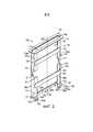
[0009] На фиг. 1 показан вид в изометрии, частично в разрезе, двухкамерного диафрагменного расходомера, имеющего позиционирующее устройство согласно принципам, описанным в данном документе.[0009] FIG. 1 is an isometric view, partially in section, of a two-chamber orifice plate flowmeter having a positioning device according to the principles described herein.
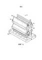
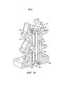
[0010] На фиг. 2 показан внешний вид в изометрии позиционирующего устройства фиг. 1.[0010] FIG. 2 shows an isometric view of the positioning device of FIG. one.
[0011] На фиг. 3 показан внешний вид спереди позиционирующего устройства фиг. 1.[0011] FIG. 3 shows a front view of the positioning device of FIG. one.
[0012] На фиг. 4 показан внешний вид сбоку позиционирующего устройства фиг. 1.[0012] FIG. 4 shows a side elevational view of the positioning device of FIG. one.
[0013] На фиг. 5 показан внешний вид сбоку верхней части двухкамерного диафрагменного расходомера, имеющего позиционирующее устройство фиг. 1.[0013] FIG. 5 shows a side view of the upper part of a two-chamber orifice plate flowmeter having a positioning device of FIG. one.
[0014] На фиг. 6 показан частично в разрезе вид сбоку позиционирующего устройства и верхней части расходомера фиг. 5.[0014] FIG. 6 is a partially cutaway side view of the positioning device and the upper part of the flowmeter of FIG. 5.
[0015] На фиг. 7 показан частично в разрезе вид сбоку позиционирующего устройства и верхней части расходомера фиг. 5.[0015] FIG. 7 is a partially cutaway side view of the positioning device and the upper part of the flowmeter of FIG. 5.
[0016] На фиг. 8 показан частично в разрезе вид сзади позиционирующего устройства и верхней части расходомера фиг. 5.[0016] FIG. 8 is a partially sectional rear view of the positioning device and the upper part of the flowmeter of FIG. 5.
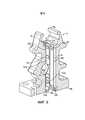
[0017] На фиг. 9 показан частично в разрезе вид в изометрии позиционирующего устройства и верхней части расходомера фиг. 5.[0017] FIG. 9 is a partially exploded perspective view of the positioning device and the top of the flowmeter of FIG. 5.
[0018] На фиг. 10 показан внешний вид в изометрии варианта осуществления позиционирующего устройства фиг. 1 из двух деталей согласно принципам, описанным в данном документе.[0018] FIG. 10 is an isometric view of an embodiment of the positioning device of FIG. 1 of two parts according to the principles described in this document.
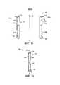
[0019] На фиг. 11 показан внешний вид спереди варианта осуществления из двух деталей позиционирующего устройства, показанного на фиг. 10.[0019] FIG. 11 shows a front view of a two-part embodiment of the positioning device shown in FIG. 10.
[0020] На фиг. 12 показан внешний вид сбоку варианта осуществления из двух деталей позиционирующего устройства фиг. 10.[0020] FIG. 12 is a side elevational view of a two-part embodiment of the positioning device of FIG. 10.
[0021] На фиг. 13 показан частично в разрезе вид сбоку варианта осуществления из двух деталей позиционирующего устройства фиг. 10 в верхней части расходомера фиг. 1.[0021] FIG. 13 is a partially cutaway side view of an embodiment of two parts of the positioning device of FIG. 10 at the top of the flowmeter of FIG. one.
[0022] На фиг. 14 показан частично в разрезе вид сбоку варианта осуществления из двух деталей позиционирующего устройства фиг. 10 в верхней части расходомера фиг. 1.[0022] FIG. 14 is a partially cutaway side view of an embodiment of two parts of the positioning device of FIG. 10 at the top of the flowmeter of FIG. one.
[0023] На фиг. 15 показан частично в разрезе вид сзади варианта осуществления из двух деталей позиционирующего устройства фиг. 10 в верхней части расходомера фиг. 1.[0023] FIG. 15 is a partially cross-sectional rear view of an embodiment of two parts of the positioning device of FIG. 10 at the top of the flowmeter of FIG. one.
[0024] На фиг. 16 показан частично в разрезе вид в изометрии варианта осуществления из двух деталей позиционирующего устройства фиг. 10 в верхней части расходомера фиг. 1.[0024] FIG. 16 is a partially cutaway perspective view of a two-part embodiment of the positioning device of FIG. 10 at the top of the flowmeter of FIG. one.
ОСУЩЕСТВЛЕНИЕ ИЗОБРЕТЕНИЯDETAILED DESCRIPTION OF THE INVENTION
[0025] Ниже рассмотрены различные, являющиеся примерами, варианты осуществления изобретения. Вместе с тем, специалисту в данной области техники понятно, что примеры, раскрытые в данном документе, имеют широкое применение, и что рассмотрение любого варианта осуществления дает только пример варианта осуществления и не предполагает ограничения объема рассмотрения, включающего в себя формулу изобретения, вариантами осуществления.[0025] Various embodiments of the invention are described below. However, one skilled in the art will understand that the examples disclosed herein are widely used, and that consideration of any embodiment provides only an example of an embodiment and does not imply limiting the scope of the consideration, including the claims, to the embodiments.
[0026] Некоторые термины применяются по всему следующему описанию и формуле изобретения для частных элементов или компонентов. Как должно быть понятно специалисту в данной области техники, разные люди могут давать одинаковому элементу или компоненту отличающиеся названия. Данный документ не имеет цели установления различий между компонентами или элементами, отличающимися названием, но не функцией. Чертежи на фигурах не обязательно выполнены с соблюдением масштаба. Некоторые элементы и компоненты в данном документе могут быть показаны с искажением масштаба или в несколько схематичном виде, и некоторые детали обычных элементов могут быть не показаны в интересах ясности и краткости.[0026] Certain terms apply throughout the following description and claims to particular elements or components. As should be understood by a person skilled in the art, different people may give different names to the same element or component. This document is not intended to distinguish between components or elements that differ in name but not function. The drawings in the figures are not necessarily drawn to scale. Some elements and components in this document may not be scaled or shown in a somewhat schematic form, and some details of ordinary elements may not be shown in the interest of clarity and brevity.
[0027] В следующем рассмотрении и в формуле изобретения термины "включающий в себя" и "содержащий" применяются в неограниченном виде и, следовательно, должны интерпретироваться, означающими "включающий в себя, но без ограничения этим". Также, термин "соединяют" или "соединяет" служит для указания либо непрямого или прямого соединения. Таким образом, если первое устройство соединено со вторым устройством, указанное соединение может быть прямым соединением, или непрямым соединением через другие устройства, компоненты и соединения. В дополнение, при использовании в данном документе, термины "осевой" и "по оси" в общем означают вдоль или параллельно центральной осевой линии (например, центральной осевой линии корпуса или окна), а термины "радиальный" и "радиально" в общем означают перпендикулярно центральной осевой линии. Например, осевое расстояние относится к расстоянию, измеренному вдоль или параллельно центральной осевой линии, и радиальное расстояние означает расстояние, измеренное перпендикулярно центральной осевой линии.[0027] In the following discussion and in the claims, the terms “including” and “comprising” are used in unlimited form and therefore should be interpreted to mean “including but not limited to”. Also, the term “connect” or “connect” serves to indicate either indirect or direct connection. Thus, if the first device is connected to the second device, the connection may be a direct connection, or an indirect connection through other devices, components and connections. In addition, as used herein, the terms “axial” and “axially” generally mean along or parallel to a central axial line (eg, the center axis of a cabinet or window), and the terms “radial” and “radially” generally mean perpendicular to the central centerline. For example, an axial distance refers to a distance measured along or parallel to the center axis line, and a radial distance means a distance measured perpendicular to the center axis line.
[0028] На фиг. 1 показан с частичным разрезом пример диафрагменного расходомера 12, более конкретно двухкамерный диафрагменный фитинг. Диафрагменный расходомер 12 включает в себя корпус 16 и верхнюю часть 18. Корпус 16 вмещает нижнюю камеру 20, которая сообщается по текучей среде с внутренним пространством или каналом трубопровода 34, который проходит вдоль продольной оси 35 с каждой из сторон расходомера 12. Проточный канал 37 проходит через и включает в себя внутреннее пространство трубопровода 34 и нижнюю камеру 20. Верхняя часть 18 вмещает верхнюю камеру 22, в которой размещена направляющая несущего устройства пластины или вставка 100, и соединен с корпусом 16 болтами 17. Вставка 100 является примером позиционирующего устройства. Проход 30 образует отверстие, соединяющее верхнюю камеру 22 с нижней камерой 20. Проход 30 выполнен с возможностью изолировать верхнюю камеру 22 и вставку 100 от нижней камеры 20 и от проточного канала, когда находится в закрытой конфигурации, и проход 30 выполнен с возможностью обеспечивать сообщение данных элементов, когда имеет открытую конфигурацию. Седло 24 клапана соединено с верхней частью 18 и обеспечивает уплотнительное взаимодействие с пластиной 56 задвижки, которой сообщает скользящее перемещение вращающийся вал 54 зубчатой передачи. Нижний привод 36 и верхний привод 38 функционируют для вертикального перемещения несущего устройства 32 диафрагменной пластины в расходомере 12.[0028] In FIG. 1 shows, in partial section, an example of a diaphragm flow meter 12, more particularly a two-chamber diaphragm fitting. The diaphragm flow meter 12 includes a
[0029] Диафрагма 31 расположена на диафрагменной пластине 33, поддерживаемой несущим устройством 32 пластины. Несущее устройство 32 пластины показано в измерительном положении, выровненным по оси с внутренним пространством трубопровода 34. Проточный канал 37 проходит через диафрагму 31, когда несущее устройство 32 пластины и диафрагменная пластина 33 установлены в нижней камере 20. Для удаления несущего устройства 32 пластины из расходомера 12 вал 54 зубчатой передачи вращается для скользящего перемещения пластины 56 задвижки вбок и от клапанного седла 24 и открытия прохода 30. Когда проход 30 открыт, приводят в действие нижний привод 36 для перемещения несущего устройства 32 пластины вверх в верхнюю камеру 22. Когда несущее устройство 32 пластины находится полностью в верхней камере 22, проход 30 закрывается для изоляции верхней камеры 22, вставки 100 и несущего устройства 32 от трубопровода 34 и нижней камеры 20; другими словами, для изоляции данных элементов от проточного канала 37. Любое давление в верхней камере 22 можно затем сбросить, и несущее устройство 32 пластины можно удалить из расходомера 12, открепив винты 48 прижимной планки и удалив прижимную планку 44 и уплотнительную планку 40 из верхней части 18.[0029] The
[0030] Как показано на фиг. 2-4, вставка 100 включает в себя кожух 101, имеющий центральную ось 105 и первый или верхний конец 110, второй или нижний конец 120, первую сторону 130, вторую сторону 140, переднюю сторону 150 и заднюю сторону 160 для образования полости или внутреннего сквозного прохода 170, согласно принципам, описанным в данном документе.[0030] As shown in FIG. 2-4, the
[0031] В настоящем варианте осуществления верхний конец 110 расположен противоположно нижнему концу 120 и содержит отверстие 115, окруженное фланцем или выступом 118, который проходит радиально наружу от отверстия 115. Фланец или выступ 118 включает в себя два сквозных отверстия 118а, 118b, причем первое сквозное отверстие 118а расположено вблизи первой стороны 130, и второе сквозное отверстие 118b расположено вблизи второй стороны 140. В других вариантах осуществления фланец 118 может иметь три или больше сквозных отверстий или может не иметь сквозных отверстий. В других вариантах осуществления верхний конец может содержать множество выступов 118 (см. фиг. 10-16); в других вариантах осуществления верхний конец может содержать множество выступов 118 со сквозными отверстиями 118а, 118b в выступах 118, расположенными вблизи первой стороны 130 и второй стороны 140.[0031] In the present embodiment, the
[0032] Как также показано на фиг. 2-4, первая сторона 130 в общем параллельна второй стороне 140 и размещена на расстоянии от нее; первая сторона 130 и вторая сторона 140 являются, в общем, прямоугольными и, таким образом, в общем, перпендикулярными фланцу 118 верхнего конца 110. В данном варианте осуществления, первая сторона 130 и вторая сторона 140 включают в себя вырезы 131, 141, соответственно. Вырезы 131, 141 расположены приблизительно посредине между верхним концом 110 и нижним концом 120, а также вблизи передней стороны 150. В других вариантах осуществления вырезы могут быть расположены ближе к верхнему концу 110 или ближе к нижнему концу 120. В настоящем варианте осуществления вырезы 131, 141 являются полукруглыми. В других вариантах осуществления вырезы 131, 141 могут иметь любую подходящую форму.[0032] As also shown in FIG. 2-4, the
[0033] Передняя сторона 150 является в общем параллельной задней стороне 160 и размещена на расстоянии от нее; передняя сторона 150 и задняя сторона 160 являются, в общем, прямоугольными и, таким образом, в общем, перпендикулярными фланцу 118 верхнего конца 110 и, в общем, перпендикулярными первой и второй сторонам 130, 140, соответственно. Передняя сторона 150 содержит первый удлиненный участок 151, второй удлиненный участок 152, верхнюю поперечную панель 153 и нижнюю поперечную панель 154. Первый удлиненный участок 151 расположен смежно с первой стороной 130 и проходит по оси от верхнего конца 110 до нижнего конца 120. Второй удлиненный участок 152 расположен смежно со второй стороной 140 и проходит по оси от верхнего конца 110 до нижнего конца 120. Вырез 131 первой стороны 130 проходит к первому удлиненному участку 151, разделяя первый удлиненный участок на верхний участок 151а и нижний участок 151b; аналогично, вырез 141 второй стороны 140 проходит к второму удлиненному участку 152, разделяя второй удлиненный участок на верхний участок 152а и нижний участок 152b. Верхняя поперечная панель 153 проходит от верхнего участка 151а первого удлиненного участка 151 до верхнего участка 152а второго удлиненного участка 152, и нижняя поперечная панель 154 проходит от нижнего участка 151b первого удлиненного участка 151 до нижнего участка 152b второго удлиненного участка 152. В альтернативных вариантах осуществления передняя сторона 150 может содержать дополнительные панели, и/или удлиненные участки могут иметь любую подходящую ширину.[0033] The
[0034] Нижний конец 120 содержит отверстие 128 и множество выступов или удлинений 121-125. Полость 170 проходит от отверстия 115 в верхнем конце 110 до отверстия 128 в нижнем конце 120. Первый выступ 121 проходит по оси вниз и радиально наружу от первой стороны 130. Второй выступ 122 проходит по оси вниз и радиально наружу от второй стороны 140. Третий выступ 123 и четвертый выступ 124 проходят по оси вниз и радиально наружу от передней стороны 150, третий выступ 123 расположен вблизи первой стороны 130 и четвертый выступ 124 расположен вблизи второй стороны 140. Каждый, третий и четвертый выступы 123, 124, соответственно, дополнительно содержат угловой участок 123а, 124а, соответственно, который проходит по оси вниз и радиально наружу от передней стороны 150, и в общем вертикальный участок 123b, 124b, соответственно, который проходит по оси вниз от углового участка 123а, 124а. Каждый вертикальный участок 123b, 124b имеет сквозной канал 123с, 124с, соответственно, расположенный на вертикальном участке 123b, 124b третьего и четвертого выступов, соответственно. Пятый выступ 125 проходит приблизительно от первой стороны 130 до второй стороны 140 и содержит угловой участок 125а, который проходит по оси вниз и радиально наружу от задней стороны 160, и в общем вертикальный участок 125b, который проходит по оси вниз от углового участка 125а. В настоящем варианте осуществления вертикальный участок 125b имеет два сквозных канала 125с, 125d, расположенных на вертикальном участке 125b, один расположенный вблизи первой стороны 130 (позиция 125с показана на фиг. 9) и один расположенный вблизи второй стороны 140 (125d).[0034] The
[0035] На фиг.5-9 показан пример верхней части 18 расходомера 12 с установленной направляющей несущего устройства пластины или вставкой 100. Вставка 100 расположена в верхней камере 22 верхней части 18, причем верхняя часть 18 имеет верхний конец 18а и нижний конец 18b. Задняя сторона 160 расположена вблизи задней боковой стенки 23 верхней камеры 22 (Фиг. 6 и 9). Передняя сторона 150 расположена вблизи передней боковой стенки 25 верхней камеры 22, причем передняя боковая стенка 25 верхней камеры имеет верхний участок 25а и нижний участок 25b, разделенные искривленным участком 25с (Фиг. 6 и 9); искривленный участок 25с передней боковой стенки 25 выполнен с возможностью размещения верхнего привода 38 и соответствующих шестерен 38а и обеспечивает беспрепятственное вращение верхнего привода 38 и шестерен 38а в нем (см. фиг. 1). Верхние участки 151а, 152а, соответственно, первого и второго удлиненных участков 151, 152, соответственно, и верхняя поперечная панель 153 вставки 100 расположены вблизи верхнего участка 25а передней боковой стенки 25 верхней камеры. Дополнительно, нижние участки 151b, 152b, соответственно, первого и второго удлиненных участков 151, 152, соответственно, и нижняя поперечная панель 154 вставки 100 расположены вблизи нижнего участка 25b передней боковой стенки 25 верхней камеры.[0035] Figure 5-9 shows an example of the
[0036] Первая сторона 130 расположена вблизи первой боковой стенки 26 верхней камеры 22, и вторая сторона 140 расположена вблизи второй боковой стенки 27 верхней камеры 22 (фиг. 8). Фланец 118 верхнего конца 110 расположен смежно с верхней поверхностью 19 верхней части 18 (фиг. 9); фланец может лежать на верхней поверхности 19 верхней части, в углублении 21 в верхней поверхности 19 верхней части, или на уплотнении, таком, например, как уплотнительная прокладка или эластомерный элемент (не показано), расположенный либо между фланцем 118 и верхней поверхностью 19 верхней части, либо между фланцем 118 и углублением 21. Углубление 21 дополнительно включает в себя два канала 21а, 21b, расположенных противоположно друг другу, первый канал 21а расположен вблизи первой стороны 18с верхней части 18 и второй канал 21b расположен вблизи второй стороны 18d верхней части 18 (Фиг. 5 и 9). Нижний конец 120 расположен вблизи нижнего конца 18b и смежно с задней боковой стенкой 23, передней боковой стенкой 25, первой боковой стенкой 26, и второй боковой стенкой 27 верхней камеры 22 (Фиг. 6 и 8). В частности, вертикальный участок 125b пятого выступа 125 расположен смежно с задней боковой стенкой 23 верхней камеры так, что сквозной канал 125с выровнен с соответствующим резьбовым каналом 23а задней боковой стенки 23, и сквозной канал 125d выровнен с соответствующим резьбовым каналом 23b задней боковой стенки 23 (Фиг. 6 и 7). Вертикальный участок 123b третьего выступа 123 расположен смежно с нижним участком 25b передней боковой стенки 25 вблизи первой боковой стенки 26 так, что сквозной канал 123с выровнен с соответствующим резьбовым каналом 25d в нижнем участке 25b передней боковой стенки 25 вблизи первой боковой стенки 26 (Фиг. 6-8). Вертикальный участок 124b четвертого выступа 124 расположен смежно с нижним участком 25b передней боковой стенки 25 вблизи второй боковой стенки 27 так, что сквозной канал 124с выровнен с соответствующим резьбовым каналом 25е в нижнем участке 25b передней боковой стенки 25 вблизи второй боковой стенки 27 (Фиг. 6-8). Первый выступ 121 расположен вблизи первой боковой стенки 26, и второй выступ 122 расположен вблизи второй боковой стенки 27.[0036] The
[0037] Вставка 100 может быть скреплена с верхней камерой 22 любым закрепляющим средством известным в технике, в том числе, но без ограничения этим, резьбовыми шпильками, болтами, винтами, сваркой и посредством удержания на месте, когда установлены уплотнительная планка 40 и прижимная планка 44. Когда установлена, уплотнительная планка 40 расположена смежно с верхним концом 110 и может соприкасаться с верхним концом 110. В настоящем варианте осуществления вставка 100 скреплена с верхней частью 18 винтами, проходящими через отверстия 118а, 118b в верхней части упорного выступа 118 и завинченными в резьбовые отверстия 21а, 21b в верхней части 18. Вставка 100 дополнительно скреплена с верхней частью 18 винтами, проходящими через отверстия 123с, 124с, расположенными на третьем и четвертом вертикальных участках 123b, 124b, соответственно, и завинченными в резьбовые отверстия 25d, 25е в передней боковой стенке 25 верхней части 18. Вставка 100 дополнительно скреплена с верхней частью 18 винтами, проходящими через отверстия 125с, 125d, расположенными на пятом вертикальном участке 125b и завинченными в резьбовые отверстия 23а, 23b задней боковой стенки 23 верхней части 18.[0037] The
[0038] Также со ссылкой на фиг. 1 ниже описано функционирование несущего устройства 32 пластины для варианта осуществления, имеющего направляющую несущего устройства пластины или вставку 100, установленную в верхней части 18 расходомера 12. Как описано выше, нижний привод 36 и верхний привод 38 функционируют для перемещения несущего устройства 32 диафрагменной пластины вертикально в расходомере 12. Ниже рассмотрено перемещение несущего устройства 32 диафрагменной пластины из нижней камеры 20 в верхнюю камеру 22; для упрощения, промежуточные этапы, такие как приведение в действие пластины 56 задвижки или удаление прижимной планки 44 и уплотнительной планки 40 ниже не описаны. Специалисту в данной области техники ясно, что кроме различий по направлению, рассмотрение перемещения несущего устройства 32 диафрагменной пластины от верхней камеры 22 до нижней камеры 20 должно быть, по существу, одинаковым. Каждый привод 36, 38 включает в себя пару шестерен 36а, 38а, соответственно; шестерни 36а, 38а выполнены с возможностью выравнивания и взаимодействия с соответствующими канавками 32а на несущем устройстве 32 пластины. Канавки 32а расположены в двух столбиках на противоположных концах несущего устройства 32 диафрагменной пластины. В примере фиг. 1, канавки 32а включают в себя множество зубьев, выставленных по линии проходящей в направлении перемещения несущего устройства 32. Каждый столбик канавки 32а образует зубчатую рейку, которую можно также называть рейкой зубчатой передачи. Шестерни 36а, 38а можно также называть прямозубыми шестернями. Когда несущее устройство 32 диафрагменной пластины расположено в нижней камере 20, нижние приводные шестерни 36а взаимодействуют с канавками 32а несущего устройства диафрагменной пластины так, что приведение в действие нижнего привода 36 обеспечивает перемещение несущего устройства 32 диафрагменной пластины вертикально вверх из нижней камеры в верхнюю камеру 22. Когда несущее устройство 32 диафрагменной пластины перемещается в верхнюю камеру 22, верхние приводные шестерни 38а взаимодействуют с канавками 32а несущего устройства диафрагменной пластины через вырезы 131, 141 (фиг. 2) в первой стороне 130, проходящие до первого удлиненного участка 151 передней стороны 150 и второй стороне 140, проходящие до второго удлиненного участка 152 передней стороны 150 вставки 100, и когда несущее устройство 32 диафрагменной пластины достигает некоторой высоты верхней камеры 22, нижние приводные шестерни 36а выходят из зацепления с канавками 32а несущего устройства диафрагменной пластины. Продолжая ссылки на фиг. 1, вставка 100 центрирует и направляет несущее устройство 32 диафрагменной пластины при его перемещении через верхнюю камеру 22. Приведение в действие верхнего привода 38 дополнительно поднимает несущее устройство 32 диафрагменной пластины для прохода за верхнюю часть 18 расходомера 12 для удаления. В альтернативных вариантах осуществления нижний привод 36 и вал 54 зубчатой передачи с расходомера 12 могут содержать иные компоненты вместо гаек, имеющие разнообразные геометрические формы, которые должны приводить в действие пластину 56 задвижки.[0038] Also with reference to FIG. 1, the operation of the
[0039] Так как диафрагменная пластина 33 обеспечивает измерение потока, проходящего в трубопроводе 34 и через расходомер 12, диафрагменную пластину 33 следует центрировать для точности. Вместе с тем, во время изготовления расходомера 12, изменения в толщине стенок и контурах внутренних камер могут создавать затруднения при позиционировании несущего устройства 32 диафрагменной пластины для вставления и выравнивания. Для вставления несущего устройства 32 диафрагменной пластины в расходомер 12 или его удаления из него, канавки 32а несущего устройства 32 диафрагменной пластины должны сохранять контакт и зацепление с шестернями 38а верхнего привода 38, когда несущее устройство 32 диафрагменной пластины перемещается через верхнюю часть 18. Вставка 100 обеспечивает согласованное и повторяющееся выравнивание при направлении несущего устройства 32 диафрагменной пластины в расходомер 12 и из него, вне зависимости от изменений толщины стенок и контуров внутренних камер расходомера.[0039] Since the orifice plate 33 measures the flow passing through the
[0040] Направляющая несущего устройства пластины или вставка 100 может быть моноблочной конструкцией, как проиллюстрировано на фиг. 2-9, или может быть конструкцией из двух деталей, как проиллюстрировано на фиг. 10-16. Одинаковые части указаны одинаковыми ссылочными позициями. Вариант осуществления вставки 100, представленный на фиг. 10, включает в себя первую и вторую детали или направляющие швеллеры 180а, 180b, которые отнесены друг от друга и расположены с противоположных сторон от оси 105. Второй направляющий швеллер 180b отделен от первого направляющего швеллера 180а и не прикреплен к нему. Первая сторона 130 и связанные элементы расположены в направляющем швеллере 180а. Вторая сторона 140 и связанные элементы расположены в направляющем швеллере 180b. Направляющие швеллеры 180а, 180b могут быть установлены в верхней части 18 расходомера 12 или удалены из нее отдельно, по одному. Как показано лучше всего на фиг. 10 и фиг. 15, направляющие швеллеры 180а, 180b образуют полость или внутренний сквозной проход 170 от верхнего конца 110 до нижнего конца 120. Сквозной проход 172 проходит в направляющих швеллерах 180а, 180b и между ними. Когда вставка 100 установлена в верхней части 18 (фиг. 15), сквозной проход 172 проходит в верхней камере 22 и выполнен с возможностью приема несущего устройства 32 диафрагменной пластины, обеспечивая его вход во вставку 100 и проход через нее.[0040] The guide of the plate carrier or insert 100 may be a monoblock structure, as illustrated in FIG. 2-9, or may be a two-piece structure, as illustrated in FIG. 10-16. The same parts are indicated by the same reference numerals. The embodiment of
[0041] В других вариантах осуществления направляющая 100 несущего устройства пластины может быть выполнена из любого числа деталей, которые поддерживают конструктивную целостность направляющей 100 несущего устройства пластины. Несущее устройство 32 диафрагменной пластины обычно выставляют в верхней части камеры 22 посредством применения упоров, выполненных литьем в верхней части камеры. Литые элементы сложно контролировать во время литья, и они могут сужать геометрические размеры отверстия в верхней части камеры. С применением направляющей 100 несущего устройства пластины для направления несущего устройства 32 пластины, литые выступы или упоры в верхней камере как позиционирующие устройства больше не требуются. Таким образом, направляющую 100 несущего устройства пластины можно применять в качестве конструкций альтернативных литым конструкциям, которые могут быть проще в изготовлении. Например, одна или более из внутренних поверхностей стенок 23, 25, 26, 27 верхней камеры 22 могут быть гладкими или плоскими, свободными от выступов. Некоторые из данных вариантов осуществления могут включать в себя стенки, которые можно описать, как в общем гладкие или в общем плоские. Некоторые варианты осуществления могут включать в себя овальное конструктивное решение для формы верхней камеры 22 (например, имеющей сечение в форме овала, которое проходит от нижней камеры 20 или оси 35 для образования стенок 23, 25, 26, 27) и может быть проще в изготовлении.[0041] In other embodiments, the implementation of the
[0042] Хотя показаны и описаны предпочтительные варианты осуществления, их модификации могут быть выполнены специалистом в данной области техники без отхода от объема или идей данного документа. Варианты осуществления, описанные в данном документе, являются только примерами и не налагают ограничений. Многочисленные вариации и модификации систем, устройств и способов, описанных в данном документе, являются возможными и относятся к объему изобретения. Например, относительные размеры различных частей, материалы, из которых различные части изготовлены, и другие параметры можно варьировать. Соответственно, объем защиты не ограничен вариантами осуществления, описанными в данном документе, но только ограничен приведенной ниже формулой изобретения, объем которой должен включать в себя все эквиваленты объекта изобретения по формуле изобретения. Если иное специально не оговорено, этапы по пункту способа можно выполнять в любом порядке. Указание идентификаторов, таких как (а), (b), (с) или (1), (2), (3), перед этапами в пункте способа не служит для определения и не определяет конкретный порядок этапов, а применяется для упрощения последующих ссылок на такие этапы.[0042] Although preferred embodiments are shown and described, their modifications can be made by a person skilled in the art without departing from the scope or ideas of this document. The embodiments described herein are only examples and are not limiting. Numerous variations and modifications of the systems, devices, and methods described herein are possible and are within the scope of the invention. For example, the relative sizes of the various parts, the materials from which the various parts are made, and other parameters can be varied. Accordingly, the scope of protection is not limited to the embodiments described herein, but is only limited by the claims below, the scope of which should include all equivalents of the subject matter of the claims. Unless otherwise specifically indicated, the steps of the method may be performed in any order. Indication of identifiers, such as (a), (b), (c) or (1), (2), (3), before the steps in the method paragraph does not serve to determine and does not determine the specific order of the steps, but is used to simplify the following links to such stages.
Claims (37)
Translated fromRussianApplications Claiming Priority (3)
| Application Number | Priority Date | Filing Date | Title |
|---|---|---|---|
| US201562149256P | 2015-04-17 | 2015-04-17 | |
| US62/149,256 | 2015-04-17 | ||
| PCT/US2016/027328WO2016168326A1 (en) | 2015-04-17 | 2016-04-13 | Plate carrier guide for an orifice fitting |
Publications (3)
| Publication Number | Publication Date |
|---|---|
| RU2017137952A RU2017137952A (en) | 2019-05-17 |
| RU2017137952A3 RU2017137952A3 (en) | 2019-08-30 |
| RU2705659C2true RU2705659C2 (en) | 2019-11-11 |
Family
ID=57126409
Family Applications (1)
| Application Number | Title | Priority Date | Filing Date |
|---|---|---|---|
| RU2017137952ARU2705659C2 (en) | 2015-04-17 | 2016-04-13 | Plate bearing device guide for diaphragm fitting |
Country Status (7)
| Country | Link |
|---|---|
| US (1) | US9841303B2 (en) |
| EP (1) | EP3283852B1 (en) |
| CN (2) | CN106052782B (en) |
| CA (1) | CA2982949C (en) |
| MX (1) | MX395140B (en) |
| RU (1) | RU2705659C2 (en) |
| WO (1) | WO2016168326A1 (en) |
Families Citing this family (5)
| Publication number | Priority date | Publication date | Assignee | Title |
|---|---|---|---|---|
| MX395140B (en)* | 2015-04-17 | 2025-03-24 | Daniel Opco Llc | CARRIER GUIDE PLATE FOR ONE MOUNTING HOLE |
| US10545040B2 (en)* | 2018-02-02 | 2020-01-28 | Daniel Measurment And Control, Inc. | Flowmeter and orifice plate carrier assembly therefor |
| US10794741B2 (en)* | 2018-10-06 | 2020-10-06 | Bell Technologies, LLC | Flow measurement insert and system for use with orifice fitting |
| CN112082613B (en)* | 2020-08-28 | 2021-09-10 | 武汉理工大学 | A kind of oval gear flowmeter auxiliary starting system |
| CN120445341B (en)* | 2025-07-07 | 2025-09-09 | 四川凯创机电设备有限公司 | An orifice flowmeter |
Citations (4)
| Publication number | Priority date | Publication date | Assignee | Title |
|---|---|---|---|---|
| RU2150680C1 (en)* | 1995-08-17 | 2000-06-10 | Жибуртович Генрих Георгиевич | Gear for location and mounting of diaphragms of flowmeter |
| RU2345264C2 (en)* | 2004-05-19 | 2009-01-27 | Дэниел Индастриз, Инк. | Device for positioning of metering diaphragm in body, unit of two-chamber metering diaphragm attachment (versions) |
| WO2009097232A1 (en)* | 2008-01-31 | 2009-08-06 | Daniel Measurement And Control, Inc. | Dual chamber orifice fitting body |
| RU2423672C2 (en)* | 2006-02-13 | 2011-07-10 | Дэниел Мэжэмэнт энд Кэнтроул, Инк. | Unit of gate valve, two-chamber diaphragm fitting and procedure for shutting-off flow of fluid medium |
Family Cites Families (16)
| Publication number | Priority date | Publication date | Assignee | Title |
|---|---|---|---|---|
| US1965826A (en) | 1931-05-06 | 1934-07-10 | Paul P Daniel | Orifice meter plate housing |
| US4531539A (en)* | 1981-11-23 | 1985-07-30 | General Signal Corporation | Control valve for flow of solids |
| US4478251A (en)* | 1982-08-02 | 1984-10-23 | Daniel Industries, Inc. | Orifice fitting seal assembly |
| US4693452A (en)* | 1986-03-12 | 1987-09-15 | Triten Corporation | Valve |
| JP2524701B2 (en)* | 1986-04-18 | 1996-08-14 | 言彦 世古口 | Orifice plate exchange device for throttle flow meter |
| US5085250A (en)* | 1990-12-18 | 1992-02-04 | Daniel Industries, Inc. | Orifice system |
| US5069252A (en)* | 1990-12-18 | 1991-12-03 | Daniel Industries, Inc. | Orifice system intermediate interface |
| US5181542A (en)* | 1991-02-22 | 1993-01-26 | Daniel Industries, Inc. | Orifice system mounting assembly |
| US5318073A (en)* | 1992-06-09 | 1994-06-07 | Daniel Industries, Inc. | Orifice plate seal |
| US5836356A (en)* | 1996-03-12 | 1998-11-17 | Mueller Steam Specialty, A Divison Of Core Industries, Inc. | Dual chamber orifice fitting |
| US6109590A (en)* | 1998-02-12 | 2000-08-29 | Tapco International, Inc. | Iron ore slide valve with internal support clamp |
| US6871666B1 (en)* | 2004-05-19 | 2005-03-29 | Daniel Industries, Inc. | Bi-directional dual chamber orifice fitting |
| US7461563B1 (en)* | 2007-09-07 | 2008-12-09 | Daniel Measurement And Control, Inc. | Bi-directional orifice plate assembly |
| US8215340B2 (en)* | 2008-02-19 | 2012-07-10 | Daniel Measurement And Control, Inc. | Orifice plate carrier |
| EP3215813B1 (en)* | 2014-11-07 | 2020-04-01 | Daniel Measurement and Control, Inc. | Orifice flowmeter security device |
| MX395140B (en)* | 2015-04-17 | 2025-03-24 | Daniel Opco Llc | CARRIER GUIDE PLATE FOR ONE MOUNTING HOLE |
- 2016
- 2016-04-13MXMX2017013361Apatent/MX395140B/enunknown
- 2016-04-13CACA2982949Apatent/CA2982949C/enactiveActive
- 2016-04-13EPEP16780646.2Apatent/EP3283852B1/enactiveActive
- 2016-04-13RURU2017137952Apatent/RU2705659C2/enactive
- 2016-04-13USUS15/098,014patent/US9841303B2/enactiveActive
- 2016-04-13WOPCT/US2016/027328patent/WO2016168326A1/ennot_activeCeased
- 2016-04-15CNCN201610237287.9Apatent/CN106052782B/ennot_activeExpired - Fee Related
- 2016-04-15CNCN201620319786.8Upatent/CN205958045U/ennot_activeWithdrawn - After Issue
Patent Citations (5)
| Publication number | Priority date | Publication date | Assignee | Title |
|---|---|---|---|---|
| RU2150680C1 (en)* | 1995-08-17 | 2000-06-10 | Жибуртович Генрих Георгиевич | Gear for location and mounting of diaphragms of flowmeter |
| RU2345264C2 (en)* | 2004-05-19 | 2009-01-27 | Дэниел Индастриз, Инк. | Device for positioning of metering diaphragm in body, unit of two-chamber metering diaphragm attachment (versions) |
| US7837176B2 (en)* | 2004-05-19 | 2010-11-23 | Daniel Measurement And Control, Inc. | Dual chamber orifice fitting plate support |
| RU2423672C2 (en)* | 2006-02-13 | 2011-07-10 | Дэниел Мэжэмэнт энд Кэнтроул, Инк. | Unit of gate valve, two-chamber diaphragm fitting and procedure for shutting-off flow of fluid medium |
| WO2009097232A1 (en)* | 2008-01-31 | 2009-08-06 | Daniel Measurement And Control, Inc. | Dual chamber orifice fitting body |
Also Published As
| Publication number | Publication date |
|---|---|
| EP3283852A1 (en) | 2018-02-21 |
| CN106052782A (en) | 2016-10-26 |
| CN205958045U (en) | 2017-02-15 |
| WO2016168326A1 (en) | 2016-10-20 |
| RU2017137952A3 (en) | 2019-08-30 |
| MX2017013361A (en) | 2018-11-09 |
| US20160305801A1 (en) | 2016-10-20 |
| CA2982949A1 (en) | 2016-10-20 |
| CN106052782B (en) | 2019-06-07 |
| EP3283852A4 (en) | 2019-01-30 |
| MX395140B (en) | 2025-03-24 |
| US9841303B2 (en) | 2017-12-12 |
| CA2982949C (en) | 2022-10-25 |
| RU2017137952A (en) | 2019-05-17 |
| EP3283852B1 (en) | 2020-05-06 |
Similar Documents
| Publication | Publication Date | Title |
|---|---|---|
| RU2705659C2 (en) | Plate bearing device guide for diaphragm fitting | |
| US20170108284A1 (en) | Heat Exchanger | |
| FI58213C (en) | ANORDNING FOER DOSERING AV VAETSKOR | |
| BR112015005302A2 (en) | inspection device filter device for a fuel distribution system | |
| RU2438100C1 (en) | Holder of measuring diaphragm (versions) and connecting fitting | |
| JP2010127811A (en) | Flow path device for measurement of fluid | |
| KR20120119880A (en) | Average pitot tube type flow meter | |
| CN106370243A (en) | Double block and bleed system for an orifice fitting | |
| JP5963294B2 (en) | Gas meter | |
| US10107721B2 (en) | Fluid sampling assembly and method of taking a fluid sample | |
| US20250085150A1 (en) | Flow passage adapter | |
| RU2129701C1 (en) | Narrowing device measuring flow rate of gas | |
| US11692661B2 (en) | Strainer | |
| JP2017090361A (en) | Ultrasonic flow meter | |
| CN220982362U (en) | Flow detection mechanism | |
| KR20150130110A (en) | Sight indicate flow meter | |
| JP2015184210A (en) | Opening/closing valve and gas meter | |
| RU223774U1 (en) | Quick change restrictor | |
| US8127792B2 (en) | Pressure equalization system for a bi-directional orifice fitting | |
| KR20090018033A (en) | Fluid distribution system and its use | |
| JP2009063326A (en) | Gas meter | |
| US20100000332A1 (en) | Orifice Fitting With a Drainage System | |
| JP2014074728A (en) | Ultrasonic fluid measuring structure | |
| JP3970482B2 (en) | Liquid filter device | |
| JP2011149719A (en) | Flowmeter |