Movatterモバイル変換


[0]ホーム

URL:


RU2705046C2 - Lighting device - Google Patents

Lighting device
Download PDF

Info

Publication number
RU2705046C2
RU2705046C2RU2015146768ARU2015146768ARU2705046C2RU 2705046 C2RU2705046 C2RU 2705046C2RU 2015146768 ARU2015146768 ARU 2015146768ARU 2015146768 ARU2015146768 ARU 2015146768ARU 2705046 C2RU2705046 C2RU 2705046C2
Authority
RU
Russia
Prior art keywords
tool
light source
distal end
housing
instrument
Prior art date
Application number
RU2015146768A
Other languages
Russian (ru)
Other versions
RU2015146768A (en
RU2015146768A3 (en
Inventor
Винод В. ПАТХИ
Original Assignee
Винод В. ПАТХИ
Priority date (The priority date is an assumption and is not a legal conclusion. Google has not performed a legal analysis and makes no representation as to the accuracy of the date listed.)
Filing date
Publication date
Application filed by Винод В. ПАТХИfiledCriticalВинод В. ПАТХИ
Publication of RU2015146768ApublicationCriticalpatent/RU2015146768A/en
Publication of RU2015146768A3publicationCriticalpatent/RU2015146768A3/ru
Application grantedgrantedCritical
Publication of RU2705046C2publicationCriticalpatent/RU2705046C2/en

Links

Images

Classifications

Landscapes

Abstract

FIELD: lighting.
SUBSTANCE: invention relates to lighting devices for a tool and to methods of mounting a lighting device on an instrument. Device comprises a body having a proximal end and a distal end and defining a substantially convergent or conical inner cavity extending from a proximal end to a distal end and forming an opening extending through the body from its proximal end to the distal end. At that, cavity is made for placement with detachable attachment of specified part of convergent or conical part of light source instrument located, in fact, on distal end of housing, wherein the light source is configured to illuminate the viewing area, and a power supply located in the housing, wherein the power supply is configured to supply power to the light source to switch on the light source.
EFFECT: technical result consists in improvement of efficiency of device and improved convenience of its use.
134 cl, 19 dwg

Description

Translated fromRussian

Ссылки на родственные заявкиLinks to related applications

[0001] Формула изобретения данной заявки на патент согласно 35 U.S.C § 119 (e) U.S. использует приоритет предварительной заявки с серийным номером 61853232, поданной 1 апреля 2013 с названием «Осветительная насадка операционного инструмента», которая явным образом включена посредством ссылки в настоящее описание.[0001] The claims of this patent application according to 35 U.S.C § 119 (e) U.S. uses the priority of the provisional application with serial number 61853232, filed April 1, 2013 with the name "Lighting nozzle of the operating instrument", which is expressly incorporated by reference into the present description.

Область техники, к которой относится изобретениеFIELD OF THE INVENTION

[0002] Настоящее изобретение относится к осветительному устройству. В частности, изобретение относится к беспроводному осветительному устройству, которое может быть прикреплено к инструменту или объекту.[0002] The present invention relates to a lighting device. In particular, the invention relates to a wireless lighting device that can be attached to an instrument or object.

Предпосылки создания изобретенияBACKGROUND OF THE INVENTION

[0003] Осветительное устройство используется для того, чтобы позволить оператору освещать и, таким образом более точно контролировать, и увеличивать пространство или область освещенной области наблюдения. Во многих ситуациях осветительное устройство может быть использовано для освещения закрытого или ограниченного пространства, которое не может постоянно получать достаточное количество света, или может быть не освещено вовсе. Существующие осветительные устройства могут прикрепляться ко множеству инструментов, включая, например, медицинские устройства и отвертки, для освещения области в которой устройство или инструмент должно быть использовано. Такие осветительные устройства и источники света содержат насадки, которые имеют электрический шнур, проходящий от них, который в свою очередь может быть подключен к источнику питания, насадки, питающиеся от батареек и источники света, сформированные за одно целое с инструментом для направления света на специфическую область наблюдения.[0003] A lighting device is used to allow an operator to illuminate, and thus more accurately control, and increase the space or area of the illuminated viewing area. In many situations, a lighting device can be used to illuminate an enclosed or confined space that cannot constantly receive enough light, or may not be lit at all. Existing lighting devices can be attached to a variety of instruments, including, for example, medical devices and screwdrivers, to illuminate the area in which the device or instrument is to be used. Such lighting devices and light sources contain nozzles that have an electric cord extending from them, which in turn can be connected to a power source, nozzles powered by batteries and light sources formed in one piece with a tool for directing light to a specific area observations.

[0004] В медицинской практике осветительные устройства используются для направления света на специфическую область, которую оперируют или обследуют. Например, осветительные устройства могут быть использованы в сочетании с электрохирургическими ручными устройствами, такими как ручка BOVIE®, используемая для разрезов тканей, и с множеством других операционных инструментов, таких как ретракторы и хирургические зажимы. Ретракторы с источником света обычно используются во время операций для помощи в освещении оперируемой области.[0004] In medical practice, lighting devices are used to direct light to a specific area that is being operated on or examined. For example, lighting devices can be used in combination with electrosurgical hand-held devices, such as the BOVIE® handle used for tissue incisions, and many other surgical instruments, such as retractors and surgical clamps. Light source retractors are commonly used during operations to help illuminate the area being operated.

[0005] Изобретатель рассмотрел ряд недостатков ранее известных осветительных устройств. Например, известные осветительные устройства, которые включают в себя источник света, образованный за одно целое с осветительным устройством, как правило, являются дорогостоящими, громоздкими и могут вызвать повреждения. Известные беспроводные и проводные осветительные устройства значительно увеличивают массу инструмента, ограничивая пользователя в манипуляции инструментом с точностью, требуемой во многих ситуациях, и в возможностях размещать инструмент в труднодоступных местах. Кроме того, поскольку для многих осветительных устройств, особенно для проводных осветительных устройств, имеется необходимость в их частом перемещении, и поскольку они являются громоздкими, то они требуют вспомогательного обслуживающего персонала для их удерживания или перестановки и могут вызывать повреждения в оперируемой области. Кроме того, проводные осветительные устройства, также как и источники света, образованные за одно целое внутри инструмента могут нагреваться, обжигая пользователя и/или пациента, и возможно даже могут привести к пожару. Налобный осветитель может быть использован как альтернатива осветительному устройству. Тем не менее, подобно осветительным устройствам, налобные осветители являются громоздкими и обычно требуют кабелей для подключения к источнику питания, требуя постоянной перенастройки, и потенциально могут привести к угрозе безопасности. Более того, размещенные на голове они находятся на расстоянии от оперируемой области, уменьшая их эффективность и могут быть неудобными пользователю, и вызывать утомление, если они используются на протяжении длительного времени.[0005] The inventor considered a number of disadvantages of previously known lighting devices. For example, known lighting devices that include a light source integrally formed with a lighting device are generally expensive, bulky, and can cause damage. Known wireless and wired lighting devices significantly increase the mass of the instrument, limiting the user in manipulating the instrument with the accuracy required in many situations, and in the ability to place the instrument in hard-to-reach places. In addition, since for many lighting devices, especially for wired lighting devices, there is a need for their frequent movement, and since they are bulky, they require auxiliary maintenance personnel to hold or rearrange them and can cause damage in the operated area. In addition, wired lighting devices, as well as light sources formed integrally inside the instrument, can heat up, burning the user and / or patient, and possibly even cause a fire. A headlamp can be used as an alternative to a lighting device. However, like lighting devices, headlamps are bulky and usually require cables to connect to a power source, requiring constant reconfiguration, and could potentially result in a safety hazard. Moreover, they are placed on the head at a distance from the area being operated, reducing their effectiveness and can be inconvenient for the user, and cause fatigue if they are used for a long time.

Сущность изобретенияSUMMARY OF THE INVENTION

[0006] Таким образом, целью настоящего изобретения является преодоление одного или более из вышеописанных недостатков уровня техники.[0006] Thus, the aim of the present invention is to overcome one or more of the above disadvantages of the prior art.

[0007] Настоящее изобретение относится к беспроводному осветительному устройству, которое может быть прикреплено к инструменту или объекту для освещения области наблюдения. В конструкциях, где устройство скользит по инструменту и до его конца, оно обладает минимальным профилем по сравнению с ранее известными устройствами и более симметричной областью освещения. Устройство надежно закреплено на инструменте в процессе использования, но может быть снято. Осветительное устройство в конкретных вариантах осуществления изобретения может быть автоматически активировано при прикреплении к инструменту или объекту и деактивировано при отсоединении от инструмента или устройства.[0007] The present invention relates to a wireless lighting device that can be attached to an instrument or object to illuminate a viewing area. In designs where the device slides along the tool to the end, it has a minimal profile compared to previously known devices and a more symmetrical lighting area. The device is securely attached to the instrument during use, but can be removed. A lighting device in particular embodiments of the invention may be automatically activated when attached to an instrument or object, and deactivated when disconnected from the instrument or device.

[0008] В конкретных вариантах осуществления изобретения осветительное устройство имеет корпус, имеющий проксимальный конец и дистальный конец с значительным сужением или внутренней конической полостью, проходящей от проксимального конца к дистальному концу и формирующей отверстие, проходящее через корпус от проксимального конца к дистальному концу. Один или более осветителей на дистальном конце корпуса освещает область наблюдения. Встроенный в устройство источник питания, такой как, например, батарейка, питает осветители. Устройство с возможностью снятия прикрепляется к сужающейся или конической части инструмента. Полость имеет форму, позволяющую размещать и закреплять в ней определенную часть инструмента. Таким образом, расположение осветительного устройства может быть выбрано исходя из наибольшей целесообразности. Например, в случае хирургического инструмента устройство может быть расположено как можно ближе к режущей части инструмента, чтобы находиться как можно ближе к оперируемой области и обеспечивать наилучшее, например, непосредственное ее освещение.[0008] In specific embodiments of the invention, the lighting device has a housing having a proximal end and a distal end with a significant narrowing or internal conical cavity extending from the proximal end to the distal end and forming an opening passing through the housing from the proximal end to the distal end. One or more illuminators at the distal end of the housing illuminates the observation area. A power source integrated in the device, such as, for example, a battery, powers the illuminators. The device is removably attached to a tapering or tapered portion of the tool. The cavity has a shape that allows you to place and fix in it a certain part of the tool. Thus, the location of the lighting device can be selected on the basis of the greatest feasibility. For example, in the case of a surgical instrument, the device can be located as close to the cutting part of the instrument as possible, to be as close as possible to the area being operated and to provide the best, for example, direct illumination of it.

[0009] В конкретных вариантах осуществления изобретения осветительное устройство включает в себя корпус, который имеет проксимальный конец и дистальный конец и внутреннюю полость, которая формирует отверстие, проходящее через корпус от проксимального конца к дистальному концу. Один или более осветителей на дистальном конце корпуса освещают область наблюдения. Встроенный в устройство источник питания, такой как, например, батарейка питает осветители. Устройство прикрепляется с возможностью снятия к инструменту одним или более самофиксирующими выступами, которые выступают в полость под углом вперед (вершина угла направлена к дистальному концу). При установке устройства на инструмент, например, в направлении от дистального конца инструмента к проксимальному концу инструмента, выступы могут сгибаться в вперед и/или вверх для обеспечения скользящего перемещения устройства относительно инструмента. Однако, при попытке перемещения устройства в направлении дистального конца инструмента вследствие того, что выступы находятся под углом вперед, на выступы из-за их взаимодействия с инструментом будет действовать тянущее усилие в проксимальном направлении и/или в направлении вниз. Это создаст эффект расклинивания и/или увеличит силу прижатия выступа(ов) к поверхности инструмента, увеличивая удерживающее усилие устройства на инструменте. Это уменьшает шансы непреднамеренного отсоединения устройства от инструмента.[0009] In specific embodiments, the lighting device includes a housing that has a proximal end and a distal end and an internal cavity that forms an opening passing through the housing from the proximal end to the distal end. One or more illuminators at the distal end of the housing illuminate the observation area. A power source integrated in the device, such as, for example, a battery, powers the illuminators. The device is attached with the possibility of removal to the instrument by one or more self-locking protrusions that protrude into the cavity at an angle forward (the apex of the angle is directed toward the distal end). When the device is mounted on the tool, for example, in the direction from the distal end of the tool to the proximal end of the tool, the protrusions can be bent forward and / or upward to provide sliding movement of the device relative to the tool. However, if you try to move the device in the direction of the distal end of the tool due to the fact that the protrusions are at an angle forward, a pulling force in the proximal direction and / or in the downward direction will act on the protrusions due to their interaction with the tool. This will create a wedging effect and / or increase the pressing force of the protrusion (s) to the surface of the tool, increasing the holding force of the device on the tool. This reduces the chances of inadvertently disconnecting the device from the instrument.

[0010] В некоторых вариантах осуществления изобретения осветительное устройство имеет разъемную втулочную часть на дистальном и/или проксимальном концах. Прорезь на втулке позволяет осветительному устройству расширяться для помещения инструмента в полость. Таким образом, устройство может быть установлено на инструментах разного размера. Сила упругости материала разъемной втулки оказывает сжимающую силу на стержень для улучшения фиксации устройства на инструменте, например, фрикционно.[0010] In some embodiments of the invention, the lighting device has a detachable sleeve portion at the distal and / or proximal ends. The slot on the sleeve allows the lighting device to expand to fit the instrument into the cavity. Thus, the device can be installed on tools of different sizes. The elastic force of the material of the detachable sleeve exerts a compressive force on the rod to improve the fixation of the device on the tool, for example, friction.

[0011] Некоторые инструменты имеют множество взаимозаменяемых частей, причем первая часть, такая как скальпель, является вставляемой с закреплением во вторую часть инструмента, такую как рукоятка. В некоторых вариантах осуществления осветительного устройства вторая часть инструмента или рукоятка входит в полость устройства, а первая часть инструмента, например, скальпель может быть вставлена и закреплена во второй части. В некоторых подобных инструментах первая часть имеет воротничок, проходящий в радиальном направлении наружу, который при обычном использовании упирается в конец инструмента. В некоторых вариантах осуществления осветительного устройства дистальный конец имеет контактную часть или фланец, имеющий внутренний диаметр меньший, чем внешний диаметр воротничка скальпеля. При вставке/закреплении первой части инструмента во вторую часть, воротничок контактирует и/или упирается в контактную часть устройства, прикрепляя устройство к инструменту для предотвращения непреднамеренного отсоединения устройства от инструмента.[0011] Some tools have many interchangeable parts, the first part, such as a scalpel, being inserted with fastening in the second part of the tool, such as a handle. In some embodiments, the implementation of the lighting device, the second part of the tool or the handle enters the cavity of the device, and the first part of the tool, for example, a scalpel, can be inserted and fixed in the second part. In some such instruments, the first part has a collar extending radially outward, which in normal use abuts against the end of the instrument. In some embodiments of the lighting device, the distal end has a contact portion or flange having an inner diameter smaller than the outer diameter of the scalpel collar. When inserting / securing the first part of the tool into the second part, the collar contacts and / or abuts against the contact part of the device, attaching the device to the tool to prevent the device from being unintentionally disconnected from the tool.

[0012] В конкретных вариантах осуществления изобретения осветительное устройство автоматически включает подсветку при установке на инструмент и/или выключает подсветку при отсоединении от инструмента. Например, в некоторых вариантах осуществления изобретения в корпусе имеется первая пластина, направленная к дистальному концу, имеющему прикрепленные к нему электронные компоненты, электрически соединенные с осветителями, и вторая пластина, направленная к проксимальному концу корпуса, имеющему электронные компоненты. Первая пластина, вторая пластина и источник питания могут формировать замкнутую электрическую схему, питая осветители, и таким образом создавая освещение. Когда устройство не установлено на инструменте, электрическая схема с источником питания, например, батарейкой, не замкнута и осветители не функционируют. При установке устройства на инструменте электрическая схема замкнута и осветители функционируют. При отсоединении устройства от инструмента контур снова размыкается, и осветители не функционируют.[0012] In specific embodiments of the invention, the lighting device automatically turns on the backlight when mounted on the instrument and / or turns off the backlight when disconnected from the instrument. For example, in some embodiments of the invention, the housing has a first plate directed toward the distal end having electronic components attached thereto, electrically connected to the illuminators, and a second plate directed toward the proximal end of the housing having electronic components. The first plate, the second plate and the power source can form a closed circuit, feeding the illuminators, and thus creating lighting. When the device is not installed on the instrument, the electric circuit with a power source, for example, a battery, is not closed and the illuminators do not function. When installing the device on the instrument, the electrical circuit is closed and the illuminators function. When the device is disconnected from the instrument, the circuit opens again and the illuminators do not function.

[0013] Одним преимуществом изобретения является то, что осветительное устройство является более компактным, чем ранее известные устройства. Другим преимуществом является то, что осветительное устройство может легко прикрепляться к инструменту и отсоединяться от него. Еще одно преимущество заключается в том, что осветительное устройство может одновременно быть закрепленным на инструменте и включать источник света для обеспечения эффективной и простой установки и использования. Также преимуществом является то, что осветительное устройство может быть прикреплено к инструменту на или над любой требуемой его частью. Эти и другие цели и преимущества настоящего изобретения и/или предпочтительного в настоящее время варианта его осуществления станут более очевидными при рассмотрении последующего подробного описания изобретения и сопроводительных чертежей.[0013] One advantage of the invention is that the lighting device is more compact than previously known devices. Another advantage is that the lighting device can be easily attached to and disconnected from the instrument. Another advantage is that the lighting device can be mounted on the instrument at the same time and include a light source for efficient and easy installation and use. It is also an advantage that the lighting device can be attached to the instrument on or above any desired part thereof. These and other objects and advantages of the present invention and / or the presently preferred embodiment thereof will become more apparent upon consideration of the following detailed description of the invention and the accompanying drawings.

Краткое описание чертежейBrief Description of the Drawings

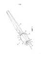
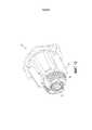
[0014] Фиг.1 это вид в спереди в изометрии осветительного устройства, расположенного на инструменте со стержнем инструмента, проходящим через осветительное устройство;[0014] FIG. 1 is an isometric front view of a lighting device located on a tool with a tool shaft extending through the lighting device;

[0015] Фиг.2 - вид справа осветительного устройства по Фиг.1, соединенного с инструментом;[0015] FIG. 2 is a right side view of the lighting device of FIG. 1 connected to a tool;

[0016] Фиг.3 - вид в спереди в изометрии осветительного устройства по Фиг.1;[0016] FIG. 3 is an isometric front view of the lighting device of FIG. 1;

[0017] Фиг.4 - вид сзади в изометрии осветительного устройства по Фиг.1;[0017] FIG. 4 is an isometric rear view of the lighting device of FIG. 1;

[0018] Фиг.5 - вид справа осветительного устройства по Фиг.1;[0018] Figure 5 is a right side view of the lighting device of Figure 1;

[0019] Фиг.6 - вид спереди осветительного устройства по Фиг.1;[0019] Figure 6 is a front view of the lighting device of Figure 1;

[0020] Фиг.7 - вид сзади осветительного устройства по Фиг.1;[0020] FIG. 7 is a rear view of the lighting device of FIG. 1;

[0021] Фиг.8 - вид сзади в изометрии в разрезе по линии А-А на Фиг.4 осветительного устройства по Фиг.1;[0021] FIG. 8 is a cross-sectional isometric rear view along line AA in FIG. 4 of the lighting device of FIG. 1;

[0022] Фиг.9 - вид в разрезе по линии B-B на Фиг.6 осветительного устройства по Фиг.1;[0022] FIG. 9 is a sectional view taken along line B-B in FIG. 6 of the lighting device of FIG. 1;

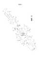
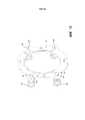
[0023] Фиг.10 - вид осветительного устройства по Фиг.1 в разобранном виде;[0023] Figure 10 is an exploded view of the lighting device of Figure 1;

[0024] Фиг.11 - вид сзади в изометрии поперечного сечения по линии С-С на Фиг.10 внешнего корпуса осветительного устройства по Фиг.1;[0024] FIG. 11 is a rear isometric view of the cross section along line CC in FIG. 10 of the outer housing of the lighting device of FIG. 1;

[0025] Фиг.12 - вид спереди в изометрии внутреннего каркаса, помещенного внутри внешнего корпуса осветительного устройства по Фиг.1;[0025] Fig. 12 is a front isometric view of an inner frame placed inside the outer casing of the lighting device of Fig. 1;

[0026] Фиг.13 - вид сзади в изометрии первой пластины осветительного устройства по Фиг.1 с расположенным на нем источником света;[0026] FIG. 13 is an isometric rear view of a first plate of the lighting device of FIG. 1 with a light source located thereon;

[0027] Фиг.14 это вид спереди в изометрии второй пластины осветительного устройства по Фиг.1;[0027] FIG. 14 is an isometric front view of a second plate of the lighting device of FIG. 1;

[0028] Фиг.15 это вид сзади в изометрии второй пластины осветительного устройства по Фиг.14;[0028] FIG. 15 is an isometric rear view of a second plate of the lighting device of FIG. 14;

[0029] Фиг.16 - вид сбоку сборки первой пластины, второй пластины и источника питания, расположенного между пластинами осветительного устройства по Фиг.1;[0029] FIG. 16 is a side view of the assembly of the first plate, the second plate, and the power source located between the plates of the lighting device of FIG. 1;

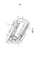
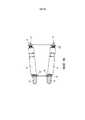
[0030] Фиг.17 - вид спереди в изометрии другого варианта осуществления осветительного устройства, закрепленного на инструменте заплечиком, проходящим вокруг периферии стержня инструмента;[0030] FIG. 17 is a front isometric view of another embodiment of a lighting device mounted on a tool with a shoulder extending around the periphery of the tool shaft;

[0031] Фиг.18 - вид в изометрии другого материала еще одного варианта осуществления осветительного устройства, которое включает в себя разъемную втулку; и[0031] Fig. 18 is an isometric view of another material of yet another embodiment of a lighting device that includes a detachable sleeve; and

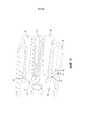
[0032] Фиг.19 - вид в изометрии еще одного варианта осуществления осветительного устройства, включающего в себя выступы, проходящие внутрь от втулки для закрепления устройства к инструменту с возможностью отсоединения.[0032] FIG. 19 is an isometric view of yet another embodiment of a lighting device including protrusions extending inwardly from a sleeve for securing the device to a detachable device.

Подробное описание вариантов осуществления изобретенияDetailed Description of Embodiments

[0033] Настоящее изобретение будет более подробно описано ниже со ссылкой на сопроводительные чертежи, на которых показаны варианты осуществления изобретения. Изобретение может, тем не менее, быть реализовано посредством многих других вариантов его осуществления и не должно ограничиваться вариантами осуществления, показанными в настоящем описании.[0033] The present invention will be described in more detail below with reference to the accompanying drawings, in which embodiments of the invention are shown. The invention can, however, be implemented by many other options for its implementation and should not be limited to the options for implementation shown in the present description.

[0034] Как показано в варианте осуществления изобретения по Фиг.1 и 2, беспроводное осветительное устройство, в целом обозначенное ссылочным номером 10, съемно установлено на и над частью дистального конца инструмента 12. Стержень 14 инструмента 12 может впоследствии проходить через отверстие, проходящее от проксимального конца к дистальному концу осветительного устройства 10 так, чтобы устройство 10 охватывало инструмент 12. В показанном варианте осуществления изобретения инструментом 12 является ручка BOVIE® и стержень 14 является скальпелем ручки BOVIE®. Однако, настоящее изобретение может быть установлено на многих различных типах инструментов, как хирургических, так и нехирургических, различных форм и размеров. Специалист в данной области техники при ознакомлении с настоящим подробным описанием изобретения поймет, что размеры и форма осветительного устройства 10 и его различные признаки могут меняться для размещения и установки на желаемом инструменте.[0034] As shown in the embodiment of the invention of FIGS. 1 and 2, a wireless lighting device, generally designated 10, is removably mounted on and above a portion of the distal end of thetool 12. Theshaft 14 of thetool 12 may subsequently pass through an opening extending from the proximal end to the distal end of thelighting device 10 so that thedevice 10 covers thetool 12. In the shown embodiment, thetool 12 is a BOVIE® handle and theshaft 14 is a scalpel of the handle BOVIE®. However, the present invention can be installed on many different types of instruments, both surgical and non-surgical, of various shapes and sizes. A person skilled in the art, upon reading this detailed description of the invention, will understand that the size and shape of thelighting device 10 and its various features can vary for placement and installation on the desired tool.

[0035] В общем, как только осветительное устройство 10 с фрикционным взаимодействием устанавливается в заданное положение на инструменте 12, направленный поток света автоматически проецируется устройством 10. Осветительное устройство 10 может быть выключено и отсоединено от инструмента 12 путем приложения осевого усилия на проксимальном конце осветительной насадки 10, которое в свою очередь отсоединяет осветительное устройство 10 от инструмента 12. В варианте осуществления изобретения осветительное устройство может альтернативно включать в себя переключатель вкл/выкл или кнопку для управления источником света.[0035] In general, as soon as thelighting device 10 with frictional interaction is set to a predetermined position on thetool 12, the directional light stream is automatically projected by thedevice 10. Thelighting device 10 can be turned off and disconnected from thetool 12 by applying axial force to the proximal end of thelighting nozzle 10, which in turn disconnects thelighting device 10 from thetool 12. In an embodiment of the invention, the lighting device may alternatively include On / off switch or button to control the light source.

[0036] Фиг.3-7 показывают различные виды и признаки осветительного устройства 10. Как будет более подробно описано ниже осветительное устройство 10 обычно включает в себя корпус 16, по меньшей мере, один источник 18 света, первую пластину 20, каркас 22, вторую пластину 24, втулку 26 и источник 28 питания.[0036] FIGS. 3-7 show various types and features of alighting device 10. As will be described in more detail below, alighting device 10 typically includes ahousing 16, at least onelight source 18, afirst plate 20, aframe 22, a second theplate 24, thesleeve 26 and thepower source 28.

[0037] Как показано на Фиг.3-7 и 10, корпус 16 включает в себя первый элемент 30 корпуса и второй элемент 32 корпуса, который может располагаться в пределах первого элемента 30 корпуса или в противном случае является соединяемым с первым элементом 30 корпуса для образования корпуса 16. В некоторых вариантах осуществления изобретения первый элемент 30 корпуса и второй элемент 32 корпуса образуют по существу герметичный контур по текучей среде, когда они соединены таким образом, чтобы защищать внутренние компоненты от проникновения текучей среды в корпус 16. Хотя корпус 16 включает в себя два элемента 30, 32 корпуса в представленном варианте осуществления изобретения корпус 16 может легко быть сделан из одного цельного элемента вместо двух независимых элементов.[0037] As shown in FIGS. 3-7 and 10, thehousing 16 includes afirst housing element 30 and asecond housing element 32, which may be located within thefirst housing element 30 or otherwise be connected to thefirst housing element 30 forhousing 16. In some embodiments, thefirst housing element 30 and thesecond housing element 32 form a substantially sealed fluid circuit when they are connected so as to protect internal components from the ingress of fluid into thehousing p 16. Although thehousing 16 includes twohousing elements 30, 32 in the present embodiment, thehousing 16 can easily be made of one integral element instead of two independent elements.

[0038] Первый элемент 30 корпуса включает в себя отверстие 34, проходящее от проксимального конца к дистальному концу так, чтобы образовать внутреннюю полость, множество утолщений 36, которые выступают наружу по внешней периферии первого элемента 30 корпуса и углубление 38, проходящее внутрь у дистального конца корпуса 16 по направлению к проксимальному концу. Источник света 18 расположен в углублении 38. Таким образом, углубление 38 защищает источник света 18 от контакта с внешними поверхностями. Наоборот, углубление 38 помогает ограничить или предохранить источник света 18 от контакта с внешними поверхностями, такими как ткань, которая может быть повреждена от прямого контакта с источником света 18. Углубление 38 также помогает направлять источник света 18 на конкретную освещаемую поверхность. В некоторых вариантах осуществления изобретения поверхности углубления 38 могут быть выполнены или покрыты отражающим материалом и в сочетании с формой углубления, как поймет средний специалист в данной области техники, будут перенаправлять световое излучение от источника света 18 для дальнейшего направления или управления освещением.[0038] Thefirst housing element 30 includes anopening 34 extending from the proximal end to the distal end so as to form an internal cavity, a plurality ofbulges 36 that protrude outwardly on the outer periphery of thefirst housing element 30, and arecess 38 extending inwardly at thedistal end body 16 towards the proximal end. Thelight source 18 is located in therecess 38. Thus, therecess 38 protects thelight source 18 from contact with external surfaces. Conversely, arecess 38 helps to limit or prevent thelight source 18 from contacting external surfaces, such as a fabric that may be damaged from direct contact with thelight source 18. Therecess 38 also helps direct thelight source 18 toward a particular illuminated surface. In some embodiments of the invention, the surfaces of therecess 38 can be made or coated with reflective material and, in combination with the shape of the recess, as one of ordinary skill in the art will recognize, redirect light from alight source 18 to further direct or control lighting.

[0039] В некоторых вариантах осуществления изобретения источник света 18 включает в себя множество светодиодных ламп, расположенных по периферии дистального конца первого элемента 30 корпуса. Светодиодные лампы могут излучать белый свет или УФ свет для освещения, например, УФ-люминесцентных красок или материалов. Как показано на Фиг.3, 5, 9, 10, 13 и 16 используются две светодиодные лампы. Две светодиодные лампы гарантируют, что осветительное устройство 10 способно направлять достаточно света на конкретное пространство для освещения требуемой области при разумном потреблении энергии с сохранением профиля потока устройства 10 для обеспечения пользователю незаблокированного обзора, ограничивая вес и стоимость осветительного устройства. Однако, как будет понятно специалисту в данной области техники, любое количество осветителей может быть использовано, в зависимости от нужд потребителя и любой источник света, который известен или может стать известным, может быть использован вместо светодиодных ламп, таких как фотолюминесцентные, хемолюминесцентные, электролюминесцентные, пальчиковые источники света типа «снэплайт» и пальчиковые источники света на основе лампочки накаливания. В дальнейшем, как видно из чертежей, осветители 18 распределены в устройстве 10 по существу равномерно под углами. Это помогает более равномерно распределить свет. Однако, изобретение охватывает любое подходящее расположение осветителей 18.[0039] In some embodiments, thelight source 18 includes a plurality of LED lamps located at the periphery of the distal end of thefirst housing element 30. LED lamps can emit white light or UV light to illuminate, for example, UV fluorescent inks or materials. As shown in FIGS. 3, 5, 9, 10, 13 and 16, two LED lamps are used. Two LED lamps ensure that thelighting device 10 is capable of directing enough light to a specific space to illuminate the desired area with reasonable energy consumption while maintaining the flow profile of thedevice 10 to provide the user with an unobstructed view, limiting the weight and cost of the lighting device. However, as one skilled in the art will understand, any number of illuminators can be used, depending on the needs of the consumer, and any light source that is known or may become known can be used instead of LED lamps, such as photoluminescent, chemoluminescent, electroluminescent, “fingerlight” type finger light sources and finger light sources based on incandescent bulbs. In the future, as can be seen from the drawings, theilluminators 18 are distributed in thedevice 10 essentially evenly at angles. This helps to distribute the light more evenly. However, the invention covers any suitable arrangement ofilluminators 18.

[0040] Устройство 10 может быть съемно прикрепляемым к инструменту 12 или объекту с использованием различных крепежных механизмов. В варианте осуществления изобретения, показанном на Фиг.8 и 11, осветительное устройство 10 может включать в себя множество выступов 40, которые расположены в пазах 42, сформированных в корпусе 16 для съемного прикрепления осветительного устройства 10 к инструменту 14. Выступы 40 закреплены внутри пазов 42 размещенными под углом стопорами 43, которые обеспечивают фрикционный контакт с выступами 40 проходящими внутрь под углом в пазах 42 от внутренней периферии корпуса 16. Выступы 40 также закреплены внутри пазов 42 выступами 44, которые выступают из второго элемента 32 корпуса и выполнены с возможностью контакта с выступами 40. В показанном варианте осуществления изобретения выступы 40 ориентированы под передним углом, вершина которого направлена к дистальному концу устройства 10. Они могут быть подпружинены. Выступы 40 включают в себя первую часть 46, вторую часть 48 проходящую от первой части 46 под передним углом, и хвостовик 50, проходящий от второй части 48 под меньшим передним углом. Выступ 40 и хвостовик 50 расположены так и имеют такую форму, чтобы контактировать с внешней поверхностью инструмента 12, когда устройство 10 установлено на инструменте 12.[0040] Thedevice 10 may be removably attached to thetool 12 or an object using various mounting mechanisms. In the embodiment shown in FIGS. 8 and 11, thelighting device 10 may include a plurality ofprotrusions 40 that are located ingrooves 42 formed in thehousing 16 for removably attaching thelighting device 10 to thetool 14. Theprotrusions 40 are fixed inside thegrooves 42angled stoppers 43 that provide frictional contact with theprotrusions 40 extending inwardly at an angle in thegrooves 42 from the inner periphery of thehousing 16. Theprotrusions 40 are also secured within thegrooves 42 with theprotrusions 44 that protrude from the second ofelement 32 of the housing and adapted to contact with theprotrusions 40. In the illustrated embodiment, theprotrusions 40 oriented at a rake angle, the vertex of which is directed to the distal end of thedevice 10. They may be spring-loaded. Theprotrusions 40 include afirst part 46, asecond part 48 extending from thefirst part 46 at a rake angle, and ashank 50 extending from thesecond part 48 at a smaller rake angle. Theprotrusion 40 and theshank 50 are arranged and are shaped so as to contact the outer surface of thetool 12 when thedevice 10 is mounted on thetool 12.

[0041] Контакт между хвостовиками 50 и инструментом 12 удерживает устройство 10 на инструменте 12. Контакт между хвостовиком 50 и внешней поверхностью инструмента 12 создает трение, которое помогает предотвратить относительное скользящее перемещения устройства 10 и инструмента 12. Величина силы трения зависит частично от силы, которую хвостовик 50 прикладывает к инструменту 12. Сила зависит от степени взаимодействия инструмента 12 и хвостовика 50 и пружинящих характеристик выступов 40. Что касается первого, то чем больше взаимодействие, то есть, чем больше внешняя поверхность инструмента 12 по отношению к пространству между хвостовиками 50 в их несжатом состоянии, тем больше поверхность инструмента будет сжимать выступы 40, например наружу в варианте осуществления изобретения по Фиг.8, и тем больше противодействующая пружинная сила будет на инструменте 12. Что касается последнего, то пружинные характеристики выступа 40 зависят от пружинных характеристик материала, из которого выступ 40 изготовлен и от конфигурации самого выступа 40. Как видно на Фиг.8, вторая часть 48 выполняет функцию плеча рычага относительно первой части 46. Эффективный пружинный коэффициент выступа уменьшается с увеличением длины и переднего угла второй части 48.[0041] The contact between theshank 50 and thetool 12 holds thedevice 10 on thetool 12. The contact between theshank 50 and the outer surface of thetool 12 creates friction, which helps to prevent relative sliding movements of thedevice 10 andtool 12. The magnitude of the friction force depends in part on the force that ashank 50 is applied to thetool 12. The force depends on the degree of interaction of thetool 12 and theshank 50 and the spring characteristics of theprotrusions 40. As for the first, the greater the interaction, that is, the more the further the outer surface of thetool 12 is relative to the space between theshanks 50 in their uncompressed state, the more the surface of the tool will compress theprotrusions 40, for example, outward in the embodiment of FIG. 8, and the more the opposing spring force will be on thetool 12. As for of the latter, the spring characteristics of theprotrusion 40 depend on the spring characteristics of the material from which theprotrusion 40 is made and on the configuration of theprotrusion 40 itself. As can be seen in Fig. 8, thesecond part 48 performs the function of the shoulder p the lever relative to thefirst part 46. The effective spring coefficient of the protrusion decreases with increasing length and rake angle of thesecond part 48.

[0042] Как понятно среднему специалисту в данной области техники величина силы трения может контролироваться, частично путем выбора конфигурации выступа 40 и материала, из которого выступ 40 изготовлен. Соответственно, фрикционная удерживающая сила на устройство 10 может быть достаточной для предотвращения непреднамеренного отсоединения устройства 10 от инструмента 12 в ожидаемых условиях эксплуатации. Выступ 40 может таким образом быть изготовлен из металла, пластика, углеволокна или любого другого подходящего материала, который известен или будет известен.[0042] As one of ordinary skill in the art understands, the magnitude of the friction force can be controlled, in part by selecting the configuration of theprotrusion 40 and the material from which theprotrusion 40 is made. Accordingly, the frictional holding force on thedevice 10 may be sufficient to prevent thedevice 10 from being unintentionally disconnected from thetool 12 under the expected operating conditions. Theprotrusion 40 may thus be made of metal, plastic, carbon fiber or any other suitable material that is known or will be known.

[0043] Сила трения также частично зависит от коэффициента трения материала хвостовика 50, который контактирует с инструментом 12. Например, если требуется высокая сила трения, хвостовик может быть изготовлен из материала с относительно высоким коэффициентом трения, такого как резина или другой эластомерный материал, или включать в себя втулку, концевой колпачок или покрытие на, или по контактной поверхности хвостовика для обеспечения требуемого трения и силы сцепления. Например, если выступ 40 изготовлен из металла или пластика, это может придать прочность и требуемые пружинные свойства выступу 40, но обеспечивает контактную поверхность с малым коэффициентом трения с инструментом. Хвостовик 50 может быть покрыт или же содержать материал, например, резину, имеющий более высокий коэффициент трения для обеспечения требуемых фрикционных характеристик.[0043] The friction force also partially depends on the coefficient of friction of the material of theshank 50, which is in contact with thetool 12. For example, if high friction force is required, the shank can be made of a material with a relatively high coefficient of friction, such as rubber or other elastomeric material, or include a sleeve, end cap, or coating on, or along the contact surface of the shank to provide the required friction and traction. For example, if theprotrusion 40 is made of metal or plastic, this can give strength and the required spring properties to theprotrusion 40, but provides a contact surface with a low coefficient of friction with the tool. Theshank 50 may be coated or contain material, for example rubber, having a higher coefficient of friction to provide the required frictional characteristics.

[0044] В том случае если внешняя поверхность инструмента 12 изготовлена из относительно мягкого материала и хвостовик 50 изготовлен из достаточно твердого материала или имеет форму заостренной структуры, например, имеет острую кромку, хвостовик 50 может до определенной степени деформировать внешнюю поверхность инструмента 12, например, «проникать» в нее так, чтобы далее закреплять устройство 10 в дополнение к просто фрикционному сцеплению. Изобретатель обнаружил, что даже небольшая деформация, во многих случаях, недостаточная для того, чтобы нанести ущерб инструменту 12, значительно усиливает закрепление устройства 10.[0044] In the event that the outer surface of thetool 12 is made of relatively soft material and theshank 50 is made of sufficiently hard material or has the shape of a pointed structure, for example, has a sharp edge, theshank 50 may deform the outer surface of thetool 12 to a certain extent, for example, “Penetrate” it so as to further secure thedevice 10 in addition to simply friction clutch. The inventor found that even a slight deformation, in many cases, insufficient to damage thetool 12, greatly enhances the fastening of thedevice 10.

[0045] В показанном варианте осуществления изобретения передний угол второй части 48 обеспечивает самофиксирующий или расклинивающий эффект против отсоединения устройства 10 от инструмента 12, в то же время не препятствуя полностью установке. Как лучше всего видно на Фиг.8, при вставке устройства 10 на инструмент 12 (или, наоборот, при вставке инструмента 12 через полость/отверстие в устройство 10), когда внешняя поверхность инструмента 12 контактирует с хвостовиками 50, это оказывает усилие на хвостовики 50 и, как следствие, на выступы 40 в дистальном направлении. Это смещает выступы 40 вперед (дистально) и наружу так, чтобы удерживающая сила на инструмент 12 была скорректирована. С другой стороны, при попытке переместить части в противоположном направлении (на Фиг.8 инструмент 12 соответственно смещен вправо и устройство 10 соответственно смещено влево), контакт между поверхностью инструмента 12 и хвостовиком 50 обеспечивает проксимальную (направленную назад) силу на хвостовики 50 и, как следствие, на выступы 40. Это смещает выступы в обратном направлении (проксимально) и внутрь, увеличивая усилие выступов 40 на инструмент 12, например, расклинивая выступы 40 с упором в инструмент 12 и усиливая закрепление устройства 10 на инструменте 12. Данное действие помогает предотвратить непреднамеренное отсоединение инструмента 12 и устройства 10.[0045] In the shown embodiment, the rake angle of thesecond part 48 provides a self-locking or proppant effect against disconnecting thedevice 10 from thetool 12, while not completely obstructing the installation. As best seen in FIG. 8, when inserting thedevice 10 onto the tool 12 (or, conversely, when inserting thetool 12 through the cavity / hole into the device 10), when the outer surface of thetool 12 is in contact with theshanks 50, this exerts a force on theshanks 50 and, as a consequence, on theprotrusions 40 in the distal direction. This biases theprotrusions 40 forward (distal) and outward so that the holding force on thetool 12 is adjusted. On the other hand, when you try to move the parts in the opposite direction (in Fig. 8, thetool 12 is respectively shifted to the right and thedevice 10 is accordingly shifted to the left), the contact between the surface of thetool 12 and theshank 50 provides proximal (backward) force on theshanks 50 and, as the consequence, on theprotrusions 40. This shifts the protrusions in the opposite direction (proximal) and inward, increasing the force of theprotrusions 40 on thetool 12, for example, wedging theprotrusions 40 with an emphasis on thetool 12 and strengthening the fastening of thedevice 10 to theins Chimney 12. This action helps prevent thetool 12 anddevice 10 from being unintentionally disconnected.

[0046] Как видно в представленном варианте осуществления изобретения, в частности на Фиг.8 и 9, втулка 26 размещена внутри каркаса 22, а каркас 22 размещен внутри корпуса 16. Втулка 26 включает в себя фланец 26, проходящий наружу на проксимальном конце и поверхность 64 с бороздками дистального конца. Поверхность 64 с бороздками упирается или находится рядом с второй частью 48 выступа. Для отсоединения осветительного устройства 10 от инструмента 12 пользователь прилагает усилие к фланцу 62 в дистальном направлении, которое заставляет втулку 26 сгибаться или перемещаться в осевом направлении к дистальному концу осветительного устройства 10. Поверхности 64 с бороздками контактируют со второй частью 48 и выполняют функцию клина или ската, взаимодействуя со второй частью 48. Это создает как направленное вперед (дистальное), так и радиально-внешнее усилия на вторую часть 48, что отклоняет вторую часть 48, например, из соединения с инструментом 12 и/или препятствуют вышеописанному действию расклинивания на выступ 40 во время снятия. Затем устройство 10 может быть отсоединено от инструмента 12. В представленном варианте осуществления изобретения втулка 26 и фланец 62 проходят наружу за пределами корпуса 16 (проксимально) и образуют проксимальный конец устройства 10. Таким образом, чтобы отсоединить устройство 10 от инструмента 12 пользователь воздействует на задний (проксимальный) конец устройства, например, фланец и перемещает устройство 10 дистально (вперед). Если стержень 14 слишком велик для устройства 10, чтобы он мог быть снят вместе с устройством 10 с инструмента 12, стержень 14 снимается с инструмента 12, чтобы затем отсоединить устройство 10.[0046] As can be seen in the presented embodiment of the invention, in particular in Figs. 8 and 9, thesleeve 26 is placed inside theframe 22, and theframe 22 is placed inside thehousing 16. Thesleeve 26 includes aflange 26 extending outward at the proximal end and surface 64 with grooves of the distal end. The grooved surface 64 abuts or is adjacent to thesecond protrusion portion 48. To disconnect thelighting device 10 from thetool 12, the user exerts a force on theflange 62 in the distal direction, which causes thesleeve 26 to bend or move axially to the distal end of thelighting device 10. The grooved surfaces 64 are in contact with thesecond part 48 and act as a wedge or ramp interacting with thesecond part 48. This creates both forward (distal) and radial-external forces on thesecond part 48, which rejects thesecond part 48, for example, from the connection with trumentom 12 and / or prevent the above-described wedging action on theprojection 40 during removal time. Then, thedevice 10 can be disconnected from thetool 12. In the presented embodiment, thesleeve 26 and theflange 62 extend outwardly outside the housing 16 (proximally) and form the proximal end of thedevice 10. Thus, to disconnect thedevice 10 from thetool 12, the user acts on the back the (proximal) end of the device, for example, a flange, and moves thedevice 10 distally (forward). If theshaft 14 is too large for thedevice 10 to be able to be removed together with thedevice 10 from thetool 12, theshaft 14 is removed from thetool 12, then to disconnect thedevice 10.

[0047] В представленном варианте осуществления изобретения втулка 26 сужается к концу с образованием по существу конической или сужающейся формы для прохождения над дистальным концом инструмента 12, имеющим по существу коническую или сужающуюся форму. Однако, как будет понятно специалисту в данной области техники, втулка 26 может иметь любую известную форму для соответствия форме инструмента 12, на котором должна быть расположена втулка 26. Например, если инструмент 12 имеет цилиндрическую форму или устройство 10 должно быть прикреплено к цилиндрическому стержню 14 инструмента 12, вместо его прикрепления к дистальному концу инструмента 14, то втулка 26 может быть цилиндрической формы, чтобы по существу, соответствовать контуру инструмента 12 и/или стержня 14.[0047] In the present embodiment, thesleeve 26 tapers toward the end to form a substantially conical or tapering shape to extend over the distal end of thetool 12 having a substantially conical or tapering shape. However, as one skilled in the art will understand, thesleeve 26 may have any known shape to match the shape of thetool 12 on which thesleeve 26 should be located. For example, if thetool 12 is cylindrical in shape or thedevice 10 should be attached to thecylindrical rod 14tool 12, instead of attaching it to the distal end of thetool 14, thesleeve 26 may be cylindrical in order to substantially match the contour of thetool 12 and / or theshaft 14.

[0048] Средний специалист в данной области техники должен понимать, что, хотя в представленном варианте осуществления изобретения используются наклоненные подпружиненные выступы, выступы 40 могут иметь большое количество структурных конфигураций, при этом обеспечивая достаточную силу сцепления, такую, при которой устройство 10, не может быть отсоединено без приложения к втулке 26 ручного усилия. Например, в некоторых вариантах осуществления изобретения выступы 40 не являются подпружиненными, но являются относительно жесткими и пластически деформируемыми. В таких вариантах осуществления изобретения выступы 40 могут быть пластически деформированными, при установке устройства 10 на инструмент 12 и/или при отсоединении устройства 10 от инструмента 12. В результате этого, поскольку для деформации выступов 40 требуется определенная величина усилия, прилагаемого к выступам 40, устройство 10 не будет непреднамеренно отсоединено от инструмента 12, но обычно это будет происходить только при приложении намеренного рассоединяющего усилия определенной величины к устройству 10. В других вариантах осуществления изобретения выступы 40 могут быть выполнены разрушаемыми или отделяемыми от корпуса 16 при приложении определенной величины отсоединяющего усилия к устройству 10 (и таким образом к выступам 40). Сломавшись или отделившись, выступы 40 не будут удерживать устройство 10 на инструменте 12. Средний специалист в данной области техники должен понимать, что выступы 40 могут иметь выбранный уровень величины отсоединяющего усилия, например, усилия, при котором выступы 40 будут достаточным образом деформироваться, ломаться или отделяться, чтобы позволить устройству 10 отсоединиться от инструмента 12. В качестве примера выступы 40 могут содержать ослабленный элемент или область, где выступ 40 выполнен с возможностью деформации, излома или отделения при заданном и/или выбранном усилии.[0048] A person of ordinary skill in the art should understand that although tilted spring-loaded protrusions are used in the present embodiment, theprotrusions 40 can have a large number of structural configurations, while providing sufficient traction such that thedevice 10 cannot be disconnected without applying manual force tosleeve 26. For example, in some embodiments of the invention, theprotrusions 40 are not spring loaded, but are relatively rigid and plastically deformable. In such embodiments, theprotrusions 40 may be plastically deformed when thedevice 10 is mounted on thetool 12 and / or when thedevice 10 is disconnected from thetool 12. As a result, since theprotrusions 40 require a certain amount of force to be applied to theprotrusions 40, thedevice 10 will not be inadvertently disconnected from thetool 12, but usually this will only happen when a deliberate disconnecting force of a certain magnitude is applied to thedevice 10. In other embodiments, According to the invention, theprotrusions 40 can be made destructible or detachable from thehousing 16 by applying a certain amount of releasing force to the device 10 (and thus to the protrusions 40). Having broken or separated, theprotrusions 40 will not hold thedevice 10 on thetool 12. The average person skilled in the art should understand that theprotrusions 40 may have a selected level of releasing force, for example, the force at which theprotrusions 40 will be sufficiently deformed, broken or detach to allow thedevice 10 to detach from thetool 12. As an example, theprotrusions 40 may comprise a weakened element or region where theprotrusion 40 is capable of deformation, fracture or separation at a predetermined and / or selected force.

[0049] В дополнение к этому другие механизмы крепления и/или смещающие элементы могут быть использованы вместо выступов 40. Примеры включают, но не ограничиваются: клеевыми соединениями, предохранительными собачками, защелками или подпругами, соединителями, рычажными запорами, скобами, петельными запорами или любыми другими техническими средствами, которые известны или станут известными. Если инструмент 12 содержит материал, который способен притягиваться магнитным материалом, например, черный метал, устройство 10 может дополнительно или альтернативно включать в себя магнитные компоненты. Таким образом, устройство 10 может быть закреплено на инструменте 12 хотя бы частично за счет магнитного воздействия.[0049] In addition, other fastening mechanisms and / or biasing elements may be used in place of theprotrusions 40. Examples include, but are not limited to: adhesive joints, safety dogs, latches or girths, connectors, lever locks, brackets, loop fasteners, or any other technical means that are known or will become known. If thetool 12 contains material that is capable of being attracted by a magnetic material, such as ferrous metal, thedevice 10 may additionally or alternatively include magnetic components. Thus, thedevice 10 can be mounted on thetool 12 at least partially due to magnetic action.

[0050] Фиг.10 - это вариант осуществления осветительного устройства в разобранном виде, представляющий компоненты, которые содержит осветительное устройство 10 и их расположение внутри корпуса 16.[0050] FIG. 10 is an exploded embodiment of a lighting device representing components that comprise alighting device 10 and their location within thehousing 16.

[0051] Как показано на Фиг.10 и 16, источник питания 28 может включать в себя одну или несколько батареек. Батарейки 28, показанные на Фиг.10 и 16, являются пальчиковыми батарейками, которые обеспечивают, как правило, продольную ориентацию (проксимально-дистально) и позволяют свести к минимуму радиальный профиль (диаметр) осветительного устройства 10. Однако, любой другой тип источника питания, включая солнечные батареи или конденсаторы, который известен или станет известен, может быть использован вместо батареек. Кроме того, другие типы батареек могут быть использованы вместо пальчиковых батареек, такие как, например, батарейка в виде полоски, батарейка в виде таблетки и батарейки на основе материи. К тому же, батарейки могут быть одноразового использования или перезаряжаемыми. Батарейки одноразового использования батарейки включать в себя щелочные, углеродно-цинковые, литиевые, серебряно-цинковые или цинк-воздушные. Пальчиковая батарейка 28, показанная на Фиг.10 и 16, является литиевой батарейкой одноразового использования. Такие пальчиковые батарейки производят энергию высокой плотности (например, 800 Вт*ч/л), могут быть использованы в широком диапазоне температур (например, от -20 °C до приблизительно 60 °C), могут сохранять энергию более двух лет, имеют низкую степень разряда (например, меньше чем 1%/год), защищены от протечек, надежны и являются экологичным продуктом, который не содержит тяжелые металлы.[0051] As shown in FIGS. 10 and 16,power supply 28 may include one or more batteries. Thebatteries 28 shown in FIGS. 10 and 16 are finger-type batteries, which generally provide a longitudinal orientation (proximal-distal) and minimize the radial profile (diameter) of thelighting device 10. However, any other type of power source, including solar panels or capacitors, which is known or will become known, can be used instead of batteries. In addition, other types of batteries can be used in place of finger batteries, such as, for example, a strip battery, a tablet battery, and a fabric battery. In addition, batteries can be disposable or rechargeable. Batteries for single use batteries include alkaline, carbon-zinc, lithium, silver-zinc or zinc-air. Thefinger battery 28 shown in FIGS. 10 and 16 is a disposable lithium battery. Such finger-type batteries produce high-density energy (for example, 800 W * h / l), can be used in a wide temperature range (for example, from -20 ° C to about 60 ° C), can store energy for more than two years, have a low degree of discharge (e.g. less than 1% / year), leak proof, reliable and environmentally friendly product that does not contain heavy metals.

[0052] Фиг.11 показывает вид в разрезе по линии С-С на Фиг.10 первого варианта осуществления первого элемента 30 корпуса. Как описано выше, первый элемент 30 корпуса может содержать утолщения 36, которые выступают наружу из него для размещения профиля батареек 28, пазы 42 выполненные в первом элементе 30 корпуса для размещения выступов 40, и отверстия 34, 58, 60, сформированные в стенке 56 рядом с дистальным концом корпуса 16. Первый элемент 30 корпуса может также включать в себя множество выступов 66, проходящих внутрь для способствования соединения корпуса 16 с каркасом 22, а также О-образные кольца 68 или другие эластомерные средства могут быть расположены внутри отверстий корпуса для защиты от проникновения загрязнений или текучих сред.[0052] FIG. 11 shows a sectional view along the line CC of FIG. 10 of a first embodiment of afirst housing member 30. As described above, thefirst housing element 30 may includebulges 36 that protrude outward to accommodate the profile of thebatteries 28,grooves 42 formed in thefirst housing element 30 to accommodate theprotrusions 40, andopenings 34, 58, 60 formed in theadjacent wall 56 with the distal end of thehousing 16. Thefirst housing element 30 may also include a plurality ofprotrusions 66 extending inward to facilitate the connection of thehousing 16 to thechassis 22, as well as O-rings 68 or other elastomeric means can be located inside the holes orpusa for protection against ingress or fluids.

[0053] Как лучше всего видно на Фиг.9 и 10, первая пластина 20 расположена внутри корпуса 16 между стенкой 56 около дистального конца корпуса 16 и каркасом 22, а источники 18 света выступают наружу через отверстия 58, 60 в стенке 56 корпуса 16. Вторая пластина 24 расположена внутри корпуса 16 около проксимального конца корпуса 16.[0053] As best seen in Figures 9 and 10, thefirst plate 20 is located inside thehousing 16 between thewall 56 near the distal end of thehousing 16 and theframe 22, and thelight sources 18 protrude through theopenings 58, 60 in thewall 56 of thehousing 16. Thesecond plate 24 is located inside thehousing 16 near the proximal end of thehousing 16.

[0054] На Фиг.13 показан вариант осуществления первой пластины 20, имеющей отверстие 76 для прохождения через нее стержня 14 инструмента 12 и источники освещения 18, проходящие через множество отверстий 78, 80, 82, 84 в пластине 20 по ее периферии. Источник освещения 18 включает в себя клеммы 86, 88, проходящие через отверстия 78, 80, 82, 84 в первой пластине 20 и выполненные с возможностью подключения к множеству электрических цепей 90, 92, 94, которые прикреплены к первой пластине 20 или выполнены в ней.[0054] FIG. 13 shows an embodiment of afirst plate 20 having anopening 76 for passing through it ashaft 14 of thetool 12 andlight sources 18 passing through a plurality ofholes 78, 80, 82, 84 in theplate 20 at its periphery. Thelighting source 18 includesterminals 86, 88 extending throughopenings 78, 80, 82, 84 in thefirst plate 20 and configured to connect to a plurality ofelectrical circuits 90, 92, 94 that are attached to or formed in thefirst plate 20 .

[0055] На Фиг.14 и 15 показаны соответственно виды в изометрии спереди и сзади второй пластины 24. Вторая пластина 24 включает в себя множество электрических цепей 96, 98, 99, которые прикреплены к первой пластине 20 или выполнены в ней, множество отверстий 100, 102, 104, 106, проходящих через цепи 96, 98 и вторую пластину 24, множество пружин 108 сжатия, прикрепленных к цепям 96, 98, 99 на первой стороне второй пластины 24 у отверстий 100, 102, 104, 106, проходящих через пластину 24. Хотя в данном варианте осуществления изобретения показаны пружины 108 сжатия, другие смещающие механизмы, которые известны или могут стать известными, могут также использоваться.[0055] Figs. 14 and 15 are respectively perspective views of the front and rear of thesecond plate 24. Thesecond plate 24 includes a plurality ofelectrical circuits 96, 98, 99 that are attached to or formed in thefirst plate 20, a plurality ofholes 100 102, 104, 106 passing through thechains 96, 98 and thesecond plate 24, a plurality of compression springs 108 attached to thechains 96, 98, 99 on the first side of thesecond plate 24 at theholes 100, 102, 104, 106 passing through theplate 24. Although compression springs 108 are shown in this embodiment, other biasing mechanisms Isms that are known or may become known may also be used.

[0056] Как можно увидеть на Фиг.16 множество источников 28 питания проходят между первой пластиной 20 и второй пластиной 24, а клеммы 110 источника 28 питания проходят через отверстия 100, 102, 104, 106 во второй пластине 24. После сборки, клеммы 110 могут быть спаяны со второй стороной второй пластины 24 для фиксации источников 28 питания на месте. Пружины 108 сжатия создают контакт с проводящей внешней оболочкой источника 28 питания, которая может представлять собой, например, алюминий или сталь в сжатом состоянии. Восстанавливающее усилие пружины в пружинах 108 сжатия помогает поддерживать контакт с оболочкой источника 28 питания. Как можно также увидеть на Фиг.16 проходящие в радиальном направлении внутрь клеммы 86, 88 источников 18 света электрически не соединены между собой. Таким образом, не формируется завершенного или замкнутого контура, и как следствие питание не поступает к источникам 18 света.[0056] As can be seen in FIG. 16, a plurality ofpower sources 28 pass between thefirst plate 20 and thesecond plate 24, and theterminals 110 of thepower source 28 pass through theholes 100, 102, 104, 106 in thesecond plate 24. After assembly, theterminals 110 can be soldered to the second side of thesecond plate 24 to fix thepower sources 28 in place. Compression springs 108 make contact with the conductive outer shell ofpower source 28, which may be, for example, aluminum or steel in a compressed state. The recovery force of the spring in the compression springs 108 helps maintain contact with the shell of thepower source 28. As can also be seen in FIG. 16, the radially inwardly extendingterminals 86, 88 of thelight sources 18 are not electrically connected. Thus, a complete or closed loop is not formed, and as a result, power is not supplied to thelight sources 18.

[0057] Фиг.12 является видом в изометрии варианта осуществления каркаса 22. Каркас 22 включает в себя множество сильфонов 70, которые проходят от дистального конца каркаса 22, и проводящее кольцо или пластина 72, изготовленное из любого подходящего проводящего материала, например, проводящего метала, прикреплено к дистальному концу каркаса 22 или отлито на нем. По меньшей мере, сильфоны 70 каркаса 22 изготовлены из эластомерного материала, позволяющего каркасу 22 и/или сильфонам 70 растягиваться (удлиняться) и сжиматься (укорачиваться). Хотя каркас 22 изготовлен хотя бы частично из эластомерного материала, каркас 22 может быть изготовлен из любого другого материала, позволяющего, по меньшей мере, сильфонам 70 растягиваться и сжиматься. Каркас 22 таким образом может быть изготовлен из комбинации материалов или одного эластомерного материала.[0057] Fig. 12 is an isometric view of an embodiment of acarcass 22. Thecarcass 22 includes a plurality ofbellows 70 that extend from the distal end of thecarcass 22, and a conductive ring orplate 72 made of any suitable conductive material, for example, conductive metal attached to the distal end of theframe 22 or molded on it. At least thebellows 70 of thecarcass 22 are made of an elastomeric material that allows thecarcass 22 and / or bellows 70 to stretch (lengthen) and contract (shorten). Although theframe 22 is made at least partially of an elastomeric material, theframe 22 can be made of any other material that allows at least thebellows 70 to stretch and contract. Theframe 22 can thus be made from a combination of materials or one elastomeric material.

[0058] По периферии дистального конца каркаса 22 между сильфонами 70 проходят зазоры для целей очистки и взаимодействия с другими элементами устройства 10. Каркас 22 также включает в себя множество выступов 74, которые проходят в радиальном направлении внутрь и наружу для соединения каркаса 22 с корпусом 16 и втулку 26 для соединения каркаса 22 с другими элементами осветительного устройства 10. Далее, хотя каркас 22 и втулка 26 показаны на Фиг.10 как два независимых элемента, каркас 22 и втулка 26 могут быть выполнены как единый элемент.[0058] Along the periphery of the distal end of thecarcass 22, gaps extend between thebellows 70 for cleaning and interaction with other elements of thedevice 10. Thecarcass 22 also includes a plurality ofprotrusions 74 that extend radially inward and outward to connect thecarcass 22 to thebody 16 and asleeve 26 for connecting theframe 22 with other elements of thelighting device 10. Further, although theframe 22 and thesleeve 26 are shown in FIG. 10 as two independent elements, theframe 22 and thesleeve 26 can be made as a single element.

[0059] В начальном состоянии, предшествующем установке устройства 10 на инструмент 12, как хорошо видно на Фиг.9, сильфоны 70 в естественных условиях достаточно сжаты так, что проводящее кольцо 72 не контактирует с первой пластиной 20, например, отделено зазором от первой пластины 20. Так как проходящие в радиальном направлении внутрь клеммы 86, 88 источников света 18 не находятся в электрической связи друг с другом, электрическая цепь (как видно на Фиг.16) разомкнута и источники света не излучают свет. Сильфоны 70 имеют сильфонное кольцо 70а (как видно, например, на Фиг.10), образующее отверстие, через которое инструмент 12 проходит при установке устройства 10 на инструмент 12.[0059] In the initial state prior to the installation of thedevice 10 on thetool 12, as can be clearly seen in Fig. 9, thebellows 70 are naturally compressed so that theconductive ring 72 is not in contact with thefirst plate 20, for example, separated by a gap from thefirst plate 20. Since thelight sources 18 passing in the radial direction inside theterminals 86, 88 are not in electrical communication with each other, the electric circuit (as seen in FIG. 16) is open and the light sources do not emit light. The bellows 70 have abellows ring 70a (as seen, for example, in FIG. 10) forming a hole through which thetool 12 passes when thedevice 10 is mounted on thetool 12.

[0060] При установке осветительного устройства 10 на инструмент 12 сильфоны 70 растянуты в осевом направлении. Когда устройство 10 размещено на выбранной части дистального конца инструмента 12, оно взаимодействует с инструментом 12. При взаимодействии трение между инструментом 12 и каркасом 22, например, сильфонным кольцом 70а вызывает растяжение (удлинение) дистального конца каркаса 22, например, сильфонов 70 относительно других компонентов устройства 10. В частности, проводящее кольцо 72 перемещается в дистальном направлении относительно первой пластины 20 до тех пор, пока оно не войдет в контакт с первой пластиной 20. А именно, проводящее кольцо контактирует с проходящими в радиальном направлении внутрь клеммами 86, 88 источников света 18, вводя их в электрическую связь друг с другом. Посредством этого замыкается электрическая схема с источником 28 питания, и электричество поступает к источникам 18 света, и источники 18 света начинают вырабатывать свет.[0060] When thelighting device 10 is mounted on thetool 12, thebellows 70 are axially stretched. When thedevice 10 is placed on a selected part of the distal end of thetool 12, it interacts with thetool 12. When interacting, friction between thetool 12 and theframe 22, for example, abellows ring 70a, causes the distal end of theframe 22 to stretch (lengthen), for example, bellows 70 relative toother components devices 10. In particular, theconductive ring 72 moves distally relative to thefirst plate 20 until it comes into contact with thefirst plate 20. Namely, the conductive ring contact extending from a radiallyinward terminals 86, 88 oflight sources 18, by introducing them into electrical communication with each other. By this means, the electrical circuit is closed to thepower source 28, and electricity is supplied to thelight sources 18, and thelight sources 18 begin to generate light.

[0061] При отсоединении устройства 10 от инструмента 12 обратное действие выключает источник 18 света. Во время отсоединения усилия трения на каркас 22 и сильфоны 70 прикладываются в противоположном направлении, нежели во время установки. Эти усилия, а также восстанавливающие пружинные усилия сильфонов 70, благодаря их растяжению во время установки, приводят каркас 22, например, сильфоны 70, к сужению, которое перемещает проводящую пластину 72 в проксимальном направлении относительно других компонентов устройства 10. Проводящая пластина 72 таким образом отделяется от первой пластины 20, и от проходящих в радиальном направлении внутрь клемм 86, 88, по мере того, как сильфоны 70 сужаются или сжимаются по направлению к положению, показанному на Фиг.9. Клеммы 86, 88 выходят из электрической связи друг с другом, что размыкает цепь. Таким образом, источник света 18 больше не вырабатывает свет в случае, когда осветительное устройство 10 не прикреплено к инструменту 14.[0061] When thedevice 10 is disconnected from thetool 12, the reverse action turns off thelight source 18. During detachment, frictional forces are applied to theframe 22 and bellows 70 in the opposite direction than during installation. These forces, as well as the restoring spring forces of thebellows 70, due to their stretching during installation, lead theframe 22, for example, bellows 70, to constrict, which moves theconductive plate 72 in the proximal direction relative to the other components of thedevice 10. Theconductive plate 72 is thus separated from thefirst plate 20, and from the radially extendinginward terminals 86, 88, as thebellows 70 taper or contract toward the position shown in FIG. 9.Terminals 86, 88 exit electrical communication with each other, which opens the circuit. Thus, thelight source 18 no longer produces light when thelighting device 10 is not attached to theinstrument 14.

[0062] Следует отметить, что вышеуказанная конфигурация является лишь одним из примеров, показывающих, как источник света 18 может включаться и/или выключаться. Изобретение охватывает любой подходящий способ осуществить это, либо любым известным на данный момент способом, либо способом, который станет известным в будущем. Лишь в качестве примера осветительное устройство 10 может включать в себя переключатель или кнопку переключения, которой пользователь оперирует вручную для включения или выключения устройства 10.[0062] It should be noted that the above configuration is just one example showing how thelight source 18 can be turned on and / or off. The invention encompasses any suitable way to accomplish this, either by any method currently known, or by a method that will become known in the future. By way of example only, thelighting device 10 may include a switch or a switching button, which the user manually operates to turn thedevice 10 on or off.

[0063] Вариант осуществления изобретения, показанный на Фиг.17, представляет альтернативное беспроводное осветительное устройство 100, которое удерживается на инструменте 112 самим инструментом. Инструмент 112 имеет проксимальный конец и дистальный конец. Инструмент 112 имеет отверстие на дистальном конце для размещения стержня 114, например, скальпеля. Стержень 114 является вставляемым и удерживается корпусом инструмента 112 известным способом. В данном примере стержень 114 имеет воротничок, обод или заплечик 115, выполненные с возможностью посадки на дистальный конец инструмента 112 во время вставки.[0063] The embodiment shown in FIG. 17 is an alternativewireless lighting device 100 that is held onto thetool 112 by the tool itself.Tool 112 has a proximal end and a distal end.Tool 112 has an opening at the distal end to accommodate arod 114, for example, a scalpel. Therod 114 is inserted and held by thetool body 112 in a known manner. In this example, therod 114 has a collar, rim orshoulder 115 adapted to fit on the distal end of thetool 112 during insertion.

[0064] Признаки осветительного устройства 100 по существу такие же, как у осветительного устройства 10, исключая те, которые будут указаны. Например, устройство 100, также как и осветительное устройство 10, имеет корпус 116 и, по меньшей мере, один источник 118 света, питаемый беспроводным источником питания, и размещает инструмент через отверстие или полость, проходящую от проксимального конца к дистальному концу устройства 100. Полость имеет такую форму и выполнена так, что устройство 100 окружает ее, например, она присоединяема к заданной части инструмента 112. Как показано, устройство 100 выполнено с возможностью взаимодействия с дистальным концом инструмента 112. Таким образом, источник 118 света расположен насколько возможно близко к стержню 114, например, вблизи от оперируемой области, без вмешательства в функционирование инструмента 112.[0064] The characteristics of thelighting device 100 are essentially the same as those of thelighting device 10, excluding those that will be indicated. For example, thedevice 100, as well as thelighting device 10, has ahousing 116 and at least onelight source 118 supplied by a wireless power source and places the instrument through an opening or cavity extending from the proximal end to the distal end of thedevice 100. The cavity has such a shape and is made so that thedevice 100 surrounds it, for example, it is attached to a given part of thetool 112. As shown, thedevice 100 is configured to interact with the distal end of thetool 112. Thus, the source a light 118 located as close as possible to therod 114, e.g., near the treated area without interfering with the operation of thetool 112.

[0065] Как может быть видно из Фиг.17, корпус 116 включает в себя выступ 117, проходящий от дистального конца и вокруг сквозного отверстия в устройстве. Выступ 117 формирует обод 119 на его дистальном конце. Внутренний диаметр выступа 117 и обода 119 является достаточно большим для вмещения стержня 114 и для его вставки и установки на дистальном конце инструмента, но меньше, чем внешний диаметр воротничка 115 стержня. Соответственно, после вставки стержня 114 в инструмент несоответствие размеров между воротничком 115 и ободом 119 препятствует отсоединению устройства 100 от дистального конца инструмента 112. Стержень114 и, более конкретно, заплечик 115, закрепляет устройство 100 на инструменте. Когда стержень 114 может быть отсоединен от инструмента 112 устройство 100 может затем быть отсоединено от инструмента аналогичным способом, что описан выше в отношении осветительного устройства 10.[0065] As can be seen from FIG. 17, thehousing 116 includes aprotrusion 117 extending from the distal end and around the through hole in the device. Theprotrusion 117 forms arim 119 at its distal end. The inner diameter of theprotrusion 117 and therim 119 is large enough to accommodate therod 114 and to insert and install it on the distal end of the tool, but smaller than the outer diameter of thecollar 115 of the rod. Accordingly, after insertion of therod 114 into the tool, a size mismatch between thecollar 115 and therim 119 prevents thedevice 100 from detaching from the distal end of thetool 112. Therod 114, and more specifically, theshoulder 115, secures thedevice 100 to the tool. When therod 114 can be disconnected from thetool 112, thedevice 100 can then be disconnected from the tool in the same manner as described above with respect to thelighting device 10.

[0066] Альтернативный вариант осуществления изобретения, представленный на Фиг.18, показывает альтернативный способ удержания осветительного устройства 300 на инструменте. Признаки осветительного устройства 300 являются по существу такими же, как показаны при описании варианта осуществления осветительных устройств 10 и 100, за исключением тех, которые будут указаны. Устройство 300 включает в себя корпус 301, который включает в себя разъемную втулку 302 с прорезью 303, проходящей вдоль оси по части длины устройства от проксимального конца устройства 300 по направлению к дистальному концу устройства 300. В данном варианте осуществления изобретения корпус 301 изготовлен из, по меньшей мере, незначительно мягкого или пружинообразного материала. Полость или отверстие устройства 300 является меньшим, чем внешняя поверхность инструмента. В том случае, когда устройство 300 установлено на инструмент, разница в размерах между инструментом и полостью устройства 300 приводит к расширению паза из-за гибкости материала корпуса 301. Таким образом, полость или отверстие будут расширяться для соответствия с внешней поверхностью инструмента.[0066] An alternative embodiment of the invention shown in FIG. 18 shows an alternative method of holding thelighting device 300 on an instrument. The characteristics of thelighting device 300 are essentially the same as shown in the description of the embodiment of thelighting devices 10 and 100, with the exception of those that will be indicated. Thedevice 300 includes ahousing 301, which includes adetachable sleeve 302 with aslot 303 extending along an axis along a portion of the length of the device from the proximal end of thedevice 300 toward the distal end of thedevice 300. In this embodiment, thehousing 301 is made of at least slightly soft or springy material. The cavity or opening of thedevice 300 is smaller than the outer surface of the tool. In the case where thedevice 300 is mounted on the tool, the size difference between the tool and the cavity of thedevice 300 leads to an expansion of the groove due to the flexibility of the material of thecase 301. Thus, the cavity or hole will expand to match the outer surface of the tool.

[0067] В то же время, восстанавливающее пружинное усилие отклоненного материала корпуса 301 будет прикладывать сжимающее усилие в противоположном направлении к внешней поверхности инструмента, обеспечивая усилие закрепления и/или трения на инструмент. Данное усилие будет способствовать устройству 300 оставаться прикрепленным к инструменту. Как поймет средний специалист в данной области техники желаемое или подходящее удерживающее усилие может быть легко выбрано. Например, усилие может быть выбрано путем выбора, среди прочих вещей, как будет понятно специалисту в данной области техники, материала корпуса для обеспечения выбранной гибкости материала, путем выбора величины разницы размеров между инструментом и полостью устройства 300, что определяет величину гибкости или отклонения, необходимую для установки устройства 300 на инструмент, и путем выбора формы, размера и конфигурации прорези 303, что оказывает влияние на общую гибкость корпуса 301.[0067] At the same time, the restoring spring force of the deflected material of thehousing 301 will exert a compressive force in the opposite direction to the outer surface of the tool, providing a clamping and / or friction force to the tool. This effort will help thedevice 300 to remain attached to the tool. As one of ordinary skill in the art will understand, the desired or suitable holding force can be easily selected. For example, the force can be selected by choosing, among other things, as one skilled in the art will understand, the body material to provide the selected material flexibility, by selecting the size difference between the tool and the cavity of thedevice 300, which determines the amount of flexibility or deviation required to install thedevice 300 on the tool, and by selecting the shape, size and configuration of theslot 303, which affects the overall flexibility of thehousing 301.

[0068] Еще один вариант осуществления изобретения, показанный на Фиг.19, отображает другую альтернативную конфигурацию для закрепления осветительного устройства 400 на инструмент. Признаки осветительного устройства 400 являются по существу такими же, как показано в вариантах осуществления осветительных устройств 10, 100 и 300 за исключением тех, которые будут указаны. В данном варианте осуществления изобретения втулка 426 включает в себя множество выступов 427, проходящих от внутренней периферийной поверхности втулки 426 в радиальном направлении внутрь в полость устройства, в котором закреплен инструмент. Выступы 427 являются гибкими, сжимаемыми и/или эластомерными. Расстояние, на которое выступы 427 проходят в полость, выбрано для обеспечения разницы размеров между выступами 427 и внешней поверхностью инструмента. При вставке инструмента в полость выступы согнуты или прижаты для их соответствия инструменту. В свою очередь, восстанавливающее пружинное усилие в сжатых/согнутых выступах 427 прилагает направленное в противоположную сторону внутрь сжимающее усилие на внешнюю поверхность инструмента. Это образует захватывающее/фрикционное усилие между выступами 427 и инструментом, что способствует тому, чтобы устройство 400 оставалось во взаимодействии с инструментом. Как будет понятно для среднего специалиста в данной области техники удерживающее усилие может быть легко выбрано. Например, как будет понятно для среднего специалиста в данной области техники, усилие может быть выбрано, среди прочих вещей, путем выбора материала выступов 427 для обеспечения необходимой сжимаемости/упругости материала, а также для обеспечения необходимого коэффициента трения между выступами 427 и инструментом, и посредством выбора величины разницы размеров между инструментом и выступами 427, которая определяет величину гибкости или отклонения, необходимых для установки устройства 400 на инструмент и таким действующую в противоположном направлении сжимающее усилие. Как будет понятным для специалиста в данной области техники удерживающее усилие может быть выбрано таким образом, что осветительное устройство 400 не будет непреднамеренно отсоединено от инструмента во время использования, но будет выбрана необходимая величина усилия, прилагаемого пользователем для установки и отсоединения осветительного устройства 400.[0068] Another embodiment of the invention shown in FIG. 19 depicts another alternative configuration for fixing thelighting device 400 to an instrument. The characteristics of thelighting device 400 are essentially the same as shown in the embodiments of thelighting devices 10, 100 and 300, with the exception of those that will be indicated. In this embodiment, thesleeve 426 includes a plurality ofprotrusions 427 extending from the inner peripheral surface of thesleeve 426 in a radial direction inward into the cavity of the device in which the tool is mounted. Theprotrusions 427 are flexible, compressible and / or elastomeric. The distance that theprotrusions 427 extend into the cavity is selected to provide a size difference between theprotrusions 427 and the outer surface of the tool. When the tool is inserted into the cavity, the protrusions are bent or pressed to match the tool. In turn, the restoring spring force in the compressed /bent protrusions 427 exerts a compressive force directed in the opposite direction inward to the outer surface of the tool. This creates a gripping / frictional force between theprotrusions 427 and the tool, which helps to ensure that thedevice 400 remains in interaction with the tool. As will be appreciated by one of ordinary skill in the art, the holding force can be easily selected. For example, as one of ordinary skill in the art will understand, the force can be selected, among other things, by selecting the material of theprotrusions 427 to provide the necessary compressibility / elasticity of the material, as well as to provide the necessary coefficient of friction between theprotrusions 427 and the tool, and by selecting the size difference between the tool and theprotrusions 427, which determines the amount of flexibility or deviation required to install thedevice 400 on the tool and thus acting in the opposite direction compressive force. As will be appreciated by one skilled in the art, the holding force can be selected so that thelighting device 400 is not inadvertently disconnected from the instrument during use, but the required amount of force exerted by the user to install and disconnect thelighting device 400 is selected.

[0069] В других вариантах осуществления изобретения выступы 427 могут содержать магнитные материалы. В таких вариантах осуществления изобретения устройство 400 может быть закреплено на инструмент 12, хотя бы частично, с помощью магнитного взаимодействия. Как будет понятно для среднего специалиста в данной области техники степень магнитного взаимодействия между выступами 427 и инструментом 12 может быть выбрана, так, чтобы быть достаточной для предотвращения по существу непреднамеренного отсоединения устройства 400 от инструмента 12, но в тоже время находиться на том уровне, чтобы допустить намеренное отсоединение, когда это требуется.[0069] In other embodiments,protrusions 427 may include magnetic materials. In such embodiments, thedevice 400 may be secured to thetool 12, at least in part, by magnetic interaction. As will be understood by one of ordinary skill in the art, the degree of magnetic interaction between theprotrusions 427 and thetool 12 can be selected so as to be sufficient to prevent thedevice 400 from being unintentionally disconnected from thetool 12, but at the same time be at a level that allow intentional disconnection when required.

[0070] Осветительные устройства согласно данному изобретению обеспечивают множество преимуществ. Одно из преимуществ осветительного устройства в его размере. Осветительное устройство имеет диаметр, который заходит лишь немного за пределы периферии инструмента, чтобы позволить пользователю легко манипулировать инструментом не ухудшая или не блокируя обзор пользователя. Преимущество компактности устройства в конкретных вариантах его осуществления достигается вследствие использования пальчиковых батареек, ориентированных по существу в проксимально-дистальном направлении в устройстве.[0070] Lighting devices according to this invention provide many advantages. One of the advantages of a lighting device is its size. The lighting device has a diameter that extends only slightly beyond the periphery of the instrument to allow the user to easily manipulate the instrument without impairing or blocking the user's view. The advantage of the compactness of the device in specific variants of its implementation is achieved due to the use of finger batteries, oriented essentially in the proximal-distal direction in the device.

[0071] Еще одно преимущество заключается в том, что осветительное устройство является легко присоединяемым к инструменту и легко снимаемым с него. Как отмечалось выше, осветительное устройство может легко скользить по дистальному концу инструмента для взаимодействия с инструментом во время использования. Если пользователь хочет отсоединить осветительное устройство от инструмента пользователь всего лишь должен приложить усилие в аксиальном направлении к проксимальному концу осветительного устройства для отсоединения осветительного устройства. В тоже время возможность непреднамеренного отсоединения устройства от инструмента уменьшена.[0071] Another advantage is that the lighting device is easily attached to and easily removable from the tool. As noted above, the lighting device can easily slide along the distal end of the instrument to interact with the instrument during use. If the user wants to disconnect the lighting device from the instrument, the user only needs to exert an axial force to the proximal end of the lighting device to disconnect the lighting device. At the same time, the possibility of inadvertently disconnecting the device from the tool is reduced.

[0072] Еще одним преимуществом изобретения является то, что осветительное устройство одновременно крепится к инструменту и включает источник света, обеспечивая эффективную установку на инструменте и использование. Осветительное устройство включает в себя средство крепления, которое является присоединяемым и отсоединяемым от инструмента; в данном устройстве нет дополнительных крепежных устройств, необходимых для того, чтобы устройство не отсоединилось автоматически от инструмента во время использования.[0072] Another advantage of the invention is that the lighting device is simultaneously attached to the instrument and includes a light source, ensuring efficient installation on the instrument and use. The lighting device includes attachment means that are attachable and detachable from the tool; this device does not have additional mounting devices necessary so that the device does not automatically disconnect from the instrument during use.

[0073] Кроме того, устройства являются беспроводными с источником питания, содержащимся внутри устройства. Устройство не требует соединения посредством электрического шнура с удаленной электрической розеткой или источником питания. Провод придает громоздкость инструменту и может требовать сторонней помощи в использовании. Известные проводные устройства также могут нагреваться и обжигать пользователя и/или пациента, и возможно, могут даже стать причиной возгорания. Настоящее изобретение снижает риски ожога или возникновения возгорания.[0073] Furthermore, the devices are wireless with a power source contained within the device. The device does not require connection via an electric cord to a remote electrical outlet or power source. The wire makes the instrument bulky and may require third-party assistance in use. Known wired devices may also heat up and burn the user and / or patient, and may possibly even cause a fire. The present invention reduces the risk of burns or fires.

[0074] Еще одним преимуществом является то, что осветительное устройство согласно изобретению закрепляется к инструменту в любом желаемом или выбранном положении. Это позволяет расположить устройство оптимально, как с точки зрения освещения, так и с точки зрения функциональности инструмента.[0074] Another advantage is that the lighting device according to the invention is fixed to the tool in any desired or selected position. This allows you to position the device optimally, both in terms of lighting and in terms of tool functionality.

[0075] Как будет понятно среднему специалисту в данной области техники на основании описанных здесь приемов, многочисленные модификации могут быть выполнены в описанных выше и других вариантах осуществления изобретения без выхода за объем патентных притязаний согласно приведенной формуле изобретения. Соответственно, следует понимать, что данное подробное описание должно быть взято только в качестве примера, иллюстрирующего изобретение, и не должно быть ограничено конкретными вариантами осуществления изобретения, и что понимается, что модификации и другие варианты осуществления изобретения входят в объем патентных притязаний согласно прилагаемой формуле изобретения. Понятно, что, хотя конкретные признаки изобретения описаны в вариантах осуществления изобретения в комбинации с другими конкретными признаками, изобретение не ограничено данными комбинациями, и изобретение охватывает признаки, раскрытые в данном описании в любых возможных комбинациях. Далее, хотя в данном описании используются конкретные термины, они применяются только в обобщенном и описательном смысле, но не с ограничительной целью.[0075] As will be appreciated by one of ordinary skill in the art based on the techniques described herein, numerous modifications may be made to the above and other embodiments without departing from the scope of patent claims in accordance with the claims. Accordingly, it should be understood that this detailed description should be taken only as an example illustrating the invention, and should not be limited to specific embodiments of the invention, and that it is understood that modifications and other embodiments of the invention are included in the scope of patent claims in accordance with the attached claims . It is understood that although specific features of the invention are described in embodiments of the invention in combination with other specific features, the invention is not limited to these combinations, and the invention covers the features disclosed in this description in any possible combinations. Further, although specific terms are used in this description, they are used only in a generalized and descriptive sense, but not for a restrictive purpose.

Claims (260)

Translated fromRussian
1. Осветительное устройство для инструмента, содержащее:1. A lighting device for a tool, comprising:корпус, имеющий проксимальный конец и дистальный конец и определяющий по существу сужающуюся или коническую внутреннюю полость, проходящую от проксимального конца к дистальному концу и формирующую отверстие, проходящее через корпус от его проксимального конца к дистальному концу, причем полость выполнена для вмещения со съемным креплением заданной части сужающейся или конической части инструмента;a housing having a proximal end and a distal end and defining a substantially tapering or conical internal cavity extending from the proximal end to the distal end and forming an opening passing through the housing from its proximal end to the distal end, the cavity being made for receiving with a removable fastening of a predetermined part tapering or tapered parts of the tool;по меньшей мере один источник света, расположенный по существу на дистальном конце корпуса, причем источник света выполнен с возможностью освещения области наблюдения; иat least one light source located essentially at the distal end of the housing, and the light source is configured to illuminate the observation area; andисточник питания, расположенный в корпусе, причем источник питания выполнен с возможностью снабжения питанием по меньшей мере одного источника света для включения источника света.a power source located in the housing, and the power source is configured to supply at least one light source to turn on the light source.2. Устройство по п.1, в котором корпус, по меньшей мере, по существу по окружности окружает инструмент на заданной части.2. The device according to claim 1, in which the housing, at least essentially circumferentially surrounds the tool on a given part.3. Устройство по п.1, в котором по меньшей мере одним источником питания является пальчиковая батарейка, расположенная в корпусе таким образом, что ее продольный размер проходит по существу в направлении от проксимального конца к дистальному концу.3. The device according to claim 1, in which at least one power source is a finger battery located in the housing so that its longitudinal size extends essentially in the direction from the proximal end to the distal end.4. Устройство по п.1, в котором по меньшей мере один источник света содержит по меньшей мере одно светодиодное устройство.4. The device according to claim 1, in which at least one light source comprises at least one LED device.5. Устройство по п.1, дополнительно содержащее по меньшей мере один выступ, проходящий в полость и включающий в себя первую часть и вторую часть, проходящую под углом от первой части к дистальному концу и имеющую хвостовик, выполненный с возможностью взаимодействия с заданной частью инструмента и с возможностью съемного закрепления устройства на инструменте.5. The device according to claim 1, additionally containing at least one protrusion extending into the cavity and including the first part and the second part extending at an angle from the first part to the distal end and having a shank configured to interact with a given part of the tool and with the possibility of removable fastening of the device to the instrument.6. Устройство по п.5, дополнительно содержащее по меньшей мере одно из эластомерной втулки, проходящей над хвостовиком, и из покрытия, нанесенного, по меньшей мере, на часть хвостовика, выполненного с возможностью фрикционного контакта между хвостовиком и инструментом и с возможностью предотвращения скольжения устройства относительно инструмента.6. The device according to claim 5, additionally containing at least one of an elastomeric sleeve extending above the shank, and from a coating applied to at least a portion of the shank, made with the possibility of frictional contact between the shank and the tool and with the possibility of preventing slipping devices relative to the tool.7. Устройство по п.5, дополнительно содержащее по существу сужающуюся или коническую втулку, расположенную внутри корпуса и подвижную относительно него, причем втулка определяет полость и отверстие, фланец, проходящий наружу на проксимальном конце, причем фланец выполнен с возможностью оказания на него воздействия пользователем, и бороздку, сформированную на дистальном конце втулки, причем при перемещении втулки относительно корпуса в дистальном направлении, бороздка взаимодействует по меньшей мере с одним выступом для отсоединения по меньшей мере одного выступа от инструмента.7. The device according to claim 5, further comprising a substantially tapering or tapered sleeve located inside the housing and movable relative to it, the sleeve defining a cavity and a hole, a flange extending outward at the proximal end, the flange being configured to influence the user and a groove formed at the distal end of the sleeve, and when moving the sleeve relative to the housing in the distal direction, the groove interacts with at least one protrusion to disconnect at least one protrusion from the tool.8. Устройство по п.1, дополнительно включающее в себя по меньшей мере один выступ, проходящий в полость, причем выступ выполнен с возможностью обеспечения фрикционного контакта с заданной частью инструмента при его размещении в полости и с возможностью съемного закрепления устройства на инструменте.8. The device according to claim 1, further comprising at least one protrusion extending into the cavity, the protrusion made with the possibility of providing frictional contact with a given part of the tool when it is placed in the cavity and with the possibility of removable fastening of the device on the tool.9. Устройство по п.1, дополнительно содержащее:9. The device according to claim 1, additionally containing:электрическую цепь для подачи питания от источника питания по меньшей мере к одному источнику света, находящуюся обычно в разомкнутом состоянии, в котором питание не подается по меньшей мере к одному источнику света, и выполненную с возможностью перехода в замкнутое состояние, в котором питание подается по меньшей мере к одному источнику света; иan electrical circuit for supplying power from a power source to at least one light source, typically in an open state, in which power is not supplied to at least one light source, and configured to transition to a closed state in which power is supplied at least at least one light source; andкаркас, расположенный в корпусе, причем каркас включает в себя гибкую часть, имеющую электрически проводящую часть, причем гибкая часть выполнена с возможностью ее расширения и при ее расширении проводящая часть перемещается относительно электрической цепи от первого положения, в котором проводящая часть не замыкает обычно разомкнутую электрическую цепь, ко второму положению, в котором проводящая часть замыкает электрическую цепь и питание подается по меньшей мере к одному источнику света для включения по меньшей мере одного источника света;the frame located in the housing, and the frame includes a flexible part having an electrically conductive part, and the flexible part is made with the possibility of expansion and when it is expanded, the conductive part moves relative to the electrical circuit from the first position in which the conductive part does not close the normally open electric circuit to a second position in which the conductive part closes the electrical circuit and power is supplied to at least one light source to turn on at least one source light;причем гибкая часть имеет отверстие для размещения в нем и взаимодействия с, по меньшей мере, частью инструмента, причем при взаимодействии гибкой части с, по меньшей мере, частью инструмента, гибкая часть расширяется, и проводящая часть перемещается относительно электрической цепи из первого положения во второе положение.moreover, the flexible part has an opening for placement in it and interacting with at least part of the tool, and when the flexible part interacts with at least part of the tool, the flexible part expands and the conductive part moves relative to the electric circuit from the first position to the second position.10. Устройство по п.1, дополнительно содержащее первую пластину, расположенную в корпусе, причем пластина имеет отверстие и электронные компоненты, прикрепленные к ней, и вторую пластину, расположенную в корпусе, имеющую отверстие, электронные компоненты и множество пружин, прикрепленных к ней.10. The device according to claim 1, additionally containing a first plate located in the housing, the plate having an opening and electronic components attached to it, and a second plate located in the housing having an opening, electronic components and a plurality of springs attached to it.11. Устройство по п.10, дополнительно содержащее каркас, расположенный в корпусе, включающий в себя металлическую пластину, прикрепленную к его дистальному концу с возможностью контакта с первой пластиной для замыкания электрической цепи и включения по меньшей мере одного источника света.11. The device according to claim 10, additionally containing a frame located in the housing, including a metal plate attached to its distal end with the possibility of contact with the first plate to close the electrical circuit and turn on at least one light source.12. Устройство по п.1, дополнительно содержащее каркас, снабженный отверстием, размещенный внутри корпуса, втулку, снабженную отверстием в ней, размещенную в каркасе, и по меньшей мере один выступ, проходящий в полость, причем выступ выполнен с возможностью взаимодействия с инструментом и закрепления устройства на инструменте.12. The device according to claim 1, additionally containing a frame provided with an opening located inside the housing, a sleeve provided with an opening therein, located in the frame, and at least one protrusion extending into the cavity, the protrusion being configured to interact with the tool and securing the device to the instrument.13. Устройство по п.1, в котором источник питания ориентирован таким образом, что его наибольший размер по существу простирается в осевом направлении устройства.13. The device according to claim 1, in which the power source is oriented so that its largest size extends essentially in the axial direction of the device.14. Устройство по п.1, в котором наименьший внешний размер источника питания простирается в радиальном направлении по отношении к устройству.14. The device according to claim 1, in which the smallest external size of the power source extends in the radial direction with respect to the device.15. Устройство по п.1, в котором источник питания содержит батарейку в виде полоски, батарейку в виде таблетки и/или батарейку на основе материи.15. The device according to claim 1, in which the power source contains a battery in the form of a strip, a battery in the form of a tablet and / or a battery based on matter.16. Устройство по п.1, дополнительно содержащее первую пластину, расположенную в корпусе, причем пластина имеет отверстие и электронные компоненты, прикрепленные к ней, и проводящую пластину, по существу ориентированную в осевом направлении устройства, выполненную с возможностью контакта с первой пластиной для замыкания электрической цепи и включения по меньшей мере одного источника света.16. The device according to claim 1, additionally containing a first plate located in the housing, the plate having a hole and electronic components attached to it, and a conductive plate essentially oriented in the axial direction of the device, made with the possibility of contact with the first plate for closing electrical circuit and the inclusion of at least one light source.17. Устройство по п.1, в котором по меньшей мере один источник света выполнен с возможностью создания ультрафиолетового света.17. The device according to claim 1, in which at least one light source is configured to create ultraviolet light.18. Устройство по п.1, в котором дистальный конец содержит отражающий материал.18. The device according to claim 1, in which the distal end contains a reflective material.19. Устройство по п.1, дополнительно содержащее переключатель или кнопку для включения или выключения по меньшей мере одного источника света.19. The device according to claim 1, further comprising a switch or button for turning on or off at least one light source.20. Устройство по п.1, в котором внутренняя полость содержит гибкий, сжимаемый и/или эластомерный материал, который создает захватывающее/фрикционное усилие с инструментом для возможности сохранения взаимодействия устройства с инструментом.20. The device according to claim 1, in which the internal cavity contains a flexible, compressible and / or elastomeric material that creates an exciting / frictional force with the tool to be able to maintain interaction between the device and the tool.21. Устройство по п.1, в котором инструмент образует проксимальный конец и дистальный конец, при этом сужающаяся или коническая часть инструмента расположена смежно по отношению к дистальному концу инструмента, когда осветительное устройство установлено на инструмент, причем устройство образует проксимально по отношению к сужающейся или конической части инструмента размер, который больше размера отверстия осветительного устройства, вследствие чего полость сужающейся или конической формы выполнена с возможностью расположения только на сужающейся или конической части инструмента.21. The device according to claim 1, in which the tool forms a proximal end and a distal end, while the tapering or conical part of the tool is adjacent to the distal end of the tool when the lighting device is mounted on the tool, and the device forms proximal to the tapering or the conical part of the tool is a size that is larger than the size of the opening of the lighting device, as a result of which the cavity of a tapering or conical shape is configured to be located only on and tapering or tapered parts of the tool.22. Устройство по п.1, дополнительно содержащее по меньшей мере один выступ, проходящий в полость под острым углом по отношению к корпусу и в направлении дистального конца, и имеющее концевую часть, выполненную с возможностью взаимодействия с заданной частью инструмента и с возможностью съемного закрепления устройства на инструменте.22. The device according to claim 1, additionally containing at least one protrusion extending into the cavity at an acute angle with respect to the body and in the direction of the distal end, and having an end part configured to interact with a given part of the tool and with the possibility of removable fastening devices on the instrument.23. Устройство по п.22, дополнительно включающее втулку, расположенную внутри корпуса и подвижную относительно него и выполненную с возможностью оказания на нее воздействия пользователем, причем при перемещении втулки относительно корпуса в дистальном направлении, втулка взаимодействует по меньшей мере с одним выступом для отсоединения по меньшей мере одного выступа от инструмента.23. The device according to item 22, further comprising a sleeve located inside the housing and movable relative to it and made with the possibility of influencing it by the user, and when moving the sleeve relative to the housing in the distal direction, the sleeve interacts with at least one protrusion to disconnect at least one protrusion from the tool.24. Осветительное устройство для инструмента, содержащее:24. A lighting device for a tool, comprising:корпус, имеющий проксимальный конец и дистальный конец и ограничивающий внутреннюю полость, проходящую от проксимального конца к дистальному концу и образующую отверстие, проходящее через корпус от проксимального конца к дистальному концу, выполненное для размещения в нем, по меньшей мере, части инструмента;a housing having a proximal end and a distal end and bounding an internal cavity extending from the proximal end to the distal end and forming an opening passing through the housing from the proximal end to the distal end, designed to accommodate at least a portion of the instrument;по меньшей мере один источник света, расположенный по существу на дистальном конце корпуса, причем источник света выполнен с возможностью освещения поля наблюдения;at least one light source located essentially at the distal end of the housing, and the light source is configured to illuminate the field of view;источник питания, расположенный в корпусе, причем источник питания выполнен с возможностью обеспечения питания по меньшей мере одного источника света для включения источника света; иa power source located in the housing, and the power source is configured to provide power to at least one light source to turn on the light source; andпо меньшей мере один самофиксирующийся выступ, проходящий в полость и включающий в себя первую часть и вторую часть, проходящую под углом от первой части к дистальному концу и имеющую хвостовик, выполненный для взаимодействия с, по меньшей мере, частью инструмента и съемного закрепления устройства к инструменту.at least one self-locking protrusion extending into the cavity and including the first part and the second part extending at an angle from the first part to the distal end and having a shank configured to interact with at least a part of the tool and to removably fasten the device to the tool .25. Устройство по п.24, содержащее по меньшей мере одно из (i) самофиксирующегося подпружиненного выступа и (ii) самофиксирующегося выступа, являющегося пластически деформируемым для сохранения контакта между выступом и инструментом при размещении инструмента в полости.25. The device according to paragraph 24, containing at least one of (i) a self-locking spring-loaded protrusion and (ii) a self-locking protrusion, which is plastically deformable to maintain contact between the protrusion and the tool when placing the tool in the cavity.26. Устройство по п.24, в котором по меньшей мере один источник света выполнен с возможностью создания ультрафиолетового света.26. The device according to paragraph 24, in which at least one light source is configured to create ultraviolet light.27. Устройство по п.24, в котором дистальный конец содержит отражающий материал.27. The device according to paragraph 24, in which the distal end contains a reflective material.28. Осветительное устройство для инструмента, содержащее:28. A lighting device for a tool, comprising:корпус, имеющий проксимальный конец и дистальный конец и ограничивающий внутреннюю полость, проходящую от проксимального конца к дистальному концу и образующую отверстие, проходящее через корпус от проксимального конца к дистальному концу, выполненное для размещения в нем, по меньшей мере, части инструмента, причем корпус включает в себя воротничковую часть у проксимального конца, которая имеет размер внутреннего радиуса, меньший, чем размер внешнего радиуса, по меньшей мере, части инструмента, и ограничивает прорезь, проходящую через стенку воротничковой части от проксимального конца в направлении по существу к дистальному концу, выполненную для обеспечения расширения воротничковой части для размещения внешнего радиуса, по меньшей мере, части инструмента при размещении, по меньшей мере, части инструмента и при приложении усилия сжатия на, по меньшей мере, часть инструмента для фрикционного закрепления устройства на инструменте;a housing having a proximal end and a distal end and bounding an internal cavity extending from the proximal end to the distal end and forming an opening passing through the housing from the proximal end to the distal end, designed to accommodate at least a portion of the instrument, and the housing includes in the collar part at the proximal end, which has a size of the inner radius smaller than the size of the outer radius of at least part of the tool, and limits the slot passing through a tench of the collar portion from the proximal end in a direction substantially toward the distal end, designed to allow expansion of the collar portion to accommodate the outer radius of at least a portion of the instrument when placing at least a portion of the instrument and applying a compressive force to at least , part of the tool for frictional fastening of the device to the tool;по меньшей мере один источник света, расположенный по существу на дистальном конце корпуса, выполненный для освещения области наблюдения; иat least one light source located essentially at the distal end of the housing, made to illuminate the observation area; andисточник питания, расположенный в корпусе, выполненный для подачи питания на по меньшей мере один источник света для включения источника света.a power source located in the housing, designed to supply power to at least one light source to turn on the light source.29. Устройство по п.28, в котором по меньшей мере один источник света выполнен с возможностью создания ультрафиолетового света.29. The device according to p, in which at least one light source is configured to create ultraviolet light.30. Устройство по п.28, в котором дистальный конец содержит отражающий материал.30. The device according to p, in which the distal end contains a reflective material.31. Инструмент с осветительным устройством, выполненным с возможностью установки на инструмент,31. Instrument with a lighting device made with the possibility of installation on the instrument,причем инструмент имеет проксимальный конец и дистальный конец, и отверстие в дистальном конце инструмента;moreover, the tool has a proximal end and a distal end, and a hole in the distal end of the tool;причем корпус осветительного устройства имеет проксимальный конец и дистальный конец и ограничивает внутреннюю полость, проходящую от проксимального конца к дистальному концу корпуса, и образует отверстие, проходящее через корпус от проксимального конца к дистальному концу корпуса, выполненное для размещения в нем, по меньшей мере, части инструмента;moreover, the housing of the lighting device has a proximal end and a distal end and limits the internal cavity passing from the proximal end to the distal end of the housing, and forms a hole passing through the housing from the proximal end to the distal end of the housing, made to accommodate at least part tool;и дополнительно содержитand additionally containsстержень, выполненный с возможностью прохождения через дистальный конец отверстия корпуса и размещаемый с возможностью закрепления в отверстии инструмента, имеющий воротничок, проходящий радиально наружу от стержня, который выполнен с возможностью контакта с дистальным концом корпуса для закрепления корпуса на инструменте;a rod configured to pass through the distal end of the housing hole and placed with the possibility of fixing in the hole of the tool, having a collar extending radially outward from the rod, which is made with the possibility of contact with the distal end of the housing for fixing the housing on the tool;по меньшей мере один источник света, расположенный по существу на дистальном конце корпуса, причем источник света выполнен с возможностью освещения области наблюдения; иat least one light source located essentially at the distal end of the housing, and the light source is configured to illuminate the observation area; andисточник питания, расположенный в корпусе, который выполнен для подачи питания на по меньшей мере один источник света для включения источника света.a power source located in the housing, which is designed to supply power to at least one light source to turn on the light source.32. Инструмент по п.31, в котором по меньшей мере один источник света выполнен с возможностью создания ультрафиолетового света.32. The tool according to p, in which at least one light source is configured to create ultraviolet light.33. Инструмент по п.31, в котором дистальный конец корпуса содержит отражающий материал.33. The tool according to p, in which the distal end of the housing contains a reflective material.34. Осветительное устройство для инструмента, содержащее:34. A lighting device for a tool, comprising:корпус, имеющий проксимальный конец и дистальный конец и ограничивающий внутреннюю полость, проходящую от проксимального конца к дистальному концу и образующую отверстие, проходящее через корпус от проксимального конца к дистальному концу и выполненное для размещения в нем, по меньшей мере, части инструмента;a housing having a proximal end and a distal end and bounding an internal cavity extending from the proximal end to the distal end and forming an opening passing through the housing from the proximal end to the distal end and configured to house at least a portion of the instrument;по меньшей мере один источник света, расположенный по существу на дистальном конце корпуса, который выполнен для освещения области наблюдения;at least one light source located essentially at the distal end of the housing, which is made to illuminate the observation area;источник питания, расположенный в корпусе и выполненный для подачи питания на по меньшей мере один источник света для включения источника света;a power source located in the housing and made to supply power to at least one light source to turn on the light source;электрическую цепь для подачи питания от источника питания к по меньшей мере одному источнику света, находящуюся обычно в разомкнутом состоянии, в котором питание не подается к по меньшей мере одному источнику света и, выполненную с возможностью перехода в замкнутое состояние, в котором питание подается по меньшей мере к одному источнику света;an electrical circuit for supplying power from a power source to at least one light source, typically in an open state, in which power is not supplied to at least one light source, and configured to transition to a closed state in which power is supplied at least at least one light source;каркас, расположенный в корпусе, включающий в себя гибкую часть, имеющую электрически проводящую часть, причем гибкая часть выполнена с возможностью расширения, и при расширении, проводящая часть перемещается относительно электрической цепи из первого положения, в котором проводящая часть не замыкает обычно разомкнутую электрическую цепь, во второе положение, в котором проводящая часть замыкает электрическую цепь и питание подается по меньшей мере к одному источнику света;a frame located in the housing, including a flexible part having an electrically conductive part, the flexible part being expandable, and when expanding, the conductive part moves relative to the electric circuit from a first position in which the conductive part does not close a normally open electric circuit, in the second position, in which the conductive part closes the electric circuit and power is supplied to at least one light source;причем гибкая часть дополнительно имеет отверстие, выполненное для размещения в нем и взаимодействия с, по меньшей мере, частью инструмента, причем при взаимодействии гибкой части, по меньшей мере, с частью инструмента, гибкая часть расширяется, и проводящая часть перемещается относительно электрической цепи из первого положения во второе положение.moreover, the flexible part further has an opening made for placement in it and interacting with at least part of the tool, and when the flexible part interacts with at least part of the tool, the flexible part expands and the conductive part moves relative to the electric circuit from the first position to the second position.35. Устройство по п.34, в котором гибкая часть содержит сильфон.35. The device according to clause 34, in which the flexible part contains a bellows.36. Устройство по п.34, в котором при отсоединении, по меньшей мере, части инструмента от гибкой части, гибкая часть сужается, и проводящая часть перемещается относительно электрической цепи из второго положения по направлению к первому положению и в свою очередь размыкает электрическую цепь.36. The device according to clause 34, in which when at least part of the tool is disconnected from the flexible part, the flexible part narrows and the conductive part moves relative to the electric circuit from the second position toward the first position and in turn opens the electric circuit.37. Устройство по п.34, в котором источник питания ориентирован таким образом, что его наибольший размер по существу простирается в осевом направлении устройства.37. The device according to clause 34, in which the power source is oriented so that its largest size extends essentially in the axial direction of the device.38. Устройство по п.34, в котором наименьший внешний размер источника питания простирается в радиальном направлении по отношении к устройству.38. The device according to clause 34, in which the smallest external size of the power source extends in the radial direction with respect to the device.39. Устройство по п.34, в котором источник питания содержит батарейку в виде полоски, батарейку в виде таблетки и/или батарейку на основе материи.39. The device according to clause 34, in which the power source contains a battery in the form of a strip, a battery in the form of a tablet and / or a battery based on matter.40. Устройство по п.34, дополнительно содержащее первую пластину, расположенную в корпусе, причем пластина имеет отверстие и электронные компоненты, прикрепленные к ней, и проводящую пластину, по существу ориентированную в осевом направлении устройства, выполненную с возможностью контакта с первой пластиной для замыкания электрической цепи и включения по меньшей мере одного источника света.40. The device according to clause 34, additionally containing a first plate located in the housing, and the plate has a hole and electronic components attached to it, and a conductive plate essentially oriented in the axial direction of the device, made with the possibility of contact with the first plate to close electrical circuit and the inclusion of at least one light source.41. Устройство по п.34, в котором по меньшей мере один источник света выполнен с возможностью создания ультрафиолетового света.41. The device according to clause 34, in which at least one light source is configured to create ultraviolet light.42. Устройство по п.34, в котором дистальный конец содержит отражающий материал.42. The device according to clause 34, in which the distal end contains a reflective material.43. Устройство по п.34, дополнительно содержащее переключатель или кнопку для включения или выключения по меньшей мере одного источника света.43. The device according to clause 34, further comprising a switch or button for turning on or off at least one light source.44. Осветительное устройство для инструмента, содержащее:44. A lighting device for a tool, comprising:корпус, имеющий проксимальный конец и дистальный конец и определяющий внутреннюю полость, проходящую от проксимального конца к дистальному концу и образующую отверстие, проходящее через корпус от проксимального конца к дистальному концу, выполненное с возможностью размещения в нем, по меньшей мере, части инструмента;a housing having a proximal end and a distal end and defining an internal cavity extending from the proximal end to the distal end and forming an opening passing through the housing from the proximal end to the distal end, configured to accommodate at least a portion of the instrument;по меньшей мере один источник света, расположенный по существу на дистальном конце корпуса, причем источник света выполнен с возможностью освещения поля наблюдения;at least one light source located essentially at the distal end of the housing, and the light source is configured to illuminate the field of view;источник питания, расположенный в корпусе, причем источник питания выполнен с возможностью обеспечения питания по меньшей мере одного источника света для включения источника света; иa power source located in the housing, and the power source is configured to provide power to at least one light source to turn on the light source; andпо меньшей мере один выступ, проходящий во внутреннюю полость под углом к дистальному концу и имеющий конец, выполненный с возможностью взаимодействия, по меньшей мере, c частью инструмента и с возможностью съемного закрепления на инструменте.at least one protrusion extending into the inner cavity at an angle to the distal end and having an end configured to interact with at least a part of the tool and to be removably secured to the tool.45. Осветительное устройство для инструмента, содержащее:45. A lighting device for a tool, comprising:корпус, имеющий проксимальный конец и дистальный конец и определяющий внутреннюю полость, проходящую от проксимального конца к дистальному концу и образующую отверстие, проходящее через корпус от проксимального конца к дистальному концу, выполненное с возможностью размещения в нем, по меньшей мере, части инструмента;a housing having a proximal end and a distal end and defining an internal cavity extending from the proximal end to the distal end and forming an opening passing through the housing from the proximal end to the distal end, configured to accommodate at least a portion of the instrument;по меньшей мере один источник света, расположенный по существу на дистальном конце корпуса, причем источник света выполнен с возможностью освещения поля наблюдения;at least one light source located essentially at the distal end of the housing, and the light source is configured to illuminate the field of view;источник питания, расположенный в корпусе, причем источник питания выполнен с возможностью обеспечения питания по меньшей мере одного источника света для включения источника света; иa power source located in the housing, and the power source is configured to provide power to at least one light source to turn on the light source; andвтулку, расположенную внутри корпуса и подвижную относительно него, причем втулка определяет полость и отверстие, и ее проксимальный конец, который выполнен с возможностью оказания на него воздействия пользователем для перемещения втулки относительно корпуса в дистальном направлении.a sleeve located inside the housing and movable relative to it, and the sleeve defines a cavity and a hole, and its proximal end, which is configured to have a user influence it to move the sleeve relative to the housing in the distal direction.46. Осветительное устройство для инструмента, содержащее:46. A lighting device for a tool, comprising:корпус, имеющий проксимальный конец и дистальный конец и определяющий внутреннюю полость, проходящую от проксимального конца к дистальному концу и образующую отверстие, проходящее через корпус от проксимального конца к дистальному концу, причем отверстие выполнено с возможностью размещения в нем, по меньшей мере, части инструмента с возможностью съемного закрепления на осветительном устройстве;a housing having a proximal end and a distal end and defining an internal cavity extending from the proximal end to the distal end and forming an opening passing through the housing from the proximal end to the distal end, the opening being configured to accommodate at least a portion of the tool therein the possibility of removable fastening on the lighting device;по меньшей мере один источник света, расположенный по существу на дистальном конце корпуса, причем источник света выполнен с возможностью освещения поля наблюдения;at least one light source located essentially at the distal end of the housing, and the light source is configured to illuminate the field of view;источник питания, выполненный с возможностью обеспечения питания, которое автоматически подается к по меньшей мере одному источнику света, если, по меньшей мере, часть инструмента вмещается в отверстие и инструмент выполнен с возможностью съемного закрепления на осветительном устройстве.a power source configured to provide power that is automatically supplied to at least one light source if at least a portion of the tool fits in the hole and the tool is removably secured to the lighting device.47. Устройство по п.46, выполненное так, что источник питания не подает питание по меньшей мере к одному источнику света, если, по меньшей мере, часть инструмента не находится в отверстии.47. The device according to item 46, made so that the power source does not supply power to at least one light source, if at least part of the tool is not in the hole.48. Устройство по п.46, дополнительно содержащее электрическую цепь, выполненную с возможностью автоматической подачи питания от источника питания к по меньшей мере одному источнику света, если, по меньшей мере, часть инструмента размещается в отверстии и инструмент съемно закреплен на осветительном устройстве.48. The device according to item 46, further comprising an electrical circuit configured to automatically supply power from the power source to at least one light source if at least a portion of the tool is placed in the hole and the tool is removably fixed to the lighting device.49. Устройство по п.46, причем устройство выполнено с возможностью взаимодействия, по меньшей мере, c частью инструмента и дополнительно содержит электрическую цепь, выполненную с возможностью автоматической подачи питания от источника питания к по меньшей мере одному источнику света при взаимодействии осветительного устройства с, по меньшей мере, частью инструмента.49. The device according to item 46, the device is configured to interact with at least part of the tool and further comprises an electrical circuit configured to automatically supply power from the power source to at least one light source when the lighting device interacts with, at least part of the tool.50. Устройство по п.46, дополнительно содержащее электрическую цепь, выполненную с возможностью автоматической подачи питания от источника питания к по меньшей мере одному источнику света при съёмном закреплении инструмента на осветительном устройстве.50. The device according to item 46, additionally containing an electric circuit configured to automatically supply power from a power source to at least one light source when the tool is detachably attached to the lighting device.51. Устройство по п.46, дополнительно содержащее:51. The device according to item 46, further comprising:электрическую цепь для доставки питания от источника питания к по меньшей мере одному источнику света, причем электрическая цепь имеет разомкнутое состояние, в котором электрическая цепь разомкнута и питание не подается к по меньшей мере одному источнику света, а также имеет замкнутое состояние, в котором цепь замкнута и питание подается к по меньшей мере одному источнику света;an electric circuit for delivering power from the power source to the at least one light source, the electric circuit having an open state in which the electric circuit is open and no power is supplied to the at least one light source, and also has a closed state in which the circuit is closed and power is supplied to at least one light source;причем электрическая цепь включает электрически проводящую часть, которая выполнена с возможностью перемещения относительно корпуса из первого положения, в котором проводящая часть не замыкает разомкнутую электрическую цепь, во второе положение, в котором проводящая часть замыкает электрическую цепь;moreover, the electrical circuit includes an electrically conductive part, which is movable relative to the housing from a first position in which the conductive part does not close an open electrical circuit, to a second position in which a conductive part closes an electric circuit;причем, если, по меньшей мере, часть инструмента размещена в отверстии и инструмент съёмно закреплен на осветительном устройстве, то проводящая часть находится во втором положении, в котором проводящая часть замыкает электрическую цепь.moreover, if at least a part of the tool is placed in the hole and the tool is removably fixed to the lighting device, then the conductive part is in the second position in which the conductive part closes the electrical circuit.52. Устройство по п.51, в котором проводящая часть выполнена с возможностью перемещения из первого положения во второе положение при съемном закреплении инструмента на осветительном устройстве.52. The device according to 51, in which the conductive part is arranged to move from a first position to a second position when the tool is detachably fixed to the lighting device.53. Устройство по п.51, причем устройство выполнено с возможностью взаимодействия, по меньшей мере, с частью объекта;53. The device according to 51, the device is configured to interact with at least part of the object;причем проводящая часть перемещается из первого положения во второе положение при взаимодействии осветительного устройства, по меньшей мере, с частью инструмента.moreover, the conductive part moves from the first position to the second position when the lighting device interacts with at least a part of the tool.54. Устройство по любому из пп.46-53, в котором источник питания выполнен с возможностью обеспечения питания по меньшей мере одного источника света для включения источника света.54. The device according to any one of claims 46-53, wherein the power source is configured to provide power to at least one light source to turn on the light source.55. Устройство по любому из пп.46-54, в котором источник питания расположен в корпусе.55. The device according to any one of paragraphs.46-54, in which the power source is located in the housing.56. Осветительное устройство для инструмента, содержащее:56. A lighting device for a tool, comprising:корпус, имеющий проксимальный конец и дистальный конец и определяющий внутреннюю полость, проходящую от проксимального конца к дистальному концу и образующую отверстие, проходящее через корпус от проксимального конца к дистальному концу, выполненное для размещения в нем, по меньшей мере, части инструмента;a housing having a proximal end and a distal end and defining an internal cavity extending from the proximal end to the distal end and forming an opening passing through the housing from the proximal end to the distal end, designed to accommodate at least a portion of the instrument;по меньшей мере один источник света, расположенный по существу на дистальном конце корпуса, причем источник света выполнен с возможностью освещения поля наблюдения;at least one light source located essentially at the distal end of the housing, and the light source is configured to illuminate the field of view;источник питания, расположенный в корпусе, причем источник питания выполнен с возможностью обеспечения питания по меньшей мере одного источника света для включения источника света;a power source located in the housing, and the power source is configured to provide power to at least one light source to turn on the light source;электрическую цепь для подачи питания от источника питания по меньшей мере к одному источнику света, имеющую разомкнутое состояние, в котором питание не подается по меньшей мере к одному источнику света, и замкнутое состояние, в котором питание подается по меньшей мере к одному источнику света; иan electrical circuit for supplying power from a power source to at least one light source having an open state in which power is not supplied to at least one light source, and a closed state in which power is supplied to at least one light source; andкаркас, расположенный в корпусе, включающий часть, имеющую электрически проводящую часть, причем проводящая часть выполнена с возможностью перемещения относительно электрической цепи из первого положения, в котором проводящая часть не замыкает обычно разомкнутую электрическую цепь, ко второму положению, в котором проводящая часть замыкает электрическую цепь и питание подается по меньшей мере к одному источнику света;a frame located in the housing, comprising a part having an electrically conductive part, and the conductive part is movable relative to the electric circuit from a first position in which the conductive part does not close an normally open electric circuit to a second position in which the conductive part closes an electric circuit and power is supplied to at least one light source;часть, дополнительно имеющую отверстие в ней, выполненное с возможностью размещения и взаимодействия, по меньшей мере, с частью инструмента, причем, если, по меньшей мере, часть инструмента размещается в отверстии и инструмент съемно закреплен к осветительному устройству, то проводящая часть находится во втором положении, в котором проводящая часть замыкает электрическую цепь.a part additionally having an opening in it, arranged to accommodate and interact with at least a part of the tool, and if at least a part of the tool is placed in the hole and the tool is removably fixed to the lighting device, the conductive part is in the second the position in which the conductive part closes the electrical circuit.57. Устройство по п.56, в котором проводящая часть выполнена с возможностью перемещения относительно электрической цепи из первого положения во второе положение: (i) при взаимодействии части, по меньшей мере, с частью инструмента и/или (ii) при съемном закреплении инструмента к осветительному устройству.57. The device according to p, in which the conductive part is arranged to move relative to the electric circuit from the first position to the second position: (i) when the part interacts with at least part of the tool and / or (ii) when the tool is detachably fixed to the lighting device.58. Беспроводное осветительное устройство для инструмента, содержащее:58. A wireless instrument lighting device comprising:корпус, имеющий проксимальный конец и дистальный конец и определяющий внутреннюю полость, проходящую от проксимального конца к дистальному концу и формирующую отверстие, проходящее через корпус от его проксимального конца к дистальному концу, причем отверстие выполнено с возможностью размещения в нем, по меньшей мере, части инструмента;a housing having a proximal end and a distal end and defining an internal cavity extending from the proximal end to the distal end and forming a hole passing through the housing from its proximal end to the distal end, the hole being configured to accommodate at least a portion of the instrument ;по меньшей мере один источник света, расположенный по существу на дистальном конце корпуса, причем источник света выполнен с возможностью освещения поля наблюдения; иat least one light source located essentially at the distal end of the housing, and the light source is configured to illuminate the field of view; andпо меньшей мере один выступ, проходящий в полость и выполненный с возможностью взаимодействия, по меньшей мере, с частью инструмента и с возможностью съемного закрепления устройства к объекту;at least one protrusion extending into the cavity and configured to interact with at least a part of the tool and with the possibility of removable fastening of the device to the object;причем по меньшей мере один выступ, проходящий в полость, содержит: (i) плечо рычага, проходящее в полость, и/или (ii) хвостовик, который выполнен с возможностью взаимодействия, по меньшей мере, с частью инструмента и возможностью съемного закрепления устройства к инструменту.wherein at least one protrusion extending into the cavity comprises: (i) a lever arm extending into the cavity and / or (ii) a shank which is configured to interact with at least a part of the tool and the possibility of removable fastening of the device to instrument.59. Устройство по п.58, дополнительно содержащее втулку, расположенную внутри корпуса и подвижную относительно него, причем втулка: (i) выполнена с возможностью оказания на нее воздействия пользователем для перемещения втулки относительно корпуса в дистальном направлении и (ii) выполнена с возможностью оказания на нее воздействия пользователем, причем при перемещении втулки относительно корпуса втулка взаимодействует по меньшей мере с одним выступом для отсоединения по меньшей мере одного выступа от, по меньшей мере, части инструмента и/или (iii) выполнена с возможностью перемещения пользователем относительно корпуса, прикладывая усилие по меньшей мере к одному выступу для отсоединения по меньшей мере одного выступа, по меньшей мере, от части инструмента.59. The device according to § 58, further comprising a sleeve located inside the housing and movable relative to it, and the sleeve: (i) is configured to have a user influence it to move the sleeve relative to the body in the distal direction, and (ii) is configured to render it is affected by the user, and when moving the sleeve relative to the body, the sleeve interacts with at least one protrusion to disconnect at least one protrusion from at least a part of the tool and / or (Iii) is movable by the user relative to the housing by applying a force to the at least one protrusion for detaching the at least one protrusion, at least part of the tool.60. Устройство по любому из пп.58, 59, в котором по меньшей мере один выступ содержит хвостовик, который выполнен с возможностью взаимодействия, по меньшей мере, с частью инструмента и возможностью съемного закрепления устройства к инструменту.60. The device according to any one of p, 59, in which at least one protrusion contains a shank that is configured to interact with at least part of the tool and the possibility of removable fastening of the device to the tool.61. Устройство по любому из пп.58-60, в котором втулка выполнена с возможностью перемещения пользователем относительно корпуса, прикладывая силу по меньшей мере к одному выступу для отсоединения по меньшей мере одного выступа, по меньшей мере, от части инструмента.61. The device according to any one of claims 58-60, wherein the sleeve is movable by the user relative to the housing, applying force to at least one protrusion to disconnect at least one protrusion from at least a portion of the tool.62. Устройство по любому из пп.58-61, дополнительно содержащее:62. The device according to any one of paragraphs.58-61, further comprising:источник питания, размещенный в корпусе и выполненный с возможностью подачи питания по меньшей мере к одному источнику света для включения источника света.a power source located in the housing and configured to supply power to at least one light source to turn on the light source.63. Способ установки осветительного устройства на инструмент, содержащий:63. A method of installing a lighting device on an instrument, comprising:установку осветительного устройства на инструмент, причем осветительное устройство содержит:the installation of the lighting device on the tool, and the lighting device contains:корпус, имеющий проксимальный конец и дистальный конец и определяющий внутреннюю полость или отверстие, проходящее от проксимального конца к дистальному концу, выполненное с возможностью размещения в нем, по меньшей мере, части инструмента;a housing having a proximal end and a distal end and defining an internal cavity or hole extending from the proximal end to the distal end, configured to accommodate at least a portion of the instrument;по меньшей мере один источник света, расположенный по существу на дистальном конце устройства, причем источник света выполнен с возможностью освещения поля наблюдения;at least one light source located essentially at the distal end of the device, the light source being configured to illuminate the field of view;электрическую цепь, выполненную с возможностью подачи электропитания по меньшей мере к одному источнику света, имеющую разомкнутое состояние, в котором электропитание не может доставляться по меньшей мере к одному источнику света электрической цепью, и замкнутое состояние, в котором электропитание может доставляться по меньшей мере к одному источнику света электрической цепью; иan electrical circuit configured to supply power to at least one light source having an open state in which power cannot be delivered to at least one light source by an electric circuit, and a closed state in which power can be supplied to at least one light source by an electric circuit; andчасть, перемещаемую между первым положением, в котором электрическая цепь находится в разомкнутом состоянии, и вторым положением, в котором электрическая цепь находится в замкнутом состоянии;a part movable between a first position in which the electrical circuit is in an open state and a second position in which the electrical circuit is in a closed state;причем этап установки включает в себя:moreover, the installation phase includes:перемещение инструмента и устройства относительно друг друга и расположение, по меньшей мере, части инструмента, по меньшей мере, в части полости или отверстия;the movement of the tool and device relative to each other and the location of at least part of the tool, at least in part of the cavity or hole;в ходе этапа перемещения перемещение части из первого положения во второе положение путем упомянутого относительного перемещения инструмента и устройства; иduring the moving step, moving the part from the first position to the second position by said relative movement of the tool and device; andприкрепление устройства к инструменту;attaching the device to the instrument;причем способ дополнительно содержит после перемещения этой части из первого положения во второе положениеmoreover, the method further comprises, after moving this part from the first position to the second positionподачу электропитания по меньшей мере к одному источнику света;supplying power to at least one light source;включение по меньшей мере одного источника света; иthe inclusion of at least one light source; andосвещение поля наблюдения с помощью по меньшей мере одного источника света.illumination of the observation field using at least one light source.64. Способ по п.63, в котором инструмент является хирургическим инструментом, причем этап освещения поля наблюдения включает в себя освещение хирургического поля наблюдения.64. The method according to item 63, in which the tool is a surgical instrument, and the stage of illumination of the observation field includes lighting the surgical field of observation.65. Способ по п.64, в котором этап освещения хирургического поля наблюдения включает в себя освещение ткани.65. The method of claim 64, wherein the step of illuminating the surgical observation field includes illuminating the tissue.66. Способ по п.65, в котором упомянутый этап освещения ткани включает в себя освещение ткани ультрафиолетовым светом по меньшей мере от одного источника света.66. The method of claim 65, wherein said step of illuminating the fabric includes irradiating the fabric with ultraviolet light from at least one light source.67. Способ по п.63, в котором этап освещения поля наблюдения включает в себя по существу симметричное освещение упомянутого поля наблюдения.67. The method of claim 63, wherein the step of illuminating the observation field includes substantially symmetric illumination of said observation field.68. Способ по п.63, в котором этап перемещения части из первого положения во второе положение включает в себя взаимодействие этой части с инструментом.68. The method according to item 63, in which the step of moving the part from the first position to the second position includes the interaction of this part with the tool.69. Способ по п.63, в котором устройство дополнительно включает в себя источник питания, расположенный в корпусе и выполненный с возможностью подачи электропитания в электрическую цепь.69. The method according to item 63, in which the device further includes a power source located in the housing and configured to supply power to the electrical circuit.70. Способ по п.63, в котором по меньшей мере один источник света включает в себя множество источников света.70. The method according to item 63, in which at least one light source includes multiple light sources.71. Способ по п.70, в котором множество источников света расположены по окружности (a) инструмента, когда устройство установлено на инструменте, или (b) дистального конца полости или отверстия, или нескольких из них.71. The method according to item 70, in which many light sources are located around the circumference of (a) the instrument when the device is mounted on the instrument, or (b) the distal end of the cavity or hole, or several of them.72. Способ по п.71, в котором множество источников света по существу эквидистантно разнесены по упомянутой окружности.72. The method of claim 71, wherein the plurality of light sources are substantially equidistantly spaced around said circle.73. Способ по п.63, содержащий автоматическое включение по меньшей мере одного источника света при установке устройства на инструмент.73. The method according to item 63, containing the automatic inclusion of at least one light source when installing the device on the instrument.74. Способ по п.63, в котором инструмент является электрохирургическим ручным инструментом, имеющим сужающуюся или коническую часть на своем дистальном конце или рядом с ним, причем этап крепления включает в себя прикрепление устройства к электрохирургическому инструменту на сужающейся или конической части.74. The method according to item 63, in which the tool is an electrosurgical hand tool having a tapering or tapered portion at or near its distal end, the attachment step including attaching the device to the electrosurgical instrument on the tapered or tapered portion.75. Способ по п.74, дополнительно включающий в себя присоединение электрохирургического ножа к электрохирургическому инструменту.75. The method of claim 74, further comprising attaching the electrosurgical knife to the electrosurgical instrument.76. Способ по п.75, в котором этап присоединения включает в себя введение проксимального конца электрохирургического ножа через дистальный конец полости или отверстия.76. The method according to item 75, in which the step of joining includes the introduction of the proximal end of the electrosurgical knife through the distal end of the cavity or hole.77. Способ по п.75, содержащий выполнение этапа присоединения до выполнения этапа установки.77. The method according to item 75, containing the implementation of the stage of joining to complete the installation phase.78. Способ по п.75, дополнительно включающий в себя78. The method according to item 75, further comprisingотсоединение электрохирургического ножа от электрохирургического инструмента; иdisconnecting the electrosurgical knife from the electrosurgical instrument; and(a) повторное присоединение электрохирургического ножа к электрохирургическому инструменту или (b) присоединение второго электрохирургического ножа к электрохирургическому инструменту без снятия устройства с электрохирургического инструмента.(a) reattaching the electrosurgical knife to the electrosurgical instrument; or (b) attaching the second electrosurgical knife to the electrosurgical instrument without removing the device from the electrosurgical instrument.79. Способ по п.63, дополнительно включающий в себя снятие устройства с инструмента.79. The method according to item 63, further comprising removing the device from the tool.80. Способ по п.79, дополнительно включающий в себя80. The method of claim 79, further comprisingв ходе этапа снятия перемещение части из второго положения в первое положение путем относительного перемещения инструмента и устройства;during the removal step, moving the part from the second position to the first position by relative movement of the tool and device;прекращение подачи электропитания по меньшей мере к одному источнику света; иinterruption of power supply to at least one light source; andвыключение по меньшей мере одного источника света.turning off at least one light source.81. Способ по п.80, дополнительно включающий в себя смещение части к первому положению.81. The method according to p. 80, further comprising displacing the part to the first position.82. Способ по п.79, в котором инструмент является электрохирургическим ручным инструментом, причем способ включает в себя, прежде чем будет выполнен этап снятия, отсоединение электрохирургического ножа от электрохирургического инструмента.82. The method according to p, in which the tool is an electrosurgical hand tool, and the method includes, before the removal step is performed, disconnecting the electrosurgical knife from the electrosurgical instrument.83. Способ по п.63, в котором инструмент является электрохирургическим ручным инструментом, содержащим проксимальную часть рукоятки, причем этап установки включает в себя установку устройства на часть электрохирургического инструмента, расположенную дистально относительно этой части рукоятки.83. The method according to item 63, in which the tool is an electrosurgical hand tool containing the proximal part of the handle, and the installation step includes installing the device on the part of the electrosurgical instrument located distally relative to this part of the handle.84. Способ установки осветительного устройства на инструмент, содержащий:84. A method of installing a lighting device on a tool, comprising:установку осветительного устройства на инструмент, причем осветительное устройство содержит:the installation of the lighting device on the tool, and the lighting device contains:корпус, имеющий проксимальный конец и дистальный конец и определяющий внутреннюю полость, проходящую от проксимального конца к дистальному концу, выполненную с возможностью размещения в ней, по меньшей мере, части инструмента;a housing having a proximal end and a distal end and defining an internal cavity extending from the proximal end to the distal end, configured to accommodate at least a portion of the instrument;по меньшей мере один источник света, расположенный по существу на дистальном конце устройства, причем источник света выполнен с возможностью освещения поля наблюдения;at least one light source located essentially at the distal end of the device, the light source being configured to illuminate the field of view;электрическую цепь, выполненную с возможностью подачи электропитания по меньшей мере к одному источнику света, имеющую разомкнутое состояние, в котором электропитание не может доставляться по меньшей мере к одному источнику света электрической цепью, и замкнутое состояние, в котором электропитание может доставляться по меньшей мере к одному источнику света электрической цепью;an electrical circuit configured to supply power to at least one light source having an open state in which power cannot be delivered to at least one light source by an electric circuit, and a closed state in which power can be supplied to at least one light source by an electric circuit;часть, расположенную в полости, определяющей отверстие, выполненное с возможностью размещения в нем по меньшей мере части инструмента; иa part located in the cavity defining the hole, configured to accommodate at least part of the tool; andэлектрически проводящую часть, перемещаемую между первым положением, в котором проводящая часть не замыкает электрическую цепь, и вторым положением, в котором проводящая часть замыкает электрическую цепь;an electrically conductive part moved between a first position in which the conductive part does not close the electric circuit and a second position in which the conductive part closes the electric circuit;причем если никакая часть инструмента не располагается в отверстии, электрически проводящая часть находится в первом положении; а если, по меньшей мере, часть инструмента располагается в отверстии и объект прикреплен к осветительному устройству, проводящая часть находится во втором положении;moreover, if no part of the tool is located in the hole, the electrically conductive part is in the first position; and if at least a part of the tool is located in the hole and the object is attached to the lighting device, the conductive part is in the second position;причем этап установки включает в себя:moreover, the installation phase includes:перемещение инструмента и устройства относительно друг друга и расположение, по меньшей мере, части инструмента в полости и в отверстии, и, в свою очередь, перемещение электрически проводящей части из первого положения во второе положение; иmoving the tool and device relative to each other and arranging at least part of the tool in the cavity and in the hole, and, in turn, moving the electrically conductive part from the first position to the second position; andприкрепление устройства к инструменту;attaching the device to the instrument;причем способ дополнительно содержит после перемещения электрически проводящей части из первого положения во второе положениеmoreover, the method further comprises, after moving the electrically conductive part from the first position to the second positionподачу электропитания по меньшей мере к одному источнику света;supplying power to at least one light source;включение по меньшей мере одного источника света; иthe inclusion of at least one light source; andосвещение поля наблюдения с помощью по меньшей мере одного источника света.illumination of the observation field using at least one light source.85. Способ по п.84, в котором инструмент является хирургическим инструментом, причем этап освещения поля наблюдения включает в себя освещение хирургического поля наблюдения.85. The method of claim 84, wherein the instrument is a surgical instrument, wherein the step of illuminating the observation field includes illuminating the surgical observation field.86. Способ по п.85, в котором этап освещения хирургического поля наблюдения включает в себя освещение ткани.86. The method of claim 85, wherein the step of illuminating the surgical observation field includes tissue illumination.87. Способ по п.86, в котором упомянутый этап освещения ткани включает в себя освещение ткани ультрафиолетовым светом по меньшей мере от одного источника света.87. The method according to p, in which said step of illuminating the fabric includes illuminating the fabric with ultraviolet light from at least one light source.88. Способ по п.84, в котором этап освещения поля наблюдения включает в себя по существу симметричное освещение упомянутого поля наблюдения.88. The method of claim 84, wherein the step of illuminating the observation field includes substantially symmetrical illumination of said observation field.89. Способ по п.84, в котором этап перемещения части из первого положения во второе положение включает в себя взаимодействие этой части с инструментом.89. The method of claim 84, wherein the step of moving the part from the first position to the second position includes engaging the part with the tool.90. Способ по п.84, в котором устройство дополнительно включает в себя источник питания, расположенный в корпусе и выполненный с возможностью подачи электропитания в электрическую цепь.90. The method according to p, in which the device further includes a power source located in the housing and configured to supply power to the electrical circuit.91. Способ по п.84, в котором по меньшей мере один источник света включает в себя множество источников света.91. The method of claim 84, wherein the at least one light source includes multiple light sources.92. Способ по п.91, в котором множество источников света расположены по окружности (a) инструмента, когда устройство установлено на инструменте, или (b) дистального конца полости или отверстия, или нескольких из них.92. The method of claim 91, wherein the plurality of light sources are located around the circumference of (a) the tool when the device is mounted on the tool, or (b) the distal end of the cavity or hole, or several of them.93. Способ по п.92, в котором множество источников света по существу эквидистантно разнесены по упомянутой окружности.93. The method of claim 92, wherein the plurality of light sources are substantially equidistantly spaced around said circle.94. Способ по п.84, содержащий автоматическое включение по меньшей мере одного источника света при установке устройства на инструмент.94. The method according to p, containing the automatic inclusion of at least one light source when installing the device on the instrument.95. Способ по п.84, в котором инструмент является электрохирургическим ручным инструментом, имеющим сужающуюся или коническую часть на своем дистальном конце или рядом с ним, причем этап крепления включает в себя прикрепление устройства к электрохирургическому инструменту на сужающейся или конической части.95. The method of claim 84, wherein the instrument is an electrosurgical hand instrument having a tapering or tapered portion at or adjacent to its distal end, the attachment step including attaching the device to the electrosurgical instrument at the tapered or tapered portion.96. Способ по п.95, дополнительно включающий в себя присоединение электрохирургического ножа к электрохирургическому инструменту.96. The method of claim 95, further comprising attaching the electrosurgical knife to the electrosurgical instrument.97. Способ по п.96, в котором этап присоединения включает в себя введение проксимального конца электрохирургического ножа через дистальный конец полости или отверстия.97. The method according to p, in which the step of joining includes the introduction of the proximal end of the electrosurgical knife through the distal end of the cavity or hole.98. Способ по п.96, содержащий выполнение этапа присоединения до выполнения этапа установки.98. The method according to p, containing the implementation of the stage of joining to complete the installation phase.99. Способ по п.96, дополнительно включающий в себя99. The method of claim 96, further comprisingотсоединение электрохирургического ножа от электрохирургического инструмента; иdisconnecting the electrosurgical knife from the electrosurgical instrument; and(a) повторное присоединение электрохирургического ножа к электрохирургическому инструменту или (b) присоединение второго электрохирургического ножа к электрохирургическому инструменту без снятия устройства с электрохирургического инструмента.(a) reattaching the electrosurgical knife to the electrosurgical instrument; or (b) attaching the second electrosurgical knife to the electrosurgical instrument without removing the device from the electrosurgical instrument.100. Способ по п.84, дополнительно включающий в себя снятие устройства с инструмента.100. The method of claim 84, further comprising removing the device from the tool.101. Способ по п.100, дополнительно включающий в себя101. The method according to p, further comprisingв ходе этапа снятия перемещение части из второго положения в первое положение путем относительного перемещения инструмента и устройства;during the removal step, moving the part from the second position to the first position by relative movement of the tool and device;прекращение подачи электропитания по меньшей мере к одному источнику света; иinterruption of power supply to at least one light source; andвыключение по меньшей мере одного источника света.turning off at least one light source.102. Способ по п.101, дополнительно включающий в себя смещение части к первому положению.102. The method according to p. 101, further comprising displacing the part to the first position.103. Способ по п.100, в котором инструмент является электрохирургическим ручным инструментом, причем способ включает в себя, прежде чем будет выполнен этап снятия, отсоединение электрохирургического ножа от электрохирургического инструмента.103. The method according to p, in which the tool is an electrosurgical hand tool, and the method includes, before the removal step is performed, disconnecting the electrosurgical knife from the electrosurgical instrument.104. Способ по п.84, в котором инструмент является электрохирургическим ручным инструментом, содержащим проксимальную часть рукоятки, причем этап установки включает в себя установку устройства на часть электрохирургического инструмента, расположенную дистально относительно этой части рукоятки.104. The method according to p, in which the tool is an electrosurgical hand tool containing the proximal part of the handle, and the installation phase includes installing the device on the part of the electrosurgical instrument located distally relative to this part of the handle.105. Способ установки осветительного устройства на инструмент, содержащий:105. A method of installing a lighting device on a tool, comprising:установку осветительного устройства на инструмент, причем осветительное устройство содержит:the installation of the lighting device on the tool, and the lighting device contains:корпус, имеющий проксимальный конец и дистальный конец и определяющий внутреннюю полость или отверстие, проходящее от проксимального конца к дистальному концу, выполненное с возможностью съемного размещения в нем, по меньшей мере, части инструмента;a housing having a proximal end and a distal end and defining an internal cavity or hole extending from the proximal end to the distal end, configured to removably accommodate at least a portion of the instrument;по меньшей мере один выступ, проходящий в полость под острым углом к смежной стенке полости или отверстия и в направлении дистального конца, причем выступ имеет концевую часть, выполненную с возможностью взаимодействия с, по меньшей мере, частью инструмента и с возможностью съемного закрепления устройства на инструменте; иat least one protrusion extending into the cavity at an acute angle to the adjacent wall of the cavity or hole and in the direction of the distal end, the protrusion has an end portion configured to interact with at least a portion of the tool and to removably fasten the device to the tool ; andпо меньшей мере один источник света, расположенный по существу на дистальном конце устройства, причем источник света выполнен с возможностью освещения поля наблюдения;at least one light source located essentially at the distal end of the device, the light source being configured to illuminate the field of view;причем этап установки включает в себя:moreover, the installation phase includes:перемещение инструмента и устройства относительно друг друга и расположение, по меньшей мере, части инструмента в полости или отверстии; иthe movement of the tool and device relative to each other and the location of at least part of the tool in the cavity or hole; andвзаимодействие, по меньшей мере, части инструмента с концевой частью и, в свою очередь, съемное прикрепление устройства к инструменту.the interaction of at least part of the tool with the end part and, in turn, removable attachment of the device to the tool.106. Способ по п.105, дополнительно включающий в себя:106. The method of claim 105, further comprising:в ходе или после выполнения этапа установки подачу электропитания по меньшей мере к одному источнику света;during or after the installation phase, the power supply to at least one light source;включение по меньшей мере одного источника света; иthe inclusion of at least one light source; andосвещение поля наблюдения с помощью по меньшей мере одного источника света.illumination of the observation field using at least one light source.107. Способ по п.106, в котором устройство включает в себя источник питания, расположенный в корпусе и выполненный с возможностью подачи электропитания по меньшей мере к одному источнику света.107. The method according to p, in which the device includes a power source located in the housing and configured to supply power to at least one light source.108. Способ по п.106, содержащий автоматическое включение по меньшей мере одного источника света при упомянутой установке устройства на инструмент.108. The method of claim 106, comprising automatically turning on at least one light source when said device is mounted on a tool.109. Способ по п.105, в котором109. The method of claim 105, whereinпо меньшей мере один выступ включает в себя первую часть и вторую часть, проходящую под углом от первой части к дистальному концу, иat least one protrusion includes a first part and a second part extending at an angle from the first part to the distal end, andконцевая часть образует хвостовик.the end part forms a shank.110. Способ по п.105, в котором по меньшей мере один выступ включает в себя эластомерную втулку, проходящую над концевой частью, или покрытие, нанесенное на концевую часть, выполненное с возможностью создания трения с, по меньшей мере, частью инструмента.110. The method according to p. 105, in which at least one protrusion includes an elastomeric sleeve extending above the end part, or a coating applied to the end part, made with the possibility of creating friction with at least part of the tool.111. Способ по п.105, дополнительно включающий в себя:111. The method of claim 105, further comprising:взаимодействие по меньшей мере с одним выступом, чтобы отсоединить по меньшей мере один выступ от инструмента; иinteracting with at least one protrusion to disconnect at least one protrusion from the tool; andснятие устройства с инструмента.removing the device from the tool.112. Способ по п.111, в котором112. The method according to p. 111, in whichустройство дополнительно включает в себя подвижную часть, перемещаемую между первым положением, в котором подвижная часть не отсоединяет по меньшей мере один выступ от инструмента, и вторым положением, в котором подвижная часть взаимодействует по меньшей мере с одним выступом и отсоединяет по меньшей мере один выступ от инструмента; иthe device further includes a movable part movable between a first position in which the movable part does not disconnect at least one protrusion from the tool and a second position in which the movable part interacts with at least one protrusion and disconnects at least one protrusion from tool; andэтап взаимодействия по меньшей мере с одним выступом включает в себя перемещение подвижной части из первого положения во второе положение.the step of interacting with at least one protrusion includes moving the movable part from the first position to the second position.113. Способ по п.112, в котором этап перемещения подвижной части включает в себя перемещение подвижной части в дистальном направлении к дистальному концу.113. The method according to p, in which the step of moving the movable part includes moving the movable part in the distal direction to the distal end.114. Способ по п.112, в котором подвижная часть выполнена с возможностью оказания на нее воздействия пользователем, причем этап перемещения подвижной части включает в себя взаимодействие пользователя с подвижной частью.114. The method according to p. 112, in which the movable part is configured to have an impact on it by the user, the step of moving the movable part includes user interaction with the movable part.115. Способ по п.111, в котором инструмент является электрохирургическим ручным инструментом, причем способ включает в себя, перед этапом этап снятия, отсоединение электрохирургического ножа от электрохирургического инструмента.115. The method according to p. 111, in which the tool is an electrosurgical hand tool, and the method includes, before the step, the removal step, disconnecting the electrosurgical knife from the electrosurgical instrument.116. Способ по п.105, в котором116. The method according to p. 105, in whichинструмент является электрохирургическим ручным инструментом, имеющим сужающуюся или коническую часть на своем дистальном конце или рядом с ним, иthe tool is an electrosurgical hand tool having a tapering or tapered portion at or near its distal end, andэтап взаимодействия включает в себя взаимодействие концевой части с сужающейся или конической частью.the interaction stage includes the interaction of the end part with a tapering or conical part.117. Способ по п.105, в котором инструмент является электрохирургическим ручным инструментом, содержащим проксимальную часть рукоятки, причем этап установки включает в себя установку устройства на часть электрохирургического инструмента, расположенную дистально относительно этой части рукоятки.117. The method according to p, in which the instrument is an electrosurgical hand tool containing the proximal part of the handle, and the installation step includes installing the device on the part of the electrosurgical instrument located distally relative to this part of the handle.118. Способ по п.105, в котором инструмент является электрохирургическим ручным инструментом, причем способ включает в себя присоединение электрохирургического ножа к электрохирургическому инструменту.118. The method according to p, in which the tool is an electrosurgical hand tool, and the method includes attaching an electrosurgical knife to an electrosurgical instrument.119. Способ по п.118, в котором этап присоединения включает в себя введение проксимального конца электрохирургического ножа через дистальный конец полости или отверстия.119. The method according to p, in which the step of joining includes the introduction of the proximal end of the electrosurgical knife through the distal end of the cavity or hole.120. Способ по п.118, содержащий выполнение этапа присоединения до выполнения этапа установки.120. The method according to p, containing the implementation of the stage of joining to complete the installation phase.121. Способ по п.118, дополнительно включающий в себя121. The method of claim 118, further comprisingотсоединение электрохирургического ножа от электрохирургического инструмента; иdisconnecting the electrosurgical knife from the electrosurgical instrument; and(a) повторное присоединение электрохирургического ножа к электрохирургическому инструменту или (b) присоединение второго электрохирургического ножа к электрохирургическому инструменту без снятия устройства с электрохирургического инструмента.(a) reattaching the electrosurgical knife to the electrosurgical instrument; or (b) attaching the second electrosurgical knife to the electrosurgical instrument without removing the device from the electrosurgical instrument.122. Способ установки осветительного устройства на инструмент, содержащий:122. A method of installing a lighting device on an instrument, comprising:установку осветительного устройства на инструмент, причем осветительное устройство содержит:the installation of the lighting device on the tool, and the lighting device contains:корпус, имеющий проксимальный конец и дистальный конец и определяющий внутреннюю полость или отверстие, проходящее от проксимального конца к дистальному концу, выполненное с возможностью съемного размещения в нем, по меньшей мере, части инструмента;a housing having a proximal end and a distal end and defining an internal cavity or hole extending from the proximal end to the distal end, configured to removably accommodate at least a portion of the instrument;по меньшей мере один выступ, проходящий в полость и выполненный с возможностью взаимодействия с, по меньшей мере, частью инструмента и с возможностью съемного закрепления устройства на инструменте;at least one protrusion extending into the cavity and configured to interact with at least a portion of the tool and to removably fasten the device to the tool;по меньшей мере один источник света, расположенный по существу на дистальном конце устройства, причем источник света выполнен с возможностью освещения поля наблюдения; иat least one light source located essentially at the distal end of the device, the light source being configured to illuminate the field of view; andподвижную часть, перемещаемую между первым положением, в котором подвижная часть не отсоединяет по меньшей мере один выступ от инструмента, и вторым положением, в котором подвижная часть взаимодействует по меньшей мере с одним выступом и отсоединяет по меньшей мере один выступ от инструмента;a movable part movable between a first position in which the movable part does not disconnect at least one protrusion from the tool and a second position in which the movable part interacts with at least one protrusion and disconnects at least one protrusion from the tool;причем этап установки включает в себя:moreover, the installation phase includes:перемещение инструмента и устройства относительно друг друга и расположение, по меньшей мере, части инструмента в полости или отверстии; иthe movement of the tool and device relative to each other and the location of at least part of the tool in a cavity or hole; andвзаимодействие, по меньшей мере, части инструмента с по меньшей мере одним выступом и, в свою очередь, съемное прикрепление устройства к инструменту;the interaction of at least part of the tool with at least one protrusion and, in turn, removable attachment of the device to the tool;причем способ дополнительно включает в себяmoreover, the method further includesперемещение подвижной части из первого положения во второе положение, что приводит к взаимодействию по меньшей мере одного выступа с подвижной частью и отсоединению по меньшей мере одного выступа от инструмента; иmoving the movable part from the first position to the second position, which leads to the interaction of at least one protrusion with the movable part and detach at least one protrusion from the tool; andснятие устройства с инструмента.removing the device from the tool.123. Способ по п.122, дополнительно включающий в себя:123. The method according to p. 122, further comprising:в ходе или после выполнения этапа установки подачу электропитания по меньшей мере к одному источнику света;during or after the installation phase, the power supply to at least one light source;включение по меньшей мере одного источника света; иthe inclusion of at least one light source; andосвещение поля наблюдения с помощью по меньшей мере одного источника света.illumination of the observation field using at least one light source.124. Способ по п.123, в котором устройство включает в себя источник питания, расположенный в корпусе и выполненный с возможностью подачи электропитания по меньшей мере к одному источнику света.124. The method according to p, in which the device includes a power source located in the housing and configured to supply power to at least one light source.125. Способ по п.123, содержащий автоматическое включение по меньшей мере одного источника света при упомянутой установке устройства на инструмент.125. The method according to p. 123, containing the automatic inclusion of at least one light source during said installation of the device on the instrument.126. Способ по п.122, в котором этап перемещения подвижной части включает в себя перемещение подвижной части в дистальном направлении к дистальному концу.126. The method according to p, in which the step of moving the movable part includes moving the movable part in the distal direction to the distal end.127. Способ по п.122, в котором подвижная часть выполнена с возможностью оказания на нее воздействия пользователем, причем этап перемещения подвижной части включает в себя взаимодействие пользователя с подвижной частью.127. The method according to p, in which the movable part is configured to have an impact on it by the user, and the step of moving the movable part includes the interaction of the user with the movable part.128. Способ по п.122, в котором инструмент является электрохирургическим ручным инструментом, причем способ включает в себя, прежде чем будет выполнен этап снятия, отсоединение электрохирургического ножа от электрохирургического инструмента.128. The method according to p. 122, in which the tool is an electrosurgical hand tool, and the method includes, before the removal step is performed, disconnecting the electrosurgical knife from the electrosurgical instrument.129. Способ по п.122, в котором129. The method according to p, in whichинструмент является электрохирургическим ручным инструментом, имеющим сужающуюся или коническую часть на своем дистальном конце или рядом с ним, иthe tool is an electrosurgical hand tool having a tapering or tapered portion at or near its distal end, andэтап взаимодействия, по меньшей мере, с частью инструмента включает в себя взаимодействие с сужающейся или конической частью.the interaction step with at least a part of the tool includes interacting with a tapering or conical part.130. Способ по п.122, в котором инструмент является электрохирургическим ручным инструментом, содержащим проксимальную часть рукоятки, причем этап установки включает в себя установку устройства на часть электрохирургического инструмента, расположенную дистально относительно этой части рукоятки.130. The method according to p, in which the tool is an electrosurgical hand tool containing the proximal part of the handle, and the installation step includes installing the device on the part of the electrosurgical instrument located distally relative to this part of the handle.131. Способ по п.122, в котором инструмент является электрохирургическим ручным инструментом, причем способ включает в себя присоединение электрохирургического ножа к электрохирургическому инструменту.131. The method according to p, in which the tool is an electrosurgical hand tool, and the method includes attaching an electrosurgical knife to an electrosurgical instrument.132. Способ по п.131, в котором этап присоединения включает в себя введение проксимального конца электрохирургического ножа через дистальный конец полости или отверстия.132. The method according to p, in which the step of joining includes the introduction of the proximal end of the electrosurgical knife through the distal end of the cavity or hole.133. Способ по п.131, содержащий выполнение этапа присоединения до выполнения этапа установки.133. The method according to p, containing the implementation of the stage of joining to complete the installation phase.134. Способ по п.131, дополнительно включающий в себя134. The method according to p, further includingотсоединение электрохирургического ножа от электрохирургического инструмента; иdisconnecting the electrosurgical knife from the electrosurgical instrument; and(a) повторное присоединение электрохирургического ножа к электрохирургическому инструменту или (b) присоединение второго электрохирургического ножа к электрохирургическому инструменту без снятия устройства с электрохирургического инструмента.(a) reattaching the electrosurgical knife to the electrosurgical instrument; or (b) attaching the second electrosurgical knife to the electrosurgical instrument without removing the device from the electrosurgical instrument.
RU2015146768A2013-04-012014-04-01Lighting deviceRU2705046C2 (en)

Applications Claiming Priority (3)

Application NumberPriority DateFiling DateTitle
US201361853232P2013-04-012013-04-01
US61/853,2322013-04-01
PCT/US2014/032595WO2014165551A1 (en)2013-04-012014-04-01Lighting device

Publications (3)

Publication NumberPublication Date
RU2015146768A RU2015146768A (en)2017-05-10
RU2015146768A3 RU2015146768A3 (en)2018-03-29
RU2705046C2true RU2705046C2 (en)2019-11-01

Family

ID=51620673

Family Applications (1)

Application NumberTitlePriority DateFiling Date
RU2015146768ARU2705046C2 (en)2013-04-012014-04-01Lighting device

Country Status (7)

CountryLink
US (4)US9851060B2 (en)
EP (2)EP2981394B1 (en)
JP (2)JP6379178B2 (en)
CN (2)CN110067953B (en)
CA (2)CA3169888A1 (en)
RU (1)RU2705046C2 (en)
WO (1)WO2014165551A1 (en)

Families Citing this family (37)

* Cited by examiner, † Cited by third party
Publication numberPriority datePublication dateAssigneeTitle
US10136960B2 (en)2011-02-282018-11-27Richard P. FleenorHand-held electrosurgical instrument
USD741531S1 (en)2012-10-172015-10-20Welch Allyn, Inc.Illuminator for a medical device or the like
USD759868S1 (en)2012-10-172016-06-21Welch Allyn, Inc.Illuminator for a medical device or the like
US9314149B2 (en)2013-03-152016-04-19Welch Allyn, Inc.Illumination device, system, and method of use
RU2705046C2 (en)*2013-04-012019-11-01Винод В. ПАТХИLighting device
USD938095S1 (en)*2013-04-012021-12-07Pathy Medical, LlcLighting device
USD753295S1 (en)*2014-06-272016-04-05Welch Allyn, Inc.Illuminator for a medical device or the like
EP4613231A3 (en)2014-08-122025-10-15Invuity, Inc.Illuminated electrosurgical system and method of use
JP6674952B2 (en)2014-12-082020-04-01インブイティ・インコーポレイテッド Method and apparatus for electrosurgical lighting and sensing
USD781477S1 (en)*2015-04-062017-03-14Clearspec, LlcIlluminator for a medical speculum
CN106168342A (en)2015-05-182016-11-30Ac(澳门离岸商业服务)有限公司Electric torch
USD761962S1 (en)2015-06-032016-07-19Richard P. FleenorLight tunnel for electrosurgical pencil
CN107847268A (en)*2015-06-032018-03-27查理德.P.弗利诺 Multi-Feature Electrosurgical Instruments
CN109068955B (en)*2016-05-022022-10-28茵泰勒斯医疗公司Nasal valve implant and method of implanting the same
US20180029207A1 (en)*2016-07-292018-02-01Carolyn HieronymusOrthotic Removal Tool
US10390903B2 (en)*2016-10-242019-08-27Steven WarnockIlluminated apparatus with telescoping for electrocautery devices and method of use
US10408431B1 (en)*2016-12-162019-09-10Rick D. ThurmanLight fixture comprising carbon fiber materials
US10801702B1 (en)2016-12-162020-10-13Rick D. ThurmanLight fixture comprising carbon materials and methods therefor
CN206663154U (en)*2017-02-212017-11-24上海拓岚机械科技有限公司A kind of Multi-functional socket wrench
US10401001B2 (en)2017-05-102019-09-03Sunoptic Technologies LlcDisposable light source for an endoscope or retractor
US10194975B1 (en)2017-07-112019-02-05Medtronic Advanced Energy, LlcIlluminated and isolated electrosurgical apparatus
US10532449B2 (en)*2017-07-262020-01-14Carolyn HieronymusOrthotic removal tool
US11357515B2 (en)2017-09-092022-06-14June Access Ip, LlcIntraosseous device having retractable motor/stylet assembly and automatic stylet point cover upon retraction operation
EP3678560A4 (en)2017-09-092021-05-19June Medical IP, LLCPassive safety intraosseous device
WO2019150207A1 (en)*2018-02-052019-08-08Novartis AgIlluminated cannula
US10226611B1 (en)*2018-05-112019-03-12Ushio America, Inc.Grip light
CN112292093B (en)*2018-06-192024-09-17美敦力先进能量有限公司Illuminated electrosurgical devices, systems, and methods
CA3116671A1 (en)2018-10-172020-04-23Pathy Medical, LlcAdapter assembly for attaching a lighting device to a handheld electrosurgical instrument
AU2019359811A1 (en)*2018-10-172021-05-20Pathy Medical, LlcLighting devices for attachment to a handheld electrosurgical instrument
KR20210133304A (en)2019-03-272021-11-05패시 메디컬, 엘엘씨 Lighting devices for portable surgical instruments, surgical instruments and lighting devices with lighting devices and holsters for surgical instruments with kits
US10716642B1 (en)*2019-07-232020-07-21Pathy Medical, LlcLighting device for handheld surgical instrument with smoke evacuation system
US12070261B2 (en)2019-07-232024-08-27Pathy Medical, LlcLighting device for handheld surgical instrument with smoke evacuation system
US12048470B2 (en)*2020-01-102024-07-30Pathy Medical, LlcLighted electrocautery blade assembly for handheld electrosurgical instrument
AU2021299188A1 (en)2020-07-012023-02-02Pathy Medical, LlcLighting device for handheld surgical instrument with smoke evacuation system
US11391456B2 (en)2020-09-112022-07-19Nova Wildcat Shur-Line, LlcHandle adapter assembly including a light assembly
US11484952B2 (en)*2020-10-282022-11-01Marc ReidIlluminated tool bit assembly
DE102021106818B3 (en)*2021-03-192022-06-30Thomas Engelhardt Device for illuminating work areas, method of using the same and application

Citations (7)

* Cited by examiner, † Cited by third party
Publication numberPriority datePublication dateAssigneeTitle
US4539003A (en)*1983-01-241985-09-03Tucker Annabelle DAngio-catheter/infusion tubing lock
US5692863A (en)*1996-01-251997-12-02Fairchild Fasteners-U.S.Self-locking preload controlling nut
US6084422A (en)*1997-11-102000-07-04Bartholomew; MarkPrinted circuit board testing device
US20090054890A1 (en)*2007-08-232009-02-26Decarlo Arnold VElectrosurgical device with LED adapter
RU2355562C1 (en)*2006-07-262009-05-20Хитачи Коки Ко., Лтд.Tool drive with light source (versions)
US7927240B2 (en)*2007-10-102011-04-19Grace Engineering Corp.Lighted archery nock with variable light emissions
US20120283728A1 (en)*2011-05-022012-11-08Ioan CosmescuElectrosurgical unit pencil apparatus and shroud having directed illumination

Family Cites Families (171)

* Cited by examiner, † Cited by third party
Publication numberPriority datePublication dateAssigneeTitle
CA79913A (en)1903-02-231903-03-31Frank John LowerySash balance and fastener
CA102076A (en)1906-10-261906-11-20John B. AlderichRailway switch
US2242536A (en)*1940-03-011941-05-20Glen E MontgomeryWork illuminating tool
US4542741A (en)1981-07-171985-09-24Burgin Kermit HSurgical instrument with incorporated lighting system
US4657012A (en)1983-11-161987-04-14Burgin Kermit HSurgical instrument with incorporated lighting system
CA1216202A (en)1984-08-221987-01-06David J. WalshLight attachment for speculum
US5281134A (en)1991-11-191994-01-25Schultz Allen JFiber optic illumination system for dental instruments
US5693044A (en)1992-12-111997-12-02Cosmescu; IoanTelescopic surgical device and method therefor
JPH07275261A (en)*1994-04-111995-10-24Morita Mfg Co Ltd Dental handpiece with built-in lighting
US5716320A (en)1994-10-311998-02-10Buttermore; William J.Illuminated intraocular surgical instrument
US5683246A (en)1995-04-171997-11-04Micro Motors, Inc.Illumination apparatus for dental handpiece
US6185356B1 (en)1995-06-272001-02-06Lumitex, Inc.Protective cover for a lighting device
US5908433A (en)1996-05-101999-06-01Stryker CorporationCarpal tunnel knife
US6129662A (en)1996-06-032000-10-10Cogent Light Technologies, Inc.Surgical tool with surgical field illuminator
US5954713A (en)1996-07-121999-09-21Newman; Fredric A.Endarterectomy surgical instruments and procedure
US7112199B2 (en)1996-09-202006-09-26Ioan CosmescuMultifunctional telescopic monopolar/bipolar surgical device and method therefore
US5845986A (en)*1996-09-241998-12-08Breen; William CharlesLight for manual rotary tool
US7083613B2 (en)1997-03-052006-08-01The Trustees Of Columbia University In The City Of New YorkRinged forceps
DE29706249U1 (en)*1997-04-081997-05-22Tseng, Kuo Hwa, Nan Mei Li, Changhwa Lighting device on a tool
US6196968B1 (en)1997-06-022001-03-06General Surgical Innovations, Inc.Direct vision subcutaneous tissue retractor and method for use
US6080105A (en)1997-06-262000-06-27Spears; Robert A.Illuminated dental and surgical retractor and kit including plurality of blades and blades recharging base
US6739744B2 (en)1997-07-022004-05-25Lumitex, Inc.Light delivery systems and applications thereof
JPH1147276A (en)*1997-08-071999-02-23Shinji KondoInjection needle protection cap and injection needle treatment device using the same
US5928140A (en)1997-09-021999-07-27Hardten; David R.Illuminated iris retractor probe system
IT1296089B1 (en)1997-11-101999-06-09Mectron Di Bianchetti Fernando DENTAL HANDPIECE WITH LIGHT SOURCE FOR DIAGNOSTIC PURPOSE
US6277064B1 (en)1997-12-302001-08-21Inbae YoonSurgical instrument with rotatably mounted offset endoscope
US6164855A (en)*1998-03-262000-12-26Bic CorporationWriting instrument with finger gripping device
US5967971A (en)1998-04-141999-10-19Bolser; Jeffrey WilliamSurgical instrument
US6228025B1 (en)1998-05-012001-05-08Genzyme CorporationIlluminated saphenous vein retractor
DE29904917U1 (en)*1999-03-182000-03-23Bundesdruckerei GmbH, 10969 Berlin UV LED pointer in a hand tool
US6270491B1 (en)1999-04-062001-08-07Duke UniversityIntensity controllable hand-held surgical light
JP2000316874A (en)*1999-05-072000-11-21Morita Mfg Co Ltd Dental instrument with lighting
EP1208331A4 (en)*1999-07-202005-01-05Mickey M KarramSurgical illumination device and method of use
US6325522B1 (en)1999-09-202001-12-04Harald WalianHand held device providing effective site illumination
US6585727B1 (en)1999-10-222003-07-01Genzyme CorporationSurgical instrument light source and surgical illumination method
US6223633B1 (en)*1999-10-292001-05-01Chen Chien-ChichScrewdriver with control portion for selectively retaining tips therein
US6213621B1 (en)*1999-12-142001-04-10Kuo Cheng ChienTool kit with illumination function
US6322499B1 (en)2000-01-202001-11-27Genzyme CorporationPivotal and illuminated saphenous vein retractor
US6497654B1 (en)2000-02-182002-12-24Genzyme CorporationIlluminated rectal retractor
IL135371A (en)2000-03-302006-10-31Roie Medical Technologies LtdResectoscope
CN2424886Y (en)*2000-05-082001-03-28洪坤池 Improved multi-tool
US6496718B1 (en)2000-05-122002-12-17The Trylon CorporationBody cavity light using diffuse light source
WO2002007615A2 (en)2000-07-202002-01-31Gmp/Surgical Solutions, Inc.Fiberoptic lighting accessory
US6554768B1 (en)2000-09-052003-04-29Genzyme CorporationIlluminated deep pelvic retractor
US6394950B1 (en)2000-10-172002-05-28Sol WeissSurgical instrument
US6517551B1 (en)2000-11-222003-02-11George Mark DriskillIntravascular foreign object retrieval catheter
US6602188B2 (en)2001-02-222003-08-05Jeffrey William BolserSurgical instrument and associated method
US6562032B1 (en)2001-03-262003-05-13Ellman Alan GElectrosurgical instrument with vibration
US6769911B2 (en)2001-04-162004-08-03Advanced Research & Technology InstitueLuminescence assisted caries excavation
US7106523B2 (en)2002-01-112006-09-12Ultradent Products, Inc.Optical lens used to focus led light
US6817978B2 (en)2002-01-232004-11-16Teleflex-Ct Devices IncorporatedIlluminated retractor for use in connection with harvesting a blood vessel from the arm
WO2003075979A2 (en)2002-03-062003-09-18Simon James SChemiluminescently illuminated medical appliances
US6805666B2 (en)2002-05-232004-10-19Donna D. HollandPivotal and illuminated saphenous vein retractor with tapered design
US6786628B2 (en)2002-07-032004-09-07Advanced Medical OpticsLight source for ophthalmic use
US7322135B2 (en)2002-12-022008-01-29Geeta Wagle GulatiDevice for medical instrument
US7390298B2 (en)2003-01-062008-06-24City Of HopeExpandable surgical retractor for internal body spaces approached with minimally invasive incisions or through existing orifices
US7503894B2 (en)2003-01-312009-03-17Zimmer Technology, Inc.Lit retractor
AT411867B (en)2003-02-202004-07-26W & H Dentalwerk Buermoos GmbhAdapter for medical instrument e.g. for dental work, provides matching of polarity of contacts within hand-piece
US20040166475A1 (en)2003-02-242004-08-26George NikolovSterilizable dental and surgical instrument
US7008076B2 (en)*2003-03-032006-03-07Zirk Jason EFolding knife light tool
US20070066872A1 (en)2003-03-072007-03-22Paul MorrisonIIIuminable retractor
US7108395B2 (en)2003-04-252006-09-19Carlos CorreaIllumination assembly usable with a plurality of devices
US6988814B1 (en)*2003-04-252006-01-24Carlos CorreaIllumination assembly usable with a plurality of devices
US7141015B2 (en)2003-05-092006-11-28Bernard Joseph RuaneExpandable and pivotally adjustable surgical retractor
US20040242970A1 (en)2003-05-282004-12-02Burns Lance S.Methods and apparatus for retracting the soft tissues of the mouth
US7481766B2 (en)2003-08-142009-01-27Synthes (U.S.A.)Multiple-blade retractor
US7393114B2 (en)2003-09-092008-07-01Devlin Joseph ELighted grip and alligator clip cord for tattoo machine
US7309341B2 (en)2003-09-302007-12-18Ethicon Endo-Surgery, Inc.Single lumen anastomosis applier for self-deploying fastener
US6955444B2 (en)2003-11-122005-10-18Visiled, Inc.Surgical headlight
JP4822698B2 (en)*2003-12-082011-11-24株式会社モリタ製作所 Dental treatment equipment
KR100800120B1 (en)2003-12-082008-02-01가부시끼가이샤 모리다 세이사꾸쇼 Dental medical examination device
JP4822673B2 (en)*2004-04-302011-11-24株式会社モリタ製作所 Intraoral lighting device
US7500947B2 (en)*2004-01-292009-03-10Cannonflow, Inc.Atraumatic arthroscopic instrument sheath
DE202004002963U1 (en)2004-02-262004-04-22Aesculap Ag & Co. KgLighting element for a surgical instrument has a connecting device to make a detachable fastening for the lighting element on the instrument
EP1568938B1 (en)2004-02-282006-09-27TRUMPF Kreuzer Medizin Systeme GmbH + Co. KGSurgical lamp and method of illumination of an operating theatre
US7976559B2 (en)2004-11-042011-07-12Dynamic Surgical Inventions, LlcArticulated surgical probe and method for use
WO2006065271A2 (en)2004-12-152006-06-22Embo-Optics, LlcPoint of infusion lighting device
US7364379B2 (en)*2004-12-302008-04-29Cotapaxi Custom Design And Manufacturing, LlcImplement grip
US8029439B2 (en)2005-01-282011-10-04Stryker CorporationDisposable attachable light source unit for an endoscope
WO2006088943A2 (en)2005-02-142006-08-24Vascular Technologies, Inc.Probes for electrical current therapy of tissue, and methods of using same
US20060189849A1 (en)2005-02-222006-08-24Sharratt Todd WSurgical illumination device and method of using
US9005115B2 (en)2005-04-042015-04-14Invuity, Inc.Illuminated telescoping cannula
WO2006119270A1 (en)2005-05-042006-11-09Synergetics, Inc.Illuminated laser probe with multiplied area of illumination
US8684577B2 (en)2005-05-132014-04-01Invuity, Inc.Body cavity illumination system
US20060282072A1 (en)2005-06-112006-12-14Desrosier PaulElectrocautery instrument
US7270439B2 (en)2005-06-132007-09-18Horrell Robin SCompact lighting system attachable to a surgical tool and method of use thereof
US20080147058A1 (en)2005-06-132008-06-19Horrell Robin SElectrocautery system, provided with safe lighting during operational use
IL169641A0 (en)2005-07-122009-02-11Sialo Lite LtdDevice and system for root canal treatment
US7399101B2 (en)2005-07-202008-07-15Streamworks, Inc.Lighted plier hand tool apparatus
WO2007021914A2 (en)2005-08-112007-02-22Synergetics, Inc.Illuminated directional laser probe
US20070049927A1 (en)2005-08-312007-03-01Saltzman Darin JElectrosurgical pencil with a light
US20070060795A1 (en)2005-09-142007-03-15Spotlight Surgical, Inc.Lighted surgical retractors with LED illumination light engines
US7771350B2 (en)*2005-10-212010-08-10General Electric CompanyLaryngoscope and laryngoscope handle apparatus including an LED and which may include an ergonomic handle
US8409088B2 (en)2006-01-182013-04-02Invuity, Inc.Retractor illumination system
WO2007092108A2 (en)2006-02-072007-08-16Boston Scientific LimitedMedical device light source
USD587832S1 (en)2006-03-092009-03-03Zumtobel Lighting Gmbh & Co. KgLED lighting fixture
US8047987B2 (en)2006-05-262011-11-01Invuity, Inc.Blade insert illuminator
US7686492B2 (en)2006-06-132010-03-30Invuity, Inc.Film illumination system
US8114121B2 (en)2006-06-222012-02-14Tyco Healthcare Group LpTissue vitality comparator with light pipe with fiber optic imaging bundle
WO2008018804A1 (en)2006-08-082008-02-14Mony PazCombination dental hand tool
US20080146935A1 (en)2006-10-132008-06-19Sen-Yung LiuAuxiliary Positioning Device For Ultrasonic Apparatus
EP1932489B1 (en)2006-11-302019-07-03W & H Dentalwerk Bürmoos GmbHMedical handpiece with a lighting device
CN200982612Y (en)*2006-12-082007-11-28赵美莲 Attached tool light
PT103654B (en)2007-02-072009-04-30Fernando Antonio Cepeda Costa ILLUMINATING APPARATUS FOR SURGICAL INSTRUMENTS
WO2008100530A2 (en)2007-02-122008-08-21Engineered Medical Solutions Company, LlcSurgical illumination device
JP2010520589A (en)2007-02-282010-06-10ドヘニー アイ インスティテュート Portable handheld lighting system
US20080266845A1 (en)*2007-04-252008-10-30Unity Opto Technology Co., Ltd.Auxiliary lighting device
GB0708761D0 (en)2007-05-042007-06-13Evexar Medical LtdImprovements in and relating to medical instruments
DE102007022205A1 (en)2007-05-112008-11-13Kaltenbach & Voigt Gmbh Hand-held device for dispensing a pasty filling material
GB0718268D0 (en)2007-09-192008-10-08Ayrshire And Arran Health BoardRetractor with integrated light source
US7631981B2 (en)2007-10-152009-12-15Utah Medical Products, Inc.Disposable medical-examination light
US8088066B2 (en)2007-10-242012-01-03Invuity, Inc.Blade insert illuminator
US7954687B2 (en)2007-11-062011-06-07Tyco Healthcare Group LpCoated surgical staples and an illuminated staple cartridge for a surgical stapling instrument
DE102007055003A1 (en)2007-11-142009-05-20Carl Zeiss Surgical Gmbh Medical lighting unit
JP5483518B2 (en)*2007-12-272014-05-07株式会社モリタ製作所 Medical display device, medical device and medical display device
US8882756B2 (en)2007-12-282014-11-11Medtronic Advanced Energy LlcFluid-assisted electrosurgical devices, methods and systems
TWI343247B (en)*2008-01-312011-06-11Tien Sheng ChenCervix check device and cervix check set
DE102008019313A1 (en)2008-04-162009-10-29Geuder Ag Light source for coupling light into a medical hand-held device
US20100030033A1 (en)2008-08-042010-02-04Thompson Surgical InstrumentsSurgical light apparatus
US8162852B2 (en)2008-10-232012-04-24Devicor Medical Products, Inc.Methods for medical device alignment
US20100106015A1 (en)2008-10-232010-04-29Norris Perry RMedical device alignment
US20110257488A1 (en)2008-10-312011-10-20Limited Liability Company Japan Medical CreativeSurgical lighting system
DE102008056565A1 (en)2008-11-102010-05-20Geuder Ag light source
US8360609B2 (en)*2008-11-112013-01-29Dongbu Hitek Co., Ltd.Illumination apparatus and driving method thereof
US20100125172A1 (en)*2008-11-142010-05-20Prash JayarajSurgical pencil providing an illuminated surgical site
US8690872B2 (en)2008-11-142014-04-08Prash JayarajSurgical pencil enabling suction
JP2010160948A (en)2009-01-072010-07-22Olympus CorpLight source device
EP2395903B1 (en)2009-02-122016-04-20Kenneth H. LawrenceIlluminated dental retractor
US8210729B2 (en)2009-04-062012-07-03Illuminoss Medical, Inc.Attachment system for light-conducting fibers
US8882768B2 (en)*2009-04-242014-11-11Megadyne Medical Products, Inc.Hand piece with adjustable utility conduit
KR101096401B1 (en)2009-04-272011-12-21국립암센터 Surgical instruments
KR101070049B1 (en)2009-05-062011-10-04국립암센터Surgical instrument
US20100312241A1 (en)2009-06-092010-12-09Erickson Jr Jerry MartinImplementation of light sources with electocautery units
TW201108985A (en)2009-09-092011-03-16Ming-Huei ChengCoagulation device with combination of suction and light emission
US8795162B2 (en)2009-11-102014-08-05Invuity, Inc.Illuminated suction apparatus
CN102665531B (en)2009-11-112014-11-12爱尔康研究有限公司Structured illumination probe and method
US8496475B2 (en)2009-12-112013-07-30Hu-Friedy Mfg. Co., LLC.Integrated, lighted ultrasonic inserts
US20110143304A1 (en)2009-12-112011-06-16Hu-Friedy Mfg. Co., Inc.Adaptor for Lighted Dental Device
US8721539B2 (en)2010-01-202014-05-13EON Surgical Ltd.Rapid laparoscopy exchange system and method of use thereof
US9289261B2 (en)2010-02-042016-03-22Buffalo Filter LlcElectrosurgical device with vacuum port
US11357564B2 (en)2012-05-092022-06-14Buffalo Filter LlcElectrosurgical device with vacuum port
US8974380B2 (en)2010-02-242015-03-10Meni-Med LtdSurgical retractor
US20110216533A1 (en)2010-03-022011-09-08Life+Gear, Inc.Electronic glow stick device with alternating flasher
EP2386263B1 (en)2010-05-112014-02-26Bien-Air Holding SALighting module with light-emitting diodes for a surgical or dental handpiece
US20110289780A1 (en)2010-05-272011-12-01Florian TiegsBlade illuminator
JP5363433B2 (en)*2010-08-062013-12-11株式会社長田中央研究所 Dental treatment instrument
EP2603151B1 (en)2010-08-132014-12-24Alcon Research, Ltd.Dual-mode illumination for surgical instrument
WO2012021937A1 (en)*2010-08-182012-02-23Throat Scope Pty LtdTongue depressor
US20120059226A1 (en)2010-09-012012-03-08Funt David KSurgical retractors with illumination
CN103415242B (en)2010-09-292016-04-13南加利福尼亚大学阿尔弗雷德·E·曼恩生物医学工程研究所The retractor that minimum degree hinders
US9011323B2 (en)2010-10-082015-04-21Invuity, Inc.Method and apparatus for soft tissue retraction
US9757109B2 (en)2010-12-102017-09-12Illumix Surgical Canada Inc.Organic light emitting diode illuminated surgical retractor
DK177210B1 (en)2011-02-242012-07-02Cms Dental ApsA dental instrument
CN202665688U (en)2011-02-282013-01-16罗伯特·L·布罗姆利 An improved hand-held high-frequency electrosurgical pen
CN103607943B (en)2011-05-062017-05-17伊恩·考斯麦斯库Lighting attachment for electrosurgical pencil and electrosurgical pencil attachment
US9107650B2 (en)2011-07-082015-08-18Spineology Inc.Minimally invasive portal system
TW201302148A (en)2011-07-132013-01-16Ying-Jie SuSurgery auxiliary device
US20130041227A1 (en)2011-08-092013-02-14Paul ChanLightwand for oral/nasal intubation
WO2013036625A1 (en)*2011-09-062013-03-14Bing Innovations, LlcModifications to vibrating instrument for reducing pain during skin-puncturing procedures and methods for use of the modified vibrating instrument
KR20140069254A (en)2011-09-232014-06-09인뷰이티, 인코포레이티드Illuminated and modular soft tissue retractor
JP3174490U (en)*2012-01-112012-03-22名伸電機株式会社 Driver tool lighting
WO2013106781A1 (en)2012-01-122013-07-18Gan Daniel LEversible candle holder
US20130197313A1 (en)2012-01-312013-08-01Shaw P. WanSurgical retractor with light
US20130197317A1 (en)2012-02-012013-08-01InLight Medical, Inc.Detachably-mountable, compact, light for surgical and diagnostic devices
JP5967971B2 (en)2012-02-202016-08-10三菱電機株式会社 Manufacturing method of electric motor
US20130267787A1 (en)*2012-04-052013-10-10Innospan Enterprises, Inc.Illuminated apparatus for electrocautery and devices and method of use
US20130331657A1 (en)*2012-06-072013-12-12Kenneth BassonSelf-powered lighting system for use with an electrosurgical pencil
US9023039B2 (en)2012-07-192015-05-05Covidien LpElectrosurgical device including an optical sensor
US9125587B2 (en)2013-03-152015-09-08DePuy Synthes Products, Inc.Surgical retractors
RU2705046C2 (en)*2013-04-012019-11-01Винод В. ПАТХИLighting device
US9301691B2 (en)2014-02-212016-04-05Covidien LpInstrument for optically detecting tissue attributes

Patent Citations (7)

* Cited by examiner, † Cited by third party
Publication numberPriority datePublication dateAssigneeTitle
US4539003A (en)*1983-01-241985-09-03Tucker Annabelle DAngio-catheter/infusion tubing lock
US5692863A (en)*1996-01-251997-12-02Fairchild Fasteners-U.S.Self-locking preload controlling nut
US6084422A (en)*1997-11-102000-07-04Bartholomew; MarkPrinted circuit board testing device
RU2355562C1 (en)*2006-07-262009-05-20Хитачи Коки Ко., Лтд.Tool drive with light source (versions)
US20090054890A1 (en)*2007-08-232009-02-26Decarlo Arnold VElectrosurgical device with LED adapter
US7927240B2 (en)*2007-10-102011-04-19Grace Engineering Corp.Lighted archery nock with variable light emissions
US20120283728A1 (en)*2011-05-022012-11-08Ioan CosmescuElectrosurgical unit pencil apparatus and shroud having directed illumination

Also Published As

Publication numberPublication date
CN110067953B (en)2022-07-05
RU2015146768A (en)2017-05-10
US10816147B2 (en)2020-10-27
US9851060B2 (en)2017-12-26
EP2981394A1 (en)2016-02-10
CN105163912B (en)2018-12-18
CN105163912A (en)2015-12-16
US11519569B2 (en)2022-12-06
CA2910032A1 (en)2014-10-09
CN110067953A (en)2019-07-30
CA3169888A1 (en)2014-10-09
JP2016514893A (en)2016-05-23
JP6681442B2 (en)2020-04-15
US20210140592A1 (en)2021-05-13
US20180135814A1 (en)2018-05-17
JP6379178B2 (en)2018-08-22
EP3906885A3 (en)2022-02-23
WO2014165551A1 (en)2014-10-09
EP2981394A4 (en)2017-04-19
HK1218900A1 (en)2017-03-17
EP2981394B1 (en)2021-06-02
EP3906885A2 (en)2021-11-10
US20230167954A1 (en)2023-06-01
CA2910032C (en)2022-10-04
JP2018186100A (en)2018-11-22
RU2015146768A3 (en)2018-03-29
US20140293590A1 (en)2014-10-02

Similar Documents

PublicationPublication DateTitle
RU2705046C2 (en)Lighting device
US7631981B2 (en)Disposable medical-examination light
US6663265B2 (en)Double lamp utility light
US11253335B2 (en)Lighting devices for attachment to a handheld electrosurgical instrument
US20220361860A1 (en)Adapter assembly for attaching a lighting device to a handheld electrosurgical instrument
WO2004054626A2 (en)Lighted cautery knife
HK40011594A (en)Lighting device and a method for using the lighting device
HK40011594B (en)Lighting device and a method for using the lighting device
HK1218900B (en)Lighting device
WO2002019476A1 (en)Openable light bulb socket assembly
KR20100085568A (en) driver
US9261268B2 (en)Mechanical connector for lighting applications and a method for using the same

Legal Events

DateCodeTitleDescription
MM4AThe patent is invalid due to non-payment of fees

Effective date:20210402


[8]ページ先頭

©2009-2025 Movatter.jp