RU2704955C1 - Method of locating shooter by sound of shot during movement of shelling object - Google Patents
Method of locating shooter by sound of shot during movement of shelling objectDownload PDFInfo
- Publication number
- RU2704955C1 RU2704955C1RU2018107337ARU2018107337ARU2704955C1RU 2704955 C1RU2704955 C1RU 2704955C1RU 2018107337 ARU2018107337 ARU 2018107337ARU 2018107337 ARU2018107337 ARU 2018107337ARU 2704955 C1RU2704955 C1RU 2704955C1
- Authority
- RU
- Russia
- Prior art keywords
- sound
- sensors
- shooter
- sensor
- location
- Prior art date
Links
- 238000000034methodMethods0.000titleclaimsabstractdescription17
- 238000012937correctionMethods0.000abstractdescription6
- 230000002093peripheral effectEffects0.000abstractdescription6
- 238000005259measurementMethods0.000abstractdescription4
- 230000005236sound signalEffects0.000abstractdescription4
- 230000015572biosynthetic processEffects0.000abstractdescription2
- 230000000694effectsEffects0.000abstract1
- 239000000126substanceSubstances0.000abstract1
- 238000004364calculation methodMethods0.000description8
- 238000004458analytical methodMethods0.000description2
- 230000014509gene expressionEffects0.000description2
- 239000000463materialSubstances0.000description2
- 230000003068static effectEffects0.000description2
- 241001442234CosaSpecies0.000description1
- 239000003570airSubstances0.000description1
- 238000010586diagramMethods0.000description1
- 238000005516engineering processMethods0.000description1
- 238000010304firingMethods0.000description1
- 238000000926separation methodMethods0.000description1
- 239000007787solidSubstances0.000description1
- 230000002123temporal effectEffects0.000description1
- XLYOFNOQVPJJNP-UHFFFAOYSA-NwaterSubstancesOXLYOFNOQVPJJNP-UHFFFAOYSA-N0.000description1
Images

Landscapes
- Measurement Of Velocity Or Position Using Acoustic Or Ultrasonic Waves (AREA)
Abstract
Description
Translated fromRussianИзобретение относится к измерительной технике, в частности, к определению местоположения стрелка на местности при движении объекта обстрела с использованием звука от выстрела.The invention relates to measuring technique, in particular, to determining the location of the shooter on the ground when moving the object of fire using sound from the shot.
Из существующего уровня техники известен способ определения направления на источник звука, который включает два датчика звука и по разности времени прихода звуковой волны определяется пеленг на источник звука - [1]. Кроме того, известны способы определения дальности, например, патенты №№2406964, 2494336, известны также устройства и способы, определяющие координаты с использованием датчиков звука [2, 3, 4, 5].From the existing level of technology there is a known method for determining the direction to the sound source, which includes two sound sensors and the bearing to the sound source is determined by the difference in the time of arrival of the sound wave - [1]. In addition, methods for determining the range are known, for example, patents Nos. 2,409,664, 2,494,336; devices and methods for determining coordinates using sound sensors are also known [2, 3, 4, 5].
Наиболее близким к заявленному техническому решению является: «Способ определения местоположения стрелка по звуку выстрела» - [2]. Патент №2610908 Российская Федерация. Антропов В.А., Антропов А.В., Успаленко В.Б., 2017 год.Closest to the claimed technical solution is: "A method for determining the location of a shooter by the sound of a shot" - [2]. Patent No. 2610908 Russian Federation. Antropov V.A., Antropov A.V., Uspalenko V.B., 2017.
Недостатком данного технического решения является:The disadvantage of this technical solution is:
- невозможность решения задачи при движении объекта.- the impossibility of solving the problem when moving the object.
Задачи, на решение которых направлено заявляемое изобретение являются:The tasks to which the invention is directed are:
- определение координат стрелка при движении объекта обстрела в реальных условиях передвижения войск и техники;- determination of the coordinates of the arrow during the movement of the object of fire in real conditions of movement of troops and equipment;
- обеспечение точности определения координат с минимальными затратами машинного времени;- ensuring the accuracy of determining coordinates with minimal expenditure of computer time;
- минимизация времени вычислительного процесса;- minimizing the time of the computing process;
- однозначное и гарантированное определение трех пространственных координат, служащих основанием для использования устройств подавления средств обстрела.- An unambiguous and guaranteed definition of three spatial coordinates, which serve as the basis for the use of devices to suppress the means of fire.
Данные задачи решаются за счет того, что заявленный способ определения координат объекта, включает размещение четырех датчиков, регистрирующих возмущение воздушной среды, в измерительных точках с известными координатами, регистрацию датчиками звукового сигнала от выстрела, определение моментов времени ti, соответствующих достижению сигналом каждого из датчиков, и интервалов времени Δti, соответствующих задержке распространения сигнала к периферийным датчикам относительно одного из датчиков, выбранного за базовый, определение координат стрелка на основании полученных данных и координат датчиков. Датчики размещают следующим образом: три датчика располагаются вдоль прямой, перпендикулярной возможному направлению на стрелка в горизонтальной плоскости и на известных расстояниях друг от друга, при этом первый из этих датчиков принимают за базовый, второй и третий (иногда будем называть периферийными), а четвертый датчик располагается на вертикали базового также на известном расстоянии. Анализ распространения звука позволяет составить три уравнения, решение которых позволяет определить неизвестные параметры, это: расстояния d между базовым датчиком и стрелком, угла χ между направлением на стрелка и прямой расположения периферийных датчиков, угла γ между направлением на стрелка и вертикалью базового датчика. Эти параметры находятся решением уравнений с учетом ограничений 180>χ>0. За счет движения объекта начальные расстояния между датчиками изменятся в соответствии с измеренными временными разностями прихода звуковой волны к периферийным датчикам относительно базового датчика и скоростью движения объекта. Что касается четвертого датчика, находящегося на вертикали базового датчика, то он фиксирует сигнал звука, который в совокупности с сигналом базового датчика дает разность сигналов, однако это измерение, как показывает анализ, несет ошибку, связанную с движением объекта и нуждается в корректировке.These tasks are solved due to the fact that the claimed method for determining the coordinates of an object includes the placement of four sensors that record the disturbance of the air in measuring points with known coordinates, the registration of the sound signal from the shot by the sensors, the determination of the time ti corresponding to the signal reaching each of the sensors , and time intervals Δti corresponding to the propagation delay of the signal to peripheral sensors relative to one of the sensors selected as the base one, determining the coordinate inat arrow based on the received data and the coordinates of the sensors. The sensors are placed as follows: three sensors are located along a straight line, perpendicular to the possible direction of the arrow in the horizontal plane and at known distances from each other, with the first of these sensors being taken as the base, second and third (sometimes called peripheral), and the fourth sensor located on the vertical of the base also at a known distance. Analysis of sound propagation allows you to make three equations, the solution of which allows you to determine unknown parameters, these are: the distance d between the base sensor and the arrow, the angle χ between the direction of the arrow and the direct location of the peripheral sensors, the angle γ between the direction of the arrow and the vertical of the base sensor. These parameters are found by solving equations taking into account the
Техническим результатом, обеспечиваемым приведенной совокупностью признаков, является возможность определения местоположения стрелка при движении объекта, повышение точности измерения пространственных координат при минимальном времени расчета.The technical result provided by the given set of features is the ability to determine the location of the shooter during the movement of the object, improving the accuracy of measuring spatial coordinates with a minimum calculation time.
Сущность изобретения поясняется чертежами, на которых изображено:The invention is illustrated by drawings, which depict:
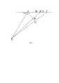
- на фиг. 1 представлена картина распространения звука в некоторой, в общем случае, наклонной плоскости; этот рисунок позволяет понять принцип формирования уравнений при расчете неизвестных параметров местоположения стрелка.- in FIG. 1 shows a picture of the propagation of sound in a generally inclined plane; This figure allows you to understand the principle of the formation of equations in the calculation of unknown parameters of the location of the shooter.
- на фиг. 2 представлена схема, позволяющая определить текущие координаты периферийных датчиков из-за движения объекта, а также определить истинное значения времени рассогласования в приходе звуковой волны к датчикам D и А.- in FIG. 2 is a diagram that allows you to determine the current coordinates of peripheral sensors due to the movement of the object, as well as to determine the true value of the mismatch time in the arrival of the sound wave to the sensors D and A.
Работает устройство по данному способу следующим образом.The device operates according to this method as follows.
Пусть имеем скорость распространения звука в воздухе равной ν, а скорость движения объекта обстрела известна, примем ее равной u. Скорость звука в воздухе легко рассчитывается по формулам физики и в основном зависит от температуры воздуха. Пусть необходимо определить направление на точку О - угол χ и расстояние OA=d. Согласно фиг. 1, с приходом звука в точку А, звук одновременно приходит и в точки В' и С'. Расстояния ВВ' и СС' зависят от скорости звука и разностей времени прихода звука в точку A, и в точки В и С (в точках В' и С' находился звук в момент его прихода к датчику А). Из рисунка видно, что за время преодоления звуком расстояния ВВ' датчик звука переместится из точки B1 в точку В. Соответственно за время преодоления звуком расстояния СС' датчик звука переместится из точки C1 в точку С.Suppose that we have the speed of sound propagation in air equal to ν, and the speed of movement of the object of fire is known, we assume it is equal to u. The speed of sound in air is easily calculated by the formulas of physics and mainly depends on air temperature. Let it be necessary to determine the direction to the point O — the angle χ and the distance OA = d. According to FIG. 1, with the arrival of sound at point A, sound simultaneously arrives at points B 'and C'. The distances BB 'and CC' depend on the speed of sound and the differences in the time of arrival of sound at point A, and at points B and C (at points B 'and C' there was sound at the time it arrived at sensor A). It can be seen from the figure that during the time the sound travels the distance BB ', the sound sensor moves from point B1 to point B. Accordingly, the time the sound travels the distance CC', the sound sensor moves from point C1 to point C.
Местоположение датчиков А, В и С являются определяющими при нахождении координат местоположения стрелка и именно в моменты прихода к ним звуковой волны. Это положение не изменяется придвижении объекта, как и в статической постановке [2].The location of the sensors A, B and C are decisive when finding the coordinates of the location of the shooter and precisely at the moments of arrival of the sound wave to them. This position does not change the movement of the object, as in the static setting [2].
Звук распространяется из точки О, координаты которой определяются в данной задаче, и достигает в разное время датчиков. Согласно фиг. 2, звук при данном расположении датчиков и местоположении точки выстрела достигает сначала датчика D, затем датчика A, затем датчиков В и С. В момент достижения звуком датчика А датчики В и С находились в точках В1 и С1 соответственно. Звуковая волна достигает этих датчиков в точках В и С, координаты которых учитывают факт перемещения датчиков из-за движения объекта. Координаты точек В и С участвуют в составлении уравнений для решения навигационной задачи. Расстояния АВ1 и В1С1 были первоначальным и известным расположением датчиков В и С на прямой АС. С учетом движения объекта эти датчики переместились в точки В и С. При этом расстояния ВВ1 и СС1 равны:Sound propagates from point O, the coordinates of which are determined in this task, and reaches the sensors at different times. According to FIG. 2, the sound at this location of the sensors and the location of the firing point reaches first sensor D, then sensor A, then sensors B and C. At the time the sound reached sensor A, sensors B and C were at points B1 and C1, respectively. The sound wave reaches these sensors at points B and C, whose coordinates take into account the fact that the sensors move due to the movement of the object. The coordinates of points B and C are involved in the preparation of equations for solving the navigation problem. The distances AB1 and B1 C1 were the initial and known location of the sensors B and C on the direct speaker. Given the movement of the object, these sensors moved to points B and C. In this case, the distances BB1 and CC1 are equal to:
ВВ1=u⋅Δt1, СС1=u⋅Δt2,BB1 = u⋅Δt1 , SS1 = u⋅Δt2 ,
где Δt1=tB-tA - разница прихода звуковой волны к датчикам А и В;where Δt1 = tB -tA is the difference in the arrival of a sound wave to sensors A and B;
Δt2=tC-tA - разница времени прихода звуковой волны к датчикам А и С;Δt2 = tC -tA is the difference in the time of arrival of the sound wave to the sensors A and C;
u - скорость движения объекта обстрела.u is the velocity of the object of fire.
В данном случае датчик А был принят за базовый и относительно его определяются промежутки времени достижения звука датчиков. Рассмотрим принцип определения координат стрелка.In this case, sensor A was taken as the base one and the time intervals for reaching the sound of the sensors are determined relative to it. Consider the principle of determining the coordinates of the arrow.
Для этого рассмотрим два косоугольных треугольника ОАВ и ОАС - фиг. 1. В этих треугольниках OA и ОВ' равны между собой: ОА=ОВ', и аналогично ОА=ОС', как радиусы одной окружности. Воспользуемся теоремой косинусов:To do this, we consider two oblique triangles OAV and OAS - Fig. 1. In these triangles, OA and OV 'are equal to each other: OA = OV', and similarly OA = OS ', as the radii of one circle. We use the cosine theorem:
а2=b2+с2-2bc⋅cosA,a2 = b2 + s2 -2bc⋅cosA,
где треугольник ABC является косоугольным, а сторонаа расположена против угла А (угол А это угол ОАВ, угол между направлением на точку выстрела и прямой расположения датчиков звука). Примем значение угла А равным χ.where the triangle ABC is oblique, and sidea is opposite the angle A (angle A is the angle OAB, the angle between the direction of the shot point and the direct location of the sound sensors). We take the value of angle A equal to χ.
Для нашего случая (фиг. 1) имеем:For our case (Fig. 1) we have:

Эта система двух уравнений содержит два неизвестных параметра: угол χ и расстояние OA=d, все остальные параметры известны, в том числе расстояние от датчика А до датчика В равноа, с учетом движения объекта обстрела расстояниеа увеличится за счет движения объекта, расстояние от датчика С до датчика А исходное равно a+b, но оно аналогично увеличится, при этом приращения расстоянийа иа+b не равны между собой, а они пропорциональны промежуткам времени Δt1и Δt2.This system of two equations contains two unknown parameters: the angle χ and the distance OA = d, all other parameters are known, including the distance from the sensor A to the sensor B is equal toa , taking into account the movement of the fired object, the distancea will increase due to the movement of the object, the distance from from sensor C to sensor A, the initial value is a + b, but it will increase similarly, while the increments of the distancesa anda + b are not equal to each other, and they are proportional to the time intervals Δt1 and Δt2 .
В свою очередь сторона OB=d+ν⋅Δt1 и ОС=d+ν⋅Δt2;In turn, the side OB = d + ν⋅Δt1 and OS = d + ν⋅Δt2 ;
где Δt1=tB-tA, Δt2=tC-tAwhere Δt1 = tB -tA , Δt2 = tC -tA
Запишем:We write:

Здесь обозначено АВ=а+u⋅Δt1, ВС=b+u⋅Δt2.…Here, AB =a + u⋅Δt1 , BC = b + u⋅Δt2. ...
Раскроем скобки и упростим выражение, получим:Expand the brackets and simplify the expression, we get:

Если обозначить:If designated:
а1=2⋅ν⋅Δt1,and1 = 2⋅ν⋅Δt1 ,
а2=2⋅ν⋅Δt2,and2 = 2⋅ν⋅Δt2 ,
b1=2⋅a+u⋅Δt1,b1 = 2⋅a + u⋅Δt1 ,
b2=2⋅(a+b+u⋅Δt2),b2 = 2⋅ (a + b + u⋅Δt2 ),
с1=(а+u⋅Δt1)2-(ν⋅Δt1)2,c1 = (a + u⋅Δt1 )2 - (ν⋅Δt1 )2 ,
c2=(a+b+u⋅Δt2)2-(ν+Δt2)2,c2 = (a + b + u⋅Δt2 )2 - (ν + Δt2 )2 ,
то имеем:then we have:

Это система двух уравнений с постоянными коэффициентами и двумя неизвестными. ОбозначимThis is a system of two equations with constant coefficients and two unknowns. Denote
d=x1, d⋅cosχ=x2;d = x1 , d⋅cosχ = x2 ;
тогда:then:

Расчет этой системы уравнений позволяет определить две переменных - угол χ и расстояние d.The calculation of this system of equations allows us to determine two variables - the angle χ and the distance d.
Для расчета третьего параметра, угла возвышения γ, обозначим расстояние OD равное l, тогда согласно фиг. 2 имеем:To calculate the third parameter, the elevation angle γ, we denote the distance OD equal to l, then according to FIG. 2 we have:
l=d-ν⋅Δt3,l = d-ν⋅Δt3 ,
где Δt3=tD-tA - рассогласование времени прихода звуковой волны к датчикам D и A в точках D и A.where Δt3 = tD -tA is the mismatch of the arrival time of the sound wave to the sensors D and A at points D and A.
Из треугольника OAD найдем третье уравнение системы:From the triangle OAD we find the third equation of the system:
l2=h2+d2-2⋅h⋅d⋅cosγ,l2 = h2 + d2 -2⋅h⋅d⋅cosγ,
откуда:where from:

илиor

здесь h=AD.here h = AD.
Параметр γ может быть определен из вышеприведенных выкладок, а может быть определен и из системы трех уравнений.The parameter γ can be determined from the above calculations, and can be determined from a system of three equations.
Таким образом, по данному способу определения местоположения стрелка при движении объекта обстрела составляются три уравнения, из которых определяются неизвестные параметры γ, d, χ. Все три уравнения представлены в тексте выше.Thus, according to this method for determining the location of the shooter when the object of fire is fired, three equations are composed, from which unknown parameters γ, d, χ are determined. All three equations are presented in the text above.
Динамика данной задачи приводит к необходимости отдельного определения Δt3, которое в статической постановке определяется однозначно, как разность прихода звуковой волны к датчикам D и A.The dynamics of this problem leads to the need for a separate determination of Δt3 , which in a static setting is uniquely determined as the difference in the arrival of a sound wave to sensors D and A.
Вернемся к фиг. 2. Согласно рисунку, звук от выстрела сначала приходит к датчику звука в точку D1, затем звук приходит к базовому датчику в точку А. Однако, за счет того, что объект движется, а датчики А и D находятся на одной вертикали, то временное расстояние между этими точками оказываются зависящими как от расстояния AD, так и от времени движения объекта от прихода звуковой волны к датчику D (в точке D1) до прихода звуковой волны к датчику А. Согласно фиг. 2 расстояние OD может быть записано в видеReturning to FIG. 2. According to the figure, the sound from the shot first comes to the sound sensor at point D1 , then the sound comes to the base sensor at point A. However, due to the fact that the object is moving, and the sensors A and D are on the same vertical, then temporary the distance between these points turns out to depend on both the distance AD and the time the object moves from the arrival of the sound wave to the sensor D (at point D1 ) until the sound wave arrives at the sensor A. According to FIG. 2 OD distance can be written as
OD=d-Δt3⋅ν.OD = d-Δt3 ⋅ν.
Время, за которое датчик D преодолел расстояниеTime over which the sensor D covered the distance
DD1=u⋅δt3,DD1 = u⋅δt3 ,
где δt3=tD-tA - время рассогласования между приходом звука к датчику D (в точке D1) и к датчику А (в точке А).where δt3 = tD -tA is the mismatch time between the sound coming to the sensor D (at point D1 ) and to the sensor A (at point A).
В момент, когда датчик D получил звуковой сигнал (точка D1), звук находился, также, в точке L1. Далее датчик D1 движется в сторону точки D со скоростью u, а звук движется из точки К1 к точке К со скоростью звука ν. За время δt3 звуковая волна оказалась в точке К, пройдя через точку D, значит, разность прихода волны в точки А и D численно равна времени прохождения этой волной расстояния DK, то естьAt the moment when the sensor D received an audio signal (point D1 ), the sound was also at point L1 . Next, the sensor D1 moves towards the point D with speed u, and the sound moves from point K1 to point K with the speed of sound ν. During the time δt3, the sound wave appeared at point K, passing through point D, which means that the difference in the arrival of the wave at points A and D is numerically equal to the travel time of the distance DK by this wave, i.e.
Δt3=DK/ν.Δt3 = DK / ν.
Именно DK является характеристикой временного рассогласования между временем прихода звука к датчику D и датчику А.It is DK that is a characteristic of the temporal mismatch between the time of sound arrival to the sensor D and sensor A.
Здесь умышленно введены обозначения δt3 (измеренное) не равное Δt3 (вычисленное) значение.Here, the notation δt3 (measured) is not equal to Δt3 (calculated) value.
Для определения расстояния DK заметим, что OA=OK, OD=OL и OD1=OK1 (как радиусы окружностей), отсюда следует вывод, что DK=AL. Примем, что угол D1K1D=90 градусов, а угол D1DK1=χ ввиду того, что расстояние OD много больше величины AD (это единственное в данной работе приближение).To determine the distance DK, we note that OA = OK, OD = OL and OD1 = OK1 (as the radii of circles), this implies that DK = AL. We assume that the angle D1 K1 D = 90 degrees, and the angle D1 DK1 = χ due to the fact that the distance OD is much larger than AD (this is the only approximation in this paper).
Тогда из треугольника D1K1D найдемThen from the triangle D1 K1 D we find
K1D=δt3⋅(u⋅cos(180-χ)).K1 D = δt3 ⋅ (u⋅cos (180-χ)).
За время δt3 точка D1 переместилась в точку D, а звук переместился из точки К1 в точку К. Учтя это, длина отрезкаDuring the time δt3, point D1 moved to point D, and the sound moved from point K1 to point K. Given this, the length of the segment
DK=δt3⋅(ν-u⋅cos(180-χ)).DK = δt3 ⋅ (ν-u⋅cos (180-χ)).
ИлиOr
Δt3=δt3⋅(ν-u⋅cos(180-χ))/ν.Δt3 = δt3 ⋅ (ν-u⋅cos (180-χ)) / ν.
Из приведенных соотношений видно, что величина δt3 не равна Δt3. Это видно также из выраженийFrom the above relations it is seen that the value of δt3 is not equal to Δt3 . This is also evident from the expressions
DK=δt3⋅(ν-u⋅cos(180-χ)) и Δt3=DK/ν.DK = δt3 ⋅ (ν-u⋅cos (180-χ)) and Δt3 = DK / ν.
Чем выше скорость объекта u, тем больше вклад скорости объекта обстрела в значение δt3. Расчеты показывают, что пройденный путь объектом за время δt3 составляет единицы сантиметров, а то и миллиметры, но далее они сказываются на величине Δt3, а та, в свою очередь, на значение γ, что нежелательно, так как этот параметр является решающим при нахождении азимута при инструментальной реализации способа.The higher the velocity of the object u, the greater the contribution of the velocity of the object of fire to the value δt3 . Calculations show that the path traveled by the object during the time δt3 is units of centimeters, or even millimeters, but then they affect the value of Δt3 , and that, in turn, affects the value of γ, which is undesirable, since this parameter is crucial for finding the azimuth in the instrumental implementation of the method.
Влияние движения объекта приводит к ошибкам в измерении Δt3 из-за того, что скорость объекта в одном случае увеличивает путь, проходимый звуковой волной (при углах χ более 90 градусов), а в другом случае (при углах χ менее 90 градусов) уменьшает этот путь за счет проекции скорости объекта на направление распространения звука.The influence of the movement of the object leads to errors in the measurement of Δt3 due to the fact that the speed of the object in one case increases the path traveled by the sound wave (at angles χ more than 90 degrees), and in the other case (at angles χ less than 90 degrees) path due to the projection of the speed of the object on the direction of sound propagation.
Таким образом, расчет Δt3 по формулеThus, the calculation of Δt3 by the formula
Δt3=δt3⋅(ν-u⋅cos(180-χ))/νΔt3 = δt3 ⋅ (ν-u⋅cos (180-χ)) / ν
позволяет более точно определить этот параметр, а не опираться на измеренное значение δt3.allows you to more accurately determine this parameter, and not rely on the measured value of δt3 .
Расчеты показали, что чем выше скорость объекта u, тем больше вклад скорости объекта обстрела в значение δt3. При скоростях объекта в пределах от 36 до 72 км/час (10…20 м/с) величина Δt3 всегда отличается от δt3, т.е. влиянием неравенства δt3 и Δt3 нельзя пренебречь; нужно измерять δt3, а затем с использованием формулы вводить поправку и вычислять Δt3,The calculations showed that the higher the speed of the object u, the greater the contribution of the speed of the object of fire to the value of δt3 . At object speeds ranging from 36 to 72 km / h (10 ... 20 m / s), Δt3 always differs from δt3 , i.e. the influence of the inequalities δt3 and Δt3 cannot be neglected; you need to measure δt3 , and then using the formula to introduce a correction and calculate Δt3 ,
Что касается влияния скорости объекта на местоположение датчиков, то это влияние достаточно велико. Например, изменение положения датчиков относительно базового датчика при углах χ близких к 0 и 180 градусам при начальном разнесении датчиков от базового датчикаа=5 метров, b=5 метров и скоростях движения объекта 20 м/с и звука - 330 м/с, Δt1=0,016129 сек., Δt2=0,0343392 сек. коррекцияа составляет 0,32258 метра,а+b - соответственно 0,64516 метра, что, конечно, значимо для целей навигации.As for the influence of the speed of the object on the location of the sensors, this influence is quite large. For example, a change in the position of the sensors relative to the base sensor at angles χ close to 0 and 180 degrees with the initial separation of the sensors from the base sensora = 5 meters, b = 5 meters and the speed of the object 20 m / s and sound - 330 m / s, Δt1 = 0.016129 sec., Δt2 = 0.0343392 sec. Correctiona is 0.32258 meters,and + b 0.64516 meters, respectively, which, of course, is significant for navigation purposes.
Авторами были проведены численные расчеты, подтверждающие предложенный в работе способ. Эти результаты не вошли в данный материал, так как оказались слишком объемными и заслоняющими материалы данной заявки. При необходимости они могут быть представлены в адрес ФИПС.The authors performed numerical calculations confirming the method proposed in the work. These results were not included in this material, since they turned out to be too voluminous and obscuring the materials of this application. If necessary, they can be submitted to FIPS.
ЛитератураLiterature
1. Патент РФ №2377594. Способ определения координат объекта. Гришин Алексей Валерьевич (RU), Кортюков Иван Иванович (RU), Ниточкин Евгений Николаевич (RU), Хорошко Алексей Николаевич (RU), Штарев Сергей Леонидович (RU) Российская Федерация, - Всероссийский научно-исследовательский институт экспериментальной физики" - ФГУП "РФЯЦ-ВНИИЭФ" (RU). Начало действия патента 23.06.2008 год.1. RF patent No. 2377594. A method for determining the coordinates of an object. Grishin Aleksey Valerievich (RU), Kortyukov Ivan Ivanovich (RU), Nitochkin Evgeny Nikolaevich (RU), Khoroshko Aleksey Nikolaevich (RU), Shtarev Sergey Leonidovich (RU) Russian Federation, - All-Russian Research Institute of Experimental Physics - FSUE RFNC -VNIIEF "(RU). The patent is valid on 23.06.2008.
2. Патент №2 610908 Российской Федерации. Способ определения местоположения стрелка по звуку выстрела. Антропов В.А., Антропов А.В., Успаленко В.Б., 2017 год.2. Patent No. 2 610908 of the Russian Federation. The method of determining the location of the shooter by the sound of the shot. Antropov V.A., Antropov A.V., Uspalenko V.B., 2017.
3. Патент №2323449. Способ определения пеленга источника звука. Шмелев В.В. и др. - 2006 г.3. Patent No. 2323449. A method for determining the bearing of a sound source. Shmelev V.V. et al. - 2006
4. Патент №2494336. Способ оценки дальности идо точки выстрела. - 2010 г.4. Patent No. 2494336. A method for assessing the range and point of a shot. - 2010
5. Патент №2406964. Устройство для определения координат места выстрела из огнестрельного оружия. - 2010 г.ц5. Patent No. 2406964. A device for determining the coordinates of the place of a shot from a firearm. - 2010 Hz
6. Красильников В.А. Звуковые и ультразвуковые волны в воздухе, воде и твердых телах. - М.: Государственное издательство физико-математической литературы. 1960.6. Krasilnikov V.A. Sound and ultrasonic waves in air, water and solids. - M .: State publishing house of physical and mathematical literature. 1960.
Claims (4)
Translated fromRussianPriority Applications (1)
| Application Number | Priority Date | Filing Date | Title |
|---|---|---|---|
| RU2018107337ARU2704955C1 (en) | 2018-02-27 | 2018-02-27 | Method of locating shooter by sound of shot during movement of shelling object |
Applications Claiming Priority (1)
| Application Number | Priority Date | Filing Date | Title |
|---|---|---|---|
| RU2018107337ARU2704955C1 (en) | 2018-02-27 | 2018-02-27 | Method of locating shooter by sound of shot during movement of shelling object |
Publications (1)
| Publication Number | Publication Date |
|---|---|
| RU2704955C1true RU2704955C1 (en) | 2019-10-31 |
Family
ID=68500838
Family Applications (1)
| Application Number | Title | Priority Date | Filing Date |
|---|---|---|---|
| RU2018107337ARU2704955C1 (en) | 2018-02-27 | 2018-02-27 | Method of locating shooter by sound of shot during movement of shelling object |
Country Status (1)
| Country | Link |
|---|---|
| RU (1) | RU2704955C1 (en) |
Cited By (3)
| Publication number | Priority date | Publication date | Assignee | Title |
|---|---|---|---|---|
| CN111024036A (en)* | 2019-12-31 | 2020-04-17 | 广东海工建设工程有限公司 | Wharf displacement monitoring device |
| RU2734289C1 (en)* | 2019-12-02 | 2020-10-14 | Федеральное государственное казенное военное образовательное учреждение высшего образования "Михайловская военная артиллерийская академия" Министерства обороны Российской Федерации | Method of positioning audio signal source using sound ranging system |
| CN117022388A (en)* | 2023-10-08 | 2023-11-10 | 成都交控轨道科技有限公司 | Train positioning method based on vehicle-mounted sensing system and transponder system |
Citations (5)
| Publication number | Priority date | Publication date | Assignee | Title |
|---|---|---|---|---|
| RU2285272C1 (en)* | 2005-01-31 | 2006-10-10 | Российская Федерация в лице Федерального агентства по атомной энергии | Method for determining position of a rifleman in an area |
| US7586812B2 (en)* | 2003-01-24 | 2009-09-08 | Shotspotter, Inc. | Systems and methods of identifying/locating weapon fire including return fire, targeting, laser sighting, and/or guided weapon features |
| RU2470252C1 (en)* | 2011-07-07 | 2012-12-20 | Российская Федерация, от имени которой выступает Государственная корпорация по атомной энергии "Росатом" | Method of defining bullet and shell position coordinates in space and time |
| RU2494336C2 (en)* | 2004-08-24 | 2013-09-27 | РЭЙТЕОН БиБиЭн ТЕКНОЛОДЖИЗ КОРП. | Method of estimating distance to shot point |
| RU2610908C2 (en)* | 2015-06-29 | 2017-02-17 | Федеральное государственное казенное военное образовательное учреждение высшего профессионального образования "Пермский военный институт внутренних войск Министерства внутренних дел Российской Федерации" | Method of shooter locating by sound of shot |
- 2018
- 2018-02-27RURU2018107337Apatent/RU2704955C1/ennot_activeIP Right Cessation
Patent Citations (5)
| Publication number | Priority date | Publication date | Assignee | Title |
|---|---|---|---|---|
| US7586812B2 (en)* | 2003-01-24 | 2009-09-08 | Shotspotter, Inc. | Systems and methods of identifying/locating weapon fire including return fire, targeting, laser sighting, and/or guided weapon features |
| RU2494336C2 (en)* | 2004-08-24 | 2013-09-27 | РЭЙТЕОН БиБиЭн ТЕКНОЛОДЖИЗ КОРП. | Method of estimating distance to shot point |
| RU2285272C1 (en)* | 2005-01-31 | 2006-10-10 | Российская Федерация в лице Федерального агентства по атомной энергии | Method for determining position of a rifleman in an area |
| RU2470252C1 (en)* | 2011-07-07 | 2012-12-20 | Российская Федерация, от имени которой выступает Государственная корпорация по атомной энергии "Росатом" | Method of defining bullet and shell position coordinates in space and time |
| RU2610908C2 (en)* | 2015-06-29 | 2017-02-17 | Федеральное государственное казенное военное образовательное учреждение высшего профессионального образования "Пермский военный институт внутренних войск Министерства внутренних дел Российской Федерации" | Method of shooter locating by sound of shot |
Cited By (4)
| Publication number | Priority date | Publication date | Assignee | Title |
|---|---|---|---|---|
| RU2734289C1 (en)* | 2019-12-02 | 2020-10-14 | Федеральное государственное казенное военное образовательное учреждение высшего образования "Михайловская военная артиллерийская академия" Министерства обороны Российской Федерации | Method of positioning audio signal source using sound ranging system |
| CN111024036A (en)* | 2019-12-31 | 2020-04-17 | 广东海工建设工程有限公司 | Wharf displacement monitoring device |
| CN117022388A (en)* | 2023-10-08 | 2023-11-10 | 成都交控轨道科技有限公司 | Train positioning method based on vehicle-mounted sensing system and transponder system |
| CN117022388B (en)* | 2023-10-08 | 2024-01-30 | 成都交控轨道科技有限公司 | Train positioning method based on vehicle-mounted sensing system and transponder system |
Similar Documents
| Publication | Publication Date | Title |
|---|---|---|
| Yin et al. | Acoustic source localization in anisotropic plates with “Z” shaped sensor clusters | |
| RU2704955C1 (en) | Method of locating shooter by sound of shot during movement of shelling object | |
| US7656159B2 (en) | Locating stationary magnetic objects | |
| Waqar et al. | Analysis of GPS and UWB positioning system for athlete tracking | |
| CN105388457B (en) | A kind of Long baselines hydrolocation method based on equivalent sound velocity gradient | |
| CN108020836B (en) | Bistatic synthetic aperture radar moving target positioning method | |
| US20090070063A1 (en) | Locating ferromagnetic objects in a single pass | |
| CN104133217B (en) | Method and device for three-dimensional velocity joint determination of underwater moving target and water flow | |
| RU2416103C2 (en) | Method of determining trajectory and speed of object | |
| ES2449466T3 (en) | Procedure and device for locating objects | |
| CN103782187A (en) | Position-determining system and method for the operation thereof | |
| Blumrich et al. | Medium-range localisation of aircraft via triangulation | |
| CN104422921A (en) | Fixed single station passive positioning system based on orientation and self time difference measurement | |
| RU2610908C2 (en) | Method of shooter locating by sound of shot | |
| CN104977559B (en) | Target positioning method in interference environment | |
| CN103033182A (en) | Positioning mechanism for determining third target | |
| RU2714884C1 (en) | Method of determining the course of an object on a linear trajectory using measurements of its radial velocity | |
| CN116324496A (en) | Monitoring Vehicle Movement Using Surface Penetrating Radar Systems and Doppler Shift | |
| KR101480834B1 (en) | Target motion analysis method using target classification and ray tracing of underwater sound energy | |
| RU2545068C1 (en) | Measurement method of changes of heading angle of movement of source of sounding signals | |
| Sheng et al. | A novel bridge curve mode measurement technique based on FOG | |
| RU2617447C1 (en) | Method of determining range to fixed radiation source by moving direction finder | |
| CN105102965B (en) | Method and apparatus for determining at least one concentration of the carbon particle in air-flow | |
| RU2684733C2 (en) | Method for determining position of object with cut from two measuring points in azimuth, elevation angle and distance | |
| JP2969491B2 (en) | Shooting evaluation device |
Legal Events
| Date | Code | Title | Description |
|---|---|---|---|
| MM4A | The patent is invalid due to non-payment of fees | Effective date:20200228 |