RU2704016C2 - Injection preparation system and method - Google Patents
Injection preparation system and methodDownload PDFInfo
- Publication number
- RU2704016C2 RU2704016C2RU2017115841ARU2017115841ARU2704016C2RU 2704016 C2RU2704016 C2RU 2704016C2RU 2017115841 ARU2017115841 ARU 2017115841ARU 2017115841 ARU2017115841 ARU 2017115841ARU 2704016 C2RU2704016 C2RU 2704016C2
- Authority
- RU
- Russia
- Prior art keywords
- container
- substance
- containers
- hollow space
- lyophilisate
- Prior art date
Links
- 238000002347injectionMethods0.000titleclaimsabstractdescription47
- 239000007924injectionSubstances0.000titleclaimsabstractdescription47
- 238000002360preparation methodMethods0.000titleabstractdescription9
- 238000000034methodMethods0.000titledescription12
- 239000000126substanceSubstances0.000claimsabstractdescription98
- 239000011796hollow space materialSubstances0.000claimsabstractdescription51
- 239000007788liquidSubstances0.000claimsabstractdescription48
- 239000012530fluidSubstances0.000claimsabstractdescription27
- 239000000243solutionSubstances0.000claimsabstractdescription20
- 239000007787solidSubstances0.000claimsabstractdescription9
- 239000002904solventSubstances0.000claimsdescription30
- 238000006073displacement reactionMethods0.000abstractdescription3
- 239000003814drugSubstances0.000abstract1
- 239000003085diluting agentSubstances0.000description11
- 239000000843powderSubstances0.000description10
- 239000000463materialSubstances0.000description7
- 239000002775capsuleSubstances0.000description5
- 238000012546transferMethods0.000description5
- 230000008901benefitEffects0.000description4
- 238000004090dissolutionMethods0.000description4
- 239000003795chemical substances by applicationSubstances0.000description3
- 238000011109contaminationMethods0.000description3
- 230000007423decreaseEffects0.000description3
- 239000012528membraneSubstances0.000description3
- 206010010774ConstipationDiseases0.000description2
- 230000001580bacterial effectEffects0.000description2
- 230000008859changeEffects0.000description2
- 150000001875compoundsChemical class0.000description2
- 230000001419dependent effectEffects0.000description2
- 238000013461designMethods0.000description2
- -1i.e.Substances0.000description2
- 238000004519manufacturing processMethods0.000description2
- 239000000203mixtureSubstances0.000description2
- 229920003023plasticPolymers0.000description2
- 230000008569processEffects0.000description2
- 238000003860storageMethods0.000description2
- 229960005486vaccineDrugs0.000description2
- 239000011782vitaminSubstances0.000description2
- 229940088594vitaminDrugs0.000description2
- 229930003231vitaminNatural products0.000description2
- 235000013343vitaminNutrition0.000description2
- 150000003722vitamin derivativesChemical class0.000description2
- 230000009471actionEffects0.000description1
- 230000003213activating effectEffects0.000description1
- 238000005352clarificationMethods0.000description1
- 238000004891communicationMethods0.000description1
- 239000000470constituentSubstances0.000description1
- 238000001125extrusionMethods0.000description1
- 210000003746featherAnatomy0.000description1
- 239000011521glassSubstances0.000description1
- 238000010438heat treatmentMethods0.000description1
- 238000001802infusionMethods0.000description1
- 230000035699permeabilityEffects0.000description1
- 230000008092positive effectEffects0.000description1
- 239000006188syrupSubstances0.000description1
- 235000020357syrupNutrition0.000description1
- 239000012780transparent materialSubstances0.000description1
- 238000003466weldingMethods0.000description1
Images


Classifications
- A—HUMAN NECESSITIES
- A61—MEDICAL OR VETERINARY SCIENCE; HYGIENE
- A61M—DEVICES FOR INTRODUCING MEDIA INTO, OR ONTO, THE BODY; DEVICES FOR TRANSDUCING BODY MEDIA OR FOR TAKING MEDIA FROM THE BODY; DEVICES FOR PRODUCING OR ENDING SLEEP OR STUPOR
- A61M3/00—Medical syringes, e.g. enemata; Irrigators
- A61M3/005—Medical syringes, e.g. enemata; Irrigators comprising means for injection of two or more media, e.g. by mixing
- A—HUMAN NECESSITIES
- A61—MEDICAL OR VETERINARY SCIENCE; HYGIENE
- A61J—CONTAINERS SPECIALLY ADAPTED FOR MEDICAL OR PHARMACEUTICAL PURPOSES; DEVICES OR METHODS SPECIALLY ADAPTED FOR BRINGING PHARMACEUTICAL PRODUCTS INTO PARTICULAR PHYSICAL OR ADMINISTERING FORMS; DEVICES FOR ADMINISTERING FOOD OR MEDICINES ORALLY; BABY COMFORTERS; DEVICES FOR RECEIVING SPITTLE
- A61J1/00—Containers specially adapted for medical or pharmaceutical purposes
- A61J1/05—Containers specially adapted for medical or pharmaceutical purposes for collecting, storing or administering blood, plasma or medical fluids ; Infusion or perfusion containers
- A61J1/06—Ampoules or carpules
- A61J1/067—Flexible ampoules, the contents of which are expelled by squeezing
- A—HUMAN NECESSITIES
- A61—MEDICAL OR VETERINARY SCIENCE; HYGIENE
- A61J—CONTAINERS SPECIALLY ADAPTED FOR MEDICAL OR PHARMACEUTICAL PURPOSES; DEVICES OR METHODS SPECIALLY ADAPTED FOR BRINGING PHARMACEUTICAL PRODUCTS INTO PARTICULAR PHYSICAL OR ADMINISTERING FORMS; DEVICES FOR ADMINISTERING FOOD OR MEDICINES ORALLY; BABY COMFORTERS; DEVICES FOR RECEIVING SPITTLE
- A61J1/00—Containers specially adapted for medical or pharmaceutical purposes
- A61J1/05—Containers specially adapted for medical or pharmaceutical purposes for collecting, storing or administering blood, plasma or medical fluids ; Infusion or perfusion containers
- A61J1/10—Bag-type containers
- A—HUMAN NECESSITIES
- A61—MEDICAL OR VETERINARY SCIENCE; HYGIENE
- A61J—CONTAINERS SPECIALLY ADAPTED FOR MEDICAL OR PHARMACEUTICAL PURPOSES; DEVICES OR METHODS SPECIALLY ADAPTED FOR BRINGING PHARMACEUTICAL PRODUCTS INTO PARTICULAR PHYSICAL OR ADMINISTERING FORMS; DEVICES FOR ADMINISTERING FOOD OR MEDICINES ORALLY; BABY COMFORTERS; DEVICES FOR RECEIVING SPITTLE
- A61J1/00—Containers specially adapted for medical or pharmaceutical purposes
- A61J1/14—Details; Accessories therefor
- A61J1/20—Arrangements for transferring or mixing fluids, e.g. from vial to syringe
- A61J1/2003—Accessories used in combination with means for transfer or mixing of fluids, e.g. for activating fluid flow, separating fluids, filtering fluid or venting
- A61J1/2048—Connecting means
- A—HUMAN NECESSITIES
- A61—MEDICAL OR VETERINARY SCIENCE; HYGIENE
- A61J—CONTAINERS SPECIALLY ADAPTED FOR MEDICAL OR PHARMACEUTICAL PURPOSES; DEVICES OR METHODS SPECIALLY ADAPTED FOR BRINGING PHARMACEUTICAL PRODUCTS INTO PARTICULAR PHYSICAL OR ADMINISTERING FORMS; DEVICES FOR ADMINISTERING FOOD OR MEDICINES ORALLY; BABY COMFORTERS; DEVICES FOR RECEIVING SPITTLE
- A61J1/00—Containers specially adapted for medical or pharmaceutical purposes
- A61J1/14—Details; Accessories therefor
- A61J1/20—Arrangements for transferring or mixing fluids, e.g. from vial to syringe
- A61J1/2093—Containers having several compartments for products to be mixed
- B—PERFORMING OPERATIONS; TRANSPORTING
- B65—CONVEYING; PACKING; STORING; HANDLING THIN OR FILAMENTARY MATERIAL
- B65D—CONTAINERS FOR STORAGE OR TRANSPORT OF ARTICLES OR MATERIALS, e.g. BAGS, BARRELS, BOTTLES, BOXES, CANS, CARTONS, CRATES, DRUMS, JARS, TANKS, HOPPERS, FORWARDING CONTAINERS; ACCESSORIES, CLOSURES, OR FITTINGS THEREFOR; PACKAGING ELEMENTS; PACKAGES
- B65D35/00—Pliable tubular containers adapted to be permanently or temporarily deformed to expel contents, e.g. collapsible tubes for toothpaste or other plastic or semi-liquid material; Holders therefor
- B65D35/02—Body construction
- B65D35/04—Body construction made in one piece
- B—PERFORMING OPERATIONS; TRANSPORTING
- B65—CONVEYING; PACKING; STORING; HANDLING THIN OR FILAMENTARY MATERIAL
- B65D—CONTAINERS FOR STORAGE OR TRANSPORT OF ARTICLES OR MATERIALS, e.g. BAGS, BARRELS, BOTTLES, BOXES, CANS, CARTONS, CRATES, DRUMS, JARS, TANKS, HOPPERS, FORWARDING CONTAINERS; ACCESSORIES, CLOSURES, OR FITTINGS THEREFOR; PACKAGING ELEMENTS; PACKAGES
- B65D35/00—Pliable tubular containers adapted to be permanently or temporarily deformed to expel contents, e.g. collapsible tubes for toothpaste or other plastic or semi-liquid material; Holders therefor
- B65D35/44—Closures
- A—HUMAN NECESSITIES
- A61—MEDICAL OR VETERINARY SCIENCE; HYGIENE
- A61J—CONTAINERS SPECIALLY ADAPTED FOR MEDICAL OR PHARMACEUTICAL PURPOSES; DEVICES OR METHODS SPECIALLY ADAPTED FOR BRINGING PHARMACEUTICAL PRODUCTS INTO PARTICULAR PHYSICAL OR ADMINISTERING FORMS; DEVICES FOR ADMINISTERING FOOD OR MEDICINES ORALLY; BABY COMFORTERS; DEVICES FOR RECEIVING SPITTLE
- A61J1/00—Containers specially adapted for medical or pharmaceutical purposes
- A61J1/14—Details; Accessories therefor
- A61J1/20—Arrangements for transferring or mixing fluids, e.g. from vial to syringe
- A61J1/2003—Accessories used in combination with means for transfer or mixing of fluids, e.g. for activating fluid flow, separating fluids, filtering fluid or venting
- A61J1/2006—Piercing means
- A61J1/201—Piercing means having one piercing end
- A—HUMAN NECESSITIES
- A61—MEDICAL OR VETERINARY SCIENCE; HYGIENE
- A61J—CONTAINERS SPECIALLY ADAPTED FOR MEDICAL OR PHARMACEUTICAL PURPOSES; DEVICES OR METHODS SPECIALLY ADAPTED FOR BRINGING PHARMACEUTICAL PRODUCTS INTO PARTICULAR PHYSICAL OR ADMINISTERING FORMS; DEVICES FOR ADMINISTERING FOOD OR MEDICINES ORALLY; BABY COMFORTERS; DEVICES FOR RECEIVING SPITTLE
- A61J1/00—Containers specially adapted for medical or pharmaceutical purposes
- A61J1/14—Details; Accessories therefor
- A61J1/20—Arrangements for transferring or mixing fluids, e.g. from vial to syringe
- A61J1/2003—Accessories used in combination with means for transfer or mixing of fluids, e.g. for activating fluid flow, separating fluids, filtering fluid or venting
- A61J1/2048—Connecting means
- A61J1/2058—Connecting means having multiple connecting ports
- A—HUMAN NECESSITIES
- A61—MEDICAL OR VETERINARY SCIENCE; HYGIENE
- A61J—CONTAINERS SPECIALLY ADAPTED FOR MEDICAL OR PHARMACEUTICAL PURPOSES; DEVICES OR METHODS SPECIALLY ADAPTED FOR BRINGING PHARMACEUTICAL PRODUCTS INTO PARTICULAR PHYSICAL OR ADMINISTERING FORMS; DEVICES FOR ADMINISTERING FOOD OR MEDICINES ORALLY; BABY COMFORTERS; DEVICES FOR RECEIVING SPITTLE
- A61J1/00—Containers specially adapted for medical or pharmaceutical purposes
- A61J1/14—Details; Accessories therefor
- A61J1/20—Arrangements for transferring or mixing fluids, e.g. from vial to syringe
- A61J1/2096—Combination of a vial and a syringe for transferring or mixing their contents
- A—HUMAN NECESSITIES
- A61—MEDICAL OR VETERINARY SCIENCE; HYGIENE
- A61M—DEVICES FOR INTRODUCING MEDIA INTO, OR ONTO, THE BODY; DEVICES FOR TRANSDUCING BODY MEDIA OR FOR TAKING MEDIA FROM THE BODY; DEVICES FOR PRODUCING OR ENDING SLEEP OR STUPOR
- A61M2207/00—Methods of manufacture, assembly or production
Landscapes
- Health & Medical Sciences (AREA)
- Life Sciences & Earth Sciences (AREA)
- Animal Behavior & Ethology (AREA)
- General Health & Medical Sciences (AREA)
- Public Health (AREA)
- Veterinary Medicine (AREA)
- Pharmacology & Pharmacy (AREA)
- Hematology (AREA)
- Engineering & Computer Science (AREA)
- Mechanical Engineering (AREA)
- Physics & Mathematics (AREA)
- Fluid Mechanics (AREA)
- Anesthesiology (AREA)
- Biomedical Technology (AREA)
- Heart & Thoracic Surgery (AREA)
- Infusion, Injection, And Reservoir Apparatuses (AREA)
- Medical Preparation Storing Or Oral Administration Devices (AREA)
Abstract
Description
Translated fromRussianИзобретение относится к системе для подготовки инъекции согласно ограничительной части пункта 1 формулы изобретения, кроме этого к комбинации шприца или карпулы с тюбиком согласно пункту 12 формулы изобретения, а также к способу подготовки инъекции согласно ограничительной части пункта 13 формулы изобретения.The invention relates to a system for preparing an injection according to the restrictive part of
Системы и способы указанного здесь типа известны. Они имеют первую емкость, которая выполнена в виде цилиндрического тела с первым полым пространством и представляет собой, например шприц или карпулу. В этом шприце или карпуле имеется порошкообразная субстанция, в частности лиофилизат, который представляет собой медицинскую субстанцию. Она служит для того, чтобы инъецироваться пациенту. Для этого необходимо растворять порошкообразную субстанцию. Известно снабжать первую емкость инъекционной канюлей, для того чтобы засасывать из второй емкости со вторым полым пространством жидкость и тем самым растворять имеющуюся в первом полом пространстве цилиндрического тела первой емкости порошкообразную субстанцию. Затем созданный раствор может вводиться пациенту. У существующих систем вторая емкость состоит из стекла или твердого прозрачного пластикового материала. Она, как обычно и первая емкость, заполнена не полностью и содержит объем воздуха. Вследствие этого возможно переносить обозначаемое также как дилюент растворяющее средство из полого пространства одной емкости в полое пространство другой емкости, для того чтобы растворять порошкообразную субстанцию. Оказалось, что, если порошкообразная субстанция трудно растворима, процесс растворения занимает много времени. Также может случаться, что порошкообразная субстанция не полностью растворяется, что при введении или инъекции может приводить к проблемам. Известны также такие системы, которые имеют первую и вторую емкость, причем, однако в отличие от вышеописанного, обе емкости имеют жидкость. Для подготовки инъекции эти обе жидкости должны смешиваться друг с другом. Существенным является то, чтобы смешивание этих жидкостей являлось полным, так что компоненты этих жидкостей были распределены почти однородно, прежде чем смесь вводится. При использовании некоторых медицинских жидкостей оказывается, что их полное и однородное смешивание может достигаться лишь с большим трудом. Это имеет место, например, в частности при вакцинах и витаминных препаратах.Systems and methods of the type indicated herein are known. They have a first container, which is made in the form of a cylindrical body with a first hollow space and is, for example, a syringe or karbul. This syringe or karbul contains a powdery substance, in particular a lyophilisate, which is a medical substance. It serves to be injected to the patient. For this, it is necessary to dissolve the powdery substance. It is known to supply the first container with an injection cannula in order to suck in a liquid from the second container with the second hollow space and thereby dissolve the powdery substance present in the first hollow space of the cylindrical body of the first container. Then, the created solution can be administered to the patient. For existing systems, the second tank consists of glass or hard transparent plastic material. It, as usual the first container, is not completely filled and contains a volume of air. As a result of this, it is possible to transfer the solvent, also referred to as diluent, from the hollow space of one container to the hollow space of another container in order to dissolve the powdery substance. It turned out that if a powdery substance is difficult to dissolve, the dissolution process takes a long time. It may also happen that the powdery substance does not completely dissolve, which, when administered or injected, can lead to problems. Also known are such systems that have a first and second tank, and, however, in contrast to the above, both tanks have a liquid. To prepare the injection, these two fluids must be mixed with each other. It is essential that the mixing of these fluids is complete, so that the components of these fluids are distributed almost uniformly before the mixture is introduced. When using certain medical fluids, it turns out that their complete and uniform mixing can only be achieved with great difficulty. This is the case, for example, in particular with vaccines and vitamin preparations.
Поэтому задача изобретения состоит в создании системы, которая предотвращает этот недостаток.Therefore, the objective of the invention is to create a system that prevents this disadvantage.
Для решения этой задачи предлагается система для подготовки инъекции, которая имеет признаки пункта 1 формулы изобретения. Она включает в себя окружающую первое полое пространство первую емкость, которая имеет твердую наружную стенку, а также два конца, причем на одной стороне первого полого пространства предусмотрена подвижная заглушка, которая его герметично закрывает и может смещаться внутри емкости. Система имеет окружающую второе полое пространство вторую емкость. Система отличается соединительным устройством, которое имеет первый, предусмотренный на первой емкости соединительный элемент и второй, предусмотренный на второй емкости соединительный элемент, и тем, что обе емкости могут соединяться друг с другом при помощи соединительных элементов таким образом, что их полые пространства находятся друг с другом в соединении с прохождением текучей среды. Далее система отличается тем, что вторая емкость имеет переменный объем. Благодаря соединению с прохождением текучей среды между обоими полыми пространствами в первой и второй емкости возможно перемешивать твердую субстанцию с жидкой. При этом переменный объем второй емкости способствует тому, что перемешивание может происходить очень интенсивно.To solve this problem, there is proposed a system for preparing an injection, which has the characteristics of
Предложенная здесь система отличается тем, что вторая емкость имеет, по меньшей мере, местами эластичную стенку, так что она включает в себя переменный объем. Вследствие этого система выполнена таким образом, что вторая емкость расширяется посредством введения объема газа и/или жидкости, так что упомянутая здесь стенка, по меньшей мере, местами упруго растягивается. Благодаря собственной эластичности стенки внутреннее пространство второй емкости находится под внутренним давлением таким образом, что предусмотренная здесь субстанция может выводиться под давлением и при этом поступает в первую емкость.The system proposed here is characterized in that the second container has at least some places an elastic wall, so that it includes a variable volume. As a consequence, the system is designed such that the second container expands by introducing a volume of gas and / or liquid, so that the wall mentioned here is at least elastically stretched in places. Due to the intrinsic elasticity of the wall, the inner space of the second container is under internal pressure so that the substance provided here can be discharged under pressure and thus enters the first container.
Для перемешивания обеих субстанций имеющаяся во второй емкости жидкая субстанция переносится в первую емкость. Она может полностью перетекать в первую емкость, так как эластичная наружная стенка второй емкости может принимать вогнутую форму, так что объем заключенного во второй емкости полого пространства может уменьшаться. То есть, если объем во второй емкости при введении жидкости увеличивается благодаря расширению местами эластичной наружной стенки, он может, как было уже сказано, также уменьшаться. Вследствие этого возникает значительно лучшее перемешивание обеих субстанций, чем это имеет место у существующих систем.To mix both substances, the liquid substance present in the second container is transferred to the first container. It can completely flow into the first container, since the elastic outer wall of the second container can take a concave shape, so that the volume of the hollow space enclosed in the second container can be reduced. That is, if the volume in the second container with the introduction of the liquid increases due to the expansion in places of the elastic outer wall, it can, as already mentioned, also decrease. As a result of this, a significantly better mixing of both substances arises than is the case with existing systems.
Вследствие этого происходит хорошее перемешивание вытесненной во второй емкости и оттуда второй субстанции с первой субстанцией в первой емкости. Это относится также к тому, что в первой емкости имеется жидкая или порошкообразная субстанция, в которую вторая субстанция из второй емкости попадает благодаря созданному, по меньшей мере, одной эластичной областью стенки избыточному давлению. То есть даже в том случае, если во второй емкости имеется порошок, он переносится благодаря избыточному давлению в первую емкость и вдувается в жидкость.As a result of this, good mixing occurs of the second substance displaced in the second container and from there with the first substance in the first container. This also applies to the fact that in the first container there is a liquid or powdery substance into which the second substance from the second container enters due to the excess pressure created by at least one elastic region of the wall. That is, even if there is powder in the second container, it is transferred due to overpressure to the first container and is blown into the liquid.
Разъясненная здесь система, у которой вторая емкость выполнена в виде тюбика, отличается экономичной реализацией. Тюбиком здесь обозначается элемент, который имеет полое, в частности трубообразное основное тело, которое на одном своем конце закрыто. При выполнении тюбика из пластикового материала основное тело может завариваться, будь то посредством нагрева, тепла от трения или при помощи ультразвуковой сварки. Также другие материалы и способы закупорки можно здесь без проблем применять.The system explained here, in which the second capacity is made in the form of a tube, is characterized by an economical implementation. A tube here denotes an element that has a hollow, in particular a tube-shaped main body, which is closed at one end. When making a tube of plastic material, the main body can be welded, whether by heating, heat from friction, or by ultrasonic welding. Also, other materials and methods of blockage can be applied here without any problems.
Противоположный другой конец основного тела выполнен в виде предпочтительно несъемной крышки основного тела и имеет закрываемое отверстие, которое предпочтительно окружено предпочтительно цилиндрическим буртиком. Предпочтительно крышка выполнена немного более устойчивой, чем боковые стенки основного тела. Цилиндрический буртик может оснащаться предпочтительно наружной резьбой, на которую навинчивается резьбовой колпачок с внутренней резьбой. Также возможны вставные или обжимные соединения.The opposite other end of the main body is made in the form of a preferably fixed cover of the main body and has a lockable hole, which is preferably surrounded by a preferably cylindrical collar. Preferably, the lid is made slightly more stable than the side walls of the main body. The cylindrical collar may preferably be equipped with an external thread onto which a threaded cap with an internal thread is screwed. Plug-in or crimp connections are also possible.
Решающим является то, что изготовление тюбика при помощи известных в настоящее время способов может реализовываться просто и весьма экономично, даже в том случае, если наружная стенка тюбика выполнена, по меньшей мере, местами эластичной и реализована предпочтительно полупрозрачной или прозрачной.It is crucial that the manufacture of the tube using currently known methods can be implemented simply and very economically, even if the outer wall of the tube is made at least in some places elastic and is preferably translucent or transparent.
При исполнении цилиндрического буртика в области крышки с наружной резьбой можно очень легко соединять тюбик с первой емкостью, например, посредством резьбового соединения, и реализовывать соединение с прохождением текучей среды между внутренними пространствами первой емкости и тюбика. При этом наружная резьба тюбика может также адаптироваться к внутренней резьбе разъема Луера, так что тюбик может без проблем использоваться с общепринятыми шприцами или тому подобным.When executing a cylindrical collar in the area of the cap with an external thread, it is very easy to connect the tube to the first container, for example, by means of a threaded connection, and to realize a connection with the passage of fluid between the internal spaces of the first container and the tube. Moreover, the external thread of the tube can also adapt to the internal thread of the Luer connector, so that the tube can be used without problems with conventional syringes or the like.
Предпочтительный пример осуществления системы отличается тем, что первая субстанция является лиофилизатом, а вторая субстанция обозначаемым как дилюент растворяющим средством для лиофилизата. Вследствие того, что у этой системы лиофилизат и растворяющее средство размещены в разделенных полых пространствах, возникает очень длительный срок хранения лиофилизата.A preferred embodiment of the system is characterized in that the first substance is a lyophilizate and the second substance is denoted as diluent by a lyophilisate solvent. Due to the fact that in this system the lyophilisate and the solvent are located in separated hollow spaces, a very long shelf life of the lyophilisate occurs.
Дальнейший пример осуществления системы отличается тем, что в первой емкости содержится лиофилизат, а во второй емкости растворяющее средство для лиофилизата.A further embodiment of the system is characterized in that the lyophilisate is contained in the first container and the lyophilisate dissolving agent in the second container.
В наиболее предпочтительном примере осуществления системы предусмотрено то, что она приспособлена и рассчитана таким образом, что для количества первой субстанции в первой емкости предоставляется количество второй субстанции во второй емкости, для того чтобы предоставлять количество инъекционного раствора для инъекции. То есть, возможно, согласовывать друг с другом емкости с предоставляемыми для инъекции субстанциями, так что система очень проста в обращении.In a most preferred embodiment of the system, it is provided that it is adapted and designed so that for the amount of the first substance in the first container, the amount of the second substance in the second container is provided in order to provide the amount of injection solution for injection. That is, it is possible to coordinate with each other containers with the substances provided for injection, so that the system is very easy to handle.
В частности, объем первой емкости согласован с количеством первой субстанции, и/или объем второй емкости согласован с количеством второй субстанции. В этом случае возникает то преимущество, что система выполнена очень компактной.In particular, the volume of the first tank is consistent with the amount of the first substance, and / or the volume of the second tank is matched with the amount of the second substance. In this case, the advantage arises that the system is very compact.
Наиболее предпочтителен пример осуществления системы, в котором предоставлено несколько емкостей с различными количествами одной субстанции. Эти емкости могут комбинироваться с другими емкостями, которые содержат различные количества другой субстанции, причем одна первая емкость с первой субстанцией соединяется с прохождением текучей среды с одной второй емкостью со второй субстанцией, для того чтобы смешивать друг с другом обе субстанции. Отличительный признак этой системы заключается в том, что количество второй субстанции точно согласовано с количеством первой субстанции, для того чтобы предоставлять инъекционный раствор для инъекции. Например, в обеих емкостях предоставлены жидкости, причем количество в первой емкости согласовано с количеством во второе емкости таким образом, что точно достигается определенное соотношение смеси обеих жидкостей. С одной стороны, это существенно, для того чтобы предоставлять инъекционный раствор определенной концентрации для инъекции. С другой стороны, этот аспект имеет отношение к тому, что, например, смешиваются друг с другом две жидкости, при которых для полного смешивания количественные соотношения должны быть согласованы друг с другом.Most preferred is an example embodiment of a system in which several containers with different amounts of one substance are provided. These containers can be combined with other containers that contain different amounts of another substance, wherein one first container with a first substance is connected to the passage of fluid from one second container with a second substance in order to mix both substances with each other. A distinctive feature of this system is that the amount of the second substance is precisely matched with the amount of the first substance in order to provide an injection solution for injection. For example, liquids are provided in both containers, the quantity in the first container being matched with the quantity in the second container so that a certain ratio of the mixture of the two liquids is precisely achieved. On the one hand, this is essential in order to provide an injection solution of a certain concentration for injection. On the other hand, this aspect relates to the fact that, for example, two liquids are mixed with each other, in which, for complete mixing, the quantitative ratios must be consistent with each other.
При этом также возможно предоставлять в распоряжение в первой емкости определенное количество первой субстанции и комбинировать его с различными емкостями, для того чтобы реализовывать инъекционный раствор с различными концентрациями. Например, в первой емкости может быть лиофилизат. А во второй емкости предоставлено, по меньшей мере, такое количество жидкости, которое необходимо для растворения или активации лиофилизата. Сверх этого, при комбинации первой емкости со второй емкостью большего количества растворяющего средства может из этого количества лиофилизата производиться инъекционный раствор другой концентрации.It is also possible to provide a certain amount of the first substance in the first container and combine it with different containers in order to realize an injection solution with different concentrations. For example, a lyophilisate may be in the first container. And in the second container, at least that amount of liquid is provided that is necessary for dissolving or activating the lyophilisate. In addition, by combining the first container with the second container of a larger amount of solvent, an injection solution of a different concentration can be produced from this amount of lyophilisate.
Рассчитанная таким образом система отличается также тем, что в нескольких первых емкостях имеются лиофилизаты различного типа, то есть первые субстанции, которые отличаются тем, что они для полного растворения требуют различные количества дилюентов, то есть растворяющих средств. При описанной здесь системе можно легко комбинировать с первыми емкостями с разными лиофилизатами вторые емкости с разными количествами дилюентов или растворяющих средств. При этом одной первой емкости с первым лиофилизатом может предоставляться в распоряжение одна вторая емкость с определенным количеством дилюента, для того чтобы предоставлять инъекционный раствор. Емкости со вторым лиофилизатом может подаваться другое количество растворяющего средства, благодаря тому, что комбинируется другая вторая емкость с большим или меньшим количеством растворяющего средства.The system thus calculated also differs in that in the first few containers there are various types of lyophilisates, that is, the first substances, which are different in that they require different amounts of diluents, i.e., solvents, for complete dissolution. With the system described herein, second containers with different amounts of diluents or solvents can be easily combined with the first containers with different lyophilisates. In this case, one first container with the first lyophilizate may be provided with one second container with a certain amount of diluent in order to provide an injection solution. The containers with the second lyophilizate can be supplied with a different amount of solvent, due to the fact that the other second container is combined with more or less solvent.
Таким образом, указанная здесь система может простым способом адаптироваться к различным случаям применения, будь то применение различных субстанций для ввода пациенту или применение инъекционных растворов с различными концентрациями составных веществ. То есть здесь предоставляется в распоряжение в некотором роде модульная система из двух емкостей, причем обе емкости имеют различные субстанции и/или различные объемы для приема субстанций, для того чтобы простым и оптимальным образом предоставлять инъекционный раствор для инъекции.Thus, the system described here can be easily adapted to various applications, whether it is the use of various substances for administration to a patient or the use of injection solutions with different concentrations of constituents. That is, a modular system of two containers is provided here in some way, both containers having different substances and / or different volumes for receiving substances in order to provide an injection solution for injection in a simple and optimal way.
Таким образом, описанная здесь система отличается гибкой возможностью использования.Thus, the system described here is flexible in use.
Наиболее предпочтительный пример осуществления системы отличается тем, что первая емкость является шприцом или карпулой, а вторая емкость тюбиком. Он имеет, по меньшей мере, местами эластичную наружную стенку, так что она при смешивании обеих субстанций в первом и втором полом пространстве может расширяться и сокращаться, так что внутренний объем тюбика уменьшается. Указанная здесь система отличается тем, что обычный однокамерный шприц или обычная однокамерная карпула с лиофилизатом может простым образом соединяться со второй емкостью, для того чтобы растворять лиофилизат.The most preferred embodiment of the system is characterized in that the first container is a syringe or karbul, and the second container is a tube. It has at least some places an elastic outer wall, so that when mixing both substances in the first and second hollow space, it can expand and contract, so that the internal volume of the tube decreases. The system indicated here is characterized in that a conventional single-chamber syringe or a conventional single-chamber syrup with lyophilisate can be easily connected to a second container in order to dissolve the lyophilisate.
Дальнейшие примеры осуществления проистекают из соответствующих зависимых пунктов формулы изобретения.Further embodiments come from the respective dependent claims.
Кроме того, задача изобретения состоит в создании комбинации из шприца или карпулы и тюбика, которая предотвращает этот недостаток.In addition, the objective of the invention is to create a combination of a syringe or karbul and tube, which prevents this disadvantage.
Для решения этой задачи создается комбинация из шприца или карпулы и имеющего, по меньшей мере, одну местами эластичную стенку тюбика. Эта комбинация отличается тем, что имеющийся в шприце или карпуле объем и имеющийся в тюбике объем согласованы друг с другом таким образом, что шприц может вмещать определенное количество первой субстанции, а тюбик определенное количество второй субстанции. Благодаря, по меньшей мере, местами эластичной стенке возможно выдавливать из шприца или карпулы, по меньшей мере, частичный объем в тюбик и тем самым расширять стенку против действия ее обусловленных упругостью возвратных усилий. Это приводит к тому, что, по меньшей мере, местами эластичная стенка после введения частичного объема из первой емкости снова сжимается и вводит вторую субстанцию в тюбике под давлением в первую емкость. Тем самым жидкость с высокой скоростью и энергией входит в контакт с порошком или жидкостью в первой емкости, так что смешивание субстанций для создания инъекционного раствора происходит оптимально. Термином "оптимально" здесь обозначается состояние, при котором лиофилизат полностью и без остатка растворяется растворяющим средством, или две жидкости смешиваются друг с другом таким образом, что концентрации обеих жидкостей во всем объеме возникающего инъекционного раствора равны. Здесь следует еще раз указать на то, что из тюбика может также порошок распыляться в жидкость, которая находится в шприце или карпуле.To solve this problem, a combination is created from a syringe or karpula and having at least one in some places an elastic tube wall. This combination is characterized in that the volume contained in the syringe or karpul and the volume contained in the tube are matched to each other so that the syringe can hold a certain amount of the first substance, and the tube a certain amount of the second substance. Owing to at least some places of the elastic wall, it is possible to squeeze at least a partial volume into the tube from the syringe or the capsule and thereby expand the wall against the action of its return-induced elastic forces. This leads to the fact that, at least in some places, the elastic wall after the partial volume is introduced from the first container is compressed again and introduces the second substance in the tube under pressure into the first container. Thus, a liquid with high speed and energy comes into contact with a powder or liquid in the first container, so that the mixing of substances to create an injection solution occurs optimally. The term "optimally" here refers to a state in which the lyophilisate is completely and without residue dissolved by a solvent, or the two liquids are mixed with each other so that the concentrations of both liquids in the entire volume of the resulting injection solution are equal. Here it should once again be pointed out that the powder can also be sprayed from the tube into the liquid that is in the syringe or karbul.
Кроме того, задача изобретения состоит в создании способа, который предотвращает этот недостаток.In addition, the object of the invention is to provide a method that prevents this drawback.
Для решения задачи предлагается также способ подготовки инъекции при помощи системы описанного здесь типа. Способ включает в себя признаки пункта 13 формулы изобретения и следующие шаги: сначала обе емкости соединяются друг с другом при помощи соединительного устройства таким образом, что реализуется соединение с прохождением текучей среды. Затем жидкая субстанция переносится в твердую, предпочтительно порошкообразную субстанцию. Этот процесс переноса очень эффективен ввиду того, что жидкая субстанция находится в емкости, которая имеет, по меньшей мере, местами эластичную наружную стенку. Для переноса жидкой субстанции в полое пространство с твердой субстанцией область эластичной наружной стенки может расширяться или втягиваться, так что максимально возможное количество жидкой субстанции достигает твердой субстанции. На дальнейшем шаге субстанции смешиваются в емкостях посредством встряхивания и/или движения предусмотренной в одной емкости заглушки. При движении заглушки оказывает наиболее положительное воздействие то, что вторая емкость включает в себя, по меньшей мере, местами эластичную наружную стенку. Посредством эластичной наружной стенки обеспечено то, что при движении заглушки не создается во второй емкости существенное обратное давление, которое могло бы препятствовать движению заглушки.To solve the problem, a method for preparing an injection using a system of the type described here is also proposed. The method includes the features of
Наиболее предпочтителен вариант осуществления способа, отличающийся тем, что для герметичного соединения обеих емкостей используется разъем Луера в качестве первого соединительного элемента, который принимает наружную резьбу второго соединительного элемента.The most preferred embodiment of the method, characterized in that for the tight connection of both containers, the Luer connector is used as the first connecting element, which receives the external thread of the second connecting element.
Дальнейшие предпочтительные варианты осуществления способа проистекают из соответствующих зависимых пунктов формулы изобретения.Further preferred embodiments of the method result from the respective dependent claims.
Далее изобретение разъясняется более подробно при помощи чертежа. На чертеже показаны:The invention is further explained in more detail using the drawing. The drawing shows:
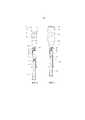
фиг. 1 - система для подготовки инъекции с первой и второй емкостью;FIG. 1 - a system for preparing an injection with a first and second container;
фиг. 2 - система согласно пункту 1 формулы изобретения с соединенными емкостями в первом функциональном положении; иFIG. 2 shows a system according to
фиг. с 3 по 5 - система в дальнейших функциональных положениях.FIG. from 3 to 5 - the system in further functional positions.
Фиг. 1 показывает систему 1 для подготовки инъекции с первой емкостью 3, которая охватывает первое полое пространство 5 и включает в себя твердую наружную стенку 7. Первая емкость 3 имеет два конца, причем на первом конце предусмотрено отверстие 9, через которое может вводиться подвижная в первом полом пространстве 5 заглушка 11. При помощи поршневого штока 13, который соединен с заглушкой 11, заглушка 11 может смещаться внутри первой емкости вдоль ее расположенной здесь вертикально продольной оси. Заглушка 11 выполнена таким образом, что она герметично прилегает к внутренней поверхности наружной стенки 7, так что полое пространство 5 герметично закрыто относительно отверстия 9. На противоположном отверстию 9 конце первой емкости 3 установлен первый соединительный элемент 15. На этом конце первая емкость 3 имеет выступ 16, на который надет соединительный элемент 15. Говоря о первой емкости 3, речь идет о шприце. В другом примере осуществления емкости на имеющемся здесь конце может быть выполнен выступ с колпачком, который герметично закрывает полое пространство 5 емкости. То есть емкость может быть также выполнена в виде карпулы, причем на упомянутом здесь конце может иметься прокалываемая пробка, однако в частности также существует возможность при помощи соединительного элемента присоединять дальнейшую емкость, для того чтобы устанавливать соединение с прохождением текучей среды между ней и полым пространством 5 в емкости. Это будет описано ниже более подробно.FIG. 1 shows an
Первая емкость 3 содержит первую субстанцию, которая размещена в полом пространстве 5. Например, говоря о первой субстанции, речь идет о порошке, в частности о лиофилизате 17, то есть о высушенной в замороженном состоянии субстанции, которая имеется в виде порошка. Выше лиофилизата 17 находится объем 19 воздуха. Однако, говоря о первой субстанции, речь может также идти о жидкости.The
Изображенная здесь система 1 включает в себя вторую емкость 21, которая охватывает полое пространство 23. В нем находится вторая субстанция, например, порошок, если, говоря о первой субстанции, речь идет о жидкости, служащая в качестве дилюента жидкость, если первая субстанция является порошком, в частности растворяющее средство 25, если первая субстанция является лиофилизатом. В качестве принципиального следует зафиксировать, что в обеих емкостях 3 и 21 имеются различные субстанции, предпочтительно с одной стороны лиофилизат, а с другой стороны обозначаемое как дилюент растворяющее средство. В изображенном здесь примере осуществления системы 1 исходят из того, что лиофилизат 17 находится в первой емкости 3, а растворяющее средство 25 во второй емкости 21. Однако также возможно размещать лиофилизат 17 во второй емкости 21, а растворяющее средство в первой емкости 3.The
Вторая емкость 21 имеет на одном, в данном случае верхнем конце запор 27, который герметично закрывает полое пространство 23 второй емкости 21.The
На расположенном на фиг. 1 сверху конце емкости 3 предусмотрена крышка K, которая удерживается соединительным элементом 15 и служит для того, чтобы герметично закрывать полое пространство 5 первой емкости 3. Таким образом, обеспечено то, что размещенная в полом пространстве 5 субстанция, то есть в данном случае лиофилизат 17, надежно закрыта со всех сторон, и обеспечивается длительный срок хранения без бактериального загрязнения. Крышка K выполнена, как известно, предпочтительно в виде сохраняющего оригинальность запора, так что манипуляции с крышкой сразу видны пользователю первой емкости 3.In FIG. 1, a cap K is provided at the top end of the
Таким образом, на фиг. 1 обе емкости 3 и 21 системы 1 закупорены отдельно друг от друга и в каждом случае герметично, так что расположенные в соответствующих полых пространствах 5 и 23 емкостей 3 и 21 субстанции надежно закрыты со всех сторон.Thus, in FIG. 1 both
Если заключенная в емкостях 3 и 21 субстанция, в данном случае лиофилизат 17 в первой емкости 3, должна вводиться пациенту, то для подготовки инъекции лиофилизат 17 должен растворяться. Это происходит при помощи размещенного во второй емкости 21 растворяющего средства 25.If the substance enclosed in
Для того чтобы была возможность растворять лиофилизат 17, обе емкости 3 и 21 должны соединяться друг с другом с возможностью прохождения текучей среды. Для того чтобы это делать возможным, сначала должны сниматься крышка K с первой емкости 3 и запор 27 со второй емкости 21. Благодаря снятию крышки K первый соединительный элемент 15 на первой емкости 3 становится доступным. Предпочтительно речь идет здесь о разъеме Луера, который надет на выступ 16 или выполнен на емкости 3 и имеет внутреннюю резьбу.In order to be able to dissolve the
Если снимается запор 27 со второй емкости 21, то на согласованном с запором 27 конце второй емкости 21 становится доступным второй соединительный элемент, который может взаимодействовать с первым соединительным элементом 15 на первой емкости 3. В случае если первый соединительный элемент 15 выполнен в виде разъема Луера, второй соединительный элемент 29 на второй емкости 21 выполнен в виде цилиндрического выступа с наружной резьбой, которая взаимодействует с внутренней резьбой в разъеме Луера. Вследствие этого возможно навинчивать вторую емкость 21 на первую емкость 3, причем первый соединительный элемент 15 герметично принимает второй соединительный элемент. Таким образом, оба соединительных элемента образуют соединительное устройство 31, которое обеспечивает герметичное соединение с прохождением текучей среды между полым пространством 5 в первой емкости 3 и полым пространством 23 второй емкости 21.If the
Конец второй емкости 21 может быть также закрыт при помощи мембраны, которая закрыта в свою очередь запором 27. Это имеет то преимущество, что содержимое второй емкости еще не полностью доступно непосредственно после снятия запора 27, который может быть выполнен, например, в виде резьбового колпачка. Посредством мембраны обеспечивается защита от загрязнений содержимого или же также от нежелательного выхода содержимого. После снятия запора 27 мембрана может прокалываться и разрываться, например, выступом 16 на конце первой емкости 3. Таким образом, в этом случае реализуется соединение с прохождением текучей среды между обеими емкостями 3 и 21.The end of the
Фиг. 2 показывает систему 1 с обеими емкостями 3 и 21, соединенными друг с другом при помощи включающего в себя оба соединительных элемента 15 и 29 соединительного устройства 31, в первом функциональном положении. Одинаковые элементы снабжены одинаковыми ссылочными позициями, так что в этом отношении делается ссылка на описание к фиг. 1, для того чтобы предотвращать повторения.FIG. 2 shows a
Изображенное на фиг. 2 первое функциональное положение системы 1 отличается тем, что при помощи соединительного устройства 31 установлено соединение с прохождением текучей среды между полым пространством 5 в первой емкости 3 и полым пространством 23 в изображенной здесь в продольном разрезе второй емкости 21, причем заглушка 11 находится в своем изображенном также на фиг. 1 исходном положении в первой емкости 3. Заглушка 11 внутри первой емкости находится еще в своем исходном положении.Depicted in FIG. 2, the first functional position of the
Фиг. 3 показывает систему 1 с обеими емкостями 3 и 21 во втором функциональном положении. Одинаковые элементы снабжены одинаковыми ссылочными позициями, так что в этом отношении делается ссылка на предшествующее описание.FIG. 3 shows a
Во втором функциональном положении согласно фиг. 3 заглушка 11 была смещена из изображенного на фиг. 1 и 2 положения согласно стрелке 33 вверх по направлению к соединительному устройству 31. Так как обе емкости 3 и 21 находятся в соединении с прохождением текучей среды, при движении вверх заглушки 11 видимый на фиг. 1 и 2 объем 19 воздуха в первом полом пространстве 5 вытесняется и поступает во второе полое пространство 23 второй емкости 21. Возможно, что во втором полом пространстве 23 перед использованием второй емкости 21 также находится воздух, как это изображено на фиг. 2, однако это не является обязательно необходимым.In the second functional position according to FIG. 3, the
Вторая емкость 21 имеет переменный объем: можно увидеть, что стенка 35 второй емкости 21 может, по меньшей мере, местами растягиваться, как только посредством введенного объема 19 воздуха создается избыточное давление во втором полом пространстве 23. Фиг. 3 показывает вторую емкость 21 в расширенном состоянии. В данном случае, что также видно на фиг. 1 и 2, вторая емкость 21 предпочтительно выполнена в виде тюбика, который состоит их эластичного, в частности полупрозрачного или прозрачного материала, так что имеющаяся в полом пространстве 23 субстанция, в данном случае растворяющее средство 25, видна. Материал второй емкости 21 предпочтительно рассчитан таким образом, что ее полое пространство 23 защищено от ультрафиолетового света. Стенка 35 состоит из материала, который при хранении системы 1 не изменяется, и который во время хранения не изменяет в частности имеющуюся в полом пространстве 23 субстанцию 25. Предпочтительно предусмотрено то, что стенка 35 на своей обращенной к полому пространству 23 внутренней поверхности имеет покрытие. Также возможно реализовывать стенку двухслойной или многослойной, для того чтобы среди прочего уменьшать ее проницаемость. Наиболее предпочтителен вариант осуществления стенки, в котором расположенный внутри, обращенный к полому пространству 23 слой устойчив к имеющейся в полом пространстве 23 субстанции. В этом случае остальной материал или остальные слои стенки 35 может/могут состоять при необходимости из более дешевых материалов. Многослойные стенки могут реализовываться посредством наслаивания, а также посредством многослойной экструзии.The
Таким образом, в изображенном на фиг. 3 функциональном положении имеющийся в полом пространстве 5 объем 19 воздуха был вытеснен благодаря смещению заглушки 11 вверх по направлению к соединительному устройству 31 в полое пространство 23 второй емкости 21, так что она растягивается и имеет больший внутренний объем, чем это имеет место в пером функциональном положении согласно фиг. 2.Thus, in FIG. 3, the
Фиг. 4 показывает третье функциональное положение системы 1. Одинаковые элементы снабжены одинаковыми ссылочными позициями, так что в этом отношении делается ссылка на предшествующее описание.FIG. 4 shows the third functional position of the
Изображение согласно фиг. 4 показывает то, что заглушка 11 была смещена из своего изображенного на фиг. 3 положения при помощи поршневого штока 13 в направлении стрелки 37 вниз, так что имеющееся во второй емкости 21 в ее полом пространстве 23 растворяющее средство 25 предпочтительно полностью поступает в полое пространство 5 первой емкости 3 и может смешиваться с имеющимся там лиофилизатом 17. То есть к лиофилизату подводится определенный объем жидкости. Таким способом также имеющаяся в первой емкости 3 жидкость может подводиться к имеющейся во второй емкости 21 второй жидкости.The image according to FIG. 4 shows that the
Благодаря вводу объема 19 воздуха вторая емкость 21 была, как уже сказано, расширена, причем ее стенка 35 была растянута. Следовательно, возникло избыточное давление во второй емкости 21. Если теперь заглушка 11 притягивается в направлении стрелки 37 вниз, в полом пространстве 5 в первой емкости 3 возникает низкое давление, которое засасывает растворяющее средство 25 из второй емкости 21. Оно наталкивается на лиофилизат 17 с высокой скоростью, так как оно дополнительно еще благодаря избыточному давлению внутри второй емкости 21 впрыскивается в первую емкость 3. Это приводит к очень хорошему перемешиванию дилюента с порошкообразным лиофилизатом 17 или обеих жидкостей, которые могут иметься в емкостях 3 и 21.Due to the introduction of the
Заглушка 11 затягивается из изображенного на фиг. 4 положения предпочтительно дальше вниз, однако таким образом, что она не вытягивается из первой емкости 3. Вследствие этого имеющиеся в полом пространстве 5 субстанции остаются герметично закрытыми со всех сторон, то есть защищенными от бактериальных загрязнений.The
Благодаря дальнейшему смещению заглушки 11 в направлении стрелки 37 вниз, то есть за пределы изображенного на фиг. 4 положения, засасывается воздух из второй емкости 21, так что лиофилизат 17 посредством встряхивания обеих емкостей 3 и 21 может просто растворяться в первом полом пространстве 5. Также возможно смещать заглушку немного вверх, так как вторая емкость 21 имеет переменный объем и тем самым не предоставляет большое сопротивление, если заглушка 11 смещается по направлению к соединительному устройству 31.Due to the further displacement of the
Это обеспечивает то, что может осуществляться оптимальное перемешивание субстанций, то есть в частности лиофилизата 17 и растворяющего средства 25, в первом полом пространстве 5 первой емкости 3. Хорошее перемешивание имеет место также в том случае, впрочем, даже в том случае, если в обеих емкостях 3 и 21 имеются жидкости, которые в принципе относительно плохо растворимы. Это имеет зачастую место, например, у вакцин и витаминных препаратов.This ensures that optimal mixing of the substances, that is, in particular the
Наконец, фиг. 5 показывает первую емкость 3 системы 1 в дальнейшем функциональном положении. Одинаковые элементы снабжены одинаковыми ссылочными позициями, так что в этом отношении делается ссылка на предшествующее описание.Finally, FIG. 5 shows a
На фиг. 5 видно, что вторая емкость 21 снята, то есть в данном случае свинчена с первой емкости. С первым соединительным элементом 15 соединена инъекционная игла 39, которая известным, имеющим наружную резьбу выступом ввинчена в выполненный здесь в виде разъема Луера соединительный элемент 15. Заглушка 11 находится здесь в положении, в котором все части воздуха удалены из полого пространства 5 и предпочтительно также из инъекционной иглы 39. Таким образом, здесь наличествует шприц, который подготовлен для инъекции.In FIG. 5 it can be seen that the
На чертеже исходили, как уже сказано выше, из того, что, говоря о первой емкости 3, речь идет о шприце, который при помощи соединительного элемента 15 может соединяться с инъекционной иглой 39.The drawing proceeded, as already mentioned above, from the fact that, speaking of the
Однако здесь следует еще раз указать на то, что первая емкость 3 может также выполняться в виде карпулы, которая при помощи соединительного устройства может соединяться со второй емкостью 21, для того чтобы имеющийся во вторых емкостях или во второй емкости карпулы лиофилизат растворять растворяющим средством, которое находится в каждом случае в другой емкости. Затем карпула может вставляться, например, в обозначаемую как шприц-ручка инъекционную систему или же в инфузионное устройство.However, it should be pointed out here again that the
В итоге существенным является то, что вторая емкость 21 имеет, по меньшей мере, местами эластичную стенку. В конечном счете, она может быть также выполнена произвольной, то есть, например, также цилиндрической. То есть не является обязательно необходимым предусматривать здесь выполненную в виде тюбика емкость.As a result, it is essential that the
Кроме того, важным является то, что соединительное устройство 31 должно быть выполнено таким образом, что устанавливается герметичное соединение с прохождением текучей среды между обоими полыми пространствами в емкостях. Так как это широко распространено, следует оказывать абсолютное предпочтение системе Луера, то есть разъему Луера в качестве первого соединительного элемента 15 и второй емкости со снабженным наружной резьбой выступом, который служит в качестве второго соединительного элемента 29.In addition, it is important that the connecting
Относительно функционирования системы для подготовки инъекции и относительно осуществления способа подготовки инъекции следует отметить следующее:Regarding the functioning of the injection preparation system and the implementation of the injection preparation method, the following should be noted:
Из разъяснений к фиг. с 1 по 5 ясно, что при осуществлении способа подготовки инъекции обе емкости 3 и 21 системы 1, которые содержат различные субстанции, в частности лиофилизат и растворяющее средство, сначала должны соединяться друг с другом таким образом, что устанавливается герметичное соединение с прохождением текучей среды между окруженными емкостями 3 и 21 полыми пространствами 5 и 23. Это осуществляется при помощи соединительного устройства 31, которое имеет первый соединительный элемент 15 на первой емкости 3 и второй соединительный элемент 29 на второй емкости 21. После соединения емкостей и реализации соединения с прохождением текучей среды жидкое вещество, то есть растворяющее средство подводится к порошкообразному веществу, то есть лиофилизату. В изображенном здесь примере осуществления системы растворяющее средство 25 вводится из второй емкости 21 в полое пространство 5 первой емкости 3, в которой находится лиофилизат 17. Переносу растворяющего средства 25 в первую емкость 3 содействует то, что вторая емкость 21 имеет переменный объем, предпочтительно стенку 35, которая, по меньшей мере, местами выполнена эластичной, и что вторая емкость 21 сначала расширяется благодаря объему 19 воздуха из первой емкости 3.From the explanation of FIG. 1 to 5 it is clear that in the implementation of the injection preparation method, both
В связи с фиг. 3 и 4 было разъяснено, что сначала заглушка 11 перемещается внутри первой емкости 3 вверх в направлении стрелки 33, для того чтобы создавать избыточное давление во второй емкости 21. Благодаря избыточному давлению и благодаря смещению заглушки 11 внутри первой емкости 3 в направлении стрелки 37 (см. фиг. 4) растворяющее средство 25 переносится из второй емкости 21 в полое пространство 5 первой емкости 3.In connection with FIG. 3 and 4, it was explained that at first the
Однако также возможно, исходя из ситуации согласно фиг. 2, смещать заглушку 11 внутри первой емкости 3 в направлении стрелки 37, которая изображена на фиг. 4, вниз и сразу переносить имеющееся во второй емкости 21 растворяющее средство 25 в первую емкость 3. В этом случае уменьшается объем внутри второй емкости 21, как это показывает сравнение фиг. 2 и 4.However, it is also possible based on the situation of FIG. 2, move the
Благодаря движению и/или встряхиванию содержащей лиофилизат 17 и растворяющее средство 25 первой емкости 3 лиофилизат 17 растворяется. Растворению лиофилизата 17, а также перемешиванию субстанций может содействовать то, что заглушка 11 перемещается внутри первой емкости 3 в направлении ее продольной оси вверх и вниз. Заглушка 11 может перемещаться вверх и вниз настолько, что смешиваемые субстанции перетекают через область соединения между обеими емкостями 3 и 21. Так как здесь, как правило, имеется относительно небольшое поперечное сечение потока, происходит наиболее хорошее перемешивание обеих субстанций. Также, таким образом, оказывается содействие растворению лиофилизата в дилюенте. При движении заглушки 11 вверх в направлении стрелки 33 (фиг. 3) увеличивается объем во второй емкости 21, так что она, как показывает фиг. 3, расширяется.By moving and / or shaking the
Перемещение заглушки 11 облегчается вследствие того, что вторая емкость 21 имеет переменный объем и тем самым противопоставляет движению заглушки 11 верх возможно только незначительное обратное давление.The movement of the
Известно для изготовления инъекционного раствора соединять две емкости друг с другом и при этом, например, жидкость из одной емкости засасывать в другую емкость, для того чтобы там смешивать жидкость с лиофилизатом или с дальнейшей жидкостью. У описанной здесь системы одна жидкость протекает через область соединения между двумя емкостями, для того чтобы вступать в контакт, например, с другой жидкостью или лиофилизатом. Возникающий при этом раствор может для перемешивания обеих жидкостей или растворенного лиофилизата вытесняться обратно через место соединения в емкость, в которой сначала находилась засасываемая жидкость. При многократном движении заглушки 11 вверх и вниз внутри первой емкости 3 в направлении ее продольной оси смешиваемые субстанции неоднократно протекают через область соединения, для того чтобы перетекать между обеими емкостями 3 и 21. При этом жидкость из первой емкости поступает во вторую емкость, которая изначально содержала служащую в качестве растворяющего средства или дилюента жидкость.It is known for the manufacture of an injection solution to connect two containers with each other and, for example, to suck a liquid from one container into another container in order to mix the liquid with a lyophilisate or further liquid there. In the system described here, one liquid flows through the connection region between the two containers in order to come into contact, for example, with another liquid or lyophilisate. The solution resulting from this can be displaced back to the container in which the suction liquid was initially located to mix both liquids or the dissolved lyophilisate. When the
Так как здесь предпочтительно предусмотрено то, что количества субстанций в обеих емкостях точно согласованы друг с другом для создания инъекционного раствора, раствор может выдавливаться из первой емкости во вторую емкость, что легко возможно благодаря, по меньшей мере, одной области упругой стенки второй емкости. Это является отличительным признаком по сравнению с другими системами, у которых в одной емкости предоставлено большое количество жидкости, которое засасывается для нескольких инъекций в другую емкость. У этих известных систем важным является то, чтобы имеющееся в емкости вещество, которое засасывается в различные шприцы или карпулы, ни в коем случае не загрязнялось, чтобы при многократном использовании емкости также не загрязнялся создаваемый инъекционный раствор.Since it is preferably provided here that the amounts of substances in both containers are precisely matched to create an injection solution, the solution can be squeezed from the first container into the second container, which is easily possible due to at least one region of the elastic wall of the second container. This is a hallmark compared to other systems that have a large amount of fluid provided in one container, which is sucked in for several injections into another container. For these known systems, it is important that the substance present in the container, which is sucked into various syringes or capsules, is in no way contaminated, so that with repeated use of the container, the created injection solution is also not contaminated.
Говоря о первой емкости 3, речь идет предпочтительно об однокамерном шприце или однокамерной карпуле, который/которая содержит лиофилизат. Подобные шприцы и карпулы известны. Лиофилизат может простым образом растворяться растворяющим средством, благодаря тому, что шприц или карпула соединяется со второй емкостью 21 при помощи соединительного устройства 31, причем устанавливается соединение с прохождением текучей среды. Вторая емкость 21 имеет переменный объем, который реализуется в частности посредством, по меньшей мере, местами эластичной стенки 35. Наиболее предпочтительно вторая емкость 21 выполняется в виде тюбика, который может простым образом соединяться с первой емкостью, то есть шприцом или карпулой. При этом этот тюбик может заменять обычные емкости, которые, как правило, содержат растворяющее средство и соединяются со шприцом или карпулой. Таким образом, можно очень легко использовать преимущества второй емкости 21 с переменным объемом, для того чтобы растворять лиофилизат в обычных шприцах и карпулах или смешивать две различные жидкости друг с другом.Speaking about the
Из разъяснений обнаруживается, что существенным аспектом изобретения является, по меньшей мере, одна местами эластичная стенка емкости, в частности тюбика. Стенка для подготовки инъекционного раствора расширяется, так что, по меньшей мере, одна местами эластичная стенка, таким образом, растягивается. Благодаря возвратным усилиям этой стенки имеющееся во второй емкости вещество вытесняется под избыточным давлением из второй емкости в первую емкость, так что это вещество оптимально смешивается с имеющимся в первой емкости веществом. Например, струя жидкости из второй емкости входит в контакт с высокой скоростью и энергией с порошкообразной субстанцией в первой емкости, так что эта субстанция оптимально смешивается с жидкостью. Это явление возникает естественно также в том случае, если выходящая с высокой энергией и скоростью из второй емкости жидкость входит в контакт с дальнейшей жидкостью в первой емкости.From the clarifications, it is found that an essential aspect of the invention is at least one locally elastic wall of the container, in particular a tube. The wall for preparing the injection solution expands, so that at least one locally elastic wall is thus stretched. Due to the return forces of this wall, the substance present in the second vessel is displaced under overpressure from the second vessel into the first vessel, so that this substance is optimally mixed with the substance present in the first vessel. For example, a jet of liquid from a second container comes into contact at high speed and energy with a powder substance in the first container, so that this substance is optimally mixed with the liquid. This phenomenon naturally occurs also in the event that a liquid exiting with a high energy and speed from a second vessel comes into contact with a further liquid in the first vessel.
Сверх этого, посредством смещения заглушки 11 в первой емкости 3 по направлению ко второй емкости и в противоположном направлении возможно простым образом допускать протекание имеющихся в емкостях веществ через соединение с прохождением текучей среды между емкостями. При движении заглушки вперед и назад жидкость со смешиваемым порошком или со смешиваемой дальнейшей жидкостью перетекает вперед и назад через соединение с прохождением текучей среды. Так как это соединение имеет меньшее поперечное сечение, чем обе емкости, субстанции проходят через соединение с прохождением текучей среды с высокой скоростью, что вызывает оптимальное перемешивание субстанций, то есть в частности хорошее растворение лиофилизата растворяющим средством или дилюентом.On top of this, by displacing the
При этом именно, по меньшей мере, местами эластичная стенка является большим преимуществом, так как она при движении заглушки вперед и назад может расширяться и сжиматься и тем самым содействует перемешиванию субстанций. При этом расширению второй емкости она противопоставляет сравнительно небольшое сопротивление.Moreover, it is at least in some places that the elastic wall is a great advantage, since it can expand and contract when the plug moves forward and backward, and thereby contributes to the mixing of substances. At the same time, it contrasts the expansion of the second capacity with a relatively small resistance.
В итоге оказывается, что для объемов первой и второй емкости, в частности шприца или карпулы и тюбика предпочтительно выбираются максимум 100 мл. Наиболее пригодными оказались объемы от 1 мл до 50 мл, в частности от 1 мл до 10 мл или 15 мл.As a result, it turns out that for volumes of the first and second containers, in particular a syringe or a capsule and a tube, a maximum of 100 ml is preferably selected. The most suitable were volumes from 1 ml to 50 ml, in particular from 1 ml to 10 ml or 15 ml.
При указанных в конце объемах первой емкости, то есть шприца или карпулы, а также второй емкости, то есть тюбика возникают наиболее компактные конструктивные исполнения для системы для подготовки инъекции или для комбинации из шприца или карпулы, с одной стороны, и тюбика, с другой стороны. Таким образом, это исполнение отличается наибольшей легкостью в использовании, которая очень хорошо может также осваиваться пациентами.With the volumes indicated at the end of the first container, that is, the syringe or karpula, as well as the second container, that is, the tube, the most compact designs for a system for preparing an injection or for a combination of a syringe or karpula, on the one hand, and a tube, on the other hand . Thus, this design is characterized by the greatest ease of use, which can also be very well mastered by patients.
Claims (21)
Translated fromRussianApplications Claiming Priority (3)
| Application Number | Priority Date | Filing Date | Title |
|---|---|---|---|
| DE102014220365.1 | 2014-10-08 | ||
| DE102014220365.1ADE102014220365A1 (en) | 2014-10-08 | 2014-10-08 | System and method for preparing an injection |
| PCT/EP2015/072998WO2016055445A1 (en) | 2014-10-08 | 2015-10-06 | System and method for providing an injection |
Publications (3)
| Publication Number | Publication Date |
|---|---|
| RU2017115841A RU2017115841A (en) | 2018-11-13 |
| RU2017115841A3 RU2017115841A3 (en) | 2018-12-25 |
| RU2704016C2true RU2704016C2 (en) | 2019-10-23 |
Family
ID=54251518
Family Applications (1)
| Application Number | Title | Priority Date | Filing Date |
|---|---|---|---|
| RU2017115841ARU2704016C2 (en) | 2014-10-08 | 2015-10-06 | Injection preparation system and method |
Country Status (9)
| Country | Link |
|---|---|
| US (1) | US20170304525A1 (en) |
| EP (1) | EP3203972A1 (en) |
| JP (1) | JP2017530804A (en) |
| BR (1) | BR112017007299A2 (en) |
| CA (1) | CA2963449A1 (en) |
| DE (1) | DE102014220365A1 (en) |
| MX (1) | MX2017004511A (en) |
| RU (1) | RU2704016C2 (en) |
| WO (1) | WO2016055445A1 (en) |
Families Citing this family (2)
| Publication number | Priority date | Publication date | Assignee | Title |
|---|---|---|---|---|
| TWI746569B (en) | 2016-06-08 | 2021-11-21 | 瑞士商瑞健醫療股份有限公司 | Dosiergerat, injektionsvorrichtung und verwendung |
| US11253652B2 (en) | 2016-11-28 | 2022-02-22 | Shl Medical Ag | Device for dispensing a substance |
Citations (5)
| Publication number | Priority date | Publication date | Assignee | Title |
|---|---|---|---|---|
| US2798488A (en)* | 1954-09-15 | 1957-07-09 | Merck & Co Inc | Syringe unit |
| US3610297A (en)* | 1968-08-28 | 1971-10-05 | Pfizer | Dual-chamber liquid ejector and filling connector |
| RU2141306C1 (en)* | 1993-09-07 | 1999-11-20 | Дебиотек С.А. | Syringe device for mixing of two components |
| WO2002000290A1 (en)* | 2000-06-27 | 2002-01-03 | Barry Farris | Method and needleless apparatus for the storage of a first substance followed by subsequent mixing with a second substance and transfer without ambient air incursion |
| EP1726285A1 (en)* | 2005-05-24 | 2006-11-29 | Vifor (International) Ag | Container for dispensing a medicament and associated administering apparatus |
Family Cites Families (14)
| Publication number | Priority date | Publication date | Assignee | Title |
|---|---|---|---|---|
| US2724383A (en)* | 1951-06-28 | 1955-11-22 | Compule Corp | Combined mixing container structure and hypodermic syringe for segregated ingredients of hypodermically injectable preparations |
| GB8800448D0 (en)* | 1988-01-09 | 1988-02-10 | Smiths Industries Plc | Liquid containers |
| FR2653661A1 (en)* | 1989-10-26 | 1991-05-03 | Faure Jean Marie | PACKAGING FOR THE ADMINISTRATION OF STERILE LIQUIDS, ESPECIALLY PHARMACEUTICAL LIQUIDS. |
| WO1993002921A1 (en)* | 1991-08-07 | 1993-02-18 | Habley Medical Technology Corporation | Metered syringe filling device for pharmaceutical containers |
| US5281198A (en)* | 1992-05-04 | 1994-01-25 | Habley Medical Technology Corporation | Pharmaceutical component-mixing delivery assembly |
| DK0928182T3 (en)* | 1996-01-11 | 2002-08-26 | Duoject Inc | Delivery system for medicines packed in pharmaceutical bottles |
| US6577344B2 (en)* | 1996-09-27 | 2003-06-10 | Canon Kabushiki Kaisha | Focus state detection apparatus with image sensing device controls |
| US6308747B1 (en)* | 1998-10-01 | 2001-10-30 | Barry Farris | Needleless method and apparatus for transferring liquid from a container to an injecting device without ambient air contamination |
| US6918418B1 (en)* | 2000-03-13 | 2005-07-19 | Barry Farris | Method and apparatus for the storage and transfer of a lyophilisate |
| WO2005102594A1 (en)* | 2004-04-21 | 2005-11-03 | Nec Corporation | Solder and mounted article using same |
| US20060058734A1 (en)* | 2004-09-15 | 2006-03-16 | Phillips John C | Self-sealing male Luer connector with molded elastomeric tip |
| DE202005004135U1 (en)* | 2005-03-11 | 2005-05-19 | Klocke Verpackungs-Service Gmbh | Multi-component packaging with applicator |
| TW201043221A (en)* | 2009-05-06 | 2010-12-16 | Ferring Int Ct Sa | Kit and method for preparation of a Degarelix solution |
| JP2011206152A (en)* | 2010-03-29 | 2011-10-20 | Morimoto Iyaku:Kk | Container for concomitant medicine, medicine container, and auxiliary container |
- 2014
- 2014-10-08DEDE102014220365.1Apatent/DE102014220365A1/ennot_activeCeased
- 2015
- 2015-10-06USUS15/517,435patent/US20170304525A1/ennot_activeAbandoned
- 2015-10-06MXMX2017004511Apatent/MX2017004511A/enunknown
- 2015-10-06EPEP15774926.8Apatent/EP3203972A1/ennot_activeWithdrawn
- 2015-10-06BRBR112017007299-8Apatent/BR112017007299A2/ennot_activeApplication Discontinuation
- 2015-10-06CACA2963449Apatent/CA2963449A1/ennot_activeAbandoned
- 2015-10-06WOPCT/EP2015/072998patent/WO2016055445A1/enactiveApplication Filing
- 2015-10-06RURU2017115841Apatent/RU2704016C2/enactive
- 2015-10-06JPJP2017518930Apatent/JP2017530804A/enactivePending
Patent Citations (5)
| Publication number | Priority date | Publication date | Assignee | Title |
|---|---|---|---|---|
| US2798488A (en)* | 1954-09-15 | 1957-07-09 | Merck & Co Inc | Syringe unit |
| US3610297A (en)* | 1968-08-28 | 1971-10-05 | Pfizer | Dual-chamber liquid ejector and filling connector |
| RU2141306C1 (en)* | 1993-09-07 | 1999-11-20 | Дебиотек С.А. | Syringe device for mixing of two components |
| WO2002000290A1 (en)* | 2000-06-27 | 2002-01-03 | Barry Farris | Method and needleless apparatus for the storage of a first substance followed by subsequent mixing with a second substance and transfer without ambient air incursion |
| EP1726285A1 (en)* | 2005-05-24 | 2006-11-29 | Vifor (International) Ag | Container for dispensing a medicament and associated administering apparatus |
Also Published As
| Publication number | Publication date |
|---|---|
| EP3203972A1 (en) | 2017-08-16 |
| JP2017530804A (en) | 2017-10-19 |
| CA2963449A1 (en) | 2016-04-14 |
| RU2017115841A (en) | 2018-11-13 |
| WO2016055445A1 (en) | 2016-04-14 |
| MX2017004511A (en) | 2017-08-08 |
| DE102014220365A1 (en) | 2016-04-28 |
| RU2017115841A3 (en) | 2018-12-25 |
| BR112017007299A2 (en) | 2018-03-13 |
| US20170304525A1 (en) | 2017-10-26 |
Similar Documents
| Publication | Publication Date | Title |
|---|---|---|
| JP6835797B2 (en) | Pressure regulation system, pressure regulation syringe assembly, and method of transferring liquid | |
| JP6747651B2 (en) | Syringe for holding vacuum in storage and for mixing two components | |
| US10456526B2 (en) | Multi-compartment pre-filled mixing syringes with bypass | |
| JP4682850B2 (en) | Prefilled syringe | |
| KR101507841B1 (en) | Method and apparatus for contamination-free transfer of a hazardous drug | |
| CN108136128B (en) | Multi-chamber syringe unit and method of making a multi-chamber syringe | |
| US10596069B2 (en) | Syringes with mixing chamber in a removable cap | |
| CN102186447A (en) | System for reconstitution of a powdered drug | |
| JP2007185319A5 (en) | ||
| JP2004524082A (en) | Reconstruction device and method of use | |
| WO2013035543A1 (en) | Medical container and method for making medical container | |
| JP2016195781A (en) | Rack and pinion driving device for bypass cartridge | |
| KR101688685B1 (en) | Pre-filled syringe | |
| JP6283034B2 (en) | Valve that allows mixing within the drug delivery device | |
| RU2704016C2 (en) | Injection preparation system and method | |
| JP2002172166A (en) | Pre-filled syringe | |
| KR101439466B1 (en) | Injection device and drug injection kit | |
| DK201500380A1 (en) | Intravenous Bag | |
| WO2020027220A1 (en) | Method for removing silicone oil when administering protein preparation | |
| WO2013047029A1 (en) | Medical container | |
| WO2025008457A1 (en) | Air injector for an infusion system | |
| TW202019505A (en) | Prefilled injection device | |
| HK1255970B (en) | Multi chamber syringe unit and method of preparing a multi chamber syringe | |
| HK1122489A1 (en) | Container with a hollow needle | |
| HK1122489B (en) | Container with a hollow needle |