RU2698940C1 - Cable fault location device - Google Patents
Cable fault location deviceDownload PDFInfo
- Publication number
- RU2698940C1 RU2698940C1RU2018142900ARU2018142900ARU2698940C1RU 2698940 C1RU2698940 C1RU 2698940C1RU 2018142900 ARU2018142900 ARU 2018142900ARU 2018142900 ARU2018142900 ARU 2018142900ARU 2698940 C1RU2698940 C1RU 2698940C1
- Authority
- RU
- Russia
- Prior art keywords
- lead
- vertical
- shutter
- container
- channel
- Prior art date
Links
- 230000005855radiationEffects0.000claimsdescription15
- 238000004804windingMethods0.000claimsdescription8
- 229910000831SteelInorganic materials0.000claimsdescription7
- 239000010959steelSubstances0.000claimsdescription7
- 125000006850spacer groupChemical group0.000claimsdescription6
- 230000002285radioactive effectEffects0.000abstractdescription6
- 230000000694effectsEffects0.000abstractdescription5
- 238000004870electrical engineeringMethods0.000abstractdescription3
- 230000002265preventionEffects0.000abstractdescription2
- 230000005540biological transmissionEffects0.000abstract1
- 239000000126substanceSubstances0.000abstract1
- 230000004907fluxEffects0.000description4
- 238000009413insulationMethods0.000description3
- 241001538234NalaSpecies0.000description1
- 230000008033biological extinctionEffects0.000description1
- 238000010586diagramMethods0.000description1
- 230000006870functionEffects0.000description1
- 230000005484gravityEffects0.000description1
- 238000005286illuminationMethods0.000description1
- 238000005259measurementMethods0.000description1
- 230000002441reversible effectEffects0.000description1
- 231100000241scarToxicity0.000description1
Images

Classifications
- G—PHYSICS
- G01—MEASURING; TESTING
- G01N—INVESTIGATING OR ANALYSING MATERIALS BY DETERMINING THEIR CHEMICAL OR PHYSICAL PROPERTIES
- G01N23/00—Investigating or analysing materials by the use of wave or particle radiation, e.g. X-rays or neutrons, not covered by groups G01N3/00 – G01N17/00, G01N21/00 or G01N22/00
- G01N23/02—Investigating or analysing materials by the use of wave or particle radiation, e.g. X-rays or neutrons, not covered by groups G01N3/00 – G01N17/00, G01N21/00 or G01N22/00 by transmitting the radiation through the material
- G01N23/06—Investigating or analysing materials by the use of wave or particle radiation, e.g. X-rays or neutrons, not covered by groups G01N3/00 – G01N17/00, G01N21/00 or G01N22/00 by transmitting the radiation through the material and measuring the absorption
- G01N23/18—Investigating the presence of flaws defects or foreign matter
- G—PHYSICS
- G01—MEASURING; TESTING
- G01R—MEASURING ELECTRIC VARIABLES; MEASURING MAGNETIC VARIABLES
- G01R31/00—Arrangements for testing electric properties; Arrangements for locating electric faults; Arrangements for electrical testing characterised by what is being tested not provided for elsewhere
Landscapes
- Physics & Mathematics (AREA)
- General Physics & Mathematics (AREA)
- Health & Medical Sciences (AREA)
- Life Sciences & Earth Sciences (AREA)
- Chemical & Material Sciences (AREA)
- Analytical Chemistry (AREA)
- Biochemistry (AREA)
- General Health & Medical Sciences (AREA)
- Immunology (AREA)
- Pathology (AREA)
- Locating Faults (AREA)
Abstract
Description
Translated fromRussianИзобретение относится к электротехнике и может быть использовано для определения мест повреждения на кабельных линиях электропередачи и связи.The invention relates to electrical engineering and can be used to determine the location of damage on cable power lines and communications.
Известно устройство для определения места повреждения кабеля (пат. РФ №2585323, авторы Кашин Я.М., Кириллов Г.А., Бордиян Р.Н.), содержащее импульсный измеритель, радиотелефон, источник радиоактивного излучения (ИРИ), установленный в центре свинцового контейнера в расположенном по его оси симметрии вертикальном канале, при этом в нижней части свинцового контейнера установлен затворный механизм, состоящий из свинцовой крышки, по центру которой выполнен вертикальный узконаправленный выходной канал, расположенный на одной оси с вертикальным каналом свинцового контейнера, и установленного внутри свинцовой крышки свинцового затвора с вертикальным проходным каналом, смещенным относительно оси симметрии свинцового контейнера влево, прижимаемого к нижней части свинцового контейнера прижимными пружинами с шариками и имеющего возможность плавно перемещаться вдоль нее до полного совмещения проходного канала свинцового затвора с вертикальным каналом свинцового контейнера и вертикальным узконаправленным выходным каналом свинцовой крышки по оси симметрии свинцового контейнера, при этом свинцовый затвор торцевыми частями упруго связан со свинцовой крышкой распорными пружинами и своей левой стороной соединен посредством гибкого троса, находящегося в стальной оболочке, с кнопкой дистанционного управления.A device for determining the location of cable damage (US Pat. RF No. 2585323, authors Kashin Ya.M., Kirillov G.A., Bordiyan R.N.) containing a pulse meter, a radiotelephone, a source of radioactive radiation (IRI), installed in the center a lead container in a vertical channel located along its axis of symmetry, while in the lower part of the lead container a shutter mechanism is installed, consisting of a lead cover, in the center of which a vertical narrowly directed output channel is made, located on the same axis as the vertical channel scar of the lead container, and installed inside the lead cover of the lead shutter with a vertical passage channel, offset to the left by the symmetry axis of the lead container, pressed to the bottom of the lead container by pressure springs with balls and able to smoothly move along it until the passage channel of the lead shutter is fully aligned with the vertical the lead container channel and the vertical narrowly directed output channel of the lead cover along the axis of symmetry of the lead container, in this case, the lead closure with end parts is elastically connected with the lead cover by spacer springs and is connected to the remote control button with its flexible cable located in the steel sheath with its left side.
Однако это устройство и входящий в его состав ИРИ не обеспечивают достаточно безопасной работы оператора, перемещающего устройство вдоль трассы в зоне повреждения кабеля, вследствие того, что находящийся в свинцовом контейнере ИРИ, устанавливаемом оператором на землю, создает определенную зону радиоактивной опасности для оператора, находящегося в непосредственной близости к ИРИ в момент нажатия им кнопки дистанционного управления.However, this device and the IRI included in it do not provide sufficiently safe operation of the operator moving the device along the track in the cable damage zone, due to the fact that the IRI located in the lead container installed by the operator on the ground creates a certain radioactive hazard zone for the operator located in Immediate proximity to Iran at the time it presses the remote control button.
Увеличение безопасной дальности в известном устройстве для определения места повреждения кабеля приводит к необходимости увеличения длины гибкого троса, что приводит к увеличению сил трения его о внутреннюю поверхность стальной оболочки при нажатии оператором на кнопку дистанционного управления, и соответственно, необходимости дополнительных усилий, прилагаемых оператором для нажатия на кнопку дистанционного управления.The increase in safe range in the known device for determining the location of cable damage leads to the need to increase the length of the flexible cable, which leads to an increase in the friction forces on the inner surface of the steel sheath when the operator presses the remote control button, and accordingly, the need for additional efforts by the operator to press on the remote control button.
Кроме того, оператор, вручную перемещающий ИРИ вдоль трассы в зоне повреждения кабеля, нажимая и удерживая кнопку дистанционного управления не может обеспечить точность совмещения проходного канала свинцового затвора с вертикальным каналом свинцового контейнера и вертикальным узконаправленным выходным каналом свинцовой крышки из-за отсутствия возможности фиксации свинцового затвора при полном совмещении этих каналов и информированности об их совмещении, а это в свою очередь приводит к смещению затвора относительно вертикального канала свинцового контейнера и вертикального узконаправленного выходного канала свинцовой крышки, и как следствие - к уменьшению потока радиоактивного γ-излучения, проходящего через проходной канал свинцового затвора и вертикальный узконаправленный выходной канал свинцовой крышки и воздействующего на поврежденный кабель, в результате чего созданная искусственная волновая неоднородность в изоляции кабеля может быть частично размыта, что приводит к уменьшению точности определения места повреждения кабеля.In addition, the operator who manually moves the IRI along the track in the cable damage zone by pressing and holding the remote control button cannot ensure the alignment of the lead shutter passage channel with the vertical lead container channel and the vertical narrowly directed output channel of the lead cover due to the inability to fix the lead shutter with full combination of these channels and awareness of their combination, and this in turn leads to a shift of the shutter relative to the vertical the lead container and the vertical narrowly directed output channel of the lead cover, and as a result, to reduce the radiation flux of γ radiation passing through the lead-through channel of the lead shutter and the vertical narrowly directed output channel of the lead cover and affecting the damaged cable, resulting in an artificial wave inhomogeneity in cable insulation can be partially blurred, which leads to a decrease in the accuracy of determining the location of cable damage.
Наиболее близким к заявляемому изобретению по технической сущности и принятым авторами за прототип является устройство для определения места повреждения кабеля (пат. РФ №2650081 авторы Кашин Я.М., Кириллов Г.А., Варенов А.Б.), содержащее импульсный измеритель, радиотелефон, источник радиоактивного излучения, установленный в центре свинцового контейнера в расположенном по его оси симметрии вертикальном канале, при этом в нижней части свинцового контейнера установлен затворный механизм, состоящий из свинцовой крышки, по центру которой выполнен вертикальный узконаправленный выходной канал, расположенный на одной оси с вертикальным каналом свинцового контейнера, и установленного внутри свинцовой крышки свинцового затвора с вертикальным проходным каналом, смещенным относительно оси симметрии свинцового контейнера влево, прижимаемого к нижней части свинцового контейнера прижимными пружинами с шариками и имеющего возможность плавно перемещаться вдоль нее до полного совмещения проходного канала свинцового затвора с вертикальным каналом свинцового контейнера и вертикальным узконаправленным выходным каналом свинцовой крышки по оси симметрии свинцового контейнера, при этом свинцовый затвор своей правой торцевой частью упруго связан со свинцовой крышкой распорной пружиной. На левой наружной стороне свинцового контейнера закреплен блок автономного управления, состоящий из реле времени, кнопки включения реле времени и аккумуляторной батареи, а к левой внутренней стороне свинцовой крышки жестко прикреплен выталкивающий электромагнит, состоящий из радиационностойкой обмотки, подключенной к выходу реле времени, и стального стержня-якоря, жестко прикрепленного к левой стороне свинцового затвора, а в нижней правой части свинцовой крышки установлен упор, расстояние от которого до оси симметрии вертикального канала свинцового контейнера выполнено равным расстоянию от оси симметрии вертикального проходного канала до правого края свинцового затвора.Closest to the claimed invention in technical essence and adopted by the authors for the prototype is a device for determining the location of cable damage (US Pat. RF No. 2650081 authors Kashin Ya.M., Kirillov GA, Varenov AB), containing a pulse meter, a radiotelephone, a radiation source installed in the center of a lead container in a vertical channel located along its axis of symmetry, while a shutter mechanism consisting of a lead cover is installed in the lower part of the lead container, in the center of which is made n a vertical narrowly directed output channel located on the same axis as the vertical channel of the lead container and installed inside the lead cover of the lead shutter with a vertical passage channel displaced to the left from the symmetry axis of the lead container, pressed to the bottom of the lead container by pressure springs with balls and having the ability to smoothly move along it until full alignment of the lead-through passage channel of the lead shutter with the vertical channel of the lead container and vertically m highly directional output channel lead cap along the symmetry axis of the lead container, the lead shutter his right end portion is elastically connected with a lead cover brace spring. On the left outer side of the lead container, an autonomous control unit is fixed, consisting of a time relay, a time switch and battery button, and a push-out electromagnet consisting of a radiation-resistant winding connected to the output of the time relay and a steel rod is rigidly attached to the left inner side of the lead container - An anchor rigidly attached to the left side of the lead closure, and in the lower right part of the lead cover there is an emphasis, the distance from which to the axis of symmetry of the vertical Nala lead container holds an equal distance from the axis of symmetry of the vertical flow channel to the right edge of the lead shutter.
Недостатками данного устройства являются:The disadvantages of this device are:
1. Возможность слабого воздействия γ-излучения через слой земли на поврежденный кабель из-за неполного прохождения γ-излучения от ИРИ через проходной канал свинцового затвора, вертикальный канал свинцового контейнера и вертикальный узконаправленный выходной канал, обусловленного возможностью неполного их совмещения и отсутствием у оператора, перемещающего свинцовый контейнер с ИРИ вдоль трассы в зоне повреждения кабеля, информации о полном совмещении этих каналов.1. The possibility of weak exposure to γ-radiation through the earth’s layer on a damaged cable due to incomplete passage of γ-radiation from the IRI through the lead-through passage channel, the vertical lead container channel and the vertical narrowly directed output channel, due to the possibility of incomplete alignment and the absence of the operator, moving a lead container with IRI along the route in the cable damage zone, information on the complete combination of these channels.
2. Недостаточное обеспечение безопасной работы оператора, перемещающего свинцовый контейнер с ИРИ вдоль трассы в зоне повреждения кабеля, вследствие того, что у него отсутствует информация об открытии свинцового затвора (совмещения вертикального проходного канала свинцового затвора с вертикальным каналом свинцового контейнера и вертикальным узконаправленным выходным каналом), и он, не владея этой информацией, может подойти к свинцовому контейнеру с ИРИ в то время, когда три канала совмещены, и поток γ-излучения рассеивается в окружающем пространстве, что оказывает негативное воздействие на организм оператора и находящихся поблизости людей.2. Lack of safe operation of the operator moving the lead container with IRI along the track in the cable damage zone, due to the fact that he does not have information about the opening of the lead shutter (combining the vertical passage channel of the lead shutter with the vertical channel of the lead container and the vertical narrowly directed output channel) , and without knowing this information, he can approach the lead container with IRI at the time when the three channels are combined and the γ-radiation flux is scattered in the surrounding m of space, which has a negative effect on the body of the operator and nearby people.
Задачей предлагаемого изобретения является усовершенствование устройства для определения места повреждения кабеля, позволяющее обеспечить безопасность работы оператора, перемещающего свинцовый контейнер с ИРИ вдоль трассы в зоне повреждения кабеля.The objective of the invention is to improve the device for determining the location of cable damage, which ensures the safety of the operator moving the lead container with IRI along the track in the cable damage zone.
Технический результат заявленного изобретения - уменьшение вероятности радиоактивного облучения оператора, перемещающего свинцовый контейнер с ИРИ вдоль трассы в зоне повреждения кабеля, за счет обеспечения возможности информирования его о точном совмещении проходного, вертикального и вертикального узконаправленного выходных каналов, а также предотвращение неполного прохождения похождения γ-излучения от ИРИ и, соответственно, слабого воздействия γ-излучения через слой земли на поврежденный кабель, за счет повышения точности совмещения каналов.The technical result of the claimed invention is to reduce the likelihood of radiation exposure of the operator moving the lead container with IRI along the track in the cable damage zone, by providing the possibility of informing him about the exact combination of the passage, vertical and vertical narrowly directed output channels, as well as preventing the incomplete passage of the passage of γ-radiation from IRI and, accordingly, the weak effect of γ-radiation through the earth layer on the damaged cable, by increasing the accuracy of compatibility eniya channels.
Технический результат достигается тем, что в устройстве для определения места повреждения кабеля, содержащем импульсный измеритель, радиотелефон, источник радиоактивного излучения, установленный в центре свинцового контейнера в расположенном по его оси симметрии вертикальном канале, при этом в нижней части свинцового контейнера установлен затворный механизм, состоящий из свинцовой крышки, по центру которой выполнен вертикальный узконаправленный выходной канал, расположенный на одной оси с вертикальным каналом свинцового контейнера и установленного внутри свинцовой крышки свинцового затвора с вертикальным проходным каналом, смещенным влево относительно оси симметрии свинцового контейнера, прижимаемого к нижней части свинцового контейнера прижимными пружинами с шариками и имеющего возможность плавно перемещаться вдоль нее до полного совмещения вертикального проходного канала свинцового затвора с вертикальным каналом свинцового контейнера и вертикальным узконаправленным выходным каналом свинцовой крышки по оси симметрии свинцового контейнера, при этом свинцовый затвор своей правой торцевой частью упруго связан со свинцовой крышкой распорной пружиной, к левой внутренней стороне свинцовой крышки жестко прикреплен выталкивающий электромагнит, состоящий из радиационностойкой обмотки и стального стержня-якоря, жестко прикрепленного к левой стороне свинцового затвора, а в нижней правой части свинцовой крышки установлен упор, расстояние от которого до оси симметрии вертикального канала свинцового контейнера выполнено равным расстоянию от оси симметрии вертикального проходного канала до правого края свинцового затвора, при этом на наружной стороне свинцового контейнера закреплен блок автономного управления, содержащий аккумуляторную батарею, при этом блок автономного управления дополнительно содержит красную сигнальную лампу и зеленую сигнальную лампу, установленные в верхней его части, и электронный блок, при этом на упоре со стороны свинцового затвора устанавливается сигнальный концевой микровыключатель, в нижней наружной части свинцовой крышки устанавливается нижний концевой выключатель, а в нижней внутренней части свинцовой крышки слева от вертикального узконаправленного выходного канала свинцовой крышки устанавливается сигнальный промежуточный микровыключатель, расстояние от правого края которого до левого края вертикального канала свинцового контейнера выполяется равным расстоянию от левого края свинцового затвора до правого края вертикального проходного канала, при этом затворный механизм управляется пультом дистанционного управления с кнопками дистанционного управления «Открытие затвора», «Закрытие затвора».The technical result is achieved by the fact that in the device for determining the place of cable damage, containing a pulse meter, a radiotelephone, a radiation source installed in the center of the lead container in the vertical channel located along its axis of symmetry, while the shutter mechanism is installed in the lower part of the lead container, consisting of from a lead cover, in the center of which a vertical narrowly directed output channel is made, located on the same axis as the vertical channel of the lead container and installed inside the lead cover of a lead shutter with a vertical passage channel, shifted to the left relative to the axis of symmetry of the lead container, pressed to the bottom of the lead container by pressure springs with balls and able to smoothly move along it until the vertical passage channel of the lead shutter is fully aligned with the vertical channel of the lead container and a vertical narrowly directed output channel of the lead cover along the axis of symmetry of the lead container, while The bolt with its right end part is elastically connected with the lead cover with a spacer spring, a pushing electromagnet consisting of a radiation-resistant winding and a steel armature rod rigidly attached to the left side of the lead shutter is rigidly attached to the left inner side of the lead cover, and in the lower right part of the lead cover a stop is installed, the distance from which to the axis of symmetry of the vertical channel of the lead container is equal to the distance from the axis of symmetry of the vertical passage channel to the edge of the lead shutter, while on the outer side of the lead container is mounted an autonomous control unit comprising a battery, while the autonomous control unit further comprises a red signal lamp and a green signal lamp mounted in its upper part, and an electronic unit, while on the stop a signal limit microswitch is installed on the side of the lead shutter, a lower limit switch is installed in the lower outer part of the lead cover, and in the lower internal part A lead micro-switch is installed to the left of the vertical narrowly directed output channel of the lead cover, the distance from the right edge of which to the left edge of the vertical channel of the lead container is equal to the distance from the left edge of the lead shutter to the right edge of the vertical passage channel, while the shutter mechanism is controlled by a remote control controls with remote control buttons "Open the shutter", "Close the shutter."
Предотвращение неполного прохождения γ-излучения от ИРИ и, соответственно, слабого воздействия γ-излучения через слой земли на поврежденный кабель достигается повышением точности совмещения вертикального проходного канала свинцового затвора с вертикальным каналом свинцового контейнера и вертикальным узконаправленным выходным каналом за счет того, что на упоре со стороны свинцового затвора устанавливается сигнальный концевой микровыключатель, который при точном и полном совмещении трех каналов замыкает цепь включения красной сигнальной лампы, загорание которой информирует об этом оператора, находящегося на трассе в зоне повреждения кабеля.Prevention of incomplete passage of γ-radiation from the IRI and, accordingly, the weak effect of γ-radiation through the earth layer on the damaged cable is achieved by increasing the accuracy of combining the vertical passage channel of the lead shutter with the vertical channel of the lead container and the vertical narrowly directed output channel due to the fact that on the side of the lead shutter, a signal microswitch is installed, which, when the three channels are accurately and completely combined, closes the red signal switching circuit an illuminating lamp, the illumination of which informs the operator who is on the track in the area of cable damage.
Уменьшение вероятности радиоактивного облучения оператора, перемещающего свинцовый контейнер с ИРИ вдоль трассы в зоне повреждения кабеля, достигается за счет обеспечения возможности информирования о точном совмещении проходного, вертикального и вертикального узконаправленного каналов, которое достигается тем, что блок автономного управления дополнительно содержит красную сигнальную лампу, установленную в верхней его части, и электронный блок, а на упоре со стороны свинцового затвора установлен сигнальный концевой микровыключатель. При полном перемещении свинцового затвора вправо, при котором все три канала совмещаются, срабатывает сигнальный концевой микровыключатель, замыкает цепь питания красной сигнальной лампы, которая загорается, информируя оператора, перемещающего свинцовый контейнер с ИРИ вдоль трассы в зоне повреждения кабеля, о полном совмещении трех вертикальных каналов и начале воздействия γ-излучения через слой земли на поврежденный кабель. При возвращении свинцового затвора влево к исходному положению и достижении им сигнального промежуточного микровыключателя, последний срабатывает, замыкает цепь питания зеленой сигнальной лампы, которая загорается, информируя оператора, перемещающего свинцовый контейнер с ИРИ вдоль трассы в зоне повреждения кабеля, о том, что вертикальные каналы не совмещены. Погасание красной сигнальной лампы до загорания зеленой сигнальной лампы информирует оператора, перемещающего свинцовый контейнер с ИРИ вдоль трассы в зоне повреждения кабеля, о том, что вертикальные каналы совмещены не полностью, и опасность радиоактивного облучения имеется.Reducing the likelihood of radiation exposure of the operator moving the lead container with IRI along the track in the cable damage zone is achieved by providing the possibility of informing about the exact combination of the passage, vertical and vertical narrowly directed channels, which is achieved by the fact that the autonomous control unit additionally contains a red signal lamp installed in its upper part, and the electronic unit, and on the stop on the side of the lead shutter, a signal microswitch is installed s. When the lead shutter is completely moved to the right, at which all three channels are aligned, the signal end microswitch is activated, closes the power supply circuit of the red signal lamp, which lights up, informing the operator moving the lead container with IRI along the track in the cable damage zone about the full combination of three vertical channels and the beginning of exposure to γ-radiation through a layer of earth on a damaged cable. When the lead shutter returns to its left position and reaches the signal intermediate microswitch, the latter operates, closes the power supply circuit of the green signal lamp, which lights up, informing the operator moving the lead container with IRI along the track in the cable damage zone that vertical channels are not combined. The extinction of the red warning light before the green warning light comes on informs the operator moving the lead container with IRI along the track in the cable damage zone that the vertical channels are not fully aligned and there is a danger of radiation exposure.
Таким образом, совокупность предлагаемых признаков позволяет обеспечить безопасность работы оператора, перемещающего свинцовый контейнер с ИРИ вдоль трассы в зоне повреждения кабеля за счет уменьшения вероятности его радиоактивного облучения.Thus, the totality of the proposed features allows you to ensure the safety of the operator moving the lead container with IRI along the track in the cable damage zone by reducing the likelihood of radiation exposure.
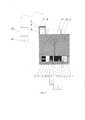
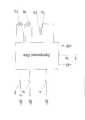
На фиг. 1 представлено предлагаемое устройство для определения места повреждения кабеля с затворным устройством, установленным в исходное положение, на фиг. 2 - предлагаемое устройство с поврежденным кабелем в момент воздействия на него радиоактивного γ-излучения и создания в изоляции кабеля искусственной волновой неоднородности, на фиг. 3 - схема соединения электронного блока с исполнительными механизмами, органами сигнализации и управления.In FIG. 1 shows the proposed device for determining the location of cable damage with a shutter installed in its original position, in FIG. 2 - the proposed device with a damaged cable at the moment of exposure to it of radioactive γ-radiation and the creation of artificial wave inhomogeneity in the cable insulation, FIG. 3 - connection diagram of the electronic unit with actuators, alarm and control.
Устройство для определения места повреждения кабеля, содержит импульсный измеритель 24, радиотелефон 23, источник радиоактивного излучения 19, установленный в центре свинцового контейнера 21 в расположенном по его оси симметрии вертикальном канале 20. В нижней части свинцового контейнера установлен затворный механизм, состоящий из свинцовой крышки 1, по центру которой выполнен вертикальный узконаправленный выходной канал 7, расположенный на одной оси с вертикальным каналом 20 свинцового контейнера 21 и установленного внутри свинцовой крышки 1 свинцового затвора 6 с вертикальным проходным каналом 9, смещенным влево относительно оси симметрии свинцового контейнера 21, прижимаемого к нижней части свинцового контейнера 21 прижимными пружинами с шариками 5 и имеющего возможность плавно перемещаться вдоль нее до полного совмещения вертикального проходного канала 9 свинцового затвора 6 с вертикальным каналом 20 свинцового контейнера 21 и вертикальным узконаправленным выходным каналом 7 свинцовой крышки 1 по оси симметрии свинцового контейнера 21. Свинцовый затвор 6 своей правой торцевой частью упруго связан со свинцовой крышкой 1 распорной пружиной 2. К левой внутренней стороне свинцовой крышки 1 жестко прикреплен выталкивающий электромагнит 12, состоящий из радиационностойкой обмотки 13 и стального стержня-якоря 11, жестко прикрепленного к левой стороне свинцового затвора 6. В нижней правой части свинцовой крышки 1 установлен упор 3, расстояние от которого до оси симметрии вертикального канала 19 свинцового контейнера 21 выполнено равным расстоянию от оси симметрии вертикального проходного канала 9 до правого края свинцового затвора 6. На наружной стороне свинцового контейнера 21 закреплен блок автономного управления 16, содержащий аккумуляторную батарею 14.A device for determining the location of cable damage, contains a
Устройство для определения места повреждения кабеля дополнительно оборудовано пультом дистанционного управления (ПДУ) 22. Пульт дистанционного управления 22 содержит кнопки дистанционного управления: «Открытие затвора», «Закрытие затвора».The device for determining the place of cable damage is additionally equipped with a remote control (RC) 22. The
Блок автономного управления 16 дополнительно содержит красную сигнальную лампу 17 и зеленую сигнальную лампу 18, установленные в верхней его части, и электронный блок 15, при этом на упоре 3 со стороны свинцового затвора 6 установлен сигнальный концевой микровыключатель 4. В нижней наружной части свинцовой крышки 1 установлен нижний концевой выключатель 8. В нижней внутренней части свинцовой крышки 1 слева от вертикального узконаправленного выходного канала 7 свинцовой крышки 1 установлен сигнальный промежуточный микровыключатель 10, расстояние

Точное определение места повреждения кабеля с помощью предлагаемого устройства осуществляется двумя операторами.Accurate determination of the place of damage to the cable using the proposed device is carried out by two operators.
Первый оператор подключает к поврежденному кабелю 25 импульсный измеритель 24 (фиг. 2) и определяет зону повреждения кабеля на трассе.The first operator connects to the damaged
Второй оператор с устройством для определения места повреждения кабеля направляется в зону повреждения кабеля 25. По прибытии в зону повреждения кабеля 25 второй оператор определяет кабелеискателем точное расположение оси кабеля на трассе. После этого второй оператор устанавливает устройство для определения места повреждения кабеля над предполагаемым местом повреждения кабеля 25 в зоне повреждения и отходит на безопасное расстояние. Сила упругости пружины в нижнем концевом выключателе 8 выбирается примерно равной 0,8 силы тяжести (веса) свинцового контейнера 21. Это позволяет обеспечить срабатывание нижнего концевого выключателя 8 при установке свинцового контейнера 21 на ровную поверхность. При касании дном свинцового контейнера 21 поверхности земли происходит замыкание нижнего концевого выключателя 8, и напряжение от аккумуляторной батареи 14 через замкнутые контакты сигнального промежуточного микровыключателя 10 и нижнего концевого выключателя 8 подается на зеленую сигнальную лампу 18, которая загорается, информируя второго оператора о том, что вертикальные каналы не совмещены. Затем второй оператор нажатием кнопки «Открытие затвора» на пульте дистанционного управления 22 подает сигнал на электронный блок 15 на открытие свинцового затвора 6.The second operator with the device for determining the location of the cable damage is sent to the
При этом электронный блок 15 подает напряжение от аккумуляторной батареи 14 на радиационностойкую обмотку 13. В результате этого под действием напряжения аккумуляторной батареи 14 по радиационностойкой обмотке 13 протекает электрический ток, который создает магнитный поток, выталкивающий стальной стержень-якорь 11 выталкивающего электромагнита 12, жестко прикрепленный к левой стороне свинцового затвора 6, вправо. В результате этого свинцовый затвор 6, прижатый прижимными пружинами с шариками 5 к нижней части крышки 1 свинцового контейнера 21, смещается по горизонтали вправо до упора 3, расстояние

Перемещение второго оператора по команде первого оператора по трассе поврежденного кабеля 25 продолжается до тех пор, пока сигнал, отраженный от места повреждения кабеля 25, не совпадет с сигналом, отраженным от искусственно созданной волновой неоднородности.The movement of the second operator at the command of the first operator along the path of the damaged
При совпадении сигнала, отраженного от места повреждения кабеля 25, с сигналом, отраженным от искусственно созданной волновой неоднородности, первый оператор подает второму оператору команду «Стоп», которую второй оператор принимает по радиотелефону 23. Место касания дном свинцового контейнера 21 поверхности земли на трассе, при котором первый оператор подал второму оператору команду «Стоп», является точным местом повреждения кабеля 25 на местности.If the signal reflected from the place of damage to the
В случае, если второй оператор по ошибке нажмет кнопку «Открытие затвора» при поднятом свинцовом контейнере 21 или при его неустойчивом положении, открытие свинцового затвора 6 не будет произведено, поскольку необходимым условием открытия свинцового затвора 6 является замыкание нижнего концевого выключателя 8, означающее, что свинцовый контейнер 6 устойчиво стоит на поверхности земли.If the second operator mistakenly presses the “Shutter Open” button when the
Размеры, свободный ход и форма кнопки нижнего концевого вылючателя 8 позволяют обеспечить его замыкание при установке свинцового контейнера 21 на мокрый или сыпучий грунт и при этом делает затруднительным замыкание нижнего концевого выключателя 8 от случайного или преднамеренного надавливания на него пальцем.The dimensions, free play and the shape of the button of the
Предлагаемое изобретение, выполняя функцию известного из патента РФ на изобретение №2650081 устройства для определения места повреждения кабеля, в то же время в отличие от него позволяет обеспечить безопасность работы оператора, перемещающего свинцовый контейнер с ИРИ вдоль трассы в зоне повреждения кабеля, путем уменьшения вероятности его радиоактивного облучения за счет обеспечения возможности информирования его о точном совмещении проходного, вертикального и вертикального узконаправленного выходных каналов; а также предотвращения за счет повышения точности совмещения каналов неполного прохождения похождения γ-излучения от ИРИ и, соответственно, слабого воздействия γ-излучения через слой земли на поврежденный кабель.The present invention, performing the function of a device for determining the place of cable damage known from the RF patent for invention No. 2650081, at the same time, unlike it, allows to ensure the safety of the operator moving the lead container with IRI along the track in the cable damage zone, by reducing its probability radioactive exposure due to the possibility of informing him about the exact combination of the passage, vertical and vertical narrowly directed output channels; as well as preventing by increasing the accuracy of combining channels of incomplete passage of the passage of γ-radiation from IRI and, accordingly, the weak effect of γ-radiation through the earth's layer on a damaged cable.
Claims (1)
Translated fromRussianPriority Applications (1)
| Application Number | Priority Date | Filing Date | Title |
|---|---|---|---|
| RU2018142900ARU2698940C1 (en) | 2018-12-04 | 2018-12-04 | Cable fault location device |
Applications Claiming Priority (1)
| Application Number | Priority Date | Filing Date | Title |
|---|---|---|---|
| RU2018142900ARU2698940C1 (en) | 2018-12-04 | 2018-12-04 | Cable fault location device |
Publications (1)
| Publication Number | Publication Date |
|---|---|
| RU2698940C1true RU2698940C1 (en) | 2019-09-02 |
Family
ID=67851734
Family Applications (1)
| Application Number | Title | Priority Date | Filing Date |
|---|---|---|---|
| RU2018142900ARU2698940C1 (en) | 2018-12-04 | 2018-12-04 | Cable fault location device |
Country Status (1)
| Country | Link |
|---|---|
| RU (1) | RU2698940C1 (en) |
Cited By (2)
| Publication number | Priority date | Publication date | Assignee | Title |
|---|---|---|---|---|
| RU2730384C1 (en)* | 2019-10-29 | 2020-08-21 | Федеральное государственное бюджетное образовательное учреждение высшего образования "Кубанский государственный технологический университет" (ФГБОУ ВО "КубГТУ") | Autonomous device for cable fault location determination |
| RU2777879C1 (en)* | 2021-07-16 | 2022-08-11 | Федеральное государственное бюджетное образовательное учреждение высшего образования "Кубанский государственный технологический университет" (ФГБОУ ВО "КубГТУ") | Autonomous apparatus for locating cable damage |
Citations (6)
| Publication number | Priority date | Publication date | Assignee | Title |
|---|---|---|---|---|
| US3944914A (en)* | 1974-04-29 | 1976-03-16 | Perkins Research And Manufacturing Co. | Fault detection method and apparatus for multiconductor cables |
| WO1983000562A1 (en)* | 1981-08-13 | 1983-02-17 | Maxwell Lab | Fault locating system for electric cables and the like |
| EP1657559A1 (en)* | 1997-01-24 | 2006-05-17 | Square D Company | Method of detecting arcing faults in a line conductor |
| RU2585323C1 (en)* | 2015-03-27 | 2016-05-27 | Федеральное государственное бюджетное образовательное учреждение высшего профессионального образования "Кубанский государственный технологический университет" (ФГБОУ ВПО "КубГТУ") | Device for determining damaged point of cable |
| RU2650081C1 (en)* | 2017-01-10 | 2018-04-06 | Федеральное государственное бюджетное образовательное учреждение высшего образования "Кубанский государственный технологический университет" (ФГБОУ ВО "КубГТУ") | Device for determining damaged point of cable |
| RU178687U1 (en)* | 2017-03-07 | 2018-04-17 | Общество с ограниченной ответственностью "Многопрофильная компания Энерготрейд", ООО "МПК Энерготрейд" | Electrical and Cable Insulation Damage Finder |
- 2018
- 2018-12-04RURU2018142900Apatent/RU2698940C1/enactive
Patent Citations (6)
| Publication number | Priority date | Publication date | Assignee | Title |
|---|---|---|---|---|
| US3944914A (en)* | 1974-04-29 | 1976-03-16 | Perkins Research And Manufacturing Co. | Fault detection method and apparatus for multiconductor cables |
| WO1983000562A1 (en)* | 1981-08-13 | 1983-02-17 | Maxwell Lab | Fault locating system for electric cables and the like |
| EP1657559A1 (en)* | 1997-01-24 | 2006-05-17 | Square D Company | Method of detecting arcing faults in a line conductor |
| RU2585323C1 (en)* | 2015-03-27 | 2016-05-27 | Федеральное государственное бюджетное образовательное учреждение высшего профессионального образования "Кубанский государственный технологический университет" (ФГБОУ ВПО "КубГТУ") | Device for determining damaged point of cable |
| RU2650081C1 (en)* | 2017-01-10 | 2018-04-06 | Федеральное государственное бюджетное образовательное учреждение высшего образования "Кубанский государственный технологический университет" (ФГБОУ ВО "КубГТУ") | Device for determining damaged point of cable |
| RU178687U1 (en)* | 2017-03-07 | 2018-04-17 | Общество с ограниченной ответственностью "Многопрофильная компания Энерготрейд", ООО "МПК Энерготрейд" | Electrical and Cable Insulation Damage Finder |
Cited By (2)
| Publication number | Priority date | Publication date | Assignee | Title |
|---|---|---|---|---|
| RU2730384C1 (en)* | 2019-10-29 | 2020-08-21 | Федеральное государственное бюджетное образовательное учреждение высшего образования "Кубанский государственный технологический университет" (ФГБОУ ВО "КубГТУ") | Autonomous device for cable fault location determination |
| RU2777879C1 (en)* | 2021-07-16 | 2022-08-11 | Федеральное государственное бюджетное образовательное учреждение высшего образования "Кубанский государственный технологический университет" (ФГБОУ ВО "КубГТУ") | Autonomous apparatus for locating cable damage |
Similar Documents
| Publication | Publication Date | Title |
|---|---|---|
| RU2650081C1 (en) | Device for determining damaged point of cable | |
| RU2698940C1 (en) | Cable fault location device | |
| EP2960923A1 (en) | Switching arrangement | |
| PH12021552670A1 (en) | Aerosol generation device having a moveable closure with a detector | |
| EP3309908A3 (en) | Cord disconnect apparatus and methods | |
| CN106454016A (en) | Wall camera with mechanical locking apparatus | |
| CN104375634A (en) | Access system for vehicle energy storage device with magnetic sensor | |
| EP3144688A3 (en) | Systems and methods for placing an imaging tool in a test and measurement tool | |
| MX376171B (en) | A push button operated switch with anti-jamming guiding system | |
| FR2375880A1 (en) | LOCKING DEVICE WITH ELECTROMECHANICAL RELEASE | |
| RU2698939C1 (en) | Cable fault location device | |
| MX2021016091A (en) | FIXED SIGNAGE AND METHOD FOR USE THEREOF. | |
| RU2730384C1 (en) | Autonomous device for cable fault location determination | |
| GB1096289A (en) | Laser tool apparatus | |
| RU2585323C1 (en) | Device for determining damaged point of cable | |
| US2150873A (en) | Burglar alarm switch | |
| FR3093226B1 (en) | Actuation system for a vacuum interrupter | |
| US505270A (en) | hicks | |
| FR3090304A3 (en) | BED ELEVATOR | |
| US2910564A (en) | Limit switch | |
| JPWO2017056174A1 (en) | Analysis equipment | |
| US1496762A (en) | Ramp device for automatic train-control apparatus | |
| US2120812A (en) | Animal trap | |
| RU2816562C1 (en) | Single-pole high-voltage combined multifunctional indicator (versions) | |
| US4531029A (en) | Cricket switch |