RU2698501C1 - Process cartridge and image forming device - Google Patents
Process cartridge and image forming deviceDownload PDFInfo
- Publication number
- RU2698501C1 RU2698501C1RU2018126081ARU2018126081ARU2698501C1RU 2698501 C1RU2698501 C1RU 2698501C1RU 2018126081 ARU2018126081 ARU 2018126081ARU 2018126081 ARU2018126081 ARU 2018126081ARU 2698501 C1RU2698501 C1RU 2698501C1
- Authority
- RU
- Russia
- Prior art keywords
- force
- force receiving
- photosensitive drum
- developing
- receiving element
- Prior art date
Links
- 238000000034methodMethods0.000titleclaimsabstractdescription131
- 230000008569processEffects0.000titleclaimsabstractdescription131
- 239000000463materialSubstances0.000claimsabstractdescription9
- 238000012546transferMethods0.000claimsdescription7
- 238000006073displacement reactionMethods0.000claims2
- 230000000694effectsEffects0.000abstract1
- 239000000126substanceSubstances0.000abstract1
- 238000003384imaging methodMethods0.000description11
- 238000003825pressingMethods0.000description11
- 238000013461designMethods0.000description9
- 238000009434installationMethods0.000description7
- 230000007246mechanismEffects0.000description7
- 229910052796boronInorganic materials0.000description4
- 238000010276constructionMethods0.000description4
- 230000008878couplingEffects0.000description4
- 238000010168coupling processMethods0.000description4
- 238000005859coupling reactionMethods0.000description4
- 230000002093peripheral effectEffects0.000description4
- 230000009471actionEffects0.000description3
- 230000005489elastic deformationEffects0.000description3
- 230000004048modificationEffects0.000description3
- 238000012986modificationMethods0.000description3
- 230000009286beneficial effectEffects0.000description2
- 230000000903blocking effectEffects0.000description2
- 230000008859changeEffects0.000description2
- 238000004140cleaningMethods0.000description2
- 239000012459cleaning agentSubstances0.000description2
- 238000000605extractionMethods0.000description2
- 238000012545processingMethods0.000description2
- ZOXJGFHDIHLPTG-UHFFFAOYSA-NBoronChemical compound[B]ZOXJGFHDIHLPTG-UHFFFAOYSA-N0.000description1
- 238000005452bendingMethods0.000description1
- 230000005540biological transmissionEffects0.000description1
- 230000015572biosynthetic processEffects0.000description1
- 239000003086colorantSubstances0.000description1
- 238000003780insertionMethods0.000description1
- 230000037431insertionEffects0.000description1
- 230000002452interceptive effectEffects0.000description1
- 239000002245particleSubstances0.000description1
- 230000008092positive effectEffects0.000description1
- 230000007704transitionEffects0.000description1
Images


Classifications
- G—PHYSICS
- G03—PHOTOGRAPHY; CINEMATOGRAPHY; ANALOGOUS TECHNIQUES USING WAVES OTHER THAN OPTICAL WAVES; ELECTROGRAPHY; HOLOGRAPHY
- G03G—ELECTROGRAPHY; ELECTROPHOTOGRAPHY; MAGNETOGRAPHY
- G03G21/00—Arrangements not provided for by groups G03G13/00 - G03G19/00, e.g. cleaning, elimination of residual charge
- G03G21/16—Mechanical means for facilitating the maintenance of the apparatus, e.g. modular arrangements
- G03G21/18—Mechanical means for facilitating the maintenance of the apparatus, e.g. modular arrangements using a processing cartridge, whereby the process cartridge comprises at least two image processing means in a single unit
- G03G21/1803—Arrangements or disposition of the complete process cartridge or parts thereof
- G03G21/1814—Details of parts of process cartridge, e.g. for charging, transfer, cleaning, developing
- G—PHYSICS
- G03—PHOTOGRAPHY; CINEMATOGRAPHY; ANALOGOUS TECHNIQUES USING WAVES OTHER THAN OPTICAL WAVES; ELECTROGRAPHY; HOLOGRAPHY
- G03G—ELECTROGRAPHY; ELECTROPHOTOGRAPHY; MAGNETOGRAPHY
- G03G21/00—Arrangements not provided for by groups G03G13/00 - G03G19/00, e.g. cleaning, elimination of residual charge
- G03G21/16—Mechanical means for facilitating the maintenance of the apparatus, e.g. modular arrangements
- G03G21/1604—Arrangement or disposition of the entire apparatus
- G03G21/1623—Means to access the interior of the apparatus
- G—PHYSICS
- G03—PHOTOGRAPHY; CINEMATOGRAPHY; ANALOGOUS TECHNIQUES USING WAVES OTHER THAN OPTICAL WAVES; ELECTROGRAPHY; HOLOGRAPHY
- G03G—ELECTROGRAPHY; ELECTROPHOTOGRAPHY; MAGNETOGRAPHY
- G03G21/00—Arrangements not provided for by groups G03G13/00 - G03G19/00, e.g. cleaning, elimination of residual charge
- G03G21/16—Mechanical means for facilitating the maintenance of the apparatus, e.g. modular arrangements
- G03G21/18—Mechanical means for facilitating the maintenance of the apparatus, e.g. modular arrangements using a processing cartridge, whereby the process cartridge comprises at least two image processing means in a single unit
- G—PHYSICS
- G03—PHOTOGRAPHY; CINEMATOGRAPHY; ANALOGOUS TECHNIQUES USING WAVES OTHER THAN OPTICAL WAVES; ELECTROGRAPHY; HOLOGRAPHY
- G03G—ELECTROGRAPHY; ELECTROPHOTOGRAPHY; MAGNETOGRAPHY
- G03G15/00—Apparatus for electrographic processes using a charge pattern
- G—PHYSICS
- G03—PHOTOGRAPHY; CINEMATOGRAPHY; ANALOGOUS TECHNIQUES USING WAVES OTHER THAN OPTICAL WAVES; ELECTROGRAPHY; HOLOGRAPHY
- G03G—ELECTROGRAPHY; ELECTROPHOTOGRAPHY; MAGNETOGRAPHY
- G03G15/00—Apparatus for electrographic processes using a charge pattern
- G03G15/02—Apparatus for electrographic processes using a charge pattern for laying down a uniform charge, e.g. for sensitising; Corona discharge devices
- G—PHYSICS
- G03—PHOTOGRAPHY; CINEMATOGRAPHY; ANALOGOUS TECHNIQUES USING WAVES OTHER THAN OPTICAL WAVES; ELECTROGRAPHY; HOLOGRAPHY
- G03G—ELECTROGRAPHY; ELECTROPHOTOGRAPHY; MAGNETOGRAPHY
- G03G21/00—Arrangements not provided for by groups G03G13/00 - G03G19/00, e.g. cleaning, elimination of residual charge
- G03G21/16—Mechanical means for facilitating the maintenance of the apparatus, e.g. modular arrangements
- G03G21/1642—Mechanical means for facilitating the maintenance of the apparatus, e.g. modular arrangements for connecting the different parts of the apparatus
- G03G21/1647—Mechanical connection means
- G—PHYSICS
- G03—PHOTOGRAPHY; CINEMATOGRAPHY; ANALOGOUS TECHNIQUES USING WAVES OTHER THAN OPTICAL WAVES; ELECTROGRAPHY; HOLOGRAPHY
- G03G—ELECTROGRAPHY; ELECTROPHOTOGRAPHY; MAGNETOGRAPHY
- G03G21/00—Arrangements not provided for by groups G03G13/00 - G03G19/00, e.g. cleaning, elimination of residual charge
- G03G21/16—Mechanical means for facilitating the maintenance of the apparatus, e.g. modular arrangements
- G03G21/1661—Mechanical means for facilitating the maintenance of the apparatus, e.g. modular arrangements means for handling parts of the apparatus in the apparatus
- G03G21/1676—Mechanical means for facilitating the maintenance of the apparatus, e.g. modular arrangements means for handling parts of the apparatus in the apparatus for the developer unit
- G—PHYSICS
- G03—PHOTOGRAPHY; CINEMATOGRAPHY; ANALOGOUS TECHNIQUES USING WAVES OTHER THAN OPTICAL WAVES; ELECTROGRAPHY; HOLOGRAPHY
- G03G—ELECTROGRAPHY; ELECTROPHOTOGRAPHY; MAGNETOGRAPHY
- G03G21/00—Arrangements not provided for by groups G03G13/00 - G03G19/00, e.g. cleaning, elimination of residual charge
- G03G21/16—Mechanical means for facilitating the maintenance of the apparatus, e.g. modular arrangements
- G03G21/18—Mechanical means for facilitating the maintenance of the apparatus, e.g. modular arrangements using a processing cartridge, whereby the process cartridge comprises at least two image processing means in a single unit
- G03G21/1803—Arrangements or disposition of the complete process cartridge or parts thereof
- G03G21/1817—Arrangements or disposition of the complete process cartridge or parts thereof having a submodular arrangement
- G03G21/1825—Pivotable subunit connection
- G—PHYSICS
- G03—PHOTOGRAPHY; CINEMATOGRAPHY; ANALOGOUS TECHNIQUES USING WAVES OTHER THAN OPTICAL WAVES; ELECTROGRAPHY; HOLOGRAPHY
- G03G—ELECTROGRAPHY; ELECTROPHOTOGRAPHY; MAGNETOGRAPHY
- G03G21/00—Arrangements not provided for by groups G03G13/00 - G03G19/00, e.g. cleaning, elimination of residual charge
- G03G21/16—Mechanical means for facilitating the maintenance of the apparatus, e.g. modular arrangements
- G03G21/18—Mechanical means for facilitating the maintenance of the apparatus, e.g. modular arrangements using a processing cartridge, whereby the process cartridge comprises at least two image processing means in a single unit
- G03G21/1839—Means for handling the process cartridge in the apparatus body
- G03G21/1842—Means for handling the process cartridge in the apparatus body for guiding and mounting the process cartridge, positioning, alignment, locks
- G—PHYSICS
- G03—PHOTOGRAPHY; CINEMATOGRAPHY; ANALOGOUS TECHNIQUES USING WAVES OTHER THAN OPTICAL WAVES; ELECTROGRAPHY; HOLOGRAPHY
- G03G—ELECTROGRAPHY; ELECTROPHOTOGRAPHY; MAGNETOGRAPHY
- G03G2215/00—Apparatus for electrophotographic processes
- G03G2215/01—Apparatus for electrophotographic processes for producing multicoloured copies
- G03G2215/0103—Plural electrographic recording members
- G03G2215/0119—Linear arrangement adjacent plural transfer points
- G—PHYSICS
- G03—PHOTOGRAPHY; CINEMATOGRAPHY; ANALOGOUS TECHNIQUES USING WAVES OTHER THAN OPTICAL WAVES; ELECTROGRAPHY; HOLOGRAPHY
- G03G—ELECTROGRAPHY; ELECTROPHOTOGRAPHY; MAGNETOGRAPHY
- G03G2221/00—Processes not provided for by group G03G2215/00, e.g. cleaning or residual charge elimination
- G03G2221/16—Mechanical means for facilitating the maintenance of the apparatus, e.g. modular arrangements and complete machine concepts
- G03G2221/1678—Frame structures
- G03G2221/169—Structural door designs
- G—PHYSICS
- G03—PHOTOGRAPHY; CINEMATOGRAPHY; ANALOGOUS TECHNIQUES USING WAVES OTHER THAN OPTICAL WAVES; ELECTROGRAPHY; HOLOGRAPHY
- G03G—ELECTROGRAPHY; ELECTROPHOTOGRAPHY; MAGNETOGRAPHY
- G03G2221/00—Processes not provided for by group G03G2215/00, e.g. cleaning or residual charge elimination
- G03G2221/16—Mechanical means for facilitating the maintenance of the apparatus, e.g. modular arrangements and complete machine concepts
- G03G2221/18—Cartridge systems
- G03G2221/183—Process cartridge
- G03G2221/1853—Process cartridge having a submodular arrangement
- G03G2221/1861—Rotational subunit connection
- G—PHYSICS
- G03—PHOTOGRAPHY; CINEMATOGRAPHY; ANALOGOUS TECHNIQUES USING WAVES OTHER THAN OPTICAL WAVES; ELECTROGRAPHY; HOLOGRAPHY
- G03G—ELECTROGRAPHY; ELECTROPHOTOGRAPHY; MAGNETOGRAPHY
- G03G2221/00—Processes not provided for by group G03G2215/00, e.g. cleaning or residual charge elimination
- G03G2221/16—Mechanical means for facilitating the maintenance of the apparatus, e.g. modular arrangements and complete machine concepts
- G03G2221/18—Cartridge systems
- G03G2221/183—Process cartridge
- G03G2221/1853—Process cartridge having a submodular arrangement
- G03G2221/1869—Cartridge holders, e.g. intermediate frames for placing cartridge parts therein
Landscapes
- Physics & Mathematics (AREA)
- General Physics & Mathematics (AREA)
- Engineering & Computer Science (AREA)
- Computer Vision & Pattern Recognition (AREA)
- Plasma & Fusion (AREA)
- Electrophotography Configuration And Component (AREA)
- Wet Developing In Electrophotography (AREA)
- Dry Development In Electrophotography (AREA)
- Apparatus For Radiation Diagnosis (AREA)
Abstract
Description
Translated fromRussianОБЛАСТЬ ИЗОБРЕТЕНИЯFIELD OF THE INVENTION
Настоящее изобретение относится к технологическому картриджу, в котором имеется электрофотографический светочувствительный барабан и проявляющий валок, воздействующий на электрофотографический светочувствительный барабан, выполненные с возможностью соединения друг с другом и отхода друг от друга, и к электрофотографическому прибору формирования изображений, в которое устанавливается такой технологический картридж с возможностью извлечения.The present invention relates to a process cartridge in which there is an electrophotographic photosensitive drum and a developing roller acting on an electrophotographic photosensitive drum configured to couple to and move away from each other, and to an electrophotographic image forming apparatus into which such a process cartridge is installed with the ability to extract.
ПРЕДШЕСТВУЮЩИЙ УРОВЕНЬ ТЕХНИКИBACKGROUND OF THE INVENTION
В приборе формирования изображений, использующем процесс электрофотографического формирования изображения, обычно применяют технологический картридж, в котором электрофотографический светочувствительный барабан и проявляющий валок, воздействующий на электрофотографический светочувствительный барабан, объединены в технологический картридж, который выполнен с возможностью съемно устанавливаться в основной узел прибора формирования изображений. При таком типе картриджа операции по обслуживанию прибора пользователь может проводить самостоятельно, без привлечения специалиста по обслуживанию. Поэтому в области электрофотографических приборов формирования изображений широко применяется именно такой тип картриджей.In an image forming apparatus using an electrophotographic image forming process, a process cartridge is typically used in which an electrophotographic photosensitive drum and a developing roller acting on an electrophotographic photosensitive drum are combined into a process cartridge that is removably mounted to the main assembly of the image forming apparatus. With this type of cartridge, the device can be serviced by the user independently without a service technician. Therefore, in the field of electrophotographic imaging devices, this type of cartridge is widely used.
Во время выполнения операции по формированию изображения проявляющий валок удерживается прижатым к электрофотографическому светочувствительному барабану с заранее определенным усилием. В контактной системе проявления, в которой проявляющий валок во время операции проявления контактирует со светочувствительным барабаном, в контакте с поверхностью светочувствительного барабана с заранее определенным усилием находится упругий слой проявляющего валка.During the imaging operation, the developing roller is held pressed against the electrophotographic photosensitive drum with a predetermined force. In the contact developing system, in which the developing roller during the developing operation is in contact with the photosensitive drum, an elastic layer of the developing roller is in contact with the surface of the photosensitive drum with a predetermined force.
Поэтому, когда технологический картридж долго не используется и остается установленным в главный узел прибора формирования изображений, упругий слой проявляющего валка может деформироваться. Если это произойдет, формируемое изображение может стать неравномерным. Поскольку проявляющий валок находится в контакте со светочувствительным барабаном, с проявляющего валка на светочувствительный барабан может наноситься проявитель, поскольку светочувствительный барабан и проявляющий валок вращаются в контакте друг с другом, даже когда операция проявления не выполняется.Therefore, when the process cartridge is not used for a long time and remains installed in the main assembly of the imaging device, the elastic layer of the developing roll may be deformed. If this happens, the resulting image may become uneven. Since the developing roller is in contact with the photosensitive drum, a developer may be applied from the developing roller to the photosensitive drum, since the photosensitive drum and the developing roller rotate in contact with each other even when the developing operation is not performed.
Для решения этой проблемы был предложен прибор формирования изображений, в котором, когда операция формирования изображения не выполняется, на технологический картридж воздействует механизм, отводящий проявляющий валок от электрофотографического светочувствительного барабана (выложенная в открытое пользование заявка на патент Японии 2003-167499).To solve this problem, an image forming apparatus was proposed in which, when the image forming operation is not performed, a mechanism is applied to the process cartridge to divert the developing roll from the electrophotographic photosensitive drum (Japanese Patent Application Laid-Open 2003-167499).
В приборе, раскрытом в этой публикации, в главный узел прибора формирования изображения с возможностью извлечения вставлены четыре технологических картриджа. Технологический картридж содержит блок светочувствительного элемента, имеющий светочувствительный барабан, и проявляющий блок для поддержки проявляющего валка, установленного в блоке светочувствительного элемента с возможностью качания. При перемещении отводящей пластины, установленной в главном узле прибора формирования изображений, принимающий усилие участок проявляющего прибора принимает усилие от отводящей пластины. При перемещении проявляющего блока относительно блока светочувствительного элемента проявляющий валок отходит от светочувствительного барабана.In the device disclosed in this publication, four process cartridges are inserted into the main assembly of the image forming apparatus with the possibility of extraction. The process cartridge includes a photosensitive member unit having a photosensitive drum, and a developing unit for supporting the developing roll mounted on the swing member of the photosensitive member. When moving the outlet plate installed in the main assembly of the imaging device, the force receiving portion of the developing device receives force from the outlet plate. When the developing unit is moved relative to the photosensitive member, the developing roller moves away from the photosensitive drum.
В известном приборе принимающий усилие участок для отвода проявляющего валка от светочувствительного барабана выступает из внешнего контура проявляющего блока. Поэтому, когда пользователь манипулирует технологическим картриджем и/или когда технологический картридж транспортируется, этот принимающий усилие участок может быть поврежден. Наличие принимающего усилие участка может воспрепятствовать уменьшению размеров технологического картриджа, в котором с возможностью соединения друг с другом и отвода друг от друга установлены проявляющий валок и светочувствительный барабан, и главного узла прибора формирования изображений, в котором с возможностью извлечения установлен такой технологический картридж.In the known device, a force receiving portion for withdrawing the developing roll from the photosensitive drum protrudes from the outer contour of the developing unit. Therefore, when the user manipulates the process cartridge and / or when the process cartridge is transported, this force receiving portion may be damaged. The presence of a force receiving portion can prevent the size of the process cartridge from being reduced, in which a developing roll and a photosensitive drum are installed with the possibility of connection with each other and the main unit of the imaging device, in which such a process cartridge is installed with the possibility of extraction.
КРАТКОЕ ОПИСАНИЕ ИЗОБРЕТЕНИЯSUMMARY OF THE INVENTION
Соответственно, главной целью настоящего изобретения является создание уменьшенного технологического картриджа, в котором электрофотографический светочувствительный барабан и проявляющий валок выполнены с возможностью контакта друг с другом и отвода друг от друга, и уменьшенного прибора формирования изображений, в который с возможностью извлечения может устанавливаться такой технологический картридж.Accordingly, the main objective of the present invention is to provide a reduced process cartridge in which an electrophotographic photosensitive drum and a developing roller are configured to contact each other and retract from each other, and a reduced image forming apparatus into which such a process cartridge can be mounted.
Другой задачей настоящего изобретения является создание технологического картриджа, в котором электрофотографический светочувствительный барабан и проявляющий валок выполнены с возможностью контакта друг с другом и отхода друг от друга, в котором при манипуляциях с технологическим картриджем или при транспортировке технологического картриджа принимающий усилие участок не повреждается.Another object of the present invention is to provide a process cartridge in which the electrophotographic photosensitive drum and the developing roller are adapted to come into contact with each other and move away from each other, in which the force-receiving portion is not damaged during handling of the process cartridge or during transportation of the process cartridge.
Согласно одному аспекту настоящего изобретения предлагается технологический картридж, выполненный с возможностью съемной установки в главный узел электрофотографического прибора формирования изображений, при этом главный узел содержит отверстие, дверцу, выполненную с возможностью перемещения между закрытым положением для закрывания отверстия и открытым положением для открывания отверстия, первый прилагающий отверстие элемент, выполненный с возможностью перемещения в вместе с перемещением дверцы из открытого положения в закрытое положение и второй прилагающий усилие элемент, выполненный с возможностью перемещения приводным усилием привода, при этом технологический картридж содержит электрофотографический светочувствительный барабан, проявляющий валок для проявления электростатического латентного изображения, сформированного на электрофотографическом светочувствительном барабане, блок барабана, содержащий этот электрофотографический светочувствительный барабан, проявляющий блок, содержащий проявляющий валок и который выполнен с возможностью перемещения относительно блока барабана так, что проявляющий валок выполнен с возможностью перемещения между положением контакта, в котором проявляющий валок контактирует с электрофотографическим светочувствительным барабаном, и отведенным положением, в котором проявляющий валок отведен от электрофотографического светочувствительного барабана, и устройство для приема усилия, содержащее первый принимающий усилие участок для приема усилия от первого прилагающего усилие элемента при движении дверцы из открытого положения в закрытое положение в состоянии, когда технологический картридж установлен в главный узел прибора через отверстие, и второй принимающий усилие участок, выполненный с возможностью перемещения из положения ожидания перемещением первого принимающего усилие участка под воздействием усилия, принятого от первого прилагающего усилие элемента, в котором второй принимающий усилие участок занимает выступающее положение для приема усилия от второго прилагающего усилие элемента для перемещения проявляющего устройства из положения контакта в отведенное положение, при этом выступающее положение расположено выше, чем положение ожидания.According to one aspect of the present invention, there is provided a process cartridge configured to be removably mounted in a main assembly of an electrophotographic image forming apparatus, the main assembly comprising a hole, a door movable between a closed position to close the hole and an open position to open the hole, the first hole element movable in conjunction with the movement of the door from open to closed the position and the second force-applying member adapted to be moved by the drive force of the drive, the process cartridge comprising an electrophotographic photosensitive drum showing a roll for developing an electrostatic latent image formed on an electrophotographic photosensitive drum, a drum unit comprising this electrophotographic photosensitive drum showing a block, comprising a developing roll and which is movable relative to the drum unit so that the developing roller is movable between a contact position in which the developing roller is in contact with the electrophotographic photosensitive drum and a retracted position in which the developing roller is retracted from the electrophotographic photosensitive drum and a force receiving device comprising a first receiving force area for receiving force from the first force applying element when the door moves from an open position to a closed position is in a state where the process cartridge is installed in the main assembly of the device through the hole, and a second force receiving portion adapted to be moved from the standby position by moving the first force receiving portion under the influence of a force received from the first force applying member in which the second force receiving portion occupies a protruding position for receiving force from the second force applying element to move the developing device from the contact position to the allotted position set, wherein the protruding position located higher than the standby position.
Согласно другому аспекту настоящего изобретения, предлагается электрофотографический прибор формирования изображения для формирования изображения на записывающем материале, в котором съемно установлен технологический картридж, при этом прибор содержит (i) отверстие, (ii) дверцу, выполненную с возможностью перемещения между закрытым положением для закрывания отверстия, и открытым положением для открывания отверстия, (iii) первый прилагающий усилие элемент, выполненный с возможностью перемещения вместе с перемещением дверцы из открытого положения в закрытое положение, (iv) второй прилагающий усилие элемент, выполненный с возможностью перемещения приводным усилием от привода, (v) средство установки для съемной установки технологического картриджа, при этом технологический картридж содержит электрофотографический светочувствительный барабан, проявляющий валок для проявки электростатического латентного изображения, сформированного на электрографическом светочувствительном барабане, блок барабана, содержащий этот электрографический светочувствительный барабан, проявляющий блок, содержащий проявляющий валок и который выполнен с возможностью перемещения относительно блока барабана так, что проявляющий валок выполнен с возможностью перемещения между контактным положением, в котором проявляющий валок контактирует с электрографическим светочувствительным барабаном, и отведенным положением, в котором проявляющий валок отведен от электрофотографического светочувствительного барабана, и принимающее усилие устройство, содержащее первый принимающий усилие участок для приема усилия от первого прилагающего усилие элемента при движении дверцы из открытого положения в закрытое положение в состоянии, когда технологический картридж установлен в главный узел прибора через отверстие, и второй принимающий усилие участок, выполненный с возможностью перемещения из положения ожидания движением первого принимающего усилие участка, в котором второй принимающий усилие участок принимает выступающее положение для приема усилия от второго прилагающего усилие элемента для перемещения проявляющего блока из положения контакта в отведенное положение, при этом выступающее положение расположено выше, чем положение ожидания, и подающее средство для подачи записывающего материала.According to another aspect of the present invention, there is provided an electrophotographic image forming apparatus for forming an image on a recording material in which a process cartridge is removably mounted, the apparatus comprising (i) an opening, (ii) a door configured to move between a closed position to close the opening, and an open position for opening the hole, (iii) a first force-applying member movable with moving the door from the open the closed position, (iv) a second force-applying member movable by the drive force from the drive, (v) installation means for removably mounting the process cartridge, the process cartridge comprising an electrophotographic photosensitive drum showing a roll for developing an electrostatic latent image, formed on the electrographic photosensitive drum, a drum unit containing this electrographic photosensitive drum, about an developing unit comprising a developing roller and which is movable relative to the drum unit so that the developing roller is movable between a contact position in which the developing roller is in contact with the electrographic photosensitive drum and a retracted position in which the developing roller is retracted from the electrophotographic photosensitive a drum, and a force receiving device comprising a first force receiving portion for receiving force from a first adj. the force exerted by the element when the door moves from the open position to the closed position in the state when the process cartridge is installed in the main unit of the device through the hole, and the second force-receiving section, configured to move from the standby position by moving the first force-receiving section, in which the second receiving force the section assumes a protruding position for receiving force from the second force applying element to move the developing unit from the contact position to the allotted floor voltage, wherein the protruding position located higher than the standby position, and feeding means for feeding the recording material.
Эти и другие цели, признаки и преимущества настоящего изобретения будут более понятны из нижеследующего описания предпочтительных вариантов настоящего изобретения со ссылками на приложенные чертежи.These and other objectives, features and advantages of the present invention will be better understood from the following description of preferred embodiments of the present invention with reference to the attached drawings.
КРАТКОЕ ОПИСАНИЕ ЧЕРТЕЖЕЙBRIEF DESCRIPTION OF THE DRAWINGS
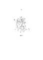
Фиг. 1 – общая компоновка электрофотографического прибора формирования изображения по первому варианту осуществления настоящего изобретения.FIG. 1 is a general arrangement of an electrophotographic image forming apparatus according to a first embodiment of the present invention.
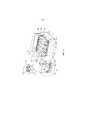
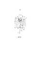
Фиг. 2 – сечение технологического картриджа по первому варианту осуществления настоящего изобретения.FIG. 2 is a sectional view of a process cartridge according to a first embodiment of the present invention.
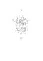
Фиг. 3 – общая компоновка электрофотографического прибора формирования изображения по первому варианту осуществления настоящего изобретения.FIG. 3 is a general arrangement of an electrophotographic image forming apparatus according to a first embodiment of the present invention.
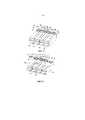
Фиг. 4 – процесс замены технологического картриджа по первому варианту осуществления настоящего изобретения.FIG. 4 illustrates a process cartridge replacement process according to a first embodiment of the present invention.
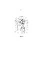
Фиг. 5 – сечение технологического картриджа, если смотреть в осевом направлении светочувствительного барабана по первому варианту осуществления настоящего изобретения.FIG. 5 is a cross-sectional view of a process cartridge when viewed in the axial direction of the photosensitive drum according to the first embodiment of the present invention.
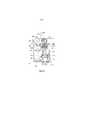
Фиг. 6 – сечение технологического картриджа, если смотреть в осевом направлении светочувствительного барабана по первому варианту осуществления настоящего изобретения.FIG. 6 is a cross-sectional view of a process cartridge as viewed in the axial direction of the photosensitive drum of the first embodiment of the present invention.
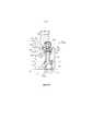
Фиг. 7 – сечение технологического картриджа, если смотреть в осевом направлении светочувствительного барабана по первому варианту осуществления настоящего изобретения.FIG. 7 is a cross-sectional view of a process cartridge when viewed in the axial direction of the photosensitive drum according to the first embodiment of the present invention.
Фиг. 8 – сечение технологического картриджа, если смотреть в осевом направлении светочувствительного барабана по первому варианту осуществления настоящего изобретения.FIG. 8 is a cross-sectional view of a process cartridge when viewed in the axial direction of the photosensitive drum of the first embodiment of the present invention.
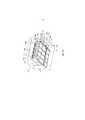
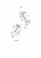
Фиг. 9 – вид в перспективе технологического картриджа, если смотреть со стороны приводов по первому варианту осуществления настоящего изобретения.FIG. 9 is a perspective view of a process cartridge as viewed from the drives of the first embodiment of the present invention.
Фиг. 10 - вид в перспективе технологического картриджа, если смотреть со стороны приводов по первому варианту осуществления настоящего изобретения.FIG. 10 is a perspective view of a process cartridge as viewed from the drives of the first embodiment of the present invention.
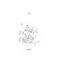
Фиг. 11 - вид в перспективе технологического картриджа, если смотреть со стороны, противоположной приводу, по первому варианту осуществления настоящего изобретения.FIG. 11 is a perspective view of a process cartridge as viewed from the opposite side to the drive of the first embodiment of the present invention.
Фиг. 12 - вид в перспективе технологического картриджа, если смотреть со стороны, противоположной приводу, по первому варианту осуществления настоящего изобретения.FIG. 12 is a perspective view of a process cartridge as viewed from the opposite side of the drive of the first embodiment of the present invention.
Фиг. 13 - вид в перспективе технологического картриджа, если смотреть со стороны, противоположной приводу, по первому варианту осуществления настоящего изобретения.FIG. 13 is a perspective view of a process cartridge as viewed from the opposite side of the drive of the first embodiment of the present invention.
Фиг. 14 - вид в перспективе технологического картриджа, если смотреть со стороны, противоположной приводу, по первому варианту осуществления настоящего изобретения.FIG. 14 is a perspective view of a process cartridge as viewed from the opposite side to the drive of the first embodiment of the present invention.
Фиг. 15 – вид в перспективе принимающего усилие устройства технологического картриджа по первому варианту осуществления настоящего изобретения.FIG. 15 is a perspective view of a force receiving device of a process cartridge according to a first embodiment of the present invention.
Фиг. 16 - вид в перспективе принимающего усилие устройства технологического картриджа по первому варианту осуществления настоящего изобретения.FIG. 16 is a perspective view of a force receiving device of a process cartridge according to a first embodiment of the present invention.
Фиг. 17 - вид в перспективе принимающего усилие устройства технологического картриджа по первому варианту осуществления настоящего изобретения.FIG. 17 is a perspective view of a force receiving device of a process cartridge according to a first embodiment of the present invention.
Фиг. 18 - вид в перспективе принимающего усилие устройства технологического картриджа по первому варианту осуществления настоящего изобретения.FIG. 18 is a perspective view of a force receiving device of a process cartridge according to a first embodiment of the present invention.
Фиг. 19 - вид в перспективе принимающего усилие устройства технологического картриджа по первому варианту осуществления настоящего изобретения.FIG. 19 is a perspective view of a force receiving device of a process cartridge according to a first embodiment of the present invention.
Фиг. 20 - вид в перспективе принимающего усилие устройства технологического картриджа по первому варианту осуществления настоящего изобретения.FIG. 20 is a perspective view of a force receiving device of a process cartridge according to a first embodiment of the present invention.
Фиг. 21 - вид в перспективе принимающего усилие устройства технологического картриджа по первому варианту осуществления настоящего изобретения.FIG. 21 is a perspective view of a force receiving device of a process cartridge according to a first embodiment of the present invention.
Фиг. 22 – технологический картридж по первому варианту настоящего изобретения, в котором на первый принимающий усилие участок и второй принимающий усилие участок воздействуют первый прилагающий усилие элемент и второй прилагающий усилие элемент электрофотографического прибора формирования изображений.FIG. 22 is a process cartridge according to a first embodiment of the present invention, in which a first force applying element and a second force applying element and a second force applying element of the electrophotographic image forming apparatus are affected by the first force receiving portion.
Фиг. 23 – общая компоновка электрофотографического прибора формирования изображения по первому варианту осуществления настоящего изобретения.FIG. 23 is a general arrangement of an electrophotographic image forming apparatus according to a first embodiment of the present invention.
Фиг. 24 – общая компоновка электрофотографического прибора формирования изображения по первому варианту осуществления настоящего изобретения.FIG. 24 is a general arrangement of an electrophotographic image forming apparatus according to a first embodiment of the present invention.
Фиг. 25 - общая компоновка электрофотографического прибора формирования изображения по первому варианту осуществления настоящего изобретения.FIG. 25 is a general arrangement of an electrophotographic image forming apparatus according to a first embodiment of the present invention.
Фиг. 26 - общая компоновка электрофотографического прибора формирования изображения по первому варианту осуществления настоящего изобретения.FIG. 26 is a general arrangement of an electrophotographic image forming apparatus according to a first embodiment of the present invention.
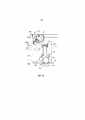
Фиг. 27 – вид, иллюстрирующий работу первого прилагающего усилие элемента по первому варианту осуществления настоящего изобретения.FIG. 27 is a view illustrating the operation of the first force-applying member of the first embodiment of the present invention.
Фиг. 28 - вид, иллюстрирующий работу второго прилагающего усилие элемента по первому варианту осуществления настоящего изобретения.FIG. 28 is a view illustrating the operation of the second force-applying member of the first embodiment of the present invention.
Фиг. 29 – вид в перспективе электрофотографического прибора формирования изображений по первому варианту осуществления настоящего изобретения.FIG. 29 is a perspective view of an electrophotographic image forming apparatus according to a first embodiment of the present invention.
Фиг. 30 - вид в перспективе электрофотографического прибора формирования изображений по первому варианту осуществления настоящего изобретения.FIG. 30 is a perspective view of an electrophotographic image forming apparatus according to a first embodiment of the present invention.
Фиг. 31 – вид, иллюстрирующий процесс замены технологического картриджа по первому варианту осуществления настоящего изобретения.FIG. 31 is a view illustrating a process for replacing a process cartridge according to a first embodiment of the present invention.
Фиг. 32 – вид, иллюстрирующий процесс замены технологического картриджа по первому варианту осуществления настоящего изобретения.FIG. 32 is a view illustrating a process for replacing a process cartridge according to a first embodiment of the present invention.
Фиг. 33 – сечение технологического картриджа, если смотреть в осевом направлении светочувствительного барабана по первому варианту настоящего изобретения, иллюстрирующее работу принимающего усилие элемента технологического картриджа.FIG. 33 is a cross-sectional view of a process cartridge when viewed in the axial direction of the photosensitive drum according to the first embodiment of the present invention, illustrating the operation of the force receiving element of the process cartridge.
Фиг. 34 - сечение технологического картриджа, если смотреть в осевом направлении светочувствительного барабана по первому варианту настоящего изобретения, иллюстрирующее работу принимающего усилие элемента технологического картриджа.FIG. 34 is a cross-sectional view of a process cartridge when viewed in the axial direction of the photosensitive drum according to the first embodiment of the present invention, illustrating the operation of the force receiving element of the process cartridge.
Фиг. 35 - сечение технологического картриджа, если смотреть в осевом направлении светочувствительного барабана по первому варианту настоящего изобретения, иллюстрирующее работу принимающего усилие элемента технологического картриджа.FIG. 35 is a cross-sectional view of a process cartridge when viewed in the axial direction of the photosensitive drum of the first embodiment of the present invention, illustrating the operation of the force receiving element of the process cartridge.
Фиг. 36 – вид, иллюстрирующий операцию отвода в технологическом картридже по первому варианту осуществления настоящего изобретения.FIG. 36 is a view illustrating a retraction operation in a process cartridge according to a first embodiment of the present invention.
Фиг. 37 - вид, иллюстрирующий операцию отвода в технологическом картридже по первому варианту осуществления настоящего изобретения.FIG. 37 is a view illustrating a retraction operation in a process cartridge according to a first embodiment of the present invention.
Фиг. 38 - вид, иллюстрирующий операцию отвода в технологическом картридже по первому варианту осуществления настоящего изобретения.FIG. 38 is a view illustrating a retraction operation in a process cartridge according to a first embodiment of the present invention.
Фиг. 39 – общая компоновка электрофотографического прибора формирования изображений по второму варианту осуществления настоящего изобретения.FIG. 39 is a general arrangement of an electrophotographic image forming apparatus according to a second embodiment of the present invention.
Фиг. 40 - общая компоновка электрофотографического прибора формирования изображений по второму варианту осуществления настоящего изобретения.FIG. 40 is a general arrangement of an electrophotographic image forming apparatus according to a second embodiment of the present invention.
Фиг. 41 - общая компоновка электрофотографического прибора формирования изображений по второму варианту осуществления настоящего изобретения.FIG. 41 is a general arrangement of an electrophotographic image forming apparatus according to a second embodiment of the present invention.
Фиг. 42 – вид, иллюстрирующий работу первого прилагающего усилие элемента электрофотографического прибора формирования изображений по второму варианту осуществления настоящего изобретения.FIG. 42 is a view illustrating the operation of a first force-applying element of an electrophotographic image forming apparatus according to a second embodiment of the present invention.
Фиг. 43 - вид, иллюстрирующий работу первого прилагающего усилие элемента по второму варианту осуществления настоящего изобретения.FIG. 43 is a view illustrating the operation of the first force-applying member of the second embodiment of the present invention.
Фиг. 44 - вид, иллюстрирующий работу первого прилагающего усилие элемента по второму варианту осуществления настоящего изобретения.FIG. 44 is a view illustrating the operation of the first force-applying member of the second embodiment of the present invention.
Фиг. 45 - вид, иллюстрирующий работу первого прилагающего усилие элемента по второму варианту осуществления настоящего изобретения.FIG. 45 is a view illustrating the operation of the first force-applying member of the second embodiment of the present invention.
Фиг. 46 – сечение технологического картриджа, если смотреть в осевом направлении светочувствительного барабана по второму варианту осуществления настоящего изобретения.FIG. 46 is a cross-sectional view of a process cartridge when viewed in the axial direction of the photosensitive drum of the second embodiment of the present invention.
Фиг. 47 – сечение технологического картриджа, если смотреть в осевом направлении светочувствительного барабана по второму варианту настоящего изобретения, иллюстрирующий принимающее усилие устройство технологического картриджа.FIG. 47 is a cross-sectional view of a process cartridge when viewed in the axial direction of the photosensitive drum of the second embodiment of the present invention, illustrating the force receiving device of the process cartridge.
Фиг. 48 – сечение технологического картриджа, если смотреть в осевом направлении фоточувствительного барабана по второму варианту настоящего изобретения, иллюстрирующее принимающее усилие устройство технологического картриджа.FIG. 48 is a cross-sectional view of a process cartridge when viewed in the axial direction of the photosensitive drum of the second embodiment of the present invention, illustrating the force receiving device of the process cartridge.
Фиг. 49 - сечение технологического картриджа, если смотреть в осевом направлении фоточувствительного барабана по второму варианту настоящего изобретения, иллюстрирующее принимающее усилие устройство технологического картриджа.FIG. 49 is a cross-sectional view of a process cartridge when viewed in the axial direction of the photosensitive drum of the second embodiment of the present invention, illustrating the force receiving device of the process cartridge.
Фиг. 50 - сечение технологического картриджа, если смотреть в осевом направлении фоточувствительного барабана по второму варианту настоящего изобретения, иллюстрирующее принимающее усилие устройство технологического картриджа.FIG. 50 is a cross-sectional view of a process cartridge when viewed in the axial direction of the photosensitive drum of the second embodiment of the present invention, illustrating the force receiving device of the process cartridge.
Фиг. 51 – сечение технологического картриджа по третьему варианту осуществления настоящего изобретения, иллюстрирующее работу принимающего усилие элемента технологического картриджа.FIG. 51 is a cross-sectional view of a process cartridge according to a third embodiment of the present invention, illustrating the operation of the force receiving element of the process cartridge.
Фиг. 52 - сечение технологического картриджа по третьему варианту осуществления настоящего изобретения, иллюстрирующее работу принимающего усилие элемента технологического картриджа.FIG. 52 is a cross-sectional view of a process cartridge according to a third embodiment of the present invention, illustrating the operation of the force receiving element of the process cartridge.
Фиг. 53 - сечение технологического картриджа по третьему варианту осуществления настоящего изобретения, иллюстрирующее работу принимающего усилие элемента технологического картриджа.FIG. 53 is a cross-sectional view of a process cartridge according to a third embodiment of the present invention, illustrating the operation of the force receiving element of the process cartridge.
Фиг. 54 - сечение технологического картриджа по третьему варианту осуществления настоящего изобретения, иллюстрирующее работу принимающего усилие элемента технологического картриджа.FIG. 54 is a cross-sectional view of a process cartridge according to a third embodiment of the present invention, illustrating the operation of the force receiving element of the process cartridge.
Фиг. 55 - сечение технологического картриджа по четвертому варианту осуществления настоящего изобретения, иллюстрирующее принимающее усилие устройство технологического картриджа.FIG. 55 is a cross-sectional view of a process cartridge according to a fourth embodiment of the present invention, illustrating the force receiving device of the process cartridge.
Фиг. 56 - сечение технологического картриджа по четвертому варианту осуществления настоящего изобретения, иллюстрирующее принимающее усилие устройство технологического картриджа.FIG. 56 is a cross-sectional view of a process cartridge according to a fourth embodiment of the present invention, illustrating the force receiving device of the process cartridge.
Фиг. 57 - сечение технологического картриджа по четвертому варианту осуществления настоящего изобретения, иллюстрирующее принимающее усилие устройство технологического картриджа.FIG. 57 is a cross-sectional view of the process cartridge of the fourth embodiment of the present invention, illustrating the force receiving device of the process cartridge.
Фиг. 58 - сечение технологического картриджа по четвертому варианту осуществления настоящего изобретения, иллюстрирующее принимающее усилие устройство технологического картриджа.FIG. 58 is a cross-sectional view of a process cartridge according to a fourth embodiment of the present invention, illustrating the force receiving device of the process cartridge.
Фиг. 59 – вид в перспективе технологического картриджа по пятому варианту настоящего изобретения, если смотреть со стороны привода.FIG. 59 is a perspective view of a process cartridge according to a fifth embodiment of the present invention when viewed from the side of the drive.
Фиг. 60 - вид в перспективе технологического картриджа по пятому варианту настоящего изобретения, если смотреть со стороны привода.FIG. 60 is a perspective view of a process cartridge according to a fifth embodiment of the present invention when viewed from the side of the drive.
Фиг. 61 – сечение технологического картриджа по шестому варианту осуществления настоящего изобретения.FIG. 61 is a cross-sectional view of a process cartridge according to a sixth embodiment of the present invention.
Фиг. 62 - сечение технологического картриджа по шестому варианту осуществления настоящего изобретения.FIG. 62 is a cross-sectional view of a process cartridge according to a sixth embodiment of the present invention.
Фиг. 63 - сечение технологического картриджа по шестому варианту осуществления настоящего изобретения.FIG. 63 is a cross-sectional view of a process cartridge according to a sixth embodiment of the present invention.
Фиг. 64 - сечение технологического картриджа по шестому варианту осуществления настоящего изобретения.FIG. 64 is a cross-sectional view of a process cartridge according to a sixth embodiment of the present invention.
Фиг. 65 – вид в перспективе технологического картриджа по седьмому варианту осуществления настоящего изобретения, иллюстрирующий принимающее усилие устройство технологического картриджа.FIG. 65 is a perspective view of a process cartridge according to a seventh embodiment of the present invention, illustrating a force receiving device of the process cartridge.
Фиг. 66 - вид в перспективе технологического картриджа по седьмому варианту осуществления настоящего изобретения, иллюстрирующий принимающее усилие устройство технологического картриджа.FIG. 66 is a perspective view of a process cartridge according to a seventh embodiment of the present invention, illustrating a force receiving device of the process cartridge.
Фиг. 67 - вид в перспективе технологического картриджа по седьмому варианту осуществления настоящего изобретения, иллюстрирующий принимающее усилие устройство технологического картриджа.FIG. 67 is a perspective view of a process cartridge according to a seventh embodiment of the present invention, illustrating a force receiving device of the process cartridge.
Фиг. 68 - вид в перспективе технологического картриджа по седьмому варианту осуществления настоящего изобретения, иллюстрирующий принимающее усилие устройство технологического картриджа.FIG. 68 is a perspective view of a process cartridge according to a seventh embodiment of the present invention, illustrating a force receiving device of the process cartridge.
ПОДРОБНОЕ ОПИСАНИЕ ИЗОБРЕТЕНИЯDETAILED DESCRIPTION OF THE INVENTION
Первый вариантFirst option
На фиг. 1-4 показаны технологический картридж и электрофотографический прибор формирования изображений по первому варианту осуществления настоящего изобретения.In FIG. 1-4, a process cartridge and an electrophotographic image forming apparatus according to a first embodiment of the present invention are shown.
На фиг. 1 показан электрофотографический прибор формирования изображений (главный узел 100 прибора), содержащий технологический картридж (картриджи) 50у, 50m, 50с, 50k, установленный(ые) с возможностью извлечения. В картриджах 50у, 50m, 50с, 50k соответственно находится желтый, пурпурный, голубой и черный тонер (проявитель). На фиг. 2 показан вид сбоку в сечении одного картриджа. На фиг. 3 и 4 представлены иллюстрации извлечения картриджей 50у, 50m, 50с, 50k из главного узла 100 прибора.In FIG. 1 shows an electrophotographic image forming apparatus (
Общая компоновка электрографического прибора формирования изображенийGeneral layout of an electrographic imaging device
Как показано на фиг. 1, в главном узле 100 прибора электрофотографический светочувствительный барабан (светочувствительные барабаны) 30у, 30m, 30c, 30k подвергается воздействию лазерных лучей, модулированных в соответствии с сигналом изображения от лазерного сканера 10 так, что на поверхностях формируется латентное электростатическое изображение. Электростатические латентные изображения проявляются проявляющими валками 42 в изображения, образованные тонером (проявленные изображения) на соответствующих поверхностях светочувствительных барабанов 30. При подаче напряжения на переносящие валки 18у, 18m, 18c, 18k образованные тонером изображения соответствующего цвета, сформированные на светочувствительных барабанах 30у, 30m, 30c, 30k, последовательно переносятся на транспортную ленту 19. После этого изображение, сформированное тонером на транспортной ленте 19, переносится транспортным валком 3 на соответствующий записывающий материал Р, подаваемый подающим валком 1 (подающее средство). После этого регистрирующий материал Р подается на фиксирующий блок 6, содержащий приводной валок, и фиксирующий валок, содержащий нагреватель. Здесь, при воздействии на записывающий материал Р теплоты и давления сформированное тонером изображение, перенесенное на записывающий материал, фиксируется. Затем, записывающий материал с зафиксированным на нем изображением, сформированным тонером, выводится в выходной участок 9 парой выходных валков 7.As shown in FIG. 1, in the
Общая компоновка технологического картриджаGeneral layout of the process cartridge
Далее следует описание картриджей 50у, 50m, 50с и 50k по настоящему варианту со ссылками на фиг. 1, 2, 5 и 22, 29, 30. Поскольку картриджи 50у, 50m, 50с и 50k совершенно одинаковы, за исключением цветов, содержащихся в них тонеров, нижеследующее описание будет относиться только к картриджу 50у.The following is a description of the
Картридж 50у содержит светочувствительный барабан 30 и обрабатывающее средство, выполненное с возможностью воздействия на светочувствительный барабан 30. Обрабатывающее средство содержит заряжающий валок 32, функционирующий как заряжающее средство для электрического заряжания светочувствительного барабана 30, проявляющий валок 42, функционирующий как проявляющее средство для проявления латентного изображения, сформированного на светочувствительном барабане, 30, и/или скребок 33, функционирующий как очищающее средство для удаления остатков тонера с поверхности светочувствительного барабана 30. Картридж 50у содержит блок 31 барабана и проявляющий блок 41.The
Конструкция блока барабанаDrum unit design
Как показано на фиг. 2, 10, блок 31 барабана содержит светочувствительный барабан 30, заряжающее средство 32, очищающее средство 33, участок 35 сбора остатков тонера, раму 34 барабана и закрывающие элементы 36, 37. Один продольный конец светочувствительного барабана 30, как показано на фиг. 9, опирается с возможностью вращения на опорный участок 36b закрывающего элемента 36. Другой продольный конец светочувствительного барабана 30, как показано на фиг. 11–14, опирается с возможностью вращения на опорный участок 37b закрывающего элемента 37. Закрывающие элементы 36, 37 прикреплены к раме 34 барабана на противоположных продольных концах рамы 34 барабана. Как показано на фиг. 9, 10, один продольный конец светочувствительного барабана 30 снабжен соединительным элементом 30а для приема приводного усилия для вращения светочувствительного барабана 30. Соединительный элемент 30а зацепляется с первым соединительным элементом 105 главного узла, показанным на фиг. 4, 30, когда картридж 50у вставлен в главный узел 100 прибора. Светочувствительный барабан 30 вращается в направлении, показанном стрелкой u, как показано на фиг. 2, под воздействием приводного усилия, передаваемого от приводного двигателя (не показан), установленного в главном узле 100 прибора, на соединительный элемент 30а. Заряжающее средство 32 установлено на раме 34 барабана и приводится во вращение светочувствительным барабаном, с которым заряжающее средство 32 находится в контакте. Очищающее средство 33 поддерживается рамой 34 барабана и контактирует с периферийной поверхностью светочувствительного барабана 30. Закрывающие элементы 36, 37 оснащены участками 36а, 37а поддерживающего отверстия для поддержки с возможностью вращения (перемещения) проявляющего блока 41.As shown in FIG. 2, 10, the
Конструкция проявляющего блокаThe developing unit design
Как показано на фиг. 2, проявляющий блок 41 содержит проявляющий валок 42, проявляющий нож 43, раму 48 проявляющего устройства, подшипниковый блок 45 и закрывающий элемент 46. Рама 48 проявляющего устройства содержит участок 49 для хранения тонера, подаваемого на проявляющий валок 42, и проявляющий нож 43 для регулировки толщины слоя тонера на периферийной поверхности проявляющего валка 42. Как показано на фиг. 9, подшипниковый блок 45 прикреплен к одной продольной стороне рамы 48 проявляющего устройства и поддерживает с возможностью вращения проявляющий валок 42, имеющий на своем конце шестерню 69. Подшипниковый блок 45 снабжен соединительным элементом 67 и промежуточной шестерней 68 для передачи приводного усилия на шестерню 69 проявляющего валка от соединительного элемента 67. Закрывающий элемент 46 прикреплен к продольной стороне снаружи от подшипникового блока 45 так, чтобы закрывать соединительный элемент 67 и промежуточную шестерню 68. Закрывающий элемент 46 снабжен цилиндрическим участком 46b, который выступает из поверхности закрывающего элемента 46. Соединительный элемент 67 обнажен сквозь внутреннее отверстие цилиндрического участка 46b. Здесь соединительный элемент 67 находится в зацеплении со вторым соединительным элементом 106 главного узла, показанным на фиг. 30, для передачи приводного усилия от приводного двигателя (не показан), установленного в главном узле 100 прибора, когда картридж 50у установлен в главном узле 100 прибора.As shown in FIG. 2, the developing
Сборка блока барабана и проявляющего блокаAssembly of the drum unit and the developing unit
Как показано на фиг. 9, 11-14, когда проявляющий блок 41 и блок 31 барабана собраны друг с другом, внешняя окружность цилиндрического участка 46b находится в зацеплении с участком 36а поддерживающего отверстия на одном конце, а имеющийся участок 48b, выступающий из рамы 48 проявляющего устройства, находится в зацеплении с участком 37а поддерживающего отверстия на другом конце. Благодаря этому проявляющий блок 41 поддерживается с возможностью вращения относительно блока 31 барабана. Как показано на фиг. 2, проявляющий блок 41 выталкивается пружиной 95 (упругим элементом) так, чтобы проявляющий валок 42 вращался вокруг цилиндрического участка 46b и выступающего участка 48b для контакта со светочувствительным барабаном 30. Более конкретно, проявляющий блок 41 выталкивается в направлении, показанном стрелкой G, усилием выталкивающей пружины 95 так, что проявляющий блок 41 получает момент Н вокруг цилиндрического участка 46b и выступающего участка 48b. Благодаря этому проявляющий валок 42 может контактировать со светочувствительным барабаном 30 с заранее определенным усилием. Положение проявляющего блока 41 в это время является "положением контакта".As shown in FIG. 9, 11-14, when the developing
Как показано на фиг. 10, выталкивающая пружина 95 в этом варианте расположена на одном конце, который находится напротив продольного конца, снабженного соединительным элементом 30а для светочувствительного барабана 30 и соединительным элементом 67 для шестерни 69 проявляющего валка. Благодаря такой конструкции сила g (фиг. 6), воздействующая на первый принимающий усилие элемент 75 принимающего усилие устройства 90 (которое будет описано ниже), который предусмотрен на одном продольном конце, от первого прилагающего усилие элемента 61, создает момент вокруг цилиндрического участка 46b в проявляющем блоке 41. Другими словами, на одном продольном конце момент h, созданный таким образом, прижимает проявляющий валок 42 к светочувствительному барабану 30 с заранее определенным усилием. На другом конце выталкивающая пружина 95 функционирует для прижатия проявляющего валка 42 к светочувствительному барабану с заранее определенным усилием.As shown in FIG. 10, the
Принимающее усилие устройствоForce receiving device
Как показано на фиг. 2, картридж 50у снабжен принимающим усилие устройством 90 для создания контакта и зазора между проявляющим валком 42 и светочувствительным барабаном 30 в главном узле 100 прибора. Как показано на фиг. 9, 15 и 19, принимающее усилие устройство 90 содержит первый принимающий усилие элемент 75, второй принимающий усилие элемент 70 и пружину 73 (выталкивающее средство).As shown in FIG. 2, the
Как показано на фиг. 9, первый принимающий усилие участок 75 установлен на подшипниковом блоке 45 путем зацепления зацепляющего участка 75d первого принимающего усилие элемента с направляющим участком 45b подшипникового блока 45. С другой стороны, второй принимающий усилие элемент 70 установлен на подшипниковом блоке 45 за счет зацепления вала 70а второго принимающего усилие элемента 70 с направляющим участком 45а подшипникового блока 45. Подшипниковый блок 45, снабженный таким образом первым принимающим усилие элементом 75 и вторым принимающим усилие элементом 70, прикреплен к участку 48 хранения проявителя, и, как показано на фиг. 10, затем закрывающий элемент 46 устанавливается так, чтобы закрыть подшипниковый блок снаружи в осевом направлении проявляющего валка 42 подшипникового блока 45. Первый принимающий усилие элемент 75 и второй принимающий усилие элемент 70 расположены над картриджем 50у в состоянии, когда картридж 50у установлен в главный узел 100 прибора.As shown in FIG. 9, the first
Далее следует подробное описание принимающего усилие устройства 90.The following is a detailed description of the
Выдвижной элемент главного узла электрофотографического прибора формирования изображенийRetractable element of the main unit of the electrophotographic image forming apparatus
Как показано на фиг. 4, лоток 13 для картриджей выполнен с возможностью прямолинейного, по существу горизонтального перемещения (выдвигается и задвигается) (направления D1, D2) относительно главного узла 100 прибора. Более конкретно, лоток 13 для картриджей выполнен с возможностью перемещения между рабочим положением в главном узле 100 прибора, показанном на фиг. 100, и выдвинутым положением вне главного узла 100 прибора, показанным на фиг. 4. В выдвинутом положении лотка 13 картриджи 50у, 50m, 50с, 50k устанавливаются оператором в лоток 13 по существу вертикально (по стрелке С), как показано на фиг. 4. Картриджи 50у, 50m, 50с, 50k расположены параллельно друг другу так, что продольные направления (осевые направления светочувствительного барабана 30 и проявляющего валка 42) по существу перпендикулярны направлению движения лотка 13 для картриджей. Картриджи 50у, 50m, 50с, 50k вставляются в главный узел 100 на лотке 13. В это время картриджи 50у, 50m, 50с, 50k перемещаются с сохранением расстояния (зазор f2) (фиг. 5) между промежуточной транспортной лентой 19, расположенной под ними, и светочувствительным барабаном 30. Когда лоток 13 с картриджами доходит до рабочего положения, картриджи 50у, 50m, 50с, 50k позиционируются позиционирующим участком 101а, выполненным в главном узле 100 прибора формирования изображений. Операция позиционирования более подробно будет описана ниже. Поэтому, пользователь может с уверенностью устанавливать картриджи 50у, 50m, 50с, 50k в главный узел 100 прибора путем введения лотка 13 и закрывания дверцы 12. Таким образом, повышается удобство эксплуатации по сравнению с конструкцией, где картриджи 50у, 50m, 50с, 50k устанавливаются пользователем в главный узел 100 прибора индивидуально.As shown in FIG. 4, the
Далее следует описание работы лотка 13 для картриджей со ссылками на фиг. 23-25 и 36-38.The following is a description of the operation of the
Здесь для упрощения пояснений работы лотка 13 картриджи опущены.Here, to simplify the explanation of the operation of the
Лоток 13 для картриджей установлен с возможностью выдвижения относительно держателя 14 лотка. Держатель 14 лотка выполнен с возможностью перемещения вместе с дверцей 12 (открывающий и закрывающий элемент). Дверца 12 установлена на главном узле 100 прибора и выполнена с возможностью поворота вокруг центра 12а вращения.
Когда картридж извлекают из главного узла 100 прибора, дверцу 12 перемещают из закрытого положения в открытое. При движении дверцы 12 зацепляющий участок 15, выполненный на дверце 12, движется по часовой стрелке вокруг центра 12а вращения. Затем, как показано на фиг. 24, зацепляющий участок 15 движется от нижнего конца 14с2 к верхнему концу 14с1 в удлиненном отверстии 14с, выполненном в держателе 14. При этой операции зацепляющий участок 15 перемещает держатель 14 в направлении z1. В это время, как показано на фиг. 25, выступы 14d1 и 14d2, отходящие от держателя 14, направляются направляющим пазом или канавкой 107, выполненной в главном узле 100 прибора. Как показано на фиг. 26, направляющая канавка содержит горизонтальный участок 107а1, наклонный участок 107а2, продолжающий горизонтальный участок 107а1 и наклоненный вверх, и горизонтальный участок 107а3, продолжающий наклонный участок 107а2. Таким образом, как показано на фиг. 24, когда дверцу 12 перемещают в открытое положение, выступы 14d1, 14d2 направляются по горизонтальному участку 107а1, наклонному участку 107а2 и горизонтальному участку 107а3 в указанной последовательности. Поэтому держатель 14 лотка перемещается в направлении z1 и в направлении y1 от транспортной ленты. В этом состоянии, как показано на фиг. 25, лоток 13 можно выдвинуть из главного узла 100 прибора в направлении, показанном стрелкой D2, через отверстие 80. На фиг. 30 приведен вид в перспективе с частичным вырезом, иллюстрирующий это состояние.When the cartridge is removed from the
Далее следует описание операции установки картриджа в главный узел 100 прибора. Когда дверца 12 открыта, как показано на фиг. 25, лоток 13 для картриджей вставляют в главный узел 100 прибора в направлении, показанном стрелкой D1 сквозь отверстие 80. Затем, как показано на фиг. 23, дверцу 12 переводят в закрытое положение. Вместе с движением дверцы 12 зацепляющий участок 15, выполненный на дверце 12, движется против часовой стрелки вокруг центра 12а вращения. Затем, как показано на фиг. 23, зацепляющий участок 15 движется вдоль удлиненного отверстия 14с, выполненного в держателе 14 лотка к нижнему концу 14с2 этого удлиненного отверстия 14с. Одновременно с этим зацепляющий участок 15 сдвигает держатель 14 в направлении z2. Поэтому, как показано на фиг. 23, когда дверку 12 сдвигают в закрытое положение, выступы 14d1, 14d2 направляются горизонтальным участком 107а3, наклонным участком 107а2 и горизонтальным участком 107а1 в перечисленной последовательности. Таким образом, держатель 14 лотка движется в направлении z2 и движется в направлении, показанном стрелкой у2 к транспортной ленте 19.The following is a description of the operation of installing the cartridge in the
Позиционирование технологического картриджа относительно главного узла электрофотографического прибора формирования изображенийPositioning the process cartridge relative to the main assembly of the electrophotographic image forming apparatus
Далее со ссылками на фиг. 5, 15 и фиг. 19, 27, 29, 30 следует описание позиционирования картриджей 50у, 50m, 50с, 50k относительно главного узла 100 прибора.Next, with reference to FIG. 5, 15 and FIG. 19, 27, 29, 30 the description of the positioning of the
Как показано на фиг. 30, имеются позиционирующие участки 101а для позиционирования картриджей 50у, 50m, 50с, 50k в главном узле 100 прибора. Позиционирующие участки 101а выполнены для соответствующих картриджей 50у, 50m, 50с, 50k вставленных над транспортной лентой 19 в продольном направлении. Как показано на фиг. 27(а) и 27(b), на поддерживающем валу 55 главного узла 100 прибора установлен с возможностью вращения первый прилагающий усилие элемент 61, находящийся в зацеплении с поддерживающим отверстием 61d в положении над держателем 14 лотка.As shown in FIG. 30, there are positioning
Как показано на фиг. 27(а) и 27(b), первый прилагающий усилие элемент 61 движется вместе с движением дверцы 12 из открытого положения в закрытое. Как показано на фиг. 20, выступающий участок 61f, выполненный на первом прилагающем усилие элементе 61, взаимодействует с выступом 31а, выполненным на участке верхней поверхности рамы 34 барабана. За счет этого картридж 50у вталкивается в направлении, показанном стрелкой Р (фиг. 19) так, что определяющий положение участок 31b (фиг. 78), выполненный на блоке 31у барабана, упирается в позиционирующий участок 101а главного узла 100 прибора, в результате чего картридж 50у позиционируется в нужном положении (фиг. 6). Та же операция осуществляется и на противоположных продольных концах. Кроме того, та же операция осуществляется и для остальных картриджей 50m, 50с, 50k.As shown in FIG. 27 (a) and 27 (b), the first force-applying
Далее следует описание механизма перемещения первого прилагающего усилие элемента 61 в соответствии с перемещением дверцы 12. Первый прилагающий усилие элемент 61 находится в зацеплении с соединительным элементом 61 для привязки к движению дверцы 12. Как показано на фиг. 15-19, соединительный элемент 62 содержит поддерживающее отверстие 62с, находящееся в зацеплении с поддерживающим валом 55, отверстие 62а, находящееся в зацеплении с выступающим участком 61f, и поддерживающий палец 62b, находящийся в зацеплении с удлиненным отверстием 14b (фиг. 27(b)), выполненным в держателе 14 лотка. Как показано на фиг. 27, движение дверцы 12 из открытого положения в закрытое положение приводит к движению держателя 14 лотка в направлении, показанном стрелкой y2 (фиг. 27). За счет этого поддерживающий палец 62b, находящийся в зацеплении с удлиненным отверстием 14b, также получает усилие в направлении, показанном стрелкой y2. Следовательно, соединительный элемент 62 поворачивается в направлении, показанном стрелкой Z (фиг. 27), вокруг поддерживающего отверстия 62с. Как показано на фиг. 19, между первым прилагающим усилие элементом 61 и соединительным элементом 62 установлена пружина 66. Пружина 66 поддерживается поддерживающим валом 55 и контактирует с выступом 62е, выполненным на соединительном элементе 62, и с выступающим участком 62f, выполненным на первом прилагающем усилие элементе 61. Под воздействием усилия пружины 66 выступающий участок 61f выталкивает выступ 31а, выполненный на раме 34 барабана, в направлении, показанном стрелкой Р так, чтобы установить картриджи 50у, 50m, 50с, 50k на позиционирующих участках 101а главного узла 100 прибора.The following is a description of the movement mechanism of the first
Как показано на фиг. 21, выступ 31а может выталкиваться непосредственно пружиной 66. Таким образом, конструкция соединительного элемента 62 для привязки к движению дверцы 12 такая же, как показана на фиг. 15-20. Когда дверца 12 находится в открытом положении, один конец 66b пружины 66 находится в зацеплении с крюком 62е, выполненным на соединительном элементе 62, а другой конец 66b пружины 66 находится в зацеплении с выступом 62f, выполненным на соединительном элементе 62. При движении дверцы из открытого положения в закрытое положение другой конец 66b отходит от выступа 62f и непосредственно толкает выступ 31а для установки картриджей 50у, 50m, 50с, 50k в позиционирующие участки 101а главного узла 100 прибора.As shown in FIG. 21, the
Механизм отвода главного узла электрофотографического прибора формирования изображенийThe removal mechanism of the main node of the electrophotographic imaging device
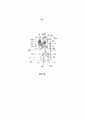
Далее со ссылками на фиг. 5-8 и фиг. 11-19 следует описание механизма для приведения в действие принимающего усилие устройства 980, выполненного на картридже 50у. На фиг. 5-8 представлены сечения картриджа, если смотреть в осевом направлении светочувствительного барабана 30, а на фиг. 11-14 представлены виды в перспективе, если смотреть со стороны, противоположной приводу картриджа 50у. Состояние, показанное на фиг. 5, соответствует состоянию, показанному на фиг. 11 и фиг. 15. Состояние, показанное на фиг. 6, соответствует состоянию, показанному на фиг. 12 и 16, состояние, показанное на фиг. 7, соответствует состоянию, показанному на фиг. 13, а состояние, показанное на фиг. 8, соответствует состоянию, показанному на фиг. 14.Next, with reference to FIG. 5-8 and FIG. 11-19, a description will be given of a mechanism for actuating a force receiving device 980 on the cartridge 50u. In FIG. 5-8 are sectional views of the cartridge when viewed in the axial direction of the
Как описано выше, при закрывании дверцы 12 из открытого положения, первый прилагающий усилие элемент 61 движется вокруг поддерживающего вала 55 из состояния, показанного на фиг. 5, 11 и 15, в состояние, показанное на фиг. 6, 12, 16. В это время первый прилагающий усилие элемент 61 не только позиционирует картридж 50у относительно главного узла 100 прибора, но также воздействует на первый принимающий усилие элемент 75 картриджа 50у. Более конкретно, выталкивающий участок 61е первого прилагающего усилие элемента 61 упирается в первый подпружиненный участок первого принимающего усилие элемента 75. После этого первый принимающий усилие элемент 75 толкает кулачковую поверхность 70с (третий подпружиненный участок), выполненный на втором принимающем усилие элементе 70, в результате чего второй принимающий усилие элемент 70 поворачивается вокруг вала 70а. Затем, второй принимающий усилие элемент 70 перемещается из положения ожидания, показанное на фиг. 5, 11, 15, вовне проявляющего блока 41 картриджа 50у, то есть от оси 46b вращения проявляющего блока 41. При конструкции, показанной на фиг. 21, выступающий участок 62g, отходящий от соединительного элемента 62, функционирует как первый прилагающий усилие элемент 61.As described above, when closing the
Далее со ссылками на фиг. 28 следует описание работы второго прилагающего усилие участка 60.Next, with reference to FIG. 28 describes the operation of the second force-applying
Приводное усилие от двигателя 110 (привод), установленного в главном узле 100 прибора, передается на шестерню 112 через шестерню 111. Шестерня 112 принимает приводное усилие и вращается в направлении, показанном стрелкой L, для поворота кулачкового участка 112а, выполненного заодно с шестерней 112, в направлении, показанном стрелкой L. Кулачковый участок 112а находится в зацеплении со сдвижным, принимающим усилие участком 60b, выполненным на втором прилагающем усилие элементе 60. Следовательно, при повороте кулачкового участка 112а, второй прилагающий усилие элемент 60 перемещается в направлении, показанном стрелками Е или В.The driving force from the motor 110 (drive) installed in the
На фиг. 28(а) показан случай, когда второй прилагающий усилие элемент 60 движется в направлении, показанном стрелкой Е, и в котором проявляющий валок 42 и светочувствительный барабан 30 все еще находятся в контакте друг с другом (фиг. 7). На фиг. 28(b) показан случай, когда второй прилагающий усилие элемент 60 движется в направлении, показанном стрелкой В, и в котором второй принимающий усилие элемент 70 принимает усилие от взаимодействующего ребра 60у. За счет этого проявляющий блок 41 поворачивается (сдвигается) вокруг оси 46b вращения так, что проявляющий валок отходит от светочувствительного барабана 30. Положение проявляющего блока 41 в это время является отведенным.In FIG. 28 (a) shows the case where the second
Как показано на фиг. 15, второй прилагающий усилие элемент 60 снабжен участком удлиненного отверстия 60с для обеспечения возможности движения опорного вала 55, на котором с возможностью вращения установлен первый прилагающий усилие элемент 61. Следовательно, даже когда второй прилагающий усилие элемент 60 движется в направлении стрелки В (фиг. 8) или в направлении стрелки Е (фиг. 7), второй прилагающий усилие элемент 60 может перемещаться без помех со стороны первого прилагающего усилие элемента 61. Аналогично первому прилагающему усилие элементу 61 имеется второй прилагающий усилие элемент 60, обращенный к траектории движения картриджей так, чтобы располагаться над картриджами 50у, 50m, 50с, 50k, вдвигаемых в главный узел 100 прибора на лотке 13. На шаге движения картриджей 50у, 50m, 50с, 50k в главный узел 100 прибора второй принимающий усилие элемент 70 находится в положении ожидания (фиг. 15). Поэтому, первый прилагающий усилие элемент 61 и второй прилагающий усилие элемент 60 могут находиться очень близко к картриджам 50у, 50m, 50с, 50k, но не мешая им, поэтому лишнее пространство можно исключить. Следовательно, главный узел 100 прибора можно уменьшить в вертикальном направлении и в продольном направлении картриджа 50у (в осевом направлении светочувствительного барабана).As shown in FIG. 15, the second
Далее следует подробное описание работыThe following is a detailed description of the work.
Установка технологических картриджей в главный узел электрофотографического прибора формирования изображенийInstalling process cartridges in the main assembly of an electrophotographic imaging device
Далее следует описание последовательности операций от установки картриджей 50у, 50m, 50с, 50k в главный узел прибора до отвода проявляющего валка 42 от светочувствительного барабана 30.The following is a description of the sequence of operations from installing
Как показано на фиг. 4, картриджи 50у, 50m, 50с, 50k устанавливаются сверху в лоток 13, выдвинутый в направлении, показанном стрелкой С, в выдвинутое положение.As shown in FIG. 4, the
При перемещении лотка 13 для картриджей в направлении, показанном стрелкой D1, картриджи 50у, 50m, 50с, 50k проходят сквозь отверстие 80 в главный узел 100 прибора. Таким образом, в этом варианте осуществления картриджи 50у, 50m, 50с, 50k вставляются в главный узел 100 прибора в направлении, по существу перпендикулярном осевому направлению светочувствительного барабана 30.When moving the
Как показано на фиг. 31, 32, картридж 50у установлен в лотке 13 в самом дальнем положении относительно направления установки или введения. Картридж 50у движется от ближней стороны к дальней стороне под первыми прилагающими усилие элементами 61k, 61c, 61m и зацепляющими ребрами 60k, 60c, 60m второго прилагающего усилие элемента 60, которые выполнены с возможностью воздействия на картриджи 50k, 50c, 50m.As shown in FIG. 31, 32, the
Картридж 50m установлен во второй позиции от дальнего конца лотка 13 для картриджей относительно направления установки. Картридж 50m движется от ближней стороны к дальней стороне под первыми прилагающими усилие элементами 61k, 61c и зацепляющими ребрами 60k, 60c второго прилагающего усилие элемента 60, которые выполнены с возможностью воздействовать на картриджи 50k, 50c.The
Картридж 50с установлен в третьей позиции от дальнего конца лотка 13 относительно направления установки. Картридж 50с проходит от ближней стороны к дальней стороне под зацепляющими ребрами 60k первого прилагающего усилие элемента 61k и под вторым прилагающим усилие элементом 60, которые выполнены с возможностью воздействовать на картридж 50k.The
Самый ближний картридж 50r на лотке 13 относительно направления установки проходит от ближней стороны к дальней стороне так, что его второй принимающий усилие элемент 70 проходит под первым прилагающим усилие элементом 61, выполненным с возможностью воздействия на картридж 50k.The closest cartridge 50r on the
Проход второго принимающего усилие элемента 70 под первым прилагающим усилие элементом 61k от ближнего конца к дальнему концу осуществляется так же, как и в отношении картриджей 50y, 50m, 50c.The passage of the second
То есть, когда технологический картридж вставлен с выступающим вторым принимающим усилие элементом 70, первый прилагающий усилие элемент 61 и второй прилагающий усилие элемент 60 должны находиться в верхней части, чтобы избежать столкновения между вторым принимающим усилие элементом и первым прилагающим усилие элементом 61 и вторым прилагающим усилие элементом 60. Однако если второй принимающий усилие элемент 70 находится в положении ожидания, первый прилагающий усилие элемент 61 и второй прилагающий усилие элемент 60 можно расположить близко к картриджам 50у, 50m, 50с, 50k без необходимости принимать во внимание степень выступания второго принимающего усилие элемента 70. Следовательно, главный узел 100 прибора можно уменьшить в вертикальном направлении. Кроме того, как показано на фиг. 31. 32, положения принимающего усилие устройства 90, первого прилагающего усилие элемента 61 и второго прилагающего усилие элемента 60 таковы, что принимающее усилие устройство 90 перекрывает первый прилагающий усилие элемент 61 и второй прилагающий усилие элемент в осевом направлении барабана, и, следовательно, продольный размер картриджа можно уменьшить.That is, when the process cartridge is inserted with a protruding second
Когда лоток 13 для картриджей вставлен в главный узел 100 прибора, между вторым прилагающим усилие элементом 60 и принимающим усилие устройством 90 выдерживается зазор f1, как показано на фиг. 5. Кроме того, между светочувствительным барабаном 30 и транспортной лентой 19 выдерживается зазор f2. Следовательно, картриджи 50у, 50m, 50с, 50k могут входить в главный узел 100 прибора без помех.When the
Затем, как показано на фиг. 23, при перемещении дверцы 12 в закрытое положение, держатель 14 лотка движется в направлении приближения к транспортной ленте 19 (стрелка y2). Вертикальная составляющая в направлении по стрелке y2 равна f2. При этом, как показано на фиг. 6, картриджи 50у, 50m, 50с, 50k также перемещаются так, что поверхность светочувствительного барабана 30 входит в контакт с поверхностью транспортной ленты 19. В этом состоянии зазор f1 между принимающим усилие устройством 90 и вторым прилагающим усилие участком 60 увеличивается и становится равным f1+f2.Then, as shown in FIG. 23, when the
Дополнительно, при перемещении дверцы 12 в закрытое положение первый прилагающий усилие элемент 61 перемещается так, что выступ 31а, выполненный на участке верхней поверхности рамы 34 барабана выталкивается выступающим участком 61f. За счет этого, как показано на фиг. 6, позиционирующие участки 31b картриджей 50у, 50m, 50с, 50k упираются в соответствующие позиционирующие участки 101а, выполненные в главном узле 100 прибора так, что картриджи 50у, 50m, 50с, 50k позиционируются в главном узле 100 прибора.Further, when the
Картриджи 50у, 50m, 50с, 50k заперты от перемещения в направлении, показанном стрелкой а (фиг. 1) в главном узле 100 прибора, поскольку находятся в зацеплении с валом 36d, выполненным на закрывающем элементе 36, показанном на фиг. 10, при этом на лотке 13 для картриджей выполнен участок 13а, препятствующий вращению.The
Выталкивающий участок 61е первого прилагающего усилие элемента 61 контактирует с подпружиненным участком 75а (фиг. 15) первого принимающего усилие элемента 75, расположенного в первом положении (фиг. 15), и выталкивает его. Затем первый принимающий усилие элемент 75 смещается в направлении, показанном стрелкой r (фиг. 16), для установки во второе положение.The
Во втором положении выталкивающий участок 75b выталкивает кулачковую поверхность 70с второго принимающего усилие элемента 70, показанного на фиг. 15. При этом второй принимающий усилие элемент 70 поворачивается вокруг оси вала 70а из положения ожидания в положение вне проявляющего блока 41 картриджа 50у, 50m, 50с, 50k, то есть в направлении от оси 46b поворота проявляющего блока 41.In the second position, the
Однако в это время верхняя поверхность 70 второго принимающего усилие элемента 70 сталкивается с нижней поверхностью зацепляющего ребра 60y второго прилагающего усилие элемента 60, которое находится в исходном положении, в результате чего движение второго принимающего усилие элемента 70 блокируется зацепляющим ребром 60y (фиг. 6, 12). Положение, которое в это время занимает второй принимающий усилие элемент 70, называется блокированным положением.However, at this time, the
Здесь это положение является исходным положением по следующим причинам: после того как картриджи 50у, 50m, 50с, 50k будут установлены в главный узел 100 прибора, состояние является таким, как показано на фиг. 8, до тех пор, пока не начнется выполнение операции формирования изображения. Более конкретно, второй прилагающий усилие элемент 60 перемещен в направлении, показанном стрелкой В, так, что зацепляющее ребро 60у толкает второй принимающий усилие элемент 70. В этом состоянии светочувствительный барабан 30 и проявляющий валок 42 разведены друг от друга. В состоянии по фиг. 8 картриджи 50у, 50m, 50с, 50k вынимаются из главного узла 100 прибора. Затем, когда картриджи 50у, 50m, 50с, 50k вновь будут установлены в главный узел 100 прибора, второй прилагающий усилие элемент 60 находится в положении, показанном на фиг. 8, и, следовательно, когда второй принимающий усилие элемент 70 выйдет из положения ожидания, он войдет в контакт с ребром 60y.Here, this position is a starting position for the following reasons: after the
Как показано на фиг. 8, направление усилия (стрелка J), которое принимает первый принимающий усилие элемент 75 от первого прилагающего усилие элемента 61, по существу противоположно направлению усилия, принимаемого вторым принимающим усилие элементом 70 от второго прилагающего усилия элемента 60. Поверхность второго принимающего усилие элемента 70, которая принимает усилие от второго принимающего усилие элемента 60, обращена в направлении введения картриджей 50у, 50m, 50с, 50k в главный узел 100 прибора. Выбирая направление принимаемого усилия, когда второй принимающий усилие элемент 70 принимает усилие от второго прилагающего усилие элемента 60, проявляющий блок 41 можно эффективно и с уверенностью перемещать относительно блока 31 барабана. Кроме того, можно стабильно поддерживать состояние, в котором светочувствительный барабан 30 и проявляющий валок 42 разведены.As shown in FIG. 8, the direction of the force (arrow J) that the first
Однако, даже когда движение второго принимающего усилие элемента 70 ограничено зацепляющим ребром 60у, принимающее усилие устройство 90, включающее второй прилагающий усилие элемент 60 и второй принимающий усилие элемент 70, не повреждается. Как показано на фиг. 22(а), поскольку движение второго принимающего усилие элемента 70 блокируется, движение толкающего участка 75b для выталкивания кулачковой поверхности 70с также блокируется. Даже если толкающий участок 61е первого прилагающего усилие элемента 61 дальше выталкивает подпружиненный участок 75а, упругий участок 75с в форме дуги, выполненный на первом принимающем усилие элементе 75, изгибается (упругая деформация). Следовательно, даже если движение второго принимающего усилие элемента 70 блокируется, принимающее усилие устройство 90 не повреждается.However, even when the movement of the second
И когда второй прилагающий усилие элемент 60 перемещается из положения, показанного на фиг. 6, 12, в направлении, показанном стрелкой Е, как показано на фиг. 7, 13, второй принимающий усилие элемент 70 движется наружу от картриджа 50у для входа на траекторию движения зацепляющего ребра 60у. Положение второго прилагающего усилие элемента 60 в это время называется выдвинутым положением. Таким образом, второй прилагающий усилие элемент 60 выдвинут за вышеописанное положение ожидания, когда он находится в выдвинутом положении. Степень выдвижения второго принимающего усилие элемента 70 в выдвинутом положении больше, чем зазор f1+f2, чтобы войти в зацепление со вторым прилагающим усилие элементом 60. Второй прилагающий усилие элемент 60 срабатывает перед формированием изображения, после того как картриджи 50у, 50m, 50с, 50k будут установлены в главный узел 100 прибора.And when the second
Затем, как показано на фиг. 8, 14, второй прилагающий усилие элемент 60 движется в направлении, показанном стрелкой В, так, что боковая поверхность 70b, которая является вторым подпружиненным участком второго принимающего усилие элемента 70, выходящим на траекторию движения, принимает усилие от зацепляющего ребра 60у. За счет этого проявляющий блок 41 поворачивается (перемещается) вокруг оси 46b вращения так, что проявляющий валок 42 отходит от светочувствительного барабана 30 на расстояние α. Второй принимающий усилие элемент 70 принимает усилие от второго принимающего усилие элемента 70 в выдвинутом положении. Таким образом, по сравнению с конструкцией, в которой второй принимающий усилие элемент движется к технологическому картриджу и входит в зацепление с проявляющим блоком для отвода проявляющего устройства, расстояние от оси 46b вращения проявляющего блока 41 можно увеличить. Следовательно, крутящий момент, необходимый для отвода проявляющего валка 42 от светочувствительного барабана 30 можно уменьшить.Then, as shown in FIG. 8, 14, the second
Кроме того, за счет движения второго прилагающего усилие элемента 60 в направлении, показанном стрелкой 4, положение, в котором первый принимающий усилие элемент 75 толкается первым прилагающим усилие элементом 61, и положение, в котором второй принимающий усилие элемент 70 принимает усилие от зацепляющего ребра 60у, меняются относительно горизонтального направления. Другими словами, отношение между расстоянием I, показанным на фиг. 7, и расстоянием II, показанным на фиг. 8, является отношением "расстояние I">"расстояние II". Изменение этого расстояния компенсируется упругим участком 75с, выполненным на втором принимающим усилие элементе 70. Как показано на фиг. 33(а), упругий участок 75с выполнен в форме гибкой дуги. Внутри упругого участка 75с установлена пружина 76, которая является упругим элементом. Пружина 76 препятствует изгибу упругого участка 75с больше, чем необходимо, и восстанавливает положение изогнутого упругого участка 75с. Дугообразная конфигурация упругого участка 75с не является обязательной, и упругий элемент может быть простым упругим элементом.Furthermore, by moving the second
Для проведения операции формирования изображения проявляющий валок 43 вводится в контакт со светочувствительным барабаном 30 путем перемещения второго прилагающего усилие элемента 60 в направлении, показанном стрелкой Е. За счет этого, как показано на фиг. 7, 13, второй принимающий усилие элемент 70 переходит в состояние, когда он не принимает усилия от зацепляющего ребра 60у. Следовательно, под действием силы пружины 95, установленной между проявляющим блоком 41 и блоком 31 барабана, проявляющий валок 42 и светочувствительный барабан 30 входят в контакт друг с другом так, что картриджи 50у, 50m, 50с, 50k получают возможность формировать изображение. В этом случае перед тем, как проявляющий валок 42 войдет в контакт со светочувствительным барабаном 31, светочувствительный барабан 30 вращается, и проявляющий валок 30 также получает приводное усилие от главного узла 100 прибора и вращается. Это достигается за счет наличия соединительного участка 67а соосно с цилиндрическим участком 46b, поэтому, даже если проявляющий блок 41 движется вокруг цилиндрического участка 46b, положение соединительного участка 67а не меняется. Таким образом, светочувствительный барабан 30 и проявляющий валок 42 вращаются еще до того, как войдут в контакт друг с другом. Следовательно, когда проявляющий валок 42 приводится в контакт со светочувствительным барабаном 30, разница в скорости между периферийными поверхностями светочувствительного барабана 30 и проявляющего валка 42 невелика и, следовательно, их износ можно уменьшить. Когда операция формирования изображения завершена, проявляющий валок 42 и светочувствительный барабан отводятся друг от друга путем перемещения второго прилагающего усилие элемента 60 в направлении, показанном стрелкой В, как описано выше. После того как проявляющий валок 42 и светочувствительный барабан отведены друг от друга, их вращение прекращается. Поэтому, разницу в скорости между периферийными поверхностями светочувствительного барабана 30 и проявляющего валка 42 можно уменьшить и, следовательно, износ светочувствительного барабана 30 и проявляющего валка 42 можно уменьшить. Поэтому качество изображения можно повысить.For the imaging operation, the developing
Упругий участок можно заменить структурой, показанной на фиг. 33, 34 и 35. Здесь принимающее усилие устройство 190 содержит первый принимающий усилие элемент 179 и второй принимающий усилие элемент 178. Как показано на фиг. 34, 35, первый прилагающий усилие элемент 165 снабжен участком 165а скольжения (наклонная поверхность), а первый принимающий усилие элемент 179 снабжен участком 179а скольжения (наклонная поверхность). На фиг. 33 показано состояние до того, как первый прилагающий усилие элемент 165 начинает движение. На фиг. 34 показано состояние, в котором второй принимающий усилие элемент 178 выступает из картриджа 150у первым прилагающим усилие элементом 165, движущегося до упора в первый принимающий усилие элемент 179. На фиг. 35 показано состояние после того, как второй прилагающий усилие элемент переместился в направлении, показанном стрелкой Е.The elastic section can be replaced by the structure shown in FIG. 33, 34 and 35. Here, the
Изменение расстояния между первым принимающим усилие элементом 179 и вторым принимающим усилие элементом 178 с I до II, как показано на фиг. 34, 35, обеспечивается скольжением между участком 179а скольжения и участком 165а скольжения и подвижностью первого принимающего усилие элемента 179 в направлении, показанном стрелкой F, как показано на фиг. 35.Changing the distance between the first
В картридже 50у, используемом для описания этого варианта, проявляющий блок 41 выполнен с возможностью поворота относительно блока 31 барабана для приведения в контакт и отвода друг от друга проявляющего валка 42 и светочувствительного барабана 30. Однако на фиг. 36 показана альтернативная структура, в которой участок 544, который следует направлять, выполнен в форме квадратного выступа, а блок 531 барабана снабжен удлиненным отверстием 536а, выполненным с возможностью зацепления с направляемым участком 544, благодаря чему проявляющий блок 541 выполнен с возможностью скольжения относительно блока 531 барабана.In the
Более конкретно, как показано на фиг. 37, когда второй прилагающий усилие элемент 560 не воздействует на второй принимающий усилие элемент 570, проявляющий валок 542 поджимается пружиной (не показана) (упругим элементом) так, чтобы контактировать со светочувствительным барабаном. Затем, как показано на фиг. 38, второй прилагающий усилие элемент 560 перемещается в направлении, показанном стрелкой В, для воздействия на второй принимающий усилие элемент 570. За счет этого проявляющий блок 541 смещается относительно блока 531 барабана так, что проявляющий валок отходит от светочувствительного барабана на расстояние g. Как и в первом варианте, принимающее усилие устройство 590 содержит первый принимающий усилие элемент 575 и второй принимающий усилие элемент 570.More specifically, as shown in FIG. 37, when the second force-applying
Далее следует описание операции по извлечению картриджей 50у, 50m, 50с, 50k из главного узла 100 прибора.The following is a description of the operation for removing the
При перемещении дверцы 12 из закрытого положения в открытое первый прилагающий усилие элемент 61 вращается из положения, показанного на фиг. 6, 12, в положение, показанное на фиг. 5, 11. За счет этого первый принимающий усилие элемент 75 освобождается от воздействия усилия первого прилагающего усилие элемента 61 и перемещается из состояния, показанного на фиг. 6, 12 в состояние, показанное на фиг. 5, 11. Более конкретно, второй принимающий усилие элемент 70 освобождается от прижимающего участка 75b первого принимающего усилие элемента 75. Как показано на фиг. 5, второй принимающий усилие элемент 70 также возвращается в положение ожидания (нерабочее положение), [поворачиваясь] вокруг вала 70а под действием пружины 73, показанной на фиг. 19, в направлении, показанном стрелкой А.When the
Когда дверца 12 перемещается из закрытого положения в открытое, держатель 14 лотка поднимается от транспортной ленты 19, как показано на фиг. 3, 4. При этом картриджи 50у, 50m, 50с, 50k поднимаются и, следовательно, отделяются от транспортной ленты 19.When the
Как описано выше, второй принимающий усилие элемент 70 для перемещения проявляющего блока 41 выполнен так, что выступает наружу от проявляющего блока 41, когда картриджи 50у, 50m, 50с, 50k установлены в главный узел 100 прибора. Следовательно, размеры картриджей 50у, 50m, 50с, 50k можно уменьшить. Кроме того, поскольку установка осуществляется, когда второй принимающий усилие элемент находится в положении ожидания, пространство в главном узле 100 прибора, необходимое для движения картриджей 50у, 50m, 50с, 50k, может быть небольшим. Другими словами, размер отверстия 80 может быть небольшим, и первый прилагающий усилие элемент 60 может располагаться близко к картриджам 50у, 50m, 50с, 50k. Следовательно, размер главного узла 100 прибора можно уменьшить в вертикальном направлении. Кроме того, как показано на фиг. 31, 32, если смотреть на главный узел прибора в вертикальном направлении, принимающее усилие устройство 90 перекрывается первым прилагающим усилие элементом 61 и вторым прилагающим усилие элементом 60 относительно осевого направления барабана, и, следовательно, размер картриджа можно уменьшить в продольном направлении.As described above, the second
Когда пользователь манипулирует картриджами 50у, 50m, 50с, 50k, или когда эти картриджи транспортируются, второй принимающий усилие элемент 70 можно установить в положение ожидания, и, следовательно, этот второй принимающий усилие элемент не будет подвержен повреждениям.When the user manipulates the
(Второй вариант)(Second option)
В первом варианте картриджи 50у, 50m, 50с, 50k устанавливают в главный узел 100 прибора в направлении, по существу перпендикулярном оси светочувствительного барабана 30. В варианте 2 картриджи 450у, 450m, 450с, 450k устанавливают в главный узел 401 электрофотографического прибора формирования изображений (главный узел прибора) в направлении, по существу параллельном осевому направлению электрофотографического светочувствительного барабана (светочувствительного барабана) 430. В нижеследующем описании описываются в основном отличия от первого варианта.In the first embodiment,
Общая компоновка электрофотографического прибора формирования изображенийGeneral layout of an electrophotographic image forming apparatus
Как показано на фиг. 39-41, в главный узел 401 прибора картриджи 450у, 450m, 450с, 450k вставляются в направлении (стрелка К), по существу параллельном осевому направлению (продольному направлению) светочувствительного барабана 430. В этом варианте картриджи 450у, 450m, 450с, 450k вставлены в держатель 480с, выполненный в главном узле 401 прибора, в направлении, показанном стрелкой К. Картриджи 450у, 450m, 450с, 450k содержат частицы, соответственно, желтого, пурпурного, голубого и черного тонера (проявителя).As shown in FIG. 39-41,
Каждый картридж 450у, 450m, 450с, 450k снабжен принимающим усилие устройством 90, имеющим первый принимающий усилие элемент 475 и второй принимающий усилие элемент 470. На задней стороне главного узла 401 прибора относительно направления входа картриджей выполнены первый прилагающий усилие элемент 461 и второй прилагающий усилие элемент 460, воздействующие, соответственно, на первый принимающий усилие элемент 475 и на второй принимающий усилие элемент 470. Как показано на фиг. 42, главный узел 401 прибора снабжен отверстием 408 для установки картриджей 450у, 450m, 450с, 450k в главный узел 401, и дверцей 412, выполненной с возможностью перемещения между закрытым положением, закрывающим отверстие 408, и открытым положением, открывающим отверстие 408. Дверца 412 выполнена с возможностью поворота вокруг оси 4012а поворота. Как показано на фиг. 45, держатель 480 содержит выполненные заодно удерживающие участки 480с для удержания картриджей 450у, 450m, 450с, 450k, соответственно, оперативный элемент 480b для перемещения первого прилагающего усилие элемента 461 и соединительный участок 480а для соединения оперативного элемента 480b и дверцы 412 друг с другом. Как показано на фиг. 42, соединительный участок 480а и дверца 412 соединены друг с другом за счет зацепления между удлиненным отверстием 480g, выполненным в соединительном участке 480а, и выступом 412b, выполненным на дверце.Each
Следовательно, при движении дверцы 412 из открытого положения в закрытое в направлении, показанном стрелкой m, выступы 480d, 480е, выполненные на соединительном участке 480а, двигаются вдоль направляющих канавок 401а, 401b, выполненных в главном узле 401 прибора, как показано на фиг. 42. Таким образом, удерживающий участок 480с, выполненный заодно с оперативным элементом 480b, движется в направлении, показанном стрелкой n. Следовательно, светочувствительные барабаны 430 картриджей 450у, 450m, 450с, 450k, поддерживаемых на удерживающем участке 480с, перемещаются из положения, отведенного от транспортной ленты 419, показанного на фиг. 47, в положение контакта с транспортной лентой, показанное на фиг. 48. Одновременно позиционируемый участок 431b, выполненный на блоке 41 барабана, упирается в позиционирующий участок 401а, выполненный в главном узле 401 прибора, благодаря чему картриджи 450у, 450m, 450с, 450k правильно позиционируются.Therefore, when the
Каждый из картриджей 450у, 450m, 450с, 450k заперт относительно перемещения в направлении, показанном стрелкой а на фиг. 39 в главном узле 401 прибора, благодаря зацеплению с валом 436d, выполненным на закрывающем элементе 436, а в главном узле 401 прибора имеется участок 485а, препятствующий повороту.Each of the
Когда картриджи 450у, 450m, 450с, 450k извлекают из главного узла 401 прибора, операции осуществляются в обратной последовательности относительно той, которая выполняется при установке картриджей.When the
Работа первого прилагающего усилие элемента и второго прилагающего усилие участкаThe operation of the first force-applying element and the second force-applying section
Со ссылками на фиг. 40-45 следует описание первого прилагающего усилие элемента 461. Как и в первом варианте, первый прилагающий усилие элемент 461 находится в зацеплении с соединительным элементом 462 для привязки к работе оперативного элемента 480b. Конструкция соединительного элемента 462 такая же, как и в первом варианте. На фиг. 40, 22(а) и 43 показано состояние, в котором дверца 412 находится в открытом положении, и в котором оперативный элемент 480b занимает верхнее положение. На фиг. 41, 42(b) и 44 показано состояние, в котором дверца 412 находится в закрытом положении. Когда дверца 412 закрывается, оперативный элемент 480b смещается вниз (в направлении, показанном стрелкой n). Как показано на фиг. 43, 44, выступ 462b, выполненный на соединительном элементе 462, находится в зацеплении с удлиненным отверстием 480h, выполненным в установочном элементе 480. Следовательно, вместе с движением оперативного элемента 480b соединительный элемент 462 поворачивается в направлении, показанном стрелкой Q вокруг центра 461d вращения. Как и в первом варианте, первый прилагающий усилие элемент 461 вращается вместе с вращением соединительного элемента 462. Когда дверцу 412 перемещают из закрытого положения в открытое, описанные выше операции повторяются в обратном порядке. Остальные операции осуществляются так же, как и в первом варианте.With reference to FIG. 40-45, a description is given of the first force-applying
Работа второго прилагающего усилие участка 460 осуществляется так же, как и в первом варианте.The operation of the second force-applying
Общая компоновка технологического картриджаGeneral layout of the process cartridge
Далее следует описание конструкции технологического картриджа по этому варианту. Конструкции картриджей 450у, 450m, 450с, 450k одинаковы, поэтому со ссылками на фиг. 46 будет описан картридж 450у.The following is a description of the design of the process cartridge in this embodiment. The designs of
Картридж 450у содержит светочувствительный барабан 430, на который воздействуют технологические средства. Технологические средства включают заряжающий валок 432, функционирующий как заряжающее средство для электрической зарядки светочувствительного барабана 430, проявляющий валок 442, функционирующий как проявляющее средство для проявления латентного изображения, сформированного на светочувствительном барабане, и/или скребок 433, функционирующий как очищающее средство для удаления остатков тонера с поверхности светочувствительного барабана 430. В картридже 450у используется проявляющий блок 431 и блок 441 барабана.Cartridge 450u contains a
Конструкция блока 431 барабана и проявляющего блока 441 и соединительной структуры между блоком барабана 431 и проявляющим блоком 441 такая же, как и в первом варианте.The construction of the
Принимающее усилие устройствоForce receiving device
Как и в первом варианте, как показано на фиг. 47, картридж 450у содержит принимающее усилие устройство 490 для приведения в контакт проявляющего валка 442 со светочувствительным барабаном 430 и отведения их друг от друга. Детали его конструкции такие же, как показано на фиг. 9 и 15-19. Как показано на фиг. 47, принимающее усилие устройство 490 по этому варианту содержит первый принимающий усилие элемент 475, второй принимающий усилие элемент 470 и пружину (не показана), являющуюся перемещающим средством.As in the first embodiment, as shown in FIG. 47, the
Механизм отвода главного узла электрофотографического прибора формирования изображений и перемещающий механизм для технологического картриджаThe removal mechanism of the main node of the electrophotographic image forming apparatus and the moving mechanism for the process cartridge
На фиг. 49 показано состояние после того, как второй прилагающий силу элемент 460 сдвинулся в направлении, показанном стрелкой Е, из исходного положения (фиг. 48), в котором проявляющий валок 442 и светочувствительный барабан 430 все еще контактируют друг с другом. На фиг. 50 показано состояние после того, как второй прилагающий усилие элемент переместился в направлении, показанном стрелкой В, в котором проявляющий валок 442 и светочувствительный барабан 430 отведены друг от друга. Как и в первом варианте, второй прилагающий усилие участок 460 снабжен участком удлиненного отверстия 460с, чтобы избежать оси вращения 461d первого прилагающего усилие элемента 461. Даже когда второй прилагающий усилие участок 460 движется в направлении, показанном стрелками Е или В, этот второй прилагающий усилие участок 460 может перемещаться без помех со стороны первого прилагающего усилие элемента 461.In FIG. 49 shows the state after the second
Первый прилагающий усилие элемент 461 и второй прилагающий усилие элемент 460, как показано на фиг. 3, расположены над картриджами 450у, 450m, 450с, 450k, вставляемыми в главный узел 401 прибора. Когда картриджи 450у, 450m, 450с, 450k находятся в процессе установки в главный узел 401 прибора, второй принимающий усилие элемент находится в положении ожидания.The
Кроме того, в этом варианте, когда картриджи 450у, 450m, 450с, 450k устанавливают в главный узел 401 прибора и дверцу 412 перемещают в закрытое положение, второй принимающий усилие элемент 470 выступает наружу от проявляющего блока 441. Следовательно, размер картриджей 450у, 450m, 450с, 450k можно уменьшить. Поскольку во время установки картриджей 450у, 450m, 450с, 450k второй принимающий усилие элемент 470 находится в положении ожидания, пространство, необходимое для установки картриджей 450у, 450m, 450с, 450k, может быть невелико. Другими словами, размер отверстия 480 может быть невелик и первый прилагающий усилие элемент 461 и второй прилагающий усилие элемент 460 могут быть расположены близко к картриджам 450у, 450m, 450с, 450k. Следовательно, вертикальный размер главного узла 401 прибора можно уменьшить. Поскольку расположение компонентов таково, что принимающее усилие устройство 490 перекрывается первым прилагающим усилие элементом 461 и вторым прилагающим усилие компонентом 460 в направлении оси барабана, если смотреть в вертикальном направлении, продольный размер картриджа можно уменьшить.In addition, in this embodiment, when the
Когда пользователь манипулирует картриджами 450у, 450m, 450с, 450k, или когда они транспортируются, второй принимающий усилие элемент 470 находится в положении ожидания и, следовательно, второй принимающий усилие элемент 470 не подвержен повреждениям.When a user manipulates
Третий вариантThird option
Этот вариант относится к модификации принимающего усилие устройства.This embodiment relates to a modification of a force receiving device.
Этот вариант также будет описан для примера со ссылками на желтый картридж 250у, в котором находится желтый проявитель.This embodiment will also be described by way of example with reference to the
Как показано на фиг. 51-54, проявляющий блок 241 снабжен принимающим усилие элементом 277 (принимающее усилие устройство).As shown in FIG. 51-54, the developing
Принимающий усилие элемент 277 содержит участок вала 277с, установленного с возможностью вращения на раме 248 проявляющего устройства, первый принимающий усилие участок 277а, на который может воздействовать первый прилагающий усилие элемент 261, и второй принимающий усилие участок 277b, на который может воздействовать второй прилагающий усилие элемент 263. Принимающий усилие элемент 277 целостно составлен из первого принимающего усилие участка и второго принимающего усилие участка. Один конец пружины 298 прикреплен к принимающему усилие элементу 277, а второй конец прикреплен к раме 248 проявляющего устройства. Пружина 298 удерживает принимающий усилие элемент 277 в состоянии, показанном на фиг. 51.The
Как показано на фиг. 52, как и в первом варианте, движение дверцы (не показана) из открытого положения в закрытое приводит к контакту первого прилагающего усилие элемента 262 с первым принимающим усилие участком 277а принимающего усилие элемента 277. За счет этого принимающий усилие элемент 277 поворачивается в направлении, показанном стрелкой S на фиг. 52, вокруг вала 277с. Второй принимающий усилие участок 277b принимающего усилие элемента 277 перемещается наружу из проявляющего блока 241.As shown in FIG. 52, as in the first embodiment, the movement of the door (not shown) from the open to the closed position causes the first
После этого, как показано на фиг. 53, второй прилагающий усилие элемент 263 движется в направлении, показанном стрелкой В, под воздействием приводного усилия главного узла прибора для контакта со вторым принимающим усилие участком 277b принимающего усилие элемента 277. Далее, когда второй прилагающий усилие элемент 263 движется в направлении, показанном стрелкой В, проявляющий блок 241 поворачивается вокруг соединительного участка 246b вместе с блоком 231 барабана, благодаря чему проявляющий валок 242 отводится от электрофотографического светочувствительного барабана 230 на расстояние γ. В это время, как показано на фиг. 53, запираемый участок 277d принимающего усилие элемента 277 контактирует с запирающим участком 248а рамы 248 проявляющего устройства для блокировки движения принимающего усилие элемента 277, показанного на фиг. 52, в направлении, показанном стрелкой S. Следовательно, за счет движения второго прилагающего усилие элемента 263 в направлении, показанном стрелкой Е, проявляющий блок 241 поворачивается относительно блока 231 барабана. За счет движения второго прилагающего усилие элемента 263 в направлении, показанном стрелкой В, первый принимающий усилие участок 277а принимающего усилие элемента 277 скользит по свободному концу 262а первого прилагающего усилие элемента 262 и деформирует его от формы, показанной сплошными линиями, до формы, показанной штриховыми линиями на фиг. 54. Для этого участок 262а свободного конца первого прилагающего усилие элемента 262 выполнен с возможностью упругой деформации. Кроме того, первый принимающий усилие участок 277а образует поверхность скольжения относительно первого прилагающего усилие элемента 262.After that, as shown in FIG. 53, the second
Возможность упругой деформации участка 262а свободного конца первого прилагающего усилие элемента 262 обеспечивает поджатие принимающего усилие элемента 277 к запирающему участку 248а, даже когда второй прилагающий усилие элемент движется в направлении, показанном стрелкой В в состоянии по фиг. 53.The possibility of elastic deformation of the
Что касается контакта между проявляющим валком 242 и светочувствительным барабаном 230, за счет движения второго прилагающего усилие элемента 263 в направлении по стрелке Е на фиг. 53 разрешается передача усилия от второго прилагающего усилие элемента 263 второму принимающему усилие элементу 277. За счет усилия пружины 295 проявляющий блок 241 поворачивается до контакта проявляющего валка 242 со светочувствительным барабаном 230.As for the contact between the developing
В этом варианте остальные структуры, кроме принимающего усилие элемента 277, одинаковы со структурами картриджа 50у, описанного в первом варианте. Операции первого прилагающего усилие элемента 261 в этом варианте такие же, что и операции первого прилагающего усилие элемента 61 в первом варианте или элемента 461 во втором варианте.In this embodiment, the remaining structures other than the
Как описано выше, в принимающем усилие устройстве по настоящему варианту количество деталей меньше, чем количество деталей в принимающем усилие устройстве 90 по первому варианту.As described above, in the force receiving device of the present embodiment, the number of parts is less than the number of parts in the
Четвертый вариантFourth option
Этот вариант относится к принимающему усилие механизму.This embodiment relates to a force receiving mechanism.
Этот вариант будет описан для примера со ссылками на желтый картридж 350у, в котором находится желтый проявитель. Как показано на фиг. 55-58, проявляющий блок 341 снабжен принимающим усилие устройством 370. Принимающее усилие устройство 370 содержит первый принимающий усилие элемент 370а, второй принимающий усилие элемент 370b, первую пружину 370с и вторую пружину 370d. Принимающее усилие устройство 370 установлено с возможностью перемещения в направляющей 341а, выполненной в раме 348 проявляющего устройства. Вторая пружина 370d установлена между запирающим участком 341с, выполненным на одном конце направляющей 341а, и запирающим участком 370е, выполненным на втором принимающем усилие элементе 370b. Первая пружина 370с установлена между первым принимающим усилие элементом 370а и вторым принимающим усилие элементом 370b.This embodiment will be described by way of example with reference to the yellow cartridge 350y, in which the yellow developer is located. As shown in FIG. 55-58, the developing
Когда дверца (не показана) находится в открытом положении, второй принимающий усилие элемент 370b находится в задвинутом положении (положении ожидания), в котором запирающий участок 370е контактирует со вторым запирающим участком 341b, выполненным в направляющей 341а, как показано на фиг. 55, под воздействием усилия пружины 370d. В это время между вторым принимающим усилие элементом 370b и вторым прилагающим усилие элементом 360, выполненным на стороне главного узла прибора, имеется зазор f1. Другими словами, поскольку второй принимающий усилие элемент 370b не принимает усилия от второго прилагающего усилие элемента 360, светочувствительный барабан 330 и проявляющий валок 342 контактируют друг с другом.When the door (not shown) is in the open position, the second
Как и в первом варианте, движение дверцы (не показана) из отрытого положения в закрытое, как показано на фиг. 56, приводит первый прилагающий усилие элемент 361 в контакт с первым подпружиненным участком 370а1 первого принимающего усилие элемента 370а. За счет этого второй принимающий усилие элемент 370b выталкивается пружиной 370с из проявляющего блока 341 (стрелка Р). В это время второй прилагающий усилие элемент 360 контактирует с верхней поверхностью 370b1 второго принимающего усилие элемента 370b для блокировки дальнейшего движения. Однако, поскольку пружина 370с упруго деформирована, принимающее усилие устройство 370 не повреждается, даже если первый прилагающий усилие элемент 361 продолжит нажатие на первый принимающий усилие элемент 370а при заблокированном движении второго принимающего усилие элемента 370b.As in the first embodiment, the movement of the door (not shown) from the open to the closed position, as shown in FIG. 56, brings the first
Как показано на фиг. 57, когда второй прилагающий усилие элемент 360 перемещается в направлении, показанном стрелкой Е, второй принимающий усилие элемент 370b усилием пружины 370с передвигается далее на траекторию движения второго прилагающего усилие элемента 360.As shown in FIG. 57, when the second
Затем, как показано на фиг. 58, перемещением второго прилагающего усилие элемента 360 в направлении, показанном стрелкой В, боковая поверхность 370b2 (второй подпружиненный участок), выполненная на втором принимающем усилие элементе 370b, принимает усилие от второго прилагающего усилие элемента 360. Далее, когда второй прилагающий усилие элемент 360 движется в направлении, показанном стрелкой Е, проявляющий блок 341 поворачивается вокруг соединительного участка 346b вместе с блоком 331 барабана, в результате чего проявляющий валок 342 отводится от электрофотографического светочувствительного барабана 330 на расстояние δ. Здесь положение, в котором первый принимающий усилие элемент 370а выталкивается первым прилагающим усилие элементом 361, зафиксировано, и второй принимающий усилие элемент 370b сдвигается движением второго прилагающего усилие элемента 360 в направлении, показанном стрелкой В на фиг. 58. Следовательно, расстояние I между первым принимающим усилие элементом 370а и вторым принимающим усилие элементом 370b и расстояние II между первым принимающим усилие элементом 370а и вторым принимающим усилие элементом 370b удовлетворяют неравенству "расстояние I">"расстояние II". В принимающем усилие устройстве 370 по этому варианту изменение расстояния может осуществляться скольжением пружины 370с и первого прилагающего усилие элемента 361 относительно первого принимающего усилие элемента 370а.Then, as shown in FIG. 58, by moving the second
Перемещение второго прилагающего усилие элемента 360 из положения, показанного на фиг. 58, в направлении, показанном стрелкой Е на фиг. 57, разрешает перемещение второго принимающего усилие элемента 370b вторым прилагающим усилие элементом 360. Как и в первом варианте, пружина 395, установленная в картридже 350у, вводит в контакт проявляющий валок 342 и светочувствительный барабан 330.Moving the second
В этом варианте структуры, кроме принимающего усилие устройства 370, такие же, что и первом варианте. Первый прилагающий усилие элемент 361 в этом варианте работает так же, как и прилагающий усилие элемент 61 в первом варианте или прилагающий усилие элемент 461 во втором варианте.In this embodiment, the structures, in addition to the
Пятый вариантFifth option
Этот вариант относится к модифицированному примеру опорной структуры для принимающего усилие устройства (фиг. 59, 60).This embodiment relates to a modified example of a support structure for a force receiving device (FIGS. 59, 60).
Этот вариант также будет описан на примере желтого картриджа 650у, в котором находится желтый проявитель.This option will also be described with the yellow cartridge 650u, in which the yellow developer is located.
Картридж 650у снабжен принимающим усилие устройством 690 для обеспечения контакта и зазора между проявляющим валком 642 и светочувствительным барабаном 630. Принимающее усилие устройство 690 содержит первый принимающий усилие элемент 675 и второй принимающий усилие элемент 670, показанные на фиг. 59, 60, как и в первом варианте. Первый принимающий усилие элемент 675 установлен на раме 634 барабана путем зацепления между зацепляющим участком 675d, выполненным на первом принимающем усилие элементе 675, и направляющим участком 638 рамы 634 барабана. Отсоединение первого принимающего усилие элемента 675 от рамы 634 барабана, на которой он установлен, предотвращает блокирующим участком 639, выполненным на раме 634 барабана.The cartridge 650u is provided with a
Вал 670а второго принимающего усилие элемента 670 находится в зацеплении с направляющим участком 645а, выполненном на подшипниковом блоке 645. Подшипниковый блок 645, включающий второй принимающий усилие элемент 670, прикреплен к одному продольному концу рамы 648 проявляющего устройства и поддерживает с возможностью вращения проявляющий валок 642, на конце которого установлена приводная шестерня 669. Как и в первом варианте, подшипниковый блок 645 снабжен соединительным элементом 667 для приема приводного усилия от приводного двигателя (не показан) и промежуточной шестерней 668 для передачи приводного усилия от соединительного элемента 667 на шестерню 669 проявляющего валка. Закрывающий элемент 646 прикреплен продольно снаружи от подшипникового блока 645 так, чтобы закрывать соединительный элемент 667 и промежуточную шестерню 668. Закрывающий элемент 646 снабжен цилиндрическим участком 646b, который выступает за поверхность закрывающего элемента 646. Соединительный элемент 667 доступен через внутреннее отверстие цилиндрического участка 646b.The
Сборка блока барабана и проявляющего блокаAssembly of the drum unit and the developing unit
Как показано на фиг. 59, 60, когда проявляющий блок 641 и блок 631 барабана собраны, внешняя окружность цилиндрического участка 646b одним концом находится в зацеплении с участком 636а поддерживающего отверстия. На другой стороне участок 637а находится в зацеплении с выступающим участком 648b, выступающим из рамы 648 проявляющего устройства. Закрывающий элемент 37 в первом варианте, показанном на фиг. 11-14, соответствует закрывающему элементу 637 по этому варианту, а участок 37а опорного отверстия, показанный на фиг. 11-14, соответствует участку 637а опорного отверстия по этому варианту. Выступающий участок 48b, выступающий из рамы 48 проявляющего устройства по первому варианту, соответствует выступающему участку 648b, выступающему из рамы 648 по этому варианту.As shown in FIG. 59, 60, when the developing unit 641 and the drum unit 631 are assembled, the outer circumference of the
При такой конструкции проявляющий блок 641 установлен с возможностью поворота на блоке 631 барабана. На фиг. 60 показан картридж 650у, в котором проявляющий блок 641 и блок 631 барабана соединены друг с другом. Как и в первом варианте, сборка производится так, что прижимающий участок 675b первого принимающего усилие элемента 675 может воздействовать на кулачковую поверхность 671 (третий подпружиненный участок), выполненный на втором принимающем усилие элементе 670, и, как и в первом варианте, можно осуществлять введение в контакт электрофотографического светочувствительного барабана 630 и проявляющего валка 642 и отвод их друг от друга. Таким образом достигаются такие же положительные эффекты, как и в первом варианте.With this design, the developing unit 641 is rotatably mounted on the drum unit 631. In FIG. 60, a cartridge 650u is shown in which the developing unit 641 and the drum unit 631 are connected to each other. As in the first embodiment, the assembly is carried out so that the
Шестой вариантSixth option
Этот вариант относится к модификации принимающего усилие устройства.This embodiment relates to a modification of a force receiving device.
Этот вариант также будет описан для примера со ссылками на желтый картридж 750у, содержащий желтый проявитель. Как показано на фиг. 61-63, проявляющий блок 741 снабжен принимающим усилие устройством 790. Принимающее усилие устройство 790 содержит первый принимающий усилие элемент 775 и второй принимающий усилие элемент 770. Первый принимающий усилие элемент 775 содержит поддерживающий участок 775с, установленный с возможностью поворота на раме 748 проявляющего устройства.This embodiment will also be described by way of example with reference to a yellow cartridge 750u containing a yellow developer. As shown in FIG. 61-63, the developing
Как и в первом варианте, показанном на фиг. 15-19, второй принимающий усилие элемент 770 нормально подпружинен подпружинивающим средством (не показано) для создания состояния, показанного на фиг. 61. Другими словами, поскольку второй принимающий усилие элемент 770 не получает усилия от второго прилагающего усилие элемента 760, светочувствительный барабан 730 и проявляющий валок 742 находятся в контакте друг с другом. Как и в первом варианте, при движении дверцы (не показана) из открытого положения в закрытое, первый прилагающий усилие элемент 761 вводится в контакт с первым подпружиненным участком 775а первого принимающего усилие элемента 775 сверху, как показано на фиг. 62. За счет этого первый принимающий усилие элемент 775 поворачивается вокруг опорного участка 775с, и подпружиненный участок 775b первого принимающего усилие элемента 775 воздействует на третий подпружиненный участок 770b второго принимающего усилие элемента 770. Затем, второй принимающий усилие элемент 770 движется наружу (стрелка Р) проявляющего блока 741. В это время участок 770с верхней поверхности второго принимающего усилие элемента 770 упирается во второй прилагающий усилие элемент 760 для блокировки дальнейшего движения. Положение второго принимающего усилие элемента в это время называется блокированным положением.As in the first embodiment shown in FIG. 15-19, the second
Однако, даже когда движение второго принимающего усилие элемента заблокировано зацепляющим ребром 760, принимающее усилие устройство 790, включающее второй прилагающий усилие элемент 760 и второй принимающий усилие элемент 770, не повреждается. Это обусловлено тем, упругий участок 775d, сформированный тонким участком первого принимающего усилие элемента 775, отгибается (упругая деформация), как показано на фиг 62. Следовательно, даже если движение второго принимающего усилие элемента 770 заблокировано, принимающее усилие устройство 790 не повреждается.However, even when the movement of the second force receiving element is blocked by the engaging
Как показано на фиг. 63, когда второй прилагающий усилие элемент 760 движется в направлении, показанном стрелкой Е, блокировка, создаваемая вторым прилагающим усилие элементом 760, снимается. Затем, упругий участок 775d первого принимающего усилие элемента 775 из упруго деформированного положения восстанавливает первоначальное положение, позволяя подпружиненному участку 775b выдвинуть второй принимающий усилие элемент 770. Затем, второй принимающий усилие элемент 770b перемещается на траекторию движения второго прилагающего усилие элемента 760.As shown in FIG. 63, when the second
Как показано на фиг. 64, за счет движения второго прилагающего усилие элемента 760 в направлении, показанном стрелкой В, боковая поверхность 770d (второй подпружиненный участок) принимает усилие от второго прилагающего усилие элемента 760. Далее, когда второй прилагающий усилие элемент 760 движется в направлении, показанном стрелкой В, проявляющий блок 741 поворачивается вокруг соединительного участка 746b с блоком 731 барабана, в результате чего проявляющий валок отводится от электрофотографического светочувствительного барабана 730 на расстояние λ. Здесь положение, в которое первый принимающий усилие элемент 775 выталкивается первым прилагающим усилие элементом 761, зафиксировано, и второй принимающий усилие элемент 760b перемещается движением второго прилагающего усилие элемента 770 в направлении, показанном стрелкой В на фиг. 64. Следовательно, расстояние I между первым принимающим усилие элементом 775 и вторым принимающим усилие элементом 770b и расстояние II между первым принимающим усилие элементом 775 и вторым принимающим усилие элементом 770b удовлетворяют неравенству "расстояние I">"расстояние II". В принимающем усилие устройстве 790 по этому варианту изменение расстояния может осуществляться скольжением первого прилагающего усилие элемента 761 относительно первого принимающего усилие элемента и деформацией упругого участка 775d, образованного тонким участком, сформированным на первом принимающем усилие элементе 775.As shown in FIG. 64, by moving the second
Движение второго прилагающего усилие элемента 760 из положения, показанного на фиг. 64 в направлении, показанном стрелкой Е на фиг. 63, разрешает перемещение второго принимающего усилие элемента 770b под воздействием второго прилагающего усилие элемента 770. Как и в первом варианте, проявляющий валок 742 и светочувствительный барабан 730 приводятся в контакт друг с другом пружиной 795, установленной в картридже 750у.The movement of the second force-applying
В этом варианте остальные структуры, кроме принимающего усилие устройства 790, такие же, как и в картридже 50у по первому варианту. Работа первого прилагающего усилие элемента 761 в этом варианте осуществляется так же, как и работа первого прилагающего усилия элемента 61 в первом варианте или первого прилагающего усилие элемента 461 во втором варианте. Принимающее усилие устройство 790 по этому варианту дает тот же положительный эффект, что и устройство по первому варианту.In this embodiment, the remaining structures other than the
Седьмой вариантSeventh option
На фиг. 65-68 показан измененный пример измененного примера.In FIG. 65-68 show a modified example of a modified example.
Этот вариант также будет описан как пример со ссылками на желтый картридж 850у, содержащий желтый проявитель. На фиг. 65 представлен вид в перспективе технологического картриджа 850у, если смотреть со стороны соединительного элемента 830а светочувствительного барабана 830, где прижимной элемент 820 главного узла прибора смещен в направлении, показанном стрелкой V (вверх) на фиг. 67. На фиг. 66 представлен вид в перспективе технологического картриджа 850у, если смотреть со стороны, противоположной соединительному элементу 830а светочувствительного барабана 830, в том же состоянии, что и на фиг. 65. На фиг. 67 представлен вид в перспективе технологического картриджа 850у, если смотреть со стороны соединительного элемента 830а светочувствительного барабана 830, где прижимной элемент 820 главного узла прибора перемещен в направлении, показанном стрелкой U на фиг. 67. На фиг. 68 представлен вид в перспективе технологического картриджа 850у, если смотреть со стороны, противоположной соединительному элементу 830а светочувствительного барабана 830 в том же состоянии, что и на фиг. 67.This embodiment will also be described as an example with reference to a
В этом варианте, как показано на фиг. 65, 66, главный узел прибора содержит прижимной элемент 820 для прижима картриджа 850у к позиционирующему участку 801а, выполненному в главном узле прибора. Светочувствительный барабан 830 снабжен соединительным элементом 830а для приема приводного усилия, а проявляющий валок снабжен шестерней 869, в свою очередь, снабженной соединительным элементом 867 для приема приводного усилия, и прижимной элемент 820, который прижимает картридж 850у на продольном конце, противоположном концу, на котором находятся соединительный элемент 830а и соединительный элемент 867. Прижимной элемент 820 имеет направляющий участок 820а, прижимной участок 822 и прижимную пружину 821. Прижимной участок 822 поддерживается направляющим участком 820а для движения в направлении картриджа 850у.In this embodiment, as shown in FIG. 65, 66, the main assembly of the device comprises a
Прижимной участок 822 поджимается пружиной 821 в направлении, показанном стрелкой U на фиг. 67. Работа прижимающего элемента 820 аналогична работе первого прилагающего усилие элемента 61 по первому варианту, и при открывании дверцы главного узла прибора прижимной элемент 820 движется в направлении, показанном стрелкой V на фиг. 67, а при закрывании дверцы главного узла прибора он движется в направлении, показанном стрелкой U на фиг. 67. Таким образом, когда прижимной элемент 820 движется в направлении, показанном стрелкой U, прижимной участок 822 контактирует с картриджем 850у под воздействием пружины 821. Это воздействие приводит к позиционированию картриджа 850у относительно главного узла 100 прибора для формирования изображений путем позиционирования выступов 831а, выполненных на раме 834 барабана по позиционирующему участку 801, выполненному на главном узле прибора так же, как осуществляется операция позиционирования картриджа 50у в главном узле 100 прибора по первому варианту.The
Также в этом варианте, как показано на фиг. 65, 66, проявляющий блок 841 снабжен принимающим усилие устройством 890. Принимающее усилие устройство содержит первый принимающий усилие элемент 875, второй принимающий усилие элемент 870 и стержень 872. В этом варианте рама 834 барабана снабжена стержнем 872, и в стержне 872 выполнено отверстие 872а, которое находится в зацеплении с валом 834а, выполненным на раме 834 барабана, при этом стержень 872 установлен на раме 834 барабана с возможностью вращения вокруг отверстия 872а. Стержень 872 поджимается в направлении, показанном стрелкой S на фиг. 65, пружиной 840. Другими словами, поскольку второй принимающий усилие элемент 870b не получает усилия от второго прилагающего усилие элемента 860, светочувствительный барабан 830 и проявляющий валок 842 находятся в контакте друг с другом.Also in this embodiment, as shown in FIG. 65, 66, the developing
Как и в первом варианте, при движении дверцы (не показана) из открытого положения в закрытое прижимной участок 822 контактирует с картриджем 850у и прижимает картридж 850у силой пружины 821, как показано на фиг. 67. В это время контактный участок 822а прижимного участка 822 перемещает контактный участок 872а стержня 872 для поворота стержня 872 вокруг отверстия 872а. Как показано на фиг. 67, 68, рабочий участок 872b стержня 872 перемещает первый принимающий усилие элемент 875 в направлении, показанном стрелкой W. Когда первый принимающий усилие элемент 875 движется в направлении, показанном стрелкой W, второй принимающий усилие элемент 870 движется (выступает) наружу из проявляющего блока 841 картриджа 850у из своего положения ожидания, как и в первом варианте.As in the first embodiment, when the door (not shown) moves from the open position to the
Рабочие операции выполняются так же, как и в третьем варианте.Work operations are performed in the same way as in the third embodiment.
Картридж по этому варианту имеет такую же конструкцию, что и картридж 50у по первому варианту. Работа второго прилагающего усилие элемента 860 по этому варианту аналогична работе второго прилагающего усилие элемента 60 по первому варианту. Принимающее усилие устройство 890 по этому варианту дает такой же положительный эффект, что и в первом варианте.The cartridge of this embodiment has the same design as the
Согласно настоящему изобретению технологический картридж, в котором электрофотографический светочувствительный барабан и проявляющий валок установлены с возможностью контакта друг с другом и отвода друг от друга, и электрофотографическое устройство для формирования изображений, в которое съемно установлен такой технологический картридж, можно уменьшить в размерах. Кроме того, принимающий усилие участок для отвода проявляющего валка и электрофотографического светочувствительного барабана друг от друга защищен от повреждений при манипуляциях технологическим картриджем или при его транспортировке.According to the present invention, a process cartridge in which an electrophotographic photosensitive drum and a developing roll are mounted so as to be able to contact and be removed from each other, and an electrophotographic image forming apparatus in which such a process cartridge is removably mounted can be reduced in size. In addition, the force receiving portion for the removal of the developing roll and the electrophotographic photosensitive drum from each other is protected from damage during manipulation of the process cartridge or during its transportation.
Промышленная применимостьIndustrial applicability
Как описано выше, согласно настоящему изобретению можно создать уменьшенный технологический картридж, в котором электрофотографический светочувствительный барабан и проявляющий валок установлены с возможностью контакта друг с другом и отвода друг от друга, и уменьшенный электрофотографический прибор формирования изображений, в котором съемно установлен такой технологический картридж.As described above, according to the present invention, it is possible to create a reduced process cartridge in which an electrophotographic photosensitive drum and a developing roller are mounted so that they can be contacted and removed from each other, and a reduced electrophotographic image forming apparatus in which such a process cartridge is removably mounted.
Хотя настоящее изобретение было описано со ссылками на раскрытые выше структуры, оно не ограничивается изложенными деталями, и настоящая заявка охватывает такие модификации изменения, которые соответствуют цели изобретения или объему приложенной формулы.Although the present invention has been described with reference to the structures disclosed above, it is not limited to the details set forth, and the present application covers such modifications of the changes that are consistent with the purpose of the invention or the scope of the attached claims.
Claims (40)
Translated fromRussianApplications Claiming Priority (4)
| Application Number | Priority Date | Filing Date | Title |
|---|---|---|---|
| JP2006004106 | 2006-01-11 | ||
| JP2006-004106 | 2006-01-11 | ||
| JP2006346270AJP4280770B2 (en) | 2006-01-11 | 2006-12-22 | Process cartridge and electrophotographic image forming apparatus |
| JP2006-346270 | 2006-12-22 |
Related Parent Applications (1)
| Application Number | Title | Priority Date | Filing Date |
|---|---|---|---|
| RU2016152196ADivisionRU2663094C2 (en) | 2006-01-11 | 2016-12-29 | Process cartridge and image forming apparatus |
Related Child Applications (1)
| Application Number | Title | Priority Date | Filing Date |
|---|---|---|---|
| RU2019126032ADivisionRU2719735C1 (en) | 2006-01-11 | 2019-08-19 | Process cartridge and image forming device |
Publications (1)
| Publication Number | Publication Date |
|---|---|
| RU2698501C1true RU2698501C1 (en) | 2019-08-28 |
Family
ID=37909796
Family Applications (10)
| Application Number | Title | Priority Date | Filing Date |
|---|---|---|---|
| RU2008132822/28ARU2426164C2 (en) | 2006-01-11 | 2007-01-11 | Process cartridge and imaging device |
| RU2011115804/28ARU2527130C2 (en) | 2006-01-11 | 2011-04-21 | Process cartridge and image forming apparatus |
| RU2014116616ARU2754838C2 (en) | 2006-01-11 | 2014-04-24 | Process cartridge and image forming apparatus |
| RU2014116614/28ARU2568052C1 (en) | 2006-01-11 | 2014-04-24 | Process cartridge and image forming device |
| RU2016152196ARU2663094C2 (en) | 2006-01-11 | 2016-12-29 | Process cartridge and image forming apparatus |
| RU2018126081ARU2698501C1 (en) | 2006-01-11 | 2018-07-16 | Process cartridge and image forming device |
| RU2019126032ARU2719735C1 (en) | 2006-01-11 | 2019-08-19 | Process cartridge and image forming device |
| RU2020112512ARU2738318C1 (en) | 2006-01-11 | 2020-03-27 | Process cartridge and image forming device |
| RU2020139678ARU2752614C1 (en) | 2006-01-11 | 2020-12-03 | Process cartridge and imaging device |
| RU2021121750ARU2769758C1 (en) | 2006-01-11 | 2021-07-22 | Process cartridge and imaging device |
Family Applications Before (5)
| Application Number | Title | Priority Date | Filing Date |
|---|---|---|---|
| RU2008132822/28ARU2426164C2 (en) | 2006-01-11 | 2007-01-11 | Process cartridge and imaging device |
| RU2011115804/28ARU2527130C2 (en) | 2006-01-11 | 2011-04-21 | Process cartridge and image forming apparatus |
| RU2014116616ARU2754838C2 (en) | 2006-01-11 | 2014-04-24 | Process cartridge and image forming apparatus |
| RU2014116614/28ARU2568052C1 (en) | 2006-01-11 | 2014-04-24 | Process cartridge and image forming device |
| RU2016152196ARU2663094C2 (en) | 2006-01-11 | 2016-12-29 | Process cartridge and image forming apparatus |
Family Applications After (4)
| Application Number | Title | Priority Date | Filing Date |
|---|---|---|---|
| RU2019126032ARU2719735C1 (en) | 2006-01-11 | 2019-08-19 | Process cartridge and image forming device |
| RU2020112512ARU2738318C1 (en) | 2006-01-11 | 2020-03-27 | Process cartridge and image forming device |
| RU2020139678ARU2752614C1 (en) | 2006-01-11 | 2020-12-03 | Process cartridge and imaging device |
| RU2021121750ARU2769758C1 (en) | 2006-01-11 | 2021-07-22 | Process cartridge and imaging device |
Country Status (17)
| Country | Link |
|---|---|
| US (23) | US7509071B2 (en) |
| EP (8) | EP3809207B1 (en) |
| JP (1) | JP4280770B2 (en) |
| KR (2) | KR100979839B1 (en) |
| CN (5) | CN102193476B (en) |
| AU (1) | AU2007205464B2 (en) |
| BR (3) | BR122015008875B1 (en) |
| CA (1) | CA2635791C (en) |
| ES (4) | ES2931207T3 (en) |
| HU (1) | HUE032198T2 (en) |
| MY (1) | MY165880A (en) |
| PL (2) | PL1977289T3 (en) |
| PT (2) | PT1977289T (en) |
| RU (10) | RU2426164C2 (en) |
| SG (2) | SG190576A1 (en) |
| TW (10) | TWI519912B (en) |
| WO (1) | WO2007081042A1 (en) |
Families Citing this family (133)
| Publication number | Priority date | Publication date | Assignee | Title |
|---|---|---|---|---|
| KR0165279B1 (en)* | 1992-11-27 | 1999-03-20 | 김광호 | Low Conversion Color Signal Processor |
| US6751428B2 (en)* | 2001-09-13 | 2004-06-15 | Brother Kogyo Kabushiki Kaisha | Image forming device and detachably loaded process unit |
| JP4241819B2 (en) | 2006-01-11 | 2009-03-18 | キヤノン株式会社 | Color electrophotographic image forming apparatus |
| JP4280770B2 (en) | 2006-01-11 | 2009-06-17 | キヤノン株式会社 | Process cartridge and electrophotographic image forming apparatus |
| JP5084257B2 (en)* | 2006-12-28 | 2012-11-28 | キヤノン株式会社 | Process cartridge and image forming apparatus using the same |
| JP4095649B1 (en) | 2006-12-28 | 2008-06-04 | キヤノン株式会社 | Electrophotographic image forming apparatus, process cartridge, and moving member |
| JP4040665B1 (en)* | 2006-12-28 | 2008-01-30 | キヤノン株式会社 | Color electrophotographic image forming apparatus |
| US7856192B2 (en)* | 2006-12-28 | 2010-12-21 | Canon Kabushiki Kaisha | Process cartridge and electrophotographic image forming apparatus |
| JP4280772B2 (en) | 2006-12-28 | 2009-06-17 | キヤノン株式会社 | Process cartridge and electrophotographic image forming apparatus |
| JP5094186B2 (en)* | 2007-04-10 | 2012-12-12 | キヤノン株式会社 | Process cartridge and electrophotographic image forming apparatus |
| US7903994B2 (en)* | 2007-05-15 | 2011-03-08 | Canon Kabushiki Kaisha | Image forming apparatus |
| JP5137647B2 (en)* | 2007-05-15 | 2013-02-06 | キヤノン株式会社 | Image forming apparatus |
| JP4882010B2 (en)* | 2007-06-29 | 2012-02-22 | キヤノン株式会社 | Process cartridge and electrophotographic image forming apparatus |
| JP4458378B2 (en) | 2007-06-29 | 2010-04-28 | キヤノン株式会社 | Process cartridge and electrophotographic image forming apparatus |
| JP4882009B2 (en)* | 2007-06-29 | 2012-02-22 | キヤノン株式会社 | Process cartridge and electrophotographic image forming apparatus |
| JP4458377B2 (en) | 2007-06-29 | 2010-04-28 | キヤノン株式会社 | Process cartridge and electrophotographic image forming apparatus |
| JP2009036920A (en)* | 2007-07-31 | 2009-02-19 | Brother Ind Ltd | Image forming apparatus |
| JP4948489B2 (en)* | 2007-08-10 | 2012-06-06 | キヤノン株式会社 | Image forming apparatus |
| JP4440295B2 (en) | 2007-10-31 | 2010-03-24 | キヤノン株式会社 | Process cartridge remanufacturing method |
| US7734226B2 (en)* | 2007-11-30 | 2010-06-08 | Lexmark International, Inc. | Lift mechanism for one or more developer members in an image forming device |
| JP4919085B2 (en)* | 2007-12-28 | 2012-04-18 | ブラザー工業株式会社 | Image forming apparatus |
| EP2075649B1 (en) | 2007-12-28 | 2018-04-25 | Brother Kogyo Kabushiki Kaisha | Image forming apparatus with a frame of process cartridges |
| JP4539736B2 (en) | 2008-02-29 | 2010-09-08 | ブラザー工業株式会社 | Tandem type photoreceptor unit and image forming apparatus |
| JP4561846B2 (en) | 2008-02-29 | 2010-10-13 | ブラザー工業株式会社 | Image forming apparatus |
| JP2009205087A (en)* | 2008-02-29 | 2009-09-10 | Kyocera Mita Corp | Image forming apparatus |
| JP4636097B2 (en) | 2008-03-07 | 2011-02-23 | ブラザー工業株式会社 | Process unit |
| JP5230265B2 (en)* | 2008-05-23 | 2013-07-10 | キヤノン株式会社 | Image forming apparatus and process cartridge |
| JP5004870B2 (en) | 2008-05-23 | 2012-08-22 | キヤノン株式会社 | Process cartridge and electrophotographic image forming apparatus |
| JP4630932B2 (en)* | 2008-05-27 | 2011-02-09 | キヤノン株式会社 | Process cartridge and image forming apparatus |
| JP4701266B2 (en) | 2008-05-27 | 2011-06-15 | キヤノン株式会社 | Process cartridge and electrophotographic image forming apparatus |
| JP5328230B2 (en) | 2008-06-10 | 2013-10-30 | キヤノン株式会社 | Cartridge and electrophotographic image forming apparatus using the cartridge |
| JP4586894B2 (en) | 2008-06-19 | 2010-11-24 | ブラザー工業株式会社 | Image forming apparatus |
| JP4596047B2 (en) | 2008-06-19 | 2010-12-08 | ブラザー工業株式会社 | Image forming apparatus |
| JP4600535B2 (en)* | 2008-06-27 | 2010-12-15 | ブラザー工業株式会社 | Image forming apparatus |
| JP4689750B2 (en)* | 2008-09-29 | 2011-05-25 | キヤノン株式会社 | Electrophotographic image forming apparatus |
| JP4995211B2 (en)* | 2008-09-29 | 2012-08-08 | キヤノン株式会社 | Electrophotographic image forming apparatus |
| JP4549426B2 (en) | 2008-09-29 | 2010-09-22 | キヤノン株式会社 | Electrophotographic image forming apparatus |
| JP5546187B2 (en) | 2008-10-22 | 2014-07-09 | キヤノン株式会社 | Image forming apparatus |
| JP2010102006A (en)* | 2008-10-22 | 2010-05-06 | Canon Inc | Image forming apparatus |
| JP2010102175A (en)* | 2008-10-24 | 2010-05-06 | Canon Inc | Image forming apparatus |
| JP2010122465A (en) | 2008-11-19 | 2010-06-03 | Canon Inc | Image forming apparatus |
| JP4334014B1 (en)* | 2008-12-18 | 2009-09-16 | キヤノン株式会社 | Color electrophotographic image forming apparatus |
| JP4692626B2 (en) | 2008-12-26 | 2011-06-01 | ブラザー工業株式会社 | Image forming apparatus and developing cartridge |
| JP5268689B2 (en)* | 2009-02-09 | 2013-08-21 | キヤノン株式会社 | Electrophotographic image forming apparatus |
| JP4546569B1 (en) | 2009-03-02 | 2010-09-15 | キヤノン株式会社 | Color electrophotographic image forming apparatus |
| JP4546570B1 (en) | 2009-03-02 | 2010-09-15 | キヤノン株式会社 | Color electrophotographic image forming apparatus |
| JP4683670B2 (en) | 2009-04-17 | 2011-05-18 | キヤノン株式会社 | Electrophotographic image forming apparatus, process cartridge, and developing cartridge |
| JP4963733B2 (en) | 2009-08-04 | 2012-06-27 | キヤノン株式会社 | Image forming apparatus and cartridge |
| JP5683228B2 (en)* | 2009-12-11 | 2015-03-11 | キヤノン株式会社 | Electrophotographic image forming apparatus |
| WO2011074707A1 (en)* | 2009-12-16 | 2011-06-23 | キヤノン株式会社 | Process cartridge, photosensitive drum unit, developing unit, and xerographic image forming device |
| JP2011186447A (en)* | 2010-02-15 | 2011-09-22 | Canon Inc | Developing device and process cartridge |
| JP5106656B2 (en) | 2010-06-22 | 2012-12-26 | キヤノン株式会社 | Process cartridge and image forming apparatus |
| US8849155B2 (en) | 2010-07-23 | 2014-09-30 | Brother Kogyo Kabushiki Kaisha | Image forming device |
| JP5707883B2 (en) | 2010-11-12 | 2015-04-30 | ブラザー工業株式会社 | Process unit |
| EP2455819B8 (en)* | 2010-11-23 | 2018-07-18 | HP Printing Korea Co., Ltd. | Developing cartridge and image forming apparatus having the same |
| KR101720530B1 (en)* | 2010-12-09 | 2017-03-28 | 에스프린팅솔루션 주식회사 | Image forming apparatus |
| KR20120064766A (en)* | 2010-12-10 | 2012-06-20 | 삼성전자주식회사 | Image forming apparatus |
| EP2469349B1 (en)* | 2010-12-24 | 2019-10-09 | Brother Kogyo Kabushiki Kaisha | Process unit and image-forming device using process unit |
| JP5372185B2 (en)* | 2011-03-24 | 2013-12-18 | キヤノン株式会社 | Process cartridge and electrophotographic image forming apparatus |
| JP5760642B2 (en)* | 2011-04-22 | 2015-08-12 | ブラザー工業株式会社 | Image forming apparatus |
| JP5793966B2 (en)* | 2011-05-30 | 2015-10-14 | ブラザー工業株式会社 | Image forming apparatus and process unit |
| DK3226075T3 (en) | 2011-08-19 | 2018-12-10 | Hewlett Packard Development Co | TONER CONTAINER |
| JP5857541B2 (en)* | 2011-08-31 | 2016-02-10 | ブラザー工業株式会社 | Process cartridge |
| JP5901327B2 (en)* | 2012-02-09 | 2016-04-06 | キヤノン株式会社 | Developing device, process cartridge, and image forming apparatus |
| JP6202911B2 (en)* | 2012-09-07 | 2017-09-27 | キヤノン株式会社 | Image forming apparatus, process cartridge |
| JP6513153B2 (en)* | 2012-09-07 | 2019-05-15 | キヤノン株式会社 | Process cartridge |
| US9122235B2 (en) | 2012-09-11 | 2015-09-01 | Canon Kabushiki Kaisha | Process cartridge and image forming apparatus with means to regulate movement of developing unit with respect to drum unit in axial direction of developing roller |
| JP5669794B2 (en) | 2012-09-11 | 2015-02-18 | キヤノン株式会社 | Process cartridge and image forming apparatus |
| US20140147167A1 (en)* | 2012-11-29 | 2014-05-29 | Canon Kabushiki Kaisha | Image forming apparatus |
| US10025266B2 (en) | 2012-12-14 | 2018-07-17 | Canon Kabushiki Kaisha | Process cartridge including a coupling member and a sheet that contacts the coupling member |
| US9696684B2 (en) | 2012-12-14 | 2017-07-04 | Canon Kabushiki Kaisha | Process cartridge and image forming apparatus |
| EP3004987B1 (en)* | 2013-05-30 | 2020-03-11 | Ricoh Company, Ltd. | Process cartridge, and image forming apparatus |
| JP6160325B2 (en)* | 2013-07-19 | 2017-07-12 | ブラザー工業株式会社 | Developing cartridge and image carrier cartridge |
| JP5805156B2 (en) | 2013-08-20 | 2015-11-04 | キヤノン株式会社 | Image forming apparatus |
| JP6156056B2 (en) | 2013-10-25 | 2017-07-05 | ブラザー工業株式会社 | Image forming apparatus |
| JP6376749B2 (en) | 2013-12-06 | 2018-08-22 | キヤノン株式会社 | Process cartridge and electrophotographic image forming apparatus |
| JP6376782B2 (en) | 2014-03-10 | 2018-08-22 | キヤノン株式会社 | Cartridge and image forming apparatus |
| JP6373081B2 (en)* | 2014-06-16 | 2018-08-15 | キヤノン株式会社 | Image forming apparatus |
| EP3226076B1 (en) | 2014-11-28 | 2020-08-05 | Canon Kabushiki Kaisha | Cartridge, member configuring cartridge, and image formation device |
| CN110673455B (en)* | 2014-11-28 | 2022-07-05 | 佳能株式会社 | Cartridge, member constituting the cartridge, and image forming apparatus |
| CN107430376B (en) | 2015-02-27 | 2021-05-14 | 佳能株式会社 | box |
| JP6873604B2 (en) | 2015-06-05 | 2021-05-19 | キヤノン株式会社 | Process cartridge and electrophotographic image forming apparatus |
| KR20170077594A (en)* | 2015-12-28 | 2017-07-06 | 에스프린팅솔루션 주식회사 | Development cartridge and electrophotographic image forming apparatus using the same |
| JP2017151358A (en)* | 2016-02-26 | 2017-08-31 | 富士ゼロックス株式会社 | Image forming assembly and image forming apparatus |
| US10073408B2 (en)* | 2016-03-11 | 2018-09-11 | Canon Kabushiki Kaisha | Image forming apparatus including a pressing member configured to press a development unit |
| US10018959B2 (en) | 2016-03-11 | 2018-07-10 | Canon Kabushiki Kaisha | Image forming apparatus |
| JP6812115B2 (en)* | 2016-03-11 | 2021-01-13 | キヤノン株式会社 | Image forming device |
| JP6786840B2 (en)* | 2016-03-30 | 2020-11-18 | ブラザー工業株式会社 | Process cartridge |
| JP6896376B2 (en)* | 2016-04-28 | 2021-06-30 | キヤノン株式会社 | Cartridge and image forming device |
| GB2567779B (en) | 2016-08-26 | 2021-08-18 | Canon Kk | Cartridge and image forming apparatus |
| US10459398B2 (en) | 2016-09-30 | 2019-10-29 | Brother Kogyo Kabushiki Kaisha | Developing cartridge having electric contact surface |
| JP6881953B2 (en) | 2016-11-16 | 2021-06-02 | キヤノン株式会社 | Image forming device |
| CN108333901B (en)* | 2017-01-18 | 2023-12-22 | 江西亿铂电子科技有限公司 | Driving component and processing box comprising same |
| KR20190009141A (en)* | 2017-07-18 | 2019-01-28 | 에이치피프린팅코리아 유한회사 | Electrophotographic image forming apparatus |
| JP2019061059A (en)* | 2017-09-27 | 2019-04-18 | 株式会社沖データ | Image forming device |
| JP7009145B2 (en)* | 2017-09-29 | 2022-01-25 | キヤノン株式会社 | Image forming device |
| ES2932091T3 (en) | 2017-12-13 | 2023-01-11 | Canon Kk | Cartridge and Imaging Device |
| JP6615242B2 (en)* | 2018-01-23 | 2019-12-04 | キヤノン株式会社 | Separation holding member, cartridge unit, and package |
| JP7102194B2 (en)* | 2018-04-03 | 2022-07-19 | キヤノン株式会社 | Image forming device |
| JP7047926B2 (en)* | 2018-09-18 | 2022-04-05 | 京セラドキュメントソリューションズ株式会社 | Image forming system and image reader |
| CN110941169B (en)* | 2018-09-21 | 2025-07-11 | 珠海纳思达信息技术有限公司 | Processing box |
| US20210216037A1 (en) | 2018-09-18 | 2021-07-15 | Ninestar Corporation | Processing cartridge |
| CN212781681U (en)* | 2018-09-18 | 2021-03-23 | 卢敬坤 | Processing box |
| WO2020057354A1 (en) | 2018-09-21 | 2020-03-26 | 纳思达股份有限公司 | Process cartridge |
| EP3825775B1 (en)* | 2018-09-21 | 2024-04-17 | Ninestar Corporation | Process cartridge |
| KR20200052715A (en)* | 2018-11-07 | 2020-05-15 | 휴렛-팩커드 디벨롭먼트 컴퍼니, 엘.피. | Shutter for effectively opening and closing waste toner collector of image forming device |
| CN210666368U (en) | 2019-01-14 | 2020-06-02 | 江西亿铂电子科技有限公司 | Processing box |
| CN211653402U (en)* | 2019-01-18 | 2020-10-09 | 江西亿铂电子科技有限公司 | Processing box |
| CN118732441A (en) | 2019-03-18 | 2024-10-01 | 佳能株式会社 | Electrophotographic image forming device and cartridge |
| JP7131446B2 (en)* | 2019-03-19 | 2022-09-06 | ブラザー工業株式会社 | image forming device |
| CN111722510B (en)* | 2019-03-22 | 2025-08-05 | 珠海纳思达信息技术有限公司 | Processing cartridge and method for installing the same |
| JP7259481B2 (en)* | 2019-03-28 | 2023-04-18 | ブラザー工業株式会社 | developer cartridge |
| CN110161824B (en)* | 2019-03-31 | 2022-10-14 | 珠海市拓佳科技有限公司 | Processing box with movable piece |
| CN212181259U (en)* | 2020-03-27 | 2020-12-18 | 中山市三润打印耗材有限公司 | Processing box |
| USD936137S1 (en)* | 2019-04-17 | 2021-11-16 | Lexmark International, Inc. | Toner cartridge |
| USD941389S1 (en)* | 2019-04-17 | 2022-01-18 | Lexmark International, Inc. | Toner cartridge |
| CN110133980B (en)* | 2019-06-03 | 2024-03-26 | 珠海市拓佳科技有限公司 | Process cartridge and image forming apparatus |
| CN210488238U (en)* | 2019-09-12 | 2020-05-08 | 珠海联合天润打印耗材有限公司 | Processing box |
| EP3796100B1 (en) | 2019-09-17 | 2023-05-03 | Canon Kabushiki Kaisha | Cartridge and image forming apparatus |
| JP7483541B2 (en) | 2019-09-17 | 2024-05-15 | キヤノン株式会社 | Cartridge and image forming apparatus |
| CN213365266U (en)* | 2019-11-01 | 2021-06-04 | 纳思达股份有限公司 | Process cartridge and image forming apparatus |
| USD934340S1 (en)* | 2020-01-21 | 2021-10-26 | Lexmark International, Inc. | Toner cartridge |
| JP2021139967A (en)* | 2020-03-02 | 2021-09-16 | ブラザー工業株式会社 | Image forming device |
| CN111413856B (en)* | 2020-04-16 | 2023-06-13 | 中山市三润打印耗材有限公司 | Process cartridge and image forming apparatus |
| JP7630929B2 (en) | 2020-06-18 | 2025-02-18 | キヤノン株式会社 | Image forming device |
| US11112749B1 (en) | 2020-06-30 | 2021-09-07 | Jiangxi Yibo E-Tech Co. Ltd. | Process cartridge |
| US11953855B2 (en)* | 2021-03-01 | 2024-04-09 | Brother Kogyo Kabushiki Kaisha | Image forming apparatus including locking member configured to lock photosensitive drum relative to drawer |
| JP7647380B2 (en)* | 2021-06-22 | 2025-03-18 | 京セラドキュメントソリューションズ株式会社 | Image forming device |
| CN114488747B (en)* | 2022-02-25 | 2024-05-24 | 珠海华人智创科技有限公司 | Toggle structure for processing box and processing box thereof |
| JP2024002824A (en) | 2022-06-24 | 2024-01-11 | キヤノン株式会社 | Cartridge and image forming apparatus |
| WO2024160292A1 (en) | 2023-02-04 | 2024-08-08 | 江西亿铂电子科技有限公司 | Process cartridge |
| CN118483885A (en) | 2023-02-11 | 2024-08-13 | 江西亿铂电子科技有限公司 | A processing box |
| CN116719216A (en)* | 2023-05-22 | 2023-09-08 | 中山市鑫泰打印耗材有限公司 | a processing box |
Citations (5)
| Publication number | Priority date | Publication date | Assignee | Title |
|---|---|---|---|---|
| RU2120387C1 (en)* | 1994-03-15 | 1998-10-20 | Интерболд | Printer cartridge, printer, device for paper feeding |
| US6574446B2 (en)* | 2000-08-02 | 2003-06-03 | Canon Kabushiki Kaisha | Image forming apparatus having drive transmitting member |
| JP2004045603A (en)* | 2002-07-10 | 2004-02-12 | Konica Minolta Holdings Inc | Image forming apparatus |
| US20050047821A1 (en)* | 2003-08-29 | 2005-03-03 | Canon Kabushiki Kaisha | Process cartridge, mounting mechanism therefor and electrophotographic image forming apparatus |
| EP1519248A1 (en)* | 2003-09-25 | 2005-03-30 | Canon Kabushiki Kaisha | Process cartridge and electrophotographic image forming apparatus |
Family Cites Families (90)
| Publication number | Priority date | Publication date | Assignee | Title |
|---|---|---|---|---|
| US5585895A (en)* | 1991-12-19 | 1996-12-17 | Canon Kabushiki Kaisha | Developing device and process cartridge with it |
| US5283616A (en)* | 1991-12-19 | 1994-02-01 | Canon Kabushiki Kaisha | Developing device having bearing for supporting a developing roller |
| JP3347361B2 (en)* | 1992-06-12 | 2002-11-20 | キヤノン株式会社 | Image forming device |
| JP3285392B2 (en)* | 1992-09-04 | 2002-05-27 | キヤノン株式会社 | Process cartridge and image forming apparatus |
| EP0586041B1 (en)* | 1992-09-04 | 1997-03-19 | Canon Kabushiki Kaisha | Electrophotographic process cartridge and image forming apparatus with such process cartridge |
| US6408142B1 (en) | 1992-09-04 | 2002-06-18 | Canon Kabushiki Kaisha | Process cartridge and image forming apparatus |
| JP3259985B2 (en)* | 1992-09-04 | 2002-02-25 | キヤノン株式会社 | Process cartridge and image forming apparatus |
| DE69320738T2 (en) | 1992-09-04 | 1999-02-18 | Canon K.K., Tokio/Tokyo | Work unit and imaging device |
| EP0770932B1 (en)* | 1992-09-04 | 1999-08-25 | Canon Kabushiki Kaisha | Process cartridge and image forming apparatus |
| US5966566A (en) | 1993-03-24 | 1999-10-12 | Canon Kabushiki Kaisha | Recycle method for process cartridge and image forming apparatus |
| CN1093946C (en)* | 1995-07-21 | 2002-11-06 | 佳能株式会社 | Electrod assembly, developing device, processing card box and imaging equipment |
| JP3359245B2 (en)* | 1995-10-25 | 2002-12-24 | キヤノン株式会社 | Process cartridge and electrophotographic image forming apparatus |
| JPH09213407A (en) | 1996-01-31 | 1997-08-15 | Canon Inc | Connector, unit, process cartridge, and electrophotographic image forming apparatus |
| JP3372747B2 (en)* | 1996-02-09 | 2003-02-04 | キヤノン株式会社 | Developing device |
| JP3337916B2 (en) | 1996-07-04 | 2002-10-28 | キヤノン株式会社 | Process cartridge, electrophotographic image forming apparatus and bearing guide parts |
| JP3382465B2 (en) | 1996-07-04 | 2003-03-04 | キヤノン株式会社 | Process cartridge and electrophotographic image forming apparatus |
| JP3397590B2 (en) | 1996-07-04 | 2003-04-14 | キヤノン株式会社 | Process cartridge assembling method, process cartridge, and electrophotographic image forming apparatus |
| JP3337915B2 (en) | 1996-07-04 | 2002-10-28 | キヤノン株式会社 | Process cartridge, method of assembling process cartridge, and image forming apparatus |
| DE19633749B4 (en) | 1996-08-22 | 2005-03-03 | Tachi-S Co., Ltd., Akishima | headrest |
| JP3969805B2 (en) | 1996-09-26 | 2007-09-05 | キヤノン株式会社 | Electrophotographic image forming apparatus |
| JPH10153938A (en) | 1996-09-26 | 1998-06-09 | Canon Inc | Electrophotographic image forming apparatus and process cartridge |
| JP3969804B2 (en) | 1996-09-26 | 2007-09-05 | キヤノン株式会社 | Electrophotographic image forming apparatus |
| JP3352370B2 (en)* | 1996-11-14 | 2002-12-03 | キヤノン株式会社 | Process cartridge and electrophotographic image forming apparatus |
| JP3327801B2 (en) | 1996-12-25 | 2002-09-24 | キヤノン株式会社 | Process cartridge, process cartridge assembling method, toner container assembling method, and electrophotographic image forming apparatus |
| JPH10222043A (en) | 1997-02-03 | 1998-08-21 | Canon Inc | Process cartridge and electrophotographic image forming apparatus |
| JP3789040B2 (en)* | 1997-03-28 | 2006-06-21 | キヤノン株式会社 | Electrophotographic image forming apparatus |
| JP3869911B2 (en)* | 1997-07-29 | 2007-01-17 | キヤノン株式会社 | Electrophotographic image forming apparatus |
| JP3466888B2 (en) | 1997-10-01 | 2003-11-17 | キヤノン株式会社 | Process cartridge and electrophotographic image forming apparatus |
| JP3472108B2 (en) | 1997-10-01 | 2003-12-02 | キヤノン株式会社 | Process cartridge and electrophotographic image forming apparatus |
| JP3437424B2 (en) | 1997-10-27 | 2003-08-18 | キヤノン株式会社 | Developing device, process cartridge, and electrophotographic image forming device |
| JPH11143226A (en) | 1997-11-11 | 1999-05-28 | Canon Inc | Process cartridge and developing device |
| US6157792A (en) | 1998-03-31 | 2000-12-05 | Canon Kabushiki Kaisha | Electrophotographic apparatus having plural image forming modes, and a process cartridge applied to such electrophotographic apparatus |
| US6404877B1 (en)* | 1998-06-02 | 2002-06-11 | At&T Corp. | Automated toll-free telecommunications information service and apparatus |
| JP2000132069A (en)* | 1998-10-28 | 2000-05-12 | Canon Inc | Process cartridge, electrophotographic image forming apparatus, and charging roller mounting method |
| JP3768706B2 (en) | 1998-12-28 | 2006-04-19 | キヤノン株式会社 | Electrophotographic image forming apparatus |
| JP2000194248A (en) | 1998-12-28 | 2000-07-14 | Canon Inc | Process cartridge and charging unit and developing unit |
| ATE431576T1 (en) | 1999-02-26 | 2009-05-15 | Brother Ind Ltd | CARTRIDGE FOR A PHOTOSENSITIVE COMPONENT |
| JP3679645B2 (en) | 1999-03-29 | 2005-08-03 | キヤノン株式会社 | Process cartridge |
| JP3320399B2 (en)* | 1999-05-20 | 2002-09-03 | キヤノン株式会社 | Process cartridge, method of assembling process cartridge, and electrophotographic image forming apparatus |
| JP3320398B2 (en) | 1999-05-20 | 2002-09-03 | キヤノン株式会社 | Process cartridge and electrophotographic image forming apparatus |
| JP3679665B2 (en) | 1999-11-19 | 2005-08-03 | キヤノン株式会社 | Gap assurance member, developing device, charging device, and process cartridge |
| JP3478797B2 (en) | 1999-12-28 | 2003-12-15 | キヤノン株式会社 | Process cartridge and electrophotographic image forming apparatus |
| JP3413173B2 (en)* | 2000-01-05 | 2003-06-03 | キヤノン株式会社 | Process cartridge and electrophotographic image forming apparatus |
| JP3720707B2 (en) | 2000-01-19 | 2005-11-30 | キヤノン株式会社 | Process cartridge and electrophotographic image forming apparatus |
| JP4250294B2 (en) | 2000-02-16 | 2009-04-08 | キヤノン株式会社 | Color electrophotographic image forming apparatus and process cartridge |
| JP2001337511A (en)* | 2000-05-26 | 2001-12-07 | Matsushita Electric Ind Co Ltd | Color image forming equipment |
| JP3432218B2 (en) | 2000-10-31 | 2003-08-04 | キヤノン株式会社 | Process cartridge, load generating member, and electrophotographic image forming apparatus |
| JP2002244382A (en) | 2000-12-13 | 2002-08-30 | Canon Inc | Process cartridge, electrical contact member, and electrophotographic image forming apparatus |
| JP3566697B2 (en)* | 2001-02-09 | 2004-09-15 | キヤノン株式会社 | Process cartridge, electrophotographic image forming apparatus, and separation mechanism |
| JP3697168B2 (en) | 2001-03-09 | 2005-09-21 | キヤノン株式会社 | Process cartridge and electrophotographic image forming apparatus |
| JP2002278367A (en)* | 2001-03-22 | 2002-09-27 | Fuji Xerox Co Ltd | Image forming device |
| JP3840063B2 (en)* | 2001-04-27 | 2006-11-01 | キヤノン株式会社 | Process cartridge |
| RU2206553C2 (en) | 2001-08-29 | 2003-06-20 | ОАО "Череповецкий "Азот" | Humatized ammonium nitrate and method for its preparing |
| JP2003162203A (en) | 2001-09-13 | 2003-06-06 | Canon Inc | Unit, developing cartridge, process cartridge, toner cartridge, and electrophotographic image forming apparatus |
| US6795671B2 (en)* | 2002-01-15 | 2004-09-21 | Canon Kabushiki Kaisha | Image forming apparatus featuring switchable, contact and spaced, clutch-operated developing units |
| JP2003215917A (en) | 2002-01-24 | 2003-07-30 | Canon Inc | Developing device, process cartridge and image forming apparatus |
| JP4011930B2 (en) | 2002-02-20 | 2007-11-21 | キヤノン株式会社 | Developer container, developing device, process cartridge, and image forming apparatus |
| JP4164293B2 (en) | 2002-06-03 | 2008-10-15 | キヤノン株式会社 | Developing device, process cartridge, and image forming apparatus |
| JP3913626B2 (en) | 2002-07-17 | 2007-05-09 | 日本電信電話株式会社 | Language model generation method, apparatus thereof, and program thereof |
| JP2004061596A (en)* | 2002-07-25 | 2004-02-26 | Canon Inc | Image forming apparatus using process cartridge with nonvolatile memory |
| JP3710129B2 (en) | 2002-09-04 | 2005-10-26 | 株式会社リコー | Image forming apparatus and transfer unit |
| JP4314006B2 (en) | 2002-09-30 | 2009-08-12 | キヤノン株式会社 | Image forming apparatus |
| JP2004170955A (en)* | 2002-11-08 | 2004-06-17 | Canon Inc | Image forming apparatus and cartridge, image forming system, memory medium for cartridge |
| US6975822B2 (en) | 2002-12-13 | 2005-12-13 | Fuji Xerox Co., Ltd. | Recycle developer bearing body, inspection method and inspection device thereof, method of recycling a developer bearing body, and method of recycling a used process cartridge |
| JP2004361749A (en)* | 2003-06-05 | 2004-12-24 | Ricoh Co Ltd | Image forming apparatus and image forming unit of the image forming apparatus |
| US7088939B2 (en) | 2003-07-25 | 2006-08-08 | Canon Kabushiki Kaisha | Process cartridge and electrophotographic image forming apparatus |
| US7190921B2 (en) | 2003-07-31 | 2007-03-13 | Brother Kogyo Kabushiki Kaisha | Developing cartridge, photosensitive member cartridge, process unit, and image forming apparatus |
| JP3970217B2 (en) | 2003-08-29 | 2007-09-05 | キヤノン株式会社 | Electrophotographic image forming apparatus |
| JP4378221B2 (en) | 2003-10-08 | 2009-12-02 | キヤノン株式会社 | Process cartridge and electrophotographic image forming apparatus |
| JP4349088B2 (en) | 2003-11-10 | 2009-10-21 | パナソニック株式会社 | Process cartridge |
| JP3782807B2 (en) | 2003-11-28 | 2006-06-07 | キヤノン株式会社 | Process cartridge and method for attaching electrophotographic photosensitive drum |
| JP4387934B2 (en)* | 2003-12-09 | 2009-12-24 | キヤノン株式会社 | Process cartridge and electrophotographic image forming apparatus |
| JP4387933B2 (en)* | 2003-12-09 | 2009-12-24 | キヤノン株式会社 | Process cartridge and electrophotographic image forming apparatus |
| JP4110128B2 (en) | 2004-04-26 | 2008-07-02 | キヤノン株式会社 | Process cartridge, electrophotographic image forming apparatus and bearing member |
| JP3885074B2 (en) | 2004-05-11 | 2007-02-21 | キヤノン株式会社 | Electrophotographic photosensitive drum, process cartridge, and electrophotographic image forming apparatus |
| JP3950883B2 (en) | 2004-10-06 | 2007-08-01 | キヤノン株式会社 | Electrophotographic image forming apparatus |
| JP3950882B2 (en) | 2004-10-06 | 2007-08-01 | キヤノン株式会社 | Electrophotographic image forming apparatus |
| JP4865341B2 (en) | 2005-02-04 | 2012-02-01 | キヤノン株式会社 | Process cartridge and electrophotographic image forming apparatus |
| JP3986077B2 (en)* | 2005-03-18 | 2007-10-03 | キヤノン株式会社 | Process cartridge and electrophotographic image forming apparatus |
| JP4040636B2 (en)* | 2005-03-24 | 2008-01-30 | キヤノン株式会社 | Process cartridge and electrophotographic image forming apparatus |
| JP4280753B2 (en) | 2005-04-27 | 2009-06-17 | キヤノン株式会社 | Electrophotographic image forming apparatus and process cartridge |
| JP4684732B2 (en) | 2005-04-27 | 2011-05-18 | キヤノン株式会社 | Electrophotographic image forming apparatus and process cartridge |
| JP4280770B2 (en) | 2006-01-11 | 2009-06-17 | キヤノン株式会社 | Process cartridge and electrophotographic image forming apparatus |
| JP4241819B2 (en)* | 2006-01-11 | 2009-03-18 | キヤノン株式会社 | Color electrophotographic image forming apparatus |
| JP5084257B2 (en)* | 2006-12-28 | 2012-11-28 | キヤノン株式会社 | Process cartridge and image forming apparatus using the same |
| JP4280772B2 (en)* | 2006-12-28 | 2009-06-17 | キヤノン株式会社 | Process cartridge and electrophotographic image forming apparatus |
| JP4095649B1 (en)* | 2006-12-28 | 2008-06-04 | キヤノン株式会社 | Electrophotographic image forming apparatus, process cartridge, and moving member |
| JP4458378B2 (en)* | 2007-06-29 | 2010-04-28 | キヤノン株式会社 | Process cartridge and electrophotographic image forming apparatus |
| JP4458377B2 (en)* | 2007-06-29 | 2010-04-28 | キヤノン株式会社 | Process cartridge and electrophotographic image forming apparatus |
| JP5370382B2 (en)* | 2011-01-28 | 2013-12-18 | ブラザー工業株式会社 | cartridge |
- 2006
- 2006-12-22JPJP2006346270Apatent/JP4280770B2/enactiveActive
- 2007
- 2007-01-11TWTW101102237Apatent/TWI519912B/enactive
- 2007-01-11EPEP20207385.4Apatent/EP3809207B1/enactiveActive
- 2007-01-11EPEP22191401.3Apatent/EP4130889B1/enactiveActive
- 2007-01-11TWTW107117080Apatent/TWI651604B/enactive
- 2007-01-11TWTW101102236Apatent/TWI464546B/enactive
- 2007-01-11MYMYPI20082554Apatent/MY165880A/enunknown
- 2007-01-11CNCN2011101480426Apatent/CN102193476B/enactiveActive
- 2007-01-11CACA2635791Apatent/CA2635791C/enactiveActive
- 2007-01-11PLPL07706929Tpatent/PL1977289T3/enunknown
- 2007-01-11EPEP24211461.9Apatent/EP4495702A3/enactivePending
- 2007-01-11SGSG2013030960Apatent/SG190576A1/enunknown
- 2007-01-11BRBR122015008875-5Apatent/BR122015008875B1/enactiveIP Right Grant
- 2007-01-11KRKR1020087016811Apatent/KR100979839B1/enactiveActive
- 2007-01-11KRKR1020107006346Apatent/KR100979840B1/enactiveActive
- 2007-01-11EPEP18166842.7Apatent/EP3379341B1/enactiveActive
- 2007-01-11ESES20207385Tpatent/ES2931207T3/enactiveActive
- 2007-01-11PLPL17171902Tpatent/PL3244266T3/enunknown
- 2007-01-11USUS11/622,205patent/US7509071B2/enactiveActive
- 2007-01-11BRBR122015008876-3Apatent/BR122015008876B1/enactiveIP Right Grant
- 2007-01-11CNCN201110148071.2Apatent/CN102193477B/enactiveActive
- 2007-01-11EPEP17171902.4Apatent/EP3244266B1/enactiveActive
- 2007-01-11ESES07706929.2Tpatent/ES2606292T3/enactiveActive
- 2007-01-11BRBRPI0706369Apatent/BRPI0706369B1/enactiveIP Right Grant
- 2007-01-11CNCN2010102845610Apatent/CN101963779B/enactiveActive
- 2007-01-11TWTW103132256Apatent/TWI581079B/enactive
- 2007-01-11TWTW096101147Apatent/TWI363937B/enactive
- 2007-01-11AUAU2007205464Apatent/AU2007205464B2/enactiveActive
- 2007-01-11TWTW107143070Apatent/TWI671604B/enactive
- 2007-01-11TWTW109132405Apatent/TWI734615B/enactive
- 2007-01-11EPEP07706929.2Apatent/EP1977289B1/enactiveActive
- 2007-01-11HUHUE07706929Apatent/HUE032198T2/enunknown
- 2007-01-11TWTW106103515Apatent/TWI632440B/enactive
- 2007-01-11WOPCT/JP2007/050622patent/WO2007081042A1/enactiveApplication Filing
- 2007-01-11PTPT77069292Tpatent/PT1977289T/enunknown
- 2007-01-11TWTW108123098Apatent/TWI708127B/enactive
- 2007-01-11EPEP14200534.7Apatent/EP2884344B1/enactiveActive
- 2007-01-11EPEP14200533.9Apatent/EP2889699B1/enactiveActive
- 2007-01-11ESES22191401Tpatent/ES3004689T3/enactiveActive
- 2007-01-11RURU2008132822/28Apatent/RU2426164C2/ennot_activeApplication Discontinuation
- 2007-01-11SGSG2013052360Apatent/SG192483A1/enunknown
- 2007-01-11ESES17171902Tpatent/ES2784940T3/enactiveActive
- 2007-01-11PTPT171719024Tpatent/PT3244266T/enunknown
- 2007-01-11TWTW110124129Apatent/TWI766745B/enactive
- 2007-01-11CNCN2010102841056Apatent/CN101950149B/enactiveActive
- 2007-01-11CNCN201110148050.0Apatent/CN102169318B/enactiveActive
- 2009
- 2009-01-30USUS12/363,114patent/US7869740B2/enactiveActive
- 2010
- 2010-11-08USUS12/941,587patent/US8165494B2/enactiveActive
- 2011
- 2011-04-21RURU2011115804/28Apatent/RU2527130C2/enactive
- 2012
- 2012-02-29USUS13/408,911patent/US8588646B2/enactiveActive
- 2013
- 2013-07-30USUS13/953,865patent/US8971760B2/enactiveActive
- 2014
- 2014-04-24RURU2014116616Apatent/RU2754838C2/enactive
- 2014-04-24RURU2014116614/28Apatent/RU2568052C1/enactive
- 2014-11-20USUS14/548,739patent/US9141083B2/enactiveActive
- 2015
- 2015-08-18USUS14/829,004patent/US9501034B2/ennot_activeExpired - Fee Related
- 2016
- 2016-04-08USUS15/094,304patent/US9519260B2/enactiveActive
- 2016-04-12USUS15/096,721patent/US9494916B2/enactiveActive
- 2016-09-09USUS15/260,520patent/US9857763B2/enactiveActive
- 2016-10-26USUS15/334,589patent/US9829856B2/enactiveActive
- 2016-12-29RURU2016152196Apatent/RU2663094C2/enactive
- 2017
- 2017-10-18USUS15/786,958patent/US10162304B2/enactiveActive
- 2018
- 2018-05-08USUS15/973,874patent/US10234820B2/enactiveActive
- 2018-07-16RURU2018126081Apatent/RU2698501C1/enactive
- 2018-10-15USUS16/160,083patent/US10642218B2/enactiveActive
- 2019
- 2019-08-19RURU2019126032Apatent/RU2719735C1/enactive
- 2019-09-25USUS16/582,076patent/US10761478B2/enactiveActive
- 2020
- 2020-03-27RURU2020112512Apatent/RU2738318C1/enactive
- 2020-03-31USUS16/835,495patent/US10976696B2/enactiveActive
- 2020-07-23USUS16/936,569patent/US11215949B2/enactiveActive
- 2020-12-03RURU2020139678Apatent/RU2752614C1/enactive
- 2021
- 2021-03-02USUS17/189,533patent/US11460802B2/enactiveActive
- 2021-07-22RURU2021121750Apatent/RU2769758C1/enactive
- 2021-10-18USUS17/503,457patent/US11579563B2/enactiveActive
- 2022
- 2022-12-12USUS18/079,093patent/US11841673B2/enactiveActive
- 2023
- 2023-11-10USUS18/388,570patent/US12105466B2/enactiveActive
- 2024
- 2024-08-29USUS18/818,757patent/US20240427282A1/enactivePending
- 2025
- 2025-01-17USUS19/027,261patent/US20250164924A1/enactivePending
Patent Citations (5)
| Publication number | Priority date | Publication date | Assignee | Title |
|---|---|---|---|---|
| RU2120387C1 (en)* | 1994-03-15 | 1998-10-20 | Интерболд | Printer cartridge, printer, device for paper feeding |
| US6574446B2 (en)* | 2000-08-02 | 2003-06-03 | Canon Kabushiki Kaisha | Image forming apparatus having drive transmitting member |
| JP2004045603A (en)* | 2002-07-10 | 2004-02-12 | Konica Minolta Holdings Inc | Image forming apparatus |
| US20050047821A1 (en)* | 2003-08-29 | 2005-03-03 | Canon Kabushiki Kaisha | Process cartridge, mounting mechanism therefor and electrophotographic image forming apparatus |
| EP1519248A1 (en)* | 2003-09-25 | 2005-03-30 | Canon Kabushiki Kaisha | Process cartridge and electrophotographic image forming apparatus |
Also Published As
Similar Documents
| Publication | Publication Date | Title |
|---|---|---|
| RU2719735C1 (en) | Process cartridge and image forming device | |
| CN101371202B (en) | Process cartridge and image forming apparatus | |
| HK1161915A (en) | Process cartridge | |
| HK1161915B (en) | Process cartridge | |
| HK1150404B (en) | Process cartridge and image forming apparatus | |
| HK1150077A (en) | Process cartridge and image forming apparatus | |
| MX2008008599A (en) | Process cartridge and image forming apparatus | |
| HK1123366B (en) | Process cartridge and image forming apparatus | |
| HK1160686B (en) | Process cartridge | |
| HK1161367B (en) | Process cartridge |