RU2695260C1 - Device for food lump movement between two stomas - Google Patents
Device for food lump movement between two stomasDownload PDFInfo
- Publication number
- RU2695260C1 RU2695260C1RU2018117825ARU2018117825ARU2695260C1RU 2695260 C1RU2695260 C1RU 2695260C1RU 2018117825 ARU2018117825 ARU 2018117825ARU 2018117825 ARU2018117825 ARU 2018117825ARU 2695260 C1RU2695260 C1RU 2695260C1
- Authority
- RU
- Russia
- Prior art keywords
- specified
- cylinder
- cavity
- food lump
- wall
- Prior art date
Links
- 235000013305foodNutrition0.000titleclaimsabstractdescription55
- 210000003815abdominal wallAnatomy0.000claimsabstractdescription6
- 238000011144upstream manufacturingMethods0.000claimsabstractdescription5
- 239000012528membraneSubstances0.000claimsdescription18
- 239000000463materialSubstances0.000claimsdescription3
- 238000007599dischargingMethods0.000claimsdescription2
- 239000012530fluidSubstances0.000claimsdescription2
- 230000006978adaptationEffects0.000abstractdescription2
- 239000003814drugSubstances0.000abstractdescription2
- 230000000694effectsEffects0.000abstract1
- 230000002265preventionEffects0.000abstract1
- 239000000126substanceSubstances0.000abstract1
- 210000000936intestineAnatomy0.000description4
- 241000272525Anas platyrhynchosSpecies0.000description3
- 238000005086pumpingMethods0.000description3
- 210000001015abdomenAnatomy0.000description2
- 239000007788liquidSubstances0.000description2
- 230000001737promoting effectEffects0.000description2
- 239000007787solidSubstances0.000description2
- 230000015572biosynthetic processEffects0.000description1
- 230000000903blocking effectEffects0.000description1
- 230000008602contractionEffects0.000description1
- 235000012489doughnutsNutrition0.000description1
- 239000001963growth mediumSubstances0.000description1
- 230000000968intestinal effectEffects0.000description1
- 238000000034methodMethods0.000description1
- 238000007789sealingMethods0.000description1
- 210000002784stomachAnatomy0.000description1
Images


Classifications
- A—HUMAN NECESSITIES
- A61—MEDICAL OR VETERINARY SCIENCE; HYGIENE
- A61F—FILTERS IMPLANTABLE INTO BLOOD VESSELS; PROSTHESES; DEVICES PROVIDING PATENCY TO, OR PREVENTING COLLAPSING OF, TUBULAR STRUCTURES OF THE BODY, e.g. STENTS; ORTHOPAEDIC, NURSING OR CONTRACEPTIVE DEVICES; FOMENTATION; TREATMENT OR PROTECTION OF EYES OR EARS; BANDAGES, DRESSINGS OR ABSORBENT PADS; FIRST-AID KITS
- A61F5/00—Orthopaedic methods or devices for non-surgical treatment of bones or joints; Nursing devices ; Anti-rape devices
- A61F5/44—Devices worn by the patient for reception of urine, faeces, catamenial or other discharge; Colostomy devices
- A61F5/4404—Details or parts
- A61F5/4405—Valves or valve arrangements specially adapted therefor ; Fluid inlets or outlets
- A—HUMAN NECESSITIES
- A61—MEDICAL OR VETERINARY SCIENCE; HYGIENE
- A61F—FILTERS IMPLANTABLE INTO BLOOD VESSELS; PROSTHESES; DEVICES PROVIDING PATENCY TO, OR PREVENTING COLLAPSING OF, TUBULAR STRUCTURES OF THE BODY, e.g. STENTS; ORTHOPAEDIC, NURSING OR CONTRACEPTIVE DEVICES; FOMENTATION; TREATMENT OR PROTECTION OF EYES OR EARS; BANDAGES, DRESSINGS OR ABSORBENT PADS; FIRST-AID KITS
- A61F5/00—Orthopaedic methods or devices for non-surgical treatment of bones or joints; Nursing devices ; Anti-rape devices
- A61F5/44—Devices worn by the patient for reception of urine, faeces, catamenial or other discharge; Colostomy devices
- A61F5/445—Colostomy, ileostomy or urethrostomy devices
- A—HUMAN NECESSITIES
- A61—MEDICAL OR VETERINARY SCIENCE; HYGIENE
- A61M—DEVICES FOR INTRODUCING MEDIA INTO, OR ONTO, THE BODY; DEVICES FOR TRANSDUCING BODY MEDIA OR FOR TAKING MEDIA FROM THE BODY; DEVICES FOR PRODUCING OR ENDING SLEEP OR STUPOR
- A61M1/00—Suction or pumping devices for medical purposes; Devices for carrying-off, for treatment of, or for carrying-over, body-liquids; Drainage systems
- A61M1/80—Suction pumps
- A—HUMAN NECESSITIES
- A61—MEDICAL OR VETERINARY SCIENCE; HYGIENE
- A61M—DEVICES FOR INTRODUCING MEDIA INTO, OR ONTO, THE BODY; DEVICES FOR TRANSDUCING BODY MEDIA OR FOR TAKING MEDIA FROM THE BODY; DEVICES FOR PRODUCING OR ENDING SLEEP OR STUPOR
- A61M2210/00—Anatomical parts of the body
- A61M2210/10—Trunk
- A61M2210/1042—Alimentary tract
Landscapes
- Health & Medical Sciences (AREA)
- Heart & Thoracic Surgery (AREA)
- Life Sciences & Earth Sciences (AREA)
- Public Health (AREA)
- Engineering & Computer Science (AREA)
- Biomedical Technology (AREA)
- Veterinary Medicine (AREA)
- Vascular Medicine (AREA)
- General Health & Medical Sciences (AREA)
- Animal Behavior & Ethology (AREA)
- Epidemiology (AREA)
- Orthopedic Medicine & Surgery (AREA)
- Nursing (AREA)
- Anesthesiology (AREA)
- Hematology (AREA)
- Media Introduction/Drainage Providing Device (AREA)
- External Artificial Organs (AREA)
- Orthopedics, Nursing, And Contraception (AREA)
- Surgical Instruments (AREA)
Abstract
Description
Translated fromRussianДанная заявка относится к устройству для продвижения пищевого комка между двумя стомами, имеющему средство для предотвращения противотока, состоящее из надуваемого баллона, представляющего собой перешеек для проведения пищевого комка.This application relates to a device for promoting a food lump between two stomas, having a means for preventing backflow, consisting of an inflated balloon, which is an isthmus for holding a food lump.
В документе WO 2014/122378 описано устройство для продвижения пищевого комка между двумя стомами. Это устройство имеет всасывательный канал и выпускной канал. Пищевой комок естественным образом выталкивается из первой стомы по направлению к коллектору вышеупомянутого устройства. Всасывательный канал позволяет выполнить всасывание пищевого комка, содержащегося в коллекторе, подходящем к всасывательному каналу устройства. В свою очередь, это позволяет выпустить всасываемый пищевой комок во вторую часть кишечника на уровне второй стомы. В вышеупомянутом документе, как всасывающий, так и выпускной канал, оборудованы запорным клапаном. Этот запорный клапан может быть типа «утиный нос», выполненный, к примеру, в виде двух гибких губ, которые расходятся друг от друга для пропускания пищевого комка в одном направлении. Запорные клапаны могут быть также в виде простых створок, которые подвижно закреплены в рассматриваемом канале для пропускания пищевого комка в одном направлении.WO 2014/122378 describes a device for promoting a food lump between two stomas. This device has a suction channel and an exhaust channel. The food lump is naturally expelled from the first stoma towards the collector of the aforementioned device. The suction channel allows the suction of the food lump contained in the collector, suitable for the suction channel of the device. In turn, this allows you to release an absorbable food lump into the second part of the intestine at the level of the second stoma. In the aforementioned document, both the suction and exhaust ducts are equipped with a shutoff valve. This shut-off valve may be of the “duck nose” type, made, for example, in the form of two flexible lips that diverge from each other to let the food lump pass in one direction. Shut-off valves can also be in the form of simple flaps that are movably fixed in the channel in question for passing the food lump in one direction.
Указанные выше типы запорных клапанов или средства для предотвращения противотока показали невозможность их адаптации для работы с пищевым комком. Действительно, последний содержит твердые куски, которые с большой вероятностью будут застревать между двумя губами клапана «утиный нос». Подобным образом эти твердые куски часто застревают между створкой и стенкой канала, не давая изменить положение створки и частично забивая сам канал.The above types of shutoff valves or means to prevent backflow have shown the impossibility of their adaptation to work with the food lump. Indeed, the latter contains solid pieces that are likely to be stuck between the two lips of the duck nose valve. Similarly, these solid pieces often get stuck between the leaf and the channel wall, preventing the leaf from changing its position and partially blocking the channel itself.
Вместе с тем, два упомянутых запорных клапана имеют неудовлетворительную герметичность. Плохая герметичность также может препятствовать перекачиванию пищевого комка и даже создать движение пищевого комка в направлении обратном желаемому.However, the two shut-off valves have poor sealing. Poor tightness can also impede pumping of the food lump and even create a movement of the food lump in the opposite direction to the desired one.
Цель изобретения - найти решение, по меньшей мере, одной из указанных выше проблем.The purpose of the invention is to find a solution to at least one of the above problems.
Настоящее изобретение предлагает устройство, позволяющее создать движение пищевого комка между двумя стомами, которое содержит:The present invention provides a device that allows you to create the movement of a food lump between two stomas, which contains:
- средства, образующие насос, имеющие всасывательный и выпускной канал, адаптированные для всасывания пищевого комка через указанный всасывательный канал и выпуска его через указанный выпускной канал, указанные средства, образующие насос, находятся снаружи тела пациента и могут быть закреплены на его теле;- means forming a pump having an suction and discharge channel adapted for suction of a food lump through said suction channel and discharging it through said discharge channel, said means forming a pump are located outside the patient’s body and can be fixed on his body;
- первые герметичные соединительные средства, позволяющие связать указанный всасывательный канал со стомой выше по ходу, расположенной на брюшной стенке пациента;- the first sealed connecting means, allowing to connect the specified suction channel with the stoma upstream located on the abdominal wall of the patient;
- вторые герметичные соединительные средства, позволяющие связать указанный выпускной канал со стомой ниже по ходу, расположенной на брюшной стенке указанного пациента; и- second sealed connecting means, allowing to connect the specified outlet channel with the stoma downstream located on the abdominal wall of the specified patient; and
- первые и вторые средства для предотвращения противотока пищевого комка, всасываемого или выпускаемого указанными средствами, образующими насос, по направлению к указанным всасывательным и выпускным каналам;- the first and second means to prevent the backflow of the food lump that is sucked in or released by the indicated means forming the pump, towards the indicated suction and exhaust channels;
отличающееся тем, что указанные первые и вторые средства для предотвращения противотока имеют:characterized in that the said first and second means for preventing countercurrent flow have:
- полость, созданную в указанном всасывательном канале, и полость, созданную в выпускном канале, в которой проходит указанный пищевой комок;- the cavity created in the specified suction channel, and the cavity created in the exhaust channel, in which the specified food lump;
- наполняемый баллон, расположенный в каждой из указанных полостей;и- a refillable cylinder located in each of these cavities; and
- средства для наполнения указанного баллона, которые позволяют изменить степень наполнения последнего, где указанный баллон имеет форму, позволяющую ему переходить из открытого положения, в котором указанный баллон частично наполнен и имеет перешеек для прохода пищевого комка, в закрытое положение, в котором указанный баллон наполнен больше, чем в указанном открытом положении, и в котором указанный баллон находится в контакте со стенкой указанной полости, и указанный перешеек перекрывается.- means for filling the specified container, which allows you to change the degree of filling of the latter, where the specified container has a shape that allows it to move from an open position in which the specified container is partially filled and has an isthmus for the passage of the food lump, to the closed position in which the specified container is filled more than in the indicated open position, and in which the specified cylinder is in contact with the wall of the specified cavity, and the specified isthmus overlaps.
Перешеек баллона позволяет сформировать проход шире, чем у клапана типа «утиный нос». Наполнение и спускание баллона позволяет легко контролировать размер перешейка, и таким образом, продвижение пищевого комка.The isthmus of the balloon allows the formation of a passage wider than that of a duck nose valve. Filling and lowering the balloon makes it easy to control the size of the isthmus, and thus the advancement of the food lump.
Перекрытие перешейка достигается путем сужения последнего и соприкосновения участков стенки баллона, определяющего форму указанного перешейка, друг с другом, по крайней мере, на протяжении части высоты перешейка.Overlapping of the isthmus is achieved by narrowing the latter and contacting portions of the wall of the cylinder defining the shape of said isthmus with each other, at least over part of the height of the isthmus.
Баллон может также легко использоваться для определения наличия пищевого комка в устройстве данного изобретения.The balloon can also be easily used to determine the presence of a food lump in the device of the present invention.
Способ установки баллона в полости не ограничивается описанным в изобретении. Таким образом, когда баллон в открытом положении, пищевой комок может пройти только через перешеек или через перешеек и между стенками полости и баллона.The method of installing the balloon in the cavity is not limited to that described in the invention. Thus, when the container is in the open position, the food lump can only pass through the isthmus or through the isthmus and between the walls of the cavity and the container.
Преимущественно, указанный баллон устанавливается в указанной полости таким образом, что в указанном открытом положении стенка указанного баллона остается в соприкосновении со стенкой указанной полости, в которой пищевой комок циркулирует только через указанный перешеек. Таким образом освобождается проход большого размера для пропускания пищевого комка; перешеек, образованный баллоном, принимает свой максимальный размер в открытом положении, и риск вырывания баллона при прохождении пищевого комка отсутствует.Advantageously, said balloon is installed in said cavity in such a way that in said open position the wall of said balloon remains in contact with the wall of said cavity in which the food lump circulates only through said isthmus. This frees up a large passage for passing the food lump; the isthmus formed by the balloon assumes its maximum size in the open position, and there is no risk of tearing the balloon when passing the food lump.
Форма баллона не ограничивается формой в соответствии с изобретением, так как она представляет собой перешеек, который может изменять свою форму для перекрытия путем соприкосновения стенок при увеличении наполненности баллона. Баллон может иметь преимущественно цилиндрическую форму с преимущественно цилиндрическим центральным проходом, который определяет форму перешейка. Он также может иметь преимущественно кольцевую или преимущественно тороидальную форму (форму бублика).The shape of the balloon is not limited to the shape in accordance with the invention, since it is an isthmus that can change its shape to overlap by touching the walls as the balloon is full. The balloon may have a predominantly cylindrical shape with a predominantly cylindrical central passage that defines the shape of the isthmus. It can also have a predominantly annular or predominantly toroidal shape (donut shape).
В соответствии с изобретением, форма полости и/или форма баллона не ограничиваются. Полость может иметь преимущественно такую же секцию, как указанные всасывательный и выпускной каналы, и быть частью указанных всасывательного и выпускного каналов. Полость может иметь секцию размером равным или превышающим размер секции указанного всасывательного или выпускного канала. Полость может иметь кольцевую или эллипсоидную секцию в плоскости перпендикулярной направлению канала и/или в плоскости параллельной направлению рассматриваемого канала.In accordance with the invention, the shape of the cavity and / or the shape of the balloon is not limited. The cavity may preferably have the same section as said suction and discharge channels, and be part of said suction and discharge channels. The cavity may have a section of a size equal to or larger than the section size of the specified suction or exhaust channel. The cavity may have an annular or ellipsoidal section in a plane perpendicular to the direction of the channel and / or in a plane parallel to the direction of the channel in question.
Баллон может устанавливаться в полости при помощи опорных элементов или непосредственно на стенку указанной полости. Например, он может быть приклеен к стенке полости. Баллон может устанавливаться прямо или опосредованно на указанную стенку указанной полости. Баллон принимает форму полости таким образом, что предотвращает проход пищевого комка между стенкой полости и баллоном, даже в открытом положении.The cylinder can be installed in the cavity using the supporting elements or directly on the wall of the specified cavity. For example, it can be glued to the wall of the cavity. The cylinder may be installed directly or indirectly on the specified wall of the specified cavity. The balloon takes the shape of a cavity in such a way that prevents the passage of the food lump between the wall of the cavity and the balloon, even in the open position.
В соответствии с предпочтительным исполнением, средства для предотвращения противотока содержат, к тому же, кольцо, которое содержит в себе указанную полость и полоску из упруго деформируемого материала, герметично прикрепленного на стенке указанной полости и образующего указанный наполняемый баллон. Это кольцо герметично устанавливается во всасывательном/выпускном канале.In accordance with a preferred embodiment, the means for preventing countercurrent flow contain, in addition, a ring that contains the specified cavity and a strip of elastically deformable material, hermetically attached to the wall of the specified cavity and forming the specified refillable balloon. This ring is sealed in the suction / discharge port.
В соответствии с другим исполнением, баллон может иметь тороидальную форму, а его внешняя поверхность приклеивается к кольцу, внутри полости.In accordance with another embodiment, the cylinder may have a toroidal shape, and its outer surface is glued to the ring, inside the cavity.
В соответствии еще с одним исполнением, баллон имеет цилиндрическую форму, а два его конца связаны друг с другом, таким образом формируя обруч или тор.In accordance with another embodiment, the cylinder has a cylindrical shape, and its two ends are connected to each other, thereby forming a hoop or torus.
Преимущественно, указанное кольцо имеет перфорацию для прохода жидкости, поступающей из указанных средств для наполнения баллона, и канавку, углубленную в толщу стенки указанного кольца, которая прерывается на уровне указанной перфорации. Канавка препятствует прилипанию мембраны, формирующей баллон, к стенке полости в открытом положении или даже от засасывания средствами, образующими насос. Эта канавка служит для прохода жидкости (воздуха или другого газа, даже сжиженного), поступающей от средств, образующих насос, и ее распределения по всему объему баллона.Advantageously, said ring has a perforation for the passage of fluid coming from said means for filling the balloon, and a groove deepened in the wall thickness of said ring, which is interrupted at the level of said perforation. The groove prevents the membrane forming the balloon from sticking to the wall of the cavity in the open position or even from being sucked in by means forming the pump. This groove serves for the passage of liquid (air or other gas, even liquefied), coming from the means forming the pump, and its distribution throughout the entire volume of the cylinder.
Преимущественно, указанные первые и/или вторые средства для предотвращения противотока являются частью указанных первых герметичных соединений и/или указанных вторых герметичных соединений.Advantageously, said first and / or second means for preventing backflow are part of said first sealed joints and / or said second sealed joints.
Преимущественно, указанная полость и указанный баллон установлены таким образом, чтобы в указанном открытом положении указанный баллон соприкасался со стенкой указанной полости.Advantageously, said cavity and said balloon are mounted so that, in said open position, said balloon is in contact with the wall of said cavity.
В соответствии с отдельным исполнением средств, образующих насос, который не обязательно объединен с вышеупомянутыми средствами для предотвращения противотока, они содержат деформируемую мембрану, образующую чашу, указанная мембрана может обратимо перемещаться из первого положения, в котором первая поверхность указанной мембраны образует вогнутую внутреннюю поверхность указанной чаши, во второе положение, в котором указанная первая поверхность образует выпуклую внешнюю поверхность указанной чаши.According to a separate embodiment of the means forming a pump, which is not necessarily combined with the aforementioned means for preventing countercurrent flow, they comprise a deformable membrane forming a bowl, said membrane can be reversibly moved from a first position in which the first surface of said membrane forms a concave inner surface of said bowl , to a second position in which said first surface forms a convex outer surface of said bowl.
Устройство может также включать в себя средства определения наличия пищевого комка в указанных первых средствах для сбора, в частности, средства определения наличия пищевого комка, которые содержат средства определения избыточного давления в баллоне, установленном в указанных средствах для предотвращения противотока.The device may also include means for determining the presence of a food lump in said first collection means, in particular, means for determining the presence of a food lump, which comprise means for determining the overpressure in the cylinder installed in said means to prevent backflow.
В соответствии с изобретением, устройство может иметь два баллона, каждый из которых подключен к собственным средствам наполнения.In accordance with the invention, the device may have two cylinders, each of which is connected to its own filling means.
Форма и размер баллона не ограничиваются данным изобретением.The shape and size of the balloon are not limited to this invention.
Настоящее изобретение, его отличительные признаки и различные преимущества станут более очевидными после прочтения следующего подробного описания исполнения, представленного как иллюстрирующий, но не ограничивающий, пример, со ссылками на прикладываемые фигуры, на которых:The present invention, its distinguishing features and various advantages will become more apparent after reading the following detailed description of the implementation, presented as illustrating, but not limiting, example, with reference to the attached figures, on which:
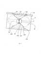
- На Фиг. 1 представлено сечение отдельного исполнения первых и вторых герметичных соединительных устройств, закрепляемых на животе пациента, имеющего две стомы;- In FIG. 1 is a cross-sectional view of a separate embodiment of the first and second sealed connecting devices mounted on the abdomen of a patient having two stomas;
- На Фиг. 2 схематично представлен вид спереди отдельного исполнения средств для предотвращения противотока по данному изобретению;- In FIG. 2 is a schematic front view of a separate embodiment of means for preventing countercurrent flow according to the invention;
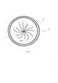
- На Фиг. 3 схематично представлен вид сверху средств для предотвращения противотока, показанных на Фиг. 2, баллон находится в открытом положении; и- In FIG. 3 is a schematic top view of the counterflow means shown in FIG. 2, the cylinder is in the open position; and
- На Фиг. 4 представлен вид сверху средств для предотвращения противотока, показанных на Фиг. 2, баллон находится в закрытом положении.- In FIG. 4 is a plan view of the counterflow preventers shown in FIG. 2, the cylinder is in the closed position.
Устройство на Фиг. 1 содержит единственный коллектор 1, который составляет первые и вторые средства герметичного присоединения к стомам S1 и S2 выше и ниже по ходу, выполненным на животе пациента. Устройство приспособлено для близко расположенных стом, для которых используется один коллектор. Коллектор 1 имеет крышку 11, закрепленную на корпусе 13 коллектора. Корпус 13 коллектора имеет мембранный отсек 131, содержащий мембрану 14. Всасывательный канал 3 выпускной канал 5 размещены в корпусе 13 коллектора и открываются в мембранный отсек 131. Корпус 13 коллектора также содержит собирающий отсек 133, в который также открываются всасывательный 3 и выпускной 5 каналы. Мембранный отсек 131 и собирающий отсек 133 связаны между собой посредством всасывательного 3 и выпускного 5 каналов. Собирающий отсек 133 закреплен на коже Р живота пациента, поверх двух стом S1 и S2. Выпускной канал 5 содержит наконечник, который проходит через собирающий отсек 133 и к которому присоединена трубка 51. Эта трубка 51 вставлена в открытую часть кишечника на уровне нижней по ходу стомы S2. Всасывательный канал 3 открывается непосредственно в собирающий отсек 133. Всасывательный канал 3 содержит первое средство 33 для предотвращения противотока, в то время как выпускной канал 5 содержит второе средство 53 для предотвращения противотока, оба эти средства будут подробнее описаны при помощи Фиг. 2 и 4. Два канала 3 и 5 не соединяются друг с другом напрямую и расположены в корпусе коллектора 13 между мембранным отсеком 131 и собирающим отсеком 133. Полость 21 расположена во всасывательном канале, в то время как полость 41 расположена в выпускном канале. Две эти полости 21 и 41 преимущественно идентичны, и каждая из них имеет эллипсоидную в плоскости перпендикулярной каналам 3 и 5 секцию; наиболее длинное направление перпендикулярно каналам 3 и 5, соответственно. Две эти полости 21 и 41 имеют форму цилиндрических колец 2, герметично закрепленные в каналах 3 и 5, что более подробно описано при помощи Фиг. 2. Средство G для наполнения баллонов первого и второго средств для предотвращения противотока содержит трубки наполнения Т, подсоединенные к этим баллонам. На Фиг. 1 баллоны не представлены для большей ясности, и показана только одна трубка Т.The device of FIG. 1 contains a
На Фиг. 2 более подробно показано исполнение первого средства для предотвращения противотока. В отдельном исполнении, представленным на рисунке, первое и второе средства для предотвращения противотока идентичны, но изобретение не ограничивается этим исполнением.In FIG. 2 shows in more detail the implementation of the first means to prevent counterflow. In a separate embodiment shown in the figure, the first and second means for preventing counterflow are identical, but the invention is not limited to this embodiment.
Как показано на Фиг. 2, средство для предотвращения противотока содержит кольцо 2 с преимущественно трубчатой внешней поверхностью, которое может быть герметично закреплено во всасывательном канале 3 или в выпускном канале 5 коллектора 1. Это кольцо 2 имеет внутреннюю полость 21 преимущественно кольцевой наибольшей секции. Полость 21 имеет эллипсоидальную форму, подобную форме мяча для регби. Канавка 22 расположена по всей секции полости 21. Полость 21 имеет перфорацию 23, на которой закрепляется конец трубки Т (см. Фиг. 1), который подключен к средству наполнения, и таким образом может наполнять баллон в большей или меньшей степени. Канавка 22 прерывается в месте нахождения перфорации 23.As shown in FIG. 2, the means for preventing countercurrent flow comprises a
Кольцо 2 имеет буртик 24, который опирается на поверхность корпуса коллектора 13 на входном отверстии всасывательного 3 или выпускного 5 канала, в мембранном отсеке 131. Полость 21 открыта в верхней и нижней части кольца 2. Первая расточка 210 выполнена в верхней части кольца 2, которое имеет буртик 24. Эту расточку 210 продолжает первый цилиндрический проход 211, который открывается в полость 21. Подобным образом, на другом конце кольца 2 находится вторая расточка 213, которую продолжает третья расточка 215 меньшей секции. Расточку 215 продолжает второй преимущественно цилиндрический проход 217, который открывается в полость 21. Вышеупомянутая полость 21, расточки и проходы образуют проход для продвижения пищевого комка.
На Фиг. 2, баллон 3 сформирован цилиндрической полосой 310, изготовленной из упруго деформируемого материала, используемого в медицине, допускающего продолжительный контакт с человеческим телом. Полоса 310 имеет верхний край 311, который приклеен на вертикальную часть прохода 211 и на горизонтальную часть первой расточки 210 по всему периметру их секции. Нижний край 313 полосы 310 приклеен на горизонтальной части третьей расточки 215 и на вертикальной стенке второго прохода 217.In FIG. 2, the
На Фиг. 2 баллон 3, сформированный полосой 310 находится в закрытом состоянии. Он наполняется при помощи средства наполнения G, а противоположные части полосы 310, соответствующей диаметру секции полости 21, находятся в соприкосновении на протяжении части высоты ленты 310. Перешеек 32 сдавливается, затягивается в соответствии с диаметром полости 21 (т.е. размером, преимущественно перпендикулярным высоте кольца 2) путем накачки баллона 3. Баллон 3 занимает целую секцию полости 21, предотвращая проход пищевого комка через перешеек 32, который таким образом исчезает.In FIG. 2,
На Фиг. 3, когда баллон 3 спущен и, следовательно, находится в открытом состоянии, полоса 310 находится близко к стенке полости 21 и образует тор, центральный перешеек 32 (или отверстие) которого позволяет осуществлять проход пищевого комка. Примыкание мембраны 310 к стенке полости 21 возможно выполнить даже путем модуляции наполнения баллона под действием всасывания, генерируемого средством накачки G. Таким образом, полость освобождается и пропускает пищевой комок.In FIG. 3, when the
На Фиг. 4 отмечается, что когда баллон наполнен, для пищевого комка не остается прохода, перешеек 32 исчезает, так как его стенки прижимаются друг к другу. Полоса 310 соприкасается сама с собой, и благодаря давлению жидкости в баллоне 3 обеспечивает герметичное перекрытие перешейка 32; пищевой комок больше не может проходить через полость 21.In FIG. 4 it is noted that when the balloon is full, there is no passage for the food lump, the
Работа устройства по изобретению будет описана подробнее при помощи Фиг. 1 и 4.The operation of the device according to the invention will be described in more detail using FIG. 1 and 4.
Когда пищевой комок попадает в часть кишечника, выше стомы S1, расположенной выше по ходу, он, благодаря сокращениям кишечника, выталкивается во всасывательный канал 3. Он пересекает полость 21 через перешеек 32 баллона 3 и достигает мембранного отсека 131. Средство наполнения G наполняет баллон 3, расположенный во всасывательном канале, для того, чтобы перекрыть перешеек 32. Средство, образующее насос, выталкивает пищевой комок благодаря деформации мембраны 14 по направлению к выпускному каналу 5, баллон 3, установленный в выпускном канале, спускается, таким образом переходя в открытое положение. Таким образом, пищевой комок пересекает полость 41 и выпускную трубку 5; затем он проникает в нижнюю по ходу часть кишечника через стому S2 ниже по ходу. Затем средство наполнения G наполняет баллон 3, расположенный в полости 41, для предотвращения противотока пищевого комка в сторону выпускного канала 5 и по направлению к мембранной секции 131.When the food lump enters the part of the intestine, above the stoma S1, located upstream, due to intestinal contractions, it is pushed into the
Отверстие баллона 3, расположенное в полости 21 всасывательного канала, позволяет поднять пищевой комок, собранный в собирающем отсеке 133 по направлению к мембранному отсеку 131, и цикл начинается заново, как было показано ранее, пока в собирающем отсеке 133 больше не останется пищевого комка.The opening of the
В соответствии с другим исполнением, не показанным здесь, устройство содержит два коллектора, соединенных трубкой. Первый коллектор располагается на стоме S1 выше по ходу, в то время как второй располагается на стоме S2 ниже по ходу.According to another embodiment not shown here, the device comprises two collectors connected by a tube. The first collector is located on the stoma S1 upstream, while the second is located on the stoma S2 downstream.
В соответствии с еще одним исполнением, не показанным здесь, устройство имеет датчик давления, установленный для измерения преобладающего давления в баллонах 3. Этот датчик позволяет обнаружить наличие пищевого комка ниже или выше по ходу баллона 3; действительно, пищевой комок давит на баллон 3, он изменяет давление, преобладающее в последнем, которое указывает на наличие пищевого комка в устройстве по изобретению.In accordance with another embodiment not shown here, the device has a pressure sensor installed to measure the prevailing pressure in the
Claims (19)
Translated fromRussianApplications Claiming Priority (3)
| Application Number | Priority Date | Filing Date | Title |
|---|---|---|---|
| FR1562433AFR3044891B1 (en) | 2015-12-15 | 2015-12-15 | DEVICE FOR ALIMENTARY BOWL FLOW BETWEEN TWO STOMES COMPRISING AN ANTI-REFLUX BALLOON HAVING A COLLAR FOR THE PASSAGE OF FOOD BOWL |
| FR15/62433 | 2015-12-15 | ||
| PCT/IB2016/057348WO2017103727A1 (en) | 2015-12-15 | 2016-12-05 | Device allowing an alimentary bolus flow between two stomas |
Publications (1)
| Publication Number | Publication Date |
|---|---|
| RU2695260C1true RU2695260C1 (en) | 2019-07-22 |
Family
ID=55182464
Family Applications (1)
| Application Number | Title | Priority Date | Filing Date |
|---|---|---|---|
| RU2018117825ARU2695260C1 (en) | 2015-12-15 | 2016-12-05 | Device for food lump movement between two stomas |
Country Status (12)
| Country | Link |
|---|---|
| US (1) | US10912668B2 (en) |
| EP (1) | EP3389575B1 (en) |
| JP (1) | JP6713045B2 (en) |
| CN (1) | CN108366869B (en) |
| AU (1) | AU2016370708B2 (en) |
| BR (1) | BR112018009498B1 (en) |
| DK (1) | DK3389575T3 (en) |
| ES (1) | ES2761270T3 (en) |
| FR (1) | FR3044891B1 (en) |
| PL (1) | PL3389575T3 (en) |
| RU (1) | RU2695260C1 (en) |
| WO (1) | WO2017103727A1 (en) |
Families Citing this family (4)
| Publication number | Priority date | Publication date | Assignee | Title |
|---|---|---|---|---|
| EP3668580B1 (en)* | 2017-08-16 | 2024-07-24 | Intervaal Pte. Ltd. | Catheter device and method of manufacturing the same |
| SG11202003202RA (en) | 2017-10-09 | 2020-05-28 | The Insides Company Ltd | Nutrient recycling device |
| JP7633808B2 (en)* | 2018-03-08 | 2025-02-20 | ザ インサイズ カンパニー リミテッド | Device for use with a surgically created orifice - Patent application |
| EP4008296A1 (en)* | 2020-12-01 | 2022-06-08 | CHRU de Lille | Device having a reservoir of variable volume and allowing the transfer of a nutritive and / or pharmaceutical composition from an ostoma to another natural or artificial orifice |
Citations (5)
| Publication number | Priority date | Publication date | Assignee | Title |
|---|---|---|---|---|
| US20090216206A1 (en)* | 2006-10-17 | 2009-08-27 | C. R. Bard, Inc. | Waste Management System |
| RU2010147388A (en)* | 2008-04-22 | 2012-05-27 | Конватек Текнолоджиз Инк. (Us) | TEMPORARY APPLIANCE |
| US20130197458A1 (en)* | 2011-02-21 | 2013-08-01 | International Medical Technology, Inc. | Flow control and collection device |
| WO2014122378A1 (en)* | 2013-02-05 | 2014-08-14 | Centre Hospitalier Regional Universitaire De Lille | Device allowing an alimentary bolus flow between two stomas |
| KR101482496B1 (en)* | 2014-03-10 | 2015-01-15 | 김강미 | An artificial stoma sphincter(ASS) with closing device |
Family Cites Families (10)
| Publication number | Priority date | Publication date | Assignee | Title |
|---|---|---|---|---|
| AUPQ115499A0 (en)* | 1999-06-24 | 1999-07-15 | Colocare Holdings Pty Limited | Colostomy pump device |
| US7141071B2 (en)* | 2002-12-23 | 2006-11-28 | Python Medical, Inc. | Implantable digestive tract organ |
| US7037343B2 (en)* | 2002-12-23 | 2006-05-02 | Python, Inc. | Stomach prosthesis |
| US8617045B2 (en)* | 2006-08-15 | 2013-12-31 | International Medical Technology, Inc. | Urinary incontinence device |
| ES3018147T3 (en)* | 2007-10-11 | 2025-05-14 | Implantica Patent Ltd | System for treating a patient having an intestinal disorder |
| JP5443366B2 (en)* | 2007-10-11 | 2014-03-19 | ミルックス・ホールディング・エスエイ | System for treating patients with bowel disease |
| US9211182B2 (en)* | 2009-11-20 | 2015-12-15 | E2, Llc | Anti-reflux devices and methods for treating gastro-esophageal reflux disease (GERD) |
| US9545329B2 (en)* | 2011-02-21 | 2017-01-17 | International Medical Technology | Flow control and collection device |
| US9149383B2 (en)* | 2012-01-23 | 2015-10-06 | Apollo Endosurgery, Inc. | Endolumenal esophageal restriction device |
| CN103405845B (en)* | 2013-08-30 | 2015-08-19 | 任东林 | A kind of Ileum fistulization tube |
- 2015
- 2015-12-15FRFR1562433Apatent/FR3044891B1/ennot_activeExpired - Fee Related
- 2016
- 2016-12-05RURU2018117825Apatent/RU2695260C1/enactive
- 2016-12-05WOPCT/IB2016/057348patent/WO2017103727A1/ennot_activeCeased
- 2016-12-05BRBR112018009498-6Apatent/BR112018009498B1/enactiveIP Right Grant
- 2016-12-05EPEP16808817.7Apatent/EP3389575B1/enactiveActive
- 2016-12-05ESES16808817Tpatent/ES2761270T3/enactiveActive
- 2016-12-05USUS15/781,194patent/US10912668B2/enactiveActive
- 2016-12-05JPJP2018526693Apatent/JP6713045B2/enactiveActive
- 2016-12-05AUAU2016370708Apatent/AU2016370708B2/enactiveActive
- 2016-12-05PLPL16808817Tpatent/PL3389575T3/enunknown
- 2016-12-05CNCN201680072792.0Apatent/CN108366869B/enactiveActive
- 2016-12-05DKDK16808817Tpatent/DK3389575T3/enactive
Patent Citations (5)
| Publication number | Priority date | Publication date | Assignee | Title |
|---|---|---|---|---|
| US20090216206A1 (en)* | 2006-10-17 | 2009-08-27 | C. R. Bard, Inc. | Waste Management System |
| RU2010147388A (en)* | 2008-04-22 | 2012-05-27 | Конватек Текнолоджиз Инк. (Us) | TEMPORARY APPLIANCE |
| US20130197458A1 (en)* | 2011-02-21 | 2013-08-01 | International Medical Technology, Inc. | Flow control and collection device |
| WO2014122378A1 (en)* | 2013-02-05 | 2014-08-14 | Centre Hospitalier Regional Universitaire De Lille | Device allowing an alimentary bolus flow between two stomas |
| KR101482496B1 (en)* | 2014-03-10 | 2015-01-15 | 김강미 | An artificial stoma sphincter(ASS) with closing device |
Also Published As
| Publication number | Publication date |
|---|---|
| FR3044891A1 (en) | 2017-06-16 |
| US20180353318A1 (en) | 2018-12-13 |
| CN108366869B (en) | 2020-06-30 |
| ES2761270T3 (en) | 2020-05-19 |
| HK1254451A1 (en) | 2019-07-19 |
| FR3044891B1 (en) | 2017-12-08 |
| JP6713045B2 (en) | 2020-06-24 |
| US10912668B2 (en) | 2021-02-09 |
| DK3389575T3 (en) | 2019-12-09 |
| BR112018009498A2 (en) | 2018-11-06 |
| EP3389575A1 (en) | 2018-10-24 |
| BR112018009498B1 (en) | 2022-10-04 |
| JP2019503726A (en) | 2019-02-14 |
| CN108366869A (en) | 2018-08-03 |
| AU2016370708B2 (en) | 2022-03-10 |
| AU2016370708A1 (en) | 2018-06-07 |
| EP3389575B1 (en) | 2019-11-06 |
| WO2017103727A1 (en) | 2017-06-22 |
| PL3389575T3 (en) | 2020-03-31 |
Similar Documents
| Publication | Publication Date | Title |
|---|---|---|
| RU2695260C1 (en) | Device for food lump movement between two stomas | |
| US12053409B2 (en) | Bodily waste collection using periodic pressure | |
| CN107802896A (en) | A kind of negative pressure drainage ball of medical anti-extrusion backflow | |
| CN102526819B (en) | Anti-backflow blockage resisting negative pressure drainage device | |
| CN108939245A (en) | Avoid the breathing circuit of doctors and patients' cross-infection | |
| CN106377804A (en) | Drainage bag | |
| CN211935002U (en) | Drainage instrument used after digestive tract anastomosis | |
| CN108578793A (en) | A kind of Breast Surgery operation negative pressure drainage device | |
| CN107432783B (en) | Pressure-adjustable pessary | |
| CN208756639U (en) | Drainage device for fecal incontinence | |
| CN204050450U (en) | A kind of drainage system | |
| CN216784528U (en) | A leak-proof medical waste collection device | |
| CN216061445U (en) | Intestinal decompression tube for anal decompression and anastomotic leakage after middle and low rectal surgery | |
| CN211096418U (en) | A new type of gastrointestinal decompression negative pressure suction device | |
| CN215023654U (en) | An enema tube for retention enema | |
| CN208017648U (en) | A kind of closed combination care device of intestinal tube Double-cavity stoma gasbag-type | |
| CN211157598U (en) | Multifunctional gastrointestinal decompression device | |
| CN104107465B (en) | A kind of drainage system | |
| CN208017832U (en) | A kind of negative pressure drainage ball of medical anti-extrusion reflux | |
| CN107411869A (en) | A kind of operating method of the closed combination care device of intestinal tube Double-cavity stoma gasbag-type | |
| CN209221109U (en) | A kind of gastrointestinal surgery gastrointestinal decompression | |
| CN206252714U (en) | Tracheostomy cannula | |
| CN213759736U (en) | Drainage bottle with metering function | |
| CN215023123U (en) | Gastrointestinal decompression device | |
| CN208448278U (en) | A kind of enteral irrigation device for anal sphincter patient out of control |