RU2690099C2 - Method and measuring device for determining specific parameters for gas properties - Google Patents
Method and measuring device for determining specific parameters for gas propertiesDownload PDFInfo
- Publication number
- RU2690099C2 RU2690099C2RU2015148670ARU2015148670ARU2690099C2RU 2690099 C2RU2690099 C2RU 2690099C2RU 2015148670 ARU2015148670 ARU 2015148670ARU 2015148670 ARU2015148670 ARU 2015148670ARU 2690099 C2RU2690099 C2RU 2690099C2
- Authority
- RU
- Russia
- Prior art keywords
- gas
- measuring device
- gas pipeline
- sound
- evaluation unit
- Prior art date
Links
Images


Classifications
- G—PHYSICS
- G01—MEASURING; TESTING
- G01F—MEASURING VOLUME, VOLUME FLOW, MASS FLOW OR LIQUID LEVEL; METERING BY VOLUME
- G01F1/00—Measuring the volume flow or mass flow of fluid or fluent solid material wherein the fluid passes through a meter in a continuous flow
- G01F1/66—Measuring the volume flow or mass flow of fluid or fluent solid material wherein the fluid passes through a meter in a continuous flow by measuring frequency, phase shift or propagation time of electromagnetic or other waves, e.g. using ultrasonic flowmeters
- G01F1/667—Arrangements of transducers for ultrasonic flowmeters; Circuits for operating ultrasonic flowmeters
- G01F1/668—Compensating or correcting for variations in velocity of sound
- G—PHYSICS
- G01—MEASURING; TESTING
- G01F—MEASURING VOLUME, VOLUME FLOW, MASS FLOW OR LIQUID LEVEL; METERING BY VOLUME
- G01F1/00—Measuring the volume flow or mass flow of fluid or fluent solid material wherein the fluid passes through a meter in a continuous flow
- G01F1/68—Measuring the volume flow or mass flow of fluid or fluent solid material wherein the fluid passes through a meter in a continuous flow by using thermal effects
- G01F1/684—Structural arrangements; Mounting of elements, e.g. in relation to fluid flow
- G01F1/688—Structural arrangements; Mounting of elements, e.g. in relation to fluid flow using a particular type of heating, cooling or sensing element
- G01F1/6882—Structural arrangements; Mounting of elements, e.g. in relation to fluid flow using a particular type of heating, cooling or sensing element making use of temperature dependence of acoustic properties, e.g. propagation speed of surface acoustic waves
- G—PHYSICS
- G01—MEASURING; TESTING
- G01N—INVESTIGATING OR ANALYSING MATERIALS BY DETERMINING THEIR CHEMICAL OR PHYSICAL PROPERTIES
- G01N25/00—Investigating or analyzing materials by the use of thermal means
- G01N25/18—Investigating or analyzing materials by the use of thermal means by investigating thermal conductivity
- G—PHYSICS
- G01—MEASURING; TESTING
- G01N—INVESTIGATING OR ANALYSING MATERIALS BY DETERMINING THEIR CHEMICAL OR PHYSICAL PROPERTIES
- G01N29/00—Investigating or analysing materials by the use of ultrasonic, sonic or infrasonic waves; Visualisation of the interior of objects by transmitting ultrasonic or sonic waves through the object
- G01N29/02—Analysing fluids
- G01N29/024—Analysing fluids by measuring propagation velocity or propagation time of acoustic waves
- G—PHYSICS
- G01—MEASURING; TESTING
- G01N—INVESTIGATING OR ANALYSING MATERIALS BY DETERMINING THEIR CHEMICAL OR PHYSICAL PROPERTIES
- G01N33/00—Investigating or analysing materials by specific methods not covered by groups G01N1/00 - G01N31/00
- G01N33/22—Fuels; Explosives
- G01N33/225—Gaseous fuels, e.g. natural gas
- G—PHYSICS
- G01—MEASURING; TESTING
- G01N—INVESTIGATING OR ANALYSING MATERIALS BY DETERMINING THEIR CHEMICAL OR PHYSICAL PROPERTIES
- G01N7/00—Analysing materials by measuring the pressure or volume of a gas or vapour
- G—PHYSICS
- G01—MEASURING; TESTING
- G01N—INVESTIGATING OR ANALYSING MATERIALS BY DETERMINING THEIR CHEMICAL OR PHYSICAL PROPERTIES
- G01N9/00—Investigating density or specific gravity of materials; Analysing materials by determining density or specific gravity
- G—PHYSICS
- G01—MEASURING; TESTING
- G01N—INVESTIGATING OR ANALYSING MATERIALS BY DETERMINING THEIR CHEMICAL OR PHYSICAL PROPERTIES
- G01N2291/00—Indexing codes associated with group G01N29/00
- G01N2291/02—Indexing codes associated with the analysed material
- G01N2291/028—Material parameters
- G01N2291/02836—Flow rate, liquid level
- G—PHYSICS
- G01—MEASURING; TESTING
- G01N—INVESTIGATING OR ANALYSING MATERIALS BY DETERMINING THEIR CHEMICAL OR PHYSICAL PROPERTIES
- G01N25/00—Investigating or analyzing materials by the use of thermal means
- G01N25/005—Investigating or analyzing materials by the use of thermal means by investigating specific heat
Landscapes
- Physics & Mathematics (AREA)
- Chemical & Material Sciences (AREA)
- General Physics & Mathematics (AREA)
- Health & Medical Sciences (AREA)
- Life Sciences & Earth Sciences (AREA)
- Analytical Chemistry (AREA)
- Biochemistry (AREA)
- Pathology (AREA)
- Immunology (AREA)
- General Health & Medical Sciences (AREA)
- Engineering & Computer Science (AREA)
- Fluid Mechanics (AREA)
- Electromagnetism (AREA)
- Chemical Kinetics & Catalysis (AREA)
- General Chemical & Material Sciences (AREA)
- Medicinal Chemistry (AREA)
- Food Science & Technology (AREA)
- Acoustics & Sound (AREA)
- Oil, Petroleum & Natural Gas (AREA)
- Investigating Or Analyzing Materials By The Use Of Ultrasonic Waves (AREA)
- Investigating Or Analyzing Materials Using Thermal Means (AREA)
- Measuring Volume Flow (AREA)
Abstract
Description
Translated fromRussianИзобретение относится к способу и к измерительному устройству для определения удельных параметров для свойства газа и/или потребления энергии в домашнем хозяйстве и промышленной области.The invention relates to a method and to a measuring device for determining specific parameters for gas properties and / or energy consumption in a household and industrial field.
Состав (природного) газа и, тем самым, свойство газа в будущем, ввиду новых источников происхождения (биогаз, сжиженный природный газ из всех стран света, водород из утилизации избыточного тока при альтернативном получении энергии) будут отклоняться больше и чаще, чем в настоящее время, и, тем самым, будут иметь в процессах использования газа различные, в том числе также негативные воздействия. При прямом измерении удельных параметров для свойства газа на месте процессы могли бы регулироваться в соответствии с изменяющимся качеством газа, чтобы обеспечить оптимальный и надежный режим работы. К удельным параметрам для свойств газа относятся, например, индекс Воббе для управления горелкой, коэффициент избытка воздуха в установках производства энергии (промышленных печах, топливных элементах и т.д.), метановое число для газовых двигателей или теплота сгорания для расчета полученного количества энергии. Последнее, в общем, предполагает, что также измеряется полученное количество газа, что в настоящее время осуществляется, с незначительными исключениями, посредством измерения объемного расхода с помощью сильфонных газометров (в домашнем хозяйстве) или, у газовых потребителей больших объемов газа (в промышленности), посредством счётчиков газа с вращающимся поршнем, с турбинным колесом или ультразвуковых счетчиков. Все эти измерительные средства пригодны только для определения производственного объема. Для того чтобы из этих данных можно было сделать вывод о потребленной, поддающейся учету энергии, необходим как пересчет на нормальный объем, так и знание теплоты сгорания соответствующего поставляемого газа. И то и другое осуществляется лишь неточно: чаще всего нормальный объем рассчитывается при средней температуре и среднем давлении, а также теплота сгорания является значением, усредненным за период расчета.The composition of (natural) gas and, thereby, the property of gas in the future, due to new sources of origin (biogas, liquefied natural gas from all countries of the world, hydrogen from the utilization of excess current with alternative energy production) will be deviated more and more often than at present , and, thereby, they will have various effects in the processes of using gas, including also negative impacts. By directly measuring the specific parameters for the on-site gas properties, the processes could be adjusted in accordance with the changing gas quality to ensure an optimal and reliable mode of operation. Specific parameters for gas properties include, for example, the Wobbe index for controlling the burner, the coefficient of excess air in power generation plants (industrial furnaces, fuel cells, etc.), the methane number for gas engines, or the heat of combustion for calculating the amount of energy received. The latter generally assumes that the amount of gas received is also measured, which is currently carried out, with minor exceptions, by measuring the volume flow rate using bellows gas meters (in the household) or, in gas consumers, large volumes of gas (in the industry), by means of gas meters with a rotating piston, with a turbine wheel or ultrasonic meters. All of these measuring tools are only suitable for determining the production volume. In order to make a conclusion about the consumed energy that can be taken into account from these data, both recalculation to a normal volume and knowledge of the heat of combustion of the corresponding supplied gas is necessary. Both are only inaccurate: most often, the normal volume is calculated at the average temperature and the average pressure, and the heat of combustion is the value averaged over the calculation period.
Целью изобретения является предложить способ и измерительное устройство, с помощью которых удельные параметры для свойства газа и/или потребление энергии могут определяться в реальном времени.The aim of the invention is to propose a method and a measuring device with which the specific parameters for gas properties and / or energy consumption can be determined in real time.
Из патентной заявки ЕР 14001767 известен способ, в котором генерируется расход с помощью критического сопла, чтобы с помощью подключенного микротермического датчика определять удельные параметры для свойства газа. Этот способ основывается на том, что на сопле всегда присутствуют критические степени сжатия, будь то из-за нагружения сопла подпором или из-за генерации вакуума за соплом. Поэтому данный способ не пригоден непосредственно для определения удельных параметров для свойства газа у конечных потребителей, так как сети снабжения на этом месте редко имеют требуемый подпор, а об установке вакуумного насоса за соплом не может быть и речи.From patent application EP 14001767 a method is known in which flow is generated using a critical nozzle in order to determine specific parameters for a gas property using a connected microthermal sensor. This method is based on the fact that critical nozzles are always present on the nozzle, either because of the overpressure of the nozzle or due to the generation of vacuum behind the nozzle. Therefore, this method is not directly suitable for determining the specific parameters for gas properties at end users, since supply networks at this place rarely have the required backwater, and installing a vacuum pump behind the nozzle is out of the question.
Из ЕР 2 574 918 А1 известен способ, в котором микротермический датчик применяется для того, чтобы объемного расходомер усовершенствовать в том отношении, чтобы можно быть определять тепловую диффузионную способность, что при известной теплопроводности позволяет разделить газы на низкокалорийные (L) или высококалорийные (Н) газы. Из объемного расхода, тепловой диффузионной способности и теплопроводности можно, однако, в общем случае, с недостаточной точностью делать вывод о теплоте сгорания и потоке энергии.From
Задачей настоящего изобретения является устранить недостатки упомянутых способов и предложить способ и измерительное устройство, которые пригодны для газораспределительных сетей низкого давления, и посредством которых, наряду с разделением газов на L-газы или H-газы, также могут определяться теплота сгорания и потребление энергии.The present invention is to eliminate the disadvantages of the above-mentioned methods and to propose a method and a measuring device that are suitable for low pressure gas distribution networks, and by means of which, along with the separation of gases into L-gases or H-gases, the heat of combustion and energy consumption can also be determined.
Эта задача решается способом согласно пункту 1 формулы изобретения и измерительным устройством согласно пункту 7 формулы изобретения.This problem is solved by the method according to
В основе изобретения лежит идея, для определения удельных параметров для свойства газа и/или потребления энергии скомбинировать ультразвуковой расходомер с микротермическим датчиком, как описано ниже.The invention is based on the idea that, in order to determine the specific parameters for gas properties and / or energy consumption, combine an ultrasonic flow meter with a microthermal sensor, as described below.
Измерение скорости звука и объемного расхода посредством ультразвукового расходомера:Measurement of sound velocity and volumetric flow rate using an ultrasonic flow meter:
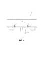
Для определения объемного расхода обычно в текучую среду вводится ультразвуковой сигнал под углом поперек направления потока, и измеряется разность времен распространения ультразвукового сигнала как в направлении потока, так и против направления потока (фиг.1b). Разность времен распространения обоих ультразвуковых сигналов является тогда мерой для средней скорости течения, из которой при известном поперечном сечении трубопровода может быть вычислен объемный расход:To determine the volumetric flow rate, an ultrasonic signal is usually introduced into the fluid at an angle across the flow direction, and the difference in the propagation times of the ultrasonic signal is measured both in the flow direction and against the flow direction (fig. 1b). The difference in propagation times of both ultrasonic signals is then a measure for the average flow velocity, from which, with a known cross section of the pipeline, the volume flow can be calculated:

гдеWhere
vx - средняя скорость течения,vx - the average flow rate
сs - скорость звука,withs - the speed of sound,
L - длина измерительного участка,L is the length of the measuring section,
t12 - время распространения в направлении потока иt12 is the propagation time in the direction of flow and
t21 - время распространения против направления потока.t21 - the time of propagation against the direction of flow.
Сумма времен распространения содержит информацию о скорости звука сs среды, которая, однако, в ультразвуковых счетчиках чаще всего не находит никакого дальнейшего применения.The sum of propagation times contains information about the speed of sound froms medium, which, however, most often does not find any further use in ultrasonic counters.
В комбинации с микротермическим датчиком, как описано в патентной заявке ЕР 14001767, благодаря информации о скорости звука, можно отказаться от критического сопла, так как последнее в первую очередь также предоставляет скорость звука, с тем преимуществом, что не требуются критические отношения давлений, то есть можно выполнять измерение при данном давлении. Тем самым, в газораспределительных сетях низкого давления не требуются ни компрессоры, ни вакуумные насосы.In combination with a microthermal sensor, as described in patent application EP 14001767, thanks to information about the speed of sound, you can opt out of the critical nozzle, since the latter primarily also provides the speed of sound, with the advantage that it does not require critical pressure ratios, i.e. You can measure at a given pressure. Thus, in the low pressure gas distribution networks, neither compressors nor vacuum pumps are required.
Определение массового потока:Determination of mass flow:
Из скорости звука путем корреляции может определяться плотность, которая для большинства газов хорошо коррелирована со скоростью звука. Для того чтобы дополнительно улучшить корреляцию плотности, можно дополнительно измерять теплопроводность при одной или нескольких температурах и использовать в корреляции.From the speed of sound, density can be determined by correlation, which for most gases is well correlated with the speed of sound. In order to further improve the density correlation, one can additionally measure the thermal conductivity at one or several temperatures and use it in correlation.
Массовый поток пропорционален произведению


причем А обозначает поперечное сечение канала потока.moreover And denotes the cross-section of the flow channel.
Измерение теплопроводности посредством микротермического датчика:Measurement of thermal conductivity using a microthermal sensor:
Интегрированные CMOS-термоанемометры обеспечивают возможность как микротермического измерения теплопроводности, так и измерение массового потока. В отношении этой технологии можно сослаться на D. Matter, B. Kramer, T. Kleiner, B. Sabbattini, T. Suter, “Mikroelektronischer Haushaltsgaszähler mit neuer Technologie”, Technisches Messen 71, 3 (2004), S.137-146.Integrated CMOS thermo-anemometers provide the possibility of both microthermal measurement of thermal conductivity and measurement of mass flow. With respect to this technology, reference may be made to D. Matter, B. Kramer, T. Kleiner, B. Sabbattini, T. Suter, “Mikroelektronischer Haushaltsgaszähler mit neuer Technologie”, Technisches Messen 71, 3 (2004), S.137-146.
Для описания микротермических измерений будем исходить из одномерного уравнения теплопроводности, описывающего микротермическую систему (Kerson Huang: Statistical Mechanics, 2. Auflage, John Wiley & Sons, New York 1987, ISBN 0-471-85913-3):For the description of microthermal measurements we will proceed from the one-dimensional heat conduction equation describing the microthermal system (Kerson Huang: Statistical Mechanics, 2. Auflage, John Wiley & Sons, New York 1987, ISBN 0-471-85913-3):

гдеWhere


Т - температура,T is the temperature

ср - теплоемкость газа при постоянном давлении,Cp - the heat capacity of the gas at constant pressure,
ρ - плотность,ρ is the density
λ - теплопроводность газа иλ is the thermal conductivity of gas and


Так как газ (газовый поток) течет только в направлении х, компоненты vy и vz в направлении y и в направлении z средней скорости течения
Следует отметить, что теплопроводность λ, ввиду источникового члена Θ, отдельно воздействует на решение уравнения (3). Напротив, может определяться теплопроводность, если микротермический датчик используется без подведенного массового потока (


Кроме того, посредством варьирования источникового члена, можно изменять распределение температуры, что позволяет определять теплопроводность при различных температурах.In addition, by varying the source term, it is possible to change the temperature distribution, which allows to determine the thermal conductivity at different temperatures.
Определение теплоемкости посредством микротермического датчика:Determination of heat capacity by microthermal sensor:
Решение уравнения (3), которое описывает распределение температуры в микротермической системе, позволяет через измерение этого распределения температуры определять коэффициент потока ϕ:The solution of equation (3), which describes the temperature distribution in the microthermal system, allows to determine the flow coefficient ϕ through the measurement of this temperature distribution:

причем А обозначает поперечное сечение канала потока через микротермический датчик, и
Корреляция удельных параметров для свойства газа:Correlation of specific parameters for gas properties:
При наличии скорости звука cs, теплопроводности λ и теплоемкости ср, в распоряжение предоставляются три независимых измеренных параметра, с помощью которых могут теперь коррелироваться удельные параметры Q для свойства газа, как, например, теплота сгорания, с использованием корреляционной функции fcorr:With the speed of sound cs , thermal conductivity λ and heat capacity withp , three independent measured parameters are available that can now be used to correlate specific Q parameters for gas properties, such as heat of combustion, using the correlation function fcorr :

“Выход датчика” Sout является при этом функцией выходных параметров cs, λ и ср:The “sensor output” Sout is in this case a function of the output parameters cs , λ and cp :

Например, для корреляции показанного на фиг.2а отношения плотностей Q = ρ/ρref при 0°С и 1013,25 мбар получается следующая корреляционная функция:For example, the following correlation function is obtained for the correlation of the density ratio Q = ρ / ρref at 0 ° C and 1013.25 mbar shown in FIG. 2a:

с коэффициентами а0 = 36, а1 = -65 и а2 = 30 и метаном (G20) в качестве эталона. Soutявляется при этом просто скоростью звука cs:with coefficients а0 = 36, а1 = -65 and а2 = 30 and methane (G20) as a reference. Sout is simply the speed of sound cs :

На Фиг.2b показана улучшенная корреляция отношения плотностей Q = ρ/ρref при 0°С и 1013,25 мбар на основе скорости звука и теплопроводности, измеренных при двух различных температурах.Figure 2b shows an improved correlation of the density ratio Q = ρ / ρref at 0 ° C and 1013.25 mbar based on the speed of sound and thermal conductivity measured at two different temperatures.
В случае корреляции удельных параметров для свойства газа на фиг.3а уравнение (8а) для примера теплоты сгорания выглядит следующим образом:In the case of the correlation of the specific parameters for the gas property in Fig. 3a, equation (8a) for the example of the heat of combustion is as follows:

с коэффициентами а0 = 8,1, а1 = -11 и а2 = 4,7 и вновь метаном (G20) в качестве эталона. Soutявляется теперь функцией всех трех выходных параметров:with the coefficients a0 = 8,1, a1 = -11 and a2 = 4.7 and again with methane (G20) as a reference. Sout is now a function of all three output parameters:

Из результатов на фиг.2 и фиг.3а легко понять, что посредством cs, сри λ, в качестве дальнейшего свойства газа, может коррелироваться индекс Воббе W как мера для производительности горелки, определенный какFrom the results of Fig. 2 and Fig. 3a, it is easy to understand that by cs , cp and λ, as a further property of the gas, the Wobbe index W can be correlated as a measure for the burner capacity, defined as

При этом уравнения (8а) для плотности и (9b) для теплоты сгорания комбинируются друг с другом.In this case, equations (8a) for density and (9b) for heat of combustion are combined with each other.
Кроме того, в качестве свойства газа, из трех независимых параметров - скорости cs звука, теплопроводности λ и теплоемкости ср, может, например, коррелироваться Z-коэффициент или коэффициент сверхсжимаемости газа, который описывает отклонение реального газа от закона идеального газа:In addition, as a property of a gas, of three independent parameters — the speed cs of sound, thermal conductivity λ and heat capacity cp , for example, the Z-coefficient or gas super-compressibility coefficient, which describes the deviation of real gas from the ideal gas law, can be correlated:

Поведение реального газа отклоняется особенно сильно при высоких давлениях от поведения идеального газа, а именно, при давлениях, которые возникают в больших трубопроводах транспортировки газа (и поэтому должны специально учитываться). Интересным при этом применении является тот факт, что определение независимых параметров должно осуществляться не при том высоком давлении, а, например, также может осуществляться при давлении окружающей среды, при котором конструкция соответствующего измерительного устройства может быть реализована намного проще. На Фиг.3b показана возможная корреляция Z-коэффициента для 50 бар со следующими ориентировочными данными:The behavior of a real gas deviates particularly strongly at high pressures from the behavior of an ideal gas, namely, at pressures that occur in large gas transmission pipelines (and therefore must be specifically taken into account). Interesting in this application is the fact that the determination of independent parameters should be carried out not at the same high pressure, but, for example, can also be carried out at ambient pressure, in which the design of the corresponding measuring device can be implemented much easier. Fig. 3b shows the possible correlation of the Z-factor for 50 bar with the following indicative data:

с коэффициентами а0 = 1,1, а1 = 0,15, а2 = -0,29 и а3 = 0,05 и метаном (G20) в качестве эталона. Soutвновь является функцией всех трех выходных параметров (при давлении окружающей среды):with the coefficients a0 = 1.1, a1 = 0.15, a2 = -0.29, and a3 = 0.05 and methane (G20) as a reference. Sout is again a function of all three output parameters (at ambient pressure):

В качестве еще одного примера может быть приведена корреляция кинематической вязкости, η/ρ (вязкость/плотность). Эта величина входит в число Рейнольдса, Re, которое применяется в теории течений и может пониматься как отношение сил инерции к силам вязкости:As another example, the kinematic viscosity correlation, η / ρ (viscosity / density), can be given. This value is included in the Reynolds number, Re, which is used in the theory of flows and can be understood as the ratio of inertial forces to viscous forces:

причем ρ обозначает плотность, v - скорость течения газа по отношению к обтекаемому телу и d - характеристическую длину тела. Отсюда следует, что режим турбулентности геометрически подобных тел при одинаковом числе Рейнольдса идентичен. При известной кинематической вязкости может, таким образом, оцениваться, когда при некотором газе в системе трубопровода возникает турбулентность, что является для газораспределительных сетей важным входным параметром для расчета таких сетей. Фиг.3с показывает корреляцию между кинематической вязкостью η/ρ и выходом датчика Sout:moreover, ρ denotes the density, v is the gas flow rate with respect to the streamlined body and d is the characteristic length of the body. From this it follows that the mode of turbulence of geometrically similar bodies with the same Reynolds number is identical. With a known kinematic viscosity, it can thus be evaluated when turbulence occurs in a pipeline system with a certain gas, which is an important input parameter for gas distribution networks for calculating such networks. FIG. 3c shows the correlation between the kinematic viscosity η / ρ and the output of the sensor Sout :

с коэффициентами а0 = 0,15 и а1 = 0,85 и метаном (G20) в качестве эталона. Soutвновь является функцией всех трех выходных параметров:with coefficients a0 = 0.15 and a1 = 0.85 and methane (G20) as a reference. Sout is again a function of all three output parameters:

Следует подчеркнуть, что выбор Sout, с одной стороны, а также fcorr, с другой стороны, никоим образом не задается, а они свободно выбираются таким образом, что результирующая ошибка корреляции становится как можно меньшей. Приведенная в уравнениях (8а)-(8d) функция полинома является типовым выбором, который чаще всего успешен, в то время как уравнения (9а)-(9d) скорее пытаются описать физическую взаимосвязь.It should be emphasized that the choice of Sout , on the one hand, and fcorr , on the other hand, is in no way specified, and they are freely chosen in such a way that the resulting correlation error becomes as small as possible. The polynomial function given in equations (8a) - (8d) is a typical choice, which is most often successful, while equations (9a) - (9d) rather try to describe the physical relationship.
Для того чтобы показать, что способ согласно настоящему изобретению не ограничивается вышеуказанными примерами, ниже будут приведены дополнительные примеры конкретных параметров для свойств газа, которые могут определяться данным способом:In order to show that the method according to the present invention is not limited to the above examples, further examples of specific parameters for gas properties that can be determined by this method will be given below:
- Метановое число, которое используется для приводов на газовом двигателе, как в стационарных установках (например, в установках совместной выработки электрической и тепловой энергии), так и в транспортной области (например, в транспортных средствах с газовыми двигателями, на судах и т.д.), является важным показателем для склонности к детонации газообразного топлива.- Methane number, which is used for gas engine drives, both in stationary installations (for example, in installations of joint generation of electric and thermal energy), and in the transport area (for example, in vehicles with gas engines, on ships, etc. .) is an important indicator for the propensity to detonate gaseous fuels.
- “Отношение воздуха к топливу” и, тем самым, количество воздуха, которое должно подводиться в процесс. Знание “отношения воздуха к топливу”, например, важно при процессах сжигания, как стехиометрических (например, в топочных установках), так и с избытком воздуха (например, в двигателях на обедненных горючих смесях), с открытыми пламенем или каталитического типа (например, в процессах преобразования в высокотемпературных топливных элементах), чтобы оптимизировать как эффективность процесса сгорания, так и параметры отработавших газов.- “The ratio of air to fuel” and, thus, the amount of air that must be fed into the process. Knowledge of “air to fuel ratio”, for example, is important in combustion processes, both stoichiometric (for example, in furnaces) and with excess air (for example, in engines with lean fuel mixtures), open flame or catalytic type (for example, in conversion processes in high-temperature fuel cells) to optimize both the efficiency of the combustion process and the exhaust gas parameters.
- Содержание метана, контроль которого имеет значение, например, в технологических процессах. В биогазовых установках содержание метана типично контролируется в неочищенном биогазе (например, как мера для эффективности ферментёра) и/или в газе, который должен вводиться в газораспределительную сеть (например, для контроля качества), и/или в выпускаемом в воздух остаточном газе (предпочтительно двуокиси углерода с как можно меньшим количеством метана, так как последний проявляет высокий парниковый эффект).- The content of methane, the control of which is important, for example, in technological processes. In biogas plants, methane content is typically controlled in crude biogas (for example, as a measure for the efficiency of the fermenter) and / or in the gas that must be introduced into the gas distribution network (for example, for quality control), and / or in the residual gas released into the air (preferably carbon dioxide with as little methane as possible, since the latter exhibits a high greenhouse effect).
Этапы способа в типичном примере выполненияThe steps of the method in a typical example run
1. Измерение давления р и температуры Т газа.1. Measurement of pressure p and temperature T of gas.
2. Ультразвуковое определение объемного расхода, пропорционального скорости vx течения, и скорости cs звука, которая для большинства газов хорошо коррелирует с нормальной плотностью ρnorm.2. Ultrasonic determination of volume flow, proportional to the velocity vx of flow, and speed cs of sound, which for most gases correlates well with the normal density ρnorm .
3. Учет измеренной микротермическим датчиком теплопроводности λTi (при одной или нескольких температурах Ti), чтобы дополнительно улучшить корреляцию нормальной плотности ρnorm.3. Accounting for the thermal conductivity λTi measured by a microthermal sensor (at one or several temperatures Ti ) in order to further improve the correlation of the normal density ρnorm .
4. Вычисление плотности при рабочих условиях согласно4. Density calculation under operating conditions according to

5. Использование этой информации (vx, ρ) для определения массового потока
6. Коррелирование желательного удельного параметра для свойства газа, в частности, теплоты сгорания CV, из скорости cs звука, теплопроводности λ и теплоемкости ср.6. Correlation of the desired specific parameter for gas properties, in particular, calorific value CV, from sound speed cs , thermal conductivity λ and heat capacity withр .
7. При необходимости, путем перемножения массового или объемного потока на теплоту сгорания CV (в Дж/кг или Дж/м3) может определяться энергопотребление ФEn.7. If necessary, by using the mass or volume flow multiplied by the calorific value CV (in J / kg or J / m3 ), the energy consumption ΦEn can be determined.
Под вышеупомянутой нормальной плотностью ρnorm в этом описании понимается плотность при установленной температуре Тnorm и установленном давлении рnorm. Нормальная плотность обычно указывается при 0°С и 1013,25 мбар. Однако также возможно устанавливать другие значения для температуры Тnorm и давления рnorm, для которых известна корреляция между плотностью и скоростью звука.The aforementioned normal density ρnorm in this description means density at a set temperature Tnorm and a set pressure pnorm . Normal density is usually indicated at 0 ° C and 1013.25 mbar. However, it is also possible to set other values for temperature Tnorm and pressure pnorm , for which the correlation between density and speed of sound is known.
Способ и измерительное устройство согласно предложенному изобретениюMethod and measuring device according to the proposed invention
В способе для определения удельных параметров для свойства газа согласно предложенному изобретениюIn a method for determining specific parameters for a gas property according to the proposed invention
- газ или газовая смесь протекает через ультразвуковой расходомер и через микротермический датчик, причем- gas or gas mixture flows through an ultrasonic flow meter and through a microthermal sensor, and
- регистрируют температуру и давление газа или газовой смеси;- record the temperature and pressure of the gas or gas mixture;
- с помощью ультразвукового расходомера определяют как скорость течения или объемный поток, так и скорость звука газа или газовой смеси;- using an ultrasonic flow meter to determine both the flow rate or volume flow, and the sound velocity of the gas or gas mixture;
- из скорости звука коррелируют плотность газа или смеси газа;- from the speed of sound correlate the density of the gas or gas mixture;
- применяют информацию о плотности, вместе со скоростью течения, для вычисления массового потока;- apply information about the density, together with the flow rate, to calculate the mass flow;
- с помощью микротермического датчика определяют теплопроводность газа или газовой смеси при одной или нескольких температурах;- using a microthermal sensor to determine the thermal conductivity of a gas or gas mixture at one or more temperatures;
- из сигнала расхода микротермического датчика вычисляют коэффициент потока, чтобы из него, вместе с информацией о массовом потоке и теплопроводности, определить теплоемкость или зависимый от теплоемкости параметр газа или газовой смеси;- the flow coefficient is calculated from the flow signal of the microthermal sensor in order to determine from it, together with information about the mass flow and thermal conductivity, the heat capacity or the parameter of the gas or gas mixture dependent on the heat capacity;
- наконец, скорость звука, теплопроводность при одной или нескольких температурах и либо теплоемкость, либо зависимый от теплоемкости параметр применяют для корреляции удельных параметров для свойства газа, в частности, теплоты сгорания.- finally, the speed of sound, thermal conductivity at one or several temperatures and either the heat capacity or the parameter dependent on the heat capacity is used to correlate the specific parameters for the properties of the gas, in particular, the heat of combustion.
Определенную с помощью ультразвукового расходомера скорость звука можно при необходимости пересчитать на скорость звука при нормальной температуре.The sound speed determined using an ultrasonic flow meter can be recalculated, if necessary, to the speed of sound at normal temperature.
В предпочтительном варианте выполнения определенная с помощью микротермического датчика теплопроводность при одной или нескольких температурах, вместе со скоростью звука, применяется для более точной корреляции плотности.In a preferred embodiment, the thermal conductivity determined by a microthermal sensor at one or several temperatures, together with the speed of sound, is used for a more accurate density correlation.
Плотность, коррелированная из скорости звука или из скорости звука и теплопроводности, может быть, например, нормальной плотностью. Предпочтительным образом, плотность, коррелированная из скорости звука или из скорости звука и теплопроводности, или нормальная плотность с помощью температуры и давления газа или газовой смеси пересчитывается в плотность при рабочих условиях.The density correlated from the speed of sound or from the speed of sound and thermal conductivity may be, for example, normal density. Preferably, the density correlated from the speed of sound or from the speed of sound and thermal conductivity, or normal density using temperature and pressure of a gas or gas mixture is converted into density under operating conditions.
В предпочтительном варианте выполнения способа скорость звука, теплопроводность при одной или нескольких температурах и либо теплоемкость, либо зависимый от теплоемкости параметр применяются для корреляции теплоты сгорания или индекса Воббе (W) или Z-коэффициента или кинематической вязкости.In a preferred embodiment of the method, the speed of sound, thermal conductivity at one or several temperatures and either the heat capacity or the parameter dependent on the heat capacity are used to correlate the heat of combustion or the Wobbe index (W) or the Z-coefficient or kinematic viscosity.
В другом предпочтительном варианте выполнения способа из теплоты сгорания, вместе с объемным или массовым потоком, вычисляется потребление энергии, например, таким образом, что произведение объемного или массового потока и теплота сгорания интегрируются во времени.In another preferred embodiment of the method, the energy consumption is calculated from the heat of combustion, together with the volume or mass flow, for example, so that the product of the volume or mass flow and the heat of combustion are integrated over time.
Вышеописанный способ и вышеописанные формы и варианты выполнения пригодны как для непрерывного, так и для прерывистого определения удельных параметров для свойства газа и/или потребления энергии.The above method and the above-described forms and embodiments are suitable for both continuous and intermittent determination of specific parameters for gas properties and / or energy consumption.
Измерительное устройство для определения удельных параметров для свойства газа и/или потребления энергии согласно предложенному изобретению включает в себя блок оценки, который выполнен с возможностью осуществления способа согласно вышеописанным формам и вариантам выполнения, а также ультразвуковой расходомер для измерения скорости звука и течения, датчик давления для измерения давления, датчик температуры для измерения температуры и микротермический датчик для измерения теплопроводности и либо теплоемкости, либо зависимого от теплоемкости параметра газа или газовой смеси.A measuring device for determining specific parameters for gas properties and / or energy consumption according to the proposed invention includes an evaluation unit that is configured to implement the method according to the above-described forms and embodiments, as well as an ultrasonic flow meter for measuring the speed of sound and flow, a pressure sensor for pressure measurement, temperature sensor for temperature measurement and microthermal sensor for measuring thermal conductivity and either heat capacity or temperature dependent Ploemosti parameter gas or gas mixture.
В первом варианте выполнения измерительного устройства ультразвуковой расходомер и микротермический датчик размещены в газопроводе и могут нагружаться тем же самым массовым потоком.In the first embodiment of the measuring device, the ultrasonic flow meter and the microthermal sensor are placed in the gas pipeline and can be loaded with the same mass flow.
Во втором варианте выполнения измерительного устройства ультразвуковой расходомер расположен в основном газопроводе, а микротермический датчик - в байпасном газопроводе по отношению к основному газопроводу, причем в основном газопроводе предусмотрен элемент, создающий перепад давления, для образования массового потока в байпасном газопроводе.In the second embodiment of the measuring device, the ultrasonic flow meter is located in the main gas pipeline, and the microthermal sensor is in the bypass gas pipeline with respect to the main gas pipeline, and the pressure differential element is provided in the main gas pipeline to form a mass flow in the bypass gas pipeline.
Предпочтительно в первом и во втором варианте выполнения ультразвуковой расходомер размещен на газопроводе или основном газопроводе не инвазивно.Preferably, in the first and second embodiment, the ultrasonic flow meter is not invasively located on the gas pipeline or the main gas pipeline.
В третьем варианте выполнения измерительного устройства ультразвуковой расходомер и микротермический датчик расположены в байпасном газопроводе по отношению к основному газопроводу, причем в основном газопроводе предусмотрен элемент, создающий перепад давления для образования массового потока в байпасном газопроводе.In the third embodiment of the measuring device, the ultrasonic flow meter and the microthermal sensor are located in the bypass gas pipeline with respect to the main gas pipeline, and the main gas pipeline has an element that creates a pressure drop to form a mass flow in the bypass gas pipeline.
Предпочтительно, во втором и третьем варианте выполнения отношение деления между массовым потоком в байпасном и в основном газопроводе известно, например, посредством калибровки с известным газом.Preferably, in the second and third embodiment, the division ratio between the mass flow in the bypass and in the main gas pipeline is known, for example, by calibration with a known gas.
Независимо от формы и варианта выполнения, измерительное устройство может дополнительно включать в себя участок газопровода или основного газопровода и/или байпасного газопровода, в которых размещен по меньшей мере один из датчиков измерительного устройства, и/или элемент, создающий перепад давления, в основном газопроводе.Regardless of the form and variant of execution, the measuring device may additionally include a section of a gas pipeline or a main gas pipeline and / or a bypass gas pipeline, in which at least one of the sensors of the measuring device is located, and / or an element that creates a pressure drop, in the main gas pipeline.
Предпочтительным образом, блок оценки вместе с остальным измерительным устройством образует конструктивный блок. В зависимости от применения, измерительное устройство может также образовывать конструктивный блок без блока оценки, причем блок оценки может быть выполнен в отдельном или вышестоящем вычислительном блоке.Preferably, the evaluation unit together with the rest of the measuring device forms a building block. Depending on the application, the measuring device can also form a structural unit without an evaluation unit, and the evaluation unit can be performed in a separate or higher computing unit.
Способ и измерительное устройство согласно предложенному изобретению для определения удельных параметров для свойства газа и/или потребления энергии имеет преимущество, состоящее в том, что они могут применяться также в газораспределительных сетях низкого давления, не требуя, как измерительное устройство, описанное в патентной заявке ЕР 14001767, дополнительного компрессора или дополнительного вакуумного насоса.The method and measuring device according to the proposed invention for determining specific parameters for gas properties and / or energy consumption has the advantage that they can also be used in low-pressure gas distribution networks without the need for measuring device described in patent application EP 14001767 , additional compressor or additional vacuum pump.
Кроме того, предпочтительно, что определенная с помощью микротермического датчика теплопроводность газа или газовой смеси при одной или нескольких температурах, вместе со скоростью звука, может применяться для более точной корреляции плотности, что приводит к более точным значениям для массового потока.In addition, it is preferable that the thermal conductivity of a gas or gas mixture at one or several temperatures, together with the speed of sound, determined with the help of a microthermal sensor can be used to more accurately correlate the density, which leads to more accurate values for the mass flow.
Корреляция удельных параметров для свойства газа из трех независимых переменных - скорости звука, теплопроводности и теплоемкости - обеспечивает к тому же более высокую точность при определении теплоты сгорания и потребления энергии, чем это было возможно с помощью вышеописанного способа согласно ЕР 2 574 918 А1.The correlation of specific parameters for the gas properties of three independent variables — sound speed, thermal conductivity and heat capacity — also provides higher accuracy in determining the heat of combustion and energy consumption than was possible using the method described above according to
Изобретение поясняется далее более подробно со ссылками на чертежи, на которых показано следующее:The invention is explained further in more detail with reference to the drawings, which show the following:
Фиг.1а - схематичная структура примера выполнения микротермического анемометра,Fig.1A is a schematic structure of an example implementation of a microthermal anemometer,
Фиг.1b - схематичное представление ультразвукового расходомера,Fig.1b is a schematic representation of an ultrasonic flow meter,
Фиг.2а - пример определения плотности (корреляции) на основе скорости звука,Figa is an example of determining the density (correlation) based on the speed of sound,
Фиг.2b - пример улучшенного определения плотности (корреляции) на основе скорости звука и теплопроводности,Fig.2b is an example of an improved determination of the density (correlation) based on the speed of sound and thermal conductivity,
Фиг.3а - пример определения теплоты сгорания (корреляции) на основе теплоемкости, теплопроводности и скорости звука,Figa is an example of determining the heat of combustion (correlation) on the basis of heat capacity, thermal conductivity and speed of sound,
Фиг.3b - пример определения Z-коэффициента (корреляции) на основе теплоемкости, теплопроводности и скорости звука,Fig.3b is an example of determining the Z-coefficient (correlation) on the basis of heat capacity, thermal conductivity and speed of sound,
Фиг.3с - пример определения кинематической вязкости (корреляции) на основе теплоемкости, теплопроводности и скорости звука,Fig.3C is an example of determining the kinematic viscosity (correlation) on the basis of heat capacity, thermal conductivity and speed of sound,
Фиг.4 - пример выполнения схематичной структуры измерительного устройства согласно предложенному изобретению в основном газопроводе,4 is an example of the schematic structure of the measuring device according to the proposed invention in the main pipeline,
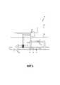
Фиг.5 - второй пример выполнения схематичной структуры измерительного устройства согласно предложенному изобретению с микротермическим датчиком в байпасном газопроводе по отношению к основному газопроводу и5 is a second exemplary embodiment of the schematic structure of the measuring device according to the proposed invention with a microthermal sensor in the bypass gas pipeline with respect to the main gas pipeline and
Фиг.6 - третий пример выполнения схематичной структуры измерительного устройства согласно предложенному изобретению в байпасном газопроводе.6 is a third exemplary embodiment of the schematic structure of the measuring device according to the proposed invention in the bypass gas pipeline.
На Фиг.1а показан пример выполнения микротермического датчика 7 для применения в измерительном устройстве согласно предложенному изобретению. Микротермический датчик может, например, как показано на фиг.1, представлять собой микротермический CMOS-термоанемометр, который при использовании располагается на участке байпасного газопровода и может нагружаться потоком 2а газа или газовой смеси. Микротермический CMOS-термоанемометр включает в себя подложку 13, которая типично содержит мембрану 14 толщиной в несколько микрометров. Кроме того, CMOS-термоанемометр включает в себя два термоэлемента 15.1, 15.2 и нагревательный элемент 16, который может располагаться между обоими термоэлементами. С помощью обоих термоэлементов 15.1, 15.2 может регистрироваться температура, которая устанавливается на основе теплообмена 15.1а, 15.2а с потоком 2а газа или газовой смеси.On Figa shows an exemplary embodiment of a
В отношении дополнительных деталей функционирования интегрального микротермического CMOS-термоанемометра можно сослаться на D. Matter, B. Kramer, T. Kleiner, B. Sabbattini, T. Suter, “Mikroelektronischer Haushaltsgaszähler mit neuer Technologie”, Technisches Messen 71, 3 (2004), S.137-146.For further details on the functioning of the integrated microthermal CMOS thermo-anemometer, refer to D. Matter, B. Kramer, T. Kleiner, B. Sabbattini, T. Suter, “Mikroelektronischer Haushaltsgaszähler mit neuer Technologie”, Technisches Messen 71, 3 (2004), S.137-146.
На Фиг.1b показан пример выполнения ультразвукового расходомера 4 для применения в измерительном устройстве согласно предложенному изобретению. Например, два генерирующих звук и принимающих звук блока 17 и 18 (например, пьезо-возбудители и приемники) расположены в косо противолежащих положениях в измерительном трубопроводе. Звуковой импульс, излученный от возбудителя 17, достигает приемника 18 быстрее, чем звуковой импульс, одновременно излученный из возбудителя 18, достигает приемника 17. Из времен t12 и t21 распространения, совместно с геометрическими факторами расположения, можно вычислить как скорость cs звука, так и скорость vx течения.On Fig.1b shows an exemplary embodiment of an
В отношении дополнительных деталей функционирования ультразвукового датчика можно сослаться на L.C. Lynnwortha, Yi Liub, “Ultrasonic flowmeters: Half-century progress report, 1955 - 2005”, в Ultrasonics, 44, Supplement (2006), S.e1371-e1378.For further details on the operation of the ultrasonic sensor, refer to L.C. Lynnwortha, Yi Liub, “Ultrasonic flowmeters: Half-century progress report, 1955 - 2005”, in Ultrasonics, 44, Supplement (2006), S.e1371-e1378.
На Фиг.4 показан пример выполнения схематичной структуры измерительного устройства согласно предложенному изобретению. В примере выполнения измерительное устройство 11 содержит блок 10 оценки, который выполнен с возможностью осуществления способа согласно предложенному изобретению, ультразвуковой расходомер 4 , микротермический датчик 7, а также датчик 8 давления и датчик 9 температуры, причем датчики могут быть расположены в газопроводе 1. Некоторые из этих компонентов или все эти компоненты могут быть объединены в один конструктивный блок, причем блок 10 оценки может быть составной частью этого конструктивного блока (вариант 11а), или блок оценки может предоставляться отдельно от него (вариант 11b), например, в вышестоящем вычислительном блоке.Figure 4 shows an exemplary embodiment of the schematic structure of the measuring device according to the proposed invention. In the exemplary embodiment, the measuring
Структура показанного на фиг.4 примера выполнения пригодна для определения удельных параметров для свойства газа при малых и очень малых расходах газа, как, например, они встречаются в области газового анализа, и где в первую очередь важна информация относительно свойства газа.The structure of the exemplary embodiment shown in FIG. 4 is suitable for determining specific parameters for a gas property at low and very low gas flow rates, such as, for example, they are encountered in the field of gas analysis, and where information regarding the gas property is primarily important.
Измерительное устройство в показанном на фиг.4 примере выполнения может использоваться, например, в качестве блока анализа или в качестве автономного устройства анализа, причем блок анализа или устройство анализа предпочтительно содержит газопровод 1, в котором размещены датчики 4, 7, 8, 9 измерительного устройства. С помощью блока анализа или устройства анализа могут отбираться и анализироваться пробы газа. Необходимые для этого соединительные элементы и клапаны на фиг.4 не показаны.The measurement device in the embodiment shown in FIG. 4 can be used, for example, as an analysis unit or as a stand-alone analysis device, with the analysis unit or analysis device preferably comprising a
Пример выполнения способа для определения удельных параметров для свойства газа или газовой смеси согласно предложенному изобретению описывается ниже со ссылкой на фиг.4. В этом способе газ или газовая смесь протекает в газопроводе через ультразвуковой расходомер 4 и через микротермический датчик 7. С помощью расположенного дополнительно в газопроводе датчика 8 давления и датчика 9 температуры определяются давление и температура газа или газовой смеси, то есть рабочие условия. Кроме того, с помощью ультразвукового датчика измеряется скорость звука и скорость течения или объемный поток. Затем выполняется корреляция плотности на основе скорости звука, причем определенную посредством корреляции плотность целесообразно пересчитать в плотность при данной температуре и данном давлении (рабочих условиях).An example of the method for determining the specific parameters for the properties of a gas or gas mixture according to the proposed invention is described below with reference to Fig.4. In this method, the gas or gas mixture flows in the gas pipeline through the
К тому же с помощью микротермического датчика 7 измеряется теплопроводность газа при одной или нескольких температурах, при этом мощность накала нити накала варьируется. Если необходимо, результат этого измерения также может вводиться в корреляцию плотности. С использованием значения плотности и объемного потока затем вычисляется массовый поток. Из измеренного также микротермическим датчиком коэффициента потока затем вычисляется отношение между теплоемкостью и теплопроводностью газа и, вместе с уже известной теплопроводностью, вычисляется значение теплоемкости. Скорость звука, теплопроводность и теплоемкость затем применяются для корреляции удельных параметров для свойства газа, например, теплоты сгорания или индекса Воббе (W) или Z-коэффициента или кинематической вязкости. Посредством умножения массового потока на теплоту сгорания можно, при необходимости, определить потребление энергии.In addition, using a
На Фиг.5 показан второй пример выполнения схематичной структуры измерительного устройства 11 согласно предложенному изобретению с микротермическим датчиком 7 в байпасном газопроводе 6 по отношению к основному газопроводу 1. В основном газопроводе в этом случае предусмотрен элемент 5, создающий перепад давления, так что при работе формируется перепад давления через байпасный газопровод, что приводит к газовому потоку 2 в байпасном трубопроводе, причем устанавливается характеристическое отношение 3 деления расхода между основным и байпасным газопроводом.Figure 5 shows the second exemplary embodiment of the schematic structure of the measuring
В показанном примере выполнения измерительное устройство, дополнительно к микротермическому датчику 7, включает в себя блок 10 оценки, который выполнен с возможностью осуществления способа согласно предложенному изобретению, а также ультразвуковой расходомер 4, датчик 8 давления и датчик 9 температуры, которые типично размещены в основном газопроводе 1. Некоторые из этих компонентов или все эти компоненты могут быть объединены в один конструктивный блок, причем блок 10 оценки может быть составной частью этого конструктивного блока (вариант 11а), или блок оценки может предоставляться отдельно от него (вариант 11b), например, в вышестоящем вычислительном блоке.In the shown example of execution, the measuring device, in addition to the
Структура показанного на фиг.5 примера выполнения пригодна как для определения удельных параметров для свойства газа, так и, в случае теплоты сгорания в качестве свойства газа, для измерения потребления энергии при расходах газа от средних до высоких, как они проявляются в сфере домашнего хозяйства, в промышленности или в подлежащем тарировке движении транспорта.The structure of the exemplary embodiment shown in FIG. 5 is suitable both for determining specific parameters for a gas property and, in the case of heat of combustion, as a gas property, for measuring energy consumption for gas from medium to high, as they appear in the household, in industry or in the movement of traffic to be calibrated.
Ультразвуковой расходомер 4 не должен при этом обязательно встраиваться в основной газопровод 1, а может также в качестве так называемого “фиксируемого прибора” размещаться снаружи на газопроводе или основном газопроводе. Микротермический датчик 7, напротив, требует лишь очень малых величин расходов и поэтому предпочтительно размещается в байпасном трубопроводе 6.The
Второй пример выполнения способа для определения удельных параметров свойства газа для газа или газовой смеси согласно предложенному изобретению будет описан ниже со ссылкой на фиг.5. В способе газ или газовая смесь течет через основной газопровод 1 или через элемент 5, создающий перепад давления. Перед элементом 5, создающим перепад давления, ответвляется байпасный газопровод 6, чтобы после него вновь соединиться с основным газопроводом. Посредством элемента 5, создающего перепад давлений, часть газа иди газовой смеси 2 вынуждается к тому, чтобы протекать через байпасный газопровод 6 или через расположенный в нем микротермический датчик 7. Ультразвуковой расходомер 4 нагружается основным газовым потоком.A second exemplary embodiment of the method for determining the specific properties of a gas for a gas or gas mixture according to the proposed invention will be described below with reference to FIG. 5. In the method, a gas or gas mixture flows through the
С помощью дополнительно размещенного в основном газопроводе датчика 8 давления и датчика 9 температуры определяются давление и температура газа или газовой смеси, то есть рабочие условия. Далее, с помощью ультразвукового датчика измеряется скорость звука и скорость течения или объемный поток. Затем выполняется корреляция плотности на основе скорости звука, причем плотность, определенная посредством корреляции, целесообразно пересчитать в плотность при данной температуре и при данном давлении (рабочих условиях).Using the
К тому же с помощью микротермического датчика 7 измеряется теплопроводность газа при одной или нескольких температурах, при этом варьируется мощность нагрева нити накала. Если необходимо, результат этого измерения также может быть включен в корреляцию плотности. С помощью значения плотности и объемного потока затем вычисляется массовый поток через основной газопровод 1. Затем целесообразно использовать отношение деления массового потока между основным и байпасным газопроводом, чтобы вычислить массовый поток в байпасном газопроводе. Отношение деления может определяться, например, заранее в калибровочном измерении с известными газами.In addition, using a
Из коэффициента потока, измеренного также микротермическим датчиком, вычисляется отношение между теплоемкостью и теплопроводностью газа или газовой смеси и, с помощью уже известной теплопроводности, значение теплоемкости. Скорость звука, теплопроводность и теплоемкость затем применяются для корреляции удельных параметров для свойства газа. В случае теплоты сгорания в качестве свойства газа, умножение массового потока в основном газопроводе на теплоту сгорания дополнительно дает потребление энергии.The ratio between the heat capacity and thermal conductivity of the gas or gas mixture and, with the help of the already known thermal conductivity, the value of the heat capacity is calculated from the flow coefficient, also measured by a microthermal sensor. The speed of sound, thermal conductivity and heat capacity are then used to correlate the specific parameters for the gas property. In the case of heat of combustion as a property of gas, multiplying the mass flow in the main gas pipeline by the heat of combustion additionally gives energy consumption.
На Фиг.6 показан третий пример выполнения схематичной структуры измерительного устройства 11 согласно предложенному изобретению в байпасном газопроводе 6 по отношению к основному газопроводу 1. В основном газопроводе в этом случае предусмотрен элемент 5, создающий перепад давлений, так что при работе создается перепад давлений через байпасный газопровод, что приводит к газовому потоку 2 в байпасном газопроводе, причем устанавливается характеристическое отношение 3 деления расхода между основным и байпасным газопроводом.Figure 6 shows the third exemplary embodiment of the schematic structure of the measuring
В показанном примере выполнения измерительное устройство содержит блок 10 оценки, который выполнен с возможностью осуществления способа согласно предложенному изобретению, а также ультразвуковой расходомер 4 и микротермический датчик 7, которые размещены в байпасном газопроводе 6. Кроме того, измерительное устройство содержит датчик 8 давления и датчик 9 температуры, которые чаще всего также размещены в байпасном газопроводе 1. Некоторые из этих компонентов или все эти компоненты могут быть объединены в один конструктивный блок, причем блок 10 оценки может быть составной частью этого конструктивного блока (вариант 11а), или блок оценки может предоставляться отдельно от него (вариант 11b), например, в вышестоящем вычислительном блоке.In the shown example, the execution of the measuring device contains the
Структура показанного на фиг.6 примера выполнения получается предпочтительным образом тогда, когда ультразвуковой датчик 4 также выполнен в микротехнике и, как и микротермический датчик 7, требует лишь очень малых величин расхода. Предпочтительным образом тогда оба датчика расположены в байпасном трубопроводе 6.The structure of the exemplary embodiment shown in FIG. 6 is advantageously obtained when the
Третий пример выполнения способа для определения удельных параметров свойства газа для газа или газовой смеси согласно предложенному изобретению будет описан ниже со ссылкой на фиг.6. Способ пригоден как для непрерывного, так и для прерывистого определения удельных параметров для свойства газа и/или потребления энергии. Необходимые при обстоятельствах соединительные элементы и клапаны на фиг.6 не показаны.The third exemplary embodiment of the method for determining the specific properties of a gas for a gas or gas mixture according to the proposed invention will be described below with reference to FIG. 6. The method is suitable for both continuous and intermittent determination of specific parameters for gas properties and / or energy consumption. The required under the circumstances of the connecting elements and valves figure 6 is not shown.
В третьем примере выполнения способа газ или газовая смесь течет через основной газопровод 1 или через элемент 5, создающий перепад давления. Перед элементом 5, создающим перепад давления, ответвляется байпасный газопровод 6, чтобы после него вновь соединиться с основным газопроводом. Посредством элемента, создающего перепад давлений, часть газа или газовой смеси 2 вынуждается к тому, чтобы протекать через байпасный газопровод 6 и через ультразвуковой расходомер 4 и через микротермический датчик 7, которые размещены в байпасном газопроводе. При этом ультразвуковой расходомер 4 и микротермический датчик 7 нагружаются одним и тем же газовым потоком.In the third exemplary embodiment of the method, the gas or gas mixture flows through the
С помощью дополнительно размещенного в байпасном газопроводе датчика 8 давления и датчика 9 температуры определяются давление и температура газа или газовой смеси, то есть рабочие условия. Далее, с помощью ультразвукового датчика измеряется скорость звука и скорость течения или объемный поток. Затем выполняется корреляция плотности на основе скорости звука, причем плотность, определенная посредством корреляции, целесообразно пересчитать в плотность при данной температуре и при данном давлении (рабочих условиях).Using the
К тому же с помощью микротермического датчика 7 измеряется теплопроводность газа при одной или нескольких температурах, при этом варьируется мощность нагрева нити накала. Если необходимо, результат этого измерения также может быть включен в корреляцию плотности. С помощью значения плотности и объемного потока затем вычисляется массовый поток через байпасный газопровод 6.In addition, using a
Из коэффициента потока, измеренного также микротермическим датчиком, вычисляется отношение между теплоемкостью и теплопроводностью газа или газовой смеси и, с помощью уже известной теплопроводности, значение теплоемкости. Скорость звука, теплопроводность и теплоемкость затем применяются для корреляции удельных параметров для свойства газа.The ratio between the heat capacity and thermal conductivity of the gas or gas mixture and, with the help of the already known thermal conductivity, the value of the heat capacity is calculated from the flow coefficient, also measured by a microthermal sensor. The speed of sound, thermal conductivity and heat capacity are then used to correlate the specific parameters for the gas property.
Так как вышеописанные измерения и расчеты относятся к байпасному газопроводу, следует использовать отношение деления массового потока между основным и байпасным газопроводом, чтобы вычислить массовый поток в основном газопроводе. Отношение деления может определяться, например, заранее в калибровочном измерении с известными газами. В случае, если в качестве свойства газа была определена теплота сгорания, умножение массового потока в основном газопроводе на теплоту сгорания дополнительно дает потребление энергии.Since the above measurements and calculations refer to the bypass pipeline, you should use the ratio of the division of the mass flow between the main and bypass gas pipelines to calculate the mass flow in the main pipeline. The fission ratio can be determined, for example, in advance in a calibration measurement with known gases. In the event that the heat of combustion was determined as a gas property, multiplying the mass flow in the main gas pipeline by the heat of combustion additionally results in energy consumption.
Способ и измерительное устройство согласно предложенному изобретению, а также вышеописанные формы и варианты выполнения для определения удельных параметров для свойства газа или потребления энергии могут применяться в газораспределительных сетях высокого и низкого давления, и, благодаря корреляции из трех независимых переменных - скорости звука, теплопроводности и теплоемкости - обеспечивают возможность достижения сравнительно высокой точности при определении указанных параметров.The method and measuring device according to the proposed invention, as well as the above described forms and embodiments for determining specific parameters for gas properties or energy consumption, can be used in high and low pressure gas distribution networks, and, due to the correlation of three independent variables — sound speed, thermal conductivity and heat capacity - provide the possibility of achieving relatively high accuracy in determining the specified parameters.
Claims (32)
Translated fromRussianApplications Claiming Priority (3)
| Application Number | Priority Date | Filing Date | Title |
|---|---|---|---|
| EP14003855 | 2014-11-14 | ||
| CH14003855.5 | 2014-11-14 | ||
| EP14003855.5 | 2014-11-14 |
Publications (3)
| Publication Number | Publication Date |
|---|---|
| RU2015148670A RU2015148670A (en) | 2017-05-15 |
| RU2015148670A3 RU2015148670A3 (en) | 2019-03-28 |
| RU2690099C2true RU2690099C2 (en) | 2019-05-30 |
Family
ID=51951539
Family Applications (1)
| Application Number | Title | Priority Date | Filing Date |
|---|---|---|---|
| RU2015148670ARU2690099C2 (en) | 2014-11-14 | 2015-11-12 | Method and measuring device for determining specific parameters for gas properties |
Country Status (6)
| Country | Link |
|---|---|
| US (1) | US10101186B2 (en) |
| EP (1) | EP3021117B1 (en) |
| JP (1) | JP6517668B2 (en) |
| CN (1) | CN105606786B (en) |
| ES (1) | ES2771798T3 (en) |
| RU (1) | RU2690099C2 (en) |
Families Citing this family (31)
| Publication number | Priority date | Publication date | Assignee | Title |
|---|---|---|---|---|
| EP3273237B1 (en)* | 2013-05-24 | 2023-11-29 | Mems Ag | Method and measuring device for determining physical gas properties |
| DE102015117468A1 (en)* | 2015-10-14 | 2017-04-20 | Endress+Hauser Flowtec Ag | A method for determining properties of a hydrocarbon-containing gas mixture and apparatus therefor |
| DE102016201350B4 (en)* | 2016-01-29 | 2017-12-21 | Continental Automotive Gmbh | Method for determining the composition of a gas mixture |
| JP6670706B2 (en)* | 2016-08-09 | 2020-03-25 | アズビル株式会社 | Apparatus and method for measuring calorific value |
| CA3032537C (en) | 2016-08-18 | 2024-02-27 | Nevada Nanotech Systems Inc. | Systems and methods for determining at least one property of a material |
| DE102016121226A1 (en)* | 2016-11-07 | 2018-05-09 | Endress + Hauser Flowtec Ag | A method for determining properties of a hydrocarbon-containing gas mixture and apparatus therefor |
| DE102016014151A1 (en)* | 2016-11-25 | 2018-05-30 | Diehl Metering Gmbh | Method for determining a calorific value and / or a Wobbe index of a gas mixture |
| KR101865801B1 (en)* | 2017-01-18 | 2018-06-11 | 주식회사 문아이앤시 | Inline-type apparatus for remotely measuring pressure and flow in water pipe |
| DE102017106904A1 (en) | 2017-03-30 | 2018-10-04 | Endress+Hauser Flowtec Ag | Method for determining the methane number of a hydrocarbon-containing fuel gas mixture |
| WO2018185008A1 (en)* | 2017-04-07 | 2018-10-11 | Continental Automotive Gmbh | Method for ascertaining a property of a fluid and sensor device for this purpose |
| EP3421947B1 (en) | 2017-06-30 | 2019-08-07 | Sensirion AG | Operation method for flow sensor device |
| JP6959078B2 (en)* | 2017-09-07 | 2021-11-02 | 理研計器株式会社 | Gas analysis method and gas analyzer |
| CN111183348B (en)* | 2017-11-14 | 2024-04-09 | 索尼公司 | Microchip for separating microparticles and device for separating microparticles |
| EP3502687B1 (en)* | 2017-12-20 | 2022-06-29 | Sensirion AG | Determination of gas parameters |
| WO2019152041A1 (en) | 2018-02-01 | 2019-08-08 | Reliance Worldwide Corporation | Sensor mount |
| MX2020007983A (en) | 2018-02-01 | 2020-10-16 | Reliance Worldwide Corp | Flow tube for hosting a flow meter and a shut-off valve. |
| EP3521816A1 (en)* | 2018-02-06 | 2019-08-07 | L'air Liquide Societe Anonyme Pour L'etude Et L'exploitation Des Procedes Georges Claude | Method for in-situ monitoring of the quality of gas delivered to a consuming industrial site using the thermal conductivity technique |
| JP7213018B2 (en)* | 2018-02-27 | 2023-01-26 | 三菱重工業株式会社 | Information output device, information output method, and program |
| IT201900009168A1 (en)* | 2019-06-17 | 2020-12-17 | Pietro Fiorentini Spa | Gas measuring device. |
| CN110596240A (en)* | 2019-08-21 | 2019-12-20 | 许昌学院 | A method and system for detecting hydrogen-gas mixtures using decoupled acoustic relaxation spectroscopy |
| JP2023500266A (en)* | 2019-11-01 | 2023-01-05 | マイクロ モーション インコーポレイテッド | Improved Supercritical Fluid Measurement Using Vibrating Sensors |
| FR3109965B1 (en)* | 2020-05-11 | 2022-05-06 | Pfeiffer Vacuum Technology AG | Apparatus and method for monitoring vacuum pump discharge reaction by-product deposition |
| US11415442B2 (en) | 2020-10-30 | 2022-08-16 | Honeywell International Inc. | Ultrasonic flow tube having a plurality of outer pipes surrounding a center pipe positioned between an inlet wall and an outlet wall having transducers therein |
| US12018975B2 (en)* | 2021-03-11 | 2024-06-25 | Honeywell International Inc. | Ultrasound and thermal massflow in one flow channel |
| DK181025B1 (en)* | 2021-06-27 | 2022-10-04 | Remoni As | Flow Sensor and Method Providing Corrected Values of the Density and/or the Flow Based on Values of the Expected Speed of Sound |
| DE102021120363A1 (en) | 2021-08-05 | 2023-02-09 | Sick Engineering Gmbh | FLOW METERING SYSTEM |
| JP7684863B2 (en)* | 2021-08-19 | 2025-05-28 | 愛知時計電機株式会社 | calorimeter |
| EP4400814B1 (en)* | 2023-01-13 | 2024-11-06 | SICK Engineering GmbH | Measuring device and method for measuring a quantity of energy transported by means of a liquefied natural gas stream |
| JPWO2024190177A1 (en)* | 2023-03-14 | 2024-09-19 | ||
| US20240310311A1 (en) | 2023-03-17 | 2024-09-19 | Honeywell International, Inc. | Closed-meshed energy measurement in the gas network |
| DE102023203729A1 (en) | 2023-04-24 | 2024-10-24 | Vitesco Technologies GmbH | Method, control device, fluid quality determination device, computer program and computer-readable medium for determining the quality of a fluid mixture |
Citations (3)
| Publication number | Priority date | Publication date | Assignee | Title |
|---|---|---|---|---|
| WO2004008136A1 (en)* | 2002-07-10 | 2004-01-22 | Flowcomp Systemtechnik Gmbh | Determining the constitution of combustible gases by measuring the thermal conductivity, thermal capacity and carbon dioxide content |
| EP2015056A1 (en)* | 2007-07-07 | 2009-01-14 | Mems Ag | Method and sensor for determining a significant value in combustibility terms of a gas mixture |
| EP2574918A1 (en)* | 2011-09-28 | 2013-04-03 | Mems Ag | Microthermal method and sensor for determining physical gas properties |
Family Cites Families (12)
| Publication number | Priority date | Publication date | Assignee | Title |
|---|---|---|---|---|
| US2591759A (en)* | 1943-03-01 | 1952-04-08 | Nina D Zaikowsky | Thermal conductivity gas analyzer |
| GB9424430D0 (en)* | 1994-12-02 | 1995-01-18 | British Gas Plc | Measurement of a gas characteristic |
| CN1225172A (en)* | 1996-07-12 | 1999-08-04 | 巴杰米特公司 | Measuring heating value of a gas using flameless combustion |
| JP3611416B2 (en)* | 1996-12-24 | 2005-01-19 | 大阪瓦斯株式会社 | Calorific value measuring method and calorific value measuring device |
| GB9715448D0 (en)* | 1997-07-22 | 1997-09-24 | British Gas Plc | Measuring relative density of a gas |
| JP2000039425A (en)* | 1998-07-23 | 2000-02-08 | Osaka Gas Co Ltd | Gas physical property-measuring device and method |
| EP1337844B1 (en)* | 2000-11-15 | 2008-02-06 | Lattice Intellectual Property Limited | Determination of effective composition of a mixture of hydrocarbon gases |
| SE0100379D0 (en)* | 2001-02-07 | 2001-02-07 | Siemens Elema Ab | Arrangement for and method of acoustic determination of fluid temperature |
| JP5782454B2 (en)* | 2010-11-15 | 2015-09-24 | 理研計器株式会社 | Specific gravity measuring method, specific gravity measuring apparatus and Wobbe index measuring apparatus for combustible gas |
| CN102426038A (en)* | 2011-09-14 | 2012-04-25 | 苏州聚元微电子有限公司 | Ultrasonic flow sensor with high reliability |
| US9175810B2 (en)* | 2012-05-04 | 2015-11-03 | General Electric Company | Custody transfer system and method for gas fuel |
| EP3273237B1 (en) | 2013-05-24 | 2023-11-29 | Mems Ag | Method and measuring device for determining physical gas properties |
- 2015
- 2015-11-12JPJP2015222123Apatent/JP6517668B2/enactiveActive
- 2015-11-12USUS14/939,756patent/US10101186B2/enactiveActive
- 2015-11-12ESES15003229Tpatent/ES2771798T3/enactiveActive
- 2015-11-12CNCN201510768899.6Apatent/CN105606786B/enactiveActive
- 2015-11-12EPEP15003229.0Apatent/EP3021117B1/enactiveActive
- 2015-11-12RURU2015148670Apatent/RU2690099C2/enactive
Patent Citations (3)
| Publication number | Priority date | Publication date | Assignee | Title |
|---|---|---|---|---|
| WO2004008136A1 (en)* | 2002-07-10 | 2004-01-22 | Flowcomp Systemtechnik Gmbh | Determining the constitution of combustible gases by measuring the thermal conductivity, thermal capacity and carbon dioxide content |
| EP2015056A1 (en)* | 2007-07-07 | 2009-01-14 | Mems Ag | Method and sensor for determining a significant value in combustibility terms of a gas mixture |
| EP2574918A1 (en)* | 2011-09-28 | 2013-04-03 | Mems Ag | Microthermal method and sensor for determining physical gas properties |
Also Published As
| Publication number | Publication date |
|---|---|
| JP6517668B2 (en) | 2019-05-22 |
| CN105606786A (en) | 2016-05-25 |
| JP2016095308A (en) | 2016-05-26 |
| RU2015148670A (en) | 2017-05-15 |
| ES2771798T3 (en) | 2020-07-07 |
| EP3021117A1 (en) | 2016-05-18 |
| EP3021117B1 (en) | 2020-01-08 |
| US10101186B2 (en) | 2018-10-16 |
| HK1221017A1 (en) | 2017-05-19 |
| RU2015148670A3 (en) | 2019-03-28 |
| CN105606786B (en) | 2019-12-24 |
| US20160138951A1 (en) | 2016-05-19 |
Similar Documents
| Publication | Publication Date | Title |
|---|---|---|
| RU2690099C2 (en) | Method and measuring device for determining specific parameters for gas properties | |
| US11474092B2 (en) | Method for determining properties of a hydrocarbon-containing gas mixture and device for the same | |
| US5486107A (en) | Determination of fuel characteristics | |
| CN108377654B (en) | Method for determining properties of a hydrocarbon-containing gas mixture and apparatus therefor | |
| CN104181074B (en) | Method and apparatus for determining physical properties of gases | |
| US20160313160A1 (en) | Apparatus and method for determining concentrations of components of a gas mixture | |
| JP7258757B2 (en) | Method for estimating combustion properties of gases that may contain hydrogen | |
| CN103175582B (en) | Fluid metering method and apparatus | |
| CN114547892B (en) | Vortex wet gas phase separation flow measurement method based on liquid film flow parameter modeling | |
| CN110672172A (en) | Internet of things MEMS (micro-electromechanical systems) thermal mass gas meter system device and gas flow measuring method | |
| KR20010072889A (en) | Measuring energy consumption | |
| Brahma | Measurement and prediction of discharge coefficients in highly compressible pulsating flows to improve EGR flow estimation and modeling of engine flows | |
| CN102607658B (en) | Method for measuring gas flow in complicated structure channel based on concentration method | |
| Kruz et al. | Field Performance Testing of Gas Turbine Driven Compressor Sets | |
| Brown et al. | Investigation of the transferability of calibration between alternative fluids for liquid and dense phase carbon dioxide flow measurement | |
| Guillou | Uncertainty and measurement sensitivity of turbocharger compressor gas stands | |
| Hajilouy-Benisi et al. | Empirical assessment of the performance characteristics in turbocharger turbine and compressor | |
| Duan et al. | A pressure-temperature coupled probe method for pneumatic measurement in non-ideal compressible gas flows | |
| Stuparu et al. | Experimental investigation of a pumping station from CET power plant Timisoara | |
| RU152854U1 (en) | DEVICE FOR MEASURING A TRUE VOLUME GAS CONTENT OF A GAS-LIQUID MIXTURE IN A PIPELINE NETWORK | |
| HK1221017B (en) | Method and measuring apparatus for determining specific quantities for gas quality | |
| CN114441067A (en) | Natural gas energy assignment calculation method and device | |
| KR101195491B1 (en) | Hybrid-type gas flowmeter | |
| RU2654934C1 (en) | Method of calibration of nozzle and device for calibration of nozzle | |
| Harrouz et al. | Control information and analyzing of metering gas system based of orifice plate |