RU2683436C1 - Method of metrological certification of thermal control of absorption of energy of preventive element of multilayered textile armored prevention and device for its implementation - Google Patents
Method of metrological certification of thermal control of absorption of energy of preventive element of multilayered textile armored prevention and device for its implementationDownload PDFInfo
- Publication number
- RU2683436C1 RU2683436C1RU2018120849ARU2018120849ARU2683436C1RU 2683436 C1RU2683436 C1RU 2683436C1RU 2018120849 ARU2018120849 ARU 2018120849ARU 2018120849 ARU2018120849 ARU 2018120849ARU 2683436 C1RU2683436 C1RU 2683436C1
- Authority
- RU
- Russia
- Prior art keywords
- textile
- output
- input
- armored
- striking element
- Prior art date
Links
- 239000004753textileSubstances0.000titleclaimsabstractdescription83
- 238000000034methodMethods0.000titleclaimsabstractdescription59
- 238000010521absorption reactionMethods0.000titleclaimsabstractdescription36
- 230000002265preventionEffects0.000title1
- 230000003449preventive effectEffects0.000title1
- 230000004888barrier functionEffects0.000claimsabstractdescription59
- 239000000835fiberSubstances0.000claimsabstractdescription53
- 239000000463materialSubstances0.000claimsabstractdescription51
- 230000000694effectsEffects0.000claimsabstractdescription13
- 238000005259measurementMethods0.000claimsabstractdescription8
- 238000010586diagramMethods0.000claimsabstractdescription6
- 238000001931thermographyMethods0.000claimsdescription24
- 230000003993interactionEffects0.000claimsdescription20
- 238000010304firingMethods0.000claimsdescription9
- 238000004458analytical methodMethods0.000claimsdescription7
- 230000003287optical effectEffects0.000claimsdescription4
- 238000012546transferMethods0.000claimsdescription4
- 238000004364calculation methodMethods0.000claimsdescription2
- 239000002131composite materialSubstances0.000abstractdescription19
- 230000008569processEffects0.000abstractdescription9
- 238000005516engineering processMethods0.000abstractdescription2
- 238000012544monitoring processMethods0.000abstractdescription2
- 238000003908quality control methodMethods0.000abstractdescription2
- 239000000126substanceSubstances0.000abstract1
- 238000012360testing methodMethods0.000description12
- 230000035515penetrationEffects0.000description8
- 230000001681protective effectEffects0.000description8
- 238000013461designMethods0.000description6
- 239000000758substrateSubstances0.000description6
- 229910010293ceramic materialInorganic materials0.000description3
- 230000007547defectEffects0.000description3
- 238000011161developmentMethods0.000description3
- 238000004519manufacturing processMethods0.000description3
- 230000005693optoelectronicsEffects0.000description3
- 238000009864tensile testMethods0.000description3
- 238000001757thermogravimetry curveMethods0.000description3
- 241000232219PlatanistaSpecies0.000description2
- 238000013459approachMethods0.000description2
- 239000000919ceramicSubstances0.000description2
- 238000001514detection methodMethods0.000description2
- 238000011156evaluationMethods0.000description2
- 238000002474experimental methodMethods0.000description2
- 238000009434installationMethods0.000description2
- 239000002184metalSubstances0.000description2
- 238000001228spectrumMethods0.000description2
- 229910000831SteelInorganic materials0.000description1
- 238000000429assemblyMethods0.000description1
- 230000000712assemblyEffects0.000description1
- 230000015572biosynthetic processEffects0.000description1
- 238000011088calibration curveMethods0.000description1
- 238000009658destructive testingMethods0.000description1
- 238000005265energy consumptionMethods0.000description1
- 230000007613environmental effectEffects0.000description1
- 230000006872improvementEffects0.000description1
- 238000011089mechanical engineeringMethods0.000description1
- 230000007246mechanismEffects0.000description1
- 239000010813municipal solid wasteSubstances0.000description1
- 238000009659non-destructive testingMethods0.000description1
- 239000002861polymer materialSubstances0.000description1
- 230000035939shockEffects0.000description1
- 239000010959steelSubstances0.000description1
- 230000007704transitionEffects0.000description1
Images


Classifications
- G—PHYSICS
- G01—MEASURING; TESTING
- G01N—INVESTIGATING OR ANALYSING MATERIALS BY DETERMINING THEIR CHEMICAL OR PHYSICAL PROPERTIES
- G01N25/00—Investigating or analyzing materials by the use of thermal means
- G01N25/72—Investigating presence of flaws
- F—MECHANICAL ENGINEERING; LIGHTING; HEATING; WEAPONS; BLASTING
- F41—WEAPONS
- F41H—ARMOUR; ARMOURED TURRETS; ARMOURED OR ARMED VEHICLES; MEANS OF ATTACK OR DEFENCE, e.g. CAMOUFLAGE, IN GENERAL
- F41H5/00—Armour; Armour plates
- F41H5/02—Plate construction
- F41H5/04—Plate construction composed of more than one layer
- F41H5/0414—Layered armour containing ceramic material
- G—PHYSICS
- G01—MEASURING; TESTING
- G01N—INVESTIGATING OR ANALYSING MATERIALS BY DETERMINING THEIR CHEMICAL OR PHYSICAL PROPERTIES
- G01N3/00—Investigating strength properties of solid materials by application of mechanical stress
- G01N3/08—Investigating strength properties of solid materials by application of mechanical stress by applying steady tensile or compressive forces
- G—PHYSICS
- G01—MEASURING; TESTING
- G01N—INVESTIGATING OR ANALYSING MATERIALS BY DETERMINING THEIR CHEMICAL OR PHYSICAL PROPERTIES
- G01N33/00—Investigating or analysing materials by specific methods not covered by groups G01N1/00 - G01N31/00
- G01N33/36—Textiles
Landscapes
- Chemical & Material Sciences (AREA)
- Engineering & Computer Science (AREA)
- Health & Medical Sciences (AREA)
- Life Sciences & Earth Sciences (AREA)
- Analytical Chemistry (AREA)
- General Physics & Mathematics (AREA)
- Pathology (AREA)
- Physics & Mathematics (AREA)
- Immunology (AREA)
- Biochemistry (AREA)
- General Health & Medical Sciences (AREA)
- Textile Engineering (AREA)
- Food Science & Technology (AREA)
- Medicinal Chemistry (AREA)
- Ceramic Engineering (AREA)
- General Engineering & Computer Science (AREA)
- Radiation Pyrometers (AREA)
- Investigating Or Analyzing Materials Using Thermal Means (AREA)
Abstract
Description
Translated fromRussianОбласть техникиTechnical field
Группа изобретений относится к области измерительной техники и может использоватьсядля оценки погрешности метода при контроле качества композитных броневых преград на основе результатов теплового контроля при попадании поражающего элемента в броневую преграду за счет поглощения энергии броневой преградой, а также для проведения непосредственно контроля.The group of inventions relates to the field of measurement technology and can be used to assess the error of the method in controlling the quality of composite armored obstacles based on the results of thermal control when a striking element enters an armored obstacle due to energy absorption by an armored obstacle, and also for direct control.
Изобретения могут быть использованы для контроля качества броневых преград, как в процессе производства, так и в реальных условиях эксплуатации.The inventions can be used to control the quality of armored obstacles, both in the production process and in actual use.
Особенно эффективно применение изобретения при испытании ответственных броневых преград, например, при защите личного состава. Такие броневые преграды, как правило, имеют сложную конструкцию и большую стоимость. Широкое распространение получили текстильные броневые преграды. К таким конструкциям с одной стороны предъявляются высокие требования по надежности защиты, а с другой стороны они являются дорогими и трудоемкими в изготовлении для того, чтобы большое количество конструкций можно было испытать методами разрушающего контроля, т.е. разрушить после воздействия поражающими элементами.Especially effective is the application of the invention when testing critical armored barriers, for example, in protecting personnel. Such armored barriers, as a rule, have a complex structure and high cost. Widespread textile armor barriers. On the one hand, such structures are subject to high demands on the reliability of protection, and on the other hand, they are expensive and laborious to manufacture so that a large number of structures can be tested using destructive testing methods, i.e. destroy after exposure to damaging elements.
При этом требуется определить потенциально опасные места (узлы конструкции), которые в первую очередь могут снизить качество броневой преграды, что может привести к поражению личного состава. А поскольку данная задача решается на основе определения энергии поглощения поражающего элемента, то существует актуальная задача оценки погрешности определения энергии поглощения, т.е. задача метрологической аттестации методики контроля.In this case, it is necessary to identify potentially dangerous places (design units), which in the first place can reduce the quality of the armored barrier, which can lead to personnel damage. And since this problem is solved on the basis of determining the absorption energy of the striking element, there is an urgent task of assessing the error in determining the absorption energy, i.e. The task of metrological certification of control methods.
Уровень техникиState of the art
Появление новых типов эффективных бронебойных боеприпасов стрелкового оружия выдвинуло перед разработчиками легкобронированной и небронированной техники задачу - повышения ее защищенности, а также защищенности людей, находящихся в ней (Анискович В.А. Научно-технологические аспекты создания комбинированной полимеркерамической брони. - М.: Издательский дом «Спектр», 2015, - 76 с. ISBN 978-5-4442-0096-4). Броневая защита как в военной, так и в невоенной области развивается в направлении получения и использования материалов с высокими защитными свойствами и более низкой, чем у традиционно используемой металлической брони, плотностью. Все более широкое применение находят композитные и керамические материалы, как сами по себе, так и в сочетании с металлической броней.The emergence of new types of effective armor-piercing ammunition for small arms posed a challenge for the developers of lightly armored and unarmored vehicles - to increase its security, as well as the security of the people in it (Aniskovich V.A. Scientific and technological aspects of creating combined polymer-ceramic armor. - M .: Publishing House "Spectrum", 2015, - 76 pp. ISBN 978-5-4442-0096-4). Armor protection in both the military and non-military areas is developing in the direction of obtaining and using materials with high protective properties and lower density than traditionally used metal armor. Composite and ceramic materials are used more and more widely, both by themselves and in combination with metal armor.
Несмотря на значительные достижения в этой области, в настоящее время отсутствует комплексный научно-технологический подход к созданию текстильной брони с требуемыми свойствами, в том числе отсутствуют методы математического моделирования и расчета комбинированной брони, новые эффективные бронематериалы, методы прогнозирования конструкции текстильной брони с заданными защитными свойствами.Despite significant achievements in this area, there is currently no comprehensive scientific and technological approach to creating textile armor with the required properties, including the lack of mathematical modeling and calculation of combined armor, new effective armored materials, and methods for predicting the design of textile armor with specified protective properties .
В том числе отсутствует подход к оценке достоверности определения энергии поглощения поражающего элемента.Including, there is no approach to assessing the reliability of determining the absorption energy of the damaging element.
Анализ современных тенденций в области развития брони для защиты крупногабаритных объектов военной техники и личного состава Вооруженных Сил выявил устойчивое развитие текстильной броневой преграды, которая в большинстве случаев заменяет сталь при защите личного состава. Это обусловлено комплексом уникальных свойств такой брони: низкой плотностью, малым весом, невысокой себестоимостью при производстве.An analysis of current trends in the development of armor for the protection of large-sized objects of military equipment and personnel of the Armed Forces revealed the steady development of a textile armor barrier, which in most cases replaces steel when protecting personnel. This is due to the complex of unique properties of such armor: low density, low weight, low cost of production.
Используются различные критерии оценки эффективности защитных свойств материала: глубина проникания при остановке поражающего элемента (ПЭ); продолжительность остановки ПЭ; давление, оказываемое на ПЭ при проникании; переходная скорость (скорость выше которой происходит проникание и ниже которой ПЭ отклоняется на поверхности); критическая скорость ПЭ, при которой вероятность его остановки данной броней более 50% или баллистический предел V50%нпрб., то есть критическая скорость удара, при которой броня пробивается с вероятностью 50%.Various criteria are used to assess the effectiveness of the protective properties of the material: penetration depth when the damaging element (PE) stops; the duration of stopping PE; pressure exerted on PE upon penetration; transition speed (the speed above which penetration occurs and below which the PE deviates on the surface); critical PE speed, at which the probability of its stopping by this armor is more than 50% or the ballistic limit V50% nprb. , that is, the critical speed of impact at which the armor breaks through with a probability of 50%.
В этой связи большое значение приобретают методы контроля и диагностики таких конструкций. Они позволяют объективно определять фактическое состояние конструкции, оценить надежность их эксплуатации и дать рекомендации по ее совершенствованию или восстановлению.In this regard, methods of monitoring and diagnosing such structures are of great importance. They allow you to objectively determine the actual state of the structure, evaluate the reliability of their operation and give recommendations for its improvement or restoration.
В настоящее время оценка результативности конструирования брони осуществляется главным образом с помощью стендовых испытаний, проводимых для широкого ряда материалов, которые состоят в экспериментальном определении максимальной скорости снаряда, при которой не происходит его проникновение сквозь мишень. Однако какие свойства материала броневой преграды являются определяющими, данными экспериментами установить затруднительно. Стендовые испытания не дали достаточной информации относительно конструкции брони, поскольку при оказании противодействия проникновению одновременно работает несколько механизмов. При обычных стендовых испытаниях нельзя разделить вклад отдельных эффектов.Currently, the evaluation of the effectiveness of armor design is carried out mainly using bench tests conducted for a wide range of materials, which consist in experimental determination of the maximum velocity of the projectile at which it does not penetrate the target. However, what properties of the material of the armored barrier are decisive, it is difficult to establish these experiments. Bench tests did not provide sufficient information regarding the design of the armor, since several mechanisms work simultaneously to counter penetration. In conventional bench tests, the contribution of the individual effects cannot be separated.
В настоящее время наиболее популярным способом определения качества защитных свойств керамической брони является определение глубины проникания снаряда (ГПС) и баллистический предел V50%нпрб. (Маринин В.М., Хромуш-кин В.А. Определение характеристик энергоемкости защитных конструкций на основе текстильной брони при баллистическом ударе // Международная конференция «Харитоновские тематические научные чтения». Саров, 2005. Сборник тезисов докладов, с. 239-241.)Currently, the most popular way to determine the quality of the protective properties of ceramic armor is to determine the depth of penetration of the projectile (GPS) and ballistic limit V50% nprb. (Marinin V.M., Khromushkin V.A. Determination of energy consumption characteristics of protective structures based on textile armor during ballistic impact // International conference "Kharitonov thematic scientific readings." Sarov, 2005. Abstracts, p. 239-241 .)
Недостатками методов испытаний на глубину проникания и определения баллистического предела V50%нпрб. является то, что они не дают точного сравнения защитных свойств керамических материалов. В реальной броне не может быть бесконечно толстой подложки (как того требует методология данных тестов). Эти методы также не позволяют оценить погрешность поглощения энергии.The disadvantages of testing methods for penetration depth and determining the ballistic limit V50% nprb. is that they do not give an accurate comparison of the protective properties of ceramic materials. In real armor, there can be no infinitely thick substrate (as required by the methodology of these tests). These methods also do not allow to estimate the error of energy absorption.
Известны способ и система, раскрытые в публикациях:The known method and system disclosed in the publications:
- Долганина, Н.Ю. Оценка баллистического предела и прогиба многослойных тканевых пластин при ударе индентором // Вестник ЮУрГУ. Серия: Машиностроение. - 2010. - №10 (186). - С. 17-23, и Долганина, Н.Ю. Исследование ударного взаимодействия индентора с тканевыми бронепластинами, расположенными на пластилиновом основании // Вестник ЮУрГУ. Серия: Вычислительная математика и информатика - 2012. - №47 (306). - С. 37-45.- Dolganina, N.Yu. Evaluation of the ballistic limit and deflection of multilayer tissue plates upon impact by an indenter // Vestnik SUSU. Series: Mechanical Engineering. - 2010. - No. 10 (186). - S. 17-23, and Dolganin, N.Yu. Study of the impact interaction of the indenter with tissue armor plates located on a plasticine base // Vestnik SUSU. Series: Computational Mathematics and Computer Science - 2012. - No. 47 (306). - S. 37-45.
Известные технические решения позволяет осуществить тепловой контроль надежности конструкций. Способ контроля качества броневых преград на основе анализа их энергии поглощения поражающего элемента, включает:Known technical solutions allows thermal control of the reliability of structures. A method for controlling the quality of armored barriers based on the analysis of their absorption energy of the damaging element includes:
- установку броневой преграды перед пластиной из пластилина,- installation of an armored barrier in front of a plate of plasticine,
- направление с заданной скоростью поражающего элемента на броневую преграду,- the direction at a given speed of the striking element to the armor barrier,
- измерение глубины проникновения поражающего элемента в пластилине,- measuring the penetration depth of the striking element in plasticine,
- определение энергии поглощения по формуле:- determination of absorption energy by the formula:

гдеWhere
m - масса поражающего элемента,m is the mass of the striking element,
v - скорость поражающего элемента в перед композитной броневой преградой,v is the speed of the striking element in front of the composite armored barrier,
A(Δw)- работа сил сопротивления пластилина при внедрении в него поражающего элемента.A (Δw) is the work of the plasticine resistance forces when a striking element is introduced into it.
Система для стендовых испытаний броневых преград на основе анализа их энергии поглощения поражающего элемента, включает:The system for bench tests of armored barriers based on the analysis of their absorption energy of the damaging element includes:
- устройство, обеспечивающее стрельбу поражающим элементом (снарядом) с заданной скоростью («устройство для стрельбы»),- a device for firing a striking element (projectile) at a given speed ("device for shooting"),
- устройство для измерения скорости поражающего элемента на выходе устройства для стрельбы,- a device for measuring the speed of the striking element at the output of the device for firing,
- подложка, как правило, из пластилина,- the substrate is usually made of plasticine,
при этом устройство измерения скорости расположено между подложкой и устройством для стрельбы на траектории полота поражающего элемента. Недостатки известных способа и системы следующие:wherein the speed measuring device is located between the substrate and the device for firing on the path of the strike of the striking element. The disadvantages of the known method and system are as follows:
1. Тарировочные кривые для определения сил сопротивления пластилина при внедрении в него поражающего элемента могут иметь достаточно большую погрешность, что, соответственно, увеличивает погрешность определения энергии поглощения в композитной броневой преграде,1. Calibration curves for determining the resistance forces of plasticine when a striking element is introduced into it may have a sufficiently large error, which, accordingly, increases the error in determining the absorption energy in a composite armored barrier,
2. Способ не позволяет оценить энергию поглощения по толщине композитной броневой преграды, что не позволяет оптимизировать расположение и характеристики композитных слоев,2. The method does not allow to estimate the absorption energy by the thickness of the composite armor barrier, which does not allow to optimize the location and characteristics of the composite layers,
3. Способ не позволяет оценить качество самих композитных слоев и их вклад в поглощение энергии,3. The method does not allow to evaluate the quality of the composite layers themselves and their contribution to energy absorption,
4. Недостатками методов испытаний на глубину проникания и определения предела V50%нпрб. является то, что они не дают точного сравнения защитных свойств керамических материалов. В реальной броне не может быть бесконечно толстой подложки (как того требует методология данных тестов),4. The disadvantages of the testing methods for the depth of penetration and determination of the limit V50% nprb. is that they do not give an accurate comparison of the protective properties of ceramic materials. In real armor there cannot be an infinitely thick substrate (as required by the methodology of these tests),
5. Для реализации способа и реализующей его системы необходима пластилиновая толстая подложка, которая отсутствует в реальных условиях эксплуатации композитной брони. Это снижает достоверность получаемых результатов, т.к. пластилиновая подложка вносит искажения в процесс контроля.5. To implement the method and the system that implements it, a plasticine thick substrate is required, which is absent in the actual operating conditions of composite armor. This reduces the reliability of the results, because plasticine substrate introduces distortions into the control process.
Поэтому данное техническое решение применимо только для контроля ограниченной номенклатуры изделий.Therefore, this technical solution is applicable only to control a limited range of products.
На сегодняшний день имеется актуальная потребность в создании способа и устройства диагностики технического состояния реальных броневых конструкций, который может применяться на практике для широкого круга объектов с использованием простого и точного оборудования и с оценкой погрешности определения энергии поглощения.Today, there is an urgent need to create a method and device for diagnosing the technical condition of real armored structures, which can be applied in practice for a wide range of objects using simple and accurate equipment and with an estimate of the error in determining the absorption energy.
Решение задач определения и локализации областей концентрации внутренних напряжений и вызванных ими дефектов типа нарушений сплошности (например, трещин) стало возможным в связи с развитием средств диагностики, основанных на регистрации и анализе температурных полей поверхности контролируемой конструкции. Наиболее значимые результаты появились в последнее десятилетие.The solution of the problems of determining and localizing the concentration regions of internal stresses and the defects caused by them, such as discontinuities (for example, cracks), became possible in connection with the development of diagnostic tools based on registration and analysis of the temperature fields of the surface of a controlled structure. The most significant results have appeared in the last decade.
Это связано, с появлением современной портативной тепловизионной техники, например, см. О.Н. Будадин и др., Тепловой неразрушающий контроль изделий, М., Наука, 2002, стр. 338-393, во-вторых, с созданием современного математического аппарата (там же, стр. 39-89), позволяющего решать прямые и обратные задачи нестационарной теплопередачи, что дало возможность перехода от дефектоскопии (обнаружения дефектов) к дефектометрии (распознавания внутренних дефектов, определения их характеристик и оценки остаточного ресурса изделий).This is due to the advent of modern portable thermal imaging equipment, for example, see O.N. Budadin et al., Thermal Non-Destructive Testing of Products, M., Nauka, 2002, pp. 338-393, and secondly, with the creation of a modern mathematical apparatus (ibid., Pp. 39-89), which allows solving direct and inverse problems of non-stationary heat transfer, which made it possible to switch from flaw detection (defect detection) to defectometry (recognition of internal defects, determination of their characteristics and assessment of the residual life of products).
Наиболее близкими техническими решениями к представленным способу и устройству являются способ и реализующее его устройство, описанные в патенте РФ 2608491.The closest technical solutions to the presented method and device are the method and the device that implements it, described in RF patent 2608491.
Известный из РФ 2608491 способ контроля качества композитных броневых преград включает направление с заданной скоростью поражающего элемента на броневую преграду, регистрацию температурного поля поверхности броневой преграды после взаимодействия с поражающим элементом, на основании анализа температурного поля определение энергии поглощения броневой преградой.Known from the Russian Federation 2608491, a method for controlling the quality of composite armored barriers involves directing a target element at a given speed to an armor barrier, registering the temperature field of the surface of an armor barrier after interacting with a striking element, based on the analysis of the temperature field, determining the absorption energy of the armored barrier.
Известное устройство контроля качества композитных броневых преград включает: устройство для стрельбы, расположенное перед многослойной текстильной броневой преградой, устройство для измерения скорости полета поражающего элемента на выходе устройства для стрельбы, тепловизионную систему, регистратор в виде, например, компьютерной системы, - устройство регистрации начала полета поражающего элемента. Тепловизионная система расположена таким образом, чтобы поле обзора ее оптической части охватывало место соприкосновения поражающего элемента и многослойной текстильной броневой преграды. Вход устройства регистрации начала полета поражающего элемента подключен к выходу устройства измерения скорости поражающего элемента на выходе устройства для стрельбы, выход устройства регистрации начала полета поражающего элемента подключен ко входу тепловизионной системы, а выход тепловизионной системы подключен к входу регистратора.A known quality control device for composite armored barriers includes: a firing device located in front of a multilayer textile armored barrier, a device for measuring the flight speed of a striking element at the output of a firing device, a thermal imaging system, a recorder in the form of, for example, a computer system, a flight start recording device striking element. The thermal imaging system is located in such a way that the field of view of its optical part covers the place of contact of the striking element and the multilayer textile armor barrier. The input of the device for recording the start of flight of the striking element is connected to the output of the device for measuring the speed of the striking element at the output of the shooting device, the output of the device for recording the beginning of flight of the striking element is connected to the input of the thermal imaging system, and the output of the thermal imaging system is connected to the input of the recorder.
Недостатки ближайшего аналога не позволяют использовать его с высокой достоверностью для решения поставленных задач по причине присущих ему принципиальных недостатков:The shortcomings of the closest analogue do not allow using it with high reliability for solving the tasks due to the fundamental disadvantages inherent in it:
- метод не позволяет оценить погрешность определения величины поглащения энергии поражающего элемента броневой преградой,- the method does not allow to estimate the error in determining the amount of absorption of energy of the striking element by an armored barrier,
- как следует из разработанной теории взаимодействия поражающего элемента и текстильной многослойной броневой преграды (см. Тепловой контроль композитных конструкций в условиях силового и ударного нагружения / В.В. Клюев, О.Н. Будадин, Е.В. Абрамова, А.Н. Пичугин, С.О. Козельская. - М.: Издательский дом «Спектр», 2017 [1]), кинетическая энергия поражающего элемента в процессе взаимодействия разделяется на три составляющие и приводит к следующим результатам: деформации волокон, разрыув волокон, колебательному процессу волокон. Только последняя составляющая, самая незначительная, переходит в тепло полностью за счет эффекта трения между волокнами. Первые две переходят в тепло лишь частично. Поэтому тепловая энергия, зарегистрированная по способу, принятому в качестве прототипа, не отражает с полной достоверностью эффект поглощения энергии броневой преградой.- as follows from the developed theory of the interaction of the striking element and the textile multilayer armored barrier (see Thermal control of composite structures under conditions of power and shock loading) / V.V. Klyuev, ON. Budadin, E.V. Abramova, A.N. Pichugin, SO O. Kozelskaya. - M .: Publishing house "Spectrum", 2017 [1]), the kinetic energy of the damaging element during the interaction is divided into three components and leads to the following results: fiber deformation, breaking the fibers, vibrational process of fibers . Only the last component, the most insignificant, passes into heat completely due to the effect of friction between the fibers. The first two go into heat only partially. Therefore, the thermal energy recorded by the method adopted as a prototype does not fully reflect the effect of energy absorption by an armored barrier.
Для определения полной энергии поглощения необходимо знать долю энергии от первых двух составляющих, переходящую в тепло.To determine the total absorption energy, it is necessary to know the fraction of energy from the first two components that goes into heat.
Сущность изобретенияSUMMARY OF THE INVENTION
Изобретение направлено на решение задачи повышения достоверности контроля текстильных композитных броневых преград за счет исключения указанных выше недостатков, т.е. обеспечения оценки погрешности определения энергии поглощения по анализу температурного поля на поверхности.The invention is aimed at solving the problem of increasing the reliability of control of textile composite armor barriers by eliminating the above disadvantages, i.e. providing estimates of the error in determining the absorption energy by analyzing the temperature field at the surface.
В конечном итоге изобретение направлено на повышение безопасности защищаемого личного состава от поражающих элементов.Ultimately, the invention is aimed at improving the security of protected personnel from damaging elements.
Технический результат, достигаемый при использовании изобретения, заключается в повышении информативности и достоверности результатов контроля текстильных композитных броневых преград.The technical result achieved by using the invention is to increase the information content and reliability of the results of the control of textile composite armor barriers.
Технический результат достигается за счет того, что в известном способе метрологической аттестации методики теплового контроля многослойных текстильных бронепреград, включающем направление с заданной скоростью поражающего элемента на многослойную броневую преграду, представляющую собой текстильный бронематериал, слои которого состоят из волокон, регистрацию температурного поля поверхности текстильного бронематериала после взаимодействия с поражающим элементом, и определение на основании анализа температурного поля энергии поглощения текстильного бронематериала, осуществляют силовое нагружение волокон слоев текстильного бронематериала, в процессе нагружения:The technical result is achieved due to the fact that in the known method of metrological certification of the method of thermal control of multilayer textile armored obstacles, including the direction at a given speed of the striking element to a multilayer armored barrier, which is a textile armored material, the layers of which are made of fibers, registration of the temperature field of the surface of the textile armored material interactions with the damaging element, and determination based on the analysis of the temperature field of the energy oshchenilas textile bronemateriala, carried force loading textile fiber layers bronemateriala, during loading:
а) строят диаграмму деформации упомянутых волокон σ=σ(ε), где σ - напряжение волокон в процессе нагружения, ε - величина деформации волокон в процессе нагружения,a) build a diagram of the deformation of the mentioned fibers σ = σ (ε), where σ is the stress of the fibers during loading, ε is the amount of deformation of the fibers during loading,
б) измеряют скорость деформации волокон -
в) измеряют динамическое температурное поле в нескольких точках по длине волокон Tkj, где k -порядковый номер регистрации, j- номер точки на волокне, в которой осуществляется регистрация температуры,c) measure the dynamic temperature field at several points along the length of the fibers Tkj , where k is the ordinal number of registration, j is the number of the point on the fiber at which temperature is recorded,
г) измеряют температуру окружающей среды в процессе нагружения Т∞, определяют коэффициент теплового эффекта b, являющегося отношением доли энергии ΔЕт, выделившейся в виде тепла на поверхности текстильного бронематериала к полной энергии ΔЕ0, поглощенной текстильным бронематериалом: b=ΔEт/ΔЕ0,d) measure the ambient temperature during loading T∞ , determine the coefficient of thermal effect b, which is the ratio of the fraction of energy ΔЕt released in the form of heat on the surface of textile armored material to the total energy ΔЕ0 absorbed by textile armored material: b = ΔEt / ΔЕ0 ,
решая уравнение относительно величины «b» и варьируя два фактора: температуру среды и коэффициент теплового эффекта «b»:solving the equation for the value of "b" and varying two factors: the temperature of the medium and the coefficient of thermal effect "b":

где i - номер точки измерения температуры на волокне, 7\,- значение измеренной температуры,where i is the number of the temperature measuring point on the fiber, 7 \, is the value of the measured temperature,
Трасч - расчетное значение температуры, определяемое путем решения уравнения теплового баланса,Trash - the calculated temperature value determined by solving the heat balance equation,
- поражающий элемент направляют в многослойную броневую преграду р раз с такой скоростью V0, чтобы он не пробил насквозь многослойную броневую преграду, р - целое число от 1 до n, равное количеству взаимодействий,- the striking element is sent to the multilayer armored barrier p times with such speed V0 so that it does not penetrate the multilayer armored barrier, p is an integer from 1 to n, equal to the number of interactions,
- после каждого р взаимодействия определяют энергию, выделившуюся в виде тепла на поверхности текстильного бронематериала после взаимодействия с поражающи элементом:- after each p interaction, determine the energy released in the form of heat on the surface of the textile armored material after interaction with the damaging element:

где Tijk - температура элемента поверхности текстильного бронематериала с координатами i,j после р-го взаимодействия поражающего элемента и броневой преграды,where Tijk is the temperature of the surface element of the textile armored material with coordinates i, j after thepth interaction of the striking element and the armor barrier,
ΔTijk - приращение температуры на поверхности текстильного бронематериала после после р-го взаимодействия поражающего элемента и броневой преграды,ΔTijk is the temperature increment on the surface of the textile armored material after therth interaction of the striking element and the armor barrier,
ρ - плотность текстильного бронематериала,ρ is the density of textile armored material,
С (Tijk)- теплоемкость текстильного бронематериала, зависфщая от температуры Tijk,C (Tijk ) is the heat capacity of the textile armored material, depending on the temperature Tijk ,
h - толщина текстильного бронематериала,h is the thickness of the textile armored material,
ΔS - мгновенное линейное поле зрения тепловизионной системы, которой осуществляется регистрация и измерение температурного поля, на поверхности текстильного бронематериала,ΔS is the instantaneous linear field of view of the thermal imaging system, which records and measures the temperature field, on the surface of the textile armored material,
- определяют энергию поглощения текстильного бронематериала преградой после р-го взаимодействия с поражающи элементом, следующим образом:- determine the absorption energy of textile armored material barrier after the p-th interaction with the striking element, as follows:
ΔЕ0р=ΔЕТр/b,ΔЕ0р = ΔЕTr / b,
- определяют погрешность измерения величины поглощения энергией тепловым методом текстильной броневой преграды при взаимодействии с поражающим элементом, следующим образом:- determine the error in measuring the amount of energy absorption by the thermal method of a textile armored barrier when interacting with a striking element, as follows:

где m - масса поражающего элемента,where m is the mass of the striking element,
- сравнивают величину ε с допустимой величиной погрешности измерения ε0 и если ε≤ε0 - делают заключение, что методика применима для практического использования.- compare the value of ε with the permissible value of the measurement error ε0 and if ε≤ε0 - conclude that the technique is applicable for practical use.
Расчетное значение температуры Трасч определяют путем решения уравнения теплового баланса:The calculated temperature Tcalc is determined by solving the heat balance equation:

где Н- толщина текстильного бронематериала,where H is the thickness of the textile armored material,
h - коэффициент теплообмена поверхности текстильного бронематериала,h is the heat transfer coefficient of the surface of the textile armored material,
Е0 - модуль упругости,E0 - modulus of elasticity,
t - текущее время,t is the current time,
ρ - плотность текстильного бронематериала,ρ is the density of textile armored material,
с - теплоемкость текстильного бронематериала.C is the heat capacity of the textile armored material.
T(t)=Tpacч(t) - расчетное значение температуры,T (t) = Tpacc (t) is the calculated temperature value,
T∞ - темпетарута окружающей среды.T∞ - environmental temperature.
Силовое нагружение представляет собой растяжение волокон слоев текстильного бронематериала.Force loading is the stretching of the fibers of layers of textile armored material.
Технический результат в части устройства для метрологической аттестации методики теплового контроля многослойных текстильных броневых преград, представляющих собой текстильный бронематериал, слои которого состоят из волокон, достигается за счет того, что устройство включает: устройство для стрельбы, расположенное перед многослойной броневой преградой, устройство для измерения скорости полета поражающего элемента на выходе устройства для стрельбы, тепловизионную систему, регистратор и устройство регистрации начала полета поражающего элемента, причем тепловизионная система расположена таким образом, чтобы поле обзора ее оптической части охватывало место соприкосновения поражающего элемента и броневой преградвход устройства регистрации начала полета поражающего элемента подключен к выходу устройства измерения скорости поражающего элемента на выходе устройства для стрельбы, а первый выход устройства регистрации начала полета поражающего элемента подключен ко входу тепловизионной системы, в него дополнительно введены коммутатор, первый - третий блоки памяти, первый - третий сумматоры, логический блок сравнения «если-то», первый - четвертый умножители, делитель и счетчик выстрелов, при этом второй выход устройства регистрации начала полета поражающего элемента подключен к входу счетчика выстрелов, выход счетчика выстрелов подключен к первому входу коммутатора, второй выход устройства для измерения скорости полета поражающего элемента подключен к входу третьего умножителя, выход третьего умножителя подключен к первому входу четвертого умножителя, второй вход четвертого умножителя подключен к третьему выходу первого блока памяти, выход четвертого умножителя подключен одновременно к первому входу третьего сумматора и ко второму входу делителя, выход второго умножителя подключен к второму входу второго сумматора, выход второго сумматора подключен к второму входу третьего сумматора, выход третьего сумматора подключен к первому входу делителя, выход делителя подключей к входу регистратора, первый - третий выходы коммутатора подключены ко входам первого - третьего блоков памяти, выход тепловизионной системы подключен к второму входу коммутатора, первый выход первого блока памяти подключен к первому входу первого умножителя, выход второго блока памяти подключен к первому входу первого сумматора, выход третьего блока памяти подключен к второму входу первого сумматора, выход первого сумматора подключен к второму входу блока «если-то», выход первого умножителя подключен к первому входу второго умножителя, второй вход второго умножителя подключен к второму выходу первого блока памяти, четвертый выход коммутатора подключен одновременно к первому входу блока сравнения «если-то» и к второму входу первого сумматора, первый выход блока сравнения «если-то» подключен к второму входу первого умножителя, а второй выход блока сравнения «если-то» подключен к третьему входу коммутатора. Регистратор выполнен в виде компьютерной системы.The technical result in terms of a device for metrological certification of the method of thermal control of multilayer textile armored barriers, which are textile armored material, the layers of which are made of fibers, is achieved due to the fact that the device includes: a shooting device located in front of a multilayer armored barrier, a device for measuring speed the flight of the striking element at the output of the shooting device, the thermal imaging system, the registrar and the registration device for the start of the flight of striking its element, and the thermal imaging system is located so that the field of view of its optical part covers the point of contact of the striking element and the armored barrier of the device for recording the start of flight of the striking element is connected to the output of the device for measuring the speed of the striking element at the output of the shooting device, and the first output of the recording device starts the flight of the striking element is connected to the input of the thermal imaging system, a switch is additionally introduced into it, the first - the third memory blocks, the first is the third adders, the if-logic comparison unit, the first is the fourth multipliers, the divider and the shot counter, while the second output of the striking element's flight start recording device is connected to the shot counter input, the shot counter output is connected to the first input of the switch, the second the output of the device for measuring the flight speed of the striking element is connected to the input of the third multiplier, the output of the third multiplier is connected to the first input of the fourth multiplier, the second input of the fourth multiplier is connected to the third output of the first memory block, the output of the fourth multiplier is connected simultaneously to the first input of the third adder and to the second input of the divider, the output of the second multiplier is connected to the second input of the second adder, the output of the second adder is connected to the second input of the third adder, the output of the third adder is connected to the first input divider, the output of the divider is connected to the input of the recorder, the first and third outputs of the switch are connected to the inputs of the first and third memory blocks, the output of the thermal imaging system is connected to the second mu input of the switch, the first output of the first memory block is connected to the first input of the first multiplier, the output of the second memory block is connected to the first input of the first adder, the output of the third memory block is connected to the second input of the first adder, the output of the first adder is connected to the second input of the “if ", The output of the first multiplier is connected to the first input of the second multiplier, the second input of the second multiplier is connected to the second output of the first memory block, the fourth output of the switch is connected simultaneously to the first input of the cp block If "if" and to the second input of the first adder, the first output of the if-then comparison unit is connected to the second input of the first multiplier, and the second output of the if-if comparison unit is connected to the third input of the switch. The registrar is made in the form of a computer system.
Краткое описание фигур чертежейBrief Description of the Drawings
Сущность изобретения и возможность достижения технического результата будут более понятны из последующего описания со ссылками на позиции фигур графических материалов, где:The invention and the possibility of achieving a technical result will be more clear from the following description with reference to the position of the figures of graphic materials, where:
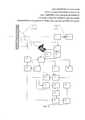
фиг. 1 - функциональная схема устройства,FIG. 1 is a functional diagram of a device,
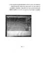
фиг. 2 - фотография устройства проведения контроля,FIG. 2 is a photograph of a control device,
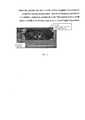
фиг. 3-фотография проведения предварительных исследований,FIG. 3-photograph of preliminary studies,
фиг. 4 - диаграмма растяжения,FIG. 4 is a tensile diagram,
фиг. 5 - фотография разрывной машины,FIG. 5 is a photograph of a tensile testing machine,
фиг. 6 - термограмма реального объекта.FIG. 6 - thermogram of a real object.
На приведенных фигурах приняты следующие обозначения:In the above figures, the following notation:
1 - многослойная текстильная броневая преграда,1 - multilayer textile armored barrier,
2 - устройство для стрельбы,2 - device for firing,
3 - устройство для измерения скорости полета поражающего элемента,3 - a device for measuring the flight speed of a striking element,
4 - тепловизионная система,4 - thermal imaging system,
5 - поле обзора тепловизионой системы,5 - field of view of the thermal imaging system,
6 - устройство регистрации начала полета поражающего элемента,6 - device for recording the start of flight of the striking element,
7 - коммутатор,7 - switch
8 - первый блок памяти,8 - the first block of memory,
9 - второй блок памяти,9 - the second memory block,
10 - третий блок памяти,10 - the third block of memory,
11 - первый сумматор,11 - the first adder
12 - логический блок сравнения «если-то»,12 is a logical if-then comparison block,
13 - первый умножитель,13 is the first multiplier,
14 - регистратор,14 - the registrar,
15 - направление полета поражающего элемента,15 - flight direction of the striking element,
16 - второй умножитель,16 - the second multiplier,
17 - термограммы волокон в различные моменты времени их нагружения,17 - thermograms of fibers at various points in time of their loading,
18 - термопрофили (зависимости температуры от времени) волокон в их различных точках,18 - thermal profiles (temperature versus time) of the fibers at their various points,
19 - разрывная машина: а - в процессе испытаний волокон, б - после завершения испытания волокон,19 - tensile testing machine: a - during the testing of fibers, b - after completion of the testing of fibers,
20 - жгуты волокон,20 - bundles of fibers,
21 - третий умножитель,21 is the third multiplier,
22 - четвертый умножитель,22 is the fourth multiplier,
23 - второй сумматор,23 - the second adder
24 - третий сумматор,24 - the third adder
25 - делитель,25 is a divider
26 - счетчик выстрелов,26 - shot counter,
Предпочтительный вариант осуществления изобретения Все используемые электронные блоки построены на основе стандартных микропроцессорных схем и микропроцессорных сборок с перепрограммируемыми запоминающими устройствами (см. например, Угрюмов Е.П. Цифровая схемотехника: учебн. пособие для вузов. - 3-е изд. перераб. и доп. - СПб.: - БХВ-Петербург, 2010.). В качестве тепловизионной системы 4 используются тепловизоры фирмы FLIR, тепловизоры марки ИРТИС-2000 или аналогичные по техническим характеристикам. В проведенных экспериментах, результаты которых представлены ниже, использовалась тепловизионная система FLIR 1500.The preferred embodiment of the invention. All electronic components used are built on the basis of standard microprocessor circuits and microprocessor assemblies with reprogrammable memory devices (see, for example, Ugryumov EP Digital circuitry: textbook for universities. - 3rd ed. Revised and additional . - SPb .: - BHV-Petersburg, 2010.). As a
Устройство 2 для стрельбы изготовлено на основе стандартной мелкокалиберной винтовки. Устройство 3 для измерения скорости полета поражающего элемента (пули) РС-4М (производство «Малое Государственное Предприятие «Нанотех», г. Санкт-Петербург, руководство по эксплуатации РС-4.00.00ТО) имеет стандартную конструкцию. Оно включает два оптико-электронных датчика (фотореле), расположенные последовательно вдоль траектории движения поражающего элемента на заданном расстоянии друг от друга. Содержит, также, таймер (электронный секундомер) и вычислитель. При пересечении поражающим элементом первого оптико-электронного датчика таймер начинает работу, а при пересечении оптической оси второго оптико-электронного датчика таймер выключается. Вычислитель по расстоянию между датчиками и времени работы таймера вычисляет скорость поражающего элемента.The
Непосредственно перед проведением контроля энергопоглощения текстильной многослойной броневой преградой 1 проводят следующие действия:Immediately before the energy absorption control of the textile multilayer
1. Осуществляют силовое нагружение (растягивание) волокон, из которых состоят слои текстильного бронематериала (фиг. 5).1. Carry out the loading (stretching) of the fibers of which the layers of textile armored material consist (Fig. 5).
2. В процессе силового нагружения волокон строят диаграмму деформирования волокон, из которых состоят слои текстильного бронематериала -2. In the process of power loading of the fibers, a diagram of the deformation of the fibers, of which the layers of textile armored material are composed, is built -
О" -5 где а - напряжение волокон в процессе нагружения, е - велична де-O "-5 where a is the stress of the fibers during loading, e is the magnitude of
формации волокон в процессе наружения (фиг. 4).formation of fibers in the process of exposure (Fig. 4).
3. Одновременно в процессе нагружения измеряют скорость деформации волокон, из которых состоят слои текстильного бронематериала -
4. В процессе нагружения волокон 20 разрывной машиной 19 с помощью тепловизионной системы 4 (фиг. 3) регистрируют термограммы волокон 17 и измеряют динамическое температурное поле 18 в нескольких точках по длине волокон Tkj, где k - номер момента времени регистрации температуры, j - номер точки на волокне, в которой осуществляется регистрация температуры,4. In the process of loading the
5. Измеряют температуру окружающей среды в процессе нагружения Тт,5. Measure the ambient temperature during loading Tt
6. Определяют коэффициент теплового эффекта (b), являющегося отношением доли энергии ΔЕт, выделившейся в виде тепла на поверхности текстильной брони к полной энергии ΔЕ0 поражающего элемента, поглощенной текстильной броней (b=ΔЕт/ΔЕ0), решая уравнение относительно величины «b», при этом варьируя два фактора: температура среды и коэффициент теплового эффекта «b»:6. Determine the coefficient of thermal effect (b), which is the ratio of the fraction of energy ΔEt released as heat on the surface of the textile armor to the total energy ΔЕ0 of the damaging element absorbed by the textile armor (b = ΔЕt / ΔЕ0 ), solving the equation with respect to "B", while varying two factors: the temperature of the medium and the coefficient of thermal effect "b":

где i - номер точки измерения температуры на волокне,where i is the number of the temperature measuring point on the fiber,
k - номер момента времени регистрации температуры,k is the number of time points of temperature registration,
Tk,i - значение измеренной температуры,Tk, i is the value of the measured temperature,
Трасч - значение температуры, рассчитанное по формуле,Tcalc - the temperature value calculated by the formula,
b - коэффициент теплового эффекта,b is the coefficient of thermal effect,
T∞ - температура окружающей среды.T∞ is the ambient temperature.
Расчетное значение температуры Трасч определяют путем решения уравнения теплового баланса:The calculated temperature Tcalc is determined by solving the heat balance equation:

Н- толщина пакета,H is the thickness of the package,
h - коэффициент теплообмена поверхности брони,h is the heat transfer coefficient of the armor surface,
Е0 - модуль упругости,E0 - modulus of elasticity,
t - текущее время,t is the current time,
ρ - плотность текстильной брони,ρ is the density of textile armor,
С - теплоемкость текстильной брони.C is the heat capacity of textile armor.
7. Результаты предварительных исследований, характеристики текстильной броневой преграды и параметры условий контроля «помещаются» в первый блок памяти 8. Подробно теоретические основы данного метода изложены в [1].7. The results of preliminary studies, the characteristics of the textile armored barrier and the parameters of the control conditions are “placed” in the
После завершения предварительных измерений и подготовки к контролю осуществляют непосредственно контроль (измерение) величины поглощенной энергии текстильным броневым материалом при его взаимодействии с поражающим элементом следующим образом:After completing the preliminary measurements and preparing for the control, the control (measurement) of the amount of absorbed energy by the textile armor material during its interaction with the damaging element is carried out directly as follows:
8. Направляют в текстильную броневую преграду 1 поражающий элемент ПЭ 15 через устройство 3 измерения скорости поражающего элемента - V0.8. Direct to the textile
9. После прохождения ПЭ устройства 3 измерения скорости с выхода устройства 3 на устройство регистрации начала полета поражающего элемента 6, поступает сигнал о выстреле.9. After passing through the PE of the
По этому сигналу с устройства 6 в тепловизионную систему 4 поступает «команда» о начале регистрации температурного поля. Таким образом, тепловизионное устройство регистрирует температурное поле Тпов(i,j,t). Здесь i,j - целочисленные координаты поверхности композитной брони (1), t- время регистрации температурного поля. В первый момент t=0 регистрируется температурное поле в момент, предшествующий моменту соприкосновения ПЭ и поверхности изделия (1) - Тпов(i,j,t=0). Последующая регистрация осуществляется в моменты времени t=t1, t2, … tk, … tn. Здесь n - количество регистрацийAccording to this signal from the
Одновременно с выхода устройства 6 поступает сигнал в счетчик выстрелов (26), который считает количество выстрелов р=1, 2, 3 …, n.Simultaneously with the output of
С выхода счетчика выстрелов 26 сигнал поступает в коммутатор 7 о начале коммутирования сигналов в устройстве.From the output of the
10. После прохождения поражающего элемента устройства для измерения скорости полета поражающего элемента сигнал с него 3, соответствующий скорости поражающего элемента V0, поступает на вход третьего умножителя 21, где вычисляется выражение V20.10. After passing the striking element of the device for measuring the flight speed of the striking element, the signal from it 3, corresponding to the speed of the striking element V0 , is input to the
11. Сигнал, соответствующий выражению V20, с выхода третьего умножителя 21 поступает в четвертый умножитель 22. На второй вход четвертого умножителя 22 поступает сигнал, соответствующий массе m поражающего элемента с третьего выхода первого блока памяти 8. В четвертом умножителе 22 осуществляется определение кинетической энергии поражающего элемента р-м выстреле:11. The signal corresponding to the expression V20 from the output of the
Ep=( V20)×m/2.Ep = (V20 ) × m / 2.
12. По команде коммутатора 7 температурное поле Тпов(i,j,t=0) с выхода темпловизионной системы 4 регистрируется во втором блоке памяти 9.12. At the command of the
13. По сигналам коммутатора температурное поле Тпов(i,j,t) в моменты времени t=t1, t2, … tk, … tn регистрируются в третьем блоке памяти 10.13. According to the signals of the switch, the temperature field Tpov (i, j, t) at time t = t1 , t2 , ... tk , ... tn are recorded in the
14. Сигналы о значениях температурного поля Тпов(i,j,t=0) и Тпов(i,j,t) поступают в сумматор 11, где измеряется их разность:14. The signals about the values of the temperature field Tpov (i, j, t = 0) and Tpov (i, j, t) are received in the adder 11, where their difference is measured:
ΔТпов(i,j,t=0)=| Тпов(i,j,t=0)-Тпов(i,j,t)|.ΔТpov (i, j, t = 0) = | Tpov (i, j, t = 0) -Tpov (i, j, t) |.
15. Сигнал, соответствующей величине ΔТпов(i,j,tk) поступает в логический блок сравнения 12 «если-то», где осуществляется его логическая обработка следующим образом:15. The signal corresponding to the ΔТpov value (i, j, tk ) enters the if-then
- если ΔТпов(i,j,tk)<ΔТпов(i,j,tk+1)), то сигнал с блока 12 поступает в коммутатор 7 и операция сравнения температурного поля повторяется,- if ΔTpov (i, j, tk ) <ΔTpov (i, j, tk + 1 )), then the signal from
- если (ΔТпов(i,j,tk)≥ΔТпов(i,j,tk+1)), то сигнал с блока 12 поступает в умножитель 13. Это означает, что разность температурного поля исходного и образованного в результате взаимодействия ПЭ и текстильной броневой преграды достигло наибольшего значения.- if (ΔТpov (i, j, tk ) ≥ΔТpov (i, j, tk + 1 )), then the signal from
16. В первом умножителе 13 осуществляется умножение сигналов, поступивших от блока 12 и первого блока памяти 8 и измеряется величина энергии, выделившаяся в виде тепла на поверхности текстильной брони:16. In the

где Тпов(i,j,tk+1) - температура элемента поверхности текстильной брони с координатами i,j, ΔТпов(i,j,tk+1) - сигнал с блока 12, ρ - плотность текстильной брони, C(Тпов(i,j,tk+1)) - теплоемкость текстильной брони при температуре Тпов(i,j,tk+1), h - толщина текстильной брони, ΔS - мгновенное линейное поле зрения тепловизионной системы, которой осуществляется регистрация и измерение температурного поля, в пространстве предмета (на поверхности текстильной брони).where Tpov (i, j, tk + 1 ) is the temperature of the surface armor of the textile armor with coordinates i, j, ΔTpov (i, j, tk + 1 ) is the signal from
Далее во втором умножителе 16 осуществляется измерение полной энергии (поглощение энергии) после взаимодействия с поражающим элементом следующим образом при р-м выстреле:Next, in the
ΔЕ0р=ΔET/b,ΔE0р = ΔET / b,
где сигнал, соответствующий «b», поступает на второй вход умножителя 16 с второго выхода первого блока памяти 8 по сигналу (команде) коммутатора 7.where the signal corresponding to "b" is fed to the second input of the
17. Сигнал, соответствующий ΔЕ0р с выхода второго умножителя 16 поступает на вход второго сумматора 23. В втором сумматоре 23 осуществляется суммирование сигналов, соответствующих ΔЕ0р:17. The signal corresponding to ΔЕ0р from the output of the

18. Сигнал со второго сумматора 23 поступает на второй вход третьего сумматора 24, на первый вход которого поступает сигнал с четвертого умножителя 22, соответствующий кинетической энергии поражающего элемента EP=(V20)×m/2, где осуществляется определение выражения:18. The signal from the
Ер-Ес.Ep-s .
19. Сигнал с выхода третьего сумматора 24 (Ер-Ес) поступает на первый вход делителя 25, на второй вход которого поступает сигнал с четвертого умножителя 22, соответствующий кинетической энергии поражающего элемента EP=(V20)×m/2. В делителе 25 осуществляется определение погрешности определения величины поглощения энергии исследуемой методики
20. Измеренное значение погрешности определения величины поглощения энергии исследуемой методики регистрируется регистратором 14.20. The measured value of the error in determining the amount of energy absorption of the investigated method is recorded by the
Коммутатор 7 осуществляет коммутирование (синхронизацию функционирования) всех блоков устройства.The
Экспериментальные исследования предлагаемого технического решения проводились на установке, фотографии которых приведены на фиг. 2,3,5.Experimental studies of the proposed technical solution were carried out on the installation, photographs of which are shown in FIG. 2,3,5.
Процесс проведения предварительных исследований по определению погрешности определения энергии поглащения исследуемой методикой представлен на фотографиях фиг. 3, 5.The process of conducting preliminary studies to determine the error in determining the absorption energy by the studied method is presented in the photographs of FIG. 3, 5.
В качестве испытуемых волокон использовались волокна марки «Русар».As test fibers, Rusar brand fibers were used.
Результаты экспериментального определения коэффициента теплового эффекта «Ъ» приведены в таблице 1.The results of the experimental determination of the coefficient of thermal effect "b" are shown in table 1.


Погрешность измерения энергии поглощения составляет 7 дж., илиThe error in measuring the absorption energy is 7 j., Or
ε=(307-300)/300=0,023 или 2,3%.ε = (307-300) / 300 = 0.023 or 2.3%.
Как правило, допустимая погрешность подобных методик контроля (ε0) составляет от 5% до 10%.As a rule, the permissible error of such control methods (ε0 ) is from 5% to 10%.
Поэтому настоящий способ метрологической аттестации достоверно описывает погрешность контроля.Therefore, the present method of metrological certification reliably describes the control error.
Таким образом, предлагаемый способ и реализующее его устройство позволяют оценивать погрешность определения энергии поглощения тепловым методом, т.е. могут быть использованы как метод метрологической аттестации методики контроля.Thus, the proposed method and the device realizing it make it possible to estimate the error in determining the absorption energy by the thermal method, i.e. can be used as a method of metrological certification of control methods.
Представленные способ и устройство являются перспективными для исследования процессов взаимодействия ПЭ с броневыми структурами из полимерных материалов, их использование позволит более эффективно производить отбор материалов для броневых структур с целью повышения их защитных свойств.The presented method and device are promising for studying the processes of interaction of PE with armor structures made of polymer materials, their use will allow more efficient selection of materials for armor structures in order to increase their protective properties.
Изобретения имеют следующие преимущества:The inventions have the following advantages:
1. Позволяет оценить погрешность определения энергии поглощения текстильной броневой преградой тепловым методом, что в свою очередь позволит на более достоверных исходных данных создавать конструкцию текстильной броневой преграды.1. Allows you to evaluate the error in determining the energy of absorption of a textile armored barrier by the thermal method, which in turn will allow to create a design of a textile armored barrier using more reliable initial data.
2. Позволяют оценить энергию поглощения по толщине композитной броневой преграды, что позволяет оптимизировать расположение и характеристики композитных слоев,2. They allow you to evaluate the absorption energy by the thickness of the composite armor barrier, which allows you to optimize the location and characteristics of the composite layers,
3. Позволяют оценить качество самих композитных слоев и их вклад в поглощение энергии,3. Allow to evaluate the quality of the composite layers themselves and their contribution to energy absorption,
4. Позволяют повысить производительность контроля, наглядность результатов.4. Allow to increase control performance, visibility of results.
5. Позволяют применять метод во внелабораторных условиях контроля и использовать современный математический аппарат для анализа результатов.5. Allow to apply the method in off-laboratory control conditions and use a modern mathematical apparatus for analyzing the results.
Claims (82)
Translated fromRussian


Priority Applications (1)
| Application Number | Priority Date | Filing Date | Title |
|---|---|---|---|
| RU2018120849ARU2683436C1 (en) | 2018-06-05 | 2018-06-05 | Method of metrological certification of thermal control of absorption of energy of preventive element of multilayered textile armored prevention and device for its implementation |
Applications Claiming Priority (1)
| Application Number | Priority Date | Filing Date | Title |
|---|---|---|---|
| RU2018120849ARU2683436C1 (en) | 2018-06-05 | 2018-06-05 | Method of metrological certification of thermal control of absorption of energy of preventive element of multilayered textile armored prevention and device for its implementation |
Publications (1)
| Publication Number | Publication Date |
|---|---|
| RU2683436C1true RU2683436C1 (en) | 2019-03-28 |
Family
ID=66089615
Family Applications (1)
| Application Number | Title | Priority Date | Filing Date |
|---|---|---|---|
| RU2018120849ARU2683436C1 (en) | 2018-06-05 | 2018-06-05 | Method of metrological certification of thermal control of absorption of energy of preventive element of multilayered textile armored prevention and device for its implementation |
Country Status (1)
| Country | Link |
|---|---|
| RU (1) | RU2683436C1 (en) |
Citations (4)
| Publication number | Priority date | Publication date | Assignee | Title |
|---|---|---|---|---|
| US20040245469A1 (en)* | 1999-09-16 | 2004-12-09 | Wayne State University | Hand-held sound source for sonic infrared imaging of defects in materials |
| RU2420730C2 (en)* | 2009-07-09 | 2011-06-10 | Елена Вячеславовна Абрамова | Method for thermal control of heat-transfer resistance of multilayer structure in unsteady heat-transfer conditions |
| RU2428102C1 (en)* | 2009-12-25 | 2011-09-10 | Олег Николаевич Будадин | Method of diagnosing vascular pathology by active thermolocational probing |
| RU2608491C1 (en)* | 2015-12-02 | 2017-01-18 | Открытое акционерное общество Центральный научно-исследовательский институт специального машиностроения | Device for thermal quality control of composite armoured protection |
- 2018
- 2018-06-05RURU2018120849Apatent/RU2683436C1/enactive
Patent Citations (4)
| Publication number | Priority date | Publication date | Assignee | Title |
|---|---|---|---|---|
| US20040245469A1 (en)* | 1999-09-16 | 2004-12-09 | Wayne State University | Hand-held sound source for sonic infrared imaging of defects in materials |
| RU2420730C2 (en)* | 2009-07-09 | 2011-06-10 | Елена Вячеславовна Абрамова | Method for thermal control of heat-transfer resistance of multilayer structure in unsteady heat-transfer conditions |
| RU2428102C1 (en)* | 2009-12-25 | 2011-09-10 | Олег Николаевич Будадин | Method of diagnosing vascular pathology by active thermolocational probing |
| RU2608491C1 (en)* | 2015-12-02 | 2017-01-18 | Открытое акционерное общество Центральный научно-исследовательский институт специального машиностроения | Device for thermal quality control of composite armoured protection |
Non-Patent Citations (4)
| Title |
|---|
| Долганина, Н.Ю., "Исследование ударного взаимодействия индентора с тканевыми бронепластинами, расположенными на пластилиновом основании", Вестник ЮУрГУ. Серия: Вычислительная математика и информатика, 2012, номер 47 (306), С. 37-45.* |
| Долганина, Н.Ю., "Исследование ударного взаимодействия индентора с тканевыми бронепластинами, расположенными на пластилиновом основании", Вестник ЮУрГУ. Серия: Вычислительная математика и информатика, 2012, номер 47 (306), С. 37-45. Харченко Е.Ф., Ермоленко А.Ф., Изменение энергопоглощения текстильных бронематериалов в зависимости от скорости поражающих элементов, Вопросы оборонной техники, Сер.15, 2010, Вып. 1(156)- 2(157), С. 39- 42.* |
| Ермоленко А.Ф., Будадин О.Н., Харченко Е.Ф., Тепловой метод исследования энергопоглощающей способности композитных броневых преград, Вопросы оборонной техники, Сер. 15, 2010, Вып. 3 (158). с. 23-27.* |
| Харченко Е.Ф., Ермоленко А.Ф., Изменение энергопоглощения текстильных бронематериалов в зависимости от скорости поражающих элементов, Вопросы оборонной техники, Сер.15, 2010, Вып. 1(156)- 2(157), С. 39- 42.* |
Similar Documents
| Publication | Publication Date | Title |
|---|---|---|
| Chocron et al. | Modeling and validation of full fabric targets under ballistic impact | |
| RU2519616C1 (en) | Computer-aided assessment method of efficiency of destructive effect of remote-action ammunition, and device for its implementation | |
| Papazian et al. | Sensors for monitoring early stage fatigue cracking | |
| RU2442104C1 (en) | Method and device for operational efficiency evaluation of ammunition destructive power | |
| Sharma et al. | Split-Hopkinson pressure bar: an experimental technique for high strain rate tests | |
| CA2207354C (en) | Apparatus and method for determining the dynamic indentation hardness of materials | |
| RU2608491C1 (en) | Device for thermal quality control of composite armoured protection | |
| Li et al. | Detection and characterization of mechanical impact damage within multi-layer carbon fiber reinforced polymer (CFRP) laminate using passive thermography | |
| RU2683436C1 (en) | Method of metrological certification of thermal control of absorption of energy of preventive element of multilayered textile armored prevention and device for its implementation | |
| RU2673773C1 (en) | Method for thermal controlling energy absorption of damaging agent of multilayered textile armor barrier and device for implementation thereof | |
| KR20220062201A (en) | System and Method for automated structural modal analysis using Long and Short Term Memory | |
| Steinmann et al. | Quantification of Behind Shield Blunt Impacts Using a Modified Upper Extremity Anthropomorphic Test Device | |
| Wang et al. | Novel damage detection techniques for structural health monitoring using a hybrid sensor | |
| Chen et al. | Muzzle energy density evaluation of airguns via witness-plate deformations | |
| RU2623700C1 (en) | Method of controlling quality of composite armored barrier and device for its implementation | |
| RU2648552C1 (en) | Method of quality control of multilayer composite armored barriers from fabrics and the device for its implementation | |
| Dzhudzhev et al. | Testing of Automaticized System for complex non-destructive study of metallic materials | |
| Hodges et al. | Ballistic loading and survivability of optical fiber sensing layers for soft body armor evaluation | |
| Duke Jr et al. | Ultrasonic Stress Wave Characterization of Composite Materials. | |
| US3872709A (en) | Fracture resistance testing method | |
| Jannotti et al. | Instrumented penetration of metal alloys during high-velocity impacts | |
| Forsyth et al. | A brief introduction to nondestructive testing | |
| Grytten | Low-velocity penetration of aluminium plates | |
| Dong et al. | An Adaptable Method for Rapid Fatigue Limit Prediction of Composite Materials Based on Acoustic Emission Technology | |
| RU2663414C1 (en) | Quality control method of multilayer composite armored barriers from fabrics and a device for its implementation |