RU2680900C2 - Plant comprising engine - Google Patents
Plant comprising engineDownload PDFInfo
- Publication number
- RU2680900C2 RU2680900C2RU2015105959ARU2015105959ARU2680900C2RU 2680900 C2RU2680900 C2RU 2680900C2RU 2015105959 ARU2015105959 ARU 2015105959ARU 2015105959 ARU2015105959 ARU 2015105959ARU 2680900 C2RU2680900 C2RU 2680900C2
- Authority
- RU
- Russia
- Prior art keywords
- container
- engine
- installation according
- containers
- wall
- Prior art date
Links
Images

Classifications
- E—FIXED CONSTRUCTIONS
- E04—BUILDING
- E04H—BUILDINGS OR LIKE STRUCTURES FOR PARTICULAR PURPOSES; SWIMMING OR SPLASH BATHS OR POOLS; MASTS; FENCING; TENTS OR CANOPIES, IN GENERAL
- E04H5/00—Buildings or groups of buildings for industrial or agricultural purposes
- E04H5/02—Buildings or groups of buildings for industrial purposes, e.g. for power-plants or factories
- E—FIXED CONSTRUCTIONS
- E04—BUILDING
- E04B—GENERAL BUILDING CONSTRUCTIONS; WALLS, e.g. PARTITIONS; ROOFS; FLOORS; CEILINGS; INSULATION OR OTHER PROTECTION OF BUILDINGS
- E04B1/00—Constructions in general; Structures which are not restricted either to walls, e.g. partitions, or floors or ceilings or roofs
- E04B1/343—Structures characterised by movable, separable, or collapsible parts, e.g. for transport
- E04B1/34315—Structures characterised by movable, separable, or collapsible parts, e.g. for transport characterised by separable parts
- E04B1/34331—Structures characterised by movable, separable, or collapsible parts, e.g. for transport characterised by separable parts mainly constituted by three-dimensional elements
- B—PERFORMING OPERATIONS; TRANSPORTING
- B65—CONVEYING; PACKING; STORING; HANDLING THIN OR FILAMENTARY MATERIAL
- B65D—CONTAINERS FOR STORAGE OR TRANSPORT OF ARTICLES OR MATERIALS, e.g. BAGS, BARRELS, BOTTLES, BOXES, CANS, CARTONS, CRATES, DRUMS, JARS, TANKS, HOPPERS, FORWARDING CONTAINERS; ACCESSORIES, CLOSURES, OR FITTINGS THEREFOR; PACKAGING ELEMENTS; PACKAGES
- B65D88/00—Large containers
- B65D88/02—Large containers rigid
- B65D88/022—Large containers rigid in multiple arrangement, e.g. stackable, nestable, connected or joined together side-by-side
- B—PERFORMING OPERATIONS; TRANSPORTING
- B65—CONVEYING; PACKING; STORING; HANDLING THIN OR FILAMENTARY MATERIAL
- B65D—CONTAINERS FOR STORAGE OR TRANSPORT OF ARTICLES OR MATERIALS, e.g. BAGS, BARRELS, BOTTLES, BOXES, CANS, CARTONS, CRATES, DRUMS, JARS, TANKS, HOPPERS, FORWARDING CONTAINERS; ACCESSORIES, CLOSURES, OR FITTINGS THEREFOR; PACKAGING ELEMENTS; PACKAGES
- B65D88/00—Large containers
- B65D88/02—Large containers rigid
- B65D88/12—Large containers rigid specially adapted for transport
- B65D88/121—ISO containers
- E—FIXED CONSTRUCTIONS
- E04—BUILDING
- E04B—GENERAL BUILDING CONSTRUCTIONS; WALLS, e.g. PARTITIONS; ROOFS; FLOORS; CEILINGS; INSULATION OR OTHER PROTECTION OF BUILDINGS
- E04B1/00—Constructions in general; Structures which are not restricted either to walls, e.g. partitions, or floors or ceilings or roofs
- E04B1/343—Structures characterised by movable, separable, or collapsible parts, e.g. for transport
- E04B1/34384—Assembling details for foldable, separable, collapsible or retractable structures
- E—FIXED CONSTRUCTIONS
- E04—BUILDING
- E04H—BUILDINGS OR LIKE STRUCTURES FOR PARTICULAR PURPOSES; SWIMMING OR SPLASH BATHS OR POOLS; MASTS; FENCING; TENTS OR CANOPIES, IN GENERAL
- E04H1/00—Buildings or groups of buildings for dwelling or office purposes; General layout, e.g. modular co-ordination or staggered storeys
- E04H1/12—Small buildings or other erections for limited occupation, erected in the open air or arranged in buildings, e.g. kiosks, waiting shelters for bus stops or for filling stations, roofs for railway platforms, watchmen's huts or dressing cubicles
- E04H1/1205—Small buildings erected in the open air
- E04H1/1238—Shelters for engines, e.g. electrical meter housings
- F—MECHANICAL ENGINEERING; LIGHTING; HEATING; WEAPONS; BLASTING
- F01—MACHINES OR ENGINES IN GENERAL; ENGINE PLANTS IN GENERAL; STEAM ENGINES
- F01N—GAS-FLOW SILENCERS OR EXHAUST APPARATUS FOR MACHINES OR ENGINES IN GENERAL; GAS-FLOW SILENCERS OR EXHAUST APPARATUS FOR INTERNAL-COMBUSTION ENGINES
- F01N3/00—Exhaust or silencing apparatus having means for purifying, rendering innocuous, or otherwise treating exhaust
- F01N3/02—Exhaust or silencing apparatus having means for purifying, rendering innocuous, or otherwise treating exhaust for cooling, or for removing solid constituents of, exhaust
- F01N3/0205—Exhaust or silencing apparatus having means for purifying, rendering innocuous, or otherwise treating exhaust for cooling, or for removing solid constituents of, exhaust using heat exchangers
- F—MECHANICAL ENGINEERING; LIGHTING; HEATING; WEAPONS; BLASTING
- F02—COMBUSTION ENGINES; HOT-GAS OR COMBUSTION-PRODUCT ENGINE PLANTS
- F02B—INTERNAL-COMBUSTION PISTON ENGINES; COMBUSTION ENGINES IN GENERAL
- F02B63/00—Adaptations of engines for driving pumps, hand-held tools or electric generators; Portable combinations of engines with engine-driven devices
- F02B63/04—Adaptations of engines for driving pumps, hand-held tools or electric generators; Portable combinations of engines with engine-driven devices for electric generators
- F02B63/044—Adaptations of engines for driving pumps, hand-held tools or electric generators; Portable combinations of engines with engine-driven devices for electric generators the engine-generator unit being placed on a frame or in an housing
- F—MECHANICAL ENGINEERING; LIGHTING; HEATING; WEAPONS; BLASTING
- F02—COMBUSTION ENGINES; HOT-GAS OR COMBUSTION-PRODUCT ENGINE PLANTS
- F02D—CONTROLLING COMBUSTION ENGINES
- F02D29/00—Controlling engines, such controlling being peculiar to the devices driven thereby, the devices being other than parts or accessories essential to engine operation, e.g. controlling of engines by signals external thereto
- F02D29/06—Controlling engines, such controlling being peculiar to the devices driven thereby, the devices being other than parts or accessories essential to engine operation, e.g. controlling of engines by signals external thereto peculiar to engines driving electric generators
- E—FIXED CONSTRUCTIONS
- E04—BUILDING
- E04H—BUILDINGS OR LIKE STRUCTURES FOR PARTICULAR PURPOSES; SWIMMING OR SPLASH BATHS OR POOLS; MASTS; FENCING; TENTS OR CANOPIES, IN GENERAL
- E04H1/00—Buildings or groups of buildings for dwelling or office purposes; General layout, e.g. modular co-ordination or staggered storeys
- E04H1/12—Small buildings or other erections for limited occupation, erected in the open air or arranged in buildings, e.g. kiosks, waiting shelters for bus stops or for filling stations, roofs for railway platforms, watchmen's huts or dressing cubicles
- E04H2001/1283—Small buildings of the ISO containers type
Landscapes
- Engineering & Computer Science (AREA)
- Architecture (AREA)
- Mechanical Engineering (AREA)
- Chemical & Material Sciences (AREA)
- Combustion & Propulsion (AREA)
- General Engineering & Computer Science (AREA)
- Civil Engineering (AREA)
- Structural Engineering (AREA)
- Physics & Mathematics (AREA)
- Electromagnetism (AREA)
- Control Of Vehicle Engines Or Engines For Specific Uses (AREA)
- Exhaust Silencers (AREA)
- Exhaust Gas After Treatment (AREA)
- Casings For Electric Apparatus (AREA)
- Cooling Or The Like Of Electrical Apparatus (AREA)
Abstract
Description
Translated fromRussianОбласть техники, к которой относится изобретениеFIELD OF THE INVENTION
Изобретение относится к установке с двигателем.The invention relates to an installation with an engine.
Уровень техникиState of the art
В настоящее время стационарные двигатели внутреннего сгорания перевозят на отдаленные участки в контейнерах. В пункте назначения двигатель извлекают из контейнера и устанавливают в здании, в котором двигатель может быть, например, соединен с генератором. После этого контейнер увозят с участка, и он может быть использован для транспортировки других двигателей и т.д..Stationary internal combustion engines are currently being transported to remote sites in containers. At the destination, the engine is removed from the container and installed in a building in which the engine can, for example, be connected to a generator. After that, the container is taken away from the site, and it can be used to transport other engines, etc.
Известен также блок, содержащий по меньшей мере один двигатель и генератор со вспомогательными устройствами, включая охладитель, и т.д., в контейнере; таким образом, контейнер может быть использован для транспортировки оборудования и служить корпусом для размещения по меньшей мере двигателя и генератора в пункте назначения.A block is also known, comprising at least one engine and a generator with auxiliary devices, including a cooler, etc., in a container; Thus, the container can be used to transport equipment and serve as a housing for accommodating at least the engine and generator at the destination.
Документ US 2014/0008359 A1 раскрывает экспедиционный модуль, содержащий множество стандартных грузовых контейнеров для хранения различного оборудования, такого как инструментальный магазин или дизель-генераторы.US 2014/0008359 A1 discloses an expeditionary module comprising a plurality of standard freight containers for storing various equipment, such as a tool magazine or diesel generators.
Из документов EP 0366559 A1 и US 8333039 B2 известны другие установки, содержащие контейнеры.Other installations containing containers are known from EP 0366559 A1 and US 8333039 B2.
Раскрытие изобретенияDisclosure of invention
Первым объектом изобретения является установка, содержащая двигатель внутреннего сгорания и корпус для защиты двигателя внутреннего сгорания, причем корпус содержит первую стенку, которая включает в себя контейнер.The first object of the invention is an installation comprising an internal combustion engine and a housing for protecting an internal combustion engine, the housing comprising a first wall that includes a container.
Двигатель может быть двигателем внутреннего сгорания, например, стационарным двигателем внутреннего сгорания или турбиной.The engine may be an internal combustion engine, for example, a stationary internal combustion engine or a turbine.
Двигатель не находится в контейнере во время использования, но помещен в корпус, одна стенка которого может состоять из или включать в себя контейнер.The engine is not in the container during use, but is placed in a housing, one wall of which may consist of or include a container.
Другим объектом изобретения является способ сборки установки с двигателем внутреннего сгорания, включающий в себя этапы:Another object of the invention is a method for assembling an installation with an internal combustion engine, comprising the steps of:
- установка двигателя;- engine installation;
- размещение двух или более контейнеров вокруг двигателя;- placing two or more containers around the engine;
- крепление крыши сверху контейнеров для защиты двигателя.- roof mounting on top of containers to protect the engine.
Другие особенности изобретения будут в дальнейшем подробно описаны на примере вариантов его осуществления со ссылками на чертежи.Other features of the invention will be further described in detail on the example of options for its implementation with reference to the drawings.
Краткое описание чертежейBrief Description of the Drawings
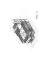
На рис. 1 показана установка;In fig. 1 shows the installation;
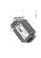
на рис. 2 - установка с двигателем внутреннего сгорания;in fig. 2 - installation with an internal combustion engine;
на рис. 3 - электростанция с двумя установками.in fig. 3 - power plant with two installations.
Осуществление изобретенияThe implementation of the invention
На рис. 1 показана установка 1, содержащая двигатель 2 и корпус 3. Двигатель 2 может быть стационарным двигателем внутреннего сгорания, в частности, стационарным двигателем внутреннего сгорания, работающим на газе, и соединен с генератором для выработки электроэнергии. Двигатель 2 и генератор расположены внутри корпуса 3. Корпус 3 имеет первую стенку 4, вторую стенку 5, третью стенку 6 и четвертую стенку 7. Первая стенка 4 может быть параллельна третьей стенке 6 и перпендикулярна второй стенке 5 и четвертой стенке 7. Стенки 4, 5, 6, 7 могут, в общем случае, образовывать квадратную или прямоугольную конструкцию, в которой находится двигатель 2. Первая стенка 4, вторая стенка 5 и четвертая стенка 7 могут каждая включать в себя два установленных один на другой контейнера - 8 и 9, соответственно, 10 и 11, соответственно, и 15 и 16, соответственно. Третья стенка 6 может включать в себя три установленных один на другой контейнера - 12, 13, 14. Контейнеры 8, 9, 10, 11, 12, 13, 14, 15, 16 могут быть разъемно соединены один с другими посредством болтов, винтов, замков, поворотных замков, угловых пластин и т.д., или их сочетаний. Кроме того, нижние контейнеры 8, 10, 12, 15 могут быть расположены на фундаменте, например, на бетонной плите 17.In fig. 1 shows an apparatus 1 comprising an
Нижние контейнеры 8, 10, 12, 15 могут быть расположены на выровненных нижних пластинах, которые могут быть помещены на фундаменте под нижними углами контейнеров. Четыре выровненные нижние пластины или более могут быть использованы для каждого из контейнеров 8, 10, 12, 15.The
Между верхними и нижними контейнерами может быть установлен защитный экран для уменьшения передачи шума и/или тепла. Материалом защитного экрана может быть вспененный материал.A shield can be installed between the upper and lower containers to reduce the transmission of noise and / or heat. The shield material may be foam.
Поверх верхних контейнеров 11, 16 может быть расположена крыша 18, которая закрывает внутреннюю часть корпуса 3, образованного контейнерами 8, 9, 10, 11, 12, 13, 14, 15, 16. К корпусу 3 может быть прикреплена дымовая труба 19, соединенная с выхлопной системой двигателя 2. Дымовая труба 19 может включать в себя глушитель 20 выхлопа для уменьшения уровня шума при работе установки 1.A
Дымовая труба и/или глушитель 20 выхлопа могут быть прикреплены к каркасу 27, имеющему размеры контейнера ISO. Контейнер ISO может иметь длину 6,095 м, ширину 2,352 м и высоту 2,393 м и может быть назван 20-футовым контейнером, либо контейнер ISO может иметь длину 12,032 м, ширину 2,352 м и высоту 2,393 м и может быть назван 40-футовым контейнером. Контейнер ISO может также иметь длину 12,032 м, ширину 2,352 м и высоту 2,698 м.A chimney and / or
Дымовая труба и/или глушитель 20 выхлопа могут быть по меньшей мере частично окружены каркасом 27.The chimney and / or
Контейнеры 8, 9, 10, 11, 12, 13, 14, 15, 16 могут содержать дверцы 21 для входа в контейнеры 8, 9, 10, 11, 12, 13, 14, 15, 16 и/или доступа к внутренней части установки 1. Кроме того, контейнеры 8, 9, 10, 11, 12, 13, 14, 15, 16 могут содержать окна 22, чтобы не зависеть от электрического освещения в контейнере.
В качестве контейнеров 8, 9, 12, 13 и 14, образующих первую стенку 4 и третью стенку 6, могут быть использованы 20-футовые контейнеры ISO. В качестве контейнеров 10, 11, 15 и 16, образующих вторую стенку 5 и четвертую стенку 7, могут быть использованы 40-футовые контейнеры ISO.As
Контейнер 8 может содержать в себе газовый тракт и/или контур промежуточного охлаждения и их соединения.The
Контейнер 9 может содержать в себе устройства, включая вентиляторы, фильтры и отверстия для отвода воздуха из внутренней части установки наружу.The
Контейнер 10 может быть вспомогательным контейнером, содержащим в себе систему охлаждения двигателя и/или систему охлаждения смазочного масла. Система охлаждения двигателя и/или система охлаждения смазочного масла может включать в себя теплообменник. Кроме того, в контейнере 10 может быть установлена система управления двигателем и/или вспомогательная система управления.The
Контейнер 11 может быть выхлопным контейнером. Внутри выхлопного контейнера 11 могут быть размещены выхлопной теплообменник и катализатор.The
Контейнеры 12, 13, 14 могут содержать систему воздухозабора, включая вентиляторы и воздушные фильтры, для подачи воздуха во внутреннюю часть установки и/или в двигатель.
Контейнер 16 может содержать блоки управления установкой и блоки управления подачей сжатого воздуха.The
Контейнер 15 может быть контейнером среднего напряжения, содержащим по меньшей мере один трансформатор для обеспечения установки 1 электроэнергией среднего напряжения. Кроме того, он может содержать блок управления среднего напряжения для управления источником питания среднего напряжения. Среднее напряжение может быть использовано для питания насосов для охлаждающего или смазочного масла.The
На рис. 2 показана установка 1, содержащая двигатель 2 и генератор 25. Двигатель 2 расположен в области, определенной контейнерами 8, 9, 10, 11, 12, 13, 14, 15, 16. Двигатель 2 расположен вдоль главной оси корпуса. Генератор 25 функционально соединен с двигателем 2, таким образом, двигатель 2 может приводить в действие генератор 25.In fig. 2 shows an apparatus 1 comprising an
На рис. 3 показана электростанция 26 с двумя установками 1. Установки 1 размещены одна рядом с другой и могут быть соединены посредством проводов, болтов и т.д. Основной блок управления электростанции 26 может быть размещен в одной из установок, соединенных с двигателем или блоком управления другой установки 1.In fig. 3 shows a
Промышленная применимостьIndustrial applicability
Далее приведено описание сборки установки и подготовки к работе. Установка может быть предварительно собрана для транспортировки на сборочную площадку. На сборочной площадке тракт управления газообразным топливом и система охлаждения газообразного топлива могут быть предварительно установлены в контейнере 8, насосы, фильтры и/или элементы управления для отвода воздуха из внутренней части установки могут быть предварительно установлены в контейнере 9, теплообменник и/или вспомогательная система управления могут быть предварительно установлены в контейнере 10, катализатор и выхлопной теплообменник могут быть расположены в контейнере 11, устройства для управления поступлением воздуха во внутреннюю часть установки могут быть расположены в контейнерах 12, 13 и 14, система подачи сжатого воздуха и блоки управления могут быть расположены в контейнере 15, трансформаторы для преобразования электрической энергии и получения среднего напряжения и блок управления среднего напряжения могут быть расположены в контейнере 16.The following is a description of the installation assembly and preparation for work. The installation can be pre-assembled for transportation to the assembly site. At the assembly site, the gaseous fuel control path and the gaseous fuel cooling system can be pre-installed in the
Кроме того, двигатель и генератор, охладители, трубы, рабочие платформы, опорные конструкции и т.д. могут быть помещены в один или несколько контейнеров для транспортировки.In addition, the engine and generator, coolers, pipes, work platforms, supporting structures, etc. can be placed in one or more containers for transportation.
В пункте назначения нижние пластины 23 могут быть уложены на фундамент 17, который может быть выполнен из бетона. Нижние пластины могут быть выровнены. Нижние пластины 23 должны поддерживать контейнеры в горизонтальном положении.At the destination, the
Нижние контейнеры 8, 10 и 15 могут быть расположены на нижних пластинах 23 один за другим. Эти контейнеры могут быть соединены один с другим посредством угловых пластин, прикрепленных к контейнерам винтами. Контейнеры 8, 10 и 15 могут быть расположены в форме буквы U; при этом контейнер 8 и контейнер 15, соответственно, могут представлять собой «ножки» буквы U, а контейнер 10 может быть расположен между контейнером 8 и контейнером 15. Контейнеры 8, 10 и 15 могут определять три стороны внутренней части установки. На нижние контейнеры 8, 10 и 15 сверху может быть уложен вспененный материал для шумо- и теплоизоляции. Сверху контейнера 8 может быть размещен контейнер 9, сверху контейнера 10 может быть размещен контейнер 11, и сверху контейнера 15 может быть размещен контейнер 16. Верхние контейнеры 9, 11, 16 могут быть соединены с нижними контейнерами 8, 10, 15 с помощью поворотных замков. Сверху контейнеров 11 и 16 может быть установлена крыша над внутренней частью установки. Опорные конструкции, рабочие платформы и т.д. могут быть установлены во внутренней части установки. Двигатель и генератор могут быть собраны, соединены и установлены во внутренней части установки.The
Различные части системы охлаждения, топливной системы, выхлопной системы и/или системы воздухозабора, расположенные в разных контейнерах, могут быть соединены гибкими трубками. Расположенные в разных контейнерах электрические компоненты могут быть соединены электрическими проводами, проложенными между контейнерами.The various parts of the cooling system, fuel system, exhaust system and / or air intake system, located in different containers, can be connected by flexible tubes. The electrical components located in different containers can be connected by electrical wires laid between the containers.
Контейнеры для воздухозабора 12, 13 и 14 могут быть расположены на открытом конце U-образного сооружения, построенного из контейнеров, чтобы закрыть этот открытый конец. Глушитель и выхлопная труба могут быть размещены в контейнерах для воздухозабора.
Claims (20)
Translated fromRussianApplications Claiming Priority (2)
| Application Number | Priority Date | Filing Date | Title |
|---|---|---|---|
| EP14000636.2AEP2910711B1 (en) | 2014-02-24 | 2014-02-24 | Assembly comprising an engine |
| EP14000636.2 | 2014-02-24 |
Publications (3)
| Publication Number | Publication Date |
|---|---|
| RU2015105959A RU2015105959A (en) | 2016-09-10 |
| RU2015105959A3 RU2015105959A3 (en) | 2018-09-03 |
| RU2680900C2true RU2680900C2 (en) | 2019-02-28 |
Family
ID=50184715
Family Applications (1)
| Application Number | Title | Priority Date | Filing Date |
|---|---|---|---|
| RU2015105959ARU2680900C2 (en) | 2014-02-24 | 2015-02-20 | Plant comprising engine |
Country Status (4)
| Country | Link |
|---|---|
| US (1) | US9534370B2 (en) |
| EP (1) | EP2910711B1 (en) |
| CN (1) | CN104864226B (en) |
| RU (1) | RU2680900C2 (en) |
Families Citing this family (34)
| Publication number | Priority date | Publication date | Assignee | Title |
|---|---|---|---|---|
| IL233641B (en)* | 2014-07-14 | 2019-03-31 | Klein Amos | Containers shelter |
| EP3018320A1 (en)* | 2014-11-10 | 2016-05-11 | Frerk Aggregatebau GmbH | Modular housing for a power supply device |
| CA2911779A1 (en)* | 2014-11-12 | 2016-05-12 | Newterra Ltd | Intermodal container building structures and methods |
| WO2017185125A1 (en)* | 2016-04-29 | 2017-11-02 | Rbon Holdings Pty Ltd | Modular beam structure and modular base structure |
| USD814657S1 (en)* | 2016-08-12 | 2018-04-03 | Kwikspace Guam | Container facility |
| US10634029B2 (en)* | 2016-08-23 | 2020-04-28 | General Electric Technology Gmbh | Mobile selective catalyst reduction system |
| USD816245S1 (en)* | 2016-09-21 | 2018-04-24 | Kwikspace Guam | Container facility |
| USD815755S1 (en)* | 2016-09-21 | 2018-04-17 | Kwikspace Guam | Container facility |
| US10030579B2 (en)* | 2016-09-21 | 2018-07-24 | General Electric Company | Systems and methods for a mobile power plant with improved mobility and reduced trailer count |
| US10184397B2 (en)* | 2016-09-21 | 2019-01-22 | General Electric Company | Systems and methods for a mobile power plant with improved mobility and reduced trailer count |
| GB2557250A (en)* | 2016-12-02 | 2018-06-20 | Proventia Emission Control Oy | Mobile container system comprising standard-sized container |
| US10352034B2 (en)* | 2017-01-23 | 2019-07-16 | Wisys Technology Foundation, Inc. | Rapid assembly storage building using shipping container buttresses |
| IT201700081333A1 (en)* | 2017-07-18 | 2019-01-18 | Reset S R L | POLYGENERATION PLANT VARIABLY CONFIGURABLE AND POWERED BY BIOMASS |
| KR102687934B1 (en)* | 2018-03-02 | 2024-07-23 | 모듈러 플랜트 솔루션스, 엘엘시 | Modular process structure system |
| USD844808S1 (en)* | 2018-04-23 | 2019-04-02 | Toshikazu Tsukii | Shipping container staircase and elevator unit |
| USD875206S1 (en)* | 2018-06-13 | 2020-02-11 | Western Global Holdings Limited | Storage container |
| CN110203571B (en)* | 2019-05-29 | 2020-06-26 | 中国科学院工程热物理研究所 | Operation box structure suitable for small-size aeroengine |
| JP7238117B2 (en)* | 2019-06-03 | 2023-03-13 | 日揮グローバル株式会社 | Module for plant construction, plant, method for manufacturing module for plant construction, and method for constructing plant |
| WO2020249848A1 (en)* | 2019-06-12 | 2020-12-17 | Wärtsilä Finland Oy | Power plant construction |
| WO2020249849A1 (en)* | 2019-06-12 | 2020-12-17 | Wärtsilä Finland Oy | Power plant construction |
| CN110145399A (en)* | 2019-06-25 | 2019-08-20 | 烟台杰瑞石油装备技术有限公司 | A mobile power generation system |
| CN110159433A (en)* | 2019-06-25 | 2019-08-23 | 烟台杰瑞石油装备技术有限公司 | A kind of dislocation generation system |
| US11753991B2 (en) | 2019-06-25 | 2023-09-12 | Yantai Jereh Petroleum Equipment & Technologies Co., Ltd. | Intake-exhaust transport apparatus mobile power generation system and assembling method thereof |
| WO2021029051A1 (en)* | 2019-08-14 | 2021-02-18 | 日揮グローバル株式会社 | Plant facility manufacturing method |
| WO2021076493A1 (en) | 2019-10-14 | 2021-04-22 | MTU Onsite Energy Corporation | Guiding mechanisms for modular generator set system |
| US11840833B2 (en) | 2020-06-09 | 2023-12-12 | Wisys Technology Foundation, Inc. | Connector system for container-based structures |
| DE102020115328B4 (en)* | 2020-06-09 | 2022-04-21 | Sma Solar Technology Ag | PLATFORM FOR STACKING CONTAINERS AS HOUSING OF COMPONENTS OF AN ENERGY CONVERSION PLANT, AND ENERGY CONVERSION PLANT |
| US11725411B2 (en)* | 2020-08-17 | 2023-08-15 | Terrapower, Llc | Nuclear fuel assembly with multi-pitch wire wrap |
| USD1072889S1 (en) | 2020-09-11 | 2025-04-29 | Cummins Power Generation Inc. | Portable modular enclosure for an engine generator set |
| CN116529468A (en)* | 2020-09-30 | 2023-08-01 | 康明斯电力公司 | Portable modular housing for an engine generator set |
| US20220396947A1 (en)* | 2021-03-30 | 2022-12-15 | John D. Moore | Compactible and foldable Drop shop building |
| DE102021116259A1 (en) | 2021-06-23 | 2022-12-29 | Endegs Gmbh | System for the removal of liquids and/or gases and method for setting up and starting up a system |
| DE102021119276A1 (en) | 2021-07-26 | 2023-01-26 | Rolls-Royce Solutions GmbH | Exhaust aftertreatment device and internal combustion engine |
| US11946269B2 (en)* | 2022-03-21 | 2024-04-02 | Nautilus True, Llc | Modular integrated system modules |
Citations (5)
| Publication number | Priority date | Publication date | Assignee | Title |
|---|---|---|---|---|
| US3925679A (en)* | 1973-09-21 | 1975-12-09 | Westinghouse Electric Corp | Modular operating centers and methods of building same for use in electric power generating plants and other industrial and commercial plants, processes and systems |
| DE2901632A1 (en)* | 1979-01-17 | 1980-07-24 | Polyma Maschinenbau Dr Appelha | On-site electric power generator set - is contained within two standardised containers fitted together on site by removing corresp. container sides |
| US4503337A (en)* | 1981-04-27 | 1985-03-05 | Daimler-Benz Aktiengesellschaft | Power supply system for heat and electricity |
| NL1012071C1 (en)* | 1999-05-17 | 2000-11-20 | Hans Cornelis Van Mameren | Modular control room for ship's engines is installed in replaceable standard transport container which is mounted to ship's structure via vibration dampers. |
| US20140008359A1 (en)* | 2012-07-06 | 2014-01-09 | Applied Minds, Llc | Expeditionary modules, systems and processes having reconfigurable mission capabilities packages |
Family Cites Families (45)
| Publication number | Priority date | Publication date | Assignee | Title |
|---|---|---|---|---|
| US3602730A (en)* | 1970-07-30 | 1971-08-31 | Sea Land Service | Power supply box |
| GB2094848A (en)* | 1981-03-12 | 1982-09-22 | Massey Ferguson Perkins Ltd | Engine test installation |
| US4657290A (en)* | 1984-10-03 | 1987-04-14 | Linden Craig L | Co-generation plant module system |
| FR2638196B1 (en)* | 1988-10-26 | 1991-01-25 | Roche Jean | METHOD AND DEVICE FOR MODULAR CONSTRUCTION OF INDUSTRIAL BUILDINGS |
| US4992669A (en)* | 1989-02-16 | 1991-02-12 | Parmley Daniel W | Modular energy system |
| US5244579A (en)* | 1992-10-09 | 1993-09-14 | Zenon Environmental Inc. | Transportable reverse osmosis water purification unit |
| TW363646U (en)* | 1995-03-24 | 1999-07-01 | Global Concept Housing Pty Ltd | Transportable building apparatus incorporating cargo shipping container |
| AUPN704595A0 (en)* | 1995-12-08 | 1996-01-11 | Hydraplant Equipment Pty Ltd | A mobile pumping station |
| US5739675A (en) | 1995-12-26 | 1998-04-14 | Carrier Corporation | Removable powertray for a self contained motor generator set |
| US6155747A (en)* | 1999-01-07 | 2000-12-05 | The United States Of America As Represented By The Secretary Of The Navy | Mobile modular warehouse structure for containment and handling of hazardous materials |
| DE69927789T2 (en)* | 1999-05-31 | 2006-07-06 | Nortron Aps | Compact apparatus and method for generating power |
| US6601542B2 (en) | 2001-08-08 | 2003-08-05 | General Electric Company | Containment systems for portable power modules |
| US6729817B1 (en)* | 2002-05-23 | 2004-05-04 | Robert J. Fennell | Stackable shipping trailer |
| US6893487B2 (en)* | 2002-12-23 | 2005-05-17 | Caterpillar Inc | Power generation aftertreatment system having a particulate filter dimensioned to be interchangeable with a muffler |
| US7793467B1 (en)* | 2003-01-31 | 2010-09-14 | Melton David S | Passively cooled and heated electrical components and power building |
| US7278273B1 (en)* | 2003-12-30 | 2007-10-09 | Google Inc. | Modular data center |
| EP1707912A1 (en)* | 2005-04-01 | 2006-10-04 | Fiwihex B.V. | Heat exchanger and greenhouse |
| US7354231B2 (en)* | 2005-12-23 | 2008-04-08 | Steve German | Intermodel truck |
| US20100091449A1 (en)* | 2006-06-01 | 2010-04-15 | Jimmy Clidaras | Modular Computing Environments |
| JP4681510B2 (en) | 2006-06-12 | 2011-05-11 | ヤマハモーターパワープロダクツ株式会社 | Power generator |
| US20090188254A1 (en)* | 2008-01-28 | 2009-07-30 | Miracom Israel (2006) Ltd. | Kinetic steam condenser |
| US20090229194A1 (en)* | 2008-03-11 | 2009-09-17 | Advanced Shielding Technologies Europe S.I. | Portable modular data center |
| US8763414B2 (en)* | 2008-03-31 | 2014-07-01 | Google Inc. | Warm floor data center |
| US8567354B2 (en)* | 2008-07-17 | 2013-10-29 | Clear Energy Systems, Inc. | Portable energy generation systems |
| US7972102B2 (en)* | 2008-07-24 | 2011-07-05 | Marine Terminals Corporation | Automated marine container terminal and system |
| US8122628B2 (en)* | 2008-08-21 | 2012-02-28 | Freight Train Media Llc | Portable advertising platform |
| US7978460B2 (en) | 2008-10-24 | 2011-07-12 | Caterpillar Inc. | Generator set having two-piece terminal box |
| US7852627B2 (en)* | 2008-10-31 | 2010-12-14 | Dell Products L.P. | System and method for high density information handling system enclosure |
| US8046896B2 (en)* | 2008-10-31 | 2011-11-01 | Dell Products L.P. | Method for configuring information handling systems and infrastructure equipment in plural containers |
| US8251785B2 (en)* | 2008-10-31 | 2012-08-28 | Cirrus Logic, Inc. | System and method for vertically stacked information handling system and infrastructure enclosures |
| US9155229B2 (en)* | 2008-10-31 | 2015-10-06 | Dell Products L.P. | System and method for passive thermal control of an information handling system enclosure |
| US20100243228A1 (en)* | 2009-03-31 | 2010-09-30 | Price Richard J | Method and Apparatus to Effect Heat Transfer |
| US8415829B2 (en)* | 2009-06-02 | 2013-04-09 | Vdc Manufacturing Inc. | Transportable modular multi-appliance device |
| CN101994405A (en)* | 2009-08-12 | 2011-03-30 | 鸿富锦精密工业(深圳)有限公司 | houses |
| US9422922B2 (en)* | 2009-08-28 | 2016-08-23 | Robert Sant'Anselmo | Systems, methods, and devices including modular, fixed and transportable structures incorporating solar and wind generation technologies for production of electricity |
| EP2545504A4 (en)* | 2010-03-10 | 2015-01-21 | Apl Ltd | Real time monitoring of ship cargo |
| US8495869B2 (en)* | 2010-11-02 | 2013-07-30 | Girtz Industries Inc. | Power systems with internally integrated aftertreatment and modular features |
| US8587136B2 (en)* | 2010-12-20 | 2013-11-19 | Solar Turbines Inc. | Mobile power system |
| PL3456915T3 (en)* | 2011-04-07 | 2024-03-11 | Typhon Technology Solutions, Llc | Electrically powered system for use in fracturing underground formations |
| US20140040151A1 (en)* | 2011-08-11 | 2014-02-06 | Chris M. Noyes | Mobile assay facility and method of using same to procure and assay precious metals |
| WO2013082601A1 (en)* | 2011-12-03 | 2013-06-06 | Scott Dittman | Photosynthetic grow module and methods of use |
| US20130269735A1 (en)* | 2011-12-29 | 2013-10-17 | Green Oilfield Environmental Services, Inc. | System and method for treating a contaminated substrate |
| US8872366B2 (en)* | 2013-01-31 | 2014-10-28 | APR Energy, LLC | Scalable portable modular power plant |
| US9033285B2 (en)* | 2013-03-14 | 2015-05-19 | Union Pacific Railroad Company | Containerized locomotive distributed power control |
| CN203201657U (en)* | 2013-05-08 | 2013-09-18 | 深圳市勤实电力科技有限公司 | Container power station |
- 2014
- 2014-02-24EPEP14000636.2Apatent/EP2910711B1/enactiveActive
- 2015
- 2015-02-16CNCN201510084942.7Apatent/CN104864226B/enactiveActive
- 2015-02-20RURU2015105959Apatent/RU2680900C2/enactive
- 2015-02-23USUS14/629,146patent/US9534370B2/enactiveActive
Patent Citations (5)
| Publication number | Priority date | Publication date | Assignee | Title |
|---|---|---|---|---|
| US3925679A (en)* | 1973-09-21 | 1975-12-09 | Westinghouse Electric Corp | Modular operating centers and methods of building same for use in electric power generating plants and other industrial and commercial plants, processes and systems |
| DE2901632A1 (en)* | 1979-01-17 | 1980-07-24 | Polyma Maschinenbau Dr Appelha | On-site electric power generator set - is contained within two standardised containers fitted together on site by removing corresp. container sides |
| US4503337A (en)* | 1981-04-27 | 1985-03-05 | Daimler-Benz Aktiengesellschaft | Power supply system for heat and electricity |
| NL1012071C1 (en)* | 1999-05-17 | 2000-11-20 | Hans Cornelis Van Mameren | Modular control room for ship's engines is installed in replaceable standard transport container which is mounted to ship's structure via vibration dampers. |
| US20140008359A1 (en)* | 2012-07-06 | 2014-01-09 | Applied Minds, Llc | Expeditionary modules, systems and processes having reconfigurable mission capabilities packages |
Also Published As
| Publication number | Publication date |
|---|---|
| US20150240474A1 (en) | 2015-08-27 |
| EP2910711B1 (en) | 2020-11-04 |
| CN104864226A (en) | 2015-08-26 |
| CN104864226B (en) | 2019-12-10 |
| RU2015105959A3 (en) | 2018-09-03 |
| RU2015105959A (en) | 2016-09-10 |
| EP2910711A1 (en) | 2015-08-26 |
| US9534370B2 (en) | 2017-01-03 |
Similar Documents
| Publication | Publication Date | Title |
|---|---|---|
| RU2680900C2 (en) | Plant comprising engine | |
| RU13562U1 (en) | TRANSPORT GAS-TURBINE POWER PLANT | |
| US10181770B2 (en) | Standby generator with air intake on rear wall and exhaust opening on front wall | |
| US12027956B2 (en) | Integrated linear generator system | |
| US20160248230A1 (en) | Modular power plant assembly | |
| US20180347175A1 (en) | Modular building structure for a turbomachinery equipment | |
| RU2601673C1 (en) | Container for recycling of waste heat, using composite heat of engine designed for electric power generation | |
| US20130058070A1 (en) | Transformer chamber for a wind turbine, wind turbine structure component, wind turbine, and method for assembling a wind turbine | |
| CN106771656B (en) | A GIS-based electromagnetic radiation monitoring device for substations | |
| KR20180054662A (en) | Gas turbine and compressor modules for coastal LNG plants | |
| EP2784306A1 (en) | Cooling device for a wind turbine generator | |
| US8544596B2 (en) | Enclosure for thermal equipment and method of construction | |
| CN104025216A (en) | High-voltage transformer module | |
| CN103778910A (en) | Noise reduction sound barrier | |
| RU2008141808A (en) | GAS TURBOGENERATOR | |
| EP3423692B1 (en) | Mounting chassis for genset with reduced clearance | |
| WO2012118491A1 (en) | Stackable containerized modular generator | |
| CN103615317B (en) | Gas generator set box | |
| US20250264052A1 (en) | Modular enclosure system for industrial generator sets | |
| RU173322U1 (en) | HEAT AND SOUND INSULATING GAS-TURBINE INSTALLATION | |
| Storm et al. | Battery energy storage system facility implementation noise control and sound abatement considerations | |
| CN104500927A (en) | Power container for diesel generating set | |
| RU2380580C2 (en) | Gas turbine power plant | |
| Szymanski | Anatomy of a Quiet Power Plant | |
| KR101207227B1 (en) | A container type integrated boiler system used in power plant on land |