RU2675661C2 - Installation features for surgical instrument end effector cartridge - Google Patents
Installation features for surgical instrument end effector cartridgeDownload PDFInfo
- Publication number
- RU2675661C2 RU2675661C2RU2015140839ARU2015140839ARU2675661C2RU 2675661 C2RU2675661 C2RU 2675661C2RU 2015140839 ARU2015140839 ARU 2015140839ARU 2015140839 ARU2015140839 ARU 2015140839ARU 2675661 C2RU2675661 C2RU 2675661C2
- Authority
- RU
- Russia
- Prior art keywords
- end effector
- cassette
- brackets
- protrusion
- jaw
- Prior art date
Links
- 239000012636effectorSubstances0.000titleclaimsabstractdescription86
- 238000009434installationMethods0.000titleabstractdescription5
- 238000007493shaping processMethods0.000claims2
- 230000002028prematureEffects0.000abstractdescription11
- 239000003814drugSubstances0.000abstractdescription2
- 238000010304firingMethods0.000abstract4
- 230000000694effectsEffects0.000abstract1
- 230000002265preventionEffects0.000abstract1
- 239000000126substanceSubstances0.000abstract1
- 238000000034methodMethods0.000description21
- 230000033001locomotionEffects0.000description20
- 239000004744fabricSubstances0.000description18
- 230000007246mechanismEffects0.000description12
- 239000000463materialSubstances0.000description9
- 230000000903blocking effectEffects0.000description8
- 230000004913activationEffects0.000description7
- 238000002224dissectionMethods0.000description5
- 230000005855radiationEffects0.000description5
- 238000012986modificationMethods0.000description4
- 230000004048modificationEffects0.000description4
- 210000000056organAnatomy0.000description4
- 238000004140cleaningMethods0.000description3
- 230000014509gene expressionEffects0.000description3
- 238000004321preservationMethods0.000description3
- 238000000926separation methodMethods0.000description3
- 238000001356surgical procedureMethods0.000description3
- 230000015572biosynthetic processEffects0.000description2
- 239000012634fragmentSubstances0.000description2
- 238000003780insertionMethods0.000description2
- 230000037431insertionEffects0.000description2
- 238000003032molecular dockingMethods0.000description2
- 210000000115thoracic cavityAnatomy0.000description2
- 230000000007visual effectEffects0.000description2
- 241000894006BacteriaSpecies0.000description1
- IAYPIBMASNFSPL-UHFFFAOYSA-NEthylene oxideChemical compoundC1CO1IAYPIBMASNFSPL-UHFFFAOYSA-N0.000description1
- 239000004775TyvekSubstances0.000description1
- 229920000690TyvekPolymers0.000description1
- 210000000683abdominal cavityAnatomy0.000description1
- 230000003213activating effectEffects0.000description1
- 239000000853adhesiveSubstances0.000description1
- 230000001070adhesive effectEffects0.000description1
- 238000013459approachMethods0.000description1
- 230000005540biological transmissionEffects0.000description1
- 230000000740bleeding effectEffects0.000description1
- 210000004204blood vesselAnatomy0.000description1
- 230000008859changeEffects0.000description1
- 238000004891communicationMethods0.000description1
- 230000006835compressionEffects0.000description1
- 238000007906compressionMethods0.000description1
- 230000007547defectEffects0.000description1
- 238000010586diagramMethods0.000description1
- 229940079593drugDrugs0.000description1
- 238000012377drug deliveryMethods0.000description1
- 238000002651drug therapyMethods0.000description1
- 239000012530fluidSubstances0.000description1
- 210000001035gastrointestinal tractAnatomy0.000description1
- 238000001415gene therapyMethods0.000description1
- 210000004072lungAnatomy0.000description1
- 238000002360preparation methodMethods0.000description1
- 230000008569processEffects0.000description1
- 238000011084recoveryMethods0.000description1
- 230000004044responseEffects0.000description1
- 238000007789sealingMethods0.000description1
- 230000035945sensitivityEffects0.000description1
- 230000001954sterilising effectEffects0.000description1
- 238000004659sterilization and disinfectionMethods0.000description1
- 238000011477surgical interventionMethods0.000description1
- 230000001360synchronised effectEffects0.000description1
- 230000001225therapeutic effectEffects0.000description1
- 238000002604ultrasonographyMethods0.000description1
Images


Classifications
- A—HUMAN NECESSITIES
- A61—MEDICAL OR VETERINARY SCIENCE; HYGIENE
- A61B—DIAGNOSIS; SURGERY; IDENTIFICATION
- A61B17/00—Surgical instruments, devices or methods
- A61B17/068—Surgical staplers, e.g. containing multiple staples or clamps
- A61B17/072—Surgical staplers, e.g. containing multiple staples or clamps for applying a row of staples in a single action, e.g. the staples being applied simultaneously
- A61B17/07207—Surgical staplers, e.g. containing multiple staples or clamps for applying a row of staples in a single action, e.g. the staples being applied simultaneously the staples being applied sequentially
- A—HUMAN NECESSITIES
- A61—MEDICAL OR VETERINARY SCIENCE; HYGIENE
- A61B—DIAGNOSIS; SURGERY; IDENTIFICATION
- A61B17/00—Surgical instruments, devices or methods
- A61B2017/00367—Details of actuation of instruments, e.g. relations between pushing buttons, or the like, and activation of the tool, working tip, or the like
- A61B2017/00398—Details of actuation of instruments, e.g. relations between pushing buttons, or the like, and activation of the tool, working tip, or the like using powered actuators, e.g. stepper motors, solenoids
- A—HUMAN NECESSITIES
- A61—MEDICAL OR VETERINARY SCIENCE; HYGIENE
- A61B—DIAGNOSIS; SURGERY; IDENTIFICATION
- A61B17/00—Surgical instruments, devices or methods
- A61B2017/00477—Coupling
- A—HUMAN NECESSITIES
- A61—MEDICAL OR VETERINARY SCIENCE; HYGIENE
- A61B—DIAGNOSIS; SURGERY; IDENTIFICATION
- A61B17/00—Surgical instruments, devices or methods
- A61B17/068—Surgical staplers, e.g. containing multiple staples or clamps
- A61B17/072—Surgical staplers, e.g. containing multiple staples or clamps for applying a row of staples in a single action, e.g. the staples being applied simultaneously
- A61B2017/07214—Stapler heads
- A61B2017/07271—Stapler heads characterised by its cartridge
- A—HUMAN NECESSITIES
- A61—MEDICAL OR VETERINARY SCIENCE; HYGIENE
- A61B—DIAGNOSIS; SURGERY; IDENTIFICATION
- A61B17/00—Surgical instruments, devices or methods
- A61B17/28—Surgical forceps
- A61B17/29—Forceps for use in minimally invasive surgery
- A61B2017/2926—Details of heads or jaws
- A61B2017/2927—Details of heads or jaws the angular position of the head being adjustable with respect to the shaft
Landscapes
- Health & Medical Sciences (AREA)
- Life Sciences & Earth Sciences (AREA)
- Surgery (AREA)
- Heart & Thoracic Surgery (AREA)
- Engineering & Computer Science (AREA)
- Biomedical Technology (AREA)
- Nuclear Medicine, Radiotherapy & Molecular Imaging (AREA)
- Medical Informatics (AREA)
- Molecular Biology (AREA)
- Animal Behavior & Ethology (AREA)
- General Health & Medical Sciences (AREA)
- Public Health (AREA)
- Veterinary Medicine (AREA)
- Surgical Instruments (AREA)
Abstract
Description
Translated fromRussianПРЕДПОСЫЛКИ СОЗДАНИЯ ИЗОБРЕТЕНИЯBACKGROUND OF THE INVENTION
В некоторых обстоятельствах эндоскопические хирургические инструменты предпочтительнее традиционных устройств для проведения открытых операций, поскольку при разрезе меньшего размера обычно сокращается восстановительный период после оперативного вмешательства и снижается риск осложнений. Следовательно, некоторые эндоскопические хирургические инструменты могут быть пригодны для введения дистального концевого эффектора в желаемое место хирургического вмешательства через канюлю троакара. Эти дистальные концевые эффекторы могут зацеплять ткань рядом способов для достижения диагностического или терапевтического эффекта (например, эндоскопическое режущее устройство, зажим, режущее устройство, сшивающий инструмент, клипсонакладыватель, устройство доступа, устройство для доставки препаратов медикаментозной/генной терапии и устройство доставки энергии с помощью ультразвука, радиоволн (РЧ-излучение), лазера и т.п.). Эндоскопические хирургические инструменты могут включать ствол между концевым эффектором и частью рукоятки, управляемой врачом. Такой ствол может позволять введение на желаемую глубину и вращение по продольной оси ствола, тем самым облегчая расположение концевого эффектора в теле пациента. Размещение концевого эффектора может дополнительно облегчать включение одного или более шарнирных сочленений или элементов, позволяющих концевому эффектору избирательно шарнирно поворачиваться или иным способом отклоняться относительно продольной оси ствола.In some circumstances, endoscopic surgical instruments are preferable to traditional devices for performing open operations, since a smaller incision usually reduces the recovery period after surgery and reduces the risk of complications. Therefore, some endoscopic surgical instruments may be suitable for introducing the distal end effector into the desired surgical site through the cannula of the trocar. These distal end effectors can engage tissue in a number of ways to achieve a diagnostic or therapeutic effect (for example, an endoscopic cutting device, a clamp, a cutting device, a stapling instrument, a clip attachment device, an access device, a drug / gene therapy drug delivery device, and an ultrasound energy delivery device radio waves (RF radiation), laser, etc.). Endoscopic surgical instruments may include a trunk between the end effector and the part of the handle controlled by the doctor. Such a barrel may allow introduction to a desired depth and rotation along the longitudinal axis of the barrel, thereby facilitating the location of the end effector in the patient’s body. The placement of the end effector may further facilitate the inclusion of one or more articulated joints or elements allowing the end effector to selectively swivel or otherwise deviate relative to the longitudinal axis of the barrel.
К примерам эндоскопических хирургических инструментов относятся хирургические сшивающие инструменты. Некоторые из таких сшивающих инструментов позволяют зажимать слои ткани, рассекать зажатые слои ткани и прошивать слои ткани скобами, чтобы по существу скреплять разделенные слои ткани рядом с разделенными концами слоев ткани. Исключительно в качестве примеров приводятся хирургические сшивающие инструменты, раскрываемые в патенте США №4805823, озаглавленном «Конфигурация углублений в сшивающих инструментах для внутренних органов», выданном 21 февраля 1989 г.; патенте США №5415334, озаглавленном «Хирургический сшивающий инструмент и кассета со скобами», выданном 16 мая 1995 г.; патенте США №5465895, озаглавленном «Хирургический сшивающий инструмент», выданном 14 ноября 1995 г.; патенте США №5597107, озаглавленном «Хирургический сшивающий инструмент», выданном 28 января 1997 г.; патенте США №5632432, озаглавленном «Хирургический инструмент», выданном 27 мая 1997 г.; патенте США №5673840, озаглавленном «Хирургический инструмент», выданном 7 октября 1997 г.; патенте США №5704534, озаглавленном «Узел шарнира для хирургических инструментов», выданном 6 января 1998 г.; патенте США №5814055, озаглавленном «Хирургический зажимной механизм», выданном 29 сентября 1998 г.; патенте США №6978921, озаглавленном «Хирургический сшивающий инструмент со встроенным пусковым механизмом с трехрогим элементом», выданном 27 декабря 2005 г.; патенте США №7000818, озаглавленном «Хирургический сшивающий инструмент, имеющий отдельные и отличные друг от друга закрывающую и спусковую системы», выданном 21 февраля 2006 г.; патенте США №7143923, озаглавленном «Хирургический сшивающий инструмент, имеющий пусковую блокировку для незакрытого упора», выданном 5 декабря 2006 г.; патенте США №7303108, озаглавленном «Хирургический сшивающий инструмент со встроенным многотактовым пусковым механизмом с гибкой рейкой», выданном 4 декабря 2007 г.; патенте США №7367485, озаглавленном «Хирургический сшивающий инструмент со встроенным многотактовым пусковым механизмом, имеющим поворотную трансмиссию», выданном 6 мая 2008 г.; патенте США №7380695, озаглавленном «Хирургический сшивающий инструмент, имеющий единственный механизм блокировки для предотвращения пуска», выданном 3 июня 2008 г.; патенте США №7380696, озаглавленном «Шарнирный хирургический сшивающий инструмент со встроенным двухкомпонентным пусковым механизмом с трехрогим элементом», выданном 3 июня 2008 г.; патенте США №7404508, озаглавленном «Хирургическое сшивающее и рассекающее устройство», выданном 29 июля 2008 г.; патенте США №7434715, озаглавленном «Хирургический сшивающий инструмент, имеющий многотактовый пуск с блокировкой открытия», выданном 14 октября 2008 г.; патенте США №7721930, озаглавленном «Одноразовая кассета с адгезивом для применения со сшивающим устройством», выданном 25 мая 2010 г.; публикации США №2010/0264193, озаглавленной «Хирургический сшивающий инструмент с шарнирно поворачиваемым концевым эффектором», выданной 21 октября 2010 г.; и публикации США №2012/0239012, озаглавленной «Режущий хирургический инструмент с приводом, имеющий узел управления направлением исполнительного механизма», выданной 20 сентября 2012 г. Описание каждого из указанных выше патентов США и заявок на патенты США включено в настоящий документ путем ссылки.Examples of endoscopic surgical instruments include surgical stapling instruments. Some of these stapling tools allow you to clamp the layers of fabric, dissect the clamped layers of fabric and stitch the layers of fabric with staples to essentially bond the separated layers of fabric near the divided ends of the layers of fabric. Surgical stapling instruments are disclosed solely as examples, as disclosed in US Pat. US patent No. 5415334, entitled "Surgical stapling instrument and cassette with brackets", issued May 16, 1995; US patent No. 5465895, entitled "Surgical stapling instrument", issued November 14, 1995; US patent No. 5597107, entitled "Surgical stapling instrument", issued January 28, 1997; US patent No. 5632432, entitled "Surgical Instrument", issued May 27, 1997; US patent No. 5673840, entitled "Surgical Instrument", issued October 7, 1997; US patent No. 5704534, entitled "Assembly of the hinge for surgical instruments", issued January 6, 1998; US patent No. 5814055, entitled "Surgical clamping mechanism", issued September 29, 1998; US patent No. 6978921, entitled "Surgical stapling instrument with an integrated trigger mechanism with a three-horned element", issued December 27, 2005; US patent No. 7000818, entitled "Surgical stapling instrument having separate and different from each other closing and trigger systems", issued February 21, 2006; US patent No. 7143923, entitled "Surgical stapling instrument having a trigger lock for the open stop", issued December 5, 2006; US patent No. 7303108, entitled "Surgical stapling instrument with built-in multi-cycle trigger mechanism with a flexible rail", issued December 4, 2007; US patent No. 7367485, entitled "Surgical stapling instrument with integrated multi-cycle trigger mechanism with a rotary transmission", issued May 6, 2008; US patent No. 7380695, entitled "Surgical stapling instrument having a single locking mechanism to prevent starting", issued June 3, 2008; US patent No. 7380696, entitled "Hinged surgical stapling instrument with integrated two-component trigger mechanism with a three-horned element", issued June 3, 2008; US patent No. 7404508, entitled "Surgical stapling and dissecting device", issued July 29, 2008; US patent No. 7434715, entitled "Surgical stapling instrument having multi-stroke start with opening lock", issued October 14, 2008; US patent No. 7721930, entitled "Disposable adhesive cartridge for use with a stapler", issued May 25, 2010; US publication No. 2010/0264193, entitled "Surgical stapling instrument with a pivotally rotatable end effector", issued October 21, 2010; and U.S. Publication No. 2012/0239012, entitled "Cutting Surgical Instrument with a Drive having an Actuator Direction Control Unit", issued September 20, 2012. A description of each of the above US patents and US patent applications is incorporated herein by reference.
Хотя упомянутые выше хирургические сшивающие инструменты описаны в связи с их применением в эндоскопических процедурах, следует понимать, что такие хирургические сшивающие инструменты также можно применять в открытых процедурах и/или других неэндоскопических процедурах. Исключительно для примера, при торакальном хирургическом вмешательстве, в котором троакар не применяют в качестве прохода для сшивающего инструмента, хирургический сшивающий инструмент может быть вставлен через торакотомию и, таким образом, между ребрами пациента для доступа к одному или более органов. Такие вмешательства могут включать применение сшивающего инструмента для рассечения и перевязывания сосуда, ведущего к легкому. Например, сосуды, ведущие к органу, можно рассечь и перевязать с помощью сшивающего инструмента перед удалением органа из грудной полости. Безусловно, хирургические сшивающие инструменты можно использовать в различных других ситуациях и процедурах.Although the aforementioned surgical stapling instruments are described in connection with their use in endoscopic procedures, it should be understood that such surgical stapling instruments can also be used in open procedures and / or other non-endoscopic procedures. By way of example only, in thoracic surgery where the trocar is not used as a passage for a suturing instrument, a surgical suturing instrument can be inserted through the thoracotomy and thus between the ribs of the patient to access one or more organs. Such interventions may include the use of a stapling instrument to dissect and bandage the vessel leading to the lung. For example, vessels leading to an organ can be dissected and bandaged with a suturing instrument before removing the organ from the chest cavity. Of course, surgical stapling instruments can be used in various other situations and procedures.
Хотя различные типы хирургических сшивающих инструментов и связанных с ними компонентов были изготовлены и применяются, считается, что никто до изобретателя (-ей) не изготовил или не применял изобретение, описанное в приложенных пунктах формулы изобретения.Although various types of surgical stapling instruments and related components have been manufactured and used, it is believed that no one prior to the inventor (s) has made or used the invention described in the attached claims.
КРАТКОЕ ОПИСАНИЕ РИСУНКОВBRIEF DESCRIPTION OF THE DRAWINGS
Сопровождающие рисунки, включенные в настоящее описание и составляющие его неотъемлемую часть, иллюстрируют варианты осуществления настоящего изобретения и, в сочетании с приведенным выше общим описанием изобретения и приведенным ниже подробным описанием вариантов осуществления, призваны разъяснить принципы настоящего изобретения.The accompanying drawings, which are included in the present description and constitute an integral part thereof, illustrate embodiments of the present invention and, in combination with the above general description of the invention and the following detailed description of embodiments, are intended to clarify the principles of the present invention.
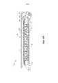
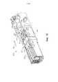
На ФИГ.1 показан вид в перспективе примера шарнирного хирургического сшивающего инструмента.FIG. 1 shows a perspective view of an example of an articulated surgical stapling instrument.
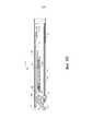
На ФИГ.2 показан вид сбоку в вертикальной проекции инструмента, изображенного на ФИГ.1.FIG. 2 shows a side elevational view of the tool of FIG. 1.
На ФИГ.3 показан вид в перспективе раскрытого концевого эффектора хирургического инструмента, изображенного на ФИГ.1.FIG. 3 shows a perspective view of the open end effector of the surgical instrument depicted in FIG. 1.
На ФИГ.4A показан вид сбоку поперечного сечения концевого эффектора с ФИГ.3 вдоль линии 4–4 на ФИГ.3 с пусковой штангой в проксимальном положении.FIG. 4A shows a side cross-sectional view of the end effector of FIG. 3 along
На ФИГ.4B показан вид сбоку в поперечном сечении концевого эффектора с ФИГ.3 вдоль линии 4–4 на ФИГ.3 с пусковой штангой в дистальном положении.FIG. 4B shows a side cross-sectional view of the end effector of FIG. 3 along line 4-4 of FIG. 3 with a launch rod in a distal position.
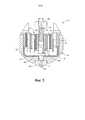
На ФИГ.5 показан вид с торца в поперечном сечении концевого эффектора, изображенного на ФИГ.3, вдоль линии 5–5 на ФИГ.3.FIG. 5 shows an end view in cross section of the end effector shown in FIG. 3 along line 5-5 in FIG. 3.
На ФИГ.6 показан вид в перспективе с пространственным разделением компонентов концевого эффектора, изображенного на ФИГ.3.FIG. 6 shows a perspective view with a spatial separation of the components of the end effector shown in FIG. 3.
На ФИГ.7 показан вид в перспективе концевого эффектора, изображенного на ФИГ.3, наложенного на ткань и приведенного в действие после наложения на ткань.FIG. 7 shows a perspective view of the end effector shown in FIG. 3 superimposed on the fabric and activated after being applied to the fabric.
На ФИГ.8 показан схематический вид примера схемы управления для применения в инструменте, показанном на ФИГ.1.FIG. 8 shows a schematic view of an example control circuit for use in the tool shown in FIG. 1.
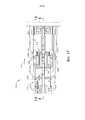
На ФИГ.9 показан вид в перспективе узла рукоятки инструмента с ФИГ.1 с полусмещенным корпусом.FIG. 9 shows a perspective view of the handle assembly of the tool of FIG. 1 with a half-shifted body.
На ФИГ.10 показан вид в перспективе компонентов узла привода от узла рукоятки, изображенного на ФИГ.9.FIG. 10 shows a perspective view of the components of the drive unit from the handle assembly shown in FIG. 9.
На ФИГ.11 показан вид в перспективе удлиненного элемента узла привода, изображенного на ФИГ.10.FIG. 11 shows a perspective view of an elongated element of the drive assembly shown in FIG. 10.
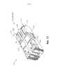
На ФИГ.12 показан вид в перспективе с пространственным разделением компонентов примера альтернативного концевого эффектора, который можно применять в инструменте, изображенном на ФИГ.1.FIG. 12 shows a perspective view with a spatial separation of the components of an example of an alternative end effector that can be used in the tool of FIG. 1.
На ФИГ.13 показан укрупненный вид в перспективе проксимальной части примера кассеты со скобами концевого эффектора, изображенного на ФИГ.12.FIG. 13 is an enlarged perspective view of a proximal portion of an example cassette with end effector brackets shown in FIG. 12.
На ФИГ.14 показан укрупненный вид в перспективе проксимальной части примера нижней бранши концевого эффектора, изображенного на ФИГ.12.FIG. 14 shows an enlarged perspective view of the proximal portion of an example of the lower branch of the end effector shown in FIG. 12.
На ФИГ.15 показан вид в перспективе с пространственным разделением компонентов концевого эффектора, изображенного на ФИГ.12, в сборе с кассетой со скобами, изображенной на ФИГ.13, и нижней браншей, изображенной на ФИГ.14.FIG. 15 shows a perspective view with a spatial separation of the components of the end effector shown in FIG. 12, assembled with the cassette with brackets shown in FIG. 13 and the lower jaw shown in FIG. 14.
На ФИГ.16 показан укрупненный вид в перспективе концевого эффектора, изображенного на ФИГ.12, в сборе с кассетой со скобами, изображенной на ФИГ.13, и нижней браншей, изображенной на ФИГ.14.FIG. 16 shows an enlarged perspective view of the end effector shown in FIG. 12, assembled with the cassette with brackets shown in FIG. 13, and the lower jaw shown in FIG. 14.
На ФИГ.17 показан укрупненный вид сверху концевого эффектора, изображенного на ФИГ.12, в сборе с кассетой со скобами, изображенной на ФИГ.13, и нижней браншей, изображенной на ФИГ.14.FIG. 17 shows an enlarged top view of the end effector shown in FIG. 12, assembled with the cassette with brackets shown in FIG. 13, and the lower jaw shown in FIG. 14.
На ФИГ.18 показан укрупненный вид в поперечном сечении концевого эффектора, изображенного на ФИГ.12, вдоль линии 18–18 на ФИГ.17, в сборе с кассетой со скобами, изображенной на ФИГ.13, и нижней браншей, изображенной на ФИГ.14.FIG. 18 shows an enlarged cross-sectional view of the end effector shown in FIG. 12 along line 18-18 in FIG. fourteen.
Предполагается, что рисунки не имеют какого-либо ограничительного характера, и считается, что различные варианты осуществления изобретения могут быть реализованы множеством других способов, включая те, которые не обязательно показаны на рисунках. Приложенные рисунки образуют часть описания и включены в него, показывая несколько аспектов настоящего изобретения, и вместе с описанием служат для пояснения принципов изобретения. Однако следует понимать, что данное изобретение не ограничено точными показанными конфигурациями.The drawings are not intended to be of any limiting nature, and it is believed that various embodiments of the invention can be implemented in a variety of other ways, including those not necessarily shown in the drawings. The accompanying drawings form part of the description and are included in it, showing several aspects of the present invention, and together with the description serve to explain the principles of the invention. However, it should be understood that the invention is not limited to the exact configurations shown.
ПОДРОБНОЕ ОПИСАНИЕDETAILED DESCRIPTION
Представленное ниже описание некоторых примеров изобретения не следует применять для ограничения объема настоящего изобретения. Другие примеры, признаки, аспекты, варианты осуществления и преимущества настоящего изобретения станут очевидны обычным специалистам в данной области из представленного ниже описания, в котором для иллюстрации показан один из лучших предполагаемых способов реализации настоящего изобретения. Как будет понятно, настоящее изобретение может быть реализовано с разными другими очевидными аспектами, каждый из которых не отклоняется от настоящего изобретения. Соответственно, рисунки и описания следует рассматривать как по сути иллюстративные и не ограничивающие.The following description of some examples of the invention should not be used to limit the scope of the present invention. Other examples, features, aspects, embodiments, and advantages of the present invention will become apparent to those of ordinary skill in the art from the description below, which illustrates one of the best proposed methods for implementing the present invention. As will be understood, the present invention can be implemented with various other obvious aspects, each of which does not deviate from the present invention. Accordingly, the drawings and descriptions should be considered as essentially illustrative and not restrictive.
I. Пример хирургического сшивающего инструментаI. Example of a surgical stapling instrument
На ФИГ.1–7 показан пример хирургического сшивающего и рассекающего инструмента (10), который выполнен по размеру с возможностью введения в несочлененном состоянии, как показано на ФИГ.1, через канюлю троакара в операционное поле внутри тела пациента для проведения хирургического вмешательства. Исключительно для примера, такой троакар можно вставить в брюшную полость пациента, между двумя ребрами пациента или другим путем. В некоторых условиях инструмент (10) используют без троакара. Например, инструмент (10) можно вставить напрямую через торакотомическое отверстие или другой тип разреза. Инструмент (10) настоящего примера включает часть рукоятки (20), соединенную со стволом (22). Ствол (22) прерывается дистально на шарнирном сочленении (11), которое дополнительно соединено с концевым эффектором (12). Следует отметить, что термины «проксимальный» и «дистальный» в настоящем документе используются по отношению к врачу, держащему часть рукоятки (20) инструмента (10). Таким образом, концевой эффектор (12) расположен дистально по отношению к более проксимальной части рукоятки (20). Следует также понимать, что для удобства и ясности такие пространственные термины, как «вертикальный» и «горизонтальный», применяются в настоящем документе в отношении рисунков. Однако хирургические инструменты применяются во множестве ориентаций и положений, и эти термины не являются ограничивающими и абсолютными.Figure 1-7 shows an example of a surgical stapling and dissecting instrument (10), which is made in size with the possibility of insertion in a non-articulated state, as shown in figure 1, through the cannula of a trocar into the surgical field inside the patient's body for surgical intervention. For example only, such a trocar can be inserted into the patient’s abdominal cavity, between two ribs of the patient, or in another way. In some conditions, instrument (10) is used without a trocar. For example, tool (10) can be inserted directly through a thoracotomy opening or other type of incision. The tool (10) of the present example includes a portion of the handle (20) connected to the barrel (22). The barrel (22) is interrupted distally at the articulated joint (11), which is additionally connected to the end effector (12). It should be noted that the terms "proximal" and "distal" in this document are used in relation to the doctor holding part of the handle (20) of the tool (10). Thus, the end effector (12) is located distally with respect to the more proximal part of the handle (20). It should also be understood that for convenience and clarity, spatial terms such as “vertical” and “horizontal” are used herein with respect to drawings. However, surgical instruments are used in a variety of orientations and positions, and these terms are not limiting and absolute.
В некоторых версиях ствол (22) может быть дополнительно разработан в соответствии с по меньшей мере некоторыми из идей, представленных в заявке на патент США № [досье патентного поверенного № END7181USNP.0599180], озаглавленной «Хирургический инструмент со ступенчатым стержнем», поданной в тот же день, что и настоящая заявка, описание которой включено в настоящий документ путем ссылки. Обычным специалистам в данной области будут очевидны другие подходящие конфигурации ствола (22) в свете идей, представленных в настоящем документе.In some versions, the barrel (22) can be further developed in accordance with at least some of the ideas presented in the application for US patent No. [dossier of the patent attorney No. END7181USNP.0599180], entitled "Surgical instrument with a stepped shaft" filed on that same day as the present application, the description of which is incorporated herein by reference. Other suitable barrel configurations (22) will be apparent to those of ordinary skill in the art in light of the ideas presented herein.
После вставки шарнирного сочленения (11) и концевого эффектора (12) через канал канюли троакара шарнирное сочленение (11) можно удаленно шарнирно поворачивать, как показано на модели на ФИГ.1, с помощью устройства управления шарниром (13) таким образом, что концевой эффектор (12) можно отклонять от продольной оси (LA) ствола (22) под желаемым углом (α). Таким образом, концевой эффектор (12) можно завести за орган или приблизить к ткани под требуемым углом либо по другим причинам. В некоторых вариантах шарнирное сочленение (11) делает возможным отклонение концевого эффектора (12) вдоль одной плоскости. В некоторых других вариантах шарнирное сочленение (11) делает возможным отклонение концевого эффектора вдоль более чем одной плоскости. Шарнирное сочленение (11) и устройство управления шарниром (13) могут быть выполнены в соответствии с идеями одной из многочисленных ссылок, приведенных в настоящем документе. Шарнирное сочленение (11) и/или устройство управления шарниром (13) альтернативно могут иметь любую другую подходящую конфигурацию. Исключительно для примера, устройство управления шарниром (13) может быть, напротив, выполнено в виде ручки, которая вращается вокруг оси, которая перпендикулярна продольной оси (LA) ствола (22).After inserting the articulated joint (11) and the end effector (12) through the channel of the trocar cannula, the articulated joint (11) can be remotely pivoted, as shown in the model in FIG. 1, using the hinge control device (13) so that the end effector (12) can deviate from the longitudinal axis (LA) of the barrel (22) at the desired angle (α). Thus, the end effector (12) can be inserted behind the organ or brought closer to the tissue at the required angle or for other reasons. In some embodiments, the articulated joint (11) makes it possible to deflect the end effector (12) along one plane. In some other embodiments, the articulation (11) makes it possible to deflect the end effector along more than one plane. The hinge joint (11) and the hinge control device (13) can be made in accordance with the ideas of one of the many references cited in this document. The hinge joint (11) and / or the hinge control device (13) can alternatively have any other suitable configuration. For example only, the hinge control device (13) can, on the contrary, be made in the form of a handle that rotates around an axis that is perpendicular to the longitudinal axis (LA) of the barrel (22).
В некоторых вариантах шарнирное сочленение (11) и/или устройство управления шарниром (13) сконструированы и могут эксплуатироваться в соответствии с по меньшей мере некоторыми из идей, представленных в заявке на патент США № [досье патентного поверенного № END7174USNP.0599176], озаглавленной «Привод шарнира концевого эффектора хирургического инструмента с шестерней и противоположными рейками», поданной в тот же день, что и настоящая заявка, описание которой включено в настоящий документ путем ссылки. Шарнирное сочленение (11) также может быть сконструировано и может эксплуатироваться в соответствии с по меньшей мере некоторыми из идей, представленных в заявке на патент США № [досье патентного поверенного № END7181USNP.0599180], содержание которой включено в настоящий документ путем ссылки. В свете идей, представленных в настоящем документе, обычным специалистам в данной области будут очевидны другие подходящие формы, которые могут принимать шарнирное сочленение (11) и устройство управления шарниром (13).In some embodiments, the articulated joint (11) and / or the articulated control device (13) are designed and operated in accordance with at least some of the ideas presented in US Patent Application No. [Attorney File No. END7174USNP.0599176] entitled “ Surgical Instrument End Effector Hinge Drive with Gear and Opposite Rails ”filed on the same day as this application, the description of which is incorporated herein by reference. The articulated joint (11) can also be designed and operated in accordance with at least some of the ideas presented in US patent application No. [patent dossier No. END7181USNP.0599180], the contents of which are incorporated herein by reference. In light of the ideas presented herein, other suitable forms that can take on the articulation (11) and the articulation control device (13) will be apparent to those skilled in the art.
Концевой эффектор (12) настоящего изобретения включает нижнюю браншу (16) и упор (18), выполненный с возможностью поворота. Различные примеры компонентов, элементов и функциональности, которые можно включить в нижнюю браншу (16), подробнее описаны ниже. Упор (18) может быть дополнительно разработан в соответствии с по меньшей мере некоторыми из идей, представленных в заявке на патент США № [досье патентного поверенного № END7176USNP.0599177], озаглавленной «Встроенные элементы для расположения ткани и выравнивания браншей для хирургического сшивающего инструмента», поданной в тот же день, что и настоящая заявка, описание которой включено в настоящий документ путем ссылки; по меньшей мере некоторыми из идей, представленных в заявке на патент США № [досье патентного поверенного № END7177USNP.0599225], озаглавленной «Элемент замыкания браншей для концевого эффектора хирургического инструмента», поданной в тот же день, что и настоящая заявка, описание которой включено в настоящий документ путем ссылки; и/или по меньшей мере некоторыми из идей, представленных в заявке на патент США № [досье патентного поверенного № END7180USNP.0599175], озаглавленной «Элементы для формирования скоб для хирургического сшивающего инструмента», поданной в тот же день, что и настоящая заявка, описание которой включено в настоящий документ путем ссылки. В свете идей, представленных в настоящем документе, обычным специалистам в данной области будут очевидны другие подходящие формы, которые могут принимать нижняя бранша (16) и упор (18).The end effector (12) of the present invention includes a lower jaw (16) and an emphasis (18) that is rotatable. Various examples of components, elements, and functionality that can be included in the lower branch (16) are described in more detail below. The emphasis (18) may be further developed in accordance with at least some of the ideas presented in US patent application No. [patent dossier No. END7176USNP.0599177] entitled “Integrated Elements for Locating Tissue and Aligning Branches for Surgical Stapling Instrument” filed on the same day as this application, the description of which is incorporated herein by reference; at least some of the ideas presented in US patent application No. [patent dossier No. END7177USNP.0599225] entitled “Jaw closure member for a surgical instrument end effector” filed on the same day as the present application, the description of which is included to this document by reference; and / or at least some of the ideas presented in US patent application No. [patent dossier No. END7180USNP.0599175], entitled “Elements for forming staples for a surgical stapling instrument”, filed on the same day as this application, a description of which is incorporated herein by reference. In the light of the ideas presented in this document, other suitable forms that the lower jaw (16) and emphasis (18) will be apparent to those of ordinary skill in the art.
Часть рукоятки (20) включает пистолетную рукоятку (24) и закрывающий спусковой механизм (26). Закрывающий спусковой механизм (26) выполнен с возможностью поворота к пистолетной рукоятке (24) для закрытия или приближения упора (18) к нижней бранше (16) концевого эффектора (12). Такое закрывание упора (18) обеспечивается через закрывающую трубку (32) и закрывающее кольцо (33), которые перемещаются поступательно в продольном направлении относительно части рукоятки (20) в ответ на поворот закрывающего спускового механизма (26) относительно пистолетной рукоятки (24). Закрывающая трубка (32) проходит вдоль длины ствола (22); и закрывающее кольцо (33) расположено дистально к шарнирному сочленению (11). Шарнирное сочленение (11) выполнено с возможностью передачи продольного перемещения от закрывающей трубки (32) до закрывающего кольца (33).Part of the handle (20) includes a pistol grip (24) and a closing trigger (26). The closing trigger mechanism (26) is rotatable to the pistol grip (24) to close or approach the stop (18) to the lower branch (16) of the end effector (12). Such closing of the stop (18) is provided through the closing tube (32) and the closing ring (33), which move translationally in the longitudinal direction relative to the part of the handle (20) in response to the rotation of the closing trigger mechanism (26) relative to the pistol grip (24). The closing tube (32) extends along the length of the barrel (22); and a closing ring (33) is located distally to the articulation (11). The articulated joint (11) is configured to transmit longitudinal movement from the closing tube (32) to the closing ring (33).
Часть рукоятки (20) также включает пусковой крючок (28). Удлиненный элемент (136) (показан на ФИГ.11) проходит продольно через ствол (22) и передает продольное пусковое движение от части рукоятки (20) к пусковой штанге (14) в результате активации пускового крючка (28). Такое дистальное поступательное перемещение пусковой штанги (14) обусловливает сшивание и рассечение зажатой ткани в концевом эффекторе (12), как будет более подробно описано ниже. После этого спусковые крючки (26, 28) отпускают для высвобождения ткани из концевого эффектора (12).Part of the handle (20) also includes a trigger (28). The elongated element (136) (shown in FIG. 11) passes longitudinally through the barrel (22) and transmits a longitudinal starting movement from part of the handle (20) to the starting rod (14) as a result of activation of the starting hook (28). Such a distal translational movement of the launch rod (14) causes the stitching and dissection of the clamped tissue in the end effector (12), as will be described in more detail below. After that, the triggers (26, 28) are released to release tissue from the end effector (12).
На ФИГ.3–6 показан концевой эффектор (12), в котором для выполнения ряда функций применяется форма трехрогого элемента пусковой штанги (14). Следует понимать, что форма трехрогого элемента приводится лишь в качестве показательного примера. Пусковая штанга (14) может принимать любую другую подходящую форму, включая, без ограничений, форму, отличную от трехрогого элемента. Как лучше всего показано на ФИГ.4A–4B, пусковая штанга (14) включает поперечно ориентированный верхний штифт (38), колпачок (44) пусковой штанги, поперечно ориентированный средний штифт (46) и дистально расположенный режущий край (48). Верхний штифт (38) расположен и может поступательно перемещаться внутри продольного паза (42) упора (18). Колпачок (44) пусковой штанги скользит по нижней поверхности нижней бранши (16) при продвижении пусковой штанги (14) через паз (45) нижней бранши (показан на ФИГ.4B), сформированный в нижней бранше (16). Средний штифт (46) скользит по верхней поверхности нижней бранши (16), взаимодействуя с колпачком (44) пусковой штанги. Таким образом, пусковая штанга (14) отдаляет концевой эффектор (12) во время пуска.Figure 3-6 shows the end effector (12), in which to perform a number of functions the shape of the three-horned element of the launch rod (14) is used. It should be understood that the shape of the three-horned element is given only as an indicative example. The trigger bar (14) may take any other suitable form, including, without limitation, a form other than the three-horned element. As best shown in FIGS. 4A – 4B, the trigger rod (14) includes a laterally oriented upper pin (38), a trigger rod cap (44), a laterally oriented middle pin (46), and a distal cutting edge (48). The upper pin (38) is located and can progressively move inside the longitudinal groove (42) of the stop (18). The trigger rod cap (44) slides along the bottom surface of the lower jaw (16) while pushing the trigger rod (14) through the groove (45) of the lower jaw (shown in FIG. 4B) formed in the lower jaw (16). The middle pin (46) slides along the upper surface of the lower jaw (16), interacting with the trigger rod cap (44). Thus, the launch rod (14) moves away the end effector (12) during start-up.
У некоторых отличных от трехрогих форм пусковой штанги (14) может отсутствовать верхний штифт (38), средний штифт (46) и/или колпачок (44) пусковой штанги. Некоторые такие варианты инструмента (10) могут просто опираться на закрывающее кольцо (33) или какой-либо другой элемент для поворота упора (18) в закрытое положение и удерживания упора (18) в закрытом положении, пока пусковая штанга (14) продвигается в дистальное положение. Исключительно для примера, пусковая штанга (14) и/или связанные с ней блокирующие элементы могут быть сконструированы и могут эксплуатироваться в соответствии с по меньшей мере некоторыми из идей, представленных в заявке на патент США № [досье патентного поверенного № END7175USNP.0599231], озаглавленной «Блокирующий элемент для режущего элемента в хирургическом инструменте, выполненного с возможностью перемещения», поданной в тот же день, что и настоящая заявка, описание которой включено в настоящий документ путем ссылки. В свете идей, представленных в настоящем документе, обычным специалистам в данной области будут очевидны другие подходящие формы такой пусковой штанги (14).Some other than three-handed forms of the trigger rod (14) may lack the top pin (38), the middle pin (46) and / or the cap (44) of the trigger rod. Some of these tool options (10) can simply rely on the closing ring (33) or some other element to rotate the stop (18) to the closed position and hold the stop (18) in the closed position while the launch bar (14) moves into the distal position. By way of example only, the launch bar (14) and / or associated locking elements may be designed and operated in accordance with at least some of the ideas presented in US Patent Application No. [Attorney File No. END7175USNP.0599231], entitled "Blocking element for a cutting element in a surgical instrument made with the possibility of movement", filed on the same day as this application, the description of which is incorporated herein by reference. In the light of the ideas presented in this document, other suitable forms of such a launch rod will be apparent to those skilled in the art (14).
На ФИГ.3 показан проксимально расположенная пусковая штанга (14) согласно настоящему примеру и упор (18), повернутый в открытое положение, что позволяет съемно установить неизрасходованную кассету со скобами (37) в канал нижней бранши (16). Как лучше всего показано на ФИГ.5–6, кассета со скобами (37) в этом примере включает корпус (70) кассеты, который представляет собой верхнюю платформу (72) и соединен с нижним лотком (74) кассеты. Как лучше всего показано на ФИГ.3, вертикальный паз (49) образован вдоль части кассеты со скобами (37). Как также лучше всего показано на ФИГ.3, три ряда отверстий (51) для скоб образованы вдоль верхней платформы (72) на одной стороне вертикального паза (49), а другие три ряда отверстий (51) для скоб образованы вдоль верхней платформы (72) на другой стороне вертикального паза (49). Безусловно, можно обеспечить наличие любого другого подходящего числа рядов скоб (например, два ряда, четыре ряда, любое другое число). Как показано на ФИГ.4A–6, клиновидные салазки (41) и множество выталкивателей (43) скоб захвачены между корпусом (70) кассеты и лотком (74), при этом клиновидные салазки (41) расположены проксимально к выталкивателям (43) скоб. Клиновидные салазки (41) выполнены с возможностью продольного перемещения внутри кассеты со скобами (37), в то время как выталкиватели (43) скоб выполнены с возможностью вертикального перемещения внутри кассеты со скобами (37). Скобы (47) также расположены внутри корпуса (70) кассеты поверх соответствующих выталкивателей (43) скоб. В частности, каждая скоба (47) выталкивается вертикально внутри корпуса (70) кассеты с помощью выталкивателя (43) скоб для выталкивания скобы (47) через соответствующее отверстие (51) для скобы. Как лучше всего показано на ФИГ.4A–4B и 6, клиновидные салазки (41) имеют наклонные криволинейные поверхности, толкающие выталкиватели (43) скоб вверх по мере дистального продвижения клиновидных салазок (41) через кассету со скобами (37).FIG. 3 shows a proximally located launching rod (14) according to the present example and a stop (18), turned to the open position, which allows removable installation of an unspent cartridge with brackets (37) in the channel of the lower jaw (16). As best shown in FIGS. 5-6, the cassette with brackets (37) in this example includes the cassette body (70), which is the upper platform (72) and connected to the lower tray (74) of the cassette. As best shown in FIG. 3, a vertical groove (49) is formed along a portion of the cassette with brackets (37). As also best shown in FIG. 3, three rows of holes (51) for brackets are formed along the upper platform (72) on one side of the vertical groove (49), and the other three rows of holes (51) for brackets are formed along the upper platform (72) ) on the other side of the vertical groove (49). Of course, you can ensure the presence of any other suitable number of rows of staples (for example, two rows, four rows, any other number). As shown in FIGS. 4A – 6, wedge-shaped slides (41) and a plurality of ejectors (43) of brackets are caught between the cassette body (70) and the tray (74), while the wedge-shaped slides (41) are located proximal to the ejectors (43) of the brackets. Wedge-shaped slides (41) are made with the possibility of longitudinal movement inside the cassette with brackets (37), while the ejectors (43) of brackets are made with the possibility of vertical movement inside the cassette with brackets (37). The brackets (47) are also located inside the casing (70) of the cartridge over the respective ejectors (43) of the brackets. In particular, each bracket (47) is pushed vertically inside the cassette body (70) with the ejector (43) of the brackets to eject the bracket (47) through the corresponding bracket hole (51). As best shown in FIGS. 4A – 4B and 6, the wedge-shaped slide (41) has sloping curved surfaces pushing the ejectors (43) of the brackets upward as the wedge-shaped slide (41) moves distally through the cassette with brackets (37).
В некоторых вариантах кассета со скобами (37) может быть сконструирована и может эксплуатироваться в соответствии с по меньшей мере некоторыми из идей, представленных в заявке на патент США № [досье патентного поверенного № END7176USNP.0599177], содержание которой включено в настоящий документ путем ссылки. Кроме того или альтернативно, кассета со скобами (37) может быть сконструирована и может эксплуатироваться в соответствии с по меньшей мере некоторыми из идей, изложенных ниже. В свете идей, представленных в настоящем документе, обычным специалистам в данной области будут очевидны другие подходящие формы такой кассеты со скобами (37).In some embodiments, the cassette with brackets (37) can be designed and operated in accordance with at least some of the ideas presented in application for US patent No. [patent dossier No. END7176USNP.0599177], the contents of which are incorporated herein by reference . In addition or alternatively, the cassette with brackets (37) can be designed and operated in accordance with at least some of the ideas set forth below. In the light of the ideas presented in this document, other suitable forms of such a cassette with brackets will be apparent to those skilled in the art (37).
При закрытии концевого эффектора (12), как показано на ФИГ.4А–4В, путем дистального продвижения закрывающей трубки (32) и закрывающего кольца (33) пусковая штанга (14) продвигается в зацепление с упором (18) путем введения верхнего штифта (38) в продольный паз (42) упора. Блок толкателя (80) (показан на ФИГ.5) размещен на дистальном конце пусковой штанги (14) и выполнен с возможностью зацепления клиновидных салазок (41) таким образом, что блок толкателя (80) дистально толкает клиновидные салазки (41) по мере того, как пусковая штанга (14) дистально продвигается через кассету со скобами (37), когда активирован пусковой крючок (28). При такой активации режущий край (48) пусковой штанги (14) входит в вертикальный паз (49) в кассете со скобами (37), рассекая ткань, зажатую между кассетой со скобами (37) и упором (18). Как показано на ФИГ.4A–4B, средний штифт (46) и блок толкателя (80) вместе активируют кассету со скобами (37), входя в вертикальный паз (49) внутри кассеты со скобами (37), выталкивая клиновидные салазки (41) в верхний кулачковый контакт с выталкивателями (43) скоб, которые в свою очередь выталкивают скобы (47) через отверстия (51) для скоб и в формирующий контакт с углублениями (53) для формирования скоб (показаны на ФИГ.3) на внутренней поверхности упора (18). На ФИГ.4B показана пусковая штанга (14), полностью дистально поступательно перемещенная после завершения рассечения и сшивания ткани. Следует понимать, что углубления (53) для формирования скоб намеренно не показаны на проекциях на ФИГ.4А–4В; однако углубления (53) для формирования скоб показаны на ФИГ.3. Также следует понимать, что упор (18) намеренно не показан на проекции на ФИГ.5.When closing the end effector (12), as shown in FIGS. 4A – 4B, by distal advancement of the closing tube (32) and the closing ring (33), the launch rod (14) is engaged with the stop (18) by inserting the upper pin (38 ) into the longitudinal groove (42) of the stop. The pusher block (80) (shown in FIG. 5) is placed on the distal end of the launch rod (14) and is configured to engage the wedge-shaped slide (41) so that the pusher block (80) distally pushes the wedge-shaped slide (41) as as the trigger bar (14) moves distally through the cassette with brackets (37) when the trigger (28) is activated. With this activation, the cutting edge (48) of the launch rod (14) enters the vertical groove (49) in the cassette with brackets (37), dissecting the tissue sandwiched between the cassette with brackets (37) and the stop (18). As shown in FIGS. 4A – 4B, the middle pin (46) and the pusher unit (80) together activate the cassette with brackets (37), entering the vertical groove (49) inside the cassette with brackets (37), pushing the wedge-shaped slides (41) into the upper cam contact with the ejectors (43) of the brackets, which in turn push the brackets (47) through the holes (51) for the brackets and into the forming contact with the recesses (53) to form the brackets (shown in FIG. 3) on the inner surface of the stop (eighteen). FIG. 4B shows a launch rod (14) that is completely distally translationally displaced after completion of dissection and stitching of the tissue. It should be understood that the recesses (53) for the formation of staples are not intentionally shown on the projections in FIGS. 4A – 4B; however, the recesses (53) for forming the brackets are shown in FIG. 3. It should also be understood that the emphasis (18) is intentionally not shown on the projection in FIG. 5.
На ФИГ.7 показан концевой эффектор (12), который был активирован с помощью одного хода через ткань (90). Как показано на фигуре, режущий край (48) (показан на ФИГ.7) рассек ткань (90), в то время как выталкиватели (43) скоб переместили через ткань (90) три чередующихся ряда скоб (47) на каждой стороне созданной режущим краем (48) линии разреза. В этом примере все скобы (47) ориентированы по существу параллельно линии рассечения, хотя следует понимать, что скобы (47) могут быть расположены в любых подходящих ориентациях. В настоящем примере концевой эффектор (12) извлекают из троакара после завершения первого хода, израсходованную кассету со скобами (37) заменяют новой кассетой со скобами, а затем концевой эффектор (12) снова вводят через троакар для доступа к месту сшивания для дополнительного рассечения и сшивания. Этот процесс можно повторять до тех пор, пока не будет обеспечено желаемое количество рассечений и сшиваний (47). Может возникнуть необходимость закрыть упор (18), чтобы содействовать введению и извлечению через троакар, а для содействия замене кассеты со скобами (37) может возникнуть необходимость открыть упор (18).FIG. 7 shows an end effector (12) that has been activated with one stroke through the tissue (90). As shown in the figure, the cutting edge (48) (shown in FIG. 7) cut through the fabric (90), while the ejectors (43) of the staples moved through the fabric (90) three alternating rows of staples (47) on each side created by the cutting edge (48) of the cut line. In this example, all the brackets (47) are oriented essentially parallel to the dissection line, although it should be understood that the brackets (47) can be located in any suitable orientation. In the present example, the end effector (12) is removed from the trocar after completion of the first stroke, the spent cassette with brackets (37) is replaced with a new cassette with brackets, and then the end effector (12) is again introduced through the trocar to access the stapling site for additional dissection and stapling . This process can be repeated until the desired number of cuts and crosslinks is achieved (47). It may be necessary to close the stop (18) to facilitate insertion and removal through the trocar, and to facilitate replacement of the cassette with brackets (37), it may be necessary to open the stop (18).
Следует понимать, что режущий край (48) может рассекать ткань по существу одновременно с выталкиванием скоб (47) через ткань во время каждого хода активации. В данном примере режущий край (48) лишь немного отстает от выталкивания скоб (47), поэтому скоба (47) выталкивается через ткань непосредственно перед тем, как режущий край (48) проходит через ту же область ткани, хотя следует понимать, что этот порядок можно изменить на обратный или непосредственно синхронизировать режущий край (48) со смежными скобами. Хотя на ФИГ.7 показано, что концевой эффектор (12) активирован на двух слоях (92, 94) ткани (90), следует понимать, что концевой эффектор (12) может быть активирован через один слой ткани (90) или более двух слоев (92, 94) ткани. Следует также понимать, что благодаря формированию и размещению скоб (47) смежно с линией разреза, образованной режущим краем (48), может происходить по существу запечатывание ткани по линии разреза и, таким образом, снижение или предотвращение кровотечения и/или утечки других текучих сред организма по линии разреза. Кроме того, хотя на ФИГ.7 показан концевой эффектор (12), активированный на двух по существу плоских, сомкнутых, лежащих в одной плоскости слоях (92, 94) ткани, следует понимать, что концевой эффектор (12) также можно активировать через трубчатую структуру, такую как кровеносный сосуд, отдел желудочно-кишечного тракта, и т. п. Таким образом, ФИГ.7 не следует рассматривать как демонстрирующую какие-либо ограничения на рассматриваемых способах эксплуатации концевого эффектора (12). В свете идей, представленных в настоящем документе, обычным специалистам в данной области будут очевидны различные подходящие ситуации и процедуры, в которых может применяться инструмент (10).It should be understood that the cutting edge (48) can dissect the tissue substantially simultaneously with the ejection of the staples (47) through the tissue during each activation stroke. In this example, the cutting edge (48) is only slightly behind the ejection of the staples (47), therefore, the staple (47) is pushed through the fabric just before the cutting edge (48) passes through the same area of the fabric, although it should be understood that this order can be reversed or the cutting edge (48) can be synchronized directly with adjacent brackets. Although FIG. 7 shows that the end effector (12) is activated on two layers (92, 94) of tissue (90), it should be understood that the end effector (12) can be activated through one layer of tissue (90) or more than two layers (92, 94) fabrics. It should also be understood that due to the formation and placement of staples (47) adjacent to the incision line formed by the cutting edge (48), substantially tissue sealing can occur along the incision line and, thus, reduce or prevent bleeding and / or leakage of other fluids organism along the cut line. In addition, although FIG. 7 shows the end effector (12) activated on two essentially flat, closed, lying in the same plane fabric layers (92, 94), it should be understood that the end effector (12) can also be activated through tubular a structure such as a blood vessel, a section of the gastrointestinal tract, etc. Thus, FIG. 7 should not be considered as demonstrating any limitations on the considered methods of operating the end effector (12). In the light of the ideas presented in this document, various suitable situations and procedures in which the tool can be used (10) will be apparent to those skilled in the art.
Следует понимать, что инструмент (10) может иметь конфигурацию и эксплуатироваться в соответствии с любыми идеями, описанными в патенте США №4805823; патенте США №5415334; патенте США №5465895; патенте США №5597107; патенте США №5632432; патенте США №5673840; патенте США №5704534; патенте США №5814055; патенте США №6978921; патенте США №7000818; патенте США №7143923; патенте США №7303108; патенте США №7367485; патенте США №7380695; патенте США №7380696; патенте США №7404508; патенте США №7434715; патенте США №7721930; публикациях США № 2010/0264193 и/или 2012/0239012. Как отмечалось выше, описание каждого из этих патентов и публикаций включено в настоящий документ путем ссылки. Дополнительные примеры модификаций, которые могут быть обеспечены для инструмента (10), будут более подробно описаны ниже. Обычным специалистам в данной области будут очевидны различные подходящие способы, которыми приведенные ниже идеи могут быть включены в инструмент (10). Аналогичным образом, обычным специалистам в данной области будут очевидны различные подходящие способы, в которых приведенные ниже идеи могут быть скомбинированы с различными идеями патентов/публикаций, указанных в настоящем документе. Следует также понимать, что приведенные ниже идеи не ограничены инструментом (10) или устройствами, описанными в патентах, указанных в настоящем документе. Приведенные ниже идеи можно легко применять к различным другим типам инструментов, включая инструменты, которые не классифицируются как хирургические сшивающие инструменты. В свете идей, представленных в настоящем документе, обычным специалистам в данной области будут очевидны различные другие подходящие устройства и элементы, к которым могут быть применены приведенные ниже идеи.It should be understood that the tool (10) can be configured and operated in accordance with any ideas described in US patent No. 4805823; U.S. Patent No. 5,415,334; U.S. Patent No. 5,465,895; U.S. Patent No. 5,597,107; U.S. Patent No. 5,632,432; U.S. Patent No. 5673840; US patent No. 5704534; US patent No. 5814055; US patent No. 6978921; U.S. Patent No. 7,000,818; US patent No. 7143923; U.S. Patent No. 7,303,108; U.S. Patent No. 7,367,485; U.S. Patent No. 7,380,695; U.S. Patent No. 7,380,696; U.S. Patent No. 7,404,508; U.S. Patent No. 7,434,715; U.S. Patent No. 7,721,930; US Publication Nos. 2010/0264193 and / or 2012/0239012. As noted above, a description of each of these patents and publications is incorporated herein by reference. Additional examples of modifications that may be provided for the tool (10) will be described in more detail below. Various suitable methods will be apparent to those of ordinary skill in the art by which the ideas below can be incorporated into a tool (10). Similarly, various suitable methods will be apparent to those of ordinary skill in the art in which the ideas below can be combined with the various ideas of the patents / publications referenced herein. It should also be understood that the ideas below are not limited to the tool (10) or devices described in the patents referred to in this document. The ideas below can easily be applied to various other types of instruments, including instruments that are not classified as surgical stapling instruments. In light of the ideas presented herein, various other suitable devices and elements will be apparent to those of ordinary skill in the art to which the following ideas may be applied.
II. Примеры элементов выталкивателя с электроприводомII. Examples of electrically driven ejector elements
В настоящем примере инструмент (10) обеспечивает управление пусковой штангой (14) с помощью электропривода. На ФИГ.8–11 показаны примеры компонентов, которые могут использоваться для управления пусковой штангой (14) с помощью электропривода. В частности, на ФИГ.8 показан пример схемы (100) управления, которую можно использовать для питания электрического двигателя (102) электрической энергией от блока батареи (104) (также показано на ФИГ.1–2). Электрический двигатель (102) выполнен с возможностью поступательного перемещения пусковой штанги (14) продольно, как будет более подробно описано ниже. Следует понимать, что вся схема (100) управления, включая двигатель (102) и блок батареи (104), может быть размещена в части рукоятки (20). На ФИГ.8 показан пусковой крючок (28) в виде разомкнутого ключа, хотя следует понимать, что этот ключ закрыт при активации пускового крючка (28). Схема (100) настоящего примера также включает ключ (106) предохранителя, который может замыкаться для замыкания контура схемы (100), однако следует понимать, что ключ (106) предохранителя все же является опционным. Ключ (106) предохранителя также можно замкнуть путем активации отдельной кнопки, ползунка или другого элемента на части рукоятки (20).In the present example, the tool (10) provides control of the launch rod (14) using an electric drive. FIGS. 8–11 show examples of components that can be used to control the launch bar (14) using an electric drive. In particular, FIG. 8 shows an example of a control circuit (100) that can be used to power an electric motor (102) with electric energy from a battery unit (104) (also shown in FIGS. 1-2). The electric motor (102) is made with the possibility of translational movement of the launch rod (14) longitudinally, as will be described in more detail below. It should be understood that the entire control circuit (100), including the engine (102) and the battery pack (104), can be placed in part of the handle (20). FIG. 8 shows the trigger (28) in the form of an open key, although it should be understood that this key is closed when the trigger (28) is activated. The circuit (100) of this example also includes a fuse key (106), which can be closed to close the circuit of the circuit (100), however, it should be understood that the fuse key (106) is still optional. The fuse key (106) can also be closed by activating a separate button, slider or other element on the handle part (20).
Схема (100) настоящего примера также включает ключ (108) блокировки, который выполнен с возможностью пребывания в закрытом положении по умолчанию, но автоматически открывается в результате возникновения условия блокировки. Исключительно для примера, условие блокировки может включать один или более из следующих компонентов: отсутствие кассеты (37) в нижней бранше (16), наличие израсходованной (например, ранее активированной) кассеты (37) в нижней бранше (16), не полностью закрытый упор (18), определение слишком частой активации инструмента (10) и/или любые другие подходящие условия. Для обнаружения условий блокировки можно применять различные подходящие датчики, алгоритмы и другие элементы, которые будут очевидны обычным специалистам в данной области в свете идей, представленных в настоящем документе. Аналогичным образом, в свете идей, представленных в настоящем документе, обычным специалистам в данной области будут очевидны другие подходящие виды условий блокировки. Следует понимать, что схема (100) разомкнута, и, таким образом, когда открыт ключ (108) блокировки, двигатель (102) находится в нефункциональном состоянии. Индикатор (110) блокировки (например, светодиод и т. п.) выполнен с возможностью подачи визуальной индикации статуса ключа (108) блокировки. Исключительно для примера, ключ (108) блокировки, индикатор (110) блокировки и связанные с ними компоненты/функции могут быть выполнены в соответствии с по меньшей мере некоторыми из идей, изложенных в патенте США №7644848, озаглавленном «Электронные блокировки и содержащие их хирургические инструменты», выпущенном 12 января 2010 г., описание которого включено в настоящий документ путем ссылки.The circuit (100) of the present example also includes a key (108) lock, which is configured to stay in the closed position by default, but automatically opens as a result of a blocking condition. By way of example only, a blocking condition may include one or more of the following components: the absence of a cartridge (37) in the lower jaw (16), the expended (for example, previously activated) cartridge (37) in the lower jaw (16), an incompletely closed stop (18) determining the activation of the instrument too frequently (10) and / or any other suitable conditions. To detect blocking conditions, various suitable sensors, algorithms, and other elements can be used that will be apparent to those of ordinary skill in the art in light of the ideas presented herein. Similarly, in light of the ideas presented herein, other suitable kinds of blocking conditions will be apparent to those of ordinary skill in the art. It should be understood that the circuit (100) is open, and thus, when the lock key (108) is open, the engine (102) is in a non-functional state. The lock indicator (110) (for example, an LED, etc.) is configured to provide a visual indication of the status of the lock key (108). By way of example only, the lock key (108), the lock indicator (110) and related components / functions may be implemented in accordance with at least some of the ideas set forth in US Pat. No. 7644848 entitled "Electronic locks and surgical locks containing them" tools ”, released January 12, 2010, a description of which is incorporated herein by reference.
Когда пусковая штанга (14) достигает самого дистального положения (например, в конце рабочего хода), ключ (112) конца хода автоматически переключается в закрытое положение, сменяя полярность напряжения, подаваемого на двигатель (102). Это меняет направление вращения двигателя (102), подразумевая, что оператор отпустит пусковой крючок (28) на этой стадии эксплуатации. На этой стадии эксплуатации для подачи оператору визуальной индикации о том, что вращение двигателя (102) изменено на противоположное, через индикатор (114) обратного направления (например, светодиод, и т. п.) проходит ток. В свете идей, представленных в настоящем документе, обычным специалистам в данной области будут очевидны различные подходящие способы, в которых ключ (112) конца хода можно автоматически переключать в закрытое положение, когда пусковая штанга (14) достигает самого дистального положения. Аналогичным образом, в свете идей, представленных в настоящем документе, обычным специалистам в данной области будут очевидны другие подходящие формы, которые может принимать индикатор (114) обратного направления.When the trigger rod (14) reaches the most distal position (for example, at the end of the stroke), the end switch (112) automatically switches to the closed position, changing the polarity of the voltage supplied to the motor (102). This changes the direction of rotation of the engine (102), implying that the operator releases the trigger (28) at this stage of operation. At this stage of operation, to give the operator a visual indication that the rotation of the engine (102) is reversed, current flows through the indicator (114) in the opposite direction (for example, an LED, etc.). In light of the ideas presented herein, various suitable methods will be apparent to those of ordinary skill in the art in which the end turn key (112) can be automatically switched to the closed position when the launch bar (14) reaches its most distal position. Similarly, in the light of the ideas presented herein, other suitable forms that the indicator (114) of the opposite direction may take will be apparent to those skilled in the art.
Часть рукоятки (20) настоящего примера также включает ручной реверсирующий ключ (116), который также показан на схеме (100). Ручной реверсирующий ключ (116) выполнен с возможностью действия в качестве «аварийного» элемента, позволяя оператору быстро вытянуть пусковую штангу (14) проксимально во время пускового хода. Иными словами, ручной реверсирующий ключ (116) можно активировать вручную, когда пусковая штанга (14) только частично продвинута дистально. Ручной реверсирующий ключ (116) может обеспечивать функциональность, аналогичную ключу (112) конца хода, сменяя полярность напряжения, подаваемого на двигатель (102), таким образом меняя направление вращения двигателя (102). Опять же, о такой смене можно визуально указывать с помощью индикатора (114) обратного направления.Part of the handle (20) of the present example also includes a manual reversing key (116), which is also shown in diagram (100). The manual reversing key (116) is configured to act as an “emergency” element, allowing the operator to quickly pull out the trigger rod (14) proximally during the launch stroke. In other words, the manual reversing key (116) can be activated manually when the trigger bar (14) is only partially advanced distally. A manual reversing key (116) can provide functionality similar to an end-of-stroke key (112) by changing the polarity of the voltage supplied to the motor (102), thereby changing the direction of rotation of the motor (102). Again, such a change can be visually indicated using the indicator (114) in the opposite direction.
В некоторых вариантах один или более ключей (28, 106, 108, 112, 116) выполнены в форме микроключей. В свете идей, представленных в настоящем документе, обычным специалистам в данной области будут очевидны другие подходящие формы. В дополнение или вместо вышеупомянутого, по меньшей мере часть схемы (100) может быть выполнена в соответствии с по меньшей мере некоторыми из идей патента США № 8,210,411, озаглавленного «Хирургический инструмент с приводом», выпущенного 3 июля 2012 г., описание которого включено в настоящий документ путем ссылки.In some embodiments, one or more keys (28, 106, 108, 112, 116) are in the form of micro keys. In light of the ideas presented herein, other suitable forms will be apparent to those skilled in the art. In addition to, or instead of, the above, at least part of the circuit (100) can be implemented in accordance with at least some of the ideas of US patent No. 8,210,411, entitled "Surgical Instrument with a Drive", issued July 3, 2012, the description of which is included in this document by reference.
На ФИГ.9–11 показаны разнообразные механические компоненты, которые можно использовать для обеспечения поступательного перемещения пусковой штанги (14) с помощью электропривода. В частности, на ФИГ.9 показан двигатель (102), размещенный в пистолетной рукоятке (24) части рукоятки (20). Следует понимать, что блок батареи (104) (показан на ФИГ.1–2) также может быть размещен в пистолетной рукоятке (24) (например, под двигателем (102)) и/или в другом месте внутри части рукоятки (20). Двигатель (102) имеет приводной ствол (120), который соединен с узлом (122) зубчатых колес. Узел (122) зубчатых колес имеет внешний кожух (не показан) и выполнен с возможностью приведения верхнего зубчатого колеса (126) в действие, как показано на ФИГ.10. Верхнее зубчатое колесо (126) зацепляется с шестерней (128), поддерживаемой с возможностью поворота штифтом (129), закрепленным в части рукоятки (20). Таким образом, следует понимать, что активация двигателя (102) в итоге приведет к повороту шестерни (128) внутри части рукоятки (20).Fig.9-11 shows a variety of mechanical components that can be used to ensure the translational movement of the launch rod (14) using an electric drive. In particular, FIG. 9 shows an engine (102) located in a pistol grip (24) of a part of the grip (20). It should be understood that the battery unit (104) (shown in FIGS. 1-2) can also be placed in the pistol grip (24) (for example, under the engine (102)) and / or in another place inside the part of the grip (20). The engine (102) has a drive shaft (120) that is connected to the gear assembly (122). The gear assembly (122) has an outer casing (not shown) and is configured to drive the upper gear (126) as shown in FIG. 10. The upper gear wheel (126) engages with the gear (128), which is supported with the possibility of rotation with a pin (129), fixed in part of the handle (20). Thus, it should be understood that activation of the engine (102) will ultimately lead to the rotation of the gear (128) inside the handle portion (20).
Как также показано на ФИГ.9–10, рейка (130) поступательного перемещения включает зубцы (132), которые зацепляются с шестерней (128) таким образом, что при вращении шестерни (128) происходит поступательное перемещение рейки (130). Как показано на ФИГ.11, рейка (130) соединена с удлиненным элементом (136), который проходит через ствол (22) и включает дистальный конец (138), который соединен с проксимальным концом пусковой штанги (14). Удлиненный элемент (136) поступательно перемещается внутри ствола (22) таким образом, что удлиненный элемент (136) передает пусковой штанге (14) поступательное движение рейки (130). Таким образом, следует понимать, что активация двигателя (102) в итоге приведет к поступательному перемещению пусковой штанги (14) внутри концевого эффектора (12). В частности, двигатель (102) может выталкивать пусковую штангу (14) дистально для рассечения ткани (90) и выталкивания скоб (47) в ткань (90). Рычаг (134) активации ключа проходит латерально от рейки (130) и расположен с возможностью зацепления ключа (112) конца хода, когда пусковая штанга (14) достигает самого дистального положения (например, после рассечения ткани (90) и выталкивания скоб (47) в ткань (90)). Как указано выше, такое зацепление ключа (112) конца хода автоматически меняет направление вращения двигателя (102) и возвращает пусковую штангу (14) из самого дистального положения в проксимальное положение, позволяя упору (18) повернуться от нижней бранши (16) для высвобождения ткани (90).As also shown in FIGS. 9-10, the translational movement rail (130) includes teeth (132) that engage with the gear (128) in such a way that during the rotation of the gear (128) the translational movement of the rail (130) occurs. As shown in FIG. 11, the rail (130) is connected to an elongated element (136) that passes through the barrel (22) and includes a distal end (138) that is connected to the proximal end of the launch rod (14). The elongated element (136) translationally moves inside the barrel (22) so that the elongated element (136) transmits the translational movement of the rack (130) to the launch rod (14). Thus, it should be understood that activation of the engine (102) will ultimately lead to the translational movement of the launch rod (14) inside the end effector (12). In particular, the engine (102) can push the launch rod (14) distally to dissect the tissue (90) and push the staples (47) into the fabric (90). The key activation lever (134) extends laterally from the rail (130) and is positioned to engage the key (112) of the end of the stroke when the trigger rod (14) reaches its most distal position (for example, after cutting the fabric (90) and pushing the staples (47) into the fabric (90)). As indicated above, this engagement of the end-of-stroke key (112) automatically changes the direction of rotation of the engine (102) and returns the trigger rod (14) from its most distal position to the proximal position, allowing the stop (18) to turn away from the lower jaw (16) to release tissue (90).
Использование термина «поворачиваться» (и аналогичных терминов с основой «поворачивать») не следует воспринимать как требующее обязательного вращательного движения вокруг неподвижной оси. В некоторых вариантах упор (18) поворачивается вокруг оси, которая определяется штифтом (или подобным элементом), который скользит вдоль удлиненного паза или канала при перемещении упора (18) к нижней бранше (16). В таких вариантах ось вращения поступательно перемещается вдоль траектории, образованной пазом или каналом, при одновременном повороте упора (18) вокруг этой оси. В дополнение или альтернативно, ось вращения может сначала скользить вдоль паза/канала, а затем упор (18) поворачивается вокруг оси вращения, после того как ось вращения переместилась на некоторое расстояние вдоль паза/канала. Следует понимать, что такое движение в виде скользящего/поступательного перемещения охватывается такими терминами, как «поворачиваться», «поворачивается», «вращательный», «с возможностью поворота», «поворачивающийся» и т.п. Безусловно, некоторые варианты могут обеспечить вращательное перемещение упора (18) вокруг оси, которая остается неподвижной и не перемещается поступательно внутри паза или канала и т.п.The use of the term “rotate” (and similar terms with the basis of “rotate”) should not be construed as requiring mandatory rotational motion around a fixed axis. In some embodiments, the stop (18) rotates around an axis that is defined by a pin (or similar element) that slides along an elongated groove or channel when the stop (18) moves to the lower jaw (16). In such cases, the axis of rotation progressively moves along the path formed by the groove or channel, while the stop (18) is rotated around this axis. In addition or alternatively, the axis of rotation can first slide along the groove / channel, and then the stop (18) rotates around the axis of rotation after the axis of rotation has moved a certain distance along the groove / channel. It should be understood that such a movement in the form of a sliding / translational movement is covered by such terms as “rotate”, “rotate”, “rotational”, “rotatable”, “rotate”, etc. Of course, some options can provide rotational movement of the stop (18) around an axis that remains stationary and does not move translationally inside a groove or channel, etc.
В дополнение или вместо вышеупомянутого, элементы, выполненные с возможностью выталкивания пусковой штанги (14), могут быть выполнены в соответствии с по меньшей мере некоторыми из идей публикации США № 2012/0239012, описание которой включено в настоящий документ путем ссылки; и/или в соответствии с по меньшей мере некоторыми из идей публикации США № 2012/0239012, описание которой включено в настоящий документ путем ссылки. В свете идей, представленных в настоящем документе, обычным специалистам в данной области будут очевидны другие подходящие компоненты, элементы и конфигурации обеспечения электропривода для пусковой штанги (14). Также следует понимать, что некоторые другие варианты могут обеспечивать ручное выталкивание пусковой штанги (14), за счет чего двигатель можно не включать. Исключительно для примера, пусковая штанга (14) может быть активирована в соответствии с по меньшей мере некоторыми идеями из любого другого патента/заявки, приведенных в настоящем документе путем ссылки.In addition to or instead of the aforementioned, elements configured to push the launch rod (14) may be made in accordance with at least some of the ideas of US Publication No. 2012/0239012, the disclosure of which is incorporated herein by reference; and / or in accordance with at least some of the ideas of US Publication No. 2012/0239012, the disclosure of which is incorporated herein by reference. In the light of the ideas presented in this document, other suitable components, elements and configurations of providing an electric drive for the launch rod (14) will be obvious to ordinary specialists in this field. It should also be understood that some other options can provide manual ejection of the launch rod (14), due to which the engine can not be turned on. By way of example only, the launch bar (14) may be activated in accordance with at least some ideas from any other patent / application cited herein by reference.
III. Пример альтернативной кассеты со скобами и нижней бранши концевого эффектораIII. An example of an alternative cassette with brackets and bottom jaw of the end effector
В качестве альтернативы концевому эффектору (12) инструмента (10), как описано выше, с инструментом (10) можно использовать пример концевого эффектора (200). Как показано на ФИГ.12, концевой эффектор (200) содержит упор (268), нижнюю браншу (240) и кассету со скобами (210) вместо описанных выше упора (18), нижней бранши (16) и кассеты со скобами (37).As an alternative to the end effector (12) of the tool (10), as described above, an example of the end effector (200) can be used with the tool (10). As shown in FIG. 12, the end effector (200) contains a stop (268), a lower jaw (240) and a cassette with brackets (210) instead of the stop (18), lower jaw (16) and a cassette with brackets (37) described above .
Упор (268) содержит ряд углублений для формирования скоб (не показаны) и выполнен и может эксплуатироваться по существу аналогично описанному выше упору (18).The stop (268) contains a number of recesses for forming brackets (not shown) and is made and can be operated essentially similar to the stop described above (18).
Как лучше всего показано на ФИГ.13, кассета со скобами (210) содержит корпус (214) кассеты, который представляет собой верхнюю платформу (215), и принимается внутрь канала (не показан), который является частью нижнего лотка (212) кассеты и соединен с ним. Кассета со скобами (210) также содержит продольно направленный вертикальный паз (222), образованный в части корпуса (214) кассеты. Кассета со скобами (210) содержит два ряда отверстий (216) для скоб, образованных через верхнюю поверхность (215) на одной стороне вертикального паза (222), и другой набор из двух рядов отверстий (216) для скоб, образованных через верхнюю поверхность (215) на другой стороне вертикального паза (222). Безусловно, можно применять любое другое подходящее число рядов отверстий (216) для скоб. Кассета со скобами (210) функционирует как описано выше со ссылкой на кассету со скобами (37). Скобы (не показаны) выталкиваются вертикально через соответствующие отверстия (216) для скоб за счет продольного движения клиновидных салазок (241) внутри кассеты со скобами (210). Благодаря этому происходит выталкивание скоб через ткань, захваченную между упором (268) и верхней платформой (215), и формирование скоб с помощью формирующих углублений упора (268) для закрепления ткани.As best shown in FIG. 13, the cassette with brackets (210) comprises a cassette body (214), which is the upper platform (215), and is received into the channel (not shown), which is part of the lower cassette tray (212) and connected to it. The cassette with brackets (210) also contains a longitudinally directed vertical groove (222) formed in the cassette body (214). The cassette with brackets (210) contains two rows of holes (216) for the brackets formed through the upper surface (215) on one side of the vertical groove (222), and another set of two rows of holes (216) for the brackets formed through the upper surface ( 215) on the other side of the vertical groove (222). Of course, any other suitable number of rows of holes (216) for the brackets can be used. The cassette with brackets (210) functions as described above with reference to the cassette with brackets (37). The brackets (not shown) are pushed vertically through the corresponding holes (216) for the brackets due to the longitudinal movement of the wedge-shaped slide (241) inside the cassette with brackets (210). Due to this, the staples are ejected through the fabric captured between the stop (268) and the upper platform (215), and the staples are formed using the forming recesses of the stop (268) to secure the fabric.
Корпус (214) и/или нижний лоток (212) кассеты со скобами (210) содержит по меньшей мере один проксимально расположенный элемент зацепления выступа, выполненный в виде проходящей вовнутрь прорези. Прорези (220) в корпусе (214) кассеты образованы на проксимальном конце (224) корпуса (214) кассеты. Прорези (218) в нижнем лотке (212) кассеты образованы на проксимальном конце (226) нижнего лотка (212) кассеты. Прорези (220) в корпусе (214) кассеты и прорези (218) в нижнем лотке (212) кассеты выполнены с возможностью выравнивания друг с другом при соединении корпуса (214) кассеты и нижнего лотка (212) кассеты вместе. Следует понимать, что прорези (218, 220) могут размещаться в любом месте вдоль корпуса (214) кассеты и/или нижнего лотка (212) кассеты и что размещение настоящего примера является лишь примером одного возможного расположения. Также следует понимать, что наличие прорезей (218, 220) как в корпусе (214) кассеты, так и в нижнем лотке (212) кассеты не обязательно. Как приведено в настоящем примере, прорези (218, 220) могут находиться в корпусе (214) кассеты или в нижнем лотке (212) кассеты, или как в корпусе (214) кассеты, так и в нижнем лотке (212) кассеты. Наконец, следует понимать, что в корпусе (214) кассеты и/или нижнем лотке (212) кассеты можно использовать любое подходящее число прорезей (218, 220).The casing (214) and / or the lower tray (212) of the cassette with brackets (210) contains at least one proximal located protrusion engagement element made in the form of an inwardly extending slot. The slots (220) in the cartridge case (214) are formed at the proximal end (224) of the cartridge case (214). The slots (218) in the lower tray (212) of the cartridge are formed at the proximal end (226) of the lower tray (212) of the cartridge. The slots (220) in the cassette body (214) and the slots (218) in the lower cassette tray (212) are made to align with each other when the cassette body (214) and the lower cassette tray (212) are connected together. It should be understood that the slots (218, 220) can be placed anywhere along the cassette body (214) and / or the lower cassette tray (212) and that the placement of this example is only an example of one possible arrangement. It should also be understood that the presence of slots (218, 220) both in the cassette body (214) and in the lower cassette tray (212) is not necessary. As shown in this example, the slots (218, 220) can be in the cassette body (214) or in the lower cassette tray (212), or both in the cassette body (214) and in the lower cassette tray (212). Finally, it should be understood that any suitable number of slots (218, 220) can be used in the cassette body (214) and / or lower cassette tray (212).
Как лучше всего показано на ФИГ.14, нижняя бранша (240) содержит канал (244), который выполнен с возможностью приема кассеты со скобами (210). Нижняя бранша (240) выполнена с возможностью соединения с инструментом (10) и функционирования в качестве нижней бранши (16) по отношению к инструменту (10), как описано выше. Кроме того, нижняя бранша (240) содержит выступы (242), которые выступают вовнутрь от внутренних поверхностей (247) нижней бранши (240) в канал (244). Выступы (242) по существу параллельны основанию нижней бранши (240). Как показано на ФИГ.15–17, выступы (242) нижней бранши (240) выполнены с возможностью сопряжения с прорезями (220) корпуса (214) кассеты и прорезями (218) нижнего лотка (212) кассеты при соединении кассеты со скобами (210) и нижней бранши (240) вместе. Следует понимать, что выступы (242) могут размещаться в любом месте вдоль нижней бранши (240), например в основании нижней бранши (240), и что размещение в настоящем примере является лишь одним примером одного возможного размещения. Следует также понимать, что можно использовать любое подходящее количество выступов (242).As best shown in FIG. 14, the lower jaw (240) comprises a channel (244) that is configured to receive a cassette with brackets (210). The lower jaw (240) is configured to connect to the tool (10) and function as the lower jaw (16) with respect to the tool (10), as described above. In addition, the lower jaw (240) contains protrusions (242) that protrude inward from the inner surfaces (247) of the lower jaw (240) into the channel (244). The protrusions (242) are essentially parallel to the base of the lower jaw (240). As shown in FIGS. 15-17, the protrusions (242) of the lower jaw (240) are configured to interface with the slots (220) of the cassette body (214) and the slots (218) of the lower tray (212) of the cartridge when connecting the cartridge to the brackets (210 ) and lower jaw (240) together. It should be understood that the protrusions (242) can be placed anywhere along the lower jaw (240), for example at the base of the lower jaw (240), and that the placement in the present example is just one example of one possible placement. It should also be understood that any suitable number of protrusions can be used (242).
Среди прочего, выступы (242) нижней бранши (240) могут предотвращать скольжение кассеты со скобами (210) проксимально за границу выступов (242) в направлении стрелки (250), как показано на ФИГ.16–18, особенно когда кассету со скобами (210) загружают в нижнюю браншу (240). Как показано на ФИГ.17 и 18, между последним рядом (217) отверстий (216) для скоб и клиновидными салазками (241) постоянно сохраняется зазор (ΔA) путем предотвращения скольжения кассеты со скобами (210) за границу выступов (242). Кроме того, между клиновидными салазками (241) и пусковой штангой (254) постоянно сохраняется зазор (ΔB) путем предотвращения скольжения кассеты со скобами (210) за границу выступов (242). Сохранение зазора (ΔB) сохраняет зазор (ΔA), поскольку сохранение зазора (ΔB) обеспечивает продольное неподвижное положение клиновидных салазок (241) до дистального выталкивания пусковой штанги (254). Сохранение зазоров (ΔA, ΔB) может предотвратить, среди прочего, преждевременное дистальное перемещение клиновидных салазок (241), предотвращая таким образом преждевременное выталкивание скоб и/или преждевременную блокировку. Это происходит из-за того, что без выступов (242) и прорезей (218, 220) при установке или во время применения кассета со скобами (210) может быть вытолкнута слишком глубоко в проксимальном направлении внутри канала (244). Это может воздействовать на неподвижную пусковую штангу (254), приводя к преждевременному дистальному выталкиванию клиновидных салазок (241), что может обусловить преждевременное вертикальное выталкивание скоб. Преждевременное выталкивание скоб и/или иное дистальное перемещение клиновидных салазок (241) может обусловить состояние блокировки, как описано выше, приводя к невозможности применения инструмента (10), пока не произойдет замена преждевременно вытолкнутой кассеты со скобами (210) на неиспользованную кассету со скобами (210). Выступы (242) в нижней бранше (240) также могут сохранять положение кассеты со скобами (210) во время эксплуатации и предотвращать извлечение кассеты со скобами (210) из нижней бранши (240) во время сжатия ткани и/или предварительного натяжения упора.Among other things, the protrusions (242) of the lower jaw (240) can prevent the cassette with brackets (210) from sliding proximally beyond the border of the protrusions (242) in the direction of the arrow (250), as shown in FIGS. 16-18, especially when the cassette with brackets ( 210) are loaded into the lower jaw (240). As shown in FIGS. 17 and 18, a gap (ΔA) is constantly maintained between the last row (217) of the holes (216) for the brackets and the wedge-shaped slides (241) by preventing the cartridge with the brackets (210) from sliding outside the protrusion (242). In addition, a gap (ΔB) is constantly maintained between the wedge-shaped slides (241) and the launch bar (254) by preventing the cassette with brackets (210) from sliding beyond the border of the protrusions (242). Preservation of the gap (ΔB) preserves the gap (ΔA), since the preservation of the gap (ΔB) provides a longitudinal stationary position of the wedge-shaped slide (241) until the distal pushing of the launch rod (254). Preservation of gaps (ΔA, ΔB) can prevent, among other things, premature distal movement of the wedge-shaped slide (241), thereby preventing premature ejection of the staples and / or premature blocking. This is due to the fact that without protrusions (242) and slots (218, 220) during installation or during use, the cassette with brackets (210) can be pushed too deep in the proximal direction inside the channel (244). This can act on the stationary launch rod (254), leading to premature distal ejection of the wedge-shaped slide (241), which can cause premature vertical ejection of the staples. Premature ejection of the brackets and / or other distal movement of the wedge-shaped slide (241) can cause a blocking state, as described above, leading to the inability to use the tool (10) until the prematurely ejected cassette with brackets (210) is replaced with an unused cassette with brackets ( 210). The protrusions (242) in the lower jaw (240) can also maintain the position of the cassette with brackets (210) during operation and prevent the cassette with brackets (210) from being removed from the lower jaw (240) during tissue compression and / or pre-tensioning of the stop.
Выступы (242) и прорези (218, 220) могут взаимодействовать для обеспечения улучшения эффективности изделия механизмом для выявления дефектов «poka-yoke» и/или предотвращения ошибок или погрешностей оператора. Это происходит из-за того, что, как описано выше, концевой эффектор (200) может предотвращать, среди прочего, преждевременное дистальное перемещение клиновидных салазок (241), обусловленное неправильной установкой кассеты со скобами (210), таким образом предотвращая преждевременное выталкивание скоб и/или преждевременную блокировку, без особого усилия или обдумывания или при отсутствии таковых со стороны оператора. Кроме того, выступы (242) и прорези (218, 220) могут совместно использоваться для обеспечения системы кодов/ключей для предотвращения загрузки в нижнюю браншу (240) кассеты со скобами (210) несоответствующего размера/конфигурации. Иными словами, различные варианты инструмента (10) могут быть выполнены с возможностью работы только со специфическими видами кассет (210). Каждый такой вариант инструмента (10) может иметь выступы (242), которые уникально выполнены с возможностью дополнения уникально выполненных прорезей (218, 220), образованных в соответствующем варианте кассеты (210).The protrusions (242) and the slots (218, 220) can interact to provide improved product performance with a mechanism for detecting poka-yoke defects and / or preventing operator errors or errors. This is due to the fact that, as described above, the end effector (200) can prevent, among other things, premature distal movement of the wedge-shaped slide (241) due to improper installation of the cassette with brackets (210), thus preventing premature ejection of the brackets and / or premature blocking, without much effort or deliberation or in the absence of such by the operator. In addition, tabs (242) and slots (218, 220) can be shared to provide a code / key system to prevent cassettes with brackets (210) of the wrong size / configuration from being loaded into the lower jaw (240). In other words, various versions of the tool (10) can be configured to work only with specific types of cassettes (210). Each such variant of the tool (10) may have protrusions (242) that are uniquely made with the possibility of complementing the uniquely made slots (218, 220) formed in the corresponding embodiment of the cartridge (210).
IV. Прочая информацияIV. other information
Следует понимать, что любую одну или более из идей, выражений, вариантов осуществления, примеров и т.п., описанных в настоящем документе, можно скомбинировать с одной или более из других идей, выражений, вариантов осуществления, примеров и т.п., описанных в настоящем документе. Таким образом, описанные выше идеи, выражения, варианты осуществления, примеры и т.п. не следует рассматривать по отдельности относительно друг друга. Различные подходящие способы, в которых можно скомбинировать идеи, представленные в настоящем документе, будут очевидны обычным специалистам в данной области в свете идей, представленных в настоящем документе. Предполагается, что такие модификации и варианты включены в объем формулы изобретения.It should be understood that any one or more of the ideas, expressions, embodiments, examples, and the like described herein can be combined with one or more of other ideas, expressions, embodiments, examples, and the like, described in this document. Thus, the above ideas, expressions, embodiments, examples, and the like. should not be considered separately relative to each other. Various suitable methods in which the ideas presented herein may be combined will be apparent to those of ordinary skill in the art in light of the ideas presented herein. Such modifications and variations are intended to be included within the scope of the claims.
Следует учитывать, что любой патент, публикация или другой материал описания, полностью или частично включенный в настоящий документ путем ссылки, включены в него только в той степени, в которой включенный материал не противоречит существующим определениям, заявлениям или другим материалам описания, представленным в настоящем описании. Таким образом, описание, в прямой форме представленное в настоящем документе, в той мере, в которой это необходимо, превалирует над любой информацией, противоречащей материалу, включенному в настоящий документ путем ссылки. Любой материал (или его часть), указанный как включенный в настоящий документ путем ссылки, но противоречащий существующим определениям, положениям или другому материалу описания, представленному в настоящем документе, будет включен в настоящий документ только в той мере, в которой между включенным материалом и существующим материалом описания не возникает противоречий.It should be borne in mind that any patent, publication or other description material, fully or partially incorporated herein by reference, is included in it only to the extent that the included material does not contradict the existing definitions, claims or other description materials presented in the present description . Thus, the description, expressly presented in this document, to the extent that it is necessary, prevails over any information that contradicts the material included in this document by reference. Any material (or part thereof) indicated as incorporated herein by reference, but contrary to existing definitions, provisions, or other description material presented herein, will be included in this document only to the extent that between the included material and existing description material does not cause contradictions.
Варианты описанных выше устройств могут применяться в традиционных видах медицинского лечения и процедурах, выполняемых медицинским специалистом, а также в роботизированных видах медицинского лечения и процедурах. Только для примера, различные идеи, представленные в настоящем документе, могут быть легко использованы в роботизированной хирургической системе, такой как система DAVINCI™, созданная компанией Intuitive Surgical, Inc., г. Саннивейл, штат Калифорния, США. Аналогичным образом, обычным специалистам в данной области будет понятно, что различные идеи, представленные в настоящем документе, можно легко комбинировать с различными идеями, представленными в патенте США №5792135, озаглавленном «Шарнирно повернутый хирургический инструмент для выполнения минимально инвазивных операций с улучшенными функциональными возможностями и чувствительностью», выпущенном 11 августа 1998 г., описание которого включено в настоящий документ путем ссылки; патенте США №5817084, озаглавленном «Устройство удаленного центрального расположения с гибким приводом», выпущенном 6 октября 1998 г., описание которого включено в настоящий документ путем ссылки; патенте США №5878193, озаглавленном «Автоматическая эндоскопическая система для оптимального расположения», выпущенном 2 марта 1999 г., описание которого включено в настоящий документ путем ссылки; патенте США №6231565, озаглавленном «Одноразовые загрузочные элементы (DLU) роботизированного рычага для выполнения хирургических задач», выпущенном 15 мая 2001 г., описание которого включено в настоящий документ путем ссылки; патенте США №6783524, озаглавленном «Роботизированный хирургический инструмент с ультразвуковым инструментом для каутеризации и рассечения», выпущенном 31 августа 2004 г., описание которого включено в настоящий документ путем ссылки; патенте США №6364888, озаглавленном «Выравнивание ведущего и подчиненного механизмов в минимально инвазивном хирургическом устройстве», выпущенном 2 апреля 2002 г., описание которого включено в настоящий документ путем ссылки; патенте США №7524320, озаглавленном «Система интерфейса механического исполнительного механизма для роботизированных хирургических инструментов», выпущенном 28 апреля 2009 г., описание которого включено в настоящий документ путем ссылки; патенте США №7691098, озаглавленном «Манжетный механизм для связи с основной системой прибора», выпущенном 6 апреля 2010 г., описание которого включено в настоящий документ путем ссылки; патенте США № 7806891, озаглавленном «Изменение положения и переориентировка отношения ведущего/подчиненного механизмов при минимально инвазивной дистанционной хирургии», выпущенном 5 октября 2010 г., описание которого включено в настоящий документ путем ссылки; публикации США № 2013/0012957, озаглавленной «Автоматическая система перезарядки компонентов концевого эффектора», выпущенной 10 января 2013 г., описание которой включено в настоящий документ путем ссылки; публикации США № 2012/0199630, озаглавленной «Роботизированный хирургический инструмент с возможностью форсированной обратной связи», выпущенной 9 августа 2012 г., описание которой включено в настоящий документ путем ссылки; публикации США № 2012/0132450, озаглавленной «Смещаемый стыковочный элемент выталкивателя для роботизированно контролируемого хирургического инструмента», выпущенной 31 мая 2012 г., описание которой включено в настоящий документ путем ссылки; публикации США № 2012/0199633, озаглавленной «Хирургические сшивающие инструменты с конструкциями с кулачковым приводом для размещения скоб», выпущенной 9 августа 2012 г., описание которой включено в настоящий документ путем ссылки; публикации США №2012/0199631, озаглавленной «Роботизированная хирургическая система концевого эффектора с электроприводом», выпущенной 9 августа 2012 г., описание которой включено в настоящий документ путем ссылки; публикации США №2012/0199632, озаглавленной «Роботизированный хирургический инструмент с избирательно шарнирно поворачиваемым концевым эффектором», выпущенной 9 августа 2012 г., описание которой включено в настоящий документ путем ссылки; публикации США №2012/0203247, озаглавленной «Роботизированная хирургическая система концевого эффектора», выпущенной 9 августа 2012 г., описание которой включено в настоящий документ путем ссылки; публикации США №2012/0211546, озаглавленной «Стыковочный элемент выталкивателя для функционального соединения управляемого хирургического инструмента с автоматическим устройством», выпущенной 23 августа 2012 г.; публикации США №2012/0138660, озаглавленной «Кабельные роботизированные хирургические концевые эффекторы», выпущенной 7 июня 2012 г., описание которой включено в настоящий документ путем ссылки; публикации США №2012/0205421, озаглавленной «Роботизированная хирургическая система концевого эффектора с поворотно активируемыми закрывающими системами», выпущенной 16 августа 2012 г., описание которой включено в настоящий документ путем ссылки.Variants of the devices described above can be used in traditional types of medical treatment and procedures performed by a medical professional, as well as in robotic types of medical treatment and procedures. By way of example only, the various ideas presented herein can be easily used in a robotic surgical system, such as the DAVINCI ™ system, created by Intuitive Surgical, Inc., Sunnyvale, California, USA. Similarly, those of ordinary skill in the art will understand that the various ideas presented in this document can be easily combined with the various ideas presented in US Pat. sensitivity ”, released on August 11, 1998, the description of which is incorporated herein by reference; US patent No. 5817084, entitled "Device remote central location with a flexible drive", issued October 6, 1998, the description of which is incorporated herein by reference; US patent No. 5878193, entitled "Automatic endoscopic system for optimal location", issued March 2, 1999, the description of which is incorporated herein by reference; US patent No. 6231565, entitled "Disposable loading elements (DLU) of the robotic arm for performing surgical tasks", issued May 15, 2001, the description of which is incorporated herein by reference; US patent No. 6783524, entitled "Robotic surgical instrument with an ultrasonic instrument for cauterization and dissection", issued August 31, 2004, the description of which is incorporated herein by reference; US patent No. 6364888, entitled "Alignment of the master and slave mechanisms in a minimally invasive surgical device", issued April 2, 2002, the description of which is incorporated herein by reference; US patent No. 7524320, entitled "Mechanical actuator interface system for robotic surgical instruments", issued April 28, 2009, the description of which is incorporated herein by reference; US patent No. 7691098, entitled "Cuff mechanism for communication with the main system of the device", issued April 6, 2010, the description of which is incorporated herein by reference; US patent No. 7806891, entitled "Changing the position and reorientation of the relationship of the leading / subordinate mechanisms with minimally invasive distance surgery", issued October 5, 2010, the description of which is incorporated herein by reference; US publication No. 2013/0012957, entitled "Automatic recharging system of the components of the end effector", released January 10, 2013, the description of which is incorporated herein by reference; US Publication No. 2012/0199630, entitled “Robotic Surgical Instrument with Forced Feedback”, issued August 9, 2012, the disclosure of which is incorporated herein by reference; US publication No. 2012/0132450, entitled "Movable ejector docking element for a robotic surgical instrument," released May 31, 2012, the description of which is incorporated herein by reference; U.S. Publication No. 2012/0199633, entitled “Surgical Stapling Instruments with Cam Drive Designs for Holding Staples,” issued August 9, 2012, the disclosure of which is incorporated herein by reference; US publication No. 2012/0199631, entitled "Electric Robotic End Effector Surgical System", issued August 9, 2012, the description of which is incorporated herein by reference; US publication No. 2012/0199632, entitled "Robotic surgical instrument with selectively pivotable end effector", issued August 9, 2012, the description of which is incorporated herein by reference; U.S. Publication No. 2012/0203247, entitled Robotic End Effector Surgical System, issued August 9, 2012, the disclosure of which is incorporated herein by reference; U.S. Publication No. 2012/0211546, entitled “Ejector Docking Element for Functionally Connecting a Surgical Instrument to an Automatic Device”, released August 23, 2012; US publication No. 2012/0138660, entitled "Cable robotic surgical end effectors", released June 7, 2012, the description of which is incorporated herein by reference; US publication No. 2012/ 0205421, entitled "Robotic surgical end effector system with rotary activated closure systems", issued August 16, 2012, the description of which is incorporated herein by reference.
Описанные выше производные устройства могут быть выполнены с возможностью утилизации после однократного применения или с возможностью многократного применения. Варианты либо в одном, либо в обоих случаях можно подготовить для повторного применения после по меньшей мере одного применения. Подготовка для повторного применения может включать любую комбинацию стадий разборки устройства, затем очистки или замены конкретных фрагментов и последующей повторной сборки. В частности, некоторые варианты устройства можно разобрать, и любое число конкретных фрагментов или частей устройства можно избирательно заменить или удалить в любой комбинации. После очистки и/или замены конкретных частей некоторые варианты устройства можно повторно собрать для последующего применения либо в отделении, выполняющем подготовку к повторному применению, либо это может сделать сам пользователь непосредственно перед процедурой. Специалистам в данной области будет понятно, что подготовка устройства к повторному применению может включать различные методики разборки, чистки/замены и повторной сборки. Применение таких методик, а также полученное восстановленное устройство входят в объем настоящей заявки.The derivatives described above can be disposed of after a single use or reusable. Options in either one or both cases can be prepared for re-use after at least one application. Preparation for reuse may include any combination of the steps of disassembling the device, then cleaning or replacing specific fragments and subsequent reassembly. In particular, some device variants can be disassembled, and any number of specific fragments or parts of the device can be selectively replaced or removed in any combination. After cleaning and / or replacing specific parts, some variants of the device can be reassembled for subsequent use either in the department preparing for reuse, or this can be done by the user himself immediately before the procedure. Those skilled in the art will understand that preparing a device for reuse may include various disassembly, cleaning / replacing, and reassembly techniques. The use of such techniques, as well as the resulting reconditioned device are included in the scope of this application.
Только в качестве примера, описанные в настоящем документе варианты можно стерилизовать до и/или после процедуры. В одной методике стерилизации устройство помещают в закрытый и герметичный контейнер, такой как пластиковый пакет или пакет из материала Тайвек (TYVEK). Затем контейнер и устройство можно поместить в поле излучения, которое может проникать в контейнер, такое как гамма-излучение, рентгеновское излучение или высокоэнергетический поток электронов. Излучение может убивать бактерии на устройстве и в контейнере. Затем стерилизованное устройство можно хранить в стерильном контейнере для дальнейшего применения. Устройство также можно стерилизовать с применением любой другой методики, известной в данной области, включая, без ограничений, бета- или гамма-излучение, этиленоксид или пар.By way of example only, the options described herein can be sterilized before and / or after the procedure. In one sterilization technique, the device is placed in a closed and sealed container, such as a plastic bag or a Tyvek bag (TYVEK). The container and device can then be placed in a radiation field that can penetrate into the container, such as gamma radiation, x-rays, or a high-energy electron stream. Radiation can kill bacteria on the device and in the container. The sterilized device can then be stored in a sterile container for future use. The device can also be sterilized using any other technique known in the art, including, without limitation, beta or gamma radiation, ethylene oxide or steam.
Обычный специалист в данной области может осуществить различные показанные и описанные варианты осуществления настоящего изобретения, дополнительные адаптации способов и систем, описанных в настоящем документе, путем соответствующих модификаций без отступления от объема настоящего изобретения. Некоторые из таких потенциальных модификаций были упомянуты, а другие будут очевидны обычным специалистам в данной области. Например, примеры, варианты осуществления, геометрические формы, материалы, размеры, коэффициенты, стадии и т.п., описанные выше, являются иллюстративными и не являются обязательными. Соответственно, объем настоящего изобретения следует рассматривать в свете представленной ниже формулы изобретения, и следует понимать, что он не ограничен подробной информацией о структуре и эксплуатации, показанной и описанной в описании и на рисунках.A person of ordinary skill in the art can make various shown and described embodiments of the present invention, further adapt the methods and systems described herein by appropriate modifications without departing from the scope of the present invention. Some of these potential modifications have been mentioned, while others will be apparent to those of ordinary skill in the art. For example, the examples, embodiments, geometric shapes, materials, sizes, coefficients, steps, etc. described above are illustrative and are not binding. Accordingly, the scope of the present invention should be considered in the light of the claims below, and it should be understood that it is not limited to detailed information about the structure and operation shown and described in the description and figures.
Claims (46)
Translated fromRussianApplications Claiming Priority (3)
| Application Number | Priority Date | Filing Date | Title |
|---|---|---|---|
| US13/780,417US9808248B2 (en) | 2013-02-28 | 2013-02-28 | Installation features for surgical instrument end effector cartridge |
| US13/780,417 | 2013-02-28 | ||
| PCT/US2014/017334WO2014133862A1 (en) | 2013-02-28 | 2014-02-20 | Installation features for surgical instrument end effector cartridge |
Publications (2)
| Publication Number | Publication Date |
|---|---|
| RU2015140839A RU2015140839A (en) | 2017-04-03 |
| RU2675661C2true RU2675661C2 (en) | 2018-12-21 |
Family
ID=50190311
Family Applications (1)
| Application Number | Title | Priority Date | Filing Date |
|---|---|---|---|
| RU2015140839ARU2675661C2 (en) | 2013-02-28 | 2014-02-20 | Installation features for surgical instrument end effector cartridge |
Country Status (10)
| Country | Link |
|---|---|
| US (1) | US9808248B2 (en) |
| EP (1) | EP2772200B1 (en) |
| JP (1) | JP6339113B2 (en) |
| CN (1) | CN105025817B (en) |
| BR (1) | BR112015020688B1 (en) |
| CA (1) | CA2902307C (en) |
| MX (1) | MX360767B (en) |
| PL (1) | PL2772200T3 (en) |
| RU (1) | RU2675661C2 (en) |
| WO (1) | WO2014133862A1 (en) |
Families Citing this family (860)
| Publication number | Priority date | Publication date | Assignee | Title |
|---|---|---|---|---|
| US20070084897A1 (en) | 2003-05-20 | 2007-04-19 | Shelton Frederick E Iv | Articulating surgical stapling instrument incorporating a two-piece e-beam firing mechanism |
| US9060770B2 (en) | 2003-05-20 | 2015-06-23 | Ethicon Endo-Surgery, Inc. | Robotically-driven surgical instrument with E-beam driver |
| US9072535B2 (en) | 2011-05-27 | 2015-07-07 | Ethicon Endo-Surgery, Inc. | Surgical stapling instruments with rotatable staple deployment arrangements |
| US11998198B2 (en) | 2004-07-28 | 2024-06-04 | Cilag Gmbh International | Surgical stapling instrument incorporating a two-piece E-beam firing mechanism |
| US8215531B2 (en) | 2004-07-28 | 2012-07-10 | Ethicon Endo-Surgery, Inc. | Surgical stapling instrument having a medical substance dispenser |
| US11890012B2 (en) | 2004-07-28 | 2024-02-06 | Cilag Gmbh International | Staple cartridge comprising cartridge body and attached support |
| US7934630B2 (en) | 2005-08-31 | 2011-05-03 | Ethicon Endo-Surgery, Inc. | Staple cartridges for forming staples having differing formed staple heights |
| US7669746B2 (en) | 2005-08-31 | 2010-03-02 | Ethicon Endo-Surgery, Inc. | Staple cartridges for forming staples having differing formed staple heights |
| US11246590B2 (en) | 2005-08-31 | 2022-02-15 | Cilag Gmbh International | Staple cartridge including staple drivers having different unfired heights |
| US11484312B2 (en) | 2005-08-31 | 2022-11-01 | Cilag Gmbh International | Staple cartridge comprising a staple driver arrangement |
| US9237891B2 (en) | 2005-08-31 | 2016-01-19 | Ethicon Endo-Surgery, Inc. | Robotically-controlled surgical stapling devices that produce formed staples having different lengths |
| US10159482B2 (en) | 2005-08-31 | 2018-12-25 | Ethicon Llc | Fastener cartridge assembly comprising a fixed anvil and different staple heights |
| US20070106317A1 (en) | 2005-11-09 | 2007-05-10 | Shelton Frederick E Iv | Hydraulically and electrically actuated articulation joints for surgical instruments |
| US20110295295A1 (en) | 2006-01-31 | 2011-12-01 | Ethicon Endo-Surgery, Inc. | Robotically-controlled surgical instrument having recording capabilities |
| US11793518B2 (en) | 2006-01-31 | 2023-10-24 | Cilag Gmbh International | Powered surgical instruments with firing system lockout arrangements |
| US20110024477A1 (en) | 2009-02-06 | 2011-02-03 | Hall Steven G | Driven Surgical Stapler Improvements |
| US20120292367A1 (en) | 2006-01-31 | 2012-11-22 | Ethicon Endo-Surgery, Inc. | Robotically-controlled end effector |
| US8820603B2 (en) | 2006-01-31 | 2014-09-02 | Ethicon Endo-Surgery, Inc. | Accessing data stored in a memory of a surgical instrument |
| US7845537B2 (en) | 2006-01-31 | 2010-12-07 | Ethicon Endo-Surgery, Inc. | Surgical instrument having recording capabilities |
| US11278279B2 (en) | 2006-01-31 | 2022-03-22 | Cilag Gmbh International | Surgical instrument assembly |
| US8708213B2 (en) | 2006-01-31 | 2014-04-29 | Ethicon Endo-Surgery, Inc. | Surgical instrument having a feedback system |
| US7753904B2 (en) | 2006-01-31 | 2010-07-13 | Ethicon Endo-Surgery, Inc. | Endoscopic surgical instrument with a handle that can articulate with respect to the shaft |
| US11224427B2 (en) | 2006-01-31 | 2022-01-18 | Cilag Gmbh International | Surgical stapling system including a console and retraction assembly |
| US8186555B2 (en) | 2006-01-31 | 2012-05-29 | Ethicon Endo-Surgery, Inc. | Motor-driven surgical cutting and fastening instrument with mechanical closure system |
| US8992422B2 (en) | 2006-03-23 | 2015-03-31 | Ethicon Endo-Surgery, Inc. | Robotically-controlled endoscopic accessory channel |
| EP2018248B1 (en) | 2006-05-19 | 2015-11-04 | Applied Medical Resources Corporation | Surgical stapler |
| US8322455B2 (en) | 2006-06-27 | 2012-12-04 | Ethicon Endo-Surgery, Inc. | Manually driven surgical cutting and fastening instrument |
| US10568652B2 (en) | 2006-09-29 | 2020-02-25 | Ethicon Llc | Surgical staples having attached drivers of different heights and stapling instruments for deploying the same |
| US11980366B2 (en) | 2006-10-03 | 2024-05-14 | Cilag Gmbh International | Surgical instrument |
| US8684253B2 (en) | 2007-01-10 | 2014-04-01 | Ethicon Endo-Surgery, Inc. | Surgical instrument with wireless communication between a control unit of a robotic system and remote sensor |
| US11291441B2 (en) | 2007-01-10 | 2022-04-05 | Cilag Gmbh International | Surgical instrument with wireless communication between control unit and remote sensor |
| US8632535B2 (en) | 2007-01-10 | 2014-01-21 | Ethicon Endo-Surgery, Inc. | Interlock and surgical instrument including same |
| US20080169333A1 (en) | 2007-01-11 | 2008-07-17 | Shelton Frederick E | Surgical stapler end effector with tapered distal end |
| US11039836B2 (en) | 2007-01-11 | 2021-06-22 | Cilag Gmbh International | Staple cartridge for use with a surgical stapling instrument |
| US7673782B2 (en) | 2007-03-15 | 2010-03-09 | Ethicon Endo-Surgery, Inc. | Surgical stapling instrument having a releasable buttress material |
| US8931682B2 (en) | 2007-06-04 | 2015-01-13 | Ethicon Endo-Surgery, Inc. | Robotically-controlled shaft based rotary drive systems for surgical instruments |
| US11564682B2 (en) | 2007-06-04 | 2023-01-31 | Cilag Gmbh International | Surgical stapler device |
| US7753245B2 (en) | 2007-06-22 | 2010-07-13 | Ethicon Endo-Surgery, Inc. | Surgical stapling instruments |
| US11849941B2 (en) | 2007-06-29 | 2023-12-26 | Cilag Gmbh International | Staple cartridge having staple cavities extending at a transverse angle relative to a longitudinal cartridge axis |
| US7866527B2 (en) | 2008-02-14 | 2011-01-11 | Ethicon Endo-Surgery, Inc. | Surgical stapling apparatus with interlockable firing system |
| US8573465B2 (en) | 2008-02-14 | 2013-11-05 | Ethicon Endo-Surgery, Inc. | Robotically-controlled surgical end effector system with rotary actuated closure systems |
| US9179912B2 (en) | 2008-02-14 | 2015-11-10 | Ethicon Endo-Surgery, Inc. | Robotically-controlled motorized surgical cutting and fastening instrument |
| US7819298B2 (en) | 2008-02-14 | 2010-10-26 | Ethicon Endo-Surgery, Inc. | Surgical stapling apparatus with control features operable with one hand |
| US11986183B2 (en) | 2008-02-14 | 2024-05-21 | Cilag Gmbh International | Surgical cutting and fastening instrument comprising a plurality of sensors to measure an electrical parameter |
| US8636736B2 (en) | 2008-02-14 | 2014-01-28 | Ethicon Endo-Surgery, Inc. | Motorized surgical cutting and fastening instrument |
| US8758391B2 (en) | 2008-02-14 | 2014-06-24 | Ethicon Endo-Surgery, Inc. | Interchangeable tools for surgical instruments |
| JP5410110B2 (en) | 2008-02-14 | 2014-02-05 | エシコン・エンド−サージェリィ・インコーポレイテッド | Surgical cutting / fixing instrument with RF electrode |
| US9585657B2 (en) | 2008-02-15 | 2017-03-07 | Ethicon Endo-Surgery, Llc | Actuator for releasing a layer of material from a surgical end effector |
| US11648005B2 (en) | 2008-09-23 | 2023-05-16 | Cilag Gmbh International | Robotically-controlled motorized surgical instrument with an end effector |
| US9386983B2 (en) | 2008-09-23 | 2016-07-12 | Ethicon Endo-Surgery, Llc | Robotically-controlled motorized surgical instrument |
| US9005230B2 (en) | 2008-09-23 | 2015-04-14 | Ethicon Endo-Surgery, Inc. | Motorized surgical instrument |
| US8210411B2 (en) | 2008-09-23 | 2012-07-03 | Ethicon Endo-Surgery, Inc. | Motor-driven surgical cutting instrument |
| US8608045B2 (en) | 2008-10-10 | 2013-12-17 | Ethicon Endo-Sugery, Inc. | Powered surgical cutting and stapling apparatus with manually retractable firing system |
| US8517239B2 (en) | 2009-02-05 | 2013-08-27 | Ethicon Endo-Surgery, Inc. | Surgical stapling instrument comprising a magnetic element driver |
| RU2525225C2 (en) | 2009-02-06 | 2014-08-10 | Этикон Эндо-Серджери, Инк. | Improvement of drive surgical suturing instrument |
| US8851354B2 (en) | 2009-12-24 | 2014-10-07 | Ethicon Endo-Surgery, Inc. | Surgical cutting instrument that analyzes tissue thickness |
| US8220688B2 (en) | 2009-12-24 | 2012-07-17 | Ethicon Endo-Surgery, Inc. | Motor-driven surgical cutting instrument with electric actuator directional control assembly |
| US8783543B2 (en) | 2010-07-30 | 2014-07-22 | Ethicon Endo-Surgery, Inc. | Tissue acquisition arrangements and methods for surgical stapling devices |
| US9016542B2 (en) | 2010-09-30 | 2015-04-28 | Ethicon Endo-Surgery, Inc. | Staple cartridge comprising compressible distortion resistant components |
| US11298125B2 (en) | 2010-09-30 | 2022-04-12 | Cilag Gmbh International | Tissue stapler having a thickness compensator |
| US10945731B2 (en) | 2010-09-30 | 2021-03-16 | Ethicon Llc | Tissue thickness compensator comprising controlled release and expansion |
| US11812965B2 (en) | 2010-09-30 | 2023-11-14 | Cilag Gmbh International | Layer of material for a surgical end effector |
| US9788834B2 (en) | 2010-09-30 | 2017-10-17 | Ethicon Llc | Layer comprising deployable attachment members |
| US11925354B2 (en) | 2010-09-30 | 2024-03-12 | Cilag Gmbh International | Staple cartridge comprising staples positioned within a compressible portion thereof |
| US9629814B2 (en) | 2010-09-30 | 2017-04-25 | Ethicon Endo-Surgery, Llc | Tissue thickness compensator configured to redistribute compressive forces |
| US12213666B2 (en) | 2010-09-30 | 2025-02-04 | Cilag Gmbh International | Tissue thickness compensator comprising layers |
| US9386988B2 (en) | 2010-09-30 | 2016-07-12 | Ethicon End-Surgery, LLC | Retainer assembly including a tissue thickness compensator |
| US9351730B2 (en) | 2011-04-29 | 2016-05-31 | Ethicon Endo-Surgery, Llc | Tissue thickness compensator comprising channels |
| US8695866B2 (en) | 2010-10-01 | 2014-04-15 | Ethicon Endo-Surgery, Inc. | Surgical instrument having a power control circuit |
| AU2012250197B2 (en) | 2011-04-29 | 2017-08-10 | Ethicon Endo-Surgery, Inc. | Staple cartridge comprising staples positioned within a compressible portion thereof |
| US11207064B2 (en) | 2011-05-27 | 2021-12-28 | Cilag Gmbh International | Automated end effector component reloading system for use with a robotic system |
| JP6224070B2 (en) | 2012-03-28 | 2017-11-01 | エシコン・エンド−サージェリィ・インコーポレイテッドEthicon Endo−Surgery,Inc. | Retainer assembly including tissue thickness compensator |
| MX358135B (en) | 2012-03-28 | 2018-08-06 | Ethicon Endo Surgery Inc | Tissue thickness compensator comprising a plurality of layers. |
| BR112014024098B1 (en) | 2012-03-28 | 2021-05-25 | Ethicon Endo-Surgery, Inc. | staple cartridge |
| US11871901B2 (en) | 2012-05-20 | 2024-01-16 | Cilag Gmbh International | Method for situational awareness for surgical network or surgical network connected device capable of adjusting function based on a sensed situation or usage |
| US9101358B2 (en) | 2012-06-15 | 2015-08-11 | Ethicon Endo-Surgery, Inc. | Articulatable surgical instrument comprising a firing drive |
| US20140001231A1 (en) | 2012-06-28 | 2014-01-02 | Ethicon Endo-Surgery, Inc. | Firing system lockout arrangements for surgical instruments |
| BR112014032776B1 (en) | 2012-06-28 | 2021-09-08 | Ethicon Endo-Surgery, Inc | SURGICAL INSTRUMENT SYSTEM AND SURGICAL KIT FOR USE WITH A SURGICAL INSTRUMENT SYSTEM |
| US9282974B2 (en) | 2012-06-28 | 2016-03-15 | Ethicon Endo-Surgery, Llc | Empty clip cartridge lockout |
| US9289256B2 (en) | 2012-06-28 | 2016-03-22 | Ethicon Endo-Surgery, Llc | Surgical end effectors having angled tissue-contacting surfaces |
| US12383267B2 (en) | 2012-06-28 | 2025-08-12 | Cilag Gmbh International | Robotically powered surgical device with manually-actuatable reversing system |
| JP6290201B2 (en) | 2012-06-28 | 2018-03-07 | エシコン・エンド−サージェリィ・インコーポレイテッドEthicon Endo−Surgery,Inc. | Lockout for empty clip cartridge |
| US9408606B2 (en) | 2012-06-28 | 2016-08-09 | Ethicon Endo-Surgery, Llc | Robotically powered surgical device with manually-actuatable reversing system |
| US11278284B2 (en) | 2012-06-28 | 2022-03-22 | Cilag Gmbh International | Rotary drive arrangements for surgical instruments |
| US9186142B2 (en) | 2013-02-28 | 2015-11-17 | Ethicon Endo-Surgery, Inc. | Surgical instrument end effector articulation drive with pinion and opposing racks |
| US9717497B2 (en) | 2013-02-28 | 2017-08-01 | Ethicon Llc | Lockout feature for movable cutting member of surgical instrument |
| US9517065B2 (en) | 2013-02-28 | 2016-12-13 | Ethicon Endo-Surgery, Llc | Integrated tissue positioning and jaw alignment features for surgical stapler |
| RU2672520C2 (en) | 2013-03-01 | 2018-11-15 | Этикон Эндо-Серджери, Инк. | Hingedly turnable surgical instruments with conducting ways for signal transfer |
| BR112015021082B1 (en) | 2013-03-01 | 2022-05-10 | Ethicon Endo-Surgery, Inc | surgical instrument |
| US9629629B2 (en) | 2013-03-14 | 2017-04-25 | Ethicon Endo-Surgey, LLC | Control systems for surgical instruments |
| EP2967564B1 (en) | 2013-03-14 | 2018-09-12 | Applied Medical Resources Corporation | Surgical stapler with partial pockets |
| US9808244B2 (en) | 2013-03-14 | 2017-11-07 | Ethicon Llc | Sensor arrangements for absolute positioning system for surgical instruments |
| US9820742B2 (en) | 2013-03-15 | 2017-11-21 | Applied Medical Resources Corporation | Surgical stapler with expandable jaw |
| KR102526549B1 (en) | 2013-03-15 | 2023-04-27 | 어플라이드 메디컬 리소시스 코포레이션 | Surgical stapler having actuation mechanism with rotatable shaft |
| US9826976B2 (en) | 2013-04-16 | 2017-11-28 | Ethicon Llc | Motor driven surgical instruments with lockable dual drive shafts |
| BR112015026109B1 (en) | 2013-04-16 | 2022-02-22 | Ethicon Endo-Surgery, Inc | surgical instrument |
| MX369362B (en) | 2013-08-23 | 2019-11-06 | Ethicon Endo Surgery Llc | Firing member retraction devices for powered surgical instruments. |
| US9775609B2 (en) | 2013-08-23 | 2017-10-03 | Ethicon Llc | Tamper proof circuit for surgical instrument battery pack |
| JP6366708B2 (en) | 2013-11-04 | 2018-08-01 | コヴィディエン リミテッド パートナーシップ | Surgical fastener application device |
| CN105682567B (en) | 2013-11-04 | 2021-09-10 | 柯惠Lp公司 | Surgical fastener applying apparatus |
| CN105682568B (en) | 2013-11-04 | 2018-10-23 | 柯惠Lp公司 | Surgical fasteners bringing device |
| US9962161B2 (en) | 2014-02-12 | 2018-05-08 | Ethicon Llc | Deliverable surgical instrument |
| US10004497B2 (en) | 2014-03-26 | 2018-06-26 | Ethicon Llc | Interface systems for use with surgical instruments |
| US20150272580A1 (en) | 2014-03-26 | 2015-10-01 | Ethicon Endo-Surgery, Inc. | Verification of number of battery exchanges/procedure count |
| US10013049B2 (en) | 2014-03-26 | 2018-07-03 | Ethicon Llc | Power management through sleep options of segmented circuit and wake up control |
| US12232723B2 (en) | 2014-03-26 | 2025-02-25 | Cilag Gmbh International | Systems and methods for controlling a segmented circuit |
| BR112016021943B1 (en) | 2014-03-26 | 2022-06-14 | Ethicon Endo-Surgery, Llc | SURGICAL INSTRUMENT FOR USE BY AN OPERATOR IN A SURGICAL PROCEDURE |
| US10327764B2 (en) | 2014-09-26 | 2019-06-25 | Ethicon Llc | Method for creating a flexible staple line |
| CN106456159B (en) | 2014-04-16 | 2019-03-08 | 伊西康内外科有限责任公司 | Fastener Cartridge Assembly and Nail Retainer Cover Arrangement |
| US10470768B2 (en) | 2014-04-16 | 2019-11-12 | Ethicon Llc | Fastener cartridge including a layer attached thereto |
| CN106456176B (en) | 2014-04-16 | 2019-06-28 | 伊西康内外科有限责任公司 | Fastener Cartridge Including Extensions With Different Configurations |
| BR112016023825B1 (en) | 2014-04-16 | 2022-08-02 | Ethicon Endo-Surgery, Llc | STAPLE CARTRIDGE FOR USE WITH A SURGICAL STAPLER AND STAPLE CARTRIDGE FOR USE WITH A SURGICAL INSTRUMENT |
| US20150297225A1 (en) | 2014-04-16 | 2015-10-22 | Ethicon Endo-Surgery, Inc. | Fastener cartridges including extensions having different configurations |
| EP3142569B1 (en) | 2014-05-15 | 2023-12-27 | Covidien LP | Surgical fastener applying apparatus |
| ES2861258T3 (en) | 2014-06-11 | 2021-10-06 | Applied Med Resources | Circumferential Shot Surgical Stapler |
| US10314577B2 (en) | 2014-06-25 | 2019-06-11 | Ethicon Llc | Lockout engagement features for surgical stapler |
| US10456132B2 (en) | 2014-06-25 | 2019-10-29 | Ethicon Llc | Jaw opening feature for surgical stapler |
| US10335147B2 (en) | 2014-06-25 | 2019-07-02 | Ethicon Llc | Method of using lockout features for surgical stapler cartridge |
| US9693774B2 (en) | 2014-06-25 | 2017-07-04 | Ethicon Llc | Pivotable articulation joint unlocking feature for surgical stapler |
| BR112016030332B1 (en) | 2014-06-25 | 2022-11-01 | Ethicon Endo-Surgery, Llc | LOCKING DEVICE FOR SURGICAL STAPLER |
| US11311294B2 (en) | 2014-09-05 | 2022-04-26 | Cilag Gmbh International | Powered medical device including measurement of closure state of jaws |
| BR112017004361B1 (en) | 2014-09-05 | 2023-04-11 | Ethicon Llc | ELECTRONIC SYSTEM FOR A SURGICAL INSTRUMENT |
| US10135242B2 (en) | 2014-09-05 | 2018-11-20 | Ethicon Llc | Smart cartridge wake up operation and data retention |
| KR102773368B1 (en) | 2014-09-15 | 2025-02-27 | 어플라이드 메디컬 리소시스 코포레이션 | Surgical stapler with self-adjusting staple height |
| US10105142B2 (en) | 2014-09-18 | 2018-10-23 | Ethicon Llc | Surgical stapler with plurality of cutting elements |
| US11523821B2 (en) | 2014-09-26 | 2022-12-13 | Cilag Gmbh International | Method for creating a flexible staple line |
| CN107427300B (en) | 2014-09-26 | 2020-12-04 | 伊西康有限责任公司 | Surgical suture buttresses and auxiliary materials |
| US10076325B2 (en) | 2014-10-13 | 2018-09-18 | Ethicon Llc | Surgical stapling apparatus comprising a tissue stop |
| US9974539B2 (en) | 2014-10-15 | 2018-05-22 | Ethicon Llc | Surgical instrument battery pack with voltage polling |
| EP3010080B1 (en) | 2014-10-15 | 2022-02-23 | Ethicon Endo-Surgery, Inc. | Surgical instrument battery pack with voltage polling |
| US9924944B2 (en) | 2014-10-16 | 2018-03-27 | Ethicon Llc | Staple cartridge comprising an adjunct material |
| US11141153B2 (en) | 2014-10-29 | 2021-10-12 | Cilag Gmbh International | Staple cartridges comprising driver arrangements |
| US10517594B2 (en) | 2014-10-29 | 2019-12-31 | Ethicon Llc | Cartridge assemblies for surgical staplers |
| US11504192B2 (en) | 2014-10-30 | 2022-11-22 | Cilag Gmbh International | Method of hub communication with surgical instrument systems |
| US9844376B2 (en) | 2014-11-06 | 2017-12-19 | Ethicon Llc | Staple cartridge comprising a releasable adjunct material |
| US10736636B2 (en) | 2014-12-10 | 2020-08-11 | Ethicon Llc | Articulatable surgical instrument system |
| US9844375B2 (en) | 2014-12-18 | 2017-12-19 | Ethicon Llc | Drive arrangements for articulatable surgical instruments |
| US9987000B2 (en) | 2014-12-18 | 2018-06-05 | Ethicon Llc | Surgical instrument assembly comprising a flexible articulation system |
| MX389118B (en) | 2014-12-18 | 2025-03-20 | Ethicon Llc | SURGICAL INSTRUMENT WITH AN ANVIL THAT CAN BE SELECTIVELY MOVED ON A DISCRETE, NON-MOBILE AXIS RELATIVE TO A STAPLE CARTRIDGE. |
| US10085748B2 (en) | 2014-12-18 | 2018-10-02 | Ethicon Llc | Locking arrangements for detachable shaft assemblies with articulatable surgical end effectors |
| US9943309B2 (en) | 2014-12-18 | 2018-04-17 | Ethicon Llc | Surgical instruments with articulatable end effectors and movable firing beam support arrangements |
| US9844374B2 (en) | 2014-12-18 | 2017-12-19 | Ethicon Llc | Surgical instrument systems comprising an articulatable end effector and means for adjusting the firing stroke of a firing member |
| US10039545B2 (en) | 2015-02-23 | 2018-08-07 | Covidien Lp | Double fire stapling |
| US10285698B2 (en) | 2015-02-26 | 2019-05-14 | Covidien Lp | Surgical apparatus |
| US10085749B2 (en) | 2015-02-26 | 2018-10-02 | Covidien Lp | Surgical apparatus with conductor strain relief |
| US11154301B2 (en) | 2015-02-27 | 2021-10-26 | Cilag Gmbh International | Modular stapling assembly |
| US9993248B2 (en) | 2015-03-06 | 2018-06-12 | Ethicon Endo-Surgery, Llc | Smart sensors with local signal processing |
| US10687806B2 (en) | 2015-03-06 | 2020-06-23 | Ethicon Llc | Adaptive tissue compression techniques to adjust closure rates for multiple tissue types |
| JP2020121162A (en) | 2015-03-06 | 2020-08-13 | エシコン エルエルシーEthicon LLC | Time dependent evaluation of sensor data to determine stability element, creep element and viscoelastic element of measurement |
| US10245033B2 (en) | 2015-03-06 | 2019-04-02 | Ethicon Llc | Surgical instrument comprising a lockable battery housing |
| US10617412B2 (en) | 2015-03-06 | 2020-04-14 | Ethicon Llc | System for detecting the mis-insertion of a staple cartridge into a surgical stapler |
| US10548504B2 (en) | 2015-03-06 | 2020-02-04 | Ethicon Llc | Overlaid multi sensor radio frequency (RF) electrode system to measure tissue compression |
| US10441279B2 (en) | 2015-03-06 | 2019-10-15 | Ethicon Llc | Multiple level thresholds to modify operation of powered surgical instruments |
| US9901342B2 (en) | 2015-03-06 | 2018-02-27 | Ethicon Endo-Surgery, Llc | Signal and power communication system positioned on a rotatable shaft |
| US10548593B2 (en) | 2015-03-25 | 2020-02-04 | Ethicon Llc | Flowable bioabsorbable polymer adhesive for releasably attaching a staple buttress to a surgical stapler |
| US10172618B2 (en) | 2015-03-25 | 2019-01-08 | Ethicon Llc | Low glass transition temperature bioabsorbable polymer adhesive for releasably attaching a staple buttress to a surgical stapler |
| US10863984B2 (en) | 2015-03-25 | 2020-12-15 | Ethicon Llc | Low inherent viscosity bioabsorbable polymer adhesive for releasably attaching a staple buttress to a surgical stapler |
| US10478187B2 (en) | 2015-03-25 | 2019-11-19 | Ethicon Llc | Biologically derived extracellular matrix with infused viscous absorbable copolymer for releasably attaching a staple buttress to a surgical stapler |
| US10172617B2 (en) | 2015-03-25 | 2019-01-08 | Ethicon Llc | Malleable bioabsorbable polymer adhesive for releasably attaching a staple buttress to a surgical stapler |
| US10568621B2 (en) | 2015-03-25 | 2020-02-25 | Ethicon Llc | Surgical staple buttress with integral adhesive for releasably attaching to a surgical stapler |
| US10136891B2 (en) | 2015-03-25 | 2018-11-27 | Ethicon Llc | Naturally derived bioabsorbable polymer gel adhesive for releasably attaching a staple buttress to a surgical stapler |
| US10349939B2 (en) | 2015-03-25 | 2019-07-16 | Ethicon Llc | Method of applying a buttress to a surgical stapler |
| US10433844B2 (en) | 2015-03-31 | 2019-10-08 | Ethicon Llc | Surgical instrument with selectively disengageable threaded drive systems |
| US10463368B2 (en) | 2015-04-10 | 2019-11-05 | Covidien Lp | Endoscopic stapler |
| CN107635481B (en) | 2015-05-25 | 2021-01-05 | 柯惠有限合伙公司 | Minor diameter surgical suturing device |
| US10349941B2 (en) | 2015-05-27 | 2019-07-16 | Covidien Lp | Multi-fire lead screw stapling device |
| US10172615B2 (en) | 2015-05-27 | 2019-01-08 | Covidien Lp | Multi-fire push rod stapling device |
| US10201348B2 (en) | 2015-07-28 | 2019-02-12 | Ethicon Llc | Surgical stapler cartridge with compression features at staple driver edges |
| US10194912B2 (en) | 2015-07-28 | 2019-02-05 | Ethicon Llc | Surgical staple cartridge with outer edge compression features |
| US10314580B2 (en) | 2015-07-28 | 2019-06-11 | Ethicon Llc | Surgical staple cartridge with compression feature at knife slot |
| US10064622B2 (en) | 2015-07-29 | 2018-09-04 | Covidien Lp | Surgical stapling loading unit with stroke counter and lockout |
| US10045782B2 (en) | 2015-07-30 | 2018-08-14 | Covidien Lp | Surgical stapling loading unit with stroke counter and lockout |
| EP3331455B1 (en) | 2015-08-06 | 2019-10-09 | Applied Medical Resources Corporation | Surgical stapler having locking articulation joint |
| US10835249B2 (en) | 2015-08-17 | 2020-11-17 | Ethicon Llc | Implantable layers for a surgical instrument |
| US10349940B2 (en) | 2015-08-24 | 2019-07-16 | Ethicon Llc | Surgical stapler buttress applicator with state indicator |
| US10342542B2 (en) | 2015-08-24 | 2019-07-09 | Ethicon Llc | Surgical stapler buttress applicator with end effector actuated release mechanism |
| US10639039B2 (en) | 2015-08-24 | 2020-05-05 | Ethicon Llc | Surgical stapler buttress applicator with multi-zone platform for pressure focused release |
| US10166023B2 (en) | 2015-08-24 | 2019-01-01 | Ethicon Llc | Method of applying a buttress to a surgical stapler end effector |
| US11039832B2 (en) | 2015-08-24 | 2021-06-22 | Cilag Gmbh International | Surgical stapler buttress applicator with spent staple cartridge lockout |
| US10342532B2 (en) | 2015-08-24 | 2019-07-09 | Ethicon Llc | Surgical stapler buttress applicator with multi-point actuated release mechanism |
| US10238386B2 (en) | 2015-09-23 | 2019-03-26 | Ethicon Llc | Surgical stapler having motor control based on an electrical parameter related to a motor current |
| US10105139B2 (en) | 2015-09-23 | 2018-10-23 | Ethicon Llc | Surgical stapler having downstream current-based motor control |
| US10299878B2 (en) | 2015-09-25 | 2019-05-28 | Ethicon Llc | Implantable adjunct systems for determining adjunct skew |
| US10182813B2 (en) | 2015-09-29 | 2019-01-22 | Ethicon Llc | Surgical stapling instrument with shaft release, powered firing, and powered articulation |
| US10314578B2 (en) | 2015-09-29 | 2019-06-11 | Ethicon Llc | Battery drain circuit for surgical instrument |
| US11890015B2 (en) | 2015-09-30 | 2024-02-06 | Cilag Gmbh International | Compressible adjunct with crossing spacer fibers |
| US10433846B2 (en) | 2015-09-30 | 2019-10-08 | Ethicon Llc | Compressible adjunct with crossing spacer fibers |
| US10980539B2 (en) | 2015-09-30 | 2021-04-20 | Ethicon Llc | Implantable adjunct comprising bonded layers |
| US10478188B2 (en) | 2015-09-30 | 2019-11-19 | Ethicon Llc | Implantable layer comprising a constricted configuration |
| US10213204B2 (en) | 2015-10-02 | 2019-02-26 | Covidien Lp | Micro surgical instrument and loading unit for use therewith |
| US10265069B2 (en) | 2015-10-15 | 2019-04-23 | Ethicon Llc | Surgical staple cartridge with varying staple crown width along a curve |
| US10499917B2 (en) | 2015-10-15 | 2019-12-10 | Ethicon Llc | Surgical stapler end effector with knife position indicators |
| US10342535B2 (en) | 2015-10-15 | 2019-07-09 | Ethicon Llc | Method of applying staples to liver and other organs |
| US10952730B2 (en) | 2015-10-15 | 2021-03-23 | Ethicon Llc | End effector for surgical stapler with varying curve and taper |
| US10265073B2 (en) | 2015-10-15 | 2019-04-23 | Ethicon Llc | Surgical stapler with terminal staple orientation crossing center line |
| US10226251B2 (en) | 2015-10-15 | 2019-03-12 | Ethicon Llc | Surgical staple actuating sled with actuation stroke having minimized distance relative to distal staple |
| US20170105727A1 (en)* | 2015-10-15 | 2017-04-20 | Ethicon Endo-Surgery, Llc | Surgical stapler with progressively driven asymmetric alternating staple drivers |
| US11141159B2 (en)* | 2015-10-15 | 2021-10-12 | Cilag Gmbh International | Surgical stapler end effector with multi-staple driver crossing center line |
| US10772632B2 (en) | 2015-10-28 | 2020-09-15 | Covidien Lp | Surgical stapling device with triple leg staples |
| US10499918B2 (en) | 2015-10-29 | 2019-12-10 | Ethicon Llc | Surgical stapler buttress assembly with features to interact with movable end effector components |
| US10314588B2 (en) | 2015-10-29 | 2019-06-11 | Ethicon Llc | Fluid penetrable buttress assembly for a surgical stapler |
| US10517592B2 (en) | 2015-10-29 | 2019-12-31 | Ethicon Llc | Surgical stapler buttress assembly with adhesion to wet end effector |
| US10238388B2 (en) | 2015-10-29 | 2019-03-26 | Ethicon Llc | Surgical stapler buttress assembly with humidity tolerant adhesive |
| US10251649B2 (en) | 2015-10-29 | 2019-04-09 | Ethicon Llc | Surgical stapler buttress applicator with data communication |
| US10441286B2 (en) | 2015-10-29 | 2019-10-15 | Ethicon Llc | Multi-layer surgical stapler buttress assembly |
| US10085745B2 (en) | 2015-10-29 | 2018-10-02 | Ethicon Llc | Extensible buttress assembly for surgical stapler |
| US10357248B2 (en) | 2015-10-29 | 2019-07-23 | Ethicon Llc | Extensible buttress assembly for surgical stapler |
| US10433839B2 (en) | 2015-10-29 | 2019-10-08 | Ethicon Llc | Surgical stapler buttress assembly with gel adhesive retainer |
| US10973517B2 (en) | 2015-11-13 | 2021-04-13 | Intuitive Surgical Operations, Inc. | Stapler with composite cardan and screw drive |
| US10595864B2 (en) | 2015-11-24 | 2020-03-24 | Covidien Lp | Adapter assembly for interconnecting electromechanical surgical devices and surgical loading units, and surgical systems thereof |
| US10111660B2 (en) | 2015-12-03 | 2018-10-30 | Covidien Lp | Surgical stapler flexible distal tip |
| US10368865B2 (en) | 2015-12-30 | 2019-08-06 | Ethicon Llc | Mechanisms for compensating for drivetrain failure in powered surgical instruments |
| US10292704B2 (en) | 2015-12-30 | 2019-05-21 | Ethicon Llc | Mechanisms for compensating for battery pack failure in powered surgical instruments |
| US10265068B2 (en) | 2015-12-30 | 2019-04-23 | Ethicon Llc | Surgical instruments with separable motors and motor control circuits |
| US10966717B2 (en) | 2016-01-07 | 2021-04-06 | Covidien Lp | Surgical fastener apparatus |
| US10660623B2 (en) | 2016-01-15 | 2020-05-26 | Covidien Lp | Centering mechanism for articulation joint |
| BR112018016098B1 (en) | 2016-02-09 | 2023-02-23 | Ethicon Llc | SURGICAL INSTRUMENT |
| US11213293B2 (en) | 2016-02-09 | 2022-01-04 | Cilag Gmbh International | Articulatable surgical instruments with single articulation link arrangements |
| US10349937B2 (en) | 2016-02-10 | 2019-07-16 | Covidien Lp | Surgical stapler with articulation locking mechanism |
| US10420559B2 (en) | 2016-02-11 | 2019-09-24 | Covidien Lp | Surgical stapler with small diameter endoscopic portion |
| US10448948B2 (en) | 2016-02-12 | 2019-10-22 | Ethicon Llc | Mechanisms for compensating for drivetrain failure in powered surgical instruments |
| US11224426B2 (en) | 2016-02-12 | 2022-01-18 | Cilag Gmbh International | Mechanisms for compensating for drivetrain failure in powered surgical instruments |
| WO2017180706A1 (en) | 2016-04-12 | 2017-10-19 | Applied Medical Resources Corporation | Surgical stapler having articulation mechanism |
| AU2017250206B2 (en) | 2016-04-12 | 2022-03-24 | Applied Medical Resources Corporation | Surgical stapler having a powered handle |
| KR102388183B1 (en) | 2016-04-12 | 2022-04-19 | 어플라이드 메디컬 리소시스 코포레이션 | Reload Shaft Assembly for Surgical Stapler |
| US11607239B2 (en) | 2016-04-15 | 2023-03-21 | Cilag Gmbh International | Systems and methods for controlling a surgical stapling and cutting instrument |
| US10335145B2 (en) | 2016-04-15 | 2019-07-02 | Ethicon Llc | Modular surgical instrument with configurable operating mode |
| US10828028B2 (en) | 2016-04-15 | 2020-11-10 | Ethicon Llc | Surgical instrument with multiple program responses during a firing motion |
| US10426467B2 (en) | 2016-04-15 | 2019-10-01 | Ethicon Llc | Surgical instrument with detection sensors |
| US10492783B2 (en) | 2016-04-15 | 2019-12-03 | Ethicon, Llc | Surgical instrument with improved stop/start control during a firing motion |
| US10357247B2 (en) | 2016-04-15 | 2019-07-23 | Ethicon Llc | Surgical instrument with multiple program responses during a firing motion |
| US10456137B2 (en) | 2016-04-15 | 2019-10-29 | Ethicon Llc | Staple formation detection mechanisms |
| US11179150B2 (en) | 2016-04-15 | 2021-11-23 | Cilag Gmbh International | Systems and methods for controlling a surgical stapling and cutting instrument |
| US11317917B2 (en) | 2016-04-18 | 2022-05-03 | Cilag Gmbh International | Surgical stapling system comprising a lockable firing assembly |
| US20170296173A1 (en) | 2016-04-18 | 2017-10-19 | Ethicon Endo-Surgery, Llc | Method for operating a surgical instrument |
| US10363037B2 (en) | 2016-04-18 | 2019-07-30 | Ethicon Llc | Surgical instrument system comprising a magnetic lockout |
| US10258337B2 (en) | 2016-04-20 | 2019-04-16 | Ethicon Llc | Surgical staple cartridge with severed tissue edge adjunct |
| US10653420B2 (en) | 2016-04-20 | 2020-05-19 | Ethicon Llc | Compliant compensation features for end effector of surgical stapling instrument |
| US10363032B2 (en) | 2016-04-20 | 2019-07-30 | Ethicon Llc | Surgical stapler with hydraulic deck control |
| US10285700B2 (en) | 2016-04-20 | 2019-05-14 | Ethicon Llc | Surgical staple cartridge with hydraulic staple deployment |
| US10561419B2 (en) | 2016-05-04 | 2020-02-18 | Covidien Lp | Powered end effector assembly with pivotable channel |
| US11065022B2 (en) | 2016-05-17 | 2021-07-20 | Covidien Lp | Cutting member for a surgical instrument |
| US10499912B2 (en) | 2016-07-13 | 2019-12-10 | Ethicon Llc | Apparatus for hydraulic assisted fracture of liver parenchyma |
| US10500000B2 (en) | 2016-08-16 | 2019-12-10 | Ethicon Llc | Surgical tool with manual control of end effector jaws |
| US11642126B2 (en) | 2016-11-04 | 2023-05-09 | Covidien Lp | Surgical stapling apparatus with tissue pockets |
| US10631857B2 (en) | 2016-11-04 | 2020-04-28 | Covidien Lp | Loading unit for surgical instruments with low profile pushers |
| US10492784B2 (en) | 2016-11-08 | 2019-12-03 | Covidien Lp | Surgical tool assembly with compact firing assembly |
| US10542981B2 (en) | 2016-11-14 | 2020-01-28 | Ethicon Llc | Atraumatic stapling head features for circular surgical stapler |
| US10463371B2 (en) | 2016-11-29 | 2019-11-05 | Covidien Lp | Reload assembly with spent reload indicator |
| US10758229B2 (en) | 2016-12-21 | 2020-09-01 | Ethicon Llc | Surgical instrument comprising improved jaw control |
| US10542982B2 (en) | 2016-12-21 | 2020-01-28 | Ethicon Llc | Shaft assembly comprising first and second articulation lockouts |
| US11090048B2 (en) | 2016-12-21 | 2021-08-17 | Cilag Gmbh International | Method for resetting a fuse of a surgical instrument shaft |
| US10973516B2 (en) | 2016-12-21 | 2021-04-13 | Ethicon Llc | Surgical end effectors and adaptable firing members therefor |
| CN110087565A (en) | 2016-12-21 | 2019-08-02 | 爱惜康有限责任公司 | Surgical stapling system |
| US10695055B2 (en) | 2016-12-21 | 2020-06-30 | Ethicon Llc | Firing assembly comprising a lockout |
| JP7010956B2 (en) | 2016-12-21 | 2022-01-26 | エシコン エルエルシー | How to staple tissue |
| US20180168625A1 (en) | 2016-12-21 | 2018-06-21 | Ethicon Endo-Surgery, Llc | Surgical stapling instruments with smart staple cartridges |
| US10568625B2 (en) | 2016-12-21 | 2020-02-25 | Ethicon Llc | Staple cartridges and arrangements of staples and staple cavities therein |
| US11419606B2 (en) | 2016-12-21 | 2022-08-23 | Cilag Gmbh International | Shaft assembly comprising a clutch configured to adapt the output of a rotary firing member to two different systems |
| JP7010957B2 (en) | 2016-12-21 | 2022-01-26 | エシコン エルエルシー | Shaft assembly with lockout |
| US10813638B2 (en) | 2016-12-21 | 2020-10-27 | Ethicon Llc | Surgical end effectors with expandable tissue stop arrangements |
| JP6983893B2 (en) | 2016-12-21 | 2021-12-17 | エシコン エルエルシーEthicon LLC | Lockout configuration for surgical end effectors and replaceable tool assemblies |
| US20180168615A1 (en) | 2016-12-21 | 2018-06-21 | Ethicon Endo-Surgery, Llc | Method of deforming staples from two different types of staple cartridges with the same surgical stapling instrument |
| US10898186B2 (en) | 2016-12-21 | 2021-01-26 | Ethicon Llc | Staple forming pocket arrangements comprising primary sidewalls and pocket sidewalls |
| US10980536B2 (en) | 2016-12-21 | 2021-04-20 | Ethicon Llc | No-cartridge and spent cartridge lockout arrangements for surgical staplers |
| MX2019007295A (en) | 2016-12-21 | 2019-10-15 | Ethicon Llc | Surgical instrument system comprising an end effector lockout and a firing assembly lockout. |
| US11134942B2 (en) | 2016-12-21 | 2021-10-05 | Cilag Gmbh International | Surgical stapling instruments and staple-forming anvils |
| US10582928B2 (en) | 2016-12-21 | 2020-03-10 | Ethicon Llc | Articulation lock arrangements for locking an end effector in an articulated position in response to actuation of a jaw closure system |
| US10485543B2 (en) | 2016-12-21 | 2019-11-26 | Ethicon Llc | Anvil having a knife slot width |
| CN110099615B (en)* | 2016-12-21 | 2022-08-09 | 爱惜康有限责任公司 | Firing member with non-parallel jaw engagement features for a surgical end effector |
| JP2020501815A (en) | 2016-12-21 | 2020-01-23 | エシコン エルエルシーEthicon LLC | Surgical stapling system |
| US10709901B2 (en) | 2017-01-05 | 2020-07-14 | Covidien Lp | Implantable fasteners, applicators, and methods for brachytherapy |
| US10952767B2 (en) | 2017-02-06 | 2021-03-23 | Covidien Lp | Connector clip for securing an introducer to a surgical fastener applying apparatus |
| US10729434B2 (en) | 2017-02-17 | 2020-08-04 | Ethicon Llc | Surgical stapler with insertable distal anvil tip |
| US10828031B2 (en) | 2017-02-17 | 2020-11-10 | Ethicon Llc | Surgical stapler with elastically deformable tip |
| US11272930B2 (en) | 2017-02-17 | 2022-03-15 | Cilag Gmbh International | Method of surgical stapling with end effector component having a curved tip |
| US11564687B2 (en) | 2017-02-17 | 2023-01-31 | Cilag Gmbh International | Method of surgical stapling with end effector component having a curved tip |
| US10806451B2 (en) | 2017-02-17 | 2020-10-20 | Ethicon Llc | Surgical stapler with cooperating distal tip features on anvil and staple cartridge |
| US11103244B2 (en) | 2017-02-17 | 2021-08-31 | Cilag Gmbh International | Surgical stapling end effector jaw with tip deflecting toward other jaw |
| US11564684B2 (en) | 2017-02-17 | 2023-01-31 | Cilag Gmbh International | Surgical stapling end effector component with tip having varying bend angle |
| US10758231B2 (en) | 2017-02-17 | 2020-09-01 | Ethicon Llc | Surgical stapler with bent anvil tip, angled staple cartridge tip, and tissue gripping features |
| US20180235618A1 (en) | 2017-02-22 | 2018-08-23 | Covidien Lp | Loading unit for surgical instruments with low profile pushers |
| US10849621B2 (en) | 2017-02-23 | 2020-12-01 | Covidien Lp | Surgical stapler with small diameter endoscopic portion |
| US11350915B2 (en) | 2017-02-23 | 2022-06-07 | Covidien Lp | Surgical stapler with small diameter endoscopic portion |
| US10299790B2 (en) | 2017-03-03 | 2019-05-28 | Covidien Lp | Adapter with centering mechanism for articulation joint |
| US10660641B2 (en) | 2017-03-16 | 2020-05-26 | Covidien Lp | Adapter with centering mechanism for articulation joint |
| US11324502B2 (en) | 2017-05-02 | 2022-05-10 | Covidien Lp | Surgical loading unit including an articulating end effector |
| US10603035B2 (en) | 2017-05-02 | 2020-03-31 | Covidien Lp | Surgical loading unit including an articulating end effector |
| US10524784B2 (en) | 2017-05-05 | 2020-01-07 | Covidien Lp | Surgical staples with expandable backspan |
| US10390826B2 (en) | 2017-05-08 | 2019-08-27 | Covidien Lp | Surgical stapling device with elongated tool assembly and methods of use |
| US10420551B2 (en) | 2017-05-30 | 2019-09-24 | Covidien Lp | Authentication and information system for reusable surgical instruments |
| US10478185B2 (en) | 2017-06-02 | 2019-11-19 | Covidien Lp | Tool assembly with minimal dead space |
| US10881399B2 (en) | 2017-06-20 | 2021-01-05 | Ethicon Llc | Techniques for adaptive control of motor velocity of a surgical stapling and cutting instrument |
| US10779820B2 (en) | 2017-06-20 | 2020-09-22 | Ethicon Llc | Systems and methods for controlling motor speed according to user input for a surgical instrument |
| US11517325B2 (en) | 2017-06-20 | 2022-12-06 | Cilag Gmbh International | Closed loop feedback control of motor velocity of a surgical stapling and cutting instrument based on measured displacement distance traveled over a specified time interval |
| US10980537B2 (en) | 2017-06-20 | 2021-04-20 | Ethicon Llc | Closed loop feedback control of motor velocity of a surgical stapling and cutting instrument based on measured time over a specified number of shaft rotations |
| US10307170B2 (en) | 2017-06-20 | 2019-06-04 | Ethicon Llc | Method for closed loop control of motor velocity of a surgical stapling and cutting instrument |
| US10888321B2 (en) | 2017-06-20 | 2021-01-12 | Ethicon Llc | Systems and methods for controlling velocity of a displacement member of a surgical stapling and cutting instrument |
| US11653914B2 (en) | 2017-06-20 | 2023-05-23 | Cilag Gmbh International | Systems and methods for controlling motor velocity of a surgical stapling and cutting instrument according to articulation angle of end effector |
| USD879809S1 (en) | 2017-06-20 | 2020-03-31 | Ethicon Llc | Display panel with changeable graphical user interface |
| US11382638B2 (en) | 2017-06-20 | 2022-07-12 | Cilag Gmbh International | Closed loop feedback control of motor velocity of a surgical stapling and cutting instrument based on measured time over a specified displacement distance |
| USD890784S1 (en) | 2017-06-20 | 2020-07-21 | Ethicon Llc | Display panel with changeable graphical user interface |
| US11071554B2 (en) | 2017-06-20 | 2021-07-27 | Cilag Gmbh International | Closed loop feedback control of motor velocity of a surgical stapling and cutting instrument based on magnitude of velocity error measurements |
| US11090046B2 (en) | 2017-06-20 | 2021-08-17 | Cilag Gmbh International | Systems and methods for controlling displacement member motion of a surgical stapling and cutting instrument |
| US10646220B2 (en) | 2017-06-20 | 2020-05-12 | Ethicon Llc | Systems and methods for controlling displacement member velocity for a surgical instrument |
| US10835218B2 (en) | 2017-06-27 | 2020-11-17 | Ethicon Llc | Apparatus and method to determine end of life of battery powered surgical instrument |
| US10987103B2 (en) | 2017-06-27 | 2021-04-27 | Ethicon Llc | Powered surgical instrument with latching feature preventing removal of battery pack |
| US10511065B2 (en) | 2017-06-27 | 2019-12-17 | Ethicon Llc | Battery powered surgical instrument with dual power utilization circuits for dual modes |
| US11071548B2 (en) | 2017-06-27 | 2021-07-27 | Cilag Gmbh International | Powered circular stapler with reciprocating drive member to provide independent stapling and cutting of tissue |
| US10163309B1 (en) | 2017-06-27 | 2018-12-25 | Ethicon Llc | Surgical instrument with integrated and independently powered displays |
| US11090049B2 (en) | 2017-06-27 | 2021-08-17 | Cilag Gmbh International | Staple forming pocket arrangements |
| US10993716B2 (en) | 2017-06-27 | 2021-05-04 | Ethicon Llc | Surgical anvil arrangements |
| US10639018B2 (en) | 2017-06-27 | 2020-05-05 | Ethicon Llc | Battery pack with integrated circuit providing sleep mode to battery pack and associated surgical instrument |
| US10828029B2 (en) | 2017-06-27 | 2020-11-10 | Ethicon Llc | Surgical stapler with independently actuated drivers to provide varying staple heights |
| US10856869B2 (en) | 2017-06-27 | 2020-12-08 | Ethicon Llc | Surgical anvil arrangements |
| US10888324B2 (en) | 2017-06-27 | 2021-01-12 | Ethicon Llc | Powered surgical instrument with independent selectively applied rotary and linear drivetrains |
| US11324503B2 (en) | 2017-06-27 | 2022-05-10 | Cilag Gmbh International | Surgical firing member arrangements |
| US10090616B1 (en) | 2017-06-27 | 2018-10-02 | Ethicon Llc | Surgical instrument handle assembly with feature to clean electrical contacts at modular shaft interface |
| US10667812B2 (en) | 2017-06-27 | 2020-06-02 | Ethicon Llc | Modular powered electrical connection for surgical instrument with features to prevent electrical discharge |
| US11266405B2 (en) | 2017-06-27 | 2022-03-08 | Cilag Gmbh International | Surgical anvil manufacturing methods |
| EP3420947B1 (en) | 2017-06-28 | 2022-05-25 | Cilag GmbH International | Surgical instrument comprising selectively actuatable rotatable couplers |
| US11246592B2 (en) | 2017-06-28 | 2022-02-15 | Cilag Gmbh International | Surgical instrument comprising an articulation system lockable to a frame |
| US10758232B2 (en) | 2017-06-28 | 2020-09-01 | Ethicon Llc | Surgical instrument with positive jaw opening features |
| US11484310B2 (en) | 2017-06-28 | 2022-11-01 | Cilag Gmbh International | Surgical instrument comprising a shaft including a closure tube profile |
| US11564686B2 (en) | 2017-06-28 | 2023-01-31 | Cilag Gmbh International | Surgical shaft assemblies with flexible interfaces |
| US10903685B2 (en) | 2017-06-28 | 2021-01-26 | Ethicon Llc | Surgical shaft assemblies with slip ring assemblies forming capacitive channels |
| US10716614B2 (en) | 2017-06-28 | 2020-07-21 | Ethicon Llc | Surgical shaft assemblies with slip ring assemblies with increased contact pressure |
| US11259805B2 (en) | 2017-06-28 | 2022-03-01 | Cilag Gmbh International | Surgical instrument comprising firing member supports |
| USD906355S1 (en) | 2017-06-28 | 2020-12-29 | Ethicon Llc | Display screen or portion thereof with a graphical user interface for a surgical instrument |
| US10765427B2 (en) | 2017-06-28 | 2020-09-08 | Ethicon Llc | Method for articulating a surgical instrument |
| US11007022B2 (en) | 2017-06-29 | 2021-05-18 | Ethicon Llc | Closed loop velocity control techniques based on sensed tissue parameters for robotic surgical instrument |
| US10898183B2 (en) | 2017-06-29 | 2021-01-26 | Ethicon Llc | Robotic surgical instrument with closed loop feedback techniques for advancement of closure member during firing |
| US10932772B2 (en) | 2017-06-29 | 2021-03-02 | Ethicon Llc | Methods for closed loop velocity control for robotic surgical instrument |
| US11944300B2 (en) | 2017-08-03 | 2024-04-02 | Cilag Gmbh International | Method for operating a surgical system bailout |
| US11974742B2 (en) | 2017-08-03 | 2024-05-07 | Cilag Gmbh International | Surgical system comprising an articulation bailout |
| US11471155B2 (en) | 2017-08-03 | 2022-10-18 | Cilag Gmbh International | Surgical system bailout |
| US11304695B2 (en) | 2017-08-03 | 2022-04-19 | Cilag Gmbh International | Surgical system shaft interconnection |
| US10624636B2 (en) | 2017-08-23 | 2020-04-21 | Covidien Lp | Surgical stapling device with floating staple cartridge |
| US10806452B2 (en) | 2017-08-24 | 2020-10-20 | Covidien Lp | Loading unit for a surgical stapling instrument |
| US10765429B2 (en) | 2017-09-29 | 2020-09-08 | Ethicon Llc | Systems and methods for providing alerts according to the operational state of a surgical instrument |
| USD907648S1 (en) | 2017-09-29 | 2021-01-12 | Ethicon Llc | Display screen or portion thereof with animated graphical user interface |
| USD907647S1 (en) | 2017-09-29 | 2021-01-12 | Ethicon Llc | Display screen or portion thereof with animated graphical user interface |
| USD917500S1 (en) | 2017-09-29 | 2021-04-27 | Ethicon Llc | Display screen or portion thereof with graphical user interface |
| US10743872B2 (en) | 2017-09-29 | 2020-08-18 | Ethicon Llc | System and methods for controlling a display of a surgical instrument |
| US11399829B2 (en) | 2017-09-29 | 2022-08-02 | Cilag Gmbh International | Systems and methods of initiating a power shutdown mode for a surgical instrument |
| US11317919B2 (en) | 2017-10-30 | 2022-05-03 | Cilag Gmbh International | Clip applier comprising a clip crimping system |
| US11134944B2 (en) | 2017-10-30 | 2021-10-05 | Cilag Gmbh International | Surgical stapler knife motion controls |
| US11510741B2 (en) | 2017-10-30 | 2022-11-29 | Cilag Gmbh International | Method for producing a surgical instrument comprising a smart electrical system |
| US11925373B2 (en) | 2017-10-30 | 2024-03-12 | Cilag Gmbh International | Surgical suturing instrument comprising a non-circular needle |
| US11229436B2 (en) | 2017-10-30 | 2022-01-25 | Cilag Gmbh International | Surgical system comprising a surgical tool and a surgical hub |
| US11311342B2 (en) | 2017-10-30 | 2022-04-26 | Cilag Gmbh International | Method for communicating with surgical instrument systems |
| US11090075B2 (en) | 2017-10-30 | 2021-08-17 | Cilag Gmbh International | Articulation features for surgical end effector |
| US11564756B2 (en) | 2017-10-30 | 2023-01-31 | Cilag Gmbh International | Method of hub communication with surgical instrument systems |
| US11911045B2 (en) | 2017-10-30 | 2024-02-27 | Cllag GmbH International | Method for operating a powered articulating multi-clip applier |
| US11291510B2 (en) | 2017-10-30 | 2022-04-05 | Cilag Gmbh International | Method of hub communication with surgical instrument systems |
| US11026687B2 (en) | 2017-10-30 | 2021-06-08 | Cilag Gmbh International | Clip applier comprising clip advancing systems |
| US11801098B2 (en) | 2017-10-30 | 2023-10-31 | Cilag Gmbh International | Method of hub communication with surgical instrument systems |
| US10842490B2 (en) | 2017-10-31 | 2020-11-24 | Ethicon Llc | Cartridge body design with force reduction based on firing completion |
| US10779903B2 (en) | 2017-10-31 | 2020-09-22 | Ethicon Llc | Positive shaft rotation lock activated by jaw closure |
| US10925603B2 (en) | 2017-11-14 | 2021-02-23 | Covidien Lp | Reload with articulation stabilization system |
| US10863987B2 (en) | 2017-11-16 | 2020-12-15 | Covidien Lp | Surgical instrument with imaging device |
| US10687813B2 (en) | 2017-12-15 | 2020-06-23 | Ethicon Llc | Adapters with firing stroke sensing arrangements for use in connection with electromechanical surgical instruments |
| US10779826B2 (en) | 2017-12-15 | 2020-09-22 | Ethicon Llc | Methods of operating surgical end effectors |
| US10743875B2 (en) | 2017-12-15 | 2020-08-18 | Ethicon Llc | Surgical end effectors with jaw stiffener arrangements configured to permit monitoring of firing member |
| US11197670B2 (en) | 2017-12-15 | 2021-12-14 | Cilag Gmbh International | Surgical end effectors with pivotal jaws configured to touch at their respective distal ends when fully closed |
| US10779825B2 (en) | 2017-12-15 | 2020-09-22 | Ethicon Llc | Adapters with end effector position sensing and control arrangements for use in connection with electromechanical surgical instruments |
| US11033267B2 (en) | 2017-12-15 | 2021-06-15 | Ethicon Llc | Systems and methods of controlling a clamping member firing rate of a surgical instrument |
| US10743874B2 (en) | 2017-12-15 | 2020-08-18 | Ethicon Llc | Sealed adapters for use with electromechanical surgical instruments |
| US10966718B2 (en) | 2017-12-15 | 2021-04-06 | Ethicon Llc | Dynamic clamping assemblies with improved wear characteristics for use in connection with electromechanical surgical instruments |
| US10828033B2 (en) | 2017-12-15 | 2020-11-10 | Ethicon Llc | Handheld electromechanical surgical instruments with improved motor control arrangements for positioning components of an adapter coupled thereto |
| US11006955B2 (en) | 2017-12-15 | 2021-05-18 | Ethicon Llc | End effectors with positive jaw opening features for use with adapters for electromechanical surgical instruments |
| US11071543B2 (en) | 2017-12-15 | 2021-07-27 | Cilag Gmbh International | Surgical end effectors with clamping assemblies configured to increase jaw aperture ranges |
| US10869666B2 (en) | 2017-12-15 | 2020-12-22 | Ethicon Llc | Adapters with control systems for controlling multiple motors of an electromechanical surgical instrument |
| USD910847S1 (en) | 2017-12-19 | 2021-02-16 | Ethicon Llc | Surgical instrument assembly |
| US11045270B2 (en) | 2017-12-19 | 2021-06-29 | Cilag Gmbh International | Robotic attachment comprising exterior drive actuator |
| US11020112B2 (en) | 2017-12-19 | 2021-06-01 | Ethicon Llc | Surgical tools configured for interchangeable use with different controller interfaces |
| US10835330B2 (en) | 2017-12-19 | 2020-11-17 | Ethicon Llc | Method for determining the position of a rotatable jaw of a surgical instrument attachment assembly |
| US10716565B2 (en) | 2017-12-19 | 2020-07-21 | Ethicon Llc | Surgical instruments with dual articulation drivers |
| US10729509B2 (en) | 2017-12-19 | 2020-08-04 | Ethicon Llc | Surgical instrument comprising closure and firing locking mechanism |
| US11129680B2 (en) | 2017-12-21 | 2021-09-28 | Cilag Gmbh International | Surgical instrument comprising a projector |
| US11076853B2 (en) | 2017-12-21 | 2021-08-03 | Cilag Gmbh International | Systems and methods of displaying a knife position during transection for a surgical instrument |
| US12336705B2 (en) | 2017-12-21 | 2025-06-24 | Cilag Gmbh International | Continuous use self-propelled stapling instrument |
| US11179151B2 (en) | 2017-12-21 | 2021-11-23 | Cilag Gmbh International | Surgical instrument comprising a display |
| US11311290B2 (en) | 2017-12-21 | 2022-04-26 | Cilag Gmbh International | Surgical instrument comprising an end effector dampener |
| US12396806B2 (en) | 2017-12-28 | 2025-08-26 | Cilag Gmbh International | Adjustment of a surgical device function based on situational awareness |
| US12376855B2 (en) | 2017-12-28 | 2025-08-05 | Cilag Gmbh International | Safety systems for smart powered surgical stapling |
| US11602393B2 (en) | 2017-12-28 | 2023-03-14 | Cilag Gmbh International | Surgical evacuation sensing and generator control |
| US11311306B2 (en) | 2017-12-28 | 2022-04-26 | Cilag Gmbh International | Surgical systems for detecting end effector tissue distribution irregularities |
| US11969142B2 (en) | 2017-12-28 | 2024-04-30 | Cilag Gmbh International | Method of compressing tissue within a stapling device and simultaneously displaying the location of the tissue within the jaws |
| US11109866B2 (en) | 2017-12-28 | 2021-09-07 | Cilag Gmbh International | Method for circular stapler control algorithm adjustment based on situational awareness |
| US11304720B2 (en) | 2017-12-28 | 2022-04-19 | Cilag Gmbh International | Activation of energy devices |
| US11202570B2 (en) | 2017-12-28 | 2021-12-21 | Cilag Gmbh International | Communication hub and storage device for storing parameters and status of a surgical device to be shared with cloud based analytics systems |
| US11026751B2 (en) | 2017-12-28 | 2021-06-08 | Cilag Gmbh International | Display of alignment of staple cartridge to prior linear staple line |
| US11832899B2 (en) | 2017-12-28 | 2023-12-05 | Cilag Gmbh International | Surgical systems with autonomously adjustable control programs |
| US11257589B2 (en) | 2017-12-28 | 2022-02-22 | Cilag Gmbh International | Real-time analysis of comprehensive cost of all instrumentation used in surgery utilizing data fluidity to track instruments through stocking and in-house processes |
| US11324557B2 (en) | 2017-12-28 | 2022-05-10 | Cilag Gmbh International | Surgical instrument with a sensing array |
| US11446052B2 (en) | 2017-12-28 | 2022-09-20 | Cilag Gmbh International | Variation of radio frequency and ultrasonic power level in cooperation with varying clamp arm pressure to achieve predefined heat flux or power applied to tissue |
| US11969216B2 (en) | 2017-12-28 | 2024-04-30 | Cilag Gmbh International | Surgical network recommendations from real time analysis of procedure variables against a baseline highlighting differences from the optimal solution |
| US11540855B2 (en) | 2017-12-28 | 2023-01-03 | Cilag Gmbh International | Controlling activation of an ultrasonic surgical instrument according to the presence of tissue |
| US11056244B2 (en) | 2017-12-28 | 2021-07-06 | Cilag Gmbh International | Automated data scaling, alignment, and organizing based on predefined parameters within surgical networks |
| US11160605B2 (en) | 2017-12-28 | 2021-11-02 | Cilag Gmbh International | Surgical evacuation sensing and motor control |
| US11529187B2 (en) | 2017-12-28 | 2022-12-20 | Cilag Gmbh International | Surgical evacuation sensor arrangements |
| US11076921B2 (en) | 2017-12-28 | 2021-08-03 | Cilag Gmbh International | Adaptive control program updates for surgical hubs |
| US11234756B2 (en) | 2017-12-28 | 2022-02-01 | Cilag Gmbh International | Powered surgical tool with predefined adjustable control algorithm for controlling end effector parameter |
| US10898622B2 (en) | 2017-12-28 | 2021-01-26 | Ethicon Llc | Surgical evacuation system with a communication circuit for communication between a filter and a smoke evacuation device |
| US11304745B2 (en) | 2017-12-28 | 2022-04-19 | Cilag Gmbh International | Surgical evacuation sensing and display |
| US10943454B2 (en) | 2017-12-28 | 2021-03-09 | Ethicon Llc | Detection and escalation of security responses of surgical instruments to increasing severity threats |
| US11410259B2 (en) | 2017-12-28 | 2022-08-09 | Cilag Gmbh International | Adaptive control program updates for surgical devices |
| US10966791B2 (en) | 2017-12-28 | 2021-04-06 | Ethicon Llc | Cloud-based medical analytics for medical facility segmented individualization of instrument function |
| US11166772B2 (en) | 2017-12-28 | 2021-11-09 | Cilag Gmbh International | Surgical hub coordination of control and communication of operating room devices |
| US11419667B2 (en) | 2017-12-28 | 2022-08-23 | Cilag Gmbh International | Ultrasonic energy device which varies pressure applied by clamp arm to provide threshold control pressure at a cut progression location |
| US12127729B2 (en) | 2017-12-28 | 2024-10-29 | Cilag Gmbh International | Method for smoke evacuation for surgical hub |
| US11612444B2 (en) | 2017-12-28 | 2023-03-28 | Cilag Gmbh International | Adjustment of a surgical device function based on situational awareness |
| US11278281B2 (en) | 2017-12-28 | 2022-03-22 | Cilag Gmbh International | Interactive surgical system |
| WO2019133144A1 (en) | 2017-12-28 | 2019-07-04 | Ethicon Llc | Detection and escalation of security responses of surgical instruments to increasing severity threats |
| US11464535B2 (en) | 2017-12-28 | 2022-10-11 | Cilag Gmbh International | Detection of end effector emersion in liquid |
| US11937769B2 (en) | 2017-12-28 | 2024-03-26 | Cilag Gmbh International | Method of hub communication, processing, storage and display |
| US11364075B2 (en) | 2017-12-28 | 2022-06-21 | Cilag Gmbh International | Radio frequency energy device for delivering combined electrical signals |
| US11253315B2 (en) | 2017-12-28 | 2022-02-22 | Cilag Gmbh International | Increasing radio frequency to create pad-less monopolar loop |
| US10987178B2 (en) | 2017-12-28 | 2021-04-27 | Ethicon Llc | Surgical hub control arrangements |
| US11903601B2 (en) | 2017-12-28 | 2024-02-20 | Cilag Gmbh International | Surgical instrument comprising a plurality of drive systems |
| US11832840B2 (en) | 2017-12-28 | 2023-12-05 | Cilag Gmbh International | Surgical instrument having a flexible circuit |
| US10849697B2 (en) | 2017-12-28 | 2020-12-01 | Ethicon Llc | Cloud interface for coupled surgical devices |
| US11179208B2 (en) | 2017-12-28 | 2021-11-23 | Cilag Gmbh International | Cloud-based medical analytics for security and authentication trends and reactive measures |
| US11424027B2 (en) | 2017-12-28 | 2022-08-23 | Cilag Gmbh International | Method for operating surgical instrument systems |
| US11678881B2 (en) | 2017-12-28 | 2023-06-20 | Cilag Gmbh International | Spatial awareness of surgical hubs in operating rooms |
| US10758310B2 (en) | 2017-12-28 | 2020-09-01 | Ethicon Llc | Wireless pairing of a surgical device with another device within a sterile surgical field based on the usage and situational awareness of devices |
| US11069012B2 (en) | 2017-12-28 | 2021-07-20 | Cilag Gmbh International | Interactive surgical systems with condition handling of devices and data capabilities |
| US20190206569A1 (en) | 2017-12-28 | 2019-07-04 | Ethicon Llc | Method of cloud based data analytics for use with the hub |
| US11464559B2 (en) | 2017-12-28 | 2022-10-11 | Cilag Gmbh International | Estimating state of ultrasonic end effector and control system therefor |
| US11659023B2 (en) | 2017-12-28 | 2023-05-23 | Cilag Gmbh International | Method of hub communication |
| US10892995B2 (en) | 2017-12-28 | 2021-01-12 | Ethicon Llc | Surgical network determination of prioritization of communication, interaction, or processing based on system or device needs |
| US11589888B2 (en) | 2017-12-28 | 2023-02-28 | Cilag Gmbh International | Method for controlling smart energy devices |
| US11304699B2 (en) | 2017-12-28 | 2022-04-19 | Cilag Gmbh International | Method for adaptive control schemes for surgical network control and interaction |
| US11666331B2 (en) | 2017-12-28 | 2023-06-06 | Cilag Gmbh International | Systems for detecting proximity of surgical end effector to cancerous tissue |
| US11051876B2 (en) | 2017-12-28 | 2021-07-06 | Cilag Gmbh International | Surgical evacuation flow paths |
| US20190201090A1 (en) | 2017-12-28 | 2019-07-04 | Ethicon Llc | Capacitive coupled return path pad with separable array elements |
| US11376002B2 (en) | 2017-12-28 | 2022-07-05 | Cilag Gmbh International | Surgical instrument cartridge sensor assemblies |
| US11423007B2 (en) | 2017-12-28 | 2022-08-23 | Cilag Gmbh International | Adjustment of device control programs based on stratified contextual data in addition to the data |
| US11432885B2 (en) | 2017-12-28 | 2022-09-06 | Cilag Gmbh International | Sensing arrangements for robot-assisted surgical platforms |
| US10892899B2 (en) | 2017-12-28 | 2021-01-12 | Ethicon Llc | Self describing data packets generated at an issuing instrument |
| US11896443B2 (en) | 2017-12-28 | 2024-02-13 | Cilag Gmbh International | Control of a surgical system through a surgical barrier |
| US11857152B2 (en) | 2017-12-28 | 2024-01-02 | Cilag Gmbh International | Surgical hub spatial awareness to determine devices in operating theater |
| US11100631B2 (en) | 2017-12-28 | 2021-08-24 | Cilag Gmbh International | Use of laser light and red-green-blue coloration to determine properties of back scattered light |
| US11013563B2 (en) | 2017-12-28 | 2021-05-25 | Ethicon Llc | Drive arrangements for robot-assisted surgical platforms |
| US11317937B2 (en) | 2018-03-08 | 2022-05-03 | Cilag Gmbh International | Determining the state of an ultrasonic end effector |
| US11096693B2 (en) | 2017-12-28 | 2021-08-24 | Cilag Gmbh International | Adjustment of staple height of at least one row of staples based on the sensed tissue thickness or force in closing |
| US11576677B2 (en) | 2017-12-28 | 2023-02-14 | Cilag Gmbh International | Method of hub communication, processing, display, and cloud analytics |
| US11308075B2 (en) | 2017-12-28 | 2022-04-19 | Cilag Gmbh International | Surgical network, instrument, and cloud responses based on validation of received dataset and authentication of its source and integrity |
| US10932872B2 (en) | 2017-12-28 | 2021-03-02 | Ethicon Llc | Cloud-based medical analytics for linking of local usage trends with the resource acquisition behaviors of larger data set |
| US11696760B2 (en) | 2017-12-28 | 2023-07-11 | Cilag Gmbh International | Safety systems for smart powered surgical stapling |
| US12096916B2 (en) | 2017-12-28 | 2024-09-24 | Cilag Gmbh International | Method of sensing particulate from smoke evacuated from a patient, adjusting the pump speed based on the sensed information, and communicating the functional parameters of the system to the hub |
| US20190201039A1 (en) | 2017-12-28 | 2019-07-04 | Ethicon Llc | Situational awareness of electrosurgical systems |
| US11633237B2 (en) | 2017-12-28 | 2023-04-25 | Cilag Gmbh International | Usage and technique analysis of surgeon / staff performance against a baseline to optimize device utilization and performance for both current and future procedures |
| US11896322B2 (en) | 2017-12-28 | 2024-02-13 | Cilag Gmbh International | Sensing the patient position and contact utilizing the mono-polar return pad electrode to provide situational awareness to the hub |
| US20190201142A1 (en) | 2017-12-28 | 2019-07-04 | Ethicon Llc | Automatic tool adjustments for robot-assisted surgical platforms |
| US11559308B2 (en) | 2017-12-28 | 2023-01-24 | Cilag Gmbh International | Method for smart energy device infrastructure |
| US11132462B2 (en) | 2017-12-28 | 2021-09-28 | Cilag Gmbh International | Data stripping method to interrogate patient records and create anonymized record |
| US10918310B2 (en) | 2018-01-03 | 2021-02-16 | Biosense Webster (Israel) Ltd. | Fast anatomical mapping (FAM) using volume filling |
| US12062442B2 (en) | 2017-12-28 | 2024-08-13 | Cilag Gmbh International | Method for operating surgical instrument systems |
| US10944728B2 (en) | 2017-12-28 | 2021-03-09 | Ethicon Llc | Interactive surgical systems with encrypted communication capabilities |
| US11284936B2 (en) | 2017-12-28 | 2022-03-29 | Cilag Gmbh International | Surgical instrument having a flexible electrode |
| US11389164B2 (en) | 2017-12-28 | 2022-07-19 | Cilag Gmbh International | Method of using reinforced flexible circuits with multiple sensors to optimize performance of radio frequency devices |
| US11786251B2 (en) | 2017-12-28 | 2023-10-17 | Cilag Gmbh International | Method for adaptive control schemes for surgical network control and interaction |
| US11179175B2 (en) | 2017-12-28 | 2021-11-23 | Cilag Gmbh International | Controlling an ultrasonic surgical instrument according to tissue location |
| US11273001B2 (en) | 2017-12-28 | 2022-03-15 | Cilag Gmbh International | Surgical hub and modular device response adjustment based on situational awareness |
| US11744604B2 (en) | 2017-12-28 | 2023-09-05 | Cilag Gmbh International | Surgical instrument with a hardware-only control circuit |
| US11786245B2 (en) | 2017-12-28 | 2023-10-17 | Cilag Gmbh International | Surgical systems with prioritized data transmission capabilities |
| US11147607B2 (en) | 2017-12-28 | 2021-10-19 | Cilag Gmbh International | Bipolar combination device that automatically adjusts pressure based on energy modality |
| US11559307B2 (en) | 2017-12-28 | 2023-01-24 | Cilag Gmbh International | Method of robotic hub communication, detection, and control |
| US11419630B2 (en) | 2017-12-28 | 2022-08-23 | Cilag Gmbh International | Surgical system distributed processing |
| US11998193B2 (en) | 2017-12-28 | 2024-06-04 | Cilag Gmbh International | Method for usage of the shroud as an aspect of sensing or controlling a powered surgical device, and a control algorithm to adjust its default operation |
| US11571234B2 (en) | 2017-12-28 | 2023-02-07 | Cilag Gmbh International | Temperature control of ultrasonic end effector and control system therefor |
| US20190201112A1 (en) | 2017-12-28 | 2019-07-04 | Ethicon Llc | Computer implemented interactive surgical systems |
| US11304763B2 (en) | 2017-12-28 | 2022-04-19 | Cilag Gmbh International | Image capturing of the areas outside the abdomen to improve placement and control of a surgical device in use |
| US11266468B2 (en) | 2017-12-28 | 2022-03-08 | Cilag Gmbh International | Cooperative utilization of data derived from secondary sources by intelligent surgical hubs |
| US11291495B2 (en) | 2017-12-28 | 2022-04-05 | Cilag Gmbh International | Interruption of energy due to inadvertent capacitive coupling |
| US11864728B2 (en) | 2017-12-28 | 2024-01-09 | Cilag Gmbh International | Characterization of tissue irregularities through the use of mono-chromatic light refractivity |
| US11818052B2 (en) | 2017-12-28 | 2023-11-14 | Cilag Gmbh International | Surgical network determination of prioritization of communication, interaction, or processing based on system or device needs |
| US10945732B2 (en) | 2018-01-17 | 2021-03-16 | Covidien Lp | Surgical stapler with self-returning assembly |
| KR20250038836A (en) | 2018-02-27 | 2025-03-19 | 어플라이드 메디컬 리소시스 코포레이션 | Surgical stapler having a powered handle |
| CA3090020A1 (en) | 2018-03-02 | 2019-09-06 | Covidien Lp | Surgical stapling instrument |
| US11259830B2 (en) | 2018-03-08 | 2022-03-01 | Cilag Gmbh International | Methods for controlling temperature in ultrasonic device |
| US12303159B2 (en) | 2018-03-08 | 2025-05-20 | Cilag Gmbh International | Methods for estimating and controlling state of ultrasonic end effector |
| US11534196B2 (en) | 2018-03-08 | 2022-12-27 | Cilag Gmbh International | Using spectroscopy to determine device use state in combo instrument |
| US11986233B2 (en) | 2018-03-08 | 2024-05-21 | Cilag Gmbh International | Adjustment of complex impedance to compensate for lost power in an articulating ultrasonic device |
| US11090047B2 (en) | 2018-03-28 | 2021-08-17 | Cilag Gmbh International | Surgical instrument comprising an adaptive control system |
| US11219453B2 (en) | 2018-03-28 | 2022-01-11 | Cilag Gmbh International | Surgical stapling devices with cartridge compatible closure and firing lockout arrangements |
| US11471156B2 (en) | 2018-03-28 | 2022-10-18 | Cilag Gmbh International | Surgical stapling devices with improved rotary driven closure systems |
| US11207067B2 (en) | 2018-03-28 | 2021-12-28 | Cilag Gmbh International | Surgical stapling device with separate rotary driven closure and firing systems and firing member that engages both jaws while firing |
| US11096688B2 (en) | 2018-03-28 | 2021-08-24 | Cilag Gmbh International | Rotary driven firing members with different anvil and channel engagement features |
| US11278280B2 (en) | 2018-03-28 | 2022-03-22 | Cilag Gmbh International | Surgical instrument comprising a jaw closure lockout |
| US11589865B2 (en) | 2018-03-28 | 2023-02-28 | Cilag Gmbh International | Methods for controlling a powered surgical stapler that has separate rotary closure and firing systems |
| US10973520B2 (en) | 2018-03-28 | 2021-04-13 | Ethicon Llc | Surgical staple cartridge with firing member driven camming assembly that has an onboard tissue cutting feature |
| US11213294B2 (en) | 2018-03-28 | 2022-01-04 | Cilag Gmbh International | Surgical instrument comprising co-operating lockout features |
| US10849622B2 (en) | 2018-06-21 | 2020-12-01 | Covidien Lp | Articulated stapling with fire lock |
| JP7494162B2 (en) | 2018-07-16 | 2024-06-03 | エシコン エルエルシー | Surgical stapling end effector components having tips with various bend angles - Patents.com |
| US10786252B2 (en) | 2018-07-16 | 2020-09-29 | Ethicon Llc | Surgical stapling end effector component with deformable tip having void |
| US10912561B2 (en) | 2018-07-16 | 2021-02-09 | Ethicon Llc | Buttress applier cartridge for surgical stapler having end effector with deflectable curved tip |
| US11160550B2 (en) | 2018-07-16 | 2021-11-02 | Cilag Gmbh International | Surgical stapling end effector component with articulation and asymmetric deformable tip |
| US11179154B2 (en) | 2018-07-16 | 2021-11-23 | Cilag Gmbh International | Surgical stapling end effector component with deformable tip skewing in multiple planes |
| US10973515B2 (en) | 2018-07-16 | 2021-04-13 | Ethicon Llc | Permanent attachment means for curved tip of component of surgical stapling instrument |
| US10912558B2 (en) | 2018-07-16 | 2021-02-09 | Ethicon Llc | Surgical stapling end effector component with deformable tip having thick distal end |
| JP7387708B2 (en) | 2018-07-16 | 2023-11-28 | エシコン エルエルシー | Device comprising an end effector having a disposed tip |
| CN112702959B (en) | 2018-07-16 | 2024-06-11 | 爱惜康有限责任公司 | Surgical stapling end effector jaw having a distal end deflected toward another jaw |
| US10736631B2 (en) | 2018-08-07 | 2020-08-11 | Covidien Lp | End effector with staple cartridge ejector |
| US11253256B2 (en) | 2018-08-20 | 2022-02-22 | Cilag Gmbh International | Articulatable motor powered surgical instruments with dedicated articulation motor arrangements |
| US11039834B2 (en) | 2018-08-20 | 2021-06-22 | Cilag Gmbh International | Surgical stapler anvils with staple directing protrusions and tissue stability features |
| US11207065B2 (en) | 2018-08-20 | 2021-12-28 | Cilag Gmbh International | Method for fabricating surgical stapler anvils |
| US11083458B2 (en) | 2018-08-20 | 2021-08-10 | Cilag Gmbh International | Powered surgical instruments with clutching arrangements to convert linear drive motions to rotary drive motions |
| US11045192B2 (en) | 2018-08-20 | 2021-06-29 | Cilag Gmbh International | Fabricating techniques for surgical stapler anvils |
| US10912559B2 (en) | 2018-08-20 | 2021-02-09 | Ethicon Llc | Reinforced deformable anvil tip for surgical stapler anvil |
| US10842492B2 (en) | 2018-08-20 | 2020-11-24 | Ethicon Llc | Powered articulatable surgical instruments with clutching and locking arrangements for linking an articulation drive system to a firing drive system |
| US20200054321A1 (en) | 2018-08-20 | 2020-02-20 | Ethicon Llc | Surgical instruments with progressive jaw closure arrangements |
| US11291440B2 (en) | 2018-08-20 | 2022-04-05 | Cilag Gmbh International | Method for operating a powered articulatable surgical instrument |
| USD914878S1 (en) | 2018-08-20 | 2021-03-30 | Ethicon Llc | Surgical instrument anvil |
| US10856870B2 (en) | 2018-08-20 | 2020-12-08 | Ethicon Llc | Switching arrangements for motor powered articulatable surgical instruments |
| US10779821B2 (en) | 2018-08-20 | 2020-09-22 | Ethicon Llc | Surgical stapler anvils with tissue stop features configured to avoid tissue pinch |
| US11324501B2 (en) | 2018-08-20 | 2022-05-10 | Cilag Gmbh International | Surgical stapling devices with improved closure members |
| US10849620B2 (en) | 2018-09-14 | 2020-12-01 | Covidien Lp | Connector mechanisms for surgical stapling instruments |
| US11510669B2 (en) | 2020-09-29 | 2022-11-29 | Covidien Lp | Hand-held surgical instruments |
| US11090051B2 (en) | 2018-10-23 | 2021-08-17 | Covidien Lp | Surgical stapling device with floating staple cartridge |
| US11197673B2 (en) | 2018-10-30 | 2021-12-14 | Covidien Lp | Surgical stapling instruments and end effector assemblies thereof |
| EP3897405A4 (en)* | 2018-12-21 | 2022-09-14 | Intuitive Surgical Operations, Inc. | ACTUATION MECHANISMS FOR SURGICAL INSTRUMENTS |
| WO2020131692A1 (en) | 2018-12-21 | 2020-06-25 | Intuitive Surgical Operations, Inc. | Surgical instruments having mechanisms for identifying and/or deactivating stapler cartridges |
| US11166725B2 (en) | 2018-12-28 | 2021-11-09 | Cilag Gmbh International | Configuration of buttress for surgical stapler |
| USD926318S1 (en) | 2018-12-28 | 2021-07-27 | Cilag Gmbh International | Surgical stapler deck with tissue engagement recess features |
| US11701109B2 (en) | 2018-12-28 | 2023-07-18 | Cilag Gmbh International | Surgical stapler with sloped staple deck for varying tissue compression |
| US11033269B2 (en) | 2018-12-28 | 2021-06-15 | Cilag Gmbh International | Method of applying buttresses to surgically cut and stapled sites |
| US11116505B2 (en) | 2018-12-28 | 2021-09-14 | Cilag Gmbh International | Applicator for surgical stapler buttress |
| USD932621S1 (en) | 2018-12-28 | 2021-10-05 | Cilag Gmbh International | Buttress assembly for a surgical stapler |
| US11202628B2 (en) | 2018-12-28 | 2021-12-21 | Cilag Gmbh International | Surgical stapler with tissue engagement features around tissue containment pin |
| USD926317S1 (en) | 2018-12-28 | 2021-07-27 | Cilag Gmbh International | Surgical stapler deck with tissue engagement cleat features |
| USD933220S1 (en) | 2018-12-28 | 2021-10-12 | Cilag Gmbh International | Buttress assembly for a surgical stapler |
| USD922576S1 (en) | 2018-12-28 | 2021-06-15 | Cilag Gmbh International | Applicator tray for a buttress applicator for a surgical stapler |
| US11166724B2 (en) | 2018-12-28 | 2021-11-09 | Cilag Gmbh International | Adhesive distribution on buttress for surgical stapler |
| US11432817B2 (en) | 2018-12-28 | 2022-09-06 | Cilag Gmbh International | Packaging for surgical stapler buttress |
| US11272935B2 (en) | 2018-12-28 | 2022-03-15 | Cilag Gmbh International | Curved tip surgical stapler buttress assembly applicator with opening feature for curved tip alignment |
| USD903115S1 (en) | 2018-12-28 | 2020-11-24 | Ethicon Llc | Applicator for a surgical stapler buttress |
| US10905424B2 (en) | 2018-12-28 | 2021-02-02 | Ethicon Llc | Curved tip surgical stapler buttress assembly applicator with proximal alignment features |
| US11103243B2 (en) | 2018-12-28 | 2021-08-31 | Cilag Gmbh International | Curved tip surgical stapler buttress assembly applicator with compression layer pocket feature |
| US20200205822A1 (en) | 2018-12-28 | 2020-07-02 | Ethicon Llc | Surgical stapler buttress with tissue in-growth promotion |
| USD901686S1 (en) | 2018-12-28 | 2020-11-10 | Ethicon Llc | Applicator for surgical stapler buttress |
| US11051809B2 (en) | 2018-12-31 | 2021-07-06 | Cilag Gmbh International | Cartridge receiving jaw for surgical stapler and associated method of manufacture with MIM |
| US11103245B2 (en) | 2018-12-31 | 2021-08-31 | Cilag Gmbh International | Knife for surgical stapler and associated method of manufacture with MIM and hip |
| US11134941B2 (en) | 2018-12-31 | 2021-10-05 | Cilag Gmbh International | Cartridge receiving jaw for surgical stapler and associated method of manufacture with stamping |
| US11141777B2 (en) | 2018-12-31 | 2021-10-12 | Cilag Gmbh International | Multi-piece jaw assembly for surgical clip applier |
| US11607217B2 (en) | 2018-12-31 | 2023-03-21 | Cilag Gmbh International | Surgical stapler shaft formed of segments of different materials |
| US11259804B2 (en) | 2018-12-31 | 2022-03-01 | Cilag Gmbh International | Frame for surgical stapler and associated method of manufacture with stamping |
| US11291450B2 (en) | 2018-12-31 | 2022-04-05 | Cilag Gmbh International | Anvil for circular surgical stapler and associated method of manufacture with MIM |
| US10912563B2 (en) | 2019-01-02 | 2021-02-09 | Covidien Lp | Stapling device including tool assembly stabilizing member |
| CN111466974B (en)* | 2019-01-24 | 2021-05-14 | 苏州英途康医疗科技有限公司 | Surgical instrument and linear stapler |
| US11304697B2 (en) | 2019-01-30 | 2022-04-19 | Cilag Gmbh International | Surgical stapler with deflectable distal tip |
| US11439391B2 (en) | 2019-01-30 | 2022-09-13 | Cilag Gmbh International | Surgical stapler with toggling distal tip |
| US11317912B2 (en) | 2019-01-30 | 2022-05-03 | Cilag Gmbh International | Surgical stapler with rotatable distal tip |
| US11369377B2 (en) | 2019-02-19 | 2022-06-28 | Cilag Gmbh International | Surgical stapling assembly with cartridge based retainer configured to unlock a firing lockout |
| US11357503B2 (en) | 2019-02-19 | 2022-06-14 | Cilag Gmbh International | Staple cartridge retainers with frangible retention features and methods of using same |
| US11331100B2 (en) | 2019-02-19 | 2022-05-17 | Cilag Gmbh International | Staple cartridge retainer system with authentication keys |
| US11317915B2 (en) | 2019-02-19 | 2022-05-03 | Cilag Gmbh International | Universal cartridge based key feature that unlocks multiple lockout arrangements in different surgical staplers |
| US11464511B2 (en) | 2019-02-19 | 2022-10-11 | Cilag Gmbh International | Surgical staple cartridges with movable authentication key arrangements |
| EP3930588B1 (en) | 2019-02-27 | 2025-09-03 | Applied Medical Resources Corporation | Surgical stapling instrument having a two-position lockout mechanism |
| US11344297B2 (en) | 2019-02-28 | 2022-05-31 | Covidien Lp | Surgical stapling device with independently movable jaws |
| US11259808B2 (en) | 2019-03-13 | 2022-03-01 | Covidien Lp | Tool assemblies with a gap locking member |
| US11172929B2 (en) | 2019-03-25 | 2021-11-16 | Cilag Gmbh International | Articulation drive arrangements for surgical systems |
| US11696761B2 (en) | 2019-03-25 | 2023-07-11 | Cilag Gmbh International | Firing drive arrangements for surgical systems |
| US11147553B2 (en) | 2019-03-25 | 2021-10-19 | Cilag Gmbh International | Firing drive arrangements for surgical systems |
| US11147551B2 (en) | 2019-03-25 | 2021-10-19 | Cilag Gmbh International | Firing drive arrangements for surgical systems |
| KR20210145248A (en) | 2019-03-29 | 2021-12-01 | 어플라이드 메디컬 리소시스 코포레이션 | Reload cover for surgical stapling system |
| US11284893B2 (en) | 2019-04-02 | 2022-03-29 | Covidien Lp | Stapling device with articulating tool assembly |
| US11284892B2 (en) | 2019-04-02 | 2022-03-29 | Covidien Lp | Loading unit and adapter with modified coupling assembly |
| US11241228B2 (en) | 2019-04-05 | 2022-02-08 | Covidien Lp | Surgical instrument including an adapter assembly and an articulating surgical loading unit |
| US11944302B2 (en) | 2019-04-15 | 2024-04-02 | Intuitive Surgical Operations, Inc. | Staple cartridge for a surgical instrument |
| US11324504B2 (en) | 2019-04-26 | 2022-05-10 | Cilag Gmbh International | Cartridge based lockout mechanism for right angle surgical stapler |
| US11202629B2 (en) | 2019-04-26 | 2021-12-21 | Cilag Gmbh International | Clamping based lockout mechanism for right angle surgical stapler |
| USD938029S1 (en) | 2019-04-26 | 2021-12-07 | Cilag Gmbh International | Staple retainer for surgical stapler cartridge |
| US11266403B2 (en) | 2019-04-26 | 2022-03-08 | Cilag Gmbh International | Tissue cutting washer for right angle surgical stapler |
| US11166721B2 (en) | 2019-04-26 | 2021-11-09 | Cilag Gmbh International | Staple retainer for surgical stapler cartridge |
| US11426251B2 (en) | 2019-04-30 | 2022-08-30 | Cilag Gmbh International | Articulation directional lights on a surgical instrument |
| US11471157B2 (en) | 2019-04-30 | 2022-10-18 | Cilag Gmbh International | Articulation control mapping for a surgical instrument |
| US11432816B2 (en) | 2019-04-30 | 2022-09-06 | Cilag Gmbh International | Articulation pin for a surgical instrument |
| US11253254B2 (en) | 2019-04-30 | 2022-02-22 | Cilag Gmbh International | Shaft rotation actuator on a surgical instrument |
| US11452528B2 (en) | 2019-04-30 | 2022-09-27 | Cilag Gmbh International | Articulation actuators for a surgical instrument |
| US11648009B2 (en) | 2019-04-30 | 2023-05-16 | Cilag Gmbh International | Rotatable jaw tip for a surgical instrument |
| US11903581B2 (en) | 2019-04-30 | 2024-02-20 | Cilag Gmbh International | Methods for stapling tissue using a surgical instrument |
| CN113905675B (en) | 2019-05-31 | 2025-01-14 | 直观外科手术操作公司 | Staple cartridge for surgical instruments |
| USD964564S1 (en) | 2019-06-25 | 2022-09-20 | Cilag Gmbh International | Surgical staple cartridge retainer with a closure system authentication key |
| USD952144S1 (en) | 2019-06-25 | 2022-05-17 | Cilag Gmbh International | Surgical staple cartridge retainer with firing system authentication key |
| USD950728S1 (en) | 2019-06-25 | 2022-05-03 | Cilag Gmbh International | Surgical staple cartridge |
| US11464601B2 (en) | 2019-06-28 | 2022-10-11 | Cilag Gmbh International | Surgical instrument comprising an RFID system for tracking a movable component |
| US11298127B2 (en) | 2019-06-28 | 2022-04-12 | Cilag GmbH Interational | Surgical stapling system having a lockout mechanism for an incompatible cartridge |
| US11638587B2 (en) | 2019-06-28 | 2023-05-02 | Cilag Gmbh International | RFID identification systems for surgical instruments |
| US11376098B2 (en) | 2019-06-28 | 2022-07-05 | Cilag Gmbh International | Surgical instrument system comprising an RFID system |
| US11224497B2 (en) | 2019-06-28 | 2022-01-18 | Cilag Gmbh International | Surgical systems with multiple RFID tags |
| US11771419B2 (en) | 2019-06-28 | 2023-10-03 | Cilag Gmbh International | Packaging for a replaceable component of a surgical stapling system |
| US12004740B2 (en) | 2019-06-28 | 2024-06-11 | Cilag Gmbh International | Surgical stapling system having an information decryption protocol |
| US11553971B2 (en) | 2019-06-28 | 2023-01-17 | Cilag Gmbh International | Surgical RFID assemblies for display and communication |
| US11627959B2 (en) | 2019-06-28 | 2023-04-18 | Cilag Gmbh International | Surgical instruments including manual and powered system lockouts |
| US11051807B2 (en) | 2019-06-28 | 2021-07-06 | Cilag Gmbh International | Packaging assembly including a particulate trap |
| US11497492B2 (en) | 2019-06-28 | 2022-11-15 | Cilag Gmbh International | Surgical instrument including an articulation lock |
| US11478241B2 (en) | 2019-06-28 | 2022-10-25 | Cilag Gmbh International | Staple cartridge including projections |
| US11660163B2 (en) | 2019-06-28 | 2023-05-30 | Cilag Gmbh International | Surgical system with RFID tags for updating motor assembly parameters |
| US11298132B2 (en) | 2019-06-28 | 2022-04-12 | Cilag GmbH Inlernational | Staple cartridge including a honeycomb extension |
| US11291451B2 (en) | 2019-06-28 | 2022-04-05 | Cilag Gmbh International | Surgical instrument with battery compatibility verification functionality |
| US11399837B2 (en) | 2019-06-28 | 2022-08-02 | Cilag Gmbh International | Mechanisms for motor control adjustments of a motorized surgical instrument |
| US11219455B2 (en) | 2019-06-28 | 2022-01-11 | Cilag Gmbh International | Surgical instrument including a lockout key |
| US11523822B2 (en) | 2019-06-28 | 2022-12-13 | Cilag Gmbh International | Battery pack including a circuit interrupter |
| US11259803B2 (en) | 2019-06-28 | 2022-03-01 | Cilag Gmbh International | Surgical stapling system having an information encryption protocol |
| US11426167B2 (en) | 2019-06-28 | 2022-08-30 | Cilag Gmbh International | Mechanisms for proper anvil attachment surgical stapling head assembly |
| US11246678B2 (en) | 2019-06-28 | 2022-02-15 | Cilag Gmbh International | Surgical stapling system having a frangible RFID tag |
| US11684434B2 (en) | 2019-06-28 | 2023-06-27 | Cilag Gmbh International | Surgical RFID assemblies for instrument operational setting control |
| US11241235B2 (en) | 2019-06-28 | 2022-02-08 | Cilag Gmbh International | Method of using multiple RFID chips with a surgical assembly |
| EP3965665A1 (en)* | 2019-07-24 | 2022-03-16 | Boston Scientific Scimed, Inc. | Device for fastening tissue |
| US11224424B2 (en) | 2019-08-02 | 2022-01-18 | Covidien Lp | Linear stapling device with vertically movable knife |
| US11406385B2 (en) | 2019-10-11 | 2022-08-09 | Covidien Lp | Stapling device with a gap locking member |
| US11123068B2 (en) | 2019-11-08 | 2021-09-21 | Covidien Lp | Surgical staple cartridge |
| US11974743B2 (en) | 2019-12-02 | 2024-05-07 | Covidien Lp | Linear stapling device with a gap locking member |
| US11707274B2 (en) | 2019-12-06 | 2023-07-25 | Covidien Lp | Articulating mechanism for surgical instrument |
| US11109862B2 (en) | 2019-12-12 | 2021-09-07 | Covidien Lp | Surgical stapling device with flexible shaft |
| US12383260B2 (en) | 2019-12-13 | 2025-08-12 | Covidien Lp | Surgical stapler with universal tip reload |
| US11737747B2 (en) | 2019-12-17 | 2023-08-29 | Covidien Lp | Hand-held surgical instruments |
| US11844520B2 (en) | 2019-12-19 | 2023-12-19 | Cilag Gmbh International | Staple cartridge comprising driver retention members |
| US12035913B2 (en) | 2019-12-19 | 2024-07-16 | Cilag Gmbh International | Staple cartridge comprising a deployable knife |
| US11304696B2 (en) | 2019-12-19 | 2022-04-19 | Cilag Gmbh International | Surgical instrument comprising a powered articulation system |
| US11529137B2 (en) | 2019-12-19 | 2022-12-20 | Cilag Gmbh International | Staple cartridge comprising driver retention members |
| US11529139B2 (en) | 2019-12-19 | 2022-12-20 | Cilag Gmbh International | Motor driven surgical instrument |
| US11504122B2 (en) | 2019-12-19 | 2022-11-22 | Cilag Gmbh International | Surgical instrument comprising a nested firing member |
| US11234698B2 (en) | 2019-12-19 | 2022-02-01 | Cilag Gmbh International | Stapling system comprising a clamp lockout and a firing lockout |
| US11701111B2 (en) | 2019-12-19 | 2023-07-18 | Cilag Gmbh International | Method for operating a surgical stapling instrument |
| US11607219B2 (en) | 2019-12-19 | 2023-03-21 | Cilag Gmbh International | Staple cartridge comprising a detachable tissue cutting knife |
| US11911032B2 (en) | 2019-12-19 | 2024-02-27 | Cilag Gmbh International | Staple cartridge comprising a seating cam |
| US11931033B2 (en) | 2019-12-19 | 2024-03-19 | Cilag Gmbh International | Staple cartridge comprising a latch lockout |
| US11576672B2 (en) | 2019-12-19 | 2023-02-14 | Cilag Gmbh International | Surgical instrument comprising a closure system including a closure member and an opening member driven by a drive screw |
| US11446029B2 (en) | 2019-12-19 | 2022-09-20 | Cilag Gmbh International | Staple cartridge comprising projections extending from a curved deck surface |
| US11559304B2 (en) | 2019-12-19 | 2023-01-24 | Cilag Gmbh International | Surgical instrument comprising a rapid closure mechanism |
| US11464512B2 (en) | 2019-12-19 | 2022-10-11 | Cilag Gmbh International | Staple cartridge comprising a curved deck surface |
| US11291447B2 (en) | 2019-12-19 | 2022-04-05 | Cilag Gmbh International | Stapling instrument comprising independent jaw closing and staple firing systems |
| US11963711B2 (en) | 2019-12-31 | 2024-04-23 | Applied Medical Resources Corporation | Electrosurgical system with tissue and maximum current identification |
| WO2021141971A1 (en) | 2020-01-07 | 2021-07-15 | Intuitive Surgical Operations, Inc. | Surgical instruments for applying multiple clips |
| US11278282B2 (en) | 2020-01-31 | 2022-03-22 | Covidien Lp | Stapling device with selective cutting |
| US11452524B2 (en) | 2020-01-31 | 2022-09-27 | Covidien Lp | Surgical stapling device with lockout |
| US12156651B2 (en) | 2020-02-03 | 2024-12-03 | Covidien Lp | Surgical stapling device |
| CN115103642A (en) | 2020-02-14 | 2022-09-23 | 柯惠有限合伙公司 | surgical stapler |
| JP2023523507A (en) | 2020-02-14 | 2023-06-06 | コヴィディエン リミテッド パートナーシップ | A cartridge holder for surgical staples and having ridges on the peripheral wall for gripping tissue |
| US11344301B2 (en) | 2020-03-02 | 2022-05-31 | Covidien Lp | Surgical stapling device with replaceable reload assembly |
| US11344302B2 (en) | 2020-03-05 | 2022-05-31 | Covidien Lp | Articulation mechanism for surgical stapling device |
| US11246593B2 (en) | 2020-03-06 | 2022-02-15 | Covidien Lp | Staple cartridge |
| US11707278B2 (en) | 2020-03-06 | 2023-07-25 | Covidien Lp | Surgical stapler tool assembly to minimize bleeding |
| US11357505B2 (en) | 2020-03-10 | 2022-06-14 | Covidien Lp | Surgical stapling apparatus with firing lockout mechanism |
| US11317911B2 (en) | 2020-03-10 | 2022-05-03 | Covidien Lp | Tool assembly with replaceable cartridge assembly |
| US11406383B2 (en) | 2020-03-17 | 2022-08-09 | Covidien Lp | Fire assisted powered EGIA handle |
| US12108953B2 (en) | 2020-03-24 | 2024-10-08 | Covidien Lp | Surgical stapling device with replaceable staple cartridge |
| US11331098B2 (en) | 2020-04-01 | 2022-05-17 | Covidien Lp | Sled detection device |
| US11426159B2 (en) | 2020-04-01 | 2022-08-30 | Covidien Lp | Sled detection device |
| US11504117B2 (en) | 2020-04-02 | 2022-11-22 | Covidien Lp | Hand-held surgical instruments |
| US11937794B2 (en) | 2020-05-11 | 2024-03-26 | Covidien Lp | Powered handle assembly for surgical devices |
| US11191537B1 (en) | 2020-05-12 | 2021-12-07 | Covidien Lp | Stapling device with continuously parallel jaws |
| US11406387B2 (en) | 2020-05-12 | 2022-08-09 | Covidien Lp | Surgical stapling device with replaceable staple cartridge |
| US11534167B2 (en) | 2020-05-28 | 2022-12-27 | Covidien Lp | Electrotaxis-conducive stapling |
| USD967421S1 (en) | 2020-06-02 | 2022-10-18 | Cilag Gmbh International | Staple cartridge |
| USD976401S1 (en) | 2020-06-02 | 2023-01-24 | Cilag Gmbh International | Staple cartridge |
| USD974560S1 (en) | 2020-06-02 | 2023-01-03 | Cilag Gmbh International | Staple cartridge |
| USD975850S1 (en) | 2020-06-02 | 2023-01-17 | Cilag Gmbh International | Staple cartridge |
| USD975851S1 (en) | 2020-06-02 | 2023-01-17 | Cilag Gmbh International | Staple cartridge |
| USD975278S1 (en) | 2020-06-02 | 2023-01-10 | Cilag Gmbh International | Staple cartridge |
| USD966512S1 (en) | 2020-06-02 | 2022-10-11 | Cilag Gmbh International | Staple cartridge |
| US11191538B1 (en) | 2020-06-08 | 2021-12-07 | Covidien Lp | Surgical stapling device with parallel jaw closure |
| US11672559B2 (en) | 2020-06-17 | 2023-06-13 | Cilag Gmbh International | Surgical stapler with cartridge pan retention features |
| US11844517B2 (en) | 2020-06-25 | 2023-12-19 | Covidien Lp | Linear stapling device with continuously parallel jaws |
| US11324500B2 (en) | 2020-06-30 | 2022-05-10 | Covidien Lp | Surgical stapling device |
| US11497494B2 (en) | 2020-06-30 | 2022-11-15 | Cilag Gmbh International | Surgical stapler cartridge retainer with ejector feature |
| US12023027B2 (en) | 2020-07-02 | 2024-07-02 | Covidien Lp | Surgical stapling device with compressible staple cartridge |
| US12349902B2 (en) | 2020-07-09 | 2025-07-08 | Covidien Lp | Powered handle assembly for surgical devices |
| US11446028B2 (en) | 2020-07-09 | 2022-09-20 | Covidien Lp | Tool assembly with pivotable clamping beam |
| US11517305B2 (en) | 2020-07-09 | 2022-12-06 | Covidien Lp | Contoured staple pusher |
| US12193662B2 (en) | 2020-07-16 | 2025-01-14 | Cilag Gmbh International | Firing circuit and control algorithm for surgical stapler |
| US20220015760A1 (en)* | 2020-07-20 | 2022-01-20 | Covidien Lp | Surgical stapling device with tissue gap control and controlled staple formation |
| EP4185215A4 (en) | 2020-07-21 | 2024-04-03 | Covidien LP | Shipping cover for staple cartridge |
| US11871925B2 (en) | 2020-07-28 | 2024-01-16 | Cilag Gmbh International | Surgical instruments with dual spherical articulation joint arrangements |
| US11266402B2 (en) | 2020-07-30 | 2022-03-08 | Covidien Lp | Sensing curved tip for surgical stapling instruments |
| US11439392B2 (en) | 2020-08-03 | 2022-09-13 | Covidien Lp | Surgical stapling device and fastener for pathological exam |
| US11395654B2 (en) | 2020-08-07 | 2022-07-26 | Covidien Lp | Surgical stapling device with articulation braking assembly |
| US11602342B2 (en) | 2020-08-27 | 2023-03-14 | Covidien Lp | Surgical stapling device with laser probe |
| US11766261B2 (en) | 2020-09-16 | 2023-09-26 | Cilag Gmbh International | Apparatus and method to apply buttress to end effector of surgical stapler via fixed base |
| US11413040B2 (en) | 2020-09-16 | 2022-08-16 | Cilag Gmbh International | Apparatus and method to apply buttress to end effector of surgical stapler with authentication |
| US11419605B2 (en) | 2020-09-16 | 2022-08-23 | Cilag Gmbh International | Apparatus and method to close end effector of surgical stapler onto buttress |
| US11452523B2 (en) | 2020-09-16 | 2022-09-27 | Cilag Gmbh International | Apparatus and method to apply buttresses separately to jaws of end effector of surgical stapler |
| US11678878B2 (en) | 2020-09-16 | 2023-06-20 | Covidien Lp | Articulation mechanism for surgical stapling device |
| US11660093B2 (en) | 2020-09-16 | 2023-05-30 | Cilag Gmbh International | Method of applying buttress to end effector of surgical stapler |
| US11559306B2 (en) | 2020-09-16 | 2023-01-24 | Cilag Gmbh International | Apparatus and method to detect full seating of buttress applicator in end effector of surgical stapler |
| US11564683B2 (en) | 2020-09-16 | 2023-01-31 | Cilag Gmbh International | Apparatus and method to apply buttress to end effector of surgical stapler via driven member |
| US11660092B2 (en) | 2020-09-29 | 2023-05-30 | Covidien Lp | Adapter for securing loading units to handle assemblies of surgical stapling instruments |
| US11406384B2 (en) | 2020-10-05 | 2022-08-09 | Covidien Lp | Stapling device with drive assembly stop member |
| US11576674B2 (en) | 2020-10-06 | 2023-02-14 | Covidien Lp | Surgical stapling device with articulation lock assembly |
| US11617577B2 (en) | 2020-10-29 | 2023-04-04 | Cilag Gmbh International | Surgical instrument comprising a sensor configured to sense whether an articulation drive of the surgical instrument is actuatable |
| US11730475B2 (en) | 2020-10-29 | 2023-08-22 | Applied Medical Resources Corporation | Surgical stapler having a powered handle |
| USD980425S1 (en) | 2020-10-29 | 2023-03-07 | Cilag Gmbh International | Surgical instrument assembly |
| US11779330B2 (en) | 2020-10-29 | 2023-10-10 | Cilag Gmbh International | Surgical instrument comprising a jaw alignment system |
| US11717289B2 (en) | 2020-10-29 | 2023-08-08 | Cilag Gmbh International | Surgical instrument comprising an indicator which indicates that an articulation drive is actuatable |
| KR20230096077A (en) | 2020-10-29 | 2023-06-29 | 어플라이드 메디컬 리소시스 코포레이션 | Working Shaft Retaining Mechanism for Surgical Stapler |
| US11931025B2 (en) | 2020-10-29 | 2024-03-19 | Cilag Gmbh International | Surgical instrument comprising a releasable closure drive lock |
| US11452526B2 (en) | 2020-10-29 | 2022-09-27 | Cilag Gmbh International | Surgical instrument comprising a staged voltage regulation start-up system |
| US11534259B2 (en) | 2020-10-29 | 2022-12-27 | Cilag Gmbh International | Surgical instrument comprising an articulation indicator |
| US11517390B2 (en) | 2020-10-29 | 2022-12-06 | Cilag Gmbh International | Surgical instrument comprising a limited travel switch |
| US12053175B2 (en) | 2020-10-29 | 2024-08-06 | Cilag Gmbh International | Surgical instrument comprising a stowed closure actuator stop |
| EP4236819A1 (en) | 2020-10-29 | 2023-09-06 | Applied Medical Resources Corporation | Material combinations and processing methods for a surgical instrument |
| USD1013170S1 (en) | 2020-10-29 | 2024-01-30 | Cilag Gmbh International | Surgical instrument assembly |
| US11896217B2 (en) | 2020-10-29 | 2024-02-13 | Cilag Gmbh International | Surgical instrument comprising an articulation lock |
| US11844518B2 (en) | 2020-10-29 | 2023-12-19 | Cilag Gmbh International | Method for operating a surgical instrument |
| US11701112B2 (en) | 2020-11-04 | 2023-07-18 | Cilag Gmbh International | Surgical stapler end effector sled having staple driver support feature |
| US11832814B2 (en) | 2020-11-04 | 2023-12-05 | Cilag Gmbh International | Surgical stapler end effector sled having tapered distal end |
| USD1072250S1 (en) | 2020-11-04 | 2025-04-22 | Cilag Gmbh International | Surgical stapler end effector sled |
| US11553912B2 (en) | 2020-11-04 | 2023-01-17 | Cilag Gmbh International | Surgical stapler end effector sled having multiple surface finishes |
| US12064112B2 (en) | 2020-11-04 | 2024-08-20 | Cilag Gmbh International | Surgical stapler end effector sled having cartridge biasing feature |
| USD1084333S1 (en) | 2020-11-04 | 2025-07-15 | Cilag Gmbh International | Surgical stapler end effector sled |
| US11540826B2 (en) | 2020-11-04 | 2023-01-03 | Cilag Gmbh International | Surgical stapler end effector sled having cartridge wall support feature |
| US11890007B2 (en) | 2020-11-18 | 2024-02-06 | Covidien Lp | Stapling device with flex cable and tensioning mechanism |
| US11890010B2 (en) | 2020-12-02 | 2024-02-06 | Cllag GmbH International | Dual-sided reinforced reload for surgical instruments |
| EP4072438A1 (en) | 2020-12-02 | 2022-10-19 | Cilag GmbH International | Dual-sided reinforced reload for surgical instruments |
| US11678882B2 (en) | 2020-12-02 | 2023-06-20 | Cilag Gmbh International | Surgical instruments with interactive features to remedy incidental sled movements |
| US11744581B2 (en) | 2020-12-02 | 2023-09-05 | Cilag Gmbh International | Powered surgical instruments with multi-phase tissue treatment |
| US11653915B2 (en) | 2020-12-02 | 2023-05-23 | Cilag Gmbh International | Surgical instruments with sled location detection and adjustment features |
| US11737751B2 (en) | 2020-12-02 | 2023-08-29 | Cilag Gmbh International | Devices and methods of managing energy dissipated within sterile barriers of surgical instrument housings |
| US11849943B2 (en) | 2020-12-02 | 2023-12-26 | Cilag Gmbh International | Surgical instrument with cartridge release mechanisms |
| US11627960B2 (en) | 2020-12-02 | 2023-04-18 | Cilag Gmbh International | Powered surgical instruments with smart reload with separately attachable exteriorly mounted wiring connections |
| US11653920B2 (en) | 2020-12-02 | 2023-05-23 | Cilag Gmbh International | Powered surgical instruments with communication interfaces through sterile barrier |
| US11944296B2 (en) | 2020-12-02 | 2024-04-02 | Cilag Gmbh International | Powered surgical instruments with external connectors |
| US11737774B2 (en) | 2020-12-04 | 2023-08-29 | Covidien Lp | Surgical instrument with articulation assembly |
| US11819200B2 (en) | 2020-12-15 | 2023-11-21 | Covidien Lp | Surgical instrument with articulation assembly |
| US11553914B2 (en) | 2020-12-22 | 2023-01-17 | Covidien Lp | Surgical stapling device with parallel jaw closure |
| WO2022140080A1 (en) | 2020-12-23 | 2022-06-30 | Covidien Lp | Surgical instrument including a decoupling mechanism |
| US11744582B2 (en) | 2021-01-05 | 2023-09-05 | Covidien Lp | Surgical stapling device with firing lockout mechanism |
| US11759206B2 (en) | 2021-01-05 | 2023-09-19 | Covidien Lp | Surgical stapling device with firing lockout mechanism |
| US12402883B2 (en) | 2021-01-08 | 2025-09-02 | Intuitive Surgical Operations, Inc. | Surgical instrument with linear and purse string suture staples |
| US12279767B2 (en) | 2021-01-14 | 2025-04-22 | Applied Medical Resources Corporation | Surgical stapler having shaft recognition mechanism |
| US11759207B2 (en) | 2021-01-27 | 2023-09-19 | Covidien Lp | Surgical stapling apparatus with adjustable height clamping member |
| US11517313B2 (en) | 2021-01-27 | 2022-12-06 | Covidien Lp | Surgical stapling device with laminated drive member |
| US11950779B2 (en) | 2021-02-26 | 2024-04-09 | Cilag Gmbh International | Method of powering and communicating with a staple cartridge |
| US11751869B2 (en) | 2021-02-26 | 2023-09-12 | Cilag Gmbh International | Monitoring of multiple sensors over time to detect moving characteristics of tissue |
| US12108951B2 (en) | 2021-02-26 | 2024-10-08 | Cilag Gmbh International | Staple cartridge comprising a sensing array and a temperature control system |
| US12324580B2 (en) | 2021-02-26 | 2025-06-10 | Cilag Gmbh International | Method of powering and communicating with a staple cartridge |
| US11793514B2 (en) | 2021-02-26 | 2023-10-24 | Cilag Gmbh International | Staple cartridge comprising sensor array which may be embedded in cartridge body |
| US11749877B2 (en) | 2021-02-26 | 2023-09-05 | Cilag Gmbh International | Stapling instrument comprising a signal antenna |
| US11950777B2 (en) | 2021-02-26 | 2024-04-09 | Cilag Gmbh International | Staple cartridge comprising an information access control system |
| US11723657B2 (en) | 2021-02-26 | 2023-08-15 | Cilag Gmbh International | Adjustable communication based on available bandwidth and power capacity |
| US11925349B2 (en) | 2021-02-26 | 2024-03-12 | Cilag Gmbh International | Adjustment to transfer parameters to improve available power |
| US11730473B2 (en) | 2021-02-26 | 2023-08-22 | Cilag Gmbh International | Monitoring of manufacturing life-cycle |
| US11812964B2 (en) | 2021-02-26 | 2023-11-14 | Cilag Gmbh International | Staple cartridge comprising a power management circuit |
| US11701113B2 (en) | 2021-02-26 | 2023-07-18 | Cilag Gmbh International | Stapling instrument comprising a separate power antenna and a data transfer antenna |
| US11744583B2 (en) | 2021-02-26 | 2023-09-05 | Cilag Gmbh International | Distal communication array to tune frequency of RF systems |
| US11980362B2 (en) | 2021-02-26 | 2024-05-14 | Cilag Gmbh International | Surgical instrument system comprising a power transfer coil |
| US11696757B2 (en) | 2021-02-26 | 2023-07-11 | Cilag Gmbh International | Monitoring of internal systems to detect and track cartridge motion status |
| US11717300B2 (en) | 2021-03-11 | 2023-08-08 | Covidien Lp | Surgical stapling apparatus with integrated visualization |
| US11759202B2 (en) | 2021-03-22 | 2023-09-19 | Cilag Gmbh International | Staple cartridge comprising an implantable layer |
| US11723658B2 (en) | 2021-03-22 | 2023-08-15 | Cilag Gmbh International | Staple cartridge comprising a firing lockout |
| US11826012B2 (en) | 2021-03-22 | 2023-11-28 | Cilag Gmbh International | Stapling instrument comprising a pulsed motor-driven firing rack |
| US11717291B2 (en) | 2021-03-22 | 2023-08-08 | Cilag Gmbh International | Staple cartridge comprising staples configured to apply different tissue compression |
| US11826042B2 (en) | 2021-03-22 | 2023-11-28 | Cilag Gmbh International | Surgical instrument comprising a firing drive including a selectable leverage mechanism |
| US11806011B2 (en) | 2021-03-22 | 2023-11-07 | Cilag Gmbh International | Stapling instrument comprising tissue compression systems |
| US11737749B2 (en) | 2021-03-22 | 2023-08-29 | Cilag Gmbh International | Surgical stapling instrument comprising a retraction system |
| US12102323B2 (en) | 2021-03-24 | 2024-10-01 | Cilag Gmbh International | Rotary-driven surgical stapling assembly comprising a floatable component |
| US11849945B2 (en) | 2021-03-24 | 2023-12-26 | Cilag Gmbh International | Rotary-driven surgical stapling assembly comprising eccentrically driven firing member |
| US11944336B2 (en) | 2021-03-24 | 2024-04-02 | Cilag Gmbh International | Joint arrangements for multi-planar alignment and support of operational drive shafts in articulatable surgical instruments |
| US11849944B2 (en) | 2021-03-24 | 2023-12-26 | Cilag Gmbh International | Drivers for fastener cartridge assemblies having rotary drive screws |
| US11793516B2 (en) | 2021-03-24 | 2023-10-24 | Cilag Gmbh International | Surgical staple cartridge comprising longitudinal support beam |
| US11896218B2 (en) | 2021-03-24 | 2024-02-13 | Cilag Gmbh International | Method of using a powered stapling device |
| US11857183B2 (en) | 2021-03-24 | 2024-01-02 | Cilag Gmbh International | Stapling assembly components having metal substrates and plastic bodies |
| US11903582B2 (en) | 2021-03-24 | 2024-02-20 | Cilag Gmbh International | Leveraging surfaces for cartridge installation |
| US11786243B2 (en) | 2021-03-24 | 2023-10-17 | Cilag Gmbh International | Firing members having flexible portions for adapting to a load during a surgical firing stroke |
| US11786239B2 (en) | 2021-03-24 | 2023-10-17 | Cilag Gmbh International | Surgical instrument articulation joint arrangements comprising multiple moving linkage features |
| US11896219B2 (en) | 2021-03-24 | 2024-02-13 | Cilag Gmbh International | Mating features between drivers and underside of a cartridge deck |
| US11744603B2 (en) | 2021-03-24 | 2023-09-05 | Cilag Gmbh International | Multi-axis pivot joints for surgical instruments and methods for manufacturing same |
| US11832816B2 (en) | 2021-03-24 | 2023-12-05 | Cilag Gmbh International | Surgical stapling assembly comprising nonplanar staples and planar staples |
| US11974750B2 (en) | 2021-03-26 | 2024-05-07 | Covidien Lp | Surgical staple cartridge |
| US11497495B2 (en) | 2021-03-31 | 2022-11-15 | Covidien Lp | Continuous stapler strip for use with a surgical stapling device |
| US11666330B2 (en) | 2021-04-05 | 2023-06-06 | Covidien Lp | Surgical stapling device with lockout mechanism |
| US11607218B2 (en) | 2021-04-30 | 2023-03-21 | Cilag Gmbh International | Translatable barrel cam of a robotic surgical system |
| US11937892B2 (en) | 2021-04-30 | 2024-03-26 | Cilag Gmbh International | Variable jaw closure of a robotic surgical system |
| US12279840B2 (en) | 2021-04-30 | 2025-04-22 | Cilag Gmbh International | Selectable jaw closure of a robotic surgical system |
| US11576670B2 (en) | 2021-05-06 | 2023-02-14 | Covidien Lp | Surgical stapling device with optimized drive assembly |
| US11812956B2 (en) | 2021-05-18 | 2023-11-14 | Covidien Lp | Dual firing radial stapling device |
| US11696755B2 (en) | 2021-05-19 | 2023-07-11 | Covidien Lp | Surgical stapling device with reload assembly removal lockout |
| CN117337154A (en) | 2021-05-21 | 2024-01-02 | 柯惠有限合伙公司 | Articulated assemblies for surgical devices |
| US11510673B1 (en) | 2021-05-25 | 2022-11-29 | Covidien Lp | Powered stapling device with manual retraction |
| US11771423B2 (en) | 2021-05-25 | 2023-10-03 | Covidien Lp | Powered stapling device with manual retraction |
| US11701119B2 (en) | 2021-05-26 | 2023-07-18 | Covidien Lp | Powered stapling device with rack release |
| US11826047B2 (en) | 2021-05-28 | 2023-11-28 | Cilag Gmbh International | Stapling instrument comprising jaw mounts |
| US11576675B2 (en) | 2021-06-07 | 2023-02-14 | Covidien Lp | Staple cartridge with knife |
| US11944340B2 (en) | 2021-06-11 | 2024-04-02 | Cilag Gmbh International | Suction and irrigation valve and method of priming same in a robotic surgical system |
| US11707275B2 (en) | 2021-06-29 | 2023-07-25 | Covidien Lp | Asymmetrical surgical stapling device |
| US11617579B2 (en) | 2021-06-29 | 2023-04-04 | Covidien Lp | Ultra low profile surgical stapling instrument for tissue resections |
| US11602344B2 (en) | 2021-06-30 | 2023-03-14 | Covidien Lp | Surgical stapling apparatus with firing lockout assembly |
| US11540831B1 (en) | 2021-08-12 | 2023-01-03 | Covidien Lp | Staple cartridge with actuation sled detection |
| US12011164B2 (en) | 2021-08-16 | 2024-06-18 | Cilag Gmbh International | Cartridge-based firing lockout mechanism for surgical stapler |
| US11779332B2 (en) | 2021-08-16 | 2023-10-10 | Cilag Gmbh International | Powered surgical stapler having independently operable closure and firing systems |
| US12029508B2 (en) | 2021-08-16 | 2024-07-09 | Cilag Gmbh International | Adjustable power transmission mechanism for powered surgical stapler |
| US11992210B2 (en) | 2021-08-16 | 2024-05-28 | Cilag Gmbh International | Multiple-sensor firing lockout mechanism for powered surgical stapler |
| US12089842B2 (en) | 2021-08-16 | 2024-09-17 | Cilag Gmbh International | Firing bailout system for powered surgical stapler |
| US12102321B2 (en) | 2021-08-16 | 2024-10-01 | Cilag Gmbh International | Methods of operating a robotic surgical stapler |
| US11957336B2 (en) | 2021-08-16 | 2024-04-16 | Cilag Gmbh International | Proximally located firing lockout mechanism for surgical stapler |
| US12171428B2 (en) | 2021-08-16 | 2024-12-24 | Cilag Gmbh International | Firing member tracking feature for surgical stapler |
| US11992209B2 (en) | 2021-08-16 | 2024-05-28 | Cilag Gmbh International | Multi-threshold motor control algorithm for powered surgical stapler |
| US12213668B2 (en) | 2021-08-16 | 2025-02-04 | Cilag Gmbh International | Firing system features for surgical stapler |
| US20230052307A1 (en) | 2021-08-16 | 2023-02-16 | Cilag Gmbh International | Deflectable firing member for surgical stapler |
| US11944297B2 (en) | 2021-08-16 | 2024-04-02 | Cilag Gmbh International | Variable response motor control algorithm for powered surgical stapler |
| US11986182B2 (en) | 2021-08-16 | 2024-05-21 | Cilag Gmbh International | Multi-position restraining member for sled movement |
| US11779334B2 (en) | 2021-08-19 | 2023-10-10 | Covidien Lp | Surgical stapling device including a manual retraction assembly |
| US11576671B1 (en) | 2021-08-20 | 2023-02-14 | Covidien Lp | Small diameter linear surgical stapling apparatus |
| US11707277B2 (en) | 2021-08-20 | 2023-07-25 | Covidien Lp | Articulating surgical stapling apparatus with pivotable knife bar guide assembly |
| US12023028B2 (en) | 2021-08-20 | 2024-07-02 | Covidien Lp | Articulating surgical stapling apparatus with pivotable knife bar guide assembly |
| US11857190B2 (en) | 2021-08-31 | 2024-01-02 | Cilag Gmbh International | Surgical stapler buttress with variable length feature |
| US11864761B2 (en) | 2021-09-14 | 2024-01-09 | Covidien Lp | Surgical instrument with illumination mechanism |
| US12004744B2 (en) | 2021-09-27 | 2024-06-11 | Cilag Gmbh International | Staple and staple-forming pocket arrangements for surgical staplers |
| US20230107231A1 (en) | 2021-09-27 | 2023-04-06 | Cilag Gmbh International | Overlapping staple pattern for surgical stapler |
| US11653922B2 (en) | 2021-09-29 | 2023-05-23 | Covidien Lp | Surgical stapling device with firing lockout mechanism |
| US11660094B2 (en) | 2021-09-29 | 2023-05-30 | Covidien Lp | Surgical fastening instrument with two-part surgical fasteners |
| US11849949B2 (en) | 2021-09-30 | 2023-12-26 | Covidien Lp | Surgical stapling device with firing lockout member |
| US12035909B2 (en) | 2021-10-13 | 2024-07-16 | Covidien Lp | Surgical stapling device with firing lockout mechanism |
| US11877745B2 (en) | 2021-10-18 | 2024-01-23 | Cilag Gmbh International | Surgical stapling assembly having longitudinally-repeating staple leg clusters |
| US12239317B2 (en) | 2021-10-18 | 2025-03-04 | Cilag Gmbh International | Anvil comprising an arrangement of forming pockets proximal to tissue stop |
| US11992218B2 (en) | 2021-10-18 | 2024-05-28 | Cilag Gmbh International | Metal injection molded anvil for circular surgical stapler |
| US11957337B2 (en) | 2021-10-18 | 2024-04-16 | Cilag Gmbh International | Surgical stapling assembly with offset ramped drive surfaces |
| US11980363B2 (en) | 2021-10-18 | 2024-05-14 | Cilag Gmbh International | Row-to-row staple array variations |
| US11937816B2 (en) | 2021-10-28 | 2024-03-26 | Cilag Gmbh International | Electrical lead arrangements for surgical instruments |
| US12432790B2 (en) | 2021-10-28 | 2025-09-30 | Cilag Gmbh International | Method and device for transmitting UART communications over a security short range wireless communication |
| US12089841B2 (en) | 2021-10-28 | 2024-09-17 | Cilag CmbH International | Staple cartridge identification systems |
| US11950781B2 (en) | 2021-10-29 | 2024-04-09 | Cilag Gmbh International | Discrete adjunct attachment features for surgical stapler |
| US11998204B2 (en) | 2021-10-29 | 2024-06-04 | Cilag Gmbh International | Compressible adjunct for surgical stapler |
| US12268386B2 (en) | 2021-10-29 | 2025-04-08 | Cilag Gmbh International | Displaceable adjunct attachment features for surgical stapler |
| US12268389B2 (en) | 2021-11-12 | 2025-04-08 | Covidien Lp | Surgical stapling device with firing lockout |
| US12268388B2 (en) | 2022-03-15 | 2025-04-08 | Cilag Gmbh International | Surgical stapler cartridge with integrated RFID feature |
| US11931029B2 (en) | 2022-03-23 | 2024-03-19 | Cilag Gmbh International | Firing limit feature for powered surgical stapler |
| US12082811B2 (en) | 2022-03-24 | 2024-09-10 | Cilag Gmbh International | Surgical stapler anvil jaw with variable firing member slot |
| US12082834B2 (en) | 2022-03-25 | 2024-09-10 | Cilag Gmbh International | Tissue cushion adjunct with staple leg support features for surgical stapler end effector |
| US12349933B2 (en) | 2022-03-25 | 2025-07-08 | Cilag Gmbh International | Tissue cushion adjunct for surgical stapler end effector |
| US12295577B2 (en) | 2022-03-25 | 2025-05-13 | Cilag Gmbh International | Tissue cushion adjuncts for surgical stapler end effector |
| US12114882B2 (en) | 2022-03-25 | 2024-10-15 | Cilag Gmbh International | Surgical stapler features for stapling variable thickness tissue |
| US12161331B2 (en) | 2022-03-25 | 2024-12-10 | Cilag Gmbh International | Thermally formed tissue cushion adjunct for surgical stapler end effector |
| EP4351437A1 (en) | 2022-03-29 | 2024-04-17 | Cilag GmbH International | Surgical stapler cartridge with support features |
| US12274437B2 (en) | 2022-03-29 | 2025-04-15 | Cilag Gmbh International | Surgical stapler cartridge with 3D printable features |
| WO2023187646A1 (en) | 2022-03-29 | 2023-10-05 | Cilag Gmbh International | Surgical stapler cartridge with 3d printable features |
| US12178433B2 (en) | 2022-03-31 | 2024-12-31 | Cilag Gmbh International | Buttress applicator system for surgical stapler |
| US12137905B2 (en) | 2022-05-16 | 2024-11-12 | Covidien Lp | Gas-powered continuous feed surgical fastening device |
| US12193666B2 (en) | 2022-05-27 | 2025-01-14 | Covidien Lp | Replaceable staple cartridge with retractable knife |
| WO2024075052A1 (en) | 2022-10-06 | 2024-04-11 | Cilag Gmbh International | Surgical stapler with discretely positionable distal tip |
| US20240115259A1 (en) | 2022-10-06 | 2024-04-11 | Cilag Gmbh International | Surgical stapler with discretely positionable distal tip |
| US11896327B1 (en) | 2022-12-28 | 2024-02-13 | Cilag Gmbh International | Tissue sensing circuit for surgical instrument |
| US12414771B2 (en) | 2023-04-17 | 2025-09-16 | Cilag Gmbh International | Surgical stapler anvil having staple forming pockets with laterally varying orientations |
| WO2024218631A1 (en) | 2023-04-17 | 2024-10-24 | Cilag Gmbh International | Surgical stapler anvil having staple forming pockets with laterally varying orientations |
| WO2024241199A1 (en) | 2023-05-19 | 2024-11-28 | Cilag Gmbh International | Surgical stapler cartridge having tissue engagement protrusions with enlarged engagement surface |
| EP4558056A1 (en) | 2023-05-19 | 2025-05-28 | Cilag GmbH International | Incompatible staple cartridge use prevention features for surgical stapler |
| WO2024241196A1 (en) | 2023-05-19 | 2024-11-28 | Cilag Gmbh International | Surgical stapler cartridge having raised surface to promote buttress adhesion |
| US12390220B2 (en) | 2023-05-19 | 2025-08-19 | Cilag Gmbh International | Surgical stapler cartridge having raised surface to promote buttress adhesion |
| WO2024241197A1 (en) | 2023-05-19 | 2024-11-28 | Cilag Gmbh International | Surgical stapler cartridge having cartridge retention features |
| US12426880B2 (en) | 2023-05-19 | 2025-09-30 | Cilag Gmbh International | Surgical stapler cartridge having intermediate raised tissue engagement protrusions |
| WO2024241198A1 (en) | 2023-05-19 | 2024-11-28 | Cilag Gmbh International | Surgical stapler cartridge having intermediate raised tissue engagement protrusions |
| US12324583B2 (en) | 2023-05-19 | 2025-06-10 | Cilag Gmbh International | Incompatible staple cartridge use prevention features for surgical stapler |
| US20250288292A1 (en) | 2024-03-18 | 2025-09-18 | Cilag Gmbh International | Indirect end of cutline detection on an endocutter which eliminates need for tool characterization for completion thereof |
| US12402880B1 (en) | 2024-04-12 | 2025-09-02 | Cilag Gmbh International | Dummy cartridge with load cells for measuring tissue thickness and indicating cartridge selection |
| US12383269B1 (en) | 2024-04-12 | 2025-08-12 | Cilag Gmbh International | Continuous track of tissue gap for cambering adjustment and accurate tissue measurement |
| US12383274B1 (en) | 2024-04-12 | 2025-08-12 | Cilag Gmbh International | Shaft deflection detection system for a surgical instrument |
Citations (4)
| Publication number | Priority date | Publication date | Assignee | Title |
|---|---|---|---|---|
| RU2161450C1 (en)* | 1999-07-22 | 2001-01-10 | Каншин Николай Николаевич | Surgical suturing device |
| RU61122U1 (en)* | 2006-07-14 | 2007-02-27 | Нина Васильевна Гайгерова | SURGICAL STAPER |
| US7500979B2 (en)* | 2005-08-31 | 2009-03-10 | Ethicon Endo-Surgery, Inc. | Surgical stapling device with multiple stacked actuator wedge cams for driving staple drivers |
| US20110290853A1 (en)* | 2003-05-20 | 2011-12-01 | Ethicon Endo-Surgery, Inc. | Robotically-driven surgical instrument with e-beam driver |
Family Cites Families (56)
| Publication number | Priority date | Publication date | Assignee | Title |
|---|---|---|---|---|
| US4805823A (en) | 1988-03-18 | 1989-02-21 | Ethicon, Inc. | Pocket configuration for internal organ staplers |
| US5129570A (en) | 1990-11-30 | 1992-07-14 | Ethicon, Inc. | Surgical stapler |
| US5657429A (en) | 1992-08-10 | 1997-08-12 | Computer Motion, Inc. | Automated endoscope system optimal positioning |
| US5415334A (en) | 1993-05-05 | 1995-05-16 | Ethicon Endo-Surgery | Surgical stapler and staple cartridge |
| EP0699053B1 (en) | 1993-05-14 | 1999-03-17 | Sri International | Surgical apparatus |
| US5597107A (en) | 1994-02-03 | 1997-01-28 | Ethicon Endo-Surgery, Inc. | Surgical stapler instrument |
| US5465895A (en) | 1994-02-03 | 1995-11-14 | Ethicon Endo-Surgery, Inc. | Surgical stapler instrument |
| US5704534A (en) | 1994-12-19 | 1998-01-06 | Ethicon Endo-Surgery, Inc. | Articulation assembly for surgical instruments |
| US5632432A (en) | 1994-12-19 | 1997-05-27 | Ethicon Endo-Surgery, Inc. | Surgical instrument |
| US5814055A (en) | 1995-09-19 | 1998-09-29 | Ethicon Endo-Surgery, Inc. | Surgical clamping mechanism |
| US5662667A (en) | 1995-09-19 | 1997-09-02 | Ethicon Endo-Surgery, Inc. | Surgical clamping mechanism |
| US5792135A (en) | 1996-05-20 | 1998-08-11 | Intuitive Surgical, Inc. | Articulated surgical instrument for performing minimally invasive surgery with enhanced dexterity and sensitivity |
| US6364888B1 (en) | 1996-09-09 | 2002-04-02 | Intuitive Surgical, Inc. | Alignment of master and slave in a minimally invasive surgical apparatus |
| US6331181B1 (en) | 1998-12-08 | 2001-12-18 | Intuitive Surgical, Inc. | Surgical robotic tools, data architecture, and use |
| US6231565B1 (en) | 1997-06-18 | 2001-05-15 | United States Surgical Corporation | Robotic arm DLUs for performing surgical tasks |
| US6459926B1 (en) | 1998-11-20 | 2002-10-01 | Intuitive Surgical, Inc. | Repositioning and reorientation of master/slave relationship in minimally invasive telesurgery |
| US6783524B2 (en) | 2001-04-19 | 2004-08-31 | Intuitive Surgical, Inc. | Robotic surgical tool with ultrasound cauterizing and cutting instrument |
| AU2002322374B2 (en) | 2001-06-29 | 2006-10-26 | Intuitive Surgical, Inc. | Platform link wrist mechanism |
| US20070010838A1 (en) | 2003-05-20 | 2007-01-11 | Shelton Frederick E Iv | Surgical stapling instrument having a firing lockout for an unclosed anvil |
| US7143923B2 (en) | 2003-05-20 | 2006-12-05 | Ethicon Endo-Surgery, Inc. | Surgical stapling instrument having a firing lockout for an unclosed anvil |
| US20070084897A1 (en) | 2003-05-20 | 2007-04-19 | Shelton Frederick E Iv | Articulating surgical stapling instrument incorporating a two-piece e-beam firing mechanism |
| US7044352B2 (en) | 2003-05-20 | 2006-05-16 | Ethicon Endo-Surgery, Inc. | Surgical stapling instrument having a single lockout mechanism for prevention of firing |
| US7380696B2 (en) | 2003-05-20 | 2008-06-03 | Ethicon Endo-Surgery, Inc. | Articulating surgical stapling instrument incorporating a two-piece E-beam firing mechanism |
| US7380695B2 (en) | 2003-05-20 | 2008-06-03 | Ethicon Endo-Surgery, Inc. | Surgical stapling instrument having a single lockout mechanism for prevention of firing |
| US6978921B2 (en) | 2003-05-20 | 2005-12-27 | Ethicon Endo-Surgery, Inc. | Surgical stapling instrument incorporating an E-beam firing mechanism |
| US7434715B2 (en) | 2003-09-29 | 2008-10-14 | Ethicon Endo-Surgery, Inc. | Surgical stapling instrument having multistroke firing with opening lockout |
| US7303108B2 (en) | 2003-09-29 | 2007-12-04 | Ethicon Endo-Surgery, Inc. | Surgical stapling instrument incorporating a multi-stroke firing mechanism with a flexible rack |
| US7367485B2 (en) | 2004-06-30 | 2008-05-06 | Ethicon Endo-Surgery, Inc. | Surgical stapling instrument incorporating a multistroke firing mechanism having a rotary transmission |
| US7784663B2 (en)* | 2005-03-17 | 2010-08-31 | Ethicon Endo-Surgery, Inc. | Surgical stapling instrument having load sensing control circuitry |
| US8579176B2 (en) | 2005-07-26 | 2013-11-12 | Ethicon Endo-Surgery, Inc. | Surgical stapling and cutting device and method for using the device |
| US8800838B2 (en) | 2005-08-31 | 2014-08-12 | Ethicon Endo-Surgery, Inc. | Robotically-controlled cable-based surgical end effectors |
| US7644848B2 (en) | 2006-01-31 | 2010-01-12 | Ethicon Endo-Surgery, Inc. | Electronic lockouts and surgical instrument including same |
| US20110295295A1 (en) | 2006-01-31 | 2011-12-01 | Ethicon Endo-Surgery, Inc. | Robotically-controlled surgical instrument having recording capabilities |
| US7845537B2 (en) | 2006-01-31 | 2010-12-07 | Ethicon Endo-Surgery, Inc. | Surgical instrument having recording capabilities |
| US8992422B2 (en) | 2006-03-23 | 2015-03-31 | Ethicon Endo-Surgery, Inc. | Robotically-controlled endoscopic accessory channel |
| US8136711B2 (en)* | 2006-09-08 | 2012-03-20 | Tyco Healthcare Group Lp | Dissection tip and introducer for surgical instrument |
| US8584921B2 (en)* | 2006-10-06 | 2013-11-19 | Covidien Lp | Surgical instrument with articulating tool assembly |
| US7721930B2 (en) | 2006-11-10 | 2010-05-25 | Thicon Endo-Surgery, Inc. | Disposable cartridge with adhesive for use with a stapling device |
| US8684253B2 (en) | 2007-01-10 | 2014-04-01 | Ethicon Endo-Surgery, Inc. | Surgical instrument with wireless communication between a control unit of a robotic system and remote sensor |
| US8931682B2 (en) | 2007-06-04 | 2015-01-13 | Ethicon Endo-Surgery, Inc. | Robotically-controlled shaft based rotary drive systems for surgical instruments |
| US8408439B2 (en) | 2007-06-22 | 2013-04-02 | Ethicon Endo-Surgery, Inc. | Surgical stapling instrument with an articulatable end effector |
| US7766209B2 (en)* | 2008-02-13 | 2010-08-03 | Ethicon Endo-Surgery, Inc. | Surgical stapling instrument with improved firing trigger arrangement |
| US8561870B2 (en)* | 2008-02-13 | 2013-10-22 | Ethicon Endo-Surgery, Inc. | Surgical stapling instrument |
| US9179912B2 (en) | 2008-02-14 | 2015-11-10 | Ethicon Endo-Surgery, Inc. | Robotically-controlled motorized surgical cutting and fastening instrument |
| US8573465B2 (en) | 2008-02-14 | 2013-11-05 | Ethicon Endo-Surgery, Inc. | Robotically-controlled surgical end effector system with rotary actuated closure systems |
| US20090206141A1 (en)* | 2008-02-15 | 2009-08-20 | Ethicon Endo-Surgery, Inc. | Buttress material having an activatable adhesive |
| US8083120B2 (en)* | 2008-09-18 | 2011-12-27 | Ethicon Endo-Surgery, Inc. | End effector for use with a surgical cutting and stapling instrument |
| US7954686B2 (en)* | 2008-09-19 | 2011-06-07 | Ethicon Endo-Surgery, Inc. | Surgical stapler with apparatus for adjusting staple height |
| US9386983B2 (en) | 2008-09-23 | 2016-07-12 | Ethicon Endo-Surgery, Llc | Robotically-controlled motorized surgical instrument |
| US8210411B2 (en) | 2008-09-23 | 2012-07-03 | Ethicon Endo-Surgery, Inc. | Motor-driven surgical cutting instrument |
| US8127976B2 (en)* | 2009-05-08 | 2012-03-06 | Tyco Healthcare Group Lp | Stapler cartridge and channel interlock |
| US8827134B2 (en)* | 2009-06-19 | 2014-09-09 | Covidien Lp | Flexible surgical stapler with motor in the head |
| US8220688B2 (en) | 2009-12-24 | 2012-07-17 | Ethicon Endo-Surgery, Inc. | Motor-driven surgical cutting instrument with electric actuator directional control assembly |
| US9332974B2 (en) | 2010-09-30 | 2016-05-10 | Ethicon Endo-Surgery, Llc | Layered tissue thickness compensator |
| US8800841B2 (en) | 2011-03-15 | 2014-08-12 | Ethicon Endo-Surgery, Inc. | Surgical staple cartridges |
| JP6110635B2 (en)* | 2012-11-08 | 2017-04-05 | コヴィディエン リミテッド パートナーシップ | Multi-use loading unit |
- 2013
- 2013-02-28USUS13/780,417patent/US9808248B2/enactiveActive
- 2014
- 2014-02-20JPJP2015560219Apatent/JP6339113B2/enactiveActive
- 2014-02-20MXMX2015011220Apatent/MX360767B/enactiveIP Right Grant
- 2014-02-20BRBR112015020688-3Apatent/BR112015020688B1/enactiveIP Right Grant
- 2014-02-20RURU2015140839Apatent/RU2675661C2/ennot_activeIP Right Cessation
- 2014-02-20WOPCT/US2014/017334patent/WO2014133862A1/enactiveApplication Filing
- 2014-02-20CNCN201480011050.8Apatent/CN105025817B/enactiveActive
- 2014-02-20CACA2902307Apatent/CA2902307C/enactiveActive
- 2014-02-28PLPL14157363Tpatent/PL2772200T3/enunknown
- 2014-02-28EPEP14157363.4Apatent/EP2772200B1/enactiveActive
Patent Citations (4)
| Publication number | Priority date | Publication date | Assignee | Title |
|---|---|---|---|---|
| RU2161450C1 (en)* | 1999-07-22 | 2001-01-10 | Каншин Николай Николаевич | Surgical suturing device |
| US20110290853A1 (en)* | 2003-05-20 | 2011-12-01 | Ethicon Endo-Surgery, Inc. | Robotically-driven surgical instrument with e-beam driver |
| US7500979B2 (en)* | 2005-08-31 | 2009-03-10 | Ethicon Endo-Surgery, Inc. | Surgical stapling device with multiple stacked actuator wedge cams for driving staple drivers |
| RU61122U1 (en)* | 2006-07-14 | 2007-02-27 | Нина Васильевна Гайгерова | SURGICAL STAPER |
Also Published As
| Publication number | Publication date |
|---|---|
| EP2772200B1 (en) | 2016-12-21 |
| US20140239044A1 (en) | 2014-08-28 |
| JP6339113B2 (en) | 2018-06-06 |
| JP2016508422A (en) | 2016-03-22 |
| US9808248B2 (en) | 2017-11-07 |
| CA2902307C (en) | 2021-10-19 |
| RU2015140839A (en) | 2017-04-03 |
| BR112015020688A2 (en) | 2017-07-18 |
| CN105025817A (en) | 2015-11-04 |
| WO2014133862A1 (en) | 2014-09-04 |
| MX2015011220A (en) | 2016-05-16 |
| EP2772200A2 (en) | 2014-09-03 |
| CA2902307A1 (en) | 2014-09-04 |
| PL2772200T3 (en) | 2017-06-30 |
| EP2772200A3 (en) | 2014-10-08 |
| BR112015020688B1 (en) | 2022-03-15 |
| CN105025817B (en) | 2019-02-15 |
| MX360767B (en) | 2018-11-15 |
Similar Documents
| Publication | Publication Date | Title |
|---|---|---|
| RU2675661C2 (en) | Installation features for surgical instrument end effector cartridge | |
| RU2676516C2 (en) | Surgery tool with hinge blocking, having double stopper spring | |
| RU2663488C2 (en) | Lockout feature for movable cutting member of surgical instrument | |
| RU2650041C2 (en) | Jaw closing element for the end effector of surgical instrument | |
| RU2659019C2 (en) | Surgical instrument end effector articulation drive with pinion and opposing racks | |
| RU2676445C2 (en) | Integrated tissue positioning and jaw alignment features for surgical stapler | |
| US12029417B2 (en) | Jaw opening feature for surgical stapler | |
| RU2661729C2 (en) | Surgical instrument with a step stretch | |
| RU2675676C2 (en) | Device for attaching cut layers together (options) | |
| RU2663717C2 (en) | Staple forming features for surgical stapling instrument | |
| RU2732381C2 (en) | End effector of surgical stapling instrument with scalpel position indicators | |
| RU2728723C2 (en) | Slide actuating the surgical stapling device with a drive stroke with a minimum distance from the distal staple | |
| RU2731200C2 (en) | End effector for a surgical stapling instrument with variable bend and taper | |
| RU2728716C2 (en) | Surgical suturing instrument with gradually actuated asymmetric alternating staple erectors |
Legal Events
| Date | Code | Title | Description |
|---|---|---|---|
| MM4A | The patent is invalid due to non-payment of fees | Effective date:20210221 |