RU2673447C9 - Space vehicle - Google Patents
Space vehicleDownload PDFInfo
- Publication number
- RU2673447C9 RU2673447C9RU2017136070ARU2017136070ARU2673447C9RU 2673447 C9RU2673447 C9RU 2673447C9RU 2017136070 ARU2017136070 ARU 2017136070ARU 2017136070 ARU2017136070 ARU 2017136070ARU 2673447 C9RU2673447 C9RU 2673447C9
- Authority
- RU
- Russia
- Prior art keywords
- truss
- belt
- spacecraft
- nodes
- farm
- Prior art date
Links
- 238000004891communicationMethods0.000claimsdescription12
- 238000000034methodMethods0.000abstractdescription5
- 239000000126substanceSubstances0.000abstract1
- 238000013461designMethods0.000description14
- 238000009434installationMethods0.000description9
- 238000005303weighingMethods0.000description6
- 239000002828fuel tankSubstances0.000description5
- 238000011160researchMethods0.000description5
- 239000000463materialSubstances0.000description4
- 125000006850spacer groupChemical group0.000description4
- 238000007906compressionMethods0.000description3
- 230000005855radiationEffects0.000description3
- 238000005452bendingMethods0.000description2
- 230000006835compressionEffects0.000description2
- 238000004321preservationMethods0.000description2
- 230000003595spectral effectEffects0.000description2
- 230000007704transitionEffects0.000description2
- 238000009827uniform distributionMethods0.000description2
- ABEXEQSGABRUHS-UHFFFAOYSA-N16-methylheptadecyl 16-methylheptadecanoateChemical compoundCC(C)CCCCCCCCCCCCCCCOC(=O)CCCCCCCCCCCCCCC(C)CABEXEQSGABRUHS-UHFFFAOYSA-N0.000description1
- 229910000838Al alloyInorganic materials0.000description1
- 241000764238IsisSpecies0.000description1
- 238000010276constructionMethods0.000description1
- 238000011161developmentMethods0.000description1
- 238000010586diagramMethods0.000description1
- 238000006073displacement reactionMethods0.000description1
- 230000005670electromagnetic radiationEffects0.000description1
- 238000005516engineering processMethods0.000description1
- 239000012634fragmentSubstances0.000description1
- 230000005251gamma rayEffects0.000description1
- 238000005417image-selected in vivo spectroscopyMethods0.000description1
- 238000012739integrated shape imaging systemMethods0.000description1
- 238000004519manufacturing processMethods0.000description1
- 238000013507mappingMethods0.000description1
- 230000003287optical effectEffects0.000description1
- 230000002093peripheral effectEffects0.000description1
- 238000001228spectrumMethods0.000description1
- 230000006641stabilisationEffects0.000description1
- 238000011105stabilizationMethods0.000description1
Images


Classifications
- B—PERFORMING OPERATIONS; TRANSPORTING
- B64—AIRCRAFT; AVIATION; COSMONAUTICS
- B64G—COSMONAUTICS; VEHICLES OR EQUIPMENT THEREFOR
- B64G1/00—Cosmonautic vehicles
Landscapes
- Engineering & Computer Science (AREA)
- Remote Sensing (AREA)
- Aviation & Aerospace Engineering (AREA)
- Aerials With Secondary Devices (AREA)
Abstract
Description
Translated fromRussianИзобретение относится к космической технике, а именно к конструкции космических аппаратов преимущественно научного назначения для проведения астрофизических исследований в рентгеновском и гамма диапазонах спектрального излучения. При разработке конструкции космических аппаратов такого назначения возникает задача крепления на космическом аппарате в составе полезной нагрузки нескольких исследовательских инструментов со значительными массами и габаритами.The invention relates to space technology, namely, to the design of spacecraft of mainly scientific purpose for conducting astrophysical research in x-ray and gamma ranges of spectral radiation. When developing the design of spacecraft for this purpose, the problem arises of mounting on a spacecraft as part of the payload of several research instruments with significant masses and dimensions.
Известен ряд технических решений, относящихся к разработке космических аппаратов для научных исследований, полезной нагрузкой которых являются космические телескопы, регистрирующие электромагнитное излучение в различных диапазонах спектра, см., например, решение по свидетельству на промышленный образец СССР №26740 (МКПО 12-07, дата подачи 14.04.1988), решение по патенту на промышленный образец РФ №102537 (МКПО 12-07, дата публ. 14.03.2017), решения по патентам на изобретения США №7513459 (МПК B64G 1/24, дата публ. 7.04.2009) и по №5848767 (МПК B64G 1/10, дата публ. 15.12.1998), решение внешнего вида космического аппарата «Астрон» (см. «Космонавтика. Энциклопедия», изд. «Советская энциклопедия», М., 1985 г., стр. 31-32).A number of technical solutions are known related to the development of spacecraft for scientific research, the payload of which are space telescopes that record electromagnetic radiation in different spectral ranges, see, for example, decision on certificate for industrial design of the USSR No. 26740 (MKPO 12-07, date filing 04/14/1988), a decision on a patent for an industrial design of the Russian Federation No. 102537 (MKPO 12-07, publication date 14.03.2017), a decision on US patents for inventions No. 7513459 (IPC
Техническое решение космического аппарата, известное из свидетельства на промышленный образец СССР №26740, содержит основной телескоп рентгеновского диапазона с узким полем зрения большой массы и габаритов, располагаемый вдоль продольной оси аппарата, и несколько широкоугольных телескопов гамма и рентгеновского диапазона меньших габаритов и массы, располагаемые на двух боковых платформах. Конструкция космического аппарата включает установленные вдоль продольной оси герметичный торовый приборный отсек, коническую проставку, герметичный цилиндрический приборный отсек и конический переходник, на котором установлен основной космический телескоп. Относительно небольшие по массе и габаритам широкоугольные телескопы и высокая несущая способность конструкции космического аппарата дают возможность обеспечить крепление боковых платформ с широкоугольными телескопами на цилиндрическом приборном отсеке. Различие в целевых задачах, решаемых основным телескопом - картографирование участков небесной сферы с высоким разрешением, и решаемых широкоугольными телескопами, предназначенными для обзорного наблюдения источников излучения, дают возможность не предъявлять высоких требований по точности взаимного положения основного телескопа и широкоугольных телескопов. Использование в конструкции космического аппарата герметичных приборных отсеков большой массы не дает возможность использовать это решение в конструкции современных космических аппаратов.The technical solution of the spacecraft, known from the USSR industrial design certificate No. 26740, contains a main x-ray telescope with a narrow field of view of large mass and dimensions, located along the longitudinal axis of the apparatus, and several wide-angle gamma and x-ray telescopes of smaller dimensions and mass, located on two side platforms. The design of the spacecraft includes a sealed torus instrument compartment installed along the longitudinal axis, a conical spacer, a sealed cylindrical instrument compartment and a conical adapter on which the main space telescope is mounted. The relatively small mass and dimensions of wide-angle telescopes and the high load-bearing capacity of the spacecraft structure make it possible to secure side platforms with wide-angle telescopes on a cylindrical instrument compartment. The difference in the objectives solved by the main telescope is the mapping of high resolution sections of the celestial sphere and solved by wide-angle telescopes intended for the observation observation of radiation sources, making it possible not to place high demands on the accuracy of the relative positions of the main telescope and wide-angle telescopes. The use of sealed instrument compartments of large mass in the design of the spacecraft does not make it possible to use this solution in the design of modern spacecraft.
В патенте США №5848767 приведена компоновочная схема (см. фиг. 1, 2 описания патента) космического аппарата, полезной нагрузкой которого является параболическая антенна большого диаметра. Параболическая антенна закреплена на корпусе модуля служебных систем, который выполнен в виде прямой восьмигранной призмы, боковые грани которой перекрыты панелями, выполненными из многослойного материала, включающего листы из сплава на основе алюминия в сочетании со слоями из полимерных материалов. Небольшая масса, относительное невысокое положение центра масс полезной нагрузки относительного модуля служебных систем, равномерное распределение нагрузки, воспринимаемой конструкцией модуля служебных систем, дает возможность выполнения в этом решении корпуса без использования дополнительных продольных силовых элементов.US Pat. No. 5,848,767 shows a layout diagram (see FIGS. 1, 2 of the patent description) for a spacecraft whose payload is a large diameter parabolic antenna. The parabolic antenna is mounted on the housing of the service system module, which is made in the form of a straight octagonal prism, the side faces of which are overlapped by panels made of a multilayer material, including aluminum alloy sheets in combination with layers of polymeric materials. The small mass, the relatively low position of the center of mass of the payload of the relative module of the service systems, the uniform distribution of the load perceived by the design of the module of the service systems, makes it possible to carry out the housing in this solution without using additional longitudinal power elements.
Полезной нагрузкой космических аппаратов, известных из патента на промышленный образец РФ №102537 и из патента на изобретение США №7513459 (см. фиг. 1, 2 описания патента), являются астрофизические телескопы ультрафиолетового диапазона спектра большой массы и габаритов.The payload of spacecraft known from the patent for industrial design of the Russian Federation No. 102537 and from the patent for US invention No. 7513459 (see Fig. 1, 2 of the patent description) are astrophysical telescopes of the ultraviolet range of the spectrum of large mass and dimensions.
Наиболее близким аналогом заявляемого решения космического аппарата является решение космического аппарата, известное из патента на промышленный образец РФ №102537. В соответствии с этим патентом полезной нагрузкой космического аппарата является оптический телескоп больших габаритов и массы. Кроме того, космический аппарат содержит модуль служебных систем и ферму, на верхнем поясе которой установлен телескоп, а нижний пояс закреплен на модуле служебных систем.The closest analogue of the claimed solution to the spacecraft is the solution of the spacecraft, known from the patent for an industrial design of the Russian Federation No. 102537. In accordance with this patent, the payload of the spacecraft is an optical telescope of large dimensions and mass. In addition, the spacecraft contains a service system module and a farm, on the upper belt of which a telescope is installed, and the lower belt is mounted on the service system module.
Корпус модуля служебных систем выполнен в виде прямой восьмигранной призмы, вдоль боковых ребер которой пропущены продольные стойки, пролеты между которыми перекрыты боковыми панелями. Концы продольных стоек соединены поперечными силовыми элементами.The housing of the service system module is made in the form of a straight octagonal prism, along the lateral ribs of which longitudinal racks are missing, the spans between which are blocked by the side panels. The ends of the longitudinal struts are connected by transverse force elements.
Ферма космического аппарата выполнена в виде осесимметричной цилиндрической формы и снабжена треугольной решеткой. Восемь нижних фитингов - нижних опорных узлов фермы, закреплены на восьми верхних концах продольных стоек модуля служебных систем. Восемь верхних фитингов - верхних опорных узлов фермы, соединены с торцевым шпангоутом телескопа. Нижние концы продольных стоек корпуса модуля служебных систем соединены с последней ступенью ракеты-носителя.The spacecraft truss is made in the form of an axisymmetric cylindrical shape and is equipped with a triangular lattice. The eight lower fittings - the lower supporting nodes of the farm, are fixed at the eight upper ends of the longitudinal racks of the service system module. The eight upper fittings - the upper supporting nodes of the truss, are connected to the end frame of the telescope. The lower ends of the longitudinal struts of the housing of the service system module are connected to the last stage of the launch vehicle.
Внутри корпуса модуля служебных систем размещены блоки бортовой служебной аппаратуры космического аппарата. Снаружи корпуса на его боковых панелях установлены антенны радиосвязи, топливные баки, аккумуляторная батарея, пилоны, приводы панелей солнечных батарей. Блоки двигателей ориентации и стабилизации размещены на топливных баках и на упомянутых пилонах.Inside the module housing system of service systems placed blocks onboard service equipment of the spacecraft. Outside the casing, radio antennas, fuel tanks, a battery, pylons, solar panel drives are installed on its side panels. The blocks of orientation and stabilization engines are located on the fuel tanks and on the said pylons.
Осесимметричное выполнение основных элементов конструкции космического аппарата, определяемое выполнением фермы и корпуса модуля служебных систем в виде осесимметричных форм, в сочетании с выполнением полезной нагрузки в виде одного телескопа позволяет с минимальными затратами массы конструкции воспринять инерционную нагрузку от телескопа и передать ее на последнюю ступень ракеты - носителя.The axisymmetric execution of the basic structural elements of the spacecraft, determined by the truss and housing of the service system module in the form of axisymmetric forms, in combination with the implementation of the payload in the form of one telescope, allows the inertial load from the telescope to be absorbed and transmitted to the last stage of the rocket with minimal expenditure of mass - carrier.
Известные технические решения космических аппаратов для проведения астрофизических исследований ориентированы на размещение на борту космического аппарата одного телескопа большой массы и габаритов или одного телескопа большой массы и габаритов в сочетании с дополнительными телескопами небольшой массы, которые не предъявляют высоких требований по точности их положения относительно основного телескопа.Known technical solutions of spacecraft for conducting astrophysical research are focused on placing on board a spacecraft one telescope of large mass and dimensions or one telescope of large mass and dimensions in combination with additional telescopes of small mass, which do not impose high requirements on the accuracy of their position relative to the main telescope.
Однако в настоящее время возникает техническая проблема в создании космического аппарата для проведения астрофизических исследований, допускающего размещение на борту двух телескопов с различной массой и больших габаритов в сочетании с обеспечением высокой точности их установки относительно друг друга как при сборке космического аппарата, так и сохранении ее при наземных операциях, в процессе выведения на ОИСЗ и во время эксплуатации.However, there is currently a technical problem in creating a spacecraft for conducting astrophysical research, allowing the placement of two telescopes with different masses and large dimensions on board in combination with ensuring high accuracy of their installation relative to each other both during assembly of the spacecraft and its preservation when ground operations, in the process of removal to the OIZZ and during operation.
Техническая проблема решается следующим образом.The technical problem is solved as follows.
Как и ближайший аналог, космический аппарат содержит полезную нагрузку, ферму и модуль служебных систем. Модуль служебных систем включает корпус, выполненный в виде правильной прямой восьмигранной призмы, вдоль ребер которой пропущены продольные стойки. Концы продольных стоек соединены поперечными силовыми элементами. Середины четырех накрест расположенных поперечных силовых элементов совмещены с первой и второй поперечными осями космического аппарата. Полезная нагрузка закреплена на верхнем поясе фермы, а опорные узлы нижнего пояса фермы соединены с продольными стойками корпуса. Пролеты между продольными стойками перекрыты боковыми панелями.Like the closest analogue, the spacecraft contains a payload, a farm, and a service system module. The service system module includes a housing made in the form of a regular straight octagonal prism, along the edges of which longitudinal racks are passed. The ends of the longitudinal struts are connected by transverse force elements. The midpoints of the four transverse transverse force elements are aligned with the first and second transverse axes of the spacecraft. The payload is fixed on the upper truss belt, and the supporting nodes of the lower truss belt are connected to the longitudinal struts of the hull. Spans between longitudinal racks are blocked by side panels.
В соответствии с заявляемым решением полезная нагрузка космического аппарата включает два телескопа с различными массами.In accordance with the claimed solution, the payload of the spacecraft includes two telescopes with different masses.
Верхний пояс фермы в соответствии с заявляемым решением снабжен шестью опорными узлами, а нижний - восемью опорными узлами.The top belt of the farm in accordance with the claimed solution is equipped with six support nodes, and the bottom - eight support nodes.
В соответствии с заявляемым решением первый и шестой опорные узлы верхнего пояса фермы совмещены с вершинами дельтоида, расположенными на концах его длинной диагонали, второй и третий - короткой диагонали дельтоида. Четвертый и пятый опорные узлы верхнего пояса фермы расположены симметрично относительно его длинной диагонали и совмещены со сторонами дельтоида на одинаковом удалении от шестого опорного узла верхнего пояса фермы. Расстояние между первым и шестым опорными узлами верхнего пояса фермы выбрано большим, а расстояние между вторым и третьим опорными узлами фермы выбрано меньшим расстояния между диаметрально противоположно расположенными продольными стойками модуля служебных систем. При этом длинная диагональ дельтоида ориентирована вдоль первой поперечной оси космического аппарата.In accordance with the claimed solution, the first and sixth support nodes of the upper belt of the farm are aligned with the vertices of the deltoid located at the ends of its long diagonal, the second and third - of the short diagonal of the deltoid. The fourth and fifth supporting nodes of the upper truss belt are located symmetrically with respect to its long diagonal and are aligned with the sides of the deltoid at the same distance from the sixth supporting node of the upper truss belt. The distance between the first and sixth support nodes of the upper truss belt is selected large, and the distance between the second and third support nodes of the farm is chosen smaller than the distance between the diametrically opposite longitudinal racks of the service system module. In this case, the long diagonal of the deltoid is oriented along the first transverse axis of the spacecraft.
Опорные узлы верхнего пояса фермы соединены друг с другом основными и, кроме того, двумя дополнительными стержнями, размещенными в проеме верхнего пояса фермы. Первый из дополнительных стержней соединен со вторым и третьим опорными узлами, а второй - с четвертым и пятым опорными узлами верхнего пояса фермы.The supporting nodes of the upper farm belt are connected to each other by the main and, in addition, two additional rods located in the opening of the upper farm belt. The first of the additional rods is connected to the second and third support nodes, and the second to the fourth and fifth support nodes of the upper truss belt.
В соответствии с заявляемым решением телескоп с большей массой закреплен на первом, втором и третьем опорных узлах, а телескоп с меньшей массой - на четвертом, пятом и шестом опорных узлах верхнего пояса фермы.In accordance with the claimed solution, a telescope with a larger mass is mounted on the first, second and third support nodes, and a telescope with a lower mass is mounted on the fourth, fifth and sixth support nodes of the upper truss belt.
Опорные узлы нижнего пояса фермы жестко закреплены на верхних концах продольных балок корпуса. В соответствии с заявляемым решением каждый из шести опорных узлов нижнего пояса фермы двумя раскосами, а каждый из двух оставшихся одним раскосом соединены с опорными узлами верхнего пояса фермы.The support nodes of the lower truss belt are rigidly fixed at the upper ends of the longitudinal beams of the housing. In accordance with the claimed solution, each of the six support nodes of the lower farm belt with two braces, and each of the two remaining one braces are connected to the support nodes of the upper farm belt.
Кроме того, модуль служебных систем дополнительно снабжен плоской фермой, стержни которой соединены с верхними концами продольных стоек корпуса.In addition, the service system module is additionally equipped with a flat truss, the rods of which are connected to the upper ends of the longitudinal struts of the housing.
Размещение первого и шестого опорных узлов верхнего пояса фермы в вершинах дельтоида, расположенных на концах его длинной диагонали, и крепление телескопа с большей массой на первом, втором и третьем опорных узлах, а телескопа с меньшей массой - на четвертом, пятом и шестом опорных узлах верхнего пояса фермы, позволяет разместить вдоль длинной диагонали дельтоида телескопы с минимальным расстоянием друг от друга в сочетании с максимальным использованием зоны полезной нагрузки головного обтекателя. Например, как показывают проектно - конструкторские проработки, внутри головного обтекателя диаметром 4000 … 4200 мм при размере длинной диагонали ромбоида от 2500 до 2800 мм могут быть размещены два телескопа с поперечными габаритными размерами от 2000 до 2200 мм и от 1000 до 1200 мм при обеспечении расстояния между осями телескопов в пределах от 1500 до 1700 мм.Placing the first and sixth support nodes of the upper truss belt at the vertices of the deltoid located at the ends of its long diagonal, and attaching the telescope with more mass to the first, second and third support nodes, and the telescope with less mass - to the fourth, fifth and sixth support nodes of the upper the truss belt allows you to place telescopes along the long diagonal of the deltoid with a minimum distance from each other in combination with the maximum use of the payload area of the head fairing. For example, as the design studies show, inside the head fairing with a diameter of 4000 ... 4200 mm with a long diagonal of the rhomboid from 2500 to 2800 mm, two telescopes with transverse dimensions from 2000 to 2200 mm and from 1000 to 1200 mm can be placed with a distance between the axes of telescopes in the range from 1500 to 1700 mm.
При этом размещение опорных четырех узлов крепления телескопов в вершинах дельтоида и двух опорных узлов, расположенных симметрично относительно его длинной диагонали на длинных его сторонах, позволяет путем изменения в разумного пределах геометрии дельтоида свести к минимуму отклонение центра масс полезной нагрузки от продольной оси космического аппарата, а геометрия расположения опорных узлов верхнего пояса фермы также способствует более равномерному нагружению продольных стоек корпуса модуля служебных систем.In this case, the placement of the four supporting telescope attachment nodes at the vertices of the deltoid and two support nodes located symmetrically with respect to its long diagonal on its long sides allows, by changing within a reasonable range of the deltoid’s geometry, to minimize the deviation of the center of mass of the payload from the longitudinal axis of the spacecraft, and the geometry of the support nodes of the upper truss belt also contributes to a more uniform loading of the longitudinal racks of the housing module of the office systems.
Совмещение второго и третьего опорных узлов верхнего пояса фермы на концах короткой диагонали дельтоида в сочетании с размещением четвертого и пятого опорных узлов симметрично относительно его длинной диагонали на одинаковом удалении от шестого опорного узла верхнего пояса фермы в сочетании с соединением опорных узлов основными и дополнительными стержнями позволяет закрепить телескопы на опорных узлах верхнего пояса фермы, совмещенных с вершинами треугольников: телескоп с большей массой на первом, втором и третьем опорных узлах, а телескоп с меньшей массой - на четвертом, пятом и шестом опорных узлах верхнего пояса фермы. Обеспечение крепления телескопов по статически определимой схеме исключает возникновение внутренних напряжений при монтаже телескопов, а также уменьшает уровень температурных деформаций в полете, что способствует размерной стабильности конструкции и сохранению соосности телескопов друг относительно друга в полете.The combination of the second and third support nodes of the upper truss belt at the ends of the short deltoid diagonal in combination with the placement of the fourth and fifth support nodes symmetrically with respect to its long diagonal at the same distance from the sixth support node of the upper truss belt in combination with the connection of the support nodes with the main and additional rods telescopes on the supporting nodes of the upper truss belt aligned with the vertices of the triangles: a telescope with a larger mass on the first, second and third supporting nodes, and t telescopes with smaller mass - the fourth, fifth and sixth nodes supporting the upper chord. Securing the telescopes in a statically determinable manner eliminates the occurrence of internal stresses during the installation of the telescopes, and also reduces the level of temperature deformations in flight, which contributes to dimensional stability of the structure and preservation of the telescopes coaxiality with respect to each other in flight.
Жесткая конструкция фермы, выполненной по статически неопределимой схеме, в сочетании с жестким креплением фермы к продольным стойкам корпуса модуля служебных систем и с наличием плоской фермы со стержнями, соединенными с верхними концами продольных стоек корпуса, определяет общую жесткость космического аппарата. При этом ферма, выполненная по статически неопределимой схеме, обеспечивает отсутствие остаточных деформаций после окончания воздействия инерционных нагрузок при выведении космического аппарата на ОИСЗ. Жесткое крепление фермы к продольным стойкам корпуса модуля служебных систем обеспечивает ограничение перемещения нижних опорных узлов фермы в поперечном направлении относительно корпуса модуля служебных систем под воздействием нагрузок при транспортировке и выведении космического аппарата на ОИСЗ. Плоская ферма модуля служебных систем стержнями, соединенными с верхними концами продольных стоек корпуса, воспринимающими распорные усилия от наклонных стержней фермы и исключающими изгибную деформацию верхнего пояса поперечных силовых элементов корпуса, усиливают жесткость корпуса модуля служебных систем.The rigid structure of the truss, made according to a statically indeterminate scheme, in combination with the rigid fastening of the truss to the longitudinal racks of the housing module of the office systems and the presence of a flat truss with rods connected to the upper ends of the longitudinal racks of the housing, determines the overall rigidity of the spacecraft. At the same time, the farm, made according to a statically indeterminate scheme, ensures the absence of residual deformations after the end of the inertial load when the spacecraft is launched to the ISIS. Rigid fastening of the truss to the longitudinal struts of the housing of the service system module provides a limitation of the movement of the lower supporting nodes of the farm in the transverse direction relative to the housing of the service system module under the influence of loads during transportation and launch of the spacecraft at the OIZZ. The flat farm of the service system module with rods connected to the upper ends of the longitudinal struts of the housing, receiving spacer forces from the inclined truss rods and excluding the bending deformation of the upper belt of the transverse power elements of the housing, increase the rigidity of the housing of the service system module.
Техническим результатом использования указанных признаков является возможность разработки космического аппарата, допускающего размещение на его борту двух телескопов различной массы и больших габаритов в сочетании с возможностью обеспечения высокой точности их установки относительно друг друга, как при сборке космического аппарата, так и сохранению точности их взаимного положения при наземных операциях, в процессе выведения на ОИСЗ и во время эксплуатации. Проектно - конструкторские проработки показывают, что использование указанных приемов позволяет обеспечить размерную стабильность по соосности телескопов друг относительно друга при сборке космического аппарата в пределах 30 угловых секунд и сохранению ее в пределах 1 … 2 угловых минут в полете после выведения на ОИСЗ. Это позволяет обеспечить одновременные астрофизические наблюдения телескопами с узкими полями зрения одного и того же участка небесной сферы.The technical result of using these features is the possibility of developing a spacecraft that allows two telescopes of different masses and large dimensions to be placed on board in combination with the ability to ensure high accuracy of their installation relative to each other, both during assembly of the spacecraft and maintaining the accuracy of their relative position when ground operations, in the process of removal to the OIZZ and during operation. Design studies show that the use of these techniques allows for dimensional stability along the alignment of telescopes relative to each other when assembling the spacecraft within 30 arc seconds and keeping it within 1 ... 2 angular minutes in flight after launching at the OIZZ. This allows for simultaneous astrophysical observations with telescopes with narrow fields of view of the same portion of the celestial sphere.
Кроме того, расстояние между первым и шестым узлами может быть выбрано на 30 … 35 процентов большим, а расстояние между вторым и третьим опорными узлами верхнего пояса фермы на 20 … 25 процентов меньшим расстояния между диаметрально противоположно расположенными продольными стойками модуля служебных систем. Выбор размеров фермы и корпуса в соответствии с указанными соотношениями позволяет обеспечить оптимальный компромисс между увеличением допускаемых габаритов телескопов за счет увеличения длинной диагонали дельтоида и увеличением массы фермы, обусловленное отклонением верхнего пояса фермы от симметричной формы.In addition, the distance between the first and sixth nodes can be selected 30 ... 35 percent larger, and the distance between the second and third support nodes of the upper belt of the farm is 20 ... 25 percent less than the distance between the diametrically opposed longitudinal racks of the service system module. The choice of the size of the truss and the housing in accordance with the indicated ratios makes it possible to ensure the optimal compromise between increasing the permissible dimensions of the telescopes by increasing the long diagonal of the deltoid and increasing the mass of the truss, due to the deviation of the upper truss belt from the symmetrical shape.
Кроме того, выбор величины углов между стержнями, соединяющими первый, второй и третий опорные узлы верхнего пояса фермы, и угла между стержнями при шестом опорном узле близкими к 60 градусам, обеспечивая равномерное распределение нагрузки от телескопов на опорные узлы, совмещенные с вершинами равностороннего треугольника, позволяет уменьшить неравномерность нагружения продольных стоек корпуса модуля служебных систем.In addition, the choice of the magnitude of the angles between the rods connecting the first, second and third support nodes of the upper truss belt, and the angle between the rods at the sixth support node are close to 60 degrees, ensuring uniform distribution of the load from the telescopes to the support nodes combined with the vertices of an equilateral triangle, allows you to reduce the uneven loading of the longitudinal racks of the housing module service systems.
Наиболее целесообразно одним раскосом соединить каждый из двух опорных узлов нижнего яруса фермы, размещенных симметрично относительно первой поперечной оси космического аппарата со смещением в сторону первого опорного узла верхнего пояса фермы, с опорным узлом верхнего пояса фермы, что позволяет уменьшить массу фермы.It is most expedient to connect each of the two support nodes of the lower tier of the truss, placed symmetrically with respect to the first transverse axis of the spacecraft with an offset to the side of the first support node of the upper truss belt, with the support node of the upper truss belt, which reduces the weight of the truss.
Помимо прочего, плоская ферма модуля служебных систем может содержать штангу, раскосы и стяжки. При этом штангу целесообразно соединить с концами продольных стоек корпуса, размещенных симметрично относительно первой поперечной оси космического аппарата, причем каждая из указанных продольных стоек корпуса дополнительно может быть соединена с первыми концами стяжек плоской фермы. При этом первые концы раскосов целесообразно соединить со штангой вблизи ее середины, а вторые концы раскосов и стяжек закрепить на концах продольных стоек корпуса, расположенных симметрично относительно второй поперечной оси модуля. Помимо этого, плоская ферма включает, по крайней мере, один дополнительный раскос, первый конец которого может быть соединен со штангой вблизи ее середины, а второй конец соединен со вторым концом одной из стяжек. Указанные приемы позволяют сформировать плоскую ферму в виде геометрически неизменяемой конструкции, что существенно повышает жесткость и прочность корпуса модуля служебных систем, обеспечивает возможность восприятия значительных распорных усилий от осевых и боковых сил от основных стержней фермы, установленных наклонно к продольной оси космического аппарата. Это также уменьшает массу корпуса модуля служебных систем, так как элементы плоской фермы, работающие на растяжение - сжатие, исключают изгибную деформацию поперечных силовых элементов корпуса модуля служебных систем. Дополнительное выполнение раскосов и стяжек плоской фермы регулируемой длины, а также выполнение узлов их соединения с продольными стойками корпуса и штангой плоской фермы с использованием шарнирных подшипников позволяет компенсировать технологические уходы и неточности изготовления корпуса модуля служебных и упростить установку плоской фермы на модуль служебных систем и, тем самым, уменьшить время сборки космического аппарата.Among other things, the flat truss of the utility system module may contain a bar, braces and couplers. In this case, it is advisable to connect the rod to the ends of the longitudinal struts of the hull arranged symmetrically with respect to the first transverse axis of the spacecraft, each of these longitudinal struts of the hull can additionally be connected to the first ends of the ties of the flat truss. At the same time, it is advisable to connect the first ends of the braces to the bar near its middle, and secure the second ends of the braces and couplers at the ends of the longitudinal struts of the body, located symmetrically relative to the second transverse axis of the module. In addition, the flat truss includes at least one additional brace, the first end of which can be connected to the rod near its middle, and the second end is connected to the second end of one of the couplers. These techniques allow you to form a flat truss in the form of a geometrically unchanged design, which significantly increases the rigidity and strength of the housing module of the service systems, provides the ability to perceive significant spacer forces from axial and lateral forces from the main truss rods mounted obliquely to the longitudinal axis of the spacecraft. It also reduces the mass of the housing of the service system module, since the elements of the flat truss working in tension - compression exclude the bending deformation of the transverse force elements of the housing of the service system module. The additional implementation of braces and couplers of a flat truss of adjustable length, as well as the execution of nodes for their connection with the longitudinal struts of the housing and the bar of the flat truss using articulated bearings, allows to compensate for the technological care and inaccuracies in the manufacture of the housing of the service module and simplify the installation of the flat truss on the module of service systems and, therefore, by itself, reduce the assembly time of the spacecraft.
Кроме этого, раскосы и стяжки наиболее предпочтительно выполнить в виде труб, концы которых резьбовым соединением соединить с законцовками, причем направление резьбы на них выбрать противоположным. Это, обеспечивая плавную регулировку длины раскосов и стяжек, исключает деформацию корпуса модуля служебных систем.In addition, braces and couplers are most preferably made in the form of pipes, the ends of which are threaded to connect to the ends, and the direction of thread on them is chosen opposite. This, providing a smooth adjustment of the length of the braces and screeds, eliminates the deformation of the housing module service systems.
Жесткое соединение фермы с корпусом модуля служебных систем наиболее предпочтительно выполнить, снабдив фитинги опорных узлов нижнего пояса фермы и фланцы верхних концов продольных стоек корпуса соосными отверстиями и соединив их друг с другом болтовыми соединениями. При этом стержни болтов и указанные отверстия в фитингах опорных узлов нижнего пояса фермы и во фланцах верхних концов продольных стоек корпуса целесообразно выполнить с допусками, соответствующими скользящей посадке, что предотвращает перемещение фермы относительно продольных балок корпуса при воздействии нагрузок при наименьших затратах массы конструкции.It is most preferable to make a rigid connection of the truss with the housing of the service system module by equipping the fittings of the supporting nodes of the lower truss belt and the flanges of the upper ends of the longitudinal struts of the housing with coaxial holes and connecting them to each other by bolted connections. In this case, the bolt rods and the indicated holes in the fittings of the supporting nodes of the lower truss belt and in the flanges of the upper ends of the longitudinal struts of the housing are expediently made with tolerances corresponding to the sliding fit, which prevents the truss from moving relative to the longitudinal beams of the housing when exposed to loads at the lowest cost of the mass of the structure.
Кроме того, космический аппарат может быть снабжен антеннами радиосвязи. Одна из них может быть ориентирована вдоль первой поперечной оси космического аппарата и закреплена на шестом опорном узле верхнего пояса фермы. Другая антенна радиосвязи может быть закреплена на раскосе фермы вблизи опорного узла нижнего пояса фермы и выполнена с возможностью раскладывания. В сложенном положении последняя из антенн может быть зафиксирована на первом опорном узле верхнего пояса фермы, а в разложенном - ориентирована параллельно первой поперечной оси космического аппарата. Указанное размещение антенн радиосвязи с их выносом от элементов космического аппарата вдоль первой поперечной оси космического аппарата позволяет выполнить антенны радиосвязи с широкими диаграммами направленности, так как их установка вблизи первого и шестого опорных узлов верхнего пояса фермы - опорных узлов, наиболее удаленных от продольной оси космического аппарата, позволяет исключить попадание элементов конструкции космического аппарата в зону действия антенны, что улучшает радиосвязь с космическим аппаратом.In addition, the spacecraft can be equipped with radio antennas. One of them can be oriented along the first transverse axis of the spacecraft and mounted on the sixth support node of the upper truss belt. Another radio communication antenna can be mounted on the brace of the truss near the support node of the lower belt of the truss and made with the possibility of folding. In the folded position, the last of the antennas can be fixed on the first support node of the upper truss belt, and in the unfolded position it is oriented parallel to the first transverse axis of the spacecraft. The indicated location of the radio communication antennas with their removal from the spacecraft elements along the first transverse axis of the spacecraft allows the implementation of radio communication antennas with wide radiation patterns, since their installation near the first and sixth support nodes of the upper truss belt - support nodes farthest from the longitudinal axis of the spacecraft , eliminates the fall of structural elements of the spacecraft in the coverage area of the antenna, which improves radio communication with the spacecraft.
Ферма космического аппарата может быть дополнительно снабжена платформой с установленными на ней гироскопическими приборами. Платформа с гироскопическими приборами может быть размещена во внутреннем объеме фермы и стержнями закреплена на четвертом, пятом и шестом опорных узлах и втором дополнительном стержне верхнего пояса фермы Размещение гироскопических приборов вблизи мест установки телескопов позволяет с большей точностью ориентировать телескопы на один и тот же участок небесной сферы, так как непосредственное крепление платформы с гироскопическими приборами к силовым элементам фермы исключает влияние от каких-либо промежуточных конструктивных элементов на точность ориентации телескопов на один и тот же участок небесной сферы.The spacecraft farm can be additionally equipped with a platform with gyroscopic devices installed on it. A platform with gyroscopic devices can be placed in the inner volume of the truss and rods mounted on the fourth, fifth and sixth support nodes and the second additional rod of the upper belt of the truss. Placing gyroscopic devices near the installation of telescopes allows you to more accurately orient telescopes to the same part of the celestial sphere , since the direct mounting of the platform with gyroscopic devices to the power elements of the truss excludes the influence of any intermediate structural elements ents on the accuracy of the orientation of the telescopes on the same part of the celestial sphere.
Заявляемое решение космического аппарата иллюстрируется следующими материалами:The claimed solution of the spacecraft is illustrated by the following materials:
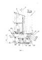
фиг. 1 - общий вид космического аппарата,FIG. 1 - General view of the spacecraft,
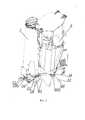
фиг. 2 - фрагмент космического аппарата (вид в аксонометрии, модуль служебных систем условно не показан),FIG. 2 - a fragment of the spacecraft (view in axonometry, the module of service systems is not conventionally shown),
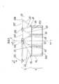
фиг. 3 - силовой каркас космического аппарата (вид в аксонометрии),FIG. 3 - power frame of the spacecraft (view in axonometry),
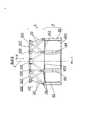
фиг. 4 - силовой каркас космического аппарата (вид А с фиг. 3),FIG. 4 - power frame of the spacecraft (view A from Fig. 3),
фиг. 5 - силовой каркас космического аппарата (вид Б с фиг. 3),FIG. 5 - power frame of the spacecraft (view B from Fig. 3),
фиг. 6 - силовой каркас космического аппарата (вид В с фиг. 4),FIG. 6 - power frame of the spacecraft (view B from Fig. 4),
фиг. 7 - силовой каркас модуля служебных систем с плоской фермой (вид в аксонометрии),FIG. 7 - power frame module service systems with a flat truss (view in axonometric view),
фиг. 8 - узел установки антенны радиосвязи на шестом опорном узле верхнего пояса фермы в аксонометрии,FIG. 8 - node installation of a radio antenna on the sixth reference node of the upper belt of the farm in a perspective view,
фиг. 9 - узел установки антенны радиосвязи на раскосе фермы (антенна зафиксирована на первом опорном узле верхнего пояса фермы),FIG. 9 - the installation site of the radio communication antenna on the diagonal of the farm (the antenna is fixed on the first reference node of the upper belt of the farm),
фиг. 10 - узел установки антенны радиосвязи на раскосе фермы (антенна в разложенном положении),FIG. 10 - site installation of a radio communication antenna on the diagonal of the farm (antenna in the unfolded position),
фиг. 11 - панель с гироскопическими приборами (вид в аксонометрии снаружи фермы),FIG. 11 - panel with gyroscopic devices (view in perspective of the outside of the farm),
фиг. 12 - панель с гироскопическими приборами (вид в аксонометрии изнутри фермы),FIG. 12 - panel with gyroscopic devices (view in axonometry from the inside of the farm),
фиг. 13 - продольный разрез раскоса плоской фермы,FIG. 13 is a longitudinal section of the brace of a flat truss,
фиг. 14 - узел крепления раскоса плоской фермы и опорного узла нижнего пояса фермы к продольной балке корпуса (фрагмент сечения Д - Д с фиг. 7).FIG. 14 is a mounting unit of a brace of a flat truss and a support node of the lower truss belt to the longitudinal beam of the hull (section D - D from Fig. 7).
В приведенных материалах обозначено:The following materials indicate:
1 продольная ось космического аппарата,1 longitudinal axis of the spacecraft,
2 первая поперечная ось космического аппарата,2 the first transverse axis of the spacecraft,
3 вторая поперечная ось космического аппарата,3 second transverse axis of the spacecraft,
4 модуль служебных систем,4 module of service systems,
41-44 продольные стойки корпуса,41-44 longitudinal racks of the body,
441 - фланец верхнего конца продольной стойки 44 корпуса,441 - flange of the upper end of the
45 боковая панель корпуса,45 side panel of the case,
451 верхний поперечный элемент корпуса,451 upper transverse housing element,
452 нижний поперечный элемент корпуса,452 lower transverse element of the housing,
46 топливный бак,46 fuel tank,
47 привод солнечной батареи,47 solar drive,
48 пилон,48 pylon
49 блок двигателей малой тяги,49 thruster block,
5 ферма,5 farm
6 телескоп с большей массой,6 telescope with a larger mass,
7 телескоп с меньшей массой,7 telescope with less mass,
10 верхний пояс фермы,10 top farm belt,
101-106 опорные узлы верхнего пояса фермы,101-106 support nodes of the upper belt of the farm,
107 основные стержни верхнего пояса фермы,107 main rods of the upper belt of the farm,
108-109 дополнительные стержни верхнего пояса фермы,108-109 additional rods of the upper belt of the farm,
11, 13 антенны радиосвязи,11, 13 radio communication antennas,
12, 14 кронштейны антенн радиосвязи,12, 14 brackets of radio communication antennas,
15 платформа прецизионных приборов,15 platform of precision instruments,
16 блок прецизионного гироскопического прибора,16 block precision gyroscopic device,
17 стержни платформы гироскопических приборов,17 rods of the platform of gyroscopic instruments,
18-20 опорные узлы нижнего пояса фермы,18-20 support nodes of the lower farm belt,
21-23 раскосы фермы,21-23 farm braces,
24 штанга плоской фермы,24 bar flat truss,
25 раскос плоской фермы,25 brace of a flat farm,
26 стяжка плоской фермы,26 screed flat farm,
27 дополнительный раскос плоской фермы,27 additional brace flat farm,
28 труба стержневого элемента плоской фермы,28 pipe truss element flat farm,
29 законцовка стержневого элемента плоской фермы,29 the ending of the core element of a flat truss,
30 шарнирный подшипник,30 spherical plain bearing
31 болт разъемного соединения опорного узла нижнего пояса фермы и фланца верхнего конца продольной балки корпуса.31 bolt of detachable connection of the support node of the lower truss belt and the flange of the upper end of the longitudinal beam of the housing.
Без ограничения общности при последующем изложении условимся терминами «внешний», «наружный», «внутренний» обозначать элементы, расположенные в поперечной плоскости космического аппарата - плоскости, перпендикулярной продольной оси 1 переходного отсека, дальше или ближе от продольной оси 1 космического аппарата в радиальном направлении, или поверхности, ориентированные в сторону от продольной оси 1 переходного отсека или в сторону к продольной оси 1 космического аппарата. Кроме того, термины «выше», «ниже», «сверху», «снизу», «верхний торец», «нижний торец», «верхняя сторона», «нижняя сторона» условимся трактовать в соответствии с расположением элементов относительно положительного направления продольной оси 1 космического аппарата (ось X, фиг. 4, Космический аппарат устроен следующим образом.Without loss of generality, in the following presentation, we will agree with the terms “external”, “external”, and “internal” to denote elements located in the transverse plane of the spacecraft — the plane perpendicular to the
Космический аппарат содержит полезную нагрузку, модуль служебных систем 4 и ферму 5 (см. фиг. 1-3).The spacecraft contains a payload, a
Полезная нагрузка включает два телескопа 6 и 7 с различными массами и габаритами. В наиболее предпочтительном варианте использования космического аппарата полезная нагрузка может включать телескоп рентгеновского диапазона массой от 700 до 850 кг и поперечным габаритным размером от 2000 до 2200 мм и телескоп гамма-диапазона массой 300 … 450 кг и поперечным габаритным размером от 1000 до 1200 мм. Телескопы 6 и 7 установлены на верхнем поясе 10 фермы 5.The payload includes two
Как и ближайший аналог, модуль служебных систем 4 включает корпус (см. фиг. 3-5), выполненный в виде правильной прямой восьмигранной призмы (см. фиг. 1). Силовой каркас модуля служебных систем 4 содержит восемь продольных стоек, пропущенных вдоль ребер призмы корпуса и поперечные силовые элементы 451, 452. Две продольные стойки 41, две стойки 42, две стойки 43 и две стойки 44 размещены друг относительно друга симметрично относительно первой поперечной оси 2 космического аппарата (см. фиг. 3, 7). Концы продольных стоек соединены поперечными силовыми элементами 451, 452. Верхние концы продольных стоек 41-44 корпуса выполнены в виде фланцев, как показано на фиг. 7, 14.Like the closest analogue, the
Середины четырех накрест расположенных поперечных силовых элементов совмещены с первой и второй поперечными осями космического аппарата: середины двух противоположно расположенных поперечных силовых элементов, соединяющих концы двух продольных стоек 41 и двух продольных стоек 44, совмещены с первой 2 поперечной осью космического аппарата, а середины двух противоположно расположенных поперечных силовых элементов, соединяющих концы продольных стоек 42 и 43, совмещены со второй 3 поперечной осью космического аппарата.The midpoints of the four transverse transverse force elements aligned are aligned with the first and second transverse axes of the spacecraft: the midpoints of the two opposing transverse force elements connecting the ends of two
Пролеты между продольными стойками силового каркаса корпуса перекрыты боковыми панелями 45. На боковых панелях корпуса могут быть размещены топливный бак 46, привод 47 солнечной батареи, пилон 48. На топливном баке 46 и пилоне 48 могут быть размещены блоки 49 двигателей малой тяги (см. фиг. 1).Spans between the longitudinal struts of the power frame of the body are blocked by
Верхний пояс 10 фермы 5 снабжен шестью опорными узлами 101-106, которые соединены друг с другом основными 107 и двумя дополнительными 108, 109 стержнями (см. фиг. 3 - 6).The
Первый 101 и шестой 106 опорные узлы верхнего пояса фермы совмещены с вершинами дельтоида (см., например, Энциклопедический словарь юного математика, изд. «Педагогика», М., 1989 г., стр. 200,201), расположенными на концах его длинной диагонали. Второй 102 и третий 103 опорные узлы верхнего пояса фермы совмещены с вершинами дельтоида, расположенными на его короткой диагонали. Четвертый 104 и пятый 105 опорные узлы верхнего пояса фермы расположены симметрично относительно его длинной диагонали и совмещены со сторонами дельтоида на одинаковом удалении от шестого 106 опорного узла верхнего пояса фермы. Основные 107 стрежни верхнего пояса фермы пропущены по контуру дельтоида вдоль его сторон и соединяют опорные узлы верхнего пояса фермы.The first 101 and sixth 106 support nodes of the upper belt of the farm are aligned with the vertices of the deltoid (see, for example, the Encyclopedic Dictionary of the Young Mathematician, ed. Pedagogika, M., 1989, pp. 200,201), located at the ends of its long diagonal. The second 102 and third 103 supporting nodes of the upper belt of the farm are aligned with the vertices of the deltoid located on its short diagonal. The fourth 104 and fifth 105 supporting nodes of the upper truss belt are located symmetrically with respect to its long diagonal and are aligned with the sides of the deltoid at the same distance from the sixth 106 supporting node of the upper truss belt. The main 107 rods of the upper farm belt are passed along the deltoid along its sides and connect the supporting nodes of the upper farm belt.
Расстояние между первым 101 и шестым 106 опорными узлами - опорными узлами, размещенными на концах длинной диагонали дельтоида, выбрано большим, а расстояние между вторым 102 и третьим 103 опорными узлами, расположенными на концах короткой диагонали дельтоида, выбрано меньшим расстояния D (см. фиг. 6) между диаметрально противоположно расположенными концами продольных стоек корпуса модуля служебных систем. В наиболее предпочтительном варианте использования изобретения в космическом аппарате, оснащенном двумя телескопами массой от 700 до 850 кг и массой 300...450 кг, расстояние между первым 101 и шестым 106 узлами может быть выбрано на 30 … 35 процентов большим, а расстояние между вторым 102 и третьим 103 опорными узлами верхнего пояса фермы на 20 … 25 процентов меньшим расстояния D между диаметрально противоположно расположенными продольными стойками модуля служебных систем.The distance between the first 101 and sixth 106 support nodes — the support nodes located at the ends of the long deltoid diagonal — is chosen to be large, and the distance between the second 102 and third 103 support nodes located at the ends of the short deltoid diagonal is chosen smaller than the distance D (see Fig. 6) between the diametrically opposite ends of the longitudinal struts of the housing module of the service systems. In the most preferred embodiment of using the invention in a spacecraft equipped with two telescopes weighing from 700 to 850 kg and weighing 300 ... 450 kg, the distance between the first 101 and sixth 106 nodes can be chosen 30 ... 35 percent wide, and the distance between the second 102 and the third 103 supporting nodes of the upper truss belt are 20 ... 25 percent less than the distance D between the diametrically opposed longitudinal racks of the service system module.
В соответствии с заявляемым изобретением длинная диагональ дельтоида ориентирована вдоль первой 2 поперечной оси космического аппарата.In accordance with the claimed invention, the long diagonal of the deltoid is oriented along the first 2 transverse axis of the spacecraft.
В соответствии с заявляемым решением космический аппарат может быть снабжен антеннами радиосвязи 11, 13. Антенны радиосвязи 11 ориентированы вдоль первой 2 поперечной оси космического аппарата - вдоль длинной диагонали дельтоида. Антенны радиосвязи 11 могут быть установлены на кронштейне 12, закрепленном на шестом 106 опорном узле верхнего пояса фермы. Антенны радиосвязи 13, ориентированные параллельно первой поперечной оси космического аппарата, могут быть установлены на кронштейне 14, закрепленном на раскосе фермы в нижней его части вблизи фитинга нижнего пояса фермы. Антенны радиосвязи 13 целесообразно выполнить с возможностью раскладывания. В сложенном положении при этом кронштейн 14 антенн 13 может быть зафиксирован на первом опорном узле 101 верхнего пояса фермы, а в разложенном положении антенны 13 и их кронштейн 14 могут быть ориентированы параллельно первой 2 поперечной оси космического аппарата, как показано на фиг. 10.In accordance with the claimed solution, the spacecraft can be equipped with
Как указывалось выше, опорные узлы 101-106 верхнего пояса фермы соединены друг с другом основными стержнями 107, пропущенными вдоль сторон дельтоида. Два дополнительных стержня 108, 109 размещены в проеме верхнего пояса фермы, причем первый 108 из дополнительных стержней соединен со вторым 102 и третьим 103 опорными узлами, а второй 109 - с четвертым и пятым опорными узлами верхнего пояса фермы.As indicated above, the support nodes 101-106 of the upper truss belt are connected to each other by
В соответствии с заявляемым решением телескоп 6 с большей массой закреплен на первом 101, втором 102 и третьем 103 опорных узлах, а телескоп 7 с меньшей массой - на четвертом 104, пятом 105 и шестом 106 опорных узлах верхнего пояса фермы.In accordance with the claimed solution, a
В наиболее предпочтительном варианте использования изобретения величины углов между стержнями, соединяющими первый 101, второй 102 и третий 103 опорные узлы, и между стержнями при шестом опорном узле могут быть выбраны близкими 60 градусов. При этом телескоп 6 с большей массой (от 700 до 850 кг) целесообразно установить на первый 101, второй 102 и третий 103 опорные узлы верхнего пояса фермы, а второй телескоп 7 с меньшей массой (от 300 до 450 кг) - на четвертый 104, пятый 105 и шестой 106 опорные узлы верхнего пояса 10 фермы.In the most preferred embodiment of the invention, the angles between the rods connecting the first 101, second 102 and third 103 support nodes, and between the rods at the sixth support node can be selected close to 60 degrees. In this case,
Кроме первого 6 и второго 7 телескопов ферма космического аппарата может быть снабжена платформой 15 (см. фиг. 11, 12). Платформу 15 наиболее предпочтительно выполнить в виде плоской панели в форме четырехугольника с подрезанными углами и ориентировать в поперечном направлении. На платформе 15 удобно разместить блок 16 прецизионного гироскопического прибора и некоторые другие блоки аппаратуры. Платформу 15 целесообразно разместить во внутреннем объеме фермы 5 вблизи шестого 106 опорного узла верхнего пояса фермы и стержнями 17 закрепить на четвертом 104, пятом 105 и шестом 106 опорных узлах и втором 109 дополнительном стержне верхнего пояса фермы, как показано на фиг. 11, 12.In addition to the first 6 and second 7 telescopes, the spacecraft farm can be equipped with a platform 15 (see Figs. 11, 12). The
В соответствии с заявляемым решением нижний пояс фермы снабжен восемью опорными узлами 18-20.In accordance with the claimed decision, the lower belt of the farm is equipped with eight support nodes 18-20.
Опорные узлы 18-20 нижнего пояса фермы наиболее предпочтительно выполнить в виде фитингов, как показано на фиг. 2-5, а верхние концы продольных стоек 41-44 корпуса - в виде фланцев 441, как показано на фиг. 3-5, 14. В соответствии с заявляемым решением опорные узлы нижнего пояса фермы жестко закреплены на верхних концах продольных балок 41, 42, 43, 44 корпуса. Наиболее предпочтительно опорные узлы нижнего пояса фермы закрепить на фланцах верхних концов продольных стоек с использованием болтового соединения. Это, например, может быть выполнено, как показано на фиг. 14: во фланце 441 продольной балки 44 корпуса и фитинге опорного узла 18 нижнего пояса фермы выполнены соосные отверстия, причем стержни болтов и указанные отверстия выполнены с допусками, соответствующими скользящей посадке, что обеспечивает минимальные зазоры между стрежнями болтов и фитингами и фланцами, достаточные для ограничения перемещений в поперечном направлении опорных узлов фермы относительно фланцев продольных стоек корпуса.The support nodes 18-20 of the lower truss belt are most preferably configured as fittings, as shown in FIG. 2-5, and the upper ends of the longitudinal struts 41-44 of the body are in the form of
Каждый из шести из опорных узлов 18 нижнего пояса фермы двумя раскосами 23 соединен с двумя опорными узлами верхнего пояса 10 фермы. Каждый из двух оставшихся раскосов 19, 20 одним раскосом 21, 22 соединен с опорными узлами верхнего пояса фермы (см. фиг. 2, 3, 4).Each of six of the supporting
В соответствии с заявляемым решением наиболее предпочтительно опорные узлы 19, 20, которые одним раскосом соединены с опорными узлами верхнего пояса фермы, разместить симметрично относительно первой 2 поперечной оси космического аппарата со смещением от второй 3 поперечной оси космического аппарата в сторону первого 101 опорного узла верхнего пояса фермы. Как показано на фиг. 2, 3, 4, первый 19 из указанных опорных узлов раскосом 21 соединен со вторым опорным узлом 102, второй 20 - раскосом 22 соединен с третьим 103 опорным узлом верхнего пояса фермы.In accordance with the claimed solution, it is most preferable that the
В соответствии с заявляемым решением модуль служебных систем дополнительно снабжен плоской фермой (см. фиг. 7), стержни которой соединены с верхними концами продольных стоек 41-44 корпуса.In accordance with the claimed solution, the service system module is additionally equipped with a flat truss (see Fig. 7), the rods of which are connected to the upper ends of the longitudinal struts 41-44 of the housing.
В соответствии с заявляемым решением плоская ферма может содержать штангу 24, раскосы 25 и стяжки 26 (см. фиг. 7). В наиболее предпочтительном варианте использования изобретения, как показано на фиг. 3, 6, 7, штанга 24 плоской фермы соединена с концами продольных стоек 43 корпуса, размещенных симметрично относительно первой 2 поперечной оси космического аппарата. Каждая из продольных стоек 43 корпуса дополнительно соединена с первыми концами стяжек 26 плоской фермы. Первые концы раскосов 25 плоской фермы соединены со штангой вблизи ее середины. Вторые концы раскосов 25 и стяжек 26 закреплены на концах продольных стоек корпуса, расположенных симметрично относительно второй 3 поперечной оси модуля: вторые концы стяжек 26 соединены с продольными стойками 41, раскосы 25 - с продольными стоками 44.In accordance with the claimed solution, a flat truss may contain a
Кроме того, плоская ферма включает, по крайней мере, один дополнительный раскос 27, первый конец которого соединен со штангой вблизи ее середины, а второй конец соединен со вторым концом одной из продольных стоек корпуса 41. В наиболее предпочтительном варианте использования изобретения при креплении на ферме телескопа 6 массой от 700 до 850 кг и телескопа 7 массой 300 … 450 кг плоскую ферму модуля служебных систем допустимо комплектовать одним дополнительным раскосом 27, в случае крепления на ферме более массивных полезных нагрузок в конструкции фермы необходимо использовать два дополнительных раскоса 27.In addition, the flat truss includes at least one
Соединение штанги 24, раскосов 25, дополнительных раскосов 27 и стяжек 26 плоской фермы с концами продольных стоек корпуса и крепление раскосов 25 и дополнительных раскосов 27 со штангой может быть выполнено с использованием соединения «ухо - вилка» (см. фиг. 13, 14). Раскосы 25, дополнительные раскосы 27 и стяжки 26 плоской фермы целесообразно выполнить регулируемой длины. Как показано, например, на фиг. 13 раскос 25 плоской фермы в средней части выполнен в виде трубы 28, концы которой соединены резьбовым соединением с законцовками 29, причем направление резьбы на разных концах трубы выбрано противоположным.The connection of the
В соответствии с заявляемым решением узлы соединения раскосов 25, дополнительных раскосов 27 к штанге 24 и к продольным стойками 41, 43, 44, а также стяжек 26 к продольным стойкам 41, 43 снабжены шарнирными подшипниками 30 (ГОСТ 3635-78).In accordance with the claimed solution, the connection points of the
Заявляемое устройство космического аппарата работает следующим образом.The inventive device of the spacecraft operates as follows.
При выведении космического аппарата на ОИСЗ поперечная и продольная нагрузки от телескопов передаются на опорные узлы верхнего пояса фермы. Далее преимущественно растяжением-сжатием основных и дополнительных элементов фермы нагрузка передается верхнему поясу модуля служебных систем. Ввиду того что периферийные стержни фермы имеют большой наклон по отношению к продольной оси, на стыке фермы и модуля служебных систем помимо продольных усилий, воспринимаемых сжатием продольных силовых элементов модуля, возникают распорные силы, которые ввиду нежесткости верхнего пояса восьмигранника модуля воспринимаются плоской фермой, расположенной в плоскости верхнего стыка модуля. Таким образом, обеспечивается прочность и жесткость всей силовой схемы космического аппарата.When the spacecraft is launched to the OIZZ, the transverse and longitudinal loads from the telescopes are transmitted to the supporting nodes of the upper belt of the farm. Further, mainly by tension-compression of the main and additional elements of the farm, the load is transferred to the upper belt of the service systems module. Due to the fact that the peripheral rods of the truss have a large inclination with respect to the longitudinal axis, at the junction of the truss and the service system module, in addition to the longitudinal forces perceived by the compression of the longitudinal power elements of the module, spacer forces arise, which, due to the nonrigidity of the upper belt of the octahedron of the module, are perceived by a flat truss located in plane of the top junction of the module. Thus, the strength and rigidity of the entire power circuit of the spacecraft is ensured.
Claims (27)
Translated fromRussianPriority Applications (1)
| Application Number | Priority Date | Filing Date | Title |
|---|---|---|---|
| RU2017136070ARU2673447C9 (en) | 2017-10-11 | 2017-10-11 | Space vehicle |
Applications Claiming Priority (1)
| Application Number | Priority Date | Filing Date | Title |
|---|---|---|---|
| RU2017136070ARU2673447C9 (en) | 2017-10-11 | 2017-10-11 | Space vehicle |
Publications (2)
| Publication Number | Publication Date |
|---|---|
| RU2673447C1 RU2673447C1 (en) | 2018-11-26 |
| RU2673447C9true RU2673447C9 (en) | 2019-01-09 |
Family
ID=64556428
Family Applications (1)
| Application Number | Title | Priority Date | Filing Date |
|---|---|---|---|
| RU2017136070ARU2673447C9 (en) | 2017-10-11 | 2017-10-11 | Space vehicle |
Country Status (1)
| Country | Link |
|---|---|
| RU (1) | RU2673447C9 (en) |
Cited By (1)
| Publication number | Priority date | Publication date | Assignee | Title |
|---|---|---|---|---|
| RU2775570C2 (en)* | 2020-12-22 | 2022-07-04 | Акционерное общество "Научно-производственное объединение им. С.А. Лавочкина" | Truss |
Families Citing this family (2)
| Publication number | Priority date | Publication date | Assignee | Title |
|---|---|---|---|---|
| CN110289477B (en)* | 2019-07-26 | 2024-05-24 | 中国电子科技集团公司第五十四研究所 | Antenna auxiliary face back frame with single-layer space structure and inner and outer edge number of 1 to 2 and manufacturing method |
| CN111463546B (en)* | 2020-05-18 | 2025-03-25 | 中国科学院国家天文台 | A FAST reflector unit adaptive connection mechanism replacement force system conversion tool |
Citations (4)
| Publication number | Priority date | Publication date | Assignee | Title |
|---|---|---|---|---|
| WO1986001484A1 (en)* | 1984-08-29 | 1986-03-13 | Scott Science & Technology, Inc. | Satelite transfer vehicle |
| US5848767A (en)* | 1996-08-05 | 1998-12-15 | The Boeing Company | One piece spacecraft frame |
| RU159980U1 (en)* | 2015-07-01 | 2016-02-27 | Федеральное государственное унитарное предприятие "Научно-производственное объединение им. С.А. Лавочкина" | SPACE VEHICLE |
| RU2617162C1 (en)* | 2016-01-18 | 2017-04-21 | Федеральное государственное унитарное предприятие "Научно-производственное объединение им. С.А. Лавочкина" | Spacecraft, its payload module and service system module |
- 2017
- 2017-10-11RURU2017136070Apatent/RU2673447C9/enactive
Patent Citations (4)
| Publication number | Priority date | Publication date | Assignee | Title |
|---|---|---|---|---|
| WO1986001484A1 (en)* | 1984-08-29 | 1986-03-13 | Scott Science & Technology, Inc. | Satelite transfer vehicle |
| US5848767A (en)* | 1996-08-05 | 1998-12-15 | The Boeing Company | One piece spacecraft frame |
| RU159980U1 (en)* | 2015-07-01 | 2016-02-27 | Федеральное государственное унитарное предприятие "Научно-производственное объединение им. С.А. Лавочкина" | SPACE VEHICLE |
| RU2617162C1 (en)* | 2016-01-18 | 2017-04-21 | Федеральное государственное унитарное предприятие "Научно-производственное объединение им. С.А. Лавочкина" | Spacecraft, its payload module and service system module |
Cited By (2)
| Publication number | Priority date | Publication date | Assignee | Title |
|---|---|---|---|---|
| RU2775570C2 (en)* | 2020-12-22 | 2022-07-04 | Акционерное общество "Научно-производственное объединение им. С.А. Лавочкина" | Truss |
| RU2846483C1 (en)* | 2024-12-13 | 2025-09-05 | Акционерное общество "Информационные спутниковые системы" имени академика М.Ф. Решетнёва" | Method of adjusting joint between abutting parts of statically indeterminate mechanical system (versions) |
Also Published As
| Publication number | Publication date |
|---|---|
| RU2673447C1 (en) | 2018-11-26 |
Similar Documents
| Publication | Publication Date | Title |
|---|---|---|
| RU2617162C1 (en) | Spacecraft, its payload module and service system module | |
| CN100575191C (en) | A New Type of Spacecraft Main Bearing Structure | |
| EP3356873B1 (en) | High-stiffness structure for larger aperture telescope | |
| CN109301452B (en) | S/X/Ka triaxial antenna | |
| Hedgepeth | Critical requirements for the design of large space structures | |
| RU2725824C1 (en) | Device for group launch of satellites and reinforced frame | |
| BR112020022592A2 (en) | concept of efficient satellite structure for multiple stacking or single launches | |
| EP3290344B1 (en) | Toroidal support structures | |
| CN112977882A (en) | High orbit satellite platform structure with central force bearing cylinder type storage boxes tiled in parallel | |
| JPS61268600A (en) | Method of controlling space craft capable of selecting two flight mode and attitude thereof | |
| RU2673447C9 (en) | Space vehicle | |
| CN104638381B (en) | The decile reflecting surface unit of FAST radio telescopes space five | |
| CN109573101A (en) | A Truss Type Fully Flexible Spacecraft Structural Platform | |
| CN112298607B (en) | A Modular Satellite Platform for High Agility and Mobility | |
| RU148483U1 (en) | ADAPTER FOR LATERAL REMOVAL OF USEFUL LOADS, POWER FARM AND SUPPORT UNIT FOR POWER FARM | |
| Shore et al. | A new generation of deployable optics for Earth observation using small satellites | |
| RU2661631C1 (en) | Carrier rocket transfer compartment and its supporting frame | |
| Bush et al. | Design and fabrication of an erectable truss for precision segmentedreflector application | |
| RU2758656C1 (en) | Spacecraft for delivering payload to space body with small gravitational field | |
| RU2617018C1 (en) | Service system module | |
| RU2340516C1 (en) | Upper-stage rocket and strong ring (2 versions) | |
| RU2624959C1 (en) | Adapter for way loose of useful load | |
| RU2621221C1 (en) | Service system module | |
| RU2603872C1 (en) | Transfer compartment of carrier rocket (versions) | |
| RU159980U1 (en) | SPACE VEHICLE |
Legal Events
| Date | Code | Title | Description |
|---|---|---|---|
| TH4A | Reissue of patent specification | ||
| TK4A | Correction to the publication in the bulletin (patent) | Free format text:CORRECTION TO CHAPTER -FG4A- IN JOURNAL 33-2018 FOR INID CODE(S) (72) |