RU2670699C9 - Control features for motorised surgical stapling instrument - Google Patents
Control features for motorised surgical stapling instrumentDownload PDFInfo
- Publication number
- RU2670699C9 RU2670699C9RU2016115750ARU2016115750ARU2670699C9RU 2670699 C9RU2670699 C9RU 2670699C9RU 2016115750 ARU2016115750 ARU 2016115750ARU 2016115750 ARU2016115750 ARU 2016115750ARU 2670699 C9RU2670699 C9RU 2670699C9
- Authority
- RU
- Russia
- Prior art keywords
- trigger
- switch
- assembly
- activator
- engine
- Prior art date
Links
- 230000033001locomotionEffects0.000claimsabstractdescription48
- 230000003213activating effectEffects0.000claimsabstractdescription14
- 230000004044responseEffects0.000claimsabstractdescription12
- 239000012636effectorSubstances0.000claimsabstractdescription10
- 239000004744fabricSubstances0.000claimsdescription16
- 239000004971Cross linkerSubstances0.000claims2
- 238000004891communicationMethods0.000abstractdescription3
- 230000000694effectsEffects0.000abstractdescription2
- 238000010304firingMethods0.000abstract10
- 238000006073displacement reactionMethods0.000abstract2
- 239000003814drugSubstances0.000abstract2
- 239000000126substanceSubstances0.000abstract1
- 239000012190activatorSubstances0.000description149
- 230000004913activationEffects0.000description17
- 238000000034methodMethods0.000description17
- 239000000463materialSubstances0.000description14
- 230000007246mechanismEffects0.000description13
- 230000003872anastomosisEffects0.000description12
- 230000000903blocking effectEffects0.000description12
- 238000005516engineering processMethods0.000description11
- 210000002105tongueAnatomy0.000description8
- 230000005540biological transmissionEffects0.000description6
- 238000013461designMethods0.000description5
- 230000005855radiationEffects0.000description4
- 238000012546transferMethods0.000description4
- 238000004140cleaningMethods0.000description3
- 238000005520cutting processMethods0.000description3
- 230000000994depressogenic effectEffects0.000description3
- 238000002224dissectionMethods0.000description3
- 230000014509gene expressionEffects0.000description3
- 238000012986modificationMethods0.000description3
- 230000004048modificationEffects0.000description3
- 238000011084recoveryMethods0.000description3
- 230000007704transitionEffects0.000description3
- 235000014676Phragmites communisNutrition0.000description2
- 230000000712assemblyEffects0.000description2
- 238000000429assemblyMethods0.000description2
- 238000005452bendingMethods0.000description2
- 238000010276constructionMethods0.000description2
- 230000007423decreaseEffects0.000description2
- 238000009826distributionMethods0.000description2
- 239000012634fragmentSubstances0.000description2
- 230000003993interactionEffects0.000description2
- 238000003825pressingMethods0.000description2
- 230000001960triggered effectEffects0.000description2
- 230000000007visual effectEffects0.000description2
- 241000894006BacteriaSpecies0.000description1
- IAYPIBMASNFSPL-UHFFFAOYSA-NEthylene oxideChemical compoundC1CO1IAYPIBMASNFSPL-UHFFFAOYSA-N0.000description1
- 239000004775TyvekSubstances0.000description1
- 229920000690TyvekPolymers0.000description1
- 239000000853adhesiveSubstances0.000description1
- 230000001070adhesive effectEffects0.000description1
- 239000002390adhesive tapeSubstances0.000description1
- 230000004323axial lengthEffects0.000description1
- 230000008901benefitEffects0.000description1
- 230000006835compressionEffects0.000description1
- 238000007906compressionMethods0.000description1
- 238000004132cross linkingMethods0.000description1
- 210000003238esophagusAnatomy0.000description1
- 230000004907fluxEffects0.000description1
- 210000001035gastrointestinal tractAnatomy0.000description1
- 230000006698inductionEffects0.000description1
- 238000003780insertionMethods0.000description1
- 230000037431insertionEffects0.000description1
- 238000009434installationMethods0.000description1
- 238000009940knittingMethods0.000description1
- 239000002184metalSubstances0.000description1
- 230000003287optical effectEffects0.000description1
- 230000008569processEffects0.000description1
- 230000007420reactivationEffects0.000description1
- 239000012858resilient materialSubstances0.000description1
- 238000000926separation methodMethods0.000description1
- 238000009958sewingMethods0.000description1
- 239000007787solidSubstances0.000description1
- 230000001954sterilising effectEffects0.000description1
- 238000004659sterilization and disinfectionMethods0.000description1
- 238000011477surgical interventionMethods0.000description1
- 210000001835visceraAnatomy0.000description1
Images


Classifications
- A—HUMAN NECESSITIES
- A61—MEDICAL OR VETERINARY SCIENCE; HYGIENE
- A61B—DIAGNOSIS; SURGERY; IDENTIFICATION
- A61B17/00—Surgical instruments, devices or methods
- A61B17/11—Surgical instruments, devices or methods for performing anastomosis; Buttons for anastomosis
- A61B17/115—Staplers for performing anastomosis, e.g. in a single operation
- A—HUMAN NECESSITIES
- A61—MEDICAL OR VETERINARY SCIENCE; HYGIENE
- A61B—DIAGNOSIS; SURGERY; IDENTIFICATION
- A61B17/00—Surgical instruments, devices or methods
- A61B17/068—Surgical staplers, e.g. containing multiple staples or clamps
- A—HUMAN NECESSITIES
- A61—MEDICAL OR VETERINARY SCIENCE; HYGIENE
- A61B—DIAGNOSIS; SURGERY; IDENTIFICATION
- A61B17/00—Surgical instruments, devices or methods
- A61B17/11—Surgical instruments, devices or methods for performing anastomosis; Buttons for anastomosis
- A61B17/115—Staplers for performing anastomosis, e.g. in a single operation
- A61B17/1155—Circular staplers comprising a plurality of staples
- A—HUMAN NECESSITIES
- A61—MEDICAL OR VETERINARY SCIENCE; HYGIENE
- A61B—DIAGNOSIS; SURGERY; IDENTIFICATION
- A61B17/00—Surgical instruments, devices or methods
- A61B2017/00367—Details of actuation of instruments, e.g. relations between pushing buttons, or the like, and activation of the tool, working tip, or the like
- A61B2017/00398—Details of actuation of instruments, e.g. relations between pushing buttons, or the like, and activation of the tool, working tip, or the like using powered actuators, e.g. stepper motors, solenoids
- A—HUMAN NECESSITIES
- A61—MEDICAL OR VETERINARY SCIENCE; HYGIENE
- A61B—DIAGNOSIS; SURGERY; IDENTIFICATION
- A61B17/00—Surgical instruments, devices or methods
- A61B2017/00681—Aspects not otherwise provided for
- A61B2017/00734—Aspects not otherwise provided for battery operated
- A—HUMAN NECESSITIES
- A61—MEDICAL OR VETERINARY SCIENCE; HYGIENE
- A61B—DIAGNOSIS; SURGERY; IDENTIFICATION
- A61B90/00—Instruments, implements or accessories specially adapted for surgery or diagnosis and not covered by any of the groups A61B1/00 - A61B50/00, e.g. for luxation treatment or for protecting wound edges
- A61B90/08—Accessories or related features not otherwise provided for
- A61B2090/0801—Prevention of accidental cutting or pricking
- A61B2090/08021—Prevention of accidental cutting or pricking of the patient or his organs
- A—HUMAN NECESSITIES
- A61—MEDICAL OR VETERINARY SCIENCE; HYGIENE
- A61B—DIAGNOSIS; SURGERY; IDENTIFICATION
- A61B90/00—Instruments, implements or accessories specially adapted for surgery or diagnosis and not covered by any of the groups A61B1/00 - A61B50/00, e.g. for luxation treatment or for protecting wound edges
- A61B90/08—Accessories or related features not otherwise provided for
- A61B2090/0807—Indication means
- A61B2090/0811—Indication means for the position of a particular part of an instrument with respect to the rest of the instrument, e.g. position of the anvil of a stapling instrument
- A—HUMAN NECESSITIES
- A61—MEDICAL OR VETERINARY SCIENCE; HYGIENE
- A61B—DIAGNOSIS; SURGERY; IDENTIFICATION
- A61B90/00—Instruments, implements or accessories specially adapted for surgery or diagnosis and not covered by any of the groups A61B1/00 - A61B50/00, e.g. for luxation treatment or for protecting wound edges
- A61B90/08—Accessories or related features not otherwise provided for
- A61B2090/0814—Preventing re-use
Landscapes
- Health & Medical Sciences (AREA)
- Life Sciences & Earth Sciences (AREA)
- Surgery (AREA)
- Heart & Thoracic Surgery (AREA)
- Engineering & Computer Science (AREA)
- Biomedical Technology (AREA)
- Nuclear Medicine, Radiotherapy & Molecular Imaging (AREA)
- Medical Informatics (AREA)
- Molecular Biology (AREA)
- Animal Behavior & Ethology (AREA)
- General Health & Medical Sciences (AREA)
- Public Health (AREA)
- Veterinary Medicine (AREA)
- Surgical Instruments (AREA)
Abstract
Description
Translated fromRussianПРЕДПОСЫЛКИ СОЗДАНИЯ ИЗОБРЕТЕНИЯBACKGROUND OF THE INVENTION
В некоторых ситуациях хирургу может потребоваться позиционировать хирургический инструмент через отверстие в организме пациента и применять инструмент для регулировки, позиционирования, прикрепления и/или другого взаимодействия с тканью внутри организма пациента. Например, в некоторых хирургических вмешательствах (например, колоректальных, бариатрических, торакотомических и т.д.) части желудочно-кишечного тракта и/или пищевода и т.д. можно рассечь и удалить для устранения нежелательной ткани или по другим причинам. После удаления требуемой ткани может возникнуть необходимость в повторном соединении оставшихся частей вместе посредством анастомоза «конец в конец». Одним таким инструментом для выполнения этих анастомотических процедур является круговой сшивающий инструмент, который вставляют через естественное отверстие в организме пациента. Некоторые круговые сшивающие инструменты выполнены с возможностью по существу одновременного рассекания ткани и сшивания ткани. Например, круговой сшивающий инструмент может отсекать излишек ткани, находящийся внутри кольцевого набора скобок в анастомозе, обеспечивая по существу плавный переход между соединяемыми частями просвета в анастомозе.In some situations, the surgeon may need to position the surgical instrument through an opening in the patient’s body and use a tool to adjust, position, attach and / or otherwise interact with tissue within the patient’s body. For example, in some surgical interventions (for example, colorectal, bariatric, thoracotomy, etc.) parts of the gastrointestinal tract and / or esophagus, etc. can be dissected and removed to eliminate unwanted tissue or for other reasons. After removal of the desired tissue, it may be necessary to reconnect the remaining parts together with an end-to-end anastomosis. One such tool for performing these anastomotic procedures is a circular stapling instrument that is inserted through a natural hole in the patient's body. Some circular stapling instruments are capable of substantially simultaneously dissecting the tissue and stitching the tissue. For example, a circular stapling instrument may cut off excess tissue located within an annular set of brackets in the anastomosis, providing a substantially smooth transition between the connected portions of the lumen in the anastomosis.
Примеры круговых хирургических сшивающих инструментов описаны в патенте США № 5,205,459, озаглавленном «Хирургический сшивающий инструмент для наложения анастомоза», выданном 27 апреля 1993 г.; патенте США № 5,271,544, озаглавленном «Хирургический сшивающий инструмент для наложения анастомоза», выданном 21 декабря 1993 г.; патенте США № 5,275,322, озаглавленном «Хирургический сшивающий инструмент для наложения анастомоза», выданном 4 января 1994 г.; патенте США № 5,285,945, озаглавленном «Хирургический сшивающий инструмент для наложения анастомоза», выданном 15 февраля 1994 г.; патенте США № 5,292,053, озаглавленном «Хирургический сшивающий инструмент для наложения анастомоза», выданном 8 марта 1994 г.; патенте США № 5,333,773, озаглавленном «Хирургический сшивающий инструмент для наложения анастомоза», выданном 2 августа 1994 г.; патенте США № 5,350,104, озаглавленном «Хирургический сшивающий инструмент для наложения анастомоза», выданном 27 сентября 1994 г.; и патенте США № 5,533,661, озаглавленном «Хирургический сшивающий инструмент для наложения анастомоза», выданном 9 июля 1996 г.; и в патентной публикации США № 2012/0292372, озаглавленной «Недорогой узел упора для кругового сшивающего инструмента», опубликованной 22 ноября 2012 г. Описание каждого из приведенных выше патентов США и патентной публикации США включено в настоящий документ путем ссылки. Некоторые такие сшивающие инструменты выполнены с возможностью зажимания слоев ткани, рассечения зажатых слоев ткани и выталкивания скобок через слои ткани, чтобы по существу запечатать рассеченные слои ткани вместе с находящимися рядом рассеченными концами слоев ткани, соединяя таким образом два рассеченных конца анатомического просвета.Examples of circular surgical stapling instruments are described in US Pat. No. 5,205,459, entitled "Surgical Stapling Instrument for Applying an Anastomosis", issued April 27, 1993; US patent No. 5,271,544, entitled "Surgical stapling instrument for applying anastomosis", issued December 21, 1993; US patent No. 5,275,322, entitled "Surgical stapling instrument for applying anastomosis", issued January 4, 1994; US patent No. 5,285,945, entitled "Surgical stapling instrument for applying anastomosis", issued February 15, 1994; US patent No. 5,292,053, entitled "Surgical stapling instrument for applying anastomosis", issued March 8, 1994; US patent No. 5,333,773, entitled "Surgical stapling instrument for applying anastomosis", issued August 2, 1994; US patent No. 5,350,104, entitled "Surgical stapling instrument for applying anastomosis", issued September 27, 1994; and US Pat. No. 5,533,661, entitled "Surgical Stapling Instrument for Anastomosis Applying", issued July 9, 1996; and U.S. Patent Publication No. 2012/0292372, entitled “Inexpensive Stop Assembly for a Circular Stapling Tool,” published November 22, 2012. A description of each of the above US patents and US Patent Publication is incorporated herein by reference. Some of these stapling instruments are capable of clamping tissue layers, dissecting the clamped tissue layers and pushing the brackets through the tissue layers to substantially seal the dissected tissue layers together with the adjacent dissected ends of the tissue layers, thereby connecting the two dissected ends of the anatomical lumen.
Исключительно в качестве других дополнительных примеров приводятся хирургические сшивающие инструменты, описанные в патенте США № 4,805,823, озаглавленном «Конфигурация углублений в сшивающих инструментах для внутренних органов», выданном 21 февраля 1989 г.; патенте США № 5,415,334, озаглавленном «Хирургический сшивающий инструмент и кассета со скобками», выданном 16 мая 1995 г.; патенте США № 5,465,895, озаглавленном «Хирургический сшивающий инструмент», выданном 14 ноября 1995 г.; патенте США № 5,597,107, озаглавленном «Хирургический сшивающий инструмент», выданном 28 января 1997 г.; патенте США № 5,632,432, озаглавленном «Хирургический инструмент», выданном 27 мая 1997 г.; патенте США № 5,673,840, озаглавленном «Хирургический инструмент», выданном 7 октября 1997 г.; патенте США № 5,704,534, озаглавленном «Узел шарнира для хирургических инструментов», выданном 6 января 1998 г.; патенте США № 5,814,055, озаглавленном «Хирургический зажимной механизм», выданном 29 сентября 1998 г.; патенте США № 6,978,921, озаглавленном «Хирургический сшивающий инструмент со встроенным пусковым механизмом с трехрогим элементом», выданном 27 декабря 2005 г.; патенте США № 7,000,818, озаглавленном «Хирургический сшивающий инструмент, имеющий отдельные и отличные друг от друга закрывающую и пусковую системы», выданном 21 февраля 2006 г.; патенте США № 7,143,923, озаглавленном «Хирургический сшивающий инструмент, имеющий пусковую блокировку для незакрытого упора», выданном 5 декабря 2006 г.; патенте США № 7,303,108, озаглавленном «Хирургический сшивающий инструмент со встроенным многотактовым пусковым механизмом с гибкой рейкой», выданном 4 декабря 2007 г.; патенте США № 7,367,485, озаглавленном «Хирургический сшивающий инструмент со встроенным многотактовым пусковым механизмом, имеющим поворотную трансмиссию», выданном 6 мая 2008 г.; патенте США № 7,380,695, озаглавленном «Хирургический сшивающий инструмент, имеющий единственный механизм блокировки для предотвращения пуска», выданном 3 июня 2008 г.; патенте США № 7,380,696, озаглавленном «Шарнирный хирургический сшивающий инструмент со встроенным двухкомпонентным пусковым механизмом с трехрогим элементом», выданном 3 июня 2008 г.; патенте США № 7,404,508, озаглавленном «Хирургическое сшивающее и рассекающее устройство», выданном 29 июля 2008 г.; патенте США № 7,434,715, озаглавленном «Хирургический сшивающий инструмент, имеющий многотактовый пуск с блокировкой открытия», выданном 14 октября 2008 г.; и патенте США № 7,721,930, озаглавленном «Одноразовая кассета с адгезивным составом для использования со сшивающим устройством», выданном 25 мая 2010 г. Описание каждого из процитированных выше патентов США включено в настоящий документ путем ссылки. Хотя упомянутые выше хирургические сшивающие инструменты описаны в связи с применением в эндоскопических процедурах, следует понимать, что такие хирургические сшивающие инструменты также можно применять в открытых процедурах и/или других неэндоскопических процедурах.Surgical stapling instruments described in US Pat. No. 4,805,823, entitled, “Configuration of Recesses in Stapling Instruments for Internal Organs,” issued February 21, 1989, are solely provided as other additional examples. US patent No. 5,415,334, entitled "Surgical stapling instrument and cassette with brackets", issued May 16, 1995; US patent No. 5,465,895, entitled "Surgical stapling instrument", issued November 14, 1995; US patent No. 5,597,107, entitled "Surgical stapling instrument", issued January 28, 1997; US patent No. 5,632,432, entitled "Surgical Instrument", issued May 27, 1997; US patent No. 5,673,840, entitled "Surgical Instrument", issued October 7, 1997; US Patent No. 5,704,534, entitled "Hinge Assembly for Surgical Instruments", issued January 6, 1998; US patent No. 5,814,055, entitled "Surgical clamping mechanism", issued September 29, 1998; US patent No. 6,978,921, entitled "Surgical stapling instrument with an integrated trigger with a three-horned element", issued December 27, 2005; US patent No. 7,000,818, entitled "Surgical stapling instrument having separate and different from each other closing and starting system", issued February 21, 2006; US patent No. 7,143,923, entitled "Surgical stapling instrument having a trigger lock for the open stop", issued December 5, 2006; US patent No. 7,303,108, entitled "Surgical stapling instrument with integrated multi-stroke trigger mechanism with a flexible rail", issued December 4, 2007; US patent No. 7,367,485, entitled "Surgical stapling instrument with a built-in multi-cycle trigger mechanism with a rotary transmission", issued May 6, 2008; US patent No. 7,380,695, entitled "Surgical stapling instrument having a single locking mechanism to prevent starting", issued June 3, 2008; US patent No. 7,380,696, entitled "Hinged surgical stapling instrument with integrated two-component trigger mechanism with a three-horned element", issued June 3, 2008; US patent No. 7,404,508, entitled "Surgical stapling and dissecting device", issued July 29, 2008; US patent No. 7,434,715, entitled "Surgical stapling instrument having multi-stroke start with opening lock", issued October 14, 2008; and US Pat. No. 7,721,930, entitled "Disposable Adhesive Tape Cartridge for Use with a Stapler," issued May 25, 2010. A description of each of the above US patents is incorporated herein by reference. Although the above-mentioned surgical stapling instruments are described in connection with their use in endoscopic procedures, it should be understood that such surgical stapling instruments can also be used in open procedures and / or other non-endoscopic procedures.
Хотя были изготовлены и применялись различные типы хирургических сшивающих инструментов и связанных с ними компонентов, считается, что до изобретателя(-ей) никто не изготовил или не применял изобретение, описанное в приложенной формуле изобретения.Although various types of surgical stapling instruments and related components have been manufactured and used, it is believed that, prior to the inventor (s), no one made or applied the invention described in the attached claims.
КРАТКОЕ ОПИСАНИЕ ЧЕРТЕЖЕЙBRIEF DESCRIPTION OF THE DRAWINGS
Хотя описание ограничивается формулой изобретения, которая подробно показывает и четко заявляет права на эту технологию, считается, что лучшему пониманию данной технологии послужит следующее описание некоторых примеров в сочетании с сопровождающими фигурами, на которых похожие числовые обозначения идентифицируют одинаковые элементы.Although the description is limited by the claims, which show and clearly state the rights to this technology, it is believed that a better understanding of this technology will be provided by the following description of some examples in combination with the accompanying figures, in which like numbers refer to like elements.
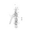
На ФИГ. 1 показан вид сбоку в вертикальной проекции примера кругового хирургического сшивающего инструмента.In FIG. 1 is a side elevational view of an example of a circular surgical stapling instrument.
На ФИГ. 2A показан увеличенный вид в продольном сечении примера узла сшивающей головки инструмента, изображенного на ФИГ. 1, на котором пример упора показан в открытом положении.In FIG. 2A is an enlarged longitudinal sectional view of an example of the staple head assembly of the tool of FIG. 1, in which an example of a stop is shown in the open position.
На ФИГ. 2B показан увеличенный вид в продольном сечении узла сшивающей головки, изображенного на ФИГ. 2A, на котором упор показан в закрытом положении.In FIG. 2B is an enlarged longitudinal sectional view of the staple head assembly shown in FIG. 2A, wherein the emphasis is shown in the closed position.
На ФИГ. 2C показан увеличенный вид в продольном сечении узла сшивающей головки, изображенного на ФИГ. 2A, на котором примеры выталкивателя скобок и лезвия показаны в активированном положении.In FIG. 2C is an enlarged longitudinal sectional view of the staple head assembly shown in FIG. 2A, in which examples of the ejector brackets and blades are shown in the activated position.
На ФИГ. 3 показан увеличенный частичный вид в поперечном сечении примера скобки, образованной об упор.In FIG. 3 shows an enlarged partial cross-sectional view of an example of a bracket formed about an abutment.
На ФИГ. 4A показан увеличенный вид сбоку в вертикальной проекции примера узла рукоятки активатора хирургического инструмента, изображенного на ФИГ. 1, с удаленным участком корпуса, на котором спусковой механизм показан в неактивированном положении, а блокирующий элемент показан в заблокированном положении.In FIG. 4A is an enlarged side elevational view of an example of an activator handle assembly of a surgical instrument shown in FIG. 1, with a removed portion of the housing in which the trigger is shown in an inactive position and the blocking element is shown in a locked position.
На ФИГ. 4B показан увеличенный вид сбоку в вертикальной проекции узла рукоятки активатора, изображенного ФИГ. 4A, на котором спусковой механизм показан в активированном положении, а блокирующий элемент показан в незаблокированном положении.In FIG. 4B is an enlarged side elevational view of the activator handle assembly of FIG. 4A, in which the trigger is shown in the activated position and the locking element is shown in the unlocked position.
На ФИГ. 5 показан увеличенный частичный вид в перспективе примера узла индикатора хирургического инструмента, изображенного на ФИГ. 1, на котором показаны окошко индикатора и рычаг индикатора.In FIG. 5 shows an enlarged partial perspective view of an example of an indicator assembly of the surgical instrument shown in FIG. 1, which shows the indicator window and the indicator lever.
На ФИГ. 6 показан схематичный вид окошка индикатора, изображенного на ФИГ. 5, на котором показан пример планки индикатора и примеры представлений соответствующих скобок.In FIG. 6 is a schematic view of an indicator window shown in FIG. 5, which shows an example of an indicator bar and examples of representations of respective brackets.
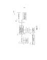
На ФИГ. 7 показан схематичный вид примера системы управления, адаптированной для встраивания в круговой хирургический сшивающий инструмент, изображенный на ФИГ. 1.In FIG. 7 is a schematic view of an example control system adapted for embedding in the circular surgical stapling instrument of FIG. one.
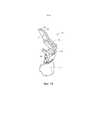
На ФИГ. 8 показан вид сбоку в вертикальной проекции внутреннего устройства примера рукоятки, содержащей систему управления, изображенную на ФИГ. 7.In FIG. 8 is a side elevational view of an internal device of an example handle containing the control system shown in FIG. 7.
На ФИГ. 9 показан вид снизу с пространственным разделением компонентов системы управления, изображенной на ФИГ. 7.In FIG. 9 shows a bottom view with a spatial separation of the components of the control system shown in FIG. 7.
На ФИГ. 10 показан вид сверху в перспективе пускового крючка системы управления, изображенной на ФИГ. 7.In FIG. 10 is a top perspective view of the trigger of the control system shown in FIG. 7.
На ФИГ. 11 показан вид сверху в перспективе челнока системы управления, изображенной на ФИГ. 7.In FIG. 11 is a top perspective view of a shuttle of the control system shown in FIG. 7.
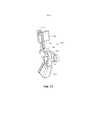
На ФИГ. 12 показан вид снизу в перспективе корпуса переключателя системы управления, изображенной на ФИГ. 7.In FIG. 12 is a bottom perspective view of a switch housing of the control system shown in FIG. 7.
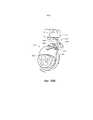
На ФИГ. 13A показан увеличенный вид сбоку рукоятки, изображенной на ФИГ. 8, с пусковым крючком в неактивированном состоянии.In FIG. 13A is an enlarged side view of the handle of FIG. 8, with a trigger in an inactive state.
На ФИГ. 13B показан увеличенный вид сбоку рукоятки, изображенной на ФИГ. 8, с высвобожденным предохранительным крючком и пусковым крючком в неактивированном состоянии.In FIG. 13B is an enlarged side view of the handle of FIG. 8, with the safety hook released and the trigger in the inactive state.
На ФИГ. 13C показан увеличенный вид сбоку рукоятки, изображенной на ФИГ. 8, с пусковым крючком в активированном состоянии и выдвинутым челноком.In FIG. 13C is an enlarged side view of the handle of FIG. 8, with the trigger hook in the activated state and the shuttle extended.
На ФИГ. 14 показан схематический вид переключателей системы управления, изображенной на ФИГ. 7, в неактивированном состоянии.In FIG. 14 is a schematic view of the switches of the control system shown in FIG. 7, in an inactive state.
На ФИГ. 15 показан схематический вид переключателей системы управления, изображенной на ФИГ. 7, в пусковом состоянии.In FIG. 15 is a schematic view of the switches of the control system shown in FIG. 7, in starting state.
На ФИГ. 16 показан схематический вид переключателей системы управления, изображенной на ФИГ. 7, в состоянии после использования устройства.In FIG. 16 is a schematic view of the switches of the control system shown in FIG. 7, able after using the device.
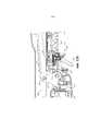
На ФИГ. 17 показан вид сбоку в вертикальной проекции примера кругового хирургического сшивающего инструмента со снятыми половиной корпуса и аккумуляторной батареей.In FIG. 17 is a side elevational view of an example of a circular surgical stapling instrument with half of the body and battery removed.
На ФИГ. 18 показан вид в перспективе скобы индикатора инструмента, изображенного на ФИГ. 17.In FIG. 18 is a perspective view of a staple of the indicator of the tool shown in FIG. 17.
На ФИГ. 19 показан вид в перспективе узла предохранительного крючка инструмента, изображенного на ФИГ. 17.In FIG. 19 is a perspective view of the safety hook assembly of the tool of FIG. 17.
На ФИГ. 20 показан вид в перспективе узла пускового крючка инструмента, изображенного на ФИГ. 17.In FIG. 20 is a perspective view of the trigger assembly of the tool of FIG. 17.
На ФИГ. 21 показан вид в перспективе участка узла пускового крючка, изображенного на ФИГ. 20, с вращательным активатором и пластинчатой пружиной.In FIG. 21 is a perspective view of a portion of a trigger hook assembly of FIG. 20, with a rotary activator and leaf spring.
На ФИГ. 22 показан вид в перспективе вращательного активатора, изображенного на ФИГ. 21.In FIG. 22 is a perspective view of the rotational activator shown in FIG. 21.
На ФИГ. 23А показан вид в перспективе узла предохранительного крючка, изображенного на ФИГ. 19, и узла пускового крючка, изображенный на ФИГ. 20, с предохранительным крючком в заблокированном положении.In FIG. 23A is a perspective view of the safety hook assembly of FIG. 19, and the trigger assembly shown in FIG. 20, with a safety hook in the locked position.
На ФИГ. 23В показан вид в перспективе узла предохранительного крючка, изображенного на ФИГ. 19, и узла пускового крючка, изображенного на ФИГ. 20, с предохранительным крючком в незаблокированном положении и узлом пускового крючка в неактивированном состоянии.In FIG. 23B is a perspective view of the safety hook assembly of FIG. 19, and the trigger assembly shown in FIG. 20, with the safety hook in the unlocked position and the trigger assembly in the inactive state.
На ФИГ. 23С показан вид в перспективе узла предохранительного крючка, изображенного на ФИГ. 19, и узла пускового крючка, изображенного на ФИГ. 20, с предохранительным крючком в незаблокированном положении и узлом пускового крючка в активированном состоянии.In FIG. 23C is a perspective view of the safety hook assembly of FIG. 19, and the trigger assembly shown in FIG. 20, with the safety hook in the unlocked position and the trigger assembly in the activated state.
На ФИГ. 24A показан вид сверху в вертикальной проекции узла, изображенного на ФИГ. 21, на котором пусковой крючок находится в неактивированном состоянии.In FIG. 24A is a top plan view of the assembly of FIG. 21, on which the trigger is in an inactive state.
На ФИГ. 24B показан вид сбоку в вертикальной проекции узла, изображенного на ФИГ. 21, с пусковым крючком в активированном состоянии и вращательным активатором в частично активированном состоянии.In FIG. 24B is a side elevational view of the assembly of FIG. 21, with a trigger in an activated state and a rotary activator in a partially activated state.
На ФИГ. 24С показан вид сбоку в вертикальной проекции узла, изображенного на ФИГ. 21, с пусковым крючком в активированном состоянии и вращательным активатором в полностью активированном состоянии.In FIG. 24C is a side elevational view of the assembly of FIG. 21, with a trigger in an activated state and a rotary activator in a fully activated state.
На ФИГ. 25 показан вид сбоку в вертикальной проекции узла стопорного переключателя инструмента, изображенного на ФИГ. 17.In FIG. 25 is a side elevational view of the tool stop switch assembly of FIG. 17.
На ФИГ. 26 показан вид в перспективе кулачкового элемента узла стопорного переключателя, изображенного на ФИГ. 25.In FIG. 26 is a perspective view of a cam member of the lock switch assembly shown in FIG. 25.
На ФИГ. 27 показан вид в перспективе шатунного элемента узла стопорного переключателя, изображенного на ФИГ. 25.In FIG. 27 is a perspective view of a connecting rod member of the lock switch assembly shown in FIG. 25.
На ФИГ. 28A показан вид в перспективе узла стопорного переключателя, изображенного на ФИГ. 25, в состоянии перед запуском.In FIG. 28A is a perspective view of the lock switch assembly shown in FIG. 25, in a state before starting.
На ФИГ. 28B представлен вид в перспективе узла стопорного переключателя, изображенного на ФИГ. 25, в активированном состоянии.In FIG. 28B is a perspective view of the lock switch assembly shown in FIG. 25, in the activated state.
Предполагается, что фигуры не являются ограничивающими каким-либо образом, и считается, что различные варианты осуществления технологии можно реализовать множеством других способов, включая те, которые необязательно показаны на фигурах. Прилагаемые фигуры, включенные в спецификацию и формирующие ее часть, иллюстрируют несколько аспектов данной технологии и вместе с описанием служат для объяснения принципов технологии; при этом понимается, что эта технология не ограничивается конкретными изображенными конструкциями.It is assumed that the figures are not limiting in any way, and it is believed that various embodiments of the technology can be implemented in many other ways, including those that are not necessarily shown in the figures. The attached figures, included in the specification and forming its part, illustrate several aspects of this technology and, together with the description, serve to explain the principles of the technology; it is understood that this technology is not limited to the particular structures depicted.
ПОДРОБНОЕ ОПИСАНИЕ ИЗОБРЕТЕНИЯDETAILED DESCRIPTION OF THE INVENTION
Следующее описание некоторых примеров технологии не следует использовать для ограничения объема настоящего изобретения. Другие примеры, элементы, аспекты, варианты осуществления и преимущества технологии станут понятны специалистам в данной области из следующего описания, в котором для целей иллюстрации предложен один из лучших способов реализации технологии. После реализации технология, описанная в настоящем документе, может иметь другие разные и очевидные аспекты, все из которых не выходят за рамки технологии. Соответственно, фигуры и описания следует рассматривать как иллюстративные по своей сути и не имеющие ограничительного характера.The following description of some examples of technology should not be used to limit the scope of the present invention. Other examples, elements, aspects, embodiments and advantages of the technology will become apparent to those skilled in the art from the following description, in which, for purposes of illustration, one of the best methods for implementing the technology is proposed. Once implemented, the technology described in this document may have other different and obvious aspects, all of which are not outside the scope of the technology. Accordingly, figures and descriptions should be considered as illustrative in nature and not restrictive.
I. Обзор примера кругового хирургического сшивающего инструментаI. Overview of an example of a circular surgical stapling instrument
На ФИГ. 1–6 представлен пример кругового хирургического сшивающего инструмента (10), имеющего узел (20) сшивающей головки, узел (60) ствола и узел (70) рукоятки активатора, каждый из которых описан более подробно ниже. Узел (60) ствола проходит дистально от узла (70) рукоятки активатора, и узел (20) сшивающей головки соединен с дистальным концом узла (60) ствола. Вкратце, узел (70) рукоятки активатора выполнен с возможностью приведения в действие выталкивателя (24) скобок узла (20) сшивающей головки для выталкивания множества скобок (66) за пределы узла (20) сшивающей головки. Скобки (66) сгибаются с образованием готовых скобок упором (40), который прикреплен к дистальному концу инструмента (10). Таким образом, ткань (2), изображенную на ФИГ. 2A–2C, можно сшить с использованием инструмента (10).In FIG. Figures 1-6 show an example of a circular surgical stapling instrument (10) having a staple head assembly (20), a trunk assembly (60) and an activator handle assembly (70), each of which is described in more detail below. The shaft assembly (60) extends distally from the activator handle assembly (70), and the stitching unit assembly (20) is connected to the distal end of the barrel assembly (60). Briefly, the activator handle assembly (70) is configured to actuate the ejector (24) of the brackets of the staple head assembly (20) to push a plurality of brackets (66) beyond the staple head assembly (20). The brackets (66) are bent to form finished brackets with a stop (40), which is attached to the distal end of the tool (10). Thus, the fabric (2) shown in FIG. 2A – 2C, can be stapled using tool (10).
В настоящем примере инструмент (10) содержит закрывающую систему и пусковую систему. Закрывающая система содержит троакар (38), активатор (39) троакара и вращательную ручку (98). Упор (40) может быть соединен с дистальным концом троакара (38). Вращательная ручка (98) выполнена с возможностью поступательного перемещения троакара (38) продольно относительно узла (20) сшивающей головки, таким образом она может поступательно перемещать упор (40), когда упор (40) соединен с троакаром (38), чтобы зажимать ткань между упором (40) и узлом (20) сшивающей головки. Пусковая система содержит спусковой механизм (74), узел (84) активации спускового механизма, активатор (64) выталкивателя и выталкиватель (24) скобок. Выталкиватель (24) скобок включает в себя скальпель (36), выполненный с возможностью рассечения ткани, когда выталкиватель (24) скобок приводится в действие продольно. Кроме того, скобки (66) расположены дистально относительно множества выталкивающих скобки элементов (30) выталкивателя (24) скобок так, что выталкиватель (24) скобок также выталкивает скобки (66) дистально, когда выталкиватель (24) скобок приводится в действие продольно. Таким образом, когда спусковой механизм (74) приведен в действие, и узел (84) активации спускового механизма приводит в действие выталкиватель (24) скобок посредством активатора (64) выталкивателя, скальпель (36) и элементы (30) по существу одновременно рассекают ткань (2) и выталкивают скобки (66) дистально в ткань относительно узла (20) сшивающей головки. Компоненты и функциональные возможности закрывающей системы и пусковой системы более подробно описаны ниже.In the present example, tool (10) comprises a closing system and a starting system. The closure system contains a trocar (38), an activator (39) of the trocar and a rotary handle (98). The stop (40) can be connected to the distal end of the trocar (38). The rotary handle (98) is capable of translational movement of the trocar (38) longitudinally relative to the staple head assembly (20), so that it can progressively move the stop (40) when the stop (40) is connected to the trocar (38) to clamp the tissue between focus (40) and the node (20) of the stapling head. The trigger system includes a trigger (74), a trigger trigger assembly (84), an ejector activator (64) and a bracket ejector (24). The bracket ejector (24) includes a scalpel (36) configured to dissect the tissue when the bracket ejector (24) is driven longitudinally. In addition, the brackets (66) are located distally relative to the plurality of ejecting brackets of the elements (30) of the ejector brackets (24) so that the ejector (24) of the brackets also ejects the brackets (66) distally when the ejector (24) of the brackets is driven longitudinally. Thus, when the trigger (74) is actuated and the trigger trigger assembly (84) activates the ejector (24) of the brackets by the ejector activator (64), the scalpel (36) and the elements (30) essentially dissect the tissue simultaneously (2) and push the brackets (66) distally into the fabric relative to the staple head assembly (20). The components and functionality of the closing system and the starting system are described in more detail below.
A. Пример упораA. Example of emphasis
Как показано на ФИГ. 1–2C, упор (40) выполнен с возможностью избирательного соединения с инструментом (10) для обеспечения поверхности, о которую могут быть согнуты скобки (66) для сшивания материала, содержащегося между узлом (20) сшивающей головки и упором (40). Упор (40) настоящего примера может быть выполнен с возможностью избирательного соединения с троакаром или заостренным штоком (38), который проходит дистально относительно узла (20) сшивающей головки. Как показано на ФИГ. 2A–2C, упор (40) выполнен с возможностью избирательного соединения посредством соединения проксимального ствола (42) упора (40) с дистальным кончиком троакара (38). Упор (40) содержит по существу круговую головку (48) упора и проксимальный ствол (42), проходящий проксимально из головки (48) упора. В показанном примере проксимальный ствол (42) содержит трубчатый элемент (44), имеющий упруго смещенные фиксаторы (46) для избирательного присоединения упора (40) к троакару (38), хотя этот пример не является обязательным, и следует понимать, что можно использовать и другие удерживающие элементы для соединения упора (40) с троакаром (38). Например, для соединения упора (40) с троакаром (38) можно использовать C-образные зажимы, фиксаторы, резьбу, штифты, адгезивы и т.п. Кроме того, хотя упор (40) описан как выполненный с возможностью избирательного соединения с троакаром (38), в некоторых вариантах проксимальный ствол (42) может включать в себя односторонний соединительный элемент, так что упор (40) невозможно удалить с троакара (38) после прикрепления упора (40). Только для примера, односторонние элементы включают в себя зазубрины, односторонние защелки, цанги, кольца, язычки, полосы и т.д. Разумеется, обычному специалисту в данной области будут очевидны и другие конфигурации для соединения упора (40) с троакаром (38) в контексте идей, представленных в настоящем документе. Например, вместо этого троакар (38) может представлять собой полый ствол, а проксимальный ствол (42) может содержать заостренный шток, выполненный с возможностью вставки в полый ствол.As shown in FIG. 1-2C, the stop (40) is made with the possibility of selective connection with the tool (10) to provide a surface about which the brackets (66) can be bent to stitch the material contained between the staple head assembly (20) and the stop (40). The stop (40) of the present example can be made with the possibility of selective connection with a trocar or a pointed rod (38), which extends distally relative to the node (20) of the stapling head. As shown in FIG. 2A – 2C, the abutment (40) is selectively connected by connecting the proximal trunk (42) of the abutment (40) with the distal tip of the trocar (38). The stop (40) comprises a substantially circular stop head (48) and a proximal shaft (42) extending proximally from the stop head (48). In the example shown, the proximal trunk (42) contains a tubular element (44) having elastically biased latches (46) for selectively attaching the stop (40) to the trocar (38), although this example is not mandatory, and it should be understood that you can use other holding elements for connecting the stop (40) with the trocar (38). For example, to connect the stop (40) with the trocar (38), you can use C-shaped clamps, retainers, threads, pins, adhesives, etc. Furthermore, although the stop (40) is described as being selectively connected to the trocar (38), in some embodiments, the proximal trunk (42) may include a one-way connecting element, so that the stop (40) cannot be removed from the trocar (38) after attaching the stop (40). By way of example only, one-way elements include notches, one-way latches, collets, rings, tongues, stripes, etc. Of course, other configurations for connecting the stop (40) with the trocar (38) in the context of the ideas presented in this document will be obvious to a person skilled in the art. For example, instead, the trocar (38) may be a hollow barrel, and the proximal trunk (42) may contain a pointed rod that can be inserted into the hollow barrel.
Головка (48) упора настоящего примера содержит множество формирующих скобки углублений (52), образованных в проксимальной поверхности (50) головки (48) упора. Соответственно, когда упор (40) находится в закрытом положении, а скобки (66) выталкиваются за пределы узла (20) сшивающей головки в формирующие скобки углубления (52), как показано на ФИГ. 2C, ножки (68) скобок (66) сгибаются с образованием завершенных скобок.The stop head (48) of the present example comprises a plurality of bracket-forming recesses (52) formed in the proximal surface (50) of the stop head (48). Accordingly, when the stop (40) is in the closed position, and the brackets (66) are pushed out of the knitting head assembly (20) into the forming brackets of the recess (52), as shown in FIG. 2C, the legs (68) of the brackets (66) are bent to form complete brackets.
Так как упор (40) является отдельным компонентом, следует понимать, что упор (40) можно вставить и присоединить к участку ткани (2) перед соединением с узлом (20) сшивающей головки. Только в качестве примера, упор (40) можно вставить в первый трубчатый участок ткани (2) и присоединить к нему, тогда как инструмент (10) вставляют во второй трубчатый участок ткани (2) и присоединяют к нему. Например, первый трубчатый участок ткани (2) можно пришить к участку упора (40) или вокруг него, а второй трубчатый участок ткани (2) можно пришить к троакару (38) или вокруг него.Since the abutment (40) is a separate component, it should be understood that the abutment (40) can be inserted and attached to the tissue site (2) before connecting to the stitching unit assembly (20). By way of example only, the emphasis (40) can be inserted into and attached to the first tubular portion of the fabric (2), while the tool (10) can be inserted into the second tubular portion of the fabric (2) and attached to it. For example, the first tubular tissue section (2) can be sewn to the area of the stop (40) or around it, and the second tubular tissue section (2) can be sewn to the trocar (38) or around it.
Как показано на ФИГ. 2A, упор (40) впоследствии соединяется с троакаром (38). Троакар (38) настоящего примера показан в самом дистальном активированном положении. Такое выдвинутое положение троакара (38) может обеспечить более большую площадь, с которой можно соединить ткань (2) перед прикреплением упора (40). Кроме того, выдвинутое положение троакара (38) также может обеспечивать более простое прикрепление упора (40) к троакару (38). Троакар (38) дополнительно включает в себя сужающийся дистальный кончик. Такой кончик способен прокалывать ткань и/или способствовать вставке упора (40) на троакар (38), хотя сужающийся дистальный кончик является необязательным. Например, в других вариантах троакар (38) может иметь тупой кончик. В дополнительном или альтернативном варианте осуществления троакар (38) может включать в себя магнитный участок (не показан), который может притягивать упор (40) к троакару (38). Конечно, обычному специалисту в данной области будут понятны и другие дополнительные конфигурации и конструкции упора (40) и троакара (38) в контексте идей, представленных в настоящем документе.As shown in FIG. 2A, the abutment (40) subsequently connects to the trocar (38). The trocar (38) of the present example is shown in the most distal activated position. Such an extended position of the trocar (38) can provide a larger area with which tissue (2) can be connected before attaching the stop (40). In addition, the extended position of the trocar (38) can also provide easier attachment of the stop (40) to the trocar (38). The trocar (38) further includes a tapering distal tip. Such a tip is capable of piercing tissue and / or facilitating the insertion of an abutment (40) onto the trocar (38), although a tapering distal tip is optional. For example, in other embodiments, the trocar (38) may have a blunt tip. In a further or alternative embodiment, the trocar (38) may include a magnetic portion (not shown) that can attract the stop (40) to the trocar (38). Of course, other ordinary configurations and constructions of the stop (40) and trocar (38) in the context of the ideas presented in this document will be understood by a person skilled in the art.
Когда упор (40) соединен с троакаром (38), расстояние между проксимальной поверхностью упора (40) и дистальной поверхностью узла (20) сшивающей головки формирует расстояние зазораd. Троакар (38) настоящего примера имеет возможность поступательного перемещения продольно относительно узла (20) сшивающей головки посредством регулировочной ручки (98), размещенной у проксимального конца узла (70) рукоятки активатора, как более подробно описано ниже. Соответственно, когда упор (40) соединен с троакаром (38), вращение регулировочной ручки (98) увеличивает или уменьшает расстояние зазора d путем активации упора (40) относительно узла (20) сшивающей головки. Например, как последовательно показано на ФИГ. 2A–2B, упор (40) показан приведенным в действие относительно узла (70) рукоятки активатора проксимально из исходного открытого положения в закрытое положение, таким образом уменьшая расстояние зазора d и расстояние между двумя участками соединяемой ткани (2). После того как расстояние зазора d доведено до пределов предварительно заданного диапазона, можно активировать узел (20) сшивающей головки, как показано на ФИГ. 2C, для сшивания и рассечения ткани (2) между упором (40) и узлом (20) сшивающей головки. Узел (20) сшивающей головки выполнен с возможностью сшивания и рассечения ткани (2) пользователем путем поворота спускового механизма (74) узла (70) рукоятки активатора, как более подробно описано ниже.When the abutment (40) is connected to the trocar (38), the distance between the proximal surface of the abutment (40) and the distal surface of the staple head assembly (20) forms a clearance distanced . The trocar (38) of the present example has the ability to translate longitudinally relative to the staple head assembly (20) by means of an adjustment knob (98) located at the proximal end of the activator handle assembly (70), as described in more detail below. Accordingly, when the stop (40) is connected to the trocar (38), the rotation of the adjustment knob (98) increases or decreases the distance of the gap d by activating the stop (40) relative to the staple head assembly (20). For example, as shown in FIG. 2A – 2B, the stop (40) is shown actuated relative to the activator handle assembly (70) proximally from the initial open position to the closed position, thereby reducing the clearance distance d and the distance between the two sections of the fabric to be connected (2). After the clearance distance d has been brought to the limits of a predetermined range, the knotting head assembly (20) can be activated, as shown in FIG. 2C, for stitching and dissecting tissue (2) between the abutment (40) and the stitching unit assembly (20). The unit (20) of the stapling head is configured to stitch and dissect the tissue (2) by the user by turning the trigger (74) of the activator handle assembly (70), as described in more detail below.
Как указано выше, расстояние зазора dсоответствует расстоянию между упором (40) и узлом (20) сшивающей головки. Когда инструмент (10) вставлен в организм пациента, данное расстояние зазора d может не быть легко видимым. Таким образом, обеспечивается выполненная с возможностью перемещения планка (110) индикатора, показанная на ФИГ. 5–6, видимая через окошко (120) индикатора, расположенное напротив спускового механизма (74). Планка (110) индикатора выполнена с возможностью перемещения в ответ на вращение регулировочной ручки (98) так, что положение планки (110) индикатора представляет расстояние зазора d. Как показано на ФИГ. 6, окошко (120) индикатора дополнительно содержит шкалу (130), которая указывает, что зазор упора находится в пределах желательного диапазона эксплуатации (например, область зеленого цвета, или «зеленая зона»), и соответствующее представление сжатия скобки на каждом конце шкалы (130). Только в качестве примера, как показано на ФИГ. 6, первое изображение (132) скобки показывает большую высоту скобки, тогда как второе изображение (134) скобки показывает малую высоту скобки. Соответственно, пользователь может видеть положение соединенного упора (40) относительно узла (20) сшивающей головки посредством планки (110) индикатора и шкалы (130). Впоследствии пользователь может отрегулировать расположение упора (40) посредством регулировочной ручки (98) соответствующим образом.As indicated above, the clearance distance dcorresponds to the distance between the stop (40) and the unit (20) of the stapling head. When the instrument (10) is inserted into the patient, this gap distance d may not be easily visible. In this way, the indicator bar (110) configured to move is provided, as shown in FIG. 5-6, visible through the window (120) of the indicator, located opposite the trigger (74). The indicator bar (110) is movable in response to the rotation of the adjustment knob (98) so that the position of the indicator bar (110) represents the clearance distance d. As shown in FIG. 6, the indicator window (120) further comprises a scale (130) that indicates that the stop clearance is within the desired operating range (for example, a green region or “green zone”), and a corresponding representation of the brace compression at each end of the scale ( 130). By way of example only, as shown in FIG. 6, the first bracket image (132) shows a large bracket height, while the second bracket image (134) shows a small bracket height. Accordingly, the user can see the position of the connected stop (40) relative to the knotting head assembly (20) by means of an indicator bar (110) and a scale (130). Subsequently, the user can adjust the position of the stop (40) by means of the adjustment knob (98) accordingly.
Как также показано на ФИГ. 2A–2C, пользователь прошивает участок ткани (2) вокруг трубчатого элемента (44) так, что головка (48) упора размещается внутри участка прошиваемой скобками ткани (2). Когда ткань (2) прикрепляется к упору (40), фиксаторы (46) и участок трубчатого элемента (44) выступают из ткани (2) так, что пользователь может присоединить упор (40) к троакару (38). Когда ткань (2) соединена с троакаром (38) и/или другим участком узла (20) сшивающей головки, пользователь прикрепляет упор (40) к троакару (38) и приводит в действие упор (40) проксимально к узлу (20) сшивающей головки, сокращая расстояние зазора d. После того как инструмент (10) окажется в пределах диапазона эксплуатации, пользователь сшивает вместе концы ткани (2), таким образом формируя по существу непрерывный трубчатый участок ткани (2).As also shown in FIG. 2A – 2C, the user sews a piece of fabric (2) around the tubular element (44) so that the stop head (48) is placed inside the piece of fabric sewn with brackets (2). When the fabric (2) is attached to the stop (40), the clips (46) and the portion of the tubular element (44) protrude from the fabric (2) so that the user can attach the stop (40) to the trocar (38). When tissue (2) is connected to the trocar (38) and / or another portion of the staple head assembly (20), the user attaches the stop (40) to the trocar (38) and actuates the stop (40) proximally to the staple head assembly (20) reducing the clearance distance d. After the tool (10) is within the operating range, the user sews together the ends of the fabric (2), thereby forming a substantially continuous tubular region of the fabric (2).
Упор (40) дополнительно может быть выполнен в соответствии с, по меньшей мере, некоторыми из идей патента США № 5,205,459; патента США № 5,271,544; патента США № 5,275,322; патента США № 5,285,945; патента США № 5,292,053; патента США № 5,333,773; патента США № 5,350,104; патента США № 5,533,661; и/или патентной публикации США № 2012/0292372, описания которых включены в настоящий документ путем ссылки; и/или в соответствии с другими конфигурациями, которые будут очевидны обычному специалисту в данной области в контексте идей, представленных в настоящем документе.The emphasis (40) may additionally be made in accordance with at least some of the ideas of US patent No. 5,205,459; U.S. Patent No. 5,271,544; U.S. Patent No. 5,275,322; U.S. Patent No. 5,285,945; U.S. Patent No. 5,292,053; U.S. Patent No. 5,333,773; U.S. Patent No. 5,350,104; U.S. Patent No. 5,533,661; and / or US patent publication No. 2012/0292372, the descriptions of which are incorporated herein by reference; and / or in accordance with other configurations that will be apparent to one of ordinary skill in the art in the context of the ideas presented herein.
B. Пример узла сшивающей головкиB. An Example of a Staple Head Assembly
Узел (20) сшивающей головки настоящего примера соединен с дистальным концом узла (60) ствола и содержит трубчатый корпус (22), вмещающий выталкиватель (24) скобок, выполненный с возможностью скольжения, и множество скобок (66), содержащихся внутри углублений (32) для скобок. Скобки (66) и углубления (32) для скобок размещены в виде кругового набора вокруг трубчатого корпуса (22). В настоящем примере скобки (66) и углубления (32) для скобок размещены в виде пары концентрических кольцевых рядов скобок (66) и углублений (32) для скобок. Выталкиватель (24) скобок выполнен с возможностью приведения в действие внутри трубчатого корпуса (22) продольно в ответ на вращение спускового механизма (74) узла (70) рукоятки активатора. Как показано на ФИГ. 2A–2C, выталкиватель (24) скобок содержит расширяющийся цилиндрический элемент, имеющий отверстие (26) троакара, центральное углубление (28) и множество элементов, (30) расположенных по окружности вокруг центрального углубления (28) и проходящих дистально относительно узла (60) ствола. Каждый элемент (30) выполнен с возможностью контакта с соответствующей скобкой (66) из множества скобок (66) внутри углублений (32) для скобок и ее зацепления. Соответственно, когда выталкиватель (24) скобок приведен в действие относительно узла (70) рукоятки активатора дистально, каждый элемент (30) выталкивает соответствующую скобку (66) за пределы ее углубления (32) для скобки через отверстие (34) для скобки, образованное в дистальном конце трубчатого корпуса (22). Поскольку каждый элемент (30) проходит из выталкивателя (24) скобок, множество скобок (66) выталкивается за пределы узла (20) сшивающей головки по существу в одно и то же время. Когда упор (40) находится в закрытом положении, скобки (66) выталкиваются в формирующие скобки углубления (52) для сгибания ножек (68) скобок (66), таким образом сшивая материал, размещенный между упором (40) и узлом (20) сшивающей головки. На ФИГ. 3 показан один пример скобки (66), выталкиваемой элементом (30) в формирующее скобку углубление (32) упора (40) для сгибания ножек (68).The stitching unit assembly (20) of the present example is connected to the distal end of the barrel assembly (60) and comprises a tubular body (22) containing a bracket ejector (24) made with sliding ability and a plurality of brackets (66) contained inside the recesses (32) for brackets. The brackets (66) and recesses (32) for the brackets are placed in the form of a circular set around the tubular body (22). In the present example, the brackets (66) and the recesses (32) for the brackets are arranged as a pair of concentric annular rows of brackets (66) and the recesses (32) for the brackets. The ejector (24) of the brackets is arranged to actuate inside the tubular body (22) longitudinally in response to the rotation of the trigger mechanism (74) of the activator handle assembly (70). As shown in FIG. 2A – 2C, the ejector (24) of the brackets comprises an expanding cylindrical element having an opening (26) of the trocar, a central recess (28) and a plurality of elements (30) located in a circle around the central recess (28) and extending distally relative to the assembly (60) the trunk. Each element (30) is made with the possibility of contact with the corresponding bracket (66) from the set of brackets (66) inside the recesses (32) for the brackets and its engagement. Accordingly, when the bracket ejector (24) is actuated distally relative to the activator handle assembly (70), each element (30) pushes the corresponding bracket (66) beyond its recess (32) for the bracket through the bracket hole (34) formed in the distal end of the tubular body (22). Since each element (30) extends from the ejector (24) of the brackets, a plurality of brackets (66) are ejected outside the assembly (20) of the stapling head at substantially the same time. When the stop (40) is in the closed position, the brackets (66) are pushed into the forming brackets of the recess (52) to bend the legs (68) of the brackets (66), thereby stitching the material placed between the stop (40) and the stapling unit (20) heads. In FIG. Figure 3 shows one example of a bracket (66) pushed by an element (30) into a bracket-forming recess (32) of an abutment (40) for bending the legs (68).
Выталкиватель (24) скобок дополнительно включает в себя цилиндрический скальпель (36), который расположен соосно c отверстием (26) для троакара и вставляется из углублений (32) для скобок. В настоящем примере цилиндрический скальпель (36) размещен внутри центрального углубления (28) для поступательного перемещения дистально выталкивателем (24) скобок. Когда упор (40) присоединен к троакару (38), как описано выше, головка (48) упора обеспечивает поверхность, вплотную к которой цилиндрический скальпель (36) рассекает материал, содержащийся между упором (40) и узлом (20) сшивающей головки. В некоторых вариантах головка (48) упора может включать в себя углубление (не показано) для цилиндрического скальпеля (36), чтобы способствовать рассечению материала (например, путем обеспечения объединенного срезающего края). В дополнительном или альтернативном варианте осуществления головка (48) упора может включать в себя один или более противоположных цилиндрических скальпелей (не показаны), смещенных от цилиндрического скальпеля (36) так, что можно обеспечить рассечение ножничного типа. Обычному специалисту в данной области будут понятны и другие конфигурации в контексте идей, представленных в настоящем документе. Таким образом, узел (20) сшивающей головки выполнен с возможностью как сшивания, так и рассечения ткани (2) по существу одновременно в ответ на приведение в действие узла (70) рукоятки активатора.The ejector (24) of the brackets further includes a cylindrical scalpel (36), which is located coaxially with the hole (26) for the trocar and is inserted from the recesses (32) for the brackets. In the present example, a cylindrical scalpel (36) is placed inside the central recess (28) for translational movement of the braces distally by the ejector (24). When the abutment (40) is attached to the trocar (38) as described above, the abutment head (48) provides a surface close to which a cylindrical scalpel (36) cuts the material contained between the abutment (40) and the staple head assembly (20). In some embodiments, the stop head (48) may include a recess (not shown) for the cylindrical scalpel (36) to facilitate dissection of the material (for example, by providing a combined cutting edge). In a further or alternative embodiment, the stop head (48) may include one or more opposing cylindrical scalpels (not shown) offset from the cylindrical scalpel (36) so that a scissor-type dissection can be provided. An ordinary specialist in this field will understand other configurations in the context of the ideas presented in this document. Thus, the stitching unit assembly (20) is configured to both stitch and dissect the tissue (2) substantially simultaneously in response to activating the activator handle assembly (70).
Конечно, узел (20) сшивающей головки дополнительно может быть сконструирован в соответствии с, по меньшей мере, некоторыми из идей патента США № 5,205,459; патента США № 5,271,544; патента США № 5,275,322; патента США № 5,285,945; патента США № 5,292,053; патента США № 5,333,773; патента США № 5,350,104; патента США № 5,533,661; и/или патентной публикации США № 2012/0292372, описания которых включены в настоящий документ путем ссылки; и/или в соответствии с другими конфигурациями, которые будут очевидны обычному специалисту в данной области в контексте идей, представленных в настоящем документе.Of course, the stitching head assembly (20) can be further constructed in accordance with at least some of the ideas of US Pat. No. 5,205,459; U.S. Patent No. 5,271,544; U.S. Patent No. 5,275,322; U.S. Patent No. 5,285,945; U.S. Patent No. 5,292,053; U.S. Patent No. 5,333,773; U.S. Patent No. 5,350,104; U.S. Patent No. 5,533,661; and / or US patent publication No. 2012/0292372, the descriptions of which are incorporated herein by reference; and / or in accordance with other configurations that will be apparent to one of ordinary skill in the art in the context of the ideas presented herein.
Как было указано ранее, выталкиватель (24) скобок включает в себя отверстие (26) для троакара. Отверстие (26) для троакара выполнено с возможностью обеспечения скольжения троакара (38) продольно относительно узла (20) сшивающей головки и/или узла (60) ствола. Как показано на ФИГ. 2A–2C, троакар (38) присоединен к активатору (39) троакара так, что троакар (38) может быть приведен в действие продольно посредством вращения вращательной ручки (98), как это будет описано более подробно ниже со ссылкой на узел (70) рукоятки активатора. В настоящем примере активатор (39) троакара содержит удлиненный, относительно жесткий ствол, соединенный с троакаром (38), хотя это является необязательным. В некоторых вариантах активатор (39) может содержать материал, жесткий в продольном направлении, позволяющий при этом сгибание в боковых направлениях, так что во время применения участки инструмента (10) могут избирательно сгибаться или изгибаться; или инструмент (10) может включать в себя узел (60) ствола, выполненный с предварительным сгибом. Когда упор (40) соединен с троакаром (38), троакар (38) и упор (40) имеют возможность поступательного перемещения посредством активатора (39) для регулировки расстояния зазора d между упором (40) и узлом (20) сшивающей головки. Обычному специалисту в данной области в контексте идей, представленных в настоящем документе, будут понятны дополнительные конфигурации активатора (39) для приведения в действие троакара (38) продольно.As previously indicated, the ejector (24) of the brackets includes an opening (26) for the trocar. The hole (26) for the trocar is made with the possibility of sliding the trocar (38) longitudinally relative to the node (20) of the stapling head and / or node (60) of the barrel. As shown in FIG. 2A – 2C, the trocar (38) is connected to the activator (39) of the trocar so that the trocar (38) can be actuated longitudinally by rotating the rotary knob (98), as will be described in more detail below with reference to the assembly (70) activator handles. In the present example, the trocar activator (39) contains an elongated, relatively rigid barrel connected to the trocar (38), although this is optional. In some embodiments, the activator (39) may contain a material that is rigid in the longitudinal direction, while allowing bending in the lateral directions, so that during use the portions of the tool (10) can be selectively bent or bent; or the tool (10) may include a barrel assembly (60) made with a preliminary bend. When the stop (40) is connected to the trocar (38), the trocar (38) and the stop (40) can be moved forward by means of an activator (39) to adjust the clearance distance d between the stop (40) and the staple head assembly (20). An ordinary specialist in this field in the context of the ideas presented in this document will understand the additional configuration of the activator (39) to actuate the trocar (38) longitudinally.
C. Пример узла стволаC. Example of a trunk assembly
Узел (20) сшивающей головки и троакар (38) расположены в дистальном конце узла (60) ствола, как показано на ФИГ. 2A–2C. Узел (60) ствола настоящего примера содержит внешний трубчатый элемент (62) и активатор (64) выталкивателя. Внешний трубчатый элемент (62) соединен с трубчатым корпусом (22) узла (20) сшивающей головки и корпусом (72) узла (70) рукоятки активатора, обеспечивая таким образом механическую основу для активации в нем компонентов. Проксимальный конец активатора (64) выталкивателя соединен с узлом (84) активации спускового механизма узла (70) рукоятки активатора, описанного ниже. Дистальный конец активатора (64) выталкивателя соединен с выталкивателем (24) скобок так, что вращение спускового механизма (74) продольно приводит в действие выталкиватель (24) скобок. Как показано на ФИГ. 2A–2C, активатор (64) выталкивателя содержит трубчатый элемент, имеющий открытую продольную ось, так что активатор (39), соединенный с троакаром (38), может быть приведен в действие продольно внутри и относительно активатора (64) выталкивателя. Конечно, следует понимать, что внутри активатора (64) выталкивателя можно разместить другие компоненты, как будет понятно обычному специалисту в данной области в контексте идей, представленных в настоящем документе.The node (20) of the staple head and the trocar (38) are located at the distal end of the node (60) of the trunk, as shown in FIG. 2A – 2C. The barrel assembly (60) of the present example comprises an external tubular element (62) and an ejector activator (64). The outer tubular element (62) is connected to the tubular body (22) of the staple head assembly (20) and the housing (72) of the activator handle assembly (70), thereby providing a mechanical basis for activating components therein. The proximal end of the actuator activator (64) is connected to the activation unit (84) of the trigger mechanism of the activator handle assembly (70) described below. The distal end of the activator (64) of the ejector is connected to the ejector (24) of the brackets so that the rotation of the trigger mechanism (74) longitudinally actuates the ejector (24) of the brackets. As shown in FIG. 2A – 2C, the ejector activator (64) comprises a tubular element having an open longitudinal axis, so that the activator (39) connected to the trocar (38) can be actuated longitudinally inside and relative to the ejector activator (64). Of course, it should be understood that other components can be placed inside the ejector activator (64), as will be appreciated by the ordinary person skilled in the art in the context of the ideas presented herein.
Узел (60) ствола может быть дополнительно сконструирован в соответствии с, по меньшей мере, некоторыми из идей патента США № 5,205,459; патента США № 5,271,544; патента США № 5,275,322; патента США № 5,285,945; патента США № 5,292,053; патента США № 5,333,773; патента США № 5,350,104; патента США № 5,533,661; и/или патентной публикации США № 2012/0292372, описания которых включены в настоящий документ путем ссылки; и/или в соответствии с другими конфигурациями, которые будут очевидны обычному специалисту в данной области в контексте идей, представленных в настоящем документе.The barrel assembly (60) may be further constructed in accordance with at least some of the ideas of US Pat. No. 5,205,459; U.S. Patent No. 5,271,544; U.S. Patent No. 5,275,322; U.S. Patent No. 5,285,945; U.S. Patent No. 5,292,053; U.S. Patent No. 5,333,773; U.S. Patent No. 5,350,104; U.S. Patent No. 5,533,661; and / or US patent publication No. 2012/0292372, the descriptions of which are incorporated herein by reference; and / or in accordance with other configurations that will be apparent to one of ordinary skill in the art in the context of the ideas presented herein.
D. Пример узла рукоятки активатораD. Example of activator handle assembly
Как показано на ФИГ. 4A–5, узел (70) рукоятки активатора содержит корпус (72), спусковой механизм (74), блокирующий элемент (82), узел (84) активации спускового механизма и узел (90) активации троакара. Спусковой механизм (74) настоящего примера поворотно установлен на корпусе (72) и соединен с узлом (84) активации спускового механизма так, что вращение спускового механизма (74) из неактивированного положения (показано на ФИГ. 4A) в активированное положение (показано на ФИГ. 4B) приводит в действие активатор (64) выталкивателя, описанный выше. Пружина (78) соединена с корпусом (72) и спусковым механизмом (74) для смещения спускового механизма (74) к неактивированному положению. Блокирующий элемент (82) представляет собой элемент, выполненный с возможностью поворота, который соединен с корпусом (72). В первом, заблокированном положении блокирующий элемент (82) поворачивается вверх и в сторону от корпуса (72) так, что блокирующий элемент (82) входит в зацепление со спусковым механизмом (74) и механически сопротивляется приведению в действие спускового механизма (74) пользователем. Во втором, незаблокированном положении, как это показано на ФИГ. 1 и 4B, блокирующий элемент (82) повернут вниз так, что спусковой механизм (74) может быть приведен пользователем в действие. Соответственно, с блокирующим элементом (82) во втором положении спусковой механизм (74) может входить в зацепление с узлом (84) активации спускового механизма для активации инструмента (10).As shown in FIG. 4A – 5, the activator handle assembly (70) comprises a housing (72), a trigger (74), a blocking element (82), a trigger activation assembly (84) and a trocar activation assembly (90). The trigger mechanism (74) of the present example is pivotally mounted on the housing (72) and connected to the trigger activation unit (84) so that the trigger (74) rotates from an inactive position (shown in FIG. 4A) to an activated position (shown in FIG. 4B) activates the activator (64) of the ejector described above. The spring (78) is connected to the housing (72) and the trigger (74) to bias the trigger (74) to an inactive position. The blocking element (82) is an element made with the possibility of rotation, which is connected to the housing (72). In the first, locked position, the blocking element (82) is rotated up and away from the housing (72) so that the blocking element (82) is engaged with the trigger (74) and mechanically resists the trigger from being triggered (74) by the user. In the second, unlocked position, as shown in FIG. 1 and 4B, the locking element (82) is rotated downward so that the trigger (74) can be actuated by the user. Accordingly, with the blocking element (82) in the second position, the trigger (74) can engage with the trigger activation unit (84) to activate the tool (10).
Как показано на ФИГ. 4A–4B, узел (84) активации спускового механизма настоящего примера содержит скользящую каретку (86) спускового механизма, находящуюся в зацеплении с проксимальным концом активатора (64) выталкивателя. Каретка (86) включает в себя набор язычков (88) на проксимальном конце каретки (86) для удержания пары плеч (76) спускового механизма, проходящих из спускового механизма (74), и зацепления с ними. Соответственно, когда спусковой механизм (74) повернут, каретка (86) приводится в действие продольно и передает продольное перемещение активатору (64) выталкивателя. В показанном примере каретка (86) жестко соединена с проксимальным концом активатора (64) выталкивателя, хотя это и является необязательным. Фактически в одном приводимом лишь в качестве примера альтернативном варианте каретка (86) может просто упираться в активатор (64) выталкивателя, тогда как дистальная пружина (не показана) смещает активатор (64) выталкивателя проксимально относительно узла (70) рукоятки активатора.As shown in FIG. 4A – 4B, the trigger activation assembly (84) of the present example comprises a sliding trigger carriage (86) engaged with the proximal end of the ejector activator (64). The carriage (86) includes a set of tongues (88) at the proximal end of the carriage (86) to hold a pair of shoulders (76) of the trigger mechanism passing from the trigger mechanism (74) and to engage it. Accordingly, when the trigger (74) is rotated, the carriage (86) is driven longitudinally and transmits the longitudinal movement to the ejector activator (64). In the example shown, the carriage (86) is rigidly connected to the proximal end of the ejector activator (64), although this is optional. In fact, in one alternate example, the carriage (86) can simply abut against the ejector activator (64), while the distal spring (not shown) biases the ejector activator (64) proximally relative to the activator handle assembly (70).
Узел (84) активации спускового механизма дополнительно может быть сконструирован в соответствии с, по меньшей мере, некоторыми из идей патента США № 5,205,459; патента США № 5,271,544; патента США № 5,275,322; патента США № 5,285,945; патента США № 5,292,053; патента США № 5,333,773; патента США № 5,350,104; патента США № 5,533,661; и/или патентной публикации США № 2012/0292372, описания которых включены в настоящий документ путем ссылки; и/или в соответствии с другими конфигурациями, которые будут очевидны обычному специалисту в данной области в контексте идей, представленных в настоящем документе.The trigger activation assembly (84) may further be constructed in accordance with at least some of the ideas of US Pat. No. 5,205,459; U.S. Patent No. 5,271,544; U.S. Patent No. 5,275,322; U.S. Patent No. 5,285,945; U.S. Patent No. 5,292,053; U.S. Patent No. 5,333,773; U.S. Patent No. 5,350,104; U.S. Patent No. 5,533,661; and / or US patent publication No. 2012/0292372, the descriptions of which are incorporated herein by reference; and / or in accordance with other configurations that will be apparent to one of ordinary skill in the art in the context of the ideas presented herein.
Корпус (72) также вмещает узел (90) активации троакара, выполненный с возможностью приведения в действие троакара (38) продольно в ответ на вращение регулировочной ручки (98). Как лучше всего показано на ФИГ. 4A–5, узел (90) активации троакара настоящего примера содержит регулировочную ручку (98), желобчатый хвостовик (94) и гильзу (92). Желобчатый хвостовик (94) настоящего примера размещен на проксимальном конце активатора (39) троакара, хотя следует понимать, что желобчатый хвостовик (94) и активатор (39) троакара могут альтернативно представлять собой отдельные компоненты, которые входят в зацепление для передачи продольного перемещения. Хотя желобчатый хвостовик (94) выполнен с возможностью поступательного перемещения внутри корпуса (72), желобчатый хвостовик (94) не вращается внутри корпуса (72). Регулировочная ручка (98) поддерживается с возможностью вращения проксимальным концом корпуса (72) и выполнена с возможностью вращения гильзы (92), которая входит в зацепление с желобчатым хвостовиком (94) посредством внутреннего язычка (не показан). Регулировочная ручка (98) также формирует внутреннюю резьбу (не показана), которая будет описана ниже более подробно. Желобчатый хвостовик (94) настоящего примера содержит непрерывный желоб (96), образованный на наружной поверхности желобчатого хвостовика (94). Таким образом, при вращении регулировочной ручки (98) внутренний язычок гильзы (92) двигается внутри желоба (96), а желобчатый хвостовик (94) приводится в действие продольно относительно гильзы (92). Так как желобчатый хвостовик (94) размещен на проксимальном конце активатора (39) троакара, вращение регулировочной ручки (98) в первом направлении выдвигает активатор (39) троакара дистально относительно узла (70) рукоятки активатора. Соответственно, расстояние зазора d между упором (40) и узлом (20) сшивающей головки увеличивается. При вращении регулировочной ручки (98) в противоположном направлении активатор (39) троакара приводится в действие проксимально относительно узла (70) рукоятки активатора для уменьшения расстояния зазора dмежду упором (40) и узлом (20) сшивающей головки. Таким образом, узел (90) активации троакара выполнен с возможностью приведения в действие троакара (38) в ответ на вращения регулировочной ручки (98). Конечно, обычному специалисту в данной области будут очевидны и другие конфигурации узла (90) активации троакара в контексте идей, представленных в настоящем документе.The housing (72) also accommodates a trocar activation unit (90) configured to actuate the trocar (38) longitudinally in response to the rotation of the adjustment knob (98). As best shown in FIG. 4A – 5, the trocar activation unit (90) of the present example comprises an adjustment knob (98), a grooved shank (94), and a sleeve (92). The grooved shank (94) of the present example is located at the proximal end of the trocar activator (39), although it should be understood that the grooved shank (94) and the trocar activator (39) can alternatively be separate components that engage to transmit longitudinal movement. Although the grooved shank (94) is movable within the housing (72), the grooved shank (94) does not rotate inside the housing (72). The adjusting knob (98) is rotatably supported by the proximal end of the housing (72) and is rotatable with a sleeve (92) that engages the grooved shank (94) by an internal tongue (not shown). The adjusting knob (98) also forms an internal thread (not shown), which will be described in more detail below. The grooved shank (94) of the present example contains a continuous groove (96) formed on the outer surface of the grooved shank (94). Thus, when the adjustment knob (98) is rotated, the inner tongue of the sleeve (92) moves inside the groove (96), and the grooved shank (94) is actuated longitudinally relative to the sleeve (92). Since the grooved shank (94) is located on the proximal end of the trocar activator (39), the rotation of the adjustment knob (98) in the first direction extends the trocar activator (39) distally relative to the activator handle assembly (70). Accordingly, the distance of the gap d between the stop (40) and the node (20) of the stapling head increases. When the adjustment knob (98) is rotated in the opposite direction, the trocar activator (39) is actuated proximally relative to the activator handle assembly (70) to reduce the clearance distance dbetween the stop (40) and the node (20) of the stapling head. Thus, the trocar activation unit (90) is configured to actuate the trocar (38) in response to the rotation of the adjustment knob (98). Of course, other configurations of the trocar activation unit (90) in the context of the ideas presented in this document will be apparent to the ordinary person skilled in the art.
Желоб (96) настоящего примера содержит множество различных участков (96A, 96B, 96C), которые имеют разный шаг или число желобов на единицу осевого расстояния. Настоящий желоб (96) разделен на дистальный участок (96A), средний участок (96B) и проксимальный участок (96C). Как показано на ФИГ. 5, дистальный участок (96А) имеет малый шаг, или большое число желобов на коротком осевом расстоянии желобчатого хвостовика (94). Средний участок (96B) содержит часть со сравнительно более крупным шагом, или меньшим числом желобов на осевой длине, так что для прохождения длинного осевого расстояния внутреннему язычку гильзы (92) необходимо относительно небольшое число поворотов. Когда упор (40) находится в исходном дистальном положении по отношению к узлу (20) сшивающей головки, внутренний язычок гильзы (92) расположен в среднем участке (96B). Соответственно, расстояние зазора d может быстро уменьшаться при сравнительно небольшом количестве вращений регулировочной ручки (98), когда внутренний язычок гильзы (92) проходит по среднему участку (96B). Проксимальный участок (96C) настоящего примера по существу аналогичен дистальному участку (96A) и содержит малый шаг, или большое число желобов на коротком осевом расстоянии желобчатого хвостовика (94), так что требуется большое число поворотов для прохождения малого осевого расстояния. Проксимальный участок (96C) настоящего примера находится в зацеплении с внутренней резьбой, образованной ручкой (98), когда упор (40) находится по существу рядом с узлом (20) сшивающей головки, так что планка (110) индикатора перемещается внутри окошка (120) индикатора вдоль шкалы (130) для указания на то, что зазор упора находится в пределах желательного диапазона эксплуатации, как более подробно описано ниже. Соответственно, когда желобчатый хвостовик (94) достигает проксимального положения, в котором проксимальный участок (96C) желоба (96) находится в зацеплении с внутренней резьбой ручки (98), каждое вращение регулировочной ручки (98) может уменьшать расстояние зазора d на относительно небольшую величину, обеспечивая точную подстройку. Следует понимать, что внутренний язычок гильзы (92) может высвобождаться из желоба (96), когда проксимальный участок (96C) входит в зацепление с внутренней резьбой ручки (98).The gutter (96) of this example contains many different sections (96A, 96B, 96C) that have different pitch or number of gutters per unit axial distance. The present trough (96) is divided into a distal section (96A), a middle section (96B) and a proximal section (96C). As shown in FIG. 5, the distal portion (96A) has a small pitch, or a large number of grooves at a short axial distance of the grooved shank (94). The middle section (96B) contains a part with a relatively larger pitch, or fewer grooves on the axial length, so that a relatively small number of turns are necessary for the inner tongue of the sleeve (92) to travel a long axial distance. When the stop (40) is in the initial distal position with respect to the staple head assembly (20), the inner sleeve tongue (92) is located in the middle portion (96B). Accordingly, the clearance distance d can quickly decrease with a relatively small number of rotations of the adjustment knob (98), when the inner tongue of the sleeve (92) passes through the middle portion (96B). The proximal section (96C) of the present example is essentially similar to the distal section (96A) and contains a small pitch, or a large number of grooves at a short axial distance of the grooved shank (94), so that a large number of turns are required to cover a small axial distance. The proximal portion (96C) of the present example is engaged with the internal thread formed by the handle (98) when the stop (40) is substantially adjacent to the sewing head assembly (20), so that the indicator strip (110) moves inside the window (120) an indicator along the scale (130) to indicate that the stop clearance is within the desired operating range, as described in more detail below. Accordingly, when the grooved shank (94) reaches a proximal position in which the proximal portion (96C) of the groove (96) is engaged with the internal thread of the handle (98), each rotation of the adjustment knob (98) can reduce the clearance distance d by a relatively small amount providing fine tuning. It should be understood that the inner tab of the sleeve (92) can be released from the groove (96) when the proximal portion (96C) engages with the internal thread of the handle (98).
Узел (90) активации троакара дополнительно может быть сконструирован в соответствии с, по меньшей мере, некоторыми из идей патента США № 5,205,459; патента США № 5,271,544; патента США № 5,275,322; патента США № 5,285,945; патента США № 5,292,053; патента США № 5,333,773; патента США № 5,350,104; патента США № 5,533,661, содержание которых полностью включено в настоящий документ путем ссылки; и/или в соответствии с другими конфигурациями, которые будут очевидны обычному специалисту в данной области в контексте идей, представленных в настоящем документе.The trocar activation unit (90) may additionally be constructed in accordance with at least some of the ideas of US Pat. No. 5,205,459; U.S. Patent No. 5,271,544; U.S. Patent No. 5,275,322; U.S. Patent No. 5,285,945; U.S. Patent No. 5,292,053; U.S. Patent No. 5,333,773; U.S. Patent No. 5,350,104; US patent No. 5,533,661, the contents of which are fully incorporated herein by reference; and / or in accordance with other configurations that will be apparent to one of ordinary skill in the art in the context of the ideas presented herein.
В примере, показанном на ФИГ. 4A–4B, U-образный зажим (100) прикреплен к промежуточному участку активатора (39) троакара, размещенному дистально от желобчатого хвостовика (94). В настоящем примере удлиненный конец активатора (39) троакара входит в зацепление с пазом в корпусе узла (70) рукоятки, чтобы предотвращать вращение активатора (39) троакара вокруг своей оси при вращении регулировочной ручки (98). U-образный зажим (100) настоящего примера дополнительно включает в себя удлиненный паз (102) на каждой из своих противоположных сторон для приема крепежного элемента, такого как шуруп, винт, штифт и т.д., для избирательной регулировки продольного положения удлиненного паза (102) U-образного зажима (100) относительно активатора (39) троакара для целей калибровки планки (110) индикатора относительно шкалы (130). В некоторых других вариантах крепежный элемент (например, шуруп, винт, штифт и т.п.) входит в зацепление с участком корпуса (72), по существу предотвращая вращение активатора (39) троакара вокруг своей оси при вращении регулировочной ручки (98).In the example shown in FIG. 4A – 4B, the U-shaped clamp (100) is attached to the intermediate portion of the activator (39) of the trocar, placed distally from the grooved shank (94). In the present example, the elongated end of the activator (39) of the trocar engages with a groove in the housing of the handle assembly (70) to prevent the activator (39) of the trocar from rotating around its axis when the adjustment knob (98) rotates. The U-shaped clamp (100) of the present example further includes an elongated groove (102) on each of its opposite sides for receiving a fastener, such as a screw, screw, pin, etc., for selectively adjusting the longitudinal position of the elongated groove ( 102) U-shaped clamp (100) relative to the activator (39) of the trocar for the purpose of calibrating the indicator strip (110) relative to the scale (130). In some other embodiments, the fastener (e.g., screw, screw, pin, etc.) engages with a portion of the body (72), essentially preventing the trocar activator (39) from rotating around its axis while rotating the adjustment knob (98).
Как показано на ФИГ. 5, узел (70) рукоятки активатора дополнительно включает скобу (140) индикатора, выполненную с возможностью зацепления и поворота индикатора (104). Скоба (140) индикатора настоящего примера выполнена с возможностью скольжения относительно корпуса (72) вдоль пары пазов, образованных на корпусе (72). Скоба (140) индикатора содержит прямоугольную пластину (144), плечо (146) индикатора и наклоненный фланец (142). Наклоненный фланец (142) образован на проксимальном конце прямоугольной пластины (144) и включает в себя отверстие (не показано) для установки с возможностью скольжения на активаторе (39) троакара и/или желобчатом хвостовике (94). Спиральная пружина (150) расположена между фланцем (142) и ступицей (152) для смещения фланца (142) к U-образному зажиму (100). Соответственно, когда U-образный зажим (100) приводится в действие активатором (39) троакара и/или желобчатым хвостовиком (94) дистально, спиральная пружина (150) подталкивает скобу (140) индикатора, чтобы она двигалась дистально с U-образным зажимом (100). Кроме того, U-образный зажим (100) подталкивает скобу (140) индикатора проксимально относительно ступицы (152), когда активатор (39) троакара и/или желобчатый хвостовик (94) поступательно перемещается проксимально, таким образом сжимая спиральную пружину (150). Конечно, следует понимать, что в некоторых вариантах скобу (140) индикатора можно жестко прикрепить к активатору (39) троакара и/или желобчатому хвостовику (94).As shown in FIG. 5, the activator handle assembly (70) further includes an indicator bracket (140) configured to engage and rotate the indicator (104). The indicator bracket (140) of the present example is adapted to slide relative to the housing (72) along a pair of grooves formed on the housing (72). The indicator bracket (140) comprises a rectangular plate (144), an indicator shoulder (146) and an inclined flange (142). The inclined flange (142) is formed at the proximal end of the rectangular plate (144) and includes a hole (not shown) for sliding installation on the trocar activator (39) and / or grooved shank (94). A coil spring (150) is located between the flange (142) and the hub (152) to bias the flange (142) toward the U-shaped clamp (100). Accordingly, when the U-shaped clamp (100) is actuated distally by the trocar activator (39) and / or the grooved shank (94), the coil spring (150) pushes the indicator bracket (140) so that it moves distally with the U-shaped clamp ( one hundred). In addition, the U-shaped clamp (100) pushes the indicator bracket (140) proximally relative to the hub (152) when the trocar activator (39) and / or grooved shank (94) translationally moves proximally, thereby compressing the coil spring (150). Of course, it should be understood that in some embodiments, the indicator bracket (140) can be rigidly attached to the trocar activator (39) and / or grooved shank (94).
В настоящем примере участок блокирующего элемента (82) упирается в поверхность (141) скобы (140) индикатора, когда скоба (140) индикатора находится в продольном положении, которое не соответствует моменту, когда зазор упора находится в пределах желательного диапазона эксплуатации (например, в области зеленого цвета, или в «зеленой зоне»). Когда зазор упора находится в пределах желательного диапазона эксплуатации (например, в области зеленого цвета, или в «зеленой зоне»), скоба (140) индикатора сужается, обеспечивая пару зазоров (145) с каждой стороны плеча (146) индикатора, что допускает поворот блокирующего элемента (82), таким образом высвобождая спусковой механизм (74). Соответственно, блокирующий элемент (82) и скоба (140) индикатора могут по существу предотвращать высвобождение и эксплуатацию спускового механизма (74) пользователем до тех пор, пока упор (40) не будет находиться в пределах предварительно заданного диапазона эксплуатации. Конечно, следует понимать, что в некоторых вариантах блокирующий элемент (82) может полностью отсутствовать.In the present example, a portion of the blocking element (82) abuts against the surface (141) of the indicator bracket (140) when the indicator bracket (140) is in a longitudinal position that does not correspond to the moment when the stop gap is within the desired operating range (for example, areas of green color, or in the "green zone"). When the stop clearance is within the desired operating range (for example, in the green area, or in the “green zone”), the indicator bracket (140) narrows, providing a pair of gaps (145) on each side of the indicator shoulder (146), which allows rotation a blocking member (82), thereby releasing the trigger (74). Accordingly, the blocking element (82) and the indicator bracket (140) can substantially prevent the release and operation of the trigger mechanism (74) by the user until the stop (40) is within a predetermined operating range. Of course, it should be understood that in some embodiments, the blocking element (82) may be completely absent.
Информация об этом диапазоне эксплуатации может визуально передаваться пользователю посредством планки (110) индикатора (104), показанной вплотную к шкале (130), вкратце описанной выше. На дистальном конце скобы (140) индикатора находится дистально выступающее плечо (146) индикатора, которое заканчивается у выступающего в боковом направлении пальца (148) для управления перемещением индикатора (104). Плечо (146) индикатора и палец (148), как лучше всего показано на ФИГ. 5, выполнены с возможностью вхождения в зацепление с язычком (106) индикатора (104) так, что индикатор (104) поворачивается при приведении в действие скобы (140) индикатора продольно. В настоящем примере индикатор (104) соединен с возможностью поворота с корпусом (72) на первом конце индикатора (104), хотя это является необязательным, а другие точки поворота индикатора (104) будут очевидны обычному специалисту в данной области в контексте идей, представленных в настоящем документе. Планка (110) индикатора расположена на втором конце индикатора (104) так, что планка (110) индикатора перемещается в ответ на приведение в действие скобы (140) индикатора. Соответственно, как описано выше, планка (110) индикатора отображается через окошко (120) индикатора вплотную к шкале (130) (показана на ФИГ. 6), показывая относительное расстояние зазора d между упором (40) и узлом (20) сшивающей головки.Information about this operating range can be visually transmitted to the user by means of a bar (110) of the indicator (104), shown close to the scale (130), briefly described above. At the distal end of the indicator bracket (140), there is a distally protruding shoulder (146) of the indicator, which ends at the laterally projecting finger (148) to control the movement of the indicator (104). The indicator arm (146) and finger (148), as best shown in FIG. 5 are adapted to engage indicator (104) with tongue (106) so that indicator (104) rotates when the indicator bracket (140) is actuated longitudinally. In the present example, the indicator (104) is rotatably connected to the housing (72) at the first end of the indicator (104), although this is optional, and other turning points of the indicator (104) will be obvious to an ordinary person skilled in the art in the context of the ideas presented in this document. The indicator strip (110) is located at the second end of the indicator (104) so that the indicator strip (110) moves in response to the actuation of the indicator bracket (140). Accordingly, as described above, the indicator strip (110) is displayed through the indicator window (120) close to the scale (130) (shown in FIG. 6), showing the relative clearance distance d between the stop (40) and the staple head assembly (20).
Конечно, скоба (140) индикатора, индикатор (104) и/или узел (70) рукоятки активатора дополнительно могут быть сконструированы в соответствии с, по меньшей мере, некоторыми из идей патента США № 5,205,459; патента США № 5,271,544; патента США № 5,275,322; патента США № 5,285,945; патента США № 5,292,053; патента США № 5,333,773; патента США № 5,350,104; патента США № 5,533,661; и/или патентной публикации США № 2012/0292372, описания которых включены в настоящий документ путем ссылки; и/или в соответствии с другими конфигурациями, которые будут очевидны обычному специалисту в данной области в контексте идей, представленных в настоящем документе.Of course, the indicator bracket (140), indicator (104) and / or activator handle assembly (70) can be further constructed in accordance with at least some of the ideas of US Pat. No. 5,205,459; U.S. Patent No. 5,271,544; U.S. Patent No. 5,275,322; U.S. Patent No. 5,285,945; U.S. Patent No. 5,292,053; U.S. Patent No. 5,333,773; U.S. Patent No. 5,350,104; U.S. Patent No. 5,533,661; and / or US patent publication No. 2012/0292372, the descriptions of which are incorporated herein by reference; and / or in accordance with other configurations that will be apparent to one of ordinary skill in the art in the context of the ideas presented herein.
II. Пример кругового сшивающего инструмента с электроприводомII. Electric circular stapling tool example
В некоторых вариантах осуществления может быть желательно двигать скобки (66) и скальпель (36) таким образом, чтобы избегать ручного приведения в движение кругового хирургического сшивающего инструмента (10). Например, в том случае, если силы руки оператора недостаточно для приведения в действие кругового хирургического сшивающего инструмента (10), может быть желательно наличие узла с электроприводом для выталкивателя скобок (24) и скальпеля (36). Оснащение двигателем, по меньшей мере, части инструмента (10) также может снизить риск ошибки оператора при движении выталкивателя (24) скобок и скальпеля (36). В некоторых случаях ошибка оператора при работе с активируемым вручную инструментом (10) может привести к тому, что инструмент (10) не приводится в действие полностью. Это может произойти, если оператору не удастся полностью привести в действие рукой спусковой механизм (74), в результате чего скобки (66) не смогут полностью сформироваться и, следовательно, полностью сшить анастомоз. Таким образом, использование двигателя для приведения в движение выталкивателя (24) скобок и скальпеля (36) может гарантировать, что за один рабочий такт и без задержек скальпель (36) будет полностью выдвинут и разрежет ткань, и скобки (66) будут полностью размещены и скрепят ткань. Может также понадобиться предотвратить повторную активацию кругового хирургического сшивающего инструмента (10) оператором после уже выполненной полной активации кругового хирургического сшивающего инструмента (10) в случае, когда круговой хирургический сшивающий инструмент (10) служит одноразовым устройством, используемым только для однократного приведения в действие.In some embodiments, it may be desirable to move the brackets (66) and the scalpel (36) in such a way as to avoid manually moving the circular surgical stapling instrument (10). For example, if the operator’s hand force is insufficient to actuate a circular surgical stapling instrument (10), it may be desirable to have an electric drive assembly for ejecting brackets (24) and a scalpel (36). Equipping the engine with at least a portion of the tool (10) can also reduce the risk of operator error when the ejector (24) moves the brackets and scalpel (36). In some cases, an operator error when working with a manually activated tool (10) can lead to the fact that the tool (10) is not fully activated. This can happen if the operator fails to fully activate the trigger mechanism (74) with his hand, as a result of which the brackets (66) will not be able to fully form and, therefore, completely stitch the anastomosis. Thus, using the motor to move the ejector (24) of the brackets and the scalpel (36) can guarantee that in one working cycle and without delay the scalpel (36) will be fully extended and cut through the fabric, and the brackets (66) will be fully placed and hold the fabric together. It may also be necessary to prevent the re-activation of the circular surgical stapling instrument (10) by the operator after the complete activation of the circular surgical stapling instrument (10) has already been performed when the circular surgical stapling instrument (10) serves as a disposable device used only for a single actuation.
Однако не обязательно для всех участков кругового хирургического сшивающего инструмента (10) может понадобиться электропривод. Например, может быть желательно сохранить ручную регулировку ручки (98) или аналогичного элемента для контроля расстояния d между упором (40) и узлом (20) сшивающей головки. Обычному специалисту в данной области в контексте представленных в настоящем документе идей будет очевидно, что в других подходящих деталях кругового хирургического сшивающего инструмента (10), несмотря на использование двигателя, также может использоваться ручное приведение в действие.However, it is not necessary for all sections of the circular surgical stapling instrument (10) an electric drive may be needed. For example, it may be desirable to maintain the manual adjustment of the handle (98) or a similar element to control the distance d between the stop (40) and the staple head assembly (20). It will be apparent to one of ordinary skill in the art in the context of the ideas presented herein that, in other suitable details of the circular surgical stapling instrument (10), despite the use of the motor, manual actuation can also be used.
A. Общее описаниеA. General Description
На ФИГ. 7 показан пример системы (200) управления, выполненной с возможностью управления приведением в действие варианта кругового хирургического сшивающего инструмента (10) с электроприводом. Как описано более подробно ниже, система (200) управления выполнена с возможностью обеспечения законченного полного пускового такта кругового хирургического сшивающего инструмента (10). Система (200) управления также выполнена с возможностью предотвращения более чем однократного приведения в действие хирургического сшивающего инструмента (10). Следует понимать, что систему (200) управления можно встроить в узел (70) рукоятки кругового хирургического сшивающего инструмента (10) и выполнить с возможностью управления активатором (64) выталкивателя и скальпелем (36). Следовательно, система (200) управления выполнена с возможностью управления рассечением ткани скальпелем (36) и скрепления ткани скобками (66).In FIG. 7 shows an example of a control system (200) configured to control the actuation of an electrically driven circular surgical stapling instrument (10). As described in more detail below, the control system (200) is configured to provide a complete complete starting stroke of a circular surgical stapling instrument (10). The control system (200) is also configured to prevent more than a single actuation of the surgical stapling instrument (10). It should be understood that the control system (200) can be integrated into the node (70) of the handle of a circular surgical stapling instrument (10) and can be configured to control the ejector activator (64) and the scalpel (36). Therefore, the control system (200) is configured to control tissue dissection with a scalpel (36) and stapling the tissue with brackets (66).
Система (200) управления настоящего примера содержит двигатель (210), множество переключателей (220), аккумулятор (230), сток (240) питания, челнок (250), пусковой крючок (260) и предохранительный крючок (270). Двигатель (210) выполнен с возможностью вызывать приведение в действие кругового хирургического сшивающего инструмента (10). В частности, двигатель (210) соединен с узлом (211) привода, который выполнен с возможностью приведения в движение активатора (64) выталкивателя и скальпеля (36). Двигатель (210) обеспечивает силовое вращение узла (211) привода, и узел (211) привода выполнен с возможностью преобразования такого вращательного перемещения в поступательное перемещение, чтобы поступательно перемещать активатор (64) выталкивателя дистально и проксимально, как описано выше. Узел (211) привода может включать в себя узел реечной передачи, выполненный с возможностью поступательно перемещать активатор (64) выталкивателя, множество рычажных соединений, выполненных с возможностью поступательно перемещать активатор (64) выталкивателя, один или более кулачков и кулачковых следящих элементов, выполненных с возможностью поступательно перемещать активатор (64) выталкивателя, и/или любые другие подходящие конструкции, которые будут очевидны обычному специалисту в данной области в контексте идей, представленных в настоящем документе. Исключительно в качестве примера, узел (211) привода и/или активатор (64) выталкивателя могут быть сконструированы в соответствии с, по меньшей мере, некоторыми из идей заявки на патент США № [досье патентного поверенного № END7287USNP.0606452], озаглавленной «Хирургический сшивающий инструмент с вращательным кулачковым приводом и возвратом», поданной в тот же день, что и настоящая заявка, описание которой включено в настоящий документ путем ссылки; заявки на патент США № [досье патентного поверенного № END7288USNP.0606439], озаглавленной «Хирургический сшивающий инструмент с узлом привода, содержащим рычажные элементы», поданной в тот же день, что и настоящая заявка, описание которой включено в настоящий документ путем ссылки; заявки на патент США № [досье патентного поверенного № END7292USNP.0505442], озаглавленной «Хирургический сшивающий инструмент с вращательным кулачковым приводом», поданной в тот же день, что и настоящая заявка, описание которой включено в настоящий документ путем ссылки. Другие различные подходящие конфигурации узла (211) привода и активатора (64) выталкивателя будут очевидны обычным специалистам в данной области в контексте идей, представленных в настоящем документе.The control system (200) of the present example includes an engine (210), a plurality of switches (220), a battery (230), a power drain (240), a shuttle (250), a trigger (260) and a safety hook (270). The engine (210) is configured to cause the actuation of a circular surgical stapling instrument (10). In particular, the motor (210) is connected to the drive unit (211), which is configured to drive the activator (64) of the ejector and scalpel (36). The engine (210) provides power rotation of the drive unit (211), and the drive unit (211) is configured to convert such rotational movement into translational movement to translationally move the ejector activator (64) distally and proximal, as described above. The drive unit (211) may include a rack-and-pinion assembly configured to translationally move the ejector activator (64), a plurality of lever joints configured to progressively move the ejector activator (64), one or more cams and cam followers made with the ability to progressively move the activator (64) of the ejector, and / or any other suitable constructions that will be obvious to an ordinary person skilled in the art in the context of the ideas presented in this document m. By way of example only, the drive assembly (211) and / or ejector activator (64) can be constructed in accordance with at least some of the ideas of US Patent Application No. [Patent Attorney File No. END7287USNP.0606452] entitled “Surgical” rotary cam drive and return stapling tool "filed on the same day as this application, the description of which is incorporated herein by reference; US Patent Application No. [Patent Attorney Dossier No. END7288USNP.0606439], entitled “Surgical Stapling Tool with a Drive Assembly Containing Lever Elements”, filed on the same day as this application, the description of which is incorporated herein by reference; US Patent Application No. [Patent Attorney File No. END7292USNP.0505442], entitled “Surgical Stapler with Rotary Cam Drive”, filed on the same day as this application, the description of which is incorporated herein by reference. Other various suitable configurations of the drive assembly and actuator (64) of the ejector (211) will be apparent to those of ordinary skill in the art in the context of the ideas presented herein.
Двигатель (210) дополнительно соединен с переключателями (220), которые выполнены с возможностью избирательного соединения двигателя (210) с аккумулятором (230). Аккумулятор (230) выполнен с возможностью обеспечения электропитания двигателя (210). Хотя настоящий пример включает в себя аккумулятор (230), возможно использование любого другого подходящего источника электропитания, как будет очевидно обычному специалисту в данной области в контексте идей, представленных в настоящем документе, включая без ограничений внешний источник электропитания. Сток (240) питания соединен с аккумулятором (230). Как более подробно описано ниже, сток (240) питания выполнен с возможностью разрядки аккумулятора (230) (например, чтобы обеспечить полную разрядку аккумулятора (230) в некоторый момент после использования инструмента (10)). Сток (240) питания может включать в себя резистор; источник света или лампу, которая может обеспечивать пользователю визуальную индикацию (например, отключение света) разрядки аккумулятора (230); и/или любой другой подходящий компонент, выполненный с возможностью разрядки аккумулятора (230). Следует понимать, что сток (240) питания является необязательным.The engine (210) is further connected to switches (220), which are configured to selectively connect the engine (210) to the battery (230). The battery (230) is configured to provide power to the engine (210). Although the present example includes a battery (230), any other suitable power supply may be used, as will be apparent to one of ordinary skill in the art in the context of the ideas presented herein, including, but not limited to, an external power supply. The drain (240) of the power is connected to the battery (230). As described in more detail below, the drain (240) power is configured to discharge the battery (230) (for example, to ensure complete discharge of the battery (230) at some point after using the tool (10)). The power drain (240) may include a resistor; a light source or a lamp that can provide the user with a visual indication (eg, turning off the light) of a low battery (230); and / or any other suitable component configured to discharge the battery (230). It should be understood that the drain (240) of power is optional.
Челнок (250) соединен с переключателями (220) и пусковым крючком (260). Челнок (250) выполнен с возможностью взаимодействия с пусковым крючком (260) так, что после вдавливания пускового крючка (260) двигатель (210) активируется и вращает входное вращательное устройство узла (211) привода на один оборот. Челнок (250) выполнен с возможностью избирательно связывать пусковой крючок (260) с переключателями (220), как более подробно описано ниже. Предохранительный крючок (270) соединен с пусковым крючком (260) и выполнен с возможностью избирательного предотвращения приведения в действие пускового крючка (260).The shuttle (250) is connected to the switches (220) and the trigger (260). The shuttle (250) is configured to interact with the trigger (260) so that after pressing the trigger (260), the engine (210) is activated and rotates the input rotational device of the drive unit (211) by one revolution. The shuttle (250) is configured to selectively bind a trigger (260) to the switches (220), as described in more detail below. The safety hook (270) is connected to the trigger (260) and is configured to selectively prevent the trigger from being actuated (260).
В. Пример системы управленияB. Example Management System
На ФИГ. 8 показан пример системы (300) управления, встроенной в узел (375) рукоятки. Функциональные возможности системы (300) управления могут быть схожими с функциональными возможностями системы (200) управления, изображенной на ФИГ. 7, с тем отличием, что на ФИГ. 7 показан схематический вид системы (200) управления, а на ФИГ. 8 показан вид примера физических компонентов, из которых осуществлена система (200) управления. Конечно, следует понимать, что для осуществления системы (200) управления возможно использовать различные другие физические компоненты, как будет очевидно обычным специалистам в данной области в контексте идей, представленных в настоящем документе. Узел (375) рукоятки по существу аналогичен узлу (70) рукоятки, изображенному на ФИГ. 1, за исключением встроенной системы (300) управления и связанных с ней компонентов, как описано ниже. Следует понимать, что узел (375) рукоятки можно использовать вместо узла (70) рукоятки. Узел (375) рукоятки включает в себя вращательную ручку (398), которая по существу аналогична вращательной ручке (98), изображенной на ФИГ. 1. Узел (375) рукоятки дополнительно содержит заднее сцепление (396), первый внутренний шток (394), второй внутренний шток (391), внутреннюю пружину (392), двигатель (310), предохранительный крючок (370), пусковой крючок (360), аккумулятор (330), корпус (350) переключателя и челнок (390).In FIG. 8 shows an example of a control system (300) integrated in the handle assembly (375). The functionality of the control system (300) may be similar to the functionality of the control system (200) shown in FIG. 7, with the difference that in FIG. 7 shows a schematic view of a control system (200), and FIG. 8 is a view of an example of the physical components from which the control system (200) is implemented. Of course, it should be understood that for the implementation of the control system (200) it is possible to use various other physical components, as will be obvious to ordinary specialists in this field in the context of the ideas presented in this document. The handle assembly (375) is substantially similar to the handle assembly (70) shown in FIG. 1, with the exception of the embedded control system (300) and related components, as described below. It should be understood that the handle assembly (375) can be used in place of the handle assembly (70). The handle assembly (375) includes a rotary handle (398), which is essentially similar to the rotary handle (98) shown in FIG. 1. The handle assembly (375) further comprises a rear clutch (396), a first inner rod (394), a second inner rod (391), an internal spring (392), an engine (310), a safety hook (370), a trigger (360 ), battery (330), switch housing (350) and shuttle (390).
Заднее сцепление (396) и первый внутренний шток (394) выполнены с возможностью передавать вращательное перемещение вращательной ручки (398) через узел (375) рукоятки, вызывая осевое перемещение упора (40), как описано выше, что позволяет оператору избирательно располагать упор (40) относительно узла (20) сшивающей головки. В частности, вращение ручки (398) рукой преобразуется в осевое перемещение упора (40) по первому внутреннему штоку (394).The rear clutch (396) and the first inner rod (394) are configured to transmit rotational movement of the rotary handle (398) through the handle assembly (375), causing axial movement of the stop (40) as described above, which allows the operator to selectively position the stop (40) ) relative to the node (20) of the stapling head. In particular, the rotation of the handle (398) by hand is converted into axial movement of the stop (40) along the first inner rod (394).
На ФИГ. 9 показан альтернативный вид системы (300) управления для встраивания в узел (375) рукоятки, имеющей двигатель (310), узел (311) привода, пусковой крючок (360), узел (350) переключателей, аккумулятор (330) и челнок (390). В примере варианта двигатель (310) показан у проксимального конца узла (375) рукоятки, но следует понимать, что двигатель (310) можно расположить в любом подходящем месте в узле (375) рукоятки. В некоторых вариантах нет никакой необходимости размещения двигателя (310) внутри узла (375) рукоятки. Например, двигатель (310) можно расположить внутри отдельного модуля и соединить удаленной связью с узлом (375) рукоятки. Двигатель (310) соединен с узлом (311) привода, который выполнен с возможностью преобразовать вращательное перемещение двигателя (310) в поступательное перемещение для приведения в движение активатора (64) выталкивателя и скальпеля (36), как описано выше. Узел (311) привода содержит эксцентрический кулачок (309), поворотный активатор (312) и второй внутренний шток (391). Двигатель (310) вращает эксцентрический кулачок (309), что вызывает поворот поворотного активатора (312) посредством торцевого биения эксцентрического кулачка (309) и поворотного активатора (312). Поворотный активатор (312) выполнен с возможностью поворота вокруг первого поворотного штифта (316) и находится в контакте с эксцентрическим кулачком (309) через край (314) следящего элемента кулачка. Поворотный активатор (312) дополнительно соединен со вторым внутренним штоком (391) через второй поворотный штифт (318) так, что поворотный активатор (312) поступательно перемещает второй внутренний шток (391) при повороте поворотного активатора (312). Второй внутренний шток (391) соединен с активатором (64) выталкивателя и скальпелем (36) так, что активатор (64) выталкивателя и скальпель (36) поступательно перемещаются, чтобы разрезать и сшивать ткань, когда второй внутренний шток (391) выдвинут дистально.In FIG. 9 shows an alternative view of a control system (300) for incorporating into a knot (375) a handle having a motor (310), a drive assembly (311), a trigger (360), a switch assembly (350), a battery (330) and a shuttle (390 ) In an example embodiment, the engine (310) is shown at the proximal end of the handle assembly (375), but it should be understood that the engine (310) can be positioned at any suitable location in the handle assembly (375). In some embodiments, there is no need to place the engine (310) inside the handle assembly (375). For example, the engine (310) can be located inside a separate module and connected by remote communication with the node (375) of the handle. The engine (310) is connected to the drive unit (311), which is configured to convert the rotational movement of the motor (310) into translational movement to drive the activator (64) of the ejector and scalpel (36), as described above. The drive unit (311) comprises an eccentric cam (309), a rotary activator (312), and a second inner rod (391). The motor (310) rotates the eccentric cam (309), which causes the rotary activator (312) to rotate by means of the end runout of the eccentric cam (309) and the rotary activator (312). The rotary activator (312) is rotatable around the first rotary pin (316) and is in contact with the eccentric cam (309) through the edge (314) of the cam follower. The rotary activator (312) is additionally connected to the second inner rod (391) through the second rotary pin (318) so that the rotary activator (312) translationally moves the second inner rod (391) when the rotary activator (312) is rotated. The second inner rod (391) is connected to the activator (64) of the ejector and the scalpel (36) so that the activator (64) of the ejector and the scalpel (36) translationally move to cut and staple the tissue when the second inner rod (391) is distally extended.
Следует понимать, что внутренний шток (391) будет выдвигаться дистально в ответ на вращение двигателя (310). В частности, при повороте кулачка (309) на 270º, кулачок (309) заставляет поворотный активатор (312) поворачиваться вокруг первого поворотного штифта (316). Это перемещение вызывает выдвижение второго внутреннего штока (391) дистально, таким образом также вызывая выдвижение активатора (64) выталкивателя и скальпеля (36). При повороте кулачка (309) еще на 90°, кулачок (309) уже не заставляет поворотный активатор (312) поворачиваться вокруг первого поворотного штифта (316). Внутренняя пружина (392) проксимально смещает второй внутренний шток (391), таким образом вызывая втягивание активатора (64) выталкивателя и скальпеля (36) проксимально. В некоторых других вариантах элемент кулачка (309) активно втягивает активатор (64) выталкивателя и скальпель (36) в соответствии с, по меньшей мере, одной или более из идей заявки на патент США № [досье патентного поверенного № END7287USNP.0606452], озаглавленной «ХИРУРГИЧЕСКИЙ СШИВАЮЩИЙ ИНСТРУМЕНТ С ВРАЩАТЕЛЬНЫМ КУЛАЧКОВЫМ ПРИВОДОМ И ВОЗВРАТОМ», поданной в тот же день, что и настоящая заявка, описание которой включено в настоящий документ путем ссылки. В настоящем примере кулачок (309) выполнен с возможностью обеспечения промежутка для проксимального поворота поворотного активатора (312) (и, следовательно, проксимального втягивания второго внутреннего штока (391) и т.д.), когда кулачок (309) завершает вторые 180 градусов вращения. После прохождения кулачком (309) полного вращения на 360° второй внутренний шток (391) поступательно перемещается от самого проксимального положения к самому дистальному положению, а затем обратно в самое проксимальное положение. Таким образом, активатор (64) выталкивателя и скальпель (36) запускаются и втягиваются за один оборот кулачка (309). Хотя полный оборот кулачка (309) на 360° распределяется как 270° для дистального перемещения активатора (64) выталкивателя и оставшиеся 90° для проксимального перемещения активатора выталкивателя, следует понимать, что распределение возможно установить в любом другом подходящем соотношении (например, 180° для дистального перемещения и 180° для проксимального перемещения и т.д.). Следует также понимать, что полный диапазон дистального и проксимального перемещения можно обеспечить посредством вращения кулачка (309) меньше чем на 360°.It should be understood that the inner rod (391) will extend distally in response to the rotation of the engine (310). In particular, when the cam (309) rotates 270º, the cam (309) causes the rotary activator (312) to rotate around the first rotary pin (316). This movement causes the extension of the second inner rod (391) distally, thus also causing the extension of the activator (64) of the ejector and scalpel (36). When the cam (309) rotates another 90 °, the cam (309) no longer causes the rotary activator (312) to rotate around the first rotary pin (316). The inner spring (392) proximally biases the second inner rod (391), thereby causing the activator (64) of the ejector and scalpel (36) to retract proximally. In some other embodiments, the cam member (309) actively retracts the activator (64) of the ejector and the scalpel (36) in accordance with at least one or more of the ideas of US patent application No. [dossier of patent attorney No. END7287USNP.0606452], entitled "SURGICAL BINDING TOOL WITH ROTARY FIVE DRIVE AND RETURN", filed on the same day as this application, the description of which is incorporated herein by reference. In the present example, the cam (309) is configured to provide a gap for proximal rotation of the rotary activator (312) (and therefore proximal retraction of the second inner rod (391), etc.) when the cam (309) completes the second 180 degrees of rotation . After the cam (309) passes through a full 360 ° rotation, the second inner rod (391) progressively moves from the most proximal position to the most distal position, and then back to the most proximal position. Thus, the activator (64) of the ejector and the scalpel (36) are launched and retracted in one revolution of the cam (309). Although the full rotation of the cam (309) 360 ° is distributed as 270 ° for the distal movement of the ejector activator (64) and the remaining 90 ° for the proximal movement of the ejector activator, it should be understood that the distribution can be set in any other suitable ratio (for example, 180 ° for distal movement and 180 ° for proximal movement, etc.). It should also be understood that the full range of distal and proximal movement can be achieved by rotating the cam (309) by less than 360 °.
Аккумуляторы (330) находятся в избирательном соединении с двигателем (310), как более подробно описано ниже. Аккумуляторы (330) в настоящем примере содержат набор из трех аккумуляторов, помещенных в корпус (331), который зажат в отсеке (332). Конечно, можно применять любое другое подходящее число аккумуляторов (330). В некоторых вариантах вместо аккумуляторов (330) или в дополнение к ним можно использовать внешний источник электропитания или иной источник электропитания, как будет очевидно обычному специалисту в данной области в контексте идей, представленных в настоящем документе.Batteries (330) are selectively coupled to an engine (310), as described in more detail below. The batteries (330) in this example comprise a set of three batteries placed in a housing (331) that is clamped in a compartment (332). Of course, any other suitable number of batteries (330) can be used. In some embodiments, instead of or in addition to batteries (330), an external power source or other power source may be used, as would be apparent to one of ordinary skill in the art in the context of the ideas presented herein.
На ФИГ. 10 более подробно показан пусковой крючок (360). Пусковой крючок (360) содержит взаимодействующий участок (362), выполненный с возможностью вхождения в зацепление с пальцем оператора. Оператор может проксимально потянуть взаимодействующий участок (362), чтобы привести в действие пусковой крючок (360). Пусковой крючок (360) дополнительно формирует желоб (364) пружины, отверстие (366) под штифт и ограничитель (368) челнока. Как показано на ФИГ. 13А–13С, первый конец торсионной пружины (367) плотно садится в желоб (364) пружины. Торсионная пружина (367) дополнительно входит в зацепление с челноком (390), как более подробно описано ниже. Штифт размещен сквозным образом в отверстии (366) под штифт так, что пусковой крючок (360) поворачивается вокруг оси, образованной отверстием (366) под штифт. Ограничитель (368) челнока выполнен в форме цельного выступа, проходящего вверх от пускового крючка (360). Ограничитель (368) челнока расположен так, чтобы входить в зацепление с челноком (390) так, что после поворота пускового крючка (360) челнок (390) удерживает пусковой крючок (360) в повернутом положении. Как более подробно описано ниже, когда оператор поворачивает крючок (360) в первом направлении, торсионная пружина (367) выдвигает челнок (390) дистально, и дистально выдвинутый челнок (390) совместно с ограничителем (368) челнока предотвращает обратный поворот крючка (360) во втором направлении. Следовательно, после поворота крючка (360) в первом направлении крючок (360) эффективно блокируется в повернутом положении.In FIG. 10 shows the trigger (360) in more detail. The trigger (360) contains an interacting section (362), made with the possibility of engagement with the finger of the operator. The operator can pull the interacting portion (362) proximally to trigger the trigger (360). The trigger (360) additionally forms a spring chute (364), a pin hole (366) and a hook stopper (368). As shown in FIG. 13A – 13C, the first end of the torsion spring (367) fits snugly into the spring groove (364). The torsion spring (367) is additionally engaged with the hook (390), as described in more detail below. The pin is positioned end-to-end in the pin hole (366) so that the trigger (360) pivots about the axis formed by the pin hole (366). The shuttle stopper (368) is made in the form of a solid projection extending upward from the trigger (360). The shuttle stop (368) is positioned to engage the shuttle (390) so that after turning the trigger (360), the shuttle (390) holds the trigger (360) in the turned position. As described in more detail below, when the operator turns the hook (360) in the first direction, the torsion spring (367) extends the hook (390) distally, and the distally extended shuttle (390) together with the shutter stopper (368) prevents the hook (360) from turning backward. in the second direction. Therefore, after turning the hook (360) in the first direction, the hook (360) is effectively locked in the turned position.
На ФИГ. 11 более подробно показан челнок (390). Челнок (390) содержит участок (386) корпуса, который расположен с возможностью скольжения в узле (375) рукоятки. Участок (386) корпуса образует паз (384), который принимает второй конец торсионной пружины (367). Соединение челнока (390) с крючком (360) посредством торсионной пружины (367) заставляет челнок (390) выдвигаться дистально при повороте крючка (360). Челнок (390) также содержит фиксатор (382) зацепления и плечо (388). Фиксатор (382) зацепления выполнен с возможностью зацепления с ограничителем (368) челнока на пусковом крючке (360) после поворота пускового крючка (360), как описано выше. Плечо (388) проходит наклонно вверх от участка (386) корпуса, хотя следует понимать, что возможны различные другие подходящие конфигурации плеча (388). Плечо (388) формирует кончик (385) плеча, который выполнен с возможностью скольжения вдоль нижней стороны корпуса (350) переключателя, как более подробно описано ниже. Плечо (388) сконструировано из упругого материала так, что кончик (385) плеча упруго смещен кверху, чтобы приводить в действие переключатель (356) на нижней стороне корпуса (350) переключателя, когда челнок (390) скользит дистально относительно корпуса (350) переключателя. В настоящем примере крючок (360) должен быть полностью повернут, чтобы выталкивать челнок (390) дистально в достаточной мере для приведения в действие переключателя (356). Таким образом, лишь частичный поворот крючка (360) не будет оказывать движущего действия.In FIG. 11, a shuttle (390) is shown in more detail. The shuttle (390) contains a section (386) of the housing, which is slidably located in the handle assembly (375). Section (386) of the housing forms a groove (384), which receives the second end of the torsion spring (367). The connection of the hook (390) with the hook (360) by means of a torsion spring (367) causes the hook (390) to extend distally when the hook (360) is rotated. The shuttle (390) also contains an engagement lock (382) and a shoulder (388). The engagement lock (382) is adapted to engage the shuttle stopper (368) on the trigger (360) after turning the trigger (360) as described above. The shoulder (388) extends obliquely upward from the body portion (386), although it should be understood that various other suitable shoulder configurations (388) are possible. The shoulder (388) forms the tip (385) of the shoulder, which is slidable along the lower side of the switch housing (350), as described in more detail below. The shoulder (388) is constructed of resilient material so that the tip (385) of the shoulder is elastically biased upward to actuate the switch (356) on the underside of the switch housing (350) when the shuttle (390) slides distally relative to the switch housing (350) . In the present example, the hook (360) must be fully rotated to push the hook (390) distally enough to actuate the switch (356). Thus, only a partial rotation of the hook (360) will not have a driving effect.
Как показано на ФИГ. 12, корпус (350) переключателя содержит язычки (352), которые выполнены с возможностью присоединения корпуса переключателя к узлу (375) рукоятки. Конечно, корпус (350) переключателя можно соединить с узлом (375) рукоятки любым другим подходящим образом. Конфигурация, показанная на ФИГ. 12, не является ограничивающей каким-либо образом. Корпус (350) переключателя дополнительно содержит переключатель (356), который выполнен с возможностью механического приведения в действие. В частности, и как указано выше, плечо (388) челнока (390) выполнено с возможностью скольжения вдоль нижней поверхности (357) корпуса (350) переключателя так, чтобы кончик (385) плеча, наконец, приводил в действие переключатель (356). Это дистальное выдвижение челнока (390) происходит при приведении в действие пускового крючка (360) так, что торсионная пружина (367) приводит в движение челнок (390) дистально относительно корпуса (350), заставляя кончик (385) плеча приводить в действие переключатель (356). Переключатель (356) соединен с аккумулятором (330) и двигателем (310) и выполнен с возможностью перемещения между активированным (вдавленным) состоянием и неактивированным (невдавленным) состоянием. В активированном состоянии переключатель (356) устанавливает электрическое соединение между аккумулятором (330) и двигателем (310). В неактивированном состоянии переключатель (356) разрывает электрическое соединение между аккумулятором (330) и двигателем (310).As shown in FIG. 12, the switch housing (350) comprises tabs (352) that are configured to attach the switch housing to the handle assembly (375). Of course, the switch housing (350) can be connected to the handle assembly (375) in any other suitable manner. The configuration shown in FIG. 12 is not limiting in any way. The switch housing (350) further comprises a switch (356) that is mechanically actuated. In particular, and as indicated above, the arm (388) of the shuttle (390) is slidable along the bottom surface (357) of the switch housing so that the tip (385) of the arm finally actuates the switch (356). This distal shuttle extension (390) occurs when the trigger (360) is actuated so that the torsion spring (367) drives the shuttle (390) distally relative to the housing (350), causing the tip (385) of the shoulder to actuate the switch ( 356). The switch (356) is connected to the battery (330) and the engine (310) and is configured to move between the activated (depressed) state and the non-activated (non-depressed) state. When activated, the switch (356) establishes an electrical connection between the battery (330) and the engine (310). In the inactive state, the switch (356) breaks the electrical connection between the battery (330) and the engine (310).
В некоторых вариантах переключатель (356) упруго смещен вниз, что предполагает неактивированное положение, показанное на ФИГ. 12. При повороте пускового крючка (360) для вращения торсионной пружины (367) торсионная пружина (367) вращается, чтобы дистально выдвинуть челнок (390). Когда челнок (390) выдвигается дистально, кончик (385) плеча запускает переключатель (356), переводя переключатель (356) кверху. После выдвижения кончика (385) плеча за переключателем (356) смещение переключателя (356) вниз может привести к надавливанию переключателя (356) вниз на кончик (385) плеча. При упругом смещении кончика (385) плеча кверху противоположное упругое смещение может обеспечить повышенное трение между плечом (388) и переключателем (356), что может содействовать удержанию дистально выдвинутого положения челнока (390). Кроме того, после поворота пускового крючка (360) в повернутое положение зацепление между ограничителем (368) челнока и фиксатором (382) зацепления челнока (390) предотвращает поворот пускового крючка (360) в обратном направлении. Растяжение торсионной пружины (367) может дополнительно содействовать удержанию дистально выдвинутого положения челнока (390). Таким образом, после поворота крючка (360) из первого положения (ФИГ. 13А–13В) во второе положение (ФИГ. 13С) крючок (360) эффективно блокируется во втором положении, а челнок (390) удерживается в дистально выдвинутом положении.In some embodiments, the switch (356) is elastically biased downward, which suggests the inactive position shown in FIG. 12. When the trigger (360) is rotated to rotate the torsion spring (367), the torsion spring (367) rotates to distally extend the hook (390). When the shuttle (390) extends distally, the tip (385) of the shoulder starts the switch (356), moving the switch (356) up. After extending the tip (385) of the shoulder behind the switch (356), moving the switch (356) down can push the switch (356) down on the tip (385) of the shoulder. When the tip of the shoulder (385) is upward biased, the opposite elastic bias can provide increased friction between the shoulder (388) and the switch (356), which can help to maintain the distally extended shuttle position (390). In addition, after the trigger (360) is rotated to the rotated position, the engagement between the hook stopper (368) and the hook lock (382) prevents the trigger (360) from turning in the opposite direction. Stretching the torsion spring (367) may further assist in maintaining the distally extended position of the hook (390). Thus, after turning the hook (360) from the first position (FIG. 13A – 13B) to the second position (FIG. 13C), the hook (360) is effectively locked in the second position, and the shuttle (390) is held in a distally extended position.
С. Пример последовательности приведения в действиеC. Example driving sequence
На ФИГ. 13А показана система управления (300) в предпусковом состоянии. На этой стадии круговой хирургический сшивающий инструмент (10) еще не приведен в действие и может находиться в процессе расположения для его применения (например, аналогично стадии, показанной на ФИГ. 2А). В предпусковом состоянии предохранительный крючок (370) находится в зацеплении так, что оператор не может привести в действие пусковой крючок (360). Аккумуляторы (330) и двигатель (310) не соединяются. Двигатель (310) не получает никакого электропитания. В настоящем примере предохранительный крючок (370) механически фиксирует пусковой крючок (360). В некоторых других вариантах применяется электронная защита или какой-либо другой тип блокирующего элемента. Как описано выше со ссылкой на ФИГ. 2В и 5–6, с помощью ручки (98) можно отрегулировать зазор между упором (40) и узлом (20) сшивающей головки. Предохранительный крючок (370) соединен с теми же элементами, приводящими в движение планку (110) относительно окошка (120) индикатора так, что предохранительный крючок (370) невозможно повернуться до тех пор, пока диапазон зазора между упором (40) и узлом (20) сшивающей головки не попадет в желательный диапазон эксплуатации (например, в «зеленую зону»). Хотя в настоящем примере предохранительный крючок (370) выполнен с возможностью механической фиксации пускового крючка (360), пока планка (110) индикатора не попадет в пределы зеленой зоны, в некоторых других вариантах предохранительный крючок (370) может находиться в электрическом соединении с двигателем (310) так, что нельзя активировать двигатель (310), если планка (110) индикатора не попадет в пределы зеленой зоны. В предпусковом состоянии челнок (390) находится в проксимальном предпусковом положении, а переключатель (356) находится в неактивированном состоянии.In FIG. 13A shows a control system (300) in a pre-start state. At this stage, the circular surgical stapling instrument (10) has not yet been activated and may be in the process of being arranged for its use (for example, similarly to the stage shown in FIG. 2A). In the pre-start state, the safety hook (370) is engaged so that the operator cannot actuate the trigger (360). Batteries (330) and engine (310) do not connect. Engine (310) is not receiving any power. In the present example, the safety hook (370) mechanically locks the trigger hook (360). In some other embodiments, electronic protection or some other type of blocking element is used. As described above with reference to FIG. 2B and 5-6, using the knob (98), you can adjust the gap between the stop (40) and the unit (20) of the stapling head. The safety hook (370) is connected to the same elements that drive the bar (110) in relation to the indicator window (120) so that the safety hook (370) cannot be rotated until the gap between the stop (40) and the assembly (20) ) the cross-linking head will not fall into the desired operating range (for example, in the "green zone"). Although in this example, the safety hook (370) is capable of mechanically locking the trigger (360) until the indicator strip (110) falls within the green zone, in some other embodiments, the safety hook (370) may be in electrical connection with the engine ( 310) so that the engine (310) cannot be activated if the indicator bar (110) does not fall within the green zone. In the pre-start state, the shuttle (390) is in the proximal pre-start position, and the switch (356) is in the inactive state.
На ФИГ. 13В показан предохранительный крючок (370), приведенный в действие так, что пусковой крючок (360) разблокирован и готов к приведению в действие. На этой стадии упор (40) был правильно расположен по отношению к узлу (20) сшивающей головки так, что расстояние зазора между ними находится в пределах желательного диапазона эксплуатации. Впоследствии оператор приводит в действие крючок (360), как показано на ФИГ. 13С. Приведение в действие крючка (360) вращает торсионную пружину (367) и заставляет челнок (390) выдвигаться дистально, как видно на ФИГ. 13С, в результате дистального побуждения челнока (390) торсионной пружиной (367) посредством спирального паза (384). По мере выдвижения челнока (390) дистально плечо (388) приводит в действие переключатель (356). Впоследствии переключатель (356) устанавливает электрическое соединение между двигателем (310) и аккумуляторами (330). После этого двигатель (310) вращает кулачок (309) на один оборот, как описано выше, чтобы дистально выдвинуть и проксимально втянуть активатор (64) выталкивателя и скальпель (36). Это выталкивает скобки (66) в ткань в виде кольцевого набора и заставляет скальпель (36) отсекать излишек ткани внутри этого кольцевого набора, как показано на ФИГ. 2С.In FIG. 13B shows a safety hook (370) that is actuated so that the trigger (360) is unlocked and ready to be actuated. At this stage, the stop (40) was correctly positioned with respect to the knotting head assembly (20) so that the gap distance between them is within the desired operating range. Subsequently, the operator actuates the hook (360), as shown in FIG. 13C. The actuation of the hook (360) rotates the torsion spring (367) and causes the shuttle (390) to extend distally, as seen in FIG. 13C, as a result of the distal induction of the shuttle (390) by a torsion spring (367) by means of a spiral groove (384). As the shuttle (390) extends, the distal shoulder (388) drives the switch (356). Subsequently, the switch (356) establishes an electrical connection between the engine (310) and the batteries (330). After that, the motor (310) rotates the cam (309) one revolution, as described above, to distally extend and retract the ejector activator (64) and scalpel (36) proximally. This pushes the brackets (66) into the tissue in the form of an annular set and causes the scalpel (36) to cut off the excess tissue inside this annular set, as shown in FIG. 2C.
После выдвижения челнока (390) дистально челнок (390) остается в дистально выдвинутом положении, которое предотвращает обратный поворот пускового крючка (360) в положение, показанное на ФИГ. 13А–13В, вследствие зацепления между ограничителем (368) челнока и фиксатором (382) зацепления. Челнок (390) также будет удерживаться в дистально выдвинутом положении. Таким образом, после активации переключателя (356) переключатель (356) невозможно активировать повторно, а крючок (360) является эффективно заблокированным. Кроме того, после активации переключателя (356) и установления электрического соединения между двигателем (310) и аккумуляторами (330) активацию двигателя (310) невозможно прервать или иначе повлиять на нее путем последующих манипуляций с пусковым крючком (360). Для дополнительной гарантии того, что может произойти только однократное приведение в действие, после окончания первой пусковой последовательности можно полностью разрядить оставшуюся энергию в аккумуляторах (330) через такой элемент, как сток (240) питания, показанный на ФИГ. 7, как более подробно описано ниже.After the shuttle (390) is pulled out, the distal shuttle (390) remains in the distally extended position, which prevents the trigger (360) from turning back to the position shown in FIG. 13A – 13B due to engagement between the shuttle stopper (368) and the engagement lock (382). The shuttle (390) will also be held in a distally extended position. Thus, after activating the switch (356), the switch (356) cannot be activated again, and the hook (360) is effectively locked. In addition, after activating the switch (356) and establishing an electrical connection between the engine (310) and the batteries (330), the activation of the engine (310) cannot be interrupted or otherwise affected by subsequent manipulations with the trigger (360). To further ensure that only a single actuation can occur, after the completion of the first start-up sequence, the remaining energy in the batteries (330) can be completely discharged through an element such as the drain (240) of the power supply shown in FIG. 7, as described in more detail below.
III. Пример электрической цепи кругового сшивающего инструмента с электроприводомIII. An example of an electrical circuit of an electric circular stapler
На ФИГ. 14–16 показан пример конструкции электрической цепи, которую можно встроить в систему (200, 300) управления. Хотя на ФИГ. 14–16 использованы числовые обозначения, связанные с системой (200) управления, следует понимать, что ту же самую конструкцию электрической цепи легко можно встроить в систему (300) управления и/или различные другие системы управления. Как указано выше, может быть желательно разрядить аккумуляторы (230) после завершения двигателем (210) одного рабочего такта в инструменте (10). Такую разрядку аккумуляторов (230) может обеспечить конструкция электрической цепи, показанная на ФИГ. 14–16, как более подробно описано ниже. Конструкция, показанная на ФИГ. 14–16, также эффективно обеспечивает короткое замыкание двигателя (210) после завершения двигателем (210) рабочего такта в инструменте (10), дополнительно гарантируя, что двигатель (210) не будет повторно активирован после завершения двигателем (210) рабочего такта.In FIG. 14–16 show an example of an electrical circuit design that can be integrated into a control system (200, 300). Although in FIG. 14-16, numerical designations associated with the control system (200) are used, it should be understood that the same electrical circuit design can easily be integrated into the control system (300) and / or various other control systems. As indicated above, it may be desirable to discharge the batteries (230) after the engine (210) has completed one working cycle in the tool (10). Such a discharge of the batteries (230) can be ensured by the design of the electrical circuit shown in FIG. 14-16, as described in more detail below. The design shown in FIG. 14-16, also effectively provides a short circuit of the engine (210) after the engine (210) completes the working cycle in the tool (10), further ensuring that the engine (210) will not be reactivated after the engine (210) completes the working cycle.
Как показано на ФИГ. 14–16, переключатели (220) содержат пусковой переключатель (500) и стопорный переключатель (510). Пусковой переключатель (500) и стопорный переключатель (510) выполнены с возможностью по существу управлять электрическим соединением между двигателем (210) и аккумуляторами (230). Аккумуляторы (230) имеют отрицательный провод (232) аккумулятора и положительный (234) провод аккумулятора. Двигатель (210) имеет первый провод (212) двигателя и второй (214) провод двигателя. Пусковой переключатель (500) имеет первый контакт (502) и второй контакт (504). Стопорный переключатель (510) имеет первый контакт (512) и второй контакт (514). В некоторых вариантах переключатели (510, 512) встроены в единый модуль, такой как корпус (350) переключателя. Другие подходящие конфигурации будут очевидны обычным специалистам в данной области в контексте идей, представленных в настоящем документе.As shown in FIG. 14-16, the switches (220) comprise a start switch (500) and a stop switch (510). The start switch (500) and the lock switch (510) are configured to substantially control the electrical connection between the engine (210) and the batteries (230). Batteries (230) have a negative battery wire (232) and a positive (234) battery wire. The engine (210) has a first motor wire (212) and a second motor wire (214). The start switch (500) has a first contact (502) and a second contact (504). The stop switch (510) has a first contact (512) and a second contact (514). In some embodiments, the switches (510, 512) are integrated in a single module, such as a switch housing (350). Other suitable configurations will be apparent to those of ordinary skill in the art in the context of the ideas presented herein.
На ФИГ. 14 показаны пусковой переключатель (500) и стопорный переключатель (510) в неактивированном состоянии. В частности, первый провод (212) двигателя соединен с первым контактом (502) пускового переключателя (500), который устанавливает соединение между первым проводом (212) двигателя и отрицательным проводом (232) аккумулятора. Второй провод (214) двигателя соединен с первым контактом (512) стопорного переключателя (510), который устанавливает соединение между вторым проводом (214) двигателя и отрицательным проводом (232) аккумулятора. Так как оба провода (212, 214) двигателя соединяются с отрицательным проводом (232) аккумулятора, аккумуляторы (230) не подают электропитание на двигатель (210). Положительный провод (234) аккумулятора соединен только со вторыми контактами (504, 514), которые ни с чем другим не соединяются. Таким образом, аккумуляторы (230) не несут никакой нагрузки и не подают электропитание. Следует понимать, что состояние пускового переключателя (500) и стопорного переключателя (510), показанное на ФИГ. 14, может соответствовать рабочему состоянию, показанному на ФИГ. 13А. В контексте системы (300) управления, показанной на ФИГ. 8, такое состояние представляет собой состояние, когда пусковой крючок (360) еще не был приведен в действие.In FIG. 14 shows a start switch (500) and a lock switch (510) in an inactive state. In particular, the first motor wire (212) is connected to the first contact (502) of the start switch (500), which establishes a connection between the first motor wire (212) and the negative battery wire (232). The second wire (214) of the engine is connected to the first contact (512) of the stop switch (510), which establishes a connection between the second wire (214) of the engine and the negative wire (232) of the battery. Since both wires (212, 214) of the engine are connected to the negative wire (232) of the battery, the batteries (230) do not supply power to the engine (210). The positive lead (234) of the battery is connected only to the second contacts (504, 514), which are not connected to anything else. Thus, the batteries (230) do not carry any load and do not supply power. It should be understood that the state of the start switch (500) and the lock switch (510) shown in FIG. 14 may correspond to the operating state shown in FIG. 13A. In the context of the control system (300) shown in FIG. 8, such a state is a state where the trigger (360) has not yet been actuated.
На ФИГ. 15 показаны пусковой переключатель (500) и стопорный переключатель (510) в пусковом состоянии. Только в качестве примера, переключатели (500, 510) могут переходить в это состояние, когда плечо (388) приводит в действие переключатель (356). В этом состоянии первый провод (212) двигателя соединен со вторым контактом (504) пускового переключателя (500), который устанавливает соединение между первым проводом (212) двигателя и положительным проводом (234) аккумулятора. Второй провод (214) двигателя соединен с первым контактом (512) стопорного переключателя (510), который устанавливает соединение между вторым проводом (214) двигателя и отрицательным проводом (232) аккумулятора. Так как первый провод (212) двигателя соединен с положительным проводом (234) аккумулятора, а второй провод (214) двигателя соединен с отрицательным проводом (232) аккумулятора, аккумуляторы (230) обеспечивают электропитанием двигатель (210) и таким образом активируют двигатель (210). Следовательно, двигатель (210) приводит в действие узел (211) привода для приведения в движение активатора (64) выталкивателя и скальпеля (36), как описано выше. Следует понимать, что состояние пускового переключателя (500) и стопорного переключателя (510) по существу может соответствовать состоянию, показанному на ФИГ. 13С, когда запущен круговой хирургический сшивающий инструмент (10). В контексте системы (300) управления, показанной на ФИГ. 8, такой запуск происходит, когда пользователь высвобождает предохранительный крючок (370) и приводит в действие пусковой крючок (360).In FIG. 15 shows a start switch (500) and a lock switch (510) in a start state. By way of example only, the switches (500, 510) may transition to this state when the shoulder (388) actuates the switch (356). In this state, the first motor wire (212) is connected to the second terminal (504) of the start switch (500), which establishes a connection between the first motor wire (212) and the battery positive wire (234). The second wire (214) of the engine is connected to the first contact (512) of the stop switch (510), which establishes a connection between the second wire (214) of the engine and the negative wire (232) of the battery. Since the first wire (212) of the engine is connected to the positive wire (234) of the battery, and the second wire (214) of the engine is connected to the negative wire (232) of the battery, the batteries (230) power the engine (210) and thus activate the engine (210) ) Therefore, the motor (210) drives the drive unit (211) to drive the activator (64) of the ejector and scalpel (36), as described above. It should be understood that the state of the start switch (500) and the lock switch (510) can essentially correspond to the state shown in FIG. 13C when a circular surgical stapling instrument (10) is started. In the context of the control system (300) shown in FIG. 8, such a trigger occurs when the user releases the safety hook (370) and activates the trigger (360).
На ФИГ. 16 показаны пусковой переключатель (500) и стопорный переключатель (510) в состоянии после использования. В этом состоянии первый провод (212) двигателя соединен со вторым контактом (504) пускового переключателя (500), который устанавливает соединение между первым проводом (212) двигателя и положительным проводом (234) аккумулятора. Второй провод (214) двигателя соединен с первым контактом (514) стопорного переключателя (510), который устанавливает соединение между вторым проводом (214) двигателя и положительным проводом (234) аккумулятора. Так как оба провода (212, 214) двигателя соединены с положительным проводом (234) аккумулятора, аккумуляторы (230) не подают электропитание на двигатель (210), и между первым проводом (212) двигателя и вторым проводом (214) двигателя обеспечивается короткое замыкание. Такое короткое замыкание предотвращает получение электропитания двигателем (210) и эффективно выключает двигатель (210). В настоящем примере короткое замыкание двигателя (210) динамически тормозит двигатель (210), хотя следует понимать, что двигатель (210) можно остановить любым другим подходящим способом. Только в качестве примера, в некоторых случаях программное обеспечение, микроконтроллер, микропроцессор, специализированная интегральная микросхема (ASIC) и/или другой тип модуля управления соединены с аккумулятором (230) и двигателем (210) и выполнены с возможностью автоматической остановки двигателя (210), таким образом обеспечивая способ динамического торможения двигателя (210) так, что двигатель (210) можно привести в действие только на один рабочий такт узла (211) привода. Только в качестве примера, такой модуль управления может находиться в соединении с кодирующим устройством и/или одним или более герконовыми переключателями, соединенными с одним или более компонентами узла (211) привода. Другие подходящие типы датчиков и модулей управления, которые можно использовать для обеспечения точной остановки двигателя (210) (например, на основе отслеживания положения одного или более компонентов узла (211) привода и т.д.) будут очевидны обычным специалистам в данной области в контексте идей, представленных в настоящем документе. Конечно, модуль управления может быть выполнен с возможностью управления двигателем (210), чтобы приводить его в действие на любое подходящее число вращений и т.п.In FIG. 16 shows a start switch (500) and a lock switch (510) in a state after use. In this state, the first motor wire (212) is connected to the second terminal (504) of the start switch (500), which establishes a connection between the first motor wire (212) and the battery positive wire (234). The second wire (214) of the engine is connected to the first contact (514) of the stop switch (510), which establishes a connection between the second wire (214) of the engine and the positive wire (234) of the battery. Since both wires (212, 214) of the engine are connected to the positive wire (234) of the battery, the batteries (230) do not supply power to the engine (210), and a short circuit is provided between the first wire (212) of the engine and the second wire (214) of the engine . Such a short circuit prevents the motor (210) from receiving power and effectively shuts off the motor (210). In the present example, a short circuit of the engine (210) dynamically slows down the engine (210), although it should be understood that the engine (210) can be stopped in any other suitable way. By way of example only, in some cases, software, a microcontroller, a microprocessor, a specialized integrated circuit (ASIC) and / or another type of control module are connected to the battery (230) and the engine (210) and are configured to automatically stop the engine (210), thus providing a method for dynamically braking the motor (210) so that the motor (210) can be actuated for only one working cycle of the drive unit (211). By way of example only, such a control module may be coupled to an encoder and / or one or more reed switches connected to one or more components of the drive assembly (211). Other suitable types of sensors and control modules that can be used to ensure precise engine stop (210) (for example, based on tracking the position of one or more components of the drive assembly (211), etc.) will be apparent to those of ordinary skill in the art in the context of ideas presented in this paper. Of course, the control module may be configured to control the engine (210) to power it for any suitable number of rotations, etc.
В контексте системы (300) управления, показанной на ФИГ. 8, будет понятно, что стопорный переключатель (510) может быть приведен в действие в ответ на приведение в движение кулачка (309) на один оборот двигателем (310), что будет представлять собой однократное приведение в действие кругового хирургического сшивающего инструмента (10). Завершение такого одного оборота можно обнаружить и передать на переключатели (220) разными способами. Только в качестве примера, диск кодирующего устройства и датчик, оптический датчик и/или датчик другого типа можно соединить с двигателем (310) и/или другими вращающимися компонентами так, чтобы датчик был способен отслеживать вращение. В качестве еще одного иллюстративного примера, можно сконфигурировать и расположить один или более герконовых переключателей и/или датчиков других типов, чтобы отслеживать поступательное перемещение второго внутреннего штока (391), которое служит показателем вращения кулачка (309). Еще один иллюстративный пример описан ниже со ссылкой на ФИГ. 28А–28В. Другие подходящие способы, которыми переключатели (220) возможно автоматически перевести из пускового состояния (ФИГ. 15) в состояние после использования (ФИГ. 16) после завершения полного оборота кулачка (309), будут очевидны обычным специалистам в данной области в контексте идей, представленных в настоящем документе.In the context of the control system (300) shown in FIG. 8, it will be appreciated that the lock switch (510) can be actuated in response to the cam (309) being driven one revolution by the motor (310), which will be a single actuation of the circular surgical stapler (10). The completion of such one revolution can be detected and transmitted to the switches (220) in various ways. By way of example only, the encoder disk and the sensor, an optical sensor and / or another type of sensor can be connected to the motor (310) and / or other rotating components so that the sensor is able to track rotation. As another illustrative example, one or more other types of reed switches and / or sensors of other types can be configured and positioned to track the translational movement of the second inner rod (391), which serves as an indicator of cam rotation (309). Another illustrative example is described below with reference to FIG. 28A – 28B. Other suitable ways in which the switches (220) can be automatically transferred from the starting state (FIG. 15) to the post-use state (FIG. 16) after completion of the complete cam revolution (309) will be apparent to ordinary specialists in this field in the context of the ideas presented in this document.
В состоянии после использования, показанном на ФИГ. 16, провода (232, 234) аккумулятора также соединены со стоком (240) питания. В некоторых вариантах сток (240) питания встроен в аккумуляторную батарею с аккумуляторами (230). Сток (240) питания окончательно разряжает энергию из аккумуляторов (230). В некоторых случаях провода аккумулятора (232, 234) соединяются со стоком (240) питания сразу же после соединения аккумуляторной батареи, содержащей аккумуляторы (230), с узлом рукоятки (375). Сток (240) питания, следовательно, может начать разрядку аккумуляторов (230) даже перед первой активацией двигателя (210). В некоторых случаях провода (232, 234) аккумулятора соединяются со стоком (240) питания в ответ на приведение в действие активатора (962) стопорного переключателя в конце пускового такта, как более подробно описано ниже.In the state after use shown in FIG. 16, the wires (232, 234) of the battery are also connected to a drain (240) of power. In some embodiments, the drain (240) of power is built into the battery with rechargeable batteries (230). The drain (240) of the power finally discharges energy from the batteries (230). In some cases, the battery wires (232, 234) are connected to the power drain (240) immediately after connecting the battery containing the batteries (230) to the handle assembly (375). The drain (240) of power, therefore, can begin to discharge the batteries (230) even before the first activation of the engine (210). In some cases, the battery wires (232, 234) are connected to the power drain (240) in response to the actuation of the lock switch activator (962) at the end of the start cycle, as described in more detail below.
IV. Пример альтернативного кругового сшивающего инструмента с электроприводомIV. An example of an alternate electrically driven circular stapler
A. Общее описаниеA. General Description
На ФИГ. 17 показан пример альтернативного сшивающего инструмента (600) с электроприводом. Инструмент (600) этого примера включает в себя узел (620) сшивающей головки, узел (660) изогнутого ствола и узел (670) рукоятки активатора. Узел (660) ствола проходит дистально от узла (670) рукоятки активатора, и узел (620) сшивающей головки соединен с дистальным концом узла (660) ствола. Вкратце, узел (670) рукоятки активатора выполнен с возможностью приведения в действие выталкивателя скобок (не показан) узла (620) сшивающей головки для выталкивания множества скобок (не показаны) за пределы узла (620) сшивающей головки. Скобки сгибаются с образованием готовых скобок упором (640), который прикреплен к дистальному концу инструмента (600). Соответственно, ткань может быть сшита с использованием инструмента (600). Следовательно, инструмент (600) работает по существу сходным образом с вышеописанным инструментом (10), за исключением описанных ниже отличий.In FIG. 17 shows an example of an alternate electrically driven stapler (600). The tool (600) of this example includes a stitching head assembly (620), a curved barrel assembly (660), and an activator handle assembly (670). The shaft assembly (660) extends distally from the activator handle assembly (670), and the stapling unit assembly (620) is connected to the distal end of the barrel assembly (660). Briefly, the activator handle assembly (670) is configured to actuate an ejector of brackets (not shown) of the staple head assembly (620) to push a plurality of brackets (not shown) beyond the staple head assembly (620). The brackets are bent to form finished brackets with a stop (640), which is attached to the distal end of the tool (600). Accordingly, the fabric can be sewn using tool (600). Therefore, the tool (600) works essentially similarly to the above tool (10), with the exception of the differences described below.
Следует понимать, что упор (640) может иметь конфигурацию и быть выполненным с возможностью работы в соответствии с идеями, описанными выше в отношении упора (40). Подобным образом, узел (620) сшивающей головки может иметь конфигурацию и быть выполненным с возможностью работы в соответствии с идеями, описанными выше в отношении узла (20) сшивающей головки. Следует также понимать, что ручку (698) можно применять для регулировки расстояния зазора между формирующей скобки проксимальной поверхностью упора (640) и выталкивающей скобки дистальной поверхностью узла (620) сшивающей головки, во многом подобно ручке (98) и ручке (398), которые описаны выше. В отличие от инструмента (10), инструмент (600) в этом примере включает в себя пистолетную рукоятку (674), образованную корпусом (672) узла (670) рукоятки. В пистолетной рукоятке (674) размещен двигатель (680), выполненный с возможностью приведения в действие узла (620) сшивающей головки, подобный двигателю (310), который описан выше. Как более подробно описано ниже, инструмент (600) настоящего примера также включает в себя узел (700) предохранительного крючка и узел (800) пускового крючка, которые работают отличным образом от узлов, описанных выше. Как будет также подробно описано ниже, инструмент (600) в настоящем примере также включает в себя стопорный переключатель (960), который работает по существу сходным образом со стопорным переключателем (510), описанному выше. Хотя это и не показано, двигатель (680) настоящего примера выполнен с возможностью приема электропитания от одного или более аккумуляторов, которые связаны с узлом (620) рукоятки, хотя двигатель (680) альтернативно может принимать электропитание каким-либо иным образом (например, от внешнего источника по проводам и т.п.).It should be understood that the emphasis (640) may be configured and configured to operate in accordance with the ideas described above with respect to the emphasis (40). Similarly, the stitching head assembly (620) may be configured and operable in accordance with the ideas described above with respect to the stitching head assembly (20). It should also be understood that the handle (698) can be used to adjust the clearance distance between the forming bracket by the proximal stop surface (640) and the ejecting bracket by the distal surface of the stapling unit assembly (620), much like the handle (98) and the handle (398), which described above. Unlike the tool (10), the tool (600) in this example includes a pistol grip (674) formed by the body (672) of the handle assembly (670). An engine (680) is arranged in the pistol grip (674), configured to actuate the stitching head assembly (620), similar to the engine (310) described above. As described in more detail below, the tool (600) of the present example also includes a safety hook assembly (700) and a trigger hook assembly (800) that operate differently from the assemblies described above. As will also be described in detail below, the tool (600) in the present example also includes a lock switch (960), which operates in a substantially similar manner to the lock switch (510) described above. Although not shown, the engine (680) of the present example is configured to receive power from one or more batteries that are connected to the handle assembly (620), although the engine (680) can alternatively receive power in some other way (e.g., from external source by wire, etc.).
В. Примеры альтернативных вариантов узлов пускового крючка и предохранительного крючкаB. Examples of alternatives for trigger and safety hook assemblies
На ФИГ. 18–24С более подробно показаны узел (700) предохранительного крючка и узел (800) пускового крючка. На ФИГ. 18 показана скоба (690) индикатора, выполненная с возможностью избирательного разрешения перемещения узла (700) предохранительного крючка и узла (800) пускового крючка. Скоба (690) выполнена с возможностью поступательного перемещения внутри узла (670) рукоятки на основании продольного положения упора (640) по отношению к узлу (620) сшивающей головки, которое изменяется вращением ручки (698), как описано выше. Подобно вышеописанной скобе (140) индикатора, скоба (690) индикатора этого примера может быть также выполнена с возможностью приведения в движение элемента индикатора, видимого через окошко (602) узла (670) рукоятки, чтобы таким образом обеспечивать визуальную обратную связь с оператором инструмента (600), показывая, находится ли упор (640) внутри определенного диапазона расстояния от узла (620) сшивающей головки, и его местонахождение. Скоба (690) формирует боковое углубление (692) и паз (694), причем оба более подробно описаны ниже.In FIG. 18-24C show in more detail the hook assembly (700) and the trigger hook assembly (800). In FIG. Figure 18 shows an indicator bracket (690) configured to selectively permit movement of the safety hook assembly (700) and the trigger hook assembly (800). The bracket (690) is made with the possibility of translational movement inside the node (670) of the handle based on the longitudinal position of the stop (640) with respect to the node (620) of the stapling head, which is changed by rotating the handle (698), as described above. Like the indicator bracket (140) described above, the indicator bracket (690) of this example can also be adapted to move the indicator element visible through the window (602) of the handle assembly (670) so as to provide visual feedback to the tool operator ( 600), showing whether the emphasis (640) is within a certain range of distance from the node (620) of the stapling head, and its location. The bracket (690) forms a lateral recess (692) and a groove (694), both of which are described in more detail below.
Как видно лучше всего на ФИГ. 19, узел (700) предохранительного крючка настоящего примера содержит кожух (702) кнопки, поворотное отверстие (704), образованное в плече (706), соединительное звено (710) и поворотную ступицу (720). Цельная стойка (610) корпуса (672) узла (670) рукоятки помещена в поворотное отверстие (704), как видно лучше всего на ФИГ. 23А–23С. Плечо (706), таким образом, выполнено с возможностью поворота вокруг оси, образованной стойкой (610), как более подробно описано ниже. Один конец соединительного звена (710) соединен с возможностью поворота с плечом (706), тогда как другой конец соединительного звена (710) соединен с возможностью поворота с поворотной ступицей (720). Поворотная ступица (720) формирует поворотное отверстие (724) и свободный конец (722). Цельная стойка (614) корпуса (672) узла рукоятки (670) помещена в поворотное отверстие (724), как видно лучше всего на ФИГ. 23А–23С. Поворотная ступица (720), таким образом, выполнена с возможностью поворота вокруг оси, образованной стойкой (614), как более подробно описано ниже.Apparently the best in FIG. 19, the safety hook assembly (700) of the present example includes a button cover (702), a pivot hole (704) formed in the shoulder (706), a link (710), and a pivot hub (720). The whole stand (610) of the body (672) of the handle assembly (670) is placed in the pivot hole (704), as best seen in FIG. 23A – 23C. The shoulder (706) is thus rotatable around an axis defined by the strut (610), as described in more detail below. One end of the connecting link (710) is rotatably connected to a shoulder (706), while the other end of the connecting link (710) is rotatably connected to a rotary hub (720). The swivel hub (720) forms a swivel hole (724) and a free end (722). The whole stand (614) of the housing (672) of the handle assembly (670) is placed in the pivot hole (724), as best seen in FIG. 23A – 23C. The pivoting hub (720) is thus rotatable around an axis defined by the strut (614), as described in more detail below.
Узел (700) предохранительного крючка выполнен так, что кожух (702) кнопки избирательно закрывает или блокирует кнопку (802) запуска узла (800) пускового крючка, как показано на ФИГ. 23А. Когда кожух (702) кнопки блокирует кнопку (802) запуска, оператор не может нажать кнопку (802) запуска, так что оператор не может привести в действие узел (620) сшивающей головки. Поэтому оператор должен переместить кожух (702) кнопки дистально, как показано на ФИГ. 23В, чтобы получить доступ к кнопке (802) запуска для запуска узла (620) сшивающей головки. Однако скоба (690) индикатора выполнена с возможностью предотвращения такого дистального перемещения кожуха (702) кнопки, пока упор (640) не находится внутри подходящего продольного диапазона от узла (620) сшивающей головки. В частности, корпус скобы (690) индикатора выполнен с возможностью вхождения в зацепление со свободным концом (722) поворотной ступицы (720), таким образом предотвращая вращение поворотной ступицы (720) вокруг стойки (614), когда упор (640) находится за пределами подходящего продольного диапазона от узла (620) сшивающей головки. Кожух (702) кнопки и плечо (706) не могут поворачиваться вокруг стойки (610), когда корпус скобы (690) индикатора блокирует поворотную ступицу (720) таким способом. После того как упор (640) достигнет подходящего продольного диапазона от узла (620) сшивающей головки, боковое углубление (692) обеспечит достаточный промежуток для свободного конца (722), таким образом разрешая вращение поворотной ступицы (720) вокруг стойки (614). Следовательно, скоба (690) индикатора позволяет кожуху (702) кнопки и плечу (706) вращаться вокруг стойки (610), когда упор (640) достигнет подходящего продольного диапазона от узла (620) сшивающей головки.The safety hook assembly (700) is configured such that the button cover (702) selectively closes or blocks the trigger button (802) of the trigger hook assembly (800), as shown in FIG. 23A. When the button cover (702) locks the start button (802), the operator cannot press the start button (802), so the operator cannot operate the staple head assembly (620). Therefore, the operator must move the button cover (702) distally, as shown in FIG. 23B to access the start button (802) for starting the staple head assembly (620). However, the indicator bracket (690) is configured to prevent such a distal movement of the button housing (702) until the stop (640) is within a suitable longitudinal range from the staple head assembly (620). In particular, the indicator bracket body (690) is adapted to engage with the free end (722) of the pivot hub (720), thereby preventing rotation of the pivot hub (720) around the strut (614) when the stop (640) is outside a suitable longitudinal range from the node (620) staple head. The button housing (702) and the shoulder (706) cannot rotate around the strut (610) when the indicator bracket body (690) blocks the rotary hub (720) in this way. After the stop (640) reaches a suitable longitudinal range from the staple head assembly (620), the side recess (692) will provide sufficient clearance for the free end (722), thereby allowing rotation of the pivot hub (720) around the strut (614). Therefore, the indicator bracket (690) allows the button housing (702) and the shoulder (706) to rotate around the strut (610) when the stop (640) reaches a suitable longitudinal range from the staple head assembly (620).
Как видно лучше всего на ФИГ. 20, узел (800) пускового крючка настоящего примера содержит кнопку (802) запуска, поворотное отверстие (804), образованное в плече (803), и передаточную ступицу (810). Стойка (610) корпуса (672) узла (670) рукоятки помещена в поворотное отверстие (804), как видно лучше всего на ФИГ. 24А–24С. Плечо (803), таким образом, выполнено с возможностью поворота вокруг оси, образованной стойкой (610), как более подробно описано ниже. Плечо (803) включает в себя кулачковую поверхность (806), которая также более подробно описана ниже. Передаточная ступица (810) поворотно соединена с плечом (803) и включает в себя свободный конец (812) и направляющий элемент (814). Направляющий элемент (814) находится в зацеплении с корпусом (672) узла (670) рукоятки так, что передаточная ступица (810) поступательно перемещается вертикально по линейному пути в ответ на поворот плеча (803) вокруг стойки (610). Такой поворот плеча (803) также приводит в действие узел (620) сшивающей головки, как более подробно описано ниже.Apparently the best in FIG. 20, the trigger hook assembly (800) of the present example includes a trigger button (802), a pivot hole (804) formed in the shoulder (803), and a transfer hub (810). The rack (610) of the housing (672) of the handle assembly (670) is placed in the pivot hole (804), as best seen in FIG. 24A – 24C. The shoulder (803) is thus rotatable around an axis defined by the strut (610), as described in more detail below. The shoulder (803) includes a cam surface (806), which is also described in more detail below. The transfer hub (810) is pivotally connected to the shoulder (803) and includes a free end (812) and a guide element (814). The guide element (814) is engaged with the housing (672) of the handle assembly (670) so that the transfer hub (810) translates vertically along a linear path in response to the rotation of the arm (803) around the strut (610). This rotation of the shoulder (803) also drives the knot head assembly (620), as described in more detail below.
В дополнение к избирательному блокированию приведения в действие узла (700) предохранительного крючка, скоба (690) индикатора также выполнена с возможностью избирательного блокирования приведения в действие узла (800) пускового крючка. В частности, корпус скобы (690) индикатора выполнен с возможностью вхождения в зацепление со свободным концом (812) передаточной ступицы (810), таким образом предотвращая поступательное перемещение вверх передаточной ступицы (810), когда упор (640) находится за пределами подходящего продольного диапазона от узла (620) сшивающей головки. Кнопка (802) запуска и плечо (803) не могут поворачиваться вокруг стойки (610), когда корпус скобы (690) индикатора блокирует передаточную ступицу (810) таким способом. После того как упор (640) достигнет подходящего продольного диапазона от узла (620) сшивающей головки, паз (694) обеспечит достаточный промежуток для свободного конца (812), таким образом разрешая поступательное перемещение кверху передаточной ступицы (810). Следовательно, скоба (690) индикатора позволяет кнопке (802) запуска и плечу (803) вращаться вокруг стойки (610), когда упор (640) достигнет подходящего продольного диапазона от узла (620) сшивающей головки.In addition to selectively blocking the actuation of the safety hook assembly (700), the indicator bracket (690) is also configured to selectively block the actuation of the trigger hook assembly (800). In particular, the indicator bracket body (690) is adapted to engage with the free end (812) of the transmission hub (810), thereby preventing upward movement of the transmission hub (810) when the stop (640) is outside a suitable longitudinal range from the node (620) staple head. The start button (802) and shoulder (803) cannot rotate around the strut (610) when the indicator bracket body (690) blocks the transmission hub (810) in this way. After the stop (640) reaches a suitable longitudinal range from the staple head assembly (620), the groove (694) will provide sufficient clearance for the free end (812), thereby allowing upward movement of the transfer hub (810). Therefore, the indicator bracket (690) allows the start button (802) and shoulder (803) to rotate around the strut (610) when the stop (640) reaches a suitable longitudinal range from the staple head assembly (620).
На ФИГ. 23А–23С показаны примеры рабочей последовательности узла (700) предохранительного крючка и узла (800) пускового крючка. На ФИГ. 23А узел (700) предохранительного крючка выполнен с возможностью закрывать или блокировать кнопку (802) запуска, таким образом предотвращая приведение в действие узла (800) пускового крючка. Это дополнительно предотвращает приведение в действие узла (620) сшивающей головки. На ФИГ. 23В узел (700) предохранительного крючка был приведен в действие для того, чтобы открыть или разблокировать кнопку (802) запуска, таким образом разрешая приведение в действие узла (800) пускового крючка. На ФИГ. 23С узел (800) пускового крючка был приведен в действие, таким образом приводя в действие узел (620) сшивающей головки. Дополнительные подробности относительно взаимодействия компонентов, которое происходит во время перехода от состояния, показанного на ФИГ. 23В, к состоянию, показанному на ФИГ. 23C, описаны ниже со ссылкой на ФИГ. 24А–24С.In FIG. 23A – 23C show examples of the operating sequence of the safety hook assembly (700) and the trigger hook assembly (800). In FIG. 23A, the safety hook assembly (700) is configured to close or lock the trigger button (802), thereby preventing the trigger hook assembly (800) from being actuated. This further prevents the actuation of the unit (620) staple head. In FIG. 23B, the safety hook assembly (700) was actuated to open or unlock the start button (802), thereby enabling actuation of the trigger assembly (800). In FIG. 23C, the trigger hook assembly (800) was actuated, thereby actuating the stitching head assembly (620). Additional details regarding the interaction of the components that occurs during the transition from the state shown in FIG. 23B, to the state shown in FIG. 23C are described below with reference to FIG. 24A – 24C.
На ФИГ. 21–22 показан вращательный активатор (850), узел (800) пускового крючка которого выполнен с возможностью задавать перемещение для запуска узла (620) сшивающей головки. Следует заметить, что передаточная ступица (810) на ФИГ. 21 для наглядности отсутствует. Вращательный активатор (850) формирует отверстие (852). Стойка (612) корпуса (672) узла (670) рукоятки помещена в поворотное отверстие (852), как видно лучше всего на ФИГ. 24А–24С. Вращательный активатор (850), таким образом, выполнен с возможностью вращения вокруг оси, образованной стойкой (612), как более подробно описано ниже. Как видно лучше всего на ФИГ. 21–22, вращательный активатор (850) включает в себя выступающий в боковом направлении кулачковый штифт (806), ребро (856) для зацепления и активирующее плечо (858). Кулачковый штифт (854) выполнен с возможностью вхождения в зацепление с кулачковой поверхностью (806) плеча (803) узла (800) пускового крючка. Ребро (856) для зацепления выполнено с возможностью вхождения в зацепление с пластинчатой пружиной (880). Активирующее плечо (858) выполнено с возможностью вхождения в зацепление с активатором (892) пускового переключателя.In FIG. 21-22, a rotational activator (850) is shown, the trigger hook assembly (800) of which is configured to define a movement to trigger the stapler assembly (620). It should be noted that the transmission hub (810) in FIG. 21 for clarity, missing. Rotational activator (850) forms a hole (852). The rack (612) of the housing (672) of the handle assembly (670) is placed in the pivot hole (852), as best seen in FIG. 24A – 24C. The rotational activator (850) is thus rotatable around an axis defined by the strut (612), as described in more detail below. Apparently the best in FIG. 21-22, the rotational activator (850) includes a laterally projecting cam pin (806), a rib (856) for engagement, and an activating arm (858). The cam pin (854) is adapted to engage with the cam surface (806) of the shoulder (803) of the trigger hook assembly (800). The rib (856) for engagement is configured to engage with a leaf spring (880). The activating arm (858) is configured to engage with the activator (892) of the start switch.
Пластинчатая пружина (880) настоящего примера образована из упругой полосы металла, хотя следует понимать, что возможно применение разных видов упругих элементов. Как видно лучше всего на ФИГ. 24А–24С, пластинчатая пружина (880) удерживается в корпусе (672) узла (670) рукоятки набором ступиц (882, 883, 884, 885, 886). Ступицы (882, 883, 884, 885, 886) выполнены с возможностью поддержания положения пластинчатой пружины (880) в корпусе (672); одновременно позволяя пластинчатой пружине (880) деформироваться во время пусковой последовательности, как показано на ФИГ. 24А–24С. В настоящем примере ребро (856) для зацепления остается в зацеплении с пластинчатой пружиной (880) на протяжении всей пусковой последовательности. В некоторых других вариантах ребро (856) для зацепления высвобождается от пластинчатой пружины (880) на время, по меньшей мере, одной стадии эксплуатации (например, перед запуском, после запуска и т.д.). Следует понимать, что пластинчатая пружина (880) расположена на расстоянии от кулачкового штифта (854) в боковом направлении так, что кулачковый штифт (854) вращается за пластинчатой пружиной (880) во время пусковой последовательности, не входя в зацепление с пластинчатой пружиной (880).The leaf spring (880) of the present example is formed from an elastic strip of metal, although it should be understood that it is possible to use different types of elastic elements. Apparently the best in FIG. 24A – 24C, the leaf spring (880) is held in the housing (672) of the handle assembly (670) by a set of hubs (882, 883, 884, 885, 886). The hubs (882, 883, 884, 885, 886) are configured to maintain the position of the leaf spring (880) in the housing (672); while allowing the leaf spring (880) to deform during the starting sequence, as shown in FIG. 24A – 24C. In the present example, the engaging rib (856) remains engaged with the leaf spring (880) throughout the starting sequence. In some other embodiments, the engaging rib (856) is released from the leaf spring (880) for at least one operational stage (for example, before starting, after starting, etc.). It should be understood that the leaf spring (880) is located laterally from the cam pin (854) so that the cam pin (854) rotates behind the leaf spring (880) during the starting sequence without engaging with the leaf spring (880) )
Активатор (892) пускового переключателя соединен с корпусом (890) пускового переключателя, который жестко закреплен в корпусе (672) узла (670) рукоятки. Активатор (892) пускового переключателя выполнен с возможностью избирательной активации двигателя (680), чтобы таким образом привести в действие узел (620) сшивающей головки. Следовательно, пусковой переключатель (356) по существу идентичен переключателю (356), описанному выше. Следует также понимать, что активатор (892) пускового переключателя может быть выполнен с возможностью работать в соответствии с идеями, описанными выше в отношении пускового переключателя (500).The activator (892) of the start switch is connected to the body (890) of the start switch, which is rigidly fixed in the body (672) of the handle assembly (670). The activator (892) of the start switch is configured to selectively activate the engine (680) so as to actuate the knotting head assembly (620). Therefore, the start switch (356) is substantially identical to the switch (356) described above. It should also be understood that the activator (892) of the start switch can be configured to operate in accordance with the ideas described above with respect to the start switch (500).
На ФИГ. 24А–24С показаны примеры пусковой последовательности, выполняемой узлом (800) пускового крючка и вращательным активатором (850). Следует заметить, что передаточная ступица (810) на ФИГ. 24А–24С для наглядности отсутствует. На ФИГ. 24A показан узел (800) пускового крючка в положении перед запуском. В этом состоянии кулачковый штифт (854) вращательного активатора (850) находится возле кулачковой поверхности (806) узла (800) пускового крючка. Ребро (856) для зацепления входит в зацепление с пластинчатой пружиной (880) так, что пластинчатая пружина (880) слегка деформируется ребром (856) для зацепления. Ребро (856) для зацепления входит в зацепление с пластинчатой пружиной (880) в месте ниже центральной линии (CL), которая определяется как линия, проходящая поперечно через пластинчатую пружину (880) в точке, лежащей посередине между ступицами (882, 883). Следовательно, ребро (856) для зацепления в этом состоянии находится «под центром». Активирующее плечо (858) по существу расположено на расстоянии от активатора (892) пускового переключателя, так что активатор (892) пускового переключателя находится в неактивированном состоянии.In FIG. 24A – 24C show examples of a trigger sequence performed by a trigger hook assembly (800) and a rotary activator (850). It should be noted that the transmission hub (810) in FIG. 24A – 24C for clarity is missing. In FIG. 24A shows the trigger assembly (800) in a pre-launch position. In this state, the cam pin (854) of the rotational activator (850) is located near the cam surface (806) of the trigger hook assembly (800). The engagement rib (856) engages with the leaf spring (880) so that the leaf spring (880) is slightly deformed by the engagement rib (856). The engagement rib (856) engages with the leaf spring (880) at a location below the center line (CL), which is defined as the line extending transversely through the leaf spring (880) at a point lying in the middle between the hubs (882, 883). Therefore, the rib (856) for engagement in this state is “under the center”. The activating arm (858) is substantially spaced from the trigger activator (892), so that the trigger activator (892) is in an inactive state.
На ФИГ. 24В показан узел (800) пускового крючка в частично активированном положении. В этом состоянии кнопка (802) запуска была полностью вдавлена так, что вращательный активатор (850) повернулся вокруг стойки (612) вследствие кулачкового взаимодействия между кулачковой поверхностью (806) и кулачковым штифтом (854). Ребро (856) для зацепления все еще находится в зацеплении с пластинчатой пружиной (880) так, что пластинчатая пружина (880) все еще деформируется ребром (856) для зацепления. На этой стадии ребро (856) для зацепления только что перешло через центральную линию (CL) так, что ребро (856) для зацепления только что достигло состояния «над центром». На этой стадии упругость пластинчатой пружины (880) продолжает приводить в движение вращательный активатор (850), чтобы он вращался вокруг стойки (612) при высвобождении кулачковой поверхности (806) от кулачкового штифта (854). Активирующее плечо (858) все еще расположено на расстоянии от активатора (892) пускового переключателя, так что активатор (892) пускового переключателя все еще находится в неактивированном состоянии на стадии, показанной на ФИГ. 24В.In FIG. 24B shows the trigger assembly (800) in a partially activated position. In this state, the start button (802) was completely depressed so that the rotary activator (850) rotates around the strut (612) due to cam interaction between the cam surface (806) and the cam pin (854). The engagement rib (856) is still engaged with the leaf spring (880) so that the leaf spring (880) is still deformed by the engagement rib (856). At this stage, the engagement rib (856) has just crossed the center line (CL) so that the engagement rib (856) has just reached the “above center” state. At this stage, the elasticity of the leaf spring (880) continues to drive the rotational activator (850) so that it rotates around the strut (612) when the cam surface (806) is released from the cam pin (854). The activating arm (858) is still located at a distance from the activator (892) of the start switch, so that the activator (892) of the start switch is still in an inactive state in the stage shown in FIG. 24V.
На ФИГ. 24С показан узел (800) пускового крючка в полностью активированном положении. В этом состоянии кнопка (802) запуска не переместилась дополнительно дальше положения, показанного на ФИГ. 24В. Однако упругость пластинчатой пружины (880) привела в движение вращательный активатор (850) для вращения вокруг стойки (612) до точки, в которой активирующее плечо (858) привело в действие активатор (892) пускового переключателя, таким образом активируя двигатель (680) для приведения в движение узла (620) сшивающей головки. На этой стадии пластинчатая пружина (880) остается в зацеплении с ребром (856) для зацепления так, что ребро (856) для зацепления продолжает деформировать пластинчатую пружину (880), и пластинчатая пружина (880) смещает активирующее плечо (858) в непрерывное зацепление с активатором (892) пускового переключателя.In FIG. 24C shows the trigger assembly (800) in the fully activated position. In this state, the start button (802) has not moved further beyond the position shown in FIG. 24V. However, the elasticity of the leaf spring (880) set in motion a rotary activator (850) to rotate around the strut (612) to the point where the activating arm (858) actuated the trigger activator (892), thereby activating the motor (680) for driving the assembly (620) of the stitching head. At this stage, the leaf spring (880) remains engaged with the rib (856) to engage so that the rib (856) continues to deform the leaf spring (880) and the leaf spring (880) biases the activating arm (858) into continuous engagement with activator (892) of the start switch.
Исходя из вышеизложенного, следует понимать, что кнопка (802) запуска может быть выполнена с возможностью приведения в движение вращательного активатора (850) на первый диапазон перемещения, в то время как ребро (856) для зацепления находится «под центром» по отношению к пластинчатой пружине (880). После того как ребро (856) для зацепления достигнет положения «над центром» по отношению к пластинчатой пружине (880), пластинчатая пружина (880) приводит в движение вращательный активатор (850) на второй диапазон перемещения. В этом втором диапазоне перемещения вращательный активатор (850) функционально разъединяется с кнопкой (802) запуска, и активатор (892) пускового переключателя приводится в действие. Поэтому следует понимать, что оператор будет уже неспособен предотвратить приведение в действие активатора (892) пускового переключателя после достижения вращательным активатором (850) второго диапазона перемещения. Иными словами, высвобождение на рукоятке кнопки (802) запуска не остановит дальнейшее вращение вращательного активатора (850) после достижения вращательным активатором состояния «над центром» по отношению к пластинчатой пружине (880).Based on the foregoing, it should be understood that the start button (802) can be configured to move the rotational activator (850) to the first range of movement, while the rib (856) for engagement is “under the center” with respect to the plate spring (880). Once the rib (856) for engagement reaches a position “above the center” with respect to the leaf spring (880), the leaf spring (880) drives the rotational activator (850) in a second range of movement. In this second range of movement, the rotational activator (850) is functionally disconnected from the start button (802), and the activator (892) of the start switch is actuated. Therefore, it should be understood that the operator will no longer be able to prevent the activation of the activator (892) of the start switch after the rotational activator (850) reaches the second range of movement. In other words, the release of the start button (802) on the handle will not stop the further rotation of the rotational activator (850) after the rotational activator reaches the “above center” state with respect to the leaf spring (880).
C. Пример узла стопорного переключателяC. Example of lock switch assembly
Примеры, описанные выше в отношении ФИГ. 14–16, включают в себя стопорный переключатель (510), выполненный с возможностью короткого замыкания двигателя (210), чтобы таким образом предотвратить последующую активацию двигателя (210). На ФИГ. 25–28В показаны разные элементы, которые возможно применить для запуска такого стопорного переключателя (510) после завершения пускового такта узла (620) сшивающей головки. В частности, на ФИГ. 25 показаны корпус (960) стопорного переключателя, кулачковый элемент (900) и качающийся элемент (940). Корпус (960) стопорного переключателя жестко смонтирован в корпусе (672) узла (670) рукоятки и включает в себя активатор (962) стопорного переключателя, как видно лучше всего на ФИГ. 28А. Тогда как активатор (962) стопорного переключателя аналогичен стопорному переключателю (510) в настоящем примере, следует понимать, что активатор (962) стопорного переключателя может обеспечить любые другие подходящие эксплуатационные качества. Как более подробно описано ниже, кулачковый элемент (900) выполнен с возможностью избирательного приведения качающегося элемента (940) в зацепление с активатором (962) стопорного переключателя по завершении рабочего такта двигателем (680) и узлом (620) сшивающей головки.The examples described above with respect to FIG. 14-16 include a lock switch (510) configured to short-circuit the engine (210) so as to prevent subsequent activation of the engine (210). In FIG. 25–28B show the different elements that can be used to start such a lock switch (510) after completion of the start cycle of the stitching head assembly (620). In particular, in FIG. 25 shows the housing (960) of the lock switch, the cam element (900) and the swing element (940). The housing (960) of the stop switch is rigidly mounted in the body (672) of the handle assembly (670) and includes an activator (962) of the stop switch, as best seen in FIG. 28A. While the lock switch activator (962) is similar to the lock switch (510) in the present example, it should be understood that the lock switch activator (962) can provide any other suitable performance. As described in more detail below, the cam element (900) is configured to selectively bring the swing element (940) into engagement with the lock switch activator (962) at the end of the working cycle by the motor (680) and the stapling unit assembly (620).
Как видно лучше всего на ФИГ. 26, кулачковый элемент (900) настоящего примера содержит цельный ствол (902), первый кулачковый элемент (904), второй кулачковый элемент (906) и третий кулачковый элемент (908). Ствол (902) соединен с двигателем (680) так, что двигатель (680) приводит в движение кулачковый элемент (900) для вращения вокруг оси, образованной стволом (902). Первый кулачковый элемент (904) соединен с поворотным активатором (920) так, что первый кулачковый элемент (904) приводит в движение поворотный активатор (920) для вращения в первом направлении во время перемещения кулачковым элементом (900) на первые 270°. Во время этого вращения поворотного активатора (920) в первом направлении поворотный активатор (920) приводит в движение выталкиватель скобок и скальпель узла (620) сшивающей головки дистально. Второй кулачковый элемент (906) соединен с поворотным активатором (920) так, что второй кулачковый элемент (906) приводит в движение поворотный активатор (920) для вращения во втором направлении во время перемещения кулачковым элементом (900) на последующие 90°. Во время этого вращения поворотного активатора (920) во втором направлении поворотный активатор (920) приводит в движение выталкиватель скобок и скальпель узла (620) сшивающей головки проксимально. Следует понимать, что поворотный активатор (920) этого примера может работать подобно поворотному активатору (312), как описано выше. Следует также понимать, что поворотный активатор (920) и кулачковый элемент (900) могут быть выполнены для работы в соответствии с, по меньшей мере, некоторыми из идей заявки на патент США № [досье патентного поверенного № END7287USNP.0606452], озаглавленной «ХИРУРГИЧЕСКИЙ СШИВАЮЩИЙ ИНСТРУМЕНТ С ВРАЩАТЕЛЬНЫМ КУЛАЧКОВЫМ ПРИВОДОМ И ВОЗВРАТОМ», поданной в тот же день, что и настоящая заявка, описание которой включено в настоящий документ путем ссылки. Хотя полный оборот кулачкового элемента (900) на 360° распределяется как 270° для дистального перемещения выталкивателя скобок и скальпеля, и оставшиеся 90° для проксимального перемещения выталкивателя скобок и скальпеля, следует понимать, что распределение возможно установить в любом другом подходящем соотношении (например, 180° для дистального перемещения и 180° для проксимального перемещения и т.д.). Следует также понимать, что полный диапазон дистального и проксимального перемещения можно обеспечить посредством вращения кулачкового элемента (900) меньше чем на 360°.Apparently the best in FIG. 26, the cam element (900) of the present example comprises an integral barrel (902), a first cam element (904), a second cam element (906) and a third cam element (908). The barrel (902) is connected to the engine (680) so that the engine (680) drives the cam element (900) to rotate around the axis formed by the barrel (902). The first cam element (904) is connected to the rotary activator (920) so that the first cam element (904) drives the rotary activator (920) to rotate in the first direction while the cam element (900) moves the first 270 °. During this rotation of the rotary activator (920) in the first direction, the rotary activator (920) drives the bracket ejector and the scalpel of the staple head assembly (620) distally. The second cam element (906) is connected to the rotary activator (920) so that the second cam element (906) drives the rotary activator (920) to rotate in the second direction while the cam element (900) moves through the next 90 °. During this rotation of the rotary activator (920) in the second direction, the rotary activator (920) drives the bracket ejector and the scalpel of the stitching head assembly (620) proximally. It should be understood that the rotary activator (920) of this example can operate similarly to the rotary activator (312), as described above. It should also be understood that the rotary activator (920) and the cam element (900) can be made to work in accordance with at least some of the ideas of US patent application No. [patent dossier No. END7287USNP.0606452], entitled "SURGICAL BINDING TOOL WITH A ROTARY CAM DRIVE AND RETURNS ”filed on the same day as this application, the description of which is incorporated herein by reference. Although the full rotation of the cam element (900) 360 ° is distributed as 270 ° for the distal movement of the ejector brackets and scalpel, and the remaining 90 ° for the proximal movement of the ejector brackets and scalpel, it should be understood that the distribution can be set in any other suitable ratio (for example, 180 ° for distal movement and 180 ° for proximal movement, etc.). It should also be understood that the full range of distal and proximal movement can be achieved by rotating the cam element (900) by less than 360 °.
Как видно лучше всего на ФИГ. 27, качающийся элемент (940) настоящего примера содержит цельный штифт (942), плечо (944) кулачка и плечо (946) активатора. Штифт (942) выполнен с возможностью поворотного зацепления с корпусом (672) узла рукоятки так, что качающийся элемент (940) имеет возможность вращаться относительно корпуса (972) вокруг оси, образованной штифтом (942). Плечо (944) кулачка выполнено с возможностью вхождения в зацепление с третьим кулачковым элементом (908) кулачкового элемента (900). Плечо (946) активатора выполнено с возможностью вхождения в зацепление с активатором (962) стопорного переключателя. На ФИГ. 28А–28В показан качающийся элемент (940), взаимодействующий с кулачковым элементом (900) и активатором (962) стопорного переключателя в примерной последовательности приведения в движение. В частности, на ФИГ. 28А показан кулачковый элемент (900) в поворотном положении перед приведением в действие узла (620) сшивающей головки. В этом состоянии качающийся элемент (940) находится в первом поворотном положении вокруг оси, образованной штифтом (942), так что плечо (946) активатора не вдавливает активатор (962) стопорного переключателя. Когда двигатель (680) активирован активатором (892) пускового переключателя, двигатель (680) вращает кулачковый элемент (900) до положения, показанного на ФИГ. 28В. Кулачковый элемент (900) приводит в действие узел (620) сшивающей головки во время перемещения из положения, показанного на ФИГ. 28А, в положение, показанное на ФИГ. 28В. Кроме того, третий кулачковый элемент (908) входит в зацепление с плечом (944) кулачка при вращении кулачкового элемента (900) в положение, показанное на ФИГ. 28А. В частности, третий кулачковый элемент (908) упирается в плечо (944) кулачка, заставляя качающийся элемент (940) поворачиваться вокруг оси, образованной штифтом (942), так что плечо (946) активатора вдавливает активатор (962) стопорного переключателя. В некоторых вариантах вдавливание активатора (962) стопорного переключателя приводит к цепи, показанной на ФИГ. 16, где двигатель (210, 680) замыкается накоротко, а аккумулятор (230) соединен со стоком (240) питания. Следовательно, кулачковый элемент (900), качающийся элемент (940) и активатор (962) стопорного переключателя взаимодействуют для эффективного отключения электропитания от двигателя (680) в конце пускового такта, а аккумулятор (230) продолжает разряжаться. Другие подходящие способы, с помощью которых можно запустить активатор (962) стопорного переключателя, будут очевидны обычным специалистам в данной области в контексте идей, представленных в настоящем документе.Apparently the best in FIG. 27, the swing element (940) of the present example comprises a single pin (942), a cam shoulder (944) and an activator shoulder (946). The pin (942) is rotatably engaged with the housing (672) of the handle assembly so that the swing element (940) has the ability to rotate relative to the housing (972) around the axis formed by the pin (942). The shoulder (944) of the cam is adapted to engage with the third cam element (908) of the cam element (900). The arm of the activator (946) is adapted to engage the lock switch with the activator (962). In FIG. 28A – 28B show a rocking element (940) interacting with a cam element (900) and an activator (962) of a lock switch in an exemplary driving sequence. In particular, in FIG. 28A, the cam element (900) is shown in a rotatable position before actuating the staple head assembly (620). In this state, the swinging member (940) is in the first pivoting position about the axis formed by the pin (942), so that the activator arm (946) does not press the lock switch activator (962). When the engine (680) is activated by the trigger activator (892), the engine (680) rotates the cam element (900) to the position shown in FIG. 28B. The cam element (900) drives the stapler head assembly (620) while moving from the position shown in FIG. 28A to the position shown in FIG. 28B. In addition, the third cam element (908) engages with the cam shoulder (944) when the cam element (900) rotates to the position shown in FIG. 28A. In particular, the third cam element (908) abuts against the cam shoulder (944), causing the swing element (940) to rotate around the axis formed by the pin (942), so that the activator arm (946) pushes the lock switch activator (962). In some embodiments, indenting the activator (962) of the lock switch results in the circuit shown in FIG. 16, where the motor (210, 680) is short-circuited and the battery (230) is connected to the drain (240) of the power supply. Therefore, the cam element (900), the oscillating element (940) and the activator (962) of the stop switch interact to effectively disconnect power from the motor (680) at the end of the starting cycle, and the battery (230) continues to discharge. Other suitable methods by which the lock switch activator (962) can be triggered will be apparent to those of ordinary skill in the art in the context of the ideas presented herein.
Следует также понимать, что сток (240) питания можно соединить с аккумулятором (230) раньше вдавливания активатора (962) стопорного переключателя. Например, сток (240) питания можно соединить с аккумулятором (230), как только аккумуляторная батарея, содержащая аккумулятор (230), будет соединена с узлом (670) рукоятки активатора. Другие подходящие условия, которые могут привести к соединению стока (240) питания с аккумулятором (230), будут очевидны обычным специалистам в данной области в контексте идей, представленных в настоящем документе. Конечно, сток (240) питания может просто отсутствовать.It should also be understood that the drain (240) of the power supply can be connected to the battery (230) before pressing the activator (962) of the lock switch. For example, the power drain (240) can be connected to the battery (230) as soon as the battery containing the battery (230) is connected to the activator handle assembly (670). Other suitable conditions that may lead to the connection of the power drain (240) to the battery (230) will be apparent to those of ordinary skill in the art in the context of the ideas presented herein. Of course, the drain (240) of power may simply be absent.
V. РазноеV. Miscellaneous
В примерах, показанных на ФИГ. 8–9 и 13А–13С, двигатели (210, 310) ориентированы соосно с приводными валами (240, 340, 440) и параллельно узлу (60) ствола. Однако вместо этого можно расположить двигатели (210, 310) и в других подходящих ориентациях. Например, в некоторых вариантах можно расположить двигатели (210, 310) перпендикулярно или под любым наклонным углом по отношению к продольной оси узла (60) ствола. В некоторых таких вариантах можно расположить двигатели (210, 310) внутри пистолетной рукоятки, предложенной в альтернативном варианте узла (70) рукоятки. Двигатели (210, 310) могут быть выполнены с возможностью передачи вращательного перемещения вдоль непараллельных осей путем соединения двигателей (210, 310) со стволами узлов (211, 311) привода через конические шестерни и т.п.; и/или с применением любой(-ых) другой(-их) подходящей(-их) структуры (структур). Только в качестве примера, двигатели (210, 310) могут передавать перемещение на узлы (211, 311) привода в соответствии с идеями, изложенными в заявке на патент США № [досье патентного поверенного № END7287USNP.0606452], озаглавленной «ХИРУРГИЧЕСКИЙ СШИВАЮЩИЙ ИНСТРУМЕНТ С ВРАЩАТЕЛЬНЫМ КУЛАЧКОВЫМ ПРИВОДОМ И ВОЗВРАТОМ», поданной в тот же день, что и настоящая заявка, описание которой включено в настоящий документ путем ссылки. Подобным образом, узел (70) рукоятки может обеспечивать перпендикулярно ориентированную или наклонно ориентированную пистолетную рукоятку в соответствии с идеями, изложенными в заявке на патент США № [досье патентного поверенного № END7287USNP.0606452], озаглавленной «ХИРУРГИЧЕСКИЙ СШИВАЮЩИЙ ИНСТРУМЕНТ С ВРАЩАТЕЛЬНЫМ КУЛАЧКОВЫМ ПРИВОДОМ И ВОЗВРАТОМ», поданной в тот же день, что и настоящая заявка, описание которой включено в настоящий документ путем ссылки. Другие подходящие способы, которыми наклонно ориентированные двигатели (210, 310) возможно встроить в описанные в настоящем документе инструменты, будут очевидны обычным специалистам в данной области в контексте идей, представленных в настоящем документе.In the examples shown in FIG. 8–9 and 13A – 13C, the engines (210, 310) are oriented coaxially with the drive shafts (240, 340, 440) and parallel to the shaft assembly (60). However, engines (210, 310) can also be arranged in other suitable orientations instead. For example, in some embodiments, the engines (210, 310) can be arranged perpendicularly or at any oblique angle with respect to the longitudinal axis of the barrel assembly (60). In some such embodiments, the engines (210, 310) can be positioned inside the pistol grip provided in an alternative embodiment of the grip assembly (70). Engines (210, 310) can be configured to transmit rotational movement along non-parallel axes by connecting motors (210, 310) to the trunks of drive units (211, 311) through bevel gears, etc .; and / or using any other (s) suitable structure (s). By way of example only, motors (210, 310) can transmit movement to drive units (211, 311) in accordance with the ideas set forth in US Patent Application No. Patent Attorney No. END7287USNP.0606452] entitled “SURGICAL STAPLING INSTRUMENT WITH ROTARY CAM DRIVE AND RETURNS ”filed on the same day as this application, the description of which is incorporated herein by reference. Similarly, the handle assembly (70) can provide a perpendicularly oriented or obliquely oriented pistol grip in accordance with the ideas set forth in US Patent Application No. [Patent Attorney No. END7287USNP.0606452] entitled “SURGICAL BINDING INSTRUMENTS "Filed on the same day as this application, the description of which is incorporated herein by reference. Other suitable ways that oblique oriented motors (210, 310) can be incorporated into the tools described herein will be apparent to those of ordinary skill in the art in the context of the ideas presented herein.
Хотя примеры представлены здесь в основном в контексте кругового хирургического сшивающего инструмента, следует понимать, что различные описанные в настоящем документе идеи могут быть легко применены к различным другим видам хирургических инструментов. Исключительно в качестве примера, различные идеи настоящего документа можно легко применить к линейным сшивающим устройствам (например, эндоскопическому режущему инструменту). Например, различные идеи, изложенные в настоящем документе, можно легко сочетать с различными идеями патентной публикации США № 2012/0239012, озаглавленной «Оснащенный двигателем хирургический режущий инструмент с электрическим узлом управления перемещением активатора», опубликованной 20 сентября 2012 г., описание которой включено в настоящий документ путем ссылки; и/или патентной публикации США № 2010/0264193, озаглавленной «Хирургический сшивающий инструмент с шарнирно-поворачиваемым концевым эффектором», опубликованной 21 октября 2010 г., описание которой включено в настоящий документ путем ссылки, как будет очевидно обычным специалистам в данной области. В качестве другого исключительно иллюстративного примера, различные идеи, изложенные в настоящем документе, можно легко применить к оснащенному электроприводом электрохирургическому устройству. Например, различные идеи, изложенные в настоящем документе, можно легко сочетать с различными идеями патентной публикации США № 2012/0116379, озаглавленной «Оснащенное двигателем электрохирургическое устройство с механической и электрической обратной связью», опубликованной 10 мая 2012 г., описание которой включено в настоящий документ путем ссылки, как будет очевидно обычным специалистам в данной области. Другие подходящие типы инструментов, в которых можно применить изложенные в настоящем документе идеи, и различные возможные способы применения изложенных идей к таким инструментам будут очевидны обычным специалистам в данной области.Although the examples are presented here mainly in the context of a circular surgical stapling instrument, it should be understood that the various ideas described herein can be easily applied to various other types of surgical instruments. By way of example only, the various ideas of this document can be easily applied to linear staplers (e.g., endoscopic cutting tools). For example, the various ideas set forth herein can be easily combined with the various ideas of US Patent Publication No. 2012/0239012, entitled “An Engine-Equipped Surgical Cutting Tool with an Electrical Activator Movement Control Unit” published September 20, 2012, the disclosure of which is incorporated in this document by reference; and / or US Patent Publication No. 2010/0264193, entitled “Surgical Stapler with Swivel End Effector,” published October 21, 2010, the disclosure of which is incorporated herein by reference, as will be apparent to those skilled in the art. As another exceptionally illustrative example, various ideas set forth herein can be easily applied to an electrically powered electrosurgical device. For example, the various ideas set forth herein can be easily combined with the various ideas of US Patent Publication No. 2012/0116379, entitled “Motor-Equipped Electrosurgical Device with Mechanical and Electrical Feedback”, published May 10, 2012, the disclosure of which is incorporated herein. the document by reference, as will be obvious to ordinary specialists in this field. Other suitable types of tools in which the ideas set forth herein can be applied, and various possible ways of applying the ideas set forth to such tools, will be apparent to those of ordinary skill in the art.
Следует понимать, что любое одно или более из идей, выражений, вариантов осуществления, примеров и т.д., описанных в настоящем документе, можно скомбинировать с любым одним или более из других идей, выражений, вариантов осуществления, примеров и т.д., описанных в настоящем документе. Поэтому не следует рассматривать описанные выше идеи, выражения, варианты осуществления, примеры и т.д. отдельно друг от друга. В контексте идей, представленных в настоящем документе, обычным специалистам в данной области будут очевидны различные подходящие способы, которыми можно комбинировать идеи, представленные в настоящем документе. Предполагается, что такие модификации и вариации включены в объем формулы изобретения.It should be understood that any one or more of the ideas, expressions, embodiments, examples, etc. described herein can be combined with any one or more of other ideas, expressions, embodiments, examples, etc. described in this document. Therefore, you should not consider the ideas described above, expressions, options for implementation, examples, etc. separately from each other. In the context of the ideas presented herein, ordinary specialists in this field will be apparent various suitable ways in which you can combine the ideas presented in this document. It is intended that such modifications and variations be included within the scope of the claims.
Следует учитывать, что любой патент, публикация или другой материал описания, полностью или частично включенный в настоящий документ путем ссылки, включен в него только в той степени, в которой включенный материал не противоречит существующим определениям, заявлениям или другим материалам описания, представленным в настоящем описании. Таким образом, в необходимой степени описание, как явно представлено в настоящем документе, имеет преимущество перед любым противоречащим материалом, включенным в настоящий документ путем ссылки. Любой материал или его часть, указанный как включенный в настоящий документ путем ссылки, но противоречащий существующим определениям, положениям или другому материалу описания, представленному в настоящем документе, будет включен в настоящий документ только в той мере, в которой между включенным материалом и существующим материалом описания не возникает противоречий.It should be borne in mind that any patent, publication or other description material, fully or partially incorporated herein by reference, is included in it only to the extent that the material included does not contradict the existing definitions, claims or other description materials presented in the present description . Thus, to the extent necessary, the description, as explicitly presented herein, takes precedence over any conflicting material incorporated herein by reference. Any material or part thereof, indicated as incorporated herein by reference, but contrary to existing definitions, provisions or other description material presented herein, will be included in this document only to the extent that between the included material and the existing description material no contradictions arise.
Варианты описанных выше устройств могут применяться в традиционных видах медицинского лечения и процедурах, выполняемых медицинским специалистом, а также в роботизированных видах медицинского лечения и процедурах. Только в качестве примера, различные идеи, представленные в настоящем документе, могут быть легко использованы в роботизированной хирургической системе, такой как система DAVINCI™, разработанная компанией Intuitive Surgical, Inc., г. Саннивейл, штат Калифорния, США.Variants of the devices described above can be used in traditional types of medical treatment and procedures performed by a medical professional, as well as in robotic types of medical treatment and procedures. By way of example only, the various ideas presented herein can be easily used in a robotic surgical system such as the DAVINCI ™ system developed by Intuitive Surgical, Inc. of Sunnyvale, California, USA.
Описанные выше варианты можно выполнить с возможностью утилизации после однократного применения, или их можно выполнить с возможностью многократного применения. В каждом либо в обоих случаях варианты можно восстановить для повторного применения после, по меньшей мере, одного применения. Восстановление может включать любую комбинацию этапов разборки устройства, затем очистки или замены конкретных фрагментов и последующей повторной сборки. В частности, некоторые варианты устройства можно разобрать, и любое число конкретных фрагментов или частей устройства можно избирательно заменить или удалить в любой комбинации. После очистки и/или замены конкретных частей некоторые варианты устройства можно повторно собрать для последующего применения либо в отделении, выполняющем восстановление, либо это может сделать сам пользователь непосредственно перед процедурой. Специалистам в данной области будет понятно, что восстановление устройства может включать различные методики разборки, очистки/замены и повторной сборки. Применение таких методик, а также полученное восстановленное устройство входят в объем настоящей заявки.The above options can be performed with the possibility of disposal after a single use, or they can be performed with the possibility of repeated use. In each or both cases, the options can be restored for re-use after at least one application. Recovery may include any combination of the steps of disassembling the device, then cleaning or replacing specific fragments and subsequent reassembly. In particular, some device variants can be disassembled, and any number of specific fragments or parts of the device can be selectively replaced or removed in any combination. After cleaning and / or replacing specific parts, some variants of the device can be reassembled for subsequent use either in the recovery department, or this can be done by the user himself immediately before the procedure. Those skilled in the art will understand that device recovery may include various disassembly, cleaning / replacing, and reassembly techniques. The use of such techniques, as well as the resulting reconditioned device are included in the scope of this application.
Только в качестве примера: описанные в настоящем документе варианты можно стерилизовать до и/или после процедуры. В одной методике стерилизации устройство помещают в закрытый и герметичный контейнер, такой как пластиковый пакет или пакет из материала «Тайвек» (TYVEK). Впоследствии контейнер и устройство можно поместить в поле излучения, которое может проникать в контейнер, такого как гамма-излучение, рентгеновское излучение или высокоэнергетический поток электронов. Излучение может убивать бактерии на устройстве и в контейнере. Впоследствии стерилизованное устройство можно хранить в стерильном контейнере для дальнейшего применения. Устройство также можно стерилизовать с применением любой другой методики, известной в данной области, включая, без ограничений, бета- или гамма-излучение, этиленоксид или пар.By way of example only: the options described herein can be sterilized before and / or after the procedure. In one sterilization technique, the device is placed in a closed and sealed container, such as a plastic bag or a Tyvek bag (TYVEK). Subsequently, the container and the device can be placed in a radiation field that can penetrate into the container, such as gamma radiation, x-rays or high-energy electron flux. Radiation can kill bacteria on the device and in the container. Subsequently, the sterilized device can be stored in a sterile container for future use. The device can also be sterilized using any other technique known in the art, including, without limitation, beta or gamma radiation, ethylene oxide or steam.
Обычный специалист в данной области может осуществить различные показанные и описанные варианты осуществления настоящего изобретения, дополнительные адаптации способов и систем, описанных в настоящем документе, путем соответствующих модификаций без отступления от объема настоящего изобретения. Некоторые из таких потенциальных модификаций были упомянуты, а другие будут очевидны специалистам в данной области. Например, примеры, варианты осуществления, геометрические формы, материалы, размеры, коэффициенты, этапы и т.п., описанные выше, являются иллюстративными и не являются обязательными. Соответственно, объем настоящего изобретения следует рассматривать в свете представленной ниже формулы изобретения, и следует понимать, что он не ограничивается подробной информацией о конструкции и эксплуатации, показанной и описанной в описании и на фигурах.A person of ordinary skill in the art can make various shown and described embodiments of the present invention, further adapt the methods and systems described herein by appropriate modifications without departing from the scope of the present invention. Some of these potential modifications have been mentioned, while others will be apparent to those skilled in the art. For example, the examples, embodiments, geometric shapes, materials, sizes, coefficients, steps, etc. described above are illustrative and are not required. Accordingly, the scope of the present invention should be considered in the light of the claims presented below, and it should be understood that it is not limited to the detailed design and operation information shown and described in the description and figures.
Claims (35)
Translated fromRussianApplications Claiming Priority (3)
| Application Number | Priority Date | Filing Date | Title |
|---|---|---|---|
| US14/033,751 | 2013-09-23 | ||
| US14/033,751US9907552B2 (en) | 2013-09-23 | 2013-09-23 | Control features for motorized surgical stapling instrument |
| PCT/US2014/056525WO2015042378A2 (en) | 2013-09-23 | 2014-09-19 | Control features for motorized surgical stapling instrument |
Publications (4)
| Publication Number | Publication Date |
|---|---|
| RU2016115750A RU2016115750A (en) | 2017-10-30 |
| RU2016115750A3 RU2016115750A3 (en) | 2018-05-22 |
| RU2670699C2 RU2670699C2 (en) | 2018-10-24 |
| RU2670699C9true RU2670699C9 (en) | 2018-11-28 |
Family
ID=51570439
Family Applications (1)
| Application Number | Title | Priority Date | Filing Date |
|---|---|---|---|
| RU2016115750ARU2670699C9 (en) | 2013-09-23 | 2014-09-19 | Control features for motorised surgical stapling instrument |
Country Status (8)
| Country | Link |
|---|---|
| US (2) | US9907552B2 (en) |
| EP (1) | EP2859853B1 (en) |
| JP (1) | JP6400713B2 (en) |
| CN (1) | CN105682576B (en) |
| BR (1) | BR112016006289B1 (en) |
| MX (1) | MX373680B (en) |
| RU (1) | RU2670699C9 (en) |
| WO (1) | WO2015042378A2 (en) |
Families Citing this family (480)
| Publication number | Priority date | Publication date | Assignee | Title |
|---|---|---|---|---|
| US20070084897A1 (en) | 2003-05-20 | 2007-04-19 | Shelton Frederick E Iv | Articulating surgical stapling instrument incorporating a two-piece e-beam firing mechanism |
| US9060770B2 (en) | 2003-05-20 | 2015-06-23 | Ethicon Endo-Surgery, Inc. | Robotically-driven surgical instrument with E-beam driver |
| US8182501B2 (en) | 2004-02-27 | 2012-05-22 | Ethicon Endo-Surgery, Inc. | Ultrasonic surgical shears and method for sealing a blood vessel using same |
| US11998198B2 (en) | 2004-07-28 | 2024-06-04 | Cilag Gmbh International | Surgical stapling instrument incorporating a two-piece E-beam firing mechanism |
| US11890012B2 (en) | 2004-07-28 | 2024-02-06 | Cilag Gmbh International | Staple cartridge comprising cartridge body and attached support |
| US9072535B2 (en) | 2011-05-27 | 2015-07-07 | Ethicon Endo-Surgery, Inc. | Surgical stapling instruments with rotatable staple deployment arrangements |
| US11246590B2 (en) | 2005-08-31 | 2022-02-15 | Cilag Gmbh International | Staple cartridge including staple drivers having different unfired heights |
| US11484312B2 (en) | 2005-08-31 | 2022-11-01 | Cilag Gmbh International | Staple cartridge comprising a staple driver arrangement |
| US7934630B2 (en) | 2005-08-31 | 2011-05-03 | Ethicon Endo-Surgery, Inc. | Staple cartridges for forming staples having differing formed staple heights |
| US10159482B2 (en) | 2005-08-31 | 2018-12-25 | Ethicon Llc | Fastener cartridge assembly comprising a fixed anvil and different staple heights |
| US7669746B2 (en) | 2005-08-31 | 2010-03-02 | Ethicon Endo-Surgery, Inc. | Staple cartridges for forming staples having differing formed staple heights |
| US20070191713A1 (en) | 2005-10-14 | 2007-08-16 | Eichmann Stephen E | Ultrasonic device for cutting and coagulating |
| US20070106317A1 (en) | 2005-11-09 | 2007-05-10 | Shelton Frederick E Iv | Hydraulically and electrically actuated articulation joints for surgical instruments |
| US7621930B2 (en) | 2006-01-20 | 2009-11-24 | Ethicon Endo-Surgery, Inc. | Ultrasound medical instrument having a medical ultrasonic blade |
| US11224427B2 (en) | 2006-01-31 | 2022-01-18 | Cilag Gmbh International | Surgical stapling system including a console and retraction assembly |
| US8186555B2 (en) | 2006-01-31 | 2012-05-29 | Ethicon Endo-Surgery, Inc. | Motor-driven surgical cutting and fastening instrument with mechanical closure system |
| US11278279B2 (en) | 2006-01-31 | 2022-03-22 | Cilag Gmbh International | Surgical instrument assembly |
| US8708213B2 (en) | 2006-01-31 | 2014-04-29 | Ethicon Endo-Surgery, Inc. | Surgical instrument having a feedback system |
| US7753904B2 (en) | 2006-01-31 | 2010-07-13 | Ethicon Endo-Surgery, Inc. | Endoscopic surgical instrument with a handle that can articulate with respect to the shaft |
| US20110295295A1 (en) | 2006-01-31 | 2011-12-01 | Ethicon Endo-Surgery, Inc. | Robotically-controlled surgical instrument having recording capabilities |
| US8820603B2 (en) | 2006-01-31 | 2014-09-02 | Ethicon Endo-Surgery, Inc. | Accessing data stored in a memory of a surgical instrument |
| US20120292367A1 (en) | 2006-01-31 | 2012-11-22 | Ethicon Endo-Surgery, Inc. | Robotically-controlled end effector |
| US11793518B2 (en) | 2006-01-31 | 2023-10-24 | Cilag Gmbh International | Powered surgical instruments with firing system lockout arrangements |
| US7845537B2 (en) | 2006-01-31 | 2010-12-07 | Ethicon Endo-Surgery, Inc. | Surgical instrument having recording capabilities |
| US8992422B2 (en) | 2006-03-23 | 2015-03-31 | Ethicon Endo-Surgery, Inc. | Robotically-controlled endoscopic accessory channel |
| US8322455B2 (en) | 2006-06-27 | 2012-12-04 | Ethicon Endo-Surgery, Inc. | Manually driven surgical cutting and fastening instrument |
| US10568652B2 (en) | 2006-09-29 | 2020-02-25 | Ethicon Llc | Surgical staples having attached drivers of different heights and stapling instruments for deploying the same |
| US11980366B2 (en) | 2006-10-03 | 2024-05-14 | Cilag Gmbh International | Surgical instrument |
| US11291441B2 (en) | 2007-01-10 | 2022-04-05 | Cilag Gmbh International | Surgical instrument with wireless communication between control unit and remote sensor |
| US8684253B2 (en) | 2007-01-10 | 2014-04-01 | Ethicon Endo-Surgery, Inc. | Surgical instrument with wireless communication between a control unit of a robotic system and remote sensor |
| US8632535B2 (en) | 2007-01-10 | 2014-01-21 | Ethicon Endo-Surgery, Inc. | Interlock and surgical instrument including same |
| US20080169333A1 (en) | 2007-01-11 | 2008-07-17 | Shelton Frederick E | Surgical stapler end effector with tapered distal end |
| US7673782B2 (en) | 2007-03-15 | 2010-03-09 | Ethicon Endo-Surgery, Inc. | Surgical stapling instrument having a releasable buttress material |
| US8057498B2 (en) | 2007-11-30 | 2011-11-15 | Ethicon Endo-Surgery, Inc. | Ultrasonic surgical instrument blades |
| US8931682B2 (en) | 2007-06-04 | 2015-01-13 | Ethicon Endo-Surgery, Inc. | Robotically-controlled shaft based rotary drive systems for surgical instruments |
| US11564682B2 (en) | 2007-06-04 | 2023-01-31 | Cilag Gmbh International | Surgical stapler device |
| US7753245B2 (en) | 2007-06-22 | 2010-07-13 | Ethicon Endo-Surgery, Inc. | Surgical stapling instruments |
| US11849941B2 (en) | 2007-06-29 | 2023-12-26 | Cilag Gmbh International | Staple cartridge having staple cavities extending at a transverse angle relative to a longitudinal cartridge axis |
| US8808319B2 (en) | 2007-07-27 | 2014-08-19 | Ethicon Endo-Surgery, Inc. | Surgical instruments |
| US8523889B2 (en) | 2007-07-27 | 2013-09-03 | Ethicon Endo-Surgery, Inc. | Ultrasonic end effectors with increased active length |
| US9044261B2 (en) | 2007-07-31 | 2015-06-02 | Ethicon Endo-Surgery, Inc. | Temperature controlled ultrasonic surgical instruments |
| US8512365B2 (en) | 2007-07-31 | 2013-08-20 | Ethicon Endo-Surgery, Inc. | Surgical instruments |
| US8430898B2 (en) | 2007-07-31 | 2013-04-30 | Ethicon Endo-Surgery, Inc. | Ultrasonic surgical instruments |
| US10010339B2 (en) | 2007-11-30 | 2018-07-03 | Ethicon Llc | Ultrasonic surgical blades |
| US9179912B2 (en) | 2008-02-14 | 2015-11-10 | Ethicon Endo-Surgery, Inc. | Robotically-controlled motorized surgical cutting and fastening instrument |
| US8636736B2 (en) | 2008-02-14 | 2014-01-28 | Ethicon Endo-Surgery, Inc. | Motorized surgical cutting and fastening instrument |
| US11986183B2 (en) | 2008-02-14 | 2024-05-21 | Cilag Gmbh International | Surgical cutting and fastening instrument comprising a plurality of sensors to measure an electrical parameter |
| US7819298B2 (en) | 2008-02-14 | 2010-10-26 | Ethicon Endo-Surgery, Inc. | Surgical stapling apparatus with control features operable with one hand |
| US8573465B2 (en) | 2008-02-14 | 2013-11-05 | Ethicon Endo-Surgery, Inc. | Robotically-controlled surgical end effector system with rotary actuated closure systems |
| JP5410110B2 (en) | 2008-02-14 | 2014-02-05 | エシコン・エンド−サージェリィ・インコーポレイテッド | Surgical cutting / fixing instrument with RF electrode |
| US7866527B2 (en) | 2008-02-14 | 2011-01-11 | Ethicon Endo-Surgery, Inc. | Surgical stapling apparatus with interlockable firing system |
| US9585657B2 (en) | 2008-02-15 | 2017-03-07 | Ethicon Endo-Surgery, Llc | Actuator for releasing a layer of material from a surgical end effector |
| US11648005B2 (en) | 2008-09-23 | 2023-05-16 | Cilag Gmbh International | Robotically-controlled motorized surgical instrument with an end effector |
| US9005230B2 (en) | 2008-09-23 | 2015-04-14 | Ethicon Endo-Surgery, Inc. | Motorized surgical instrument |
| US9386983B2 (en) | 2008-09-23 | 2016-07-12 | Ethicon Endo-Surgery, Llc | Robotically-controlled motorized surgical instrument |
| US8210411B2 (en) | 2008-09-23 | 2012-07-03 | Ethicon Endo-Surgery, Inc. | Motor-driven surgical cutting instrument |
| US8608045B2 (en) | 2008-10-10 | 2013-12-17 | Ethicon Endo-Sugery, Inc. | Powered surgical cutting and stapling apparatus with manually retractable firing system |
| US8220688B2 (en) | 2009-12-24 | 2012-07-17 | Ethicon Endo-Surgery, Inc. | Motor-driven surgical cutting instrument with electric actuator directional control assembly |
| US8851354B2 (en) | 2009-12-24 | 2014-10-07 | Ethicon Endo-Surgery, Inc. | Surgical cutting instrument that analyzes tissue thickness |
| US8951272B2 (en) | 2010-02-11 | 2015-02-10 | Ethicon Endo-Surgery, Inc. | Seal arrangements for ultrasonically powered surgical instruments |
| US8783543B2 (en) | 2010-07-30 | 2014-07-22 | Ethicon Endo-Surgery, Inc. | Tissue acquisition arrangements and methods for surgical stapling devices |
| US11812965B2 (en) | 2010-09-30 | 2023-11-14 | Cilag Gmbh International | Layer of material for a surgical end effector |
| US11925354B2 (en) | 2010-09-30 | 2024-03-12 | Cilag Gmbh International | Staple cartridge comprising staples positioned within a compressible portion thereof |
| US9629814B2 (en) | 2010-09-30 | 2017-04-25 | Ethicon Endo-Surgery, Llc | Tissue thickness compensator configured to redistribute compressive forces |
| US9016542B2 (en) | 2010-09-30 | 2015-04-28 | Ethicon Endo-Surgery, Inc. | Staple cartridge comprising compressible distortion resistant components |
| US10945731B2 (en) | 2010-09-30 | 2021-03-16 | Ethicon Llc | Tissue thickness compensator comprising controlled release and expansion |
| US12213666B2 (en) | 2010-09-30 | 2025-02-04 | Cilag Gmbh International | Tissue thickness compensator comprising layers |
| US9788834B2 (en) | 2010-09-30 | 2017-10-17 | Ethicon Llc | Layer comprising deployable attachment members |
| US9351730B2 (en) | 2011-04-29 | 2016-05-31 | Ethicon Endo-Surgery, Llc | Tissue thickness compensator comprising channels |
| US11298125B2 (en) | 2010-09-30 | 2022-04-12 | Cilag Gmbh International | Tissue stapler having a thickness compensator |
| US9386988B2 (en) | 2010-09-30 | 2016-07-12 | Ethicon End-Surgery, LLC | Retainer assembly including a tissue thickness compensator |
| US8695866B2 (en) | 2010-10-01 | 2014-04-15 | Ethicon Endo-Surgery, Inc. | Surgical instrument having a power control circuit |
| AU2012250197B2 (en) | 2011-04-29 | 2017-08-10 | Ethicon Endo-Surgery, Inc. | Staple cartridge comprising staples positioned within a compressible portion thereof |
| US11207064B2 (en) | 2011-05-27 | 2021-12-28 | Cilag Gmbh International | Automated end effector component reloading system for use with a robotic system |
| MX358135B (en) | 2012-03-28 | 2018-08-06 | Ethicon Endo Surgery Inc | Tissue thickness compensator comprising a plurality of layers. |
| BR112014024098B1 (en) | 2012-03-28 | 2021-05-25 | Ethicon Endo-Surgery, Inc. | staple cartridge |
| US11871901B2 (en) | 2012-05-20 | 2024-01-16 | Cilag Gmbh International | Method for situational awareness for surgical network or surgical network connected device capable of adjusting function based on a sensed situation or usage |
| US9101358B2 (en) | 2012-06-15 | 2015-08-11 | Ethicon Endo-Surgery, Inc. | Articulatable surgical instrument comprising a firing drive |
| US9408606B2 (en) | 2012-06-28 | 2016-08-09 | Ethicon Endo-Surgery, Llc | Robotically powered surgical device with manually-actuatable reversing system |
| US20140001231A1 (en) | 2012-06-28 | 2014-01-02 | Ethicon Endo-Surgery, Inc. | Firing system lockout arrangements for surgical instruments |
| JP6290201B2 (en) | 2012-06-28 | 2018-03-07 | エシコン・エンド−サージェリィ・インコーポレイテッドEthicon Endo−Surgery,Inc. | Lockout for empty clip cartridge |
| US9282974B2 (en) | 2012-06-28 | 2016-03-15 | Ethicon Endo-Surgery, Llc | Empty clip cartridge lockout |
| US9289256B2 (en) | 2012-06-28 | 2016-03-22 | Ethicon Endo-Surgery, Llc | Surgical end effectors having angled tissue-contacting surfaces |
| BR112014032776B1 (en) | 2012-06-28 | 2021-09-08 | Ethicon Endo-Surgery, Inc | SURGICAL INSTRUMENT SYSTEM AND SURGICAL KIT FOR USE WITH A SURGICAL INSTRUMENT SYSTEM |
| US12383267B2 (en) | 2012-06-28 | 2025-08-12 | Cilag Gmbh International | Robotically powered surgical device with manually-actuatable reversing system |
| US11278284B2 (en) | 2012-06-28 | 2022-03-22 | Cilag Gmbh International | Rotary drive arrangements for surgical instruments |
| US9820768B2 (en) | 2012-06-29 | 2017-11-21 | Ethicon Llc | Ultrasonic surgical instruments with control mechanisms |
| RU2672520C2 (en) | 2013-03-01 | 2018-11-15 | Этикон Эндо-Серджери, Инк. | Hingedly turnable surgical instruments with conducting ways for signal transfer |
| BR112015021082B1 (en) | 2013-03-01 | 2022-05-10 | Ethicon Endo-Surgery, Inc | surgical instrument |
| US9629629B2 (en) | 2013-03-14 | 2017-04-25 | Ethicon Endo-Surgey, LLC | Control systems for surgical instruments |
| US9826976B2 (en) | 2013-04-16 | 2017-11-28 | Ethicon Llc | Motor driven surgical instruments with lockable dual drive shafts |
| BR112015026109B1 (en) | 2013-04-16 | 2022-02-22 | Ethicon Endo-Surgery, Inc | surgical instrument |
| US9636112B2 (en)* | 2013-08-16 | 2017-05-02 | Covidien Lp | Chip assembly for reusable surgical instruments |
| MX369362B (en) | 2013-08-23 | 2019-11-06 | Ethicon Endo Surgery Llc | Firing member retraction devices for powered surgical instruments. |
| US9775609B2 (en) | 2013-08-23 | 2017-10-03 | Ethicon Llc | Tamper proof circuit for surgical instrument battery pack |
| US10478189B2 (en)* | 2015-06-26 | 2019-11-19 | Ethicon Llc | Method of applying an annular array of staples to tissue |
| US10980542B2 (en) | 2016-11-14 | 2021-04-20 | Ethicon Llc | Circular surgical stapler with recessed deck |
| US20150083772A1 (en) | 2013-09-23 | 2015-03-26 | Ethicon Endo-Surgery, Inc. | Surgical stapler with rotary cam drive and return |
| US9713469B2 (en) | 2013-09-23 | 2017-07-25 | Ethicon Llc | Surgical stapler with rotary cam drive |
| US20180132849A1 (en) | 2016-11-14 | 2018-05-17 | Ethicon Endo-Surgery, Llc | Staple forming pocket configurations for circular surgical stapler anvil |
| US10695068B2 (en) | 2017-04-28 | 2020-06-30 | Ethicon Llc | Hysteresis removal feature in surgical stapling instrument |
| US9907552B2 (en) | 2013-09-23 | 2018-03-06 | Ethicon Llc | Control features for motorized surgical stapling instrument |
| US10729444B2 (en) | 2017-04-28 | 2020-08-04 | Ethicon Llc | Liquid-immune trigger circuit for surgical instrument |
| US10709452B2 (en) | 2013-09-23 | 2020-07-14 | Ethicon Llc | Methods and systems for performing circular stapling |
| US12232723B2 (en) | 2014-03-26 | 2025-02-25 | Cilag Gmbh International | Systems and methods for controlling a segmented circuit |
| US20150272580A1 (en) | 2014-03-26 | 2015-10-01 | Ethicon Endo-Surgery, Inc. | Verification of number of battery exchanges/procedure count |
| BR112016021943B1 (en) | 2014-03-26 | 2022-06-14 | Ethicon Endo-Surgery, Llc | SURGICAL INSTRUMENT FOR USE BY AN OPERATOR IN A SURGICAL PROCEDURE |
| US10013049B2 (en) | 2014-03-26 | 2018-07-03 | Ethicon Llc | Power management through sleep options of segmented circuit and wake up control |
| CN106456159B (en) | 2014-04-16 | 2019-03-08 | 伊西康内外科有限责任公司 | Fastener Cartridge Assembly and Nail Retainer Cover Arrangement |
| BR112016023825B1 (en) | 2014-04-16 | 2022-08-02 | Ethicon Endo-Surgery, Llc | STAPLE CARTRIDGE FOR USE WITH A SURGICAL STAPLER AND STAPLE CARTRIDGE FOR USE WITH A SURGICAL INSTRUMENT |
| US10327764B2 (en) | 2014-09-26 | 2019-06-25 | Ethicon Llc | Method for creating a flexible staple line |
| CN106456176B (en) | 2014-04-16 | 2019-06-28 | 伊西康内外科有限责任公司 | Fastener Cartridge Including Extensions With Different Configurations |
| US20150297225A1 (en) | 2014-04-16 | 2015-10-22 | Ethicon Endo-Surgery, Inc. | Fastener cartridges including extensions having different configurations |
| BR112017004361B1 (en) | 2014-09-05 | 2023-04-11 | Ethicon Llc | ELECTRONIC SYSTEM FOR A SURGICAL INSTRUMENT |
| US11311294B2 (en) | 2014-09-05 | 2022-04-26 | Cilag Gmbh International | Powered medical device including measurement of closure state of jaws |
| US10135242B2 (en) | 2014-09-05 | 2018-11-20 | Ethicon Llc | Smart cartridge wake up operation and data retention |
| US10105142B2 (en) | 2014-09-18 | 2018-10-23 | Ethicon Llc | Surgical stapler with plurality of cutting elements |
| US11523821B2 (en) | 2014-09-26 | 2022-12-13 | Cilag Gmbh International | Method for creating a flexible staple line |
| CN107427300B (en) | 2014-09-26 | 2020-12-04 | 伊西康有限责任公司 | Surgical suture buttresses and auxiliary materials |
| US9924944B2 (en) | 2014-10-16 | 2018-03-27 | Ethicon Llc | Staple cartridge comprising an adjunct material |
| US11141153B2 (en) | 2014-10-29 | 2021-10-12 | Cilag Gmbh International | Staple cartridges comprising driver arrangements |
| US10517594B2 (en) | 2014-10-29 | 2019-12-31 | Ethicon Llc | Cartridge assemblies for surgical staplers |
| US9844376B2 (en) | 2014-11-06 | 2017-12-19 | Ethicon Llc | Staple cartridge comprising a releasable adjunct material |
| US10736636B2 (en) | 2014-12-10 | 2020-08-11 | Ethicon Llc | Articulatable surgical instrument system |
| US10085748B2 (en) | 2014-12-18 | 2018-10-02 | Ethicon Llc | Locking arrangements for detachable shaft assemblies with articulatable surgical end effectors |
| US9844374B2 (en) | 2014-12-18 | 2017-12-19 | Ethicon Llc | Surgical instrument systems comprising an articulatable end effector and means for adjusting the firing stroke of a firing member |
| MX389118B (en) | 2014-12-18 | 2025-03-20 | Ethicon Llc | SURGICAL INSTRUMENT WITH AN ANVIL THAT CAN BE SELECTIVELY MOVED ON A DISCRETE, NON-MOBILE AXIS RELATIVE TO A STAPLE CARTRIDGE. |
| US9943309B2 (en) | 2014-12-18 | 2018-04-17 | Ethicon Llc | Surgical instruments with articulatable end effectors and movable firing beam support arrangements |
| US9987000B2 (en) | 2014-12-18 | 2018-06-05 | Ethicon Llc | Surgical instrument assembly comprising a flexible articulation system |
| US9844375B2 (en) | 2014-12-18 | 2017-12-19 | Ethicon Llc | Drive arrangements for articulatable surgical instruments |
| US11154301B2 (en) | 2015-02-27 | 2021-10-26 | Cilag Gmbh International | Modular stapling assembly |
| US10548504B2 (en) | 2015-03-06 | 2020-02-04 | Ethicon Llc | Overlaid multi sensor radio frequency (RF) electrode system to measure tissue compression |
| JP2020121162A (en) | 2015-03-06 | 2020-08-13 | エシコン エルエルシーEthicon LLC | Time dependent evaluation of sensor data to determine stability element, creep element and viscoelastic element of measurement |
| US9993248B2 (en) | 2015-03-06 | 2018-06-12 | Ethicon Endo-Surgery, Llc | Smart sensors with local signal processing |
| US10441279B2 (en) | 2015-03-06 | 2019-10-15 | Ethicon Llc | Multiple level thresholds to modify operation of powered surgical instruments |
| US10190888B2 (en)* | 2015-03-11 | 2019-01-29 | Covidien Lp | Surgical stapling instruments with linear position assembly |
| US10433844B2 (en) | 2015-03-31 | 2019-10-08 | Ethicon Llc | Surgical instrument with selectively disengageable threaded drive systems |
| US9987001B2 (en) | 2015-06-12 | 2018-06-05 | Covidien Lp | Surgical anastomosis apparatus |
| US10271841B2 (en) | 2015-06-26 | 2019-04-30 | Ethicon Llc | Bailout assembly for surgical stapler |
| US10188386B2 (en) | 2015-06-26 | 2019-01-29 | Ethicon Llc | Surgical stapler with anvil state indicator |
| US10456134B2 (en)* | 2015-06-26 | 2019-10-29 | Ethicon Llc | Surgical stapler with reversible motor |
| US10271842B2 (en) | 2015-06-26 | 2019-04-30 | Ethicon Llc | Anvil stabilization features for surgical stapler |
| US10265066B2 (en) | 2015-06-26 | 2019-04-23 | Ethicon Llc | Surgical stapler with incomplete firing indicator |
| US10226253B2 (en) | 2015-06-26 | 2019-03-12 | Ethicon Llc | Firing assembly for circular stapler |
| US10307157B2 (en) | 2015-06-26 | 2019-06-04 | Ethicon Llc | Surgical stapler with anvil seating detection |
| US10905415B2 (en) | 2015-06-26 | 2021-02-02 | Ethicon Llc | Surgical stapler with electromechanical lockout |
| US10517602B2 (en) | 2015-06-26 | 2019-12-31 | Ethicon Llc | Surgical stapler with reversible polarity |
| US10194911B2 (en) | 2015-06-26 | 2019-02-05 | Ethicon Llc | Surgical stapler with ready state indicator |
| US10405855B2 (en)* | 2015-06-26 | 2019-09-10 | Ethicon Llc | Firing circuit for surgical stapler |
| US10357303B2 (en) | 2015-06-30 | 2019-07-23 | Ethicon Llc | Translatable outer tube for sealing using shielded lap chole dissector |
| US10238386B2 (en) | 2015-09-23 | 2019-03-26 | Ethicon Llc | Surgical stapler having motor control based on an electrical parameter related to a motor current |
| US10105139B2 (en) | 2015-09-23 | 2018-10-23 | Ethicon Llc | Surgical stapler having downstream current-based motor control |
| US10499909B2 (en) | 2015-09-24 | 2019-12-10 | Ethicon Llc | Apparatus and method for pleating a bodily lumen |
| US10485548B2 (en) | 2015-09-24 | 2019-11-26 | Ethicon Llc | Apparatus and method for forming a staple line with trocar passageway |
| US10492790B2 (en) | 2015-09-24 | 2019-12-03 | Ethicon Llc | Apparatus and method for cinching a straight staple line |
| US9987013B2 (en) | 2015-09-24 | 2018-06-05 | Ethicon Llc | Surgical staple buttress with magnetic elements |
| US10307165B2 (en) | 2015-09-24 | 2019-06-04 | Ethicon Llc | Apparatus and method for radially bunching a bodily lumen |
| US10299878B2 (en) | 2015-09-25 | 2019-05-28 | Ethicon Llc | Implantable adjunct systems for determining adjunct skew |
| US11890015B2 (en) | 2015-09-30 | 2024-02-06 | Cilag Gmbh International | Compressible adjunct with crossing spacer fibers |
| US10433846B2 (en) | 2015-09-30 | 2019-10-08 | Ethicon Llc | Compressible adjunct with crossing spacer fibers |
| US10478188B2 (en) | 2015-09-30 | 2019-11-19 | Ethicon Llc | Implantable layer comprising a constricted configuration |
| US10265068B2 (en) | 2015-12-30 | 2019-04-23 | Ethicon Llc | Surgical instruments with separable motors and motor control circuits |
| US10292704B2 (en) | 2015-12-30 | 2019-05-21 | Ethicon Llc | Mechanisms for compensating for battery pack failure in powered surgical instruments |
| BR112018016098B1 (en) | 2016-02-09 | 2023-02-23 | Ethicon Llc | SURGICAL INSTRUMENT |
| US11213293B2 (en) | 2016-02-09 | 2022-01-04 | Cilag Gmbh International | Articulatable surgical instruments with single articulation link arrangements |
| US11224426B2 (en) | 2016-02-12 | 2022-01-18 | Cilag Gmbh International | Mechanisms for compensating for drivetrain failure in powered surgical instruments |
| US10448948B2 (en) | 2016-02-12 | 2019-10-22 | Ethicon Llc | Mechanisms for compensating for drivetrain failure in powered surgical instruments |
| US10357247B2 (en) | 2016-04-15 | 2019-07-23 | Ethicon Llc | Surgical instrument with multiple program responses during a firing motion |
| US11607239B2 (en) | 2016-04-15 | 2023-03-21 | Cilag Gmbh International | Systems and methods for controlling a surgical stapling and cutting instrument |
| US10492783B2 (en) | 2016-04-15 | 2019-12-03 | Ethicon, Llc | Surgical instrument with improved stop/start control during a firing motion |
| US10828028B2 (en) | 2016-04-15 | 2020-11-10 | Ethicon Llc | Surgical instrument with multiple program responses during a firing motion |
| US11179150B2 (en) | 2016-04-15 | 2021-11-23 | Cilag Gmbh International | Systems and methods for controlling a surgical stapling and cutting instrument |
| US10456137B2 (en) | 2016-04-15 | 2019-10-29 | Ethicon Llc | Staple formation detection mechanisms |
| US10426467B2 (en) | 2016-04-15 | 2019-10-01 | Ethicon Llc | Surgical instrument with detection sensors |
| US10363037B2 (en) | 2016-04-18 | 2019-07-30 | Ethicon Llc | Surgical instrument system comprising a magnetic lockout |
| US11317917B2 (en) | 2016-04-18 | 2022-05-03 | Cilag Gmbh International | Surgical stapling system comprising a lockable firing assembly |
| US20170296173A1 (en) | 2016-04-18 | 2017-10-19 | Ethicon Endo-Surgery, Llc | Method for operating a surgical instrument |
| US10245064B2 (en) | 2016-07-12 | 2019-04-02 | Ethicon Llc | Ultrasonic surgical instrument with piezoelectric central lumen transducer |
| US10500000B2 (en) | 2016-08-16 | 2019-12-10 | Ethicon Llc | Surgical tool with manual control of end effector jaws |
| USD847990S1 (en) | 2016-08-16 | 2019-05-07 | Ethicon Llc | Surgical instrument |
| US10736649B2 (en) | 2016-08-25 | 2020-08-11 | Ethicon Llc | Electrical and thermal connections for ultrasonic transducer |
| US10542981B2 (en) | 2016-11-14 | 2020-01-28 | Ethicon Llc | Atraumatic stapling head features for circular surgical stapler |
| US10603041B2 (en) | 2016-11-14 | 2020-03-31 | Ethicon Llc | Circular surgical stapler with angularly asymmetric deck features |
| US10542982B2 (en) | 2016-12-21 | 2020-01-28 | Ethicon Llc | Shaft assembly comprising first and second articulation lockouts |
| US10582928B2 (en) | 2016-12-21 | 2020-03-10 | Ethicon Llc | Articulation lock arrangements for locking an end effector in an articulated position in response to actuation of a jaw closure system |
| US11419606B2 (en) | 2016-12-21 | 2022-08-23 | Cilag Gmbh International | Shaft assembly comprising a clutch configured to adapt the output of a rotary firing member to two different systems |
| JP6983893B2 (en) | 2016-12-21 | 2021-12-17 | エシコン エルエルシーEthicon LLC | Lockout configuration for surgical end effectors and replaceable tool assemblies |
| JP7010957B2 (en) | 2016-12-21 | 2022-01-26 | エシコン エルエルシー | Shaft assembly with lockout |
| US11090048B2 (en) | 2016-12-21 | 2021-08-17 | Cilag Gmbh International | Method for resetting a fuse of a surgical instrument shaft |
| US20180168625A1 (en) | 2016-12-21 | 2018-06-21 | Ethicon Endo-Surgery, Llc | Surgical stapling instruments with smart staple cartridges |
| JP7010956B2 (en) | 2016-12-21 | 2022-01-26 | エシコン エルエルシー | How to staple tissue |
| US10973516B2 (en) | 2016-12-21 | 2021-04-13 | Ethicon Llc | Surgical end effectors and adaptable firing members therefor |
| MX2019007295A (en) | 2016-12-21 | 2019-10-15 | Ethicon Llc | Surgical instrument system comprising an end effector lockout and a firing assembly lockout. |
| JP2020501815A (en) | 2016-12-21 | 2020-01-23 | エシコン エルエルシーEthicon LLC | Surgical stapling system |
| CN110087565A (en) | 2016-12-21 | 2019-08-02 | 爱惜康有限责任公司 | Surgical stapling system |
| US20180168615A1 (en) | 2016-12-21 | 2018-06-21 | Ethicon Endo-Surgery, Llc | Method of deforming staples from two different types of staple cartridges with the same surgical stapling instrument |
| US10813638B2 (en) | 2016-12-21 | 2020-10-27 | Ethicon Llc | Surgical end effectors with expandable tissue stop arrangements |
| US10980536B2 (en) | 2016-12-21 | 2021-04-20 | Ethicon Llc | No-cartridge and spent cartridge lockout arrangements for surgical staplers |
| EP3573543A4 (en)* | 2017-01-25 | 2021-03-03 | Covidien LP | Circular stapling device and method of use |
| US10779820B2 (en) | 2017-06-20 | 2020-09-22 | Ethicon Llc | Systems and methods for controlling motor speed according to user input for a surgical instrument |
| US10881399B2 (en) | 2017-06-20 | 2021-01-05 | Ethicon Llc | Techniques for adaptive control of motor velocity of a surgical stapling and cutting instrument |
| US11517325B2 (en) | 2017-06-20 | 2022-12-06 | Cilag Gmbh International | Closed loop feedback control of motor velocity of a surgical stapling and cutting instrument based on measured displacement distance traveled over a specified time interval |
| US10307170B2 (en) | 2017-06-20 | 2019-06-04 | Ethicon Llc | Method for closed loop control of motor velocity of a surgical stapling and cutting instrument |
| US11653914B2 (en) | 2017-06-20 | 2023-05-23 | Cilag Gmbh International | Systems and methods for controlling motor velocity of a surgical stapling and cutting instrument according to articulation angle of end effector |
| US11382638B2 (en) | 2017-06-20 | 2022-07-12 | Cilag Gmbh International | Closed loop feedback control of motor velocity of a surgical stapling and cutting instrument based on measured time over a specified displacement distance |
| US11266405B2 (en) | 2017-06-27 | 2022-03-08 | Cilag Gmbh International | Surgical anvil manufacturing methods |
| US11324503B2 (en) | 2017-06-27 | 2022-05-10 | Cilag Gmbh International | Surgical firing member arrangements |
| US11090049B2 (en) | 2017-06-27 | 2021-08-17 | Cilag Gmbh International | Staple forming pocket arrangements |
| US10667812B2 (en)* | 2017-06-27 | 2020-06-02 | Ethicon Llc | Modular powered electrical connection for surgical instrument with features to prevent electrical discharge |
| US10993716B2 (en) | 2017-06-27 | 2021-05-04 | Ethicon Llc | Surgical anvil arrangements |
| EP3420947B1 (en) | 2017-06-28 | 2022-05-25 | Cilag GmbH International | Surgical instrument comprising selectively actuatable rotatable couplers |
| US10765427B2 (en) | 2017-06-28 | 2020-09-08 | Ethicon Llc | Method for articulating a surgical instrument |
| US11564686B2 (en) | 2017-06-28 | 2023-01-31 | Cilag Gmbh International | Surgical shaft assemblies with flexible interfaces |
| US11484310B2 (en) | 2017-06-28 | 2022-11-01 | Cilag Gmbh International | Surgical instrument comprising a shaft including a closure tube profile |
| US10758232B2 (en) | 2017-06-28 | 2020-09-01 | Ethicon Llc | Surgical instrument with positive jaw opening features |
| USD906355S1 (en) | 2017-06-28 | 2020-12-29 | Ethicon Llc | Display screen or portion thereof with a graphical user interface for a surgical instrument |
| US11246592B2 (en) | 2017-06-28 | 2022-02-15 | Cilag Gmbh International | Surgical instrument comprising an articulation system lockable to a frame |
| US10932772B2 (en) | 2017-06-29 | 2021-03-02 | Ethicon Llc | Methods for closed loop velocity control for robotic surgical instrument |
| US11974742B2 (en) | 2017-08-03 | 2024-05-07 | Cilag Gmbh International | Surgical system comprising an articulation bailout |
| US11944300B2 (en) | 2017-08-03 | 2024-04-02 | Cilag Gmbh International | Method for operating a surgical system bailout |
| US11471155B2 (en) | 2017-08-03 | 2022-10-18 | Cilag Gmbh International | Surgical system bailout |
| US11304695B2 (en) | 2017-08-03 | 2022-04-19 | Cilag Gmbh International | Surgical system shaft interconnection |
| US10966720B2 (en) | 2017-09-01 | 2021-04-06 | RevMedica, Inc. | Surgical stapler with removable power pack |
| US10695060B2 (en) | 2017-09-01 | 2020-06-30 | RevMedica, Inc. | Loadable power pack for surgical instruments |
| US11331099B2 (en) | 2017-09-01 | 2022-05-17 | Rev Medica, Inc. | Surgical stapler with removable power pack and interchangeable battery pack |
| US10835256B2 (en)* | 2017-09-27 | 2020-11-17 | Ethicon Llc | Circular stapling instrument with firing trigger having integral resilient features |
| US11399829B2 (en) | 2017-09-29 | 2022-08-02 | Cilag Gmbh International | Systems and methods of initiating a power shutdown mode for a surgical instrument |
| US10743872B2 (en) | 2017-09-29 | 2020-08-18 | Ethicon Llc | System and methods for controlling a display of a surgical instrument |
| US11925373B2 (en) | 2017-10-30 | 2024-03-12 | Cilag Gmbh International | Surgical suturing instrument comprising a non-circular needle |
| US11510741B2 (en) | 2017-10-30 | 2022-11-29 | Cilag Gmbh International | Method for producing a surgical instrument comprising a smart electrical system |
| US11801098B2 (en) | 2017-10-30 | 2023-10-31 | Cilag Gmbh International | Method of hub communication with surgical instrument systems |
| US11564756B2 (en) | 2017-10-30 | 2023-01-31 | Cilag Gmbh International | Method of hub communication with surgical instrument systems |
| US11134944B2 (en) | 2017-10-30 | 2021-10-05 | Cilag Gmbh International | Surgical stapler knife motion controls |
| US11291510B2 (en) | 2017-10-30 | 2022-04-05 | Cilag Gmbh International | Method of hub communication with surgical instrument systems |
| US11911045B2 (en) | 2017-10-30 | 2024-02-27 | Cllag GmbH International | Method for operating a powered articulating multi-clip applier |
| US10842490B2 (en) | 2017-10-31 | 2020-11-24 | Ethicon Llc | Cartridge body design with force reduction based on firing completion |
| WO2019091343A1 (en)* | 2017-11-10 | 2019-05-16 | Ethicon Llc | Laparoscopic stapler with flippable staple housing assembly and flippable anvil assembly |
| US10779826B2 (en) | 2017-12-15 | 2020-09-22 | Ethicon Llc | Methods of operating surgical end effectors |
| US10835330B2 (en) | 2017-12-19 | 2020-11-17 | Ethicon Llc | Method for determining the position of a rotatable jaw of a surgical instrument attachment assembly |
| US11179151B2 (en) | 2017-12-21 | 2021-11-23 | Cilag Gmbh International | Surgical instrument comprising a display |
| US11311290B2 (en) | 2017-12-21 | 2022-04-26 | Cilag Gmbh International | Surgical instrument comprising an end effector dampener |
| US12336705B2 (en) | 2017-12-21 | 2025-06-24 | Cilag Gmbh International | Continuous use self-propelled stapling instrument |
| US11559308B2 (en) | 2017-12-28 | 2023-01-24 | Cilag Gmbh International | Method for smart energy device infrastructure |
| US11576677B2 (en) | 2017-12-28 | 2023-02-14 | Cilag Gmbh International | Method of hub communication, processing, display, and cloud analytics |
| US12376855B2 (en) | 2017-12-28 | 2025-08-05 | Cilag Gmbh International | Safety systems for smart powered surgical stapling |
| US11612444B2 (en) | 2017-12-28 | 2023-03-28 | Cilag Gmbh International | Adjustment of a surgical device function based on situational awareness |
| US11744604B2 (en) | 2017-12-28 | 2023-09-05 | Cilag Gmbh International | Surgical instrument with a hardware-only control circuit |
| US11304763B2 (en) | 2017-12-28 | 2022-04-19 | Cilag Gmbh International | Image capturing of the areas outside the abdomen to improve placement and control of a surgical device in use |
| US11896322B2 (en) | 2017-12-28 | 2024-02-13 | Cilag Gmbh International | Sensing the patient position and contact utilizing the mono-polar return pad electrode to provide situational awareness to the hub |
| US20190201112A1 (en) | 2017-12-28 | 2019-07-04 | Ethicon Llc | Computer implemented interactive surgical systems |
| US11132462B2 (en) | 2017-12-28 | 2021-09-28 | Cilag Gmbh International | Data stripping method to interrogate patient records and create anonymized record |
| US11903601B2 (en) | 2017-12-28 | 2024-02-20 | Cilag Gmbh International | Surgical instrument comprising a plurality of drive systems |
| US12062442B2 (en) | 2017-12-28 | 2024-08-13 | Cilag Gmbh International | Method for operating surgical instrument systems |
| US11786245B2 (en) | 2017-12-28 | 2023-10-17 | Cilag Gmbh International | Surgical systems with prioritized data transmission capabilities |
| US20190201142A1 (en) | 2017-12-28 | 2019-07-04 | Ethicon Llc | Automatic tool adjustments for robot-assisted surgical platforms |
| US10892995B2 (en) | 2017-12-28 | 2021-01-12 | Ethicon Llc | Surgical network determination of prioritization of communication, interaction, or processing based on system or device needs |
| US20190201034A1 (en)* | 2017-12-28 | 2019-07-04 | Ethicon Llc | Powered stapling device configured to adjust force, advancement speed, and overall stroke of cutting member based on sensed parameter of firing or clamping |
| US11678881B2 (en) | 2017-12-28 | 2023-06-20 | Cilag Gmbh International | Spatial awareness of surgical hubs in operating rooms |
| US11589888B2 (en) | 2017-12-28 | 2023-02-28 | Cilag Gmbh International | Method for controlling smart energy devices |
| US11304699B2 (en) | 2017-12-28 | 2022-04-19 | Cilag Gmbh International | Method for adaptive control schemes for surgical network control and interaction |
| US20190206569A1 (en) | 2017-12-28 | 2019-07-04 | Ethicon Llc | Method of cloud based data analytics for use with the hub |
| US11832840B2 (en) | 2017-12-28 | 2023-12-05 | Cilag Gmbh International | Surgical instrument having a flexible circuit |
| US12127729B2 (en) | 2017-12-28 | 2024-10-29 | Cilag Gmbh International | Method for smoke evacuation for surgical hub |
| US11257589B2 (en) | 2017-12-28 | 2022-02-22 | Cilag Gmbh International | Real-time analysis of comprehensive cost of all instrumentation used in surgery utilizing data fluidity to track instruments through stocking and in-house processes |
| US11324557B2 (en) | 2017-12-28 | 2022-05-10 | Cilag Gmbh International | Surgical instrument with a sensing array |
| US11696760B2 (en) | 2017-12-28 | 2023-07-11 | Cilag Gmbh International | Safety systems for smart powered surgical stapling |
| US11896443B2 (en) | 2017-12-28 | 2024-02-13 | Cilag Gmbh International | Control of a surgical system through a surgical barrier |
| US11109866B2 (en) | 2017-12-28 | 2021-09-07 | Cilag Gmbh International | Method for circular stapler control algorithm adjustment based on situational awareness |
| US11202570B2 (en) | 2017-12-28 | 2021-12-21 | Cilag Gmbh International | Communication hub and storage device for storing parameters and status of a surgical device to be shared with cloud based analytics systems |
| US12096916B2 (en) | 2017-12-28 | 2024-09-24 | Cilag Gmbh International | Method of sensing particulate from smoke evacuated from a patient, adjusting the pump speed based on the sensed information, and communicating the functional parameters of the system to the hub |
| US11937769B2 (en) | 2017-12-28 | 2024-03-26 | Cilag Gmbh International | Method of hub communication, processing, storage and display |
| US11376002B2 (en) | 2017-12-28 | 2022-07-05 | Cilag Gmbh International | Surgical instrument cartridge sensor assemblies |
| WO2019133144A1 (en) | 2017-12-28 | 2019-07-04 | Ethicon Llc | Detection and escalation of security responses of surgical instruments to increasing severity threats |
| US11969142B2 (en) | 2017-12-28 | 2024-04-30 | Cilag Gmbh International | Method of compressing tissue within a stapling device and simultaneously displaying the location of the tissue within the jaws |
| US12396806B2 (en) | 2017-12-28 | 2025-08-26 | Cilag Gmbh International | Adjustment of a surgical device function based on situational awareness |
| US11013563B2 (en) | 2017-12-28 | 2021-05-25 | Ethicon Llc | Drive arrangements for robot-assisted surgical platforms |
| US11076921B2 (en) | 2017-12-28 | 2021-08-03 | Cilag Gmbh International | Adaptive control program updates for surgical hubs |
| US20190201090A1 (en) | 2017-12-28 | 2019-07-04 | Ethicon Llc | Capacitive coupled return path pad with separable array elements |
| US11666331B2 (en) | 2017-12-28 | 2023-06-06 | Cilag Gmbh International | Systems for detecting proximity of surgical end effector to cancerous tissue |
| US11389164B2 (en) | 2017-12-28 | 2022-07-19 | Cilag Gmbh International | Method of using reinforced flexible circuits with multiple sensors to optimize performance of radio frequency devices |
| US10918310B2 (en) | 2018-01-03 | 2021-02-16 | Biosense Webster (Israel) Ltd. | Fast anatomical mapping (FAM) using volume filling |
| US11166772B2 (en) | 2017-12-28 | 2021-11-09 | Cilag Gmbh International | Surgical hub coordination of control and communication of operating room devices |
| US20190201039A1 (en) | 2017-12-28 | 2019-07-04 | Ethicon Llc | Situational awareness of electrosurgical systems |
| US11857152B2 (en) | 2017-12-28 | 2024-01-02 | Cilag Gmbh International | Surgical hub spatial awareness to determine devices in operating theater |
| US11832899B2 (en) | 2017-12-28 | 2023-12-05 | Cilag Gmbh International | Surgical systems with autonomously adjustable control programs |
| US11998193B2 (en) | 2017-12-28 | 2024-06-04 | Cilag Gmbh International | Method for usage of the shroud as an aspect of sensing or controlling a powered surgical device, and a control algorithm to adjust its default operation |
| US11311306B2 (en) | 2017-12-28 | 2022-04-26 | Cilag Gmbh International | Surgical systems for detecting end effector tissue distribution irregularities |
| US11818052B2 (en) | 2017-12-28 | 2023-11-14 | Cilag Gmbh International | Surgical network determination of prioritization of communication, interaction, or processing based on system or device needs |
| US11659023B2 (en) | 2017-12-28 | 2023-05-23 | Cilag Gmbh International | Method of hub communication |
| US11969216B2 (en) | 2017-12-28 | 2024-04-30 | Cilag Gmbh International | Surgical network recommendations from real time analysis of procedure variables against a baseline highlighting differences from the optimal solution |
| US11633237B2 (en) | 2017-12-28 | 2023-04-25 | Cilag Gmbh International | Usage and technique analysis of surgeon / staff performance against a baseline to optimize device utilization and performance for both current and future procedures |
| US11179175B2 (en) | 2017-12-28 | 2021-11-23 | Cilag Gmbh International | Controlling an ultrasonic surgical instrument according to tissue location |
| US11864728B2 (en) | 2017-12-28 | 2024-01-09 | Cilag Gmbh International | Characterization of tissue irregularities through the use of mono-chromatic light refractivity |
| US11786251B2 (en) | 2017-12-28 | 2023-10-17 | Cilag Gmbh International | Method for adaptive control schemes for surgical network control and interaction |
| US11026751B2 (en) | 2017-12-28 | 2021-06-08 | Cilag Gmbh International | Display of alignment of staple cartridge to prior linear staple line |
| US11464559B2 (en) | 2017-12-28 | 2022-10-11 | Cilag Gmbh International | Estimating state of ultrasonic end effector and control system therefor |
| US10758310B2 (en) | 2017-12-28 | 2020-09-01 | Ethicon Llc | Wireless pairing of a surgical device with another device within a sterile surgical field based on the usage and situational awareness of devices |
| EP3563778A3 (en) | 2018-03-07 | 2019-12-18 | Ethicon LLC | Surgical stapler with reversible polarity |
| US11259830B2 (en) | 2018-03-08 | 2022-03-01 | Cilag Gmbh International | Methods for controlling temperature in ultrasonic device |
| US12303159B2 (en) | 2018-03-08 | 2025-05-20 | Cilag Gmbh International | Methods for estimating and controlling state of ultrasonic end effector |
| US11986233B2 (en) | 2018-03-08 | 2024-05-21 | Cilag Gmbh International | Adjustment of complex impedance to compensate for lost power in an articulating ultrasonic device |
| US11534196B2 (en) | 2018-03-08 | 2022-12-27 | Cilag Gmbh International | Using spectroscopy to determine device use state in combo instrument |
| US11589865B2 (en) | 2018-03-28 | 2023-02-28 | Cilag Gmbh International | Methods for controlling a powered surgical stapler that has separate rotary closure and firing systems |
| US11090047B2 (en) | 2018-03-28 | 2021-08-17 | Cilag Gmbh International | Surgical instrument comprising an adaptive control system |
| US11324501B2 (en) | 2018-08-20 | 2022-05-10 | Cilag Gmbh International | Surgical stapling devices with improved closure members |
| US11291440B2 (en) | 2018-08-20 | 2022-04-05 | Cilag Gmbh International | Method for operating a powered articulatable surgical instrument |
| US11207065B2 (en) | 2018-08-20 | 2021-12-28 | Cilag Gmbh International | Method for fabricating surgical stapler anvils |
| US20200054321A1 (en) | 2018-08-20 | 2020-02-20 | Ethicon Llc | Surgical instruments with progressive jaw closure arrangements |
| US11701109B2 (en) | 2018-12-28 | 2023-07-18 | Cilag Gmbh International | Surgical stapler with sloped staple deck for varying tissue compression |
| US11051809B2 (en) | 2018-12-31 | 2021-07-06 | Cilag Gmbh International | Cartridge receiving jaw for surgical stapler and associated method of manufacture with MIM |
| US11141777B2 (en) | 2018-12-31 | 2021-10-12 | Cilag Gmbh International | Multi-piece jaw assembly for surgical clip applier |
| US11103245B2 (en) | 2018-12-31 | 2021-08-31 | Cilag Gmbh International | Knife for surgical stapler and associated method of manufacture with MIM and hip |
| US11607217B2 (en) | 2018-12-31 | 2023-03-21 | Cilag Gmbh International | Surgical stapler shaft formed of segments of different materials |
| US11259804B2 (en) | 2018-12-31 | 2022-03-01 | Cilag Gmbh International | Frame for surgical stapler and associated method of manufacture with stamping |
| US11134941B2 (en) | 2018-12-31 | 2021-10-05 | Cilag Gmbh International | Cartridge receiving jaw for surgical stapler and associated method of manufacture with stamping |
| US11291450B2 (en) | 2018-12-31 | 2022-04-05 | Cilag Gmbh International | Anvil for circular surgical stapler and associated method of manufacture with MIM |
| US11331100B2 (en) | 2019-02-19 | 2022-05-17 | Cilag Gmbh International | Staple cartridge retainer system with authentication keys |
| US11464511B2 (en) | 2019-02-19 | 2022-10-11 | Cilag Gmbh International | Surgical staple cartridges with movable authentication key arrangements |
| US11123075B2 (en) | 2019-03-08 | 2021-09-21 | Cilag Gmbh International | Circular surgical stapler |
| US11116508B2 (en) | 2019-03-08 | 2021-09-14 | Cilag Gmbh International | Electrical potential shifting circuit for powered surgical stapler |
| US11224432B2 (en) | 2019-03-08 | 2022-01-18 | Cilag Gmbh International | Timer circuit to control firing of powered surgical stapler |
| US12082817B2 (en) | 2019-03-08 | 2024-09-10 | Cilag Gmbh International | Power control circuit for powered surgical stapler |
| US11147559B2 (en) | 2019-03-08 | 2021-10-19 | Cilag Gmbh International | Staple height indicator for powered surgical stapler |
| US11172929B2 (en) | 2019-03-25 | 2021-11-16 | Cilag Gmbh International | Articulation drive arrangements for surgical systems |
| US11147553B2 (en) | 2019-03-25 | 2021-10-19 | Cilag Gmbh International | Firing drive arrangements for surgical systems |
| US11696761B2 (en) | 2019-03-25 | 2023-07-11 | Cilag Gmbh International | Firing drive arrangements for surgical systems |
| CN111789650B (en)* | 2019-04-09 | 2025-03-07 | 天臣国际医疗科技股份有限公司 | Medical stapler |
| US11432816B2 (en) | 2019-04-30 | 2022-09-06 | Cilag Gmbh International | Articulation pin for a surgical instrument |
| US11471157B2 (en) | 2019-04-30 | 2022-10-18 | Cilag Gmbh International | Articulation control mapping for a surgical instrument |
| US11253254B2 (en) | 2019-04-30 | 2022-02-22 | Cilag Gmbh International | Shaft rotation actuator on a surgical instrument |
| US11648009B2 (en) | 2019-04-30 | 2023-05-16 | Cilag Gmbh International | Rotatable jaw tip for a surgical instrument |
| US11452528B2 (en) | 2019-04-30 | 2022-09-27 | Cilag Gmbh International | Articulation actuators for a surgical instrument |
| US11426251B2 (en) | 2019-04-30 | 2022-08-30 | Cilag Gmbh International | Articulation directional lights on a surgical instrument |
| US11903581B2 (en) | 2019-04-30 | 2024-02-20 | Cilag Gmbh International | Methods for stapling tissue using a surgical instrument |
| US11478241B2 (en) | 2019-06-28 | 2022-10-25 | Cilag Gmbh International | Staple cartridge including projections |
| US11224497B2 (en) | 2019-06-28 | 2022-01-18 | Cilag Gmbh International | Surgical systems with multiple RFID tags |
| US11246678B2 (en) | 2019-06-28 | 2022-02-15 | Cilag Gmbh International | Surgical stapling system having a frangible RFID tag |
| US11771419B2 (en) | 2019-06-28 | 2023-10-03 | Cilag Gmbh International | Packaging for a replaceable component of a surgical stapling system |
| US11464601B2 (en) | 2019-06-28 | 2022-10-11 | Cilag Gmbh International | Surgical instrument comprising an RFID system for tracking a movable component |
| US11426167B2 (en) | 2019-06-28 | 2022-08-30 | Cilag Gmbh International | Mechanisms for proper anvil attachment surgical stapling head assembly |
| US11298127B2 (en) | 2019-06-28 | 2022-04-12 | Cilag GmbH Interational | Surgical stapling system having a lockout mechanism for an incompatible cartridge |
| US11376098B2 (en) | 2019-06-28 | 2022-07-05 | Cilag Gmbh International | Surgical instrument system comprising an RFID system |
| US11853835B2 (en) | 2019-06-28 | 2023-12-26 | Cilag Gmbh International | RFID identification systems for surgical instruments |
| US11627959B2 (en) | 2019-06-28 | 2023-04-18 | Cilag Gmbh International | Surgical instruments including manual and powered system lockouts |
| US11241235B2 (en) | 2019-06-28 | 2022-02-08 | Cilag Gmbh International | Method of using multiple RFID chips with a surgical assembly |
| US11660163B2 (en) | 2019-06-28 | 2023-05-30 | Cilag Gmbh International | Surgical system with RFID tags for updating motor assembly parameters |
| US11298132B2 (en) | 2019-06-28 | 2022-04-12 | Cilag GmbH Inlernational | Staple cartridge including a honeycomb extension |
| US11361176B2 (en) | 2019-06-28 | 2022-06-14 | Cilag Gmbh International | Surgical RFID assemblies for compatibility detection |
| US11523822B2 (en) | 2019-06-28 | 2022-12-13 | Cilag Gmbh International | Battery pack including a circuit interrupter |
| US11399837B2 (en) | 2019-06-28 | 2022-08-02 | Cilag Gmbh International | Mechanisms for motor control adjustments of a motorized surgical instrument |
| US11684434B2 (en) | 2019-06-28 | 2023-06-27 | Cilag Gmbh International | Surgical RFID assemblies for instrument operational setting control |
| US11553971B2 (en) | 2019-06-28 | 2023-01-17 | Cilag Gmbh International | Surgical RFID assemblies for display and communication |
| US11497492B2 (en) | 2019-06-28 | 2022-11-15 | Cilag Gmbh International | Surgical instrument including an articulation lock |
| US11291451B2 (en) | 2019-06-28 | 2022-04-05 | Cilag Gmbh International | Surgical instrument with battery compatibility verification functionality |
| US11259803B2 (en) | 2019-06-28 | 2022-03-01 | Cilag Gmbh International | Surgical stapling system having an information encryption protocol |
| US11638587B2 (en) | 2019-06-28 | 2023-05-02 | Cilag Gmbh International | RFID identification systems for surgical instruments |
| US12004740B2 (en) | 2019-06-28 | 2024-06-11 | Cilag Gmbh International | Surgical stapling system having an information decryption protocol |
| US12357307B2 (en) | 2022-05-13 | 2025-07-15 | RevMedica, Inc. | Power pack for activating surgical instruments and providing user feedback |
| US12279770B2 (en) | 2019-07-19 | 2025-04-22 | RevMedica, Inc. | Power pack for activating surgical instruments and providing user feedback |
| US12279771B2 (en) | 2019-07-19 | 2025-04-22 | RevMedica, Inc. | Power pack for activating surgical instruments and providing user feedback |
| US12290257B2 (en) | 2019-07-19 | 2025-05-06 | RevMedica, Inc. | Surgical clip applier with removable power pack |
| EP3998960A4 (en) | 2019-07-19 | 2022-12-14 | Revmedica, Inc. | Surgical stapler with removable power pack |
| EP4009881B1 (en)* | 2019-08-08 | 2025-09-24 | Novelrad Ltd. | Suturing device |
| US11123074B2 (en) | 2019-09-18 | 2021-09-21 | Cilag Gmbh International | Method for controlling cutting member actuation for powered surgical stapler |
| US11185331B2 (en) | 2019-09-18 | 2021-11-30 | Cilag Gmbh International | Method for controlling end effector closure for powered surgical stapler |
| US11185324B2 (en) | 2019-09-18 | 2021-11-30 | Cilag Gmbh International | Anvil retention and release features for powered circular surgical stapler |
| US11464516B2 (en) | 2019-09-18 | 2022-10-11 | Cilag Gmbh International | Method for calibrating movements of actuated members of powered surgical stapler |
| US11446029B2 (en) | 2019-12-19 | 2022-09-20 | Cilag Gmbh International | Staple cartridge comprising projections extending from a curved deck surface |
| US11576672B2 (en) | 2019-12-19 | 2023-02-14 | Cilag Gmbh International | Surgical instrument comprising a closure system including a closure member and an opening member driven by a drive screw |
| US12035913B2 (en) | 2019-12-19 | 2024-07-16 | Cilag Gmbh International | Staple cartridge comprising a deployable knife |
| US11844520B2 (en) | 2019-12-19 | 2023-12-19 | Cilag Gmbh International | Staple cartridge comprising driver retention members |
| US11529139B2 (en) | 2019-12-19 | 2022-12-20 | Cilag Gmbh International | Motor driven surgical instrument |
| US11911032B2 (en) | 2019-12-19 | 2024-02-27 | Cilag Gmbh International | Staple cartridge comprising a seating cam |
| US11529137B2 (en) | 2019-12-19 | 2022-12-20 | Cilag Gmbh International | Staple cartridge comprising driver retention members |
| US11304696B2 (en) | 2019-12-19 | 2022-04-19 | Cilag Gmbh International | Surgical instrument comprising a powered articulation system |
| US11931033B2 (en) | 2019-12-19 | 2024-03-19 | Cilag Gmbh International | Staple cartridge comprising a latch lockout |
| US11607219B2 (en) | 2019-12-19 | 2023-03-21 | Cilag Gmbh International | Staple cartridge comprising a detachable tissue cutting knife |
| US11464512B2 (en) | 2019-12-19 | 2022-10-11 | Cilag Gmbh International | Staple cartridge comprising a curved deck surface |
| US11234698B2 (en) | 2019-12-19 | 2022-02-01 | Cilag Gmbh International | Stapling system comprising a clamp lockout and a firing lockout |
| US11291447B2 (en) | 2019-12-19 | 2022-04-05 | Cilag Gmbh International | Stapling instrument comprising independent jaw closing and staple firing systems |
| US11701111B2 (en) | 2019-12-19 | 2023-07-18 | Cilag Gmbh International | Method for operating a surgical stapling instrument |
| US11504122B2 (en) | 2019-12-19 | 2022-11-22 | Cilag Gmbh International | Surgical instrument comprising a nested firing member |
| US11559304B2 (en) | 2019-12-19 | 2023-01-24 | Cilag Gmbh International | Surgical instrument comprising a rapid closure mechanism |
| US11426171B2 (en)* | 2020-05-29 | 2022-08-30 | Cilag Gmbh International | Knife for circular surgical stapler |
| US11504128B2 (en) | 2020-05-29 | 2022-11-22 | Cilag Gmbh International | Shaft attachment feature for circular surgical stapler |
| USD975850S1 (en) | 2020-06-02 | 2023-01-17 | Cilag Gmbh International | Staple cartridge |
| USD975851S1 (en) | 2020-06-02 | 2023-01-17 | Cilag Gmbh International | Staple cartridge |
| USD966512S1 (en) | 2020-06-02 | 2022-10-11 | Cilag Gmbh International | Staple cartridge |
| USD967421S1 (en) | 2020-06-02 | 2022-10-18 | Cilag Gmbh International | Staple cartridge |
| USD974560S1 (en) | 2020-06-02 | 2023-01-03 | Cilag Gmbh International | Staple cartridge |
| USD976401S1 (en) | 2020-06-02 | 2023-01-24 | Cilag Gmbh International | Staple cartridge |
| USD975278S1 (en) | 2020-06-02 | 2023-01-10 | Cilag Gmbh International | Staple cartridge |
| US11737758B2 (en) | 2020-07-10 | 2023-08-29 | Cilag Gmbh International | Compression and firing force sensor for circular surgical stapler |
| US11490891B2 (en) | 2020-07-10 | 2022-11-08 | Cilag Gmbh International | Load sensor for circular surgical stapler |
| US11871925B2 (en) | 2020-07-28 | 2024-01-16 | Cilag Gmbh International | Surgical instruments with dual spherical articulation joint arrangements |
| US11534259B2 (en) | 2020-10-29 | 2022-12-27 | Cilag Gmbh International | Surgical instrument comprising an articulation indicator |
| US11517390B2 (en) | 2020-10-29 | 2022-12-06 | Cilag Gmbh International | Surgical instrument comprising a limited travel switch |
| US11844518B2 (en) | 2020-10-29 | 2023-12-19 | Cilag Gmbh International | Method for operating a surgical instrument |
| USD1013170S1 (en) | 2020-10-29 | 2024-01-30 | Cilag Gmbh International | Surgical instrument assembly |
| USD980425S1 (en) | 2020-10-29 | 2023-03-07 | Cilag Gmbh International | Surgical instrument assembly |
| US11896217B2 (en) | 2020-10-29 | 2024-02-13 | Cilag Gmbh International | Surgical instrument comprising an articulation lock |
| US11717289B2 (en) | 2020-10-29 | 2023-08-08 | Cilag Gmbh International | Surgical instrument comprising an indicator which indicates that an articulation drive is actuatable |
| US11931025B2 (en) | 2020-10-29 | 2024-03-19 | Cilag Gmbh International | Surgical instrument comprising a releasable closure drive lock |
| US12053175B2 (en) | 2020-10-29 | 2024-08-06 | Cilag Gmbh International | Surgical instrument comprising a stowed closure actuator stop |
| US11779330B2 (en) | 2020-10-29 | 2023-10-10 | Cilag Gmbh International | Surgical instrument comprising a jaw alignment system |
| US11452526B2 (en) | 2020-10-29 | 2022-09-27 | Cilag Gmbh International | Surgical instrument comprising a staged voltage regulation start-up system |
| US11617577B2 (en) | 2020-10-29 | 2023-04-04 | Cilag Gmbh International | Surgical instrument comprising a sensor configured to sense whether an articulation drive of the surgical instrument is actuatable |
| US11678882B2 (en) | 2020-12-02 | 2023-06-20 | Cilag Gmbh International | Surgical instruments with interactive features to remedy incidental sled movements |
| US11737751B2 (en) | 2020-12-02 | 2023-08-29 | Cilag Gmbh International | Devices and methods of managing energy dissipated within sterile barriers of surgical instrument housings |
| US11890010B2 (en) | 2020-12-02 | 2024-02-06 | Cllag GmbH International | Dual-sided reinforced reload for surgical instruments |
| US11627960B2 (en) | 2020-12-02 | 2023-04-18 | Cilag Gmbh International | Powered surgical instruments with smart reload with separately attachable exteriorly mounted wiring connections |
| US11653915B2 (en) | 2020-12-02 | 2023-05-23 | Cilag Gmbh International | Surgical instruments with sled location detection and adjustment features |
| US11744581B2 (en) | 2020-12-02 | 2023-09-05 | Cilag Gmbh International | Powered surgical instruments with multi-phase tissue treatment |
| US11849943B2 (en) | 2020-12-02 | 2023-12-26 | Cilag Gmbh International | Surgical instrument with cartridge release mechanisms |
| US11944296B2 (en) | 2020-12-02 | 2024-04-02 | Cilag Gmbh International | Powered surgical instruments with external connectors |
| US11653920B2 (en) | 2020-12-02 | 2023-05-23 | Cilag Gmbh International | Powered surgical instruments with communication interfaces through sterile barrier |
| US11793514B2 (en) | 2021-02-26 | 2023-10-24 | Cilag Gmbh International | Staple cartridge comprising sensor array which may be embedded in cartridge body |
| US11723657B2 (en) | 2021-02-26 | 2023-08-15 | Cilag Gmbh International | Adjustable communication based on available bandwidth and power capacity |
| US11751869B2 (en) | 2021-02-26 | 2023-09-12 | Cilag Gmbh International | Monitoring of multiple sensors over time to detect moving characteristics of tissue |
| US11744583B2 (en) | 2021-02-26 | 2023-09-05 | Cilag Gmbh International | Distal communication array to tune frequency of RF systems |
| US11812964B2 (en) | 2021-02-26 | 2023-11-14 | Cilag Gmbh International | Staple cartridge comprising a power management circuit |
| US11749877B2 (en) | 2021-02-26 | 2023-09-05 | Cilag Gmbh International | Stapling instrument comprising a signal antenna |
| US11925349B2 (en) | 2021-02-26 | 2024-03-12 | Cilag Gmbh International | Adjustment to transfer parameters to improve available power |
| US11950779B2 (en) | 2021-02-26 | 2024-04-09 | Cilag Gmbh International | Method of powering and communicating with a staple cartridge |
| US11950777B2 (en) | 2021-02-26 | 2024-04-09 | Cilag Gmbh International | Staple cartridge comprising an information access control system |
| US11701113B2 (en) | 2021-02-26 | 2023-07-18 | Cilag Gmbh International | Stapling instrument comprising a separate power antenna and a data transfer antenna |
| US11730473B2 (en) | 2021-02-26 | 2023-08-22 | Cilag Gmbh International | Monitoring of manufacturing life-cycle |
| US11980362B2 (en) | 2021-02-26 | 2024-05-14 | Cilag Gmbh International | Surgical instrument system comprising a power transfer coil |
| US11696757B2 (en) | 2021-02-26 | 2023-07-11 | Cilag Gmbh International | Monitoring of internal systems to detect and track cartridge motion status |
| US12324580B2 (en) | 2021-02-26 | 2025-06-10 | Cilag Gmbh International | Method of powering and communicating with a staple cartridge |
| US12108951B2 (en) | 2021-02-26 | 2024-10-08 | Cilag Gmbh International | Staple cartridge comprising a sensing array and a temperature control system |
| US12178535B2 (en) | 2021-03-01 | 2024-12-31 | RevMedica, Inc. | Power pack for activating surgical instruments |
| US11806011B2 (en) | 2021-03-22 | 2023-11-07 | Cilag Gmbh International | Stapling instrument comprising tissue compression systems |
| US11826012B2 (en) | 2021-03-22 | 2023-11-28 | Cilag Gmbh International | Stapling instrument comprising a pulsed motor-driven firing rack |
| US11717291B2 (en) | 2021-03-22 | 2023-08-08 | Cilag Gmbh International | Staple cartridge comprising staples configured to apply different tissue compression |
| US11826042B2 (en) | 2021-03-22 | 2023-11-28 | Cilag Gmbh International | Surgical instrument comprising a firing drive including a selectable leverage mechanism |
| US11737749B2 (en) | 2021-03-22 | 2023-08-29 | Cilag Gmbh International | Surgical stapling instrument comprising a retraction system |
| US11759202B2 (en) | 2021-03-22 | 2023-09-19 | Cilag Gmbh International | Staple cartridge comprising an implantable layer |
| US11723658B2 (en) | 2021-03-22 | 2023-08-15 | Cilag Gmbh International | Staple cartridge comprising a firing lockout |
| US11849945B2 (en) | 2021-03-24 | 2023-12-26 | Cilag Gmbh International | Rotary-driven surgical stapling assembly comprising eccentrically driven firing member |
| US11793516B2 (en) | 2021-03-24 | 2023-10-24 | Cilag Gmbh International | Surgical staple cartridge comprising longitudinal support beam |
| US11786239B2 (en) | 2021-03-24 | 2023-10-17 | Cilag Gmbh International | Surgical instrument articulation joint arrangements comprising multiple moving linkage features |
| US11786243B2 (en) | 2021-03-24 | 2023-10-17 | Cilag Gmbh International | Firing members having flexible portions for adapting to a load during a surgical firing stroke |
| US11896219B2 (en) | 2021-03-24 | 2024-02-13 | Cilag Gmbh International | Mating features between drivers and underside of a cartridge deck |
| US11896218B2 (en) | 2021-03-24 | 2024-02-13 | Cilag Gmbh International | Method of using a powered stapling device |
| US12102323B2 (en) | 2021-03-24 | 2024-10-01 | Cilag Gmbh International | Rotary-driven surgical stapling assembly comprising a floatable component |
| US11903582B2 (en) | 2021-03-24 | 2024-02-20 | Cilag Gmbh International | Leveraging surfaces for cartridge installation |
| US11857183B2 (en) | 2021-03-24 | 2024-01-02 | Cilag Gmbh International | Stapling assembly components having metal substrates and plastic bodies |
| US11744603B2 (en) | 2021-03-24 | 2023-09-05 | Cilag Gmbh International | Multi-axis pivot joints for surgical instruments and methods for manufacturing same |
| US11832816B2 (en) | 2021-03-24 | 2023-12-05 | Cilag Gmbh International | Surgical stapling assembly comprising nonplanar staples and planar staples |
| US11849944B2 (en) | 2021-03-24 | 2023-12-26 | Cilag Gmbh International | Drivers for fastener cartridge assemblies having rotary drive screws |
| US11944336B2 (en) | 2021-03-24 | 2024-04-02 | Cilag Gmbh International | Joint arrangements for multi-planar alignment and support of operational drive shafts in articulatable surgical instruments |
| US11826047B2 (en) | 2021-05-28 | 2023-11-28 | Cilag Gmbh International | Stapling instrument comprising jaw mounts |
| US11653926B2 (en) | 2021-08-13 | 2023-05-23 | Cilag Gmbh International | Circular surgical stapler for forming pattern of non-tangential staples |
| US11998209B2 (en) | 2021-08-13 | 2024-06-04 | Cilag Gmbh International | Staple forming features for circular surgical stapler |
| US12201301B2 (en) | 2021-08-13 | 2025-01-21 | Cilag Gmbh International | Circular surgical stapler end effector having staple line alignment feature |
| US11944310B2 (en) | 2021-08-13 | 2024-04-02 | Cilag Gmbh International | Non-circular end effector features for surgical stapler |
| US12256934B2 (en) | 2021-08-13 | 2025-03-25 | Cilag Gmbh International | Methods of forming an anastomosis between organs with an expandable pattern |
| US11666339B2 (en) | 2021-08-13 | 2023-06-06 | Cilag Gmbh International | Circular surgical stapler for forming cross-pattern of staples |
| US11911039B2 (en) | 2021-08-13 | 2024-02-27 | Cilag Gmbh International | Circular surgical stapler having staples with expandable crowns |
| US11896231B2 (en) | 2021-09-10 | 2024-02-13 | Cilag Gmbh International | Coupling feature for circular surgical stapler end effector |
| US12004744B2 (en) | 2021-09-27 | 2024-06-11 | Cilag Gmbh International | Staple and staple-forming pocket arrangements for surgical staplers |
| US11937812B2 (en) | 2021-09-30 | 2024-03-26 | Cilag Gmbh International | Lockout feature for linear surgical stapler cartridge |
| US12064116B2 (en) | 2021-09-30 | 2024-08-20 | Cilag Gmbh International | Circular surgical stapler with anastomosis release feature |
| US12059155B2 (en) | 2021-09-30 | 2024-08-13 | Cilag Gmbh International | Staple driver and guide assembly for circular surgical stapler |
| US11786250B2 (en) | 2021-10-07 | 2023-10-17 | Cilag Gmbh International | Collar for securing circular surgical stapler end effector to shaft |
| US11980363B2 (en) | 2021-10-18 | 2024-05-14 | Cilag Gmbh International | Row-to-row staple array variations |
| US11992218B2 (en) | 2021-10-18 | 2024-05-28 | Cilag Gmbh International | Metal injection molded anvil for circular surgical stapler |
| US12239317B2 (en) | 2021-10-18 | 2025-03-04 | Cilag Gmbh International | Anvil comprising an arrangement of forming pockets proximal to tissue stop |
| US11877745B2 (en) | 2021-10-18 | 2024-01-23 | Cilag Gmbh International | Surgical stapling assembly having longitudinally-repeating staple leg clusters |
| US11957337B2 (en) | 2021-10-18 | 2024-04-16 | Cilag Gmbh International | Surgical stapling assembly with offset ramped drive surfaces |
| US12089841B2 (en) | 2021-10-28 | 2024-09-17 | Cilag CmbH International | Staple cartridge identification systems |
| US11937816B2 (en) | 2021-10-28 | 2024-03-26 | Cilag Gmbh International | Electrical lead arrangements for surgical instruments |
| US12432790B2 (en) | 2021-10-28 | 2025-09-30 | Cilag Gmbh International | Method and device for transmitting UART communications over a security short range wireless communication |
| US11896232B2 (en) | 2021-11-24 | 2024-02-13 | Cilag Gmbh International | Tissue stabilizing features for circular surgical stapler |
| CN114795341A (en)* | 2022-04-01 | 2022-07-29 | 常州安康医疗器械有限公司 | Manual closed electric endoscope anastomat with safety mechanism |
| US12232734B2 (en) | 2023-07-24 | 2025-02-25 | Cilag Gmbh International | Independently powered anvil for circular surgical stapler |
| US12364481B2 (en) | 2023-11-02 | 2025-07-22 | Cilag Gmbh International | Intelligent anvil for circular surgical stapler |
| US12383274B1 (en) | 2024-04-12 | 2025-08-12 | Cilag Gmbh International | Shaft deflection detection system for a surgical instrument |
| US12419638B1 (en) | 2024-06-25 | 2025-09-23 | Cilag Gmbh International | Adaptive knife-based closure methods for surgical stapler |
Citations (4)
| Publication number | Priority date | Publication date | Assignee | Title |
|---|---|---|---|---|
| RU2098025C1 (en)* | 1993-10-11 | 1997-12-10 | Аркадий Вениаминович Дубровский | Rotary device |
| EP2329773A1 (en)* | 2009-12-02 | 2011-06-08 | Tyco Healthcare Group LP | Adapters for use between surgical handle assembly and surgical end effector |
| US20120071866A1 (en)* | 2010-09-17 | 2012-03-22 | Ethicon Endo-Surgery, Inc. | Power control arrangements for surgical instruments and batteries |
| EP2606834A2 (en)* | 2011-12-20 | 2013-06-26 | Covidien LP | Hand held surgical handle assembly, surgical adapters for use between surgical handle assembly and surgical end effectors, and methods of use |
Family Cites Families (42)
| Publication number | Priority date | Publication date | Assignee | Title |
|---|---|---|---|---|
| US4805823A (en) | 1988-03-18 | 1989-02-21 | Ethicon, Inc. | Pocket configuration for internal organ staplers |
| US5333773A (en) | 1991-08-23 | 1994-08-02 | Ethicon, Inc. | Sealing means for endoscopic surgical anastomosis stapling instrument |
| GR920100358A (en) | 1991-08-23 | 1993-06-07 | Ethicon Inc | Surgical anastomosis stapling instrument. |
| US5350104A (en) | 1991-08-23 | 1994-09-27 | Ethicon, Inc. | Sealing means for endoscopic surgical anastomosis stapling instrument |
| US5433721A (en)* | 1992-01-17 | 1995-07-18 | Ethicon, Inc. | Endoscopic instrument having a torsionally stiff drive shaft for applying fasteners to tissue |
| US5415334A (en) | 1993-05-05 | 1995-05-16 | Ethicon Endo-Surgery | Surgical stapler and staple cartridge |
| US5465895A (en) | 1994-02-03 | 1995-11-14 | Ethicon Endo-Surgery, Inc. | Surgical stapler instrument |
| US5597107A (en) | 1994-02-03 | 1997-01-28 | Ethicon Endo-Surgery, Inc. | Surgical stapler instrument |
| US5628446A (en)* | 1994-05-05 | 1997-05-13 | United States Surgical Corporation | Self-contained powered surgical apparatus |
| US5704534A (en) | 1994-12-19 | 1998-01-06 | Ethicon Endo-Surgery, Inc. | Articulation assembly for surgical instruments |
| US5632432A (en) | 1994-12-19 | 1997-05-27 | Ethicon Endo-Surgery, Inc. | Surgical instrument |
| US5814055A (en) | 1995-09-19 | 1998-09-29 | Ethicon Endo-Surgery, Inc. | Surgical clamping mechanism |
| EP2397080B1 (en) | 2001-04-03 | 2018-08-01 | Covidien LP | Surgical stapling device |
| US7143923B2 (en) | 2003-05-20 | 2006-12-05 | Ethicon Endo-Surgery, Inc. | Surgical stapling instrument having a firing lockout for an unclosed anvil |
| US7380695B2 (en) | 2003-05-20 | 2008-06-03 | Ethicon Endo-Surgery, Inc. | Surgical stapling instrument having a single lockout mechanism for prevention of firing |
| US6978921B2 (en) | 2003-05-20 | 2005-12-27 | Ethicon Endo-Surgery, Inc. | Surgical stapling instrument incorporating an E-beam firing mechanism |
| US7380696B2 (en) | 2003-05-20 | 2008-06-03 | Ethicon Endo-Surgery, Inc. | Articulating surgical stapling instrument incorporating a two-piece E-beam firing mechanism |
| JP4262012B2 (en)* | 2003-07-31 | 2009-05-13 | ティケイディ株式会社 | Switch operating device |
| US7303108B2 (en) | 2003-09-29 | 2007-12-04 | Ethicon Endo-Surgery, Inc. | Surgical stapling instrument incorporating a multi-stroke firing mechanism with a flexible rack |
| US7434715B2 (en) | 2003-09-29 | 2008-10-14 | Ethicon Endo-Surgery, Inc. | Surgical stapling instrument having multistroke firing with opening lockout |
| US7367485B2 (en) | 2004-06-30 | 2008-05-06 | Ethicon Endo-Surgery, Inc. | Surgical stapling instrument incorporating a multistroke firing mechanism having a rotary transmission |
| US7143926B2 (en)* | 2005-02-07 | 2006-12-05 | Ethicon Endo-Surgery, Inc. | Surgical stapling instrument incorporating a multi-stroke firing mechanism with return spring rotary manual retraction system |
| US8579176B2 (en) | 2005-07-26 | 2013-11-12 | Ethicon Endo-Surgery, Inc. | Surgical stapling and cutting device and method for using the device |
| US8186555B2 (en)* | 2006-01-31 | 2012-05-29 | Ethicon Endo-Surgery, Inc. | Motor-driven surgical cutting and fastening instrument with mechanical closure system |
| US7721930B2 (en) | 2006-11-10 | 2010-05-25 | Thicon Endo-Surgery, Inc. | Disposable cartridge with adhesive for use with a stapling device |
| US7422136B1 (en)* | 2007-03-15 | 2008-09-09 | Tyco Healthcare Group Lp | Powered surgical stapling device |
| US8408439B2 (en) | 2007-06-22 | 2013-04-02 | Ethicon Endo-Surgery, Inc. | Surgical stapling instrument with an articulatable end effector |
| US8011551B2 (en)* | 2008-07-01 | 2011-09-06 | Tyco Healthcare Group Lp | Retraction mechanism with clutch-less drive for use with a surgical apparatus |
| US9050083B2 (en)* | 2008-09-23 | 2015-06-09 | Ethicon Endo-Surgery, Inc. | Motorized surgical instrument |
| US9005230B2 (en)* | 2008-09-23 | 2015-04-14 | Ethicon Endo-Surgery, Inc. | Motorized surgical instrument |
| US8444036B2 (en)* | 2009-02-06 | 2013-05-21 | Ethicon Endo-Surgery, Inc. | Motor driven surgical fastener device with mechanisms for adjusting a tissue gap within the end effector |
| US8453907B2 (en)* | 2009-02-06 | 2013-06-04 | Ethicon Endo-Surgery, Inc. | Motor driven surgical fastener device with cutting member reversing mechanism |
| US8220688B2 (en) | 2009-12-24 | 2012-07-17 | Ethicon Endo-Surgery, Inc. | Motor-driven surgical cutting instrument with electric actuator directional control assembly |
| US8695866B2 (en)* | 2010-10-01 | 2014-04-15 | Ethicon Endo-Surgery, Inc. | Surgical instrument having a power control circuit |
| US9161803B2 (en) | 2010-11-05 | 2015-10-20 | Ethicon Endo-Surgery, Inc. | Motor driven electrosurgical device with mechanical and electrical feedback |
| US8733615B2 (en) | 2011-05-19 | 2014-05-27 | Ethicon Endo-Surgery, Inc. | Circular stapler with frictional reducing member |
| PL2945549T3 (en) | 2013-01-18 | 2019-01-31 | Ethicon Llc | Motorized surgical instrument |
| US9907552B2 (en) | 2013-09-23 | 2018-03-06 | Ethicon Llc | Control features for motorized surgical stapling instrument |
| US20150083772A1 (en) | 2013-09-23 | 2015-03-26 | Ethicon Endo-Surgery, Inc. | Surgical stapler with rotary cam drive and return |
| US10709452B2 (en) | 2013-09-23 | 2020-07-14 | Ethicon Llc | Methods and systems for performing circular stapling |
| US9713469B2 (en) | 2013-09-23 | 2017-07-25 | Ethicon Llc | Surgical stapler with rotary cam drive |
| US9936949B2 (en) | 2013-09-23 | 2018-04-10 | Ethicon Llc | Surgical stapling instrument with drive assembly having toggle features |
- 2013
- 2013-09-23USUS14/033,751patent/US9907552B2/enactiveActive
- 2014
- 2014-09-19MXMX2016003717Apatent/MX373680B/enactiveIP Right Grant
- 2014-09-19RURU2016115750Apatent/RU2670699C9/ennot_activeIP Right Cessation
- 2014-09-19WOPCT/US2014/056525patent/WO2015042378A2/enactiveApplication Filing
- 2014-09-19BRBR112016006289-2Apatent/BR112016006289B1/enactiveIP Right Grant
- 2014-09-19JPJP2016544014Apatent/JP6400713B2/enactiveActive
- 2014-09-19CNCN201480052184.4Apatent/CN105682576B/enactiveActive
- 2014-09-22EPEP14185830.8Apatent/EP2859853B1/enactiveActive
- 2018
- 2018-02-05USUS15/888,528patent/US10888317B2/enactiveActive
Patent Citations (4)
| Publication number | Priority date | Publication date | Assignee | Title |
|---|---|---|---|---|
| RU2098025C1 (en)* | 1993-10-11 | 1997-12-10 | Аркадий Вениаминович Дубровский | Rotary device |
| EP2329773A1 (en)* | 2009-12-02 | 2011-06-08 | Tyco Healthcare Group LP | Adapters for use between surgical handle assembly and surgical end effector |
| US20120071866A1 (en)* | 2010-09-17 | 2012-03-22 | Ethicon Endo-Surgery, Inc. | Power control arrangements for surgical instruments and batteries |
| EP2606834A2 (en)* | 2011-12-20 | 2013-06-26 | Covidien LP | Hand held surgical handle assembly, surgical adapters for use between surgical handle assembly and surgical end effectors, and methods of use |
Also Published As
| Publication number | Publication date |
|---|---|
| WO2015042378A2 (en) | 2015-03-26 |
| US20150083774A1 (en) | 2015-03-26 |
| MX2016003717A (en) | 2016-08-18 |
| US20180221018A1 (en) | 2018-08-09 |
| RU2016115750A3 (en) | 2018-05-22 |
| CN105682576B (en) | 2018-09-25 |
| US10888317B2 (en) | 2021-01-12 |
| EP2859853A3 (en) | 2015-08-05 |
| JP2016530063A (en) | 2016-09-29 |
| CN105682576A (en) | 2016-06-15 |
| BR112016006289B1 (en) | 2022-07-12 |
| US9907552B2 (en) | 2018-03-06 |
| EP2859853A2 (en) | 2015-04-15 |
| JP6400713B2 (en) | 2018-10-03 |
| WO2015042378A3 (en) | 2015-05-21 |
| RU2016115750A (en) | 2017-10-30 |
| MX373680B (en) | 2020-04-02 |
| EP2859853B1 (en) | 2020-04-29 |
| RU2670699C2 (en) | 2018-10-24 |
| BR112016006289A2 (en) | 2017-08-01 |
Similar Documents
| Publication | Publication Date | Title |
|---|---|---|
| RU2670699C9 (en) | Control features for motorised surgical stapling instrument | |
| RU2677085C2 (en) | Surgical stapling instrument with drive assembly having toggle features | |
| RU2670698C9 (en) | Surgical stapler with rotary cam drive | |
| RU2676492C2 (en) | Surgical stapler with rotary cam drive and return | |
| RU2676523C2 (en) | Circular stapler with selectable motorized and manual control | |
| RU2675661C2 (en) | Installation features for surgical instrument end effector cartridge | |
| RU2676516C2 (en) | Surgery tool with hinge blocking, having double stopper spring | |
| JP7130669B2 (en) | Hysteresis removal mechanism for surgical stapling instruments | |
| JP6797845B2 (en) | Surgical stapler with electromechanical lockout | |
| RU2659019C2 (en) | Surgical instrument end effector articulation drive with pinion and opposing racks | |
| RU2673376C2 (en) | Motor driven rotary input circular stapler with modular end effector | |
| JP2016530059A5 (en) |
Legal Events
| Date | Code | Title | Description |
|---|---|---|---|
| TH4A | Reissue of patent specification | ||
| MM4A | The patent is invalid due to non-payment of fees | Effective date:20200920 |