RU2670649C9 - Method of manufacturing virtual reality gloves (options) - Google Patents
Method of manufacturing virtual reality gloves (options)Download PDFInfo
- Publication number
- RU2670649C9 RU2670649C9RU2017137724ARU2017137724ARU2670649C9RU 2670649 C9RU2670649 C9RU 2670649C9RU 2017137724 ARU2017137724 ARU 2017137724ARU 2017137724 ARU2017137724 ARU 2017137724ARU 2670649 C9RU2670649 C9RU 2670649C9
- Authority
- RU
- Russia
- Prior art keywords
- sensors
- fingers
- imu
- system board
- light
- Prior art date
Links
Images


Classifications
- G—PHYSICS
- G06—COMPUTING OR CALCULATING; COUNTING
- G06F—ELECTRIC DIGITAL DATA PROCESSING
- G06F3/00—Input arrangements for transferring data to be processed into a form capable of being handled by the computer; Output arrangements for transferring data from processing unit to output unit, e.g. interface arrangements
- G06F3/01—Input arrangements or combined input and output arrangements for interaction between user and computer
- G06F3/011—Arrangements for interaction with the human body, e.g. for user immersion in virtual reality
- G06F3/014—Hand-worn input/output arrangements, e.g. data gloves
- G—PHYSICS
- G06—COMPUTING OR CALCULATING; COUNTING
- G06F—ELECTRIC DIGITAL DATA PROCESSING
- G06F3/00—Input arrangements for transferring data to be processed into a form capable of being handled by the computer; Output arrangements for transferring data from processing unit to output unit, e.g. interface arrangements
- G06F3/01—Input arrangements or combined input and output arrangements for interaction between user and computer
- G06F3/017—Gesture based interaction, e.g. based on a set of recognized hand gestures
- G—PHYSICS
- G06—COMPUTING OR CALCULATING; COUNTING
- G06F—ELECTRIC DIGITAL DATA PROCESSING
- G06F3/00—Input arrangements for transferring data to be processed into a form capable of being handled by the computer; Output arrangements for transferring data from processing unit to output unit, e.g. interface arrangements
- G06F3/01—Input arrangements or combined input and output arrangements for interaction between user and computer
- G06F3/048—Interaction techniques based on graphical user interfaces [GUI]
- G06F3/0481—Interaction techniques based on graphical user interfaces [GUI] based on specific properties of the displayed interaction object or a metaphor-based environment, e.g. interaction with desktop elements like windows or icons, or assisted by a cursor's changing behaviour or appearance
- G06F3/04815—Interaction with a metaphor-based environment or interaction object displayed as three-dimensional, e.g. changing the user viewpoint with respect to the environment or object
Landscapes
- Engineering & Computer Science (AREA)
- General Engineering & Computer Science (AREA)
- Theoretical Computer Science (AREA)
- Human Computer Interaction (AREA)
- Physics & Mathematics (AREA)
- General Physics & Mathematics (AREA)
- User Interface Of Digital Computer (AREA)
Abstract
Description
Translated fromRussianИзобретение относится к манипуляторам и может быть использовано при изготовлении виртуальных перчаток, предназначенных для работы с интерактивными устройствами, компьютерной робототехникой и компьютером.The invention relates to manipulators and can be used in the manufacture of virtual gloves designed to work with interactive devices, computer robotics and a computer.
Из уровня техники известно решение KR 100221335, где описана система и способ передачи перчаткой значение датчика в системе виртуальной реальности, включающая в себя ряд датчиков, измеряющих движения запястья и пальцев рук и вывода электрического сигнала; мультиплексор выбирает количество сигналов датчиков, включенных в одну из групп датчиков. Цель патента принципиально отличается от заявленного решения. В аналоги описана именно скоростная передача данных между датчиками и системой виртуальной реальности. В заявленном решении метод передачи данных не имеет никакого значения.The prior art knows the solution KR 100221335, which describes a system and method for transmitting with a glove the value of a sensor in a virtual reality system, including a series of sensors that measure the movements of the wrist and fingers and output an electrical signal; the multiplexer selects the number of sensor signals included in one of the sensor groups. The purpose of the patent is fundamentally different from the claimed solution. In analogs, it is precisely the high-speed data transfer between the sensors and the virtual reality system that is described. In the claimed solution, the data transfer method does not matter.
В патенте CN 1480822 описано устройство для ввода данных для людей с ограниченными возможностями, представляющее собой перчатку, имеющую множество датчиков, способных обнаруживать движение пальцев, значительно быстрее, чем обычно требуется для нажатия клавиш в обычной клавиатуре; датчик содержит детектор виртуальных клавиш и ключевой декодер, оба из которых по отдельности калиброваны. Отличается назначение перчатки и метод детекции. В аналоге предлагается осуществлять взаимодействие путем прикосновений к определенным датчикам перчатки для людей с ограниченными способностями, прикосновения будут передавать на внешнее устройство. Заявленное нами решение определяет именно движения и положения пальцев и руки для передачи на внешнее устройство.CN 1480822 describes a device for entering data for people with disabilities, which is a glove having many sensors capable of detecting finger movements much faster than is usually required to press keys in a regular keyboard; The sensor contains a virtual key detector and a key decoder, both of which are individually calibrated. The purpose of the glove and the method of detection are different. In the analogue, it is proposed to carry out interaction by touching certain sensors of the glove for people with disabilities, the touch will be transmitted to an external device. The solution we claimed determines precisely the movements and positions of the fingers and hands for transmission to an external device.
В заявке US 20150002401 описаны альтернативные перчатки на основе «ключа» для мобильных устройств, включающие в себя, по меньшей мере, одну пару перчаток, множество датчиков, расположенных на первой стороне, по меньшей мере, два экрана, расположенных с каждой стороны перчатки. Задачей перчатки является ввод каких-то ключей для мобильных устройств. При этом перчатка не детектирует движение и положения пальцев и руки, как это делает заявленное решение.In the application US 20150002401 described alternative gloves on the basis of the "key" for mobile devices, including at least one pair of gloves, many sensors located on the first side, at least two screens located on each side of the glove. The task of the glove is to enter some keys for mobile devices. In this case, the glove does not detect the movement and position of the fingers and hands, as the stated decision does.
В патенте US 6870526 описана перчатка мышь с виртуальным отслеживанием курсора, предназначенная для контроля перемещения курсора и обеспечения функции компьютерной мыши. Представленная перчатка предназначена только для управления курсором и мышки.US Pat. No. 6,870,526 describes a virtual mouse tracking mouse glove for controlling cursor movement and providing the function of a computer mouse. The presented glove is intended only for cursor and mouse control.
Заявленное нами решение может не только управлять курсором мышки, но и определять движение всех пальцев и руки для создания цифровой 3D модели руки в виртуальном пространстве.Our solution can not only control the mouse cursor, but also determine the movement of all fingers and hands to create a digital 3D model of the hand in virtual space.
В патенте US 7205979 описано устройство формирования управляющих сигналов для манипулирования виртуальными объектами в компьютерной системе в соответствии с жестами оператора или другими частями тела; устройство включает в себя перчатку, которая включает датчики для обнаружения жестов кисти руки, а также сенсоры положения рук, соединенные с перчаткой и подключенные к компьютерной системе для определения положения руки по отношению к системе.US Pat. No. 7205979 describes a device for generating control signals for manipulating virtual objects in a computer system in accordance with gestures of an operator or other parts of the body; the device includes a glove, which includes sensors for detecting hand gestures, as well as hand position sensors connected to the glove and connected to a computer system to determine the position of the hand in relation to the system.
Отличается принципом определения жестов руки. В аналоге жесты определяются по средствам внешних датчиков установленных например на мониторе компьютера. Заявленное нами решение использует встроенные прямо в перчатку инерционные датчики.It differs in the principle of determining hand gestures. In the analogue, gestures are determined by means of external sensors installed, for example, on a computer monitor. Our solution uses inertial sensors built right into the glove.
В решении ЕР 2624238 описан виртуальный макет с тактильной рукой, имеющий смоделированные объекты, которые манипулируются с помощью носимых на руках перчаток во время работы тренажера. В перчатке на пальцах расположены 3D общие средства обнаружения движения, интегрированные вместе с по меньшей мере одним датчиком задач взаимодействия и одним тактильным компонентом.Decision EP 2624238 describes a virtual mock-up with a tactile hand, having simulated objects that are manipulated with hand-worn gloves while the simulator is in operation. In the glove on the fingers are 3D common motion detection tools integrated with at least one interaction task sensor and one tactile component.
В аналоге не конкретизировано, как именно датчики движений используются.The analogue does not specify how motion sensors are used.
В заявленном решении конкретизировано использование инерционных датчиков с акселерометром и гироскопом.In the claimed solution, the use of inertial sensors with an accelerometer and a gyroscope is specified.
В международной заявке WO 98050839, описана система для управления данными на основе жестов, предназначенная для обработки компьютерной анимации в реальном времени, таких как виртуальная реальность, и управляется на компьютере. Система включает в себя цифровую перчатку для управления данными на основе жестов рук оператора. Решение основано на использовании материалов, которые меняют свое сопротивление при сгибании.WO 98050839, describes a gesture-based data management system for processing real-time computer animations, such as virtual reality, and is computer-controlled. The system includes a digital glove for managing data based on operator’s hand gestures. The solution is based on the use of materials that change their resistance to bending.
Отличием заявленной полезной модели - использование инерционных датчиков. В международной заявке WO 2007129663 (опубл.: 15.11.2007), описано устройство ввода с использованием датчиков, установленных на палец. Пользователь надевает перчатки с пальцами, каждый из которых имеет датчик обнаружения движения и тактильный датчик для каждого из кончиков пальцев на обеих руках. Информация движения на каждом из кончиков пальцев передается на различные информационные устройства, такие как персональный компьютер (ПК), карманный компьютер, и сотовый телефон, так что позиции соответствующих кончиков пальцев отображаются на виртуальной клавиатуре на дисплее одного из устройств обработки информации.The difference of the claimed utility model is the use of inertial sensors. In the international application WO 2007129663 (publ.: 15.11.2007), an input device is described using sensors mounted on a finger. The user wears gloves with fingers, each of which has a motion detection sensor and a tactile sensor for each of the fingertips on both hands. Motion information at each of the fingertips is transmitted to various information devices, such as a personal computer (PC), handheld computer, and cell phone, so that the positions of the corresponding fingertips are displayed on the virtual keyboard on the display of one of the information processing devices.
В аналоге не конкретизировано, как и именно датчики движений используются.The analogue is not specified how motion sensors are used.
В заявленном решении конкретизировано использование инерционных датчиков с акселерометром и гироскопом.In the claimed solution, the use of inertial sensors with an accelerometer and a gyroscope is specified.
Наиболее близким аналогом является виртуальная перчатка по патенту US 9060385, опубл.: 16.06.2015. В прототипе описана перчатка виртуальной реальности, содержащая датчики, расположенные на пальцах перчатки, и сенсоры положения рук, расположенные на фалангах пальцев перчатки, причем датчики подключены к микропроцессору.The closest analogue is a virtual glove according to the patent US 9060385, publ.: 06.16.2015. The prototype describes a virtual reality glove containing sensors located on the fingers of the glove and position sensors of hands located on the phalanges of the fingers of the glove, the sensors being connected to a microprocessor.
Недостатком прототипа и иных известных решений является следующее.The disadvantage of the prototype and other known solutions is the following.
Как известно, тактильный анализатор обладает высокой способностью к пространственной локализации. Характерная его особенность - быстрое развитие адаптации (привыкания), т.е. исчезновение чувства прикосновения или давления. Время адаптации зависит от силы раздражителя, для различных участков тела оно колеблется от 2 до 20 секунд. Благодаря адаптации мы не чувствуем прикосновение одежды к телу. См. [Экзерцева Екатерина Вадимовна, Тема 1.1. Общие вопросы безопасности жизнедеятельности, Российский государственный технологический университет им. К.Э. Циолковского (МАТИ), Лекции, http://www.studfiles.ru/preview/854779/page:6/]As you know, the tactile analyzer has a high ability for spatial localization. Its characteristic feature is the rapid development of adaptation (addiction), i.e. the disappearance of a feeling of touch or pressure. The adaptation time depends on the strength of the stimulus; for different parts of the body, it ranges from 2 to 20 seconds. Thanks to adaptation, we do not feel the touch of clothing on the body. See [Ekzertseva Ekaterina Vadimovna, Topic 1.1. General life safety issues, Russian State Technological University named after K.E. Tsiolkovsky (MATI), Lectures, http://www.studfiles.ru/preview/854779/page:6/]
Аналогичные проблемы работы с виртуальными перчатками вызывают и известные аналоги, что снижает эффект восприятия у пользователя с течением определенного времени работы в них.Similar problems with virtual gloves are caused by well-known analogues, which reduces the user’s perception effect over time with them.
Недостатком использования IMU-сенсоров без дополнительного внешнего "трекинга" является проблема "дрифта" - накоплению погрешности гироскопических/инерциальных датчиков, существенному отклонению получаемых данных от реальных и, как следствие, невозможности точного абсолютного позиционирования.The disadvantage of using IMU sensors without additional external "tracking" is the problem of "drift" - the accumulation of inaccuracy of gyroscopic / inertial sensors, a significant deviation of the received data from real ones and, as a result, the impossibility of accurate absolute positioning.
Для решения этой проблемы приходится накладывать ограничения на получаемые данные, ограничивая тем самым подвижность "виртуальной руки" - рука фиксируется в локтевом суставе. Таким образом, все движения интерпретируются в рамках полусферы, которую может описать кисть при зафиксированном локтевом суставе - движения руки в горизонтальной плоскости полностью игнорируются, что доставляет неудобства на практике.To solve this problem, it is necessary to impose restrictions on the data obtained, thereby limiting the mobility of the "virtual arm" - the arm is fixed in the elbow joint. Thus, all movements are interpreted within the hemisphere, which the brush can describe when the elbow is fixed - arm movements in the horizontal plane are completely ignored, which is inconvenient in practice.
Задачей изобретения является устранение указанных проблем.The objective of the invention is to remedy these problems.
Техническим результатом изобретения является возможность получать и передавать в компьютер или другое устройство данные о положении пальцев, кистей рук, локтевых и плечевых суставов, а также осуществлять тактильную обратную связь путем передачи вибрации на пальцы.The technical result of the invention is the ability to receive and transmit to a computer or other device data on the position of the fingers, hands, elbow and shoulder joints, as well as provide tactile feedback by transmitting vibration to the fingers.
Также техническим результатом является более точное вычисление положения кисти в пространстве и придание дополнительной степени свободы руке.Also, the technical result is a more accurate calculation of the position of the brush in space and giving an additional degree of freedom to the hand.
Также техническим результатом является возможность фиксировать виртуальную модель руки не в локтевом суставе, а в плечевом и с высокой точностью распознавать и передавать на компьютер или иное устройство всех возможных движений руки, в том числе и в горизонтальной плоскости.Also, the technical result is the ability to fix the virtual arm model not in the elbow joint, but in the shoulder and with high accuracy to recognize and transmit to the computer or other device all possible hand movements, including in the horizontal plane.
Еще одним преимуществом перед другими известными устройствами, основанными только на внешнем трекинге, является возможность использования вне стационарно оборудованных помещений, что удобно при использовании решения вместе с мобильными устройствами (смартфонами), или портативными решениями виртуальной и дополненной реальностей.Another advantage over other well-known devices based only on external tracking is the possibility of using them outside of stationary equipped rooms, which is convenient when using the solution together with mobile devices (smartphones), or portable solutions of virtual and augmented realities.
Указанный технический результат по первому варианту достигается за счет того, что заявлен способ изготовления перчатки виртуальной реальности, использующий датчики, которые располагают на пальцах перчатки, причем датчики подключают к системной плате, отличающийся тем, что в качестве датчиков используют сенсоры IMU, которые устанавливают на пальцы перчатки, причем на указательный, средний, безымянный пальцы и мизинец устанавливают по одному датчику в области предпоследней фаланги пальца, с внешней стороны ладони; на большой палец устанавливают два датчика - на первую и на вторую фалангу, с внешней стороны; дополнительно IMU-сенсоры устанавливают на кисть руки; IMU-сенсоры с помощью кабеля подключают к системной плате; дополнительно, на внутренней стороне ладони, на предпоследней фалангах каждого пальца размещают вибрационные моторы, которые крепят аналогичным IMU-сенсорам способом, и также с помощью кабеля подключают к системной плате; на системную плату размещают по меньшей мере два фотодиода, при этом внешний корпус для модуля управления изготавливают из прозрачного материала, пропускающего свет, либо целиком, либо лишь в тех участках, где расположены фотодиоды, а в сам внешний корпус для модуля управления встраивают системную плату и аккумулятор.The specified technical result according to the first embodiment is achieved due to the fact that the claimed method of manufacturing a virtual reality glove using sensors that are placed on the fingers of the gloves, and the sensors are connected to the system board, characterized in that the sensors use IMU sensors that are installed on the fingers gloves, and on the index, middle, ring fingers and little finger set one sensor in the penultimate phalanx of the finger, on the outside of the palm; two sensors are installed on the thumb - on the first and second phalanx, from the outside; in addition, IMU sensors are installed on the hand; IMU sensors using a cable connect to the system board; additionally, on the inner side of the palm, on the penultimate phalanx of each finger, vibration motors are mounted that are mounted in the same way as IMU sensors, and also connected to the system board using a cable; at least two photodiodes are placed on the system board, while the external case for the control module is made of transparent material that transmits light, either entirely or only in those areas where the photodiodes are located, and the system board is built into the external case for the control module and battery.
Дополнительный фотодиод устанавливают рядом с IMU-сенсором на запястье.An additional photodiode is mounted next to the IMU sensor on the wrist.
Предпочтительно, дополнительный фотодиод располагают вместе с IMU-сенсором в плечевом модуле.Preferably, an additional photodiode is disposed together with the IMU sensor in the shoulder module.
Посредством фотодиодов регистрируют световые сигналы, посылаемые парой специальных внешних световых излучателей, установленных стационарно, неподвижно и отдельно от описываемого контроллера (системной платы и набора сенсоров в виде перчатки или другой форме), по разные стороны от него.By means of photodiodes, light signals are sent that are sent by a pair of special external light emitters installed stationary, motionless and separately from the described controller (system board and a set of sensors in the form of a glove or other form), on different sides of it.
Излучатели выполняют таким образом, что они генерируют световые импульсы определенной длины, формы и направления, через определенные промежутки времени. Свет от излучателей испускают как в видимом, так и в инфракрасном, либо ультрафиолетовом диапазонах.The emitters are designed in such a way that they generate light pulses of a certain length, shape and direction, at certain intervals. Light from the emitters emit both in the visible, and in the infrared, or ultraviolet ranges.
Посредством одного излучателя генерируют набор коротких импульсов света, а затем генерируют узкую полосу лазером, установленном на поворотном механизме, вращающемся в горизонтальной плоскости, а посредством другого излучателя параллельно, но в другие временные интервалы, генерируют такие же импульсы, но в вертикальной плоскости.A set of short pulses of light is generated by means of one emitter, and then a narrow band is generated by a laser mounted on a rotary mechanism rotating in the horizontal plane, and by means of another emitter in parallel, but at different time intervals, the same pulses are generated, but in the vertical plane.
Данные о временных интервалах, последовательности световых импульсов, формы и характера импульсов, которые известны по параметрическим данным излучателей, сопоставляют с полученными через драйвер внешнего устройства: временем регистрации фотодиодами различных импульсов света, посредством чего вычисляют их координаты относительно излучателей в пространстве, затем эти данные используют для корректировки абсолютной позиции руки в пространстве, вычисленной с помощью IMU-сенсоров, и устраняют накопленную погрешность.Data on time intervals, the sequence of light pulses, the shape and nature of the pulses, which are known from the parametric data of the emitters, are compared with those obtained through the driver of the external device: the time of registration of various light pulses by the photodiodes, whereby their coordinates are calculated relative to the emitters in space, then these data are used to adjust the absolute position of the hand in the space calculated using IMU sensors, and eliminate the accumulated error.
На плечевом суставе дополнительно закрепляют плечевой модуль с IMU-сенсором, который подсоединяют к системной плате с помощью кабеля через разъем совмещенного модуля, либо беспроводным способом.On the shoulder joint, a shoulder module with an IMU sensor is additionally fixed, which is connected to the system board using a cable through the connector of the combined module, or wirelessly.
Указанный технический результат по второму варианту достигается за счет того, что заявлен способ изготовления перчатки виртуальной реальности, использующий датчики, которые располагают на пальцах перчатки, причем датчики подключают к системной плате, отличающийся тем, что в качестве датчиков используют сенсоры IMU, которые устанавливают на пальцы перчатки, причем на указательный, средний, безымянный пальцы и мизинец устанавливают по одному датчику в области предпоследней фаланги пальца, с внешней стороны ладони; на большой палец устанавливают два датчика - на первую и на вторую фалангу, с внешней стороны; дополнительно IMU-сенсоры устанавливают на кисть руки; IMU-сенсоры с помощью кабеля подключают к системной плате; дополнительно, на внутренней стороне ладони, на предпоследней фалангах каждого пальца размещают вибрационные моторы, которые крепят аналогичным IMU-сенсорам способом, и также с помощью кабеля подключают к системной плате; на системную плату размещают по меньшей мере два световых или инфракрасных светодиода, при этом внешний корпус для модуля управления изготавливают из прозрачного материала, пропускающего свет, либо целиком, либо лишь в тех участках, где расположены светодиоды, а в сам внешний корпус для модуля управления встраивают системную плату и аккумулятор.The specified technical result according to the second embodiment is achieved due to the fact that the claimed method of manufacturing a virtual reality glove using sensors that are placed on the fingers of the glove, and the sensors are connected to the system board, characterized in that the sensors use IMU sensors that are installed on the fingers gloves, and on the index, middle, ring fingers and little finger set one sensor in the penultimate phalanx of the finger, on the outside of the palm; two sensors are installed on the thumb - on the first and second phalanx, from the outside; in addition, IMU sensors are installed on the hand; IMU sensors using a cable connect to the system board; additionally, on the inner side of the palm, on the penultimate phalanx of each finger, vibration motors are mounted that are mounted in the same way as IMU sensors, and also connected to the system board using a cable; at least two light or infrared LEDs are placed on the system board, while the external housing for the control module is made of transparent material that transmits light, either entirely or only in those areas where the LEDs are located, and they are built into the external housing for the control module motherboard and battery.
Используют по меньшей мере две видеокамеры, от которых на внешнее устройство управления получают доступ к изображению с камер; на формируемых с камер изображениях находят позицию светодиодов и затем, используя данные о взаимном расположении камер, о линейном расстоянии между светодиодами и о получившемся размере и искажении (повороте/сжатии) изображения светодиодов вычисляют абсолютную позицию светодиодов в пространстве, после чего эти данные используют для корректировки абсолютной позиции руки в пространстве, вычисленную с помощью IMU-сенсоров, и устраняют накопленную погрешность.At least two video cameras are used, from which the image from the cameras is accessed by an external control device; on the images generated from the cameras, find the position of the LEDs and then, using data on the relative positions of the cameras, on the linear distance between the LEDs and on the resulting size and distortion (rotation / compression) of the LED images, calculate the absolute position of the LEDs in space, after which these data are used to adjust the absolute position of the hand in space, calculated using IMU sensors, and eliminate the accumulated error.
Краткое описание чертежейBrief Description of the Drawings
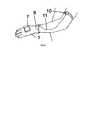
На Фиг. 1 показан пример выполнения перчатки с использованием на запястье и IMU сенсора и без использования фотодиодов.In FIG. Figure 1 shows an example of a glove using wrist and IMU sensor and without using photodiodes.
На Фиг. 2 показан пример выполнения перчатки с использованием фотодиодов и расположенного на запястье совмещенного модуля, содержащего фотодиод и IMU сенсор.In FIG. Figure 2 shows an example of a glove using photodiodes and a combined module located on the wrist containing a photodiode and an IMU sensor.
На Фиг. 3 показан пример выполнения перчатки без использования фотодиодов в системной плате и расположенного на запястье совмещенного модуля, содержащего фотодиод и IMU сенсор.In FIG. Figure 3 shows an example of a glove without using photodiodes in the system board and located on the wrist of a combined module containing a photodiode and an IMU sensor.
На Фиг. 4 показан пример подключения к перчатке плечевого модуля.In FIG. 4 shows an example of connecting a shoulder module to a glove.
На чертежах: 1 - перчатка, 2 - инерционный датчик (сенсор) IMU, объединяющий в себе акселерометр, гироскоп и магнитометр, 3 - вибрационный мотор, предназначенный для передачи ощущений вибрации, 4 - системная плата, 5 - аккумулятор, 6 - провода, 7 - корпус, объединяющий системную плату и аккумулятор, 8 - фотодиод, 9 - совмещенный модуль, 10 - плечевой модуль, 11 - соединительный провод между совмещенным модулем и плечевым модулем.In the drawings: 1 - a glove, 2 - an inertial sensor (sensor) IMU, combining an accelerometer, gyroscope and magnetometer, 3 - a vibration motor designed to transmit sensations of vibration, 4 - system board, 5 - battery, 6 - wires, 7 - a case combining the system board and the battery, 8 - a photodiode, 9 - a combined module, 10 - a shoulder module, 11 - a connecting wire between the combined module and the shoulder module.
Осуществление изобретенияThe implementation of the invention
Заявленное решение позволяет получать и передавать в компьютер или другое устройство данные о положении пальцев, кистей рук, локтевых и плечевых суставов, а также осуществлять тактильную обратную связь путем передачи вибрации на пальцы.The claimed solution allows you to receive and transmit to a computer or other device data on the position of the fingers, hands, elbows and shoulder joints, as well as provide tactile feedback by transmitting vibration to the fingers.
Это достигается следующим образом.This is achieved as follows.
На пальцы устанавливаются гироскопические/инерциальные датчики (IMU-сенсоры): на указательный, средний, безымянный пальцы и мизинец устанавливается по одному датчику в области предпоследней фаланги пальца, с внешней стороны ладони; на большой палец устанавливается два датчика - на первую и на вторую фалангу, с внешней стороны. Дополнительно аналогичные датчики устанавливаются на кисть руки, с внешней стороны, и на запястье, с внешней или внутренней стороны ладони.Gyroscopic / inertial sensors (IMU sensors) are installed on the fingers: on the index, middle, ring fingers and little fingers, one sensor is installed in the penultimate phalanx of the finger, on the outside of the palm; two sensors are installed on the thumb - on the first and second phalanx, from the outside. Additionally, similar sensors are installed on the hand, on the outside, and on the wrist, on the outside or inside of the palm.
Датчики могут быть закреплены в данных позициях с помощью тряпичной перчатки, будучи вшитыми в необходимых позициях, либо каждый датчик может быть закреплен независимо с помощью тряпичного (или из другого материала) кольца (крепления), надеваемого на палец/кисть/запястье, либо любым другим способом, обеспечивающим неподвижность датчика относительно пальца/кисти/запястья соответственно.The sensors can be fixed in these positions with a rag glove, being sewn in the required positions, or each sensor can be fixed independently using a rag (or from another material) ring (mount), worn on the finger / wrist / wrist, or any other in a way that ensures the immobility of the sensor relative to the finger / hand / wrist, respectively.
В качестве IMU-сенсора может использоваться, например:As an IMU sensor can be used, for example:
https://www.digikey.com/product-detail/en/invensense/MPU-6000/1428-1005-1-ND/4038006https://www.digikey.com/product-detail/en/invensense/MPU-6000/1428-1005-1-ND/4038006
Датчики с помощью кабеля подключаются к модулю управления, расположенному на внешней стороне ладони в пластиковом корпусе. Модуль управления содержит электронику управления на основе микроконтроллера, радиомодуль беспроводной связи, аккумулятор.The sensors are connected via cable to the control module located on the outside of the palm in a plastic case. The control module contains control electronics based on a microcontroller, a wireless radio module, and a battery.
Датчики постоянно собирают данные о движении и передают их микроконтроллеру, который по радиоканалу передает эти данные на компьютер или другое устройство.Sensors constantly collect motion data and transmit them to the microcontroller, which transmits this data via radio channel to a computer or other device.
На компьютере (или другом устройстве) установлено программное обеспечение-драйвер, которое использует данные с датчиков (угловые скорости и векторы ускорения) и преобразует их в кватернионы поворота пространства для следующих суставов: поворот (сгиб) последней фаланги пальца относительно ладони для указательного, среднего, безымянного пальцев и мизинца, в вертикальной плоскости относительно ладони; поворот указательного, среднего, безымянного пальцев и мизинца в горизонтальной плоскости (плоскости ладони); поворот/сгиб большого пальца относительно ладони в пространстве; поворот/сгиб кисти (ладони) относительно локтевого сустава; поворот локтевого сустава относительно плечевого сустава. Затем из полученных углов, с помощью алгоритмов инверсной кинематики (данных о связях суставов и их линейных размерах) вычисляются повороты всех остальных суставов и относительное положение всех суставов кисти руки.A driver software is installed on a computer (or other device) that uses data from sensors (angular velocities and acceleration vectors) and converts them into quaternions of space rotation for the following joints: rotation (bend) of the last phalanx of the finger relative to the palm for the index, middle, ring fingers and little finger, in a vertical plane relative to the palm; rotation of the index, middle, ring fingers and little finger in the horizontal plane (palm plane); rotation / folding of the thumb relative to the palm in space; turn / bend of the hand (palm) relative to the elbow joint; rotation of the elbow joint relative to the shoulder joint. Then, from the obtained angles, using the inverse kinematics algorithms (data on the joints of the joints and their linear dimensions), the turns of all other joints and the relative position of all joints of the wrist are calculated.
Полученные данные затем предоставляются для доступа в виде программного интерфейса приложения (API) и могут быть использованы сторонними производителями программного обеспечения в любых целях.The data obtained is then provided for access in the form of a software application interface (API) and can be used by third-party software manufacturers for any purpose.
Дополнительно, на внутренней стороне ладони, на предпоследней фалангах каждого пальца размещается вибрационный мотор, который крепится аналогичным IMU-сенсорам способом, и также с помощью кабеля подключается к системной плате и микроконтроллеру.Additionally, on the inner side of the palm, on the penultimate phalanx of each finger, a vibration motor is mounted, which is mounted in a similar way to IMU sensors, and is also connected via cable to the system board and microcontroller.
Программный интерфейс приложения (API) позволяет запускать вибрационный мотор независимо на каждом из пальцев, задавая необходимые параметры широтно-импульсной модуляции (частоту/интенсивность вибрации).The application program interface (API) allows you to start the vibration motor independently on each of the fingers, setting the necessary parameters for pulse-width modulation (frequency / intensity of vibration).
Команда от программного интерфейса обрабатывается драйвером устройства и, через радиоканал, передается на микроконтроллер, который управляет непосредственно вибрационным мотором.The command from the software interface is processed by the device driver and, through the radio channel, is transmitted to the microcontroller, which controls the vibration motor directly.
Таким образом, вибрация может контролироваться сторонними производителями программного обеспечения с помощью программного интерфейса приложения (API).In this way, vibration can be controlled by third-party software manufacturers using the application programming interface (API).
В качестве вибрационного мотора может использоваться, например:As a vibration motor can be used, for example:
https://ru.aliexpress.com/item/50pcs-DC3V-0820-8-2-0mm-Mobile-phone-micro-flat-vibration-motor-Coin-motor-Mini-vibrator/32783671636.htmlhttps://en.aliexpress.com/item/50pcs-DC3V-0820-8-2-0mm-Mobile-phone-micro-flat-vibration-motor-Coin-motor-Mini-vibrator/32783671636.html
Недостатком использования IMU-сенсоров без дополнительного внешнего "трекинга" (трекинг - определение местоположения движущихся объектов во времени с помощью камеры) является проблема "дрифта" - накоплению погрешности гироскопических/инерциальных датчиков, существенному отклонению получаемых данных от реальных и, как следствие, невозможности точного абсолютного позиционирования.The disadvantage of using IMU sensors without additional external "tracking" (tracking - determining the location of moving objects in time using the camera) is the problem of "drift" - the accumulation of inaccuracy of gyroscopic / inertial sensors, a significant deviation of the received data from real and, as a result, the impossibility of accurate absolute positioning.
Для решения этой проблемы приходится накладывать ограничения на получаемые данные, ограничивая тем самым подвижность "виртуальной руки" - рука фиксируется в локтевом суставе. Таким образом, все движения интерпретируются в рамках полусферы, которую может описать кисть при зафиксированном локтевом суставе - движения руки в горизонтальной плоскости полностью игнорируются, что доставляет неудобства на практике.To solve this problem, it is necessary to impose restrictions on the data obtained, thereby limiting the mobility of the "virtual arm" - the arm is fixed in the elbow joint. Thus, all movements are interpreted within the hemisphere, which the brush can describe when the elbow is fixed - arm movements in the horizontal plane are completely ignored, which is inconvenient in practice.
По причине чего на плечевом суставе дополнительно может быть закреплен еще один гироскопический/инерциальный датчик (IMU-сенсор), например, внутри плечевого модуля (10) (Фиг. 4) и подсоединен к системной плате (4) с помощью кабеля (11) через разъем совмещенного модуля (9).For this reason, another gyroscopic / inertial sensor (IMU sensor) can be additionally fixed on the shoulder joint, for example, inside the shoulder module (10) (Fig. 4) and connected to the system board (4) using a cable (11) through combined module connector (9).
Данные с датчика, передаются на микроконтроллер, и далее через радиоканал - в программное обеспечение-драйвер, где они используются для вычисления поворота локтевого сустава относительно плечевого, а также вращения локтевого сустава в перпендикулярной ему плоскости. Это позволяет более точно вычислять положение кисти в пространстве и придать дополнительные степени свободы руке.Data from the sensor is transmitted to the microcontroller, and then through the radio channel to the driver software, where it is used to calculate the rotation of the elbow joint relative to the shoulder, as well as the rotation of the elbow joint in a plane perpendicular to it. This allows you to more accurately calculate the position of the brush in space and give additional degrees of freedom to the hand.
Благодаря такому подходу, можно зафиксировать виртуальную модель руки не в локтевом суставе, а в плечевом и с высокой точностью распознавать и передавать на компьютер (или иное устройство) все возможные движения руки, в том числе и в горизонтальной плоскости.Thanks to this approach, it is possible to fix the virtual arm model not in the elbow joint, but in the shoulder and with high accuracy to recognize and transmit to the computer (or other device) all possible hand movements, including in the horizontal plane.
Для полного решения проблемы накапливаемой погрешности в вычисленной абсолютной позиции датчиков допустимо добавить поддержку внешнего "трекинга".To completely solve the problem of accumulated error in the calculated absolute position of the sensors, it is permissible to add support for external "tracking".
Для этого (по первому варианту) на модуль управления размещаются два или более фотодиодов, реагирующие на вспышки света. При этом корпус для модуля управления изготавливается из прозрачного материала, пропускающего свет, либо целиком, либо лишь в тех участках, где расположены фотодиоды. Еще один фотодиод располагается рядом с IMU-сенсором на запястье. Опционально еще один фотодиод также располагается вместе с IMU-сенсором на плечевом суставе.To do this (in the first embodiment), two or more photodiodes that respond to flashes of light are placed on the control module. In this case, the housing for the control module is made of a transparent material that transmits light, either in its entirety, or only in those areas where the photodiodes are located. Another photodiode is located next to the IMU sensor on the wrist. Optionally, another photodiode is also located with the IMU sensor on the shoulder joint.
Фотодиоды регистрируют световые сигналы, посылаемые парой специальных внешних свето-излучателей, установленных стационарно, неподвижно и отдельно от описываемого контроллера (системной платы и набора сенсоров в виде перчатки или другой форме), по разные стороны от него.Photodiodes register light signals sent by a pair of special external light emitters installed stationary, motionless and separately from the described controller (system board and a set of sensors in the form of a glove or other form), on different sides of it.
Излучатели запрограммированы особым образом и генерируют световые импульсы определенной длины, формы и направления, через определенные промежутки времени. Свет может излучаться как в видимом, так и в невидимых (инфракрасный, ультрафиолетовый) диапазонах.The emitters are programmed in a special way and generate light pulses of a certain length, shape and direction, at certain intervals. Light can be emitted both in the visible and in the invisible (infrared, ultraviolet) ranges.
Например, излучатель может генерировать набор коротких импульсов света, а затем генерировать узкую полосу лазером, установленном на поворотном механизме, вращающемся в горизонтальной плоскости. Другой излучатель может параллельно (но в другие временные интервалы) делать тоже самое, но в вертикальной плоскости. Временные интервалы, последовательность световых импульсов, форму и характер импульсов (например форму пучка света лазера и скорость поворотного механизма) известны заранее, эти данные сопоставляются программным обеспечением-драйвером со временем регистрации фотодиодами различных импульсов света, благодаря чему вычисляется их позиция относительно излучателей, и таким образом - абсолютная позиция фотодиодов в пространстве. Затем эти данные используются для корректировки абсолютной позиции руки в пространстве, вычисленную с помощью IMU-сенсоров, и устранения накопленной погрешности.For example, an emitter can generate a set of short pulses of light, and then generate a narrow band of laser mounted on a rotary mechanism rotating in a horizontal plane. Another radiator can do the same thing in parallel (but at different time intervals), but in a vertical plane. The time intervals, the sequence of light pulses, the shape and nature of the pulses (for example, the shape of the laser light beam and the speed of the rotary mechanism) are known in advance, these data are compared by the driver software with the time of registration of various light pulses by photodiodes, due to which their position relative to the emitters is calculated, and so image - the absolute position of the photodiodes in space. Then these data are used to correct the absolute position of the hand in space, calculated using IMU sensors, and to eliminate the accumulated error.
В качестве фотодиода может использоваться, например: https://www.digikey.com/product-detail/en/osram-opto-semiconductors-inc/BPW-34-S-Z/475-2659-1-ND/1893861As a photodiode can be used, for example: https://www.digikey.com/product-detail/en/osram-opto-semiconductors-inc/BPW-34-S-Z/475-2659-1-ND/1893861
В качестве внешнего излучателя может использоваться, например:As an external emitter can be used, for example:
https://www.microsoftstore.com/store/msusa/en_US/pdp/HTC-Vive-Base-Station/productID.5073718900https://www.microsoftstore.com/store/msusa/en_US/pdp/HTC-Vive-Base-Station/productID.5073718900
Альтернативным способом (вторым вариантом реализации) является расположение в тех же позициях световых или инфракрасных светодиодов вместо фотодиодов и замена световых излучателей на две или более видеокамеры. В этом случае, программное обеспечение должно иметь доступ к изображению, получаемому с камер.An alternative way (the second embodiment) is to place light or infrared LEDs in the same positions instead of photodiodes and replace the light emitters with two or more video cameras. In this case, the software must have access to the image received from the cameras.
Программное обеспечение находит на изображении позицию светодиодов и затем, используя данные о взаимном расположении камер, о линейном расстоянии между светодиодами и о получившемся размере и искажении (повороте/сжатии) изображения светодиодов вычисляет абсолютную позицию светодиодов в пространстве.The software finds the position of the LEDs in the image and then, using data on the relative position of the cameras, on the linear distance between the LEDs and on the resulting size and distortion (rotation / compression) of the LED image, calculates the absolute position of the LEDs in space.
Затем эти данные используются для корректировки абсолютной позиции руки в пространстве, вычисленную с помощью IMU-сенсоров, и устранения накопленной погрешности.Then these data are used to correct the absolute position of the hand in space, calculated using IMU sensors, and to eliminate the accumulated error.
Заявленное решение может использоваться для анимации 3D моделей человеческой (или иной) руки в компьютерных программах, как способ взаимодействия с интерфейсами в виртуальной (VR - virtual reality) или дополненной (AR - augmented reality) реальностях, а также видеоиграх, симуляторах различных видов деятельности и в любых других задачах, где требуется получение, обработка, хранение или передача точных движений рук в пространстве.The claimed solution can be used to animate 3D models of a human (or other) hand in computer programs, as a way of interacting with interfaces in virtual (VR - virtual reality) or augmented (AR - augmented reality) realities, as well as video games, simulators of various activities and in any other tasks that require the receipt, processing, storage or transmission of precise hand movements in space.
Например, заявленное решение также может применяться в медицине, для пациентов с нарушениями моторики рук для отслеживания движений кистей и пальцев рук и стимулирования их активности.For example, the claimed solution can also be used in medicine for patients with impaired motor skills to monitor the movements of the hands and fingers and stimulate their activity.
Обратная связь с помощью вибромоторов может применяться для имитации ощущений прикосновения к предметам в виртуальной реальности, когда данные о положении руки и пальцев используются для определения коллизий с виртуальными предметами и, в случае их обнаружения, подавать на соответствующие месту контакта пальцы вибрации. При этом степень вибрации может зависеть от формы контакта - размера области пересечения, или от характеристик виртуального предмета. Другой возможный сценарий использования вибрации - подтверждение события взаимодействиями с виртуальными интерфейсами - например, нажатие на виртуальную кнопку.Feedback using vibromotors can be used to simulate the sensations of touching objects in virtual reality, when data on the position of the hand and fingers are used to determine collisions with virtual objects and, if they are detected, to apply vibration fingers to the contact point. Moreover, the degree of vibration may depend on the form of contact - the size of the intersection area, or on the characteristics of the virtual object. Another possible scenario for using vibration is to confirm an event by interacting with virtual interfaces - for example, clicking on a virtual button.
Заявленное решение предлагает новый способ размещения IMU-сенсоров и, как следствие, высокую точность получаемых результатов: взаимное расположение датчиков позволяет получить необходимые углы, между пальцами, кистью, локтевым и плечевым суставами; во вторую очередь такое расположение сенсоров и вибрационных моторов позволяет освободить последнюю фалангу пальцев, что удобно в практическом применении - пользователь может пользоваться сенсорными экранами, производить действия требующие мелкой моторики пальцев и т.п.The claimed solution offers a new way of placing IMU sensors and, as a result, high accuracy of the results: the relative position of the sensors allows you to get the necessary angles between the fingers, hand, elbow and shoulder joints; secondly, this arrangement of sensors and vibration motors allows you to release the last phalanx of the fingers, which is convenient in practical use - the user can use touch screens, perform actions requiring fine motor skills of the fingers, etc.
Преимуществом использования комбинированного подхода (применение IMU-сенсоров и внешнего трекинга в одной технологии) является высокая точность измерения пространственного перемещения, еще более высокая, чем любые альтернативные методы, такие как тензорезисторы (датчики сгиба) или решения, основанные только на IMU-сенсорах. Кроме того, в отличии от методов, основанных на внешнем оптическом или другом внешнем трекинге у данного подхода полностью отсутствуют "слепые зоны", даже если между светодиодом (фотодиодом) и камерой (светоизлучателем) не будет прямого обзора, заявленное решение все равно позволит достаточно точно вычислить позицию руки в пространстве.The advantage of using a combined approach (using IMU sensors and external tracking in one technology) is the high accuracy of measuring spatial displacement, even higher than any alternative methods, such as strain gages (bend sensors) or solutions based only on IMU sensors. In addition, in contrast to methods based on external optical or other external tracking, this approach completely lacks “blind spots”, even if there is no direct view between the LED (photodiode) and the camera (light emitter), the claimed solution will still allow quite accurate calculate the position of the hand in space.
Еще одним преимуществом перед другими известными устройствами, основанными только на внешнем трекинге, является возможность использования вне стационарно оборудованных помещений, что удобно при использовании решения вместе с мобильными устройствами (смартфонами), или портативными решениями виртуальной и дополненной реальностей.Another advantage over other well-known devices based only on external tracking is the possibility of using them outside of stationary equipped rooms, which is convenient when using the solution together with mobile devices (smartphones), or portable solutions of virtual and augmented realities.
Способ может быть реализован на примере выполнения перчатки в следующей конструкции.The method can be implemented by the example of a glove in the following design.
Перчатка (Фиг. 1) (1) выполняется из ткани, внутри которой расположены: IMU сенсоры (2), каждый из которых содержит в себе акселерометр, гироскоп и магнитометр, при этом четыре IMU сенсора (2) расположены на предпоследних фалангах мизинца, безымянного, среднего и указательного пальцев, два IMU сенсора (2) расположены на первой и второй фалангах большого пальца, один сенсор IMU (2) расположен на системной плате.The glove (Fig. 1) (1) is made of fabric, inside which are located: IMU sensors (2), each of which contains an accelerometer, gyroscope and magnetometer, while four IMU sensors (2) are located on the penultimate phalanges of the little finger, anonymous , middle and index fingers, two IMU sensors (2) are located on the first and second phalanges of the thumb, one IMU sensor (2) is located on the system board.
На пальцах перчатки (1) также закреплены вибрационные моторы (3), по одному на каждом пальце, причем на всех пальцах, кроме большого, вибрационные моторы (3) закреплены на предпоследних фалангах пальцев, а на большом пальце вибрационный мотор (3) закреплен на последней фаланге.On the fingers of the glove (1), vibration motors (3) are also fixed, one on each finger, and on all fingers except the thumb, vibration motors (3) are mounted on the penultimate phalanges of the fingers, and on the thumb, the vibration motor (3) is mounted on the last phalanx.
На перчатке (1) закреплены системная плата (4), где расположен вычислительный модуль. При этом модуль беспроводной связи Bluetooth, для связи с компьютером или иным устройством по радиоканалу, установлен на системной плате (4).On the glove (1), the motherboard (4) is fixed, where the computing module is located. In this case, the Bluetooth wireless module, for communication with a computer or other device over the air, is installed on the system board (4).
Системная плата (4) закреплена поверх аккумулятора (5), который закреплен на перчатке (1).The system board (4) is mounted on top of the battery (5), which is attached to the glove (1).
Сенсоры IMU (2), вибромоторы (3), аккумулятор (5) подключены к системной плате (4) посредством проводов (6).IMU sensors (2), vibration motors (3), battery (5) are connected to the system board (4) via wires (6).
При необходимости, системная плата (4) и аккумулятор (5) могут быть выполнены в едином корпусе (7) из светопроницаемого пластика.If necessary, the system board (4) and the battery (5) can be made in a single housing (7) made of translucent plastic.
На системной плате (4) также установлены фотодиоды (8), подключенные к совмещенному модулю (9), содержащему фотодиод и IMU сенсор.Photodiodes (8) are also installed on the system board (4), connected to a combined module (9) containing a photodiode and an IMU sensor.
Предпочтительно, фотодиоды (8) могут быть установлены на системной плате (4) по ее краям равноудалено. Их может быть четыре.Preferably, the photodiodes (8) can be mounted on the system board (4) at its edges equidistant. There may be four.
Модуль (9) с IMU сенсором и световым датчиком располагают на запястье перчатки (1). Дополнительным преимуществом виртуальной перчатки (1) является использование дополнительного плечевого модуля (10), который располагают на плече (бицепсе), и подключают к системной плате с помощью провода (11) через модуль (9), который выполняют содержащим соединительный коннектор (на чертежах не показан).A module (9) with an IMU sensor and a light sensor is located on the wrist of the glove (1). An additional advantage of a virtual glove (1) is the use of an additional shoulder module (10), which is located on the shoulder (biceps), and connected to the system board using a wire (11) through the module (9), which is made containing a connecting connector (not shown shown).
Внутри плечевого модуля (10) может быть установлен IMU-сенсор.An IMU sensor can be installed inside the shoulder module (10).
Данное взаимное расположение IMU сенсоров с использованием сенсора, закрепленного в плечевом модуле (10), позволяет эффективно бороться с проблемой "дрифта" данных о положении пальцев и кисти рук в пространстве и более эффективно отслеживать движения плечевого сустава. В отличие от систем с внешним трекингом (основанным на фотодиодах или светодиодах и внешних камерах), данное решение может быть использовано без каких либо внешних устройств, что удобно для работы с мобильными устройствами (смартфонами).This mutual arrangement of IMU sensors using a sensor mounted in the shoulder module (10), allows you to effectively deal with the problem of "drift" data on the position of the fingers and hands in space and more effectively track the movement of the shoulder joint. Unlike systems with external tracking (based on photodiodes or LEDs and external cameras), this solution can be used without any external devices, which is convenient for working with mobile devices (smartphones).
Плечевой модуль (10) может быть так же реализован в беспроводном варианте, и подключаться к вычислительному модулю по радиоканалу (Bluetooth или Wifi). В этом случае в едином модуле с датчиком (10) располагают аккумулятор и радиомодуль (на чертежах не показаны) и провод (11) не используют.The shoulder module (10) can also be implemented wirelessly, and connected to the computing module via a radio channel (Bluetooth or Wifi). In this case, a battery and a radio module (not shown in the drawings) are placed in a single module with a sensor (10) and the wire (11) is not used.
Также плечевой модуль (10) может быть опционально реализован не с помощью IMU-сенсора, а с помощью одного или нескольких тензорезисторов (датчиков сгиба). В этом случае в плечевом модуле (10) устанавливается микроконтроллер, к которому подключают тензорезисторы, и через них агрегируют информацию и передают ее на основной вычислительный модуль системной платы (4).Also, the shoulder module (10) can be optionally implemented not using an IMU sensor, but using one or more strain gauges (bend sensors). In this case, a microcontroller is installed in the shoulder module (10), to which strain gages are connected, and information is aggregated through them and transferred to the main computing module of the system board (4).
Claims (11)
Translated fromRussianPriority Applications (2)
| Application Number | Priority Date | Filing Date | Title |
|---|---|---|---|
| RU2017137724ARU2670649C9 (en) | 2017-10-27 | 2017-10-27 | Method of manufacturing virtual reality gloves (options) |
| PCT/RU2018/000631WO2019083406A1 (en) | 2017-10-27 | 2018-09-28 | Method of producing a virtual reality glove (embodiments) |
Applications Claiming Priority (1)
| Application Number | Priority Date | Filing Date | Title |
|---|---|---|---|
| RU2017137724ARU2670649C9 (en) | 2017-10-27 | 2017-10-27 | Method of manufacturing virtual reality gloves (options) |
Publications (2)
| Publication Number | Publication Date |
|---|---|
| RU2670649C1 RU2670649C1 (en) | 2018-10-24 |
| RU2670649C9true RU2670649C9 (en) | 2018-12-11 |
Family
ID=63923364
Family Applications (1)
| Application Number | Title | Priority Date | Filing Date |
|---|---|---|---|
| RU2017137724ARU2670649C9 (en) | 2017-10-27 | 2017-10-27 | Method of manufacturing virtual reality gloves (options) |
Country Status (2)
| Country | Link |
|---|---|
| RU (1) | RU2670649C9 (en) |
| WO (1) | WO2019083406A1 (en) |
Families Citing this family (3)
| Publication number | Priority date | Publication date | Assignee | Title |
|---|---|---|---|---|
| CN111722698A (en)* | 2019-03-18 | 2020-09-29 | 深圳市掌网科技股份有限公司 | A force feedback virtual reality handle |
| CN113467599B (en)* | 2020-03-31 | 2024-05-17 | 京东科技信息技术有限公司 | Method and device for resolving flexibility between fingers and palms and data glove |
| CN113370272B (en)* | 2021-05-27 | 2022-12-13 | 西安交通大学 | A pose monitoring system and method for a multi-segment continuum robot |
Citations (6)
| Publication number | Priority date | Publication date | Assignee | Title |
|---|---|---|---|---|
| WO2010085476A1 (en)* | 2009-01-20 | 2010-07-29 | Northeastern University | Multi-user smartglove for virtual environment-based rehabilitation |
| US20140098018A1 (en)* | 2012-10-04 | 2014-04-10 | Microsoft Corporation | Wearable sensor for tracking articulated body-parts |
| US9526443B1 (en)* | 2013-01-19 | 2016-12-27 | Bertec Corporation | Force and/or motion measurement system and a method of testing a subject |
| RU2617922C2 (en)* | 2011-09-29 | 2017-04-28 | Еадс Дойчланд Гмбх | Sensor glove and method of generating tactile response to sensor glove finger while interacting finger with infrared touch screen |
| US20170146659A1 (en)* | 2014-06-12 | 2017-05-25 | Terabee S.A.S. | Dynamic Tracking System and Automatic Guidance Method Based on 3D Time-of-Flight Cameras |
| US20170185737A1 (en)* | 2014-09-12 | 2017-06-29 | Gregory T. Kovacs | Physical examination method and apparatus |
Family Cites Families (1)
| Publication number | Priority date | Publication date | Assignee | Title |
|---|---|---|---|---|
| WO2016097841A2 (en)* | 2014-12-16 | 2016-06-23 | Quan Xiao | Methods and apparatus for high intuitive human-computer interface and human centric wearable "hyper" user interface that could be cross-platform / cross-device and possibly with local feel-able/tangible feedback |
- 2017
- 2017-10-27RURU2017137724Apatent/RU2670649C9/enactive
- 2018
- 2018-09-28WOPCT/RU2018/000631patent/WO2019083406A1/ennot_activeCeased
Patent Citations (6)
| Publication number | Priority date | Publication date | Assignee | Title |
|---|---|---|---|---|
| WO2010085476A1 (en)* | 2009-01-20 | 2010-07-29 | Northeastern University | Multi-user smartglove for virtual environment-based rehabilitation |
| RU2617922C2 (en)* | 2011-09-29 | 2017-04-28 | Еадс Дойчланд Гмбх | Sensor glove and method of generating tactile response to sensor glove finger while interacting finger with infrared touch screen |
| US20140098018A1 (en)* | 2012-10-04 | 2014-04-10 | Microsoft Corporation | Wearable sensor for tracking articulated body-parts |
| US9526443B1 (en)* | 2013-01-19 | 2016-12-27 | Bertec Corporation | Force and/or motion measurement system and a method of testing a subject |
| US20170146659A1 (en)* | 2014-06-12 | 2017-05-25 | Terabee S.A.S. | Dynamic Tracking System and Automatic Guidance Method Based on 3D Time-of-Flight Cameras |
| US20170185737A1 (en)* | 2014-09-12 | 2017-06-29 | Gregory T. Kovacs | Physical examination method and apparatus |
Also Published As
| Publication number | Publication date |
|---|---|
| WO2019083406A1 (en) | 2019-05-02 |
| RU2670649C1 (en) | 2018-10-24 |
Similar Documents
| Publication | Publication Date | Title |
|---|---|---|
| KR101666096B1 (en) | System and method for enhanced gesture-based interaction | |
| RU187548U1 (en) | VIRTUAL REALITY GLOVE | |
| US10534431B2 (en) | Tracking finger movements to generate inputs for computer systems | |
| RU179301U1 (en) | VIRTUAL REALITY GLOVE | |
| CN105677036B (en) | A kind of interactive data gloves | |
| US10775946B2 (en) | Universal handheld controller of a computer system | |
| US10976863B1 (en) | Calibration of inertial measurement units in alignment with a skeleton model to control a computer system based on determination of orientation of an inertial measurement unit from an image of a portion of a user | |
| CN110603510A (en) | Position and orientation tracking of virtual controllers in virtual reality systems | |
| US20220155866A1 (en) | Ring device having an antenna, a touch pad, and/or a charging pad to control a computing device based on user motions | |
| JP2010108500A (en) | User interface device for wearable computing environmental base, and method therefor | |
| JP6932267B2 (en) | Controller device | |
| US11054923B2 (en) | Automatic switching between different modes of tracking user motions to control computer applications | |
| WO2017021902A1 (en) | System and method for gesture based measurement of virtual reality space | |
| CN114503057A (en) | Orientation determination based on both image and inertial measurement unit | |
| US20250238083A1 (en) | Device for intuitive dexterous touch and feel interaction in virtual worlds | |
| RU2670649C9 (en) | Method of manufacturing virtual reality gloves (options) | |
| Kao et al. | Novel digital glove design for virtual reality applications | |
| RU176318U1 (en) | VIRTUAL REALITY GLOVE | |
| RU2673406C1 (en) | Method of manufacturing virtual reality glove | |
| KR20220108417A (en) | Method of providing practical skill training using hmd hand tracking | |
| RU186397U1 (en) | VIRTUAL REALITY GLOVE | |
| WO2019083405A1 (en) | Virtual reality glove | |
| RU176660U1 (en) | VIRTUAL REALITY GLOVE | |
| Campos et al. | Touchscreen device layout based on thumb comfort and precision | |
| Nguyen | 3DTouch: Towards a Wearable 3D Input Device for 3D Applications |
Legal Events
| Date | Code | Title | Description |
|---|---|---|---|
| TH4A | Reissue of patent specification |