Movatterモバイル変換


[0]ホーム

URL:


RU2668853C2 - Weighing device - Google Patents

Weighing device
Download PDF

Info

Publication number
RU2668853C2
RU2668853C2RU2011138944KRU2011138944KRU2668853C2RU 2668853 C2RU2668853 C2RU 2668853C2RU 2011138944 KRU2011138944 KRU 2011138944KRU 2011138944 KRU2011138944 KRU 2011138944KRU 2668853 C2RU2668853 C2RU 2668853C2
Authority
RU
Russia
Prior art keywords
weighing device
core
weighing
transport auger
product
Prior art date
Application number
RU2011138944K
Other languages
Russian (ru)
Inventor
Хеннинг Ингеманн ХАНСЕН
Original Assignee
Кабинплант Интернасиональ А/С
Priority date (The priority date is an assumption and is not a legal conclusion. Google has not performed a legal analysis and makes no representation as to the accuracy of the date listed.)
Filing date
Publication date
Family has litigation
First worldwide family litigation filedlitigationCriticalhttps://patents.darts-ip.com/?family=35276486&utm_source=google_patent&utm_medium=platform_link&utm_campaign=public_patent_search&patent=RU2668853(C2)"Global patent litigation dataset” by Darts-ip is licensed under a Creative Commons Attribution 4.0 International License.
Application filed by Кабинплант Интернасиональ А/СfiledCriticalКабинплант Интернасиональ А/С
Application grantedgrantedCritical
Publication of RU2668853C2publicationCriticalpatent/RU2668853C2/en

Links

Images

Classifications

Landscapes

Abstract

FIELD: measuring equipment.
SUBSTANCE: presented group of inventions relates to multi-head weight batchers. Weighing device contains (1) feeding device for material product intended for weighing and at least one dispenser (3) intended for controlled delivery of portions of material of the product from said feeding device (1) to the weighing system. Dispenser (3) comprises transport screws (5) with drive motor, made in the form of spiral-shaped rod and placed in an open trough for delivering material of the product from the feeding device (1) to the weighing system, and a control unit to control motor (7) in order to generate the required portion of material of the product weighing system. Feeding device (1) comprises a central bottom part, having a conical shape, wherein motors to drive transport augers are located at cone bottom feeder.
EFFECT: this weighing device makes it possible to ensure smooth, accurate delivery of such material products, which are suitable for vibration transportation or transportation of screw conveyor placed in a tubular casing.
114 cl, 3 dwg

Description

Translated fromRussian

Область техники, к которой относится изобретениеFIELD OF THE INVENTION

Настоящее изобретение относится к взвешивающему устройству, такому как многоголовочный весовой дозатор, который содержит загрузочный или накопительный бункер (оба будут называться подающим устройством) для материала продукта, предназначенного для взвешивания, и по меньшей мере один дозатор, предназначенный для контролируемой доставки порций материала продукта от указанной подачки к системе взвешивания.The present invention relates to a weighing device, such as a multi-head weighing batcher, which contains a loading or storage hopper (both will be called a feeding device) for the product material intended for weighing, and at least one dispenser designed for the controlled delivery of portions of product material from the specified feeds to the weighing system.

Предпосылки к созданию изобретенияBACKGROUND OF THE INVENTION

Во взвешивающих устройствах такого типа известно использование дозирующего или порционирующего механизма, состоящего из вибрационных поддонов, размещенных в качестве желоба, предназначенного для доставки материала продукта от подающего устройства к системе взвешивания и управления вибрацией по времени и интенсивности для того, чтобы подать нужную порцию материала продукта в систему взвешивания. Такое взвешивающее устройство может использоваться с самыми различными материальными продуктами, при условии, что эти материальные продукты могут доставляться с помощью вибрации в достаточной мере стабильным и организованным образом. Альтернативным способом обеспечить доставку нужных порций материала продукта в систему взвешивания является применение шнекового конвейера, помещенного в трубчатый кожух, пригодного для контролируемой транспортировки зернистых или порошкообразных материалов, таких, например, как известные из патента ЕР 1439379. Однако обычные шнековые конвейеры оказывают относительно большое механическое воздействие на материальный продукт. Такого механического воздействия следует, однако, избегать при работе с чувствительными продуктами. Так, при работе с чувствительными, липкими и/или гибкими материалами продукта, такими как домашняя птица, рыба, свежее мясо, маринованное мясо и соответствующие кусковые и/или липкие материалы, ни вибрационная, ни шнековая конвейерная доставка материала продукта не будет достаточно стабильной, четкой и плавной и, таким образом, не сможет обеспечить требующейся доставки этих видов продуктов.In weighing devices of this type, it is known to use a metering or portioning mechanism consisting of vibrating pallets arranged as a chute for delivering product material from the feeding device to the weighing system and controlling the vibration in time and intensity in order to supply the desired portion of the product material to weighing system. Such a weighing device can be used with a wide variety of material products, provided that these material products can be delivered by vibration in a sufficiently stable and organized manner. An alternative way to ensure the delivery of the required portions of the product material to the weighing system is to use a screw conveyor placed in a tubular casing suitable for the controlled transportation of granular or powder materials, such as, for example, those known from patent EP 1439379. However, conventional screw conveyors have a relatively large mechanical effect on a material product. Such mechanical stress should, however, be avoided when handling sensitive products. So, when working with sensitive, sticky and / or flexible product materials, such as poultry, fish, fresh meat, marinated meat and the corresponding lump and / or sticky materials, neither the vibrating nor the screw conveyor delivery of the product material will be sufficiently stable, clear and smooth, and thus will not be able to provide the required delivery of these types of products.

Описание изобретенияDescription of the invention

Целью настоящего изобретения является предложение взвешивающего устройства типа, упомянутого выше, с помощью которого можно обеспечить четкую доставку материальных продуктов, не пригодных для вибрационного перемещения, и этой цели достигают с помощью взвешивающего устройства, предназначенного для взвешивания липких и/или гибких материалов продуктов, таких как свежее мясо, домашняя птица, рыба и соответствующие комковатые и/или липкие материалы, которые согласно настоящему изобретению содержат признаки, изложенные в пункте 1. Указанное устройство содержит транспортные шнеки с приводом от двигателя, выполненные в виде имеющего форму спирали стержня и обеспечивающие четкую доставку материала продукта от подающего устройства к системе взвешивания даже в том случае, когда материальный продукт является липким и/или гибким или по другим причинам не подходит для вибрационной транспортировки.The aim of the present invention is to provide a weighing device of the type mentioned above, with which it is possible to provide a clear delivery of material products not suitable for vibrational movement, and this goal is achieved using a weighing device designed to weigh sticky and / or flexible material products, such as fresh meat, poultry, fish and the corresponding lumpy and / or sticky materials which according to the present invention contain the characteristics set forth in paragraph 1. e the device contains transport augers driven by a motor, made in the form of a spiral-shaped rod and providing a clear delivery of product material from the feeding device to the weighing system even when the material product is sticky and / or flexible or for other reasons is not suitable for vibration transportation.

Размещение шнека в открытом желобе обеспечивает плавную доставку без приложения какого-либо значительного механического воздействия или давления на материальный продукт.Placing the auger in an open trough ensures smooth delivery without any significant mechanical impact or pressure on the material product.

Краткое описание чертежейBrief Description of the Drawings

В следующей подробной части настоящего описания изобретение будет объяснено более подробно со ссылкой на пример варианта реализации системы взвешивания согласно изобретению, показанный на чертежах, на которых:In the following detailed part of the present description, the invention will be explained in more detail with reference to an example embodiment of a weighing system according to the invention, shown in the drawings, in which:

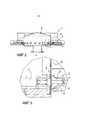
на фиг.1 показан вид сверху подающего устройства для материала продукта и восемнадцати транспортных шнеков с приводом от двигателя, помещенных в желобах для доставки материала продукта от подающего устройства к системе взвешивания (не показана);figure 1 shows a top view of the feeding device for the product material and eighteen transport augers driven by a motor, placed in the gutters for the delivery of product material from the feeding device to the weighing system (not shown);

на фиг.2 показан вид в поперечном разрезе устройства с фиг.1, выполненный по линии А-А;figure 2 shows a view in cross section of the device of figure 1, made along the line aa;

на фиг.3 показана деталь с фиг.2, указывающая пример соединения между двигателем и транспортным шнеком.figure 3 shows a detail from figure 2, indicating an example of the connection between the engine and the transport auger.

Описание предпочтительных вариантов реализации изобретенияDescription of preferred embodiments of the invention

Устройство, показанное на фиг.1, содержит подающее устройство 1, имеющее восемнадцать дозаторов 3, симметрично размещенных по окружности подающего устройства 1. Каждый дозатор 3 содержит желоб 4, в который помещен транспортный шнек 5 в виде имеющего форму спирали стержня с приводом от двигателя 7 (см. фиг.3). Соосно с транспортным шнеком 5 помещен сердечник 6, который считается дополнительным, и этот сердечник 6 может иметь диаметр, который меньше внутреннего диаметра транспортного шнека 5.The device shown in figure 1, contains a feeding device 1, having eighteendispensers 3, symmetrically placed around the circumference of the feeding device 1. Eachdispenser 3 contains a groove 4, in which is placed atransport auger 5 in the form of a spiral-shaped rod driven by a motor 7 (see figure 3). A core 6, which is considered optional, is placed coaxially with thetransport screw 5, and this core 6 may have a diameter that is smaller than the internal diameter of thetransport screw 5.

Подающее устройство 1, которое показано в поперечном разрезе на фиг.2, содержит коническую центральную донную часть 2, которая обеспечивает распределение материала продукта в направлении наружной стенки 12 подающего устройства 1. Коническая центральная донная часть 2 подающего устройства оканчивается на определенном расстоянии от наружной стенки 12 подающего устройства, и в промежутке между ними материал продукта падает в отдельные желоба 4, в которых размещены транспортный шнек 5 и, возможно, сердечник 6, предназначенные для доставки продукта от подающего устройства 1 контролируемым образом для того, чтобы выдать контролируемые порции материала продукта в систему взвешивания, расположенную ниже конца желоба 4.The feeding device 1, which is shown in cross section in figure 2, contains a conicalcentral bottom part 2, which provides the distribution of product material in the direction of theouter wall 12 of the feeding device 1. The conicalcentral bottom part 2 of the feeding device ends at a certain distance from theouter wall 12 feeding device, and in between, the material of the product falls into separate grooves 4, in which the transport screw 5 and, possibly, the core 6, are arranged for delivery of the product that from the feed unit 1 in a controlled manner in order to give controlled portions of product material to the weighing system positioned below the end of the chute 4.

Предпочтительно имеющий форму спирали стержень имеет по своей длине возрастающий шаг для улучшения плавной транспортировки материала продукта.Preferably, the spiral-shaped rod has an increasing pitch along its length to improve the smooth transport of the product material.

Как показано на фиг.3, соединение между двигателем 7 и транспортным шнеком 5 содержит втулку 8, с которой постоянно, например посредством сварки, соединен транспортный шнек 5, или же указанная втулка 8 может быть объединена в одно целое с сердечником 6, в случае его наличия. Втулка 8 содержит штифт 9, обеспечивающий не допускающее вращения соединение с приводимой во вращение двигателем осью и механизмом защелкивания 10, например, снабженным пружиной и шариком, причем указанный шарик вдавливают в выемку, выполненную в оси двигателя.As shown in figure 3, the connection between theengine 7 and thetransport screw 5 contains a sleeve 8, which is constantly connected, for example by welding, thetransport screw 5, or the specified sleeve 8 can be combined with the core 6, if it availability. The sleeve 8 contains a pin 9, providing a non-rotational connection with the axis driven by the engine and thelocking mechanism 10, for example, provided with a spring and a ball, and this ball is pressed into a recess made in the axis of the engine.

Для того чтобы избежать протечки материала продукта из желоба 4 во внутреннюю часть отсека двигателя, между осью двигателя и задней стенкой желоба 4 помещен сальник 11.In order to avoid leakage of the product material from the groove 4 into the inside of the engine compartment, anoil seal 11 is placed between the engine axis and the rear wall of the groove 4.

Монтаж двигателя 7 и возможное применение дополнительных подшипников для оси указанного двигателя обеспечиваются обычным образом и не требуют детального объяснения в этом отношении.The installation of theengine 7 and the possible use of additional bearings for the axis of the specified engine are provided in the usual way and do not require a detailed explanation in this regard.

Компоненты, находящиеся в контакте с материалом продукта, предпочтительно изготавливаются из нержавеющей стали, но по различным причинам возможен выбор других материалов, таких как пластмассы и т.д.The components in contact with the material of the product are preferably made of stainless steel, but for various reasons, a choice of other materials such as plastics, etc.

Показанное устройство действует следующим образом. Материал продукта, предназначенного для взвешивания, контролируемым образом доставляют к подающему устройству для того, чтобы поддерживать в общем постоянный уровень материала продукта в указанном подающем устройстве 1. Материал продукта распределяют по отдельным дозаторам 3 с помощью конической центральной части дна 2 подающего устройства. Между отдельными желобами 4 дозатора 3 могут быть предусмотрены подходящие наклонные поверхности, так чтобы направлять материал продукта в отдельные желоба 4. Дозатор 3 выдает определенные порции материала продукта на соответствующую систему взвешивания по сигналам общей системы управления взвешивающего устройства. Контролируемая, четко определенная порция выдается при контролируемой скорости вращения двигателя 7 в течение заданного периода времени. Для оптимизации дозирования последующее взвешивание выданной порции используют для регулирования периода времени и/или скорости вращения двигателя с целью регулировать дозирование материала продукта для каждого отдельного дозатора 3.The device shown operates as follows. The material of the product to be weighed is controlled in a controlled manner to the feed device in order to maintain a generally constant level of product material in the specified feed device 1. The product material is distributed intoindividual dispensers 3 using the conical central part of thebottom 2 of the feed device. Suitable inclined surfaces may be provided between the individual grooves 4 of thedispenser 3 so that the product material is guided to the separate grooves 4. Thedispenser 3 provides certain portions of the product material to the corresponding weighing system according to the signals of the overall control system of the weighing device. A controlled, well-defined portion is issued at a controlled rotation speed of theengine 7 for a predetermined period of time. To optimize dosing, subsequent weighing of the dispensed portion is used to control the time period and / or engine rotation speed in order to adjust the dosage of the product material for eachindividual dispenser 3.

Типичные значения скорости вращения транспортного шнека 5 составляют 10-100 оборотов в минуту, а типичная длительность времени работы составляет от 50 до 2000 мс.Typical values of the rotational speed of thetransport auger 5 are 10-100 rpm, and a typical duration of the operating time is from 50 to 2000 ms.

Последующее взвешивание и комбинирование дозированных частичных порций в конечные порции должно быть как можно более близко к нужному весу конечных порций за счет соединения определенного количества дозированных и взвешенных порций, что хорошо известно в данной области техники и не нуждается в дополнительных деталях.The subsequent weighing and combination of the dosed partial portions into the final portions should be as close as possible to the desired weight of the final portions by combining a certain number of dosed and weighted portions, which is well known in the art and does not require additional details.

Выше изобретение было описано и объяснено в связи с конкретным вариантом его реализации, как показано на чертежах, однако специалисту в данной области техники очевидна возможность многих вариантов без отклонения от следующей далее формулы изобретения. Среди таких естественных отклонений имеется другое число дозаторов 3, применение сердечников 6 с меньшим диаметром или полное исключение сердечников 6 и возможность применения сердечника 6 с другой наружной формой, отличающейся от цилиндрической формы, показанной на чертежах. Кроме того, сердечник может оставаться неподвижным при вращении транспортного шнека 5 вместо того, чтобы вращаться синхронно с транспортным шнеком 5. Будет также очевидно, что отверстие в стороне 12 подающего устройства 1, через которое выдвинут желоб 4, нужно приспособить к материалу продукта, который доставляется дозатором.The invention has been described and explained above in connection with a specific embodiment, as shown in the drawings, however, it is obvious to a person skilled in the art the possibility of many options without deviating from the following claims. Among such natural deviations there is a different number ofdispensers 3, the use of cores 6 with a smaller diameter or the complete exclusion of cores 6 and the possibility of using the core 6 with a different outer shape, different from the cylindrical shape shown in the drawings. In addition, the core may remain stationary when thetransport screw 5 is rotated instead of rotating synchronously with thetransport screw 5. It will also be obvious that the hole in theside 12 of the feeding device 1 through which the groove 4 is extended needs to be adapted to the material of the product that is delivered dispenser.

Claims (69)

Translated fromRussian
1. Взвешивающее устройство для взвешивания липкого и/или гибкого материала продукта, такого как свежее мясо, маринованное мясо, домашняя птица, рыба и соответствующие кусковые и/или липкие материалы, содержащее подающее устройство для материала продукта, подлежащего взвешиванию; по меньшей мере один дозатор, предназначенный для контролируемой доставки порций материала продукта от указанного подающего устройства к системе взвешивания, причем указанный дозатор содержит транспортный шнек с приводом от двигателя, выполненный в виде имеющего форму спирали стержня и размещенный в открытом желобе для доставки материала продукта от подающего устройства к системе взвешивания, и блок управления, предназначенный для управления двигателем для того, чтобы подавать требуемую порцию материала продукта в систему взвешивания, причем указанное подающее устройство содержит имеющую коническую форму центральную донную часть, выводящую материал продукта радиально наружу к нескольким дозаторам, размещенным по круговой схеме вокруг конического дна, причем двигатели для привода транспортных шнеков располагаются под коническим дном подающего устройства.1. A weighing device for weighing sticky and / or flexible material of a product, such as fresh meat, pickled meat, poultry, fish and related lump and / or sticky materials, comprising a feeding device for the material of the product to be weighed; at least one dispenser designed for the controlled delivery of portions of the product material from the specified feeding device to the weighing system, said dispenser comprising a motor-driven transport auger made in the form of a spiral-shaped rod and placed in an open trough for delivering product material from the feed devices to the weighing system, and a control unit designed to control the engine in order to supply the required portion of the product material to the weighing system iy, and the specified feeding device contains a conical central bottom part, leading the product material radially outward to several dispensers placed in a circular pattern around the conical bottom, and the motors for driving the transport augers are located under the conical bottom of the feeding device.2. Взвешивающее устройство по п. 1, в котором указанный имеющий форму спирали стержень имеет по своей длине возрастающий шаг.2. The weighing device according to claim 1, wherein said spiral-shaped rod has an increasing pitch along its length.3. Взвешивающее устройство по п. 1 или 2, которое содержит также сердечник, помещенный внутри транспортного шнека, причем указанный сердечник имеет диаметр, который меньше или равен внутреннему диаметру транспортного шнека.3. The weighing device according to claim 1 or 2, which also contains a core placed inside the transport auger, said core having a diameter that is less than or equal to the inner diameter of the transport auger.4. Взвешивающее устройство по п. 3, в котором указанный сердечник имеет в общем цилиндрическую форму.4. The weighing device according to claim 3, wherein said core has a generally cylindrical shape.5. Взвешивающее устройство по п. 3, в котором указанный сердечник вращается синхронно с транспортным шнеком.5. The weighing device according to claim 3, wherein said core rotates synchronously with the transport auger.6. Взвешивающее устройство по п. 3, в котором указанный сердечник остается стационарным.6. The weighing device according to claim 3, wherein said core remains stationary.7. Взвешивающее устройство по п. 3, в котором указанный сердечник имеет желобчатую наружную поверхность.7. The weighing device according to claim 3, wherein said core has a grooved outer surface.8. Взвешивающее устройство по п. 3, в котором указанный сердечник является сменным для того, чтобы облегчить получение различных диаметров для доставки различных продуктов и/или достижения различных скоростей доставки.8. The weighing device according to claim 3, wherein said core is interchangeable in order to facilitate the receipt of various diameters for the delivery of various products and / or to achieve different delivery speeds.9. Взвешивающее устройство по п. 1, в котором указанный желоб содержит донную часть, имеющую цилиндрическую форму, с диаметром, который соответствует или больше наружного диаметра транспортного шнека.9. The weighing device according to claim 1, wherein said trough comprises a bottom part having a cylindrical shape with a diameter that corresponds to or more than the outer diameter of the transport auger.10. Взвешивающее устройство по п. 9, в котором указанный желоб проходит сквозь отверстие в боковой стороне подающего устройства.10. The weighing device according to claim 9, wherein said trough passes through an opening in a side of the feeding device.11. Взвешивающее устройство по п. 1, в котором соединение между транспортным шнеком и сердечником, в случае его наличия, и двигателем содержит прикрепляемый при помощи фиксатора механизм для облегчения сборки, разборки, чистки и замены транспортного шнека и/или сердечника.11. The weighing device according to claim 1, wherein the connection between the transport auger and the core, if present, and the engine comprises a mechanism attached with a latch to facilitate assembly, disassembly, cleaning and replacement of the transport auger and / or core.12. Взвешивающее устройство по п. 1, в котором управление скоростью и временем вращения указанного двигателя осуществляет блок управления.12. The weighing device according to claim 1, in which the control unit controls the speed and time of rotation of the specified engine.13. Взвешивающее устройство по п. 12, в котором блок управления присоединен для получения информации о весе порций материала и выполнен с возможностью регулирования скорости и/или времени вращения в зависимости от этого.13. The weighing device according to p. 12, in which the control unit is attached to obtain information about the weight of portions of the material and is configured to control the speed and / or time of rotation, depending on this.14. Взвешивающее устройство по п. 1, в котором указанное устройство содержит 2-40 дозаторов, например 2-4, 4-8, 8-16, 16-40, например 10-20, 20-40, предпочтительно 16 или 18 дозаторов.14. The weighing device according to claim 1, wherein said device comprises 2-40 dispensers, for example 2-4, 4-8, 8-16, 16-40, for example 10-20, 20-40, preferably 16 or 18 dispensers .15. Взвешивающее устройство для взвешивания липкого и/или гибкого материала продукта, такого как свежее мясо, маринованное мясо, домашняя птица, рыба и соответствующие кусковые и/или липкие материалы, содержащее подающее устройство для материала продукта, подлежащего взвешиванию; по меньшей мере один дозатор, предназначенный для контролируемой доставки порций материала продукта от указанного подающего устройства к системе взвешивания, причем указанный дозатор содержит транспортный шнек с приводом от двигателя, выполненный в виде имеющего форму спирали стержня и размещенный в открытом желобе для доставки материала продукта от подающего устройства к системе взвешивания, блок управления, предназначенный для управления двигателем для того, чтобы подавать требуемую порцию материала продукта в систему взвешивания, и сердечник, помещенный внутри транспортного шнека, при этом соединение между транспортным шнеком и двигателем содержит прикрепляемый при помощи фиксатора механизм для облегчения сборки, разборки, чистки и замены транспортного шнека и/или сердечника, выполненный в виде механизма защелкивания, который снабжен пружиной и шариком, вдавливаемым в выемку, выполненную в оси двигателя.15. A weighing device for weighing sticky and / or flexible material of a product, such as fresh meat, pickled meat, poultry, fish and corresponding lumpy and / or sticky materials, comprising a feeding device for the material of the product to be weighed; at least one dispenser designed for the controlled delivery of portions of the product material from the specified feeding device to the weighing system, said dispenser comprising a motor-driven transport auger made in the form of a spiral-shaped rod and placed in an open trough for delivering product material from the feed devices to the weighing system, a control unit for controlling the engine in order to supply the desired portion of the product material to the weighing system and a core placed inside the transport auger, wherein the connection between the transport auger and the motor includes a mechanism attached with a latch to facilitate assembly, disassembly, cleaning and replacement of the transport auger and / or core, made in the form of a snap mechanism, which is equipped with a spring and ball pressed into a recess made in the axis of the engine.16. Взвешивающее устройство по п. 15, в котором указанный имеющий форму спирали стержень имеет по своей длине возрастающий шаг.16. The weighing device according to claim 15, wherein said spiral-shaped rod has an increasing pitch along its length.17. Взвешивающее устройство по п. 15, в котором указанный сердечник имеет в общем цилиндрическую форму.17. The weighing device according to claim 15, wherein said core has a generally cylindrical shape.18. Взвешивающее устройство по п. 15, в котором указанный сердечник вращается синхронно с транспортным шнеком.18. The weighing device according to claim 15, wherein said core rotates synchronously with the transport auger.19. Взвешивающее устройство по п. 15, в котором указанный сердечник остается стационарным.19. The weighing device according to claim 15, wherein said core remains stationary.20. Взвешивающее устройство по п. 15, в котором указанный сердечник имеет желобчатую наружную поверхность.20. The weighing device according to claim 15, wherein said core has a grooved outer surface.21. Взвешивающее устройство по п. 15, в котором указанный сердечник является сменным для того, чтобы облегчить получение различных диаметров для доставки различных продуктов и/или достижения различных скоростей доставки.21. The weighing device according to claim 15, wherein said core is interchangeable in order to facilitate obtaining different diameters for the delivery of various products and / or to achieve different delivery speeds.22. Взвешивающее устройство по п. 15, в котором указанный желоб содержит донную часть, имеющую цилиндрическую форму, с диаметром, который соответствует или больше наружного диаметра транспортного шнека.22. The weighing device according to claim 15, wherein said trough comprises a bottom portion having a cylindrical shape with a diameter that corresponds to or greater than the outer diameter of the transport auger.23. Взвешивающее устройство по п. 22, в котором указанный желоб проходит сквозь отверстие в боковой стороне подающего устройства.23. The weighing device according to claim 22, wherein said trough extends through an opening in a side of the feed device.24. Взвешивающее устройство по п. 15, в котором указанное подающее устройство содержит имеющую коническую форму центральную донную часть, выводящую материал продукта радиально наружу к нескольким дозаторам, размещенным по круговой схеме вокруг конического дна.24. The weighing device according to claim 15, wherein said feeding device comprises a conical central bottom portion that discharges the product material radially outward to several dispensers arranged in a circular pattern around the conical bottom.25. Взвешивающее устройство по п. 24, в котором двигатели для привода транспортных шнеков располагаются под коническим дном подающего устройства.25. The weighing device according to p. 24, in which the motors for driving the transport augers are located under the conical bottom of the feeding device.26. Взвешивающее устройство по п. 15, в котором управление скоростью и временем вращения указанного двигателя осуществляет блок управления.26. The weighing device according to claim 15, in which the control unit controls the speed and time of rotation of the specified engine.27. Взвешивающее устройство по п. 26, в котором блок управления присоединен для получения информации о весе порций материала и выполнен с возможностью регулирования скорости и/или времени вращения в зависимости от этого.27. The weighing device according to p. 26, in which the control unit is attached to obtain information about the weight of portions of the material and is configured to control the speed and / or time of rotation, depending on this.28. Взвешивающее устройство по п. 15, в котором указанное устройство содержит 2-40 дозаторов, например 2-4, 4-8, 8-16, 16-40, например 10-20, 20-40, предпочтительно 16 или 18 дозаторов.28. The weighing device according to claim 15, wherein said device comprises 2-40 dispensers, for example 2-4, 4-8, 8-16, 16-40, for example 10-20, 20-40, preferably 16 or 18 dispensers .29. Взвешивающее устройство для взвешивания липкого и/или гибкого материала продукта, такого как свежее мясо, маринованное мясо, домашняя птица, рыба и соответствующие кусковые и/или липкие материалы, содержащее подающее устройство для материала продукта, подлежащего взвешиванию; по меньшей мере один дозатор, предназначенный для контролируемой доставки порций материала продукта от указанного подающего устройства к системе взвешивания, причем указанный дозатор содержит транспортный шнек с приводом от двигателя, выполненный в виде имеющего форму спирали стержня и размещенный в открытом желобе для доставки материала продукта от подающего устройства к системе взвешивания, и блок управления, предназначенный для управления двигателем для того, чтобы подавать требуемую порцию материала продукта в систему взвешивания, при этом указанный имеющий форму спирали стержень имеет по своей длине возрастающий шаг, причем двигатели для привода транспортных шнеков располагаются под коническим дном подающего устройства.29. A weighing device for weighing sticky and / or flexible material of a product, such as fresh meat, pickled meat, poultry, fish and related lump and / or sticky materials, comprising a feed device for the material of the product to be weighed; at least one dispenser designed for the controlled delivery of portions of the product material from the specified feeding device to the weighing system, said dispenser comprising a motor-driven transport auger made in the form of a spiral-shaped rod and placed in an open trough for delivering product material from the feed devices to the weighing system, and a control unit designed to control the engine in order to supply the required portion of the product material to the weighing system iia, while the specified spiral-shaped rod has an increasing step along its length, and the motors for driving the transport augers are located under the conical bottom of the feeding device.30. Взвешивающее устройство по п. 29, которое содержит также сердечник, помещенный внутри транспортного шнека, причем указанный сердечник имеет диаметр, который меньше или равен внутреннему диаметру транспортного шнека.30. The weighing device according to claim 29, which also contains a core placed inside the transport auger, said core having a diameter that is less than or equal to the inner diameter of the transport auger.31. Взвешивающее устройство по п. 30, в котором указанный сердечник имеет в общем цилиндрическую форму.31. The weighing device according to claim 30, wherein said core has a generally cylindrical shape.32. Взвешивающее устройство по п. 30, в котором указанный сердечник вращается синхронно с транспортным шнеком.32. The weighing device according to claim 30, wherein said core rotates synchronously with the transport auger.33. Взвешивающее устройство по п. 30, в котором указанный сердечник остается стационарным.33. A weighing device according to claim 30, wherein said core remains stationary.34. Взвешивающее устройство по п. 30, в котором указанный сердечник имеет желобчатую наружную поверхность.34. The weighing device according to claim 30, wherein said core has a grooved outer surface.35. Взвешивающее устройство по п. 30, в котором указанный сердечник является сменным для того, чтобы облегчить получение различных диаметров для доставки различных продуктов и/или достижения различных скоростей доставки.35. The weighing device according to claim 30, wherein said core is interchangeable in order to facilitate the receipt of various diameters for the delivery of various products and / or to achieve different delivery speeds.36. Взвешивающее устройство по п. 29, в котором указанный желоб содержит донную часть, имеющую цилиндрическую форму, с диаметром, который соответствует или больше наружного диаметра транспортного шнека.36. The weighing device according to claim 29, wherein said trough comprises a bottom portion having a cylindrical shape with a diameter that corresponds to or is greater than the outer diameter of the transport auger.37. Взвешивающее устройство по п. 36, в котором указанный желоб проходит сквозь отверстие в боковой стороне подающего устройства.37. The weighing device according to claim 36, wherein said trough extends through an opening in a side of the feed device.38. Взвешивающее устройство по п. 29, в котором указанное подающее устройство содержит имеющую коническую форму центральную донную часть, выводящую материал продукта радиально наружу к нескольким дозаторам, размещенным по круговой схеме вокруг конического дна.38. The weighing device according to claim 29, wherein said feeding device comprises a conical central bottom portion that discharges the product material radially outward to several dispensers arranged in a circular pattern around the conical bottom.39. Взвешивающее устройство по п. 29, в котором соединение между транспортным шнеком и сердечником, в случае его наличия, и двигателем содержит прикрепляемый при помощи фиксатора механизм для облегчения сборки, разборки, чистки и замены транспортного шнека и/или сердечника.39. The weighing device according to claim 29, wherein the connection between the transport auger and the core, if present, and the engine comprises a mechanism attached with a latch to facilitate assembly, disassembly, cleaning and replacement of the transport auger and / or core.40. Взвешивающее устройство по п. 29, в котором управление скоростью и временем вращения указанного двигателя осуществляет блок управления.40. The weighing device according to claim 29, in which the control unit controls the speed and time of rotation of the specified engine.41. Взвешивающее устройство по п. 40, в котором блок управления присоединен для получения информации о весе порций материала и выполнен с возможностью регулирования скорости и/или времени вращения в зависимости от этого.41. The weighing device according to p. 40, in which the control unit is attached to obtain information about the weight of portions of the material and is configured to control the speed and / or time of rotation, depending on this.42. Взвешивающее устройство по п. 29, в котором указанное устройство содержит 2-40 дозаторов, например 2-4, 4-8, 8-16, 16-40, например 10-20, 20-40, предпочтительно 16 или 18 дозаторов.42. The weighing device according to claim 29, wherein said device comprises 2-40 dispensers, for example 2-4, 4-8, 8-16, 16-40, for example 10-20, 20-40, preferably 16 or 18 dispensers .43. Взвешивающее устройство для взвешивания липкого и/или гибкого материала продукта, такого как свежее мясо, маринованное мясо, домашняя птица, рыба и соответствующие кусковые и/или липкие материалы, содержащее подающее устройство для материала продукта, подлежащего взвешиванию; по меньшей мере один дозатор, предназначенный для контролируемой доставки порций материала продукта от указанного подающего устройства к системе взвешивания, причем указанный дозатор содержит транспортный шнек с приводом от двигателя, выполненный в виде имеющего форму спирали стержня и размещенный в открытом желобе для доставки материала продукта от подающего устройства к системе взвешивания, и блок управления, предназначенный для управления двигателем для того, чтобы подавать требуемую порцию материала продукта в систему взвешивания, при этом указанный желоб проходит сквозь отверстие в боковой стороне подающего устройства, а подающее устройство содержит имеющую коническую форму центральную донную часть, выводящую материал продукта радиально наружу к нескольким дозаторам, размещенным по круговой схеме вокруг конического дна, причем двигатели для привода транспортных шнеков располагаются под коническим дном подающего устройства.43. A weighing device for weighing sticky and / or flexible material of a product, such as fresh meat, pickled meat, poultry, fish and related lump and / or sticky materials, comprising a feeding device for the material of the product to be weighed; at least one dispenser designed for the controlled delivery of portions of the product material from the specified feeding device to the weighing system, said dispenser comprising a motor-driven transport auger made in the form of a spiral-shaped rod and placed in an open trough for delivering product material from the feed devices to the weighing system, and a control unit designed to control the engine in order to supply the required portion of the product material to the weighing system 1, wherein said trough extends through an opening in the side of the feeding device, and the feeding device comprises a conical central bottom portion that discharges the product material radially outward to several dispensers arranged in a circular pattern around the conical bottom, and the motors for driving the transport augers are located under the conical bottom of the feeder.44. Взвешивающее устройство по п. 43, в котором указанный имеющий форму спирали стержень имеет по своей длине возрастающий шаг.44. The weighing device according to claim 43, wherein said spiral-shaped rod has an increasing pitch along its length.45. Взвешивающее устройство по п. 43, которое содержит также сердечник, помещенный внутри транспортного шнека, причем указанный сердечник имеет диаметр, который меньше или равен внутреннему диаметру транспортного шнека.45. The weighing device according to p. 43, which also contains a core placed inside the transport auger, said core having a diameter that is less than or equal to the inner diameter of the transport auger.46. Взвешивающее устройство по п. 45, в котором указанный сердечник имеет в общем цилиндрическую форму.46. The weighing device according to claim 45, wherein said core has a generally cylindrical shape.47. Взвешивающее устройство по п. 45, в котором указанный сердечник вращается синхронно с транспортным шнеком.47. The weighing device according to claim 45, wherein said core rotates synchronously with the transport auger.48. Взвешивающее устройство по п. 45, в котором указанный сердечник остается стационарным.48. The weighing device according to claim 45, wherein said core remains stationary.49. Взвешивающее устройство по п. 45, в котором указанный сердечник имеет желобчатую наружную поверхность.49. The weighing device according to claim 45, wherein said core has a grooved outer surface.50. Взвешивающее устройство по п. 45, в котором указанный сердечник является сменным для того, чтобы облегчить получение различных диаметров для доставки различных продуктов и/или достижения различных скоростей доставки.50. The weighing device according to claim 45, wherein said core is interchangeable in order to facilitate the preparation of various diameters for the delivery of various products and / or to achieve different delivery speeds.51. Взвешивающее устройство по п. 43, в котором указанный желоб содержит донную часть, имеющую цилиндрическую форму, с диаметром, который соответствует или больше наружного диаметра транспортного шнека.51. The weighing device according to claim 43, wherein said trough comprises a bottom portion having a cylindrical shape with a diameter that corresponds to or is greater than the outer diameter of the transport auger.52. Взвешивающее устройство по п. 43, в котором соединение между транспортным шнеком и сердечником, в случае его наличия, и двигателем содержит прикрепляемый при помощи фиксатора механизм для облегчения сборки, разборки, чистки и замены транспортного шнека и/или сердечника.52. The weighing device according to claim 43, wherein the connection between the transport auger and the core, if present, and the engine comprises a mechanism attached with a latch to facilitate assembly, disassembly, cleaning and replacement of the transport auger and / or core.53. Взвешивающее устройство по п. 43, в котором управление скоростью и временем вращения указанного двигателя осуществляет блок управления.53. The weighing device according to claim 43, in which the control unit controls the speed and time of rotation of the specified engine.54. Взвешивающее устройство по п. 53, в котором блок управления присоединен для получения информации о весе порций материала и выполнен с возможностью регулирования скорости и/или времени вращения в зависимости от этого.54. The weighing device according to p. 53, in which the control unit is attached to obtain information about the weight of portions of the material and is configured to control the speed and / or time of rotation, depending on this.55. Взвешивающее устройство по п. 43, в котором указанное устройство содержит 2-40 дозаторов, например 2-4, 4-8, 8-16, 16-40, например 10-20, 20-40, предпочтительно 16 или 18 дозаторов.55. The weighing device according to claim 43, wherein said device comprises 2-40 dispensers, for example 2-4, 4-8, 8-16, 16-40, for example 10-20, 20-40, preferably 16 or 18 dispensers .56. Взвешивающее устройство для взвешивания липкого и/или гибкого материала продукта, такого как свежее мясо, маринованное мясо, домашняя птица, рыба и соответствующие кусковые и/или липкие материалы, содержащее подающее устройство для материала продукта, подлежащего взвешиванию; по меньшей мере один дозатор, предназначенный для контролируемой доставки порций материала продукта от указанного подающего устройства к системе взвешивания, причем указанный дозатор содержит транспортный шнек с приводом от двигателя, выполненный в виде имеющего форму спирали стержня и размещенный в открытом желобе для доставки материала продукта от подающего устройства к системе взвешивания, и блок управления, предназначенный для управления двигателем для того, чтобы подавать требуемую порцию материала продукта в систему взвешивания, при этом внутри транспортного шнека помещен сердечник, который выполнен сменным для того, чтобы облегчить получение различных диаметров для доставки различных продуктов и/или достижения различных скоростей доставки, причем управление скоростью и временем вращения указанного двигателя осуществляет блок управления, причем двигатели для привода транспортных шнеков располагаются под коническим дном подающего устройства.56. A weighing device for weighing a sticky and / or flexible material of a product, such as fresh meat, pickled meat, poultry, fish and related lump and / or sticky materials, comprising a feed device for the material of the product to be weighed; at least one dispenser designed for the controlled delivery of portions of the product material from the specified feeding device to the weighing system, said dispenser comprising a motor-driven transport auger made in the form of a spiral-shaped rod and placed in an open trough for delivering product material from the feed devices to the weighing system, and a control unit designed to control the engine in order to supply the required portion of the product material to the weighing system while a core is placed inside the transport auger, which is removable in order to facilitate the production of different diameters for the delivery of various products and / or to achieve different delivery speeds, moreover, the speed and time of rotation of the specified engine are controlled by a control unit, the motors for driving transport screws are located under the conical bottom of the feeding device.57. Взвешивающее устройство по п. 56, в котором значения скорости вращения транспортного шнека составляют 10-100 об/мин, а длительность времени работы составляет от 50 до 2000 мс.57. The weighing device according to claim 56, in which the rotational speed of the transport auger is 10-100 rpm, and the duration of the operating time is from 50 to 2000 ms.58. Взвешивающее устройство по п. 56, в котором указанный имеющий форму спирали стержень имеет по своей длине возрастающий шаг.58. The weighing device according to claim 56, wherein said spiral-shaped rod has an increasing pitch along its length.59. Взвешивающее устройство по п. 56, в котором указанный сердечник имеет диаметр, который меньше или равен внутреннему диаметру транспортного шнека.59. The weighing device according to claim 56, wherein said core has a diameter that is less than or equal to the inner diameter of the transport screw.60. Взвешивающее устройство по п. 56, в котором указанный сердечник имеет в общем цилиндрическую форму.60. The weighing device according to claim 56, wherein said core has a generally cylindrical shape.61. Взвешивающее устройство по п. 56, в котором указанный сердечник вращается синхронно с транспортным шнеком.61. A weighing device according to claim 56, wherein said core rotates synchronously with the transport auger.62. Взвешивающее устройство по п. 56, в котором указанный сердечник остается стационарным.62. The weighing device according to claim 56, wherein said core remains stationary.63. Взвешивающее устройство по п. 56, в котором указанный сердечник имеет желобчатую наружную поверхность.63. The weighing device according to claim 56, wherein said core has a grooved outer surface.64. Взвешивающее устройство по п. 56, в котором указанный желоб содержит донную часть, имеющую цилиндрическую форму, с диаметром, который соответствует или больше наружного диаметра транспортного шнека.64. The weighing device according to p. 56, in which the specified trough contains a bottom part having a cylindrical shape, with a diameter that corresponds to or more than the outer diameter of the transport auger.65. Взвешивающее устройство по п. 64, в котором указанный желоб проходит сквозь отверстие в боковой стороне подающего устройства.65. The weighing device according to claim 64, wherein said trough extends through an opening in a side of the feeding device.66. Взвешивающее устройство по п. 56, в котором указанное подающее устройство содержит имеющую коническую форму центральную донную часть, выводящую материал продукта радиально наружу к нескольким дозаторам, размещенным по круговой схеме вокруг конического дна.66. The weighing device according to claim 56, wherein said feeding device comprises a conical central bottom portion that discharges the product material radially outward to several dispensers arranged in a circular pattern around the conical bottom.67. Взвешивающее устройство по п. 56, в котором соединение между транспортным шнеком и сердечником, в случае его наличия, и двигателем содержит прикрепляемый при помощи фиксатора механизм для облегчения сборки, разборки, чистки и замены транспортного шнека и/или сердечника.67. The weighing device according to claim 56, wherein the connection between the transport auger and the core, if present, and the engine comprises a mechanism attached with a latch to facilitate assembly, disassembly, cleaning and replacement of the transport auger and / or core.68. Взвешивающее устройство по п. 56, в котором блок управления присоединен для получения информации о весе порций материала и выполнен с возможностью регулирования скорости и/или времени вращения в зависимости от этого.68. The weighing device according to p. 56, in which the control unit is attached to obtain information about the weight of portions of the material and is configured to control the speed and / or time of rotation, depending on this.69. Взвешивающее устройство по п. 56, в котором указанное устройство содержит 2-40 дозаторов, например 2-4, 4-8, 8-16, 16-40, например 10-20, 20-40, предпочтительно 16 или 18 дозаторов.69. The weighing device according to claim 56, wherein said device contains 2-40 dispensers, for example 2-4, 4-8, 8-16, 16-40, for example 10-20, 20-40, preferably 16 or 18 dispensers .
RU2011138944K2005-03-032006-03-03Weighing deviceRU2668853C2 (en)

Applications Claiming Priority (2)

Application NumberPriority DateFiling DateTitle
EP05388019.12005-03-03
EP05388019AEP1698868A1 (en)2005-03-032005-03-03Weighing arrangement

Publications (1)

Publication NumberPublication Date
RU2668853C2true RU2668853C2 (en)2018-10-03

Family

ID=35276486

Family Applications (4)

Application NumberTitlePriority DateFiling Date
RU2007136491/28ARU2550898C9 (en)2005-03-032006-03-03Weighing apparatus
RU2011138944/28ARU2587639C2 (en)2005-03-032006-03-03Weighing device
RU2007136491/28KRU2550898C2 (en)2005-03-032006-03-03Weighing apparatus
RU2011138944KRU2668853C2 (en)2005-03-032006-03-03Weighing device

Family Applications Before (3)

Application NumberTitlePriority DateFiling Date
RU2007136491/28ARU2550898C9 (en)2005-03-032006-03-03Weighing apparatus
RU2011138944/28ARU2587639C2 (en)2005-03-032006-03-03Weighing device
RU2007136491/28KRU2550898C2 (en)2005-03-032006-03-03Weighing apparatus

Country Status (13)

CountryLink
EP (3)EP1698868A1 (en)
JP (2)JP5106125B2 (en)
CN (2)CN102620800A (en)
AU (1)AU2006220135B2 (en)
BR (1)BRPI0609376B1 (en)
CA (1)CA2600069C (en)
DE (1)DE202006021133U1 (en)
DK (3)DK2278284T4 (en)
ES (2)ES2449518T3 (en)
FI (1)FI9936U1 (en)
PL (2)PL2278284T5 (en)
RU (4)RU2550898C9 (en)
WO (1)WO2006092148A1 (en)

Cited By (1)

* Cited by examiner, † Cited by third party
Publication numberPriority datePublication dateAssigneeTitle
RU201475U1 (en)*2020-09-222020-12-16Общество с ограниченной ответственностью "АМАТА СКЕЙЛ" WEIGHT BATCHER

Families Citing this family (20)

* Cited by examiner, † Cited by third party
Publication numberPriority datePublication dateAssigneeTitle
JP4651130B2 (en)*2008-10-102011-03-16株式会社イシダ Combination weighing device
US8188383B2 (en)*2008-10-102012-05-29Ishida Co., Ltd.Combination weighing apparatus with conveyor apparatus having coaxial sprial members
JP5364602B2 (en)*2010-01-182013-12-11株式会社イシダ Combination weighing device
EP2484593A1 (en)2011-02-042012-08-08Cabinplant International A/SAn apparatus for conveying and selectively discharging products
CN102680061B (en)*2012-04-252014-04-16三一重工股份有限公司Powder ash material weighing system and weighing method
CN102774666B (en)*2012-07-262015-11-18中国神华能源股份有限公司Material level balance control method and system
CN102756926B (en)*2012-07-262015-03-04中国神华能源股份有限公司Material level balancing controlling method and system
CN102774629B (en)*2012-07-262015-05-20中国神华能源股份有限公司Discharge control method and system for silo
EP2737802A1 (en)2012-11-302014-06-04Cabinplant International A/SA food processing system and a corresponding method for sorting, weighing, conveying, and marinating solid food products
JP6007117B2 (en)*2013-01-302016-10-12株式会社イシダ Combination weighing device and method of use thereof
JP6389387B2 (en)*2014-07-182018-09-12株式会社イシダ Combination weighing device
JP3195388U (en)*2014-10-312015-01-15株式会社イシダ Combination weighing device
EP3100955A1 (en)2015-06-042016-12-07Cabinplant International A/SA product dispenser and a method of dispensing a flowable product
JP5855308B1 (en)*2015-08-032016-02-09株式会社イシダ Combination weighing device
CN105109955A (en)*2015-08-122015-12-02江苏中烟工业有限责任公司Feeder flow automatic control method in tobacco primary processing line
DK3568675T3 (en)2017-01-132022-07-25Marel As FEEDING SNAIL FOR COMBINATION WEIGHT
JP2018155640A (en)2017-03-172018-10-04株式会社イシダCombination measuring device
CN110741233B (en)*2017-05-022021-05-18卡布恩普兰特国际公司 Method and system for weighing and collecting solid foods
GB2567417A (en)*2017-09-192019-04-17Ishida Europe LtdWeighing apparatus and method for weighing food product
CN110155746A (en)*2019-06-052019-08-23中山市嘉威包装机械有限公司Rotary feeding combined scale

Citations (7)

* Cited by examiner, † Cited by third party
Publication numberPriority datePublication dateAssigneeTitle
US3845856A (en)*1972-11-241974-11-05Mac Millan Bloedel ResearchScrew conveyor for particulate material
EP0253895A1 (en)*1985-12-291988-01-27Anritsu CorporationCombination type weighing apparatus
EP0287134A2 (en)*1987-02-101988-10-19Aerts Elektro B.V.Weighing and mixing device
US5101961A (en)*1991-08-161992-04-07Jenike & Johanson, Inc.Feeding screw
US5340949A (en)*1990-09-171994-08-23Anritsu CorporationMetering system capable of easily effecting high-accuracy metering for various works including sticky materials
RU2050179C1 (en)*1992-12-101995-12-20Научно-производственное объединение "Нива Татарстана"Mixing batcher
EP1439379A1 (en)*2001-10-222004-07-21Yamato Scale Co., Ltd.Powder and granular material weighing apparatus

Family Cites Families (36)

* Cited by examiner, † Cited by third party
Publication numberPriority datePublication dateAssigneeTitle
FR2266875A1 (en)1974-04-041975-10-31Rayneri LucienneWeighing method for sticky or toxic materials - uses vibration to add material up to set limit for discharge
DE2903259C2 (en)*1979-01-291986-04-10Carl Schenck Ag, 6100 Darmstadt Process for dosing materials with changing flow properties
GB2074329B (en)1980-03-251984-05-16Ishida Scale Mfg Co LtdAutomatic weighing apparatus
NL8101186A (en)*1981-03-111982-10-01Chore Time Nv TRANSPORT DEVICE.
CH642170A5 (en)*1981-03-201984-03-30Hasler Freres SaInstallation for continuously weighing and metering divided products
JPS59180106A (en)1983-03-301984-10-13株式会社 モリタ東京製作所Detachable joint mechanism
JPS6133411A (en)1984-07-241986-02-17Yamato Scale Co LtdMaterial supply device for combined weighing device
DE3501259A1 (en)*1985-01-161986-07-17Industrie-Technik Erich A. Hindermann Aktiengesellschaft für Rationalisierung und Verfahrenstechnik, Küssnacht SCREW CONVEYOR
JPH0232080Y2 (en)*1986-03-141990-08-30
US4880142A (en)*1987-05-121989-11-14Fuji Photo Film Co., Ltd.Powder weighing mixer and method thereof
JP2695430B2 (en)*1988-04-191997-12-24富山化学工業株式会社 Powder cutting device
EP0362567B1 (en)1988-09-071992-12-09Ishida Scales Mfg. Co., Ltd.Waterproof automatic weighing apparatus
JP2514812Y2 (en)1990-07-191996-10-23大和製衡株式会社 Commodity weighing equipment
JP2710494B2 (en)*1991-08-201998-02-10アンリツ株式会社 Control method of transport screw
US5143166A (en)*1991-02-011992-09-01Hough Richard MMicro weighing system
JP2502950B2 (en)1991-02-211996-05-29株式会社イシダ Combination weighing method and apparatus
US5316195A (en)1991-09-301994-05-31Accurate, Inc.Apparatus for dispensing a flavorable material
FR2690131B1 (en)*1992-04-171994-12-30Serac Group Weight metering device, especially for pasty or heterogeneous product.
JPH06219532A (en)1993-01-271994-08-09Leotec:KkDispersion strengthening material supplying device
JP2577716Y2 (en)*1993-02-241998-07-30大和製衡株式会社 Combination weigher device
JP3064740B2 (en)*1993-04-222000-07-12株式会社日立製作所 Printer
US5350089A (en)1993-04-301994-09-27K-Tron Technologies, Inc.Feeder for dispensing flowable substances
US5375923A (en)*1993-06-161994-12-27Fieldstone Cabinetry, Inc.Drawer front attachment system
JP3136969B2 (en)1995-01-262001-02-19富士電機株式会社 Cooking material quantitative supply device
DE19617982A1 (en)1996-05-061997-11-13Multipond Waegetechnik Gmbh Combination scales
JPH1038667A (en)1996-07-251998-02-13Ishida Co LtdMeasuring device
AU7143098A (en)*1997-05-071998-11-27E.I. Du Pont De Nemours And CompanyMeasuring and dispensing system for solid dry flowable materials
JP3690705B2 (en)*1997-06-022005-08-31アンリツ産機システム株式会社 Combination weighing device
US6073818A (en)1998-06-192000-06-13Genzyme Transgenics CorporationApparatus for controlled delivery of powdered solid materials
US6753484B1 (en)1999-05-032004-06-22Bilwinco A/SUnder-transporter shield for a weighing machine
JP4245230B2 (en)1999-06-142009-03-25大和製衡株式会社 Metering device
JP2001080601A (en)1999-09-092001-03-27Kaoru WatanabeSpecified weight measuring-cum-fermented soybean container packing device per fermented soybean packaging container unit for cooked bean of fermented soybean raw material
JP4394798B2 (en)2000-02-252010-01-06株式会社イシダ Combination weighing device
EP1493004A1 (en)2002-04-072005-01-05Bilwinco A/SA weighing machine
ITMO20020199A1 (en)*2002-07-092004-01-09Tecnogen Srl APPARATUS FOR CONVEYING FRUIT AND VEGETABLES
DE202004016295U1 (en)2004-10-212005-01-05Kramer, HanswalterDevice for transporting cuttings produced during the machining of workpieces comprises a motor-driven hollow worm conveyor mounted in a transport path forming a conveying channel,

Patent Citations (7)

* Cited by examiner, † Cited by third party
Publication numberPriority datePublication dateAssigneeTitle
US3845856A (en)*1972-11-241974-11-05Mac Millan Bloedel ResearchScrew conveyor for particulate material
EP0253895A1 (en)*1985-12-291988-01-27Anritsu CorporationCombination type weighing apparatus
EP0287134A2 (en)*1987-02-101988-10-19Aerts Elektro B.V.Weighing and mixing device
US5340949A (en)*1990-09-171994-08-23Anritsu CorporationMetering system capable of easily effecting high-accuracy metering for various works including sticky materials
US5101961A (en)*1991-08-161992-04-07Jenike & Johanson, Inc.Feeding screw
RU2050179C1 (en)*1992-12-101995-12-20Научно-производственное объединение "Нива Татарстана"Mixing batcher
EP1439379A1 (en)*2001-10-222004-07-21Yamato Scale Co., Ltd.Powder and granular material weighing apparatus

Cited By (1)

* Cited by examiner, † Cited by third party
Publication numberPriority datePublication dateAssigneeTitle
RU201475U1 (en)*2020-09-222020-12-16Общество с ограниченной ответственностью "АМАТА СКЕЙЛ" WEIGHT BATCHER

Also Published As

Publication numberPublication date
BRPI0609376A2 (en)2010-03-30
PL2278284T3 (en)2019-03-29
JP2008537099A (en)2008-09-11
RU2435145C2 (en)2011-11-27
JP2012181195A (en)2012-09-20
RU2550898C2 (en)2015-05-20
EP1859237A1 (en)2007-11-28
RU2587639C2 (en)2016-06-20
FI9936U1 (en)2012-10-10
WO2006092148A1 (en)2006-09-08
CN102620800A (en)2012-08-01
RU2011138944A (en)2013-03-27
CN101189495B (en)2012-01-11
EP2278284A2 (en)2011-01-26
EP2278284B2 (en)2024-10-16
DK1859237T3 (en)2014-03-10
ES2683898T5 (en)2025-03-20
DK2278284T3 (en)2018-08-20
RU2007136491A (en)2009-04-10
EP1859237B1 (en)2013-12-04
DK201300181Y3 (en)2014-01-17
DK201300181U1 (en)2013-12-13
ES2683898T3 (en)2018-09-28
RU2550898C9 (en)2016-01-20
BRPI0609376B1 (en)2018-01-16
JP5106125B2 (en)2012-12-26
EP2278284B1 (en)2018-05-16
CN101189495A (en)2008-05-28
AU2006220135A1 (en)2006-09-08
EP2278284A3 (en)2011-03-02
DK2278284T4 (en)2024-12-16
EP1698868A1 (en)2006-09-06
PL2278284T5 (en)2025-01-07
ES2449518T3 (en)2014-03-20
AU2006220135B2 (en)2011-12-01
CA2600069C (en)2018-11-13
DE202006021133U1 (en)2012-11-28
CA2600069A1 (en)2006-09-08
PL1859237T3 (en)2014-09-30

Similar Documents

PublicationPublication DateTitle
RU2668853C2 (en)Weighing device
US7569778B2 (en)Arrangement for conveying controlled portions of a product material to a weighing system
US8729410B2 (en)Arrangement for conveying controlled portions of a product material to a combinational weighing system consisting of a transport screw with a quick release mechanism
US20100272551A1 (en)Powder/granular material feeder
GB2346537A (en)Automatic dry pet food dispenser
US4392591A (en)Apparatus for metering semi-flowable material
JPS59428B2 (en) Bulk bin delivery and weighing device
US20080135129A1 (en)Apparatus and method for handling particulate material
JP2009539731A (en) Device for conveying material in a dispensing system
EP3768076B1 (en)A dispensing hopper and a method for dispensing a non-liquid material with flowable characteristics
JP2010112897A (en)Combination weighing device
JPS6236097Y2 (en)
WO2019058114A1 (en)Weighing apparatus and method for weighing food product
JP2591354B2 (en) Non-liquid content filling equipment for cans in canned production line
JP2001045902A (en) Livestock feeding machine
CZ279715B6 (en)Device for feeding loose materials

[8]ページ先頭

©2009-2025 Movatter.jp