RU2668411C2 - Removable bracket for rear view mirrors of vehicles - Google Patents
Removable bracket for rear view mirrors of vehiclesDownload PDFInfo
- Publication number
- RU2668411C2 RU2668411C2RU2016131210ARU2016131210ARU2668411C2RU 2668411 C2RU2668411 C2RU 2668411C2RU 2016131210 ARU2016131210 ARU 2016131210ARU 2016131210 ARU2016131210 ARU 2016131210ARU 2668411 C2RU2668411 C2RU 2668411C2
- Authority
- RU
- Russia
- Prior art keywords
- holder
- base
- connector
- head
- removable
- Prior art date
Links
- 230000007704transitionEffects0.000claimsdescription15
- 230000035939shockEffects0.000abstractdescription2
- 238000004519manufacturing processMethods0.000abstract1
- 239000000126substanceSubstances0.000abstract1
- 239000000243solutionSubstances0.000description5
- 238000009434installationMethods0.000description2
- 230000013011matingEffects0.000description2
- 238000012986modificationMethods0.000description2
- 230000004048modificationEffects0.000description2
- 229910001297Zn alloyInorganic materials0.000description1
- 238000010276constructionMethods0.000description1
- 230000007613environmental effectEffects0.000description1
- 238000001746injection mouldingMethods0.000description1
- 239000002184metalSubstances0.000description1
- 229910052751metalInorganic materials0.000description1
Images


Classifications
- B—PERFORMING OPERATIONS; TRANSPORTING
- B60—VEHICLES IN GENERAL
- B60R—VEHICLES, VEHICLE FITTINGS, OR VEHICLE PARTS, NOT OTHERWISE PROVIDED FOR
- B60R1/00—Optical viewing arrangements; Real-time viewing arrangements for drivers or passengers using optical image capturing systems, e.g. cameras or video systems specially adapted for use in or on vehicles
- B60R1/02—Rear-view mirror arrangements
- B60R1/04—Rear-view mirror arrangements mounted inside vehicle
- F—MECHANICAL ENGINEERING; LIGHTING; HEATING; WEAPONS; BLASTING
- F16—ENGINEERING ELEMENTS AND UNITS; GENERAL MEASURES FOR PRODUCING AND MAINTAINING EFFECTIVE FUNCTIONING OF MACHINES OR INSTALLATIONS; THERMAL INSULATION IN GENERAL
- F16M—FRAMES, CASINGS OR BEDS OF ENGINES, MACHINES OR APPARATUS, NOT SPECIFIC TO ENGINES, MACHINES OR APPARATUS PROVIDED FOR ELSEWHERE; STANDS; SUPPORTS
- F16M11/00—Stands or trestles as supports for apparatus or articles placed thereon ; Stands for scientific apparatus such as gravitational force meters
- F16M11/02—Heads
- F16M11/04—Means for attachment of apparatus; Means allowing adjustment of the apparatus relatively to the stand
- F16M11/06—Means for attachment of apparatus; Means allowing adjustment of the apparatus relatively to the stand allowing pivoting
- F16M11/12—Means for attachment of apparatus; Means allowing adjustment of the apparatus relatively to the stand allowing pivoting in more than one direction
- F16M11/14—Means for attachment of apparatus; Means allowing adjustment of the apparatus relatively to the stand allowing pivoting in more than one direction with ball-joint
- F—MECHANICAL ENGINEERING; LIGHTING; HEATING; WEAPONS; BLASTING
- F16—ENGINEERING ELEMENTS AND UNITS; GENERAL MEASURES FOR PRODUCING AND MAINTAINING EFFECTIVE FUNCTIONING OF MACHINES OR INSTALLATIONS; THERMAL INSULATION IN GENERAL
- F16M—FRAMES, CASINGS OR BEDS OF ENGINES, MACHINES OR APPARATUS, NOT SPECIFIC TO ENGINES, MACHINES OR APPARATUS PROVIDED FOR ELSEWHERE; STANDS; SUPPORTS
- F16M11/00—Stands or trestles as supports for apparatus or articles placed thereon ; Stands for scientific apparatus such as gravitational force meters
- F16M11/20—Undercarriages with or without wheels
- F16M11/2007—Undercarriages with or without wheels comprising means allowing pivoting adjustment
- F16M11/2035—Undercarriages with or without wheels comprising means allowing pivoting adjustment in more than one direction
- F16M11/2078—Undercarriages with or without wheels comprising means allowing pivoting adjustment in more than one direction with ball-joint
Landscapes
- Engineering & Computer Science (AREA)
- Mechanical Engineering (AREA)
- General Engineering & Computer Science (AREA)
- Multimedia (AREA)
- Rear-View Mirror Devices That Are Mounted On The Exterior Of The Vehicle (AREA)
- Fittings On The Vehicle Exterior For Carrying Loads, And Devices For Holding Or Mounting Articles (AREA)
- Body Structure For Vehicles (AREA)
Abstract
Description
Translated fromRussianОбласть техники, к которой относится изобретениеFIELD OF THE INVENTION
Настоящее изобретение относится к частям автомобилей и в частности к съемному кронштейну (держателю) для салонного зеркала заднего вида.The present invention relates to parts of automobiles and, in particular, to a removable bracket (holder) for the interior rearview mirror.
Предпосылки создания изобретенияBACKGROUND OF THE INVENTION
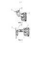
Некоторые существующие салонные зеркала заднего вида автомобилей снабжены держателями, однако при замене держателей разных салонных зеркал заднего вида возникают трудности. В связи с предложениями на рынке различных частей для автомобилей пользователи иногда хотели бы снять оригинальный держатель зеркала заднего вида и поставить вместо него держатель, имеющий улучшенные характеристики, например, возможность регулирования положения зеркала в более широком диапазоне углов. Держатели, выпускаемые изготовителями оригинальных частей, обычно делятся на два типа. Один тип представляет собой держатели с одним шаровым шарниром, как показано на фигуре 1, и основание держателя расположено выше салонного зеркала заднего вида. Для такого держателя на рынке предлагаются техническое решение по замене его задней части. Другой тип держателей зеркал заднего вида включает два или три шаровых шарнира, как показано на фигурах 2 и 3, причем основание этого типа держателя обычно находится перед салонным зеркалом заднего вида. На рынке отсутствуют удовлетворительные конструкции, обеспечивающие возможность замены держателей такого типа.Some existing car interior mirrors are equipped with holders, but difficulties arise when replacing holders of different interior mirrors. In connection with the offers on the market of various parts for automobiles, users sometimes would like to remove the original rear-view mirror holder and put in place a holder with improved characteristics, for example, the ability to adjust the position of the mirror in a wider range of angles. Holders manufactured by original parts manufacturers are usually divided into two types. One type is holders with one ball joint, as shown in figure 1, and the base of the holder is located above the cabin rearview mirror. For such a holder, a technical solution is offered on the market for replacing its rear end. Another type of mirror holder includes two or three ball joints, as shown in figures 2 and 3, the base of this type of holder is usually located in front of the cabin mirror. There are no satisfactory designs on the market that can replace holders of this type.
Сущность изобретенияSUMMARY OF THE INVENTION
Целью настоящего изобретения является создание узла съемного держателя для салонного зеркала заднего вида автомобиля, который может обеспечивать хорошую устойчивость в отношении ударных нагрузок, высокую степень безопасности и широкий диапазон регулирования углов наклона зеркала заднего вида, причем за счет регулировки средств фиксации шаровой головки решается проблема известных конструкций держателей, связанная с невозможностью их замены, и зеркало заднего вида может быть установлено под разными углами. Для решения вышеуказанных технических проблем в настоящем изобретении предлагается следующее техническое решение.The aim of the present invention is to provide a removable holder assembly for a passenger car rearview mirror, which can provide good stability against shock loads, a high degree of safety and a wide range of adjustment of the tilt angles of the rearview mirror, and the known structures are solved by adjusting the fixation means of the ball head holders associated with the inability to replace them, and a rearview mirror can be installed at different angles. To solve the above technical problems, the present invention proposes the following technical solution.
Предлагаемый узел съемного держателя для салонного зеркала заднего вида автомобиля содержит основание держателя, установленное в зеркале заднего вида, и основание, изготовленное производителем частей автомобиля (оригинальное основание), установленное на ветровом стекле автомобиля, а также содержит съемный держатель, расположенный между основанием держателя и оригинальным основанием, причем съемный держатель содержит основание шаровой головки, трубку держателя и переходную головку, при этом основание шаровой головки прикреплено к оригинальному основанию, основание держателя снабжено соединителем, который соединен с переходной головкой на съемном держателе и прикреплен к съемному держателю посредством крепежного винта.The proposed assembly of the removable holder for the interior rear-view mirror of the car comprises a holder base mounted in the rear-view mirror and a base made by the car parts manufacturer (original base) mounted on the car windshield, and also contains a removable holder located between the holder base and the original the base, and the removable holder contains the base of the ball head, the tube of the holder and the adapter head, while the base of the ball head is attached to iginalnomu base, the base is provided with a holder connector which is connected to the head at the transition and a detachable holder attached to the holder by means of detachable fastening screw.
Внутри трубки съемного держателя расположена пружина и гнездо шаровой головки.Inside the tube of the removable holder, a spring and a socket of the ball head are located.
В центральной части соединителя выполнено отверстие с круговой канавкой для крепежного винта.A hole with a circular groove for the fixing screw is made in the central part of the connector.
В центральной части переходной головки выполнено сквозное отверстие.A through hole is made in the central part of the transition head.
На одном конце соединителя, соединенного с переходной головкой, с обеих сторон выполнены внутренние скосы, формирующие канавку со скругленными стенками.On one end of the connector connected to the transition head, internal bevels are made on both sides, forming a groove with rounded walls.
На одном конце переходной головки, соединенной с соединителем, с обеих сторон выполнены внешние скосы, соответствующие внутренним скосам соединителя.On one end of the transition head connected to the connector, external bevels are made on both sides corresponding to the internal bevels of the connector.
Техническое решение, предлагаемое в настоящем изобретении, может гибко подстраиваться к салонному зеркалу заднего вида автомобиля, причем соединитель имеет такую конструкцию, которая сопрягается с основанием держателя в зеркале заднего вида, съемный держатель имеет такую конструкцию, которая сопрягается с оригинальным основанием, и соединитель прикрепляется к съемному держателю посредством крепежного винта, в результате чего основание держателя, соединитель и съемный держатель с переходной головкой могут быть соединены как одно целое для формирования вместе с салонным зеркалом заднего вида автомобиля комбинированного изделия, и, таким образом, не только обеспечивается решение проблемы, связанной с заменой известных держателей с двумя и тремя шаровыми шарнирами, но также облегчается сборка и разборка. В конструкции узла по настоящему изобретению соединитель и переходная головка скреплены между собой посредством крепежного винта, так что указанные две части не будут смещаться относительно друг друга в радиальном и в продольном направлениях, и внутренние боковые скосы сопрягаются с внешними боковыми скосами, а именно, одна часть, соединитель, имеет с обеих сторон внутренние скосы, формирующие канавку со скругленными стенками, и другая часть, переходная головка, имеет с обеих сторон своей концевой части внешние скосы, причем часть со скосами на переходной головке вводится в канавку, сформированную внутренними скосами соединителя, так что скосы этих частей прижимаются друг к другу, в результате чего, в сочетании с фиксирующим действием крепежного винта, обеспечивается простота и удобство сборки прочного узла. Кроме того, в соответствии с настоящим изобретение крепление осуществляется посредством крепежного винта, проходящего внутри съемного держателя и внутри пружины, в результате чего винт скрыт внутри съемного держателя, он не виден человеку, то есть, обеспечивается привлекательный внешний вид изделия, безопасность и надежность.The technical solution proposed in the present invention can be flexibly adjusted to the interior rear-view mirror of the car, the connector having a structure that mates with the base of the holder in the rear-view mirror, the removable holder has a structure that mates with the original base, and the connector is attached to removable holder by means of a fixing screw, as a result of which the base of the holder, the connector and the removable holder with the adapter head can be connected as one It is used to form a combined product together with a car rearview mirror, and thus, not only is a solution to the problem of replacing the known holders with two and three ball joints, but assembly and disassembly is also facilitated. In the construction of the assembly of the present invention, the connector and the adapter head are fastened together by means of a fixing screw, so that these two parts will not be displaced relative to each other in the radial and longitudinal directions, and the inner side bevels are mated with the outer side bevels, namely, one part , the connector has internal bevels on both sides forming a groove with rounded walls, and the other part, the transition head, has external bevels on both sides of its end part, and the part with a bevel themselves on the transition head is inserted into the groove formed by the internal bevels of the connector, so that the bevels of these parts are pressed against each other, as a result, in combination with the fixing action of the fastening screw, the assembly of the durable unit is simple and convenient. In addition, in accordance with the present invention, the fastening is carried out by means of a fixing screw passing inside the removable holder and inside the spring, as a result of which the screw is hidden inside the removable holder, it is not visible to humans, that is, an attractive appearance of the product, safety and reliability are provided.
Характеристики и достоинства настоящего изобретения станут более понятными после прочтения подробного описания вариантов осуществления изобретения со ссылками на прилагаемые фигуры.The characteristics and advantages of the present invention will become more apparent after reading the detailed description of embodiments of the invention with reference to the accompanying figures.
Краткое описание чертежейBrief Description of the Drawings
Фигура 1 - схематический вид сечения известного оригинального держателя с одним шаровым шарниром в сборке с салонным зеркалом заднего вида;Figure 1 is a schematic sectional view of a known original holder with one ball joint in an assembly with a salon rear-view mirror;
фигура 2 - схематический вид сечения известного оригинального держателя с двумя шаровыми шарнирами;figure 2 is a schematic sectional view of a well-known original holder with two ball joints;
фигура 3 - схематический вид сечения известного оригинального держателя с тремя шаровыми шарнирами;figure 3 is a schematic sectional view of a well-known original holder with three ball joints;
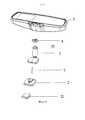
фигура 4 - схематический вид сечения узла съемного держателя по первому варианту осуществления изобретения, установленного вместе с салонным зеркалом заднего вида;figure 4 is a schematic sectional view of a removable holder assembly according to a first embodiment of the invention installed together with a salon rear-view mirror;
фигура 5 - схематический вид разобранного узла съемного держателя по первому варианту осуществления изобретения вместе с салонным зеркалом заднего вида;figure 5 is a schematic view of a disassembled node of the removable holder according to the first embodiment of the invention together with a salon rear-view mirror;
фигура 6 - схематический вид в перспективе узла держателя по первому варианту осуществления изобретения вместе с салонным зеркалом заднего вида;figure 6 is a schematic perspective view of a holder assembly according to a first embodiment of the invention together with a salon rear-view mirror;
фигура 7 - схематический вид в перспективе соединителя узла держателя по первому варианту осуществления изобретения;7 is a schematic perspective view of a connector of a holder assembly according to a first embodiment of the invention;
фигура 8 - схематический вид в перспективе переходной головки узла держателя по первому варианту осуществления изобретения;Figure 8 is a schematic perspective view of a transition head of a holder assembly according to a first embodiment of the invention;
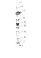
фигура 9 - схематический вид в перспективе разобранного узла держателя по первому варианту осуществления изобретения;figure 9 is a schematic perspective view of an exploded holder assembly according to a first embodiment of the invention;
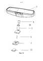
фигура 10 - схематический вид установки узла съемного держателя по первому варианту осуществления изобретения на салонное зеркало заднего вида;figure 10 is a schematic view of the installation of the node of the removable holder according to the first embodiment of the invention on the cabin rear view mirror;
фигура 11 - схематический вид, иллюстрирующий соединение узла съемного держателя по первому варианту осуществления изобретения с салонным зеркалом заднего вида;figure 11 is a schematic view illustrating the connection of the node of the removable holder according to the first embodiment of the invention with a salon rear-view mirror;
фигура 12 - схематический вид сечения узла съемного держателя по второму варианту изобретения, установленного вместе с салонным зеркалом заднего вида;figure 12 is a schematic sectional view of a removable holder assembly according to a second embodiment of the invention installed together with a salon rear-view mirror;
фигура 13 - схематический вид разобранного узла съемного держателя по второму варианту изобретения вместе с салонным зеркалом заднего вида;figure 13 is a schematic view of a disassembled node of the removable holder according to the second embodiment of the invention together with a salon rear-view mirror;
фигура 14 - схематический вид в перспективе узла держателя по второму варианту осуществления изобретения вместе с салонным зеркалом заднего вида;Figure 14 is a schematic perspective view of a holder assembly according to a second embodiment of the invention, together with a cabin rear view mirror;
фигура 15 - схематический вид в перспективе соединителя узла держателя по второму варианту осуществления изобретения;Figure 15 is a schematic perspective view of a connector of a holder assembly according to a second embodiment of the invention;
фигура 16 - схематический вид в перспективе разобранного узла держателя по второму варианту осуществления изобретения;figure 16 is a schematic perspective view of an exploded holder assembly according to a second embodiment of the invention;
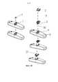
фигура 17 - схематический вид установки узла съемного держателя по второму варианту осуществления изобретения на салонное зеркало заднего вида;figure 17 is a schematic view of the installation of the node of the removable holder according to the second embodiment of the invention on the cabin rear view mirror;
фигура 18 - схематический вид, иллюстрирующий соединение узла съемного держателя по второму варианту осуществления изобретения с салонным зеркалом заднего вида.figure 18 is a schematic view illustrating the connection of the node of the removable holder according to the second embodiment of the invention with a salon rear-view mirror.
Ссылочные номера на фигурах:Reference numbers in the figures:
1 - основание держателя; 2 - оригинальное основание; 21 - опорный фиксатор; 31 - основание шаровой головки; 32 - трубка держателя; 33 - гнездо шаровой головки; 34 - пружина; 35 - переходная головка; 351 - сквозное отверстие; 352 - внешний скос; 353 - переходная шаровая головка; 41 - отверстие для винта; 42 - фиксирующая колонка; 43 - внутренний скос; 44 - соединительная шаровая головка; 5 - крепежный винт; 6 - корпус салонного зеркала заднего вида автомобиля; 7 - ветровое стекло автомобиля.1 - the base of the holder; 2 - original base; 21 - reference retainer; 31 - the base of the ball head; 32 - tube holder; 33 - socket ball head; 34 - spring; 35 - transitional head; 351 - through hole; 352 - external bevel; 353 - transition ball head; 41 - hole for the screw; 42 - fixing column; 43 - internal bevel; 44 - connecting ball head; 5 - fixing screw; 6 - body cabin mirror; 7 - a car windshield.
Подробное описание вариантов осуществления изобретенияDetailed Description of Embodiments
Ниже приводится подробное описание изобретения на примерах некоторых вариантов его осуществления, однако следует понимать, что объем изобретения не ограничивается лишь описанными вариантами.Below is a detailed description of the invention by the examples of some variants of its implementation, however, it should be understood that the scope of the invention is not limited to the described options.
Первый вариантFirst option
Как показано на фигурах 4-11, узел съемного держателя салонного зеркала заднего вида автомобиля содержит основание 1 держателя, оригинальное основание 2, опорный фиксатор 21 основания 2 и съемный держатель 3. Основание 1 держателя расположено в корпусе 6 салонного зеркала заднего вида, оригинальное основание 2 расположено на ветровом стекле 7 автомобиля, опорный фиксатор 21 расположен под оригинальным основанием 2, и съемный держатель 3 расположен между основанием 1 держателя и оригинальным основанием 2. Съемный держатель 3 содержит основание 31 шаровой головки, трубку 32 держателя, гнездо 33 шаровой головки, пружину 34 и переходную головку 35. Основание 31 шаровой головки прикрепляется к оригинальному основанию 2. Основание 1 держателя снабжено соединителем 4. Соединитель 4 соединен с переходной головкой 35 на съемном держателе. Для фиксации соединителя 4 используется крепежный винт 5, проходящий через основание 31 шаровой головки, трубку 32 держателя, гнездо 33 шаровой головки, пружину 34 и переходную головку 35 съемного держателя 3. В центральной части соединителя 4 выполнено отверстие 41 под винт, в нижней его части выполнена фиксирующая колонка 42, сопрягающаяся с основанием 1 держателя, и в верхней части соединителя 4 выполнены с двух сторон внутренние скосы 43 для формирования канавки со скругленными стенками. В центральной части переходной головки 35 выполнено сквозное отверстие 351, и на одном ее конце с двух сторон выполнены внешние скосы 352, соответствующие внутренним скосам 43 соединителя 4, для соединения с соединителем 4, а на другом конце переходной головки 35 расположена шаровая головка 353.As shown in figures 4-11, the assembly of the removable holder for the interior rearview mirror of the vehicle comprises a
Настоящее изобретение направлено на замену оригинального держателя с двумя шаровыми шарнирами. Как показано на фигуре 1, поскольку оригинальный держатель с одним шаровым шарниром установлен на основании держателя салонного зеркала заднего вида, и поскольку основание держателя установлено на жестком металлическом кольце, то возникают трудности при снятии и замене держателя с одним шаровым шарниром. Для решения этой проблемы некоторые производители выпускают отдельную конструкцию для держателя с одним шаровым шарниром. Однако на рынке нет удовлетворительных технических решений для замены держателя с двумя шаровыми шарнирами. Проблема решается в настоящем изобретении с помощью соединителя, установленного в зеркале, и переходной головки узла съемного держателя. При сборке узла соединитель 4 в зеркале заднего вида фиксируют в основании 1 держателя посредством штифта, затем переходную головку 35 совмещают с соединителем 4 в зеркале заднего вида, и после установки крепежного винта 5, проходящего через гнездо 33 шаровой головки и пружину 34 в трубке 32 держателя, соединитель 4 закрепляется в зеркале заднего вида. Таким образом, держатель с двумя шарнирами и салонное зеркало заднего вида формируют сборное изделие. Если необходима замена, то следует лишь отвинтить крепежный винт и поставить другой держатель с двумя шаровыми шарнирами.The present invention aims to replace the original holder with two ball joints. As shown in FIG. 1, since the original holder with one ball joint is mounted on the base of the holder of the rear view mirror, and since the base of the holder is mounted on a rigid metal ring, it becomes difficult to remove and replace the holder with one ball joint. To solve this problem, some manufacturers produce a separate design for a holder with one ball joint. However, there are no satisfactory technical solutions on the market for replacing the holder with two ball joints. The problem is solved in the present invention by means of a connector mounted in the mirror and a transition head of the removable holder assembly. When assembling the assembly, the
Второй вариантSecond option
Как показано на фигурах 8 и 12-18, съемный узел держателя салонного зеркала заднего вида автомобиля содержит основание 1 держателя, оригинальное основание 2 и съемный держатель 3. Основание 1 держателя расположено в корпусе салонного зеркала заднего вида, оригинальное основание 2 расположено на ветровом стекле 7 автомобиля, и съемный держатель 3 расположен между основанием 1 держателя и оригинальным основанием 2. Съемный держатель 3 содержит основание 31 шаровой головки, трубку 32 держателя, гнездо 33 шаровой головки, пружину 34 и переходную головку 35. Основание 31 шаровой головки крепится на оригинальном основании 2. Основание 1 держателя снабжено соединителем 4. Соединитель 4 соединен с переходной головкой 35 на съемном держателе. Для крепления и фиксации соединителя 4 используется крепежный винт 5, проходящий через основание 31 шаровой головки, трубку 32 держателя, гнездо 33 шаровой головки, пружину 34 и переходную головку 35 съемного держателя 3. В центральной части соединителя 4 выполнено отверстие 41 под винт, в нижней его части выполнена соединительная шаровая головка 44, сопрягающаяся с основанием 1 держателя, и в верхней части соединителя 4 выполнены внутренние скосы 43 для формирования канавки со скругленными стенками. В центральной части переходной головки 35 выполнено сквозное отверстие 351, и на одном ее конце по двум сторонам выполнены внешние скосы 352, соответствующие внутренним скосам 43 соединителя 4, для соединения с соединителем 4, а на другом конце переходной головки 35 расположена шаровая головка 353.As shown in figures 8 and 12-18, the removable assembly of the car interior mirror holder includes a
Настоящее изобретение направлено на замену оригинального держателя с тремя шаровыми шарнирами. Соединительная шаровая головка 44 в рассматриваемом варианте, расположенная в зеркале заднего вида, находится в нижней части соединителя 4. Обычный держатель с тремя шаровыми шарнирами содержит шаровую головку, находящуюся в соединительной части между держателем с тремя шаровыми шарнирами и салонным зеркалом заднего вида. Один конец части с двумя шаровыми головками соединен с основанием держателя, а другой ее конец соединен с держателем с тремя шаровыми шарнирами. Из-за плотной посадки основания держателя возникают серьезные затруднения при съеме держателя вручную. В рассматриваемом варианте предлагается отдельная конструкция, то есть, узел держателя с тремя шаровыми шарнирами модифицирован таким образом, что он содержит, среди прочего, две части: одна часть представляет собой соединитель 4 в зеркале заднего вида, а другая часть представляет собой переходную головку 35. В собранном узле соединитель 4 в зеркале заднего вида запрессован в основание 1 держателя зеркала заднего вида с использованием фиксирующего элемента. Если необходимо заменить узел держателя с тремя шаровыми шарнирами, съемный держатель 3 с двумя шаровыми шарнирами соединяют с соединителем 4 внутри зеркала заднего вида, затем вставляют крепежный винт таким образом, чтобы он проходил сквозь гнездо 33 шаровой головки и пружину 34 в трубке 32 держателя, после чего переходную головку 35 съемного держателя 3 прикрепляют к соединителю 4 в зеркале заднего вида, затем основание 31 шаровой головки соединяют с оригинальным основанием 2, и на этом замена узла держателя с тремя шаровыми шарнирами заканчивается. Для повышения прочности всего узла держателя съемный держатель 3 по настоящему изобретению изготавливают из цинкового сплава с использованием литья под давлением, в результате чего обеспечивается не только экологичность и жесткость конструкции, но и прочность. Оригинальное основание 2 установлено в автомобиле, и съемный держатель 3 с переходной головкой 35 прикрепляют с помощью крепежного винта, и при этом соединитель 4 расположен в салонном зеркале заднего вида.The present invention aims to replace the original holder with three ball joints. The connecting
Здесь были описаны возможные варианты осуществления настоящего изобретения со ссылками на прилагаемые фигуры, однако специалисты в данной области техники могут предложить различные модификации этих вариантов, которые будут охватываться объемом охраны изобретения, при условии что эти модификации будут находиться в пределах объема, определяемого формулой изобретения.Possible embodiments of the present invention have been described here with reference to the accompanying figures, however, those skilled in the art can propose various modifications of these options that will be covered by the protection scope of the invention, provided that these modifications are within the scope defined by the claims.
Claims (5)
Translated fromRussianApplications Claiming Priority (3)
| Application Number | Priority Date | Filing Date | Title |
|---|---|---|---|
| CN201420434347.2 | 2014-08-01 | ||
| CN201420434347.2UCN204077516U (en) | 2014-08-01 | 2014-08-01 | A kind of removable inside-automobile rear mirror support |
| PCT/CN2014/093641WO2016015429A1 (en) | 2014-08-01 | 2014-12-11 | Replaceable automobile interior rearview mirror bracket |
Publications (3)
| Publication Number | Publication Date |
|---|---|
| RU2016131210A RU2016131210A (en) | 2018-09-03 |
| RU2016131210A3 RU2016131210A3 (en) | 2018-09-03 |
| RU2668411C2true RU2668411C2 (en) | 2018-09-28 |
Family
ID=52170262
Family Applications (1)
| Application Number | Title | Priority Date | Filing Date |
|---|---|---|---|
| RU2016131210ARU2668411C2 (en) | 2014-08-01 | 2014-12-11 | Removable bracket for rear view mirrors of vehicles |
Country Status (10)
| Country | Link |
|---|---|
| US (2) | US10017118B2 (en) |
| EP (1) | EP3078546B1 (en) |
| JP (1) | JP6220460B2 (en) |
| CN (1) | CN204077516U (en) |
| AU (1) | AU2014402007B2 (en) |
| BR (1) | BR112016017542B1 (en) |
| ES (1) | ES2660839T3 (en) |
| RU (1) | RU2668411C2 (en) |
| TR (1) | TR201803004T4 (en) |
| WO (1) | WO2016015429A1 (en) |
Families Citing this family (6)
| Publication number | Priority date | Publication date | Assignee | Title |
|---|---|---|---|---|
| US11173842B2 (en) | 2018-10-02 | 2021-11-16 | Gentex Corporation | Adjustable mounting mechanism for a rearview assembly |
| USD965669S1 (en)* | 2020-03-16 | 2022-10-04 | Getac Technology Corporation | Camera support |
| GB2601340A (en)* | 2020-11-26 | 2022-06-01 | Aptiv Tech Ltd | An articulated stand for holding an electronic device |
| US11927298B2 (en) | 2021-08-23 | 2024-03-12 | Gentex Corporation | Rearview assembly mounting element |
| US12049169B2 (en)* | 2021-08-23 | 2024-07-30 | Gentex Corporation | Rearview assembly mount |
| CN114954237B (en)* | 2022-02-22 | 2025-05-09 | 冠捷电子科技(福建)有限公司 | A kind of automobile rearview mirror bracket |
Citations (5)
| Publication number | Priority date | Publication date | Assignee | Title |
|---|---|---|---|---|
| US5321556A (en)* | 1992-05-11 | 1994-06-14 | Joe Tobby F | Vehicle safety convex rearview mirror with distortion offset means and method of using the same |
| US5572354A (en)* | 1993-03-19 | 1996-11-05 | Donnelly Mirrors, Ltd. | Rearview mirror support bracket with retaining protrusion, rearview mirror case and reflective element |
| US5931440A (en)* | 1996-11-01 | 1999-08-03 | Gentex Corporation | Regulated attachment for mirror mount |
| US20040195486A1 (en)* | 2003-04-07 | 2004-10-07 | Wayne Rumsey | Quick-attach mirror mounting structure facilitating assembly |
| JP2007290658A (en)* | 2006-04-27 | 2007-11-08 | Denso Corp | Anti-glare mirror mounting device |
Family Cites Families (14)
| Publication number | Priority date | Publication date | Assignee | Title |
|---|---|---|---|---|
| US4807096A (en)* | 1986-06-26 | 1989-02-21 | Donnelly Corporation | Interior light/carrier module for vehicles |
| US4733336A (en)* | 1986-06-26 | 1988-03-22 | Donnelly Corporation | Lighted/information case assembly for rearview mirrors |
| US6326613B1 (en)* | 1998-01-07 | 2001-12-04 | Donnelly Corporation | Vehicle interior mirror assembly adapted for containing a rain sensor |
| US6428172B1 (en)* | 1999-11-24 | 2002-08-06 | Donnelly Corporation | Rearview mirror assembly with utility functions |
| AU2002251807A1 (en)* | 2001-01-23 | 2002-08-19 | Donnelly Corporation | Improved vehicular lighting system for a mirror assembly |
| US20040019548A1 (en)* | 2002-07-25 | 2004-01-29 | Kenneth Hu | Security evaluating system and method thereof |
| WO2004103772A2 (en)* | 2003-05-19 | 2004-12-02 | Donnelly Corporation | Mirror assembly for vehicle |
| US7360932B2 (en)* | 2004-06-01 | 2008-04-22 | Donnelly Corporation | Mirror assembly for vehicle |
| US6899437B2 (en)* | 2002-10-02 | 2005-05-31 | Gentax Corporation | Environmentally improved rearview mirror assembly |
| US7023379B2 (en)* | 2003-04-03 | 2006-04-04 | Gentex Corporation | Vehicle rearview assembly incorporating a tri-band antenna module |
| US20100085653A1 (en)* | 2008-09-15 | 2010-04-08 | Magna Mirrors Of America, Inc. | Mirror assembly for vehicle |
| KR100970329B1 (en)* | 2009-01-30 | 2010-07-15 | 에스엠알 페턴츠 에스.에이.알.엘. | Inside mirror using ball clamp for vehicle |
| CN102648113B (en)* | 2009-10-07 | 2015-05-27 | 麦格纳镜片美国有限公司 | Frameless interior rearview mirror assembly |
| CN202271907U (en)* | 2011-08-26 | 2012-06-13 | 潘磊 | Automobile rearview mirror bracket |
- 2014
- 2014-08-01CNCN201420434347.2Upatent/CN204077516U/ennot_activeExpired - Fee Related
- 2014-12-11TRTR2018/03004Tpatent/TR201803004T4/enunknown
- 2014-12-11JPJP2016549438Apatent/JP6220460B2/enactiveActive
- 2014-12-11ESES14898521.1Tpatent/ES2660839T3/enactiveActive
- 2014-12-11WOPCT/CN2014/093641patent/WO2016015429A1/enactiveApplication Filing
- 2014-12-11AUAU2014402007Apatent/AU2014402007B2/enactiveActive
- 2014-12-11BRBR112016017542-5Apatent/BR112016017542B1/enactiveIP Right Grant
- 2014-12-11EPEP14898521.1Apatent/EP3078546B1/enactiveActive
- 2014-12-11RURU2016131210Apatent/RU2668411C2/enactive
- 2016
- 2016-07-07USUS15/204,778patent/US10017118B2/enactiveActive
- 2018
- 2018-04-30USUS15/967,553patent/US20180244202A1/ennot_activeAbandoned
Patent Citations (5)
| Publication number | Priority date | Publication date | Assignee | Title |
|---|---|---|---|---|
| US5321556A (en)* | 1992-05-11 | 1994-06-14 | Joe Tobby F | Vehicle safety convex rearview mirror with distortion offset means and method of using the same |
| US5572354A (en)* | 1993-03-19 | 1996-11-05 | Donnelly Mirrors, Ltd. | Rearview mirror support bracket with retaining protrusion, rearview mirror case and reflective element |
| US5931440A (en)* | 1996-11-01 | 1999-08-03 | Gentex Corporation | Regulated attachment for mirror mount |
| US20040195486A1 (en)* | 2003-04-07 | 2004-10-07 | Wayne Rumsey | Quick-attach mirror mounting structure facilitating assembly |
| JP2007290658A (en)* | 2006-04-27 | 2007-11-08 | Denso Corp | Anti-glare mirror mounting device |
Also Published As
| Publication number | Publication date |
|---|---|
| WO2016015429A1 (en) | 2016-02-04 |
| US20160318447A1 (en) | 2016-11-03 |
| CN204077516U (en) | 2015-01-07 |
| US10017118B2 (en) | 2018-07-10 |
| AU2014402007B2 (en) | 2017-04-20 |
| ES2660839T3 (en) | 2018-03-26 |
| US20180244202A1 (en) | 2018-08-30 |
| EP3078546A4 (en) | 2016-11-23 |
| EP3078546B1 (en) | 2018-01-31 |
| JP6220460B2 (en) | 2017-10-25 |
| AU2014402007A1 (en) | 2016-07-28 |
| TR201803004T4 (en) | 2018-03-21 |
| BR112016017542A2 (en) | 2017-08-08 |
| BR112016017542B1 (en) | 2022-06-21 |
| RU2016131210A (en) | 2018-09-03 |
| EP3078546A1 (en) | 2016-10-12 |
| JP2017504521A (en) | 2017-02-09 |
| RU2016131210A3 (en) | 2018-09-03 |
Similar Documents
| Publication | Publication Date | Title |
|---|---|---|
| RU2668411C2 (en) | Removable bracket for rear view mirrors of vehicles | |
| US10343608B2 (en) | Rearview assembly | |
| US8960786B2 (en) | Supporting structure for a swivelable center armrest | |
| CN104411544A (en) | exterior mirror | |
| CN107107828B (en) | Vehicular door rear mirror | |
| US10240712B2 (en) | Ball mount assembly for vehicle | |
| KR102000947B1 (en) | Assistance headrest | |
| WO2020085181A1 (en) | Vehicle sun visor | |
| US10293754B2 (en) | Mirror device for vehicle | |
| EP4003789A1 (en) | A cover fastening system for a vehicle | |
| JP6341817B2 (en) | Inner mirror structure for vehicles | |
| JP2000168357A (en) | Bearing structure for sun visor for vehicle | |
| JP2010099223A (en) | Chair | |
| CN211710725U (en) | Rearview mirror structure suitable for truck | |
| CN208915073U (en) | A kind of installation of outside rear-view mirror auxiliary and location structure | |
| JP6310776B2 (en) | Vehicle side mirror | |
| CN205854001U (en) | A kind of room mirror | |
| CN215552875U (en) | Friction ball socket structure of rearview mirror surface adjuster, automobile rearview mirror and automobile | |
| CN210284074U (en) | Outer rearview mirror shell assembly | |
| CN206202124U (en) | A kind of vehicle mirrors for being easy to assemble | |
| CN106240469A (en) | A kind of Novel rearview optical module of automobile-use | |
| JPS5941152Y2 (en) | Support structure for adjusting screws in automobile headlights | |
| KR200359725Y1 (en) | The back mirror of a car | |
| JP2006315553A (en) | Bumper assembly structure | |
| JP6494758B2 (en) | Motorcycle front cover mounting structure |