RU2666889C1 - Outer engine housing reversing device deflecting grille - Google Patents
Outer engine housing reversing device deflecting grilleDownload PDFInfo
- Publication number
- RU2666889C1 RU2666889C1RU2017108680ARU2017108680ARU2666889C1RU 2666889 C1RU2666889 C1RU 2666889C1RU 2017108680 ARU2017108680 ARU 2017108680ARU 2017108680 ARU2017108680 ARU 2017108680ARU 2666889 C1RU2666889 C1RU 2666889C1
- Authority
- RU
- Russia
- Prior art keywords
- reversing device
- deflecting
- sections
- longitudinal ribs
- transverse
- Prior art date
Links
- 239000002131composite materialSubstances0.000claimsabstractdescription6
- 230000002441reversible effectEffects0.000claimsdescription9
- 229920000642polymerPolymers0.000claimsdescription5
- 239000007787solidSubstances0.000abstract1
- 239000000126substanceSubstances0.000abstract1
- 238000009434installationMethods0.000description2
- 101100334009Caenorhabditis elegans rib-2 geneProteins0.000description1
- 229920000049Carbon (fiber)Polymers0.000description1
- 239000011230binding agentSubstances0.000description1
- 230000015572biosynthetic processEffects0.000description1
- 230000000903blocking effectEffects0.000description1
- 239000004917carbon fiberSubstances0.000description1
- 238000000465mouldingMethods0.000description1
Images


Classifications
- F—MECHANICAL ENGINEERING; LIGHTING; HEATING; WEAPONS; BLASTING
- F02—COMBUSTION ENGINES; HOT-GAS OR COMBUSTION-PRODUCT ENGINE PLANTS
- F02K—JET-PROPULSION PLANTS
- F02K1/00—Plants characterised by the form or arrangement of the jet pipe or nozzle; Jet pipes or nozzles peculiar thereto
- F02K1/54—Nozzles having means for reversing jet thrust
- F02K1/64—Reversing fan flow
- F02K1/70—Reversing fan flow using thrust reverser flaps or doors mounted on the fan housing
- F02K1/72—Reversing fan flow using thrust reverser flaps or doors mounted on the fan housing the aft end of the fan housing being movable to uncover openings in the fan housing for the reversed flow
- B—PERFORMING OPERATIONS; TRANSPORTING
- B64—AIRCRAFT; AVIATION; COSMONAUTICS
- B64D—EQUIPMENT FOR FITTING IN OR TO AIRCRAFT; FLIGHT SUITS; PARACHUTES; ARRANGEMENT OR MOUNTING OF POWER PLANTS OR PROPULSION TRANSMISSIONS IN AIRCRAFT
- B64D33/00—Arrangement in aircraft of power plant parts or auxiliaries not otherwise provided for
- B64D33/04—Arrangement in aircraft of power plant parts or auxiliaries not otherwise provided for of exhaust outlets or jet pipes
- F—MECHANICAL ENGINEERING; LIGHTING; HEATING; WEAPONS; BLASTING
- F02—COMBUSTION ENGINES; HOT-GAS OR COMBUSTION-PRODUCT ENGINE PLANTS
- F02K—JET-PROPULSION PLANTS
- F02K1/00—Plants characterised by the form or arrangement of the jet pipe or nozzle; Jet pipes or nozzles peculiar thereto
- F02K1/54—Nozzles having means for reversing jet thrust
- F02K1/56—Reversing jet main flow
- F02K1/58—Reversers mounted on the inner cone or the nozzle housing or the fuselage
- B—PERFORMING OPERATIONS; TRANSPORTING
- B64—AIRCRAFT; AVIATION; COSMONAUTICS
- B64C—AEROPLANES; HELICOPTERS
- B64C7/00—Structures or fairings not otherwise provided for
- B64C7/02—Nacelles
- B—PERFORMING OPERATIONS; TRANSPORTING
- B64—AIRCRAFT; AVIATION; COSMONAUTICS
- B64D—EQUIPMENT FOR FITTING IN OR TO AIRCRAFT; FLIGHT SUITS; PARACHUTES; ARRANGEMENT OR MOUNTING OF POWER PLANTS OR PROPULSION TRANSMISSIONS IN AIRCRAFT
- B64D29/00—Power-plant nacelles, fairings or cowlings
- F—MECHANICAL ENGINEERING; LIGHTING; HEATING; WEAPONS; BLASTING
- F05—INDEXING SCHEMES RELATING TO ENGINES OR PUMPS IN VARIOUS SUBCLASSES OF CLASSES F01-F04
- F05D—INDEXING SCHEME FOR ASPECTS RELATING TO NON-POSITIVE-DISPLACEMENT MACHINES OR ENGINES, GAS-TURBINES OR JET-PROPULSION PLANTS
- F05D2240/00—Components
- F05D2240/10—Stators
- F05D2240/12—Fluid guiding means, e.g. vanes
- F05D2240/129—Cascades, i.e. assemblies of similar profiles acting in parallel
- F—MECHANICAL ENGINEERING; LIGHTING; HEATING; WEAPONS; BLASTING
- F05—INDEXING SCHEMES RELATING TO ENGINES OR PUMPS IN VARIOUS SUBCLASSES OF CLASSES F01-F04
- F05D—INDEXING SCHEME FOR ASPECTS RELATING TO NON-POSITIVE-DISPLACEMENT MACHINES OR ENGINES, GAS-TURBINES OR JET-PROPULSION PLANTS
- F05D2300/00—Materials; Properties thereof
- F05D2300/40—Organic materials
- F05D2300/43—Synthetic polymers, e.g. plastics; Rubber
- F—MECHANICAL ENGINEERING; LIGHTING; HEATING; WEAPONS; BLASTING
- F05—INDEXING SCHEMES RELATING TO ENGINES OR PUMPS IN VARIOUS SUBCLASSES OF CLASSES F01-F04
- F05D—INDEXING SCHEME FOR ASPECTS RELATING TO NON-POSITIVE-DISPLACEMENT MACHINES OR ENGINES, GAS-TURBINES OR JET-PROPULSION PLANTS
- F05D2300/00—Materials; Properties thereof
- F05D2300/60—Properties or characteristics given to material by treatment or manufacturing
- F05D2300/603—Composites; e.g. fibre-reinforced
- Y—GENERAL TAGGING OF NEW TECHNOLOGICAL DEVELOPMENTS; GENERAL TAGGING OF CROSS-SECTIONAL TECHNOLOGIES SPANNING OVER SEVERAL SECTIONS OF THE IPC; TECHNICAL SUBJECTS COVERED BY FORMER USPC CROSS-REFERENCE ART COLLECTIONS [XRACs] AND DIGESTS
- Y02—TECHNOLOGIES OR APPLICATIONS FOR MITIGATION OR ADAPTATION AGAINST CLIMATE CHANGE
- Y02T—CLIMATE CHANGE MITIGATION TECHNOLOGIES RELATED TO TRANSPORTATION
- Y02T50/00—Aeronautics or air transport
- Y02T50/60—Efficient propulsion technologies, e.g. for aircraft
Landscapes
- Engineering & Computer Science (AREA)
- Chemical & Material Sciences (AREA)
- Combustion & Propulsion (AREA)
- Mechanical Engineering (AREA)
- General Engineering & Computer Science (AREA)
- Aviation & Aerospace Engineering (AREA)
- Structures Of Non-Positive Displacement Pumps (AREA)
- Sliding-Contact Bearings (AREA)
- Wind Motors (AREA)
Abstract
Description
Translated fromRussianИзобретение относится к области авиационного машиностроения, а именно к конструкции авиационных двигателей и тормозных устройств самолетов, и может быть использовано в отклоняющей решетке реверсивного устройства решетчатого типа из полимерных композиционных материалов (ПКМ).The invention relates to the field of aeronautical engineering, in particular to the design of aircraft engines and aircraft braking devices, and can be used in a deflecting grid of a lattice-type reversing device made of polymer composite materials (PCM).
Из уровня техники известны конструкции отклоняющих решеток, имеющих аэродинамические отклоняющие элементы, которые представляют собой сборную конструкцию (патенты RU 2145672, F02K 1/78, опубл. 20.02.2000; RU 2363580, В29С 70/08, опубл. 10.08.2009; US 2012/0036716, B21D 53/78, опубл. 16.02.2012; US 4852805, В29С 45/14, опубл. 01.08.1989; US 2001/0009642, F01D 1/02, опубл. 26.07.2001).The prior art designs of deflecting grids having aerodynamic deflecting elements, which are a prefabricated structure (patents RU 2145672,
Недостатками конструкций таких устройств является необходимость дополнительных операций по сборке решеток, наличие дополнительных крепежных деталей.The disadvantages of the designs of such devices is the need for additional operations for the assembly of gratings, the presence of additional fasteners.
Наиболее близким к предлагаемому изобретению по технической сущности и достигаемому техническому результату является отклоняющая решетка реверсивного устройства наружного корпуса двигателя, состоящая из секций из полимерных композиционных материалов, включающая намотанные непрерывным жгутом из однонаправленных, например углеродных нитей, пропитанных полимерным связующим, перекрещивающиеся продольные и поперечные слои ребер и лопаток секции решетки различного сечения, от прямоугольного для несущих торцевых лопаток до с-образного и изогнутого, с различной степенью изогнутости, каплевидного для аэродинамических лопаток и ребер, строительной высотой, соразмерной расстоянию между лопатками, с поднутрением ячеек решетки, также соразмерным размерам ячеек, причем каждый слой каждого ребра или лопатки выполнен с количеством жгутов, пропорциональным толщине ребра или лопатки на уровне этого слоя (патент РФ №2509649, В29С 70/08, опубл. 20.03.2014 - прототип).The closest to the proposed invention in technical essence and the technical result achieved is a deflecting grate of the reversing device of the outer motor casing, consisting of sections of polymer composite materials, including wound with a continuous bundle of unidirectional, for example carbon fibers, impregnated with a polymeric binder, intersecting longitudinal and transverse layers of ribs and blades of the lattice section of various sections, from rectangular for bearing end blades to c-shaped and curved, with a different degree of curvature, drop-shaped for aerodynamic blades and ribs, building height commensurate with the distance between the blades, with undercutting of the lattice cells, also commensurate with the size of the cells, each layer of each rib or blade made with the number of bundles proportional to the thickness of the rib or blade at the level of this layer (RF patent No. 2509649, B29C 70/08, publ. 03.20.2014 - prototype).
Недостатком конструкции прототипа является необходимость частичной разборки реверсивного устройства для монтажа/демонтажа секций отклоняющей решетки.The disadvantage of the design of the prototype is the need for partial disassembly of the reversing device for mounting / dismounting sections of the deflecting grid.
Техническим результатом заявленного изобретения является создание высокотехнологичной конструкции отклоняющей решетки реверсивного устройства, повышение надежности работы реверсивного устройства, а также упрощение монтажа/демонтажа секций отклоняющей решетки реверсивного устройства.The technical result of the claimed invention is the creation of a high-tech design of the deflecting lattice of the reversing device, improving the reliability of the reversing device, as well as simplifying the installation / dismantling of sections of the deflecting lattice of the reversing device.
Технический результат достигается за счет того, что в отклоняющей решетке реверсивного устройства наружного корпуса двигателя, изготовленной из полимерного композиционного материала, включающей монолитные секции, каждая из которых содержит продольные ребра и поперечные отклоняющие лопатки, согласно изобретению секции передним фланцем прикреплены посредством разъемного соединения к переднему шпангоуту силового каркаса реверсивного устройства, а задним фланцем прикреплены посредством разъемного соединения к заднему шпангоуту силового каркаса реверсивного устройства, при этом продольные ребра и поперечные отклоняющие лопатки в каждой секции выполнены толщиной 1,5-10 мм, причем продольные ребра выполнены с возможностью обеспечения направления истечения реверсивных струй под углом β=0°-40° к радиальному направлению, а поперечные отклоняющие лопатки расположены под углом γ=40°-80° к продольной оси двигателя.The technical result is achieved due to the fact that in the deflecting grid of the reversing device of the outer motor housing made of a polymer composite material, including monolithic sections, each of which contains longitudinal ribs and transverse deflecting vanes, according to the invention, the sections with the front flange are attached via a detachable connection to the front frame the power frame of the reversing device, and the rear flange is attached via a detachable connection to the rear frame of the forces the frame of the reversing device, while the longitudinal ribs and transverse deflecting blades in each section are made with a thickness of 1.5-10 mm, and the longitudinal ribs are made with the possibility of ensuring the direction of flow of the reversible jets at an angle β = 0 ° -40 ° to the radial direction, and transverse deflecting blades are located at an angle γ = 40 ° -80 ° to the longitudinal axis of the engine.
Закрепление секций соответствующим образом к силовому каркасу реверсивного устройства позволяет упростить монтаж/демонтаж секций отклоняющей решетки на реверсивное устройство.Securing the sections accordingly to the power frame of the reversing device makes it possible to simplify the installation / dismantling of the sections of the deflecting grate on the reversing device.
Выполнение продольных ребер и поперечных отклоняющих лопаток в каждой секции толщиной 1,5-10 мм, выполнение продольных ребер с возможностью обеспечения направления истечения реверсивных струй под углом β=0°-40° к радиальному направлению, а также расположение поперечных отклоняющих лопаток под углом γ=40°-80° к продольной оси двигателя позволяют обеспечить заданную величину обратной тяги, предотвратить прямое воздействие реверсивных струй на элементы самолета и попадание отраженных от взлетно-посадочной полосы реверсивных струй на вход в двигатель, что повышает надежность работы реверсивного устройства.The execution of longitudinal ribs and transverse deflecting blades in each section with a thickness of 1.5-10 mm, the execution of longitudinal ribs with the possibility of providing the direction of flow of reversible jets at an angle β = 0 ° -40 ° to the radial direction, as well as the location of the transverse deflecting blades at an angle γ = 40 ° -80 ° to the longitudinal axis of the engine allows you to provide a given amount of reverse thrust, to prevent the direct impact of reversible jets on the elements of the aircraft and hit the reversible jets reflected from the runway at the entrance to drive, which increases the reliability of the reversing device.
Сущность изобретения поясняется следующими чертежами.The invention is illustrated by the following drawings.
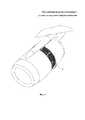
На фиг. 1 представлен общий вид отклоняющей решетки реверсивного устройства, состоящего из секций.In FIG. 1 shows a General view of the deflecting lattice of a reversing device consisting of sections.
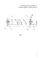
На фиг. 2 представлен вид монолитной секции отклоняющей решетки, включающей продольные ребра и поперечные отклоняющие лопатки.In FIG. 2 is a view of a monolithic section of a deflecting grating, including longitudinal ribs and transverse deflecting blades.
На фиг. 3 показано крепление секции отклоняющей решетки в реверсивном устройстве.In FIG. 3 shows the fastening of the deflecting grid section in a reversing device.
На фиг. 4 показано сечение продольных ребер.In FIG. 4 shows a cross section of longitudinal ribs.
На фиг. 5 показано сечение отклоняющих лопаток.In FIG. 5 shows a cross section of deflecting vanes.
Отклоняющая решетка реверсивного устройства (решетчатого типа), наружного корпуса двигателя состоит из нескольких секций 1, где каждая из секций 1 представляет собой сетчатую конструкцию из продольных ребер 2 и поперечных отклоняющих лопаток 3 и является монолитной конструкцией, изготовленной из полимерного композиционного материала. Каждая из секций 1 изготавливается из ПКМ за одну технологическую операцию формования. Секции 1 отклоняющей решетки передним фланцем 4 прикреплены посредством разъемного соединения 5 к переднему шпангоуту 6 неподвижного силового каркаса реверсивного устройства и задним фланцем 7 присоединяются посредством разъемного соединения 8 к заднему шпангоуту 9 неподвижного силового каркаса реверсивного устройства. Одно из креплений заднего фланца 7 к заднему шпангоуту 9 выполнено по конусу с углом α=1°-90° к образующей.The deflecting grate of the reversing device (grating type) of the outer motor casing consists of
Продольные ребра (элементы) 2 в каждой секции 1 имеют толщину от 1,5 мм до 10 мм и могут быть выполнены различной формы в пределах указанной толщины для каждого ребра 2 с радиусом входной кромки не менее 0,6 мм и углом наклона выходной кромки от 0° до 60° и окружным шагом от 2° до 8° между соседними ребрами 2. Продольные ребра 2 в секции 1 выполнены и расположены таким образом, чтобы обеспечить возможность направления истечения реверсивных струй под углом β=0°-40° к радиальному направлению.The longitudinal ribs (elements) 2 in each
Поперечные отклоняющие лопатки 3 в каждой секции 1 имеют толщину от 1,5 мм до 10 мм и могут быть выполнены различной формы в пределах указанной толщины для каждой лопатки 3 с радиусом входной кромки не менее 0,6 мм. Лопатки 3 расположены под углом наклона γ=40°-80° к продольной оси двигателя. Расстояние между лопатками 3 соразмерно высоте лопаток 3.The
Отклоняющая решетка реверсивного устройства работает следующим образом.The deflection lattice of the reversing device operates as follows.
Для уменьшения длины пробега реактивного самолета при приземлении в конструкции реактивного двигателя используется реверсивное устройство. Реверсивное устройство решетчатого типа располагается в наружном контуре двигателя и состоит, как правило, из подвижной части и неподвижного силового каркаса. При включении реверсивного устройства подвижная часть сдвигается, одновременно перекрывая поток наружного контура и открывая отклоняющие решетки, которые обеспечивают формирование реверсивной струи. Продольные ребра 2 и поперечные отклоняющие лопатки 3 обеспечивают углы истечения реверсивных струй, необходимые для достижения заданной величины обратной тяги, обтекание элементов фюзеляжа самолета, предотвращение попадания отраженной от взлетно-посадочной полосы струи на вход в двигатель.To reduce the path length of a jet plane during landing, a reversing device is used in the design of the jet engine. The lattice-type reversing device is located in the outer circuit of the engine and consists, as a rule, of the movable part and the stationary power frame. When the reversing device is turned on, the movable part is shifted, simultaneously blocking the flow of the external circuit and opening the deflecting gratings, which ensure the formation of the reversing jet. The
Claims (1)
Translated fromRussianPriority Applications (3)
| Application Number | Priority Date | Filing Date | Title |
|---|---|---|---|
| RU2017108680ARU2666889C1 (en) | 2017-03-16 | 2017-03-16 | Outer engine housing reversing device deflecting grille |
| EP18767434.6AEP3597543A4 (en) | 2017-03-16 | 2018-03-23 | Deflecting cascade of a thrust reverser of an engine nacelle |
| PCT/RU2018/000187WO2018169454A2 (en) | 2017-03-16 | 2018-03-23 | Thrust reverser rotating cascade of outer body of engine |
Applications Claiming Priority (1)
| Application Number | Priority Date | Filing Date | Title |
|---|---|---|---|
| RU2017108680ARU2666889C1 (en) | 2017-03-16 | 2017-03-16 | Outer engine housing reversing device deflecting grille |
Publications (1)
| Publication Number | Publication Date |
|---|---|
| RU2666889C1true RU2666889C1 (en) | 2018-09-12 |
Family
ID=63523129
Family Applications (1)
| Application Number | Title | Priority Date | Filing Date |
|---|---|---|---|
| RU2017108680ARU2666889C1 (en) | 2017-03-16 | 2017-03-16 | Outer engine housing reversing device deflecting grille |
Country Status (3)
| Country | Link |
|---|---|
| EP (1) | EP3597543A4 (en) |
| RU (1) | RU2666889C1 (en) |
| WO (1) | WO2018169454A2 (en) |
Families Citing this family (4)
| Publication number | Priority date | Publication date | Assignee | Title |
|---|---|---|---|---|
| AT523287B1 (en) | 2020-07-13 | 2021-07-15 | Facc Ag | Cascade element for a thrust reverser system of an engine |
| FR3134855A1 (en) | 2022-04-21 | 2023-10-27 | Airbus Operations | Deflector provided with a spoiler for a thrust reverser of an aircraft engine nacelle. |
| FR3134856A1 (en) | 2022-04-21 | 2023-10-27 | Airbus Operations | Deflector provided with faces with different curvatures for a thrust reverser of an aircraft engine nacelle. |
| EP4528093A1 (en)* | 2023-09-20 | 2025-03-26 | Airbus Operations (S.A.S.) | Aircraft nacelle provided with at least one thrust reverser device comprising at least one longitudinal deflector, aircraft comprising at least one propulsion assembly comprising such a nacelle |
Citations (4)
| Publication number | Priority date | Publication date | Assignee | Title |
|---|---|---|---|---|
| RU2145672C1 (en)* | 1998-06-03 | 2000-02-20 | Запорожское машиностроительное конструкторское бюро "Прогресс" им.акад.А.Г.Ивченко | Jet engine reverser aerofoil cascade |
| RU2509649C1 (en)* | 2012-11-01 | 2014-03-20 | Открытое акционерное общество Центральный научно-исследовательский институт специального машиностроения | Method of making aircraft thrust reverser bearing grate sections from polymer composites, mandrel to this end, mould for pouring anti-adhesion elastic material of mandrel separation layer for implementation of said method and sections of aircraft thrust reverser bearing grate |
| WO2015119740A1 (en)* | 2014-02-10 | 2015-08-13 | Mra Systems, Inc. | Thrust reverser cascade |
| RU2572153C2 (en)* | 2010-06-08 | 2015-12-27 | Эрсель | Self-supporting deflector grate for thrust reverser, set of grates with above grate and nacelle provided with such set |
Family Cites Families (9)
| Publication number | Priority date | Publication date | Assignee | Title |
|---|---|---|---|---|
| US4852805A (en) | 1983-12-30 | 1989-08-01 | The Boeing Company | Hybrid thrust reverser cascade basket and method |
| US4722821A (en)* | 1983-12-30 | 1988-02-02 | The Boeing Company | Method of making a cascade basket for a thrust reverser |
| GB0001279D0 (en) | 2000-01-21 | 2000-03-08 | Rolls Royce Plc | A flow directing element and a method of manufacturing a flow directing element |
| FR2869258B1 (en) | 2004-04-27 | 2006-07-21 | Hurel Hispano Sa | METHOD FOR MANUFACTURING ELEMENTS, SUCH AS FLANGES FOR CASCADES OF PUSHED INVERTER, BY MOLDING COMPOSITE MATERIAL |
| US8484944B2 (en) | 2010-08-13 | 2013-07-16 | Spirit Aerosystems, Inc. | Aerodynamic device for thrust reverser cascades |
| US20120272637A1 (en)* | 2011-04-28 | 2012-11-01 | Brian Kenneth Holland | Replacing an aperture in a laminated component |
| US9086034B2 (en)* | 2011-10-13 | 2015-07-21 | Rohr, Inc. | Thrust reverser cascade assembly with flow deflection shelf |
| US9527238B2 (en)* | 2015-03-13 | 2016-12-27 | Rohr, Inc. | Method of manufacturing thrust reverser cascades |
| US10830176B2 (en)* | 2015-08-26 | 2020-11-10 | Rohr, Inc. | Additive manufacturing fiber-reinforced, thrust reverser cascade |
- 2017
- 2017-03-16RURU2017108680Apatent/RU2666889C1/enactive
- 2018
- 2018-03-23EPEP18767434.6Apatent/EP3597543A4/enactivePending
- 2018-03-23WOPCT/RU2018/000187patent/WO2018169454A2/ennot_activeCeased
Patent Citations (4)
| Publication number | Priority date | Publication date | Assignee | Title |
|---|---|---|---|---|
| RU2145672C1 (en)* | 1998-06-03 | 2000-02-20 | Запорожское машиностроительное конструкторское бюро "Прогресс" им.акад.А.Г.Ивченко | Jet engine reverser aerofoil cascade |
| RU2572153C2 (en)* | 2010-06-08 | 2015-12-27 | Эрсель | Self-supporting deflector grate for thrust reverser, set of grates with above grate and nacelle provided with such set |
| RU2509649C1 (en)* | 2012-11-01 | 2014-03-20 | Открытое акционерное общество Центральный научно-исследовательский институт специального машиностроения | Method of making aircraft thrust reverser bearing grate sections from polymer composites, mandrel to this end, mould for pouring anti-adhesion elastic material of mandrel separation layer for implementation of said method and sections of aircraft thrust reverser bearing grate |
| WO2015119740A1 (en)* | 2014-02-10 | 2015-08-13 | Mra Systems, Inc. | Thrust reverser cascade |
Non-Patent Citations (1)
| Title |
|---|
| В.Ф. ПАВЛЕНКО. Силовые установки с поворотом вектора тяги в полете. М.: Машиностроение, 1987, с. 118-124, рис. 3.24.* |
Also Published As
| Publication number | Publication date |
|---|---|
| WO2018169454A3 (en) | 2018-11-22 |
| EP3597543A4 (en) | 2021-01-06 |
| EP3597543A2 (en) | 2020-01-22 |
| WO2018169454A2 (en) | 2018-09-20 |
Similar Documents
| Publication | Publication Date | Title |
|---|---|---|
| RU2666889C1 (en) | Outer engine housing reversing device deflecting grille | |
| US9969499B2 (en) | Nacelle for an aircraft turbojet engine with an extended front lip | |
| US9598978B2 (en) | Fan containment system | |
| US20170361939A1 (en) | Assembly for aircraft comprising engines with boundary layer propulsion by injection | |
| RU2735341C2 (en) | Aircraft power plant, aircraft, aircraft power plant thrust reversing device grid and aircraft power plant thrust reversing method | |
| US10385870B2 (en) | Composite fan inlet blade containment | |
| US9732626B2 (en) | Turbomachine casing assembly | |
| EP2610471B1 (en) | Variable area fan nozzle | |
| RU2696177C2 (en) | Axial turbomachine | |
| EP3963193B1 (en) | Acoustic liner with obliquely angled slots | |
| CN106150696A (en) | Immersion core inflow entrance between rotor blade and stator vanes | |
| CN107023514B (en) | Load absorbing system and method | |
| US10612558B2 (en) | Rotary assembly of an aeronautical turbomachine comprising an added-on fan blade platform | |
| CN110173372A (en) | Thrust reverser cascade | |
| EP2933461A1 (en) | Propulsion engine | |
| US20230243275A1 (en) | Composite fan case containment hook and improved forward debris capture | |
| CN106121746B (en) | Compound current divider lip for axial flow turbine machinery compressor | |
| RU2566091C2 (en) | Cold flow nozzle of bypass turbojet with separate flows including grate thrust reverser | |
| US20160252102A1 (en) | Rotary assembly for an aviation turbine engine, the assembly comprising a separate fan blade platform mounted on a fan disk | |
| EP3002421B1 (en) | Fan track liner assembly | |
| RU2570181C2 (en) | Aircraft engine assembly | |
| CN109209980B (en) | Guide plate for axial flow compressor | |
| US5370501A (en) | Fan for a ducted fan gas turbine engine | |
| US20170097009A1 (en) | Aviation turbine engine fan assembly including a fitted platform | |
| EP2824277A1 (en) | Gas turbine stage |
Legal Events
| Date | Code | Title | Description |
|---|---|---|---|
| QZ41 | Official registration of changes to a registered agreement (patent) | Free format text:LICENCE FORMERLY AGREED ON 20180706 Effective date:20190903 | |
| QZ41 | Official registration of changes to a registered agreement (patent) | Free format text:SUB-LICENCE FORMERLY AGREED ON 20180924 Effective date:20191120 | |
| QZ41 | Official registration of changes to a registered agreement (patent) | Free format text:SUB-LICENCE FORMERLY AGREED ON 20180924 Effective date:20210115 | |
| QZ41 | Official registration of changes to a registered agreement (patent) | Free format text:LICENCE FORMERLY AGREED ON 20180706 Effective date:20210325 | |
| QZ41 | Official registration of changes to a registered agreement (patent) | Free format text:LICENCE FORMERLY AGREED ON 20180706 Effective date:20210520 | |
| QZ41 | Official registration of changes to a registered agreement (patent) | Free format text:SUB-LICENCE FORMERLY AGREED ON 20180924 Effective date:20210701 | |
| QZ41 | Official registration of changes to a registered agreement (patent) | Free format text:SUB-LICENCE FORMERLY AGREED ON 20180924 Effective date:20211018 | |
| QZ41 | Official registration of changes to a registered agreement (patent) | Free format text:LICENCE FORMERLY AGREED ON 20180706 Effective date:20220426 |