RU2664633C2 - Device for measuring electrical impedance in parts of body - Google Patents
Device for measuring electrical impedance in parts of bodyDownload PDFInfo
- Publication number
- RU2664633C2 RU2664633C2RU2016137936ARU2016137936ARU2664633C2RU 2664633 C2RU2664633 C2RU 2664633C2RU 2016137936 ARU2016137936 ARU 2016137936ARU 2016137936 ARU2016137936 ARU 2016137936ARU 2664633 C2RU2664633 C2RU 2664633C2
- Authority
- RU
- Russia
- Prior art keywords
- electrodes
- pairs
- impedance
- control
- conductors
- Prior art date
Links
- 239000004020conductorSubstances0.000claimsabstractdescription23
- 239000000523sampleSubstances0.000claimsabstractdescription12
- 238000005259measurementMethods0.000abstractdescription15
- 210000001124body fluidAnatomy0.000abstractdescription3
- 239000010839body fluidSubstances0.000abstractdescription3
- 230000000694effectsEffects0.000abstractdescription2
- 238000003908quality control methodMethods0.000abstractdescription2
- 239000003814drugSubstances0.000abstract1
- 238000005516engineering processMethods0.000abstract1
- 230000003071parasitic effectEffects0.000abstract1
- 239000000126substanceSubstances0.000abstract1
- 210000003414extremityAnatomy0.000description6
- 239000012530fluidSubstances0.000description6
- 238000000034methodMethods0.000description6
- 210000001519tissueAnatomy0.000description5
- 230000007704transitionEffects0.000description4
- 238000010586diagramMethods0.000description3
- 210000004027cellAnatomy0.000description2
- 238000001631haemodialysisMethods0.000description2
- 230000000322hemodialysisEffects0.000description2
- 230000036571hydrationEffects0.000description2
- 238000006703hydration reactionMethods0.000description2
- 238000012544monitoring processMethods0.000description2
- 230000029058respiratory gaseous exchangeEffects0.000description2
- 238000009736wettingMethods0.000description2
- 230000005540biological transmissionEffects0.000description1
- 230000015572biosynthetic processEffects0.000description1
- 230000017531blood circulationEffects0.000description1
- 210000000748cardiovascular systemAnatomy0.000description1
- 238000013461designMethods0.000description1
- 238000003745diagnosisMethods0.000description1
- 230000008482dysregulationEffects0.000description1
- 210000003722extracellular fluidAnatomy0.000description1
- 210000000245forearmAnatomy0.000description1
- 230000010247heart contractionEffects0.000description1
- 238000002847impedance measurementMethods0.000description1
- 210000002977intracellular fluidAnatomy0.000description1
- 150000002500ionsChemical class0.000description1
- 239000000463materialSubstances0.000description1
- 230000002746orthostatic effectEffects0.000description1
- 230000035790physiological processes and functionsEffects0.000description1
- 238000012545processingMethods0.000description1
- 210000000115thoracic cavityAnatomy0.000description1
- 238000012546transferMethods0.000description1
- 230000009466transformationEffects0.000description1
- 238000000844transformationMethods0.000description1
- XLYOFNOQVPJJNP-UHFFFAOYSA-NwaterSubstancesOXLYOFNOQVPJJNP-UHFFFAOYSA-N0.000description1
Images


Classifications
- A—HUMAN NECESSITIES
- A61—MEDICAL OR VETERINARY SCIENCE; HYGIENE
- A61B—DIAGNOSIS; SURGERY; IDENTIFICATION
- A61B5/00—Measuring for diagnostic purposes; Identification of persons
- A61B5/05—Detecting, measuring or recording for diagnosis by means of electric currents or magnetic fields; Measuring using microwaves or radio waves
- A61B5/053—Measuring electrical impedance or conductance of a portion of the body
- A61B5/0537—Measuring body composition by impedance, e.g. tissue hydration or fat content
Landscapes
- Health & Medical Sciences (AREA)
- Life Sciences & Earth Sciences (AREA)
- Biomedical Technology (AREA)
- Molecular Biology (AREA)
- Radiology & Medical Imaging (AREA)
- Biophysics (AREA)
- Pathology (AREA)
- Engineering & Computer Science (AREA)
- Nuclear Medicine, Radiotherapy & Molecular Imaging (AREA)
- Heart & Thoracic Surgery (AREA)
- Medical Informatics (AREA)
- Physics & Mathematics (AREA)
- Surgery (AREA)
- Animal Behavior & Ethology (AREA)
- General Health & Medical Sciences (AREA)
- Public Health (AREA)
- Veterinary Medicine (AREA)
- Measurement And Recording Of Electrical Phenomena And Electrical Characteristics Of The Living Body (AREA)
- Measurement Of Resistance Or Impedance (AREA)
Abstract
Description
Translated fromRussianИзобретение относится к медицинской технике, а именно к диагностическим устройствам, измеряющим импеданс в заданных частях тела, путем дистанционного сканирования их зондирующим током, и может использоваться для неинвазивного определения объемов жидкости тела.The invention relates to medical equipment, namely to diagnostic devices that measure impedance in predetermined parts of the body, by remote scanning them with a probing current, and can be used for non-invasive determination of body fluid volumes.
Диагностическая информация при измерении электрического импеданса частей тела получается в результате анализа параметров переменного зондирующего тока при его объемном прохождении через ткани организма. Для измерения с высокой точностью электрического импеданса участка тела используется тетраполярный метод, в котором зондирующий ток (I3) пропускается через токовые электроды, а падение напряжения на исследуемом участке тела измеряется посредством потенциальных электродов.Diagnostic information when measuring the electrical impedance of body parts is obtained by analyzing the parameters of an alternating probe current during its volumetric passage through body tissues. To measure with high accuracy the electric impedance of a body part, the tetrapolar method is used, in which a probing current (I3 ) is passed through current electrodes, and the voltage drop in the studied part of the body is measured by potential electrodes.
Диагностические устройства, использующие переменный ток в качестве зондирующего сигнала, являются наиболее неинвазивными среди современных технических средств, отображающих количества жидкости в организме. Это достигается за счет использования зондирующих сигналов малой мощности, например не более 3⋅10-4 Вт между электродами, контактирующими с телом. А также за счет отсутствия однонаправленности в передаче энергии зондирующего сигнала в организме: переменный ток заставляет совершать только колебательные движения полярные молекулы и ионы.Diagnostic devices that use alternating current as a probe signal are the most non-invasive among modern technical means that display the amount of fluid in the body. This is achieved through the use of probing signals of low power, for example, no more than 3⋅10-4 W between the electrodes in contact with the body. And also due to the lack of one-pointedness in the energy transfer of the probe signal in the body: alternating current forces only polar molecules and ions to oscillate.
В диагностическом плане устройства для измерения импеданса частей тела используются в качестве первичных преобразователей в приборах, отражающих динамику клинического состояния больного: параметры кровообращения, дыхания и водного баланса, а также для контроля качества проведения процедур пациентам, находящимся на постоянном гемодиализе, путем оценки величины «сухого веса» пациента, характеризующего адекватное состояние гидратации организма.In the diagnostic plan, devices for measuring the impedance of body parts are used as primary converters in devices reflecting the dynamics of the patient’s clinical condition: blood circulation, respiration and water balance parameters, as well as for monitoring the quality of procedures for patients undergoing permanent hemodialysis by assessing the value of “dry weight ”of the patient, characterizing an adequate state of hydration of the body.
Из уровня техники известны следующие технические решения.The following technical solutions are known from the prior art.
Известно устройство для определения объемного содержания внеклеточной и внутриклеточной жидкости в тканях биологического объекта, содержащее четыре пары потенциально-токовых электродов, генератор зондирующего тока, управляемый коммутатор, детектор, аналого-цифровой преобразователь и блок обработки и индикации, которое позволяет измерять импеданс частей тела: рук, туловища и ног и, используя его значения, полученные при измерениях на низкой и высокой частотах, определять объемы жидкости [1]. Импеданс туловища в устройстве измеряется с помощью электродов, расположенных на руках и ногах. Такое расположение электродов не создает помех для процедурных манипуляций в области туловища. Но при измерениях на низкой частоте, например 5 кГц, существенное влияние на точность измерения импеданса тела оказывает величина переходного сопротивления между токовым электродом и телом (RЭ). Отсутствие контроля величины RЭ вносит непредсказуемые ошибки в величину измеряемого импеданса тела, в значительной мере это часто встречается при обследовании пожилых людей, кожа которых более сухая. Снижение величины RЭ достигается дополнительным увлажнением поверхности токовых электродов. При измерении импеданса на высокой частоте, например 500 кГц, существенное влияние на точность измерения оказывают паразитные электрические емкости (СЭ), возникающие между токовыми проводниками, обеспечивающими соединение электродов с прибором. В данном устройстве отсутствует инструментальный контроль положения проводников, соединяющих электроды с прибором, и величина СЭ является непредсказуемой и существенно влияет на точность измерения импеданса на частоте 500 кГц.A device for determining the volumetric content of extracellular and intracellular fluid in the tissues of a biological object, containing four pairs of potential current electrodes, a probe current generator, a controlled switch, a detector, an analog-to-digital converter and a processing and indication unit that allows you to measure the impedance of body parts: hands , trunk and legs and, using its values obtained during measurements at low and high frequencies, determine the volume of fluid [1]. The body impedance in the device is measured using electrodes located on the arms and legs. This arrangement of the electrodes does not interfere with procedural manipulations in the body area. But the measurements at low frequency, such as 5 kHz, a significant effect on the accuracy of the measurement of body impedance value has a transition resistance between electrode body and current (RE). The lack of control of the value of RE introduces unpredictable errors in the value of the measured impedance of the body, to a large extent this is often found when examining older people whose skin is drier. The decrease in the value of RE is achieved by additional wetting the surface of the current electrodes. When measuring impedance at a high frequency, for example, 500 kHz, spurious electrical capacitances (CE ) arising between current conductors providing connection of the electrodes to the device have a significant impact on the measurement accuracy. In this device, there is no instrumental control of the position of the conductors connecting the electrodes to the device, and the value of CE is unpredictable and significantly affects the accuracy of measuring the impedance at a frequency of 500 kHz.
Наиболее близким аналогом заявленного устройства является устройство для измерения электрического импеданса в частях тела, содержащее четыре пары электродов, каждая из которых содержит токовый и потенциальный электрод, предназначенные для фиксации на конечностях, генератор зондирующих сигналов, разноименные выходы которого через первый и второй коммутаторы соединены с парами электродов, причем потенциальные выходы коммутаторов соединены с входами детектора, выход которого через аналогово-цифровой преобразователь соединен с сигнальным входом блока управления и регистрации, управляющие выходы которого соединены с управляющими входами коммутаторов и генератора зондирующих сигналов [2]. Определение объема клеточной жидкости в устройстве производится на основании вычисления емкостной составляющей импеданса частей тела исходя из величин импеданса измеренного на низкой 5 кГц и высокой 500 кГц частотах [3]. Данная методика вычисления объема клеточной жидкости требует повышенной точности измерения импеданса частей тела и отсутствие контроля величины RЭ и снижение величины СЭ существенно влияет на диагностические возможности данного устройства, например, при проведении измерений у больных на гемодиализе, когда наблюдается значительная динамика объемов жидкости тела: до 5 литров за 4 часа процедуры.The closest analogue of the claimed device is a device for measuring electrical impedance in parts of the body, containing four pairs of electrodes, each of which contains a current and potential electrode, intended for fixation on the limbs, a probe signal generator, the opposite outputs of which are connected through pairs of the first and second switches to pairs electrodes, and the potential outputs of the switches are connected to the inputs of the detector, the output of which is connected via an analog-to-digital converter to a signal nym input register and the control unit, the control outputs of which are connected to control inputs of switches and the sounding signal [2]. The determination of the volume of cell fluid in the device is based on the calculation of the capacitive component of the impedance of body parts based on the values of the impedance measured at low 5 kHz and high 500 kHz frequencies [3]. This method of calculating the volume of cell fluid requires increased accuracy in measuring the impedance of body parts and the lack of control of the value of RE and a decrease in the value of CE significantly affect the diagnostic capabilities of this device, for example, when measuring in hemodialysis patients, when significant dynamics of body fluid volumes are observed: up to 5 liters in 4 hours of the procedure.
Технический результат изобретения заключается в повышении точности измерения импеданса тела путем обеспечения контроля качества контакта электродов с телом в процессе измерения импеданса, а также снижением величины паразитной электрической емкости, возникающей между проводами, соединяющими электроды с корпусом прибора.The technical result of the invention is to improve the accuracy of measuring the impedance of the body by providing quality control of the contact of the electrodes with the body during the measurement of impedance, as well as reducing the amount of stray electric capacitance that arises between the wires connecting the electrodes to the body of the device.
Технический результат достигается за счет конструкции устройства для измерения электрического импеданса в частях тела, содержащее четыре пары электродов, каждая из которых содержит токовый и потенциальный электрод, предназначенные для фиксации на конечностях, генератор зондирующих сигналов, разноименные выходы которого через первый и второй коммутаторы соединены с парами электродов, при этом потенциальные выходы коммутаторов соединены с входами детектора, выход которого через аналогово-цифровой преобразователь соединен с первым - сигнальным входом блока управления и регистрации, первый, второй и третий управляющие выходы которого соединены с управляющими входами коммутаторов и генератора зондирующих сигналов, причем межблочные выходы зондирующих сигналов первого и второго коммутаторов соединены с их вторыми входами, дополнительно между разноименными выходами генератора зондирующих сигналов подключена калибровочная цепочка, содержащая последовательно соединенные резистор и управляемый ключ, вход которого соединен с четвертым выходом блока управления и регистрации, при этом электрические проводники, соединенные с парами электродов, предназначенных для фиксации на правых конечностях тела, и электрические проводники, соединенные с парами электродов, предназначенных для фиксации на левых конечностях тела, входят в корпус устройства с противоположных сторон, причем проводники пар электродов, предназначенных для фиксации на ногах, короче проводников, соединенных с парами электродов, предназначенных для фиксации на руках.The technical result is achieved due to the design of the device for measuring electrical impedance in parts of the body, containing four pairs of electrodes, each of which contains a current and potential electrode, intended for fixation on the limbs, a probe signal generator, the opposite outputs of which are connected to the pairs through the first and second switches electrodes, while the potential outputs of the switches are connected to the inputs of the detector, the output of which through an analog-to-digital converter is connected to the first the control and registration unit input, the first, second and third control outputs of which are connected to the control inputs of the switches and the sounding signal generator, the interblock outputs of the sounding signals of the first and second switches are connected to their second inputs, in addition, a calibration chain is connected between the opposite outputs of the sounding signal generator containing a series-connected resistor and a controlled key, the input of which is connected to the fourth output of the control unit and reg strata, while electrical conductors connected to pairs of electrodes intended for fixation on the right limbs of the body, and electrical conductors connected to pairs of electrodes intended to fix on the left limbs of the body enter the device body from opposite sides, and the conductors of pairs of electrodes, intended for fixing on legs, shorter than conductors connected to pairs of electrodes intended for fixing on hands.
При этом устройство содержит блок радиоканала, соединенный с пятым выходом блока управления.Moreover, the device comprises a radio channel unit connected to a fifth output of the control unit.
Далее решение поясняется ссылками на фигуры, на которых приведено следующее.Next, the solution is illustrated by reference to the figures, which show the following.
Фиг. 1 - условное обозначение импеданса частей тела.FIG. 1 - reference designation of the impedance of body parts.
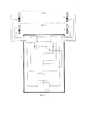
Фиг. 2 - структурная схема устройства для измерения импеданса в частях тела.FIG. 2 is a block diagram of a device for measuring impedance in parts of the body.
Фиг. 3 - эквивалентная схема, отображающая переходное сопротивление электрод-ткань и функциональные блоки для его измерения.FIG. 3 is an equivalent circuit showing the transition resistance of the electrode-tissue and functional blocks for measuring it.
Фиг. 4 - диаграмма сигналов, регистрируемых посредством потенциальных электродов при измерении импеданса в одном отведении.FIG. 4 is a diagram of signals recorded by potential electrodes when measuring impedance in one lead.
Фиг. 5 - условное отображение логической последовательности измерений в «n-циклах» работы устройства.FIG. 5 - conditional display of the logical sequence of measurements in the "n-cycles" of the device.
Фиг. 6 - представлена функциональная схема, обеспечивающая передачу измеренных параметров по радиоканалу.FIG. 6 - presents a functional diagram that provides the transmission of the measured parameters over the air.
Устройство для измерения электрического импеданса частей тела (фиг. 1) содержит: генератор 1 зондирующих сигналов, выходы которого соединены с входами первого коммутатора 2 и второго коммутатора 3, блок 4 управления и регистрации, первый выход которого соединен с управляющим входом генератора 1, а второй и третий управляющие выходы с управляющими входами коммутатора 2 и коммутатора 3, детектор 5 входы которого соединен с сигнальными выходами коммутатора 2 и коммутатора 3, а выход - через аналого-цифровой преобразователь 6 с информационным входом блока 4.A device for measuring the electrical impedance of body parts (Fig. 1) contains: a
Пары электродов 7, 9, предназначенные для правой ноги и правой руки, посредством проводников соединены с коммутатором 2, пары электродов 8, 10, предназначенные для левой ноги и левой руки, посредством проводников соединены с коммутатором 3, причем проводники от 7 и 8 пары электродов и проводники от 8 и 10 пары электродов входят в корпус 13 прибора с противоположных сторон, при этом проводники 7 и 8 пары электродов короче проводников 9 и 10 пары электродов.The pairs of
Для измерения импеданса составных частей тела используется тетраполярный метод, в котором пары электродов, содержащие токовый и потенциальный электроды, накладывают на дистальные части предплечий, голеней и шеи, причем токовый электрод накладывается на правую часть шеи, а потенциальный - на левую. Импеданс в выбранных отведениях измеряют посредством зондирующего тока низкой и высокой частот, коммутация которого между токовыми электродами осуществляется посредством первого и второго коммутатора. При этом для измерения сигнала используются потенциальные электроды, входящие в пары электродов, через которые подается зондирующий ток. Сигналы с потенциальных электродов 7÷100 через коммутаторы 2 и 3, детектор 5 и аналого-цифровой преобразователь 6 поступают на блок 4 управления и регистрации. Пары электродов 7÷10 позволяют производить измерения в отведениях, характеризующих импеданс следующих частей тела (фиг. 1):To measure the impedance of body parts, the tetrapolar method is used, in which pairs of electrodes containing the current and potential electrodes are applied to the distal parts of the forearms, legs and neck, the current electrode being applied to the right side of the neck and the potential electrode to the left. The impedance in the selected leads is measured by means of a probing current of low and high frequencies, the switching of which between current electrodes is carried out by means of the first and second commutators. In this case, potential electrodes are used to measure the signal, which are included in pairs of electrodes through which a probing current is supplied. The signals from the
ZП=ZПР+ZПНТ+ZПН,ZP = ZPR + ZPNT + ZPN,
где ZП - импеданс правой части тела, который измерен при прохождении тока между правой рукой и правой ногой путем измерения между ними напряжения отведения для правой части тела;where ZP - the impedance of the right side of the body, which is measured with the passage of current between the right hand and the right foot by measuring between them the voltage leads for the right side of the body;
ZПН - импеданс правой ноги;ZPN - impedance of the right leg;
ZПНТ - импеданс правой нижней части туловища;ZPNT - impedance of the right lower body;
ZПР - импеданс правой рукиZPR - impedance of the right hand
ZЛ=ZЛР+ZЛНТ+ZЛН,ZL = ZLR + ZLNT + ZLN,
где ZЛ - импеданс левой части тела, который измерен при прохождении тока между левой рукой и левой ногой путем измерения между ними напряжения отведения для левой части тела;where ZL is the impedance of the left side of the body, which was measured during the passage of current between the left hand and left foot by measuring the lead voltage between the left side of the body;
ZЛН - импеданс левой ноги;ZLN - impedance of the left leg;
ZЛНТ - импеданс левой нижней части туловища;ZLNT - impedance of the left lower torso;
ZЛР - импеданс левой рукиZLR - impedance of the left hand
ZН=ZПН+ZЛН,ZN = ZPN + ZLN,
где ZН - импеданс ног, который измеряется при прохождении тока между ногами путем измерения напряжения между ними;where ZN is the impedance of the legs, which is measured by the passage of current between the legs by measuring the voltage between them;
ZВ=ZПР+ZТТ+ZЛР,ZB = ZPR + ZTT + ZLR,
где ZВ - импеданс верхней части тела, который измерен при прохождении тока между правой рукой и левой рукой путем измерения между ними напряжения отведения для верхней части тела;where ZIn - the impedance of the upper body, which is measured by the passage of current between the right hand and the left hand by measuring between them the lead voltage for the upper body;
ZТТ - импеданс торакальной части туловища;ZTT - impedance of the thoracic part of the body;
ZД=ZПР+ZДТ+ZЛН,ZD = ZPR + ZDT + ZLN,
ZД - диагональный импеданс тела, который измеряется при прохождении тока между правой рукой и левой ногой путем измерения напряжения между правой рукой и левой ногой;ZD - the diagonal impedance of the body, which is measured with the passage of current between the right hand and left foot by measuring the voltage between the right hand and left foot;
Устройство для измерения электрического импеданса в частях тела работает следующим образом.A device for measuring electrical impedance in parts of the body works as follows.
Измерение импеданса: ZП, ZЛ, ZН, ZВ, ZД производится путем подключения посредством коммутаторов 2 и 3 выходов генератора 1 синусоидального сигнала с частотой 5 и 500 кГц и стабилизированной величиной тока, например 0,3 мА, к токовым электродам, а также подключением посредством коммутаторов 2 и 3 потенциальных электродов к входам детектора 5. Например, для измерения импеданса ZП подключение стабилизированной величины зондирующего тока, посредством коммутаторов 2 и 3, производится к токовым электродам пар 7 и 9, а потенциальные электроды этих же пар, посредством коммутаторов 2 и 3, подключаются к входам детектора 5. на выходе которого формируется напряжение, пропорциональное величине импеданса исследуемого участка тела, значение которого после преобразования в цифровую форму преобразователем 6 подается на информационный вход блока 4. Для измерения импеданса ZB используются пары электродов 9 и 10, а для измерения импеданса ног ZH используются пары электродов 7 и 8.Impedance measurement: ZP , ZL , ZN , ZV , ZD is made by connecting, through the
Управление работой генератора 1 осуществляет блок 4 таким образом, что для измерения импеданса в одном отведении на токовые электроды выбранных пар электродов с генератора 1 подается синусоидальный сигнал с частотой 5 и 500 кГц во временной последовательности, приведенной на фиг. 4. Синхронно с формированием зондирующего сигнала генератором 1 блок 4 управляет работой ключа 12, переключая его в замкнутое или разомкнутое состояние. Когда ключ 12 замкнут, то параллельно выходу генератора 1 подключается резистор 11. Последовательность зондирующих сигналов в виде напряжений, регистрируемых посредством потенциальных электродов, представлена на фиг. 4. На токовые электроды последовательно интервалами по 80 мс подается стабильное значение зондирующего тока в первом и втором интервалах с частотой 5 кГц и в третьем интервале с частотой 500 кГц. В течение первого интервала замкнут ключ 12. Амплитуды сигналов, регистрируемые посредством потенциальных электродов, имеют следующие соотношения: амплитуда в первом интервале меньше, чем во втором, т.к. подключен резистор 11 и часть тока протекает через него, амплитуда в третьем интервале меньше чем во втором, т.к. импеданс тканей имеет емкостную составляющую. Соотношение амплитуд в первом и втором интервалах используется для вычисления величины RЭ (фиг. 3).The operation of the
Оценка качества контакта токовых электродов с телом пациента производится путем измерения величины переходного сопротивления «RЭ» на частоте 5кГц зондирующего тока (I) (фиг. 3). Перед информационным измерением импеданса тела на частоте 5 кГц параллельно выходу генератора тока посредством управляемого ключа «кл» подключают шунтирующий резистор «RШ» и посредством потенциальных электродов и измерителя напряжения «V» измеряют падение напряжения на измеряемом участке тела «UШ» после чего без подключения резистора RШ измеряют информационное напряжение «U», которое используется для вычисления импеданса исследуемого участка тела «RT». Вычисление значения RЭ производится согласно следующим математическим преобразованиям:The quality of contact of the current electrodes with the patient’s body is assessed by measuring the transition resistance “RE ” at a frequency of 5 kHz of the probing current (I) (Fig. 3). Before the information measurement of the body impedance at a frequency of 5 kHz, a shunt resistor “RШ ” is connected to the output of the current generator using a controlled key “kl” and voltage drop across the measured section of the body “UШ ” is measured using potential electrodes and a voltage meter “V”, and then without the connection of the resistor RW measure the information voltage "U", which is used to calculate the impedance of the investigated part of the body "RT ". The calculation of the value of Re is made according to the following mathematical transformations:
RЭ=(rэ+rэ);Re = (re + re );
R=RЭ+RТ;R = RE + RT ;
U=I⋅RT; RT=U/I;U = I ⋅ RT ; RT = U / I;
UШ=(I-IШ)⋅RT; RТ=UШ/(I-IШ);UW = (IIW ) ⋅RT ; RT = UW / (IIW );
U/I=UШ/(I-IШ); UШ/U=(I-IШ)/I=1-(IШ/I);U / I = UW / (IIW ); UW / U = (IIW ) / I = 1- (IW / I);
UГ=I⋅(RШ⋅R)/(RШ+R);UГ = I⋅ (RШ ⋅R) / (RШ + R);
где UГ - напряжение на выходе генератора 5 кГц;where UG - voltage at the output of the
IШ=UГ/RШ=I⋅R/(RШ+R);IW = UG / RW = I⋅R / (RW + R);
I=UГ/R=I⋅RШ/(RШ+R);I = UG / R = I⋅RW / (RW + R);
UШ/U=RШ/(RШ+R);UW / U = RW / (RW + R);
U/UШ=1+R/RШ;U / UW = 1 + R / RW ;
R=RШ⋅[(U/UШ)-1];R = RW ⋅ [(U / UW ) -1];
RЭ={RШ⋅[(U/UШ)-1]}-RT.Re = {RW ⋅ [(U / UW ) -1]} - RT.
При превышении измеренной величиной RЭ порогового значения формируется сообщение, и дальнейшие измерения не производятся. Амплитуда сигнала во втором интервале пропорциональна активной составляющей тканей (ZП, ZЛ, ZН, ZВ, ZД), а соотношение ее с амплитудой в третьем интервале позволяет вычислить емкостную составляющую импеданса тканей. Сигналы с потенциальных электродов через коммутаторы 2 и 3 подаются на входы детектора 5, который их усиливает, детектирует действующее значение и через преобразователь 6 в цифровой форме величины, пропорциональные сигналам для каждого интервала зондирующего тока, подаются на вход блока 4. Блок 4 последовательно формирует управляющие сигналы, обеспечивающие измерение напряжений, приведенных на фиг. 3 для всех отведений, которые выбраны для измерения импеданса: ZП, ZЛ, ZН, ZВ, ZД,. Измеренные напряжения (фиг. 3) для всех выбранных отведений (ZП, ZЛ, ZН, ZВ, ZД) запоминаются в оперативной памяти блока 4 и образуют 1-й цикл измерения. Блок 4 осуществляет управление для последовательного измерения и запоминания измеренных напряжений для «n-циклов» фиг. 5. После измерения напряжений в «n-циклах» режим измерения в работе блока 4 считается завершенным и все измеренные значения становятся доступными для отображения их на индикаторе блока 4 или все измеренные значения посредством блока 18 радиоканала («Wi-Fi») (фиг. 6) передаются во внешнее вычислительное устройство для вычисления параметров гидратации согласно известным методам. Измерение параметров импеданса в «n-циклах» производится для того чтобы усреднить колебания измеренных значений, вызванных, в первую очередь, физиологическими процессами в организме: дыхание, сердечные сокращения, ортостатическое перераспределение жидкости.If the measured value RE exceeds the threshold value, a message is generated, and further measurements are not performed. The signal amplitude in the second interval is proportional to the active component of the tissues (ZP , ZL , ZN , ZB , ZD ), and its ratio with the amplitude in the third interval allows us to calculate the capacitive component of the tissue impedance. The signals from the potential electrodes through the
При измерениях импеданса на низкой частоте, например 5 кГц, существенное влияние на точность измерения импеданса тела оказывает величина переходного сопротивления между токовым электродом и телом (RЭ). Контроль величины RЭ позволяет устранить непредсказуемые ошибки при измерении импеданса тела, в значительной мере это существенно при обследовании пожилых людей, кожа которых более сухая. При выявлении устройством превышения порогового значения измеренной величиной RЭ производится дополнительное увлажнением поверхности токовых электродов.When measuring impedance at a low frequency, for example 5 kHz, a significant influence on the accuracy of measuring the impedance of the body is exerted by the magnitude of the transition resistance between the current electrode and the body (RE ). Monitoring the value of RE allows you to eliminate unpredictable errors when measuring the impedance of the body, to a large extent this is significant when examining older people whose skin is drier. If the device identifies an excess of the threshold value by the measured value of RE , additional wetting of the surface of the current electrodes is performed.
При измерении импеданса на высокой частоте, например 500 кГц, существенное влияние на точность измерения оказывают паразитные электрические емкости (СЭ), возникающие между токовыми проводниками, обеспечивающими соединение электродов с прибором. Выполнение в корпусе устройства с противоположных сторон выводов проводников, соединенных с парами электродов, предназначенных для фиксации на правых конечностях тела относительно пар электродов, предназначенных для фиксации на левых конечностях тела, существенно снижает и нормализует остаточное значение величины емкости СЭ и позволяет вносить поправку в значение измеренного импеданса на частоте 500 кГц.When measuring impedance at a high frequency, for example, 500 kHz, spurious electrical capacitances (CE ) arising between current conductors providing connection of the electrodes to the device have a significant impact on the measurement accuracy. The execution in the device case from opposite sides of the leads of the conductors connected to pairs of electrodes intended for fixation on the right limbs of the body relative to pairs of electrodes intended for fixation on the left limbs of the body, significantly reduces and normalizes the residual value of the capacitance CE and allows you to make an amendment to measured impedance at a frequency of 500 kHz.
ИСТОЧНИКИ ИНФОРМАЦИИINFORMATION SOURCES
1. Патент SU №1826864 кл. А61В 5/05, 1990.1. Patent SU No. 1826864 class.
2. Патент RU №2242165 кл. А61В 5/053, 2003.2. Patent RU No. 2242165 class.
3. Капитанов Е.Н. Биофизическая модель для определения объемов жидкости в организме при его зондировании переменным электрическим током, М., Материалы пятой научно-практической конференции: "Диагностика и лечение нарушений регуляции сердечно-сосудистой системы", март 2003, С. 196-203.3. Kapitanov E.N. Biophysical model for determining the volume of fluid in the body when it is probed by alternating electric current, M., Materials of the fifth scientific-practical conference: "Diagnosis and treatment of dysregulation of the cardiovascular system", March 2003, S. 196-203.
Claims (2)
Translated fromRussianPriority Applications (1)
| Application Number | Priority Date | Filing Date | Title |
|---|---|---|---|
| RU2016137936ARU2664633C2 (en) | 2016-09-23 | 2016-09-23 | Device for measuring electrical impedance in parts of body |
Applications Claiming Priority (1)
| Application Number | Priority Date | Filing Date | Title |
|---|---|---|---|
| RU2016137936ARU2664633C2 (en) | 2016-09-23 | 2016-09-23 | Device for measuring electrical impedance in parts of body |
Publications (3)
| Publication Number | Publication Date |
|---|---|
| RU2016137936A RU2016137936A (en) | 2018-03-27 |
| RU2016137936A3 RU2016137936A3 (en) | 2018-03-27 |
| RU2664633C2true RU2664633C2 (en) | 2018-08-21 |
Family
ID=61708215
Family Applications (1)
| Application Number | Title | Priority Date | Filing Date |
|---|---|---|---|
| RU2016137936ARU2664633C2 (en) | 2016-09-23 | 2016-09-23 | Device for measuring electrical impedance in parts of body |
Country Status (1)
| Country | Link |
|---|---|
| RU (1) | RU2664633C2 (en) |
Cited By (3)
| Publication number | Priority date | Publication date | Assignee | Title |
|---|---|---|---|---|
| CN112155545A (en)* | 2020-09-22 | 2021-01-01 | 芯海科技(深圳)股份有限公司 | Impedance measuring device, human body scale and human body composition analyzer |
| RU2771118C1 (en)* | 2021-06-18 | 2022-04-26 | Самсунг Электроникс Ко., Лтд. | Device and method for analyzing the impedance of the human body, insensitive to high contact impedance and parasitic effects |
| RU2771118C9 (en)* | 2021-06-18 | 2022-09-01 | Самсунг Электроникс Ко., Лтд. | Device and method for analyzing the impedance of the human body, insensitive to high contact impedance and parasitic effects |
Citations (7)
| Publication number | Priority date | Publication date | Assignee | Title |
|---|---|---|---|---|
| WO1998006328A1 (en)* | 1996-08-09 | 1998-02-19 | R.S. Medical Monitoring Ltd. | Method and device for stable impedance plethysmography |
| US6295468B1 (en)* | 1999-03-13 | 2001-09-25 | Bruno M. Hess | Apparatus for measuring bioelectrical parameters |
| RU2242165C1 (en)* | 2003-07-17 | 2004-12-20 | Капитанов Евгений Николаевич | Device for measuring electric impedance in body parts |
| RU2273452C2 (en)* | 2004-06-25 | 2006-04-10 | Государственное учреждение Московский областной научно-исследовательский клинический институт им. М.Ф. Владимирского | Method for diagnosing water balance disorders in extracellular fluid of body |
| WO2007102893A2 (en)* | 2005-11-11 | 2007-09-13 | Greatbatch Ltd. | Tank filters placed in series with the lead wires or circuits of active medical devices to enhance mri compatibility |
| WO2014143982A1 (en)* | 2013-03-15 | 2014-09-18 | Welch Allyn, Inc. | Electrode with charge-operated indicator |
| RU164812U1 (en)* | 2016-02-26 | 2016-09-20 | федеральное государственное бюджетное образовательное учреждение высшего образования "Южно-Российский государственный политехнический университет (НПИ) имени М.И. Платова" | DEVICE FOR DATA COLLECTION AND TRANSFER FOR ELECTRIC IMPEDANCE TOMOGRAPHY OF BIOLOGICAL OBJECTS |
- 2016
- 2016-09-23RURU2016137936Apatent/RU2664633C2/ennot_activeIP Right Cessation
Patent Citations (7)
| Publication number | Priority date | Publication date | Assignee | Title |
|---|---|---|---|---|
| WO1998006328A1 (en)* | 1996-08-09 | 1998-02-19 | R.S. Medical Monitoring Ltd. | Method and device for stable impedance plethysmography |
| US6295468B1 (en)* | 1999-03-13 | 2001-09-25 | Bruno M. Hess | Apparatus for measuring bioelectrical parameters |
| RU2242165C1 (en)* | 2003-07-17 | 2004-12-20 | Капитанов Евгений Николаевич | Device for measuring electric impedance in body parts |
| RU2273452C2 (en)* | 2004-06-25 | 2006-04-10 | Государственное учреждение Московский областной научно-исследовательский клинический институт им. М.Ф. Владимирского | Method for diagnosing water balance disorders in extracellular fluid of body |
| WO2007102893A2 (en)* | 2005-11-11 | 2007-09-13 | Greatbatch Ltd. | Tank filters placed in series with the lead wires or circuits of active medical devices to enhance mri compatibility |
| WO2014143982A1 (en)* | 2013-03-15 | 2014-09-18 | Welch Allyn, Inc. | Electrode with charge-operated indicator |
| RU164812U1 (en)* | 2016-02-26 | 2016-09-20 | федеральное государственное бюджетное образовательное учреждение высшего образования "Южно-Российский государственный политехнический университет (НПИ) имени М.И. Платова" | DEVICE FOR DATA COLLECTION AND TRANSFER FOR ELECTRIC IMPEDANCE TOMOGRAPHY OF BIOLOGICAL OBJECTS |
Cited By (4)
| Publication number | Priority date | Publication date | Assignee | Title |
|---|---|---|---|---|
| CN112155545A (en)* | 2020-09-22 | 2021-01-01 | 芯海科技(深圳)股份有限公司 | Impedance measuring device, human body scale and human body composition analyzer |
| RU2771118C1 (en)* | 2021-06-18 | 2022-04-26 | Самсунг Электроникс Ко., Лтд. | Device and method for analyzing the impedance of the human body, insensitive to high contact impedance and parasitic effects |
| RU2771118C9 (en)* | 2021-06-18 | 2022-09-01 | Самсунг Электроникс Ко., Лтд. | Device and method for analyzing the impedance of the human body, insensitive to high contact impedance and parasitic effects |
| US12295710B2 (en) | 2021-06-18 | 2025-05-13 | Samsung Electronics Co., Ltd. | Device and method for human body impedance analysis insensitive to high contact impedance and parasitic effects |
Also Published As
| Publication number | Publication date |
|---|---|
| RU2016137936A (en) | 2018-03-27 |
| RU2016137936A3 (en) | 2018-03-27 |
Similar Documents
| Publication | Publication Date | Title |
|---|---|---|
| US8744564B2 (en) | Oedema detection | |
| US20110190655A1 (en) | Scanning head including at least two electrodes for impedance measurement, arrangement, and related method | |
| Harder et al. | Smart multi-frequency bioelectrical impedance spectrometer for BIA and BIVA applications | |
| Li et al. | Design of a noninvasive bladder urinary volume monitoring system based on bio-impedance | |
| KR101324560B1 (en) | Multi-channel impedance measuring method and device | |
| US20120271192A1 (en) | Method and apparatus for analysing the structure of bone tissue | |
| RU2094013C1 (en) | Method of regional bioimpedometry and device intended for its realization | |
| CN205597918U (en) | Human body component analyzer based on dual -frenquency bio -electrical impedance measures | |
| RU2664633C2 (en) | Device for measuring electrical impedance in parts of body | |
| JPH09220209A (en) | Living body electric impedance measuring instrument | |
| Yang et al. | A design of bioimpedance spectrometer for early detection of pressure ulcer | |
| Dheman et al. | Towards Enhanced Bladder Volume Measurement with Context-Aware Bio-Impedance Sensor Fusion | |
| JP3636825B2 (en) | Body fat measuring device | |
| RU2692959C2 (en) | Method of bioimpedance determination of body liquid volumes and device for its implementation | |
| KR20130016204A (en) | Method and apparatus for non-invasive analysing the structure and chemical composition of bone tissue eliminating the influence of surrounding tissues | |
| KR101150380B1 (en) | Apparatus for measuring the bioelectrical impedance ofa living body | |
| RU2242165C1 (en) | Device for measuring electric impedance in body parts | |
| Kamat et al. | Multi-frequency and multi-segment bio-impedance measurement using tetra-polar electrode setup | |
| Potdar et al. | Monitoring breathing rate using bio-impedance technique | |
| Szuster et al. | Bioimpedance spectroscopy monitoring—designing challenges and description of the acquired results | |
| Piuzzi et al. | Comparison among low-cost portable systems for thoracic impedance plethysmography | |
| Giannini et al. | Investigation of the SENSIPLUS Chip for Bioimpedance Spectroscopy Applications | |
| RU2134533C1 (en) | Device for determination of cutaneous blood flow | |
| JP3461646B2 (en) | Body fat measurement device | |
| RU2251969C2 (en) | Method and device for diagnosing biological object condition |
Legal Events
| Date | Code | Title | Description |
|---|---|---|---|
| MM4A | The patent is invalid due to non-payment of fees | Effective date:20180924 |