RU2661754C2 - Leadless cardiac pacing devices - Google Patents
Leadless cardiac pacing devicesDownload PDFInfo
- Publication number
- RU2661754C2 RU2661754C2RU2016109156ARU2016109156ARU2661754C2RU 2661754 C2RU2661754 C2RU 2661754C2RU 2016109156 ARU2016109156 ARU 2016109156ARU 2016109156 ARU2016109156 ARU 2016109156ARU 2661754 C2RU2661754 C2RU 2661754C2
- Authority
- RU
- Russia
- Prior art keywords
- section
- distal
- region
- curved section
- anchor element
- Prior art date
Links
- 230000000747cardiac effectEffects0.000titledescription2
- 239000002775capsuleSubstances0.000claimsabstractdescription6
- 230000000638stimulationEffects0.000claimsdescription38
- 210000005003heart tissueAnatomy0.000claimsdescription15
- 210000001519tissueAnatomy0.000claimsdescription7
- 239000000126substanceSubstances0.000abstractdescription2
- 238000004873anchoringMethods0.000abstract3
- 150000001875compoundsChemical class0.000abstract3
- 239000003814drugSubstances0.000abstract1
- 229910001000nickel titaniumInorganic materials0.000description24
- HLXZNVUGXRDIFK-UHFFFAOYSA-Nnickel titaniumChemical compound[Ti].[Ti].[Ti].[Ti].[Ti].[Ti].[Ti].[Ti].[Ti].[Ti].[Ti].[Ni].[Ni].[Ni].[Ni].[Ni].[Ni].[Ni].[Ni].[Ni].[Ni].[Ni].[Ni].[Ni].[Ni]HLXZNVUGXRDIFK-UHFFFAOYSA-N0.000description15
- 239000000463materialSubstances0.000description13
- -1polytetrafluoroethylenePolymers0.000description12
- 229910001182Mo alloyInorganic materials0.000description7
- 229910045601alloyInorganic materials0.000description7
- 239000000956alloySubstances0.000description7
- 238000000034methodMethods0.000description6
- RTZKZFJDLAIYFH-UHFFFAOYSA-NDiethyl etherChemical compoundCCOCCRTZKZFJDLAIYFH-UHFFFAOYSA-N0.000description5
- 239000000203mixtureSubstances0.000description5
- 238000003032molecular dockingMethods0.000description5
- 210000005241right ventricleAnatomy0.000description5
- PXHVJJICTQNCMI-UHFFFAOYSA-NNickelChemical compound[Ni]PXHVJJICTQNCMI-UHFFFAOYSA-N0.000description4
- 229910000856hastalloyInorganic materials0.000description4
- 238000004519manufacturing processMethods0.000description4
- 229920003023plasticPolymers0.000description4
- 239000004033plasticSubstances0.000description4
- BASFCYQUMIYNBI-UHFFFAOYSA-NplatinumChemical compound[Pt]BASFCYQUMIYNBI-UHFFFAOYSA-N0.000description4
- 229920000728polyesterPolymers0.000description4
- 229920000642polymerPolymers0.000description4
- 229920000106Liquid crystal polymerPolymers0.000description3
- 239000004977Liquid-crystal polymers (LCPs)Substances0.000description3
- 239000004952PolyamideSubstances0.000description3
- 239000004698PolyethyleneSubstances0.000description3
- 229920001400block copolymerPolymers0.000description3
- 210000005242cardiac chamberAnatomy0.000description3
- 229920001577copolymerPolymers0.000description3
- 230000006870functionEffects0.000description3
- 238000002595magnetic resonance imagingMethods0.000description3
- 230000007246mechanismEffects0.000description3
- 229910052751metalInorganic materials0.000description3
- 239000002184metalSubstances0.000description3
- 229920002647polyamidePolymers0.000description3
- 229920000573polyethylenePolymers0.000description3
- 239000010935stainless steelSubstances0.000description3
- 229910001220stainless steelInorganic materials0.000description3
- 229910000881Cu alloyInorganic materials0.000description2
- 239000004812Fluorinated ethylene propyleneSubstances0.000description2
- 229920000339MarlexPolymers0.000description2
- KDLHZDBZIXYQEI-UHFFFAOYSA-NPalladiumChemical compound[Pd]KDLHZDBZIXYQEI-UHFFFAOYSA-N0.000description2
- 239000004696Poly ether ether ketoneSubstances0.000description2
- 229920002614Polyether block amidePolymers0.000description2
- 239000004697PolyetherimideSubstances0.000description2
- 239000004642PolyimideSubstances0.000description2
- 239000004721Polyphenylene oxideSubstances0.000description2
- 239000004734Polyphenylene sulfideSubstances0.000description2
- 239000004743PolypropyleneSubstances0.000description2
- RTAQQCXQSZGOHL-UHFFFAOYSA-NTitaniumChemical compound[Ti]RTAQQCXQSZGOHL-UHFFFAOYSA-N0.000description2
- 229910001080W alloyInorganic materials0.000description2
- MTHLBYMFGWSRME-UHFFFAOYSA-N[Cr].[Co].[Mo]Chemical compound[Cr].[Co].[Mo]MTHLBYMFGWSRME-UHFFFAOYSA-N0.000description2
- HZEWFHLRYVTOIW-UHFFFAOYSA-N[Ti].[Ni]Chemical compound[Ti].[Ni]HZEWFHLRYVTOIW-UHFFFAOYSA-N0.000description2
- 238000004458analytical methodMethods0.000description2
- 210000003484anatomyAnatomy0.000description2
- 229910001566austeniteInorganic materials0.000description2
- 238000005452bendingMethods0.000description2
- 230000008859changeEffects0.000description2
- 239000000788chromium alloySubstances0.000description2
- PRQRQKBNBXPISG-UHFFFAOYSA-Nchromium cobalt molybdenum nickelChemical compound[Cr].[Co].[Ni].[Mo]PRQRQKBNBXPISG-UHFFFAOYSA-N0.000description2
- YOCUPQPZWBBYIX-UHFFFAOYSA-Ncopper nickelChemical compound[Ni].[Cu]YOCUPQPZWBBYIX-UHFFFAOYSA-N0.000description2
- 238000000113differential scanning calorimetryMethods0.000description2
- 229910000701elgiloys (Co-Cr-Ni Alloy)Inorganic materials0.000description2
- 229920000840ethylene tetrafluoroethylene copolymerPolymers0.000description2
- 239000004744fabricSubstances0.000description2
- 238000002513implantationMethods0.000description2
- 230000007794irritationEffects0.000description2
- 229910000734martensiteInorganic materials0.000description2
- 229910001092metal group alloyInorganic materials0.000description2
- 230000004048modificationEffects0.000description2
- 238000012986modificationMethods0.000description2
- DDTIGTPWGISMKL-UHFFFAOYSA-Nmolybdenum nickelChemical compound[Ni].[Mo]DDTIGTPWGISMKL-UHFFFAOYSA-N0.000description2
- 229910052759nickelInorganic materials0.000description2
- 230000035515penetrationEffects0.000description2
- 230000008447perceptionEffects0.000description2
- 229920009441perflouroethylene propylenePolymers0.000description2
- 229910052697platinumInorganic materials0.000description2
- 229920001200poly(ethylene-vinyl acetate)Polymers0.000description2
- 229920001707polybutylene terephthalatePolymers0.000description2
- 229920002530polyetherether ketonePolymers0.000description2
- 229920001601polyetherimidePolymers0.000description2
- 229920001721polyimidePolymers0.000description2
- 229920006324polyoxymethylenePolymers0.000description2
- 229920006380polyphenylene oxidePolymers0.000description2
- 229920000069polyphenylene sulfidePolymers0.000description2
- 229920001155polypropylenePolymers0.000description2
- 229920001343polytetrafluoroethylenePolymers0.000description2
- 239000004810polytetrafluoroethyleneSubstances0.000description2
- 229920002635polyurethanePolymers0.000description2
- 239000004814polyurethaneSubstances0.000description2
- 210000005245right atriumAnatomy0.000description2
- 238000000926separation methodMethods0.000description2
- 239000010936titaniumSubstances0.000description2
- 229910052719titaniumInorganic materials0.000description2
- 230000007704transitionEffects0.000description2
- 230000002792vascularEffects0.000description2
- KHXKESCWFMPTFT-UHFFFAOYSA-N1,1,1,2,2,3,3-heptafluoro-3-(1,2,2-trifluoroethenoxy)propaneChemical compoundFC(F)=C(F)OC(F)(F)C(F)(F)C(F)(F)FKHXKESCWFMPTFT-UHFFFAOYSA-N0.000description1
- 229910000531Co alloyInorganic materials0.000description1
- 229920004943Delrin®Polymers0.000description1
- 229920000219Ethylene vinyl alcoholPolymers0.000description1
- 229910000640Fe alloyInorganic materials0.000description1
- 229920003620Grilon®Polymers0.000description1
- 229910000787Gum metalInorganic materials0.000description1
- 229920000271Kevlar®Polymers0.000description1
- JHWNWJKBPDFINM-UHFFFAOYSA-NLaurolactamChemical compoundO=C1CCCCCCCCCCCN1JHWNWJKBPDFINM-UHFFFAOYSA-N0.000description1
- 229910001209Low-carbon steelInorganic materials0.000description1
- 229910000792MonelInorganic materials0.000description1
- 229910000990Ni alloyInorganic materials0.000description1
- 229920000299Nylon 12Polymers0.000description1
- 229930040373ParaformaldehydeNatural products0.000description1
- 239000004793PolystyreneSubstances0.000description1
- QXZUUHYBWMWJHK-UHFFFAOYSA-N[Co].[Ni]Chemical compound[Co].[Ni]QXZUUHYBWMWJHK-UHFFFAOYSA-N0.000description1
- 150000001408amidesChemical class0.000description1
- 229920000249biocompatible polymerPolymers0.000description1
- 239000008280bloodSubstances0.000description1
- 210000004369bloodAnatomy0.000description1
- 210000004204blood vesselAnatomy0.000description1
- 230000036760body temperatureEffects0.000description1
- 239000000919ceramicSubstances0.000description1
- OGSYQYXYGXIQFH-UHFFFAOYSA-Nchromium molybdenum nickelChemical compound[Cr].[Ni].[Mo]OGSYQYXYGXIQFH-UHFFFAOYSA-N0.000description1
- 239000002131composite materialSubstances0.000description1
- 239000004020conductorSubstances0.000description1
- 238000010276constructionMethods0.000description1
- 239000002872contrast mediaSubstances0.000description1
- 238000006073displacement reactionMethods0.000description1
- 239000013013elastic materialSubstances0.000description1
- 229920001971elastomerPolymers0.000description1
- 239000000806elastomerSubstances0.000description1
- 238000001827electrotherapyMethods0.000description1
- 229920006351engineering plasticPolymers0.000description1
- 238000005516engineering processMethods0.000description1
- 150000002118epoxidesChemical class0.000description1
- JBKVHLHDHHXQEQ-UHFFFAOYSA-Nepsilon-caprolactamChemical compoundO=C1CCCCCN1JBKVHLHDHHXQEQ-UHFFFAOYSA-N0.000description1
- 150000002148estersChemical class0.000description1
- QHSJIZLJUFMIFP-UHFFFAOYSA-Nethene;1,1,2,2-tetrafluoroetheneChemical groupC=C.FC(F)=C(F)FQHSJIZLJUFMIFP-UHFFFAOYSA-N0.000description1
- HQQADJVZYDDRJT-UHFFFAOYSA-Nethene;prop-1-eneChemical groupC=C.CC=CHQQADJVZYDDRJT-UHFFFAOYSA-N0.000description1
- 239000005038ethylene vinyl acetateSubstances0.000description1
- 239000004715ethylene vinyl alcoholSubstances0.000description1
- 230000001747exhibiting effectEffects0.000description1
- 238000000605extractionMethods0.000description1
- 210000003191femoral veinAnatomy0.000description1
- 239000003302ferromagnetic materialSubstances0.000description1
- 239000000945fillerSubstances0.000description1
- PCHJSUWPFVWCPO-UHFFFAOYSA-NgoldChemical compound[Au]PCHJSUWPFVWCPO-UHFFFAOYSA-N0.000description1
- 229910052737goldInorganic materials0.000description1
- 239000010931goldSubstances0.000description1
- RZXDTJIXPSCHCI-UHFFFAOYSA-Nhexa-1,5-diene-2,5-diolChemical compoundOC(=C)CCC(O)=CRZXDTJIXPSCHCI-UHFFFAOYSA-N0.000description1
- 229920001903high density polyethylenePolymers0.000description1
- 239000004700high-density polyethyleneSubstances0.000description1
- 229910001026inconelInorganic materials0.000description1
- 229920000554ionomerPolymers0.000description1
- UGKDIUIOSMUOAW-UHFFFAOYSA-Niron nickelChemical compound[Fe].[Ni]UGKDIUIOSMUOAW-UHFFFAOYSA-N0.000description1
- 210000005246left atriumAnatomy0.000description1
- 210000005240left ventricleAnatomy0.000description1
- 229920000092linear low density polyethylenePolymers0.000description1
- 239000004707linear low-density polyethyleneSubstances0.000description1
- 229920001684low density polyethylenePolymers0.000description1
- 239000004702low-density polyethyleneSubstances0.000description1
- 230000014759maintenance of locationEffects0.000description1
- 239000002905metal composite materialSubstances0.000description1
- 150000002739metalsChemical class0.000description1
- 210000003205muscleAnatomy0.000description1
- MOWMLACGTDMJRV-UHFFFAOYSA-Nnickel tungstenChemical compound[Ni].[W]MOWMLACGTDMJRV-UHFFFAOYSA-N0.000description1
- 229910000623nickel–chromium alloyInorganic materials0.000description1
- 229910052763palladiumInorganic materials0.000description1
- VPRUMANMDWQMNF-UHFFFAOYSA-Nphenylethane boronic acidChemical compoundOB(O)CCC1=CC=CC=C1VPRUMANMDWQMNF-UHFFFAOYSA-N0.000description1
- XNGIFLGASWRNHJ-UHFFFAOYSA-Lphthalate(2-)Chemical compound[O-]C(=O)C1=CC=CC=C1C([O-])=OXNGIFLGASWRNHJ-UHFFFAOYSA-L0.000description1
- 230000035790physiological processes and functionsEffects0.000description1
- 239000004417polycarbonateSubstances0.000description1
- 229920000515polycarbonatePolymers0.000description1
- 239000011112polyethylene naphthalateSubstances0.000description1
- 239000002861polymer materialSubstances0.000description1
- 229920000098polyolefinPolymers0.000description1
- 229920001296polysiloxanePolymers0.000description1
- 229920002223polystyrenePolymers0.000description1
- 229920002215polytrimethylene terephthalatePolymers0.000description1
- 239000004800polyvinyl chlorideSubstances0.000description1
- 239000005033polyvinylidene chlorideSubstances0.000description1
- 230000002441reversible effectEffects0.000description1
- 230000004936stimulating effectEffects0.000description1
- 229910052715tantalumInorganic materials0.000description1
- GUVRBAGPIYLISA-UHFFFAOYSA-Ntantalum atomChemical compound[Ta]GUVRBAGPIYLISA-UHFFFAOYSA-N0.000description1
- 125000000383tetramethylene groupChemical group[H]C([H])([*:1])C([H])([H])C([H])([H])C([H])([H])[*:2]0.000description1
- 210000000591tricuspid valveAnatomy0.000description1
- WFKWXMTUELFFGS-UHFFFAOYSA-NtungstenChemical compound[W]WFKWXMTUELFFGS-UHFFFAOYSA-N0.000description1
- 229910052721tungstenInorganic materials0.000description1
- 239000010937tungstenSubstances0.000description1
- 210000001631vena cava inferiorAnatomy0.000description1
- 238000012800visualizationMethods0.000description1
Images


Classifications
- A—HUMAN NECESSITIES
- A61—MEDICAL OR VETERINARY SCIENCE; HYGIENE
- A61N—ELECTROTHERAPY; MAGNETOTHERAPY; RADIATION THERAPY; ULTRASOUND THERAPY
- A61N1/00—Electrotherapy; Circuits therefor
- A61N1/02—Details
- A61N1/04—Electrodes
- A61N1/05—Electrodes for implantation or insertion into the body, e.g. heart electrode
- A61N1/056—Transvascular endocardial electrode systems
- A61N1/057—Anchoring means; Means for fixing the head inside the heart
- A61N1/0573—Anchoring means; Means for fixing the head inside the heart chacterised by means penetrating the heart tissue, e.g. helix needle or hook
- A—HUMAN NECESSITIES
- A61—MEDICAL OR VETERINARY SCIENCE; HYGIENE
- A61N—ELECTROTHERAPY; MAGNETOTHERAPY; RADIATION THERAPY; ULTRASOUND THERAPY
- A61N1/00—Electrotherapy; Circuits therefor
- A61N1/18—Applying electric currents by contact electrodes
- A61N1/32—Applying electric currents by contact electrodes alternating or intermittent currents
- A61N1/36—Applying electric currents by contact electrodes alternating or intermittent currents for stimulation
- A61N1/362—Heart stimulators
- A—HUMAN NECESSITIES
- A61—MEDICAL OR VETERINARY SCIENCE; HYGIENE
- A61N—ELECTROTHERAPY; MAGNETOTHERAPY; RADIATION THERAPY; ULTRASOUND THERAPY
- A61N1/00—Electrotherapy; Circuits therefor
- A61N1/18—Applying electric currents by contact electrodes
- A61N1/32—Applying electric currents by contact electrodes alternating or intermittent currents
- A61N1/36—Applying electric currents by contact electrodes alternating or intermittent currents for stimulation
- A61N1/372—Arrangements in connection with the implantation of stimulators
- A61N1/37205—Microstimulators, e.g. implantable through a cannula
- A—HUMAN NECESSITIES
- A61—MEDICAL OR VETERINARY SCIENCE; HYGIENE
- A61N—ELECTROTHERAPY; MAGNETOTHERAPY; RADIATION THERAPY; ULTRASOUND THERAPY
- A61N1/00—Electrotherapy; Circuits therefor
- A61N1/18—Applying electric currents by contact electrodes
- A61N1/32—Applying electric currents by contact electrodes alternating or intermittent currents
- A61N1/36—Applying electric currents by contact electrodes alternating or intermittent currents for stimulation
- A61N1/372—Arrangements in connection with the implantation of stimulators
- A61N1/375—Constructional arrangements, e.g. casings
- A61N1/37518—Anchoring of the implants, e.g. fixation
- A—HUMAN NECESSITIES
- A61—MEDICAL OR VETERINARY SCIENCE; HYGIENE
- A61N—ELECTROTHERAPY; MAGNETOTHERAPY; RADIATION THERAPY; ULTRASOUND THERAPY
- A61N1/00—Electrotherapy; Circuits therefor
- A61N1/18—Applying electric currents by contact electrodes
- A61N1/32—Applying electric currents by contact electrodes alternating or intermittent currents
- A61N1/36—Applying electric currents by contact electrodes alternating or intermittent currents for stimulation
- A61N1/372—Arrangements in connection with the implantation of stimulators
- A61N1/375—Constructional arrangements, e.g. casings
- A61N1/3756—Casings with electrodes thereon, e.g. leadless stimulators
- A—HUMAN NECESSITIES
- A61—MEDICAL OR VETERINARY SCIENCE; HYGIENE
- A61N—ELECTROTHERAPY; MAGNETOTHERAPY; RADIATION THERAPY; ULTRASOUND THERAPY
- A61N1/00—Electrotherapy; Circuits therefor
- A61N1/02—Details
- A61N1/04—Electrodes
- A61N1/05—Electrodes for implantation or insertion into the body, e.g. heart electrode
- A61N1/056—Transvascular endocardial electrode systems
- A61N1/057—Anchoring means; Means for fixing the head inside the heart
- A61N2001/0578—Anchoring means; Means for fixing the head inside the heart having means for removal or extraction
- A—HUMAN NECESSITIES
- A61—MEDICAL OR VETERINARY SCIENCE; HYGIENE
- A61N—ELECTROTHERAPY; MAGNETOTHERAPY; RADIATION THERAPY; ULTRASOUND THERAPY
- A61N1/00—Electrotherapy; Circuits therefor
- A61N1/02—Details
- A61N1/04—Electrodes
- A61N1/05—Electrodes for implantation or insertion into the body, e.g. heart electrode
- A61N1/056—Transvascular endocardial electrode systems
- A61N1/057—Anchoring means; Means for fixing the head inside the heart
- A61N2001/058—Fixing tools
Landscapes
- Health & Medical Sciences (AREA)
- Life Sciences & Earth Sciences (AREA)
- Public Health (AREA)
- Veterinary Medicine (AREA)
- Engineering & Computer Science (AREA)
- Biomedical Technology (AREA)
- Nuclear Medicine, Radiotherapy & Molecular Imaging (AREA)
- General Health & Medical Sciences (AREA)
- Animal Behavior & Ethology (AREA)
- Radiology & Medical Imaging (AREA)
- Cardiology (AREA)
- Heart & Thoracic Surgery (AREA)
- Vascular Medicine (AREA)
- Electrotherapy Devices (AREA)
- Prostheses (AREA)
- Surgical Instruments (AREA)
Abstract
Description
Translated fromRussianПЕРЕКРЕСТНАЯ ССЫЛКА НА СВЯЗАННЫЕ ЗАЯВКИCROSS REFERENCE TO RELATED APPLICATIONS
По данной заявке испрашивается приоритет предварительной заявки США № 61/866,799, поданной 16 августа 2013 года, все содержание которой включено в данное описание посредством ссылки.This application claims the priority of provisional application US No. 61 / 866,799, filed August 16, 2013, the entire contents of which are incorporated into this description by reference.
ОБЛАСТЬ ТЕХНИКИFIELD OF TECHNOLOGY
Настоящее раскрытие относится к медицинским устройствам и способам изготовления медицинских устройств. Более конкретно, настоящее раскрытие относится к устройству кардиостимуляции без проводов.The present disclosure relates to medical devices and methods for manufacturing medical devices. More specifically, the present disclosure relates to a cordless pacemaker.
УРОВЕНЬ ТЕХНИКИBACKGROUND
Разработан широкий спектр медицинских устройств для медицинского использования, например, кардиологического использования. Некоторые из этих устройств включают катетеры, провода, водители ритма и т. п. Эти устройства производят любым из множества различных способов производства, и их можно использовать в соответствии с любым из множества способов. Среди известных медицинских устройств и способов каждый имеет определенные преимущества и недостатки. Сохраняется потребность в предоставлении альтернативных медицинских устройств, а также альтернативных способов изготовления и использования медицинских устройств.A wide range of medical devices have been developed for medical use, for example, cardiological use. Some of these devices include catheters, wires, pacemakers, etc. These devices are produced by any of a variety of different manufacturing methods, and can be used in accordance with any of a variety of methods. Among the known medical devices and methods, each has certain advantages and disadvantages. There remains a need for alternative medical devices, as well as alternative methods for manufacturing and using medical devices.
КРАТКОЕ ИЗЛОЖЕНИЕSUMMARY
В этом раскрытии предоставлены конструкция, материал, способ производства и альтернативное использование медицинских устройств. Пример медицинского устройства может включать имплантируемое устройство стимуляции без проводов. Имплантируемое устройство стимуляции без проводов может содержать капсулу стимуляции. Капсула стимуляции может содержать корпус. Корпус может иметь проксимальную область и дистальную область. Первый электрод можно располагать вдоль дистальной области. Один или несколько анкерных элементов можно соединять с дистальной областью. Каждый из анкерных элементов может содержать область со сложной кривой.In this disclosure, the construction, material, manufacturing method and alternative use of medical devices are provided. An example of a medical device may include an implantable cordless stimulation device. The wire-free implantable stimulation device may comprise a stimulation capsule. The stimulation capsule may contain a body. The body may have a proximal region and a distal region. The first electrode can be positioned along the distal region. One or more anchor elements can be connected to the distal region. Each of the anchor elements may contain a region with a complex curve.
Система имплантируемого устройства стимуляции без проводов может содержать катетер доставки, который имеет проксимальную область, дистальную вмещающую секцию и просвет, сформированный в ней. Толкающий элемент можно с возможностью скольжения располагать в просвете. Устройство стимуляции без проводов можно с возможностью скольжения вмещать в дистальную вмещающую секцию. Устройство стимуляции без проводов может содержать корпус, который имеет проксимальную область и дистальную область. Первый электрод можно располагать вдоль дистальной области. Множество анкерных элементов, включая первый анкерный элемент, можно соединять с дистальной областью. Первый анкерный элемент может быть способен смещаться между первой конфигурацией, когда устройство стимуляции без проводов располагают внутри дистальной вмещающей секции, и второй конфигурацией, когда устройство стимуляции без проводов выдвигают из дистальной вмещающей секции. Дистальная вмещающая секция может иметь продольную ось. Первый анкерный элемент можно располагать по существу параллельно продольной оси, когда первый анкерный элемент находится в первой конфигурации. Первый анкерный элемент может содержать область со сложной кривой, когда первый анкерный элемент находится во второй конфигурации.A wire-free implantable stimulation device system may include a delivery catheter that has a proximal region, a distal receiving section, and a lumen formed therein. The pushing member can be slidably positioned in the lumen. The cordless stimulation device can be slidably accommodated in a distal containing section. The cordless stimulation device may include a housing that has a proximal region and a distal region. The first electrode can be positioned along the distal region. Many anchor elements, including the first anchor element, can be connected to the distal region. The first anchor element may be able to shift between the first configuration when the cordless stimulation device is positioned inside the distal containing section and the second configuration when the cordless stimulation device is pulled out of the distal containing section. The distal containing section may have a longitudinal axis. The first anchor element can be positioned substantially parallel to the longitudinal axis when the first anchor element is in the first configuration. The first anchor element may comprise a region with a complex curve when the first anchor element is in a second configuration.
Другая образцовая система имплантируемого устройства стимуляции без проводов может содержать катетер доставки, который имеет проксимальную область, дистальную вмещающую секцию и просвет, сформированный в ней. Толкающий элемент можно с возможностью скольжения располагать внутри просвета. Устройство стимуляции без проводов можно с возможностью скольжения размещать внутри дистальной вмещающей секции. Устройство стимуляции без проводов может содержать корпус, который имеет проксимальную область и дистальную область. Первый электрод можно располагать вдоль дистальной области. Множество анкерных элементов, в том числе первый анкерный элемент, можно соединять с дистальной областью. Первый анкерный элемент может быть способен смещаться между первой конфигурацией, когда устройство стимуляции без проводов располагают внутри дистальной вмещающей секции, и второй конфигурацией, когда устройство стимуляции без проводов выдвигают из дистальной вмещающей секции. Контактная секция первого анкерного элемента может контактировать с внутренней поверхностью стенки дистальной вмещающей секции, когда первый анкерный элемент находится в первой конфигурации. Контактная секция может быть расположена проксимально от дистального конца первого анкерного элемента. Первый анкерный элемент может содержать область со сложной кривой, когда первый анкерный элемент находится во второй конфигурации.Another exemplary system for a wire-free implantable stimulation device may include a delivery catheter that has a proximal region, a distal receiving section, and a lumen formed therein. The pushing member can be slidably positioned within the lumen. The cordless stimulation device can be slidably placed inside the distal containing section. The cordless stimulation device may include a housing that has a proximal region and a distal region. The first electrode can be positioned along the distal region. Many anchor elements, including the first anchor element, can be connected to the distal region. The first anchor element may be able to shift between the first configuration when the cordless stimulation device is positioned inside the distal containing section and the second configuration when the cordless stimulation device is pulled out of the distal containing section. The contact section of the first anchor element may be in contact with the inner wall surface of the distal containing section when the first anchor element is in the first configuration. The contact section may be located proximal to the distal end of the first anchor element. The first anchor element may comprise a region with a complex curve when the first anchor element is in a second configuration.
Приведенное выше краткое изложение некоторых вариантов осуществления не предназначено для того, чтобы описывать каждый раскрытый вариант осуществления или каждую реализацию по настоящему раскрытию. Фигуры и подробное описание, которые следуют далее, более конкретно поясняют примерами эти варианты осуществления.The above summary of some embodiments is not intended to describe each disclosed embodiment or each implementation of the present disclosure. The figures and the detailed description that follow further more specifically illustrate these embodiments with examples.
КРАТКОЕ ОПИСАНИЕ ФИГУРBRIEF DESCRIPTION OF THE FIGURES
Раскрытие можно более полно понять, принимая во внимание следующее подробное описание применительно к сопроводительным чертежам, на которых:The disclosure can be more fully understood, taking into account the following detailed description with reference to the accompanying drawings, in which:
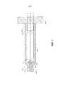
на фиг. 1 представлен вид сверху образцового устройства стимуляции без проводов, имплантированного внутри сердца;in FIG. 1 is a top view of an exemplary cordless stimulation device implanted within the heart;
на фиг. 2 представлен вид в перспективе образцового устройства стимуляции без проводов;in FIG. 2 is a perspective view of an exemplary cordless stimulation device;
на фиг. 3A представлен вид в поперечном разрезе, выполненный по линии 3A-3A;in FIG. 3A is a cross-sectional view taken along
на фиг. 3B представлен альтернативный вид в поперечном разрезе;in FIG. 3B is an alternative cross-sectional view;
на фиг. 3C представлен альтернативный вид в поперечном разрезе;in FIG. 3C is an alternative cross-sectional view;
на фиг. 4 представлен частичный вид в сечении сбоку образцовой системы медицинского устройства, распложенного смежно с сердечной тканью;in FIG. 4 is a partial cross-sectional side view of an exemplary system of a medical device located adjacent to cardiac tissue;
на фиг. 5 представлен частичный вид в сечении сбоку образцового устройства стимуляции без проводов, прикрепленного к сердечной ткани;in FIG. 5 is a partial cross-sectional side view of an exemplary cordless stimulation device attached to cardiac tissue;
на фиг. 6 представлен частичный вид в сечении сбоку другой образцовой системы медицинского устройства, расположенной смежно с сердечной тканью; иin FIG. 6 is a partial cross-sectional side view of another exemplary system of a medical device located adjacent to cardiac tissue; and
на фиг. 7 представлен частичный вид в сечении сбоку другой образцовой системы медицинского устройства, расположенной смежно с сердечной тканью.in FIG. 7 is a partial cross-sectional side view of another exemplary system of a medical device located adjacent to cardiac tissue.
Хотя раскрытие предусматривает различные модификации и альтернативные формы, их специфика показана в качестве примера на рисунках и подробно описана. Однако следует понимать, что изобретение не ограничено описанными конкретными вариантами осуществления. Напротив, имеет место намерение охватить все модификации, эквиваленты и альтернативы, попадающие в сущность и объем раскрытия.Although the disclosure provides for various modifications and alternative forms, their specificity is shown as an example in the figures and described in detail. However, it should be understood that the invention is not limited to the specific embodiments described. On the contrary, there is an intention to cover all modifications, equivalents and alternatives that fall within the essence and scope of disclosure.
ПОДРОБНОЕ ОПИСАНИЕDETAILED DESCRIPTION
Для следующих терминов, которым даны определения, эти определения следует применять до тех пор, пока иное определение не будет дано в формуле изобретения или в другом месте в этом описании.For the following terms that are defined, these definitions should be applied until a different definition is given in the claims or elsewhere in this description.
Предполагают, что все числовые значения в настоящем документе должны быть модифицированы термином «приблизительно», независимо от того, указан он в явной форме или нет. Термин «приблизительно» в целом относится к диапазону чисел, который специалист в данной области сочтет эквивалентным приведенному значению (т. е., имеющим ту же функцию или результат). Во многих случаях, термины «приблизительно» могут включать числа, которые округлены до ближайшего значимого знака.It is intended that all numerical values herein be modified by the term “approximately,” whether explicitly or not. The term “approximately” generally refers to a range of numbers that one of skill in the art would consider equivalent to a given value (that is, having the same function or result). In many cases, the terms “approximately” may include numbers that are rounded to the nearest significant character.
Изложение числового диапазона с помощью конечных точек включает все числа внутри этого диапазона (например, от 1 до 5 включает 1, 1,5, 2, 2,75, 3, 3,80, 4 и 5).An exposition of a numerical range using endpoints includes all numbers within that range (for example, 1 to 5 includes 1, 1.5, 2, 2.75, 3, 3.80, 4, and 5).
Как используют в этом описании и приложенной формуле изобретения, формы единственного числа включают множественное число до тех пор, пока содержание не диктует явно иное. Как используют в этом описании и приложенной формуле изобретения, термин «или» в целом используют в его значении, включающем «и/или» до тех пор, пока содержание не диктует явно иное.As used in this description and the appended claims, the singular forms include the plural unless the content dictates otherwise. As used in this description and the appended claims, the term “or” is generally used in its meaning, including “and / or” until the content dictates clearly otherwise.
Следует отметить, что в описании упоминания о «варианте осуществления», «некоторых вариантах осуществления», «других вариантах осуществления» и т. д. указывают на то, что описываемый вариант осуществления может включать один или несколько конкретных признаков, структур и/или характеристик. Однако такое изложение не обязательно обозначает, что все варианты осуществления содержат конкретные признаки, структуры и/или характеристики. Дополнительно, когда конкретные признаки, структуры и/или характеристики описаны применительно к одному из вариантов осуществления, следует понимать, что такие признаки, структуры и/или характеристики также можно использовать в соединении с другими вариантами осуществления, независимо от того, описано это в явной форме или нет, до тех пор, пока явно не указано иное.It should be noted that in the description of the reference to the “embodiment”, “some embodiments”, “other embodiments”, etc., it is indicated that the described embodiment may include one or more specific features, structures and / or characteristics . However, such a summary does not necessarily mean that all embodiments contain specific features, structures, and / or characteristics. Additionally, when specific features, structures, and / or characteristics are described with reference to one embodiment, it should be understood that such features, structures, and / or characteristics can also be used in conjunction with other embodiments, regardless of whether this is explicitly described. or not, unless explicitly stated otherwise.
Следующее подробное описание следует читать со ссылкой на рисунки, на которых схожие элементы на различных рисунках имеют одинаковую нумерацию. На рисунках, на которых не обязательно соблюден масштаб, изображены иллюстративные варианты осуществления, и они не предназначены для того, чтобы ограничивать объем изобретения.The following detailed description should be read with reference to the drawings, in which similar elements in different figures are given the same numbering. The drawings, which are not necessarily scaled, illustrate embodiments, and are not intended to limit the scope of the invention.
Водители сердечного ритма обеспечивают электрическую стимуляцию сердечной ткани, чтобы заставлять сердце сокращаться и, таким образом, качать кровь через сосудистую систему. Стандартные водители ритма типично содержат электрический провод, который идет от генератора импульсов, имплантируемого под кожу или мышцы, к электроду, расположенному смежно с внешней или внутренней стенкой камеры сердца. В качестве альтернативы стандартным водителям ритма предложен автономный водитель сердечного ритма или водитель сердечного ритма без проводов. Водитель сердечного ритма без проводов может принимать форму относительно небольшой капсулы, которую можно фиксировать в интракардиальном месте имплантации в камере сердца. Без труда можно понять, что может произойти смещение имплантированного устройства стимуляции без проводов внутри сокращающегося сердца, когда сердце функционирует. Соответственно, может быть желательно, чтобы устройство стимуляции без проводов содержало анкерный механизм и/или один или несколько анкерных элементов, чтобы помогать закреплять устройство стимуляции в сердце.Heart rate drivers provide electrical stimulation of the heart tissue to cause the heart to contract and thus pump blood through the vascular system. Standard pacemakers typically contain an electrical wire that extends from a pulse generator implanted under the skin or muscles to an electrode adjacent to the outer or inner wall of the heart chamber. As an alternative to standard pacemakers, an autonomous heart rate driver or a cordless heart rate driver is provided. A cordless heart-rate driver can take the form of a relatively small capsule that can be fixed at the intracardial implantation site in the heart chamber. One can easily understand that a displacement of an implanted stimulation device without wires inside a contracting heart can occur when the heart is functioning. Accordingly, it may be desirable for the cordless stimulation device to comprise an anchor mechanism and / or one or more anchor elements to help fix the stimulation device to the heart.
На фиг. 1 проиллюстрировано образцовое имплантируемое устройство 10 кардиостимуляции без проводов, имплантированное в камеру H сердца, например, такую как правый желудочек RV. Устройство 10 может содержать оболочку или корпус 12, который имеет дистальную область 14 и проксимальную область 16. Один или несколько анкерных элементов 18 можно располагать смежно с дистальной областью 14. Анкерные элементы 18 можно использовать для того, чтобы прикреплять устройство 10 к стенке ткани сердца H или иным образом закреплять имплантируемое устройство 10 в анатомической структуре пациента. Стыковочный элемент 20 можно располагать смежно с проксимальной областью 16 корпуса 12. Стыковочный элемент 20 можно использовать для того, чтобы содействовать доставке и/или извлечению имплантируемого устройства 10.In FIG. 1 illustrates an exemplary cordless implantable
На фиг. 2 представлен вид в перспективе устройства 10. Здесь можно видеть, что стыковочный элемент 20 может идти от проксимальной области 16 корпуса 12. По меньшей мере в некоторых вариантах осуществления, стыковочный элемент 20 может содержать головную часть 22 и шейную часть 24, которая идет между корпусом 12 и головной часть 22. Головная часть 22 может быть способна входить в зацепление с доставляющим и/или извлекающим катетером. Например, если желательно извлечь устройство 10 из пациента, извлекающий катетер можно продвигать в положение, смежное с устройством 10. Извлекающий механизм, такой как петля, трос, рычаг или другая подходящая структура, могут отходить от извлекающего катетера и входить в зацепление с головной частью 22. После зацепления подходящим образом, устройство 10 можно вытягивать из сердечной ткани и, в конечном итоге, удалять из пациента.In FIG. 2 is a perspective view of the
Имплантируемое устройство 10 может содержать первый электрод 26, расположенный смежно с дистальной областью 14 корпуса 12. Второй электрод 28 также может быть образован вдоль корпуса 12. Например, корпус 12 может содержать проводящий материал и может быть изолирован вдоль части его длины. Секция вдоль проксимальной области 16 может не иметь изоляции для того, чтобы определять второй электрод 28. Электроды 26/28 могут представлять собой воспринимающие и/или стимулирующие электроды, чтобы предоставлять возможности электротерапии и/или восприятия. Первый электрод 26 может допускать расположение вплотную или иным образом контактировать с сердечной тканью сердца H, тогда как второй электрод 28 может быть отнесен от первого электрода 26 и, таким образом, отнесен от сердечной ткани.The
Устройство 10 также может содержать генератор импульсов (например, электрическую схему) и источник питания (например, батарею) внутри корпуса 12, чтобы подавать электрические сигналы на электроды 26/28. Электрическая связь между генератором импульсов и электродами 26/28 может обеспечивать электрическую стимуляцию сердечной ткани и/или восприятие физиологического состояния.The
Как предполагает название, анкерные элементы 18 можно использовать для того, чтобы закреплять устройство 10 в целевой ткани. С устройством 10 можно использовать подходящее число анкерных элементов 18. Например, устройство 10 может содержать один, два, три, четыре, пять, шесть, семь, восемь или больше анкерных элементов. По меньшей мере в некоторых вариантах осуществления, анкерные элементы 18 могут принимать форму захватных крюков, которые способны прокалывать сердечную ткань, делать петлю через часть сердечной ткани и затем выходить назад из сердечной ткани. При этом, может быть желательно, чтобы анкерные элементы 18 относительно поверхностно проникали в сердечную ткань. Кроме того, может быть желательно располагать анкерные элементы 18 на расстоянии от первого электрода 26. Предусмотрены другие конфигурации.As the name suggests,
Для того чтобы достигать этих и других целей, анкерные элементы 18 могут иметь сложную криволинейную структуру. В целях этого раскрытия сложную криволинейную структуру можно понимать как структура, которая содержит множество различных криволинейных областей. Например, по меньшей мере некоторые анкерные элементы 18 могут содержать область 30 основания, первую криволинейную область 32, в целом прямую область 34, вторую криволинейную область 36 и концевую область 38. Область 30 основания может быть расположена в месте соединения между анкерными элементами 18 и корпусом 12. В некоторых вариантах осуществления область 30 основания можно фиксировать на корпусе 12. В других вариантах осуществления область 30 основания можно поворотно прикреплять к корпусу 12. В соответствии с этими вариантами осуществления, область 30 основания может иметь некоторую свободу движения относительно корпуса 12. В определенном случае приводной механизм можно соединять с анкерными элементами 18 так, чтобы клиницист мог поворачивать анкерные элементы 18 во время процедуры имплантации. Например, перемещаемый механический элемент, такой как проволока, трос или тому подобное, можно соединять с корпусом 12, который способен передавать движение на анкерные элементы 18.In order to achieve these and other goals, the
Первая криволинейная область 32 может отгибаться от корпуса 12. Другими словами, кривизна первой криволинейной области 32 может приводить к тому, что по меньшей мере к часть анкерных элементов 18 становится расположенными все дальше радиально от корпуса 12. Например, может быть желательно, чтобы анкерные элементы 18 шли или иным образом располагались латерально настолько далеко от первого электрода 26, насколько возможно, чтобы минимизировать раздражение ткани рядом с тем местом, где первый электрод 26 контактирует со стенкой сердца. Кроме того, кривизна первой криволинейной области 32 (и/или других областей анкерных элементов 18) может допускать надежное удержание устройства в стенке сердца, при этом имея относительно поверхностное проникновение в ткань. Поверхностное проникновение может помогать снижать локальное раздражение ткани и/или повреждение стенки сердца.The first
В некоторых вариантах осуществления радиус кривизны первой криволинейной области 32 может быть постоянным. В других вариантах осуществления радиус кривизны может варьироваться вдоль первой криволинейной области 32. Например, первая криволинейная область 32 может содержать параболическую кривую, гиперболическую кривую, экспоненциальную кривую, кривую, определяемую полиномом первого порядка, кривую, определяемую полиномом второго порядка, кривую, определяемую полиномом третьего порядка, кривую, определяемую полиномом четвертого или более высокого порядка, и т. д. Первая криволинейная область 32 может лежать полностью в одной плоскости (например, первая криволинейная область 32 может проходить только в двух измерениях) или первая криволинейная область 32 может лежать больше чем в одной плоскости (например, первая криволинейная область 32 может проходить в трех измерениях). Это является только примерами. Предусмотрены другие кривые, геометрические формы, конфигурации и т. д.In some embodiments, the radius of curvature of the first
В целом прямая область 34, как подсказывает название, может по существу не содержать кривых. В целом прямая область 34 может иметь подходящую длину. Например, в некоторых вариантах осуществления может быть желательно большее разделение между первой криволинейной областью 32 и второй криволинейной областью 36. В таких вариантах осуществления может быть желательно, чтобы в целом прямая область 34 имела относительно большую длину. В других вариантах осуществления меньшее разделение может быть желаемым между криволинейными частями 32/36 и, таким образом, в целом прямая область 34 может быть относительно короткой. В других вариантах осуществления анкерные элементы 18 могут не содержать в целом прямую область 34. Другими словами, первая криволинейная область 32 может быть непосредственно прикреплены к или иным образом быть непрерывной со второй криволинейной областью 36.In general, the
Вторая криволинейная область 36 может изгибаться в направлении корпуса 12. По меньшей мере в некоторых вариантах осуществления, кривизну второй криволинейной области 36 можно ориентировать в противоположном направлении относительно первой криволинейной области 32. Аналогично первой криволинейной области 32, вторая криволинейная область 36 может иметь постоянный или переменный радиус кривизны.The second
Концевая область 38 может быть в целом прямой или концевая область 38 может содержать кривую. По меньшей мере в некоторых вариантах осуществления концевая область 38 может иметь острый или относительно заостренный конец, который может быть способен прокалывать ткань.The
В дополнение к предоставлению возможности надежно закреплять устройство 10 в сердце пациента, анкерные элементы 18 также могут предусматривать срочное изменение положения устройства 10. Например, устройство 10 можно закреплять в сердце пациента через анкерные элементы 18. Если желательно изменить местоположение устройства 10, подходящее устройство извлечения и/или изменения положения можно использовать для зацепления устройства 10 с тем, чтобы можно было изменять его положение (например, удаление анкерных элементов 18 из ткани и перемещение устройства 10 в другое желаемое местоположение) и повторно закреплять.In addition to allowing the
Форма поперечного сечения анкерных элементов 18 может варьироваться. Например, по меньшей мере некоторые анкерные элементы 18 могут иметь в целом прямоугольную форму поперечного сечения, как показано на фиг. 3A. Согласно этим вариантам осуществления, ширина W анкерного элемента 18 может быть больше, чем толщина T. Однако в других вариантах осуществления толщина T может быть больше, чем ширина W. В других вариантах осуществления по меньшей мере некоторые из анкерных элементов 18 могут иметь в целом круглую форму поперечного сечения диаметра D, как изображено на фиг. 3B. Предусмотрены другие формы поперечного сечения. Например, анкерные элементы 18 могут иметь овальную форму поперечного сечения (например, как изображено на фиг. 3C), полукруглую форму поперечного сечения, многоугольную форму поперечного сечения (например, треугольную, квадратную, четырехстороннюю, пятиугольную, шестиугольную, восьмиугольную и т. д.), их сочетания (например, многомерную геометрическую форму со скругленными ребрами или углами) или какую-либо другую подходящую геометрическую форму. Анкерные элементы 18 могут иметь одну и ту же форму поперечного сечения по существу по всей своей длине. Альтернативно, форма поперечного сечения может варьировать вдоль длины анкерных элементов 18. Например, части анкерных элементов 18 могут иметь в целом некруглую форму поперечного сечения, а другие части анкерных элементов 18 могут иметь в целом круглую форму поперечного сечения. Кроме того, в некоторых вариантах осуществления все анкерные элементы 18 могут иметь одну и ту же форму поперечного сечения и/или профиль. В других вариантах осуществления различные анкерные элементы 18 данного устройства 10 могут отличаться друг от друга.The cross-sectional shape of the
На фиг. 4 проиллюстрирован катетер 100 доставки, который можно использовать, например, чтобы доставлять устройство 10 в подходящее местоположение внутри анатомической структуры (например, сердца). Катетер 100 может содержать проксимальный элемент или область 140 и дистальный элемент или вмещающую секцию 146. Толкающий элемент 142 можно располагать (например, располагать с возможностью скольжения) внутри проксимальной области 140. Головную область 144 толкающего элемента 142 можно располагать внутри дистальной вмещающей секции 146. Головная область 144 может быть способна входить в зацепление со стыковочным элементом 20 устройства 10. Толкающий элемент 142 можно использовать для того, чтобы «выталкивать» устройство 10 из дистальной вмещающей секции 146 с тем, чтобы размещать и закреплять устройство 10 внутри целевой области 148 (например, такой области сердца, как правый желудочек). К целевой области 148 катетер 100 можно продвигать через сосудистое русло. Например, катетер 100 можно продвигать через бедренную вену, в нижнюю полую вену, в правое предсердие, через трехстворчатый клапан и в правый желудочек. Целевая область 148 может представлять собой часть правого желудочка. Например, целевая область 148 может представлять собой часть правого желудочка около верхушки сердца. Целевая область 148 также может представлять собой другие области, в том числе другие области сердца (например, правое предсердие, левый желудочек, левое предсердие), кровеносный сосуд или другие подходящие цели.In FIG. 4 illustrates a
Анкерные элементы 18 могут быть способны перемещаться между первой конфигурацией и второй конфигурацией. Например, когда устройство 10 располагают внутри дистальной вмещающей секции 146 катетера 100 доставки, анкерные элементы 18 могут быть в первой конфигурации. В такой конфигурации анкерные элементы 18 могут проходить дистально от устройства 10 в целом в более выпрямленной конфигурации. Другими словами, анкерные элементы 18 могут идти в дистальном направлении. Например, катетер 100 может иметь продольную ось X и анкерные элементы 18 могут иметь соответствующую продольную ось Y, которая в целом параллельна продольной оси X катетера 100. Однако, анкерные элементы 18 не обязательно идут точно параллельно продольной оси X катетера 100 и вместо этого могут быть в целом ориентированы в дистальном направлении.
Когда устройство 10 подходящим образом располагают смежно с целевой областью 148, толкающий элемент 142 можно продвигать дистально, чтобы толкать устройство 10 дистально с тем, чтобы анкерные элементы 18 входили в зацепление с целевой областью 148. При этом, анкерные элементы могут сдвигаться во вторую конфигурацию, как показано на фиг. 5. Во второй конфигурации анкерные элементы 18 могут иметь сложную криволинейную конфигурацию. Сложная кривая анкерных элементов 18 может помогать направлять анкерные элементы 18 латерально от точки входа в ткань и затем обратно наружу из ткани в местоположение, которое латерально отстоит от точки входа.When the
По меньшей мере в некоторых вариантах осуществления анкерные элементы 18 все же могут сохранять сложную кривизну (например, несмотря на измененную геометрическую форму), когда находятся в более выпрямленной конфигурации. Например, когда устройство 10 располагают внутри катетера доставки, анкерные элементы 18 могут все еще сохранять сложную кривую. В других вариантах осуществления одна или несколько из кривых, сформированных в анкерных элементах 18, могут быть по существу выпрямленными так, что анкерные элементы 18 можно рассматривать в качестве более не имеющих сложную кривую, когда находятся в более выпрямленной конфигурации. При смещении во вторую конфигурацию (например, которую можно рассматривать как развернутую, имплантированную, доставленную или «несмещенную» конфигурацию), анкерные элементы 18 могут иметь или иным образом возвращаться к геометрической форме, которая включает в себя сложную кривую.In at least some embodiments, the
В первой конфигурации часть анкерных элементов 18 может входить в зацепление с внутренней поверхностью стенки дистальной вмещающей секции 146. Часть анкерного элемента 18, которая входит в зацепление с внутренней поверхностью стенки дистальной вмещающей секции 146, может быть расположена проксимально от дистального конца анкерного элемента 18. Например, вторая криволинейная область 36 может входить в зацепление с внутренней поверхностью стенки дистальной вмещающей секции 146, как показано на фиг. 4. Предусмотрены другие компоновки. Например, на фиг. 6 проиллюстрировано устройство 110 (которое может быть схоже по форме и функции с другими устройствами, описанными в настоящем документе), включая анкерный элемент 118 и стыковочный элемент 120. Здесь можно видеть, что первая криволинейная область 132 может входить в зацепление с внутренней поверхностью стенки дистальной вмещающей секции 146.In a first configuration, part of the
На фиг. 7 проиллюстрировано устройство 210 (которое может быть схоже по форме и функции с другими устройствами, описанными в настоящем документе), содержащее анкерный элемент 218 и стыковочный элемент 220. В этом варианте осуществления секция анкерного элемента 218, идущая от второй криволинейной области 232 к кончику 238, может лежать ровно напротив внутренней поверхности стенки дистальной вмещающей секции 146.In FIG. 7 illustrates a device 210 (which may be similar in shape and function to other devices described herein) comprising an
Материалы, которые можно использовать для различных компонентов устройства 10 и катетера 100 (и/или других устройств/катетеров, описанных в настоящем документе), могут включать те, которые обычно связаны с медицинскими устройствами. Например, устройство 10 и/или катетер 100 может быть выполнен из металла, металлического сплава, полимера (некоторые примеры которого раскрыты далее), металл-полимерного композита, керамики, их сочетания, и т. п. или другого подходящего материала. Некоторые примеры подходящих полимеров могут включать политетрафторэтилен (PTFE), этилентетрафторэтилен (ETFE), фторированный этиленпропилен (FEP), полиоксиметилен (POM, например, DELRIN®, доступный в DuPont), блок-сополимер простого полиэфира и сложного эфира, полиуретан (например, полиуретан 85A), полипропилен (PP), поливинилхлорид (PVC), сополимер простого полиэфира и сложного эфира (например, ARNITEL®, доступный в DSM Engineering Plastics), сополимеры на основе простых эфиров или сложных эфиров (например, бутилен/поли(простой алкиленовый эфир)фталат и/или другие сложные полиэфирные эластомеры, такие как HYTREL®, поставляемый DuPont), полиамид (например, DУРЕТАН®, поставляемый Bayer, или CRISTAMID®, поставляемый Elf Atochem), эластомерные полиамиды, блок-сополимеры полиамидов/простых эфиров, блок-сополимер простого полиэфира и амида (PEBA, например, доступный под торговым названием PEBAX®), этиленвинилацетатные сополимеры (EVA), силиконы, полиэтилен (PE), полиэтилен высокой плотности Marlex, полиэтилен низкой плотности Marlex, линейный полиэтилен низкой плотности (например, REXELL®), сложный полиэфир, полибутилентерефталат (PBT), полиэтилентерефталат (PET), политриметилентерефталат, полиэтиленнафталат (PEN), полиэфирэфиркетон (PEEK), полиимид (PI), полиэфиримид (PEI), полифениленсульфид (PPS), полифенилен оксид (PPO), полипарафенилентерефталамид (например, KEVLAR®), полисульфон, нейлон, нейлон-12 (такой как GRILAMID®, поставляемый EMS American Grilon), перфтор(простой пропилвиниловый эфир) (PFA), этиленвиниловый спирт, полиолефин, полистирол, эпоксид, поливинилиденхлорид (PVdC), поли(стирол-b-изобутилен-b-стирол) (например, SIBS и/или SIBS 50A), поликарбонаты, иономеры, биологически совместимые полимеры, другие подходящие материалы или их смеси, комбинации, сополимеры, композиты полимеров/металлов и т. п. В некоторых вариантах осуществления кожух может содержать смесь с жидкокристаллическим полимером (LCP). Например, смесь может содержать приблизительно до 6 процентов LCP.Materials that can be used for various components of
Некоторые примеры подходящих металлов и металлических сплавов включают нержавеющую сталь, такую как нержавеющая сталь 304V, 304L и 316LV; малоуглеродистую сталь; никель-титановый сплав, такой как линейный упругий и/или сверхупругий нитинол; другие никелевые сплавы, такие как никель-хром-молибденовые сплавы (например, UNS: N06625, такие как INCONEL® 625, UNS: N06022, такие как HASTELLOY® C-22®, UNS: N10276, такие как HASTELLOY® C276®, другие сплавы HASTELLOY® и т. п.), никель-медные сплавы (например, UNS: N04400, такие как MONEL® 400, NICKELVAC® 400, NICORROS® 400 и т. п.), никель-кобальт-хром-молибденовые сплавы (например, UNS: R30035, такие как MP35-N®, и т. п.), никель-молибденовые сплавы (например, UNS: N10665, такие как HASTELLOY® ALLOY B2®), другие никель-хромовые сплавы, другие никель-молибденовые сплавы, другие никель-кобальтовые сплавы, другие никель-железные сплавы, другие никель-медные сплавы, другие никель-вольфрамовые или вольфрамовые сплавы и т. п.; кобальт-хромовые сплавы; кобальт-хром-молибденовые сплавы (например, UNS: R30003, такие как ELGILOY®, PHYNOX®, и т. п.); нержавеющая сталь, обогащенная платиной; титан; их сочетания; и т. п.; или какой-либо другой подходящий материал.Some examples of suitable metals and metal alloys include stainless steel, such as 304V, 304L, and 316LV; mild steel; a nickel-titanium alloy such as linear elastic and / or superelastic nitinol; other nickel alloys such as nickel-chromium-molybdenum alloys (e.g. UNS: N06625, such as INCONEL® 625, UNS: N06022, such as HASTELLOY® C-22®, UNS: N10276, such as HASTELLOY® C276®, others HASTELLOY® alloys, etc.), nickel-copper alloys (e.g. UNS: N04400 such as MONEL® 400, NICKELVAC® 400, NICORROS® 400, etc.), nickel-cobalt-chromium-molybdenum alloys ( e.g. UNS: R30035, such as MP35-N®, etc.), nickel-molybdenum alloys (e.g. UNS: N10665, such as HASTELLOY® ALLOY B2®), other nickel-chromium alloys, other nickel-molybdenum alloys, other nickel-cobalt alloys, other nickel-iron alloys s, other nickel-copper alloys, other nickel-tungsten or tungsten alloys and m. p .; cobalt-chromium alloys; cobalt-chromium-molybdenum alloys (for example, UNS: R30003, such as ELGILOY®, PHYNOX®, etc.); platinum enriched stainless steel; titanium; their combination; etc.; or any other suitable material.
Как указано в настоящем документе, в семействе коммерчески доступных никель-титановых сплавов или нитинолов есть категория, обозначаемая «линейно упругие» или «не сверхупругие», которые, несмотря на то, что могут быть схожи по химическим свойствам со стандартными сортами с памятью формы и сверхупругими сортами, могут проявлять резко выраженные и полезные механические свойства. Линейно упругий и/или не сверхупругий нитинол может отличаться от сверхупругого нитинола тем, что линейно упругий и/или не сверхупругий нитинол не демонстрирует существенного «сверхупругого плато» или «области флага» на своей кривой напряжения/деформации, подобного сверхупругому нитинолу. Вместо этого в линейно упругом и/или не сверхупругом нитиноле с ростом обратимой деформации напряжение продолжает возрастать в по существу линейной или до некоторой степени, но не обязательно полностью, линейной зависимости до тех пор, пока не начнется пластическая деформация, или по меньшей мере в зависимости, которая является более линейной, чем сверхупругое плато и/или область флага, которые можно наблюдать в сверхупругом нитиноле. Таким образом, для целей этого раскрытия линейно упругий и/или не сверхупругий нитинол также можно называть «по существу» линейно упругими и/или не сверхупругим нитинолом.As indicated herein, in the family of commercially available nickel-titanium alloys or nitinols, there is a category designated “linearly elastic” or “non-superelastic” which, despite being similar in chemical properties to standard grades with shape memory and superelastic grades, can exhibit pronounced and useful mechanical properties. Linearly elastic and / or non-superelastic nitinol may differ from superelastic nitinol in that the linearly elastic and / or non-superelastic nitinol does not exhibit a significant "superelastic plateau" or "flag region" on its stress / strain curve similar to superelastic nitinol. Instead, in linearly elastic and / or non-superelastic nitinol, with increasing reversible deformation, the stress continues to increase in a substantially linear or to some extent, but not necessarily completely, linear relationship until plastic deformation begins, or at least depending which is more linear than the superelastic plateau and / or flag region that can be observed in superelastic nitinol. Thus, for the purposes of this disclosure, linearly elastic and / or non-superelastic nitinol can also be called “substantially” linearly elastic and / or non-superelastic nitinol.
В некоторых случаях, линейно упругий и/или не сверхупругий нитинол также может отличаться от сверхупругого нитинола тем, что линейно упругий и/или не сверхупругий нитинол может допускать вплоть до приблизительно 2-5% напряжения, при этом оставаясь по существу упругим (например, перед пластической деформацией) тогда как сверхупругий нитинол может допускать вплоть до приблизительно до 8% напряжения перед пластической деформацией. Оба этих материала можно отличать от других линейно упругих материалов, таких как нержавеющая сталь (которую также можно отличать на основании ее композиции), которая может допускать только приблизительно от 0,2 до 0,44 процента напряжения перед пластической деформацией.In some cases, the linearly elastic and / or non-superelastic nitinol may also differ from the superelastic nitinol in that the linearly elastic and / or non-superelastic nitinol can tolerate up to about 2-5% stress, while remaining substantially elastic (e.g., before plastic deformation) whereas superelastic nitinol can tolerate up to about 8% stress before plastic deformation. Both of these materials can be distinguished from other linearly elastic materials, such as stainless steel (which can also be distinguished based on its composition), which can only tolerate from about 0.2 to 0.44 percent stress before plastic deformation.
В некоторых вариантах осуществления линейно упругий и/или не сверхупругий никель-титановый сплав представляет собой сплав, который не демонстрирует каких-либо фазовых переходов мартенсит/аустенит, которые поддаются обнаружению с помощью дифференциальной сканирующей калориметрии (DSC) и динамического термического анализа металлов (DMTA) в большом температурном диапазоне. Например, в некоторых вариантах осуществления в линейно упругом и/или не сверхупругом никель-титановом сплаве могут отсутствовать фазовые переходы мартенсит/аустенит, поддающиеся обнаружению с помощью анализа DSC и DMTA, в диапазоне приблизительно от –60 градусов по Цельсию (°C) приблизительно до 120°C. Следовательно, механические свойства при изгибе у такого материала могут быть в целом инертными к влиянию температуры в этом очень широком диапазоне температур. В некоторых вариантах осуществления механические свойства при изгибе у линейно упругого и/или не сверхупругого никель-титанового сплава при окружающей или комнатной температуре являются по существу теми же, что механические свойства при температуре тела, например, в том отношении, что они не демонстрируют сверхупругое плато и/или область флага. Другими словами, в широком температурном диапазоне линейно упругий и/или не сверхупругий никель-титановый сплав сохраняет свои линейно упругие и/или не сверхупругие характеристики и/или свойства.In some embodiments, the linearly elastic and / or non-superelastic nickel-titanium alloy is an alloy that does not exhibit any martensite / austenite phase transitions that are detectable by differential scanning calorimetry (DSC) and dynamic thermal metal analysis (DMTA) in a large temperature range. For example, in some embodiments, the linearly elastic and / or non-superelastic nickel-titanium alloy may lack martensite / austenite phase transitions detectable by DSC and DMTA analysis in the range of about −60 degrees Celsius (° C) to 120 ° C. Consequently, the bending mechanical properties of such a material can be generally inert to the influence of temperature in this very wide temperature range. In some embodiments, the mechanical properties in bending of a linearly elastic and / or non-superelastic nickel-titanium alloy at ambient or room temperature are substantially the same as mechanical properties at body temperature, for example, in that they do not exhibit a superelastic plateau and / or flag area. In other words, in a wide temperature range, the linearly elastic and / or non-superelastic nickel-titanium alloy retains its linearly elastic and / or non-superelastic characteristics and / or properties.
В некоторых вариантах осуществления линейно упругий и/или не сверхупругий никель-титановый сплав может содержать никель в диапазоне приблизительно от 50 приблизительно до 60 процентов по массе, а остальное по существу титан. В некоторых вариантах осуществления композиция находится в диапазоне приблизительно от 54 приблизительно до 57 процентов никеля по массе. Один из примеров подходящего никель-титанового сплава является сплав FHP-NT, коммерчески доступный в Furukawa Techno Material Co., Kanagawa, Japan. Некоторые примеры никель-титановых сплавов раскрыты в патентах США №№ 5238004 и 6508803, которые включены в настоящий документ посредством ссылки. Другие подходящие материалы могут включать ULTANIUM™ (поставляемый Neo-Metrics) и GUM METAL™ (поставляемый Toyota). В некоторых других вариантах осуществления сверхупругий сплав, например, сверхупругий нитинол, можно использовать для того, чтобы достигать желаемых свойств.In some embodiments, the linearly resilient and / or non-superelastic nickel-titanium alloy may contain nickel in the range of about 50 to about 60 percent by weight, and the remainder is essentially titanium. In some embodiments, the composition is in the range of from about 54 to about 57 percent nickel by weight. One example of a suitable nickel-titanium alloy is FHP-NT alloy commercially available from Furukawa Techno Material Co., Kanagawa, Japan. Some examples of nickel-titanium alloys are disclosed in US patent No. 5238004 and 6508803, which are incorporated herein by reference. Other suitable materials may include ULTANIUM ™ (supplied by Neo-Metrics) and GUM METAL ™ (supplied by Toyota). In some other embodiments, a superelastic alloy, for example, superelastic nitinol, can be used to achieve the desired properties.
По меньшей мере в некоторых вариантах осуществления части или все устройство 10 и/или катетер 100 также можно легировать, выполнять из или иным образом включать рентгеноконтрастный материал. Под рентгеноконтрастными материалами понимают материалы, способные давать относительно светлое изображение на флуороскопическом экране или в другом способе визуализации во время медицинской процедуры. Это относительно светлое изображение помогает пользователю устройства 10 и/или катетера 100 при определении его местоположения. Некоторые примеры рентгеноконтрастных материалов могут включать, но не ограничиваясь этим, золото, платину, палладий, тантал, вольфрамовый сплав, полимерный материал, нагруженный рентгеноконтрастным наполнителем, и т. п. Дополнительно, другие рентгеноконтрастные маркирующие полоски и/или спирали также можно встраивать в конструкцию устройства 10 и/или катетера 100, чтобы достигать того же результата.In at least some embodiments, part or all of the
В некоторых вариантах осуществления устройству 10 и/или катетеру 100 придают в некоторой степени совместимость с магнитно-резонансной визуализацией (MRI). Например, устройство 10 и/или катетер 100 (или его части) можно создавать из материала, который по существу не искажает изображение и не создает существенные артефакты (т. е., пропуски на изображении). Определенные ферромагнитные материалы, например, могут не подходить, поскольку они создают артефакты на MRI изображении. Устройство 10 и/или катетер 100 (или его части) также можно выполнять из материала, который может визуализировать устройство MRI. Такие материалы, проявляющие эти характеристики, включают, например, вольфрам, кобальт-хром-молибденовые сплавы (например, UNS: R30003, такие как ELGILOY®, PHYNOX®, и т. п.), никель-кобальт-хром-молибденовые сплавы (например, UNS: R30035, такие как MP35-N® и т. п.), нитинол и т. п. и другие.In some embodiments,
Следует понимать, что это раскрытие во многих отношениях является только иллюстративным. Изменения можно выполнять в деталях, в частности, в отношении геометрической формы, размера и расположения стадий, не выходя за рамки объема раскрытия. Это может включать, в той мере, в которой это подходит, использование каких-либо признаков из одного приведенного в качестве примера варианта осуществления, которые используют в других вариантах осуществления. Конечно, объем изобретения определен формулировками, в которых выражена приложенная формула изобретения.It should be understood that this disclosure is only illustrative in many respects. Changes can be made in detail, in particular with respect to the geometric shape, size and location of the stages, without going beyond the scope of the disclosure. This may include, to the extent that this is appropriate, the use of any of the features from one exemplary embodiment that are used in other embodiments. Of course, the scope of the invention is defined by the language in which the appended claims are expressed.
Claims (44)
Translated fromRussianApplications Claiming Priority (3)
| Application Number | Priority Date | Filing Date | Title |
|---|---|---|---|
| US201361866799P | 2013-08-16 | 2013-08-16 | |
| US61/866,799 | 2013-08-16 | ||
| PCT/US2014/049914WO2015023488A1 (en) | 2013-08-16 | 2014-08-06 | Leadless cardiac pacing devices |
Publications (2)
| Publication Number | Publication Date |
|---|---|
| RU2016109156A RU2016109156A (en) | 2017-09-21 |
| RU2661754C2true RU2661754C2 (en) | 2018-07-19 |
Family
ID=51358118
Family Applications (1)
| Application Number | Title | Priority Date | Filing Date |
|---|---|---|---|
| RU2016109156ARU2661754C2 (en) | 2013-08-16 | 2014-08-06 | Leadless cardiac pacing devices |
Country Status (9)
| Country | Link |
|---|---|
| US (4) | US10179236B2 (en) |
| EP (1) | EP3033141B1 (en) |
| JP (1) | JP6266779B2 (en) |
| CN (1) | CN105916544B (en) |
| AU (1) | AU2014306940B2 (en) |
| BR (1) | BR112016003148B1 (en) |
| ES (1) | ES2652306T3 (en) |
| RU (1) | RU2661754C2 (en) |
| WO (1) | WO2015023488A1 (en) |
Families Citing this family (120)
| Publication number | Priority date | Publication date | Assignee | Title |
|---|---|---|---|---|
| US20100256696A1 (en) | 2009-04-07 | 2010-10-07 | Boston Scientific Neuromodulation Corporation | Anchoring Units For Implantable Electrical Stimulation Systems And Methods Of Making And Using |
| CN105392522B (en) | 2013-05-14 | 2017-09-22 | 波士顿科学神经调制公司 | The electro photoluminescence lead arranged with anchoring unit and electrode with and production and preparation method thereof |
| US10071243B2 (en) | 2013-07-31 | 2018-09-11 | Medtronic, Inc. | Fixation for implantable medical devices |
| AU2015204693B2 (en) | 2014-01-10 | 2017-03-23 | Cardiac Pacemakers, Inc. | Methods and systems for improved communication between medical devices |
| WO2015106015A1 (en) | 2014-01-10 | 2015-07-16 | Cardiac Pacemakers, Inc. | Systems and methods for detecting cardiac arrhythmias |
| US9669210B2 (en) | 2014-04-22 | 2017-06-06 | Boston Scientific Neuromodulation Corporation | Electrical stimulation leads and systems with folding anchoring units and methods of making and using |
| WO2015168155A1 (en) | 2014-04-29 | 2015-11-05 | Cardiac Pacemakers, Inc. | Leadless cardiac pacemaker with retrieval features |
| US10080887B2 (en) | 2014-04-29 | 2018-09-25 | Cardiac Pacemakers, Inc. | Leadless cardiac pacing devices including tissue engagement verification |
| US9649489B2 (en) | 2014-06-02 | 2017-05-16 | Boston Scientific Neuromodulation Corporation | Electrical stimulation leads and systems with anchoring units having struts and methods of making and using |
| US9533141B2 (en)* | 2014-07-07 | 2017-01-03 | Boston Scientific Neuromodulation Corporation | Electrical stimulation leads and systems with elongate anchoring elements |
| CN107073275B (en) | 2014-08-28 | 2020-09-01 | 心脏起搏器股份公司 | Medical device with triggered blanking period |
| WO2016073509A1 (en) | 2014-11-04 | 2016-05-12 | Cardiac Pacemakers, Inc. | Implantable medical devices and methods for making and delivering implantable medical devices |
| EP3253449B1 (en) | 2015-02-06 | 2018-12-12 | Cardiac Pacemakers, Inc. | Systems for safe delivery of electrical stimulation therapy |
| AU2016215606B2 (en) | 2015-02-06 | 2018-05-31 | Cardiac Pacemakers, Inc. | Systems and methods for treating cardiac arrhythmias |
| US10046167B2 (en) | 2015-02-09 | 2018-08-14 | Cardiac Pacemakers, Inc. | Implantable medical device with radiopaque ID tag |
| CN107530002B (en) | 2015-03-04 | 2021-04-30 | 心脏起搏器股份公司 | System and method for treating cardiac arrhythmias |
| US10050700B2 (en) | 2015-03-18 | 2018-08-14 | Cardiac Pacemakers, Inc. | Communications in a medical device system with temporal optimization |
| EP3270768B1 (en) | 2015-03-18 | 2023-12-13 | Cardiac Pacemakers, Inc. | Communications in a medical device system with link quality assessment |
| US9526891B2 (en) | 2015-04-24 | 2016-12-27 | Medtronic, Inc. | Intracardiac medical device |
| CN108136187B (en) | 2015-08-20 | 2021-06-29 | 心脏起搏器股份公司 | System and method for communication between medical devices |
| CN108136186B (en) | 2015-08-20 | 2021-09-17 | 心脏起搏器股份公司 | System and method for communication between medical devices |
| US9968787B2 (en) | 2015-08-27 | 2018-05-15 | Cardiac Pacemakers, Inc. | Spatial configuration of a motion sensor in an implantable medical device |
| US9956414B2 (en) | 2015-08-27 | 2018-05-01 | Cardiac Pacemakers, Inc. | Temporal configuration of a motion sensor in an implantable medical device |
| US10226631B2 (en) | 2015-08-28 | 2019-03-12 | Cardiac Pacemakers, Inc. | Systems and methods for infarct detection |
| WO2017040115A1 (en) | 2015-08-28 | 2017-03-09 | Cardiac Pacemakers, Inc. | System for detecting tamponade |
| US10137305B2 (en) | 2015-08-28 | 2018-11-27 | Cardiac Pacemakers, Inc. | Systems and methods for behaviorally responsive signal detection and therapy delivery |
| WO2017044389A1 (en) | 2015-09-11 | 2017-03-16 | Cardiac Pacemakers, Inc. | Arrhythmia detection and confirmation |
| WO2017062806A1 (en) | 2015-10-08 | 2017-04-13 | Cardiac Pacemakers, Inc. | Devices and methods for adjusting pacing rates in an implantable medical device |
| EP3389775B1 (en) | 2015-12-17 | 2019-09-25 | Cardiac Pacemakers, Inc. | Conducted communication in a medical device system |
| US10905886B2 (en) | 2015-12-28 | 2021-02-02 | Cardiac Pacemakers, Inc. | Implantable medical device for deployment across the atrioventricular septum |
| WO2017127548A1 (en) | 2016-01-19 | 2017-07-27 | Cardiac Pacemakers, Inc. | Devices for wirelessly recharging a rechargeable battery of an implantable medical device |
| US10099050B2 (en) | 2016-01-21 | 2018-10-16 | Medtronic, Inc. | Interventional medical devices, device systems, and fixation components thereof |
| US10463853B2 (en) | 2016-01-21 | 2019-11-05 | Medtronic, Inc. | Interventional medical systems |
| CN109069840B (en) | 2016-02-04 | 2022-03-15 | 心脏起搏器股份公司 | Delivery system with force sensor for leadless cardiac devices |
| EP3436142B1 (en) | 2016-03-31 | 2025-04-30 | Cardiac Pacemakers, Inc. | Implantable medical device with rechargeable battery |
| US10328272B2 (en) | 2016-05-10 | 2019-06-25 | Cardiac Pacemakers, Inc. | Retrievability for implantable medical devices |
| US10668294B2 (en) | 2016-05-10 | 2020-06-02 | Cardiac Pacemakers, Inc. | Leadless cardiac pacemaker configured for over the wire delivery |
| EP3474945B1 (en) | 2016-06-27 | 2022-12-28 | Cardiac Pacemakers, Inc. | Cardiac therapy system using subcutaneously sensed p-waves for resynchronization pacing management |
| US11207527B2 (en) | 2016-07-06 | 2021-12-28 | Cardiac Pacemakers, Inc. | Method and system for determining an atrial contraction timing fiducial in a leadless cardiac pacemaker system |
| WO2018009392A1 (en) | 2016-07-07 | 2018-01-11 | Cardiac Pacemakers, Inc. | Leadless pacemaker using pressure measurements for pacing capture verification |
| EP3487579B1 (en) | 2016-07-20 | 2020-11-25 | Cardiac Pacemakers, Inc. | System for utilizing an atrial contraction timing fiducial in a leadless cardiac pacemaker system |
| WO2018035343A1 (en) | 2016-08-19 | 2018-02-22 | Cardiac Pacemakers, Inc. | Trans septal implantable medical device |
| EP3503970B1 (en) | 2016-08-24 | 2023-01-04 | Cardiac Pacemakers, Inc. | Cardiac resynchronization using fusion promotion for timing management |
| EP3503799B1 (en) | 2016-08-24 | 2021-06-30 | Cardiac Pacemakers, Inc. | Integrated multi-device cardiac resynchronization therapy using p-wave to pace timing |
| EP3292884B1 (en)* | 2016-09-12 | 2019-09-04 | BIOTRONIK SE & Co. KG | Modified implantation tool tip configuration for the improved installation of leadless pacemakers with short tine-based anchors |
| CN106362288B (en)* | 2016-09-14 | 2019-06-11 | 郭成军 | Cardiac implant and its fixation method |
| US10994145B2 (en) | 2016-09-21 | 2021-05-04 | Cardiac Pacemakers, Inc. | Implantable cardiac monitor |
| US10758737B2 (en) | 2016-09-21 | 2020-09-01 | Cardiac Pacemakers, Inc. | Using sensor data from an intracardially implanted medical device to influence operation of an extracardially implantable cardioverter |
| CN109803720B (en)* | 2016-09-21 | 2023-08-15 | 心脏起搏器股份公司 | Leadless stimulation device having a housing containing its internal components and functioning as a terminal for a battery case and an internal battery |
| CN109922860B (en) | 2016-10-27 | 2023-07-04 | 心脏起搏器股份公司 | Implantable medical device delivery system with integrated sensor |
| EP3532161B1 (en) | 2016-10-27 | 2023-08-30 | Cardiac Pacemakers, Inc. | Implantable medical device with pressure sensor |
| US10413733B2 (en) | 2016-10-27 | 2019-09-17 | Cardiac Pacemakers, Inc. | Implantable medical device with gyroscope |
| US10434314B2 (en) | 2016-10-27 | 2019-10-08 | Cardiac Pacemakers, Inc. | Use of a separate device in managing the pace pulse energy of a cardiac pacemaker |
| WO2018081275A1 (en) | 2016-10-27 | 2018-05-03 | Cardiac Pacemakers, Inc. | Multi-device cardiac resynchronization therapy with timing enhancements |
| US10561330B2 (en) | 2016-10-27 | 2020-02-18 | Cardiac Pacemakers, Inc. | Implantable medical device having a sense channel with performance adjustment |
| EP3532157B1 (en) | 2016-10-31 | 2020-08-26 | Cardiac Pacemakers, Inc. | Systems for activity level pacing |
| US10434317B2 (en) | 2016-10-31 | 2019-10-08 | Cardiac Pacemakers, Inc. | Systems and methods for activity level pacing |
| WO2018089311A1 (en) | 2016-11-08 | 2018-05-17 | Cardiac Pacemakers, Inc | Implantable medical device for atrial deployment |
| WO2018089308A1 (en) | 2016-11-09 | 2018-05-17 | Cardiac Pacemakers, Inc. | Systems, devices, and methods for setting cardiac pacing pulse parameters for a cardiac pacing device |
| CN109963618B (en) | 2016-11-21 | 2023-07-04 | 心脏起搏器股份公司 | Leadless cardiac pacemaker with multi-mode communication |
| US10639486B2 (en) | 2016-11-21 | 2020-05-05 | Cardiac Pacemakers, Inc. | Implantable medical device with recharge coil |
| US10881869B2 (en) | 2016-11-21 | 2021-01-05 | Cardiac Pacemakers, Inc. | Wireless re-charge of an implantable medical device |
| US11147979B2 (en) | 2016-11-21 | 2021-10-19 | Cardiac Pacemakers, Inc. | Implantable medical device with a magnetically permeable housing and an inductive coil disposed about the housing |
| WO2018093605A1 (en) | 2016-11-21 | 2018-05-24 | Cardiac Pacemakers, Inc. | Leadless cardiac pacemaker providing cardiac resynchronization therapy |
| US10806931B2 (en) | 2016-12-27 | 2020-10-20 | Cardiac Pacemakers, Inc. | Delivery devices and methods for leadless cardiac devices |
| US10485981B2 (en) | 2016-12-27 | 2019-11-26 | Cardiac Pacemakers, Inc. | Fixation methods for leadless cardiac devices |
| CN110114114B (en)* | 2016-12-27 | 2023-05-02 | 心脏起搏器股份公司 | Delivery devices and methods for leadless cardiac devices |
| AU2017387024B2 (en) | 2016-12-27 | 2020-04-09 | Cardiac Pacemakers, Inc. | Leadless delivery catheter with conductive pathway |
| US11207532B2 (en) | 2017-01-04 | 2021-12-28 | Cardiac Pacemakers, Inc. | Dynamic sensing updates using postural input in a multiple device cardiac rhythm management system |
| JP7000438B2 (en) | 2017-01-26 | 2022-01-19 | カーディアック ペースメイカーズ, インコーポレイテッド | Human device communication with redundant message transmission |
| WO2018140597A2 (en) | 2017-01-26 | 2018-08-02 | Cardiac Pacemakers, Inc. | Delivery devices and methods for leadless cardiac devices |
| US10029107B1 (en) | 2017-01-26 | 2018-07-24 | Cardiac Pacemakers, Inc. | Leadless device with overmolded components |
| CN110198759B (en) | 2017-01-26 | 2023-08-11 | 心脏起搏器股份公司 | Leadless implantable device with removable fasteners |
| CN110418661B (en)* | 2017-03-10 | 2024-01-02 | 心脏起搏器股份公司 | Fixing piece for leadless cardiac device |
| US10737092B2 (en) | 2017-03-30 | 2020-08-11 | Cardiac Pacemakers, Inc. | Delivery devices and methods for leadless cardiac devices |
| US10905872B2 (en) | 2017-04-03 | 2021-02-02 | Cardiac Pacemakers, Inc. | Implantable medical device with a movable electrode biased toward an extended position |
| CN110740779B (en) | 2017-04-03 | 2024-03-08 | 心脏起搏器股份公司 | Cardiac pacemaker with pacing pulse energy modulation based on sensed heart rate |
| CN107233665B (en)* | 2017-08-01 | 2024-08-06 | 郭成军 | Intracardiac implant |
| US11577085B2 (en) | 2017-08-03 | 2023-02-14 | Cardiac Pacemakers, Inc. | Delivery devices and methods for leadless cardiac devices |
| US10918875B2 (en) | 2017-08-18 | 2021-02-16 | Cardiac Pacemakers, Inc. | Implantable medical device with a flux concentrator and a receiving coil disposed about the flux concentrator |
| CN111032148B (en) | 2017-08-18 | 2024-04-02 | 心脏起搏器股份公司 | Implantable medical device with pressure sensor |
| US11426578B2 (en)* | 2017-09-15 | 2022-08-30 | Medtronic, Inc. | Electrodes for intra-cardiac pacemaker |
| US11235163B2 (en) | 2017-09-20 | 2022-02-01 | Cardiac Pacemakers, Inc. | Implantable medical device with multiple modes of operation |
| CN107583187B (en)* | 2017-09-25 | 2020-04-10 | 创领心律管理医疗器械(上海)有限公司 | Leadless pacemaker system and method of use |
| US11185703B2 (en) | 2017-11-07 | 2021-11-30 | Cardiac Pacemakers, Inc. | Leadless cardiac pacemaker for bundle of his pacing |
| WO2019108830A1 (en) | 2017-12-01 | 2019-06-06 | Cardiac Pacemakers, Inc. | Leadless cardiac pacemaker with reversionary behavior |
| WO2019108482A1 (en) | 2017-12-01 | 2019-06-06 | Cardiac Pacemakers, Inc. | Methods and systems for detecting atrial contraction timing fiducials and determining a cardiac interval from a ventricularly implanted leadless cardiac pacemaker |
| CN111417433B (en) | 2017-12-01 | 2024-04-30 | 心脏起搏器股份公司 | Method and system for detecting atrial contraction timing reference during ventricular filling from a ventricularly implanted leadless cardiac pacemaker |
| EP3717059B1 (en) | 2017-12-01 | 2024-11-20 | Cardiac Pacemakers, Inc. | Systems for detecting atrial contraction timing fiducials within a search window from a ventricularly implanted leadless cardiac pacemaker |
| CN111491694A (en)* | 2017-12-22 | 2020-08-04 | 心脏起搏器股份公司 | Implantable medical device for vascular deployment |
| EP3727576B1 (en)* | 2017-12-22 | 2024-01-31 | Cardiac Pacemakers, Inc. | Implantable medical device for vascular deployment |
| US11529523B2 (en) | 2018-01-04 | 2022-12-20 | Cardiac Pacemakers, Inc. | Handheld bridge device for providing a communication bridge between an implanted medical device and a smartphone |
| WO2019136148A1 (en) | 2018-01-04 | 2019-07-11 | Cardiac Pacemakers, Inc. | Dual chamber pacing without beat-to-beat communication |
| EP3768160B1 (en) | 2018-03-23 | 2023-06-07 | Medtronic, Inc. | Vfa cardiac therapy for tachycardia |
| JP2021518192A (en) | 2018-03-23 | 2021-08-02 | メドトロニック,インコーポレイテッド | VfA cardiac resynchronization therapy |
| CN111886046B (en) | 2018-03-23 | 2025-05-27 | 美敦力公司 | AV-synchronized VFA cardiac therapy |
| US11235161B2 (en) | 2018-09-26 | 2022-02-01 | Medtronic, Inc. | Capture in ventricle-from-atrium cardiac therapy |
| US11951313B2 (en) | 2018-11-17 | 2024-04-09 | Medtronic, Inc. | VFA delivery systems and methods |
| US20220015906A1 (en)* | 2018-11-29 | 2022-01-20 | Cardiomech As | Device for Heart Repair |
| US12296177B2 (en) | 2018-12-21 | 2025-05-13 | Medtronic, Inc. | Delivery systems and methods for left ventricular pacing |
| CN109568793B (en)* | 2018-12-25 | 2023-08-04 | 创领心律管理医疗器械(上海)有限公司 | Leadless pacemaker and leadless pacing system |
| US11679265B2 (en) | 2019-02-14 | 2023-06-20 | Medtronic, Inc. | Lead-in-lead systems and methods for cardiac therapy |
| US11413453B2 (en) | 2019-02-18 | 2022-08-16 | Pacesetter, Inc. | Biostimulator having resilient scaffold |
| US11759632B2 (en) | 2019-03-28 | 2023-09-19 | Medtronic, Inc. | Fixation components for implantable medical devices |
| US11697025B2 (en) | 2019-03-29 | 2023-07-11 | Medtronic, Inc. | Cardiac conduction system capture |
| EP3946556B1 (en) | 2019-03-29 | 2024-06-19 | Cardiac Pacemakers, Inc. | Systems for treating cardiac arrhythmias |
| CN113660977B (en) | 2019-03-29 | 2024-12-17 | 心脏起搏器股份公司 | Systems and methods for treating cardiac arrhythmias |
| US11213676B2 (en) | 2019-04-01 | 2022-01-04 | Medtronic, Inc. | Delivery systems for VfA cardiac therapy |
| US11712188B2 (en) | 2019-05-07 | 2023-08-01 | Medtronic, Inc. | Posterior left bundle branch engagement |
| US20200360687A1 (en) | 2019-05-16 | 2020-11-19 | Biotronik Se & Co. Kg | Implantable medical device comprising an anchoring device |
| EP4454611A3 (en) | 2019-07-03 | 2024-11-20 | Boston Scientific Scimed, Inc. | System for anchoring an artificial chordae tendineae to a papillary muscle or heart wall |
| US11305127B2 (en) | 2019-08-26 | 2022-04-19 | Medtronic Inc. | VfA delivery and implant region detection |
| WO2021050685A1 (en) | 2019-09-11 | 2021-03-18 | Cardiac Pacemakers, Inc. | Tools and systems for implanting and/or retrieving a leadless cardiac pacing device with helix fixation |
| US11510697B2 (en) | 2019-09-11 | 2022-11-29 | Cardiac Pacemakers, Inc. | Tools and systems for implanting and/or retrieving a leadless cardiac pacing device with helix fixation |
| US11813466B2 (en) | 2020-01-27 | 2023-11-14 | Medtronic, Inc. | Atrioventricular nodal stimulation |
| US11911168B2 (en) | 2020-04-03 | 2024-02-27 | Medtronic, Inc. | Cardiac conduction system therapy benefit determination |
| US11813464B2 (en) | 2020-07-31 | 2023-11-14 | Medtronic, Inc. | Cardiac conduction system evaluation |
| EP4088775B1 (en) | 2021-05-12 | 2023-07-26 | BIOTRONIK SE & Co. KG | Manufacturing methods for a header assembly and for its implantable intracardiac device, a header assembly and an implantable intracardiac device comprising it |
| US12226642B2 (en) | 2021-04-09 | 2025-02-18 | Biotronik Se & Co. Kg | Manufacturing method for an implantable intracardiac device and for a respective header assembly |
| JP2024534335A (en)* | 2021-10-05 | 2024-09-20 | バイオトロニック エスエー アンド カンパニー カーゲー | Intracardiac device and fixation method thereof |
Citations (8)
| Publication number | Priority date | Publication date | Assignee | Title |
|---|---|---|---|---|
| US20040249417A1 (en)* | 2003-06-04 | 2004-12-09 | Terrance Ransbury | Implantable intravascular device for defibrillation and/or pacing |
| US20090082827A1 (en)* | 2007-09-26 | 2009-03-26 | Cardiac Pacemakers, Inc. | Hinged anchors for wireless pacing electrodes |
| US20090204170A1 (en)* | 2008-02-07 | 2009-08-13 | Cardiac Pacemakers, Inc. | Wireless tissue electrostimulation |
| US20110054555A1 (en)* | 2003-06-04 | 2011-03-03 | Williams Michael S | Method and apparatus for retaining medical implants within body vessels |
| US20120172690A1 (en)* | 2010-12-29 | 2012-07-05 | Medtronic, Inc. | Implantable medical device fixation |
| US20130110219A1 (en)* | 2011-10-31 | 2013-05-02 | Pacesetter, Inc. | Unitary dual-chamber leadless intra-cardiac medical device and method of implanting same |
| US20130116740A1 (en)* | 2011-11-03 | 2013-05-09 | Pacesetter, Inc. | Single-chamber leadless intra-cardiac medical device with dual-chamber functionality and shaped stabilization intra-cardiac extension |
| RU2011151104A (en)* | 2009-05-15 | 2013-06-20 | Конинклейке Филипс Электроникс Н.В. | IMPLANTED COMMUNICATION DEVICE |
Family Cites Families (224)
| Publication number | Priority date | Publication date | Assignee | Title |
|---|---|---|---|---|
| US721869A (en) | 1902-07-07 | 1903-03-03 | Samuel H Dunning | Stay-bolt. |
| US3943936A (en) | 1970-09-21 | 1976-03-16 | Rasor Associates, Inc. | Self powered pacers and stimulators |
| US3835864A (en) | 1970-09-21 | 1974-09-17 | Rasor Ass Inc | Intra-cardiac stimulator |
| DE2053919A1 (en) | 1970-10-24 | 1972-05-04 | Schaldach M | Pacemaker detector and stimulation electrode |
| US3717151A (en) | 1971-03-11 | 1973-02-20 | R Collett | Flesh penetrating apparatus |
| US3814104A (en)* | 1971-07-05 | 1974-06-04 | W Irnich | Pacemaker-electrode |
| US3754555A (en) | 1971-10-05 | 1973-08-28 | G Schmitt | Controllable barbed intracardial electrode |
| US3902501A (en) | 1973-06-21 | 1975-09-02 | Medtronic Inc | Endocardial electrode |
| NL7502008A (en) | 1974-02-25 | 1975-08-27 | German Schmitt | INTRAKARDIAL STIMULATING ELECTRODE. |
| US3971364A (en) | 1975-05-16 | 1976-07-27 | Nasa | Catheter tip force transducer for cardiovascular research |
| US4112952A (en) | 1977-02-11 | 1978-09-12 | The United States Of America As Represented By The Secretary Of Health, Education And Welfare | Electrode for artificial pacemaker |
| US4103690A (en) | 1977-03-21 | 1978-08-01 | Cordis Corporation | Self-suturing cardiac pacer lead |
| DE2843096A1 (en) | 1978-09-30 | 1980-04-10 | Biotronik Mess & Therapieg | PACEMAKER ELECTRODE FOR TRANSVENOUS APPLICATION |
| US4269198A (en) | 1979-12-26 | 1981-05-26 | Medtronic, Inc. | Body implantable lead |
| US4301815A (en) | 1980-01-23 | 1981-11-24 | Telectronics Pty. Limited | Trailing tine electrode lead |
| US4402328A (en) | 1981-04-28 | 1983-09-06 | Telectronics Pty. Limited | Crista terminalis atrial electrode lead |
| US4409994A (en) | 1981-06-02 | 1983-10-18 | Telectronics Pty., Ltd. | Lap joint molding member for a pacemaker electrode lead |
| US4502492A (en) | 1983-04-28 | 1985-03-05 | Medtronic, Inc. | Low-polarization low-threshold electrode |
| US4662382A (en) | 1985-01-16 | 1987-05-05 | Intermedics, Inc. | Pacemaker lead with enhanced sensitivity |
| DE3825631A1 (en) | 1988-07-28 | 1990-02-08 | Osypka Peter | DEVICE FOR TRANSVENOUS OR ARTERIAL INSERTION BY MEANS OF A GUIDE WIRE |
| US4913164A (en) | 1988-09-27 | 1990-04-03 | Intermedics, Inc. | Extensible passive fixation mechanism for lead assembly of an implantable cardiac stimulator |
| JPH0288666A (en) | 1988-09-27 | 1990-03-28 | Hitachi Chem Co Ltd | Thermosetting resin composition |
| US4898577A (en) | 1988-09-28 | 1990-02-06 | Advanced Cardiovascular Systems, Inc. | Guiding cathether with controllable distal tip |
| US5697936A (en) | 1988-11-10 | 1997-12-16 | Cook Pacemaker Corporation | Device for removing an elongated structure implanted in biological tissue |
| JPH0288666U (en)* | 1988-12-28 | 1990-07-13 | ||
| US5238004A (en) | 1990-04-10 | 1993-08-24 | Boston Scientific Corporation | High elongation linear elastic guidewire |
| JPH04558U (en) | 1990-04-17 | 1992-01-06 | ||
| US5171233A (en) | 1990-04-25 | 1992-12-15 | Microvena Corporation | Snare-type probe |
| US5057114A (en) | 1990-09-18 | 1991-10-15 | Cook Incorporated | Medical retrieval basket |
| US5282845A (en) | 1990-10-01 | 1994-02-01 | Ventritex, Inc. | Multiple electrode deployable lead |
| US5193540A (en) | 1991-12-18 | 1993-03-16 | Alfred E. Mann Foundation For Scientific Research | Structure and method of manufacture of an implantable microstimulator |
| JPH05245215A (en) | 1992-03-03 | 1993-09-24 | Terumo Corp | Heart pace maker |
| US5314462A (en) | 1992-05-27 | 1994-05-24 | Cardiac Pacemakers, Inc. | Positive fixation device |
| US5257634A (en) | 1992-07-16 | 1993-11-02 | Angeion Corporation | Low impedence defibrillation catheter electrode |
| US5300107A (en) | 1992-10-22 | 1994-04-05 | Medtronic, Inc. | Universal tined myocardial pacing lead |
| US5336253A (en) | 1993-02-23 | 1994-08-09 | Medtronic, Inc. | Pacing and cardioversion lead systems with shared lead conductors |
| US5318528A (en) | 1993-04-13 | 1994-06-07 | Advanced Surgical Inc. | Steerable surgical devices |
| US5405374A (en) | 1993-08-25 | 1995-04-11 | Medtronic, Inc. | Transvenous defibrillation lead and method of use |
| US5492119A (en) | 1993-12-22 | 1996-02-20 | Heart Rhythm Technologies, Inc. | Catheter tip stabilizing apparatus |
| US5443492A (en) | 1994-02-02 | 1995-08-22 | Medtronic, Inc. | Medical electrical lead and introducer system for implantable pulse generator |
| US5522875A (en) | 1994-07-28 | 1996-06-04 | Medtronic, Inc. | Medical electrical lead system having a torque transfer stylet |
| US5562723A (en) | 1994-10-06 | 1996-10-08 | Medtronic, Inc. | Medical electrical lead having a reinforced tine assembly |
| US5522876A (en) | 1994-10-26 | 1996-06-04 | Vitatron Medical, B.V. | Screw-in pacing lead |
| US5545206A (en) | 1994-12-22 | 1996-08-13 | Ventritex, Inc. | Low profile lead with automatic tine activation |
| US5575814A (en) | 1995-01-27 | 1996-11-19 | Medtronic, Inc. | Active fixation medical electrical lead having mapping capability |
| US5551427A (en) | 1995-02-13 | 1996-09-03 | Altman; Peter A. | Implantable device for the effective elimination of cardiac arrhythmogenic sites |
| US5545201A (en) | 1995-03-29 | 1996-08-13 | Pacesetter, Inc. | Bipolar active fixation lead for sensing and pacing the heart |
| US5578068A (en) | 1995-05-08 | 1996-11-26 | Medtronic, Inc. | Medical electrical lead with radially asymmetric tip |
| US6322548B1 (en) | 1995-05-10 | 2001-11-27 | Eclipse Surgical Technologies | Delivery catheter system for heart chamber |
| US6251104B1 (en) | 1995-05-10 | 2001-06-26 | Eclipse Surgical Technologies, Inc. | Guiding catheter system for ablating heart tissue |
| US5716391A (en) | 1995-08-23 | 1998-02-10 | Medtronic, Inc. | Medical electrical lead having temporarily rigid fixation |
| FR2742058B1 (en) | 1995-12-12 | 1998-03-06 | Ela Medical Sa | FOLDABLE ANCHOR BARS PROBES FOR AN IMPLANTED MEDICAL DEVICE, IN PARTICULAR FOR A HEART STIMULATOR |
| US5658327A (en) | 1995-12-19 | 1997-08-19 | Ventritex, Inc. | Intracardiac lead having a compliant fixation device |
| US5776178A (en) | 1996-02-21 | 1998-07-07 | Medtronic, Inc. | Medical electrical lead with surface treatment for enhanced fixation |
| US5716390A (en) | 1996-08-09 | 1998-02-10 | Pacesetter, Inc. | Reduced diameter active fixation pacing lead using concentric interleaved coils |
| US5755764A (en) | 1996-09-10 | 1998-05-26 | Sulzer Intermedics Inc. | Implantable cardiac stimulation catheter |
| US5837006A (en) | 1996-09-10 | 1998-11-17 | Medtronic, Inc. | Retraction stop for helical medical lead electrode |
| US5851226A (en) | 1996-10-22 | 1998-12-22 | Medtronic, Inc. | Temporary transvenous endocardial lead |
| US5807399A (en) | 1996-10-23 | 1998-09-15 | Medtronic, Inc. | Method for removal of chronically implanted leads and leads optimized for use therewith |
| SE9604143D0 (en) | 1996-11-13 | 1996-11-13 | Pacesetter Ab | Implantable electrode cable |
| US6074401A (en) | 1997-01-09 | 2000-06-13 | Coalescent Surgical, Inc. | Pinned retainer surgical fasteners, instruments and methods for minimally invasive vascular and endoscopic surgery |
| US6093177A (en) | 1997-03-07 | 2000-07-25 | Cardiogenesis Corporation | Catheter with flexible intermediate section |
| US5908381A (en) | 1997-04-30 | 1999-06-01 | C. R. Bard Inc. | Directional surgical device for use with endoscope, gastroscope, colonoscope or the like |
| US6078840A (en) | 1997-04-30 | 2000-06-20 | Medtronic, Inc. | Medical electrical lead having improved fixation |
| US6477423B1 (en) | 1997-05-28 | 2002-11-05 | Transneuronix, Inc. | Medical device for use in laparoscopic surgery |
| US6381495B1 (en) | 1997-05-28 | 2002-04-30 | Transneuronix, Inc. | Medical device for use in laparoscopic surgery |
| IT1292016B1 (en) | 1997-05-28 | 1999-01-25 | Valerio Cigaina | IMPLANT DEVICE PARTICULARLY FOR ELECTROSTIMULATION AND / OR ELECTRO-REGISTRATION OF ENDOABDOMINAL VISCERS |
| US6321124B1 (en) | 1997-05-28 | 2001-11-20 | Transneuronix, Inc. | Implant device for electrostimulation and/or monitoring of endo-abdominal cavity tissue |
| IT1293973B1 (en) | 1997-08-13 | 1999-03-15 | Sorin Biomedica Cardio Spa | ELEMENT FOR ANCHORING OF INSTALLATION DEVICES IN SITU. |
| US5871531A (en) | 1997-09-25 | 1999-02-16 | Medtronic, Inc. | Medical electrical lead having tapered spiral fixation |
| US5908447A (en) | 1998-02-06 | 1999-06-01 | Intermedics Inc. | Breakaway structure for body implantable medical device |
| US5931864A (en)* | 1998-02-20 | 1999-08-03 | Cardiac Pacemakers, Inc. | Coronary venous lead having fixation mechanism |
| US6132456A (en) | 1998-03-10 | 2000-10-17 | Medtronic, Inc. | Arrangement for implanting an endocardial cardiac lead |
| US6055457A (en) | 1998-03-13 | 2000-04-25 | Medtronic, Inc. | Single pass A-V lead with active fixation device |
| AU746955B2 (en) | 1998-03-27 | 2002-05-09 | Cook Urological Inc. | Minimally-invasive medical retrieval device |
| JP2002503140A (en) | 1998-04-23 | 2002-01-29 | サイムド ライフ システムズ,インコーポレイテッド | Non-traumatic medical recovery device |
| US6592581B2 (en) | 1998-05-05 | 2003-07-15 | Cardiac Pacemakers, Inc. | Preformed steerable catheter with movable outer sleeve and method for use |
| US6108582A (en) | 1998-07-02 | 2000-08-22 | Intermedics Inc. | Cardiac pacemaker lead with extendable/retractable fixation |
| US6129749A (en) | 1998-08-25 | 2000-10-10 | Cardiac Pacemakers, Inc. | Monorail left ventricular access lead |
| US6240322B1 (en) | 1998-11-04 | 2001-05-29 | Cardiac Pacemakers, Inc. | System and apparatus having low profile collapsible tines |
| WO2000027462A1 (en) | 1998-11-06 | 2000-05-18 | The Furukawa Electric Co., Ltd. | NiTi-TYPE MEDICAL GUIDE WIRE AND METHOD OF PRODUCING THE SAME |
| US6363938B2 (en) | 1998-12-22 | 2002-04-02 | Angiotrax, Inc. | Methods and apparatus for perfusing tissue and/or stimulating revascularization and tissue growth |
| DE69921447T2 (en) | 1999-04-02 | 2005-11-24 | Sorin Biomedica Crm S.R.L., Saluggia | Anchor structure for implantable electrodes |
| DE19928901C2 (en) | 1999-06-24 | 2003-06-05 | Vasco Med Inst Fuer Katheterte | Device for pulling an object having an elongated inner lumen out of its anchoring in a body |
| US6510332B1 (en) | 1999-08-30 | 2003-01-21 | Transneuronix, Inc. | Electrode leads for use in laparoscopic surgery |
| US6572587B2 (en) | 2000-01-10 | 2003-06-03 | Benjamin S. Lerman | Anchoring device for medical apparatus |
| GB2359024A (en) | 2000-02-09 | 2001-08-15 | Anson Medical Ltd | Fixator for arteries |
| SE0000548D0 (en) | 2000-02-18 | 2000-02-18 | Pacesetter Ab | Electrode |
| US6582441B1 (en) | 2000-02-24 | 2003-06-24 | Advanced Bionics Corporation | Surgical insertion tool |
| US6638268B2 (en) | 2000-04-07 | 2003-10-28 | Imran K. Niazi | Catheter to cannulate the coronary sinus |
| US6510345B1 (en) | 2000-04-24 | 2003-01-21 | Medtronic, Inc. | System and method of bridging a transreceiver coil of an implantable medical device during non-communication periods |
| US6408214B1 (en) | 2000-07-11 | 2002-06-18 | Medtronic, Inc. | Deflectable tip catheter for CS pacing |
| US6684109B1 (en) | 2000-09-13 | 2004-01-27 | Oscor Inc. | Endocardial lead |
| US6522915B1 (en) | 2000-10-26 | 2003-02-18 | Medtronic, Inc. | Surround shroud connector and electrode housings for a subcutaneous electrode array and leadless ECGS |
| US6458145B1 (en) | 2000-11-28 | 2002-10-01 | Hatch Medical L.L.C. | Intra vascular snare and method of forming the same |
| US6716226B2 (en) | 2001-06-25 | 2004-04-06 | Inscope Development, Llc | Surgical clip |
| US6746404B2 (en) | 2000-12-18 | 2004-06-08 | Biosense, Inc. | Method for anchoring a medical device between tissue |
| US6783499B2 (en) | 2000-12-18 | 2004-08-31 | Biosense, Inc. | Anchoring mechanism for implantable telemetric medical sensor |
| US6623518B2 (en) | 2001-02-26 | 2003-09-23 | Ev3 Peripheral, Inc. | Implant delivery system with interlock |
| US6909920B2 (en) | 2001-04-27 | 2005-06-21 | Medtronic, Inc. | System and method for positioning an implantable medical device within a body |
| US7678128B2 (en) | 2001-06-29 | 2010-03-16 | Advanced Cardiovascular Systems, Inc. | Delivery and recovery sheaths for medical devices |
| US6711443B2 (en) | 2001-07-25 | 2004-03-23 | Oscor Inc. | Implantable coronary sinus lead and method of implant |
| US6776784B2 (en) | 2001-09-06 | 2004-08-17 | Core Medical, Inc. | Clip apparatus for closing septal defects and methods of use |
| US7027876B2 (en) | 2001-10-12 | 2006-04-11 | Medtronic, Inc. | Lead system for providing electrical stimulation to the Bundle of His |
| US20030078618A1 (en) | 2001-10-19 | 2003-04-24 | Fey Kate E. | System and method for removing implanted devices |
| US6755812B2 (en) | 2001-12-11 | 2004-06-29 | Cardiac Pacemakers, Inc. | Deflectable telescoping guide catheter |
| US7717899B2 (en) | 2002-01-28 | 2010-05-18 | Cardiac Pacemakers, Inc. | Inner and outer telescoping catheter delivery system |
| US7462184B2 (en) | 2002-05-06 | 2008-12-09 | Pressure Products Medical Supplies Inc. | Introducer for accessing the coronary sinus of a heart |
| US7181288B1 (en) | 2002-06-24 | 2007-02-20 | The Cleveland Clinic Foundation | Neuromodulation device and method of using the same |
| US7993351B2 (en) | 2002-07-24 | 2011-08-09 | Pressure Products Medical Supplies, Inc. | Telescopic introducer with a compound curvature for inducing alignment and method of using the same |
| WO2004011081A1 (en) | 2002-07-25 | 2004-02-05 | Oscor Inc. | Epicardial screw-in lead |
| US7731655B2 (en) | 2002-09-20 | 2010-06-08 | Id, Llc | Tissue retractor and method for using the retractor |
| US7092765B2 (en) | 2002-09-23 | 2006-08-15 | Medtronic, Inc. | Non-sheath based medical device delivery system |
| WO2004028348A2 (en) | 2002-09-26 | 2004-04-08 | Savacor, Inc. | Cardiovascular anchoring device and method of deploying same |
| US8303511B2 (en) | 2002-09-26 | 2012-11-06 | Pacesetter, Inc. | Implantable pressure transducer system optimized for reduced thrombosis effect |
| US7313445B2 (en) | 2002-09-26 | 2007-12-25 | Medtronic, Inc. | Medical lead with flexible distal guidewire extension |
| US7082335B2 (en) | 2002-09-30 | 2006-07-25 | Medtronic, Inc. | Multipolar pacing method and apparatus |
| US7158838B2 (en) | 2003-01-31 | 2007-01-02 | Medtronic, Inc. | Arrangement for implanting a miniaturized cardiac lead having a fixation helix |
| US8252019B2 (en) | 2003-01-31 | 2012-08-28 | Cordis Corporation | Filter retrieval catheter system, and methods |
| US7618435B2 (en) | 2003-03-04 | 2009-11-17 | Nmt Medical, Inc. | Magnetic attachment systems |
| US7499758B2 (en)* | 2003-04-11 | 2009-03-03 | Cardiac Pacemakers, Inc. | Helical fixation elements for subcutaneous electrodes |
| DE10323016A1 (en) | 2003-05-15 | 2004-12-02 | Biotronik Meß- und Therapiegeräte GmbH & Co. Ingenieurbüro Berlin | Epicardium electrode |
| US7383091B1 (en) | 2003-06-05 | 2008-06-03 | Pacesetter, Inc. | Medical electrical lead providing far-field signal attenuation |
| EP1488735B1 (en) | 2003-06-17 | 2007-06-13 | Raymond Moser | Instrumented retrievable implantable device |
| US7317951B2 (en)* | 2003-07-25 | 2008-01-08 | Integrated Sensing Systems, Inc. | Anchor for medical implant placement and method of manufacture |
| US7187982B2 (en) | 2003-08-08 | 2007-03-06 | Medtronic, Inc. | Medical electrical lead anchoring |
| US7289853B1 (en) | 2003-08-28 | 2007-10-30 | David Campbell | High frequency wireless pacemaker |
| US7993384B2 (en) | 2003-09-12 | 2011-08-09 | Abbott Cardiovascular Systems Inc. | Delivery system for medical devices |
| US7251532B2 (en) | 2003-10-17 | 2007-07-31 | Medtronic, Inc. | Medical lead fixation |
| US7092766B1 (en) | 2003-11-19 | 2006-08-15 | Pacesetter, Inc. | Active fixation lead with multiple density |
| US8142347B2 (en) | 2003-11-20 | 2012-03-27 | Boston Scientific Scimed, Inc. | Self-orienting polypectomy snare device |
| CN100558423C (en) | 2003-12-18 | 2009-11-11 | 泰尔茂株式会社 | guide line |
| US7212869B2 (en) | 2004-02-04 | 2007-05-01 | Medtronic, Inc. | Lead retention means |
| US7162310B2 (en) | 2004-05-10 | 2007-01-09 | Pacesetter, Inc. | Flat wire helix electrode used in screw-in cardiac stimulation leads |
| US20050267555A1 (en) | 2004-05-28 | 2005-12-01 | Marnfeldt Goran N | Engagement tool for implantable medical devices |
| US7875049B2 (en) | 2004-10-04 | 2011-01-25 | Medtronic, Inc. | Expandable guide sheath with steerable backbone and methods for making and using them |
| US7200437B1 (en) | 2004-10-13 | 2007-04-03 | Pacesetter, Inc. | Tissue contact for satellite cardiac pacemaker |
| US7650186B2 (en) | 2004-10-20 | 2010-01-19 | Boston Scientific Scimed, Inc. | Leadless cardiac stimulation systems |
| US7532933B2 (en) | 2004-10-20 | 2009-05-12 | Boston Scientific Scimed, Inc. | Leadless cardiac stimulation systems |
| US8489189B2 (en) | 2004-10-29 | 2013-07-16 | Medtronic, Inc. | Expandable fixation mechanism |
| US7558631B2 (en) | 2004-12-21 | 2009-07-07 | Ebr Systems, Inc. | Leadless tissue stimulation systems and methods |
| US7450999B1 (en) | 2005-02-07 | 2008-11-11 | Pacesetter, Inc. | Trans-septal intra-cardiac lead system |
| US20060247753A1 (en) | 2005-04-29 | 2006-11-02 | Wenger William K | Subcutaneous lead fixation mechanisms |
| US7785264B2 (en) | 2005-07-19 | 2010-08-31 | Medtronic, Inc. | System and method of determining cardiac pressure |
| US7532939B2 (en) | 2005-07-21 | 2009-05-12 | Medtronic, Inc. | Active fixation medical lead |
| US7515971B1 (en) | 2005-09-09 | 2009-04-07 | Pacesetter, Inc. | Left atrial pressure sensor lead |
| US7328071B1 (en) | 2005-10-12 | 2008-02-05 | Pacesetter, Inc. | Lead placement device |
| EP1948296B2 (en) | 2005-10-14 | 2017-10-11 | Pacesetter, Inc. | Leadless cardiac pacemaker and system |
| WO2007064251A1 (en) | 2005-11-29 | 2007-06-07 | St. Jude Medical Ab | An implantable lead |
| EP1957147B1 (en) | 2005-12-09 | 2010-12-29 | Boston Scientific Scimed, Inc. | Cardiac stimulation system |
| US8219213B2 (en) | 2005-12-30 | 2012-07-10 | Medtronic, Inc. | Active fixation cardiac vein medical lead |
| US7657325B2 (en) | 2005-12-30 | 2010-02-02 | Medtronic, Inc. | Implantable medical lead including a helical fixation member |
| US8160722B2 (en) | 2006-02-28 | 2012-04-17 | Medtronic, Inc. | Subcutaneous lead fixation mechanisms |
| DE102006014698A1 (en) | 2006-03-30 | 2007-10-04 | Biotronik Crm Patent Ag | Medical implantable electrode device |
| US7937161B2 (en) | 2006-03-31 | 2011-05-03 | Boston Scientific Scimed, Inc. | Cardiac stimulation electrodes, delivery devices, and implantation configurations |
| US7860580B2 (en) | 2006-04-24 | 2010-12-28 | Medtronic, Inc. | Active fixation medical electrical lead |
| US8244379B2 (en) | 2006-04-26 | 2012-08-14 | Medtronic, Inc. | Pericardium fixation concepts of epicardium pacing leads and tools |
| US8406901B2 (en) | 2006-04-27 | 2013-03-26 | Medtronic, Inc. | Sutureless implantable medical device fixation |
| US20070276444A1 (en) | 2006-05-24 | 2007-11-29 | Daniel Gelbart | Self-powered leadless pacemaker |
| US20070293904A1 (en) | 2006-06-20 | 2007-12-20 | Daniel Gelbart | Self-powered resonant leadless pacemaker |
| US7840281B2 (en) | 2006-07-21 | 2010-11-23 | Boston Scientific Scimed, Inc. | Delivery of cardiac stimulation devices |
| US8036757B2 (en) | 2006-09-10 | 2011-10-11 | Seth Worley | Pacing lead and method for pacing in the pericardial space |
| US7840283B1 (en) | 2006-09-21 | 2010-11-23 | Pacesetter, Inc. | Bipolar screw-in lead |
| US7801624B1 (en) | 2007-01-16 | 2010-09-21 | Pacesetter, Inc. | Reduced perforation distal tip for an implantable cardiac electrotherapy lead |
| US7920928B1 (en) | 2007-01-31 | 2011-04-05 | Pacesetter, Inc. | Passive fixation for epicardial lead |
| US7835801B1 (en) | 2007-02-13 | 2010-11-16 | Pacesetter, Inc. | Electric lead with controllable fixation |
| WO2008106338A2 (en) | 2007-02-28 | 2008-09-04 | Medtronic, Inc. | Implantable medical device system with fixation member |
| US8057486B2 (en) | 2007-09-18 | 2011-11-15 | Bioness Inc. | Apparatus and method for inserting implants into the body |
| JP2010540037A (en) | 2007-09-20 | 2010-12-24 | ナノスティム インコーポレイテッド | Leadless cardiac pacemaker with secondary fixation capability |
| US8364277B2 (en) | 2008-01-10 | 2013-01-29 | Bioness Inc. | Methods and apparatus for implanting electronic implants within the body |
| WO2009120636A1 (en) | 2008-03-25 | 2009-10-01 | Ebr Systems, Inc. | Temporary electrode connection for wireless pacing systems |
| DE102008040773A1 (en) | 2008-07-28 | 2010-02-04 | Biotronik Crm Patent Ag | Implantable catheter or electrode lead |
| US8494650B2 (en) | 2008-08-07 | 2013-07-23 | Bioness, Inc. | Insertion tools and methods for an electrical stimulation implant |
| US8527068B2 (en) | 2009-02-02 | 2013-09-03 | Nanostim, Inc. | Leadless cardiac pacemaker with secondary fixation capability |
| US8108054B2 (en) | 2009-02-04 | 2012-01-31 | Pacesetter, Inc. | Active fixation implantable medical lead configured to indicate via fluoroscopy embedment of helical anchor in cardiac tissue |
| US8170690B2 (en) | 2009-02-13 | 2012-05-01 | Pacesetter, Inc. | Implantable medical lead having an anchor providing enhanced fixation |
| US8518060B2 (en) | 2009-04-09 | 2013-08-27 | Medtronic, Inc. | Medical clip with radial tines, system and method of using same |
| US20110112548A1 (en) | 2009-11-06 | 2011-05-12 | Daniel Fifer | Methods and systems for removal of implantable intravascular devices |
| US9724126B2 (en) | 2010-01-29 | 2017-08-08 | Medtronic, Inc. | Introduction of medical lead into patient |
| US8801728B2 (en) | 2010-01-29 | 2014-08-12 | Medtronic, Inc. | Introduction of medical lead into patient |
| US8352028B2 (en) | 2010-03-26 | 2013-01-08 | Medtronic, Inc. | Intravascular medical device |
| US8478431B2 (en) | 2010-04-13 | 2013-07-02 | Medtronic, Inc. | Slidable fixation device for securing a medical implant |
| US8532790B2 (en) | 2010-04-13 | 2013-09-10 | Medtronic, Inc. | Slidable fixation device for securing a medical implant |
| US20110270340A1 (en) | 2010-04-30 | 2011-11-03 | Medtronic Vascular,Inc. | Two-Stage Delivery Systems and Methods for Fixing a Leadless Implant to Tissue |
| US20110270339A1 (en) | 2010-04-30 | 2011-11-03 | Medtronic Vascular, Inc. | Two-Stage Delivery Systems and Methods for Fixing a Leadless Implant to Tissue |
| EP2394695B1 (en) | 2010-06-14 | 2012-09-26 | Sorin CRM SAS | Standalone intracardiac capsule and implantation accessory |
| EP2433675B1 (en) | 2010-09-24 | 2013-01-09 | Sorin CRM SAS | Active implantable medical device including a means for wireless communication via electric pulses conducted by the interstitial tissue of the body |
| US20120095539A1 (en) | 2010-10-13 | 2012-04-19 | Alexander Khairkhahan | Delivery Catheter Systems and Methods |
| EP2627406A1 (en) | 2010-10-13 | 2013-08-21 | Nanostim, Inc. | Leadless cardiac pacemaker with anti-unscrewing feature |
| US9072872B2 (en) | 2010-10-29 | 2015-07-07 | Medtronic, Inc. | Telescoping catheter delivery system for left heart endocardial device placement |
| US20120109148A1 (en) | 2010-10-29 | 2012-05-03 | Medtronic, Inc. | System and method for retrieval of an implantable medical device |
| US9204842B2 (en) | 2010-10-29 | 2015-12-08 | Medtronic, Inc. | Medical device fixation attachment mechanism |
| US9504820B2 (en) | 2010-10-29 | 2016-11-29 | Medtronic, Inc. | System and method for implantation of an implantable medical device |
| EP2651502B1 (en) | 2010-12-13 | 2016-11-09 | Pacesetter, Inc. | Pacemaker retrieval systems |
| US8615310B2 (en) | 2010-12-13 | 2013-12-24 | Pacesetter, Inc. | Delivery catheter systems and methods |
| WO2012088118A1 (en) | 2010-12-20 | 2012-06-28 | Nanostim, Inc. | Leadless pacemaker with radial fixation mechanism |
| US9775982B2 (en) | 2010-12-29 | 2017-10-03 | Medtronic, Inc. | Implantable medical device fixation |
| US20120172891A1 (en) | 2010-12-29 | 2012-07-05 | Medtronic, Inc. | Implantable medical device fixation testing |
| EP2661233A4 (en) | 2011-01-04 | 2014-09-03 | Merit Medical Systems Inc | Multiple loop snare |
| US8727996B2 (en) | 2011-04-20 | 2014-05-20 | Medtronic Vascular, Inc. | Delivery system for implantable medical device |
| EP2537555B1 (en) | 2011-06-24 | 2013-05-01 | Sorin CRM SAS | Leadless autonomous intracardiac implant with disengageable attachment element |
| US8926588B2 (en) | 2011-07-05 | 2015-01-06 | Medtronic Vascular, Inc. | Steerable delivery catheter |
| US20130035636A1 (en) | 2011-08-03 | 2013-02-07 | Medtronic Vascular, Inc. | Delivery and Deployment Catheter for an Implantable Medical Device |
| US8758365B2 (en) | 2011-08-03 | 2014-06-24 | Medtronic, Inc. | Implant system including guiding accessory and methods of use |
| US8504156B2 (en) | 2011-08-26 | 2013-08-06 | Medtronic, Inc. | Holding members for implantable cardiac stimulation devices |
| US8945145B2 (en) | 2011-09-22 | 2015-02-03 | Medtronic, Inc. | Delivery system assemblies for implantable medical devices |
| US9101281B2 (en) | 2011-09-27 | 2015-08-11 | Medtronic, Inc. | IMD stability monitor |
| US8945146B2 (en) | 2011-10-24 | 2015-02-03 | Medtronic, Inc. | Delivery system assemblies and associated methods for implantable medical devices |
| US10086190B2 (en) | 2011-10-25 | 2018-10-02 | Medtronic, Inc. | Methods, tools, and assemblies for implantation of medical leads having distal tip anchors |
| US8634912B2 (en) | 2011-11-04 | 2014-01-21 | Pacesetter, Inc. | Dual-chamber leadless intra-cardiac medical device with intra-cardiac extension |
| US9511236B2 (en) | 2011-11-04 | 2016-12-06 | Pacesetter, Inc. | Leadless cardiac pacemaker with integral battery and redundant welds |
| US9216293B2 (en) | 2011-11-17 | 2015-12-22 | Medtronic, Inc. | Delivery system assemblies for implantable medical devices |
| US8721587B2 (en) | 2011-11-17 | 2014-05-13 | Medtronic, Inc. | Delivery system assemblies and associated methods for implantable medical devices |
| US9833625B2 (en) | 2012-03-26 | 2017-12-05 | Medtronic, Inc. | Implantable medical device delivery with inner and outer sheaths |
| US9339197B2 (en) | 2012-03-26 | 2016-05-17 | Medtronic, Inc. | Intravascular implantable medical device introduction |
| US9220906B2 (en) | 2012-03-26 | 2015-12-29 | Medtronic, Inc. | Tethered implantable medical device deployment |
| US10485435B2 (en) | 2012-03-26 | 2019-11-26 | Medtronic, Inc. | Pass-through implantable medical device delivery catheter with removeable distal tip |
| US20130253342A1 (en) | 2012-03-26 | 2013-09-26 | Medtronic, Inc. | Pass-through implantable medical device delivery catheter |
| US9717421B2 (en) | 2012-03-26 | 2017-08-01 | Medtronic, Inc. | Implantable medical device delivery catheter with tether |
| US20150157268A1 (en)* | 2012-07-04 | 2015-06-11 | Vectorious Medical Technologies Ltd | Organ wall retention mechanism for implants |
| WO2014031752A1 (en) | 2012-08-21 | 2014-02-27 | Nanostim, Inc. | X-ray identification for active implantable medical device |
| US9238145B2 (en) | 2012-11-27 | 2016-01-19 | Biotronik Se & Co. Kg | Leadless implantable device delivery apparatus |
| US8670842B1 (en) | 2012-12-14 | 2014-03-11 | Pacesetter, Inc. | Intra-cardiac implantable medical device |
| US10071243B2 (en) | 2013-07-31 | 2018-09-11 | Medtronic, Inc. | Fixation for implantable medical devices |
- 2014
- 2014-08-06BRBR112016003148-2Apatent/BR112016003148B1/ennot_activeIP Right Cessation
- 2014-08-06CNCN201480057334.0Apatent/CN105916544B/enactiveActive
- 2014-08-06JPJP2016534609Apatent/JP6266779B2/enactiveActive
- 2014-08-06ESES14752738.6Tpatent/ES2652306T3/enactiveActive
- 2014-08-06RURU2016109156Apatent/RU2661754C2/enactive
- 2014-08-06USUS14/452,680patent/US10179236B2/enactiveActive
- 2014-08-06EPEP14752738.6Apatent/EP3033141B1/enactiveActive
- 2014-08-06AUAU2014306940Apatent/AU2014306940B2/ennot_activeCeased
- 2014-08-06WOPCT/US2014/049914patent/WO2015023488A1/enactiveApplication Filing
- 2018
- 2018-12-05USUS16/210,536patent/US10857353B2/enactiveActive
- 2020
- 2020-11-04USUS17/088,835patent/US11666752B2/enactiveActive
- 2023
- 2023-04-28USUS18/141,183patent/US12161863B2/enactiveActive
Patent Citations (8)
| Publication number | Priority date | Publication date | Assignee | Title |
|---|---|---|---|---|
| US20040249417A1 (en)* | 2003-06-04 | 2004-12-09 | Terrance Ransbury | Implantable intravascular device for defibrillation and/or pacing |
| US20110054555A1 (en)* | 2003-06-04 | 2011-03-03 | Williams Michael S | Method and apparatus for retaining medical implants within body vessels |
| US20090082827A1 (en)* | 2007-09-26 | 2009-03-26 | Cardiac Pacemakers, Inc. | Hinged anchors for wireless pacing electrodes |
| US20090204170A1 (en)* | 2008-02-07 | 2009-08-13 | Cardiac Pacemakers, Inc. | Wireless tissue electrostimulation |
| RU2011151104A (en)* | 2009-05-15 | 2013-06-20 | Конинклейке Филипс Электроникс Н.В. | IMPLANTED COMMUNICATION DEVICE |
| US20120172690A1 (en)* | 2010-12-29 | 2012-07-05 | Medtronic, Inc. | Implantable medical device fixation |
| US20130110219A1 (en)* | 2011-10-31 | 2013-05-02 | Pacesetter, Inc. | Unitary dual-chamber leadless intra-cardiac medical device and method of implanting same |
| US20130116740A1 (en)* | 2011-11-03 | 2013-05-09 | Pacesetter, Inc. | Single-chamber leadless intra-cardiac medical device with dual-chamber functionality and shaped stabilization intra-cardiac extension |
Also Published As
| Publication number | Publication date |
|---|---|
| AU2014306940A1 (en) | 2016-03-03 |
| WO2015023488A1 (en) | 2015-02-19 |
| JP6266779B2 (en) | 2018-01-24 |
| US20150051616A1 (en) | 2015-02-19 |
| EP3033141A1 (en) | 2016-06-22 |
| US10179236B2 (en) | 2019-01-15 |
| RU2016109156A (en) | 2017-09-21 |
| CN105916544A (en) | 2016-08-31 |
| JP2016527991A (en) | 2016-09-15 |
| EP3033141B1 (en) | 2017-10-11 |
| US20190105492A1 (en) | 2019-04-11 |
| BR112016003148B1 (en) | 2021-01-12 |
| US11666752B2 (en) | 2023-06-06 |
| US10857353B2 (en) | 2020-12-08 |
| US12161863B2 (en) | 2024-12-10 |
| CN105916544B (en) | 2019-11-12 |
| ES2652306T3 (en) | 2018-02-01 |
| AU2014306940B2 (en) | 2017-09-07 |
| US20230256240A1 (en) | 2023-08-17 |
| US20210128908A1 (en) | 2021-05-06 |
Similar Documents
| Publication | Publication Date | Title |
|---|---|---|
| RU2661754C2 (en) | Leadless cardiac pacing devices | |
| US10981008B2 (en) | Delivery devices and methods for leadless cardiac devices | |
| CN110418661B (en) | Fixing piece for leadless cardiac device | |
| US10842993B2 (en) | Leadless cardiac pacing devices | |
| US20150051614A1 (en) | Leadless cardiac pacing devices | |
| US12172005B2 (en) | Delivery devices and methods for leadless cardiac devices | |
| US10092745B2 (en) | Implantable medical devices and methods for making and delivering implantable medical devices | |
| US10894162B2 (en) | Delivery devices and methods for leadless cardiac devices |