RU2661676C1 - Topogeodetic survey and target designations formation portable equipment kit - Google Patents
Topogeodetic survey and target designations formation portable equipment kitDownload PDFInfo
- Publication number
- RU2661676C1 RU2661676C1RU2017124950ARU2017124950ARU2661676C1RU 2661676 C1RU2661676 C1RU 2661676C1RU 2017124950 ARU2017124950 ARU 2017124950ARU 2017124950 ARU2017124950 ARU 2017124950ARU 2661676 C1RU2661676 C1RU 2661676C1
- Authority
- RU
- Russia
- Prior art keywords
- kit
- range finder
- channel
- electronic
- goniometer
- Prior art date
Links
- 230000015572biosynthetic processEffects0.000titleabstractdescription3
- 230000007246mechanismEffects0.000claimsabstractdescription21
- 238000009434installationMethods0.000claimsabstractdescription10
- 238000004891communicationMethods0.000claimsabstractdescription9
- 230000035945sensitivityEffects0.000claimsabstractdescription4
- 238000012876topographyMethods0.000abstractdescription2
- 239000000126substanceSubstances0.000abstract1
- 230000008685targetingEffects0.000abstract1
- 238000005259measurementMethods0.000description25
- 238000000034methodMethods0.000description7
- 238000012545processingMethods0.000description5
- 238000005516engineering processMethods0.000description4
- 230000005484gravityEffects0.000description4
- 230000005540biological transmissionEffects0.000description2
- 230000003287optical effectEffects0.000description2
- 230000009897systematic effectEffects0.000description2
- 238000012546transferMethods0.000description2
- 241000282324FelisSpecies0.000description1
- 241000566137SagittariusSpecies0.000description1
- 230000001133accelerationEffects0.000description1
- 230000009471actionEffects0.000description1
- 238000013459approachMethods0.000description1
- 238000004364calculation methodMethods0.000description1
- 238000012937correctionMethods0.000description1
- 230000007123defenseEffects0.000description1
- 238000013461designMethods0.000description1
- 238000010586diagramMethods0.000description1
- 238000010304firingMethods0.000description1
- 230000010365information processingEffects0.000description1
- 238000004519manufacturing processMethods0.000description1
- 239000000463materialSubstances0.000description1
- 230000004297night visionEffects0.000description1
- 230000008520organizationEffects0.000description1
- 230000008569processEffects0.000description1
- 230000004043responsivenessEffects0.000description1
Images


Classifications
- G—PHYSICS
- G01—MEASURING; TESTING
- G01C—MEASURING DISTANCES, LEVELS OR BEARINGS; SURVEYING; NAVIGATION; GYROSCOPIC INSTRUMENTS; PHOTOGRAMMETRY OR VIDEOGRAMMETRY
- G01C23/00—Combined instruments indicating more than one navigational value, e.g. for aircraft; Combined measuring devices for measuring two or more variables of movement, e.g. distance, speed or acceleration
Landscapes
- Engineering & Computer Science (AREA)
- Radar, Positioning & Navigation (AREA)
- Remote Sensing (AREA)
- Aviation & Aerospace Engineering (AREA)
- Physics & Mathematics (AREA)
- General Physics & Mathematics (AREA)
- Measuring Magnetic Variables (AREA)
Abstract
Description
Translated fromRussianКомплект носимой аппаратуры топогеодезической привязки и формирования целеуказаний относится к средствам топографии и навигации, в частности, к средствам измерения углов, расстояний и их комбинации. Комплект может быть использован для управления стрельбой артиллерии (ствольной и реактивных систем залпового огня), летательными аппаратами оперативно-тактической и армейской авиации и предназначен для оснащения войсковых разведчиков, корректировщиков артиллерийского огня, передовых авиационных наводчиков (далее - операторов комплекта).A set of wearable equipment for geodetic reference and target designation relates to topography and navigation, in particular, to measuring angles, distances, and combinations thereof. The kit can be used to control the firing of artillery (receiver and multiple launch rocket systems), aircraft of operational tactical and army aviation and is intended to equip military reconnaissance, artillery fire spotters, advanced aviation gunners (hereinafter - the kit's operators).
Задачами комплекта являются его собственная топогеодезическая привязка на местности и измерение относительного положения цели, что позволяет рассчитать ее координаты. Результатом работы заявляемого комплекта являются его координаты, дальность, дирекционный угол и угол места цели, а также ее координаты. Возможность и качество решения этих задач зависит от состава технических средств комплекта, наличия априорных данных (об ориентирах, реперных точках, опорных пунктах и др.), доступности внешних источников информации (спутниковых навигационных систем и др.). В зависимости от перечисленных условий возможны различные режимы работы комплекта.The tasks of the kit are its own topographic and geodetic reference on the ground and measuring the relative position of the target, which allows you to calculate its coordinates. The result of the proposed kit are its coordinates, range, directional angle and elevation angle of the target, as well as its coordinates. The ability and quality of solving these problems depends on the composition of the hardware of the kit, the availability of a priori data (about landmarks, reference points, strong points, etc.), the availability of external sources of information (satellite navigation systems, etc.). Depending on the conditions listed, various modes of operation of the kit are possible.
Известна артиллерийская буссоль [1], содержащая поворотный механизм с опорой, одноосевой магнитометр (компас) и визирное устройство. В качестве поворотного механизма используются шаровый зажим и артиллерийская буссоль. Шаровый зажим предназначен для начальной установки (горизонтирования) буссоли на опоре (треноге) с помощью пузырькового уровня. Буссоль обеспечивает наведение визирного устройства на цель. Результаты измерений - углы азимута и места - считываются оператором со шкал поворотного механизма буссоли.Known artillery compass [1], containing a rotary mechanism with a support, a single-axis magnetometer (compass) and a sighting device. As a rotary mechanism, a ball clamp and an artillery compass are used. The ball clamp is designed for initial installation (leveling) of the compass on a support (tripod) using a bubble level. The bussol provides guidance of the sighting device to the target. The measurement results - azimuth and elevation angles - are read by the operator from the scales of the swivel mechanism of the compass.
Недостатками устройства [1] являются ограниченные функциональные возможности, обусловленные невозможностью решения задачи топогеодезической привязки из-за использования только одного измерительного прибора - магнитного компаса.The disadvantages of the device [1] are limited functionality due to the impossibility of solving the problem of topographic and geodetic reference due to the use of only one measuring device - a magnetic compass.
Известен лазерный целеуказатель - дальномер [2], содержащий комплект приборов, включающий поворотный механизм с опорой, одноосевой магнитометр, дальномер, компьютер оператора комплекта, соединенный с дальномером, модулем спутниковых навигационных систем (СНС) с антенной, а также каналом беспроводной связи. В целеуказателе [2], кроме перечисленных устройств, предусмотрена возможность использования лазерного гирокомпаса с оптическим визиром и барометрического датчика давления. Гирокомпас в режиме ориентирования устанавливается вместо дальномера и позволяет определять дирекционные углы направлений на ориентиры. Барометрический датчик позволяет вычислить давление в месте расположения цели. В целеуказателе [2] в качестве поворотного механизма используются буссоль и шаровый зажим, а целеуказатель устанавливается на опору (треногу). Наличие модуля СНС позволяет частично решить задачу топопривязки, а компьютер и канал связи - повысить оперативность получения исходных данных и отправки результатов целеуказания - информационного сообщения о координатах целеуказателя и цели, а также ряда служебных данных.Known laser target designator - range finder [2], containing a set of devices, including a rotary mechanism with a support, a single-axis magnetometer, range finder, a set operator computer connected to a range finder, a module of satellite navigation systems (SNA) with an antenna, as well as a wireless channel. In the designator [2], in addition to the listed devices, it is possible to use a laser gyrocompass with an optical sight and a barometric pressure sensor. The gyrocompass in orientation mode is set instead of the rangefinder and allows you to determine the directional angles of directions to landmarks. The barometric sensor allows you to calculate the pressure at the location of the target. In the designator [2], a compass and a ball clamp are used as a rotary mechanism, and the designator is mounted on a support (tripod). The presence of the SNA module allows you to partially solve the topographic location problem, and the computer and the communication channel can improve the efficiency of obtaining source data and sending the results of target designation - an information message about the coordinates of the target and the target, as well as a number of service data.
Недостатками устройства [2] являются ограниченные функциональные возможности, большие размеры и вес. Ограниченные функциональные возможности обусловлены сложностью топогеодезической привязки, вызванной необходимостью неоднократной переустановки дальномера и гирокомпаса. Также отсутствует функциональное и конструктивное единство магнитного компаса, дальномера, гирокомпаса и модуля СНС.The disadvantages of the device [2] are limited functionality, large size and weight. Limited functionality is due to the complexity of the topographic and geodetic reference, caused by the need to repeatedly reinstall the rangefinder and gyrocompass. There is also no functional and constructive unity of the magnetic compass, rangefinder, gyrocompass, and the SNS module.
Наиболее близким к заявляемому изобретению является [3] комплект выносной аппаратуры топопривязчика, содержащий поворотный механизм с опорой, одноосевой магнитометр, дальномер, компьютер оператора комплекта, соединенный с дальномером, модулем спутниковых навигационных систем с антенной и каналом беспроводной связи. Комплект базируется на автомобиле и позволяет вести топопривязку в исходной точке движения, на маршруте и в конечной точке. В этом комплекте содержатся и могут использоваться гирокомпас, теодолит и угломерное устройство СНС. Обработка информации ведется с использованием компьютера, а передача информации обеспечивается радиостанцией, входящей в состав комплекта. Комплект [3] позволяет сохранять топопривязку в процессе движения автомобиля, в том числе с использованием одометра. Комплект топопривязчика [3] не предназначен для решения задачи целеуказания, для которой предполагается использование других средств.Closest to the claimed invention is [3] a set of portable equipment of a topographic device containing a rotary mechanism with a support, a single-axis magnetometer, a range finder, a set operator computer connected to a range finder, a module of satellite navigation systems with an antenna and a wireless channel. The set is based on a car and allows you to conduct topographic location at the starting point of movement, on the route and at the end point. This kit contains and can be used gyrocompass, theodolite and goniometer device SNS. Information is processed using a computer, and the transmission of information is provided by the radio station, which is part of the kit. Set [3] allows you to maintain topographic location while the car is moving, including using the odometer. The topographic bin kit [3] is not intended to solve the target designation problem, for which other means are supposed to be used.
Недостатками комплекта [3] являются ограниченные функциональные возможности, большие размеры и вес. Ограниченные функциональные возможности обусловлены отсутствием функционального и конструктивного единства источников измерений: гирокомпаса, магнитометра, СНС, теодолита и дальномера. Использование автомобиля для перевозки комплекта снижает оперативность и скрытность, делает невозможным его использование одиночным оператором.The disadvantages of the kit [3] are limited functionality, large size and weight. Limited functionality is due to the lack of functional and constructive unity of measurement sources: gyrocompass, magnetometer, SNA, theodolite and range finder. Using a car to transport the kit reduces responsiveness and stealth, making it impossible to use it as a single operator.
Все аналоги заявляемого изобретения имеют общие недостатки:All analogues of the claimed invention have common disadvantages:
1. Представляют собой комплект разрозненных приборов, которые для использования необходимо собирать, устанавливать, переставлять и т.п., что требует временных и физических затрат.1. They are a set of disparate devices, which for use must be assembled, installed, rearranged, etc., which requires time and physical costs.
2. Нуждаются в опоре в виде тяжелой треноги.2. Need support in the form of a heavy tripod.
3. В качестве поворотного механизма используют тяжелую буссоль.3. As a rotary mechanism using a heavy compass.
4. Требуют точной установки буссоли в горизонтальной плоскости, что приводит к значительным временным затратам.4. They require precise installation of the compass in the horizontal plane, which leads to significant time costs.
5. Оценка углов производится оператором комплекта по шкалам буссоли и/или теодолита, что не позволяет автоматизировать измерения.5. Angles are estimated by the kit operator on the compass and / or theodolite scales, which does not allow automation of measurements.
Задача, стоящая перед разработчиками заявляемого комплекта, состоит в создании малогабаритного, легкого, универсального прибора, способного с высокой точностью и в различных условиях оперативно решать задачи топогеодезической привязки и формирования целеуказаний.The task facing the developers of the claimed kit is to create a small-sized, lightweight, versatile device capable of quickly solving the problems of topographic and geodetic reference and forming target designations with high accuracy and in various conditions.
Техническими результатами использования заявляемого изобретения являются:The technical results of using the claimed invention are:
• малые габариты и вес комплекта, что обеспечивает его транспортировку и применение одним оператором;• small dimensions and weight of the kit, which ensures its transportation and use by one operator;
• наличие различных микро-измерителей в составе комплекта, что позволяет:• the presence of various micro-meters in the kit, which allows you to:
- выбирать различные режимы работы в зависимости от наличия априорных данных и доступности внешних источников информации;- choose different modes of operation depending on the availability of a priori data and the availability of external sources of information;
- отказаться от строгого горизонтирования комплекта;- refuse strict leveling of the kit;
- повысить точность измерений.- increase the accuracy of measurements.
Для достижения этого результата комплект носимой аппаратуры топогеодезической привязки и формирования целеуказаний, содержащий поворотный механизм с опорой, дальномер, компьютер оператора комплекта, соединенный с дальномером, модулем спутниковых навигационных систем с антенной и каналом беспроводной связи, дополнительно оснащен электронным угломерным устройством, выполненным в виде блока, содержащего контроллер, который соединен с органами локального управления и индикации, трехосевыми датчиком угловой скорости, акселерометром и магнетометром с согласованными между собой осями чувствительности, датчиком температуры, двухканальным угломерным модулем спутниковых навигационных систем с возможностью подключения к каждому каналу отдельной выносной антенны с собственным средством установки, контроллер электронного угломерного устройства соединен информационно и по питанию с компьютером оператора комплекта, блок электронного угломерного устройства механически с помощью безлюфтовых разъемных соединений связан с дальномером и поворотным механизмом.To achieve this result, a set of wearable equipment for topographic and geodetic reference and target designation, containing a rotary mechanism with a support, a range finder, a set operator’s computer connected to a range finder, a module of satellite navigation systems with an antenna and a wireless communication channel, is additionally equipped with an electronic goniometer made in the form of a unit comprising a controller that is connected to local control and indication bodies, a three-axis angular velocity sensor, an accelerometer, and a magnetometer with coordinated sensitivity axes, a temperature sensor, a two-channel goniometer module of satellite navigation systems with the ability to connect to each channel a separate remote antenna with its own installation tool, the controller of the electronic goniometer device is connected information and power to the kit operator’s computer, the block of the electronic goniometer device with the help of backlash-free plug-in connections it is connected with a range finder and a rotary mechanism.
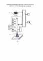
Заявляемое устройство иллюстрируют следующие графические материалы:The inventive device is illustrated by the following graphic materials:
Фиг. 1 Структурная схема комплекта, где:FIG. 1 block diagram of the kit, where:
1. Поворотный механизм.1. The rotary mechanism.
2. Опора.2. Prop.
3. Дальномер.3. Rangefinder.
4. Компьютер оператора комплекта.4. Computer operator kit.
5. Модуль СНС.5. The module of the SNA.
6. Антенна модуля СНС.6. Antenna module SNS.
7. Канал беспроводной связи.7. Wireless channel.
8. Электронное угломерное устройство.8. Electronic goniometer device.
9. Контроллер.9. The controller.
10. Органы локального управления и индикации.10. Local control and indication bodies.
11. Трехосевой датчик угловой скорости (ДУС).11. Three-axis angular velocity sensor (DOS).
12. Трехосевой акселерометр.12. Three-axis accelerometer.
13. Трехосевой магнитометр.13. Three-axis magnetometer.
14. Двухканальный угломерный модуль (ДУМ) СНС.14. Two-channel goniometer module (DUM) SNS.
15. Выносные антенны ДУМ.15. Remote antenna DUM.
16. Датчик температуры.16. The temperature sensor.
17. Безлюфтовое соединение с дальномером.17. Backlashless connection with a range finder.
18. Безлюфтовое соединение с поворотным механизмом.18. Backlash-free connection with a rotary mechanism.
Фиг. 2 Внешний вид электронного угломерного устройства 8, где:FIG. 2 The appearance of the
19 - Откидные держатели.19 - Folding holders.
Фиг. 3 Собранный комплект с дальномером 3, электронным угломерным устройством 8 и опорой 2 в виде треноги 20.FIG. 3 Assembled kit with
Фиг. 4 Собранный комплект с поворотным механизмом в виде буссоли 21.FIG. 4 Assembled kit with swivel mechanism in the form of a
Существенные отличия заявляемого изобретения от прототипа заключаются в следующем.Significant differences of the claimed invention from the prototype are as follows.
Наличие электронного угломерного устройства 8 позволяет быстро и точно выполнить измерения, ввести результаты в компьютер 4 и передать их по каналу беспроводной связи 7 в вышестоящие органы управления.The presence of an
В прототипе измерение углов проводится по рискам поворотного механизма (буссоли), не точно и не может быть оперативно обработано компьютером 4.In the prototype, the measurement of the angles is carried out according to the risks of the rotary mechanism (compasses), it is not accurate and cannot be quickly processed by
Выполнение электронного угломерного устройства 8 в виде блока, содержащего контроллер 9, к которому подключены органы локального управления и индикации 10, позволяет автоматизировать (упростить и ускорить) процесс управления режимами измерений, наблюдать за ходом их выполнения, а также в реальном масштабе времени передавать результаты измерений в компьютер 4. Благодаря описанным ниже технологиям электронное угломерное устройство 8 оказывается малогабаритным и легким.The implementation of the
В прототипе изменение режимов измерений сопряжено с выполнением трудоемких операций оператором комплекта, а сам комплект является тяжелым и громоздким.In the prototype, changing measurement modes involves performing labor-intensive operations by the kit operator, and the kit itself is heavy and cumbersome.
Трехосевые ДУС, акселерометр и магнитометр выполнены в виде единого устройства, позволяющего использовать вектор силы тяжести, угловые скорости вращения Земли и самого комплекта, а также вектор магнитного поля Земли (совместно или по отдельности) в различных режимах с возможностью автоматической передачи результатов измерений.Three-axis DOS, accelerometer and magnetometer are made in the form of a single device that allows you to use the vector of gravity, the angular velocity of rotation of the Earth and the set itself, as well as the vector of the Earth's magnetic field (together or separately) in various modes with the ability to automatically transmit measurement results.
В прототипе отсутствует акселерометр, используются одноосевой магнитометр и гирокомпас. Все эти устройства разрозненны и не позволяют использовать результаты их измерений в автоматическом режиме.In the prototype there is no accelerometer, a single-axis magnetometer and gyrocompass are used. All these devices are fragmented and do not allow the use of the results of their measurements in automatic mode.
Оси чувствительности датчика угловой скорости 11, акселерометра 12 и магнитометра 13 согласованы, что позволяет упростить совместную обработку измерений. Указанные оси также согласованы со связанными осями электронного угломерного устройства 8 и дальномера 3. Согласованность осей позволяет упростить вычисления.The sensitivity axis of the
В прототипе таких источников измерений нет, поэтому результаты обработки являются малоинформативными, а их прием и передача выполняются оператором вручную.In the prototype there are no such measurement sources, therefore, the processing results are uninformative, and their reception and transmission are performed manually by the operator.
Датчик температуры 16 предназначен для уточнения результатов измерений датчика угловой скорости 11, акселерометра 12 и магнитометра 13 путем введения поправок по градировочным зависимостям систематических ошибок датчиков от температуры, закладываемым в датчики при заводской калибровке.The
В прототипе датчика температуры нет.There is no temperature sensor in the prototype.
Наличие двухканального угломерного модуля СНС 14 в электронном угломерном устройстве 8 с возможностью подключения к каждому каналу отдельной выносной антенны 15 позволяет решить задачу угловой ориентации комплекта без использования остальных датчиков и искусственных и естественных ориентиров на местности.The presence of a two-channel
В прототипе отсутствует угломерный модуль, но предполагается возможность использования двух отдельных модулей СНС с антеннами для измерения углов.In the prototype there is no goniometer module, but it is assumed the possibility of using two separate SNA modules with antennas for measuring angles.
Электронное угломерное устройство 8 соединено информационно и по питанию с компьютером 4. Информационное соединение позволяет быстро передать результаты измерений (азимут и угол места) в компьютер 4 и по каналу связи 7 на вышестоящие уровни. Связь по питанию позволяет уменьшить вес электронного угломерного устройства 8 за счет отсутствия собственных источников питания.The
В прототипе угломерное устройство (буссоль) не имеет питания.In the prototype, the goniometer device (compass) does not have power.
Электронное угломерное устройство 8 соединено механически безлюфтовыми разъемными соединениями 17 и 18 с дальномером 3 и поворотным механизмом 1 соответственно.The
В прототипе отсутствует электронное угломерное устройство.In the prototype there is no electronic goniometer device.
Рассмотрим возможность реализации заявляемого комплекта.Consider the possibility of implementing the inventive kit.
Поворотный механизм 1 предназначен для наведения дальномера 3 на цель по азимуту и углу места. В аналогах [1-3] это действие выполняется в два этапа: горизонтирование буссоли и наведение буссоли на цель, Фиг. 4. Аналогичная процедура может быть использована и в заявляемом комплекте. Для этого используются тренога 20, шаровый зажим 1, Фиг. 1 и буссоль 21, Фиг. 4.The
Тренога 20 устанавливается на землю путем изменения длин ног и их заглубления, так, чтобы ее верхняя поверхность была горизонтальной. На треноге 20 устанавливается шаровый зажим 1, который состоит из шаровой чашки с зажимным механизмом, средства крепления к опоре 2 (шуруп) и шаровой опоры, установленной на буссоли 21. Затем производится горизонтирование буссоли 21 с использованием ее пузырькового уровня. После горизонтирования буссоли 21 шаровый зажим фиксируется. Для наведения дальномера 3 на цель используется буссоль 21 за счет ее поворота в горизонтальной и вертикальной плоскостях.A
В заявляемом изобретении могут использоваться более простые технологии. Трехосевой акселерометр 12, используемый в качестве инклинометра, дает возможность измерить проекции вектора силы тяжести Земли и по ним вычислить положение ортогональной ему плоскости местного горизонта. Наличие такой возможности позволяет ориентировать угломерное устройство 8, не предъявляя высоких требований по точности его горизонтирования. Аналогичные возможности дает трехосевой магнитометр 13, который также позволяет построить плоскость местного горизонта.In the claimed invention, simpler technologies can be used. The three-
Это дает возможность отказаться от тяжелой треноги 20 в качестве опоры 2. Вместо треноги может быть использована любая опора 2 - пень, дерево и т.п., к которой крепится, например, шаровый зажим, а на нем устанавливаться электронное угломерное устройство 8.This makes it possible to abandon the
Кроме того, в заявляемом комплекте появляется возможность отказаться от тяжелого поворотного устройства - буссоли 21 (теодолита). Вместо этого в заявляемом комплекте может использоваться, например, шаровый зажим 1.In addition, in the inventive kit, it becomes possible to abandon the heavy rotary device - compass 21 (theodolite). Instead, in the inventive kit can be used, for example, a
Дальномер 3 предназначен для наведения на цель, наблюдения за ней и измерения расстояния до нее. В качестве дальномера могут использоваться лазерные дальномеры, приборы ночного видения и т.п. Такие устройства требуют бережного отношения, транспортируются в отдельном боксе, а на время работы подключаются к комплекту безлюфтовым соединением 17, например, типа «ласточкин хвост». Дальномер 3 может иметь разные механизмы крепления 17, что приводит к необходимости использования соответствующих переходников, входящих в состав заявляемого комплекта.The
Компьютер оператора комплекта 4 является необходимым элементом приборного оснащения современного военнослужащего. Известны компьютерные системы военнослужащего: FELIN (Франция), Future ForceWarrior (США), Gladius (Германия), Стрелец (РФ) [4] и т.п. Такой компьютер обеспечивает военнослужащего каналом беспроводной связи 7, навигационной информацией через модуль СНС 5 с антенной 6, а также выполняет ряд других функций по управлению и разведке. Обладая достаточно большой вычислительной мощностью, компьютер 4 поддерживает другие информационные модули оснащения военнослужащего. В заявляемом изобретении основные задачи обработки информации, а также обеспечение энергоснабжения решает компьютер 4.The computer of the operator of
Электронное угломерное устройство 8, Фиг. 2, предназначено для измерения азимута и угла места. В заявляемом устройстве для их определения используется математическая обработка результатов измерений электронных датчиков 11-14 с учетом показаний датчика температуры 16.
Контроллер 9 предназначен для:
- получения команд из органов локального управления и индикации стадии их выполнения через блок 10;- receiving commands from local authorities and indicating the stage of their implementation through
- организации заданных режимов работы угломерного устройства 8;- the organization of the specified operating modes of the
- передачи полученных результатов в компьютер 4.- transferring the results to a
Трехосевой ДУС 11, трехосевой акселерометр 12 и трехосевой магнитометр 13 составляют основу известных бесплатформенных инерциальных навигационных систем (БИНС). Для носимого исполнения БИНС, соответствующего заявляемому комплекту, предпочтение следует отдать малогабаритным микроэлектромеханическим системам (МЭМС), содержащимся, например, в большинстве обычных смартфонов. В качестве технологии изготовления может быть использовано решение фирмы Интел [5]. Среди множества вариантов исполнения МЭМС следует выбирать образцы, удовлетворяющие требованиям по точности измерений.Three-
ДУМ спутниковых навигационных систем 14 предназначен для угловых измерений между двумя выносными, разнесенными антеннами 15 СНС. Такие модули выпускаются промышленностью.The SUM of
Датчик температуры 16 зачастую входит в состав МЭМС.
Безлюфтовое соединение 17 с дальномером 3 обеспечивает бережную транспортировку дальномера, а также быструю подготовку к работе. В качестве такого соединения может использоваться, например, «ласточкин хвост».The
Начальная установка комплекта состоит в том, что поворотный механизм 1 устанавливается на опору 2, к нему безлюфтовым соединением 18 присоединяется электронное угломерное устройство 8, к которому в свою очередь безлюфтовым соединением 17 подключается дальномер 3, Фиг. 3. Наличие в составе устройства 8 соответствующих измерителей позволяет скомпенсировать неточность начальной установки (горизонтирования) комплекта. Угломерное устройство 8 и дальномер 3 подключаются кабелями к компьютеру 4, обеспечивая связь по информации и питанию. При включении электронного угломерного устройства 8 под управлением контроллера 9 трехосевой ДУС 11 готов измерять проекции вектора угловой скорости, трехосевой акселерометр 12 - проекции вектора силы тяжести, трехосевой магнитометр 13 - проекции вектора направления на северный магнитный полюс, а датчик температуры 16 - температуру. Считается, что заводские и полевые калибровки перечисленных датчиков выполнены, см. [6, 7, 8]. Режимы работы комплекта задаются и отображаются с помощью органов локального управления и индикации 10.The initial installation of the kit consists in the fact that the
Рассмотрим режимы работы заявляемого комплекта.Consider the operating modes of the claimed kit.
Ключевым узлом заявляемого комплекта, существенно отличающим его от прототипа, является электронное угломерное устройство 8, объединяющее в себе функции буссоли, теодолита и гирокомпаса. По своей сущности устройство 8 представляет собой измерительную часть угломерного канала БИНС на неподвижном основании, выполненного на принципиально иной по сравнению с прототипом элементной базе, а именно с использованием МЭМС-технологий (датчики 11-13). БИНС дополнена встроенным в устройство 8 двухканальным угломерным модулем 14 с двумя выносными антеннами 15. Модуль 14 имеет большее число (шестьдесят четыре) измерительных каналов, обеспечивающих прием сигналов СНС ГЛОНАСС, GPS, Galileo, SBAS, СДКМ с частотным и кодовым разделением, и реализует более точный по сравнению с прототипом (метод относительного позиционирования) метод углометрии по фазе несущей частоты.The key node of the claimed kit, significantly distinguishing it from the prototype, is an
Сказанное позволяет электронному угломерному устройству 8 совместно с дальномером 3 и компьютером оператора 4 (а следовательно, заявляемому комплекту в целом) в полном объеме решать весь перечень задач топогеодезической привязки, выполняемых прототипом.The aforementioned allows the
При формировании целеуказаний основной операцией, помимо измерения дальности до цели (дальномер 3), является определение дирекционного угла αд и угла места β цели. Данная задача решается путем математической обработки результатов измерений датчиков 11-14 в компьютере оператора 4.In the formation of target designations, the main operation, in addition to measuring the distance to the target (range finder 3), is to determine the directional angle αd and the elevation angle β of the target. This problem is solved by mathematical processing of the measurement results of the sensors 11-14 in the operator's
В соответствии с составом измерительных датчиков 11-14, входящих в угломерное устройство 8, возможны два основных режима определения углов αд, β.In accordance with the composition of the measuring sensors 11-14 included in the
В первом режиме - режиме измерения магнитного азимута - дирекционный угол αд определяется соотношением:In the first mode - magnetic azimuth measurement mode - the directional angle αd is determined by the ratio:
αд=αи-δαсм=αм+δαмс-δαсмαd = αand -δαcm = αm + δαms -δαcm
где αи - истинный азимут, αм - магнитный азимут, δαмс - магнитное склонение, δαсм - сближение меридианов.where αand are the true azimuth, αm is the magnetic azimuth, δαms is the magnetic declination, δαcm is the approach of the meridians.
При этом магнитный азимут αм вычисляется по формуле:The magnetic azimuth αm is calculated by the formula:

где Нх, Ну, Hz - проекции магнитного поля Земли, измеряемые магнитометром 13; β - угол места цели, γ - угол крена угломерного устройства 8, вычисляемые по показаниям ах aу, az акселерометра 12 в соответствии с соотношениями:where Nx , Ny , Hz are the projections of the Earth's magnetic field, measured by a

где g - ускорение силы тяжести в точке установки комплекта. Соотношения (2) определяют работу акселерометра 12 в качестве акселерометрического трехосевого инклинометра.where g is the acceleration of gravity at the installation point of the kit. Relations (2) determine the operation of the
Формулы (1), (2) описывают работу электронного угломерного устройства 8 в магнитной географической системе координат OEмNмh и связанной системе координат OXYZ с началом в его центре масс. При этом ось OY совпадает с продольной осью оптического визира дальномера 3 и направлена на цель. Данные системы координат широко используются при решении топогеодезических и навигационных задач.Formulas (1), (2) describe the operation of the
Вторым режимом является гироазимутальный режим (режим гироскопа направления). Этот режим предполагает наличие предварительно выбранного опорного направления, задаваемого дирекционным углом αдоп некоторого ориентира.The second mode is the gyro-azimuthal mode (direction gyro mode). This mode assumes the presence of a preselected reference direction defined by the directional angle αdop of a certain reference point.
Физический смысл этого режима состоит в том, что относительно направления αд оп по измерениям датчика угловой скорости 11 при перенацеливании (вращении) угломерного устройства 8 с ориентира на цель проводится измерение приращения угла Δαд с последующим определением полного значения дирекционного угла цели αд.The physical meaning of this mode is that relative to the direction of αd op according to the measurements of the
Математически при обработке измерений в компьютере оператора 4 этот режим реализуется с помощью рекуррентной процедуры:Mathematically, when processing measurements in

где c1 (k)=sinαд(k)cosβ(k), с2(k)=соsαд(k)соsβ(k), c3(k)=sinβ(k) - текущие значения направляющих косинусов оси OY связанной системы координат OXYZ относительно осей географической системы координат (географический трехгранник) OENh, являющейся опорной в задачах инерциальной навигации.where c1 (k) = sinαd (k) cosβ (k), c2 (k) = cosαd (k) cosβ (k), c3 (k) = sinβ (k) are the current values of the direction cosines of the OY axis the associated coordinate system OXYZ relative to the axes of the geographic coordinate system (geographic trihedron) OENh, which is the reference in inertial navigation problems.
В процедуре (3) δx(k)=ωх(k)Т, δу(k)=ωу(k)Т, δz(k)=ωz(k)T - парциальные (пошаговые) приращения углов вращения угломерного устройства 8; ωх(k), ωу(k), ωz(k) - текущие показания (отсчеты) датчика угловой скорости 11; Т=tk-tk-1 - шаг (интервал времени) выдачи данных датчиком, в течение которого угловые скорости ωх, ωу, ωz считаются постоянными; k=1,2,…, K - номер очередного шага; K - количество шагов (измерительных отсчетов датчика) на интервале перенацеливания угломерного устройства 8 с ориентира на цель.In procedure (3), δx (k) = ωx (k) T, δy (k) = ωy (k) T, δz (k) = ωz (k) T are the partial (incremental) increments of the angles rotation of the
По окончании перенацеливания (k=K) определяются искомые дирекционный угол целиAt the end of the retargeting (k = K), the desired directional angle of the target is determined

и ее угол местаand its elevation

Возможен также вариант определения угла β(K) по соотношению (2) с использованием измерения акселерометра ау(K) на момент окончания перенацеливания.It is also possible to determine the angle β (K) from relation (2) using the measurement of the accelerometer ау (K) at the end of the redirection.
Необходимые для запуска рекуррентной процедуры (3) начальные условия задаются так:The initial conditions necessary for starting recursive procedure (3) are defined as follows:
с1(0)=sinαд опсоsβ(0), с2(0)=соsαд опсоsβ(0), c3(0)=sinβ(0),c1 (0) = sinαd op cos β (0), c2 (0) = cos αd op cos β (0), c3 (0) = sin β (0),
где β(0) - угол места ориентира, определяемый соотношением (2) по измерению ау (0) в начальном положении угломерного устройства 8.where β (0) is the elevation angle of the landmark, determined by the relation (2) by measurement andy (0) in the initial position of the
Возможны три варианта задания опорного дирекционного угла αд оп:There are three options for setting the reference directional angle αd op :
- с помощью ориентира (репера) с известными координатами и модуля СНС 5, определяющего координаты точки установки комплекта;- using a landmark (reference point) with known coordinates and the
- с использованием двухканального угломерного модуля 14 с двумя вынесенными антеннами 15, разнесенными на базу заданной длины, обеспечивающей требуемую точность угловой фазометрии;- using a two-
- с применением датчика угловой скорости 11 и акселерометра 12 в режиме гирокомпасирования.- using an
В последнем случае для истинного опорного угла азимута αи оп в формуле расчета угла αд оп=αи оп-δсм остается справедливым соотношение (1) при замене проекций магнитного поля Нх Ну, Hz на измеренные датчиком угловой скорости 11 проекции ωх(0), ωу(0), ω2(0) вектора угловой скорости вращения Земли Ω в положении установки угломерного устройства 8 на ориентир:In the latter case, for the true reference azimuth angle αand op in the formula for calculating the angle αd op = αand op -δcm , relation (1) remains valid when replacing the magnetic field projections Нх Ну , Hz with the projections measured by the

где, как и ранее, β(0) - угол места ориентира; γ(0) - угол крена угломерного устройства 8. Оба угла определяются соотношениями (2).where, as before, β (0) is the angle of the landmark; γ (0) is the roll angle of the
В заключение отметим, что при использовании в электронном угломерном устройстве 8 высокоточных образцов датчика угловой скорости 11, обладающих малыми значениями систематической (дрейф нуля) и флюктуационной ошибок (таких как МЭМС-датчики тактического и навигационного классов, миниатюрный волновой твердотельный гироскоп [9]), режим гирокомпасирования может стать самостоятельным режимом в дополнение к двум основным режимам определения углов αд, β цели.In conclusion, we note that when 8 high-precision
Таким образом, заявляемый комплект носимой аппаратуры топогеодезической привязки и формирования целеуказаний может быть реализован. Обладает малыми габаритами и весом и позволяет решать возложенные задачи с достаточной точностью.Thus, the inventive set of wearable equipment of topographic and geodetic reference and target designation can be implemented. It has small dimensions and weight and allows solving assigned tasks with sufficient accuracy.
Источники информацииInformation sources
1. Перископическая артиллерийская буссоль ПАБ-2. Ордена Трудового Красного Знамени Военное издательство Министерства Обороны СССР, издание четвертое, Москва, 1970 г.1. Periscope artillery compass PAB-2. Order of the Red Banner of Labor Military Publishing House of the Ministry of Defense of the USSR, Fourth Edition, Moscow, 1970
2. Патент RU 2522784.2. Patent RU 2522784.
3. Патент RU 2480714.3. Patent RU 2480714.
4. https://vpk.name/library/f/strelec.html.4. https://vpk.name/library/f/strelec.html.
5. Патент RU №2602746.5. Patent RU No. 2602746.
6. Патент RU №2577806.6. Patent RU No. 2577806.
7. Патент RU №2572109.7. Patent RU No. 2572109.
8. Заявка на изобретение RU №2016104007, решение о выдаче патента от 15.03.2017.8. Application for invention RU No. 2016104007, decision on the grant of a patent dated 03.15.2017.
9. Патент RU №2544870.9. Patent RU No. 2544870.
Claims (1)
Translated fromRussianPriority Applications (1)
| Application Number | Priority Date | Filing Date | Title |
|---|---|---|---|
| RU2017124950ARU2661676C1 (en) | 2017-07-12 | 2017-07-12 | Topogeodetic survey and target designations formation portable equipment kit |
Applications Claiming Priority (1)
| Application Number | Priority Date | Filing Date | Title |
|---|---|---|---|
| RU2017124950ARU2661676C1 (en) | 2017-07-12 | 2017-07-12 | Topogeodetic survey and target designations formation portable equipment kit |
Publications (1)
| Publication Number | Publication Date |
|---|---|
| RU2661676C1true RU2661676C1 (en) | 2018-07-18 |
Family
ID=62917254
Family Applications (1)
| Application Number | Title | Priority Date | Filing Date |
|---|---|---|---|
| RU2017124950ARU2661676C1 (en) | 2017-07-12 | 2017-07-12 | Topogeodetic survey and target designations formation portable equipment kit |
Country Status (1)
| Country | Link |
|---|---|
| RU (1) | RU2661676C1 (en) |
Cited By (4)
| Publication number | Priority date | Publication date | Assignee | Title |
|---|---|---|---|---|
| RU2696807C1 (en)* | 2019-01-10 | 2019-08-06 | Иван Владимирович Чернов | Method for determining a coefficient of reducing a priori estimation of accuracy of determining azimuth with gyrotheodolite |
| RU2711165C1 (en)* | 2018-10-02 | 2020-01-15 | Алина Борисовна Шилина | Method of contactless determination of distance between two points |
| RU2717138C1 (en)* | 2019-09-05 | 2020-03-18 | Открытое акционерное общество "Радиоавионика" | System of portable sets for automated target designation on the battlefield |
| RU2762080C1 (en)* | 2020-11-17 | 2021-12-15 | Федеральное Государственное Казенное Военное Образовательное Учреждение Высшего Образования "Военный Учебно-Научный Центр Сухопутных Войск "Общевойсковая Ордена Жукова Академия Вооруженных Сил Российской Федерации" | Autonomous mobile module for increasing the accuracy of determining the coordinates and paths of movement of army objects |
Citations (4)
| Publication number | Priority date | Publication date | Assignee | Title |
|---|---|---|---|---|
| WO2011014481A1 (en)* | 2009-07-30 | 2011-02-03 | Mine Safety Appliances Company | Personal navigation system and associated methods |
| RU2439497C1 (en)* | 2010-06-09 | 2012-01-10 | Открытое акционерное общество "Завод им. В.А. Дегтярева" | Automated system of navigation and survey control |
| RU2468338C1 (en)* | 2011-07-08 | 2012-11-27 | Открытое акционерное общество "Завод им. В.А. Дегтярева" | Software and hardware complex of surveying system |
| US9488492B2 (en)* | 2014-03-18 | 2016-11-08 | Sri International | Real-time system for multi-modal 3D geospatial mapping, object recognition, scene annotation and analytics |
- 2017
- 2017-07-12RURU2017124950Apatent/RU2661676C1/enactive
Patent Citations (4)
| Publication number | Priority date | Publication date | Assignee | Title |
|---|---|---|---|---|
| WO2011014481A1 (en)* | 2009-07-30 | 2011-02-03 | Mine Safety Appliances Company | Personal navigation system and associated methods |
| RU2439497C1 (en)* | 2010-06-09 | 2012-01-10 | Открытое акционерное общество "Завод им. В.А. Дегтярева" | Automated system of navigation and survey control |
| RU2468338C1 (en)* | 2011-07-08 | 2012-11-27 | Открытое акционерное общество "Завод им. В.А. Дегтярева" | Software and hardware complex of surveying system |
| US9488492B2 (en)* | 2014-03-18 | 2016-11-08 | Sri International | Real-time system for multi-modal 3D geospatial mapping, object recognition, scene annotation and analytics |
Cited By (4)
| Publication number | Priority date | Publication date | Assignee | Title |
|---|---|---|---|---|
| RU2711165C1 (en)* | 2018-10-02 | 2020-01-15 | Алина Борисовна Шилина | Method of contactless determination of distance between two points |
| RU2696807C1 (en)* | 2019-01-10 | 2019-08-06 | Иван Владимирович Чернов | Method for determining a coefficient of reducing a priori estimation of accuracy of determining azimuth with gyrotheodolite |
| RU2717138C1 (en)* | 2019-09-05 | 2020-03-18 | Открытое акционерное общество "Радиоавионика" | System of portable sets for automated target designation on the battlefield |
| RU2762080C1 (en)* | 2020-11-17 | 2021-12-15 | Федеральное Государственное Казенное Военное Образовательное Учреждение Высшего Образования "Военный Учебно-Научный Центр Сухопутных Войск "Общевойсковая Ордена Жукова Академия Вооруженных Сил Российской Федерации" | Autonomous mobile module for increasing the accuracy of determining the coordinates and paths of movement of army objects |
Similar Documents
| Publication | Publication Date | Title |
|---|---|---|
| EP2239540B1 (en) | Gyroscope adapted to be mounted to a goniometer | |
| US8311757B2 (en) | Miniaturized smart self-calibration electronic pointing method and system | |
| AU2012241778B2 (en) | Measuring system and method for determining new points | |
| EP1974277B1 (en) | True azimuth and north finding method and system | |
| US8275544B1 (en) | Magnetically stabilized forward observation platform | |
| US8209140B2 (en) | Cooperative calibration of heading sensors | |
| EP1949016B1 (en) | Precision targeting | |
| RU2661676C1 (en) | Topogeodetic survey and target designations formation portable equipment kit | |
| JPS5912966B2 (en) | Method and device for automatically leveling a goniometer | |
| US5463402A (en) | Motion measurement system and method for airborne platform | |
| RU2522784C1 (en) | Laser pointer/range-finder | |
| CN104833348A (en) | Static torque mode gyroscopic total station-based successive multi-position north seeking measurement method | |
| US6526667B1 (en) | Satellite spacecraft targeting device and method | |
| US10222214B2 (en) | Digital sight for hand-carried projectile-firing device and method of controlling the same | |
| CN110108265B (en) | A gyroscope measuring instrument that acquires geographic latitude autonomously and seeks north automatically | |
| Tait | North-seeking instruments and inertial systems | |
| Brown et al. | Precision Targeting Using GPS/Inertial-Aided Sensors | |
| Martinenq | Inertial Measurement Unit for Trajectography | |
| RU2692945C1 (en) | Method of orienting mobile objects relative to an object with a known directional angle | |
| Baeder et al. | Low cost navigation technology investigation for the unmanned ground vehicle program | |
| RU2641515C2 (en) | Method for construction of astroinercial navigation system | |
| D'Angelo et al. | Sensor fusion and transfer alignment concept for pointing stabilization | |
| RU2574309C2 (en) | Personal navigation system | |
| Lawrence | An outline of inertial navigation | |
| CN116817895A (en) | Satellite guidance system and guidance method containing guidance instrument |