RU2661139C2 - Interchangeable shaft assemblies for use with surgical instrument - Google Patents
Interchangeable shaft assemblies for use with surgical instrumentDownload PDFInfo
- Publication number
- RU2661139C2 RU2661139C2RU2014109797ARU2014109797ARU2661139C2RU 2661139 C2RU2661139 C2RU 2661139C2RU 2014109797 ARU2014109797 ARU 2014109797ARU 2014109797 ARU2014109797 ARU 2014109797ARU 2661139 C2RU2661139 C2RU 2661139C2
- Authority
- RU
- Russia
- Prior art keywords
- rod
- hinge
- frame
- end effector
- proximal
- Prior art date
Links
- 230000000712assemblyEffects0.000titleclaimsdescription21
- 238000000429assemblyMethods0.000titleclaimsdescription21
- 239000012636effectorSubstances0.000claimsabstractdescription553
- 230000033001locomotionEffects0.000claimsabstractdescription175
- 230000004913activationEffects0.000claimsabstractdescription89
- 230000004044responseEffects0.000claimsabstractdescription61
- 238000005520cutting processMethods0.000claimsabstractdescription55
- 230000000903blocking effectEffects0.000claimsdescription146
- 230000007246mechanismEffects0.000claimsdescription93
- 230000003213activating effectEffects0.000claimsdescription20
- 230000008093supporting effectEffects0.000claimsdescription10
- 230000000694effectsEffects0.000abstractdescription10
- 239000003814drugSubstances0.000abstractdescription2
- 238000010304firingMethods0.000abstract1
- 239000000126substanceSubstances0.000abstract1
- 238000000034methodMethods0.000description75
- 230000006870functionEffects0.000description46
- 230000000875corresponding effectEffects0.000description41
- 230000015654memoryEffects0.000description37
- 210000001519tissueAnatomy0.000description36
- 230000008569processEffects0.000description29
- 238000004891communicationMethods0.000description28
- 238000010586diagramMethods0.000description25
- 238000003032molecular dockingMethods0.000description24
- 230000036961partial effectEffects0.000description21
- 238000012512characterization methodMethods0.000description20
- 238000005304joiningMethods0.000description20
- 238000000926separation methodMethods0.000description20
- 238000006073displacement reactionMethods0.000description19
- 239000000463materialSubstances0.000description19
- 230000009471actionEffects0.000description18
- 238000002224dissectionMethods0.000description17
- 239000007858starting materialSubstances0.000description17
- 210000005069earsAnatomy0.000description15
- 230000007935neutral effectEffects0.000description15
- 230000004888barrier functionEffects0.000description12
- 208000018747cerebellar ataxia with neuropathy and bilateral vestibular areflexia syndromeDiseases0.000description11
- 238000005259measurementMethods0.000description10
- 238000004422calculation algorithmMethods0.000description9
- 238000009434installationMethods0.000description9
- 230000000670limiting effectEffects0.000description9
- 230000010355oscillationEffects0.000description9
- 230000008859changeEffects0.000description8
- 239000004744fabricSubstances0.000description8
- 238000012986modificationMethods0.000description8
- 230000004048modificationEffects0.000description8
- 238000003825pressingMethods0.000description8
- 230000005355Hall effectEffects0.000description7
- 230000005540biological transmissionEffects0.000description7
- 230000002829reductive effectEffects0.000description7
- 230000002441reversible effectEffects0.000description7
- 238000001356surgical procedureMethods0.000description7
- 230000001276controlling effectEffects0.000description6
- 238000012545processingMethods0.000description6
- 239000000853adhesiveSubstances0.000description5
- 230000001070adhesive effectEffects0.000description5
- 239000003638chemical reducing agentSubstances0.000description5
- 238000004590computer programMethods0.000description5
- 239000004020conductorSubstances0.000description5
- 230000007423decreaseEffects0.000description5
- 230000006698inductionEffects0.000description5
- 230000000977initiatory effectEffects0.000description5
- 230000003993interactionEffects0.000description5
- 238000003491arrayMethods0.000description4
- 238000004140cleaningMethods0.000description4
- 239000013078crystalSubstances0.000description4
- 238000013461designMethods0.000description4
- 230000009467reductionEffects0.000description4
- 230000001953sensory effectEffects0.000description4
- 230000001360synchronised effectEffects0.000description4
- 238000012935AveragingMethods0.000description3
- HBBGRARXTFLTSG-UHFFFAOYSA-NLithium ionChemical compound[Li+]HBBGRARXTFLTSG-UHFFFAOYSA-N0.000description3
- 238000004364calculation methodMethods0.000description3
- 239000003990capacitorSubstances0.000description3
- 230000000295complement effectEffects0.000description3
- 230000006835compressionEffects0.000description3
- 238000007906compressionMethods0.000description3
- 230000005669field effectEffects0.000description3
- 229910001416lithium ionInorganic materials0.000description3
- 238000004519manufacturing processMethods0.000description3
- 230000005855radiationEffects0.000description3
- 239000004065semiconductorSubstances0.000description3
- 241000238366CephalopodaSpecies0.000description2
- 230000003044adaptive effectEffects0.000description2
- 230000006399behaviorEffects0.000description2
- 238000005452bendingMethods0.000description2
- 230000008901benefitEffects0.000description2
- 239000002131composite materialSubstances0.000description2
- 230000000881depressing effectEffects0.000description2
- 238000005516engineering processMethods0.000description2
- 230000002349favourable effectEffects0.000description2
- 238000001415gene therapyMethods0.000description2
- 238000011068loading methodMethods0.000description2
- 239000013081microcrystalSubstances0.000description2
- 230000003287optical effectEffects0.000description2
- 239000013307optical fiberSubstances0.000description2
- 238000010422paintingMethods0.000description2
- 230000000704physical effectEffects0.000description2
- 238000011084recoveryMethods0.000description2
- 238000005096rolling processMethods0.000description2
- 238000005070samplingMethods0.000description2
- 238000002604ultrasonographyMethods0.000description2
- ZCYVEMRRCGMTRW-UHFFFAOYSA-N7553-56-2Chemical compound[I]ZCYVEMRRCGMTRW-UHFFFAOYSA-N0.000description1
- 235000005338Allium tuberosumNutrition0.000description1
- 244000003377Allium tuberosumSpecies0.000description1
- 241000894006BacteriaSpecies0.000description1
- 102000010410Nogo ProteinsHuman genes0.000description1
- 108010077641Nogo ProteinsProteins0.000description1
- 229910000831SteelInorganic materials0.000description1
- 239000004775TyvekSubstances0.000description1
- 229920000690TyvekPolymers0.000description1
- 230000001133accelerationEffects0.000description1
- 230000001154acute effectEffects0.000description1
- 230000015572biosynthetic processEffects0.000description1
- 230000037396body weightEffects0.000description1
- 210000000988bone and boneAnatomy0.000description1
- 230000015556catabolic processEffects0.000description1
- 239000002800charge carrierSubstances0.000description1
- 239000003795chemical substances by applicationSubstances0.000description1
- 238000012790confirmationMethods0.000description1
- 238000010276constructionMethods0.000description1
- 230000002596correlated effectEffects0.000description1
- 230000008878couplingEffects0.000description1
- 238000010168coupling processMethods0.000description1
- 238000005859coupling reactionMethods0.000description1
- 230000000994depressogenic effectEffects0.000description1
- 238000001514detection methodMethods0.000description1
- 238000009826distributionMethods0.000description1
- 229940079593drugDrugs0.000description1
- 238000012377drug deliveryMethods0.000description1
- 238000002651drug therapyMethods0.000description1
- 230000005684electric fieldEffects0.000description1
- 230000008030eliminationEffects0.000description1
- 238000003379elimination reactionMethods0.000description1
- 230000007717exclusionEffects0.000description1
- 238000000605extractionMethods0.000description1
- 239000000835fiberSubstances0.000description1
- 238000001914filtrationMethods0.000description1
- 239000003292glueSubstances0.000description1
- 230000002439hemostatic effectEffects0.000description1
- 230000006872improvementEffects0.000description1
- 230000001939inductive effectEffects0.000description1
- 238000003780insertionMethods0.000description1
- 230000037431insertionEffects0.000description1
- 229910052740iodineInorganic materials0.000description1
- 239000011630iodineSubstances0.000description1
- 238000012830laparoscopic surgical procedureMethods0.000description1
- 230000007774longtermEffects0.000description1
- 238000012423maintenanceMethods0.000description1
- 230000014759maintenance of locationEffects0.000description1
- 238000007726management methodMethods0.000description1
- 238000007620mathematical functionMethods0.000description1
- 230000013011matingEffects0.000description1
- 239000002184metalSubstances0.000description1
- 229910052751metalInorganic materials0.000description1
- 229910044991metal oxideInorganic materials0.000description1
- 150000004706metal oxidesChemical class0.000description1
- 238000012978minimally invasive surgical procedureMethods0.000description1
- 235000003715nutritional statusNutrition0.000description1
- 238000002355open surgical procedureMethods0.000description1
- 230000005693optoelectronicsEffects0.000description1
- 238000013021overheatingMethods0.000description1
- 230000002093peripheral effectEffects0.000description1
- 238000002360preparation methodMethods0.000description1
- 230000002265preventionEffects0.000description1
- 230000007420reactivationEffects0.000description1
- 238000004353relayed correlation spectroscopyMethods0.000description1
- 235000012046side dishNutrition0.000description1
- 230000008054signal transmissionEffects0.000description1
- 210000004872soft tissueAnatomy0.000description1
- 239000007787solidSubstances0.000description1
- 230000005236sound signalEffects0.000description1
- 229910001220stainless steelInorganic materials0.000description1
- 239000010935stainless steelSubstances0.000description1
- 230000003068static effectEffects0.000description1
- 239000010959steelSubstances0.000description1
- 230000001954sterilising effectEffects0.000description1
- 238000004659sterilization and disinfectionMethods0.000description1
- 238000003860storageMethods0.000description1
- 238000006467substitution reactionMethods0.000description1
- 239000000758substrateSubstances0.000description1
- 239000000725suspensionSubstances0.000description1
- 238000012546transferMethods0.000description1
- 230000001960triggered effectEffects0.000description1
- XLYOFNOQVPJJNP-UHFFFAOYSA-NwaterSubstancesOXLYOFNOQVPJJNP-UHFFFAOYSA-N0.000description1
- 230000003313weakening effectEffects0.000description1
- 238000003466weldingMethods0.000description1
Images


Classifications
- A—HUMAN NECESSITIES
- A61—MEDICAL OR VETERINARY SCIENCE; HYGIENE
- A61B—DIAGNOSIS; SURGERY; IDENTIFICATION
- A61B17/00—Surgical instruments, devices or methods
- A61B17/10—Surgical instruments, devices or methods for applying or removing wound clamps, e.g. containing only one clamp or staple; Wound clamp magazines
- A61B17/105—Wound clamp magazines
- A—HUMAN NECESSITIES
- A61—MEDICAL OR VETERINARY SCIENCE; HYGIENE
- A61B—DIAGNOSIS; SURGERY; IDENTIFICATION
- A61B17/00—Surgical instruments, devices or methods
- A61B17/064—Surgical staples, i.e. penetrating the tissue
- A—HUMAN NECESSITIES
- A61—MEDICAL OR VETERINARY SCIENCE; HYGIENE
- A61B—DIAGNOSIS; SURGERY; IDENTIFICATION
- A61B18/00—Surgical instruments, devices or methods for transferring non-mechanical forms of energy to or from the body
- A61B18/04—Surgical instruments, devices or methods for transferring non-mechanical forms of energy to or from the body by heating
- A61B18/12—Surgical instruments, devices or methods for transferring non-mechanical forms of energy to or from the body by heating by passing a current through the tissue to be heated, e.g. high-frequency current
- A61B18/14—Probes or electrodes therefor
- A61B18/1442—Probes having pivoting end effectors, e.g. forceps
- A61B18/1445—Probes having pivoting end effectors, e.g. forceps at the distal end of a shaft, e.g. forceps or scissors at the end of a rigid rod
- A—HUMAN NECESSITIES
- A61—MEDICAL OR VETERINARY SCIENCE; HYGIENE
- A61B—DIAGNOSIS; SURGERY; IDENTIFICATION
- A61B17/00—Surgical instruments, devices or methods
- A61B17/068—Surgical staplers, e.g. containing multiple staples or clamps
- A61B17/072—Surgical staplers, e.g. containing multiple staples or clamps for applying a row of staples in a single action, e.g. the staples being applied simultaneously
- A—HUMAN NECESSITIES
- A61—MEDICAL OR VETERINARY SCIENCE; HYGIENE
- A61B—DIAGNOSIS; SURGERY; IDENTIFICATION
- A61B17/00—Surgical instruments, devices or methods
- A61B17/068—Surgical staplers, e.g. containing multiple staples or clamps
- A—HUMAN NECESSITIES
- A61—MEDICAL OR VETERINARY SCIENCE; HYGIENE
- A61B—DIAGNOSIS; SURGERY; IDENTIFICATION
- A61B17/00—Surgical instruments, devices or methods
- A61B17/068—Surgical staplers, e.g. containing multiple staples or clamps
- A61B17/0682—Surgical staplers, e.g. containing multiple staples or clamps for applying U-shaped staples or clamps, e.g. without a forming anvil
- A61B17/0686—Surgical staplers, e.g. containing multiple staples or clamps for applying U-shaped staples or clamps, e.g. without a forming anvil having a forming anvil staying below the tissue during stapling
- A—HUMAN NECESSITIES
- A61—MEDICAL OR VETERINARY SCIENCE; HYGIENE
- A61B—DIAGNOSIS; SURGERY; IDENTIFICATION
- A61B17/00—Surgical instruments, devices or methods
- A61B17/068—Surgical staplers, e.g. containing multiple staples or clamps
- A61B17/072—Surgical staplers, e.g. containing multiple staples or clamps for applying a row of staples in a single action, e.g. the staples being applied simultaneously
- A61B17/07207—Surgical staplers, e.g. containing multiple staples or clamps for applying a row of staples in a single action, e.g. the staples being applied simultaneously the staples being applied sequentially
- A—HUMAN NECESSITIES
- A61—MEDICAL OR VETERINARY SCIENCE; HYGIENE
- A61B—DIAGNOSIS; SURGERY; IDENTIFICATION
- A61B17/00—Surgical instruments, devices or methods
- A61B17/28—Surgical forceps
- A61B17/29—Forceps for use in minimally invasive surgery
- A—HUMAN NECESSITIES
- A61—MEDICAL OR VETERINARY SCIENCE; HYGIENE
- A61B—DIAGNOSIS; SURGERY; IDENTIFICATION
- A61B17/00—Surgical instruments, devices or methods
- A61B17/32—Surgical cutting instruments
- A—HUMAN NECESSITIES
- A61—MEDICAL OR VETERINARY SCIENCE; HYGIENE
- A61B—DIAGNOSIS; SURGERY; IDENTIFICATION
- A61B34/00—Computer-aided surgery; Manipulators or robots specially adapted for use in surgery
- A—HUMAN NECESSITIES
- A61—MEDICAL OR VETERINARY SCIENCE; HYGIENE
- A61B—DIAGNOSIS; SURGERY; IDENTIFICATION
- A61B34/00—Computer-aided surgery; Manipulators or robots specially adapted for use in surgery
- A61B34/30—Surgical robots
- A—HUMAN NECESSITIES
- A61—MEDICAL OR VETERINARY SCIENCE; HYGIENE
- A61B—DIAGNOSIS; SURGERY; IDENTIFICATION
- A61B17/00—Surgical instruments, devices or methods
- A61B2017/00017—Electrical control of surgical instruments
- A—HUMAN NECESSITIES
- A61—MEDICAL OR VETERINARY SCIENCE; HYGIENE
- A61B—DIAGNOSIS; SURGERY; IDENTIFICATION
- A61B17/00—Surgical instruments, devices or methods
- A61B2017/00017—Electrical control of surgical instruments
- A61B2017/00115—Electrical control of surgical instruments with audible or visual output
- A61B2017/00119—Electrical control of surgical instruments with audible or visual output alarm; indicating an abnormal situation
- A61B2017/00123—Electrical control of surgical instruments with audible or visual output alarm; indicating an abnormal situation and automatic shutdown
- A—HUMAN NECESSITIES
- A61—MEDICAL OR VETERINARY SCIENCE; HYGIENE
- A61B—DIAGNOSIS; SURGERY; IDENTIFICATION
- A61B17/00—Surgical instruments, devices or methods
- A61B2017/00367—Details of actuation of instruments, e.g. relations between pushing buttons, or the like, and activation of the tool, working tip, or the like
- A61B2017/00389—Button or wheel for performing multiple functions, e.g. rotation of shaft and end effector
- A61B2017/00393—Button or wheel for performing multiple functions, e.g. rotation of shaft and end effector with means for switching between functions
- A—HUMAN NECESSITIES
- A61—MEDICAL OR VETERINARY SCIENCE; HYGIENE
- A61B—DIAGNOSIS; SURGERY; IDENTIFICATION
- A61B17/00—Surgical instruments, devices or methods
- A61B2017/00367—Details of actuation of instruments, e.g. relations between pushing buttons, or the like, and activation of the tool, working tip, or the like
- A61B2017/00398—Details of actuation of instruments, e.g. relations between pushing buttons, or the like, and activation of the tool, working tip, or the like using powered actuators, e.g. stepper motors, solenoids
- A—HUMAN NECESSITIES
- A61—MEDICAL OR VETERINARY SCIENCE; HYGIENE
- A61B—DIAGNOSIS; SURGERY; IDENTIFICATION
- A61B17/00—Surgical instruments, devices or methods
- A61B2017/0046—Surgical instruments, devices or methods with a releasable handle; with handle and operating part separable
- A—HUMAN NECESSITIES
- A61—MEDICAL OR VETERINARY SCIENCE; HYGIENE
- A61B—DIAGNOSIS; SURGERY; IDENTIFICATION
- A61B17/00—Surgical instruments, devices or methods
- A61B2017/0046—Surgical instruments, devices or methods with a releasable handle; with handle and operating part separable
- A61B2017/00464—Surgical instruments, devices or methods with a releasable handle; with handle and operating part separable for use with different instruments
- A—HUMAN NECESSITIES
- A61—MEDICAL OR VETERINARY SCIENCE; HYGIENE
- A61B—DIAGNOSIS; SURGERY; IDENTIFICATION
- A61B17/00—Surgical instruments, devices or methods
- A61B2017/0046—Surgical instruments, devices or methods with a releasable handle; with handle and operating part separable
- A61B2017/00473—Distal part, e.g. tip or head
- A—HUMAN NECESSITIES
- A61—MEDICAL OR VETERINARY SCIENCE; HYGIENE
- A61B—DIAGNOSIS; SURGERY; IDENTIFICATION
- A61B17/00—Surgical instruments, devices or methods
- A61B2017/00477—Coupling
- A—HUMAN NECESSITIES
- A61—MEDICAL OR VETERINARY SCIENCE; HYGIENE
- A61B—DIAGNOSIS; SURGERY; IDENTIFICATION
- A61B17/00—Surgical instruments, devices or methods
- A61B2017/00681—Aspects not otherwise provided for
- A61B2017/00707—Dummies, phantoms; Devices simulating patient or parts of patient
- A61B2017/00716—Dummies, phantoms; Devices simulating patient or parts of patient simulating physical properties
- A—HUMAN NECESSITIES
- A61—MEDICAL OR VETERINARY SCIENCE; HYGIENE
- A61B—DIAGNOSIS; SURGERY; IDENTIFICATION
- A61B17/00—Surgical instruments, devices or methods
- A61B2017/00681—Aspects not otherwise provided for
- A61B2017/00734—Aspects not otherwise provided for battery operated
- A—HUMAN NECESSITIES
- A61—MEDICAL OR VETERINARY SCIENCE; HYGIENE
- A61B—DIAGNOSIS; SURGERY; IDENTIFICATION
- A61B17/00—Surgical instruments, devices or methods
- A61B17/068—Surgical staplers, e.g. containing multiple staples or clamps
- A61B17/072—Surgical staplers, e.g. containing multiple staples or clamps for applying a row of staples in a single action, e.g. the staples being applied simultaneously
- A61B2017/07214—Stapler heads
- A61B2017/07271—Stapler heads characterised by its cartridge
- A—HUMAN NECESSITIES
- A61—MEDICAL OR VETERINARY SCIENCE; HYGIENE
- A61B—DIAGNOSIS; SURGERY; IDENTIFICATION
- A61B17/00—Surgical instruments, devices or methods
- A61B17/068—Surgical staplers, e.g. containing multiple staples or clamps
- A61B17/072—Surgical staplers, e.g. containing multiple staples or clamps for applying a row of staples in a single action, e.g. the staples being applied simultaneously
- A61B2017/07214—Stapler heads
- A61B2017/07278—Stapler heads characterised by its sled or its staple holder
- A—HUMAN NECESSITIES
- A61—MEDICAL OR VETERINARY SCIENCE; HYGIENE
- A61B—DIAGNOSIS; SURGERY; IDENTIFICATION
- A61B17/00—Surgical instruments, devices or methods
- A61B17/28—Surgical forceps
- A61B17/29—Forceps for use in minimally invasive surgery
- A61B2017/2901—Details of shaft
- A61B2017/2902—Details of shaft characterized by features of the actuating rod
- A61B2017/2903—Details of shaft characterized by features of the actuating rod transferring rotary motion
- A—HUMAN NECESSITIES
- A61—MEDICAL OR VETERINARY SCIENCE; HYGIENE
- A61B—DIAGNOSIS; SURGERY; IDENTIFICATION
- A61B17/00—Surgical instruments, devices or methods
- A61B17/28—Surgical forceps
- A61B17/29—Forceps for use in minimally invasive surgery
- A61B17/2909—Handles
- A61B2017/2912—Handles transmission of forces to actuating rod or piston
- A61B2017/2913—Handles transmission of forces to actuating rod or piston cams or guiding means
- A—HUMAN NECESSITIES
- A61—MEDICAL OR VETERINARY SCIENCE; HYGIENE
- A61B—DIAGNOSIS; SURGERY; IDENTIFICATION
- A61B17/00—Surgical instruments, devices or methods
- A61B17/28—Surgical forceps
- A61B17/29—Forceps for use in minimally invasive surgery
- A61B17/2909—Handles
- A61B2017/2912—Handles transmission of forces to actuating rod or piston
- A61B2017/2923—Toothed members, e.g. rack and pinion
- A—HUMAN NECESSITIES
- A61—MEDICAL OR VETERINARY SCIENCE; HYGIENE
- A61B—DIAGNOSIS; SURGERY; IDENTIFICATION
- A61B17/00—Surgical instruments, devices or methods
- A61B17/28—Surgical forceps
- A61B17/29—Forceps for use in minimally invasive surgery
- A61B17/2909—Handles
- A61B2017/2925—Pistol grips
- A—HUMAN NECESSITIES
- A61—MEDICAL OR VETERINARY SCIENCE; HYGIENE
- A61B—DIAGNOSIS; SURGERY; IDENTIFICATION
- A61B17/00—Surgical instruments, devices or methods
- A61B17/28—Surgical forceps
- A61B17/29—Forceps for use in minimally invasive surgery
- A61B2017/2926—Details of heads or jaws
- A61B2017/2927—Details of heads or jaws the angular position of the head being adjustable with respect to the shaft
- A—HUMAN NECESSITIES
- A61—MEDICAL OR VETERINARY SCIENCE; HYGIENE
- A61B—DIAGNOSIS; SURGERY; IDENTIFICATION
- A61B17/00—Surgical instruments, devices or methods
- A61B17/28—Surgical forceps
- A61B17/29—Forceps for use in minimally invasive surgery
- A61B2017/2926—Details of heads or jaws
- A61B2017/2931—Details of heads or jaws with releasable head
- A—HUMAN NECESSITIES
- A61—MEDICAL OR VETERINARY SCIENCE; HYGIENE
- A61B—DIAGNOSIS; SURGERY; IDENTIFICATION
- A61B17/00—Surgical instruments, devices or methods
- A61B17/28—Surgical forceps
- A61B17/29—Forceps for use in minimally invasive surgery
- A61B2017/2926—Details of heads or jaws
- A61B2017/2932—Transmission of forces to jaw members
- A61B2017/2943—Toothed members, e.g. rack and pinion
- A—HUMAN NECESSITIES
- A61—MEDICAL OR VETERINARY SCIENCE; HYGIENE
- A61B—DIAGNOSIS; SURGERY; IDENTIFICATION
- A61B18/00—Surgical instruments, devices or methods for transferring non-mechanical forms of energy to or from the body
- A61B2018/00053—Mechanical features of the instrument of device
- A61B2018/00172—Connectors and adapters therefor
- A—HUMAN NECESSITIES
- A61—MEDICAL OR VETERINARY SCIENCE; HYGIENE
- A61B—DIAGNOSIS; SURGERY; IDENTIFICATION
- A61B18/00—Surgical instruments, devices or methods for transferring non-mechanical forms of energy to or from the body
- A61B2018/00053—Mechanical features of the instrument of device
- A61B2018/00297—Means for providing haptic feedback
- A61B2018/00303—Means for providing haptic feedback active, e.g. with a motor creating vibrations
- A—HUMAN NECESSITIES
- A61—MEDICAL OR VETERINARY SCIENCE; HYGIENE
- A61B—DIAGNOSIS; SURGERY; IDENTIFICATION
- A61B18/00—Surgical instruments, devices or methods for transferring non-mechanical forms of energy to or from the body
- A61B18/04—Surgical instruments, devices or methods for transferring non-mechanical forms of energy to or from the body by heating
- A61B18/12—Surgical instruments, devices or methods for transferring non-mechanical forms of energy to or from the body by heating by passing a current through the tissue to be heated, e.g. high-frequency current
- A61B18/14—Probes or electrodes therefor
- A61B18/1442—Probes having pivoting end effectors, e.g. forceps
- A61B2018/1452—Probes having pivoting end effectors, e.g. forceps including means for cutting
- A61B2018/1455—Probes having pivoting end effectors, e.g. forceps including means for cutting having a moving blade for cutting tissue grasped by the jaws
- A—HUMAN NECESSITIES
- A61—MEDICAL OR VETERINARY SCIENCE; HYGIENE
- A61B—DIAGNOSIS; SURGERY; IDENTIFICATION
- A61B34/00—Computer-aided surgery; Manipulators or robots specially adapted for use in surgery
- A61B34/20—Surgical navigation systems; Devices for tracking or guiding surgical instruments, e.g. for frameless stereotaxis
- A61B2034/2046—Tracking techniques
- A61B2034/2059—Mechanical position encoders
- A—HUMAN NECESSITIES
- A61—MEDICAL OR VETERINARY SCIENCE; HYGIENE
- A61B—DIAGNOSIS; SURGERY; IDENTIFICATION
- A61B90/00—Instruments, implements or accessories specially adapted for surgery or diagnosis and not covered by any of the groups A61B1/00 - A61B50/00, e.g. for luxation treatment or for protecting wound edges
- A61B90/06—Measuring instruments not otherwise provided for
- A61B2090/064—Measuring instruments not otherwise provided for for measuring force, pressure or mechanical tension
- A—HUMAN NECESSITIES
- A61—MEDICAL OR VETERINARY SCIENCE; HYGIENE
- A61B—DIAGNOSIS; SURGERY; IDENTIFICATION
- A61B90/00—Instruments, implements or accessories specially adapted for surgery or diagnosis and not covered by any of the groups A61B1/00 - A61B50/00, e.g. for luxation treatment or for protecting wound edges
- A61B90/06—Measuring instruments not otherwise provided for
- A61B2090/067—Measuring instruments not otherwise provided for for measuring angles
- A—HUMAN NECESSITIES
- A61—MEDICAL OR VETERINARY SCIENCE; HYGIENE
- A61B—DIAGNOSIS; SURGERY; IDENTIFICATION
- A61B90/00—Instruments, implements or accessories specially adapted for surgery or diagnosis and not covered by any of the groups A61B1/00 - A61B50/00, e.g. for luxation treatment or for protecting wound edges
- A61B90/08—Accessories or related features not otherwise provided for
- A61B2090/0807—Indication means
- A61B2090/0808—Indication means for indicating correct assembly of components, e.g. of the surgical apparatus
- A—HUMAN NECESSITIES
- A61—MEDICAL OR VETERINARY SCIENCE; HYGIENE
- A61B—DIAGNOSIS; SURGERY; IDENTIFICATION
- A61B90/00—Instruments, implements or accessories specially adapted for surgery or diagnosis and not covered by any of the groups A61B1/00 - A61B50/00, e.g. for luxation treatment or for protecting wound edges
- A61B90/08—Accessories or related features not otherwise provided for
- A61B2090/0807—Indication means
- A61B2090/0811—Indication means for the position of a particular part of an instrument with respect to the rest of the instrument, e.g. position of the anvil of a stapling instrument
- A—HUMAN NECESSITIES
- A61—MEDICAL OR VETERINARY SCIENCE; HYGIENE
- A61B—DIAGNOSIS; SURGERY; IDENTIFICATION
- A61B90/00—Instruments, implements or accessories specially adapted for surgery or diagnosis and not covered by any of the groups A61B1/00 - A61B50/00, e.g. for luxation treatment or for protecting wound edges
- A61B90/08—Accessories or related features not otherwise provided for
- A61B2090/0814—Preventing re-use
- A—HUMAN NECESSITIES
- A61—MEDICAL OR VETERINARY SCIENCE; HYGIENE
- A61B—DIAGNOSIS; SURGERY; IDENTIFICATION
- A61B34/00—Computer-aided surgery; Manipulators or robots specially adapted for use in surgery
- A61B34/70—Manipulators specially adapted for use in surgery
- A61B34/76—Manipulators having means for providing feel, e.g. force or tactile feedback
- G—PHYSICS
- G01—MEASURING; TESTING
- G01D—MEASURING NOT SPECIALLY ADAPTED FOR A SPECIFIC VARIABLE; ARRANGEMENTS FOR MEASURING TWO OR MORE VARIABLES NOT COVERED IN A SINGLE OTHER SUBCLASS; TARIFF METERING APPARATUS; MEASURING OR TESTING NOT OTHERWISE PROVIDED FOR
- G01D5/00—Mechanical means for transferring the output of a sensing member; Means for converting the output of a sensing member to another variable where the form or nature of the sensing member does not constrain the means for converting; Transducers not specially adapted for a specific variable
- G01D5/12—Mechanical means for transferring the output of a sensing member; Means for converting the output of a sensing member to another variable where the form or nature of the sensing member does not constrain the means for converting; Transducers not specially adapted for a specific variable using electric or magnetic means
- G01D5/14—Mechanical means for transferring the output of a sensing member; Means for converting the output of a sensing member to another variable where the form or nature of the sensing member does not constrain the means for converting; Transducers not specially adapted for a specific variable using electric or magnetic means influencing the magnitude of a current or voltage
- G01D5/142—Mechanical means for transferring the output of a sensing member; Means for converting the output of a sensing member to another variable where the form or nature of the sensing member does not constrain the means for converting; Transducers not specially adapted for a specific variable using electric or magnetic means influencing the magnitude of a current or voltage using Hall-effect devices
- G01D5/145—Mechanical means for transferring the output of a sensing member; Means for converting the output of a sensing member to another variable where the form or nature of the sensing member does not constrain the means for converting; Transducers not specially adapted for a specific variable using electric or magnetic means influencing the magnitude of a current or voltage using Hall-effect devices influenced by the relative movement between the Hall device and magnetic fields
Landscapes
- Health & Medical Sciences (AREA)
- Surgery (AREA)
- Life Sciences & Earth Sciences (AREA)
- Engineering & Computer Science (AREA)
- Heart & Thoracic Surgery (AREA)
- Biomedical Technology (AREA)
- Nuclear Medicine, Radiotherapy & Molecular Imaging (AREA)
- Medical Informatics (AREA)
- Molecular Biology (AREA)
- Animal Behavior & Ethology (AREA)
- General Health & Medical Sciences (AREA)
- Public Health (AREA)
- Veterinary Medicine (AREA)
- Robotics (AREA)
- Ophthalmology & Optometry (AREA)
- Plasma & Fusion (AREA)
- Otolaryngology (AREA)
- Physics & Mathematics (AREA)
- Surgical Instruments (AREA)
- User Interface Of Digital Computer (AREA)
- Manipulator (AREA)
- Control Of Position Or Direction (AREA)
- Dental Tools And Instruments Or Auxiliary Dental Instruments (AREA)
- Control Of Position, Course, Altitude, Or Attitude Of Moving Bodies (AREA)
- Dicing (AREA)
- Microwave Tubes (AREA)
- Measurement Of Length, Angles, Or The Like Using Electric Or Magnetic Means (AREA)
- Transmission And Conversion Of Sensor Element Output (AREA)
Abstract
Description
Translated fromRussianПРЕДПОСЫЛКИ СОЗДАНИЯ ИЗОБРЕТЕНИЯBACKGROUND OF THE INVENTION
Настоящее изобретение относится к хирургическим инструментам и, в различных вариантах осуществления, к хирургическим режущим и сшивающим скобами инструментам и используемым в них кассетам со скобами, которые выполнены с возможностью разрезания и сшивания ткани скобами.The present invention relates to surgical instruments and, in various embodiments, to surgical cutting and stapling staples instruments and cassettes with staples used in them that are capable of cutting and stapling tissue with staples.
КРАТКОЕ ОПИСАНИЕ ЧЕРТЕЖЕЙBRIEF DESCRIPTION OF THE DRAWINGS
Особенности и преимущества настоящего изобретения, а также способ их достижения станут более очевидны, а само изобретение станет более понятным после ознакомления со следующим описанием вариантов осуществления настоящего изобретения в совокупности с сопроводительными фигурами, на которых:Features and advantages of the present invention, as well as a method for achieving them, will become more apparent, and the invention itself will become more apparent after reading the following description of embodiments of the present invention in conjunction with the accompanying figures, in which:
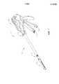
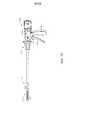
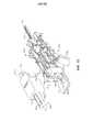
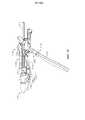
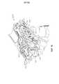
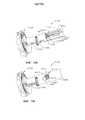
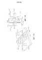
на ФИГ. 1 представлен вид в перспективе хирургического инструмента, содержащего рукоятку, стержень и шарнирно поворачиваемый концевой эффектор;in FIG. 1 is a perspective view of a surgical instrument comprising a handle, a shaft and a pivotally rotatable end effector;
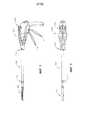
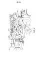
на ФИГ. 2 представлен вид в вертикальной проекции хирургического инструмента, изображенного на ФИГ. 1;in FIG. 2 is a perspective view of the surgical instrument shown in FIG. one;
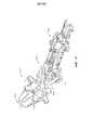
на ФИГ. 3 представлен вид в горизонтальной проекции хирургического инструмента, изображенного на ФИГ. 1;in FIG. 3 is a horizontal perspective view of the surgical instrument shown in FIG. one;
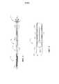
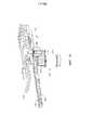
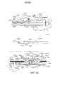
на ФИГ. 4 представлен вид в сечении концевого эффектора и стержня хирургического инструмента, изображенного на ФИГ. 1;in FIG. 4 is a sectional view of the end effector and the shaft of the surgical instrument shown in FIG. one;
на ФИГ. 5 представлен подробный вид шарнирного сочленения, которое поворотно соединяет стержень и концевой эффектор, изображенный на ФИГ. 1, на котором концевой эффектор показан в нейтральном, или центральном, положении;in FIG. 5 is a detailed view of the articulation that rotationally connects the rod and the end effector shown in FIG. 1, in which the end effector is shown in a neutral, or central, position;
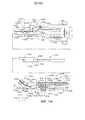
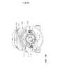
на ФИГ. 6 представлен вид в сечении устройства управления шарнирным сочленением хирургического инструмента, изображенного на ФИГ. 1, в нейтральном, или центральном, положении;in FIG. 6 is a sectional view of the articulation control device of the surgical instrument shown in FIG. 1, in a neutral, or central, position;
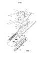
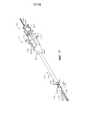
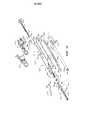
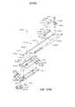
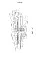
на ФИГ. 7 представлен вид с пространственным разделением компонентов концевого эффектора, удлиненного стержня и шарнирного сочленения хирургического инструмента, изображенного на ФИГ. 1;in FIG. 7 is a view with a spatial separation of the components of the end effector, the elongated shaft and the articulation of the surgical instrument shown in FIG. one;
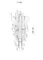
на ФИГ. 8 представлен вид в сечении концевого эффектора, удлиненного стержня и шарнирного сочленения хирургического инструмента, изображенного на ФИГ. 1;in FIG. 8 is a sectional view of an end effector, an elongated shaft, and an articulated joint of the surgical instrument of FIG. one;
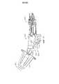
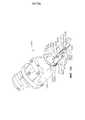
на ФИГ. 9 представлен вид в перспективе концевого эффектора, удлиненного стержня и шарнирного сочленения хирургического инструмента, изображенного на ФИГ. 1;in FIG. 9 is a perspective view of an end effector, an elongated shaft, and an articulated joint of the surgical instrument of FIG. one;
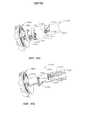
на ФИГ. 10 показан концевой эффектор хирургического инструмента, изображенного на ФИГ. 1, шарнирно повернутый вокруг шарнирного сочленения;in FIG. 10 shows the end effector of the surgical instrument of FIG. 1, pivotally rotated around the articulation;
на ФИГ. 11 представлен вид в сечении устройства управления шарнирным сочленением, изображенного на ФИГ. 6, которое активировано для перемещения концевого эффектора, как показано на ФИГ. 12;in FIG. 11 is a cross-sectional view of the articulation control device shown in FIG. 6, which is activated to move the end effector, as shown in FIG. 12;
на ФИГ. 12 представлен вид в перспективе хирургического инструмента, содержащего рукоятку, стержень и шарнирно поворачиваемый концевой эффектор;in FIG. 12 is a perspective view of a surgical instrument comprising a handle, a shaft, and a pivotally rotatable end effector;
на ФИГ. 13 представлен вид сбоку хирургического инструмента, изображенного на ФИГ. 12;in FIG. 13 is a side view of the surgical instrument shown in FIG. 12;
на ФИГ. 14 представлен вид в перспективе пускового элемента и ведущей шестерни, расположенных внутри рукоятки, изображенной на ФИГ. 12;in FIG. 14 is a perspective view of a trigger element and pinion gear located inside the handle of FIG. 12;
на ФИГ. 15 представлен вид в перспективе пускового элемента и ведущей шестерни, изображенных на ФИГ. 14, а также узла зубчатого редуктора, функционально зацепленного с ведущей шестерней;in FIG. 15 is a perspective view of the trigger element and pinion gear shown in FIG. 14, as well as a gear reducer assembly operatively engaged with a pinion gear;
на ФИГ. 16 представлен вид в перспективе рукоятки, изображенной на ФИГ. 12, с удаленными с нее частями для иллюстрации пускового элемента и ведущей шестерни, изображенных на ФИГ. 14, узла зубчатого редуктора, изображенного на ФИГ. 15, и электрического двигателя, выполненного с возможностью привода пускового элемента дистально и/или проксимально в зависимости от направления вращения электрического двигателя;in FIG. 16 is a perspective view of the handle of FIG. 12, with parts removed therefrom to illustrate the trigger element and pinion gear of FIG. 14, the gear reducer assembly shown in FIG. 15, and an electric motor configured to drive the trigger element distally and / or proximally depending on the direction of rotation of the electric motor;
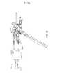
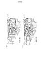
на ФИГ. 17 представлен вид в перспективе хирургического инструмента, содержащего рукоятку, стержень, концевой эффектор и шарнирное сочленение, которое соединяет концевой эффектор со стержнем, причем на изображении части рукоятки удалены для целей иллюстрации;in FIG. 17 is a perspective view of a surgical instrument comprising a handle, a rod, an end effector, and an articulation that connects the end effector to the rod, wherein portions of the handle are removed for illustration purposes;
на ФИГ. 18 представлен вид в сечении хирургического инструмента, изображенного на ФИГ. 17;in FIG. 18 is a sectional view of the surgical instrument shown in FIG. 17;
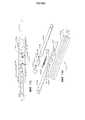
на ФИГ. 19 представлен вид с пространственным разделением компонентов хирургического инструмента, изображенного на ФИГ. 17;in FIG. 19 is an exploded view of the components of the surgical instrument shown in FIG. 17;
на ФИГ. 20 представлен подробный вид в сечении хирургического инструмента, изображенного на ФИГ. 17, причем на изображении концевой эффектор находится в открытой конфигурации, шарнирное сочленение находится в незаблокированной конфигурации, а исполнительный механизм блокировки шарнира в рукоятке хирургического инструмента показан в незаблокированной конфигурации;in FIG. 20 is a detailed sectional view of the surgical instrument shown in FIG. 17, wherein the end effector is in an open configuration in the image, the articulation is in an unlocked configuration, and the hinge lock actuator in the handle of a surgical instrument is shown in an unlocked configuration;
на ФИГ. 21 представлен подробный вид в сечении хирургического инструмента, изображенного на ФИГ. 17, на котором концевой эффектор находится в шарнирно повернутой открытой конфигурации, шарнирное сочленение находится в незаблокированной конфигурации, а шкив шарнира зацеплен с пусковым элементом хирургического инструмента, изображенного на ФИГ. 17, причем перемещение пускового элемента может подталкивать шкив шарнира и шарнирно поворачивать концевой эффектор;in FIG. 21 is a detailed sectional view of the surgical instrument shown in FIG. 17, in which the end effector is pivotally rotated in an open configuration, the articulation is in an unlocked configuration, and the pivot pulley is engaged with the trigger element of the surgical instrument shown in FIG. 17, the movement of the starting element can push the hinge pulley and pivotally rotate the end effector;
на ФИГ. 22 представлен подробный вид в сечении хирургического инструмента, изображенного на ФИГ. 17, на котором концевой эффектор показан в закрытой конфигурации, шарнирное сочленение показано в незаблокированной конфигурации, а закрывающий привод концевого эффектора активируют для закрытия концевого эффектора и перемещения исполнительного механизма блокировки шарнира в заблокированную конфигурацию;in FIG. 22 is a detailed sectional view of the surgical instrument shown in FIG. 17, in which the end effector is shown in a closed configuration, the articulated joint is shown in an unlocked configuration, and the closing drive of the end effector is activated to close the end effector and move the hinge lock actuator to the locked configuration;
на ФИГ. 22A представлен подробный вид в сечении рукоятки хирургического инструмента, изображенного на ФИГ. 17, на котором показана конфигурация, описанная в отношении ФИГ. 22;in FIG. 22A is a detailed sectional view of the handle of the surgical instrument shown in FIG. 17, which shows the configuration described in relation to FIG. 22;
на ФИГ. 23 представлен подробный вид в сечении хирургического инструмента, изображенного на ФИГ. 17, на котором показаны концевой эффектор в закрытой конфигурации и шарнирное сочленение в заблокированной конфигурации, причем активированный закрывающий привод предотвращает переход исполнительного механизма блокировки шарнира в его незаблокированную конфигурацию, показанную на ФИГ. 20-22;in FIG. 23 is a detailed sectional view of the surgical instrument shown in FIG. 17, which shows the end effector in a closed configuration and the articulation in a locked configuration, the activated closing drive preventing the hinge locking actuator from transitioning to its unlocked configuration shown in FIG. 20-22;
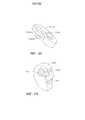
на ФИГ. 24A представлен вид в горизонтальной проекции шарнирного сочленения хирургического инструмента, изображенного на ФИГ. 17, который показан в заблокированной конфигурации;in FIG. 24A is a horizontal perspective view of the articulation of the surgical instrument shown in FIG. 17, which is shown in a locked configuration;
на ФИГ. 24B представлен вид в горизонтальной проекции шарнирного сочленения хирургического инструмента, изображенного на ФИГ. 17, который показан в незаблокированной конфигурации;in FIG. 24B is a horizontal perspective view of the articulation of the surgical instrument shown in FIG. 17, which is shown in an unlocked configuration;
на ФИГ. 25 представлен подробный вид в сечении рукоятки хирургического инструмента, изображенной на ФИГ. 17, на котором показан шкив шарнира, отсоединенный от пускового элемента закрывающим приводом;in FIG. 25 is a detailed sectional view of the handle of the surgical instrument shown in FIG. 17, which shows a hinge pulley disconnected from the starting element by a closing drive;
на ФИГ. 26 представлен подробный вид в сечении хирургического инструмента, изображенного на ФИГ. 17, на котором показан пусковой элемент по меньшей мере в частично активированном положении и шкив шарнира, отсоединенный от пускового элемента закрывающим приводом;in FIG. 26 is a detailed sectional view of the surgical instrument shown in FIG. 17, which shows a trigger element at least in a partially activated position and a hinge pulley disconnected from the trigger element by a closing actuator;
на ФИГ. 27 представлен подробный вид в сечении хирургического инструмента, изображенного на ФИГ. 17, на котором показан концевой эффектор в закрытой конфигурации, шарнирное сочленение и исполнительный механизм шарнирного сочленения в заблокированной конфигурации и пусковой элемент в оттянутом положении;in FIG. 27 is a detailed sectional view of the surgical instrument shown in FIG. 17, which shows the end effector in a closed configuration, the articulated joint and the actuator of the articulated joint in a locked configuration, and the trigger in the drawn position;
на ФИГ. 28 представлен подробный вид в сечении хирургического инструмента, изображенного на ФИГ. 17, на котором показан концевой эффектор в открытой конфигурации, закрывающий привод концевого эффектора в оттянутом положении и шарнирное сочленение в заблокированной конфигурации;in FIG. 28 is a detailed sectional view of the surgical instrument shown in FIG. 17, which shows an end effector in an open configuration that closes the end effector drive in a retracted position and an articulated joint in a locked configuration;
на ФИГ. 29 представлен подробный вид в сечении хирургического инструмента, изображенного на ФИГ. 17, на котором концевой эффектор показан в открытой конфигурации, шарнирное сочленение и исполнительный механизм шарнирного сочленения показаны в незаблокированной конфигурации, причем шкив шарнира может быть повторно соединен с пусковым приводом и использован для шарнирного поворота концевого эффектора еще раз;in FIG. 29 is a detailed sectional view of the surgical instrument shown in FIG. 17, in which the end effector is shown in an open configuration, the articulation and the articulated actuator are shown in an unlocked configuration, wherein the hinge pulley can be reconnected to the trigger actuator and used to articulate the end effector again;
на ФИГ. 30 представлен вид с пространственным разделением компонентов стержня и концевого эффектора хирургического инструмента, включая альтернативную конфигурацию блокировки шарнира;in FIG. 30 is an exploded view of the components of the shaft and the end effector of a surgical instrument, including an alternative hinge lock configuration;
на ФИГ. 31 представлен вид в сечении в вертикальной проекции концевого эффектора и стержня хирургического инструмента, изображенного на ФИГ. 30, на котором показан концевой эффектор в незаблокированной конфигурации;in FIG. 31 is a vertical sectional view of an end effector and a shaft of the surgical instrument shown in FIG. 30 showing an end effector in an unlocked configuration;
на ФИГ. 32 представлен вид в сечении в вертикальной проекции концевого эффектора и стержня хирургического инструмента, изображенного на ФИГ. 30, на котором показан концевой эффектор в заблокированной конфигурации;in FIG. 32 is a cross-sectional elevational view of the end effector and the shaft of the surgical instrument of FIG. 30 showing an end effector in a locked configuration;
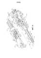
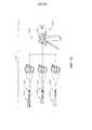
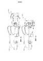
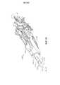
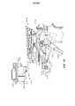
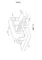
на ФИГ. 33 представлен общий вид одной формы хирургической системы, включающей хирургический инструмент и множество сменных узлов стержня;in FIG. 33 is a perspective view of one form of surgical system including a surgical instrument and a plurality of interchangeable shaft assemblies;
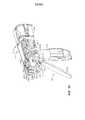
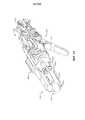
на ФИГ. 34 представлен вид в перспективе рукоятки хирургического инструмента, соединенной со сменным узлом стержня;in FIG. 34 is a perspective view of a handle of a surgical instrument connected to a removable shaft assembly;
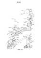
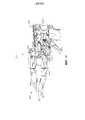
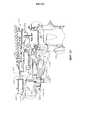
на ФИГ. 35 представлен вид в перспективе с пространственным разделением компонентов рукоятки хирургического инструмента, изображенной на ФИГ. 34;in FIG. 35 is a perspective view with a spatial separation of the components of the handle of the surgical instrument shown in FIG. 34;
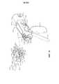
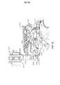
на ФИГ. 36 представлен вид сбоку в вертикальной проекции рукоятки, изображенной на ФИГ. 35, причем часть кожуха рукоятки на фигуре удалена;in FIG. 36 is a side elevational view of the handle shown in FIG. 35, wherein a portion of the handle casing in the figure is removed;
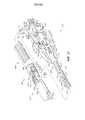
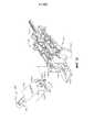
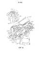
на ФИГ. 37 представлен вид в перспективе с пространственным разделением компонентов сменного узла стержня;in FIG. 37 is a perspective view with a spatial separation of the components of a replaceable rod assembly;
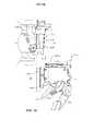
на ФИГ. 38 представлен общий вид сбоку в вертикальной проекции части рукоятки и сменного узла стержня, изображенного на ФИГ. 34, на котором показано вертикальное совмещение этих компонентов до соединения вместе, причем их части опущены для ясности;in FIG. 38 is a perspective side elevational view of a portion of the handle and a replaceable shaft assembly of FIG. 34, which shows a vertical alignment of these components prior to joining together, with parts thereof omitted for clarity;
на ФИГ. 39 представлен вид в перспективе части сменного узла стержня до прикрепления хирургического инструмента к рукоятке;in FIG. 39 is a perspective view of a portion of a replaceable shaft assembly prior to attachment of a surgical instrument to a handle;
на ФИГ. 40 представлен вид сбоку части сменного узла стержня, соединенного с рукояткой с помощью вилки блокировки, в заблокированном или зацепленном положении с частью модуля крепления рамы рукоятки;in FIG. 40 is a side view of a portion of a replaceable shaft assembly connected to a handle using a locking fork in an locked or engaged position with a portion of a handle frame mount module;
на ФИГ. 41 представлен другой вид сбоку сменного узла стержня и рукоятки, изображенных на ФИГ. 40, причем вилка блокировки находится в расцепленном или незаблокированном положении;in FIG. 41 is another side view of the interchangeable shaft and handle assembly shown in FIG. 40, wherein the locking fork is in an unlocked or unlocked position;
на ФИГ. 42 представлен вид сверху части сменного узла стержня и рукоятки до соединения вместе;in FIG. 42 is a top view of a portion of a removable shaft and handle assembly before joining together;
на ФИГ. 43 представлен другой вид сверху части сменного узла стержня и рукоятки, изображенных на ФИГ. 42, соединенных вместе;in FIG. 43 is another top view of a portion of the interchangeable shaft and handle assembly shown in FIG. 42 connected together;
на ФИГ. 44 представлен вид сбоку в вертикальной проекции сменного узла стержня, совмещенного с рукояткой хирургического инструмента, до соединения вместе;in FIG. 44 is a side elevational view of the interchangeable shaft assembly aligned with the handle of a surgical instrument before joining together;
на ФИГ. 45 представлен вид спереди в перспективе сменного узла стержня и рукоятки хирургического инструмента, изображенных на ФИГ. 44, причем их части удалены для ясности;in FIG. 45 is a front perspective view of a replaceable shaft assembly and a surgical instrument handle shown in FIG. 44, with parts thereof removed for clarity;
на ФИГ. 46 представлен вид сбоку части сменного узла стержня, совмещенного с частью рукоятки хирургического инструмента до соединения вместе, причем их части опущены для ясности;in FIG. 46 is a side view of a portion of a removable shaft assembly aligned with a portion of a handle of a surgical instrument prior to joining together, with portions thereof omitted for clarity;
на ФИГ. 47 представлен другой вид сбоку в вертикальной проекции сменного узла стержня и рукоятки, изображенных на ФИГ. 46, причем узел стержня находится в частичном соединительном зацеплении с рукояткой;in FIG. 47 is a different side elevational view of the interchangeable shaft and handle assembly shown in FIG. 46, wherein the shaft assembly is in partial engagement with the handle;
на ФИГ. 48 представлен другой вид сбоку в вертикальной проекции сменного узла стержня и рукоятки, изображенных на ФИГ. 46 и 47, после соединения вместе;in FIG. 48 is another side elevational view of the interchangeable shaft and handle assembly shown in FIG. 46 and 47, after joining together;
на ФИГ. 49 представлен другой вид сбоку в вертикальной проекции части сменного узла стержня, совмещенной с частью рукоятки, до начала процесса соединения;in FIG. 49 is another side elevational view of a portion of a removable shaft assembly aligned with a portion of a handle prior to the start of the joining process;
на ФИГ. 50 представлен вид сверху части другого сменного узла стержня и части хирургического инструмента с другой конфигурацией рамы;in FIG. 50 is a plan view of part of another removable shaft assembly and part of a surgical instrument with a different frame configuration;
на ФИГ. 51 представлен другой вид сверху сменного узла стержня и части рамы, изображенных на ФИГ. 50, после соединения вместе;in FIG. 51 is another top view of a removable rod assembly and part of the frame shown in FIG. 50, after joining together;
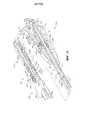
на ФИГ. 52 представлен вид в перспективе с пространственным разделением компонентов сменного узла стержня и части рамы, изображенных на ФИГ. 50;in FIG. 52 is a perspective view with a spatial separation of the components of the replaceable shaft assembly and the frame portion shown in FIG. fifty;
на ФИГ. 53 представлен другой вид в перспективе с пространственным разделением компонентов сменного узла стержня и части рамы, изображенных на ФИГ. 52, причем модуль крепления стержня узла стержня совмещен с модулем крепления части рамы к раме до соединения;in FIG. 53 presents another perspective view with a spatial separation of the components of the removable node of the rod and part of the frame shown in FIG. 52, wherein the rod attachment module of the rod assembly is aligned with the attachment module of the frame portion to the frame prior to connection;
на ФИГ. 54 представлен вид сбоку в вертикальной проекции сменного узла стержня и части рамы, изображенных на ФИГ. 52;in FIG. 54 is a side elevational view of the interchangeable shaft assembly and part of the frame shown in FIG. 52;
на ФИГ. 55 представлен вид в перспективе сменного узла стержня и части рамы, изображенных на ФИГ. 53 и 54, после соединения вместе;in FIG. 55 is a perspective view of a replaceable shaft assembly and part of the frame shown in FIG. 53 and 54, after joining together;
на ФИГ. 56 представлен вид сбоку в вертикальной проекции сменного узла стержня и части рамы, изображенных на ФИГ. 55;in FIG. 56 is a side elevational view of the interchangeable shaft assembly and part of the frame shown in FIG. 55;
на ФИГ. 57 представлен другой вид в перспективе сменного узла стержня и части рамы, изображенных на ФИГ. 55 и 56, причем их части опущены для ясности;in FIG. 57 is a different perspective view of a replaceable shaft assembly and part of the frame shown in FIG. 55 and 56, with parts thereof omitted for clarity;
на ФИГ. 58 представлен вид сверху части другого сменного узла стержня и части рамы хирургического инструмента до соединения вместе;in FIG. 58 is a plan view of a portion of another removable shaft assembly and a portion of a surgical instrument frame before joining together;
на ФИГ. 59 представлен другой вид сверху сменного узла стержня и части рамы, изображенных на ФИГ. 58, после соединения вместе;in FIG. 59 is another top view of a removable shaft assembly and part of the frame shown in FIG. 58, after joining together;
на ФИГ. 60 представлен вид в перспективе сменного узла стержня и рамы, изображенных на ФИГ. 58 и 59, до соединения вместе;in FIG. 60 is a perspective view of the interchangeable shaft and frame assembly shown in FIG. 58 and 59, before joining together;
на ФИГ. 61 представлен другой вид в перспективе сменного узла стержня и части рамы, изображенных на ФИГ. 58-60, после соединения вместе;in FIG. 61 is another perspective view of a replaceable shaft assembly and part of the frame shown in FIG. 58-60, after joining together;
на ФИГ. 62 представлен другой вид в перспективе сменного узла стержня и части рамы, изображенных на ФИГ. 58-60, после соединения вместе, причем части узла стержня показаны в сечении;in FIG. 62 is a different perspective view of a replaceable rod assembly and part of the frame shown in FIG. 58-60, after joining together, wherein parts of the rod assembly are shown in cross section;
на ФИГ. 63 представлен общий вид в перспективе с пространственным разделением компонентов другого узла стержня концевого эффектора и части рамы хирургического инструмента;in FIG. 63 is a perspective perspective view with a spatial separation of the components of another rod end effector shaft assembly and a portion of a surgical instrument frame;
на ФИГ. 64 представлен общий вид сверху с пространственным разделением компонентов узла стержня концевого эффектора и части рамы, изображенных на ФИГ. 63;in FIG. 64 is a general plan view with a spatial separation of the components of the rod assembly of the end effector and part of the frame shown in FIG. 63;
на ФИГ. 65 представлен другой общий вид в перспективе с пространственным разделением компонентов узла стержня концевого эффектора и части рамы, изображенных на ФИГ. 63 и 64;in FIG. 65 is another perspective perspective view with a spatial separation of the components of the rod assembly of the end effector and the part of the frame shown in FIG. 63 and 64;
на ФИГ. 66 представлен вид в перспективе узла стержня концевого эффектора и части рамы, изображенных на ФИГ. 63-65, после соединения вместе;in FIG. 66 is a perspective view of the terminal assembly of the end effector and part of the frame shown in FIG. 63-65, after joining together;
на ФИГ. 67 представлен вид сбоку в вертикальной проекции узла стержня концевого эффектора и части рамы, изображенных на ФИГ. 66, причем их части опущены для ясности;in FIG. 67 is a side elevational view of the terminal assembly of the end effector rod and part of the frame shown in FIG. 66, with parts thereof omitted for clarity;
на ФИГ. 68 представлен общий вид сверху с пространственным разделением компонентов другого узла стержня концевого эффектора и части рамы другого хирургического инструмента;in FIG. 68 is a general top view with a spatial separation of the components of another node of the end effector shaft and part of the frame of another surgical instrument;
на ФИГ. 69 представлен общий вид в перспективе с пространственным разделением компонентов узла стержня концевого эффектора и части рамы, изображенных на ФИГ. 68;in FIG. 69 is a perspective perspective view with a spatial separation of the components of the rod assembly of the end effector and the part of the frame shown in FIG. 68;
на ФИГ. 70 представлен другой общий вид в перспективе узла стержня концевого эффектора и части рамы, изображенных на ФИГ. 68 и 69, причем узел стержня концевого эффектора показан до защелкивания в соединительном зацеплении с частью рамы;in FIG. 70 is another perspective perspective view of a shaft assembly of the end effector and part of the frame shown in FIG. 68 and 69, wherein the end effector rod assembly is shown to snap into engagement with part of the frame until it clicks;
на ФИГ. 71 представлен вид сверху узла стержня концевого эффектора и части рамы, изображенных на ФИГ. 70;in FIG. 71 is a top view of the terminal assembly of the end effector and part of the frame shown in FIG. 70;
на ФИГ. 72 представлен вид сверху узла стержня концевого эффектора и части рамы, изображенных на ФИГ. 68-71, после соединения вместе;in FIG. 72 is a plan view of the terminal assembly of the end effector and part of the frame shown in FIG. 68-71, after joining together;
на ФИГ. 73 представлен вид сбоку в вертикальной проекции узла стержня концевого эффектора и части рамы, изображенных на ФИГ. 72;in FIG. 73 is a side elevational view of the end node of the end effector rod and part of the frame shown in FIG. 72;
на ФИГ. 74 представлен вид в перспективе узла стержня концевого эффектора и части рамы, изображенных на ФИГ. 72 и 73;in FIG. 74 is a perspective view of a shaft assembly of the end effector and part of the frame shown in FIG. 72 and 73;
на ФИГ. 75 представлен общий вид с пространственным разделением компонентов сменного узла стержня и соответствующей рукоятки, причем их некоторые компоненты показаны в сечении;in FIG. 75 is a perspective view of the spatial separation of the components of the removable shaft assembly and the corresponding handle, some of which are shown in cross section;
на ФИГ. 76 представлен вид в перспективе и частичном сечении частей узла стержня концевого эффектора и рукоятки, изображенных на ФИГ. 75;in FIG. 76 is a perspective and partial sectional view of portions of a shaft assembly of the end effector and the handle shown in FIG. 75;
на ФИГ. 77 представлен частичный вид в перспективе узла стержня концевого эффектора и рукоятки, изображенных на ФИГ. 75 и 76, соединенных вместе, причем различные компоненты опущены для ясности;in FIG. 77 is a partial perspective view of the shaft assembly of the end effector and the handle shown in FIG. 75 and 76 connected together, the various components omitted for clarity;
на ФИГ. 78 представлен вид сбоку в вертикальной проекции узла стержня концевого эффектора и рукоятки, изображенных на ФИГ. 77;in FIG. 78 is a side elevational view of the shaft assembly of the end effector and the handle of FIG. 77;
на ФИГ. 79 представлен вид сбоку в вертикальной проекции узла стержня концевого эффектора и рукоятки, изображенных на ФИГ. 75-78, соединенных вместе, причем закрывающий привод находится в неактивированном положении, а некоторые компоненты показаны в сечении;in FIG. 79 is a side elevational view of the shaft assembly of the end effector and the handle shown in FIG. 75-78, connected together, and the closing actuator is in the inactive position, and some components are shown in cross section;
на ФИГ. 80 представлен другой вид сбоку в вертикальной проекции узла стержня концевого эффектора и рукоятки, изображенных на ФИГ. 79, причем закрывающий привод находится в полностью активированном положении;in FIG. 80 is another side elevational view of the rod end effector and handle assembly shown in FIG. 79, the closing drive being in the fully activated position;
на ФИГ. 81 представлен общий вид с пространственным разделением компонентов сменного узла стержня и соответствующей рукоятки, причем их некоторые компоненты опущены для ясности и причем система закрывающего привода находится в заблокированной ориентации;in FIG. 81 is a perspective view of the spatial separation of the components of the interchangeable shaft assembly and the corresponding handle, some of which are omitted for clarity and the closing drive system is in a locked orientation;
на ФИГ. 82 представлен вид сбоку узла стержня концевого эффектора и рукоятки, изображенных на ФИГ. 81, соединенных вместе, причем различные компоненты опущены для ясности и причем система закрывающего привода находится в незаблокированном и неактивированном положении;in FIG. 82 is a side view of the shaft assembly of the end effector and the handle shown in FIG. 81 connected together, wherein various components are omitted for clarity and wherein the closing drive system is in an unlocked and inactive position;
на ФИГ. 83 представлен вид сбоку узла стержня концевого эффектора и рукоятки, изображенных на ФИГ. 82, причем различные компоненты показаны в сечении для ясности;in FIG. 83 is a side view of the shaft assembly of the end effector and the handle shown in FIG. 82, wherein various components are shown in cross section for clarity;
на ФИГ. 84 представлен вид сбоку узла стержня концевого эффектора и рукоятки, изображенных на ФИГ. 81-83, соединенных вместе, причем различные компоненты опущены для ясности и причем система закрывающего привода находится в активированном положении;in FIG. 84 is a side view of the shaft assembly of the end effector and the handle shown in FIG. 81-83 connected together, wherein various components are omitted for clarity and wherein the closing drive system is in an activated position;
на ФИГ. 85 представлен вид сбоку узла стержня концевого эффектора и рукоятки, изображенных на ФИГ. 84, причем различные компоненты показаны в сечении для ясности;in FIG. 85 is a side view of the shaft assembly of the end effector and the handle shown in FIG. 84, wherein various components are shown in cross section for clarity;
на ФИГ. 86 представлен общий вид в перспективе с пространственным разделением компонентов части сменного узла стержня, а также части рукоятки хирургического инструмента;in FIG. 86 is a perspective perspective view with a spatial separation of the components of a portion of a removable shaft assembly as well as a portion of a handle of a surgical instrument;
на ФИГ. 87 представлен вид сбоку в вертикальной проекции частей сменного узла стержня и рукоятки, изображенных на ФИГ. 86;in FIG. 87 is a side elevational view of parts of the interchangeable shaft and handle assembly depicted in FIG. 86;
на ФИГ. 88 представлен другой общий вид в перспективе с пространственным разделением компонентов частей сменного узла стержня и рукоятки, изображенных на ФИГ. 86 и 87, причем части сменного узла стержня показаны в сечении для ясности;in FIG. 88 is another perspective perspective view showing the spatial separation of the components of the parts of the interchangeable shaft assembly and the handle of FIG. 86 and 87, wherein portions of the replaceable shaft assembly are shown in cross section for clarity;
на ФИГ. 89 представлен другой вид сбоку в вертикальной проекции частей сменного узла стержня и рукоятки, изображенных на ФИГ. 86-88, причем их части показаны в сечении для ясности;in FIG. 89 is another side elevational view of portions of a removable shaft assembly and handle depicted in FIG. 86-88, with parts thereof shown in cross section for clarity;
на ФИГ. 90 представлен вид сбоку в вертикальной проекции частей сменного узла стержня и рукоятки, изображенных на ФИГ. 86-89, после того как сменный узел стержня был функционально соединен с рукояткой, причем их части показаны в сечении для ясности;in FIG. 90 is a side elevational view of parts of the removable shaft assembly and the handle of FIG. 86-89, after the removable shaft assembly was operatively connected to the handle, their parts being shown in cross section for clarity;
на ФИГ. 91 представлен другой вид сбоку в вертикальной проекции частей сменного узла стержня и соединенной с ним рукоятки, причем система закрывающего привода находится в полностью активированном положении;in FIG. 91 is another side elevational view of parts of a removable shaft assembly and a handle connected thereto, the closing drive system being in a fully activated position;
на ФИГ. 92 представлен общий вид в перспективе с пространственным разделением компонентов части другого сменного узла стержня и части рукоятки другого хирургического инструмента;in FIG. 92 is a perspective perspective view with a spatial separation of components of a portion of another removable shaft assembly and a handle portion of another surgical instrument;
на ФИГ. 93 представлен вид сбоку в вертикальной проекции частей сменного узла стержня и рукоятки, изображенных на ФИГ. 92, которые совмещены до соединения вместе;in FIG. 93 is a side elevational view of portions of a replaceable shaft assembly and handle depicted in FIG. 92, which are aligned before joining together;
на ФИГ. 94 представлен другой вид в перспективе с пространственным разделением компонентов сменного узла стержня и рукоятки, изображенных на ФИГ. 92 и 93, причем некоторые их части показаны в сечении;in FIG. 94 is another perspective view with a spatial separation of the components of the replaceable shaft assembly and the handle of FIG. 92 and 93, some of their parts shown in cross section;
на ФИГ. 95 представлен другой вид в перспективе сменного узла стержня и рукоятки, изображенных на ФИГ. 92-94, соединенных вместе с помощью функционального зацепления;in FIG. 95 is a different perspective view of the interchangeable shaft and handle assembly shown in FIG. 92-94 connected together by functional engagement;
на ФИГ. 96 представлен вид сбоку в вертикальной проекции сменного узла стержня и рукоятки, изображенных на ФИГ. 95;in FIG. 96 is a side elevational view of the interchangeable shaft and handle assembly shown in FIG. 95;
на ФИГ. 97 представлен другой вид сбоку в вертикальной проекции сменного узла стержня и рукоятки, изображенных на ФИГ. 96, причем некоторые их части показаны в сечении;in FIG. 97 is another side elevational view of the interchangeable shaft and handle assembly depicted in FIG. 96, some of which are shown in cross-section;
на ФИГ. 98 представлен другой вид сбоку в вертикальной проекции сменного узла стержня и рукоятки, изображенных на ФИГ. 92-96, причем закрывающий спусковой механизм находится в полностью активированном положении;in FIG. 98 is another side elevational view of the interchangeable shaft and handle assembly shown in FIG. 92-96, wherein the closing trigger is in a fully activated position;
на ФИГ. 99 представлен вид в перспективе части другого сменного узла стержня, который включает в себя механизм блокирующего узла стержня;in FIG. 99 is a perspective view of a portion of another interchangeable rod assembly, which includes a mechanism for locking the rod assembly;
на ФИГ. 100 представлен вид в перспективе механизма блокирующего узла стержня, изображенного на ФИГ. 99, в заблокированном положении с промежуточной частью пускового стержня пускового элемента сменного узла стержня;in FIG. 100 is a perspective view of the mechanism of the blocking assembly of the rod shown in FIG. 99, in a locked position with an intermediate portion of the trigger rod of the trigger element of the replaceable rod assembly;
на ФИГ. 101 представлен другой вид в перспективе блокирующего узла стержня и промежуточной части пускового элемента, причем блокирующий узел стержня находится в незаблокированном положении;in FIG. 101 is another perspective view of a locking member of a rod and an intermediate portion of a starting element, the locking member of the rod being in an unlocked position;
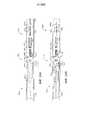
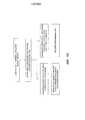
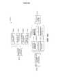
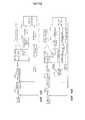
на ФИГ. 102 представлена схема, на которой показаны, во-первых, узел сцепления для функционального соединения привода шарнира с пусковым приводом хирургического инструмента и, во-вторых, блокировка шарнира, выполненная с возможностью разъемно удерживать привод шарнира и концевой эффектор хирургического инструмента в положении, причем на ФИГ. 102 узел сцепления показан в зацепленном положении, а блокировка шарнира - в заблокированном состоянии;in FIG. 102 is a diagram that shows, firstly, the clutch assembly for the functional connection of the hinge drive with the trigger drive of the surgical instrument and, secondly, the hinge lock configured to releasably hold the hinge drive and the end effector of the surgical instrument in position, FIG. 102, the clutch assembly is shown in the engaged position, and the hinge lock is in the locked state;
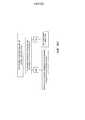
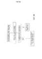
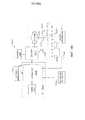
на ФИГ. 103 представлена схема, на которой показан узел сцепления, изображенный на ФИГ. 102, в его зацепленном положении, а блокировка шарнира, изображенная на ФИГ. 102, - в первом незаблокированном состоянии, что позволяет шарнирно поворачивать концевой эффектор, изображенный на ФИГ. 102, в первом направлении;in FIG. 103 is a diagram showing a clutch assembly shown in FIG. 102, in its engaged position, and the hinge lock depicted in FIG. 102, - in the first unlocked state, which allows you to pivotally rotate the end effector shown in FIG. 102, in a first direction;
на ФИГ. 104 представлена схема, на которой показан узел сцепления, изображенный на ФИГ. 102, в его зацепленном положении, а блокировка шарнира, изображенная на ФИГ. 102, - во втором незаблокированном состоянии, что позволяет шарнирно поворачивать концевой эффектор, изображенный на ФИГ. 102, во втором направлении;in FIG. 104 is a diagram showing a clutch assembly shown in FIG. 102, in its engaged position, and the hinge lock depicted in FIG. 102, - in the second unlocked state, which allows you to pivotally rotate the end effector shown in FIG. 102, in a second direction;
на ФИГ. 104A представлен вид с пространственным разделением компонентов узла сцепления и блокировки шарнира, изображенных на ФИГ. 102;in FIG. 104A is an exploded view of the components of the clutch and hinge assembly of FIG. 102;
на ФИГ. 105 представлен частичный вид в перспективе узла стержня, включая узел сцепления, изображенный на ФИГ. 102, в его зацепленном положении с частями узла стержня, удаленными для целей иллюстрации;in FIG. 105 is a partial perspective view of a shaft assembly, including the clutch assembly shown in FIG. 102, in its engaged position with parts of the shaft assembly removed for illustration purposes;
на ФИГ. 106 представлен частичный вид сверху в горизонтальной проекции узла стержня, изображенного на ФИГ. 105, на котором показан узел сцепления, изображенный на ФИГ. 102, в его зацепленном положении;in FIG. 106 is a partial top view in horizontal projection of the rod assembly shown in FIG. 105, which shows the clutch assembly shown in FIG. 102 in its engaged position;
на ФИГ. 107 представлен частичный вид снизу в горизонтальной проекции узла стержня, изображенного на ФИГ. 105, на котором показан узел сцепления, изображенный на ФИГ. 102, в его зацепленном положении;in FIG. 107 is a partial bottom view in horizontal view of the rod assembly shown in FIG. 105, which shows the clutch assembly shown in FIG. 102 in its engaged position;
на ФИГ. 108 представлен частичный вид в перспективе узла стержня, изображенного на ФИГ. 105, на котором показан узел сцепления, изображенный на ФИГ. 102, в его зацепленном положении, причем дополнительные части удалены для целей иллюстрации;in FIG. 108 is a partial perspective view of the shaft assembly shown in FIG. 105, which shows the clutch assembly shown in FIG. 102, in its engaged position, with additional parts removed for purposes of illustration;
на ФИГ. 109 представлен частичный вид в перспективе узла стержня, изображенного на ФИГ. 105, на котором показан узел сцепления, изображенный на ФИГ. 102, в расцепленном положении, причем дополнительные части удалены для целей иллюстрации;in FIG. 109 is a partial perspective view of the shaft assembly shown in FIG. 105, which shows the clutch assembly shown in FIG. 102, in the disengaged position, with additional parts removed for purposes of illustration;
на ФИГ. 110 представлен частичный вид в перспективе узла стержня, изображенного на ФИГ. 105, на котором показан узел сцепления, изображенный на ФИГ. 102, перемещенный в расцепленное положение с помощью закрывающего привода узла стержня;in FIG. 110 is a partial perspective view of the shaft assembly shown in FIG. 105, which shows the clutch assembly shown in FIG. 102 moved to the disengaged position by the closing drive of the shaft assembly;
на ФИГ. 111 представлен частичный вид в горизонтальной проекции узла стержня, изображенного на ФИГ. 105, на котором показан узел сцепления, изображенный на ФИГ. 102, в его зацепленном положении, причем дополнительные части удалены для целей иллюстрации;in FIG. 111 is a partial horizontal view of the assembly of the shaft shown in FIG. 105, which shows the clutch assembly shown in FIG. 102, in its engaged position, with additional parts removed for purposes of illustration;
на ФИГ. 112 представлен частичный вид в горизонтальной проекции узла стержня, изображенного на ФИГ. 105, на котором показан узел сцепления, изображенный на ФИГ. 102, в расцепленном положении, причем дополнительные части удалены для целей иллюстрации;in FIG. 112 is a partial horizontal view of the assembly of the rod shown in FIG. 105, which shows the clutch assembly shown in FIG. 102, in the disengaged position, with additional parts removed for purposes of illustration;
на ФИГ. 113 представлен вид в горизонтальной проекции альтернативного варианта осуществления блокировки шарнира, показанной в заблокированном состоянии;in FIG. 113 is a plan view of an alternative embodiment of a hinge lock shown in a locked state;
на ФИГ. 114 представлен вид с пространственным разделением компонентов блокировки шарнира, изображенной на ФИГ. 113;in FIG. 114 is a spatial exploded view of the hinge lock components shown in FIG. 113;
на ФИГ. 115 представлен вид в сечении другого альтернативного варианта осуществления блокировки шарнира, показанной в заблокированном состоянии;in FIG. 115 is a cross-sectional view of another alternative embodiment of a hinge lock shown in a locked state;
на ФИГ. 116 представлен вид с пространственным разделением компонентов блокировки шарнира, изображенной на ФИГ. 114;in FIG. 116 is an exploded view of the hinge lock components shown in FIG. 114;
на ФИГ. 117 представлен вид в перспективе другого альтернативного варианта осуществления блокировки шарнира, показанной в заблокированном состоянии;in FIG. 117 is a perspective view of another alternative embodiment of a hinge lock shown in a locked state;
на ФИГ. 118 представлен вид с пространственным разделением компонентов блокировки шарнира, изображенной на ФИГ. 117;in FIG. 118 is a spatial exploded view of the hinge lock components shown in FIG. 117;
на ФИГ. 119 представлен вид в вертикальной проекции блокировки шарнира, изображенной на ФИГ. 117, на котором блокировка шарнира показана в заблокированном состоянии;in FIG. 119 is a perspective view of the hinge lock shown in FIG. 117, in which the hinge lock is shown in the locked state;
на ФИГ. 120 представлен вид в вертикальной проекции блокировки шарнира, изображенной на ФИГ. 117, на котором блокировка шарнира показана в первом незаблокированном состоянии для шарнирного поворота концевого эффектора в первом направлении;in FIG. 120 is a perspective view of the hinge lock shown in FIG. 117, in which the hinge lock is shown in a first unlocked state for pivotally turning the end effector in a first direction;
на ФИГ. 121 представлен вид в вертикальной проекции блокировки шарнира, изображенной на ФИГ. 117, на котором блокировка шарнира показана во втором незаблокированном состоянии для шарнирного поворота концевого эффектора во втором направлении;in FIG. 121 is a perspective view of the hinge lock shown in FIG. 117, in which the hinge lock is shown in a second unlocked state for pivotally turning the end effector in a second direction;
на ФИГ. 122 представлен другой вид с пространственным разделением компонентов блокировки шарнира, изображенной на ФИГ. 117;in FIG. 122 is another spatial exploded view of the hinge lock components shown in FIG. 117;
на ФИГ. 123 представлен вид в перспективе первого блокирующего кулачка блокировки шарнира, изображенной на ФИГ. 117;in FIG. 123 is a perspective view of a first hinge locking lock cam of FIG. 117;
на ФИГ. 124 представлен вид в перспективе второго блокирующего кулачка блокировки шарнира, изображенной на ФИГ. 117;in FIG. 124 is a perspective view of a second hinge locking lock cam of FIG. 117;
на ФИГ. 125 представлен вид в перспективе другого альтернативного варианта осуществления блокировки шарнира, показанной в заблокированном состоянии;in FIG. 125 is a perspective view of another alternative embodiment of a hinge lock shown in a locked state;
на ФИГ. 126 представлен вид с пространственным разделением компонентов блокировки шарнира, изображенной на ФИГ. 125;in FIG. 126 is an exploded view of the hinge lock components shown in FIG. 125;
на ФИГ. 127 представлен вид в сечении в вертикальной проекции блокировки шарнира, изображенной на ФИГ. 125, на котором блокировка шарнира показана в первом незаблокированном состоянии для шарнирного поворота концевого эффектора в первом направлении;in FIG. 127 is a sectional elevational view of the hinge lock shown in FIG. 125, in which the hinge lock is shown in a first unlocked state for pivotally turning the end effector in a first direction;
на ФИГ. 128 представлен вид в сечении в вертикальной проекции блокировки шарнира, изображенной на ФИГ. 125, на котором блокировка шарнира показана в заблокированном состоянии;in FIG. 128 is a cross-sectional elevational view of the hinge lock shown in FIG. 125, in which the hinge lock is shown in the locked state;
на ФИГ. 129 представлен вид в сечении в вертикальной проекции блокировки шарнира, изображенной на ФИГ. 125, на котором блокировка шарнира показана во втором незаблокированном состоянии для шарнирного поворота концевого эффектора во втором направлении;in FIG. 129 is a cross-sectional elevational view of the hinge lock shown in FIG. 125, in which the hinge lock is shown in a second unlocked state for pivotally turning the end effector in a second direction;
на ФИГ. 130 представлен вид в сечении в вертикальной проекции блокировки шарнира, изображенной на ФИГ. 125, на котором блокировка шарнира показана в заблокированном состоянии;in FIG. 130 is a cross-sectional elevational view of the hinge lock shown in FIG. 125, in which the hinge lock is shown in the locked state;
на ФИГ. 131 представлен вид в перспективе узла стержня;in FIG. 131 is a perspective view of a rod assembly;
на ФИГ. 132 представлен вид с пространственным разделением компонентов узла стержня, изображенного на ФИГ. 131, на котором показан альтернативный вариант осуществления узла сцепления для функционального соединения привода шарнира с пусковым приводом узла стержня;in FIG. 132 is an exploded view of the components of the rod assembly shown in FIG. 131, which shows an alternative embodiment of the clutch assembly for the functional connection of the hinge drive with the starting drive of the rod assembly;
на ФИГ. 133 представлен другой вид с пространственным разделением компонентов узла стержня, изображенного на ФИГ. 131;in FIG. 133 is another spatially separated view of the components of the rod assembly shown in FIG. 131;
на ФИГ. 134 представлен частичный вид с пространственным разделением компонентов узла стержня, изображенного на ФИГ. 131, на котором части удалены для целей иллюстрации;in FIG. 134 is a partial exploded view of the components of the rod assembly shown in FIG. 131, in which parts are removed for purposes of illustration;
на ФИГ. 135 представлен вид с торца узла стержня, изображенного на ФИГ. 131, на котором части удалены для целей иллюстрации;in FIG. 135 is an end view of the rod assembly shown in FIG. 131, in which parts are removed for purposes of illustration;
на ФИГ. 136 представлен другой вид с торца узла стержня, изображенного на ФИГ. 131, на котором части удалены для целей иллюстрации;in FIG. 136 is a different end view of the rod assembly shown in FIG. 131, in which parts are removed for purposes of illustration;
на ФИГ. 137 представлен частичный вид в сечении в вертикальной проекции узла стержня, изображенного на ФИГ. 131;in FIG. 137 is a partial cross-sectional view in vertical projection of the rod assembly shown in FIG. 131;
на ФИГ. 138 представлен частичный вид в перспективе в сечении узла стержня, изображенного на ФИГ. 131;in FIG. 138 is a partial perspective sectional view of the shaft assembly shown in FIG. 131;
на ФИГ. 139 представлен другой частичный вид в сечении узла стержня, изображенного на ФИГ. 131;in FIG. 139 is another partial cross-sectional view of the rod assembly shown in FIG. 131;
на ФИГ. 140 представлен вид в перспективе узла стержня, изображенного на ФИГ. 131, на котором узел сцепления показан в зацепленном положении, а части удалены для целей ясности; в частности, показан исполнительный механизм сцепления, а гильза сцепления, барабан переключателя, проксимальный шкив шарнира и закрывающая трубка не показаны;in FIG. 140 is a perspective view of the shaft assembly shown in FIG. 131, wherein the clutch assembly is shown in an engaged position and the parts are removed for clarity; in particular, the clutch actuator is shown, and the clutch sleeve, the switch drum, the hinge proximal pulley and the closing tube are not shown;
на ФИГ. 141 представлен вид в перспективе узла стержня, изображенного на ФИГ. 131, на котором узел сцепления показан в зацепленном положении, а части удалены для целей ясности; в частности, показаны исполнительный механизм сцепления и гильза сцепления, а барабан переключателя, проксимальный шкив шарнира и закрывающая трубка не показаны;in FIG. 141 is a perspective view of the shaft assembly shown in FIG. 131, wherein the clutch assembly is shown in an engaged position and the parts are removed for clarity; in particular, the clutch actuator and the clutch sleeve are shown, and the switch drum, the proximal hinge pulley and the closing tube are not shown;
на ФИГ. 142 представлен вид в перспективе узла стержня, изображенного на ФИГ. 131, на котором узел сцепления показан в расцепленном положении, а части удалены для целей ясности; в частности, показаны исполнительный механизм сцепления и гильза сцепления, а барабан переключателя, проксимальный шкив шарнира и закрывающая трубка не показаны;in FIG. 142 is a perspective view of the shaft assembly shown in FIG. 131, wherein the clutch assembly is shown in a disengaged position and parts are removed for clarity; in particular, the clutch actuator and the clutch sleeve are shown, and the switch drum, the proximal hinge pulley and the closing tube are not shown;
на ФИГ. 143 представлен вид в перспективе узла стержня, изображенного на ФИГ. 131, на котором узел сцепления показан в расцепленном положении, а части удалены для целей ясности; в частности, показаны исполнительный механизм сцепления, гильза сцепления и закрывающая трубка, а барабан переключателя и проксимальный шкив шарнира не показаны;in FIG. 143 is a perspective view of the shaft assembly shown in FIG. 131, wherein the clutch assembly is shown in a disengaged position and parts are removed for clarity; in particular, the clutch actuator, the clutch sleeve and the closing tube are shown, and the switch drum and the proximal hinge pulley are not shown;
на ФИГ. 144 представлен вид в перспективе узла стержня, изображенного на ФИГ. 131, на котором узел сцепления показан в расцепленном положении; показаны исполнительный механизм сцепления, гильза сцепления, закрывающая трубка, барабан переключателя и проксимальный шкив шарнира;in FIG. 144 is a perspective view of the shaft assembly shown in FIG. 131, in which the clutch assembly is shown in an unlocked position; shows the clutch actuator, clutch sleeve, cover tube, switch drum, and hinge proximal pulley;
на ФИГ. 145 представлен вид в перспективе узла стержня, изображенного на ФИГ. 131, на котором узел сцепления показан в зацепленном положении, а части удалены для целей ясности; в частности, показаны исполнительный механизм сцепления, гильза сцепления и проксимальный шкив шарнира, а барабан переключателя и закрывающая трубка не показаны;in FIG. 145 is a perspective view of the shaft assembly shown in FIG. 131, wherein the clutch assembly is shown in an engaged position and the parts are removed for clarity; in particular, the clutch actuator, the clutch sleeve and the proximal hinge pulley are shown, and the switch drum and the closing tube are not shown;
на ФИГ. 146 представлен вид в перспективе узла стержня, изображенного на ФИГ. 131, на котором узел сцепления показан в зацепленном положении, а части удалены для целей ясности; в частности, показаны исполнительный механизм сцепления, гильза сцепления, проксимальный шкив шарнира и закрывающая трубка, а барабан переключателя не показан; более того, система привода шарнира узла стержня показана в центральном, или шарнирно неповернутом, состоянии;in FIG. 146 is a perspective view of the shaft assembly shown in FIG. 131, wherein the clutch assembly is shown in an engaged position and the parts are removed for clarity; in particular, the clutch actuator, the clutch sleeve, the proximal hinge pulley and the closing tube are shown, and the switch drum is not shown; moreover, the drive system of the hinge of the rod assembly is shown in a central, or pivotally untwisted, state;
на ФИГ. 147 представлен вид в перспективе узла стержня, изображенного на ФИГ. 131, на котором узел сцепления показан в зацепленном положении, а части удалены для целей ясности; в частности, показаны исполнительный механизм сцепления, гильза сцепления и проксимальный шкив шарнира, а барабан переключателя и закрывающая трубка не показаны; более того, система привода шарнира узла стержня показана в состоянии, в котором концевой эффектор узла стержня может быть шарнирно повернут влево относительно продольной оси узла стержня;in FIG. 147 is a perspective view of the shaft assembly shown in FIG. 131, wherein the clutch assembly is shown in an engaged position and the parts are removed for clarity; in particular, the clutch actuator, the clutch sleeve and the proximal hinge pulley are shown, and the switch drum and the closing tube are not shown; moreover, the drive system of the hinge of the rod node is shown in a state in which the end effector of the rod node can be pivotally rotated to the left relative to the longitudinal axis of the rod node;
на ФИГ. 148 представлен вид в перспективе узла стержня, изображенного на ФИГ. 131, на котором узел сцепления показан в зацепленном состоянии, а части удалены для целей ясности; в частности, показаны исполнительный механизм сцепления, гильза сцепления и проксимальный шкив шарнира, а барабан переключателя и закрывающая трубка не показаны; более того, система привода шарнира узла стержня показана в состоянии, в котором концевой эффектор узла стержня может быть шарнирно повернут вправо относительно продольной оси узла стержня;in FIG. 148 is a perspective view of the shaft assembly shown in FIG. 131, wherein the clutch assembly is shown in an engaged state and parts are removed for clarity; in particular, the clutch actuator, the clutch sleeve and the proximal hinge pulley are shown, and the switch drum and the closing tube are not shown; moreover, the drive system of the hinge of the rod node is shown in a state in which the end effector of the rod node can be pivotally rotated to the right relative to the longitudinal axis of the rod node;
на ФИГ. 149 представлен вид в перспективе узла стержня, изображенного на ФИГ. 131, на котором узел сцепления показан в зацепленном состоянии, а части удалены для целей ясности; в частности, показаны исполнительный механизм сцепления, гильза сцепления, закрывающая трубка и проксимальный шкив шарнира, а барабан переключателя не показан;in FIG. 149 is a perspective view of the shaft assembly shown in FIG. 131, wherein the clutch assembly is shown in an engaged state and parts are removed for clarity; in particular, a clutch actuator, a clutch sleeve, a cover tube and a proximal hinge pulley are shown, and a switch drum is not shown;
на ФИГ. 150 представлен вид в перспективе хирургического инструмента в соответствии с некоторыми вариантами осуществления, описанными в настоящем документе;in FIG. 150 is a perspective view of a surgical instrument in accordance with some embodiments described herein;
на ФИГ. 151 представлена принципиальная блок-схема системы управления хирургическим инструментом в соответствии с некоторыми вариантами осуществления, описанными в настоящем документе;in FIG. 151 is a schematic block diagram of a surgical instrument control system in accordance with some embodiments described herein;
на ФИГ. 152 представлен вид в перспективе стыковочного элемента хирургического инструмента в соответствии с некоторыми вариантами осуществления, описанными в настоящем документе;in FIG. 152 is a perspective view of a docking element of a surgical instrument in accordance with some embodiments described herein;
на ФИГ. 153 представлен вид сверху стыковочного элемента, изображенного на ФИГ. 152;in FIG. 153 is a top view of the docking member shown in FIG. 152;
на ФИГ. 154 представлен вид в сечении стыковочного элемента, изображенного на ФИГ. 152, в неактивной или нейтральной конфигурации в соответствии с некоторыми вариантами осуществления, описанными в настоящем документе;in FIG. 154 is a cross-sectional view of the docking member shown in FIG. 152, in an inactive or neutral configuration in accordance with some of the options for implementation described herein;
на ФИГ. 155 представлен вид в сечении стыковочного элемента, изображенного на ФИГ. 152, активированного для шарнирного поворота концевого эффектора в соответствии с некоторыми вариантами осуществления, описанными в настоящем документе;in FIG. 155 is a cross-sectional view of the docking member shown in FIG. 152 activated to articulate an end effector in accordance with some embodiments described herein;
на ФИГ. 156 представлен вид в сечении стыковочного элемента, изображенного на ФИГ. 152, активированного для возврата концевого эффектора в положение исходного состояния шарнира в соответствии с некоторыми вариантами осуществления, описанными в настоящем документе;in FIG. 156 is a cross-sectional view of the docking member shown in FIG. 152 activated to return the end effector to the initial state of the hinge in accordance with some embodiments described herein;
на ФИГ. 157 представлен вид в сечении стыковочного элемента, аналогичного стыковочному элементу, изображенному на ФИГ. 152, в неактивной или нейтральной конфигурации в соответствии с некоторыми вариантами осуществления, описанными в настоящем документе;in FIG. 157 is a cross-sectional view of a docking member similar to the docking member shown in FIG. 152, in an inactive or neutral configuration in accordance with some of the options for implementation described herein;
на ФИГ. 158 представлен вид в сечении стыковочного элемента, изображенного на ФИГ. 152, активированного для шарнирного поворота концевого эффектора в соответствии с некоторыми вариантами осуществления, описанными в настоящем документе;in FIG. 158 is a cross-sectional view of the docking member shown in FIG. 152 activated to articulate an end effector in accordance with some embodiments described herein;
на ФИГ. 159 представлен вид в сечении стыковочного элемента, изображенного на ФИГ. 152, активированного для возврата концевого эффектора в положение исходного состояния шарнира в соответствии с некоторыми вариантами осуществления, описанными в настоящем документе;in FIG. 159 is a cross-sectional view of the docking member shown in FIG. 152 activated to return the end effector to the initial state of the hinge in accordance with some embodiments described herein;
на ФИГ. 160 представлена принципиальная блок-схема, на которой кратко отображен ответ контроллера хирургического инструмента, изображенного на ФИГ. 150, на входной сигнал сброса в соответствии с некоторыми вариантами осуществления, описанными в настоящем документе;in FIG. 160 is a schematic block diagram that briefly displays the response of a surgical instrument controller depicted in FIG. 150, to a reset input, in accordance with some embodiments described herein;
на ФИГ. 161 представлена принципиальная блок-схема, на которой кратко отображен ответ контроллера хирургического инструмента, изображенного на ФИГ. 150, на входной сигнал исходного состояния в соответствии с некоторыми вариантами осуществления, описанными в настоящем документе;in FIG. 161 is a schematic block diagram that briefly displays the response of a surgical instrument controller depicted in FIG. 150, to an input signal of the initial state in accordance with some of the options for implementation described herein;
на ФИГ. 162 представлена принципиальная блок-схема, на которой кратко отображен ответ контроллера хирургического инструмента, изображенного на ФИГ. 150, на входной сигнал исходного состояния в соответствии с некоторыми вариантами осуществления, описанными в настоящем документе;in FIG. 162 is a schematic block diagram that briefly displays the response of a surgical instrument controller depicted in FIG. 150, to an input signal of the initial state in accordance with some of the options for implementation described herein;
на ФИГ. 163 представлена принципиальная блок-схема, на которой кратко отображен ответ контроллера хирургического инструмента, изображенного на ФИГ. 150, на входной сигнал пуска в исходном состоянии в соответствии с некоторыми вариантами осуществления, описанными в настоящем документе;in FIG. 163 is a schematic block diagram that briefly displays the response of a surgical instrument controller depicted in FIG. 150, to the input start signal in the initial state in accordance with some of the options for implementation described herein;
на ФИГ. 164 представлен вид сбоку в вертикальной проекции хирургического инструмента, включающего рукоятку, отделенную от стержня, в соответствии с различными вариантами осуществления, описанными в настоящем документе;in FIG. 164 is a side elevational view of a surgical instrument including a handle separated from a shaft in accordance with various embodiments described herein;
на ФИГ. 165 представлен вид сбоку в вертикальной проекции части рукоятки, включающей переключатель замка, и части стержня, включающей блокирующий элемент, в соответствии с различными вариантами осуществления, описанными в настоящем документе;in FIG. 165 is a side elevational view of a portion of a handle including a lock switch and a portion of a shaft including a locking member, in accordance with various embodiments described herein;
на ФИГ. 166 представлен частичный вид в сечении хирургического инструмента, изображенного на ФИГ. 150, на котором показан блокирующий элемент в заблокированной конфигурации и открытый переключатель в соответствии с различными вариантами осуществления, описанными в настоящем документе;in FIG. 166 is a partial sectional view of the surgical instrument shown in FIG. 150, which shows a locking element in a locked configuration and an open switch in accordance with various embodiments described herein;
на ФИГ. 167 представлен частичный вид в сечении хирургического инструмента, изображенного на ФИГ. 150, на котором блокирующий элемент показан в незаблокированной конфигурации, а закрытый переключатель прижат блокирующим элементом в соответствии с различными вариантами осуществления, описанными в настоящем документе;in FIG. 167 is a partial sectional view of the surgical instrument shown in FIG. 150, in which the locking element is shown in an unlocked configuration, and the closed switch is pressed by the locking element in accordance with various embodiments described herein;
на ФИГ. 167A представлен частичный вид в сечении хирургического инструмента, изображенного на ФИГ. 150, на котором показан продвинутый пусковой привод в соответствии с различными вариантами осуществления, описанными в настоящем документе;in FIG. 167A is a partial cross-sectional view of the surgical instrument of FIG. 150 showing an advanced launcher in accordance with various embodiments described herein;
на ФИГ. 167B представлен частичный вид в сечении хирургического инструмента, изображенного на ФИГ. 150, на котором пусковой привод показан в оттянутом или базовом положении в соответствии с различными вариантами осуществления, описанными в настоящем документе;in FIG. 167B is a partial cross-sectional view of the surgical instrument of FIG. 150, wherein the starter actuator is shown in a retracted or base position in accordance with various embodiments described herein;
на ФИГ. 168 представлена принципиальная блок-схема, на которой кратко отображен ответ контроллера хирургического инструмента, изображенного на ФИГ. 150, на входной сигнал в соответствии с некоторыми вариантами осуществления, описанными в настоящем документе;in FIG. 168 is a schematic block diagram that briefly displays the response of a surgical instrument controller depicted in FIG. 150, to an input signal in accordance with some of the embodiments described herein;
на ФИГ. 169 представлена принципиальная блок-схема, на которой кратко отображен ответ контроллера хирургического инструмента, изображенного на ФИГ. 150, на входной сигнал в соответствии с некоторыми вариантами осуществления, описанными в настоящем документе;in FIG. 169 is a schematic block diagram that briefly displays the response of a surgical instrument controller depicted in FIG. 150, to an input signal in accordance with some of the embodiments described herein;
на ФИГ. 170 представлен вид снизу электрического двигателя и резонатора в соответствии с различными вариантами осуществления настоящего описания;in FIG. 170 is a bottom view of an electric motor and resonator in accordance with various embodiments of the present description;
на ФИГ. 171 представлен вид в перспективе резонатора, изображенного на ФИГ. 170;in FIG. 171 is a perspective view of the resonator shown in FIG. 170;
на ФИГ. 172 представлен вид снизу резонатора, изображенного на ФИГ. 170;in FIG. 172 is a bottom view of the resonator shown in FIG. 170;
на ФИГ. 173 представлен частичный вид в перспективе рукоятки хирургического инструмента, на котором показан электрический двигатель, изображенный на ФИГ. 170, и резонатор, расположенный внутри рукоятки, в соответствии с различными вариантами осуществления настоящего описания;in FIG. 173 is a partial perspective view of the handle of a surgical instrument, which shows the electric motor shown in FIG. 170, and a resonator located inside the handle, in accordance with various embodiments of the present description;
на ФИГ. 174 представлен вид снизу электрического двигателя и резонатора, изображенных на ФИГ. 173;in FIG. 174 is a bottom view of the electric motor and resonator shown in FIG. 173;
на ФИГ. 175 представлен вид в перспективе резонатора, изображенного на ФИГ. 173;in FIG. 175 is a perspective view of the resonator shown in FIG. 173;
на ФИГ. 176 представлен вид снизу резонатора, изображенного на ФИГ. 173;in FIG. 176 is a bottom view of the resonator shown in FIG. 173;
на ФИГ. 177 представлен частичный вид в перспективе рукоятки, изображенной на ФИГ. 173, на котором показан электрический двигатель, изображенный на ФИГ. 170, и резонатор, расположенный внутри рукоятки, в соответствии с различными вариантами осуществления настоящего описания;in FIG. 177 is a partial perspective view of the handle of FIG. 173, which shows the electric motor shown in FIG. 170, and a resonator located inside the handle, in accordance with various embodiments of the present description;
на ФИГ. 178 представлен вид снизу электрического двигателя и резонатора, изображенных на ФИГ. 177;in FIG. 178 is a bottom view of the electric motor and resonator shown in FIG. 177;
на ФИГ. 179 представлен первый вид в перспективе резонатора, изображенного на ФИГ. 177;in FIG. 179 is a first perspective view of the resonator shown in FIG. 177;
на ФИГ. 180 представлен второй вид в перспективе резонатора, изображенного на ФИГ. 177;in FIG. 180 is a second perspective view of the resonator shown in FIG. 177;
на ФИГ. 181 представлен вид в перспективе рукоятки, изображенной на ФИГ. 173, на котором показан электрический двигатель, изображенный на ФИГ. 170, резонатор и стопорное кольцо, расположенное внутри рукоятки, в соответствии с различными вариантами осуществления настоящего описания;in FIG. 181 is a perspective view of the handle of FIG. 173, which shows the electric motor shown in FIG. 170, a resonator and a snap ring located inside the handle, in accordance with various embodiments of the present description;
на ФИГ. 182 представлена структурная схема работы хирургического инструмента во время хирургической операции в соответствии с различными вариантами осуществления настоящего описания;in FIG. 182 is a structural diagram of the operation of a surgical instrument during a surgical operation in accordance with various embodiments of the present description;
на ФИГ. 183 представлен вид в перспективе с пространственным разделением компонентов рукоятки хирургического инструмента, изображенного на ФИГ. 34, на котором показана часть сенсорного механизма системы абсолютного позиционирования в соответствии с одним вариантом осуществления;in FIG. 183 is a perspective view with a spatial separation of the components of the handle of the surgical instrument shown in FIG. 34, which shows a portion of the sensor mechanism of an absolute positioning system in accordance with one embodiment;
на ФИГ. 184 представлен вид сбоку в вертикальной проекции рукоятки, изображенной на ФИГ. 34 и 183, причем часть кожуха рукоятки удалена для отображения части сенсорного механизма системы абсолютного позиционирования в соответствии с одним вариантом осуществления;in FIG. 184 is a side elevational view of the handle depicted in FIG. 34 and 183, the part of the handle casing being removed to display part of the sensor mechanism of the absolute positioning system in accordance with one embodiment;
на ФИГ. 185 представлена принципиальная схема системы абсолютного позиционирования, содержащей управляемый микроконтроллером механизм с электроприводной цепью, содержащий сенсорный механизм, в соответствии с одним вариантом осуществления;in FIG. 185 is a schematic diagram of an absolute positioning system comprising a microcontroller-controlled mechanism with an electric drive circuit comprising a sensor mechanism, in accordance with one embodiment;
на ФИГ. 186 представлен подробный вид в перспективе сенсорного механизма системы абсолютного позиционирования в соответствии с одним вариантом осуществления;in FIG. 186 is a detailed perspective view of a sensor mechanism of an absolute positioning system in accordance with one embodiment;
на ФИГ. 187 представлен вид в перспективе с пространственным разделением компонентов сенсорного механизма системы абсолютного позиционирования, на котором показан узел платы со схемой управления и относительное совмещение элементов сенсорного механизма в соответствии с одним вариантом осуществления;in FIG. 187 is a perspective view with a spatial separation of the components of the sensor mechanism of an absolute positioning system, showing a board assembly with a control circuit and relative alignment of elements of the sensor mechanism in accordance with one embodiment;
на ФИГ. 188 представлен вид сбоку в перспективе сенсорного механизма системы абсолютного позиционирования, на котором показан узел платы со схемой управления, в соответствии с одним вариантом осуществления;in FIG. 188 is a perspective side view of a sensor mechanism of an absolute positioning system showing a board assembly with a control circuit, in accordance with one embodiment;
на ФИГ. 189 представлен вид сбоку в перспективе сенсорного механизма системы абсолютного позиционирования с удаленным узлом платы со схемой управления для отображения узла держателя сенсорного элемента в соответствии с одним вариантом осуществления;in FIG. 189 is a perspective side view of a sensor mechanism of an absolute positioning system with a remote board assembly with a control circuit for displaying a sensor holder assembly in accordance with one embodiment;
на ФИГ. 190 представлен вид сбоку в перспективе сенсорного механизма системы абсолютного позиционирования с удаленными узлами платы со схемой управления и держателя сенсорного элемента для отображения сенсорного элемента в соответствии с одним вариантом осуществления;in FIG. 190 is a perspective side view of a sensor mechanism of an absolute positioning system with remote board nodes with a control circuit and a sensor element holder for displaying a sensor element in accordance with one embodiment;
на ФИГ. 191 представлен вид сверху сенсорного механизма системы абсолютного позиционирования с удаленной платой со схемой управления, но с все еще видимыми электронными компонентами для отображения относительного положения между датчиком положения и компонентами цепи в соответствии с одним вариантом осуществления;in FIG. 191 is a plan view of a sensor mechanism of an absolute positioning system with a remote board with a control circuit but with still visible electronic components for displaying the relative position between the position sensor and the circuit components in accordance with one embodiment;
на ФИГ. 192 представлена принципиальная схема одного варианта осуществления датчика положения для системы абсолютного позиционирования, содержащей магнитную ротационную систему абсолютного позиционирования, в соответствии с одним вариантом осуществления;in FIG. 192 is a schematic diagram of one embodiment of a position sensor for an absolute positioning system comprising a magnetic rotational absolute positioning system, in accordance with one embodiment;
на ФИГ. 193 представлено шарнирное сочленение в прямом положении, т.е. при нулевом угле относительно продольного направления, в соответствии с одним вариантом осуществления;in FIG. 193 shows the articulation in the upright position, i.e. at zero angle relative to the longitudinal direction, in accordance with one embodiment;
на ФИГ. 194 представлено шарнирное сочленение, изображенное на ФИГ. 193, шарнирно повернутое в одном направлении с образованием первого угла между продольной осью L-A и осью шарнирного поворота A-A в соответствии с одним вариантом осуществления;in FIG. 194 shows the articulation shown in FIG. 193 pivotally rotated in one direction to form a first angle between the longitudinal axis L-A and the pivot axis A-A in accordance with one embodiment;
на ФИГ. 195 представлено шарнирное сочленение, изображенное на ФИГ. 193, шарнирно повернутое в другом направлении с образованием второго угла между продольной осью L-A и осью шарнирного поворота A’-A в соответствии с одним вариантом осуществления;in FIG. 195 shows the articulation shown in FIG. 193 pivotally rotated in the other direction to form a second angle between the longitudinal axis L-A and the pivot axis A’-A in accordance with one embodiment;
на ФИГ. 196 представлен один вариант осуществления логической схемы для способа компенсации эффекта скашивания в гибких полотнах скальпелей по длине рассечения;in FIG. 196 shows one embodiment of a logic diagram for a method of compensating for a mowing effect in flexible scalpel webs along a dissection length;
на ФИГ. 197 представлена схема системы отключения питания на электрическом разъеме рукоятки хирургического инструмента, когда узел стержня с ней не соединен;in FIG. 197 is a diagram of a power off system on an electrical connector on a handle of a surgical instrument when the shaft assembly is not connected to it;
на ФИГ. 198 представлена схема, на которой показана система управления скоростью двигателя и/или скоростью приводимого элемента хирургического инструмента, раскрытого в настоящем документе; иin FIG. 198 is a diagram showing a system for controlling engine speed and / or the speed of a driven element of a surgical instrument disclosed herein; and
на ФИГ. 199 представлена схема, на которой показана другая система управления скоростью двигателя и/или скоростью приводимого элемента хирургического инструмента, раскрытого в настоящем документе.in FIG. 199 is a diagram showing another system for controlling engine speed and / or the speed of a driven element of a surgical instrument disclosed herein.
Для соответствующих частей на разных видах использованы соответствующие условные обозначения. Иллюстративные примеры, представленные в настоящем документе, в одной форме предназначены для иллюстрации определенных вариантов осуществления настоящего изобретения, и такие иллюстративные примеры не следует толковать как каким-либо образом ограничивающие объем настоящего изобретения.For the corresponding parts in different views, the corresponding conventions are used. The illustrative examples presented herein in one form are intended to illustrate certain embodiments of the present invention, and such illustrative examples should not be construed as in any way limiting the scope of the present invention.
ПОДРОБНОЕ ОПИСАНИЕ ИЗОБРЕТЕНИЯDETAILED DESCRIPTION OF THE INVENTION
Заявителю настоящей заявки принадлежат нижеуказанные заявки на патенты, поданные 1 марта 2013 г., каждая из которых полностью включена в настоящий документ путем ссылки:The applicant of this application owns the following patent applications filed March 1, 2013, each of which is fully incorporated into this document by reference:
- заявка на патент США с серийным № 13/782,295, озаглавленная «ШАРНИРНО ПОВОРАЧИВАЕМЫЕ ХИРУРГИЧЕСКИЕ ИНСТРУМЕНТЫ С ПРОВОДЯЩИМИ ДОРОЖКАМИ ДЛЯ ПЕРЕДАЧИ СИГНАЛА»;- US Patent Application Serial No. 13 / 782,295, entitled “HINGED SURGICAL SIGNAL TRANSMITTING TOOLS”;
- заявка на патент США с серийным № 13/782,323, озаглавленная «ВРАЩАЮЩИЕСЯ ШАРНИРНЫЕ СОЧЛЕНЕНИЯ С ЭЛЕКТРОПИТАНИЕМ ДЛЯ ХИРУРГИЧЕСКИХ ИНСТРУМЕНТОВ»;- US Patent Application Serial No. 13 / 782,323, entitled “ROTATING HINGED ARTICLES WITH POWER SUPPLIES FOR SURGICAL INSTRUMENTS”;
- заявка на патент США с серийным № 13/782,338, озаглавленная «МЕХАНИЗМЫ ДИСКОВОГО ПЕРЕКЛЮЧАТЕЛЯ ДЛЯ ХИРУРГИЧЕСКИХ ИНСТРУМЕНТОВ»;- US Patent Application Serial No. 13 / 782,338, entitled “DISC SWITCH MECHANISMS FOR SURGICAL INSTRUMENTS”;
- заявка на патент США с серийным № 13/782,499, озаглавленная «ЭЛЕКТРОМЕХАНИЧЕСКОЕ ХИРУРГИЧЕСКОЕ УСТРОЙСТВО С МЕХАНИЗМОМ СИГНАЛЬНОГО РЕЛЕ»;- US Patent Application Serial No. 13 / 782,499, entitled "ELECTROMECHANICAL SURGICAL DEVICE WITH SIGNAL RELAY MECHANISM";
- заявка на патент США с серийным № 13/782,460, озаглавленная «МНОГОПРОЦЕССОРНАЯ СИСТЕМА УПРАВЛЕНИЯ ДВИГАТЕЛЕМ ДЛЯ МОДУЛЬНЫХ ХИРУРГИЧЕСКИХ ИНСТРУМЕНТОВ»;- US Patent Application Serial No. 13 / 782,460, entitled “MULTI-PROCESSOR ENGINE CONTROL SYSTEM FOR MODULAR SURGICAL INSTRUMENTS”;
- заявка на патент США с серийным № 13/782,358, озаглавленная «УЗЛЫ РЫЧАЖНОГО ПЕРЕКЛЮЧАТЕЛЯ ДЛЯ ХИРУРГИЧЕСКИХ ИНСТРУМЕНТОВ»;- US Patent Application Serial No. 13 / 782,358, entitled “KNOBS FOR KNOB SWITCH FOR SURGICAL INSTRUMENTS”;
- заявка на патент США с серийным № 13/782,481, озаглавленная «КОНЦЕВОЙ ЭФФЕКТОР, ВЫПРЯМЛЯЕМЫЙ С ПОМОЩЬЮ ДАТЧИКА ВО ВРЕМЯ ИЗВЛЕЧЕНИЯ ЧЕРЕЗ ТРОАКАР»;- US Patent Application Serial No. 13 / 782,481, entitled "END EFFECTOR RECTIFIED BY THE SENSOR DURING EXTRACTION THROUGH A TROACAR";
- заявка на патент США с серийным № 13/782,518, озаглавленная «СПОСОБЫ УПРАВЛЕНИЯ ХИРУРГИЧЕСКИМИ ИНСТРУМЕНТАМИ СО СЪЕМНЫМИ РАБОЧИМИ ЧАСТЯМИ»;- US Patent Application Serial No. 13 / 782,518, entitled “METHODS FOR MANAGING SURGICAL INSTRUMENTS WITH REMOVABLE WORKING PARTS”;
- заявка на патент США с серийным № 13/782,375, озаглавленная «ВРАЩАЮЩИЕСЯ ХИРУРГИЧЕСКИЕ ИНСТРУМЕНТЫ С ЭЛЕКТРОПИТАНИЕМ С МНОЖЕСТВОМ СТЕПЕНЕЙ СВОБОДЫ»; и- US Patent Application Serial No. 13 / 782,375, entitled “ROTATING SURGICAL POWER TOOLS WITH MANY DEGREES OF FREEDOM”; and
- заявка на патент США с серийным № 13/782,536, озаглавленная «МЯГКИЙ ОГРАНИЧИТЕЛЬ ХОДА ДЛЯ ХИРУРГИЧЕСКОГО ИНСТРУМЕНТА», которые полностью включены в настоящий документ путем ссылки.- US Patent Application Serial No. 13 / 782,536, entitled “SOFT SURGICAL RESTRICTOR FOR SURGICAL INSTRUMENT”, which are incorporated herein by reference in their entirety.
Заявителю настоящей заявки также принадлежат нижеуказанные заявки на патенты, поданные в тот же день и полностью включенные в настоящий документ путем ссылки:The applicant of this application also owns the following patent applications filed on the same day and fully incorporated herein by reference:
- заявка на патент США, озаглавленная «УПРАВЛЯЮЩИЕ МЕХАНИЗМЫ ДЛЯ ПРИВОДНОГО ЭЛЕМЕНТА ХИРУРГИЧЕСКОГО ИНСТРУМЕНТА», досье патентного поверенного № END7261USNP/130029;- US Patent Application entitled “CONTROL MECHANISMS FOR DRIVING ELEMENT OF SURGICAL INSTRUMENT”, Patent Attorney File No. END7261USNP / 130029;
- заявка на патент США, озаглавленная «ШАРНИРНО ПОВОРАЧИВАЕМЫЙ ХИРУРГИЧЕСКИЙ ИНСТРУМЕНТ, СОДЕРЖАЩИЙ БЛОКИРОВКУ ШАРНИРА», досье патентного поверенного № END7260USNP/130031;- US Patent Application entitled “HINGED-TURNING SURGICAL TOOL CONTAINING HINGE LOCK”, Patent Attorney File No. END7260USNP / 130031;
- заявка на патент США, озаглавленная «СЕНСОРНЫЕ МЕХАНИЗМЫ СИСТЕМЫ АБСОЛЮТНОГО ПОЗИЦИОНИРОВАНИЯ ДЛЯ ХИРУРГИЧЕСКИХ ИНСТРУМЕНТОВ», досье патентного поверенного № END7262USNP/130032;- US patent application entitled "SENSOR MECHANISMS OF THE ABSOLUTE POSITIONING SYSTEM FOR SURGICAL INSTRUMENTS", dossier of the patent attorney No. END7262USNP / 130032;
- заявка на патент США, озаглавленная «МНОГОФУНКЦИОНАЛЬНЫЙ ДВИГАТЕЛЬ ДЛЯ ХИРУРГИЧЕСКОГО ИНСТРУМЕНТА», досье патентного поверенного № END7257USNP/130033;- US Patent Application entitled "MULTIFUNCTIONAL SURGERY ENGINE TOOL", dossier of patent attorney No. END7257USNP / 130033;
- заявка на патент США, озаглавленная «МЕХАНИЗМЫ БЛОКИРОВКИ ПРИВОДНОЙ СИСТЕМЫ ДЛЯ МОДУЛЬНЫХ ХИРУРГИЧЕСКИХ ИНСТРУМЕНТОВ», досье патентного поверенного № END7254USNP/130034;- US Patent Application entitled “DRIVE SYSTEM LOCKING MECHANISMS FOR MODULAR SURGICAL INSTRUMENTS”, Patent Attorney File No. END7254USNP / 130034;
- заявка на патент США, озаглавленная «СИСТЕМА УПРАВЛЕНИЯ ШАРНИРНЫМ СОЧЛЕНЕНИЕМ ДЛЯ ШАРНИРНО ПОВОРАЧИВАЕМЫХ ХИРУРГИЧЕСКИХ ИНСТРУМЕНТОВ», досье патентного поверенного № END7258USNP/130035;- US Patent Application entitled “HINGE CONTROL SYSTEM FOR HINGE-TURNING SURGICAL INSTRUMENTS”, Patent Attorney File No. END7258USNP / 130035;
- заявка на патент США, озаглавленная «МЕХАНИЗМЫ УПРАВЛЕНИЯ ПРИВОДНОЙ ЛИНИЕЙ ДЛЯ МОДУЛЬНЫХ ХИРУРГИЧЕСКИХ ИНСТРУМЕНТОВ», досье патентного поверенного № END7255USNP/130036;- US patent application entitled “DRIVING LINE CONTROLS FOR MODULAR SURGICAL INSTRUMENTS”, Patent Attorney Dossier No. END7255USNP / 130036;
- заявка на патент США, озаглавленная «СПОСОБ И СИСТЕМА РАБОТЫ С ХИРУРГИЧЕСКИМ ИНСТРУМЕНТОМ», досье патентного поверенного № END7256USNP/130037; и- US patent application entitled “METHOD AND SYSTEM FOR WORKING WITH SURGICAL INSTRUMENT”, file of patent attorney No. END7256USNP / 130037; and
- заявка на патент США, озаглавленная «ШАРНИРНО ПОВОРАЧИВАЕМЫЙ ХИРУРГИЧЕСКИЙ ИНСТРУМЕНТ, СОДЕРЖАЩИЙ ПУСКОВОЙ ПРИВОД», досье патентного поверенного № END7263USNP/130079.- US Patent Application entitled “HINGED-TURNING SURGICAL TOOL CONTAINING START-UP DRIVE”, Patent Attorney File No. END7263USNP / 130079.
Для обеспечения полного понимания принципов конструкции, функционирования, производства и применения устройств и способов, раскрытых в настоящем документе, будет приведено описание некоторых примеров осуществления. Один или более примеров этих вариантов осуществления проиллюстрированы сопроводительными фигурами. Обычному специалисту в данной области будет понятно, что устройства и способы, конкретно описанные в настоящем документе и проиллюстрированные сопроводительными фигурами, представляют собой не имеющие ограничительного характера примеры осуществления, а также что объем различных вариантов осуществления настоящего изобретения определяется только формулой изобретения. Особенности, проиллюстрированные или описанные в связи с одним примером осуществления, могут быть скомбинированы с особенностями других вариантов осуществления. Предполагается, что объем настоящего изобретения включает в себя такие модификации и вариации.In order to provide a thorough understanding of the principles of construction, operation, production and use of the devices and methods disclosed herein, some embodiments will be described. One or more examples of these embodiments are illustrated by the accompanying figures. It will be understood by one of ordinary skill in the art that the devices and methods specifically described herein and illustrated in the accompanying figures are non-limiting embodiments and also that the scope of the various embodiments of the present invention is defined solely by the claims. Features illustrated or described in connection with one embodiment may be combined with features of other embodiments. It is intended that the scope of the present invention include such modifications and variations.
В настоящем описании ссылка на «различные варианты осуществления», «некоторые варианты осуществления», «один вариант осуществления», «вариант осуществления» и т.п. означает, что конкретная особенность, конструкция или характеристика, описанные в связи с вариантом осуществления, включены по меньшей мере в один вариант осуществления. Таким образом, фразы «в различных вариантах осуществления», «в некоторых вариантах осуществления», «в одном варианте осуществления», «в варианте осуществления» и т.п., используемые в настоящем описании, необязательно относятся к одному и тому же варианту осуществления. Более того, конкретные особенности, конструкции или характеристики могут быть скомбинированы любым подходящим способом в одном или более вариантах осуществления. Таким образом, конкретные особенности, конструкции или характеристики, проиллюстрированные или описанные в связи с одним вариантом осуществления, могут без ограничений быть полностью или частично скомбинированы с особенностями, конструкциями или характеристиками одного или более другого варианта осуществления. Предполагается, что объем настоящего изобретения включает в себя такие модификации и вариации.In the present description, a reference to “various embodiments”, “some embodiments”, “one embodiment”, “embodiment”, and the like. means that a particular feature, design, or characteristic described in connection with an embodiment is included in at least one embodiment. Thus, the phrases “in various embodiments,” “in some embodiments,” “in one embodiment,” “in an embodiment,” and the like, as used herein, do not necessarily refer to the same embodiment . Moreover, specific features, structures, or characteristics may be combined in any suitable manner in one or more embodiments. Thus, specific features, structures, or characteristics illustrated or described in connection with one embodiment may, without limitation, be combined in whole or in part with the features, structures, or characteristics of one or more other embodiments. It is intended that the scope of the present invention include such modifications and variations.
В настоящем документе термины «проксимальный» и «дистальный» применяются в отношении врача, манипулирующего частью рукоятки хирургического инструмента. Термин «проксимальный» относится к части, размещенной ближе всего к врачу, а термин «дистальный» относится к части, размещенной на удалении от врача. Также следует понимать, что для удобства и ясности в настоящем документе в отношении чертежей могут применяться пространственные термины, такие как «вертикальный», «горизонтальный», «верх» и «низ». Однако хирургические инструменты применяются во многих ориентациях и положениях, и эти термины не предполагают ограничивающий и/или абсолютный характер.As used herein, the terms “proximal” and “distal” are used to refer to a physician manipulating a portion of the handle of a surgical instrument. The term "proximal" refers to the part located closest to the doctor, and the term "distal" refers to the part located away from the doctor. It should also be understood that for convenience and clarity, spatial terms such as “vertical”, “horizontal”, “top” and “bottom” may be used with respect to the drawings in this document. However, surgical instruments are used in many orientations and positions, and these terms are not intended to be limiting and / or absolute.
Предложены различные примеры устройств и способов проведения лапароскопических и минимально инвазивных хирургических процедур. Однако обычному специалисту в данной области будет понятно, что различные способы и устройства, раскрытые в настоящем документе, можно применять в рамках множества хирургических процедур, а также сфер применения, включая, например, связанные с проведением открытых хирургических процедур. По ходу данного подробного описания обычный специалист в данной области также сможет дополнительно оценить, что различные инструменты, раскрытые в настоящем документе, могут быть введены в организм любым способом, таким как через естественное отверстие, через разрез или пункционное отверстие, образованное в ткани, и т.д. Рабочие части или части концевых эффекторов инструментов могут быть введены в организм пациента непосредственно или через устройство доступа, которое имеет рабочий канал, через который могут быть продвинуты концевой эффектор и удлиненный стержень хирургического инструмента.Various examples of devices and methods for carrying out laparoscopic and minimally invasive surgical procedures are proposed. However, it will be understood by one of ordinary skill in the art that the various methods and devices disclosed herein can be applied to a wide variety of surgical procedures as well as applications, including, for example, those associated with open surgical procedures. In the course of this detailed description, one of ordinary skill in the art will also be able to further appreciate that the various instruments disclosed herein can be introduced into the body by any means, such as through a natural opening, through an incision or a puncture hole formed in the tissue, and so on. .d. The working parts or parts of the end effectors of the instruments can be introduced into the patient’s body directly or through an access device that has a working channel through which the end effector and the extended shaft of the surgical instrument can be advanced.
На ФИГ. 1-3 представлен пример хирургического инструмента 100, который может включать в себя рукоятку 103, стержень 104 и шарнирно поворачивающийся концевой эффектор 102, вращательно соединенный со стержнем 104 шарнирным сочленением 110. Предусмотрено устройство управления шарниром 112, которое предусмотрено для воздействия на поворот концевого эффектора 102 вокруг шарнирного сочленения 110. Показан концевой эффектор 102, выполненный с возможностью функционировать как эндокатер для зажатия, рассечения и сшивания скобами ткани, однако следует понимать, что различные варианты осуществления могут включать в себя концевые эффекторы, выполненные с возможностью функционировать как другие хирургические устройства, включая, например, захваты, режущие устройства, сшивающие скобами устройства, клипсонакладыватели, устройства доступа, устройства для доставки препаратов/генной терапии, ультразвуковые, РЧ и/или лазерные устройства и т.д. Рукоятка 103 инструмента 100 может включать в себя закрывающий спусковой механизм 114 и пусковой крючок 116 для активации концевого эффектора 102. Следует понимать, что инструменты с концевыми эффекторами, предназначенные для различных хирургических задач, могут иметь различное количество или типы спусковых механизмов или других подходящих средств управления для работы с концевым эффектором. Концевой эффектор 102 соединен с рукояткой 103 с помощью стержня 104. Врач может шарнирно поворачивать концевой эффектор 102 относительно стержня 104, используя устройство управления шарниром 112, как дополнительно более подробно описано ниже.In FIG. 1-3, an example of a
Следует понимать, что пространственные термины, такие как вертикальный, горизонтальный, правый, левый и т.д. приведены в настоящем документе в отношении чертежей с учетом предположения о том, что продольная ось хирургического инструмента 100 расположена коаксиально центральной оси стержня 104, причем спусковые механизмы 114, 116 проходят вниз под острым углом от низа рукоятки 103. Однако в действительной практике хирургический инструмент 100 может быть ориентирован под разными углами, и как таковые эти пространственные термины применяются в отношении самого хирургического инструмента 100. Дополнительно термин «проксимальный» применяется для обозначения угла зрения врача, который находится позади рукоятки 103 и размещает концевой эффектор 102 в дистальном направлении, или от себя. При применении в настоящем документе фраза «по существу поперечен продольной оси», где «продольная ось» представляет собой ось стержня, означает направление, которое почти перпендикулярно продольной оси. Однако следует понимать, что направления, которые несколько отклоняются от перпендикуляра относительно продольной оси, также являются по существу поперечными продольной оси.It should be understood that spatial terms such as vertical, horizontal, right, left, etc. are given herein with respect to the drawings, bearing in mind the assumption that the longitudinal axis of the
Различные варианты осуществления, раскрытые в настоящем документе, относятся к инструментам, имеющим шарнирное сочленение, приводимое сгибающими тросами или ремнями. На ФИГ. 4 и 5 показан вид сверху в сечении удлиненного стержня 104 и концевого эффектора 102, включающего ремень 205, механически соединенный со ступицей 206, проходящей от концевого эффектора 102. Ремень 205 может включать в себя части ремня 202 и 204, проходящие проксимально от ступицы 206 вдоль удлиненного стержня 104 и через устройство управления шарниром 112. Ремень 205 и части ремня 202, 204 могут иметь фиксированную длину. Ремень 205 может быть механически соединен со ступицей 206, как показано, с применением любого подходящего способа сшивания, включая, например, клей, сварку и т.д. В различных вариантах осуществления каждая часть ремня 202, 204 может быть выполнена в виде отдельного ремня, причем у каждого отдельного ремня один конец может быть механически соединен со ступицей 206, а другой конец может проходить через стержень 104 и контроллер шарнира 112. Отдельные ремни могут быть механически соединены со ступицей 206, как описано выше.Various embodiments disclosed herein relate to tools having an articulation driven by folding cables or belts. In FIG. 4 and 5 show a top sectional view of an
В дополнение к указанному выше, части ремня 202, 204 могут проходить от ступицы 206 через шарнирное сочленение 110 и вдоль стержня 104 к устройству управления шарниром 112, показанному на ФИГ. 6. Устройство управления шарниром 112 может включать в себя ползунок шарнира 208, раму 212 и кожух 218. Части ремня 202, 204 могут проходить через ползунок шарнира 208 с помощью прорези 210 или другого отверстия, хотя следует понимать, что части ремня 202, 204 могут быть соединены с ползунком 208 любыми подходящими средствами. Ползунок шарнира 208 может представлять собой один элемент, как показано на ФИГ. 6, или может включать в себя два элемента со стыковочным элементом между двумя частями, образующими прорезь 210. В одном не имеющем ограничительного характера варианте осуществления ползунок шарнира 208 может включать в себя, например, множество прорезей, причем каждая прорезь выполнена с возможностью принимать одну из частей ремня 202, 204. Кожух 218 может покрывать различные компоненты устройства управления шарниром 112 для предотвращения попадания органических остатков в устройство управления шарниром 112.In addition to the above, parts of the
Как показано на ФИГ. 6, части ремня 202, 204 могут быть зафиксированы на раме 212 в точках соединения 214, 216 соответственно, которые расположены проксимально от прорези 210. Следует понимать, что части ремня 202, 204 могут быть зафиксированы в любом месте инструмента 10, размещенном проксимально от прорези 210, включая рукоятку 103. В не имеющем ограничительного характера варианте осуществления, изображенном на ФИГ. 6, показано, что части ремня 202, 204 могут содержать изогнутую конфигурацию между соединительными точками 214, 216 и прорезью 210, размещенной поблизости от продольной оси стержня 104. Предусмотрены другие варианты осуществления, в которых части ремня 202, 204 являются прямыми.As shown in FIG. 6, the parts of the
На ФИГ. 7-9 показаны виды концевого эффектора 102 и удлиненного стержня 104 инструмента 100, включающего шарнирное сочленение 110, показанное на ФИГ. 5. На ФИГ. 7 показан вид с пространственным разделением компонентов концевого эффектора 102 и удлиненного стержня 104, включая различные внутренние компоненты. По меньшей мере в одном варианте осуществления рама концевого эффектора 150 и рама стержня 154 выполнены с возможностью соединения с шарнирным сочленением 110. Ступица 206 может быть неотъемлемой частью рамы концевого эффектора 150, причем ремень 205 может стыковаться со ступицей 206, как показано на фигуре. Рама стержня 154 может включать в себя дистально направленный хвостовик 302, образующий отверстие 304. Отверстие 304 может быть расположено так, чтобы стыковаться с шарнирным штифтом (не показан), включенным в раму концевого эффектора 150, что позволяет раме концевого эффектора 150 вращаться относительно рамы стержня 154 и, соответственно, концевому эффектору 102 вращаться относительно стержня 104. При сборке различные компоненты могут вращаться вокруг шарнирного сочленения 110 по оси вращения 306, показанной на ФИГ. 9 и 10.In FIG. 7-9 show views of the
На ФИГ. 7 также показан упор 120. В данном не имеющем ограничительного характера варианте осуществления упор 120 соединен с удлиненным каналом 198. Например, в удлиненном канале 198 могут быть образованы отверстия 199, которые могут принимать штифты 152, проходящие от упора 120, и позволяют упору 120 вращаться из открытого положения в закрытое положение относительно удлиненного канала 198 и кассеты со скобами 118. Кроме того, на ФИГ. 7 показан пусковой стержень 172, выполненный с возможностью продольно поступательно перемещаться по раме стержня 154 через гибкое шарнирное сочленение закрывающей трубки и вращающейся рамы 110, а также через пусковую щель 176 в дистальной раме 150 в концевой эффектор 102. Пусковой стержень 172 может быть изготовлен из одной сплошной секции или, в различных вариантах осуществления, он может включать в себя многослойный материал, содержащий, например, комплект стальных пластин. Следует понимать, что пусковой стержень 172 из многослойного материала может снижать усилие, необходимое для шарнирного поворота концевого эффектора 102. В различных вариантах осуществления на раме концевого эффектора 150 может быть смонтирован пружинный зажим 158 для смещения пускового стержня 172 вниз. Дистальное и проксимальное квадратные отверстия 164, 168, образованные сверху рамы концевого эффектора 150, могут образовывать между ними планку зажима 170, которая принимает верхнее плечо 162 пружинного зажима 158, нижнее дистально проходящее плечо 160 которого оказывает направленное вниз усилие на приподнятую часть 174 пускового стержня 172, как описано ниже.In FIG. 7, a
Дистально выступающий конец пускового стержня 172 может быть прикреплен к трехрогому элементу 178, который может, помимо прочего, помогать отделять упор 120 от кассеты со скобами 118, расположенной в удлиненном канале 198, когда упор 120 находится в закрытом положении. Трехрогий элемент 178 также может включать в себя заостренный режущий край 182, который может применяться для рассечения ткани по мере продвижения трехрогого элемента 178 дистально пусковым стержнем 172. В процессе эксплуатации трехрогий элемент 178 также может активироваться или обеспечивать срабатывание кассеты со скобами 118. Кассета со скобами 118 может включать в себя формованный корпус кассеты 194, который удерживает множество скоб 191, уложенных на выталкиватели скоб 192 внутри соответствующих открытых вверх гнездах для скоб 195. Трехрогий элемент 178 дистально выталкивает клиновидные салазки 190, которые скользят по лотку кассеты 196, удерживающему вместе различные компоненты съемной кассеты со скобами 118. Клиновидные салазки 190 поднимают вверх выталкиватели скоб 192 для выталкивания скоб 191 в деформирующий контакт с упором 120, в то время как режущая поверхность 182 трехрогого элемента 178 рассекает зажатую ткань.The distally protruding end of the
В дополнение к указанному выше, трехрогий элемент 178 может включать в себя верхние штифты 180, которые зацепляют упор 120 во время активации. Трехрогий элемент 178 дополнительно может включать в себя средние штифты 184 и пятку 186, которые могут зацеплять различные части корпуса кассеты 194, лотка кассеты 196 и удлиненного канала 198. Когда кассета со скобами 118 расположена внутри удлиненного канала 198, прорезь 193, образованная в корпусе кассеты 194, может быть совмещена с прорезью 197, образованной в лотке кассеты 196, и прорезью 189, образованной в удлиненном канале 198. В процессе применения трехрогий элемент 178 может скользить по совмещенным прорезям 193, 197 и 189, причем, как показано на ФИГ. 7, пятка 186 трехрогого элемента 178 может зацеплять канавку, проходящую вдоль нижней поверхности канала 198 вдоль длины прорези 189, средние штифты 184 могут зацеплять верхние поверхности лотка кассеты 196 вдоль длины продольной прорези 197, а верхние штифты 180 могут зацеплять упор 120. В таких обстоятельствах трехрогий элемент 178 может отделять или ограничивать относительное перемещение между упором 120 и кассетой со скобами 118 по мере перемещения пускового стержня 172 дистально для наложения скоб из кассеты со скобами 118 и/или рассечения ткани, захваченной между упором 120 и кассетой со скобами 118. После этого пусковой стержень 172 и трехрогий элемент 178 можно оттянуть проксимально, что позволяет упору 120 открыться, чтобы высвободить две сшитые скобами и рассеченные части ткани (не показаны).In addition to the above, the three-
На ФИГ. 7-9 также показан узел двухшарнирной закрывающей гильзы 121 в соответствии с различными вариантами осуществления. Как в особенности показано на ФИГ. 7, узел двухшарнирной закрывающей гильзы 121 включает в себя секцию закрывающей трубки стержня 128, имеющую верхний и нижний хвостовики 146, 148, выступающие дистально. Секция закрывающей трубки концевого эффектора 126 включает в себя подковообразное отверстие 124 и язычок 123 для зацепления открывающего язычка 122 на упоре 120. Подковообразное отверстие 124 и язычок 123 зацепляют язычок 122, когда упор 120 открыт. Показано, что секция закрывающей трубки 126 имеет проксимально выступающие верхний 144 и нижний (не виден) хвостовики. Верхнее двухшарнирное звено 130 включает в себя выступающие вверх дистальный и проксимальный шарнирные штифты 134, 136, которые зацепляют, соответственно, верхнее дистальное штифтовое отверстие 138 в верхнем проксимально выступающем хвостовике 144 и верхнее проксимальное штифтовое отверстие 140 в верхнем дистально выступающем хвостовике 146. Нижнее двухшарнирное звено 132 включает в себя выступающие вниз дистальный и проксимальный шарнирные штифты (на ФИГ. 7 не показаны, но см. ФИГ. 8), которые зацепляют, соответственно, нижнее дистальное штифтовое отверстие в нижнем проксимально выступающем хвостовике и нижнее проксимальное штифтовое отверстие 142 в нижнем дистально выступающем хвостовике 148.In FIG. 7-9 also show a double-hinged
В процессе применения узел закрывающей гильзы 121 поступательно дистально перемещается для закрытия упора 120, например, в ответ на активацию закрывающего спускового механизма 114. Упор 120 закрывается путем поступательного перемещения секции закрывающей трубки 126 и, следовательно, узла гильзы 121 дистально, что приводит к тому, что он ударяется о проксимальную поверхность упора 120, расположенного на ФИГ. 9A слева от язычка 122. Как более ясно показано на ФИГ. 8 и 9, упор 120 открывается путем поступательного перемещения секции трубки 126 и узла гильзы 121 проксимально, что приводит к тому, что язычок 123 и подковообразное отверстие 124 входят в контакт и давят на язычок 122, поднимая упор 120. В положении с открытым упором узел двухшарнирной закрывающей гильзы 121 перемещен в проксимальное положение.During use, the
В процессе эксплуатации врач может шарнирно повернуть концевой эффектор 102 инструмента 100 относительно стержня 104 вокруг шарнира 110, надавив на элемент управления 112 латерально. Из нейтрального положения врач может шарнирно повернуть концевой эффектор 102 влево относительно стержня 104, приложив латеральное усилие к левой стороне устройства управления 112. В ответ на усилие ползунок шарнира 208 может быть по меньшей мере частично вдавлен в раму 212. По мере вдавливания ползунка 208 в раму 212 прорезь 210, а также часть ремня 204 могут поступательно перемещаться по удлиненному стержню 104 в поперечном направлении, например, в направлении, по существу поперечном (перпендикулярном) продольной оси стержня 104. Соответственно, к части ремня 204 прилагается усилие, приводящее к ее упругому изгибу и/или смещению из исходного предварительно изогнутого положения в направлении противоположной стороны стержня 104. Одновременно часть ремня 202 ослабевает относительно своего исходного предварительного изогнутого положения. Такое перемещение части ремня 204 с одновременным распрямлением части ремня 202 позволяет приложить вращательное усилие в направлении против часовой стрелки к ступице 206, которое в свою очередь приводит к тому, что ступица 206 и концевой эффектор 102 вращаются влево вокруг шарнирного сочленения 110 на желаемый угол относительно оси стержня 104, как показано на ФИГ. 12. Ослабление части ремня 202 снижает натяжение этой части ремня, что позволяет части ремня 204 шарнирно повернуть концевой эффектор 102 без значительной помехи со стороны части ремня 202. Следует понимать, что врач также может шарнирно повернуть концевой эффектор 102 вправо относительно стержня 104, приложив латеральное усилие к правой стороне устройства управления 112. Это приводит к сгибанию части троса 202, вызывая вращательное усилие в направлении по часовой стрелке к ступице 206, что в свою очередь приводит к тому, что ступица 206 и концевой эффектор вращаются вправо вокруг шарнирного сочленения 110. Аналогично указанному выше, часть ремня 204 может быть одновременно ослаблена, позволяя выполнить такое перемещение.During operation, the doctor can pivotally rotate the
На ФИГ. 12 и 13 показан хирургический режущий и сшивающий инструмент с приводом 310. Данный представленный на иллюстрациях вариант осуществления показывает эндоскопический инструмент и, как правило, инструмент 310, описанный в настоящем документе, который представляет собой хирургический эндоскопический режущий и сшивающий инструмент. Однако следует отметить, что настоящее изобретение этим не ограничено и, что в соответствии с другими вариантами осуществления любой инструмент, раскрытый в настоящем документе, может содержать хирургический неэндоскопический режущий и сшивающий инструмент. Хирургический инструмент 310, показанный на ФИГ. 12 и 13, содержит рукоятку 306, стержень 308 и концевой эффектор 312, соединенный со стержнем 308. В различных вариантах осуществления концевой эффектор 312 может быть шарнирно повернут относительно стержня 308 вокруг шарнирного сочленения 314. Различные средства шарнирного поворота концевого эффектора 312 и/или средства обеспечения шарнирного поворота концевого эффектора 312 относительно стержня 308 раскрыты в патенте США № 7,753,245, озаглавленном «ХИРУРГИЧЕСКИЕ СШИВАЮЩИЕ СКОБАМИ ИНСТРУМЕНТЫ», выпущенном 13 июля 2010 г., и в патенте США № 7,670,334, озаглавленном «ХИРУРГИЧЕСКИЙ ИНСТРУМЕНТ, ИМЕЮЩИЙ ШАРНИРНЫЙ КОНЦЕВОЙ ЭФФЕКТОР», выпущенном 2 марта 2010 г., полное описание которых включено в настоящий документ путем ссылки. Различные другие средства шарнирного поворота концевого эффектора 312 более подробно описаны ниже. Аналогично вышеуказанному, концевой эффектор 312 выполнен с возможностью функционировать в качестве эндокатера для зажатия, рассечения и/или сшивания ткани скобами, хотя в других вариантах осуществления могут применяться разные типы концевых эффекторов, такие как концевые эффекторы для других типов хирургических устройств, зажимы, режущие устройства, сшивающие скобами устройства, клипсонакладыватели, устройства доступа, устройства для введения препаратов/генной терапии, ультразвуковые, РЧ и/или лазерные устройства и т.д. Описание нескольких РЧ-устройств можно найти в патенте США № 5,403,312, озаглавленном «ЭЛЕКТРОХИРУРГИЧЕСКОЕ ГЕМОСТАТИЧЕСКОЕ УСТРОЙСТВО», выпущенном 4 апреля 1995 г., и в заявке на патент США с серийным № 12/031,573, озаглавленной «ХИРУРГИЧЕСКИЙ РЕЖУЩИЙ И СШИВАЮЩИЙ ИНСТРУМЕНТ, ИМЕЮЩИЙ РЧ-ЭЛЕКТРОДЫ», поданной 14 февраля 2008 г., полные описания которых включены путем ссылки.In FIG. 12 and 13, a surgical cutting and stapling instrument with a
Следует понимать, что термины «проксимальный» и «дистальный» применяются в настоящем документе в отношении захвата врачом рукоятки 306 инструмента 310. Таким образом, концевой эффектор 312 расположен дистально по отношению к более проксимальной рукоятке 306. Дополнительно следует понимать, что для удобства и ясности пространственные термины, такие как «вертикальный» и «горизонтальный», применяются в настоящем документе по отношению к фигурам. Однако хирургические инструменты применяются во многих ориентациях и положениях, и не предполагается, что эти термины являются ограничивающими и абсолютными.It should be understood that the terms “proximal” and “distal” are used herein to refer to a doctor grip the
Концевой эффектор 312 может включать в себя, помимо прочего, канал для скоб 322 и зажимный элемент с возможностью поступательного перемещения вращательно, такой как, например, упор 324. Рукоятка 306 инструмента 310 может включать в себя закрывающий спусковой механизм 318 и пусковой крючок 320 для активации концевого эффектора 312. Следует понимать, что инструменты с концевыми эффекторами, предназначенными для различных хирургических задач, могут иметь другое количество или типы спусковых механизмов или других подходящих устройств управления для работы с концевым эффектором 312. Рукоятка 306 может включать в себя проходящую вниз пистолетную рукоятку 326, в направлении которой хирург вращательно прижимает закрывающий спусковой механизм 318 для зажатия или закрытия упора 324 в направлении канала для скоб 322 концевого эффектора 312, чтобы посредством этого зажать ткань, расположенную между упором 324 и каналом 322. В других вариантах осуществления в дополнение или вместо упора 324 могут применяться различные типы зажимных элементов. Рукоятка 306 дополнительно может включать в себя блокировку, которая может быть выполнена с возможностью разъемно удерживать закрывающий спусковой механизм 318 в его закрытом положении. Более полная информация о вариантах осуществления примера закрывающей системы для закрытия (или зажатия) упора 324 концевого эффектора 312 путем оттягивания закрывающего спускового механизма 318 приведена в патенте США № 7,000,818, озаглавленном «ХИРУРГИЧЕСКИЙ СШИВАЮЩИЙ СКОБАМИ ИНСТРУМЕНТ, ИМЕЮЩИЙ ОТДЕЛЬНЫЕ СИСТЕМЫ ЗАКРЫТИЯ И АКТИВАЦИИ», выпущенном 21 февраля 2006 г., патенте США № 7,422,139, озаглавленном «ХИРУРГИЧЕСКИЙ РЕЖУЩИЙ И СШИВАЮЩИЙ ИНСТРУМЕНТ С ПРИВОДОМ С ТАКТИЛЬНОЙ ОБРАТНОЙ СВЯЗЬЮ ДЛЯ ПОЗИЦИОНИРОВАНИЯ», выпущенном 9 сентября 2008 г., а также в патенте США № 7,464,849, озаглавленном «ЭЛЕКТРОМЕХАНИЧЕСКИЙ ХИРУРГИЧЕСКИЙ ИНСТРУМЕНТ С СИСТЕМОЙ ЗАКРЫТИЯ И КОМПОНЕНТАМИ ВЫРАВНИВАНИЯ УПОРА», выпущенном 16 декабря 2008 г., полные описания которых включены в настоящий документ путем ссылки.The
Когда врача устраивает позиционирование концевого эффектора 312, он может оттянуть назад закрывающий спусковой механизм 318 в полностью закрытое заблокированное положение поблизости от пистолетной рукоятки 326. Затем может активироваться или срабатывать пусковой крючок 320. По меньшей мере в одном таком варианте осуществления пусковой крючок 320 может быть расположен дальше наружу от закрывающего спускового механизма 318, причем закрытие закрывающего спускового механизма 318 может перемещать или поворачивать пусковой крючок 320 в направлении пистолетной рукоятки 326 так, чтобы до пускового крючка 320 в различных обстоятельствах оператор мог достать одной рукой. После этого оператор может вращательно прижать пусковой крючок 320 в направлении пистолетной рукоятки 312, чтобы выполнить сшивание скобами и рассечение ткани, зажатой в концевом эффекторе 312. После этого пусковой крючок 320 можно возвратить в неактивированное или несработавшее положение (показанное на ФИГ. 1 и 2), после того как врач ослабит и прекратит прилагать усилие к пусковому крючку 320. Чтобы высвободить заблокированный закрывающий спусковой механизм 318, необходимо нажать кнопку высвобождения на рукоятке 306. Кнопка высвобождения может быть реализована в различных формах, таких как, например, раскрытые в опубликованной заявке на патент США № 2007/0175955, озаглавленной «ХИРУРГИЧЕСКИЙ РЕЖУЩИЙ И СШИВАЮЩИЙ ИНСТРУМЕНТ С БЛОКИРУЮЩИМ МЕХАНИЗМОМ ЗАКРЫВАЮЩЕГО СПУСКОВОГО МЕХАНИЗМА», поданной 31 января 2006 г., полное описание которой включено в настоящий документ путем ссылки.When the physician is satisfied with the positioning of the
В дополнение к указанному выше, концевой эффектор 312 может включать в себя режущий инструмент, такой как скальпель, например, для разрезания зажатой в концевом эффекторе 312 ткани при оттягивании пользователем пускового крючка 320. Дополнительно к указанному выше, концевой эффектор 312 также может содержать средства для сшивания ткани, рассеченной режущим инструментом, таким как, например, скобы, РЧ-электроды и/или адгезивы. Выполненный с возможностью перемещения продольно приводной стержень, расположенный внутри стержня 308 инструмента 310, может приводить в действие/активировать режущий инструмент и средства сшивания в концевом эффекторе 312. Для приведения в действие приводного стержня может применяться электрический двигатель, расположенный в рукоятке 306 инструмента 310, как дополнительно описано в настоящем документе. В различных вариантах осуществления двигатель может представлять собой приводной щеточный двигатель постоянного тока с максимальной скоростью вращения, например, приблизительно 25 000 оборотов в минуту. В других вариантах осуществления двигатель может включать в себя бесщеточный двигатель, беспроводной двигатель, синхронный двигатель, шаговый двигатель или любой другой подходящий электрический двигатель. Батарея (или «источник питания», или «силовой агрегат»), такой как, например, литий-ионная батарея, может находиться в части пистолетной рукоятки 26 рукоятки 6, смежной с двигателем, причем батарея может подавать электропитание к двигателю через цепь управления двигателем. В качестве источника питания для подачи питания на двигатель может применяться ряд последовательно соединенных элементов питания. Кроме того, источник питания может быть съемным и/или перезаряжаемым.In addition to the above, the
Как кратко описано выше, электрический двигатель в рукоятке 306 инструмента 310 может быть функционально зацеплен с выполненным с возможностью продольного перемещения приводным элементом, расположенным внутри стержня 308. Как показано на ФИГ. 14-16, электрический двигатель 342 может быть установлен на части пистолетной рукоятки 326 рукоятки 306 и расположен внутри нее. Электрический двигатель 342 может включать в себя вращаемый стержень, функционально связанный с узлом зубчатого редуктора 370, причем узел зубчатого редуктора 370 может включать в себя, помимо прочего, кожух 374 и выходную ведущую шестерню 372. В некоторых вариантах осуществления выходная ведущая шестерня 372 может быть непосредственно функционально зацеплена с выполненным с возможностью продольного перемещения приводным элементом 382 или, альтернативно, функционально зацеплена с приводным элементом 382 с помощью одной или более промежуточных шестерней 386. Промежуточная шестерня 386 по меньшей мере в одном таком варианте осуществления может быть сцепленно зацеплена с набором или рейкой приводных зубцов 384, образованных в приводном элементе 382. В процессе применения электрический двигатель 342 может приводить приводной элемент дистально, как указано стрелкой D (ФИГ. 15), и/или проксимально, как указано стрелкой D (ФИГ. 16), в зависимости от направления, в котором электрический двигатель 342 поворачивает промежуточную шестерню 386. В процессе применения полярность напряжения, обеспечиваемая батареей, позволяет электрическому двигателю 342 работать в направлении по часовой стрелке, причем полярность напряжения, приложенного к электрическому двигателю батареей, может быть изменена на обратную для работы электрического двигателя 342 в направлении против часовой стрелки. Рукоятка 306 может включать в себя переключатель, который может быть выполнен с возможностью изменять на обратную полярность, прилагаемую к электрическому двигателю 342 батареей. Рукоятка 306 также может включать в себя датчик 330, выполненный с возможностью обнаруживать положение приводного элемента 382 и/или направление перемещения приводного элемента 382.As briefly described above, the electric motor in the
Как было указано выше, хирургический инструмент 310 может включать в себя шарнирное сочленение 314, вокруг которого может шарнирно поворачиваться концевой эффектор 312. Инструмент 310 дополнительно может включать в себя блокировку шарнира, которая может быть выполнена с возможностью и может работать так, чтобы обеспечивать избирательную блокировку концевого эффектора 312 в положении. По меньшей мере в одном таком варианте осуществления блокировка шарнира может проходить от проксимального конца стержня 308 к дистальному концу стержня 308, причем дистальный конец блокировки шарнира может зацеплять концевой эффектор 312 для блокировки концевого эффектора 312 в положении. Как также показано на ФИГ. 12 и 13, инструмент 310 дополнительно может включать в себя устройство управления шарниром 316, которое может быть зацеплено с проксимальным концом блокировки шарнира и которое может быть выполнено с возможностью работы блокировки шарнира между заблокированным состоянием и незаблокированным состоянием. В процессе применения устройство управления шарниром 316 может быть вытянуто проксимально для разблокирования концевого эффектора 312, чтобы концевой эффектор 312 мог поворачиваться вокруг шарнирного сочленения 314. После выполнения подходящего шарнирного поворота концевого эффектора 312 устройство управления шарниром 316 может быть перемещено дистально для повторной блокировки концевого эффектора 312 в положении. По меньшей мере в одном таком варианте осуществления рукоятка 306 дополнительно может включать в себя пружину и/или другие подходящие смещающие элементы, выполненные с возможностью смещать устройство управления шарниром 316 дистально и смещать блокировку шарнира в заблокированную конфигурацию с концевым эффектором 312. При необходимости врач еще раз может потянуть устройство управления шарниром 316 назад, или проксимально, чтобы разблокировать концевой эффектор 312, шарнирно повернуть концевой эффектор 312, а затем переместить устройство управления шарниром 316 назад в его заблокированное состояние. В таком заблокированном состоянии концевой эффектор 312 не может шарнирно поворачиваться относительно стержня 308.As indicated above, the
Как кратко описано выше, хирургический инструмент 310 может включать в себя блокировку шарнира, выполненную с возможностью удерживать концевой эффектор 312 в положении относительно стержня 308. Как кратко описано выше, концевой эффектор 312 можно поворачивать, или шарнирно повернуть, относительно стержня 308, когда блокировка шарнира находится в ее незаблокированном состоянии. В таком незаблокированном состоянии концевой эффектор 312 может быть позиционирован и прижат к мягкой ткани и/или кости, например, окружающей операционное поле внутри организма пациента, в результате чего концевой эффектор 312 шарнирно поворачивается относительно стержня 308. В некоторых вариантах осуществления устройство управления шарниром 316 может содержать переключатель шарнира, или оно может быть выполнено с возможностью работы переключателя шарнира, который может избирательно обеспечивать и/или предотвращать работу пускового крючка 320 от электрического двигателя 342. Например, такой переключатель шарнира может быть размещен последовательно с электрическим двигателем 342, и пусковой переключатель может быть функционально связан с пусковым крючком 320, причем переключатель шарнира может находиться в закрытом состоянии, когда устройство управления шарниром 316 находится в заблокированном состоянии. Когда устройство управления шарниром 316 перемещено в незаблокированное состояние, устройство управления шарниром 316 может открывать переключатель шарнира, посредством этого разрывая электрический контакт для работы пускового крючка 320 и работы электрического двигателя 342. В таких обстоятельствах пусковой привод инструмента 310 не может быть активирован, когда концевой эффектор 312 находится в незаблокированном состоянии и шарнирно поворачивается относительно стержня 308. Когда устройство управления шарниром 316 возвращается в заблокированное состояние, устройство управления шарниром 316 может повторно замыкать переключатель шарнира, что затем может приводить к электрическому контакту для работы пускового крючка 320 с электрическим двигателем 342. Различная подробная информация по одному или более хирургическому сшивающему скобами инструменту раскрыта в заявке на патент с серийным № 12/647,100, озаглавленной «ХИРУРГИЧЕСКИЙ РЕЖУЩИЙ ИНСТРУМЕНТ С ПРИВОДОМ С ЭЛЕКТРИЧЕСКИМ ИСПОЛНИТЕЛЬНЫМ МЕХАНИЗМОМ УЗЛА УПРАВЛЕНИЯ НАПРАВЛЕНИЕМ», поданной 24 декабря 2009 г., которая была опубликована 30 июня 2011 г. в виде публикации заявки на патент США № 2011/0155785, полное описание которой включено в настоящий документ путем ссылки.As briefly described above, the
Как показано на ФИГ. 17-29, хирургический инструмент 400 может содержать рукоятку 403, стержень 404, проходящий от рукоятки 403, и концевой эффектор 402, проходящий от стержня 404. Как отметит читатель, части рукоятки 403 были удалены для целей иллюстрации, однако рукоятка 403 может включать в себя закрывающий спусковой механизм и пусковой крючок, например, аналогичный закрывающему спусковому механизму 114 и пусковому крючку 116, показанному на ФИГ. 1. Как будет более подробно описано ниже, пусковой крючок 116 может быть функционально соединен с пусковым приводом, включающим пусковой элемент 470, проходящий через стержень 404, причем работа пускового крючка 116 может продвигать пусковой элемент 470 дистально в направлении концевого эффектора 402. Как ниже также будет описано более подробно, хирургический инструмент 400 может дополнительно включать в себя привод шарнира, который может быть избирательно соединен с пусковым элементом 470 так, что когда пусковой элемент 470 подталкивается, например, пусковым крючком 116 и/или отдельным шарнирным крючком и/или кнопкой, привод шарнира может приводиться пусковым элементом 470, а привод шарнира в свою очередь может шарнирно поворачивать концевой эффектор 402 вокруг шарнирного сочленения 410.As shown in FIG. 17-29, the
Читатель отметит, что на ФИГ. 17 концевой эффектор 402 хирургического инструмента 400 показан в открытой конфигурации. Более конкретно первая бранша концевого эффектора 402, содержащая упор 420, показана в открытом положении относительно канала 498 второй бранши концевого эффектора 402. Аналогично вышеуказанному, канал 498 может быть выполнен с возможностью принимать и фиксировать в нем кассету со скобами. Как показано на ФИГ. 20, на котором также показан концевой эффектор 420 в открытой конфигурации, рукоятка 403 хирургического инструмента 400 может включать в себя исполнительный механизм блокировки шарнира 409, который может перемещаться между дистальным, или заблокированным, положением, в котором концевой эффектор 402 заблокирован в положении относительно стержня 404, и проксимальным, или незаблокированным, положением, в котором концевой эффектор 402 может шарнирно поворачиваться относительно стержня 404 вокруг шарнирного сочленения 410. Хотя концевой эффектор 402 и стержень 404 на ФИГ. 20 показаны совмещенными в прямой конфигурации, исполнительный механизм блокировки шарнира 409 показан в его оттянутом незаблокированном положении, в результате чего концевой эффектор 402 может быть шарнирно повернут относительно стержня 404. Как показано на ФИГ. 19, 24A и 24B, исполнительный механизм блокировки шарнира 409 (ФИГ. 21) может быть функционально соединен с блокировкой шарнира 443, причем исполнительный механизм блокировки шарнира 409 может перемещать блокировку шарнира 443 между дистальным положением (ФИГ. 24A), в котором блокировка шарнира 443 зацеплена с проксимальным элементом блокировки 407 концевого эффектора 402, и проксимальным положением (ФИГ. 24B), в котором блокировка шарнира 443 расцеплена от концевого эффектора 402. Как будет понятно читателю, дистальное заблокированное положение исполнительного механизма блокировки шарнира 409 соответствует дистальному положению блокировки шарнира 443, а проксимальное незаблокированное положение исполнительного механизма блокировки шарнира 409 соответствует проксимальному положению блокировки шарнира 443. Как показано на ФИГ. 19, блокировка шарнира 443 соединена с исполнительным механизмом блокировки шарнира 409 с помощью планки блокировки шарнира 440, которая содержит дистальный конец 442, зацепленный с блокировкой шарнира 443, как лучше показано на ФИГ. 24A, и проксимальный конец 441, зацепленный с исполнительным механизмом блокировки шарнира 409, как лучше показано на ФИГ. 22. Как показано на ФИГ. 24A и 24B, блокировка шарнира 443 может содержать один или более зубцов 445, которые могут быть выполнены с возможностью сцепленно зацепляться за один или более зубцов 446, например, образованных вокруг периметра проксимального элемента блокировки 407. Как показано преимущественно на ФИГ. 19, стержень 404 дополнительно может содержать смещающий элемент, например, такой как пружина 444, которая может быть выполнена с возможностью смещать зубец 445 блокировки шарнира 443 в зацепление с зубцом 446 проксимального элемента блокировки 407 концевого эффектора 402. Аналогичным образом, рукоятка 403 дополнительно может содержать смещающий элемент, расположенный внутри полости 488 (ФИГ. 23), образованной между исполнительным механизмом блокировки шарнира 409 и рамой 480 так, что смещающий элемент может толкать исполнительный механизм блокировки шарнира 409 в направлении его дистального заблокированного положения.The reader will note that in FIG. 17, the
Как показано на ФИГ. 17, исполнительный механизм блокировки шарнира 409 может состоять из двух половин форсунки, или частей, 411a и 411b, причем, как отметит читатель, часть форсунки 411b удалена с ФИГ. 18-27 для целей иллюстрации. Как также показано на ФИГ. 17, исполнительный механизм блокировки шарнира 409 может содержать множество крючков для пальцев 413, за которые может ухватываться хирург или другой врач, чтобы оттянуть исполнительный механизм блокировки шарнира 409 в его проксимальную незаблокированную конфигурацию. Исполнительный механизм блокировки шарнира 409, как также показано на ФИГ. 20, может дополнительно включать в себя узел стопора 452, который может быть выполнен с возможностью смещать стопорный элемент 457 относительно рамы стержня 404 или рамы рукоятки 403. Более конкретно стержень 404 может содержать раму стержня 454, проходящую от рамы рукоятки 480, причем узел стопора 452 может быть выполнен с возможностью смещать стопорный элемент 457 относительно рамы стержня 454. Как показано на ФИГ. 19, рама стержня 454 может включать в себя образованный в ней канал стопора 453, который может быть совмещен со стопорным элементом 457 так, что по мере того как исполнительный механизм блокировки шарнира 409 скользит между заблокированным и незаблокированным положениями, описанными выше, стопорный элемент 457 может скользить внутри канала стопора 453. Узел стопора 452, как также показано на ФИГ. 20, может включать в себя неподвижную часть рамы 458, в которой может быть образовано резьбовое отверстие, выполненное с возможность принимать регулируемый резьбовой элемент 459. Регулируемый резьбовой элемент 459 может включать в себя внутреннее отверстие, причем по меньшей мере часть стопорного элемента 457 может быть расположена внутри внутреннего отверстия и причем стопорный элемент 457 может быть смещен к концу внутреннего отверстия с помощью пружины, например, расположенной в промежутке между стопорным элементом 457 и закрытым концом внутреннего отверстия. Как показано на ФИГ. 19, проксимальный конец канала стопора 453 может содержать седло стопора 455, которое может быть выполнено с возможностью съемно принимать стопорный элемент 457, когда исполнительный механизм блокировки шарнира 409 достиг его проксимального незаблокированного положения. В различных обстоятельствах стопорный элемент 457, седло стопора 455 и смещающая пружина, расположенная в регулируемом резьбовом элементе 459, могут быть выполнены по форме и размеру так, чтобы узел стопора 452 мог разъемно удерживать исполнительный механизм блокировки шарнира 409 в его проксимальном незаблокированном положении. Как более подробно описано ниже, исполнительный механизм блокировки шарнира 409 может удерживаться в его проксимальном незаблокированном положении до тех пор, пока концевой эффектор 402 не будет надлежащим образом шарнирно повернут. В этот момент исполнительный механизм блокировки шарнира 409 можно нажать вперед, чтобы расцепить стопорный элемент 457 от седла стопора 455. Как будет понятно читателю, главным образом на ФИГ. 20 показано, что регулируемый резьбовой элемент 459 можно поворачивать вниз в направлении рамы стержня 454, чтобы увеличить усилие, необходимое для отделения стопорного элемента 457 от седла стопора 455, в то время как регулируемый резьбовой элемент 459 можно поворачивать вверх от рамы стержня 454, чтобы снизить усилие, необходимое для отделения стопорного элемента 457 от седла стопора 455. Как также показано на ФИГ. 20, исполнительный механизм блокировки шарнира 409 может содержать отверстие для доступа 418, который может использоваться для получения доступа и поворота резьбового элемента 459.As shown in FIG. 17, the actuator for locking the
Как описано выше, исполнительный механизм блокировки шарнира 409 находится в оттянутом незаблокированном положении, показанном на ФИГ. 20, а концевой эффектор 402 находится в незаблокированной конфигурации, как показано на ФИГ. 24B. Как показано на ФИГ. 19 и 20, хирургический инструмент 400 дополнительно содержит шкив шарнира 460, который может быть протолкнут дистально, чтобы поворачивать концевой эффектор 402 вокруг шарнирного сочленения 410 в первом направлении, и вытянут проксимально, чтобы поворачивать концевой эффектор 402 вокруг шарнирного сочленения во втором, или противоположном, направлении, как показано на ФИГ. 21. При сравнении ФИГ. 20 и 21 читатель отметит, что шкив шарнира 460 был вытянут проксимально с помощью пускового элемента 470. Более конкретно в промежуточной части 475 пускового элемента 470 может содержаться образованная в нем щель или прорезь 476, которая может быть выполнена с возможностью принимать проксимальный конец 461 шкива шарнира 460 так, что когда пусковой элемент 470 вытягивают проксимально, пусковой элемент 470 также может вытягивать шкив шарнира 460 проксимально. Аналогичным образом, когда пусковой элемент 470 проталкивают дистально, пусковой элемент 470 может дистально толкать шкив шарнира 460. Как также показано на ФИГ. 20 и 21, шкив шарнира 460 может содержать дистальный конец 462, зацепленный с выступом 414, проходящим, например, от проксимального элемента блокировки 407, который может быть выполнен с возможностью передавать проксимальное и дистальное шарнирные движения шкива шарнира 460 к концевому эффектору 102. Как показано преимущественно на ФИГ. 18-20, рукоятка 404 может дополнительно содержать проксимальную часть 482 пускового элемента 470, включающую в себя дистальный конец 481, зацепленный с проксимальным концом 477 промежуточной части 475 пускового элемента 470. Аналогично указанному выше, рукоятка 403 может включать в себя электрический двигатель, содержащий выходной стержень и шестерню, функционально зацепленную с выходным стержнем, причем шестерня может быть функционально зацеплена за продольный набор зубцов 484, образованных в поверхности части пускового элемента 482. В процессе применения, в дополнение к указанному выше, электрический двигатель может работать в первом направлении, продвигая пусковой элемент 470 дистально, и во втором, или противоположном, направлении, оттягивая пусковой элемент 470 проксимально. Хотя на фигуре это не показано, рукоятка 403 дополнительно может содержать переключатель, который может находиться в первом состоянии, чтобы электрический двигатель мог работать в его первом направлении, во втором состоянии, чтобы электрический двигатель мог работать в его втором направлении, и/или в нейтральном состоянии, в котором электрический двигатель не работает ни в одном направлении. По меньшей мере в одном таком варианте осуществления переключатель может включать в себя по меньшей мере один смещающий элемент, такой как пружина, например, который может быть выполнен с возможностью смещать переключатель в его нейтральное состояние. Также по меньшей мере в одном таком варианте осуществления, например, первое состояние переключателя шарнира может содержать первое положение механизма переключателя с первой стороны от нейтрального положения, а второе состояние переключателя шарнира может содержать второе положение механизма переключателя со второй, или противоположной, стороны от нейтрального положения.As described above, the
В различных обстоятельствах, в дополнение к указанному выше, переключатель шарнира может применяться для внесения небольших корректировок в положение концевого эффектора 402. Например, хирург может переместить переключатель шарнира в первом направлении для поворота концевого эффектора 402 вокруг шарнирного сочленения в первом направлении, а затем изменять на обратное перемещение концевого эффектора 402 путем перемещения переключателя шарнира во втором направлении, и/или может предполагать любые другие подходящие комбинации перемещений в первом и втором направлениях до тех пор, пока концевой эффектор 402 не займет желаемое положение. Как показано преимущественно на ФИГ. 19, 24A и 24B, шарнирное сочленение 410 может включать в себя шарнирный штифт 405, проходящий от элемента рамы стержня 451, и, в дополнение к этому, отверстие 408, образованное в проксимальном элементе блокировки 407, выполненном с возможностью плотно принимать в него шарнирный штифт 405 так, что поворот концевого эффектора 402 ограничен, например, поворотом вокруг оси шарнира 406. Как показано преимущественно на ФИГ. 19, дистальный конец рамы стержня 454 может включать в себя выемку 456, выполненную с возможностью принимать в нее элемент рамы стержня 451. Как будет более подробно описано ниже, стержень 404 может включать в себя внешнюю гильзу, которая может скользить относительно рамы стержня 454 для закрытия упора 420. Как показано преимущественно на ФИГ. 19-21, внешняя гильза стержня 410 может содержать проксимальную часть 428 и дистальную часть 426, которые могут соединяться друг с другом шарнирными звеньями 430 и 432. Когда внешняя гильза скользит относительно шарнирного сочленения 410, шарнирные звенья 430 могут обеспечивать угловое относительное перемещение между дистальной частью 426 и проксимальной частью 428 внешней гильзы, когда осуществляется шарнирный поворот концевого эффектора 402, как показано на ФИГ. 21. В различных обстоятельствах шарнирные звенья 430 и 432 могут обеспечивать две или более степеней свободы шарнирного сочленения 410 для обеспечения шарнирного поворота концевого эффектора 402. Читатель также отметит, что шарнирное сочленение 410 дополнительно может включать в себя направляющую 401, которая может быть выполнена с возможностью принимать в нее дистальную режущую часть 472 пускового элемента 470 и направлять дистальную режущую часть 472 по мере ее продвижения дистально и/или оттягивания проксимально внутри и/или относительно шарнирного сочленения 410.In various circumstances, in addition to the above, the hinge switch can be used to make small adjustments to the position of the
Как кратко описано выше, пусковой элемент 470 может быть продвинут дистально для продвижения шкива шарнира 460 дистально и в результате этого поворота концевого эффектора 402 в первом направлении. Аналогичным образом, пусковой элемент 470 может быть оттянут проксимально для оттягивания шкива шарнира 460 проксимально и в результате этого поворота концевого эффектора 402 в противоположном направлении. Однако в некоторых обстоятельствах может быть нежелательно перемещать или по меньшей мере по существу перемещать дистальную режущую часть 472 пускового элемента 470, когда пусковой элемент 470 используется для шарнирного поворота концевого эффектора 402. Как показано на ФИГ. 19-21, промежуточная часть 475 пускового элемента 470 может содержать продольную прорезь 474, образованную в ее дистальной части, которая может быть выполнена с возможностью принимать проксимальный конец 473 дистальной режущей части 472. Продольная прорезь 474 и проксимальный конец 473 могут быть выполнены по форме и размеру так, чтобы обеспечить относительное перемещение между ними, и могут содержать скользящее сочленение 471. Скользящее сочленение 471 может обеспечивать перемещение промежуточной части 475 пускового привода 470 для шарнирного поворота концевого эффектора 402 без перемещения или по меньшей мере без перемещения по существу дистальной режущей части 472. После того как концевой эффектор 402 приобрел подходящую ориентацию, промежуточную часть 475 можно продвигать дистально до тех пор, пока проксимальная боковая стенка продольной прорези 474 не вступит в контакт с проксимальным концом 473 для продвижения дистальной режущей части 472 и не наложит скобы из кассеты, расположенной внутри канала 498, как дополнительно более подробно описано ниже. Как показано преимущественно на ФИГ. 19, рама стержня 454 может содержать образованную в ней продольную прорезь 469, которая может быть выполнена с возможностью скользящего приема шкива шарнира 460. Аналогичным образом, проксимальная часть 428 внешней гильзы стержня может содержать продольное отверстие 425, выполненное с возможностью обеспечивать относительное перемещение между шкивом шарнира 460 и внешней гильзой стержня 404, описанными выше.As briefly described above, the
В дополнение к указанному выше, исполнительный механизм блокировки шарнира 409 может быть выполнен с возможностью смещать проксимальную часть 461 шкива шарнира 460 в направлении приводного элемента 470, когда исполнительный механизм блокировки шарнира 409 находится в его проксимальном незаблокированном положении. Более конкретно, по меньшей мере в одном таком варианте осуществления внутренняя поверхность исполнительного механизма блокировки шарнира 409 может содержать кулачок, который может зацеплять латеральную сторону 466 проксимальной части 461 и смещать проксимальную часть 461 в зацепление с прорезью 476, образованной в промежуточной части 475 приводного элемента 470. Когда исполнительный механизм блокировки шарнира 409 перемещен назад в его дистальное заблокированное положение, исполнительный механизм блокировки шарнира 409 может более не смещать проксимальную часть 461 внутрь в направлении приводного элемента 470. По меньшей мере в одном таком варианте осуществления рукоятка 403 и/или стержень 404 могут содержать упругий элемент, такой как, например, пружина, которая может быть выполнена с возможностью смещать проксимальную часть 461 наружу от пускового элемента 470 так, что проксимальная часть 461 не будет функционально зацепляться с прорезью 476 до тех пор, пока смещающее усилие упругого элемента не будет преодолено исполнительным механизмом блокировки шарнира 409 при перемещении исполнительного механизма блокировки шарнира 409 проксимально в его незаблокированное положение, как описано выше. В различных обстоятельствах проксимальная часть 461 и прорезь 476 могут содержать ограничивающее усилие сцепление.In addition to the above, the
После того как концевой эффектор 402 был шарнирно повернут в желаемое положение, в дополнение к указанному выше, можно активировать закрывающий спусковой механизм 114 для перемещения упора 420 в направлении его закрытого положения, как показано на ФИГ. 22. Более конкретно, закрывающий спусковой механизм 114 может продвигать внешнюю гильзу стержня 410 дистально так, чтобы, например, дистальная часть 426 внешней гильзы могла толкать упор 420 дистально и вниз. Упор 420 может содержать выступы 497, проходящие от противоположных сторон упора 420, каждый из которых может быть выполнен с возможностью скользить и поворачиваться внутри удлиненных прорезей 499, образованных в канале кассеты 498. Упор 420 дополнительно может содержать выступ 496, проходящий от него вверх, который может быть расположен внутри отверстия 495, образованного в дистальной части 426 внешней гильзы, причем боковая стенка отверстия 495 может находиться в контакте с выступом 496 по мере того, как дистальная часть 426 продвигается дистально для перемещения упора 420 в направлении канала кассеты 498. Активация закрывающего привода, в дополнение к указанному выше, также может перемещать исполнительный механизм блокировки шарнира 409 из его проксимального незаблокированного положения (ФИГ. 20-22) в его дистальное заблокированное положение (ФИГ. 23). Более конкретно, закрывающий привод может быть выполнен с возможностью продвигать дистально каретку закрывающего привода 415, которая может находиться в контакте с кольцом 450, смонтированным внутри исполнительного механизма шарнира 409, как показано на ФИГ. 22. Как показано на ФИГ. 19 и 22, кольцо 450 может содержать противоположные части, или половины, которые могут быть собраны вместе так, чтобы противоположные части кольца 450 могли окружать стержень 404. Кольцо 450 также может поддерживать узел стопора 452, который описан выше, и может включать в себя монтажную часть, зацепленную с проксимальным концом 441 планки блокировки шарнира 440, которая также описана выше. В любом случае каретка закрывающего привода 415 может находиться в контакте с кольцом 450 и заставлять скользить исполнительный механизм блокировки шарнира 409 дистально, а также, в дополнение к указанному выше, смещать элемент стопора 457 из седла стопора 455, как показано на ФИГ. 19, в канал стопора 453 так, чтобы исполнительный механизм блокировки шарнира 409 можно было протолкнуть в его заблокированное положение, а блокировку шарнира 443 можно было переместить в зацепление с проксимальной частью блокировки 407 и заблокировать концевой эффектор 402 в положении, как показано на ФИГ. 23. В этот момент каретка закрывающего привода 415 может предотвращать разблокирование и шарнирный поворот концевого эффектора 402 до тех пор, пока закрывающий привод и упор 420 не будут повторно открыты, а каретка закрывающего привода 415 не будет перемещена проксимально, как дополнительно более подробно описано ниже.After the
Как показано на ФИГ. 25, активация закрывающего привода с помощью привода исполнительного механизма 114 и дистальное продвижение внешней гильзы 428 стержня 410 также может функционально расцеплять шкив шарнира 460 от пускового привода 470. После повторного изучения ФИГ. 20 и 21 читатель отметит, что внешняя гильза 428 включает в себя окно 424, образованное в ней, внутри которого может быть расположен поворачиваемый кулачковый элемент 465. Кулачковый элемент 465 может содержать первый конец, поворотно прикрепленный или соединенный с рамой стержня 454, и второй конец, выполненный с возможностью поворачиваться относительно прикрепленного конца кулачкового элемента 465, в то время как в других вариантах осуществления кулачковый элемент 465 может содержать любую подходящую форму. Когда внешняя гильза 428 находится в ее проксимальном положении, а упор 420 находится в его открытой конфигурации, кулачковый элемент 465 может быть в первом положении, которое позволяет проксимальному концу 461 шкива шарнира 460 зацепляться с прорезью 476, образованной в пусковом элементе 470. Однако когда внешняя гильза 428 продвигается дистально, боковая стенка окна 424 может зацепляться за кулачковый элемент 465 и поднимать второй конец кулачкового элемента 465 от рамы стержня 454 во второе положение. В этом втором положении кулачковый элемент 465 может перемещать проксимальный конец 461 шкива шарнира 460 от пускового привода 470 так, чтобы проксимальный конец 461 был более не расположен внутри прорези 476, образованной в пусковом приводе 470. Таким образом, когда закрывающий привод был активирован для закрытия упора 420, закрывающий привод может толкать исполнительный механизм блокировки шарнира 409 в его дистальную заблокированную конфигурацию, а исполнительный механизм блокировки шарнира 409 может толкать блокировку шарнира 445 в заблокированную конфигурацию с концевым эффектором 402, а также, в дополнение к этому, закрывающий привод может функционально отсоединять шкив шарнира 460 от пускового привода 470. В этот момент работы хирургического инструмента 400 активация пускового привода 470 не вызовет шарнирного поворота концевого эффектора 402, а пусковой привод 470 сможет перемещаться независимо от шкива шарнира 460.As shown in FIG. 25, activating the closing drive by the
Как показано на ФИГ. 26 и как упомянуто выше, пусковой привод 470 может быть продвинут дистально для выталкивания скоб из кассеты со скобами, расположенной внутри канала 498 концевого эффектора 402, а также деформации скоб об упор 420. Как было кратко описано выше, пусковой привод 470 может дополнительно содержать режущий элемент, который может быть выполнен с возможностью поперечно рассекать ткань, захваченную внутри концевого эффектора 402. Как также было упомянуто выше, электрический двигатель внутри рукоятки 403 может быть приведен в действие с помощью пускового исполнительного механизма 116 для продвижения пускового элемента 470 дистально, причем в различных обстоятельствах электрический двигатель может работать до тех пор, пока дистальная режущая часть 472 пускового элемента 470 не достигнет дистального конца кассеты со скобами и/или любого другого подходящего положения внутри кассеты со скобами. В любом случае поворот электрического двигателя может быть изменен на обратный для оттягивания пускового элемента 470 проксимально, как показано на ФИГ. 27. В различных обстоятельствах электрический двигатель может оттягивать проксимальную часть привода 482 и промежуточную часть 475 до тех пор, пока дистальная боковая стенка продольной прорези 474, образованной в промежуточной части 475, не войдет в контакт с проксимальным концом 473 дистального режущего элемента 472. В этот момент дополнительное оттягивание проксимальной части привода 482 и промежуточной части 475 приведет к оттягиванию дистального режущего элемента 472 проксимально. В различных обстоятельствах электрический двигатель может работать до тех пор, пока прорезь 476, образованная в промежуточной части 475 пускового элемента 470, не будет повторно совмещена с проксимальной частью 461 шкива шарнира 460. Однако поскольку закрывающая гильза 428 все еще находится в дистально выдвинутом положении, кулачковый элемент 465 может по-прежнему смещать шкив шарнира 460 из зацепления за пусковой элемент 470. Чтобы обеспечить повторное зацепление шкива шарнира 460 с пусковым элементом 470, в таких обстоятельствах закрывающий привод необходимо повторно открыть, чтобы совместить окно 424, образованное в части внешней гильзы 428, с кулачковым элементом 465 так, чтобы кулачковый элемент 465 можно было вращать внутрь в направлении рамы стержня 454 в его первое положение. В различных обстоятельствах шкив шарнира 460 можно упруго отогнуть, выведя из зацепления за пусковой элемент 470 так, что когда кулачковый элемент 465 может переместиться назад в его первое положение, шкив шарнира 460 может упруго изогнуться внутрь в направлении рамы стержня 454 и повторно зацепиться за проксимальную часть 461 шкива шарнира 460 с помощью прорези 476, образованной в промежуточной части 475 приводного элемента 470. В различных вариантах осуществления хирургический инструмент 400 дополнительно может содержать смещающий элемент, который может быть выполнен с возможностью смещать проксимальную часть 461 назад в зацепление с промежуточной частью 475.As shown in FIG. 26 and as mentioned above, the
Читатель отметит, что промежуточная часть 475 пускового элемента 470 была оттянута проксимально на ФИГ. 27 так, что прорезь 476, образованная в промежуточной части 475, расположена проксимально относительно проксимальной части 461 шкива шарнира 460. В результате этого в таких обстоятельствах проксимальная часть 461 не сможет повторно функционально соединяться с пусковым элементом 470 до тех пор, пока промежуточная часть 475 не будет продвинута дистально для совмещения прорези 476 с проксимальной частью 461. Такая ситуация может произойти в результате относительного скольжения между промежуточной частью 475 и частью режущего элемента 472 пускового элемента 470, создаваемого скользящим сочленением 471, что может быть реализовано, например, путем кратковременной повторной активации электрического двигателя в первом направлении.The reader will note that the
Как также показано на ФИГ. 27, пусковой элемент 470 может находиться в оттянутом положении или положении сброса, однако закрывающий привод может по-прежнему находиться в активированной, или закрытой, конфигурации, которая может предотвратить повторное открытие упора 420 и повторный шарнирный поворот концевого эффектора 402. Как показано на ФИГ. 28, при высвобождении закрывающего привода каретка закрывающего привода 415 может быть оттянута в проксимальное положение, в котором закрывающая гильза, включая части 426 и 428, также оттягивается проксимально. Как показано на ФИГ. 19, проксимальная часть гильзы 428 может включать в себя проксимальный конец 417, который может зацепляться с кареткой закрывающего привода 415 так, что проксимальная часть гильзы 428 и каретка закрывающего привода 415 перемещаются вместе в дистальном направлении и/или проксимальном направлении. В любом случае, в дополнение к указанному выше, проксимальное перемещение дистальной части гильзы 426 может привести к тому, что дистальная боковая стенка отверстия 495 зацепляется за выступ 496, проходящий от упора 420 для вращения упора 420 в его открытое положение, как показано на ФИГ. 29. Более того, проксимальное перемещение каретки закрывающего привода 415 может разблокировать исполнительный механизм блокировки шарнира 409 так, что исполнительный механизм блокировки шарнира 409 может быть перемещен в проксимальное незаблокированное положение, что в результате позволяет вытянуть блокировку шарнира 443 проксимально для сжатия пружины 444 и разблокирования концевого эффектора 402. Затем, как описано выше, концевой эффектор 402 может быть шарнирно повернут вокруг шарнирного сочленения 410, и работу с хирургическим инструментом 400, описанным выше, можно повторить. Как показано преимущественно на ФИГ. 18-20, рукоятка 404 дополнительно может содержать переключатель 408, установленный на раме рукоятки 480, который может быть выполнен с возможностью обнаруживать то, находится ли исполнительный механизм блокировки шарнира 409 в его проксимальном незаблокированном положении. В некоторых вариантах осуществления переключатель 408 может быть функционально соединен с индикатором на рукоятке 404, таком как, например, свет, который может указывать оператору хирургического инструмента 400 на то, что концевой эффектор 402 находится в незаблокированном состоянии и, что оператор может использовать переключатель шарнира, например, для шарнирного поворота концевого эффектора 402.As also shown in FIG. 27, the
Как описано выше в связи с вариантом осуществления, изображенным на ФИГ. 17, хирургический инструмент 400 может содержать систему блокировки шарнира, выполненную с возможностью блокировать и разблокировать концевой эффектор 402, а также закрывающий привод, выполненный с возможностью открывать и закрывать упор 420 концевого эффектора 402. Хотя эти две системы хирургического инструмента 400 в нескольких аспектах взаимодействуют, как описано выше, в других аспектах системы могут активироваться независимо друг от друга. Например, исполнительный механизм блокировки шарнира 409 и блокировка концевого эффектора 443 могут активироваться без закрытия упора 420. В этом варианте осуществления хирургического инструмента 400 закрывающий привод работает независимо, закрывая упор 420. Как показано на ФИГ. 30-32, хирургический инструмент 400 может включать в себя альтернативную конфигурацию, в которой закрывающий привод активируется, во-первых, для закрытия упора 420, а во-вторых, для блокирования концевого эффектора 402 в положении. Как показано преимущественно на ФИГ. 31 и 32, стержень 404 может содержать планку блокировки шарнира 540, которая может перемещаться между проксимальным незаблокированным положением (ФИГ. 31), в котором концевой эффектор 402 может шарнирно поворачиваться вокруг шарнирного сочленения 410, и дистальным заблокированным положением (ФИГ. 32), в котором концевой эффектор 402 может быть заблокирован в положении. Аналогично планке блокировки шарнира 440, планка блокировки шарнира 540 может включать в себя дистальный конец 542, функционально зацепленный с блокировкой шарнира 443 так, что когда планка блокировки шарнира 540 вытягивается проксимально, блокировка шарнира 443 также может быть вытянута проксимально. Аналогичным образом, когда планку блокировки шарнира 540 толкают дистально, блокировка шарнира 443 также может толкаться дистально. В отличие от планки блокировки шарнира 440, которая толкается дистально и вытягивается проксимально с помощью исполнительного механизма блокировки шарнира 409, как описано выше, планку блокировки шарнира 540 можно проталкивать дистально и вытягивать проксимально с помощью закрывающей гильзы 428. Более конкретно, проксимальный конец 541 планки блокировки шарнира 540 может содержать крюк 547, который при вытягивании закрывающей гильзы 428 проксимально может захватывать часть закрывающей гильзы 428 и может вытягиваться проксимально с помощью закрывающей гильзы 428. В таких обстоятельствах гильза 428 может вытянуть планку блокировки шарнира 540 в незаблокированное состояние. Как отметит читатель, закрывающая гильза 428 может включать в себя окно 549, внутри которого может быть размещен проксимальный конец 541 планки блокировки шарнира 540. Когда закрывающую гильзу 428 толкают дистально, в дополнение к указанному выше, проксимальная боковая стенка 548 окна 549 может входить в контакт с проксимальным концом 541 и толкать планку блокировки шарнира 540 и блокировку шарнира 443 дистально для блокировки концевого эффектора 402 в положении.As described above in connection with the embodiment depicted in FIG. 17, the
Как описано в настоящем документе, может быть желательно реализовать хирургические системы и устройства, которые могут включать в себя части многоразового использования, выполненные с возможностью применения со сменными хирургическими компонентами. Например, на ФИГ. 33 показана хирургическая система, по существу обозначенная как элемент 1000, которая по меньшей мере в одной форме содержит хирургический инструмент 1010, который может использоваться или не использоваться многократно. Хирургический инструмент 1010 может быть реализован с множеством сменных узлов стержня 1200, 1200’, 1200”. Сменные узлы стержня 1200, 1200’, 1200” могут иметь функционально соединенный с ними хирургический концевой эффектор 1300, 1300’, 1300”, выполненный с возможностью выполнять одну или более хирургических задач или процедур. Например, каждый из хирургических концевых эффекторов 1300, 1300’, 1300” может содержать хирургическое режущее и сшивающее устройство, выполненное с возможностью функционально поддерживать в нем хирургическую кассету со скобами. В каждом из узлов стержня могут использоваться концевые эффекторы, приспособленные для поддержки кассет со скобами разных размеров и типов, которые имеют стержни различной длины, размеров и типов и т.д. Несмотря на то, что на настоящих фигурах показаны концевые эффекторы, выполненные с возможностью разрезать и сшивать скобами ткань, также могут быть реализованы различные аспекты хирургической системы 1000 с хирургическими инструментами, выполненными с возможностью прилагать другие движения и формы энергии, такие как, например, радиочастотная (РЧ) энергия, ультразвуковая энергия и/или движение, в виде сменных механизмов концевых эффекторов, монтируемых на стержень и применяемых для различных сфер применения и процедур. Более того, в концевых эффекторах, узлах стержня, рукоятках, хирургических инструментах и/или системах хирургических инструментов для фиксации ткани может использоваться любой подходящий крепежный элемент или крепежные элементы. Например, кассета с крепежными элементами, содержащая множество съемно хранимых в ней крепежных элементов, может съемно вводиться и/или прикрепляться к концевому эффектору узла стержня. В различных обстоятельствах может осуществляться выбор узла стержня для прикрепления к рукоятке хирургического инструмента и выбор кассеты с крепежными элементами для прикрепления к узлу стержня.As described herein, it may be desirable to implement surgical systems and devices that may include reusable parts adapted for use with replaceable surgical components. For example, in FIG. 33 shows a surgical system, essentially designated as
Хирургический инструмент 1010, показанный на ФИГ. 33, содержит кожух 1040, состоящий из рукоятки 1042, выполненной с возможностью захвата, манипулирования и активирования врачом. Однако по мере изучения настоящего подробного описания будет понятно, что различные уникальные и инновационные механизмы различных форм сменных узлов стержня, раскрытые в настоящем документе, также могут эффективно применяться в связи с хирургическими системами с роботизированным управлением. Таким образом, термин «кожух» также может охватывать кожух или аналогичную часть роботизированной системы, которая вмещает или иным образом функционально поддерживает по меньшей мере одну приводную систему, выполненную с возможностью генерировать и применять по меньшей мере одно управляющее движение, которое может применяться для активации сменных узлов стержня, раскрытых в настоящем документе, и их соответствующих эквивалентов. Термин «рама» может относиться к части ручного хирургического инструмента. Термин «рама» также может представлять собой часть хирургического инструмента с роботизированным управлением и/или часть роботизированной системы, которая может применяться для функционального управления хирургическим инструментом. Например, сменные узлы стержня, раскрытые в настоящем документе, могут применяться с различными роботизированными системами, инструментами, компонентами и способами, раскрытыми в публикации заявки на патент США № US 2012/0298719. Заявка на патент США с серийным № 13/118,241, озаглавленная «ХИРУРГИЧЕСКИЕ СШИВАЮЩИЕ СКОБАМИ ИНСТРУМЕНТЫ С ПОВОРАЧИВАЕМЫМИ МЕХАНИЗМАМИ РАЗМЕЩЕНИЯ СКОБ», в настоящее время - публикация заявки на патент США № 2012/0298719, полностью включена в настоящий документ путем ссылки.
На ФИГ. 34 показан хирургический инструмент 1010 с функционально соединенным с ним сменным узлом стержня 1200. В показанной форме хирургический инструмент включает в себя рукоятку 1042. По меньшей мере в одной форме рукоятка 1042 может содержать пару соединяемых друг с другом сегментов кожуха 1044, 1046, которые могут быть взаимно соединены с помощью винтов, элементов защелок, адгезивов и т.д. См. ФИГ. 35. В показанной конфигурации сегменты кожуха рукоятки 1044, 1046 совместно образуют часть пистолетной рукоятки 1048, которую может захватывать и которой может манипулировать врач. Как будет дополнительно более подробно описано ниже, рукоятка 1042 функционально поддерживает множество приводных систем в ней, которые выполнены с возможностью генерировать и прилагать различные управляющие движения к соответствующим частям сменного узла стержня, к которому эти системы функционально прикреплены.In FIG. 34 shows a
Рукоятка 1042 дополнительно может включать в себя раму 1080, функционально поддерживающую множество приводных систем. Например, рама 1080 может функционально поддерживать первую или систему закрывающего привода, по существу обозначенную как элемент 1050, которая может быть реализована для приложения закрывающих и открывающих движений к сменному узлу стержня 1200, который функционально связан или прикреплен к нему. По меньшей мере в одной форме система закрывающего привода 1050 может включать в себя исполнительный механизм в форме закрывающего спускового механизма 1052, который вращательно поддерживается рамой 1080. Более конкретно, как показано на ФИГ. 35, закрывающий спусковой механизм 1052 может вращательно поддерживаться рамой 1080 так, что когда врач захватывает часть пистолетной рукоятки 1048 рукоятки 1042, закрывающий спусковой механизм 1052 может быть легко повернут из исходного или неактивированного положения в активированное положение, а более конкретно - в полностью нажатое или полностью активированное положение. Закрывающий спусковой механизм 1052 может быть смещен в неактивированное положение с помощью пружины или другого смещающего механизма (не показан). В различных формах система закрывающего привода 1050 дополнительно включает в себя узел закрывающего звена 1060, который вращательно соединен с закрывающим спусковым механизмом 1052. Как может быть показано на ФИГ. 35, узел закрывающего звена 1060 может включать в себя закрывающий спусковой механизм 1052, вращательно соединенный с закрывающим звеном 1064, которое имеет пару латерально проходящих крепежных ушек или частей 1066, выступающих из него. Закрывающее звено 1064 также в настоящем документе может называться «крепежным элементом».The
Как также показано на ФИГ. 35, можно видеть, что на закрывающем спусковом механизме 1052 может иметься блокирующая стенка 1068, выполненная с возможностью совместной работы с узлом высвобождения закрывающего механизма 1070, вращательно соединенным с рамой 1080. По меньшей мере в одной форме узел высвобождения закрывающего механизма 1070 может содержать узел кнопки высвобождения 1072, на котором имеется выступающее дистально плечо элемента, приводимого в действие кулачком, 1074. Узел кнопки высвобождения 1072 может вращаться в направлении против часовой стрелки с помощью пружины высвобождения 1076. Когда врач нажимает на закрывающий спусковой механизм 1052 в его неактивированном положении в направлении части пистолетной рукоятки 1048 рукоятки 1042, закрывающее звено 1062 вращается вверх до точки, в которой плечо элемента, приводимого в действие кулачком, 1072 входит в удерживающее зацепление с блокирующей стенкой 1068 на закрывающем звене 1062, посредством этого не позволяя закрывающему спусковому механизму 1052 вернуться в неактивированное положение. Таким образом, узел высвобождения закрывающего механизма 1070 служит для блокировки закрывающего спускового механизма 1052 в полностью активированном положении. Когда врачу нужно разблокировать закрывающий спусковой механизм 1052, чтобы он смог сместиться в неактивированное положение, врач просто вращает узел кнопки высвобождения закрывающего механизма 1072 так, чтобы плечо элемента, приводимого в действие кулачком, 1074 вышло из зацепления с блокирующей стенкой 1068 на закрывающем спусковом механизме 1052. После того как плечо элемента, приводимого в действие кулачком, 1074 вышло из зацепления с закрывающим спусковым механизмом 1052, закрывающий спусковой механизм 1052 может вращаться назад в неактивированное положение. Также возможна реализация других блокирующих и высвобождающих механизмов закрывающего спускового механизма.As also shown in FIG. 35, it can be seen that, on the
По меньшей мере в одной форме рукоятка 1042 и рама 1080 могут функционально поддерживать другую приводную систему, которая в настоящем документе называется системой пускового привода 1100, выполненной с возможностью прилагать пусковые движения к соответствующим частям прикрепленного к нему сменного узла стержня. Также в настоящем документе система пускового привода может называться «второй приводной системой». В системе пускового привода 1100 может применяться электрический двигатель 1102, размещенный в части пистолетной рукоятке 1048 рукоятки 1042. В различных формах двигатель 1102 может представлять собой приводной щеточный двигатель постоянного тока с максимальной скоростью поворота, например, приблизительно 25 000 оборотов в минуту. В других конфигурациях двигатель может включать в себя бесщеточный двигатель, беспроводной двигатель, синхронный двигатель, шаговый двигатель или любой другой подходящий электрический двигатель. Батарея 1104 (или «источник питания», или «блок питания»), такая как, например, литий-ионная батарея, может быть соединена с рукояткой 1042 и может подавать питание на узел платы со схемой управления 1106 и в конечном итоге двигатель 1102. На ФИГ. 34 показан кожух батареи 1104, выполненный с возможностью разъемно монтироваться к рукоятке 1042 для подачи управляющего питания к хирургическому инструменту 1010. В качестве источника питания для подачи питания на двигатель может применяться ряд последовательно соединенных элементов питания. Кроме того, источник питания может быть съемным и/или перезаряжаемым.In at least one form, the
Как кратко описано выше в отношении различных других форм, электрический двигатель 1102 может включать в себя поворачиваемый стержень (не показан), функционально стыкующийся с узлом зубчатого редуктора 1108, который монтируется так, что находится в сцепленном зацеплении с набором или рейкой приводных зубцов 1112 на выполненном с возможностью продольного перемещения приводном элементе 1110. В процессе применения полярность напряжения, обеспечиваемая батареей, позволяет электрическому двигателю 1102 работать в направлении по часовой стрелке, причем полярность напряжения, приложенная к электрическому двигателю батареей, может быть изменена на обратную для работы электрического двигателя 1102 в направлении против часовой стрелки. Когда электрический двигатель 1102 поворачивается в одном направлении, приводной элемент 1110 будет аксиально приводиться в дистальном направлении D. Когда двигатель 1102 приводится в противоположном направлении вращения, приводной элемент 1110 будет аксиально приводиться в проксимальном направлении P. См., например, ФИГ. 35. Рукоятка 1042 может включать в себя переключатель, выполненный с возможностью изменять на обратную полярность, приложенную к электрическому двигателю 1102 батареей. Как и в других формах, описанных в настоящем документе, рукоятка 1042 также может включать в себя датчик, выполненный с возможностью обнаруживать положение приводного элемента 1110 и/или направление, в котором перемещается приводной элемент 1110.As briefly described above in relation to various other forms, the
Активацией двигателя 1102 можно управлять с помощью пускового крючка 1120, вращательно поддерживаемого на рукоятке 1042. Пусковой крючок 1120 можно вращать между неактивированным положением и активированным положением. Пусковой крючок 1120 может смещаться в неактивированное положение с помощью пружины (не показана) или другого смещающего механизма так, что когда врач высвобождает пусковой крючок 1120, его можно вращать или иным образом возвращать в неактивированное положение с помощью пружины или смещающего механизма. По меньшей мере в одной форме пусковой крючок 1120 может быть расположен «на удалении» от закрывающего спускового механизма 1052, как было описано выше. По меньшей мере в одной форме к закрывающему спусковому механизму 1052 может вращательно монтироваться кнопка предохранителя пускового крючка 1122. Как может быть показано на ФИГ. 35 и 36, например, кнопка предохранителя 1122 может быть расположена между пусковым крючком 1120 и закрывающим спусковым механизмом 1052 и может иметь выступающее из него плечо вращения 1124. Как показано на ФИГ. 38, когда закрывающий спусковой механизм 1052 находится в неактивированном положении, кнопка предохранителя 1122 содержится в кожухе рукоятки, где врач не может получить к нему простой доступ и переместить его между безопасным положением, предотвращающим активацию пускового крючка 1120, и пусковым положением, в котором пусковой крючок 1120 может быть нажат. Когда врач нажимает на закрывающий спусковой механизм 1052, кнопка предохранителя 1122 и пусковой крючок 1120 вращаются вниз, и в этом положении врач может манипулировать ими.The activation of the
Как указано выше, по меньшей мере в одной форме выполненный с возможностью продольного перемещения приводной элемент 1110 имеет рейку зубцов 1112, образованных на нем, для сцепленного зацепления с соответствующей приводной шестерней 1114 узла зубчатого редуктора 1108. По меньшей мере одна форма также может включать в себя приводимый в действие вручную «аварийный» узел 1130, выполненный с возможностью того, чтобы врач мог вручную оттянуть выполненный с возможностью продольного перемещения приводной элемент 1110, если двигатель становится недоступен. Аварийный узел 1130 может включать в себя узел рычага или аварийной рукоятки 1132, выполненный с возможностью ручного вращения в храповое зацепление с зубцом 1112 приводного элемента 1110. Таким образом, врач может вручную оттянуть приводной элемент 1110 с помощью узла аварийной рукоятки 1132, чтобы передвинуть приводной элемент с помощью храпового механизма в проксимальном направлении P. В публикации заявки на патент США № US 2010/0089970 раскрыты аварийные механизмы и другие компоненты, механизмы и системы, которые также могут применяться с различными инструментами, раскрытыми в настоящем документе. Заявка на патент США с серийным № 12/249,117, озаглавленная «ХИРУРГИЧЕСКОЕ РЕЖУЩЕЕ И СШИВАЮЩЕЕ СКОБАМИ УСТРОЙСТВО С ЭЛЕКТРОПИТАНИЕМ С ВОЗМОЖНОСТЬЮ РУЧНОГО ОТТЯГИВАНИЯ ПУСКОВОЙ СИСТЕМЫ», в настоящее время - публикация заявки на патент США № 2010/0089970, которая полностью включена в настоящий документ путем ссылки.As indicated above, in at least one form, the longitudinally
На ФИГ. 34 и 37 показана одна форма сменного узла стержня 1200, имеющая, например, функционально прикрепленный к нему хирургический концевой эффектор 1300. Концевой эффектор 1300, как показано на этих фигурах, может быть выполнен с возможностью разрезания и сшивания ткани скобами различными способами, раскрытыми в настоящем документе. Например, концевой эффектор 1300 может включать в себя канал 1302, выполненный с возможностью поддерживать хирургическую кассету со скобами 1304. Кассета со скобами 1304 может содержать съемную кассету со скобами 1304, которая может быть заменена после применения. Однако в других конфигурациях кассета со скобами может быть выполнена так, чтобы после установки внутрь канала 1302 ее не нужно было извлекать из него. Канал 1032 и кассета со скобами 1304 в совокупности могут называться «первой частью бранши» концевого эффектора 1300. В различных формах концевой эффектор 1300 может иметь «вторую часть бранши» в форме упора 1310, который подвижно или вращательно поддерживается на канале 1302 различными способами, описанными в настоящем документе.In FIG. 34 and 37 show one form of a removable node of the
Сменный узел стержня 1200 дополнительно может включать в себя стержень 1210, который включает в себя раму стержня 1212, соединенную с модулем крепления стержня или частью крепления стержня 1220. По меньшей мере в одной форме проксимальный конец 1214 рамы стержня 1212 может проходить через полую кольцевую часть 1222, образованную на модуле крепления стержня 1220, и может быть вращательно прикреплен к нему. Например, на проксимальном конце 1214 рамы стержня 1212 может быть предусмотрен кольцевой паз 1216 для зацепления с U-образным ограничителем 1226, проходящим через прорезь 1224 в модуле крепления стержня 1220. Такой механизм позволяет раме стержня 1212 вращаться относительно модуля крепления стержня 1220.The
Узел стержня 1200 дополнительно может содержать внешнюю полую гильзу или закрывающую трубку 1250, через которую проходит рама стержня 1212. Также в настоящем документе внешняя гильза 1250 может называться «первым стержнем» и/или «первым узлом стержня». Внешняя гильза 1250 имеет проксимальный конец 1252, приспособленный для вращательного соединения с направляющей траверсой для крепления закрывающей трубки 1260. Как может быть показано на ФИГ. 37, проксимальный конец 1252 внешней гильзы 1250 выполнен с возможностью принимать внутрь ложа 1262 направляющей траверсы для крепления закрывающей трубки 1260. U-образный соединитель 1266 проходит через прорезь 1264 в направляющей траверсе для крепления закрывающей трубки 1260 для приема в кольцевой паз 1254 в проксимальном конце 1252 внешней гильзы 1250. Такой механизм служит для того, чтобы вращательно соединить внешнюю гильзу 1250 с направляющей траверсой для крепления закрывающей трубки 1260 так, что внешняя гильза 1250 может вращаться относительно нее.The
Как может быть показано на ФИГ. 38 и 39, проксимальный конец 1214 рамы стержня 1214 выступает проксимально из проксимального конца 1252 внешней гильзы 1250 и вращательно соединен с модулем крепления стержня 1220 с помощью U-образного ограничителя 1226 (показан на ФИГ. 38). Направляющая траверса для крепления закрывающей трубки 1260 выполнена с возможностью скользящего приема внутрь хода 1268 в модуле крепления стержня 1220. Такая конфигурация обеспечивает аксиальное перемещение внешней гильзы 1250 в проксимальном направлении P и дистальном направлении D по раме стержня 1212 относительно модуля крепления стержня 1220, как дополнительно будет более подробно описано ниже.As can be shown in FIG. 38 and 39, the
По меньшей мере в одной форме сменный узел стержня 1200 дополнительно может включать в себя шарнирное сочленение 1350. Однако другие сменные узлы стержня могут не осуществлять шарнирный поворот. Как может быть показано, например, на ФИГ. 37, шарнирное сочленение 1350 включает в себя узел двухшарнирной закрывающей гильзы 1352. В соответствии с различными формами узел двухшарнирной закрывающей гильзы 1352 включает в себя узел закрывающей гильзы стержня 1354, который имеет дистально выступающие верхний и нижний хвостовики 1356, 1358. Узел закрывающей гильзы концевого эффектора 1354 включает в себя подковообразное отверстие 1360 и язычок 1362 для зацепления с открывающим язычком на упоре 1310 способом, описанным выше. Как описано выше, подковообразное отверстие 1360 и язычок 1362 зацепляются с язычком упора, когда упор 1310 открыт. Верхнее двухшарнирное звено 1364 включает в себя выступающие вверх дистальный и проксимальный шарнирные штифты, которые зацепляются, соответственно, с верхним дистальным штифтовым отверстием в верхнем проксимально выступающем хвостовике 1356 и с верхним проксимальным штифтовым отверстием в верхнем дистально выступающем хвостовике 1256 на внешней гильзе 1250. Нижнее двухшарнирное звено 1366 включает в себя выступающие вниз дистальный и проксимальный шарнирные штифты, которые зацепляются, соответственно, с нижним дистальным штифтовым отверстием в нижнем проксимально выступающем хвостовике 1358 и с нижним проксимальным штифтовым отверстием в нижнем дистально выступающем хвостовике 1258.In at least one form, the
В процессе применения узел закрывающей гильзы 1354 поступательно перемещают дистально (в направлении D) для закрытия упора 1310, например, в ответ на активацию закрывающего спускового механизма 1052. Упор 1310 закрывается путем поступательного перемещения дистально внешней гильзы 1250 и, таким образом, узла закрывающей гильзы стержня 1354, в результате чего он ударяется о проксимальную поверхность упора 1310 способом, описанным выше. Также, как было описано выше, упор 1310 открывается путем поступательного перемещения проксимально внешней гильзы 1250 и узла закрывающей гильзы стержня 1354, в результате чего язычок 1362 и подковообразное отверстие 1360 входят в контакт с язычком упора и толкают его, поднимая упор 1310. В положении с открытым упором узел закрывающей гильзы стержня 1352 перемещается в проксимальное положение.In use, the
По меньшей мере в одной форме сменный узел стержня 1200 дополнительно включает в себя пусковой элемент 1270, который поддерживается для осевого перемещения внутри рамы стержня 1212. Пусковой элемент 1270 включает в себя промежуточную часть пускового стержня 1272, выполненную с возможностью прикрепления к дистальной режущей части 1280. Также в настоящем документе пусковой элемент 1270 может называться «вторым стержнем» и/или «вторым узлом стержня». Как может быть показано на ФИГ. 37, промежуточная часть пускового стержня 1272 может включать в себя продольную прорезь 1274 в ее дистальном конце, которая может быть выполнена с возможностью принимать проксимальный конец 1282 дистальной режущей части 1280. Продольная прорезь 1274 и проксимальный конец 1282 могут быть выполнены по форме и размеру так, чтобы обеспечить относительное перемещение между ними, а также могут содержать скользящее сочленение 1276. Скользящее сочленение 1276 может обеспечивать перемещение промежуточной части пускового стержня 1272 пускового привода 1270 для перемещения так, чтобы обеспечить шарнирный поворот концевого эффектора 1300 без перемещения или по меньшей мере без перемещения по существу дистальной режущей части 1280. После того как концевой эффектор 1300 приобрел подходящую ориентацию, промежуточную часть пускового стержня 1272 можно продвигать дистально до тех пор, пока проксимальная боковая стенка продольной прорези 1272 не войдет в контакт с проксимальным концом 1282 для продвижения дистальной режущей части 1280 и не наложит скобы из кассеты, расположенной внутри канала 1302, как описано в настоящем документе. Как дополнительно показано на ФИГ. 37, рама стержня 1212 имеет удлиненное отверстие или окно 1213 в ней, упрощающее сборку и вставку промежуточной части пускового стержня 1272 в раму стержня 1212. После того как промежуточная часть пускового стержня 1272 была вставлена в нее, верхний сегмент рамы 1215 может зацепляться с рамой стержня 1212, заключая в нее промежуточную часть пускового стержня 1272 и дистальную режущую часть 1280. Также читатель отметит, что шарнирное сочленение 1350 может дополнительно включать в себя направляющую 1368, которая может быть выполнена с возможностью принимать в нее дистальную режущую часть 1280 пускового элемента 1270 и направлять дистальную режущую часть 1280 по мере ее продвижения дистально и/или оттягивания проксимально внутри и/или относительно шарнирного сочленения 1350.In at least one form, the
Как может быть показано на ФИГ. 37, модуль крепления стержня 1220 может дополнительно включать в себя узел исполнительного механизма защелки 1230, который может съемно крепиться к модулю крепления стержня с помощью крепежных винтов (не показаны) или других подходящих крепежных элементов. Узел исполнительного механизма защелки 1230 выполнен с возможностью взаимодействовать с вилкой блокировки 1240, вращательно соединенной с модулем крепления стержня 1220 для обеспечения избирательного вращательного перемещения относительно него. См. ФИГ. 41. Как показано на ФИГ. 39, вилка блокировки 1240 может включать в себя два проксимально выступающих ушка блокировки 1242 (ФИГ. 37), выполненных с возможностью разъемного зацепления с соответствующими стопорами или канавками блокировки 1086, образованными в части модуля крепления рамы 1084 рамы 1080, как дополнительно будет более подробно описано ниже. Вилка блокировки 1240 имеет по существу U-образную форму и устанавливается поверх узла исполнительного механизма защелки 1230 после того, как узел исполнительного механизма защелки 1230 был соединен с модулем крепления стержня 1220. Узел исполнительного механизма защелки 1230 может иметь дугообразную часть корпуса 1234, обеспечивающую достаточный зазор для вилки блокировки 1240, которая может вращаться относительно нее между защелкнутым и незащелкнутым положениями.As can be shown in FIG. 37, the
В различных формах вилка блокировки 1240 смещается в проксимальном направлении с помощью пружины или смещающего элемента (не показан). Иначе говоря, вилка блокировки 1240 смещается в защелкнутое положение (ФИГ. 40) и может быть повернута в незащелкнутое положение (ФИГ. 41) с помощью кнопки защелки 1236, подвижно поддерживаемой на узле исполнительного механизма защелки 1230. По меньшей мере в одной конфигурации, например, кнопка защелки 1236 удерживается с возможностью скольжения внутри части кожуха защелки 1235 и смещается в проксимальном направлении P с помощью пружины защелки или смещающего элемента (не показан). Как дополнительно будет более подробно описано ниже, кнопка защелки 1236 имеет дистально выступающее высвобождающее ушко 1237, которое выполнено с возможностью зацепляться с вилкой блокировки 1240 и вращать ее из защелкнутого положения в незащелкнутое положение, показанное на ФИГ. 41, после активации кнопки защелки 1236.In various forms, the locking
Сменный узел стержня 1200 дополнительно может включать в себя узел форсунки 1290, вращательно поддерживаемый на модуле крепления стержня 1220. По меньшей мере в одной форме, например, узел форсунки 1290 может состоять из двух половин, или частей, форсунки 1292, 1294, которые могут быть взаимно соединены с помощью винтов, элементов защелки, адгезива и т.д. При монтаже на модуле крепления стержня 1220 узел форсунки 1290 может стыковаться с внешней гильзой 1250 и рамой стержня 1212, что позволяет врачу избирательно вращать стержень 1210 относительно модуля крепления стержня 1220 вокруг оси стержня SA-SA, которая, например, может быть определена как ось узла пускового элемента 1270. В частности, часть узла форсунки 1290 может проходить через окно 1253 во внешней гильзе и зацепляться с щелью 1218 в раме стержня 1212. См. ФИГ. 37. Таким образом, вращение узла форсунки 1290 приведет к вращению рамы стержня 1212 и внешней гильзы 1250 вокруг оси A-A относительно модуля крепления стержня 1220.The
Читатель отметит, что, как показано на ФИГ. 42 и 43, часть модуля крепления рамы 1084 рамы 1080 образована двумя обращенными внутрь приемными прорезями типа «ласточкин хвост» 1088. Каждая приемная прорезь типа «ласточкин хвост» 1088 может быть конусообразной или, иначе говоря, несколько V-образной. См., например, ФИГ. 36 и 38 (показана только одна из прорезей 1088). Приемные прорези типа «ласточкин хвост» 1088 выполнены с возможностью разъемно принимать соответствующие конусообразные части крепления или части ушек 1229 проходящей проксимально части соединителя 1228 модуля крепления стержня 1220. Как дополнительно показано на ФИГ. 37-39, ушко крепления стержня 1278 образовано на проксимальном конце 1277 промежуточной части пускового стержня 1272. Как дополнительно будет более подробно описано ниже, когда сменный стержневой узел 1200 соединяется с рукояткой 1042, ушко крепления стержня 1278 принимается в ложе для крепления пускового стержня 1113, образованное на дистальном конце 1111 продольного приводного элемента 1110. Кроме того, направляющая траверса для крепления закрывающей трубки 1260 включает в себя проксимально проходящую часть направляющей траверсы 1265, которая включает в себя две захватывающие прорези 1267, открывающиеся вниз для захвата ушек крепления 1066 на закрывающей планке крепления 1064.The reader will note that, as shown in FIG. 42 and 43, a part of the attachment module of the
Прикрепление сменного узла стержня 1220 к рукоятке 1042 будет описано со ссылкой на ФИГ. 44-48. В различных формах рама 1080 или по меньшей мере одна из приводных систем образуют ось активации AA-AA. Например, ось активации AA-AA может быть образована осью выполненного с возможностью продольного перемещения приводного элемента 1110. По существу, когда промежуточный пусковой стержень 1272 функционально соединен с приводным элементом 1110, выполненным с возможностью продольного перемещения, ось активации AA-AA соосна оси стержня SA-SA, как показано на ФИГ. 48.The attachment of the removable assembly of the
Чтобы начать процесс соединения, врач может разместить модуль крепления стержня 1220 сменного узла стержня 1200 поверх или смежно с частью модуля крепления 1084 рамы 1080 так, чтобы ушки крепления 1229, образованные на части соединителя 1228 модуля крепления стержня 1220, были совмещены с прорезями типа «ласточкин хвост» 1088 части модуля крепления 1084, как показано на ФИГ. 45. Затем врач может переместить модуль крепления стержня 1220 вдоль оси установки IA-IA, которая по существу поперечна оси активации AA-AA. Иными словами, модуль крепления стержня 1220 перемещают в направлении установки ID, по существу поперечном оси активации AA-AA, до тех пор, пока ушки крепления 1229 части соединителя 1228 не войдут в «функциональное зацепление» с соответствующими приемными прорезями типа «ласточкин хвост» 1088. См. ФИГ. 44 и 46. На ФИГ. 47 показано положение модуля крепления стержня 1220 до того, как ушко крепления стержня 1278 на промежуточном пусковом стержне 1272 вошло в ложе 1113 в выполненном с возможностью продольного перемещения приводном элементе 1110, и ушки крепления 1066 на закрывающей планке крепления 1064 вошли в соответствующие прорези 1267 в части направляющей траверсы 1265 направляющей траверсы для крепления закрывающей трубки 1260. На ФИГ. 48 показано положение модуля крепления стержня 1220 после завершения процесса прикрепления. Как может быть показано на этом чертеже, ушки 1066 (показано только одно) вошли в функциональное зацепление с соответствующими им прорезями 1267 в части направляющей траверсы 1265 направляющей траверсы для крепления закрывающей трубки 1260. При использовании в настоящем документе термин «функциональное зацепление» применительно к двум компонентам означает, что два компонента находятся в достаточном зацеплении друг с другом так, что после приложения к ним активирующего движения компоненты могут выполнять назначенное действие, функцию и/или процедуру.To begin the joining process, the doctor may place the attachment module of the
Как описано выше и также показано на ФИГ. 44-49, по меньшей мере пять систем сменных узлов стержня 1200 могут быть функционально соединены по меньшей мере с пятью соответствующими системами рукоятки 1042. Первая система может содержать систему рамы, которая соединяет и/или совмещает раму узла стержня 1200 с рамой рукоятки 1042. Как кратко описано выше, часть соединителя 1228 узла стержня 1200 может зацепляться с частью модуля крепления 1084 рамы рукоятки 1080. Вторая система может содержать систему закрывающего привода, которая может функционально соединять закрывающий спусковой механизм 1052 рукоятки 1042 и закрывающую трубку 1250 и упором 1310 узла стержня 1200. Как кратко описано выше, направляющая траверса для крепления закрывающей трубки 1260 узла стержня 1200 может зацепляться с ушками крепления 1066 рукоятки 1042. Третья система может содержать систему пускового привода, которая может функционально соединять пусковой крючок 1120 рукоятки 1042 с промежуточным пусковым стержнем 1272 узла стержня 1200. Как кратко описано выше, ушко крепления стержня 1278 может быть функционально соединено с ложем 1113 продольного приводного элемента 1110. Четвертая система может содержать электрическую систему, которая может, во-первых, подавать сигнал контроллеру в рукоятке 1042, такому как микроконтроллер 7004, о том, что, например, узел стержня, такой как узел стержня 1200, функционально зацепляется с рукояткой 1042, и/или, во-вторых, подавать питание и/или сигналы связи между узлом стержня 1200 и рукояткой 1042. Например, узел стержня 1200 может включать в себя шесть электрических контактов, а электрический разъем 4000 также может включать в себя шесть электрических контактов, причем каждый электрический контакт узла стержня 1200 может быть спарен и может соединяться с электрическим контактом на электрическом разъеме 4000, когда узел стержня 1200 собран с рукояткой 1042. Узел стержня 1200 также может включать в себя защелку 1236, которая может представлять собой часть пятой системы, такой как система блокировки, которая может разъемно блокировать узел стержня 1200 к рукоятке 1042. В различных обстоятельствах защелка 1236 может замыкать цепь в рукоятке 1042, например, когда защелка 1236 зацеплена с рукояткой 1042.As described above and also shown in FIG. 44-49, at least five systems of replaceable assemblies of the
В дополнение к указанному выше, система рамы, система закрывающего привода, система пускового привода и электрическая система узла стержня 1200 могут собираться с соответствующими системами рукоятки 1042 в поперечном направлении, т.е., например, вдоль оси IA-IA. В различных обстоятельствах система рамы, система закрывающего привода и система пускового привода узла стержня 1200 могут одновременно соединяться с соответствующими системами рукоятки 1042. В некоторых обстоятельствах две из системы рамы, системы закрывающего привода и системы пускового привода узла стержня 1200 могут одновременно соединяться с соответствующими системами рукоятки 1042. По меньшей мере в одной ситуации система рамы может по меньшей мере исходно соединяться до соединения системы закрывающего привода и системы пускового привода. В таких обстоятельствах система рамы может быть выполнена с возможностью совмещать соответствующие компоненты системы закрывающего привода и системы пускового привода до их соединения так, как кратко описано выше. В различных обстоятельствах части электрической системы узла кожуха 1200 и рукоятки 1042 могут быть выполнены с возможностью соединяться одновременно с окончательным, или полным, соединением системы рамы, системы закрывающего привода и/или системы пускового привода. В некоторых обстоятельствах части электрической системы узла кожуха 1200 и рукоятки 1042 могут быть выполнены с возможностью соединяться до окончательного, или полного, соединения системы рамы, системы закрывающего привода и/или системы пускового привода. В некоторых обстоятельствах части электрической системы узла кожуха 1200 и рукоятки 1042 могут быть выполнены с возможностью соединения после по меньшей мере частичного соединения системы рамы, но до соединения системы закрывающего привода и/или системы пускового привода. В различных обстоятельствах блокирующая система может быть выполнена так, что зацепление этой системы происходит в последнюю очередь, т.е. после зацепления всех из системы рамы, системы закрывающего привода, системы пускового привода и электрической системы.In addition to the above, the frame system, the closing drive system, the starting drive system, and the electrical system of the
Как кратко описано выше и также показано на ФИГ. 44-49, электрический разъем 4000 рукоятки 1042 может содержать множество электрических контактов. Как показано на ФИГ. 197, электрический разъем 4000, например, может содержать первый контакт 4001a, второй контакт 4001b, третий контакт 4001c, четвертый контакт 4001d, пятый контакт 4001e и шестой контакт 4001f. Несмотря на то, что в показанном варианте осуществления используются шесть контактов, предусмотрены другие варианты осуществления, в которых могут использоваться более шести контактов или менее шести контактов. Как показано на ФИГ. 197, первый контакт 4001a может находиться в электрической связи с транзистором 4008, контакты 4001b-4001e могут находиться в электрической связи с микроконтроллером 7004, а шестой контакт 4001f может находиться в электрической связи с землей. Микроконтроллер 7004 дополнительно описан ниже более подробно. В некоторых обстоятельствах один или более электрических контактов 4001b-4001e могут находиться в электрической связи с одним или более выходными каналами микроконтроллера 7004, и на них может подаваться питание или к ним может прилагаться потенциал, когда рукоятка 1042 находится в состоянии с электропитанием. В некоторых обстоятельствах один или более электрических контактов 4001b-4001e могут находиться в электрической связи с одним или более входными каналами микроконтроллера 7004, и когда рукоятка 1042 находится в состоянии с электропитанием, микроконтроллер 7004 может быть выполнен с возможностью обнаруживать приложение потенциала к таким электрическим контактам. Когда узел стержня, например, такой как узел стержня 1200, собирается с рукояткой 1042, электрические контакты 4001a-4001f могут быть не связаны друг с другом. Однако когда узел стержня не собран с рукояткой 1042, электрические контакты 4001a-4001f электрического разъема 4000 могут быть открыты, и в некоторых обстоятельствах один или более контактов 4001a-4001f могут случайно войти в электрическое соединение друг с другом. Такие ситуации могут быть возможны, например, когда один или более контактов 4001a-4001f входят в контакт с электропроводным материалом. В этом случае микроконтроллер 7004, например, может получить ошибочный входной сигнал, и/или узел стержня 1200 может получить ошибочный выходной сигнал. Для решения этой проблемы в различных обстоятельствах рукоятка 1042 может быть отключена от питания, когда узел стержня, например, такой как узел стержня 1200, не прикреплен к рукоятке 1042. В других обстоятельствах рукоятка 1042 может быть подключена к питанию, когда узел стержня, например, такой как узел стержня 1200, не прикреплен к ней. В таких обстоятельствах микроконтроллер 7004 может быть выполнен с возможностью игнорировать входные сигналы или потенциалы, приложенные к контактам, находящимся в электрической связи с микроконтроллером 7004, т.е. контактам 4001b-4001e, например, до тех пор, пока узел стержня не будет прикреплен к рукоятке 1042. Хотя в таких обстоятельствах на микроконтроллер 7004 может подаваться питание для работы других функций рукоятки 1042, рукоятка 1042 может находиться в состоянии с отключенным питанием. В некотором смысле электрический разъем 4000 может находиться в состоянии с отключенным питанием, так как потенциалы, приложенные к электрическим контактам 4001b-4001e, не могут влиять на работу рукоятки 1042. Читателю будет понятно, что хотя контакты 4001b-4001e могут находиться в состоянии с отключенным питанием, электрические контакты 4001a и 4001f, которые не находятся в электрической связи с микроконтроллером 7004, могут находиться или могут не находиться в состоянии с отключенным питанием. Например, шестой контакт 4001f может оставаться в электрической связи с землей независимо от того, находится ли рукоятка 1042 в состоянии с включенным или с отключенным питанием. Более того, транзистор 4008 и/или любая другая подходящая конфигурация транзисторов, например, такая как транзистор 4010, и/или переключателей может быть выполнена с возможностью управлять подачей питания от источника питания 4004, например, такого как батарея 1104 внутри рукоятки 1042, к первому электрическому контакту 4001a, независимо от того, находится ли рукоятка 1042 в состоянии с включенным или отключенным питанием, как кратко описано выше. В различных обстоятельствах защелка 1236 узла стержня 1200, например, может быть выполнена с возможностью изменять состояние транзистора 4008, когда защелка 1236 зацепляется с рукояткой 1042. В различных обстоятельствах, как описано в другом месте настоящего документа, защелка 1236 может быть выполнена с возможностью замыкать цепь, когда она находится в зацеплении с рукояткой 1042 и в результате может влиять на состояние транзистора 4008. В некоторых обстоятельствах, в дополнение к указанному ниже, датчик Холла 4002 может быть выполнен с возможностью переключать состояние транзистора 4010, который в результате может переключать состояние транзистора 4008 и, в конечном итоге, подавать питание от источника питания 4004 на первый контакт 4001a. Таким образом, в дополнение к указанному выше, как цепи питания, так и сигнальные цепи разъема 4000 могут быть обесточены, когда узел стержня не установлен в рукоятку 1042, и могут получать питание, когда узел стержня установлен в рукоятку 1042.As briefly described above and also shown in FIG. 44-49, the
В различных обстоятельствах, как показано на ФИГ. 197, рукоятка 1042 может включать в себя, например, датчик Холла 4002, который может быть выполнен с возможностью обнаруживать обнаружимый элемент, например, такой как магнитный элемент, на узле стержня, например, таком как узел стержня 1200, когда узел стержня соединен с рукояткой 1042. Датчик Холла 4002 может получать питание от источника питания 4006, например, такого как батарея, которое в результате может усиливать сигнал обнаружения от датчика Холла 4002 и связываться с входным каналом микроконтроллера 7004 через цепь, показанную на ФИГ. 197. После того как микроконтроллер 7004 получил входной сигнал, указывающий на то, что узел стержня был по меньшей мере частично соединен с рукояткой 1042 и, что в результате этого электрические контакты 4001a-4001f более не открыты, микроконтроллер 7004 может войти в его нормальное рабочее состояние с питанием. В таком рабочем состоянии микроконтроллер 7004 будет оценивать сигналы, передаваемые на один или более контактов 4001b-4001e от узла стержня, и/или передавать сигналы к узлу стержня через один или более контактов 4001b-4001e в процессе его обычного применения. В различных обстоятельствах может потребоваться, чтобы узел стержня 1200 был полностью установлен, прежде чем датчик Холла 4002 сможет обнаружить магнитный элемент. Несмотря на то, что датчик Холла 4002 можно использовать для обнаружения наличия узла стержня 1200, для обнаружения того, был ли узел стержня 1042 собран с рукояткой, можно использовать любую подходящую систему датчиков и/или переключателей. Таким образом, в дополнение к указанному выше, как цепи питания, так и сигнальные цепи разъема 4000 могут быть обесточены, когда узел стержня не установлен в рукоятку 1042, и могут получать питание, когда узел стержня установлен в рукоятку 1042.In various circumstances, as shown in FIG. 197, the
В различных вариантах осуществления для обнаружения, например, того, что узел стержня был собран с рукояткой 1042, можно использовать любое количество магнитных сенсорных элементов. Например, технологии, применяемые для обнаружения магнитного поля, включают в себя, помимо прочего, индукционную катушку, магнитный датчик с оптической накачкой, ядерную прецессию, сверхпроводящий магнитометр (SQUID), эффект Холла, анизотропное магнитосопротивление, гигантское магнитосопротивление, магнитные туннельные переходы, гигантский магнитоимпеданс, магнитострикционные/пьезоэлектрические композиты, магнитодиод, магнитотранзистор, оптоволокно, магнитооптические датчики и магнитные датчики на основе микроэлектромеханических систем.In various embodiments, for detecting, for example, that the shaft assembly has been assembled with the
После функционального соединения сменного узла стержня 1200 с рукояткой 1042 активация закрывающего спускового механизма 1052 приведет к дистальному осевому продвижению внешней гильзы 1250 и соединенного с ним узла закрывающей гильзы стержня 1354 для активации упора 1310 различными способами, раскрытыми в настоящем документе. Как также показано на ФИГ. 48, пусковой элемент 1270 в сменном узле стержня 1200 соединен с выполненным с возможностью продольного перемещения приводным элементом 1110 в рукоятке 1042. Более конкретно ушко крепления стержня 1278, образованное на проксимальном конце 1277 промежуточного пускового стержня 1272, принимается внутрь ложа для крепления пускового стержня 1113, образованного в дистальном конце 1111 выполненного с возможностью продольного перемещения приводного элемента 1110. Таким образом, активация пускового крючка 1120, которая приводит к подаче питания на двигатель 1102 для аксиального продвижения выполненного с возможностью продольного перемещения приводного элемента 1110, также приведет к тому, что пусковой элемент 1270 будет аксиально перемещаться внутри рамы стержня 1212. Такое действие приведет к продвижению дистальной режущей части 1280 через ткань, зажатую в концевом эффекторе 1300, различными способами, раскрытыми в настоящем документе. Хотя это и не видно на ФИГ. 48, обычному специалисту в данной области также будет понятно, что в соединенном положении, показанном на этом чертеже, части ушек крепления 1229 модуля крепления стержня 1220 входят внутрь их соответствующих приемных прорезей типа «ласточкин хвост» 1088 в части модуля крепления 1084 рамы 1080. Таким образом, модуль крепления стержня 1220 соединен с рамой 1080. В дополнение к этому, хотя это и не показано на ФИГ. 48 (но показано на ФИГ. 40), когда модуль крепления стержня 1220 соединен с рамой 1080, ушки блокировки 1242 на вилке блокировки 1240 входят в их соответствующие канавки блокировки 1086 (на ФИГ. 40 показана только одна) в части модуля крепления 1084 рамы 1080, разъемно удерживая модуль крепления стержня 1220 в функциональном зацеплении с рамой 1080.After the
Чтобы отсоединить сменный узел стержня 1220 от рамы 1080, врач нажимает кнопку защелки 1236 в дистальном направлении D, в результате чего вилка блокировки 1240 вращается, как показано на ФИГ. 41. Такое вращательное перемещение вилки блокировки 1240 приводит к тому, что ушки блокировки 1242 на ней перемещаются из удерживающего зацепления с канавками блокировки 1086. Затем врач может переместить модуль крепления стержня 1220 от рукоятки в направлении отсоединения DD, как показано на ФИГ. 49.To detach the removable assembly of the
Обычному специалисту в данной области будет понятно, что модуль крепления стержня 1220 также может удерживаться неподвижным, а рукоятку 1042 можно перемещать вдоль оси установки IA-IA, по существу поперечной оси стержня SA-SA, вводя ушки 1229 на части соединителя 1228 в опорное зацепление с прорезями типа «ласточкин хвост» 1088. Дополнительно будет понятно, что модуль крепления стержня 1220 и рукоятку 1042 можно одновременно перемещать в направлении друг к другу вдоль оси установки IA-IA, по существу поперечной оси стержня SA-SA и оси активации AA-AA.It will be understood by one of ordinary skill in the art that the attachment module of the
При использовании в настоящем документе фраза «по существу поперечно оси активации и/или оси стержня» означает направление, которое близко к перпендикуляру к оси активации и/или оси стержня. Однако следует понимать, что направления, которые несколько отличаются от перпендикуляра к оси активации и/или оси стержня, также по существу поперечны этим осям.As used herein, the phrase “substantially transverse to the axis of activation and / or axis of the rod” means a direction that is close to the perpendicular to the axis of activation and / or axis of the rod. However, it should be understood that directions that differ slightly from the perpendicular to the axis of activation and / or the axis of the rod are also substantially transverse to these axes.
На ФИГ. 50-57 показана другая конфигурация для соединения сменного узла стержня 1600 с рамой 1480 рукоятки (не показана), которая в ином случае функционирует как рукоятка 1042, подробно описанная в настоящем документе. Таким образом, дополнительно будет подробно представлена только та информация, которая необходима для понимания уникальных и инновационных соединительных элементов узла стержня 1600. Однако обычному специалисту в данной области будет понятно, что рама может поддерживаться внутри кожуха роботизированной системы, которая в ином случае функционально поддерживает или вмещает множество приводных систем. В других конфигурациях рама может содержать часть роботизированной системы для функционального прикрепления к ней сменных узлов стержня.In FIG. 50-57, another configuration is shown for connecting the removable assembly of the
По меньшей мере в одной форме узел стержня 1600 включает в себя стержень 1610, который может включать в себя все другие компоненты стержня 1210, описанные выше, и может иметь концевой эффектор (не показан) описанного выше типа, функционально прикрепленный к нему. Как показано на ФИГ. 57, в показанной на фигуре конфигурации узел стержня 1600 включает в себя направляющую траверсу для крепления закрывающей трубки 1660, которая может вращательно соединяться с внешней гильзой 1650 таким способом, в котором узел направляющей траверсы закрывающей трубки 1260 вращательно соединен с внешней гильзой 1250.In at least one form, the node of the
В различных формах узел стержня 1600 включает в себя модуль крепления стержня или часть крепления стержня 1620, имеющую открытый низ 1621. Стержень 1610 соединяется с модулем крепления стержня 1620 путем вставки проксимального конца стержня 1610 через отверстие 1622 в модуле крепления стержня 1620. Направляющая траверса для крепления закрывающей трубки 1660 может вставляться в модуль крепления стержня 1620 через открытую нижнюю часть 1621 так, что проксимальный конец 1652 внешней гильзы 1650 принимается внутрь ложа 1662 направляющей траверсы для крепления закрывающей трубки 1660. В соответствии с описанным выше способом, U-образный соединитель 1666 проходит через прорезь 1624 в модуле крепления стержня 1620 и входит в зацепление с кольцевым пазом 1654 в проксимальном конце 1652 внешней гильзы 1250 и прорезями 1664 в направляющей траверсе для крепления закрывающей трубки 1660 для прикрепления внешней гильзы 1650 к направляющей траверсе для крепления закрывающей трубки 1660. Как было описано выше, такая конфигурация позволяет внешней гильзе 1650 вращаться относительно модуля крепления стержня 1620.In various forms, the
По меньшей мере в одной форме направляющая траверса для крепления закрывающей трубки 1660 выполнена с возможностью поддержки внутри модуля крепления стержня 1620 так, что направляющая траверса для крепления закрывающей трубки направляющей траверсы 1660 может перемещаться аксиально в нем в дистальном и проксимальном направлениях. По меньшей мере в одной форме внутри модуля крепления стержня предусмотрена закрывающая пружина 1625 для смещения узла направляющей траверсы закрывающей трубки 1660 в проксимальном направлении P. См. ФИГ. 57. Как и в случае описанного выше узла стержня 1210, проксимальный конец 1614 рамы стержня 1612 выступает проксимально из проксимального конца 1652 внешней гильзы 1650. Как может быть показано на ФИГ. 57, на проксимальном конце 1614 рамы стержня 1612 может быть образовано удерживающее кольцо 1617. U-образный элемент ограничителя 1627 вставляют через латеральную прорезь 1633 в модуле крепления стержня 1620, удерживая проксимальный конец 1652 внешней гильзы в этом осевом положении, одновременно позволяя внешней гильзе 1650 вращаться относительно модуля крепления стержня 1620. Такая конфигурация позволяет врачу вращать стержень 1610 вокруг оси стержня SA-SA относительно модуля крепления стержня 1620. Обычному специалисту в данной области будет понятно, что стержень 1610 может вращаться при помощи такого же или аналогичного механизма форсунки, как описано выше. Например, части форсунки (не показаны) могут быть собраны вокруг внешней гильзы 1650 и входить в зацепление с щелью 1618 в раме стержня 1612 через окно 1653 во внешней гильзе 1650. См. ФИГ. 53.In at least one form, the yoke guide for attaching the
По меньшей мере в одной форме рама 1480 имеет модуль крепления рамы или часть крепления рамы 1484, образованную на ней или прикрепленную к ней. Модуль крепления рамы 1484 может быть образован с противоположными приемными прорезями типа «ласточкин хвост» 1488. Каждая приемная прорезь типа «ласточкин хвост» 1488 может быть конусообразной или, иначе говоря, несколько V-образной. Прорези 1488 выполнены с возможностью разъемно принимать соответствующую часть соединителя типа «ласточкин хвост» 1629, выступающего из проксимального конца модуля крепления стержня 1620. Как может быть показано на ФИГ. 52, проксимальный конец 1677 промежуточного пускового стержня 1672 выступает проксимально из модуля крепления стержня 1620, и на нем образовано ушко крепления стержня 1678. Проксимальный конец 1677 промежуточного пускового стержня 1672 может проходить через пространство между торцевыми стенками 1485 модуля крепления рамы 1484, что позволяет принимать образованное на нем ушко для крепления стержня 1678 в ложе для крепления пускового стержня 1513, образованное в дистальном конце 1511 продольно перемещаемого приводного элемента 1510. См. ФИГ. 57. Когда сменный узел стержня 1600 соединен с рукояткой, или кожухом, или рамой хирургического инструмента, устройством, роботизированной системой и т.д., ушко крепления стержня 1678 принимается в ложе для крепления пускового стержня 1513, образованное в дистальном конце 1511 выполненного с возможностью продольного перемещения приводного элемента 1510.In at least one form, the
Как также показано на ФИГ. 52-55, модуль крепления рамы 1484 может иметь выступающий дистально нижний элемент 1490, приспособленный для заключения по меньшей мере части открытого низа 1621 модуля крепления стержня 1620, когда модуль крепления стержня 1620 функционально соединен с модулем крепления рамы 1484. В одной форме направляющая траверса для крепления закрывающей трубки 1660 имеет пару проксимально выступающих из нее и расположенных на расстоянии плеч направляющей траверсы 1661. Между ними может проходить поперечный крепежный штифт направляющей траверсы 1663. См. ФИГ. 57. Когда модуль крепления стержня 1620 входит в функциональное зацепление с модулем крепления рамы 1484, крепежный штифт направляющей траверсы 1663 выполнен с возможностью зацепления его крюком 1469, образованным на закрывающем звене 1467 системы закрывающего привода 1450. Система закрывающего привода 1450 может быть аналогична описанной выше системе закрывающего привода 1050 и может включать в себя закрывающий спусковой механизм 1452 и узел закрывающего звена 1460. Узел закрывающего звена 1460 может включать в себя закрывающее звено 1462, вращательно соединенное с закрывающей планкой крепления 1464. Закрывающая планка крепления 1464 вращательно соединена с закрывающим звеном 1467. См. ФИГ. 54.As also shown in FIG. 52-55, the
Способ соединения узла стержня 1600 с рамой 1480 может быть понятен со ссылкой на ФИГ. 53 и 54. Как и в других конфигурациях, раскрытых в настоящем документе, узел стержня 1600 может образовывать ось стержня SA-SA, а рама 1480 может образовывать ось активации AA-AA. Например, ось стержня SA-SA может быть образована пусковым элементом 1670, а ось активации AA-AA может быть образована выполненным с возможностью продольного перемещения приводным элементом 1510. Чтобы начать процесс соединения, врач может расположить модуль крепления стержня 1620 сменного узла стержня 1600 поверх или смежно с модулем крепления рамы 1484 рамы 1480 так, чтобы соединитель типа «ласточкин хвост» 1629 модуля крепления стержня 1620 был совмещен с прорезями типа «ласточкин хвост» 1488 в модуле крепления стержня 1484, как показано на ФИГ. 53. Затем врач может переместить модуль крепления стержня 1620 вдоль оси установки IA-IA, которая по существу поперечна оси активации AA-AA. Иными словами, модуль крепления стержня 1620 перемещают в направлении установки ID, по существу поперечном оси активации AA-AA, до тех пор, пока соединитель типа «ласточкин хвост» 1629 не войдет в прорези типа «ласточкин хвост» 1488 в модуле рамы 1484. См. ФИГ. 55-57. Когда модуль крепления стержня 1620 функционально зацеплен с модулем крепления рамы 1484, направляющая траверса для крепления закрывающей трубки 1665 будет входить в функциональное зацепление с системой закрывающего привода 1450, а активация закрывающего спускового механизма 1452 будет приводить к дистальному осевому продвижению внешней гильзы 1650 и соединенного с ней узла закрывающей трубки стержня для активации упора различными способами, раскрытыми в настоящем документе. Аналогичным образом, пусковой элемент 1270 будет функционально зацепляться с выполненным с возможностью продольного перемещения приводным элементом 1510. См. ФИГ. 57. Таким образом, активация двигателя (не показан) системы пускового привода 1500 приведет к осевому продвижению выполненного с возможностью продольного перемещения приводного элемента 1510, а также пускового элемента 1670. Такое действие приведет к продвижению дистальной режущей части пускового элемента (не показан) через ткань, зажатую в концевом эффекторе, различными способами, раскрытыми в настоящем документе.The method of connecting the node of the
На ФИГ. 58-62 показана другая конфигурация для соединения сменного узла стержня 1900 с рамой 1780 рукоятки (не показана), которая в ином случае функционирует как рукоятка 1042, подробно описанная в настоящем документе. Таким образом, подробно будет представлена только та информация, которая необходима для понимания уникальных и инновационных соединительных элементов узла стержня 1900. Однако обычному специалисту в данной области будет понятно, что рама может поддерживаться внутри кожуха или другой части роботизированной системы, которая в ином случае функционально поддерживает или вмещает множество приводных систем. В других конфигурациях рама может содержать часть роботизированной системы для функционального прикрепления к ней сменных узлов стержня.In FIG. 58-62, another configuration is shown for connecting a
По меньшей мере в одной форме узел стержня 1900 включает в себя стержень 1910, который может включать в себя все другие компоненты стержня 1210, описанные выше и может иметь концевой эффектор (не показан), например, описанного выше типа, функционально прикрепленный к нему. Как показано на ФИГ. 62, в показанной конфигурации узел стержня 1900 включает в себя направляющую траверсу для крепления закрывающей трубки 1960, которая может вращательно соединяться с внешней гильзой 1950 таким способом, в котором узел направляющей траверсы закрывающей трубки 1260 вращательно соединен с внешней гильзой 1250.In at least one form, the
В различных формах узел стержня 1900 может включать в себя модуль крепления стержня или часть крепления стержня 1920, имеющую открытый низ 1921. Стержень 1910 соединяется с модулем крепления стержня 1920 путем вставки проксимального конца стержня 1910 через отверстие 1922 в модуле крепления стержня 1920. Направляющая траверса для крепления закрывающей трубки 1960 может вставляться в модуль крепления стержня 1920 через открытую нижнюю часть 1921 так, что проксимальный конец 1952 внешней гильзы 1950 принимается внутрь ложа 1962 направляющей траверсы для крепления закрывающей трубки 1660. В соответствии с описанным выше способом U-образный соединитель 1966 зацепляет кольцевой паз (не показан) в проксимальном конце 1952 внешней гильзы 1950 и прорези 1964 в направляющей траверсе для крепления закрывающей трубки 1960 для прикрепления внешней гильзы 1950 к направляющей траверсе для крепления закрывающей трубки 1960. Как было описано выше, такая конфигурация позволяет внешней гильзе 1950 вращаться относительно модуля крепления стержня 1920.In various forms, the
По меньшей мере в одной форме направляющая траверса для крепления закрывающей трубки 1960 выполнена с возможностью поддерживаться внутри модуля крепления стержня 1920 так, что узел направляющей траверсы закрывающей трубки 1960 может перемещаться аксиально в нем в дистальном (D) и проксимальном (P) направлениях. Как и в случае с описанным выше узлом стержня 1210, проксимальный конец рамы стержня выступает проксимально из проксимального конца 1952 внешней гильзы 1950. Как может быть показано на ФИГ. 62, на проксимальном конце рамы стержня может быть образовано удерживающее кольцо 1917. U-образный элемент ограничителя 1927 может применяться для удержания проксимального конца рамы стержня в таком осевом положении, которое позволяет раме стержня вращаться относительно модуля крепления стержня 1920. Такая конфигурация позволяет врачу вращать стержень 1910 вокруг оси стержня SA-SA относительно модуля крепления стержня 1920. Узел форсунки 1990 может применяться различными способами, описанными в настоящем документе, для облегчения вращения стержня 1910 относительно модуля крепления стержня 1920.In at least one form, the guide beam for attaching the
Сменный узел стержня 1900 дополнительно может включать в себя узел форсунки 1990, поворотно поддерживаемый на модуле крепления стержня 1920. По меньшей мере в одной форме, например, узел форсунки 1990 может состоять из двух половин, или частей, форсунки, которые могут быть взаимно соединены с помощью винтов, элементов защелки, адгезива и т.д. При монтаже на модуле крепления стержня 1920 узел форсунки 1990 может стыковаться с адаптером поворота стержня 1995, который выполнен с возможностью зацепляться с внешней гильзой 1950 и рамой стержня 1912, что позволяет врачу избирательно поворачивать стержень 1910 относительно модуля крепления стержня 1920 вокруг оси стержня SA-SA, которая, например, может быть образована как ось узла пускового элемента. Таким образом, поворот узла форсунки 1990 приведет к повороту рамы стержня и внешней гильзы 1950 вокруг оси A-A относительно модуля крепления стержня 1920.The
По меньшей мере в одной форме рама 1780 имеет модуль крепления рамы или часть крепления рамы 1784, образованную на ней или прикрепленную к ней. Модуль крепления рамы 1784 может быть образован с обращенными наружу приемными прорезями типа «ласточкин хвост» 1788. Каждая приемная прорезь типа «ласточкин хвост» 1788 может быть конусообразной или, иначе говоря, несколько V-образной. См. ФИГ. 60. Прорези 1788 выполнены с возможностью разъемно функционально зацеплять соответствующие обращенные внутрь части соединителя типа «ласточкин хвост» 1929, образованные на модуле крепления стержня 1920. Как может быть показано на ФИГ. 60, проксимальный конец 1977 промежуточного пускового стержня 1972 выступает проксимально из модуля крепления стержня 1920, и на нем образовано ушко крепления стержня 1978. Ушко крепления стержня 1978 выполнено с возможностью приема в ложе крепления пускового стержня 1813, образованное в дистальном конце 1811 продольно перемещаемого приводного элемента 1810. См. ФИГ. 62. Когда сменный узел стержня 1900 находится в функциональном зацеплении с рамой, или кожухом хирургического инструмента, устройством, роботизированной системой и т.д., ушко крепления стержня 1978 принимается в функциональное зацепление с ложем для крепления пускового стержня 1813, образованным в дистальном конце 1811 продольного приводного элемента 1810.In at least one form, the
По меньшей мере в одной форме направляющая траверса для крепления закрывающей трубки 1960 имеет проксимально выступающее из него плечо направляющей траверсы 1961, которая имеет открытый вниз крюк 1963, образованный на ней для зацепления с ушком крепления 1766, образованным на закрывающей планке крепления 1764 системы закрывающего привода 1750. См. ФИГ. 62. Когда модуль крепления стержня 1920 вводят в соединяющее зацепление с модулем крепления рамы 1784, ушко крепления 1766 зацепляется крюком 1963, образованным на плече направляющей траверсы закрывающей трубки 1961. Система закрывающего привода 1750 может быть аналогична описанной выше системе закрывающего привода 1050 и может включать в себя закрывающий спусковой механизм 1752 и узел закрывающего звена 1760. Узел закрывающего звена 1760 может включать в себя закрывающее звено 1762, вращательно соединенное с закрывающей планкой крепления 1764. См. ФИГ. 62. Активация закрывающего спускового механизма 1752 приведет к осевому перемещению закрывающей планки крепления 1764 в дистальном направлении D.In at least one form, the traverse guide for attaching the
Как и в других конфигурациях, раскрытых в настоящем документе, узел стержня 1900 может образовывать ось стержня SA-SA, а рама 1780 может образовывать ось активации AA-AA. Например, ось стержня SA-SA может быть образована пусковым элементом 1970, а ось активации AA-AA может быть образована выполненным с возможностью продольного перемещения приводным элементом 1810, функционально поддерживаемым рамой 1780. Чтобы начать процесс соединения, врач может расположить модуль крепления стержня 1920 сменного узла стержня 1900 поверх или смежно с модулем крепления рамы 1784 рамы 1780 так, чтобы каждая из частей соединителя типа «ласточкин хвост» 1929 модуля крепления стержня 1920 была совмещена с соответствующей ей прорезью типа «ласточкин хвост» 1788 в модуле крепления рамы 1784. Затем врач может переместить модуль крепления стержня 1920 вдоль оси установки, которая по существу поперечна оси активации AA-AA. Иными словами, модуль крепления стержня 1920 перемещают в направлении установки, которое по существу поперечно оси активации AA-AA до тех пор, пока соединители типа «ласточкин хвост» 1929 не войдут в функциональное зацепление с соответствующей им прорезью типа «ласточкин хвост» 1788 в модуле рамы 1784. Когда модуль крепления стержня 1920 прикреплен к модулю крепления рамы 1784, направляющая траверса для крепления закрывающей трубки 1960 функционально соединяется с системой закрывающего привода 1750, а активация закрывающего спускового механизма 1752 приводит к дистальному осевому продвижению внешней гильзы 1950 и соединенного с ней узла закрывающей трубки стержня и активации упора различными способами, раскрытыми в настоящем документе. Аналогичным образом, пусковой элемент будет соединяться в функциональном зацеплении с выполненным с возможностью продольного перемещения приводным элементом 1810. См. ФИГ. 62. Таким образом, активация двигателя (не показан) системы пускового привода 1800 приведет к осевому продвижению выполненного с возможностью продольного перемещения приводного элемента 1810, а также пускового элемента 1970. Такое действие приведет к продвижению дистальной режущей части пускового элемента (не показан) через ткань, зажатую в концевом эффекторе, различными способами, раскрытыми в настоящем документе.As with the other configurations disclosed herein, the
На ФИГ. 63-66 показана другая конфигурация для соединения сменного узла стержня 2200 с рамой 2080 рукоятки (не показана), которая может функционировать как рукоятка 1042, подробно описанная в настоящем документе. Таким образом, подробно будет представлена только та информация, которая необходима для понимания уникальных и инновационных соединительных элементов узла стержня 2200. Однако обычному специалисту в данной области будет понятно, что рама может поддерживаться внутри кожуха или другой части роботизированной системы, которая в ином случае функционально поддерживает или вмещает множество приводных систем. В других конфигурациях рама может содержать часть роботизированной системы для функционального прикрепления к ней сменных узлов стержня.In FIG. 63-66, another configuration is shown for connecting a
По меньшей мере в одной форме узел стержня 2200 включает в себя стержень 2210, который может включать в себя все другие компоненты стержня 1210, описанные выше, и может иметь концевой эффектор (не показан) описанного выше типа, функционально прикрепленный к нему. Различные конструкции и варианты работы этих элементов описаны выше. В показанной конфигурации узел стержня 2200 включает в себя направляющую траверсу для крепления закрывающей трубки 2260, которая может поворотно соединяться с внешней гильзой 2250 таким способом, в котором направляющая траверса для крепления направляющей траверсы закрывающей трубки 1260 поворотно соединена с внешней гильзой 1250. Однако узел стержня 2200 не включает в себя модуль крепления стержня, как было описано выше.In at least one form, the
Как может быть показано на ФИГ. 63-65, рама 2080 может быть образована в виде первой части рамы 2080A и второй части рамы 2080B. В тех сферах применения, в которых рама 2080 применяется с рукояткой, каждая из первой и второй частей рамы 2080A и 2080B может быть связана с частью кожуха рукоятки. Таким образом, когда врачу необходимо прикрепить другой узел стержня 2200, врачу может потребоваться отсоединить друг от друга части кожуха рукоятки. В таких конфигурациях, например, части кожуха могут быть соединены вместе с помощью съемных крепежных элементов или других механизмов, которые способствуют простому отсоединению частей кожуха. В других вариантах осуществления узел стержня 2200 может быть выполнен с возможностью однократного применения. В показанной конфигурации первая часть рамы 2080A может функционально поддерживать в ней различные приводные системы, а вторая часть рамы 2080B может содержать часть рамы, которая удерживает различные компоненты узла стержня 2200 в функциональном зацеплении с соответствующими им компонентами приводной системы, поддерживаемыми в первой части рамы 2080A.As can be shown in FIG. 63-65, the
По меньшей мере в одной форме направляющая траверса для крепления закрывающей трубки 2260 выполнена с возможностью поддержки внутри хода 2081 в раме 2080 так, что направляющая траверса для крепления закрывающей трубки 2260 может аксиально перемещаться в нем в дистальном и проксимальном направлениях. Как и в случае описанного выше узла стержня 1210, проксимальный конец 2214 рамы стержня 2212 проксимально выступает из проксимального конца 2252 внешней гильзы 2250. Как может быть показано на ФИГ. 63, на проксимальном конце 2214 рамы стержня 2212 может быть образовано удерживающее кольцо 2217. Удерживающее кольцо 2217 может быть приспособлено для поворотного приема внутрь кольцевого паза 2083, образованного в раме 2080. Такая конфигурация служит для функционального соединения рамы стержня 2212 с рамой 2080 для предотвращения какого-либо относительного осевого перемещения между этими компонентами, обеспечивая возможность поворота рамы стержня 2212 относительно рамы 2080. Такая конфигурация дополнительно позволяет врачу поворачивать стержень 2210 вокруг оси стержня SA-SA относительно рамы. Обычному специалисту в данной области будет очевидно, что описанный выше механизм форсунки можно применять для поворота стержня 2210 вокруг оси стержня SA-SA относительно рамы 2080. Например, части форсунки (не показаны) могут быть собраны вокруг внешней гильзы 2250 и зацеплены с щелью 2218 в раме стержня 2212 через окно 2253 во внешней гильзе 2250. См. ФИГ. 64.In at least one form, the yoke guide for attaching the
Как дополнительно показано на ФИГ. 64, проксимальный конец 2277 промежуточного пускового стержня 2272 проксимально выступает из проксимального конца 2214 рамы стержня 2212, и на нем образовано ушко крепления стержня 2278. Ложе крепления пускового стержня 2113, образованное в дистальном конце 2111 продольно перемещаемого приводного элемента 2110, образовано для возможности загрузки с ушка крепления пускового стержня 2278 этой стороны. Чтобы помочь врачу совместить компоненты узла стержня 2220 и первую и вторую части рамы 2080A и 2080B во время сборки, на второй части рамы 2080B могут быть предусмотрены ушки 2090, выполненные с возможностью приема в соответствующие отверстия или карманы 2091, образованные в первой части рамы 2080A, и наоборот. В таких сферах однократного применения, в которых нежелательно иметь возможность отсоединять узел стержня 2200 от рамы 2080, карманы 2090 могут быть выполнены с возможностью постоянно захватывать или зацеплять вставленные в них ушки 2090.As further shown in FIG. 64, the proximal end 2277 of the
Первая часть рамы 2080A и/или выполненный с возможностью продольного перемещения приводной элемент 2110, подвижно поддерживаемый первой частью рамы 2080A, может образовывать ось активации A-A, а узел стержня 2200 образует ось стержня SA-SA. Как может быть показано на ФИГ. 64, чтобы начать процесс соединения, узел стержня 2200 и первую часть рамы 2080A можно ориентировать относительно друг друга так, чтобы ось стержня SA-SA была по существу параллельна оси активации AA-AA, и так, чтобы кольцо 2217 было латерально совмещено вдоль оси установки IA, то есть по существу поперечен оси активации, причем кольцевой паз 2083 и ушко крепления стержня 2278 латерально совмещены вдоль другой оси установки IA-IA, которая также по существу поперечна оси активации AA-AA. Затем узел стержня 2200 перемещают в направлении установки ID, по существу поперечном оси активации AA-AA, до тех пор, пока направляющая траверса для крепления закрывающей трубки 2260 не войдет в часть хода 2081, образованного в первой части рамы 2080A, кольцо 2217 не войдет внутрь части кольцевого паза 2083, образованного в первой части рамы 2080А, а ушко крепления стержня 2278 не войдет в ложе крепления стержня 2113, образованное в выполненном с возможностью продольного перемещения приводном элементе 2110. В другой конфигурации узел стержня 2200 и первую часть рамы 2080A можно свести вместе аналогичным способом, удерживая узел стержня 2200 неподвижно и перемещая первую часть рамы 2080A в направлении узла рукоятки 2200 до тех пор, пока описанные выше части компонентов не войдут в функциональное соединение вместе, или каждый из узла рукоятки 2200 и первой части рамы 2080A можно перемещать одновременно в направлении друг друга до тех пор, пока они не войдут в соединение вместе. После того как узел рукоятки 2200 функционально вошел внутрь первой части рамы 2080A, как показано на ФИГ. 63, вторую часть рамы 2080B можно соединить с первой частью рамы 2080A путем совмещения штырей 2090 с соответствующими им отверстиями или карманами 2091 и соединения компонентов вместе. Первая и вторая части рамы 2080A и 2080B могут удерживаться вместе с помощью крепежных элементов (например, винтов, болтов и т.д.), адгезива и/или элементов защелки. В других конфигурациях первая часть рамы 2080A и вторая часть рамы 2080B могут удерживаться вместе в соединительном зацеплении, когда соответствующие им сегменты кожуха соединяются вместе.The first part of the
После того как первая и вторая части рамы 2080A, 2080B были соединены вместе, как показано на ФИГ. 65 и 66, затем врач может соединить систему закрывающего привода 2050 и направляющую траверсу для крепления закрывающей трубки 2260. Система закрывающего привода 2050 может быть аналогична описанной выше системе закрывающего привода 1050 и может включать в себя закрывающий спусковой механизм 2052 и узел закрывающего звена 2060. Узел закрывающего звена может включать в себя закрывающее звено 2062, вращательно соединенное с закрывающей планкой крепления 2064. В дополнение к этому другое закрывающее звено 2067 вращательно соединено с закрывающей планкой крепления 2064. Закрывающее звено 2067 может быть выполнено с возможностью вращательного прикрепления к плечам 2261 направляющей траверсы для крепления закрывающей трубки 2260 с помощью штифта 2269. См. ФИГ. 66.After the first and second parts of the
На ФИГ. 68-74 показана другая конфигурация для соединения сменного узла стержня 2500 с рамой 2380. Рама 2380 может применяться с рукояткой, как описано в настоящем документе, или может применяться в связи с роботизированной системой. По меньшей мере в одной форме узел стержня 2500 включает в себя стержень 2510, который может включать в себя все другие компоненты стержня 1210, описанные выше, и может иметь концевой эффектор (не показан) описанного выше типа, функционально прикрепленный к нему. Различные конструкции и варианты работы этих элементов описаны выше. Как может быть показано на ФИГ. 68-74, узел стержня 2500 включает в себя модуль крепления стержня или часть крепления стержня 2520, выполненную с возможностью вращательно зацеплять часть модуля крепления рамы 2384 рамы 2380, как дополнительно будет более подробно описано ниже. Модуль крепления стержня 2520, например, может иметь часть кольца 2522, через которую проходит проксимальный конец стержня 2510. Модуль крепления стержня 2520 взаимодействует с частью модуля крепления 2384 рамы 2380 с образованием в нем хода 2581 для подвижного поддержания направляющей траверсы для крепления закрывающей трубки 2560 в нем. Узел направляющей траверсы закрывающей трубки 2560 может поддерживаться на части модуля крепления стержня 2520 и выполнен с возможностью поддержания внутри хода 2581 так, что узел направляющей траверсы закрывающей трубки 2560 может аксиально перемещаться в нем в дистальном и проксимальном направлениях. Как и в случае описанных выше узлов стержня, проксимальный конец рамы стержня 2512 поворотно соединен с модулем крепления стержня 2520 так, что он может поворачиваться относительно него. Проксимальный конец внешней гильзы 2550 поворотно соединен с направляющей траверсой для крепления закрывающей трубки 2560 способами, описанными выше, так, что он может поворачиваться относительно нее. В различных формах форсунка 2590 может применяться описанными выше способами для поворота стержня 2510 вокруг оси стержня SA-SA относительно модуля крепления рамы стержня 2520.In FIG. 68-74 show another configuration for connecting the
Как дополнительно может быть показано на ФИГ. 68-70, проксимальный конец 2577 промежуточного пускового стержня 2572 проксимально выступает из направляющей траверсы для крепления закрывающей трубки 2560, и на нем образовано ушко крепления стержня 2578. Ложе крепления пускового стержня 2413, образованное в дистальном конце 2411 продольно перемещаемого пускового элемента 2410, образовано для обеспечения вращательной загрузки ушка крепления пускового стержня 2578 с этой стороны.As may further be shown in FIG. 68-70, the
Как может быть показано на ФИГ. 69, на части модуля крепления рамы 2384 имеется пара шарнирных лож 2385, образованных на ней, которые приспособлены для приема соответствующих шарнирных ушек 2529, образованных на модуле крепления стержня 2520. Когда ушки 2529 поддерживаются внутри шарнирных лож 2385, модуль крепления стержня 2520 можно вращать в функциональное зацепление с модулем крепления рамы 2384, как показано на ФИГ. 70. В частности, ушки 2529 могут образовывать ось шарнира PA-PA, которая может быть по существу поперечна оси активации AA-AA. См. ФИГ. 73. Модуль крепления стержня 2520 может иметь латерально выступающие защелкивающие штифты 2591, выполненные с возможностью защелкивающего зацепления с соответствующими защелкивающими карманами 2387 в модуле крепления рамы 2384. Чтобы начать процесс соединения, промежуточный пусковой стержень 2572 вводят в функциональное зацепление с выполненным с возможностью продольного перемещения приводным элементом в направлении, по существу поперечном оси активации AA-AA.As can be shown in FIG. 69, on the part of the
После того как модуль крепления стержня 2520 защелкнут к модулю крепления рамы 2384, как показано на ФИГ. 72 и 73, затем врач может присоединить систему закрывающего привода (которая может быть аналогична описанной в настоящем документе системе закрывающего привода) к направляющей траверсе для крепления закрывающей трубки 2560.After the attachment module of the
Различные механизмы сменного стержня, раскрытые в настоящем документе, представляют собой значительные улучшения в сравнении с механизмами хирургического инструмента предшествующего уровня техники, в которых применялись специальные стержни. Например, один механизм стержня может применяться во множестве механизмов рукоятки и/или хирургических системах с роботизированным управлением. Способы соединения механизмов стержня также отличаются от механизмов стержня предшествующего уровня техники, в которых применяют байонетные разъемы и другие конструкции, требующие приложения вращательного движения к стержню и/или рукоятке или кожуху в процессе соединения. Различные примеры описаний процессов соединения, применяемых в раскрытых в настоящем документе узлах стержня, включают в себя приведение части сменного узла стержня в соединительное зацепление с соответствующей частью кожуха, рукоятки и/или рамы в направлении или ориентации, по существу поперечной оси активации. Предполагается, что эти процессы охватывают перемещение одного или обоих из узла стержня и кожуха, рукоятки и/или рамы в процессе соединения. Например, один способ может охватывать удержание рукоятки, кожуха и/или рамы неподвижно при перемещении узла стержня в соединительное зацепление с ним. Другой способ может охватывать удержание узла стержня неподвижно при перемещении рукоятки, кожуха и/или рамы в соединительное зацепление с ним. Другой способ может включать одновременное перемещение узла стержня и рукоятки, кожуха и/или рамы вместе в соединительное зацепление. Следует понимать, что процедуры соединения, применяемые для соединения различных раскрытых в настоящем документе механизмов узла стержня, могут охватывать одну или более (включая все) таких вариаций.The various interchangeable shaft mechanisms disclosed herein represent significant improvements over prior art surgical tool mechanisms that utilize special rods. For example, one rod mechanism can be used in a variety of crank mechanisms and / or robotic control surgical systems. The methods for connecting the rod mechanisms are also different from the prior art rod mechanisms in which bayonet connectors and other structures are used that require the application of rotational motion to the rod and / or the handle or casing during the connection process. Various examples of descriptions of the joining processes used in the rod assemblies disclosed herein include engaging a portion of the removable rod assembly in engagement with a corresponding portion of the housing, handle and / or frame in a direction or orientation substantially transverse to the axis of activation. It is assumed that these processes encompass the movement of one or both of the rod assembly and the casing, the handle and / or frame during the connection process. For example, one method may include holding the handle, casing and / or frame stationary while moving the shaft assembly into engagement with it. Another method may include holding the rod assembly stationary while moving the handle, casing and / or frame in engagement with it. Another method may include simultaneously moving the shaft assembly and the handle, casing and / or frame together into engagement. It should be understood that the joining procedures used to join the various rod assembly mechanisms disclosed herein may cover one or more (including all) of such variations.
На ФИГ. 75-80 показана рукоятка 2642, которая может быть по существу идентична описанной выше рукоятке 1042, за исключением того, что модуль крепления стержня или часть крепления рамы 2684 рамы 2680 включает в себя узел блокировки 2690 для предотвращения непреднамеренной активации системы закрывающего привода 1750. Как показано, например, на ФИГ. 75 и 76, в модуле крепления рамы 2684 образован проксимальный сегмент прорези блокировки 2692, так что до прикрепления к нему сменного узла стержня 1900’ соответствующее ушко крепления 1066 на закрывающей планке крепления 1764 принимается в него с возможностью скольжения. Таким образом, когда закрывающая планка крепления 1764 находится в этом положении, врач не может активировать систему закрывающего привода. Иными словами, когда ушко активации 1766 принято в проксимальный сегмент прорези блокировки 2692, врач не может активировать закрывающий спусковой механизм 1752. В различных формах может применяться только один проксимальный сегмент прорези блокировки 2692. В других формах предусмотрены два проксимальных сегмента прорези блокировки 2692, и каждое ушко крепления 1766 может приниматься в соответствующий проксимальный сегмент прорези блокировки 2692. В различных формах может применяться пружина блокировки 2695, смещающая узел звена 1760, так что когда закрывающий спусковой механизм 1752 находится в неактивированном положении, закрывающая планка крепления 1764 смещается в положение, в котором по меньшей мере одно из ушек крепления 1766 принимается в проксимальный сегмент прорези блокировки 2692.In FIG. 75-80 shows a
Как показано на ФИГ. 77 и 78, узел блокировки 2690 дополнительно может включать в себя дистальную прорезь ушка 2694, образованную в модуле крепления стержня 1920’ и размещенную так, что когда модуль крепления стержня 1920’ полностью прикреплен к раме 2680, дистальная прорезь ушка 2694 открывается в проксимальный сегмент прорези блокировки 2692, как показано на ФИГ. 77 и 78.As shown in FIG. 77 and 78, the locking
Работа узла блокировки закрытия 2690 может быть понятна со ссылкой на ФИГ. 76-80. На ФИГ. 76 показано положение закрывающей планки крепления 1764, когда закрывающий спусковой механизм 1752 не активирован. Как может быть показано на этом чертеже, при нахождении в этом положении ушко крепления 1766 принимается внутрь проксимального сегмента прорези блокировки 2692. Таким образом, если врач попытается активировать закрывающий крючок 1752 в этом положении (т.е. до функционального прикрепления сменного узла стержня 1900’ к раме 2680 в функциональном зацеплении), врач не сможет активировать систему закрывающего привода 1750. После того как врач прикрепил сменный узел стержня 1900’ к раме 2684 так, что он полностью вошел и полностью прикрепился в функциональном зацеплении, дистальный сегмент прорези блокировки 2694 в модуле крепления стержня 1920” будет открываться в проксимальный сегмент прорези блокировки 2692, как показано на ФИГ. 77 и 78. По мере того как модуль крепления стержня 1920’ вводят в функциональное зацепление с модулем крепления рамы 2684, плечо направляющей траверсы 1961, выступающее проксимально из направляющей траверсы для крепления закрывающей трубки 1960, захватит ушко крепления 1766 в открытую вниз прорезь 1963 и протолкнет ее в низ проксимальной прорези блокировки 2692, как показано на ФИГ. 79. После этого, когда врач желает активировать систему закрывающего привода 1750 путем активации закрывающего спускового механизма 1752, узел закрывающего звена 1760 будет протолкнут в дистальном направлении D. По мере того как закрывающая планка крепления 1764 продвигается дистально, ушко крепления 1766 может продвигаться дистально в дистальную прорезь блокировки 2694 на расстояние, необходимое, например, для обеспечения закрытия упора или приложения соответствующего активирующего движения к концевому эффектору, функционально соединенному с узлом стержня концевого эффектора 1900’. На ФИГ. 80 показано положение закрывающей планки крепления 1764, когда система закрывающего привода 1750 полностью активирована, например, когда закрывающий спусковой механизм 1752 полностью нажат.The operation of the
На ФИГ. 81-85 показан другой узел блокировки 2690’ для предотвращения непреднамеренной активации системы закрывающего привода 1750 до функционального зацепления сменного узла стержня 1900’ с рамой 2680. По меньшей мере в одной форме на модуле крепления рамы или части крепления рамы 2684’ образован буртик блокировки 2696 так, что когда сменный узел стержня 1900’ не находится в функциональном зацеплении с рамой 2680, закрывающая планка крепления 1764 не может перемещаться в дистальном направлении D с помощью буртика 2696. См. ФИГ. 81. Когда модуль крепления стержня 1920’ введен в функциональное зацепление с модулем крепления рамы 2684’, плечо направляющей траверсы 1961, выступающее проксимально из направляющей траверсы для крепления закрывающей трубки 1960, захватит ушко крепления 1766 на закрывающей планке крепления 1764 и переместит закрывающую планку крепления 1764 в «незаблокированное» положение, показанное на ФИГ. 82 и 83. Как, в частности, показано на ФИГ. 82, находясь в незаблокированном положении, закрывающая планка крепления 1764 размещена ниже буртика 2696 на модуле крепления рамы 2684’. Когда закрывающая планка крепления находится в незаблокированном положении, она может быть продвинута дистально, когда система закрывающего привода 1750 активирована путем нажатия на активирующий спусковой механизм 1752.In FIG. 81-85, another locking assembly 2690 'is shown to prevent the shut-
На ФИГ. 86-91 показаны другой сменный узел стержня 1900” и рукоятка 2642, в которых применяется узел блокировки 2700 для предотвращения непреднамеренной активации системы закрывающего привода 1750”. Как показано на ФИГ. 88 и 89, одна форма узла блокировки 2700 включает в себя скользящий элемент исполнительного механизма 2720, который поддерживается цапфой с возможностью скольжения в дистально проходящей лапке блокировки 2710, образованной на модуле крепления рамы или части крепления рамы 2684”. В частности, по меньшей мере в одной форме скользящий элемент исполнительного механизма 2720 имеет два латерально проходящих скользящих язычка 2722, которые принимаются в соответствующие прорези 2712, образованные в лапке блокировки 2710. См. ФИГ. 86. Скользящий элемент исполнительного элемента 2720 вращательно соединен с закрывающей планкой крепления 1764” системы закрывающего привода 1750”, и в нем также образован карман исполнительного механизма 2724, приспособленный для приема выступающего вниз язычка исполнительного механизма 2702 на направляющей траверсе для крепления закрывающей трубки 1960’. Как и в случае с описанной выше направляющей траверсой для крепления закрывающей трубки 1960, закрывающая направляющая траверса для крепления закрывающей трубки 1960’ поворотно прикреплена к внешней гильзе 1950 различными способами, описанными в настоящем документе, и выполнена с возможностью аксиально перемещаться внутри модуля крепления стержня 1920’.In FIG. 86-91 show another replaceable 1900 ”shaft assembly and handle 2642 that use a locking 2700 assembly to prevent inadvertent activation of the 1750” closing drive system. As shown in FIG. 88 and 89, one shape of the locking
Как показано на ФИГ. 88-89, узел блокировки 2700 дополнительно может включать в себя выполненный с возможностью перемещения элемент блокировки 2730, который принимается в полость 2714, образованную в лапке блокировки 2710. Элемент блокировки 2730 имеет часть блокировки 2732, которая выполнена по размеру так, чтобы проходить в карман исполнительного механизма 2724 так, что при нахождении в «заблокированном» положении элемент блокировки 2730 предотвращает дистальное перемещение скользящего элемента исполнительного механизма 2720 относительно лапки блокировки 2710. Как, в частности, показано на ФИГ. 89, в полости 2714 предусмотрена пружина блокировки 2734, смещающая элемент блокировки 2730 в заблокированное положение.As shown in FIG. 88-89, the locking
На ФИГ. 89 показан узел блокировки 2700 в заблокированном положении. В этом положении часть блокировки 2732 размещена в кармане исполнительного механизма 2724, и посредством этого не допускается дистальное перемещение скользящего элемента исполнительного механизма 2720. Таким образом, если врач пытается активировать систему закрывающего привода 1750”, нажимая на закрывающий спусковой механизм 1752, часть блокировки 2732 предотвратит продвижение скользящего элемента 2720. На ФИГ. 90 показано положение элемента блокировки 2730 после того, как язычок исполнительного механизма 2702 на направляющей траверсе закрывающей трубки 1960’ был введен в карман исполнительного механизма 2724 и сместил элемент блокировки 2370 в «незаблокированное» положение внизу полости 2714, причем скользящий элемент исполнительного механизма 2720 может быть продвинут дистально. На ФИГ. 91 показано положение ползунка исполнительного механизма 2720 после того, как закрывающий спусковой механизм 1752 был полностью нажат и посредством этого аксиально продвинул направляющую траверсу для крепления закрывающей трубки 1960’ и прикрепленную к ней внешнюю гильзу 1950.In FIG. 89 shows a
На ФИГ. 92-98 показан другой сменный узел стержня 1900” и рукоятка 2642”, в которых применяется узел блокировки 2800 для предотвращения непреднамеренной активации системы закрывающего привода 1750”. Система закрывающего привода 1750” может быть аналогична описанной выше системе закрывающего привода 1050 и 1750 и включает в себя закрывающий спусковой механизм 1752 и узел закрывающего звена 1760’. Узел закрывающего звена 1760’ может включать в себя закрывающее звено 1762’, вращательно соединенное с закрывающей планкой крепления 1764. В дополнение скользящий элемент исполнительного механизма 2720 может быть вращательно прикреплен к закрывающей планке крепления 1764 и также может поддерживаться цапфой с возможностью скольжения в проходящую дистально лапку блокировки 2710’, образованную на модуле крепления рамы 2684”. В частности, по меньшей мере в одной форме скользящий элемент исполнительного механизма 2720 имеет два латерально проходящих скользящих язычка 2722, которые принимаются в соответствующие прорези 2712, образованные в лапке блокировки 2710. См. ФИГ. 92. Скользящий элемент исполнительного механизма 2720 вращательно соединен с закрывающей планкой крепления 1764 системы закрывающего привода 1750”, и в нем также образован карман исполнительного механизма 2724, приспособленный для приема выступающего вниз язычка исполнительного механизма 2702 на направляющей траверсе для крепления закрывающей трубки 1960’. Как и в случае с описанной выше направляющей траверсой для крепления закрывающей трубки 1960’, закрывающая направляющая траверса для крепления закрывающей трубки 1960’ поворотно прикреплена к внешней гильзе 1950 различными способами, описанными в настоящем документе, и выполнена с возможностью аксиального перемещения внутри модуля крепления стержня 1920”.In FIG. 92-98 show another 1900 ”rod replacement assembly and a 2642” handle that uses a 2800 locking assembly to prevent the 1750 ”closing drive system from being inadvertently activated. The 1750 ”closing drive system may be similar to the
В различных формах узел блокировки 2800 дополнительно может включать в себя выполненную с возможностью перемещения планку блокировки или элемент блокировки 2802, вращательно прикрепленный к модулю крепления рамы 2684”. Например, планка блокировки 2802 может быть вращательно примонтирована к латерально выступающему штифту 2804 на модуле крепления рамы 2684”. Планка блокировки 2802 дополнительно может иметь штифт блокировки 2806, выступающий из ее проксимальной части и выполненный с возможностью проходить в прорезь блокировки 2808, предусмотренную в закрывающем звене 1762’, когда система закрывающего привода 1750” не активирована. См. ФИГ. 94. Штифт блокировки 2806 может проходить через прорезь блокировки 2812, предусмотренную в боковой пластине 2810, прикрепленной к раме 2680’. Прорезь блокировки 2812 может служить для направления штифта блокировки 2806 между заблокированным (ФИГ. 92-94) и незаблокированным положениями (ФИГ. 95-98).In various forms, the locking
Когда узел блокировки находится в заблокированном положении, штифт блокировки 2806 принимается в прорезь блокировки 2808 в закрывающем звене 1762’. При нахождении в этом положении штифт блокировки предотвращает перемещение узла закрывающего звена 1760’. Таким образом, если врач пытается активировать систему закрывающего привода 1750” путем нажатия на закрывающий спусковой механизм 1752, штифт блокировки 2806 предотвратит перемещение закрывающего звена 1762 и в конечном счете предотвратит продвижение скользящего элемента 2720. На ФИГ. 95-98 показано положение планки блокировки 2602 после того, как модуль крепления стержня 1920” был соединен в функциональном зацеплении с модулем крепления рамы 2684”. При нахождении в этом положении часть высвобождения блокировки 2820 на модуле крепления рамы 2684” находится в контакте с планкой блокировки 2802 и заставляет ее вращаться, посредством этого перемещая штифт блокировки 2806 из прорези блокировки 2808 в закрывающем звене 1762’. Также, как показано на ФИГ. 97 и 98, когда модуль крепления стержня 1920” соединен в функциональном зацеплении с модулем крепления рамы 2684”, язычок исполнительного механизма 2702 на направляющей траверсе для закрывающей трубки 1960’ входит в карман исполнительного механизма 2724 в скользящем элементе исполнительного механизма 2720. На ФИГ. 98 показано положение скользящего элемента исполнительного механизма 2720 после того, как закрывающий спусковой механизм 1752 полностью нажат и посредством этого аксиально продвинул направляющую траверсу для крепления закрывающей трубки 1960’ и прикрепленную к ней внешнюю гильзу 1950 в дистальном направлении D.When the lock assembly is in the locked position, the
На ФИГ. 99-101 показан блокирующий узел стержня 2900, выполненный с возможностью предотвращения осевого перемещения пускового элемента 1270 до тех пор, пока сменный узел стержня не будет соединен в функциональном зацеплении с хирургическим инструментом. Более конкретно блокирующий узел стержня 2900 может предотвращать осевое перемещение пускового элемента 1270 до тех пор, пока пусковой элемент не будет соединен функциональным зацеплением с выполненным с возможностью продольного перемещения приводным элементом 1110 (выполненный с возможностью продольного перемещения приводной элемент 1110 можно увидеть на ФИГ. 88). По меньшей мере в одной форме блокирующий узел стержня 2900 может содержать блокирующий элемент стержня или блокирующую пластину 2902, имеющую отверстие с зазором для стержня 2904 через нее, которая поддерживается частью рамы крепления стержня или модуля 1920” для скользящего перемещения в направлениях LD, по существу поперечных оси стержня SA-SA. См. ФИГ. 99. Блокирующая пластина стержня 2902 может, например, перемещаться между заблокированным положением, показанным на ФИГ. 100, причем блокирующая пластина стержня 2902 проходит в утопленную область 1279 между ушком крепления 1278 и проксимальным концом 1277 промежуточной части пускового стержня 1272. В таком заблокированном положении блокирующая пластина стержня 2902 предотвращает какое-либо осевое перемещение промежуточной части пускового стержня 1272. Блокирующая пластина стержня 2902 может смещаться в заблокированное положение с помощью пружины блокировки 2906 или другого смещающего механизма. Следует обратить внимание на то, что на ФИГ. 99 для целей ясности блокирующая пластина 2902 показана в незаблокированной конфигурации. Когда сменный узел стержня не прикреплен к хирургическому инструменту, блокирующая пластина 2902 будет смещена в заблокированное положение, как показано на ФИГ. 100. Следует понимать, что такой механизм предотвращает любое непреднамеренное осевое перемещение пускового элемента 1270, когда сменный узел стержня не был прикреплен в функциональном зацеплении с хирургическим инструментом (например, портативным инструментом, роботизированной системой и т.д.).In FIG. 99-101 shows a blocking assembly of the
Как подробно описано выше, в процессе соединения сменного узла стержня с хирургическим инструментом ушко крепления 1278 на конце промежуточной части пускового стержня 1272 входит в ложе 1113 в дистальном конце выполненного с возможностью продольного перемещения приводного элемента 1110. См. ФИГ. 88. Когда ушко крепления 1278 входит в ложе 1113, дистальный конец выполненного с возможностью продольного перемещения приводного элемента 1110 входит в контакт с блокирующей пластиной стержня 2902 и перемещает ее в незаблокированное положение (ФИГ. 101), причем дистальный конец выполненного с возможностью продольного перемещения приводного элемента 1110 и проксимальный конец 1277 промежуточной части пускового стержня 1272 могут аксиально перемещаться внутри отверстия с зазором для стержня 2904 в ответ на активирующие движения, прилагаемые к выполненному с возможностью продольного перемещения приводному элементу 1110.As described in detail above, in the process of connecting the interchangeable shaft assembly to the surgical instrument, the
Как показано на ФИГ. 102-112, хирургический инструмент, такой как хирургический инструмент 10000, и/или любой другой хирургический инструмент, такой как система хирургического инструмента 1000, например, может содержать стержень 10010 и концевой эффектор 10020, причем концевой эффектор 10020 может шарнирно поворачиваться относительно стержня 10010. В дополнение к указанному выше, хирургический инструмент 10000 может содержать узел стержня, содержащий стержень 10010 и концевой эффектор 10020, причем узел стержня может съемно прикрепляться к рукоятке хирургического инструмента 10000. Как показано преимущественно на ФИГ. 102-104, стержень 10010 может содержать раму стержня 10012, а концевой эффектор 10020 может содержать раму концевого эффектора 10022, причем рама концевого эффектора 10022 может быть поворотно соединена с рамой стержня 10012 вокруг шарнирного сочленения 10090. В отношении шарнирного сочленения 10090 по меньшей мере в одном примере рама стержня 10012 может содержать шарнирный штифт 10014, который может приниматься внутрь шарнирного отверстия 10024, образованного в раме концевого эффектора 10022. Рама концевого эффектора 10022 дополнительно может содержать проходящий от нее приводной штифт 10021, который может быть функционально зацеплен со шкивом шарнира. Приводной штифт 10021 может быть выполнен с возможностью принимать прилагаемое к нему усилие и, в зависимости от направления, в котором усилие приложено к приводному штифту 10021, поворота концевого эффектора 10020 в первом направлении или во втором, противоположном, направлении. Более конкретно, когда усилие прилагается к приводному штифту 10021, например, шкивом шарнира, в дистальном направлении, шкив шарнира может толкать приводной штифт 10021 вокруг шарнирного штифта 10014 и, аналогичным образом, когда шкив шарнира прилагает усилие к приводному штифту 10021 в проксимальном направлении, шкив шарнира может вытягивать приводной штифт 10021 вокруг шарнирного штифта 10014 в противоположном направлении. В случае если приводной штифт 10021 должен был быть размещен, например, на противоположной стороне шарнирного сочленения 10090, дистальные и проксимальные перемещения шкива шарнира будут оказывать противоположное воздействие на концевой эффектор 10020.As shown in FIG. 102-112, a surgical instrument, such as a
В дополнение к указанному выше, как показано на ФИГ. 102-104, хирургический инструмент 10000 может содержать систему шкива шарнира, включающую в себя проксимальный шкив шарнира 10030 и дистальный шкив шарнира 10040. Когда приводное усилие передается на проксимальный шкив шарнира 10030 в проксимальном направлении или дистальном направлении, приводное усилие может передаваться на дистальный шкив шарнира 10040 через блокировку шарнира 10050, как более подробно описано ниже. В различных ситуациях, в дополнение к указанному выше, пусковой элемент 10060 хирургического инструмента 10000 может использоваться для передачи такого приводного усилия на проксимальный шкив шарнира 10040. Например, как показано преимущественно на ФИГ. 102-112, хирургический инструмент 10000 может содержать систему сцепления 10070, которая может быть выполнена с возможностью избирательного соединения проксимального шкива шарнира 10030 с пусковым элементом 10060 так, чтобы перемещение пускового элемента 10060 можно было передать на проксимальный шкив шарнира 10030. В процессе применения система сцепления 10070 может быть выполнена с возможностью перемещения между зацепленным состоянием (ФИГ. 102-108 и 111), в котором проксимальный шкив шарнира 10030 функционально зацеплен с пусковым элементом 10060, и расцепленным состоянием (ФИГ. 109, 110 и 112), в котором проксимальный шкив шарнира 10030 функционально не зацеплен с пусковым элементом 10060. В различных обстоятельствах система сцепления 10070 может содержать зацепляющий элемент 10072, который может быть выполнен с возможностью непосредственного соединения проксимального шкива шарнира 10030 с пусковым элементом 10060. Зацепляющий элемент 10072 может содержать по меньшей мере один приводной зубец 10073, который может приниматься внутрь приводной выемки 10062, образованной в пусковом элементе 10060, когда система сцепления 10070 находится в ее зацепленном состоянии. В некоторых обстоятельствах, как показано преимущественно на ФИГ. 28 и 31, зацепляющий элемент 10072 может содержать первый приводной зубец 10073, проходящий с одной стороны проксимального шкива шарнира 10030, и второй приводной зубец 10073, проходящий с другой стороны проксимального шкива шарнира 10030, для зацепления с приводной выемкой 10062, образованной в пусковом элементе 10060.In addition to the above, as shown in FIG. 102-104, the
В дополнение к указанному выше, как показано на ФИГ. 102-112, система сцепления 10070 дополнительно может содержать элемент исполнительного механизма 10074, который может быть выполнен с возможностью поворота или вращения зацепляющего элемента 10072 вокруг шарнирного штифта 10071, примонтированного к проксимальному концу 10039 (ФИГ. 104A) проксимального шкива шарнира 10030. Элемент исполнительного механизма 10074 может содержать первый, или внешний, выступ 10076 и второй, или внутренний, выступ 10077, между которыми может быть образована выемка 10078, выполненная с возможностью принимать управляющее плечо 10079, образованное в зацепляющем элементе 10072. Когда элемент исполнительного механизма 10074 поворачивается в направлении от пускового элемента 10060, т.е. от продольной оси стержня 10010, внутренний выступ 10077 может входить в контакт с управляющим плечом 10079 зацепляющего элемента 10072 и поворачивать зацепляющий элемент 10072 от пускового элемента 10060, перемещая приводной зубец 10073 из приводной щели 10062 и в результате этого расцепляя зацепляющий элемент 10072 от пускового элемента 10060. Одновременно зацепляющий элемент 10072 также может быть расцеплен от проксимального шкива шарнира 10030. По меньше мере в одной ситуации проксимальный шкив шарнира 10030 может содержать приводную щель 10035, образованную в ней, которая также может быть выполнена с возможность принимать часть приводного зубца 10073, когда зацепляющий элемент 10072 находится в зацепленном положении, причем, аналогично указанному выше, приводной зубец 10073 может быть извлечен из приводной щели 10035, когда зацепляющий элемент 10072 перемещен в его расцепленное положение. В некоторых других обстоятельствах, как показано преимущественно на ФИГ. 108, приводной зубец 10073 может образовывать углубление 10083 между ними, которое может приниматься в приводную щель 10035. В любом случае в некотором смысле зацепляющий элемент 10072 может быть выполнен с возможностью, во-первых, одновременного зацепления с приводной щелью 10035 в проксимальном шкиве шарнира 10030 и приводной щелью 10062 в пусковом элементе 10060, когда зацепляющий элемент 10072 находится в его зацепленном положении и, во-вторых, одновременного расцепления от приводной щели 10035 и приводной щели 10062, когда зацепляющий элемент 10072 перемещен в его расцепленное состояние. Как далее показано на ФИГ. 102-104, элемент исполнительного механизма 10074 может быть поворотно или вращательно установлен на кожухе, по меньшей мере частично окружающем стержень 10010, с помощью шарнирного штифта 10075. В некоторых обстоятельствах шарнирный штифт 10075 может быть примонтирован к раме рукоятки 10001 и/или кожуху рукоятки, окружающему раму рукоятки 10001, такому как, например, кожух рукоятки, включающий в себя части 11002 и 11003, как показано на ФИГ. 131. Хирургический инструмент 10000 дополнительно может содержать торсионную пружину 10080, по меньшей мере частично окружающую указанный шарнирный штифт 10075, который может быть выполнен с возможностью передачи поворотного смещения элементу исполнительного механизма 10074 для смещения исполнительного механизма 10074 и зацепляющего элемента 10072 в направлении пускового элемента 10060, а также для смещения зацепляющего элемента 10072 в его зацепленное положение. Для этого внешний выступ 10076 элемента исполнительного механизма 10074 может находиться в контакте с управляющим плечом 10079 зацепляющего элемента 10072 и вращать зацепляющий элемент 10072 внутрь вокруг шарнирного штифта 10071.In addition to the above, as shown in FIG. 102-112, the
В дополнение к указанному выше, при сравнении ФИГ. 108 и 109 читателю будет понятно, что система сцепления 10070 была перемещена между зацепленным состоянием (ФИГ. 108) и расцепленным состоянием (ФИГ. 109). Аналогичное сравнение можно провести между ФИГ. 111 и 112, причем читателю будет понятно, что закрывающая трубка 10015 стержня 10010 была продвинута из проксимального положения (ФИГ. 111) в дистальное положение (ФИГ. 112) для перемещения системы сцепления 10070 между ее зацепленным состоянием (ФИГ. 111) и ее расцепленным состоянием (ФИГ. 112). Более конкретно элемент исполнительного механизма 10074 может включать в себя часть элемента, приводимого в действие кулачком, 10081, который может находиться в контакте с закрывающей трубкой 10015 и может быть смещен в его расцепленное положение, когда закрывающая трубка 10015 продвигается дистально, например, для закрытия упора концевого эффектора 10020. Взаимодействие закрывающей трубки и упора описано в другом месте настоящей заявки, и для краткости описание не будет повторяться в настоящем документе. В различных обстоятельствах, как показано преимущественно на ФИГ. 107, часть элемента, приводимого в действие кулачком, 10081 элемента исполнительного механизма 10074 может быть расположена внутри окна 10016, образованного в закрывающей трубке 10015. Когда система сцепления 10070 находится в ее зацепленном состоянии, край или боковая стенка 10017 окна 10016 может находиться в контакте с частью элемента, приводимого в действие кулачком, 10081 и вращать элемент исполнительного механизма 10074 вокруг шарнирного штифта 10075. В результате боковая стенка 10017 окна 10016 может действовать как кулачок по мере перемещения закрывающей трубки 10015 в его дистальное, или закрытое, положение. По меньшей мере в одной ситуации элемент исполнительного механизма 10074 может содержать проходящий от него стопор, который может быть выполнен с возможностью зацепления, например, кожуха рукоятки, и ограничения перемещения элемента исполнительного механизма 10074. В некоторых обстоятельствах узел стержня может включать в себя пружину, расположенную в промежутке между кожухом узла стержня и консолью 10082, проходящей от элемента исполнительного механизма 10074, которая может быть выполнена с возможностью смещать элемент исполнительного механизма 10074 в его зацепленное положение. В дистальном закрытом положении закрывающей трубки 10015, описанной выше, закрывающая трубка 10015 может оставаться расположенной под частью элемента, приводимого в действие кулачком, 10081 и удерживать систему сцепления 10070 в ее расцепленном состоянии. В таком расцепленном состоянии перемещение пускового элемента 10060 не передается на проксимальный шкив шарнира 10030 и/или любую другую часть системы шкива шарнира. Когда закрывающая трубка 10015 отведена назад в ее проксимальное, или открытое, положение, закрывающая трубка 10015 может быть отведена из-под части элемента, приводимого в действие кулачком, 10081 элемента исполнительного механизма 10074 так, что пружина 10080 может сместить элемент исполнительного механизма 10074 назад в окно 10016 и позволить системе сцепления 10070 повторно войти в ее зацепленное состояние.In addition to the above, when comparing FIG. 108 and 109, it will be understood by the reader that the
Когда проксимальный шкив шарнира 10030 функционально зацеплен с пусковым элементом 10060 с помощью системы сцепления 10070, в дополнение к указанному выше, пусковой элемент 10060 может перемещать проксимальный шкив шарнира 10030 проксимально и/или дистально. Например, проксимальное перемещение пускового элемента 10060 может перемещать проксимальный шкив шарнира 10030 проксимально, и, аналогичным образом, дистальное перемещение пускового элемента 10060 может перемещать проксимальный шкив шарнира 10030 дистально. Как показано преимущественно на ФИГ. 102-104, перемещение проксимального шкива шарнира 10030 (проксимальное или дистальное) может разблокировать блокировку шарнира 10050, как ниже дополнительно описано более подробно. Как показано в основном на ФИГ. 102, блокировка шарнира 10050 может содержать раму, имеющую одинаковую протяженность с рамой 10042 дистального шкива шарнира 10040. В совокупности рама блокировки шарнира 10050 и рама 10042 в дальнейшем в совокупности могут называться рамой 10042. Рама 10042 может содержать первую, или дистальную, полость блокировки 10044 и вторую, или проксимальную, полость блокировки 10046, образованную в ней, причем первая полость блокировки 10044 и вторая полость блокировки 10046 могут быть отделены промежуточным элементом рамы 10045. Блокировка шарнира 10050 дополнительно может включать в себя по меньшей мере один первый элемент блокировки 10054, по меньшей мере частично расположенный внутри первой полости блокировки 10044, которая может быть выполнена с возможностью затруднять или предотвращать проксимальное перемещение дистального шкива шарнира 10040. В отношении конкретного варианта осуществления, показанного на ФИГ. 102-104, имеются три первых элемента блокировки 10054, расположенных внутри первой полости блокировки 10044, все из которых могут действовать аналогичным параллельным способом и могут в совокупности действовать как единый элемент блокировки. Предусмотрены другие варианты осуществления, в которых могут использоваться более трех или менее трех первых элементов блокировки 10054. Аналогичным образом, блокировка шарнира 10050 дополнительно может включать в себя по меньшей мере один второй элемент блокировки 10056, по меньшей мере частично расположенный внутри второй полости блокировки 10046, которая может быть выполнена с возможностью затруднять или предотвращать дистальное перемещение дистального шкива шарнира 10040. В отношении конкретного варианта осуществления, показанного на ФИГ. 102-104, имеются три вторых элемента блокировки 10056, расположенных внутри второй полости блокировки 10046, все из которых могут действовать аналогичным параллельным способом и могут в совокупности действовать как единый элемент блокировки. Предусмотрены другие варианты осуществления, в которых могут использоваться более трех или менее трех вторых элементов блокировки 10056.When the proximal pulley of the
В дополнение к указанному выше, как показано преимущественно на ФИГ. 104A, каждый первый элемент блокировки 10054 может содержать отверстие блокировки 10052 и хвостовик блокировки 10053. Хвостовик блокировки 10053 может быть расположен внутри первой полости блокировки 10044, а отверстие блокировки 10052 может зацепляться с возможностью скольжения с рельсовой направляющей рамы 10011, примонтированной к раме стержня 10012. Как показано на ФИГ. 102, рельсовая направляющая рамы 10011 проходит через отверстия 10052 в первых элементах блокировки 10054. Как читатель отметит с дополнительной ссылкой на ФИГ. 102, первые элементы блокировки 10054 не ориентированы в перпендикулярной конфигурации с рельсовой направляющей рамы 10011. Скорее первые элементы блокировки 10054 расположены и совмещены под непрямым углом по отношению к рельсовой направляющей рамы 10011 так, что края или боковые стенки отверстий блокировки 10052 зацепляются с рельсовой направляющей рамы 10011. Более того, взаимодействие между боковыми стенками отверстий блокировки 10052 и рельсовой направляющей рамы 10011 может создавать усилие сопротивления или фрикционное усилие между ними, что может затруднять относительное перемещение между первыми элементами блокировки 10054 и рельсовой направляющей рамы 10011 и в результате этого сопротивляться проксимальному толкающему усилию P, приложенному к дистальному шкиву шарнира 10040. Иными словами, первые элементы блокировки 10054 могут предотвращать или по меньшей мере затруднять поворот концевого эффектора 10020 в направлении, указанном стрелкой 10002. Если к концевому эффектору 10020 приложен вращающий момент в направлении стрелки 10002, проксимальное толкающее усилие P будет передаваться от приводного штифта 10021, проходящего от рамы 10022 концевого эффектора 10024, к раме 10042 дистального шкива шарнира 10040. В различных обстоятельствах приводной штифт 10021 может плотно приниматься внутрь прорези для штифта 10043, образованной в дистальном конце 10041 дистального шкива шарнира 10040 так, что приводной штифт 10021 может прилегать к проксимальной боковой стенке прорези для штифта 10043 и передавать проксимальное толкающее усилие P к дистальному шкиву шарнира 10040. Однако в дополнение к указанному выше, проксимальное толкающее усилие P будет использоваться только для стимулирования блокирующего зацепления между первыми элементами блокировки 10054 и рельсовой направляющей рамы 10011. Более конкретно, проксимальное толкающее усилие P может быть передано на хвостовики 10053 первых элементов блокировки 10054, что может привести к тому, что первые элементы блокировки 10054 поворачиваются и уменьшают угол, образованный между первыми элементами блокировки 10054 и рельсовой направляющей рамы 10011, и в результате этого увеличивается сцепление между боковыми стенками отверстий блокировки 10052 и рельсовой направляющей рамы 10011. Затем, в конечном счете первые элементы блокировки 10054 могут блокировать перемещение дистального шкива шарнира 10040 в одном направлении.In addition to the above, as shown primarily in FIG. 104A, each
Для высвобождения первых элементов блокировки 10054 и обеспечения возможности поворота концевого эффектора 10020 в направлении, указанном стрелкой 10002, как показано на ФИГ. 103, можно проксимально вытянуть проксимальный шкив шарнира 10030, чтобы распрямить или по меньшей мере по существу распрямить первые элементы блокировки 10054 в перпендикулярное или по меньшей мере по существу перпендикулярное положение. В таком положении сцепление или усилие сопротивления между боковыми стенками отверстий блокировки 10052 и рельсовой направляющей рамы 10011 может быть достаточно снижено или устранено так, что дистальный шкив шарнира 10040 можно будет перемещать проксимально. Для выпрямления первых элементов блокировки 10054 в положение, показанное на ФИГ. 103, проксимальный шкив шарнира 10030 можно вытянуть проксимально так, что дистальное плечо 10034 проксимального шкива шарнира 10030 войдет в контакт с первыми элементами блокировки 10054, вытянув и повернув первые элементы блокировки 10054 в их выпрямленное положение. В различных обстоятельствах проксимальный шкив шарнира 10030 можно продолжать вытягивать проксимально до тех пор, пока проксимальное плечо 10036, проходящее от него, не пойдет в контакт или не упрется в проксимальную стенку привода 10052 рамы 10042 и не вытянет раму 10042 проксимально, шарнирно поворачивая концевой эффектор 10002. По существу можно приложить проксимальное вытягивающее усилие от проксимального шкива шарнира 10030 к дистальному шкиву шарнира 10040 путем взаимодействия между проксимальным плечом 10036 и проксимальной стенкой привода 10052, причем такое вытягивающее усилие может быть передано через раму 10042 к приводному штифту 10021, шарнирно поворачивая концевой эффектор 10020 в направлении, указанном стрелкой 10002. После того как концевой эффектор 10020 был надлежащим образом шарнирно повернут в направлении стрелки 10002, проксимальный шкив шарнира 10040 в различных ситуациях можно высвободить, что позволит блокировке шарнира 10050 повторно заблокировать дистальный шкив шарнира 10040 и концевой эффектор 10020 в положении. В различных обстоятельствах блокировка шарнира 10050 может содержать пружину 10055, расположенную в промежутке между группой первых элементов блокировки 10054 и группой вторых элементов блокировки 10056, которая может сжиматься, когда первые элементы блокировки 10054 распрямляются для разблокирования проксимального перемещения дистального шкива шарнира 10040, как описано выше. Когда проксимальный шкив шарнира 10030 высвобождается, пружина 10055 может повторно упруго расширяться, толкая первые элементы блокировки 10054 в их угловые положения, показанные на ФИГ. 102.To release the
Одновременно с указанным выше, как также показано на ФИГ. 102 и 103, вторые элементы блокировки 10056 могут оставаться в угловом положении, в то время как первые элементы блокировки 10054 блокируются и разблокируются, как описано выше. Читателю будет понятно, что, хотя вторые элементы блокировки 10056 расположены и совмещены в угловом положении относительно рельсовой направляющей стержня 10011, вторые элементы блокировки 10056 не выполнены с возможностью препятствовать или по меньшей мере по существу препятствовать проксимальному движению дистального шкива шарнира 10040. Когда дистальный шкив шарнира 10040 и блокировка шарнира 10050 скользят проксимально, как описано выше, вторые элементы блокировки 10056 могут скользить дистально вдоль рельсовой направляющей рамы 10011, в различных ситуациях без изменения или по меньшей мере без изменения по существу их углового совмещения в отношении рельсовой направляющей 10011. Хотя вторые элементы блокировки 10056 допускают проксимальное перемещение дистального шкива шарнира 10040 и блокировки шарнира 10050, вторые элементы блокировки 10056 могут быть выполнены с возможностью избирательно предотвращать или по меньшей мере затруднять дистальное перемещение дистального шкива шарнира 10040, как дополнительно более подробно описано ниже.Simultaneously with the above, as also shown in FIG. 102 and 103, the
Аналогично указанному выше, как показано преимущественно на ФИГ. 104A, каждый из второго элемента блокировки 10056 может содержать отверстие блокировки 10057 и хвостовик блокировки 10058. Хвостовик блокировки 10058 может быть размещен внутри второй полости блокировки 10046, а отверстие блокировки 10057 может быть зацеплено с возможностью скольжения с рельсовой направляющей рамы 10011, примонтированной к раме стержня 10012. Как также показано на ФИГ. 102, рельсовая направляющая рамы 10011 проходит через отверстия 10057 во вторых элементах блокировки 10056. Как читатель отметит с дополнительной ссылкой на ФИГ. 102, вторые элементы блокировки 10056 не ориентированы в перпендикулярной конфигурации с рельсовой направляющей рамы 10011. Скорее вторые элементы блокировки 10056 расположены и совмещены под непрямым углом по отношению к рельсовой направляющей рамы 10011 так, что края или боковые стенки отверстий блокировки 10057 зацепляются с рельсовой направляющей рамы 10011. Более того, взаимодействие между боковыми стенками отверстий блокировки 10057 и рельсовой направляющей рамы 10011 может создавать усилие сопротивления или фрикционное усилие между ними, которое может затруднять относительное перемещение между вторыми элементами блокировки 10056 и рельсовой направляющей рамы 10011 и в результате сопротивляться дистальному усилию D, приложенному к дистальному шкиву шарнира 10040. Иными словами, вторые элементы блокировки 10056 могут предотвратить или по меньшей мере затруднить поворот концевого эффектора 10020 в направлении, указанном стрелкой 10003. Если к концевому эффектору 10020 прилагается вращающий момент в направлении стрелки 10003, дистальное вытягивающее усилие D будет передано от приводного штифта 10021, проходящего от рамы 10022 концевого эффектора 10024, к раме 10042 дистального шкива шарнира 10040. В различных обстоятельствах приводной штифт 10021 может плотно приниматься внутрь прорези для штифта 10043, образованной в дистальном конце 10041 дистального шкива шарнира 10040 так, что приводной штифт 10021 может прилегать к дистальной боковой стенке прорези для штифта 10043 и передавать дистальное вытягивающее усилие D к дистальному шкиву шарнира 10040. Однако в дополнение к указанному выше, дистальное вытягивающее усилие D будет использоваться только для стимуляции блокирующего зацепления между вторыми элементами блокировки 10056 и рельсовой направляющей рамы 10011. Более конкретно, дистальное вытягивающее усилие D может быть передано хвостовикам 10058 вторых элементов блокировки 10056, что может привести к тому, что вторые элементы блокировки 10056 поворачиваются и уменьшают угол, образованный между вторыми элементами блокировки 10056 и рельсовой направляющей рамы 10011, и в результате этого увеличивается сцепление между боковыми стенками отверстий блокировки 10057 и рельсовой направляющей рамы 10011. Затем в конечном итоге вторые элементы блокировки 10056 могут блокировать перемещение дистального шкива шарнира 10040 в одном направлении.Similar to the above, as shown mainly in FIG. 104A, each of the
Для высвобождения вторых элементов блокировки 10056 и обеспечения возможности поворота концевого эффектора 10020 в направлении, указанном стрелкой 10003, как показано на ФИГ. 104, проксимальный шкив шарнира 10030 можно протолкнуть дистально, чтобы распрямить или по меньшей мере по существу распрямить вторые элементы блокировки 10056 в перпендикулярное или по меньшей мере по существу перпендикулярное положение. В таком положении сцепление или усилие сопротивления между боковыми стенками отверстий блокировки 10057 и рельсовой направляющей рамы 10011 может быть достаточно уменьшено или устранено так, что дистальный шкив шарнира 10040 можно переместить дистально. Чтобы выпрямить вторые элементы блокировки 10056 в положение, показанное на ФИГ. 104, проксимальный шкив шарнира 10030 можно протолкнуть дистально так, что проксимальное плечо 10036 проксимального шкива шарнира 10030 войдет в контакт со вторыми элементами блокировки 10056, протолкнув и повернув вторые элементы блокировки 10056 в их выпрямленное положение. В различных обстоятельствах проксимальный шкив шарнира 10030 можно продолжать толкать дистально до тех пор, пока дистальное плечо 10034, проходящее от него, не войдет в контакт или не упрется в дистальную приводную стенку 10051 на раме 10042 и не толкнет раму 10042 дистально, шарнирно повернув концевой эффектор 10020. По существу можно приложить дистальное толкающее усилие от проксимального шкива шарнира 10030 к дистальному шкиву шарнира 10040 с помощью взаимодействия между дистальным плечом 10034 и дистальной приводной стенкой 10051, причем такое толкающее усилие может передаваться через раму 10042 на приводной штифт 10021, шарнирно поворачивая концевой эффектор 10020 в направлении, указанном стрелкой 10003. После того как концевой эффектор 10020 был надлежащим образом шарнирно повернут в направлении стрелки 10003, проксимальный шкив шарнира 10040 можно в различных ситуациях высвободить, что позволит блокировке шарнира 10050 повторно заблокировать дистальный шкив шарнира 10040 и концевой эффектор 10020 в положении. В различных обстоятельствах, аналогично указанному выше, пружина 10055, расположенная в промежутке между группой первых элементов блокировки 10054 и группой вторых элементов блокировки 10056, может сжиматься, когда вторые элементы блокировки 10056 распрямляются и разблокируют дистальное перемещение дистального шкива шарнира 10040, как описано выше. Когда проксимальный шкив шарнира 10040 высвобождается, пружина 10055 может повторно упруго расширяться, толкая вторые элементы блокировки 10056 в их угловые положения, показанные на ФИГ. 102.To release the
Одновременно с указанным выше, как также показано на ФИГ. 102 и 104, первые элементы блокировки 10054 могут оставаться в угловом положении, в то время как вторые элементы блокировки 10056 блокируются и разблокируются, как описано выше. Читателю будет понятно, что хотя первые элементы блокировки 10054 расположены и совмещены в угловом положении относительно рельсовой направляющей стержня 10011, первые элементы блокировки 10054 не выполнены с возможностью того, чтобы препятствовать или по меньшей мере по существу препятствовать дистальному движению дистального шкива шарнира 10040. Когда дистальный шкив шарнира 10040 и блокировка шарнира 10050 скользят дистально, как описано выше, первые элементы блокировки 10054 могут скользить дистально вдоль рельсовой направляющей рамы 10011, в различных ситуациях без изменения или по меньшей мере без изменения по существу их углового совмещения в отношении рельсовой направляющей 10011. Хотя первые элементы блокировки 10054 допускают дистальное перемещение дистального шкива шарнира 10040 и блокировку шарнира 10050, первые элементы блокировки 10054 могут быть выполнены с возможностью избирательного предотвращения или по меньшей мере затруднения проксимального перемещения дистального шкива шарнира 10040, как описано выше.Simultaneously with the above, as also shown in FIG. 102 and 104, the
В свете указанного выше блокировка шарнира 10050 в заблокированном состоянии может быть выполнена с возможностью сопротивления проксимальным и дистальным перемещениям дистального шкива шарнира 10040. В том, что касается сопротивления, блокировка шарнира 10050 может быть выполнена с возможностью предотвращения или по меньшей мере предотвращения по существу проксимального и дистального перемещений дистального шкива шарнира 10040. В совокупности сопротивление проксимальному движению дистального шкива шарнира 10040 оказывают первые элементы блокировки 10054, когда первые элементы блокировки 10054 находятся в их заблокированной ориентации, а сопротивление дистальному движению дистального шкива шарнира 10040 оказывают вторые элементы блокировки 10056, когда вторые элементы блокировки 10056 находятся в их заблокированной ориентации, как описано выше. Иными словами, первые элементы блокировки 10054 содержат первую одностороннюю блокировку, а вторые элементы блокировки 10056 содержат вторую одностороннюю блокировку, которая осуществляет блокировку в противоположном направлении.In light of the above, locking the
Когда первые элементы блокировки 10054 находятся в заблокированной конфигурации, как показано на ФИГ. 102 и как описано выше, попытка переместить дистальный шкив шарнира 10040 проксимально может использоваться только для дополнительного уменьшения угла между первыми элементами блокировки 10054 и рельсовой направляющей рамы 10011. В различных обстоятельствах первые элементы блокировки 10054 могут изгибаться, а по меньшей мере в некоторых обстоятельствах первые элементы блокировки 10054 могут упираться в дистальный буртик 10047, образованный в первой полости блокировки 10044. Точнее говоря, самый внешний из первых элементов блокировки 10054 может упираться в дистальный буртик 10047, а другие первые элементы блокировки 10054 могут упираться в смежный первый элемент блокировки 10054. В некоторых обстоятельствах дистальный буртик 10047 может препятствовать перемещению первых элементов блокировки 10054. В некоторых обстоятельствах дистальный буртик 10047 может обеспечивать снижение напряжения. Например, когда дистальный буртик 10047 находится в контакте с первыми элементами блокировки 10054, дистальный буртик 10047 может поддерживать первые элементы блокировки 10054 в месте, которое смежно или по меньшей мере по существу смежно с рельсовой направляющей блокировки 10011 так, что противоположные усилия, передаваемые через первые элементы блокировки 10054, находящиеся в их разных местах, разделены только небольшим плечом рычага или плечом кручения. В результате этого в таких обстоятельствах усилие, передаваемое через хвостовики 10053 первых элементов блокировки 10054, может быть снижено или устранено.When the
Аналогично указанному выше, когда вторые элементы блокировки 10056 находятся в заблокированной конфигурации, как показано на ФИГ. 102 и как описано выше, попытка переместить дистальный шкив шарнира 10040 дистально может дополнительно использоваться только для уменьшения угла между вторыми элементами блокировки 10056 и рельсовой направляющей рамы 10011. В различных обстоятельствах вторые элементы блокировки 10056 могут изгибаться, а по меньшей мере в некоторых обстоятельствах вторые элементы блокировки 10056 могут упираться в проксимальный буртик 10048, образованный во второй полости блокировки 10046. Точнее говоря, самый наружный из вторых элементов блокировки 10056 может упираться в проксимальный буртик 10048, а другие вторые элементы блокировки 10056 могут упираться в смежный второй элемент блокировки 10056. В некоторых обстоятельствах проксимальный буртик 10048 может препятствовать перемещению вторых элементов блокировки 10056. В некоторых обстоятельствах проксимальный буртик 10048 может обеспечивать уменьшение напряжения. Например, когда проксимальный буртик 10048 находится в контакте со вторыми элементами блокировки 10056, проксимальный буртик 10048 может поддерживать вторые элементы блокировки 10056 в месте, смежном или по меньшей мере по существу смежном с рельсовой направляющей блокировки 10011 так, что противоположные усилия, передаваемые через вторые элементы блокировки 10056, находящиеся в их разных местах, разделены только небольшим плечом рычага или плечом кручения. В результате этого в таких обстоятельствах усилие, передаваемое через хвостовики 10058 вторых элементов блокировки 10056, может быть уменьшено или устранено.Similar to the above, when the
Как описано в связи с примером осуществления, показанном на ФИГ. 102-112, исходное проксимальное перемещение проксимального шкива шарнира 10030 может разблокировать проксимальное перемещение дистального шкива шарнира 10040 и блокировки шарнира 10050, в то время как дополнительно проксимальное перемещение проксимального шкива шарнира 10030 может привести в действие дистальный шкив шарнира 10040 и блокировку шарнира 10050 проксимально. Аналогичным образом, исходное дистальное перемещение проксимального шкива шарнира 10030 может разблокировать дистальное перемещение дистального шкива шарнира 10040 и блокировки шарнира 10050, в то время как дополнительное дистальное перемещение проксимального шкива шарнира 10030 может привести в действие дистальный шкив шарнира 10040 и блокировку шарнира 10050 дистально. Такой общий принцип описан в связи с несколькими дополнительными примерами осуществления, раскрытыми ниже. В случае если такое описание является дублирующим или по существу дополняющим описание в связи с примером осуществления, раскрытым на ФИГ. 102-112, такое описание для краткости не будет приведено повторно.As described in connection with the embodiment shown in FIG. 102-112, the initial proximal movement of the proximal pulley of the
Как показано на ФИГ. 113 и 114, хирургический инструмент, такой как, например, хирургический инструмент 10000, и/или любая другая система хирургического инструмента может содержать проксимальный шкив шарнира 10130, дистальный шкив шарнира 10140 и блокировку шарнира 10150. Блокировка шарнира 10150 может содержать раму 10152, которая может включать в себя прорезь, или канал блокировки, 10151, образованный в ней, выполненный с возможностью принимать по меньшей мере часть проксимального шкива шарнира 10130 и по меньшей мере часть дистального шкива шарнира 10140. Блокировка шарнира 10150 дополнительно может содержать первый элемент блокировки 10154, расположенный внутри первой, или дистальной, полости блокировки 10144, и второй элемент блокировки 10155, расположенный внутри второй, или проксимальной, полости блокировки 10146. Аналогично указанному выше, первый элемент блокировки 10154 может быть выполнен с возможностью сопротивляться проксимальному толкающему усилию P, переданному через дистальный шкив шарнира 10140. Для этого дистальный шкив шарнира 10140 может включать в себя выемку блокировки 10145, образованную в нем, которая может включать в себя одну или более поверхностей блокировки, выполненных с возможностью зацеплять первый элемент блокировки 10154 и предотвращать перемещение дистального шкива шарнира 10140 относительно рамы блокировки 10152. Более конкретно, боковая стенка выемки блокировки 10145 может содержать первую, или дистальную, поверхность блокировки 10141, которая может быть выполнена с возможностью создания клина для первого элемента блокировки 10154 с боковой стенкой, или стенкой блокировки, 10153 канала блокировки 10151, и благодаря такому заклиниванию дистальный шкив шарнира 10140 не будет иметь возможности проходить между первым элементом блокировки 10154 и противоположной боковой стенкой 10157 канала блокировки 10151. Читателю будет понятно, что выемка блокировки 10145 имеет такую форму, что ее глубина постепенно уменьшается в направлении дистального конца выемки блокировки 10145, причем, соответствующим образом, постепенно возрастает толщина дистального шкива шарнира 10140 в направлении дистального конца выемки блокировки 10145. В результате этого проксимальное толкающее усилие P, приложенное к дистальному шкиву шарнира 10140, может только дополнительно усиливать сопротивление или силу заклинивания, удерживающую дистальный шкив шарнира 10140 в положении.As shown in FIG. 113 and 114, a surgical instrument, such as, for example, a
Для вытягивания дистального шкива шарнира 10140 проксимально проксимальный шкив шарнира 10130 может быть выполнен с возможностью, во-первых, смещения дистального элемента блокировки 10154 проксимально для разблокирования блокировки шарнира 10150 в проксимальном направлении и, во-вторых, непосредственного зацепления с дистальным шкивом шарнира 10140 и приложения к ней вытягивающей силы. Более конкретно, в дополнение к указанному выше, проксимальный шкив шарнира 10130 может содержать дистальное плечо 10134, выполненное с возможностью исходно зацеплять первый элемент блокировки 10154, и проксимальное плечо 10136, выполненное с возможностью последующего зацепления за проксимальную приводную стенку 10147, образованную на проксимальном конце выемки блокировки 10145, и вытягивания дистального шкива шарнира 10140 проксимально. Аналогично указанному выше, проксимальное перемещение дистального шкива шарнира 10140 может быть выполнено с возможностью шарнирного поворота концевого эффектора хирургического инструмента. После того как концевой эффектор был надлежащим образом шарнирно повернут, проксимальный шкив шарнира 10130 может высвобождаться, что в различных ситуациях позволяет пружине 10155, расположенной в промежутке между первым элементом блокировки 10154 и вторым элементом блокировки 10156, расширяться и в достаточной степени изменять положение первого элемента блокировки 10154 относительно первой поверхности блокировки 10141 и повторно блокировать дистальный шкив шарнира 10140 и концевой эффектор в положении.To extend the distal pulley of the
Одновременно с указанным выше, второй элемент блокировки 10156 может не сопротивляться или по меньшей мере по существу не сопротивляться проксимальному перемещению дистального шкива шарнира 10140. Когда блокировка шарнира 10150 находится в заблокированном состоянии, второй элемент блокировки 10156 может быть расположен между второй, или проксимальной, поверхностью блокировки 10143 выемки блокировки 10145 и стенкой блокировки 10153 канала блокировки 10151. Когда дистальный шкив шарнира 10140 вытягивается проксимально с помощью проксимального шкива шарнира 10130, в дополнение к указанному выше стопорная часть 10142 выемки блокировки 10145 может перемещаться поверх второго элемента блокировки 10156. В различных обстоятельствах стопорная часть 10142 выемки блокировки 10145 может содержать самую широкую часть выемки 10145, которая в результате этого допускает относительное скользящее перемещение между дистальным шкивом шарнира 10140 и вторым элементом блокировки 10156 по мере вытягивания дистального шкива шарнира 10140 проксимально. В некоторых обстоятельствах второй элемент блокировки 10156 может быть выполнен с возможностью качения внутри стопорной части 10142, посредством чего снижается усилие сопротивления между дистальным шкивом шарнира 10140 и вторым элементом блокировки 10156. Читателю будет понятно, что второй элемент блокировки 10156 может допускать проксимальное перемещение дистального шкива шарнира 10140, но может быть выполнен с возможностью избирательного сопротивления дистальному перемещению дистального шкива шарнира 10140, как дополнительно более подробно описано ниже.Simultaneously with the above, the
Аналогично указанному выше, второй элемент блокировки 10156 может быть выполнен с возможностью сопротивления дистальному вытягивающему усилию D, переданному через дистальный шкив шарнира 10140. Для этого вторая поверхность блокировки 10143 выемки блокировки 10145 может быть выполнена с возможностью создания клина для второго элемента блокировки 10156 со стенкой блокировки 10153 канала блокировки 10151, и благодаря такому заклиниванию дистальный шкив шарнира 10140 не будет иметь возможность проходить между вторым элементом блокировки 10156 и противоположной боковой стенкой 10157 канала блокировки 10151. Читателю будет понятно, что выемка блокировки 10145 имеет такую форму, что ее глубина постепенно уменьшается в направлении проксимального конца выемки блокировки 10145, причем соответствующим образом постепенно возрастает толщина дистального шкива шарнира 10140 в направлении проксимального конца выемки блокировки 10145. В результате этого дистальное вытягивающее усилие D, приложенное к дистальному шкиву шарнира 10140, может использовать только для того, чтобы дополнительно увеличить усилие сопротивления или заклинивания, удерживающее дистальный шкив шарнира 10140 в положении.Similarly to the above, the
Для выталкивания дистального шкива шарнира 10140 дистально проксимальный шкив шарнира 10130 может быть выполнен с возможностью, во-первых, смещения второго элемента блокировки 10156 дистально для разблокирования блокировки шарнира 10150 и, во-вторых, непосредственного зацепления с дистальным шкивом шарнира 10140 и приложения к нему дистального толкающего усилия. Более конкретно, в дополнение к указанному выше, проксимальное плечо 10136 проксимального шкива шарнира 10130 может быть выполнено с возможностью исходно зацеплять второй элемент блокировки 10156, причем затем дистальное плечо 10134 может зацепляться за дистальную приводную стенку 10148, образованную на дистальном конце выемки блокировки 10145, и выталкивать дистальный шкив шарнира 10140 дистально. Аналогично указанному выше, дистальное перемещение дистального шкива шарнира 10140 может быть выполнено с возможностью шарнирного поворота концевого эффектора хирургического инструмента. После того как концевой эффектор был надлежащим образом шарнирно повернут, проксимальный шкив шарнира 10130 может высвобождаться, что в различных обстоятельствах позволяет пружине 10155 расширяться и в достаточной степени изменять положение второго элемента блокировки 10156 относительно второй поверхности блокировки 10143 для повторной блокировки дистального шкива шарнира 10140 и концевого эффектора в положении.To push the
Одновременно с указанным выше, первый элемент блокировки 10154 может не сопротивляться или по меньшей мере по существу не сопротивляться дистальному перемещению дистального шкива шарнира 10140. Когда блокировка шарнира 10150 находится в заблокированном состоянии, первый элемент блокировки 10154 может быть расположен между первой поверхностью блокировки 10141 выемки блокировки 10145 и стенкой блокировки 10153 канала блокировки 10151, как описано выше. Когда дистальный шкив шарнира 10140 толкается дистально с помощью проксимального шкива шарнира 10130, в дополнение к указанному выше стопорная часть 10142 выемки блокировки 10145 может перемещаться поверх первого элемента блокировки 10154. В различных обстоятельствах стопорная часть 10142 может допускать относительное скользящее перемещение между дистальным шкивом шарнира 10140 и первым элементом блокировки 10154 по мере того, как дистальный шкив шарнира 10140 толкается дистально. В некоторых обстоятельствах первый элемент блокировки 10154 может быть выполнен с возможностью качения внутри стопорной части 10142, посредством чего уменьшается усилие сопротивления между дистальным шкивом шарнира 10140 и первым элементом блокировки 10154. Читателю будет понятно, что первый элемент блокировки 10154 может допускать дистальное перемещение дистального шкива шарнира 10140, но может избирательно сопротивляться проксимальному перемещению дистального шкива шарнира 10140, как описано выше.Simultaneously with the above, the
В дополнение к указанному выше, первая поверхность блокировки 10141, стопор 10142 и вторая поверхность блокировки 10143 выемки блокировки 10145 могут образовывать надлежащую форму. Такая форма может быть образована первой, второй и третьей плоскими поверхностями, которые содержат первую поверхность блокировки 10141, стопор 10142 и вторую поверхность блокировки 10143 соответственно. В таких обстоятельствах между первой поверхностью блокировки 10141, стопором 10142 и второй поверхностью блокировки 10143 могут быть выявлены четкие разрывы. В различных обстоятельствах первая поверхность блокировки 10141, стопор 10142 и вторая поверхность блокировки 10143 могут содержать непрерывную поверхность, например, такую как дугообразная поверхность, причем четких разрывов между первой поверхностью блокировки 10141, стопором 10142 и второй поверхностью блокировки 10143 может не быть.In addition to the above, the
Как показано на ФИГ. 115 и 116, хирургический инструмент, например, такой как хирургический инструмент 10000, и/или любая другая система хирургического инструмента могут содержать стержень 10210, систему шкива шарнира, содержащую проксимальный шкив шарнира 10230 и дистальный шкив шарнира 10240, а также блокировку шарнира 10250, выполненную с возможностью разъемно удерживать дистальный шкив шарнира 10240 в положении. Общая работа системы шкива шарнира аналогична или по меньшей мере по существу аналогична системе шкива шарнира, описанной в связи с вариантом осуществления, раскрытом на ФИГ. 113 и 114, и в результате этого для краткости такое описание повторяться не будет. Читателю будет понятно, что, как показано на ФИГ. 115 и 116, блокировка шарнира 10250 может содержать первый элемент блокировки 10254, способный обеспечить одностороннюю блокировку, выполненную с возможностью разъемно затруднять проксимальное перемещение дистального шкива шарнира 10240, и второй элемент блокировки 10256, способный обеспечить вторую одностороннюю блокировку, выполненную с возможностью разъемно затруднять дистальное перемещение дистального шкива шарнира 10240. Аналогично указанному выше, первый элемент блокировки 10254 и второй элемент блокировки 10256 могут быть расположены внутри выемки блокировки 10245, образованной в дистальном шкиве шарнира 10240, и могут смещаться в заблокированное состояние, например, с помощью смещающего элемента, или пружины 10255. Для разблокирования первого элемента блокировки 10254, аналогично указанному выше, проксимальный шкив шарнира 10230 может быть вытянут проксимально так, что дистальный крюк 10234 входит в контакт с первым элементом блокировки 10254 и вытягивает первый элемент блокировки 10254 проксимально. После этого проксимальный шкив шарнира 10230 может быть вытянут дополнительно проксимально до тех пор, пока дистальный крюк 10234 не войдет в контакт с рамой дистального шкива шарнира 10242, не вытянет дистальный шкив шарнира 10240 проксимально и не повернет шарнирно концевой эффектор 10020, аналогично описанным выше вариантам осуществления. Для разблокирования второго элемента блокировки 10256, аналогично указанному выше, проксимальный шкив шарнира 10230 можно протолкнуть дистально так, чтобы проксимальный крюк 10236 вошел в контакт со вторым элементом блокировки 10256 и толкнул второй элемент блокировки 10256 дистально. После этого проксимальный шкив шарнира 10230 может быть дополнительно протолкнут дистально до тех пор, пока проксимальный крюк 10236 не войдет в контакт с рамой дистального шкива шарнира 10242, не протолкнет дистальный шкив шарнира 10240 дистально и не повернет шарнирно концевой эффектор 10020 в противоположном направлении, аналогично описанным выше вариантам осуществления. В различных обстоятельствах каждый из первого элемента блокировки 10254 и второго элемента блокировки 10256 может содержать, например, поворачиваемый сферический элемент, или подшипник, который может быть выполнен с возможностью снижения трения скольжения между элементами блокировки 10254, 10256, рамой стержня 10212, проксимальным шкивом шарнира 10230 и/или дистальным шкивом шарнира 10240.As shown in FIG. 115 and 116, a surgical instrument, for example, such as a
Как показано на ФИГ. 125-130, хирургический инструмент, например, такой как хирургический инструмент 10000, и/или любая другая система хирургического инструмента, могут содержать систему шкива шарнира, содержащую проксимальный шкив шарнира 10330 и дистальный шкив шарнира 10340, а также блокировку шарнира 10350, выполненную с возможностью разъемно удерживать дистальный шкив шарнира 10340 в положении. Во многих аспектах общая работа системы шкива шарнира такая же или по меньшей мере по существу аналогична системе шкива шарнира, описанной в связи с вариантами осуществления, раскрытыми выше, и в результате этого такие аспекты для краткости не будут повторены в настоящем документе. Читателю будет понятно, что, как показано преимущественно на ФИГ. 125 и 126, блокировка шарнира 10350 может содержать первый элемент блокировки 10354, который может обеспечивать одностороннюю блокировку, выполненную с возможностью разъемно затруднять проксимальное перемещение дистального шкива шарнира 10340, и второй элемент блокировки 10356, который может обеспечивать вторую одностороннюю блокировку, выполненную с возможностью разъемно затруднять дистальное перемещение дистального шкива шарнира 10340. Аналогично указанному выше, первый элемент блокировки 10354 может быть расположен внутри первой, или дистальной, выемки блокировки 10344, а второй элемент блокировки 10356 может быть расположен внутри второй, или проксимальной, выемки блокировки 10346, образованной в дистальном шкиве шарнира 10340, и может смещаться в заблокированное состояние, например, с помощью смещающего элемента, или пружины, 10355. Для разблокирования первого элемента блокировки 10354, как показано по существу на ФИГ. 129, проксимальный шкив шарнира 10330 может вытягиваться проксимально так, что дистальный крюк 10334 входит в контакт с первым элементом блокировки 10354 и вытягивает первый элемент блокировки 10354 проксимально. После этого, как показано на ФИГ. 129, проксимальный шкив шарнира 10330 может быть дополнительно вытянут проксимально до тех пор, пока первый элемент блокировки 10354 не войдет в контакт с промежуточным буртиком 10345, проходящим от рамы 10342 рамы шкива шарнира 10340 и не вытянет дистальный шкив шарнира 10340 проксимально для шарнирного поворота концевого эффектора, аналогично описанным выше вариантам осуществления. После того как концевой эффектор был в достаточной степени шарнирно повернут, проксимальный шкив шарнира 10330 может быть высвобожден, что может позволить смещающей пружине 10355 сместить элементы блокировки 10354 и 10356 друг от друга и вставить элементы блокировки 10354 и 10356 в заблокированное состояние, как показано на ФИГ. 130. Для разблокирования второго элемента блокировки 10356, как показано по существу на ФИГ. 127, проксимальный шкив шарнира 10330 можно протолкнуть дистально так, что проксимальный крюк 10336 войдет в контакт со вторым элементом блокировки 10356 и протолкнет второй элемент блокировки 10356 дистально. После этого проксимальный шкив шарнира 10330 может быть протолкнут дополнительно дистально до тех пор, пока второй элемент блокировки 10356 не войдет в контакт с промежуточным буртиком 10345 рамы дистального шкива шарнира 10342 и не протолкнет дистальный шкив шарнира 10340 дистально, чтобы шарнирно повернуть концевой эффектор в противоположном направлении, аналогично описанным выше вариантам осуществления. После того как концевой эффектор в достаточной степени шарнирно повернется, аналогично указанному выше, проксимальный шкив шарнира 10330 может высвободиться, что может позволить смещающей пружине 10355 сместить элементы блокировки 10354 и 10356 друг от друга и вставить элементы блокировки 10354 и 10356 в заблокированное состояние, как показано на ФИГ. 128.As shown in FIG. 125-130, a surgical instrument, for example, such as a
В различных обстоятельствах, в дополнение к указанному выше, каждый из первого элемента блокировки 10354 и второго элемента блокировки 10356 может содержать, например, клин, который может быть выполнен с возможностью блокировки дистального шкива шарнира 10340 в положении. Как также показано преимущественно на ФИГ. 125 и 126, блокировка шарнира 10350 может содержать раму 10352, включающую канал блокировки 10351, образованный в ней, который может быть выполнен с возможностью принимать по меньшей мере часть проксимального шкива шарнира 10330 и по меньшей мере часть дистального шкива шарнира 10340. В дополнение к указанному выше, между дистальным шкивом шарнира 10340 и стенкой блокировки 10353 канала блокировки 10351 может быть образована первая полость блокировки 10344. Когда проксимальная нагрузка P передается на дистальный шкив шарнира 10340 от концевого эффектора, дистальный шкив шарнира 10340 может зацепляться за клиновидную часть 10358 первого элемента блокировки 10354 и смещать первый элемент блокировки 10354 к стенке блокировки 10353. В таких обстоятельствах проксимальная нагрузка P может только увеличить заклинивающее усилие, удерживающее первый элемент блокировки 10354 в положении. В результате этого первый элемент блокировки 10354 может содержать одностороннюю блокировку, которая может затруднять проксимальное перемещение дистального шкива шарнира 10340 до тех пор, пока первый элемент блокировки 10354 не будет разблокирован, как описано выше. Когда первый элемент блокировки 10354 разблокирован и дистальный шкив шарнира 10340 перемещается проксимально, второй элемент блокировки 10356 может не сопротивляться или по меньшей мере по существу не сопротивляться проксимальному перемещению дистального шкива шарнира 10340. Аналогично указанному выше и в дополнение к указанному выше, между дистальным шкивом шарнира 10340 и стенкой блокировки 10353 может быть образована вторая полость блокировки 10346. Когда дистальная нагрузка D передается на дистальный шкив шарнира 10340 от концевого эффектора, дистальный шкив шарнира 10340 может зацепляться за клиновидную часть 10359 второго элемента блокировки 10356 и смещать второй элемент блокировки 10356 к стенке блокировки 10353. В таких обстоятельствах дистальная нагрузка D может только увеличивать заклинивающее усилие, удерживающее второй элемент блокировки 10356 в положении. В результате этого второй элемент блокировки 10356 может содержать одностороннюю блокировку, которая может затруднять дистальное перемещение дистального шкива шарнира 10340 до тех пор, пока второй элемент блокировки 10356 не будет разблокирован, как описано выше. Когда первый элемент блокировки 10356 разблокирован и дистальный шкив шарнира 10340 перемещается дистально, первый элемент блокировки 10354 может не сопротивляться или по меньшей мере по существу не сопротивляться дистальному перемещению дистального шкива шарнира 10340.In various circumstances, in addition to the above, each of the
Как показано на ФИГ. 117-124, хирургический инструмент, например, такой как хирургический инструмент 10000, и/или любая другая система хирургического инструмента могут содержать систему шкива шарнира, содержащую проксимальный шкив шарнира 10430 и дистальный шкив шарнира 10440, а также блокировку шарнира 10450, выполненную с возможностью разъемно удерживать дистальный шкив шарнира 10440 в положении. Читателю будет понятно, что, как показано преимущественно на ФИГ. 117 и 118, блокировка шарнира 10450 может содержать первый кулачок блокировки 10454, который может обеспечивать одностороннюю блокировку, выполненную с возможностью разъемно затруднять дистальное перемещение дистального шкива шарнира 10440, и второй кулачок блокировки 10456, который может обеспечивать вторую одностороннюю блокировку, выполненную с возможностью разъемно затруднять проксимальное перемещение дистального шкива шарнира 10440. Первый кулачок блокировки 10454 может быть поворотно примонтирован к дистальному шкиву шарнира 10440 и может включать в себя выступ 10457, поворотно расположенный внутри шарнирного отверстия 10447, образованного в дистальном шкиве шарнира 10440. Аналогичным образом, второй кулачок блокировки 10456 может быть поворотно примонтирован к дистальному шкиву шарнира 10440 и может включать в себя выступ 10458, поворотно расположенный внутри шарнирного отверстия 10448, также образованного в дистальном шкиве шарнира 10440. Блокировка шарнира 10450 дополнительно может содержать раму 10452, имеющую канал блокировки 10451, образованный в ней, который может быть выполнен с возможностью принимать по меньшей мере часть проксимального шкива шарнира 10430, по меньшей мере часть дистального шкива шарнира 10440, первый кулачок блокировки 10454 и второй кулачок блокировки 10456. Канал блокировки 10451 может содержать первую стенку блокировки 10453 и вторую стенку блокировки 10459, причем когда блокировка шарнира 10450 находится в заблокированном состоянии, первый кулачок блокировки 10454 может смещаться в зацепление с первой стенкой блокировки 10453, а второй кулачок блокировки 10456 может смещаться в зацепление со второй стенкой блокировки 10459. Первый кулачок блокировки 10454 может быть выполнен с возможностью смещать первую точку опоры 10445 дистального шкива шарнира 10440 ко второй стенке блокировки 10459, когда первый кулачок блокировки 10454 находится в его заблокированном положении. Аналогичным образом, второй кулачок блокировки 10456 может быть выполнен с возможностью смещать вторую точку опоры 10446 дистального шкива шарнира 10440 к первой стенке блокировки 10453, когда второй кулачок блокировки 10454 находится в его заблокированном положении. Такое заблокированное состояние показано на ФИГ. 119. Как также показано на ФИГ. 119, блокировка шарнира 10450 может быть смещена в заблокированное состояние с помощью пружины 10455. Пружина 10455 может быть выполнена с возможностью поворачивать первый кулачок блокировки 10454 вокруг его выступа 10457 так, чтобы выступающая часть первого кулачка блокировки 10454 зацеплялась за первую стенку блокировки 10453, и, аналогичным образом, поворачивать второй кулачок блокировки 10456 вокруг его выступа 10458 так, чтобы выступающая часть второго кулачка блокировки 10456 зацеплялась за вторую стенку блокировки 10459. В различных обстоятельства каждый из первого кулачка блокировки 10454 и второго кулачка блокировки 10456 могут содержать отверстие для пружины 10449, образованное в нем, которое может быть выполнено с возможность принимать конец пружины 10455 так, чтобы пружина 10455 могла прилагать описанные выше смещающие усилия.As shown in FIG. 117-124, a surgical instrument, for example, such as a
Для разблокирования первого кулачка блокировки 10454, как показано по существу на ФИГ. 120, проксимальный шкив шарнира 10430 может быть протолкнут дистально так, чтобы дистальный буртик привода 10434 проксимального шкива шарнира 10430 вошел в контакт с первым кулачком блокировки 10454 и протолкнул первый кулачок блокировки 10454 дистально. В различных обстоятельствах первый кулачок блокировки 10454 может содержать проходящий от него приводной штифт 10437, который может входить в контакт с дистальным буртиком привода 10434 так, что по мере того, как проксимальный шкив шарнира 10430 проталкивается дистально, первый кулачок блокировки 10454 и дистальный шкив шарнира 10440 могут скользить дистально относительно первой поверхности блокировки 10451. В некоторых обстоятельствах первый кулачок блокировки 10454 может поворачиваться вокруг его выступа 10447, чтобы приспособиться к такому перемещению. В любом случае, аналогично указанному выше, дистальное перемещение дистального шкива шарнира 10440 может шарнирно поворачивать концевой эффектор. После того как концевой эффектор в достаточной степени шарнирно повернулся, проксимальный шкив шарнира 10430 может быть высвобожден, что может позволить смещающей пружине 10455 сместить кулачки блокировки 10454 и 10456 в зацепление с поверхностями блокировки 10453 и 10459, соответственно, и разместить блокировку шарнира 10450 в ее заблокированное состояние, как показано на ФИГ. 119. Для разблокирования второго кулачка блокировки 10456, как показано по существу на ФИГ. 121, проксимальный шкив шарнира 10430 можно вытянуть проксимально так, чтобы проксимальный буртик привода 10436 вошел в контакт со вторым кулачком блокировки 10456 и вытянул второй кулачок блокировки 10456 проксимально. В различных обстоятельствах второй кулачок блокировки 10456 может содержать проходящий от него приводной штифт 10438, который может входить в контакт с проксимальным буртиком привода 10436 так, что по мере того как проксимальный шкив шарнира 10430 вытягивается проксимально, второй кулачок блокировки 10456 и дистальный шкив шарнира 10440 могут скользить проксимально относительно второй поверхности блокировки 10459. В некоторых обстоятельствах второй кулачок блокировки 10456 может поворачиваться вокруг его выступа 10458, чтобы приспособиться к такому перемещению. В любом случае, аналогично указанному выше, проксимальное перемещение дистального шкива шарнира 10440 может шарнирно поворачивать концевой эффектор в противоположном направлении. Аналогично указанному выше, после того как концевой эффектор шарнирно повернут в достаточной степени, проксимальный шкив шарнира 10430 может быть высвобожден, что может позволить смещающей пружине 10455 сместить кулачки блокировки 10454 и 10456 в зацепление с поверхностями блокировки 10453 и 10459, соответственно, и разместить блокировку шарнира 10450 в ее заблокированное состояние, как показано на ФИГ. 119.To unlock the
В дополнение к указанному выше, когда проксимальная нагрузка P передается на дистальный шкив шарнира 10440 от концевого эффектора при нахождении блокировки шарнира 10450 в ее заблокированном состоянии, второй кулачок блокировки 10456 будет дополнительно смещаться в зацепление со стенкой блокировки 10459. В таких обстоятельствах проксимальная нагрузка P может только увеличивать заклинивающее усилие, удерживающее второй кулачок блокировки 10456 в положении. В результате этого второй кулачок блокировки 10456 может содержать одностороннюю блокировку, которая может затруднять проксимальное перемещение дистального шкива шарнира 10440 до тех пор, пока второй кулачок блокировки 10456 не будет разблокирован, как описано выше. Когда второй кулачок блокировки 10454 разблокирован и дистальный шкив шарнира 10440 перемещается проксимально, первый кулачок блокировки 10456 может не сопротивляться или по меньшей мере по существу не сопротивляться проксимальному перемещению дистального шкива шарнира 10440. Когда дистальная нагрузка D передается на дистальный шкив шарнира 10440 от концевого эффектора при нахождении блокировки шарнира 10450 в ее заблокированном состоянии, первый кулачок блокировки 10454 будет дополнительно смещаться в зацепление со стенкой блокировки 10453. В таких обстоятельствах дистальная нагрузка D может только увеличивать заклинивающее усилие, удерживающее первый кулачок блокировки 10454 в положении. В результате этого первый кулачок блокировки 10454 может содержать одностороннюю блокировку, которая может затруднять дистальное перемещение дистального шкива шарнира 10440 до тех пор, пока первый кулачок блокировки 10454 не будет разблокирован, как описано выше. Когда первый кулачок блокировки 10454 разблокирован и дистальный шкив шарнира 10440 перемещается дистально, второй кулачок блокировки 10454 может не сопротивляться или по меньшей мере по существу не сопротивляться дистальному перемещению дистального шкива шарнира 10440.In addition to the above, when the proximal load P is transferred to the distal pulley of the
Как описано выше, хирургический инструмент может содержать пусковой привод для обработки ткани, захваченной внутри концевого эффектора хирургического инструмента, привод шарнира для шарнирного поворота концевого эффектора вокруг шарнирного сочленения, а также узел сцепления, который может использоваться для избирательного зацепления привода шарнира с пусковым приводом. Пример узла сцепления 10070 был описан выше, в то время как ниже описан другой пример узла сцепления, т.е. узел сцепления 11070. В различных обстоятельствах в хирургических инструментах, раскрытых в настоящем документе, может использоваться любой узел сцепления.As described above, the surgical instrument may comprise a trigger drive for treating tissue trapped inside the end effector of the surgical instrument, a hinge drive for pivotally turning the end effector around the hinge, and a clutch assembly that can be used to selectively engage the hinge drive with the trigger drive. An example of a
Как показано на ФИГ. 131-149, в хирургическом инструменте может использоваться узел стержня 11010, который может включать в себя концевой эффектор 10020, шарнирное сочленение 10090 и блокировку шарнира 10050, которая может быть выполнена с возможностью разъемно удерживать концевой эффектор 10020 в положении. Читателю будет понятно, что части концевого эффектора 10020 на ФИГ. 131-133 были удалены для целей иллюстрации, однако концевой эффектор 10020 может включать в себя расположенную в нем кассету со скобами и/или упор, поворотно соединенный с каналом, поддерживающим кассету со скобами. Работа концевого эффектора 10020, шарнирного сочленения 10090 и блокировки шарнира 10050 была описана выше, и для краткости не будет повторяться в настоящем документе. Узел стержня 11010 дополнительно может включать в себя проксимальный кожух, например, состоящий из частей кожуха 11002 и 11003, который может соединять узел стержня 11010 с рукояткой хирургического инструмента. Узел стержня 11010 дополнительно может включать в себя закрывающую трубку 11015, которая может использоваться для закрытия и/или открытия упора концевого эффектора 10020. Как показано преимущественно на ФИГ. 132-134, узел стержня 11010 может включать в себя цапфу 11004, которая может быть выполнена с возможностью неподвижно поддерживать часть рамы стержня 10012, как описано выше в связи с блокировкой шарнира 10050. Цапфа 11004 может быть выполнена с возможностью, во-первых, скользящей поддержки пускового элемента 11060 в ней, а, во-вторых, скользящей поддержки закрывающей трубки 11015, которая проходит вокруг цапфы 11004. Цапфа 11004 также может быть выполнена с возможностью скользящей поддержки проксимального шкива шарнира 11030. В различных обстоятельствах цапфа 11004 может содержать проксимальный конец 11009, который поддерживается частью рамы 11001, которая может быть выполнена с возможностью поворота цапфы 11004 вокруг ее продольной оси.As shown in FIG. 131-149, a
В дополнение к указанному выше, узел стержня 11010 может включать в себя узел сцепления 11070, который может быть выполнен с возможностью избирательно и разъемно соединять проксимальный шкив шарнира 11030 и пусковой элемент 11060. Узел сцепления 11070 может содержать кольцо блокировки, или гильзу, 11072, расположенную вокруг пускового элемента 11060, причем гильза блокировки 11072 может поворачиваться между зацепленным положением, в котором гильза блокировки 11072 соединяет проксимальный шкив шарнира 11030 с пусковым элементом 11060, и расцепленным положением, в котором проксимальный шкив шарнира 11030 не соединен функционально с пусковым элементом 11060. Когда гильза блокировки 11072 находится в ее зацепленном положении (ФИГ. 135, 136, 138, 139, 141 и 145-149), в дополнение к указанному выше, дистальное перемещение пускового элемента 11060 может перемещать проксимальный шкив шарнира 11030 дистально и, соответственно, проксимальное перемещение пускового элемента 11060 может перемещать проксимальный шкив шарнира 11030 проксимально. Когда гильза блокировки 11072 находится в ее расцепленном положении (ФИГ. 142-144), перемещение пускового элемента 11060 не передается на проксимальный шкив шарнира 11030, и в результате этого пусковой элемент 11060 может перемещаться независимо от проксимального шкива шарнира 11030. В различных обстоятельствах проксимальный шкив шарнира 11030 может удерживаться в положении с помощью блокировки шарнира 11050, когда проксимальный шкив шарнира 11030 не перемещается в проксимальное или дистальное направления с помощью пускового элемента 11060.In addition to the above, the
Как показано преимущественно на ФИГ. 134, гильза блокировки 11072 может содержать цилиндрический или по меньшей мере по существу цилиндрический корпус, включающий продольное отверстие, образованное с возможностью принимать пусковой элемент 11060. Гильза блокировки 11072 может содержать первый обращенный внутрь элемент блокировки 11073 и второй обращенный наружу элемент блокировки 11078. Первый элемент блокировки 11073 может быть выполнен с возможностью избирательно зацепляться с пусковым элементом 11060. Более конкретно, когда гильза блокировки 11072 находится в ее зацепленном положении, первый элемент блокировки 11073 может быть расположен внутри приводной щели 11062, образованной в пусковом элементе 11060 так, что дистальное толкающее усилие и/или проксимальное вытягивающее усилие может быть передано от пускового элемента 11060 к гильзе блокировки 11072. Когда гильза блокировки 11072 находится в ее зацепленном положении, второй элемент блокировки 11078 может быть расположен внутри приводной щели 11035, образованной в проксимальном шкиве шарнира 11035 так, что дистальное толкающее усилие и/или проксимальное вытягивающее усилие, приложенное к гильзе блокировки 11072, может передаваться к проксимальному шкиву шарнира 11030. В результате этого когда гильза блокировки 11072 находится в ее зацепленном положении, пусковой элемент 11060, гильза блокировки 11072 и проксимальный шкив шарнира 11030 будут перемещаться вместе. С другой стороны, когда гильза блокировки 11072 находится в ее расцепленном положении, первый элемент блокировки 11073 может не быть расположен внутри приводной щели 11062 пускового элемента 11060, и в результате этого дистальное толкающее усилие и/или проксимальное вытягивающее усилие может не передаваться от пускового элемента 11060 к гильзе блокировки 11072. Соответственно, дистальное толкающее усилие и/или проксимальное вытягивающее усилие может не передаваться на проксимальный шкив шарнира 11030. В таких обстоятельствах пусковой элемент 11060 может скользить проксимально и/или дистально относительно гильзы блокировки 11072 и проксимального шкива шарнира 11030. Чтобы приспособиться к такому относительному перемещению, в таких обстоятельствах пусковой элемент 11060 может включать в себя продольную прорезь или канавку 11061, образованную в нем, которая может быть выполнена с возможностью принимать первый элемент блокировки 11073 гильзы блокировки 11072, когда гильза блокировки 11072 находится в ее расцепленном положении и, более этого, чтобы приспособиться к продольному перемещению пускового элемента 11060 относительно гильзы блокировки 11072. В различных обстоятельствах второй элемент блокировки 11078 может оставаться в зацеплении с приводной щелью 11035 в проксимальном шкиве шарнира 11030 независимо от того, находится ли гильза блокировки 11072 в ее зацепленном положении или в ее расцепленном положении.As shown primarily in FIG. 134, the
В дополнение к указанному выше, узел сцепления 11070 дополнительно может содержать поворачиваемый исполнительный механизм блокировки 11074, который может быть выполнен с возможностью поворачивать гильзу блокировки 11072 между ее зацепленным положением и ее расцепленным положением. В различных обстоятельствах исполнительный механизм блокировки 11074 может содержать кольцо, которое может окружать гильзу блокировки 11072, продольное отверстие, проходящее через кольцо, и, как показано преимущественно на ФИГ. 135, проходящий внутрь приводной элемент 11077, зацепленный с гильзой блокировки 11072. Как также показано на ФИГ. 134, гильза блокировки 11072 может содержать продольную прорезь 11079, образованную в ней, в которую может быть принят приводной элемент 11077 исполнительного механизма блокировки 11074. Аналогично указанному выше, исполнительный механизм блокировки 11074 может быть перемещен между зацепленным положением, в котором исполнительный механизм блокировки 11074 может размещать гильзу блокировки 11072 в ее зацепленное положение, и расцепленным положением, в котором исполнительный механизм блокировки 11074 может размещать гильзу блокировки 11072 в ее расцепленное положение. Для перемещения гильзы блокировки 11072 между ее зацепленным положением и ее расцепленным положением исполнительный механизм блокировки 11074 может поворачиваться вокруг его продольной оси так, чтобы проходящий от него приводной элемент 11077 зацеплял боковую стенку прорези 11079, чтобы передать поворотное усилие на гильзу блокировки 11072. В различных обстоятельствах исполнительный механизм блокировки 11074 может быть ограничен так, чтобы он не перемещался продольно с гильзой блокировки 11072. В таких обстоятельствах исполнительный механизм исполнительного механизма блокировки 11074 может поворачиваться внутри по меньшей мере частично кольцевого окна 11089, образованного в цапфе стержня 11004. Чтобы приспособиться к продольному перемещению гильзы блокировки 11072, когда гильза блокировки 11072 находится в ее зацепленном положении, гильза блокировки 11072 дополнительно может включать в себя продольное отверстие 11079, внутри которого может перемещаться приводной элемент 11077. В различных обстоятельствах продольное отверстие 11079 может включать в себя центральную щель 11076, которая может соответствовать шарнирно неповернутому положению концевого эффектора 10020. В таких обстоятельствах центральная щель 11076 может служить в качестве стопора, выполненного, например, с возможностью разъемно удерживать или указывать центральную ориентацию концевого эффектора 10020.In addition to the above, the
В дополнение к указанному выше, как показано преимущественно на ФИГ. 134, исполнительный механизм блокировки 11074 дополнительно может содержать элемент, приводимый в действие кулачком, 11081, проходящий от него наружу, который может быть выполнен с возможностью принимать прилагаемое к нему усилие, чтобы поворачивать гильзу блокировки 11072, как описано выше. В различных обстоятельствах узел стержня 11010 дополнительно может содержать барабан переключателя 11075, который может быть выполнен с возможностью прилагать поворотное усилие к элементу, приводимому в действие кулачком, 11081. Барабан переключателя 11075 может проходить вокруг исполнительного механизма блокировки 11074 и может включать в себя продольную прорезь 11083, образованную в нем, внутри которой может быть размещен элемент, приводимый в действие кулачком, 11081. При повороте барабана переключателя 11075 боковая стенка прорези 11083 может входить в контакт с элементом, приводимым в действие кулачком, 11081 и поворачивать исполнительный механизм блокировки 11074, как кратко описано выше. Барабан переключателя 11075 дополнительно может содержать по меньшей мере частично кольцевые отверстия 11085, образованные в нем, которые, как показано на ФИГ. 137, могут быть выполнены с возможностью принимать кольцевые стойки 11007, проходящие от кожуха стержня, содержащего половины кожуха 11002 и 11003, и обеспечивать относительное поворачивание, но не поступательное перемещение, между барабаном переключателя 11075 и кожухом стержня. Как также показано на ФИГ. 134, барабан переключателя 11075 может использоваться для поворачивания исполнительного механизма блокировки 11074 и гильзы блокировки 11072 между их зацепленным и расцепленным положениями. В различных обстоятельствах узел стержня 11010 дополнительно может содержать смещающий элемент, например, такой как пружина 11080, которая может быть выполнена с возможностью смещать барабан переключателя 11075 в направлении, в котором исполнительный механизм блокировки 11074 и гильза блокировки 11072 смещаются в их зацепленные положения. Таким образом, по существу пружина 11080 и барабан переключателя 11075 могут быть выполнены с возможностью смещать систему привода шарнира в функциональное зацепление с системой пускового привода. Как также показано на ФИГ. 134, барабан переключателя 11075 может содержать части узла токосъемного кольца 11005, который может быть выполнен с возможностью проводить электрическое питание к и/или от концевого эффектора 10020 и/или сигналы связи к и/или от концевого эффектора 10020. Узел токосъемного кольца 11005 может содержать множество концентрических или по меньшей мере по существу концентрических проводников 11008 на их противоположных сторонах, которые могут быть выполнены с возможностью обеспечивать относительное поворачивание между половинами узла токосъемного кольца 11005 с поддержанием электропроводящих путей между ними. Заявка на патент США с серийным № 13/800,067, озаглавленная «СИСТЕМА ДАТЧИКА ТОЛЩИНЫ ТКАНИ КАССЕТЫ СО СКОБАМИ», поданная 13 марта 2013 г., которая полностью включена в настоящий документ путем ссылки. Заявка на патент США с серийным № 13/800,025, озаглавленная «СИСТЕМА ДАТЧИКА ТОЛЩИНЫ ТКАНИ КАССЕТЫ СО СКОБАМИ», поданная 13 марта 2013 г., которая полностью включена в настоящий документ путем ссылки.In addition to the above, as shown primarily in FIG. 134, the locking
В различных обстоятельствах, в дополнение к указанному выше, закрывающий механизм узла стержня 11010 может быть выполнен с возможностью смещать узел сцепления 11070 в его расцепленное состояние. Например, как показано преимущественно на ФИГ. 134 и 144-147, закрывающая трубка 11015 может быть продвинута дистально для закрытия упора концевого эффектора 10020, как описано выше, и в процессе этого отведения кулачком исполнительного механизма блокировки 11074 и, соответственно, гильзы блокировки 11072 в их расцепленные положения. Для этого закрывающая трубка 11015 может содержать криволинейное окно 11016, через которое может проходить элемент, приводимый в действие кулачком, 11081, проходящий от исполнительного механизма блокировки 11074. Криволинейное окно 11016 может включать в себя наклоненную боковую стенку, или криволинейный край, 11017, который может быть выполнен с возможностью зацеплять элемент, приводимый в действие кулачком, 11081 по мере того, как закрывающая трубка 11015 перемещается дистально между открытым, или незакрытым, положением (ФИГ. 145-149) в закрытое положение (ФИГ. 142-144) и поворачивать исполнительный механизм блокировки 11074 из его зацепленного положения (ФИГ. 145-149) в его расцепленное положение (ФИГ. 142-144). При сравнении ФИГ. 144 и 149 читателю будет понятно, что когда элемент, приводимый в действие кулачком, 11081 и исполнительный механизм блокировки 11074 отводятся кулачком в их расцепленное положение, элемент, приводимый в действие кулачком, 11081 может поворачивать барабан переключателя 11075 и сжимать пружину 11080 между барабаном переключателя 11075 и кожухом стержня. Поскольку закрывающая трубка 11015 остается в ее продвинутом закрытом положении, привод шарнира будет отсоединен от пускового привода. Чтобы повторно зацепить привод шарнира и пусковой привод, закрывающую трубку 11015 можно оттянуть в ее неактивированное положение, которое также может открывать концевой эффектор 10020 и в результате этого вытягивать криволинейный край 11017 проксимально, позволяя пружине 11080 повторно смещать исполнительный механизм блокировки 11074 и гильзу блокировки 11072 в их зацепленные положения.In various circumstances, in addition to the above, the closing mechanism of the
Как более подробно описано в других частях документа, хирургический инструмент 1010 может включать в себя несколько рабочих систем, которые по меньшей мере частично проходят через стержень 1210 и находятся в функциональном зацеплении с концевым эффектором 1300. Например, хирургический инструмент 1010 может включать в себя закрывающий узел, который может переводить концевой эффектор 1300 между открытой конфигурацией и закрытой конфигурацией, узел шарнира, который может шарнирно поворачивать концевой эффектор 1300 относительно стержня 1210, и/или пусковой узел, который может скреплять и/или разрезать ткань, захваченную концевым эффектором 1300. В дополнение к этому хирургический инструмент 1010 может включать в себя кожух, например, такой как рукоятка 1042, которая может соединяться со стержнем 1210 с возможностью отделения и может включать в себя дополняющие системы закрытия, шарнира и/или пускового привода, которые могут быть функционально соединены с узлами закрытия, шарнира и/или пуска, соответственно, стержня 1210, когда рукоятка 1042 соединена со стержнем 1210.As described in more detail in other parts of the document, the
В процессе применения оператору хирургического инструмента 1010 может потребоваться выполнить сброс хирургического инструмента 1010 и возврат одного или более узлов хирургического инструмента 1010 в базовое положение. Например, оператор может ввести концевой эффектор 1300 в операционное поле внутри организма пациента через отверстие для доступа, а затем может шарнирно повернуть и/или закрыть концевой эффектор 1300, чтобы захватить ткань внутрь полости. Затем оператор может принять решение об отмене некоторых или всех из предыдущих действий и может принять решение об удалении хирургического инструмента 1010 из полости. Хирургический инструмент 1010 может включать в себя одну или более систем, выполненных с возможностью содействовать надежному возврату одного или более вышеописанных узлов в исходное состояние с минимальным участием оператора, посредством чего позволяя оператору извлечь хирургический инструмент из полости.In use, the operator of the
Как показано на ФИГ. 150, хирургический инструмент 1010 может включать в себя систему управления шарнирным сочленением 3000. Оператор-хирург может использовать систему управления шарнирным сочленением 3000 для шарнирного поворота концевого эффектора 1300 относительно стержня 1210 между положением исходного состояния шарнира и шарнирно повернутым положением. В дополнение к этому оператор-хирург может использовать систему управления шарнирным сочленением 3000 для сброса или возврата шарнирно повернутого концевого эффектора 1300 в положение исходного состояния шарнира. Система управления шарнирным сочленением 3000 может быть расположена по меньшей мере частично в рукоятке 1042. В дополнение к этому, как показано на примере принципиальной блок-схемы, показанной на ФИГ. 151, система управления шарнирным сочленением 3000 может содержать контроллер, такой как, например, контроллер 3002, который может быть выполнен с возможностью принимать входной сигнал и в ответ активировать двигатель, такой как, например, двигатель 1102, что приводит к шарнирному повороту концевого эффектора 1300 в соответствии с таким входным сигналом. Примеры подходящих контроллеров описаны в других местах настоящего документа и включают в себя, без ограничений, микроконтроллер 7004 (см. ФИГ. 185).As shown in FIG. 150, the
В дополнение к указанному выше, концевой эффектор 1300 может быть расположен в достаточном совмещении со стержнем 1210 в положении исходного состояния шарнира, который также в настоящем документе называется шарнирно неповернутым положением, так что концевой эффектор 1300 и по меньшей мере часть стержня 1210 могут быть введены в или оттянуты из внутренней полости организма пациента через отверстие для доступа, такое как, например, троакар, расположенный в стенке внутренней полости, без повреждения осевого порта. В некоторых вариантах осуществления концевой эффектор 1300 может быть совмещен или по меньшей мере по существу совмещен с продольной осью LL, проходящей через стержень 1210, когда концевой эффектор 1300 находится в положении исходного состояния шарнира, как показано на ФИГ. 150. По меньшей мере в одном варианте осуществления положение исходного состояния шарнира может находиться, например, под любым углом до 5° включительно с продольной осью на любой стороне продольной оси. В другом варианте осуществления положение исходного состояния шарнира может находиться, например, под любым углом до 3° включительно с продольной осью на любой стороне продольной оси. В еще одном варианте осуществления положение исходного состояния шарнира может находиться, например, под любым углом до 7° включительно с продольной осью на любой стороне продольной оси.In addition to the above, the
Система управления шарнирным сочленением 3000 может быть выполнена с возможностью шарнирного поворота концевого эффектора 1300 относительно стержня 1210 в плоскости, пересекающей продольную ось в первом направлении, таком как, например, направление по часовой стрелке, и/или во втором направлении, таком как, например, направление против часовой стрелки. По меньшей мере в одном примере система управления шарнирным сочленением 3000 может быть выполнена с возможностью шарнирного поворота концевого эффектора 1300 в направлении по часовой стрелке из положения исходного состояния шарнира в шарнирно повернутое положение под углом 10° к продольной оси, например, справа от продольной оси. В другом примере система управления шарнирным сочленением 3000 может быть выполнена с возможностью шарнирного поворота концевого эффектора 1300 в направлении против часовой стрелки из шарнирно повернутого положения под углом 10° к продольной оси в положение исходного состояния шарнира. В еще одном примере система управления шарнирным сочленением 3000 может быть выполнена с возможностью шарнирного поворота концевого эффектора 1300 относительно стержня 1210 в направлении против часовой стрелки из положения исходного состояния шарнира в шарнирно повернутое положение под углом 10° к продольной оси слева от продольной оси. Читателю будет понятно, что концевой эффектор может быть шарнирно повернут под разными углами в направлении по часовой стрелке и/или в направлении против часовой стрелки в ответ на команды оператора.The
Как показано на ФИГ. 150, рукоятка 1042 хирургического инструмента 1010 может содержать стыковочный элемент 3001, который может включать в себя множество входов, которые могут быть использованы оператором частично для шарнирного поворота концевого эффектора 1300 относительно стержня 1210, как описано выше. В некоторых вариантах осуществления стыковочный элемент 3001 может содержать множество переключателей, которые могут быть соединены с контроллером 3002, например, с помощью электрических цепей. В варианте осуществления, показанном на ФИГ. 151, стыковочный элемент 3001 содержит три переключателя 3004A-C, причем каждый из переключателей 3004A-C соединен с контроллером 3002 с помощью одной из трех электрических цепей 3006A-C соответственно. Читателю будет понятно, что со стыковочным элементом 3001 могут использоваться другие комбинации переключателей и цепей.As shown in FIG. 150, the
В дополнение к указанному выше контроллер 3002 может содержать процессор 3008 и/или одно или более устройств памяти 3010. Путем исполнения кодовой инструкции, которая хранится в памяти 3010, процессор 3008 может управлять различными компонентами хирургического инструмента 1, такими как двигатель 1102 и/или пользовательский дисплей. Контроллер 3002 может быть реализован с применением интегрированных и/или отдельных аппаратных элементов, программных элементов и/или их комбинации. Примеры интегрированных аппаратных элементов могут включать в себя процессоры, микропроцессоры, микроконтроллеры, интегральные схемы, специализированные интегральные схемы (СИС), программируемые логические устройства (ПЛУ), процессоры для обработки цифровых сигналов (DSP), программируемые пользователем вентильные матрицы (ППВМ), логические вентили, регистры, полупроводниковые устройства, кристаллы, микрокристаллы, наборы кристаллов, микроконтроллер, система на кристалле (SoC) и/или система в пакете (SIP). Примеры отдельных аппаратных элементов могут включать в себя схемы и/или элементы схемы (например, логические вентили, полевые транзисторы, биполярные транзисторы, резисторы, конденсаторы, индукционные катушки, реле и т.п.). В других вариантах осуществления контроллер 3002 может включать в себя гибридную схему, содержащую, например, отдельные или интегрированные элементы схемы или компоненты на одной или более подложках.In addition to the above, the
Как также показано на ФИГ. 151, хирургический инструмент 1010 может включать в себя контроллер двигателя 3005, находящийся в функциональной связи с контроллером 3002. Контроллер двигателя 3005 может быть выполнен с возможностью управлять направлением поворота двигателя 1102. Например, двигатель 1102 может получать питание от батареи, например, такой как батарея 1104, а контроллер двигателя 3002 может быть выполнен с возможностью определять полярность напряжения, приложенного к двигателю 1102 батареей 1104, и в свою очередь направление поворота двигателя 1102 на основе входного сигнала от контроллера 3002. Например, двигатель 1102 может изменять направление его поворота на обратное с направления по часовой стрелке на направление против часовой стрелки, когда полярность напряжения, приложенного к двигателю 1102 батареей 1104, изменяется на обратную с помощью контроллера двигателя 3005 на основе входного сигнала от контроллера 3002. Примеры подходящих контроллеров двигателя описаны в других местах настоящего документа и включают в себя, без ограничений, шкив 7010 (ФИГ. 185).As also shown in FIG. 151, a
В дополнение к этому, как более подробно описано в других местах настоящего документа, двигатель 1102 может быть функционально соединен с приводом шарнира, таким как, например, проксимальный привод шарнира 10030 (ФИГ. 37). В процессе применения двигатель 1102 может приводить в действие проксимальный привод шарнира 10030 дистально или проксимально, в зависимости от того, в каком направлении поворачивается двигатель 1102. Более того, проксимальный привод шарнира 10030 может быть функционально соединен с концевым эффектором 1300, например, так, что аксиальное поступательное перемещение проксимального привода шарнира 10030 проксимально может заставлять концевой эффектор 1300 шарнирно поворачиваться, например, в направлении против часовой стрелки, и/или аксиальное поступательное перемещение проксимального привода шарнира 10030 дистально может заставлять концевой эффектор 1300 шарнирно поворачиваться, например, в направлении по часовой стрелке.In addition, as described in more detail elsewhere in this document, the
В дополнение к указанному выше, как также показано на ФИГ. 151, стыковочный элемент 3001 может быть выполнен так, что переключатель 3004A может быть предназначен для шарнирного поворота концевого эффектора 1300 в направлении по часовой стрелке, а переключатель 3004B может быть предназначен для шарнирного поворота концевого эффектора 1300 в направлении против часовой стрелки. Например, оператор может шарнирно повернуть концевой эффектор 1300 в направлении по часовой стрелке, замкнув переключатель 3004A, что может подавать на контроллер 3002 сигнал, чтобы заставить двигатель 1102 поворачиваться в направлении по часовой стрелке, посредством чего в итоге приводя к продвижению проксимального привода шарнира 10030 дистально и приводя к шарнирному повороту концевого эффектора 1300 в направлении по часовой стрелке. В другом примере оператор может шарнирно повернуть концевой эффектор 1300 в направлении против часовой стрелки, замкнув переключатель 3004B, что может подавать на контроллер 3002 сигнал, чтобы заставить двигатель 1102 поворачиваться в направлении против часовой стрелки, и, например, оттянув проксимальный привод шарнира 10030 проксимально для шарнирного поворота концевого эффектора 1300 в направлении против часовой стрелки.In addition to the above, as also shown in FIG. 151, the
В дополнение к указанному выше переключатели 3004A-C могут содержать куполообразные переключатели без фиксации состояния размыкания, как показано на ФИГ. 154. Также могут быть использованы другие типы переключателей, такие как, например, емкостные переключатели. В варианте осуществления, показанном на ФИГ. 154, управление куполообразными переключателями 3004A и 3004B осуществляется с помощью тумблера 3012. Также предусмотрено, что другие средства управления переключателями 3004A и 3004B находятся в рамках объема настоящего описания. В нейтральном положении, показанном на ФИГ. 154, оба переключателя 3004A и 3004B смещаются в разомкнутое положение. Например, оператор может шарнирно повернуть концевой эффектор 1300 в направлении по часовой стрелке, наклонив тумблер вперед, посредством этого нажимая на куполообразный переключатель 3004A, как показано на ФИГ. 155. В результате этого цепь 3006A (ФИГ. 151) может замыкаться, подавая контроллеру 3002 сигнал для активации двигателя 1102, чтобы шарнирно поворачивать концевой эффектор 1300 в направлении по часовой стрелке, как описано выше. Двигатель 1102 может продолжать шарнирно поворачивать концевой эффектор 1300 до тех пор, пока оператор не высвободит тумблер 3012, посредством этого позволяя куполообразному переключателю 3004A возвращаться в разомкнутое положение, а тумблеру 3012 - в нейтральное положение. В некоторых обстоятельствах контроллер 3002 может быть способен определять, когда концевой эффектор 1300 достиг максимальной заданной степени шарнирного поворота, прекращая в этот момент подачу питания на двигатель 1102, независимо от того, нажат ли куполообразный переключатель 3004A. В некотором отношении контроллер 3002 может быть выполнен с возможностью изменения приоритета ввода оператора и остановки двигателя 1102 при достижении максимальной безопасной степени шарнирного поворота. Альтернативно оператор может шарнирно поворачивать концевой эффектор 1300 в направлении против часовой стрелки, например, отклонив тумблер назад, посредством этого нажав на куполообразный переключатель 3004B. В результате этого цепь 3006B может замыкаться, подавая контроллеру 3002 сигнал для активации двигателя 1102, чтобы шарнирно повернуть концевой эффектор 1300 в направлении против часовой стрелки, как описано выше. Двигатель 1102 может продолжать шарнирно поворачивать концевой эффектор 1300 до тех пор, пока оператор не высвободит тумблер 3012, посредством этого позволяя куполообразному переключателю 3004B возвращаться в разомкнутое положение, а тумблеру 3012 - в нейтральное положение. В некоторых обстоятельствах контролер 3002 может быть способен определять, когда концевой эффектор 1300 достиг максимальной заданной степени шарнирного поворота, прекращая в этот момент подачу питания на двигатель 1102, независимо от того, нажат ли куполообразный переключатель 3004B. В некотором отношении контроллер 3002 может быть выполнен с возможностью изменения приоритета ввода оператора и остановки двигателя 1102 при достижении максимальной безопасной степени шарнирного поворота.In addition to the above, switches 3004A-C may include dome-shaped switches without locking an open state, as shown in FIG. 154. Other types of switches may also be used, such as, for example, capacitive switches. In the embodiment shown in FIG. 154,
В некоторых вариантах осуществления система управления шарнирным сочленением 3000 может включать в себя виртуальный стопор, который может предупреждать оператора о том, что концевой эффектор достиг положения исходного состояния шарнира. Например, оператор может отклонить тумблер 3012, чтобы шарнирно повернуть концевой эффектор 1300 из шарнирно повернутого положения в положение исходного состояния шарнира. При достижении положения исходного состояния шарнира контроллер 3002 может останавливать шарнирный поворот концевого эффектора 1300. Для продолжения движения после достижения положения исходного состояния шарнира оператор может высвобождать тумблер 3012, а затем снова отклонять его, чтобы повторно начать шарнирный поворот. Альтернативно также может применяться механический стопор для обеспечения гаптической обратной связи для оператора, которая показывает, что концевой эффектор достиг положения исходного состояния шарнира. Могут использоваться другие формы обратной связи, такая как, например, звуковая обратная связь.In some embodiments, the
В дополнение к указанному выше, система управления шарнирным сочленением 3000 может включать в себя вход сброса, который может сбрасывать или возвращать концевой эффектор 1300 в положение исходного состояния шарнира, если концевой эффектор 1300 находится в шарнирно повернутом положении. Например, как показано на ФИГ. 160, получив входной сигнал сброса, контроллер 3002 может определять шарнирное положение концевого эффектора 1300, и если концевой эффектор 1300 находится в положении исходного состояния шарнира, контроллер 3002 может не предпринимать действий. Однако если концевой эффектор 1300 находится в шарнирно повернутом положении, когда он получает входной сигнал сброса, контроллер может активировать двигатель 1102 для возврата концевого эффектора 1300 в положение исходного состояния шарнира. Как показано на ФИГ. 156, оператор может нажимать на тумблер 3012 вниз, чтобы замкнуть куполообразные переключатели 3004A и 3004B одновременно или по меньшей мере в течение короткого периода времени друг после друга, в результате чего на контроллер 3002 может быть подан входной сигнал сброса или возврата концевого эффектора 1300 в положение исходного состояния шарнира. Затем оператор может высвободить тумблер 3012, посредством этого позволяя тумблеру 3012 возвращаться в нейтральное положение, а переключателям 3004A и 3004B - в разомкнутые положения. Альтернативно стыковочный элемент 3001 системы управления шарнирным сочленением 3000 может включать в себя отдельный переключатель сброса, такой как, например, другой куполообразный переключатель, который оператор может замыкать независимо, передавая входной сигнал сброса на контроллер 3002.In addition to the above, the articulated
Как показано на ФИГ. 157-159, в некоторых вариантах осуществления стыковочный элемент 3001 хирургического инструмента 1010 может включать в себя тумблер стыковочного элемента 3012A, включающий в себя контактный элемент 3013, который может быть выполнен с возможностью содействия перемещению тумблера 3012A в его нейтральное положение, как показано на ФИГ. 157. Контактный элемент 3013 может содержать дугообразную поверхность 3017, которая может быть смещена к кожуху стыковочного элемента 3011 с помощью смещающего элемента и/или с помощью смещающих усилий, прилагаемых к нему куполообразными переключателями 3004A и 3004B. Контактный элемент 3013 может быть выполнен с возможностью качаться или вращаться, когда оператор отклоняет тумблер 3012A вперед, как показано на ФИГ. 158, или назад, чтобы шарнирно повернуть концевой эффектор 1300 в направлении по часовой стрелке или в направлении против часовой стрелки соответственно. При высвобождении тумблера 3012A дугообразная поверхность тумблера 3012A может быть повернута назад в его нейтральное положение к кожуху стыковочного элемента 3011 с помощью прилагаемых к нему смещающих усилий. В различных обстоятельствах контактный элемент 3013 может быть смещен от кожуха стыковочного элемента 3011, когда оператор нажимает на тумблер 3012A вниз, как показано на ФИГ. 159, чтобы нажать на куполообразные переключатели 3004A и 3004B одновременно или по меньшей мере в пределах короткого периода времени друг после друга, в результате чего на контроллер 3002 может передаваться входной сигнал сброса для сброса или возврата концевого эффектора 1300 в положение исходного состояния шарнира, как описано выше.As shown in FIG. 157-159, in some embodiments, the
Как описано выше, контроллер 3002 может быть выполнен с возможностью определять шарнирное положение концевого эффектора 1300. Информация о шарнирном положении концевого эффектора 1300 может позволить контроллеру 3002 определить, необходимо ли активировать двигатель 1102 для возврата концевого эффектора 1300 в положение исходного состояния шарнира, и если это необходимо, определить направление поворачивания и объем поворачивания двигателя 1102, необходимые для возврата концевого эффектора 1300 в положение исходного состояния шарнира. В некоторых вариантах осуществления контроллер 3002 может отслеживать шарнирный поворот концевого эффектора 1300 и сохранять шарнирное положение концевого эффектора 1300, например, в памяти 3010. Например, контроллер 3002 может отслеживать направление поворачивания, скорость поворачивания и время поворачивания двигателя 1102, когда двигатель 1102 применяется для шарнирного поворота концевого эффектора 1300. В некоторых обстоятельствах контроллер 3002 может быть выполнен с возможностью оценивать смещение пусковой системы, когда пусковая система применяется для приведения в действие системы шарнира. Более конкретно, когда привод шарнира соединен с пусковым приводом, контроллер 3002 может контролировать пусковой привод, чтобы определить смещение привода шарнира. На основании этих параметров процессор 3008 может рассчитывать шарнирное положение концевого эффектора 1300 и сохранять информацию о смещенном положении привода шарнира, например, в памяти 3010. Читателю будет понятно, что процессор 3010 может использовать другие параметры для отслеживания и другие алгоритмы для расчета шарнирного положения концевого эффектора 1300, все из которых предусмотрены в настоящем описании. Сохраненное шарнирное положение концевого эффектора 1300 может постоянно обновляться по мере шарнирного поворота концевого эффектора 1300. Альтернативно сохраненное шарнирное положение может обновляться в отдельные точки, например, когда оператор высвобождает куполообразный переключатель 3004A или переключать 3004B после нажатия на них для шарнирного поворота концевого эффектора 1300.As described above, the
В любом случае, получив входной сигнал сброса, процессор 3008 может получать доступ к памяти 3010 для восстановления последнего сохраненного шарнирного положения концевого эффектора 1300. Если последнее сохраненное шарнирное положение не является положением исходного состояния шарнира, процессор 3008 может рассчитывать направление и время поворачивания двигателя 1102, необходимые для возврата концевого эффектора 1300 в положение исходного состояния шарнира на основе последнего сохраненного шарнирного положения. В некоторых обстоятельствах процессор 3008 может рассчитывать расстояние и направление, в котором необходимо сместить пусковой привод, чтобы разместить привод шарнира в его состояние исходного положения. В любом случае контроллер 3002 может активировать двигатель 1102 для соответствующего поворачивания для возврата концевого эффектора 1300 в положение исходного состояния шарнира. Более того, процессор 3008 также может обновлять сохраненное шарнирное положение, чтобы указать положение исходного состояния шарнира. Однако если последнее сохраненное шарнирное положение представляет собой положение исходного состояния шарнира, контролер 3002 может не предпринимать действий. В некоторых обстоятельствах контроллер 3002 может предупреждать пользователя с помощью некоторой формы обратной связи о том, что концевой эффектор и система шарнира находятся в ее состоянии исходного положения. Например, контроллер 3002 может быть выполнен с возможностью активировать звуковой и/или световой сигнал для предупреждения оператора о том, что концевой эффектор 1300 находится в положении исходного состояния шарнира.In any case, upon receiving the reset input, the
В некоторых вариантах осуществления хирургический инструмент 1010 может включать в себя датчик, выполненный с возможностью определять шарнирное положение концевого эффектора 1300 и передавать информацию о нем на контроллер 3002. Аналогично указанному выше определенное шарнирное положение концевого эффектора 1300, например, может быть сохранено в памяти 3010 и может постоянно обновляться по мере шарнирного поворота концевого эффектора 1300 или может обновляться, когда оператор высвобождает куполообразный переключатель 3004A, или после нажатия на него для шарнирного поворота концевого эффектора 1300.In some embodiments, the
В некоторых вариантах осуществления может быть желательно включить предупреждающий этап до сброса или возврата концевого эффектора 1300 в положение исходного состояния шарнира, чтобы дать оператору шанс исправить ошибочную активацию переключателя сброса. Например, контроллер 3002 может быть выполнен с возможностью реагировать на первую передачу входного сигнала сброса на контроллер 3002 путем активации светового и/или звукового сигнала, предупреждающего оператора о том, что тумблер 3012 был нажат. В дополнение к этому контроллер 3002 также может быть выполнен с возможностью реагировать на вторую передачу входного сигнала сброса на контроллер 3002 в пределах заданного периода времени после первой передачи путем активации двигателя 1102 для возврата концевого эффектора 1300 в положение исходного состояния шарнира. Иными словами, первое нажатие на тумблер 3012 вниз может приводить к предупреждению оператора, а второе нажатие на тумблер 3012 вниз в пределах заданного периода времени после первого нажатия вниз может приводить к тому, что контроллер 3002 активирует двигатель 1102 для возврата концевого эффектора 1300 в положение исходного состояния шарнира.In some embodiments, it may be desirable to turn on the warning step before resetting or returning
В дополнение к указанному выше стыковочный элемент 3001 может включать в себя дисплей, который может применяться контроллером 3002 для представления предупреждающего сообщения для оператора в ответ на первое нажатие на тумблер 3012 вниз. Например, в ответ на первое нажатие на тумблер 3012 вниз контроллер 3002 может с помощью дисплея предложить оператору подтвердить, что оператор желает возвратить концевой эффектор 1300 в положение исходного состояния шарнира. Если оператор реагирует путем повторного нажатия на тумблер 3012 в пределах заданного периода времени, контроллер 3012 может среагировать путем активации двигателя 1102 для возврата концевого эффектора 1300 в положение исходного состояния шарнира.In addition to the above, the
Как более подробно описано в других частях документа, концевой эффектор 1300 хирургического инструмента 1010 может включать в себя первую браншу, содержащую упор, например, такой как упор 1310, и вторую браншу, содержащую канал, выполненный с возможностью принимать кассету со скобами, например, такую как кассета со скобами 1304, которая может включать в себя множество скоб. В дополнение к этому концевой эффектор 1300 может быть переведен между открытой конфигурацией и закрытой конфигурацией. Более того, хирургический инструмент 1010 может включать в себя закрывающую блокировку, а рукоятка 1042 может включать в себя освобождающий элемент закрывающей блокировки, такой как, например, освобождающий элемент 1072, на который оператор может нажать, чтобы высвободить закрывающую блокировку, посредством этого возвращая концевой эффектор 1300 в открытую конфигурацию. В дополнение к этому контроллер 3002 может быть соединен с датчиком 3014, выполненным с возможностью обнаруживать высвобождение закрывающей блокировки с помощью освобождающего элемента 1272. Более того, хирургический инструмент 1010 может включать в себя пусковой привод, например, такой как пусковой привод 1110, который может быть функционально соединен с пусковым элементом, например, таким как пусковой элемент 10060. Контроллер 3002 может быть соединен с датчиком 3015, выполненным с возможностью обнаруживать положение пускового привода 1110. Пусковой привод 1110 может быть аксиально перемещен для продвижения пускового элемента 10060 из положения исходного состояния пуска в активированное положение для размещения скоб из кассеты со скобами 1304 и/или для разрезания ткани, захваченной между упором 1310 и кассетой со скобами 1304, когда концевой эффектор 1300 находится в закрытой конфигурации.As described in more detail in other parts of the document, the
Также, как более подробно описано в других частях документа, проксимальный привод шарнира 10030 хирургического инструмента 1010 может избирательно соединяться с пусковым приводом 1110 так, что когда пусковой привод 1110 подталкивается двигателем 1102, проксимальный привод шарнира 10030 может приводиться в действие пусковым приводом 1110, а проксимальный привод шарнира 10030 в свою очередь может шарнирно поворачивать концевой эффектор 1300 относительно стержня 1210, как описано выше. Более того, пусковой привод 1110 может отсоединяться от проксимального привода шарнира 10030, когда концевой эффектор 1300 находится в закрытой конфигурации. Такая конфигурация позволяет двигателю 1102 подталкивать пусковой привод 1110 для перемещения пускового элемента 10060 между положением исходного состояния пуска и активированным положением независимо от проксимального привода шарнира 10030.Also, as described in more detail elsewhere in the document, the
В дополнение к указанному выше, как более подробно описано в других местах документа, хирургический инструмент 1010 может включать в себя систему сцепления 10070 (см. ФИГ. 37), которая может зацепляться, когда концевой эффектор 1300 переводят из открытой конфигурации в закрытую конфигурацию, и расцепляться, когда концевой эффектор 1300 переводят из закрытой конфигурации в открытую конфигурацию. При зацеплении система сцепления 10070 может функционально соединять пусковой привод 1110 с проксимальным приводным элементом 10030, а когда элемент сцепления расцеплен, пусковой привод 1110 может быть отсоединен от проксимального привода шарнира. Так как пусковой привод 1110 может быть отсоединен и перемещен независимо от проксимального привода шарнира 10030, контроллер 3002 может быть выполнен с возможностью направлять пусковой привод 1110, чтобы разместить проксимальный привод шарнира 10030 и еще раз повторно соединить проксимальный привод шарнира 10030 с пусковым приводом 1110. Контроллер 3002 может отслеживать направление поворачивания, скорость поворачивания и время поворачивания двигателя 1102, когда пусковой привод 1110 соединен с проксимальным приводом шарнира 10030 для определения и сохранения местонахождения проксимального привода шарнира 10030, например, в памяти 3010. Контроллер 3002, как описано в других местах настоящего документа, может контролировать смещение пусковой системы, применяемой для приведения в действие системы шарнира. Для определения местонахождения проксимального привода шарнира 10030 могут быть использованы другие параметры и алгоритмы. В некоторых вариантах осуществления пусковой привод 1110 может включать в себя датчик, выполненный с возможностью обнаруживать, когда пусковой привод 1110 соединен с проксимальным приводом шарнира 10030, и передавать информацию на контроллер 3002 для подтверждения соединительного зацепления между пусковым приводом 1110 и проксимальным приводом шарнира 10030. В некоторых вариантах осуществления, когда контроллер 3002 не выполнен с возможностью сохранять и получать доступ к информации о шарнирном положении концевого эффектора 1300, контроллер может активировать двигатель 1102, чтобы подталкивать пусковой привод 1110 перемещаться вдоль его полного диапазона движений до тех пор, как пусковой привод 1110 не войдет в соединительную конфигурацию с проксимальным приводом шарнира 10030.In addition to the above, as described in more detail elsewhere in the document, the
В дополнение к указанному выше в некоторых вариантах осуществления положение исходного состояния пуска пускового элемента 10060 может быть размещено в проксимальной части концевого эффектора 1300. Альтернативно положение исходного состояния пуска пускового элемента 10060 может быть размещено в дистальной части концевого эффектора 1300. В некоторых вариантах осуществления положение исходного состояния пуска может быть определено в положении, в котором пусковой элемент 10060 в достаточной степени оттянут относительно концевого эффектора 1300 так, что концевой эффектор 1300 может быть свободно перемещен между открытой конфигурацией и закрытой конфигурацией. В других обстоятельствах положение исходного состояния пуска пускового элемента 10060 может быть определено как положение пускового элемента, в котором система привода шарнира и концевой эффектор расположены в состоянии исходного положения шарнирного поворота.In addition to the above, in some embodiments, the starting position of the starting element of the
Как также показано на ФИГ. 151, стыковочный элемент 3001 хирургического инструмента 1010 может включать в себя вход исходного состояния. Оператор может использовать вход исходного состояния для передачи входного сигнала исходного состояния на контроллер 3002 для возврата хирургического инструмента 1010 в исходное состояние, что может включать в себя возврат концевого эффектора 1300 в положение исходного состояния шарнира и/или пускового элемента 10060 в положение исходного состояния пуска. Как показано на ФИГ. 154, вход исходного состояния может включать в себя переключатель, такой как, например, переключатель 3004C, который может быть соединен с контроллером 3002 с помощью электрической цепи 3006C. Как показано на ФИГ. 152 и 153, вход исходного состояния может включать в себя колпачок или крышку, такую как, например, крышка 3014, на которую оператор может нажимать, чтобы замкнуть переключатель 3004C и передать входной сигнал исходного состояния через цепь 3006C на контроллер 3002.As also shown in FIG. 151, the
Как также показано на ФИГ. 161, контроллер 3002, получив входной сигнал исходного состояния, может проверять положение пускового привода 1110 с помощью датчика 3015 и может проверять память 3010 на наличие последнего обновленного шарнирного положения. Если контроллер 3002 определяет, что концевой эффектор 1300 находится в положении исходного состояния шарнира, а пусковой привод 1110 расположен так, что он соединен с проксимальным приводом шарнира 10030, то контроллер 3002 может не предпринимать действий. Альтернативно контроллер 3002 может обеспечивать обратную связь для оператора о том, что хирургический инструмент 1010 находится в исходном состоянии. Например, контроллер 3002 может быть выполнен с возможностью активировать звуковой и/или световой сигнал или передавать сообщение через дисплей для предупреждения оператора о том, что хирургический инструмент 1010 находится в исходном состоянии. Однако если контроллер 3002 определяет, что концевой эффектор 1300 не находится в положении исходного состояния шарнира и, что пусковой привод 1110 расположен так, что он соединен с проксимальным приводом шарнира 10030, контроллер 3002 может активировать двигатель 1102 для подталкивания пускового привода 1110 с целью перемещения проксимального привода шарнира 10030, который в свою очередь может шарнирно повернуть концевой эффектор 1300 относительно стержня 1210 назад в положение исходного состояния шарнира. Альтернативно если контроллер 3002 определяет, что концевой эффектор 1300 не находится в положении исходного состояния шарнира, но пусковой привод 1110 не расположен так, что он соединен с проксимальным приводом шарнира 10030, контроллер 3002 может активировать двигатель 1102 для перемещения пускового привода 1110 в положение, в котором пусковой привод 1110 соединен с приводом шарнира 10030. В процессе двигатель 1102 может оттягивать пусковой элемент 10060 в положение исходного состояния пуска.As also shown in FIG. 161, the
В некоторых вариантах осуществления, как показано на ФИГ. 162, контроллер 3002, получив входной сигнал исходного состояния, может проверить, находится ли концевой эффектор 1300 в открытой конфигурации, с помощью датчика 3016. Также могут использоваться другие средства определения того, находится ли концевой эффектор 1300 в открытой конфигурации. Если контроллер 3002 определяет, что концевой эффектор 1300 находится в открытой конфигурации, контроллер 3002 может продолжать, как описано выше. Однако если контроллер 3002, получив входной сигнал исходного состояния, определяет, что концевой эффектор 1300 находится в закрытой конфигурации, контроллер 3002 может предложить оператору подтвердить, что оператор желает возвратить хирургический инструмент 1010 в исходное состояние. Данный этап может представлять собой этап предосторожности, чтобы предотвратить случайное открытие оператором концевого эффектора 1300, например, во время хирургической процедуры. В некоторых вариантах осуществления контроллер 3002 может, отобразив сообщение, например, на дисплее, соединенном с контроллером 3002, запросить у оператора о необходимости возврата концевого эффектора 1300 в открытую конфигурацию путем нажатия на освобождающий элемент 1072. Если оператор не высвободит концевой эффектор 1300 в открытую конфигурацию, контроллер 3002 может не предпринимать действий. В других вариантах осуществления контроллер 3002 может предупредить оператора путем отображения сообщения об ошибке или активации звука или света. Однако если оператор высвобождает концевой эффектор 1300 в открытую конфигурацию, контроллер 3002 может выполнить сброс хирургического инструмента, как описано выше.In some embodiments, implementation, as shown in FIG. 162, the
Как показано на ФИГ. 163, пусковой элемент 10060 может содержать отдельный вход сброса пуска, который может включать в себя переключатель и электрическую цепь, соединяющую переключатель с контроллером 3002, причем переключатель может быть выполнен с возможностью замыкать цепь и передавать входной сигнал сброса пуска на контроллер 3002. Контроллер 3002, получив входной сигнал сброса пуска, может проверить, находится ли пусковой элемент 10060 в положении исходного состояния пуска. Как более подробно описано в других частях документа, пусковой элемент 10060 может быть функционально соединен с пусковым приводом 1110, который может содержать датчик, например, такой как датчик 3015 (см. ФИГ. 151), который может передавать информацию о местонахождении пускового привода 1110 на контроллер 3002. Соответственно, контроллер 3002 может определять местонахождение пускового элемента 10060, контролируя местонахождение пускового привода 1110. В любом случае если контроллер 3002 определяет, что пусковой элемент 10060 находится в положении исходного состояния пуска, контроллер может не предпринимать действий или может предупреждать оператора о том, что пусковой элемент 10060 уже находится в положении исходного состояния пуска, активируя звук и/или свет. С другой стороны, если контроллер 3002 определяет, что пусковой элемент 10060 не находится в положении исходного состояния пуска, контроллер 3002 может активировать двигатель 1102, подталкивая пусковой привод 1110, чтобы возвратить пусковой элемент 10060 в положение исходного состояния пуска.As shown in FIG. 163, the
Как более подробно описано в других местах документа, хирургический инструмент 1010 может включать в себя несколько узлов, которые проходят по меньшей мере частично через стержень 1210 и могут находиться в функциональном зацеплении с концевым эффектором 1300. Например, хирургический инструмент 1010 может включать в себя закрывающий узел, который может переводить концевой эффектор 1300 между открытой конфигурацией и закрытой конфигурацией, узел шарнира, который может шарнирно поворачивать концевой эффектор 1300 относительно стержня 1210, и/или пусковой узел, который может скреплять и/или разрезать ткань, захваченную концевым эффектором 1300. В дополнение к этому хирургический инструмент 1010 может включать в себя кожух, например, такой как рукоятка 1042, которая может быть выполнена с возможностью разъемно соединяться со стержнем 1210 и может включать в себя дополняющие системы закрытия, шарнира и/или пускового привода, которые могут быть функционально соединены с узлами закрытия, шарнира и/или пуска, соответственно, стержня 1210, когда рукоятка 1042 соединена со стержнем 1210.As described in more detail elsewhere in the document, the
В процессе применения описанные выше узлы и их соответствующие приводные системы могут быть функционально соединены. Попытка отделить рукоятку 1042 от стержня 1210 во время работы хирургического инструмента 1010 может рассекать соединения между узлами и их соответствующими приводными системами таким способом, чтобы один или более из этих узлов и их соответствующие приводные системы не будут совмещены. С другой стороны, если у пользователя не получится отделить рукоятку 1042 от стержня 1210 во время работы, это может, не больше, не меньше, вызвать замешательство, досаду и/или ошибочное предположение о том, что хирургический инструмент не работает надлежащим образом.In the process of application, the nodes described above and their respective drive systems can be functionally connected. An attempt to separate the
Хирургический инструмент 1010 может включать в себя систему безопасного высвобождения 3080, которая может быть выполнена с возможностью возврата один или более узлов и/или соответствующих приводных систем хирургического инструмента 1010 в исходное состояние, посредством чего позволяя оператору безопасно отделять рукоятку 1042 от стержня 1210. При использовании в настоящем документе термин «исходное состояние» может означать базовое состояние, в котором один или более узлов и/или соответствующих приводных систем хирургического инструмента 1010 могут находиться или могут быть возвращены в их базовое положение, такое как, например, их положение до соединения рукоятки 1042 со стержнем 1210.
Как показано на ФИГ. 150, система безопасного высвобождения 3080 хирургического инструмента 1010 может включать в себя блокирующий элемент, такой как, например, блокирующий элемент 3082, который может быть перемещен между заблокированной конфигурацией и незаблокированной конфигурацией. Как показано на ФИГ. 164 и как более подробно описано в других частях документа, стержень 1210 может быть совмещен и соединен с рукояткой 1042 хирургического инструмента 1010. В дополнение к этому блокирующий элемент 3082 может быть перемещен из незаблокированной конфигурации в заблокированную конфигурацию для блокировки рукоятки в соединительном зацеплении со стержнем 1210. Блокирующий элемент 3082 может быть расположен в проксимальной части стержня 1210, как показано на ФИГ. 166, и может включать в себя элемент защелки 3083, который может быть продвинут в приемную прорезь 3085, расположенную в рукоятке 1042, когда блокирующий элемент 3082 перемещен в заблокированную конфигурацию, а рукоятка 1042 соединена со стержнем 1210. В дополнение к этому элемент защелки 3083 может быть оттянут из приемной прорези 3085, когда блокирующий элемент 3082 перемещен в незаблокированную конфигурацию, посредством чего позволяя отделять рукоятку 1042 от стержня 1210, как показано на ФИГ. 167.As shown in FIG. 150, the
Как показано на ФИГ. 151, система безопасного высвобождения 3080 дополнительно может включать в себя переключатель замка 3084, который может быть соединен с контроллером 3002 с помощью электрической цепью 3086, которая может быть выполнена с возможностью передачи входного сигнала исходного состояния на контроллер 3002. В дополнение к этому переключатель замка 3084 может быть функционально соединен с блокирующим элементом 3082. Например, переключатель 3086 можно переместить, чтобы замкнуть цепь 3086, когда блокирующий элемент перемещен в незаблокированную конфигурацию, как показано на ФИГ. 167, и можно переместить, чтобы разомкнуть цепь 3086, когда блокирующий элемент 3082 перемещен в заблокированную конфигурацию, как показано на ФИГ. 166. В данном примере контроллер 3002 может быть выполнен с возможностью распознавать замыкание цепи 3086 как передачи входного сигнала исходного состояния. Альтернативно в другом примере переключатель 3086 можно перемещать, чтобы разомкнуть цепь 3086, когда блокирующий элемент перемещен в незаблокированную конфигурацию, и можно перемещать, чтобы замкнуть цепь 3086, когда блокирующий элемент 3082 перемещен в заблокированную конфигурацию. В данном примере контроллер 3002 может быть выполнен с возможностью распознавать размыкание цепи 3086 как передачи входного сигнала исходного состояния.As shown in FIG. 151, the
Как также показано на ФИГ. 166 и ФИГ. 167, блокирующий элемент 3082 может включать в себя первую поверхность 3090 и вторую поверхность 3092, которые могут быть разделены уклоном 3094, причем блокирующий элемент 3082 может быть расположен относительно переключателя 3084 так, что первая поверхность 3090 и вторая 3092 могут перемещаться с возможностью скольжения относительно переключателя 3084, когда рукоятка 1042 соединяется со стержнем 1210. Более того, как показано на ФИГ. 166, первая поверхность 3090 может проходить в первой плоскости, а вторая поверхность 3092 может проходить во второй плоскости, причем переключатель 3084 может быть ближе к первой плоскости, чем ко второй плоскости. Более того, как показано на ФИГ. 166, переключатель 3084 может нажиматься первой поверхностью 3090, когда блокирующий элемент 3082 находится в заблокированной конфигурации, а элемент защелки 3083 принимается внутрь приемной прорези 3085, посредством чего замыкая цепь 3086 (ФИГ. 151) и передавая входной сигнал исходного состояния на контроллер 3002. Однако по мере перемещения блокирующего элемента 3082 в незаблокированную конфигурацию и оттягивания элемента защелки 3083 из приемной прорези 3085 переключатель 3084 может скользить вдоль уклона 3094, чтобы быть обращенным ко второй поверхности 3092, которая может обеспечивать переключателю без фиксации положения 3084 достаточно места для возврата в разомкнутое положение, как показано на ФИГ. 166.As also shown in FIG. 166 and FIG. 167, the
В некоторых вариантах осуществления, как показано на ФИГ. 151 и 165, первый конец 3084a переключателя 3084 может быть расположен в рукоятке 1042, например, в ее дистальной части, а второй конец 3084b переключателя 3084 может быть расположен в стержне 1210, например, в его проксимальной части, и они могут быть функционально соединены блокирующим элементом 3082. В этих вариантах осуществления переключатель 3084 не может замыкать цепь 3086 до тех пор, пока рукоятка 1042 не будет соединена со стержнем 1210, позволяя блокирующему элементу 3082 приводить второй конец 3084b переключателя 3084 в контакт с первым концом 3084a, посредством чего замыкая цепь 3086 и передавая входной сигнал исходного состояния на контроллер 3002. В других вариантах осуществления блокирующий элемент 3082, первый конец 3084a и второй конец 3084b переключателя 3084 могут быть расположены в рукоятке 1042, позволяя замыкать цепь 3086 и передавать входной сигнал исходного состояния на контроллер 3002 до соединения рукоятки 1042, например, для возврата системы пускового привода в ее базовое положение, чтобы обеспечить надлежащее совмещение с пусковым узлом при соединении стержня 1210 с рукояткой 1042.In some embodiments, implementation, as shown in FIG. 151 and 165, the first end 3084a of the
Как более подробно описано в других частях документа, концевой эффектор 1300 хирургического инструмента 1010 может включать в себя первую браншу, содержащую упор, например, такой как упор 1310, и вторую браншу, содержащую канал, выполненный с возможностью принимать кассету со скобами, например, такую как кассета со скобами 1304, которая может включать в себя множество скоб. В дополнение к этому концевой эффектор 1300 может быть переведен между открытой конфигурацией и закрытой конфигурацией. Например, хирургический инструмент 1010 может включать в себя закрывающую блокировку для блокировки концевого эффектора 1300 в закрытой конфигурации, а рукоятка 1042 может включать в себя освобождающий элемент для закрывающей блокировки, например, такой как освобождающий элемент 1072, на который оператор может нажать, чтобы высвободить закрывающую блокировку, посредством чего возвращая концевой эффектор 1300 в открытую конфигурацию. В дополнение к этому контроллер 3002 может быть соединен с датчиком 3014, выполненным с возможностью обнаруживать высвобождение закрывающей блокировки с помощью освобождающего элемента 1072. Более того, хирургический инструмент 1010 может включать в себя пусковой привод, например, такой как пусковой привод 1110, который может быть функционально соединен с пусковым элементом, например, таким как пусковой элемент 10060. Контроллер 3002 может быть соединен с датчиком 3015, выполненным с возможностью обнаруживать положение пускового привода 1110. В дополнение к этому пусковой привод 1110 может продвигаться аксиально, как показано на ФИГ. 167A, чтобы продвигать пусковой элемент 10060 между неактивированным положением и активированным положением для размещения скоб из кассеты со скобами 1304 и/или разрезания ткани, захваченной между упором 1310 и кассетой со скобами 1304, когда концевой эффектор 1300 находится в закрытой конфигурации. Более того, пусковой привод может быть оттянут двигателем 1102 из продвинутого положения, например, положения, показанного на ФИГ. 167A, в базовое или отведенное положение, как показано на ФИГ. 167B, когда блокирующий элемент 3082 перемещен из закрытой конфигурации в открытую конфигурацию.As described in more detail in other parts of the document, the
В дополнение к указанному выше, как более подробно описано в других частях документа, проксимальный привод шарнира 10030 хирургического инструмента 1010 может избирательно соединяться с пусковым приводом 1110 так, что когда пусковой привод 1110 подталкивается двигателем 5, проксимальный привод шарнира 10030 может приводиться в действие пусковым приводом 1110, а проксимальный привод шарнира 10030 в свою очередь может шарнирно поворачивать концевой эффектор 1300 относительно стержня 1210 между положением исходного состояния шарнира и шарнирным положением, как описано выше. Более того, пусковой привод 1110 может отсоединяться от проксимального привода шарнира 10030, например, когда концевой эффектор 1300 находится в закрытой конфигурации. Такая конфигурация позволяет двигателю 1102 подталкивать пусковой привод 1110 для перемещения пускового элемента 10060 между неактивированным положением и активированным положением независимо от проксимального привода шарнира 10030. Так как пусковой привод 1110 может быть отсоединен и перемещен независимо от проксимального привода шарнира 10030, контроллер 3002 может быть выполнен с возможностью направлять пусковой привод 1110, чтобы обнаруживать местоположение и повторно соединять проксимальный привод шарнира 10030. Некоторым образом контроллер 3002 может запоминать, где он оставил проксимальный привод шарнира 10030. Более конкретно контроллер 3002 может, во-первых, оценивать положение пускового привода 1110, когда проксимальный привод шарнира 10030 отсоединяется от пускового привода 1110 а, во-вторых, запоминать, где находится проксимальный привод шарнира 10030, когда контроллер 3002 получает инструкцию о повторном соединении пускового привода 1110 с проксимальным приводом шарнира 10030. В таких обстоятельствах контроллер 3002 может перемещать пусковой привод 1110 в положение, в котором узел сцепления 10070, например, может повторно соединять проксимальный привод шарнира 10030 с пусковым приводом 1110. Контроллер 3002 может отслеживать направление поворачивания, скорость поворачивания и время поворачивания двигателя 1102, когда пусковой привод 1110 соединен с проксимальным приводом шарнира 10030, для определения и сохранения местонахождения проксимального привода шарнира 10030, например, в памяти 3010. Для определения местонахождения проксимального привода шарнира 10030 могут быть использованы другие параметры и алгоритмы. В некоторых вариантах осуществления пусковой привод 1110 может включать в себя датчик, выполненный с возможностью обнаруживать, когда пусковой привод 1110 соединен с проксимальным приводом шарнира 10030, и передавать информацию на контроллер 3002 для подтверждения соединительного зацепления между пусковым приводом 1110 и проксимальным приводом шарнира 10030. В некоторых вариантах осуществления, когда контроллер 3002 не выполнен с возможностью сохранять и получать доступ к проксимальному приводу шарнира 10030, контроллер может активировать двигатель 1102, чтобы подтолкнуть пусковой привод 1110 для перемещения вдоль всего его диапазона движений до тех пор, пока пусковой привод 1110 не войдет в соединение с проксимальным приводом шарнира 10030.In addition to the above, as described in more detail in other parts of the document, the proximal drive of the
Как показано на ФИГ. 151 и 165, система безопасного высвобождения 3080 может реагировать на попытку оператора отделить рукоятку 1042 от стержня 1210 путем выполнения сброса хирургического инструмента 1010 в исходное состояние, например, когда оператор перемещает блокирующий элемент 3082 из заблокированной конфигурации в незаблокированную конфигурацию. Как описано выше, переключатель 3084 может быть функционально соединен с блокирующим элементом 3082 так, что когда блокирующий элемент 3082 перемещен из заблокированной конфигурации в незаблокированную конфигурацию, переключатель 3084 может быть перемещен для размыкания цепи 3086, посредством чего передавая входной сигнал исходного состояния на контроллер 3002. Альтернативно перемещение переключателя 3084 из заблокированной конфигурации в незаблокированную конфигурацию может позволить замкнуть цепь 3086, посредством чего передавая входной сигнал исходного состояния на контроллер 3002.As shown in FIG. 151 and 165, the
Как также показано на ФИГ. 168, контроллер 3002, получив входной сигнал исходного состояния, может проверить положение пускового привода 1110 с помощью датчика 3015 и может проверить память 3010 на наличие последнего обновления шарнирного положения концевого эффектора и, соответственно, последнего положения проксимального привода шарнира 10030. Если контроллер 3002 определяет, что концевой эффектор 1300 находится в положении исходного состояния шарнира, а пусковой привод 1110 расположен так, что он соединяется с проксимальным приводом шарнира 10030, то контроллер 3002 может не предпринимать действий и пользователь может удалить узел стержня с рукоятки. Альтернативно контроллер 3002 может обеспечить для оператора обратную связь о том, что хирургический инструмент 1010 находится в исходном состоянии, и/или о том, что можно безопасно отделить рукоятку 1042 от стержня 1210. Например, контроллер 3002 может быть выполнен с возможностью активировать звуковой и/или световой сигнал и/или передать сообщение с помощью дисплея (не показан), соединенного с контроллером 3002, для предупреждения оператора о том, что хирургический инструмент 1010 находится в исходном состоянии, и/или о том, что можно безопасно отделить рукоятку 1042 от стержня 1210. Однако если контроллер 3002 определяет, что концевой эффектор 1300 не находится в положении исходного состояния шарнира и, что пусковой привод 1110 расположен так, что он соединен с проксимальным приводом шарнира 10030, контроллер 3002 может активировать двигатель 1102 для подталкивания пускового привода 1110 с целью перемещения проксимального привода шарнира 10030, который в свою очередь может шарнирно повернуть концевой эффектор 1300 относительно стержня 1210 назад в положение исходного состояния шарнира. Альтернативно если контроллер 3002 определяет, что концевой эффектор 1300 не находится в положении исходного состояния шарнира, но пусковой привод 1110 не расположен так, что он соединен с проксимальным приводом шарнира 10030, контроллер 3002 может активировать двигатель 1102, переместив пусковой привод 1110 в положение, в котором пусковой привод 1110 может быть выполнен с возможностью соединения с приводом шарнира 9. В процессе этого пусковой элемент 9 может оттягивать пусковой элемент 10060 в положение исходного состояния пуска. Как описано выше, контроллер 3002 необязательно может обеспечивать для оператора обратную связь о том, что хирургический инструмент 1010 находится в исходном состоянии, и о том, что можно безопасно отделять рукоятку 1042 от стержня 1210.As also shown in FIG. 168, the
В некоторых вариантах осуществления, как показано на ФИГ. 169, контроллер 3002, получив входной сигнал исходного состояния, может проверить, находится ли концевой эффектор 1300 в открытой конфигурации, с помощью датчика 3016. Также можно использовать другие средства определения того, что концевой эффектор 1300 находится в открытой конфигурации. Если контроллер 3002 определяет, что концевой эффектор 1300 находится в открытой конфигурации, контроллер 3002 может продолжить с целью сброса хирургического инструмента 1010 в исходное состояние, как описано выше. Однако если контроллер 3002, получив входной сигнал исходного состояния, определяет, что концевой эффектор 1300 находится в закрытой конфигурации, контроллер 3002 может предложить оператору подтвердить, что оператор желает отделить рукоятку 1042 от стержня 1210. Данный этап может представлять собой этап предосторожности, предотвращающий сброс хирургического инструмента 1010, если оператор случайно переместил блокирующий элемент 3082, посредством чего ошибочно передавая входной сигнал исходного состояния на контроллер 3002, в то время как концевой эффектор 1300 находится в процессе применения и, например, зажимает ткань. В некоторых вариантах осуществления контроллер 3002 может, отобразив сообщение, например, на дисплее, соединенном с контроллером 3002, предложить возвратить концевой эффектор 1300 в открытую конфигурацию путем нажатия на освобождающий элемент 1072. В дополнение к механическому блокирующему элементу 3082 система безопасного высвобождения 3080 также может включать в себя электронную блокировку (не показана), управление которой может осуществляться контроллером 3002. Электронная блокировка может быть выполнена с возможностью предотвращать отделение оператором рукоятки 1042 от стержня 1210 до тех пор, пока оператор не нажмет на освобождающий элемент 1072. Если оператор не высвободит концевой эффектор 1300 в открытую конфигурацию, контроллер 3002 может не предпринимать действий. В других вариантах осуществления контроллер 3002 может предупредить оператора путем отображения сообщения об ошибке или активации звукового и/или светового сигнала. С другой стороны, если оператор высвобождает концевой эффектор 1300 в открытую конфигурацию, контроллер 3002 может выполнить сброс хирургического инструмента 1010, как описано выше. Если применяется электронная блокировка, после этого контроллер 3002 может высвободить электронную блокировку, чтобы позволить оператору отделить рукоятку 1042 от стержня 1210. Затем в дополнение к этому контроллер 3002 может предупредить оператора о том, что можно безопасно удалить рукоятку 1042 от стержня 1210, как описано выше.In some embodiments, implementation, as shown in FIG. 169, the
В некоторых вариантах осуществления может быть желательно включить предупреждающий этап до сброса хирургического инструмента 1010 в исходное состояние в ответ на входной сигнал исходного состояния, чтобы дать оператору шанс исправить случайную разблокировку блокирующего элемента 3082. Например, контроллер 3002 может быть выполнен с возможностью реагировать на первую передачу входного сигнала исходного состояния путем запроса у оператора подтверждения того, что оператор желает выполнить сброс хирургического инструмента 1010, например, с помощью дисплея. В некоторых вариантах осуществления оператор может передавать второй входной сигнал исходного состояния на контроллер 3002 в течение заданного периода времени после первого входного сигнала исходного состояния путем блокировки и разблокировки блокирующего элемента 3082 во второй раз. Контроллер 3002 может быть выполнен с возможностью реагировать на вторую передачу входного сигнала исходного состояния, если передача осуществлена в пределах заданного периода времени после первой передачи, путем сброса хирургического инструмента 1010 в исходное состояние, как описано выше.In some embodiments, it may be desirable to turn on the warning step before resetting the
Электрический двигатель для хирургического инструмента, описанного в настоящем документе, может выполнять множество функций. Например, многофункциональный электрический двигатель может продвигать и оттягивать пусковой элемент во время пусковой последовательности. Для выполнения множества функций многофункциональный электрический двигатель может переключаться между разными рабочими состояниями. Например, электрический двигатель может выполнять первую функцию в первом рабочем состоянии и впоследствии может переключаться во второе рабочее состояние, чтобы выполнять, например, вторую функцию. В различных обстоятельствах электрический двигатель может приводить пусковой элемент дистально во время первого рабочего состояния, например, продвигающего состояния, и может оттягивать пусковой элемент проксимально во время второго рабочего состояния, например, оттягивающего состояния. В некоторых обстоятельствах электрический двигатель может поворачиваться в первом направлении во время первого рабочего состояния и может поворачиваться во втором направлении во время второго рабочего состояния. Например, поворот электрического двигателя по часовой стрелке может продвигать пусковой элемент дистально, а поворот электрического двигателя против часовой стрелки может оттягивать пусковой элемент проксимально. Электрический двигатель во время первого и второго рабочих состояний может быть сбалансирован или по существу сбалансирован так, чтобы фоновая гаптическая обратная связь или «шум», генерируемый электрическим двигателем, был сведен к минимуму. Хотя гаптическую обратную связь во время первого и второго рабочих состояний можно свести к минимуму, в некоторых обстоятельствах ее полное устранение может не происходить. Фактически такой «шум» может ожидаться оператором в процессе нормальной работы хирургического инструмента и, таким образом, может не представлять собой сигнал об обратной связи, указывающий на конкретное состояние хирургического инструмента.The electric motor for the surgical instrument described herein can perform many functions. For example, a multi-function electric motor can advance and pull the trigger during the starting sequence. To perform many functions, the multifunctional electric motor can switch between different operating states. For example, an electric motor may perform a first function in a first operational state and subsequently may switch to a second operational state to perform, for example, a second function. In various circumstances, the electric motor may drive the trigger element distally during the first operating state, for example, the driving state, and may pull the trigger element proximally during the second operating state, for example, the pulling state. In some circumstances, the electric motor may rotate in the first direction during the first operating state and may rotate in the second direction during the second operational state. For example, turning the electric motor clockwise can advance the trigger element distally, and turning the electric motor counterclockwise can pull the trigger element proximally. The electric motor during the first and second operating states can be balanced or substantially balanced so that the background haptic feedback or “noise” generated by the electric motor is minimized. Although haptic feedback during the first and second operating conditions can be minimized, in some circumstances its complete elimination may not occur. In fact, such “noise” can be expected by the operator during the normal operation of the surgical instrument and, thus, may not constitute a feedback signal indicating a specific state of the surgical instrument.
В различных обстоятельствах многофункциональный электрический двигатель может выполнять дополнительные функции во время дополнительных рабочих состояний. Например, во время третьего рабочего состояния, например, состояния обратной связи, электрический двигатель может генерировать усиленную гаптическую или тактильную обратную связь для передачи информации о конкретном состоянии хирургического инструмента его оператору. Иными словами, многофункциональный электрический двигатель может приводить пусковой элемент дистально или проксимально во время пусковой последовательности, например, во время первого рабочего состояния и второго рабочего состояния соответственно, а также может генерировать усиленную гаптическую обратную связь для передачи информации о хирургическом инструменте оператору, например, во время третьего рабочего состояния. Усиленная гаптическая обратная связь, генерируемая во время третьего рабочего состояния, может по существу превышать фоновую гаптическую обратную связь или «шум», генерируемый во время первого и второго рабочих состояний. В различных вариантах осуществления усиленная гаптическая обратная связь, генерируемая во время третьего рабочего состояния, может представлять собой сигнал обратной связи для оператора, который указывает на конкретное состояние хирургического инструмента. Например, электрический двигатель может генерировать усиленную гаптическую обратную связь, когда на пусковом элементе обнаруживается заданное пороговое усилие. В таких вариантах осуществления усиленная гаптическая обратная связь может представлять собой предупреждающий сигнал для оператора, например, такой как предупреждение о потенциальной перегрузке. В других вариантах осуществления усиленная гаптическая обратная связь может передавать информацию об обновлении статуса оператору, например, такую как сигнал о том, что пусковой элемент достиг наиболее дистального положения и/или успешно завершил пусковой такт. В различных вариантах осуществления электрический двигатель во время третьего рабочего состояния может колебаться между поворотом по часовой стрелке и поворотом против часовой стрелки. Как описано в настоящем документе, резонатор или усилитель, примонтированный к электрическому двигателю, может колебаться с электрическим двигателем для оптимизации или усиления гаптической обратной связи, генерируемой электрическим двигателем. Хотя во время третьего рабочего состояния резонатор может усиливать гаптическую обратную связь, резонатор может быть сбалансирован относительно его оси поворота, например, так, чтобы фоновая гаптическая обратную связь или «шум» во время первого и второго рабочих состояний оставался сведенным к минимуму.In various circumstances, a multifunctional electric motor may perform additional functions during additional operating conditions. For example, during the third operating state, for example, the feedback state, the electric motor can generate enhanced haptic or tactile feedback to transmit information about the specific state of the surgical instrument to its operator. In other words, the multifunctional electric motor can drive the trigger element distally or proximal during the trigger sequence, for example, during the first operating state and the second working state, respectively, and can also generate reinforced haptic feedback to transmit information about the surgical instrument to the operator, for example, time of the third working condition. The reinforced haptic feedback generated during the third operating state may substantially exceed the background haptic feedback or “noise” generated during the first and second operating states. In various embodiments, the reinforced haptic feedback generated during the third operating state may be an operator feedback signal that indicates a particular state of the surgical instrument. For example, an electric motor can generate amplified haptic feedback when a predetermined threshold force is detected on the trigger element. In such embodiments, the reinforced haptic feedback may be a warning signal to the operator, for example, such as a warning of potential overload. In other embodiments, reinforced haptic feedback may convey status update information to an operator, for example, such as a signal that the trigger has reached its most distal position and / or has successfully completed the trigger. In various embodiments, the electric motor during the third operating state may oscillate between a clockwise rotation and a counterclockwise rotation. As described herein, a resonator or amplifier mounted to an electric motor can oscillate with an electric motor to optimize or amplify the haptic feedback generated by the electric motor. Although during the third operating state, the resonator can enhance haptic feedback, the resonator can be balanced with respect to its axis of rotation, for example, so that the background haptic feedback or “noise” during the first and second operating states remains minimized.
В различных обстоятельствах многофункциональный электрический двигатель может переключаться между разными рабочими состояниями. Например, электрический двигатель может переключаться из первого рабочего состояния во второе рабочее состояние, чтобы оттянуть пусковой элемент из дистального положения концевого эффектора. Более того, электрический двигатель может переключаться в третье рабочее состояние для передачи оператору сигнала, указывающего на конкретное состоянии хирургического инструмента. Например, когда обнаруживается клинически важное состояние, электрический двигатель может переключаться из первого рабочего состояния в третье рабочее состояние, чтобы передать оператору информацию о клинически важном состоянии. В некоторых вариантах осуществления для передачи информации о клинически важном состоянии оператору электрический двигатель может генерировать усиленную гаптическую обратную связь. Когда электрический двигатель переключается в третье рабочее состояние, продвижение пускового элемента может быть приостановлено. В различных вариантах осуществления, получив усиленную гаптическую обратную связь, оператор может принять решение: (A) возобновлять работу в первом рабочем состоянии или (B) инициировать второе рабочее состояние. Например, когда клинически важным состоянием является высокое усилие на пусковом элементе, которое может указывать на потенциальную перегрузку инструмента, оператор может принять решение: (A) возобновить продвижение пускового элемента дистально или (B) учесть предупреждение о возможной перегрузке и оттянуть пусковой элемент проксимально. Если оператор примет решение возобновлять работу в первом рабочем состоянии, несмотря на возможность перегрузки инструмента, инструмент может подвергаться риску выхода из строя. В различных вариантах осуществления обратную связь для передачи оператору информации о клинически важном состоянии может генерировать другой электрический двигатель. Например, второй электрический двигатель может генерировать сенсорную обратную связь, например, такую как шумовой, световой и/или тактильный сигнал, для передачи оператору информации о клинически важном состоянии.In various circumstances, a multifunctional electric motor may switch between different operating states. For example, an electric motor may switch from a first operating state to a second operating state in order to pull the trigger from the distal position of the end effector. Moreover, the electric motor can switch to the third operating state to transmit to the operator a signal indicating the specific state of the surgical instrument. For example, when a clinically important condition is detected, the electric motor may switch from the first operating state to the third operational state to transmit information to the operator about the clinically important condition. In some embodiments, to transmit information about a clinically important condition to the operator, the electric motor may generate enhanced haptic feedback. When the electric motor switches to the third operating state, the advancement of the starting element can be paused. In various embodiments, having received enhanced haptic feedback, the operator may decide: (A) to resume operation in a first operational state or (B) to initiate a second operational state. For example, when a clinically important condition is a high force on the trigger element, which may indicate a potential overload of the tool, the operator may decide: (A) to resume the advancement of the trigger element distally or (B) to take into account the warning of a possible overload and pull the trigger element proximally. If the operator decides to resume work in the first working condition, despite the possibility of overloading the tool, the tool may be at risk of failure. In various embodiments, another electric motor may generate feedback for transmitting clinically important condition information to the operator. For example, a second electric motor may generate sensory feedback, such as, for example, a noise, light and / or tactile signal, to transmit information about a clinically important condition to the operator.
Как показано на ФИГ. 170, электрический двигатель 5002 хирургического инструмента (показан в других частях документа) может содержать кожух двигателя 5004 и стержень 5006, проходящий от кожуха двигателя 5004. Хотя электрический двигатель 5002 описан в настоящем документе в качестве одного примера, другие электрические двигатели, такие как, например, двигатель 1102, могут включать раскрытые в настоящем документе идеи. Стержень 5006 может быть прикреплен к ротору (не показан), расположенному внутри кожуха двигателя 5004, а стержень 5006 может поворачиваться по мере поворота ротора. Стержень 5006 может поворачиваться в одном направлении, например, во время первого рабочего состояния, и может поворачиваться во втором направлении, например, во время второго рабочего состояния. Более того, поворот электрического двигателя 5002 в одном направлении может реализовывать первую хирургическую функцию, а поворот электрического двигателя 5002 в другом направлении может реализовывать вторую хирургическую функцию. В различных вариантах осуществления электрический двигатель 5002 и/или его стержень 5006 могут быть функционально соединены с пусковым элементом (показан в других частях документа) и могут приводить пусковой элемент во время пусковой последовательности. Например, поворот электрического двигателя 5002 по часовой стрелке может приводить пусковой элемент дистально, а поворот электрического двигателя 5002 против часовой стрелки может приводить пусковой элемент проксимально. Альтернативно поворот электрического двигателя 5002 против часовой стрелки может приводить пусковой элемент дистально, а поворот электрического двигателя 5002 по часовой стрелке может приводить пусковой элемент проксимально. Иными словами, электрический двигатель может продвигать пусковой элемент во время первого рабочего состояния и может оттягивать пусковой элемент во время второго рабочего состояния, или наоборот. В других вариантах осуществления электрический двигатель 5002 может быть функционально соединен с шарнирным механизмом (показан в других частях документа) и может шарнирно поворачивать концевой эффектор относительно рукоятки хирургического инструмента. Например, поворот электрического двигателя 5002 по часовой стрелке может шарнирно поворачивать концевой эффектор в первом направлении, а поворот электрического двигателя 5002 против часовой стрелки может шарнирно поворачивать концевой эффектор во втором направлении.As shown in FIG. 170, the surgical instrument electric motor 5002 (shown in other parts of the document) may comprise an
В различных вариантах осуществления резонатор или усилитель 5020 может быть смонтирован на стержне 5006 электрического двигателя 5002. Фиксировать резонатор 5020 относительно стержня 5006 может, например, шайба 5008. Более того, резонатор 5020 может быть неподвижно прикреплен к стержню 5006 так, что резонатор 5020 поворачивается и/или перемещается со стержнем 5006. В различных вариантах осуществления резонатор 5020 и/или его различные части могут быть прикреплены к стержню 5006 и/или, например, могут быть образованы с ним как единое целое.In various embodiments, the resonator or
Как показано на ФИГ. 170-172, резонатор 5020 может содержать корпус 5022, содержащий монтажное отверстие 5040 (ФИГ. 171 и 172) для приема стержня 5006 (ФИГ. 170). Например, стержень 5006 может проходить через монтажное отверстие 5040, когда резонатор 5020 прикреплен к стержню 5006. Монтажное отверстие 5040 и стержень 5006 могут быть, например, коаксиальны. В различных вариантах осуществления корпус 5022 резонатора 5020 может быть сбалансирован и/или симметричным относительно монтажного отверстия 5040, а центр массы корпуса 5022 может быть расположен, например, вдоль центральной оси монтажного отверстия 5040. В таких вариантах осуществления центр массы корпуса 5022 может быть расположен вдоль оси поворота стержня 5006, а корпус 5022 может быть сбалансирован, например, относительно стержня 5006.As shown in FIG. 170-172, the
В различных обстоятельствах резонатор 5020 дополнительно может содержать маятник 5030, проходящий от корпуса 5022. Например, маятник 5030 может содержать пружину или рейку 5032, проходящую от корпуса 5022, и вес 5034, проходящий от пружины 5032. В некоторых обстоятельствах резонатор 5020 и/или его маятник 5030 может быть выполнен с возможностью иметь оптимизированную собственную частоту. Как описано в настоящем документе, оптимизированная собственная частота может усиливать гаптическую обратную связь, генерируемую при колебании электрического двигателя 5002 между поворотом по часовой стрелке и поворотом против часовой стрелки, например, во время третьего рабочего состояния. В различных обстоятельствах резонатор 5020 дополнительно может содержать противовес 5024, проходящий от корпуса 5022. Как показано преимущественно на ФИГ. 172, маятник 5030 может проходить от корпуса 5022 в первом направлении X, а противовес 5024 может проходить от корпуса 5022 во втором направлении Y. Второе направление Y может быть, например, отличным и/или противоположным первому направлению X. В различных вариантах осуществления противовес 5024 может быть выполнен с возможностью балансировать массу маятника 5030 относительно монтажного отверстия 5040 (ФИГ. 171 и 172) через корпус 5022. Например, геометрическая форма и материал противовеса 5024 могут быть выбраны так, чтобы центр массы 5028 (ФИГ. 172) всего резонатора 5020 был расположен вдоль центральной оси монтажного отверстия 5040 корпуса 5022 и, таким образом, вдоль оси поворота резонатора 5020 и стержня 5006 (ФИГ. 170).In various circumstances, the
Центр массы 5028 резонатора 5020 (

где


где


В различных обстоятельствах, когда центр массы 5028 резонатора 5020 совмещен вдоль центральной оси монтажного отверстия 5040 и, таким образом, вдоль оси поворота стержня 5006 (ФИГ. 170), резонатор 5020 может быть сбалансирован относительно его оси поворота. В таких вариантах осуществления, поскольку резонатор 5020 сбалансирован, фоновая гаптическая обратная связь может быть сведена к минимуму во время первого и второго рабочих состояний. В различных обстоятельствах резонатор 5020 может включать в себя дополнительное или меньшее количество компонентов. Различные компоненты резонатора 5020 могут быть сбалансированы так, чтобы центр массы 5028 всего резонатора 5020 был сбалансирован относительно оси поворота резонатора 5020. Дополнительно в некоторых вариантах осуществления материал и/или плотность различных компонентов резонатора 5020 может отличаться от различных других компонентов резонатора 5020. Материал и/или плотность различных компонентов могут быть выбраны так, чтобы сбалансировать массу резонатора 5020 относительно оси поворота и/или оптимизировать собственную частоту резонатора 5020 и/или его маятника 5030, как описано в настоящем документе.In various circumstances, when the center of
Как также показано на ФИГ. 170-172, пружина 5032 маятника 5030 может быть отклоняемой и/или деформируемой. Например, поворот резонатора 5020 может воздействовать на пружину 5032 маятника 5030, вызывая ее отклонение. Пружина 5032 может отклоняться под действием исходного поворота резонатора 5020 и может продолжать оставаться отклоненной, по мере того как резонатор 5020 продолжает поворачиваться в том же направлении и с той же скоростью поворота. Поскольку отклонение пружины 5032 остается по меньшей мере по существу постоянным в процессе по существу постоянного поворачивания резонатора 5020 в одном направлении, фоновая гаптическая обратная связь может оставаться сведенной к минимуму во время первого и второго рабочих состояний. Когда направление поворота резонатора 5020 изменяется, пружина 5032 может отклоняться в другом направлении. Например, пружина 5032 может отклоняться в первом направлении, когда резонатор 5020 вращается по часовой стрелке, и может отклоняться во втором направлении, когда резонатор 5020 поворачивается против часовой стрелки. Второе направление может быть, например, противоположным первому направлению. Иными словами, по мере того как электрический двигатель 5020 колеблется между поворотом по часовой стрелке и поворотом против часовой стрелки, пружина 5032 может многократно отклоняться в разных направлениях в ответ на изменения направления поворота. Многократные отклонения пружины 5032 в противоположных направлениях, т.е. отклоняющиеся колебания, могут генерировать усиленную гаптическую обратную связь. Например, гаптическая обратная связь, генерируемая колеблющимся резонатором 5020, который приводится в действие колеблющимся двигателем 5002 (ФИГ. 170), может быть достаточно усилена так, чтобы обеспечить для оператора сигнал, указывающий на конкретное состояние хирургического инструмента. Усиленная гаптическая обратная связь, генерируемая колеблющимся резонатором 5020 и двигателем 5002, может быть по существу больше, чем фоновая гаптическая обратная связь, сгенерированная при длительном поворачивании резонатора 5020 и двигателя 5002 в одном направлении.As also shown in FIG. 170-172, the
В процессе применения поворачивание маятника 5030 может генерировать центробежное усилие на вес 5034, а пружина 5032 мятника 5030 может удлиняться в ответ на центробежное усилие. В различных вариантах осуществления резонатор 5020 и/или двигатель 5002 может содержать ограничитель для ограничения радиального удлинения пружины 5032. Такой ограничитель может удерживать маятник 5030 в пределах заданной радиальной границы 5050 (ФИГ. 170). В различных обстоятельствах центробежное усилие, воздействующее на вес 5034 во время третьего рабочего состояния, может быть недостаточно для удлинения маятника 5030 за пределы повторно заданной радиальной границы 5050.During application, the rotation of the
В различных обстоятельствах резонатор 5020 может быть выполнен с возможностью усиливать гаптическую обратную связь, сгенерированную электрическим двигателем 5002 (ФИГ. 170) во время третьего рабочего состояния. Иными словами, резонатор 5020 может быть выполнен так, чтобы собственная частота резонатора 5020 была оптимизирована, а электрический двигатель 5002 мог колебаться с частотой, которая заставляет резонатор 5020 колебаться с его оптимизированной собственной частотой. В различных вариантах осуществления оптимизированная собственная частота резонатора 5020 может быть связана с частотой колебаний электрического двигателя 5002. Оптимизированная собственная частота резонатора 5020 может, например, совпадать и/или соответствовать частоте колебания электрического двигателя 5002. В некоторых вариантах осуществления оптимизированная собственная частота резонатора 5020 может, например, иметь сдвиг относительно частоты колебания электрического двигателя 5002.In various circumstances, the
В некоторых вариантах осуществления собственная частота резонатора 5020 может быть аппроксимирована собственной частотой маятника 5030. Например, по существу неколеблющиеся компоненты при аппроксимации собственной частоты могут быть проигнорированы. В некоторых вариантах осуществления корпус 5022 и противовес 5024 могут считаться по существу неколеблющимися компонентами резонатора 5020 и, таким образом, могут считаться оказывающими пренебрежимо малое или незначительное воздействие на собственную частоту резонатора 5020. Соответственно, колеблющийся компонент резонатора 5020, например, маятник 5030, может быть выполнен с возможностью усиливать гаптическую обратную связь, сгенерированную электрическим двигателем 5002 (ФИГ. 170) во время третьего рабочего состояния. Если масса пружины 5032 по существу меньше массы веса 5034, то собственная частота маятника 5030 (

где


где


Как также показано на ФИГ. 170-172, собственную частоту резонатора 5020 и/или его маятника 5030 можно оптимизировать до частоты, которая обеспечивает для оператора оптимальную гаптическую обратную связь. Например, собственную частоту резонатора 5020 можно оптимизировать до частоты между приблизительно 50 Гц и приблизительно 300 Гц, чтобы усиливать обратную связь, испытываемую оператором. В некоторых вариантах осуществления собственную частоту резонатора 5020 можно оптимизировать до частоты, например, менее приблизительно 50 Гц, а в других вариантах осуществления резонатор 5020 можно оптимизировать до частоты более чем приблизительно 300 Гц. Более того, электрический двигатель 5002 (ФИГ. 170) может колебаться с частотой, которая заставляет резонатор 5020 колебаться с частотой, равной или приблизительно равной его собственной частоте. В некоторых вариантах осуществления электрический двигатель 5002 может заставлять резонатор 5020 колебаться в пределах диапазона усиливающих частот, включая собственную частоту резонатора 5020.As also shown in FIG. 170-172, the natural frequency of the
В различных вариантах осуществления частота колебания электрического двигателя 5002 может совпадать и/или соответствовать собственной частоте резонатора 5020, чтобы приводить в действие резонатор 5020 с частотой, равной или приблизительно равной его собственной частоте. В некоторых вариантах осуществления частота колебания электрического двигателя 5002 может быть приблизительно равной или равной собственной частоте резонатора 5020, а в других вариантах осуществления частота колебания электрического двигателя 5002 может иметь сдвиг относительно собственной частоты резонатора 5020. В различных вариантах осуществления частота колебания электрического двигателя 5002 может быть оптимизирована до совпадения с собственной частотой резонатора 5020. Более того, в некоторых вариантах осуществления частота колебания электрического двигателя 5002 и собственная частота резонатора 5020 могут в совокупности быть выбраны, выполнены с возможностью и/или оптимизированы для усиления гаптической обратной связи, сгенерированной электрическим двигателем 5002 во время третьего рабочего состояния.In various embodiments, the frequency of oscillation of the
Как показано преимущественно на ФИГ. 170, электрический двигатель 5002 может генерировать усиленную гаптическую обратную связь, когда электрический двигатель 5002 колеблется между направлением по часовой стрелке и направлением против часовой стрелки во время третьего рабочего состояния. Дополнительно поворачивание электрического двигателя 5002 во время первого и второго рабочих состояний может приводить в действие пусковой элемент (показан в других частях документа) во время пускового такта. Например, поворачивание электрического двигателя 5002 по часовой стрелке может продвигать пусковой элемент дистально, а поворачивание электрического двигателя 5002 против часовой стрелки может оттягивать пусковой элемент проксимально. Соответственно, когда электрический двигатель 5002 колеблется между направлением по часовой стрелке и направлением против часовой стрелки, дистальный конец пускового элемента может перемещаться между несколько более дистальным положением и несколько более проксимальным положением. Однако электрический двигатель 5002 может быть значительно замедлен так, чтобы колебания электрического двигателя 5002 во время третьего рабочего состояния перемещали дистальный конец пускового элемента на незначительное и/или неощутимое расстояние. В различных вариантах осуществления передаточное отношение может быть, например, от приблизительно 200:1 до приблизительно 800:1. В некоторых вариантах осуществления пусковой элемент во время третьего рабочего состояния может оставаться неподвижным. Например, зазор между двигателем 5002 и дистальным концом пускового элемента может поглощать колебания электрического двигателя 5002. Например, как показано на ФИГ. 102-104, такой зазор имеется между пусковым элементом 10060 и держателем скальпеля 10066. В различных обстоятельствах держатель скальпеля 10066 может содержать приводной язычок 10065, который проходит в приводную прорезь 10064, образованную в пусковом элементе 10060, причем длина приводной прорези 10064 между ее дистальным концом 10067 и проксимальным концом 10069 может быть больше длины приводного язычка 10065. В процессе применения необходимо достаточное перемещение пускового элемента 10060, прежде чем дистальный конец 10067 или проксимальный конец 10069 войдет в контакт с приводным язычком 10065.As shown primarily in FIG. 170, the
Как показано на ФИГ. 173-176, электрический двигатель 5002 (ФИГ. 173 и 174) может быть расположен внутри рукоятки 5101 (ФИГ. 173) хирургического инструмента 5100 (ФИГ. 173). В различных вариантах осуществления резонатор или усилитель 5120 может быть смонтирован на стержне 5006 электрического двигателя 5002. Стержень 5006 может быть прикреплен к ротору (не показан), расположенному внутри кожуха двигателя 5004, и стержень 5006 может поворачиваться по мере поворота двигателя. Фиксировать резонатор 5120 относительно стержня 5006 может, например, шайба 5008. Более того, резонатор 5120 может крепиться к стержню 5006 так, чтобы резонатор 5120 поворачивался и/или перемещался со стержнем 5006. В некоторых обстоятельствах для передачи поворотного перемещения стержня 5006 на резонатор 5120 может использоваться, например, ключ. В различных обстоятельствах резонатор 5120 и/или его различные части могут быть прикреплены к стержню 5006 и/или, например, могут быть образованы с ним как единое целое.As shown in FIG. 173-176, an electric motor 5002 (FIG. 173 and 174) may be located inside the handle 5101 (FIG. 173) of a surgical instrument 5100 (FIG. 173). In various embodiments, a resonator or
Как показано преимущественно на ФИГ. 175 и 176, аналогично резонатору 5020 резонатор 5120 может содержать корпус 5122, содержащий монтажное отверстие 5140 для принятия стержня 5006 (ФИГ. 173 и 174) электрического двигателя 5002 (ФИГ. 173 и 174). Например, стержень 5006 может проходить через монтажное отверстие 5140, когда резонатор 5120 прикреплен к стержню 5006. В различных вариантах осуществления корпус 5122 резонатора 5120 может быть сбалансированным и симметричным относительно монтажного отверстия 5140, а центр массы корпуса 5122 может быть расположен, например, вдоль центральной оси монтажного отверстия 5140. Дополнительно центр массы корпуса 5122 может быть расположен вдоль оси поворота резонатора 5120 и стержня 5006 так, что корпус 5122 сбалансирован, например, относительно стержня 5006.As shown primarily in FIG. 175 and 176, similarly to the
В различных вариантах осуществления резонатор 5120 дополнительно может содержать маятник 5130, проходящий от корпуса 5122. Например, маятник 5130 может содержать пружину или рейку 5132, проходящую от корпуса 5122, и вес 5134, проходящий от пружины 5132. В некоторых вариантах осуществления пружина 5132 может проходить вдоль оси, образующей по меньшей мере один профиль между корпусом 5122 и весом 5134. Пружина 5132 может, например, извиваться, изгибаться, перекручиваться, поворачиваться, пересекаться и/или образовывать зигзаг. Геометрия пружины 5132 может воздействовать, например, на ее коэффициент жесткости. По меньшей мере в одном варианте осуществления пружина 5132 может образовывать первую петлю 5137 на первой боковой стороне резонатора 5120 и вторую петлю 5138 на второй боковой стороне резонатора 5120. Промежуточная часть 5139 пружины 5132 может проходить поперек, например, между первой и второй петлями 5137, 5138. Аналогично пружине 5032 пружина 5132 может быть отклоняемой и может отклоняться в ответ на повороты и/или колебания резонатора 5120. Более того, в некоторых вариантах осуществления вес 5134 может включать в себя штифт 5136, который может, например, обеспечивать дополнительную массу для веса 5134. Как описано в настоящем документе, масса веса 5134 и геометрия и свойства пружины 5132 могут быть выбраны, например, так, чтобы оптимизировать собственную частоту маятника 5130 и, таким образом, собственную частоту всего резонатора 5120.In various embodiments, the
Как также показано на ФИГ. 175 и 176, резонатор 5120 дополнительно может содержать противовес 5124, проходящий от корпуса 5122. В некоторых вариантах осуществления штифт 5126 может проходить от противовеса 5124 и может, например, обеспечивать дополнительную массу для противовеса 5124. Маятник 5130 может проходить от корпуса 5122 в первом направлении X, а противовес 5124 может проходить от корпуса 5122 во втором направлении Y. Второе направление Y может быть, например, отличным и/или противоположным первому направлению X. В различных вариантах осуществления противовес 5124 может быть выполнен с возможностью балансировать массу маятника 5130 относительно монтажного отверстия 5140 через корпус 5120. Например, геометрия и материал противовеса 5124 могут быть выбраны так, чтобы центр массы 5128 резонатора 5120 был расположен вдоль центральной оси монтажного отверстия 5140 корпуса 5122 и, таким образом, вдоль оси поворота А (ФИГ. 173) резонатора 5120.As also shown in FIG. 175 and 176, the
Аналогично резонатору 5020 резонатор 5120 может быть выполнен с возможностью усиливать гаптическую обратную связь, сгенерированную электрическим двигателем 5002 (ФИГ. 173 и 174) во время третьего рабочего состояния. Иными словами, резонатор 5120 может быть выполнен так, чтобы собственная частота резонатора 5120 была оптимизирована, а электрический двигатель 5002 мог колебаться с частотой, заставляющей резонатор 5120 колебаться с частотой, равной или приблизительно равной ее оптимизированной собственной частоте. Например, электрический двигатель 5002 может заставлять резонатор 5120 колебаться в пределах диапазона усиливающих частот, включая собственную частоту резонатора 5120. В некоторых вариантах осуществления собственная частота резонатора 5120 может быть аппроксимирована собственной частотой маятника 5130. В таких вариантах осуществления резонатор 5130 может быть выполнен с возможностью усиливать гаптическую обратную связь, сгенерированную электрическим двигателем 5002 во время третьего рабочего состояния. Например, маятник 5130 может быть выполнен с возможностью иметь оптимизированную собственную частоту, а электрический двигатель 5002 может заставлять резонатор 5120 колебаться с частотой, равной или приблизительно равной оптимизированной собственной частоте маятника 5130, чтобы усиливать гаптическую обратную связь, сгенерированную во время третьего рабочего состояния.Similarly to the
Как показано на ФИГ. 177-180, электрический двигатель 5002 (ФИГ. 177 и 178) может быть расположен внутри рукоятки 5101 (ФИГ. 177) хирургического инструмента 5100 (ФИГ. 177). В различных вариантах осуществления резонатор или усилитель 5220 может быть смонтирован на стержне 5006 (ФИГ. 170) электрического двигателя 5002. Стержень 5006 может быть прикреплен к ротору (не показан), расположенному внутри кожуха 5004, и стержень 5006 может поворачиваться по мере поворота ротора. Фиксировать резонатор 5220 относительно стержня 5006 может, например, шайба 5008 (ФИГ. 170). Более того, резонатор 5220 может быть прикреплен к стержню 5006 так, чтобы резонатор 5220 поворачивался и/или перемещался со стержнем 5006. В различных вариантах осуществления резонатор 5220 и/или его различные части могут быть прикреплены к стержню 5006 и/или, например, могут быть образованы с ним как единое целое.As shown in FIG. 177-180, an electric motor 5002 (FIG. 177 and 178) may be located inside the handle 5101 (FIG. 177) of a surgical instrument 5100 (FIG. 177). In various embodiments, a resonator or
Как показано преимущественно на ФИГ. 179 и 180, аналогично резонаторам 5020, 5120 резонатор 5220 может содержать корпус 5222, содержащий монтажное отверстие 5240 для приема стержня 5006 (ФИГ. 176 и 177) электрического двигателя 5002 (ФИГ. 176 и 177). Например, стержень 5006 может проходить через монтажное отверстие 5240, когда резонатор 5220 прикреплен к стержню 5006. В различных вариантах осуществления корпус 5222 резонатора 5220 может быть сбалансирован и симметричен относительно монтажного отверстия 5240, а центр массы корпуса 5222 может быть расположен, например, вдоль центральной оси монтажного отверстия 5240. Более того, центр массы корпуса 5222 может быть расположен вдоль оси поворота стержня 5006 так, что корпус 5222 сбалансирован, например, относительно стержня 5006.As shown primarily in FIG. 179 and 180, similarly to the
В различных вариантах осуществления резонатор 5220 дополнительно может содержать маятник 5230, проходящий от корпуса 5222. Например, маятник 5230 может содержать пружину или рейку 5232, проходящую от корпуса 5222, и вес 5234, проходящий от пружины 5232. В различных вариантах осуществления пружина 5232 может искривляться, извиваться, изгибаться, перекручиваться, поворачивать, перекрещиваться и/или образовывать зигзаг между корпусом 5222 и весом 5234. Более того, в некоторых вариантах осуществления вес 5234 может включать в себя штифт 5236, который может, например, обеспечивать дополнительную массу для веса 5234. Как описано в настоящем документе, масса веса 5234 и геометрия и свойства пружины 5232 могут быть выбраны, например, для оптимизации собственной частоты маятника 5230 и, таким образом, собственной частоты всего резонатора 5220.In various embodiments, the
В различных вариантах осуществления ограничитель может ограничивать или сдерживать радиальное удлинение пружины 5232 и/или маятника 5230 в процессе поворачивания и/или колебания. Например, ограничитель может содержать барьер или удерживающую стенку вокруг по меньшей мере части маятника 5230. Например, во время первого и второго рабочих состояний пружина 5232 может деформироваться и протягивать вес 5234 в направлении барьера, который может предотвращать дополнительное удлинение пружины 5232. Например, как показано преимущественно на ФИГ. 179 и 180, резонатор 5220 может содержать ограничитель 5244. Ограничитель 5244 может содержать первую ножку 5246, которая может быть закреплена на корпусе 5222 и/или на противовесе 5224 резонатора 5220. Первая ножка 5246 может быть прикреплена к резонатору 5220 и может быть, например, выполнена с ним как единое целое и/или прикреплена к нему. Ограничитель 5244 дополнительно может содержать вторую ножку или барьерную ножку 5248, которая может проходить за вес 5234 маятника 5230, когда пружина 5232 не деформирована. Барьерная ножка 5248 может образовывать радиальную границу 5050, за пределы которой не может проходить маятник 5230. Иными словами, барьерная ножка 5248 может блокировать радиальное удлинение маятника 5230. Например, барьерная ножка 5248 может не быть в контакте с маятником 5230, когда пружина 5232 не деформирована, поскольку маятник 5230 может быть расположен внутри радиальной границы 5050. Иными словами, между весом 5234 и барьерной ножкой 5248, когда пружина 5234 не деформирована, может быть образован интервал 5249 (ФИГ. 180). Более того, барьерная ножка 5248 может не оставаться в контакте с маятником 5230, когда резонатор 5220 колеблется во время третьего рабочего состояния. Например, центробежного усилия на колеблющийся маятник 5230 во время третьего рабочего состояния может быть недостаточно для прохождения веса 5234 маятника 5230 за пределы заданной радиальной границы 5050 двигателя 5002. Несмотря на то, что интервал 5249 во время третьего рабочего состояния может уменьшаться, вес 5234, например, может не оставаться в контакте с барьерной ножкой 5248. В таких вариантах осуществления во время третьего рабочего состояния ограничитель 5244 может по существу не воздействовать на собственную частоту маятника 5230.In various embodiments, the limiter may limit or constrain the radial extension of the
В различных вариантах осуществления, когда резонатор 5220 поворачивается во время первого и второго рабочих состояний, пружина 5232 маятника 5230 может быть по существу деформирована и/или удлинена. Например, поворачивание резонатора 5220 может генерировать центробежное усилие на пружину 5232, а пружина 5232 может удлиняться в ответ на центробежное усилие. В некоторых вариантах осуществления вес 5234 маятника 5230 может перемещаться в направлении и в упорный контакт с барьерной ножкой 5248 ограничителя 5244. В таких вариантах осуществления барьер 5248 может ограничивать или сдерживать дополнительное радиальное удлинение пружины 5232 во время первого и второго рабочих состояний.In various embodiments, when the
В различных вариантах осуществления ограничитель 5244 может быть по существу жестким так, чтобы ограничитель 5244 сопротивлялся деформации и/или удлинению. В некоторых вариантах осуществления ограничитель 5244 может быть образован как единое целое с резонатором 5220 и/или прикреплен относительно него. В некоторых вариантах осуществления ограничитель 5244 может быть прикреплен к двигателю 5002 (ФИГ. 177 и 178I). Например, ограничитель 5244 может быть прикреплен относительно ротора и/или стержня 5006 (ФИГ. 177 и 178) двигателя 5002 и может поворачиваться и/или перемещаться с ними. В таких вариантах осуществления ограничитель 5244 может, например, поворачиваться с резонатором 5220. В различных вариантах осуществления ограничитель 5244 может быть, например, прикреплен к двигателю 5002 и/или может быть образован с ним как единое целое. В некоторых вариантах осуществления ограничитель 5244 может, например, оставаться неподвижным относительно поворачивающегося стержня 5008 и/или резонатора 5220.In various embodiments, the
Как также показано на ФИГ. 179 и 180, резонатор 5220 дополнительно может содержать противовес 5224, проходящий от корпуса 5222. В некоторых вариантах осуществления штифт 5226 может проходить от противовеса 5224 и может, например, обеспечивать дополнительную массу для противовеса 5224. Маятник 5230 может проходить от корпуса 5222 в первом направлении, а противовес 5224 может проходить от корпуса 5222 во втором направлении. Второе направление может быть, например, отличным и/или противоположным первому направлению маятника 5230. В различных вариантах осуществления противовес 5224 может быть выполнен с возможностью балансировать массу маятника 5230 и ограничителя 5244 относительно монтажного отверстия 5240 через корпус 5220 резонатора 5220. Например, геометрия и материал противовеса 5224 могут быть выбраны так, чтобы центр массы 5228 резонатора 5220 был расположен вдоль центральной оси монтажного отверстия 5240 корпуса 5222 и, таким образом, вдоль оси поворота А (ФИГ. 177) стержня 5008 (ФИГ. 177 и 178) и резонатора 5220.As also shown in FIG. 179 and 180,
Аналогично резонаторам 5020, 5120 резонатор 5220 может быть выполнен с возможностью усиливать гаптическую обратную связь, сгенерированную электрическим двигателем 5002 во время третьего рабочего состояния. Иными словами, резонатор 5220 может быть выполнен так, чтобы собственная частота резонатора 5220 была оптимизирована, а электрический двигатель 5002 мог колебаться с частотой, заставляющей резонатор 5220 колебаться с частотой, равной или приблизительно равной его оптимизированной собственной частоте. Например, электрический двигатель 5002 может заставлять резонатор 5220 колебаться в пределах диапазона усиливающих частот, включая собственную частоту резонатора 5220. В некоторых вариантах осуществления собственная частота резонатора 5220 может быть аппроксимирована собственной частотой маятника 5230. В таких вариантах осуществления маятник 5230 может быть выполнен с возможностью усиливать гаптическую обратную связь, сгенерированную электрическим двигателем 5002 во время третьего рабочего состояния. Например, маятник 5230 может быть выполнен с возможностью иметь оптимизированную собственную частоту, а электрический двигатель 5002 может заставлять резонатор 5220 колебаться с частотой, равной или приблизительно равной оптимизированной собственной частоте маятника 5230, чтобы усиливать гаптическую обратную связь, сгенерированную во время третьего рабочего состояния.Similarly to the
Как показано на ФИГ. 181, электрический двигатель 5002 может быть расположен внутри рукоятки 5101 хирургического инструмента 5100. В различных вариантах осуществления резонатор или усилитель 5320, аналогичный резонатору 5220, например, может быть смонтирован на стержне 5006 (ФИГ. 170) электрического двигателя 5002. Резонатор 5320 может содержать корпус 5322, содержащий монтажное отверстие 5340, например, маятник 5330, содержащий пружину 5332, вес 5334 и штифт 5336, а также, например, противовес 5324, содержащий, например, штифт 5326. В различных вариантах осуществления центр массы резонатора 5320 может лежать вдоль оси поворота А, а геометрия и материал резонатора 5230 могут быть выбраны с целью оптимизации его собственной частоты.As shown in FIG. 181, an
В различных вариантах осуществления стопорное кольцо 5344, аналогичное ограничителю 5244, может ограничивать или сдерживать радиальное удлинение пружины 5332 и/или маятника 5230 во время поворота и/или колебания. В различных вариантах осуществления стопорное кольцо 5344 может содержать барьер или удерживающую стенку вокруг по меньшей мере части маятника 5330. В некоторых вариантах осуществления стопорное кольцо 5344 может содержать, например, кольцо, охватывающее резонатор 5320. В различных вариантах осуществления стопорное кольцо 5344 может быть прикреплено к электрическому двигателю 5002, например, такому как кожух двигателя 5004. В других вариантах осуществления стопорное кольцо 5344 может быть прикреплено, например, к рукоятке 5101 хирургического инструмента 5100. В других вариантах осуществления стопорное кольцо 5344 может быть прикреплено к ротору и/или стержню 5006 (ФИГ. 170) электрического двигателя 5002, например, так, чтобы стопорное кольцо 5344 поворачивалось со стержнем 5006 и/или резонатором 5320. В различных вариантах осуществления стопорное кольцо 5344 может быть по существу жестким так, чтобы оно сопротивлялось деформации и/или удлинению.In various embodiments, a
Стопорное кольцо 5344 может образовывать радиальную границу, за пределы которой не может проходить маятник 5330. Например, маятник 5330 может не быть в контакте со стопорным кольцом 5344, когда пружина 5332 не деформирована. Иными словами, между весом 5334 маятника 5330 и стопорным кольцом 5344 может быть образован интервал, когда пружина 5334 не деформирована. Более того, маятник 5330 может оставаться не в контакте со стопорным кольцом 5344, когда резонатор 5320 колеблется во время третьего рабочего состояния. Например, центробежного усилия на колеблющийся маятник 5330 во время третьего рабочего состояния может быть недостаточно, чтобы протянуть вес 5334 маятника 5330 за пределы заданной радиальной границы. Несмотря на то, что интервал, образованный между весом 5334 и стопорным кольцом 5344, во время третьего рабочего состояния может уменьшаться, вес 5334, например, может оставаться не в контакте со стопорным кольцом 5344. В таких вариантах осуществления во время третьего рабочего состояния стопорное кольцо 5344 может по существу не воздействовать на собственную частоту маятника 5330.The
В различных вариантах осуществления, когда резонатор 5320 поворачивается во время первого и второго рабочих состояний, пружина 5332 маятника 5330 может быть по существу деформирована и/или удлинена. Например, поворот резонатора 5320 может генерировать центробежное усилие на пружину 5332, а пружина 5332 может удлиняться в ответ на центробежное усилие. В некоторых вариантах осуществления вес 5334 маятника 5330 может перемещаться в направлении и в упорный контакт со стопорным кольцом 5344. В таких вариантах осуществления стопорное кольцо 5344 может ограничивать или сдерживать дополнительное радиальное удлинение пружины 5332 во время первого и второго рабочих состояний.In various embodiments, when the
В различных вариантах осуществления хирургический инструмент 5100 (ФИГ. 177) может содержать систему управления (не показана), которая может управлять электрическим двигателем 5002. В различных вариантах осуществления система управления, например, может содержать один или более компьютеров, процессоров, микропроцессоров, схем, элементов схем (например, транзисторы, резисторы, конденсаторы, индукционные катушки и т.д.), интегральных схем, специализированных интегральных схем (СИС), программируемых логических устройств (ПЛУ), процессоров для обработки цифровых сигналов (DSP), программируемых пользователем вентильных матриц (ППВМ), логических вентилей, регистров, полупроводниковых устройств, кристаллов, микрокристаллов и/или наборов кристаллов. Система управления может запускать, приостанавливать, возобновлять и/или прерывать различные рабочие состояния электрического двигателя 5002. Например, электрический двигатель 5002 может выполнять первую функцию, например, продвижение пускового элемента дистально, во время первого рабочего состояния, и впоследствии может переключаться во второе рабочее состояние для выполнения второй функции, например, оттягивание пускового элемента проксимально. Пусковой элемент может быть продвинут дистально, например, чтобы рассекать ткань на заданную длину и/или вытолкнуть и/или образовать заданное число скоб (показаны в других частях документа). В различных вариантах осуществления, когда ткань была рассечена на заданную длину и/или было вытолкнуто и/или образовано заданное число скоб, система управления может управлять электрическим двигателем 5002, переключая во второе рабочее состояние. Во время второго рабочего состояния пусковой элемент может быть оттянут проксимально, например, для подготовки к последующему пусковому такту. В некоторых вариантах осуществления электрический двигатель 5002 может переключаться в третье рабочее состояние до того, как пусковой элемент завершит рассечение на заданную длину и/или вытолкнет и/или образует заданное число скоб. Например, электрический двигатель 5002 может преждевременно переключаться из первого рабочего состояния в третье рабочее состояние, чтобы передать оператору сигнал, указывающий на состояние хирургического инструмента. В различных вариантах осуществления электрический двигатель 5002 может переключаться в третье рабочее состояние для передачи оператору предупреждающего сигнала о возможной перегрузке. В других вариантах осуществления усиленная гаптическая обратная связь может передавать информацию об обновлении статуса оператору, например, такую как сигнал о том, что пусковой элемент достиг наиболее дистального положения и/или успешно завершил пусковой такт.In various embodiments, a surgical instrument 5100 (FIG. 177) may comprise a control system (not shown) that can control an
В различных вариантах осуществления хирургический инструмент 5100 может быть выполнен с возможностью преодолевать максимальное пороговое усилие для рассечения ткани. Когда усилие, приложенное к пусковому элементу, превышает максимальное пороговое усилие, хирургический инструмент 5100 может не работать должным образом. Например, когда пусковой элемент пытается рассечь более толстую и/или более плотную ткань, то более толстая и/или более плотная ткань может оказывать на пусковой элемент усилие, превышающее максимальное пороговое усилие. Соответственно, пусковой элемент может не иметь возможности рассекать более толстую и/или более плотную ткань. В таких вариантах осуществления электрический двигатель 5002 может переключаться в третье рабочее состояние, чтобы предупредить оператора о том, что возможна перегрузка и/или выход хирургического инструмента 5100 из строя. В различных вариантах осуществления хирургический инструмент 5100 может содержать датчик (не показан). Датчик может быть расположен в концевом эффекторе (показан в других частях документа) и, например, может быть выполнен с возможностью обнаруживать усилие, приложенное к пусковому элементу во время пусковой последовательности. В некоторых вариантах осуществления датчик и система управления могут находиться в связи для передачи сигнала. В таких вариантах осуществления, когда усилие, обнаруженное датчиком, превышает максимальное пороговое усилие, система управления может переключать электрический двигатель 5002 в третье рабочее состояние. В третьем рабочем состоянии, как описано в настоящем документе, продвижение пускового элемента может быть приостановлено, а электрический двигатель может генерировать усиленную гаптическую обратную связь, передавая оператору предупреждение о возможной перегрузке.In various embodiments, a
В ответ на усиленную гаптическую обратную связь оператор может принять решение возобновлять работу в первом рабочем состоянии или инициировать второе рабочее состояние. Например, оператор может принять решение возобновить продвижение пускового элемента дистально, т.е. работать с хирургическим инструментом в предупреждающем рабочем состоянии, или учесть предупреждение о возможной перегрузке и оттянуть пусковой элемент проксимально, т.е. работать с хирургическим инструментом в модифицированном рабочем состоянии. Если оператор решает продолжить работу с хирургическим инструментом в предупреждающем рабочем состоянии, хирургический инструмент 5100 может подвергаться риску выхода из строя. В различных вариантах осуществления хирургический инструмент 5100 может содержать клавишу ввода (не показана), например, такую как множество рычагов и/или кнопок. В различных вариантах осуществления клавиша ввода может находиться в связи с системой управления для передачи сигнала. Оператор может управлять хирургическим инструментом, вводя входные данные через клавишу ввода. Например, оператор может выбрать первую кнопку клавиши ввода, чтобы возобновить продвижение пускового элемента, т.е. войти в предупреждающее рабочее состояние, или может выбрать вторую кнопку клавиши ввода, чтобы оттянуть пусковой элемент, т.е. войти в модифицированное рабочее состояние. В различных вариантах осуществления оператор может выбрать дополнительную кнопку и/или рычаг для выбора другого рабочего состояния.In response to enhanced haptic feedback, the operator may decide to resume operation in the first operational state or initiate a second operational state. For example, the operator may decide to resume the advancement of the trigger element distally, i.e. work with the surgical instrument in a warning working condition, or take into account the warning about a possible overload and pull the trigger element proximally, i.e. work with a surgical instrument in a modified working condition. If the operator decides to continue working with the surgical instrument in a warning operating condition, the
Несмотря на то, что хирургический инструмент 5100 может выйти из строя при работе в предупреждающем рабочем состоянии, оператор хирургического инструмента 5100 может решить, что риск выхода из строя перевешивает необходимость и/или актуальность хирургической функции. Например, когда важно время, оператор может решить, что риск выхода инструмента из строя перевешивает критическая потребность оперативно завершить (или попытаться завершить) хирургическое рассечение и/или сшивание скобами. Более того, позволяя оператору определять порядок действий, во время хирургической операции оператор может приложить комплексные знания, и меньше вероятность того, что оператор будет поставлен в тупик и/или введен в замешательство хирургическим инструментом 5100.Although the
В различных вариантах осуществления генерировать обратную связь для передачи информации оператору может другой двигатель. Например, первый двигатель может приводить в действие пусковой элемент во время пусковой последовательности, а второй двигатель может генерировать обратную связь. В различных вариантах осуществления второй двигатель может генерировать сенсорную обратную связь, например, такую как шумовой, световой и/или тактильный сигнал для передачи информации оператору. Более того, в некоторых вариантах осуществления система управления может управлять множеством двигателей хирургического инструмента.In various embodiments, another engine may generate feedback for transmitting information to the operator. For example, the first motor may actuate a start element during a start sequence, and the second motor may generate feedback. In various embodiments, the second engine may generate sensory feedback, such as, for example, a noise, light, and / or tactile signal for transmitting information to an operator. Moreover, in some embodiments, a control system can control multiple motors of a surgical instrument.
Как показано преимущественно на ФИГ. 180, способ работы хирургической системы или хирургического инструмента может включать в себя множество рабочих состояний хирургического инструмента. Например, хирургический инструмент сначала может работать в исходном рабочем состоянии 5402 и впоследствии может работать в одном из вторичных рабочих состояний 5412 или 5414. Вторичное рабочее состояние может представлять собой, например, предупреждающее рабочее состояние 5412 или, например, модифицированное рабочее состояние 5414. Когда хирургический инструмент работает в исходном рабочем состоянии 5402, на этапе 5404 может быть инициирована исходная хирургическая функция. Исходная хирургическая функция может представлять собой одну или более различных функций хирургического инструмента, например, таких как зажатие ткани между браншами концевого эффектора, шарнирный поворот концевого эффектора, продвижение пускового элемента, оттягивание пускового элемента, открытие браншей концевого эффектора и/или повтор и/или комбинирование различной(ых) функции(й). После инициации исходной хирургической функции хирургический инструмент может обнаруживать состояние хирургического инструмента на этапе 5406. Например, когда исходная хирургическая функция продвигает пусковой элемент, датчик может обнаруживать клинически важное состояние, например, такое как усилие на продвигающийся пусковой элемент, превышающее пороговое усилие.As shown primarily in FIG. 180, a method of operating a surgical system or surgical instrument may include a plurality of operating states of the surgical instrument. For example, the surgical instrument may initially operate in the
Как также показано на ФИГ. 180, в ответ на обнаруженное состояние хирургический инструмент может приостанавливать исходную хирургическую функцию на этапе 5408. Дополнительно на этапе 5410 хирургический инструмент может обеспечивать оператору хирургического инструмента обратную связь. Обратная связь может представлять собой сенсорную обратную связь, например, такую как шумовой, световой и/или тактильный сигнал. В некоторых вариантах осуществления первый двигатель может приостанавливать исходную хирургическую функцию, а второй двигатель может генерировать сенсорную обратную связь. Альтернативно, как описано в настоящем документе, многофункциональный электрический двигатель, например, такой как электрический двигатель 5002, может переключаться из первого рабочего состояния, или продвигающего состояния, в третье рабочее состояние, или состояние обратной связи, в котором электрический двигатель колеблется для генерирования усиленной гаптической обратной связи. Когда многофункциональный электрический двигатель колеблется для генерирования усиленной гаптической обратной связи, продвижение и/или втягивание пускового элемента может быть приостановлено и/или уменьшено до незначительного и/или неощутимого уровня благодаря большому передаточному отношению между электрическим двигателем и пусковым элементом. В таких вариантах осуществления, в которых многофункциональный двигатель переключается из первого рабочего состояния в третье рабочее состояние, приостановка исходной хирургической функции на этапе 5408 и обеспечение обратной связи для оператора на этапе 5410 могут происходить, например, одновременно или приблизительно одновременно.As also shown in FIG. 180, in response to the detected state, the surgical instrument may pause the initial surgical function at
В некоторых вариантах осуществления после того, как хирургический инструмент передал оператору информацию об обратной связи, указывающую на конкретное состояние, оператор может определять дальнейшие действия. Например, оператор может принять решение о выборе между множеством возможных рабочих состояний. В различных вариантах осуществления оператор может принять решение войти в предупреждающее рабочее состояние 5412 или в модифицированное рабочее состояние 5414. Например, как показано на ФИГ. 180, оператор может выбирать исходную хирургическую функцию на этапе 5416 или может выбирать модифицированную хирургическую функцию на этапе 5418. В различных вариантах осуществления оператор может взаимодействовать, например, с клавишей, кнопкой и/или рычагом для выбора одного из вторичных рабочих состояний. Если оператор выбирает исходную хирургическую функцию на этапе 5416, хирургический инструмент может возобновить исходную хирургическую функцию на этапе 5418. Если оператор выбирает модифицированную хирургическую функцию на этапе 5420, хирургический инструмент может инициировать модифицированную хирургическую функцию на этапе 5422.In some embodiments, after a surgical instrument has provided the operator with feedback information indicating a specific condition, the operator may determine further actions. For example, the operator may decide to choose between many possible operating states. In various embodiments, an operator may decide to enter a warning operating state 5412 or a modified
На ФИГ. 183-192 показаны различные варианты осуществления устройства, системы и способа определения абсолютного положения эндокатера с вращающимся или линейным приводом. Для управляемых микроконтроллером эндокатеров необходимы значения положения и скорости, чтобы можно было надлежащим образом управлять шарнирным поворотом, пуском и другими хирургическими функциями. В прошлом это достигалось с помощью применения поворотных регуляторов, прикрепленных к двигателям привода, которые позволяют микроконтроллеру прогнозировать положение путем подсчета числа шагов, которые двигатель сделал назад и вперед. Предпочтительно в различных ситуациях заменить эту систему компактным механизмом, который обеспечивает для микроконтроллера уникальный сигнал о положении для каждого возможного местонахождения толкающей штанги или скальпеля. Различные примеры реализации таких механизмов датчика абсолютного положения для эндокатера с вращающимся или линейным приводом конкретно описаны в связи с ФИГ. 183-192.In FIG. 183-192, various embodiments of a device, system, and method for determining the absolute position of an endocater with a rotary or linear drive are shown. Microcontroller-controlled endocaters require position and speed values so that articulation, launch, and other surgical functions can be properly controlled. This has been achieved in the past through the use of rotary controls attached to drive motors that allow the microcontroller to predict the position by counting the number of steps the motor has taken back and forth. It is preferable in various situations to replace this system with a compact mechanism that provides a unique position signal for the microcontroller for each possible location of the push rod or scalpel. Various examples of the implementation of such absolute position sensor mechanisms for an endocater with a rotary or linear drive are specifically described in connection with FIG. 183-192.
На ФИГ. 183 представлен вид в перспективе с пространственным разделением компонентов рукоятки хирургического инструмента 1042, изображенной на ФИГ. 34, на котором показана часть сенсорного механизма 7002 системы абсолютного позиционирования 7000 в соответствии с одним вариантом осуществления. Рукоятка хирургического инструмента 1042, изображенная на ФИГ. 34, подробно описана в связи с ФИГ. 34. Соответственно, для краткости и ясности описание, отличное от описания элементов, связанных с сенсорным механизмом 7002 системы абсолютного позиционирования 7000, такое как подробное описание рукоятки хирургического инструмента 1042, изображенной на ФИГ. 34, в данной части повторяться не будет. Соответственно, как показано на ФИГ. 183, рукоятка 1042 кожуха 1040 хирургического инструмента функционально поддерживает систему пускового привода 1100, выполненную с возможностью прилагать пусковые движения к соответствующим частям сменного узла стержня. В системе пускового привода 1100 может использоваться электрический двигатель 1102. В различных формах двигатель 1102 может представлять собой приводной щеточный двигатель постоянного тока с максимальной скоростью поворота, например, приблизительно 25 000 оборотов в минуту. В других конфигурациях двигатель может включать в себя бесщеточный двигатель, беспроводной двигатель, синхронный двигатель, шаговый двигатель или любой другой подходящий электрический двигатель. Батарея 1104 (или «источник питания», или «блок питания»), такая как, например, литий-ионная батарея, может быть соединена с рукояткой 1042 и может подавать питание на узел платы со схемой управления 1106 и в конечном итоге двигатель 1102. Кожух батареи 1104 может быть выполнен с возможностью разъемно монтироваться к рукоятке 1042 для подачи управляющего питания к хирургическому инструменту 1010 (ФИГ. 33). В качестве источника питания для подачи питания на двигатель может применяться ряд последовательно соединенных элементов питания. В дополнение к этому источник питания может быть съемным и/или перезаряжаемым.In FIG. 183 is a perspective view with a spatial separation of the components of the handle of a
Как кратко описано выше в отношении различных других форм, электрический двигатель 1102 может включать в себя поворачиваемый стержень (не показан), функционально стыкующийся с узлом зубчатого редуктора 1108, который монтируется так, что находится в сцепленном зацеплении с набором или рейкой приводных зубцов 1112 на выполненном с возможностью продольного перемещения приводном элементе 1110. В процессе применения полярность напряжения, обеспечиваемая батареей, позволяет электрическому двигателю 1102 работать в направлении по часовой стрелке, причем полярность напряжения, приложенного к электрическому двигателю батареей, может быть изменена на обратную для работы электрического двигателя 1102 в направлении против часовой стрелки. Когда электрический двигатель 1102 поворачивается в одном направлении, приводной элемент 1110 будет аксиально приводиться в дистальном направлении D. Когда двигатель 1102 приводится в противоположном направлении вращения, приводной элемент 1110 будет аксиально приводиться в проксимальном направлении P. Рукоятка 1042 может включать в себя переключатель, выполненный с возможностью изменять на обратную полярность, приложенную к электрическому двигателю 1102 батареей. Как и в других формах, описанных в настоящем документе, рукоятка 1042 также может включать в себя датчик, выполненный с возможностью обнаруживать положение приводного элемента 1110 и/или направление, в котором перемещается приводной элемент 1110.As briefly described above in relation to various other forms, the
На ФИГ. 184 представлен вид сбоку в вертикальной проекции рукоятки, изображенной на ФИГ. 183, причем часть кожуха рукоятки удалена для демонстрации части сенсорного механизма 7002 системы абсолютного позиционирования 7000 в соответствии с одним вариантом осуществления. Кожух 1040 рукоятки 1042 поддерживает узел платы со схемой управления 1106, который содержит необходимые логические и другие компоненты схемы, необходимые для реализации системы абсолютного позиционирования 7000.In FIG. 184 is a side elevational view of the handle depicted in FIG. 183, wherein a portion of the handle casing is removed to demonstrate a portion of the
На ФИГ. 185 представлена принципиальная схема системы абсолютного позиционирования 7000, содержащей управляемую микроконтроллером 7004 электроприводную схему механизма, содержащую сенсорный механизм 7002, в соответствии с одним вариантом осуществления. Элементы электрической и электронной схемы, связанные с системой абсолютного позиционирования 7000 и/или сенсорным механизмом 7002, поддерживаются узлом платы со схемой управления 1106. Микроконтроллер 7004 по существу содержит функционально связанные с ним память 7006 и микропроцессор 7008 («процессор»). Процессор 7008 управляет схемой драйвера двигателя 7010, которая управляет положением и скоростью двигателя 1102. Двигатель 1102 функционально соединен с сенсорным механизмом 7002 и датчиком механизма абсолютного позиционирования 7012, обеспечивающим для микроконтроллера 7004 уникальный сигнал о положении для каждого возможного местонахождения толкающей штанги или скальпеля хирургического инструмента 1010 (ФИГ. 33). Уникальный сигнал о положении передается на микроконтроллер 7004 через элемент обратной связи 7024. Следует понимать, что уникальный сигнал о положении может представлять собой аналоговый сигнал или цифровое значение на основе интерфейса между датчиком положения 7012 и микроконтроллером 7004. В одном варианте осуществления, описанном ниже в настоящем документе, интерфейс между датчиком положения 7012 и микроконтроллером 7004 представляет собой стандартный последовательный периферийный интерфейс (SPI), а уникальный сигнал о положении представляет собой цифровое значение, представляющее положение сенсорного элемента 7026 за один оборот. Значение, представляющее абсолютное положение сенсорного элемента 7026 за один оборот может быть сохранено в памяти 7006. Значение обратной связи об абсолютном положении сенсорного элемента 7026 соответствует положению элементов шарнира и скальпеля. Таким образом, значение обратной связи об абсолютном положении сенсорного элемента 7026 обеспечивает управление положением элементов шарнира и скальпеля по обратной связи.In FIG. 185 is a schematic diagram of an
Батарея 1104 или другой источник питания обеспечивает питание системы абсолютного позиционирования 7000. В дополнение к этому может быть предусмотрен другой(ие) датчик(и) 7018 для измерения других параметров, связанных с системой абсолютного позиционирования 7000. Также могут быть предусмотрены один или более дисплейных индикаторов 7020, которые могут включать в себя звуковой компонент.
Как показано на ФИГ. 185, сенсорный механизм 7002 обеспечивает уникальный сигнал о положении, соответствующий местонахождению выполненного с возможностью продольного перемещения приводного элемента 1110. Электрический двигатель 1102 может включать в себя поворачиваемый стержень 7016, функционально состыкованный с узлом зубчатых колес 7014, который смонтирован в сцепленном зацеплении с набором или рейкой приводных зубцов 1112 (ФИГ. 183) на приводном элементе 1110, выполненном с возможностью продольного перемещения. Сенсорный элемент 7026 может быть функционально соединен с узлом зубчатых колес 7104 так, чтобы один оборот сенсорного элемента 7026 соответствовал некоторому линейному продольному поступательному перемещению приводного элемента 1110, выполненного с возможностью продольного перемещения, как более подробно описано ниже в настоящем документе. В одном варианте осуществления механизм шестерней и датчиков может быть соединен с линейным исполнительным механизмом с помощью реечного и шестереночного механизма или с вращающимся исполнительным механизмом с помощью цилиндрической прямозубой передачи или другого соединения. Для вариантов осуществления, содержащих конфигурацию с вращающимся винтовым приводом и требующих большого числа оборотов, между приводным элементом и датчиком может использоваться шестереночный механизм, подобный червячному элементу или колесу.As shown in FIG. 185, the
В соответствии с одним вариантом осуществления настоящего описания сенсорный механизм 7002 системы абсолютного позиционирования 7000 предусмотрен более надежный датчик положения 7012 для применения с хирургическими устройствами. Обеспечивая уникальный сигнал о положении или значение для каждого возможного положения исполнительного механизма, такой механизм устраняет необходимость в этапе обнуления или калибровки, а также снижает возможность отрицательного воздействия конструкции в тех случаях, когда состояния шума или ограничения питания могут приводить к ошибкам в определении положения, как в традиционных конфигурациях с поворотным регулятором.In accordance with one embodiment of the present description, the
В одном варианте осуществления сенсорный механизм 7002 системы абсолютного позиционирования 7000 заменяет традиционные поворотные регуляторы, которые, как правило, прикрепляются к ротору двигателя, и заменяет их на датчик положения 7012, генерирующий уникальный сигнал о положении для каждого поворотного положения во время одного оборота сенсорного элемента, связанного с датчиком положения 7012. Таким образом, один оборот сенсорного элемента, связанного с датчиком положения 7012, эквивалентен продольному линейному смещению d1 выполненного с возможностью продольного перемещения приводного элемента 1110. Иными словами, d1 представляет собой продольное линейное расстояние, на которое выполненный с возможностью продольного перемещения приводной элемент 1110 перемещается из точки a в точку b после одного оборота сенсорного элемента, соединенного с выполненным с возможностью продольного перемещения приводным элементом 1110. Сенсорный механизм 7002 может быть соединен понижающей передачей, что приводит к тому, что датчик положения 7012 завершает только один поворот за полный такт выполненного с возможностью продольного перемещения приводного элемента 1110. При подходящем передаточном отношении полный такт выполненного с возможностью продольного перемещения приводного элемента 1110 может быть представлен в виде одного оборота датчика положения 7012.In one embodiment, the
Для обеспечения уникального сигнала о положении при более чем одном обороте датчика положения 7012 по отдельности или в комбинации с понижающей передачей может использоваться серия переключателей от 7022a до 7022n, где n - это целое число больше единицы. Состояние переключателей 7022a-7022n передается назад на микроконтроллер 7004, который использует логику для определения уникального сигнала о положении, соответствующего продольному линейному смещению d1+d2+ … dn выполненного с возможностью продольного перемещения приводного элемента 1110.To provide a unique position signal with more than one revolution of the 7012 position transmitter individually or in combination with a reduction gear, a series of switches from 7022a to 7022n can be used, where n is an integer greater than one. The state of the switches 7022a-7022n is transmitted back to the
Соответственно, система абсолютного позиционирования 7000 обеспечивает абсолютное положение выполненного с возможностью продольного перемещения приводного элемента 1110 при включенном питании инструмента без оттягивания или продвижения выполненного с возможностью продольного перемещения приводного элемента 1110 в положение сброса (нулевое или исходное), которое может быть необходимо в традиционных поворотных регуляторах, которые для прогнозирования положения исполнительного механизма устройства, толкающей штанги, скальпеля и т.п. лишь отсчитывают число шагов двигателя вперед или назад.Accordingly, the
В различных вариантах осуществления датчик положения 7012 сенсорного механизма 7002 может содержать один или более магнитных датчиков, аналоговых роторных датчиков, таких как потенциометр, матрица аналоговых элементов Холла, которые, например, выводят, помимо прочего, уникальную комбинацию сигналов или значений положения.In various embodiments, the position sensor 7012 of the
В различных вариантах осуществления микроконтроллер 7004 может быть запрограммирован для выполнения различных функций, таких как точный контроль скорости и положения систем скальпеля и шарнирного поворота. Используя известные физические свойства, микроконтроллер 7004 может быть выполнен с возможностью моделировать ответ действительной системы в программном обеспечении контроллера 7004. Моделированный ответ сравнивается (с зашумлением и дискретно) с измеренным ответом действительной системы для получения «наблюдаемого» ответа, который применяется для принятия действительных решений по обратной связи. Наблюдаемый ответ - это благоприятное скорректированное значение, которое балансирует сглаженный непрерывный характер моделированного ответа с измеренным ответом, который может обнаруживать внешние воздействия на систему.In various embodiments, the
В различных вариантах осуществления система абсолютного позиционирования 7000 дополнительно может содержать и/или может быть запрограммирована для реализации следующих функций. Контроллер обратной связи, который может представлять собой один из любых контроллеров обратной связи, включая без ограничений следующее: ПИД-регулятор, обратную связь по состоянию и адаптивный контроллер. Источник питания преобразует сигнал от контроллера обратной связи в физический входной сигнал системы, в данном случае - напряжение. Другие примеры включают в себя без ограничений широтно-импульсное модулированное (ШИМ) напряжение, ток и усилие. Двигатель 1102 может представлять собой щеточный двигатель постоянного тока с зубчатой передачей и механическими звеньями с системой шарнира или скальпеля. Может (Могут) быть обеспечен(ы) другой(ие) датчик(и) 7018 для измерения физических параметров физической системы в дополнение к положению, измеренному датчиком положения 7012. Так как это цифровой сигнал (или соединение с системой получения цифровых данных), выходной сигнал будет иметь конечное разрешение и частоту выборки. Может быть предусмотрена схема сравнения и комбинирования для комбинирования моделированного ответа и измеренного ответа с применением алгоритмов, таких как, без ограничений, средневзвешенное значение и теоретическая петля управления, которая приближает моделированный ответ в направлении измеренного ответа. При моделировании физической системы учет таких свойств, как масса, инерционное вязкое трение, индуктивность, сопротивление и т.п., позволяет прогнозировать то, какими будут состояния и выходные сигналы физической системы, на основе известных входных данных.In various embodiments, the
В одном варианте осуществления микроконтроллер 7004 может представлять собой, например, LM 4F230H5QR производства компании Texas Instruments. В одном варианте осуществления Texas Instruments LM4F230H5QR представляет собой процессорное ядро ARM Cortex-M4F, содержащее однотактную флеш-память на кристалле 7006 объемом 256 Кб или другую энергонезависимую память с частотой максимум 40 МГц, буфер предвыборки для повышения производительности выше 40 МГц, однотактное оперативное запоминающее устройство (ООЗУ) объемом 32 Кб, внутреннее постоянное запоминающее устройство (ПЗУ) с загруженным программным обеспечением StellarisWare, электрически стираемую программируемую постоянную память (ЭСППЗУ) объемом 2 Кб, два модуля широтно-импульсной модуляции (ШИМ) всего с 16 усовершенствованными ШИМ-выходами для движения и подачи питания, два аналога импульсных датчиков положения (QEI), два 12-битных аналогово-цифровых преобразователя (АЦП) с 12 аналоговыми входными каналами, помимо других элементов, информацию о которых можно получить из паспорта изделия. В качестве замены в системе абсолютного позиционирования 7000 могут применяться другие микроконтроллеры. Соответственно, настоящее описание не должно быть ограничено в этом контексте.In one embodiment,
В одном варианте осуществления драйвер 7010 может представлять собой A3941 производства компании Allegro Microsystems, Inc. Драйвер A3941 7010 представляет собой полномостовой контроллер для применения с внешними N-канальными металлоксидными полупроводниковыми полевыми транзисторами (MOSFET), специально выполненными с возможностью обеспечивать индуктивные нагрузки, такие как щеточные двигатели постоянного тока. Драйвер 7010 содержит уникальный регулятор накачки заряда, который обеспечивает полный (>10 В) привод вентиля для снижения напряжений батареи до 7 В, а также позволяет A3941 работать со сниженным до 5,5 В приводом вентиля. Для обеспечения необходимого для N-канальных MOSFET-транзисторов напряжения питания, превышающего возможности батареи, может использоваться конденсатор в цепи положительной обратной связи. Внутренний генератор накачки заряда для привода верхнего плеча обеспечивает работу с постоянным током (100% рабочий цикл). Полномостовая схема может быть приведена в действие в режиме с быстрым или медленным затуханием с применением диодного или синхронного выпрямления. В режиме с медленным затуханием обратная циркуляция тока может осуществляться в полевых транзисторах (FET) верхнего или нижнего плеча. Силовые FET защищены от пробоя с помощью регулируемой резистором бестоковой паузы. Встроенные средства диагностики обеспечивают указание на недостаточное напряжение, перегрев и сбой силового моста и могут быть выполнены с возможностью защищать силовые MOSFET-транзисторы от большинства состояний короткого замыкания. В качестве замены в системе абсолютного позиционирования 7000 могут применяться другие драйверы двигателя. Соответственно, настоящее описание не должно быть ограничено в этом контексте.In one embodiment,
После описания общей архитектуры реализации различных вариантов осуществления системы абсолютного позиционирования 7000 для сенсорного механизма 7002 описание обращается к ФИГ. 186-192 для описания одного варианта осуществления сенсорного механизма системы абсолютного позиционирования 7000. В варианте осуществления, показанном на ФИГ. 186, сенсорный механизм 7002 содержит магнитный датчик положения 7100, сенсорный элемент с биполярным магнитом 7102, держатель магнита 7104, который делает один оборот на каждый полный такт приводного элемента 1110 (ФИГ. 183-185), выполненного с возможностью продольного перемещения, и узел зубчатых колес 7106 для обеспечения понижающей передачи. Предусмотрен структурный элемент, такой как кронштейн 7116, поддерживающий узел зубчатых колес 7106, держатель магнита 7104 и магнит 7102. Магнитный датчик положения 7100 содержит один или более магнитных сенсорных элементов, таких как элементы Холла, и расположен в непосредственной близости от магнита 7102. Соответственно, по мере поворачивания магнита 7102 магнитные сенсорные элементы магнитного датчика положения 7100 определяют абсолютное угловое положение магнита 7102 за один оборот.After describing the general architecture for implementing the various embodiments of the
В различных вариантах осуществления в системе абсолютного позиционирования 7000 может использоваться любое число магнитных сенсорных элементов, например, магнитных датчиков, классифицируемых в соответствии с тем, измеряют ли они общее магнитное поле или векторные компоненты магнитного поля. Методики, применяемые при производстве обоих типов магнитных датчиков, охватывают многие аспекты физики и электроники. Технологии, применяемые для измерения магнитного поля включают в себя, помимо прочего, индукционную катушку, магнитный датчик с оптической накачкой, ядерную прецессию, сверхпроводящий магнитометр (SQUID), эффект Холла, анизотропное магнитосопротивление, гигантское магнитосопротивление, магнитные туннельные переходы, гигантский магнитоимпеданс, магнитострикционные/пьезоэлектрические композиты, магнитодиод, магнитотранзистор, оптоволокно, магнитооптические датчики и магнитные датчики на основе микроэлектромеханических систем.In various embodiments, any number of magnetic sensor elements, such as magnetic sensors, classified according to whether they measure the total magnetic field or vector components of the magnetic field, can be used in
В показанном варианте осуществления узел зубчатых колес 7106 содержит первую шестерню 7108 и вторую шестерню 7110, которые находятся в сцепленном зацеплении для обеспечения соединения с передаточным отношением 3:1. Третья шестерня 7112 поворачивается вокруг стержня 7114. Третья шестерня находится в сцепленном зацеплении с выполненным с возможностью продольного перемещения приводным элементом 1110 и поворачивается в первом направлении по мере того, как выполненный с возможностью продольного перемещения приводной элемент 1110 продвигается в дистальном направлении D (ФИГ. 183) и поворачивается во втором направлении по мере того, как выполненный с возможностью продольного перемещения приводной элемент 1110 оттягивается в проксимальном направлении P (ФИГ. 183). Вторая шестерня 7110 поворачивается вокруг того же стержня 7114, поэтому поворот второй шестерни 7110 вокруг стержня 7114 соответствует продольному поступательному перемещению выполненного с возможностью продольного перемещения приводного элемента 1110. Таким образом, один полный такт выполненного с возможностью продольного перемещения приводного элемента 1110 в дистальном или проксимальном направлениях D, P соответствует трем поворотам второй шестерни 7110 и одному повороту первой шестерни 7108. Так как держатель магнита 7104 соединен с первой шестерней 7108, держатель магнита 7104 совершает один полный поворот с каждым полным тактом выполненного с возможностью продольного перемещения приводного элемента 1110.In the shown embodiment, the
На ФИГ. 187 представлен вид в перспективе с пространственным разделением компонентов сенсорного механизма 7002 системы абсолютного позиционирования 7000, на котором показан узел платы со схемой управления 1106 и относительное совмещение элементов сенсорного механизма 7002 в соответствии с одним вариантом осуществления. Датчик положения 7100 (на этом виде не показан) поддерживается держателем датчика положения 7118, образующим отверстие 7120, подходящее для содержания в нем датчика положения 7100, точно совмещенного с поворачивающимся магнитом 7102 снизу. Фиксатор 7120 соединен с кронштейном 7116 и узлом платы со схемой управления 1106 и остается неподвижным при повороте магнита 7102 с держателем магнита 7104. Втулка 7122 предусмотрена для сопряжения с узлом первой шестерни 7108/держателя магнита 7104.In FIG. 187 is a perspective view of the components of the
На ФИГ. 188-190 представлены дополнительные виды сенсорного механизма 7002 в соответствии с одним вариантом осуществления. В частности, на ФИГ. 188 показан полный сенсорный механизм 7002, который расположен в рабочем режиме. Держатель датчика положения 7118 размещен ниже узла платы со схемой управления 1106 и герметично охватывает держатель магнита 7104 и магнит 7102. На ФИГ. 189 показан магнит 7102, размещенный ниже отверстия 7120, образованного в держателе датчика положения 7118. Датчик положения 7100 и узел платы со схемой управления 1106 для ясности не показаны. На ФИГ. 190 показан сенсорный механизм 7002 с удаленным узлом платы со схемой управления 1106, держателем датчика положения 7118, датчиком положения 7100 и магнитом 7102 для демонстрации отверстия 7124, которое принимает магнит 7102.In FIG. 188-190 show additional views of the
На ФИГ. 191 показан вид сверху сенсорного механизма 7002 с удаленной платой со схемой управления 1106, но все еще с показанными электронными компонентами, чтобы показать относительное положение между датчиком положения 7100 и компонентами схемы 7126 в соответствии с одним вариантом осуществления. В варианте осуществления, показанном на ФИГ. 186-191, узел зубчатых колес 7106, состоящий из первой шестерни 7108 и второй шестерни 7110, имеет передаточное отношение 3:1 так, чтобы три поворота второй шестерни 7110 обеспечивали один поворот первой шестерни 7108 и, таким образом, держателя магнита 7104. Как описано ранее, датчик положения 7100 остается неподвижным, тогда как узел держателя магнита 7104/магнита 7102 поворачивается.In FIG. 191 is a plan view of a
Как описано выше, узел зубчатых колес может использоваться для приведения в действие держателя магнита 7104 и магнита 7102. Узел зубчатых колес может применяться в различных обстоятельствах по мере того, как относительное поворачивание между одной шестерней в узле зубчатых колес и другой шестерней в узле зубчатых колес можно надежно предсказать. В различных других обстоятельствах для приведения в действие держателя 7104 и магнита 7102 могут использоваться любые подходящие средства приведения в действие, при условии, что можно надежно предсказать соотношение между выходным сигналом двигателя и поворачиванием магнита 7102. Такие средства могут, например, включать в себя узел колеса, включающий по меньшей мере два находящихся в контакте колеса, такие как, например, пластиковые колеса и/или эластомерные колеса, которые могут передавать движение друг другу. Такие средства также могут включать в себя, например, колесно-ременной узел.As described above, the gear assembly can be used to actuate the
На ФИГ. 192 показана принципиальная схема одного варианта осуществления датчика положения 7100 системы абсолютного позиционирования 7000, содержащего магнитную ротационную систему абсолютного позиционирования, в соответствии с одним вариантом осуществления. В одном варианте осуществления датчик положения 7100 может быть реализован в виде однокристального магнитного ротационного датчика AS5055EQFT производства компании austriamicrosystems, AG. Датчик положения 7100 стыкуется с микроконтроллером 7004, обеспечивая систему абсолютного позиционирования 7000. Датчик положения 7100 представляет собой низковольтный низкомощный компонент, который включает в себя четыре встроенных элемента с эффектом Холла 7128A, 7128B, 7128C, 7128D в области 7130 датчика положения 7100, которая размещена над магнитом 7104 (ФИГ. 186, 187). Также на кристалле предусмотрен АЦП высокого разрешения 7132 и контроллер интеллектуального управления питанием 7138. Для реализации простого и эффективного алгоритма расчета гиперболических и тригонометрических функций, для которых требуются только операции сложения, вычитания, побитового сдвига и табличного поиска, также известного как поразрядный метод или алгоритм Волдера, предусмотрен процессор CORDIC (сокращение от COordinate Rotation DIgital Computer) 7136. Информация об угловом положении, аварийных битах и магнитном поле передается по стандартному интерфейсу SPI 7134 на центральный процессор - микроконтроллер 7004. Датчик положения 7100 обеспечивает разрешение 12 или 14 бит. В варианте осуществления, показанном на ФИГ. 191, датчик положения 7100 представляет собой кристалл AS5055 в небольшом 16-штырьковом пакете QFN размером 4×4×0,85 мм.In FIG. 192 is a schematic diagram of one embodiment of a
Элементы с эффектом Холла 7128A, 7128B, 7128C, 7128D размещены непосредственно над поворачивающимся магнитом. Эффект Холла - это хорошо известный эффект, и для краткости и ясности описания он подробно описан в настоящем документе не будет. По существу эффект Холла представляет собой получение разности потенциалов (напряжение Холла) по электрическому проводнику поперек направления электрического тока в проводнике и в магнитном поле, перпендикулярном направлению тока. Эффект был открыт Эдвином Холлом в 1879 г. Коэффициент Холла определяется как отношение индуцированного электрического поля к произведению плотности тока и приложенному магнитному полю. Это характеристика материала, из которого изготовлен проводник, так как его значение зависит от типа, количества и свойств носителей заряда, которые составляют ток. В датчике положения AS5055 7100 элементы с эффектом Холла 7128A, 7128B, 7128C, 7128D могут создавать сигнал, который указывает на абсолютное положение магнита 7104 (ФИГ. 186, 187) как угла в пределах одного оборота магнита 7104. Значение угла, который представляет собой уникальный сигнал о положении, рассчитанный процессором CORDIC 7136, и сохраняется на датчике положения AS5055 7100 в регистре или памяти. Значение угла, который указывает на положение магнита 7104 за один оборот, передается на главный процессор 7004 различными методиками, например, при включении питания или по запросу главного процессора 7004.
Для работы датчика положения AS5055 7100, подсоединенного к главному микроконтроллеру 7004, необходимо лишь несколько внешних компонентов. Необходимо шесть проводов для простого применения с одним источником питания: два провода питания и четыре провода 7140 для последовательного интерфейса связи SPI 7134 с главным микроконтроллером 7004. Седьмое соединение можно добавить для отправки на главный микроконтроллер 7004 прерывания, информирующего о новом допустимом угле.For operation of the
При включении питания датчик положения AS5055 7100 выполняет полную последовательность включения питания, включая одно измерение угла. Завершение этого цикла указано как запрос INT на выходной штырь 7142, а значение угла сохраняется во внутреннем регистре. После установки данного выхода датчик положения AS5055 7100 временно переходит в спящий режим. Внешний микроконтроллер 7004 может ответить на запрос INT на 7142 путем считывания значения угла из датчика положения AS5055 7100 через интерфейс SPI 7134. После того как значение угла считывается микроконтроллером 7004, выход INT 7142 снова очищается. Отправка команды «считать угол» через интерфейс SPI 7134 с помощью микроконтроллера 7004 на датчик положения 7100 также автоматически приводит к включению питания кристалла и запуску другого измерения угла. Как только микроконтроллер 7004 завершил считывание значения угла, выход INT 7142 очищается и новый результат сохраняется в регистре угла. Завершение измерения угла снова указывается путем установки выхода INT 7142 и соответствующего флага в регистре статуса.When the power is turned on, the
Вследствие принципа измерения датчика положения AS5055 7100 лишь одно измерение угла выполняется с очень коротким интервалом (~600 мкс) после каждой последовательности включения питания. Как только измерение одного угла завершено, датчик положения AS5055 7100 переходит в состояние отключения питания. Фильтрование значения угла путем цифрового усреднения на кристалле не реализовано, поскольку это может потребовать более одного измерения угла и, следовательно, более длительного включения питания, что нежелательно в сферах применения в маломощных устройствах. Колебания значения угла можно снизить путем усреднения нескольких выборок угла во внешнем микроконтроллере 7004. Например, усреднение по 4 выборкам снижает колебания на 6 дБ (50%).Due to the measuring principle of the
Как описано выше, двигатель 1102, расположенный внутри рукоятки 1042 системы хирургического инструмента 1000, может использоваться для продвижения и/или оттягивания пусковой системы узла стержня 1200, включая, например, пусковые элементы 1272 и 1280, относительно концевого эффектора 1300 узла стержня 1200 для сшивания скобами и/или рассечения ткани, захваченной внутри концевого эффектора 1300. В различных обстоятельствах может быть желательно продвигать пусковые элементы 1272 и 1280 с желаемой скоростью или в пределах диапазона желаемых скоростей. Аналогичным образом, может быть желательно оттягивать пусковые элементы 1272 и 1280 с желаемой скоростью или в пределах диапазона желаемых скоростей. В различных обстоятельствах, например, микроконтроллер 7004 рукоятки 1042 и/или любой другой подходящий контроллер может быть выполнен с возможностью управлять скоростью пусковых элементов 1272 и 1280. В некоторых обстоятельствах контроллер может быть выполнен с возможностью прогнозировать скорость пусковых элементов 1272 и 1280 на основе различных параметров питания, подаваемого к двигателю 1102, например, такого как напряжение и/или ток, и/или других рабочих параметров двигателя 1102. Контроллер также может быть выполнен с возможностью прогнозировать текущую скорость пусковых элементов 1272 и 1280 на основе предшествующих значений тока и/или напряжения, подаваемых к двигателю 1102, и/или предыдущих состояний системы, таких как скорость, ускорение и/или положение. Более того, контроллер также может быть выполнен с возможностью измерять скорость пусковых элементов 1272 и 1280, используя сенсорную систему абсолютного позиционирования, например, описанную выше. В различных обстоятельствах контроллер может быть выполнен с возможностью сравнивать спрогнозированную скорость пусковых элементов 1272 и 1280 и измеренную скорость пусковых элементов 1272 и 1280 для определения того, нужно ли увеличить подачу питания на двигатель 1102 для увеличения скорости пусковых элементов 1272 и 1280 и/или уменьшить для уменьшения скорости пусковых элементов 1272 и 1280. Заявка на патент США с серийным № 12/235,782, озаглавленная «ХИРУРГИЧЕСКИЙ РЕЖУЩИЙ ИНСТРУМЕНТ С ПРИВОДОМ», в настоящее время - патент США № 8,210,411, полностью включена в настоящий документ путем ссылки. Заявка на патент США с серийным № 11/343,803, озаглавленная «ХИРУРГИЧЕСКИЙ ИНСТРУМЕНТ, ИМЕЮЩИЙ ФУНКЦИИ ЗАПИСИ», полностью включена в настоящий документ путем ссылки.As described above, an
Используя физические свойства инструментов, раскрытых в настоящем документе, как показано на ФИГ. 198 и 199, контроллер, например, такой как микроконтроллер 7004, может быть выполнен с возможностью моделировать ответ действительной системы инструмента в программном обеспечении контроллера. Моделированный ответ сравнивается (с зашумлением и дискретно) с измеренным ответом действительной системы для получения «наблюдаемого» ответа, который применяется для принятия действительных решений по обратной связи. Наблюдаемый ответ - это благоприятное скорректированное значение, которое балансирует сглаженный непрерывный характер моделированного ответа с измеренным ответом, который может обнаруживать внешние воздействия на систему. Как показано на ФИГ. 198 и 199, пусковой элемент или режущий элемент в концевом эффекторе 1300 узла стержня 1200 может перемещаться со скоростью, равной или приблизительно равной целевой скорости, или быстродействием. Системы, раскрытые на ФИГ. 198 и 199, могут использоваться для перемещения режущего элемента с целевой скоростью. Системы могут включать в себя контроллер обратной связи 4200, который может представлять собой один из любых контроллеров обратной связи, включая, без ограничений, например, ПИД-регулятор, обратную связь по состоянию, линейно-квадратичный регулятор (LQR) и/или адаптивный контроллер. Системы дополнительно могут включать в себя источник питания. Источник питания может преобразовывать сигнал от контроллера обратной связи 4200 в физический вход для системы, в данном случае, например, напряжение. Другие примеры включают в себя, без ограничений, например, напряжение с широтно-импульсной модуляцией (ШИМ), частотно-модулированное напряжение, ток, вращающий момент и/или силу.Using the physical properties of the instruments disclosed herein as shown in FIG. 198 and 199, a controller, for example, such as a
Как также показано на ФИГ. 198 и 199, физическая система, которая в настоящем документе называется действительной приводной системой инструмента, выполнена с возможностью приводить в действие пусковой элемент или режущий элемент. Один пример представляет собой щеточный двигатель постоянного тока с зубчатой передачей и механическими звеньями с системой шарнира и/или скальпеля. Другим примером является двигатель 1102, раскрытый в настоящем документе, который управляет, например, работой пускового элемента 10060 и шкива шарнира 10030 сменного узла стержня. Внешнее воздействие 4201, показанное на ФИГ. 198 и 199, представляет собой неизмеренное непредсказуемое воздействие, например, таких факторов, как ткань, окружающие объекты и трение физической системы. Такое внешнее воздействие может называться тягой и может быть представлено, например, двигателем 4202, который действует противоположно двигателю 1102. В различных обстоятельствах внешнее воздействие, такое как тяга, является основной причиной отклонения модели физической системы от действительной физической системы. Системы, показанные на ФИГ. 198 и 199 и дополнительно описанные ниже, могут учитывать различия между прогнозируемым поведением пускового элемента или режущего элемента и действительным поведением пускового элемента или режущего элемента.As also shown in FIG. 198 and 199, the physical system, referred to herein as the actual tool drive system, is configured to actuate a trigger element or cutting element. One example is a gear brush DC motor with mechanical links with a joint and / or scalpel system. Another example is the
Как также показано на ФИГ. 198 и 199, указанный на них отдельный датчик измеряет физические параметры действительной физической системы. Один вариант осуществления такого отдельного датчика может включать в себя датчик абсолютного позиционирования 7102 и систему, описанную в настоящем документе. Поскольку выход такого отдельного датчика может представлять собой цифровой сигнал (или может быть соединен с системой получения цифровых данных), выход может иметь конечное разрешение и частоту выборки. Выход отдельного датчика может подаваться на микроконтроллер, например, такой как микроконтроллер 7004. В различных обстоятельствах микроконтроллер может комбинировать моделированный, или оценочный, ответ с измеренным ответом. В некоторых обстоятельствах может быть достаточно применять измеренный ответ, чтобы обеспечить учет внешнего воздействия, не делая наблюдаемый ответ непригодным из-за шума. Примеры алгоритмов, которые делают это, включают в себя, например, средневзвешенное значение и/или теоретическую петлю управления, которая приводит моделированный ответ в направлении измеренного ответа. В конце концов, в дополнение к указанному выше, в модели физической системы для прогнозирования состояний и выходов физической системы по известному входу учитываются, например, такие свойства, как масса, инерционное вязкое трение и/или индукционное сопротивление. На ФИГ. 199 показана дополнительная оценка и измерение тока, подаваемого для работы действительной системы, что является другим параметром, который, например, можно оценить для управления скоростью режущего элемента или пускового элемента узла стержня 1200. Измерение тока в дополнение или вместо измерения напряжения в некоторых обстоятельствах позволяет сделать физическую систему более точной. Тем не менее идеи, раскрытые в настоящем документе, могут быть дополнены измерением других параметров состояния других физических систем.As also shown in FIG. 198 and 199, a separate sensor indicated on them measures the physical parameters of the actual physical system. One embodiment of such a separate sensor may include an
После описания различных вариантов осуществления системы абсолютного позиционирования 7000 для определения сигнала/значения абсолютного положения от сенсорного элемента, соответствующего уникальному абсолютному положению элементов, связанных с шарнирным поворотом и пуском, описание будет относиться к нескольким методикам использования абсолютного положения/значения в системе обратной связи по положению для управления положением шарнира и скальпеля для компенсации скашивания полотна скальпеля в шарнирном хирургическом инструменте с электропитанием 1010 (ФИГ. 33). Система абсолютного позиционирования 7000 обеспечивает для микроконтроллера уникальный сигнал/значение положения для каждого возможного местонахождения толкающей штанги или скальпеля вдоль длины кассеты со скобами.After describing various embodiments of the 7000 absolute positioning system for determining a signal / absolute position value from a sensor element corresponding to the unique absolute position of the elements associated with articulated rotation and start-up, the description will refer to several techniques for using the absolute position / value in a position feedback system to control the position of the hinge and scalpel to compensate for the bevelling of the scalpel blade in a hinged surgical instrument e with power 1010 (FIG. 33). The 7000 absolute positioning system provides the microcontroller with a unique signal / position value for each possible location of the push rod or scalpel along the length of the cassette with brackets.
Работа шарнирного сочленения 1350 описана в связи с ФИГ. 37, и для краткости и ясности описания в данном разделе подробно повторяться не будет. Работа шарнирного сочленения 10090 описана в связи с ФИГ. 102, и для краткости и ясности описания в данном разделе подробно повторяться не будет. На ФИГ. 193 представлено шарнирное сочленение 8000 в прямом положении, т.е. под нулевым углом θ0 относительно продольного направления, показанного продольной осью L-A, в соответствии с одним вариантом осуществления. На ФИГ. 195 представлено шарнирное сочленение 8000, изображенное на ФИГ. 193, шарнирно повернутое в одном направлении под первым углом θ1, образованным между продольной осью L-A и осью шарнирного поворота A-A, в соответствии с одним вариантом осуществления. На ФИГ. 195 представлено шарнирное сочленение 8000, изображенное на ФИГ. 194, шарнирно повернутое в другом направлении под вторым углом θ2, образованным между продольной осью L-A и осью шарнирного поворота A’-A, в соответствии с одним вариантом осуществления.The
В хирургическом инструменте в соответствии с настоящим описанием используется множество гибких полотен скальпеля 8002 для передачи сжимающего усилия на поступательно перемещающийся элемент скальпеля в кассете (не показан) концевого эффектора 1300 (ФИГ. 37). Гибкие полотна скальпеля 8002 позволяют концевому эффектору 1300 (ФИГ. 33) шарнирно поворачиваться под различными углами θ. Однако действие шарнирного поворота приводит к скашиванию гибких полотен скальпеля 8002. Скашивание гибких полотен скальпеля 8002 изменяет эффективную длину рассечения Tl в продольном направлении. Таким образом, сложно определить точное положение скальпеля после шарнирного сочленения 8000, когда гибкие полотна скальпеля 8002 шарнирно повернуты более чем на угол θ=0. Как описано ранее, положение элемента шарнира и скальпеля можно определить непосредственно, используя сигнал/значение обратной связи об абсолютном положении от системы абсолютного позиционирования 7000, когда угол шарнирного поворота равен нулю θ0, как показано на ФИГ. 194. Однако когда гибкие полотна скальпеля 8002 отклоняются от нулевого угла θ0 относительно продольной оси L-A, абсолютное положение скальпеля внутри кассеты невозможно точно определить на основе сигнала/значения абсолютного положения, поступающего от системы абсолютного позиционирования 7000 к микроконтроллеру 7004, не зная угол шарнирного поворота θ.In a surgical instrument in accordance with the present description, a plurality of
В одном варианте осуществления угол шарнирного поворота θ можно определить достаточно точно на основе пускового привода хирургического инструмента. Как кратко описано выше, перемещение пускового элемента 10060 можно отслеживать с помощью системы абсолютного позиционирования 7000 в нем, когда привод шарнира функционально соединен с пусковым элементом 10060 с помощью системы сцепления 10070, например, система абсолютного позиционирования 7000 может в результате отслеживать перемещение системы шарнира с помощью пускового элемента 10060. В результате отслеживания перемещения системы шарнира контроллер хирургического инструмента может отследить угол шарнирного поворота θ концевого эффектора, например, такого как концевой эффектор 10020. В результате в различных обстоятельствах угол шарнирного поворота θ можно определить как функцию продольного смещения DL гибких полотен скальпеля 8002. Поскольку продольное смещение DL гибких полотен скальпеля 8002 можно точно определить на основе сигнала/значения абсолютного положения, поступившего от системы абсолютного позиционирования 7000, можно использовать алгоритм компенсации ошибки смещения скальпеля после шарнирного сочленения 8000.In one embodiment, the articulation angle θ can be determined quite accurately based on the trigger drive of the surgical instrument. As briefly described above, the movement of the
В другом варианте осуществления угол шарнирного поворота θ можно определить путем размещения датчиков на гибких полотнах скальпеля 8002 дистально D относительно шарнирного сочленения 8000. Датчики могут быть выполнены с возможностью измерять величину натяжения или сжатия шарнирно повернутых гибких полотен скальпеля 8002. Измеренные результаты натяжения или сжатия передаются на микроконтроллер 7004 для расчета угла шарнирного поворота θ на основе величины натяжения или сжатия, измеренной в полотнах скальпеля 8002. Подходящие датчики, такие как устройства микроэлектромеханических систем (МЭМС) и датчики деформации, можно легко приспособить к выполнению таких измерений. Другие методики включают в себя размещение в шарнирном сочленении 8000 датчика наклона, уклонометра, акселерометра или любого подходящего устройства для измерения углов для измерения угла шарнирного поворота θ.In another embodiment, the pivot angle θ can be determined by placing the sensors on the flexible canvases of the
Ниже в различных вариантах осуществления описано несколько методик компенсации скашивания гибких полотен скальпеля 8002 в шарнирном поворачиваемом хирургическом инструменте с электропитанием 1010 (ФИГ. 33) в контексте хирургического инструмента с электропитанием 1010, содержащего систему абсолютного позиционирования 7000 и микроконтроллер 7004 с возможностью хранения данных, такой как память 7006.In various embodiments, several methods for compensating for mowing
На ФИГ. 196 представлен один вариант осуществления логической схемы 8100 для способа компенсации влияния скашивания гибких полотен скальпеля 8002 на длину рассечения Tl. Способ будет описан в связи с ФИГ. 185 и 192-196. Соответственно, в одном варианте осуществления способа 8100 компенсации воздействия скашивания гибких полотен скальпеля 8002 на длину рассечения Tl первично характеризуется соотношение между углом шарнирного поворота θ концевого эффектора 1300 (ФИГ. 37) или, например, концевого эффектора 10020 (ФИГ. 102), и эффективной длиной рассечения Tl дистально относительно шарнирного сочленения 8000, и данные характеризации сохраняются в памяти 7006 хирургического инструмента 1010 (ФИГ. 33). В одном варианте осуществления память 7006 представляет собой энергонезависимую память, такую как флеш-память, ЭСППЗУ и т.п. Часть процессора 7008 микроконтроллера 7004 обращается 8102 к данным характеризации, хранящимся в памяти 7006. Процессор 7008 отслеживает 8104 угол шарнирного поворота концевого эффектора 1300 в процессе применения хирургического инструмента 1010. Процессор 7008 корректирует 8106 целевую длину рассечения Tl с помощью хирургического инструмента 1010 на основе известного угла шарнирного поворота θM и сохраненных данных характеризации, которые представляют соотношение между углом шарнирного поворота θS и длиной рассечения Tl.In FIG. 196 shows one embodiment of logic 8100 for a method of compensating for the effect of mowing
В различных вариантах осуществления данные характеризации, которые представляют соотношение между углом шарнирного поворота θ концевого эффектора 1300 (ФИГ. 37) и эффективной длиной рассечения Tl, могут быть получены для стержня хирургического инструмента 1010 (ФИГ. 33) в процессе производства. В одном варианте осуществления выходом процесса характеризации 8102 является справочная таблица, встроенная в память 7006. Соответственно, в одном варианте осуществления процессор 7008 обращается к данным характеризации из справочной таблицы, встроенной в память 7006. В одном аспекте справочная таблица содержит массив, заменяющий динамическое вычисление с помощью более простой операции индексирования массива. Экономия времени обработки может быть значительной, поскольку извлечение значения из памяти 7006 процессором 7008 по существу быстрее, чем выполнение «затратной» операции вычисления или ввода/вывода. Справочная таблица может быть предварительно рассчитана и сохранена в статическом программном хранилище, может быть вычислена (или «предварительно выбрана») как часть этапа инициализации программы (сохранения результатов) или даже может сохраняться в аппаратном обеспечении специализированных платформ. В данной сфере применения справочная таблица хранит выходные значения характеризации соотношения между углом шарнирного поворота концевого эффектора 1300 (ФИГ. 37) и эффективной длиной рассечения. В справочной таблице эти выходные значения хранятся в массиве и в некоторых языках программирования могут включать в себя функции указателя (или смещения к меткам) для обработки совпадающего входа. Таким образом, для каждого уникального значения линейного смещения DL имеется соответствующий угол шарнирного поворота θ. Угол шарнирного поворота θ применяется для вычисления соответствующего смещения длины рассечения Tl, например, дистально относительно шарнирного сочленения 8000, шарнирного сочленения 1350 или шарнирного сочленения 10090. Соответствующее смещение длины рассечения Tl хранится в справочной таблице и применяется микроконтроллером 7004 для определения положения скальпеля после шарнирного сочленения. Считается, что другие методики справочной таблицы находятся в рамках объема настоящего описания.In various embodiments, characterization data that represent the relationship between the pivot angle θ of the end effector 1300 (FIG. 37) and the effective dissection length Tl can be obtained for the surgical instrument shaft 1010 (FIG. 33) during production. In one embodiment, the output of
В одном варианте осуществления выход процесса характеризации 8102 представляет собой формулу с наилучшей аппроксимацией кривой, линейной или нелинейной. Соответственно, в одном варианте осуществления процессор 7008 может исполнять машиночитаемые инструкции, реализующие формулу с наилучшей аппроксимацией кривой, на основе данных характеризации. Аппроксимация кривой - это процесс построения кривой или математической функции, наилучшим образом соответствующей серии точек данных с возможными ограничениями. Аппроксимация кривой может включать в себя любую интерполяцию, когда требуется точная аппроксимация данных. В настоящем описании кривая представляет смещение длины рассечения Tl гибких полотен скальпеля 8002 дистально D относительно шарнирно повернутого шарнирного сочленения 8000 (ФИГ. 37) на основе угла шарнирного поворота θ, которое зависит от линейного смещения DL гибких полотен скальпеля 8002 проксимально P относительно шарнирного сочленения 1350. Точки данных, такие как линейное смещение DL гибких полотен скальпеля 8002 проксимально относительно шарнирного сочленения 1350, смещение Tl гибких полотен скальпеля 8002 дистально относительно шарнирно повернутого шарнирного сочленения 1350 и угол шарнирного поворота θ можно измерять и применять для генерации наилучшей аппроксимации в форме многочлена n-го порядка (как правило, многочлен 3-го порядка обеспечивает подходящую аппроксимацию кривой к измеренным данным). Микроконтроллер 7004 можно запрограммировать для реализации многочлена n-го порядка. В процессе применения входной многочлен n-го порядка представляет собой линейное смещение гибких полотен скальпеля 8002, полученное из уникального сигнала/значения абсолютного положения от системы абсолютного позиционирования 7000.In one embodiment, the output of
В одном варианте осуществления в процессе характеризации 8102 учитывается угол шарнирного поворота θ и сжимающее усилие полотен скальпеля 8002.In one embodiment, the
В одном варианте осуществления эффективная длина рассечения представляет собой расстояние между наиболее дистальной поверхностью полотна скальпеля в соотношении с заданной опорной точкой в рукоятке хирургических инструментов 1010.In one embodiment, the effective dissection length is the distance between the most distal surface of the scalpel blade in relation to a predetermined reference point in the handle of
В различных вариантах осуществления память 7006 для хранения характеризации может представлять собой энергонезависимую память, размещенную на стержне, рукоятке или обеих частях хирургического инструмента 1010 (ФИГ. 33).In various embodiments, the memory 7006 for storing the characterization may be a non-volatile memory located on a shaft, handle, or both parts of a surgical instrument 1010 (FIG. 33).
В различных вариантах осуществления угол шарнирного поворота θ может отслеживаться датчиком, размещенным на стержне хирургического инструмента 1010 (ФИГ. 33). В других вариантах осуществления угол шарнирного поворота θ может отслеживаться датчиком на рукоятке хирургического инструмента 1010, или угол шарнирного поворота θ может отслеживаться с помощью переменных в управляющем программном обеспечении для хирургического инструмента 1010.In various embodiments, the articulation angle θ may be monitored by a sensor located on the shaft of the surgical instrument 1010 (FIG. 33). In other embodiments, the articulation angle θ can be monitored by a sensor on the handle of the
В одном варианте осуществления характеризация используется управляющим программным обеспечением микроконтроллера 7004, который связывается с энергонезависимой памятью 7006, чтобы обратиться к характеризации.In one embodiment, the characterization is used by the control software of the
Различные варианты осуществления, описанные в настоящем документе, описаны в контексте скоб, съемно хранящихся внутри кассет для скоб для применения с хирургическими сшивающими инструментами. В некоторых обстоятельствах скобы могут включать в себя проволоки, деформирующиеся при контакте с упором хирургического сшивающего инструмента. Такие проволоки могут быть образованы из металла, например, такого как нержавеющая сталь, и/или из любого другого подходящего материала. Такие варианты осуществления и представленные в настоящем документе идеи могут быть применимы к вариантам осуществления, которые включают в себя крепежные элементы, съемно хранящиеся в кассетах с крепежными элементами для применения с любым подходящим сшивающим хирургическим инструментом.The various embodiments described herein are described in the context of staples removably stored inside staple cassettes for use with surgical stapling instruments. In some circumstances, the staples may include wires that deform upon contact with the abutment of the surgical stapling instrument. Such wires may be formed from a metal, for example, such as stainless steel, and / or from any other suitable material. Such embodiments and the ideas presented herein may be applicable to embodiments that include fasteners removably stored in cassettes with fasteners for use with any suitable stapling surgical instrument.
Различные варианты осуществления, описанные в настоящем документе, описаны в контексте линейных концевых эффекторов и/или кассетах с линейными крепежными элементами. Такие варианты осуществления и представленных в них идеи могут быть применимы к нелинейным концевым эффекторам и/или кассетам с нелинейными крепежными элементами, например, таким как круглые концевые эффекторы и/или концевые эффекторы определенной формы. Например, различные концевые эффекторы, включая нелинейные концевые эффекторы, раскрыты в заявке на патент США с серийным № 13/036,647, поданной 28 февраля 2011 г., озаглавленной «ХИРУРГИЧЕСКИЙ СШИВАЮЩИЙ ИНСТРУМЕНТ», в настоящее время - публикация заявки на патент США № 2011/0226837, которая полностью включена в настоящий документ путем ссылки. Дополнительно заявка на патент США с серийным № 12/893,461, поданная 29 сентября 2012 г., озаглавленная «КАССЕТА СО СКОБАМИ», в настоящее время - публикация заявки на патент США № 2012/0074198, полностью включена в настоящий документ путем ссылки. Заявка на патент США с серийным № 12/031,873, поданная 15 февраля 2008 г., озаглавленная «КОНЦЕВЫЕ ЭФФЕКТОРЫ ДЛЯ ХИРУРГИЧЕСКОГО РЕЖУЩЕГО И СШИВАЮЩЕГО ИНСТРУМЕНТА», в настоящее время - патент США № 7,980,443, также полностью включена в настоящий документ путем ссылки. Патент США № 8,393,514, озаглавленный «ИЗБИРАТЕЛЬНО ОРИЕНТИРУЕМАЯ ИМПЛАНТИРУЕМАЯ КАССЕТА С КРЕПЕЖНЫМИ ЭЛЕМЕНТАМИ», выпущенный 12 марта 2013 г., также полностью включен в настоящий документ путем ссылки.The various embodiments described herein are described in the context of linear end effectors and / or cassettes with linear fasteners. Such embodiments and the ideas presented therein may be applicable to non-linear end effectors and / or cassettes with non-linear fasteners, for example, such as circular end effectors and / or end effectors of a particular shape. For example, various end effectors, including non-linear end effectors, are disclosed in US Patent Application Serial No. 13 / 036,647, filed February 28, 2011, entitled “SURGICAL STAPLING INSTRUMENT”, currently the publication of US Patent Application No. 2011 / 0226837, which is incorporated herein by reference in its entirety. Additionally, US Patent Application Serial No. 12 / 893,461, filed September 29, 2012, entitled “BRACKET CARTRIDGE”, currently the publication of US Patent Application No. 2012/0074198, is incorporated herein by reference in its entirety. US Patent Application Serial No. 12 / 031,873, filed February 15, 2008, entitled “END EFFECTORS FOR SURGICAL CUTTING AND BINDING TOOL”, currently US Patent No. 7,980,443, is also incorporated herein by reference in its entirety. US Patent No. 8,393,514, entitled “SELECTIVELY ORIENTABLE IMPLANTED FASTENING ELEMENT CASSETTE”, issued March 12, 2013, is also incorporated herein by reference in its entirety.
ПримерыExamples
Хирургический инструмент для обработки ткани может содержать рукоятку, включающую спусковой механизм, стержень, проходящий от рукоятки, концевой эффектор и шарнирное сочленение, причем концевой эффектор поворотно соединен со стержнем с помощью шарнирного сочленения. Хирургический инструмент дополнительно может содержать пусковой элемент, функционально соединенный со спусковым механизмом, причем процесс эксплуатации спускового механизма выполнен с возможностью продвигать пусковой элемент в направлении концевого эффектора, а шарнирный элемент функционально соединен с концевым эффектором. Шарнирный элемент может избирательно зацепляться с пусковым элементом так, что шарнирный элемент функционально зацеплен с пусковым элементом в зацепленной конфигурации, и так, что шарнирный элемент функционально расцеплен с пусковым элементом в расцепленной конфигурации, причем пусковой элемент выполнен с возможностью продвигать шарнирный элемент в направлении концевого эффектора для поворота концевого эффектора вокруг шарнирного сочленения, когда шарнирный элемент и пусковой элемент находятся в зацепленной конфигурации. Хирургический инструмент дополнительно может включать в себя смещающий элемент, например, такой как пружина, которая может быть выполнена с возможностью повторного центрирования концевого эффектора и повторного выравнивания концевого эффектора со стержнем вдоль продольной оси после шарнирного поворота концевого эффектора.A surgical tissue processing tool may include a handle including a trigger, a rod extending from the handle, an end effector and a hinge, the end effector being pivotally connected to the rod using a hinge. The surgical tool may further comprise a trigger element operably connected to the trigger mechanism, the trigger operation process being configured to advance the trigger element in the direction of the end effector, and the hinge element is operatively connected to the end effector. The hinge element can be selectively engaged with the trigger element so that the hinge element is functionally engaged with the trigger element in an engaged configuration, and so that the hinge element is functionally engaged with the trigger element in an unlocked configuration, the trigger element being configured to advance the hinge element in the direction of the end effector to rotate the end effector around the articulation when the articulated element and the trigger element are in an engaged configuration. The surgical instrument may further include a biasing element, for example, such as a spring, which can be adapted to re-center the end effector and re-align the end effector with the rod along the longitudinal axis after the end effector is pivotally rotated.
Хирургический инструмент для обработки ткани может содержать электрический двигатель, стержень, концевой эффектор и шарнирное сочленение, причем концевой эффектор поворотно соединен со стержнем с помощью шарнирного сочленения. Хирургический инструмент дополнительно может содержать пусковой привод, который может функционально соединяться с электрическим двигателем, причем пусковой привод выполнен с возможностью продвижения в направлении концевого эффектора и оттягивания от концевого эффектора с помощью электрического двигателя. Хирургический инструмент также может содержать привод шарнира, функционально соединенный с концевым эффектором, причем привод шарнира выполнен с возможностью поворачивать концевой эффектор в первом направлении, когда привод шарнира толкается дистально в направлении концевого эффектора, причем привод шарнира выполнен с возможностью поворачивать концевой эффектор во втором направлении, когда привод шарнира вытягивается проксимально от концевого эффектора, причем пусковой привод может избирательно зацепляться с приводом шарнира и выполнен с возможностью по меньшей мере одного из проталкивания привода шарнира дистально в направлении концевого эффектора и вытягивания привода шарнира от концевого эффектора, когда пусковой привод функционально зацеплен с приводом шарнира, и причем пусковой привод может работать независимо от привода шарнира, когда пусковой привод функционально расцеплен с приводом шарнира.A surgical tissue processing instrument may comprise an electric motor, a rod, an end effector and an articulation, the end effector being pivotally connected to the rod by an articulation. The surgical instrument may further comprise a trigger actuator that can be operatively connected to the electric motor, the trigger actuator being able to advance in the direction of the end effector and pull away from the end effector by an electric motor. The surgical instrument may also comprise a hinge drive operably connected to the end effector, wherein the hinge drive is configured to rotate the end effector in the first direction, when the hinge drive is pushed distally in the direction of the end effector, the hinge drive is configured to rotate the end effector in the second direction, when the hinge drive extends proximally from the end effector, and the trigger drive can selectively engage with the hinge drive and is capable of at least one of pushing the hinge drive distally toward the end effector and pulling the hinge drive from the end effector when the starter drive is operably engaged with the hinge drive, and wherein the starter drive can operate independently of the hinge drive when the starter drive is functionally disengaged from drive hinge.
Хирургический инструмент для обработки ткани может содержать стержень, концевой эффектор, поворотно соединенный со стержнем, и пусковой элемент, выполненный с возможностью перемещения относительно концевого эффектора. Хирургический инструмент дополнительно может содержать шарнирный элемент, функционально соединенный с концевым эффектором, причем шарнирный элемент может избирательно зацепляться с пусковым элементом так, что шарнирный элемент функционально зацеплен с пусковым элементом в зацепленной конфигурации, и так, что шарнирный элемент функционально расцеплен от пускового элемента в расцепленной конфигурации, и причем пусковой элемент выполнен с возможностью перемещать шарнирный элемент относительно концевого эффектора для поворота концевого эффектора, когда шарнирный элемент и пусковой элемент находятся в зацепленной конфигурации. Хирургический инструмент дополнительно может содержать блокировку концевого эффектора, выполненную с возможностью находиться в заблокированной конфигурации и незаблокированной конфигурации, причем блокировка концевого эффектора выполнена с возможностью функционально зацеплять шарнирный элемент с пусковым элементом, когда блокировка концевого эффектора находится в незаблокированной конфигурации.A surgical tissue processing instrument may include a rod, an end effector rotatably connected to the rod, and a trigger element that is movable relative to the end effector. The surgical instrument may further comprise a hinge element operably connected to the end effector, the hinge element being selectively engaged with the trigger element so that the hinge element is operatively engaged with the trigger element in an engaged configuration, and so that the hinge element is functionally disengaged from the trigger element in the disengaged configurations, and wherein the trigger element is configured to move the hinge element relative to the end effector to rotate the end th effector when the articulation element and the trigger is in the engaged configuration. The surgical instrument may further comprise an end effector lock configured to be in a locked configuration and an unlocked configuration, wherein the end effector lock is configured to functionally engage a hinge member with a trigger when the end effector lock is in an unlocked configuration.
Хирургический инструмент дополнительно может включать в себя по меньшей мере одну приводную систему, выполненную с возможностью генерировать управляющие движения, которая образует ось активации. Хирургический инструмент дополнительно может содержать по меньшей мере один сменный узел стержня, выполненный с возможностью съемно соединяться по меньшей мере с одной приводной системой в направлении, по существу поперечном оси активации, и передавать управляющие движения от по меньшей мере одной приводной системы на хирургический концевой эффектор, функционально соединенный со сменным узлом стержня. В дополнение к этому хирургический инструмент дополнительно может включать в себя узел блокировки, который стыкуется по меньшей мере с одной приводной системой для предотвращения активации приводной системы до тех пор, пока по меньшей мере один сменный узел стержня не войдет в функциональное соединение по меньшей мере с одной приводной системой.The surgical instrument may further include at least one drive system configured to generate control movements that forms an activation axis. The surgical instrument may further comprise at least one interchangeable shaft assembly configured to removably couple to at least one drive system in a direction substantially transverse to the axis of activation and transmit control movements from the at least one drive system to the surgical end effector, functionally connected to a removable shaft assembly. In addition, the surgical instrument may further include a locking assembly that interfaces with the at least one drive system to prevent activation of the drive system until at least one interchangeable shaft assembly makes a functional connection with the at least one drive system.
Хирургический инструмент, который содержит узел стержня, который включает в себя концевой эффектор. Концевой эффектор может содержать хирургическую кассету со скобами и упор, поддерживаемый с возможностью перемещения относительно хирургической кассеты со скобами. Узел стержня дополнительно может содержать выполненный с возможностью перемещения закрывающий узел стержня, выполненный с возможностью прилагать открывающие и закрывающие движения к упору. Рама крепления стержня может функционально поддерживать часть выполненного с возможностью перемещения закрывающего узла стержня на ней. Хирургический инструмент дополнительно может содержать элемент рамы, выполненный с возможностью разъемного функционального зацепления с рамой крепления стержня, и систему закрывающего привода, функционально поддерживаемую элементом рамы и образующую ось активации. Система закрывающего привода может быть выполнена с возможностью функционального зацепления с закрывающим узлом стержня в направлении, по существу поперечном оси активации, когда рама крепления стержня находится в функциональном зацеплении с элементом рамы. Узел блокировки может стыковаться с системой закрывающего привода, предотвращая активацию системы закрывающего привода до тех пор, пока закрывающий узел стержня не войдет в функциональное зацепление с системой закрывающего привода.A surgical instrument that contains a shaft assembly that includes an end effector. The end effector may include a surgical cassette with brackets and an emphasis supported with the ability to move relative to the surgical cassette with brackets. The rod assembly may further comprise a movable closing rod assembly configured to apply opening and closing movements to the stop. The rod attachment frame may functionally support a portion of the rod closure assembly movable thereon. The surgical instrument may further comprise a frame element configured to releasably functionally engage the shaft by the attachment frame, and a closing drive system functionally supported by the frame element and forming the activation axis. The closure drive system may be operably engaged with the closure of the rod in a direction substantially transverse to the axis of activation when the attachment frame of the rod is operatively engaged with the frame member. The locking unit may dock with the closing drive system, preventing the closing drive system from being activated until the closing rod assembly is in functional engagement with the closing drive system.
Хирургическая система, которая может содержать раму, функционально поддерживающую по меньшей мере одну приводную систему для генерации управляющих движений при активации управляющего исполнительного механизма. По меньшей мере одна из приводных систем образует ось активации. Хирургическая система дополнительно может содержать множество сменных узлов стержня, причем каждый сменный узел стержня может содержать раму крепления стержня, выполненную с возможностью съемно функционально зацепляться за часть рамы в направлении, по существу поперечном оси активации. Первый узел стержня может функционально поддерживаться рамой крепления стержня и может быть выполнен с возможностью функционального зацепления с соответствующей одной из по меньшей мере одной приводной системы в направлении, по существу поперечном оси активации. Узел блокировки может механически зацепляться с частью соответствующей одной из по меньшей мере одной приводной системы и взаимодействовать с управляющим исполнительным механизмом, чтобы предотвратить активацию управляющего исполнительного механизма до тех пор, пока рама крепления стержня не войдет в функциональное зацепление с частью рамы, а первый узел стержня не войдет в функциональное зацепление с одной из по меньшей мере одной приводной системы.A surgical system, which may include a frame functionally supporting at least one drive system for generating control movements upon activation of the control actuator. At least one of the drive systems forms an axis of activation. The surgical system may further comprise a plurality of replaceable rod assemblies, each replaceable rod assembly may include a rod attachment frame configured to detachably functionally engage with a portion of the frame in a direction substantially transverse to the activation axis. The first rod assembly may be functionally supported by the rod attachment frame and may be operably engaged with the corresponding one of the at least one drive system in a direction substantially transverse to the axis of activation. The locking unit may be mechanically engaged with a part of the corresponding one of the at least one drive system and interact with the control actuator to prevent the activation of the control actuator until the rod mounting frame is in functional engagement with the frame part and the first rod assembly will not enter into functional engagement with one of the at least one drive system.
Сменный узел стержня может применяться с хирургическим инструментом. По меньшей мере в одной форме хирургический инструмент включает в себя раму, функционально поддерживающую множество приводных систем и образующую ось активации. В одной форме узел стержня содержит первый стержень, выполненный с возможностью приложения первых активирующих движений к функционально соединенному с ним хирургическому концевому эффектору, причем проксимальный конец первого стержня выполнен с возможностью функционально разъемно соединяться с первой одной из приводных систем, поддерживаемых рамой, в направлении, по существу поперечном оси активации.A replaceable shaft assembly can be used with a surgical instrument. In at least one form, a surgical instrument includes a frame functionally supporting a plurality of drive systems and forming an activation axis. In one form, the rod assembly comprises a first rod configured to apply the first activating movements to a surgical end effector operatively connected to it, the proximal end of the first rod being operably detachably connected to the first one of the drive systems supported by the frame in the direction creature transverse axis of activation.
Сменный узел стержня может применяться с хирургическим инструментом. По меньшей мере в одной форме хирургический инструмент может включать в себя раму, которая образует ось активации и функционально поддерживает множество приводных систем. Различные формы узла стержня могут содержать раму стержня, которая имеет модуль крепления стержня, прикрепленный к ее проксимальному концу и выполненный с возможностью разъемно соединяться с частью рамы в направлении, по существу поперечном оси активации. Узел стержня дополнительно может содержать концевой эффектор, функционально соединенный с дистальным концом рамы стержня. По меньшей мере в одной форме концевой эффектор содержит хирургическую кассету со скобами и упор, подвижно поддерживаемый относительно хирургической кассеты со скобами. Узел стержня может дополнительно содержать внешний узел стержня, который включает в себя дистальный конец, выполненный с возможностью прилагать управляющие движения к упору. Внешний узел стержня может включать в себя проксимальный конец, выполненный с возможностью функционально разъемно соединяться с первой одной из приводных систем, поддерживаемых рамой, в направлении, по существу поперечном оси активации. Узел стержня также может содержать пусковой узел стержня, который включает в себя дистальную режущую часть, выполненную с возможностью перемещаться между начальным положением и конечным положением внутри концевого эффектора. Пусковой узел стержня может включать в себя проксимальный конец, выполненный с возможностью функционально разъемно соединяться с системой пускового привода, поддерживаемой рамой, в направлении, по существу поперечном оси активации.A replaceable shaft assembly can be used with a surgical instrument. In at least one form, a surgical instrument may include a frame that forms an axis of activation and functionally supports multiple drive systems. Various forms of the rod assembly may comprise a rod frame which has a rod attachment module attached to its proximal end and configured to detachably connect to a part of the frame in a direction substantially transverse to the axis of activation. The rod assembly may further comprise an end effector operably connected to the distal end of the rod frame. In at least one form, the end effector comprises a surgical cassette with brackets and an emphasis movably supported relative to the surgical cassette with brackets. The rod assembly may further comprise an external rod assembly, which includes a distal end configured to apply control movements to the stop. The external shaft assembly may include a proximal end configured to detachably connect to the first one of the drive systems supported by the frame in a direction substantially transverse to the activation axis. The rod assembly may also include a rod trigger assembly, which includes a distal cutting portion configured to move between the initial position and the final position inside the end effector. The rod trigger assembly may include a proximal end configured to detachably be connected to the trigger actuator system supported by the frame in a direction substantially transverse to the activation axis.
Хирургическая система может содержать раму, которая поддерживает множество приводных систем и образует ось активации. Система может дополнительно содержать множество сменных узлов стержня. Каждый сменный узел стержня может содержать удлиненный стержень, выполненный с возможностью приложения первых активирующих движений к функционально соединенному с ним хирургическому концевому эффектору, причем проксимальный конец удлиненного стержня выполнен с возможностью функционально разъемно соединяться с первой одной из приводных систем, поддерживаемых рамой, в направлении, по существу поперечном оси активации. Каждый сменный узел стержня может дополнительно содержать управляющий узел стержня, функционально поддерживаемый внутри удлиненного стержня и выполненный с возможностью прилагать управляющие движения к концевому эффектору, и причем проксимальный конец управляющего узла стержня выполнен с возможностью функционально разъемно соединяться со второй одной из приводных систем, поддерживаемых рамой, в направлении, по существу поперечном оси активации, и причем по меньшей мере один хирургический концевой эффектор отличается от другого одного из хирургических концевых эффекторов.A surgical system may comprise a frame that supports a plurality of drive systems and forms an activation axis. The system may further comprise a plurality of interchangeable rod assemblies. Each replaceable rod assembly may comprise an elongated rod configured to apply the first activating movements to the surgical end effector functionally connected to it, the proximal end of the elongated rod being operably detachably connected to the first one of the drive systems supported by the frame in the direction creature transverse axis of activation. Each interchangeable shaft assembly may further comprise a shaft control assembly functionally supported within the elongated shaft and configured to apply control movements to the end effector, wherein the proximal end of the shaft control assembly is operably detachably connected to the second one of the drive systems supported by the frame, in a direction substantially transverse to the axis of activation, and wherein at least one surgical end effector is different from another th of the surgical end effector.
Обычному специалисту в данной области будет очевидно, что различные конфигурации хирургического инструмента, раскрытые в настоящем документе, включают в себя различные механизмы и структуры для надлежащего выравнивания и надлежащей блокировки и разблокировки сменных узлов стержня к соответствующей(им) части(ям) хирургического инструмента, несмотря на то что, каким может быть инструмент - портативным инструментом или инструментом с роботизированным управлением. Например, может быть желательно, чтобы инструмент был выполнен с возможностью предотвращать активацию одной или более (включая все) приводных систем в неверное время при подготовке инструмента или при его применении во время хирургической процедуры.It will be apparent to one of ordinary skill in the art that the various configurations of a surgical instrument disclosed herein include various mechanisms and structures for properly aligning and properly locking and unlocking interchangeable shaft assemblies to the corresponding part (s) of the surgical instrument, despite on what a tool can be - a portable tool or a tool with robotic control. For example, it may be desirable for the instrument to be configured to prevent the activation of one or more (including all) drive systems at the wrong time during preparation of the instrument or during its use during a surgical procedure.
Кожух для применения с хирургическим инструментом, который включает в себя стержень и концевой эффектор, причем хирургический инструмент включает в себя узел шарнира, выполненный с возможностью перемещать концевой эффектор относительно стержня. Кожух содержит двигатель, функционально поддерживаемый кожухом, привод шарнира, выполненный с возможностью передавать по меньшей мере одно шарнирное движение на узел шарнира для перемещения концевого эффектора между положением исходного состояния шарнира и шарнирно повернутым положением, контроллер, находящийся в связи с двигателем, первый вход, выполненный с возможностью передавать на контроллер первый входной сигнал, причем контроллер выполнен с возможностью активировать двигатель, чтобы сгенерировать по меньшей мере одно шарнирное движение для перемещения концевого эффектора в шарнирно повернутое положение в ответ на первый входной сигнал, и вход сброса, выполненный с возможностью передавать на контроллер входной сигнал сброса, причем контроллер выполнен с возможностью активировать двигатель, чтобы сгенерировать по меньшей мере одно движение сброса для перемещения концевого эффектора в положение исходного состояния шарнира в ответ на входной сигнал сброса.A casing for use with a surgical instrument that includes a rod and an end effector, the surgical instrument including a hinge assembly configured to move the end effector relative to the rod. The casing comprises an engine functionally supported by the casing, a hinge drive configured to transmit at least one hinge movement to the hinge assembly to move the end effector between the initial state of the hinge and the pivotally rotated position, a controller in communication with the engine, a first input made with the ability to transmit to the controller the first input signal, and the controller is configured to activate the engine to generate at least one hinge a move to move the end effector to the articulated position in response to the first input signal, and a reset input configured to transmit a reset input signal to the controller, the controller being configured to activate the engine to generate at least one reset movement to move the end the effector to the initial state of the hinge in response to the input reset signal.
Хирургический инструмент содержит стержень, концевой эффектор, проходящий дистально от стержня, причем концевой эффектор выполнен с возможностью перемещаться относительно стержня между положением исходного состояния шарнира и шарнирно повернутым положением. Концевой эффектор содержит кассету со скобами, включающую множество скоб, а также пусковой элемент, выполненный с возможностью накладывать множество скоб, причем пусковой элемент выполнен с возможностью перемещения между положением исходного состояния пуска и активированным положением. В дополнение к этому хирургический инструмент содержит кожух, проходящий проксимально от стержня. Кожух содержит двигатель, функционально поддерживаемый кожухом, контроллер, находящийся в связи с двигателем, вход исходного состояния, выполненный с возможностью передавать на контроллер входной сигнал исходного состояния, причем контроллер выполнен с возможностью активировать двигатель в ответ на входной сигнал исходного состояния для выполнения возврата концевого эффектора в положение исходного состояния шарнира и возврата пускового элемента в положение исходного состояния пуска.The surgical instrument comprises a rod, an end effector extending distally from the rod, and the end effector is configured to move relative to the rod between the position of the initial state of the hinge and the pivotally rotated position. The end effector comprises a cassette with brackets comprising a plurality of brackets, as well as a trigger element configured to superimpose a plurality of brackets, wherein the trigger element is movable between the position of the initial trigger state and the activated position. In addition to this, the surgical instrument includes a casing extending proximally from the shaft. The casing comprises an engine functionally supported by the casing, a controller in communication with the engine, an initial state input configured to transmit an initial state input signal to the controller, the controller being configured to activate the engine in response to the initial state signal to complete the end effector return to the position of the initial state of the hinge and the return of the starting element to the position of the initial state of the start.
Хирургический инструмент содержит концевой эффектор, стержень, проходящий проксимально от концевого эффектора, узел шарнира, выполненный с возможностью перемещать концевой эффектор относительно стержня между шарнирно неповернутым положением, первым шарнирно повернутым положением с первой стороны шарнирно неповернутого положения и вторым шарнирно повернутым положением со второй стороны от шарнирно неповернутого положения, причем первая сторона противоположна второй стороне. В дополнение к этому хирургический инструмент дополнительно содержит двигатель, контроллер, находящийся в связи с двигателем, первый вход, выполненный с возможностью передавать на контроллер первый входной сигнал, причем контроллер выполнен с возможностью активировать двигатель, чтобы переместить концевой эффектор в первое шарнирно повернутое положение в ответ на первый входной сигнал, второй вход, выполненный с возможностью передавать на контроллер второй входной сигнал, причем контроллер выполнен с возможностью активировать двигатель, чтобы переместить концевой эффектор во второе шарнирно повернутое положение в ответ на второй входной сигнал, и вход сброса, выполненный с возможностью передавать на контроллер входной сигнал сброса, причем контроллер выполнен с возможностью активировать двигатель, чтобы переместить концевой эффектор в шарнирно неповернутое положение в ответ на входной сигнал сброса.The surgical instrument comprises an end effector, a rod extending proximally from the end effector, a hinge assembly configured to move the end effector relative to the rod between the articulated non-rotated position, the first articulated rotated position on the first side of the articulated non-rotated position and the second articulated rotated position on the second side of the articulated non-turned position, with the first side opposite to the second side. In addition to this, the surgical instrument further comprises a motor, a controller in communication with the motor, a first input configured to transmit a first input signal to the controller, the controller being configured to activate the motor to move the end effector to the first articulated position in response on the first input signal, the second input, configured to transmit to the controller a second input signal, and the controller is configured to activate the motor a device to move the end effector to a second pivotally position in response to the second input signal, and a reset input configured to transmit a reset input signal to the controller, the controller being configured to activate the motor to move the end effector to the articulated untwisted position in response to the reset input.
Хирургический инструмент содержит концевой эффектор, стержень, проходящий проксимально от концевого эффектора, пусковой узел, выполненный с возможностью накладывать множество скоб, узел шарнира, выполненный с возможностью шарнирного поворота концевого эффектора относительно стержня, блокирующий элемент, выполненный с возможностью перемещения между заблокированной конфигурацией и незаблокированной конфигурацией, и кожух, проходящий проксимально от стержня, причем кожух может съемно соединяться со стержнем, когда блокирующий элемент находится в незаблокированной конфигурации. Кожух содержит двигатель, выполненный с возможностью приведения в действие по меньшей мере одного из пускового узла и узла шарнира, и контроллер, находящийся в связи с двигателем, причем контроллер выполнен с возможностью активировать двигатель для сброса по меньшей мере одного из пускового узла и узла шарнира в исходное состояние, когда блокирующий элемент перемещен между заблокированной конфигурацией и незаблокированной конфигурацией.The surgical instrument comprises an end effector, a rod extending proximally from the end effector, a launch unit configured to lay a plurality of brackets, a hinge unit configured to pivotally rotate the end effector relative to the rod, a locking element configured to move between a locked configuration and an unlocked configuration and a casing extending proximally from the rod, the casing being removably connected to the rod when the blocking element t is in the unlocked configuration. The casing comprises an engine configured to actuate at least one of the starting assembly and the hinge assembly, and a controller in communication with the engine, the controller being configured to activate the engine to reset at least one of the starting assembly and the hinge assembly in initial state when the blocking element is moved between the locked configuration and the unlocked configuration.
Хирургический инструмент содержит концевой эффектор, стержень, проходящий проксимально от концевого эффектора, пусковой узел, выполненный с возможностью накладывать множество скоб, узел шарнира, выполненный с возможностью шарнирного поворота концевого эффектора относительно стержня, блокирующий элемент, выполненный с возможностью перемещения между заблокированной конфигурацией и незаблокированной конфигурацией, и кожух, проходящий проксимально от стержня, причем кожух может съемно соединяться со стержнем, когда блокирующий элемент находится в незаблокированной конфигурации. Кожух содержит двигатель, выполненный с возможностью приводить в действие по меньшей мере один из пускового узла и узла шарнира, контроллер, находящийся в связи с двигателем, и вход исходного состояния, функционально соединенный с блокирующим элементом, причем вход исходного состояния выполнен с возможностью передавать входной сигнал исходного состояния на контроллер, и причем контроллер выполнен с возможностью активировать двигатель для сброса по меньшей мере одного из пускового узла и узла шарнира в исходное состояние в ответ на входной сигнал исходного состояния.The surgical instrument comprises an end effector, a rod extending proximally from the end effector, a launch unit configured to lay a plurality of brackets, a hinge unit configured to pivotally rotate the end effector relative to the rod, a locking element configured to move between a locked configuration and an unlocked configuration and a casing extending proximally from the rod, the casing being removably connected to the rod when the blocking element t is in the unlocked configuration. The casing comprises an engine configured to actuate at least one of the starting assembly and the hinge assembly, a controller in communication with the engine, and an initial state input operably connected to the blocking element, wherein the initial state input is configured to transmit an input signal the initial state to the controller, and wherein the controller is configured to activate the engine to reset at least one of the starting unit and the hinge unit to its original state in response to an input hydrochloric initial state signal.
Хирургический инструмент содержит концевой эффектор, стержень, проходящий проксимально от концевого эффектора, узел шарнира, выполненный с возможностью шарнирного поворота концевого эффектора относительно стержня между положением исходного состояния и шарнирно повернутым положением, блокирующий элемент, выполненный с возможностью перемещения между заблокированной конфигурацией и незаблокированной конфигурацией, и кожух, проходящий проксимально от стержня, причем кожух может разъемно соединяться со стержнем, когда блокирующий элемент находится в незаблокированной конфигурации. Кожух содержит двигатель, выполненный с возможностью приводить в действие узел шарнира, и контроллер, находящийся в связи с двигателем, причем контроллер выполнен с возможностью активировать двигатель для выполнения возврата концевого эффектора в положение исходного состояния, когда блокирующий элемент перемещен между заблокированной конфигурацией и незаблокированной конфигурацией.The surgical instrument comprises an end effector, a rod extending proximally from the end effector, a hinge assembly configured to pivotally rotate the end effector relative to the rod between the position of the initial state and the articulated position, a locking member configured to move between the locked configuration and the unlocked configuration, and a casing extending proximally from the rod, the casing being detachably connected to the rod when the blocking ment is in the unlocked configuration. The casing comprises an engine configured to drive the hinge assembly and a controller in communication with the engine, the controller being configured to activate the engine to return the end effector to its initial state when the blocking element is moved between the locked configuration and the unlocked configuration.
Сенсорная система абсолютного позиционирования для хирургического инструмента может содержать, во-первых, сенсорный элемент, функционально соединенный с выполненным с возможностью перемещения приводным элементом хирургического инструмента, и, во-вторых, датчик положения, функционально соединенный с сенсорным элементом, причем датчик положения выполнен с возможностью измерять абсолютное положение сенсорного элемента.The absolute positioning sensor system for a surgical instrument may comprise, firstly, a sensor element operatively connected to the movable drive element of the surgical instrument, and secondly, a position sensor operably connected to the sensor element, wherein the position sensor is adapted to measure the absolute position of the sensor element.
Хирургический инструмент может содержать, во-первых, сенсорную систему абсолютного позиционирования, содержащую сенсорный элемент, функционально соединенный с выполненным с возможностью перемещения приводным элементом хирургического инструмента, и датчик положения, функционально соединенный с сенсорным элементом, причем датчик положения выполнен с возможностью измерять абсолютное положение сенсорного элемента и, во-вторых, двигатель, функционально соединенный с выполненным с возможностью перемещения приводным элементом.The surgical instrument may comprise, firstly, a sensor system for absolute positioning, comprising a sensor element operatively connected to a movable drive element of the surgical instrument, and a position sensor operably connected to the sensor element, wherein the position sensor is configured to measure the absolute position of the sensor element and, secondly, an engine operably connected to the movable drive element.
Сенсорная система абсолютного положения для хирургического инструмента может содержать, во-первых, сенсорный элемент, функционально соединенный с выполненным с возможностью перемещения приводным элементом хирургического инструмента, во-вторых, держатель для удерживания сенсорного элемента, причем держатель и сенсорный элемент поворотно соединены, и, в-третьих, датчик положения, функционально соединенный с сенсорным элементом, причем датчик положения выполнен с возможностью измерять абсолютное положение сенсорного элемента, причем датчик положения фиксирован относительно поворота держателя и сенсорного элемента.The absolute position sensor system for a surgical instrument may comprise, firstly, a sensor element operably connected to a movable drive element of the surgical instrument, and secondly, a holder for holding the sensor element, the holder and the sensor element being pivotally connected, and, thirdly, a position sensor operably connected to the sensor element, wherein the position sensor is configured to measure the absolute position of the sensor element, wherein the position sensor is fixed relative to the rotation of the holder and the sensor element.
Способ компенсации воздействия скашивания гибких полотен скальпеля на длину рассечения хирургическим инструментом, содержащим процессор и память, причем хирургический инструмент содержит сохраненные в памяти данные характеризации, представляющие соотношение между углом шарнирного поворота концевого эффектора и эффективной длиной рассечения дистально относительно шарнирного сочленения, содержащий этапы, во-первых, обращения процессора к данным характеризации из памяти хирургического инструмента, во-вторых, отслеживания процессором угла шарнирного поворота концевого эффектора в процессе применения хирургического инструмента и, в-третьих, регулирования процессором целевой длины рассечения хирургическим инструментом на основе отслеженного угла шарнирного поворота и сохраненных данных характеризации.A method of compensating for the effect of mowing flexible scalpel canvases on the dissection length with a surgical instrument containing a processor and memory, the surgical instrument containing characterization data stored in memory representing the relationship between the articulated angle of the end effector and the effective dissection length distally relative to the articulation, comprising the steps of first, the processor accesses characterization data from the memory of the surgical instrument, and secondly, tracking the process ohm articulation angle of the end effector into the surgical instrument during use and, thirdly, adjusting the length of the target processor dissecting surgical instrument based on the angle of articulation tracked and stored characterization data.
Хирургический инструмент может содержать микроконтроллер, содержащий процессор, выполненный с возможностью исполнять машиночитаемые инструкции, и память, соединенную с микроконтроллером, причем процессор может работать с целью, во-первых, обращения к данным характеризации из памяти, представляющим соотношение между углом шарнирного поворота концевого эффектора и эффективной длиной рассечения дистально относительно шарнирного сочленения, во-вторых, отслеживания угла шарнирного поворота концевого эффектора в процессе применения хирургического инструмента и, в-третьих, регулирования целевой длины рассечения на основе отслеженного угла шарнирного поворота и сохраненных данных характеризации.The surgical instrument may comprise a microcontroller comprising a processor configured to execute machine-readable instructions and a memory coupled to the microcontroller, the processor being operable to, firstly, access characterization data from memory representing the relationship between the swivel angle of the end effector and the effective dissection length distally relative to the articulation, and secondly, tracking the angle of articulation of the end effector during the application of chi urgicheskogo tool and, thirdly, adjusting the target cut length based on the tracked articulation angle and the stored characterization data.
Хирургический инструмент может содержать концевой эффектор, содержащий шарнирное сочленение, гибкие полотна скальпеля, выполненные с возможностью поступательного перемещения из положения, проксимального относительно шарнирного сочленения, в положение, дистальное относительно шарнирного сочленения, микроконтроллер, содержащий процессор, который может исполнять машиночитаемые инструкции, и память, соединенную с микроконтроллером. Процессор может работать с возможностью, во-первых, обращения к данным характеризации из памяти, представляющим соотношение между углом шарнирного поворота концевого эффектора и эффективной длиной рассечения дистально относительно шарнирного сочленения, во-вторых, отслеживания угла шарнирного поворота концевого эффектора в процессе применения хирургического инструмента и, в-третьих, регулирования целевой длины рассечения на основе известного угла шарнирного поворота и сохраненных данных характеризации.The surgical instrument may comprise an end effector comprising a hinge, flexible scalpel webs capable of translational movement from a position proximal to the hinge, to a position distal relative to the hinge, a microcontroller comprising a processor that can execute machine-readable instructions, and memory, connected to the microcontroller. The processor can operate with the ability, firstly, to access characterization data from memory, representing the relationship between the angle of articulation of the end effector and the effective dissection length distally relative to the articulation, and secondly, to track the angle of articulation of the end effector in the process of using a surgical instrument and thirdly, adjusting the target dissection length based on the known articulation angle and the stored characterization data.
Узел стержня для применения с хирургическим инструментом может содержать стержень, концевой эффектор, шарнирное сочленение, соединяющее концевой эффектор со стержнем, пусковой шкив, выполненный с возможностью перемещения относительно концевого эффектора, шкив шарнира, выполненный с возможностью шарнирного поворота концевого эффектора вокруг шарнирного сочленения, и кольцо сцепления, выполненное с возможностью избирательного зацепления шкива шарнира с пусковым шкивом для передачи перемещения пускового шкива на шкив шарнира.The rod assembly for use with a surgical instrument may include a rod, an end effector, an articulation connecting the end effector to the rod, a start pulley configured to move relative to the end effector, a hinge pulley made to swivel the end effector around the articulation, and a ring clutch made with the possibility of selective engagement of the hinge pulley with the starting pulley to transfer the movement of the starting pulley to the hinge pulley.
Хирургический инструмент может содержать рукоятку, электрический двигатель, расположенный в рукоятке, стержень, прикрепляемый к рукоятке, концевой эффектор, шарнирное сочленение, соединяющее концевой эффектор со стержнем, пусковой шкив, выполненный с возможностью перемещения в направлении концевого эффектора, причем электрический двигатель выполнен с возможностью передавать пусковое движение на пусковой шкив, шкив шарнира, выполненный с возможностью шарнирного поворота концевого эффектора вокруг шарнирного сочленения, и поворачиваемое сцепление, выполненное с возможностью избирательно зацеплять шкив шарнира с пусковым шкивом для передачи пускового движения на шкив шарнира.The surgical instrument may include a handle, an electric motor located in the handle, a shaft attached to the handle, an end effector, a hinge connecting the end effector to the rod, a start pulley configured to move in the direction of the end effector, the electric motor being configured to transmit starting movement on the starting pulley, hinge pulley, made with the possibility of pivoting the end effector around the articulation, and turning emoe clutch operable to selectively engage the trigger to pivot the pulley sheave to transmit trigger movement to pivot the pulley.
Узел стержня для применения с хирургическим инструментом может содержать стержень, концевой эффектор, шарнирное сочленение, соединяющее концевой эффектор со стержнем, пусковой шкив, выполненный с возможностью перемещения относительно концевого эффектора, шкив шарнира, выполненный с возможностью шарнирного поворота концевого эффектора вокруг шарнирного сочленения, и продольное сцепление, выполненное с возможностью избирательно зацеплять шкив шарнира с пусковым шкивом для передачи перемещения пускового шкива на шкив шарнира.The rod assembly for use with a surgical instrument may include a rod, an end effector, a hinge connecting the end effector with a rod, a start pulley made to move relative to the end effector, a hinge pulley made to swivel the end effector around the hinge, and a longitudinal a clutch configured to selectively engage the hinge pulley with the starting pulley to transmit the movement of the starting pulley to the hinge pulley.
Узел стержня, прикрепляемый к рукоятке хирургического инструмента, причем узел стержня содержит стержень, содержащий часть разъема, выполненную с возможностью функционально соединять стержень с рукояткой, концевой эффектор, шарнирное сочленение, соединяющее концевой эффектор со стержнем, пусковой шкив, выполненный с возможностью перемещения относительно концевого эффектора, когда к пусковому шкиву прилагают пусковое движение, шкив шарнира, выполненный с возможностью шарнирного поворота концевого эффектора вокруг шарнирного сочленения, когда к шкиву шарнира прилагают шарнирное движение, и блокировку шарнира, выполненную с возможностью разъемно удерживать шкив шарнира в положении, причем шарнирное движение выполнено с возможностью разблокирования блокировки шарнира.A shaft assembly that is attached to the handle of a surgical instrument, the shaft assembly comprising a shaft comprising a part of a connector configured to functionally connect the shaft to the handle, an end effector, an articulation connecting the end effector to the rod, a starting pulley configured to move relative to the end effector when a starting movement is applied to the starting pulley, a hinge pulley configured to pivotally end the end effector around the articulated occur in which the pulley is applied to the hinge hinging movement of the hinge and a lock configured to releasably retain the hinge in the position of the pulley, wherein movement of the articulation is arranged to unlock the hinge lock.
Узел стержня, прикрепляемый к рукоятке хирургического инструмента, причем узел стержня содержит стержень, включающий, во-первых, часть разъема, выполненную с возможностью функционально соединять стержень с рукояткой, и, во-вторых, проксимальный конец, концевой эффектор, содержащий дистальный конец, шарнирное сочленение, соединяющее концевой эффектор со стержнем, пусковой шкив, выполненный с возможностью перемещения относительно концевого эффектора с помощью пускового движения, шкив шарнира, выполненный с возможностью шарнирного поворота концевого эффектора вокруг шарнирного сочленения, когда к шкиву шарнира прилагают шарнирное движение, и блокировку шарнира, содержащую, во-первых, первую одностороннюю блокировку, выполненную с возможностью разъемно сопротивляться проксимальному перемещению шкива шарнира, и, во-вторых, вторую одностороннюю блокировку, выполненную с возможностью разъемно сопротивляться дистальному перемещению шкива шарнира.A shaft assembly attached to the handle of a surgical instrument, the shaft assembly comprising a shaft comprising, firstly, a portion of a connector configured to operatively connect the shaft to the handle, and secondly, a proximal end, an end effector comprising a distal end, articulated an articulation connecting the end effector to the rod, a starting pulley made with the possibility of movement relative to the end effector by means of a starting movement, a hinge pulley made with the possibility of hinge rotation from the end effector around the hinge, when the hinge movement is applied to the hinge pulley, and the hinge lock containing, firstly, the first one-way lock made with the ability to detachably resist the proximal movement of the hinge pulley, and, secondly, the second one-way lock made with the ability to detachably resist the distal movement of the hinge pulley.
Узел стержня, прикрепляемый к рукоятке хирургического инструмента, содержащего стержень, включающий, во-первых, часть разъема, выполненную с возможностью функционально соединять стержень с рукояткой, и, во-вторых, проксимальный конец, концевой эффектор, содержащий дистальный конец, шарнирное сочленение, соединяющее концевой эффектор со стержнем, пусковой шкив, выполненный с возможностью перемещения относительно концевого эффектора с помощью пускового движения, систему шкива шарнира, содержащую, во-первых, проксимальный шкив шарнира и, во-вторых, дистальный шкив шарнира, функционально зацепленный с концевым эффектором, и блокировку шарнира, выполненную с возможностью разъемно удерживать дистальный шкив шарнира в положении, причем перемещение проксимального шкива шарнира выполнено с возможностью разблокирования блокировки шарнира и приведения в действие дистального шкива шарнира.The node of the rod attached to the handle of a surgical instrument containing a rod, including, firstly, a part of the connector, configured to functionally connect the rod to the handle, and, secondly, a proximal end, an end effector containing a distal end, an articulating joint an end effector with a rod, a starting pulley configured to move relative to the end effector using a starting movement, a hinge pulley system comprising, firstly, a proximal hinge pulley and, secondly, the distal hinge pulley functionally engaged with the end effector and the hinge lock configured to detachably hold the hinge pulley in the position, wherein the movement of the proximal hinge pulley is capable of unlocking the hinge and actuating the distal hinge pulley.
Узел стержня, прикрепляемый к рукоятке хирургического инструмента, содержащего стержень, включающий, во-первых, часть разъема, выполненную с возможностью функционально соединять стержень с рукояткой, и, во-вторых, проксимальный конец, концевой эффектор, содержащий дистальный конец, шарнирное сочленение, соединяющее концевой эффектор со стержнем, пусковой шкив, выполненный с возможностью перемещения относительно концевого эффектора с помощью пускового движения, и систему шкива шарнира, содержащую, во-первых, первый шкив шарнира и, во-вторых, второй шкив шарнира, функционально зацепленный с концевым эффектором, и блокировку шарнира, выполненную с возможностью разъемно удерживать второй шкив шарнира в положении, причем первичное перемещение первого шкива шарнира выполнено с возможностью разблокирования второго шкива шарнира, а последующее перемещение первого шкива шарнира выполнено с возможностью приводить в действие второй шкив шарнира.The node of the rod attached to the handle of a surgical instrument containing a rod, including, firstly, a part of the connector, configured to functionally connect the rod to the handle, and, secondly, a proximal end, an end effector containing a distal end, an articulation connecting an end effector with a rod, a starting pulley made to move relative to the end effector by means of a starting movement, and a hinge pulley system comprising, firstly, a first hinge pulley and, secondly ryh, a second hinge pulley functionally engaged with the end effector, and a hinge lock configured to releasably hold the second hinge pulley in position, wherein the primary movement of the first hinge pulley is made to unlock the second hinge pulley, and the subsequent movement of the first hinge pulley is made with the possibility drive the second hinge pulley.
Хирургический сшивающий инструмент может содержать рукоятку, пусковой элемент и электрический двигатель. Электрический двигатель может продвигать пусковой элемент во время первого рабочего состояния, оттягивать пусковой элемент во время второго рабочего состояния и передавать обратную связь на рукоятку во время третьего рабочего состояния. Более того, электрический двигатель может содержать стержень и резонатор, смонтированный на стержне. Резонатор может содержать корпус, который может содержать монтажное отверстие. Монтажное отверстие и стержень могут быть коаксиальны центральной оси резонатора, а центр массы резонатора может быть расположен вдоль центральной оси. Резонатор также может содержать пружину, проходящую от корпуса, вес, проходящий от пружины, и противовес, проходящий от корпуса.A surgical stapling instrument may include a handle, a trigger, and an electric motor. The electric motor can advance the starting element during the first operating state, delay the starting element during the second operating state, and transmit feedback to the handle during the third operating state. Moreover, the electric motor may include a rod and a resonator mounted on the rod. The resonator may include a housing, which may include a mounting hole. The mounting hole and the rod can be coaxial to the central axis of the resonator, and the center of mass of the resonator can be located along the central axis. The resonator may also comprise a spring passing from the housing, weight passing from the spring, and a counterweight passing from the housing.
Хирургический инструмент для разрезания и сшивания скобами ткани может содержать рукоятку, пусковой элемент, проходящий от рукоятки, электрический двигатель, расположенный в рукоятке, и усилитель, содержащий центр массы. Электрический двигатель может быть выполнен с возможностью работы во множестве состояний и может содержать стержень двигателя. Более того, усилитель может быть примонтирован к стержню двигателя в центре массы. Усилитель может поворачиваться в первом направлении, когда электрический двигатель находится в пусковом состоянии, и усилитель может колебаться между первым направлением и вторым направлением, когда электрический двигатель находится в состоянии обратной связи.A surgical tool for cutting and stapling tissue can include a handle, a trigger element extending from the handle, an electric motor located in the handle, and an amplifier containing a center of mass. An electric motor may be configured to operate in a variety of conditions and may comprise a motor shaft. Moreover, the amplifier can be mounted to the motor shaft in the center of mass. The amplifier may rotate in a first direction when the electric motor is in a starting state, and the amplifier may oscillate between a first direction and a second direction when the electric motor is in a feedback state.
Хирургический инструмент для разрезания и сшивания скобами ткани может содержать средства удержания для удержания хирургического инструмента, пусковой элемент и средства двигателя для работы во множестве рабочих состояний. Множество рабочих состояний может содержать пусковое состояние и состояние обратной связи. Средства двигателя могут поворачиваться в первом направлении во время пускового состояния и могут колебаться между первым направлением и вторым направлением во время состояния обратной связи. Хирургический инструмент может дополнительно содержать средства генерации обратной связи для генерации гаптической обратной связи. Средства генерации обратной связи могут быть примонтированы к средствам двигателя. A surgical instrument for cutting and stapling tissue may comprise retention means for holding the surgical instrument, a trigger element and motor means for operating in a plurality of operating conditions. Many operating states may include a starting state and a feedback state. The engine means may rotate in the first direction during the starting state and may oscillate between the first direction and the second direction during the feedback state. The surgical instrument may further comprise feedback generating means for generating haptic feedback. Feedback generating means can be mounted to the engine means.
Хирургический инструмент для разрезания и сшивания скобами ткани может содержать рукоятку, пусковой элемент, проходящий от рукоятки, и электрический двигатель, расположенный в рукоятке. Электрический двигатель может быть выполнен с возможностью работы во множестве состояний, и электрический двигатель может содержать стержень двигателя. Хирургический инструмент может дополнительно содержать резонатор, содержащий центр массы. Резонатор может быть примонтирован к стержню двигателя в центре массы. Более того, резонатор может быть сбалансирован, когда электрический двигатель находится в продвигающем состоянии, и резонатор может быть несбалансирован, когда электрический двигатель находится в состоянии обратной связи.A surgical instrument for cutting and stapling tissue may include a handle, a trigger element extending from the handle, and an electric motor located in the handle. The electric motor may be configured to operate in a variety of conditions, and the electric motor may comprise a motor shaft. The surgical instrument may further comprise a resonator containing a center of mass. The resonator can be mounted to the motor rod in the center of mass. Moreover, the resonator may be balanced when the electric motor is in the advanced state, and the resonator may be unbalanced when the electric motor is in the feedback state.
Способ работы хирургического сшивающего инструмента может содержать инициирование первичного рабочего состояния. Режущий элемент во время первичного рабочего состояния может приводиться в действие дистально. Способ также может содержать обнаружение порогового состояния режущего элемента, передачу информации о пороговом состоянии оператору хирургического сшивающего инструмента и получение одного из множества входов от оператора. Множество входов может содержать первый вход и второй вход. Способ также может содержать инициирование вторичного рабочего состояния в ответ на вход от оператора. Режущий элемент может приводиться в действие дистально в ответ на первый вход и может оттягиваться проксимально в ответ на второй вход.The method of operation of a surgical stapling instrument may comprise initiating a primary working condition. The cutting element during the initial operating state may be distally actuated. The method may also include detecting the threshold state of the cutting element, transmitting information about the threshold state to the operator of the surgical stapling instrument, and receiving one of the plurality of inputs from the operator. Many inputs may contain a first input and a second input. The method may also include initiating a secondary operating state in response to input from the operator. The cutting element can be actuated distally in response to the first input and can be pulled proximally in response to the second input.
Способ работы хирургического инструмента может содержать инициирование первичной хирургической функции, обнаружение клинически важного состояния, передачу информации о клинически важном состоянии оператору хирургического инструмента, прием входа от оператора и выполнение вторичной хирургической функции на основе входа от оператора. Вторичная хирургическая функция может содержать одно из продолжения первичной хирургической функции или инициации модифицированной хирургической функции.The method of operation of a surgical instrument may include initiating a primary surgical function, detecting a clinically important condition, transmitting information about a clinically important condition to the operator of the surgical instrument, receiving input from the operator, and performing a secondary surgical function based on input from the operator. The secondary surgical function may comprise one of a continuation of the primary surgical function or the initiation of a modified surgical function.
Система для управления хирургическим инструментом может содержать двигатель, и двигатель может приводить в действие пусковой элемент во время пускового такта. Система также может содержать контроллер для управления двигателем, и контроллер может быть выполнен с возможностью работы во множестве рабочих состояний во время пускового такта. Множество рабочих состояний может содержать продвигающее состояние и оттягивающее состояние. Система также может содержать датчик, выполненный с возможностью обнаруживать усилие на пусковом элементе, причем датчик и контроллер могут находиться в связи для передачи сигнала. Контроллер может приостанавливать пусковой такт, когда датчик обнаруживает усилие на пусковом элементе, которое превышает пороговое усилие. Система также может содержать множество клавиш ввода, причем клавиши ввода и контроллер могут находиться в связи для передачи сигнала. Контроллер может возобновить работу в продвигающем состоянии при активации первой клавиши ввода, и контроллер может инициировать оттягивающее состояние при активации второй клавиши ввода.The surgical instrument control system may comprise an engine, and the engine may actuate a trigger element during a trigger cycle. The system may also comprise a controller for controlling the engine, and the controller may be configured to operate in a plurality of operating states during a start cycle. Many operating states may include an advanced state and a retracted state. The system may also include a sensor configured to detect a force on the trigger element, the sensor and controller may be in communication to transmit a signal. The controller can pause the start cycle when the sensor detects a force on the start element that exceeds the threshold force. The system may also comprise a plurality of input keys, wherein the input keys and the controller may be in communication for transmitting a signal. The controller can resume operation in the advanced state when the first enter key is activated, and the controller can initiate a pull-off state when the second enter key is activated.
Хирургический инструмент может содержать пусковой элемент, двигатель, выполненный с возможностью приведения в действие пускового элемента, и контроллер для управления двигателем. Контроллер может быть выполнен с возможностью работы хирургического инструмента во множестве рабочих состояний, и множество рабочих состояний может содержать пусковое состояние для приведения в действие пускового элемента и предупреждающее пусковое состояние для приведения в действие пускового элемента. Хирургический инструмент также может содержать средства для работы хирургического инструмента в предупреждающем пусковом состоянии.The surgical instrument may include a trigger element, an engine configured to actuate the trigger element, and a controller for controlling the engine. The controller may be configured to operate the surgical instrument in a plurality of operating states, and the plurality of operating states may comprise a starting state for actuating the starting element and a warning starting state for actuating the starting element. The surgical instrument may also include means for operating the surgical instrument in a warning starting state.
Хирургический инструмент может содержать рукоятку, стержень, проходящий от рукоятки, концевой эффектор и шарнирное сочленение, соединяющее концевой эффектор со стержнем. Хирургический инструмент может дополнительно содержать пусковой шкив, выполненный с возможностью перемещения относительно концевого эффектора, когда к пусковому шкиву прилагают пусковое движение, шкив шарнира, выполненный с возможностью шарнирного поворота концевого эффектора вокруг шарнирного сочленения, когда к шкиву шарнира прилагают шарнирное движение, и блокировку шарнира, выполненную с возможностью разъемно удерживать пусковой шкив в положении, причем шарнирное движение выполнено с возможностью разблокирования блокировки шарнира.The surgical instrument may include a handle, a shaft extending from the handle, an end effector, and an articulation connecting the end effector to the rod. The surgical instrument may further comprise a trigger pulley configured to move relative to the end effector when a trigger movement is applied to the trigger pulley, a hinge pulley configured to pivotally rotate the end effector around the hinge when a hinge movement is applied to the hinge pulley, and the hinge is locked, configured to detachably hold the starting pulley in position, wherein the articulated movement is configured to unlock the lock w a side dish.
Хирургический инструмент может содержать по меньшей мере одну приводную систему, выполненную с возможностью генерировать управляющие движения при ее активации и образующую ось активации, по меньшей мере один сменный узел стержня, выполненный с возможностью съемно соединяться по меньшей мере с одной приводной системой в направлении, по существу поперечном оси активации, и передающий управляющие движения от по меньшей мере одной приводной системы на хирургический концевой эффектор, функционально соединенный с указанным сменным узлом стержня, и узел блокировки, содержащий средства стыковки для стыковки по меньшей мере с одной приводной системой, а также для предотвращения активации приводной системы до тех пор, пока по меньшей мере один сменный узел стержня не будет функционально соединен по меньшей мере с одной приводной системой.A surgical instrument may include at least one drive system configured to generate control movements upon activation and forming an activation axis, at least one replaceable shaft assembly configured to removably connect to at least one drive system in a substantially direction transverse axis of activation, and transmitting control movements from at least one drive system to a surgical end effector, functionally connected to the specified interchangeable unit with a rod, and a locking assembly comprising docking means for connecting to at least one drive system, and also to prevent activation of the drive system until at least one replaceable rod assembly is operatively connected to the at least one drive system.
Хирургический инструмент, включающий узел стержня, может содержать концевой эффектор, содержащий хирургическую кассету со скобами и упор, причем одно из упора и/или хирургической кассеты со скобами выполнен с возможностью перемещения относительно другого из упора и/или хирургической кассеты со скобами при приложении открывающего движения и закрывающего движения. Хирургический инструмент может дополнительно содержать выполненный с возможностью перемещения закрывающий узел стержня, выполненный с возможностью приложения открывающего движения и закрывающего движения, раму крепления стержня, функционально поддерживающую часть выполненного с возможностью перемещения закрывающего узла стержня на нем, элемент рамы, выполненный с возможностью разъемного функционального зацепления с рамой крепления стержня, систему закрывающего привода, функционально поддерживаемую элементом рамы и образующую ось активации, причем система закрывающего привода выполнена с возможностью функционального зацепления с закрывающим узлом стержня в направлении, по существу поперечном оси активации, когда рама крепления стержня находится в функциональном зацеплении с пусковым элементом, а также узел блокировки, стыкующийся с системой закрывающего привода для предотвращения активации системы закрывающего привода до тех пор, пока закрывающий узел стержня не войдет в функциональное зацепление с системой закрывающего привода.A surgical instrument including a rod assembly may comprise an end effector comprising a surgical cassette with brackets and an emphasis, wherein one of the stop and / or surgical cassette with brackets is movable relative to the other from the stop and / or surgical cassette with brackets when an opening movement is applied and closing movement. The surgical instrument may further comprise a movable closing node of the rod, configured to apply an opening movement and a closing movement, a mounting frame of the rod, a functionally supporting part of a movable closing node of the rod on it, a frame element configured to detachably mesh with a rod fastening frame, a closing drive system functionally supported by a frame element and forming activation, wherein the closing drive system is operably engaged with the closure of the rod in a direction substantially transverse to the axis of activation when the fastening frame of the rod is in functional engagement with the trigger element, as well as a locking assembly that engages with the closing drive system to prevent activation closing drive systems until the closing rod assembly is in functional engagement with the closing drive system.
Хирургический инструмент может содержать концевой эффектор, стержень, проходящий проксимально от концевого эффектора, и узел шарнира, выполненный с возможностью перемещения концевого эффектора относительно стержня между шарнирно неповернутым положением, первым диапазоном шарнирно повернутых положений с первой стороны шарнирно неповернутого положения и вторым диапазоном шарнирно повернутых положений со второй стороны шарнирно неповернутого положения, причем первая сторона противоположна второй стороне. Хирургический инструмент может дополнительно содержать двигатель, контроллер, находящийся в связи с двигателем, первый вход, выполненный с возможностью передачи на контроллер первого входного сигнала, причем контроллер выполнен с возможностью активировать двигатель так, чтобы переместить концевой эффектор в шарнирно повернутое положение в пределах первого диапазона шарнирно повернутых положений в ответ на первый входной сигнал, второго входа, выполненного с возможностью передавать второй входной сигнал на контроллер, причем контроллер выполнен с возможностью активировать двигатель так, чтобы переместить концевой эффектор в шарнирно повернутое положение в пределах второго диапазона шарнирно повернутых положений в ответ на второй входной сигнал, а также входа сброса, выполненного с возможностью передачи входного сигнала сброса на контроллер, причем контроллер выполнен с возможностью активировать двигатель для перемещения концевого эффектора в шарнирно неповернутое положение в ответ на входной сигнал сброса.The surgical instrument may include an end effector, a rod extending proximally from the end effector, and a hinge assembly configured to move the end effector relative to the rod between the articulated non-rotated position, the first range of articulated rotated positions on the first side of the articulated non-rotated position and the second range of articulated rotated positions from the second side of the articulated non-rotated position, the first side being opposite to the second side. The surgical instrument may further comprise an engine, a controller in communication with the engine, a first input configured to transmit a first input signal to the controller, the controller being configured to activate the engine so as to move the end effector to an articulated position within the first range articulated rotated positions in response to the first input signal, the second input, configured to transmit the second input signal to the controller, The controller is configured to activate the engine so as to move the end effector to a pivotally rotated position within the second range of pivotally rotated positions in response to the second input signal, as well as a reset input, configured to transmit the reset input signal to the controller, the controller being configured to activate the motor to move the end effector to a pivotally untwisted position in response to the reset input.
Хотя различные подробности были описаны в приведенном выше описании, на практике возможны различные варианты осуществления, не содержащие этих конкретных подробностей. Например, для краткости и ясности выбранные аспекты показаны в форме блок-схемы, а не подробного описания. Некоторые части подробных описаний, представленных в настоящем документе, могут быть представлены в виде инструкций, которые работают с данными, хранящимися в компьютерной памяти. Такие описания и представления применяются специалистами в данной области для описания и доведения сути их работы до других специалистов в данной области. Как правило, алгоритмом называют логическую последовательность этапов, приводящих к получению желаемого результата, где «этап» относится к манипулированию физическими величинами, которые могут, хотя и не обязательно, принимать форму электрических или магнитных сигналов, которые можно сохранять, передавать, комбинировать, сравнивать и которыми можно иным образом манипулировать. В распространенной практике эти сигналы называют битами, значениями, элементами, символами, знаками, терминами, числами и т.п. Эти и аналогичные термины могут быть связаны с соответствующими физическими величинами, и они являются лишь удобными метками, применяемыми в отношении этих физических величин.Although various details have been described in the above description, in practice various embodiments are possible without those specific details. For example, for brevity and clarity, selected aspects are shown in block diagram form rather than a detailed description. Some parts of the detailed descriptions presented in this document may be presented in the form of instructions that work with data stored in computer memory. Such descriptions and representations are used by specialists in this field to describe and communicate the essence of their work to other specialists in this field. Typically, an algorithm is a logical sequence of steps leading to the desired result, where a “step” refers to the manipulation of physical quantities that can, although not necessarily, take the form of electrical or magnetic signals that can be stored, transmitted, combined, compared and which can be manipulated otherwise. In common practice, these signals are called bits, values, elements, symbols, signs, terms, numbers, etc. These and similar terms may be associated with the corresponding physical quantities, and they are only convenient labels applied to these physical quantities.
Если иное конкретно не указано, как очевидно из приведенного выше описания, следует понимать, что на протяжении приведенного выше описания использование таких терминов, как «обработка», или «вычисление», или «расчет», или «определение», или «отображение» и т.п., относится к действию или процессам компьютерной системы или аналогичного электронного вычислительного устройства, которое манипулирует и преобразует данные, представленные в виде физических (электронных) величин в регистрах и памяти компьютерной системы, в другие данные, аналогичным образом представленные в виде физических величин в памяти или регистрах компьютерной системы или другом таком устройстве хранения, передачи или отображения информации.Unless otherwise specifically indicated, as is obvious from the above description, it should be understood that throughout the above description, the use of terms such as “processing” or “calculation” or “calculation” or “definition” or “display” and the like, refers to the action or processes of a computer system or similar electronic computing device that manipulates and converts data presented in the form of physical (electronic) quantities in the registers and memory of a computer system into other data, an analog chnym manner represented as physical quantities within the registers or memories of the computer system or other such storage device, transmission or display information.
В общем смысле специалистам в данной области будет понятно, что различные аспекты, описанные в настоящем документе, которые могут быть реализованы по отдельности и/или в совокупности широким диапазоном аппаратного обеспечения, программного обеспечения, встроенного программного обеспечения или любой их комбинации, могут рассматриваться как состоящие из различных типов «электронных схем». Следовательно, при применении в настоящем документе термин «электрическая схема» включает в себя, без ограничений, электрическую схему, имеющую по меньшей мере одну отдельную электрическую схему, электрическую схему, имеющую по меньшей мере одну интегральную схему, электрическую схему, имеющую по меньшей мере одну специализированную интегральную схему, электрическую схему, образующую компьютерное устройство общего назначения, конфигурируемое компьютерной программой (например, компьютерное устройство общего назначения, конфигурируемое компьютерной программой, которое по меньшей мере частично проводит описанные в настоящем документе процессы и/или устройства, или микропроцессор, конфигурируемый компьютерной программой, который по меньшей мере частично проводит описанные в настоящем документе процессы и/или устройства), электрическую схему, образующую устройство памяти (например, формы оперативного запоминающего устройства), и/или электрическую схему, образующую устройство связи (например, модем, переключатель линии связи и/или оптоэлектронное оборудование). Специалистам в данной области будет понятно, что описанный в настоящем документе объект изобретения может быть реализован аналоговым или цифровым способом или в виде их некоторой комбинации.In a general sense, it will be understood by those skilled in the art that various aspects described herein, which can be implemented individually and / or in combination with a wide range of hardware, software, firmware, or any combination thereof, can be considered as consisting from various types of "electronic circuits". Therefore, as used herein, the term “circuitry” includes, without limitation, an circuitry having at least one separate circuitry, a circuitry having at least one integrated circuit, a circuitry having at least one specialized integrated circuit, an electrical circuit forming a general-purpose computer device, configurable by a computer program (e.g., a general-purpose computer device, configurable my computer program, which at least partially conducts the processes and / or devices described in this document, or a microprocessor configured by a computer program, which at least partially conducts the processes and / or devices described in this document), the electrical circuit forming the memory device (for example, a form of random access memory), and / or an electric circuit forming a communication device (for example, a modem, a communication line switch and / or optoelectronic equipment). Those skilled in the art will understand that the subject matter described herein may be implemented in an analog or digital manner or in the form of some combination thereof.
В приведенном выше подробном описании установлены различные варианты осуществления устройств и/или процессов с применением блок-схем, структурных схем и/или примеров. Поскольку такие блок-схемы, структурные схемы и/или примеры содержат одну или более функций и/или операций, специалистам в данной области будет понятно, что каждая функция и/или операция внутри таких блок-схем, структурных схем или примеров может быть реализована по отдельности и/или в совокупности широким диапазоном аппаратного обеспечения, программного обеспечения, встроенного программного обеспечения или практически любой их комбинации. В одном варианте осуществления несколько частей объекта изобретения, описанного в настоящем документе, могут быть реализованы с помощью специализированных интегральных схем (СИС), программируемых пользователем вентильных матриц (ППВМ), процессоров для обработки цифровых сигналов (DSP) или других встроенных форматов. Однако специалистам в данной области будет понятно, что некоторые аспекты раскрытых в настоящем документе вариантов осуществления полностью или частично могут быть эквивалентно реализованы во встроенных схемах в виде одной или более компьютерных программ, работающих на одном или более компьютерах (например, в виде одной или более программ, работающих на одной или более компьютерных системах), в виде одной или более компьютерных программ, работающих на одном или более процессорах (например, в виде одной или более программ, работающих на одном или более микропроцессорах), в виде встроенного программного обеспечения или практически в виде любой их комбинации, а разработка схемы и/или написание кода для программного обеспечения и/или встроенного программного обеспечения в свете настоящего описания будет соответствовать навыкам специалиста в данной области. В дополнение к этому специалистам в данной области будет очевидно, что механизмы описанного в настоящем документе объекта изобретения могут распространяться в виде программного продукта в различных формах и, что описанный в настоящем документе иллюстративный вариант осуществления объекта изобретения, описанный в настоящем документе, применяется независимо от конкретного типа среды, являющейся носителем сигнала, применяемой для действительного осуществления распространения. Примеры среды, являющейся носителем сигнала, включают в себя, без ограничений, следующие: записываемые типы носителей, такие как гибкий диск, накопитель на жестком магнитном диске, компакт-диск (CD), цифровой видеодиск (DVD), цифровая лента, компьютерная память и т.п.; и среда типа среды передачи сигнала, такая как цифровая и/или аналоговая среда связи (например, волоконно-оптический кабель, волновод, проводное коммуникационное соединение, беспроводное коммуникационное соединение (например, передатчик, приемник, передающая логическая схема, принимающая логическая схема и т.п.) и т.п.).In the above detailed description, various embodiments of devices and / or processes using block diagrams, block diagrams, and / or examples are set forth. Since such flowcharts, block diagrams, and / or examples contain one or more functions and / or operations, those skilled in the art will understand that each function and / or operation within such flowcharts, block diagrams, or examples can be implemented by individually and / or collectively with a wide range of hardware, software, firmware, or virtually any combination thereof. In one embodiment, several parts of the subject matter described herein can be implemented using specialized integrated circuits (SIS), user programmable gate arrays (FPGAs), digital signal processors (DSPs), or other embedded formats. However, it will be understood by those skilled in the art that certain aspects of the embodiments disclosed herein may be fully or partially equivalently implemented in embedded circuits as one or more computer programs running on one or more computers (e.g., as one or more programs running on one or more computer systems), in the form of one or more computer programs running on one or more processors (for example, in the form of one or more programs running on bottom or more microprocessors), in the form of embedded software, or practically any combination thereof, and designing a circuit and / or writing code for software and / or embedded software in the light of the present description will correspond to the skills of a person skilled in the art. In addition to those skilled in the art, it will be apparent that the mechanisms of the subject matter described herein can be distributed as a software product in various forms and that the illustrative embodiment of the subject matter described herein is applied regardless of the particular type of medium, which is the carrier of the signal used for the actual implementation of the distribution. Examples of a medium that is a signal carrier include, but are not limited to, recordable media types such as a floppy disk, hard disk drive, compact disc (CD), digital video disc (DVD), digital tape, computer memory, and etc .; and a medium such as a signal transmission medium, such as a digital and / or analog communication medium (e.g., a fiber optic cable, a waveguide, a wired communication connection, a wireless communication connection (e.g., a transmitter, a receiver, a transmitting logic circuit, a receiving logic circuit, etc.). p.), etc.).
Специалисту в данной области будет понятно, что описанные в настоящем документе компоненты (например, операции), устройства, объекты и сопровождающее их описание применяются в качестве примеров ради обеспечения концептуальной ясности и, что предполагаются различные модификации конфигурации. Следовательно, при применении в настоящем документе конкретные приведенные примеры и сопроводительное описание считаются представителями их более общих классов. Как правило, применение любого конкретного примера считается представляющим его класс, а неисключение конкретных компонентов (например, операций), устройств и объектов не следует считать ограничивающими.One skilled in the art will understand that the components described herein (eg, operations), devices, objects, and the accompanying description are used as examples to provide conceptual clarity and that various configuration modifications are contemplated. Therefore, when used in this document, the specific examples cited and the accompanying description are considered to be representatives of their more general classes. As a rule, the application of any particular example is considered to represent its class, and the non-exclusion of specific components (eg, operations), devices, and objects should not be considered limiting.
В отношении применения по существу любых случаев множественного и/или единственного числа для терминов в настоящем документе специалисты в данной области могут изменять множественное на единственное и/или единственное на множественное в соответствии с требованиями контекста и/или сферой применения. Различные комбинации единственного/множественного числа для ясности в настоящем документе явным образом не указаны.With regard to the use of essentially any cases of the plural and / or singular for terms in this document, specialists in this field can change the plural to the singular and / or singular to the plural in accordance with the requirements of the context and / or scope. The various singular / plural combinations are not expressly indicated herein for clarity.
Описанный в настоящем документе объект изобретения иногда иллюстрирует различные компоненты, содержащиеся внутри или соединенные с различными другими компонентами. Следует понимать, что такие показанные архитектуры являются лишь примерами и, что фактически могут быть реализованы многие другие архитектуры с такой же функциональностью. В концептуальном смысле любая конфигурация компонентов для достижения такой же функциональности эффективно «связана» так, чтобы желаемая функциональность была достигнута. Таким образом, любые два компонента, скомбинированные в настоящем документе для достижения конкретной функциональности, могут рассматриваться как «связанные» друг с другом так, чтобы достигалась желаемая функциональность, независимо от архитектур или промежуточных компонентов. Аналогичным образом любые два компонента, соединенные таким образом, можно рассматривать как «функционально соединенные» или «функционально связанные» друг с другом для достижения желаемой функциональности, а любые два компонента, которые могут быть связаны таким образом, также могут рассматриваться как «функционально соединяемые» друг с другом для достижения желаемой функциональности. Конкретные примеры функционально соединяемых компонентов включают в себя, без ограничений, физически сопрягаемые, и/или физически взаимодействующие компоненты, и/или беспроводно взаимодействующие, и/или логически взаимодействующие, и/или логически взаимодействующие компоненты.The subject matter described herein sometimes illustrates various components contained within or connected to various other components. It should be understood that such architectures shown are merely examples and that many other architectures with the same functionality may actually be implemented. In a conceptual sense, any configuration of components to achieve the same functionality is effectively “connected” so that the desired functionality is achieved. Thus, any two components combined in this document to achieve specific functionality can be considered as “connected” to each other so that the desired functionality is achieved, regardless of architecture or intermediate components. Similarly, any two components connected in this way can be considered as “functionally connected” or “functionally connected” to each other to achieve the desired functionality, and any two components that can be connected in this way can also be considered as “functionally connected” each other to achieve the desired functionality. Specific examples of functionally coupled components include, but are not limited to, physically mating and / or physically interacting components and / or wirelessly interacting and / or logically interacting and / or logically interacting components.
В некоторых случаях один или более компонентов могут называться в настоящем документе как «выполненные с возможностью», «которые могут быть выполнены с возможностью», «функциональные/способные к», «приспособленные/которые могут быть приспособлены для», «способные к», «соответствующие/которые могут соответствовать» и т.п. Специалистам в данной области будет понятно, что термин «выполненный с возможностью» может по существу охватывать компоненты в активном состоянии, и/или компоненты в неактивном состоянии, и/или компоненты в состоянии ожидания, если контекст не требует иного.In some cases, one or more components may be referred to herein as “capable of”, “which can be configured”, “functional / capable of”, “adapted / which can be adapted to”, “capable of”, “Relevant / which may correspond”, etc. Those skilled in the art will understand that the term "configured to" can essentially encompass components in an active state, and / or components in an inactive state, and / or components in an idle state, unless the context otherwise requires.
В отношении приложенных пунктов формулы изобретения специалистам в данной области будет понятно, что перечисленные в них операции могут по существу выполняться в любом порядке. Также, хотя различные операционные потоки представлены в виде последовательности(ей), следует понимать, что различные операции могут выполняться в других порядках, отличных от показанного, или же могут выполняться одновременно. Примеры таких альтернативных порядков могут включать в себя перекрывающийся, перемежающийся, прерываемый, перестраиваемый, инкрементный, предварительный, дополнительный, одновременный, обратный или другие варианты порядка, если контекст не требует иного. Более того, предполагается, что такие термины, как «чувствительный к», «связанный с» или другие прилагательные прошедшего времени по существу не должны исключать таких вариантов, если контекст не требует иного.With respect to the attached claims, it will be understood by those skilled in the art that the operations listed therein can essentially be performed in any order. Also, although various operating flows are presented in the form of a sequence (s), it should be understood that various operations may be performed in other orders than the one shown, or may be performed simultaneously. Examples of such alternative orders may include overlapping, intermittent, interruptible, tunable, incremental, preliminary, additional, simultaneous, reverse, or other variants of the order, unless the context requires otherwise. Moreover, it is assumed that terms such as “sensitive to,” “associated with,” or other past tense adjectives should not essentially exclude such options unless the context requires otherwise.
Хотя в настоящем документе описаны различные варианты осуществления, специалистам в данной области может быть очевидна возможность множества модификаций, вариантов, замен, изменений и эквивалентов для этих вариантов осуществления. Также для некоторых компонентов, для которых раскрыты материалы, могут применяться другие материалы. Таким образом, следует понимать, что представленное выше описание и приложенные пункты формулы изобретения должны охватывать все такие модификации и варианты как попадающие в рамки объема раскрытых вариантов осуществления. Предполагается, что следующие пункты формулы изобретения охватывают все такие модификации и варианты.Although various embodiments have been described herein, it will be apparent to those skilled in the art that many modifications, variations, substitutions, changes, and equivalents may be made to these embodiments. Also, for some components for which the materials are disclosed, other materials may be used. Thus, it should be understood that the above description and the appended claims should cover all such modifications and variations as fall within the scope of the disclosed embodiments. The following claims are intended to cover all such modifications and variations.
Описание публикации заявки на патент США № 2010/0264194, озаглавленной «ХИРУРГИЧЕСКИЙ СШИВАЮЩИЙ ИНСТРУМЕНТ С ШАРНИРНО ПОВОРАЧИВАЕМЫМ КОНЦЕВЫМ ЭФФЕКТОРОМ», поданной 22 апреля 2010 г., полностью включено в настоящий документ путем ссылки. Описание заявки на патент США с серийным № 13/524,049, озаглавленной «ШАРНИРНО ПОВОРАЧИВАЕМЫЙ ХИРУРГИЧЕСКИЙ ИНСТРУМЕНТ, СОДЕРЖАЩИЙ ПУСКОВОЙ ПРИВОД», поданной 15 июня 2012 г., полностью включено в настоящий документ путем ссылки.A description of the publication of US Patent Application No. 2010/0264194, entitled “SURGICAL STITCHING TOOL WITH HINGE-TAPING END EFFECTOR”, filed April 22, 2010, is hereby incorporated by reference in its entirety. The description of the US patent application Serial No. 13 / 524,049, entitled “HINGED SURGICAL SURGERY INSTRUMENT”, filed June 15, 2012, is incorporated herein by reference in its entirety.
Устройства, раскрытые в настоящем документе, могут быть выполнены с возможностью утилизации после однократного применения, или они могут быть выполнены с возможностью применения множество раз. Однако в любом случае после по меньшей мере одного применения устройство можно применять повторно после восстановления. Восстановление может включать в себя любую комбинацию этапов разборки устройства, после которого выполняется очистка или замена конкретных элементов с последующей повторной сборкой. В частности, можно разобрать устройство и избирательно заменить или удалить в любой комбинации любой ряд конкретных элементов или частей. После очистки и/или замены конкретных элементов устройство можно повторно собрать для последующего применения либо в центрах по восстановлению, либо хирургической командой непосредственно перед хирургической процедурой. Специалистам в данной области будет очевидно, что при восстановлении устройства можно использовать различные методики разборки, очистки/замены и повторной сборки. Применение таких методик, а также полученное восстановленное устройство входят в рамки объема настоящей заявки.The devices disclosed herein can be disposed of after a single use, or they can be made multiple times. However, in any case, after at least one application, the device can be reused after restoration. Recovery may include any combination of the steps of disassembling the device, after which cleaning or replacement of specific elements is carried out, followed by reassembly. In particular, it is possible to disassemble the device and selectively replace or remove in any combination any number of specific elements or parts. After cleaning and / or replacing specific elements, the device can be reassembled for subsequent use either in recovery centers or by a surgical team immediately before the surgical procedure. It will be apparent to those skilled in the art that various techniques for disassembling, cleaning / replacing, and reassembling can be used in rebuilding a device. The use of such techniques, as well as the resulting reconditioned device are included in the scope of the present application.
Предпочтительно, чтобы изобретение, описанное в настоящем документе, было обработано до хирургической операции. Прежде всего новый или использованный инструмент получают и при необходимости очищают. Затем его можно стерилизовать. В одной методике стерилизации инструмент помещают в закрытый и герметичный контейнер, такой как пластиковый пакет или пакет из материала Тайвек (TYVEK). Затем контейнер и инструмент помещают в поле излучения, которое может проникать в контейнер, такое как гамма-излучение, рентгеновские лучи или электроны высокой энергии. Излучение убивает бактерии на инструменте и в контейнере. Затем стерилизованный инструмент можно хранить в стерильном контейнере. Герметичный контейнер сохраняет инструмент в стерильном состоянии до его открытия в медицинском учреждении.Preferably, the invention described herein is processed prior to surgery. First of all, a new or used tool is obtained and, if necessary, cleaned. Then it can be sterilized. In one sterilization technique, the instrument is placed in a closed and sealed container, such as a plastic bag or a Tyvek bag (TYVEK). The container and instrument are then placed in a radiation field that can penetrate into the container, such as gamma radiation, X-rays or high energy electrons. Radiation kills bacteria on the instrument and in the container. The sterilized instrument can then be stored in a sterile container. A sealed container keeps the instrument in a sterile condition until it is opened in a medical facility.
Любой патент, публикация или другой материал описания, который полностью или частично включен в настоящий документ путем ссылки, являются неотъемлемой частью данного документа в той степени, в которой они не противоречат существующим определениям, утверждениям или другим материалам описания, представленным в настоящем описании. Таким образом, описание, в прямой форме представленное в настоящем документе, в той мере, в которой это необходимо, превалирует над любой информацией, противоречащей материалу, включенному в настоящий документ путем ссылки. Любой материал или его часть, указанная как включенная в настоящий документ путем ссылки, но противоречащая существующим определениям, положениям или другому материалу описания, представленному в настоящем документе, будет включена в настоящий документ только в той мере, в которой между включенным материалом и существующим материалом описания не возникает противоречий.Any patent, publication or other description material that is fully or partially incorporated herein by reference is an integral part of this document to the extent that they do not contradict the existing definitions, statements or other description materials presented in this description. Thus, the description, expressly presented in this document, to the extent that it is necessary, prevails over any information that contradicts the material included in this document by reference. Any material or part thereof, indicated as incorporated herein by reference, but contrary to existing definitions, provisions, or other description material presented herein, will be included in this document only to the extent that between the included material and the existing description material no contradictions arise.
В целом использование описанных в настоящем документе принципов настоящего изобретения обеспечивает получение множества преимуществ. Представленное выше описание одного или более вариантов осуществления было представлено для целей иллюстрации и описания. Считается, что описание не является исчерпывающим или ограничивающим точной раскрытой формой. В свете вышеуказанных идей возможны модификации или варианты. Один или более вариантов осуществления были выбраны и описаны для иллюстрации принципов и способов практической реализации, посредством чего позволяя специалисту в данной области использовать различные варианты осуществления изобретения, а также с различными модификациями, соответствующими конкретной предполагаемой сфере применения. Предполагается, что полный объем определен в приложенных пунктах формулы изобретения.In general, the use of the principles of the present invention described herein provides many advantages. The above description of one or more embodiments has been presented for purposes of illustration and description. It is believed that the description is not exhaustive or limiting the exact form disclosed. In light of the above ideas, modifications or variations are possible. One or more embodiments have been selected and described to illustrate the principles and methods of practical implementation, whereby allowing a person skilled in the art to use various embodiments of the invention, as well as various modifications corresponding to the particular intended field of application. It is assumed that the full scope is defined in the attached claims.
Claims (37)
Translated fromRussianApplications Claiming Priority (11)
| Application Number | Priority Date | Filing Date | Title |
|---|---|---|---|
| US13/803,148US10470762B2 (en) | 2013-03-14 | 2013-03-14 | Multi-function motor for a surgical instrument |
| US13/803,053US9883860B2 (en) | 2013-03-14 | 2013-03-14 | Interchangeable shaft assemblies for use with a surgical instrument |
| US13/803,086US20140263541A1 (en) | 2013-03-14 | 2013-03-14 | Articulatable surgical instrument comprising an articulation lock |
| US13/803,210US9808244B2 (en) | 2013-03-14 | 2013-03-14 | Sensor arrangements for absolute positioning system for surgical instruments |
| US13/803,159US9888919B2 (en) | 2013-03-14 | 2013-03-14 | Method and system for operating a surgical instrument |
| US13/803,066US9629623B2 (en) | 2013-03-14 | 2013-03-14 | Drive system lockout arrangements for modular surgical instruments |
| US13/803,193US9332987B2 (en) | 2013-03-14 | 2013-03-14 | Control arrangements for a drive member of a surgical instrument |
| US13/803,053 | 2013-03-14 | ||
| US13/803,130US9351727B2 (en) | 2013-03-14 | 2013-03-14 | Drive train control arrangements for modular surgical instruments |
| US13/803,117US9351726B2 (en) | 2013-03-14 | 2013-03-14 | Articulation control system for articulatable surgical instruments |
| US13/803,097US9687230B2 (en) | 2013-03-14 | 2013-03-14 | Articulatable surgical instrument comprising a firing drive |
Publications (2)
| Publication Number | Publication Date |
|---|---|
| RU2014109797A RU2014109797A (en) | 2015-09-20 |
| RU2661139C2true RU2661139C2 (en) | 2018-07-11 |
Family
ID=74557387
Family Applications (9)
| Application Number | Title | Priority Date | Filing Date |
|---|---|---|---|
| RU2015143673ARU2684021C2 (en) | 2013-03-14 | 2014-03-05 | Sensor arrangement for absolute positioning system for surgical instruments |
| RU2014109797ARU2661139C2 (en) | 2013-03-14 | 2014-03-13 | Interchangeable shaft assemblies for use with surgical instrument |
| RU2014109746ARU2665020C2 (en) | 2013-03-14 | 2014-03-13 | Articulation control system for articulatable surgical instruments |
| RU2014109794ARU2662877C2 (en) | 2013-03-14 | 2014-03-13 | Multifunctional engine for surgical instrument |
| RU2014109798ARU2675960C2 (en) | 2013-03-14 | 2014-03-13 | Drive system lockout arrangements for modular surgical instruments |
| RU2014109799ARU2662855C2 (en) | 2013-03-14 | 2014-03-13 | Pivot-hinged surgical instrument comprising hinge lock |
| RU2014109768ARU2664172C2 (en) | 2013-03-14 | 2014-03-13 | Articulatable surgical instrument comprising firing drive |
| RU2014109974ARU2666116C2 (en) | 2013-03-14 | 2014-03-14 | Method and system for operating surgical instrument |
| RU2014110025ARU2670669C9 (en) | 2013-03-14 | 2014-03-14 | Drive train control arrangements for modular surgical instruments |
Family Applications Before (1)
| Application Number | Title | Priority Date | Filing Date |
|---|---|---|---|
| RU2015143673ARU2684021C2 (en) | 2013-03-14 | 2014-03-05 | Sensor arrangement for absolute positioning system for surgical instruments |
Family Applications After (7)
| Application Number | Title | Priority Date | Filing Date |
|---|---|---|---|
| RU2014109746ARU2665020C2 (en) | 2013-03-14 | 2014-03-13 | Articulation control system for articulatable surgical instruments |
| RU2014109794ARU2662877C2 (en) | 2013-03-14 | 2014-03-13 | Multifunctional engine for surgical instrument |
| RU2014109798ARU2675960C2 (en) | 2013-03-14 | 2014-03-13 | Drive system lockout arrangements for modular surgical instruments |
| RU2014109799ARU2662855C2 (en) | 2013-03-14 | 2014-03-13 | Pivot-hinged surgical instrument comprising hinge lock |
| RU2014109768ARU2664172C2 (en) | 2013-03-14 | 2014-03-13 | Articulatable surgical instrument comprising firing drive |
| RU2014109974ARU2666116C2 (en) | 2013-03-14 | 2014-03-14 | Method and system for operating surgical instrument |
| RU2014110025ARU2670669C9 (en) | 2013-03-14 | 2014-03-14 | Drive train control arrangements for modular surgical instruments |
Country Status (12)
| Country | Link |
|---|---|
| US (12) | US9808244B2 (en) |
| EP (15) | EP2777537B1 (en) |
| JP (9) | JP6682425B2 (en) |
| CN (10) | CN105142541B (en) |
| AU (2) | AU2014242023B2 (en) |
| BR (3) | BR112015022883B1 (en) |
| CA (2) | CA2905698C (en) |
| IN (5) | IN2014DE00763A (en) |
| MX (9) | MX361800B (en) |
| PL (6) | PL2786714T3 (en) |
| RU (9) | RU2684021C2 (en) |
| WO (2) | WO2014158636A1 (en) |
Families Citing this family (1347)
| Publication number | Priority date | Publication date | Assignee | Title |
|---|---|---|---|---|
| US5865361A (en)* | 1997-09-23 | 1999-02-02 | United States Surgical Corporation | Surgical stapling apparatus |
| US11229472B2 (en)* | 2001-06-12 | 2022-01-25 | Cilag Gmbh International | Modular battery powered handheld surgical instrument with multiple magnetic position sensors |
| US20070084897A1 (en) | 2003-05-20 | 2007-04-19 | Shelton Frederick E Iv | Articulating surgical stapling instrument incorporating a two-piece e-beam firing mechanism |
| US9060770B2 (en) | 2003-05-20 | 2015-06-23 | Ethicon Endo-Surgery, Inc. | Robotically-driven surgical instrument with E-beam driver |
| US10041822B2 (en) | 2007-10-05 | 2018-08-07 | Covidien Lp | Methods to shorten calibration times for powered devices |
| US11890012B2 (en) | 2004-07-28 | 2024-02-06 | Cilag Gmbh International | Staple cartridge comprising cartridge body and attached support |
| US8215531B2 (en) | 2004-07-28 | 2012-07-10 | Ethicon Endo-Surgery, Inc. | Surgical stapling instrument having a medical substance dispenser |
| US9072535B2 (en) | 2011-05-27 | 2015-07-07 | Ethicon Endo-Surgery, Inc. | Surgical stapling instruments with rotatable staple deployment arrangements |
| US11998198B2 (en) | 2004-07-28 | 2024-06-04 | Cilag Gmbh International | Surgical stapling instrument incorporating a two-piece E-beam firing mechanism |
| CA2809110A1 (en) | 2004-10-08 | 2006-04-20 | Tyco Healthcare Group Lp | Apparatus for applying surgical clips |
| EP2641548B1 (en) | 2004-10-08 | 2015-08-19 | Covidien LP | Endoscopic surgical clip applier |
| US11291443B2 (en)* | 2005-06-03 | 2022-04-05 | Covidien Lp | Surgical stapler with timer and feedback display |
| US10159482B2 (en) | 2005-08-31 | 2018-12-25 | Ethicon Llc | Fastener cartridge assembly comprising a fixed anvil and different staple heights |
| US7934630B2 (en) | 2005-08-31 | 2011-05-03 | Ethicon Endo-Surgery, Inc. | Staple cartridges for forming staples having differing formed staple heights |
| US7673781B2 (en) | 2005-08-31 | 2010-03-09 | Ethicon Endo-Surgery, Inc. | Surgical stapling device with staple driver that supports multiple wire diameter staples |
| US7669746B2 (en) | 2005-08-31 | 2010-03-02 | Ethicon Endo-Surgery, Inc. | Staple cartridges for forming staples having differing formed staple heights |
| US11484312B2 (en) | 2005-08-31 | 2022-11-01 | Cilag Gmbh International | Staple cartridge comprising a staple driver arrangement |
| US11246590B2 (en) | 2005-08-31 | 2022-02-15 | Cilag Gmbh International | Staple cartridge including staple drivers having different unfired heights |
| US9237891B2 (en) | 2005-08-31 | 2016-01-19 | Ethicon Endo-Surgery, Inc. | Robotically-controlled surgical stapling devices that produce formed staples having different lengths |
| US20070106317A1 (en) | 2005-11-09 | 2007-05-10 | Shelton Frederick E Iv | Hydraulically and electrically actuated articulation joints for surgical instruments |
| US11278279B2 (en) | 2006-01-31 | 2022-03-22 | Cilag Gmbh International | Surgical instrument assembly |
| US8186555B2 (en) | 2006-01-31 | 2012-05-29 | Ethicon Endo-Surgery, Inc. | Motor-driven surgical cutting and fastening instrument with mechanical closure system |
| US20110024477A1 (en) | 2009-02-06 | 2011-02-03 | Hall Steven G | Driven Surgical Stapler Improvements |
| US20120292367A1 (en) | 2006-01-31 | 2012-11-22 | Ethicon Endo-Surgery, Inc. | Robotically-controlled end effector |
| US8708213B2 (en) | 2006-01-31 | 2014-04-29 | Ethicon Endo-Surgery, Inc. | Surgical instrument having a feedback system |
| US11793518B2 (en) | 2006-01-31 | 2023-10-24 | Cilag Gmbh International | Powered surgical instruments with firing system lockout arrangements |
| US7845537B2 (en) | 2006-01-31 | 2010-12-07 | Ethicon Endo-Surgery, Inc. | Surgical instrument having recording capabilities |
| US9861359B2 (en) | 2006-01-31 | 2018-01-09 | Ethicon Llc | Powered surgical instruments with firing system lockout arrangements |
| US8820603B2 (en) | 2006-01-31 | 2014-09-02 | Ethicon Endo-Surgery, Inc. | Accessing data stored in a memory of a surgical instrument |
| US11224427B2 (en) | 2006-01-31 | 2022-01-18 | Cilag Gmbh International | Surgical stapling system including a console and retraction assembly |
| US7753904B2 (en) | 2006-01-31 | 2010-07-13 | Ethicon Endo-Surgery, Inc. | Endoscopic surgical instrument with a handle that can articulate with respect to the shaft |
| US20110295295A1 (en) | 2006-01-31 | 2011-12-01 | Ethicon Endo-Surgery, Inc. | Robotically-controlled surgical instrument having recording capabilities |
| US8236010B2 (en) | 2006-03-23 | 2012-08-07 | Ethicon Endo-Surgery, Inc. | Surgical fastener and cutter with mimicking end effector |
| US8992422B2 (en) | 2006-03-23 | 2015-03-31 | Ethicon Endo-Surgery, Inc. | Robotically-controlled endoscopic accessory channel |
| EP2018248B1 (en) | 2006-05-19 | 2015-11-04 | Applied Medical Resources Corporation | Surgical stapler |
| US8322455B2 (en) | 2006-06-27 | 2012-12-04 | Ethicon Endo-Surgery, Inc. | Manually driven surgical cutting and fastening instrument |
| US10568652B2 (en) | 2006-09-29 | 2020-02-25 | Ethicon Llc | Surgical staples having attached drivers of different heights and stapling instruments for deploying the same |
| US7506791B2 (en) | 2006-09-29 | 2009-03-24 | Ethicon Endo-Surgery, Inc. | Surgical stapling instrument with mechanical mechanism for limiting maximum tissue compression |
| US10130359B2 (en) | 2006-09-29 | 2018-11-20 | Ethicon Llc | Method for forming a staple |
| US11980366B2 (en) | 2006-10-03 | 2024-05-14 | Cilag Gmbh International | Surgical instrument |
| CA2605135C (en) | 2006-10-17 | 2014-12-30 | Tyco Healthcare Group Lp | Apparatus for applying surgical clips |
| US11291441B2 (en) | 2007-01-10 | 2022-04-05 | Cilag Gmbh International | Surgical instrument with wireless communication between control unit and remote sensor |
| US8684253B2 (en) | 2007-01-10 | 2014-04-01 | Ethicon Endo-Surgery, Inc. | Surgical instrument with wireless communication between a control unit of a robotic system and remote sensor |
| US8632535B2 (en) | 2007-01-10 | 2014-01-21 | Ethicon Endo-Surgery, Inc. | Interlock and surgical instrument including same |
| US8652120B2 (en) | 2007-01-10 | 2014-02-18 | Ethicon Endo-Surgery, Inc. | Surgical instrument with wireless communication between control unit and sensor transponders |
| US11039836B2 (en) | 2007-01-11 | 2021-06-22 | Cilag Gmbh International | Staple cartridge for use with a surgical stapling instrument |
| US20080169333A1 (en) | 2007-01-11 | 2008-07-17 | Shelton Frederick E | Surgical stapler end effector with tapered distal end |
| US7673782B2 (en) | 2007-03-15 | 2010-03-09 | Ethicon Endo-Surgery, Inc. | Surgical stapling instrument having a releasable buttress material |
| EP2157920B1 (en) | 2007-03-26 | 2017-09-27 | Covidien LP | Endoscopic surgical clip applier |
| US8893946B2 (en) | 2007-03-28 | 2014-11-25 | Ethicon Endo-Surgery, Inc. | Laparoscopic tissue thickness and clamp load measuring devices |
| CN102327136B (en) | 2007-04-11 | 2014-04-23 | 柯惠Lp公司 | Surgical clip applier |
| US11564682B2 (en) | 2007-06-04 | 2023-01-31 | Cilag Gmbh International | Surgical stapler device |
| US8931682B2 (en) | 2007-06-04 | 2015-01-13 | Ethicon Endo-Surgery, Inc. | Robotically-controlled shaft based rotary drive systems for surgical instruments |
| US7753245B2 (en) | 2007-06-22 | 2010-07-13 | Ethicon Endo-Surgery, Inc. | Surgical stapling instruments |
| US8408439B2 (en) | 2007-06-22 | 2013-04-02 | Ethicon Endo-Surgery, Inc. | Surgical stapling instrument with an articulatable end effector |
| US11849941B2 (en) | 2007-06-29 | 2023-12-26 | Cilag Gmbh International | Staple cartridge having staple cavities extending at a transverse angle relative to a longitudinal cartridge axis |
| US8012170B2 (en)* | 2009-04-27 | 2011-09-06 | Tyco Healthcare Group Lp | Device and method for controlling compression of tissue |
| US10271844B2 (en) | 2009-04-27 | 2019-04-30 | Covidien Lp | Surgical stapling apparatus employing a predictive stapling algorithm |
| US8561870B2 (en) | 2008-02-13 | 2013-10-22 | Ethicon Endo-Surgery, Inc. | Surgical stapling instrument |
| US8636736B2 (en) | 2008-02-14 | 2014-01-28 | Ethicon Endo-Surgery, Inc. | Motorized surgical cutting and fastening instrument |
| US7819298B2 (en) | 2008-02-14 | 2010-10-26 | Ethicon Endo-Surgery, Inc. | Surgical stapling apparatus with control features operable with one hand |
| US9179912B2 (en) | 2008-02-14 | 2015-11-10 | Ethicon Endo-Surgery, Inc. | Robotically-controlled motorized surgical cutting and fastening instrument |
| JP5410110B2 (en) | 2008-02-14 | 2014-02-05 | エシコン・エンド−サージェリィ・インコーポレイテッド | Surgical cutting / fixing instrument with RF electrode |
| US8573465B2 (en) | 2008-02-14 | 2013-11-05 | Ethicon Endo-Surgery, Inc. | Robotically-controlled surgical end effector system with rotary actuated closure systems |
| US8758391B2 (en) | 2008-02-14 | 2014-06-24 | Ethicon Endo-Surgery, Inc. | Interchangeable tools for surgical instruments |
| US7866527B2 (en) | 2008-02-14 | 2011-01-11 | Ethicon Endo-Surgery, Inc. | Surgical stapling apparatus with interlockable firing system |
| US11986183B2 (en) | 2008-02-14 | 2024-05-21 | Cilag Gmbh International | Surgical cutting and fastening instrument comprising a plurality of sensors to measure an electrical parameter |
| US8657174B2 (en) | 2008-02-14 | 2014-02-25 | Ethicon Endo-Surgery, Inc. | Motorized surgical cutting and fastening instrument having handle based power source |
| US11272927B2 (en) | 2008-02-15 | 2022-03-15 | Cilag Gmbh International | Layer arrangements for surgical staple cartridges |
| US9585657B2 (en) | 2008-02-15 | 2017-03-07 | Ethicon Endo-Surgery, Llc | Actuator for releasing a layer of material from a surgical end effector |
| US20090206131A1 (en) | 2008-02-15 | 2009-08-20 | Ethicon Endo-Surgery, Inc. | End effector coupling arrangements for a surgical cutting and stapling instrument |
| US9089360B2 (en) | 2008-08-06 | 2015-07-28 | Ethicon Endo-Surgery, Inc. | Devices and techniques for cutting and coagulating tissue |
| US8465502B2 (en) | 2008-08-25 | 2013-06-18 | Covidien Lp | Surgical clip applier and method of assembly |
| US8409223B2 (en) | 2008-08-29 | 2013-04-02 | Covidien Lp | Endoscopic surgical clip applier with clip retention |
| US8267944B2 (en) | 2008-08-29 | 2012-09-18 | Tyco Healthcare Group Lp | Endoscopic surgical clip applier with lock out |
| US9358015B2 (en) | 2008-08-29 | 2016-06-07 | Covidien Lp | Endoscopic surgical clip applier with wedge plate |
| US7954686B2 (en) | 2008-09-19 | 2011-06-07 | Ethicon Endo-Surgery, Inc. | Surgical stapler with apparatus for adjusting staple height |
| PL3476312T3 (en) | 2008-09-19 | 2024-03-11 | Ethicon Llc | Surgical stapler with apparatus for adjusting staple height |
| US9386983B2 (en) | 2008-09-23 | 2016-07-12 | Ethicon Endo-Surgery, Llc | Robotically-controlled motorized surgical instrument |
| US11648005B2 (en) | 2008-09-23 | 2023-05-16 | Cilag Gmbh International | Robotically-controlled motorized surgical instrument with an end effector |
| US9005230B2 (en) | 2008-09-23 | 2015-04-14 | Ethicon Endo-Surgery, Inc. | Motorized surgical instrument |
| US8210411B2 (en) | 2008-09-23 | 2012-07-03 | Ethicon Endo-Surgery, Inc. | Motor-driven surgical cutting instrument |
| US8608045B2 (en) | 2008-10-10 | 2013-12-17 | Ethicon Endo-Sugery, Inc. | Powered surgical cutting and stapling apparatus with manually retractable firing system |
| US20100114081A1 (en) | 2008-11-05 | 2010-05-06 | Spectranetics | Biasing laser catheter: monorail design |
| US8702773B2 (en) | 2008-12-17 | 2014-04-22 | The Spectranetics Corporation | Eccentric balloon laser catheter |
| US8517239B2 (en) | 2009-02-05 | 2013-08-27 | Ethicon Endo-Surgery, Inc. | Surgical stapling instrument comprising a magnetic element driver |
| RU2525225C2 (en) | 2009-02-06 | 2014-08-10 | Этикон Эндо-Серджери, Инк. | Improvement of drive surgical suturing instrument |
| US8453907B2 (en) | 2009-02-06 | 2013-06-04 | Ethicon Endo-Surgery, Inc. | Motor driven surgical fastener device with cutting member reversing mechanism |
| US8444036B2 (en) | 2009-02-06 | 2013-05-21 | Ethicon Endo-Surgery, Inc. | Motor driven surgical fastener device with mechanisms for adjusting a tissue gap within the end effector |
| US8663220B2 (en) | 2009-07-15 | 2014-03-04 | Ethicon Endo-Surgery, Inc. | Ultrasonic surgical instruments |
| US20110022331A1 (en) | 2009-07-27 | 2011-01-27 | Meso Scale Technologies, Llc | Assay Information Management Methods and Devices |
| US8733612B2 (en)* | 2009-08-17 | 2014-05-27 | Covidien Lp | Safety method for powered surgical instruments |
| US9050093B2 (en) | 2009-10-09 | 2015-06-09 | Ethicon Endo-Surgery, Inc. | Surgical generator for ultrasonic and electrosurgical devices |
| US11090104B2 (en) | 2009-10-09 | 2021-08-17 | Cilag Gmbh International | Surgical generator for ultrasonic and electrosurgical devices |
| US10441345B2 (en) | 2009-10-09 | 2019-10-15 | Ethicon Llc | Surgical generator for ultrasonic and electrosurgical devices |
| CA2994889C (en) | 2009-12-07 | 2019-01-22 | Meso Scale Technologies, Llc | Assay cartridges and methods of using the same |
| US8545486B2 (en) | 2009-12-15 | 2013-10-01 | Covidien Lp | Surgical clip applier |
| US8220688B2 (en) | 2009-12-24 | 2012-07-17 | Ethicon Endo-Surgery, Inc. | Motor-driven surgical cutting instrument with electric actuator directional control assembly |
| US8851354B2 (en) | 2009-12-24 | 2014-10-07 | Ethicon Endo-Surgery, Inc. | Surgical cutting instrument that analyzes tissue thickness |
| US8608046B2 (en) | 2010-01-07 | 2013-12-17 | Ethicon Endo-Surgery, Inc. | Test device for a surgical tool |
| US8469981B2 (en) | 2010-02-11 | 2013-06-25 | Ethicon Endo-Surgery, Inc. | Rotatable cutting implement arrangements for ultrasonic surgical instruments |
| US8403945B2 (en) | 2010-02-25 | 2013-03-26 | Covidien Lp | Articulating endoscopic surgical clip applier |
| GB2480498A (en) | 2010-05-21 | 2011-11-23 | Ethicon Endo Surgery Inc | Medical device comprising RF circuitry |
| US8795327B2 (en) | 2010-07-22 | 2014-08-05 | Ethicon Endo-Surgery, Inc. | Electrosurgical instrument with separate closure and cutting members |
| US9192431B2 (en) | 2010-07-23 | 2015-11-24 | Ethicon Endo-Surgery, Inc. | Electrosurgical cutting and sealing instrument |
| US8968337B2 (en) | 2010-07-28 | 2015-03-03 | Covidien Lp | Articulating clip applier |
| US8783543B2 (en) | 2010-07-30 | 2014-07-22 | Ethicon Endo-Surgery, Inc. | Tissue acquisition arrangements and methods for surgical stapling devices |
| US8360296B2 (en) | 2010-09-09 | 2013-01-29 | Ethicon Endo-Surgery, Inc. | Surgical stapling head assembly with firing lockout for a surgical stapler |
| US8632525B2 (en) | 2010-09-17 | 2014-01-21 | Ethicon Endo-Surgery, Inc. | Power control arrangements for surgical instruments and batteries |
| US9289212B2 (en) | 2010-09-17 | 2016-03-22 | Ethicon Endo-Surgery, Inc. | Surgical instruments and batteries for surgical instruments |
| US8733613B2 (en) | 2010-09-29 | 2014-05-27 | Ethicon Endo-Surgery, Inc. | Staple cartridge |
| US9629814B2 (en) | 2010-09-30 | 2017-04-25 | Ethicon Endo-Surgery, Llc | Tissue thickness compensator configured to redistribute compressive forces |
| US9301752B2 (en) | 2010-09-30 | 2016-04-05 | Ethicon Endo-Surgery, Llc | Tissue thickness compensator comprising a plurality of capsules |
| US9232941B2 (en) | 2010-09-30 | 2016-01-12 | Ethicon Endo-Surgery, Inc. | Tissue thickness compensator comprising a reservoir |
| US9788834B2 (en) | 2010-09-30 | 2017-10-17 | Ethicon Llc | Layer comprising deployable attachment members |
| US11298125B2 (en) | 2010-09-30 | 2022-04-12 | Cilag Gmbh International | Tissue stapler having a thickness compensator |
| US12213666B2 (en) | 2010-09-30 | 2025-02-04 | Cilag Gmbh International | Tissue thickness compensator comprising layers |
| RU2013119928A (en) | 2010-09-30 | 2014-11-10 | Этикон Эндо-Серджери, Инк. | A STAPLING SYSTEM CONTAINING A RETAINING MATRIX AND A LEVELING MATRIX |
| US9307989B2 (en) | 2012-03-28 | 2016-04-12 | Ethicon Endo-Surgery, Llc | Tissue stapler having a thickness compensator incorportating a hydrophobic agent |
| US9386988B2 (en) | 2010-09-30 | 2016-07-12 | Ethicon End-Surgery, LLC | Retainer assembly including a tissue thickness compensator |
| US9016542B2 (en) | 2010-09-30 | 2015-04-28 | Ethicon Endo-Surgery, Inc. | Staple cartridge comprising compressible distortion resistant components |
| US9301753B2 (en) | 2010-09-30 | 2016-04-05 | Ethicon Endo-Surgery, Llc | Expandable tissue thickness compensator |
| US9220501B2 (en) | 2010-09-30 | 2015-12-29 | Ethicon Endo-Surgery, Inc. | Tissue thickness compensators |
| US11925354B2 (en) | 2010-09-30 | 2024-03-12 | Cilag Gmbh International | Staple cartridge comprising staples positioned within a compressible portion thereof |
| US11812965B2 (en) | 2010-09-30 | 2023-11-14 | Cilag Gmbh International | Layer of material for a surgical end effector |
| US9364233B2 (en) | 2010-09-30 | 2016-06-14 | Ethicon Endo-Surgery, Llc | Tissue thickness compensators for circular surgical staplers |
| US9314246B2 (en) | 2010-09-30 | 2016-04-19 | Ethicon Endo-Surgery, Llc | Tissue stapler having a thickness compensator incorporating an anti-inflammatory agent |
| US9351730B2 (en) | 2011-04-29 | 2016-05-31 | Ethicon Endo-Surgery, Llc | Tissue thickness compensator comprising channels |
| US10945731B2 (en) | 2010-09-30 | 2021-03-16 | Ethicon Llc | Tissue thickness compensator comprising controlled release and expansion |
| US9332974B2 (en) | 2010-09-30 | 2016-05-10 | Ethicon Endo-Surgery, Llc | Layered tissue thickness compensator |
| US9055941B2 (en) | 2011-09-23 | 2015-06-16 | Ethicon Endo-Surgery, Inc. | Staple cartridge including collapsible deck |
| US9277919B2 (en) | 2010-09-30 | 2016-03-08 | Ethicon Endo-Surgery, Llc | Tissue thickness compensator comprising fibers to produce a resilient load |
| EP2622594B1 (en) | 2010-10-01 | 2018-08-22 | Applied Medical Resources Corporation | Portable laparoscopic trainer |
| US8695866B2 (en) | 2010-10-01 | 2014-04-15 | Ethicon Endo-Surgery, Inc. | Surgical instrument having a power control circuit |
| US12402960B2 (en) | 2010-10-11 | 2025-09-02 | Ecole Polytechnique Federale De Lausanne (Epfl) | Mechanical manipulator for surgical instruments |
| WO2013014621A2 (en) | 2011-07-27 | 2013-01-31 | Ecole Polytechnique Federale De Lausanne (Epfl) | Mechanical teleoperated device for remote manipulation |
| EP2627278B1 (en) | 2010-10-11 | 2015-03-25 | Ecole Polytechnique Fédérale de Lausanne (EPFL) | Mechanical manipulator for surgical instruments |
| US9186153B2 (en) | 2011-01-31 | 2015-11-17 | Covidien Lp | Locking cam driver and jaw assembly for clip applier |
| US9211122B2 (en) | 2011-03-14 | 2015-12-15 | Ethicon Endo-Surgery, Inc. | Surgical access devices with anvil introduction and specimen retrieval structures |
| AU2012250197B2 (en) | 2011-04-29 | 2017-08-10 | Ethicon Endo-Surgery, Inc. | Staple cartridge comprising staples positioned within a compressible portion thereof |
| US11207064B2 (en) | 2011-05-27 | 2021-12-28 | Cilag Gmbh International | Automated end effector component reloading system for use with a robotic system |
| US9259265B2 (en) | 2011-07-22 | 2016-02-16 | Ethicon Endo-Surgery, Llc | Surgical instruments for tensioning tissue |
| US9050084B2 (en) | 2011-09-23 | 2015-06-09 | Ethicon Endo-Surgery, Inc. | Staple cartridge including collapsible deck arrangement |
| US9218753B2 (en) | 2011-10-21 | 2015-12-22 | Applied Medical Resources Corporation | Simulated tissue structure for surgical training |
| US9333025B2 (en) | 2011-10-24 | 2016-05-10 | Ethicon Endo-Surgery, Llc | Battery initialization clip |
| US20130131697A1 (en) | 2011-11-21 | 2013-05-23 | Covidien Lp | Surgical clip applier |
| KR101953187B1 (en) | 2011-12-20 | 2019-02-28 | 어플라이드 메디컬 리소시스 코포레이션 | Advanced surgical simulation |
| US9364216B2 (en) | 2011-12-29 | 2016-06-14 | Covidien Lp | Surgical clip applier with integrated clip counter |
| WO2013119545A1 (en) | 2012-02-10 | 2013-08-15 | Ethicon-Endo Surgery, Inc. | Robotically controlled surgical instrument |
| US9044230B2 (en) | 2012-02-13 | 2015-06-02 | Ethicon Endo-Surgery, Inc. | Surgical cutting and fastening instrument with apparatus for determining cartridge and firing motion status |
| US9078653B2 (en) | 2012-03-26 | 2015-07-14 | Ethicon Endo-Surgery, Inc. | Surgical stapling device with lockout system for preventing actuation in the absence of an installed staple cartridge |
| BR112014024098B1 (en) | 2012-03-28 | 2021-05-25 | Ethicon Endo-Surgery, Inc. | staple cartridge |
| MX358135B (en) | 2012-03-28 | 2018-08-06 | Ethicon Endo Surgery Inc | Tissue thickness compensator comprising a plurality of layers. |
| US9198662B2 (en) | 2012-03-28 | 2015-12-01 | Ethicon Endo-Surgery, Inc. | Tissue thickness compensator having improved visibility |
| JP6224070B2 (en) | 2012-03-28 | 2017-11-01 | エシコン・エンド−サージェリィ・インコーポレイテッドEthicon Endo−Surgery,Inc. | Retainer assembly including tissue thickness compensator |
| US9439668B2 (en) | 2012-04-09 | 2016-09-13 | Ethicon Endo-Surgery, Llc | Switch arrangements for ultrasonic surgical instruments |
| US9408610B2 (en) | 2012-05-04 | 2016-08-09 | Covidien Lp | Surgical clip applier with dissector |
| US11871901B2 (en) | 2012-05-20 | 2024-01-16 | Cilag Gmbh International | Method for situational awareness for surgical network or surgical network connected device capable of adjusting function based on a sensed situation or usage |
| US9532787B2 (en) | 2012-05-31 | 2017-01-03 | Covidien Lp | Endoscopic clip applier |
| US9101358B2 (en) | 2012-06-15 | 2015-08-11 | Ethicon Endo-Surgery, Inc. | Articulatable surgical instrument comprising a firing drive |
| US20140005718A1 (en) | 2012-06-28 | 2014-01-02 | Ethicon Endo-Surgery, Inc. | Multi-functional powered surgical device with external dissection features |
| JP6290201B2 (en) | 2012-06-28 | 2018-03-07 | エシコン・エンド−サージェリィ・インコーポレイテッドEthicon Endo−Surgery,Inc. | Lockout for empty clip cartridge |
| US9028494B2 (en) | 2012-06-28 | 2015-05-12 | Ethicon Endo-Surgery, Inc. | Interchangeable end effector coupling arrangement |
| US9125662B2 (en) | 2012-06-28 | 2015-09-08 | Ethicon Endo-Surgery, Inc. | Multi-axis articulating and rotating surgical tools |
| US20140001231A1 (en) | 2012-06-28 | 2014-01-02 | Ethicon Endo-Surgery, Inc. | Firing system lockout arrangements for surgical instruments |
| US9561038B2 (en) | 2012-06-28 | 2017-02-07 | Ethicon Endo-Surgery, Llc | Interchangeable clip applier |
| US9282974B2 (en) | 2012-06-28 | 2016-03-15 | Ethicon Endo-Surgery, Llc | Empty clip cartridge lockout |
| US9101385B2 (en) | 2012-06-28 | 2015-08-11 | Ethicon Endo-Surgery, Inc. | Electrode connections for rotary driven surgical tools |
| US9408606B2 (en) | 2012-06-28 | 2016-08-09 | Ethicon Endo-Surgery, Llc | Robotically powered surgical device with manually-actuatable reversing system |
| US12383267B2 (en) | 2012-06-28 | 2025-08-12 | Cilag Gmbh International | Robotically powered surgical device with manually-actuatable reversing system |
| US11278284B2 (en) | 2012-06-28 | 2022-03-22 | Cilag Gmbh International | Rotary drive arrangements for surgical instruments |
| BR112014032776B1 (en) | 2012-06-28 | 2021-09-08 | Ethicon Endo-Surgery, Inc | SURGICAL INSTRUMENT SYSTEM AND SURGICAL KIT FOR USE WITH A SURGICAL INSTRUMENT SYSTEM |
| US9289256B2 (en) | 2012-06-28 | 2016-03-22 | Ethicon Endo-Surgery, Llc | Surgical end effectors having angled tissue-contacting surfaces |
| US9072536B2 (en) | 2012-06-28 | 2015-07-07 | Ethicon Endo-Surgery, Inc. | Differential locking arrangements for rotary powered surgical instruments |
| US9119657B2 (en) | 2012-06-28 | 2015-09-01 | Ethicon Endo-Surgery, Inc. | Rotary actuatable closure arrangement for surgical end effector |
| US20140005705A1 (en) | 2012-06-29 | 2014-01-02 | Ethicon Endo-Surgery, Inc. | Surgical instruments with articulating shafts |
| US20140005702A1 (en) | 2012-06-29 | 2014-01-02 | Ethicon Endo-Surgery, Inc. | Ultrasonic surgical instruments with distally positioned transducers |
| US9408622B2 (en) | 2012-06-29 | 2016-08-09 | Ethicon Endo-Surgery, Llc | Surgical instruments with articulating shafts |
| US9226767B2 (en) | 2012-06-29 | 2016-01-05 | Ethicon Endo-Surgery, Inc. | Closed feedback control for electrosurgical device |
| US9198714B2 (en) | 2012-06-29 | 2015-12-01 | Ethicon Endo-Surgery, Inc. | Haptic feedback devices for surgical robot |
| US9393037B2 (en) | 2012-06-29 | 2016-07-19 | Ethicon Endo-Surgery, Llc | Surgical instruments with articulating shafts |
| US9351754B2 (en) | 2012-06-29 | 2016-05-31 | Ethicon Endo-Surgery, Llc | Ultrasonic surgical instruments with distally positioned jaw assemblies |
| US9326788B2 (en) | 2012-06-29 | 2016-05-03 | Ethicon Endo-Surgery, Llc | Lockout mechanism for use with robotic electrosurgical device |
| CA2880277A1 (en) | 2012-08-03 | 2014-02-06 | Applied Medical Resources Corporation | Simulated stapling and energy based ligation for surgical training |
| JP2015532450A (en) | 2012-09-26 | 2015-11-09 | アプライド メディカル リソーシーズ コーポレイション | Surgical training model for laparoscopic procedures |
| US9959786B2 (en) | 2012-09-27 | 2018-05-01 | Applied Medical Resources Corporation | Surgical training model for laparoscopic procedures |
| US10679520B2 (en) | 2012-09-27 | 2020-06-09 | Applied Medical Resources Corporation | Surgical training model for laparoscopic procedures |
| WO2014052612A1 (en) | 2012-09-27 | 2014-04-03 | Applied Medical Resources Corporation | Surgical training model for laparoscopic procedures |
| CA2885314C (en) | 2012-09-28 | 2021-01-19 | Applied Medical Resources Corporation | Surgical training model for transluminal laparoscopic procedures |
| EP2901439A1 (en) | 2012-09-28 | 2015-08-05 | Applied Medical Resources Corporation | Surgical training model for laparoscopic procedures |
| EP2900158B1 (en) | 2012-09-28 | 2020-04-15 | Ethicon LLC | Multi-function bi-polar forceps |
| US9386985B2 (en) | 2012-10-15 | 2016-07-12 | Ethicon Endo-Surgery, Llc | Surgical cutting instrument |
| US9095367B2 (en) | 2012-10-22 | 2015-08-04 | Ethicon Endo-Surgery, Inc. | Flexible harmonic waveguides/blades for surgical instruments |
| US20140135804A1 (en) | 2012-11-15 | 2014-05-15 | Ethicon Endo-Surgery, Inc. | Ultrasonic and electrosurgical devices |
| US9113892B2 (en) | 2013-01-08 | 2015-08-25 | Covidien Lp | Surgical clip applier |
| US9750500B2 (en) | 2013-01-18 | 2017-09-05 | Covidien Lp | Surgical clip applier |
| US9386984B2 (en) | 2013-02-08 | 2016-07-12 | Ethicon Endo-Surgery, Llc | Staple cartridge comprising a releasable cover |
| US9468438B2 (en) | 2013-03-01 | 2016-10-18 | Eticon Endo-Surgery, LLC | Sensor straightened end effector during removal through trocar |
| BR112015021082B1 (en) | 2013-03-01 | 2022-05-10 | Ethicon Endo-Surgery, Inc | surgical instrument |
| RU2672520C2 (en) | 2013-03-01 | 2018-11-15 | Этикон Эндо-Серджери, Инк. | Hingedly turnable surgical instruments with conducting ways for signal transfer |
| AU2014224004B2 (en) | 2013-03-01 | 2018-04-05 | Applied Medical Resources Corporation | Advanced surgical simulation constructions and methods |
| US9345481B2 (en) | 2013-03-13 | 2016-05-24 | Ethicon Endo-Surgery, Llc | Staple cartridge tissue thickness sensor system |
| US9808244B2 (en) | 2013-03-14 | 2017-11-07 | Ethicon Llc | Sensor arrangements for absolute positioning system for surgical instruments |
| EP2967564B1 (en) | 2013-03-14 | 2018-09-12 | Applied Medical Resources Corporation | Surgical stapler with partial pockets |
| US9629629B2 (en) | 2013-03-14 | 2017-04-25 | Ethicon Endo-Surgey, LLC | Control systems for surgical instruments |
| US9820742B2 (en) | 2013-03-15 | 2017-11-21 | Applied Medical Resources Corporation | Surgical stapler with expandable jaw |
| KR102526549B1 (en) | 2013-03-15 | 2023-04-27 | 어플라이드 메디컬 리소시스 코포레이션 | Surgical stapler having actuation mechanism with rotatable shaft |
| US9795384B2 (en) | 2013-03-27 | 2017-10-24 | Ethicon Llc | Fastener cartridge comprising a tissue thickness compensator and a gap setting element |
| US9332984B2 (en) | 2013-03-27 | 2016-05-10 | Ethicon Endo-Surgery, Llc | Fastener cartridge assemblies |
| US9572577B2 (en) | 2013-03-27 | 2017-02-21 | Ethicon Endo-Surgery, Llc | Fastener cartridge comprising a tissue thickness compensator including openings therein |
| US9826976B2 (en) | 2013-04-16 | 2017-11-28 | Ethicon Llc | Motor driven surgical instruments with lockable dual drive shafts |
| BR112015026109B1 (en) | 2013-04-16 | 2022-02-22 | Ethicon Endo-Surgery, Inc | surgical instrument |
| CA3139494A1 (en) | 2013-05-15 | 2014-11-20 | Applied Medical Resources Corporation | Hernia model |
| US9574644B2 (en) | 2013-05-30 | 2017-02-21 | Ethicon Endo-Surgery, Llc | Power module for use with a surgical instrument |
| KR102607634B1 (en) | 2013-06-18 | 2023-11-29 | 어플라이드 메디컬 리소시스 코포레이션 | Gallbladder model for teaching and practicing surgical procedures |
| US10117654B2 (en)* | 2013-06-18 | 2018-11-06 | Covidien Lp | Method of emergency retraction for electro-mechanical surgical devices and systems |
| US20140367445A1 (en)* | 2013-06-18 | 2014-12-18 | Covidien Lp | Emergency retraction for electro-mechanical surgical devices and systems |
| US10085746B2 (en)* | 2013-06-28 | 2018-10-02 | Covidien Lp | Surgical instrument including rotating end effector and rotation-limiting structure |
| AU2014293036B2 (en) | 2013-07-24 | 2017-12-21 | Applied Medical Resources Corporation | First entry model |
| US10198966B2 (en) | 2013-07-24 | 2019-02-05 | Applied Medical Resources Corporation | Advanced first entry model for surgical simulation |
| JP6120715B2 (en)* | 2013-07-26 | 2017-04-26 | オリンパス株式会社 | Medical system |
| JP6091370B2 (en)* | 2013-07-26 | 2017-03-08 | オリンパス株式会社 | Medical system and medical instrument control method |
| MX369362B (en) | 2013-08-23 | 2019-11-06 | Ethicon Endo Surgery Llc | Firing member retraction devices for powered surgical instruments. |
| BR112016003391B1 (en) | 2013-08-23 | 2021-12-28 | Ethicon Endo-Surgery, Llc | SURGICAL STAPLER |
| US9775609B2 (en) | 2013-08-23 | 2017-10-03 | Ethicon Llc | Tamper proof circuit for surgical instrument battery pack |
| US9775624B2 (en) | 2013-08-27 | 2017-10-03 | Covidien Lp | Surgical clip applier |
| US9814514B2 (en) | 2013-09-13 | 2017-11-14 | Ethicon Llc | Electrosurgical (RF) medical instruments for cutting and coagulating tissue |
| JP6366708B2 (en) | 2013-11-04 | 2018-08-01 | コヴィディエン リミテッド パートナーシップ | Surgical fastener application device |
| CN105682567B (en) | 2013-11-04 | 2021-09-10 | 柯惠Lp公司 | Surgical fastener applying apparatus |
| CN105682568B (en) | 2013-11-04 | 2018-10-23 | 柯惠Lp公司 | Surgical fasteners bringing device |
| US9265926B2 (en) | 2013-11-08 | 2016-02-23 | Ethicon Endo-Surgery, Llc | Electrosurgical devices |
| US10368892B2 (en)* | 2013-11-22 | 2019-08-06 | Ethicon Llc | Features for coupling surgical instrument shaft assembly with instrument body |
| ES2755485T3 (en)* | 2013-12-09 | 2020-04-22 | Covidien Lp | Adapter assembly for the interconnection of electromechanical surgical devices and surgical load units, and surgical systems thereof |
| US9918713B2 (en)* | 2013-12-09 | 2018-03-20 | Covidien Lp | Adapter assembly for interconnecting electromechanical surgical devices and surgical loading units, and surgical systems thereof |
| GB2521228A (en) | 2013-12-16 | 2015-06-17 | Ethicon Endo Surgery Inc | Medical device |
| US20150173749A1 (en) | 2013-12-23 | 2015-06-25 | Ethicon Endo-Surgery, Inc. | Surgical staples and staple cartridges |
| US9681870B2 (en) | 2013-12-23 | 2017-06-20 | Ethicon Llc | Articulatable surgical instruments with separate and distinct closing and firing systems |
| US9724092B2 (en) | 2013-12-23 | 2017-08-08 | Ethicon Llc | Modular surgical instruments |
| US20150173756A1 (en) | 2013-12-23 | 2015-06-25 | Ethicon Endo-Surgery, Inc. | Surgical cutting and stapling methods |
| US9642620B2 (en) | 2013-12-23 | 2017-05-09 | Ethicon Endo-Surgery, Llc | Surgical cutting and stapling instruments with articulatable end effectors |
| US9839428B2 (en) | 2013-12-23 | 2017-12-12 | Ethicon Llc | Surgical cutting and stapling instruments with independent jaw control features |
| US9795436B2 (en) | 2014-01-07 | 2017-10-24 | Ethicon Llc | Harvesting energy from a surgical generator |
| CN106659540B (en) | 2014-02-03 | 2019-03-05 | 迪斯塔莫申股份公司 | Mechanical teleoperated devices including interchangeable distal instruments |
| US9962161B2 (en) | 2014-02-12 | 2018-05-08 | Ethicon Llc | Deliverable surgical instrument |
| JP6462004B2 (en) | 2014-02-24 | 2019-01-30 | エシコン エルエルシー | Fastening system with launcher lockout |
| US20140166724A1 (en) | 2014-02-24 | 2014-06-19 | Ethicon Endo-Surgery, Inc. | Staple cartridge including a barbed staple |
| US9554854B2 (en) | 2014-03-18 | 2017-01-31 | Ethicon Endo-Surgery, Llc | Detecting short circuits in electrosurgical medical devices |
| US20180132850A1 (en) | 2014-03-26 | 2018-05-17 | Ethicon Llc | Surgical instrument comprising a sensor system |
| US10013049B2 (en) | 2014-03-26 | 2018-07-03 | Ethicon Llc | Power management through sleep options of segmented circuit and wake up control |
| BR112016021815B1 (en)* | 2014-03-26 | 2022-07-19 | Ethicon Endo-Surgery, Llc. | METHOD TO CONTROL A SURGICAL INSTRUMENT |
| BR112016021943B1 (en) | 2014-03-26 | 2022-06-14 | Ethicon Endo-Surgery, Llc | SURGICAL INSTRUMENT FOR USE BY AN OPERATOR IN A SURGICAL PROCEDURE |
| US10004497B2 (en) | 2014-03-26 | 2018-06-26 | Ethicon Llc | Interface systems for use with surgical instruments |
| US12232723B2 (en) | 2014-03-26 | 2025-02-25 | Cilag Gmbh International | Systems and methods for controlling a segmented circuit |
| US9913642B2 (en) | 2014-03-26 | 2018-03-13 | Ethicon Llc | Surgical instrument comprising a sensor system |
| ES2891756T3 (en) | 2014-03-26 | 2022-01-31 | Applied Med Resources | Simulated dissectable tissue |
| US20150272580A1 (en) | 2014-03-26 | 2015-10-01 | Ethicon Endo-Surgery, Inc. | Verification of number of battery exchanges/procedure count |
| US10092310B2 (en) | 2014-03-27 | 2018-10-09 | Ethicon Llc | Electrosurgical devices |
| US10463421B2 (en) | 2014-03-27 | 2019-11-05 | Ethicon Llc | Two stage trigger, clamp and cut bipolar vessel sealer |
| US9737355B2 (en) | 2014-03-31 | 2017-08-22 | Ethicon Llc | Controlling impedance rise in electrosurgical medical devices |
| US9913680B2 (en) | 2014-04-15 | 2018-03-13 | Ethicon Llc | Software algorithms for electrosurgical instruments |
| CN106456159B (en) | 2014-04-16 | 2019-03-08 | 伊西康内外科有限责任公司 | Fastener Cartridge Assembly and Nail Retainer Cover Arrangement |
| BR112016023825B1 (en) | 2014-04-16 | 2022-08-02 | Ethicon Endo-Surgery, Llc | STAPLE CARTRIDGE FOR USE WITH A SURGICAL STAPLER AND STAPLE CARTRIDGE FOR USE WITH A SURGICAL INSTRUMENT |
| US10470768B2 (en) | 2014-04-16 | 2019-11-12 | Ethicon Llc | Fastener cartridge including a layer attached thereto |
| CN106456176B (en) | 2014-04-16 | 2019-06-28 | 伊西康内外科有限责任公司 | Fastener Cartridge Including Extensions With Different Configurations |
| US10327764B2 (en) | 2014-09-26 | 2019-06-25 | Ethicon Llc | Method for creating a flexible staple line |
| US20150297225A1 (en) | 2014-04-16 | 2015-10-22 | Ethicon Endo-Surgery, Inc. | Fastener cartridges including extensions having different configurations |
| EP3142569B1 (en) | 2014-05-15 | 2023-12-27 | Covidien LP | Surgical fastener applying apparatus |
| ES2861258T3 (en) | 2014-06-11 | 2021-10-06 | Applied Med Resources | Circumferential Shot Surgical Stapler |
| US10045781B2 (en) | 2014-06-13 | 2018-08-14 | Ethicon Llc | Closure lockout systems for surgical instruments |
| US20150374372A1 (en)* | 2014-06-26 | 2015-12-31 | Covidien Lp | Hand held surgical handle assembly, surgical adapters for use between surgical handle assembly and surgical end effectors, and methods of use |
| US9730694B2 (en)* | 2014-07-01 | 2017-08-15 | Covidien Lp | Loading unit including shipping assembly |
| US10285724B2 (en) | 2014-07-31 | 2019-05-14 | Ethicon Llc | Actuation mechanisms and load adjustment assemblies for surgical instruments |
| EP3185808B1 (en) | 2014-08-27 | 2022-02-23 | DistalMotion SA | Surgical system for microsurgical techniques |
| US11311294B2 (en) | 2014-09-05 | 2022-04-26 | Cilag Gmbh International | Powered medical device including measurement of closure state of jaws |
| BR112017004361B1 (en) | 2014-09-05 | 2023-04-11 | Ethicon Llc | ELECTRONIC SYSTEM FOR A SURGICAL INSTRUMENT |
| US10135242B2 (en) | 2014-09-05 | 2018-11-20 | Ethicon Llc | Smart cartridge wake up operation and data retention |
| KR102773368B1 (en) | 2014-09-15 | 2025-02-27 | 어플라이드 메디컬 리소시스 코포레이션 | Surgical stapler with self-adjusting staple height |
| US10105142B2 (en) | 2014-09-18 | 2018-10-23 | Ethicon Llc | Surgical stapler with plurality of cutting elements |
| CN107155297B (en)* | 2014-09-25 | 2019-11-05 | 柯惠有限合伙公司 | Surgical instrument to assist in disposable component replacement and/or sterilization of reusable components |
| US11207127B2 (en) | 2014-09-25 | 2021-12-28 | Covidien Lp | Surgical instruments facilitating replacement of disposable components and/or sterilization of reusable components |
| US11523821B2 (en) | 2014-09-26 | 2022-12-13 | Cilag Gmbh International | Method for creating a flexible staple line |
| CN107427300B (en) | 2014-09-26 | 2020-12-04 | 伊西康有限责任公司 | Surgical suture buttresses and auxiliary materials |
| US10076325B2 (en) | 2014-10-13 | 2018-09-18 | Ethicon Llc | Surgical stapling apparatus comprising a tissue stop |
| US9974539B2 (en) | 2014-10-15 | 2018-05-22 | Ethicon Llc | Surgical instrument battery pack with voltage polling |
| EP3010080B1 (en) | 2014-10-15 | 2022-02-23 | Ethicon Endo-Surgery, Inc. | Surgical instrument battery pack with voltage polling |
| US9924944B2 (en) | 2014-10-16 | 2018-03-27 | Ethicon Llc | Staple cartridge comprising an adjunct material |
| US10517594B2 (en) | 2014-10-29 | 2019-12-31 | Ethicon Llc | Cartridge assemblies for surgical staplers |
| WO2016069754A1 (en) | 2014-10-29 | 2016-05-06 | The Spectranetics Corporation | Laser energy delivery devices including laser transmission detection systems and methods |
| US10136938B2 (en)* | 2014-10-29 | 2018-11-27 | Ethicon Llc | Electrosurgical instrument with sensor |
| US11141153B2 (en) | 2014-10-29 | 2021-10-12 | Cilag Gmbh International | Staple cartridges comprising driver arrangements |
| US10492863B2 (en) | 2014-10-29 | 2019-12-03 | The Spectranetics Corporation | Laser energy delivery devices including laser transmission detection systems and methods |
| US11504192B2 (en) | 2014-10-30 | 2022-11-22 | Cilag Gmbh International | Method of hub communication with surgical instrument systems |
| US9844376B2 (en) | 2014-11-06 | 2017-12-19 | Ethicon Llc | Staple cartridge comprising a releasable adjunct material |
| AU2015347077B2 (en) | 2014-11-13 | 2021-08-12 | Applied Medical Resources Corporation | Simulated tissue models and methods |
| WO2016086028A1 (en)* | 2014-11-24 | 2016-06-02 | The Board Of Regents Of The University Of Oklahoma | Surgical cleaning tool, system, and method |
| US10702278B2 (en) | 2014-12-02 | 2020-07-07 | Covidien Lp | Laparoscopic surgical ligation clip applier |
| US10639092B2 (en) | 2014-12-08 | 2020-05-05 | Ethicon Llc | Electrode configurations for surgical instruments |
| CN104367352B (en)* | 2014-12-09 | 2016-07-06 | 郭学奎 | Adjustable Surgical Cannula Pusher |
| US10736636B2 (en) | 2014-12-10 | 2020-08-11 | Ethicon Llc | Articulatable surgical instrument system |
| US10188385B2 (en)* | 2014-12-18 | 2019-01-29 | Ethicon Llc | Surgical instrument system comprising lockable systems |
| US10085748B2 (en) | 2014-12-18 | 2018-10-02 | Ethicon Llc | Locking arrangements for detachable shaft assemblies with articulatable surgical end effectors |
| US10117649B2 (en)* | 2014-12-18 | 2018-11-06 | Ethicon Llc | Surgical instrument assembly comprising a lockable articulation system |
| MX389118B (en) | 2014-12-18 | 2025-03-20 | Ethicon Llc | SURGICAL INSTRUMENT WITH AN ANVIL THAT CAN BE SELECTIVELY MOVED ON A DISCRETE, NON-MOBILE AXIS RELATIVE TO A STAPLE CARTRIDGE. |
| US9844374B2 (en)* | 2014-12-18 | 2017-12-19 | Ethicon Llc | Surgical instrument systems comprising an articulatable end effector and means for adjusting the firing stroke of a firing member |
| US9844375B2 (en)* | 2014-12-18 | 2017-12-19 | Ethicon Llc | Drive arrangements for articulatable surgical instruments |
| US9943309B2 (en) | 2014-12-18 | 2018-04-17 | Ethicon Llc | Surgical instruments with articulatable end effectors and movable firing beam support arrangements |
| US9987000B2 (en) | 2014-12-18 | 2018-06-05 | Ethicon Llc | Surgical instrument assembly comprising a flexible articulation system |
| EP3653145B1 (en) | 2014-12-19 | 2024-01-24 | DistalMotion SA | Reusable surgical instrument for minimally invasive procedures |
| WO2016097873A2 (en) | 2014-12-19 | 2016-06-23 | Distalmotion Sa | Articulated handle for mechanical telemanipulator |
| EP3232951B1 (en) | 2014-12-19 | 2023-10-25 | DistalMotion SA | Surgical instrument with articulated end-effector |
| WO2016097871A1 (en) | 2014-12-19 | 2016-06-23 | Distalmotion Sa | Docking system for mechanical telemanipulator |
| WO2016097861A1 (en) | 2014-12-19 | 2016-06-23 | Distalmotion Sa | Sterile interface for articulated surgical instruments |
| US10159524B2 (en) | 2014-12-22 | 2018-12-25 | Ethicon Llc | High power battery powered RF amplifier topology |
| US9931124B2 (en) | 2015-01-07 | 2018-04-03 | Covidien Lp | Reposable clip applier |
| CN107205747B (en) | 2015-01-15 | 2020-09-08 | 柯惠有限合伙公司 | Reusable endoscopic surgical clip applier |
| US10292712B2 (en) | 2015-01-28 | 2019-05-21 | Covidien Lp | Surgical clip applier with integrated cutter |
| US10245095B2 (en) | 2015-02-06 | 2019-04-02 | Ethicon Llc | Electrosurgical instrument with rotation and articulation mechanisms |
| KR102586607B1 (en) | 2015-02-19 | 2023-10-10 | 어플라이드 메디컬 리소시스 코포레이션 | Simulated tissue structures and methods |
| US10039545B2 (en) | 2015-02-23 | 2018-08-07 | Covidien Lp | Double fire stapling |
| US10285698B2 (en) | 2015-02-26 | 2019-05-14 | Covidien Lp | Surgical apparatus |
| US10085749B2 (en) | 2015-02-26 | 2018-10-02 | Covidien Lp | Surgical apparatus with conductor strain relief |
| US10180463B2 (en) | 2015-02-27 | 2019-01-15 | Ethicon Llc | Surgical apparatus configured to assess whether a performance parameter of the surgical apparatus is within an acceptable performance band |
| US10159483B2 (en) | 2015-02-27 | 2018-12-25 | Ethicon Llc | Surgical apparatus configured to track an end-of-life parameter |
| US11154301B2 (en) | 2015-02-27 | 2021-10-26 | Cilag Gmbh International | Modular stapling assembly |
| US9993258B2 (en) | 2015-02-27 | 2018-06-12 | Ethicon Llc | Adaptable surgical instrument handle |
| US9901342B2 (en) | 2015-03-06 | 2018-02-27 | Ethicon Endo-Surgery, Llc | Signal and power communication system positioned on a rotatable shaft |
| US10548504B2 (en) | 2015-03-06 | 2020-02-04 | Ethicon Llc | Overlaid multi sensor radio frequency (RF) electrode system to measure tissue compression |
| JP2020121162A (en) | 2015-03-06 | 2020-08-13 | エシコン エルエルシーEthicon LLC | Time dependent evaluation of sensor data to determine stability element, creep element and viscoelastic element of measurement |
| US10245033B2 (en) | 2015-03-06 | 2019-04-02 | Ethicon Llc | Surgical instrument comprising a lockable battery housing |
| US9895148B2 (en)* | 2015-03-06 | 2018-02-20 | Ethicon Endo-Surgery, Llc | Monitoring speed control and precision incrementing of motor for powered surgical instruments |
| US9808246B2 (en) | 2015-03-06 | 2017-11-07 | Ethicon Endo-Surgery, Llc | Method of operating a powered surgical instrument |
| US9993248B2 (en) | 2015-03-06 | 2018-06-12 | Ethicon Endo-Surgery, Llc | Smart sensors with local signal processing |
| US10687806B2 (en) | 2015-03-06 | 2020-06-23 | Ethicon Llc | Adaptive tissue compression techniques to adjust closure rates for multiple tissue types |
| US10441279B2 (en) | 2015-03-06 | 2019-10-15 | Ethicon Llc | Multiple level thresholds to modify operation of powered surgical instruments |
| US10045776B2 (en) | 2015-03-06 | 2018-08-14 | Ethicon Llc | Control techniques and sub-processor contained within modular shaft with select control processing from handle |
| US9924961B2 (en) | 2015-03-06 | 2018-03-27 | Ethicon Endo-Surgery, Llc | Interactive feedback system for powered surgical instruments |
| US10617412B2 (en) | 2015-03-06 | 2020-04-14 | Ethicon Llc | System for detecting the mis-insertion of a staple cartridge into a surgical stapler |
| CN104758020B (en)* | 2015-03-09 | 2017-03-22 | 盈甲医疗器械制造(天津)有限公司 | Rotatable stapling device capable of being operated with one hand |
| CN104739470B (en)* | 2015-03-09 | 2017-03-08 | 天津万和医疗器械有限公司 | A kind of hysteroscope Endo-GIA of one-hand operation |
| US10159491B2 (en) | 2015-03-10 | 2018-12-25 | Covidien Lp | Endoscopic reposable surgical clip applier |
| US10190888B2 (en)* | 2015-03-11 | 2019-01-29 | Covidien Lp | Surgical stapling instruments with linear position assembly |
| US10321950B2 (en) | 2015-03-17 | 2019-06-18 | Ethicon Llc | Managing tissue treatment |
| US10342602B2 (en) | 2015-03-17 | 2019-07-09 | Ethicon Llc | Managing tissue treatment |
| US10595929B2 (en) | 2015-03-24 | 2020-03-24 | Ethicon Llc | Surgical instruments with firing system overload protection mechanisms |
| AU2016243292B2 (en) | 2015-03-27 | 2020-12-24 | Sonitrack Systems, Inc. | Rapidly repositionable powered support arm |
| US10433844B2 (en) | 2015-03-31 | 2019-10-08 | Ethicon Llc | Surgical instrument with selectively disengageable threaded drive systems |
| CA2980685A1 (en)* | 2015-04-01 | 2016-10-06 | Artack Medical (2013) Ltd. | Articulating medical device |
| EP3280337B1 (en) | 2015-04-09 | 2019-11-13 | DistalMotion SA | Articulated hand-held instrument |
| US10568709B2 (en) | 2015-04-09 | 2020-02-25 | Distalmotion Sa | Mechanical teleoperated device for remote manipulation |
| US10463368B2 (en) | 2015-04-10 | 2019-11-05 | Covidien Lp | Endoscopic stapler |
| US10881408B2 (en)* | 2015-04-22 | 2021-01-05 | Covidien Lp | Interlock assembly for replaceable loading units |
| US10159471B2 (en)* | 2015-05-13 | 2018-12-25 | C.R. Bard, Inc. | Actuation lockout for a surgical instrument |
| ES2716924T3 (en) | 2015-05-14 | 2019-06-18 | Applied Med Resources | Synthetic tissue structures for training and electrosurgical stimulation |
| CN111803215B (en)* | 2015-05-15 | 2025-01-24 | 直观外科手术操作公司 | System and method for reducing blade exposure |
| CN107635481B (en) | 2015-05-25 | 2021-01-05 | 柯惠有限合伙公司 | Minor diameter surgical suturing device |
| US10349941B2 (en) | 2015-05-27 | 2019-07-16 | Covidien Lp | Multi-fire lead screw stapling device |
| US10172615B2 (en) | 2015-05-27 | 2019-01-08 | Covidien Lp | Multi-fire push rod stapling device |
| AU2016276771B2 (en) | 2015-06-09 | 2022-02-03 | Applied Medical Resources Corporation | Hysterectomy model |
| CN107771060B (en) | 2015-06-18 | 2021-06-04 | 伊西康有限责任公司 | Dual-articulation drive system structure for articulating surgical instruments |
| CN107750142B (en)* | 2015-06-18 | 2021-04-16 | 伊西康有限责任公司 | Composite firing beam structure articulatable surgical instrument having a central firing support member for articulation support |
| JP6862364B2 (en)* | 2015-06-18 | 2021-04-21 | エシコン エルエルシーEthicon LLC | Push / pull joint motion drive system for joint motion surgical instruments |
| US10154841B2 (en) | 2015-06-18 | 2018-12-18 | Ethicon Llc | Surgical stapling instruments with lockout arrangements for preventing firing system actuation when a cartridge is spent or missing |
| JP6697487B2 (en)* | 2015-06-19 | 2020-05-20 | コヴィディエン リミテッド パートナーシップ | Robotic surgery assembly |
| US10265066B2 (en)* | 2015-06-26 | 2019-04-23 | Ethicon Llc | Surgical stapler with incomplete firing indicator |
| US10456134B2 (en)* | 2015-06-26 | 2019-10-29 | Ethicon Llc | Surgical stapler with reversible motor |
| US10226253B2 (en)* | 2015-06-26 | 2019-03-12 | Ethicon Llc | Firing assembly for circular stapler |
| US10517602B2 (en) | 2015-06-26 | 2019-12-31 | Ethicon Llc | Surgical stapler with reversible polarity |
| US10034704B2 (en) | 2015-06-30 | 2018-07-31 | Ethicon Llc | Surgical instrument with user adaptable algorithms |
| US11129669B2 (en) | 2015-06-30 | 2021-09-28 | Cilag Gmbh International | Surgical system with user adaptable techniques based on tissue type |
| US10898256B2 (en) | 2015-06-30 | 2021-01-26 | Ethicon Llc | Surgical system with user adaptable techniques based on tissue impedance |
| US11051873B2 (en) | 2015-06-30 | 2021-07-06 | Cilag Gmbh International | Surgical system with user adaptable techniques employing multiple energy modalities based on tissue parameters |
| US11141213B2 (en) | 2015-06-30 | 2021-10-12 | Cilag Gmbh International | Surgical instrument with user adaptable techniques |
| US10001531B2 (en)* | 2015-07-15 | 2018-06-19 | Indian Oil Corporation Limited | Giant magneto-impedance (GMI) based sensing device for the detection of carburization in austenitic stainless steel |
| KR102697097B1 (en) | 2015-07-16 | 2024-08-21 | 어플라이드 메디컬 리소시스 코포레이션 | Simulated exciseable tissue |
| WO2017015438A1 (en) | 2015-07-22 | 2017-01-26 | Applied Medical Resources Corporation | Appendectomy model |
| US10064622B2 (en) | 2015-07-29 | 2018-09-04 | Covidien Lp | Surgical stapling loading unit with stroke counter and lockout |
| US11154300B2 (en) | 2015-07-30 | 2021-10-26 | Cilag Gmbh International | Surgical instrument comprising separate tissue securing and tissue cutting systems |
| US10194913B2 (en)* | 2015-07-30 | 2019-02-05 | Ethicon Llc | Surgical instrument comprising systems for assuring the proper sequential operation of the surgical instrument |
| US10045782B2 (en) | 2015-07-30 | 2018-08-14 | Covidien Lp | Surgical stapling loading unit with stroke counter and lockout |
| EP3331455B1 (en) | 2015-08-06 | 2019-10-09 | Applied Medical Resources Corporation | Surgical stapler having locking articulation joint |
| JP6885923B2 (en)* | 2015-08-12 | 2021-06-16 | ヴェサテック エルエルシー | Systems and methods for operating long medical devices |
| US10835249B2 (en) | 2015-08-17 | 2020-11-17 | Ethicon Llc | Implantable layers for a surgical instrument |
| EP3147631B1 (en)* | 2015-08-25 | 2019-10-23 | IDT Europe GmbH | 360° magnetic rotary position sensor system and method for calculating high precision 360-degrees absolute angle of a rotating body |
| MX2022009705A (en) | 2015-08-26 | 2022-11-07 | Ethicon Llc | Surgical staples comprising hardness variations for improved fastening of tissue. |
| US10980538B2 (en) | 2015-08-26 | 2021-04-20 | Ethicon Llc | Surgical stapling configurations for curved and circular stapling instruments |
| RU2725081C2 (en) | 2015-08-26 | 2020-06-29 | ЭТИКОН ЭлЭлСи | Strips with surgical staples allowing the presence of staples with variable properties and providing simple loading of the cartridge |
| MX2018002392A (en) | 2015-08-26 | 2018-08-01 | Ethicon Llc | Staple cartridge assembly comprising various tissue compression gaps and staple forming gaps. |
| WO2017037532A1 (en) | 2015-08-28 | 2017-03-09 | Distalmotion Sa | Surgical instrument with increased actuation force |
| US10238390B2 (en) | 2015-09-02 | 2019-03-26 | Ethicon Llc | Surgical staple cartridges with driver arrangements for establishing herringbone staple patterns |
| MX2022006189A (en) | 2015-09-02 | 2022-06-16 | Ethicon Llc | Surgical staple configurations with camming surfaces located between portions supporting surgical staples. |
| US10363036B2 (en) | 2015-09-23 | 2019-07-30 | Ethicon Llc | Surgical stapler having force-based motor control |
| US10076326B2 (en) | 2015-09-23 | 2018-09-18 | Ethicon Llc | Surgical stapler having current mirror-based motor control |
| US10238386B2 (en) | 2015-09-23 | 2019-03-26 | Ethicon Llc | Surgical stapler having motor control based on an electrical parameter related to a motor current |
| US10327769B2 (en) | 2015-09-23 | 2019-06-25 | Ethicon Llc | Surgical stapler having motor control based on a drive system component |
| US10085751B2 (en) | 2015-09-23 | 2018-10-02 | Ethicon Llc | Surgical stapler having temperature-based motor control |
| US10105139B2 (en) | 2015-09-23 | 2018-10-23 | Ethicon Llc | Surgical stapler having downstream current-based motor control |
| US20170079642A1 (en) | 2015-09-23 | 2017-03-23 | Ethicon Endo-Surgery, Llc | Surgical stapler having magnetic field-based motor control |
| AU2016326371B2 (en) | 2015-09-25 | 2020-07-23 | Covidien Lp | Robotic surgical assemblies and instrument drive connectors thereof |
| US10299878B2 (en) | 2015-09-25 | 2019-05-28 | Ethicon Llc | Implantable adjunct systems for determining adjunct skew |
| US10182813B2 (en)* | 2015-09-29 | 2019-01-22 | Ethicon Llc | Surgical stapling instrument with shaft release, powered firing, and powered articulation |
| US10314578B2 (en) | 2015-09-29 | 2019-06-11 | Ethicon Llc | Battery drain circuit for surgical instrument |
| US10478188B2 (en) | 2015-09-30 | 2019-11-19 | Ethicon Llc | Implantable layer comprising a constricted configuration |
| US10433846B2 (en) | 2015-09-30 | 2019-10-08 | Ethicon Llc | Compressible adjunct with crossing spacer fibers |
| US10194973B2 (en) | 2015-09-30 | 2019-02-05 | Ethicon Llc | Generator for digitally generating electrical signal waveforms for electrosurgical and ultrasonic surgical instruments |
| US10980539B2 (en) | 2015-09-30 | 2021-04-20 | Ethicon Llc | Implantable adjunct comprising bonded layers |
| US11890015B2 (en) | 2015-09-30 | 2024-02-06 | Cilag Gmbh International | Compressible adjunct with crossing spacer fibers |
| KR20250099424A (en) | 2015-10-02 | 2025-07-01 | 어플라이드 메디컬 리소시스 코포레이션 | Hysterectomy Model |
| US10213204B2 (en) | 2015-10-02 | 2019-02-26 | Covidien Lp | Micro surgical instrument and loading unit for use therewith |
| US10660652B2 (en) | 2015-10-10 | 2020-05-26 | Covidien Lp | Endoscopic surgical clip applier |
| US10595930B2 (en) | 2015-10-16 | 2020-03-24 | Ethicon Llc | Electrode wiping surgical device |
| US10959771B2 (en) | 2015-10-16 | 2021-03-30 | Ethicon Llc | Suction and irrigation sealing grasper |
| US10548655B2 (en) | 2015-10-16 | 2020-02-04 | Ethicon Llc | Control and electrical connections for electrode endocutter device |
| DE102015013923A1 (en)* | 2015-10-21 | 2017-04-27 | Karl Storz Gmbh & Co. Kg | Microsurgical instrument, handle and motor block for a microsurgical instrument |
| US10772632B2 (en) | 2015-10-28 | 2020-09-15 | Covidien Lp | Surgical stapling device with triple leg staples |
| CN108348259B (en) | 2015-11-03 | 2020-12-11 | 柯惠有限合伙公司 | Endoscopic Surgical Fixture Applicator |
| US10390831B2 (en) | 2015-11-10 | 2019-08-27 | Covidien Lp | Endoscopic reposable surgical clip applier |
| US10905425B2 (en) | 2015-11-10 | 2021-02-02 | Covidien Lp | Endoscopic reposable surgical clip applier |
| JP6886975B2 (en) | 2015-11-20 | 2021-06-16 | アプライド メディカル リソーシーズ コーポレイション | Simulated incisable tissue |
| US10595864B2 (en) | 2015-11-24 | 2020-03-24 | Covidien Lp | Adapter assembly for interconnecting electromechanical surgical devices and surgical loading units, and surgical systems thereof |
| US10111660B2 (en) | 2015-12-03 | 2018-10-30 | Covidien Lp | Surgical stapler flexible distal tip |
| US10292704B2 (en) | 2015-12-30 | 2019-05-21 | Ethicon Llc | Mechanisms for compensating for battery pack failure in powered surgical instruments |
| US10959806B2 (en)* | 2015-12-30 | 2021-03-30 | Ethicon Llc | Energized medical device with reusable handle |
| US10368865B2 (en) | 2015-12-30 | 2019-08-06 | Ethicon Llc | Mechanisms for compensating for drivetrain failure in powered surgical instruments |
| US10265068B2 (en) | 2015-12-30 | 2019-04-23 | Ethicon Llc | Surgical instruments with separable motors and motor control circuits |
| US10179022B2 (en) | 2015-12-30 | 2019-01-15 | Ethicon Llc | Jaw position impedance limiter for electrosurgical instrument |
| US10575892B2 (en) | 2015-12-31 | 2020-03-03 | Ethicon Llc | Adapter for electrical surgical instruments |
| US10966717B2 (en) | 2016-01-07 | 2021-04-06 | Covidien Lp | Surgical fastener apparatus |
| CN108472044B (en) | 2016-01-11 | 2021-04-16 | 柯惠有限合伙公司 | endoscope-reserved surgical clip applier |
| JP7590072B2 (en)* | 2016-01-12 | 2024-11-26 | インテュイティブ サージカル オペレーションズ, インコーポレイテッド | Gradual force-feedback transitions between control states |
| US12193698B2 (en) | 2016-01-15 | 2025-01-14 | Cilag Gmbh International | Method for self-diagnosing operation of a control switch in a surgical instrument system |
| US11129670B2 (en) | 2016-01-15 | 2021-09-28 | Cilag Gmbh International | Modular battery powered handheld surgical instrument with selective application of energy based on button displacement, intensity, or local tissue characterization |
| US10660623B2 (en) | 2016-01-15 | 2020-05-26 | Covidien Lp | Centering mechanism for articulation joint |
| US10716615B2 (en) | 2016-01-15 | 2020-07-21 | Ethicon Llc | Modular battery powered handheld surgical instrument with curved end effectors having asymmetric engagement between jaw and blade |
| US20170202595A1 (en) | 2016-01-15 | 2017-07-20 | Ethicon Endo-Surgery, Llc | Modular battery powered handheld surgical instrument with a plurality of control programs |
| US11051840B2 (en) | 2016-01-15 | 2021-07-06 | Ethicon Llc | Modular battery powered handheld surgical instrument with reusable asymmetric handle housing |
| US11229471B2 (en) | 2016-01-15 | 2022-01-25 | Cilag Gmbh International | Modular battery powered handheld surgical instrument with selective application of energy based on tissue characterization |
| AU2016388454A1 (en) | 2016-01-18 | 2018-07-19 | Covidien Lp | Endoscopic surgical clip applier |
| US10413291B2 (en) | 2016-02-09 | 2019-09-17 | Ethicon Llc | Surgical instrument articulation mechanism with slotted secondary constraint |
| BR112018016098B1 (en) | 2016-02-09 | 2023-02-23 | Ethicon Llc | SURGICAL INSTRUMENT |
| US11213293B2 (en) | 2016-02-09 | 2022-01-04 | Cilag Gmbh International | Articulatable surgical instruments with single articulation link arrangements |
| US10349937B2 (en) | 2016-02-10 | 2019-07-16 | Covidien Lp | Surgical stapler with articulation locking mechanism |
| US10420559B2 (en)* | 2016-02-11 | 2019-09-24 | Covidien Lp | Surgical stapler with small diameter endoscopic portion |
| US10258331B2 (en) | 2016-02-12 | 2019-04-16 | Ethicon Llc | Mechanisms for compensating for drivetrain failure in powered surgical instruments |
| US10448948B2 (en)* | 2016-02-12 | 2019-10-22 | Ethicon Llc | Mechanisms for compensating for drivetrain failure in powered surgical instruments |
| US11224426B2 (en) | 2016-02-12 | 2022-01-18 | Cilag Gmbh International | Mechanisms for compensating for drivetrain failure in powered surgical instruments |
| US10555769B2 (en) | 2016-02-22 | 2020-02-11 | Ethicon Llc | Flexible circuits for electrosurgical instrument |
| CA2958160A1 (en) | 2016-02-24 | 2017-08-24 | Covidien Lp | Endoscopic reposable surgical clip applier |
| US10118696B1 (en) | 2016-03-31 | 2018-11-06 | Steven M. Hoffberg | Steerable rotating projectile |
| US10413297B2 (en) | 2016-04-01 | 2019-09-17 | Ethicon Llc | Surgical stapling system configured to apply annular rows of staples having different heights |
| US10617413B2 (en) | 2016-04-01 | 2020-04-14 | Ethicon Llc | Closure system arrangements for surgical cutting and stapling devices with separate and distinct firing shafts |
| JP6942720B2 (en)* | 2016-04-01 | 2021-09-29 | エシコン エルエルシーEthicon LLC | Replaceable surgical tool assembly with surgical end effectors that can selectively rotate around the shaft axis |
| CN109310435B (en)* | 2016-04-01 | 2021-07-13 | 伊西康有限责任公司 | Surgical stapling system including tissue compression lockout |
| US10531874B2 (en) | 2016-04-01 | 2020-01-14 | Ethicon Llc | Surgical cutting and stapling end effector with anvil concentric drive member |
| US11284890B2 (en) | 2016-04-01 | 2022-03-29 | Cilag Gmbh International | Circular stapling system comprising an incisable tissue support |
| US10420552B2 (en) | 2016-04-01 | 2019-09-24 | Ethicon Llc | Surgical stapling system configured to provide selective cutting of tissue |
| JP7010838B2 (en) | 2016-04-01 | 2022-01-26 | エシコン エルエルシー | Surgical staple fasteners |
| CN109219405B (en)* | 2016-04-01 | 2022-05-24 | 伊西康有限责任公司 | Surgical Suture System |
| US10405876B2 (en)* | 2016-04-05 | 2019-09-10 | Ethicon Llc | Articulation joint for surgical instrument |
| AU2017250206B2 (en)* | 2016-04-12 | 2022-03-24 | Applied Medical Resources Corporation | Surgical stapler having a powered handle |
| WO2017180706A1 (en) | 2016-04-12 | 2017-10-19 | Applied Medical Resources Corporation | Surgical stapler having articulation mechanism |
| KR102388183B1 (en)* | 2016-04-12 | 2022-04-19 | 어플라이드 메디컬 리소시스 코포레이션 | Reload Shaft Assembly for Surgical Stapler |
| US11179150B2 (en) | 2016-04-15 | 2021-11-23 | Cilag Gmbh International | Systems and methods for controlling a surgical stapling and cutting instrument |
| US10456137B2 (en) | 2016-04-15 | 2019-10-29 | Ethicon Llc | Staple formation detection mechanisms |
| US10357247B2 (en) | 2016-04-15 | 2019-07-23 | Ethicon Llc | Surgical instrument with multiple program responses during a firing motion |
| US10492783B2 (en) | 2016-04-15 | 2019-12-03 | Ethicon, Llc | Surgical instrument with improved stop/start control during a firing motion |
| US11607239B2 (en) | 2016-04-15 | 2023-03-21 | Cilag Gmbh International | Systems and methods for controlling a surgical stapling and cutting instrument |
| US10426467B2 (en) | 2016-04-15 | 2019-10-01 | Ethicon Llc | Surgical instrument with detection sensors |
| US10405859B2 (en) | 2016-04-15 | 2019-09-10 | Ethicon Llc | Surgical instrument with adjustable stop/start control during a firing motion |
| US10828028B2 (en) | 2016-04-15 | 2020-11-10 | Ethicon Llc | Surgical instrument with multiple program responses during a firing motion |
| US10335145B2 (en) | 2016-04-15 | 2019-07-02 | Ethicon Llc | Modular surgical instrument with configurable operating mode |
| US10363037B2 (en) | 2016-04-18 | 2019-07-30 | Ethicon Llc | Surgical instrument system comprising a magnetic lockout |
| US11317917B2 (en) | 2016-04-18 | 2022-05-03 | Cilag Gmbh International | Surgical stapling system comprising a lockable firing assembly |
| US20170296173A1 (en) | 2016-04-18 | 2017-10-19 | Ethicon Endo-Surgery, Llc | Method for operating a surgical instrument |
| US10987156B2 (en) | 2016-04-29 | 2021-04-27 | Ethicon Llc | Electrosurgical instrument with electrically conductive gap setting member and electrically insulative tissue engaging members |
| US10702329B2 (en) | 2016-04-29 | 2020-07-07 | Ethicon Llc | Jaw structure with distal post for electrosurgical instruments |
| US10485607B2 (en) | 2016-04-29 | 2019-11-26 | Ethicon Llc | Jaw structure with distal closure for electrosurgical instruments |
| US10646269B2 (en) | 2016-04-29 | 2020-05-12 | Ethicon Llc | Non-linear jaw gap for electrosurgical instruments |
| US10856934B2 (en) | 2016-04-29 | 2020-12-08 | Ethicon Llc | Electrosurgical instrument with electrically conductive gap setting and tissue engaging members |
| US10456193B2 (en) | 2016-05-03 | 2019-10-29 | Ethicon Llc | Medical device with a bilateral jaw configuration for nerve stimulation |
| US10561419B2 (en) | 2016-05-04 | 2020-02-18 | Covidien Lp | Powered end effector assembly with pivotable channel |
| CN109069172B (en)* | 2016-05-05 | 2021-09-24 | 柯惠有限合伙公司 | Surgical forceps for treating and cutting tissue |
| US11065022B2 (en) | 2016-05-17 | 2021-07-20 | Covidien Lp | Cutting member for a surgical instrument |
| US20170340325A1 (en)* | 2016-05-31 | 2017-11-30 | Covidien Lp | Endoscopic reposable surgical clip applier |
| CN106073840B (en)* | 2016-06-08 | 2019-02-19 | 宁波维尔凯迪医疗器械有限公司 | A kind of hysteroscope stapler |
| CN105919641B (en)* | 2016-06-08 | 2019-07-12 | 宁波维尔凯迪医疗器械有限公司 | A kind of electronic hysteroscope stapler |
| CN105816214B (en)* | 2016-06-08 | 2019-04-09 | 宁波维尔凯迪医疗器械有限公司 | A kind of insurance system and the stapler with the insurance system |
| JP6957532B2 (en) | 2016-06-24 | 2021-11-02 | エシコン エルエルシーEthicon LLC | Staple cartridges including wire staples and punched staples |
| JP6980705B2 (en) | 2016-06-24 | 2021-12-15 | エシコン エルエルシーEthicon LLC | Stapling system for use with wire staples and punched staples |
| USD847989S1 (en) | 2016-06-24 | 2019-05-07 | Ethicon Llc | Surgical fastener cartridge |
| US10893863B2 (en) | 2016-06-24 | 2021-01-19 | Ethicon Llc | Staple cartridge comprising offset longitudinal staple rows |
| USD850617S1 (en) | 2016-06-24 | 2019-06-04 | Ethicon Llc | Surgical fastener cartridge |
| USD826405S1 (en) | 2016-06-24 | 2018-08-21 | Ethicon Llc | Surgical fastener |
| USD822206S1 (en) | 2016-06-24 | 2018-07-03 | Ethicon Llc | Surgical fastener |
| ES2946810T3 (en) | 2016-06-27 | 2023-07-26 | Applied Med Resources | simulated abdominal wall |
| DK3488031T3 (en) | 2016-07-22 | 2024-09-16 | Meso Scale Technologies Llc | INTEGRATED CONSUMABLE DATA MANAGEMENT SYSTEM AND PLATFORM |
| GB201615616D0 (en)* | 2016-09-14 | 2016-10-26 | Cambridge Medical Robotics Ltd | Interfacing a surgical robotic arm and instrument |
| US10376305B2 (en) | 2016-08-05 | 2019-08-13 | Ethicon Llc | Methods and systems for advanced harmonic energy |
| WO2018027788A1 (en) | 2016-08-11 | 2018-02-15 | Covidien Lp | Endoscopic surgical clip applier and clip applying systems |
| US10500000B2 (en) | 2016-08-16 | 2019-12-10 | Ethicon Llc | Surgical tool with manual control of end effector jaws |
| CN109640844B (en)* | 2016-08-25 | 2021-08-06 | 柯惠Lp公司 | Endoscopic Surgical Clip Appliers and Applicator Systems |
| CN106264673A (en)* | 2016-08-30 | 2017-01-04 | 苏州品诺维新医疗科技有限公司 | A kind of method monitoring power output and a kind of processor |
| US10751117B2 (en) | 2016-09-23 | 2020-08-25 | Ethicon Llc | Electrosurgical instrument with fluid diverter |
| US10639044B2 (en) | 2016-10-31 | 2020-05-05 | Covidien Lp | Ligation clip module and clip applier |
| US10660651B2 (en)* | 2016-10-31 | 2020-05-26 | Covidien Lp | Endoscopic reposable surgical clip applier |
| US10492795B2 (en) | 2016-11-01 | 2019-12-03 | Covidien Lp | Endoscopic surgical clip applier |
| US10426489B2 (en) | 2016-11-01 | 2019-10-01 | Covidien Lp | Endoscopic reposable surgical clip applier |
| US10610236B2 (en) | 2016-11-01 | 2020-04-07 | Covidien Lp | Endoscopic reposable surgical clip applier |
| US11642126B2 (en) | 2016-11-04 | 2023-05-09 | Covidien Lp | Surgical stapling apparatus with tissue pockets |
| US10631857B2 (en) | 2016-11-04 | 2020-04-28 | Covidien Lp | Loading unit for surgical instruments with low profile pushers |
| US10492784B2 (en) | 2016-11-08 | 2019-12-03 | Covidien Lp | Surgical tool assembly with compact firing assembly |
| US10463371B2 (en) | 2016-11-29 | 2019-11-05 | Covidien Lp | Reload assembly with spent reload indicator |
| US11266430B2 (en) | 2016-11-29 | 2022-03-08 | Cilag Gmbh International | End effector control and calibration |
| US10398460B2 (en) | 2016-12-20 | 2019-09-03 | Ethicon Llc | Robotic endocutter drivetrain with bailout and manual opening |
| US10987177B2 (en)* | 2016-12-20 | 2021-04-27 | Ethicon Llc | Robotic endocutter drivetrain with bailout and manual opening |
| US10485543B2 (en) | 2016-12-21 | 2019-11-26 | Ethicon Llc | Anvil having a knife slot width |
| US10898186B2 (en) | 2016-12-21 | 2021-01-26 | Ethicon Llc | Staple forming pocket arrangements comprising primary sidewalls and pocket sidewalls |
| US10993715B2 (en) | 2016-12-21 | 2021-05-04 | Ethicon Llc | Staple cartridge comprising staples with different clamping breadths |
| US20180168648A1 (en) | 2016-12-21 | 2018-06-21 | Ethicon Endo-Surgery, Llc | Durability features for end effectors and firing assemblies of surgical stapling instruments |
| JP7062662B2 (en)* | 2016-12-21 | 2022-05-06 | エシコン エルエルシー | Surgical tool assembly with clutch configuration for shifting between a closure system with a closure stroke reduction mechanism and a joint motion and launch system |
| US10426471B2 (en) | 2016-12-21 | 2019-10-01 | Ethicon Llc | Surgical instrument with multiple failure response modes |
| JP7080890B2 (en)* | 2016-12-21 | 2022-06-06 | エシコン エルエルシー | Launch assembly with multiple fault condition fuses |
| US10980536B2 (en) | 2016-12-21 | 2021-04-20 | Ethicon Llc | No-cartridge and spent cartridge lockout arrangements for surgical staplers |
| JP7010956B2 (en) | 2016-12-21 | 2022-01-26 | エシコン エルエルシー | How to staple tissue |
| JP2020501815A (en) | 2016-12-21 | 2020-01-23 | エシコン エルエルシーEthicon LLC | Surgical stapling system |
| CN110099638B (en) | 2016-12-21 | 2022-08-02 | 爱惜康有限责任公司 | Firing member pin configuration |
| US10945727B2 (en) | 2016-12-21 | 2021-03-16 | Ethicon Llc | Staple cartridge with deformable driver retention features |
| US10758229B2 (en) | 2016-12-21 | 2020-09-01 | Ethicon Llc | Surgical instrument comprising improved jaw control |
| US20180168615A1 (en) | 2016-12-21 | 2018-06-21 | Ethicon Endo-Surgery, Llc | Method of deforming staples from two different types of staple cartridges with the same surgical stapling instrument |
| CN110099631B (en) | 2016-12-21 | 2022-08-26 | 爱惜康有限责任公司 | Articulatable surgical end effector with asymmetric shaft arrangement |
| US10542982B2 (en) | 2016-12-21 | 2020-01-28 | Ethicon Llc | Shaft assembly comprising first and second articulation lockouts |
| JP6983893B2 (en) | 2016-12-21 | 2021-12-17 | エシコン エルエルシーEthicon LLC | Lockout configuration for surgical end effectors and replaceable tool assemblies |
| CN110099644B (en)* | 2016-12-21 | 2022-08-09 | 爱惜康有限责任公司 | Articulation locking arrangement for locking an end effector in an articulated position in response to actuation of a jaw closure system |
| MX2019007424A (en)* | 2016-12-21 | 2019-11-18 | Ethicon Llc | Laterally actuatable articulation lock arrangements for locking an end effector of a surgical instrument in an articulated configuration. |
| JP7098620B2 (en)* | 2016-12-21 | 2022-07-11 | エシコン エルエルシー | Range of motion surgical instrument with range of motion stroke amplification mechanism |
| JP6968886B2 (en)* | 2016-12-21 | 2021-11-17 | エシコン エルエルシーEthicon LLC | Surgical system with rotatable launcher in articulated state for articulation to the end effector of the surgical system |
| CN110087565A (en) | 2016-12-21 | 2019-08-02 | 爱惜康有限责任公司 | Surgical stapling system |
| US11419606B2 (en) | 2016-12-21 | 2022-08-23 | Cilag Gmbh International | Shaft assembly comprising a clutch configured to adapt the output of a rotary firing member to two different systems |
| US11090048B2 (en) | 2016-12-21 | 2021-08-17 | Cilag Gmbh International | Method for resetting a fuse of a surgical instrument shaft |
| JP7010957B2 (en) | 2016-12-21 | 2022-01-26 | エシコン エルエルシー | Shaft assembly with lockout |
| US10695055B2 (en) | 2016-12-21 | 2020-06-30 | Ethicon Llc | Firing assembly comprising a lockout |
| US20180168625A1 (en) | 2016-12-21 | 2018-06-21 | Ethicon Endo-Surgery, Llc | Surgical stapling instruments with smart staple cartridges |
| MX2019007299A (en)* | 2016-12-21 | 2019-10-15 | Ethicon Llc | Method for attaching a shaft assembly to a surgical instrument and, alternatively, to a surgical robot. |
| US10568625B2 (en) | 2016-12-21 | 2020-02-25 | Ethicon Llc | Staple cartridges and arrangements of staples and staple cavities therein |
| US10813638B2 (en) | 2016-12-21 | 2020-10-27 | Ethicon Llc | Surgical end effectors with expandable tissue stop arrangements |
| US11684367B2 (en) | 2016-12-21 | 2023-06-27 | Cilag Gmbh International | Stepped assembly having and end-of-life indicator |
| MX2019007295A (en) | 2016-12-21 | 2019-10-15 | Ethicon Llc | Surgical instrument system comprising an end effector lockout and a firing assembly lockout. |
| US11134942B2 (en) | 2016-12-21 | 2021-10-05 | Cilag Gmbh International | Surgical stapling instruments and staple-forming anvils |
| US10973516B2 (en) | 2016-12-21 | 2021-04-13 | Ethicon Llc | Surgical end effectors and adaptable firing members therefor |
| US10582928B2 (en) | 2016-12-21 | 2020-03-10 | Ethicon Llc | Articulation lock arrangements for locking an end effector in an articulated position in response to actuation of a jaw closure system |
| US10687810B2 (en) | 2016-12-21 | 2020-06-23 | Ethicon Llc | Stepped staple cartridge with tissue retention and gap setting features |
| CN106725680B (en)* | 2016-12-29 | 2019-01-22 | 江苏风和医疗器材股份有限公司 | Shaft member and surgical instruments for surgical instruments |
| US10709901B2 (en) | 2017-01-05 | 2020-07-14 | Covidien Lp | Implantable fasteners, applicators, and methods for brachytherapy |
| DE102017101093A1 (en)* | 2017-01-20 | 2018-07-26 | Karl Storz Se & Co. Kg | Surgical instrument, in particular for neurosurgery |
| US10357270B2 (en)* | 2017-02-02 | 2019-07-23 | Ethicon Llc | Resisting torque in articulating surgical tools |
| US10709455B2 (en) | 2017-02-02 | 2020-07-14 | Covidien Lp | Endoscopic surgical clip applier |
| US10758244B2 (en) | 2017-02-06 | 2020-09-01 | Covidien Lp | Endoscopic surgical clip applier |
| US11116514B2 (en) | 2017-02-06 | 2021-09-14 | Covidien Lp | Surgical clip applier with user feedback feature |
| US10952767B2 (en) | 2017-02-06 | 2021-03-23 | Covidien Lp | Connector clip for securing an introducer to a surgical fastener applying apparatus |
| US10660725B2 (en) | 2017-02-14 | 2020-05-26 | Covidien Lp | Endoscopic surgical clip applier including counter assembly |
| ES3004046T3 (en) | 2017-02-14 | 2025-03-11 | Applied Med Resources | Laparoscopic training system |
| US11033325B2 (en) | 2017-02-16 | 2021-06-15 | Cilag Gmbh International | Electrosurgical instrument with telescoping suction port and debris cleaner |
| US20180235618A1 (en) | 2017-02-22 | 2018-08-23 | Covidien Lp | Loading unit for surgical instruments with low profile pushers |
| US10603038B2 (en) | 2017-02-22 | 2020-03-31 | Covidien Lp | Surgical clip applier including inserts for jaw assembly |
| US11350915B2 (en) | 2017-02-23 | 2022-06-07 | Covidien Lp | Surgical stapler with small diameter endoscopic portion |
| US11583291B2 (en) | 2017-02-23 | 2023-02-21 | Covidien Lp | Endoscopic surgical clip applier |
| US10849621B2 (en) | 2017-02-23 | 2020-12-01 | Covidien Lp | Surgical stapler with small diameter endoscopic portion |
| US10548602B2 (en) | 2017-02-23 | 2020-02-04 | Covidien Lp | Endoscopic surgical clip applier |
| US10847057B2 (en) | 2017-02-23 | 2020-11-24 | Applied Medical Resources Corporation | Synthetic tissue structures for electrosurgical training and simulation |
| US10299790B2 (en) | 2017-03-03 | 2019-05-28 | Covidien Lp | Adapter with centering mechanism for articulation joint |
| US10799284B2 (en) | 2017-03-15 | 2020-10-13 | Ethicon Llc | Electrosurgical instrument with textured jaws |
| US10660641B2 (en) | 2017-03-16 | 2020-05-26 | Covidien Lp | Adapter with centering mechanism for articulation joint |
| US11207092B2 (en)* | 2017-03-27 | 2021-12-28 | RELIGN Corporation | Arthroscopic devices and methods |
| US11497546B2 (en) | 2017-03-31 | 2022-11-15 | Cilag Gmbh International | Area ratios of patterned coatings on RF electrodes to reduce sticking |
| US10433842B2 (en) | 2017-04-07 | 2019-10-08 | Lexington Medical, Inc. | Surgical handle assembly |
| US10932845B2 (en)* | 2017-04-27 | 2021-03-02 | Ethicon Llc | Detent feature for articulation control in surgical instrument |
| US11324502B2 (en) | 2017-05-02 | 2022-05-10 | Covidien Lp | Surgical loading unit including an articulating end effector |
| US10603035B2 (en) | 2017-05-02 | 2020-03-31 | Covidien Lp | Surgical loading unit including an articulating end effector |
| EP4018946A1 (en)* | 2017-05-03 | 2022-06-29 | Medtronic Vascular, Inc. | Tissue-removing catheter |
| AU2018202813A1 (en)* | 2017-05-03 | 2018-11-22 | Covidien Lp | Surgical stapling apparatus employing a predictive stapling algorithm |
| US10524784B2 (en) | 2017-05-05 | 2020-01-07 | Covidien Lp | Surgical staples with expandable backspan |
| US10390826B2 (en) | 2017-05-08 | 2019-08-27 | Covidien Lp | Surgical stapling device with elongated tool assembly and methods of use |
| US11058503B2 (en) | 2017-05-11 | 2021-07-13 | Distalmotion Sa | Translational instrument interface for surgical robot and surgical robot systems comprising the same |
| US10420551B2 (en) | 2017-05-30 | 2019-09-24 | Covidien Lp | Authentication and information system for reusable surgical instruments |
| US10478185B2 (en) | 2017-06-02 | 2019-11-19 | Covidien Lp | Tool assembly with minimal dead space |
| US10813639B2 (en) | 2017-06-20 | 2020-10-27 | Ethicon Llc | Closed loop feedback control of motor velocity of a surgical stapling and cutting instrument based on system conditions |
| US11090046B2 (en) | 2017-06-20 | 2021-08-17 | Cilag Gmbh International | Systems and methods for controlling displacement member motion of a surgical stapling and cutting instrument |
| US20180360456A1 (en)* | 2017-06-20 | 2018-12-20 | Ethicon Llc | Surgical instrument having controllable articulation velocity |
| US11517325B2 (en)* | 2017-06-20 | 2022-12-06 | Cilag Gmbh International | Closed loop feedback control of motor velocity of a surgical stapling and cutting instrument based on measured displacement distance traveled over a specified time interval |
| US10368864B2 (en) | 2017-06-20 | 2019-08-06 | Ethicon Llc | Systems and methods for controlling displaying motor velocity for a surgical instrument |
| US10624633B2 (en) | 2017-06-20 | 2020-04-21 | Ethicon Llc | Systems and methods for controlling motor velocity of a surgical stapling and cutting instrument |
| US10307170B2 (en) | 2017-06-20 | 2019-06-04 | Ethicon Llc | Method for closed loop control of motor velocity of a surgical stapling and cutting instrument |
| US11071554B2 (en)* | 2017-06-20 | 2021-07-27 | Cilag Gmbh International | Closed loop feedback control of motor velocity of a surgical stapling and cutting instrument based on magnitude of velocity error measurements |
| US10779820B2 (en) | 2017-06-20 | 2020-09-22 | Ethicon Llc | Systems and methods for controlling motor speed according to user input for a surgical instrument |
| USD890784S1 (en) | 2017-06-20 | 2020-07-21 | Ethicon Llc | Display panel with changeable graphical user interface |
| US11653914B2 (en) | 2017-06-20 | 2023-05-23 | Cilag Gmbh International | Systems and methods for controlling motor velocity of a surgical stapling and cutting instrument according to articulation angle of end effector |
| USD879809S1 (en) | 2017-06-20 | 2020-03-31 | Ethicon Llc | Display panel with changeable graphical user interface |
| US10888321B2 (en) | 2017-06-20 | 2021-01-12 | Ethicon Llc | Systems and methods for controlling velocity of a displacement member of a surgical stapling and cutting instrument |
| US10881396B2 (en) | 2017-06-20 | 2021-01-05 | Ethicon Llc | Surgical instrument with variable duration trigger arrangement |
| US10980537B2 (en) | 2017-06-20 | 2021-04-20 | Ethicon Llc | Closed loop feedback control of motor velocity of a surgical stapling and cutting instrument based on measured time over a specified number of shaft rotations |
| US10646220B2 (en) | 2017-06-20 | 2020-05-12 | Ethicon Llc | Systems and methods for controlling displacement member velocity for a surgical instrument |
| US10881399B2 (en) | 2017-06-20 | 2021-01-05 | Ethicon Llc | Techniques for adaptive control of motor velocity of a surgical stapling and cutting instrument |
| US10327767B2 (en) | 2017-06-20 | 2019-06-25 | Ethicon Llc | Control of motor velocity of a surgical stapling and cutting instrument based on angle of articulation |
| USD879808S1 (en) | 2017-06-20 | 2020-03-31 | Ethicon Llc | Display panel with graphical user interface |
| US10390841B2 (en) | 2017-06-20 | 2019-08-27 | Ethicon Llc | Control of motor velocity of a surgical stapling and cutting instrument based on angle of articulation |
| US11382638B2 (en) | 2017-06-20 | 2022-07-12 | Cilag Gmbh International | Closed loop feedback control of motor velocity of a surgical stapling and cutting instrument based on measured time over a specified displacement distance |
| US10835218B2 (en) | 2017-06-27 | 2020-11-17 | Ethicon Llc | Apparatus and method to determine end of life of battery powered surgical instrument |
| US10090616B1 (en) | 2017-06-27 | 2018-10-02 | Ethicon Llc | Surgical instrument handle assembly with feature to clean electrical contacts at modular shaft interface |
| US11090049B2 (en) | 2017-06-27 | 2021-08-17 | Cilag Gmbh International | Staple forming pocket arrangements |
| US10667812B2 (en)* | 2017-06-27 | 2020-06-02 | Ethicon Llc | Modular powered electrical connection for surgical instrument with features to prevent electrical discharge |
| US10856869B2 (en) | 2017-06-27 | 2020-12-08 | Ethicon Llc | Surgical anvil arrangements |
| US11071548B2 (en) | 2017-06-27 | 2021-07-27 | Cilag Gmbh International | Powered circular stapler with reciprocating drive member to provide independent stapling and cutting of tissue |
| US10639018B2 (en) | 2017-06-27 | 2020-05-05 | Ethicon Llc | Battery pack with integrated circuit providing sleep mode to battery pack and associated surgical instrument |
| US10163309B1 (en) | 2017-06-27 | 2018-12-25 | Ethicon Llc | Surgical instrument with integrated and independently powered displays |
| US10888324B2 (en)* | 2017-06-27 | 2021-01-12 | Ethicon Llc | Powered surgical instrument with independent selectively applied rotary and linear drivetrains |
| WO2019003031A1 (en) | 2017-06-27 | 2019-01-03 | Ethicon Llc | Surgical anvil arrangements |
| US10828029B2 (en) | 2017-06-27 | 2020-11-10 | Ethicon Llc | Surgical stapler with independently actuated drivers to provide varying staple heights |
| US10511065B2 (en) | 2017-06-27 | 2019-12-17 | Ethicon Llc | Battery powered surgical instrument with dual power utilization circuits for dual modes |
| US11266405B2 (en) | 2017-06-27 | 2022-03-08 | Cilag Gmbh International | Surgical anvil manufacturing methods |
| US10772629B2 (en) | 2017-06-27 | 2020-09-15 | Ethicon Llc | Surgical anvil arrangements |
| US11324503B2 (en) | 2017-06-27 | 2022-05-10 | Cilag Gmbh International | Surgical firing member arrangements |
| US10987103B2 (en) | 2017-06-27 | 2021-04-27 | Ethicon Llc | Powered surgical instrument with latching feature preventing removal of battery pack |
| US10993716B2 (en) | 2017-06-27 | 2021-05-04 | Ethicon Llc | Surgical anvil arrangements |
| US10888369B2 (en) | 2017-06-28 | 2021-01-12 | Ethicon Llc | Systems and methods for controlling control circuits for independent energy delivery over segmented sections |
| US10813640B2 (en) | 2017-06-28 | 2020-10-27 | Ethicon Llc | Method of coating slip rings |
| JP7196115B2 (en)* | 2017-06-28 | 2022-12-26 | エシコン エルエルシー | Surgical instrument with openable and closable jaws and an axially movable firing member initially positioned adjacent the jaws prior to firing |
| US10765427B2 (en) | 2017-06-28 | 2020-09-08 | Ethicon Llc | Method for articulating a surgical instrument |
| US10603117B2 (en) | 2017-06-28 | 2020-03-31 | Ethicon Llc | Articulation state detection mechanisms |
| CN110831517B (en)* | 2017-06-28 | 2023-04-25 | 爱惜康有限责任公司 | Surgical instrument including articulation system lockable by closure system |
| US11129666B2 (en) | 2017-06-28 | 2021-09-28 | Cilag Gmbh International | Shaft module circuitry arrangements |
| US11103301B2 (en) | 2017-06-28 | 2021-08-31 | Cilag Gmbh International | Surgical system coupleable with staple cartridge and radio frequency cartridge, and having a plurality of radio-frequency energy return paths |
| US11272976B2 (en) | 2017-06-28 | 2022-03-15 | Cilag Gmbh International | Surgical end effector for applying electrosurgical energy to different electrodes on different time periods |
| US11160604B2 (en) | 2017-06-28 | 2021-11-02 | Cilag Gmbh International | Surgical end effector to adjust jaw compression |
| US10716614B2 (en) | 2017-06-28 | 2020-07-21 | Ethicon Llc | Surgical shaft assemblies with slip ring assemblies with increased contact pressure |
| USD869655S1 (en) | 2017-06-28 | 2019-12-10 | Ethicon Llc | Surgical fastener cartridge |
| US10265120B2 (en) | 2017-06-28 | 2019-04-23 | Ethicon Llc | Systems and methods for controlling control circuits for an independent energy delivery over segmented sections |
| US11065048B2 (en) | 2017-06-28 | 2021-07-20 | Cilag Gmbh International | Flexible circuit arrangement for surgical fastening instruments |
| US11013552B2 (en) | 2017-06-28 | 2021-05-25 | Cilag Gmbh International | Electrosurgical cartridge for use in thin profile surgical cutting and stapling instrument |
| US11246592B2 (en) | 2017-06-28 | 2022-02-15 | Cilag Gmbh International | Surgical instrument comprising an articulation system lockable to a frame |
| US10903685B2 (en) | 2017-06-28 | 2021-01-26 | Ethicon Llc | Surgical shaft assemblies with slip ring assemblies forming capacitive channels |
| US10888325B2 (en) | 2017-06-28 | 2021-01-12 | Ethicon Llc | Cartridge arrangements for surgical cutting and fastening instruments with lockout disablement features |
| CN110868943B (en)* | 2017-06-28 | 2022-11-25 | 爱惜康有限责任公司 | Surgical Instruments with Articulation System Ratio |
| US11298128B2 (en) | 2017-06-28 | 2022-04-12 | Cilag Gmbh International | Surgical system couplable with staple cartridge and radio frequency cartridge, and method of using same |
| USD851762S1 (en) | 2017-06-28 | 2019-06-18 | Ethicon Llc | Anvil |
| US11564686B2 (en)* | 2017-06-28 | 2023-01-31 | Cilag Gmbh International | Surgical shaft assemblies with flexible interfaces |
| USD893717S1 (en) | 2017-06-28 | 2020-08-18 | Ethicon Llc | Staple cartridge for surgical instrument |
| USD908216S1 (en) | 2017-06-28 | 2021-01-19 | Ethicon Llc | Surgical instrument |
| US11259805B2 (en)* | 2017-06-28 | 2022-03-01 | Cilag Gmbh International | Surgical instrument comprising firing member supports |
| US10758232B2 (en) | 2017-06-28 | 2020-09-01 | Ethicon Llc | Surgical instrument with positive jaw opening features |
| US11058477B2 (en) | 2017-06-28 | 2021-07-13 | Cilag Gmbh International | Surgical cutting and fastening instruments with dual power sources |
| USD854151S1 (en) | 2017-06-28 | 2019-07-16 | Ethicon Llc | Surgical instrument shaft |
| US11278346B2 (en) | 2017-06-28 | 2022-03-22 | Cilag Gmbh International | Systems and methods of displaying surgical instrument status |
| USD906355S1 (en) | 2017-06-28 | 2020-12-29 | Ethicon Llc | Display screen or portion thereof with a graphical user interface for a surgical instrument |
| US10211586B2 (en) | 2017-06-28 | 2019-02-19 | Ethicon Llc | Surgical shaft assemblies with watertight housings |
| EP3420947B1 (en) | 2017-06-28 | 2022-05-25 | Cilag GmbH International | Surgical instrument comprising selectively actuatable rotatable couplers |
| US11484310B2 (en) | 2017-06-28 | 2022-11-01 | Cilag Gmbh International | Surgical instrument comprising a shaft including a closure tube profile |
| USD865175S1 (en) | 2017-06-28 | 2019-10-29 | Ethicon Llc | Staple cartridge for surgical instrument |
| US10258418B2 (en) | 2017-06-29 | 2019-04-16 | Ethicon Llc | System for controlling articulation forces |
| US10932772B2 (en) | 2017-06-29 | 2021-03-02 | Ethicon Llc | Methods for closed loop velocity control for robotic surgical instrument |
| US10398434B2 (en) | 2017-06-29 | 2019-09-03 | Ethicon Llc | Closed loop velocity control of closure member for robotic surgical instrument |
| US11007022B2 (en) | 2017-06-29 | 2021-05-18 | Ethicon Llc | Closed loop velocity control techniques based on sensed tissue parameters for robotic surgical instrument |
| US10898183B2 (en) | 2017-06-29 | 2021-01-26 | Ethicon Llc | Robotic surgical instrument with closed loop feedback techniques for advancement of closure member during firing |
| US11304695B2 (en) | 2017-08-03 | 2022-04-19 | Cilag Gmbh International | Surgical system shaft interconnection |
| US11974742B2 (en) | 2017-08-03 | 2024-05-07 | Cilag Gmbh International | Surgical system comprising an articulation bailout |
| US11944300B2 (en) | 2017-08-03 | 2024-04-02 | Cilag Gmbh International | Method for operating a surgical system bailout |
| US11471155B2 (en)* | 2017-08-03 | 2022-10-18 | Cilag Gmbh International | Surgical system bailout |
| US10675112B2 (en) | 2017-08-07 | 2020-06-09 | Covidien Lp | Endoscopic surgical clip applier including counter assembly |
| US10932790B2 (en) | 2017-08-08 | 2021-03-02 | Covidien Lp | Geared actuation mechanism and surgical clip applier including the same |
| US10786262B2 (en) | 2017-08-09 | 2020-09-29 | Covidien Lp | Endoscopic reposable surgical clip applier |
| US10786263B2 (en) | 2017-08-15 | 2020-09-29 | Covidien Lp | Endoscopic reposable surgical clip applier |
| US10695073B2 (en)* | 2017-08-22 | 2020-06-30 | Arthrex, Inc. | Control system for retrograde drill medical device |
| US10624636B2 (en) | 2017-08-23 | 2020-04-21 | Covidien Lp | Surgical stapling device with floating staple cartridge |
| US10806452B2 (en) | 2017-08-24 | 2020-10-20 | Covidien Lp | Loading unit for a surgical stapling instrument |
| US10772677B2 (en) | 2017-08-29 | 2020-09-15 | Ethicon Llc | Electrically-powered surgical systems |
| US10898219B2 (en) | 2017-08-29 | 2021-01-26 | Ethicon Llc | Electrically-powered surgical systems for cutting and welding solid organs |
| US10905417B2 (en) | 2017-08-29 | 2021-02-02 | Ethicon Llc | Circular stapler |
| WO2019043507A1 (en) | 2017-08-29 | 2019-03-07 | Ethicon Llc | Circular stapler |
| US10675082B2 (en) | 2017-08-29 | 2020-06-09 | Ethicon Llc | Control of surgical field irrigation by electrosurgical tool |
| US10881403B2 (en) | 2017-08-29 | 2021-01-05 | Ethicon Llc | Endocutter control system |
| US11160602B2 (en) | 2017-08-29 | 2021-11-02 | Cilag Gmbh International | Control of surgical field irrigation |
| US11504126B2 (en) | 2017-08-29 | 2022-11-22 | Cilag Gmbh International | Control system for clip applier |
| US10912567B2 (en) | 2017-08-29 | 2021-02-09 | Ethicon Llc | Circular stapler |
| US10925602B2 (en) | 2017-08-29 | 2021-02-23 | Ethicon Llc | Endocutter control system |
| US10925682B2 (en) | 2017-08-29 | 2021-02-23 | Ethicon Llc | Electrically-powered surgical systems employing variable compression during treatment |
| US10912581B2 (en) | 2017-08-29 | 2021-02-09 | Ethicon Llc | Electrically-powered surgical systems with articulation-compensated ultrasonic energy delivery |
| US10888370B2 (en) | 2017-08-29 | 2021-01-12 | Ethicon Llc | Methods, systems, and devices for controlling electrosurgical tools |
| US10905421B2 (en) | 2017-08-29 | 2021-02-02 | Ethicon Llc | Electrically-powered surgical box staplers |
| US10470758B2 (en) | 2017-08-29 | 2019-11-12 | Ethicon Llc | Suturing device |
| US10548601B2 (en) | 2017-08-29 | 2020-02-04 | Ethicon Llc | Control system for clip applier |
| US10856928B2 (en) | 2017-08-29 | 2020-12-08 | Ethicon Llc | Electrically-powered surgical systems |
| US11013528B2 (en) | 2017-08-29 | 2021-05-25 | Ethicon Llc | Electrically-powered surgical systems providing fine clamping control during energy delivery |
| WO2019043508A2 (en)* | 2017-08-29 | 2019-03-07 | Ethicon Llc | Endocutter control system |
| US10485527B2 (en) | 2017-08-29 | 2019-11-26 | Ethicon Llc | Control system for clip applier |
| US10905493B2 (en) | 2017-08-29 | 2021-02-02 | Ethicon Llc | Methods, systems, and devices for controlling electrosurgical tools |
| US10932808B2 (en) | 2017-08-29 | 2021-03-02 | Ethicon Llc | Methods, systems, and devices for controlling electrosurgical tools |
| US10695060B2 (en) | 2017-09-01 | 2020-06-30 | RevMedica, Inc. | Loadable power pack for surgical instruments |
| US10966720B2 (en) | 2017-09-01 | 2021-04-06 | RevMedica, Inc. | Surgical stapler with removable power pack |
| US11331099B2 (en) | 2017-09-01 | 2022-05-17 | Rev Medica, Inc. | Surgical stapler with removable power pack and interchangeable battery pack |
| US10835341B2 (en) | 2017-09-12 | 2020-11-17 | Covidien Lp | Endoscopic surgical clip applier and handle assemblies for use therewith |
| US10758245B2 (en) | 2017-09-13 | 2020-09-01 | Covidien Lp | Clip counting mechanism for surgical clip applier |
| US10835260B2 (en) | 2017-09-13 | 2020-11-17 | Covidien Lp | Endoscopic surgical clip applier and handle assemblies for use therewith |
| US10653429B2 (en) | 2017-09-13 | 2020-05-19 | Covidien Lp | Endoscopic surgical clip applier |
| USD917500S1 (en) | 2017-09-29 | 2021-04-27 | Ethicon Llc | Display screen or portion thereof with graphical user interface |
| US10729501B2 (en) | 2017-09-29 | 2020-08-04 | Ethicon Llc | Systems and methods for language selection of a surgical instrument |
| USD907647S1 (en) | 2017-09-29 | 2021-01-12 | Ethicon Llc | Display screen or portion thereof with animated graphical user interface |
| US11484358B2 (en) | 2017-09-29 | 2022-11-01 | Cilag Gmbh International | Flexible electrosurgical instrument |
| US10743872B2 (en) | 2017-09-29 | 2020-08-18 | Ethicon Llc | System and methods for controlling a display of a surgical instrument |
| US10796471B2 (en) | 2017-09-29 | 2020-10-06 | Ethicon Llc | Systems and methods of displaying a knife position for a surgical instrument |
| US11399829B2 (en) | 2017-09-29 | 2022-08-02 | Cilag Gmbh International | Systems and methods of initiating a power shutdown mode for a surgical instrument |
| US11490951B2 (en) | 2017-09-29 | 2022-11-08 | Cilag Gmbh International | Saline contact with electrodes |
| US11033323B2 (en) | 2017-09-29 | 2021-06-15 | Cilag Gmbh International | Systems and methods for managing fluid and suction in electrosurgical systems |
| USD907648S1 (en) | 2017-09-29 | 2021-01-12 | Ethicon Llc | Display screen or portion thereof with animated graphical user interface |
| US10765429B2 (en) | 2017-09-29 | 2020-09-08 | Ethicon Llc | Systems and methods for providing alerts according to the operational state of a surgical instrument |
| GB2567435B (en)* | 2017-10-10 | 2021-11-03 | Gyrus Medical Ltd | Bipolar surgical instruments |
| CN107550526B (en)* | 2017-10-16 | 2020-07-03 | 吉林大学 | Handheld minimally invasive surgical instrument with self-locking property |
| CN107693068B (en)* | 2017-10-25 | 2020-09-08 | 宁波维尔凯迪医疗器械有限公司 | Angle changing mechanism and anastomat with same |
| US11801098B2 (en) | 2017-10-30 | 2023-10-31 | Cilag Gmbh International | Method of hub communication with surgical instrument systems |
| US10736616B2 (en) | 2017-10-30 | 2020-08-11 | Ethicon Llc | Surgical instrument with remote release |
| US11564756B2 (en) | 2017-10-30 | 2023-01-31 | Cilag Gmbh International | Method of hub communication with surgical instrument systems |
| WO2019089305A1 (en)* | 2017-10-30 | 2019-05-09 | Ethicon Llc | Surgical suturing instrument configured to manipulate tissue using mechanical and electrical power |
| US11026687B2 (en) | 2017-10-30 | 2021-06-08 | Cilag Gmbh International | Clip applier comprising clip advancing systems |
| US11317919B2 (en) | 2017-10-30 | 2022-05-03 | Cilag Gmbh International | Clip applier comprising a clip crimping system |
| US11134944B2 (en) | 2017-10-30 | 2021-10-05 | Cilag Gmbh International | Surgical stapler knife motion controls |
| US11911045B2 (en) | 2017-10-30 | 2024-02-27 | Cllag GmbH International | Method for operating a powered articulating multi-clip applier |
| US11291510B2 (en) | 2017-10-30 | 2022-04-05 | Cilag Gmbh International | Method of hub communication with surgical instrument systems |
| US11229436B2 (en) | 2017-10-30 | 2022-01-25 | Cilag Gmbh International | Surgical system comprising a surgical tool and a surgical hub |
| US11129634B2 (en) | 2017-10-30 | 2021-09-28 | Cilag Gmbh International | Surgical instrument with rotary drive selectively actuating multiple end effector functions |
| US10932804B2 (en) | 2017-10-30 | 2021-03-02 | Ethicon Llc | Surgical instrument with sensor and/or control systems |
| US11925373B2 (en) | 2017-10-30 | 2024-03-12 | Cilag Gmbh International | Surgical suturing instrument comprising a non-circular needle |
| US11311342B2 (en) | 2017-10-30 | 2022-04-26 | Cilag Gmbh International | Method for communicating with surgical instrument systems |
| US11090075B2 (en) | 2017-10-30 | 2021-08-17 | Cilag Gmbh International | Articulation features for surgical end effector |
| US11510741B2 (en) | 2017-10-30 | 2022-11-29 | Cilag Gmbh International | Method for producing a surgical instrument comprising a smart electrical system |
| US10842490B2 (en) | 2017-10-31 | 2020-11-24 | Ethicon Llc | Cartridge body design with force reduction based on firing completion |
| US10779903B2 (en) | 2017-10-31 | 2020-09-22 | Ethicon Llc | Positive shaft rotation lock activated by jaw closure |
| EP3703602A4 (en) | 2017-11-02 | 2021-01-13 | Intuitive Surgical Operations, Inc. | SYSTEMS AND PROCEDURES FOR CORRECTING THE SET POINT OF AN ENDEFFECTOR POSITION |
| US10945734B2 (en) | 2017-11-03 | 2021-03-16 | Covidien Lp | Rotation knob assemblies and surgical instruments including the same |
| US11376015B2 (en) | 2017-11-03 | 2022-07-05 | Covidien Lp | Endoscopic surgical clip applier and handle assemblies for use therewith |
| US10828036B2 (en) | 2017-11-03 | 2020-11-10 | Covidien Lp | Endoscopic surgical clip applier and handle assemblies for use therewith |
| US10932791B2 (en) | 2017-11-03 | 2021-03-02 | Covidien Lp | Reposable multi-fire surgical clip applier |
| US11116513B2 (en) | 2017-11-03 | 2021-09-14 | Covidien Lp | Modular surgical clip cartridge |
| US10925603B2 (en) | 2017-11-14 | 2021-02-23 | Covidien Lp | Reload with articulation stabilization system |
| US10863987B2 (en) | 2017-11-16 | 2020-12-15 | Covidien Lp | Surgical instrument with imaging device |
| CN107951521B (en)* | 2017-11-30 | 2023-08-29 | 北京派尔特医疗科技股份有限公司 | An electric endoscopic stapler and its clutch safety device |
| US10987175B2 (en) | 2017-12-06 | 2021-04-27 | Medtech S.A. | Robotic shoulder repair and reconstruction |
| US10722236B2 (en) | 2017-12-12 | 2020-07-28 | Covidien Lp | Endoscopic reposable surgical clip applier |
| US10959737B2 (en) | 2017-12-13 | 2021-03-30 | Covidien Lp | Reposable multi-fire surgical clip applier |
| US10743887B2 (en) | 2017-12-13 | 2020-08-18 | Covidien Lp | Reposable multi-fire surgical clip applier |
| US10849630B2 (en) | 2017-12-13 | 2020-12-01 | Covidien Lp | Reposable multi-fire surgical clip applier |
| US11071543B2 (en) | 2017-12-15 | 2021-07-27 | Cilag Gmbh International | Surgical end effectors with clamping assemblies configured to increase jaw aperture ranges |
| US10966718B2 (en) | 2017-12-15 | 2021-04-06 | Ethicon Llc | Dynamic clamping assemblies with improved wear characteristics for use in connection with electromechanical surgical instruments |
| US10779826B2 (en) | 2017-12-15 | 2020-09-22 | Ethicon Llc | Methods of operating surgical end effectors |
| US10828033B2 (en) | 2017-12-15 | 2020-11-10 | Ethicon Llc | Handheld electromechanical surgical instruments with improved motor control arrangements for positioning components of an adapter coupled thereto |
| US10743874B2 (en) | 2017-12-15 | 2020-08-18 | Ethicon Llc | Sealed adapters for use with electromechanical surgical instruments |
| US10687813B2 (en) | 2017-12-15 | 2020-06-23 | Ethicon Llc | Adapters with firing stroke sensing arrangements for use in connection with electromechanical surgical instruments |
| US11033267B2 (en) | 2017-12-15 | 2021-06-15 | Ethicon Llc | Systems and methods of controlling a clamping member firing rate of a surgical instrument |
| US11006955B2 (en) | 2017-12-15 | 2021-05-18 | Ethicon Llc | End effectors with positive jaw opening features for use with adapters for electromechanical surgical instruments |
| US10743875B2 (en) | 2017-12-15 | 2020-08-18 | Ethicon Llc | Surgical end effectors with jaw stiffener arrangements configured to permit monitoring of firing member |
| US10869666B2 (en)* | 2017-12-15 | 2020-12-22 | Ethicon Llc | Adapters with control systems for controlling multiple motors of an electromechanical surgical instrument |
| US10779825B2 (en)* | 2017-12-15 | 2020-09-22 | Ethicon Llc | Adapters with end effector position sensing and control arrangements for use in connection with electromechanical surgical instruments |
| US11197670B2 (en) | 2017-12-15 | 2021-12-14 | Cilag Gmbh International | Surgical end effectors with pivotal jaws configured to touch at their respective distal ends when fully closed |
| US10716565B2 (en) | 2017-12-19 | 2020-07-21 | Ethicon Llc | Surgical instruments with dual articulation drivers |
| US10729509B2 (en) | 2017-12-19 | 2020-08-04 | Ethicon Llc | Surgical instrument comprising closure and firing locking mechanism |
| US11045270B2 (en) | 2017-12-19 | 2021-06-29 | Cilag Gmbh International | Robotic attachment comprising exterior drive actuator |
| US10835330B2 (en) | 2017-12-19 | 2020-11-17 | Ethicon Llc | Method for determining the position of a rotatable jaw of a surgical instrument attachment assembly |
| USD910847S1 (en) | 2017-12-19 | 2021-02-16 | Ethicon Llc | Surgical instrument assembly |
| US11020112B2 (en)* | 2017-12-19 | 2021-06-01 | Ethicon Llc | Surgical tools configured for interchangeable use with different controller interfaces |
| US11076853B2 (en) | 2017-12-21 | 2021-08-03 | Cilag Gmbh International | Systems and methods of displaying a knife position during transection for a surgical instrument |
| US11129680B2 (en) | 2017-12-21 | 2021-09-28 | Cilag Gmbh International | Surgical instrument comprising a projector |
| US12336705B2 (en) | 2017-12-21 | 2025-06-24 | Cilag Gmbh International | Continuous use self-propelled stapling instrument |
| US11311290B2 (en) | 2017-12-21 | 2022-04-26 | Cilag Gmbh International | Surgical instrument comprising an end effector dampener |
| US11179151B2 (en) | 2017-12-21 | 2021-11-23 | Cilag Gmbh International | Surgical instrument comprising a display |
| US11132462B2 (en) | 2017-12-28 | 2021-09-28 | Cilag Gmbh International | Data stripping method to interrogate patient records and create anonymized record |
| JP7322030B2 (en) | 2017-12-28 | 2023-08-07 | エシコン エルエルシー | Variable output cartridge sensor assembly |
| US11998193B2 (en) | 2017-12-28 | 2024-06-04 | Cilag Gmbh International | Method for usage of the shroud as an aspect of sensing or controlling a powered surgical device, and a control algorithm to adjust its default operation |
| US11857152B2 (en) | 2017-12-28 | 2024-01-02 | Cilag Gmbh International | Surgical hub spatial awareness to determine devices in operating theater |
| US10892899B2 (en) | 2017-12-28 | 2021-01-12 | Ethicon Llc | Self describing data packets generated at an issuing instrument |
| US11818052B2 (en) | 2017-12-28 | 2023-11-14 | Cilag Gmbh International | Surgical network determination of prioritization of communication, interaction, or processing based on system or device needs |
| WO2019130083A1 (en) | 2017-12-28 | 2019-07-04 | Ethicon Llc | Controlling a surgical instrument according to sensed closure parameters |
| US11432885B2 (en) | 2017-12-28 | 2022-09-06 | Cilag Gmbh International | Sensing arrangements for robot-assisted surgical platforms |
| US11311306B2 (en) | 2017-12-28 | 2022-04-26 | Cilag Gmbh International | Surgical systems for detecting end effector tissue distribution irregularities |
| US11317937B2 (en) | 2018-03-08 | 2022-05-03 | Cilag Gmbh International | Determining the state of an ultrasonic end effector |
| US11051876B2 (en) | 2017-12-28 | 2021-07-06 | Cilag Gmbh International | Surgical evacuation flow paths |
| US11464559B2 (en) | 2017-12-28 | 2022-10-11 | Cilag Gmbh International | Estimating state of ultrasonic end effector and control system therefor |
| WO2019130085A1 (en) | 2017-12-28 | 2019-07-04 | Ethicon Llc | Safety systems for smart powered surgical stapling |
| US11304763B2 (en) | 2017-12-28 | 2022-04-19 | Cilag Gmbh International | Image capturing of the areas outside the abdomen to improve placement and control of a surgical device in use |
| CN111526816B (en)* | 2017-12-28 | 2024-03-08 | 爱惜康有限责任公司 | Detecting presence of end effector in liquid |
| US11786245B2 (en) | 2017-12-28 | 2023-10-17 | Cilag Gmbh International | Surgical systems with prioritized data transmission capabilities |
| US11696760B2 (en) | 2017-12-28 | 2023-07-11 | Cilag Gmbh International | Safety systems for smart powered surgical stapling |
| US11559307B2 (en) | 2017-12-28 | 2023-01-24 | Cilag Gmbh International | Method of robotic hub communication, detection, and control |
| US11969142B2 (en) | 2017-12-28 | 2024-04-30 | Cilag Gmbh International | Method of compressing tissue within a stapling device and simultaneously displaying the location of the tissue within the jaws |
| US20190200987A1 (en) | 2017-12-28 | 2019-07-04 | Ethicon Llc | Variable output cartridge sensor assembly |
| US11419667B2 (en) | 2017-12-28 | 2022-08-23 | Cilag Gmbh International | Ultrasonic energy device which varies pressure applied by clamp arm to provide threshold control pressure at a cut progression location |
| US10695081B2 (en) | 2017-12-28 | 2020-06-30 | Ethicon Llc | Controlling a surgical instrument according to sensed closure parameters |
| US20190201039A1 (en) | 2017-12-28 | 2019-07-04 | Ethicon Llc | Situational awareness of electrosurgical systems |
| US20190201142A1 (en) | 2017-12-28 | 2019-07-04 | Ethicon Llc | Automatic tool adjustments for robot-assisted surgical platforms |
| US11109866B2 (en) | 2017-12-28 | 2021-09-07 | Cilag Gmbh International | Method for circular stapler control algorithm adjustment based on situational awareness |
| US11147607B2 (en) | 2017-12-28 | 2021-10-19 | Cilag Gmbh International | Bipolar combination device that automatically adjusts pressure based on energy modality |
| US12127729B2 (en) | 2017-12-28 | 2024-10-29 | Cilag Gmbh International | Method for smoke evacuation for surgical hub |
| US20190206569A1 (en) | 2017-12-28 | 2019-07-04 | Ethicon Llc | Method of cloud based data analytics for use with the hub |
| US11937769B2 (en) | 2017-12-28 | 2024-03-26 | Cilag Gmbh International | Method of hub communication, processing, storage and display |
| US11069012B2 (en) | 2017-12-28 | 2021-07-20 | Cilag Gmbh International | Interactive surgical systems with condition handling of devices and data capabilities |
| US10987178B2 (en) | 2017-12-28 | 2021-04-27 | Ethicon Llc | Surgical hub control arrangements |
| US11424027B2 (en) | 2017-12-28 | 2022-08-23 | Cilag Gmbh International | Method for operating surgical instrument systems |
| US11304720B2 (en) | 2017-12-28 | 2022-04-19 | Cilag Gmbh International | Activation of energy devices |
| US12096916B2 (en) | 2017-12-28 | 2024-09-24 | Cilag Gmbh International | Method of sensing particulate from smoke evacuated from a patient, adjusting the pump speed based on the sensed information, and communicating the functional parameters of the system to the hub |
| US11257589B2 (en) | 2017-12-28 | 2022-02-22 | Cilag Gmbh International | Real-time analysis of comprehensive cost of all instrumentation used in surgery utilizing data fluidity to track instruments through stocking and in-house processes |
| US11446052B2 (en) | 2017-12-28 | 2022-09-20 | Cilag Gmbh International | Variation of radio frequency and ultrasonic power level in cooperation with varying clamp arm pressure to achieve predefined heat flux or power applied to tissue |
| JP7263367B2 (en) | 2017-12-28 | 2023-04-24 | エシコン エルエルシー | surgical instrument cartridge sensor assembly |
| US11903601B2 (en) | 2017-12-28 | 2024-02-20 | Cilag Gmbh International | Surgical instrument comprising a plurality of drive systems |
| US11464535B2 (en)* | 2017-12-28 | 2022-10-11 | Cilag Gmbh International | Detection of end effector emersion in liquid |
| US20190201090A1 (en) | 2017-12-28 | 2019-07-04 | Ethicon Llc | Capacitive coupled return path pad with separable array elements |
| US11529187B2 (en) | 2017-12-28 | 2022-12-20 | Cilag Gmbh International | Surgical evacuation sensor arrangements |
| US10892995B2 (en) | 2017-12-28 | 2021-01-12 | Ethicon Llc | Surgical network determination of prioritization of communication, interaction, or processing based on system or device needs |
| US20190201034A1 (en) | 2017-12-28 | 2019-07-04 | Ethicon Llc | Powered stapling device configured to adjust force, advancement speed, and overall stroke of cutting member based on sensed parameter of firing or clamping |
| JP7225249B2 (en) | 2017-12-28 | 2023-02-20 | エシコン エルエルシー | Surgical system for detecting irregularities in end effector tissue distribution |
| CN111787865B (en)* | 2017-12-28 | 2024-12-03 | 爱惜康有限责任公司 | Surgical instrument including push button circuit |
| US11284936B2 (en) | 2017-12-28 | 2022-03-29 | Cilag Gmbh International | Surgical instrument having a flexible electrode |
| US11410259B2 (en) | 2017-12-28 | 2022-08-09 | Cilag Gmbh International | Adaptive control program updates for surgical devices |
| US11179208B2 (en) | 2017-12-28 | 2021-11-23 | Cilag Gmbh International | Cloud-based medical analytics for security and authentication trends and reactive measures |
| US11786251B2 (en) | 2017-12-28 | 2023-10-17 | Cilag Gmbh International | Method for adaptive control schemes for surgical network control and interaction |
| US11266468B2 (en) | 2017-12-28 | 2022-03-08 | Cilag Gmbh International | Cooperative utilization of data derived from secondary sources by intelligent surgical hubs |
| US11376002B2 (en) | 2017-12-28 | 2022-07-05 | Cilag Gmbh International | Surgical instrument cartridge sensor assemblies |
| WO2019130088A1 (en) | 2017-12-28 | 2019-07-04 | Ethicon Llc | Systems for detecting proximity of surgical end effector to cancerous tissue |
| US11179175B2 (en) | 2017-12-28 | 2021-11-23 | Cilag Gmbh International | Controlling an ultrasonic surgical instrument according to tissue location |
| US11633237B2 (en) | 2017-12-28 | 2023-04-25 | Cilag Gmbh International | Usage and technique analysis of surgeon / staff performance against a baseline to optimize device utilization and performance for both current and future procedures |
| JP2021509311A (en) | 2017-12-28 | 2021-03-25 | エシコン エルエルシーEthicon LLC | Surgical instrument with tissue marking assembly |
| US11304745B2 (en) | 2017-12-28 | 2022-04-19 | Cilag Gmbh International | Surgical evacuation sensing and display |
| US11304699B2 (en) | 2017-12-28 | 2022-04-19 | Cilag Gmbh International | Method for adaptive control schemes for surgical network control and interaction |
| US10932872B2 (en) | 2017-12-28 | 2021-03-02 | Ethicon Llc | Cloud-based medical analytics for linking of local usage trends with the resource acquisition behaviors of larger data set |
| US11364075B2 (en) | 2017-12-28 | 2022-06-21 | Cilag Gmbh International | Radio frequency energy device for delivering combined electrical signals |
| US10898622B2 (en) | 2017-12-28 | 2021-01-26 | Ethicon Llc | Surgical evacuation system with a communication circuit for communication between a filter and a smoke evacuation device |
| US11602393B2 (en) | 2017-12-28 | 2023-03-14 | Cilag Gmbh International | Surgical evacuation sensing and generator control |
| US11576677B2 (en) | 2017-12-28 | 2023-02-14 | Cilag Gmbh International | Method of hub communication, processing, display, and cloud analytics |
| US11096693B2 (en) | 2017-12-28 | 2021-08-24 | Cilag Gmbh International | Adjustment of staple height of at least one row of staples based on the sensed tissue thickness or force in closing |
| US11419630B2 (en) | 2017-12-28 | 2022-08-23 | Cilag Gmbh International | Surgical system distributed processing |
| US11324557B2 (en) | 2017-12-28 | 2022-05-10 | Cilag Gmbh International | Surgical instrument with a sensing array |
| US11832899B2 (en) | 2017-12-28 | 2023-12-05 | Cilag Gmbh International | Surgical systems with autonomously adjustable control programs |
| US11540855B2 (en) | 2017-12-28 | 2023-01-03 | Cilag Gmbh International | Controlling activation of an ultrasonic surgical instrument according to the presence of tissue |
| US11291495B2 (en) | 2017-12-28 | 2022-04-05 | Cilag Gmbh International | Interruption of energy due to inadvertent capacitive coupling |
| US10918310B2 (en) | 2018-01-03 | 2021-02-16 | Biosense Webster (Israel) Ltd. | Fast anatomical mapping (FAM) using volume filling |
| US10943454B2 (en) | 2017-12-28 | 2021-03-09 | Ethicon Llc | Detection and escalation of security responses of surgical instruments to increasing severity threats |
| US11612444B2 (en) | 2017-12-28 | 2023-03-28 | Cilag Gmbh International | Adjustment of a surgical device function based on situational awareness |
| US20190201112A1 (en) | 2017-12-28 | 2019-07-04 | Ethicon Llc | Computer implemented interactive surgical systems |
| US11278281B2 (en) | 2017-12-28 | 2022-03-22 | Cilag Gmbh International | Interactive surgical system |
| US11253315B2 (en) | 2017-12-28 | 2022-02-22 | Cilag Gmbh International | Increasing radio frequency to create pad-less monopolar loop |
| US11744604B2 (en) | 2017-12-28 | 2023-09-05 | Cilag Gmbh International | Surgical instrument with a hardware-only control circuit |
| US11166772B2 (en) | 2017-12-28 | 2021-11-09 | Cilag Gmbh International | Surgical hub coordination of control and communication of operating room devices |
| WO2019130116A1 (en) | 2017-12-28 | 2019-07-04 | Ethicon Llc | Surgical systems with prioritized data transmission capabilities |
| US11160605B2 (en) | 2017-12-28 | 2021-11-02 | Cilag Gmbh International | Surgical evacuation sensing and motor control |
| US11100631B2 (en) | 2017-12-28 | 2021-08-24 | Cilag Gmbh International | Use of laser light and red-green-blue coloration to determine properties of back scattered light |
| US10758310B2 (en) | 2017-12-28 | 2020-09-01 | Ethicon Llc | Wireless pairing of a surgical device with another device within a sterile surgical field based on the usage and situational awareness of devices |
| WO2019133144A1 (en) | 2017-12-28 | 2019-07-04 | Ethicon Llc | Detection and escalation of security responses of surgical instruments to increasing severity threats |
| US11571234B2 (en) | 2017-12-28 | 2023-02-07 | Cilag Gmbh International | Temperature control of ultrasonic end effector and control system therefor |
| US12396806B2 (en) | 2017-12-28 | 2025-08-26 | Cilag Gmbh International | Adjustment of a surgical device function based on situational awareness |
| US10755813B2 (en) | 2017-12-28 | 2020-08-25 | Ethicon Llc | Communication of smoke evacuation system parameters to hub or cloud in smoke evacuation module for interactive surgical platform |
| US11896443B2 (en) | 2017-12-28 | 2024-02-13 | Cilag Gmbh International | Control of a surgical system through a surgical barrier |
| US11389164B2 (en) | 2017-12-28 | 2022-07-19 | Cilag Gmbh International | Method of using reinforced flexible circuits with multiple sensors to optimize performance of radio frequency devices |
| US11234756B2 (en) | 2017-12-28 | 2022-02-01 | Cilag Gmbh International | Powered surgical tool with predefined adjustable control algorithm for controlling end effector parameter |
| US12062442B2 (en) | 2017-12-28 | 2024-08-13 | Cilag Gmbh International | Method for operating surgical instrument systems |
| US11559308B2 (en) | 2017-12-28 | 2023-01-24 | Cilag Gmbh International | Method for smart energy device infrastructure |
| US11423007B2 (en) | 2017-12-28 | 2022-08-23 | Cilag Gmbh International | Adjustment of device control programs based on stratified contextual data in addition to the data |
| US11273001B2 (en) | 2017-12-28 | 2022-03-15 | Cilag Gmbh International | Surgical hub and modular device response adjustment based on situational awareness |
| US10944728B2 (en) | 2017-12-28 | 2021-03-09 | Ethicon Llc | Interactive surgical systems with encrypted communication capabilities |
| US11896322B2 (en) | 2017-12-28 | 2024-02-13 | Cilag Gmbh International | Sensing the patient position and contact utilizing the mono-polar return pad electrode to provide situational awareness to the hub |
| US11308075B2 (en) | 2017-12-28 | 2022-04-19 | Cilag Gmbh International | Surgical network, instrument, and cloud responses based on validation of received dataset and authentication of its source and integrity |
| US11659023B2 (en) | 2017-12-28 | 2023-05-23 | Cilag Gmbh International | Method of hub communication |
| US11969216B2 (en) | 2017-12-28 | 2024-04-30 | Cilag Gmbh International | Surgical network recommendations from real time analysis of procedure variables against a baseline highlighting differences from the optimal solution |
| US11832840B2 (en) | 2017-12-28 | 2023-12-05 | Cilag Gmbh International | Surgical instrument having a flexible circuit |
| US11589888B2 (en) | 2017-12-28 | 2023-02-28 | Cilag Gmbh International | Method for controlling smart energy devices |
| US10849697B2 (en) | 2017-12-28 | 2020-12-01 | Ethicon Llc | Cloud interface for coupled surgical devices |
| US10966791B2 (en) | 2017-12-28 | 2021-04-06 | Ethicon Llc | Cloud-based medical analytics for medical facility segmented individualization of instrument function |
| US11013563B2 (en) | 2017-12-28 | 2021-05-25 | Ethicon Llc | Drive arrangements for robot-assisted surgical platforms |
| US11076921B2 (en) | 2017-12-28 | 2021-08-03 | Cilag Gmbh International | Adaptive control program updates for surgical hubs |
| US11026751B2 (en) | 2017-12-28 | 2021-06-08 | Cilag Gmbh International | Display of alignment of staple cartridge to prior linear staple line |
| JP7342004B2 (en) | 2017-12-28 | 2023-09-11 | エシコン エルエルシー | Safety system for smart electric surgical stapling |
| US11056244B2 (en) | 2017-12-28 | 2021-07-06 | Cilag Gmbh International | Automated data scaling, alignment, and organizing based on predefined parameters within surgical networks |
| US11864728B2 (en) | 2017-12-28 | 2024-01-09 | Cilag Gmbh International | Characterization of tissue irregularities through the use of mono-chromatic light refractivity |
| US12376855B2 (en) | 2017-12-28 | 2025-08-05 | Cilag Gmbh International | Safety systems for smart powered surgical stapling |
| US11666331B2 (en) | 2017-12-28 | 2023-06-06 | Cilag Gmbh International | Systems for detecting proximity of surgical end effector to cancerous tissue |
| US11202570B2 (en) | 2017-12-28 | 2021-12-21 | Cilag Gmbh International | Communication hub and storage device for storing parameters and status of a surgical device to be shared with cloud based analytics systems |
| US11678881B2 (en) | 2017-12-28 | 2023-06-20 | Cilag Gmbh International | Spatial awareness of surgical hubs in operating rooms |
| WO2019136127A1 (en)* | 2018-01-05 | 2019-07-11 | Medrobotics Corporation | Introducer for articulatable probe |
| US11134928B2 (en)* | 2018-01-10 | 2021-10-05 | C.R. Bard, Inc. | Articulating surgical instruments |
| US11051827B2 (en) | 2018-01-16 | 2021-07-06 | Covidien Lp | Endoscopic surgical instrument and handle assemblies for use therewith |
| US10945732B2 (en) | 2018-01-17 | 2021-03-16 | Covidien Lp | Surgical stapler with self-returning assembly |
| AU2019218707B2 (en) | 2018-02-07 | 2024-10-24 | Distalmotion Sa | Surgical robot systems comprising robotic telemanipulators and integrated laparoscopy |
| US12376927B2 (en) | 2018-02-07 | 2025-08-05 | Distalmotion Sa | Surgical robot systems comprising robotic telemanipulators and integrated laparoscopy |
| KR20250038836A (en) | 2018-02-27 | 2025-03-19 | 어플라이드 메디컬 리소시스 코포레이션 | Surgical stapler having a powered handle |
| CA3090020A1 (en) | 2018-03-02 | 2019-09-06 | Covidien Lp | Surgical stapling instrument |
| US11259830B2 (en) | 2018-03-08 | 2022-03-01 | Cilag Gmbh International | Methods for controlling temperature in ultrasonic device |
| EP3536255B1 (en) | 2018-03-08 | 2022-10-05 | Ethicon LLC | Adjustment of complex impedance to compensate for lost power in an articulating ultrasonic device |
| US11986233B2 (en) | 2018-03-08 | 2024-05-21 | Cilag Gmbh International | Adjustment of complex impedance to compensate for lost power in an articulating ultrasonic device |
| US11534196B2 (en) | 2018-03-08 | 2022-12-27 | Cilag Gmbh International | Using spectroscopy to determine device use state in combo instrument |
| US12303159B2 (en) | 2018-03-08 | 2025-05-20 | Cilag Gmbh International | Methods for estimating and controlling state of ultrasonic end effector |
| USD878585S1 (en) | 2018-03-12 | 2020-03-17 | Zimmer Biomet CMF and Thoracic, LLC | End effector coupler stem |
| US10687792B2 (en) | 2018-03-12 | 2020-06-23 | Zimmer Biomet CMF and Thoracic, LLC | End effector coupler for surgical arm |
| US10835345B2 (en) | 2018-03-12 | 2020-11-17 | Zimmer Biomet CMF and Thoracic, LLC | End effector coupler for surgical arm |
| EP3764933A1 (en)* | 2018-03-12 | 2021-01-20 | Zimmer Biomet CMF And Thoracic, LLC | End effector coupler for surgical arm |
| US10772704B2 (en) | 2018-03-12 | 2020-09-15 | Zimmer Biomet CMF and Thoracic, LLC | End effector coupler for surgical arm |
| US10631861B2 (en) | 2018-03-23 | 2020-04-28 | Ethicon Llc | Slip ring assembly for surgical instrument |
| US10631860B2 (en) | 2018-03-23 | 2020-04-28 | Ethicon Llc | Surgical instrument with electrical contact under membrane |
| US10799257B2 (en) | 2018-03-23 | 2020-10-13 | Ethicon Llc | Seal for surgical instrument |
| US10779828B2 (en) | 2018-03-23 | 2020-09-22 | Ethicon Llc | Surgical instrument with capacitive electrical interface |
| US11712637B1 (en) | 2018-03-23 | 2023-08-01 | Steven M. Hoffberg | Steerable disk or ball |
| US10639038B2 (en) | 2018-03-23 | 2020-05-05 | Ethicon Llc | Staple cartridge with short circuit prevention features |
| US11026681B2 (en) | 2018-03-23 | 2021-06-08 | Cilag Gmbh International | Surgical instrument with recessed contacts and electrically insulating barriers |
| US10842517B2 (en) | 2018-03-23 | 2020-11-24 | Ethicon Llc | Surgical instrument with compressible electrical connector |
| US11090047B2 (en) | 2018-03-28 | 2021-08-17 | Cilag Gmbh International | Surgical instrument comprising an adaptive control system |
| EP3545862A3 (en) | 2018-03-28 | 2019-12-25 | Ethicon LLC | Method of compressing tissue within a stapling device and simultaneously displaying the location of the tissue within the jaws |
| US11207067B2 (en) | 2018-03-28 | 2021-12-28 | Cilag Gmbh International | Surgical stapling device with separate rotary driven closure and firing systems and firing member that engages both jaws while firing |
| US11471156B2 (en) | 2018-03-28 | 2022-10-18 | Cilag Gmbh International | Surgical stapling devices with improved rotary driven closure systems |
| US11096688B2 (en) | 2018-03-28 | 2021-08-24 | Cilag Gmbh International | Rotary driven firing members with different anvil and channel engagement features |
| US10973520B2 (en) | 2018-03-28 | 2021-04-13 | Ethicon Llc | Surgical staple cartridge with firing member driven camming assembly that has an onboard tissue cutting feature |
| US11219453B2 (en) | 2018-03-28 | 2022-01-11 | Cilag Gmbh International | Surgical stapling devices with cartridge compatible closure and firing lockout arrangements |
| US11213294B2 (en) | 2018-03-28 | 2022-01-04 | Cilag Gmbh International | Surgical instrument comprising co-operating lockout features |
| US20190298353A1 (en) | 2018-03-28 | 2019-10-03 | Ethicon Llc | Surgical stapling devices with asymmetric closure features |
| US11278280B2 (en) | 2018-03-28 | 2022-03-22 | Cilag Gmbh International | Surgical instrument comprising a jaw closure lockout |
| US11589865B2 (en) | 2018-03-28 | 2023-02-28 | Cilag Gmbh International | Methods for controlling a powered surgical stapler that has separate rotary closure and firing systems |
| BR112020019898A2 (en) | 2018-03-30 | 2021-01-05 | Ethicon Llc | METHOD OF COMPRESSING TISSUE INSIDE A STAPLING DEVICE AND SIMULTANEOUSLY DISPLAY THE TISSUE LOCATION INSIDE THE CLAWS |
| US11051841B2 (en)* | 2018-04-12 | 2021-07-06 | Ethicon Llc | Mechanical lockout for ultrasonic surgical instrument |
| US10993721B2 (en) | 2018-04-25 | 2021-05-04 | Covidien Lp | Surgical clip applier |
| EP4595919A3 (en) | 2018-05-15 | 2025-08-13 | The Regents of the University of California | System for automated image-guided robotic intraocular surgery |
| TWI669887B (en)* | 2018-06-01 | 2019-08-21 | 張勛 | Magnetic motor structure |
| US10849622B2 (en) | 2018-06-21 | 2020-12-01 | Covidien Lp | Articulated stapling with fire lock |
| US11497490B2 (en)* | 2018-07-09 | 2022-11-15 | Covidien Lp | Powered surgical devices including predictive motor control |
| US11272948B2 (en) | 2018-07-10 | 2022-03-15 | Covidien Lp | Hand-held surgical instruments |
| US10786273B2 (en) | 2018-07-13 | 2020-09-29 | Covidien Lp | Rotation knob assemblies for handle assemblies |
| US10736631B2 (en) | 2018-08-07 | 2020-08-11 | Covidien Lp | End effector with staple cartridge ejector |
| US11344316B2 (en) | 2018-08-13 | 2022-05-31 | Covidien Lp | Elongated assemblies for surgical clip appliers and surgical clip appliers incorporating the same |
| US11219463B2 (en) | 2018-08-13 | 2022-01-11 | Covidien Lp | Bilateral spring for surgical instruments and surgical instruments including the same |
| US11246601B2 (en) | 2018-08-13 | 2022-02-15 | Covidien Lp | Elongated assemblies for surgical clip appliers and surgical clip appliers incorporating the same |
| US11051828B2 (en) | 2018-08-13 | 2021-07-06 | Covidien Lp | Rotation knob assemblies and surgical instruments including same |
| US11278267B2 (en) | 2018-08-13 | 2022-03-22 | Covidien Lp | Latch assemblies and surgical instruments including the same |
| US11039834B2 (en) | 2018-08-20 | 2021-06-22 | Cilag Gmbh International | Surgical stapler anvils with staple directing protrusions and tissue stability features |
| US20200054321A1 (en) | 2018-08-20 | 2020-02-20 | Ethicon Llc | Surgical instruments with progressive jaw closure arrangements |
| US10856870B2 (en) | 2018-08-20 | 2020-12-08 | Ethicon Llc | Switching arrangements for motor powered articulatable surgical instruments |
| US10912559B2 (en) | 2018-08-20 | 2021-02-09 | Ethicon Llc | Reinforced deformable anvil tip for surgical stapler anvil |
| US11291440B2 (en) | 2018-08-20 | 2022-04-05 | Cilag Gmbh International | Method for operating a powered articulatable surgical instrument |
| US10779821B2 (en) | 2018-08-20 | 2020-09-22 | Ethicon Llc | Surgical stapler anvils with tissue stop features configured to avoid tissue pinch |
| USD914878S1 (en) | 2018-08-20 | 2021-03-30 | Ethicon Llc | Surgical instrument anvil |
| US11045192B2 (en) | 2018-08-20 | 2021-06-29 | Cilag Gmbh International | Fabricating techniques for surgical stapler anvils |
| US11083458B2 (en) | 2018-08-20 | 2021-08-10 | Cilag Gmbh International | Powered surgical instruments with clutching arrangements to convert linear drive motions to rotary drive motions |
| US11324501B2 (en) | 2018-08-20 | 2022-05-10 | Cilag Gmbh International | Surgical stapling devices with improved closure members |
| US10842492B2 (en) | 2018-08-20 | 2020-11-24 | Ethicon Llc | Powered articulatable surgical instruments with clutching and locking arrangements for linking an articulation drive system to a firing drive system |
| US11253256B2 (en) | 2018-08-20 | 2022-02-22 | Cilag Gmbh International | Articulatable motor powered surgical instruments with dedicated articulation motor arrangements |
| US11207065B2 (en) | 2018-08-20 | 2021-12-28 | Cilag Gmbh International | Method for fabricating surgical stapler anvils |
| US10849620B2 (en) | 2018-09-14 | 2020-12-01 | Covidien Lp | Connector mechanisms for surgical stapling instruments |
| US11871924B2 (en) | 2018-09-21 | 2024-01-16 | Covidien Lp | Hand-held surgical instruments |
| US11510669B2 (en) | 2020-09-29 | 2022-11-29 | Covidien Lp | Hand-held surgical instruments |
| US11395655B2 (en) | 2019-12-06 | 2022-07-26 | Covidien Lp | Hand-held surgical instruments |
| CN109124740B (en)* | 2018-09-26 | 2020-07-14 | 上海联影医疗科技有限公司 | Mammary machine and puncture device thereof |
| US11147566B2 (en) | 2018-10-01 | 2021-10-19 | Covidien Lp | Endoscopic surgical clip applier |
| US11090051B2 (en) | 2018-10-23 | 2021-08-17 | Covidien Lp | Surgical stapling device with floating staple cartridge |
| CA3111088A1 (en)* | 2018-10-30 | 2020-05-07 | Covidien Lp | Binding and non-binding articulation limits for robotic surgical systems |
| US11197673B2 (en) | 2018-10-30 | 2021-12-14 | Covidien Lp | Surgical stapling instruments and end effector assemblies thereof |
| US11065005B2 (en)* | 2018-11-07 | 2021-07-20 | Covidien Lp | Reload assembly for a circular stapling device |
| US10912563B2 (en) | 2019-01-02 | 2021-02-09 | Covidien Lp | Stapling device including tool assembly stabilizing member |
| US10856871B2 (en) | 2019-01-16 | 2020-12-08 | Lexington Medical, Inc. | Advancing a toothed rack of a surgical handle assembly |
| US11464511B2 (en) | 2019-02-19 | 2022-10-11 | Cilag Gmbh International | Surgical staple cartridges with movable authentication key arrangements |
| US11369377B2 (en) | 2019-02-19 | 2022-06-28 | Cilag Gmbh International | Surgical stapling assembly with cartridge based retainer configured to unlock a firing lockout |
| US11317915B2 (en) | 2019-02-19 | 2022-05-03 | Cilag Gmbh International | Universal cartridge based key feature that unlocks multiple lockout arrangements in different surgical staplers |
| US11331100B2 (en) | 2019-02-19 | 2022-05-17 | Cilag Gmbh International | Staple cartridge retainer system with authentication keys |
| US11357503B2 (en) | 2019-02-19 | 2022-06-14 | Cilag Gmbh International | Staple cartridge retainers with frangible retention features and methods of using same |
| EP3930588B1 (en) | 2019-02-27 | 2025-09-03 | Applied Medical Resources Corporation | Surgical stapling instrument having a two-position lockout mechanism |
| US11344297B2 (en) | 2019-02-28 | 2022-05-31 | Covidien Lp | Surgical stapling device with independently movable jaws |
| RU192867U1 (en)* | 2019-03-13 | 2019-10-03 | Общество с ограниченной ответственностью Научно-производственная фирма "Сосны" | TV device |
| US11259808B2 (en) | 2019-03-13 | 2022-03-01 | Covidien Lp | Tool assemblies with a gap locking member |
| US11524398B2 (en) | 2019-03-19 | 2022-12-13 | Covidien Lp | Gear drive mechanisms for surgical instruments |
| US11147553B2 (en) | 2019-03-25 | 2021-10-19 | Cilag Gmbh International | Firing drive arrangements for surgical systems |
| US11147551B2 (en) | 2019-03-25 | 2021-10-19 | Cilag Gmbh International | Firing drive arrangements for surgical systems |
| US11696761B2 (en) | 2019-03-25 | 2023-07-11 | Cilag Gmbh International | Firing drive arrangements for surgical systems |
| US11172929B2 (en) | 2019-03-25 | 2021-11-16 | Cilag Gmbh International | Articulation drive arrangements for surgical systems |
| KR102310177B1 (en)* | 2019-03-28 | 2021-10-08 | 가톨릭대학교 산학협력단 | Needle holder apparatus capable of multi-axis controlling |
| KR20210145248A (en) | 2019-03-29 | 2021-12-01 | 어플라이드 메디컬 리소시스 코포레이션 | Reload cover for surgical stapling system |
| US11284892B2 (en) | 2019-04-02 | 2022-03-29 | Covidien Lp | Loading unit and adapter with modified coupling assembly |
| US11284893B2 (en) | 2019-04-02 | 2022-03-29 | Covidien Lp | Stapling device with articulating tool assembly |
| US11241228B2 (en) | 2019-04-05 | 2022-02-08 | Covidien Lp | Surgical instrument including an adapter assembly and an articulating surgical loading unit |
| US20200345359A1 (en) | 2019-04-30 | 2020-11-05 | Ethicon Llc | Tissue stop for a surgical instrument |
| US20200345357A1 (en) | 2019-04-30 | 2020-11-05 | Ethicon Llc | Intelligent firing associated with a surgical instrument |
| US11452528B2 (en) | 2019-04-30 | 2022-09-27 | Cilag Gmbh International | Articulation actuators for a surgical instrument |
| US11903581B2 (en) | 2019-04-30 | 2024-02-20 | Cilag Gmbh International | Methods for stapling tissue using a surgical instrument |
| US11253254B2 (en) | 2019-04-30 | 2022-02-22 | Cilag Gmbh International | Shaft rotation actuator on a surgical instrument |
| US11648009B2 (en) | 2019-04-30 | 2023-05-16 | Cilag Gmbh International | Rotatable jaw tip for a surgical instrument |
| US11432816B2 (en) | 2019-04-30 | 2022-09-06 | Cilag Gmbh International | Articulation pin for a surgical instrument |
| US11426251B2 (en) | 2019-04-30 | 2022-08-30 | Cilag Gmbh International | Articulation directional lights on a surgical instrument |
| US20200345356A1 (en) | 2019-04-30 | 2020-11-05 | Ethicon Llc | Intelligent firing associated with a surgical instrument |
| US11471157B2 (en) | 2019-04-30 | 2022-10-18 | Cilag Gmbh International | Articulation control mapping for a surgical instrument |
| US20200375596A1 (en) | 2019-05-28 | 2020-12-03 | Ethicon Llc | Nozzle Fluid Ingress Prevention Features for Surgical Stapler |
| US11219495B2 (en)* | 2019-05-31 | 2022-01-11 | Ethicon Llc | Disabling surgical tools due to manual bailout |
| US11690624B2 (en)* | 2019-06-21 | 2023-07-04 | Covidien Lp | Reload assembly injection molded strain gauge |
| USD950728S1 (en) | 2019-06-25 | 2022-05-03 | Cilag Gmbh International | Surgical staple cartridge |
| USD952144S1 (en) | 2019-06-25 | 2022-05-17 | Cilag Gmbh International | Surgical staple cartridge retainer with firing system authentication key |
| USD964564S1 (en) | 2019-06-25 | 2022-09-20 | Cilag Gmbh International | Surgical staple cartridge retainer with a closure system authentication key |
| US11259803B2 (en) | 2019-06-28 | 2022-03-01 | Cilag Gmbh International | Surgical stapling system having an information encryption protocol |
| US11627959B2 (en)* | 2019-06-28 | 2023-04-18 | Cilag Gmbh International | Surgical instruments including manual and powered system lockouts |
| US11246678B2 (en) | 2019-06-28 | 2022-02-15 | Cilag Gmbh International | Surgical stapling system having a frangible RFID tag |
| US11298132B2 (en) | 2019-06-28 | 2022-04-12 | Cilag GmbH Inlernational | Staple cartridge including a honeycomb extension |
| US11523822B2 (en) | 2019-06-28 | 2022-12-13 | Cilag Gmbh International | Battery pack including a circuit interrupter |
| US11376098B2 (en) | 2019-06-28 | 2022-07-05 | Cilag Gmbh International | Surgical instrument system comprising an RFID system |
| US20200405306A1 (en)* | 2019-06-28 | 2020-12-31 | Ethicon Llc | Surgical instrument including a firing system bailout |
| US11298127B2 (en) | 2019-06-28 | 2022-04-12 | Cilag GmbH Interational | Surgical stapling system having a lockout mechanism for an incompatible cartridge |
| US11241235B2 (en) | 2019-06-28 | 2022-02-08 | Cilag Gmbh International | Method of using multiple RFID chips with a surgical assembly |
| US20200405307A1 (en)* | 2019-06-28 | 2020-12-31 | Ethicon Llc | Control circuit comprising a coating |
| US11219455B2 (en) | 2019-06-28 | 2022-01-11 | Cilag Gmbh International | Surgical instrument including a lockout key |
| US11660163B2 (en) | 2019-06-28 | 2023-05-30 | Cilag Gmbh International | Surgical system with RFID tags for updating motor assembly parameters |
| US11399837B2 (en) | 2019-06-28 | 2022-08-02 | Cilag Gmbh International | Mechanisms for motor control adjustments of a motorized surgical instrument |
| US11464601B2 (en) | 2019-06-28 | 2022-10-11 | Cilag Gmbh International | Surgical instrument comprising an RFID system for tracking a movable component |
| US11051807B2 (en) | 2019-06-28 | 2021-07-06 | Cilag Gmbh International | Packaging assembly including a particulate trap |
| US11224497B2 (en) | 2019-06-28 | 2022-01-18 | Cilag Gmbh International | Surgical systems with multiple RFID tags |
| US12004740B2 (en) | 2019-06-28 | 2024-06-11 | Cilag Gmbh International | Surgical stapling system having an information decryption protocol |
| US11684434B2 (en) | 2019-06-28 | 2023-06-27 | Cilag Gmbh International | Surgical RFID assemblies for instrument operational setting control |
| US11497492B2 (en) | 2019-06-28 | 2022-11-15 | Cilag Gmbh International | Surgical instrument including an articulation lock |
| US11291451B2 (en) | 2019-06-28 | 2022-04-05 | Cilag Gmbh International | Surgical instrument with battery compatibility verification functionality |
| US11426167B2 (en) | 2019-06-28 | 2022-08-30 | Cilag Gmbh International | Mechanisms for proper anvil attachment surgical stapling head assembly |
| US11553971B2 (en) | 2019-06-28 | 2023-01-17 | Cilag Gmbh International | Surgical RFID assemblies for display and communication |
| US11638587B2 (en) | 2019-06-28 | 2023-05-02 | Cilag Gmbh International | RFID identification systems for surgical instruments |
| US11478241B2 (en) | 2019-06-28 | 2022-10-25 | Cilag Gmbh International | Staple cartridge including projections |
| US11771419B2 (en) | 2019-06-28 | 2023-10-03 | Cilag Gmbh International | Packaging for a replaceable component of a surgical stapling system |
| US11344309B2 (en) | 2019-07-05 | 2022-05-31 | Covidien Lp | Circular stapling instruments |
| AU2020315615A1 (en) | 2019-07-15 | 2022-02-17 | Stryker Corporation | Robotic hand-held surgical instrument systems and methods |
| US12290257B2 (en) | 2019-07-19 | 2025-05-06 | RevMedica, Inc. | Surgical clip applier with removable power pack |
| US12357307B2 (en) | 2022-05-13 | 2025-07-15 | RevMedica, Inc. | Power pack for activating surgical instruments and providing user feedback |
| EP3998960A4 (en) | 2019-07-19 | 2022-12-14 | Revmedica, Inc. | Surgical stapler with removable power pack |
| US12279770B2 (en) | 2019-07-19 | 2025-04-22 | RevMedica, Inc. | Power pack for activating surgical instruments and providing user feedback |
| US12279771B2 (en) | 2019-07-19 | 2025-04-22 | RevMedica, Inc. | Power pack for activating surgical instruments and providing user feedback |
| US11224424B2 (en) | 2019-08-02 | 2022-01-18 | Covidien Lp | Linear stapling device with vertically movable knife |
| CN112401959B (en)* | 2019-08-23 | 2022-11-18 | 江苏风和医疗器材股份有限公司 | End effector driving device for surgical instrument and surgical instrument |
| CN110638498B (en)* | 2019-09-06 | 2021-04-02 | 湖北理工学院 | Circular cutting anastomat |
| US11406385B2 (en) | 2019-10-11 | 2022-08-09 | Covidien Lp | Stapling device with a gap locking member |
| US11123068B2 (en) | 2019-11-08 | 2021-09-21 | Covidien Lp | Surgical staple cartridge |
| US11076850B2 (en) | 2019-11-26 | 2021-08-03 | Covidien Lp | Surgical instrument including an adapter assembly and an articulating surgical loading unit |
| US11974743B2 (en) | 2019-12-02 | 2024-05-07 | Covidien Lp | Linear stapling device with a gap locking member |
| US11707274B2 (en) | 2019-12-06 | 2023-07-25 | Covidien Lp | Articulating mechanism for surgical instrument |
| US11109862B2 (en) | 2019-12-12 | 2021-09-07 | Covidien Lp | Surgical stapling device with flexible shaft |
| US11540827B2 (en) | 2019-12-13 | 2023-01-03 | Covidien Lp | Hand-held electromechanical surgical instruments |
| US12383260B2 (en) | 2019-12-13 | 2025-08-12 | Covidien Lp | Surgical stapler with universal tip reload |
| US11737747B2 (en) | 2019-12-17 | 2023-08-29 | Covidien Lp | Hand-held surgical instruments |
| US11291446B2 (en) | 2019-12-18 | 2022-04-05 | Covidien Lp | Surgical instrument including an adapter assembly and an articulating surgical loading unit |
| US11291447B2 (en) | 2019-12-19 | 2022-04-05 | Cilag Gmbh International | Stapling instrument comprising independent jaw closing and staple firing systems |
| US11234698B2 (en) | 2019-12-19 | 2022-02-01 | Cilag Gmbh International | Stapling system comprising a clamp lockout and a firing lockout |
| US11844520B2 (en) | 2019-12-19 | 2023-12-19 | Cilag Gmbh International | Staple cartridge comprising driver retention members |
| US11931033B2 (en) | 2019-12-19 | 2024-03-19 | Cilag Gmbh International | Staple cartridge comprising a latch lockout |
| US11559304B2 (en) | 2019-12-19 | 2023-01-24 | Cilag Gmbh International | Surgical instrument comprising a rapid closure mechanism |
| US11607219B2 (en) | 2019-12-19 | 2023-03-21 | Cilag Gmbh International | Staple cartridge comprising a detachable tissue cutting knife |
| US11529137B2 (en) | 2019-12-19 | 2022-12-20 | Cilag Gmbh International | Staple cartridge comprising driver retention members |
| US11446029B2 (en) | 2019-12-19 | 2022-09-20 | Cilag Gmbh International | Staple cartridge comprising projections extending from a curved deck surface |
| US12035913B2 (en) | 2019-12-19 | 2024-07-16 | Cilag Gmbh International | Staple cartridge comprising a deployable knife |
| CN110974422B (en)* | 2019-12-19 | 2022-03-25 | 上海钛米机器人股份有限公司 | Puncture abnormality detection method, puncture abnormality detection device, puncture apparatus, and computer storage medium |
| US11304696B2 (en) | 2019-12-19 | 2022-04-19 | Cilag Gmbh International | Surgical instrument comprising a powered articulation system |
| US11911032B2 (en) | 2019-12-19 | 2024-02-27 | Cilag Gmbh International | Staple cartridge comprising a seating cam |
| US11701111B2 (en) | 2019-12-19 | 2023-07-18 | Cilag Gmbh International | Method for operating a surgical stapling instrument |
| US11464512B2 (en) | 2019-12-19 | 2022-10-11 | Cilag Gmbh International | Staple cartridge comprising a curved deck surface |
| US11529139B2 (en) | 2019-12-19 | 2022-12-20 | Cilag Gmbh International | Motor driven surgical instrument |
| US11576672B2 (en) | 2019-12-19 | 2023-02-14 | Cilag Gmbh International | Surgical instrument comprising a closure system including a closure member and an opening member driven by a drive screw |
| US11504122B2 (en) | 2019-12-19 | 2022-11-22 | Cilag Gmbh International | Surgical instrument comprising a nested firing member |
| WO2021128088A1 (en)* | 2019-12-25 | 2021-07-01 | 北京博辉瑞进生物科技有限公司 | Intelligent driven surgical stapler |
| US12262937B2 (en) | 2019-12-30 | 2025-04-01 | Cilag Gmbh International | User interface for surgical instrument with combination energy modality end-effector |
| US11944366B2 (en) | 2019-12-30 | 2024-04-02 | Cilag Gmbh International | Asymmetric segmented ultrasonic support pad for cooperative engagement with a movable RF electrode |
| US11812957B2 (en) | 2019-12-30 | 2023-11-14 | Cilag Gmbh International | Surgical instrument comprising a signal interference resolution system |
| US11950797B2 (en) | 2019-12-30 | 2024-04-09 | Cilag Gmbh International | Deflectable electrode with higher distal bias relative to proximal bias |
| US11937863B2 (en) | 2019-12-30 | 2024-03-26 | Cilag Gmbh International | Deflectable electrode with variable compression bias along the length of the deflectable electrode |
| US11779329B2 (en) | 2019-12-30 | 2023-10-10 | Cilag Gmbh International | Surgical instrument comprising a flex circuit including a sensor system |
| US12076006B2 (en) | 2019-12-30 | 2024-09-03 | Cilag Gmbh International | Surgical instrument comprising an orientation detection system |
| US11696776B2 (en) | 2019-12-30 | 2023-07-11 | Cilag Gmbh International | Articulatable surgical instrument |
| US20210196362A1 (en) | 2019-12-30 | 2021-07-01 | Ethicon Llc | Electrosurgical end effectors with thermally insulative and thermally conductive portions |
| US11779387B2 (en) | 2019-12-30 | 2023-10-10 | Cilag Gmbh International | Clamp arm jaw to minimize tissue sticking and improve tissue control |
| US11684412B2 (en) | 2019-12-30 | 2023-06-27 | Cilag Gmbh International | Surgical instrument with rotatable and articulatable surgical end effector |
| US11937866B2 (en) | 2019-12-30 | 2024-03-26 | Cilag Gmbh International | Method for an electrosurgical procedure |
| US11786291B2 (en) | 2019-12-30 | 2023-10-17 | Cilag Gmbh International | Deflectable support of RF energy electrode with respect to opposing ultrasonic blade |
| US12023086B2 (en) | 2019-12-30 | 2024-07-02 | Cilag Gmbh International | Electrosurgical instrument for delivering blended energy modalities to tissue |
| US12114912B2 (en) | 2019-12-30 | 2024-10-15 | Cilag Gmbh International | Non-biased deflectable electrode to minimize contact between ultrasonic blade and electrode |
| US12336747B2 (en) | 2019-12-30 | 2025-06-24 | Cilag Gmbh International | Method of operating a combination ultrasonic / bipolar RF surgical device with a combination energy modality end-effector |
| US12053224B2 (en) | 2019-12-30 | 2024-08-06 | Cilag Gmbh International | Variation in electrode parameters and deflectable electrode to modify energy density and tissue interaction |
| US12064109B2 (en) | 2019-12-30 | 2024-08-20 | Cilag Gmbh International | Surgical instrument comprising a feedback control circuit |
| US12082808B2 (en) | 2019-12-30 | 2024-09-10 | Cilag Gmbh International | Surgical instrument comprising a control system responsive to software configurations |
| US20210196270A1 (en) | 2019-12-30 | 2021-07-01 | Ethicon Llc | Surgical instrument comprising a flex circuit |
| US11660089B2 (en) | 2019-12-30 | 2023-05-30 | Cilag Gmbh International | Surgical instrument comprising a sensing system |
| US12343063B2 (en) | 2019-12-30 | 2025-07-01 | Cilag Gmbh International | Multi-layer clamp arm pad for enhanced versatility and performance of a surgical device |
| US11986201B2 (en) | 2019-12-30 | 2024-05-21 | Cilag Gmbh International | Method for operating a surgical instrument |
| US11911063B2 (en) | 2019-12-30 | 2024-02-27 | Cilag Gmbh International | Techniques for detecting ultrasonic blade to electrode contact and reducing power to ultrasonic blade |
| US11786294B2 (en) | 2019-12-30 | 2023-10-17 | Cilag Gmbh International | Control program for modular combination energy device |
| US11452525B2 (en) | 2019-12-30 | 2022-09-27 | Cilag Gmbh International | Surgical instrument comprising an adjustment system |
| US20210196357A1 (en) | 2019-12-30 | 2021-07-01 | Ethicon Llc | Electrosurgical instrument with asynchronous energizing electrodes |
| US11963711B2 (en) | 2019-12-31 | 2024-04-23 | Applied Medical Resources Corporation | Electrosurgical system with tissue and maximum current identification |
| US11779340B2 (en) | 2020-01-02 | 2023-10-10 | Covidien Lp | Ligation clip loading device |
| US11723669B2 (en) | 2020-01-08 | 2023-08-15 | Covidien Lp | Clip applier with clip cartridge interface |
| CN111198581B (en)* | 2020-01-17 | 2021-02-12 | 同济大学 | Speed adjusting method and device for virtual passive walking robot and storage medium terminal |
| CN111214266B (en)* | 2020-01-17 | 2020-12-08 | 盈甲医疗科技(北京)有限公司 | Firing and turning switching device for electric stapler and electric stapler |
| US11452524B2 (en) | 2020-01-31 | 2022-09-27 | Covidien Lp | Surgical stapling device with lockout |
| US11278282B2 (en) | 2020-01-31 | 2022-03-22 | Covidien Lp | Stapling device with selective cutting |
| US12156651B2 (en) | 2020-02-03 | 2024-12-03 | Covidien Lp | Surgical stapling device |
| EP3861920A1 (en) | 2020-02-05 | 2021-08-11 | Erbe Elektromedizin GmbH | Surgical instrument with a position detection device |
| CN115103642A (en) | 2020-02-14 | 2022-09-23 | 柯惠有限合伙公司 | surgical stapler |
| JP2023523507A (en) | 2020-02-14 | 2023-06-06 | コヴィディエン リミテッド パートナーシップ | A cartridge holder for surgical staples and having ridges on the peripheral wall for gripping tissue |
| US11344301B2 (en) | 2020-03-02 | 2022-05-31 | Covidien Lp | Surgical stapling device with replaceable reload assembly |
| US11234704B2 (en)* | 2020-03-03 | 2022-02-01 | Covidien Lp | Cable-actuated adapter for surgical stapling instrument |
| US11344302B2 (en) | 2020-03-05 | 2022-05-31 | Covidien Lp | Articulation mechanism for surgical stapling device |
| US11707278B2 (en) | 2020-03-06 | 2023-07-25 | Covidien Lp | Surgical stapler tool assembly to minimize bleeding |
| US11246593B2 (en) | 2020-03-06 | 2022-02-15 | Covidien Lp | Staple cartridge |
| US11317911B2 (en) | 2020-03-10 | 2022-05-03 | Covidien Lp | Tool assembly with replaceable cartridge assembly |
| US11357505B2 (en) | 2020-03-10 | 2022-06-14 | Covidien Lp | Surgical stapling apparatus with firing lockout mechanism |
| US11406383B2 (en) | 2020-03-17 | 2022-08-09 | Covidien Lp | Fire assisted powered EGIA handle |
| US12108953B2 (en) | 2020-03-24 | 2024-10-08 | Covidien Lp | Surgical stapling device with replaceable staple cartridge |
| US12114866B2 (en) | 2020-03-26 | 2024-10-15 | Covidien Lp | Interoperative clip loading device |
| US11331098B2 (en) | 2020-04-01 | 2022-05-17 | Covidien Lp | Sled detection device |
| US11426159B2 (en) | 2020-04-01 | 2022-08-30 | Covidien Lp | Sled detection device |
| US11504117B2 (en) | 2020-04-02 | 2022-11-22 | Covidien Lp | Hand-held surgical instruments |
| GB2593921B (en)* | 2020-04-09 | 2024-08-07 | Gyrus Medical Ltd | Electrosurgical Device |
| JP7476654B2 (en)* | 2020-04-30 | 2024-05-01 | マックス株式会社 | Electric stapler, post-processing device and image forming system |
| CN113440194B (en)* | 2020-05-09 | 2024-01-02 | 麦德莱(苏州)医疗科技有限公司 | Stapler with indication |
| US11937794B2 (en) | 2020-05-11 | 2024-03-26 | Covidien Lp | Powered handle assembly for surgical devices |
| US11191537B1 (en) | 2020-05-12 | 2021-12-07 | Covidien Lp | Stapling device with continuously parallel jaws |
| US11406387B2 (en) | 2020-05-12 | 2022-08-09 | Covidien Lp | Surgical stapling device with replaceable staple cartridge |
| US11534167B2 (en) | 2020-05-28 | 2022-12-27 | Covidien Lp | Electrotaxis-conducive stapling |
| WO2021245763A1 (en)* | 2020-06-01 | 2021-12-09 | オリンパス株式会社 | Treatment instrument |
| USD974560S1 (en) | 2020-06-02 | 2023-01-03 | Cilag Gmbh International | Staple cartridge |
| USD975851S1 (en) | 2020-06-02 | 2023-01-17 | Cilag Gmbh International | Staple cartridge |
| USD975850S1 (en) | 2020-06-02 | 2023-01-17 | Cilag Gmbh International | Staple cartridge |
| USD975278S1 (en) | 2020-06-02 | 2023-01-10 | Cilag Gmbh International | Staple cartridge |
| USD976401S1 (en) | 2020-06-02 | 2023-01-24 | Cilag Gmbh International | Staple cartridge |
| USD967421S1 (en) | 2020-06-02 | 2022-10-18 | Cilag Gmbh International | Staple cartridge |
| USD966512S1 (en) | 2020-06-02 | 2022-10-11 | Cilag Gmbh International | Staple cartridge |
| US11191538B1 (en) | 2020-06-08 | 2021-12-07 | Covidien Lp | Surgical stapling device with parallel jaw closure |
| CN111671479B (en)* | 2020-06-12 | 2022-02-11 | 妙思医疗科技(上海)有限公司 | Rigid segment of endoscopic stapling device for performing fundoplication |
| CN111616753B (en)* | 2020-06-12 | 2025-01-14 | 妙思医疗科技(上海)有限公司 | Endoscopic stapling device with angle deflection tracking guidance and ultrasound positioning function |
| US11844517B2 (en) | 2020-06-25 | 2023-12-19 | Covidien Lp | Linear stapling device with continuously parallel jaws |
| US11324500B2 (en) | 2020-06-30 | 2022-05-10 | Covidien Lp | Surgical stapling device |
| US12023027B2 (en) | 2020-07-02 | 2024-07-02 | Covidien Lp | Surgical stapling device with compressible staple cartridge |
| US11446028B2 (en) | 2020-07-09 | 2022-09-20 | Covidien Lp | Tool assembly with pivotable clamping beam |
| US11517305B2 (en) | 2020-07-09 | 2022-12-06 | Covidien Lp | Contoured staple pusher |
| US12349902B2 (en) | 2020-07-09 | 2025-07-08 | Covidien Lp | Powered handle assembly for surgical devices |
| WO2022006795A1 (en) | 2020-07-09 | 2022-01-13 | Covidien Lp | Powered handle assembly for surgical devices |
| EP4185215A4 (en) | 2020-07-21 | 2024-04-03 | Covidien LP | Shipping cover for staple cartridge |
| US11871925B2 (en) | 2020-07-28 | 2024-01-16 | Cilag Gmbh International | Surgical instruments with dual spherical articulation joint arrangements |
| US11266402B2 (en) | 2020-07-30 | 2022-03-08 | Covidien Lp | Sensing curved tip for surgical stapling instruments |
| US11439392B2 (en) | 2020-08-03 | 2022-09-13 | Covidien Lp | Surgical stapling device and fastener for pathological exam |
| US11395654B2 (en) | 2020-08-07 | 2022-07-26 | Covidien Lp | Surgical stapling device with articulation braking assembly |
| US11602342B2 (en) | 2020-08-27 | 2023-03-14 | Covidien Lp | Surgical stapling device with laser probe |
| CN114176689B (en)* | 2020-09-14 | 2024-04-19 | 苏州英途康医疗科技有限公司 | Positioning method and device for electric anastomat and driving mechanism of electric anastomat and storage medium |
| US11678878B2 (en) | 2020-09-16 | 2023-06-20 | Covidien Lp | Articulation mechanism for surgical stapling device |
| US20220175441A1 (en)* | 2020-09-17 | 2022-06-09 | Flexdex, Inc. | Detachable surgical tool configured as a finite state machine |
| US11660092B2 (en) | 2020-09-29 | 2023-05-30 | Covidien Lp | Adapter for securing loading units to handle assemblies of surgical stapling instruments |
| US11883052B2 (en) | 2020-10-02 | 2024-01-30 | Cilag Gmbh International | End effector updates |
| US11911030B2 (en) | 2020-10-02 | 2024-02-27 | Cilag Gmbh International | Communication capability of a surgical device with component |
| US11963683B2 (en) | 2020-10-02 | 2024-04-23 | Cilag Gmbh International | Method for operating tiered operation modes in a surgical system |
| US11877897B2 (en) | 2020-10-02 | 2024-01-23 | Cilag Gmbh International | Situational awareness of instruments location and individualization of users to control displays |
| US11992372B2 (en) | 2020-10-02 | 2024-05-28 | Cilag Gmbh International | Cooperative surgical displays |
| US11672534B2 (en) | 2020-10-02 | 2023-06-13 | Cilag Gmbh International | Communication capability of a smart stapler |
| US11748924B2 (en) | 2020-10-02 | 2023-09-05 | Cilag Gmbh International | Tiered system display control based on capacity and user operation |
| US12016566B2 (en) | 2020-10-02 | 2024-06-25 | Cilag Gmbh International | Surgical instrument with adaptive function controls |
| US11883022B2 (en) | 2020-10-02 | 2024-01-30 | Cilag Gmbh International | Shared situational awareness of the device actuator activity to prioritize certain aspects of displayed information |
| US11830602B2 (en) | 2020-10-02 | 2023-11-28 | Cilag Gmbh International | Surgical hub having variable interconnectivity capabilities |
| US12064293B2 (en) | 2020-10-02 | 2024-08-20 | Cilag Gmbh International | Field programmable surgical visualization system |
| US12213801B2 (en) | 2020-10-02 | 2025-02-04 | Cilag Gmbh International | Surgical visualization and particle trend analysis system |
| US11877792B2 (en) | 2020-10-02 | 2024-01-23 | Cilag Gmbh International | Smart energy combo control options |
| US11406384B2 (en) | 2020-10-05 | 2022-08-09 | Covidien Lp | Stapling device with drive assembly stop member |
| US11801050B2 (en) | 2020-10-06 | 2023-10-31 | Covidien Lp | Hand-held surgical instruments |
| US11576674B2 (en) | 2020-10-06 | 2023-02-14 | Covidien Lp | Surgical stapling device with articulation lock assembly |
| USD980425S1 (en) | 2020-10-29 | 2023-03-07 | Cilag Gmbh International | Surgical instrument assembly |
| US11452526B2 (en) | 2020-10-29 | 2022-09-27 | Cilag Gmbh International | Surgical instrument comprising a staged voltage regulation start-up system |
| US11896217B2 (en) | 2020-10-29 | 2024-02-13 | Cilag Gmbh International | Surgical instrument comprising an articulation lock |
| USD1013170S1 (en) | 2020-10-29 | 2024-01-30 | Cilag Gmbh International | Surgical instrument assembly |
| US11534259B2 (en) | 2020-10-29 | 2022-12-27 | Cilag Gmbh International | Surgical instrument comprising an articulation indicator |
| US11517390B2 (en)* | 2020-10-29 | 2022-12-06 | Cilag Gmbh International | Surgical instrument comprising a limited travel switch |
| US11730475B2 (en) | 2020-10-29 | 2023-08-22 | Applied Medical Resources Corporation | Surgical stapler having a powered handle |
| US11931025B2 (en) | 2020-10-29 | 2024-03-19 | Cilag Gmbh International | Surgical instrument comprising a releasable closure drive lock |
| US11779330B2 (en) | 2020-10-29 | 2023-10-10 | Cilag Gmbh International | Surgical instrument comprising a jaw alignment system |
| US11617577B2 (en) | 2020-10-29 | 2023-04-04 | Cilag Gmbh International | Surgical instrument comprising a sensor configured to sense whether an articulation drive of the surgical instrument is actuatable |
| KR20230096077A (en) | 2020-10-29 | 2023-06-29 | 어플라이드 메디컬 리소시스 코포레이션 | Working Shaft Retaining Mechanism for Surgical Stapler |
| US11717289B2 (en) | 2020-10-29 | 2023-08-08 | Cilag Gmbh International | Surgical instrument comprising an indicator which indicates that an articulation drive is actuatable |
| US20220133303A1 (en) | 2020-10-29 | 2022-05-05 | Ethicon Llc | Surgical instrument comprising sealable interface |
| EP4236819A1 (en) | 2020-10-29 | 2023-09-06 | Applied Medical Resources Corporation | Material combinations and processing methods for a surgical instrument |
| US11844518B2 (en) | 2020-10-29 | 2023-12-19 | Cilag Gmbh International | Method for operating a surgical instrument |
| US12053175B2 (en) | 2020-10-29 | 2024-08-06 | Cilag Gmbh International | Surgical instrument comprising a stowed closure actuator stop |
| EP4236851A1 (en) | 2020-10-30 | 2023-09-06 | MAKO Surgical Corp. | Robotic surgical system with slingshot prevention |
| US11890007B2 (en) | 2020-11-18 | 2024-02-06 | Covidien Lp | Stapling device with flex cable and tensioning mechanism |
| US11744581B2 (en) | 2020-12-02 | 2023-09-05 | Cilag Gmbh International | Powered surgical instruments with multi-phase tissue treatment |
| US11849943B2 (en) | 2020-12-02 | 2023-12-26 | Cilag Gmbh International | Surgical instrument with cartridge release mechanisms |
| US11627960B2 (en) | 2020-12-02 | 2023-04-18 | Cilag Gmbh International | Powered surgical instruments with smart reload with separately attachable exteriorly mounted wiring connections |
| US11653920B2 (en) | 2020-12-02 | 2023-05-23 | Cilag Gmbh International | Powered surgical instruments with communication interfaces through sterile barrier |
| US11890010B2 (en) | 2020-12-02 | 2024-02-06 | Cllag GmbH International | Dual-sided reinforced reload for surgical instruments |
| US11678882B2 (en) | 2020-12-02 | 2023-06-20 | Cilag Gmbh International | Surgical instruments with interactive features to remedy incidental sled movements |
| US11737751B2 (en) | 2020-12-02 | 2023-08-29 | Cilag Gmbh International | Devices and methods of managing energy dissipated within sterile barriers of surgical instrument housings |
| US11944296B2 (en) | 2020-12-02 | 2024-04-02 | Cilag Gmbh International | Powered surgical instruments with external connectors |
| US11653915B2 (en) | 2020-12-02 | 2023-05-23 | Cilag Gmbh International | Surgical instruments with sled location detection and adjustment features |
| US11737774B2 (en) | 2020-12-04 | 2023-08-29 | Covidien Lp | Surgical instrument with articulation assembly |
| US11819200B2 (en) | 2020-12-15 | 2023-11-21 | Covidien Lp | Surgical instrument with articulation assembly |
| US11553914B2 (en) | 2020-12-22 | 2023-01-17 | Covidien Lp | Surgical stapling device with parallel jaw closure |
| WO2022140080A1 (en) | 2020-12-23 | 2022-06-30 | Covidien Lp | Surgical instrument including a decoupling mechanism |
| US12070287B2 (en)* | 2020-12-30 | 2024-08-27 | Cilag Gmbh International | Robotic surgical tools having dual articulation drives |
| US11744582B2 (en) | 2021-01-05 | 2023-09-05 | Covidien Lp | Surgical stapling device with firing lockout mechanism |
| US11759206B2 (en) | 2021-01-05 | 2023-09-19 | Covidien Lp | Surgical stapling device with firing lockout mechanism |
| CN116669636A (en)* | 2021-01-08 | 2023-08-29 | 直观外科手术操作公司 | Surgical stapling instrument |
| US12279767B2 (en) | 2021-01-14 | 2025-04-22 | Applied Medical Resources Corporation | Surgical stapler having shaft recognition mechanism |
| US20220233253A1 (en) | 2021-01-22 | 2022-07-28 | Ethicon Llc | Situation adaptable surgical instrument control |
| US11694533B2 (en) | 2021-01-22 | 2023-07-04 | Cilag Gmbh International | Predictive based system adjustments based on biomarker trending |
| US12100496B2 (en) | 2021-01-22 | 2024-09-24 | Cilag Gmbh International | Patient biomarker monitoring with outcomes to monitor overall healthcare delivery |
| US12011163B2 (en) | 2021-01-22 | 2024-06-18 | Cilag Gmbh International | Prediction of tissue irregularities based on biomarker monitoring |
| US20220233241A1 (en) | 2021-01-22 | 2022-07-28 | Ethicon Llc | Surgical procedure monitoring |
| US11682487B2 (en) | 2021-01-22 | 2023-06-20 | Cilag Gmbh International | Active recognition and pairing sensing systems |
| US12239407B2 (en) | 2021-01-22 | 2025-03-04 | Cilag Gmbh International | Adaptable surgical instrument control |
| US11517313B2 (en) | 2021-01-27 | 2022-12-06 | Covidien Lp | Surgical stapling device with laminated drive member |
| US11759207B2 (en) | 2021-01-27 | 2023-09-19 | Covidien Lp | Surgical stapling apparatus with adjustable height clamping member |
| CN112947293B (en)* | 2021-02-22 | 2022-07-01 | 中国矿业大学 | Sliding mode-based safe trajectory tracking control method for manipulators |
| US11925349B2 (en) | 2021-02-26 | 2024-03-12 | Cilag Gmbh International | Adjustment to transfer parameters to improve available power |
| US11980362B2 (en) | 2021-02-26 | 2024-05-14 | Cilag Gmbh International | Surgical instrument system comprising a power transfer coil |
| US11793514B2 (en) | 2021-02-26 | 2023-10-24 | Cilag Gmbh International | Staple cartridge comprising sensor array which may be embedded in cartridge body |
| US11950779B2 (en) | 2021-02-26 | 2024-04-09 | Cilag Gmbh International | Method of powering and communicating with a staple cartridge |
| US11696757B2 (en) | 2021-02-26 | 2023-07-11 | Cilag Gmbh International | Monitoring of internal systems to detect and track cartridge motion status |
| US11950777B2 (en) | 2021-02-26 | 2024-04-09 | Cilag Gmbh International | Staple cartridge comprising an information access control system |
| US11723657B2 (en) | 2021-02-26 | 2023-08-15 | Cilag Gmbh International | Adjustable communication based on available bandwidth and power capacity |
| US11744583B2 (en) | 2021-02-26 | 2023-09-05 | Cilag Gmbh International | Distal communication array to tune frequency of RF systems |
| US11749877B2 (en) | 2021-02-26 | 2023-09-05 | Cilag Gmbh International | Stapling instrument comprising a signal antenna |
| US11751869B2 (en) | 2021-02-26 | 2023-09-12 | Cilag Gmbh International | Monitoring of multiple sensors over time to detect moving characteristics of tissue |
| US11812964B2 (en) | 2021-02-26 | 2023-11-14 | Cilag Gmbh International | Staple cartridge comprising a power management circuit |
| US11701113B2 (en) | 2021-02-26 | 2023-07-18 | Cilag Gmbh International | Stapling instrument comprising a separate power antenna and a data transfer antenna |
| US12108951B2 (en) | 2021-02-26 | 2024-10-08 | Cilag Gmbh International | Staple cartridge comprising a sensing array and a temperature control system |
| US11730473B2 (en) | 2021-02-26 | 2023-08-22 | Cilag Gmbh International | Monitoring of manufacturing life-cycle |
| US12324580B2 (en) | 2021-02-26 | 2025-06-10 | Cilag Gmbh International | Method of powering and communicating with a staple cartridge |
| US12178535B2 (en) | 2021-03-01 | 2024-12-31 | RevMedica, Inc. | Power pack for activating surgical instruments |
| US11717300B2 (en) | 2021-03-11 | 2023-08-08 | Covidien Lp | Surgical stapling apparatus with integrated visualization |
| US12415273B2 (en) | 2021-03-12 | 2025-09-16 | University Of South Florida | Control of robotic arms through hybrid inverse kinematics and intuitive reference frame |
| US11826042B2 (en) | 2021-03-22 | 2023-11-28 | Cilag Gmbh International | Surgical instrument comprising a firing drive including a selectable leverage mechanism |
| US11717291B2 (en) | 2021-03-22 | 2023-08-08 | Cilag Gmbh International | Staple cartridge comprising staples configured to apply different tissue compression |
| US11737749B2 (en) | 2021-03-22 | 2023-08-29 | Cilag Gmbh International | Surgical stapling instrument comprising a retraction system |
| US11826012B2 (en) | 2021-03-22 | 2023-11-28 | Cilag Gmbh International | Stapling instrument comprising a pulsed motor-driven firing rack |
| US11723658B2 (en) | 2021-03-22 | 2023-08-15 | Cilag Gmbh International | Staple cartridge comprising a firing lockout |
| US11759202B2 (en) | 2021-03-22 | 2023-09-19 | Cilag Gmbh International | Staple cartridge comprising an implantable layer |
| US11806011B2 (en) | 2021-03-22 | 2023-11-07 | Cilag Gmbh International | Stapling instrument comprising tissue compression systems |
| US11857183B2 (en) | 2021-03-24 | 2024-01-02 | Cilag Gmbh International | Stapling assembly components having metal substrates and plastic bodies |
| US11793516B2 (en) | 2021-03-24 | 2023-10-24 | Cilag Gmbh International | Surgical staple cartridge comprising longitudinal support beam |
| US11849944B2 (en) | 2021-03-24 | 2023-12-26 | Cilag Gmbh International | Drivers for fastener cartridge assemblies having rotary drive screws |
| US11786239B2 (en) | 2021-03-24 | 2023-10-17 | Cilag Gmbh International | Surgical instrument articulation joint arrangements comprising multiple moving linkage features |
| US11896218B2 (en) | 2021-03-24 | 2024-02-13 | Cilag Gmbh International | Method of using a powered stapling device |
| US11896219B2 (en) | 2021-03-24 | 2024-02-13 | Cilag Gmbh International | Mating features between drivers and underside of a cartridge deck |
| US11944336B2 (en) | 2021-03-24 | 2024-04-02 | Cilag Gmbh International | Joint arrangements for multi-planar alignment and support of operational drive shafts in articulatable surgical instruments |
| US11832816B2 (en) | 2021-03-24 | 2023-12-05 | Cilag Gmbh International | Surgical stapling assembly comprising nonplanar staples and planar staples |
| US11903582B2 (en) | 2021-03-24 | 2024-02-20 | Cilag Gmbh International | Leveraging surfaces for cartridge installation |
| US12102323B2 (en) | 2021-03-24 | 2024-10-01 | Cilag Gmbh International | Rotary-driven surgical stapling assembly comprising a floatable component |
| US11849945B2 (en) | 2021-03-24 | 2023-12-26 | Cilag Gmbh International | Rotary-driven surgical stapling assembly comprising eccentrically driven firing member |
| US11786243B2 (en) | 2021-03-24 | 2023-10-17 | Cilag Gmbh International | Firing members having flexible portions for adapting to a load during a surgical firing stroke |
| US11744603B2 (en) | 2021-03-24 | 2023-09-05 | Cilag Gmbh International | Multi-axis pivot joints for surgical instruments and methods for manufacturing same |
| US11974750B2 (en) | 2021-03-26 | 2024-05-07 | Covidien Lp | Surgical staple cartridge |
| US11497495B2 (en) | 2021-03-31 | 2022-11-15 | Covidien Lp | Continuous stapler strip for use with a surgical stapling device |
| US11666330B2 (en) | 2021-04-05 | 2023-06-06 | Covidien Lp | Surgical stapling device with lockout mechanism |
| US20220346860A1 (en) | 2021-04-30 | 2022-11-03 | Cilag Gmbh International | Surgical systems configured to control therapeutic energy application to tissue based on cartridge and tissue parameters |
| US20220346784A1 (en) | 2021-04-30 | 2022-11-03 | Cilag Gmbh International | Surgical instrument comprising a closure bar and a firing bar |
| US20220346859A1 (en) | 2021-04-30 | 2022-11-03 | Cilag Gmbh International | Surgical instrument comprising independently activatable segmented electrodes |
| US20220346786A1 (en) | 2021-04-30 | 2022-11-03 | Cilag Gmbh International | Shaft system for surgical instrument |
| US11944295B2 (en) | 2021-04-30 | 2024-04-02 | Cilag Gmbh International | Surgical instrument comprising end effector with longitudinal sealing step |
| US11826043B2 (en) | 2021-04-30 | 2023-11-28 | Cilag Gmbh International | Staple cartridge comprising formation support features |
| US20220346785A1 (en) | 2021-04-30 | 2022-11-03 | Cilag Gmbh International | Surgical instrument comprising end effector with energy sensitive resistance elements |
| US20220346773A1 (en) | 2021-04-30 | 2022-11-03 | Cilag Gmbh International | Surgical staple for use with combination electrosurgical instruments |
| US20220346787A1 (en) | 2021-04-30 | 2022-11-03 | Cilag Gmbh International | Interchangeable end effector reloads |
| US12232796B2 (en) | 2021-04-30 | 2025-02-25 | Cilag Gmbh International | Electrosurgical techniques for sealing, short circuit detection, and system determination of power level |
| US20220346861A1 (en) | 2021-04-30 | 2022-11-03 | Cilag Gmbh International | Surgical systems configured to cooperatively control end effector function and application of therapeutic energy |
| US11857184B2 (en) | 2021-04-30 | 2024-01-02 | Cilag Gmbh International | Surgical instrument comprising a rotation-driven and translation-driven tissue cutting knife |
| US20220346781A1 (en) | 2021-04-30 | 2022-11-03 | Cilag Gmbh International | Staple cartridge comprising staple drivers and stability supports |
| US11931035B2 (en) | 2021-04-30 | 2024-03-19 | Cilag Gmbh International | Articulation system for surgical instrument |
| US11918275B2 (en) | 2021-04-30 | 2024-03-05 | Cilag Gmbh International | Electrosurgical adaptation techniques of energy modality for combination electrosurgical instruments based on shorting or tissue impedance irregularity |
| WO2022235625A1 (en) | 2021-05-03 | 2022-11-10 | Covidien Lp | Motor position control and methods for robotic assisted sealing instrument |
| US11576670B2 (en) | 2021-05-06 | 2023-02-14 | Covidien Lp | Surgical stapling device with optimized drive assembly |
| US20220354487A1 (en) | 2021-05-10 | 2022-11-10 | Cilag Gmbh International | Method for implementing a staple system |
| US20220370065A1 (en) | 2021-05-10 | 2022-11-24 | Cilag Gmbh International | Dissimilar staple cartridges with different bioabsorbable components |
| BR112023023389A2 (en) | 2021-05-10 | 2024-01-23 | Cilag Gmbh Int | ABSORBABLE SURGICAL CLIP COMPRISING A COATING |
| WO2022238841A2 (en) | 2021-05-10 | 2022-11-17 | Cilag Gmbh International | Packaging assemblies for surgical staple cartridges containing bioabsorbable staples |
| EP4178458A1 (en) | 2021-05-10 | 2023-05-17 | Cilag GmbH International | System of surgical staple cartridges comprising absorbable staples |
| EP4188238A1 (en) | 2021-05-10 | 2023-06-07 | Cilag GmbH International | Bioabsorbable staple comprising mechanisms for slowing the absorption of the staple |
| US11812956B2 (en) | 2021-05-18 | 2023-11-14 | Covidien Lp | Dual firing radial stapling device |
| US11696755B2 (en) | 2021-05-19 | 2023-07-11 | Covidien Lp | Surgical stapling device with reload assembly removal lockout |
| CN117337154A (en) | 2021-05-21 | 2024-01-02 | 柯惠有限合伙公司 | Articulated assemblies for surgical devices |
| US11771423B2 (en) | 2021-05-25 | 2023-10-03 | Covidien Lp | Powered stapling device with manual retraction |
| US11510673B1 (en) | 2021-05-25 | 2022-11-29 | Covidien Lp | Powered stapling device with manual retraction |
| US11701119B2 (en) | 2021-05-26 | 2023-07-18 | Covidien Lp | Powered stapling device with rack release |
| WO2022249088A1 (en) | 2021-05-28 | 2022-12-01 | Cilag Gmbh International | Stapling instrument comprising a staple cartridge insertion stop |
| BR112023023286A2 (en) | 2021-05-28 | 2024-01-30 | Cilag Gmbh Int | CLIPPING INSTRUMENT COMPRISING A MOUNTED DRIVE AXIS ORIENTATION SENSOR |
| JP2024520515A (en) | 2021-05-28 | 2024-05-24 | シラグ・ゲーエムベーハー・インターナショナル | Stapling instrument with articulation control display - Patents.com |
| US11826047B2 (en) | 2021-05-28 | 2023-11-28 | Cilag Gmbh International | Stapling instrument comprising jaw mounts |
| BR112023022500A2 (en) | 2021-05-28 | 2024-01-16 | Cilag Gmbh Int | CLIPPING INSTRUMENT COMPRISING A SHOT LOCK |
| WO2022249094A1 (en) | 2021-05-28 | 2022-12-01 | Cilag Gmbh International | Stapling instrument comprising a control system that controls a firiing stroke length |
| EP4167872A1 (en) | 2021-05-28 | 2023-04-26 | Cilag GmbH International | Stapling instrument comprising jaw mounts |
| US11576675B2 (en) | 2021-06-07 | 2023-02-14 | Covidien Lp | Staple cartridge with knife |
| US12343009B2 (en)* | 2021-06-07 | 2025-07-01 | Lexington Medical, Inc. | Motorized surgical handle assembly |
| US11707275B2 (en) | 2021-06-29 | 2023-07-25 | Covidien Lp | Asymmetrical surgical stapling device |
| US11617579B2 (en) | 2021-06-29 | 2023-04-04 | Covidien Lp | Ultra low profile surgical stapling instrument for tissue resections |
| US11602344B2 (en) | 2021-06-30 | 2023-03-14 | Covidien Lp | Surgical stapling apparatus with firing lockout assembly |
| CN113418637B (en)* | 2021-07-22 | 2023-05-12 | 珠海市钧兴机电有限公司 | Torsion sensor for electric power-assisted vehicle |
| USD1044829S1 (en) | 2021-07-29 | 2024-10-01 | Mako Surgical Corp. | Display screen or portion thereof with graphical user interface |
| US11540831B1 (en) | 2021-08-12 | 2023-01-03 | Covidien Lp | Staple cartridge with actuation sled detection |
| US11779332B2 (en)* | 2021-08-16 | 2023-10-10 | Cilag Gmbh International | Powered surgical stapler having independently operable closure and firing systems |
| US11779334B2 (en) | 2021-08-19 | 2023-10-10 | Covidien Lp | Surgical stapling device including a manual retraction assembly |
| US12023028B2 (en) | 2021-08-20 | 2024-07-02 | Covidien Lp | Articulating surgical stapling apparatus with pivotable knife bar guide assembly |
| US11707277B2 (en) | 2021-08-20 | 2023-07-25 | Covidien Lp | Articulating surgical stapling apparatus with pivotable knife bar guide assembly |
| US11576671B1 (en) | 2021-08-20 | 2023-02-14 | Covidien Lp | Small diameter linear surgical stapling apparatus |
| WO2023037273A1 (en) | 2021-09-13 | 2023-03-16 | Distalmotion Sa | Instruments for surgical robotic system and interfaces for the same |
| CN114533268A (en)* | 2021-09-13 | 2022-05-27 | 广西大学 | Sterile adapter and power output part |
| US11864761B2 (en) | 2021-09-14 | 2024-01-09 | Covidien Lp | Surgical instrument with illumination mechanism |
| US11660094B2 (en) | 2021-09-29 | 2023-05-30 | Covidien Lp | Surgical fastening instrument with two-part surgical fasteners |
| US11653922B2 (en) | 2021-09-29 | 2023-05-23 | Covidien Lp | Surgical stapling device with firing lockout mechanism |
| US11849949B2 (en) | 2021-09-30 | 2023-12-26 | Covidien Lp | Surgical stapling device with firing lockout member |
| US12035909B2 (en) | 2021-10-13 | 2024-07-16 | Covidien Lp | Surgical stapling device with firing lockout mechanism |
| US11877745B2 (en) | 2021-10-18 | 2024-01-23 | Cilag Gmbh International | Surgical stapling assembly having longitudinally-repeating staple leg clusters |
| US12279845B2 (en) | 2021-10-18 | 2025-04-22 | Cilag Gmbh International | Cable-driven actuation system for robotic surgical tool attachment |
| US11957337B2 (en) | 2021-10-18 | 2024-04-16 | Cilag Gmbh International | Surgical stapling assembly with offset ramped drive surfaces |
| US11980363B2 (en) | 2021-10-18 | 2024-05-14 | Cilag Gmbh International | Row-to-row staple array variations |
| US12239317B2 (en) | 2021-10-18 | 2025-03-04 | Cilag Gmbh International | Anvil comprising an arrangement of forming pockets proximal to tissue stop |
| US12251105B2 (en) | 2021-10-20 | 2025-03-18 | Cilag Gmbh International | Lockout arrangements for surgical instruments |
| US12089841B2 (en) | 2021-10-28 | 2024-09-17 | Cilag CmbH International | Staple cartridge identification systems |
| US12432790B2 (en) | 2021-10-28 | 2025-09-30 | Cilag Gmbh International | Method and device for transmitting UART communications over a security short range wireless communication |
| US20230134883A1 (en) | 2021-10-28 | 2023-05-04 | Cilag Gmbh International | Alternate means to establish resistive load force |
| US11937816B2 (en) | 2021-10-28 | 2024-03-26 | Cilag Gmbh International | Electrical lead arrangements for surgical instruments |
| US20230138314A1 (en) | 2021-10-28 | 2023-05-04 | Cilag Gmbh International | Surgical device with internal communication that combines multiple signals per wire |
| US20230135811A1 (en) | 2021-10-28 | 2023-05-04 | Cilag Gmbh International | Surgical instrument cartridge with unique resistor for surgical instrument identification |
| US11957342B2 (en) | 2021-11-01 | 2024-04-16 | Cilag Gmbh International | Devices, systems, and methods for detecting tissue and foreign objects during a surgical operation |
| US12268389B2 (en) | 2021-11-12 | 2025-04-08 | Covidien Lp | Surgical stapling device with firing lockout |
| CN113940716B (en)* | 2021-11-29 | 2023-04-11 | 苏州法兰克曼医疗器械有限公司 | Electric endoscope anastomat convenient to adjust bending state |
| US12137905B2 (en) | 2022-05-16 | 2024-11-12 | Covidien Lp | Gas-powered continuous feed surgical fastening device |
| US12193666B2 (en) | 2022-05-27 | 2025-01-14 | Covidien Lp | Replaceable staple cartridge with retractable knife |
| DE102022116372B4 (en)* | 2022-06-30 | 2024-10-31 | Karl Storz Se & Co. Kg | SURGICAL INSTRUMENT AND METHOD FOR DISASSEMBLY THEREOF |
| US12419648B2 (en) | 2022-09-26 | 2025-09-23 | Covidien Lp | Two-part fasteners for surgical clip appliers and surgical clip appliers for deploying the same |
| WO2024069565A1 (en) | 2022-09-29 | 2024-04-04 | Cilag Gmbh International | Surgical algorithms with incremental sensory actions |
| WO2024069557A1 (en) | 2022-09-29 | 2024-04-04 | Cilag Gmbh International | Monitoring one drive system to adapt the motor driven aspect of a second drive system |
| WO2024069567A1 (en) | 2022-09-29 | 2024-04-04 | Cilag Gmbh International | Surgical system with motor relative capacity interrogations |
| EP4453953A1 (en) | 2022-09-29 | 2024-10-30 | Cilag GmbH International | Surgical systems with synchronized distributed processing capabilities |
| CN120265218A (en) | 2022-09-29 | 2025-07-04 | 西拉格国际有限公司 | Utilizing local firing parameters to enable motor control regulation in surgical systems |
| WO2024069560A1 (en) | 2022-09-29 | 2024-04-04 | Cilag Gmbh International | Surgical systems with dynamic force to fire adjustments |
| US12239319B2 (en) | 2022-09-29 | 2025-03-04 | Cilag Gmbh International | Adjustment of a motor control command signal to adapt to system changes |
| EP4398812A1 (en) | 2022-09-29 | 2024-07-17 | Cilag GmbH International | Adapting tissue treatment motion parameters based on situational parameters |
| CN120187363A (en) | 2022-09-29 | 2025-06-20 | 西拉格国际有限公司 | Adaptation of independent firing and closing electric suturing system |
| WO2024069568A1 (en) | 2022-09-29 | 2024-04-04 | Cilag Gmbh International | Motor control of surgical instrument systems |
| WO2024069556A1 (en) | 2022-09-29 | 2024-04-04 | Cilag Gmbh International | Motor adjustments in absence of motor drive signal |
| EP4452094A1 (en)* | 2022-09-29 | 2024-10-30 | Cilag GmbH International | Adjustment of a motor control command signal to adapt to system changes |
| EP4447821A2 (en) | 2022-09-29 | 2024-10-23 | Cilag GmbH International | Systems and methods for adjustment of the motor control program based on detection of individual device drive train properties |
| CN120265216A (en) | 2022-09-29 | 2025-07-04 | 西拉格国际有限公司 | Surgical system with amplitude and pulse width modulation regulation |
| WO2024069571A1 (en) | 2022-09-29 | 2024-04-04 | Cilag Gmbh International | Adaptive firing control algorithm based on mechanical actuation of user controls |
| CN115337069B (en)* | 2022-10-18 | 2023-01-10 | 苏州英途康医疗科技有限公司 | Clamping mechanism and clamping device thereof |
| US12254977B2 (en) | 2022-12-30 | 2025-03-18 | Cilag Gmbh International | Detection of knock-off or counterfeit surgical devices |
| US12315617B2 (en) | 2022-12-30 | 2025-05-27 | Cilag Gmbh International | Surgical data processing associated with multiple system hierarchy levels |
| US11844585B1 (en)* | 2023-02-10 | 2023-12-19 | Distalmotion Sa | Surgical robotics systems and devices having a sterile restart, and methods thereof |
| CN116549041A (en)* | 2023-04-13 | 2023-08-08 | 江苏风和医疗器材股份有限公司 | Surgical instrument |
| CN116172637B (en)* | 2023-04-18 | 2023-12-01 | 弘福瑞昇(苏州)微创医疗科技有限公司 | Linear type cutting anastomat and anastomosis system for endoscope |
| WO2024238529A1 (en)* | 2023-05-15 | 2024-11-21 | American Sterilizer Company | Surgical table with integrated absolute sensors |
| US20250025169A1 (en)* | 2023-07-21 | 2025-01-23 | Cilag Gmbh International | Robotic stapling and cutting systems and methods |
| US12433589B2 (en)* | 2023-10-13 | 2025-10-07 | Cilag Gmbh International | Learned triggers for adaptive control of surgical stapling systems |
| US20250196373A1 (en) | 2023-12-15 | 2025-06-19 | Cilag Gmbh International | Immersible and corrosion resistant shaft assemblies |
| CN117694952B (en)* | 2024-02-01 | 2024-04-16 | 以诺康医疗科技(苏州)有限公司 | Emergency switching device, electric stapler and medical equipment |
| CN118121252B (en)* | 2024-03-06 | 2025-04-29 | 北京德益达美医疗科技有限公司 | Meniscus stitching instrument |
| CN119856982B (en)* | 2025-03-25 | 2025-09-09 | 哈尔滨思哲睿智能医疗设备股份有限公司 | Surgical robot, slide control device and storage medium |
Citations (5)
| Publication number | Priority date | Publication date | Assignee | Title |
|---|---|---|---|---|
| SU733670A1 (en)* | 1977-05-27 | 1980-05-15 | За витель | Surgical tool |
| US5855312A (en)* | 1996-07-25 | 1999-01-05 | Toledano; Haviv | Flexible annular stapler for closed surgery of hollow organs |
| US20060201989A1 (en)* | 2005-03-11 | 2006-09-14 | Ojeda Herminio F | Surgical anvil and system for deploying the same |
| US20070158385A1 (en)* | 2006-01-10 | 2007-07-12 | Ethicon Endo-Surgery, Inc. | Surgical instrument having an articulating end effector |
| EP1813207A1 (en)* | 2006-01-31 | 2007-08-01 | Ethicon Endo-Surgery, Inc. | Electronic lockouts and surgical instrument including same |
Family Cites Families (5234)
| Publication number | Priority date | Publication date | Assignee | Title |
|---|---|---|---|---|
| US1306107A (en) | 1919-06-10 | Assigotob to amebxcak | ||
| US1314601A (en) | 1919-09-02 | Flexible shaft | ||
| US60052A (en) | 1866-11-27 | Dewey phillips | ||
| DE273689C (en) | 1913-08-07 | 1914-05-08 | ||
| US66052A (en) | 1867-06-25 | smith | ||
| US662587A (en) | 1900-05-18 | 1900-11-27 | Charles Chandler Blake | Insulated support for electric conductors. |
| US670748A (en) | 1900-10-25 | 1901-03-26 | Paul Weddeler | Flexible shafting. |
| US719487A (en) | 1901-09-16 | 1903-02-03 | William E Minor | Dilator. |
| US804229A (en) | 1904-07-27 | 1905-11-14 | Thomas C Hutchinson | Forceps and the like. |
| US951393A (en) | 1909-04-06 | 1910-03-08 | John N Hahn | Staple. |
| FR459743A (en) | 1912-09-14 | 1913-11-12 | Bariquant Et Marre Des Atel | Flexible transmission |
| US1188721A (en) | 1915-05-05 | 1916-06-27 | Frank Bittner | Pipe-wrench. |
| US1677337A (en) | 1924-09-27 | 1928-07-17 | Thomas E Grove | Antrum drill |
| US1849427A (en) | 1927-10-17 | 1932-03-15 | Westminster Tool And Electric | Handle of tools driven by flexible shafts |
| US1794907A (en) | 1929-07-19 | 1931-03-03 | Joseph N Kelly | Worm and gear |
| US1944116A (en) | 1930-05-26 | 1934-01-16 | Edward A Stratman | Lever locking device |
| US1954048A (en) | 1931-01-06 | 1934-04-10 | Jeffrey Mfg Co | Tool holder |
| US2037727A (en) | 1934-12-27 | 1936-04-21 | United Shoe Machinery Corp | Fastening |
| US2132295A (en) | 1937-05-05 | 1938-10-04 | Hawkins Earl | Stapling device |
| US2113246A (en)* | 1937-05-17 | 1938-04-05 | Wappler Frederick Charles | Endoscopic forceps |
| US2211117A (en) | 1937-09-06 | 1940-08-13 | Rieter Joh Jacob & Cie Ag | Device for drawing rovings in speeders and spinning machines |
| US2161632A (en) | 1937-12-20 | 1939-06-06 | Martin L Nattenheimer | Fastening device |
| US2214870A (en) | 1938-08-10 | 1940-09-17 | William J West | Siding cutter |
| US2224882A (en) | 1939-08-01 | 1940-12-17 | Herbert G Peck | Umbrella |
| US2329440A (en) | 1941-04-02 | 1943-09-14 | Bocjl Corp | Fastener |
| US2318379A (en) | 1941-04-17 | 1943-05-04 | Walter S Davis | Suture package |
| US2406389A (en) | 1942-11-30 | 1946-08-27 | Lee Engineering Res Corp | Electric motor |
| US2377581A (en) | 1944-03-09 | 1945-06-05 | Matthew J Shaffrey | Divided nut construction |
| US2441096A (en) | 1944-09-04 | 1948-05-04 | Singer Mfg Co | Control means for portable electric tools |
| US2448741A (en) | 1945-04-25 | 1948-09-07 | American Cystoscope Makers Inc | Endoscopic surgical instrument |
| US2578686A (en) | 1945-04-27 | 1951-12-18 | Tubing Appliance Co Inc | Open-sided-socket ratchet wrench |
| US2450527A (en) | 1945-10-27 | 1948-10-05 | P & V Quicklocking Co | Semiautomatic coupling |
| US2507872A (en) | 1946-01-18 | 1950-05-16 | Unsinger Ap Corp | Implement or toolholder |
| US2526902A (en) | 1947-07-31 | 1950-10-24 | Norman C Rublee | Insulating staple |
| US2527256A (en) | 1947-11-07 | 1950-10-24 | Earle R Jackson | Connector for brushes, brooms, and the like |
| FR999646A (en) | 1949-11-16 | 1952-02-04 | Cable clamp device | |
| US2742955A (en) | 1951-01-13 | 1956-04-24 | Richard A Dominguez | Collapsible seat structure |
| US2638901A (en) | 1951-07-30 | 1953-05-19 | Everett D Sugarbaker | Surgical clamp |
| US2701489A (en) | 1951-09-12 | 1955-02-08 | Leonard C Osborn | Cam-actuated slidable jaw wrench |
| US2674149A (en) | 1952-03-01 | 1954-04-06 | Jerry S Benson | Multiple pronged fastener device with spreading means |
| US2711461A (en) | 1953-12-24 | 1955-06-21 | Singer Mfg Co | Portable electric tool handle assemblies |
| US2804848A (en) | 1954-09-30 | 1957-09-03 | Chicago Pneumatic Tool Co | Drilling apparatus |
| FR1112936A (en) | 1954-10-20 | 1956-03-20 | Electric motor and three-speed control enclosed in a sheath | |
| US2887004A (en) | 1954-11-04 | 1959-05-19 | William H Stewart | Staple having flat depressed head with reinforcing ridge |
| US2808482A (en) | 1956-04-12 | 1957-10-01 | Miniature Switch Corp | Toggle switch construction |
| US2853074A (en) | 1956-06-15 | 1958-09-23 | Edward A Olson | Stapling instrument for surgical purposes |
| US2856192A (en) | 1956-10-29 | 1958-10-14 | Hi Shear Rivet Tool Company | Collet with spring jaws |
| US3060972A (en) | 1957-08-22 | 1962-10-30 | Bausch & Lomb | Flexible tube structures |
| US3972734A (en) | 1957-12-27 | 1976-08-03 | Catalyst Research Corporation | Thermal deferred action battery |
| US2959974A (en) | 1958-05-28 | 1960-11-15 | Melvin H Emrick | Forward and reverse friction drive tapping attachment |
| DE1775926U (en) | 1958-06-11 | 1958-10-16 | Rudolf W Dipl Ing Ihmig | BALLPOINT REFILL. |
| US2957353A (en) | 1958-08-26 | 1960-10-25 | Teleflex Inc | Connector |
| US3032769A (en) | 1959-08-18 | 1962-05-08 | John R Palmer | Method of making a bracket |
| US3078465A (en) | 1959-09-09 | 1963-02-26 | Bobrov Boris Sergueevitch | Instrument for stitching gastric stump |
| US3080564A (en) | 1959-09-10 | 1963-03-12 | Strekopitov Alexey Alexeevich | Instrument for stitching hollow organs |
| GB939929A (en) | 1959-10-30 | 1963-10-16 | Vasilii Fedotovich Goodov | Instrument for stitching blood vessels, intestines, bronchi and other soft tissues |
| US3079606A (en) | 1960-01-04 | 1963-03-05 | Bobrov Boris Sergeevich | Instrument for placing lateral gastrointestinal anastomoses |
| US3075062A (en) | 1960-02-02 | 1963-01-22 | J B T Instr Inc | Toggle switch |
| US4034143A (en) | 1960-02-24 | 1977-07-05 | Catalyst Research Corporation | Thermal deferred action battery with interconnecting, foldable electrodes |
| SU143738A1 (en) | 1960-06-15 | 1960-11-30 | А.А. Стрекопытов | Method of suturing lung tissue by double-sided immersion sutures |
| US3204731A (en) | 1961-05-26 | 1965-09-07 | Gardner Denver Co | Positive engaging jaw clutch or brake |
| US3187308A (en) | 1961-07-03 | 1965-06-01 | Gen Electric | Information storage system for microwave computer |
| US3157308A (en) | 1961-09-05 | 1964-11-17 | Clark Mfg Co J L | Canister type container and method of making the same |
| US3196869A (en) | 1962-06-13 | 1965-07-27 | William M Scholl | Buttress pad and method of making the same |
| US3166072A (en) | 1962-10-22 | 1965-01-19 | Jr John T Sullivan | Barbed clips |
| US3180236A (en) | 1962-12-20 | 1965-04-27 | Beckett Harcum Co | Fluid motor construction |
| US3266494A (en) | 1963-08-26 | 1966-08-16 | Possis Machine Corp | Powered forceps |
| US3317105A (en) | 1964-03-25 | 1967-05-02 | Niiex Khirurgicheskoi Apparatu | Instrument for placing lateral intestinal anastomoses |
| US3269630A (en) | 1964-04-30 | 1966-08-30 | Fleischer Harry | Stapling instrument |
| US3269631A (en) | 1964-06-19 | 1966-08-30 | Takaro Timothy | Surgical stapler |
| US3359978A (en) | 1964-10-26 | 1967-12-26 | Jr Raymond M Smith | Guide needle for flexible catheters |
| US3317103A (en) | 1965-05-03 | 1967-05-02 | Cullen | Apparatus for handling hose or similar elongate members |
| US3275211A (en) | 1965-05-10 | 1966-09-27 | United States Surgical Corp | Surgical stapler with replaceable cartridge |
| US3357296A (en) | 1965-05-14 | 1967-12-12 | Keuneth W Lefever | Staple fastener |
| US3726755A (en) | 1966-09-29 | 1973-04-10 | Owens Corning Fiberglass Corp | High-strength foam material |
| US3509629A (en) | 1966-10-01 | 1970-05-05 | Mitsubishi Electric Corp | Portable and adjustable contra-angle dental instrument |
| US3490675A (en) | 1966-10-10 | 1970-01-20 | United States Surgical Corp | Instrument for placing lateral gastrointestinal anastomoses |
| US3494533A (en) | 1966-10-10 | 1970-02-10 | United States Surgical Corp | Surgical stapler for stitching body organs |
| GB1210522A (en) | 1966-10-10 | 1970-10-28 | United States Surgical Corp | Instrument for placing lateral gastro-intestinal anastomoses |
| US3377893A (en) | 1967-03-06 | 1968-04-16 | John A. Shorb | Wrench having pivoted jaws adjustable by a lockable exterior camming sleeve |
| US3499591A (en) | 1967-06-23 | 1970-03-10 | United States Surgical Corp | Instrument for placing lateral gastro-intestinal anastomoses |
| US3480193A (en) | 1967-09-15 | 1969-11-25 | Robert E Ralston | Power-operable fastener applying device |
| DE1791114B1 (en) | 1967-09-19 | 1971-12-02 | Vnii Chirurgitscheskoj Apparat | Surgical device for stapling tissues |
| US3503396A (en) | 1967-09-21 | 1970-03-31 | American Hospital Supply Corp | Atraumatic surgical clamp |
| GB1217159A (en) | 1967-12-05 | 1970-12-31 | Coventry Gauge & Tool Co Ltd | Torque limiting device |
| US3583393A (en) | 1967-12-26 | 1971-06-08 | Olympus Optical Co | Bendable tube assembly |
| JPS4711908Y1 (en) | 1968-01-18 | 1972-05-02 | ||
| DE1775926A1 (en) | 1968-08-28 | 1972-01-27 | Ver Deutsche Metallwerke Ag | Verfaerkungen for plastic Bowden cable guide hoses without wire reinforcement |
| US3568675A (en) | 1968-08-30 | 1971-03-09 | Clyde B Harvey | Fistula and penetrating wound dressing |
| US3551987A (en) | 1968-09-12 | 1971-01-05 | Jack E Wilkinson | Stapling clamp for gastrointestinal surgery |
| US4369013A (en) | 1969-02-13 | 1983-01-18 | Velo-Bind, Inc. | Bookbinding strips |
| US3640317A (en) | 1969-03-21 | 1972-02-08 | Jack Panfili | Clip for closing fragile stuffed casings |
| US3572159A (en) | 1969-06-12 | 1971-03-23 | Teleflex Inc | Motion transmitting remote control assembly |
| US3643851A (en) | 1969-08-25 | 1972-02-22 | United States Surgical Corp | Skin stapler |
| US3688966A (en) | 1969-11-10 | 1972-09-05 | Spotnails | Magazine and feed assembly for a fastener-driving tool |
| US3709221A (en) | 1969-11-21 | 1973-01-09 | Pall Corp | Microporous nonadherent surgical dressing |
| US3598943A (en) | 1969-12-01 | 1971-08-10 | Illinois Tool Works | Actuator assembly for toggle switch |
| US3744495A (en) | 1970-01-02 | 1973-07-10 | M Johnson | Method of securing prolapsed vagina in cattle |
| US3608549A (en) | 1970-01-15 | 1971-09-28 | Merrill Edward Wilson | Method of administering drugs and capsule therefor |
| US3662939A (en) | 1970-02-26 | 1972-05-16 | United States Surgical Corp | Surgical stapler for skin and fascia |
| FR2084475A5 (en) | 1970-03-16 | 1971-12-17 | Brumlik George | |
| US3618842A (en) | 1970-03-20 | 1971-11-09 | United States Surgical Corp | Surgical stapling cartridge with cylindrical driving cams |
| US3902247A (en) | 1970-05-15 | 1975-09-02 | Siemens Ag | Device for operating dental hand pieces |
| US3638652A (en) | 1970-06-01 | 1972-02-01 | James L Kelley | Surgical instrument for intraluminal anastomosis |
| US3695646A (en) | 1970-06-18 | 1972-10-03 | Metal Matic Inc | Ball and socket pipe joint with clip spring |
| US3661666A (en) | 1970-08-06 | 1972-05-09 | Philip Morris Inc | Method for making swab applicators |
| US3650453A (en) | 1970-08-13 | 1972-03-21 | United States Surgical Corp | Staple cartridge with drive belt |
| US3740994A (en) | 1970-10-13 | 1973-06-26 | Surgical Corp | Three stage medical instrument |
| US3717294A (en) | 1970-12-14 | 1973-02-20 | Surgical Corp | Cartridge and powering instrument for stapling skin and fascia |
| US3837555A (en) | 1970-12-14 | 1974-09-24 | Surgical Corp | Powering instrument for stapling skin and fascia |
| US3799151A (en) | 1970-12-21 | 1974-03-26 | Olympus Optical Co | Controllably bendable tube of an endoscope |
| US3727904A (en) | 1971-03-12 | 1973-04-17 | E Gabbey | Concentricity coil for screw threads |
| US3746002A (en) | 1971-04-29 | 1973-07-17 | J Haller | Atraumatic surgical clamp |
| US3836171A (en) | 1971-07-07 | 1974-09-17 | Tokai Rika Co Ltd | Safety belt locking device |
| CA960189A (en) | 1971-07-12 | 1974-12-31 | Hilti Aktiengesellschaft | Nail holder assembly |
| US3752161A (en) | 1971-08-02 | 1973-08-14 | Minnesota Mining & Mfg | Fluid operated surgical tool |
| US3747692A (en) | 1971-08-30 | 1973-07-24 | Parrott Bell Seltzer Park & Gi | Stonesetter{40 s hand tool |
| US3851196A (en) | 1971-09-08 | 1974-11-26 | Xynetics Inc | Plural axis linear motor structure |
| US3747603A (en) | 1971-11-03 | 1973-07-24 | B Adler | Cervical dilators |
| US3883624A (en) | 1971-11-18 | 1975-05-13 | Grandview Ind Limited | Recovery and utilization of scrap in production of foamed thermoplastic polymeric products |
| US3734207A (en) | 1971-12-27 | 1973-05-22 | M Fishbein | Battery powered orthopedic cutting tool |
| US3940844A (en) | 1972-02-22 | 1976-03-02 | Pci Group, Inc. | Method of installing an insulating sleeve on a staple |
| US3751902A (en) | 1972-02-22 | 1973-08-14 | Emhart Corp | Apparatus for installing insulation on a staple |
| US4198734A (en) | 1972-04-04 | 1980-04-22 | Brumlik George C | Self-gripping devices with flexible self-gripping means and method |
| GB1339394A (en) | 1972-04-06 | 1973-12-05 | Vnii Khirurgicheskoi Apparatur | Dies for surgical stapling instruments |
| USRE28932E (en) | 1972-09-29 | 1976-08-17 | United States Surgical Corporation | Surgical stapling instrument |
| US3819100A (en) | 1972-09-29 | 1974-06-25 | United States Surgical Corp | Surgical stapling instrument |
| US3892228A (en) | 1972-10-06 | 1975-07-01 | Olympus Optical Co | Apparatus for adjusting the flexing of the bending section of an endoscope |
| US3821919A (en) | 1972-11-10 | 1974-07-02 | Illinois Tool Works | Staple |
| US3959879A (en) | 1973-02-26 | 1976-06-01 | Rockwell International Corporation | Electrically powered grass trimmer |
| US3944163A (en) | 1973-03-24 | 1976-03-16 | Kabushiki Kaisha Tokai Rika Denki Seisakusho | Seat belt retractor |
| US3826978A (en) | 1973-04-03 | 1974-07-30 | Dynalysis Of Princeton | Waveguide refractometer |
| US3863940A (en) | 1973-04-04 | 1975-02-04 | Philip T Cummings | Wide opening collet |
| US3808452A (en) | 1973-06-04 | 1974-04-30 | Gte Automatic Electric Lab Inc | Power supply system having redundant d. c. power supplies |
| SU511939A1 (en) | 1973-07-13 | 1976-04-30 | Центральная Научно-Исследовательская Лаборатория При 4-М Главном Управлении | Apparatus for imposing arcuate suture on the greater curvature of the stomach |
| JPS5033988U (en) | 1973-07-21 | 1975-04-11 | ||
| US3885491A (en) | 1973-12-21 | 1975-05-27 | Illinois Tool Works | Locking staple |
| JPS552966Y2 (en) | 1974-02-08 | 1980-01-24 | ||
| JPS543B2 (en) | 1974-02-28 | 1979-01-05 | ||
| US3952747A (en) | 1974-03-28 | 1976-04-27 | Kimmell Jr Garman O | Filter and filter insertion instrument |
| US3863639A (en) | 1974-04-04 | 1975-02-04 | Richard N Kleaveland | Disposable visceral retainer |
| CA1015829A (en) | 1974-05-23 | 1977-08-16 | Kurt Pokrandt | Current sensing circuitry |
| US4459519A (en) | 1974-06-24 | 1984-07-10 | General Electric Company | Electronically commutated motor systems and control therefor |
| US4169990A (en) | 1974-06-24 | 1979-10-02 | General Electric Company | Electronically commutated motor |
| US3894174A (en) | 1974-07-03 | 1975-07-08 | Emhart Corp | Insulated staple and method of making the same |
| DE2442260A1 (en) | 1974-09-04 | 1976-03-18 | Bosch Gmbh Robert | CRAFT MACHINE |
| US3955581A (en) | 1974-10-18 | 1976-05-11 | United States Surgical Corporation | Three-stage surgical instrument |
| DE2530261C2 (en) | 1974-10-22 | 1986-10-23 | Asea S.p.A., Mailand/Milano | Programming device for a manipulator |
| US4129059A (en) | 1974-11-07 | 1978-12-12 | Eck William F Van | Staple-type fastener |
| US3950686A (en) | 1974-12-11 | 1976-04-13 | Trw Inc. | Series redundant drive system |
| GB1491083A (en) | 1975-03-19 | 1977-11-09 | Newage Kitchens Ltd | Joint assemblies |
| US4108211A (en) | 1975-04-28 | 1978-08-22 | Fuji Photo Optical Co., Ltd. | Articulated, four-way bendable tube structure |
| SU566574A1 (en) | 1975-05-04 | 1977-07-30 | Всесоюзный научно-исследовательский и испытательный институт медицинской техники | Apparatus for applying linear agraffe suture on organs and tissue |
| US4185701A (en) | 1975-05-19 | 1980-01-29 | Sps Technologies, Inc. | Tightening apparatus |
| US4060089A (en) | 1975-09-03 | 1977-11-29 | United States Surgical Corporation | Surgical fastening method and device therefor |
| US4027746A (en) | 1975-09-05 | 1977-06-07 | Shimano Industrial Company, Limited | Center-pull type caliper brake for a bicycle |
| US4085337A (en) | 1975-10-07 | 1978-04-18 | Moeller Wolfgang W | Electric drill multi-functional apparatus |
| DE2628508A1 (en) | 1976-06-25 | 1977-12-29 | Hilti Ag | SWIVEL NUT WITH TWO U-SHAPED DISCS |
| US4054108A (en) | 1976-08-02 | 1977-10-18 | General Motors Corporation | Internal combustion engine |
| US4100820A (en) | 1976-09-13 | 1978-07-18 | Joel Evett | Shift lever and integral handbrake apparatus |
| AU518664B2 (en) | 1976-10-08 | 1981-10-15 | K. Jarvik Robert | Surgical' clip applicator |
| US4226242A (en) | 1977-09-13 | 1980-10-07 | United States Surgical Corporation | Repeating hemostatic clip applying instruments and multi-clip cartridges therefor |
| US4127227A (en) | 1976-10-08 | 1978-11-28 | United States Surgical Corporation | Wide fascia staple cartridge |
| SU674747A1 (en) | 1976-11-24 | 1979-07-25 | Всесоюзный научно-исследовательский и испытательный институт медицинской техники | Apparatus for mechanical suturing of tissues |
| FR2446509A1 (en) | 1977-04-29 | 1980-08-08 | Garret Roger | PROGRAMMER |
| SU728848A1 (en) | 1977-05-24 | 1980-04-25 | Всесоюзный научно-исследовательский и испытательный институт медицинской техники | Surgical suturing arrangement |
| US4304236A (en) | 1977-05-26 | 1981-12-08 | United States Surgical Corporation | Stapling instrument having an anvil-carrying part of particular geometric shape |
| US4573468A (en) | 1977-05-26 | 1986-03-04 | United States Surgical Corporation | Hollow body organ stapling instrument and disposable cartridge employing relief vents |
| US4135517A (en) | 1977-07-21 | 1979-01-23 | Minnesota Mining And Manufacturing Company | Femoral prosthesis trial fitting device |
| CA1124605A (en) | 1977-08-05 | 1982-06-01 | Charles H. Klieman | Surgical stapler |
| US4452376A (en) | 1977-08-05 | 1984-06-05 | Charles H. Klieman | Hemostatic clip applicator |
| USD261356S (en) | 1977-09-07 | 1981-10-20 | Ofrex Group Limited | Strip of insulated cable clips |
| US5133727A (en) | 1990-05-10 | 1992-07-28 | Symbiosis Corporation | Radial jaw biopsy forceps |
| US6264617B1 (en) | 1977-09-12 | 2001-07-24 | Symbiosis Corporation | Radial jaw biopsy forceps |
| US4154122A (en) | 1977-09-16 | 1979-05-15 | Severin Hubert J | Hand-powered tool |
| US4106620A (en) | 1977-10-03 | 1978-08-15 | Brimmer Frances M | Surgical blade dispenser |
| JPS6060024B2 (en) | 1977-10-19 | 1985-12-27 | 株式会社日立製作所 | Engine control method |
| US4241861A (en) | 1977-12-20 | 1980-12-30 | Fleischer Harry N | Scissor-type surgical stapler |
| US4900303A (en) | 1978-03-10 | 1990-02-13 | Lemelson Jerome H | Dispensing catheter and method |
| US4190042A (en) | 1978-03-16 | 1980-02-26 | Manfred Sinnreich | Surgical retractor for endoscopes |
| US4207898A (en) | 1978-03-27 | 1980-06-17 | Senco Products, Inc. | Intralumenal anastomosis surgical stapling instrument |
| US4321002A (en) | 1978-03-27 | 1982-03-23 | Minnesota Mining And Manufacturing Company | Medical stapling device |
| US4274304A (en) | 1978-03-29 | 1981-06-23 | Cooper Industries, Inc. | In-line reversing mechanism |
| SU1036324A1 (en) | 1978-03-31 | 1983-08-23 | Всесоюзный научно-исследовательский и испытательный институт медицинской техники | Surgical suturing device |
| US4198982A (en) | 1978-03-31 | 1980-04-22 | Memorial Hospital For Cancer And Allied Diseases | Surgical stapling instrument and method |
| GB2024012B (en) | 1978-04-10 | 1982-07-28 | Johnson & Johnson | Oxygen-generating surgical dressing |
| US4180285A (en) | 1978-05-11 | 1979-12-25 | Reneau Bobby J | Articulated ball connector for use with pipeline |
| DE2839990C2 (en) | 1978-09-14 | 1980-05-14 | Audi Nsu Auto Union Ag, 7107 Neckarsulm | Method for remelt hardening the surface of a workpiece rotating about its axis of rotation, which surface is at a different distance from the axis of rotation |
| US4321746A (en) | 1978-11-01 | 1982-03-30 | White Consolidated Industries, Inc. | Tool changer for vertical boring machine |
| SU886897A1 (en) | 1978-12-25 | 1981-12-07 | Всесоюзный Научно-Исследовательский Институт Медицинской Техники | Surgical apparatus for applying side gastroenterostomy |
| SE419421B (en) | 1979-03-16 | 1981-08-03 | Ove Larson | RESIDENTIAL ARM IN SPECIAL ROBOT ARM |
| US4340331A (en) | 1979-03-26 | 1982-07-20 | Savino Dominick J | Staple and anviless stapling apparatus therefor |
| SU886900A1 (en) | 1979-03-26 | 1981-12-07 | Всесоюзный научно-исследовательский и испытательный институт медицинской техники | Surgical apparatus for applying line sutures |
| JPS55138634A (en) | 1979-04-16 | 1980-10-29 | Kansai Electric Power Co Inc:The | Fault diagnosis apparatus of apparatus |
| US4512038A (en) | 1979-04-27 | 1985-04-23 | University Of Medicine And Dentistry Of New Jersey | Bio-absorbable composite tissue scaffold |
| US4274398A (en) | 1979-05-14 | 1981-06-23 | Scott Jr Frank B | Surgical retractor utilizing elastic tubes frictionally held in spaced notches |
| US4261244A (en) | 1979-05-14 | 1981-04-14 | Senco Products, Inc. | Surgical staple |
| US4289131A (en) | 1979-05-17 | 1981-09-15 | Ergo Instruments, Inc. | Surgical power tool |
| US4272662A (en) | 1979-05-21 | 1981-06-09 | C & K Components, Inc. | Toggle switch with shaped wire spring contact |
| US4275813A (en) | 1979-06-04 | 1981-06-30 | United States Surgical Corporation | Coherent surgical staple array |
| US4272002A (en) | 1979-07-23 | 1981-06-09 | Lawrence M. Smith | Internal surgical stapler |
| US4296654A (en) | 1979-08-20 | 1981-10-27 | Mercer Albert E | Adjustable angled socket wrench extension |
| US4250436A (en) | 1979-09-24 | 1981-02-10 | The Singer Company | Motor braking arrangement and method |
| US4357940A (en) | 1979-12-13 | 1982-11-09 | Detroit Neurosurgical Foundation | Tissue pneumatic separator structure |
| SU1022703A1 (en) | 1979-12-20 | 1983-06-15 | Всесоюзный научно-исследовательский и испытательный институт медицинской техники | Device for correcting and fixing vertebral column of patients ill with scoliosis surgical apparatus for applying compression sutures |
| US4278091A (en) | 1980-02-01 | 1981-07-14 | Howmedica, Inc. | Soft tissue retainer for use with bone implants, especially bone staples |
| CA1205525A (en) | 1980-02-01 | 1986-06-03 | Russell H. Taggart | Current detector |
| US4429695A (en) | 1980-02-05 | 1984-02-07 | United States Surgical Corporation | Surgical instruments |
| AU534210B2 (en) | 1980-02-05 | 1984-01-12 | United States Surgical Corporation | Surgical staples |
| US4376380A (en) | 1980-02-05 | 1983-03-15 | John D. Brush & Co., Inc. | Combination lock |
| JPS56112235A (en) | 1980-02-07 | 1981-09-04 | Vnii Ispytatel Med Tech | Surgical suturing implement for suturing staple |
| SU1042742A1 (en)* | 1980-02-08 | 1983-09-23 | Всесоюзный Научно-Исследовательский Институт Клинической И Экспериментальной Хирургии | Surgical suturing apparatus for application of linear suture |
| US4368731A (en) | 1980-02-12 | 1983-01-18 | Schramm Heinrich W | Pistol-type syringe |
| US4396139A (en) | 1980-02-15 | 1983-08-02 | Technalytics, Inc. | Surgical stapling system, apparatus and staple |
| US4317451A (en) | 1980-02-19 | 1982-03-02 | Ethicon, Inc. | Plastic surgical staple |
| US4312363A (en) | 1980-02-26 | 1982-01-26 | Senco Products, Inc. | Surgical tissue thickness measuring instrument |
| US4319576A (en) | 1980-02-26 | 1982-03-16 | Senco Products, Inc. | Intralumenal anastomosis surgical stapling instrument |
| US4361057A (en) | 1980-02-28 | 1982-11-30 | John Sigan | Handlebar adjusting device |
| US4289133A (en) | 1980-02-28 | 1981-09-15 | Senco Products, Inc. | Cut-through backup washer for the scalpel of an intraluminal surgical stapling instrument |
| US4296881A (en) | 1980-04-03 | 1981-10-27 | Sukoo Lee | Surgical stapler using cartridge |
| US4428376A (en) | 1980-05-02 | 1984-01-31 | Ethicon Inc. | Plastic surgical staple |
| US4331277A (en) | 1980-05-23 | 1982-05-25 | United States Surgical Corporation | Self-contained gas powered surgical stapler |
| US5445604A (en) | 1980-05-22 | 1995-08-29 | Smith & Nephew Associated Companies, Ltd. | Wound dressing with conformable elastomeric wound contact layer |
| US4293604A (en) | 1980-07-11 | 1981-10-06 | Minnesota Mining And Manufacturing Company | Flocked three-dimensional network mat |
| US4380312A (en) | 1980-07-17 | 1983-04-19 | Minnesota Mining And Manufacturing Company | Stapling tool |
| US4606343A (en) | 1980-08-18 | 1986-08-19 | United States Surgical Corporation | Self-powered surgical fastening instrument |
| US4328839A (en) | 1980-09-19 | 1982-05-11 | Drilling Development, Inc. | Flexible drill pipe |
| US4353371A (en) | 1980-09-24 | 1982-10-12 | Cosman Eric R | Longitudinally, side-biting, bipolar coagulating, surgical instrument |
| DE3036217C2 (en) | 1980-09-25 | 1986-12-18 | Siemens AG, 1000 Berlin und 8000 München | Remote-controlled medical device |
| US4349028A (en) | 1980-10-03 | 1982-09-14 | United States Surgical Corporation | Surgical stapling apparatus having self-contained pneumatic system for completing manually initiated motion sequence |
| AU542936B2 (en) | 1980-10-17 | 1985-03-28 | United States Surgical Corporation | Self centering staple |
| JPS5778844A (en) | 1980-11-04 | 1982-05-17 | Kogyo Gijutsuin | Lasre knife |
| US4430997A (en) | 1980-11-19 | 1984-02-14 | Ethicon, Inc. | Multiple clip applier |
| US4500024A (en) | 1980-11-19 | 1985-02-19 | Ethicon, Inc. | Multiple clip applier |
| US4347450A (en) | 1980-12-10 | 1982-08-31 | Colligan Wallace M | Portable power tool |
| SU1235495A1 (en) | 1980-12-29 | 1986-06-07 | Всесоюзный научно-исследовательский и испытательный институт медицинской техники | Apparatus for placing compression anastomoses |
| US4451743A (en) | 1980-12-29 | 1984-05-29 | Citizen Watch Company Limited | DC-to-DC Voltage converter |
| US4394613A (en) | 1981-01-19 | 1983-07-19 | California Institute Of Technology | Full-charge indicator for battery chargers |
| US4409057A (en) | 1981-01-19 | 1983-10-11 | Minnesota Mining & Manufacturing Company | Staple supporting and removing strip |
| US4382326A (en) | 1981-01-19 | 1983-05-10 | Minnesota Mining & Manufacturing Company | Staple supporting and staple removing strip |
| US4348603A (en) | 1981-01-29 | 1982-09-07 | Black & Decker Inc. | Printed-circuit board and trigger-switch arrangement for a portable electric tool |
| FR2499395A1 (en) | 1981-02-10 | 1982-08-13 | Amphoux Andre | DEFORMABLE CONDUIT SUCH AS GAS FLUID SUCTION ARM |
| FR2499782A1 (en) | 1981-02-11 | 1982-08-13 | Faiveley Sa | METHOD FOR ADJUSTING THE POWER SUPPLY OF A DC MOTOR AND DEVICE FOR IMPLEMENTING SAID METHOD |
| US4379457A (en) | 1981-02-17 | 1983-04-12 | United States Surgical Corporation | Indicator for surgical stapler |
| US4350151A (en) | 1981-03-12 | 1982-09-21 | Lone Star Medical Products, Inc. | Expanding dilator |
| SU1009439A1 (en) | 1981-03-24 | 1983-04-07 | Предприятие П/Я Р-6094 | Surgical suturing device for application of anastomosis on digestive tract |
| US4526174A (en) | 1981-03-27 | 1985-07-02 | Minnesota Mining And Manufacturing Company | Staple and cartridge for use in a tissue stapling device and a tissue closing method |
| SU982676A1 (en) | 1981-04-07 | 1982-12-23 | Всесоюзный научно-исследовательский и испытательный институт медицинской техники | Surgical cramp |
| DE3115192C2 (en) | 1981-04-15 | 1983-05-19 | Christian Prof. Dr.med. 2400 Lübeck Krüger | Medical instrument |
| JPS57171207A (en)* | 1981-04-15 | 1982-10-21 | Mitsubishi Heavy Ind Ltd | Position detector |
| US4406621A (en) | 1981-05-04 | 1983-09-27 | Young Dental Manufacturing Company, Inc. | Coupling ensemble for dental handpiece |
| US4383634A (en) | 1981-05-26 | 1983-05-17 | United States Surgical Corporation | Surgical stapler apparatus with pivotally mounted actuator assemblies |
| JPS57211361A (en) | 1981-06-23 | 1982-12-25 | Terumo Corp | Liquid injecting apparatus |
| US4485816A (en) | 1981-06-25 | 1984-12-04 | Alchemia | Shape-memory surgical staple apparatus and method for use in surgical suturing |
| FR2509490B1 (en) | 1981-07-09 | 1985-02-22 | Tractel Sa | RELEASE MECHANISM FOR TRACTION EQUIPMENT ACTING ON A CABLE THROUGH IT |
| US4486928A (en) | 1981-07-09 | 1984-12-11 | Magnavox Government And Industrial Electronics Company | Apparatus for tool storage and selection |
| US4373147A (en) | 1981-07-23 | 1983-02-08 | General Signal Corporation | Torque compensated electric motor |
| US4475679A (en) | 1981-08-07 | 1984-10-09 | Fleury Jr George J | Multi-staple cartridge for surgical staplers |
| US4417890A (en) | 1981-08-17 | 1983-11-29 | Baxter Travenol Laboratories, Inc. | Antibacterial closure |
| US4632290A (en) | 1981-08-17 | 1986-12-30 | United States Surgical Corporation | Surgical stapler apparatus |
| US4576167A (en) | 1981-09-03 | 1986-03-18 | United States Surgical Corporation | Surgical stapler apparatus with curved shaft |
| US4461305A (en) | 1981-09-04 | 1984-07-24 | Cibley Leonard J | Automated biopsy device |
| JPS5844033A (en) | 1981-09-11 | 1983-03-14 | 富士写真光機株式会社 | Adaptor type treating tool introducing apparatus for endoscope |
| US4402445A (en) | 1981-10-09 | 1983-09-06 | United States Surgical Corporation | Surgical fastener and means for applying same |
| JPS5861747A (en) | 1981-10-08 | 1983-04-12 | 馬渕 健一 | Beauty tool |
| EP0077526B1 (en) | 1981-10-15 | 1987-09-16 | Olympus Optical Co., Ltd. | Endoscope system with an electric bending mechanism |
| US4483562A (en) | 1981-10-16 | 1984-11-20 | Arnold Schoolman | Locking flexible shaft device with live distal end attachment |
| US4809695A (en) | 1981-10-21 | 1989-03-07 | Owen M. Gwathmey | Suturing assembly and method |
| US4416276A (en) | 1981-10-26 | 1983-11-22 | Valleylab, Inc. | Adaptive, return electrode monitoring system |
| US4415112A (en) | 1981-10-27 | 1983-11-15 | United States Surgical Corporation | Surgical stapling assembly having resiliently mounted anvil |
| JPS5878639A (en) | 1981-11-04 | 1983-05-12 | オリンパス光学工業株式会社 | Endoscope |
| US4423456A (en) | 1981-11-13 | 1983-12-27 | Medtronic, Inc. | Battery reversal protection |
| JPS5887494U (en) | 1981-12-05 | 1983-06-14 | 株式会社モリタ製作所 | Speed control device for small medical motors |
| US4442964A (en) | 1981-12-07 | 1984-04-17 | Senco Products, Inc. | Pressure sensitive and working-gap controlled surgical stapling instrument |
| US4724840A (en) | 1982-02-03 | 1988-02-16 | Ethicon, Inc. | Surgical fastener applier with rotatable front housing and laterally extending curved needle for guiding a flexible pusher |
| US4471781A (en) | 1982-02-03 | 1984-09-18 | Ethicon, Inc. | Surgical instrument with rotatable front housing and latch mechanism |
| US4586502A (en) | 1982-02-03 | 1986-05-06 | Ethicon, Inc. | Surgical instrument actuator with non-collinear hydraulic pistons |
| US4448194A (en) | 1982-02-03 | 1984-05-15 | Ethicon, Inc. | Full stroke compelling mechanism for surgical instrument with drum drive |
| US4480641A (en) | 1982-02-05 | 1984-11-06 | Ethicon, Inc. | Tip configuration for a ligating clip applier |
| US4478220A (en) | 1982-02-05 | 1984-10-23 | Ethicon, Inc. | Ligating clip cartridge |
| US4471780A (en) | 1982-02-05 | 1984-09-18 | Ethicon, Inc. | Multiple ligating clip applier instrument |
| DE3204532C2 (en) | 1982-02-10 | 1983-12-08 | B. Braun Melsungen Ag, 3508 Melsungen | Surgical skin staple |
| SU1114405A1 (en) | 1982-02-23 | 1984-09-23 | Всесоюзный научно-исследовательский и испытательный институт медицинской техники | Surgical suturing apparatus for placing compression anastomoses on the organs of digestive tract |
| DE3210466A1 (en) | 1982-03-22 | 1983-09-29 | Peter Dipl.-Kfm. Dr. 6230 Frankfurt Gschaider | Method and device for carrying out handling processes |
| USD278081S (en) | 1982-04-02 | 1985-03-19 | United States Surgical Corporation | Linear anastomosis surgical staple cartridge |
| US4408692A (en) | 1982-04-12 | 1983-10-11 | The Kendall Company | Sterile cover for instrument |
| US4664305A (en) | 1982-05-04 | 1987-05-12 | Blake Joseph W Iii | Surgical stapler |
| US4473077A (en) | 1982-05-28 | 1984-09-25 | United States Surgical Corporation | Surgical stapler apparatus with flexible shaft |
| US4485817A (en) | 1982-05-28 | 1984-12-04 | United States Surgical Corporation | Surgical stapler apparatus with flexible shaft |
| US4467805A (en) | 1982-08-25 | 1984-08-28 | Mamoru Fukuda | Skin closure stapling device for surgical procedures |
| US4488523A (en) | 1982-09-24 | 1984-12-18 | United States Surgical Corporation | Flexible, hydraulically actuated device for applying surgical fasteners |
| FR2534801A1 (en) | 1982-10-21 | 1984-04-27 | Claracq Michel | DEVICE FOR PARTIALLY OCCLUDING A VESSEL, PARTICULARLY OF THE CAUDAL CAVE VEIN, AND CONSTITUENT PART THEREOF |
| US4604786A (en) | 1982-11-05 | 1986-08-12 | The Grigoleit Company | Method of making a composite article including a body having a decorative metal plate attached thereto |
| US4790225A (en) | 1982-11-24 | 1988-12-13 | Panduit Corp. | Dispenser of discrete cable ties provided on a continuous ribbon of cable ties |
| US4676245A (en) | 1983-02-09 | 1987-06-30 | Mamoru Fukuda | Interlocking surgical staple assembly |
| JPS59163608A (en) | 1983-03-08 | 1984-09-14 | Hitachi Koki Co Ltd | jigsaw |
| JPS59168848A (en) | 1983-03-11 | 1984-09-22 | エチコン・インコ−ポレ−テツド | Antiseptic surgical apparatus made of nonmetal having affinity to organism |
| US4652820A (en) | 1983-03-23 | 1987-03-24 | North American Philips Corporation | Combined position sensor and magnetic motor or bearing |
| US4506671A (en) | 1983-03-30 | 1985-03-26 | United States Surgical Corporation | Apparatus for applying two-part surgical fasteners |
| US4556058A (en) | 1983-08-17 | 1985-12-03 | United States Surgical Corporation | Apparatus for ligation and division with fixed jaws |
| US4569346A (en) | 1983-03-30 | 1986-02-11 | United States Surgical Corporation | Safety apparatus for surgical occluding and cutting device |
| US4530357A (en) | 1983-04-18 | 1985-07-23 | Pawloski James A | Fluid actuated orthopedic tool |
| GB2138298B (en) | 1983-04-21 | 1986-11-05 | Hundon Forge Ltd | Pellet implanter |
| US4522327A (en) | 1983-05-18 | 1985-06-11 | United States Surgical Corporation | Surgical fastener applying apparatus |
| US4527724A (en) | 1983-06-10 | 1985-07-09 | Senmed, Inc. | Disposable linear surgical stapling instrument |
| US4573469A (en) | 1983-06-20 | 1986-03-04 | Ethicon, Inc. | Two-piece tissue fastener with coinable leg staple and retaining receiver and method and instrument for applying same |
| US4548202A (en) | 1983-06-20 | 1985-10-22 | Ethicon, Inc. | Mesh tissue fasteners |
| US4531522A (en) | 1983-06-20 | 1985-07-30 | Ethicon, Inc. | Two-piece tissue fastener with locking top and method for applying same |
| GR81919B (en) | 1983-06-20 | 1984-12-12 | Ethicon Inc | |
| US4693248A (en) | 1983-06-20 | 1987-09-15 | Ethicon, Inc. | Two-piece tissue fastener with deformable retaining receiver |
| US4532927A (en) | 1983-06-20 | 1985-08-06 | Ethicon, Inc. | Two-piece tissue fastener with non-reentry bent leg staple and retaining receiver |
| JPS607357A (en) | 1983-06-28 | 1985-01-16 | Tokuyama Soda Co Ltd | Membrane for electrodes |
| DE3325282C2 (en) | 1983-07-13 | 1986-09-25 | Howmedica International, Inc., 2301 Schönkirchen | Procedure for charging an accumulator |
| SU1175891A1 (en) | 1983-08-16 | 1985-08-30 | Предприятие П/Я А-7840 | Device for moulding articles |
| US4944443A (en) | 1988-04-22 | 1990-07-31 | Innovative Surgical Devices, Inc. | Surgical suturing instrument and method |
| US4669647A (en) | 1983-08-26 | 1987-06-02 | Technalytics, Inc. | Surgical stapler |
| US4667674A (en) | 1983-10-04 | 1987-05-26 | United States Surgical Corporation | Surgical fastener exhibiting improved hemostasis |
| US4589416A (en) | 1983-10-04 | 1986-05-20 | United States Surgical Corporation | Surgical fastener retainer member assembly |
| US4530453A (en) | 1983-10-04 | 1985-07-23 | United States Surgical Corporation | Surgical fastener applying apparatus |
| US4505414A (en) | 1983-10-12 | 1985-03-19 | Filipi Charles J | Expandable anvil surgical stapler |
| US4610383A (en) | 1983-10-14 | 1986-09-09 | Senmed, Inc. | Disposable linear surgical stapler |
| US4571213A (en) | 1983-11-17 | 1986-02-18 | Nikko Co., Ltd. | Direction-converting device for a toy car |
| JPS60113007A (en) | 1983-11-24 | 1985-06-19 | Nissan Motor Co Ltd | Internal combustion engine intake/exhaust valve control device |
| US4565109A (en) | 1983-12-27 | 1986-01-21 | Tsay Chi Chour | Instantaneous direction changing rotation mechanism |
| US4576165A (en) | 1984-01-23 | 1986-03-18 | United States Surgical Corporation | Surgical ligation and cutting device with safety means |
| US4635638A (en) | 1984-02-07 | 1987-01-13 | Galil Advanced Technologies Ltd. | Power-driven gripping tool particularly useful as a suturing device |
| US4589870A (en) | 1984-02-21 | 1986-05-20 | Indicon, Inc. | Incremental actuator for syringe |
| USD287278S (en) | 1984-02-21 | 1986-12-16 | Senmed, Inc. | Flexible surgical stapler |
| JPS60137406U (en) | 1984-02-24 | 1985-09-11 | シ−アイ化成株式会社 | magnetic sheet |
| US4600037A (en) | 1984-03-19 | 1986-07-15 | Texas Eastern Drilling Systems, Inc. | Flexible drill pipe |
| US4612933A (en) | 1984-03-30 | 1986-09-23 | Senmed, Inc. | Multiple-load cartridge assembly for a linear surgical stapling instrument |
| US4619391A (en) | 1984-04-18 | 1986-10-28 | Acme United Corporation | Surgical stapling instrument |
| US4607638A (en) | 1984-04-20 | 1986-08-26 | Design Standards Corporation | Surgical staples |
| JPS60232124A (en) | 1984-05-04 | 1985-11-18 | 旭光学工業株式会社 | Endoscope bending device |
| US4894051A (en) | 1984-05-14 | 1990-01-16 | Surgical Systems & Instruments, Inc. | Atherectomy system with a biasing sleeve and method of using the same |
| US5002553A (en) | 1984-05-14 | 1991-03-26 | Surgical Systems & Instruments, Inc. | Atherectomy system with a clutch |
| US4628636A (en) | 1984-05-18 | 1986-12-16 | Holmes-Hally Industries, Inc. | Garage door operator mechanism |
| US5464013A (en) | 1984-05-25 | 1995-11-07 | Lemelson; Jerome H. | Medical scanning and treatment system and method |
| US4781186A (en) | 1984-05-30 | 1988-11-01 | Devices For Vascular Intervention, Inc. | Atherectomy device having a flexible housing |
| GB8417562D0 (en) | 1984-07-10 | 1984-08-15 | Surgical Design Services | Fasteners |
| US4605004A (en) | 1984-07-16 | 1986-08-12 | Ethicon, Inc. | Surgical instrument for applying fasteners said instrument including force supporting means (case IV) |
| US4585153A (en) | 1984-07-16 | 1986-04-29 | Ethicon, Inc. | Surgical instrument for applying two-piece fasteners comprising frictionally held U-shaped staples and receivers (Case III) |
| US4741336A (en) | 1984-07-16 | 1988-05-03 | Ethicon, Inc. | Shaped staples and slotted receivers (case VII) |
| IN165375B (en) | 1984-07-16 | 1989-10-07 | Ethicon Inc | |
| US4591085A (en) | 1984-07-16 | 1986-05-27 | Ethicon, Inc. | Surgical instrument for applying fasteners, said instrument having an improved trigger interlocking mechanism (Case VI) |
| US4607636A (en) | 1984-07-16 | 1986-08-26 | Ethicon, Inc. | Surgical instrument for applying fasteners having tissue locking means for maintaining the tissue in the instrument while applying the fasteners (case I) |
| DE3427329A1 (en) | 1984-07-25 | 1986-01-30 | Mannesmann Kienzle GmbH, 7730 Villingen-Schwenningen | METHOD FOR POSITIONING A SWITCH ASSOCIATED WITH A SPEED LIMITER |
| US4655222A (en) | 1984-07-30 | 1987-04-07 | Ethicon, Inc. | Coated surgical staple |
| US4754909A (en) | 1984-08-09 | 1988-07-05 | Barker John M | Flexible stapler |
| US4671445A (en) | 1984-08-09 | 1987-06-09 | Baxter Travenol Laboratories, Inc. | Flexible surgical stapler assembly |
| US4589582A (en) | 1984-08-23 | 1986-05-20 | Senmed, Inc. | Cartridge and driver assembly for a surgical stapling instrument |
| US4560915A (en) | 1984-08-23 | 1985-12-24 | Wen Products, Inc. | Electronic charging circuit for battery operated appliances |
| IL73079A (en) | 1984-09-26 | 1989-01-31 | Porat Michael | Gripper means for medical instruments |
| USD286180S (en) | 1984-10-16 | 1986-10-14 | United States Surgical Corporation | Surgical fastener |
| US4767044A (en) | 1984-10-19 | 1988-08-30 | United States Surgical Corporation | Surgical fastener applying apparatus |
| US4633861A (en) | 1984-10-19 | 1987-01-06 | Senmed, Inc. | Surgical stapling instrument with jaw clamping mechanism |
| US4633874A (en) | 1984-10-19 | 1987-01-06 | Senmed, Inc. | Surgical stapling instrument with jaw latching mechanism and disposable staple cartridge |
| US4608981A (en) | 1984-10-19 | 1986-09-02 | Senmed, Inc. | Surgical stapling instrument with staple height adjusting mechanism |
| US4573622A (en) | 1984-10-19 | 1986-03-04 | United States Surgical Corporation | Surgical fastener applying apparatus with variable fastener arrays |
| US4566620A (en) | 1984-10-19 | 1986-01-28 | United States Surgical Corporation | Articulated surgical fastener applying apparatus |
| US4605001A (en) | 1984-10-19 | 1986-08-12 | Senmed, Inc. | Surgical stapling instrument with dual staple height mechanism |
| US4580712A (en) | 1984-10-19 | 1986-04-08 | United States Surgical Corporation | Surgical fastener applying apparatus with progressive application of fastener |
| IT1180106B (en) | 1984-11-05 | 1987-09-23 | Olivetti & Co Spa | CIRCUIT FOR PILOTING ELECTRIC MOTORS OF TABULATION SELECTION AND INTERLINE OF A ELECTRONIC WRITING MACHINE |
| US4949707A (en) | 1984-11-08 | 1990-08-21 | Minnesota Scientific, Inc. | Retractor apparatus |
| US4787387A (en) | 1984-11-08 | 1988-11-29 | American Cyanamid Company | Surgical closure element |
| DE3543096A1 (en) | 1984-12-05 | 1986-06-05 | Olympus Optical Co., Ltd., Tokio/Tokyo | DEVICE FOR THE CRUSHING OF STONES, LIKE KIDNEY AND GALLET STONES OR THE LIKE |
| US4646722A (en) | 1984-12-10 | 1987-03-03 | Opielab, Inc. | Protective endoscope sheath and method of installing same |
| SU1271497A1 (en) | 1985-01-07 | 1986-11-23 | Научно-производственное объединение "Мединструмент" | Apparatus for bringing together the wound edges |
| US4828542A (en) | 1986-08-29 | 1989-05-09 | Twin Rivers Engineering | Foam substrate and micropackaged active ingredient particle composite dispensing materials |
| US4671278A (en) | 1985-01-14 | 1987-06-09 | Thomas J. Fogarty | Scalp hemostatic clip and dispenser therefor |
| US4705038A (en) | 1985-01-23 | 1987-11-10 | Dyonics, Inc. | Surgical system for powered instruments |
| US4641076A (en) | 1985-01-23 | 1987-02-03 | Hall Surgical-Division Of Zimmer, Inc. | Method and apparatus for sterilizing and charging batteries |
| US4643173A (en) | 1985-01-29 | 1987-02-17 | Bell John H | Heated traction belt |
| JPS61129692U (en) | 1985-02-02 | 1986-08-14 | ||
| US4651734A (en) | 1985-02-08 | 1987-03-24 | The United States Of America As Represented By The United States Department Of Energy | Electrosurgical device for both mechanical cutting and coagulation of bleeding |
| US4569469A (en) | 1985-02-15 | 1986-02-11 | Minnesota Mining And Manufacturing Company | Bone stapler cartridge |
| JPS61209647A (en) | 1985-03-14 | 1986-09-17 | 須广 久善 | Incision opening retractor for connecting blood vessel |
| JPS635697Y2 (en) | 1985-04-04 | 1988-02-17 | ||
| JPS61235446A (en) | 1985-04-11 | 1986-10-20 | Karupu Kogyo Kk | Jacket tube for industrial robot |
| JPH0339685Y2 (en) | 1985-04-11 | 1991-08-21 | ||
| SU1377052A1 (en) | 1985-04-17 | 1988-02-28 | Всесоюзный онкологический научный центр | Arrangement for connecting hollow organs |
| US4833937A (en) | 1985-04-22 | 1989-05-30 | Shimano Industrial Company Limited | Adjusting device for a control cable for a bicycle |
| US4807628A (en) | 1985-04-26 | 1989-02-28 | Edward Weck & Company, Inc. | Method and apparatus for storing, dispensing, and applying surgical staples |
| DE3515659C1 (en) | 1985-05-02 | 1986-08-28 | Goetze Ag, 5093 Burscheid | Piston ring |
| US4671280A (en) | 1985-05-13 | 1987-06-09 | Ethicon, Inc. | Surgical fastening device and method for manufacture |
| US4642618A (en) | 1985-07-23 | 1987-02-10 | Ibm Corporation | Tool failure detector |
| US5012411A (en) | 1985-07-23 | 1991-04-30 | Charles J. Policastro | Apparatus for monitoring, storing and transmitting detected physiological information |
| US4665916A (en) | 1985-08-09 | 1987-05-19 | United States Surgical Corporation | Surgical stapler apparatus |
| US4643731A (en) | 1985-08-16 | 1987-02-17 | Alza Corporation | Means for providing instant agent from agent dispensing system |
| US4750902A (en) | 1985-08-28 | 1988-06-14 | Sonomed Technology, Inc. | Endoscopic ultrasonic aspirators |
| US4750488A (en) | 1986-05-19 | 1988-06-14 | Sonomed Technology, Inc. | Vibration apparatus preferably for endoscopic ultrasonic aspirator |
| US4728020A (en) | 1985-08-30 | 1988-03-01 | United States Surgical Corporation | Articulated surgical fastener applying apparatus |
| CH670753A5 (en) | 1985-09-10 | 1989-07-14 | Vnii Ispytatel Med Tech | |
| SU1377053A1 (en) | 1985-10-02 | 1988-02-28 | В. Г. Сахаутдинов, Р. А. Талипов, Р. М. Халиков и 3. X. Гарифуллин | Surgical suturing apparatus |
| US4610250A (en) | 1985-10-08 | 1986-09-09 | United States Surgical Corporation | Two-part surgical fastener for fascia wound approximation |
| US4715520A (en) | 1985-10-10 | 1987-12-29 | United States Surgical Corporation | Surgical fastener applying apparatus with tissue edge control |
| US4721099A (en) | 1985-10-30 | 1988-01-26 | Kabushiki Kaisha Machida Seisakusho | Operating mechanism for bendable section of endoscope |
| US4729260A (en) | 1985-12-06 | 1988-03-08 | Desoutter Limited | Two speed gearbox |
| SU1333319A2 (en) | 1985-12-10 | 1987-08-30 | Петрозаводский государственный университет им.О.В.Куусинена | Suture appliance for hollow organs |
| US4634419A (en) | 1985-12-13 | 1987-01-06 | Cooper Lasersonics, Inc. | Angulated ultrasonic surgical handpieces and method for their production |
| USD297764S (en) | 1985-12-18 | 1988-09-20 | Ethicon, Inc. | Surgical staple cartridge |
| US4679719A (en) | 1985-12-27 | 1987-07-14 | Senco Products, Inc. | Electronic control for a pneumatic fastener driving tool |
| USD286442S (en) | 1985-12-31 | 1986-10-28 | United States Surgical Corporation | Surgical fastener |
| US4763669A (en) | 1986-01-09 | 1988-08-16 | Jaeger John C | Surgical instrument with adjustable angle of operation |
| US4728876A (en) | 1986-02-19 | 1988-03-01 | Minnesota Mining And Manufacturing Company | Orthopedic drive assembly |
| US4672964A (en) | 1986-02-21 | 1987-06-16 | Dee Robert N | Scalpel with universally adjustable blade |
| US4662555A (en) | 1986-03-11 | 1987-05-05 | Edward Weck & Company, Inc. | Surgical stapler |
| US4675944A (en) | 1986-03-17 | 1987-06-30 | Wells Daryl F | Pneumatic meat saw |
| JPS62221897A (en) | 1986-03-24 | 1987-09-29 | Mitsubishi Electric Corp | Motor control apparatus |
| US4700703A (en) | 1986-03-27 | 1987-10-20 | Semion Resnick | Cartridge assembly for a surgical stapling instrument |
| US4903697A (en) | 1986-03-27 | 1990-02-27 | Semion Resnick | Cartridge assembly for a surgical stapling instrument |
| US4909789A (en) | 1986-03-28 | 1990-03-20 | Olympus Optical Co., Ltd. | Observation assisting forceps |
| US4827911A (en) | 1986-04-02 | 1989-05-09 | Cooper Lasersonics, Inc. | Method and apparatus for ultrasonic surgical fragmentation and removal of tissue |
| US4747820A (en) | 1986-04-09 | 1988-05-31 | Cooper Lasersonics, Inc. | Irrigation/aspiration manifold and fittings for ultrasonic surgical aspiration system |
| US4988334A (en) | 1986-04-09 | 1991-01-29 | Valleylab, Inc. | Ultrasonic surgical system with aspiration tubulation connector |
| JPS62170011U (en) | 1986-04-16 | 1987-10-28 | ||
| US4817847A (en) | 1986-04-21 | 1989-04-04 | Finanzaktiengesellschaft Globe Control | Instrument and a procedure for performing an anastomosis |
| SU1561964A1 (en) | 1986-04-24 | 1990-05-07 | Благовещенский государственный медицинский институт | Surgical suturing apparatus |
| US4691703A (en) | 1986-04-25 | 1987-09-08 | Board Of Regents, University Of Washington | Thermal cautery system |
| US4688555A (en) | 1986-04-25 | 1987-08-25 | Circon Corporation | Endoscope with cable compensating mechanism |
| FR2598905B1 (en) | 1986-05-22 | 1993-08-13 | Chevalier Jean Michel | DEVICE FOR INTERRUPTING THE CIRCULATION OF A FLUID IN A FLEXIBLE WALL CONDUIT, IN PARTICULAR A HOLLOW VISCERE AND CLIP ASSEMBLY COMPRISING THIS DEVICE |
| US4709120A (en) | 1986-06-06 | 1987-11-24 | Pearson Dean C | Underground utility equipment vault |
| USD298967S (en) | 1986-06-09 | 1988-12-13 | Ethicon, Inc. | Surgical staple cartridge |
| US5190544A (en) | 1986-06-23 | 1993-03-02 | Pfizer Hospital Products Group, Inc. | Modular femoral fixation system |
| JPS635976A (en) | 1986-06-27 | 1988-01-11 | Matsushita Electric Ind Co Ltd | Thermal transfer recording device |
| US4744363A (en) | 1986-07-07 | 1988-05-17 | Hasson Harrith M | Intra-abdominal organ stabilizer, retractor and tissue manipulator |
| DE8620714U1 (en) | 1986-08-01 | 1986-11-20 | C. & E. Fein GmbH & Co KG, 70176 Stuttgart | Sterilizable battery |
| US4727308A (en) | 1986-08-28 | 1988-02-23 | International Business Machines Corporation | FET power converter with reduced switching loss |
| US4743214A (en) | 1986-09-03 | 1988-05-10 | Tai Cheng Yang | Steering control for toy electric vehicles |
| US4875486A (en) | 1986-09-04 | 1989-10-24 | Advanced Techtronics, Inc. | Instrument and method for non-invasive in vivo testing for body fluid constituents |
| US4890613A (en) | 1986-09-19 | 1990-01-02 | Ethicon, Inc. | Two piece internal organ fastener |
| US4893622A (en) | 1986-10-17 | 1990-01-16 | United States Surgical Corporation | Method of stapling tubular body organs |
| US4752024A (en) | 1986-10-17 | 1988-06-21 | Green David T | Surgical fastener and surgical stapling apparatus |
| CH674058A5 (en) | 1986-10-22 | 1990-04-30 | Festo Kg | |
| US4933843A (en) | 1986-11-06 | 1990-06-12 | Storz Instrument Company | Control system for ophthalmic surgical instruments |
| US4954960A (en) | 1986-11-07 | 1990-09-04 | Alcon Laboratories | Linear power control for ultrasonic probe with tuned reactance |
| US4970656A (en) | 1986-11-07 | 1990-11-13 | Alcon Laboratories, Inc. | Analog drive for ultrasonic probe with tunable phase angle |
| JPH0418209Y2 (en) | 1986-11-14 | 1992-04-23 | ||
| JPH0755222B2 (en) | 1986-12-12 | 1995-06-14 | オリンパス光学工業株式会社 | Treatment tool |
| SE457680B (en) | 1987-01-15 | 1989-01-16 | Toecksfors Verkstads Ab | ELECTRONIC SWITCH INCLUDING ONE IN A MUCH MOVABLE MANUAL |
| US4832158A (en) | 1987-01-20 | 1989-05-23 | Delaware Capital Formation, Inc. | Elevator system having microprocessor-based door operator |
| US4865030A (en) | 1987-01-21 | 1989-09-12 | American Medical Systems, Inc. | Apparatus for removal of objects from body passages |
| CA1322314C (en) | 1987-02-10 | 1993-09-21 | Paul Mulhauser | Venous cuff applicator |
| US4873977A (en) | 1987-02-11 | 1989-10-17 | Odis L. Avant | Stapling method and apparatus for vesicle-urethral re-anastomosis following retropubic prostatectomy and other tubular anastomosis |
| US4719917A (en) | 1987-02-17 | 1988-01-19 | Minnesota Mining And Manufacturing Company | Surgical staple |
| US5217478A (en) | 1987-02-18 | 1993-06-08 | Linvatec Corporation | Arthroscopic surgical instrument drive system |
| DE3807004A1 (en) | 1987-03-02 | 1988-09-15 | Olympus Optical Co | ULTRASONIC TREATMENT DEVICE |
| DE3709067A1 (en) | 1987-03-19 | 1988-09-29 | Ewald Hensler | Medical, especially surgical, instrument |
| US5001649A (en) | 1987-04-06 | 1991-03-19 | Alcon Laboratories, Inc. | Linear power control for ultrasonic probe with tuned reactance |
| US4777780A (en) | 1987-04-21 | 1988-10-18 | United States Surgical Corporation | Method for forming a sealed sterile package |
| US4730726A (en) | 1987-04-21 | 1988-03-15 | United States Surgical Corporation | Sealed sterile package |
| SU1443874A1 (en) | 1987-04-23 | 1988-12-15 | Всесоюзный научно-исследовательский и испытательный институт медицинской техники | Surgical apparatus for applying compression anastomoses |
| JPS63270040A (en) | 1987-04-28 | 1988-11-08 | Haruo Takase | Suturing method and device in surgical operation |
| US4941623A (en) | 1987-05-12 | 1990-07-17 | United States Surgical Corporation | Stapling process and device for use on the mesentery of the abdomen |
| US5542949A (en) | 1987-05-14 | 1996-08-06 | Yoon; Inbae | Multifunctional clip applier instrument |
| US4928699A (en) | 1987-05-18 | 1990-05-29 | Olympus Optical Co., Ltd. | Ultrasonic diagnosis device |
| US4838859A (en) | 1987-05-19 | 1989-06-13 | Steve Strassmann | Steerable catheter |
| US5285944A (en) | 1987-05-26 | 1994-02-15 | United States Surgical Corporation | Surgical stapler apparatus |
| US5158222A (en) | 1987-05-26 | 1992-10-27 | United States Surgical Corp. | Surgical stapler apparatus |
| USD309350S (en) | 1987-06-01 | 1990-07-17 | Pfizer Hospital Products Group, Inc. | Surgical sternotomy band tightening instrument |
| US4844068A (en) | 1987-06-05 | 1989-07-04 | Ethicon, Inc. | Bariatric surgical instrument |
| US4761326A (en) | 1987-06-09 | 1988-08-02 | Precision Fabrics Group, Inc. | Foam coated CSR/surgical instrument wrap fabric |
| SU1475611A1 (en) | 1987-06-10 | 1989-04-30 | Предприятие П/Я А-3697 | Device for joining tubular organs |
| US5027834A (en) | 1987-06-11 | 1991-07-02 | United States Surgical Corporation | Stapling process for use on the mesenteries of the abdomen |
| US4848637A (en) | 1987-06-11 | 1989-07-18 | Pruitt J Crayton | Staple device for use on the mesenteries of the abdomen |
| US4930503A (en) | 1987-06-11 | 1990-06-05 | Pruitt J Crayton | Stapling process and device for use on the mesenteries of the abdomen |
| US4773420A (en) | 1987-06-22 | 1988-09-27 | U.S. Surgical Corporation | Purse string applicator |
| DE3723310A1 (en) | 1987-07-15 | 1989-01-26 | John Urquhart | PHARMACEUTICAL PREPARATION AND METHOD FOR THE PRODUCTION THEREOF |
| US4817643A (en) | 1987-07-30 | 1989-04-04 | Olson Mary Lou C | Chinese finger cuff dental floss |
| US4821939A (en) | 1987-09-02 | 1989-04-18 | United States Surgical Corporation | Staple cartridge and an anvilless surgical stapler |
| US5158567A (en) | 1987-09-02 | 1992-10-27 | United States Surgical Corporation | One-piece surgical staple |
| SU1509051A1 (en) | 1987-09-14 | 1989-09-23 | Институт прикладной физики АН СССР | Appliance for suturing organs |
| GB2209673B (en) | 1987-09-15 | 1991-06-12 | Wallace Ltd H G | Catheter and cannula assembly |
| US5025559A (en) | 1987-09-29 | 1991-06-25 | Food Industry Equipment International, Inc. | Pneumatic control system for meat trimming knife |
| US4931047A (en) | 1987-09-30 | 1990-06-05 | Cavitron, Inc. | Method and apparatus for providing enhanced tissue fragmentation and/or hemostasis |
| US5015227A (en) | 1987-09-30 | 1991-05-14 | Valleylab Inc. | Apparatus for providing enhanced tissue fragmentation and/or hemostasis |
| US4921479A (en) | 1987-10-02 | 1990-05-01 | Joseph Grayzel | Catheter sheath with longitudinal seam |
| US4805617A (en) | 1987-11-05 | 1989-02-21 | Ethicon, Inc. | Surgical fastening systems made from polymeric materials |
| US4830855A (en) | 1987-11-13 | 1989-05-16 | Landec Labs, Inc. | Temperature-controlled active agent dispenser |
| FR2622429A1 (en) | 1987-11-16 | 1989-05-05 | Blagoveschensky G | SURGICAL SUTURE APPARATUS |
| US5106627A (en) | 1987-11-17 | 1992-04-21 | Brown University Research Foundation | Neurological therapy devices |
| US5018515A (en) | 1987-12-14 | 1991-05-28 | The Kendall Company | See through absorbent dressing |
| US5062491A (en) | 1987-12-23 | 1991-11-05 | Honda Giken Kogyo Kabushiki Kaisha | Apparatus for controlling nut runner |
| US4834720A (en) | 1987-12-24 | 1989-05-30 | Becton, Dickinson And Company | Implantable port septum |
| US4951860A (en) | 1987-12-28 | 1990-08-28 | Edward Weck & Co. | Method and apparatus for storing, dispensing and applying surgical staples |
| US4819853A (en) | 1987-12-31 | 1989-04-11 | United States Surgical Corporation | Surgical fastener cartridge |
| US5100420A (en) | 1989-07-18 | 1992-03-31 | United States Surgical Corporation | Apparatus and method for applying surgical clips in laparoscopic or endoscopic procedures |
| US5084057A (en) | 1989-07-18 | 1992-01-28 | United States Surgical Corporation | Apparatus and method for applying surgical clips in laparoscopic or endoscopic procedures |
| US5030226A (en) | 1988-01-15 | 1991-07-09 | United States Surgical Corporation | Surgical clip applicator |
| GB8800909D0 (en) | 1988-01-15 | 1988-02-17 | Ethicon Inc | Gas powered surgical stapler |
| US5383881A (en) | 1989-07-18 | 1995-01-24 | United States Surgical Corporation | Safety device for use with endoscopic instrumentation |
| US5197970A (en) | 1988-01-15 | 1993-03-30 | United States Surgical Corporation | Surgical clip applicator |
| JPH01182196A (en) | 1988-01-18 | 1989-07-20 | Sanshin Ind Co Ltd | Auxiliary shift device |
| DE3805179A1 (en) | 1988-02-19 | 1989-08-31 | Wolf Gmbh Richard | DEVICE WITH A ROTATING DRIVEN SURGICAL INSTRUMENT |
| US5060658A (en) | 1988-02-23 | 1991-10-29 | Vance Products Incorporated | Fine-needle aspiration cell sampling apparatus |
| US4860644A (en) | 1988-02-29 | 1989-08-29 | Donaldson Company, Inc. | Articulatable fume exhauster trunk |
| US4862891A (en) | 1988-03-14 | 1989-09-05 | Canyon Medical Products | Device for sequential percutaneous dilation |
| FR2628488B1 (en) | 1988-03-14 | 1990-12-28 | Ecia Equip Composants Ind Auto | QUICK ATTACHMENT OF THE IMPROVED BAYONET TYPE |
| US4790314A (en) | 1988-03-16 | 1988-12-13 | Kenneth Weaver | Orifice dilator |
| US4805823A (en) | 1988-03-18 | 1989-02-21 | Ethicon, Inc. | Pocket configuration for internal organ staplers |
| US4856078A (en) | 1988-03-23 | 1989-08-08 | Zenith Electronics Corporation | DC fan speed control |
| US4880015A (en) | 1988-06-03 | 1989-11-14 | Nierman David M | Biopsy forceps |
| US4933800A (en) | 1988-06-03 | 1990-06-12 | Yang Tai Her | Motor overload detection with predetermined rotation reversal |
| GB2220919B (en) | 1988-06-10 | 1992-04-08 | Seikosha Kk | Automatic feeder |
| JPH01313783A (en) | 1988-06-14 | 1989-12-19 | Philips Kk | Measuring circuit for capacity of battery |
| US5193731A (en) | 1988-07-01 | 1993-03-16 | United States Surgical Corporation | Anastomosis surgical stapling instrument |
| KR920001244Y1 (en) | 1988-07-06 | 1992-02-20 | 이재희 | Stapler |
| US5185717A (en) | 1988-08-05 | 1993-02-09 | Ryoichi Mori | Tamper resistant module having logical elements arranged in multiple layers on the outer surface of a substrate to protect stored information |
| US5444113A (en) | 1988-08-08 | 1995-08-22 | Ecopol, Llc | End use applications of biodegradable polymers |
| ES2011110A6 (en) | 1988-09-02 | 1989-12-16 | Lopez Hervas Pedro | Hydraulic device with flexible body for surgical anastomosts |
| CA1327424C (en) | 1988-09-16 | 1994-03-08 | James C. Armour | Compact tampon applicator |
| DE3831607A1 (en) | 1988-09-17 | 1990-03-22 | Haubold Kihlberg Gmbh | STRIKE DEVICE OPERATED BY COMPRESSED AIR WITH BLEEDING VALVE FOR THE MAIN VALVE |
| US5024671A (en) | 1988-09-19 | 1991-06-18 | Baxter International Inc. | Microporous vascular graft |
| US5071052A (en) | 1988-09-22 | 1991-12-10 | United States Surgical Corporation | Surgical fastening apparatus with activation lockout |
| US5024652A (en) | 1988-09-23 | 1991-06-18 | Dumenek Vladimir A | Ophthalmological device |
| DE3832528C1 (en) | 1988-09-24 | 1989-11-16 | Fresenius Ag, 6380 Bad Homburg, De | |
| US4869415A (en) | 1988-09-26 | 1989-09-26 | Ethicon, Inc. | Energy storage means for a surgical stapler |
| US4948327A (en) | 1988-09-28 | 1990-08-14 | Crupi Jr Theodore P | Towing apparatus for coupling to towed vehicle undercarriage |
| CA1308782C (en) | 1988-10-13 | 1992-10-13 | Gyrus Medical Limited | Screening and monitoring instrument |
| US4892244A (en) | 1988-11-07 | 1990-01-09 | Ethicon, Inc. | Surgical stapler cartridge lockout device |
| DE68924692T2 (en) | 1988-11-11 | 1996-04-25 | United States Surgical Corp | Surgical instrument. |
| US5197648A (en) | 1988-11-29 | 1993-03-30 | Gingold Bruce S | Surgical stapling apparatus |
| US4915100A (en) | 1988-12-19 | 1990-04-10 | United States Surgical Corporation | Surgical stapler apparatus with tissue shield |
| US4986808A (en) | 1988-12-20 | 1991-01-22 | Valleylab, Inc. | Magnetostrictive transducer |
| US4978333A (en) | 1988-12-20 | 1990-12-18 | Valleylab, Inc. | Resonator for surgical handpiece |
| US5098360A (en) | 1988-12-26 | 1992-03-24 | Tochigifujisangyo Kabushiki Kaisha | Differential gear with limited slip and locking mechanism |
| US5108368A (en) | 1990-01-04 | 1992-04-28 | Pilot Cardiovascular System, Inc. | Steerable medical device |
| US5111987A (en) | 1989-01-23 | 1992-05-12 | Moeinzadeh Manssour H | Semi-disposable surgical stapler |
| US5089606A (en) | 1989-01-24 | 1992-02-18 | Minnesota Mining And Manufacturing Company | Water-insoluble polysaccharide hydrogel foam for medical applications |
| US4919679A (en) | 1989-01-31 | 1990-04-24 | Osteonics Corp. | Femoral stem surgical instrument system |
| US5077506A (en) | 1989-02-03 | 1991-12-31 | Dyonics, Inc. | Microprocessor controlled arthroscopic surgical system |
| US5061269A (en) | 1989-02-07 | 1991-10-29 | Joseph J. Berke | Surgical rongeur power grip structure and method |
| EP0389102B1 (en) | 1989-02-22 | 1995-05-10 | United States Surgical Corporation | Skin fastener |
| US4930674A (en) | 1989-02-24 | 1990-06-05 | Abiomed, Inc. | Surgical stapler |
| US5186711A (en) | 1989-03-07 | 1993-02-16 | Albert Einstein College Of Medicine Of Yeshiva University | Hemostasis apparatus and method |
| US5522817A (en) | 1989-03-31 | 1996-06-04 | United States Surgical Corporation | Absorbable surgical fastener with bone penetrating elements |
| US5062563A (en) | 1989-04-10 | 1991-11-05 | United States Surgical Corporation | Fascia stapler |
| US5104397A (en) | 1989-04-14 | 1992-04-14 | Codman & Shurtleff, Inc. | Multi-position latching mechanism for forceps |
| US5038247A (en) | 1989-04-17 | 1991-08-06 | Delco Electronics Corporation | Method and apparatus for inductive load control with current simulation |
| US5119009A (en) | 1989-04-20 | 1992-06-02 | Motorola, Inc. | Lithium battery deactivator |
| US5009661A (en) | 1989-04-24 | 1991-04-23 | Michelson Gary K | Protective mechanism for surgical rongeurs |
| US6200320B1 (en) | 1989-04-24 | 2001-03-13 | Gary Karlin Michelson | Surgical rongeur |
| JP2722132B2 (en) | 1989-05-03 | 1998-03-04 | 日機装株式会社 | Device and method for alleviating stenosis from the lumen |
| US5222976A (en) | 1989-05-16 | 1993-06-29 | Inbae Yoon | Suture devices particularly useful in endoscopic surgery |
| SU1708312A1 (en) | 1989-05-16 | 1992-01-30 | Всесоюзный научно-исследовательский и испытательный институт медицинской техники | Surgical apparatus for suturing bone tissue |
| US5031814A (en) | 1989-05-26 | 1991-07-16 | United States Surgical Corporation | Locking mechanism for surgical fastening apparatus |
| US5040715B1 (en) | 1989-05-26 | 1994-04-05 | United States Surgical Corp | Apparatus and method for placing staples in laparoscopic or endoscopic procedures |
| US5505363A (en) | 1989-05-26 | 1996-04-09 | United States Surgical Corporation | Surgical staples with plated anvils |
| US5413268A (en) | 1989-05-26 | 1995-05-09 | United States Surgical Corporation | Apparatus and method for placing stables in laparoscopic or endoscopic procedures |
| US4978049A (en) | 1989-05-26 | 1990-12-18 | United States Surgical Corporation | Three staple drive member |
| US4955959A (en) | 1989-05-26 | 1990-09-11 | United States Surgical Corporation | Locking mechanism for a surgical fastening apparatus |
| US5318221A (en) | 1989-05-26 | 1994-06-07 | United States Surgical Corporation | Apparatus and method for placing staples in laparoscopic or endoscopic procedures |
| US5104400A (en) | 1989-05-26 | 1992-04-14 | Impra, Inc. | Blood vessel patch |
| US5106008A (en) | 1989-05-26 | 1992-04-21 | United States Surgical Corporation | Locking mechanism for a surgical fastening apparatus |
| US5035040A (en) | 1989-05-30 | 1991-07-30 | Duo-Fast Corporation | Hog ring fastener, tool and methods |
| JPH034831A (en) | 1989-06-01 | 1991-01-10 | Toshiba Corp | endoscope equipment |
| US4946067A (en) | 1989-06-07 | 1990-08-07 | Wickes Manufacturing Company | Inflation valve with actuating lever interlock |
| US4987049A (en) | 1989-07-21 | 1991-01-22 | Konica Corporation | Image-receiving element for heat transfer type dye image |
| USD327323S (en) | 1989-08-02 | 1992-06-23 | Ethicon,Inc. | Combination skin stapler and rotating head |
| US6004330A (en) | 1989-08-16 | 1999-12-21 | Medtronic, Inc. | Device or apparatus for manipulating matter |
| US4932960A (en) | 1989-09-01 | 1990-06-12 | United States Surgical Corporation | Absorbable surgical fastener |
| DE3929575A1 (en) | 1989-09-06 | 1991-03-07 | Vascomed Kathetertech | DILATATION CATHETER FOR EXTENDING BLOOD VESSELS WITH MOTOR DRIVE |
| US5155941A (en) | 1989-09-18 | 1992-10-20 | Olympus Optical Co., Ltd. | Industrial endoscope system having a rotary treatment member |
| US4965709A (en) | 1989-09-25 | 1990-10-23 | General Electric Company | Switching converter with pseudo-resonant DC link |
| US4984564A (en) | 1989-09-27 | 1991-01-15 | Frank Yuen | Surgical retractor device |
| CH677728A5 (en) | 1989-10-17 | 1991-06-28 | Bieffe Medital Sa | |
| US5264218A (en) | 1989-10-25 | 1993-11-23 | C. R. Bard, Inc. | Modifiable, semi-permeable, wound dressing |
| GB8924806D0 (en) | 1989-11-03 | 1989-12-20 | Neoligaments Ltd | Prosthectic ligament system |
| US5239981A (en) | 1989-11-16 | 1993-08-31 | Effner Biomet Gmbh | Film covering to protect a surgical instrument and an endoscope to be used with the film covering |
| US5176677A (en) | 1989-11-17 | 1993-01-05 | Sonokinetics Group | Endoscopic ultrasonic rotary electro-cauterizing aspirator |
| JPH0737603Y2 (en) | 1989-11-30 | 1995-08-30 | 晴夫 高瀬 | Surgical suture instrument |
| JPH0527929Y2 (en) | 1989-12-19 | 1993-07-16 | ||
| US5098004A (en) | 1989-12-19 | 1992-03-24 | Duo-Fast Corporation | Fastener driving tool |
| US5156609A (en) | 1989-12-26 | 1992-10-20 | Nakao Naomi L | Endoscopic stapling device and method |
| US5109722A (en) | 1990-01-12 | 1992-05-05 | The Toro Company | Self-detenting transmission shift key |
| US5195968A (en) | 1990-02-02 | 1993-03-23 | Ingemar Lundquist | Catheter steering mechanism |
| US6033378A (en) | 1990-02-02 | 2000-03-07 | Ep Technologies, Inc. | Catheter steering mechanism |
| AU7082091A (en) | 1990-02-13 | 1991-08-15 | Ethicon Inc. | Rotating head skin stapler |
| US5100042A (en) | 1990-03-05 | 1992-03-31 | United States Surgical Corporation | Surgical fastener apparatus |
| US5217457A (en) | 1990-03-15 | 1993-06-08 | Valleylab Inc. | Enhanced electrosurgical apparatus |
| US5088997A (en) | 1990-03-15 | 1992-02-18 | Valleylab, Inc. | Gas coagulation device |
| US5244462A (en) | 1990-03-15 | 1993-09-14 | Valleylab Inc. | Electrosurgical apparatus |
| US5014899A (en) | 1990-03-30 | 1991-05-14 | United States Surgical Corporation | Surgical stapling apparatus |
| SU1722476A1 (en) | 1990-04-02 | 1992-03-30 | Свердловский Филиал Научно-Производственного Объединения "Фтизиопульмонология" | Appliance for temporary occlusion of tubular organs |
| US5005754A (en) | 1990-04-04 | 1991-04-09 | Ethicon, Inc. | Bladder and mandrel for use with surgical stapler |
| US5002543A (en) | 1990-04-09 | 1991-03-26 | Bradshaw Anthony J | Steerable intramedullary fracture reduction device |
| US5343391A (en) | 1990-04-10 | 1994-08-30 | Mushabac David R | Device for obtaining three dimensional contour data and for operating on a patient and related method |
| US5124990A (en) | 1990-05-08 | 1992-06-23 | Caterpillar Inc. | Diagnostic hardware for serial datalink |
| US5613499A (en) | 1990-05-10 | 1997-03-25 | Symbiosis Corporation | Endoscopic biopsy forceps jaws and instruments incorporating same |
| US5331971A (en) | 1990-05-10 | 1994-07-26 | Symbiosis Corporation | Endoscopic surgical instruments |
| US5454378A (en) | 1993-02-11 | 1995-10-03 | Symbiosis Corporation | Biopsy forceps having a detachable proximal handle and distal jaws |
| CA2042006C (en) | 1990-05-11 | 1995-08-29 | Morito Idemoto | Surgical ultrasonic horn |
| US5086401A (en) | 1990-05-11 | 1992-02-04 | International Business Machines Corporation | Image-directed robotic system for precise robotic surgery including redundant consistency checking |
| US5290271A (en) | 1990-05-14 | 1994-03-01 | Jernberg Gary R | Surgical implant and method for controlled release of chemotherapeutic agents |
| US5116349A (en) | 1990-05-23 | 1992-05-26 | United States Surgical Corporation | Surgical fastener apparatus |
| US5396635A (en) | 1990-06-01 | 1995-03-07 | Vadem Corporation | Power conservation apparatus having multiple power reduction levels dependent upon the activity of the computer system |
| US5074454A (en) | 1990-06-04 | 1991-12-24 | Peters Ronald L | Surgical stapler |
| US5342395A (en) | 1990-07-06 | 1994-08-30 | American Cyanamid Co. | Absorbable surgical repair devices |
| NL9001564A (en) | 1990-07-09 | 1992-02-03 | Optische Ind De Oude Delft Nv | BODY CONTAINABLE TUBE EQUIPPED WITH A MANIPULATOR. |
| SU1752361A1 (en) | 1990-07-10 | 1992-08-07 | Производственное Объединение "Челябинский Тракторный Завод Им.В.И.Ленина" | Surgical sutural material |
| RU2008830C1 (en) | 1990-07-13 | 1994-03-15 | Константин Алексеевич Додонов | Electrosurgical apparatus |
| US5163598A (en) | 1990-07-23 | 1992-11-17 | Rudolph Peters | Sternum stapling apparatus |
| US5234447A (en) | 1990-08-28 | 1993-08-10 | Robert L. Kaster | Side-to-end vascular anastomotic staple apparatus |
| US5094247A (en) | 1990-08-31 | 1992-03-10 | Cordis Corporation | Biopsy forceps with handle having a flexible coupling |
| US5389102A (en) | 1990-09-13 | 1995-02-14 | United States Surgical Corporation | Apparatus and method for subcuticular stapling of body tissue |
| US5156614A (en) | 1990-09-17 | 1992-10-20 | United States Surgical Corporation | Apparatus for applying two-part surgical fasteners |
| US5156315A (en) | 1990-09-17 | 1992-10-20 | United States Surgical Corporation | Arcuate apparatus for applying two-part surgical fasteners |
| US5653373A (en) | 1990-09-17 | 1997-08-05 | United States Surgical Corporation | Arcuate apparatus for applying two-part surgical fasteners |
| US5253793A (en) | 1990-09-17 | 1993-10-19 | United States Surgical Corporation | Apparatus for applying two-part surgical fasteners |
| US5080556A (en) | 1990-09-28 | 1992-01-14 | General Electric Company | Thermal seal for a gas turbine spacer disc |
| US5104025A (en) | 1990-09-28 | 1992-04-14 | Ethicon, Inc. | Intraluminal anastomotic surgical stapler with detached anvil |
| EP0484677B2 (en) | 1990-10-05 | 2000-07-05 | United States Surgical Corporation | Apparatus for placing staples in laparoscopic or endoscopic procedures |
| US5088979A (en) | 1990-10-11 | 1992-02-18 | Wilson-Cook Medical Inc. | Method for esophageal invagination and devices useful therein |
| US5042707A (en) | 1990-10-16 | 1991-08-27 | Taheri Syde A | Intravascular stapler, and method of operating same |
| USD330699S (en) | 1990-10-19 | 1992-11-03 | W. W. Cross, Inc. | Insulated staple |
| FR2668361A1 (en) | 1990-10-30 | 1992-04-30 | Mai Christian | OSTEOSYNTHESIS CLIP AND PLATE WITH SELF-RETENTIVE DYNAMIC COMPRESSION. |
| US5344454A (en) | 1991-07-24 | 1994-09-06 | Baxter International Inc. | Closed porous chambers for implanting tissue in a host |
| US5658307A (en) | 1990-11-07 | 1997-08-19 | Exconde; Primo D. | Method of using a surgical dissector instrument |
| GB9025131D0 (en) | 1990-11-19 | 1991-01-02 | Ofrex Group Holdings Plc | Improvements in or relating to a stapling machine |
| US5129570A (en) | 1990-11-30 | 1992-07-14 | Ethicon, Inc. | Surgical stapler |
| CA2055943C (en) | 1990-12-06 | 2003-09-23 | Daniel P. Rodak | Surgical fastening apparatus with locking mechanism |
| US5470009A (en) | 1990-12-06 | 1995-11-28 | United States Surgical Corporation | Surgical fastening apparatus with locking mechanism |
| USRE36720E (en) | 1990-12-13 | 2000-05-30 | United States Surgical Corporation | Apparatus and method for applying latchless surgical clips |
| US5209747A (en) | 1990-12-13 | 1993-05-11 | Knoepfler Dennis J | Adjustable angle medical forceps |
| US7384417B2 (en) | 1990-12-14 | 2008-06-10 | Cucin Robert L | Air-powered tissue-aspiration instrument system employing curved bipolar-type electro-cauterizing dual cannula assembly |
| US5122156A (en) | 1990-12-14 | 1992-06-16 | United States Surgical Corporation | Apparatus for securement and attachment of body organs |
| BR9107241A (en) | 1990-12-18 | 1994-02-16 | Minnesota Mining & Mfg | CLAMP CARTRIDGE SET ADAPTED FOR USE IN A SURGICAL STAPLER |
| US5141144A (en) | 1990-12-18 | 1992-08-25 | Minnesota Mining And Manufacturing Company | Stapler and firing device |
| US5083695A (en) | 1990-12-18 | 1992-01-28 | Minnesota Mining And Manufacturing Company | Stapler and firing device |
| CA2055985A1 (en) | 1990-12-20 | 1992-06-21 | Daniel Shichman | Fascia clip |
| US5195505A (en) | 1990-12-27 | 1993-03-23 | United States Surgical Corporation | Surgical retractor |
| EP0566694A1 (en) | 1991-01-09 | 1993-10-27 | EndoMedix Corporation | Method and device for intracorporeal liquidization of tissue and/or intracorporeal fragmentation of calculi during endoscopic surgical procedures |
| US5354303A (en) | 1991-01-09 | 1994-10-11 | Endomedix Corporation | Devices for enclosing, manipulating, debulking and removing tissue through minimal incisions |
| US5222963A (en) | 1991-01-17 | 1993-06-29 | Ethicon, Inc. | Pull-through circular anastomosic intraluminal stapler with absorbable fastener means |
| US5188111A (en) | 1991-01-18 | 1993-02-23 | Catheter Research, Inc. | Device for seeking an area of interest within a body |
| US5425355A (en) | 1991-01-28 | 1995-06-20 | Laserscope | Energy discharging surgical probe and surgical process having distal energy application without concomitant proximal movement |
| US5342385A (en) | 1991-02-05 | 1994-08-30 | Norelli Robert A | Fluid-expandable surgical retractor |
| CA2060635A1 (en) | 1991-02-12 | 1992-08-13 | Keith D'alessio | Bioabsorbable medical implants |
| US5690675A (en) | 1991-02-13 | 1997-11-25 | Fusion Medical Technologies, Inc. | Methods for sealing of staples and other fasteners in tissue |
| US5168605A (en) | 1991-02-15 | 1992-12-08 | Russell Bartlett | Method and apparatus for securing a tarp |
| US5329923A (en) | 1991-02-15 | 1994-07-19 | Lundquist Ingemar H | Torquable catheter |
| DE4104755A1 (en) | 1991-02-15 | 1992-08-20 | Heidmueller Harald | SURGICAL INSTRUMENT |
| US5571285A (en) | 1991-02-19 | 1996-11-05 | Ethicon, Inc. | Surgical staple for insertion into tissue |
| AU1102192A (en) | 1991-02-19 | 1992-08-27 | Ethicon Inc. | Surgical staple for insertion into tissue |
| US5219111A (en) | 1991-03-11 | 1993-06-15 | Ethicon, Inc. | Pneumatically actuated linear stapling device |
| US5445155A (en) | 1991-03-13 | 1995-08-29 | Scimed Life Systems Incorporated | Intravascular imaging apparatus and methods for use and manufacture |
| US5438997A (en) | 1991-03-13 | 1995-08-08 | Sieben; Wayne | Intravascular imaging apparatus and methods for use and manufacture |
| US5336232A (en) | 1991-03-14 | 1994-08-09 | United States Surgical Corporation | Approximating apparatus for surgical jaw structure and method of using the same |
| CA2061885A1 (en) | 1991-03-14 | 1992-09-15 | David T. Green | Approximating apparatus for surgical jaw structure |
| JP2760666B2 (en) | 1991-03-15 | 1998-06-04 | 株式会社東芝 | Method and apparatus for controlling PWM converter |
| US5217453A (en) | 1991-03-18 | 1993-06-08 | Wilk Peter J | Automated surgical system and apparatus |
| US5170925A (en) | 1991-03-18 | 1992-12-15 | Ethicon, Inc. | Laparoscopic stapler with knife means |
| SU1814161A1 (en) | 1991-03-19 | 1993-05-07 | Penzen Nii Elektronno Mekh Pri | Electric motor |
| USD338729S (en) | 1991-03-22 | 1993-08-24 | Ethicon, Inc. | Linear surgical stapler |
| US5171253A (en) | 1991-03-22 | 1992-12-15 | Klieman Charles H | Velcro-like closure system with absorbable suture materials for absorbable hemostatic clips and surgical strips |
| US5065929A (en) | 1991-04-01 | 1991-11-19 | Ethicon, Inc. | Surgical stapler with locking means |
| US5359993A (en) | 1992-12-31 | 1994-11-01 | Symbiosis Corporation | Apparatus for counting the number of times a medical instrument has been used |
| US5171247A (en) | 1991-04-04 | 1992-12-15 | Ethicon, Inc. | Endoscopic multiple ligating clip applier with rotating shaft |
| US5246156A (en) | 1991-09-12 | 1993-09-21 | Ethicon, Inc. | Multiple fire endoscopic stapling mechanism |
| US5171249A (en) | 1991-04-04 | 1992-12-15 | Ethicon, Inc. | Endoscopic multiple ligating clip applier |
| US5470010A (en) | 1991-04-04 | 1995-11-28 | Ethicon, Inc. | Multiple fire endoscopic stapling mechanism |
| JPH05226945A (en) | 1991-04-09 | 1993-09-03 | Olympus Optical Co Ltd | Voltage current conversion circuit and differential amplifier circuit having same circuit |
| JPH05208014A (en) | 1991-04-10 | 1993-08-20 | Olympus Optical Co Ltd | Treating tool |
| US5297714A (en) | 1991-04-17 | 1994-03-29 | Ethicon, Inc. | Surgical staple with modified "B" shaped configuration |
| US5339799A (en) | 1991-04-23 | 1994-08-23 | Olympus Optical Co., Ltd. | Medical system for reproducing a state of contact of the treatment section in the operation unit |
| US5257713A (en) | 1991-05-07 | 1993-11-02 | United States Surgical Corporation | Surgical fastening device |
| US5413267A (en) | 1991-05-14 | 1995-05-09 | United States Surgical Corporation | Surgical stapler with spent cartridge sensing and lockout means |
| AU671685B2 (en) | 1991-05-14 | 1996-09-05 | United States Surgical Corporation | Surgical stapler with spent cartridge sensing and lockout means |
| US5137198A (en) | 1991-05-16 | 1992-08-11 | Ethicon, Inc. | Fast closure device for linear surgical stapling instrument |
| DE4116343A1 (en) | 1991-05-18 | 1992-11-19 | Bosch Gmbh Robert | HAND-MADE ELECTRIC TOOL, ESPECIALLY DRILLING MACHINE |
| US5181514A (en) | 1991-05-21 | 1993-01-26 | Hewlett-Packard Company | Transducer positioning system |
| FI93607C (en) | 1991-05-24 | 1995-05-10 | John Koivukangas | Cutting Remedy |
| JP2581082Y2 (en) | 1991-05-24 | 1998-09-17 | 三洋電機株式会社 | Battery device |
| US5527264A (en) | 1991-05-29 | 1996-06-18 | Origin Medsystem, Inc. | Methods of using endoscopic inflatable retraction devices |
| US5370134A (en) | 1991-05-29 | 1994-12-06 | Orgin Medsystems, Inc. | Method and apparatus for body structure manipulation and dissection |
| US5361752A (en) | 1991-05-29 | 1994-11-08 | Origin Medsystems, Inc. | Retraction apparatus and methods for endoscopic surgery |
| US5258010A (en) | 1991-05-30 | 1993-11-02 | United States Surgical Corporation | Anvilless surgical apparatus for applying surgical fasteners |
| US5190517A (en) | 1991-06-06 | 1993-03-02 | Valleylab Inc. | Electrosurgical and ultrasonic surgical system |
| US5221036A (en) | 1991-06-11 | 1993-06-22 | Haruo Takase | Surgical stapler |
| US5190560A (en) | 1991-06-20 | 1993-03-02 | Woods John B | Instrument for ligation and castration |
| US5262678A (en) | 1991-06-21 | 1993-11-16 | Lutron Electronics Co., Inc. | Wallbox-mountable switch and dimmer |
| US5207697A (en) | 1991-06-27 | 1993-05-04 | Stryker Corporation | Battery powered surgical handpiece |
| US5268622A (en) | 1991-06-27 | 1993-12-07 | Stryker Corporation | DC powered surgical handpiece having a motor control circuit |
| US5735290A (en) | 1993-02-22 | 1998-04-07 | Heartport, Inc. | Methods and systems for performing thoracoscopic coronary bypass and other procedures |
| US5176688A (en) | 1991-07-17 | 1993-01-05 | Perinchery Narayan | Stone extractor and method |
| US5261877A (en) | 1991-07-22 | 1993-11-16 | Dow Corning Wright | Method of performing a thrombectomy procedure |
| US5190657A (en) | 1991-07-22 | 1993-03-02 | Lydall, Inc. | Blood filter and method of filtration |
| US5173133A (en) | 1991-07-23 | 1992-12-22 | United States Surgical Corporation | Method for annealing stapler anvils |
| US5187422A (en) | 1991-07-31 | 1993-02-16 | Stryker Corporation | Charger for batteries of different type |
| US5391180A (en) | 1991-08-05 | 1995-02-21 | United States Surgical Corporation | Articulating endoscopic surgical apparatus |
| US5383888A (en) | 1992-02-12 | 1995-01-24 | United States Surgical Corporation | Articulating endoscopic surgical apparatus |
| US5490819A (en) | 1991-08-05 | 1996-02-13 | United States Surgical Corporation | Articulating endoscopic surgical apparatus |
| AU2063592A (en) | 1991-08-09 | 1993-02-11 | Emerson Electric Co. | Cordless power tool |
| US5282829A (en) | 1991-08-15 | 1994-02-01 | United States Surgical Corporation | Hollow body implants |
| US5333773A (en) | 1991-08-23 | 1994-08-02 | Ethicon, Inc. | Sealing means for endoscopic surgical anastomosis stapling instrument |
| GR920100358A (en) | 1991-08-23 | 1993-06-07 | Ethicon Inc | Surgical anastomosis stapling instrument. |
| US5350104A (en) | 1991-08-23 | 1994-09-27 | Ethicon, Inc. | Sealing means for endoscopic surgical anastomosis stapling instrument |
| US5259835A (en) | 1991-08-29 | 1993-11-09 | Tri-Point Medical L.P. | Wound closure means and method using flowable adhesive |
| US5263973A (en) | 1991-08-30 | 1993-11-23 | Cook Melvin S | Surgical stapling method |
| US5142932A (en) | 1991-09-04 | 1992-09-01 | The United States Of America As Represented By The Administrator Of The National Aeronautics And Space Administration | Flexible robotic arm |
| US5200280A (en) | 1991-09-05 | 1993-04-06 | Black & Decker Inc. | Terminal cover for a battery pack |
| IT1251206B (en) | 1991-09-18 | 1995-05-04 | Magneti Marelli Spa | ELECTRICAL SYSTEM OF A MOTOR VEHICLE, INCLUDING AT LEAST A SUPER CAPACITOR. |
| US5476479A (en) | 1991-09-26 | 1995-12-19 | United States Surgical Corporation | Handle for endoscopic surgical instruments and jaw structure |
| CA2075319C (en) | 1991-09-26 | 1998-06-30 | Ernie Aranyi | Handle for surgical instruments |
| US5431654A (en) | 1991-09-30 | 1995-07-11 | Stryker Corporation | Bone cement injector |
| US5220269A (en) | 1991-10-04 | 1993-06-15 | Innova Electronics Corporation | Power supply unit |
| US5369565A (en) | 1991-10-04 | 1994-11-29 | Innova Electronics Corp. | Modular power supply system |
| JP2817749B2 (en) | 1991-10-07 | 1998-10-30 | 三菱電機株式会社 | Laser processing equipment |
| US5697909A (en) | 1992-01-07 | 1997-12-16 | Arthrocare Corporation | Methods and apparatus for surgical cutting |
| USD347474S (en) | 1991-10-11 | 1994-05-31 | Ethicon, Inc. | Endoscopic stapler |
| USD348930S (en) | 1991-10-11 | 1994-07-19 | Ethicon, Inc. | Endoscopic stapler |
| US5275608A (en) | 1991-10-16 | 1994-01-04 | Implemed, Inc. | Generic endoscopic instrument |
| CA2075141C (en) | 1991-10-17 | 1998-06-30 | Donald A. Morin | Anvil for surgical staplers |
| US5326013A (en) | 1991-10-18 | 1994-07-05 | United States Surgical Corporation | Self contained gas powered surgical apparatus |
| CA2078794C (en) | 1991-10-18 | 1998-10-06 | Frank J. Viola | Locking device for an apparatus for applying surgical fasteners |
| AU660712B2 (en) | 1991-10-18 | 1995-07-06 | United States Surgical Corporation | Apparatus for applying surgical fasteners |
| US5579978A (en) | 1991-10-18 | 1996-12-03 | United States Surgical Corporation | Apparatus for applying surgical fasteners |
| US5366134A (en) | 1991-10-18 | 1994-11-22 | United States Surgical Corporation | Surgical fastening apparatus |
| US5397046A (en) | 1991-10-18 | 1995-03-14 | United States Surgical Corporation | Lockout mechanism for surgical apparatus |
| US5474223A (en) | 1991-10-18 | 1995-12-12 | United States Surgical Corporation | Surgical fastener applying apparatus |
| US5364001A (en) | 1991-10-18 | 1994-11-15 | United States Surgical Corporation | Self contained gas powered surgical apparatus |
| CA2075227C (en) | 1991-10-18 | 2004-02-10 | Robert J. Geiste | Surgical fastening apparatus with shipping interlock |
| US5307976A (en) | 1991-10-18 | 1994-05-03 | Ethicon, Inc. | Linear stapling mechanism with cutting means |
| US5711472A (en) | 1991-10-18 | 1998-01-27 | United States Surgical Corporation | Self contained gas powered surgical apparatus |
| AU657364B2 (en) | 1991-10-18 | 1995-03-09 | United States Surgical Corporation | Self contained gas powered surgical apparatus |
| US5356064A (en) | 1991-10-18 | 1994-10-18 | United States Surgical Corporation | Apparatus and method for applying surgical staples to attach an object to body tissue |
| US5332142A (en) | 1991-10-18 | 1994-07-26 | Ethicon, Inc. | Linear stapling mechanism with cutting means |
| US6250532B1 (en) | 1991-10-18 | 2001-06-26 | United States Surgical Corporation | Surgical stapling apparatus |
| CA2079756A1 (en) | 1991-10-18 | 1993-04-19 | David T. Green | Apparatus for applying surgical fasteners |
| US5497933A (en) | 1991-10-18 | 1996-03-12 | United States Surgical Corporation | Apparatus and method for applying surgical staples to attach an object to body tissue |
| US5289963A (en) | 1991-10-18 | 1994-03-01 | United States Surgical Corporation | Apparatus and method for applying surgical staples to attach an object to body tissue |
| US5431322A (en) | 1991-10-18 | 1995-07-11 | United States Surgical Corporation | Self contained gas powered surgical apparatus |
| US5443198A (en) | 1991-10-18 | 1995-08-22 | United States Surgical Corporation | Surgical fastener applying apparatus |
| US5478003A (en) | 1991-10-18 | 1995-12-26 | United States Surgical Corporation | Surgical apparatus |
| US5312023A (en) | 1991-10-18 | 1994-05-17 | United States Surgical Corporation | Self contained gas powered surgical apparatus |
| US5395312A (en) | 1991-10-18 | 1995-03-07 | Desai; Ashvin | Surgical tool |
| US5308576A (en) | 1991-10-18 | 1994-05-03 | United States Surgical Corporation | Injection molded anvils |
| EP0540461A1 (en) | 1991-10-29 | 1993-05-05 | SULZER Medizinaltechnik AG | Sterile puncturing apparatus for blood vessels with non-sterile ultrasound probe and device for preparing the apparatus |
| US5197649A (en) | 1991-10-29 | 1993-03-30 | The Trustees Of Columbia University In The City Of New York | Gastrointestinal endoscoptic stapler |
| US5240163A (en) | 1991-10-30 | 1993-08-31 | American Cyanamid Company | Linear surgical stapling instrument |
| US5350400A (en) | 1991-10-30 | 1994-09-27 | American Cyanamid Company | Malleable, bioabsorbable, plastic staple; and method and apparatus for deforming such staple |
| EP0541950B1 (en) | 1991-10-30 | 2004-03-10 | Sherwood Services AG | Stapling device comprising malleable, bioabsorbable, plastic staples |
| US5290310A (en) | 1991-10-30 | 1994-03-01 | Howmedica, Inc. | Hemostatic implant introducer |
| US5531744A (en) | 1991-11-01 | 1996-07-02 | Medical Scientific, Inc. | Alternative current pathways for bipolar surgical cutting tool |
| JPH05123325A (en) | 1991-11-01 | 1993-05-21 | Olympus Optical Co Ltd | Treating tool |
| WO1993008754A1 (en)* | 1991-11-01 | 1993-05-13 | Medical Scientific, Inc. | Electrosurgical cutting tool |
| US5713896A (en) | 1991-11-01 | 1998-02-03 | Medical Scientific, Inc. | Impedance feedback electrosurgical system |
| US5665085A (en) | 1991-11-01 | 1997-09-09 | Medical Scientific, Inc. | Electrosurgical cutting tool |
| US5741271A (en) | 1991-11-05 | 1998-04-21 | Nakao; Naomi L. | Surgical retrieval assembly and associated method |
| US5395034A (en) | 1991-11-07 | 1995-03-07 | American Cyanamid Co. | Linear surgical stapling instrument |
| US5383874A (en) | 1991-11-08 | 1995-01-24 | Ep Technologies, Inc. | Systems for identifying catheters and monitoring their use |
| CA2106410C (en) | 1991-11-08 | 2004-07-06 | Stuart D. Edwards | Ablation electrode with insulated temperature sensing elements |
| WO1993009843A1 (en) | 1991-11-15 | 1993-05-27 | Schoendorf Erhard | Electrotherapy apparatus |
| RU2069981C1 (en) | 1991-11-15 | 1996-12-10 | Ялмар Яковлевич Татти | Surgical suture appliance |
| US5242456A (en) | 1991-11-21 | 1993-09-07 | Kensey Nash Corporation | Apparatus and methods for clamping tissue and reflecting the same |
| US5173053A (en) | 1991-11-26 | 1992-12-22 | Caterpillar Inc. | Electrical connector for an electromechanical device |
| US5439467A (en) | 1991-12-03 | 1995-08-08 | Vesica Medical, Inc. | Suture passer |
| US5458579A (en) | 1991-12-31 | 1995-10-17 | Technalytics, Inc. | Mechanical trocar insertion apparatus |
| WO1993013704A1 (en) | 1992-01-09 | 1993-07-22 | Endomedix Corporation | Bi-directional miniscope |
| US5383880A (en) | 1992-01-17 | 1995-01-24 | Ethicon, Inc. | Endoscopic surgical system with sensing means |
| US5433721A (en) | 1992-01-17 | 1995-07-18 | Ethicon, Inc. | Endoscopic instrument having a torsionally stiff drive shaft for applying fasteners to tissue |
| US5631973A (en) | 1994-05-05 | 1997-05-20 | Sri International | Method for telemanipulation with telepresence |
| US6963792B1 (en) | 1992-01-21 | 2005-11-08 | Sri International | Surgical method |
| CA2128606C (en) | 1992-01-21 | 2008-07-22 | Philip S. Green | Teleoperator system and method with telepresence |
| DE9290164U1 (en) | 1992-01-21 | 1994-09-15 | Valleylab, Inc., Boulder, Col. | Electrosurgical control for a trocar |
| US5284128A (en) | 1992-01-24 | 1994-02-08 | Applied Medical Resources Corporation | Surgical manipulator |
| DE9290173U1 (en) | 1992-02-07 | 1994-10-27 | Valleylab, Inc., Boulder, Col. | Ultrasonic surgical device |
| WO1993015648A1 (en) | 1992-02-07 | 1993-08-19 | Wilk Peter J | Endoscope with disposable insertion member |
| US5271543A (en) | 1992-02-07 | 1993-12-21 | Ethicon, Inc. | Surgical anastomosis stapling instrument with flexible support shaft and anvil adjusting mechanism |
| US5348259A (en) | 1992-02-10 | 1994-09-20 | Massachusetts Institute Of Technology | Flexible, articulable column |
| US5514157A (en) | 1992-02-12 | 1996-05-07 | United States Surgical Corporation | Articulating endoscopic surgical apparatus |
| US5626595A (en) | 1992-02-14 | 1997-05-06 | Automated Medical Instruments, Inc. | Automated surgical instrument |
| US5350355A (en) | 1992-02-14 | 1994-09-27 | Automated Medical Instruments, Inc. | Automated surgical instrument |
| AU667877B2 (en) | 1992-02-14 | 1996-04-18 | Board Of Regents, The University Of Texas System | Multi-phase bioerodible implant/carrier and method of manufacturing and using same |
| US5261922A (en) | 1992-02-20 | 1993-11-16 | Hood Larry L | Improved ultrasonic knife |
| US5282806A (en) | 1992-08-21 | 1994-02-01 | Habley Medical Technology Corporation | Endoscopic surgical instrument having a removable, rotatable, end effector assembly |
| CA2089999A1 (en) | 1992-02-24 | 1993-08-25 | H. Jonathan Tovey | Resilient arm mesh deployer |
| US5658238A (en) | 1992-02-25 | 1997-08-19 | Olympus Optical Co., Ltd. | Endoscope apparatus capable of being switched to a mode in which a curvature operating lever is returned and to a mode in which the curvature operating lever is not returned |
| US5352235A (en) | 1992-03-16 | 1994-10-04 | Tibor Koros | Laparoscopic grasper and cutter |
| GR1002537B (en) | 1992-03-30 | 1997-01-27 | Ethicon Inc. | Surgical staple for insertion into tissue. |
| US5484095A (en) | 1992-03-31 | 1996-01-16 | United States Surgical Corporation | Apparatus for endoscopically applying staples individually to body tissue |
| US5281216A (en) | 1992-03-31 | 1994-01-25 | Valleylab, Inc. | Electrosurgical bipolar treating apparatus |
| US5223675A (en) | 1992-04-02 | 1993-06-29 | Taft Anthony W | Cable fastener |
| DE4211230C2 (en) | 1992-04-03 | 1997-06-26 | Ivoclar Ag | Rechargeable light curing device |
| US5314424A (en) | 1992-04-06 | 1994-05-24 | United States Surgical Corporation | Surgical instrument locking mechanism |
| US5411481A (en) | 1992-04-08 | 1995-05-02 | American Cyanamid Co. | Surgical purse string suturing instrument and method |
| US5314466A (en) | 1992-04-13 | 1994-05-24 | Ep Technologies, Inc. | Articulated unidirectional microwave antenna systems for cardiac ablation |
| US5602449A (en) | 1992-04-13 | 1997-02-11 | Smith & Nephew Endoscopy, Inc. | Motor controlled surgical system and method having positional control |
| US5563481A (en) | 1992-04-13 | 1996-10-08 | Smith & Nephew Endoscopy, Inc. | Brushless motor |
| FR2689749B1 (en) | 1992-04-13 | 1994-07-22 | Toledano Haviv | FLEXIBLE SURGICAL STAPLING INSTRUMENT FOR CIRCULAR ANASTOMOSES. |
| US5672945A (en) | 1992-04-13 | 1997-09-30 | Smith & Nephew Endoscopy, Inc. | Motor controlled surgical system and method having self clearing motor control |
| WO1993020886A1 (en) | 1992-04-13 | 1993-10-28 | Ep Technologies, Inc. | Articulated systems for cardiac ablation |
| US5236440A (en) | 1992-04-14 | 1993-08-17 | American Cyanamid Company | Surgical fastener |
| DK50592A (en) | 1992-04-15 | 1993-10-16 | Jane Noeglebaek Christensen | BACENTIAL TRAINING APPARATUS |
| US5355897A (en) | 1992-04-16 | 1994-10-18 | Ethicon, Inc. | Method of performing a pyloroplasty/pylorectomy using a stapler having a shield |
| US5603318A (en) | 1992-04-21 | 1997-02-18 | University Of Utah Research Foundation | Apparatus and method for photogrammetric surgical localization |
| US5417203A (en) | 1992-04-23 | 1995-05-23 | United States Surgical Corporation | Articulating endoscopic surgical apparatus |
| US5261135A (en) | 1992-05-01 | 1993-11-16 | Mitchell Brent R | Screw gun router for drywall installation |
| US5443463A (en) | 1992-05-01 | 1995-08-22 | Vesta Medical, Inc. | Coagulating forceps |
| GR1002336B (en) | 1992-05-06 | 1996-05-21 | Ethicon Inc. | Endoscopic surgical apparatus capable of ligation and division. |
| US5242457A (en) | 1992-05-08 | 1993-09-07 | Ethicon, Inc. | Surgical instrument and staples for applying purse string sutures |
| US5211655A (en) | 1992-05-08 | 1993-05-18 | Hasson Harrith M | Multiple use forceps for endoscopy |
| US5484451A (en) | 1992-05-08 | 1996-01-16 | Ethicon, Inc. | Endoscopic surgical instrument and staples for applying purse string sutures |
| US5258007A (en) | 1992-05-14 | 1993-11-02 | Robert F. Spetzler | Powered surgical instrument |
| US5389098A (en) | 1992-05-19 | 1995-02-14 | Olympus Optical Co., Ltd. | Surgical device for stapling and/or fastening body tissues |
| US5344059A (en) | 1992-05-19 | 1994-09-06 | United States Surgical Corporation | Surgical apparatus and anvil delivery system therefor |
| JPH0630945A (en) | 1992-05-19 | 1994-02-08 | Olympus Optical Co Ltd | Suturing apparatus |
| US5405378A (en) | 1992-05-20 | 1995-04-11 | Strecker; Ernst P. | Device with a prosthesis implantable in the body of a patient |
| US5197966A (en) | 1992-05-22 | 1993-03-30 | Sommerkamp T Greg | Radiodorsal buttress blade plate implant for repairing distal radius fractures |
| US5192288A (en) | 1992-05-26 | 1993-03-09 | Origin Medsystems, Inc. | Surgical clip applier |
| US5906625A (en) | 1992-06-04 | 1999-05-25 | Olympus Optical Co., Ltd. | Tissue-fixing surgical instrument, tissue-fixing device, and method of fixing tissue |
| US5658300A (en) | 1992-06-04 | 1997-08-19 | Olympus Optical Co., Ltd. | Tissue fixing surgical instrument, tissue-fixing device, and method of fixing tissues |
| JPH0647050A (en) | 1992-06-04 | 1994-02-22 | Olympus Optical Co Ltd | Tissue suture and ligature device |
| JP3442423B2 (en) | 1992-06-05 | 2003-09-02 | 積水化学工業株式会社 | Simple corset and simple corset stuck body |
| US5236424A (en) | 1992-06-05 | 1993-08-17 | Cardiac Pathways Corporation | Catheter with retractable cannula for delivering a plurality of chemicals |
| US5361902A (en) | 1992-06-05 | 1994-11-08 | Leonard Bloom | Surgical blade dispenser and disposal system for use during an operating procedure and method thereof |
| US5279416A (en) | 1992-06-05 | 1994-01-18 | Edward Weck Incorporated | Ligating device cartridge with separable retainer |
| US7928281B2 (en) | 1992-06-19 | 2011-04-19 | Arizant Technologies Llc | Wound covering |
| US5263629A (en) | 1992-06-29 | 1993-11-23 | Ethicon, Inc. | Method and apparatus for achieving hemostasis along a staple line |
| US5258009A (en) | 1992-06-30 | 1993-11-02 | American Cyanamid Company | Malleable, bioabsorbable,plastic staple having a knotted configuration; and method and apparatus for deforming such staple |
| US5258012A (en) | 1992-06-30 | 1993-11-02 | Ethicon, Inc. | Surgical fasteners |
| US5221281A (en) | 1992-06-30 | 1993-06-22 | Valleylab Inc. | Electrosurgical tubular trocar |
| US5341807A (en) | 1992-06-30 | 1994-08-30 | American Cardiac Ablation Co., Inc. | Ablation catheter positioning system |
| US5368606A (en) | 1992-07-02 | 1994-11-29 | Marlow Surgical Technologies, Inc. | Endoscopic instrument system |
| JP3217463B2 (en) | 1992-07-07 | 2001-10-09 | 住友大阪セメント株式会社 | Fiber end face interferometer |
| US5222975A (en) | 1992-07-13 | 1993-06-29 | Lawrence Crainich | Surgical staples |
| US5360428A (en) | 1992-07-22 | 1994-11-01 | Hutchinson Jr William B | Laparoscopic instrument with electrical cutting wires |
| US5313967A (en) | 1992-07-24 | 1994-05-24 | Medtronic, Inc. | Helical guidewire |
| US5258008A (en) | 1992-07-29 | 1993-11-02 | Wilk Peter J | Surgical stapling device and associated method |
| US5511564A (en) | 1992-07-29 | 1996-04-30 | Valleylab Inc. | Laparoscopic stretching instrument and associated method |
| US5657429A (en) | 1992-08-10 | 1997-08-12 | Computer Motion, Inc. | Automated endoscope system optimal positioning |
| US5762458A (en) | 1996-02-20 | 1998-06-09 | Computer Motion, Inc. | Method and apparatus for performing minimally invasive cardiac procedures |
| AU675077B2 (en) | 1992-08-14 | 1997-01-23 | British Telecommunications Public Limited Company | Position location system |
| US5375588A (en) | 1992-08-17 | 1994-12-27 | Yoon; Inbae | Method and apparatus for use in endoscopic procedures |
| DE4228909C2 (en) | 1992-08-28 | 1994-06-09 | Ethicon Gmbh | Endoscopic instrument for the application of ligature binders and ligature binders |
| US5630782A (en) | 1992-09-01 | 1997-05-20 | Adair; Edwin L. | Sterilizable endoscope with separable auxiliary assembly |
| JP3421038B2 (en) | 1992-09-01 | 2003-06-30 | エドウィン エル アデアー, | Sterilizable endoscope having a detachable disposable tube assembly |
| CA2104345A1 (en) | 1992-09-02 | 1994-03-03 | David T. Green | Surgical clamp apparatus |
| US5368215A (en) | 1992-09-08 | 1994-11-29 | United States Surgical Corporation | Surgical apparatus and detachable anvil rod therefor |
| US5285381A (en) | 1992-09-09 | 1994-02-08 | Vanderbilt University | Multiple control-point control system and method of use |
| US5772597A (en) | 1992-09-14 | 1998-06-30 | Sextant Medical Corporation | Surgical tool end effector |
| CA2100532C (en) | 1992-09-21 | 2004-04-20 | David T. Green | Device for applying a meniscal staple |
| US5485952A (en) | 1992-09-23 | 1996-01-23 | United States Surgical Corporation | Apparatus for applying surgical fasteners |
| US5465819A (en) | 1992-09-29 | 1995-11-14 | Borg-Warner Automotive, Inc. | Power transmitting assembly |
| US5573169A (en) | 1992-10-02 | 1996-11-12 | United States Surgical Corporation | Apparatus for applying two-part surgical fasteners in laparoscopic or endoscopic procedures |
| US5423471A (en) | 1992-10-02 | 1995-06-13 | United States Surgical Corporation | Apparatus for applying two-part surgical fasteners in laparoscopic or endoscopic procedures |
| US5383460A (en) | 1992-10-05 | 1995-01-24 | Cardiovascular Imaging Systems, Inc. | Method and apparatus for ultrasound imaging and atherectomy |
| US5569161A (en) | 1992-10-08 | 1996-10-29 | Wendell V. Ebling | Endoscope with sterile sleeve |
| US5330502A (en) | 1992-10-09 | 1994-07-19 | Ethicon, Inc. | Rotational endoscopic mechanism with jointed drive mechanism |
| US5601224A (en) | 1992-10-09 | 1997-02-11 | Ethicon, Inc. | Surgical instrument |
| US5431323A (en) | 1992-10-09 | 1995-07-11 | Ethicon, Inc. | Endoscopic surgical instrument with pivotable and rotatable staple cartridge |
| US5286253A (en) | 1992-10-09 | 1994-02-15 | Linvatec Corporation | Angled rotating surgical instrument |
| US5374277A (en) | 1992-10-09 | 1994-12-20 | Ethicon, Inc. | Surgical instrument |
| US5626587A (en) | 1992-10-09 | 1997-05-06 | Ethicon Endo-Surgery, Inc. | Method for operating a surgical instrument |
| US5381943A (en) | 1992-10-09 | 1995-01-17 | Ethicon, Inc. | Endoscopic surgical stapling instrument with pivotable and rotatable staple cartridge |
| US5662662A (en) | 1992-10-09 | 1997-09-02 | Ethicon Endo-Surgery, Inc. | Surgical instrument and method |
| US5222945A (en) | 1992-10-13 | 1993-06-29 | Basnight Robert W | Hypodermic syringe with protective shield |
| US5350391A (en) | 1992-10-19 | 1994-09-27 | Benedetto Iacovelli | Laparoscopic instruments |
| US5718548A (en) | 1992-10-20 | 1998-02-17 | Clipmaster Corporation Pty Ltd | Staple assembly |
| CA2108605A1 (en) | 1992-10-21 | 1994-04-22 | Nagabhushanam Totakura | Bioabsorbable foam pledget |
| US5309927A (en) | 1992-10-22 | 1994-05-10 | Ethicon, Inc. | Circular stapler tissue retention spring method |
| US5578052A (en) | 1992-10-27 | 1996-11-26 | Koros; Tibor | Insulated laparoscopic grasper with removable shaft |
| US5259366A (en) | 1992-11-03 | 1993-11-09 | Boris Reydel | Method of using a catheter-sleeve assembly for an endoscope |
| US5409498A (en) | 1992-11-05 | 1995-04-25 | Ethicon, Inc. | Rotatable articulating endoscopic fastening instrument |
| GB2272159A (en) | 1992-11-10 | 1994-05-11 | Andreas G Constantinides | Surgical/diagnostic aid |
| IL103737A (en) | 1992-11-13 | 1997-02-18 | Technion Res & Dev Foundation | Stapler device particularly useful in medical suturing |
| US5441483A (en) | 1992-11-16 | 1995-08-15 | Avitall; Boaz | Catheter deflection control |
| US5389104A (en) | 1992-11-18 | 1995-02-14 | Symbiosis Corporation | Arthroscopic surgical instruments |
| US5346504A (en) | 1992-11-19 | 1994-09-13 | Ethicon, Inc. | Intraluminal manipulator with a head having articulating links |
| AU672227B2 (en) | 1992-11-30 | 1996-09-26 | Sherwood Services Ag | An ultrasonic surgical handpiece and an energy initiator to maintain the vibration and linear dynamics |
| US5372602A (en) | 1992-11-30 | 1994-12-13 | Device For Vascular Intervention, Inc. | Method of removing plaque using catheter cutter with torque control |
| US5333422A (en) | 1992-12-02 | 1994-08-02 | The United States Of America As Represented By The United States Department Of Energy | Lightweight extendable and retractable pole |
| US5400267A (en) | 1992-12-08 | 1995-03-21 | Hemostatix Corporation | Local in-device memory feature for electrically powered medical equipment |
| US5356006A (en) | 1992-12-16 | 1994-10-18 | Ethicon, Inc. | Sterile package for surgical devices |
| US5330487A (en) | 1992-12-17 | 1994-07-19 | Tfi Acquistion Corp. | Drive mechanism for surgical instruments |
| JP3042816B2 (en) | 1992-12-18 | 2000-05-22 | 矢崎総業株式会社 | Power supply connector |
| US5807393A (en) | 1992-12-22 | 1998-09-15 | Ethicon Endo-Surgery, Inc. | Surgical tissue treating device with locking mechanism |
| US5403312A (en) | 1993-07-22 | 1995-04-04 | Ethicon, Inc. | Electrosurgical hemostatic device |
| US5558671A (en) | 1993-07-22 | 1996-09-24 | Yates; David C. | Impedance feedback monitor for electrosurgical instrument |
| FR2699806B1 (en) | 1992-12-30 | 1995-03-24 | Duthoit Francois | Instrument, intended in particular to allow the extraction of pathological venous sections such as varicose veins. |
| US5313935A (en) | 1992-12-31 | 1994-05-24 | Symbiosis Corporation | Apparatus for counting the number of times a surgical instrument has been used |
| EP0604789A1 (en) | 1992-12-31 | 1994-07-06 | K. Widmann Ag | Surgical clamping element for making a purse string |
| US5236269A (en) | 1993-01-14 | 1993-08-17 | Mattel, Inc. | Battery-powered dispenser for hot melt adhesive |
| US5468253A (en) | 1993-01-21 | 1995-11-21 | Ethicon, Inc. | Elastomeric medical device |
| US5358510A (en) | 1993-01-26 | 1994-10-25 | Ethicon, Inc. | Two part surgical fastener |
| JP2857555B2 (en) | 1993-01-27 | 1999-02-17 | 三菱電機株式会社 | Electric power steering device |
| CA2114282A1 (en) | 1993-01-28 | 1994-07-29 | Lothar Schilder | Multi-layered implant |
| US5336229A (en) | 1993-02-09 | 1994-08-09 | Laparomed Corporation | Dual ligating and dividing apparatus |
| US5304204A (en) | 1993-02-09 | 1994-04-19 | Ethicon, Inc. | Receiverless surgical fasteners |
| US5383895A (en) | 1993-02-10 | 1995-01-24 | Unisurge, Inc. | Endoscopic surgical grasper and method |
| US5342381A (en) | 1993-02-11 | 1994-08-30 | Everest Medical Corporation | Combination bipolar scissors and forceps instrument |
| US5553624A (en) | 1993-02-11 | 1996-09-10 | Symbiosis Corporation | Endoscopic biopsy forceps jaws and instruments incorporating same |
| US5263937A (en) | 1993-02-11 | 1993-11-23 | Shipp John I | Trocar with profile to reduce insertion force |
| JPH06237937A (en) | 1993-02-12 | 1994-08-30 | Olympus Optical Co Ltd | Suturing device for surgery |
| US5403276A (en) | 1993-02-16 | 1995-04-04 | Danek Medical, Inc. | Apparatus for minimally invasive tissue removal |
| US5613937A (en) | 1993-02-22 | 1997-03-25 | Heartport, Inc. | Method of retracting heart tissue in closed-chest heart surgery using endo-scopic retraction |
| JPH08502438A (en) | 1993-02-22 | 1996-03-19 | ヴァリーラブ・インコーポレーテッド | Laparoscopic distraction tension retractor device and method |
| US5643294A (en) | 1993-03-01 | 1997-07-01 | United States Surgical Corporation | Surgical apparatus having an increased range of operability |
| US5749968A (en) | 1993-03-01 | 1998-05-12 | Focal, Inc. | Device for priming for improved adherence of gels to substrates |
| US5342396A (en) | 1993-03-02 | 1994-08-30 | Cook Melvin S | Staples |
| JP2672713B2 (en) | 1993-03-02 | 1997-11-05 | ホロビーム インコーポレイティド | Surgical equipment |
| DE4306786C1 (en) | 1993-03-04 | 1994-02-10 | Wolfgang Daum | Hand-type surgical manipulator for areas hard to reach - has distal components actuated by fingers via Bowden cables |
| US5336130A (en) | 1993-03-04 | 1994-08-09 | Metal-Fab, Inc. | Adjustable exhauster arm assembly |
| US5431676A (en) | 1993-03-05 | 1995-07-11 | Innerdyne Medical, Inc. | Trocar system having expandable port |
| US5397324A (en) | 1993-03-10 | 1995-03-14 | Carroll; Brendan J. | Surgical stapler instrument and method for vascular hemostasis |
| DE4308454A1 (en) | 1993-03-17 | 1994-09-22 | Ferdinand Dr Koeckerling | Surgical suture clip, in particular tobacco pouch suture clip |
| US5360305A (en) | 1993-03-19 | 1994-11-01 | Duo-Fast Corporation | Clinch staples and method of manufacturing and applying clinch staples |
| US5343382A (en) | 1993-04-05 | 1994-08-30 | Delco Electronics Corp. | Adaptive current control |
| US5312329A (en) | 1993-04-07 | 1994-05-17 | Valleylab Inc. | Piezo ultrasonic and electrosurgical handpiece |
| US5456917A (en) | 1993-04-12 | 1995-10-10 | Cambridge Scientific, Inc. | Method for making a bioerodible material for the sustained release of a medicament and the material made from the method |
| US5370645A (en) | 1993-04-19 | 1994-12-06 | Valleylab Inc. | Electrosurgical processor and method of use |
| USD352780S (en) | 1993-04-19 | 1994-11-22 | Valleylab Inc. | Combined suction, irrigation and electrosurgical handle |
| US5540375A (en) | 1993-04-20 | 1996-07-30 | United States Surgical Corporation | Endoscopic stapler |
| DE69406845T2 (en) | 1993-04-20 | 1998-04-09 | United States Surgical Corp | Surgical stapling instrument |
| CA2121861A1 (en) | 1993-04-23 | 1994-10-24 | William D. Fox | Mechanical morcellator |
| US5467911A (en) | 1993-04-27 | 1995-11-21 | Olympus Optical Co., Ltd. | Surgical device for stapling and fastening body tissues |
| DE69403271T2 (en) | 1993-04-27 | 1997-09-18 | American Cyanamid Co | Automatic laparoscopic applicator for ligation clips |
| US5407293A (en) | 1993-04-29 | 1995-04-18 | Crainich; Lawrence | Coupling apparatus for medical instrument |
| US5464300A (en) | 1993-04-29 | 1995-11-07 | Crainich; Lawrence | Medical instrument and coupling apparatus for same |
| US5431668A (en) | 1993-04-29 | 1995-07-11 | Ethicon, Inc. | Ligating clip applier |
| ES2122282T3 (en) | 1993-04-30 | 1998-12-16 | United States Surgical Corp | SURGICAL INSTRUMENT THAT HAS AN ARTICULATED JAW STRUCTURE. |
| US5447265A (en) | 1993-04-30 | 1995-09-05 | Minnesota Mining And Manufacturing Company | Laparoscopic surgical instrument with a mechanism for preventing its entry into the abdominal cavity once it is depleted and removed from the abdominal cavity |
| US6716232B1 (en) | 1993-04-30 | 2004-04-06 | United States Surgical Corporation | Surgical instrument having an articulated jaw structure and a detachable knife |
| GB9309151D0 (en) | 1993-05-04 | 1993-06-16 | Zeneca Ltd | Syringes and syringe pumps |
| GB9309142D0 (en) | 1993-05-04 | 1993-06-16 | Gyrus Medical Ltd | Laparoscopic instrument |
| US5415334A (en) | 1993-05-05 | 1995-05-16 | Ethicon Endo-Surgery | Surgical stapler and staple cartridge |
| US5364003A (en) | 1993-05-05 | 1994-11-15 | Ethicon Endo-Surgery | Staple cartridge for a surgical stapler |
| US5449370A (en) | 1993-05-12 | 1995-09-12 | Ethicon, Inc. | Blunt tipped ultrasonic trocar |
| US5352229A (en) | 1993-05-12 | 1994-10-04 | Marlowe Goble E | Arbor press staple and washer and method for its use |
| EP0699053B1 (en) | 1993-05-14 | 1999-03-17 | Sri International | Surgical apparatus |
| US6406472B1 (en) | 1993-05-14 | 2002-06-18 | Sri International, Inc. | Remote center positioner |
| US5549621A (en) | 1993-05-14 | 1996-08-27 | Byron C. Sutherland | Apparatus and method for performing vertical banded gastroplasty |
| US5791231A (en) | 1993-05-17 | 1998-08-11 | Endorobotics Corporation | Surgical robotic system and hydraulic actuator therefor |
| JPH06327684A (en) | 1993-05-19 | 1994-11-29 | Olympus Optical Co Ltd | Surgical suture instrument |
| CA2124109A1 (en) | 1993-05-24 | 1994-11-25 | Mark T. Byrne | Endoscopic surgical instrument with electromagnetic sensor |
| JP3172977B2 (en) | 1993-05-26 | 2001-06-04 | 富士重工業株式会社 | In-vehicle battery capacity meter |
| US5601604A (en) | 1993-05-27 | 1997-02-11 | Inamed Development Co. | Universal gastric band |
| US5404870A (en) | 1993-05-28 | 1995-04-11 | Ethicon, Inc. | Method of using a transanal inserter |
| US5489290A (en) | 1993-05-28 | 1996-02-06 | Snowden-Pencer, Inc. | Flush port for endoscopic surgical instruments |
| US5381649A (en) | 1993-06-04 | 1995-01-17 | Webb; Stephen A. | Medical staple forming die and punch |
| US5443197A (en) | 1993-06-16 | 1995-08-22 | United States Surgical Corporation | Locking mechanism for a skin stapler cartridge |
| RU2066128C1 (en) | 1993-06-21 | 1996-09-10 | Иван Александрович Корольков | Surgical suture appliance |
| US5409703A (en) | 1993-06-24 | 1995-04-25 | Carrington Laboratories, Inc. | Dried hydrogel from hydrophilic-hygroscopic polymer |
| US5341724A (en) | 1993-06-28 | 1994-08-30 | Bronislav Vatel | Pneumatic telescoping cylinder and method |
| US6063025A (en) | 1993-07-09 | 2000-05-16 | Bioenterics Corporation | Apparatus for holding intestines out of an operative field |
| US5651762A (en) | 1993-07-09 | 1997-07-29 | Bridges; Doye R. | Apparatus for holding intestines out of an operative field |
| GB9314391D0 (en) | 1993-07-12 | 1993-08-25 | Gyrus Medical Ltd | A radio frequency oscillator and an electrosurgical generator incorporating such an oscillator |
| US5478354A (en) | 1993-07-14 | 1995-12-26 | United States Surgical Corporation | Wound closing apparatus and method |
| DE4323585A1 (en) | 1993-07-14 | 1995-01-19 | Delma Elektro Med App | Bipolar high-frequency surgical instrument |
| DE9310601U1 (en) | 1993-07-15 | 1993-09-02 | Siemens AG, 80333 München | Cassette for holding medical, in particular dental, instruments |
| DE4323815C2 (en) | 1993-07-15 | 1997-09-25 | Siemens Ag | Method and device for the hygienic preparation of medical, in particular dental, instruments |
| US5501654A (en) | 1993-07-15 | 1996-03-26 | Ethicon, Inc. | Endoscopic instrument having articulating element |
| US5805140A (en) | 1993-07-16 | 1998-09-08 | Immersion Corporation | High bandwidth force feedback interface using voice coils and flexures |
| ATE209875T1 (en) | 1993-07-21 | 2001-12-15 | Charles H Klieman | SURGICAL INSTRUMENT FOR ENDOSCOPIC AND GENERAL OPERATIONS |
| US5827323A (en) | 1993-07-21 | 1998-10-27 | Charles H. Klieman | Surgical instrument for endoscopic and general surgery |
| US5792165A (en) | 1993-07-21 | 1998-08-11 | Charles H. Klieman | Endoscopic instrument with detachable end effector |
| US5582617A (en) | 1993-07-21 | 1996-12-10 | Charles H. Klieman | Surgical instrument for endoscopic and general surgery |
| US5693051A (en) | 1993-07-22 | 1997-12-02 | Ethicon Endo-Surgery, Inc. | Electrosurgical hemostatic device with adaptive electrodes |
| US5709680A (en) | 1993-07-22 | 1998-01-20 | Ethicon Endo-Surgery, Inc. | Electrosurgical hemostatic device |
| US5688270A (en) | 1993-07-22 | 1997-11-18 | Ethicon Endo-Surgery,Inc. | Electrosurgical hemostatic device with recessed and/or offset electrodes |
| US5810811A (en) | 1993-07-22 | 1998-09-22 | Ethicon Endo-Surgery, Inc. | Electrosurgical hemostatic device |
| GR940100335A (en) | 1993-07-22 | 1996-05-22 | Ethicon Inc. | Electrosurgical device for placing staples. |
| US5817093A (en) | 1993-07-22 | 1998-10-06 | Ethicon Endo-Surgery, Inc. | Impedance feedback monitor with query electrode for electrosurgical instrument |
| US5372596A (en) | 1993-07-27 | 1994-12-13 | Valleylab Inc. | Apparatus for leakage control and method for its use |
| JPH079622U (en) | 1993-07-27 | 1995-02-10 | 和光化成工業株式会社 | Vehicle sun visor holder structure |
| US5441494A (en) | 1993-07-29 | 1995-08-15 | Ethicon, Inc. | Manipulable hand for laparoscopy |
| US5503320A (en) | 1993-08-19 | 1996-04-02 | United States Surgical Corporation | Surgical apparatus with indicator |
| US5447417A (en) | 1993-08-31 | 1995-09-05 | Valleylab Inc. | Self-adjusting pump head and safety manifold cartridge for a peristaltic pump |
| USD357981S (en) | 1993-09-01 | 1995-05-02 | United States Surgical Corporation | Surgical stapler |
| CH689906A5 (en) | 1993-09-16 | 2000-01-14 | Whitaker Corp | Module-like electrical contact arrangement. |
| US5441193A (en) | 1993-09-23 | 1995-08-15 | United States Surgical Corporation | Surgical fastener applying apparatus with resilient film |
| WO1995008354A1 (en) | 1993-09-24 | 1995-03-30 | Takiron Co., Ltd. | Implantation material |
| US5419766A (en) | 1993-09-28 | 1995-05-30 | Critikon, Inc. | Catheter with stick protection |
| US5405344A (en) | 1993-09-30 | 1995-04-11 | Ethicon, Inc. | Articulable socket joint assembly for an endoscopic instrument for surgical fastner track therefor |
| CA2133159A1 (en) | 1993-09-30 | 1995-03-31 | Eric J. Butterfield | Surgical instrument having improved manipulating means |
| DE4333983A1 (en) | 1993-10-05 | 1995-04-06 | Delma Elektro Med App | High frequency electrosurgical instrument |
| US5542594A (en) | 1993-10-06 | 1996-08-06 | United States Surgical Corporation | Surgical stapling apparatus with biocompatible surgical fabric |
| CA2132917C (en) | 1993-10-07 | 2004-12-14 | John Charles Robertson | Circular anastomosis device |
| US5439155A (en) | 1993-10-07 | 1995-08-08 | United States Surgical Corporation | Cartridge for surgical fastener applying apparatus |
| US6210403B1 (en) | 1993-10-07 | 2001-04-03 | Sherwood Services Ag | Automatic control for energy from an electrosurgical generator |
| US5496312A (en) | 1993-10-07 | 1996-03-05 | Valleylab Inc. | Impedance and temperature generator control |
| US5562682A (en) | 1993-10-08 | 1996-10-08 | Richard-Allan Medical Industries, Inc. | Surgical Instrument with adjustable arms |
| US5487499A (en) | 1993-10-08 | 1996-01-30 | United States Surgical Corporation | Surgical apparatus for applying surgical fasteners including a counter |
| US5725554A (en) | 1993-10-08 | 1998-03-10 | Richard-Allan Medical Industries, Inc. | Surgical staple and stapler |
| US5560532A (en) | 1993-10-08 | 1996-10-01 | United States Surgical Corporation | Apparatus and method for applying surgical staples to body tissue |
| RU2098025C1 (en) | 1993-10-11 | 1997-12-10 | Аркадий Вениаминович Дубровский | Rotary device |
| US5556416A (en) | 1993-10-12 | 1996-09-17 | Valleylab, Inc. | Endoscopic instrument |
| US5724025A (en) | 1993-10-21 | 1998-03-03 | Tavori; Itzchak | Portable vital signs monitor |
| US5427298A (en) | 1993-10-28 | 1995-06-27 | Tegtmeier; C. Allen | Method and apparatus for indicating quantity of fasteners in a fastening device |
| US5571100B1 (en) | 1993-11-01 | 1998-01-06 | Gyrus Medical Ltd | Electrosurgical apparatus |
| GB9322464D0 (en) | 1993-11-01 | 1993-12-22 | Gyrus Medical Ltd | Electrosurgical apparatus |
| JP3414455B2 (en) | 1993-11-02 | 2003-06-09 | オリンパス光学工業株式会社 | Suture device |
| US5376095A (en) | 1993-11-04 | 1994-12-27 | Ethicon Endo-Surgery | Endoscopic multi-fire flat stapler with low profile |
| US5531305A (en) | 1993-11-05 | 1996-07-02 | Borg-Warner Automotive, Inc. | Synchronizer clutch assembly for multiple ratio gearing |
| US5658298A (en) | 1993-11-09 | 1997-08-19 | Inamed Development Company | Laparoscopic tool |
| US5503635A (en) | 1993-11-12 | 1996-04-02 | United States Surgical Corporation | Apparatus and method for performing compressional anastomoses |
| US5562690A (en) | 1993-11-12 | 1996-10-08 | United States Surgical Corporation | Apparatus and method for performing compressional anastomoses |
| US5449355A (en) | 1993-11-24 | 1995-09-12 | Valleylab Inc. | Retrograde tissue splitter and method |
| US5633374A (en) | 1993-11-26 | 1997-05-27 | The Upjohn Company | Pyrimidine, cyanoguanidines as K-channel blockers |
| DE4340707C2 (en) | 1993-11-30 | 1997-03-27 | Wolf Gmbh Richard | manipulator |
| US5514129A (en) | 1993-12-03 | 1996-05-07 | Valleylab Inc. | Automatic bipolar control for an electrosurgical generator |
| US5405073A (en) | 1993-12-06 | 1995-04-11 | Ethicon, Inc. | Flexible support shaft assembly |
| US5465894A (en) | 1993-12-06 | 1995-11-14 | Ethicon, Inc. | Surgical stapling instrument with articulated stapling head assembly on rotatable and flexible support shaft |
| US5543695A (en) | 1993-12-15 | 1996-08-06 | Stryker Corporation | Medical instrument with programmable torque control |
| US5743456A (en) | 1993-12-16 | 1998-04-28 | Stryker Corporation | Hand actuable surgical handpiece |
| US5470008A (en) | 1993-12-20 | 1995-11-28 | United States Surgical Corporation | Apparatus for applying surgical fasteners |
| US5422567A (en) | 1993-12-27 | 1995-06-06 | Valleylab Inc. | High frequency power measurement |
| US5643293A (en) | 1993-12-29 | 1997-07-01 | Olympus Optical Co., Ltd. | Suturing instrument |
| US5564658A (en) | 1993-12-29 | 1996-10-15 | B-Line Systems, Inc. | Support system for data transmission lines |
| WO1995017855A1 (en) | 1993-12-30 | 1995-07-06 | Valleylab, Inc. | Bipolar ultrasonic surgery |
| US5441191A (en) | 1993-12-30 | 1995-08-15 | Linden; Gerald E. | Indicating "staples low" in a paper stapler |
| US5782397A (en) | 1994-01-04 | 1998-07-21 | Alpha Surgical Technologies, Inc. | Stapling device |
| US5437681A (en) | 1994-01-13 | 1995-08-01 | Suturtek Inc. | Suturing instrument with thread management |
| US5382247A (en) | 1994-01-21 | 1995-01-17 | Valleylab Inc. | Technique for electrosurgical tips and method of manufacture and use |
| US5452837A (en) | 1994-01-21 | 1995-09-26 | Ethicon Endo-Surgery, Inc. | Surgical stapler with tissue gripping ridge |
| JP2925036B2 (en) | 1994-01-31 | 1999-07-26 | ヴァリーラブ・インコーポレーテッド | Telescopic telescopic bipolar electrode for non-invasive therapy |
| US5597107A (en) | 1994-02-03 | 1997-01-28 | Ethicon Endo-Surgery, Inc. | Surgical stapler instrument |
| US5465895A (en) | 1994-02-03 | 1995-11-14 | Ethicon Endo-Surgery, Inc. | Surgical stapler instrument |
| US5487500A (en) | 1994-02-03 | 1996-01-30 | Ethicon Endo-Surgery, Inc. | Surgical stapler instrument |
| US5452836A (en) | 1994-02-07 | 1995-09-26 | Ethicon Endo-Surgery, Inc. | Surgical stapling instrument with improved jaw closure and staple firing actuator mechanism |
| US5527320A (en) | 1994-02-10 | 1996-06-18 | Pilling Weck Inc. | Surgical clip applying instrument |
| US5503638A (en) | 1994-02-10 | 1996-04-02 | Bio-Vascular, Inc. | Soft tissue stapling buttress |
| US5413107A (en) | 1994-02-16 | 1995-05-09 | Tetrad Corporation | Ultrasonic probe having articulated structure and rotatable transducer head |
| US5507773A (en) | 1994-02-18 | 1996-04-16 | Ethicon Endo-Surgery | Cable-actuated jaw assembly for surgical instruments |
| JPH0833642A (en) | 1994-02-25 | 1996-02-06 | Ethicon Endo Surgery Inc | Improved anvil receiving port for surgical stapler |
| WO1995023557A1 (en) | 1994-03-01 | 1995-09-08 | United States Surgical Corporation | Surgical stapler with anvil sensor and lockout |
| CA2143560C (en) | 1994-03-02 | 2007-01-16 | Mark Fogelberg | Sterile occlusion fasteners and instrument and method for their placement |
| US5445142A (en) | 1994-03-15 | 1995-08-29 | Ethicon Endo-Surgery, Inc. | Surgical trocars having optical tips defining one or more viewing ports |
| CA2144211C (en) | 1994-03-16 | 2005-05-24 | David T. Green | Surgical instruments useful for endoscopic spinal procedures |
| DE9404459U1 (en) | 1994-03-16 | 1994-07-14 | Chr. Renz GmbH & Co, 73540 Heubach | Device for packaging binding elements |
| JP3421117B2 (en) | 1994-03-17 | 2003-06-30 | テルモ株式会社 | Surgical instruments |
| US5484398A (en) | 1994-03-17 | 1996-01-16 | Valleylab Inc. | Methods of making and using ultrasonic handpiece |
| RU2052979C1 (en) | 1994-03-22 | 1996-01-27 | Товарищество с ограниченной ответственностью "Дипы" ЛТД | Apparatus for application of clamping clips and magazine for suturing staples or clamping clips |
| US5561881A (en) | 1994-03-22 | 1996-10-08 | U.S. Philips Corporation | Electric toothbrush |
| US5472442A (en) | 1994-03-23 | 1995-12-05 | Valleylab Inc. | Moveable switchable electrosurgical handpiece |
| US5860581A (en) | 1994-03-24 | 1999-01-19 | United States Surgical Corporation | Anvil for circular stapler |
| US5541376A (en) | 1994-03-28 | 1996-07-30 | Valleylab Inc | Switch and connector |
| CA2145723A1 (en) | 1994-03-30 | 1995-10-01 | Steven W. Hamblin | Surgical stapling instrument with remotely articulated stapling head assembly on rotatable support shaft |
| US5715987A (en) | 1994-04-05 | 1998-02-10 | Tracor Incorporated | Constant width, adjustable grip, staple apparatus and method |
| US5695524A (en) | 1994-04-05 | 1997-12-09 | Tracor Aerospace, Inc. | Constant width, adjustable grip, staple apparatus and method |
| CA2144818C (en) | 1994-04-07 | 2006-07-11 | Henry Bolanos | Graduated anvil for surgical stapling instruments |
| US5415335A (en) | 1994-04-07 | 1995-05-16 | Ethicon Endo-Surgery | Surgical stapler cartridge containing lockout mechanism |
| US5653677A (en) | 1994-04-12 | 1997-08-05 | Fuji Photo Optical Co. Ltd | Electronic endoscope apparatus with imaging unit separable therefrom |
| JPH07285089A (en) | 1994-04-14 | 1995-10-31 | Mitsubishi Heavy Ind Ltd | Pentadactylic hand arm mechanism |
| US5529235A (en) | 1994-04-28 | 1996-06-25 | Ethicon Endo-Surgery, Inc. | Identification device for surgical instrument |
| US5470007A (en) | 1994-05-02 | 1995-11-28 | Minnesota Mining And Manufacturing Company | Laparoscopic stapler with overload sensor and interlock |
| US5489058A (en) | 1994-05-02 | 1996-02-06 | Minnesota Mining And Manufacturing Company | Surgical stapler with mechanisms for reducing the firing force |
| CA2148667A1 (en) | 1994-05-05 | 1995-11-06 | Carlo A. Mililli | Self-contained powered surgical apparatus |
| US5628446A (en) | 1994-05-05 | 1997-05-13 | United States Surgical Corporation | Self-contained powered surgical apparatus |
| US5474566A (en) | 1994-05-05 | 1995-12-12 | United States Surgical Corporation | Self-contained powered surgical apparatus |
| US5498164A (en) | 1994-05-09 | 1996-03-12 | Ward; Mark C. | Automotive steering column electrical connector |
| US5843021A (en) | 1994-05-09 | 1998-12-01 | Somnus Medical Technologies, Inc. | Cell necrosis apparatus |
| US5782749A (en) | 1994-05-10 | 1998-07-21 | Riza; Erol D. | Laparoscopic surgical instrument with adjustable grip |
| US5480409A (en) | 1994-05-10 | 1996-01-02 | Riza; Erol D. | Laparoscopic surgical instrument |
| US6704210B1 (en) | 1994-05-20 | 2004-03-09 | Medtronic, Inc. | Bioprothesis film strip for surgical stapler and method of attaching the same |
| USRE38335E1 (en) | 1994-05-24 | 2003-11-25 | Endius Incorporated | Surgical instrument |
| US5454827A (en) | 1994-05-24 | 1995-10-03 | Aust; Gilbert M. | Surgical instrument |
| ES2135012T3 (en) | 1994-05-30 | 1999-10-16 | Canon Kk | RECHARGEABLE BATTERIES. |
| US5814057A (en) | 1994-06-03 | 1998-09-29 | Gunze Limited | Supporting element for staple region |
| GB9411429D0 (en) | 1994-06-08 | 1994-07-27 | Seton Healthcare Group Plc | Wound dressings |
| US5553675A (en) | 1994-06-10 | 1996-09-10 | Minnesota Mining And Manufacturing Company | Orthopedic surgical device |
| US5522831A (en) | 1994-06-13 | 1996-06-04 | Dennis R. Sleister | Incising trocar and cannula assembly |
| US5473204A (en) | 1994-06-16 | 1995-12-05 | Temple; Thomas D. | Time delay switch |
| US5732872A (en) | 1994-06-17 | 1998-03-31 | Heartport, Inc. | Surgical stapling instrument |
| WO1995035065A1 (en) | 1994-06-17 | 1995-12-28 | Heartport, Inc. | Surgical stapling instrument and method thereof |
| US5807376A (en) | 1994-06-24 | 1998-09-15 | United States Surgical Corporation | Apparatus and method for performing surgical tasks during laparoscopic procedures |
| US5746224A (en) | 1994-06-24 | 1998-05-05 | Somnus Medical Technologies, Inc. | Method for ablating turbinates |
| US5558665A (en) | 1994-06-24 | 1996-09-24 | Archimedes Surgical, Inc. | Surgical instrument and method for intraluminal retraction of an anatomic structure |
| DE19523332C2 (en) | 1994-06-27 | 1998-05-28 | Ricoh Kk | Battery disposal and collection device |
| DE4422621C1 (en) | 1994-06-28 | 1995-08-31 | Aesculap Ag | Surgical instrument for gripping, transporting or fixing objects |
| GB9413070D0 (en) | 1994-06-29 | 1994-08-17 | Gyrus Medical Ltd | Electrosurgical apparatus |
| US5833695A (en) | 1994-07-13 | 1998-11-10 | Yoon; Inbae | Surgical stapling system and method of applying staples from multiple staple cartridges |
| US5551622A (en) | 1994-07-13 | 1996-09-03 | Yoon; Inbae | Surgical stapler |
| US5623582A (en) | 1994-07-14 | 1997-04-22 | Immersion Human Interface Corporation | Computer interface or control input device for laparoscopic surgical instrument and other elongated mechanical objects |
| US5629577A (en) | 1994-07-15 | 1997-05-13 | Micro Medical Devices | Miniature linear motion actuator |
| US5533521A (en) | 1994-07-15 | 1996-07-09 | United States Surgical Corporation | Interchangeable tissue measuring device |
| US5712460A (en) | 1994-07-19 | 1998-01-27 | Linvatec Corporation | Multi-function surgical device control system |
| US5583114A (en) | 1994-07-27 | 1996-12-10 | Minnesota Mining And Manufacturing Company | Adhesive sealant composition |
| US5544802A (en) | 1994-07-27 | 1996-08-13 | Crainich; Lawrence | Surgical staple and stapler device therefor |
| DE9412228U1 (en) | 1994-07-28 | 1994-09-22 | Loctite Europa E.E.I.G. (E.W.I.V.), 85748 Garching | Peristaltic pump for precise dosing of small amounts of liquid |
| US5582907A (en) | 1994-07-28 | 1996-12-10 | Pall Corporation | Melt-blown fibrous web |
| AU694225B2 (en) | 1994-08-02 | 1998-07-16 | Ethicon Endo-Surgery, Inc. | Ultrasonic hemostatic and cutting instrument |
| RU2104671C1 (en) | 1994-08-03 | 1998-02-20 | Виктор Алексеевич Липатов | Surgical suturing device |
| EP0699418A1 (en) | 1994-08-05 | 1996-03-06 | United States Surgical Corporation | Self-contained powered surgical apparatus |
| US5779130A (en) | 1994-08-05 | 1998-07-14 | United States Surgical Corporation | Self-contained powered surgical apparatus |
| US5507426A (en) | 1994-08-05 | 1996-04-16 | United States Surgical Corporation | Apparatus for applying surgical fasteners |
| US5509916A (en) | 1994-08-12 | 1996-04-23 | Valleylab Inc. | Laser-assisted electrosurgery system |
| US5480089A (en) | 1994-08-19 | 1996-01-02 | United States Surgical Corporation | Surgical stapler apparatus with improved staple pockets |
| CA2146508C (en) | 1994-08-25 | 2006-11-14 | Robert H. Schnut | Anvil for circular stapler |
| US6120433A (en) | 1994-09-01 | 2000-09-19 | Olympus Optical Co., Ltd. | Surgical manipulator system |
| JPH08136626A (en) | 1994-09-16 | 1996-05-31 | Seiko Epson Corp | Battery remaining capacity meter and method for calculating battery remaining capacity |
| US5609601A (en) | 1994-09-23 | 1997-03-11 | United States Surgical Corporation | Endoscopic surgical apparatus with rotation lock |
| US5569284A (en) | 1994-09-23 | 1996-10-29 | United States Surgical Corporation | Morcellator |
| DE4434864C2 (en) | 1994-09-29 | 1997-06-19 | United States Surgical Corp | Surgical staple applicator with interchangeable staple magazine |
| US5916225A (en) | 1994-09-29 | 1999-06-29 | Surgical Sense, Inc. | Hernia mesh patch |
| US5571116A (en) | 1994-10-02 | 1996-11-05 | United States Surgical Corporation | Non-invasive treatment of gastroesophageal reflux disease |
| US5685474A (en) | 1994-10-04 | 1997-11-11 | United States Surgical Corporation | Tactile indicator for surgical instrument |
| US5797538A (en) | 1994-10-05 | 1998-08-25 | United States Surgical Corporation | Articulating apparatus for applying surgical fasteners to body tissue |
| US5901895A (en) | 1994-10-05 | 1999-05-11 | United States Surgical Corporation | Articulating apparatus for applying surgical fasteners to body tissue |
| US5540374A (en) | 1994-10-06 | 1996-07-30 | Minnesota Mining And Manufacturing Company | Bone stapler cartridge |
| EP0705571A1 (en) | 1994-10-07 | 1996-04-10 | United States Surgical Corporation | Self-contained powered surgical apparatus |
| CA2157744C (en) | 1994-10-07 | 2005-08-23 | Charles R. Sherts | Endoscopic vascular suturing apparatus |
| US5575805A (en) | 1994-10-07 | 1996-11-19 | Li Medical Technologies, Inc. | Variable tip-pressure surgical grasper |
| US5571090A (en) | 1994-10-07 | 1996-11-05 | United States Surgical Corporation | Vascular suturing apparatus |
| CN1163558A (en) | 1994-10-11 | 1997-10-29 | 查尔斯·H·克利曼 | Endoscopic instrument with detachable end effector |
| US5718714A (en) | 1994-10-11 | 1998-02-17 | Circon Corporation | Surgical instrument with removable shaft assembly |
| US5591170A (en) | 1994-10-14 | 1997-01-07 | Genesis Orthopedics | Intramedullary bone cutting saw |
| AU706434B2 (en) | 1994-10-18 | 1999-06-17 | Ethicon Inc. | Injectable liquid copolymers for soft tissue repair and augmentation |
| US5752973A (en) | 1994-10-18 | 1998-05-19 | Archimedes Surgical, Inc. | Endoscopic surgical gripping instrument with universal joint jaw coupler |
| US5549627A (en) | 1994-10-21 | 1996-08-27 | Kieturakis; Maciej J. | Surgical instruments and method for applying progressive intracorporeal traction |
| US5599852A (en) | 1994-10-18 | 1997-02-04 | Ethicon, Inc. | Injectable microdispersions for soft tissue repair and augmentation |
| US5620454A (en) | 1994-10-25 | 1997-04-15 | Becton, Dickinson And Company | Guarded surgical scalpel |
| USD381077S (en) | 1994-10-25 | 1997-07-15 | Ethicon Endo-Surgery | Multifunctional surgical stapling instrument |
| US5575789A (en) | 1994-10-27 | 1996-11-19 | Valleylab Inc. | Energizable surgical tool safety device and method |
| US5549637A (en) | 1994-11-10 | 1996-08-27 | Crainich; Lawrence | Articulated medical instrument |
| JPH08136628A (en) | 1994-11-11 | 1996-05-31 | Fujitsu Ltd | Battery capacity monitor |
| US5989244A (en) | 1994-11-15 | 1999-11-23 | Gregory; Kenton W. | Method of use of a sheet of elastin or elastin-based material |
| US5891558A (en) | 1994-11-22 | 1999-04-06 | Tissue Engineering, Inc. | Biopolymer foams for use in tissue repair and reconstruction |
| US5709934A (en) | 1994-11-22 | 1998-01-20 | Tissue Engineering, Inc. | Bipolymer foams having extracellular matrix particulates |
| US6206897B1 (en) | 1994-12-02 | 2001-03-27 | Ethicon, Inc. | Enhanced visualization of the latching mechanism of latching surgical devices |
| US7235089B1 (en) | 1994-12-07 | 2007-06-26 | Boston Scientific Corporation | Surgical apparatus and method |
| US5868760A (en) | 1994-12-07 | 1999-02-09 | Mcguckin, Jr.; James F. | Method and apparatus for endolumenally resectioning tissue |
| US5569270A (en) | 1994-12-13 | 1996-10-29 | Weng; Edward E. | Laparoscopic surgical instrument |
| JPH08164141A (en) | 1994-12-13 | 1996-06-25 | Olympus Optical Co Ltd | Treating tool |
| US5988479A (en) | 1994-12-13 | 1999-11-23 | United States Surgical Corporation | Apparatus for applying surgical fasteners |
| US5636779A (en) | 1994-12-13 | 1997-06-10 | United States Surgical Corporation | Apparatus for applying surgical fasteners |
| US5541489A (en) | 1994-12-15 | 1996-07-30 | Intel Corporation | Smart battery power availability feature based on battery-specific characteristics |
| US5704534A (en) | 1994-12-19 | 1998-01-06 | Ethicon Endo-Surgery, Inc. | Articulation assembly for surgical instruments |
| US5632432A (en) | 1994-12-19 | 1997-05-27 | Ethicon Endo-Surgery, Inc. | Surgical instrument |
| US5713505A (en) | 1996-05-13 | 1998-02-03 | Ethicon Endo-Surgery, Inc. | Articulation transmission mechanism for surgical instruments |
| US5492671A (en) | 1994-12-20 | 1996-02-20 | Zimmer, Inc. | Sterilization case and method of sterilization |
| US5628743A (en) | 1994-12-21 | 1997-05-13 | Valleylab Inc. | Dual mode ultrasonic surgical apparatus |
| US5613966A (en) | 1994-12-21 | 1997-03-25 | Valleylab Inc | System and method for accessory rate control |
| GB9425781D0 (en) | 1994-12-21 | 1995-02-22 | Gyrus Medical Ltd | Electrosurgical instrument |
| AU701320B2 (en) | 1994-12-22 | 1999-01-28 | Ethicon Endo-Surgery, Inc. | Impedance feedback monitor with query electrode for electrosurgical instrument |
| US5695494A (en) | 1994-12-22 | 1997-12-09 | Valleylab Inc | Rem output stage topology |
| US5620452A (en) | 1994-12-22 | 1997-04-15 | Yoon; Inbae | Surgical clip with ductile tissue penetrating members |
| US5713895A (en) | 1994-12-30 | 1998-02-03 | Valleylab Inc | Partially coated electrodes |
| US5466020A (en) | 1994-12-30 | 1995-11-14 | Valleylab Inc. | Bayonet connector for surgical handpiece |
| US6430298B1 (en) | 1995-01-13 | 2002-08-06 | Lonnie Joe Kettl | Microphone mounting structure for a sound amplifying respirator and/or bubble suit |
| CA2168404C (en) | 1995-02-01 | 2007-07-10 | Dale Schulze | Surgical instrument with expandable cutting element |
| CA2210517A1 (en) | 1995-02-03 | 1996-08-08 | Valleylab, Inc. | Electrosurgical aspirator combined with a pencil |
| AU4763296A (en) | 1995-02-03 | 1996-08-21 | Inbae Yoon | Cannula with distal end valve |
| USD372086S (en) | 1995-02-03 | 1996-07-23 | Valleylab Inc. | Aspirator attachment for a surgical device |
| EP0726632B1 (en) | 1995-02-10 | 2000-10-25 | The Raymond Corporation | Lift truck with internal temperature monitor and system |
| US5669907A (en) | 1995-02-10 | 1997-09-23 | Valleylab Inc. | Plasma enhanced bipolar electrosurgical system |
| US6409722B1 (en) | 1998-07-07 | 2002-06-25 | Medtronic, Inc. | Apparatus and method for creating, maintaining, and controlling a virtual electrode used for the ablation of tissue |
| US5695504A (en) | 1995-02-24 | 1997-12-09 | Heartport, Inc. | Devices and methods for performing a vascular anastomosis |
| US6110187A (en) | 1995-02-24 | 2000-08-29 | Heartport, Inc. | Device and method for minimizing heart displacements during a beating heart surgical procedure |
| US5669904A (en) | 1995-03-07 | 1997-09-23 | Valleylab Inc. | Surgical gas plasma ignition apparatus and method |
| US5735445A (en) | 1995-03-07 | 1998-04-07 | United States Surgical Corporation | Surgical stapler |
| US6213999B1 (en) | 1995-03-07 | 2001-04-10 | Sherwood Services Ag | Surgical gas plasma ignition apparatus and method |
| US5681341A (en) | 1995-03-14 | 1997-10-28 | Origin Medsystems, Inc. | Flexible lifting apparatus |
| DE19509115C2 (en) | 1995-03-16 | 1997-11-27 | Deutsche Forsch Luft Raumfahrt | Surgical device for preparing an anastomosis using minimally invasive surgical techniques |
| DE19509116C2 (en) | 1995-03-16 | 2000-01-05 | Deutsch Zentr Luft & Raumfahrt | Flexible structure |
| US5575799A (en) | 1995-03-30 | 1996-11-19 | United States Surgical Corporation | Articulating surgical apparatus |
| US5599350A (en) | 1995-04-03 | 1997-02-04 | Ethicon Endo-Surgery, Inc. | Electrosurgical clamping device with coagulation feedback |
| US5618307A (en) | 1995-04-03 | 1997-04-08 | Heartport, Inc. | Clamp assembly and method of use |
| US6056735A (en) | 1996-04-04 | 2000-05-02 | Olympus Optical Co., Ltd. | Ultrasound treatment system |
| US6669690B1 (en) | 1995-04-06 | 2003-12-30 | Olympus Optical Co., Ltd. | Ultrasound treatment system |
| US5619992A (en) | 1995-04-06 | 1997-04-15 | Guthrie; Robert B. | Methods and apparatus for inhibiting contamination of reusable pulse oximetry sensors |
| US5624452A (en) | 1995-04-07 | 1997-04-29 | Ethicon Endo-Surgery, Inc. | Hemostatic surgical cutting or stapling instrument |
| JPH08289895A (en) | 1995-04-21 | 1996-11-05 | Olympus Optical Co Ltd | Suture device |
| JPH10513390A (en) | 1995-04-21 | 1998-12-22 | ダブリュ.エル.ゴア アンド アソシエイツ,インコーポレイティド | Surgical pledget dispensing and feeding system |
| US5553765A (en) | 1995-04-28 | 1996-09-10 | Ethicon Endo-Surgery, Inc. | Surgical stapler with improved operating lever mounting arrangement |
| US5773991A (en) | 1995-05-02 | 1998-06-30 | Texas Instruments Incorporated | Motor current sense circuit using H bridge circuits |
| US5657417A (en) | 1995-05-02 | 1997-08-12 | Burndy Corporation | Control for battery powered tool |
| JP3526487B2 (en) | 1995-05-08 | 2004-05-17 | 株式会社伊垣医療設計 | Medical sutures |
| JP3795100B2 (en) | 1995-05-08 | 2006-07-12 | 株式会社伊垣医療設計 | Medical suture material |
| AU5741296A (en) | 1995-05-12 | 1996-11-29 | Rodney C. Perkins | Translumenal circumferential injector |
| US5540705A (en) | 1995-05-19 | 1996-07-30 | Suturtek, Inc. | Suturing instrument with thread management |
| US6123241A (en) | 1995-05-23 | 2000-09-26 | Applied Tool Development Corporation | Internal combustion powered tool |
| US5678748A (en) | 1995-05-24 | 1997-10-21 | Vir Engineering | Surgical stapler with improved safety mechanism |
| US5630540A (en) | 1995-05-24 | 1997-05-20 | United States Surgical Corporation | Surgical staple and staple drive member |
| JPH10506564A (en) | 1995-06-06 | 1998-06-30 | ヴァリーラブ・インコーポレーテッド | Digital waveform generation for electrosurgical generators |
| WO1996039086A1 (en) | 1995-06-06 | 1996-12-12 | Valleylab Inc. | Power control for an electrosurgical generator |
| US5720744A (en) | 1995-06-06 | 1998-02-24 | Valleylab Inc | Control system for neurosurgery |
| US5628745A (en) | 1995-06-06 | 1997-05-13 | Bek; Robin B. | Exit spark control for an electrosurgical generator |
| US5599344A (en) | 1995-06-06 | 1997-02-04 | Valleylab Inc. | Control apparatus for electrosurgical generator power output |
| US5814038A (en) | 1995-06-07 | 1998-09-29 | Sri International | Surgical manipulator for a telerobotic system |
| US5649956A (en) | 1995-06-07 | 1997-07-22 | Sri International | System and method for releasably holding a surgical instrument |
| US5667864A (en) | 1995-06-07 | 1997-09-16 | Landoll; Leo M. | Absorbant laminates and method of making same |
| US5614887A (en) | 1995-06-07 | 1997-03-25 | Buchbinder; Dale | Patient monitoring system and method thereof |
| US5620326A (en) | 1995-06-09 | 1997-04-15 | Simulab Corporation | Anatomical simulator for videoendoscopic surgical training |
| DE19521257C2 (en) | 1995-06-10 | 1999-01-28 | Winter & Ibe Olympus | Surgical forceps |
| FR2735350B1 (en) | 1995-06-15 | 1997-12-26 | Maurice Lanzoni | DEVICE FOR DEVELOPING EFFORTS OF A CUTTER |
| US5849011A (en) | 1995-06-19 | 1998-12-15 | Vidamed, Inc. | Medical device with trigger actuation assembly |
| GB9600377D0 (en) | 1996-01-09 | 1996-03-13 | Gyrus Medical Ltd | Electrosurgical instrument |
| EP1025807B1 (en) | 1995-06-23 | 2004-12-08 | Gyrus Medical Limited | An electrosurgical instrument |
| US6780180B1 (en) | 1995-06-23 | 2004-08-24 | Gyrus Medical Limited | Electrosurgical instrument |
| US6293942B1 (en) | 1995-06-23 | 2001-09-25 | Gyrus Medical Limited | Electrosurgical generator method |
| GB9604770D0 (en) | 1995-06-23 | 1996-05-08 | Gyrus Medical Ltd | An electrosurgical generator and system |
| US6015406A (en) | 1996-01-09 | 2000-01-18 | Gyrus Medical Limited | Electrosurgical instrument |
| GB9526627D0 (en) | 1995-12-29 | 1996-02-28 | Gyrus Medical Ltd | An electrosurgical instrument and an electrosurgical electrode assembly |
| KR19990028365A (en) | 1995-06-23 | 1999-04-15 | 니겔 마크 고블 | Electrosurgical surgical instruments |
| US6185356B1 (en) | 1995-06-27 | 2001-02-06 | Lumitex, Inc. | Protective cover for a lighting device |
| US6077280A (en) | 1995-06-29 | 2000-06-20 | Thomas Jefferson University | Surgical clamp |
| US5902312A (en) | 1995-07-03 | 1999-05-11 | Frater; Dirk A. | System for mounting bolster material on tissue staplers |
| US5878607A (en) | 1995-07-06 | 1999-03-09 | Johnson & Johnson Professional, Inc. | Surgical cast cutter |
| USRE38708E1 (en) | 1995-07-11 | 2005-03-01 | United States Surgical Corporation | Disposable loading unit for surgical stapler |
| US5752644A (en) | 1995-07-11 | 1998-05-19 | United States Surgical Corporation | Disposable loading unit for surgical stapler |
| US5591187A (en) | 1995-07-14 | 1997-01-07 | Dekel; Moshe | Laparoscopic tissue retrieval device and method |
| US5706998A (en) | 1995-07-17 | 1998-01-13 | United States Surgical Corporation | Surgical stapler with alignment pin locking mechanism |
| AU6499596A (en) | 1995-07-18 | 1997-02-18 | Edwards, Garland U. | Flexible shaft |
| US5749896A (en) | 1995-07-18 | 1998-05-12 | Cook; Melvin S. | Staple overlap |
| US6447518B1 (en) | 1995-07-18 | 2002-09-10 | William R. Krause | Flexible shaft components |
| US5702409A (en) | 1995-07-21 | 1997-12-30 | W. L. Gore & Associates, Inc. | Device and method for reinforcing surgical staples |
| US5810855A (en) | 1995-07-21 | 1998-09-22 | Gore Enterprise Holdings, Inc. | Endoscopic device and method for reinforcing surgical staples |
| US5556020A (en) | 1995-07-21 | 1996-09-17 | Hou; Chang F. | Power staple gun |
| JP3264607B2 (en) | 1995-07-28 | 2002-03-11 | 株式会社モリタ製作所 | Motor control device for dental handpiece |
| US6023638A (en) | 1995-07-28 | 2000-02-08 | Scimed Life Systems, Inc. | System and method for conducting electrophysiological testing using high-voltage energy pulses to stun tissue |
| US5810846A (en) | 1995-08-03 | 1998-09-22 | United States Surgical Corporation | Vascular hole closure |
| RU2110965C1 (en) | 1995-08-03 | 1998-05-20 | Ярослав Петрович Кулик | Apparatus for laparoscopic interventions |
| US5549583A (en) | 1995-08-04 | 1996-08-27 | Adam Spence Corporation | Surgical connector |
| US5611709A (en) | 1995-08-10 | 1997-03-18 | Valleylab Inc | Method and assembly of member and terminal |
| US5715988A (en) | 1995-08-14 | 1998-02-10 | United States Surgical Corporation | Surgical stapler with lockout mechanism |
| US5718359A (en) | 1995-08-14 | 1998-02-17 | United States Of America Surgical Corporation | Surgical stapler with lockout mechanism |
| US5839639A (en) | 1995-08-17 | 1998-11-24 | Lasersurge, Inc. | Collapsible anvil assembly and applicator instrument |
| US5931853A (en) | 1995-08-25 | 1999-08-03 | Mcewen; James A. | Physiologic tourniquet with safety circuit |
| US5782396A (en) | 1995-08-28 | 1998-07-21 | United States Surgical Corporation | Surgical stapler |
| US6032849A (en) | 1995-08-28 | 2000-03-07 | United States Surgical | Surgical stapler |
| US5762256A (en) | 1995-08-28 | 1998-06-09 | United States Surgical Corporation | Surgical stapler |
| US5574431A (en) | 1995-08-29 | 1996-11-12 | Checkpoint Systems, Inc. | Deactivateable security tag |
| US5891094A (en) | 1995-09-07 | 1999-04-06 | Innerdyne, Inc. | System for direct heating of fluid solution in a hollow body organ and methods |
| US5667526A (en) | 1995-09-07 | 1997-09-16 | Levin; John M. | Tissue retaining clamp |
| US6075441A (en) | 1996-09-05 | 2000-06-13 | Key-Trak, Inc. | Inventoriable-object control and tracking system |
| DE19534043A1 (en) | 1995-09-14 | 1997-03-20 | Carisius Christensen Gmbh Dr | Surgical machine with inductively stored electric energy driven electric motor |
| DE19534112A1 (en) | 1995-09-14 | 1997-03-20 | Wolf Gmbh Richard | Endoscopic instrument with steerable distal end |
| US5704087A (en) | 1995-09-19 | 1998-01-06 | Strub; Richard | Dental care apparatus and technique |
| US5776130A (en) | 1995-09-19 | 1998-07-07 | Valleylab, Inc. | Vascular tissue sealing pressure control |
| US5662667A (en) | 1995-09-19 | 1997-09-02 | Ethicon Endo-Surgery, Inc. | Surgical clamping mechanism |
| US5814055A (en) | 1995-09-19 | 1998-09-29 | Ethicon Endo-Surgery, Inc. | Surgical clamping mechanism |
| US5827271A (en) | 1995-09-19 | 1998-10-27 | Valleylab | Energy delivery system for vessel sealing |
| US5797959A (en) | 1995-09-21 | 1998-08-25 | United States Surgical Corporation | Surgical apparatus with articulating jaw structure |
| US5797927A (en) | 1995-09-22 | 1998-08-25 | Yoon; Inbae | Combined tissue clamping and suturing instrument |
| US5772659A (en) | 1995-09-26 | 1998-06-30 | Valleylab Inc. | Electrosurgical generator power control circuit and method |
| US5702387A (en) | 1995-09-27 | 1997-12-30 | Valleylab Inc | Coated electrosurgical electrode |
| US5732821A (en) | 1995-09-28 | 1998-03-31 | Biomet, Inc. | System for sterilizing medical devices |
| US5707392A (en) | 1995-09-29 | 1998-01-13 | Symbiosis Corporation | Hermaphroditic stamped forceps jaw for disposable endoscopic biopsy forceps and method of making the same |
| US5796188A (en) | 1995-10-05 | 1998-08-18 | Xomed Surgical Products, Inc. | Battery-powered medical instrument with power booster |
| US5804726A (en) | 1995-10-16 | 1998-09-08 | Mtd Products Inc. | Acoustic signature analysis for a noisy enviroment |
| US5653721A (en) | 1995-10-19 | 1997-08-05 | Ethicon Endo-Surgery, Inc. | Override mechanism for an actuator on a surgical instrument |
| US5697542A (en) | 1995-10-19 | 1997-12-16 | Ethicon Endo-Surgery, Inc. | Endoscopic surgical stapler with compact profile |
| US5809441A (en) | 1995-10-19 | 1998-09-15 | Case Corporation | Apparatus and method of neutral start control of a power transmission |
| US5700270A (en) | 1995-10-20 | 1997-12-23 | United States Surgical Corporation | Surgical clip applier |
| US5839369A (en) | 1995-10-20 | 1998-11-24 | Eastman Kodak Company | Method of controlled laser imaging of zirconia alloy ceramic lithographic member to provide localized melting in exposed areas |
| US5997552A (en) | 1995-10-20 | 1999-12-07 | United States Surgical Corporation | Meniscal fastener applying device |
| GB9521772D0 (en) | 1995-10-24 | 1996-01-03 | Gyrus Medical Ltd | An electrosurgical instrument |
| US5941442A (en) | 1995-10-27 | 1999-08-24 | United States Surgical | Surgical stapler |
| US5651491A (en) | 1995-10-27 | 1997-07-29 | United States Surgical Corporation | Surgical stapler having interchangeable loading units |
| CA2188738A1 (en) | 1995-10-27 | 1997-04-28 | Lisa W. Heaton | Surgical stapler having interchangeable loading units |
| US5804936A (en) | 1995-10-31 | 1998-09-08 | Smith & Nephew, Inc. | Motor controlled surgical system |
| US5827298A (en) | 1995-11-17 | 1998-10-27 | Innovasive Devices, Inc. | Surgical fastening system and method for using the same |
| US5860953A (en) | 1995-11-21 | 1999-01-19 | Catheter Imaging Systems, Inc. | Steerable catheter having disposable module and sterilizable handle and method of connecting same |
| JPH09149941A (en) | 1995-12-01 | 1997-06-10 | Tokai Rika Co Ltd | Sensor for intra-corporeal medical instrument |
| US5658281A (en) | 1995-12-04 | 1997-08-19 | Valleylab Inc | Bipolar electrosurgical scissors and method of manufacture |
| US5638582A (en) | 1995-12-20 | 1997-06-17 | Flexible Steel Lacing Company | Belt fastener with pre-set staples |
| US5865638A (en) | 1995-12-21 | 1999-02-02 | Alcoa Fujikura Ltd. | Electrical connector |
| US5971916A (en) | 1995-12-27 | 1999-10-26 | Koren; Arie | Video camera cover |
| BR9612395A (en) | 1995-12-29 | 1999-07-13 | Gyrus Medical Ltd | Electrosurgical instrument and an electrosurgical electrode set |
| GB9600354D0 (en) | 1996-01-09 | 1996-03-13 | Gyrus Medical Ltd | Electrosurgical instrument |
| US6013076A (en) | 1996-01-09 | 2000-01-11 | Gyrus Medical Limited | Electrosurgical instrument |
| US6090106A (en) | 1996-01-09 | 2000-07-18 | Gyrus Medical Limited | Electrosurgical instrument |
| US5755717A (en) | 1996-01-16 | 1998-05-26 | Ethicon Endo-Surgery, Inc. | Electrosurgical clamping device with improved coagulation feedback |
| US5738648A (en) | 1996-01-23 | 1998-04-14 | Valleylab Inc | Method and apparatus for a valve and irrigator |
| US6015417A (en) | 1996-01-25 | 2000-01-18 | Reynolds, Jr.; Walker | Surgical fastener |
| DE19603889C2 (en) | 1996-02-03 | 1999-05-06 | Aesculap Ag & Co Kg | Surgical application device |
| US7166117B2 (en) | 1996-02-07 | 2007-01-23 | Hellenkamp Johann F | Automatic surgical device and control assembly for cutting a cornea |
| US20070244496A1 (en) | 1996-02-07 | 2007-10-18 | Hellenkamp Johann F | Automatic surgical device and control assembly for cutting a cornea |
| US5624398A (en) | 1996-02-08 | 1997-04-29 | Symbiosis Corporation | Endoscopic robotic surgical tools and methods |
| GB9602580D0 (en) | 1996-02-08 | 1996-04-10 | Dual Voltage Ltd | Plastics flexible core |
| US5620289A (en) | 1996-02-09 | 1997-04-15 | Curry; Rinda M. | Colored staples |
| US5749889A (en) | 1996-02-13 | 1998-05-12 | Imagyn Medical, Inc. | Method and apparatus for performing biopsy |
| WO1997029680A1 (en) | 1996-02-13 | 1997-08-21 | Imagyn Medical, Inc. | Surgical access device and method of constructing same |
| US5713128A (en) | 1996-02-16 | 1998-02-03 | Valleylab Inc | Electrosurgical pad apparatus and method of manufacture |
| US5725536A (en) | 1996-02-20 | 1998-03-10 | Richard-Allen Medical Industries, Inc. | Articulated surgical instrument with improved articulation control mechanism |
| US5797537A (en) | 1996-02-20 | 1998-08-25 | Richard-Allan Medical Industries, Inc. | Articulated surgical instrument with improved firing mechanism |
| US5855583A (en) | 1996-02-20 | 1999-01-05 | Computer Motion, Inc. | Method and apparatus for performing minimally invasive cardiac procedures |
| US5762255A (en) | 1996-02-20 | 1998-06-09 | Richard-Allan Medical Industries, Inc. | Surgical instrument with improvement safety lockout mechanisms |
| US6699177B1 (en) | 1996-02-20 | 2004-03-02 | Computer Motion, Inc. | Method and apparatus for performing minimally invasive surgical procedures |
| US5894843A (en) | 1996-02-20 | 1999-04-20 | Cardiothoracic Systems, Inc. | Surgical method for stabilizing the beating heart during coronary artery bypass graft surgery |
| CA2197614C (en) | 1996-02-20 | 2002-07-02 | Charles S. Taylor | Surgical instruments and procedures for stabilizing the beating heart during coronary artery bypass graft surgery |
| US6010054A (en) | 1996-02-20 | 2000-01-04 | Imagyn Medical Technologies | Linear stapling instrument with improved staple cartridge |
| US5820009A (en) | 1996-02-20 | 1998-10-13 | Richard-Allan Medical Industries, Inc. | Articulated surgical instrument with improved jaw closure mechanism |
| US6436107B1 (en) | 1996-02-20 | 2002-08-20 | Computer Motion, Inc. | Method and apparatus for performing minimally invasive surgical procedures |
| US6063095A (en) | 1996-02-20 | 2000-05-16 | Computer Motion, Inc. | Method and apparatus for performing minimally invasive surgical procedures |
| US5800379A (en) | 1996-02-23 | 1998-09-01 | Sommus Medical Technologies, Inc. | Method for ablating interior sections of the tongue |
| US5716370A (en) | 1996-02-23 | 1998-02-10 | Williamson, Iv; Warren | Means for replacing a heart valve in a minimally invasive manner |
| US5891160A (en) | 1996-02-23 | 1999-04-06 | Cardiovascular Technologies, Llc | Fastener delivery and deployment mechanism and method for placing the fastener in minimally invasive surgery |
| US6099537A (en) | 1996-02-26 | 2000-08-08 | Olympus Optical Co., Ltd. | Medical treatment instrument |
| DE19607123C2 (en) | 1996-02-26 | 1998-07-16 | Aesculap Ag & Co Kg | Drilling machine for surgical purposes |
| US5951575A (en) | 1996-03-01 | 1999-09-14 | Heartport, Inc. | Apparatus and methods for rotationally deploying needles |
| US5810721A (en) | 1996-03-04 | 1998-09-22 | Heartport, Inc. | Soft tissue retractor and method for providing surgical access |
| US5673842A (en)* | 1996-03-05 | 1997-10-07 | Ethicon Endo-Surgery | Surgical stapler with locking mechanism |
| US5605272A (en) | 1996-03-12 | 1997-02-25 | Ethicon Endo-Surgery, Inc. | Trigger mechanism for surgical instruments |
| US5697543A (en) | 1996-03-12 | 1997-12-16 | Ethicon Endo-Surgery, Inc. | Linear stapler with improved firing stroke |
| US5810240A (en) | 1996-03-15 | 1998-09-22 | United States Surgical Corporation | Surgical fastener applying device |
| IL117607A0 (en) | 1996-03-21 | 1996-07-23 | Dev Of Advanced Medical Produc | Surgical stapler and method of surgical fastening |
| WO1997035533A1 (en) | 1996-03-25 | 1997-10-02 | Enrico Nicolo | Surgical mesh prosthetic material and methods of use |
| US5747953A (en) | 1996-03-29 | 1998-05-05 | Stryker Corporation | Cordless, battery operated surical tool |
| USD416089S (en) | 1996-04-08 | 1999-11-02 | Richard-Allan Medical Industries, Inc. | Endoscopic linear stapling and dividing surgical instrument |
| US5728121A (en) | 1996-04-17 | 1998-03-17 | Teleflex Medical, Inc. | Surgical grasper devices |
| US5785232A (en) | 1996-04-17 | 1998-07-28 | Vir Engineering | Surgical stapler |
| US6149660A (en) | 1996-04-22 | 2000-11-21 | Vnus Medical Technologies, Inc. | Method and apparatus for delivery of an appliance in a vessel |
| US5836503A (en) | 1996-04-22 | 1998-11-17 | United States Surgical Corporation | Insertion device for surgical apparatus |
| JP3791856B2 (en) | 1996-04-26 | 2006-06-28 | オリンパス株式会社 | Medical suture device |
| US6050472A (en) | 1996-04-26 | 2000-04-18 | Olympus Optical Co., Ltd. | Surgical anastomosis stapler |
| US5928137A (en) | 1996-05-03 | 1999-07-27 | Green; Philip S. | System and method for endoscopic imaging and endosurgery |
| US6221007B1 (en) | 1996-05-03 | 2001-04-24 | Philip S. Green | System and method for endoscopic imaging and endosurgery |
| US5741305A (en) | 1996-05-06 | 1998-04-21 | Physio-Control Corporation | Keyed self-latching battery pack for a portable defibrillator |
| DE19618291A1 (en) | 1996-05-07 | 1998-01-29 | Storz Karl Gmbh & Co | Instrument with a bendable handle |
| US5823066A (en) | 1996-05-13 | 1998-10-20 | Ethicon Endo-Surgery, Inc. | Articulation transmission mechanism for surgical instruments |
| US5797900A (en) | 1996-05-20 | 1998-08-25 | Intuitive Surgical, Inc. | Wrist mechanism for surgical instrument for performing minimally invasive surgery with enhanced dexterity and sensitivity |
| US5792135A (en) | 1996-05-20 | 1998-08-11 | Intuitive Surgical, Inc. | Articulated surgical instrument for performing minimally invasive surgery with enhanced dexterity and sensitivity |
| US5772379A (en) | 1996-05-24 | 1998-06-30 | Evensen; Kenneth | Self-filling staple fastener |
| JPH09323068A (en) | 1996-06-07 | 1997-12-16 | Chowa Kogyo Kk | Method for controlling phase difference of eccentric weight for excitation and mechanism for controlling the same phase |
| US6119913A (en) | 1996-06-14 | 2000-09-19 | Boston Scientific Corporation | Endoscopic stapler |
| GB2314274A (en) | 1996-06-20 | 1997-12-24 | Gyrus Medical Ltd | Electrode construction for an electrosurgical instrument |
| US5735874A (en) | 1996-06-21 | 1998-04-07 | Ethicon Endo-Surgery, Inc. | Variable position handle locking mechanism |
| US6911916B1 (en) | 1996-06-24 | 2005-06-28 | The Cleveland Clinic Foundation | Method and apparatus for accessing medical data over a network |
| US5853366A (en) | 1996-07-08 | 1998-12-29 | Kelsey, Inc. | Marker element for interstitial treatment and localizing device and method using same |
| US5782748A (en) | 1996-07-10 | 1998-07-21 | Symbiosis Corporation | Endoscopic surgical instruments having detachable proximal and distal portions |
| US5812188A (en) | 1996-07-12 | 1998-09-22 | Adair; Edwin L. | Sterile encapsulated endoscopic video monitor |
| US5957831A (en) | 1996-07-12 | 1999-09-28 | Adair; Edwin L. | Sterile encapsulated endoscopic video monitor |
| US5765565A (en) | 1996-07-12 | 1998-06-16 | Adair; Edwin L. | Sterile encapsulated operating room video monitor and video monitor support device |
| US5702408A (en) | 1996-07-17 | 1997-12-30 | Ethicon Endo-Surgery, Inc. | Articulating surgical instrument |
| US6440146B2 (en) | 1996-07-23 | 2002-08-27 | United States Surgical Corporation | Anastomosis instrument and method |
| US6024748A (en) | 1996-07-23 | 2000-02-15 | United States Surgical Corporation | Singleshot anastomosis instrument with detachable loading unit and method |
| US6083234A (en) | 1996-07-23 | 2000-07-04 | Surgical Dynamics, Inc. | Anastomosis instrument and method |
| US5785647A (en) | 1996-07-31 | 1998-07-28 | United States Surgical Corporation | Surgical instruments useful for spinal surgery |
| US6054142A (en) | 1996-08-01 | 2000-04-25 | Cyto Therapeutics, Inc. | Biocompatible devices with foam scaffolds |
| JP3752737B2 (en) | 1996-08-12 | 2006-03-08 | トヨタ自動車株式会社 | Angular velocity detector |
| US5830598A (en) | 1996-08-15 | 1998-11-03 | Ericsson Inc. | Battery pack incorporating battery pack contact assembly and method |
| US6017354A (en) | 1996-08-15 | 2000-01-25 | Stryker Corporation | Integrated system for powered surgical tools |
| USD393067S (en) | 1996-08-27 | 1998-03-31 | Valleylab Inc. | Electrosurgical pencil |
| US5997528A (en) | 1996-08-29 | 1999-12-07 | Bausch & Lomb Surgical, Inc. | Surgical system providing automatic reconfiguration |
| US5873885A (en) | 1996-08-29 | 1999-02-23 | Storz Instrument Company | Surgical handpiece |
| US6065679A (en) | 1996-09-06 | 2000-05-23 | Ivi Checkmate Inc. | Modular transaction terminal |
| US6364888B1 (en) | 1996-09-09 | 2002-04-02 | Intuitive Surgical, Inc. | Alignment of master and slave in a minimally invasive surgical apparatus |
| US5730758A (en) | 1996-09-12 | 1998-03-24 | Allgeyer; Dean O. | Staple and staple applicator for use in skin fixation of catheters |
| US20050143769A1 (en) | 2002-08-19 | 2005-06-30 | White Jeffrey S. | Ultrasonic dissector |
| US5833696A (en) | 1996-10-03 | 1998-11-10 | United States Surgical Corporation | Apparatus for applying surgical clips |
| US6109500A (en) | 1996-10-04 | 2000-08-29 | United States Surgical Corporation | Lockout mechanism for a surgical stapler |
| US6036667A (en) | 1996-10-04 | 2000-03-14 | United States Surgical Corporation | Ultrasonic dissection and coagulation system |
| US5843132A (en) | 1996-10-07 | 1998-12-01 | Ilvento; Joseph P. | Self-contained, self-powered temporary intravenous pacing catheter assembly |
| US5904647A (en) | 1996-10-08 | 1999-05-18 | Asahi Kogyo Kabushiki Kaisha | Treatment accessories for an endoscope |
| US5851179A (en) | 1996-10-10 | 1998-12-22 | Nellcor Puritan Bennett Incorporated | Pulse oximeter sensor with articulating head |
| JP3091420B2 (en) | 1996-10-18 | 2000-09-25 | 株式会社貝印刃物開発センター | Endoscope treatment tool |
| US5752965A (en) | 1996-10-21 | 1998-05-19 | Bio-Vascular, Inc. | Apparatus and method for producing a reinforced surgical fastener suture line |
| US5769892A (en) | 1996-10-22 | 1998-06-23 | Mitroflow International Inc. | Surgical stapler sleeve for reinforcing staple lines |
| US6043626A (en) | 1996-10-29 | 2000-03-28 | Ericsson Inc. | Auxiliary battery holder with multicharger functionality |
| US6162537A (en) | 1996-11-12 | 2000-12-19 | Solutia Inc. | Implantable fibers and medical articles |
| US6033105A (en) | 1996-11-15 | 2000-03-07 | Barker; Donald | Integrated bone cement mixing and dispensing system |
| US6165184A (en) | 1996-11-18 | 2000-12-26 | Smith & Nephew, Inc. | Systems methods and instruments for minimally invasive surgery |
| BR9714740A (en) | 1996-11-18 | 2002-01-02 | Univ Massachusetts | Systems, methods and instruments for minimized penetration surgery |
| US5993466A (en) | 1997-06-17 | 1999-11-30 | Yoon; Inbae | Suturing instrument with multiple rotatably mounted spreadable needle holders |
| US6159224A (en) | 1996-11-27 | 2000-12-12 | Yoon; Inbae | Multiple needle suturing instrument and method |
| FR2756574B1 (en) | 1996-11-29 | 1999-01-08 | Staubli Lyon | SELECTION DEVICE, THREE POSITION WEAPON MECHANICS AND WEAVING MACHINE EQUIPPED WITH SUCH WEAPON MECHANICS |
| US5899915A (en) | 1996-12-02 | 1999-05-04 | Angiotrax, Inc. | Apparatus and method for intraoperatively performing surgery |
| US6102926A (en) | 1996-12-02 | 2000-08-15 | Angiotrax, Inc. | Apparatus for percutaneously performing myocardial revascularization having means for sensing tissue parameters and methods of use |
| US6165188A (en) | 1996-12-02 | 2000-12-26 | Angiotrax, Inc. | Apparatus for percutaneously performing myocardial revascularization having controlled cutting depth and methods of use |
| US6162211A (en) | 1996-12-05 | 2000-12-19 | Thermolase Corporation | Skin enhancement using laser light |
| CA2224366C (en) | 1996-12-11 | 2006-10-31 | Ethicon, Inc. | Meniscal repair device |
| US9050119B2 (en) | 2005-12-20 | 2015-06-09 | Intuitive Surgical Operations, Inc. | Cable tensioning in a robotic surgical system |
| US6331181B1 (en) | 1998-12-08 | 2001-12-18 | Intuitive Surgical, Inc. | Surgical robotic tools, data architecture, and use |
| US8206406B2 (en) | 1996-12-12 | 2012-06-26 | Intuitive Surgical Operations, Inc. | Disposable sterile surgical adaptor |
| US6132368A (en) | 1996-12-12 | 2000-10-17 | Intuitive Surgical, Inc. | Multi-component telepresence system and method |
| GB9626512D0 (en) | 1996-12-20 | 1997-02-05 | Gyrus Medical Ltd | An improved electrosurgical generator and system |
| US6063098A (en) | 1996-12-23 | 2000-05-16 | Houser; Kevin | Articulable ultrasonic surgical apparatus |
| IL119883A0 (en) | 1996-12-23 | 1997-03-18 | Dev Of Advanced Medical Produc | Connector of rod posts in surgical stapler apparatus |
| US5966126A (en) | 1996-12-23 | 1999-10-12 | Szabo; Andrew J. | Graphic user interface for database system |
| US5849023A (en) | 1996-12-27 | 1998-12-15 | Mericle; Robert William | Disposable remote flexible drive cutting apparatus |
| US6007521A (en) | 1997-01-07 | 1999-12-28 | Bidwell; Robert E. | Drainage catheter system |
| DE19700402C2 (en) | 1997-01-08 | 1999-12-30 | Ferdinand Peer | Instrument to compensate for hand tremors when manipulating fine structures |
| US6074401A (en) | 1997-01-09 | 2000-06-13 | Coalescent Surgical, Inc. | Pinned retainer surgical fasteners, instruments and methods for minimally invasive vascular and endoscopic surgery |
| US5931847A (en) | 1997-01-09 | 1999-08-03 | Ethicon Endo-Surgery, Inc. | Surgical cutting instrument with improved cutting edge |
| JPH10200699A (en) | 1997-01-16 | 1998-07-31 | Ricoh Co Ltd | Servo control device in scanner of image forming apparatus |
| US5769748A (en) | 1997-01-16 | 1998-06-23 | Hughes Electronics Corporation | Gimbal employing differential combination of offset drives |
| US6485667B1 (en) | 1997-01-17 | 2002-11-26 | Rayonier Products And Financial Services Company | Process for making a soft, strong, absorbent material for use in absorbent articles |
| GB2323744B (en) | 1997-01-17 | 1999-03-24 | Connell Anne O | Method of supporting unknown addresses in an interface for data transmission in an asynchronous transfer mode |
| US5784934A (en) | 1997-01-30 | 1998-07-28 | Shinano Pneumatic Industries, Inc. | Ratchet wrench with pivotable head |
| US5908402A (en) | 1997-02-03 | 1999-06-01 | Valleylab | Method and apparatus for detecting tube occlusion in argon electrosurgery system |
| US6545384B1 (en) | 1997-02-07 | 2003-04-08 | Sri International | Electroactive polymer devices |
| US6376971B1 (en) | 1997-02-07 | 2002-04-23 | Sri International | Electroactive polymer electrodes |
| US5899824A (en) | 1997-02-12 | 1999-05-04 | Accudart Corporation | Snap-fit dart and adapter |
| US5797637A (en) | 1997-02-21 | 1998-08-25 | Ervin; Scott P. | Roll mover and method of using |
| DE19707373C1 (en) | 1997-02-25 | 1998-02-05 | Storz Karl Gmbh & Co | Releasable connection of two tube shaft instruments or instrument parts |
| US5907211A (en) | 1997-02-28 | 1999-05-25 | Massachusetts Institute Of Technology | High-efficiency, large stroke electromechanical actuator |
| IT1291164B1 (en) | 1997-03-04 | 1998-12-29 | Coral Spa | UNIVERSAL DUCT FOR THE CONVEYANCE OF HARMFUL SMOKES OR GAS FROM A WORKING PLACE. |
| CA2283392C (en) | 1997-03-05 | 2009-06-30 | The Trustees Of Columbia University In The City Of New York | Electrothermal device for sealing and joining or cutting tissue |
| US5810821A (en) | 1997-03-28 | 1998-09-22 | Biomet Inc. | Bone fixation screw system |
| WO1998043543A1 (en) | 1997-03-31 | 1998-10-08 | Kabushikikaisha Igaki Iryo Sekkei | Suture retaining member for use in medical treatment |
| US6050172A (en) | 1997-04-04 | 2000-04-18 | Emhart Glass S.A. | Pneumatically operated mechanism |
| US5843169A (en) | 1997-04-08 | 1998-12-01 | Taheri; Syde A. | Apparatus and method for stapling graft material to a blood vessel wall while preserving the patency of orifices |
| US5846254A (en) | 1997-04-08 | 1998-12-08 | Ethicon Endo-Surgery, Inc. | Surgical instrument for forming a knot |
| US6033399A (en) | 1997-04-09 | 2000-03-07 | Valleylab, Inc. | Electrosurgical generator with adaptive power control |
| US6270916B1 (en) | 1997-04-10 | 2001-08-07 | Alcatel | Complete discharge device for lithium battery |
| USD462758S1 (en) | 1997-04-14 | 2002-09-10 | Baxter International Inc. | Pistol grip manually operable irrigation surgical instrument |
| RU2144791C1 (en) | 1997-04-14 | 2000-01-27 | Дубровский Аркадий Вениаминович | Gently sloping turning device |
| TW473600B (en) | 1997-04-15 | 2002-01-21 | Swagelok Co | Tube fitting, rear ferrule for a two ferrule tube fitting and ferrule for a tube fitting and a non-flared tube fitting |
| US5919198A (en) | 1997-04-17 | 1999-07-06 | Ethicon Endo-Surgery, Inc. | Disposable cartridge with drivers |
| DE29720616U1 (en) | 1997-04-18 | 1998-08-20 | Kaltenbach & Voigt Gmbh & Co, 88400 Biberach | Handpiece for medical purposes, in particular for a medical or dental treatment facility, preferably for machining a tooth root canal |
| US5893878A (en) | 1997-04-24 | 1999-04-13 | Pierce; Javin | Micro traumatic tissue manipulator apparatus |
| GB9708268D0 (en) | 1997-04-24 | 1997-06-18 | Gyrus Medical Ltd | An electrosurgical instrument |
| JPH10296660A (en) | 1997-04-25 | 1998-11-10 | Hitachi Koki Co Ltd | Battery-powered portable tools |
| US5906577A (en) | 1997-04-30 | 1999-05-25 | University Of Massachusetts | Device, surgical access port, and method of retracting an incision into an opening and providing a channel through the incision |
| US6157169A (en) | 1997-04-30 | 2000-12-05 | Samsung Electronics Co., Ltd. | Monitoring technique for accurately determining residual capacity of a battery |
| US6017358A (en) | 1997-05-01 | 2000-01-25 | Inbae Yoon | Surgical instrument with multiple rotatably mounted offset end effectors |
| US6037724A (en) | 1997-05-01 | 2000-03-14 | Osteomed Corporation | Electronic controlled surgical power tool |
| US6867248B1 (en) | 1997-05-12 | 2005-03-15 | Metabolix, Inc. | Polyhydroxyalkanoate compositions having controlled degradation rates |
| USH2037H1 (en) | 1997-05-14 | 2002-07-02 | David C. Yates | Electrosurgical hemostatic device including an anvil |
| USH1904H (en) | 1997-05-14 | 2000-10-03 | Ethicon Endo-Surgery, Inc. | Electrosurgical hemostatic method and device |
| US7048716B1 (en) | 1997-05-15 | 2006-05-23 | Stanford University | MR-compatible devices |
| US5817091A (en) | 1997-05-20 | 1998-10-06 | Medical Scientific, Inc. | Electrosurgical device having a visible indicator |
| DE19721076A1 (en) | 1997-05-20 | 1998-11-26 | Trw Repa Gmbh | Method for producing a rope section with a fastening element for a vehicle occupant restraint system, and rope section produced with this method |
| US5997952A (en) | 1997-05-23 | 1999-12-07 | The Dow Chemical Company | Fast-setting latex coating and formulations |
| US5899914A (en) | 1997-06-11 | 1999-05-04 | Endius Incorporated | Surgical instrument |
| US5851212A (en) | 1997-06-11 | 1998-12-22 | Endius Incorporated | Surgical instrument |
| US6231565B1 (en) | 1997-06-18 | 2001-05-15 | United States Surgical Corporation | Robotic arm DLUs for performing surgical tasks |
| US5947996A (en) | 1997-06-23 | 1999-09-07 | Medicor Corporation | Yoke for surgical instrument |
| US5849020A (en) | 1997-06-30 | 1998-12-15 | Ethicon Endo-Surgery, Inc. | Inductively coupled electrosurgical instrument |
| US5951552A (en) | 1997-06-30 | 1999-09-14 | Ethicon Endo-Surgery, Inc. | Capacitively coupled cordless electrosurgical instrument |
| US7021878B1 (en) | 1997-07-03 | 2006-04-04 | Trackers Company | Categorizing fasteners and construction connectors using visual identifiers |
| US6049145A (en) | 1997-07-07 | 2000-04-11 | Motorola, Inc. | Tamper proof safety circuit |
| FR2765794B1 (en) | 1997-07-11 | 1999-09-03 | Joel Bardeau | DRAINAGE DEVICE, PARTICULARLY FOR COVERING |
| US6338737B1 (en) | 1997-07-17 | 2002-01-15 | Haviv Toledano | Flexible annular stapler for closed surgery of hollow organs |
| GB9900964D0 (en) | 1999-01-15 | 1999-03-10 | Gyrus Medical Ltd | An electrosurgical system |
| WO1999003409A1 (en) | 1997-07-18 | 1999-01-28 | Gyrus Medical Limited | An electrosurgical instrument |
| GB2327352A (en) | 1997-07-18 | 1999-01-27 | Gyrus Medical Ltd | Electrosurgical instrument |
| WO1999003408A1 (en) | 1997-07-18 | 1999-01-28 | Gyrus Medical Limited | An electrosurgical instrument |
| US5937951A (en) | 1997-07-18 | 1999-08-17 | Ethicon Endo-Surgery, Inc. | Skin stapler with rack and pinion staple feed mechanism |
| AU731398B2 (en) | 1997-07-18 | 2001-03-29 | Gyrus Medical Limited | An electrosurgical instrument |
| US6923803B2 (en) | 1999-01-15 | 2005-08-02 | Gyrus Medical Limited | Electrosurgical system and method |
| US7278994B2 (en) | 1997-07-18 | 2007-10-09 | Gyrus Medical Limited | Electrosurgical instrument |
| CA2297122A1 (en) | 1997-07-24 | 1999-02-04 | James F. Mcguckin, Jr. | Stationary central tunnel dialysis catheter with optional separable sheath |
| US5948030A (en) | 1997-07-25 | 1999-09-07 | General Motors Corporation | Steering angle determaination method and apparatus |
| ES2242289T3 (en) | 1997-07-25 | 2005-11-01 | MINNESOTA INNOVATIVE TECHNOLOGIES & INSTRUMENTS CORPORATION (MITI) | CONTROL DEVICE TO SUPPLY SUPPLEMENTARY OXYGEN FOR BREATHING. |
| AU8586298A (en) | 1997-07-25 | 1999-02-16 | University Of Massachusetts | Designed protein pores as components for biosensors |
| US6371114B1 (en) | 1998-07-24 | 2002-04-16 | Minnesota Innovative Technologies & Instruments Corporation | Control device for supplying supplemental respiratory oxygen |
| US6532958B1 (en) | 1997-07-25 | 2003-03-18 | Minnesota Innovative Technologies & Instruments Corporation | Automated control and conservation of supplemental respiratory oxygen |
| DE69824545T2 (en) | 1997-07-29 | 2005-06-16 | Thomas & Betts International, Inc., Wilmington | DEVICE FOR DISTRIBUTING CABLE TIES |
| JP3811291B2 (en) | 1998-07-02 | 2006-08-16 | オリンパス株式会社 | Endoscope system |
| US5878938A (en) | 1997-08-11 | 1999-03-09 | Ethicon Endo-Surgery, Inc. | Surgical stapler with improved locking mechanism |
| US5904702A (en) | 1997-08-14 | 1999-05-18 | University Of Massachusetts | Instrument for thoracic surgical procedures |
| US6024750A (en) | 1997-08-14 | 2000-02-15 | United States Surgical | Ultrasonic curved blade |
| US6024764A (en) | 1997-08-19 | 2000-02-15 | Intermedics, Inc. | Apparatus for imparting physician-determined shapes to implantable tubular devices |
| US6211626B1 (en) | 1997-08-26 | 2001-04-03 | Color Kinetics, Incorporated | Illumination components |
| US6083223A (en) | 1997-08-28 | 2000-07-04 | Baker; James A. | Methods and apparatus for welding blood vessels |
| AUPO889497A0 (en) | 1997-09-01 | 1997-09-25 | N.J. Phillips Pty. Limited | An applicator |
| US6731976B2 (en) | 1997-09-03 | 2004-05-04 | Medtronic, Inc. | Device and method to measure and communicate body parameters |
| US6762897B1 (en)* | 1997-09-08 | 2004-07-13 | Kabushiki Kaisha Yaskawa Denki | Magnetic encoder apparatus |
| US6267761B1 (en) | 1997-09-09 | 2001-07-31 | Sherwood Services Ag | Apparatus and method for sealing and cutting tissue |
| WO1999012488A1 (en) | 1997-09-10 | 1999-03-18 | Sherwood Services Ag | Bipolar instrument for vessel fusion |
| AU9478498A (en) | 1997-09-11 | 1999-03-29 | Genzyme Corporation | Articulating endoscopic implant rotator surgical apparatus and method for using same |
| EP2362286B1 (en) | 1997-09-19 | 2015-09-02 | Massachusetts Institute Of Technology | Robotic apparatus |
| US6214001B1 (en) | 1997-09-19 | 2001-04-10 | Oratec Interventions, Inc. | Electrocauterizing tool for orthopedic shave devices |
| US6017356A (en) | 1997-09-19 | 2000-01-25 | Ethicon Endo-Surgery Inc. | Method for using a trocar for penetration and skin incision |
| US20040236352A1 (en) | 1997-09-22 | 2004-11-25 | Yulun Wang | Method and apparatus for performing minimally invasive cardiac procedures |
| US5865361A (en) | 1997-09-23 | 1999-02-02 | United States Surgical Corporation | Surgical stapling apparatus |
| US5921956A (en) | 1997-09-24 | 1999-07-13 | Smith & Nephew, Inc. | Surgical instrument |
| US6173074B1 (en) | 1997-09-30 | 2001-01-09 | Lucent Technologies, Inc. | Acoustic signature recognition and identification |
| US6174318B1 (en) | 1998-04-23 | 2001-01-16 | Scimed Life Systems, Inc. | Basket with one or more moveable legs |
| CA2304663C (en) | 1997-10-02 | 2005-08-09 | Boston Scientific Limited | Device and method for delivering fiber into a body |
| GB2329840C (en) | 1997-10-03 | 2007-10-05 | Johnson & Johnson Medical | Biopolymer sponge tubes |
| US5944172A (en) | 1997-10-06 | 1999-08-31 | Allen-Bradley Company, Llc | Biasing assembly for a switching device |
| US7030904B2 (en) | 1997-10-06 | 2006-04-18 | Micro-Medical Devices, Inc. | Reduced area imaging device incorporated within wireless endoscopic devices |
| US5984949A (en) | 1997-10-06 | 1999-11-16 | Levin; John M. | Tissue hooks and tools for applying same |
| US6293941B1 (en) | 1997-10-06 | 2001-09-25 | Somnus Medical Technologies, Inc. | Method and apparatus for impedance measurement in a multi-channel electro-surgical generator |
| EP1674044B1 (en) | 1997-10-09 | 2015-08-19 | Aesculap AG | Systems for organ resection |
| US6206894B1 (en) | 1997-10-09 | 2001-03-27 | Ethicon Endo-Surgery, Inc. | Electrically powered needle holder to assist in suturing |
| US5893835A (en) | 1997-10-10 | 1999-04-13 | Ethicon Endo-Surgery, Inc. | Ultrasonic clamp coagulator apparatus having dual rotational positioning |
| US6171316B1 (en) | 1997-10-10 | 2001-01-09 | Origin Medsystems, Inc. | Endoscopic surgical instrument for rotational manipulation |
| US5947984A (en) | 1997-10-10 | 1999-09-07 | Ethicon Endo-Surger, Inc. | Ultrasonic clamp coagulator apparatus having force limiting clamping mechanism |
| US6241723B1 (en) | 1997-10-15 | 2001-06-05 | Team Medical Llc | Electrosurgical system |
| US6117148A (en) | 1997-10-17 | 2000-09-12 | Ravo; Biagio | Intraluminal anastomotic device |
| US6511468B1 (en) | 1997-10-17 | 2003-01-28 | Micro Therapeutics, Inc. | Device and method for controlling injection of liquid embolic composition |
| US6224617B1 (en) | 1997-10-17 | 2001-05-01 | Angiotrax, Inc. | Methods and apparatus for defibrillating a heart refractory to electrical stimuli |
| US6142149A (en) | 1997-10-23 | 2000-11-07 | Steen; Scot Kenneth | Oximetry device, open oxygen delivery system oximetry device and method of controlling oxygen saturation |
| US5903117A (en) | 1997-10-28 | 1999-05-11 | Xomed Surgical Products, Inc. | Method and adaptor for connecting a powered surgical instrument to a medical console |
| JP4121615B2 (en) | 1997-10-31 | 2008-07-23 | オリンパス株式会社 | Endoscope |
| US6086600A (en) | 1997-11-03 | 2000-07-11 | Symbiosis Corporation | Flexible endoscopic surgical instrument for invagination and fundoplication |
| US7435249B2 (en) | 1997-11-12 | 2008-10-14 | Covidien Ag | Electrosurgical instruments which reduces collateral damage to adjacent tissue |
| US6187003B1 (en) | 1997-11-12 | 2001-02-13 | Sherwood Services Ag | Bipolar electrosurgical instrument for sealing vessels |
| US6050996A (en) | 1997-11-12 | 2000-04-18 | Sherwood Services Ag | Bipolar electrosurgical instrument with replaceable electrodes |
| US5946978A (en) | 1997-11-13 | 1999-09-07 | Shimano Inc. | Cable adjustment device |
| US6228083B1 (en) | 1997-11-14 | 2001-05-08 | Sherwood Services Ag | Laparoscopic bipolar electrosurgical instrument |
| FR2771145B1 (en) | 1997-11-19 | 2000-02-25 | Car X | FLEXIBLE SHEATH WITH BELLOWS FOR ARTICULATED JOINT AND TOOLS FOR PLACING THIS SHEATH |
| US6010513A (en) | 1997-11-26 | 2000-01-04 | Bionx Implants Oy | Device for installing a tissue fastener |
| US6273876B1 (en) | 1997-12-05 | 2001-08-14 | Intratherapeutics, Inc. | Catheter segments having circumferential supports with axial projection |
| US6254642B1 (en) | 1997-12-09 | 2001-07-03 | Thomas V. Taylor | Perorally insertable gastroesophageal anti-reflux valve prosthesis and tool for implantation thereof |
| US6068627A (en) | 1997-12-10 | 2000-05-30 | Valleylab, Inc. | Smart recognition apparatus and method |
| US6171330B1 (en) | 1997-12-15 | 2001-01-09 | Sofradim Production | Pneumatic surgical instrument for the distribution and placement of connecting or fastening means |
| US6472784B2 (en) | 1997-12-16 | 2002-10-29 | Fred N. Miekka | Methods and apparatus for increasing power of permanent magnet motors |
| ES2227877T3 (en) | 1997-12-16 | 2005-04-01 | B. Braun Celsa | MEDICAL SET FOR THE TREATMENT OF AN ANATOMICAL CONDUCT AFFECTION. |
| EP0923907A1 (en) | 1997-12-19 | 1999-06-23 | Gyrus Medical Limited | An electrosurgical instrument |
| US6228089B1 (en) | 1997-12-19 | 2001-05-08 | Depuy International Limited | Device for positioning and guiding a surgical instrument during orthopaedic interventions |
| US6055062A (en) | 1997-12-19 | 2000-04-25 | Hewlett-Packard Company | Electronic printer having wireless power and communications connections to accessory units |
| JPH11178833A (en) | 1997-12-24 | 1999-07-06 | Olympus Optical Co Ltd | Ultrasonic treatment implement |
| US6033427A (en) | 1998-01-07 | 2000-03-07 | Lee; Benjamin I. | Method and device for percutaneous sealing of internal puncture sites |
| US6156056A (en) | 1998-01-09 | 2000-12-05 | Ethicon, Inc. | Suture buttress |
| US6620166B1 (en) | 1998-01-09 | 2003-09-16 | Ethicon, Inc. | Suture buttress system |
| US6245081B1 (en) | 1998-01-09 | 2001-06-12 | Steven M. Bowman | Suture buttress |
| GB2336214A (en) | 1998-01-16 | 1999-10-13 | David William Taylor | Preventionof multiple use of limited use devices |
| US6200311B1 (en) | 1998-01-20 | 2001-03-13 | Eclipse Surgical Technologies, Inc. | Minimally invasive TMR device |
| US6072299A (en) | 1998-01-26 | 2000-06-06 | Medtronic Physio-Control Manufacturing Corp. | Smart battery with maintenance and testing functions |
| US6096074A (en) | 1998-01-27 | 2000-08-01 | United States Surgical | Stapling apparatus and method for heart valve replacement |
| US6228454B1 (en) | 1998-02-02 | 2001-05-08 | Fort James Corporation | Sheet material having weakness zones and a system for dispensing the material |
| US6296640B1 (en) | 1998-02-06 | 2001-10-02 | Ethicon Endo-Surgery, Inc. | RF bipolar end effector for use in electrosurgical instruments |
| US6165175A (en) | 1999-02-02 | 2000-12-26 | Ethicon Endo-Surgery, Inc. | RF bipolar mesentery takedown device including improved bipolar end effector |
| US6457625B1 (en) | 1998-02-17 | 2002-10-01 | Bionx Implants, Oy | Device for installing a tissue fastener |
| US7052499B2 (en) | 1998-02-18 | 2006-05-30 | Walter Lorenz Surgical, Inc. | Method and apparatus for bone fracture fixation |
| US6645201B1 (en) | 1998-02-19 | 2003-11-11 | Curon Medical, Inc. | Systems and methods for treating dysfunctions in the intestines and rectum |
| US7090683B2 (en) | 1998-02-24 | 2006-08-15 | Hansen Medical, Inc. | Flexible instrument |
| US8414598B2 (en) | 1998-02-24 | 2013-04-09 | Hansen Medical, Inc. | Flexible instrument |
| US7713190B2 (en) | 1998-02-24 | 2010-05-11 | Hansen Medical, Inc. | Flexible instrument |
| US7789875B2 (en) | 1998-02-24 | 2010-09-07 | Hansen Medical, Inc. | Surgical instruments |
| US20020128661A1 (en) | 1998-02-24 | 2002-09-12 | Brock David L. | Surgical instrument |
| US20020095175A1 (en) | 1998-02-24 | 2002-07-18 | Brock David L. | Flexible instrument |
| US6949106B2 (en) | 1998-02-24 | 2005-09-27 | Endovia Medical, Inc. | Surgical instrument |
| US20020087048A1 (en) | 1998-02-24 | 2002-07-04 | Brock David L. | Flexible instrument |
| US7775972B2 (en) | 1998-02-24 | 2010-08-17 | Hansen Medical, Inc. | Flexible instrument |
| US6183442B1 (en) | 1998-03-02 | 2001-02-06 | Board Of Regents Of The University Of Texas System | Tissue penetrating device and methods for using same |
| US5909062A (en) | 1998-03-10 | 1999-06-01 | Krietzman; Mark Howard | Secondary power supply for use with handheld illumination devices |
| RU2141279C1 (en) | 1998-03-11 | 1999-11-20 | Кондратюк Георгий Константинович | Multipurpose attachment |
| US6099551A (en) | 1998-03-12 | 2000-08-08 | Shelhigh, Inc. | Pericardial strip and stapler assembly for dividing and sealing visceral tissues and method of use thereof |
| US7491232B2 (en) | 1998-09-18 | 2009-02-17 | Aptus Endosystems, Inc. | Catheter-based fastener implantation apparatus and methods with implantation force resolution |
| US6042601A (en) | 1998-03-18 | 2000-03-28 | United States Surgical Corporation | Apparatus for vascular hole closure |
| US6592538B1 (en) | 1998-03-20 | 2003-07-15 | New York Society For The Ruptured And Crippled Maintaining The Hospital For Special Surgery | Dynamic orthopedic braces |
| US20020025921A1 (en) | 1999-07-26 | 2002-02-28 | Petito George D. | Composition and method for growing, protecting, and healing tissues and cells |
| GB9807303D0 (en) | 1998-04-03 | 1998-06-03 | Gyrus Medical Ltd | An electrode assembly for an electrosurgical instrument |
| AU3157599A (en) | 1998-03-26 | 1999-10-18 | Gyrus Medical Limited | An electrosurgical instrument |
| GB2335858A (en) | 1998-04-03 | 1999-10-06 | Gyrus Medical Ltd | Resectoscope having pivoting electrode assembly |
| US6347241B2 (en) | 1999-02-02 | 2002-02-12 | Senorx, Inc. | Ultrasonic and x-ray detectable biopsy site marker and apparatus for applying it |
| US6482217B1 (en) | 1998-04-10 | 2002-11-19 | Endicor Medical, Inc. | Neuro thrombectomy catheter |
| US6249076B1 (en) | 1998-04-14 | 2001-06-19 | Massachusetts Institute Of Technology | Conducting polymer actuator |
| US6047861A (en) | 1998-04-15 | 2000-04-11 | Vir Engineering, Inc. | Two component fluid dispenser |
| FR2777443B1 (en) | 1998-04-21 | 2000-06-30 | Tornier Sa | ANCILLARY FOR THE PLACEMENT AND REMOVAL OF AN IMPLANT AND MORE PARTICULARLY A SUTURE ANCHOR |
| US6450989B2 (en) | 1998-04-27 | 2002-09-17 | Artemis Medical, Inc. | Dilating and support apparatus with disease inhibitors and methods for use |
| US6023641A (en) | 1998-04-29 | 2000-02-08 | Medtronic, Inc. | Power consumption reduction in medical devices employing multiple digital signal processors |
| US6003517A (en) | 1998-04-30 | 1999-12-21 | Ethicon Endo-Surgery, Inc. | Method for using an electrosurgical device on lung tissue |
| US6030384A (en) | 1998-05-01 | 2000-02-29 | Nezhat; Camran | Bipolar surgical instruments having focused electrical fields |
| US6514252B2 (en) | 1998-05-01 | 2003-02-04 | Perfect Surgical Techniques, Inc. | Bipolar surgical instruments having focused electrical fields |
| US6010520A (en) | 1998-05-01 | 2000-01-04 | Pattison; C. Phillip | Double tapered esophageal dilator |
| US6558378B2 (en) | 1998-05-05 | 2003-05-06 | Cardiac Pacemakers, Inc. | RF ablation system and method having automatic temperature control |
| US6171305B1 (en) | 1998-05-05 | 2001-01-09 | Cardiac Pacemakers, Inc. | RF ablation apparatus and method having high output impedance drivers |
| US6517566B1 (en) | 1998-05-11 | 2003-02-11 | Surgical Connections, Inc. | Devices and methods for treating e.g. urinary stress incontinence |
| US6062360A (en) | 1998-05-13 | 2000-05-16 | Brunswick Corporation | Synchronizer for a gear shift mechanism for a marine propulsion system |
| US6165929A (en) | 1998-05-18 | 2000-12-26 | Phillips Petroleum Company | Compositions that can produce polymers |
| US6261679B1 (en) | 1998-05-22 | 2001-07-17 | Kimberly-Clark Worldwide, Inc. | Fibrous absorbent material and methods of making the same |
| KR20010052459A (en) | 1998-05-29 | 2001-06-25 | 바이-패스, 인크. | Methods and devices for vascular surgery |
| US20050283188A1 (en) | 1998-05-29 | 2005-12-22 | By-Pass, Inc. | Vascular closure device |
| US6309403B1 (en) | 1998-06-01 | 2001-10-30 | Board Of Trustees Operating Michigan State University | Dexterous articulated linkage for surgical applications |
| US6599302B2 (en) | 1998-06-10 | 2003-07-29 | Converge Medical, Inc. | Aortic aneurysm treatment systems |
| JP3331172B2 (en) | 1998-06-12 | 2002-10-07 | 旭光学工業株式会社 | Endoscope foreign matter collection tool |
| JP2000002228A (en) | 1998-06-12 | 2000-01-07 | Chuo Spring Co Ltd | End structure of pull cable |
| US6126058A (en) | 1998-06-19 | 2000-10-03 | Scimed Life Systems, Inc. | Method and device for full thickness resectioning of an organ |
| US6601749B2 (en) | 1998-06-19 | 2003-08-05 | Scimed Life Systems, Inc. | Multi fire full thickness resectioning device |
| US6629630B2 (en) | 1998-06-19 | 2003-10-07 | Scimed Life Systems, Inc. | Non-circular resection device and endoscope |
| US6585144B2 (en) | 1998-06-19 | 2003-07-01 | Acimed Life Systems, Inc. | Integrated surgical staple retainer for a full thickness resectioning device |
| US6478210B2 (en) | 2000-10-25 | 2002-11-12 | Scimed Life Systems, Inc. | Method and device for full thickness resectioning of an organ |
| US6018227A (en) | 1998-06-22 | 2000-01-25 | Stryker Corporation | Battery charger especially useful with sterilizable, rechargeable battery packs |
| US5941890A (en) | 1998-06-26 | 1999-08-24 | Ethicon Endo-Surgery, Inc. | Implantable surgical marker |
| US6309400B2 (en) | 1998-06-29 | 2001-10-30 | Ethicon Endo-Surgery, Inc. | Curved ultrasonic blade having a trapezoidal cross section |
| CA2276316C (en) | 1998-06-29 | 2008-02-12 | Ethicon Endo-Surgery, Inc. | Method of balancing asymmetric ultrasonic surgical blades |
| CA2276313C (en) | 1998-06-29 | 2008-01-29 | Ethicon Endo-Surgery, Inc. | Balanced ultrasonic blade including a plurality of balance asymmetries |
| US6066132A (en) | 1998-06-30 | 2000-05-23 | Ethicon, Inc. | Articulating endometrial ablation device |
| US6228098B1 (en) | 1998-07-10 | 2001-05-08 | General Surgical Innovations, Inc. | Apparatus and method for surgical fastening |
| JP3806518B2 (en) | 1998-07-17 | 2006-08-09 | オリンパス株式会社 | Endoscopic treatment device |
| US6352503B1 (en) | 1998-07-17 | 2002-03-05 | Olympus Optical Co., Ltd. | Endoscopic surgery apparatus |
| US5977746A (en) | 1998-07-21 | 1999-11-02 | Stryker Corporation | Rechargeable battery pack and method for manufacturing same |
| JP2000055752A (en) | 1998-08-03 | 2000-02-25 | Kayaba Ind Co Ltd | Torque detector |
| WO2000007503A1 (en) | 1998-08-04 | 2000-02-17 | Intuitive Surgical, Inc. | Manipulator positioning linkage for robotic surgery |
| US6818018B1 (en) | 1998-08-14 | 2004-11-16 | Incept Llc | In situ polymerizable hydrogels |
| WO2000009179A2 (en) | 1998-08-14 | 2000-02-24 | Verigen Transplantation Service International (Vtsi) Ag | Methods, instruments and materials for chondrocyte cell transplantation |
| DE19836950B4 (en) | 1998-08-17 | 2004-09-02 | Deutsches Zentrum für Luft- und Raumfahrt e.V. | Surgical instrument in the form of a suturing device |
| US6554798B1 (en) | 1998-08-18 | 2003-04-29 | Medtronic Minimed, Inc. | External infusion device with remote programming, bolus estimator and/or vibration alarm capabilities |
| US6050989A (en) | 1998-08-24 | 2000-04-18 | Linvatec Corporation | Angularly adjustable powered surgical handpiece |
| US6458147B1 (en) | 1998-11-06 | 2002-10-01 | Neomend, Inc. | Compositions, systems, and methods for arresting or controlling bleeding or fluid leakage in body tissue |
| USH2086H1 (en) | 1998-08-31 | 2003-10-07 | Kimberly-Clark Worldwide | Fine particle liquid filtration media |
| US6131790A (en) | 1998-09-02 | 2000-10-17 | Piraka; Hadi A. | Surgical stapler and cartridge |
| DE19840163A1 (en) | 1998-09-03 | 2000-03-16 | Webasto Karosseriesysteme | Drive device and method for adjusting a vehicle part |
| US6924781B1 (en) | 1998-09-11 | 2005-08-02 | Visible Tech-Knowledgy, Inc. | Smart electronic label employing electronic ink |
| FR2783429B1 (en) | 1998-09-18 | 2002-04-12 | Imedex Biomateriaux | BICOMPOSITE COLLAGENIC MATERIAL, ITS OBTAINING PROCESS AND ITS THERAPEUTIC APPLICATIONS |
| US6445530B1 (en) | 1998-09-25 | 2002-09-03 | Seagate Technology Llc | Class AB H-bridge using current sensing MOSFETs |
| JP3766552B2 (en) | 1998-10-01 | 2006-04-12 | 富士写真フイルム株式会社 | Film unit with lens with data imprinting device |
| US6262216B1 (en) | 1998-10-13 | 2001-07-17 | Affymetrix, Inc. | Functionalized silicon compounds and methods for their synthesis and use |
| US6245084B1 (en) | 1998-10-20 | 2001-06-12 | Promex, Inc. | System for controlling a motor driven surgical cutting instrument |
| US5951574A (en) | 1998-10-23 | 1999-09-14 | Ethicon Endo-Surgery, Inc. | Multiple clip applier having a split feeding mechanism |
| WO2000024322A1 (en) | 1998-10-23 | 2000-05-04 | Applied Medical Resources Corporation | Surgical grasper with inserts and method of using same |
| US7267677B2 (en) | 1998-10-23 | 2007-09-11 | Sherwood Services Ag | Vessel sealing instrument |
| US6398779B1 (en) | 1998-10-23 | 2002-06-04 | Sherwood Services Ag | Vessel sealing system |
| AU756626B2 (en) | 1998-10-23 | 2003-01-16 | Covidien Ag | Open vessel sealing forceps with disposable electrodes |
| JP4463424B2 (en) | 1998-10-23 | 2010-05-19 | ボストン サイエンティフィック リミテッド | Improved system and method for intraluminal imaging processing |
| JP4164235B2 (en) | 1998-10-23 | 2008-10-15 | コビディエン アクチェンゲゼルシャフト | Endoscopic bipolar electrosurgical forceps |
| US7137980B2 (en) | 1998-10-23 | 2006-11-21 | Sherwood Services Ag | Method and system for controlling output of RF medical generator |
| US6270508B1 (en) | 1998-10-26 | 2001-08-07 | Charles H. Klieman | End effector and instrument for endoscopic and general surgery needle control |
| DE19851291A1 (en) | 1998-11-06 | 2000-01-05 | Siemens Ag | Data input unit suitable for use in operating theatre |
| US6887710B2 (en) | 1998-11-13 | 2005-05-03 | Mesosystems Technology, Inc. | Robust system for screening mail for biological agents |
| US6249105B1 (en) | 1998-11-13 | 2001-06-19 | Neal Andrews | System and method for detecting performance components of a battery pack |
| US6659939B2 (en) | 1998-11-20 | 2003-12-09 | Intuitive Surgical, Inc. | Cooperative minimally invasive telesurgical system |
| US6459926B1 (en) | 1998-11-20 | 2002-10-01 | Intuitive Surgical, Inc. | Repositioning and reorientation of master/slave relationship in minimally invasive telesurgery |
| US6398726B1 (en) | 1998-11-20 | 2002-06-04 | Intuitive Surgical, Inc. | Stabilizer for robotic beating-heart surgery |
| US6142933A (en) | 1998-11-23 | 2000-11-07 | Ethicon Endo-Surgery, Inc. | Anoscope for hemorrhoidal surgery |
| US6200330B1 (en) | 1998-11-23 | 2001-03-13 | Theodore V. Benderev | Systems for securing sutures, grafts and soft tissue to bone and periosteum |
| US6102271A (en) | 1998-11-23 | 2000-08-15 | Ethicon Endo-Surgery, Inc. | Circular stapler for hemorrhoidal surgery |
| US6167185A (en) | 1998-11-24 | 2000-12-26 | Jds Fitel Inc. | Adjustable optical attenuator |
| US6254534B1 (en) | 1999-10-14 | 2001-07-03 | Atropos Limited | Retractor |
| US7537564B2 (en) | 1998-12-01 | 2009-05-26 | Atropos Limited | Wound retractor device |
| US6309397B1 (en) | 1999-12-02 | 2001-10-30 | Sri International | Accessories for minimally invasive robotic surgery and methods |
| JP2000171730A (en) | 1998-12-08 | 2000-06-23 | Olympus Optical Co Ltd | Battery type portable endoscopic device |
| US7125403B2 (en) | 1998-12-08 | 2006-10-24 | Intuitive Surgical | In vivo accessories for minimally invasive robotic surgery |
| JP4233656B2 (en) | 1998-12-11 | 2009-03-04 | ジョンソン・エンド・ジョンソン株式会社 | Automatic anastomosis instrument and guide balloon attachable to the anastomosis instrument |
| US6828902B2 (en) | 1998-12-14 | 2004-12-07 | Soundcraft, Inc. | Wireless data input to RFID reader |
| US6126670A (en) | 1998-12-16 | 2000-10-03 | Medtronic, Inc. | Cordless surgical handpiece with disposable battery; and method |
| DE19858512C1 (en) | 1998-12-18 | 2000-05-25 | Storz Karl Gmbh & Co Kg | Bipolar medical instrument for minimally invasive surgery for endoscopic operations; has mutually insulated leads passing through tubular shaft to conductor elements on linked jaw parts |
| DE19860444C2 (en) | 1998-12-28 | 2001-03-29 | Storz Karl Gmbh & Co Kg | Handle for a medical tubular shaft instrument |
| DE19860611C1 (en) | 1998-12-29 | 2000-03-23 | Fraunhofer Ges Forschung | Particulate polymer foam product molding process for impact resisting cushions, models, prototypes, involving shaping and microwave fusing of foam particles in evacuated bag |
| US6806867B1 (en) | 1998-12-31 | 2004-10-19 | A.T.X. International, Inc. | Palm pad system |
| US6147135A (en) | 1998-12-31 | 2000-11-14 | Ethicon, Inc. | Fabrication of biocompatible polymeric composites |
| US6113618A (en) | 1999-01-13 | 2000-09-05 | Stryker Corporation | Surgical saw with spring-loaded, low-noise cutting blade |
| US20040030333A1 (en) | 1999-01-15 | 2004-02-12 | Gyrus Medical Ltd. | Electrosurgical system and method |
| US7001380B2 (en) | 1999-01-15 | 2006-02-21 | Gyrus Medical Limited | Electrosurgical system and method |
| US6554861B2 (en) | 1999-01-19 | 2003-04-29 | Gyrus Ent L.L.C. | Otologic prosthesis |
| US6273252B1 (en) | 1999-01-20 | 2001-08-14 | Burke H. Mitchell | Protective covering for a hand-held device |
| US6394998B1 (en) | 1999-01-22 | 2002-05-28 | Intuitive Surgical, Inc. | Surgical tools for use in minimally invasive telesurgical applications |
| US8529588B2 (en) | 1999-01-25 | 2013-09-10 | Applied Medical Resources Corporation | Multiple clip applier apparatus and method |
| DE19905085A1 (en) | 1999-01-29 | 2000-08-03 | Black & Decker Inc N D Ges D S | Battery operated, hand-held power tool |
| US6387113B1 (en) | 1999-02-02 | 2002-05-14 | Biomet, Inc. | Method and apparatus for repairing a torn meniscus |
| US6174309B1 (en) | 1999-02-11 | 2001-01-16 | Medical Scientific, Inc. | Seal & cut electrosurgical instrument |
| DE19906191A1 (en) | 1999-02-15 | 2000-08-17 | Ingo F Herrmann | Mouldable endoscope for transmitting light and images with supplementary device has non-round cross section along longitudinal section for inserting in human or animal body opening |
| US6295888B1 (en) | 1999-02-16 | 2001-10-02 | Shimano Inc. | Gear indicator for a bicycle |
| US6083242A (en) | 1999-02-17 | 2000-07-04 | Holobeam, Inc. | Surgical staples with deformation zones of non-uniform cross section |
| US6065919A (en) | 1999-02-18 | 2000-05-23 | Peck; Philip D. | Self-tapping screw with an improved thread design |
| USD429252S (en) | 1999-02-22 | 2000-08-08 | 3Com Corporation | Computer icon for a display screen |
| US6806808B1 (en) | 1999-02-26 | 2004-10-19 | Sri International | Wireless event-recording device with identification codes |
| US6666875B1 (en) | 1999-03-05 | 2003-12-23 | Olympus Optical Co., Ltd. | Surgical apparatus permitting recharge of battery-driven surgical instrument in noncontact state |
| GB9905211D0 (en) | 1999-03-05 | 1999-04-28 | Gyrus Medical Ltd | Electrosurgery system and instrument |
| US6582427B1 (en) | 1999-03-05 | 2003-06-24 | Gyrus Medical Limited | Electrosurgery system |
| US20020022836A1 (en) | 1999-03-05 | 2002-02-21 | Gyrus Medical Limited | Electrosurgery system |
| GB9905209D0 (en) | 1999-03-05 | 1999-04-28 | Gyrus Medical Ltd | Electrosurgery system |
| US6398781B1 (en) | 1999-03-05 | 2002-06-04 | Gyrus Medical Limited | Electrosurgery system |
| GB9905210D0 (en) | 1999-03-05 | 1999-04-28 | Gyrus Medical Ltd | Electrosurgical system |
| US6190386B1 (en) | 1999-03-09 | 2001-02-20 | Everest Medical Corporation | Electrosurgical forceps with needle electrodes |
| US6179776B1 (en) | 1999-03-12 | 2001-01-30 | Scimed Life Systems, Inc. | Controllable endoscopic sheath apparatus and related method of use |
| US6159146A (en) | 1999-03-12 | 2000-12-12 | El Gazayerli; Mohamed Mounir | Method and apparatus for minimally-invasive fundoplication |
| US6512360B1 (en) | 1999-03-15 | 2003-01-28 | Amiteq Co., Ltd | Self-induction-type stroke sensor |
| DE19912038C1 (en) | 1999-03-17 | 2001-01-25 | Storz Karl Gmbh & Co Kg | Handle for a medical instrument |
| JP2000271141A (en) | 1999-03-23 | 2000-10-03 | Olympus Optical Co Ltd | Operation device |
| CA2368470C (en) | 1999-03-25 | 2011-05-17 | Metabolix, Inc. | Medical devices and applications of polyhydroxyalkanoate polymers |
| US6416486B1 (en) | 1999-03-31 | 2002-07-09 | Ethicon Endo-Surgery, Inc. | Ultrasonic surgical device having an embedding surface and a coagulating surface |
| AU4187800A (en) | 1999-03-31 | 2000-10-16 | Peter L. Rosenblatt | Systems and methods for soft tissue reconstruction |
| US6120462A (en) | 1999-03-31 | 2000-09-19 | Ethicon Endo-Surgery, Inc. | Control method for an automated surgical biopsy device |
| US6086544A (en) | 1999-03-31 | 2000-07-11 | Ethicon Endo-Surgery, Inc. | Control apparatus for an automated surgical biopsy device |
| JP2000287987A (en) | 1999-04-01 | 2000-10-17 | Olympus Optical Co Ltd | Chargeable battery type medical treatment apparatus |
| DE19915291A1 (en) | 1999-04-03 | 2000-10-05 | Gardena Kress & Kastner Gmbh | Pipe connector comprises two connecting sections and locking sleeve which can be slid back to undo joint, sleeve and one part of the coupling having stops which fit into sockets on other part to lock connector together |
| US6228084B1 (en) | 1999-04-06 | 2001-05-08 | Kirwan Surgical Products, Inc. | Electro-surgical forceps having recessed irrigation channel |
| US6594552B1 (en) | 1999-04-07 | 2003-07-15 | Intuitive Surgical, Inc. | Grip strength with tactile feedback for robotic surgery |
| US6424885B1 (en) | 1999-04-07 | 2002-07-23 | Intuitive Surgical, Inc. | Camera referenced control in a minimally invasive surgical apparatus |
| US10327743B2 (en) | 1999-04-09 | 2019-06-25 | Evalve, Inc. | Device and methods for endoscopic annuloplasty |
| AU770243B2 (en) | 1999-04-09 | 2004-02-19 | Evalve, Inc. | Methods and apparatus for cardiac valve repair |
| US6182673B1 (en) | 1999-04-12 | 2001-02-06 | Mike Kindermann Marketing/Vertriebs Gmbh | Dump facility for cassette sewage tanks |
| US6308089B1 (en) | 1999-04-14 | 2001-10-23 | O.B. Scientific, Inc. | Limited use medical probe |
| US6689153B1 (en) | 1999-04-16 | 2004-02-10 | Orthopaedic Biosystems Ltd, Inc. | Methods and apparatus for a coated anchoring device and/or suture |
| US6248117B1 (en) | 1999-04-16 | 2001-06-19 | Vital Access Corp | Anastomosis apparatus for use in intraluminally directed vascular anastomosis |
| JP2000304153A (en) | 1999-04-19 | 2000-11-02 | Honda Motor Co Ltd | Electromagnetic actuator drive |
| US6319510B1 (en) | 1999-04-20 | 2001-11-20 | Alayne Yates | Gum pad for delivery of medication to mucosal tissues |
| US20050222665A1 (en) | 1999-04-23 | 2005-10-06 | Ernest Aranyi | Endovascular fastener applicator |
| US6325805B1 (en) | 1999-04-23 | 2001-12-04 | Sdgi Holdings, Inc. | Shape memory alloy staple |
| TNSN00088A1 (en) | 1999-04-26 | 2002-05-30 | Int Paper Co | VARIABLE MOTION SYSTEM AND METHOD |
| US6181105B1 (en) | 1999-04-26 | 2001-01-30 | Exonix Corporation | Self contained transportable power source maintenance and charge |
| US6383201B1 (en) | 1999-05-14 | 2002-05-07 | Tennison S. Dong | Surgical prosthesis for repairing a hernia |
| JP4503725B2 (en) | 1999-05-17 | 2010-07-14 | オリンパス株式会社 | Endoscopic treatment device |
| US6921412B1 (en) | 1999-05-18 | 2005-07-26 | Cryolife, Inc. | Self-supporting, shaped, three-dimensional biopolymeric materials and methods |
| AU5150600A (en) | 1999-05-18 | 2000-12-05 | Vascular Innovations, Inc. | Tissue punch |
| GB9911954D0 (en) | 1999-05-21 | 1999-07-21 | Gyrus Medical Ltd | Electrosurgery system and instrument |
| GB9911956D0 (en) | 1999-05-21 | 1999-07-21 | Gyrus Medical Ltd | Electrosurgery system and method |
| US6547786B1 (en) | 1999-05-21 | 2003-04-15 | Gyrus Medical | Electrosurgery system and instrument |
| US6762339B1 (en) | 1999-05-21 | 2004-07-13 | 3M Innovative Properties Company | Hydrophilic polypropylene fibers having antimicrobial activity |
| US6063020A (en) | 1999-05-21 | 2000-05-16 | Datex-Ohmeda, Inc. | Heater door safety interlock for infant warming apparatus |
| US6454781B1 (en) | 1999-05-26 | 2002-09-24 | Ethicon Endo-Surgery, Inc. | Feedback control in an ultrasonic surgical instrument for improved tissue effects |
| DE19924311A1 (en) | 1999-05-27 | 2000-11-30 | Walter A Rau | Clip cutting device to cut body tissue and place staple on at least one side of cut line; has clamp head with staples and pressure plate part, with collagen and fibrin fleece underlay covering staples |
| GB9912625D0 (en) | 1999-05-28 | 1999-07-28 | Gyrus Medical Ltd | An electrosurgical generator and system |
| US6409724B1 (en) | 1999-05-28 | 2002-06-25 | Gyrus Medical Limited | Electrosurgical instrument |
| GB9912627D0 (en) | 1999-05-28 | 1999-07-28 | Gyrus Medical Ltd | An electrosurgical instrument |
| US6443973B1 (en) | 1999-06-02 | 2002-09-03 | Power Medical Interventions, Inc. | Electromechanical driver device for use with anastomosing, stapling, and resecting instruments |
| US7695485B2 (en) | 2001-11-30 | 2010-04-13 | Power Medical Interventions, Llc | Surgical device |
| US8229549B2 (en) | 2004-07-09 | 2012-07-24 | Tyco Healthcare Group Lp | Surgical imaging device |
| US6716233B1 (en) | 1999-06-02 | 2004-04-06 | Power Medical Interventions, Inc. | Electromechanical driver and remote surgical instrument attachment having computer assisted control capabilities |
| US8025199B2 (en) | 2004-02-23 | 2011-09-27 | Tyco Healthcare Group Lp | Surgical cutting and stapling device |
| US6793652B1 (en) | 1999-06-02 | 2004-09-21 | Power Medical Interventions, Inc. | Electro-mechanical surgical device |
| US7951071B2 (en) | 1999-06-02 | 2011-05-31 | Tyco Healthcare Group Lp | Moisture-detecting shaft for use with an electro-mechanical surgical device |
| US8241322B2 (en) | 2005-07-27 | 2012-08-14 | Tyco Healthcare Group Lp | Surgical device |
| US6315184B1 (en) | 1999-06-02 | 2001-11-13 | Powermed, Inc. | Stapling device for use with an electromechanical driver device for use with anastomosing, stapling, and resecting instruments |
| US6517565B1 (en) | 1999-06-02 | 2003-02-11 | Power Medical Interventions, Inc. | Carriage assembly for controlling a steering wire steering mechanism within a flexible shaft |
| US6264087B1 (en) | 1999-07-12 | 2001-07-24 | Powermed, Inc. | Expanding parallel jaw device for use with an electromechanical driver device |
| US6981941B2 (en) | 1999-06-02 | 2006-01-03 | Power Medical Interventions | Electro-mechanical surgical device |
| US7032798B2 (en) | 1999-06-02 | 2006-04-25 | Power Medical Interventions, Inc. | Electro-mechanical surgical device |
| US6491201B1 (en) | 2000-02-22 | 2002-12-10 | Power Medical Interventions, Inc. | Fluid delivery mechanism for use with anastomosing, stapling, and resecting instruments |
| US6223833B1 (en) | 1999-06-03 | 2001-05-01 | One World Technologies, Inc. | Spindle lock and chipping mechanism for hammer drill |
| EP1058177A1 (en) | 1999-06-04 | 2000-12-06 | Alps Electric Co., Ltd. | Input device for game machine |
| GB9913652D0 (en) | 1999-06-11 | 1999-08-11 | Gyrus Medical Ltd | An electrosurgical generator |
| US6273902B1 (en) | 1999-06-18 | 2001-08-14 | Novare Surgical Systems, Inc. | Surgical clamp having replaceable pad |
| SE519023C2 (en) | 1999-06-21 | 2002-12-23 | Micromuscle Ab | Catheter-borne microsurgical tool kit |
| US6494888B1 (en) | 1999-06-22 | 2002-12-17 | Ndo Surgical, Inc. | Tissue reconfiguration |
| US7637905B2 (en) | 2003-01-15 | 2009-12-29 | Usgi Medical, Inc. | Endoluminal tool deployment system |
| FR2795301B1 (en) | 1999-06-25 | 2001-08-31 | Prec | ENDOSCOPIC SURGERY INSTRUMENT |
| US6257351B1 (en) | 1999-06-29 | 2001-07-10 | Microaire Surgical Instruments, Inc. | Powered surgical instrument having locking systems and a clutch mechanism |
| US6488196B1 (en) | 1999-06-30 | 2002-12-03 | Axya Medical, Inc. | Surgical stapler and method of applying plastic staples to body tissue |
| US6306424B1 (en) | 1999-06-30 | 2001-10-23 | Ethicon, Inc. | Foam composite for the repair or regeneration of tissue |
| US6333029B1 (en) | 1999-06-30 | 2001-12-25 | Ethicon, Inc. | Porous tissue scaffoldings for the repair of regeneration of tissue |
| US6175290B1 (en) | 1999-06-30 | 2001-01-16 | Gt Development Corporation | Contactless stalk mounted control switch |
| US6325810B1 (en) | 1999-06-30 | 2001-12-04 | Ethicon, Inc. | Foam buttress for stapling apparatus |
| US6355699B1 (en) | 1999-06-30 | 2002-03-12 | Ethicon, Inc. | Process for manufacturing biomedical foams |
| US6104304A (en) | 1999-07-06 | 2000-08-15 | Conexant Systems, Inc. | Self-test and status reporting system for microcontroller-controlled devices |
| US6117158A (en) | 1999-07-07 | 2000-09-12 | Ethicon Endo-Surgery, Inc. | Ratchet release mechanism for hand held instruments |
| JP3293802B2 (en) | 1999-07-07 | 2002-06-17 | エスエムシー株式会社 | Chuck with position detection function |
| US6168605B1 (en) | 1999-07-08 | 2001-01-02 | Ethicon Endo-Surgery, Inc. | Curved laparoscopic scissor having arcs of curvature |
| JP2001035827A (en) | 1999-07-16 | 2001-02-09 | Memc Kk | High concentration ozone water, preparation method thereof and cleaning method using the same |
| RU2161450C1 (en) | 1999-07-22 | 2001-01-10 | Каншин Николай Николаевич | Surgical suturing device |
| US6402766B2 (en) | 1999-07-23 | 2002-06-11 | Ethicon, Inc. | Graft fixation device combination |
| US6436110B2 (en) | 1999-07-23 | 2002-08-20 | Ethicon, Inc. | Method of securing a graft using a graft fixation device |
| US7285131B1 (en) | 1999-07-28 | 2007-10-23 | Cardica, Inc. | System for performing anastomosis |
| US7303570B2 (en) | 1999-07-28 | 2007-12-04 | Cardica, Inc. | Anastomosis tool having a connector holder |
| US7766924B1 (en) | 1999-07-28 | 2010-08-03 | Cardica, Inc. | System for performing anastomosis |
| US7063712B2 (en) | 2001-04-27 | 2006-06-20 | Cardica, Inc. | Anastomosis method |
| US7682368B1 (en) | 1999-07-28 | 2010-03-23 | Cardica, Inc. | Anastomosis tool actuated with stored energy |
| US6391038B2 (en) | 1999-07-28 | 2002-05-21 | Cardica, Inc. | Anastomosis system and method for controlling a tissue site |
| DE19935725C2 (en) | 1999-07-29 | 2003-11-13 | Wolf Gmbh Richard | Medical instrument, especially a rectoscope |
| DE19935904C1 (en) | 1999-07-30 | 2001-07-12 | Karlsruhe Forschzent | Applicator tip of a surgical applicator for placing clips / clips for the connection of tissue |
| US20020116063A1 (en) | 1999-08-02 | 2002-08-22 | Bruno Giannetti | Kit for chondrocyte cell transplantation |
| CA2380111A1 (en) | 1999-08-03 | 2001-02-08 | Smith & Nephew, Inc. | Controlled release implantable devices |
| US6788018B1 (en) | 1999-08-03 | 2004-09-07 | Intuitive Surgical, Inc. | Ceiling and floor mounted surgical robot set-up arms |
| US6527785B2 (en) | 1999-08-03 | 2003-03-04 | Onux Medical, Inc. | Surgical suturing instrument and method of use |
| AU6519100A (en) | 1999-08-05 | 2001-03-05 | Biocardia, Inc. | A system and method for delivering thermally sensitive and reverse-thermal gelation matrials |
| IT1307263B1 (en) | 1999-08-05 | 2001-10-30 | Sorin Biomedica Cardio Spa | ANGIOPLASTIC STENT WITH RESTENOSIS ANTAGONIST ACTION, RELATED KIT AND COMPONENTS. |
| EP1206254A1 (en) | 1999-08-06 | 2002-05-22 | The Board Of Regents, The University Of Texas System | Drug releasing biodegradable fiber implant |
| US6358197B1 (en) | 1999-08-13 | 2002-03-19 | Enteric Medical Technologies, Inc. | Apparatus for forming implants in gastrointestinal tract and kit for use therewith |
| US6666860B1 (en) | 1999-08-24 | 2003-12-23 | Olympus Optical Co., Ltd. | Electric treatment system |
| DE19941859C2 (en) | 1999-09-02 | 2002-06-13 | Siemens Audiologische Technik | Digital hearing aid |
| US6237604B1 (en) | 1999-09-07 | 2001-05-29 | Scimed Life Systems, Inc. | Systems and methods for preventing automatic identification of re-used single use devices |
| US6611793B1 (en) | 1999-09-07 | 2003-08-26 | Scimed Life Systems, Inc. | Systems and methods to identify and disable re-use single use devices based on detecting environmental changes |
| US6387092B1 (en) | 1999-09-07 | 2002-05-14 | Scimed Life Systems, Inc. | Systems and methods to identify and disable re-used single use devices based on time elapsed from first therapeutic use |
| DE50014373D1 (en) | 1999-09-09 | 2007-07-12 | Tuebingen Scient Medical Gmbh | SURGICAL INSTRUMENT FOR MINIMALLY INVASIVE INTERVENTIONS |
| US6077290A (en) | 1999-09-10 | 2000-06-20 | Tnco, Incorporated | Endoscopic instrument with removable front end |
| US6104162A (en) | 1999-09-11 | 2000-08-15 | Sainsbury; Simon R. | Method and apparatus for multi-power source for power tools |
| US7662161B2 (en) | 1999-09-13 | 2010-02-16 | Rex Medical, L.P | Vascular hole closure device |
| US7267679B2 (en) | 1999-09-13 | 2007-09-11 | Rex Medical, L.P | Vascular hole closure device |
| US6636412B2 (en) | 1999-09-17 | 2003-10-21 | Taser International, Inc. | Hand-held stun gun for incapacitating a human target |
| US7075770B1 (en) | 1999-09-17 | 2006-07-11 | Taser International, Inc. | Less lethal weapons and methods for halting locomotion |
| US6358224B1 (en) | 1999-09-24 | 2002-03-19 | Tyco Healthcare Group Lp | Irrigation system for endoscopic surgery |
| JP2001087272A (en) | 1999-09-24 | 2001-04-03 | Motoko Iwabuchi | Automatic suturing unit for excising living body tissue |
| US6356072B1 (en) | 1999-09-24 | 2002-03-12 | Jacob Chass | Hall effect sensor of displacement of magnetic core |
| CA2322061A1 (en) | 1999-10-05 | 2001-04-05 | Anil K. Nalagatla | Stapling instrument having two staple forming surfaces |
| US6325811B1 (en) | 1999-10-05 | 2001-12-04 | Ethicon Endo-Surgery, Inc. | Blades with functional balance asymmetries for use with ultrasonic surgical instruments |
| US6458142B1 (en) | 1999-10-05 | 2002-10-01 | Ethicon Endo-Surgery, Inc. | Force limiting mechanism for an ultrasonic surgical instrument |
| US6312435B1 (en) | 1999-10-08 | 2001-11-06 | Intuitive Surgical, Inc. | Surgical instrument with extended reach for use in minimally invasive surgery |
| US6206903B1 (en) | 1999-10-08 | 2001-03-27 | Intuitive Surgical, Inc. | Surgical tool with mechanical advantage |
| US7887535B2 (en) | 1999-10-18 | 2011-02-15 | Covidien Ag | Vessel sealing wave jaw |
| US6320123B1 (en) | 1999-10-20 | 2001-11-20 | Steven S. Reimers | System and method for shielding electrical components from electromagnetic waves |
| US6749560B1 (en) | 1999-10-26 | 2004-06-15 | Circon Corporation | Endoscope shaft with slotted tube |
| US6780151B2 (en) | 1999-10-26 | 2004-08-24 | Acmi Corporation | Flexible ureteropyeloscope |
| US6471659B2 (en) | 1999-12-27 | 2002-10-29 | Neothermia Corporation | Minimally invasive intact recovery of tissue |
| EP1095627A1 (en) | 1999-10-27 | 2001-05-02 | Everest Medical Corporation | Electrosurgical probe for surface treatment |
| DE19951940C2 (en) | 1999-10-28 | 2001-11-29 | Karlsruhe Forschzent | Clamping device that can be used endoscopically |
| SE515391C2 (en) | 1999-11-08 | 2001-07-23 | Tagmaster Ab | Identification tag and reader with interference protection |
| DE19954497C1 (en) | 1999-11-11 | 2001-04-19 | Norbert Lemke | Electrical apparatus operating device for use in sterile area uses magnetic field device within sterile device cooperating with magnetic field sensor outside sterile area |
| US6666846B1 (en) | 1999-11-12 | 2003-12-23 | Edwards Lifesciences Corporation | Medical device introducer and obturator and methods of use |
| DE19955412A1 (en) | 1999-11-18 | 2001-05-23 | Hilti Ag | Drilling and chiseling device |
| GB9927338D0 (en) | 1999-11-18 | 2000-01-12 | Gyrus Medical Ltd | Electrosurgical system |
| US6324339B1 (en) | 1999-11-29 | 2001-11-27 | Eveready Battery Company, Inc. | Battery pack including input and output waveform modification capability |
| US6494896B1 (en) | 1999-11-30 | 2002-12-17 | Closure Medical Corporation | Applicator for laparoscopic or endoscopic surgery |
| US20020022810A1 (en) | 1999-12-07 | 2002-02-21 | Alex Urich | Non-linear flow restrictor for a medical aspiration system |
| US6184655B1 (en) | 1999-12-10 | 2001-02-06 | Stryker Corporation | Battery charging system with internal power manager |
| US6352532B1 (en) | 1999-12-14 | 2002-03-05 | Ethicon Endo-Surgery, Inc. | Active load control of ultrasonic surgical instruments |
| US6736825B2 (en) | 1999-12-14 | 2004-05-18 | Integrated Vascular Interventional Technologies, L C (Ivit Lc) | Paired expandable anastomosis devices and related methods |
| US6432065B1 (en) | 1999-12-17 | 2002-08-13 | Ethicon Endo-Surgery, Inc. | Method for using a surgical biopsy system with remote control for selecting and operational mode |
| TW429637B (en) | 1999-12-17 | 2001-04-11 | Synergy Scientech Corp | Electrical energy storage device |
| US6428487B1 (en) | 1999-12-17 | 2002-08-06 | Ethicon Endo-Surgery, Inc. | Surgical biopsy system with remote control for selecting an operational mode |
| USD535657S1 (en) | 1999-12-20 | 2007-01-23 | Apple Computer, Inc. | User interface for computer display |
| US6254619B1 (en) | 1999-12-28 | 2001-07-03 | Antoine Garabet | Microkeratome |
| US6942674B2 (en) | 2000-01-05 | 2005-09-13 | Integrated Vascular Systems, Inc. | Apparatus and methods for delivering a closure device |
| US6197042B1 (en) | 2000-01-05 | 2001-03-06 | Medical Technology Group, Inc. | Vascular sheath with puncture site closure apparatus and methods of use |
| RU2181566C2 (en) | 2000-01-10 | 2002-04-27 | Дубровский Аркадий Вениаминович | Controllable pivoting mechanism |
| US6361546B1 (en) | 2000-01-13 | 2002-03-26 | Endotex Interventional Systems, Inc. | Deployable recoverable vascular filter and methods for use |
| US6770078B2 (en) | 2000-01-14 | 2004-08-03 | Peter M. Bonutti | Movable knee implant and methods therefor |
| US8221402B2 (en) | 2000-01-19 | 2012-07-17 | Medtronic, Inc. | Method for guiding a medical device |
| US6699214B2 (en) | 2000-01-19 | 2004-03-02 | Scimed Life Systems, Inc. | Shear-sensitive injectable delivery system |
| US20030205029A1 (en) | 2000-01-20 | 2003-11-06 | Chapolini Robert J. | Method and apparatus for introducing a non-sterile component into a sterile device |
| HU225908B1 (en) | 2000-01-24 | 2007-12-28 | Ethicon Endo Surgery Europe | Surgical circular stapling head |
| US6193129B1 (en) | 2000-01-24 | 2001-02-27 | Ethicon Endo-Surgery, Inc. | Cutting blade for a surgical anastomosis stapling instrument |
| DE10003020C2 (en) | 2000-01-25 | 2001-12-06 | Aesculap Ag & Co Kg | Bipolar barrel instrument |
| US6377011B1 (en) | 2000-01-26 | 2002-04-23 | Massachusetts Institute Of Technology | Force feedback user interface for minimally invasive surgical simulator and teleoperator and other similar apparatus |
| US20010034530A1 (en) | 2000-01-27 | 2001-10-25 | Malackowski Donald W. | Surgery system |
| US6429611B1 (en) | 2000-01-28 | 2002-08-06 | Hui Li | Rotary and linear motor |
| DE10004264C2 (en) | 2000-02-01 | 2002-06-13 | Storz Karl Gmbh & Co Kg | Device for the intracorporeal, minimally invasive treatment of a patient |
| KR20020081295A (en) | 2000-02-04 | 2002-10-26 | 이매진 메디칼 테크놀로지즈 캘리포니아, 인코포레이티드. | Surgical clip applier |
| US6758846B2 (en) | 2000-02-08 | 2004-07-06 | Gyrus Medical Limited | Electrosurgical instrument and an electrosurgery system including such an instrument |
| GB0223348D0 (en) | 2002-10-08 | 2002-11-13 | Gyrus Medical Ltd | A surgical instrument |
| US20040181219A1 (en) | 2000-02-08 | 2004-09-16 | Gyrus Medical Limited | Electrosurgical instrument and an electrosugery system including such an instrument |
| GB0002849D0 (en) | 2000-02-08 | 2000-03-29 | Gyrus Medical Ltd | An electrosurgical instrument and an electosurgery system including such an instrument |
| US20040068307A1 (en) | 2000-02-08 | 2004-04-08 | Gyrus Medical Limited | Surgical instrument |
| US7963964B2 (en) | 2000-02-10 | 2011-06-21 | Santilli Albert N | Surgical clamp assembly with electrodes |
| US6756705B2 (en) | 2000-02-10 | 2004-06-29 | Tri-Tech., Inc | Linear stepper motor |
| US6911033B2 (en) | 2001-08-21 | 2005-06-28 | Microline Pentax Inc. | Medical clip applying device |
| US6589164B1 (en) | 2000-02-15 | 2003-07-08 | Transvascular, Inc. | Sterility barriers for insertion of non-sterile apparatus into catheters or other medical devices |
| US6569171B2 (en) | 2001-02-28 | 2003-05-27 | Microline, Inc. | Safety locking mechanism for a medical clip device |
| US6306149B1 (en) | 2000-02-15 | 2001-10-23 | Microline, Inc. | Medical clip device with cyclical pusher mechanism |
| DE10007919C2 (en) | 2000-02-21 | 2003-07-17 | Wolf Gmbh Richard | Forceps for free preparation of tissue in a body cavity |
| JP4447196B2 (en) | 2000-02-22 | 2010-04-07 | パワー メディカル インターベンションズ, エルエルシー | Telesurgical instrument attachment with electromechanical driver and computer control capability |
| US8016855B2 (en) | 2002-01-08 | 2011-09-13 | Tyco Healthcare Group Lp | Surgical device |
| GB0004179D0 (en) | 2000-02-22 | 2000-04-12 | Gyrus Medical Ltd | Tissue resurfacing |
| US7770773B2 (en) | 2005-07-27 | 2010-08-10 | Power Medical Interventions, Llc | Surgical device |
| US6348061B1 (en) | 2000-02-22 | 2002-02-19 | Powermed, Inc. | Vessel and lumen expander attachment for use with an electromechanical driver device |
| US6533157B1 (en) | 2000-02-22 | 2003-03-18 | Power Medical Interventions, Inc. | Tissue stapling attachment for use with an electromechanical driver device |
| US6488197B1 (en) | 2000-02-22 | 2002-12-03 | Power Medical Interventions, Inc. | Fluid delivery device for use with anastomosing resecting and stapling instruments |
| US6629974B2 (en) | 2000-02-22 | 2003-10-07 | Gyrus Medical Limited | Tissue treatment method |
| US6723091B2 (en) | 2000-02-22 | 2004-04-20 | Gyrus Medical Limited | Tissue resurfacing |
| US7335199B2 (en) | 2000-02-22 | 2008-02-26 | Rhytec Limited | Tissue resurfacing |
| US6603050B2 (en) | 2000-02-23 | 2003-08-05 | Uxb International, Inc. | Destruction of energetic materials |
| US6582441B1 (en) | 2000-02-24 | 2003-06-24 | Advanced Bionics Corporation | Surgical insertion tool |
| US20010025183A1 (en) | 2000-02-25 | 2001-09-27 | Ramin Shahidi | Methods and apparatuses for maintaining a trajectory in sterotaxi for tracking a target inside a body |
| US6273897B1 (en) | 2000-02-29 | 2001-08-14 | Ethicon, Inc. | Surgical bettress and surgical stapling apparatus |
| US20030070683A1 (en) | 2000-03-04 | 2003-04-17 | Deem Mark E. | Methods and devices for use in performing pulmonary procedures |
| DE60136862D1 (en) | 2000-03-06 | 2009-01-15 | Tyco Healthcare | DEVICE FOR IMPLEMENTING A BYPASS IN THE DIGESTING SYSTEM |
| US6763307B2 (en) | 2000-03-06 | 2004-07-13 | Bioseek, Inc. | Patient classification |
| US6953461B2 (en) | 2002-05-16 | 2005-10-11 | Tissuelink Medical, Inc. | Fluid-assisted medical devices, systems and methods |
| US6423079B1 (en) | 2000-03-07 | 2002-07-23 | Blake, Iii Joseph W | Repeating multi-clip applier |
| USD455758S1 (en) | 2000-03-08 | 2002-04-16 | Ethicon Endo-Surgery, Inc. | Operational mode icon for a display screen of a control unit for a surgical device |
| US6663623B1 (en) | 2000-03-13 | 2003-12-16 | Olympus Optical Co., Ltd. | Electric surgical operation apparatus |
| US6525499B2 (en) | 2000-03-15 | 2003-02-25 | Keihin Corporation | System for controlling vehicle power sliding door |
| IL139788A (en) | 2000-11-20 | 2006-10-05 | Minelu Zonnenschein | Stapler for endoscopes |
| US6510854B2 (en) | 2000-03-16 | 2003-01-28 | Gyrus Medical Limited | Method of treatment of prostatic adenoma |
| JP4477280B2 (en) | 2000-03-16 | 2010-06-09 | メディガス リミテッド | Gastric fistula wall forming device |
| US7819799B2 (en) | 2000-03-16 | 2010-10-26 | Immersion Medical, Inc. | System and method for controlling force applied to and manipulation of medical instruments |
| US6770070B1 (en) | 2000-03-17 | 2004-08-03 | Rita Medical Systems, Inc. | Lung treatment apparatus and method |
| US9314339B2 (en) | 2000-03-27 | 2016-04-19 | Formae, Inc. | Implants for replacing cartilage, with negatively-charged hydrogel surfaces and flexible matrix reinforcement |
| DE10015398A1 (en) | 2000-03-28 | 2001-10-11 | Bosch Gmbh Robert | Electrical device, especially hand-held tool, has connection point for transfer of information via information link for evaluation in power supply unit |
| JP2001276091A (en) | 2000-03-29 | 2001-10-09 | Toshiba Corp | Medical manipulator |
| US6778846B1 (en) | 2000-03-30 | 2004-08-17 | Medtronic, Inc. | Method of guiding a medical device and system regarding same |
| US6802822B1 (en) | 2000-03-31 | 2004-10-12 | 3M Innovative Properties Company | Dispenser for an adhesive tissue sealant having a flexible link |
| JP4723156B2 (en) | 2000-03-31 | 2011-07-13 | アンジオ ダイナミクス インコーポレイテッド | Tissue biopsy and treatment equipment |
| US6858005B2 (en) | 2000-04-03 | 2005-02-22 | Neo Guide Systems, Inc. | Tendon-driven endoscope and methods of insertion |
| US6837846B2 (en) | 2000-04-03 | 2005-01-04 | Neo Guide Systems, Inc. | Endoscope having a guide tube |
| WO2005018428A2 (en) | 2000-04-03 | 2005-03-03 | Neoguide Systems, Inc. | Activated polymer articulated instruments and methods of insertion |
| US6984203B2 (en) | 2000-04-03 | 2006-01-10 | Neoguide Systems, Inc. | Endoscope with adjacently positioned guiding apparatus |
| US8888688B2 (en) | 2000-04-03 | 2014-11-18 | Intuitive Surgical Operations, Inc. | Connector device for a controllable instrument |
| IL135571A0 (en) | 2000-04-10 | 2001-05-20 | Doron Adler | Minimal invasive surgery imaging system |
| US6517528B1 (en) | 2000-04-13 | 2003-02-11 | Scimed Life Systems, Inc. | Magnetic catheter drive shaft clutch |
| JP4716594B2 (en) | 2000-04-17 | 2011-07-06 | オリンパス株式会社 | Endoscope |
| USD445745S1 (en) | 2000-04-18 | 2001-07-31 | Honda Giken Kogyo Kabushiki Kaisha | Indicator icon for a vehicle display screen |
| US6415542B1 (en) | 2000-04-19 | 2002-07-09 | International Business Machines Corporation | Location-based firearm discharge prevention |
| RU2187249C2 (en) | 2000-04-27 | 2002-08-20 | Общество с ограниченной ответственностью "ЭНДОМЕДИУМ+" | Surgical instrument |
| US6905498B2 (en) | 2000-04-27 | 2005-06-14 | Atricure Inc. | Transmural ablation device with EKG sensor and pacing electrode |
| DE60111517T2 (en) | 2000-04-27 | 2006-05-11 | Medtronic, Inc., Minneapolis | VIBRATION-SENSITIVE ABLATION DEVICE |
| US6387114B2 (en) | 2000-04-28 | 2002-05-14 | Scimed Life Systems, Inc. | Gastrointestinal compression clips |
| US6412639B1 (en) | 2000-04-28 | 2002-07-02 | Closure Medical Corporation | Medical procedure kit having medical adhesive |
| DE10058796A1 (en) | 2000-05-09 | 2001-11-15 | Heidelberger Druckmasch Ag | Saddle stitcher with separate drives |
| FR2808674B1 (en) | 2000-05-12 | 2002-08-02 | Cie Euro Etude Rech Paroscopie | GASTROPLASTY RING WITH GRIPPED LEGS |
| US6305891B1 (en) | 2000-05-15 | 2001-10-23 | Mark S. Burlingame | Fastening device and a spacer, and a method of using the same |
| US7510566B2 (en) | 2000-05-19 | 2009-03-31 | Coapt Systems, Inc. | Multi-point tissue tension distribution device and method, a chin lift variation |
| US7172615B2 (en) | 2000-05-19 | 2007-02-06 | Coapt Systems, Inc. | Remotely anchored tissue fixation device |
| US6485503B2 (en) | 2000-05-19 | 2002-11-26 | Coapt Systems, Inc. | Multi-point tissue tension distribution device, a brow and face lift variation, and a method of tissue approximation using the device |
| US6419695B1 (en) | 2000-05-22 | 2002-07-16 | Shlomo Gabbay | Cardiac prosthesis for helping improve operation of a heart valve |
| DE10026683C2 (en) | 2000-05-30 | 2003-07-10 | Ethicon Endo Surgery Europe | Surgical stapling device |
| US6805273B2 (en) | 2002-11-04 | 2004-10-19 | Federico Bilotti | Surgical stapling instrument |
| US6602262B2 (en) | 2000-06-02 | 2003-08-05 | Scimed Life Systems, Inc. | Medical device having linear to rotation control |
| US6883199B1 (en) | 2000-06-06 | 2005-04-26 | Koninklijke Philips Electronics, N.V. | Short-life power toothbrush for trial use |
| AU2001275511A1 (en) | 2000-06-07 | 2001-12-17 | Stereotaxis, Inc. | Guide for medical devices |
| GB0014059D0 (en) | 2000-06-09 | 2000-08-02 | Chumas Paul D | Method and apparatus |
| US6492785B1 (en) | 2000-06-27 | 2002-12-10 | Deere & Company | Variable current limit control for vehicle electric drive system |
| DE10031436A1 (en) | 2000-06-28 | 2002-01-10 | Alexander Von Fuchs | Anti-slip protection for a housing head of medical instruments |
| US6863694B1 (en) | 2000-07-03 | 2005-03-08 | Osteotech, Inc. | Osteogenic implants derived from bone |
| JP3789733B2 (en) | 2000-07-06 | 2006-06-28 | アルプス電気株式会社 | Compound operation switch |
| DE10033344B4 (en) | 2000-07-08 | 2011-04-07 | Robert Bosch Gmbh | Method and device for evaluating a sensor signal |
| US6660008B1 (en) | 2001-06-07 | 2003-12-09 | Opus Medical, Inc. | Method and apparatus for attaching connective tissues to bone using a suture anchoring device |
| JP3897962B2 (en) | 2000-07-19 | 2007-03-28 | 株式会社モリタ製作所 | Identification-type instrument body, identification-type adapter, identification-type tube, and medical device using these |
| US20100241137A1 (en) | 2000-07-20 | 2010-09-23 | Mark Doyle | Hand-actuated articulating surgical tool |
| EP2005914B1 (en) | 2000-07-20 | 2012-04-04 | CareFusion 2200, Inc. | Hand-actuated articulating surgical tool |
| EP1303222A1 (en) | 2000-07-21 | 2003-04-23 | Atropos Limited | A cannula |
| US6447799B1 (en) | 2000-07-24 | 2002-09-10 | Joseph M. Ullman | Thromboplastic system |
| JP2004520865A (en) | 2000-07-25 | 2004-07-15 | リタ メディカル システムズ インコーポレイテッド | Apparatus for tumor detection and treatment using localized impedance measurements |
| US6494882B1 (en) | 2000-07-25 | 2002-12-17 | Verimetra, Inc. | Cutting instrument having integrated sensors |
| US6392854B1 (en) | 2000-07-27 | 2002-05-21 | Motorola, Inc. | Method and system for testing continuity of a motor and associated drive circuitry |
| US6746443B1 (en) | 2000-07-27 | 2004-06-08 | Intuitive Surgical Inc. | Roll-pitch-roll surgical tool |
| US6902560B1 (en) | 2000-07-27 | 2005-06-07 | Intuitive Surgical, Inc. | Roll-pitch-roll surgical tool |
| US6585664B2 (en) | 2000-08-02 | 2003-07-01 | Ethicon Endo-Surgery, Inc. | Calibration method for an automated surgical biopsy device |
| US8366787B2 (en) | 2000-08-04 | 2013-02-05 | Depuy Products, Inc. | Hybrid biologic-synthetic bioabsorbable scaffolds |
| JP5162782B2 (en) | 2000-08-07 | 2013-03-13 | 株式会社小松製作所 | Work machine display |
| JP2002054903A (en) | 2000-08-10 | 2002-02-20 | Nippon Densan Corp | Displacement detecting device |
| JP2002051974A (en) | 2000-08-14 | 2002-02-19 | Fuji Photo Optical Co Ltd | Endoscope manipulator |
| GB0020461D0 (en) | 2000-08-18 | 2000-10-11 | Oliver Crispin Consulting Ltd | Improvements in and relating to the robotic positioning of a work tool to a sensor |
| US6533723B1 (en) | 2000-08-25 | 2003-03-18 | Ge Marquette Medical Systems, Inc. | Multiple-link cable management apparatus |
| US6876850B2 (en) | 2000-08-30 | 2005-04-05 | Sony Corporation | Communication apparatus and communication method |
| AU2001288462A1 (en) | 2000-08-30 | 2002-03-13 | Cerebral Vascular Applications Inc. | Medical instrument |
| US20040093024A1 (en) | 2000-09-01 | 2004-05-13 | James Lousararian | Advanced wound site management systems and methods |
| US6767356B2 (en) | 2000-09-01 | 2004-07-27 | Angiolink Corporation | Advanced wound site management systems and methods |
| GB0021799D0 (en) | 2000-09-05 | 2000-10-18 | Gyrus Medical Ltd | Electrosurgery system |
| AU2001288945A1 (en) | 2000-09-07 | 2002-03-22 | Eva Arkin | Fluorescent surgical device |
| JP2002078674A (en) | 2000-09-08 | 2002-03-19 | Fuji Photo Optical Co Ltd | Curved surface structure of endoscope |
| DE60144328D1 (en) | 2000-09-08 | 2011-05-12 | Abbott Vascular Inc | Surgical clamp |
| US6712773B1 (en) | 2000-09-11 | 2004-03-30 | Tyco Healthcare Group Lp | Biopsy system |
| JP4297603B2 (en) | 2000-09-19 | 2009-07-15 | 株式会社トップ | Surgical stapler |
| ATE369800T1 (en) | 2000-09-24 | 2007-09-15 | Medtronic Inc | MOTOR CONTROL SYSTEM FOR A SURGICAL HANDPIECE |
| WO2002026143A1 (en) | 2000-09-27 | 2002-04-04 | Applied Medical Resources | Surgical apparatus with detachable handle assembly |
| JP4014792B2 (en) | 2000-09-29 | 2007-11-28 | 株式会社東芝 | manipulator |
| US6755843B2 (en) | 2000-09-29 | 2004-06-29 | Olympus Optical Co., Ltd. | Endoscopic suturing device |
| BR0017336B1 (en) | 2000-10-04 | 2008-11-18 | device for supplying electric power to an electric pen, electric pen for use with such a device as well as device with such an electric pen. | |
| US7007176B2 (en) | 2000-10-10 | 2006-02-28 | Primarion, Inc. | System and method for highly phased power regulation using adaptive compensation control |
| US6817508B1 (en) | 2000-10-13 | 2004-11-16 | Tyco Healthcare Group, Lp | Surgical stapling device |
| US7407076B2 (en) | 2000-10-13 | 2008-08-05 | Tyco Healthcare Group Lp | Surgical stapling device |
| US7334717B2 (en) | 2001-10-05 | 2008-02-26 | Tyco Healthcare Group Lp | Surgical fastener applying apparatus |
| WO2003079909A2 (en) | 2002-03-19 | 2003-10-02 | Tyco Healthcare Group, Lp | Surgical fastener applying apparatus |
| US7055730B2 (en) | 2000-10-13 | 2006-06-06 | Tyco Healthcare Group Lp | Surgical fastener applying apparatus |
| JP5190169B2 (en) | 2000-10-19 | 2013-04-24 | アプライド メディカル リソーシーズ コーポレイション | Surgical access instruments and methods |
| US7485124B2 (en) | 2000-10-19 | 2009-02-03 | Ethicon Endo-Surgery, Inc. | Surgical instrument having a fastener delivery mechanism |
| US6551333B2 (en) | 2000-10-19 | 2003-04-22 | Ethicon Endo-Surgery, Inc. | Method for attaching hernia mesh |
| US6773438B1 (en) | 2000-10-19 | 2004-08-10 | Ethicon Endo-Surgery | Surgical instrument having a rotary lockout mechanism |
| US7273483B2 (en) | 2000-10-20 | 2007-09-25 | Ethicon Endo-Surgery, Inc. | Apparatus and method for alerting generator functions in an ultrasonic surgical system |
| AU2002234140A1 (en) | 2000-10-20 | 2002-05-06 | Onux Medical, Inc. | Surgical suturing instrument and method of use |
| US20040267310A1 (en) | 2000-10-20 | 2004-12-30 | Racenet David C | Directionally biased staple and anvil assembly for forming the staple |
| US6945981B2 (en) | 2000-10-20 | 2005-09-20 | Ethicon-Endo Surgery, Inc. | Finger operated switch for controlling a surgical handpiece |
| US6908472B2 (en) | 2000-10-20 | 2005-06-21 | Ethicon Endo-Surgery, Inc. | Apparatus and method for altering generator functions in an ultrasonic surgical system |
| US6913608B2 (en) | 2000-10-23 | 2005-07-05 | Viacor, Inc. | Automated annular plication for mitral valve repair |
| US7665995B2 (en) | 2000-10-23 | 2010-02-23 | Toly Christopher C | Medical training simulator including contact-less sensors |
| US6500176B1 (en) | 2000-10-23 | 2002-12-31 | Csaba Truckai | Electrosurgical systems and techniques for sealing tissue |
| US6656177B2 (en) | 2000-10-23 | 2003-12-02 | Csaba Truckai | Electrosurgical systems and techniques for sealing tissue |
| US20020188287A1 (en) | 2001-05-21 | 2002-12-12 | Roni Zvuloni | Apparatus and method for cryosurgery within a body cavity |
| US6605090B1 (en) | 2000-10-25 | 2003-08-12 | Sdgi Holdings, Inc. | Non-metallic implant devices and intra-operative methods for assembly and fixation |
| US6793661B2 (en) | 2000-10-30 | 2004-09-21 | Vision Sciences, Inc. | Endoscopic sheath assemblies having longitudinal expansion inhibiting mechanisms |
| GB0026586D0 (en) | 2000-10-31 | 2000-12-13 | Gyrus Medical Ltd | An electrosurgical system |
| US6893435B2 (en) | 2000-10-31 | 2005-05-17 | Gyrus Medical Limited | Electrosurgical system |
| US6843789B2 (en) | 2000-10-31 | 2005-01-18 | Gyrus Medical Limited | Electrosurgical system |
| US20030139741A1 (en) | 2000-10-31 | 2003-07-24 | Gyrus Medical Limited | Surgical instrument |
| FR2815842B1 (en) | 2000-10-31 | 2003-05-09 | Assist Publ Hopitaux De Paris | MECHANICAL STAPLER FOR RECTUM SURGERY |
| JP2002149860A (en) | 2000-11-07 | 2002-05-24 | Japan Institute Of Plant Maintenance | Maintenance management method and maintenance management support system for equipment in manufacturing operations |
| JP2002143078A (en) | 2000-11-08 | 2002-05-21 | Olympus Optical Co Ltd | Outside tube for endoscope |
| US6506197B1 (en) | 2000-11-15 | 2003-01-14 | Ethicon, Inc. | Surgical method for affixing a valve to a heart using a looped suture combination |
| US6749600B1 (en) | 2000-11-15 | 2004-06-15 | Impulse Dynamics N.V. | Braided splittable catheter sheath |
| JP3822433B2 (en) | 2000-11-16 | 2006-09-20 | オリンパス株式会社 | TREATMENT TOOL, TREATMENT TOOL CONTROL DEVICE AND MEDICAL TREATMENT SYSTEM |
| US6498480B1 (en) | 2000-11-22 | 2002-12-24 | Wabash Technologies, Inc. | Magnetic non-contacting rotary transducer |
| US6821282B2 (en) | 2000-11-27 | 2004-11-23 | Scimed Life Systems, Inc. | Full thickness resection device control handle |
| US8286845B2 (en) | 2000-11-27 | 2012-10-16 | Boston Scientific Scimed, Inc. | Full thickness resection device control handle |
| US6520971B1 (en) | 2000-11-27 | 2003-02-18 | Scimed Life Systems, Inc. | Full thickness resection device control handle |
| JP2002159500A (en) | 2000-11-28 | 2002-06-04 | Koseki Ika Kk | Ligament fixing system |
| US7081114B2 (en) | 2000-11-29 | 2006-07-25 | St. Jude Medical, Atrial Fibrillation Division, Inc. | Electrophysiology/ablation catheter having lariat configuration of variable radius |
| US6899915B2 (en) | 2000-11-29 | 2005-05-31 | President And Fellows Of Harvard College | Methods and compositions for culturing a biological tooth |
| JP2002170622A (en) | 2000-11-30 | 2002-06-14 | Sumitomo Wiring Syst Ltd | Connector |
| US6398795B1 (en) | 2000-11-30 | 2002-06-04 | Scimed Life Systems, Inc. | Stapling and cutting in resectioning for full thickness resection devices |
| US6439446B1 (en) | 2000-12-01 | 2002-08-27 | Stephen J. Perry | Safety lockout for actuator shaft |
| US6569085B2 (en) | 2001-08-16 | 2003-05-27 | Syntheon, Llc | Methods and apparatus for delivering a medical instrument over an endoscope while the endoscope is in a body lumen |
| US6588931B2 (en) | 2000-12-07 | 2003-07-08 | Delphi Technologies, Inc. | Temperature sensor with flexible circuit substrate |
| ES2326467T3 (en) | 2000-12-08 | 2009-10-13 | Osteotech, Inc. | IMPLANT FOR ORTHOPEDIC APPLICATIONS. |
| CA2365376C (en) | 2000-12-21 | 2006-03-28 | Ethicon, Inc. | Use of reinforced foam implants with enhanced integrity for soft tissue repair and regeneration |
| US6406440B1 (en) | 2000-12-21 | 2002-06-18 | Ethicon Endo-Surgery, Inc. | Specimen retrieval bag |
| US6852330B2 (en) | 2000-12-21 | 2005-02-08 | Depuy Mitek, Inc. | Reinforced foam implants with enhanced integrity for soft tissue repair and regeneration |
| US20020127265A1 (en) | 2000-12-21 | 2002-09-12 | Bowman Steven M. | Use of reinforced foam implants with enhanced integrity for soft tissue repair and regeneration |
| US6599323B2 (en) | 2000-12-21 | 2003-07-29 | Ethicon, Inc. | Reinforced tissue implants and methods of manufacture and use |
| US20020185514A1 (en) | 2000-12-22 | 2002-12-12 | Shane Adams | Control module for flywheel operated hand tool |
| KR100498302B1 (en) | 2000-12-27 | 2005-07-01 | 엘지전자 주식회사 | Copacity variable motor for linear compressor |
| US6503259B2 (en) | 2000-12-27 | 2003-01-07 | Ethicon, Inc. | Expandable anastomotic device |
| US6840938B1 (en) | 2000-12-29 | 2005-01-11 | Intuitive Surgical, Inc. | Bipolar cauterizing instrument |
| US7041868B2 (en) | 2000-12-29 | 2006-05-09 | Kimberly-Clark Worldwide, Inc. | Bioabsorbable wound dressing |
| US6482200B2 (en) | 2001-01-03 | 2002-11-19 | Ronald D. Shippert | Cautery apparatus and method |
| DE60218814T2 (en) | 2001-01-03 | 2007-12-06 | Santa Fe Science and Technology, Inc., Santa Fe | STABLE, CONJUGATED POLYMER-CONTAINING ELECTROCHROMIC DEVICES WITH IONIC LIQUIDS |
| AU2002251732A1 (en) | 2001-01-04 | 2002-08-28 | Becomm Corporation | Universal media bar for controlling different types of media |
| US20020151770A1 (en) | 2001-01-04 | 2002-10-17 | Noll Austin F. | Implantable medical device with sensor |
| US7037314B2 (en) | 2001-01-09 | 2006-05-02 | Armstrong David N | Multiple band ligator and anoscope system and method for using same |
| US20020133131A1 (en) | 2001-01-09 | 2002-09-19 | Krishnakumar Rangachari | Absorbent material incorporating synthetic fibers and process for making the material |
| IL156876A0 (en) | 2001-01-11 | 2004-02-08 | Given Imaging Ltd | Device and system for in-vivo procedures |
| US6439439B1 (en) | 2001-01-12 | 2002-08-27 | Telios Orthopedic Systems, Inc. | Bone cement delivery apparatus and hand-held fluent material dispensing apparatus |
| US6494885B1 (en) | 2001-01-17 | 2002-12-17 | Avtar S. Dhindsa | Endoscopic stone extraction device with rotatable basket |
| JP4121730B2 (en) | 2001-01-19 | 2008-07-23 | 富士通コンポーネント株式会社 | Pointing device and portable information device |
| US6695774B2 (en) | 2001-01-19 | 2004-02-24 | Endactive, Inc. | Apparatus and method for controlling endoscopic instruments |
| EP1357844B1 (en) | 2001-01-24 | 2008-06-25 | Tyco Healthcare Group Lp | Anastomosis instrument and method for performing same |
| US6620161B2 (en) | 2001-01-24 | 2003-09-16 | Ethicon, Inc. | Electrosurgical instrument with an operational sequencing element |
| US6626834B2 (en) | 2001-01-25 | 2003-09-30 | Shane Dunne | Spiral scanner with electronic control |
| ES2304430T3 (en) | 2001-01-29 | 2008-10-16 | The Acrobot Company Limited | ROBOTS WITH ACTIVE LIMITATION. |
| US20020134811A1 (en) | 2001-01-29 | 2002-09-26 | Senco Products, Inc. | Multi-mode power tool utilizing attachment |
| US6835199B2 (en) | 2001-01-31 | 2004-12-28 | Rex Medical, L.P. | Apparatus and method for resectioning gastro-esophageal tissue |
| US20020103494A1 (en) | 2001-01-31 | 2002-08-01 | Pacey John Allen | Percutaneous cannula delvery system for hernia patch |
| US6997931B2 (en) | 2001-02-02 | 2006-02-14 | Lsi Solutions, Inc. | System for endoscopic suturing |
| US8313496B2 (en) | 2001-02-02 | 2012-11-20 | Lsi Solutions, Inc. | System for endoscopic suturing |
| US9050192B2 (en) | 2001-02-05 | 2015-06-09 | Formae, Inc. | Cartilage repair implant with soft bearing surface and flexible anchoring device |
| JP3939158B2 (en) | 2001-02-06 | 2007-07-04 | オリンパス株式会社 | Endoscope device |
| US6723109B2 (en) | 2001-02-07 | 2004-04-20 | Karl Storz Endoscopy-America, Inc. | Deployable surgical clamp with delivery/retrieval device and actuator |
| US6302743B1 (en) | 2001-02-09 | 2001-10-16 | Pen-Li Chiu | Electric outlet assembly with rotary receptacles |
| EP2298220B1 (en) | 2001-02-15 | 2016-06-08 | Hansen Medical, Inc. | Flexible instrument |
| US7699835B2 (en) | 2001-02-15 | 2010-04-20 | Hansen Medical, Inc. | Robotically controlled surgical instruments |
| US7008433B2 (en) | 2001-02-15 | 2006-03-07 | Depuy Acromed, Inc. | Vertebroplasty injection device |
| US7766894B2 (en) | 2001-02-15 | 2010-08-03 | Hansen Medical, Inc. | Coaxial catheter system |
| AU2002251958A1 (en) | 2001-02-15 | 2002-09-04 | Brock Rogers Surgical, Inc. | Surgical master/slave system |
| US20030135204A1 (en) | 2001-02-15 | 2003-07-17 | Endo Via Medical, Inc. | Robotically controlled medical instrument with a flexible section |
| DE10108732A1 (en) | 2001-02-23 | 2002-09-05 | Philips Corp Intellectual Pty | Device with a magnetic position sensor |
| US6533784B2 (en) | 2001-02-24 | 2003-03-18 | Csaba Truckai | Electrosurgical working end for transecting and sealing tissue |
| WO2002067798A1 (en) | 2001-02-26 | 2002-09-06 | Ntero Surgical, Inc. | System and method for reducing post-surgical complications |
| EP1234587B1 (en) | 2001-02-26 | 2005-11-23 | Ethicon, Inc. | Biocompatible foam composite |
| USD454951S1 (en) | 2001-02-27 | 2002-03-26 | Visionary Biomedical, Inc. | Steerable catheter |
| DE60224990T2 (en) | 2001-02-27 | 2009-02-05 | Tyco Healthcare Group Lp, Norwalk | EXTERNAL MIXING ARRANGEMENT |
| US7139016B2 (en) | 2001-02-28 | 2006-11-21 | Eastman Kodak Company | Intra-oral camera system with chair-mounted display |
| US6682527B2 (en) | 2001-03-13 | 2004-01-27 | Perfect Surgical Techniques, Inc. | Method and system for heating tissue with a bipolar instrument |
| US6582387B2 (en) | 2001-03-20 | 2003-06-24 | Therox, Inc. | System for enriching a bodily fluid with a gas |
| US20020135474A1 (en) | 2001-03-21 | 2002-09-26 | Sylliassen Douglas G. | Method and device for sensor-based power management of a consumer electronic device |
| US6802844B2 (en) | 2001-03-26 | 2004-10-12 | Nuvasive, Inc | Spinal alignment apparatus and methods |
| JP2002282269A (en) | 2001-03-28 | 2002-10-02 | Gc Corp | Pin for fixing dental tissue regenerated membrane |
| US7097644B2 (en) | 2001-03-30 | 2006-08-29 | Ethicon Endo-Surgery, Inc. | Medical device with improved wall construction |
| US6861954B2 (en) | 2001-03-30 | 2005-03-01 | Bruce H. Levin | Tracking medical products with integrated circuits |
| US20030181900A1 (en) | 2002-03-25 | 2003-09-25 | Long Gary L. | Endoscopic ablation system with a plurality of electrodes |
| US6769590B2 (en) | 2001-04-02 | 2004-08-03 | Susan E. Vresh | Luminal anastomotic device and method |
| EP2397080B1 (en) | 2001-04-03 | 2018-08-01 | Covidien LP | Surgical stapling device |
| US6605669B2 (en) | 2001-04-03 | 2003-08-12 | E. I. Du Pont De Nemours And Company | Radiation-curable coating compounds |
| JP2004525707A (en) | 2001-04-05 | 2004-08-26 | ヒースレイ、ジョン、マーティン | General field isolation rubber dam |
| US7101371B2 (en) | 2001-04-06 | 2006-09-05 | Dycus Sean T | Vessel sealer and divider |
| US7090673B2 (en) | 2001-04-06 | 2006-08-15 | Sherwood Services Ag | Vessel sealer and divider |
| ES2262639T3 (en) | 2001-04-06 | 2006-12-01 | Sherwood Services Ag | SHUTTER AND DIVIDER OF GLASSES WITH BUMPER MEMBERS N OCONDUCTIVES. |
| US7101372B2 (en) | 2001-04-06 | 2006-09-05 | Sherwood Sevices Ag | Vessel sealer and divider |
| DE10117597C1 (en) | 2001-04-07 | 2002-11-28 | Itt Mfg Enterprises Inc | Switch |
| US6638285B2 (en) | 2001-04-16 | 2003-10-28 | Shlomo Gabbay | Biological tissue strip and system and method to seal tissue |
| JP2002314298A (en) | 2001-04-18 | 2002-10-25 | Matsushita Electric Ind Co Ltd | Electronic component mounting equipment |
| US7824401B2 (en) | 2004-10-08 | 2010-11-02 | Intuitive Surgical Operations, Inc. | Robotic tool with wristed monopolar electrosurgical end effectors |
| US6994708B2 (en) | 2001-04-19 | 2006-02-07 | Intuitive Surgical | Robotic tool with monopolar electro-surgical scissors |
| US6783524B2 (en) | 2001-04-19 | 2004-08-31 | Intuitive Surgical, Inc. | Robotic surgical tool with ultrasound cauterizing and cutting instrument |
| WO2002085254A1 (en) | 2001-04-20 | 2002-10-31 | The Research Foundation Of State University Of Newyork | Apparatus and method for fixation of vascular grafts |
| US20040110439A1 (en) | 2001-04-20 | 2004-06-10 | Chaikof Elliot L | Native protein mimetic fibers, fiber networks and fabrics for medical use |
| ATE551955T1 (en) | 2001-04-20 | 2012-04-15 | Tyco Healthcare | SURGICAL DEVICE HAVING BIPOLAR OR ULTRASONIC FEATURES |
| US6620111B2 (en) | 2001-04-20 | 2003-09-16 | Ethicon Endo-Surgery, Inc. | Surgical biopsy device having automatic rotation of the probe for taking multiple samples |
| JP4617059B2 (en) | 2001-04-20 | 2011-01-19 | パワー メディカル インターベンションズ, エルエルシー | Imaging device |
| IL158527A0 (en) | 2001-04-26 | 2004-05-12 | Control Delivery Sys Inc | Sustained release drug delivery system containing codrugs |
| US20020188170A1 (en) | 2001-04-27 | 2002-12-12 | Santamore William P. | Prevention of myocardial infarction induced ventricular expansion and remodeling |
| US20020158593A1 (en) | 2001-04-27 | 2002-10-31 | Henderson Jeffery L. | Circuit for controlling dynamic braking of a motor shaft in a power tool |
| US7225959B2 (en) | 2001-04-30 | 2007-06-05 | Black & Decker, Inc. | Portable, battery-powered air compressor for a pneumatic tool system |
| US6586898B2 (en) | 2001-05-01 | 2003-07-01 | Magnon Engineering, Inc. | Systems and methods of electric motor control |
| US6913579B2 (en) | 2001-05-01 | 2005-07-05 | Surgrx, Inc. | Electrosurgical working end and method for obtaining tissue samples for biopsy |
| US6535764B2 (en) | 2001-05-01 | 2003-03-18 | Intrapace, Inc. | Gastric treatment and diagnosis device and method |
| DE10121305A1 (en) | 2001-05-02 | 2002-12-12 | Ethicon Endo Surgery Europe | Surgical instrument |
| DK1389958T3 (en) | 2001-05-06 | 2009-01-12 | Stereotaxis Inc | Catheter delivery system |
| US6656193B2 (en) | 2001-05-07 | 2003-12-02 | Ethicon Endo-Surgery, Inc. | Device for attachment of buttress material to a surgical fastening device |
| US6503257B2 (en) | 2001-05-07 | 2003-01-07 | Ethicon Endo-Surgery, Inc. | Method for releasing buttress material attached to a surgical fastening device |
| US7160296B2 (en) | 2001-05-10 | 2007-01-09 | Rita Medical Systems, Inc. | Tissue ablation apparatus and method |
| US6827725B2 (en) | 2001-05-10 | 2004-12-07 | Gyrus Medical Limited | Surgical instrument |
| US6630047B2 (en) | 2001-05-21 | 2003-10-07 | 3M Innovative Properties Company | Fluoropolymer bonding composition and method |
| US6588277B2 (en) | 2001-05-21 | 2003-07-08 | Ethicon Endo-Surgery | Method for detecting transverse mode vibrations in an ultrasonic hand piece/blade |
| US20050010158A1 (en) | 2001-05-24 | 2005-01-13 | Brugger James M. | Drop-in blood treatment cartridge with filter |
| US6766957B2 (en) | 2001-05-25 | 2004-07-27 | Sony Corporation | Optical device for bar-code reading, method for manufacturing an optical device, and light projection/receiving package |
| US8740987B2 (en) | 2001-06-04 | 2014-06-03 | Warsaw Orthopedic, Inc. | Tissue-derived mesh for orthopedic regeneration |
| DE50214070D1 (en) | 2001-06-07 | 2010-01-21 | Kaltenbach & Voigt | MEDICAL OR DENTAL MEDICINE INSTRUMENT AND / OR SUPPLY APPARATUS AND / OR CARE INSTRUMENT FOR THE MEDICAL OR DENTAL MEDICINE INSTRUMENT |
| IES20010547A2 (en) | 2001-06-07 | 2002-12-11 | Christy Cummins | Surgical Staple |
| US7041068B2 (en) | 2001-06-12 | 2006-05-09 | Pelikan Technologies, Inc. | Sampling module device and method |
| EP2308391B1 (en) | 2001-06-14 | 2016-08-31 | Endoevolution, Llc | Apparatus for surgical suturing with thread management |
| US7371403B2 (en) | 2002-06-14 | 2008-05-13 | Providence Health System-Oregon | Wound dressing and method for controlling severe, life-threatening bleeding |
| DE20121753U1 (en) | 2001-06-15 | 2003-04-17 | BEMA GmbH + Co. KG Endochirurgische Instrumente, 78576 Emmingen-Liptingen | Handle for a surgical instrument comprises a locking device having a sliding element attached to one handle part and axially moving in a clamping housing attached to the other handle part |
| US20030040670A1 (en) | 2001-06-15 | 2003-02-27 | Assaf Govari | Method for measuring temperature and of adjusting for temperature sensitivity with a medical device having a position sensor |
| USD465226S1 (en) | 2001-06-18 | 2002-11-05 | Bellsouth Intellecutal Property Corporation | Display screen with a user interface icon |
| AU2002315397A1 (en) | 2001-06-20 | 2003-01-08 | Power Medical Interventions, Inc. | A method and system for integrated medical tracking |
| CA2814279C (en) | 2001-06-22 | 2015-12-29 | Tyco Healthcare Group Lp | Electro-mechanical surgical device with data memory unit |
| US7000911B2 (en) | 2001-06-22 | 2006-02-21 | Delaware Capital Formation, Inc. | Motor pack for automated machinery |
| US6726706B2 (en) | 2001-06-26 | 2004-04-27 | Steven Dominguez | Suture tape and method for use |
| US20060199999A1 (en) | 2001-06-29 | 2006-09-07 | Intuitive Surgical Inc. | Cardiac tissue ablation instrument with flexible wrist |
| US6817974B2 (en) | 2001-06-29 | 2004-11-16 | Intuitive Surgical, Inc. | Surgical tool having positively positionable tendon-actuated multi-disk wrist joint |
| US20060178556A1 (en) | 2001-06-29 | 2006-08-10 | Intuitive Surgical, Inc. | Articulate and swapable endoscope for a surgical robot |
| AU2002322374B2 (en) | 2001-06-29 | 2006-10-26 | Intuitive Surgical, Inc. | Platform link wrist mechanism |
| US20050182298A1 (en) | 2002-12-06 | 2005-08-18 | Intuitive Surgical Inc. | Cardiac tissue ablation instrument with flexible wrist |
| US7607189B2 (en) | 2004-07-14 | 2009-10-27 | Colgate-Palmolive | Oral care implement |
| US20040243147A1 (en) | 2001-07-03 | 2004-12-02 | Lipow Kenneth I. | Surgical robot and robotic controller |
| JP3646162B2 (en) | 2001-07-04 | 2005-05-11 | 独立行政法人産業技術総合研究所 | Transplant for cartilage tissue regeneration |
| CN2488482Y (en) | 2001-07-05 | 2002-05-01 | 天津市华志计算机应用有限公司 | Joint locking mechanism for mechanical arm |
| US6696814B2 (en) | 2001-07-09 | 2004-02-24 | Tyco Electronics Corporation | Microprocessor for controlling the speed and frequency of a motor shaft in a power tool |
| CA2451102C (en) | 2001-07-09 | 2009-09-15 | Tyco Healthcare Group Lp | Right angle clip applier apparatus and method |
| AU2002313694B2 (en) | 2001-07-16 | 2007-08-30 | Depuy Products, Inc. | Cartilage repair apparatus and method |
| US20050027307A1 (en) | 2001-07-16 | 2005-02-03 | Schwartz Herbert Eugene | Unitary surgical device and method |
| US8025896B2 (en) | 2001-07-16 | 2011-09-27 | Depuy Products, Inc. | Porous extracellular matrix scaffold and method |
| DE50109817D1 (en) | 2001-07-19 | 2006-06-22 | Hilti Ag | Bolt setting tool with setting depth control |
| IL144446A0 (en) | 2001-07-19 | 2002-05-23 | Prochon Biotech Ltd | Plasma protein matrices and methods for their preparation |
| US7510534B2 (en) | 2001-07-20 | 2009-03-31 | Ethicon Endo-Surgery, Inc. | Method for operating biopsy device |
| JP3646163B2 (en) | 2001-07-31 | 2005-05-11 | 国立大学法人 東京大学 | Active forceps |
| DE20112837U1 (en) | 2001-08-02 | 2001-10-04 | Aesculap AG & Co. KG, 78532 Tuttlingen | Forceps or tweezers shaped surgical instrument |
| WO2003013374A1 (en) | 2001-08-06 | 2003-02-20 | Penn State Research Foundation | Multifunctional tool and method for minimally invasive surgery |
| DE60216676T2 (en) | 2001-08-07 | 2007-10-04 | Universitair Medisch Centrum Utrecht | Device for connecting a surgical device with a stable base |
| JP4235105B2 (en) | 2001-08-07 | 2009-03-11 | 並木精密宝石株式会社 | Magnetic microencoder and micromotor |
| EP2314233B1 (en) | 2001-08-08 | 2013-06-12 | Stryker Corporation | A surgical tool system with an intermediate attachment located between the handpiece and an accessory or an implant, the attachment able to transmit energy from the handpiece to the accessory or the implant and the transmission of data signals from the accessory or implant to the handpiece |
| US6592608B2 (en) | 2001-12-07 | 2003-07-15 | Biopsy Sciences, Llc | Bioabsorbable sealant |
| DE10139153A1 (en) | 2001-08-09 | 2003-02-27 | Ingo F Herrmann | Disposable endoscope sheath |
| IES20010748A2 (en) | 2001-08-09 | 2003-02-19 | Christy Cummins | Surgical Stapling Device and Method |
| ATE333094T1 (en) | 2001-08-10 | 2006-08-15 | Hoffmann La Roche | METHOD FOR PRODUCING PROTEIN-LOADED MICROPARTICLES |
| JP3926119B2 (en) | 2001-08-10 | 2007-06-06 | 株式会社東芝 | Medical manipulator |
| US6705503B1 (en) | 2001-08-20 | 2004-03-16 | Tricord Solutions, Inc. | Electrical motor driven nail gun |
| US6692507B2 (en) | 2001-08-23 | 2004-02-17 | Scimed Life Systems, Inc. | Impermanent biocompatible fastener |
| US7563862B2 (en) | 2001-08-24 | 2009-07-21 | Neuren Pharmaceuticals Limited | Neural regeneration peptides and methods for their use in treatment of brain damage |
| US7282048B2 (en) | 2001-08-27 | 2007-10-16 | Gyrus Medical Limited | Electrosurgical generator and system |
| US6929641B2 (en) | 2001-08-27 | 2005-08-16 | Gyrus Medical Limited | Electrosurgical system |
| EP1287788B1 (en) | 2001-08-27 | 2011-04-20 | Gyrus Medical Limited | Electrosurgical system |
| US6966907B2 (en) | 2001-08-27 | 2005-11-22 | Gyrus Medical Limited | Electrosurgical generator and system |
| GB0425051D0 (en) | 2004-11-12 | 2004-12-15 | Gyrus Medical Ltd | Electrosurgical generator and system |
| WO2004078051A2 (en) | 2001-08-27 | 2004-09-16 | Gyrus Medial Limited | Electrosurgical system |
| US7344532B2 (en) | 2001-08-27 | 2008-03-18 | Gyrus Medical Limited | Electrosurgical generator and system |
| US6808525B2 (en) | 2001-08-27 | 2004-10-26 | Gyrus Medical, Inc. | Bipolar electrosurgical hook probe for cutting and coagulating tissue |
| US6629988B2 (en) | 2001-08-28 | 2003-10-07 | Ethicon, Inc. | Composite staple for completing an anastomosis |
| US6755338B2 (en) | 2001-08-29 | 2004-06-29 | Cerebral Vascular Applications, Inc. | Medical instrument |
| US20030045835A1 (en) | 2001-08-30 | 2003-03-06 | Vascular Solutions, Inc. | Method and apparatus for coagulation and closure of pseudoaneurysms |
| NL1018874C2 (en) | 2001-09-03 | 2003-03-05 | Michel Petronella Hub Vleugels | Surgical instrument. |
| JP2003070804A (en) | 2001-09-05 | 2003-03-11 | Olympus Optical Co Ltd | Remote medical support system |
| US6747121B2 (en) | 2001-09-05 | 2004-06-08 | Synthes (Usa) | Poly(L-lactide-co-glycolide) copolymers, methods for making and using same, and devices containing same |
| JP4857504B2 (en) | 2001-09-10 | 2012-01-18 | マックス株式会社 | Electric stapler staple detection mechanism |
| US6802843B2 (en) | 2001-09-13 | 2004-10-12 | Csaba Truckai | Electrosurgical working end with resistive gradient electrodes |
| US6799669B2 (en) | 2001-09-13 | 2004-10-05 | Siemens Vdo Automotive Corporation | Dynamic clutch control |
| US6773409B2 (en) | 2001-09-19 | 2004-08-10 | Surgrx Llc | Surgical system for applying ultrasonic energy to tissue |
| GB2379878B (en) | 2001-09-21 | 2004-11-10 | Gyrus Medical Ltd | Electrosurgical system and method |
| US6587750B2 (en) | 2001-09-25 | 2003-07-01 | Intuitive Surgical, Inc. | Removable infinite roll master grip handle and touch sensor for robotic surgery |
| DE10147145C2 (en) | 2001-09-25 | 2003-12-18 | Kunz Reiner | Multi-function instrument for micro-invasive surgery |
| US6578751B2 (en) | 2001-09-26 | 2003-06-17 | Scimed Life Systems, Inc. | Method of sequentially firing staples using springs and a rotary or linear shutter |
| JP3557186B2 (en) | 2001-09-26 | 2004-08-25 | 三洋電機株式会社 | DC-DC converter |
| JP4450622B2 (en) | 2001-09-28 | 2010-04-14 | アンジオ ダイナミクス インコーポレイテッド | Impedance-controlled tissue peeling device and method |
| US7108701B2 (en) | 2001-09-28 | 2006-09-19 | Ethicon, Inc. | Drug releasing anastomosis devices and methods for treating anastomotic sites |
| SE523684C2 (en) | 2001-10-04 | 2004-05-11 | Isaberg Rapid Ab | Control device for a drive motor in a stapler |
| US6770027B2 (en) | 2001-10-05 | 2004-08-03 | Scimed Life Systems, Inc. | Robotic endoscope with wireless interface |
| US6835173B2 (en) | 2001-10-05 | 2004-12-28 | Scimed Life Systems, Inc. | Robotic endoscope |
| JP4245480B2 (en) | 2001-10-05 | 2009-03-25 | タイコ ヘルスケア グループ エルピー | Surgical stapling apparatus and method |
| CA2462536C (en) | 2001-10-05 | 2010-03-30 | Tyco Healthcare Group Lp | Tilt top anvil for a surgical fastener device |
| EP1434571B1 (en) | 2001-10-05 | 2005-05-11 | SurModics, Inc. | Particle immobilized coatings and uses thereof |
| EP1432358B1 (en) | 2001-10-05 | 2015-08-12 | Covidien LP | Surgical stapling device |
| US7070597B2 (en) | 2001-10-18 | 2006-07-04 | Surgrx, Inc. | Electrosurgical working end for controlled energy delivery |
| US6929644B2 (en) | 2001-10-22 | 2005-08-16 | Surgrx Inc. | Electrosurgical jaw structure for controlled energy delivery |
| US7464847B2 (en) | 2005-06-03 | 2008-12-16 | Tyco Healthcare Group Lp | Surgical stapler with timer and feedback display |
| US10285694B2 (en) | 2001-10-20 | 2019-05-14 | Covidien Lp | Surgical stapler with timer and feedback display |
| US7052454B2 (en) | 2001-10-20 | 2006-05-30 | Applied Medical Resources Corporation | Sealed surgical access device |
| US6770072B1 (en) | 2001-10-22 | 2004-08-03 | Surgrx, Inc. | Electrosurgical jaw structure for controlled energy delivery |
| US6905497B2 (en) | 2001-10-22 | 2005-06-14 | Surgrx, Inc. | Jaw structure for electrosurgical instrument |
| US7083619B2 (en) | 2001-10-22 | 2006-08-01 | Surgrx, Inc. | Electrosurgical instrument and method of use |
| US6926716B2 (en) | 2001-11-09 | 2005-08-09 | Surgrx Inc. | Electrosurgical instrument |
| US7041102B2 (en) | 2001-10-22 | 2006-05-09 | Surgrx, Inc. | Electrosurgical working end with replaceable cartridges |
| US7011657B2 (en) | 2001-10-22 | 2006-03-14 | Surgrx, Inc. | Jaw structure for electrosurgical instrument and method of use |
| US7125409B2 (en) | 2001-10-22 | 2006-10-24 | Surgrx, Inc. | Electrosurgical working end for controlled energy delivery |
| US20030216732A1 (en) | 2002-05-20 | 2003-11-20 | Csaba Truckai | Medical instrument with thermochromic or piezochromic surface indicators |
| WO2003054849A1 (en)* | 2001-10-23 | 2003-07-03 | Immersion Corporation | Method of using tactile feedback to deliver silent status information to a user of an electronic device |
| US6677687B2 (en) | 2001-10-23 | 2004-01-13 | Sun Microsystems, Inc. | System for distributing power in CPCI computer architecture |
| US20060020336A1 (en) | 2001-10-23 | 2006-01-26 | Liddicoat John R | Automated annular plication for mitral valve repair |
| FR2831417B1 (en) | 2001-10-30 | 2004-08-06 | Eurosurgical | SURGICAL INSTRUMENT |
| JP2003135473A (en) | 2001-11-01 | 2003-05-13 | Mizuho Co Ltd | Active forceps for endoscopic surgery |
| AUPR865901A0 (en) | 2001-11-02 | 2002-01-24 | Poly Systems Pty Ltd | Projectile firing device |
| US8089509B2 (en) | 2001-11-09 | 2012-01-03 | Karl Storz Imaging, Inc. | Programmable camera control unit with updatable program |
| US6716223B2 (en) | 2001-11-09 | 2004-04-06 | Micrus Corporation | Reloadable sheath for catheter system for deploying vasoocclusive devices |
| FR2832262A1 (en) | 2001-11-09 | 2003-05-16 | France Telecom | METHOD AND DEVICE FOR SUPPLYING ELECTRICAL ENERGY TO AN APPARATUS |
| US6471106B1 (en) | 2001-11-15 | 2002-10-29 | Intellectual Property Llc | Apparatus and method for restricting the discharge of fasteners from a tool |
| US6993200B2 (en) | 2001-11-20 | 2006-01-31 | Sony Corporation | System and method for effectively rendering high dynamic range images |
| GB2382226A (en) | 2001-11-20 | 2003-05-21 | Black & Decker Inc | Switch mechanism for a power tool |
| US6997935B2 (en) | 2001-11-20 | 2006-02-14 | Advanced Medical Optics, Inc. | Resonant converter tuning for maintaining substantially constant phaco handpiece power under increased load |
| JP2003164066A (en) | 2001-11-21 | 2003-06-06 | Hitachi Koki Co Ltd | Battery pack |
| US6605078B2 (en) | 2001-11-26 | 2003-08-12 | Scimed Life Systems, Inc. | Full thickness resection device |
| DE10158246C1 (en) | 2001-11-28 | 2003-08-21 | Ethicon Endo Surgery Europe | Surgical stapling instrument |
| US6671185B2 (en) | 2001-11-28 | 2003-12-30 | Landon Duval | Intelligent fasteners |
| US20070073389A1 (en) | 2001-11-28 | 2007-03-29 | Aptus Endosystems, Inc. | Endovascular aneurysm devices, systems, and methods |
| DE60238362D1 (en) | 2001-11-29 | 2010-12-30 | Max Co Ltd | Electric stapler |
| US10098640B2 (en) | 2001-12-04 | 2018-10-16 | Atricure, Inc. | Left atrial appendage devices and methods |
| EP1453432B1 (en) | 2001-12-04 | 2012-08-01 | Tyco Healthcare Group LP | System and method for calibrating a surgical instrument |
| US7591818B2 (en) | 2001-12-04 | 2009-09-22 | Endoscopic Technologies, Inc. | Cardiac ablation devices and methods |
| US7542807B2 (en) | 2001-12-04 | 2009-06-02 | Endoscopic Technologies, Inc. | Conduction block verification probe and method of use |
| US7331968B2 (en) | 2004-06-14 | 2008-02-19 | Ethicon Endo-Surgery, Inc. | Endoscopic clip applier with threaded clip |
| US7918867B2 (en) | 2001-12-07 | 2011-04-05 | Abbott Laboratories | Suture trimmer |
| US20030121586A1 (en) | 2001-12-11 | 2003-07-03 | 3M Innovative Properties Company | Tack-on-pressure films for temporary surface protection and surface modification |
| US20030114851A1 (en) | 2001-12-13 | 2003-06-19 | Csaba Truckai | Electrosurgical jaws for controlled application of clamping pressure |
| GB2383006A (en) | 2001-12-13 | 2003-06-18 | Black & Decker Inc | Mechanism for use in a power tool and a power tool including such a mechanism |
| US6723087B2 (en) | 2001-12-14 | 2004-04-20 | Medtronic, Inc. | Apparatus and method for performing surgery on a patient |
| US7122028B2 (en) | 2001-12-19 | 2006-10-17 | Allegiance Corporation | Reconfiguration surgical apparatus |
| US6974462B2 (en) | 2001-12-19 | 2005-12-13 | Boston Scientific Scimed, Inc. | Surgical anchor implantation device |
| US6939358B2 (en) | 2001-12-20 | 2005-09-06 | Gore Enterprise Holdings, Inc. | Apparatus and method for applying reinforcement material to a surgical stapler |
| EP1465555B1 (en) | 2001-12-21 | 2015-05-06 | QuickRing Medical Technologies Ltd. | Implantation system for annuloplasty rings |
| US7729742B2 (en) | 2001-12-21 | 2010-06-01 | Biosense, Inc. | Wireless position sensor |
| RU2225170C2 (en) | 2001-12-25 | 2004-03-10 | Дубровский Аркадий Вениаминович | Instrument having rotation device |
| GB0425842D0 (en) | 2004-11-24 | 2004-12-29 | Gyrus Group Plc | An electrosurgical instrument |
| US6942662B2 (en) | 2001-12-27 | 2005-09-13 | Gyrus Group Plc | Surgical Instrument |
| JP4313205B2 (en) | 2001-12-27 | 2009-08-12 | ジラス メディカル リミティド | Surgical instruments |
| GB0130975D0 (en) | 2001-12-27 | 2002-02-13 | Gyrus Group Plc | A surgical instrument |
| US20060264929A1 (en) | 2001-12-27 | 2006-11-23 | Gyrus Group Plc | Surgical system |
| US6729119B2 (en) | 2001-12-28 | 2004-05-04 | The Schnipke Family Limited Liability Company | Robotic loader for surgical stapling cartridge |
| US6913594B2 (en) | 2001-12-31 | 2005-07-05 | Biosense Webster, Inc. | Dual-function catheter handle |
| US6602252B2 (en) | 2002-01-03 | 2003-08-05 | Starion Instruments Corporation | Combined dissecting, cauterizing, and stapling device |
| US6740030B2 (en) | 2002-01-04 | 2004-05-25 | Vision Sciences, Inc. | Endoscope assemblies having working channels with reduced bending and stretching resistance |
| CA2472207A1 (en) | 2002-01-09 | 2003-07-24 | Neoguide Systems, Inc. | Apparatus and method for endoscopic colectomy |
| DE60335080D1 (en) | 2002-01-16 | 2011-01-05 | Toyota Motor Co Ltd | TESTING PROCEDURE, STORAGE MEDIUM, PROGRAM, DRIVE |
| AU2003205148A1 (en) | 2002-01-16 | 2003-09-02 | Eva Corporation | Catheter hand-piece apparatus and method of using the same |
| US6869435B2 (en) | 2002-01-17 | 2005-03-22 | Blake, Iii John W | Repeating multi-clip applier |
| US6999821B2 (en) | 2002-01-18 | 2006-02-14 | Pacesetter, Inc. | Body implantable lead including one or more conductive polymer electrodes and methods for fabricating same |
| US7091412B2 (en) | 2002-03-04 | 2006-08-15 | Nanoset, Llc | Magnetically shielded assembly |
| US6676660B2 (en) | 2002-01-23 | 2004-01-13 | Ethicon Endo-Surgery, Inc. | Feedback light apparatus and method for use with an electrosurgical instrument |
| DE10203282A1 (en) | 2002-01-29 | 2003-08-21 | Behrens Ag Friedrich Joh | Fasteners and process for its manufacture |
| EP1478263B1 (en) | 2002-01-30 | 2011-03-09 | Tyco Healthcare Group LP | Surgical imaging device |
| US7530985B2 (en) | 2002-01-30 | 2009-05-12 | Olympus Corporation | Endoscopic suturing system |
| US7501198B2 (en) | 2002-02-07 | 2009-03-10 | Linvatec Corporation | Sterile transfer battery container |
| US20030149406A1 (en) | 2002-02-07 | 2003-08-07 | Lucie Martineau | Multi-layer dressing as medical drug delivery system |
| JP2005516714A (en) | 2002-02-13 | 2005-06-09 | アプライド メディカル リソーシーズ コーポレイション | Tissue melting / welding apparatus and method |
| EP1336392A1 (en) | 2002-02-14 | 2003-08-20 | John S. Geis | Body vessel support and catheter system |
| US7494499B2 (en) | 2002-02-15 | 2009-02-24 | Olympus Corporation | Surgical therapeutic instrument |
| US6524180B1 (en) | 2002-02-19 | 2003-02-25 | Maury Simms | Adjustable duct assembly for fume and dust removal |
| US7427607B2 (en) | 2002-02-20 | 2008-09-23 | Next21 K.K. | Drug administration method |
| US7400752B2 (en) | 2002-02-21 | 2008-07-15 | Alcon Manufacturing, Ltd. | Video overlay system for surgical apparatus |
| US6646307B1 (en) | 2002-02-21 | 2003-11-11 | Advanced Micro Devices, Inc. | MOSFET having a double gate |
| US6847190B2 (en) | 2002-02-26 | 2005-01-25 | Linvatec Corporation | Method and apparatus for charging sterilizable rechargeable batteries |
| US6747300B2 (en) | 2002-03-04 | 2004-06-08 | Ternational Rectifier Corporation | H-bridge drive utilizing a pair of high and low side MOSFETs in a common insulation housing |
| TW200304608A (en) | 2002-03-06 | 2003-10-01 | Z Kat Inc | System and method for using a haptic device in combination with a computer-assisted surgery system |
| US8010180B2 (en) | 2002-03-06 | 2011-08-30 | Mako Surgical Corp. | Haptic guidance system and method |
| US7831292B2 (en) | 2002-03-06 | 2010-11-09 | Mako Surgical Corp. | Guidance system and method for surgical procedures with improved feedback |
| USD473239S1 (en) | 2002-03-08 | 2003-04-15 | Dca Design International Limited | Portion of a display panel with a computer icon image |
| US7289139B2 (en) | 2002-03-12 | 2007-10-30 | Karl Storz Imaging, Inc. | Endoscope reader |
| GB0206208D0 (en) | 2002-03-15 | 2002-05-01 | Gyrus Medical Ltd | A surgical instrument |
| US7660988B2 (en) | 2002-03-18 | 2010-02-09 | Cognomina, Inc. | Electronic notary |
| US20040049172A1 (en) | 2002-03-18 | 2004-03-11 | Root Thomas V. | Reusable instruments and related systems and methods |
| US7247161B2 (en) | 2002-03-22 | 2007-07-24 | Gyrus Ent L.L.C. | Powered surgical apparatus, method of manufacturing powered surgical apparatus, and method of using powered surgical apparatus |
| USD484977S1 (en) | 2002-03-22 | 2004-01-06 | Gyrus Ent L.L.C. | Surgical tool blade holder |
| USD484243S1 (en) | 2002-03-22 | 2003-12-23 | Gyrus Ent L.L.C. | Surgical tool blade holder |
| USD484596S1 (en) | 2002-03-22 | 2003-12-30 | Gyrus Ent L.L.C. | Surgical tool blade holder |
| USD484595S1 (en) | 2002-03-22 | 2003-12-30 | Gyrus Ent L.L.C. | Surgical tool blade holder |
| USD478986S1 (en) | 2002-03-22 | 2003-08-26 | Gyrus Ent L.L.C. | Surgical tool |
| USD478665S1 (en) | 2002-03-22 | 2003-08-19 | Gyrus Ent L.L.C. | Disposable trigger |
| JP4071642B2 (en) | 2002-03-25 | 2008-04-02 | 株式会社リコー | Paper processing apparatus and image forming system |
| US7137981B2 (en) | 2002-03-25 | 2006-11-21 | Ethicon Endo-Surgery, Inc. | Endoscopic ablation system with a distally mounted image sensor |
| US7128748B2 (en) | 2002-03-26 | 2006-10-31 | Synovis Life Technologies, Inc. | Circular stapler buttress combination |
| JP4347705B2 (en) | 2002-04-09 | 2009-10-21 | ファン キム,ジェ | Medical intestinal tract manager for stool bypass of patients with bowel surgery |
| JP2003300416A (en) | 2002-04-10 | 2003-10-21 | Kyowa Sangyo Kk | Sun visor for vehicles |
| US7070083B2 (en) | 2002-04-11 | 2006-07-04 | Tyco Healthcare Group Lp | Surgical stapling apparatus including an anvil and cartridge each having cooperating mating surfaces |
| WO2003088854A1 (en) | 2002-04-15 | 2003-10-30 | Tyco Healthcare Group, Lp | Instrument introducer |
| CA2479765C (en) | 2002-04-15 | 2009-01-27 | Cook Biotech Incorporated | Apparatus and method for producing a reinforced surgical staple line |
| EP2298187B1 (en) | 2002-04-16 | 2017-06-07 | Covidien LP | Surgical stapler and method |
| US7547287B2 (en) | 2002-04-19 | 2009-06-16 | Pelikan Technologies, Inc. | Method and apparatus for penetrating tissue |
| JP4347216B2 (en) | 2002-04-22 | 2009-10-21 | マルシオ マルク アブリュー | Biological parameter measuring device |
| US6846811B2 (en) | 2002-04-22 | 2005-01-25 | Wisconsin Alumni Research Foundation | (20S) 1α-hydroxy-2α-methyl and 2β-methyl-19-nor-vitamin D3 and their uses |
| US7141055B2 (en) | 2002-04-24 | 2006-11-28 | Surgical Connections, Inc. | Resection and anastomosis devices and methods |
| US8241308B2 (en) | 2002-04-24 | 2012-08-14 | Boston Scientific Scimed, Inc. | Tissue fastening devices and processes that promote tissue adhesion |
| AU2003234088A1 (en) | 2002-04-25 | 2003-11-10 | Terumo Kabushiki Kaisha | Organism tissue suturing apparatus |
| WO2003090630A2 (en) | 2002-04-25 | 2003-11-06 | Tyco Healthcare Group, Lp | Surgical instruments including micro-electromechanical systems (mems) |
| US7161580B2 (en)* | 2002-04-25 | 2007-01-09 | Immersion Corporation | Haptic feedback using rotary harmonic moving mass |
| US6692692B2 (en) | 2002-04-29 | 2004-02-17 | Eric J. Stetzel | Dental drill sterilization through application of high amperage current |
| US6969385B2 (en) | 2002-05-01 | 2005-11-29 | Manuel Ricardo Moreyra | Wrist with decoupled motion transmission |
| US7101394B2 (en) | 2002-05-02 | 2006-09-05 | Boston Scientific Scimed, Inc. | Energetically-controlled delivery of biologically active material from an implanted medical device |
| US7674270B2 (en) | 2002-05-02 | 2010-03-09 | Laparocision, Inc | Apparatus for positioning a medical instrument |
| CN1457139A (en) | 2002-05-08 | 2003-11-19 | 精工爱普生株式会社 | Stabilized voltage swtich supply with overpressure output protective circuit and electronic device |
| AU2003224567A1 (en) | 2002-05-08 | 2003-11-11 | Radi Medical Systems Ab | Dissolvable medical sealing device |
| US7044350B2 (en) | 2002-05-09 | 2006-05-16 | Toshiyuki Kameyama | Cartridge for stapler and stapler |
| EP2292151B1 (en) | 2002-05-10 | 2014-08-27 | Covidien LP | Surgical stapling apparatus having a wound closure material applicator assembly |
| JP4316491B2 (en) | 2002-05-10 | 2009-08-19 | タイコ ヘルスケア グループ エルピー | Wound closure material applicator and stapler |
| AU2003230359B2 (en) | 2002-05-10 | 2008-11-13 | Covidien Lp | Electrosurgical stapling apparatus |
| US6736854B2 (en) | 2002-05-10 | 2004-05-18 | C. R. Bard, Inc. | Prosthetic repair fabric with erosion resistant edge |
| AU2003234551A1 (en) | 2002-05-13 | 2003-11-11 | Tyco Healthcare Group, Lp | Surgical stapler and disposable loading unit having different size staples |
| TWI237916B (en) | 2002-05-13 | 2005-08-11 | Sun Bridge Corp | Cordless device system |
| US20040158261A1 (en) | 2002-05-15 | 2004-08-12 | Vu Dinh Q. | Endoscopic device for spill-proof laparoscopic ovarian cystectomy |
| US20040254455A1 (en) | 2002-05-15 | 2004-12-16 | Iddan Gavriel J. | Magneic switch for use in a system that includes an in-vivo device, and method of use thereof |
| US7968569B2 (en) | 2002-05-17 | 2011-06-28 | Celgene Corporation | Methods for treatment of multiple myeloma using 3-(4-amino-1-oxo-1,3-dihydro-isoindol-2-yl)-piperidine-2,6-dione |
| US7967839B2 (en) | 2002-05-20 | 2011-06-28 | Rocky Mountain Biosystems, Inc. | Electromagnetic treatment of tissues and cells |
| US8147421B2 (en) | 2003-01-15 | 2012-04-03 | Nuvasive, Inc. | System and methods for determining nerve direction to a surgical instrument |
| US6638297B1 (en) | 2002-05-30 | 2003-10-28 | Ethicon Endo-Surgery, Inc. | Surgical staple |
| US7004174B2 (en) | 2002-05-31 | 2006-02-28 | Neothermia Corporation | Electrosurgery with infiltration anesthesia |
| US6769594B2 (en) | 2002-05-31 | 2004-08-03 | Tyco Healthcare Group, Lp | End-to-end anastomosis instrument and method for performing same |
| US20030225439A1 (en) | 2002-05-31 | 2003-12-04 | Cook Alonzo D. | Implantable product with improved aqueous interface characteristics and method for making and using same |
| US6543456B1 (en) | 2002-05-31 | 2003-04-08 | Ethicon Endo-Surgery, Inc. | Method for minimally invasive surgery in the digestive system |
| US7056330B2 (en) | 2002-05-31 | 2006-06-06 | Ethicon Endo-Surgery, Inc. | Method for applying tissue fastener |
| US6989034B2 (en) | 2002-05-31 | 2006-01-24 | Ethicon, Inc. | Attachment of absorbable tissue scaffolds to fixation devices |
| US6861142B1 (en) | 2002-06-06 | 2005-03-01 | Hills, Inc. | Controlling the dissolution of dissolvable polymer components in plural component fibers |
| ATE392998T1 (en) | 2002-06-07 | 2008-05-15 | Black & Decker Inc | POWER-DRIVEN TOOL WITH LOCKING DEVICE |
| US6790173B2 (en) | 2002-06-13 | 2004-09-14 | Usgi Medical, Inc. | Shape lockable apparatus and method for advancing an instrument through unsupported anatomy |
| US7166133B2 (en) | 2002-06-13 | 2007-01-23 | Kensey Nash Corporation | Devices and methods for treating defects in the tissue of a living being |
| US20050137454A1 (en) | 2002-06-13 | 2005-06-23 | Usgi Medical Corp. | Shape lockable apparatus and method for advancing an instrument through unsupported anatomy |
| US7717873B2 (en) | 2002-06-14 | 2010-05-18 | Mcneil-Ppc, Inc. | Applicator device for suppositories and the like |
| CA2489727C (en) | 2002-06-14 | 2011-04-26 | Power Medical Interventions, Inc. | Surgical device |
| EP1719461B1 (en) | 2002-06-17 | 2009-06-03 | Tyco Healthcare Group Lp | Annular support structures |
| EP1515645B1 (en) | 2002-06-17 | 2006-08-16 | Tyco Healthcare Group Lp | Annular support structures |
| US7063671B2 (en) | 2002-06-21 | 2006-06-20 | Boston Scientific Scimed, Inc. | Electronically activated capture device |
| RU2284160C2 (en) | 2002-06-24 | 2006-09-27 | Аркадий Вениаминович Дубровский | Device for rotating remote control instrument |
| US6635838B1 (en) | 2002-06-24 | 2003-10-21 | Brent A. Kornelson | Switch actuating device and method of mounting same |
| US7112214B2 (en) | 2002-06-25 | 2006-09-26 | Incisive Surgical, Inc. | Dynamic bioabsorbable fastener for use in wound closure |
| GB2390024B (en) | 2002-06-27 | 2005-09-21 | Gyrus Medical Ltd | Electrosurgical system |
| US7699856B2 (en) | 2002-06-27 | 2010-04-20 | Van Wyk Robert A | Method, apparatus, and kit for thermal suture cutting |
| US9126317B2 (en) | 2002-06-27 | 2015-09-08 | Snap-On Incorporated | Tool apparatus system and method of use |
| US7220260B2 (en) | 2002-06-27 | 2007-05-22 | Gyrus Medical Limited | Electrosurgical system |
| US8287561B2 (en) | 2002-06-28 | 2012-10-16 | Boston Scientific Scimed, Inc. | Balloon-type actuator for surgical applications |
| AUPS322702A0 (en) | 2002-06-28 | 2002-07-18 | Cochlear Limited | Cochlear implant electrode array |
| US20040006340A1 (en) | 2002-07-02 | 2004-01-08 | Gyrus Medical, Inc. | Bipolar electrosurgical instrument for cutting, desiccating and sealing tissue |
| US7033356B2 (en) | 2002-07-02 | 2006-04-25 | Gyrus Medical, Inc. | Bipolar electrosurgical instrument for cutting desiccating and sealing tissue |
| EP1646320B1 (en) | 2002-07-03 | 2009-02-25 | Abbott Vascular Inc | Surgical stapling device |
| US6932218B2 (en) | 2002-07-03 | 2005-08-23 | Monica Rich Kosann Photography Llc | Folding photo case |
| US20040006335A1 (en) | 2002-07-08 | 2004-01-08 | Garrison Lawrence L. | Cauterizing surgical saw |
| US7029439B2 (en) | 2002-07-09 | 2006-04-18 | Welch Allyn, Inc. | Medical diagnostic instrument |
| US20060089535A1 (en) | 2002-07-11 | 2006-04-27 | Dan Raz | Piston-actuated endoscopic steering system |
| US7035762B2 (en) | 2002-07-11 | 2006-04-25 | Alcatel Canada Inc. | System and method for tracking utilization data for an electronic device |
| US20040006860A1 (en) | 2002-07-15 | 2004-01-15 | Haytayan Harry M. | Method and apparatus for attaching structural components with fasteners |
| US20040166169A1 (en) | 2002-07-15 | 2004-08-26 | Prasanna Malaviya | Porous extracellular matrix scaffold and method |
| US7769427B2 (en) | 2002-07-16 | 2010-08-03 | Magnetics, Inc. | Apparatus and method for catheter guidance control and imaging |
| US7054696B2 (en) | 2002-07-18 | 2006-05-30 | Black & Decker Inc. | System and method for data retrieval in AC power tools via an AC line cord |
| IL150853A0 (en) | 2002-07-22 | 2003-02-12 | Niti Medical Technologies Ltd | Imppoved intussusception and anastomosis apparatus |
| US7074880B2 (en) | 2002-07-22 | 2006-07-11 | Aspen Aerogels, Inc. | Polyimide aerogels, carbon aerogels, and metal carbide aerogels and methods of making same |
| JP4046569B2 (en) | 2002-07-30 | 2008-02-13 | オリンパス株式会社 | Surgical instrument |
| WO2004011037A2 (en) | 2002-07-31 | 2004-02-05 | Tyco Heathcare Group, Lp | Tool member cover and cover deployment device |
| US8016881B2 (en) | 2002-07-31 | 2011-09-13 | Icon Interventional Systems, Inc. | Sutures and surgical staples for anastamoses, wound closures, and surgical closures |
| US7179223B2 (en) | 2002-08-06 | 2007-02-20 | Olympus Optical Co., Ltd. | Endoscope apparatus having an internal channel |
| JP4142369B2 (en) | 2002-08-07 | 2008-09-03 | オリンパス株式会社 | Endoscopic treatment system |
| US6969395B2 (en) | 2002-08-07 | 2005-11-29 | Boston Scientific Scimed, Inc. | Electroactive polymer actuated medical devices |
| US9271753B2 (en) | 2002-08-08 | 2016-03-01 | Atropos Limited | Surgical device |
| US6720734B2 (en) | 2002-08-08 | 2004-04-13 | Datex-Ohmeda, Inc. | Oximeter with nulled op-amp current feedback |
| AU2003257309A1 (en) | 2002-08-13 | 2004-02-25 | Microbotics Corporation | Microsurgical robot system |
| US6863668B2 (en) | 2002-08-16 | 2005-03-08 | Edwards Lifesciences Corporation | Articulation mechanism for medical devices |
| US20040044295A1 (en) | 2002-08-19 | 2004-03-04 | Orthosoft Inc. | Graphical user interface for computer-assisted surgery |
| US7494460B2 (en) | 2002-08-21 | 2009-02-24 | Medtronic, Inc. | Methods and apparatus providing suction-assisted tissue engagement through a minimally invasive incision |
| EP1531750B1 (en) | 2002-08-28 | 2014-08-27 | Heribert Schmid | Dental treatment system |
| US20040044364A1 (en) | 2002-08-29 | 2004-03-04 | Devries Robert | Tissue fasteners and related deployment systems and methods |
| US6981978B2 (en) | 2002-08-30 | 2006-01-03 | Satiety, Inc. | Methods and devices for maintaining a space occupying device in a relatively fixed location within a stomach |
| US7174636B2 (en) | 2002-09-04 | 2007-02-13 | Scimed Life Systems, Inc. | Method of making an embolic filter |
| US20040049121A1 (en) | 2002-09-06 | 2004-03-11 | Uri Yaron | Positioning system for neurological procedures in the brain |
| US7223230B2 (en) | 2002-09-06 | 2007-05-29 | C. R. Bard, Inc. | External endoscopic accessory control system |
| AU2003270549A1 (en) | 2002-09-09 | 2004-03-29 | Brian Kelleher | Device and method for endoluminal therapy |
| US6925849B2 (en) | 2002-09-10 | 2005-08-09 | Acco Brands, Inc. | Stapler anvil |
| US8298161B2 (en) | 2002-09-12 | 2012-10-30 | Intuitive Surgical Operations, Inc. | Shape-transferring cannula system and method of use |
| US6895176B2 (en) | 2002-09-12 | 2005-05-17 | General Electric Company | Method and apparatus for controlling electronically commutated motor operating characteristics |
| US7096972B2 (en) | 2002-09-17 | 2006-08-29 | Orozco Jr Efrem | Hammer drill attachment |
| JP3680050B2 (en) | 2002-09-18 | 2005-08-10 | 株式会社東芝 | Medical manipulator and control method thereof |
| GB0221707D0 (en) | 2002-09-18 | 2002-10-30 | Gyrus Medical Ltd | Electrical system |
| US7033378B2 (en) | 2002-09-20 | 2006-04-25 | Id, Llc | Surgical fastener, particularly for the endoluminal treatment of gastroesophageal reflux disease (GERD) |
| US8454628B2 (en) | 2002-09-20 | 2013-06-04 | Syntheon, Llc | Surgical fastener aligning instrument particularly for transoral treatment of gastroesophageal reflux disease |
| US7001408B2 (en) | 2002-09-20 | 2006-02-21 | Ethicon Endo-Surgery,Inc. | Surgical device with expandable member |
| US6814154B2 (en) | 2002-09-23 | 2004-11-09 | Wen San Chou | Power tool having automatically selective driving direction |
| US7256695B2 (en) | 2002-09-23 | 2007-08-14 | Microstrain, Inc. | Remotely powered and remotely interrogated wireless digital sensor telemetry system |
| WO2004028402A2 (en) | 2002-09-26 | 2004-04-08 | Bioaccess, Inc. | Orthopedic medical device with unitary components |
| WO2006047598A1 (en) | 2002-09-27 | 2006-05-04 | Surgifile, Inc. | Surgical file system |
| AU2002368279A1 (en) | 2002-09-27 | 2004-05-04 | Aesculap Ag And Co. Kg | Set of instruments for performing a surgical operation |
| WO2004028585A2 (en) | 2002-09-30 | 2004-04-08 | Sightline Technologies Ltd. | Piston-actuated endoscopic tool |
| US7326203B2 (en) | 2002-09-30 | 2008-02-05 | Depuy Acromed, Inc. | Device for advancing a functional element through tissue |
| US7087054B2 (en) | 2002-10-01 | 2006-08-08 | Surgrx, Inc. | Electrosurgical instrument and method of use |
| JP4049217B2 (en) | 2002-10-02 | 2008-02-20 | イーメックス株式会社 | Conductive polymer molded article and apparatus using laminate |
| US20040068224A1 (en) | 2002-10-02 | 2004-04-08 | Couvillon Lucien Alfred | Electroactive polymer actuated medication infusion pumps |
| US20040068161A1 (en) | 2002-10-02 | 2004-04-08 | Couvillon Lucien Alfred | Thrombolysis catheter |
| US6836611B2 (en) | 2002-10-03 | 2004-12-28 | J. W. Speaker Corporation | Light guide and lateral illuminator |
| AU2003279854B2 (en) | 2002-10-04 | 2008-12-18 | Covidien Lp | Tool assembly for a surgical stapling device |
| CA2500785C (en) | 2002-10-04 | 2011-04-26 | Philip C. Roy | Pneumatic powered surgical stapling device |
| US7083626B2 (en) | 2002-10-04 | 2006-08-01 | Applied Medical Resources Corporation | Surgical access device with pendent valve |
| US7276068B2 (en) | 2002-10-04 | 2007-10-02 | Sherwood Services Ag | Vessel sealing instrument with electrical cutting mechanism |
| ES2289334T3 (en) | 2002-10-04 | 2008-02-01 | Tyco Healthcare Group Lp | TOOL ASSEMBLY FOR SURGICAL STAPLING DEVICE. |
| ES2730694T3 (en) | 2002-10-04 | 2019-11-12 | Covidien Lp | Surgical stapler with universal joint and prior tissue support |
| US7135027B2 (en) | 2002-10-04 | 2006-11-14 | Baxter International, Inc. | Devices and methods for mixing and extruding medically useful compositions |
| JP4422027B2 (en) | 2002-10-04 | 2010-02-24 | タイコ ヘルスケア グループ エルピー | Surgical stapling device |
| US7041088B2 (en) | 2002-10-11 | 2006-05-09 | Ethicon, Inc. | Medical devices having durable and lubricious polymeric coating |
| US20040070369A1 (en) | 2002-10-11 | 2004-04-15 | Makita Corporation | Adapters for battery chargers |
| US6958035B2 (en) | 2002-10-15 | 2005-10-25 | Dusa Pharmaceuticals, Inc | Medical device sheath apparatus and method of making and using same |
| US7023159B2 (en) | 2002-10-18 | 2006-04-04 | Black & Decker Inc. | Method and device for braking a motor |
| US8100872B2 (en) | 2002-10-23 | 2012-01-24 | Tyco Healthcare Group Lp | Medical dressing containing antimicrobial agent |
| US20040092992A1 (en) | 2002-10-23 | 2004-05-13 | Kenneth Adams | Disposable battery powered rotary tissue cutting instruments and methods therefor |
| AU2003287204B2 (en) | 2002-10-28 | 2008-12-11 | Covidien Lp | Fast curing compositions |
| JP4086621B2 (en) | 2002-10-28 | 2008-05-14 | 株式会社トップ | Surgical instrument handle structure |
| US6923093B2 (en) | 2002-10-29 | 2005-08-02 | Rizwan Ullah | Tool drive system |
| US20040085180A1 (en) | 2002-10-30 | 2004-05-06 | Cyntec Co., Ltd. | Current sensor, its production substrate, and its production process |
| US7083620B2 (en) | 2002-10-30 | 2006-08-01 | Medtronic, Inc. | Electrosurgical hemostat |
| US7037344B2 (en) | 2002-11-01 | 2006-05-02 | Valentx, Inc. | Apparatus and methods for treatment of morbid obesity |
| US8070743B2 (en) | 2002-11-01 | 2011-12-06 | Valentx, Inc. | Devices and methods for attaching an endolumenal gastrointestinal implant |
| US20090149871A9 (en) | 2002-11-01 | 2009-06-11 | Jonathan Kagan | Devices and methods for treating morbid obesity |
| US8142515B2 (en) | 2002-11-04 | 2012-03-27 | Sofradim Production | Prosthesis for reinforcement of tissue structures |
| US20040218451A1 (en) | 2002-11-05 | 2004-11-04 | Said Joe P. | Accessible user interface and navigation system and method |
| US6884392B2 (en) | 2002-11-12 | 2005-04-26 | Minntech Corporation | Apparatus and method for steam reprocessing flexible endoscopes |
| US6951562B2 (en) | 2002-11-13 | 2005-10-04 | Ralph Fritz Zwirnmann | Adjustable length tap and method for drilling and tapping a bore in bone |
| CA2505743A1 (en) | 2002-11-14 | 2004-06-03 | Ethicon Endo-Surgery, Inc. | Methods and devices for detecting tissue cells |
| DE10253572A1 (en) | 2002-11-15 | 2004-07-29 | Vega Grieshaber Kg | Wireless communication |
| US20050256452A1 (en) | 2002-11-15 | 2005-11-17 | Demarchi Thomas | Steerable vascular sheath |
| US7211092B2 (en) | 2002-11-19 | 2007-05-01 | Pilling Weck Incorporated | Automated-feed surgical clip applier and related methods |
| US7896897B2 (en) | 2002-11-22 | 2011-03-01 | Tyco Healthcare Group Lp | Sheath introduction apparatus and method |
| CN1486667A (en) | 2002-11-22 | 2004-04-07 | Endoscope system with disposable sheath | |
| US20040101822A1 (en) | 2002-11-26 | 2004-05-27 | Ulrich Wiesner | Fluorescent silica-based nanoparticles |
| DE10257760A1 (en) | 2002-11-26 | 2004-06-17 | Stefan Koscher | Surgical instrument |
| US20040102783A1 (en) | 2002-11-27 | 2004-05-27 | Sutterlin Chester E. | Powered Kerrison-like Rongeur system |
| CA2507803C (en) | 2002-11-29 | 2012-12-04 | John R. Liddicoat | Apparatus and method for manipulating tissue |
| US7386365B2 (en) | 2004-05-04 | 2008-06-10 | Intuitive Surgical, Inc. | Tool grip calibration for robotic surgery |
| KR100486596B1 (en) | 2002-12-06 | 2005-05-03 | 엘지전자 주식회사 | Apparatus and control method for driving of reciprocating compressor |
| KR100803798B1 (en) | 2002-12-16 | 2008-02-14 | 군제 가부시키가이샤 | Medical film |
| EP1572009A2 (en) | 2002-12-17 | 2005-09-14 | Applied Medical Resources Corporation | Surgical staple-clip and applier |
| US20040122419A1 (en) | 2002-12-18 | 2004-06-24 | Ceramoptec Industries, Inc. | Medical device recognition system with write-back feature |
| US7119534B2 (en) | 2002-12-18 | 2006-10-10 | Koninklijke Philips Electronics N.V. | Magnetic position sensor |
| US7343920B2 (en) | 2002-12-20 | 2008-03-18 | Toby E Bruce | Connective tissue repair system |
| US7348763B1 (en) | 2002-12-20 | 2008-03-25 | Linvatec Corporation | Method for utilizing temperature to determine a battery state |
| US7682686B2 (en) | 2002-12-20 | 2010-03-23 | The Procter & Gamble Company | Tufted fibrous web |
| US20040147909A1 (en) | 2002-12-20 | 2004-07-29 | Gyrus Ent L.L.C. | Surgical instrument |
| US7249267B2 (en) | 2002-12-21 | 2007-07-24 | Power-One, Inc. | Method and system for communicating filter compensation coefficients for a digital power control system |
| US7131445B2 (en) | 2002-12-23 | 2006-11-07 | Gyrus Medical Limited | Electrosurgical method and apparatus |
| US6931830B2 (en) | 2002-12-23 | 2005-08-23 | Chase Liao | Method of forming a wire package |
| GB0230055D0 (en) | 2002-12-23 | 2003-01-29 | Gyrus Medical Ltd | Electrosurgical method and apparatus |
| US6863924B2 (en) | 2002-12-23 | 2005-03-08 | Kimberly-Clark Worldwide, Inc. | Method of making an absorbent composite |
| US20040119185A1 (en) | 2002-12-23 | 2004-06-24 | Chen Ching Hsi | Method for manufacturing opened-cell plastic foams |
| US20040186349A1 (en) | 2002-12-24 | 2004-09-23 | Usgi Medical Corp. | Apparatus and methods for achieving endoluminal access |
| JP4160381B2 (en) | 2002-12-27 | 2008-10-01 | ローム株式会社 | Electronic device having audio output device |
| JP2004208922A (en) | 2002-12-27 | 2004-07-29 | Olympus Corp | Medical apparatus, medical manipulator and control process for medical apparatus |
| US7455687B2 (en) | 2002-12-30 | 2008-11-25 | Advanced Cardiovascular Systems, Inc. | Polymer link hybrid stent |
| US7914561B2 (en) | 2002-12-31 | 2011-03-29 | Depuy Spine, Inc. | Resilient bone plate and screw system allowing bi-directional assembly |
| JP2004209042A (en) | 2003-01-06 | 2004-07-29 | Olympus Corp | Ultrasonic treatment apparatus |
| CN1323649C (en) | 2003-01-09 | 2007-07-04 | 盖拉斯医疗有限公司 | electrosurgical generator |
| US7195627B2 (en) | 2003-01-09 | 2007-03-27 | Gyrus Medical Limited | Electrosurgical generator |
| GB0426648D0 (en) | 2004-12-03 | 2005-01-05 | Gyrus Medical Ltd | An electrosurgical generator |
| US7287682B1 (en) | 2003-01-20 | 2007-10-30 | Hazem Ezzat | Surgical device and method |
| US20040143297A1 (en) | 2003-01-21 | 2004-07-22 | Maynard Ramsey | Advanced automatic external defibrillator powered by alternative and optionally multiple electrical power sources and a new business method for single use AED distribution and refurbishment |
| TWI225129B (en) | 2003-01-21 | 2004-12-11 | Honda Motor Co Ltd | Transmission |
| US6960220B2 (en) | 2003-01-22 | 2005-11-01 | Cardia, Inc. | Hoop design for occlusion device |
| US6821284B2 (en) | 2003-01-22 | 2004-11-23 | Novare Surgical Systems, Inc. | Surgical clamp inserts with micro-tractive surfaces |
| US6852122B2 (en) | 2003-01-23 | 2005-02-08 | Cordis Corporation | Coated endovascular AAA device |
| US20040225186A1 (en) | 2003-01-29 | 2004-11-11 | Horne Guy E. | Composite flexible endoscope insertion shaft with tubular substructure |
| US7341591B2 (en) | 2003-01-30 | 2008-03-11 | Depuy Spine, Inc. | Anterior buttress staple |
| EP1442720A1 (en) | 2003-01-31 | 2004-08-04 | Tre Esse Progettazione Biomedica S.r.l | Apparatus for the maneuvering of flexible catheters in the human cardiovascular system |
| JP2004229976A (en) | 2003-01-31 | 2004-08-19 | Nippon Zeon Co Ltd | Forceps type electric treatment instrument |
| EP2263833B1 (en) | 2003-02-05 | 2012-01-18 | Makita Corporation | Power tool with a torque limiter using only rotational angle detecting means |
| US20090318557A1 (en) | 2003-12-22 | 2009-12-24 | Stockel Richard F | Dermatological compositions |
| US7067038B2 (en) | 2003-02-06 | 2006-06-27 | The Procter & Gamble Company | Process for making unitary fibrous structure comprising randomly distributed cellulosic fibers and non-randomly distributed synthetic fibers |
| US7041196B2 (en) | 2003-02-06 | 2006-05-09 | The Procter & Gamble Company | Process for making a fibrous structure comprising cellulosic and synthetic fibers |
| EP2196288B1 (en) | 2003-02-07 | 2011-11-23 | MAX Kabushiki Kaisha | Staple Refill, Stapler |
| DE602004015729D1 (en) | 2003-02-11 | 2008-09-25 | Olympus Corp | ABOUT TUBE |
| CN100442622C (en) | 2003-02-18 | 2008-12-10 | 美商波特-凯博公司 | Over current protective amperage control for battery of electric tool |
| US20040167572A1 (en) | 2003-02-20 | 2004-08-26 | Roth Noah M. | Coated medical devices |
| AU2004212990B2 (en) | 2003-02-20 | 2009-12-10 | Covidien Ag | Motion detector for controlling electrosurgical output |
| US7083615B2 (en) | 2003-02-24 | 2006-08-01 | Intuitive Surgical Inc | Surgical tool having electrocautery energy supply conductor with inhibited current leakage |
| JP4231707B2 (en) | 2003-02-25 | 2009-03-04 | オリンパス株式会社 | Capsule medical device |
| ES2570987T3 (en) | 2003-02-25 | 2016-05-23 | Tria Beauty Inc | Dermatological treatment device, based on diode laser and autonomous |
| EP2604216B1 (en) | 2003-02-25 | 2018-08-22 | Tria Beauty, Inc. | Self-contained, diode-laser-based dermatologic treatment apparatus |
| CA2877504C (en) | 2003-02-25 | 2017-07-25 | Bennie Thompson | Biopsy device with variable speed cutter advance |
| JP4754474B2 (en) | 2003-02-25 | 2011-08-24 | エシコン・エンド−サージェリィ・インコーポレイテッド | Biopsy device with variable speed cutter |
| US7476237B2 (en) | 2003-02-27 | 2009-01-13 | Olympus Corporation | Surgical instrument |
| WO2004078236A2 (en) | 2003-03-04 | 2004-09-16 | Norton Healthcare Limited | Medicament dispensing device with a display indicative of the state of an internal medicament reservoir |
| AU2004216886B9 (en) | 2003-03-05 | 2010-02-25 | Gyrus Medical Limited | Electrosurgical generator and system |
| US7368124B2 (en) | 2003-03-07 | 2008-05-06 | Depuy Mitek, Inc. | Method of preparation of bioabsorbable porous reinforced tissue implants and implants thereof |
| US8197837B2 (en) | 2003-03-07 | 2012-06-12 | Depuy Mitek, Inc. | Method of preparation of bioabsorbable porous reinforced tissue implants and implants thereof |
| IL154814A0 (en) | 2003-03-09 | 2003-10-31 | Edward G Shifrin | Sternal closure system, method and apparatus therefor |
| FR2852226B1 (en) | 2003-03-10 | 2005-07-15 | Univ Grenoble 1 | LOCALIZED MEDICAL INSTRUMENT WITH ORIENTABLE SCREEN |
| US7126879B2 (en) | 2003-03-10 | 2006-10-24 | Healthtrac Systems, Inc. | Medication package and method |
| US20060064086A1 (en) | 2003-03-13 | 2006-03-23 | Darren Odom | Bipolar forceps with multiple electrode array end effector assembly |
| EP1603452B1 (en) | 2003-03-17 | 2017-05-17 | Covidien LP | Endoscopic tissue removal apparatus |
| CA2433205A1 (en) | 2003-03-18 | 2004-09-18 | James Alexander Keenan | Drug delivery, bodily fluid drainage, and biopsy device with enhanced ultrasonic visibility |
| US6928902B1 (en) | 2003-03-20 | 2005-08-16 | Luis P. Eyssallenne | Air powered wrench device with pivotable head and method of using |
| US20060041188A1 (en) | 2003-03-25 | 2006-02-23 | Dirusso Carlo A | Flexible endoscope |
| US20040193189A1 (en) | 2003-03-25 | 2004-09-30 | Kortenbach Juergen A. | Passive surgical clip |
| US7559449B2 (en) | 2003-03-26 | 2009-07-14 | Tyco Healthcare Group Lp | Energy stored in spring with controlled release |
| US7014640B2 (en) | 2003-03-28 | 2006-03-21 | Depuy Products, Inc. | Bone graft delivery device and method of use |
| DE10314072B4 (en) | 2003-03-28 | 2009-01-15 | Aesculap Ag | Surgical instrument |
| JP3944108B2 (en) | 2003-03-31 | 2007-07-11 | 株式会社東芝 | Power transmission mechanism and manipulator for medical manipulator |
| US7295893B2 (en) | 2003-03-31 | 2007-11-13 | Kabushiki Kaisha Toshiba | Manipulator and its control apparatus and method |
| US7527632B2 (en) | 2003-03-31 | 2009-05-05 | Cordis Corporation | Modified delivery device for coated medical devices |
| JP3752494B2 (en) | 2003-03-31 | 2006-03-08 | 株式会社東芝 | Master-slave manipulator, control device and control method thereof |
| US7591783B2 (en) | 2003-04-01 | 2009-09-22 | Boston Scientific Scimed, Inc. | Articulation joint for video endoscope |
| DE10324844A1 (en) | 2003-04-01 | 2004-12-23 | Tuebingen Scientific Surgical Products Gmbh | Surgical instrument with instrument handle and zero point adjustment |
| DE10314827B3 (en) | 2003-04-01 | 2004-04-22 | Tuebingen Scientific Surgical Products Gmbh | Surgical instrument used in minimal invasive surgery comprises an effector-operating gear train having a push bar displaceably arranged in a tubular shaft and lying in contact with a push bolt interacting with an engaging element |
| DE10330604A1 (en) | 2003-04-01 | 2004-10-28 | Tuebingen Scientific Surgical Products Gmbh | Surgical instrument |
| US20040197375A1 (en) | 2003-04-02 | 2004-10-07 | Alireza Rezania | Composite scaffolds seeded with mammalian cells |
| US20040199181A1 (en) | 2003-04-02 | 2004-10-07 | Knodel Bryan D. | Surgical device for anastomosis |
| US20040243163A1 (en) | 2003-04-02 | 2004-12-02 | Gyrus Ent L.L.C | Surgical instrument |
| US20070010702A1 (en) | 2003-04-08 | 2007-01-11 | Xingwu Wang | Medical device with low magnetic susceptibility |
| US20040204735A1 (en) | 2003-04-11 | 2004-10-14 | Shiroff Jason Alan | Subcutaneous dissection tool incorporating pharmacological agent delivery |
| US6754959B1 (en) | 2003-04-15 | 2004-06-29 | Guiette, Iii William E. | Hand-held, cartridge-actuated cutter |
| US20050116673A1 (en) | 2003-04-18 | 2005-06-02 | Rensselaer Polytechnic Institute | Methods and systems for controlling the operation of a tool |
| CN100515381C (en) | 2003-04-23 | 2009-07-22 | 株式会社大塚制药工厂 | Plastic ampoule filled with medicinal liquid and its manufacturing method |
| US8377029B2 (en) | 2003-04-23 | 2013-02-19 | Otsuka Pharmaceutical Factory, Inc. | Drug solution filling plastic ampoule and process for producing the same |
| CA2523270A1 (en) | 2003-04-25 | 2004-11-11 | Applied Medical Resources Corporation | Steerable kink-resistant sheath |
| US8714429B2 (en) | 2003-04-29 | 2014-05-06 | Covidien Lp | Dissecting tip for surgical stapler |
| US20040243151A1 (en) | 2003-04-29 | 2004-12-02 | Demmy Todd L. | Surgical stapling device with dissecting tip |
| US9597078B2 (en) | 2003-04-29 | 2017-03-21 | Covidien Lp | Surgical stapling device with dissecting tip |
| TWI231076B (en) | 2003-04-29 | 2005-04-11 | Univ Nat Chiao Tung | Evanescent-field optical amplifiers and lasers |
| RU32984U1 (en) | 2003-04-30 | 2003-10-10 | Институт экспериментальной ветеринарии Сибири и Дальнего Востока СО РАСХН | CUTIMETER |
| US8128624B2 (en) | 2003-05-01 | 2012-03-06 | Covidien Ag | Electrosurgical instrument that directs energy delivery and protects adjacent tissue |
| US7160299B2 (en) | 2003-05-01 | 2007-01-09 | Sherwood Services Ag | Method of fusing biomaterials with radiofrequency energy |
| CA2777958C (en) | 2003-05-06 | 2015-01-20 | Enpath Medical, Inc. | Rotatable lead introducer |
| JP4391762B2 (en) | 2003-05-08 | 2009-12-24 | オリンパス株式会社 | Surgical instrument |
| US6722550B1 (en) | 2003-05-09 | 2004-04-20 | Illinois Tool Works Inc. | Fuel level indicator for combustion tools |
| AU2003243219B2 (en) | 2003-05-09 | 2009-10-29 | Covidien Lp | Anastomotic staple with fluid dispensing capillary |
| US7404449B2 (en) | 2003-05-12 | 2008-07-29 | Bermingham Construction Limited | Pile driving control apparatus and pile driving system |
| US7025775B2 (en) | 2003-05-15 | 2006-04-11 | Applied Medical Resources Corporation | Surgical instrument with removable shaft apparatus and method |
| US7615003B2 (en) | 2005-05-13 | 2009-11-10 | Ethicon Endo-Surgery, Inc. | Track for medical devices |
| US7431694B2 (en) | 2003-05-16 | 2008-10-07 | Ethicon Endo-Surgery, Inc. | Method of guiding medical devices |
| US7815565B2 (en) | 2003-05-16 | 2010-10-19 | Ethicon Endo-Surgery, Inc. | Endcap for use with an endoscope |
| WO2004102824A1 (en) | 2003-05-19 | 2004-11-25 | Telefonaktiebolaget L M Ericsson (Publ) | Determination of a channel estimate of a transmission channel |
| US6988649B2 (en) | 2003-05-20 | 2006-01-24 | Ethicon Endo-Surgery, Inc. | Surgical stapling instrument having a spent cartridge lockout |
| US7380695B2 (en) | 2003-05-20 | 2008-06-03 | Ethicon Endo-Surgery, Inc. | Surgical stapling instrument having a single lockout mechanism for prevention of firing |
| US20070010838A1 (en) | 2003-05-20 | 2007-01-11 | Shelton Frederick E Iv | Surgical stapling instrument having a firing lockout for an unclosed anvil |
| US6978921B2 (en) | 2003-05-20 | 2005-12-27 | Ethicon Endo-Surgery, Inc. | Surgical stapling instrument incorporating an E-beam firing mechanism |
| US7140528B2 (en) | 2003-05-20 | 2006-11-28 | Ethicon Endo-Surgery, Inc. | Surgical stapling instrument having an electroactive polymer actuated single lockout mechanism for prevention of firing |
| US9060770B2 (en) | 2003-05-20 | 2015-06-23 | Ethicon Endo-Surgery, Inc. | Robotically-driven surgical instrument with E-beam driver |
| US7143923B2 (en) | 2003-05-20 | 2006-12-05 | Ethicon Endo-Surgery, Inc. | Surgical stapling instrument having a firing lockout for an unclosed anvil |
| US20070084897A1 (en) | 2003-05-20 | 2007-04-19 | Shelton Frederick E Iv | Articulating surgical stapling instrument incorporating a two-piece e-beam firing mechanism |
| US7044352B2 (en) | 2003-05-20 | 2006-05-16 | Ethicon Endo-Surgery, Inc. | Surgical stapling instrument having a single lockout mechanism for prevention of firing |
| US7380696B2 (en) | 2003-05-20 | 2008-06-03 | Ethicon Endo-Surgery, Inc. | Articulating surgical stapling instrument incorporating a two-piece E-beam firing mechanism |
| US7286850B2 (en) | 2003-05-20 | 2007-10-23 | Agere Systems Inc. | Wireless communication module system and method for performing a wireless communication |
| USD502994S1 (en) | 2003-05-21 | 2005-03-15 | Blake, Iii Joseph W | Repeating multi-clip applier |
| US7410483B2 (en) | 2003-05-23 | 2008-08-12 | Novare Surgical Systems, Inc. | Hand-actuated device for remote manipulation of a grasping tool |
| US7090637B2 (en) | 2003-05-23 | 2006-08-15 | Novare Surgical Systems, Inc. | Articulating mechanism for remote manipulation of a surgical or diagnostic tool |
| US8100824B2 (en) | 2003-05-23 | 2012-01-24 | Intuitive Surgical Operations, Inc. | Tool with articulation lock |
| NL1023532C2 (en) | 2003-05-26 | 2004-11-29 | Innosource B V | Speed control for a brushless DC motor. |
| US6921397B2 (en) | 2003-05-27 | 2005-07-26 | Cardia, Inc. | Flexible delivery device |
| US7413563B2 (en) | 2003-05-27 | 2008-08-19 | Cardia, Inc. | Flexible medical device |
| US7583063B2 (en) | 2003-05-27 | 2009-09-01 | Pratt & Whitney Canada Corp. | Architecture for electric machine |
| US6965183B2 (en) | 2003-05-27 | 2005-11-15 | Pratt & Whitney Canada Corp. | Architecture for electric machine |
| US7430772B2 (en) | 2003-05-28 | 2008-10-07 | Koninklijke Philips Electronics N.V. | Device including moveable support for examining persons |
| DE10325393B3 (en) | 2003-05-28 | 2005-01-05 | Karl Storz Gmbh & Co. Kg | retractor |
| JP3521910B1 (en) | 2003-05-29 | 2004-04-26 | 清輝 司馬 | External forceps channel device for endoscope |
| US7346344B2 (en) | 2003-05-30 | 2008-03-18 | Aol Llc, A Delaware Limited Liability Company | Identity-based wireless device configuration |
| US6796921B1 (en) | 2003-05-30 | 2004-09-28 | One World Technologies Limited | Three speed rotary power tool |
| US20040247415A1 (en) | 2003-06-04 | 2004-12-09 | Mangone Peter G. | Slotted fastener and fastening method |
| US8007511B2 (en) | 2003-06-06 | 2011-08-30 | Hansen Medical, Inc. | Surgical instrument design |
| US7043852B2 (en) | 2003-06-09 | 2006-05-16 | Mitutoyo Corporation | Measuring instrument |
| WO2004110553A1 (en) | 2003-06-09 | 2004-12-23 | The University Of Cincinnati | Actuation mechanisms for a heart actuation device |
| WO2005006939A2 (en) | 2003-06-11 | 2005-01-27 | Pelikan Technologies, Inc. | Method and apparatus for body fluid sampling and analyte sensing |
| DE10326677A1 (en) | 2003-06-13 | 2005-01-20 | Zf Friedrichshafen Ag | planetary gear |
| US7597693B2 (en) | 2003-06-13 | 2009-10-06 | Covidien Ag | Vessel sealer and divider for use with small trocars and cannulas |
| US20060052825A1 (en) | 2003-06-16 | 2006-03-09 | Ransick Mark H | Surgical implant alloy |
| US7862546B2 (en) | 2003-06-16 | 2011-01-04 | Ethicon Endo-Surgery, Inc. | Subcutaneous self attaching injection port with integral moveable retention members |
| US7905902B2 (en) | 2003-06-16 | 2011-03-15 | Ethicon Endo-Surgery, Inc. | Surgical implant with preferential corrosion zone |
| US20040254590A1 (en) | 2003-06-16 | 2004-12-16 | Hoffman Gary H. | Method and instrument for the performance of stapled anastamoses |
| US20060052824A1 (en) | 2003-06-16 | 2006-03-09 | Ransick Mark H | Surgical implant |
| US7494039B2 (en) | 2003-06-17 | 2009-02-24 | Tyco Healthcare Group Lp | Surgical stapling device |
| EP2474272B1 (en) | 2003-06-17 | 2020-11-04 | Covidien LP | Surgical stapling device |
| AU2012200594B2 (en) | 2003-06-17 | 2014-03-27 | Covidien Lp | Surgical stapling device |
| US20040260315A1 (en) | 2003-06-17 | 2004-12-23 | Dell Jeffrey R. | Expandable tissue support member and method of forming the support member |
| EP1635712B1 (en) | 2003-06-20 | 2015-09-30 | Covidien LP | Surgical stapling device |
| JP4665432B2 (en) | 2003-06-20 | 2011-04-06 | 日立工機株式会社 | Combustion power tool |
| WO2004112652A2 (en) | 2003-06-20 | 2004-12-29 | Medtronic Vascular, Inc. | Device, system, and method for contracting tissue in a mammalian body |
| US20060154546A1 (en) | 2003-06-25 | 2006-07-13 | Andover Coated Products, Inc. | Air permeable pressure-sensitive adhesive tapes |
| GB0314863D0 (en) | 2003-06-26 | 2003-07-30 | Univ Dundee | Medical apparatus and method |
| SE526852C2 (en) | 2003-06-26 | 2005-11-08 | Kongsberg Automotive Ab | Method and arrangement for controlling DC motor |
| DE10328934B4 (en) | 2003-06-27 | 2005-06-02 | Christoph Zepf | Motor drive for surgical instruments |
| JP2005013573A (en) | 2003-06-27 | 2005-01-20 | Olympus Corp | Electronic endoscope system |
| US9002518B2 (en) | 2003-06-30 | 2015-04-07 | Intuitive Surgical Operations, Inc. | Maximum torque driving of robotic surgical tools in robotic surgical systems |
| DE102004063606B4 (en) | 2004-02-20 | 2015-10-22 | Carl Zeiss Meditec Ag | Holding device, in particular for a medical-optical instrument, with a device for active vibration damping |
| US6998816B2 (en) | 2003-06-30 | 2006-02-14 | Sony Electronics Inc. | System and method for reducing external battery capacity requirement for a wireless card |
| US8226715B2 (en) | 2003-06-30 | 2012-07-24 | Depuy Mitek, Inc. | Scaffold for connective tissue repair |
| US7126303B2 (en) | 2003-07-08 | 2006-10-24 | Board Of Regents Of The University Of Nebraska | Robot for surgical applications |
| US7042184B2 (en) | 2003-07-08 | 2006-05-09 | Board Of Regents Of The University Of Nebraska | Microrobot for surgical applications |
| US7147648B2 (en) | 2003-07-08 | 2006-12-12 | Board Of Supervisors Of Louisiana State University And Agricultural And Mechanical College | Device for cutting and holding a cornea during a transplant procedure |
| US20050010213A1 (en) | 2003-07-08 | 2005-01-13 | Depuy Spine, Inc. | Attachment mechanism for surgical instrument |
| US7055731B2 (en) | 2003-07-09 | 2006-06-06 | Ethicon Endo-Surgery Inc. | Surgical stapling instrument incorporating a tapered firing bar for increased flexibility around the articulation joint |
| US6964363B2 (en) | 2003-07-09 | 2005-11-15 | Ethicon Endo-Surgery, Inc. | Surgical stapling instrument having articulation joint support plates for supporting a firing bar |
| US7213736B2 (en) | 2003-07-09 | 2007-05-08 | Ethicon Endo-Surgery, Inc. | Surgical stapling instrument incorporating an electroactive polymer actuated firing bar track through an articulation joint |
| US6981628B2 (en) | 2003-07-09 | 2006-01-03 | Ethicon Endo-Surgery, Inc. | Surgical instrument with a lateral-moving articulation control |
| US6786382B1 (en)* | 2003-07-09 | 2004-09-07 | Ethicon Endo-Surgery, Inc. | Surgical stapling instrument incorporating an articulation joint for a firing bar track |
| US7111769B2 (en) | 2003-07-09 | 2006-09-26 | Ethicon Endo-Surgery, Inc. | Surgical instrument incorporating an articulation mechanism having rotation about the longitudinal axis |
| US7931695B2 (en) | 2003-07-15 | 2011-04-26 | Kensey Nash Corporation | Compliant osteosynthesis fixation plate |
| US7066879B2 (en) | 2003-07-15 | 2006-06-27 | The Trustees Of Columbia University In The City Of New York | Insertable device and system for minimal access procedure |
| EP1498077B8 (en) | 2003-07-15 | 2005-12-28 | University Of Dundee | Medical gripping and/or cutting instrument |
| CA2531909C (en) | 2003-07-16 | 2011-02-15 | Tyco Healthcare Group Lp | Surgical stapling device with tissue tensioner |
| WO2005008769A1 (en) | 2003-07-16 | 2005-01-27 | Tokyo Electron Limited | Transportation apparatus and drive mechanism |
| US7183737B2 (en) | 2003-07-17 | 2007-02-27 | Asmo Co., Ltd. | Motor control device and motor control method |
| ATE482656T1 (en) | 2003-07-17 | 2010-10-15 | Gunze Kk | SEAM REINFORCEMENT MATERIAL FOR AN AUTOMATIC SEWING DEVICE |
| JP4124041B2 (en) | 2003-07-18 | 2008-07-23 | 日立工機株式会社 | DC power supply with charging function |
| US7712182B2 (en) | 2003-07-25 | 2010-05-11 | Milwaukee Electric Tool Corporation | Air flow-producing device, such as a vacuum cleaner or a blower |
| US7121773B2 (en) | 2003-08-01 | 2006-10-17 | Nitto Kohki Co., Ltd. | Electric drill apparatus |
| JP4472395B2 (en) | 2003-08-07 | 2010-06-02 | オリンパス株式会社 | Ultrasonic surgery system |
| US20050032511A1 (en) | 2003-08-07 | 2005-02-10 | Cardiac Pacemakers, Inc. | Wireless firmware download to an external device |
| FI120333B (en) | 2003-08-20 | 2009-09-30 | Bioretec Oy | Porous medical agent and process for its manufacture |
| US7313430B2 (en) | 2003-08-28 | 2007-12-25 | Medtronic Navigation, Inc. | Method and apparatus for performing stereotactic surgery |
| JP3853807B2 (en) | 2003-08-28 | 2006-12-06 | 本田技研工業株式会社 | Sound vibration analysis apparatus, sound vibration analysis method, computer-readable recording medium recording sound vibration analysis program, and program for sound vibration analysis |
| US7686201B2 (en) | 2003-09-01 | 2010-03-30 | Tyco Healthcare Group Lp | Circular stapler for hemorrhoid operations |
| JP4190983B2 (en) | 2003-09-04 | 2008-12-03 | ジョンソン・エンド・ジョンソン株式会社 | Staple device |
| CA2439536A1 (en) | 2003-09-04 | 2005-03-04 | Jacek Krzyzanowski | Variations of biopsy jaw and clevis and method of manufacture |
| JP4494742B2 (en)* | 2003-09-12 | 2010-06-30 | ジーイー・メディカル・システムズ・グローバル・テクノロジー・カンパニー・エルエルシー | Magnetic resonance imaging system |
| JP4722849B2 (en) | 2003-09-12 | 2011-07-13 | マイルストーン サイアンティフィック インク | Drug injection device that identifies tissue using pressure sensing |
| US20050058890A1 (en) | 2003-09-15 | 2005-03-17 | Kenneth Brazell | Removable battery pack for a portable electric power tool |
| US7901381B2 (en) | 2003-09-15 | 2011-03-08 | Allergan, Inc. | Implantable device fastening system and methods of use |
| JP4722850B2 (en) | 2003-09-15 | 2011-07-13 | アラーガン、インコーポレイテッド | Implantable device clamping system and method of use |
| US20050059997A1 (en) | 2003-09-17 | 2005-03-17 | Bauman Ann M. | Circular stapler buttress |
| US7547312B2 (en) | 2003-09-17 | 2009-06-16 | Gore Enterprise Holdings, Inc. | Circular stapler buttress |
| US20090325859A1 (en) | 2003-09-19 | 2009-12-31 | Northwestern University | Citric acid polymers |
| US7000819B2 (en) | 2003-09-29 | 2006-02-21 | Ethicon Endo-Surgery, Inc. | Surgical stapling instrument having multistroke firing incorporating a traction-biased ratcheting mechanism |
| US7434715B2 (en) | 2003-09-29 | 2008-10-14 | Ethicon Endo-Surgery, Inc. | Surgical stapling instrument having multistroke firing with opening lockout |
| DE20321118U1 (en) | 2003-09-29 | 2005-12-22 | Robert Bosch Gmbh | Cordless drill/driver, comprising spring supported switch extending across full front of handle |
| US6905057B2 (en) | 2003-09-29 | 2005-06-14 | Ethicon Endo-Surgery, Inc. | Surgical stapling instrument incorporating a firing mechanism having a linked rack transmission |
| US7083075B2 (en) | 2003-09-29 | 2006-08-01 | Ethicon Endo-Surgery, Inc. | Multi-stroke mechanism with automatic end of stroke retraction |
| US7303108B2 (en) | 2003-09-29 | 2007-12-04 | Ethicon Endo-Surgery, Inc. | Surgical stapling instrument incorporating a multi-stroke firing mechanism with a flexible rack |
| US7364061B2 (en) | 2003-09-29 | 2008-04-29 | Ethicon Endo-Surgery, Inc. | Surgical stapling instrument incorporating a multistroke firing position indicator and retraction mechanism |
| US7094202B2 (en) | 2003-09-29 | 2006-08-22 | Ethicon Endo-Surgery, Inc. | Method of operating an endoscopic device with one hand |
| US6959852B2 (en) | 2003-09-29 | 2005-11-01 | Ethicon Endo-Surgery, Inc. | Surgical stapling instrument with multistroke firing incorporating an anti-backup mechanism |
| US20050070929A1 (en) | 2003-09-30 | 2005-03-31 | Dalessandro David A. | Apparatus and method for attaching a surgical buttress to a stapling apparatus |
| US20050075561A1 (en) | 2003-10-01 | 2005-04-07 | Lucent Medical Systems, Inc. | Method and apparatus for indicating an encountered obstacle during insertion of a medical device |
| US7202576B1 (en) | 2003-10-03 | 2007-04-10 | American Power Conversion Corporation | Uninterruptible power supply systems and enclosures |
| US7556647B2 (en) | 2003-10-08 | 2009-07-07 | Arbor Surgical Technologies, Inc. | Attachment device and methods of using the same |
| US7533906B2 (en) | 2003-10-14 | 2009-05-19 | Water Pik, Inc. | Rotatable and pivotable connector |
| US7914543B2 (en) | 2003-10-14 | 2011-03-29 | Satiety, Inc. | Single fold device for tissue fixation |
| US7097650B2 (en) | 2003-10-14 | 2006-08-29 | Satiety, Inc. | System for tissue approximation and fixation |
| US20060161050A1 (en) | 2003-10-15 | 2006-07-20 | John Butler | A surgical sealing device |
| US7029435B2 (en) | 2003-10-16 | 2006-04-18 | Granit Medical Innovation, Llc | Endoscope having multiple working segments |
| US8968276B2 (en) | 2007-09-21 | 2015-03-03 | Covidien Lp | Hand held surgical handle assembly, surgical adapters for use between surgical handle assembly and surgical end effectors, and methods of use |
| US8806973B2 (en) | 2009-12-02 | 2014-08-19 | Covidien Lp | Adapters for use between surgical handle assembly and surgical end effector |
| US9055943B2 (en) | 2007-09-21 | 2015-06-16 | Covidien Lp | Hand held surgical handle assembly, surgical adapters for use between surgical handle assembly and surgical end effectors, and methods of use |
| EP1680028B1 (en) | 2003-10-17 | 2012-01-25 | Tyco Healthcare Group LP | Surgical stapling device |
| US7296722B2 (en) | 2003-10-17 | 2007-11-20 | Tyco Healthcare Group Lp | Surgical fastener applying apparatus with controlled beam deflection |
| USD509589S1 (en) | 2003-10-17 | 2005-09-13 | Tyco Healthcare Group, Lp | Handle for surgical instrument |
| US8770459B2 (en) | 2003-10-17 | 2014-07-08 | Covidien Lp | Surgical stapling device with independent tip rotation |
| US7840253B2 (en) | 2003-10-17 | 2010-11-23 | Medtronic Navigation, Inc. | Method and apparatus for surgical navigation |
| US10105140B2 (en)* | 2009-11-20 | 2018-10-23 | Covidien Lp | Surgical console and hand-held surgical device |
| US9113880B2 (en)* | 2007-10-05 | 2015-08-25 | Covidien Lp | Internal backbone structural chassis for a surgical device |
| US10588629B2 (en) | 2009-11-20 | 2020-03-17 | Covidien Lp | Surgical console and hand-held surgical device |
| US20090090763A1 (en) | 2007-10-05 | 2009-04-09 | Tyco Healthcare Group Lp | Powered surgical stapling device |
| USD509297S1 (en) | 2003-10-17 | 2005-09-06 | Tyco Healthcare Group, Lp | Surgical instrument |
| US10041822B2 (en) | 2007-10-05 | 2018-08-07 | Covidien Lp | Methods to shorten calibration times for powered devices |
| US20050090817A1 (en) | 2003-10-22 | 2005-04-28 | Scimed Life Systems, Inc. | Bendable endoscopic bipolar device |
| US20050214318A1 (en) | 2003-10-23 | 2005-09-29 | Nmk Research, Llc | Immunogenic composition and method of developing a vaccine based on fusion protein |
| CA2542849C (en) | 2003-10-23 | 2013-08-20 | Sherwood Services Ag | Redundant temperature monitoring in electrosurgical systems for safety mitigation |
| WO2005039835A1 (en) | 2003-10-24 | 2005-05-06 | The University Of Western Ontario | Force reflective robotic control system and minimally invasive surgical device |
| US7190147B2 (en) | 2003-10-24 | 2007-03-13 | Eagle-Picher Technologies, Llc | Battery with complete discharge device |
| EP1682297A4 (en) | 2003-10-28 | 2009-11-11 | Ibex Ind Ltd | Powered hand tool |
| US7842028B2 (en) | 2005-04-14 | 2010-11-30 | Cambridge Endoscopic Devices, Inc. | Surgical instrument guide device |
| US7338513B2 (en) | 2003-10-30 | 2008-03-04 | Cambridge Endoscopic Devices, Inc. | Surgical instrument |
| US7147650B2 (en) | 2003-10-30 | 2006-12-12 | Woojin Lee | Surgical instrument |
| DE602004015134D1 (en) | 2003-10-30 | 2008-08-28 | Mcneil Ppc Inc | VACUUM ARTICLES WITH METAL-LOADED NANOTEILES |
| US7686826B2 (en) | 2003-10-30 | 2010-03-30 | Cambridge Endoscopic Devices, Inc. | Surgical instrument |
| JP2005131173A (en) | 2003-10-31 | 2005-05-26 | Olympus Corp | Externally mounted channel for endoscope |
| JP2005131211A (en) | 2003-10-31 | 2005-05-26 | Olympus Corp | Externally mounted channel for endoscope |
| JP2005131164A (en) | 2003-10-31 | 2005-05-26 | Olympus Corp | External channel for endoscope |
| JP2005131212A (en) | 2003-10-31 | 2005-05-26 | Olympus Corp | External channel for endoscope and endoscope device |
| JP2005131163A (en) | 2003-10-31 | 2005-05-26 | Olympus Corp | External channel for endoscope |
| US20050096683A1 (en) | 2003-11-01 | 2005-05-05 | Medtronic, Inc. | Using thinner laminations to reduce operating temperature in a high speed hand-held surgical power tool |
| JP2005137423A (en) | 2003-11-04 | 2005-06-02 | Olympus Corp | External channel for endoscope and branch member for external channel |
| US7397364B2 (en) | 2003-11-11 | 2008-07-08 | Biosense Webster, Inc. | Digital wireless position sensor |
| JP4614965B2 (en) | 2003-11-12 | 2011-01-19 | アプライド メディカル リソーシーズ コーポレイション | Overmold gripping jaw |
| DE10353846A1 (en) | 2003-11-18 | 2005-06-16 | Maquet Gmbh & Co. Kg | Method of preparation of equipment intended for the performance of medical or surgical procedures |
| US8122128B2 (en) | 2003-11-18 | 2012-02-21 | Burke Ii Robert M | System for regulating access to and distributing content in a network |
| US6899593B1 (en) | 2003-11-18 | 2005-05-31 | Dieter Moeller | Grinding apparatus for blending defects on turbine blades and associated method of use |
| JP4594612B2 (en) | 2003-11-27 | 2010-12-08 | オリンパス株式会社 | Insertion aid |
| GB0327904D0 (en) | 2003-12-02 | 2004-01-07 | Qinetiq Ltd | Gear change mechanism |
| US8133500B2 (en) | 2003-12-04 | 2012-03-13 | Kensey Nash Bvf Technology, Llc | Compressed high density fibrous polymers suitable for implant |
| US8257393B2 (en) | 2003-12-04 | 2012-09-04 | Ethicon, Inc. | Active suture for the delivery of therapeutic fluids |
| US8389588B2 (en) | 2003-12-04 | 2013-03-05 | Kensey Nash Corporation | Bi-phasic compressed porous reinforcement materials suitable for implant |
| GB2408936B (en) | 2003-12-09 | 2007-07-18 | Gyrus Group Plc | A surgical instrument |
| US7439354B2 (en) | 2003-12-11 | 2008-10-21 | E.I. Du Pont De Nemours And Company | Process for preparing amide acetals |
| MXPA06006362A (en) | 2003-12-12 | 2006-08-23 | Automated Merchandising System | Adjustable storage rack for a vending machine. |
| US7378817B2 (en) | 2003-12-12 | 2008-05-27 | Microsoft Corporation | Inductive power adapter |
| US7375493B2 (en) | 2003-12-12 | 2008-05-20 | Microsoft Corporation | Inductive battery charger |
| US7604118B2 (en) | 2003-12-15 | 2009-10-20 | Panasonic Corporation | Puncture needle cartridge and lancet for blood collection |
| US20050131457A1 (en) | 2003-12-15 | 2005-06-16 | Ethicon, Inc. | Variable stiffness shaft |
| US7091191B2 (en) | 2003-12-19 | 2006-08-15 | Ethicon, Inc. | Modified hyaluronic acid for use in musculoskeletal tissue repair |
| US8221424B2 (en) | 2004-12-20 | 2012-07-17 | Spinascope, Inc. | Surgical instrument for orthopedic surgery |
| US7742036B2 (en)* | 2003-12-22 | 2010-06-22 | Immersion Corporation | System and method for controlling haptic devices having multiple operational modes |
| JP4552435B2 (en) | 2003-12-22 | 2010-09-29 | 住友化学株式会社 | Oxime production method |
| JP4398716B2 (en) | 2003-12-24 | 2010-01-13 | 呉羽テック株式会社 | Highly stretchable nonwoven fabric provided with a clear embossed pattern and method for producing the same |
| US8590764B2 (en) | 2003-12-24 | 2013-11-26 | Boston Scientific Scimed, Inc. | Circumferential full thickness resectioning device |
| CN1634601A (en) | 2003-12-26 | 2005-07-06 | 吉林省中立实业有限公司 | Method for sterilizing medical appliance |
| US7134587B2 (en) | 2003-12-30 | 2006-11-14 | Ethicon Endo-Surgery, Inc. | Knife retraction arm for a curved cutter stapler |
| US7766207B2 (en) | 2003-12-30 | 2010-08-03 | Ethicon Endo-Surgery, Inc. | Articulating curved cutter stapler |
| US7204404B2 (en) | 2003-12-30 | 2007-04-17 | Ethicon Endo-Surgery, Inc. | Slotted pins guiding knife in a curved cutter stapler |
| US20050143759A1 (en) | 2003-12-30 | 2005-06-30 | Kelly William D. | Curved cutter stapler shaped for male pelvis |
| US7147139B2 (en) | 2003-12-30 | 2006-12-12 | Ethicon Endo-Surgery, Inc | Closure plate lockout for a curved cutter stapler |
| US6988650B2 (en) | 2003-12-30 | 2006-01-24 | Ethicon Endo-Surgery, Inc. | Retaining pin lever advancement mechanism for a curved cutter stapler |
| US7549563B2 (en) | 2003-12-30 | 2009-06-23 | Ethicon Endo-Surgery, Inc. | Rotating curved cutter stapler |
| US7207472B2 (en) | 2003-12-30 | 2007-04-24 | Ethicon Endo-Surgery, Inc. | Cartridge with locking knife for a curved cutter stapler |
| US7147140B2 (en)* | 2003-12-30 | 2006-12-12 | Ethicon Endo - Surgery, Inc. | Cartridge retainer for a curved cutter stapler |
| US20050139636A1 (en) | 2003-12-30 | 2005-06-30 | Schwemberger Richard F. | Replaceable cartridge module for a surgical stapling and cutting instrument |
| US6995729B2 (en) | 2004-01-09 | 2006-02-07 | Biosense Webster, Inc. | Transponder with overlapping coil antennas on a common core |
| TWI228850B (en) | 2004-01-14 | 2005-03-01 | Asia Optical Co Inc | Laser driver circuit for burst mode and making method thereof |
| GB2410161B (en) | 2004-01-16 | 2008-09-03 | Btg Int Ltd | Method and system for calculating and verifying the integrity of data in data transmission system |
| US7146191B2 (en) | 2004-01-16 | 2006-12-05 | United States Thermoelectric Consortium | Wireless communications apparatus and method |
| US7219980B2 (en) | 2004-01-21 | 2007-05-22 | Silverbrook Research Pty Ltd | Printhead assembly with removable cover |
| JP2005204987A (en)* | 2004-01-23 | 2005-08-04 | Kumamoto Technology & Industry Foundation | Automatic bone extending device |
| JP3944172B2 (en)* | 2004-01-27 | 2007-07-11 | オリンパス株式会社 | Surgical instrument |
| JP2005211455A (en) | 2004-01-30 | 2005-08-11 | Olympus Corp | Surgical excision apparatus |
| US20050171522A1 (en) | 2004-01-30 | 2005-08-04 | Christopherson Mark A. | Transurethral needle ablation system with needle position indicator |
| US7204835B2 (en) | 2004-02-02 | 2007-04-17 | Gyrus Medical, Inc. | Surgical instrument |
| DE102004005709A1 (en) | 2004-02-05 | 2005-08-25 | Polydiagnost Gmbh | Endoscope with a flexible probe |
| US20050177176A1 (en) | 2004-02-05 | 2005-08-11 | Craig Gerbi | Single-fold system for tissue approximation and fixation |
| JP4845382B2 (en) | 2004-02-06 | 2011-12-28 | キヤノン株式会社 | Image processing apparatus, control method therefor, computer program, and computer-readable storage medium |
| US11395865B2 (en) | 2004-02-09 | 2022-07-26 | DePuy Synthes Products, Inc. | Scaffolds with viable tissue |
| KR100855957B1 (en) | 2004-02-09 | 2008-09-02 | 삼성전자주식회사 | Solid-state image sensor and its driving method for compensating the brightness of the periphery of the screen |
| AU2005212341B2 (en) | 2004-02-10 | 2011-11-24 | Synecor, Llc. | Intravascular delivery system for therapeutic agents |
| US7979137B2 (en) | 2004-02-11 | 2011-07-12 | Ethicon, Inc. | System and method for nerve stimulation |
| GB0403020D0 (en) | 2004-02-11 | 2004-03-17 | Pa Consulting Services | Portable charging device |
| ATE520440T1 (en) | 2004-02-12 | 2011-09-15 | Ndi Medical Llc | WEARABLE ARRANGEMENTS AND SYSTEMS FOR FUNCTIONAL OR THERAPEUTIC NEUROMUSCULAR STIMULATION |
| ES2285586T3 (en) | 2004-02-17 | 2007-11-16 | Tyco Healthcare Group Lp | SURGICAL ENGRAVING DEVICE WITH LOCKING MECHANISM. |
| US20100191292A1 (en) | 2004-02-17 | 2010-07-29 | Demeo Joseph | Oriented polymer implantable device and process for making same |
| DE602005001328T2 (en) | 2004-02-17 | 2008-02-14 | Tyco Healthcare Group Lp, Norwalk | Surgical stapler |
| US7097089B2 (en) | 2004-02-17 | 2006-08-29 | Tyco Healthcare Group Lp | Surgical stapling apparatus with locking mechanism |
| US7886952B2 (en) | 2004-02-17 | 2011-02-15 | Tyco Healthcare Group Lp | Surgical stapling apparatus with locking mechanism |
| ES2285587T3 (en) | 2004-02-17 | 2007-11-16 | Tyco Healthcare Group Lp | SURGICAL ENGRAVING DEVICE WITH LOCKING MECHANISM. |
| GB2429651C (en) | 2004-02-17 | 2009-03-25 | Cook Biotech Inc | Medical devices and methods useful for applying bolster material |
| US20050182443A1 (en) | 2004-02-18 | 2005-08-18 | Closure Medical Corporation | Adhesive-containing wound closure device and method |
| US6953138B1 (en) | 2004-02-18 | 2005-10-11 | Frank W. Dworak | Surgical stapler anvil with nested staple forming pockets |
| US7086267B2 (en) | 2004-02-18 | 2006-08-08 | Frank W. Dworak | Metal-forming die and method for manufacturing same |
| US20050187545A1 (en) | 2004-02-20 | 2005-08-25 | Hooven Michael D. | Magnetic catheter ablation device and method |
| US8046049B2 (en) | 2004-02-23 | 2011-10-25 | Biosense Webster, Inc. | Robotically guided catheter |
| US20050186240A1 (en) | 2004-02-23 | 2005-08-25 | Ringeisen Timothy A. | Gel suitable for implantation and delivery system |
| GB2411527B (en) | 2004-02-26 | 2006-06-28 | Itt Mfg Enterprises Inc | Electrical connector |
| JP2005279253A (en) | 2004-03-02 | 2005-10-13 | Olympus Corp | Endoscope |
| US20050209614A1 (en) | 2004-03-04 | 2005-09-22 | Fenter Felix W | Anastomosis apparatus and methods with computer-aided, automated features |
| US20060100610A1 (en) | 2004-03-05 | 2006-05-11 | Wallace Daniel T | Methods using a robotic catheter system |
| US8052636B2 (en) | 2004-03-05 | 2011-11-08 | Hansen Medical, Inc. | Robotic catheter system and methods |
| WO2005087128A1 (en) | 2004-03-05 | 2005-09-22 | Hansen Medical, Inc. | Robotic catheter system |
| US8252009B2 (en) | 2004-03-09 | 2012-08-28 | Ethicon Endo-Surgery, Inc. | Devices and methods for placement of partitions within a hollow body organ |
| US8449560B2 (en) | 2004-03-09 | 2013-05-28 | Satiety, Inc. | Devices and methods for placement of partitions within a hollow body organ |
| US9028511B2 (en) | 2004-03-09 | 2015-05-12 | Ethicon Endo-Surgery, Inc. | Devices and methods for placement of partitions within a hollow body organ |
| WO2005084556A1 (en) | 2004-03-10 | 2005-09-15 | Olympus Corporation | Treatment tool for surgery |
| JP4610934B2 (en) | 2004-06-03 | 2011-01-12 | オリンパス株式会社 | Surgical instrument |
| US20080269596A1 (en) | 2004-03-10 | 2008-10-30 | Ian Revie | Orthpaedic Monitoring Systems, Methods, Implants and Instruments |
| US7066944B2 (en) | 2004-03-11 | 2006-06-27 | Laufer Michael D | Surgical fastening system |
| GB2412232A (en) | 2004-03-15 | 2005-09-21 | Ims Nanofabrication Gmbh | Particle-optical projection system |
| US7118528B1 (en) | 2004-03-16 | 2006-10-10 | Gregory Piskun | Hemorrhoids treatment method and associated instrument assembly including anoscope and cofunctioning tissue occlusion device |
| MXPA06010653A (en) | 2004-03-18 | 2007-03-26 | Contipi Ltd | Apparatus for the prevention of urinary incontinence in females. |
| FI20040415A7 (en) | 2004-03-18 | 2005-09-19 | Stora Enso Oyj | Food packaging and its manufacturing method |
| US7093492B2 (en) | 2004-03-19 | 2006-08-22 | Mechworks Systems Inc. | Configurable vibration sensor |
| US8181840B2 (en) | 2004-03-19 | 2012-05-22 | Tyco Healthcare Group Lp | Tissue tensioner assembly and approximation mechanism for surgical stapling device |
| ES2400050T3 (en) | 2004-03-19 | 2013-04-05 | Covidien Lp | Anvil set with improved cutting ring |
| JP2005261827A (en)* | 2004-03-22 | 2005-09-29 | Olympus Corp | Treatment tool for endoscope |
| WO2005092177A1 (en) | 2004-03-22 | 2005-10-06 | Bodymedia, Inc. | Non-invasive temperature monitoring device |
| JP4727158B2 (en) | 2004-03-23 | 2011-07-20 | オリンパス株式会社 | Endoscope system |
| DE102004014011A1 (en) | 2004-03-23 | 2005-10-20 | Airtec Pneumatic Gmbh | Multifunctional therapy device for shock wave or massage therapy comprises a module with a housing containing a rear and a front cylinder head and a cylinder tube, a piston, a control unit, a piston rod, and an adaptable treatment head |
| TWI234339B (en) | 2004-03-25 | 2005-06-11 | Richtek Techohnology Corp | High-efficiency voltage transformer |
| EP1584300A3 (en) | 2004-03-30 | 2006-07-05 | Kabushiki Kaisha Toshiba | Manipulator apparatus |
| DE102004015667B3 (en) | 2004-03-31 | 2006-01-19 | Sutter Medizintechnik Gmbh | Bipolar double jointed instrument |
| US7331403B2 (en) | 2004-04-02 | 2008-02-19 | Black & Decker Inc. | Lock-out for activation arm mechanism in a power tool |
| EP1591208A1 (en) | 2004-04-02 | 2005-11-02 | BLACK & DECKER INC. | Electronic fastening tool |
| US7036680B1 (en) | 2004-04-07 | 2006-05-02 | Avery Dennison Corporation | Device for dispensing plastic fasteners |
| JP2005296412A (en) | 2004-04-13 | 2005-10-27 | Olympus Corp | Endoscopic treatment apparatus |
| WO2006033671A2 (en) | 2004-04-15 | 2006-03-30 | Wilson-Cook Medical Inc. | Endoscopic surgical access devices and methods of articulating an external accessory channel |
| US6960107B1 (en) | 2004-04-16 | 2005-11-01 | Brunswick Corporation | Marine transmission with a cone clutch used for direct transfer of torque |
| WO2005102193A2 (en) | 2004-04-19 | 2005-11-03 | Acumed, Llc | Placement of fasteners into bone |
| US7361168B2 (en) | 2004-04-21 | 2008-04-22 | Acclarent, Inc. | Implantable device and methods for delivering drugs and other substances to treat sinusitis and other disorders |
| US7758612B2 (en) | 2004-04-27 | 2010-07-20 | Tyco Healthcare Group Lp | Surgery delivery device and mesh anchor |
| US7377918B2 (en) | 2004-04-28 | 2008-05-27 | Gyrus Medical Limited | Electrosurgical method and apparatus |
| US7098794B2 (en) | 2004-04-30 | 2006-08-29 | Kimberly-Clark Worldwide, Inc. | Deactivating a data tag for user privacy or tamper-evident packaging |
| CA2562096A1 (en) | 2004-05-03 | 2005-11-24 | Ams Research Corporation | Surgical implants and related methods |
| US7348875B2 (en) | 2004-05-04 | 2008-03-25 | Battelle Memorial Institute | Semi-passive radio frequency identification (RFID) tag with active beacon |
| CA2563426C (en) | 2004-05-05 | 2013-12-24 | Direct Flow Medical, Inc. | Unstented heart valve with formed in place support structure |
| US20050251063A1 (en) | 2004-05-07 | 2005-11-10 | Raghuveer Basude | Safety device for sampling tissue |
| US7736374B2 (en) | 2004-05-07 | 2010-06-15 | Usgi Medical, Inc. | Tissue manipulation and securement system |
| US8333764B2 (en) | 2004-05-12 | 2012-12-18 | Medtronic, Inc. | Device and method for determining tissue thickness and creating cardiac ablation lesions |
| US8251891B2 (en) | 2004-05-14 | 2012-08-28 | Nathan Moskowitz | Totally wireless electronically embedded action-ended endoscope utilizing differential directional illumination with digitally controlled mirrors and/or prisms |
| JP2005328882A (en) | 2004-05-18 | 2005-12-02 | Olympus Corp | Treatment instrument for endoscope, and endoscopic system |
| GB2414185A (en) | 2004-05-20 | 2005-11-23 | Gyrus Medical Ltd | Morcellating device using cutting electrodes on end-face of tube |
| US7260431B2 (en) | 2004-05-20 | 2007-08-21 | Cardiac Pacemakers, Inc. | Combined remodeling control therapy and anti-remodeling therapy by implantable cardiac device |
| JP2005335432A (en) | 2004-05-24 | 2005-12-08 | Nissan Motor Co Ltd | Rear wheel steering control device |
| IES20040368A2 (en) | 2004-05-25 | 2005-11-30 | James E Coleman | Surgical stapler |
| US7450991B2 (en) | 2004-05-28 | 2008-11-11 | Advanced Neuromodulation Systems, Inc. | Systems and methods used to reserve a constant battery capacity |
| US7828808B2 (en)* | 2004-06-07 | 2010-11-09 | Novare Surgical Systems, Inc. | Link systems and articulation mechanisms for remote manipulation of surgical or diagnostic tools |
| DE102004027850A1 (en) | 2004-06-08 | 2006-01-05 | Henke-Sass Wolf Gmbh | Bendable section of an introducer tube of an endoscope and method for its manufacture |
| US7695493B2 (en) | 2004-06-09 | 2010-04-13 | Usgi Medical, Inc. | System for optimizing anchoring force |
| US7446131B1 (en) | 2004-06-10 | 2008-11-04 | The United States Of America As Represented By The Secretary Of Agriculture | Porous polymeric matrices made of natural polymers and synthetic polymers and optionally at least one cation and methods of making |
| US20050283226A1 (en) | 2004-06-18 | 2005-12-22 | Scimed Life Systems, Inc. | Medical devices |
| GB2415140A (en) | 2004-06-18 | 2005-12-21 | Gyrus Medical Ltd | A surgical instrument |
| US8663245B2 (en) | 2004-06-18 | 2014-03-04 | Medtronic, Inc. | Device for occlusion of a left atrial appendage |
| US7331406B2 (en) | 2004-06-21 | 2008-02-19 | Duraspin Products Llc | Apparatus for controlling a fastener driving tool, with user-adjustable torque limiting control |
| USD530339S1 (en) | 2004-06-23 | 2006-10-17 | Cellco Partnership | Animated icon for a cellularly communicative electronic device |
| USD511525S1 (en) | 2004-06-24 | 2005-11-15 | Verizon Wireless | Icon for the display screen of a cellulary communicative electronic device |
| US7059508B2 (en) | 2004-06-30 | 2006-06-13 | Ethicon Endo-Surgery, Inc. | Surgical stapling instrument incorporating an uneven multistroke firing mechanism having a rotary transmission |
| US7229408B2 (en) | 2004-06-30 | 2007-06-12 | Ethicon, Inc. | Low profile surgical retractor |
| US7367485B2 (en) | 2004-06-30 | 2008-05-06 | Ethicon Endo-Surgery, Inc. | Surgical stapling instrument incorporating a multistroke firing mechanism having a rotary transmission |
| EP1614394A3 (en) | 2004-07-02 | 2006-11-02 | Discus Dental Impressions Inc. | Support system for dentistry |
| US7443547B2 (en) | 2004-07-03 | 2008-10-28 | Science Forge, Inc. | Portable electronic faxing, scanning, copying, and printing device |
| US7966236B2 (en) | 2004-07-07 | 2011-06-21 | Ubs Financial Services Inc. | Method and system for real time margin calculation |
| US7485133B2 (en) | 2004-07-14 | 2009-02-03 | Warsaw Orthopedic, Inc. | Force diffusion spinal hook |
| JP4257270B2 (en) | 2004-07-14 | 2009-04-22 | オリンパス株式会社 | Biological tissue suturing method and biological tissue suturing device |
| US20060020258A1 (en) | 2004-07-20 | 2006-01-26 | Medtronic, Inc. | Surgical apparatus with a manually actuatable assembly and a method of operating same |
| US20090078736A1 (en) | 2004-07-26 | 2009-03-26 | Van Lue Stephen J | Surgical stapler with magnetically secured components |
| RU42750U1 (en) | 2004-07-26 | 2004-12-20 | Альбертин Сергей Викторович | DEVICE FOR DOSED SUBMISSION OF SUBSTANCES |
| US8075476B2 (en) | 2004-07-27 | 2011-12-13 | Intuitive Surgical Operations, Inc. | Cannula system and method of use |
| US7410086B2 (en) | 2004-07-28 | 2008-08-12 | Ethicon Endo-Surgery, Inc. | Electroactive polymer-based actuation mechanism for circular stapler |
| US7407074B2 (en) | 2004-07-28 | 2008-08-05 | Ethicon Endo-Surgery, Inc. | Electroactive polymer-based actuation mechanism for multi-fire surgical fastening instrument |
| US7407077B2 (en) | 2004-07-28 | 2008-08-05 | Ethicon Endo-Surgery, Inc. | Electroactive polymer-based actuation mechanism for linear surgical stapler |
| CA2512948C (en) | 2004-07-28 | 2013-10-01 | Ethicon Endo-Surgery, Inc. | Surgical stapling instrument having an electroactive polymer actuated medical substance dispenser |
| US7147138B2 (en) | 2004-07-28 | 2006-12-12 | Ethicon Endo-Surgery, Inc. | Surgical stapling instrument having an electroactive polymer actuated buttress deployment mechanism |
| US8215531B2 (en) | 2004-07-28 | 2012-07-10 | Ethicon Endo-Surgery, Inc. | Surgical stapling instrument having a medical substance dispenser |
| US7354447B2 (en) | 2005-11-10 | 2008-04-08 | Ethicon Endo-Surgery, Inc. | Disposable loading unit and surgical instruments including same |
| US8905977B2 (en) | 2004-07-28 | 2014-12-09 | Ethicon Endo-Surgery, Inc. | Surgical stapling instrument having an electroactive polymer actuated medical substance dispenser |
| US7879070B2 (en) | 2004-07-28 | 2011-02-01 | Ethicon Endo-Surgery, Inc. | Electroactive polymer-based actuation mechanism for grasper |
| US7143926B2 (en) | 2005-02-07 | 2006-12-05 | Ethicon Endo-Surgery, Inc. | Surgical stapling instrument incorporating a multi-stroke firing mechanism with return spring rotary manual retraction system |
| US7857183B2 (en) | 2004-07-28 | 2010-12-28 | Ethicon Endo-Surgery, Inc. | Surgical instrument incorporating an electrically actuated articulation mechanism |
| US9072535B2 (en) | 2011-05-27 | 2015-07-07 | Ethicon Endo-Surgery, Inc. | Surgical stapling instruments with rotatable staple deployment arrangements |
| US11998198B2 (en) | 2004-07-28 | 2024-06-04 | Cilag Gmbh International | Surgical stapling instrument incorporating a two-piece E-beam firing mechanism |
| US7487899B2 (en) | 2004-07-28 | 2009-02-10 | Ethicon Endo-Surgery, Inc. | Surgical instrument incorporating EAP complete firing system lockout mechanism |
| US7143925B2 (en) | 2004-07-28 | 2006-12-05 | Ethicon Endo-Surgery, Inc. | Surgical instrument incorporating EAP blocking lockout mechanism |
| US8057508B2 (en) | 2004-07-28 | 2011-11-15 | Ethicon Endo-Surgery, Inc. | Surgical instrument incorporating an electrically actuated articulation locking mechanism |
| AU2005203215B2 (en) | 2004-07-28 | 2011-06-09 | Ethicon Endo-Surgery, Inc. | Surgical instrument incorporating an electrically actuated pivoting articulation mechanism |
| US7506790B2 (en) | 2004-07-28 | 2009-03-24 | Ethicon Endo-Surgery, Inc. | Surgical instrument incorporating an electrically actuated articulation mechanism |
| US20060025812A1 (en) | 2004-07-28 | 2006-02-02 | Ethicon Endo-Surgery, Inc. | Surgical instrument incorporating an electrically actuated pivoting articulation mechanism |
| US7513408B2 (en) | 2004-07-28 | 2009-04-07 | Ethicon Endo-Surgery, Inc. | Multiple firing stroke surgical instrument incorporating electroactive polymer anti-backup mechanism |
| DE202004012389U1 (en) | 2004-07-30 | 2004-09-30 | Aesculap Ag & Co. Kg | Surgical machine has brushless electric motor with space vector pulse width modulation control using rotor position sensing by reverse EMF during coil disconnection |
| US7210609B2 (en) | 2004-07-30 | 2007-05-01 | Tools For Surgery, Llc | Stapling apparatus having a curved anvil and driver |
| DE102004038415A1 (en) | 2004-07-30 | 2006-03-23 | Aesculap Ag & Co. Kg | Surgical machine and method for controlling and / or regulating a surgical machine |
| DE102004038414A1 (en) | 2004-07-30 | 2006-03-23 | Aesculap Ag & Co. Kg | Surgical machine and method for operating a surgical machine |
| EP1774037B1 (en) | 2004-08-06 | 2011-05-11 | Genentech, Inc. | Assays and methods using biomarkers |
| CN2716900Y (en) | 2004-08-09 | 2005-08-10 | 陈永 | Novel feeling mouse |
| US7779737B2 (en) | 2004-08-12 | 2010-08-24 | The Chisel Works, LLC. | Multi-axis panel saw |
| AU2005277448B2 (en) | 2004-08-17 | 2011-04-21 | Covidien Lp | Stapling support structures |
| EP1778752B1 (en) | 2004-08-19 | 2012-02-15 | Tyco Healthcare Group LP | Water-swellable copolymers and articles and coating made therefrom |
| US7182239B1 (en) | 2004-08-27 | 2007-02-27 | Myers Stephan R | Segmented introducer device for a circular surgical stapler |
| WO2006026520A2 (en) | 2004-08-31 | 2006-03-09 | Surgical Solutions Llc | Medical device with articulating shaft |
| US8657808B2 (en) | 2004-08-31 | 2014-02-25 | Medtronic, Inc. | Surgical apparatus including a hand-activated, cable assembly and method of using same |
| DE102004042886A1 (en) | 2004-09-04 | 2006-03-30 | Roche Diagnostics Gmbh | Lancet device for creating a puncture wound |
| US8066158B2 (en) | 2004-09-05 | 2011-11-29 | Gateway Plastics, Inc. | Closure for a container |
| US7128254B2 (en)* | 2004-09-07 | 2006-10-31 | Ethicon Endo-Surgery, Inc. | Surgical stapling instrument incorporating a multistroke firing mechanism having a rotary slip-clutch transmission |
| CA2579606C (en) | 2004-09-10 | 2012-04-17 | Ethicon Endo-Surgery, Inc. | Surgical stapling instrument |
| KR100646762B1 (en) | 2004-09-10 | 2006-11-23 | 인하대학교 산학협력단 | Surgical staples and surgical anastomosis device having the same |
| US7162758B2 (en) | 2004-09-14 | 2007-01-16 | Skinner Lyle J | Multipurpose gripping tool |
| JP2006081687A (en) | 2004-09-15 | 2006-03-30 | Max Co Ltd | Medical stapler |
| US7726171B2 (en) | 2004-09-15 | 2010-06-01 | Ao Technology Ag | Device and process for calibrating geometrical measurements of surgical tools and orienting the same in space |
| US7391164B2 (en) | 2004-09-15 | 2008-06-24 | Research In Motion Limited | Visual notification methods for candy-bar type cellphones |
| US8123764B2 (en) | 2004-09-20 | 2012-02-28 | Endoevolution, Llc | Apparatus and method for minimally invasive suturing |
| US7540872B2 (en) | 2004-09-21 | 2009-06-02 | Covidien Ag | Articulating bipolar electrosurgical instrument |
| GB0519252D0 (en) | 2005-09-21 | 2005-10-26 | Dezac Ltd | Laser hair removal device |
| US7336184B2 (en) | 2004-09-24 | 2008-02-26 | Intel Corporation | Inertially controlled switch and RFID tag |
| US20070187857A1 (en) | 2004-09-30 | 2007-08-16 | Riley Susan L | Methods for making and using composites, polymer scaffolds, and composite scaffolds |
| US9261172B2 (en) | 2004-09-30 | 2016-02-16 | Intuitive Surgical Operations, Inc. | Multi-ply strap drive trains for surgical robotic arms |
| JP5047797B2 (en) | 2004-09-30 | 2012-10-10 | コヴァロン・テクノロジーズ・インコーポレーテッド | Non-adhesive elastic gelatin matrix |
| US20120016239A1 (en) | 2004-10-06 | 2012-01-19 | Guided Therapy Systems, Llc | Systems for cosmetic treatment |
| USD541418S1 (en) | 2004-10-06 | 2007-04-24 | Sherwood Services Ag | Lung sealing device |
| FR2876020B1 (en) | 2004-10-06 | 2007-03-09 | Sofradim Production Sa | APPARATUS FOR STORAGE, DISTRIBUTION AND INSTALLATION OF SURGICAL ATTACHES |
| US8409222B2 (en) | 2004-10-08 | 2013-04-02 | Covidien Lp | Endoscopic surgical clip applier |
| EP2641548B1 (en) | 2004-10-08 | 2015-08-19 | Covidien LP | Endoscopic surgical clip applier |
| US7819886B2 (en) | 2004-10-08 | 2010-10-26 | Tyco Healthcare Group Lp | Endoscopic surgical clip applier |
| US20060079879A1 (en) | 2004-10-08 | 2006-04-13 | Faller Craig N | Actuation mechanism for use with an ultrasonic surgical instrument |
| CA2809110A1 (en) | 2004-10-08 | 2006-04-20 | Tyco Healthcare Group Lp | Apparatus for applying surgical clips |
| US9763668B2 (en) | 2004-10-08 | 2017-09-19 | Covidien Lp | Endoscopic surgical clip applier |
| WO2006044581A2 (en) | 2004-10-13 | 2006-04-27 | Medtronic, Inc. | Single-use transurethral needle ablation device |
| US8372094B2 (en) | 2004-10-15 | 2013-02-12 | Covidien Lp | Seal element for anastomosis |
| US8257356B2 (en) | 2004-10-15 | 2012-09-04 | Baxano, Inc. | Guidewire exchange systems to treat spinal stenosis |
| US7857813B2 (en) | 2006-08-29 | 2010-12-28 | Baxano, Inc. | Tissue access guidewire system and method |
| US20100331883A1 (en) | 2004-10-15 | 2010-12-30 | Schmitz Gregory P | Access and tissue modification systems and methods |
| US7455682B2 (en) | 2004-10-18 | 2008-11-25 | Tyco Healthcare Group Lp | Structure containing wound treatment material |
| US7938307B2 (en) | 2004-10-18 | 2011-05-10 | Tyco Healthcare Group Lp | Support structures and methods of using the same |
| CN201515238U (en) | 2004-10-18 | 2010-06-23 | 布莱克和戴克公司 | Cordless power tool system and battery pack for cordless power tool system |
| US7845536B2 (en) | 2004-10-18 | 2010-12-07 | Tyco Healthcare Group Lp | Annular adhesive structure |
| US7717313B2 (en) | 2004-10-18 | 2010-05-18 | Tyco Healthcare Group Lp | Surgical apparatus and structure for applying sprayable wound treatment material |
| US7922743B2 (en) | 2004-10-18 | 2011-04-12 | Tyco Healthcare Group Lp | Structure for applying sprayable wound treatment material |
| WO2006044799A2 (en) | 2004-10-18 | 2006-04-27 | Tyco Healthcare Group, Lp | Extraluminal sealant applicator and method |
| CA2583800C (en) | 2004-10-18 | 2013-12-10 | Tyco Healthcare Group Lp | Apparatus for applying wound treatment material using tissue-penetrating needles |
| US7823592B2 (en) | 2004-10-18 | 2010-11-02 | Tyco Healthcare Group Lp | Annular adhesive structure |
| ES2748926T3 (en) | 2004-10-18 | 2020-03-18 | Covidien Lp | Surgical fixings coated with wound treatment materials |
| DE102004052204A1 (en) | 2004-10-19 | 2006-05-04 | Karl Storz Gmbh & Co. Kg | Deflectible endoscopic instrument |
| CN101137402B (en) | 2004-10-20 | 2012-01-11 | 伊西康公司 | Reinforced absorbable multilayered fabric for use in medical devices and its preparation thereof |
| US7582086B2 (en) | 2004-10-20 | 2009-09-01 | Atricure, Inc. | Surgical clamp |
| US8128662B2 (en) | 2004-10-20 | 2012-03-06 | Vertiflex, Inc. | Minimally invasive tooling for delivery of interspinous spacer |
| US20060087746A1 (en) | 2004-10-22 | 2006-04-27 | Kenneth Lipow | Remote augmented motor-sensory interface for surgery |
| US20060086032A1 (en) | 2004-10-27 | 2006-04-27 | Joseph Valencic | Weapon and input device to record information |
| ATE479387T1 (en) | 2004-11-02 | 2010-09-15 | Medtronic Inc | TECHNIQUES FOR USER-ACTIVATED DATA RETENTION IN AN IMPLANTABLE MEDICAL DEVICE |
| US20060097699A1 (en) | 2004-11-05 | 2006-05-11 | Mathews Associates, Inc. | State of charge indicator for battery |
| US20060106369A1 (en) | 2004-11-12 | 2006-05-18 | Desai Jaydev P | Haptic interface for force reflection in manipulation tasks |
| KR20060046933A (en) | 2004-11-12 | 2006-05-18 | 노틸러스효성 주식회사 | Pinpad module protector |
| CN2738962Y (en) | 2004-11-15 | 2005-11-09 | 胡建坤 | Electric shaver and electric shaver with charger |
| US7641671B2 (en) | 2004-11-22 | 2010-01-05 | Design Standards Corporation | Closing assemblies for clamping device |
| EP1838223A2 (en) | 2004-11-23 | 2007-10-03 | Novare Surgical Systems, Inc. | Articulating mechanisms and link systems with torque transmission in remote manipulation of instruments and tools |
| US7182763B2 (en) | 2004-11-23 | 2007-02-27 | Instrasurgical, Llc | Wound closure device |
| US9700334B2 (en) | 2004-11-23 | 2017-07-11 | Intuitive Surgical Operations, Inc. | Articulating mechanisms and link systems with torque transmission in remote manipulation of instruments and tools |
| GB0425843D0 (en) | 2004-11-24 | 2004-12-29 | Gyrus Group Plc | An electrosurgical instrument |
| US7255012B2 (en) | 2004-12-01 | 2007-08-14 | Rosemount Inc. | Process fluid flow device with variable orifice |
| CA2526541C (en) | 2004-12-01 | 2013-09-03 | Tyco Healthcare Group Lp | Novel biomaterial drug delivery and surface modification compositions |
| JP2006158525A (en) | 2004-12-03 | 2006-06-22 | Olympus Medical Systems Corp | Ultrasonic surgical apparatus and driving method of ultrasonic treatment instrument |
| US7328829B2 (en) | 2004-12-13 | 2008-02-12 | Niti Medical Technologies Ltd. | Palm size surgical stapler for single hand operation |
| US7121446B2 (en) | 2004-12-13 | 2006-10-17 | Niti Medical Technologies Ltd. | Palm-size surgical stapler for single hand operation |
| US7568619B2 (en) | 2004-12-15 | 2009-08-04 | Alcon, Inc. | System and method for identifying and controlling ophthalmic surgical devices and components |
| US7384403B2 (en) | 2004-12-17 | 2008-06-10 | Depuy Products, Inc. | Wireless communication system for transmitting information from a medical device |
| US7678121B1 (en) | 2004-12-23 | 2010-03-16 | Cardica, Inc. | Surgical stapling tool |
| US7896869B2 (en) | 2004-12-29 | 2011-03-01 | Depuy Products, Inc. | System and method for ensuring proper medical instrument use in an operating room |
| US7611474B2 (en) | 2004-12-29 | 2009-11-03 | Ethicon Endo-Surgery, Inc. | Core sampling biopsy device with short coupled MRI-compatible driver |
| US20060142772A1 (en) | 2004-12-29 | 2006-06-29 | Ralph James D | Surgical fasteners and related implant devices having bioabsorbable components |
| US7118020B2 (en) | 2005-01-05 | 2006-10-10 | Chung-Heng Lee | Stapler |
| US7419321B2 (en) | 2005-01-05 | 2008-09-02 | Misha Tereschouk | Hand applicator of encapsulated liquids |
| US8182422B2 (en) | 2005-12-13 | 2012-05-22 | Avantis Medical Systems, Inc. | Endoscope having detachable imaging device and method of using |
| JP4681961B2 (en) | 2005-01-14 | 2011-05-11 | オリンパスメディカルシステムズ株式会社 | Surgical instrument |
| US7713542B2 (en) | 2005-01-14 | 2010-05-11 | Ada Foundation | Three dimensional cell protector/pore architecture formation for bone and tissue constructs |
| US7686804B2 (en) | 2005-01-14 | 2010-03-30 | Covidien Ag | Vessel sealer and divider with rotating sealer and cutter |
| US20060161185A1 (en) | 2005-01-14 | 2006-07-20 | Usgi Medical Inc. | Methods and apparatus for transmitting force to an end effector over an elongate member |
| EP1847225B1 (en) | 2005-01-26 | 2011-12-21 | Suzhou Touchstone International Medical Science Co., Ltd. | Surgical stapler having a stapling head with a rotatable cutter |
| US20060167471A1 (en) | 2005-01-27 | 2006-07-27 | Vector Surgical | Surgical marker |
| US20060173470A1 (en) | 2005-01-31 | 2006-08-03 | Oray B N | Surgical fastener buttress material |
| US20060176031A1 (en) | 2005-02-04 | 2006-08-10 | Ess Technology, Inc. | Dual output switching regulator and method of operation |
| US8007440B2 (en) | 2005-02-08 | 2011-08-30 | Volcano Corporation | Apparatus and methods for low-cost intravascular ultrasound imaging and for crossing severe vascular occlusions |
| WO2006085389A1 (en) | 2005-02-09 | 2006-08-17 | Johnson & Johnson Kabushiki Kaisha | Stapling instrument |
| EP1690638A1 (en) | 2005-02-09 | 2006-08-16 | BLACK & DECKER INC. | Power tool gear-train and torque overload clutch therefor |
| JP2006218129A (en) | 2005-02-10 | 2006-08-24 | Olympus Corp | Surgery supporting system |
| CA2597621C (en) | 2005-02-11 | 2012-04-17 | Radatec, Inc. | Microstrip patch antenna for high temperature environments |
| GB2423199B (en) | 2005-02-11 | 2009-05-13 | Pa Consulting Services | Power supply systems for electrical devices |
| JP2006218228A (en) | 2005-02-14 | 2006-08-24 | Olympus Corp | Battery unit, battery device having the same, medical instrument and endoscope |
| US20060180633A1 (en) | 2005-02-17 | 2006-08-17 | Tyco Healthcare Group, Lp | Surgical staple |
| US7780054B2 (en)* | 2005-02-18 | 2010-08-24 | Ethicon Endo-Surgery, Inc. | Surgical instrument with laterally moved shaft actuator coupled to pivoting articulation joint |
| US7559450B2 (en) | 2005-02-18 | 2009-07-14 | Ethicon Endo-Surgery, Inc. | Surgical instrument incorporating a fluid transfer controlled articulation mechanism |
| US20060289602A1 (en) | 2005-06-23 | 2006-12-28 | Ethicon Endo-Surgery, Inc. | Surgical instrument with articulating shaft with double pivot closure and single pivot frame ground |
| US7654431B2 (en) | 2005-02-18 | 2010-02-02 | Ethicon Endo-Surgery, Inc. | Surgical instrument with guided laterally moving articulation member |
| US7784662B2 (en) | 2005-02-18 | 2010-08-31 | Ethicon Endo-Surgery, Inc. | Surgical instrument with articulating shaft with single pivot closure and double pivot frame ground |
| US7559452B2 (en) | 2005-02-18 | 2009-07-14 | Ethicon Endo-Surgery, Inc. | Surgical instrument having fluid actuated opposing jaws |
| GB2423931B (en) | 2005-03-03 | 2009-08-26 | Michael John Radley Young | Ultrasonic cutting tool |
| US7674263B2 (en) | 2005-03-04 | 2010-03-09 | Gyrus Ent, L.L.C. | Surgical instrument and method |
| US7699846B2 (en) | 2005-03-04 | 2010-04-20 | Gyrus Ent L.L.C. | Surgical instrument and method |
| US20060206100A1 (en) | 2005-03-09 | 2006-09-14 | Brasseler Usa Medical Llc | Surgical apparatus and power module for same, and a method of preparing a surgical apparatus |
| US20060217729A1 (en) | 2005-03-09 | 2006-09-28 | Brasseler Usa Medical Llc | Surgical apparatus and tools for same |
| US7064509B1 (en) | 2005-03-14 | 2006-06-20 | Visteon Global Technologies, Inc. | Apparatus for DC motor position detection with capacitive ripple current extraction |
| AU2012200178B2 (en) | 2005-03-15 | 2013-07-11 | Covidien Lp | Anastomosis composite gasket |
| US9364229B2 (en) | 2005-03-15 | 2016-06-14 | Covidien Lp | Circular anastomosis structures |
| US20070203510A1 (en) | 2006-02-28 | 2007-08-30 | Bettuchi Michael J | Annular disk for reduction of anastomotic tension and methods of using the same |
| US7942890B2 (en) | 2005-03-15 | 2011-05-17 | Tyco Healthcare Group Lp | Anastomosis composite gasket |
| US7431230B2 (en) | 2005-03-16 | 2008-10-07 | Medtronic Ps Medical, Inc. | Apparatus and method for bone morselization for surgical grafting |
| US7784663B2 (en) | 2005-03-17 | 2010-08-31 | Ethicon Endo-Surgery, Inc. | Surgical stapling instrument having load sensing control circuitry |
| US9504521B2 (en) | 2005-03-17 | 2016-11-29 | Stryker Corporation | Surgical tool arrangement |
| CN2796654Y (en) | 2005-03-21 | 2006-07-19 | 强生(上海)医疗器材有限公司 | Linear cutting and suturing instrument |
| US7116100B1 (en) | 2005-03-21 | 2006-10-03 | Hr Textron, Inc. | Position sensing for moveable mechanical systems and associated methods and apparatus |
| WO2006100658A2 (en) | 2005-03-22 | 2006-09-28 | Atropos Limited | A surgical instrument |
| US20060252993A1 (en) | 2005-03-23 | 2006-11-09 | Freed David I | Medical devices and systems |
| US7918848B2 (en) | 2005-03-25 | 2011-04-05 | Maquet Cardiovascular, Llc | Tissue welding and cutting apparatus and method |
| JP2006271697A (en) | 2005-03-29 | 2006-10-12 | Fujinon Corp | Electronic endoscope |
| ATE543455T1 (en) | 2005-03-29 | 2012-02-15 | Toshiba Kk | MANIPULATOR |
| US8945095B2 (en) | 2005-03-30 | 2015-02-03 | Intuitive Surgical Operations, Inc. | Force and torque sensing for surgical instruments |
| US9138226B2 (en) | 2005-03-30 | 2015-09-22 | Covidien Lp | Cartridge assembly for a surgical stapling device |
| JP4857585B2 (en) | 2005-04-04 | 2012-01-18 | 日立工機株式会社 | Cordless power tool |
| US7780055B2 (en) | 2005-04-06 | 2010-08-24 | Tyco Healthcare Group Lp | Loading unit having drive assembly locking mechanism |
| US7408310B2 (en) | 2005-04-08 | 2008-08-05 | Lg Electronics Inc. | Apparatus for controlling driving of reciprocating compressor and method thereof |
| US7211979B2 (en) | 2005-04-13 | 2007-05-01 | The Broad Of Trustees Of The Leland Stanford Junior University | Torque-position transformer for task control of position controlled robots |
| US8038686B2 (en) | 2005-04-14 | 2011-10-18 | Ethicon Endo-Surgery, Inc. | Clip applier configured to prevent clip fallout |
| US7297149B2 (en) | 2005-04-14 | 2007-11-20 | Ethicon Endo-Surgery, Inc. | Surgical clip applier methods |
| US7731724B2 (en) | 2005-04-14 | 2010-06-08 | Ethicon Endo-Surgery, Inc. | Surgical clip advancement and alignment mechanism |
| US7699860B2 (en) | 2005-04-14 | 2010-04-20 | Ethicon Endo-Surgery, Inc. | Surgical clip |
| US9204830B2 (en) | 2005-04-15 | 2015-12-08 | Surgisense Corporation | Surgical instruments with sensors for detecting tissue properties, and system using such instruments |
| JP4892546B2 (en) | 2005-04-16 | 2012-03-07 | アエスキュラップ アーゲー | Surgical machine and method for controlling and / or adjusting surgical machine |
| EP1874211B1 (en) | 2005-04-21 | 2017-05-31 | Boston Scientific Scimed, Inc. | Control devices for energy delivery |
| US20080206186A1 (en) | 2005-04-26 | 2008-08-28 | Rimon Therapeutics Ltd. | Pro-Angiogenic Polymer Scaffolds |
| WO2006116392A2 (en) | 2005-04-27 | 2006-11-02 | The Regents Of The University Of Michigan | Particle-containing complex porous materials |
| US7837694B2 (en) | 2005-04-28 | 2010-11-23 | Warsaw Orthopedic, Inc. | Method and apparatus for surgical instrument identification |
| US20060244460A1 (en) | 2005-04-29 | 2006-11-02 | Weaver Jeffrey S | System and method for battery management |
| US8084001B2 (en) | 2005-05-02 | 2011-12-27 | Cornell Research Foundation, Inc. | Photoluminescent silica-based sensors and methods of use |
| DE102005020377B4 (en) | 2005-05-02 | 2021-08-12 | Robert Bosch Gmbh | Method for operating an electric machine tool |
| US20100012703A1 (en) | 2005-05-05 | 2010-01-21 | Allison Calabrese | Surgical Gasket |
| US20100100124A1 (en) | 2005-05-05 | 2010-04-22 | Tyco Healthcare Group Lp | Bioabsorbable surgical composition |
| US20090177226A1 (en) | 2005-05-05 | 2009-07-09 | Jon Reinprecht | Bioabsorbable Surgical Compositions |
| US20100016888A1 (en) | 2005-05-05 | 2010-01-21 | Allison Calabrese | Surgical Gasket |
| US7418078B2 (en) | 2005-05-06 | 2008-08-26 | Siemens Medical Solutions Usa, Inc. | Spot-size effect reduction |
| US20060252990A1 (en) | 2005-05-06 | 2006-11-09 | Melissa Kubach | Systems and methods for endoscope integrity testing |
| US7806871B2 (en) | 2005-05-09 | 2010-10-05 | Boston Scientific Scimed, Inc. | Method and device for tissue removal and for delivery of a therapeutic agent or bulking agent |
| JP4339275B2 (en) | 2005-05-12 | 2009-10-07 | 株式会社エスティック | Method and apparatus for controlling impact type screw fastening device |
| US7648457B2 (en) | 2005-05-13 | 2010-01-19 | Ethicon Endo-Surgery, Inc. | Method of positioning a device on an endoscope |
| US20060258904A1 (en) | 2005-05-13 | 2006-11-16 | David Stefanchik | Feeding tube and track |
| US8108072B2 (en) | 2007-09-30 | 2012-01-31 | Intuitive Surgical Operations, Inc. | Methods and systems for robotic instrument tool tracking with adaptive fusion of kinematics information and image information |
| DE102006023187B4 (en) | 2005-05-17 | 2020-02-27 | Milwaukee Electric Tool Corp. | Method for operating a battery charger and a combination comprising a battery and a battery charger |
| SG127831A1 (en) | 2005-05-17 | 2006-12-29 | Ethicon Endo Surgery Inc | Surgical stapler having a plastic closure plate |
| US7415827B2 (en) | 2005-05-18 | 2008-08-26 | United Technologies Corporation | Arrangement for controlling fluid jets injected into a fluid stream |
| DE102005000062A1 (en) | 2005-05-18 | 2006-11-23 | Hilti Ag | Electrically operated tacker |
| US8840876B2 (en) | 2005-05-19 | 2014-09-23 | Ethicon, Inc. | Antimicrobial polymer compositions and the use thereof |
| US7682561B2 (en) | 2005-05-19 | 2010-03-23 | Sage Products, Inc. | Needleless hub disinfection device and method |
| US20060263444A1 (en) | 2005-05-19 | 2006-11-23 | Xintian Ming | Antimicrobial composition |
| US20060265031A1 (en) | 2005-05-20 | 2006-11-23 | Medtronic, Inc. | Operation indicator for a portable therapy delivery device |
| US7758594B2 (en) | 2005-05-20 | 2010-07-20 | Neotract, Inc. | Devices, systems and methods for treating benign prostatic hyperplasia and other conditions |
| US8157815B2 (en) | 2005-05-20 | 2012-04-17 | Neotract, Inc. | Integrated handle assembly for anchor delivery system |
| US20060261763A1 (en) | 2005-05-23 | 2006-11-23 | Masco Corporation | Brushed motor position control based upon back current detection |
| EP1883358B1 (en) | 2005-05-25 | 2009-12-02 | Gyrus Medical, Inc. | A surgical instrument |
| US20060271042A1 (en) | 2005-05-26 | 2006-11-30 | Gyrus Medical, Inc. | Cutting and coagulating electrosurgical forceps having cam controlled jaw closure |
| JP2006334029A (en) | 2005-05-31 | 2006-12-14 | Olympus Medical Systems Corp | Surgical surgical device |
| DE202005009061U1 (en) | 2005-05-31 | 2006-10-12 | Karl Storz Gmbh & Co. Kg | Clip and clip setter for closing blood vessels |
| US20060291981A1 (en) | 2005-06-02 | 2006-12-28 | Viola Frank J | Expandable backspan staple |
| CA2549209C (en) | 2005-06-02 | 2014-03-25 | Tyco Healthcare Group Lp | Multiple coil staple and staple applier |
| AU2006344427B2 (en) | 2005-06-03 | 2012-03-01 | Covidien Lp | Surgical stapler with timer and feedback display |
| CA2609970C (en) | 2005-06-03 | 2014-08-12 | Tyco Healthcare Group Lp | Battery powered surgical instrument |
| US7717312B2 (en) | 2005-06-03 | 2010-05-18 | Tyco Healthcare Group Lp | Surgical instruments employing sensors |
| US7909191B2 (en) | 2005-06-03 | 2011-03-22 | Greatbatch Ltd. | Connectable instrument trays for creating a modular case |
| MX2007015387A (en) | 2005-06-06 | 2008-02-19 | Lutron Electronics Co | Method and apparatus for quiet variable motor speed control. |
| US7824579B2 (en) | 2005-06-07 | 2010-11-02 | E. I. Du Pont De Nemours And Company | Aluminum thick film composition(s), electrode(s), semiconductor device(s) and methods of making thereof |
| TW200642841A (en) | 2005-06-08 | 2006-12-16 | Nanoforce Technologies Corp | After glow lighting film having UV filtering and explosion-proof |
| US7265374B2 (en) | 2005-06-10 | 2007-09-04 | Arima Computer Corporation | Light emitting semiconductor device |
| US7295907B2 (en) | 2005-06-14 | 2007-11-13 | Trw Automotive U.S. Llc | Recovery of calibrated center steering position after loss of battery power |
| EP1736112B1 (en) | 2005-06-20 | 2011-08-17 | Heribert Schmid | Medical device |
| US7655003B2 (en) | 2005-06-22 | 2010-02-02 | Smith & Nephew, Inc. | Electrosurgical power control |
| EP2241270B1 (en) | 2005-06-28 | 2012-10-10 | Stryker Corporation | Control assembly for a motorized surgical tool that contains a sensor that monitors the state of the motor rotor |
| US7898198B2 (en) | 2005-06-29 | 2011-03-01 | Drs Test & Energy Management, Llc | Torque controller in an electric motor |
| KR100846472B1 (en) | 2005-06-29 | 2008-07-17 | 엘지전자 주식회사 | Linear motor |
| US20070005002A1 (en) | 2005-06-30 | 2007-01-04 | Intuitive Surgical Inc. | Robotic surgical instruments for irrigation, aspiration, and blowing |
| USD605201S1 (en) | 2005-07-01 | 2009-12-01 | Roche Diagnostics Operations, Inc. | Image for a risk evaluation system for a portion of a computer screen |
| US20080312686A1 (en) | 2005-07-01 | 2008-12-18 | Abbott Laboratories | Antimicrobial closure element and closure element applier |
| KR100751733B1 (en) | 2005-07-07 | 2007-08-24 | 한국과학기술연구원 | Method of preparing porous polymer scaffold for tissue engineering using gel spinning technique |
| JP4879645B2 (en) | 2005-07-12 | 2012-02-22 | ローム株式会社 | Motor drive device and electric apparatus using the same |
| US7837685B2 (en) | 2005-07-13 | 2010-11-23 | Covidien Ag | Switch mechanisms for safe activation of energy on an electrosurgical instrument |
| US8409175B2 (en) | 2005-07-20 | 2013-04-02 | Woojin Lee | Surgical instrument guide device |
| WO2007014215A2 (en) | 2005-07-22 | 2007-02-01 | Berg Howard K | Ultrasonic scalpel device |
| US7554343B2 (en) | 2005-07-25 | 2009-06-30 | Piezoinnovations | Ultrasonic transducer control method and system |
| US7597699B2 (en) | 2005-07-25 | 2009-10-06 | Rogers William G | Motorized surgical handpiece |
| US9662116B2 (en) | 2006-05-19 | 2017-05-30 | Ethicon, Llc | Electrically self-powered surgical instrument with cryptographic identification of interchangeable part |
| US8679154B2 (en) | 2007-01-12 | 2014-03-25 | Ethicon Endo-Surgery, Inc. | Adjustable compression staple and method for stapling with adjustable compression |
| US8579176B2 (en) | 2005-07-26 | 2013-11-12 | Ethicon Endo-Surgery, Inc. | Surgical stapling and cutting device and method for using the device |
| US8573462B2 (en) | 2006-05-19 | 2013-11-05 | Ethicon Endo-Surgery, Inc. | Electrical surgical instrument with optimized power supply and drive |
| US7479608B2 (en) | 2006-05-19 | 2009-01-20 | Ethicon Endo-Surgery, Inc. | Force switch |
| US7959050B2 (en) | 2005-07-26 | 2011-06-14 | Ethicon Endo-Surgery, Inc | Electrically self-powered surgical instrument with manual release |
| US8627993B2 (en) | 2007-02-12 | 2014-01-14 | Ethicon Endo-Surgery, Inc. | Active braking electrical surgical instrument and method for braking such an instrument |
| US8627995B2 (en) | 2006-05-19 | 2014-01-14 | Ethicon Endo-Sugery, Inc. | Electrically self-powered surgical instrument with cryptographic identification of interchangeable part |
| JP4336386B2 (en) | 2005-07-26 | 2009-09-30 | エシコン エンド−サージェリー,インク. | Surgical stapling and cutting device and method of using the device |
| US8123523B2 (en) | 2005-07-26 | 2012-02-28 | Angstrom Manufacturing, Inc. | Prophy angle and adapter |
| WO2007014354A2 (en) | 2005-07-27 | 2007-02-01 | Power Medical Interventions, Inc. | Staple pocket arrangement for surgical stapler |
| CA2617120C (en) | 2005-07-27 | 2014-10-07 | Power Medical Interventions, Inc. | System and method for forming staple pockets of a surgical stapler |
| CN101495046B (en) | 2005-07-27 | 2012-12-12 | Tyco医疗健康集团 | e.g. shafts for electromechanical surgical equipment |
| CA2616886C (en) | 2005-07-29 | 2011-11-08 | Gore Enterprise Holdings, Inc. | Highly porous self-cohered web materials having haemostatic properties |
| US20070155010A1 (en) | 2005-07-29 | 2007-07-05 | Farnsworth Ted R | Highly porous self-cohered fibrous tissue engineering scaffold |
| US7655584B2 (en) | 2005-07-29 | 2010-02-02 | Gore Enterprise Holdings, Inc. | Highly porous self-cohered web materials |
| US20070027551A1 (en) | 2005-07-29 | 2007-02-01 | Farnsworth Ted R | Composite self-cohered web materials |
| US7655288B2 (en) | 2005-07-29 | 2010-02-02 | Gore Enterprise Holdings, Inc. | Composite self-cohered web materials |
| US20070026039A1 (en) | 2005-07-29 | 2007-02-01 | Drumheller Paul D | Composite self-cohered web materials |
| US20070026040A1 (en) | 2005-07-29 | 2007-02-01 | Crawley Jerald M | Composite self-cohered web materials |
| US7604668B2 (en) | 2005-07-29 | 2009-10-20 | Gore Enterprise Holdings, Inc. | Composite self-cohered web materials |
| US8048503B2 (en) | 2005-07-29 | 2011-11-01 | Gore Enterprise Holdings, Inc. | Highly porous self-cohered web materials |
| BRPI0520473A2 (en) | 2005-08-01 | 2009-05-12 | Miret Lab | preservative systems comprising cationic surfactants |
| US20070027468A1 (en) | 2005-08-01 | 2007-02-01 | Wales Kenneth S | Surgical instrument with an articulating shaft locking mechanism |
| JP4675709B2 (en) | 2005-08-03 | 2011-04-27 | 株式会社リコー | Optical scanning apparatus and image forming apparatus |
| US7641092B2 (en) | 2005-08-05 | 2010-01-05 | Ethicon Endo - Surgery, Inc. | Swing gate for device lockout in a curved cutter stapler |
| US7559937B2 (en) | 2005-08-09 | 2009-07-14 | Towertech Research Group | Surgical fastener apparatus and reinforcing material |
| US7101187B1 (en) | 2005-08-11 | 2006-09-05 | Protex International Corp. | Rotatable electrical connector |
| US8579178B2 (en) | 2005-08-15 | 2013-11-12 | Covidien Lp | Surgical stapling instruments including a cartridge having multiple staples sizes |
| US7401721B2 (en) | 2005-08-15 | 2008-07-22 | Tyco Healthcare Group Lp | Surgical stapling instruments including a cartridge having multiple staple sizes |
| US7407075B2 (en) | 2005-08-15 | 2008-08-05 | Tyco Healthcare Group Lp | Staple cartridge having multiple staple sizes for a surgical stapling instrument |
| US7398908B2 (en) | 2005-08-15 | 2008-07-15 | Tyco Healthcare Group Lp | Surgical stapling instruments including a cartridge having multiple staple sizes |
| US7388484B2 (en) | 2005-08-16 | 2008-06-17 | Honeywell International Inc. | Conductive tamper switch for security devices |
| DE102005038919A1 (en) | 2005-08-17 | 2007-03-15 | BSH Bosch und Siemens Hausgeräte GmbH | Electric motor kitchen appliance with electrical or electronic interlock |
| JP4402629B2 (en) | 2005-08-19 | 2010-01-20 | オリンパスメディカルシステムズ株式会社 | Ultrasonic coagulation and incision device |
| US8657814B2 (en) | 2005-08-22 | 2014-02-25 | Medtronic Ablation Frontiers Llc | User interface for tissue ablation system |
| US7828794B2 (en) | 2005-08-25 | 2010-11-09 | Covidien Ag | Handheld electrosurgical apparatus for controlling operating room equipment |
| US20070049950A1 (en) | 2005-08-25 | 2007-03-01 | Microline Pentax Inc. | Medical clip applying device |
| US20080177392A1 (en) | 2005-08-30 | 2008-07-24 | Williams Michael S | Closed system artificial intervertebral disc |
| US7500979B2 (en) | 2005-08-31 | 2009-03-10 | Ethicon Endo-Surgery, Inc. | Surgical stapling device with multiple stacked actuator wedge cams for driving staple drivers |
| US7934630B2 (en) | 2005-08-31 | 2011-05-03 | Ethicon Endo-Surgery, Inc. | Staple cartridges for forming staples having differing formed staple heights |
| US8800838B2 (en) | 2005-08-31 | 2014-08-12 | Ethicon Endo-Surgery, Inc. | Robotically-controlled cable-based surgical end effectors |
| US7669746B2 (en) | 2005-08-31 | 2010-03-02 | Ethicon Endo-Surgery, Inc. | Staple cartridges for forming staples having differing formed staple heights |
| US11246590B2 (en) | 2005-08-31 | 2022-02-15 | Cilag Gmbh International | Staple cartridge including staple drivers having different unfired heights |
| US9237891B2 (en) | 2005-08-31 | 2016-01-19 | Ethicon Endo-Surgery, Inc. | Robotically-controlled surgical stapling devices that produce formed staples having different lengths |
| US10159482B2 (en) | 2005-08-31 | 2018-12-25 | Ethicon Llc | Fastener cartridge assembly comprising a fixed anvil and different staple heights |
| US7673781B2 (en) | 2005-08-31 | 2010-03-09 | Ethicon Endo-Surgery, Inc. | Surgical stapling device with staple driver that supports multiple wire diameter staples |
| CN2815700Y (en) | 2005-09-01 | 2006-09-13 | 煜日升电子(深圳)有限公司 | Electric book binding machine |
| US20070051375A1 (en) | 2005-09-06 | 2007-03-08 | Milliman Keith L | Instrument introducer |
| US7778004B2 (en) | 2005-09-13 | 2010-08-17 | Taser International, Inc. | Systems and methods for modular electronic weaponry |
| JP2009507617A (en) | 2005-09-14 | 2009-02-26 | ネオガイド システムズ, インコーポレイテッド | Method and apparatus for performing transluminal and other operations |
| US7467740B2 (en) | 2005-09-21 | 2008-12-23 | Ethicon Endo-Surgery, Inc. | Surgical stapling instruments having flexible channel and anvil features for adjustable staple heights |
| CA2520413C (en) | 2005-09-21 | 2016-10-11 | Sherwood Services Ag | Bipolar forceps with multiple electrode array end effector assembly |
| US7407078B2 (en) | 2005-09-21 | 2008-08-05 | Ehthicon Endo-Surgery, Inc. | Surgical stapling instrument having force controlled spacing end effector |
| EP1767163A1 (en) | 2005-09-22 | 2007-03-28 | Sherwood Services AG | Bipolar forceps with multiple electrode array end effector assembly |
| US7772725B2 (en) | 2005-09-22 | 2010-08-10 | Eastman Kodak Company | Apparatus and method for current control in H-Bridge load drivers |
| US7691106B2 (en) | 2005-09-23 | 2010-04-06 | Synvasive Technology, Inc. | Transverse acting surgical saw blade |
| US7451904B2 (en) | 2005-09-26 | 2008-11-18 | Ethicon Endo-Surgery, Inc. | Surgical stapling instrument having end effector gripping surfaces |
| JP4927371B2 (en) | 2005-09-28 | 2012-05-09 | 興和株式会社 | Intraocular lens |
| US8079950B2 (en) | 2005-09-29 | 2011-12-20 | Intuitive Surgical Operations, Inc. | Autofocus and/or autoscaling in telesurgery |
| US7357287B2 (en) | 2005-09-29 | 2008-04-15 | Ethicon Endo-Surgery, Inc. | Surgical stapling instrument having preloaded firing assistance mechanism |
| AU2006222753B2 (en) | 2005-09-30 | 2012-09-27 | Ethicon Endo-Surgery, Inc. | Electroactive polymer-based actuation mechanism for linear surgical stapler |
| DE102005047320A1 (en) | 2005-09-30 | 2007-04-05 | Biotronik Crm Patent Ag | Detector for atrial flicker and flutter |
| US7722607B2 (en) | 2005-09-30 | 2010-05-25 | Covidien Ag | In-line vessel sealer and divider |
| US9055942B2 (en) | 2005-10-03 | 2015-06-16 | Boston Scienctific Scimed, Inc. | Endoscopic plication devices and methods |
| US20080190989A1 (en) | 2005-10-03 | 2008-08-14 | Crews Samuel T | Endoscopic plication device and method |
| US20070078484A1 (en) | 2005-10-03 | 2007-04-05 | Joseph Talarico | Gentle touch surgical instrument and method of using same |
| US7641091B2 (en) | 2005-10-04 | 2010-01-05 | Tyco Healthcare Group Lp | Staple drive assembly |
| US7635074B2 (en) | 2005-10-04 | 2009-12-22 | Tyco Healthcare Group Lp | Staple drive assembly |
| US8096459B2 (en) | 2005-10-11 | 2012-01-17 | Ethicon Endo-Surgery, Inc. | Surgical stapler with an end effector support |
| AU2006228045B2 (en) | 2005-10-14 | 2011-11-24 | Covidien Lp | Apparatus for laparoscopic or endoscopic procedures |
| CA2563147C (en) | 2005-10-14 | 2014-09-23 | Tyco Healthcare Group Lp | Surgical stapling device |
| AU2006304141B2 (en) | 2005-10-14 | 2012-07-05 | Applied Medical Resources Corporation | Gel cap for wound retractor |
| US8266232B2 (en) | 2005-10-15 | 2012-09-11 | International Business Machines Corporation | Hardware processing of commands within virtual client computing environment |
| US20070173870A2 (en) | 2005-10-18 | 2007-07-26 | Jaime Zacharias | Precision Surgical System |
| US7966269B2 (en) | 2005-10-20 | 2011-06-21 | Bauer James D | Intelligent human-machine interface |
| DE602006018510D1 (en) | 2005-10-21 | 2011-01-05 | Stryker Corp | SYSTEM AND METHOD FOR RECHARGING A HARSH ENVIRONMENT EXPOSED BATTERY |
| US20070244471A1 (en) | 2005-10-21 | 2007-10-18 | Don Malackowski | System and method for managing the operation of a battery powered surgical tool and the battery used to power the tool |
| US20070103437A1 (en) | 2005-10-26 | 2007-05-10 | Outland Research, Llc | Haptic metering for minimally invasive medical procedures |
| US8080004B2 (en) | 2005-10-26 | 2011-12-20 | Earl Downey | Laparoscopic surgical instrument |
| US7850623B2 (en) | 2005-10-27 | 2010-12-14 | Boston Scientific Scimed, Inc. | Elongate medical device with continuous reinforcement member |
| EP1780867B1 (en) | 2005-10-28 | 2016-11-30 | Black & Decker Inc. | Battery pack for cordless power tools |
| US7656131B2 (en) | 2005-10-31 | 2010-02-02 | Black & Decker Inc. | Methods of charging battery packs for cordless power tool systems |
| EP2919295B1 (en) | 2005-10-31 | 2018-08-29 | Black & Decker, Inc. | Method of arranging the components of a battery pack |
| CN101030709A (en) | 2005-11-01 | 2007-09-05 | 布莱克和戴克公司 | Recharging battery group and operation system |
| US20070102472A1 (en) | 2005-11-04 | 2007-05-10 | Ethicon Endo-Surgery, Inc. | Electrosurgical stapling instrument with disposable severing / stapling unit |
| US7328828B2 (en) | 2005-11-04 | 2008-02-12 | Ethicon Endo-Surgery, Inc, | Lockout mechanisms and surgical instruments including same |
| US8182444B2 (en) | 2005-11-04 | 2012-05-22 | Medrad, Inc. | Delivery of agents such as cells to tissue |
| US7607557B2 (en) | 2005-11-04 | 2009-10-27 | Ethicon Endo-Surgery, Inc. | Surgical stapling instruments structured for pump-assisted delivery of medical agents |
| US7673783B2 (en) | 2005-11-04 | 2010-03-09 | Ethicon Endo-Surgery, Inc. | Surgical stapling instruments structured for delivery of medical agents |
| US20070106113A1 (en) | 2005-11-07 | 2007-05-10 | Biagio Ravo | Combination endoscopic operative delivery system |
| US7673780B2 (en) | 2005-11-09 | 2010-03-09 | Ethicon Endo-Surgery, Inc. | Articulation joint with improved moment arm extension for articulating an end effector of a surgical instrument |
| US7799039B2 (en) | 2005-11-09 | 2010-09-21 | Ethicon Endo-Surgery, Inc. | Surgical instrument having a hydraulically actuated end effector |
| US20070106317A1 (en) | 2005-11-09 | 2007-05-10 | Shelton Frederick E Iv | Hydraulically and electrically actuated articulation joints for surgical instruments |
| CN2868212Y (en) | 2005-11-11 | 2007-02-14 | 钟李宽 | Random-replaceable laparoscope surgical forceps |
| CN101351236B (en) | 2005-11-15 | 2013-05-29 | 约翰霍普金斯大学 | An active sleeve for biosensing and surgery |
| US7272002B2 (en) | 2005-11-16 | 2007-09-18 | Adc Dsl Systems, Inc. | Auxiliary cooling methods and systems for electrical device housings |
| US7651017B2 (en) | 2005-11-23 | 2010-01-26 | Ethicon Endo-Surgery, Inc. | Surgical stapler with a bendable end effector |
| US7896895B2 (en) | 2005-11-23 | 2011-03-01 | Ethicon Endo-Surgery, Inc. | Surgical clip and applier device and method of use |
| US7246734B2 (en) | 2005-12-05 | 2007-07-24 | Ethicon Endo-Surgery, Inc. | Rotary hydraulic pump actuated multi-stroke surgical instrument |
| CN101336315B (en) | 2005-12-07 | 2012-12-19 | 特拉维夫大学拉莫特有限公司 | Drug-delivering composite structures |
| US8498691B2 (en) | 2005-12-09 | 2013-07-30 | Hansen Medical, Inc. | Robotic catheter system and methods |
| US8190238B2 (en) | 2005-12-09 | 2012-05-29 | Hansen Medical, Inc. | Robotic catheter system and methods |
| CN2868208Y (en) | 2005-12-14 | 2007-02-14 | 苏州天臣国际医疗科技有限公司 | Round Tube Binding Instrument with Automatic Safety Mechanism |
| US20070135686A1 (en) | 2005-12-14 | 2007-06-14 | Pruitt John C Jr | Tools and methods for epicardial access |
| KR101337278B1 (en) | 2005-12-20 | 2013-12-09 | 인튜어티브 서지컬 인코포레이티드 | Instrument interface of a robotic surgical system |
| US8672922B2 (en) | 2005-12-20 | 2014-03-18 | Intuitive Surgical Operations, Inc. | Wireless communication in a robotic surgical system |
| US7464845B2 (en) | 2005-12-22 | 2008-12-16 | Welcome Co., Ltd. | Hand-held staple gun having a safety device |
| RU61114U1 (en) | 2005-12-23 | 2007-02-27 | Мирзакарим Санакулович Норбеков | DEVICE FOR THE DEVELOPMENT OF BRAIN ACTIVITY |
| WO2007074647A1 (en) | 2005-12-26 | 2007-07-05 | Nitto Kohki Co., Ltd. | Portable drilling machine |
| US20100145146A1 (en) | 2005-12-28 | 2010-06-10 | Envisionier Medical Technologies, Inc. | Endoscopic digital recording system with removable screen and storage device |
| WO2007074430A1 (en) | 2005-12-28 | 2007-07-05 | Given Imaging Ltd. | Device, system and method for activation of an in vivo device |
| US7481824B2 (en) | 2005-12-30 | 2009-01-27 | Ethicon Endo-Surgery, Inc. | Surgical instrument with bending articulation controlled articulation pivot joint |
| US7553173B2 (en) | 2005-12-30 | 2009-06-30 | Click, Inc. | Vehicle connector lockout apparatus and method of using same |
| US8628518B2 (en) | 2005-12-30 | 2014-01-14 | Intuitive Surgical Operations, Inc. | Wireless force sensor on a distal portion of a surgical instrument and method |
| US7930065B2 (en) | 2005-12-30 | 2011-04-19 | Intuitive Surgical Operations, Inc. | Robotic surgery system including position sensors using fiber bragg gratings |
| TWI288526B (en) | 2005-12-30 | 2007-10-11 | Yen Sun Technology Corp | Speed transmission control circuit of a brushless DC motor |
| USD552623S1 (en) | 2006-01-04 | 2007-10-09 | Microsoft Corporation | User interface for a portion of a display screen |
| US7955257B2 (en) | 2006-01-05 | 2011-06-07 | Depuy Spine, Inc. | Non-rigid surgical retractor |
| US7835823B2 (en) | 2006-01-05 | 2010-11-16 | Intuitive Surgical Operations, Inc. | Method for tracking and reporting usage events to determine when preventive maintenance is due for a medical robotic system |
| KR100752548B1 (en) | 2006-01-10 | 2007-08-29 | (주)이앤아이 | Control device of hybrid electric motor and control method thereof |
| DE102006001677B3 (en) | 2006-01-12 | 2007-05-03 | Gebr. Brasseler Gmbh & Co. Kg | Surgical connection device e.g. for removable connection of hand piece to surgical instrument, has recess in which coupling part of instrument can be inserted and at wall on inside of recess resting recess is provided |
| US20120064483A1 (en) | 2010-09-13 | 2012-03-15 | Kevin Lint | Hard-wired and wireless system with footswitch for operating a dental or medical treatment apparatus |
| US20070173872A1 (en) | 2006-01-23 | 2007-07-26 | Ethicon Endo-Surgery, Inc. | Surgical instrument for cutting and coagulating patient tissue |
| US8147485B2 (en) | 2006-01-24 | 2012-04-03 | Covidien Ag | System and method for tissue sealing |
| US20070173813A1 (en) | 2006-01-24 | 2007-07-26 | Sherwood Services Ag | System and method for tissue sealing |
| CA2574934C (en) | 2006-01-24 | 2015-12-29 | Sherwood Services Ag | System and method for closed loop monitoring of monopolar electrosurgical apparatus |
| CA2854625C (en) | 2006-01-27 | 2017-01-24 | Suturtek Incorporated | Apparatus and method for tissue closure |
| US20070198039A1 (en) | 2006-01-27 | 2007-08-23 | Wilson-Cook Medical, Inc. | Intragastric device for treating obesity |
| US7705559B2 (en) | 2006-01-27 | 2010-04-27 | Stryker Corporation | Aseptic battery with a removal cell cluster, the cell cluster configured for charging in a socket that receives a sterilizable battery |
| US7770775B2 (en) | 2006-01-31 | 2010-08-10 | Ethicon Endo-Surgery, Inc. | Motor-driven surgical cutting and fastening instrument with adaptive user feedback |
| US20070175955A1 (en) | 2006-01-31 | 2007-08-02 | Shelton Frederick E Iv | Surgical cutting and fastening instrument with closure trigger locking mechanism |
| US7416101B2 (en) | 2006-01-31 | 2008-08-26 | Ethicon Endo-Surgery, Inc. | Motor-driven surgical cutting and fastening instrument with loading force feedback |
| US11278279B2 (en) | 2006-01-31 | 2022-03-22 | Cilag Gmbh International | Surgical instrument assembly |
| US8186555B2 (en) | 2006-01-31 | 2012-05-29 | Ethicon Endo-Surgery, Inc. | Motor-driven surgical cutting and fastening instrument with mechanical closure system |
| US20070175951A1 (en) | 2006-01-31 | 2007-08-02 | Shelton Frederick E Iv | Gearing selector for a powered surgical cutting and fastening instrument |
| US8708213B2 (en) | 2006-01-31 | 2014-04-29 | Ethicon Endo-Surgery, Inc. | Surgical instrument having a feedback system |
| US7464846B2 (en) | 2006-01-31 | 2008-12-16 | Ethicon Endo-Surgery, Inc. | Surgical instrument having a removable battery |
| US8161977B2 (en) | 2006-01-31 | 2012-04-24 | Ethicon Endo-Surgery, Inc. | Accessing data stored in a memory of a surgical instrument |
| US8763879B2 (en) | 2006-01-31 | 2014-07-01 | Ethicon Endo-Surgery, Inc. | Accessing data stored in a memory of surgical instrument |
| US7568603B2 (en) | 2006-01-31 | 2009-08-04 | Ethicon Endo-Surgery, Inc. | Motor-driven surgical cutting and fastening instrument with articulatable end effector |
| US9861359B2 (en) | 2006-01-31 | 2018-01-09 | Ethicon Llc | Powered surgical instruments with firing system lockout arrangements |
| US20110295295A1 (en) | 2006-01-31 | 2011-12-01 | Ethicon Endo-Surgery, Inc. | Robotically-controlled surgical instrument having recording capabilities |
| US20070175950A1 (en) | 2006-01-31 | 2007-08-02 | Shelton Frederick E Iv | Disposable staple cartridge having an anvil with tissue locator for use with a surgical cutting and fastening instrument and modular end effector system therefor |
| US7575144B2 (en) | 2006-01-31 | 2009-08-18 | Ethicon Endo-Surgery, Inc. | Surgical fastener and cutter with single cable actuator |
| US8820603B2 (en) | 2006-01-31 | 2014-09-02 | Ethicon Endo-Surgery, Inc. | Accessing data stored in a memory of a surgical instrument |
| US11224427B2 (en) | 2006-01-31 | 2022-01-18 | Cilag Gmbh International | Surgical stapling system including a console and retraction assembly |
| US7766210B2 (en) | 2006-01-31 | 2010-08-03 | Ethicon Endo-Surgery, Inc. | Motor-driven surgical cutting and fastening instrument with user feedback system |
| US7464849B2 (en) | 2006-01-31 | 2008-12-16 | Ethicon Endo-Surgery, Inc. | Electro-mechanical surgical instrument with closure system and anvil alignment components |
| US7422139B2 (en) | 2006-01-31 | 2008-09-09 | Ethicon Endo-Surgery, Inc. | Motor-driven surgical cutting fastening instrument with tactile position feedback |
| US20110024477A1 (en) | 2009-02-06 | 2011-02-03 | Hall Steven G | Driven Surgical Stapler Improvements |
| US7891531B1 (en) | 2006-01-31 | 2011-02-22 | Ward Gary L | Sub-miniature surgical staple cartridge |
| US20120292367A1 (en) | 2006-01-31 | 2012-11-22 | Ethicon Endo-Surgery, Inc. | Robotically-controlled end effector |
| US7753904B2 (en) | 2006-01-31 | 2010-07-13 | Ethicon Endo-Surgery, Inc. | Endoscopic surgical instrument with a handle that can articulate with respect to the shaft |
| US7845537B2 (en) | 2006-01-31 | 2010-12-07 | Ethicon Endo-Surgery, Inc. | Surgical instrument having recording capabilities |
| US7422138B2 (en) | 2006-02-01 | 2008-09-09 | Ethicon Endo-Surgery, Inc. | Elliptical intraluminal surgical stapler for anastomosis |
| US7595642B2 (en) | 2006-02-01 | 2009-09-29 | Qualcomm Incorporated | Battery management system for determining battery charge sufficiency for a task |
| US9629626B2 (en) | 2006-02-02 | 2017-04-25 | Covidien Lp | Mechanically tuned buttress material to assist with proper formation of surgical element in diseased tissue |
| US8062236B2 (en) | 2006-02-02 | 2011-11-22 | Tyco Healthcare Group, Lp | Method and system to determine an optimal tissue compression time to implant a surgical element |
| EP1837041A1 (en) | 2006-03-20 | 2007-09-26 | Tissuemed Limited | Tissue-adhesive materials |
| EP1815950A1 (en) | 2006-02-03 | 2007-08-08 | The European Atomic Energy Community (EURATOM), represented by the European Commission | Robotic surgical system for performing minimally invasive medical procedures |
| GB0602192D0 (en) | 2006-02-03 | 2006-03-15 | Tissuemed Ltd | Tissue-adhesive materials |
| WO2007092852A2 (en) | 2006-02-06 | 2007-08-16 | Mynosys Cellular Devices, Inc. | Microsurgical cutting instruments |
| US20070185545A1 (en) | 2006-02-06 | 2007-08-09 | Medtronic Emergency Response Systems, Inc. | Post-download patient data protection in a medical device |
| DE102006005998B4 (en) | 2006-02-08 | 2008-05-08 | Schnier, Dietmar, Dr. | Nut with at least two parts |
| WO2007095005A1 (en) | 2006-02-10 | 2007-08-23 | Z-Medica Corporation | Agents and devices for providing blood clotting functions to wounds |
| US7854735B2 (en) | 2006-02-16 | 2010-12-21 | Ethicon Endo-Surgery, Inc. | Energy-based medical treatment system and method |
| CN201263101Y (en) | 2006-02-20 | 2009-06-24 | 布莱克和戴克公司 | DC motor with double commutator strip set and selectable series/parallel connection adjacent coil |
| US20070208375A1 (en) | 2006-02-23 | 2007-09-06 | Kouji Nishizawa | Surgical device |
| JP4910423B2 (en) | 2006-02-27 | 2012-04-04 | ソニー株式会社 | Battery pack, electronic device, and battery remaining amount detection method |
| US8500628B2 (en) | 2006-02-28 | 2013-08-06 | Olympus Endo Technology America, Inc. | Rotate-to-advance catheterization system |
| US20070208359A1 (en) | 2006-03-01 | 2007-09-06 | Hoffman Douglas B | Method for stapling tissue |
| US20070207010A1 (en) | 2006-03-03 | 2007-09-06 | Roni Caspi | Split nut with magnetic coupling |
| US8706316B1 (en) | 2006-03-14 | 2014-04-22 | Snap-On Incorporated | Method and system for enhanced scanner user interface |
| US7955380B2 (en) | 2006-03-17 | 2011-06-07 | Medtronic Vascular, Inc. | Prosthesis fixation apparatus and methods |
| US7771396B2 (en) | 2006-03-22 | 2010-08-10 | Ethicon Endo-Surgery, Inc. | Intubation device for enteral feeding |
| US8721630B2 (en) | 2006-03-23 | 2014-05-13 | Ethicon Endo-Surgery, Inc. | Methods and devices for controlling articulation |
| US8992422B2 (en) | 2006-03-23 | 2015-03-31 | Ethicon Endo-Surgery, Inc. | Robotically-controlled endoscopic accessory channel |
| US20110163146A1 (en) | 2006-03-23 | 2011-07-07 | Ortiz Mark S | Surgical Stapling And Cuttting Device |
| US8348959B2 (en) | 2006-03-23 | 2013-01-08 | Symmetry Medical Manufacturing, Inc. | Angled surgical driver |
| US8236010B2 (en) | 2006-03-23 | 2012-08-07 | Ethicon Endo-Surgery, Inc. | Surgical fastener and cutter with mimicking end effector |
| JP4689511B2 (en) | 2006-03-24 | 2011-05-25 | 株式会社エヌ・ティ・ティ・ドコモ | Portable base station equipment |
| US9675375B2 (en) | 2006-03-29 | 2017-06-13 | Ethicon Llc | Ultrasonic surgical system and method |
| US20090020958A1 (en) | 2006-03-31 | 2009-01-22 | Soul David F | Methods and apparatus for operating an internal combustion engine |
| EP2007466A4 (en) | 2006-03-31 | 2012-01-18 | Automated Medical Instr Inc | System and method for advancing, orienting, and immobilizing on internal body tissue a catheter or other therapeutic device |
| US7836400B2 (en) | 2006-03-31 | 2010-11-16 | Research In Motion Limited | Snooze support for event reminders |
| JP4102409B2 (en) | 2006-04-03 | 2008-06-18 | オリンパス株式会社 | Suture and ligature applier |
| US7635922B2 (en) | 2006-04-03 | 2009-12-22 | C.E. Niehoff & Co. | Power control system and method |
| US20100081883A1 (en) | 2008-09-30 | 2010-04-01 | Ethicon Endo-Surgery, Inc. | Methods and devices for performing gastroplasties using a multiple port access device |
| US8926506B2 (en) | 2009-03-06 | 2015-01-06 | Ethicon Endo-Surgery, Inc. | Methods and devices for providing access into a body cavity |
| US8485970B2 (en) | 2008-09-30 | 2013-07-16 | Ethicon Endo-Surgery, Inc. | Surgical access device |
| EP2006185B1 (en) | 2006-04-11 | 2016-07-20 | NSK Ltd. | Electric power steering device and method of assembling the same |
| MX2008012555A (en) | 2006-04-11 | 2008-10-14 | Tyco Healthcare | Wound dressings with anti-microbial and zinc-containing agents. |
| US7741273B2 (en) | 2006-04-13 | 2010-06-22 | Warsaw Orthopedic, Inc. | Drug depot implant designs |
| US20070243227A1 (en) | 2006-04-14 | 2007-10-18 | Michael Gertner | Coatings for surgical staplers |
| US7450010B1 (en) | 2006-04-17 | 2008-11-11 | Tc License Ltd. | RFID mutual authentication verification session |
| US8267849B2 (en) | 2006-04-18 | 2012-09-18 | Wazer David E | Radioactive therapeutic fastening instrument |
| AU2007250136B2 (en) | 2006-04-20 | 2011-05-26 | Illinois Tool Works Inc. | Fastener-driving tool having trigger control mechanism for alternatively permitting bump firing and sequential firing modes of operation |
| US8518024B2 (en) | 2006-04-24 | 2013-08-27 | Transenterix, Inc. | System and method for multi-instrument surgical access using a single access port |
| US20070246505A1 (en) | 2006-04-24 | 2007-10-25 | Medical Ventures Inc. | Surgical buttress assemblies and methods of uses thereof |
| US7650185B2 (en) | 2006-04-25 | 2010-01-19 | Cardiac Pacemakers, Inc. | System and method for walking an implantable medical device from a sleep state |
| US7278563B1 (en) | 2006-04-25 | 2007-10-09 | Green David T | Surgical instrument for progressively stapling and incising tissue |
| JP4566943B2 (en) | 2006-04-26 | 2010-10-20 | 株式会社マキタ | Charger |
| CN101484599A (en) | 2006-04-28 | 2009-07-15 | 生物镁系统有限公司 | Biodegradable magnesium alloys and uses thereof |
| JP2009535161A (en) | 2006-04-29 | 2009-10-01 | ボード・オブ・リージエンツ,ザ・ユニバーシテイ・オブ・テキサス・システム | Device for use in transmural and intraluminal surgery |
| EP2015681B1 (en) | 2006-05-03 | 2018-03-28 | Datascope Corp. | Tissue closure device |
| US20070262592A1 (en) | 2006-05-08 | 2007-11-15 | Shih-Ming Hwang | Mounting plate for lock and lock therewith |
| WO2007129121A1 (en) | 2006-05-08 | 2007-11-15 | Tayside Health Board | Device and method for improved surgical suturing |
| JP4829005B2 (en) | 2006-05-12 | 2011-11-30 | テルモ株式会社 | manipulator |
| WO2007136769A2 (en) | 2006-05-19 | 2007-11-29 | Mako Surgical Corp. | Method and apparatus for controlling a haptic device |
| EP2486862B1 (en) | 2006-05-19 | 2019-03-27 | Ethicon Endo-Surgery, Inc. | Electrical surgical instrument |
| EP3181063B1 (en) | 2006-05-19 | 2019-09-11 | Ethicon Endo-Surgery, Inc. | Surgical device |
| EP2018248B1 (en) | 2006-05-19 | 2015-11-04 | Applied Medical Resources Corporation | Surgical stapler |
| BRPI0722407B8 (en) | 2006-05-19 | 2021-06-22 | Ethicon Endo Surgery Inc | surgical instrument with optimized power and operating period |
| US8105350B2 (en) | 2006-05-23 | 2012-01-31 | Cambridge Endoscopic Devices, Inc. | Surgical instrument |
| US7586289B2 (en) | 2006-05-23 | 2009-09-08 | Ultralife Corporation | Complete discharge device |
| US20070275035A1 (en) | 2006-05-24 | 2007-11-29 | Microchips, Inc. | Minimally Invasive Medical Implant Devices for Controlled Drug Delivery |
| US20080039746A1 (en) | 2006-05-25 | 2008-02-14 | Medtronic, Inc. | Methods of using high intensity focused ultrasound to form an ablated tissue area containing a plurality of lesions |
| US20070276409A1 (en) | 2006-05-25 | 2007-11-29 | Ethicon Endo-Surgery, Inc. | Endoscopic gastric restriction methods and devices |
| WO2007138571A2 (en) | 2006-06-01 | 2007-12-06 | Mor Research Applications Ltd. | Membrane augmentation, such as of for treatment of cardiac valves, and fastening devices for membrane augmentation |
| US7615067B2 (en) | 2006-06-05 | 2009-11-10 | Cambridge Endoscopic Devices, Inc. | Surgical instrument |
| US7530984B2 (en) | 2006-06-05 | 2009-05-12 | Medigus Ltd. | Transgastric method for carrying out a partial fundoplication |
| IL176133A0 (en) | 2006-06-05 | 2006-10-05 | Medigus Ltd | Stapler |
| US9561045B2 (en) | 2006-06-13 | 2017-02-07 | Intuitive Surgical Operations, Inc. | Tool with rotation lock |
| US20070286892A1 (en) | 2006-06-13 | 2007-12-13 | Uri Herzberg | Compositions and methods for preventing or reducing postoperative ileus and gastric stasis in mammals |
| KR101477133B1 (en) | 2006-06-13 | 2014-12-29 | 인튜어티브 서지컬 인코포레이티드 | Minimally invasive surgical system |
| WO2007146984A2 (en) | 2006-06-13 | 2007-12-21 | Intuitive Surgical, Inc. | Control system configured to compensate for non-ideal actuator-to-joint linkage characteristics in a medical robotic system |
| US8551076B2 (en) | 2006-06-13 | 2013-10-08 | Intuitive Surgical Operations, Inc. | Retrograde instrument |
| DE202007003114U1 (en) | 2006-06-13 | 2007-06-21 | Olympus Winter & Ibe Gmbh | Medical forceps has a removable tool that fits into a retaining sleeve that has a snap action element that prevents rotation |
| EP2040635A1 (en) | 2006-06-14 | 2009-04-01 | MacDonald Dettwiler & Associates Inc. | Surgical manipulator with right-angle pulley drive mechanisms |
| WO2007147058A2 (en) | 2006-06-14 | 2007-12-21 | Cornova, Inc. | Method and apparatus for identifying and treating myocardial infarction |
| US8560047B2 (en) | 2006-06-16 | 2013-10-15 | Board Of Regents Of The University Of Nebraska | Method and apparatus for computer aided surgery |
| EP2035723A4 (en) | 2006-06-20 | 2011-11-30 | Aortx Inc | Torque shaft and torque drive |
| DE502006006482C5 (en) | 2006-06-21 | 2017-08-17 | Steffpa Gmbh | DEVICE FOR INTRODUCING AND POSITIONING SURGICAL INSTRUMENTS |
| US9579088B2 (en) | 2007-02-20 | 2017-02-28 | Board Of Regents Of The University Of Nebraska | Methods, systems, and devices for surgical visualization and device manipulation |
| US8974542B2 (en) | 2006-06-27 | 2015-03-10 | University of Pittsburgh—of the Commonwealth System of Higher Education | Biodegradable elastomeric patch for treating cardiac or cardiovascular conditions |
| US8322455B2 (en) | 2006-06-27 | 2012-12-04 | Ethicon Endo-Surgery, Inc. | Manually driven surgical cutting and fastening instrument |
| EP1872729B1 (en) | 2006-06-29 | 2009-10-21 | The University of Dundee | Medical instrument for grasping on object, in particular needle holder |
| US9718190B2 (en) | 2006-06-29 | 2017-08-01 | Intuitive Surgical Operations, Inc. | Tool position and identification indicator displayed in a boundary area of a computer display screen |
| US20080200835A1 (en) | 2006-06-30 | 2008-08-21 | Monson Gavin M | Energy Biopsy Device for Tissue Penetration and Hemostasis |
| US9492192B2 (en) | 2006-06-30 | 2016-11-15 | Atheromed, Inc. | Atherectomy devices, systems, and methods |
| US20080003196A1 (en) | 2006-06-30 | 2008-01-03 | Jonn Jerry Y | Absorbable cyanoacrylate compositions |
| US7391173B2 (en) | 2006-06-30 | 2008-06-24 | Intuitive Surgical, Inc | Mechanically decoupled capstan drive |
| CN101500630B (en) | 2006-07-03 | 2012-05-30 | 诺沃-诺迪斯克有限公司 | Coupling for an injection device |
| JP4157574B2 (en) | 2006-07-04 | 2008-10-01 | オリンパスメディカルシステムズ株式会社 | Surgical instrument |
| WO2008004548A1 (en) | 2006-07-06 | 2008-01-10 | Nippon Oil Corporation | Refrigerator oil, compressor oil composition, hydraulic fluid composition, metalworking fluid composition, heat treatment oil composition, lubricant composition for machine tool and lubricant composition |
| DE602006010845D1 (en) | 2006-07-07 | 2010-01-14 | Ethicon Endo Surgery Inc | Surgical stapling device |
| US7776037B2 (en) | 2006-07-07 | 2010-08-17 | Covidien Ag | System and method for controlling electrode gap during tissue sealing |
| US7993360B2 (en) | 2006-07-11 | 2011-08-09 | Arthrex, Inc. | Rotary shaver with improved connection between flexible and rigid rotatable tubes |
| CA2592221C (en) | 2006-07-11 | 2014-10-07 | Tyco Healthcare Group Lp | Skin staples with thermal properties |
| DE102006031971A1 (en) | 2006-07-11 | 2008-01-17 | Karl Storz Gmbh & Co. Kg | Medical instrument |
| FR2903696B1 (en) | 2006-07-12 | 2011-02-11 | Provence Technologies | PROCESS FOR PURIFYING DIAMINOPHENOTHIAZIUM COMPOUNDS |
| RU61122U1 (en) | 2006-07-14 | 2007-02-27 | Нина Васильевна Гайгерова | SURGICAL STAPER |
| IL176889A0 (en) | 2006-07-16 | 2006-10-31 | Medigus Ltd | Devices and methods for treating morbid obesity |
| DE102007020583B4 (en) | 2006-07-19 | 2012-10-11 | Erbe Elektromedizin Gmbh | Electrode device with an impedance measuring device and method for producing such an electrode device |
| WO2008011351A2 (en) | 2006-07-19 | 2008-01-24 | Boston Scientific Scimed, Inc. | Apparatus for tissue resection |
| US7748632B2 (en) | 2006-07-25 | 2010-07-06 | Hand Held Products, Inc. | Portable data terminal and battery therefor |
| WO2008013863A2 (en) | 2006-07-26 | 2008-01-31 | Cytori Therapeutics, Inc. | Generation of adipose tissue and adipocytes |
| US7740159B2 (en) | 2006-08-02 | 2010-06-22 | Ethicon Endo-Surgery, Inc. | Pneumatically powered surgical cutting and fastening instrument with a variable control of the actuating rate of firing with mechanical power assist |
| US20080029574A1 (en) | 2006-08-02 | 2008-02-07 | Shelton Frederick E | Pneumatically powered surgical cutting and fastening instrument with actuator at distal end |
| US7431189B2 (en) | 2006-08-02 | 2008-10-07 | Ethicon Endo-Surgery, Inc. | Pneumatically powered surgical cutting and fastening instrument with mechanical linkage coupling end effector and trigger motion |
| US20080030170A1 (en) | 2006-08-03 | 2008-02-07 | Bruno Dacquay | Safety charging system for surgical hand piece |
| JP4755047B2 (en) | 2006-08-08 | 2011-08-24 | テルモ株式会社 | Working mechanism and manipulator |
| WO2008021969A2 (en) | 2006-08-09 | 2008-02-21 | Coherex Medical, Inc. | Methods, systems and devices for reducing the size of an internal tissue opening |
| US7708758B2 (en) | 2006-08-16 | 2010-05-04 | Cambridge Endoscopic Devices, Inc. | Surgical instrument |
| US20080042861A1 (en) | 2006-08-16 | 2008-02-21 | Bruno Dacquay | Safety battery meter system for surgical hand piece |
| DE102006038515A1 (en) | 2006-08-17 | 2008-02-21 | Karl Storz Gmbh & Co. Kg | Medical tubular shaft instrument |
| CN200942099Y (en) | 2006-08-17 | 2007-09-05 | 苏州天臣国际医疗科技有限公司 | Stapler Insurance Agency |
| US7674253B2 (en) | 2006-08-18 | 2010-03-09 | Kensey Nash Corporation | Catheter for conducting a procedure within a lumen, duct or organ of a living being |
| US20080051833A1 (en) | 2006-08-25 | 2008-02-28 | Vincent Gramuglia | Suture passer and method of passing suture material |
| US20080196253A1 (en) | 2006-08-28 | 2008-08-21 | Richard Simon Ezra | Precision knife and blade dispenser for the same |
| US20080125749A1 (en) | 2006-08-29 | 2008-05-29 | Boston Scientific Scimed, Inc. | Self-powered medical devices |
| WO2008026319A1 (en) | 2006-08-30 | 2008-03-06 | Rohm Co., Ltd. | Motor drive circuit, drive method, and motor unit and electronic device using the motor unit |
| DE102006041951B4 (en) | 2006-08-30 | 2022-05-05 | Deltatech Controls Usa, Llc | Switch |
| US8323789B2 (en) | 2006-08-31 | 2012-12-04 | Cambridge Enterprise Limited | Nanomaterial polymer compositions and uses thereof |
| US20080071328A1 (en) | 2006-09-06 | 2008-03-20 | Medtronic, Inc. | Initiating medical system communications |
| US8982195B2 (en) | 2006-09-07 | 2015-03-17 | Abbott Medical Optics Inc. | Digital video capture system and method with customizable graphical overlay |
| US8136711B2 (en) | 2006-09-08 | 2012-03-20 | Tyco Healthcare Group Lp | Dissection tip and introducer for surgical instrument |
| US8403196B2 (en) | 2006-09-08 | 2013-03-26 | Covidien Lp | Dissection tip and introducer for surgical instrument |
| US20080065153A1 (en) | 2006-09-08 | 2008-03-13 | Warsaw Orthopedic, Inc. | Surgical staple |
| CN100464715C (en) | 2006-09-11 | 2009-03-04 | 苏州天臣国际医疗科技有限公司 | Surgical binding instrument binding mechanism |
| US8794496B2 (en) | 2006-09-11 | 2014-08-05 | Covidien Lp | Rotating knob locking mechanism for surgical stapling device |
| JP5148092B2 (en) | 2006-09-11 | 2013-02-20 | オリンパスメディカルシステムズ株式会社 | Energy surgical device |
| US7648519B2 (en) | 2006-09-13 | 2010-01-19 | Cambridge Endoscopic Devices, Inc. | Surgical instrument |
| US7780663B2 (en) | 2006-09-22 | 2010-08-24 | Ethicon Endo-Surgery, Inc. | End effector coatings for electrosurgical instruments |
| US7506791B2 (en) | 2006-09-29 | 2009-03-24 | Ethicon Endo-Surgery, Inc. | Surgical stapling instrument with mechanical mechanism for limiting maximum tissue compression |
| US20100133317A1 (en) | 2006-09-29 | 2010-06-03 | Shelton Iv Frederick E | Motor-Driven Surgical Cutting And Fastening Instrument with Tactile Position Feedback |
| US10130359B2 (en) | 2006-09-29 | 2018-11-20 | Ethicon Llc | Method for forming a staple |
| US20080082114A1 (en) | 2006-09-29 | 2008-04-03 | Mckenna Robert H | Adhesive Mechanical Fastener for Lumen Creation Utilizing Tissue Necrosing Means |
| US10568652B2 (en) | 2006-09-29 | 2020-02-25 | Ethicon Llc | Surgical staples having attached drivers of different heights and stapling instruments for deploying the same |
| US20110087276A1 (en) | 2009-10-09 | 2011-04-14 | Ethicon Endo-Surgery, Inc. | Method for forming a staple |
| US20190269402A1 (en) | 2006-09-29 | 2019-09-05 | Ethicon Llc | Surgical staple having a deformable member with a non-circular cross-sectional geometry |
| US20200038018A1 (en) | 2006-09-29 | 2020-02-06 | Ethicon Llc | End effector for use with a surgical fastening instrument |
| DE102006047204B4 (en) | 2006-10-05 | 2015-04-23 | Erbe Elektromedizin Gmbh | Tubular shaft instrument |
| US8708210B2 (en) | 2006-10-05 | 2014-04-29 | Covidien Lp | Method and force-limiting handle mechanism for a surgical instrument |
| JP5481194B2 (en) | 2006-10-05 | 2014-04-23 | コヴィディエン リミテッド パートナーシップ | Flexible endoscopic suturing device |
| US7866525B2 (en) | 2006-10-06 | 2011-01-11 | Tyco Healthcare Group Lp | Surgical instrument having a plastic surface |
| EP1908422B1 (en) | 2006-10-06 | 2009-07-08 | Ethicon Endo-Surgery, Inc. | Improvements relating to an anastomotic ring applier |
| US8733614B2 (en) | 2006-10-06 | 2014-05-27 | Covidien Lp | End effector identification by mechanical features |
| US8475453B2 (en) | 2006-10-06 | 2013-07-02 | Covidien Lp | Endoscopic vessel sealer and divider having a flexible articulating shaft |
| US20080085296A1 (en) | 2006-10-06 | 2008-04-10 | Powell Darrel M | Methods for reduction of post operative ileus. |
| JP5225996B2 (en) | 2006-10-06 | 2013-07-03 | タイコ ヘルスケア グループ リミテッド パートナーシップ | Endoscopic vessel sealer and divider with flexible articulation shaft |
| US7967178B2 (en) | 2006-10-06 | 2011-06-28 | Tyco Healthcare Group Lp | Grasping jaw mechanism |
| US7481348B2 (en) | 2006-10-06 | 2009-01-27 | Tyco Healthcare Group Lp | Surgical instrument with articulating tool assembly |
| US8807414B2 (en) | 2006-10-06 | 2014-08-19 | Covidien Lp | System and method for non-contact electronic articulation sensing |
| US20080086078A1 (en) | 2006-10-06 | 2008-04-10 | Powell Darrel M | Devices for reduction of post operative ileus |
| US8584921B2 (en) | 2006-10-06 | 2013-11-19 | Covidien Lp | Surgical instrument with articulating tool assembly |
| DE102006047882B3 (en) | 2006-10-10 | 2007-08-02 | Rasmussen Gmbh | Pluggable connection arrangement for hose and pipe or tube, uses leaf-spring ring for latching into annular groove |
| US7736254B2 (en) | 2006-10-12 | 2010-06-15 | Intuitive Surgical Operations, Inc. | Compact cable tension tender device |
| ATE470399T1 (en) | 2006-10-13 | 2010-06-15 | Terumo Corp | MANIPULATOR |
| CA2605135C (en) | 2006-10-17 | 2014-12-30 | Tyco Healthcare Group Lp | Apparatus for applying surgical clips |
| US7862502B2 (en) | 2006-10-20 | 2011-01-04 | Ellipse Technologies, Inc. | Method and apparatus for adjusting a gastrointestinal restriction device |
| US8226635B2 (en) | 2006-10-23 | 2012-07-24 | Boston Scientific Scimed, Inc. | Device for circulating heated fluid |
| US8157793B2 (en) | 2006-10-25 | 2012-04-17 | Terumo Kabushiki Kaisha | Manipulator for medical use |
| JP5198014B2 (en) | 2006-10-25 | 2013-05-15 | テルモ株式会社 | Medical manipulator |
| JP5085996B2 (en) | 2006-10-25 | 2012-11-28 | テルモ株式会社 | Manipulator system |
| EP1915963A1 (en) | 2006-10-25 | 2008-04-30 | The European Atomic Energy Community (EURATOM), represented by the European Commission | Force estimation for a minimally invasive robotic surgery system |
| US8028883B2 (en) | 2006-10-26 | 2011-10-04 | Tyco Healthcare Group Lp | Methods of using shape memory alloys for buttress attachment |
| US7845533B2 (en) | 2007-06-22 | 2010-12-07 | Tyco Healthcare Group Lp | Detachable buttress material retention systems for use with a surgical stapling device |
| US7828854B2 (en) | 2006-10-31 | 2010-11-09 | Ethicon, Inc. | Implantable repair device |
| US20080129253A1 (en) | 2006-11-03 | 2008-06-05 | Advanced Desalination Inc. | Battery energy reclamation apparatus and method thereby |
| EP2091463B1 (en) | 2006-11-03 | 2018-03-07 | Koninklijke Philips N.V. | System for maintaining performance of battery-operated toothbrushes |
| US8822934B2 (en) | 2006-11-03 | 2014-09-02 | Accuray Incorporated | Collimator changer |
| JP2008114339A (en) | 2006-11-06 | 2008-05-22 | Terumo Corp | manipulator |
| US7946453B2 (en) | 2006-11-09 | 2011-05-24 | Ethicon Endo-Surgery, Inc. | Surgical band fluid media dispenser |
| US7780685B2 (en) | 2006-11-09 | 2010-08-24 | Ethicon Endo-Surgery, Inc. | Adhesive and mechanical fastener |
| US7708180B2 (en) | 2006-11-09 | 2010-05-04 | Ethicon Endo-Surgery, Inc. | Surgical fastening device with initiator impregnation of a matrix or buttress to improve adhesive application |
| US20080114250A1 (en) | 2006-11-10 | 2008-05-15 | Penrith Corporation | Transducer array imaging system |
| US7721930B2 (en) | 2006-11-10 | 2010-05-25 | Thicon Endo-Surgery, Inc. | Disposable cartridge with adhesive for use with a stapling device |
| US8834498B2 (en) | 2006-11-10 | 2014-09-16 | Ethicon Endo-Surgery, Inc. | Method and device for effecting anastomosis of hollow organ structures using adhesive and fasteners |
| US7935130B2 (en) | 2006-11-16 | 2011-05-03 | Intuitive Surgical Operations, Inc. | Two-piece end-effectors for robotic surgical tools |
| US9011439B2 (en) | 2006-11-20 | 2015-04-21 | Poly-Med, Inc. | Selectively absorbable/biodegradable, fibrous composite constructs and applications thereof |
| WO2008061566A1 (en) | 2006-11-23 | 2008-05-29 | Tte Germany Gmbh | Power failure detection circuit |
| CN200984209Y (en) | 2006-11-24 | 2007-12-05 | 苏州天臣国际医疗科技有限公司 | Nail anvil molding groove of the chirurgery binding instrument |
| US8114100B2 (en) | 2006-12-06 | 2012-02-14 | Ethicon Endo-Surgery, Inc. | Safety fastener for tissue apposition |
| US20080140159A1 (en) | 2006-12-06 | 2008-06-12 | Transoma Medical, Inc. | Implantable device for monitoring biological signals |
| WO2008073362A2 (en) | 2006-12-08 | 2008-06-19 | Bovie Medical | Forceps for performing endoscopic surgery |
| US7871440B2 (en) | 2006-12-11 | 2011-01-18 | Depuy Products, Inc. | Unitary surgical device and method |
| US8062306B2 (en) | 2006-12-14 | 2011-11-22 | Ethicon Endo-Surgery, Inc. | Manually articulating devices |
| CN200991269Y (en) | 2006-12-20 | 2007-12-19 | 张红 | Reload-unit structure of alimentary tract stapler |
| US7434716B2 (en) | 2006-12-21 | 2008-10-14 | Tyco Healthcare Group Lp | Staple driver for articulating surgical stapler |
| PL2094173T3 (en) | 2006-12-21 | 2016-09-30 | Disposable vitrectomy handpiece | |
| US8292801B2 (en) | 2006-12-22 | 2012-10-23 | Olympus Medical Systems Corp. | Surgical treatment apparatus |
| CN201001747Y (en) | 2006-12-25 | 2008-01-09 | 苏州天臣国际医疗科技有限公司 | Illuminated round tube surgical stapler |
| CN201029899Y (en) | 2007-01-05 | 2008-03-05 | 苏州天臣国际医疗科技有限公司 | Minimally Invasive Surgery Side-to-Side Binding Instruments |
| US7900805B2 (en) | 2007-01-10 | 2011-03-08 | Ethicon Endo-Surgery, Inc. | Surgical instrument with enhanced battery performance |
| US8684253B2 (en) | 2007-01-10 | 2014-04-01 | Ethicon Endo-Surgery, Inc. | Surgical instrument with wireless communication between a control unit of a robotic system and remote sensor |
| US7738971B2 (en) | 2007-01-10 | 2010-06-15 | Ethicon Endo-Surgery, Inc. | Post-sterilization programming of surgical instruments |
| US7721936B2 (en)* | 2007-01-10 | 2010-05-25 | Ethicon Endo-Surgery, Inc. | Interlock and surgical instrument including same |
| US7721931B2 (en) | 2007-01-10 | 2010-05-25 | Ethicon Endo-Surgery, Inc. | Prevention of cartridge reuse in a surgical instrument |
| US8652120B2 (en) | 2007-01-10 | 2014-02-18 | Ethicon Endo-Surgery, Inc. | Surgical instrument with wireless communication between control unit and sensor transponders |
| US7954682B2 (en) | 2007-01-10 | 2011-06-07 | Ethicon Endo-Surgery, Inc. | Surgical instrument with elements to communicate between control unit and end effector |
| US8459520B2 (en) | 2007-01-10 | 2013-06-11 | Ethicon Endo-Surgery, Inc. | Surgical instrument with wireless communication between control unit and remote sensor |
| US8632535B2 (en) | 2007-01-10 | 2014-01-21 | Ethicon Endo-Surgery, Inc. | Interlock and surgical instrument including same |
| US20110174861A1 (en) | 2007-01-10 | 2011-07-21 | Shelton Iv Frederick E | Surgical Instrument With Wireless Communication Between Control Unit and Remote Sensor |
| US11291441B2 (en) | 2007-01-10 | 2022-04-05 | Cilag Gmbh International | Surgical instrument with wireless communication between control unit and remote sensor |
| US20080169333A1 (en) | 2007-01-11 | 2008-07-17 | Shelton Frederick E | Surgical stapler end effector with tapered distal end |
| US20080169328A1 (en) | 2007-01-11 | 2008-07-17 | Shelton Frederick E | Buttress material for use with a surgical stapler |
| US11039836B2 (en) | 2007-01-11 | 2021-06-22 | Cilag Gmbh International | Staple cartridge for use with a surgical stapling instrument |
| AU2011218702B2 (en) | 2007-01-12 | 2013-06-06 | Ethicon Endo-Surgery, Inc | Adjustable compression staple and method for stapling with adjustable compression |
| WO2008089404A2 (en) | 2007-01-19 | 2008-07-24 | Synovis Life Technologies, Inc. | Circular stapler anvil introducer |
| WO2008092056A1 (en) | 2007-01-25 | 2008-07-31 | Eveready Battery Company, Inc. | Portable power supply |
| US7753246B2 (en) | 2007-01-31 | 2010-07-13 | Tyco Healthcare Group Lp | Surgical instrument with replaceable loading unit |
| US20110125149A1 (en) | 2007-02-06 | 2011-05-26 | Rizk El-Galley | Universal surgical function control system |
| US7789883B2 (en) | 2007-02-14 | 2010-09-07 | Olympus Medical Systems Corp. | Curative treatment system, curative treatment device, and treatment method for living tissue using energy |
| US20080200911A1 (en) | 2007-02-15 | 2008-08-21 | Long Gary L | Electrical ablation apparatus, system, and method |
| US20080200933A1 (en) | 2007-02-15 | 2008-08-21 | Bakos Gregory J | Surgical devices and methods for forming an anastomosis between organs by gaining access thereto through a natural orifice in the body |
| US20080200934A1 (en) | 2007-02-15 | 2008-08-21 | Fox William D | Surgical devices and methods using magnetic force to form an anastomosis |
| US7655004B2 (en) | 2007-02-15 | 2010-02-02 | Ethicon Endo-Surgery, Inc. | Electroporation ablation apparatus, system, and method |
| US20080249536A1 (en) | 2007-02-15 | 2008-10-09 | Hansen Medical, Inc. | Interface assembly for controlling orientation of robotically controlled medical instrument |
| US20080200755A1 (en) | 2007-02-15 | 2008-08-21 | Bakos Gregory J | Method and device for retrieving suture tags |
| US20080200762A1 (en) | 2007-02-16 | 2008-08-21 | Stokes Michael J | Flexible endoscope shapelock |
| US7430675B2 (en) | 2007-02-16 | 2008-09-30 | Apple Inc. | Anticipatory power management for battery-powered electronic device |
| CA2621045A1 (en) | 2007-02-16 | 2008-08-16 | Serge Dube | Build-up monitoring system for refrigerated enclosures |
| EP1961433A1 (en) | 2007-02-20 | 2008-08-27 | National University of Ireland Galway | Porous substrates for implantation |
| US9265559B2 (en) | 2007-02-25 | 2016-02-23 | Avent, Inc. | Electrosurgical method |
| US7682367B2 (en) | 2007-02-28 | 2010-03-23 | Tyco Healthcare Group Lp | Surgical stapling apparatus |
| JP5096020B2 (en) | 2007-03-02 | 2012-12-12 | オリエンタルモーター株式会社 | Inductance load control device |
| EP1983312B1 (en) | 2007-03-05 | 2018-02-28 | LG Electronics Inc. | Automatic Liquid Dispenser And Refrigerator With The Same |
| EP3087929B1 (en) | 2007-03-06 | 2020-04-29 | Covidien LP | Surgical stapling apparatus |
| US8011550B2 (en) | 2009-03-31 | 2011-09-06 | Tyco Healthcare Group Lp | Surgical stapling apparatus |
| US9888924B2 (en) | 2007-03-06 | 2018-02-13 | Covidien Lp | Wound closure material |
| US20100076489A1 (en) | 2007-03-06 | 2010-03-25 | Joshua Stopek | Wound closure material |
| CA2678889A1 (en) | 2007-03-06 | 2008-09-12 | Tyco Healthcare Group Lp | Wound closure material |
| US8011555B2 (en) | 2007-03-06 | 2011-09-06 | Tyco Healthcare Group Lp | Surgical stapling apparatus |
| US7533790B1 (en) | 2007-03-08 | 2009-05-19 | Cardica, Inc. | Surgical stapler |
| US7815662B2 (en) | 2007-03-08 | 2010-10-19 | Ethicon Endo-Surgery, Inc. | Surgical suture anchors and deployment device |
| US20100318085A1 (en) | 2007-03-13 | 2010-12-16 | Smith & Nephew, Inc. | Internal fixation devices |
| US20150127021A1 (en) | 2007-03-13 | 2015-05-07 | Longevity Surgical, Inc. | Devices for reconfiguring a portion of the gastrointestinal tract |
| US20110016960A1 (en) | 2007-03-13 | 2011-01-27 | Franck Debrailly | Device For Detecting Angular Position, Electric Motor, Steering Column And Reduction Gear |
| EP2338325B1 (en) | 2007-03-14 | 2018-05-16 | Robert Bosch GmbH | Cutting tools |
| US7673782B2 (en) | 2007-03-15 | 2010-03-09 | Ethicon Endo-Surgery, Inc. | Surgical stapling instrument having a releasable buttress material |
| US7422136B1 (en) | 2007-03-15 | 2008-09-09 | Tyco Healthcare Group Lp | Powered surgical stapling device |
| US7431188B1 (en) | 2007-03-15 | 2008-10-07 | Tyco Healthcare Group Lp | Surgical stapling apparatus with powered articulation |
| US20110052660A1 (en) | 2007-03-16 | 2011-03-03 | Board Of Regents Of The University Of Texas System | Ceramic scaffolds for bone repair |
| US7776065B2 (en) | 2007-03-20 | 2010-08-17 | Symmetry Medical New Bedford Inc | End effector mechanism for a surgical instrument |
| US8308725B2 (en) | 2007-03-20 | 2012-11-13 | Minos Medical | Reverse sealing and dissection instrument |
| US8142461B2 (en) | 2007-03-22 | 2012-03-27 | Ethicon Endo-Surgery, Inc. | Surgical instruments |
| CA2681186C (en) | 2007-03-22 | 2015-07-21 | Tyco Healthcare Group Lp | Apparatus for forming variable height surgical fasteners |
| US8226675B2 (en) | 2007-03-22 | 2012-07-24 | Ethicon Endo-Surgery, Inc. | Surgical instruments |
| US20080234709A1 (en) | 2007-03-22 | 2008-09-25 | Houser Kevin L | Ultrasonic surgical instrument and cartilage and bone shaping blades therefor |
| US8911460B2 (en) | 2007-03-22 | 2014-12-16 | Ethicon Endo-Surgery, Inc. | Ultrasonic surgical instruments |
| US8608745B2 (en) | 2007-03-26 | 2013-12-17 | DePuy Synthes Products, LLC | System, apparatus, and method for cutting bone during an orthopaedic surgical procedure |
| EP2157920B1 (en) | 2007-03-26 | 2017-09-27 | Covidien LP | Endoscopic surgical clip applier |
| US8142200B2 (en) | 2007-03-26 | 2012-03-27 | Liposonix, Inc. | Slip ring spacer and method for its use |
| US7490749B2 (en) | 2007-03-28 | 2009-02-17 | Ethicon Endo-Surgery, Inc. | Surgical stapling and cutting instrument with manually retractable firing member |
| US8056787B2 (en) | 2007-03-28 | 2011-11-15 | Ethicon Endo-Surgery, Inc. | Surgical stapling and cutting instrument with travel-indicating retraction member |
| US8893946B2 (en) | 2007-03-28 | 2014-11-25 | Ethicon Endo-Surgery, Inc. | Laparoscopic tissue thickness and clamp load measuring devices |
| US8496153B2 (en) | 2007-03-29 | 2013-07-30 | Covidien Lp | Anvil-mounted dissecting tip for surgical stapling device |
| US7630841B2 (en) | 2007-03-30 | 2009-12-08 | Texas Instruments Incorporated | Supervising and sequencing commonly driven power supplies with digital information |
| US8377044B2 (en) | 2007-03-30 | 2013-02-19 | Ethicon Endo-Surgery, Inc. | Detachable end effectors |
| AU2008233166B2 (en) | 2007-03-30 | 2013-05-16 | Covidien Lp | Laparoscopic port assembly |
| US7923144B2 (en) | 2007-03-31 | 2011-04-12 | Tesla Motors, Inc. | Tunable frangible battery pack system |
| USD570868S1 (en) | 2007-04-02 | 2008-06-10 | Tokyo Electron Limited | Computer generated image for a display panel or screen |
| US20080242939A1 (en) | 2007-04-02 | 2008-10-02 | William Johnston | Retractor system for internal in-situ assembly during laparoscopic surgery |
| JP5006093B2 (en) | 2007-04-03 | 2012-08-22 | テルモ株式会社 | Manipulator system and control device |
| JP5090045B2 (en) | 2007-04-03 | 2012-12-05 | テルモ株式会社 | Manipulator and control method thereof |
| US20080249608A1 (en) | 2007-04-04 | 2008-10-09 | Vipul Dave | Bioabsorbable Polymer, Bioabsorbable Composite Stents |
| JP4728996B2 (en) | 2007-04-04 | 2011-07-20 | 三菱電機株式会社 | Particle beam therapy apparatus and particle beam irradiation dose calculation method |
| FR2914554B1 (en) | 2007-04-05 | 2009-07-17 | Germitec Soc Par Actions Simpl | METHOD OF MONITORING THE USE OF A MEDICAL DEVICE. |
| US8951274B2 (en) | 2007-04-06 | 2015-02-10 | Hologic, Inc. | Methods of high rate, low profile tissue removal |
| EP2144660A4 (en) | 2007-04-09 | 2016-05-04 | Creative Surgical Llc | FRAME DEVICE |
| US8006885B2 (en) | 2007-04-09 | 2011-08-30 | Tyco Healthcare Group Lp | Surgical stapling apparatus with powered retraction |
| CN102327136B (en) | 2007-04-11 | 2014-04-23 | 柯惠Lp公司 | Surgical clip applier |
| US7950560B2 (en) | 2007-04-13 | 2011-05-31 | Tyco Healthcare Group Lp | Powered surgical instrument |
| US20080255413A1 (en) | 2007-04-13 | 2008-10-16 | Michael Zemlok | Powered surgical instrument |
| US20080255663A1 (en) | 2007-04-13 | 2008-10-16 | Akpek Esen K | Artificial Cornea and Method of Making Same |
| US8800837B2 (en) | 2007-04-13 | 2014-08-12 | Covidien Lp | Powered surgical instrument |
| USD582934S1 (en) | 2007-04-13 | 2008-12-16 | Samsung Electronics Co., Ltd. | Transitional video image display for portable phone |
| US9050123B2 (en) | 2007-04-16 | 2015-06-09 | Smith & Nephew, Inc. | Powered surgical system |
| US7708182B2 (en) | 2007-04-17 | 2010-05-04 | Tyco Healthcare Group Lp | Flexible endoluminal surgical instrument |
| US7839109B2 (en) | 2007-04-17 | 2010-11-23 | Lutron Electronics Co., Inc. | Method of controlling a motorized window treatment |
| CN101765414B (en) | 2007-04-20 | 2013-09-25 | 多汉尼眼科研究所 | Independent surgical center |
| US8323271B2 (en) | 2007-04-20 | 2012-12-04 | Doheny Eye Institute | Sterile surgical tray |
| DE102007019409B3 (en) | 2007-04-23 | 2008-11-13 | Lösomat Schraubtechnik Neef Gmbh | power wrench |
| JP4668946B2 (en) | 2007-04-25 | 2011-04-13 | 株式会社デンソー | On-vehicle air conditioner operation unit and on-vehicle air conditioner control apparatus using the same |
| EP1986123A1 (en) | 2007-04-27 | 2008-10-29 | Italdata Ingegneria Dell'Idea S.p.A. | Data survey device, integrated with an anti-tamper system |
| US7823760B2 (en) | 2007-05-01 | 2010-11-02 | Tyco Healthcare Group Lp | Powered surgical stapling device platform |
| US8028882B2 (en) | 2007-05-01 | 2011-10-04 | Tyco Healthcare Group | Anvil position detector for a surgical stapler |
| JP2007289715A (en) | 2007-05-07 | 2007-11-08 | Olympus Corp | Ultrasonic diagnostic and therapeutic system |
| US9636111B2 (en) | 2007-05-07 | 2017-05-02 | Covidien Lp | Method of stapling tissues with a staple assembly |
| US20080281171A1 (en) | 2007-05-08 | 2008-11-13 | Abbott Diabetes Care, Inc. | Analyte monitoring system and methods |
| US7931660B2 (en) | 2007-05-10 | 2011-04-26 | Tyco Healthcare Group Lp | Powered tacker instrument |
| JP4348714B2 (en) | 2007-05-10 | 2009-10-21 | シャープ株式会社 | Data transmission system and data transmission method |
| CA2691269C (en) | 2007-05-12 | 2016-04-12 | Barosense, Inc. | Devices and methods for stomach partitioning |
| US7810691B2 (en) | 2007-05-16 | 2010-10-12 | The Invention Science Fund I, Llc | Gentle touch surgical stapler |
| US7832611B2 (en) | 2007-05-16 | 2010-11-16 | The Invention Science Fund I, Llc | Steerable surgical stapler |
| US7823761B2 (en) | 2007-05-16 | 2010-11-02 | The Invention Science Fund I, Llc | Maneuverable surgical stapler |
| US8910846B2 (en) | 2007-05-17 | 2014-12-16 | Covidien Lp | Gear driven knife drive mechanism |
| US9545258B2 (en) | 2007-05-17 | 2017-01-17 | Boston Scientific Scimed, Inc. | Tissue aperture securing and sealing apparatuses and related methods of use |
| US7981102B2 (en) | 2007-05-21 | 2011-07-19 | Asante Solutions, Inc. | Removable controller for an infusion pump |
| US20080293910A1 (en) | 2007-05-24 | 2008-11-27 | Tyco Healthcare Group Lp | Adhesive formulatiions |
| US8038045B2 (en) | 2007-05-25 | 2011-10-18 | Tyco Healthcare Group Lp | Staple buttress retention system |
| US7810693B2 (en) | 2007-05-30 | 2010-10-12 | Ethicon Endo-Surgery, Inc. | Surgical stapling and cutting instrument with articulatable end effector |
| US7549564B2 (en) | 2007-06-22 | 2009-06-23 | Ethicon Endo-Surgery, Inc. | Surgical stapling instrument with an articulating end effector |
| US20080297287A1 (en) | 2007-05-30 | 2008-12-04 | Magnetecs, Inc. | Magnetic linear actuator for deployable catheter tools |
| US7798386B2 (en) | 2007-05-30 | 2010-09-21 | Ethicon Endo-Surgery, Inc. | Surgical instrument articulation joint cover |
| US8157145B2 (en) | 2007-05-31 | 2012-04-17 | Ethicon Endo-Surgery, Inc. | Pneumatically powered surgical cutting and fastening instrument with electrical feedback |
| US20080296346A1 (en) | 2007-05-31 | 2008-12-04 | Shelton Iv Frederick E | Pneumatically powered surgical cutting and fastening instrument with electrical control and recording mechanisms |
| US8931682B2 (en) | 2007-06-04 | 2015-01-13 | Ethicon Endo-Surgery, Inc. | Robotically-controlled shaft based rotary drive systems for surgical instruments |
| US8534528B2 (en) | 2007-06-04 | 2013-09-17 | Ethicon Endo-Surgery, Inc. | Surgical instrument having a multiple rate directional switching mechanism |
| KR101349639B1 (en) | 2007-06-04 | 2014-01-09 | 타이코 일렉트로닉스 저팬 지.케이. | A memory card and a SIM card mounting socket having a sensing switch |
| US7832408B2 (en) | 2007-06-04 | 2010-11-16 | Ethicon Endo-Surgery, Inc. | Surgical instrument having a directional switching mechanism |
| US7819299B2 (en) | 2007-06-04 | 2010-10-26 | Ethicon Endo-Surgery, Inc. | Surgical instrument having a common trigger for actuating an end effector closing system and a staple firing system |
| US7905380B2 (en) | 2007-06-04 | 2011-03-15 | Ethicon Endo-Surgery, Inc. | Surgical instrument having a multiple rate directional switching mechanism |
| US7780309B2 (en) | 2007-06-05 | 2010-08-24 | Eveready Battery Company, Inc. | Preparedness flashlight |
| US8016841B2 (en) | 2007-06-11 | 2011-09-13 | Novus Scientific Pte. Ltd. | Mesh implant with an interlocking knitted structure |
| US8899460B2 (en) | 2007-06-12 | 2014-12-02 | Black & Decker Inc. | Magazine assembly for nailer |
| JP2008307383A (en) | 2007-06-12 | 2008-12-25 | Tyco Healthcare Group Lp | Surgical fastener |
| US9096033B2 (en) | 2007-06-13 | 2015-08-04 | Intuitive Surgical Operations, Inc. | Surgical system instrument sterile adapter |
| US7950561B2 (en) | 2007-06-18 | 2011-05-31 | Tyco Healthcare Group Lp | Structure for attachment of buttress material to anvils and cartridges of surgical staplers |
| US7665646B2 (en) | 2007-06-18 | 2010-02-23 | Tyco Healthcare Group Lp | Interlocking buttress material retention system |
| US7731072B2 (en) | 2007-06-18 | 2010-06-08 | Ethicon Endo-Surgery, Inc. | Surgical stapling and cutting instrument with improved anvil opening features |
| USD578644S1 (en) | 2007-06-20 | 2008-10-14 | Abbott Laboratories | Medical device delivery handle |
| US7604150B2 (en) | 2007-06-22 | 2009-10-20 | Ethicon Endo-Surgery, Inc. | Surgical stapling instrument with an anti-back up mechanism |
| US7658311B2 (en) | 2007-06-22 | 2010-02-09 | Ethicon Endo-Surgery, Inc. | Surgical stapling instrument with a geared return mechanism |
| US8408439B2 (en) | 2007-06-22 | 2013-04-02 | Ethicon Endo-Surgery, Inc. | Surgical stapling instrument with an articulatable end effector |
| US7753245B2 (en)* | 2007-06-22 | 2010-07-13 | Ethicon Endo-Surgery, Inc. | Surgical stapling instruments |
| US7441685B1 (en) | 2007-06-22 | 2008-10-28 | Ethicon Endo-Surgery, Inc. | Surgical stapling instrument with a return mechanism |
| US7597229B2 (en) | 2007-06-22 | 2009-10-06 | Ethicon Endo-Surgery, Inc. | End effector closure system for a surgical stapling instrument |
| ES2677323T3 (en) | 2007-06-22 | 2018-08-01 | Medical Components, Inc. | Bushing for removable sheath assembly with hemostatic valve |
| US20090004455A1 (en) | 2007-06-27 | 2009-01-01 | Philippe Gravagna | Reinforced composite implant |
| US8062330B2 (en) | 2007-06-27 | 2011-11-22 | Tyco Healthcare Group Lp | Buttress and surgical stapling apparatus |
| US10219832B2 (en) | 2007-06-29 | 2019-03-05 | Actuated Medical, Inc. | Device and method for less forceful tissue puncture |
| CA2698728C (en) | 2007-06-29 | 2016-08-02 | Ethicon Endo-Surgery, Inc. | Washer for use with a surgical stapling instrument |
| CN101873834B (en) | 2007-06-29 | 2012-12-05 | 伊西康内外科公司 | Washer for use with a surgical stapling instrument |
| US8093572B2 (en) | 2007-06-29 | 2012-01-10 | Accuray Incorporated | Integrated variable-aperture collimator and fixed-aperture collimator |
| DE102007031008A1 (en) | 2007-07-04 | 2009-01-08 | Braun Gmbh | Device with electrical device and charging station |
| US7600663B2 (en) | 2007-07-05 | 2009-10-13 | Green David T | Apparatus for stapling and incising tissue |
| US8758366B2 (en) | 2007-07-09 | 2014-06-24 | Neotract, Inc. | Multi-actuating trigger anchor delivery system |
| US9492278B2 (en) | 2007-07-10 | 2016-11-15 | Warsaw Orthopedic, Inc. | Delivery system |
| US8348972B2 (en) | 2007-07-11 | 2013-01-08 | Covidien Lp | Surgical staple with augmented compression area |
| US7967791B2 (en) | 2007-07-23 | 2011-06-28 | Ethicon Endo-Surgery, Inc. | Surgical access device |
| JP2009028157A (en) | 2007-07-25 | 2009-02-12 | Terumo Corp | Medical manipulator system |
| KR101540920B1 (en) | 2007-07-26 | 2015-08-03 | 사노피 파스퇴르 리미티드 | Antigen-adjuvant compositions and methods |
| US8808319B2 (en) | 2007-07-27 | 2014-08-19 | Ethicon Endo-Surgery, Inc. | Surgical instruments |
| JP5042738B2 (en) | 2007-07-30 | 2012-10-03 | テルモ株式会社 | Working mechanism and cleaning method of medical manipulator |
| US9044261B2 (en) | 2007-07-31 | 2015-06-02 | Ethicon Endo-Surgery, Inc. | Temperature controlled ultrasonic surgical instruments |
| US8430898B2 (en) | 2007-07-31 | 2013-04-30 | Ethicon Endo-Surgery, Inc. | Ultrasonic surgical instruments |
| US7747146B2 (en) | 2007-08-08 | 2010-06-29 | Allegro Microsystems, Inc. | Motor controller having a multifunction port |
| US7787256B2 (en) | 2007-08-10 | 2010-08-31 | Gore Enterprise Holdings, Inc. | Tamper respondent system |
| EP2626030A3 (en) | 2007-08-14 | 2017-03-08 | Koninklijke Philips N.V. | Robotic instrument systems and methods utilizing optical fiber sensors |
| WO2009023745A1 (en) | 2007-08-14 | 2009-02-19 | The Regents Of The University Of California | Mesocellular oxide foams as hemostatic compositions and methods of use |
| US20090048589A1 (en) | 2007-08-14 | 2009-02-19 | Tomoyuki Takashino | Treatment device and treatment method for living tissue |
| US7556185B2 (en) | 2007-08-15 | 2009-07-07 | Tyco Healthcare Group Lp | Surgical instrument with flexible drive mechanism |
| CA2695619C (en) | 2007-08-15 | 2015-11-24 | Board Of Regents Of The University Of Nebraska | Modular and cooperative medical devices and related systems and methods |
| US7714334B2 (en) | 2007-08-16 | 2010-05-11 | Lin Peter P W | Polarless surface mounting light emitting diode |
| JP2009050288A (en) | 2007-08-23 | 2009-03-12 | Terumo Corp | Work mechanism of medical manipulator |
| US9005238B2 (en) | 2007-08-23 | 2015-04-14 | Covidien Lp | Endoscopic surgical devices |
| US7967181B2 (en) | 2007-08-29 | 2011-06-28 | Tyco Healthcare Group Lp | Rotary knife cutting systems |
| US8465515B2 (en) | 2007-08-29 | 2013-06-18 | Ethicon Endo-Surgery, Inc. | Tissue retractors |
| KR101387404B1 (en) | 2007-08-30 | 2014-04-21 | 삼성전자주식회사 | Apparatus of controlling digital image processing apparatus and method thereof |
| US7624902B2 (en) | 2007-08-31 | 2009-12-01 | Tyco Healthcare Group Lp | Surgical stapling apparatus |
| US8579897B2 (en) | 2007-11-21 | 2013-11-12 | Ethicon Endo-Surgery, Inc. | Bipolar forceps |
| US8262655B2 (en) | 2007-11-21 | 2012-09-11 | Ethicon Endo-Surgery, Inc. | Bipolar forceps |
| JP2009056164A (en) | 2007-08-31 | 2009-03-19 | Terumo Corp | Medical manipulator system |
| US8061576B2 (en) | 2007-08-31 | 2011-11-22 | Tyco Healthcare Group Lp | Surgical instrument |
| US7988026B2 (en) | 2007-09-06 | 2011-08-02 | Cardica, Inc. | Endocutter with staple feed |
| US9168039B1 (en) | 2007-09-06 | 2015-10-27 | Cardica, Inc. | Surgical stapler with staples of different sizes |
| FR2920683B1 (en) | 2007-09-06 | 2010-02-12 | Pellenc Sa | MULTIPURPOSE ELECTROPORTATIVE DEVICES. |
| US8257386B2 (en) | 2007-09-11 | 2012-09-04 | Cambridge Endoscopic Devices, Inc. | Surgical instrument |
| US8556151B2 (en) | 2007-09-11 | 2013-10-15 | Covidien Lp | Articulating joint for surgical instruments |
| US8317790B2 (en) | 2007-09-14 | 2012-11-27 | W. L. Gore & Associates, Inc. | Surgical staple line reinforcements |
| EP2039302A3 (en) | 2007-09-18 | 2009-06-10 | Ethicon Endo-Surgery, Inc. | Devices for reduction of post operative ileus |
| US20090076506A1 (en) | 2007-09-18 | 2009-03-19 | Surgrx, Inc. | Electrosurgical instrument and method |
| US7513407B1 (en) | 2007-09-20 | 2009-04-07 | Acuman Power Tools Corp. | Counterforce-counteracting device for a nailer |
| CN102793571B (en) | 2007-09-21 | 2014-12-17 | 柯惠Lp公司 | Surgical device |
| AU2008302043B2 (en) | 2007-09-21 | 2013-06-27 | Covidien Lp | Surgical device |
| US9023014B2 (en) | 2007-09-21 | 2015-05-05 | Covidien Lp | Quick connect assembly for use between surgical handle assembly and surgical accessories |
| US8678263B2 (en) | 2007-09-24 | 2014-03-25 | Covidien Lp | Materials delivery system for stapling device |
| US9597080B2 (en) | 2007-09-24 | 2017-03-21 | Covidien Lp | Insertion shroud for surgical instrument |
| US8721666B2 (en) | 2007-09-26 | 2014-05-13 | Ethicon, Inc. | Method of facial reconstructive surgery using a self-anchoring tissue lifting device |
| US20090088659A1 (en) | 2007-09-27 | 2009-04-02 | Immersion Corporation | Biological Sensing With Haptic Feedback |
| US20090132400A1 (en) | 2007-09-28 | 2009-05-21 | Verizon Services Organization Inc. | Data metering |
| US7703653B2 (en)* | 2007-09-28 | 2010-04-27 | Tyco Healthcare Group Lp | Articulation mechanism for surgical instrument |
| US9050120B2 (en) | 2007-09-30 | 2015-06-09 | Intuitive Surgical Operations, Inc. | Apparatus and method of user interface with alternate tool mode for robotic surgical tools |
| US8084969B2 (en) | 2007-10-01 | 2011-12-27 | Allegro Microsystems, Inc. | Hall-effect based linear motor controller |
| US9707003B2 (en) | 2007-10-02 | 2017-07-18 | Covidien Lp | Articulating surgical instrument |
| US7945798B2 (en) | 2007-10-03 | 2011-05-17 | Lenovo (Singapore) Pte. Ltd. | Battery pack for portable computer |
| US8285367B2 (en) | 2007-10-05 | 2012-10-09 | The Invention Science Fund I, Llc | Vasculature and lymphatic system imaging and ablation associated with a reservoir |
| US20130214025A1 (en) | 2007-10-05 | 2013-08-22 | Covidien Lp | Powered surgical stapling device |
| EP2044888B1 (en) | 2007-10-05 | 2016-12-07 | Covidien LP | Articulation mechanism for a surgical instrument |
| US10498269B2 (en) | 2007-10-05 | 2019-12-03 | Covidien Lp | Powered surgical stapling device |
| US8517241B2 (en) | 2010-04-16 | 2013-08-27 | Covidien Lp | Hand-held surgical devices |
| US8967443B2 (en) | 2007-10-05 | 2015-03-03 | Covidien Lp | Method and apparatus for determining parameters of linear motion in a surgical instrument |
| US8960520B2 (en) | 2007-10-05 | 2015-02-24 | Covidien Lp | Method and apparatus for determining parameters of linear motion in a surgical instrument |
| US10500309B2 (en) | 2007-10-05 | 2019-12-10 | Cook Biotech Incorporated | Absorbable adhesives and their formulation for use in medical applications |
| US8012170B2 (en) | 2009-04-27 | 2011-09-06 | Tyco Healthcare Group Lp | Device and method for controlling compression of tissue |
| US10779818B2 (en) | 2007-10-05 | 2020-09-22 | Covidien Lp | Powered surgical stapling device |
| US20110022032A1 (en) | 2007-10-05 | 2011-01-27 | Tyco Healthcare Group Lp | Battery ejection design for a surgical device |
| US10271844B2 (en) | 2009-04-27 | 2019-04-30 | Covidien Lp | Surgical stapling apparatus employing a predictive stapling algorithm |
| US20120289979A1 (en) | 2007-10-08 | 2012-11-15 | Sherif Eskaros | Apparatus for Supplying Surgical Staple Line Reinforcement |
| AU2008311321B2 (en) | 2007-10-08 | 2012-11-08 | W. L. Gore & Associates, Inc. | Apparatus for supplying surgical staple line reinforcement |
| US8044536B2 (en) | 2007-10-10 | 2011-10-25 | Ams Research Corporation | Powering devices having low and high voltage circuits |
| US8992409B2 (en) | 2007-10-11 | 2015-03-31 | Peter Forsell | Method for controlling flow in a bodily organ |
| US20090099579A1 (en) | 2007-10-16 | 2009-04-16 | Tyco Healthcare Group Lp | Self-adherent implants and methods of preparation |
| EP2995276B1 (en) | 2007-10-17 | 2017-07-05 | Davol, Inc. | Fixating means between a mesh and mesh deployment means especially useful for hernia repair surgeries |
| US7945792B2 (en) | 2007-10-17 | 2011-05-17 | Spansion Llc | Tamper reactive memory device to secure data from tamper attacks |
| US8142425B2 (en) | 2007-10-30 | 2012-03-27 | Hemostatix Medical Techs, LLC | Hemostatic surgical blade, system and method of blade manufacture |
| AU2008318560B2 (en) | 2007-10-31 | 2014-12-04 | Cardinal Health 529, Llc | Method of making a vascular closure device |
| US7922063B2 (en) | 2007-10-31 | 2011-04-12 | Tyco Healthcare Group, Lp | Powered surgical instrument |
| JP5364255B2 (en) | 2007-10-31 | 2013-12-11 | テルモ株式会社 | Medical manipulator |
| US20090118762A1 (en) | 2007-10-31 | 2009-05-07 | Lawrence Crainch | Disposable cartridge for use in a gastric volume reduction procedure |
| US20090112234A1 (en) | 2007-10-31 | 2009-04-30 | Lawrence Crainich | Reloadable laparoscopic fastener deploying device for use in a gastric volume reduction procedure |
| US7954687B2 (en) | 2007-11-06 | 2011-06-07 | Tyco Healthcare Group Lp | Coated surgical staples and an illuminated staple cartridge for a surgical stapling instrument |
| US7954685B2 (en) | 2007-11-06 | 2011-06-07 | Tyco Healthcare Group Lp | Articulation and firing force mechanisms |
| JP2009115640A (en) | 2007-11-07 | 2009-05-28 | Honda Motor Co Ltd | Navigation device |
| RU2010123052A (en) | 2007-11-08 | 2011-12-20 | Сеапро Инк. (Ca) | AVENANTRAMID COMPOSITIONS |
| US8425600B2 (en) | 2007-11-14 | 2013-04-23 | G. Patrick Maxwell | Interfaced medical implant assembly |
| US8125168B2 (en) | 2007-11-19 | 2012-02-28 | Honeywell International Inc. | Motor having controllable torque |
| US20090131819A1 (en) | 2007-11-20 | 2009-05-21 | Ritchie Paul G | User Interface On Biopsy Device |
| GB0722820D0 (en) | 2007-11-21 | 2008-01-02 | Smith & Nephew | Vacuum assisted wound dressing |
| ES2715605T3 (en) | 2007-11-21 | 2019-06-05 | Smith & Nephew | Wound dressing |
| WO2009067649A2 (en) | 2007-11-21 | 2009-05-28 | Ethicon Endo-Surgery, Inc. | Bipolar forceps having a cutting element |
| EP2214612B1 (en) | 2007-11-21 | 2019-05-01 | Smith & Nephew PLC | Wound dressing |
| US8457757B2 (en) | 2007-11-26 | 2013-06-04 | Micro Transponder, Inc. | Implantable transponder systems and methods |
| DE102007057033A1 (en) | 2007-11-27 | 2009-05-28 | Robert Bosch Gmbh | Electrically drivable hand tool machine |
| JP5283209B2 (en) | 2007-11-29 | 2013-09-04 | マニー株式会社 | Medical staples |
| US20090143855A1 (en) | 2007-11-29 | 2009-06-04 | Boston Scientific Scimed, Inc. | Medical Device Including Drug-Loaded Fibers |
| JP5377944B2 (en) | 2007-11-30 | 2013-12-25 | 住友ベークライト株式会社 | Gastrostomy sheath, sheathed dilator, gastrostomy sheath with insertion aid, gastrostomy catheter kit |
| US20090143800A1 (en) | 2007-12-03 | 2009-06-04 | Derek Dee Deville | Cordless Hand-Held Ultrasonic Cautery Cutting Device |
| US8061014B2 (en) | 2007-12-03 | 2011-11-22 | Covidien Ag | Method of assembling a cordless hand-held ultrasonic cautery cutting device |
| US7772720B2 (en) | 2007-12-03 | 2010-08-10 | Spx Corporation | Supercapacitor and charger for secondary power |
| US9017355B2 (en) | 2007-12-03 | 2015-04-28 | Covidien Ag | Battery-powered hand-held ultrasonic surgical cautery cutting device |
| US9107690B2 (en) | 2007-12-03 | 2015-08-18 | Covidien Ag | Battery-powered hand-held ultrasonic surgical cautery cutting device |
| US8663262B2 (en) | 2007-12-03 | 2014-03-04 | Covidien Ag | Battery assembly for battery-powered surgical instruments |
| US8425545B2 (en) | 2007-12-03 | 2013-04-23 | Covidien Ag | Cordless hand-held ultrasonic cautery cutting device and method |
| US8334468B2 (en) | 2008-11-06 | 2012-12-18 | Covidien Ag | Method of switching a cordless hand-held ultrasonic cautery cutting device |
| US9314261B2 (en) | 2007-12-03 | 2016-04-19 | Covidien Ag | Battery-powered hand-held ultrasonic surgical cautery cutting device |
| WO2009073815A1 (en) | 2007-12-06 | 2009-06-11 | Cpair, Inc. | Cpr system with feed back instruction |
| JP5235394B2 (en) | 2007-12-06 | 2013-07-10 | 株式会社ハーモニック・エイディ | Switchable rotary drive |
| US8319002B2 (en) | 2007-12-06 | 2012-11-27 | Nanosys, Inc. | Nanostructure-enhanced platelet binding and hemostatic structures |
| US8180458B2 (en) | 2007-12-17 | 2012-05-15 | Thermage, Inc. | Method and apparatus for digital signal processing for radio frequency surgery measurements |
| US8352004B2 (en) | 2007-12-21 | 2013-01-08 | Covidien Lp | Medical sensor and technique for using the same |
| AU2008345557B2 (en) | 2007-12-21 | 2014-11-27 | Smith & Nephew, Inc. | Surgical drilling aimer |
| CN201150555Y (en)* | 2007-12-28 | 2008-11-19 | 苏州天臣国际医疗科技有限公司 | Sensing type surgery bookbinding appliance |
| US20090171147A1 (en) | 2007-12-31 | 2009-07-02 | Woojin Lee | Surgical instrument |
| TWI348086B (en) | 2008-01-02 | 2011-09-01 | Mstar Semiconductor Inc | Dc power converter and mode-switching method |
| US8727199B2 (en) | 2008-01-03 | 2014-05-20 | Covidien Lp | Surgical stapler |
| JP5116490B2 (en) | 2008-01-08 | 2013-01-09 | 株式会社マキタ | Motor control device and electric tool using the same |
| EP2240083B8 (en) | 2008-01-10 | 2015-08-19 | Covidien LP | Imaging system for a surgical device |
| US8647258B2 (en) | 2008-01-10 | 2014-02-11 | Covidien Lp | Apparatus for endoscopic procedures |
| US8031069B2 (en) | 2008-01-14 | 2011-10-04 | Oded Yair Cohn | Electronic security seal and system |
| US20090181290A1 (en) | 2008-01-14 | 2009-07-16 | Travis Baldwin | System and Method for an Automated Battery Arrangement |
| US8490851B2 (en) | 2008-01-15 | 2013-07-23 | Covidien Lp | Surgical stapling apparatus |
| WO2009091497A2 (en) | 2008-01-16 | 2009-07-23 | John Hyoung Kim | Minimally invasive surgical instrument |
| US20110287082A1 (en) | 2008-01-25 | 2011-11-24 | Jennifer Margaret Smith | Multilayer Scaffold |
| US8192350B2 (en) | 2008-01-28 | 2012-06-05 | Ethicon Endo-Surgery, Inc. | Methods and devices for measuring impedance in a gastric restriction system |
| US8814836B2 (en) | 2008-01-29 | 2014-08-26 | Edge Systems Llc | Devices, systems and methods for treating the skin using time-release substances |
| US20090192534A1 (en) | 2008-01-29 | 2009-07-30 | Ethicon Endo-Surgery, Inc. | Sensor trigger |
| WO2009097468A2 (en) | 2008-01-29 | 2009-08-06 | Kliman Gilbert H | Drug delivery devices, kits and methods therefor |
| US8006365B2 (en) | 2008-01-30 | 2011-08-30 | Easylap Ltd. | Device and method for applying rotary tacks |
| CN101219648B (en) | 2008-01-31 | 2010-12-08 | 北京经纬恒润科技有限公司 | Car lamp steering driving mechanism |
| US20100249947A1 (en) | 2009-03-27 | 2010-09-30 | Evera Medical, Inc. | Porous implant with effective extensibility and methods of forming an implant |
| US20090198272A1 (en) | 2008-02-06 | 2009-08-06 | Lawrence Kerver | Method and apparatus for articulating the wrist of a laparoscopic grasping instrument |
| US8870867B2 (en) | 2008-02-06 | 2014-10-28 | Aesculap Ag | Articulable electrosurgical instrument with a stabilizable articulation actuator |
| US7766209B2 (en) | 2008-02-13 | 2010-08-03 | Ethicon Endo-Surgery, Inc. | Surgical stapling instrument with improved firing trigger arrangement |
| US8561870B2 (en) | 2008-02-13 | 2013-10-22 | Ethicon Endo-Surgery, Inc. | Surgical stapling instrument |
| US8453908B2 (en) | 2008-02-13 | 2013-06-04 | Ethicon Endo-Surgery, Inc. | Surgical stapling instrument with improved firing trigger arrangement |
| US8540133B2 (en) | 2008-09-19 | 2013-09-24 | Ethicon Endo-Surgery, Inc. | Staple cartridge |
| JP5496520B2 (en) | 2008-02-14 | 2014-05-21 | エシコン・エンド−サージェリィ・インコーポレイテッド | Motorized cutting and fastening device with control circuit to optimize battery use |
| US7819297B2 (en) | 2008-02-14 | 2010-10-26 | Ethicon Endo-Surgery, Inc. | Surgical stapling apparatus with reprocessible handle assembly |
| US8584919B2 (en) | 2008-02-14 | 2013-11-19 | Ethicon Endo-Sugery, Inc. | Surgical stapling apparatus with load-sensitive firing mechanism |
| US20090206133A1 (en) | 2008-02-14 | 2009-08-20 | Ethicon Endo-Surgery, Inc. | Articulatable loading units for surgical stapling and cutting instruments |
| US7810692B2 (en) | 2008-02-14 | 2010-10-12 | Ethicon Endo-Surgery, Inc. | Disposable loading unit with firing indicator |
| US8622274B2 (en) | 2008-02-14 | 2014-01-07 | Ethicon Endo-Surgery, Inc. | Motorized cutting and fastening instrument having control circuit for optimizing battery usage |
| US8636736B2 (en) | 2008-02-14 | 2014-01-28 | Ethicon Endo-Surgery, Inc. | Motorized surgical cutting and fastening instrument |
| US8459525B2 (en) | 2008-02-14 | 2013-06-11 | Ethicon Endo-Sugery, Inc. | Motorized surgical cutting and fastening instrument having a magnetic drive train torque limiting device |
| US7857185B2 (en) | 2008-02-14 | 2010-12-28 | Ethicon Endo-Surgery, Inc. | Disposable loading unit for surgical stapling apparatus |
| US7793812B2 (en) | 2008-02-14 | 2010-09-14 | Ethicon Endo-Surgery, Inc. | Disposable motor-driven loading unit for use with a surgical cutting and stapling apparatus |
| US8573465B2 (en) | 2008-02-14 | 2013-11-05 | Ethicon Endo-Surgery, Inc. | Robotically-controlled surgical end effector system with rotary actuated closure systems |
| JP5410110B2 (en) | 2008-02-14 | 2014-02-05 | エシコン・エンド−サージェリィ・インコーポレイテッド | Surgical cutting / fixing instrument with RF electrode |
| US7819296B2 (en) | 2008-02-14 | 2010-10-26 | Ethicon Endo-Surgery, Inc. | Surgical stapling apparatus with retractable firing systems |
| US9179912B2 (en) | 2008-02-14 | 2015-11-10 | Ethicon Endo-Surgery, Inc. | Robotically-controlled motorized surgical cutting and fastening instrument |
| US8758391B2 (en) | 2008-02-14 | 2014-06-24 | Ethicon Endo-Surgery, Inc. | Interchangeable tools for surgical instruments |
| US8752749B2 (en) | 2008-02-14 | 2014-06-17 | Ethicon Endo-Surgery, Inc. | Robotically-controlled disposable motor-driven loading unit |
| US7819298B2 (en) | 2008-02-14 | 2010-10-26 | Ethicon Endo-Surgery, Inc. | Surgical stapling apparatus with control features operable with one hand |
| US7913891B2 (en) | 2008-02-14 | 2011-03-29 | Ethicon Endo-Surgery, Inc. | Disposable loading unit with user feedback features and surgical instrument for use therewith |
| US8657174B2 (en) | 2008-02-14 | 2014-02-25 | Ethicon Endo-Surgery, Inc. | Motorized surgical cutting and fastening instrument having handle based power source |
| US7861906B2 (en)* | 2008-02-14 | 2011-01-04 | Ethicon Endo-Surgery, Inc. | Surgical stapling apparatus with articulatable components |
| US7866527B2 (en) | 2008-02-14 | 2011-01-11 | Ethicon Endo-Surgery, Inc. | Surgical stapling apparatus with interlockable firing system |
| JP5507093B2 (en) | 2008-02-15 | 2014-05-28 | エシコン・エンド−サージェリィ・インコーポレイテッド | Surgical end effector with support retention feature |
| US8608044B2 (en) | 2008-02-15 | 2013-12-17 | Ethicon Endo-Surgery, Inc. | Feedback and lockout mechanism for surgical instrument |
| US20090206137A1 (en) | 2008-02-15 | 2009-08-20 | Ethicon Endo-Surgery, Inc. | Disposable loading units for a surgical cutting and stapling instrument |
| US9585657B2 (en) | 2008-02-15 | 2017-03-07 | Ethicon Endo-Surgery, Llc | Actuator for releasing a layer of material from a surgical end effector |
| US7959051B2 (en) | 2008-02-15 | 2011-06-14 | Ethicon Endo-Surgery, Inc. | Closure systems for a surgical cutting and stapling instrument |
| US8047100B2 (en) | 2008-02-15 | 2011-11-01 | Black & Decker Inc. | Tool assembly having telescoping fastener support |
| US20090206131A1 (en) | 2008-02-15 | 2009-08-20 | Ethicon Endo-Surgery, Inc. | End effector coupling arrangements for a surgical cutting and stapling instrument |
| US7980443B2 (en) | 2008-02-15 | 2011-07-19 | Ethicon Endo-Surgery, Inc. | End effectors for a surgical cutting and stapling instrument |
| US11272927B2 (en) | 2008-02-15 | 2022-03-15 | Cilag Gmbh International | Layer arrangements for surgical staple cartridges |
| US20090206141A1 (en) | 2008-02-15 | 2009-08-20 | Ethicon Endo-Surgery, Inc. | Buttress material having an activatable adhesive |
| US8398673B2 (en) | 2008-02-15 | 2013-03-19 | Surgical Innovations V.O.F. | Surgical instrument for grasping and cutting tissue |
| EP2252222B1 (en) | 2008-02-18 | 2014-03-26 | Texas Scottish Rite Hospital For Children | Tool for external fixation strut adjustment |
| JP5377991B2 (en) | 2008-02-26 | 2013-12-25 | テルモ株式会社 | manipulator |
| JP2009207260A (en) | 2008-02-27 | 2009-09-10 | Denso Corp | Motor controller |
| US8733611B2 (en) | 2008-03-12 | 2014-05-27 | Covidien Lp | Ratcheting mechanism for surgical stapling device |
| US8118206B2 (en) | 2008-03-15 | 2012-02-21 | Surgisense Corporation | Sensing adjunct for surgical staplers |
| US20090234273A1 (en) | 2008-03-17 | 2009-09-17 | Alfred Intoccia | Surgical trocar with feedback |
| US8020741B2 (en) | 2008-03-18 | 2011-09-20 | Barosense, Inc. | Endoscopic stapling devices and methods |
| US8491581B2 (en) | 2008-03-19 | 2013-07-23 | Covidien Ag | Method for powering a surgical instrument |
| US8328802B2 (en) | 2008-03-19 | 2012-12-11 | Covidien Ag | Cordless medical cauterization and cutting device |
| US8197501B2 (en) | 2008-03-20 | 2012-06-12 | Medtronic Xomed, Inc. | Control for a powered surgical instrument |
| JP2009226028A (en) | 2008-03-24 | 2009-10-08 | Terumo Corp | Manipulator |
| US8136713B2 (en) | 2008-03-25 | 2012-03-20 | Tyco Healthcare Group Lp | Surgical stapling instrument having transducer effecting vibrations |
| US20090247901A1 (en) | 2008-03-25 | 2009-10-01 | Brian Zimmer | Latching side removal spacer |
| US8639936B2 (en) | 2008-03-25 | 2014-01-28 | Alcatel Lucent | Methods and entities using IPSec ESP to support security functionality for UDP-based traffic |
| US20090242610A1 (en) | 2008-03-26 | 2009-10-01 | Shelton Iv Frederick E | Disposable loading unit and surgical instruments including same |
| US8317744B2 (en) | 2008-03-27 | 2012-11-27 | St. Jude Medical, Atrial Fibrillation Division, Inc. | Robotic catheter manipulator assembly |
| US8684962B2 (en) | 2008-03-27 | 2014-04-01 | St. Jude Medical, Atrial Fibrillation Division, Inc. | Robotic catheter device cartridge |
| US8808164B2 (en) | 2008-03-28 | 2014-08-19 | Intuitive Surgical Operations, Inc. | Controlling a robotic surgical tool with a display monitor |
| US20090248100A1 (en) | 2008-03-28 | 2009-10-01 | Defibtech, Llc | System and Method for Conditioning a Lithium Battery in an Automatic External Defibrillator |
| US9895813B2 (en) | 2008-03-31 | 2018-02-20 | Intuitive Surgical Operations, Inc. | Force and torque sensing in a surgical robot setup arm |
| ES2442241T3 (en) | 2008-03-31 | 2014-02-10 | Applied Medical Resources Corporation | Electrosurgical system with a switching mechanism |
| US7886743B2 (en) | 2008-03-31 | 2011-02-15 | Intuitive Surgical Operations, Inc. | Sterile drape interface for robotic surgical instrument |
| US7843158B2 (en) | 2008-03-31 | 2010-11-30 | Intuitive Surgical Operations, Inc. | Medical robotic system adapted to inhibit motions resulting in excessive end effector forces |
| JP2009240605A (en) | 2008-03-31 | 2009-10-22 | Gc Corp | Cell engineering support and its manufacturing method |
| US20090247368A1 (en) | 2008-03-31 | 2009-10-01 | Boson Technology Co., Ltd. | Sports health care apparatus with physiological monitoring function |
| US10368838B2 (en) | 2008-03-31 | 2019-08-06 | Intuitive Surgical Operations, Inc. | Surgical tools for laser marking and laser cutting |
| US8534527B2 (en) | 2008-04-03 | 2013-09-17 | Black & Decker Inc. | Cordless framing nailer |
| JP5301867B2 (en) | 2008-04-07 | 2013-09-25 | オリンパスメディカルシステムズ株式会社 | Medical manipulator system |
| JP5145103B2 (en) | 2008-04-08 | 2013-02-13 | ローム株式会社 | Inverter, control circuit thereof, control method, and liquid crystal display device using the same |
| DE102008018158A1 (en) | 2008-04-10 | 2009-10-15 | Aesculap Ag | Ligature clip magazine and bearing body for use in this |
| US8231041B2 (en) | 2008-04-14 | 2012-07-31 | Tyco Healthcare Group Lp | Variable compression surgical fastener cartridge |
| US8231040B2 (en) | 2008-04-14 | 2012-07-31 | Tyco Healthcare Group Lp | Variable compression surgical fastener cartridge |
| US8100310B2 (en) | 2008-04-14 | 2012-01-24 | Tyco Healthcare Group Lp | Variable compression surgical fastener apparatus |
| US7926691B2 (en) | 2008-04-14 | 2011-04-19 | Tyco Healthcare Group, L.P. | Variable compression surgical fastener cartridge |
| US20090255974A1 (en) | 2008-04-14 | 2009-10-15 | Tyco Healthcare Group Lp | Single loop surgical fastener apparatus for applying variable compression |
| US8170241B2 (en) | 2008-04-17 | 2012-05-01 | Intouch Technologies, Inc. | Mobile tele-presence system with a microphone system |
| US20090261141A1 (en) | 2008-04-18 | 2009-10-22 | Stratton Lawrence D | Ergonomic stapler and method for setting staples |
| US20090262078A1 (en) | 2008-04-21 | 2009-10-22 | David Pizzi | Cellular phone with special sensor functions |
| US8021375B2 (en) | 2008-04-21 | 2011-09-20 | Conmed Corporation | Surgical clip applicator |
| US8028884B2 (en) | 2008-04-22 | 2011-10-04 | Tyco Healthcare Group Lp | Cartridge for applying varying amounts of tissue compression |
| US8357158B2 (en) | 2008-04-22 | 2013-01-22 | Covidien Lp | Jaw closure detection system |
| CA2665017A1 (en) | 2008-05-05 | 2009-11-05 | Tyco Healthcare Group Lp | Surgical instrument with sequential clamping and cutting |
| EP2502595B1 (en) | 2008-05-05 | 2014-10-01 | Stryker Corporation | Control console for a surgical tool, the console capable of reading data from a memory integral with the tool from the console terminals over which power is sourced to the tool |
| US7997468B2 (en) | 2008-05-05 | 2011-08-16 | Tyco Healthcare Group Lp | Surgical instrument with clamp |
| DE102008001664B4 (en) | 2008-05-08 | 2015-07-30 | Deutsches Zentrum für Luft- und Raumfahrt e.V. | Medical robot and method for meeting the performance requirement of a medical robot |
| US8795308B2 (en) | 2008-05-09 | 2014-08-05 | Elmer Valin | Laparoscopic gastric and intestinal trocar |
| JP5145113B2 (en) | 2008-05-09 | 2013-02-13 | Hoya株式会社 | Endoscope operation part |
| US8186556B2 (en) | 2008-05-09 | 2012-05-29 | Tyco Healthcare Group Lp | Variable compression surgical fastener apparatus |
| US8091756B2 (en) | 2008-05-09 | 2012-01-10 | Tyco Healthcare Group Lp | Varying tissue compression using take-up component |
| US8967446B2 (en) | 2008-05-09 | 2015-03-03 | Covidien Lp | Variable compression surgical fastener cartridge |
| US8308659B2 (en) | 2008-05-09 | 2012-11-13 | Greatbatch Ltd. | Bi-directional sheath deflection mechanism |
| US9016541B2 (en) | 2008-05-09 | 2015-04-28 | Covidien Lp | Varying tissue compression with an anvil configuration |
| US8464922B2 (en) | 2008-05-09 | 2013-06-18 | Covidien Lp | Variable compression surgical fastener cartridge |
| US8409079B2 (en) | 2008-05-14 | 2013-04-02 | Olympus Medical Systems Corp. | Electric bending operation device and medical treatment system including electric bending operation device |
| US8273404B2 (en) | 2008-05-19 | 2012-09-25 | Cordis Corporation | Extraction of solvents from drug containing polymer reservoirs |
| US20090290016A1 (en) | 2008-05-20 | 2009-11-26 | Hoya Corporation | Endoscope system |
| US7922061B2 (en)* | 2008-05-21 | 2011-04-12 | Ethicon Endo-Surgery, Inc. | Surgical instrument with automatically reconfigurable articulating end effector |
| DE112009001239T5 (en) | 2008-05-21 | 2011-04-07 | Cook Biotech, Inc., West Lafayette | Apparatus and methods for attaching reinforcing materials to surgical fasteners |
| US8179705B2 (en) | 2008-05-27 | 2012-05-15 | Power-One, Inc. | Apparatus and method of optimizing power system efficiency using a power loss model |
| US9402679B2 (en) | 2008-05-27 | 2016-08-02 | Maquet Cardiovascular Llc | Surgical instrument and method |
| MX2010012963A (en) | 2008-05-30 | 2011-04-05 | Xbiotech Inc | Il-1î± abs and methods of use. |
| US8771260B2 (en) | 2008-05-30 | 2014-07-08 | Ethicon Endo-Surgery, Inc. | Actuating and articulating surgical device |
| US8016176B2 (en) | 2008-06-04 | 2011-09-13 | Tyco Healthcare Group, Lp | Surgical stapling instrument with independent sequential firing |
| US8403926B2 (en) | 2008-06-05 | 2013-03-26 | Ethicon Endo-Surgery, Inc. | Manually articulating devices |
| US8701959B2 (en) | 2008-06-06 | 2014-04-22 | Covidien Lp | Mechanically pivoting cartridge channel for surgical instrument |
| US7942303B2 (en) | 2008-06-06 | 2011-05-17 | Tyco Healthcare Group Lp | Knife lockout mechanisms for surgical instrument |
| US20090306639A1 (en) | 2008-06-06 | 2009-12-10 | Galil Medical Ltd. | Cryoprobe incorporating electronic module, and system utilizing same |
| US7789283B2 (en) | 2008-06-06 | 2010-09-07 | Tyco Healthcare Group Lp | Knife/firing rod connection for surgical instrument |
| WO2009151064A1 (en) | 2008-06-10 | 2009-12-17 | 株式会社マキタ | Circular saw |
| US8267951B2 (en) | 2008-06-12 | 2012-09-18 | Ncontact Surgical, Inc. | Dissecting cannula and methods of use thereof |
| US8007513B2 (en) | 2008-06-12 | 2011-08-30 | Ethicon Endo-Surgery, Inc. | Partially reusable surgical stapler |
| BRPI0915375B8 (en) | 2008-06-12 | 2021-06-22 | Ethicon Endo Surgery Inc | surgical stapler for installing staples in fabrics |
| EP2303353B1 (en) | 2008-06-12 | 2018-01-10 | Ramot at Tel-Aviv University Ltd. | Drug-eluting medical devices |
| US8628545B2 (en) | 2008-06-13 | 2014-01-14 | Covidien Lp | Endoscopic stitching devices |
| US9396669B2 (en) | 2008-06-16 | 2016-07-19 | Microsoft Technology Licensing, Llc | Surgical procedure capture, modelling, and editing interactive playback |
| US20140100558A1 (en) | 2012-10-05 | 2014-04-10 | Gregory P. Schmitz | Micro-articulated surgical instruments using micro gear actuation |
| US7543730B1 (en) | 2008-06-24 | 2009-06-09 | Tyco Healthcare Group Lp | Segmented drive member for surgical instruments |
| DE102008002641A1 (en) | 2008-06-25 | 2009-12-31 | Biotronik Vi Patent Ag | Fiber strand and implantable support body with a fiber strand |
| EP3649969A1 (en)* | 2008-06-26 | 2020-05-13 | Smart Medical Devices, Inc. | Depth controllable and measurable medical driver devices |
| US8414469B2 (en) | 2008-06-27 | 2013-04-09 | Intuitive Surgical Operations, Inc. | Medical robotic system having entry guide controller with instrument tip velocity limiting |
| US8011551B2 (en) | 2008-07-01 | 2011-09-06 | Tyco Healthcare Group Lp | Retraction mechanism with clutch-less drive for use with a surgical apparatus |
| DE102008040061A1 (en) | 2008-07-02 | 2010-01-07 | Robert Bosch Gmbh | Power tool |
| US20100005035A1 (en) | 2008-07-02 | 2010-01-07 | Cake Financial Corporation | Systems and Methods for a Cross-Linked Investment Trading Platform |
| JP2011527611A (en) | 2008-07-08 | 2011-11-04 | パワー メディカル インターベンションズ, エルエルシー | Surgical attachment for use with robotic surgical systems |
| US8888792B2 (en) | 2008-07-14 | 2014-11-18 | Ethicon Endo-Surgery, Inc. | Tissue apposition clip application devices and methods |
| US8487487B2 (en) | 2008-07-15 | 2013-07-16 | Ethicon Endo-Surgery, Inc. | Magnetostrictive actuator of a medical ultrasound transducer assembly, and a medical ultrasound handpiece and a medical ultrasound system having such actuator |
| US8834465B2 (en) | 2008-07-15 | 2014-09-16 | Immersion Corporation | Modular tool with signal feedback |
| US9204923B2 (en) | 2008-07-16 | 2015-12-08 | Intuitive Surgical Operations, Inc. | Medical instrument electronically energized using drive cables |
| US9186221B2 (en) | 2008-07-16 | 2015-11-17 | Intuitive Surgical Operations Inc. | Backend mechanism for four-cable wrist |
| US8074858B2 (en) | 2008-07-17 | 2011-12-13 | Tyco Healthcare Group Lp | Surgical retraction mechanism |
| US20110101794A1 (en) | 2008-07-21 | 2011-05-05 | Kirk Schroeder | Portable Power Supply Device |
| WO2010011661A1 (en) | 2008-07-21 | 2010-01-28 | Atricure, Inc. | Apparatus and methods for occluding an anatomical structure |
| US20100022824A1 (en) | 2008-07-22 | 2010-01-28 | Cybulski James S | Tissue modification devices and methods of using the same |
| US20110088921A1 (en) | 2008-07-25 | 2011-04-21 | Sylvain Forgues | Pneumatic hand tool rotational speed control method and portable apparatus |
| US9061392B2 (en) | 2008-07-25 | 2015-06-23 | Sylvain Forgues | Controlled electro-pneumatic power tools and interactive consumable |
| US20100023024A1 (en) | 2008-07-25 | 2010-01-28 | Zeiner Mark S | Reloadable laparoscopic fastener deploying device with disposable cartridge for use in a gastric volume reduction procedure |
| US8317437B2 (en) | 2008-08-01 | 2012-11-27 | The Boeing Company | Adaptive positive feed drilling system |
| US8968355B2 (en) | 2008-08-04 | 2015-03-03 | Covidien Lp | Articulating surgical device |
| US8801752B2 (en) | 2008-08-04 | 2014-08-12 | Covidien Lp | Articulating surgical device |
| US8058771B2 (en) | 2008-08-06 | 2011-11-15 | Ethicon Endo-Surgery, Inc. | Ultrasonic device for cutting and coagulating with stepped output |
| US9089360B2 (en) | 2008-08-06 | 2015-07-28 | Ethicon Endo-Surgery, Inc. | Devices and techniques for cutting and coagulating tissue |
| US20100036370A1 (en) | 2008-08-07 | 2010-02-11 | Al Mirel | Electrosurgical instrument jaw structure with cutting tip |
| US8109426B2 (en) | 2008-08-12 | 2012-02-07 | Tyco Healthcare Group Lp | Surgical tilt anvil assembly |
| US8413661B2 (en) | 2008-08-14 | 2013-04-09 | Ethicon, Inc. | Methods and devices for treatment of obstructive sleep apnea |
| US8211125B2 (en) | 2008-08-15 | 2012-07-03 | Ethicon Endo-Surgery, Inc. | Sterile appliance delivery device for endoscopic procedures |
| US8465475B2 (en)* | 2008-08-18 | 2013-06-18 | Intuitive Surgical Operations, Inc. | Instrument with multiple articulation locks |
| US8532747B2 (en) | 2008-08-22 | 2013-09-10 | Devicor Medical Products, Inc. | Biopsy marker delivery device |
| WO2010022329A1 (en) | 2008-08-22 | 2010-02-25 | Zevex, Inc. | Removable adapter for phacoemulsification handpiece having irrigation and aspiration fluid paths |
| US8465502B2 (en) | 2008-08-25 | 2013-06-18 | Covidien Lp | Surgical clip applier and method of assembly |
| JP2010054718A (en) | 2008-08-27 | 2010-03-11 | Sony Corp | Display device |
| US9358015B2 (en) | 2008-08-29 | 2016-06-07 | Covidien Lp | Endoscopic surgical clip applier with wedge plate |
| US8409223B2 (en) | 2008-08-29 | 2013-04-02 | Covidien Lp | Endoscopic surgical clip applier with clip retention |
| US8834353B2 (en) | 2008-09-02 | 2014-09-16 | Olympus Medical Systems Corp. | Medical manipulator, treatment system, and treatment method |
| US20100051668A1 (en) | 2008-09-03 | 2010-03-04 | Milliman Keith L | Surgical instrument with indicator |
| US20100057118A1 (en) | 2008-09-03 | 2010-03-04 | Dietz Timothy G | Ultrasonic surgical blade |
| US8113405B2 (en) | 2008-09-03 | 2012-02-14 | Tyco Healthcare Group, Lp | Surgical instrument with indicator |
| WO2010028332A2 (en) | 2008-09-08 | 2010-03-11 | Mayo Foundation For Medical Education And Research | Devices, kits and methods for surgical fastening |
| US8808294B2 (en) | 2008-09-09 | 2014-08-19 | William Casey Fox | Method and apparatus for a multiple transition temperature implant |
| WO2010028701A1 (en) | 2008-09-09 | 2010-03-18 | , Olympus Winter & Ibe Gmbh | Laparoscope having adjustable shaft |
| CN101669833A (en) | 2008-09-11 | 2010-03-17 | 苏州天臣国际医疗科技有限公司 | Automatic purse-string device |
| WO2010030850A2 (en) | 2008-09-12 | 2010-03-18 | Ethicon Endo-Surgery, Inc. | Ultrasonic device for fingertip control |
| US8047236B2 (en) | 2008-09-12 | 2011-11-01 | Boston Scientific Scimed, Inc. | Flexible conduit with locking element |
| EP2163209A1 (en) | 2008-09-15 | 2010-03-17 | Zhiqiang Weng | Lockout mechanism for a surgical stapler |
| US8290883B2 (en) | 2008-09-18 | 2012-10-16 | Honda Motor Co., Ltd. | Learning system and learning method comprising an event list database |
| US7837080B2 (en) | 2008-09-18 | 2010-11-23 | Ethicon Endo-Surgery, Inc. | Surgical stapling instrument with device for indicating when the instrument has cut through tissue |
| US8083120B2 (en) | 2008-09-18 | 2011-12-27 | Ethicon Endo-Surgery, Inc. | End effector for use with a surgical cutting and stapling instrument |
| US20100069942A1 (en) | 2008-09-18 | 2010-03-18 | Ethicon Endo-Surgery, Inc. | Surgical instrument with apparatus for measuring elapsed time between actions |
| BRPI0904975B1 (en) | 2008-09-19 | 2019-09-10 | Ethicon Endo Surgery Inc | surgical stapler |
| US7954686B2 (en) | 2008-09-19 | 2011-06-07 | Ethicon Endo-Surgery, Inc. | Surgical stapler with apparatus for adjusting staple height |
| BRPI0903919B8 (en) | 2008-09-19 | 2021-06-22 | Ethicon Endo Surgery Inc | staple cartridge and surgical stapler |
| US8215532B2 (en) | 2008-09-23 | 2012-07-10 | Tyco Healthcare Group Lp | Tissue stop for surgical instrument |
| US9386983B2 (en) | 2008-09-23 | 2016-07-12 | Ethicon Endo-Surgery, Llc | Robotically-controlled motorized surgical instrument |
| US8360298B2 (en) | 2008-09-23 | 2013-01-29 | Covidien Lp | Surgical instrument and loading unit for use therewith |
| US9327061B2 (en) | 2008-09-23 | 2016-05-03 | Senorx, Inc. | Porous bioabsorbable implant |
| US9050083B2 (en) | 2008-09-23 | 2015-06-09 | Ethicon Endo-Surgery, Inc. | Motorized surgical instrument |
| US9005230B2 (en) | 2008-09-23 | 2015-04-14 | Ethicon Endo-Surgery, Inc. | Motorized surgical instrument |
| US8210411B2 (en) | 2008-09-23 | 2012-07-03 | Ethicon Endo-Surgery, Inc. | Motor-driven surgical cutting instrument |
| US7988028B2 (en) | 2008-09-23 | 2011-08-02 | Tyco Healthcare Group Lp | Surgical instrument having an asymmetric dynamic clamping member |
| US8628544B2 (en) | 2008-09-23 | 2014-01-14 | Covidien Lp | Knife bar for surgical instrument |
| US7896214B2 (en) | 2008-09-23 | 2011-03-01 | Tyco Healthcare Group Lp | Tissue stop for surgical instrument |
| JP2010075242A (en) | 2008-09-24 | 2010-04-08 | Terumo Corp | Medical manipulator |
| US9259274B2 (en) | 2008-09-30 | 2016-02-16 | Intuitive Surgical Operations, Inc. | Passive preload and capstan drive for surgical instruments |
| JP5475262B2 (en) | 2008-10-01 | 2014-04-16 | テルモ株式会社 | Medical manipulator |
| US8608045B2 (en) | 2008-10-10 | 2013-12-17 | Ethicon Endo-Sugery, Inc. | Powered surgical cutting and stapling apparatus with manually retractable firing system |
| US8808308B2 (en) | 2008-10-13 | 2014-08-19 | Alcon Research, Ltd. | Automated intraocular lens injector device |
| US20100094340A1 (en) | 2008-10-15 | 2010-04-15 | Tyco Healthcare Group Lp | Coating compositions |
| US8020743B2 (en) | 2008-10-15 | 2011-09-20 | Ethicon Endo-Surgery, Inc. | Powered articulatable surgical cutting and fastening instrument with flexible drive member |
| US8287487B2 (en) | 2008-10-15 | 2012-10-16 | Asante Solutions, Inc. | Infusion pump system and methods |
| US7918377B2 (en) | 2008-10-16 | 2011-04-05 | Ethicon Endo-Surgery, Inc. | Surgical stapling instrument with apparatus for providing anvil position feedback |
| JP2010098844A (en) | 2008-10-16 | 2010-04-30 | Toyota Motor Corp | Power supply system of vehicle |
| US20100100123A1 (en) | 2008-10-17 | 2010-04-22 | Confluent Surgical, Inc. | Hemostatic implant |
| US9889230B2 (en) | 2008-10-17 | 2018-02-13 | Covidien Lp | Hemostatic implant |
| US8063619B2 (en) | 2008-10-20 | 2011-11-22 | Dell Products L.P. | System and method for powering an information handling system in multiple power states |
| US8996165B2 (en)* | 2008-10-21 | 2015-03-31 | Intouch Technologies, Inc. | Telepresence robot with a camera boom |
| US9370341B2 (en) | 2008-10-23 | 2016-06-21 | Covidien Lp | Surgical retrieval apparatus |
| CN101721236A (en) | 2008-10-29 | 2010-06-09 | 苏州天臣国际医疗科技有限公司 | Surgical cutting and binding apparatus |
| US8561617B2 (en) | 2008-10-30 | 2013-10-22 | Ethicon, Inc. | Implant systems and methods for treating obstructive sleep apnea |
| KR101075363B1 (en) | 2008-10-31 | 2011-10-19 | 정창욱 | Surgical Robot System Having Tool for Minimally Invasive Surgery |
| MX2011004313A (en) | 2008-10-31 | 2011-06-16 | Dsm Ip Assets Bv | Improved composition for making a dairy product. |
| US8231042B2 (en) | 2008-11-06 | 2012-07-31 | Tyco Healthcare Group Lp | Surgical stapler |
| US9119898B2 (en) | 2008-11-07 | 2015-09-01 | Sofradim Production | Medical implant including a 3D mesh of oxidized cellulose and a collagen sponge |
| US7934631B2 (en) | 2008-11-10 | 2011-05-03 | Barosense, Inc. | Multi-fire stapling systems and methods for delivering arrays of staples |
| EP2355720A4 (en) | 2008-11-14 | 2015-11-11 | Cole Isolation Tech Llc | Follicular dissection device and method |
| US8657821B2 (en) | 2008-11-14 | 2014-02-25 | Revascular Therapeutics Inc. | Method and system for reversibly controlled drilling of luminal occlusions |
| JP5212039B2 (en) | 2008-11-18 | 2013-06-19 | 宇部興産株式会社 | Fiber mixed papermaking board and manufacturing method thereof |
| TWI414713B (en) | 2008-11-24 | 2013-11-11 | Everlight Electronics Co Ltd | Led lamp device manufacturing method |
| US7886951B2 (en) | 2008-11-24 | 2011-02-15 | Tyco Healthcare Group Lp | Pouch used to deliver medication when ruptured |
| US8539866B2 (en) | 2008-12-01 | 2013-09-24 | Castrax, L.L.C. | Method and apparatus to remove cast from an individual |
| USD600712S1 (en) | 2008-12-02 | 2009-09-22 | Microsoft Corporation | Icon for a display screen |
| GB0822110D0 (en) | 2008-12-03 | 2009-01-07 | Angiomed Ag | Catheter sheath for implant delivery |
| GB2466180B (en) | 2008-12-05 | 2013-07-10 | Surgical Innovations Ltd | Surgical instrument, handle for a surgical instrument and surgical instrument system |
| US8348837B2 (en) | 2008-12-09 | 2013-01-08 | Covidien Lp | Anoscope |
| US8034363B2 (en) | 2008-12-11 | 2011-10-11 | Advanced Technologies And Regenerative Medicine, Llc. | Sustained release systems of ascorbic acid phosphate |
| US20100331856A1 (en) | 2008-12-12 | 2010-12-30 | Hansen Medical Inc. | Multiple flexible and steerable elongate instruments for minimally invasive operations |
| USD607010S1 (en) | 2008-12-12 | 2009-12-29 | Microsoft Corporation | Icon for a portion of a display screen |
| US8060250B2 (en) | 2008-12-15 | 2011-11-15 | GM Global Technology Operations LLC | Joint-space impedance control for tendon-driven manipulators |
| US20100147921A1 (en) | 2008-12-16 | 2010-06-17 | Lee Olson | Surgical Apparatus Including Surgical Buttress |
| US8770460B2 (en) | 2008-12-23 | 2014-07-08 | George E. Belzer | Shield for surgical stapler and method of use |
| US8245594B2 (en) | 2008-12-23 | 2012-08-21 | Intuitive Surgical Operations, Inc. | Roll joint and method for a surgical apparatus |
| US8374723B2 (en) | 2008-12-31 | 2013-02-12 | Intuitive Surgical Operations, Inc. | Obtaining force information in a minimally invasive surgical procedure |
| US8281974B2 (en) | 2009-01-14 | 2012-10-09 | Tyco Healthcare, Group LP | Surgical stapler with suture locator |
| US8632539B2 (en) | 2009-01-14 | 2014-01-21 | Covidien Lp | Vessel sealer and divider |
| WO2010083110A1 (en) | 2009-01-16 | 2010-07-22 | Rhaphis Medical, Inc. | Surgical suturing latch |
| US20100180711A1 (en) | 2009-01-19 | 2010-07-22 | Comau, Inc. | Robotic end effector system and method |
| US8833219B2 (en) | 2009-01-26 | 2014-09-16 | Illinois Tool Works Inc. | Wire saw |
| US20120330329A1 (en) | 2011-06-21 | 2012-12-27 | Harris Jason L | Methods of forming a laparoscopic greater curvature plication using a surgical stapler |
| US20100191262A1 (en) | 2009-01-26 | 2010-07-29 | Harris Jason L | Surgical stapler for applying a large staple through small delivery port and a method of using the stapler to secure a tissue fold |
| US9713468B2 (en) | 2009-01-26 | 2017-07-25 | Ethicon Endo-Surgery, Inc. | Surgical stapler for applying a large staple through a small delivery port and a method of using the stapler to secure a tissue fold |
| US20110278343A1 (en) | 2009-01-29 | 2011-11-17 | Cardica, Inc. | Clamping of Hybrid Surgical Instrument |
| US8228048B2 (en) | 2009-01-30 | 2012-07-24 | Hewlett-Packard Development Company, L.P. | Method and system of regulating voltages |
| US8037591B2 (en) | 2009-02-02 | 2011-10-18 | Ethicon Endo-Surgery, Inc. | Surgical scissors |
| US8523900B2 (en) | 2009-02-03 | 2013-09-03 | Terumo Kabushiki Kaisha | Medical manipulator |
| US8517239B2 (en)* | 2009-02-05 | 2013-08-27 | Ethicon Endo-Surgery, Inc. | Surgical stapling instrument comprising a magnetic element driver |
| US8397971B2 (en) | 2009-02-05 | 2013-03-19 | Ethicon Endo-Surgery, Inc. | Sterilizable surgical instrument |
| US8414577B2 (en) | 2009-02-05 | 2013-04-09 | Ethicon Endo-Surgery, Inc. | Surgical instruments and components for use in sterile environments |
| US20100193566A1 (en) | 2009-02-05 | 2010-08-05 | Ethicon Endo-Surgery, Inc. | Surgical stapling instrument |
| US8485413B2 (en) | 2009-02-05 | 2013-07-16 | Ethicon Endo-Surgery, Inc. | Surgical stapling instrument comprising an articulation joint |
| US8453907B2 (en) | 2009-02-06 | 2013-06-04 | Ethicon Endo-Surgery, Inc. | Motor driven surgical fastener device with cutting member reversing mechanism |
| RU2525225C2 (en) | 2009-02-06 | 2014-08-10 | Этикон Эндо-Серджери, Инк. | Improvement of drive surgical suturing instrument |
| US20120007442A1 (en) | 2009-02-06 | 2012-01-12 | Mark Rhodes | Rotary data and power transfer system |
| US20110024478A1 (en) | 2009-02-06 | 2011-02-03 | Shelton Iv Frederick E | Driven Surgical Stapler Improvements |
| US8245899B2 (en) | 2009-02-06 | 2012-08-21 | Ethicon Endo-Surgery, Inc. | Driven surgical stapler improvements |
| US8444036B2 (en) | 2009-02-06 | 2013-05-21 | Ethicon Endo-Surgery, Inc. | Motor driven surgical fastener device with mechanisms for adjusting a tissue gap within the end effector |
| USD622286S1 (en) | 2009-02-11 | 2010-08-24 | Ricoh Company, Ltd. | Portion of liquid crystal panel with icon image |
| EP2395941B1 (en) | 2009-02-11 | 2017-01-11 | Nanyang Technological University | Multi-layered surgical prosthesis |
| US20100204717A1 (en) | 2009-02-12 | 2010-08-12 | Cardica, Inc. | Surgical Device for Multiple Clip Application |
| US8708211B2 (en) | 2009-02-12 | 2014-04-29 | Covidien Lp | Powered surgical instrument with secondary circuit board |
| WO2010093955A1 (en) | 2009-02-12 | 2010-08-19 | Osteotech,Inc. | Segmented delivery system |
| US8349987B2 (en) | 2009-02-19 | 2013-01-08 | Covidien Lp | Adhesive formulations |
| US20100298636A1 (en) | 2009-02-19 | 2010-11-25 | Salvatore Castro | Flexible rigidizing instruments |
| JP2010193994A (en) | 2009-02-24 | 2010-09-09 | Fujifilm Corp | Clip package, multiple clip system, and mechanism for preventing mismatch of the multiple clip system |
| US8393516B2 (en) | 2009-02-26 | 2013-03-12 | Covidien Lp | Surgical stapling apparatus with curved cartridge and anvil assemblies |
| US20130066304A1 (en) | 2009-02-27 | 2013-03-14 | Modular Surgical, Inc. | Apparatus and methods for hybrid endoscopic and laparoscopic surgery |
| US9030169B2 (en) | 2009-03-03 | 2015-05-12 | Robert Bosch Gmbh | Battery system and method for system state of charge determination |
| JP5431749B2 (en) | 2009-03-04 | 2014-03-05 | テルモ株式会社 | Medical manipulator |
| US20100228250A1 (en) | 2009-03-05 | 2010-09-09 | Intuitive Surgical Operations, Inc. | Cut and seal instrument |
| US8418073B2 (en) | 2009-03-09 | 2013-04-09 | Intuitive Surgical Operations, Inc. | User interfaces for electrosurgical tools in robotic surgical systems |
| US8397973B1 (en) | 2009-03-09 | 2013-03-19 | Cardica, Inc. | Wide handle for true multi-fire surgical stapler |
| US8423182B2 (en) | 2009-03-09 | 2013-04-16 | Intuitive Surgical Operations, Inc. | Adaptable integrated energy control system for electrosurgical tools in robotic surgical systems |
| US7918376B1 (en) | 2009-03-09 | 2011-04-05 | Cardica, Inc. | Articulated surgical instrument |
| US8317071B1 (en) | 2009-03-09 | 2012-11-27 | Cardica, Inc. | Endocutter with auto-feed buttress |
| US8356740B1 (en) | 2009-03-09 | 2013-01-22 | Cardica, Inc. | Controlling compression applied to tissue by surgical tool |
| US8120301B2 (en) | 2009-03-09 | 2012-02-21 | Intuitive Surgical Operations, Inc. | Ergonomic surgeon control console in robotic surgical systems |
| US8007370B2 (en) | 2009-03-10 | 2011-08-30 | Cobra Golf, Inc. | Metal injection molded putter |
| JP5177683B2 (en) | 2009-03-12 | 2013-04-03 | 株式会社リコー | Image reading apparatus and copying machine |
| JP4875117B2 (en) | 2009-03-13 | 2012-02-15 | 株式会社東芝 | Image processing device |
| DE102009013034B4 (en) | 2009-03-16 | 2015-11-19 | Olympus Winter & Ibe Gmbh | Autoclavable charging device for an energy store of a surgical instrument and method for charging a rechargeable energy store in an autoclaved surgical instrument or for an autoclaved surgical instrument |
| US8366719B2 (en) | 2009-03-18 | 2013-02-05 | Integrated Spinal Concepts, Inc. | Image-guided minimal-step placement of screw into bone |
| US8066167B2 (en) | 2009-03-23 | 2011-11-29 | Ethicon Endo-Surgery, Inc. | Circular surgical stapling instrument with anvil locking system |
| JP5292155B2 (en) | 2009-03-27 | 2013-09-18 | Tdkラムダ株式会社 | Power supply control device, power supply device, and power supply control method |
| US20100249497A1 (en) | 2009-03-30 | 2010-09-30 | Peine William J | Surgical instrument |
| US8092443B2 (en) | 2009-03-30 | 2012-01-10 | Medtronic, Inc. | Element for implantation with medical device |
| US8110208B1 (en) | 2009-03-30 | 2012-02-07 | Biolife, L.L.C. | Hemostatic compositions for arresting blood flow from an open wound or surgical site |
| US7967179B2 (en) | 2009-03-31 | 2011-06-28 | Tyco Healthcare Group Lp | Center cinch and release of buttress material |
| JP2010239817A (en) | 2009-03-31 | 2010-10-21 | Brother Ind Ltd | Information display device |
| US8365972B2 (en) | 2009-03-31 | 2013-02-05 | Covidien Lp | Surgical stapling apparatus |
| US8016178B2 (en) | 2009-03-31 | 2011-09-13 | Tyco Healthcare Group Lp | Surgical stapling apparatus |
| US7988027B2 (en) | 2009-03-31 | 2011-08-02 | Tyco Healthcare Group Lp | Crimp and release of suture holding buttress material |
| US8348126B2 (en) | 2009-03-31 | 2013-01-08 | Covidien Lp | Crimp and release of suture holding buttress material |
| US20100249520A1 (en) | 2009-03-31 | 2010-09-30 | Shelton Iv Frederick E | Method Of Surgical Access |
| US9277969B2 (en) | 2009-04-01 | 2016-03-08 | Covidien Lp | Microwave ablation system with user-controlled ablation size and method of use |
| US8945163B2 (en) | 2009-04-01 | 2015-02-03 | Ethicon Endo-Surgery, Inc. | Methods and devices for cutting and fastening tissue |
| KR101132659B1 (en) | 2009-04-02 | 2012-04-02 | 한국과학기술원 | A Laparoscopic Surgical Instrument with 4 Degree of Freedom |
| US9050176B2 (en) | 2009-04-03 | 2015-06-09 | Biomerix Corporation | At least partially resorbable reticulated elastomeric matrix elements and methods of making same |
| EP2413838A4 (en) | 2009-04-03 | 2012-09-19 | Biomerix Corp | At least partially resorbable reticulated elastomeric matrix elements and methods of making same |
| US20100256675A1 (en) | 2009-04-03 | 2010-10-07 | Romans Matthew L | Absorbable surgical staple |
| AU2010232921B2 (en) | 2009-04-03 | 2016-04-28 | The Board Of Trustees Of The Leland Stanford Junior University | Surgical device and method |
| US8257251B2 (en) | 2009-04-08 | 2012-09-04 | Ethicon Endo-Surgery, Inc. | Methods and devices for providing access into a body cavity |
| US8419635B2 (en) | 2009-04-08 | 2013-04-16 | Ethicon Endo-Surgery, Inc. | Surgical access device having removable and replaceable components |
| US8444549B2 (en) | 2009-04-16 | 2013-05-21 | Covidien Lp | Self-steering endoscopic device |
| US9730749B2 (en) | 2009-04-17 | 2017-08-15 | Domain Surgical, Inc. | Surgical scalpel with inductively heated regions |
| US9131977B2 (en) | 2009-04-17 | 2015-09-15 | Domain Surgical, Inc. | Layered ferromagnetic coated conductor thermal surgical tool |
| US20100274160A1 (en) | 2009-04-22 | 2010-10-28 | Chie Yachi | Switching structure and surgical equipment |
| WO2010121356A1 (en) | 2009-04-24 | 2010-10-28 | Storefront.Com Online Inc. | Automated battery and data delivery system |
| EP2424448A4 (en) | 2009-04-27 | 2015-03-04 | Intersect Ent Inc | Devices and methods for treating pain associated with tonsillectomies |
| JP5886043B2 (en) | 2009-04-30 | 2016-03-16 | カール シュトルツ ゲゼルシャフト ミット ベシュレンクテル ハフツング ウント コンパニー コマンディートゲゼルシャフト | Medical manipulator |
| US9192430B2 (en) | 2009-05-01 | 2015-11-24 | Covidien Lp | Electrosurgical instrument with time limit circuit |
| US8631992B1 (en) | 2009-05-03 | 2014-01-21 | Cardica, Inc. | Feeder belt with padded staples for true multi-fire surgical stapler |
| US8167898B1 (en) | 2009-05-05 | 2012-05-01 | Cardica, Inc. | Flexible cutter for surgical stapler |
| US9038881B1 (en) | 2009-05-05 | 2015-05-26 | Cardica, Inc. | Feeder belt actuation mechanism for true multi-fire surgical stapler |
| US8365975B1 (en) | 2009-05-05 | 2013-02-05 | Cardica, Inc. | Cam-controlled knife for surgical instrument |
| US8328064B2 (en) | 2009-05-06 | 2012-12-11 | Covidien Lp | Pin locking mechanism for a surgical instrument |
| US8523881B2 (en) | 2010-07-26 | 2013-09-03 | Valtech Cardio, Ltd. | Multiple anchor delivery tool |
| US8127976B2 (en) | 2009-05-08 | 2012-03-06 | Tyco Healthcare Group Lp | Stapler cartridge and channel interlock |
| US8324585B2 (en) | 2009-05-11 | 2012-12-04 | General Electric Company | Digital image detector |
| US20100292540A1 (en) | 2009-05-12 | 2010-11-18 | Hess Christopher J | Surgical retractor and method |
| US8728099B2 (en) | 2009-05-12 | 2014-05-20 | Ethicon, Inc. | Surgical fasteners, applicator instruments, and methods for deploying surgical fasteners |
| JP5428515B2 (en) | 2009-05-15 | 2014-02-26 | マックス株式会社 | Electric stapler and motor driving method of electric stapler |
| US9023069B2 (en) | 2009-05-18 | 2015-05-05 | Covidien Lp | Attachable clamp for use with surgical instruments |
| US8308043B2 (en) | 2009-05-19 | 2012-11-13 | Covidien Lp | Recognition of interchangeable component of a device |
| WO2010134913A1 (en) | 2009-05-20 | 2010-11-25 | California Institute Of Technology | Endoscope and system and method of operation thereof |
| US9004339B1 (en) | 2009-05-26 | 2015-04-14 | Cardica, Inc. | Cartridgizable feeder belt for surgical stapler |
| CN102448389B (en) | 2009-05-26 | 2014-10-15 | 捷迈公司 | Handheld tool for driving a bone pin into a fractured bone |
| US8070034B1 (en) | 2009-05-29 | 2011-12-06 | Cardica, Inc. | Surgical stapler with angled staple bays |
| US8418909B2 (en) | 2009-06-02 | 2013-04-16 | Covidien Lp | Surgical instrument and method for performing a resection |
| US9383881B2 (en) | 2009-06-03 | 2016-07-05 | Synaptics Incorporated | Input device and method with pressure-sensitive layer |
| US8056789B1 (en) | 2009-06-03 | 2011-11-15 | Cardica, Inc. | Staple and feeder belt configurations for surgical stapler |
| US8132706B2 (en) | 2009-06-05 | 2012-03-13 | Tyco Healthcare Group Lp | Surgical stapling apparatus having articulation mechanism |
| US9086875B2 (en) | 2009-06-05 | 2015-07-21 | Qualcomm Incorporated | Controlling power consumption of a mobile device based on gesture recognition |
| US20100310623A1 (en) | 2009-06-05 | 2010-12-09 | Laurencin Cato T | Synergetic functionalized spiral-in-tubular bone scaffolds |
| US8821514B2 (en) | 2009-06-08 | 2014-09-02 | Covidien Lp | Powered tack applier |
| CH701320B1 (en) | 2009-06-16 | 2013-10-15 | Frii S A | A device for resection treatments / endoscopic tissue removal. |
| US8827134B2 (en) | 2009-06-19 | 2014-09-09 | Covidien Lp | Flexible surgical stapler with motor in the head |
| US8701960B1 (en) | 2009-06-22 | 2014-04-22 | Cardica, Inc. | Surgical stapler with reduced clamp gap for insertion |
| US8087562B1 (en) | 2009-06-22 | 2012-01-03 | Cardica, Inc. | Anvil for surgical instrument |
| USD604325S1 (en) | 2009-06-26 | 2009-11-17 | Microsoft Corporation | Animated image for a portion of a display screen |
| US9463260B2 (en) | 2009-06-29 | 2016-10-11 | Covidien Lp | Self-sealing compositions |
| US8784404B2 (en) | 2009-06-29 | 2014-07-22 | Carefusion 2200, Inc. | Flexible wrist-type element and methods of manufacture and use thereof |
| KR101042597B1 (en) | 2009-07-01 | 2011-06-20 | 경남정보대학산학협력단 | Production method of gompi, lettuce, and turmeric added castella and castella with improved shelf life and palatability |
| KR101180665B1 (en) | 2009-07-03 | 2012-09-07 | 주식회사 이턴 | Hybrid surgical robot system and control method thereof |
| US9030166B2 (en) | 2009-07-03 | 2015-05-12 | Nikon Corporation | Electronic device, and method controlling electronic power supply |
| CN101940844A (en) | 2009-07-03 | 2011-01-12 | 林翠琼 | Analog dog tail oscillator |
| US8146790B2 (en) | 2009-07-11 | 2012-04-03 | Tyco Healthcare Group Lp | Surgical instrument with safety mechanism |
| US8276802B2 (en) | 2009-07-11 | 2012-10-02 | Tyco Healthcare Group Lp | Surgical instrument with double cartridge and anvil assemblies |
| US8343150B2 (en) | 2009-07-15 | 2013-01-01 | Covidien Lp | Mechanical cycling of seal pressure coupled with energy for tissue fusion |
| CN102497827B (en) | 2009-07-15 | 2016-06-01 | 伊西康内外科公司 | Electrosurgical generator for ultrasonic surgical instrument |
| US20110011916A1 (en) | 2009-07-16 | 2011-01-20 | New York University | Anastomosis device |
| USD606992S1 (en) | 2009-07-21 | 2009-12-29 | Micro-Star Int'l Co., Ltd. | Laptop computer |
| US8328062B2 (en) | 2009-07-21 | 2012-12-11 | Covidien Lp | Surgical instrument with curvilinear tissue-contacting surfaces |
| US8143520B2 (en) | 2009-07-22 | 2012-03-27 | Paul Cutler | Universal wall plate thermometer |
| US8205779B2 (en) | 2009-07-23 | 2012-06-26 | Tyco Healthcare Group Lp | Surgical stapler with tactile feedback system |
| US20110021871A1 (en) | 2009-07-27 | 2011-01-27 | Gerry Berkelaar | Laparoscopic surgical instrument |
| US20110025311A1 (en) | 2009-07-29 | 2011-02-03 | Logitech Europe S.A. | Magnetic rotary system for input devices |
| MX2012001210A (en) | 2009-07-29 | 2012-03-26 | Hitachi Koki Kk | Impact tool. |
| JP5440766B2 (en) | 2009-07-29 | 2014-03-12 | 日立工機株式会社 | Impact tools |
| FR2948594B1 (en) | 2009-07-31 | 2012-07-20 | Dexterite Surgical | ERGONOMIC AND SEMI-AUTOMATIC MANIPULATOR AND INSTRUMENT APPLICATIONS FOR MINI-INVASIVE SURGERY |
| EP2281506B1 (en) | 2009-08-03 | 2013-01-16 | Fico Mirrors, S.A. | Method and system for determining an individual's state of attention |
| US8172004B2 (en) | 2009-08-05 | 2012-05-08 | Techtronic Power Tools Technology Limited | Automatic transmission for a power tool |
| US8968358B2 (en) | 2009-08-05 | 2015-03-03 | Covidien Lp | Blunt tissue dissection surgical instrument jaw designs |
| US10383629B2 (en)* | 2009-08-10 | 2019-08-20 | Covidien Lp | System and method for preventing reprocessing of a powered surgical instrument |
| DE202009011312U1 (en) | 2009-08-11 | 2010-12-23 | C. & E. Fein Gmbh | Hand tool with an oscillation drive |
| US8955732B2 (en) | 2009-08-11 | 2015-02-17 | Covidien Lp | Surgical stapling apparatus |
| US8276801B2 (en)* | 2011-02-01 | 2012-10-02 | Tyco Healthcare Group Lp | Surgical stapling apparatus |
| US20110036891A1 (en) | 2009-08-11 | 2011-02-17 | Tyco Healthcare Group Lp | Surgical stapler with visual positional indicator |
| US8360299B2 (en) | 2009-08-11 | 2013-01-29 | Covidien Lp | Surgical stapling apparatus |
| US8459524B2 (en) | 2009-08-14 | 2013-06-11 | Covidien Lp | Tissue fastening system for a medical device |
| US8733612B2 (en) | 2009-08-17 | 2014-05-27 | Covidien Lp | Safety method for powered surgical instruments |
| US20110046667A1 (en) | 2009-08-17 | 2011-02-24 | Patrick John Culligan | Apparatus for housing a plurality of needles and method of use therefor |
| US8342378B2 (en) | 2009-08-17 | 2013-01-01 | Covidien Lp | One handed stapler |
| US9271718B2 (en) | 2009-08-18 | 2016-03-01 | Karl Storz Gmbh & Co. Kg | Suturing and ligating method |
| US9265500B2 (en) | 2009-08-19 | 2016-02-23 | Covidien Lp | Surgical staple |
| US8387848B2 (en) | 2009-08-20 | 2013-03-05 | Covidien Lp | Surgical staple |
| US8162965B2 (en) | 2009-09-09 | 2012-04-24 | Tyco Healthcare Group Lp | Low profile cutting assembly with a return spring |
| US8258745B2 (en) | 2009-09-10 | 2012-09-04 | Syntheon, Llc | Surgical sterilizer with integrated battery charging device |
| JP2011079510A (en) | 2009-09-10 | 2011-04-21 | Makita Corp | Electric vehicle |
| TWI394362B (en) | 2009-09-11 | 2013-04-21 | Anpec Electronics Corp | Method of driving dc motor and related circuit for avoiding reverse current |
| US8974932B2 (en) | 2009-09-14 | 2015-03-10 | Warsaw Orthopedic, Inc. | Battery powered surgical tool with guide wire |
| US20110066156A1 (en) | 2009-09-14 | 2011-03-17 | Warsaw Orthopedic, Inc. | Surgical Tool |
| US9168144B2 (en) | 2009-09-14 | 2015-10-27 | Evgeny Rivin | Prosthesis for replacement of cartilage |
| DE102009041329A1 (en) | 2009-09-15 | 2011-03-24 | Celon Ag Medical Instruments | Combined Ultrasonic and HF Surgical System |
| DE102009042411A1 (en) | 2009-09-21 | 2011-03-31 | Richard Wolf Gmbh | Medical instrument |
| EP2485079B1 (en) | 2009-09-29 | 2016-12-21 | Olympus Corporation | Endoscope system |
| WO2011041488A2 (en) | 2009-09-30 | 2011-04-07 | Mayo Foundation For Medical Education And Research | Tissue capture and occlusion systems and methods |
| JP2011072574A (en) | 2009-09-30 | 2011-04-14 | Terumo Corp | Medical manipulator |
| WO2011041571A2 (en) | 2009-10-01 | 2011-04-07 | Kardium Inc. | Medical device, kit and method for constricting tissue or a bodily orifice, for example, a mitral valve |
| US8470355B2 (en) | 2009-10-01 | 2013-06-25 | Covidien Lp | Mesh implant |
| US8970507B2 (en) | 2009-10-02 | 2015-03-03 | Blackberry Limited | Method of waking up and a portable electronic device configured to perform the same |
| US8430892B2 (en) | 2009-10-06 | 2013-04-30 | Covidien Lp | Surgical clip applier having a wireless clip counter |
| US8236011B2 (en) | 2009-10-06 | 2012-08-07 | Ethicon Endo-Surgery, Inc. | Method for deploying fasteners for use in a gastric volume reduction procedure |
| US8257634B2 (en) | 2009-10-06 | 2012-09-04 | Tyco Healthcare Group Lp | Actuation sled having a curved guide member and method |
| US10194904B2 (en) | 2009-10-08 | 2019-02-05 | Covidien Lp | Surgical staple and method of use |
| US8496154B2 (en) | 2009-10-08 | 2013-07-30 | Covidien Lp | Pair of double staple pusher in triple row stapler |
| US9474540B2 (en) | 2009-10-08 | 2016-10-25 | Ethicon-Endo-Surgery, Inc. | Laparoscopic device with compound angulation |
| US9168054B2 (en) | 2009-10-09 | 2015-10-27 | Ethicon Endo-Surgery, Inc. | Surgical generator for ultrasonic and electrosurgical devices |
| WO2011044343A2 (en) | 2009-10-09 | 2011-04-14 | Ethicon Endo-Surgery, Inc. | Surgical instrument |
| US10441345B2 (en) | 2009-10-09 | 2019-10-15 | Ethicon Llc | Surgical generator for ultrasonic and electrosurgical devices |
| US9050093B2 (en) | 2009-10-09 | 2015-06-09 | Ethicon Endo-Surgery, Inc. | Surgical generator for ultrasonic and electrosurgical devices |
| US8152041B2 (en) | 2009-10-14 | 2012-04-10 | Tyco Healthcare Group Lp | Varying tissue compression aided by elastic members |
| US20150231409A1 (en) | 2009-10-15 | 2015-08-20 | Covidien Lp | Buttress brachytherapy and integrated staple line markers for margin identification |
| US10293553B2 (en) | 2009-10-15 | 2019-05-21 | Covidien Lp | Buttress brachytherapy and integrated staple line markers for margin identification |
| US9610080B2 (en) | 2009-10-15 | 2017-04-04 | Covidien Lp | Staple line reinforcement for anvil and cartridge |
| US8157151B2 (en) | 2009-10-15 | 2012-04-17 | Tyco Healthcare Group Lp | Staple line reinforcement for anvil and cartridge |
| US9693772B2 (en) | 2009-10-15 | 2017-07-04 | Covidien Lp | Staple line reinforcement for anvil and cartridge |
| US8523042B2 (en) | 2009-10-21 | 2013-09-03 | The General Hospital Corporation | Apparatus and method for preserving a tissue margin |
| US8038693B2 (en) | 2009-10-21 | 2011-10-18 | Tyco Healthcare Group Ip | Methods for ultrasonic tissue sensing and feedback |
| US20110095064A1 (en) | 2009-10-22 | 2011-04-28 | Taylor Walter J | Fuel level monitoring system for combustion-powered tools |
| JP4704520B1 (en) | 2009-10-28 | 2011-06-15 | オリンパスメディカルシステムズ株式会社 | High-frequency surgical apparatus and medical device operating method |
| US8430292B2 (en) | 2009-10-28 | 2013-04-30 | Covidien Lp | Surgical fastening apparatus |
| US8322590B2 (en) | 2009-10-28 | 2012-12-04 | Covidien Lp | Surgical stapling instrument |
| JPWO2011052391A1 (en) | 2009-10-28 | 2013-03-21 | オリンパスメディカルシステムズ株式会社 | Medical device |
| US8413872B2 (en) | 2009-10-28 | 2013-04-09 | Covidien Lp | Surgical fastening apparatus |
| MX2012004919A (en) | 2009-10-29 | 2012-08-15 | Prosidyan Inc | Bone graft material. |
| US8657175B2 (en) | 2009-10-29 | 2014-02-25 | Medigus Ltd. | Medical device comprising alignment systems for bringing two portions into alignment |
| US8225979B2 (en) | 2009-10-30 | 2012-07-24 | Tyco Healthcare Group Lp | Locking shipping wedge |
| US8398633B2 (en) | 2009-10-30 | 2013-03-19 | Covidien Lp | Jaw roll joint |
| US8357161B2 (en) | 2009-10-30 | 2013-01-22 | Covidien Lp | Coaxial drive |
| US8418907B2 (en) | 2009-11-05 | 2013-04-16 | Covidien Lp | Surgical stapler having cartridge with adjustable cam mechanism |
| US20110112530A1 (en) | 2009-11-06 | 2011-05-12 | Keller Craig A | Battery Powered Electrosurgery |
| US20110112517A1 (en) | 2009-11-06 | 2011-05-12 | Peine Willliam J | Surgical instrument |
| US8162138B2 (en) | 2009-11-09 | 2012-04-24 | Containmed, Inc. | Universal surgical fastener sterilization caddy |
| US8186558B2 (en) | 2009-11-10 | 2012-05-29 | Tyco Healthcare Group Lp | Locking mechanism for use with loading units |
| US20110118708A1 (en) | 2009-11-13 | 2011-05-19 | Intuitive Surgical Operations, Inc. | Double universal joint |
| EP2467065B1 (en) | 2009-11-13 | 2020-01-08 | Intuitive Surgical Operations, Inc. | End effector with redundant closing mechanisms |
| EP2498710B1 (en) | 2009-11-13 | 2018-05-16 | Intuitive Surgical Operations, Inc. | Motor interface for parallel drive shafts within an independently rotating member |
| KR102152042B1 (en) | 2009-11-13 | 2020-09-04 | 인튜어티브 서지컬 오퍼레이션즈 인코포레이티드 | Surgical tool with a compact wrist |
| US20110114697A1 (en) | 2009-11-19 | 2011-05-19 | Ethicon Endo-Surgery, Inc. | Circular stapler introducer with multi-lumen sheath |
| US8235272B2 (en) | 2009-11-20 | 2012-08-07 | Tyco Healthcare Group Lp | Surgical stapling device with captive anvil |
| JP5211022B2 (en) | 2009-11-30 | 2013-06-12 | 株式会社日立製作所 | Lithium ion secondary battery |
| JP5073733B2 (en) | 2009-11-30 | 2012-11-14 | シャープ株式会社 | Storage battery forced discharge mechanism and safety switch device |
| US8167622B2 (en) | 2009-12-02 | 2012-05-01 | Mig Technology Inc. | Power plug with a freely rotatable delivery point |
| US8136712B2 (en) | 2009-12-10 | 2012-03-20 | Ethicon Endo-Surgery, Inc. | Surgical stapler with discrete staple height adjustment and tactile feedback |
| FR2953752B1 (en) | 2009-12-11 | 2012-01-20 | Prospection & Inventions | INTERNAL COMBUSTION ENGINE FIXING TOOL WITH SINGLE CHAMBER OPENING AND CLOSING |
| GB2476461A (en) | 2009-12-22 | 2011-06-29 | Neosurgical Ltd | Laparoscopic surgical device with jaws biased closed |
| US8220688B2 (en) | 2009-12-24 | 2012-07-17 | Ethicon Endo-Surgery, Inc. | Motor-driven surgical cutting instrument with electric actuator directional control assembly |
| US8851354B2 (en) | 2009-12-24 | 2014-10-07 | Ethicon Endo-Surgery, Inc. | Surgical cutting instrument that analyzes tissue thickness |
| US8267300B2 (en) | 2009-12-30 | 2012-09-18 | Ethicon Endo-Surgery, Inc. | Dampening device for endoscopic surgical stapler |
| US8714430B2 (en) | 2009-12-31 | 2014-05-06 | Covidien Lp | Indicator for surgical stapler |
| US8561871B2 (en) | 2009-12-31 | 2013-10-22 | Covidien Lp | Indicators for surgical staplers |
| US8261958B1 (en) | 2010-01-06 | 2012-09-11 | Cardica, Inc. | Stapler cartridge with staples frangibly affixed thereto |
| US9475180B2 (en) | 2010-01-07 | 2016-10-25 | Black & Decker Inc. | Power tool having rotary input control |
| CN102753782B (en) | 2010-01-07 | 2015-09-30 | 布莱克和戴克公司 | There is the electric screw driver rotating input control |
| US8608046B2 (en) | 2010-01-07 | 2013-12-17 | Ethicon Endo-Surgery, Inc. | Test device for a surgical tool |
| US8313509B2 (en) | 2010-01-19 | 2012-11-20 | Covidien Lp | Suture and retainer assembly and SULU |
| AU2011341678B2 (en) | 2010-01-21 | 2014-12-11 | OrthAlign, Inc. | Systems and methods for joint replacement |
| US10911515B2 (en) | 2012-05-24 | 2021-02-02 | Deka Products Limited Partnership | System, method, and apparatus for electronic patient care |
| CN102811675B (en) | 2010-01-22 | 2016-01-20 | 奥林巴斯株式会社 | Treatment instrument for treatment, treatment device for treatment, and treatment method for treatment |
| US8469254B2 (en) | 2010-01-22 | 2013-06-25 | Covidien Lp | Surgical instrument having a drive assembly |
| ES2662543T3 (en) | 2010-01-26 | 2018-04-06 | Artack Medical (2013) Ltd. | Articulated medical instrument |
| US8322901B2 (en) | 2010-01-28 | 2012-12-04 | Michelotti William M | Illuminated vehicle wheel with bearing seal slip ring assembly |
| US9510925B2 (en) | 2010-02-02 | 2016-12-06 | Covidien Lp | Surgical meshes |
| US8328061B2 (en) | 2010-02-02 | 2012-12-11 | Covidien Lp | Surgical instrument for joining tissue |
| WO2011097634A1 (en) | 2010-02-08 | 2011-08-11 | On Demand Therapeutics, Inc. | Low-permeability, laser-activated drug delivery device |
| JP5432761B2 (en) | 2010-02-12 | 2014-03-05 | 株式会社マキタ | Electric tool powered by multiple battery packs |
| US20110199225A1 (en) | 2010-02-15 | 2011-08-18 | Honeywell International Inc. | Use of token switch to indicate unauthorized manipulation of a protected device |
| CN101779977B (en) | 2010-02-25 | 2011-12-14 | 上海创亿医疗器械技术有限公司 | Nail bin for surgical linear cut stapler |
| JP2011172787A (en)* | 2010-02-25 | 2011-09-08 | Olympus Corp | Trocar |
| US8403945B2 (en) | 2010-02-25 | 2013-03-26 | Covidien Lp | Articulating endoscopic surgical clip applier |
| US8403832B2 (en) | 2010-02-26 | 2013-03-26 | Covidien Lp | Drive mechanism for articulation of a surgical instrument |
| EP2538841A2 (en) | 2010-02-26 | 2013-01-02 | Myskin, Inc. | Analytic methods of tissue evaluation |
| US20110218400A1 (en) | 2010-03-05 | 2011-09-08 | Tyco Healthcare Group Lp | Surgical instrument with integrated wireless camera |
| US20110218550A1 (en) | 2010-03-08 | 2011-09-08 | Tyco Healthcare Group Lp | System and method for determining and adjusting positioning and orientation of a surgical device |
| AU2011200961B2 (en) | 2010-03-12 | 2014-05-29 | Covidien Lp | Method and apparatus for determining parameters of linear motion in a surgical instrument |
| JP5875973B2 (en) | 2010-03-15 | 2016-03-02 | カール シュトルツ ゲゼルシャフト ミット ベシュレンクテル ハフツング ウント コンパニー コマンディートゲゼルシャフト | Medical manipulator |
| US8575880B2 (en) | 2010-03-17 | 2013-11-05 | Alan Lyndon Grantz | Direct current motor with independently driven and switchable stators |
| US8288984B2 (en) | 2010-03-17 | 2012-10-16 | Tai-Her Yang | DC brushless motor drive circuit with speed variable-voltage |
| US8696665B2 (en) | 2010-03-26 | 2014-04-15 | Ethicon Endo-Surgery, Inc. | Surgical cutting and sealing instrument with reduced firing force |
| US20110172495A1 (en) | 2010-03-26 | 2011-07-14 | Armstrong David N | Surgical retractor |
| DE102010013150A1 (en) | 2010-03-27 | 2011-09-29 | Volkswagen Ag | Device for thermal insulation of e.g. lead acid battery utilized in engine component of hybrid car, has battery arranged at distance from inner surfaces of base part, side panel and upper part of housing |
| US20110241597A1 (en) | 2010-03-30 | 2011-10-06 | Lin Engineering | H-bridge drive circuit for step motor control |
| CN102834064B (en) | 2010-03-30 | 2016-01-27 | 卡尔·施托尔茨两合公司 | Medical manipulator system |
| US8894654B2 (en) | 2010-03-31 | 2014-11-25 | Smart Medical Devices, Inc. | Depth controllable and measurable medical driver devices and methods of use |
| US8074859B2 (en) | 2010-03-31 | 2011-12-13 | Tyco Healthcare Group Lp | Surgical instrument |
| CN201719298U (en) | 2010-04-01 | 2011-01-26 | 江苏瑞安贝医疗器械有限公司 | Free handle anti-dropping mechanism for straight line cutting anastomat |
| USD667018S1 (en) | 2010-04-02 | 2012-09-11 | Kewaunee Scientific Corporation | Display screen of a biological safety cabinet with graphical user interface |
| US20120265220A1 (en) | 2010-04-06 | 2012-10-18 | Pavel Menn | Articulating Steerable Clip Applier for Laparoscopic Procedures |
| US8348127B2 (en) | 2010-04-07 | 2013-01-08 | Covidien Lp | Surgical fastener applying apparatus |
| US9722334B2 (en) | 2010-04-07 | 2017-08-01 | Black & Decker Inc. | Power tool with light unit |
| US8662370B2 (en) | 2010-04-08 | 2014-03-04 | Hidehisa Thomas Takei | Introducer system and assembly for surgical staplers |
| US8961504B2 (en) | 2010-04-09 | 2015-02-24 | Covidien Lp | Optical hydrology arrays and system and method for monitoring water displacement during treatment of patient tissue |
| US8834518B2 (en) | 2010-04-12 | 2014-09-16 | Ethicon Endo-Surgery, Inc. | Electrosurgical cutting and sealing instruments with cam-actuated jaws |
| EP2377477B1 (en) | 2010-04-14 | 2012-05-30 | Tuebingen Scientific Medical GmbH | Surgical instrument with elastically moveable instrument head |
| US8734831B2 (en) | 2010-04-16 | 2014-05-27 | Snu R&Db Foundation | Method for manufacturing a porous ceramic scaffold having an organic/inorganic hybrid coating layer containing a bioactive factor |
| US9451938B2 (en) | 2010-04-27 | 2016-09-27 | DePuy Synthes Products, Inc. | Insertion instrument for anchor assembly |
| CA2797582C (en) | 2010-04-29 | 2018-04-10 | Ethicon, Llc | High-density self-retaining sutures, manufacturing equipment and methods |
| US20110271186A1 (en) | 2010-04-30 | 2011-11-03 | John Colin Owens | Visual audio mixing system and method thereof |
| US20110276083A1 (en) | 2010-05-07 | 2011-11-10 | Ethicon Endo-Surgery, Inc. | Bendable shaft for handle positioning |
| US20110275901A1 (en) | 2010-05-07 | 2011-11-10 | Ethicon Endo-Surgery, Inc. | Laparoscopic devices with articulating end effectors |
| US8562592B2 (en) | 2010-05-07 | 2013-10-22 | Ethicon Endo-Surgery, Inc. | Compound angle laparoscopic methods and devices |
| US8646674B2 (en) | 2010-05-11 | 2014-02-11 | Ethicon Endo-Surgery, Inc. | Methods and apparatus for delivering tissue treatment compositions to stapled tissue |
| US8464925B2 (en) | 2010-05-11 | 2013-06-18 | Ethicon Endo-Surgery, Inc. | Methods and apparatus for delivering tissue treatment compositions to stapled tissue |
| CN101828940A (en) | 2010-05-12 | 2010-09-15 | 苏州天臣国际医疗科技有限公司 | Flexural linear closed cutter |
| US8603077B2 (en) | 2010-05-14 | 2013-12-10 | Intuitive Surgical Operations, Inc. | Force transmission for robotic surgical instrument |
| US8685020B2 (en) | 2010-05-17 | 2014-04-01 | Ethicon Endo-Surgery, Inc. | Surgical instruments and end effectors therefor |
| US8958860B2 (en) | 2010-05-17 | 2015-02-17 | Covidien Lp | Optical sensors for intraoperative procedures |
| DE102010029100A1 (en) | 2010-05-19 | 2011-11-24 | Osram Gesellschaft mit beschränkter Haftung | Circuit arrangement for operating at least one discharge lamp and at least one LED |
| JP5534327B2 (en) | 2010-05-19 | 2014-06-25 | 日立工機株式会社 | Electric tool |
| JP5085684B2 (en) | 2010-05-19 | 2012-11-28 | オリンパスメディカルシステムズ株式会社 | Treatment instrument system and manipulator system |
| US20110293690A1 (en) | 2010-05-27 | 2011-12-01 | Tyco Healthcare Group Lp | Biodegradable Polymer Encapsulated Microsphere Particulate Film and Method of Making Thereof |
| US9091588B2 (en) | 2010-05-28 | 2015-07-28 | Prognost Systems Gmbh | System and method of mechanical fault detection based on signature detection |
| USD666209S1 (en) | 2010-06-05 | 2012-08-28 | Apple Inc. | Display screen or portion thereof with graphical user interface |
| KR101095099B1 (en) | 2010-06-07 | 2011-12-16 | 삼성전기주식회사 | Flat vibration motor |
| US9144455B2 (en) | 2010-06-07 | 2015-09-29 | Just Right Surgical, Llc | Low power tissue sealing device and method |
| US8795276B2 (en) | 2010-06-09 | 2014-08-05 | Ethicon Endo-Surgery, Inc. | Electrosurgical instrument employing a plurality of electrodes |
| FR2961087B1 (en) | 2010-06-09 | 2013-06-28 | Allflex Europ | TOOL FOR SAMPLING AN ANIMAL TISSUE SAMPLE. |
| WO2011156776A2 (en) | 2010-06-10 | 2011-12-15 | The Regents Of The University Of California | Smart electric vehicle (ev) charging and grid integration apparatus and methods |
| US8825164B2 (en) | 2010-06-11 | 2014-09-02 | Enteromedics Inc. | Neural modulation devices and methods |
| US20120130217A1 (en) | 2010-11-23 | 2012-05-24 | Kauphusman James V | Medical devices having electrodes mounted thereon and methods of manufacturing therefor |
| US20110313894A1 (en) | 2010-06-18 | 2011-12-22 | Dye Alan W | System and Method for Surgical Pack Manufacture, Monitoring, and Tracking |
| US8596515B2 (en) | 2010-06-18 | 2013-12-03 | Covidien Lp | Staple position sensor system |
| US8302323B2 (en) | 2010-06-21 | 2012-11-06 | Confluent Surgical, Inc. | Hemostatic patch |
| KR20110139127A (en) | 2010-06-21 | 2011-12-28 | 엔비전 에너지 (덴마크) 에이피에스 | Wind turbines and shafts for wind turbines |
| US9226799B2 (en) | 2010-06-23 | 2016-01-05 | Mako Surgical Corp. | Inertially tracked objects |
| US9028495B2 (en) | 2010-06-23 | 2015-05-12 | Covidien Lp | Surgical instrument with a separable coaxial joint |
| US8366559B2 (en) | 2010-06-23 | 2013-02-05 | Lenkbar, Llc | Cannulated flexible drive shaft |
| USD650789S1 (en) | 2010-06-25 | 2011-12-20 | Microsoft Corporation | Display screen with in-process indicator |
| US20110315413A1 (en) | 2010-06-25 | 2011-12-29 | Mako Surgical Corp. | Kit-Of Parts for Multi-Functional Tool, Drive Unit, and Operating Members |
| DE102010030801A1 (en)* | 2010-07-01 | 2012-01-05 | Vs Sensorik Gmbh | Rotary transducer e.g. multi-turn rotary transducer, for determination of absolute rotational position of rotatable shaft, has signal transmitter and signal receiver for detecting position of gear element |
| US20120004636A1 (en) | 2010-07-02 | 2012-01-05 | Denny Lo | Hemostatic fibrous material |
| KR101143469B1 (en) | 2010-07-02 | 2012-05-08 | 에스케이하이닉스 주식회사 | Output enable signal generation circuit of semiconductor memory |
| EP2405439B1 (en) | 2010-07-07 | 2013-01-23 | Crocus Technology S.A. | Magnetic device with optimized heat confinement |
| WO2012006306A2 (en) | 2010-07-08 | 2012-01-12 | Ethicon Endo-Surgery, Inc. | Surgical instrument comprising an articulatable end effector |
| US9149324B2 (en) | 2010-07-08 | 2015-10-06 | Ethicon Endo-Surgery, Inc. | Surgical instrument comprising an articulatable end effector |
| WO2012149480A2 (en) | 2011-04-29 | 2012-11-01 | University Of Southern California | Systems and methods for in vitro and in vivo imaging of cells on a substrate |
| JP2012023847A (en) | 2010-07-14 | 2012-02-02 | Panasonic Electric Works Co Ltd | Rechargeable electrical apparatus |
| US20120016413A1 (en) | 2010-07-14 | 2012-01-19 | Ethicon Endo-Surgery, Inc. | Surgical fastening devices comprising rivets |
| US8453906B2 (en) | 2010-07-14 | 2013-06-04 | Ethicon Endo-Surgery, Inc. | Surgical instruments with electrodes |
| US8439246B1 (en) | 2010-07-20 | 2013-05-14 | Cardica, Inc. | Surgical stapler with cartridge-adjustable clamp gap |
| US8663270B2 (en) | 2010-07-23 | 2014-03-04 | Conmed Corporation | Jaw movement mechanism and method for a surgical tool |
| US8840609B2 (en) | 2010-07-23 | 2014-09-23 | Conmed Corporation | Tissue fusion system and method of performing a functional verification test |
| US8979843B2 (en) | 2010-07-23 | 2015-03-17 | Ethicon Endo-Surgery, Inc. | Electrosurgical cutting and sealing instrument |
| US9011437B2 (en) | 2010-07-23 | 2015-04-21 | Ethicon Endo-Surgery, Inc. | Electrosurgical cutting and sealing instrument |
| WO2012013577A1 (en) | 2010-07-26 | 2012-02-02 | Laboratorios Miret, S.A. | Composition for coating medical devices containing lae and a polycationic amphoteric polymer |
| US8403946B2 (en) | 2010-07-28 | 2013-03-26 | Covidien Lp | Articulating clip applier cartridge |
| US8968337B2 (en) | 2010-07-28 | 2015-03-03 | Covidien Lp | Articulating clip applier |
| WO2012016016A2 (en) | 2010-07-29 | 2012-02-02 | Homax Products, Inc. | Microemulsion liquid cleaning compositions |
| US8801734B2 (en) | 2010-07-30 | 2014-08-12 | Ethicon Endo-Surgery, Inc. | Circular stapling instruments with secondary cutting arrangements and methods of using same |
| US8789740B2 (en) | 2010-07-30 | 2014-07-29 | Ethicon Endo-Surgery, Inc. | Linear cutting and stapling device with selectively disengageable cutting member |
| JP5686236B2 (en) | 2010-07-30 | 2015-03-18 | 日立工機株式会社 | Electric tools and electric tools for screw tightening |
| US8783543B2 (en) | 2010-07-30 | 2014-07-22 | Ethicon Endo-Surgery, Inc. | Tissue acquisition arrangements and methods for surgical stapling devices |
| US8900267B2 (en) | 2010-08-05 | 2014-12-02 | Microline Surgical, Inc. | Articulable surgical instrument |
| US8852199B2 (en) | 2010-08-06 | 2014-10-07 | Abyrx, Inc. | Method and device for handling bone adhesives |
| CN102378503A (en) | 2010-08-06 | 2012-03-14 | 鸿富锦精密工业(深圳)有限公司 | Electronic device combination |
| US8675820B2 (en) | 2010-08-10 | 2014-03-18 | Varian Medical Systems, Inc. | Electronic conical collimator verification |
| EP2417925B1 (en) | 2010-08-12 | 2016-12-07 | Immersion Corporation | Electrosurgical tool having tactile feedback |
| CN101912284B (en) | 2010-08-13 | 2012-07-18 | 李东瑞 | Arc-shaped cutting anastomat |
| US8298233B2 (en) | 2010-08-20 | 2012-10-30 | Tyco Healthcare Group Lp | Surgical instrument configured for use with interchangeable hand grips |
| JP2013126430A (en) | 2010-08-25 | 2013-06-27 | Kevin W Smith | Battery-powered hand-held ultrasonic surgical cautery cutting device |
| WO2012033860A1 (en) | 2010-09-07 | 2012-03-15 | Boston Scientific Scimed, Inc. | Self-powered ablation catheter for renal denervation |
| US8360296B2 (en) | 2010-09-09 | 2013-01-29 | Ethicon Endo-Surgery, Inc. | Surgical stapling head assembly with firing lockout for a surgical stapler |
| US8632525B2 (en) | 2010-09-17 | 2014-01-21 | Ethicon Endo-Surgery, Inc. | Power control arrangements for surgical instruments and batteries |
| US9289212B2 (en) | 2010-09-17 | 2016-03-22 | Ethicon Endo-Surgery, Inc. | Surgical instruments and batteries for surgical instruments |
| US9545253B2 (en) | 2010-09-24 | 2017-01-17 | Ethicon Endo-Surgery, Llc | Surgical instrument with contained dual helix actuator assembly |
| US20120078244A1 (en) | 2010-09-24 | 2012-03-29 | Worrell Barry C | Control features for articulating surgical device |
| US20130131651A1 (en) | 2010-09-24 | 2013-05-23 | Ethicon Endo-Surgery, Inc. | Features providing linear actuation through articulation joint in surgical instrument |
| US9220559B2 (en) | 2010-09-24 | 2015-12-29 | Ethicon Endo-Surgery, Inc. | Articulation joint features for articulating surgical device |
| DK2621339T3 (en) | 2010-09-29 | 2020-02-24 | Dexcom Inc | ADVANCED SYSTEM FOR CONTINUOUS ANALYTICAL MONITORING |
| US8733613B2 (en) | 2010-09-29 | 2014-05-27 | Ethicon Endo-Surgery, Inc. | Staple cartridge |
| US9055941B2 (en) | 2011-09-23 | 2015-06-16 | Ethicon Endo-Surgery, Inc. | Staple cartridge including collapsible deck |
| US9301752B2 (en) | 2010-09-30 | 2016-04-05 | Ethicon Endo-Surgery, Llc | Tissue thickness compensator comprising a plurality of capsules |
| US9232941B2 (en) | 2010-09-30 | 2016-01-12 | Ethicon Endo-Surgery, Inc. | Tissue thickness compensator comprising a reservoir |
| US9016542B2 (en) | 2010-09-30 | 2015-04-28 | Ethicon Endo-Surgery, Inc. | Staple cartridge comprising compressible distortion resistant components |
| US9332974B2 (en) | 2010-09-30 | 2016-05-10 | Ethicon Endo-Surgery, Llc | Layered tissue thickness compensator |
| US9314246B2 (en) | 2010-09-30 | 2016-04-19 | Ethicon Endo-Surgery, Llc | Tissue stapler having a thickness compensator incorporating an anti-inflammatory agent |
| US8893949B2 (en) | 2010-09-30 | 2014-11-25 | Ethicon Endo-Surgery, Inc. | Surgical stapler with floating anvil |
| US9629814B2 (en) | 2010-09-30 | 2017-04-25 | Ethicon Endo-Surgery, Llc | Tissue thickness compensator configured to redistribute compressive forces |
| US9220501B2 (en) | 2010-09-30 | 2015-12-29 | Ethicon Endo-Surgery, Inc. | Tissue thickness compensators |
| US9788834B2 (en) | 2010-09-30 | 2017-10-17 | Ethicon Llc | Layer comprising deployable attachment members |
| US20120248169A1 (en) | 2010-09-30 | 2012-10-04 | Ethicon Endo-Surgery, Inc. | Methods for forming tissue thickness compensator arrangements for surgical staplers |
| US9301753B2 (en) | 2010-09-30 | 2016-04-05 | Ethicon Endo-Surgery, Llc | Expandable tissue thickness compensator |
| RU2013119928A (en) | 2010-09-30 | 2014-11-10 | Этикон Эндо-Серджери, Инк. | A STAPLING SYSTEM CONTAINING A RETAINING MATRIX AND A LEVELING MATRIX |
| US9277919B2 (en) | 2010-09-30 | 2016-03-08 | Ethicon Endo-Surgery, Llc | Tissue thickness compensator comprising fibers to produce a resilient load |
| RU2586246C2 (en) | 2010-09-30 | 2016-06-10 | Этикон Эндо-Серджери, Инк. | Compressible fastener cartridge |
| US9351730B2 (en) | 2011-04-29 | 2016-05-31 | Ethicon Endo-Surgery, Llc | Tissue thickness compensator comprising channels |
| US11812965B2 (en) | 2010-09-30 | 2023-11-14 | Cilag Gmbh International | Layer of material for a surgical end effector |
| US9307989B2 (en) | 2012-03-28 | 2016-04-12 | Ethicon Endo-Surgery, Llc | Tissue stapler having a thickness compensator incorportating a hydrophobic agent |
| US9364233B2 (en) | 2010-09-30 | 2016-06-14 | Ethicon Endo-Surgery, Llc | Tissue thickness compensators for circular surgical staplers |
| CN102440813B (en) | 2010-09-30 | 2013-05-08 | 上海创亿医疗器械技术有限公司 | Endoscopic surgical cutting anastomat with chain joints |
| US9386988B2 (en) | 2010-09-30 | 2016-07-12 | Ethicon End-Surgery, LLC | Retainer assembly including a tissue thickness compensator |
| US10945731B2 (en) | 2010-09-30 | 2021-03-16 | Ethicon Llc | Tissue thickness compensator comprising controlled release and expansion |
| US9113862B2 (en) | 2010-09-30 | 2015-08-25 | Ethicon Endo-Surgery, Inc. | Surgical stapling instrument with a variable staple forming system |
| EP3120781B1 (en) | 2010-09-30 | 2018-03-21 | Ethicon LLC | Surgical stapling instrument with interchangeable staple cartridge arrangements |
| US8998061B2 (en) | 2010-10-01 | 2015-04-07 | Covidien Lp | Surgical fastener applying apparatus |
| US8695866B2 (en) | 2010-10-01 | 2014-04-15 | Ethicon Endo-Surgery, Inc. | Surgical instrument having a power control circuit |
| USD650074S1 (en) | 2010-10-01 | 2011-12-06 | Ethicon Endo-Surgery, Inc. | Surgical instrument |
| US8979890B2 (en) | 2010-10-01 | 2015-03-17 | Ethicon Endo-Surgery, Inc. | Surgical instrument with jaw member |
| US9750502B2 (en) | 2010-10-01 | 2017-09-05 | Covidien Lp | Surgical stapling device for performing circular anastomosis and surgical staples for use therewith |
| US8888809B2 (en) | 2010-10-01 | 2014-11-18 | Ethicon Endo-Surgery, Inc. | Surgical instrument with jaw member |
| US8899461B2 (en) | 2010-10-01 | 2014-12-02 | Covidien Lp | Tissue stop for surgical instrument |
| EP2621390A2 (en) | 2010-10-01 | 2013-08-07 | Ethicon Endo-Surgery, Inc. | Surgical instrument with jaw member |
| JP5636247B2 (en) | 2010-10-06 | 2014-12-03 | Hoya株式会社 | Electronic endoscope processor and electronic endoscope apparatus |
| GB2500478A (en) | 2010-10-12 | 2013-09-25 | Hewlett Packard Development Co | Supplying power to an electronic device using multiple power sources |
| US20110225105A1 (en) | 2010-10-21 | 2011-09-15 | Ford Global Technologies, Llc | Method and system for monitoring an energy storage system for a vehicle for trip planning |
| US9039694B2 (en) | 2010-10-22 | 2015-05-26 | Just Right Surgical, Llc | RF generator system for surgical vessel sealing |
| US20120109186A1 (en) | 2010-10-29 | 2012-05-03 | Parrott David A | Articulating laparoscopic surgical instruments |
| US8568425B2 (en) | 2010-11-01 | 2013-10-29 | Covidien Lp | Wire spool for passing of wire through a rotational coupling |
| US8292150B2 (en) | 2010-11-02 | 2012-10-23 | Tyco Healthcare Group Lp | Adapter for powered surgical devices |
| US9526921B2 (en) | 2010-11-05 | 2016-12-27 | Ethicon Endo-Surgery, Llc | User feedback through end effector of surgical instrument |
| US9597143B2 (en) | 2010-11-05 | 2017-03-21 | Ethicon Endo-Surgery, Llc | Sterile medical instrument charging device |
| US9381058B2 (en) | 2010-11-05 | 2016-07-05 | Ethicon Endo-Surgery, Llc | Recharge system for medical devices |
| US9011471B2 (en) | 2010-11-05 | 2015-04-21 | Ethicon Endo-Surgery, Inc. | Surgical instrument with pivoting coupling to modular shaft and end effector |
| US9039720B2 (en) | 2010-11-05 | 2015-05-26 | Ethicon Endo-Surgery, Inc. | Surgical instrument with ratcheting rotatable shaft |
| US9782214B2 (en) | 2010-11-05 | 2017-10-10 | Ethicon Llc | Surgical instrument with sensor and powered control |
| US9421062B2 (en) | 2010-11-05 | 2016-08-23 | Ethicon Endo-Surgery, Llc | Surgical instrument shaft with resiliently biased coupling to handpiece |
| US9161803B2 (en) | 2010-11-05 | 2015-10-20 | Ethicon Endo-Surgery, Inc. | Motor driven electrosurgical device with mechanical and electrical feedback |
| US9000720B2 (en) | 2010-11-05 | 2015-04-07 | Ethicon Endo-Surgery, Inc. | Medical device packaging with charging interface |
| US9375255B2 (en) | 2010-11-05 | 2016-06-28 | Ethicon Endo-Surgery, Llc | Surgical instrument handpiece with resiliently biased coupling to modular shaft and end effector |
| US20120116265A1 (en) | 2010-11-05 | 2012-05-10 | Houser Kevin L | Surgical instrument with charging devices |
| US9510895B2 (en) | 2010-11-05 | 2016-12-06 | Ethicon Endo-Surgery, Llc | Surgical instrument with modular shaft and end effector |
| US20120116261A1 (en) | 2010-11-05 | 2012-05-10 | Mumaw Daniel J | Surgical instrument with slip ring assembly to power ultrasonic transducer |
| US9072523B2 (en) | 2010-11-05 | 2015-07-07 | Ethicon Endo-Surgery, Inc. | Medical device with feature for sterile acceptance of non-sterile reusable component |
| US20120116381A1 (en) | 2010-11-05 | 2012-05-10 | Houser Kevin L | Surgical instrument with charging station and wireless communication |
| US8308041B2 (en) | 2010-11-10 | 2012-11-13 | Tyco Healthcare Group Lp | Staple formed over the wire wound closure procedure |
| US20120123463A1 (en) | 2010-11-11 | 2012-05-17 | Moises Jacobs | Mechanically-guided transoral bougie |
| EP2640301B1 (en) | 2010-11-15 | 2016-03-30 | Intuitive Surgical Operations, Inc. | Decoupling instrument shaft roll and end effector actuation in a surgical instrument |
| US8480703B2 (en) | 2010-11-19 | 2013-07-09 | Covidien Lp | Surgical device |
| US20120175398A1 (en) | 2010-11-22 | 2012-07-12 | Mayo Foundation For Medical Education And Research | Stapling apparatus and methods of assembling or operating the same |
| US8679093B2 (en) | 2010-11-23 | 2014-03-25 | Microchips, Inc. | Multi-dose drug delivery device and method |
| KR20120059105A (en) | 2010-11-30 | 2012-06-08 | 현대자동차주식회사 | Water drain apparatus of mounting high voltage battery pack in vehicle |
| WO2012072133A1 (en) | 2010-12-01 | 2012-06-07 | Ethicon Endo-Surgery, Inc. | A surgical stapling device and a method for anchoring a liner to a hollow organ |
| US9731410B2 (en) | 2010-12-02 | 2017-08-15 | Makita Corporation | Power tool |
| JP5530911B2 (en) | 2010-12-02 | 2014-06-25 | Hoya株式会社 | Zoom electronic endoscope |
| CN102038532A (en) | 2010-12-07 | 2011-05-04 | 苏州天臣国际医疗科技有限公司 | Nail bin assembly |
| US8801710B2 (en) | 2010-12-07 | 2014-08-12 | Immersion Corporation | Electrosurgical sealing tool having haptic feedback |
| US8523043B2 (en) | 2010-12-07 | 2013-09-03 | Immersion Corporation | Surgical stapler having haptic feedback |
| DE102010053811A1 (en) | 2010-12-08 | 2012-06-14 | Moog Gmbh | Fault-proof actuation system |
| US20120239068A1 (en) | 2010-12-10 | 2012-09-20 | Morris James R | Surgical instrument |
| CN201949071U (en) | 2010-12-10 | 2011-08-31 | 苏州天臣国际医疗科技有限公司 | Linear type cutting suturing device |
| CN101991452B (en) | 2010-12-10 | 2012-07-04 | 苏州天臣国际医疗科技有限公司 | Linear type surgical stapling apparatus |
| US8714352B2 (en) | 2010-12-10 | 2014-05-06 | Covidien Lp | Cartridge shipping aid |
| CN101991453B (en) | 2010-12-10 | 2012-07-18 | 苏州天臣国际医疗科技有限公司 | Linear type cutting seaming device |
| US8348130B2 (en) | 2010-12-10 | 2013-01-08 | Covidien Lp | Surgical apparatus including surgical buttress |
| FR2968564B1 (en) | 2010-12-13 | 2013-06-21 | Perouse Medical | MEDICAL DEVICE FOR INPUT IN CONTACT WITH TISSUE OF A PATIENT AND ASSOCIATED MANUFACTURING METHOD. |
| US8736212B2 (en) | 2010-12-16 | 2014-05-27 | St. Jude Medical, Atrial Fibrillation Division, Inc. | System and method of automatic detection and prevention of motor runaway |
| US8540735B2 (en) | 2010-12-16 | 2013-09-24 | Apollo Endosurgery, Inc. | Endoscopic suture cinch system |
| CN201879759U (en) | 2010-12-21 | 2011-06-29 | 南京迈迪欣医疗器械有限公司 | Cartridge device of disposable rotary cutting anastomat capable of controlling tissue thickness |
| WO2012083468A1 (en) | 2010-12-24 | 2012-06-28 | Ao Technology Ag | Surgical instrument |
| US9124097B2 (en) | 2010-12-29 | 2015-09-01 | International Safety And Development, Inc. | Polarity correcting device |
| CN102228387B (en)* | 2010-12-29 | 2012-11-07 | 北京中法派尔特医疗设备有限公司 | Numerically controlled surgical stapling apparatus |
| US8936614B2 (en) | 2010-12-30 | 2015-01-20 | Covidien Lp | Combined unilateral/bilateral jaws on a surgical instrument |
| DE102011002404A1 (en) | 2011-01-03 | 2012-07-05 | Robert Bosch Gmbh | Hand machine tool power supply unit |
| JP2012143283A (en) | 2011-01-07 | 2012-08-02 | Tomato Inc:Kk | Optical beauty instrument and handpiece used for it |
| DE102012100086A1 (en) | 2011-01-07 | 2012-08-02 | Z-Medical Gmbh & Co. Kg | Surgical instrument |
| WO2012097342A1 (en) | 2011-01-14 | 2012-07-19 | Transenterix, Inc. | Surgical stapling device and method |
| US8603089B2 (en) | 2011-01-19 | 2013-12-10 | Covidien Lp | Surgical instrument including inductively coupled accessory |
| JPWO2012101728A1 (en) | 2011-01-25 | 2014-06-30 | パナソニック株式会社 | Battery module and assembled battery used therefor |
| US9084602B2 (en) | 2011-01-26 | 2015-07-21 | Covidien Lp | Buttress film with hemostatic action for surgical stapling apparatus |
| EP3964146B1 (en) | 2011-01-31 | 2023-10-18 | Boston Scientific Scimed Inc. | Medical devices having releasable coupling |
| US9730717B2 (en) | 2011-02-03 | 2017-08-15 | Karl Storz Gmbh & Co. Kg | Medical manipulator system |
| US8336754B2 (en) | 2011-02-04 | 2012-12-25 | Covidien Lp | Locking articulation mechanism for surgical stapler |
| US8348124B2 (en) | 2011-02-08 | 2013-01-08 | Covidien Lp | Knife bar with geared overdrive |
| WO2012112251A1 (en) | 2011-02-15 | 2012-08-23 | Intuitive Surgical Operations, Inc. | Systems for indicating a clamping prediction |
| KR102143818B1 (en) | 2011-02-15 | 2020-08-13 | 인튜어티브 서지컬 오퍼레이션즈 인코포레이티드 | Indicator for knife location in a stapling or vessel sealing instrument |
| US9393017B2 (en) | 2011-02-15 | 2016-07-19 | Intuitive Surgical Operations, Inc. | Methods and systems for detecting staple cartridge misfire or failure |
| WO2012110119A1 (en) | 2011-02-15 | 2012-08-23 | Zimmer Surgical Sa | Battery housing for powered surgical tool |
| KR102359695B1 (en) | 2011-02-15 | 2022-02-09 | 인튜어티브 서지컬 오퍼레이션즈 인코포레이티드 | Systems for detecting clamping or firing failure |
| US9216062B2 (en) | 2011-02-15 | 2015-12-22 | Intuitive Surgical Operations, Inc. | Seals and sealing methods for a surgical instrument having an articulated end effector actuated by a drive shaft |
| BR112013021042B1 (en) | 2011-02-18 | 2021-08-17 | DePuy Synthes Products, LLC | MANUAL TOOL |
| JP6518403B2 (en) | 2011-02-18 | 2019-05-22 | インテュイティブ サージカル オペレーションズ, インコーポレイテッド | Fusion and cutting surgical instruments and related methods |
| US8968340B2 (en) | 2011-02-23 | 2015-03-03 | Covidien Lp | Single actuating jaw flexible endolumenal stitching device |
| US20120211542A1 (en) | 2011-02-23 | 2012-08-23 | Tyco Healthcare Group I.P | Controlled tissue compression systems and methods |
| US9585672B2 (en) | 2011-02-25 | 2017-03-07 | Thd S.P.A. | Device for implanting a prosthesis in a tissue |
| US8479968B2 (en) | 2011-03-10 | 2013-07-09 | Covidien Lp | Surgical instrument buttress attachment |
| CN106217295B (en) | 2011-03-11 | 2019-07-12 | S·D·温纳德 | Hand-held drive device |
| US9211122B2 (en) | 2011-03-14 | 2015-12-15 | Ethicon Endo-Surgery, Inc. | Surgical access devices with anvil introduction and specimen retrieval structures |
| US8556935B1 (en) | 2011-03-15 | 2013-10-15 | Cardica, Inc. | Method of manufacturing surgical staples |
| US9044229B2 (en) | 2011-03-15 | 2015-06-02 | Ethicon Endo-Surgery, Inc. | Surgical fastener instruments |
| US8857693B2 (en)* | 2011-03-15 | 2014-10-14 | Ethicon Endo-Surgery, Inc. | Surgical instruments with lockable articulating end effector |
| US8800841B2 (en) | 2011-03-15 | 2014-08-12 | Ethicon Endo-Surgery, Inc. | Surgical staple cartridges |
| US8926598B2 (en) | 2011-03-15 | 2015-01-06 | Ethicon Endo-Surgery, Inc. | Surgical instruments with articulatable and rotatable end effector |
| US8540131B2 (en) | 2011-03-15 | 2013-09-24 | Ethicon Endo-Surgery, Inc. | Surgical staple cartridges with tissue tethers for manipulating divided tissue and methods of using same |
| US20120234895A1 (en) | 2011-03-15 | 2012-09-20 | Ethicon Endo-Surgery, Inc. | Surgical staple cartridges and end effectors with vessel measurement arrangements |
| WO2012127462A1 (en) | 2011-03-22 | 2012-09-27 | Human Extensions Ltd. | Motorized surgical instruments |
| US8575895B2 (en) | 2011-03-29 | 2013-11-05 | Rally Manufacturing, Inc. | Method and device for voltage detection and charging of electric battery |
| WO2012135721A1 (en) | 2011-03-30 | 2012-10-04 | Tyco Healthcare Group Lp | Ultrasonic surgical instruments |
| US10729458B2 (en) | 2011-03-30 | 2020-08-04 | Covidien Lp | Ultrasonic surgical instruments |
| US20120253328A1 (en) | 2011-03-30 | 2012-10-04 | Tyco Healthcare Group Lp | Combined presentation unit for reposable battery operated surgical system |
| US20120251861A1 (en) | 2011-03-31 | 2012-10-04 | De Poan Pneumatic Corp. | Shock proof structure of battery pack for receiving battery cell |
| US20140330579A1 (en) | 2011-03-31 | 2014-11-06 | Healthspot, Inc. | Medical Kiosk and Method of Use |
| US9370362B2 (en) | 2011-04-07 | 2016-06-21 | Wake Forest University Health Sciences | Surgical staplers with tissue protection and related methods |
| DE102011007121A1 (en) | 2011-04-11 | 2012-10-11 | Karl Storz Gmbh & Co. Kg | Handling device for a micro-invasive-surgical instrument |
| WO2012141679A1 (en) | 2011-04-11 | 2012-10-18 | Hassan Chandra | Surgical technique(s) and/or device(s) |
| CA2774751C (en) | 2011-04-15 | 2018-11-06 | Covidien Ag | Battery powered hand-held ultrasonic surgical cautery cutting device |
| US9131950B2 (en) | 2011-04-15 | 2015-09-15 | Endoplus, Inc. | Laparoscopic instrument |
| JP5703497B2 (en) | 2011-04-18 | 2015-04-22 | ▲華▼▲為▼▲終▼端有限公司 | Battery, battery assembly, and user equipment |
| US9021684B2 (en) | 2011-04-19 | 2015-05-05 | Tyco Electronics Corporation | Method of fabricating a slip ring component |
| US9655615B2 (en) | 2011-04-19 | 2017-05-23 | Dextera Surgical Inc. | Active wedge and I-beam for surgical stapler |
| US20140039549A1 (en) | 2011-04-21 | 2014-02-06 | Novogate Medical Ltd | Tissue closure device and method of deliver and uses thereof |
| JP5839828B2 (en) | 2011-04-25 | 2016-01-06 | キヤノン株式会社 | Image forming apparatus, image forming apparatus control method, and program |
| US8631990B1 (en) | 2011-04-25 | 2014-01-21 | Cardica, Inc. | Staple trap for surgical stapler |
| US8789737B2 (en) | 2011-04-27 | 2014-07-29 | Covidien Lp | Circular stapler and staple line reinforcement material |
| CN103797681B (en) | 2011-04-28 | 2018-05-11 | 佐尔循环公司 | The system and method for tracking and achieving battery performance |
| US9337668B2 (en) | 2011-04-28 | 2016-05-10 | Zoll Circulation, Inc. | Viral distribution of battery management parameters |
| JP2014513512A (en) | 2011-04-28 | 2014-05-29 | ゾール サーキュレイション インコーポレイテッド | Battery management system for control of lithium power cell |
| US9901412B2 (en) | 2011-04-29 | 2018-02-27 | Vanderbilt University | Dexterous surgical manipulator and method of use |
| AU2012250197B2 (en) | 2011-04-29 | 2017-08-10 | Ethicon Endo-Surgery, Inc. | Staple cartridge comprising staples positioned within a compressible portion thereof |
| BR112013027777B1 (en) | 2011-04-29 | 2020-11-24 | Ethicon Endo-Surgery, Inc. | staple cartridge |
| AU2012201645B2 (en) | 2011-04-29 | 2015-04-16 | Covidien Lp | Surgical stapling apparatus |
| CA3182519A1 (en) | 2011-04-29 | 2012-11-01 | Selecta Biosciences, Inc. | Tolerogenic synthetic nanocarriers for antigen-specific deletion of t effector cells |
| CN102125450B (en) | 2011-04-29 | 2012-07-25 | 常州市康迪医用吻合器有限公司 | Cutter stapler for surgery |
| HK1198738A1 (en) | 2011-05-03 | 2015-06-05 | Endosee股份有限公司 | Method and apparatus for hysteroscopy and endometrial biopsy |
| US9820741B2 (en) | 2011-05-12 | 2017-11-21 | Covidien Lp | Replaceable staple cartridge |
| JP5816457B2 (en) | 2011-05-12 | 2015-11-18 | オリンパス株式会社 | Surgical device |
| US20120289811A1 (en) | 2011-05-13 | 2012-11-15 | Tyco Healthcare Group Lp | Mask on monitor hernia locator |
| FR2975534B1 (en) | 2011-05-19 | 2013-06-28 | Electricite De France | METAL-AIR ACCUMULATOR WITH PROTECTION DEVICE FOR THE AIR ELECTRODE |
| US8852185B2 (en) | 2011-05-19 | 2014-10-07 | Covidien Lp | Apparatus for performing an electrosurgical procedure |
| US20120296342A1 (en) | 2011-05-22 | 2012-11-22 | Kathleen Haglund Wendelschafer | Electric hand-held grooming tool |
| US9161807B2 (en) | 2011-05-23 | 2015-10-20 | Covidien Lp | Apparatus for performing an electrosurgical procedure |
| WO2012160163A1 (en) | 2011-05-25 | 2012-11-29 | Sanofi-Aventis Deutschland Gmbh | Medicament delivery device with cap |
| US10542978B2 (en) | 2011-05-27 | 2020-01-28 | Covidien Lp | Method of internally potting or sealing a handheld medical device |
| US11207064B2 (en) | 2011-05-27 | 2021-12-28 | Cilag Gmbh International | Automated end effector component reloading system for use with a robotic system |
| WO2012166817A2 (en) | 2011-05-31 | 2012-12-06 | Intuitive Surgical Operations, Inc. | Surgical instrument with single drive input for two end effector mechanisms |
| US9913694B2 (en) | 2011-05-31 | 2018-03-13 | Intuitive Surgical Operations, Inc. | Grip force control in a robotic surgical instrument |
| KR102109615B1 (en) | 2011-05-31 | 2020-05-12 | 인튜어티브 서지컬 오퍼레이션즈 인코포레이티드 | Positive control of robotic surgical instrument end effector |
| CN102217963A (en) | 2011-06-08 | 2011-10-19 | 刘忠臣 | Sandwiched stapler type alimentary tract anastomosis dissecting sealer |
| US9289209B2 (en) | 2011-06-09 | 2016-03-22 | Covidien Lp | Surgical fastener applying apparatus |
| WO2012171423A1 (en) | 2011-06-14 | 2012-12-20 | 常州市康迪医用吻合器有限公司 | Kidney-shaped surgical stapler nail and shaping groove therefor |
| US8715302B2 (en) | 2011-06-17 | 2014-05-06 | Estech, Inc. (Endoscopic Technologies, Inc.) | Left atrial appendage treatment systems and methods |
| CN102835977A (en) | 2011-06-21 | 2012-12-26 | 达华国际股份有限公司 | Minimally invasive medical device |
| US8963714B2 (en) | 2011-06-24 | 2015-02-24 | Abbvie Inc. | Tamper-evident packaging |
| CN103764061B (en) | 2011-06-27 | 2017-03-08 | 内布拉斯加大学评议会 | On Tool Tracking System and Computer Assisted Surgery Method |
| US9498231B2 (en) | 2011-06-27 | 2016-11-22 | Board Of Regents Of The University Of Nebraska | On-board tool tracking system and methods of computer assisted surgery |
| US8763876B2 (en) | 2011-06-30 | 2014-07-01 | Covidien Lp | Surgical instrument and cartridge for use therewith |
| US20130012983A1 (en) | 2011-07-08 | 2013-01-10 | Tyco Healthcare Group Lp | Surgical Instrument with Flexible Shaft |
| EP2734121A2 (en) | 2011-07-11 | 2014-05-28 | Agile Endosurgery, Inc. | Articulated surgical tool |
| WO2013009252A2 (en) | 2011-07-11 | 2013-01-17 | Medical Vision Research & Development Ab | Status control for electrically powered surgical tool systems |
| US8758235B2 (en) | 2011-07-13 | 2014-06-24 | Cook Medical Technologies Llc | Foldable surgical retractor |
| WO2013010107A2 (en) | 2011-07-13 | 2013-01-17 | Cook Medical Technologies Llc | Surgical retractor device |
| US8960521B2 (en) | 2011-07-15 | 2015-02-24 | Covidien Lp | Loose staples removal system |
| ES2951258T3 (en) | 2011-07-20 | 2023-10-19 | Int Paper Co | Substrate for board joint tape and process for its manufacture |
| US8603135B2 (en) | 2011-07-20 | 2013-12-10 | Covidien Lp | Articulating surgical apparatus |
| US8574263B2 (en) | 2011-07-20 | 2013-11-05 | Covidien Lp | Coaxial coil lock |
| US20130023910A1 (en) | 2011-07-21 | 2013-01-24 | Solomon Clifford T | Tissue-identifying surgical instrument |
| US9259265B2 (en) | 2011-07-22 | 2016-02-16 | Ethicon Endo-Surgery, Llc | Surgical instruments for tensioning tissue |
| TWI485572B (en) | 2011-07-26 | 2015-05-21 | 睿能創意公司 | Apparatus, method and article for physical preservation of power storage devices in vehicles |
| CN103891089B (en) | 2011-07-26 | 2016-10-12 | 睿能创意公司 | Apparatus, method and article for authentication, security and control of electric power storage devices such as batteries |
| US10512459B2 (en) | 2011-07-27 | 2019-12-24 | William Casey Fox | Bone staple, instrument and method of use and manufacturing |
| US8998059B2 (en) | 2011-08-01 | 2015-04-07 | Ethicon Endo-Surgery, Inc. | Adjunct therapy device having driver with cavity for hemostatic agent |
| JP5841451B2 (en) | 2011-08-04 | 2016-01-13 | オリンパス株式会社 | Surgical instrument and control method thereof |
| US9724095B2 (en) | 2011-08-08 | 2017-08-08 | Covidien Lp | Surgical fastener applying apparatus |
| US20130041292A1 (en) | 2011-08-09 | 2013-02-14 | Tyco Healthcare Group Lp | Customizable Haptic Assisted Robot Procedure System with Catalog of Specialized Diagnostic Tips |
| US9492170B2 (en) | 2011-08-10 | 2016-11-15 | Ethicon Endo-Surgery, Inc. | Device for applying adjunct in endoscopic procedure |
| KR20130017624A (en) | 2011-08-11 | 2013-02-20 | 주식회사 모바수 | Apparatus for holding articulative structure |
| WO2013027202A2 (en) | 2011-08-21 | 2013-02-28 | M.S.T. Medical Surgery Technologies Ltd. | Device and method for asissting laparoscopic surgery - rule based approach |
| JP5859650B2 (en) | 2011-08-25 | 2016-02-10 | アンドコントロルEndocontrol | Surgical instrument with disengageable handle |
| US8956342B1 (en) | 2011-09-01 | 2015-02-17 | Microaire Surgical Instruments Llc | Method and device for ergonomically and ambidextrously operable surgical device |
| US9707043B2 (en) | 2011-09-02 | 2017-07-18 | Stryker Corporation | Surgical instrument including housing, a cutting accessory that extends from the housing and actuators that establish the position of the cutting accessory relative to the housing |
| US8833632B2 (en) | 2011-09-06 | 2014-09-16 | Ethicon Endo-Surgery, Inc. | Firing member displacement system for a stapling instrument |
| US9099863B2 (en) | 2011-09-09 | 2015-08-04 | Covidien Lp | Surgical generator and related method for mitigating overcurrent conditions |
| USD677273S1 (en) | 2011-09-12 | 2013-03-05 | Microsoft Corporation | Display screen with icon |
| US8679098B2 (en) | 2011-09-13 | 2014-03-25 | Covidien Lp | Rotation knobs for surgical instruments |
| US8998060B2 (en) | 2011-09-13 | 2015-04-07 | Ethicon Endo-Surgery, Inc. | Resistive heated surgical staple cartridge with phase change sealant |
| EP2755549A1 (en) | 2011-09-13 | 2014-07-23 | Dose Medical Corporation | Intraocular physiological sensor |
| DE102011113126B4 (en) | 2011-09-14 | 2015-05-13 | Olaf Storz | Power unit and medical hand-held device |
| US9999408B2 (en) | 2011-09-14 | 2018-06-19 | Ethicon Endo-Surgery, Inc. | Surgical instrument with fluid fillable buttress |
| DE102011113127B4 (en) | 2011-09-14 | 2015-05-13 | Olaf Storz | Medical handset and power unit |
| US8814025B2 (en) | 2011-09-15 | 2014-08-26 | Ethicon Endo-Surgery, Inc. | Fibrin pad matrix with suspended heat activated beads of adhesive |
| US20130068816A1 (en) | 2011-09-15 | 2013-03-21 | Venkataramanan Mandakolathur Vasudevan | Surgical instrument and buttress material |
| WO2013042118A1 (en) | 2011-09-20 | 2013-03-28 | A.A. Cash Technology Ltd | Methods and devices for occluding blood flow to an organ |
| US9393018B2 (en) | 2011-09-22 | 2016-07-19 | Ethicon Endo-Surgery, Inc. | Surgical staple assembly with hemostatic feature |
| US9198644B2 (en) | 2011-09-22 | 2015-12-01 | Ethicon Endo-Surgery, Inc. | Anvil cartridge for surgical fastening device |
| US8985429B2 (en) | 2011-09-23 | 2015-03-24 | Ethicon Endo-Surgery, Inc. | Surgical stapling device with adjunct material application feature |
| US8911448B2 (en) | 2011-09-23 | 2014-12-16 | Orthosensor, Inc | Device and method for enabling an orthopedic tool for parameter measurement |
| USD680646S1 (en) | 2011-09-23 | 2013-04-23 | Ethicon Endo-Surgery, Inc. | Circular stapler |
| US9050084B2 (en) | 2011-09-23 | 2015-06-09 | Ethicon Endo-Surgery, Inc. | Staple cartridge including collapsible deck arrangement |
| JP2014528796A (en) | 2011-09-30 | 2014-10-30 | コヴィディエン リミテッド パートナーシップ | Implantable device having a swellable gripping member |
| US8899464B2 (en) | 2011-10-03 | 2014-12-02 | Ethicon Endo-Surgery, Inc. | Attachment of surgical staple buttress to cartridge |
| US9089326B2 (en) | 2011-10-07 | 2015-07-28 | Ethicon Endo-Surgery, Inc. | Dual staple cartridge for surgical stapler |
| US9629652B2 (en) | 2011-10-10 | 2017-04-25 | Ethicon Endo-Surgery, Llc | Surgical instrument with clutching slip ring assembly to power ultrasonic transducer |
| US8585721B2 (en) | 2011-10-12 | 2013-11-19 | Covidien Lp | Mesh fixation system |
| DE102011084499A1 (en) | 2011-10-14 | 2013-04-18 | Robert Bosch Gmbh | tool attachment |
| US9153994B2 (en) | 2011-10-14 | 2015-10-06 | Welch Allyn, Inc. | Motion sensitive and capacitor powered handheld device |
| US8931679B2 (en) | 2011-10-17 | 2015-01-13 | Covidien Lp | Surgical stapling apparatus |
| US9060794B2 (en) | 2011-10-18 | 2015-06-23 | Mako Surgical Corp. | System and method for robotic surgery |
| US20130096568A1 (en) | 2011-10-18 | 2013-04-18 | Warsaw Orthopedic, Inc. | Modular tool apparatus and method |
| EP2768418B1 (en) | 2011-10-19 | 2017-07-19 | Ethicon Endo-Surgery, Inc. | Clip applier adapted for use with a surgical robot |
| US8968308B2 (en) | 2011-10-20 | 2015-03-03 | Covidien Lp | Multi-circuit seal plates |
| US9333025B2 (en) | 2011-10-24 | 2016-05-10 | Ethicon Endo-Surgery, Llc | Battery initialization clip |
| US9492146B2 (en) | 2011-10-25 | 2016-11-15 | Covidien Lp | Apparatus for endoscopic procedures |
| US9480492B2 (en) | 2011-10-25 | 2016-11-01 | Covidien Lp | Apparatus for endoscopic procedures |
| US8657177B2 (en) | 2011-10-25 | 2014-02-25 | Covidien Lp | Surgical apparatus and method for endoscopic surgery |
| US8899462B2 (en) | 2011-10-25 | 2014-12-02 | Covidien Lp | Apparatus for endoscopic procedures |
| US20130098970A1 (en) | 2011-10-25 | 2013-04-25 | David Racenet | Surgical Apparatus and Method for Endoluminal Surgery |
| US8672206B2 (en) | 2011-10-25 | 2014-03-18 | Covidien Lp | Apparatus for endoscopic procedures |
| US9016539B2 (en) | 2011-10-25 | 2015-04-28 | Covidien Lp | Multi-use loading unit |
| EP2770937B1 (en) | 2011-10-26 | 2016-10-05 | Intuitive Surgical Operations, Inc. | Cartridge status and presence detection |
| US8418908B1 (en) | 2011-10-26 | 2013-04-16 | Covidien Lp | Staple feeding and forming apparatus |
| US8912746B2 (en) | 2011-10-26 | 2014-12-16 | Intuitive Surgical Operations, Inc. | Surgical instrument motor pack latch |
| US9675351B2 (en) | 2011-10-26 | 2017-06-13 | Covidien Lp | Buttress release from surgical stapler by knife pushing |
| KR102019754B1 (en) | 2011-10-26 | 2019-09-10 | 인튜어티브 서지컬 오퍼레이션즈 인코포레이티드 | Surgical instrument with integral knife blade |
| US9364231B2 (en) | 2011-10-27 | 2016-06-14 | Covidien Lp | System and method of using simulation reload to optimize staple formation |
| JP2013099120A (en) | 2011-10-31 | 2013-05-20 | Sanyo Electric Co Ltd | Charger, battery pack attachment unit, and battery pack unit |
| JP5855423B2 (en) | 2011-11-01 | 2016-02-09 | オリンパス株式会社 | Surgery support device |
| US8584920B2 (en) | 2011-11-04 | 2013-11-19 | Covidien Lp | Surgical stapling apparatus including releasable buttress |
| WO2013063674A1 (en) | 2011-11-04 | 2013-05-10 | Titan Medical Inc. | Apparatus and method for controlling an end-effector assembly |
| CN202313537U (en) | 2011-11-07 | 2012-07-11 | 苏州天臣国际医疗科技有限公司 | Staple cartridge component for linear stapling and cutting device |
| US20130123816A1 (en) | 2011-11-10 | 2013-05-16 | Gerald Hodgkinson | Hydrophilic medical devices |
| US8992042B2 (en) | 2011-11-14 | 2015-03-31 | Halma Holdings, Inc. | Illumination devices using natural light LEDs |
| US9486213B2 (en) | 2011-11-14 | 2016-11-08 | Thd Lap Ltd. | Drive mechanism for articulating tacker |
| WO2013074694A1 (en) | 2011-11-15 | 2013-05-23 | Oneeros, Inc. | Pulse oximetry system |
| CN111281457B (en) | 2011-11-15 | 2023-10-20 | 直观外科手术操作公司 | Surgical instrument with retracting blade |
| US8968312B2 (en) | 2011-11-16 | 2015-03-03 | Covidien Lp | Surgical device with powered articulation wrist rotation |
| EP2781195B1 (en) | 2011-11-16 | 2016-10-26 | Olympus Corporation | Medical instrument |
| DE102011086826A1 (en) | 2011-11-22 | 2013-05-23 | Robert Bosch Gmbh | System with a hand tool battery and at least one hand tool battery charger |
| US9486186B2 (en) | 2011-12-05 | 2016-11-08 | Devicor Medical Products, Inc. | Biopsy device with slide-in probe |
| WO2013087092A1 (en) | 2011-12-13 | 2013-06-20 | Ethicon Endo-Surgery, Inc. | An applier and a method for anchoring a lining to a hollow organ |
| US9113885B2 (en) | 2011-12-14 | 2015-08-25 | Covidien Lp | Buttress assembly for use with surgical stapling device |
| US9351731B2 (en) | 2011-12-14 | 2016-05-31 | Covidien Lp | Surgical stapling apparatus including releasable surgical buttress |
| US9351732B2 (en) | 2011-12-14 | 2016-05-31 | Covidien Lp | Buttress attachment to degradable polymer zones |
| US9010608B2 (en) | 2011-12-14 | 2015-04-21 | Covidien Lp | Releasable buttress retention on a surgical stapler |
| US8967448B2 (en) | 2011-12-14 | 2015-03-03 | Covidien Lp | Surgical stapling apparatus including buttress attachment via tabs |
| US9237892B2 (en) | 2011-12-14 | 2016-01-19 | Covidien Lp | Buttress attachment to the cartridge surface |
| US9113868B2 (en) | 2011-12-15 | 2015-08-25 | Ethicon Endo-Surgery, Inc. | Devices and methods for endoluminal plication |
| US9173657B2 (en) | 2011-12-15 | 2015-11-03 | Ethicon Endo-Surgery, Inc. | Devices and methods for endoluminal plication |
| US9603599B2 (en) | 2011-12-16 | 2017-03-28 | Ethicon Endo-Surgery, Llc | Feature to reengage safety switch of tissue stapler |
| CN103169493A (en) | 2011-12-20 | 2013-06-26 | 通用电气公司 | Device and method for guiding ultraphonic probe and ultraphonic system |
| CN202568350U (en) | 2011-12-21 | 2012-12-05 | 常州市康迪医用吻合器有限公司 | Clamping thickness adjustment mechanism for surgical linear cut stapler |
| CN202426586U (en) | 2011-12-22 | 2012-09-12 | 苏州天臣国际医疗科技有限公司 | Nail cabinet for surgical suture cutter |
| USD701238S1 (en) | 2011-12-23 | 2014-03-18 | Citrix Systems, Inc. | Display screen with animated graphical user interface |
| CA2796525A1 (en) | 2011-12-23 | 2013-06-23 | Covidien Lp | Apparatus for endoscopic procedures |
| JP5361983B2 (en) | 2011-12-27 | 2013-12-04 | 株式会社東芝 | Information processing apparatus and control method |
| US9220502B2 (en) | 2011-12-28 | 2015-12-29 | Covidien Lp | Staple formation recognition for a surgical device |
| WO2013101485A1 (en) | 2011-12-29 | 2013-07-04 | Boston Scientific Scimed, Inc. | Device and methods for renal nerve modulation monitoring |
| CN202397539U (en) | 2011-12-29 | 2012-08-29 | 瑞奇外科器械(中国)有限公司 | Surgical suturing machine and suturing nail drive thereof |
| CN202489990U (en) | 2011-12-30 | 2012-10-17 | 苏州天臣国际医疗科技有限公司 | Linear sewing and cutting device for surgery |
| US9186148B2 (en) | 2012-01-05 | 2015-11-17 | Ethicon Endo-Surgery, Inc. | Tissue stapler anvil feature to prevent premature jaw opening |
| US9168042B2 (en) | 2012-01-12 | 2015-10-27 | Covidien Lp | Circular stapling instruments |
| US8894647B2 (en) | 2012-01-13 | 2014-11-25 | Covidien Lp | System and method for performing surgical procedures with a reusable instrument module |
| USD736792S1 (en) | 2012-01-13 | 2015-08-18 | Htc Corporation | Display screen with graphical user interface |
| US8864010B2 (en) | 2012-01-20 | 2014-10-21 | Covidien Lp | Curved guide member for articulating instruments |
| US20130211244A1 (en) | 2012-01-25 | 2013-08-15 | Surgix Ltd. | Methods, Devices, Systems, Circuits and Associated Computer Executable Code for Detecting and Predicting the Position, Orientation and Trajectory of Surgical Tools |
| US9326812B2 (en) | 2012-01-25 | 2016-05-03 | Covidien Lp | Portable surgical instrument |
| WO2013116869A1 (en) | 2012-02-02 | 2013-08-08 | Transenterix, Inc. | Mechanized multi-instrument surgical system |
| WO2013119545A1 (en) | 2012-02-10 | 2013-08-15 | Ethicon-Endo Surgery, Inc. | Robotically controlled surgical instrument |
| US9931116B2 (en) | 2012-02-10 | 2018-04-03 | Covidien Lp | Buttress composition |
| US9044230B2 (en) | 2012-02-13 | 2015-06-02 | Ethicon Endo-Surgery, Inc. | Surgical cutting and fastening instrument with apparatus for determining cartridge and firing motion status |
| USD686244S1 (en) | 2012-02-23 | 2013-07-16 | JVC Kenwood Corporation | Display screen with an animated dial for a wireless communication device |
| US8820606B2 (en) | 2012-02-24 | 2014-09-02 | Covidien Lp | Buttress retention system for linear endostaplers |
| USD725674S1 (en) | 2012-02-24 | 2015-03-31 | Samsung Electronics Co., Ltd. | Display screen or portion thereof with transitional graphical user interface |
| US20130231661A1 (en) | 2012-03-01 | 2013-09-05 | Hasan M. Sh. Sh. Alshemari | Electrosurgical midline clamping scissors |
| ES2422332B1 (en) | 2012-03-05 | 2014-07-01 | Iv�n Jes�s ARTEAGA GONZ�LEZ | Surgical device |
| KR101965892B1 (en) | 2012-03-05 | 2019-04-08 | 삼성디스플레이 주식회사 | DC-DC Converter and Organic Light Emitting Display Device Using the same |
| US20150066000A1 (en) | 2012-03-06 | 2015-03-05 | Briteseed Llc | Surgical Tool With Integrated Sensor |
| US8752264B2 (en) | 2012-03-06 | 2014-06-17 | Covidien Lp | Surgical tissue sealer |
| JP2013188812A (en) | 2012-03-13 | 2013-09-26 | Hitachi Koki Co Ltd | Impact tool |
| EP2825105B1 (en) | 2012-03-13 | 2022-05-04 | Medtronic Xomed, Inc. | Surgical system including powered rotary-type handpiece |
| US9113881B2 (en) | 2012-03-16 | 2015-08-25 | Covidien Lp | Travel clip for surgical staple cartridge |
| US20130253480A1 (en) | 2012-03-22 | 2013-09-26 | Cory G. Kimball | Surgical instrument usage data management |
| US9078653B2 (en) | 2012-03-26 | 2015-07-14 | Ethicon Endo-Surgery, Inc. | Surgical stapling device with lockout system for preventing actuation in the absence of an installed staple cartridge |
| US20130256373A1 (en) | 2012-03-28 | 2013-10-03 | Ethicon Endo-Surgery, Inc. | Devices and methods for attaching tissue thickness compensating materials to surgical stapling instruments |
| JP6224070B2 (en) | 2012-03-28 | 2017-11-01 | エシコン・エンド−サージェリィ・インコーポレイテッドEthicon Endo−Surgery,Inc. | Retainer assembly including tissue thickness compensator |
| MX358135B (en) | 2012-03-28 | 2018-08-06 | Ethicon Endo Surgery Inc | Tissue thickness compensator comprising a plurality of layers. |
| BR112014024098B1 (en) | 2012-03-28 | 2021-05-25 | Ethicon Endo-Surgery, Inc. | staple cartridge |
| US9198662B2 (en) | 2012-03-28 | 2015-12-01 | Ethicon Endo-Surgery, Inc. | Tissue thickness compensator having improved visibility |
| EP3275378B1 (en) | 2012-03-28 | 2019-07-17 | Ethicon LLC | Tissue thickness compensator comprising a plurality of capsules |
| EP2833802A4 (en) | 2012-04-04 | 2015-11-18 | Cardica Inc | Surgical staple cartridge with bendable tip |
| US9526563B2 (en) | 2012-04-06 | 2016-12-27 | Covidien Lp | Spindle assembly with mechanical fuse for surgical instruments |
| US9237921B2 (en) | 2012-04-09 | 2016-01-19 | Ethicon Endo-Surgery, Inc. | Devices and techniques for cutting and coagulating tissue |
| US9724118B2 (en) | 2012-04-09 | 2017-08-08 | Ethicon Endo-Surgery, Llc | Techniques for cutting and coagulating tissue for ultrasonic surgical instruments |
| CA2809613C (en) | 2012-04-09 | 2019-11-12 | Covidien Lp | Surgical fastener applying apparatus |
| US9241731B2 (en) | 2012-04-09 | 2016-01-26 | Ethicon Endo-Surgery, Inc. | Rotatable electrical connection for ultrasonic surgical instruments |
| EP2836123B1 (en) | 2012-04-09 | 2017-05-10 | Facet Technologies, LLC | Push-to-charge lancing device |
| US9439668B2 (en) | 2012-04-09 | 2016-09-13 | Ethicon Endo-Surgery, Llc | Switch arrangements for ultrasonic surgical instruments |
| WO2013152452A1 (en) | 2012-04-09 | 2013-10-17 | Intel Corporation | Parallel processing image data having top-left dependent pixels |
| US9113887B2 (en) | 2012-04-10 | 2015-08-25 | Covidien Lp | Electrosurgical generator |
| AU2013201994B2 (en) | 2012-04-11 | 2017-09-07 | Covidien Lp | Apparatus for endoscopic procedures |
| JP5997365B2 (en) | 2012-04-18 | 2016-09-28 | カーディカ インコーポレイテッド | Safety lockout for surgical staplers |
| US9788851B2 (en) | 2012-04-18 | 2017-10-17 | Ethicon Llc | Surgical instrument with tissue density sensing |
| US9539726B2 (en) | 2012-04-20 | 2017-01-10 | Vanderbilt University | Systems and methods for safe compliant insertion and hybrid force/motion telemanipulation of continuum robots |
| US8818523B2 (en) | 2012-04-25 | 2014-08-26 | Medtronic, Inc. | Recharge of an implantable device in the presence of other conductive objects |
| KR101635698B1 (en)* | 2012-04-27 | 2016-07-08 | 쿠카 레보라토리즈 게엠베하 | Robotic surgery system and surgical instrument |
| US9331721B2 (en) | 2012-04-30 | 2016-05-03 | The Trustees Of Columbia University In The City Of New York | Systems, devices, and methods for continuous time signal processing |
| KR101800189B1 (en) | 2012-04-30 | 2017-11-23 | 삼성전자주식회사 | Apparatus and method for controlling power of surgical robot |
| US9668807B2 (en) | 2012-05-01 | 2017-06-06 | Covidien Lp | Simplified spring load mechanism for delivering shaft force of a surgical instrument |
| EP2846710B1 (en) | 2012-05-09 | 2016-07-13 | Boston Scientific Scimed, Inc. | Bushing arm deformation mechanism |
| DE102012207707A1 (en) | 2012-05-09 | 2013-11-28 | Deutsches Zentrum für Luft- und Raumfahrt e.V. | Minimally invasive instrument for robotic surgery |
| CA2873076A1 (en) | 2012-05-10 | 2013-11-14 | The Trustees Of The Stevens Institute Of Technology | Biphasic osteochondral scaffold for reconstruction of articular cartilage |
| EP2852336B1 (en) | 2012-05-23 | 2021-06-23 | Stryker Corporation | Battery and control module for a powered surgical tool, the module including a switch and sensors for both the surgical tool and the switch |
| US8973805B2 (en) | 2012-05-25 | 2015-03-10 | Covidien Lp | Surgical fastener applying apparatus including a knife guard |
| AU2013203675B2 (en) | 2012-05-31 | 2014-11-27 | Covidien Lp | Hand held surgical handle assembly, surgical adapters for use between surgical handle assembly and surgical end effectors, and methods of use |
| US9572592B2 (en) | 2012-05-31 | 2017-02-21 | Ethicon Endo-Surgery, Llc | Surgical instrument with orientation sensing |
| US9681884B2 (en) | 2012-05-31 | 2017-06-20 | Ethicon Endo-Surgery, Llc | Surgical instrument with stress sensor |
| US9868198B2 (en) | 2012-06-01 | 2018-01-16 | Covidien Lp | Hand held surgical handle assembly, surgical adapters for use between surgical handle assembly and surgical loading units, and methods of use |
| US9597104B2 (en) | 2012-06-01 | 2017-03-21 | Covidien Lp | Handheld surgical handle assembly, surgical adapters for use between surgical handle assembly and surgical end effectors, and methods of use |
| US20130327552A1 (en) | 2012-06-08 | 2013-12-12 | Black & Decker Inc. | Power tool having multiple operating modes |
| US10039440B2 (en) | 2012-06-11 | 2018-08-07 | Intuitive Surgical Operations, Inc. | Systems and methods for cleaning a minimally invasive instrument |
| US20130334280A1 (en) | 2012-06-14 | 2013-12-19 | Covidien Lp | Sliding Anvil/Retracting Cartridge Reload |
| US9101358B2 (en) | 2012-06-15 | 2015-08-11 | Ethicon Endo-Surgery, Inc. | Articulatable surgical instrument comprising a firing drive |
| US9364220B2 (en) | 2012-06-19 | 2016-06-14 | Covidien Lp | Apparatus for endoscopic procedures |
| US11589771B2 (en) | 2012-06-21 | 2023-02-28 | Globus Medical Inc. | Method for recording probe movement and determining an extent of matter removed |
| USD692916S1 (en) | 2012-06-22 | 2013-11-05 | Mako Surgical Corp. | Display device or portion thereof with graphical user interface |
| US9641122B2 (en) | 2012-06-26 | 2017-05-02 | Johnson Controls Technology Company | HVAC actuator with automatic end stop recalibration |
| US20140001231A1 (en) | 2012-06-28 | 2014-01-02 | Ethicon Endo-Surgery, Inc. | Firing system lockout arrangements for surgical instruments |
| US9119657B2 (en) | 2012-06-28 | 2015-09-01 | Ethicon Endo-Surgery, Inc. | Rotary actuatable closure arrangement for surgical end effector |
| US9561038B2 (en) | 2012-06-28 | 2017-02-07 | Ethicon Endo-Surgery, Llc | Interchangeable clip applier |
| US9125662B2 (en) | 2012-06-28 | 2015-09-08 | Ethicon Endo-Surgery, Inc. | Multi-axis articulating and rotating surgical tools |
| JP6290201B2 (en) | 2012-06-28 | 2018-03-07 | エシコン・エンド−サージェリィ・インコーポレイテッドEthicon Endo−Surgery,Inc. | Lockout for empty clip cartridge |
| US9289256B2 (en) | 2012-06-28 | 2016-03-22 | Ethicon Endo-Surgery, Llc | Surgical end effectors having angled tissue-contacting surfaces |
| US20140005640A1 (en) | 2012-06-28 | 2014-01-02 | Ethicon Endo-Surgery, Inc. | Surgical end effector jaw and electrode configurations |
| RU2686954C2 (en) | 2012-06-28 | 2019-05-06 | Конинклейке Филипс Н.В. | Navigation by optical fiber sensor for visualization and monitoring of vessels |
| US9101385B2 (en) | 2012-06-28 | 2015-08-11 | Ethicon Endo-Surgery, Inc. | Electrode connections for rotary driven surgical tools |
| US9408606B2 (en) | 2012-06-28 | 2016-08-09 | Ethicon Endo-Surgery, Llc | Robotically powered surgical device with manually-actuatable reversing system |
| US8747238B2 (en) | 2012-06-28 | 2014-06-10 | Ethicon Endo-Surgery, Inc. | Rotary drive shaft assemblies for surgical instruments with articulatable end effectors |
| US11278284B2 (en) | 2012-06-28 | 2022-03-22 | Cilag Gmbh International | Rotary drive arrangements for surgical instruments |
| US20140005718A1 (en) | 2012-06-28 | 2014-01-02 | Ethicon Endo-Surgery, Inc. | Multi-functional powered surgical device with external dissection features |
| US9072536B2 (en) | 2012-06-28 | 2015-07-07 | Ethicon Endo-Surgery, Inc. | Differential locking arrangements for rotary powered surgical instruments |
| US9282974B2 (en) | 2012-06-28 | 2016-03-15 | Ethicon Endo-Surgery, Llc | Empty clip cartridge lockout |
| US9028494B2 (en) | 2012-06-28 | 2015-05-12 | Ethicon Endo-Surgery, Inc. | Interchangeable end effector coupling arrangement |
| US20140005702A1 (en) | 2012-06-29 | 2014-01-02 | Ethicon Endo-Surgery, Inc. | Ultrasonic surgical instruments with distally positioned transducers |
| US9226767B2 (en) | 2012-06-29 | 2016-01-05 | Ethicon Endo-Surgery, Inc. | Closed feedback control for electrosurgical device |
| US9220570B2 (en) | 2012-06-29 | 2015-12-29 | Children's National Medical Center | Automated surgical and interventional procedures |
| US9283045B2 (en) | 2012-06-29 | 2016-03-15 | Ethicon Endo-Surgery, Llc | Surgical instruments with fluid management system |
| US9039691B2 (en) | 2012-06-29 | 2015-05-26 | Covidien Lp | Surgical forceps |
| EP2693954B1 (en) | 2012-06-29 | 2022-03-02 | Gyrus ACMI, Inc. | Blade retention mechanism for surgical instrument |
| US9326788B2 (en) | 2012-06-29 | 2016-05-03 | Ethicon Endo-Surgery, Llc | Lockout mechanism for use with robotic electrosurgical device |
| US9408622B2 (en) | 2012-06-29 | 2016-08-09 | Ethicon Endo-Surgery, Llc | Surgical instruments with articulating shafts |
| US9820768B2 (en) | 2012-06-29 | 2017-11-21 | Ethicon Llc | Ultrasonic surgical instruments with control mechanisms |
| JP6235008B2 (en) | 2012-07-02 | 2017-11-22 | ボストン サイエンティフィック サイムド,インコーポレイテッドBoston Scientific Scimed,Inc. | Stapling apparatus and staple cartridge assembly |
| EP2883511B1 (en) | 2012-07-03 | 2018-08-22 | KUKA Deutschland GmbH | Surgical instrument arrangement |
| US9839480B2 (en) | 2012-07-09 | 2017-12-12 | Covidien Lp | Surgical adapter assemblies for use between surgical handle assembly and surgical end effectors |
| US10492814B2 (en) | 2012-07-09 | 2019-12-03 | Covidien Lp | Apparatus for endoscopic procedures |
| US9955965B2 (en) | 2012-07-09 | 2018-05-01 | Covidien Lp | Switch block control assembly of a medical device |
| WO2014010998A1 (en) | 2012-07-13 | 2014-01-16 | Samsung Electronics Co., Ltd. | Method for transmitting and receiving data between memo layer and application and electronic device using the same |
| WO2014014965A1 (en) | 2012-07-16 | 2014-01-23 | Mirabilis Medica, Inc. | Human interface and device for ultrasound guided treatment |
| US8939975B2 (en) | 2012-07-17 | 2015-01-27 | Covidien Lp | Gap control via overmold teeth and hard stops |
| AU2013206807A1 (en) | 2012-07-18 | 2014-02-06 | Covidien Lp | Apparatus for endoscopic procedures |
| US10194907B2 (en) | 2012-07-18 | 2019-02-05 | Covidien Lp | Multi-fire stapler with electronic counter, lockout, and visual indicator |
| US9572576B2 (en) | 2012-07-18 | 2017-02-21 | Covidien Lp | Surgical apparatus including surgical buttress |
| US9554796B2 (en) | 2012-07-18 | 2017-01-31 | Covidien Lp | Multi-fire surgical stapling apparatus including safety lockout and visual indicator |
| US9402604B2 (en) | 2012-07-20 | 2016-08-02 | Covidien Lp | Apparatus for endoscopic procedures |
| US10058317B2 (en) | 2012-07-26 | 2018-08-28 | Smith & Nephew, Inc. | Knotless anchor for instability repair |
| US9161769B2 (en) | 2012-07-30 | 2015-10-20 | Covidien Lp | Endoscopic instrument |
| US9468447B2 (en) | 2012-08-14 | 2016-10-18 | Insurgical, LLC | Limited-use tool system and method of reprocessing |
| KR101359053B1 (en) | 2012-08-14 | 2014-02-06 | 정창욱 | Apparatus for holding articulative structure |
| AU2013206804B2 (en) | 2012-08-15 | 2017-12-07 | Covidien Lp | Buttress attachment to degradable polymer zones |
| US9277957B2 (en) | 2012-08-15 | 2016-03-08 | Ethicon Endo-Surgery, Inc. | Electrosurgical devices and methods |
| US8690893B2 (en) | 2012-08-16 | 2014-04-08 | Coloplast A/S | Vaginal manipulator head with tissue index and head extender |
| CN102783741B (en) | 2012-08-16 | 2014-10-15 | 东华大学 | Multistage-spreading heat-dissipation fire-proof heat-insulation composite fabric, preparation method and application |
| US20140048580A1 (en) | 2012-08-20 | 2014-02-20 | Covidien Lp | Buttress attachment features for surgical stapling apparatus |
| US9610068B2 (en) | 2012-08-29 | 2017-04-04 | Boston Scientific Scimed, Inc. | Articulation joint with bending member |
| US9131957B2 (en) | 2012-09-12 | 2015-09-15 | Gyrus Acmi, Inc. | Automatic tool marking |
| US9713474B2 (en) | 2012-09-17 | 2017-07-25 | The Cleveland Clinic Foundation | Endoscopic stapler |
| CN102885641B (en) | 2012-09-18 | 2015-04-01 | 上海逸思医疗科技有限公司 | Improved performer for surgical instruments |
| JP6082553B2 (en) | 2012-09-26 | 2017-02-15 | カール シュトルツ ゲゼルシャフト ミット ベシュレンクテル ハフツング ウント コンパニー コマンディートゲゼルシャフト | Brake release mechanism and medical manipulator having the same |
| JP2014069252A (en) | 2012-09-28 | 2014-04-21 | Hitachi Koki Co Ltd | Power tool |
| US20140094681A1 (en) | 2012-10-02 | 2014-04-03 | Covidien Lp | System for navigating surgical instruments adjacent tissue of interest |
| US9526564B2 (en) | 2012-10-08 | 2016-12-27 | Covidien Lp | Electric stapler device |
| US10842357B2 (en) | 2012-10-10 | 2020-11-24 | Moskowitz Family Llc | Endoscopic surgical system |
| US9161753B2 (en) | 2012-10-10 | 2015-10-20 | Covidien Lp | Buttress fixation for a circular stapler |
| US9386985B2 (en) | 2012-10-15 | 2016-07-12 | Ethicon Endo-Surgery, Llc | Surgical cutting instrument |
| US9364217B2 (en) | 2012-10-16 | 2016-06-14 | Covidien Lp | In-situ loaded stapler |
| US10478182B2 (en) | 2012-10-18 | 2019-11-19 | Covidien Lp | Surgical device identification |
| US9421014B2 (en) | 2012-10-18 | 2016-08-23 | Covidien Lp | Loading unit velocity and position feedback |
| US9044281B2 (en) | 2012-10-18 | 2015-06-02 | Ellipse Technologies, Inc. | Intramedullary implants for replacing lost bone |
| US20140115229A1 (en) | 2012-10-19 | 2014-04-24 | Lsi Corporation | Method and system to reduce system boot loader download time for spi based flash memories |
| US9095367B2 (en) | 2012-10-22 | 2015-08-04 | Ethicon Endo-Surgery, Inc. | Flexible harmonic waveguides/blades for surgical instruments |
| US10201365B2 (en) | 2012-10-22 | 2019-02-12 | Ethicon Llc | Surgeon feedback sensing and display methods |
| US9265585B2 (en) | 2012-10-23 | 2016-02-23 | Covidien Lp | Surgical instrument with rapid post event detection |
| USD686240S1 (en) | 2012-10-25 | 2013-07-16 | Advanced Mediwatch Co., Ltd. | Display screen with graphical user interface for a sports device |
| JP6304661B2 (en) | 2012-10-26 | 2018-04-04 | 勝行 戸津 | Automatic screw tightening control method and apparatus |
| WO2014070831A1 (en) | 2012-10-30 | 2014-05-08 | Board Of Trustees Of The University Of Alabama | Distributed battery power electronics architecture and control |
| JP5154710B1 (en) | 2012-11-01 | 2013-02-27 | 株式会社テクノプロジェクト | Medical image exchange system, image relay server, medical image transmission system, and medical image reception system |
| CN104755041B (en) | 2012-11-02 | 2018-11-13 | 直观外科手术操作公司 | Self-antagonistic drive for medical instruments |
| US20140131418A1 (en) | 2012-11-09 | 2014-05-15 | Covidien Lp | Surgical Stapling Apparatus Including Buttress Attachment |
| US9192384B2 (en) | 2012-11-09 | 2015-11-24 | Covidien Lp | Recessed groove for better suture retention |
| WO2014080862A1 (en) | 2012-11-20 | 2014-05-30 | オリンパスメディカルシステムズ株式会社 | Tissue ablation apparatus |
| USD748668S1 (en) | 2012-11-23 | 2016-02-02 | Samsung Electronics Co., Ltd. | Display screen or portion thereof with transitional graphical user interface |
| CN103829981A (en) | 2012-11-26 | 2014-06-04 | 天津瑞贝精密机械技术研发有限公司 | Electric endoscope anastomat |
| CN103841802B (en) | 2012-11-27 | 2017-04-05 | 华硕电脑股份有限公司 | electronic device |
| US9289207B2 (en) | 2012-11-29 | 2016-03-22 | Ethicon Endo-Surgery, Llc | Surgical staple with integral pledget for tip deflection |
| USD729274S1 (en) | 2012-11-30 | 2015-05-12 | Google Inc. | Portion of a display screen with icon |
| US9295466B2 (en) | 2012-11-30 | 2016-03-29 | Covidien Lp | Surgical apparatus including surgical buttress |
| US9566062B2 (en) | 2012-12-03 | 2017-02-14 | Ethicon Endo-Surgery, Llc | Surgical instrument with secondary jaw closure feature |
| KR102076233B1 (en) | 2012-12-05 | 2020-02-11 | 가부시키가이샤 아이피솔루션즈 | Facility-management-system control interface |
| US20140158747A1 (en) | 2012-12-06 | 2014-06-12 | Ethicon Endo-Surgery, Inc. | Surgical stapler with varying staple widths along different circumferences |
| US9050100B2 (en) | 2012-12-10 | 2015-06-09 | Ethicon Endo-Surgery, Inc. | Surgical instrument with feedback at end effector |
| US9445808B2 (en) | 2012-12-11 | 2016-09-20 | Ethicon Endo-Surgery, Llc | Electrosurgical end effector with tissue tacking features |
| US8815594B2 (en) | 2012-12-12 | 2014-08-26 | Southwest Research Institute | Hybrid tissue scaffold for tissue engineering |
| CN102973300B (en) | 2012-12-13 | 2014-10-15 | 常州市新能源吻合器总厂有限公司 | Tissue clamping piece of linear cutting anastomat and nail bin seat thereof |
| US9402627B2 (en) | 2012-12-13 | 2016-08-02 | Covidien Lp | Folded buttress for use with a surgical apparatus |
| KR101484208B1 (en) | 2012-12-14 | 2015-01-21 | 현대자동차 주식회사 | The motor velocity compensating device of the fuel cell vehicle and sensor, the motor velocity compensating method thereof |
| US9445816B2 (en) | 2012-12-17 | 2016-09-20 | Ethicon Endo-Surgery, Llc | Circular stapler with selectable motorized and manual control |
| JP6154483B2 (en) | 2012-12-17 | 2017-06-28 | コーニンクレッカ フィリップス エヌ ヴェKoninklijke Philips N.V. | Apparatus and method for preparing extrudable food |
| CN103860225B (en) | 2012-12-18 | 2016-03-09 | 苏州天臣国际医疗科技有限公司 | Linear seam cutting device |
| USD741895S1 (en) | 2012-12-18 | 2015-10-27 | 2236008 Ontario Inc. | Display screen or portion thereof with graphical user interface |
| US9470297B2 (en) | 2012-12-19 | 2016-10-18 | Covidien Lp | Lower anterior resection 90 degree instrument |
| AU2013266989A1 (en) | 2012-12-19 | 2014-07-03 | Covidien Lp | Buttress attachment to the cartridge surface |
| US9566065B2 (en) | 2012-12-21 | 2017-02-14 | Cardica, Inc. | Apparatus and methods for surgical stapler clamping and deployment |
| JP6024446B2 (en) | 2012-12-22 | 2016-11-16 | 日立工機株式会社 | Impact tools |
| DE102012025393A1 (en) | 2012-12-24 | 2014-06-26 | Festool Group Gmbh & Co. Kg | Electric device in the form of a hand-held machine tool or a suction device |
| US20140181710A1 (en) | 2012-12-26 | 2014-06-26 | Harman International Industries, Incorporated | Proximity location system |
| US9614258B2 (en) | 2012-12-28 | 2017-04-04 | Semiconductor Energy Laboratory Co., Ltd. | Power storage device and power storage system |
| CN103908313A (en) | 2012-12-29 | 2014-07-09 | 苏州天臣国际医疗科技有限公司 | Surgical operating instrument |
| GB2509523A (en) | 2013-01-07 | 2014-07-09 | Anish Kumar Mampetta | Surgical instrument with flexible members and a motor |
| USD750129S1 (en) | 2013-01-09 | 2016-02-23 | Samsung Electronics Co., Ltd. | Display screen or portion thereof with graphical user interface |
| US9204881B2 (en) | 2013-01-11 | 2015-12-08 | Covidien Lp | Buttress retainer for EEA anvil |
| US9522003B2 (en) | 2013-01-14 | 2016-12-20 | Intuitive Surgical Operations, Inc. | Clamping instrument |
| US9675354B2 (en) | 2013-01-14 | 2017-06-13 | Intuitive Surgical Operations, Inc. | Torque compensation |
| US10265090B2 (en) | 2013-01-16 | 2019-04-23 | Covidien Lp | Hand held electromechanical surgical system including battery compartment diagnostic display |
| PL2945549T3 (en) | 2013-01-18 | 2019-01-31 | Ethicon Llc | Motorized surgical instrument |
| US9345480B2 (en) | 2013-01-18 | 2016-05-24 | Covidien Lp | Surgical instrument and cartridge members for use therewith |
| US9433420B2 (en) | 2013-01-23 | 2016-09-06 | Covidien Lp | Surgical apparatus including surgical buttress |
| US20140207124A1 (en) | 2013-01-23 | 2014-07-24 | Ethicon Endo-Surgery, Inc. | Surgical instrument with selectable integral or external power source |
| EP2948274A1 (en) | 2013-01-24 | 2015-12-02 | Hitachi Koki Co., Ltd. | Power tool |
| US10918364B2 (en) | 2013-01-24 | 2021-02-16 | Covidien Lp | Intelligent adapter assembly for use with an electromechanical surgical system |
| US9149325B2 (en) | 2013-01-25 | 2015-10-06 | Ethicon Endo-Surgery, Inc. | End effector with compliant clamping jaw |
| US20140209658A1 (en) | 2013-01-25 | 2014-07-31 | Covidien Lp | Foam application to stapling device |
| US9028510B2 (en) | 2013-02-01 | 2015-05-12 | Olympus Medical Systems Corp. | Tissue excision method |
| US20140224857A1 (en) | 2013-02-08 | 2014-08-14 | Ethicon Endo-Surgery, Inc. | Staple cartridge comprising a compressible portion |
| US9386984B2 (en) | 2013-02-08 | 2016-07-12 | Ethicon Endo-Surgery, Llc | Staple cartridge comprising a releasable cover |
| BR112015018699B1 (en) | 2013-02-08 | 2022-01-11 | Ethicon Endo-Surgery, Inc | END ACTUATOR ASSEMBLY FOR USE WITH A SURGICAL INSTRUMENT |
| CN105120771B (en) | 2013-02-08 | 2018-07-24 | 伊西康内外科公司 | Multi-thickness for surgical stapling device can plant layer |
| JP5733332B2 (en) | 2013-02-13 | 2015-06-10 | 株式会社豊田自動織機 | Battery module |
| USD759063S1 (en) | 2013-02-14 | 2016-06-14 | Healthmate International, LLC | Display screen with graphical user interface for an electrotherapy device |
| US9216013B2 (en) | 2013-02-18 | 2015-12-22 | Covidien Lp | Apparatus for endoscopic procedures |
| US9421003B2 (en) | 2013-02-18 | 2016-08-23 | Covidien Lp | Apparatus for endoscopic procedures |
| US9867615B2 (en) | 2013-02-28 | 2018-01-16 | Ethicon Llc | Surgical instrument with articulation lock having a detenting binary spring |
| US9622746B2 (en) | 2013-02-28 | 2017-04-18 | Ethicon Endo-Surgery, Llc | Distal tip features for end effector of surgical instrument |
| US20140239047A1 (en) | 2013-02-28 | 2014-08-28 | Covidien Lp | Adherence concepts for non-woven absorbable felt buttresses |
| US10092292B2 (en) | 2013-02-28 | 2018-10-09 | Ethicon Llc | Staple forming features for surgical stapling instrument |
| US9186142B2 (en) | 2013-02-28 | 2015-11-17 | Ethicon Endo-Surgery, Inc. | Surgical instrument end effector articulation drive with pinion and opposing racks |
| US9795379B2 (en) | 2013-02-28 | 2017-10-24 | Ethicon Llc | Surgical instrument with multi-diameter shaft |
| US9808248B2 (en) | 2013-02-28 | 2017-11-07 | Ethicon Llc | Installation features for surgical instrument end effector cartridge |
| US9839421B2 (en) | 2013-02-28 | 2017-12-12 | Ethicon Llc | Jaw closure feature for end effector of surgical instrument |
| US9717497B2 (en) | 2013-02-28 | 2017-08-01 | Ethicon Llc | Lockout feature for movable cutting member of surgical instrument |
| BR112015021082B1 (en) | 2013-03-01 | 2022-05-10 | Ethicon Endo-Surgery, Inc | surgical instrument |
| JP2014194211A (en) | 2013-03-01 | 2014-10-09 | Aisan Ind Co Ltd | Electric vacuum pump |
| US9468438B2 (en) | 2013-03-01 | 2016-10-18 | Eticon Endo-Surgery, LLC | Sensor straightened end effector during removal through trocar |
| MX373144B (en) | 2013-03-01 | 2020-05-26 | Ethicon Endo Surgery Inc | ROTATIONALLY FED SURGICAL INSTRUMENTS WITH MULTIPLE DEGREES OF FREEDOM. |
| RU2672520C2 (en) | 2013-03-01 | 2018-11-15 | Этикон Эндо-Серджери, Инк. | Hingedly turnable surgical instruments with conducting ways for signal transfer |
| US9483095B2 (en) | 2013-03-04 | 2016-11-01 | Abbott Medical Optics Inc. | Apparatus and method for providing a modular power supply with multiple adjustable output voltages |
| US10561432B2 (en) | 2013-03-05 | 2020-02-18 | Covidien Lp | Pivoting screw for use with a pair of jaw members of a surgical instrument |
| AU2014200501B2 (en) | 2013-03-07 | 2017-08-24 | Covidien Lp | Powered surgical stapling device |
| US9706993B2 (en) | 2013-03-08 | 2017-07-18 | Covidien Lp | Staple cartridge with shipping wedge |
| CN104042267A (en) | 2013-03-12 | 2014-09-17 | 伊西康内外科公司 | Powered Surgical Instruments With Firing System Lockout Arrangements |
| US9936951B2 (en) | 2013-03-12 | 2018-04-10 | Covidien Lp | Interchangeable tip reload |
| USD711905S1 (en) | 2013-03-12 | 2014-08-26 | Arthrocare Corporation | Display screen for electrosurgical controller with graphical user interface |
| EP3135225B1 (en) | 2013-03-13 | 2019-08-14 | Covidien LP | Surgical stapling apparatus |
| US9629628B2 (en) | 2013-03-13 | 2017-04-25 | Covidien Lp | Surgical stapling apparatus |
| US9717498B2 (en) | 2013-03-13 | 2017-08-01 | Covidien Lp | Surgical stapling apparatus |
| US9668729B2 (en) | 2013-03-13 | 2017-06-06 | Covidien Lp | Surgical stapling apparatus |
| US9814463B2 (en) | 2013-03-13 | 2017-11-14 | Covidien Lp | Surgical stapling apparatus |
| US9254170B2 (en) | 2013-03-13 | 2016-02-09 | Ethicon Endo-Surgery, Inc. | Electrosurgical device with disposable shaft having modular subassembly |
| US9345481B2 (en) | 2013-03-13 | 2016-05-24 | Ethicon Endo-Surgery, Llc | Staple cartridge tissue thickness sensor system |
| US9492189B2 (en) | 2013-03-13 | 2016-11-15 | Covidien Lp | Apparatus for endoscopic procedures |
| EP2967564B1 (en) | 2013-03-14 | 2018-09-12 | Applied Medical Resources Corporation | Surgical stapler with partial pockets |
| US9867620B2 (en) | 2013-03-14 | 2018-01-16 | Covidien Lp | Articulation joint for apparatus for endoscopic procedures |
| US9808244B2 (en) | 2013-03-14 | 2017-11-07 | Ethicon Llc | Sensor arrangements for absolute positioning system for surgical instruments |
| JP6114583B2 (en) | 2013-03-14 | 2017-04-12 | カール シュトルツ ゲゼルシャフト ミット ベシュレンクテル ハフツング ウント コンパニー コマンディートゲゼルシャフト | Medical manipulator |
| US20140276730A1 (en) | 2013-03-14 | 2014-09-18 | Ethicon Endo-Surgery, Inc. | Surgical instrument with reinforced articulation section |
| US9629629B2 (en) | 2013-03-14 | 2017-04-25 | Ethicon Endo-Surgey, LLC | Control systems for surgical instruments |
| US9655613B2 (en) | 2013-03-14 | 2017-05-23 | Dextera Surgical Inc. | Beltless staple chain for cartridge and cartridgeless surgical staplers |
| US9592056B2 (en) | 2013-03-14 | 2017-03-14 | Covidien Lp | Powered stapling apparatus |
| US10314559B2 (en) | 2013-03-14 | 2019-06-11 | Inneroptic Technology, Inc. | Medical device guidance |
| US9722236B2 (en) | 2013-03-15 | 2017-08-01 | General Atomics | Apparatus and method for use in storing energy |
| US9283028B2 (en) | 2013-03-15 | 2016-03-15 | Covidien Lp | Crest-factor control of phase-shifted inverter |
| KR102526549B1 (en) | 2013-03-15 | 2023-04-27 | 어플라이드 메디컬 리소시스 코포레이션 | Surgical stapler having actuation mechanism with rotatable shaft |
| US20140263558A1 (en) | 2013-03-15 | 2014-09-18 | Cardica, Inc. | Extended curved tip for surgical apparatus |
| JP6396987B2 (en) | 2013-03-15 | 2018-09-26 | エスアールアイ インターナショナルSRI International | Super elaborate surgical system |
| US8961191B2 (en) | 2013-03-15 | 2015-02-24 | Garmin Switzerland Gmbh | Electrical connector for pedal spindle |
| US9420967B2 (en) | 2013-03-19 | 2016-08-23 | Surgisense Corporation | Apparatus, systems and methods for determining tissue oxygenation |
| FR3003660B1 (en) | 2013-03-22 | 2016-06-24 | Schneider Electric Ind Sas | MAN-MACHINE DIALOGUE SYSTEM |
| US9510827B2 (en) | 2013-03-25 | 2016-12-06 | Covidien Lp | Micro surgical instrument and loading unit for use therewith |
| US9572577B2 (en) | 2013-03-27 | 2017-02-21 | Ethicon Endo-Surgery, Llc | Fastener cartridge comprising a tissue thickness compensator including openings therein |
| US20140291379A1 (en) | 2013-03-27 | 2014-10-02 | Ethicon Endo-Surgery, Inc. | Tissue thickness compensator comprising a cutting member path |
| US9795384B2 (en) | 2013-03-27 | 2017-10-24 | Ethicon Llc | Fastener cartridge comprising a tissue thickness compensator and a gap setting element |
| US9332984B2 (en) | 2013-03-27 | 2016-05-10 | Ethicon Endo-Surgery, Llc | Fastener cartridge assemblies |
| US20140303660A1 (en) | 2013-04-04 | 2014-10-09 | Elwha Llc | Active tremor control in surgical instruments |
| US9700318B2 (en) | 2013-04-09 | 2017-07-11 | Covidien Lp | Apparatus for endoscopic procedures |
| US9775610B2 (en) | 2013-04-09 | 2017-10-03 | Covidien Lp | Apparatus for endoscopic procedures |
| US9826976B2 (en) | 2013-04-16 | 2017-11-28 | Ethicon Llc | Motor driven surgical instruments with lockable dual drive shafts |
| WO2014172589A1 (en) | 2013-04-17 | 2014-10-23 | Sp Surgical Inc. | Method and apparatus for passing suture |
| US10542908B2 (en) | 2013-04-25 | 2020-01-28 | Intuitive Surgical Operations, Inc. | Surgical equipment control input visualization field |
| USD741882S1 (en) | 2013-05-01 | 2015-10-27 | Viber Media S.A.R.L. | Display screen or a portion thereof with graphical user interface |
| US20140330298A1 (en) | 2013-05-03 | 2014-11-06 | Ethicon Endo-Surgery, Inc. | Clamp arm features for ultrasonic surgical instrument |
| US9687233B2 (en) | 2013-05-09 | 2017-06-27 | Dextera Surgical Inc. | Surgical stapling and cutting apparatus—deployment mechanisms, systems and methods |
| US9237900B2 (en) | 2013-05-10 | 2016-01-19 | Ethicon Endo-Surgery, Inc. | Surgical instrument with split jaw |
| ES2799580T3 (en) | 2013-05-15 | 2020-12-18 | Aesculap Ag | Stapling and cutting surgical apparatus |
| US9574644B2 (en) | 2013-05-30 | 2017-02-21 | Ethicon Endo-Surgery, Llc | Power module for use with a surgical instrument |
| US9240740B2 (en) | 2013-05-30 | 2016-01-19 | The Boeing Company | Active voltage controller for an electric motor |
| US10722292B2 (en) | 2013-05-31 | 2020-07-28 | Covidien Lp | Surgical device with an end-effector assembly and system for monitoring of tissue during a surgical procedure |
| USD742893S1 (en) | 2013-06-09 | 2015-11-10 | Apple Inc. | Display screen or portion thereof with graphical user interface |
| USD740851S1 (en) | 2013-06-10 | 2015-10-13 | Apple Inc. | Display screen or portion thereof with icon |
| USD742894S1 (en) | 2013-06-10 | 2015-11-10 | Apple Inc. | Display screen or portion thereof with graphical user interface |
| DE102013106277A1 (en) | 2013-06-17 | 2014-12-18 | Aesculap Ag | Surgical clip applicator |
| US10117654B2 (en) | 2013-06-18 | 2018-11-06 | Covidien Lp | Method of emergency retraction for electro-mechanical surgical devices and systems |
| US20140367445A1 (en) | 2013-06-18 | 2014-12-18 | Covidien Lp | Emergency retraction for electro-mechanical surgical devices and systems |
| TWM473838U (en) | 2013-06-19 | 2014-03-11 | Mouldex Co Ltd | Rotary medical connector |
| US9797486B2 (en) | 2013-06-20 | 2017-10-24 | Covidien Lp | Adapter direct drive with manual retraction, lockout and connection mechanisms |
| US10085746B2 (en) | 2013-06-28 | 2018-10-02 | Covidien Lp | Surgical instrument including rotating end effector and rotation-limiting structure |
| US9351728B2 (en) | 2013-06-28 | 2016-05-31 | Covidien Lp | Articulating apparatus for endoscopic procedures |
| US9757129B2 (en) | 2013-07-08 | 2017-09-12 | Covidien Lp | Coupling member configured for use with surgical devices |
| KR101550600B1 (en) | 2013-07-10 | 2015-09-07 | 현대자동차 주식회사 | Hydraulic circuit for automatic transmission |
| JP6157258B2 (en) | 2013-07-26 | 2017-07-05 | オリンパス株式会社 | Manipulator and manipulator system |
| USD757028S1 (en) | 2013-08-01 | 2016-05-24 | Palantir Technologies Inc. | Display screen or portion thereof with graphical user interface |
| US10828089B2 (en) | 2013-08-02 | 2020-11-10 | Biosense Webster (Israel) Ltd. | Catheter with improved irrigated tip electrode having two-piece construction, and method of manufacturing therefor |
| USD749623S1 (en) | 2013-08-07 | 2016-02-16 | Robert Bosch Gmbh | Display screen with an animated graphical user interface |
| CN104337556B (en) | 2013-08-09 | 2016-07-13 | 瑞奇外科器械(中国)有限公司 | Curved rotation control apparatus and surgical operating instrument |
| JP6090576B2 (en) | 2013-08-19 | 2017-03-08 | 日立工機株式会社 | Electric tool |
| MX369362B (en) | 2013-08-23 | 2019-11-06 | Ethicon Endo Surgery Llc | Firing member retraction devices for powered surgical instruments. |
| WO2015025493A1 (en) | 2013-08-23 | 2015-02-26 | 日本電産コパル電子株式会社 | Damping mechanism |
| US9775609B2 (en) | 2013-08-23 | 2017-10-03 | Ethicon Llc | Tamper proof circuit for surgical instrument battery pack |
| US9295514B2 (en) | 2013-08-30 | 2016-03-29 | Ethicon Endo-Surgery, Llc | Surgical devices with close quarter articulation features |
| US9662108B2 (en) | 2013-08-30 | 2017-05-30 | Covidien Lp | Surgical stapling apparatus |
| WO2015032797A1 (en) | 2013-09-03 | 2015-03-12 | Frank Wenger | Intraluminal stapler |
| US9220508B2 (en) | 2013-09-06 | 2015-12-29 | Ethicon Endo-Surgery, Inc. | Surgical clip applier with articulation section |
| EP3041427B1 (en) | 2013-09-06 | 2024-11-06 | Brigham and Women's Hospital, Inc. | System for a tissue resection margin measurement device |
| US20140018832A1 (en) | 2013-09-13 | 2014-01-16 | Ethicon Endo-Surgery, Inc. | Method For Applying A Surgical Clip Having A Compliant Portion |
| USD751082S1 (en) | 2013-09-13 | 2016-03-08 | Airwatch Llc | Display screen with a graphical user interface for an email application |
| US20140014704A1 (en) | 2013-09-16 | 2014-01-16 | Ethicon Endo-Surgery, Inc. | Medical Device Having An Improved Coating |
| US20140014707A1 (en) | 2013-09-16 | 2014-01-16 | Ethicon Endo-Surgery, Inc. | Surgical Stapling Instrument Having An Improved Coating |
| US10172636B2 (en) | 2013-09-17 | 2019-01-08 | Ethicon Llc | Articulation features for ultrasonic surgical instrument |
| US9955966B2 (en) | 2013-09-17 | 2018-05-01 | Covidien Lp | Adapter direct drive with manual retraction, lockout, and connection mechanisms for improper use prevention |
| US9962157B2 (en) | 2013-09-18 | 2018-05-08 | Covidien Lp | Apparatus and method for differentiating between tissue and mechanical obstruction in a surgical instrument |
| USD768152S1 (en) | 2013-09-20 | 2016-10-04 | ACCO Brands Corporation | Display screen including a graphical user interface |
| US20150088547A1 (en) | 2013-09-22 | 2015-03-26 | Ricoh Company, Ltd. | Mobile Information Gateway for Home Healthcare |
| US9936949B2 (en) | 2013-09-23 | 2018-04-10 | Ethicon Llc | Surgical stapling instrument with drive assembly having toggle features |
| US10478189B2 (en) | 2015-06-26 | 2019-11-19 | Ethicon Llc | Method of applying an annular array of staples to tissue |
| US20180132849A1 (en) | 2016-11-14 | 2018-05-17 | Ethicon Endo-Surgery, Llc | Staple forming pocket configurations for circular surgical stapler anvil |
| CN203564285U (en) | 2013-09-23 | 2014-04-30 | 瑞奇外科器械(中国)有限公司 | End effector, surgical operating instrument and purse-string clamp |
| CN203564287U (en) | 2013-09-23 | 2014-04-30 | 瑞奇外科器械(中国)有限公司 | End effector, surgical operating instrument and purse-string forceps |
| WO2015046349A1 (en) | 2013-09-27 | 2015-04-02 | オリンパスメディカルシステムズ株式会社 | Treatment tool and treatment system |
| US20140175150A1 (en) | 2013-10-01 | 2014-06-26 | Ethicon Endo-Surgery, Inc. | Providing Near Real Time Feedback To A User of A Surgical Instrument |
| USD749128S1 (en) | 2013-10-04 | 2016-02-09 | Microsoft Corporation | Display screen with icon |
| CN104580654B (en) | 2013-10-09 | 2019-05-10 | 中兴通讯股份有限公司 | A kind of method of terminal and electronics waterproof |
| EP3441023B1 (en) | 2013-10-10 | 2021-04-07 | Gyrus ACMI, Inc. (D.B.A. Olympus Surgical Technologies America) | Laparoscopic forceps assembly |
| US9295565B2 (en) | 2013-10-18 | 2016-03-29 | Spine Wave, Inc. | Method of expanding an intradiscal space and providing an osteoconductive path during expansion |
| CN203597997U (en) | 2013-10-31 | 2014-05-21 | 山东威瑞外科医用制品有限公司 | Nail bin of anastomat and anastomat |
| US11504346B2 (en) | 2013-11-03 | 2022-11-22 | Arizona Board Of Regents On Behalf Of The University Of Arizona | Redox-activated pro-chelators |
| US9295522B2 (en) | 2013-11-08 | 2016-03-29 | Covidien Lp | Medical device adapter with wrist mechanism |
| US20150134077A1 (en) | 2013-11-08 | 2015-05-14 | Ethicon Endo-Surgery, Inc. | Sealing materials for use in surgical stapling |
| US9936950B2 (en) | 2013-11-08 | 2018-04-10 | Ethicon Llc | Hybrid adjunct materials for use in surgical stapling |
| US9907600B2 (en) | 2013-11-15 | 2018-03-06 | Ethicon Llc | Ultrasonic anastomosis instrument with piezoelectric sealing head |
| JP6007357B2 (en) | 2013-11-18 | 2016-10-12 | 日信工業株式会社 | Electronic control device and vehicle brake fluid pressure control device |
| US10368892B2 (en) | 2013-11-22 | 2019-08-06 | Ethicon Llc | Features for coupling surgical instrument shaft assembly with instrument body |
| USD750122S1 (en) | 2013-12-04 | 2016-02-23 | Medtronic, Inc. | Display screen or portion thereof with graphical user interface |
| USD746854S1 (en) | 2013-12-04 | 2016-01-05 | Medtronic, Inc. | Display screen or portion thereof with graphical user interface |
| ES2755485T3 (en) | 2013-12-09 | 2020-04-22 | Covidien Lp | Adapter assembly for the interconnection of electromechanical surgical devices and surgical load units, and surgical systems thereof |
| CN105813582B (en) | 2013-12-11 | 2019-05-28 | 柯惠Lp公司 | Wrist and jaw assemblies for robotic surgical systems |
| US9782193B2 (en) | 2013-12-11 | 2017-10-10 | Medos International Sàrl | Tissue shaving device having a fluid removal path |
| CN110448377A (en) | 2013-12-12 | 2019-11-15 | 柯惠Lp公司 | Gear train for robotic surgical system |
| MX369672B (en) | 2013-12-17 | 2019-11-15 | Standard Bariatrics Inc | Resection line guide for a medical procedure and method of using same. |
| USD744528S1 (en) | 2013-12-18 | 2015-12-01 | Aliphcom | Display screen or portion thereof with animated graphical user interface |
| USD769930S1 (en) | 2013-12-18 | 2016-10-25 | Aliphcom | Display screen or portion thereof with animated graphical user interface |
| US9642620B2 (en) | 2013-12-23 | 2017-05-09 | Ethicon Endo-Surgery, Llc | Surgical cutting and stapling instruments with articulatable end effectors |
| US20150173749A1 (en) | 2013-12-23 | 2015-06-25 | Ethicon Endo-Surgery, Inc. | Surgical staples and staple cartridges |
| USD775336S1 (en) | 2013-12-23 | 2016-12-27 | Ethicon Endo-Surgery, Llc | Surgical fastener |
| US9724092B2 (en) | 2013-12-23 | 2017-08-08 | Ethicon Llc | Modular surgical instruments |
| US20150173789A1 (en) | 2013-12-23 | 2015-06-25 | Ethicon Endo-Surgery, Inc. | Surgical instruments with articulatable shaft arrangements |
| US9681870B2 (en) | 2013-12-23 | 2017-06-20 | Ethicon Llc | Articulatable surgical instruments with separate and distinct closing and firing systems |
| US9839428B2 (en) | 2013-12-23 | 2017-12-12 | Ethicon Llc | Surgical cutting and stapling instruments with independent jaw control features |
| US20150173756A1 (en) | 2013-12-23 | 2015-06-25 | Ethicon Endo-Surgery, Inc. | Surgical cutting and stapling methods |
| EP3087928A4 (en) | 2013-12-27 | 2017-11-08 | Olympus Corporation | Treatment tool handle and treatment tool |
| CN203736251U (en) | 2013-12-30 | 2014-07-30 | 瑞奇外科器械(中国)有限公司 | Support of flexible driving element, end effector and surgical operating instrument |
| CN103750872B (en) | 2013-12-31 | 2016-05-11 | 苏州天臣国际医疗科技有限公司 | Straight line stitching instrument cutter sweep |
| CN103690212B (en) | 2013-12-31 | 2015-08-12 | 上海创亿医疗器械技术有限公司 | There is the surgical linear anastomat from changing cutter function |
| US20150201918A1 (en) | 2014-01-02 | 2015-07-23 | Osseodyne Surgical Solutions, Llc | Surgical Handpiece |
| CN203693685U (en) | 2014-01-09 | 2014-07-09 | 杨宗德 | High-speed automatic stop vertebral plate drill |
| US9655616B2 (en) | 2014-01-22 | 2017-05-23 | Covidien Lp | Apparatus for endoscopic procedures |
| US9700312B2 (en) | 2014-01-28 | 2017-07-11 | Covidien Lp | Surgical apparatus |
| US9802033B2 (en) | 2014-01-28 | 2017-10-31 | Ethicon Llc | Surgical devices having controlled tissue cutting and sealing |
| US9629627B2 (en) | 2014-01-28 | 2017-04-25 | Coviden Lp | Surgical apparatus |
| CN203815517U (en) | 2014-01-29 | 2014-09-10 | 上海创亿医疗器械技术有限公司 | Surgical anastomotic nail forming groove with nail bending groove |
| USD787548S1 (en) | 2014-02-10 | 2017-05-23 | What Watch Ag | Display screen or portion thereof with animated graphical user interface |
| USD758433S1 (en) | 2014-02-11 | 2016-06-07 | Samsung Electronics Co., Ltd. | Display screen or portion thereof with graphical user interface |
| US11090109B2 (en) | 2014-02-11 | 2021-08-17 | Covidien Lp | Temperature-sensing electrically-conductive tissue-contacting plate configured for use in an electrosurgical jaw member, electrosurgical system including same, and methods of controlling vessel sealing using same |
| US9962161B2 (en) | 2014-02-12 | 2018-05-08 | Ethicon Llc | Deliverable surgical instrument |
| US9707005B2 (en) | 2014-02-14 | 2017-07-18 | Ethicon Llc | Lockout mechanisms for surgical devices |
| US9974541B2 (en) | 2014-02-14 | 2018-05-22 | Covidien Lp | End stop detection |
| USD756373S1 (en) | 2014-02-21 | 2016-05-17 | Aliphcom | Display screen or portion thereof with graphical user interface |
| US9301691B2 (en) | 2014-02-21 | 2016-04-05 | Covidien Lp | Instrument for optically detecting tissue attributes |
| US11033182B2 (en) | 2014-02-21 | 2021-06-15 | 3Dintegrated Aps | Set comprising a surgical instrument |
| RU2703827C2 (en) | 2014-02-24 | 2019-10-22 | ЭТИКОН ЭНДО-СЕРДЖЕРИ, ЭлЭлСи. | Implantable layers containing compressed area |
| USD755196S1 (en) | 2014-02-24 | 2016-05-03 | Kennedy-Wilson, Inc. | Display screen or portion thereof with graphical user interface |
| JP6462004B2 (en) | 2014-02-24 | 2019-01-30 | エシコン エルエルシー | Fastening system with launcher lockout |
| US20140166724A1 (en) | 2014-02-24 | 2014-06-19 | Ethicon Endo-Surgery, Inc. | Staple cartridge including a barbed staple |
| US20150238118A1 (en) | 2014-02-27 | 2015-08-27 | Biorasis, Inc. | Detection of the spatial location of an implantable biosensing platform and method thereof |
| WO2015134755A2 (en) | 2014-03-07 | 2015-09-11 | Ubiquiti Networks, Inc. | Devices and methods for networked living and work spaces |
| CN103829983A (en) | 2014-03-07 | 2014-06-04 | 常州威克医疗器械有限公司 | Anti-skid cartridge with different staple heights |
| US10342623B2 (en) | 2014-03-12 | 2019-07-09 | Proximed, Llc | Surgical guidance systems, devices, and methods |
| WO2015138760A1 (en) | 2014-03-12 | 2015-09-17 | Conextions, Inc. | Soft tissue repair devices, systems, and methods |
| US9861261B2 (en) | 2014-03-14 | 2018-01-09 | Hrayr Karnig Shahinian | Endoscope system and method of operation thereof |
| JP6204858B2 (en) | 2014-03-25 | 2017-09-27 | 富士フイルム株式会社 | Touch panel module and electronic device |
| US9913642B2 (en) | 2014-03-26 | 2018-03-13 | Ethicon Llc | Surgical instrument comprising a sensor system |
| US10004497B2 (en) | 2014-03-26 | 2018-06-26 | Ethicon Llc | Interface systems for use with surgical instruments |
| US10013049B2 (en) | 2014-03-26 | 2018-07-03 | Ethicon Llc | Power management through sleep options of segmented circuit and wake up control |
| US20180132850A1 (en) | 2014-03-26 | 2018-05-17 | Ethicon Llc | Surgical instrument comprising a sensor system |
| US20150272580A1 (en) | 2014-03-26 | 2015-10-01 | Ethicon Endo-Surgery, Inc. | Verification of number of battery exchanges/procedure count |
| CN106456267B (en) | 2014-03-28 | 2020-04-03 | 直观外科手术操作公司 | Quantitative 3D visualization of instruments in the field of view |
| AU2015241193B2 (en) | 2014-03-29 | 2020-01-02 | Standard Bariatrics, Inc. | End effectors surgical stapling devices, and methods of using same |
| WO2015153324A1 (en) | 2014-03-29 | 2015-10-08 | Standard Bariatrics, Inc. | End effectors, surgical stapling devices, and methods of using same |
| US10420577B2 (en) | 2014-03-31 | 2019-09-24 | Covidien Lp | Apparatus and method for tissue thickness sensing |
| CN106163445B (en) | 2014-03-31 | 2019-11-29 | 直观外科手术操作公司 | Surgical instruments with switchable drives |
| US9757126B2 (en) | 2014-03-31 | 2017-09-12 | Covidien Lp | Surgical stapling apparatus with firing lockout mechanism |
| US11116383B2 (en) | 2014-04-02 | 2021-09-14 | Asensus Surgical Europe S.à.R.L. | Articulated structured light based-laparoscope |
| US9918730B2 (en) | 2014-04-08 | 2018-03-20 | Ethicon Llc | Methods and devices for controlling motorized surgical devices |
| US9675405B2 (en) | 2014-04-08 | 2017-06-13 | Ethicon Llc | Methods and devices for controlling motorized surgical devices |
| US9980769B2 (en) | 2014-04-08 | 2018-05-29 | Ethicon Llc | Methods and devices for controlling motorized surgical devices |
| US10470768B2 (en) | 2014-04-16 | 2019-11-12 | Ethicon Llc | Fastener cartridge including a layer attached thereto |
| US10636104B2 (en) | 2014-04-16 | 2020-04-28 | Vios Medical, Inc. | Patient care and health information management systems and methods |
| BR112016023825B1 (en) | 2014-04-16 | 2022-08-02 | Ethicon Endo-Surgery, Llc | STAPLE CARTRIDGE FOR USE WITH A SURGICAL STAPLER AND STAPLE CARTRIDGE FOR USE WITH A SURGICAL INSTRUMENT |
| US10327764B2 (en) | 2014-09-26 | 2019-06-25 | Ethicon Llc | Method for creating a flexible staple line |
| CN106456176B (en) | 2014-04-16 | 2019-06-28 | 伊西康内外科有限责任公司 | Fastener Cartridge Including Extensions With Different Configurations |
| US20150297225A1 (en) | 2014-04-16 | 2015-10-22 | Ethicon Endo-Surgery, Inc. | Fastener cartridges including extensions having different configurations |
| US20150297200A1 (en) | 2014-04-17 | 2015-10-22 | Covidien Lp | End of life transmission system for surgical instruments |
| USD756377S1 (en) | 2014-04-17 | 2016-05-17 | Google Inc. | Portion of a display panel with an animated computer icon |
| DE102015201574A1 (en) | 2014-04-17 | 2015-10-22 | Robert Bosch Gmbh | battery device |
| US9668733B2 (en) | 2014-04-21 | 2017-06-06 | Covidien Lp | Stapling device with features to prevent inadvertent firing of staples |
| US10133248B2 (en) | 2014-04-28 | 2018-11-20 | Covidien Lp | Systems and methods for determining an end of life state for surgical devices |
| CA2947530A1 (en) | 2014-04-30 | 2015-11-05 | Vanderbilt Universtiy | Surgical grasper |
| USD786280S1 (en) | 2014-05-01 | 2017-05-09 | Beijing Qihoo Technology Company Limited | Display screen with a graphical user interface |
| US9872722B2 (en) | 2014-05-05 | 2018-01-23 | Covidien Lp | Wake-up system and method for powered surgical instruments |
| US10175127B2 (en) | 2014-05-05 | 2019-01-08 | Covidien Lp | End-effector force measurement drive circuit |
| US9861366B2 (en) | 2014-05-06 | 2018-01-09 | Covidien Lp | Ejecting assembly for a surgical stapler |
| US20150324317A1 (en) | 2014-05-07 | 2015-11-12 | Covidien Lp | Authentication and information system for reusable surgical instruments |
| USD754679S1 (en) | 2014-05-08 | 2016-04-26 | Express Scripts, Inc. | Display screen with a graphical user interface |
| CN103981635B (en) | 2014-05-09 | 2017-01-11 | 浙江省纺织测试研究院 | Preparation method of porous fiber non-woven fabric |
| EP3142569B1 (en) | 2014-05-15 | 2023-12-27 | Covidien LP | Surgical fastener applying apparatus |
| JP2015217112A (en) | 2014-05-16 | 2015-12-07 | キヤノン株式会社 | Mobile radiography apparatus and mobile radiation generation apparatus |
| US9901341B2 (en) | 2014-05-16 | 2018-02-27 | Covidien Lp | Surgical instrument |
| US9668734B2 (en) | 2014-05-16 | 2017-06-06 | Covidien Lp | In-situ loaded stapler |
| JP1517663S (en) | 2014-05-30 | 2015-02-16 | ||
| USD771112S1 (en) | 2014-06-01 | 2016-11-08 | Apple Inc. | Display screen or portion thereof with graphical user interface |
| WO2015187107A1 (en) | 2014-06-05 | 2015-12-10 | Eae Elektri̇k Asansör Endüstri̇si̇ İnşaat Sanayi̇ Ve Ti̇caret Anoni̇m Şi̇rketi̇ | Rotary connection mechanism carrying cable in the wind turbines |
| US10251725B2 (en) | 2014-06-09 | 2019-04-09 | Covidien Lp | Authentication and information system for reusable surgical instruments |
| US9848871B2 (en) | 2014-06-10 | 2017-12-26 | Ethicon Llc | Woven and fibrous materials for reinforcing a staple line |
| US10172611B2 (en) | 2014-06-10 | 2019-01-08 | Ethicon Llc | Adjunct materials and methods of using same in surgical methods for tissue sealing |
| US9936954B2 (en) | 2014-06-10 | 2018-04-10 | Ethicon Llc | Devices and methods for sealing staples in tissue |
| ES2861258T3 (en) | 2014-06-11 | 2021-10-06 | Applied Med Resources | Circumferential Shot Surgical Stapler |
| US10045781B2 (en) | 2014-06-13 | 2018-08-14 | Ethicon Llc | Closure lockout systems for surgical instruments |
| US9918714B2 (en) | 2014-06-13 | 2018-03-20 | Cook Medical Technologies Llc | Stapling device and method |
| US9987099B2 (en) | 2014-06-18 | 2018-06-05 | Covidien Lp | Disposable housings for encasing handle assemblies |
| US20150366585A1 (en) | 2014-06-18 | 2015-12-24 | Matthieu Olivier Lemay | Tension-limiting temporary epicardial pacing wire extraction device |
| US9471969B2 (en) | 2014-06-23 | 2016-10-18 | Exxonmobil Upstream Research Company | Methods for differential image quality enhancement for a multiple detector system, systems and use thereof |
| US10335147B2 (en) | 2014-06-25 | 2019-07-02 | Ethicon Llc | Method of using lockout features for surgical stapler cartridge |
| US10064620B2 (en) | 2014-06-25 | 2018-09-04 | Ethicon Llc | Method of unlocking articulation joint in surgical stapler |
| US10314577B2 (en) | 2014-06-25 | 2019-06-11 | Ethicon Llc | Lockout engagement features for surgical stapler |
| US10456132B2 (en) | 2014-06-25 | 2019-10-29 | Ethicon Llc | Jaw opening feature for surgical stapler |
| US9693774B2 (en) | 2014-06-25 | 2017-07-04 | Ethicon Llc | Pivotable articulation joint unlocking feature for surgical stapler |
| US9999423B2 (en) | 2014-06-25 | 2018-06-19 | Ethicon Llc | Translatable articulation joint unlocking feature for surgical stapler |
| US20150374372A1 (en) | 2014-06-26 | 2015-12-31 | Covidien Lp | Hand held surgical handle assembly, surgical adapters for use between surgical handle assembly and surgical end effectors, and methods of use |
| US10561418B2 (en) | 2014-06-26 | 2020-02-18 | Covidien Lp | Adapter assemblies for interconnecting surgical loading units and handle assemblies |
| US9987095B2 (en) | 2014-06-26 | 2018-06-05 | Covidien Lp | Adapter assemblies for interconnecting electromechanical handle assemblies and surgical loading units |
| US10163589B2 (en) | 2014-06-26 | 2018-12-25 | Covidien Lp | Adapter assemblies for interconnecting surgical loading units and handle assemblies |
| USD753167S1 (en) | 2014-06-27 | 2016-04-05 | Opower, Inc. | Display screen of a communications terminal with graphical user interface |
| DE102014009893B4 (en) | 2014-07-04 | 2016-04-28 | gomtec GmbH | End effector for an instrument |
| US10064649B2 (en) | 2014-07-07 | 2018-09-04 | Covidien Lp | Pleated seal for surgical hand or instrument access |
| US10717179B2 (en) | 2014-07-28 | 2020-07-21 | Black & Decker Inc. | Sound damping for power tools |
| JP6265859B2 (en) | 2014-07-28 | 2018-01-24 | オリンパス株式会社 | Treatment instrument drive |
| US10058395B2 (en) | 2014-08-01 | 2018-08-28 | Intuitive Surgical Operations, Inc. | Active and semi-active damping in a telesurgical system |
| EP3178411B1 (en) | 2014-08-04 | 2023-12-20 | Olympus Corporation | Surgical instrument |
| US9913733B2 (en) | 2014-08-20 | 2018-03-13 | Synaptive Medical (Barbados) Inc. | Intra-operative determination of dimensions for fabrication of artificial bone flap |
| US20160051316A1 (en) | 2014-08-25 | 2016-02-25 | Ethicon Endo-Surgery, Inc. | Electrosurgical electrode mechanism |
| US10194976B2 (en) | 2014-08-25 | 2019-02-05 | Ethicon Llc | Lockout disabling mechanism |
| US9877776B2 (en) | 2014-08-25 | 2018-01-30 | Ethicon Llc | Simultaneous I-beam and spring driven cam jaw closure mechanism |
| US9700320B2 (en) | 2014-09-02 | 2017-07-11 | Ethicon Llc | Devices and methods for removably coupling a cartridge to an end effector of a surgical device |
| US10004500B2 (en) | 2014-09-02 | 2018-06-26 | Ethicon Llc | Devices and methods for manually retracting a drive shaft, drive beam, and associated components of a surgical fastening device |
| US9943312B2 (en) | 2014-09-02 | 2018-04-17 | Ethicon Llc | Methods and devices for locking a surgical device based on loading of a fastener cartridge in the surgical device |
| US9788835B2 (en) | 2014-09-02 | 2017-10-17 | Ethicon Llc | Devices and methods for facilitating ejection of surgical fasteners from cartridges |
| US9795380B2 (en) | 2014-09-02 | 2017-10-24 | Ethicon Llc | Devices and methods for facilitating closing and clamping of an end effector of a surgical device |
| USD762659S1 (en) | 2014-09-02 | 2016-08-02 | Apple Inc. | Display screen or portion thereof with graphical user interface |
| US9848877B2 (en) | 2014-09-02 | 2017-12-26 | Ethicon Llc | Methods and devices for adjusting a tissue gap of an end effector of a surgical device |
| US9413128B2 (en) | 2014-09-04 | 2016-08-09 | Htc Corporation | Connector module having a rotating element disposed within and rotatable relative to a case |
| BR112017004361B1 (en) | 2014-09-05 | 2023-04-11 | Ethicon Llc | ELECTRONIC SYSTEM FOR A SURGICAL INSTRUMENT |
| CN204092074U (en) | 2014-09-05 | 2015-01-14 | 瑞奇外科器械(中国)有限公司 | The driving device of surgical operating instrument and surgical operating instrument |
| US11311294B2 (en) | 2014-09-05 | 2022-04-26 | Cilag Gmbh International | Powered medical device including measurement of closure state of jaws |
| US10135242B2 (en) | 2014-09-05 | 2018-11-20 | Ethicon Llc | Smart cartridge wake up operation and data retention |
| US20160069449A1 (en) | 2014-09-08 | 2016-03-10 | Nidec Copal Electronics Corporation | Thin-type gear motor and muscle force assisting device using thin-type gear motor |
| WO2016037529A1 (en) | 2014-09-12 | 2016-03-17 | 瑞奇外科器械(中国)有限公司 | End effector and staple magazine assembly thereof, and surgical operation instrument |
| KR102773368B1 (en) | 2014-09-15 | 2025-02-27 | 어플라이드 메디컬 리소시스 코포레이션 | Surgical stapler with self-adjusting staple height |
| US10820939B2 (en) | 2014-09-15 | 2020-11-03 | Covidien Lp | Vessel-sealing device including force-balance interface and electrosurgical system including same |
| US10105142B2 (en) | 2014-09-18 | 2018-10-23 | Ethicon Llc | Surgical stapler with plurality of cutting elements |
| CN204158441U (en) | 2014-09-26 | 2015-02-18 | 重庆康美唯外科器械有限公司 | Pin chamber of straight anastomat structure |
| US11523821B2 (en) | 2014-09-26 | 2022-12-13 | Cilag Gmbh International | Method for creating a flexible staple line |
| CN204158440U (en) | 2014-09-26 | 2015-02-18 | 重庆康美唯外科器械有限公司 | Linear anastomat suturing nail chamber structure |
| US9901406B2 (en) | 2014-10-02 | 2018-02-27 | Inneroptic Technology, Inc. | Affected region display associated with a medical device |
| US10603128B2 (en) | 2014-10-07 | 2020-03-31 | Covidien Lp | Handheld electromechanical surgical system |
| USD766261S1 (en) | 2014-10-10 | 2016-09-13 | Salesforce.Com, Inc. | Display screen or portion thereof with animated graphical user interface |
| US10076325B2 (en) | 2014-10-13 | 2018-09-18 | Ethicon Llc | Surgical stapling apparatus comprising a tissue stop |
| US9974539B2 (en) | 2014-10-15 | 2018-05-22 | Ethicon Llc | Surgical instrument battery pack with voltage polling |
| US9924944B2 (en) | 2014-10-16 | 2018-03-27 | Ethicon Llc | Staple cartridge comprising an adjunct material |
| USD780803S1 (en) | 2014-10-16 | 2017-03-07 | Orange Research, Inc. | Display panel portion with icon |
| USD761309S1 (en) | 2014-10-17 | 2016-07-12 | Samsung Electronics Co., Ltd. | Display screen or portion thereof with animated graphical user interface |
| JP5945653B1 (en) | 2014-10-20 | 2016-07-05 | オリンパス株式会社 | Solid-state imaging device and electronic endoscope provided with the solid-state imaging device |
| US10729443B2 (en) | 2014-10-21 | 2020-08-04 | Covidien Lp | Adapter, extension, and connector assemblies for surgical devices |
| US10085750B2 (en) | 2014-10-22 | 2018-10-02 | Covidien Lp | Adapter with fire rod J-hook lockout |
| US11141153B2 (en) | 2014-10-29 | 2021-10-12 | Cilag Gmbh International | Staple cartridges comprising driver arrangements |
| US10517594B2 (en) | 2014-10-29 | 2019-12-31 | Ethicon Llc | Cartridge assemblies for surgical staplers |
| US9844376B2 (en) | 2014-11-06 | 2017-12-19 | Ethicon Llc | Staple cartridge comprising a releasable adjunct material |
| WO2016076100A1 (en) | 2014-11-11 | 2016-05-19 | オリンパス株式会社 | Treatment instrument and treatment system |
| USD772905S1 (en) | 2014-11-14 | 2016-11-29 | Volvo Car Corporation | Display screen with graphical user interface |
| EP3229703B1 (en) | 2014-12-10 | 2024-08-28 | Edwards Lifesciences AG | Multiple-firing securing device |
| US10736636B2 (en) | 2014-12-10 | 2020-08-11 | Ethicon Llc | Articulatable surgical instrument system |
| USD777773S1 (en) | 2014-12-11 | 2017-01-31 | Lenovo (Beijing) Co., Ltd. | Display screen or portion thereof with graphical user interface |
| JP6518766B2 (en) | 2014-12-17 | 2019-05-22 | コヴィディエン リミテッド パートナーシップ | Surgical stapling device with firing indicator |
| WO2016100682A1 (en) | 2014-12-17 | 2016-06-23 | Maquet Cardiovascular Llc | Surgical device |
| US9943309B2 (en) | 2014-12-18 | 2018-04-17 | Ethicon Llc | Surgical instruments with articulatable end effectors and movable firing beam support arrangements |
| US9844374B2 (en) | 2014-12-18 | 2017-12-19 | Ethicon Llc | Surgical instrument systems comprising an articulatable end effector and means for adjusting the firing stroke of a firing member |
| US9987000B2 (en) | 2014-12-18 | 2018-06-05 | Ethicon Llc | Surgical instrument assembly comprising a flexible articulation system |
| US10085748B2 (en) | 2014-12-18 | 2018-10-02 | Ethicon Llc | Locking arrangements for detachable shaft assemblies with articulatable surgical end effectors |
| US9844375B2 (en) | 2014-12-18 | 2017-12-19 | Ethicon Llc | Drive arrangements for articulatable surgical instruments |
| US10188385B2 (en) | 2014-12-18 | 2019-01-29 | Ethicon Llc | Surgical instrument system comprising lockable systems |
| US10117649B2 (en) | 2014-12-18 | 2018-11-06 | Ethicon Llc | Surgical instrument assembly comprising a lockable articulation system |
| ES2971142T3 (en) | 2014-12-30 | 2024-06-03 | Touchstone International Medical Science Co Ltd | Stapling head and suturing and cutting apparatus set for endoscopic surgery |
| WO2016107585A1 (en) | 2014-12-30 | 2016-07-07 | 苏州天臣国际医疗科技有限公司 | Nail head assembly and suturing and cutting apparatus for endoscopic surgery |
| US9775611B2 (en) | 2015-01-06 | 2017-10-03 | Covidien Lp | Clam shell surgical stapling loading unit |
| AU2016200084B2 (en) | 2015-01-16 | 2020-01-16 | Covidien Lp | Powered surgical stapling device |
| WO2016118616A1 (en) | 2015-01-20 | 2016-07-28 | Talon Medical, LLC | Tissue engagement devices, systems, and methods |
| USD798319S1 (en) | 2015-02-02 | 2017-09-26 | Scanmaskin Sverige Ab | Portion of an electronic display panel with changeable computer-generated screens and icons |
| US10470767B2 (en) | 2015-02-10 | 2019-11-12 | Covidien Lp | Surgical stapling instrument having ultrasonic energy delivery |
| US10034668B2 (en) | 2015-02-19 | 2018-07-31 | Covidien Lp | Circular knife blade for linear staplers |
| USD791784S1 (en) | 2015-02-20 | 2017-07-11 | Google Inc. | Portion of a display panel with a graphical user interface with icons |
| US10039545B2 (en) | 2015-02-23 | 2018-08-07 | Covidien Lp | Double fire stapling |
| US10085749B2 (en) | 2015-02-26 | 2018-10-02 | Covidien Lp | Surgical apparatus with conductor strain relief |
| US10285698B2 (en) | 2015-02-26 | 2019-05-14 | Covidien Lp | Surgical apparatus |
| WO2016138443A2 (en) | 2015-02-26 | 2016-09-01 | Stryker Corporation | Surgical instrument with articulation region |
| USD767624S1 (en) | 2015-02-26 | 2016-09-27 | Samsung Electronics Co., Ltd. | Display screen or portion thereof with animated graphical user interface |
| US10159483B2 (en) | 2015-02-27 | 2018-12-25 | Ethicon Llc | Surgical apparatus configured to track an end-of-life parameter |
| US10180463B2 (en) | 2015-02-27 | 2019-01-15 | Ethicon Llc | Surgical apparatus configured to assess whether a performance parameter of the surgical apparatus is within an acceptable performance band |
| US11154301B2 (en) | 2015-02-27 | 2021-10-26 | Cilag Gmbh International | Modular stapling assembly |
| USD770515S1 (en) | 2015-02-27 | 2016-11-01 | Samsung Electronics Co., Ltd. | Display screen or portion thereof with graphical user interface |
| JP6762952B2 (en) | 2015-02-27 | 2020-09-30 | エシコン エルエルシーEthicon LLC | Surgical instrument system with inspection station |
| US9993258B2 (en) | 2015-02-27 | 2018-06-12 | Ethicon Llc | Adaptable surgical instrument handle |
| US9855040B2 (en) | 2015-03-04 | 2018-01-02 | Covidien Lp | Surgical stapling loading unit having articulating jaws |
| US20160256159A1 (en) | 2015-03-05 | 2016-09-08 | Covidien Lp | Jaw members and methods of manufacture |
| US10441279B2 (en) | 2015-03-06 | 2019-10-15 | Ethicon Llc | Multiple level thresholds to modify operation of powered surgical instruments |
| US10617412B2 (en) | 2015-03-06 | 2020-04-14 | Ethicon Llc | System for detecting the mis-insertion of a staple cartridge into a surgical stapler |
| US9993248B2 (en) | 2015-03-06 | 2018-06-12 | Ethicon Endo-Surgery, Llc | Smart sensors with local signal processing |
| US9808246B2 (en) | 2015-03-06 | 2017-11-07 | Ethicon Endo-Surgery, Llc | Method of operating a powered surgical instrument |
| US9901342B2 (en) | 2015-03-06 | 2018-02-27 | Ethicon Endo-Surgery, Llc | Signal and power communication system positioned on a rotatable shaft |
| US9924961B2 (en) | 2015-03-06 | 2018-03-27 | Ethicon Endo-Surgery, Llc | Interactive feedback system for powered surgical instruments |
| US10548504B2 (en) | 2015-03-06 | 2020-02-04 | Ethicon Llc | Overlaid multi sensor radio frequency (RF) electrode system to measure tissue compression |
| US10045776B2 (en) | 2015-03-06 | 2018-08-14 | Ethicon Llc | Control techniques and sub-processor contained within modular shaft with select control processing from handle |
| US10245033B2 (en) | 2015-03-06 | 2019-04-02 | Ethicon Llc | Surgical instrument comprising a lockable battery housing |
| US10687806B2 (en) | 2015-03-06 | 2020-06-23 | Ethicon Llc | Adaptive tissue compression techniques to adjust closure rates for multiple tissue types |
| US9895148B2 (en) | 2015-03-06 | 2018-02-20 | Ethicon Endo-Surgery, Llc | Monitoring speed control and precision incrementing of motor for powered surgical instruments |
| CN204636451U (en) | 2015-03-12 | 2015-09-16 | 葛益飞 | Arteriovenous is cut and stapling apparatus |
| US10159506B2 (en) | 2015-03-16 | 2018-12-25 | Ethicon Llc | Methods and devices for actuating surgical instruments |
| US10092290B2 (en) | 2015-03-17 | 2018-10-09 | Covidien Lp | Surgical instrument, loading unit for use therewith and related methods |
| US9918717B2 (en) | 2015-03-18 | 2018-03-20 | Covidien Lp | Pivot mechanism for surgical device |
| US9883843B2 (en) | 2015-03-19 | 2018-02-06 | Medtronic Navigation, Inc. | Apparatus and method of counterbalancing axes and maintaining a user selected position of a X-Ray scanner gantry |
| US10595929B2 (en) | 2015-03-24 | 2020-03-24 | Ethicon Llc | Surgical instruments with firing system overload protection mechanisms |
| US10863984B2 (en) | 2015-03-25 | 2020-12-15 | Ethicon Llc | Low inherent viscosity bioabsorbable polymer adhesive for releasably attaching a staple buttress to a surgical stapler |
| US10349939B2 (en) | 2015-03-25 | 2019-07-16 | Ethicon Llc | Method of applying a buttress to a surgical stapler |
| US10136891B2 (en) | 2015-03-25 | 2018-11-27 | Ethicon Llc | Naturally derived bioabsorbable polymer gel adhesive for releasably attaching a staple buttress to a surgical stapler |
| US10568621B2 (en) | 2015-03-25 | 2020-02-25 | Ethicon Llc | Surgical staple buttress with integral adhesive for releasably attaching to a surgical stapler |
| US10172617B2 (en) | 2015-03-25 | 2019-01-08 | Ethicon Llc | Malleable bioabsorbable polymer adhesive for releasably attaching a staple buttress to a surgical stapler |
| USD832301S1 (en) | 2015-03-30 | 2018-10-30 | Creed Smith | Display screen or portion thereof with animated graphical user interface |
| US10433844B2 (en) | 2015-03-31 | 2019-10-08 | Ethicon Llc | Surgical instrument with selectively disengageable threaded drive systems |
| US20160287279A1 (en) | 2015-04-01 | 2016-10-06 | Auris Surgical Robotics, Inc. | Microsurgical tool for robotic applications |
| AU2016243992B2 (en) | 2015-04-03 | 2019-02-21 | Conmed Corporation | Autoclave tolerant battery powered motorized surgical hand piece tool and motor control method |
| US10016656B2 (en) | 2015-04-07 | 2018-07-10 | Ohio State Innovation Foundation | Automatically adjustable treadmill control system |
| USD768167S1 (en) | 2015-04-08 | 2016-10-04 | Anthony M Jones | Display screen with icon |
| US10226239B2 (en) | 2015-04-10 | 2019-03-12 | Covidien Lp | Adapter assembly with gimbal for interconnecting electromechanical surgical devices and surgical loading units, and surgical systems thereof |
| US10111698B2 (en) | 2015-04-16 | 2018-10-30 | Ethicon Llc | Surgical instrument with rotatable shaft having plurality of locking positions |
| US10226274B2 (en) | 2015-04-16 | 2019-03-12 | Ethicon Llc | Ultrasonic surgical instrument with articulation joint having plurality of locking positions |
| US10029125B2 (en) | 2015-04-16 | 2018-07-24 | Ethicon Llc | Ultrasonic surgical instrument with articulation joint having integral stiffening members |
| JP6344674B2 (en) | 2015-04-20 | 2018-06-20 | メディ チューリップ カンパニー,リミテッド | Surgical linear stapling device |
| EP3741309A1 (en) | 2015-04-22 | 2020-11-25 | Covidien LP | Handheld electromechanical surgical system |
| US20160314712A1 (en) | 2015-04-27 | 2016-10-27 | KindHeart, Inc. | Telerobotic surgery system for remote surgeon training using robotic surgery station and remote surgeon station and associated methods |
| US10117650B2 (en) | 2015-05-05 | 2018-11-06 | Covidien Lp | Adapter assembly and loading units for surgical stapling devices |
| US10299789B2 (en) | 2015-05-05 | 2019-05-28 | Covidie LP | Adapter assembly for surgical stapling devices |
| US10039532B2 (en) | 2015-05-06 | 2018-08-07 | Covidien Lp | Surgical instrument with articulation assembly |
| EP4245227A3 (en) | 2015-05-08 | 2024-01-17 | Bolder Surgical, LLC | Surgical stapler |
| CA3029355A1 (en) | 2015-05-22 | 2016-11-22 | Covidien Lp | Surgical instruments and methods for performing tonsillectomy, adenoidectomy, and other surgical procedures |
| US10172615B2 (en) | 2015-05-27 | 2019-01-08 | Covidien Lp | Multi-fire push rod stapling device |
| US10349941B2 (en) | 2015-05-27 | 2019-07-16 | Covidien Lp | Multi-fire lead screw stapling device |
| US10722293B2 (en) | 2015-05-29 | 2020-07-28 | Covidien Lp | Surgical device with an end effector assembly and system for monitoring of tissue before and after a surgical procedure |
| USD772269S1 (en) | 2015-06-05 | 2016-11-22 | Apple Inc. | Display screen or portion thereof with graphical user interface |
| USD764498S1 (en) | 2015-06-07 | 2016-08-23 | Apple Inc. | Display screen or portion thereof with graphical user interface |
| US10201381B2 (en) | 2015-06-11 | 2019-02-12 | Conmed Corporation | Hand instruments with shaped shafts for use in laparoscopic surgery |
| KR101719208B1 (en) | 2015-06-17 | 2017-03-23 | 주식회사 하이딥 | Touch pressure detectable touch input device including display module |
| US10154841B2 (en) | 2015-06-18 | 2018-12-18 | Ethicon Llc | Surgical stapling instruments with lockout arrangements for preventing firing system actuation when a cartridge is spent or missing |
| USD769315S1 (en) | 2015-07-09 | 2016-10-18 | Monthly Gift Inc. | Display screen or portion thereof with graphical user interface |
| CN108024806B (en) | 2015-07-21 | 2022-07-01 | 3D集成公司 | Cannula assembly kit, trocar assembly kit, sleeve assembly, minimally invasive surgical system and method thereof |
| US10201348B2 (en) | 2015-07-28 | 2019-02-12 | Ethicon Llc | Surgical stapler cartridge with compression features at staple driver edges |
| US10194913B2 (en) | 2015-07-30 | 2019-02-05 | Ethicon Llc | Surgical instrument comprising systems for assuring the proper sequential operation of the surgical instrument |
| US11154300B2 (en) | 2015-07-30 | 2021-10-26 | Cilag Gmbh International | Surgical instrument comprising separate tissue securing and tissue cutting systems |
| US10045782B2 (en) | 2015-07-30 | 2018-08-14 | Covidien Lp | Surgical stapling loading unit with stroke counter and lockout |
| USD768709S1 (en) | 2015-07-31 | 2016-10-11 | Gen-Probe Incorporated | Display screen or portion thereof with animated graphical user interface |
| USD763277S1 (en) | 2015-08-06 | 2016-08-09 | Fore Support Services, Llc | Display screen with an insurance authorization/preauthorization dashboard graphical user interface |
| US10835249B2 (en) | 2015-08-17 | 2020-11-17 | Ethicon Llc | Implantable layers for a surgical instrument |
| USD803234S1 (en) | 2015-08-26 | 2017-11-21 | General Electric Company | Display screen or portion thereof with graphical user interface |
| US10980538B2 (en) | 2015-08-26 | 2021-04-20 | Ethicon Llc | Surgical stapling configurations for curved and circular stapling instruments |
| USD770476S1 (en) | 2015-08-27 | 2016-11-01 | Google Inc. | Display screen with animated graphical user interface |
| US10245034B2 (en) | 2015-08-31 | 2019-04-02 | Ethicon Llc | Inducing tissue adhesions using surgical adjuncts and medicants |
| US9829698B2 (en) | 2015-08-31 | 2017-11-28 | Panasonic Corporation | Endoscope |
| US10130738B2 (en) | 2015-08-31 | 2018-11-20 | Ethicon Llc | Adjunct material to promote tissue growth |
| US10569071B2 (en) | 2015-08-31 | 2020-02-25 | Ethicon Llc | Medicant eluting adjuncts and methods of using medicant eluting adjuncts |
| US10238390B2 (en) | 2015-09-02 | 2019-03-26 | Ethicon Llc | Surgical staple cartridges with driver arrangements for establishing herringbone staple patterns |
| CN108348264B (en) | 2015-09-03 | 2021-04-30 | 史赛克公司 | Powered surgical drill with integrated depth gauge including probe sliding on drill bit |
| HRP20240478T1 (en) | 2015-09-15 | 2024-07-05 | Ilc Therapeutics Ltd | Compositions and methods relating to the treatment of diseases |
| US10105139B2 (en) | 2015-09-23 | 2018-10-23 | Ethicon Llc | Surgical stapler having downstream current-based motor control |
| US10085751B2 (en) | 2015-09-23 | 2018-10-02 | Ethicon Llc | Surgical stapler having temperature-based motor control |
| US10363036B2 (en) | 2015-09-23 | 2019-07-30 | Ethicon Llc | Surgical stapler having force-based motor control |
| US20170079642A1 (en) | 2015-09-23 | 2017-03-23 | Ethicon Endo-Surgery, Llc | Surgical stapler having magnetic field-based motor control |
| US10327769B2 (en) | 2015-09-23 | 2019-06-25 | Ethicon Llc | Surgical stapler having motor control based on a drive system component |
| US10076326B2 (en) | 2015-09-23 | 2018-09-18 | Ethicon Llc | Surgical stapler having current mirror-based motor control |
| US10238386B2 (en) | 2015-09-23 | 2019-03-26 | Ethicon Llc | Surgical stapler having motor control based on an electrical parameter related to a motor current |
| US10299878B2 (en) | 2015-09-25 | 2019-05-28 | Ethicon Llc | Implantable adjunct systems for determining adjunct skew |
| US10182813B2 (en) | 2015-09-29 | 2019-01-22 | Ethicon Llc | Surgical stapling instrument with shaft release, powered firing, and powered articulation |
| US10433846B2 (en) | 2015-09-30 | 2019-10-08 | Ethicon Llc | Compressible adjunct with crossing spacer fibers |
| US10478188B2 (en) | 2015-09-30 | 2019-11-19 | Ethicon Llc | Implantable layer comprising a constricted configuration |
| US10980539B2 (en) | 2015-09-30 | 2021-04-20 | Ethicon Llc | Implantable adjunct comprising bonded layers |
| US10052164B2 (en) | 2015-10-02 | 2018-08-21 | Ethicon Llc | System and method of converting user input into motion of a surgical instrument via a robotic surgical system |
| US10226251B2 (en) | 2015-10-15 | 2019-03-12 | Ethicon Llc | Surgical staple actuating sled with actuation stroke having minimized distance relative to distal staple |
| US10342535B2 (en) | 2015-10-15 | 2019-07-09 | Ethicon Llc | Method of applying staples to liver and other organs |
| US10265073B2 (en) | 2015-10-15 | 2019-04-23 | Ethicon Llc | Surgical stapler with terminal staple orientation crossing center line |
| US11141159B2 (en) | 2015-10-15 | 2021-10-12 | Cilag Gmbh International | Surgical stapler end effector with multi-staple driver crossing center line |
| USD788140S1 (en) | 2015-10-16 | 2017-05-30 | Nasdaq, Inc. | Display screen or portion thereof with animated graphical user interface |
| USD788123S1 (en) | 2015-10-20 | 2017-05-30 | 23Andme, Inc. | Display screen or portion thereof with a graphical user interface for conveying genetic information |
| USD788792S1 (en) | 2015-10-28 | 2017-06-06 | Technogym S.P.A. | Portion of a display screen with a graphical user interface |
| US10772632B2 (en) | 2015-10-28 | 2020-09-15 | Covidien Lp | Surgical stapling device with triple leg staples |
| US10314588B2 (en) | 2015-10-29 | 2019-06-11 | Ethicon Llc | Fluid penetrable buttress assembly for a surgical stapler |
| US10499918B2 (en) | 2015-10-29 | 2019-12-10 | Ethicon Llc | Surgical stapler buttress assembly with features to interact with movable end effector components |
| US10441286B2 (en) | 2015-10-29 | 2019-10-15 | Ethicon Llc | Multi-layer surgical stapler buttress assembly |
| US10433839B2 (en) | 2015-10-29 | 2019-10-08 | Ethicon Llc | Surgical stapler buttress assembly with gel adhesive retainer |
| US10517592B2 (en) | 2015-10-29 | 2019-12-31 | Ethicon Llc | Surgical stapler buttress assembly with adhesion to wet end effector |
| US10251649B2 (en) | 2015-10-29 | 2019-04-09 | Ethicon Llc | Surgical stapler buttress applicator with data communication |
| US10357248B2 (en) | 2015-10-29 | 2019-07-23 | Ethicon Llc | Extensible buttress assembly for surgical stapler |
| WO2017079044A1 (en) | 2015-11-06 | 2017-05-11 | Intuitive Surgical Operations, Inc. | Knife with mechanical fuse |
| DE102015221998B4 (en) | 2015-11-09 | 2019-01-17 | Siemens Healthcare Gmbh | A method of assisting a finder in locating a target structure in a breast, apparatus and computer program |
| EP3373838B1 (en) | 2015-11-11 | 2020-10-28 | Intuitive Surgical Operations Inc. | Reconfigurable end effector architecture |
| WO2017083129A1 (en) | 2015-11-13 | 2017-05-18 | Intuitive Surgical Operations, Inc. | Stapler anvil with compliant tip |
| WO2017083989A1 (en) | 2015-11-16 | 2017-05-26 | Ao Technology Ag | Surgical power drill including a measuring unit suitable for bone screw length determination |
| US10617411B2 (en) | 2015-12-01 | 2020-04-14 | Covidien Lp | Adapter assembly for surgical device |
| JP6682627B2 (en) | 2015-12-03 | 2020-04-15 | ボストン サイエンティフィック サイムド,インコーポレイテッドBoston Scientific Scimed,Inc. | Electrocautery hemostatic clip |
| US10111660B2 (en) | 2015-12-03 | 2018-10-30 | Covidien Lp | Surgical stapler flexible distal tip |
| USD803235S1 (en) | 2015-12-04 | 2017-11-21 | Capital One Services, Llc | Display screen with a graphical user interface |
| USD789384S1 (en) | 2015-12-09 | 2017-06-13 | Facebook, Inc. | Display screen with animated graphical user interface |
| GB201521812D0 (en) | 2015-12-10 | 2016-01-27 | Cambridge Medical Robotics Ltd | Driving a surgical instrument articulation |
| USD800766S1 (en) | 2015-12-11 | 2017-10-24 | Samsung Electronics Co., Ltd. | Display screen or portion thereof with graphical user interface |
| USD795919S1 (en) | 2015-12-17 | 2017-08-29 | The Procter & Gamble Company | Display screen with icon |
| US10624616B2 (en) | 2015-12-18 | 2020-04-21 | Covidien Lp | Surgical instruments including sensors |
| USD864388S1 (en) | 2015-12-21 | 2019-10-22 | avateramedical GmBH | Instrument unit |
| US10420554B2 (en) | 2015-12-22 | 2019-09-24 | Covidien Lp | Personalization of powered surgical devices |
| US10368865B2 (en) | 2015-12-30 | 2019-08-06 | Ethicon Llc | Mechanisms for compensating for drivetrain failure in powered surgical instruments |
| US10292704B2 (en) | 2015-12-30 | 2019-05-21 | Ethicon Llc | Mechanisms for compensating for battery pack failure in powered surgical instruments |
| US10265068B2 (en) | 2015-12-30 | 2019-04-23 | Ethicon Llc | Surgical instruments with separable motors and motor control circuits |
| US10561474B2 (en) | 2015-12-31 | 2020-02-18 | Ethicon Llc | Surgical stapler with end of stroke indicator |
| US10966717B2 (en) | 2016-01-07 | 2021-04-06 | Covidien Lp | Surgical fastener apparatus |
| CN108430350B (en) | 2016-01-11 | 2021-06-08 | 捷锐士阿希迈公司(以奥林巴斯美国外科技术名义) | Clamps with Tissue Stops |
| US10786248B2 (en) | 2016-01-11 | 2020-09-29 | Ethicon. Inc. | Intra dermal tissue fixation device |
| GB201600546D0 (en) | 2016-01-12 | 2016-02-24 | Gyrus Medical Ltd | Electrosurgical device |
| EP3192491B1 (en) | 2016-01-15 | 2020-01-08 | Evonik Operations GmbH | Composition comprising polyglycerol esters and hydroxy-alkyl modified guar |
| US11051840B2 (en) | 2016-01-15 | 2021-07-06 | Ethicon Llc | Modular battery powered handheld surgical instrument with reusable asymmetric handle housing |
| US10695123B2 (en) | 2016-01-29 | 2020-06-30 | Covidien Lp | Surgical instrument with sensor |
| KR102760033B1 (en) | 2016-01-29 | 2025-02-03 | 인튜어티브 서지컬 오퍼레이션즈 인코포레이티드 | Systems and methods for variable speed surgical devices |
| USD782530S1 (en) | 2016-02-01 | 2017-03-28 | Microsoft Corporation | Display screen with animated graphical user interface |
| EP3410957B1 (en) | 2016-02-04 | 2020-06-03 | Covidien LP | Circular stapler with visual indicator mechanism |
| US10413291B2 (en) | 2016-02-09 | 2019-09-17 | Ethicon Llc | Surgical instrument articulation mechanism with slotted secondary constraint |
| US11213293B2 (en) | 2016-02-09 | 2022-01-04 | Cilag Gmbh International | Articulatable surgical instruments with single articulation link arrangements |
| US10420559B2 (en) | 2016-02-11 | 2019-09-24 | Covidien Lp | Surgical stapler with small diameter endoscopic portion |
| US10258331B2 (en) | 2016-02-12 | 2019-04-16 | Ethicon Llc | Mechanisms for compensating for drivetrain failure in powered surgical instruments |
| US20170231628A1 (en) | 2016-02-12 | 2017-08-17 | Ethicon Endo-Surgery, Llc | Mechanisms for compensating for drivetrain failure in powered surgical instruments |
| US11224426B2 (en) | 2016-02-12 | 2022-01-18 | Cilag Gmbh International | Mechanisms for compensating for drivetrain failure in powered surgical instruments |
| US10448948B2 (en) | 2016-02-12 | 2019-10-22 | Ethicon Llc | Mechanisms for compensating for drivetrain failure in powered surgical instruments |
| US10315566B2 (en) | 2016-03-07 | 2019-06-11 | Lg Electronics Inc. | Vehicle control device mounted on vehicle and method for controlling the vehicle |
| USD800904S1 (en) | 2016-03-09 | 2017-10-24 | Ethicon Endo-Surgery, Llc | Surgical stapling instrument |
| CN111329553B (en) | 2016-03-12 | 2021-05-04 | P·K·朗 | Devices and methods for surgery |
| US10350016B2 (en) | 2016-03-17 | 2019-07-16 | Intuitive Surgical Operations, Inc. | Stapler with cable-driven advanceable clamping element and dual distal pulleys |
| US10278703B2 (en) | 2016-03-21 | 2019-05-07 | Ethicon, Inc. | Temporary fixation tools for use with circular anastomotic staplers |
| USD800742S1 (en) | 2016-03-25 | 2017-10-24 | Illumina, Inc. | Display screen or portion thereof with graphical user interface |
| US10420552B2 (en) | 2016-04-01 | 2019-09-24 | Ethicon Llc | Surgical stapling system configured to provide selective cutting of tissue |
| US10531874B2 (en) | 2016-04-01 | 2020-01-14 | Ethicon Llc | Surgical cutting and stapling end effector with anvil concentric drive member |
| US10617413B2 (en) | 2016-04-01 | 2020-04-14 | Ethicon Llc | Closure system arrangements for surgical cutting and stapling devices with separate and distinct firing shafts |
| US11284890B2 (en) | 2016-04-01 | 2022-03-29 | Cilag Gmbh International | Circular stapling system comprising an incisable tissue support |
| US10413297B2 (en) | 2016-04-01 | 2019-09-17 | Ethicon Llc | Surgical stapling system configured to apply annular rows of staples having different heights |
| US10722233B2 (en) | 2016-04-07 | 2020-07-28 | Intuitive Surgical Operations, Inc. | Stapling cartridge |
| KR102388183B1 (en) | 2016-04-12 | 2022-04-19 | 어플라이드 메디컬 리소시스 코포레이션 | Reload Shaft Assembly for Surgical Stapler |
| US10492783B2 (en) | 2016-04-15 | 2019-12-03 | Ethicon, Llc | Surgical instrument with improved stop/start control during a firing motion |
| US11179150B2 (en) | 2016-04-15 | 2021-11-23 | Cilag Gmbh International | Systems and methods for controlling a surgical stapling and cutting instrument |
| US10828028B2 (en) | 2016-04-15 | 2020-11-10 | Ethicon Llc | Surgical instrument with multiple program responses during a firing motion |
| US10426467B2 (en) | 2016-04-15 | 2019-10-01 | Ethicon Llc | Surgical instrument with detection sensors |
| US10405859B2 (en) | 2016-04-15 | 2019-09-10 | Ethicon Llc | Surgical instrument with adjustable stop/start control during a firing motion |
| US10456137B2 (en) | 2016-04-15 | 2019-10-29 | Ethicon Llc | Staple formation detection mechanisms |
| US10357247B2 (en) | 2016-04-15 | 2019-07-23 | Ethicon Llc | Surgical instrument with multiple program responses during a firing motion |
| US11607239B2 (en) | 2016-04-15 | 2023-03-21 | Cilag Gmbh International | Systems and methods for controlling a surgical stapling and cutting instrument |
| US10335145B2 (en) | 2016-04-15 | 2019-07-02 | Ethicon Llc | Modular surgical instrument with configurable operating mode |
| US20170296173A1 (en) | 2016-04-18 | 2017-10-19 | Ethicon Endo-Surgery, Llc | Method for operating a surgical instrument |
| US11317917B2 (en) | 2016-04-18 | 2022-05-03 | Cilag Gmbh International | Surgical stapling system comprising a lockable firing assembly |
| US10363037B2 (en) | 2016-04-18 | 2019-07-30 | Ethicon Llc | Surgical instrument system comprising a magnetic lockout |
| USD786896S1 (en) | 2016-04-29 | 2017-05-16 | Salesforce.Com, Inc. | Display screen or portion thereof with animated graphical user interface |
| US11076908B2 (en) | 2016-06-02 | 2021-08-03 | Gyrus Acmi, Inc. | Two-stage electrosurgical device for vessel sealing |
| US20170348010A1 (en) | 2016-06-03 | 2017-12-07 | Orion Biotech Inc. | Surgical drill and method of controlling the automatic stop thereof |
| USD790575S1 (en) | 2016-06-12 | 2017-06-27 | Apple Inc. | Display screen or portion thereof with graphical user interface |
| US10349963B2 (en) | 2016-06-14 | 2019-07-16 | Gyrus Acmi, Inc. | Surgical apparatus with jaw force limiter |
| US10959731B2 (en) | 2016-06-14 | 2021-03-30 | Covidien Lp | Buttress attachment for surgical stapling instrument |
| US20170360441A1 (en) | 2016-06-15 | 2017-12-21 | Covidien Lp | Tool assembly for leak resistant tissue dissection |
| WO2017214928A1 (en) | 2016-06-16 | 2017-12-21 | 深圳市汇顶科技股份有限公司 | Touch sensor, touch detection apparatus and detection method, and touch control device |
| US10893863B2 (en) | 2016-06-24 | 2021-01-19 | Ethicon Llc | Staple cartridge comprising offset longitudinal staple rows |
| USD850617S1 (en) | 2016-06-24 | 2019-06-04 | Ethicon Llc | Surgical fastener cartridge |
| USD822206S1 (en) | 2016-06-24 | 2018-07-03 | Ethicon Llc | Surgical fastener |
| USD826405S1 (en) | 2016-06-24 | 2018-08-21 | Ethicon Llc | Surgical fastener |
| USD847989S1 (en) | 2016-06-24 | 2019-05-07 | Ethicon Llc | Surgical fastener cartridge |
| USD819682S1 (en) | 2016-06-29 | 2018-06-05 | Rockwell Collins, Inc. | Ground system display screen portion with transitional graphical user interface |
| USD813899S1 (en) | 2016-07-20 | 2018-03-27 | Facebook, Inc. | Display screen with animated graphical user interface |
| USD844666S1 (en) | 2016-08-02 | 2019-04-02 | Smule, Inc. | Display screen or portion thereof with graphical user interface |
| USD844667S1 (en) | 2016-08-02 | 2019-04-02 | Smule, Inc. | Display screen or portion thereof with graphical user interface |
| USD845342S1 (en) | 2016-08-02 | 2019-04-09 | Smule, Inc. | Display screen or portion thereof with graphical user interface |
| US10500000B2 (en) | 2016-08-16 | 2019-12-10 | Ethicon Llc | Surgical tool with manual control of end effector jaws |
| US10413373B2 (en) | 2016-08-16 | 2019-09-17 | Ethicon, Llc | Robotic visualization and collision avoidance |
| US10687904B2 (en) | 2016-08-16 | 2020-06-23 | Ethicon Llc | Robotics tool exchange |
| US9943377B2 (en) | 2016-08-16 | 2018-04-17 | Ethicon Endo-Surgery, Llc | Methods, systems, and devices for causing end effector motion with a robotic surgical system |
| US10952759B2 (en) | 2016-08-25 | 2021-03-23 | Ethicon Llc | Tissue loading of a surgical instrument |
| US10125586B2 (en) | 2016-09-02 | 2018-11-13 | Saudi Arabian Oil Company | Controlling hydrocarbon production |
| USD806108S1 (en) | 2016-10-07 | 2017-12-26 | General Electric Company | Display screen portion with graphical user interface for a healthcare command center computing system |
| CN107967874B (en) | 2016-10-19 | 2020-04-28 | 元太科技工业股份有限公司 | pixel structure |
| MY197572A (en) | 2016-10-26 | 2023-06-26 | Virginia Flavin Pribanic | System and method for synthetic interaction with user and devices |
| US10631857B2 (en) | 2016-11-04 | 2020-04-28 | Covidien Lp | Loading unit for surgical instruments with low profile pushers |
| USD819684S1 (en) | 2016-11-04 | 2018-06-05 | Microsoft Corporation | Display screen with graphical user interface |
| US11642126B2 (en) | 2016-11-04 | 2023-05-09 | Covidien Lp | Surgical stapling apparatus with tissue pockets |
| US11116594B2 (en) | 2016-11-08 | 2021-09-14 | Covidien Lp | Surgical systems including adapter assemblies for interconnecting electromechanical surgical devices and end effectors |
| USD820307S1 (en) | 2016-11-16 | 2018-06-12 | Airbnb, Inc. | Display screen with graphical user interface for a video pagination indicator |
| US11602364B2 (en) | 2016-11-16 | 2023-03-14 | Cilag Gmbh International | Surgical instrument with removable end effector components |
| USD810099S1 (en) | 2016-11-17 | 2018-02-13 | Nasdaq, Inc. | Display screen or portion thereof with graphical user interface |
| US10337148B2 (en) | 2016-11-23 | 2019-07-02 | Kimberly-Clark Worldwide, Inc. | Hesperaloe tissue having improved cross-machine direction properties |
| USD841667S1 (en) | 2016-12-19 | 2019-02-26 | Coren Intellect LLC | Display screen with employee survey graphical user interface |
| US10881446B2 (en) | 2016-12-19 | 2021-01-05 | Ethicon Llc | Visual displays of electrical pathways |
| US10987177B2 (en) | 2016-12-20 | 2021-04-27 | Ethicon Llc | Robotic endocutter drivetrain with bailout and manual opening |
| USD808989S1 (en) | 2016-12-20 | 2018-01-30 | Abbott Laboratories | Display screen with graphical user interface |
| USD831676S1 (en) | 2016-12-20 | 2018-10-23 | Hancom, Inc. | Display screen or portion thereof with icon |
| US10426471B2 (en) | 2016-12-21 | 2019-10-01 | Ethicon Llc | Surgical instrument with multiple failure response modes |
| CN110087565A (en) | 2016-12-21 | 2019-08-02 | 爱惜康有限责任公司 | Surgical stapling system |
| US20180168615A1 (en) | 2016-12-21 | 2018-06-21 | Ethicon Endo-Surgery, Llc | Method of deforming staples from two different types of staple cartridges with the same surgical stapling instrument |
| US10687810B2 (en) | 2016-12-21 | 2020-06-23 | Ethicon Llc | Stepped staple cartridge with tissue retention and gap setting features |
| US10980536B2 (en) | 2016-12-21 | 2021-04-20 | Ethicon Llc | No-cartridge and spent cartridge lockout arrangements for surgical staplers |
| US10898186B2 (en) | 2016-12-21 | 2021-01-26 | Ethicon Llc | Staple forming pocket arrangements comprising primary sidewalls and pocket sidewalls |
| US10568625B2 (en) | 2016-12-21 | 2020-02-25 | Ethicon Llc | Staple cartridges and arrangements of staples and staple cavities therein |
| US10993715B2 (en) | 2016-12-21 | 2021-05-04 | Ethicon Llc | Staple cartridge comprising staples with different clamping breadths |
| US11419606B2 (en) | 2016-12-21 | 2022-08-23 | Cilag Gmbh International | Shaft assembly comprising a clutch configured to adapt the output of a rotary firing member to two different systems |
| JP6983893B2 (en) | 2016-12-21 | 2021-12-17 | エシコン エルエルシーEthicon LLC | Lockout configuration for surgical end effectors and replaceable tool assemblies |
| US10695055B2 (en) | 2016-12-21 | 2020-06-30 | Ethicon Llc | Firing assembly comprising a lockout |
| US10813638B2 (en) | 2016-12-21 | 2020-10-27 | Ethicon Llc | Surgical end effectors with expandable tissue stop arrangements |
| US20180168648A1 (en) | 2016-12-21 | 2018-06-21 | Ethicon Endo-Surgery, Llc | Durability features for end effectors and firing assemblies of surgical stapling instruments |
| US10973516B2 (en) | 2016-12-21 | 2021-04-13 | Ethicon Llc | Surgical end effectors and adaptable firing members therefor |
| US10945727B2 (en) | 2016-12-21 | 2021-03-16 | Ethicon Llc | Staple cartridge with deformable driver retention features |
| US10485543B2 (en) | 2016-12-21 | 2019-11-26 | Ethicon Llc | Anvil having a knife slot width |
| US11090048B2 (en) | 2016-12-21 | 2021-08-17 | Cilag Gmbh International | Method for resetting a fuse of a surgical instrument shaft |
| US20180168625A1 (en) | 2016-12-21 | 2018-06-21 | Ethicon Endo-Surgery, Llc | Surgical stapling instruments with smart staple cartridges |
| US11134942B2 (en) | 2016-12-21 | 2021-10-05 | Cilag Gmbh International | Surgical stapling instruments and staple-forming anvils |
| US10582928B2 (en) | 2016-12-21 | 2020-03-10 | Ethicon Llc | Articulation lock arrangements for locking an end effector in an articulated position in response to actuation of a jaw closure system |
| US10758229B2 (en) | 2016-12-21 | 2020-09-01 | Ethicon Llc | Surgical instrument comprising improved jaw control |
| US10542982B2 (en) | 2016-12-21 | 2020-01-28 | Ethicon Llc | Shaft assembly comprising first and second articulation lockouts |
| USD820867S1 (en) | 2016-12-30 | 2018-06-19 | Facebook, Inc. | Display screen with animated graphical user interface |
| US10952767B2 (en) | 2017-02-06 | 2021-03-23 | Covidien Lp | Connector clip for securing an introducer to a surgical fastener applying apparatus |
| US10758231B2 (en) | 2017-02-17 | 2020-09-01 | Ethicon Llc | Surgical stapler with bent anvil tip, angled staple cartridge tip, and tissue gripping features |
| US10813710B2 (en) | 2017-03-02 | 2020-10-27 | KindHeart, Inc. | Telerobotic surgery system using minimally invasive surgical tool with variable force scaling and feedback and relayed communications between remote surgeon and surgery station |
| USD854032S1 (en) | 2017-03-03 | 2019-07-16 | Deere & Company | Display screen with a graphical user interface |
| US10299790B2 (en) | 2017-03-03 | 2019-05-28 | Covidien Lp | Adapter with centering mechanism for articulation joint |
| US11078945B2 (en) | 2017-03-26 | 2021-08-03 | Verb Surgical Inc. | Coupler to attach robotic arm to surgical table |
| USD837244S1 (en) | 2017-03-27 | 2019-01-01 | Vudu, Inc. | Display screen or portion thereof with interactive graphical user interface |
| USD837245S1 (en) | 2017-03-27 | 2019-01-01 | Vudu, Inc. | Display screen or portion thereof with graphical user interface |
| USD819072S1 (en) | 2017-03-30 | 2018-05-29 | Facebook, Inc. | Display panel of a programmed computer system with a graphical user interface |
| JP6557274B2 (en) | 2017-03-31 | 2019-08-07 | ファナック株式会社 | Component mounting position guidance device, component mounting position guidance system, and component mounting position guidance method |
| US10765442B2 (en) | 2017-04-14 | 2020-09-08 | Ethicon Llc | Surgical devices and methods for biasing an end effector to a closed configuration |
| US10524784B2 (en) | 2017-05-05 | 2020-01-07 | Covidien Lp | Surgical staples with expandable backspan |
| JP1601498S (en) | 2017-06-05 | 2018-04-09 | ||
| USD836124S1 (en) | 2017-06-19 | 2018-12-18 | Abishkking Ltd. | Display screen or portion thereof with a graphical user interface |
| US10779820B2 (en) | 2017-06-20 | 2020-09-22 | Ethicon Llc | Systems and methods for controlling motor speed according to user input for a surgical instrument |
| US11071554B2 (en) | 2017-06-20 | 2021-07-27 | Cilag Gmbh International | Closed loop feedback control of motor velocity of a surgical stapling and cutting instrument based on magnitude of velocity error measurements |
| US11382638B2 (en) | 2017-06-20 | 2022-07-12 | Cilag Gmbh International | Closed loop feedback control of motor velocity of a surgical stapling and cutting instrument based on measured time over a specified displacement distance |
| USD879809S1 (en) | 2017-06-20 | 2020-03-31 | Ethicon Llc | Display panel with changeable graphical user interface |
| US10390841B2 (en) | 2017-06-20 | 2019-08-27 | Ethicon Llc | Control of motor velocity of a surgical stapling and cutting instrument based on angle of articulation |
| US10327767B2 (en) | 2017-06-20 | 2019-06-25 | Ethicon Llc | Control of motor velocity of a surgical stapling and cutting instrument based on angle of articulation |
| US10646220B2 (en) | 2017-06-20 | 2020-05-12 | Ethicon Llc | Systems and methods for controlling displacement member velocity for a surgical instrument |
| US10888321B2 (en) | 2017-06-20 | 2021-01-12 | Ethicon Llc | Systems and methods for controlling velocity of a displacement member of a surgical stapling and cutting instrument |
| US10980537B2 (en) | 2017-06-20 | 2021-04-20 | Ethicon Llc | Closed loop feedback control of motor velocity of a surgical stapling and cutting instrument based on measured time over a specified number of shaft rotations |
| US10881396B2 (en) | 2017-06-20 | 2021-01-05 | Ethicon Llc | Surgical instrument with variable duration trigger arrangement |
| US11517325B2 (en) | 2017-06-20 | 2022-12-06 | Cilag Gmbh International | Closed loop feedback control of motor velocity of a surgical stapling and cutting instrument based on measured displacement distance traveled over a specified time interval |
| US10368864B2 (en) | 2017-06-20 | 2019-08-06 | Ethicon Llc | Systems and methods for controlling displaying motor velocity for a surgical instrument |
| US11090046B2 (en) | 2017-06-20 | 2021-08-17 | Cilag Gmbh International | Systems and methods for controlling displacement member motion of a surgical stapling and cutting instrument |
| US10307170B2 (en) | 2017-06-20 | 2019-06-04 | Ethicon Llc | Method for closed loop control of motor velocity of a surgical stapling and cutting instrument |
| US10813639B2 (en) | 2017-06-20 | 2020-10-27 | Ethicon Llc | Closed loop feedback control of motor velocity of a surgical stapling and cutting instrument based on system conditions |
| USD879808S1 (en) | 2017-06-20 | 2020-03-31 | Ethicon Llc | Display panel with graphical user interface |
| US10881399B2 (en) | 2017-06-20 | 2021-01-05 | Ethicon Llc | Techniques for adaptive control of motor velocity of a surgical stapling and cutting instrument |
| US20180360456A1 (en) | 2017-06-20 | 2018-12-20 | Ethicon Llc | Surgical instrument having controllable articulation velocity |
| US11653914B2 (en) | 2017-06-20 | 2023-05-23 | Cilag Gmbh International | Systems and methods for controlling motor velocity of a surgical stapling and cutting instrument according to articulation angle of end effector |
| US10624633B2 (en) | 2017-06-20 | 2020-04-21 | Ethicon Llc | Systems and methods for controlling motor velocity of a surgical stapling and cutting instrument |
| US10993716B2 (en) | 2017-06-27 | 2021-05-04 | Ethicon Llc | Surgical anvil arrangements |
| US10639018B2 (en) | 2017-06-27 | 2020-05-05 | Ethicon Llc | Battery pack with integrated circuit providing sleep mode to battery pack and associated surgical instrument |
| US10772629B2 (en) | 2017-06-27 | 2020-09-15 | Ethicon Llc | Surgical anvil arrangements |
| US10856869B2 (en) | 2017-06-27 | 2020-12-08 | Ethicon Llc | Surgical anvil arrangements |
| US11324503B2 (en) | 2017-06-27 | 2022-05-10 | Cilag Gmbh International | Surgical firing member arrangements |
| US11090049B2 (en) | 2017-06-27 | 2021-08-17 | Cilag Gmbh International | Staple forming pocket arrangements |
| US11266405B2 (en) | 2017-06-27 | 2022-03-08 | Cilag Gmbh International | Surgical anvil manufacturing methods |
| US11484310B2 (en) | 2017-06-28 | 2022-11-01 | Cilag Gmbh International | Surgical instrument comprising a shaft including a closure tube profile |
| US10888325B2 (en) | 2017-06-28 | 2021-01-12 | Ethicon Llc | Cartridge arrangements for surgical cutting and fastening instruments with lockout disablement features |
| US10765427B2 (en) | 2017-06-28 | 2020-09-08 | Ethicon Llc | Method for articulating a surgical instrument |
| US10888369B2 (en) | 2017-06-28 | 2021-01-12 | Ethicon Llc | Systems and methods for controlling control circuits for independent energy delivery over segmented sections |
| US11129666B2 (en) | 2017-06-28 | 2021-09-28 | Cilag Gmbh International | Shaft module circuitry arrangements |
| USD869655S1 (en) | 2017-06-28 | 2019-12-10 | Ethicon Llc | Surgical fastener cartridge |
| US11013552B2 (en) | 2017-06-28 | 2021-05-25 | Cilag Gmbh International | Electrosurgical cartridge for use in thin profile surgical cutting and stapling instrument |
| USD854151S1 (en) | 2017-06-28 | 2019-07-16 | Ethicon Llc | Surgical instrument shaft |
| US10603117B2 (en) | 2017-06-28 | 2020-03-31 | Ethicon Llc | Articulation state detection mechanisms |
| US10211586B2 (en) | 2017-06-28 | 2019-02-19 | Ethicon Llc | Surgical shaft assemblies with watertight housings |
| US10758232B2 (en) | 2017-06-28 | 2020-09-01 | Ethicon Llc | Surgical instrument with positive jaw opening features |
| US11246592B2 (en) | 2017-06-28 | 2022-02-15 | Cilag Gmbh International | Surgical instrument comprising an articulation system lockable to a frame |
| US10903685B2 (en) | 2017-06-28 | 2021-01-26 | Ethicon Llc | Surgical shaft assemblies with slip ring assemblies forming capacitive channels |
| US11065048B2 (en) | 2017-06-28 | 2021-07-20 | Cilag Gmbh International | Flexible circuit arrangement for surgical fastening instruments |
| US10716614B2 (en) | 2017-06-28 | 2020-07-21 | Ethicon Llc | Surgical shaft assemblies with slip ring assemblies with increased contact pressure |
| US11564686B2 (en) | 2017-06-28 | 2023-01-31 | Cilag Gmbh International | Surgical shaft assemblies with flexible interfaces |
| US11259805B2 (en) | 2017-06-28 | 2022-03-01 | Cilag Gmbh International | Surgical instrument comprising firing member supports |
| US11298128B2 (en) | 2017-06-28 | 2022-04-12 | Cilag Gmbh International | Surgical system couplable with staple cartridge and radio frequency cartridge, and method of using same |
| US10813640B2 (en) | 2017-06-28 | 2020-10-27 | Ethicon Llc | Method of coating slip rings |
| USD851762S1 (en) | 2017-06-28 | 2019-06-18 | Ethicon Llc | Anvil |
| US10258418B2 (en) | 2017-06-29 | 2019-04-16 | Ethicon Llc | System for controlling articulation forces |
| US11007022B2 (en) | 2017-06-29 | 2021-05-18 | Ethicon Llc | Closed loop velocity control techniques based on sensed tissue parameters for robotic surgical instrument |
| US10398434B2 (en) | 2017-06-29 | 2019-09-03 | Ethicon Llc | Closed loop velocity control of closure member for robotic surgical instrument |
| US10898183B2 (en) | 2017-06-29 | 2021-01-26 | Ethicon Llc | Robotic surgical instrument with closed loop feedback techniques for advancement of closure member during firing |
| US10932772B2 (en) | 2017-06-29 | 2021-03-02 | Ethicon Llc | Methods for closed loop velocity control for robotic surgical instrument |
| USD865796S1 (en) | 2017-07-19 | 2019-11-05 | Lenovo (Beijing) Co., Ltd. | Smart glasses with graphical user interface |
| US11304695B2 (en) | 2017-08-03 | 2022-04-19 | Cilag Gmbh International | Surgical system shaft interconnection |
| US11471155B2 (en) | 2017-08-03 | 2022-10-18 | Cilag Gmbh International | Surgical system bailout |
| US11944300B2 (en) | 2017-08-03 | 2024-04-02 | Cilag Gmbh International | Method for operating a surgical system bailout |
| US11974742B2 (en) | 2017-08-03 | 2024-05-07 | Cilag Gmbh International | Surgical system comprising an articulation bailout |
| USD855634S1 (en) | 2017-08-17 | 2019-08-06 | Samsung Electronics Co., Ltd. | Display screen or portion thereof with transitional graphical user interface |
| USD831209S1 (en) | 2017-09-14 | 2018-10-16 | Ethicon Llc | Surgical stapler cartridge |
| USD863343S1 (en) | 2017-09-27 | 2019-10-15 | Bigfoot Biomedical, Inc. | Display screen or portion thereof with graphical user interface associated with insulin delivery |
| US10743872B2 (en) | 2017-09-29 | 2020-08-18 | Ethicon Llc | System and methods for controlling a display of a surgical instrument |
| US10765429B2 (en) | 2017-09-29 | 2020-09-08 | Ethicon Llc | Systems and methods for providing alerts according to the operational state of a surgical instrument |
| US10796471B2 (en) | 2017-09-29 | 2020-10-06 | Ethicon Llc | Systems and methods of displaying a knife position for a surgical instrument |
| US10729501B2 (en) | 2017-09-29 | 2020-08-04 | Ethicon Llc | Systems and methods for language selection of a surgical instrument |
| US11399829B2 (en) | 2017-09-29 | 2022-08-02 | Cilag Gmbh International | Systems and methods of initiating a power shutdown mode for a surgical instrument |
| USD847199S1 (en) | 2017-10-16 | 2019-04-30 | Caterpillar Inc. | Display screen with animated graphical user interface |
| US11090075B2 (en) | 2017-10-30 | 2021-08-17 | Cilag Gmbh International | Articulation features for surgical end effector |
| US11134944B2 (en) | 2017-10-30 | 2021-10-05 | Cilag Gmbh International | Surgical stapler knife motion controls |
| US10842490B2 (en) | 2017-10-31 | 2020-11-24 | Ethicon Llc | Cartridge body design with force reduction based on firing completion |
| US10779903B2 (en) | 2017-10-31 | 2020-09-22 | Ethicon Llc | Positive shaft rotation lock activated by jaw closure |
| USD848473S1 (en) | 2017-11-01 | 2019-05-14 | General Electric Company | Display screen with transitional graphical user interface |
| USD839900S1 (en) | 2017-11-06 | 2019-02-05 | Shenzhen Valuelink E-Commerce Co., Ltd. | Display screen with graphical user interface |
| JP1630005S (en) | 2017-11-21 | 2019-04-22 | ||
| AU201812807S (en) | 2017-11-24 | 2018-06-14 | Dyson Technology Ltd | Display screen with graphical user interface |
| US10779826B2 (en) | 2017-12-15 | 2020-09-22 | Ethicon Llc | Methods of operating surgical end effectors |
| US10869666B2 (en) | 2017-12-15 | 2020-12-22 | Ethicon Llc | Adapters with control systems for controlling multiple motors of an electromechanical surgical instrument |
| US10687813B2 (en) | 2017-12-15 | 2020-06-23 | Ethicon Llc | Adapters with firing stroke sensing arrangements for use in connection with electromechanical surgical instruments |
| US10966718B2 (en) | 2017-12-15 | 2021-04-06 | Ethicon Llc | Dynamic clamping assemblies with improved wear characteristics for use in connection with electromechanical surgical instruments |
| US11197670B2 (en) | 2017-12-15 | 2021-12-14 | Cilag Gmbh International | Surgical end effectors with pivotal jaws configured to touch at their respective distal ends when fully closed |
| US11033267B2 (en) | 2017-12-15 | 2021-06-15 | Ethicon Llc | Systems and methods of controlling a clamping member firing rate of a surgical instrument |
| US11006955B2 (en) | 2017-12-15 | 2021-05-18 | Ethicon Llc | End effectors with positive jaw opening features for use with adapters for electromechanical surgical instruments |
| US11071543B2 (en) | 2017-12-15 | 2021-07-27 | Cilag Gmbh International | Surgical end effectors with clamping assemblies configured to increase jaw aperture ranges |
| US10743875B2 (en) | 2017-12-15 | 2020-08-18 | Ethicon Llc | Surgical end effectors with jaw stiffener arrangements configured to permit monitoring of firing member |
| US10779825B2 (en) | 2017-12-15 | 2020-09-22 | Ethicon Llc | Adapters with end effector position sensing and control arrangements for use in connection with electromechanical surgical instruments |
| US10828033B2 (en) | 2017-12-15 | 2020-11-10 | Ethicon Llc | Handheld electromechanical surgical instruments with improved motor control arrangements for positioning components of an adapter coupled thereto |
| US10743874B2 (en) | 2017-12-15 | 2020-08-18 | Ethicon Llc | Sealed adapters for use with electromechanical surgical instruments |
| US20190183502A1 (en) | 2017-12-15 | 2019-06-20 | Ethicon Llc | Systems and methods of controlling a clamping member |
| US11020112B2 (en) | 2017-12-19 | 2021-06-01 | Ethicon Llc | Surgical tools configured for interchangeable use with different controller interfaces |
| US11045270B2 (en) | 2017-12-19 | 2021-06-29 | Cilag Gmbh International | Robotic attachment comprising exterior drive actuator |
| US10716565B2 (en) | 2017-12-19 | 2020-07-21 | Ethicon Llc | Surgical instruments with dual articulation drivers |
| US10729509B2 (en) | 2017-12-19 | 2020-08-04 | Ethicon Llc | Surgical instrument comprising closure and firing locking mechanism |
| US10835330B2 (en) | 2017-12-19 | 2020-11-17 | Ethicon Llc | Method for determining the position of a rotatable jaw of a surgical instrument attachment assembly |
| US11076853B2 (en) | 2017-12-21 | 2021-08-03 | Cilag Gmbh International | Systems and methods of displaying a knife position during transection for a surgical instrument |
| US11179151B2 (en) | 2017-12-21 | 2021-11-23 | Cilag Gmbh International | Surgical instrument comprising a display |
| US11129680B2 (en) | 2017-12-21 | 2021-09-28 | Cilag Gmbh International | Surgical instrument comprising a projector |
| US11311290B2 (en) | 2017-12-21 | 2022-04-26 | Cilag Gmbh International | Surgical instrument comprising an end effector dampener |
| US11576677B2 (en) | 2017-12-28 | 2023-02-14 | Cilag Gmbh International | Method of hub communication, processing, display, and cloud analytics |
| US11026751B2 (en) | 2017-12-28 | 2021-06-08 | Cilag Gmbh International | Display of alignment of staple cartridge to prior linear staple line |
| USD870742S1 (en) | 2018-01-26 | 2019-12-24 | Facebook, Inc. | Display screen or portion thereof with animated user interface |
| US10210244B1 (en) | 2018-02-12 | 2019-02-19 | Asapp, Inc. | Updating natural language interfaces by processing usage data |
| KR20250038836A (en) | 2018-02-27 | 2025-03-19 | 어플라이드 메디컬 리소시스 코포레이션 | Surgical stapler having a powered handle |
| USD861035S1 (en) | 2018-03-01 | 2019-09-24 | Google Llc | Display screen with animated icon |
| USD856359S1 (en) | 2018-05-30 | 2019-08-13 | Mindtronic Ai Co., Ltd. | Vehicle display screen or portion thereof with an animated graphical user interface |
| US10973515B2 (en) | 2018-07-16 | 2021-04-13 | Ethicon Llc | Permanent attachment means for curved tip of component of surgical stapling instrument |
| US10779821B2 (en) | 2018-08-20 | 2020-09-22 | Ethicon Llc | Surgical stapler anvils with tissue stop features configured to avoid tissue pinch |
| US11253256B2 (en) | 2018-08-20 | 2022-02-22 | Cilag Gmbh International | Articulatable motor powered surgical instruments with dedicated articulation motor arrangements |
| US10856870B2 (en) | 2018-08-20 | 2020-12-08 | Ethicon Llc | Switching arrangements for motor powered articulatable surgical instruments |
| US11083458B2 (en) | 2018-08-20 | 2021-08-10 | Cilag Gmbh International | Powered surgical instruments with clutching arrangements to convert linear drive motions to rotary drive motions |
| US11291440B2 (en) | 2018-08-20 | 2022-04-05 | Cilag Gmbh International | Method for operating a powered articulatable surgical instrument |
| US11045192B2 (en) | 2018-08-20 | 2021-06-29 | Cilag Gmbh International | Fabricating techniques for surgical stapler anvils |
| US10842492B2 (en) | 2018-08-20 | 2020-11-24 | Ethicon Llc | Powered articulatable surgical instruments with clutching and locking arrangements for linking an articulation drive system to a firing drive system |
| US11324501B2 (en) | 2018-08-20 | 2022-05-10 | Cilag Gmbh International | Surgical stapling devices with improved closure members |
| US11039834B2 (en) | 2018-08-20 | 2021-06-22 | Cilag Gmbh International | Surgical stapler anvils with staple directing protrusions and tissue stability features |
| US20200054321A1 (en) | 2018-08-20 | 2020-02-20 | Ethicon Llc | Surgical instruments with progressive jaw closure arrangements |
| US10912559B2 (en) | 2018-08-20 | 2021-02-09 | Ethicon Llc | Reinforced deformable anvil tip for surgical stapler anvil |
| US11207065B2 (en) | 2018-08-20 | 2021-12-28 | Cilag Gmbh International | Method for fabricating surgical stapler anvils |
- 2013
- 2013-03-14USUS13/803,210patent/US9808244B2/enactiveActive
- 2013-03-14USUS13/803,066patent/US9629623B2/enactiveActive
- 2013-03-14USUS13/803,193patent/US9332987B2/enactiveActive
- 2013-03-14USUS13/803,097patent/US9687230B2/enactiveActive
- 2013-03-14USUS13/803,148patent/US10470762B2/enactiveActive
- 2013-03-14USUS13/803,130patent/US9351727B2/enactiveActive
- 2013-03-14USUS13/803,117patent/US9351726B2/enactiveActive
- 2013-03-14USUS13/803,086patent/US20140263541A1/ennot_activeAbandoned
- 2013-03-14USUS13/803,159patent/US9888919B2/enactiveActive
- 2013-03-14USUS13/803,053patent/US9883860B2/enactiveActive
- 2014
- 2014-02-27CNCN201480014894.8Apatent/CN105142541B/enactiveActive
- 2014-02-27WOPCT/US2014/018951patent/WO2014158636A1/enactiveApplication Filing
- 2014-02-27AUAU2014242023Apatent/AU2014242023B2/ennot_activeCeased
- 2014-02-27CACA2905698Apatent/CA2905698C/enactiveActive
- 2014-03-05WOPCT/US2014/020652patent/WO2014158882A2/enactiveApplication Filing
- 2014-03-05BRBR112015022883-6Apatent/BR112015022883B1/enactiveIP Right Grant
- 2014-03-05CNCN201480015407.XApatent/CN105188591B/enactiveActive
- 2014-03-05JPJP2016500648Apatent/JP6682425B2/enactiveActive
- 2014-03-05RURU2015143673Apatent/RU2684021C2/ennot_activeIP Right Cessation
- 2014-03-05CACA2905818Apatent/CA2905818C/enactiveActive
- 2014-03-05MXMX2015012108Apatent/MX361800B/enactiveIP Right Grant
- 2014-03-05AUAU2014241823Apatent/AU2014241823B2/ennot_activeCeased
- 2014-03-13RURU2014109797Apatent/RU2661139C2/ennot_activeIP Right Cessation
- 2014-03-13RURU2014109746Apatent/RU2665020C2/ennot_activeIP Right Cessation
- 2014-03-13RURU2014109794Apatent/RU2662877C2/ennot_activeIP Right Cessation
- 2014-03-13JPJP2014050137Apatent/JP6452945B2/enactiveActive
- 2014-03-13CNCN201410093084.8Apatent/CN104042269A/enactivePending
- 2014-03-13RURU2014109798Apatent/RU2675960C2/ennot_activeIP Right Cessation
- 2014-03-13RURU2014109799Apatent/RU2662855C2/ennot_activeIP Right Cessation
- 2014-03-13RURU2014109768Apatent/RU2664172C2/ennot_activeIP Right Cessation
- 2014-03-14MXMX2014003109Apatent/MX340915B/enactiveIP Right Grant
- 2014-03-14MXMX2014003098Apatent/MX364133B/enactiveIP Right Grant
- 2014-03-14CNCN201410096535.3Apatent/CN104042279B/enactiveActive
- 2014-03-14EPEP14159863.1Apatent/EP2777537B1/enactiveActive
- 2014-03-14MXMX2014003117Apatent/MX351076B/enactiveIP Right Grant
- 2014-03-14EPEP17177998.6Apatent/EP3251611B1/enactiveActive
- 2014-03-14ININ763DE2014patent/IN2014DE00763A/enunknown
- 2014-03-14MXMX2014003105Apatent/MX344602B/enactiveIP Right Grant
- 2014-03-14CNCN201410097684.1Apatent/CN104042284B/enactiveActive
- 2014-03-14PLPL14159847Tpatent/PL2786714T3/enunknown
- 2014-03-14JPJP2014051432Apatent/JP6411039B2/enactiveActive
- 2014-03-14CNCN201410097776.XApatent/CN104042285B/ennot_activeExpired - Fee Related
- 2014-03-14CNCN201410096593.6Apatent/CN104042280B/enactiveActive
- 2014-03-14RURU2014109974Apatent/RU2666116C2/ennot_activeIP Right Cessation
- 2014-03-14EPEP14160045.2Apatent/EP2777539B1/enactiveActive
- 2014-03-14BRBR102014006192-4Apatent/BR102014006192B1/enactiveIP Right Grant
- 2014-03-14EPEP19167691.5Apatent/EP3524173B1/enactiveActive
- 2014-03-14ININ770DE2014patent/IN2014DE00770A/enunknown
- 2014-03-14JPJP2014051399Apatent/JP6452946B2/enactiveActive
- 2014-03-14EPEP14160125.2Apatent/EP2777522B8/enactiveActive
- 2014-03-14JPJP2014051425Apatent/JP6362888B2/ennot_activeExpired - Fee Related
- 2014-03-14CNCN201410096603.6Apatent/CN104042281B/enactiveActive
- 2014-03-14MXMX2014003101Apatent/MX352432B/enactiveIP Right Grant
- 2014-03-14JPJP2014051392Apatent/JP6444603B2/enactiveActive
- 2014-03-14PLPL14160011Tpatent/PL2777520T3/enunknown
- 2014-03-14MXMX2014003100Apatent/MX356567B/enactiveIP Right Grant
- 2014-03-14MXMX2014003113Apatent/MX356566B/enactiveIP Right Grant
- 2014-03-14PLPL14160127Tpatent/PL2801327T3/enunknown
- 2014-03-14CNCN201410096451.XApatent/CN104042278B/enactiveActive
- 2014-03-14PLPL14160125Tpatent/PL2777522T3/enunknown
- 2014-03-14EPEP14160154.2Apatent/EP2777540B1/enactiveActive
- 2014-03-14CNCN201410097934.1Apatent/CN104042286B/enactiveActive
- 2014-03-14EPEP14160011.4Apatent/EP2777520B1/enactiveActive
- 2014-03-14PLPL14159863Tpatent/PL2777537T3/enunknown
- 2014-03-14JPJP2014051408Apatent/JP6370569B2/enactiveActive
- 2014-03-14EPEP14159847.4Apatent/EP2786714B1/enactiveActive
- 2014-03-14JPJP2014051421Apatent/JP6396048B2/enactiveActive
- 2014-03-14EPEP18164730.6Apatent/EP3378410B1/enactiveActive
- 2014-03-14MXMX2014003099Apatent/MX356207B/enactiveIP Right Grant
- 2014-03-14EPEP14159829.2Apatent/EP2777536B1/enactiveActive
- 2014-03-14PLPL14160143Tpatent/PL2799018T3/enunknown
- 2014-03-14RURU2014110025Apatent/RU2670669C9/ennot_activeIP Right Cessation
- 2014-03-14EPEP17175819.6Apatent/EP3248551B1/enactiveActive
- 2014-03-14ININ767DE2014patent/IN2014DE00767A/enunknown
- 2014-03-14JPJP2014051389Apatent/JP6419443B2/ennot_activeExpired - Fee Related
- 2014-03-14BRBR102014006190Apatent/BR102014006190B8/enactiveIP Right Grant
- 2014-03-14EPEP18174955.7Apatent/EP3388001B1/ennot_activeNot-in-force
- 2014-03-14ININ774DE2014patent/IN2014DE00774A/enunknown
- 2014-03-14EPEP14160127.8Apatent/EP2801327B1/ennot_activeNot-in-force
- 2014-03-14EPEP14160022.1Apatent/EP2777521B1/enactiveActive
- 2014-03-14ININ768DE2014patent/IN2014DE00768A/enunknown
- 2014-03-14EPEP14160143.5Apatent/EP2799018B1/ennot_activeNot-in-force
- 2016
- 2016-03-17USUS15/072,649patent/US10238391B2/enactiveActive
- 2018
- 2018-10-03USUS16/150,413patent/US10893867B2/enactiveActive
Patent Citations (5)
| Publication number | Priority date | Publication date | Assignee | Title |
|---|---|---|---|---|
| SU733670A1 (en)* | 1977-05-27 | 1980-05-15 | За витель | Surgical tool |
| US5855312A (en)* | 1996-07-25 | 1999-01-05 | Toledano; Haviv | Flexible annular stapler for closed surgery of hollow organs |
| US20060201989A1 (en)* | 2005-03-11 | 2006-09-14 | Ojeda Herminio F | Surgical anvil and system for deploying the same |
| US20070158385A1 (en)* | 2006-01-10 | 2007-07-12 | Ethicon Endo-Surgery, Inc. | Surgical instrument having an articulating end effector |
| EP1813207A1 (en)* | 2006-01-31 | 2007-08-01 | Ethicon Endo-Surgery, Inc. | Electronic lockouts and surgical instrument including same |
Also Published As
Similar Documents
| Publication | Publication Date | Title |
|---|---|---|
| RU2661139C2 (en) | Interchangeable shaft assemblies for use with surgical instrument | |
| RU2654602C2 (en) | Control systems for surgical instruments | |
| RU2647149C2 (en) | Control arrangements for a drive member of a surgical instrument |
Legal Events
| Date | Code | Title | Description |
|---|---|---|---|
| MM4A | The patent is invalid due to non-payment of fees | Effective date:20210314 |