RU2659897C1 - Photovideofixation module - Google Patents
Photovideofixation moduleDownload PDFInfo
- Publication number
- RU2659897C1 RU2659897C1RU2017135307ARU2017135307ARU2659897C1RU 2659897 C1RU2659897 C1RU 2659897C1RU 2017135307 ARU2017135307 ARU 2017135307ARU 2017135307 ARU2017135307 ARU 2017135307ARU 2659897 C1RU2659897 C1RU 2659897C1
- Authority
- RU
- Russia
- Prior art keywords
- module
- control board
- track
- ability
- video
- Prior art date
Links
Images

Classifications
- G—PHYSICS
- G03—PHOTOGRAPHY; CINEMATOGRAPHY; ANALOGOUS TECHNIQUES USING WAVES OTHER THAN OPTICAL WAVES; ELECTROGRAPHY; HOLOGRAPHY
- G03B—APPARATUS OR ARRANGEMENTS FOR TAKING PHOTOGRAPHS OR FOR PROJECTING OR VIEWING THEM; APPARATUS OR ARRANGEMENTS EMPLOYING ANALOGOUS TECHNIQUES USING WAVES OTHER THAN OPTICAL WAVES; ACCESSORIES THEREFOR
- G03B19/00—Cameras
- G—PHYSICS
- G03—PHOTOGRAPHY; CINEMATOGRAPHY; ANALOGOUS TECHNIQUES USING WAVES OTHER THAN OPTICAL WAVES; ELECTROGRAPHY; HOLOGRAPHY
- G03B—APPARATUS OR ARRANGEMENTS FOR TAKING PHOTOGRAPHS OR FOR PROJECTING OR VIEWING THEM; APPARATUS OR ARRANGEMENTS EMPLOYING ANALOGOUS TECHNIQUES USING WAVES OTHER THAN OPTICAL WAVES; ACCESSORIES THEREFOR
- G03B15/00—Special procedures for taking photographs; Apparatus therefor
- G03B15/14—Special procedures for taking photographs; Apparatus therefor for taking photographs during medical operations
- A—HUMAN NECESSITIES
- A61—MEDICAL OR VETERINARY SCIENCE; HYGIENE
- A61B—DIAGNOSIS; SURGERY; IDENTIFICATION
- A61B90/00—Instruments, implements or accessories specially adapted for surgery or diagnosis and not covered by any of the groups A61B1/00 - A61B50/00, e.g. for luxation treatment or for protecting wound edges
- A61B90/36—Image-producing devices or illumination devices not otherwise provided for
- G—PHYSICS
- G06—COMPUTING OR CALCULATING; COUNTING
- G06F—ELECTRIC DIGITAL DATA PROCESSING
- G06F3/00—Input arrangements for transferring data to be processed into a form capable of being handled by the computer; Output arrangements for transferring data from processing unit to output unit, e.g. interface arrangements
- G06F3/01—Input arrangements or combined input and output arrangements for interaction between user and computer
- G06F3/03—Arrangements for converting the position or the displacement of a member into a coded form
- G06F3/033—Pointing devices displaced or positioned by the user, e.g. mice, trackballs, pens or joysticks; Accessories therefor
- G06F3/0346—Pointing devices displaced or positioned by the user, e.g. mice, trackballs, pens or joysticks; Accessories therefor with detection of the device orientation or free movement in a 3D space, e.g. 3D mice, 6-DOF [six degrees of freedom] pointers using gyroscopes, accelerometers or tilt-sensors
- G—PHYSICS
- G03—PHOTOGRAPHY; CINEMATOGRAPHY; ANALOGOUS TECHNIQUES USING WAVES OTHER THAN OPTICAL WAVES; ELECTROGRAPHY; HOLOGRAPHY
- G03B—APPARATUS OR ARRANGEMENTS FOR TAKING PHOTOGRAPHS OR FOR PROJECTING OR VIEWING THEM; APPARATUS OR ARRANGEMENTS EMPLOYING ANALOGOUS TECHNIQUES USING WAVES OTHER THAN OPTICAL WAVES; ACCESSORIES THEREFOR
- G03B13/00—Viewfinders; Focusing aids for cameras; Means for focusing for cameras; Autofocus systems for cameras
- G03B13/18—Focusing aids
- G03B13/20—Rangefinders coupled with focusing arrangements, e.g. adjustment of rangefinder automatically focusing camera
- G—PHYSICS
- G03—PHOTOGRAPHY; CINEMATOGRAPHY; ANALOGOUS TECHNIQUES USING WAVES OTHER THAN OPTICAL WAVES; ELECTROGRAPHY; HOLOGRAPHY
- G03B—APPARATUS OR ARRANGEMENTS FOR TAKING PHOTOGRAPHS OR FOR PROJECTING OR VIEWING THEM; APPARATUS OR ARRANGEMENTS EMPLOYING ANALOGOUS TECHNIQUES USING WAVES OTHER THAN OPTICAL WAVES; ACCESSORIES THEREFOR
- G03B17/00—Details of cameras or camera bodies; Accessories therefor
- G03B17/56—Accessories
- G03B17/563—Camera grips, handles
Landscapes
- Engineering & Computer Science (AREA)
- General Physics & Mathematics (AREA)
- Health & Medical Sciences (AREA)
- Physics & Mathematics (AREA)
- Surgery (AREA)
- General Engineering & Computer Science (AREA)
- Theoretical Computer Science (AREA)
- Life Sciences & Earth Sciences (AREA)
- Heart & Thoracic Surgery (AREA)
- Molecular Biology (AREA)
- Oral & Maxillofacial Surgery (AREA)
- Nuclear Medicine, Radiotherapy & Molecular Imaging (AREA)
- Biomedical Technology (AREA)
- Human Computer Interaction (AREA)
- Medical Informatics (AREA)
- Pathology (AREA)
- Animal Behavior & Ethology (AREA)
- General Health & Medical Sciences (AREA)
- Public Health (AREA)
- Veterinary Medicine (AREA)
- Studio Devices (AREA)
- Structure And Mechanism Of Cameras (AREA)
- Measurement Of The Respiration, Hearing Ability, Form, And Blood Characteristics Of Living Organisms (AREA)
Abstract
Description
Translated fromRussianИзобретение относится к медицинской технике, а именно, к подвесным модулям фотовидеофиксации и может быть использовано при проведении манипуляций специалиста во время гистологических, аутопсийных или иных лабораторных работ.The invention relates to medical equipment, namely, to suspension modules for photo and video recording and can be used during specialist manipulations during histological, autopsy or other laboratory work.
Из уровня техники известен модуль фиксации, содержащий видеокамеру, управляющую плату с пространственными датчиками, лазерный дальномер и блок коммуникации, обеспечивающий возможность подключения к компьютеру (см. патент ЕР №1857070, кл. А61В 19/00, опубл. 21.11.2007). Недостатками известного устройства являются недостаточная точность и неудобство использования при проведении лабораторных работ.The fixation module is known from the prior art, comprising a video camera, a control board with spatial sensors, a laser rangefinder and a communication unit that provides the ability to connect to a computer (see EP patent No. 1857070, class A61B 19/00, published on November 21, 2007). The disadvantages of the known device are the lack of accuracy and inconvenience of use during laboratory work.
Технической проблемой является расширение арсенала модулей фотовидеофиксации. Технический результат заключается в создании модуля с повышенной точностью морфометрии захваченного изображения. Проблема решается тем, а технический результат достигается тем, что модуль фотовидеофиксации, содержащий видеокамеру, управляющую плату с пространственными датчиками, лазерный дальномер и блок коммуникации, обеспечивающий возможность подключения к компьютеру, выполнен в виде блочной конструкции, заключенной в единый корпус с креплением, под которым расположено два кронштейна со съемными ручками на концах, внутри корпуса лазерный дальномер установлен соосно с объективом видеокамеры, при этом управляющая плата выполнена с возможностью изменения и регистрации фокусного расстояния видеокамеры, а ее пространственные датчики содержат акселерометры, обеспечивающие возможность отслеживания перемещений модуля, и клинометры, обеспечивающие возможность отслеживания направления оси объектива видеокамеры. Блок коммуникации предпочтительно выполнен в виде выхода для соединительного кабеля или в виде устройства беспроводной связи. Крепление предпочтительно выполнено с возможностью закрепления на линейном кронштейне и кронштейне с форматом VESA.A technical problem is the expansion of the arsenal of photo and video recording modules. The technical result consists in creating a module with increased accuracy of the morphometry of the captured image. The problem is solved by that, and the technical result is achieved by the fact that the photo and video fixation module containing a video camera, a control board with spatial sensors, a laser rangefinder and a communication unit that provides the ability to connect to a computer is made in the form of a block structure enclosed in a single housing with a mount under which there are two brackets with removable handles at the ends, inside the case the laser rangefinder is installed coaxially with the camera lens, while the control board is made with the possibility of changing and registering focal distance of the camcorder, and its spatial sensors comprise accelerometers, provide the ability to track movement unit, clinometers and providing the ability to track the direction of the camera lens axis. The communication unit is preferably made in the form of an output for a connecting cable or in the form of a wireless communication device. The fastening is preferably adapted to be mounted on a linear bracket and a bracket with a VESA format.
Модуль фотовидеофиксации может быть снабжен дополнительной платой, обеспечивающей техническую возможность управления фокусным расстоянием видеокамеры посредством подключения упомянутой дополнительной платы к компьютеру посредством дополнительного соединительного кабеля или беспроводной связью.The photo and video fixation module can be equipped with an additional board that provides the technical ability to control the focal length of the camcorder by connecting the mentioned additional board to a computer via an additional connecting cable or wireless connection.
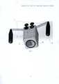
На фиг. 1 представлен общий вид предлагаемого модуля спереди;In FIG. 1 shows a General view of the proposed module in front;
на фиг. 2 - его устройство, вид сверху;in FIG. 2 - its device, a top view;
на фиг. 3 - его устройство, вид снизу.in FIG. 3 - its device, bottom view.
Предлагаемый модуль фотовидеофиксации представляет собой блочную конструкцию, заключенную в единый корпус 1 и включающую видеокамеру 2, управляющую плату 3 с пространственными датчиками, лазерный дальномер 4, установленный соосно с объективом видеокамеры 2, и блок коммуникации в виде выхода 5 для соединительного кабеля и/или в виде устройства беспроводной связи (не показано), обеспечивающих возможность подключения к компьютеру. Управляющая плата 3 выполнена с возможностью изменения и регистрации фокусного расстояния видеокамеры 2, а ее пространственные датчики содержат акселерометры, обеспечивающие возможность отслеживания перемещений модуля, и клинометры, обеспечивающие возможность отслеживания направления оси объектива видеокамеры 2.The proposed photo and video fixation module is a block design enclosed in a
Корпус 1 снабжен универсальным креплением 6, выполненным с возможностью закрепления на линейном кронштейне и кронштейне с форматом VESA. Питание модуля может осуществляться как по соединительному кабелю от компьютера (типа USB, Thunderbird, Ethernet), так и отдельно. Под креплением 6 на корпусе 1 расположено два кронштейна 7, снабженные на концах съемными ручками 8 для перемещения модуля и защиты его от загрязнения. Использование съемных ручек 8 позволяет проводить их дезинфекцию отдельно от корпуса 1 основного модуля.The
Предлагаемое устройство работает следующим образом.The proposed device operates as follows.
Корпус 1 модуля располагают на кронштейне с помощью универсального крепления 6. В ходе лабораторных работ специалист с помощью ручек 8 направляет объектив видеокамеры 2 на то место, которое необходимо зафиксировать: это может быть поверхность рабочего стола или стола для аутопсии, на котором происходят манипуляции. Управляющая плата 3 с помощью пространственных датчиков регистрирует начало движения в пространстве и включает лазерный луч дальномера 4, который позволяет следить за перемещением модуля и точно указывает, куда направлен объектив видеокамеры 2. По окончании движения управляющая плата 3 включает режим измерения расстояния на лазерном дальномере 4 и проводит серию измерений, чтобы исключить ошибки. Результат передается в компьютер в виде значения расстояния.The
Одновременно с данными по расстоянию, в компьютер непрерывно передается видеопоток в цифровом формате с видеокамеры 2, а также зарегистрированные значения фокусного расстояния. По команде с компьютера и/или управляющей платы 3 видеокамера 2 может изменять фокусное расстояние. Управляющая плата 3 позволяет настраивать чувствительность регистрации движения, точность измерения расстояния, а также хранит данные по последнему.Simultaneously with the data on the distance, a video stream in digital format from
Предлагаемый модуль передает в компьютер фото и видео изображение, значение фокусного расстояние (зума), а также точное расстояние до объекта съемки, что в целом дает возможность проводить точную морфометрию захваченного изображения (сопоставлять фотографию с реальными размерами). Наличие лазерного целеуказания позволяет точно направлять модуль на объект съемки, что критично при большом удалении от объекта съемки.The proposed module transfers to the computer a photo and video image, the focal length (zoom) value, as well as the exact distance to the subject, which in general makes it possible to carry out accurate morphometry of the captured image (to compare the photo with the actual size). The presence of laser target designation allows you to accurately direct the module to the subject, which is critical at a large distance from the subject.
Claims (4)
Translated fromRussianPriority Applications (4)
| Application Number | Priority Date | Filing Date | Title |
|---|---|---|---|
| RU2017135307ARU2659897C1 (en) | 2017-10-05 | 2017-10-05 | Photovideofixation module |
| PCT/RU2018/000101WO2019070151A1 (en) | 2017-10-05 | 2018-02-21 | Photo/video recording module |
| DE202018104068.5UDE202018104068U1 (en) | 2017-10-05 | 2018-07-16 | Audiovisual recording module |
| FIU20184176UFI12355U1 (en) | 2017-10-05 | 2018-10-02 | Audiovisual recording module |
Applications Claiming Priority (1)
| Application Number | Priority Date | Filing Date | Title |
|---|---|---|---|
| RU2017135307ARU2659897C1 (en) | 2017-10-05 | 2017-10-05 | Photovideofixation module |
Publications (1)
| Publication Number | Publication Date |
|---|---|
| RU2659897C1true RU2659897C1 (en) | 2018-07-04 |
Family
ID=62815609
Family Applications (1)
| Application Number | Title | Priority Date | Filing Date |
|---|---|---|---|
| RU2017135307ARU2659897C1 (en) | 2017-10-05 | 2017-10-05 | Photovideofixation module |
Country Status (4)
| Country | Link |
|---|---|
| DE (1) | DE202018104068U1 (en) |
| FI (1) | FI12355U1 (en) |
| RU (1) | RU2659897C1 (en) |
| WO (1) | WO2019070151A1 (en) |
Cited By (1)
| Publication number | Priority date | Publication date | Assignee | Title |
|---|---|---|---|---|
| RU233060U1 (en)* | 2024-12-13 | 2025-04-02 | Антон Петрович Фомичев | Self-photography device |
Citations (3)
| Publication number | Priority date | Publication date | Assignee | Title |
|---|---|---|---|---|
| WO1998038908A1 (en)* | 1997-03-03 | 1998-09-11 | Schneider Medical Technologies, Inc. | Imaging device and method |
| EP1857070A1 (en)* | 2006-05-18 | 2007-11-21 | BrainLAB AG | Contactless medical registration with distance measurement |
| RU2486467C1 (en)* | 2011-10-14 | 2013-06-27 | Открытое акционерное общество "НПО "Геофизика-НВ" | Apparatus for measuring and recording spherical coordinates of remote object and method of determining spherical coordinates of remote object on location |
- 2017
- 2017-10-05RURU2017135307Apatent/RU2659897C1/enactive
- 2018
- 2018-02-21WOPCT/RU2018/000101patent/WO2019070151A1/ennot_activeCeased
- 2018-07-16DEDE202018104068.5Upatent/DE202018104068U1/enactiveActive
- 2018-10-02FIFIU20184176Upatent/FI12355U1/enactiveIP Right Grant
Patent Citations (3)
| Publication number | Priority date | Publication date | Assignee | Title |
|---|---|---|---|---|
| WO1998038908A1 (en)* | 1997-03-03 | 1998-09-11 | Schneider Medical Technologies, Inc. | Imaging device and method |
| EP1857070A1 (en)* | 2006-05-18 | 2007-11-21 | BrainLAB AG | Contactless medical registration with distance measurement |
| RU2486467C1 (en)* | 2011-10-14 | 2013-06-27 | Открытое акционерное общество "НПО "Геофизика-НВ" | Apparatus for measuring and recording spherical coordinates of remote object and method of determining spherical coordinates of remote object on location |
Non-Patent Citations (1)
| Title |
|---|
| Grimson, W.E.L. et al., "An Automatic Registration Method for Frameless Stereotaxy, Image Guided Surgery, and Enhanced Reality Visualization," IEEE CVPR '94 Proceedings, June 1994, pp. 430-436.* |
Cited By (1)
| Publication number | Priority date | Publication date | Assignee | Title |
|---|---|---|---|---|
| RU233060U1 (en)* | 2024-12-13 | 2025-04-02 | Антон Петрович Фомичев | Self-photography device |
Also Published As
| Publication number | Publication date |
|---|---|
| FI12355U1 (en) | 2019-05-15 |
| WO2019070151A1 (en) | 2019-04-11 |
| DE202018104068U1 (en) | 2018-09-27 |
Similar Documents
| Publication | Publication Date | Title |
|---|---|---|
| US8483806B2 (en) | Systems and methods for non-contact biometric sensing | |
| US8360639B2 (en) | Radiation imaging system and assist apparatus for the same | |
| US20150098075A1 (en) | Scanner for space measurement | |
| JP4899217B2 (en) | Eye movement control device using the principle of vestibulo-oculomotor reflex | |
| CN103792957A (en) | Light two-freedom-degree camera stabilized platform device | |
| RU2012118821A (en) | TABLE FOR A PATIENT CONTAINING A POSITIONING SYSTEM, AND ALSO A WAY TO USE SUCH A TABLE FOR A PATIENT | |
| BRPI1013048B1 (en) | IMAGE STABILIZATION AND IMAGE CAPTURE APPARATUS | |
| US9918044B2 (en) | Handheld observation device comprising a digital magnetic compass | |
| EP3325916B1 (en) | Method and apparatus for unambiguously determining orientation of a human head in 3d geometric modeling | |
| RU2659897C1 (en) | Photovideofixation module | |
| KR101830296B1 (en) | System for drawing digital map | |
| JP4486631B2 (en) | Imaging system | |
| CN106603914B (en) | Unmanned aerial vehicle focusing system based on optical-mechanical-electrical integration and focusing method | |
| JP2009109290A (en) | Target position measuring device | |
| JP5542461B2 (en) | Vibration isolator | |
| RU2324896C1 (en) | Surveillance optical device | |
| RU155336U1 (en) | THERMAL VISION SIGHT COMPLEX AND FOCUS NODE OF THE THERMAL VISION SIGHT COMPLEX | |
| US7864305B2 (en) | Self-contained underwater velocimetry apparatus | |
| KR20160063460A (en) | Optical Type Remote Bearing Device | |
| RU2794341C1 (en) | Imaging system for medical purposes | |
| EP3839883A1 (en) | A method and a system for obtaining image data of an object | |
| CN213179903U (en) | Three-dimensional information acquisition equipment with rotatory stabilising arrangement that gathers | |
| JPH10322584A5 (en) | Lens device and imaging device | |
| RU2425327C1 (en) | Video device to control irregularities of inner vertical cylindrical surface | |
| RU180394U1 (en) | TECHNICAL VISION MODULE WITH SPHERICAL INDUCTION MOTOR |