RU2658718C1 - Adjuster of multiaxial vehicle transverse stability - Google Patents
Adjuster of multiaxial vehicle transverse stabilityDownload PDFInfo
- Publication number
- RU2658718C1 RU2658718C1RU2017119106ARU2017119106ARU2658718C1RU 2658718 C1RU2658718 C1RU 2658718C1RU 2017119106 ARU2017119106 ARU 2017119106ARU 2017119106 ARU2017119106 ARU 2017119106ARU 2658718 C1RU2658718 C1RU 2658718C1
- Authority
- RU
- Russia
- Prior art keywords
- vehicle
- adjuster
- stability
- identical flexible
- power
- Prior art date
Links
- 238000003466weldingMethods0.000claimsabstractdescription4
- 238000010891electric arcMethods0.000claimsdescription3
- 230000000694effectsEffects0.000abstract1
- 239000000126substanceSubstances0.000abstract1
- 238000013016dampingMethods0.000description1
- 238000010586diagramMethods0.000description1
- 238000012423maintenanceMethods0.000description1
- 238000004519manufacturing processMethods0.000description1
- 230000000087stabilizing effectEffects0.000description1
Images


Classifications
- B—PERFORMING OPERATIONS; TRANSPORTING
- B60—VEHICLES IN GENERAL
- B60G—VEHICLE SUSPENSION ARRANGEMENTS
- B60G11/00—Resilient suspensions characterised by arrangement, location or kind of springs
- B60G11/18—Resilient suspensions characterised by arrangement, location or kind of springs having torsion-bar springs only
- F—MECHANICAL ENGINEERING; LIGHTING; HEATING; WEAPONS; BLASTING
- F16—ENGINEERING ELEMENTS AND UNITS; GENERAL MEASURES FOR PRODUCING AND MAINTAINING EFFECTIVE FUNCTIONING OF MACHINES OR INSTALLATIONS; THERMAL INSULATION IN GENERAL
- F16F—SPRINGS; SHOCK-ABSORBERS; MEANS FOR DAMPING VIBRATION
- F16F1/00—Springs
- F16F1/02—Springs made of steel or other material having low internal friction; Wound, torsion, leaf, cup, ring or the like springs, the material of the spring not being relevant
- F16F1/14—Torsion springs consisting of bars or tubes
Landscapes
- Engineering & Computer Science (AREA)
- General Engineering & Computer Science (AREA)
- Mechanical Engineering (AREA)
- Automatic Cycles, And Cycles In General (AREA)
Abstract
Description
Translated fromRussianИзобретение относится к транспорту, а именно к вспомогательным устройствам, устанавливаемым для перераспределения собственной нагрузки транспортного средства между противоположно расположенными движителями в целях повышения устойчивости, скорости движения и безопасности эксплуатации при движении по склонам, в условиях сложных и горных рельефов местности.The invention relates to transport, and in particular to auxiliary devices installed for the redistribution of the vehicle’s own load between opposing movers in order to increase stability, speed and operational safety when driving on slopes, in difficult and mountainous terrain.
Известно устройство-стабилизатор вертикальных колебаний моста колесного транспортного средства, включающее две полуэллиптические сдвоенные плоские пружины рессорного типа, болтовые стремянки, коромысло, шарнир с опорным рычагом, траверсу рамы колесного транспортного средства (Патент РФ на полезную модель №154775, МКИ F16F 1/14, B60G 11/18, взято за прототип).A device is known for stabilizing the vertical vibrations of a wheeled vehicle’s bridge, including two semi-elliptic double spring springs, bolt ladders, a rocker arm, a hinge with a support arm, a traverse of the wheeled vehicle frame (RF Patent Utility Model No. 154775, MKI F16F 1/14, B60G 11/18, taken as a prototype).
Недостатком данного устройство является высокая конструкционная сложность и невозможность перераспределения собственной нагрузки транспортного средства между движителями одного моста при движении по склонам.The disadvantage of this device is the high structural complexity and the inability to redistribute the vehicle’s own load between the movers of the same bridge when driving on slopes.
Известно устройство-регулятор поперечной устойчивости колесного энергетического средства, включающее две гибкие силовые тросовые связи, установленные в опорных рычагах, выполненных на нижней поверхности траверсы рамы энергетического средства и закрепленных на окончаниях моста энергетического средства подиагонально (Патент РФ на полезную модель №169390, МКИ F16F 1/14, B60G 11/18, взято за прототип).A device is known for adjusting the lateral stability of a wheeled power tool, including two flexible power cable ties installed in the support arms made on the lower surface of the yoke frame of the power tool and mounted diagonally at the ends of the bridge of the power tool (RF Patent Utility Model No. 169390, MKI F16F 1 / 14, B60G 11/18, taken as a prototype).
Недостатком данного устройство является невозможность его использования для многоосного транспортного средства.The disadvantage of this device is the inability to use it for a multi-axis vehicle.
Технической задачей полезной модели является повышение устойчивости, скорости движения и безопасности при проведении работ на склонах, сложных рельефах местности и эксплуатации энергетического средства в горных условиях.The technical task of the utility model is to increase stability, speed and safety when working on slopes, difficult terrain and the operation of an energy tool in mountain conditions.
Техническим решением задачи является создание устанавливаемого на силовых элементах рамы и ходовой части многоосного энергетического средства устройства-регулятора поперечной устойчивости многоосного транспортного средства, включающего в себя систему амортизации вертикальных колебаний моста при движении по склонам и имеющего возможность перераспределения собственной нагрузки транспортного средства между противоположнорасположенными движителями одного моста или задней колесной тележки.The technical solution to the problem is the creation of a multi-axis vehicle lateral stability control device mounted on the frame and chassis power components of a multi-axis vehicle, which includes a system for damping the vertical vibrations of the bridge when driving on slopes and having the ability to redistribute the vehicle’s own load between the opposite movers of one bridge or rear wheel trolley.
Поставленная задача достигается тем, что регулятор поперечной устойчивости многоосного транспортного средства выполнен в виде конструкции, состоящей из двух одинаковых гибких тросовых силовых связей (стандартных буксировочных тросов с петлевыми окончаниями), проходящих через опорные рычаги, имеющие вид скобы, вваренные посредством электродуговой сварки в нижнюю часть силовой траверсы рамы или кузова транспортного средства и закрепленные окончаниями на чулке моста, вблизи движителей автомобиля побортно.The problem is achieved in that the lateral stability control of the multi-axis vehicle is made in the form of a structure consisting of two identical flexible cable power connections (standard towing cables with loop ends) passing through the support arms, which have the form of a bracket welded by electric arc welding to the lower part the power traverse of the frame or the vehicle body and fixed with the ends on the stocking of the bridge, near the vehicle movers.
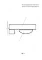
На фиг. 1 изображена принципиальная схема регулятора поперечной устойчивости многоосного транспортного средства, на фиг. 2 изображен опорный рычаг регулятора поперечной устойчивости многоосного транспортного средства, на фиг. 3 изображен вид сверху энергетического средства с установленным регулятором поперечной устойчивости многоосного транспортного средства.In FIG. 1 is a schematic diagram of the anti-roll bar of a multi-axis vehicle; FIG. 2 shows the support arm of the anti-roll bar of a multi-axle vehicle, FIG. 3 shows a top view of an energy vehicle with an installed lateral stability adjuster for a multi-axis vehicle.
Регулятор поперечной устойчивости многоосного транспортного средства выполнен в виде конструкции 1, состоящей из двух одинаковых гибких тросовых силовых связей 2 и 3 (стандартных буксировочных тросов с петлевыми окончаниями), проходящих через опорные рычаги 4, имеющие вид скобы, вваренные посредством электродуговой сварки в нижнюю часть силовой траверсы рамы 5 или кузова 6 и закрепленные окончаниями на чулке моста 7, вблизи движителей 8 автомобиля 9 побортно.The lateral stability control of a multi-axis vehicle is made in the form of a structure 1 consisting of two identical flexible
Устройство работает следующим образом:The device operates as follows:
При передвижении многоосного транспортного средства по склонам собственный вес вертикально-смещаемых движителей 8 моста 7, находящегося ниже по склону, производит силовое нагружение гибкой тросовой силовой связи 2 или 3, через опорный рычаг 4 вызывая прижимание противоположной части рамы 5 и кузова 6 автомобиля 9, обеспечивая изменение расположения центра масс, что приводит к снижению его высоты и перераспределению весовой нагрузки на противоположные движители колесной тележки, находящиеся выше по склону, повышая устойчивость автомобиля, скорость движения и безопасные режимы эксплуатации.When moving a multi-axle vehicle along the slopes, the own weight of the vertically displaced
Использование данного изобретения, обладающего высокой надежностью, низкой себестоимостью, удобством в обслуживании и эксплуатации, при достаточно несложной конструкции и простоте изготовления регулятора поперечной устойчивости многоосного транспортного средства позволит повысить устойчивость, скорость движения и безопасность эксплуатации при проведении работ на склонах, в условиях сложного и горного рельефа местности.The use of this invention, which has high reliability, low cost, ease of maintenance and operation, with a fairly simple design and ease of manufacture of the anti-roll bar of a multi-axle vehicle will increase the stability, speed and safety of operation when working on slopes, in difficult and mountainous conditions terrain.
Claims (1)
Translated fromRussianPriority Applications (1)
| Application Number | Priority Date | Filing Date | Title |
|---|---|---|---|
| RU2017119106ARU2658718C1 (en) | 2017-05-31 | 2017-05-31 | Adjuster of multiaxial vehicle transverse stability |
Applications Claiming Priority (1)
| Application Number | Priority Date | Filing Date | Title |
|---|---|---|---|
| RU2017119106ARU2658718C1 (en) | 2017-05-31 | 2017-05-31 | Adjuster of multiaxial vehicle transverse stability |
Publications (1)
| Publication Number | Publication Date |
|---|---|
| RU2658718C1true RU2658718C1 (en) | 2018-06-22 |
Family
ID=62713591
Family Applications (1)
| Application Number | Title | Priority Date | Filing Date |
|---|---|---|---|
| RU2017119106ARU2658718C1 (en) | 2017-05-31 | 2017-05-31 | Adjuster of multiaxial vehicle transverse stability |
Country Status (1)
| Country | Link |
|---|---|
| RU (1) | RU2658718C1 (en) |
Citations (4)
| Publication number | Priority date | Publication date | Assignee | Title |
|---|---|---|---|---|
| US20060175785A1 (en)* | 2004-02-25 | 2006-08-10 | Hamm Alton B | Methods of improving stability of a vehicle using a vehicle stability control system |
| US8498773B2 (en)* | 2010-05-20 | 2013-07-30 | GM Global Technology Operations LLC | Stability enhancing system and method for enhancing the stability of a vehicle |
| RU154775U1 (en)* | 2015-05-05 | 2015-09-10 | Федеральное Государственное Бюджетное Образовательное Учреждение Высшего Профессионального Образования Дальневосточный Государственный Аграрный Университет | VERTICAL VIBRATION STABILIZER BRIDGE WHEELED VEHICLE |
| RU169390U1 (en)* | 2016-07-21 | 2017-03-16 | Федеральное Государственное Бюджетное Образовательное Учреждение Высшего Образования Дальневосточный Государственный Аграрный Университет | Wheel Stabilizer |
- 2017
- 2017-05-31RURU2017119106Apatent/RU2658718C1/ennot_activeIP Right Cessation
Patent Citations (4)
| Publication number | Priority date | Publication date | Assignee | Title |
|---|---|---|---|---|
| US20060175785A1 (en)* | 2004-02-25 | 2006-08-10 | Hamm Alton B | Methods of improving stability of a vehicle using a vehicle stability control system |
| US8498773B2 (en)* | 2010-05-20 | 2013-07-30 | GM Global Technology Operations LLC | Stability enhancing system and method for enhancing the stability of a vehicle |
| RU154775U1 (en)* | 2015-05-05 | 2015-09-10 | Федеральное Государственное Бюджетное Образовательное Учреждение Высшего Профессионального Образования Дальневосточный Государственный Аграрный Университет | VERTICAL VIBRATION STABILIZER BRIDGE WHEELED VEHICLE |
| RU169390U1 (en)* | 2016-07-21 | 2017-03-16 | Федеральное Государственное Бюджетное Образовательное Учреждение Высшего Образования Дальневосточный Государственный Аграрный Университет | Wheel Stabilizer |
Similar Documents
| Publication | Publication Date | Title |
|---|---|---|
| US4082316A (en) | Multiple axle suspension with load equalizer beam | |
| EP0001344A1 (en) | Suspension for a wheeled vehicle | |
| JPS5810264B2 (en) | Vehicle running stability mechanism in overhead cableway system | |
| CN104608573A (en) | Leaf spring suspension system of air bag lifting bridge structure and car | |
| JP2015009696A (en) | Suspension control device | |
| US2888271A (en) | Link supported axle suspension | |
| US2862724A (en) | By-pass arrangement for vehicle suspension | |
| RU2610891C2 (en) | Rigid axle with air suspension | |
| RU2018103088A (en) | CONNECTING DESIGN REDUCING THE VIBRATION EFFECT OF THE POWER SYSTEM ON THE BODY OF THE CAR | |
| RU2658718C1 (en) | Adjuster of multiaxial vehicle transverse stability | |
| CN212289852U (en) | Bogie and straddle type monorail vehicle with same | |
| US4221172A (en) | Articulated railway truck | |
| CN204821017U (en) | Adjustable height of car triangle -shaped inflatable shock absorber of preventing leaning forward | |
| CN222202537U (en) | Suspension vehicle | |
| RU169390U1 (en) | Wheel Stabilizer | |
| CN105291744A (en) | Independent suspension device for touring car | |
| CN116373527B (en) | Air spring balanced suspension system | |
| CN110126932B (en) | Shock absorber and shock absorbing system for tractor | |
| KR20070122375A (en) | Method and apparatus for using auxiliary leaf spring to stabilize the vehicle chassis | |
| US3092040A (en) | Monorail constructions | |
| CN217260289U (en) | Rear suspension structure of unmanned drive-by-wire chassis | |
| US3867991A (en) | Shock absorbing suspension system for a snowmobile | |
| CN104260606A (en) | Unmanned vehicle suspension system | |
| RU166919U1 (en) | INTER-axial WEIGHT REGULATOR | |
| CN110027638B (en) | Chassis frame and chassis assembly of crawler tractor |
Legal Events
| Date | Code | Title | Description |
|---|---|---|---|
| MM4A | The patent is invalid due to non-payment of fees | Effective date:20190601 |