RU2657850C2 - Fastener cartridge comprising a tissue thickness compensator including openings therein - Google Patents
Fastener cartridge comprising a tissue thickness compensator including openings thereinDownload PDFInfo
- Publication number
- RU2657850C2 RU2657850C2RU2015145947ARU2015145947ARU2657850C2RU 2657850 C2RU2657850 C2RU 2657850C2RU 2015145947 ARU2015145947 ARU 2015145947ARU 2015145947 ARU2015145947 ARU 2015145947ARU 2657850 C2RU2657850 C2RU 2657850C2
- Authority
- RU
- Russia
- Prior art keywords
- brackets
- cassette
- view
- suture
- cartridge
- Prior art date
Links
- 239000003814drugSubstances0.000abstractdescription50
- 239000000126substanceSubstances0.000abstractdescription5
- 230000000694effectsEffects0.000abstractdescription4
- 210000001519tissueAnatomy0.000description961
- 239000010410layerSubstances0.000description667
- 239000004744fabricSubstances0.000description540
- 239000011159matrix materialSubstances0.000description297
- 239000012636effectorSubstances0.000description267
- 239000000463materialSubstances0.000description251
- 238000005520cutting processMethods0.000description126
- 230000008093supporting effectEffects0.000description109
- 230000033001locomotionEffects0.000description107
- 230000036961partial effectEffects0.000description97
- 229920000954PolyglycolidePolymers0.000description76
- 239000004633polyglycolic acidSubstances0.000description75
- 229920001610polycaprolactonePolymers0.000description61
- 239000004632polycaprolactoneSubstances0.000description61
- 229920000642polymerPolymers0.000description61
- 238000000034methodMethods0.000description60
- 239000000203mixtureSubstances0.000description56
- 230000007246mechanismEffects0.000description55
- 238000004132cross linkingMethods0.000description54
- 238000010586diagramMethods0.000description53
- 229920000747poly(lactic acid)Polymers0.000description52
- 239000000853adhesiveSubstances0.000description51
- 230000001070adhesive effectEffects0.000description51
- 230000006835compressionEffects0.000description48
- 238000007906compressionMethods0.000description48
- 210000001331noseAnatomy0.000description45
- 210000003128headAnatomy0.000description43
- 238000000926separation methodMethods0.000description43
- 230000008569processEffects0.000description42
- -1PDS (polydiaxane)Polymers0.000description40
- 229940079593drugDrugs0.000description40
- 230000015572biosynthetic processEffects0.000description38
- 239000005014poly(hydroxyalkanoate)Substances0.000description36
- 238000011068loading methodMethods0.000description33
- 229920003023plasticPolymers0.000description30
- 239000004033plasticSubstances0.000description30
- 238000002224dissectionMethods0.000description28
- 239000006260foamSubstances0.000description27
- 230000001681protective effectEffects0.000description26
- 229920001432poly(L-lactide)Polymers0.000description23
- 229920000903polyhydroxyalkanoatePolymers0.000description23
- JVTAAEKCZFNVCJ-REOHCLBHSA-NL-lactic acidChemical compoundC[C@H](O)C(O)=OJVTAAEKCZFNVCJ-REOHCLBHSA-N0.000description22
- 229920002463poly(p-dioxanone) polymerPolymers0.000description22
- 239000000622polydioxanoneSubstances0.000description22
- 229910052751metalInorganic materials0.000description21
- 239000002184metalSubstances0.000description21
- 239000011148porous materialSubstances0.000description21
- 230000007423decreaseEffects0.000description20
- 238000001994activationMethods0.000description19
- 239000004626polylactic acidSubstances0.000description19
- LCSKNASZPVZHEG-UHFFFAOYSA-N3,6-dimethyl-1,4-dioxane-2,5-dione;1,4-dioxane-2,5-dioneChemical groupO=C1COC(=O)CO1.CC1OC(=O)C(C)OC1=OLCSKNASZPVZHEG-UHFFFAOYSA-N0.000description18
- RTAQQCXQSZGOHL-UHFFFAOYSA-NTitaniumChemical compound[Ti]RTAQQCXQSZGOHL-UHFFFAOYSA-N0.000description18
- 230000004913activationEffects0.000description18
- 229910001220stainless steelInorganic materials0.000description18
- 239000010935stainless steelSubstances0.000description18
- 239000007858starting materialSubstances0.000description18
- 239000010936titaniumSubstances0.000description18
- 239000002131composite materialSubstances0.000description17
- 230000003213activating effectEffects0.000description16
- 238000005538encapsulationMethods0.000description16
- 230000000903blocking effectEffects0.000description15
- 229920001577copolymerPolymers0.000description15
- 230000002439hemostatic effectEffects0.000description14
- 102000009123FibrinHuman genes0.000description13
- 108010073385FibrinProteins0.000description13
- BWGVNKXGVNDBDI-UHFFFAOYSA-NFibrin monomerChemical compoundCNC(=O)CNC(=O)CNBWGVNKXGVNDBDI-UHFFFAOYSA-N0.000description13
- 229950003499fibrinDrugs0.000description13
- 239000000017hydrogelSubstances0.000description13
- 238000003825pressingMethods0.000description13
- 210000003739neckAnatomy0.000description12
- 238000004519manufacturing processMethods0.000description11
- 230000001225therapeutic effectEffects0.000description11
- 238000000418atomic force spectrumMethods0.000description10
- 229920001198elastomeric copolymerPolymers0.000description10
- 239000006261foam materialSubstances0.000description10
- 230000006870functionEffects0.000description10
- 238000003780insertionMethods0.000description10
- 230000037431insertionEffects0.000description10
- 102000004169proteins and genesHuman genes0.000description10
- 108090000623proteins and genesProteins0.000description10
- 230000002441reversible effectEffects0.000description10
- 229910052719titaniumInorganic materials0.000description10
- 230000009471actionEffects0.000description9
- 229910001200FerrotitaniumInorganic materials0.000description8
- 230000000149penetrating effectEffects0.000description8
- 230000002028prematureEffects0.000description8
- 238000009958sewingMethods0.000description8
- 238000012546transferMethods0.000description8
- PAPBSGBWRJIAAV-UHFFFAOYSA-Nε-CaprolactoneChemical compoundO=C1CCCCCO1PAPBSGBWRJIAAV-UHFFFAOYSA-N0.000description8
- 239000004696Poly ether ether ketoneSubstances0.000description7
- 230000008901benefitEffects0.000description7
- 230000000740bleeding effectEffects0.000description7
- 238000006073displacement reactionMethods0.000description7
- 229920001971elastomerPolymers0.000description7
- 239000012530fluidSubstances0.000description7
- 238000002513implantationMethods0.000description7
- JJTUDXZGHPGLLC-UHFFFAOYSA-NlactideChemical compoundCC1OC(=O)C(C)OC1=OJJTUDXZGHPGLLC-UHFFFAOYSA-N0.000description7
- 238000000465mouldingMethods0.000description7
- 229920002530polyetherether ketonePolymers0.000description7
- 229920001296polysiloxanePolymers0.000description7
- 238000001356surgical procedureMethods0.000description7
- YFHICDDUDORKJB-UHFFFAOYSA-Ntrimethylene carbonateChemical compoundO=C1OCCCO1YFHICDDUDORKJB-UHFFFAOYSA-N0.000description7
- 229920002319Poly(methyl acrylate)Polymers0.000description6
- 239000013543active substanceSubstances0.000description6
- 230000005540biological transmissionEffects0.000description6
- 238000013461designMethods0.000description6
- 230000002829reductive effectEffects0.000description6
- 239000004627regenerated celluloseSubstances0.000description6
- VPVXHAANQNHFSF-UHFFFAOYSA-N1,4-dioxan-2-oneChemical compoundO=C1COCCO1VPVXHAANQNHFSF-UHFFFAOYSA-N0.000description5
- RKDVKSZUMVYZHH-UHFFFAOYSA-N1,4-dioxane-2,5-dioneChemical compoundO=C1COC(=O)CO1RKDVKSZUMVYZHH-UHFFFAOYSA-N0.000description5
- PEDCQBHIVMGVHV-UHFFFAOYSA-NGlycerineChemical compoundOCC(O)COPEDCQBHIVMGVHV-UHFFFAOYSA-N0.000description5
- BQCADISMDOOEFD-UHFFFAOYSA-NSilverChemical compound[Ag]BQCADISMDOOEFD-UHFFFAOYSA-N0.000description5
- 108090000190ThrombinProteins0.000description5
- XEFQLINVKFYRCS-UHFFFAOYSA-NTriclosanChemical compoundOC1=CC(Cl)=CC=C1OC1=CC=C(Cl)C=C1ClXEFQLINVKFYRCS-UHFFFAOYSA-N0.000description5
- 238000005452bendingMethods0.000description5
- 230000008859changeEffects0.000description5
- 230000003993interactionEffects0.000description5
- 230000000670limiting effectEffects0.000description5
- 238000002483medicationMethods0.000description5
- 239000000758substrateSubstances0.000description5
- 229920001059synthetic polymerPolymers0.000description5
- 229960004072thrombinDrugs0.000description5
- 229960003500triclosanDrugs0.000description5
- 238000003466weldingMethods0.000description5
- JVTAAEKCZFNVCJ-UHFFFAOYSA-NLactic AcidNatural productsCC(O)C(O)=OJVTAAEKCZFNVCJ-UHFFFAOYSA-N0.000description4
- 230000000845anti-microbial effectEffects0.000description4
- 229940030225antihemorrhagicsDrugs0.000description4
- 238000013459approachMethods0.000description4
- 239000008280bloodSubstances0.000description4
- 210000004369bloodAnatomy0.000description4
- 238000005266castingMethods0.000description4
- 229920002678cellulosePolymers0.000description4
- 239000001913celluloseSubstances0.000description4
- 239000013013elastic materialSubstances0.000description4
- 239000000806elastomerSubstances0.000description4
- 239000003292glueSubstances0.000description4
- 239000002874hemostatic agentSubstances0.000description4
- 210000002429large intestineAnatomy0.000description4
- 239000007788liquidSubstances0.000description4
- 238000004020luminiscence typeMethods0.000description4
- 230000014759maintenance of locationEffects0.000description4
- 229920000728polyesterPolymers0.000description4
- 239000012779reinforcing materialSubstances0.000description4
- JJTUDXZGHPGLLC-IMJSIDKUSA-N4511-42-6Chemical compoundC[C@@H]1OC(=O)[C@H](C)OC1=OJJTUDXZGHPGLLC-IMJSIDKUSA-N0.000description3
- 102000008186CollagenHuman genes0.000description3
- 108010035532CollagenProteins0.000description3
- 239000004743PolypropyleneSubstances0.000description3
- 229910000831SteelInorganic materials0.000description3
- 239000003795chemical substances by applicationSubstances0.000description3
- 238000004140cleaningMethods0.000description3
- 239000011248coating agentSubstances0.000description3
- 238000000576coating methodMethods0.000description3
- 229920001436collagenPolymers0.000description3
- 230000008878couplingEffects0.000description3
- 238000010168coupling processMethods0.000description3
- 238000005859coupling reactionMethods0.000description3
- 239000000835fiberSubstances0.000description3
- 150000004676glycansChemical class0.000description3
- 230000001788irregularEffects0.000description3
- 235000014655lactic acidNutrition0.000description3
- 239000004310lactic acidSubstances0.000description3
- 230000035515penetrationEffects0.000description3
- 230000002085persistent effectEffects0.000description3
- 229920000139polyethylene terephthalatePolymers0.000description3
- 239000005020polyethylene terephthalateSubstances0.000description3
- 229920000223polyglycerolPolymers0.000description3
- 229920001155polypropylenePolymers0.000description3
- 229920001282polysaccharidePolymers0.000description3
- 239000005017polysaccharideSubstances0.000description3
- 230000005855radiationEffects0.000description3
- 239000005060rubberSubstances0.000description3
- 229910052709silverInorganic materials0.000description3
- 239000004332silverSubstances0.000description3
- 239000010959steelSubstances0.000description3
- 210000003813thumbAnatomy0.000description3
- 230000007704transitionEffects0.000description3
- 230000037303wrinklesEffects0.000description3
- RTZKZFJDLAIYFH-UHFFFAOYSA-NDiethyl etherChemical compoundCCOCCRTZKZFJDLAIYFH-UHFFFAOYSA-N0.000description2
- AOJJSUZBOXZQNB-TZSSRYMLSA-NDoxorubicinChemical compoundO([C@H]1C[C@@](O)(CC=2C(O)=C3C(=O)C=4C=CC=C(C=4C(=O)C3=C(O)C=21)OC)C(=O)CO)[C@H]1C[C@H](N)[C@H](O)[C@H](C)O1AOJJSUZBOXZQNB-TZSSRYMLSA-N0.000description2
- 239000004812Fluorinated ethylene propyleneSubstances0.000description2
- 108010010803GelatinProteins0.000description2
- XEEYBQQBJWHFJM-UHFFFAOYSA-NIronChemical compound[Fe]XEEYBQQBJWHFJM-UHFFFAOYSA-N0.000description2
- 239000004677NylonSubstances0.000description2
- 239000002033PVDF binderSubstances0.000description2
- 235000014676Phragmites communisNutrition0.000description2
- 239000004698PolyethyleneSubstances0.000description2
- 239000002202Polyethylene glycolSubstances0.000description2
- 229920004738ULTEM®Polymers0.000description2
- 230000001154acute effectEffects0.000description2
- 229910052782aluminiumInorganic materials0.000description2
- XAGFODPZIPBFFR-UHFFFAOYSA-NaluminiumChemical compound[Al]XAGFODPZIPBFFR-UHFFFAOYSA-N0.000description2
- 239000003242anti bacterial agentSubstances0.000description2
- 239000004599antimicrobialSubstances0.000description2
- 239000000560biocompatible materialSubstances0.000description2
- 239000013060biological fluidSubstances0.000description2
- 239000002775capsuleSubstances0.000description2
- 150000001720carbohydratesChemical class0.000description2
- 229910010293ceramic materialInorganic materials0.000description2
- 230000001186cumulative effectEffects0.000description2
- 230000000994depressogenic effectEffects0.000description2
- 229920000295expanded polytetrafluoroethylenePolymers0.000description2
- 238000000605extractionMethods0.000description2
- 210000004709eyebrowAnatomy0.000description2
- 229920000159gelatinPolymers0.000description2
- 239000008273gelatinSubstances0.000description2
- 235000019322gelatineNutrition0.000description2
- 235000011852gelatine dessertsNutrition0.000description2
- 235000011187glycerolNutrition0.000description2
- 238000000227grindingMethods0.000description2
- 230000035876healingEffects0.000description2
- JYGXADMDTFJGBT-VWUMJDOOSA-NhydrocortisoneChemical compoundO=C1CC[C@]2(C)[C@H]3[C@@H](O)C[C@](C)([C@@](CC4)(O)C(=O)CO)[C@@H]4[C@@H]3CCC2=C1JYGXADMDTFJGBT-VWUMJDOOSA-N0.000description2
- 239000007943implantSubstances0.000description2
- 230000001976improved effectEffects0.000description2
- 238000007373indentationMethods0.000description2
- 238000001746injection mouldingMethods0.000description2
- 238000005304joiningMethods0.000description2
- 230000013011matingEffects0.000description2
- 239000012528membraneSubstances0.000description2
- 230000004048modificationEffects0.000description2
- 238000012986modificationMethods0.000description2
- 239000002991molded plasticSubstances0.000description2
- 229920001778nylonPolymers0.000description2
- 229920009441perflouroethylene propylenePolymers0.000description2
- 229920003229poly(methyl methacrylate)Polymers0.000description2
- 239000004417polycarbonateSubstances0.000description2
- 229920000515polycarbonatePolymers0.000description2
- 229920000573polyethylenePolymers0.000description2
- 229920001223polyethylene glycolPolymers0.000description2
- 229920001195polyisoprenePolymers0.000description2
- 239000004926polymethyl methacrylateSubstances0.000description2
- 229920001343polytetrafluoroethylenePolymers0.000description2
- 239000004810polytetrafluoroethyleneSubstances0.000description2
- 239000004814polyurethaneSubstances0.000description2
- 229920002620polyvinyl fluoridePolymers0.000description2
- 229920002981polyvinylidene fluoridePolymers0.000description2
- 230000001737promoting effectEffects0.000description2
- 239000011241protective layerSubstances0.000description2
- 230000009467reductionEffects0.000description2
- 238000001881scanning electron acoustic microscopyMethods0.000description2
- 239000000565sealantSubstances0.000description2
- 238000004826seamingMethods0.000description2
- 238000005476solderingMethods0.000description2
- 239000011343solid materialSubstances0.000description2
- XLYOFNOQVPJJNP-UHFFFAOYSA-NwaterSubstancesOXLYOFNOQVPJJNP-UHFFFAOYSA-N0.000description2
- 238000004804windingMethods0.000description2
- KKGSHHDRPRINNY-UHFFFAOYSA-N1,4-dioxan-2-oneChemical compoundO=C1COCCO1.O=C1COCCO1KKGSHHDRPRINNY-UHFFFAOYSA-N0.000description1
- MFRCZYUUKMFJQJ-UHFFFAOYSA-N1,4-dioxane-2,5-dione;1,3-dioxan-2-oneChemical compoundO=C1OCCCO1.O=C1COC(=O)CO1MFRCZYUUKMFJQJ-UHFFFAOYSA-N0.000description1
- SCRCZNMJAVGGEI-UHFFFAOYSA-N1,4-dioxane-2,5-dione;oxepan-2-oneChemical compoundO=C1COC(=O)CO1.O=C1CCCCCO1SCRCZNMJAVGGEI-UHFFFAOYSA-N0.000description1
- 229910000984420 stainless steelInorganic materials0.000description1
- 229910000825440 stainless steelInorganic materials0.000description1
- BSYNRYMUTXBXSQ-UHFFFAOYSA-NAspirinChemical compoundCC(=O)OC1=CC=CC=C1C(O)=OBSYNRYMUTXBXSQ-UHFFFAOYSA-N0.000description1
- 241000894006BacteriaSpecies0.000description1
- OKTJSMMVPCPJKN-UHFFFAOYSA-NCarbonChemical compound[C]OKTJSMMVPCPJKN-UHFFFAOYSA-N0.000description1
- 208000013641Cerebrofacial arteriovenous metameric syndromeDiseases0.000description1
- 229920004937Dexon®Polymers0.000description1
- 102000016942ElastinHuman genes0.000description1
- 108010014258ElastinProteins0.000description1
- 235000009161Espostoa lanataNutrition0.000description1
- 240000001624Espostoa lanataSpecies0.000description1
- 241000282326Felis catusSpecies0.000description1
- IWDQPCIQCXRBQP-UHFFFAOYSA-MFenaminosulfChemical compound[Na+].CN(C)C1=CC=C(N=NS([O-])(=O)=O)C=C1IWDQPCIQCXRBQP-UHFFFAOYSA-M0.000description1
- 229930182566GentamicinNatural products0.000description1
- CEAZRRDELHUEMR-URQXQFDESA-NGentamicinChemical compoundO1[C@H](C(C)NC)CC[C@@H](N)[C@H]1O[C@H]1[C@H](O)[C@@H](O[C@@H]2[C@@H]([C@@H](NC)[C@@](C)(O)CO2)O)[C@H](N)C[C@@H]1NCEAZRRDELHUEMR-URQXQFDESA-N0.000description1
- AEMRFAOFKBGASW-UHFFFAOYSA-NGlycolic acidPolymersOCC(O)=OAEMRFAOFKBGASW-UHFFFAOYSA-N0.000description1
- 102000003886GlycoproteinsHuman genes0.000description1
- 108090000288GlycoproteinsProteins0.000description1
- 229920000544Gore-TexPolymers0.000description1
- 244000043261Hevea brasiliensisSpecies0.000description1
- OUYCCCASQSFEME-QMMMGPOBSA-NL-tyrosineChemical compoundOC(=O)[C@@H](N)CC1=CC=C(O)C=C1OUYCCCASQSFEME-QMMMGPOBSA-N0.000description1
- 229930192392MitomycinNatural products0.000description1
- NWIBSHFKIJFRCO-WUDYKRTCSA-NMytomycinChemical compoundC1N2C(C(C(C)=C(N)C3=O)=O)=C3[C@@H](COC(N)=O)[C@@]2(OC)[C@@H]2[C@H]1N2NWIBSHFKIJFRCO-WUDYKRTCSA-N0.000description1
- CMWTZPSULFXXJA-UHFFFAOYSA-NNaproxenNatural productsC1=C(C(C)C(O)=O)C=CC2=CC(OC)=CC=C21CMWTZPSULFXXJA-UHFFFAOYSA-N0.000description1
- 229920002292Nylon 6Polymers0.000description1
- 229920002302Nylon 6,6Polymers0.000description1
- 208000034530PLAA-associated neurodevelopmental diseaseDiseases0.000description1
- 229930182556PolyacetalNatural products0.000description1
- 239000004952PolyamideSubstances0.000description1
- 229920002732PolyanhydridePolymers0.000description1
- 229920000331PolyhydroxybutyratePolymers0.000description1
- 108010093965Polymyxin BProteins0.000description1
- 229920001710PolyorthoesterPolymers0.000description1
- 239000004793PolystyreneSubstances0.000description1
- 229920005830Polyurethane FoamPolymers0.000description1
- 239000004792ProleneSubstances0.000description1
- 102000016611ProteoglycansHuman genes0.000description1
- 108010067787ProteoglycansProteins0.000description1
- CDBYLPFSWZWCQE-UHFFFAOYSA-LSodium CarbonateChemical compound[Na+].[Na+].[O-]C([O-])=OCDBYLPFSWZWCQE-UHFFFAOYSA-L0.000description1
- 239000004830Super GlueSubstances0.000description1
- 241000244155TaeniaSpecies0.000description1
- 229910001069Ti alloyInorganic materials0.000description1
- 244000042038Tropaeolum tuberosumSpecies0.000description1
- 239000004775TyvekSubstances0.000description1
- 229920000690TyvekPolymers0.000description1
- 230000002745absorbentEffects0.000description1
- 239000002250absorbentSubstances0.000description1
- 229960001138acetylsalicylic acidDrugs0.000description1
- 238000004026adhesive bondingMethods0.000description1
- 229940009456adriamycinDrugs0.000description1
- 125000001931aliphatic groupChemical group0.000description1
- 229910045601alloyInorganic materials0.000description1
- 239000000956alloySubstances0.000description1
- 150000001413amino acidsChemical class0.000description1
- 229960000723ampicillinDrugs0.000description1
- AVKUERGKIZMTKX-NJBDSQKTSA-NampicillinChemical compoundC1([C@@H](N)C(=O)N[C@H]2[C@H]3SC([C@@H](N3C2=O)C(O)=O)(C)C)=CC=CC=C1AVKUERGKIZMTKX-NJBDSQKTSA-N0.000description1
- 230000003872anastomosisEffects0.000description1
- 229940124599anti-inflammatory drugDrugs0.000description1
- 229940088710antibiotic agentDrugs0.000description1
- 239000002246antineoplastic agentSubstances0.000description1
- 230000000712assemblyEffects0.000description1
- 238000000429assemblyMethods0.000description1
- 230000003115biocidal effectEffects0.000description1
- 229920002988biodegradable polymerPolymers0.000description1
- 239000004621biodegradable polymerSubstances0.000description1
- 238000006065biodegradation reactionMethods0.000description1
- 210000004204blood vesselAnatomy0.000description1
- 210000000988bone and boneAnatomy0.000description1
- 238000005219brazingMethods0.000description1
- 230000002308calcificationEffects0.000description1
- 229910052799carbonInorganic materials0.000description1
- 210000000080chela (arthropods)Anatomy0.000description1
- 229960005091chloramphenicolDrugs0.000description1
- WIIZWVCIJKGZOK-RKDXNWHRSA-NchloramphenicolChemical compoundClC(Cl)C(=O)N[C@H](CO)[C@H](O)C1=CC=C([N+]([O-])=O)C=C1WIIZWVCIJKGZOK-RKDXNWHRSA-N0.000description1
- DQLATGHUWYMOKM-UHFFFAOYSA-LcisplatinChemical compoundN[Pt](N)(Cl)ClDQLATGHUWYMOKM-UHFFFAOYSA-L0.000description1
- 229960004316cisplatinDrugs0.000description1
- 238000003776cleavage reactionMethods0.000description1
- 239000011247coating layerSubstances0.000description1
- 239000003086colorantSubstances0.000description1
- 150000001875compoundsChemical class0.000description1
- 239000004020conductorSubstances0.000description1
- 238000013270controlled releaseMethods0.000description1
- 230000003111delayed effectEffects0.000description1
- 229910003460diamondInorganic materials0.000description1
- 239000010432diamondSubstances0.000description1
- 229960001259diclofenacDrugs0.000description1
- DCOPUUMXTXDBNB-UHFFFAOYSA-NdiclofenacChemical compoundOC(=O)CC1=CC=CC=C1NC1=C(Cl)C=CC=C1ClDCOPUUMXTXDBNB-UHFFFAOYSA-N0.000description1
- 229920002549elastinPolymers0.000description1
- 238000002674endoscopic surgeryMethods0.000description1
- HQQADJVZYDDRJT-UHFFFAOYSA-Nethene;prop-1-eneChemical groupC=C.CC=CHQQADJVZYDDRJT-UHFFFAOYSA-N0.000description1
- VJYFKVYYMZPMAB-UHFFFAOYSA-NethoprophosChemical compoundCCCSP(=O)(OCC)SCCCVJYFKVYYMZPMAB-UHFFFAOYSA-N0.000description1
- FGBJXOREULPLGL-UHFFFAOYSA-Nethyl cyanoacrylateChemical compoundCCOC(=O)C(=C)C#NFGBJXOREULPLGL-UHFFFAOYSA-N0.000description1
- 238000001125extrusionMethods0.000description1
- 238000011049fillingMethods0.000description1
- 239000000834fixativeSubstances0.000description1
- 229920001821foam rubberPolymers0.000description1
- 239000012634fragmentSubstances0.000description1
- 238000009432framingMethods0.000description1
- 239000000499gelSubstances0.000description1
- 229960002518gentamicinDrugs0.000description1
- 210000004907glandAnatomy0.000description1
- 239000011521glassSubstances0.000description1
- 238000010438heat treatmentMethods0.000description1
- 230000023597hemostasisEffects0.000description1
- HCDGVLDPFQMKDK-UHFFFAOYSA-NhexafluoropropyleneChemical groupFC(F)=C(F)C(F)(F)FHCDGVLDPFQMKDK-UHFFFAOYSA-N0.000description1
- 229960000890hydrocortisoneDrugs0.000description1
- 208000015181infectious diseaseDiseases0.000description1
- 230000000977initiatory effectEffects0.000description1
- 229930002839iononeNatural products0.000description1
- 150000002499ionone derivativesChemical class0.000description1
- 229910052742ironInorganic materials0.000description1
- 238000002357laparoscopic surgeryMethods0.000description1
- 238000003698laser cuttingMethods0.000description1
- 230000007774longtermEffects0.000description1
- 238000002844meltingMethods0.000description1
- 230000008018meltingEffects0.000description1
- 239000007769metal materialSubstances0.000description1
- 150000002739metalsChemical class0.000description1
- 229960004857mitomycinDrugs0.000description1
- GKTNLYAAZKKMTQ-UHFFFAOYSA-Nn-[bis(dimethylamino)phosphinimyl]-n-methylmethanamineChemical compoundCN(C)P(=N)(N(C)C)N(C)CGKTNLYAAZKKMTQ-UHFFFAOYSA-N0.000description1
- 229960002009naproxenDrugs0.000description1
- CMWTZPSULFXXJA-VIFPVBQESA-NnaproxenChemical compoundC1=C([C@H](C)C(O)=O)C=CC2=CC(OC)=CC=C21CMWTZPSULFXXJA-VIFPVBQESA-N0.000description1
- 229920003052natural elastomerPolymers0.000description1
- 239000005445natural materialSubstances0.000description1
- 229920001194natural rubberPolymers0.000description1
- ORQBXQOJMQIAOY-UHFFFAOYSA-NnobeliumChemical compound[No]ORQBXQOJMQIAOY-UHFFFAOYSA-N0.000description1
- 239000004745nonwoven fabricSubstances0.000description1
- 238000002355open surgical procedureMethods0.000description1
- 239000002304perfumeSubstances0.000description1
- 239000002985plastic filmSubstances0.000description1
- 229920001308poly(aminoacid)Polymers0.000description1
- 229920002492poly(sulfone)Polymers0.000description1
- 229920002647polyamidePolymers0.000description1
- 229920000024polymyxin BPolymers0.000description1
- 229960005266polymyxin bDrugs0.000description1
- 229920006324polyoxymethylenePolymers0.000description1
- 229920000166polytrimethylene carbonatePolymers0.000description1
- 108010033949polytyrosineProteins0.000description1
- 229920002635polyurethanePolymers0.000description1
- 239000011496polyurethane foamSubstances0.000description1
- 239000004800polyvinyl chlorideSubstances0.000description1
- 235000015277porkNutrition0.000description1
- 239000013354porous frameworkSubstances0.000description1
- 238000002360preparation methodMethods0.000description1
- 230000002035prolonged effectEffects0.000description1
- 238000010791quenchingMethods0.000description1
- 230000008707rearrangementEffects0.000description1
- 238000011084recoveryMethods0.000description1
- 239000011819refractory materialSubstances0.000description1
- 230000003014reinforcing effectEffects0.000description1
- 239000012858resilient materialSubstances0.000description1
- 230000004044responseEffects0.000description1
- 230000000284resting effectEffects0.000description1
- 230000007017scissionEffects0.000description1
- 238000007789sealingMethods0.000description1
- 239000012056semi-solid materialSubstances0.000description1
- 229940009188silverDrugs0.000description1
- 210000004872soft tissueAnatomy0.000description1
- 229910000679solderInorganic materials0.000description1
- 239000007787solidSubstances0.000description1
- 239000000243solutionSubstances0.000description1
- 125000006850spacer groupChemical group0.000description1
- 238000010561standard procedureMethods0.000description1
- 230000003068static effectEffects0.000description1
- 230000001954sterilising effectEffects0.000description1
- 238000004659sterilization and disinfectionMethods0.000description1
- 238000005728strengtheningMethods0.000description1
- 229960000894sulindacDrugs0.000description1
- MLKXDPUZXIRXEP-MFOYZWKCSA-NsulindacChemical compoundCC1=C(CC(O)=O)C2=CC(F)=CC=C2\C1=C/C1=CC=C(S(C)=O)C=C1MLKXDPUZXIRXEP-MFOYZWKCSA-N0.000description1
- 230000003319supportive effectEffects0.000description1
- 230000008961swellingEffects0.000description1
- 229940126585therapeutic drugDrugs0.000description1
- 230000008719thickeningEffects0.000description1
- 230000001960triggered effectEffects0.000description1
- OUYCCCASQSFEME-UHFFFAOYSA-NtyrosineNatural productsOC(=O)C(N)CC1=CC=C(O)C=C1OUYCCCASQSFEME-UHFFFAOYSA-N0.000description1
- 230000002792vascularEffects0.000description1
- 239000011800void materialSubstances0.000description1
- 239000002759woven fabricSubstances0.000description1
Images


Classifications
- A—HUMAN NECESSITIES
- A61—MEDICAL OR VETERINARY SCIENCE; HYGIENE
- A61B—DIAGNOSIS; SURGERY; IDENTIFICATION
- A61B17/00—Surgical instruments, devices or methods
- A61B17/068—Surgical staplers, e.g. containing multiple staples or clamps
- A61B17/072—Surgical staplers, e.g. containing multiple staples or clamps for applying a row of staples in a single action, e.g. the staples being applied simultaneously
- A61B17/07292—Reinforcements for staple line, e.g. pledgets
- A—HUMAN NECESSITIES
- A61—MEDICAL OR VETERINARY SCIENCE; HYGIENE
- A61B—DIAGNOSIS; SURGERY; IDENTIFICATION
- A61B17/00—Surgical instruments, devices or methods
- A61B17/068—Surgical staplers, e.g. containing multiple staples or clamps
- A61B17/072—Surgical staplers, e.g. containing multiple staples or clamps for applying a row of staples in a single action, e.g. the staples being applied simultaneously
- A61B17/07207—Surgical staplers, e.g. containing multiple staples or clamps for applying a row of staples in a single action, e.g. the staples being applied simultaneously the staples being applied sequentially
- A—HUMAN NECESSITIES
- A61—MEDICAL OR VETERINARY SCIENCE; HYGIENE
- A61B—DIAGNOSIS; SURGERY; IDENTIFICATION
- A61B17/00—Surgical instruments, devices or methods
- A61B17/068—Surgical staplers, e.g. containing multiple staples or clamps
- A61B17/072—Surgical staplers, e.g. containing multiple staples or clamps for applying a row of staples in a single action, e.g. the staples being applied simultaneously
- A61B2017/07214—Stapler heads
- A61B2017/07278—Stapler heads characterised by its sled or its staple holder
Landscapes
- Health & Medical Sciences (AREA)
- Life Sciences & Earth Sciences (AREA)
- Surgery (AREA)
- General Health & Medical Sciences (AREA)
- Veterinary Medicine (AREA)
- Biomedical Technology (AREA)
- Heart & Thoracic Surgery (AREA)
- Medical Informatics (AREA)
- Molecular Biology (AREA)
- Animal Behavior & Ethology (AREA)
- Nuclear Medicine, Radiotherapy & Molecular Imaging (AREA)
- Public Health (AREA)
- Engineering & Computer Science (AREA)
- Surgical Instruments (AREA)
- Treatment Of Fiber Materials (AREA)
- Packaging Of Annular Or Rod-Shaped Articles, Wearing Apparel, Cassettes, Or The Like (AREA)
- User Interface Of Digital Computer (AREA)
- Apparatus For Radiation Diagnosis (AREA)
- Medicines Containing Material From Animals Or Micro-Organisms (AREA)
- Accommodation For Nursing Or Treatment Tables (AREA)
Abstract
Description
Translated fromRussianПРЕДПОСЫЛКИ СОЗДАНИЯ ИЗОБРЕТЕНИЯBACKGROUND OF THE INVENTION
Настоящее изобретение относится к хирургическим инструментам, а в различных вариантах осуществления - к хирургическим режущим и сшивающим инструментам и кассетам со скобками для них, которые выполнены с возможностью рассечения и сшивания ткани скобами.The present invention relates to surgical instruments, and in various embodiments, to surgical cutting and stapling instruments and cassettes with brackets for them, which are made with the possibility of dissection and stitching of tissue staples.
КРАТКОЕ ОПИСАНИЕ ЧЕРТЕЖЕЙBRIEF DESCRIPTION OF THE DRAWINGS
Особенности и преимущества настоящего изобретения, а также способ их достижения станут более очевидными, а само изобретение станет более понятным после ознакомления со следующим описанием вариантов осуществления настоящего изобретения в сочетании с сопроводительными чертежами, причем:Features and advantages of the present invention, as well as a method of achieving them, will become more apparent, and the invention itself will become more apparent after reading the following description of embodiments of the present invention in combination with the accompanying drawings, wherein:
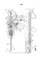
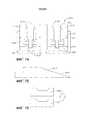
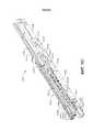
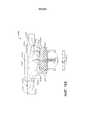
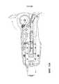
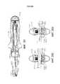
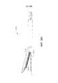
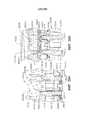
на ФИГ.1 представлен вид в поперечном сечении варианта осуществления хирургического инструмента;figure 1 presents a view in cross section of an embodiment of a surgical instrument;
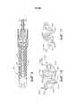
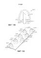
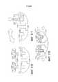
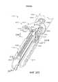
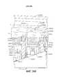
на ФИГ.1A представлен вид в перспективе одного варианта осуществления имплантируемой кассеты со скобками;FIG. 1A is a perspective view of one embodiment of an implantable cassette with brackets;
на ФИГ.1B-1E показаны части концевого эффектора, зажимающего и сшивающего ткань, с имплантируемой кассетой со скобками;1B-1E show portions of an end effector clamping and stitching tissue with an implantable cassette with brackets;
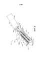
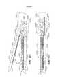
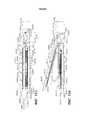
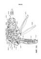
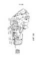
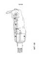
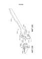
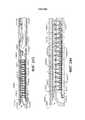
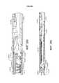
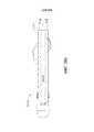
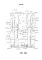
на ФИГ.2 представлен частичный вид сбоку в поперечном сечении другого концевого эффектора, соединенного с частью хирургического инструмента, причем концевой эффектор поддерживает картридж с хирургическими скобками, а его упор находится в открытом положении;FIG. 2 is a partial cross-sectional side view of another end effector connected to a part of a surgical instrument, the end effector supporting a cartridge with surgical brackets and its stop in the open position;
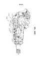
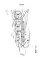
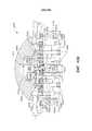
на ФИГ.3 представлен другой частичный вид сбоку в поперечном сечении концевого эффектора, изображенного на ФИГ.2, в закрытом положении;figure 3 presents another partial side view in cross section of the end effector depicted in figure 2, in the closed position;
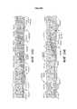
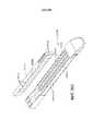
на ФИГ.4 представлен другой частичный вид сбоку в поперечном сечении концевого эффектора, изображенного на ФИГ.2 и 3, на котором держатель скальпеля начинает продвигаться через концевой эффектор;FIG. 4 shows another partial side cross-sectional view of the end effector shown in FIGS. 2 and 3, in which the scalpel holder begins to advance through the end effector;
на ФИГ.5 представлен еще один вид частичного поперечного сечения торцевого эффектора, изображенного на ФИГ. 2-4, с частично продвинутым ножом;figure 5 presents another view of a partial cross section of the end effector depicted in figure. 2-4, with a partially advanced knife;
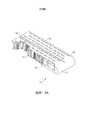
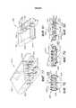
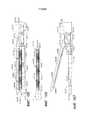
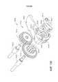
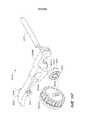
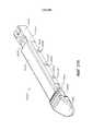
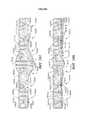
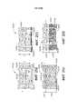
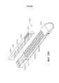
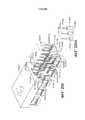
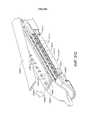
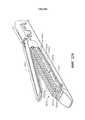
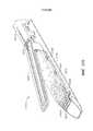
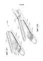
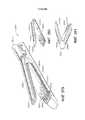
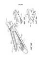
на ФИГ.6 представлен вид в перспективе альтернативного варианта осуществления кассеты со скобками, установленного в хирургическом режущем и сшивающем устройстве;FIG. 6 is a perspective view of an alternative embodiment of a cassette with brackets mounted in a surgical cutting and stapling device;
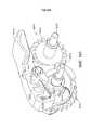
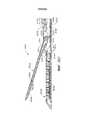
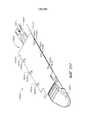
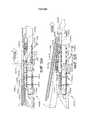
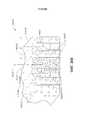
ФИГ.7 является видом сверху хирургической кассеты со скобками и продолговатого желоба аппарата, изображенного на ФИГ.6;FIG.7 is a top view of a surgical cassette with brackets and an oblong groove of the apparatus shown in FIG.6;
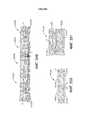
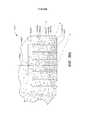
на ФИГ.8 представлен вид сверху другого варианта осуществления хирургической кассеты со скобками, установленного в удлиненный канал концевого эффектора;FIG. 8 is a top view of another embodiment of a surgical cassette with brackets mounted in an elongated channel of an end effector;
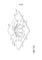
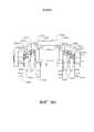
на ФИГ.9 представлен вид снизу упорного элемента;figure 9 presents a bottom view of the thrust element;
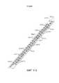
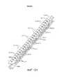
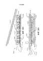
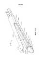
на ФИГ.10 представлен частичный вид в перспективе множества скобок, образующих часть линии скобок;FIG. 10 is a partial perspective view of a plurality of brackets forming part of a line of brackets;
на ФИГ.11 представлен другой частичный вид в перспективе линии скобок, изображенной на ФИГ.10, причем скобки из нее сформированы в результате приведения в контакт с упором хирургического режущего и сшивающего устройства;FIG. 11 shows another partial perspective view of the line of brackets shown in FIG. 10, and the brackets from it are formed as a result of bringing the cutting and stapling device into contact with the stop;
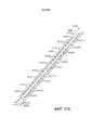
на ФИГ.12 представлен частичный вид в перспективе альтернативных скобок, формирующих часть другой линии скобок;12 is a partial perspective view of alternative brackets forming part of another line of brackets;
на ФИГ.13 представлен частичный вид в перспективе альтернативных скобок, формирующих часть другой линии скобок;13 is a partial perspective view of alternative brackets forming part of another line of brackets;
на ФИГ.14 представлен частичный вид в перспективе альтернативных скобок, формирующих часть другого варианта осуществления линии скобок;14 is a partial perspective view of alternative brackets forming part of another embodiment of a line of brackets;
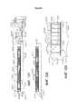
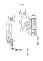
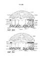
на ФИГ.15 представлен вид в сечении концевого эффектора, поддерживающего картридж со скобками;15 is a sectional view of an end effector supporting a cartridge with brackets;
на ФИГ.16 представлен вид в сечении части удлиненного канала концевого эффектора, изображенного на ФИГ.15, после извлечения из него части корпуса имплантируемой кассеты со скобками и скобок;on Fig presents a view in section of part of an elongated channel of the end effector shown in FIG. 15, after removing from it a part of the body of the implantable cassette with brackets and brackets;
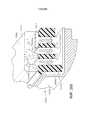
На ФИГ.17 представлен вид в сечении концевого эффектора, поддерживающего другую кассету со скобками;On Fig presents a view in section of an end effector supporting another cassette with brackets;
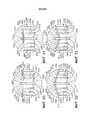
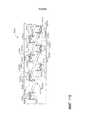
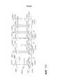
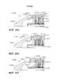
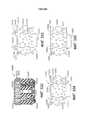
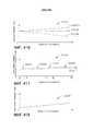
на ФИГ.18A-18D представлена схема деформации хирургической скобки, расположенной внутри корпуса сминаемой кассеты со скобками, в соответствии с по меньшей мере одним вариантом осуществления;on Figa-18D presents a diagram of the deformation of a surgical bracket located inside the body of the crushable cassette with brackets, in accordance with at least one embodiment;
на ФИГ.19A представлена схема, иллюстрирующая скобку, расположенную в корпусе раздавливаемой картриджа со скобками;19A is a diagram illustrating a bracket located in a housing of a crushable cartridge with brackets;
на ФИГ.19B представлена схема, иллюстрирующая корпус раздавливаемой кассеты со скобками, изображенный на ФИГ.19A, раздавленный упором;FIG. 19B is a diagram illustrating a casing of a crushable cartridge with brackets shown in FIG. 19A crushed by a stop;
на ФИГ.19C представлена схема, иллюстрирующая дальнейшее раздавливание упором корпуса раздавливаемой кассеты со скобками, изображенного на ФИГ.19A;FIG. 19C is a diagram illustrating further crushing by focusing the body of the crushable cartridge with brackets shown in FIG. 19A;
на ФИГ.19D представлена схема, иллюстрирующая скобку, изображенную на ФИГ.19A, в полностью сформированной конфигурации и раздавливаемый картридж со скобками, изображенную на ФИГ.19A, в полностью раздавленном состоянии;FIG. 19D is a diagram illustrating a bracket shown in FIG. 19A in a fully formed configuration and a crushable cartridge with brackets shown in FIG. 19A in a fully crushed state;
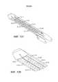
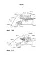
ФИГ.20 является схемой, изображающей шовную скобку, расположенную напротив несущей поверхности картриджа со скобками, и ее возможные движения в этом промежутке;FIGURE 20 is a diagram depicting a suture bracket located opposite the bearing surface of the cartridge with brackets, and its possible movements in this interval;
ФИГ.21 является изображением в поперечном разрезе несущей поверхности картриджа со скобками, на которой имеется паз или прорезь, которые были сконфигурированы для стабилизации основания шовной скобки с ФИГ.20;FIGURE 21 is a cross-sectional view of the bearing surface of the cartridge with brackets, on which there is a groove or slot that has been configured to stabilize the base of the suture bracket with FIGURE 20;
На ФИГ.22 представлен вид в сечении скобки, содержащей запрессованную головку и паз, или желобок, выполненный с возможностью принимать часть головки в соответствии по меньшей мере с одним альтернативным вариантом осуществления;FIG. 22 is a cross-sectional view of a bracket containing a press-in head and groove, or groove, configured to receive a portion of the head in accordance with at least one alternative embodiment;
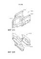
на ФИГ.23 представлен вид сверху кассеты со скобками в соответствии с по меньшей мере одним вариантом осуществления, содержащей скобки, помещенные в корпус сминаемой кассеты со скобками;FIG. 23 is a plan view of a cassette with brackets in accordance with at least one embodiment comprising brackets placed in a case of a crushable cassette with brackets;
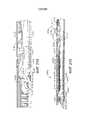
на ФИГ.24 представлен вид сбоку кассеты со скобками, показанного на ФИГ.23;FIG. 24 is a side view of the cassette with brackets shown in FIG. 23;
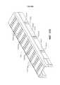
ФИГ.25 является видом сбоку кассеты со скобками в соответствии с по меньшей мере одним вариантом осуществления, в котором имеется защитный слой, окружающий шовные скобки, расположенные внутри деформируемого корпуса кассеты;FIGURE 25 is a side view of the cassette with brackets in accordance with at least one embodiment, in which there is a protective layer surrounding the suture brackets located inside the deformable cassette body;
ФИГ.26 является видом в поперечном разрезе кассеты со скобками с ФИГ.25, выполненным по линии разреза 26-26 на ФИГ.25;FIG. 26 is a cross-sectional view of a cassette with brackets from FIG. 25 made along the section line 26-26 in FIG. 25;
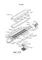
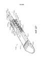
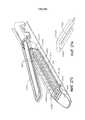
На ФИГ.27 представлен вид в вертикальной проекции картриджа со скобками в соответствии по меньшей мере с одним вариантом осуществления, содержащей скобки, которые по меньшей мере частично проходят за пределы корпуса сминаемой кассеты со скобками и защитного слоя, окружающего корпус кассеты со скобками;FIG. 27 is a perspective view of a cartridge with brackets in accordance with at least one embodiment comprising brackets that at least partially extend outside the casing of the cassette with brackets and a protective layer surrounding the cassette with brackets;
ФИГ.28 является видом в поперечном разрезе кассеты со скобками с ФИГ.27, выполненным по линии разреза 28-28 на ФИГ.27;FIG. 28 is a cross-sectional view of a cassette with brackets from FIG. 27 made along the section line 28-28 in FIG. 27;
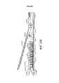
На ФИГ.29 представлен частичный вид в разрезе кассеты со скобками в соответствии по меньшей мере с одним вариантом осуществления, содержащей скобки, по меньшей мере частично помещенные в корпус сминаемой кассеты со скобками, при этом скобки по меньшей мере частично расположены в гнездах для скобок корпуса кассеты со скобками;FIG. 29 is a partial cross-sectional view of a cassette with brackets in accordance with at least one embodiment comprising brackets at least partially placed in a cassette cassette with brackets, with the brackets at least partially located in the casing bracket slots cassettes with brackets;
ФИГ.30 является видом в поперечном разрезе кассеты со скобками с ФИГ.29, выполненным по линии разреза 30-30 на ФИГ.29;FIG. 30 is a cross-sectional view of a cassette with brackets from FIG. 29 made along the cut line 30-30 in FIG. 29;
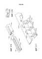
ФИГ.31 является частичным изображением в разобранном виде кассеты со скобками в соответствии с по меньшей мере одним вариантом осуществления;FIG 31 is a partial exploded view of a cassette with brackets in accordance with at least one embodiment;
на ФИГ.32 представлен частичный вид в разрезе кассеты со скобками в соответствии по меньшей мере с одним вариантом осуществления, содержащей скобки, по меньшей мере частично помещенные в корпус сминаемой кассеты со скобками, и выравнивающую матрицу, соединяющую скобки и выравнивающую скобки относительно друг друга;FIG. 32 is a partial cross-sectional view of a cassette with brackets in accordance with at least one embodiment, comprising brackets at least partially placed in a cassette with brackets, and an alignment matrix connecting the brackets and the alignment brackets with respect to each other;
ФИГ.33 является видом в поперечном разрезе кассеты со скобками с ФИГ.32, выполненным по линии разреза 33-33 на ФИГ.32;FIG.33 is a cross-sectional view of the cartridge with brackets from FIG.32, made along the cut line 33-33 in FIG.32;
ФИГ.34 является частичным видом в разрезе внутреннего слоя сжимаемого корпуса кассеты со скобками;34 is a partial sectional view of the inner layer of a compressible cassette body with brackets;
на ФИГ.35 представлена схема, иллюстрирующая внутренний слой, изображенный на ФИГ.34, который сжат между передаточной пластиной и опорной пластиной;FIG. 35 is a diagram illustrating the inner layer shown in FIG. 34, which is compressed between the transfer plate and the support plate;
на ФИГ.36 представлена схема, иллюстрирующая процесс вставки скобок в сжимаемый внутренний слой, изображенный на ФИГ.35;FIG. 36 is a diagram illustrating a process for inserting brackets into a compressible inner layer depicted in FIG. 35;
ФИГ.37 является схемой несущей пластины с ФИГ.35, которая была удалена из внутреннего слоя;FIG. 37 is a diagram of a carrier plate with FIG. 35, which has been removed from the inner layer;
на ФИГ.38 представлена схема подузла, содержащего изображенный на ФИГ.34 внутренний слой и показанные на ФИГ.36 скобки в процессе вставки во внешний слой;FIG. 38 is a diagram of a subassembly containing the inner layer shown in FIG. 34 and the brackets shown in FIG. 36 during insertion into the outer layer;
ФИГ.39 является схемой, изображающей наружный слой с ФИГ.38, который был герметизирован для образования герметичной кассеты со скобками;FIG. 39 is a diagram depicting the outer layer of FIG. 38, which has been sealed to form an airtight cartridge with brackets;
ФИГ.40 является видом в поперечном разрезе герметичной кассеты со скобками с ФИГ.39;FIG.40 is a view in cross section of a sealed cartridge with brackets with FIG.39;
ФИГ.41 является видом в поперечном разрезе кассеты со скобками и желоба для кассеты со скобками в соответствии с по меньшей мере одним вариантом осуществления;41 is a cross-sectional view of a cassette with brackets and a groove for a cassette with brackets in accordance with at least one embodiment;
ФИГ.42 является схемой, изображающей часть картриджа со скобками с ФИГ.41 в деформированном состоянии;FIG. 42 is a diagram showing a portion of a cartridge with brackets of FIG. 41 in a deformed state;
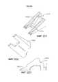
На ФИГ.43 представлен вид в вертикальной проекции концевого эффектора хирургического сшивающего устройства, содержащего упор в открытом положении и картридж со скобками, расположенный в канале для кассеты со скобками;On Fig presents a view in vertical projection of the end effector of a surgical stapler, containing the emphasis in the open position and the cartridge with brackets located in the channel for the cartridge with brackets;
на ФИГ.44 представлен вид в вертикальной проекции концевого эффектора, изображенного на ФИГ.43, иллюстрирующий упор в закрытом положении и кассету со скобками, зажатую между упором и каналом для кассеты со скобками;on Fig presents a view in vertical projection of the end effector depicted in FIG. 43, illustrating the stop in the closed position and the cassette with brackets, sandwiched between the stop and the channel for the cassette with brackets;
на ФИГ.45 представлен вид в вертикальной проекции концевого эффектора, изображенного на ФИГ.43, иллюстрирующий изображенную на ФИГ.43 картридж со скобками, расположенный альтернативным способом в канале для кассеты со скобками;on FIG presents a view in vertical projection of the end effector shown in FIG. 43, illustrating the cartridge shown in FIG. 43 with brackets, located in an alternative way in the channel for the cartridge with brackets;
на ФИГ.46 представлен вид в сечении концевого эффектора хирургического сшивающего инструмента, содержащего сжимаемую кассету со скобками, расположенный в канале для кассеты со скобками, а также фрагмент поддерживающего материала, прикрепленного к упору;on Fig presents a view in cross section of the end effector of a surgical stapling instrument containing a compressible cassette with brackets located in the channel for the cassette with brackets, as well as a fragment of the supporting material attached to the stop;
на ФИГ.47 представлен вид в сечении концевого эффектора, изображенного на ФИГ.46, иллюстрирующий упор в закрытом положении;FIG. 47 is a cross-sectional view of the end effector of FIG. 46 illustrating a stop in the closed position;
на ФИГ.48 представлен вид в сечении альтернативного варианта осуществления концевого эффектора хирургического сшивающего инструмента, содержащего картридж со скобками, содержащий водонепроницаемый слой;on Fig presents a cross-sectional view of an alternative embodiment of the end effector of a surgical stapling instrument containing a cartridge with brackets containing a waterproof layer;
на ФИГ.49 представлен вид в сечении другого альтернативного варианта осуществления концевого эффектора хирургического сшивающего инструмента;FIG. 49 is a cross-sectional view of another alternative embodiment of an end effector of a surgical stapling instrument;
на ФИГ.50 представлен вид в сечении альтернативного варианта осуществления концевого эффектора хирургического сшивающего инструмента, содержащего ступенчатый упор и картридж со скобками, содержащий ступенчатый корпус кассеты;FIG. 50 is a sectional view of an alternative embodiment of an end effector of a surgical stapling instrument comprising a step stop and a cartridge with brackets comprising a step cassette body;
на ФИГ.51 представлен вид в сечении другого альтернативного варианта осуществления концевого эффектора хирургического сшивающего инструмента;FIG. 51 is a sectional view of another alternative embodiment of an end effector of a surgical stapling instrument;
на ФИГ.52 представлен вид в сечении альтернативного варианта осуществления концевого эффектора хирургического сшивающего инструмента, содержащего наклонные контактирующие с тканью поверхности;FIG. 52 is a cross-sectional view of an alternative embodiment of an end effector of a surgical stapling instrument comprising inclined surfaces in contact with tissue;
на ФИГ.53 представлен вид в сечении другого альтернативного варианта осуществления концевого эффектора хирургического сшивающего инструмента, содержащего наклонные контактирующие с тканью поверхности;FIG. 53 is a cross-sectional view of another alternative embodiment of an end effector of a surgical stapling instrument comprising inclined surfaces in contact with tissue;
на ФИГ.54 представлен вид в сечении альтернативного варианта осуществления концевого эффектора хирургического сшивающего инструмента, содержащего опорную вставку, выполненную с возможностью поддерживания картриджа со скобками;FIG. 54 is a sectional view of an alternative embodiment of an end effector of a surgical stapling instrument comprising a support insert configured to support a cartridge with brackets;
на ФИГ.55 представлен вид в сечении альтернативного варианта осуществления концевого эффектора хирургического сшивающего инструмента, содержащего картридж со скобками, содержащий множество сжимаемых слоев;FIG. 55 is a cross-sectional view of an alternative embodiment of an end effector of a surgical stapling instrument comprising a cartridge with brackets comprising a plurality of compressible layers;
на ФИГ.56 представлен вид в сечении альтернативного варианта осуществления концевого эффектора хирургического сшивающего инструмента, содержащего картридж со скобками, содержащий ступенчатый корпус сжимаемого картриджа;FIG. 56 is a sectional view of an alternative embodiment of an end effector of a surgical stapling instrument comprising a cartridge with brackets comprising a stepped housing of a compressible cartridge;
на ФИГ.57 представлен вид в сечении другого альтернативного варианта осуществления концевого эффектора хирургического сшивающего инструмента, содержащего картридж со скобками, содержащий ступенчатый корпус сжимаемого картриджа;Fig. 57 is a sectional view of another alternative embodiment of an end effector of a surgical stapling instrument comprising a cartridge with brackets comprising a stepped housing of a compressible cartridge;
на ФИГ.58 представлен вид в сечении альтернативного варианта осуществления концевого эффектора хирургического сшивающего инструмента, содержащего картридж со скобками, содержащий изогнутую контактирующую с тканью поверхность;FIG. 58 is a cross-sectional view of an alternative embodiment of an end effector of a surgical stapling instrument comprising a cartridge with brackets comprising a curved tissue-contacting surface;
на ФИГ.59 представлен вид в сечении альтернативного варианта осуществления концевого эффектора хирургического сшивающего инструмента, содержащего картридж со скобками, имеющий наклонную контактирующую с тканью поверхность;FIG. 59 is a cross-sectional view of an alternative embodiment of an end effector of a surgical stapling instrument comprising a cartridge with brackets having an inclined surface in contact with tissue;
ФИГ.60 является видом в поперечном разрезе сжимаемой кассеты со скобками, содержащего шовные скобки, и в котором хранится по меньшей мере один медикамент;FIG. 60 is a cross-sectional view of a compressible cassette with brackets containing suture brackets, and in which at least one medication is stored;
ФИГ.61 является схемой, изображающей сжимаемую кассету со скобками с ФИГ.60 после того, как он был сжат, и находящиеся в нем шовные скобки были деформированы;FIG. 61 is a diagram depicting a compressible cartridge with brackets from FIG. 60 after it has been compressed and the suture brackets therein are deformed;
ФИГ.62 является частичным видом в разрезе кассеты со скобками в соответствии с по меньшей мере одним вариантом осуществления;FIG. 62 is a partial sectional view of a cassette with brackets in accordance with at least one embodiment;
на ФИГ.63 представлен вид в поперечном сечении кассеты со скобками, изображенной на ФИГ.62;FIG.63 is a cross-sectional view of a cassette with brackets shown in FIG.62;
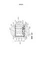
ФИГ.64 является видом в перспективе имплантируемого картриджа со скобками в соответствии с по меньшей мере одним альтернативным вариантом осуществления;FIG. 64 is a perspective view of an implantable cartridge with brackets in accordance with at least one alternative embodiment;
ФИГ.65 является видом в поперечном разрезе имплантируемого картриджа со скобками с ФИГ.64;FIG.65 is a view in cross section of an implantable cartridge with brackets with FIG.64;
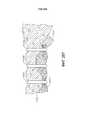
на ФИГ.66 представлен вид в перспективе альтернативного варианта осуществления кассеты со скобками, содержащей деформируемые элементы, проходящие от внешнего слоя картриджа со скобками.on FIG presents a perspective view of an alternative embodiment of a cartridge with brackets containing deformable elements passing from the outer layer of the cartridge with brackets.
ФИГ.67 является видом в перспективе альтернативного варианта осуществления кассеты со скобками, имеющего наружный слой, который соединен с внутренним слоем картриджа со скобками;67 is a perspective view of an alternative embodiment of a cartridge with brackets having an outer layer that is connected to the inner layer of the cartridge with brackets;
ФИГ.68 является видом в поперечном разрезе альтернативного варианта осуществления кассеты со скобками, содержащего множество шовных скобок, сжимаемый слой и компрессионный слой;FIG. 68 is a cross-sectional view of an alternative embodiment of a cassette with brackets comprising a plurality of suture brackets, a compressible layer and a compression layer;
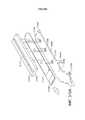
ФИГ.69 является видом в перспективе компрессионного слоя с ФИГ.68;FIG.66 is a perspective view of the compression layer with FIG.68;
на ФИГ.70 представлен вид в перспективе тампона, отделенного от слоя тампона, изображенного на ФИГ.68, и скобки, выровненной с канавкой в тампоне;FIG. 70 is a perspective view of a tampon separated from the tampon layer shown in FIG. 68 and the brackets aligned with a groove in the tampon;
ФИГ.71 является видом в перспективе двух соединенных прижимов из компрессионного слоя с ФИГ.68;FIG. 71 is a perspective view of two connected clips from the compression layer with FIG.
ФИГ.72 является видом в перспективе компрессионного несущего каркаса компрессионного слоя с ФИГ.68, который был отделен от отдельных прижимов;FIG. 72 is a perspective view of the compression support frame of the compression layer of FIG. 68, which has been separated from the individual clips;
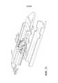
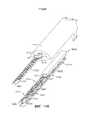
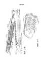
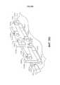
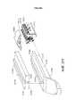
на ФИГ.73 представлен вид в перспективе с пространственным разделением компонентов альтернативного варианта осуществления сжимаемой кассеты со скобками, содержащего скобки и систему выталкивания скобок вплотную к упору;on FIG presents a perspective view with a spatial separation of the components of an alternative embodiment of a compressible cartridge with brackets, containing brackets and a system of pushing brackets close to the stop;
на ФИГ.73A представлен частичный вид в частичном разрезе альтернативного варианта осуществления кассеты со скобками, изображенного на ФИГ.73;FIG. 73A is a partial partial cross-sectional view of an alternative embodiment of the cassette with brackets shown in FIG. 73;
на ФИГ.74 представлен вид в поперечном сечении кассеты со скобками, изображенной на ФИГ.73;on Fig presents a view in cross section of a cassette with brackets, depicted in FIG.73;
на ФИГ.75 представлен вид в вертикальной проекции салазок, выполненных с возможностью прохождения через кассету со скобками, изображенную на ФИГ.73, и перемещения скобок к упору;on FIG presents a view in vertical projection of a slide made with the possibility of passing through the cassette with brackets, shown in FIG.73, and moving the brackets to the stop;
на ФИГ.76 представлена схема выталкивателя скобок, который можно поднять к упору салазками, изображенными на ФИГ.75;on Fig presents a diagram of the ejector brackets, which can be lifted to the stop with the slide shown in FIG.75;
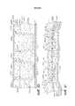
ФИГ.77 является изображением в разобранном виде кассеты со скобками в соответствии с по меньшей мере одним альтернативным вариантом осуществления, в котором шовные скобки находятся внутри направляющих для шовных скобок;FIG. 77 is an exploded view of a cassette with brackets in accordance with at least one alternative embodiment in which suture brackets are inside guides for suture brackets;
ФИГ.78 является видом в поперечном разрезе кассеты со скобками с ФИГ.77, который находится внутри желоба для кассеты со скобками;FIG. 78 is a cross-sectional view of the cassette with brackets of FIG. 77, which is located inside the gutter for the cassette with brackets;
ФИГ.79 является видом в поперечном разрезе кассеты со скобками с ФИГ.77, на котором изображено, как упорный элемент перемещается в закрытое положение, и шовные скобки, находящиеся внутри кассеты со скобками, деформируются при помощи упорного элемента;FIG. 79 is a cross-sectional view of the cassette with brackets of FIG. 77, which shows how the stop element moves to the closed position, and the suture brackets inside the cassette with brackets are deformed by the stop element;
ФИГ.80 является видом в поперечном разрезе кассеты со скобками с ФИГ.77, на котором изображено, как шовные скобки перемещаются вверх к упорному элементу;FIG. 80 is a cross-sectional view of a cassette with brackets from FIG. 77, which shows how the suture brackets move up to the stop element;
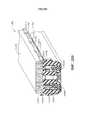
ФИГ.81 является видом в перспективе альтернативного варианта осуществления кассеты со скобками, в котором имеются перемычки между гибкими сторонами картриджа со скобками;FIG is a perspective view of an alternative embodiment of a cartridge with brackets, in which there are jumpers between the flexible sides of the cartridge with brackets;
ФИГ.82 является видом в перспективе салазок и режущего элемента в сборе;FIG 82 is a perspective view of the slide and the cutting element assembly;
ФИГ.83 является схемой салазок и режущего элемента в сборе с ФИГ.82, который используется для поднимания шовных скобок из картриджа со скобками с ФИГ.77;FIG. 83 is a diagram of a slide and a cutting element assembly with FIG. 82, which is used to raise the suture brackets from the cartridge with brackets from FIG. 77;
ФИГ.84 является схемой, изображающей салазки, которые сконфигурированы для захвата и поднимания шовных скобок к упорному элементу, и блокировочную систему, сконфигурированную для выборочного ограничения перемещения салазок дистально;FIG. 84 is a diagram depicting a slide that is configured to grip and raise suture brackets to the abutment member, and a locking system configured to selectively limit the movement of the slide distally;
на ФИГ. 85A-85C представлена последовательность вставки скобки в головку скобки;in FIG. 85A-85C show a sequence for inserting a bracket into a bracket head;
ФИГ.86 является видом в поперечном разрезе кассеты со скобками, имеющего поддерживающий поддон или держатель;FIG. 86 is a cross-sectional view of a cassette with brackets having a support tray or holder;
ФИГ.87 является частичным видом в поперечном разрезе сжимаемой кассеты со скобками в соответствии с по меньшей мере одним альтернативным вариантом осуществления;FIG. 87 is a partial cross-sectional view of a compressible cassette with brackets in accordance with at least one alternative embodiment;
ФИГ.88 является схемой, изображающей картридж со скобками с ФИГ.87 во внедренном состоянии;FIG.88 is a diagram showing a cartridge with brackets with FIG.87 in an embedded state;
ФИГ.89 является частичным видом в разрезе сжимаемой кассеты со скобками в соответствии с по меньшей мере одним альтернативным вариантом осуществления;FIG. 89 is a partial sectional view of a compressible cassette with brackets in accordance with at least one alternative embodiment;
ФИГ.90 является частичным видом в разрезе кассеты со скобками с ФИГ.89;FIG.90 is a partial sectional view of a cassette with brackets from FIG.89;
ФИГ.91 является схемой, изображающей картридж со скобками с ФИГ.89 во внедренном состоянии;FIG. 91 is a diagram showing a cartridge with brackets of FIG. 89 in an embedded state;
ФИГ.92 является частичным видом в разрезе сминаемой кассеты со скобками в соответствии с по меньшей мере одним альтернативным вариантом осуществления;FIG. 92 is a partial sectional view of a crushable cassette with brackets in accordance with at least one alternative embodiment;
ФИГ.93 является частичным видом в разрезе деформируемой кассеты со скобками в соответствии с по меньшей мере одним вариантом осуществления, который содержит множество разборных элементов;FIG. 93 is a partial sectional view of a deformable cassette with brackets in accordance with at least one embodiment that comprises a plurality of collapsible elements;
ФИГ.94 является видом в перспективе разборного элемента с ФИГ.93 в недеформированном состоянии;FIG. 94 is a perspective view of a collapsible member with FIG. 93 in an undeformed state;
ФИГ.95 является видом в перспективе разборного элемента с ФИГ.94 в деформированном состоянии;FIG.95 is a perspective view of a collapsible element with FIG.94 in a deformed state;
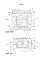
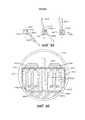
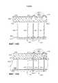
ФИГ.96A - частичный вид в разрезе концевого эффектора хирургического сшивающего аппарата, включающего браншу, желоб кассеты шовных скобок, расположенный напротив бранши, и картридж шовных скобок, расположенный в желобе картриджа шовных скобок, где бранша включает прикрепленную фиксирующую матрицу;FIGA is a partial sectional view of the end effector of a surgical stapler including a jaw, a suture staple cartridge groove opposite the jaw, and a suture staple cartridge located in the suture staple cartridge groove, where the jaw includes an attached fixation matrix;
ФИГ.96B - частичный вид в разрезе концевого эффектора ФИГ.96A, демонстрирующего браншу, перемещаемую по направлению к желобу картриджа шовных скобок, картридж шовных скобок, сжимаемый упорным элементом и фиксирующей матрицей, и шовную скобку по меньшей мере частично проходящую через ткань, размещенную между фиксирующей матрицей и картриджем шовных скобок;FIG. 96B is a partial cross-sectional view of the end effector of FIG. 96A showing a branch moving toward the groove of the suture staple cartridge, a suture staple cartridge compressible by a stop member and a fixing matrix, and a suture staple at least partially passing through a fabric placed between fixing matrix and suture cartridge;
ФИГ.96C - частичный вид в разрезе концевого эффектора ФИГ.96A, демонстрирующий браншу в конечном положении и фиксирующую матрицу, сцепленную с шовной скобкой ФИГ.96B;FIG.96C is a partial cross-sectional view of the end effector of FIG.96A, showing the branch in the final position and the fixing matrix linked to the suture bracket of FIG.96B;
ФИГ.96D - частичный вид в разрезе концевого эффектора на ФИГ.96A, демонстрирующий браншу и желоб кассеты шовных скобок, который отодвигается от вживленной кассеты шовных скобок и фиксирующей матрицы;FIG. 96D is a partial cross-sectional view of the end effector of FIG. 96A, showing the branch and groove of the suture staple cassette that moves away from the implanted suture staple cassette and the fixation matrix;
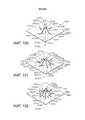
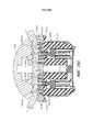
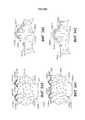
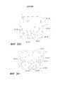
ФИГ.97 - перспективный вид отверстия фиксирующей матрицы в соответствии с по меньшей мере одним альтернативным вариантом осуществления настоящего изобретения, которое включает множество фиксирующих элементов, сконструированных таким образом, чтобы захватывать ножку шовного элемента, проходящую через них;FIG. 97 is a perspective view of an aperture of a fixation matrix in accordance with at least one alternative embodiment of the present invention, which includes a plurality of fixation elements designed to capture a leg of the suture element passing through them;
ФИГ.98 - перспективный вид отверстия фиксирующей матрицы в соответствии с по меньшей мере одним альтернативным вариантом осуществления настоящего изобретения, которое включает шесть фиксирующих частей;FIG. 98 is a perspective view of an aperture of a fixing matrix in accordance with at least one alternative embodiment of the present invention, which includes six fixing parts;
ФИГ.99 - перспективный вид отверстия фиксирующей матрицы в соответствии с по меньшей мере одним альтернативным вариантом осуществления настоящего изобретения, которое включает восемь фиксирующих частей;99 is a perspective view of an aperture of a fixing matrix in accordance with at least one alternative embodiment of the present invention, which includes eight fixing parts;
ФИГ.100 - перспективный вид отверстия фиксирующей матрицы в соответствии с по меньшей мере одним альтернативным вариантом осуществления настоящего изобретения, которое включает множество фиксирующих элементов, сконструированных таким образом, чтобы захватывать ножку шовного элемента, проходящую через них;FIG. 100 is a perspective view of an aperture of a fixing matrix in accordance with at least one alternative embodiment of the present invention, which includes a plurality of fixing elements designed to capture a leg of the suture element passing through them;
ФИГ.101 - перспективный вид отверстия фиксирующей матрицы в соответствии с по меньшей мере одним альтернативным вариантом осуществления настоящего изобретения, которое включает шесть фиксирующих частей;FIG. 101 is a perspective view of an aperture of a fixing matrix in accordance with at least one alternative embodiment of the present invention, which includes six fixing parts;
ФИГ.102 - перспективный вид отверстия фиксирующей матрицы в соответствии с по меньшей мере одним альтернативным вариантом осуществления настоящего изобретения, которое включает восемь фиксирующих частей;FIG. 102 is a perspective view of an aperture of a fixing matrix in accordance with at least one alternative embodiment of the present invention, which includes eight fixing parts;
ФИГ.103 - перспективный вид отверстия фиксирующей матрицы в соответствии с по меньшей мере одним альтернативным вариантом осуществления настоящего изобретения, которое включает множество фиксирующих элементов, изготовленных из листа металла методом штамповки;FIG. 103 is a perspective view of an aperture of a fixing matrix in accordance with at least one alternative embodiment of the present invention, which includes a plurality of fixing elements made of a metal sheet by stamping;
ФИГ.104 - перспективный вид отверстия фиксирующей матрицы в соответствии с по меньшей мере одним альтернативным вариантом осуществления настоящего изобретения, которое включает множество отверстий по периметру фиксирующего отверстия;FIG. 104 is a perspective view of a hole of a fixing matrix in accordance with at least one alternative embodiment of the present invention, which includes a plurality of holes around the perimeter of the fixing hole;
ФИГ.105 - вид сверху отверстия фиксирующей матрицы в соответствии с по меньшей мере одним альтернативным вариантом осуществления настоящего изобретения;FIG. 105 is a plan view of an aperture of a fixing matrix in accordance with at least one alternative embodiment of the present invention; FIG.
ФИГ.106 - вид сверху отверстия фиксирующей матрицы в соответствии с по меньшей мере одним альтернативным вариантом осуществления настоящего изобретения;FIG. 106 is a plan view of an aperture of a fixing matrix in accordance with at least one alternative embodiment of the present invention; FIG.
ФИГ.107 - вид сверху отверстия фиксирующей матрицы в соответствии с по меньшей мере одним альтернативным вариантом осуществления настоящего изобретения;FIG. 107 is a plan view of an aperture of a fixing matrix in accordance with at least one alternative embodiment of the present invention; FIG.
ФИГ.108 - вид сверху отверстия фиксирующей матрицы в соответствии с по меньшей мере одним альтернативным вариантом осуществления настоящего изобретения;FIG. 108 is a plan view of an aperture of a fixing matrix in accordance with at least one alternative embodiment of the present invention; FIG.
ФИГ.109 - вид сверху отверстия фиксирующей матрицы в соответствии с по меньшей мере одним альтернативным вариантом осуществления настоящего изобретения;FIG. 109 is a plan view of an aperture of a fixing matrix in accordance with at least one alternative embodiment of the present invention; FIG.
ФИГ.110 - вид сверху отверстия фиксирующей матрицы с пластиной, выступающей из фиксирующего отверстие в соответствии с по меньшей мере одним вариантом осуществления настоящего изобретения;FIG. 110 is a plan view of a hole of the fixing matrix with a plate protruding from the fixing hole in accordance with at least one embodiment of the present invention;
ФИГ.111 - вид сверху отверстия фиксирующей матрицы с пластиной, переходящей в фиксирующее отверстие в соответствии с по меньшей мере одним альтернативным вариантом осуществления настоящего изобретения;FIG. 111 is a plan view of a hole of a fixing matrix with a plate turning into a fixing hole in accordance with at least one alternative embodiment of the present invention;
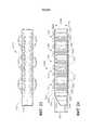
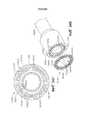
ФИГ.112 - перспективный вид сшивающей системы с набором шовных скобок, фиксирующей матрицей, сцепленной с шовными скобками, и выравнивающей основой, которая сконструирована таким образом, чтобы фиксировать шовные скобки в определенном положении относительно друг друга;FIG. 112 is a perspective view of a suturing system with a set of suture brackets, a fixing matrix coupled to suture braces, and a leveling base that is designed to fix the suture brackets in a specific position relative to each other;
ФИГ.113 - перспективный вид фиксирующей матрицы на ФИГ.112;FIG.113 is a perspective view of the fixing matrix in FIG.112;
ФИГ.114 - перспективный вид выравнивающей основы на ФИГ.112;FIG. 114 is a perspective view of a leveling base in FIG. 112;
ФИГ.115 - частичный вид сверху фиксирующей матрицы на ФИГ.112, сцепленной с шовными скобками на ФИГ.112;FIG.115 is a partial top view of the fixing matrix in FIG. 112 coupled to suture brackets in FIG. 112;
ФИГ.116 - частичный вид снизу фиксирующей матрицы на ФИГ.112, сцепленной с шовными скобками на ФИГ.112;FIG. 116 is a partial bottom view of the fixing matrix of FIG. 112 coupled to suture brackets in FIG. 112;
ФИГ.117 - частичный вертикальный вид сшивающей системы на ФИГ.112;FIG. 117 is a partial vertical view of a crosslinking system in FIG. 112;
ФИГ.118 - частичный перспективный вид сшивающей системы на ФИГ.112;FIG.118 is a partial perspective view of a crosslinking system in FIG.112;
ФИГ.119 - частичный вид в разрезе фиксирующей матрицы на ФИГ.112, сцепленной с ножками шовных скобок на ФИГ.112;FIG.119 is a partial cross-sectional view of a fixing matrix in FIG. 112 coupled to the legs of suture brackets in FIG. 112;
ФИГ.120 - частичный вид в разрезе сшивающей системы на ФИГ.112;FIG. 120 is a partial sectional view of a crosslinking system in FIG. 112;
ФИГ.121 - перспективный вид сшивающей системы на ФИГ.112, также включающей в себя защитные колпачки в сборе с ножками шовных скобок;FIG.121 is a perspective view of the crosslinking system of FIG.112, which also includes protective caps assembly with legs suture brackets;
ФИГ.122 - перспективный вид снизу сшивающей системы на ФИГ.121;FIG. 122 is a perspective view from below of a crosslinking system in FIG. 121;
ФИГ.123 - частичный перспективный вид сшивающей системы на ФИГ.121;FIG. 123 is a partial perspective view of a crosslinking system in FIG. 121;
ФИГ.124 - частичный вид в разрезе сшивающей системы на ФИГ.121;FIG. 124 is a partial sectional view of a crosslinking system in FIG. 121;
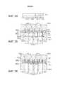
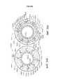
ФИГ.125 - вид в вертикальном разрезе концевого эффектора в соответствии с по меньшей мере одним вариантом осуществления настоящего изобретения, который включает браншу в открытом положении, фиксирующую матрицу и множество защитных колпачков, размещенных в бранше, a также картридж шовных скобок в желобе для кассеты шовных скобок;FIG. 125 is a vertical sectional view of an end effector in accordance with at least one embodiment of the present invention, which includes a jaw in the open position, a retaining matrix and a plurality of protective caps placed in the jaw, as well as a cartridge of suture brackets in the groove for the suture cartridge brackets;
ФИГ.126 - вид в вертикальном разрезе концевого эффектора на ФИГ.125 в закрытом положении;FIG. 126 is a vertical sectional view of an end effector in FIG. 125 in a closed position;
ФИГ.127 - вид в вертикальном разрезе концевого эффектора на ФИГ.125 в сшитом положении;FIG. 127 is a vertical sectional view of an end effector in FIG. 125 in a stitched position;
ФИГ.128 - вид в вертикальном разрезе фиксирующей матрицы и защитных колпачков на ФИГ.125 в сборе в картридже шовных скобок на ФИГ.125;FIG. 128 is a vertical sectional view of a fixing matrix and protective caps in FIG. 125 assembly in a cartridge of suture brackets in FIG. 125;
ФИГ.129 - подробный вид конфигурации с ФИГ.128;FIG.129 is a detailed view of the configuration of FIG.128;
ФИГ.130 - вид в вертикальном разрезе концевого эффектора на ФИГ.125, демонстрирующий браншу в открытом положении с более тонкой тканью, зажатой между фиксирующей матрицей и картриджем шовных скобок;FIG. 130 is a vertical sectional view of the end effector in FIG. 125 showing the branch in the open position with a thinner tissue sandwiched between the fixation matrix and the suture cartridge cartridge;
ФИГ.131 - вид в вертикальном разрезе концевого эффектора на ФИГ.125, демонстрирующий браншу в закрытом положении с более тонкой тканью на ФИГ.130;FIG.131 is a view in vertical section of the end effector in FIG.125, showing the branch in the closed position with a thinner fabric in FIG.130;
ФИГ.132 - вид в вертикальном разрезе концевого эффектора на ФИГ.125, демонстрирующий браншу в сшитом положении с более тонкой тканью на ФИГ.130, зажатой между фиксирующей матрицей и картриджем шовных скобок;FIG.132 is a vertical sectional view of the end effector in FIG.125, showing the branch in the stitched position with a thinner fabric in FIG.130, sandwiched between the fixing matrix and the cartridge of suture brackets;
ФИГ.133 - вид в вертикальном разрезе фиксирующей матрицы и защитных колпачков на ФИГ.125 в сборе с кассетой шовных скобок на ФИГ.125 и с более тонкой тканью на ФИГ.130, зажатой между ними;FIG.133 is a vertical sectional view of a fixing matrix and protective caps in FIG.125 assembled with a cassette of suture brackets in FIG.125 and with a thinner fabric in FIG.130 sandwiched between them;
ФИГ.134 - подробный вид конфигурации с ФИГ.133;FIG.134 is a detailed view of the configuration of FIG.133;
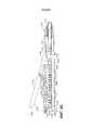
ФИГ.135 - вид в разрезе защитного колпачка на кончике ножки шовной скобки в соответствии с по меньшей мере одним альтернативным вариантом осуществления настоящего изобретения;FIG. 135 is a sectional view of a protective cap at the tip of a leg of a suture bracket in accordance with at least one alternative embodiment of the present invention;
ФИГ.136 - перспективный вид набора защитных колпачков, утопленных в лист материала;FIG.136 is a perspective view of a set of protective caps recessed into a sheet of material;
ФИГ.137 - перспективный вид бранши, включающей в себя набор отверстий, которые сконструированы таким образом, чтобы в них вставлялись защитные колпачки;FIG.137 is a perspective view of a jaw, which includes a set of holes that are designed so that protective caps are inserted into them;
ФИГ.138 - подробный вид части бранши с листом, накрывающим защитные колпачки, расположенные внутри бранши на ФИГ.137;FIG.138 is a detailed view of a portion of the jaw with a sheet covering the protective caps located inside the jaw of FIG.137;
ФИГ.139 - вид в разрезе защитного колпачка, расположенного на кончике ножки шовной скобки в соответствии с по меньшей мере одним альтернативным вариантом осуществления настоящего изобретения, где защитный колпачок имеет внутреннюю формующую поверхность;FIG.139 is a sectional view of a protective cap located on the tip of a leg of a suture bracket in accordance with at least one alternative embodiment of the present invention, where the protective cap has an inner forming surface;
ФИГ.140 - другой вид в разрезе защитного колпачка на ФИГ.139, демонстрирующего ножку шовной скобки, деформируемую формующей поверхностью;FIG.140 is another view in section of a protective cap in FIG.139, showing the leg of the suture bracket, deformable by the forming surface;
ФИГ.141 - вид сверху альтернативного варианта осуществления настоящего изобретения фиксирующей матрицы, включающей в себя ряд соединенных элементов матрицы;FIG. 144 is a top view of an alternative embodiment of the present invention of a fixing matrix including a series of connected matrix elements;
ФИГ.142 - вид сверху альтернативного варианта осуществления настоящего изобретения фиксирующей матрицы, включающей в себя ряд соединенных элементов матрицы;FIG. 142 is a top view of an alternative embodiment of the present invention of a fixing matrix including a series of connected matrix elements;
ФИГ.143 - вид сверху альтернативного варианта осуществления настоящего изобретения фиксирующей матрицы, включающей в себя ряд соединенных элементов матрицы;FIG.143 is a top view of an alternative embodiment of the present invention of a fixing matrix including a number of connected matrix elements;
ФИГ.144 - вид сверху альтернативного варианта осуществления настоящего изобретения, демонстрирующий цепочку фиксирующих матриц, состоящих из ряда соединенных элементов матрицы;FIG. 144 is a top view of an alternative embodiment of the present invention, showing a chain of fixing matrices consisting of a series of connected matrix elements;
ФИГ.145 - вид сверху альтернативного варианта осуществления настоящего изобретения фиксирующей матрицы, включающей в себя ряд соединенных элементов матрицы;FIG. 145 is a top view of an alternative embodiment of the present invention of a fixing matrix including a series of connected matrix elements;
ФИГ.146 - частичный покомпонентный вид бранши с фиксирующей матрицей, включающей в себя сжимаемый покрывающий лист;FIG.146 is a partial exploded view of a jaw with a fixing matrix, including a compressible covering sheet;
ФИГ.147 - подробный вид фиксирующей матрицы на ФИГ.146;FIG.147 is a detailed view of the locking matrix in FIG.146;
ФИГ.148 - частичный вид в разрезе сшивающей системы, включающей в себя фиксирующую матрицу с сжимаемым покрывающим слоем и рядом ячеек, содержащих один или несколько медикаментов;FIG.148 is a partial sectional view of a crosslinking system including a fixation matrix with a compressible coating layer and a series of cells containing one or more medications;
ФИГ.149 - диаграмма, демонстрирующая ножки шовной скобки, которые прокололи ячейки на ФИГ.148 после сцепки с фиксирующей матрицей;FIG.149 is a diagram showing the legs of the suture brace that punctured the cells in FIG.148 after coupling with a fixing matrix;
ФИГ.150 - частичный вид в разрезе сшивающей системы, включающей в себя фиксирующую матрицу с сжимаемым слоем;FIG. 150 is a partial sectional view of a crosslinking system including a fixing matrix with a compressible layer; FIG.
ФИГ.151 - вид в вертикальном разрезе механизма для загрузки кассеты с сшивающими элементами, включающего рукоятку, первую кассету с сшивающими элементами и вторую кассету с сшивающими элементами;FIG.151 is a view in vertical section of a mechanism for loading a cartridge with stapling elements, including a handle, a first cartridge with stapling elements and a second cartridge with stapling elements;
ФИГ.152 - вид в вертикальном разрезе концевого эффектора хирургического сшивающего аппарата, включающего первую браншу и вторую браншу, где вторая бранша изображена в открытом положении;FIG. 152 is a vertical sectional view of an end effector of a surgical stapler including a first branch and a second branch, where the second branch is shown in the open position;
на ФИГ.153 представлен вид в вертикальной проекции концевого эффектора, изображенного на ФИГ.152, иллюстрирующий вторую браншу в закрытой конфигурации и узел вставки кассеты с крепежными элементами, изображенный на ФИГ.151 и используемый для загрузки первой кассеты в первую браншу и второй кассеты во вторую браншу;FIG. 153 is a perspective view of the end effector shown in FIG. 152 illustrating a second jaw in a closed configuration and a cartridge insert assembly with fasteners shown in FIG. 151 and used to load the first cartridge into the first branch and second cartridge into second branch;
ФИГ.154 - вид в вертикальном разрезе загруженного концевого эффектора с ФИГ.153, демонстрирующий момент, когда приспособление для загрузки кассеты с шовными скобками убрано с концевого эффектора; вторая бранша изображена снова в открытом положении, а ткань размещена между первой браншей и второй браншей;FIG.154 is a view in vertical section of a loaded end effector with FIG.153, showing the moment when the device for loading cassettes with suture staples removed from the end effector; the second branch is again shown in the open position, and the tissue is placed between the first branch and the second branch;
ФИГ.155 - вид в вертикальном разрезе загруженного концевого эффектора на ФИГ.154 в сшитом положении;FIG.155 is a view in vertical section of a loaded end effector in FIG.154 in a stitched position;
ФИГ.156 - вид в вертикальном разрезе первого картриджа и второго картриджа во вживленном положении;FIG.156 is a view in vertical section of the first cartridge and the second cartridge in the implanted position;
ФИГ.157 - вид в вертикальном разрезе концевого эффектора на ФИГ.152, демонстрирующий часть первой кассеты, которая все еще крепится к первой бранше в соответствии с по меньшей мере одним вариантом осуществления настоящего изобретения;FIG. 157 is a vertical sectional view of an end effector in FIG. 152 showing a portion of a first cartridge that is still attached to a first jaw in accordance with at least one embodiment of the present invention;
ФИГ.158 - вид в вертикальном разрезе альтернативного варианта осуществления настоящего изобретения устройства для загрузки кассеты, которое включает в себя рукоятку, первую кассету и вторую кассету с сшивающими элементами;FIG. 158 is a vertical sectional view of an alternative embodiment of the present invention of a cassette loading device that includes a handle, a first cassette and a second cassette with stapling elements;
ФИГ.159 - вид в вертикальном разрезе устройства для загрузки кассеты на ФИГ.158, которое используется для загрузки первой бранши концевого эффектора первой кассетой, а второй бранши второй кассетой;FIG. 159 is a vertical sectional view of the cartridge loading device of FIG. 158, which is used to load the first end effector jaw by the first cassette, and the second jaw by the second cassette;
ФИГ.160 - вид в разрезе загруженного концевого эффектора на ФИГ.159;FIG. 160 is a sectional view of a loaded end effector in FIG. 159;
ФИГ.161 - перспективный вид хирургического сшивающего аппарата, включающего нижнюю браншу и верхнюю браншу, в соответствии с по меньшей мере одним вариантом осуществления настоящего изобретения, где части хирургического сшивающего аппарата сняты;FIG.161 is a perspective view of a surgical stapler including a lower jaw and an upper jaw, in accordance with at least one embodiment of the present invention, where parts of a surgical stapler are removed;
ФИГ.162 - перспективный вид хирургического сшивающего аппарата на ФИГ.161, где снята верхняя бранша;FIG.162 is a perspective view of a surgical stapler in FIG.161, where the upper jaw is removed;
ФИГ.163 - перспективный вид подвижной системы упоров верхней бранши хирургического сшивающего аппарата на ФИГ.161, включающего первый подвижный упорный элемент и второй подвижный упорный элемент;FIG.163 is a perspective view of the movable stop system of the upper jaw of the surgical stapler in FIG.161, comprising a first movable stop element and a second movable stop element;
ФИГ.164 - вид сбоку системы подвижных упоров на ФИГ.163;FIG.164 is a side view of a system of movable stops in FIG.163;
ФИГ.165 - вид сверху системы подвижных упоров на ФИГ.163;FIG.165 is a top view of a system of movable stops in FIG.163;
ФИГ.166 - диаграмма, демонстрирующая систему подвижных упоров на ФИГ.163 в несшитом положении;FIG.166 is a diagram showing a system of movable stops in FIG.163 in a non-crosslinked position;
ФИГ.167 - диаграмма, демонстрирующая первый подвижный упорный элемент системы подвижных упоров на ФИГ.163 в несшитом положении и шовные скобки в нижней бранше, которые еще не вошли в ткань;FIG.167 is a diagram illustrating a first movable stop element of the movable stop system of FIG.163 in an unstitched position and suture brackets in the lower jaw that have not yet entered the fabric;
ФИГ.168 - диаграмма, демонстрирующая шовные скобки в нижней бранше, которые вошли в ткань, первый подвижный упорный элемент на ФИГ.167, который отодвинут максимально проксимально для деформации первой ножек шовных скобок;FIG. 168 is a diagram illustrating suture brackets in the lower jaw that have entered the fabric, the first movable stop member in FIG. 167, which is moved as far as possible proximally to deform the first legs of the suture braces;
ФИГ.169 - диаграмма, демонстрирующая первую группу шовных скобок на ФИГ.168, которые были полностью деформированы;FIG.169 is a diagram showing the first group of suture brackets in FIG.168, which were completely deformed;
ФИГ.170 - диаграмма, демонстрирующая второй подвижный упорный элемент системы подвижных упоров на ФИГ.163, который максимально дистально передвинут, чтобы деформировать вторую группу ножек шовных скобок;FIG. 170 is a diagram illustrating a second movable stop element of the movable stop system of FIG. 163, which is distally moved as far as possible to deform the second group of suture leg legs;
ФИГ.171 - частичный перспективный вид упорного элемента со множеством формующих углублений в по меньшей мере одном вариантом осуществления настоящего изобретения;FIG. 71 is a partial perspective view of a thrust member with a plurality of forming recesses in at least one embodiment of the present invention;
ФИГ.172 - вид сбоку сечения упорного элемента на ФИГ.171;FIG.172 is a side view of a cross section of a thrust element in FIG.171;
ФИГ.173 - диаграмма, демонстрирующая первый этап производства формующих углублений на ФИГ.171;FIG. 173 is a diagram illustrating a first step in the production of forming recesses in FIG. 171;
ФИГ.174 - диаграмма, демонстрирующая второй этап производства формующих углублений на ФИГ.171;FIG.174 is a diagram illustrating a second stage of production of forming depressions in FIG.171;
ФИГ.175 - вид сверху формующих углублений упорного элемента на ФИГ.171;FIG.175 is a top view of the forming recesses of the thrust element in FIG.171;
ФИГ.176 - диаграмма, демонстрирующая первый этап процесса производства упорного элемента;FIG .76 is a diagram illustrating a first step in a manufacturing process of a thrust member;
ФИГ.177 - диаграмма, демонстрирующая второй этап процесса производства на ФИГ.176;FIG. 177 is a diagram illustrating a second stage of the manufacturing process in FIG. 176;
на ФИГ.178 представлена схема, иллюстрирующая третью стадию процесса производства, изображенного на ФИГ.176;on FIG presents a diagram illustrating the third stage of the production process depicted in FIG. 176;
на ФИГ.179 представлен вид в перспективе слева и спереди хирургического сшивающего и рассекающего инструмента с частью рукоятки, включающей рычажный автоматический механизм оттягивания и храповой механизм ручного оттягивания;on FIG presents a perspective view of the left and front of the surgical stapling and dissecting instrument with a part of the handle, including a lever automatic retraction mechanism and a ratchet manual retraction mechanism;
на ФИГ.180 представлен вид в перспективе справа и сзади хирургического сшивающего и рассекающего инструмента, показанного на ФИГ.179, на котором часть удлиненного стержня обрезана, а правая полуоболочка кожуха рукоятки удалена, чтобы открыть автоматический механизм послепускового оттягивания и ручной механизм пускового оттягивания;FIG. 180 is a perspective view on the right and rear of the surgical stapling and dissecting instrument shown in FIG. 179, in which a portion of the elongated shaft is trimmed and the right half-shell of the handle housing is removed to open the automatic post-launch retraction mechanism and the manual trigger retention mechanism;
на ФИГ.181 представлен вид в перспективе справа и сзади разобранной части рукоятки и удлиненного ствола хирургического сшивающего и рассекающего инструмента, показанного на ФИГ.179;on FIG presents a perspective view on the right and rear of the disassembled part of the handle and the elongated shaft of the surgical stapling and dissecting instrument shown in FIG. 179;
на ФИГ.182 представлен вид в перспективе справа и сзади хирургического сшивающего и рассекающего инструмента с ФИГ.31 со снятыми правой полуоболочкой кожуха и внешними частями рабочей части чтобы открыть закрывающий и пусковой механизмы в исходном состоянии;FIG.182 is a perspective view of the right and rear surgical stapling and dissecting instrument of FIG.31 with the right casing half-shell and external parts of the working part removed to open the closing and starting mechanisms in the initial state;
на ФИГ.183 представлен вид сбоку справа в вертикальной проекции частично разобранного хирургического сшивающего и рассекающего инструмента, показанного на ФИГ.182;on FIG presents a side view on the right in a vertical projection of a partially disassembled surgical stapling and dissecting instrument shown in FIG.
на ФИГ.184 представлен вид в перспективе справа и сзади частично разобранного хирургического сшивающего и рассекающего инструмента, показанного на ФИГ.182, на котором замыкающий механизм закрыт и зажат, пусковой механизм с боковым предохранителем завершает первый такт, а механизм ручного оттягивания удален, чтобы открыть дистальное звено соединительной рейки, которая запускает автоматическое оттягивание пускового механизма;FIG. 184 is a perspective view of the partially and partially disassembled surgical stapling and dissecting instrument shown in FIG. 182 on the right and rear, in which the locking mechanism is closed and clamped, the trigger mechanism with the side fuse completes the first beat, and the manual retraction mechanism is removed to open the distal link of the connecting rail, which triggers the automatic delay of the trigger;
на ФИГ.185 представлен вид в перспективе справа и сзади частично разобранного хирургического сшивающего и рассекающего инструмента с ФИГ.183 с отцепленным пусковым механизмом с боковым предохранителем и дистальным звеном, приближающимся к автоматическому оттягиванию;on FIG presents a perspective view on the right and back of a partially disassembled surgical stapling and dissecting instrument with FIG 183 with an uncoupled trigger mechanism with a side fuse and a distal link approaching automatic retraction;
на ФИГ.186 представлен вид сбоку слева в вертикальной проекции частично разобранного хирургического сшивающего и рассекающего инструмента, показанного на ФИГ.183, в исходном состоянии с открытым концевым эффектором и зацепленным механизмом блокировки обратного хода;FIG. 186 is a left side elevational view of a partially disassembled surgical stapling and dissecting instrument shown in FIG. 183 in the initial state with an open end effector and an engaged backstop;
на ФИГ.187 представлен подробный вид сбоку слева правой полуоболочки кожуха и рычага запуска обратного хода части рукоятки, показанной на ФИГ.186;on FIG presents a detailed side view from the left of the right half-shell of the casing and the lever to reverse the part of the handle shown in FIG.
на ФИГ.188 представлен подробный вид сбоку слева в вертикальной проекции разобранного хирургического сшивающего и рассекающего инструмента, изображенного на ФИГ.179, на котором закрывающий спусковой механизм зажат, пусковой крючок выполняет конечный такт, а дистальное звено находится в положении захвата автоматического втягивания;FIG. 188 is a detailed left side elevational view of the disassembled surgical stapling and dissecting instrument shown in FIG. 179, on which the closing trigger is held, the trigger executes the final beat, and the distal link is in the gripping position of the automatic retract;
на ФИГ.189 представлен подробный вид сбоку слева в вертикальной проекции разобранного хирургического сшивающего и рассекающего инструмента, показанного на ФИГ.188, сразу после активации и блокировки в переднем положении рычага высвобождения блокировки обратного хода с помощью дистального звена с обеспечением оттягивания соединительной рейки;FIG. 189 is a detailed left side elevational view of the disassembled surgical stapling and dissecting instrument shown in FIG. 188, immediately after activation and locking in the forward position of the release lever of the backstop using the distal link, ensuring the connection rail is retracted;
на ФИГ.190 представлен вид в перспективе справа разобранных промежуточной и задней шестерен, рычага ручного оттягивания и предохранителя храпового механизма ручного оттягивания хирургического сшивающего и рассекающего инструмента, показанного на ФИГ.179;FIG. 190 is a perspective view on the right of a disassembled intermediate and rear gears, a manual retraction lever and a ratchet safety device of the manual retraction of the surgical stapling and dissecting instrument shown in FIG. 179;
на ФИГ.191 представлен вид в перспективе справа механизма ручного втягивания, изображенного на ФИГ.190, с частично вырезанным рычагом ручного втягивания, чтобы открыть храповую шестерню меньшего диаметра, расположенную на задней шестерне и зацепляющую предохранитель храпового механизма;FIG. 191 is a perspective view on the right of the manual retraction mechanism depicted in FIG. 190 with a partially retracted manual retraction lever to open a smaller diameter ratchet gear located on the rear gear and engaging the ratchet mechanism fuse;
на ФИГ.192 представлен вид слева в вертикальной проекции частично разобранного хирургического сшивающего и рассекающего инструмента, изображенного на ФИГ.179, с механизмом блокировки обратного хода, зацепленным с полностью активированной соединительной рейкой, которая не соединена с комбинированной пружиной натяжения/сжатия, перед активацией рычага ручного втягивания, изображенного на ФИГ.190;FIG. 192 shows a left side elevational view of a partially disassembled surgical stapling and dissecting instrument shown in FIG. 179 with a backstop locking mechanism engaged with a fully activated coupling rail that is not connected to the combined tension / compression spring before activating the lever manual retraction shown in FIG. 190;
на ФИГ.193 представлен вид слева в вертикальной проекции частично разобранного хирургического сшивающего и рассекающего инструмента, изображенного на ФИГ.192, со скрытыми частями рычага высвобождения блокировки обратного хода, задней шестерни и рычага ручного пуска, показанными пунктиром;FIG.193 is a left side elevational view of a partially disassembled surgical stapling and dissecting instrument depicted in FIG.192, with hidden parts of the reverse lock release lever, rear gear and manual start lever, shown in broken lines;
на ФИГ.194 представлен вид слева в вертикальной проекции частично разобранного хирургического сшивающего и рассекающего инструмента, изображенного на ФИГ.193, после того как активация рычага ручного пуска вызвала ручное втягивание соединительной рейки;FIG.194 is a left side elevational view of a partially disassembled surgical stapling and dissecting instrument depicted in FIG.193 after activation of the manual start lever caused manual retraction of the connecting rail;
на ФИГ.195 представлен вид слева в вертикальной проекции частично разобранного хирургического сшивающего и рассекающего инструмента, изображенного на ФИГ.194, с отсутствующей соединительной рейкой, где показано, что рычаг ручного пуска расцеплен от механизма блокировки обратного хода;FIG. 195 shows a left side elevational view of a partially disassembled surgical stapling and dissecting instrument depicted in FIG. 194 with an absent connecting rail, where it is shown that the manual start lever is disengaged from the backstop;
на ФИГ.196 представлен подробный вид слева альтернативного рычага высвобождения блокировки обратного хода и корпуса рукоятки хирургического сшивающего и рассекающего инструмента, изображенного на ФИГ.179;on FIG presents a detailed left side view of an alternative lever release the reverse lock and the handle body of the surgical stapling and dissecting instrument depicted in FIG. 179;
на ФИГ.197 представлен вид в перспективе слева с пространственным разделением компонентов альтернативного рычага высвобождения блокировки обратного хода, вала задней шестерни и кулачкового круга механизма автоматического втягивания, изображенных на ФИГ.196;on FIG presented a perspective view on the left with a spatial separation of the components of the alternative lever release the reverse lock, the shaft of the rear gear and the cam circle of the automatic retraction mechanism shown in FIG.
на ФИГ.198 представлен вид справа сбоку в вертикальной проекции альтернативного механизма высвобождения блокировки обратного хода, изображенного на ФИГ.196, в котором соединительная рейка находится в оттянутом положении и рычаг высвобождения блокировки обратного хода расположен проксимально к пластине блокировки обратного хода, зацепленной с пусковым штоком;FIG.198 is a right side elevational view of an alternative backstop release mechanism shown in FIG.196, in which the connecting rail is in a retracted position and the backstop release lever is proximal to the backstop lock plate engaged with the trigger rod ;
на ФИГ.198A представлен подробный вид сбоку справа в вертикальной проекции задней шестерни, кулачкового круга механизма автоматического втягивания и самого дистального звена, изображенных на ФИГ.198;on FIGA presents a detailed side view on the right in the vertical projection of the rear gear, the cam circle of the automatic retraction mechanism and the most distal link shown in FIG.198;
на ФИГ.199 представлен вид справа в вертикальной проекции механизма высвобождения блокировки обратного хода, изображенного на ФИГ.198, после первого пускового такта;FIG.199 shows a right side view in vertical projection of the release mechanism of the reverse lock depicted in FIG.198, after the first starting cycle;
на ФИГ.199A представлен подробный вид справа в вертикальной проекции задней шестерни, кулачкового круга механизма автоматического втягивания и второго звена, изображенных на ФИГ.199;FIG.199A shows a detailed right side view in vertical projection of the rear gear, the cam circle of the automatic retraction mechanism and the second link shown in FIG.199;
на ФИГ.200 представлен вид сбоку справа в вертикальной проекции механизма высвобождения блокировки обратного хода, изображенного на ФИГ.199, после второго пускового такта;FIG. 200 is a side view to the right in a vertical projection of the release mechanism of the backstop shown in FIG. 199, after the second starting cycle;
на ФИГ.200A представлен подробный вид сбоку справа в вертикальной проекции задней шестерни, кулачкового круга механизма автоматического втягивания и третьего звена, изображенных на ФИГ.200;FIG. 200A shows a detailed side view on the right in a vertical projection of the rear gear, the cam circle of the automatic retraction mechanism and the third link shown in FIG. 200;
на ФИГ.201 представлен подробный вид сбоку справа в вертикальной проекции механизма высвобождения блокировки обратного хода, изображенного на ФИГ.200, после третьего пускового и конечного такта;FIG. 201 shows a detailed side view on the right in a vertical projection of the release mechanism of the reverse lock depicted in FIG. 200, after the third starting and ending clock cycle;
на ФИГ.201A представлен подробный вид сбоку справа в вертикальной проекции задней шестерни, кулачкового круга механизма автоматического втягивания и самого проксимального четвертого звена, изображенных на ФИГ.201;FIG. 201A is a detailed side view on the right in a vertical projection of the rear gear, the cam circle of the automatic retraction mechanism and the most proximal fourth link shown in FIG.
на ФИГ.202 представлен вид сбоку справа в вертикальной проекции механизма автоматического высвобождения, изображенного на ФИГ.201, после того как в результате дополнительного пускового такта кулачковый круг механизма автоматического втягивания дистально задвинул и заблокировал рычаг высвобождения блокировки обратного хода, расцепляя механизм блокировки обратного хода;FIG. 202 is a side elevational view of the right-hand side of the automatic release mechanism shown in FIG. 201, after, as a result of an additional starting stroke, the cam circle of the automatic retraction mechanism distally pushed and locked the release lever of the backstop, releasing the backstop;
на ФИГ.203 представлен вид в перспективе множества выталкивателей скобок, выполненных с возможностью установки внутри корпуса кассеты со скобками;FIG. 203 is a perspective view of a plurality of ejectors of brackets configured to install cassettes with brackets inside the housing;
на ФИГ.204 представлен вид в перспективе с пространственным разделением компонентов узла наложения скобок, изображенного на ФИГ.203, с полной сменным картриджем со скобками и нешарнирной конфигурацией стержня;on FIG presents a perspective view with a spatial separation of the components of the node overlay brackets depicted in FIG.203, with a full replaceable cartridge with brackets and un-hinged configuration of the rod;
на ФИГ.205 представлен вид в перспективе двухкомпонентного скальпеля и пускового стержня (трехрогий элемент) узла наложения скобок, показанного на ФИГ.203;FIG.205 is a perspective view of a two-component scalpel and trigger rod (three-horned element) of the brace overlay assembly shown in FIG.203;
на ФИГ.206 представлен вид в перспективе клиновидных салазок картриджа со скобками узла наложения скобок;on FIG presents a perspective view of the wedge-shaped slide of the cartridge with the brackets of the node overlay brackets;
на ФИГ.207 представлен вид сбоку слева в вертикальной проекции, выполненной по продольному сечению вдоль центральной линии 207-207 узла наложения скобок, показанного на ФИГ.203;on FIG presented a side view from the left in vertical projection, made in longitudinal section along the center line 207-207 of the node overlay brackets shown in FIG.
на ФИГ.208 представлен вид в перспективе открытого узла наложения скобок, показанного на ФИГ.203, без сменной картриджа со скобками и без дистальной части канала для скобок;FIG. 208 is a perspective view of an open bracket assembly shown in FIG. 203, without a replaceable cartridge with brackets and without a distal portion of the channel for brackets;
на ФИГ.209 представлен вид спереди в вертикальной проекции, выполненной по поперечному сечению вдоль линии 209-209 узла наложения скобок, показанного на ФИГ.203, на котором показаны внутренние выталкиватели скобок картриджа со скобками и части двухкомпонентного скальпеля и пускового стержня;FIG. 209 is a front elevational view taken in cross section along line 209–209 of the brace overlay assembly shown in FIG. 203, which shows the internal brace ejectors of the cartridge with brackets and parts of a two-component scalpel and launch rod;
на ФИГ.210 представлен вид сбоку слева в вертикальной проекции, выполненной по существу вдоль продольной оси линии 207-207 закрытого узла наложения скобок, показанного на ФИГ.203, для включения центральных точек контакта между двухкомпонентным скальпелем и клиновидными салазками, но также со смещением латерально, чтобы показать скобки и выталкиватели скобок внутри кассеты со скобками;FIG. 210 shows a side view from the left in a vertical projection made essentially along the longitudinal axis of line 207-207 of the closed brace overlay assembly shown in FIG. 203 to include central contact points between a two-component scalpel and a wedge-shaped slide, but also laterally displaced to show the brackets and brace ejectors inside the bracket cassette;
на ФИГ.211 представлен подробный вид сбоку слева в вертикальной проекции узла наложения скобок, показанного на ФИГ.210, причем двухкомпонентный скальпель оттянут немного больше, чем это характерно для замены картриджа со скобками;FIG. 211 is a detailed left side elevational view of the brace overlay assembly shown in FIG. 210, with the two-component scalpel extending slightly more than is typical for replacing the cartridge with brackets;
на ФИГ.212 представлен подробный вид сбоку слева в вертикальной проекции узла наложения скобок, показанного на ФИГ.211, на котором начинается активация двухкомпонентного скальпеля, в соответствии с конфигурацией, показанной на ФИГ.210;FIG. 212 is a detailed left side elevational view of the brace overlay assembly shown in FIG. 211, where activation of a two-component scalpel begins, in accordance with the configuration shown in FIG. 210;
на ФИГ.213 представлен вид сбоку слева в поперечном сечении в вертикальной проекции закрытого узла наложения скобок, показанного на ФИГ.210, после активации двухкомпонентного скальпеля и пускового стержня дистально;FIG. 213 is a side view from the left in cross section in a vertical projection of a closed brace overlay assembly shown in FIG. 210 after activating a two-component scalpel and a launch rod distally;
на ФИГ.214 представлен вид сбоку слева в поперечном сечении в вертикальной проекции закрытого узла наложения скобок, показанного на ФИГ.213, после активации картриджа со скобками и оттягивания двухкомпонентного скальпеля;FIG. 214 is a side view from the left in cross section in a vertical projection of a closed brace overlay assembly shown in FIG. 213 after activating the cartridge with brackets and pulling off a two-component scalpel;
на ФИГ.215 представлен подробный вид сбоку слева в поперечном сечении в вертикальной проекции узла наложения скобок, показанного на ФИГ.214, на котором двухкомпонентный скальпель может перейти в положение блокировки;FIG. 215 is a detailed left side view in cross section in a vertical projection of the brace overlay assembly shown in FIG. 214, in which a two-component scalpel can move to the locked position;
на ФИГ.216 представлен вид в перспективе картриджа со скобками, содержащей жесткую опорную часть и сжимаемый компенсатор толщины ткани для применения с хирургическим сшивающим инструментом в соответствии по меньшей мере с одним вариантом осуществления настоящего изобретения;FIG. 216 is a perspective view of a cartridge with brackets comprising a rigid support portion and a compressible tissue thickness compensator for use with a surgical stapling instrument in accordance with at least one embodiment of the present invention;
на ФИГ.217 представлен вид с частичным пространственным разделением компонентов кассеты со скобками, изображенной на ФИГ.216;FIG.217 presents a view with a partial spatial separation of the components of the cartridge with brackets shown in FIG.216;
на ФИГ.218 представлен вид с полным пространственным разделением компонентов кассеты со скобками, изображенной на ФИГ.216;FIG.218 presents a view with a complete spatial separation of the components of the cartridge with brackets shown in FIG.216;
на ФИГ.219 представлен другой вид с пространственным разделением компонентов кассеты со скобками, изображенной на ФИГ.216, без оболочки, покрывающей компенсатор толщины ткани;FIG. 219 shows another view with a spatial separation of the components of the cartridge with brackets shown in FIG. 216, without a shell covering the fabric thickness compensator;
на ФИГ.220 представлен вид в перспективе корпуса кассеты или опорной части кассеты со скобками, изображенной на ФИГ.216;FIG. 220 is a perspective view of a cartridge case or a supporting part of a cartridge with brackets shown in FIG. 216;
на ФИГ.221 представлен вид в перспективе сверху салазок, выполненных с возможностью перемещения внутри кассеты со скобками, изображенной на ФИГ.216, для размещения скоб из картриджа со скобками;FIG. 211 is a perspective view from above of a slide arranged to move inside the cassette with brackets shown in FIG. 216 for placing brackets from a cartridge with brackets;
на ФИГ.222 представлен вид в перспективе снизу салазок, изображенных на ФИГ.221;FIG. 222 is a perspective view from below of the slide shown in FIG. 211;
на ФИГ.223 представлен вид в вертикальной проекции салазок, изображенных на ФИГ.221;FIG.223 presents a view in vertical projection of the slide shown in FIG.221;
на ФИГ.224 представлен вид в перспективе сверху выталкивателя, выполненного с возможностью поддерживания одной или более скоб и с возможностью подъема вверх при помощи салазок, изображенных на ФИГ.221, для выталкивания скоб из картриджа со скобками;FIG. 244 is a perspective view from above of an ejector configured to support one or more brackets and to be lifted upward using the slide shown in FIG. 211 to eject brackets from a cartridge with brackets;
на ФИГ.225 представлен вид в перспективе снизу выталкивателя, изображенного на ФИГ.224;FIG. 252 is a perspective view from below of the ejector depicted in FIG. 244;
на ФИГ.226 представлена оболочка, выполненная с возможностью по меньшей мере частично окружать сжимаемый компенсатор толщины ткани картриджа со скобками;FIG.226 presents a shell made with the ability to at least partially surround a compressible compensator for the thickness of the tissue of the cartridge with brackets;
на ФИГ.227 представлен частичный вид в частичном разрезе кассеты со скобками, содержащей жесткую опорную часть и сжимаемый компенсатор толщины ткани, проиллюстрированной со скобками, перемещаемыми в ходе первой последовательности из неактивированного положения в активированное положение;FIG.227 is a partial partial cross-sectional view of a cassette with brackets containing a rigid support portion and a compressible tissue thickness compensator, illustrated with brackets moved during the first sequence from an inactive position to an activated position;
на ФИГ.228 представлен вид сбоку кассеты со скобками, показанной на ФИГ.227;FIG.228 is a side view of the cassette with brackets shown in FIG.227;
на ФИГ.229 представлен подробный вид в вертикальной проекции кассеты со скобками, изображенной на ФИГ.227;on FIG presents a detailed view in vertical projection of a cassette with brackets depicted in FIG.
на ФИГ.230 представлен вид с торца в поперечном сечении кассеты со скобками, изображенного на ФИГ.227;FIG. 230 shows an end view in cross section of a cassette with brackets shown in FIG. 277;
на ФИГ.231 представлен вид снизу кассеты со скобками, изображенного на ФИГ.227;FIG. 231 is a bottom view of a cassette with brackets shown in FIG. 277;
на ФИГ.232 представлен подробный вид снизу кассеты со скобками, показанной на ФИГ.227;FIG.232 shows a detailed bottom view of the cassette with brackets shown in FIG.227;
на ФИГ.233 представлен вид в продольном сечении упора в закрытом положении и кассеты со скобками, содержащей жесткую опорную часть и сжимаемый компенсатор толщины ткани, на котором показаны скобки, перемещаемые во время первой последовательности из неактивированного положения в активированное положение;FIG. 233 is a longitudinal sectional view of an abutment in a closed position and a cassette with brackets comprising a rigid support portion and a compressible tissue thickness compensator, showing brackets moving during the first sequence from an inactive position to an activated position;
на ФИГ.234 представлен другой вид в поперечном сечении упора и кассеты со скобками, показанных на ФИГ.233, на котором упор показан в открытом положении после завершения пусковой последовательности;FIG. 234 shows another cross-sectional view of the abutment and cartridge with brackets shown in FIG. 233, in which the abutment is shown in the open position after completion of the starting sequence;
на ФИГ.235 представлен частичный подробный вид кассеты со скобками, показанной на ФИГ.233, на котором скобки показаны в неактивированном положении;FIG. 235 is a partial detailed view of a cassette with brackets shown in FIG. 233, in which the brackets are shown in the inactive position;
на ФИГ.236 представлен вид в поперечном сечении в вертикальной проекции кассеты со скобками, содержащей жесткую опорную часть и сжимаемый компенсатор толщины ткани, на котором скобки показаны в неактивированном положении;on FIG presents a cross-sectional view in vertical projection of a cassette with brackets containing a rigid supporting part and a compressible compensator for the thickness of the fabric, on which the brackets are shown in the inactive position;
на ФИГ.237 представлен подробный вид кассеты со скобками, показанной на ФИГ.236;FIG.237 presents a detailed view of the cartridge with brackets shown in FIG.236;
на ФИГ.238 представлен вид в вертикальной проекции упора в открытом положении и кассеты со скобками, содержащей жесткую опорную часть и сжимаемый компенсатор толщины ткани, на котором скобки показаны в неактивированном положении;FIG.238 is a perspective view of an abutment in an open position and a cassette with brackets comprising a rigid support portion and a compressible tissue thickness compensator, in which the brackets are shown in an inactive position;
на ФИГ.239 представлен вид в вертикальной проекции упора в закрытом положении и кассеты со скобками, содержащей жесткую опорную часть и сжимаемый компенсатор толщины ткани, на котором скобки показаны в неактивированном положении, а ткань захвачена между упором и компенсатором толщины ткани;FIG. 239 is a vertical projection view of an abutment in a closed position and a cassette with brackets comprising a rigid support portion and a compressible tissue thickness compensator, in which the brackets are shown in an inactive position, and tissue is caught between the abutment and tissue thickness compensator;
на ФИГ.240 представлен подробный вид упора и кассеты со скобками, показанных на ФИГ.239;FIG. 240 shows a detailed view of the stop and cartridge with brackets shown in FIG. 239;
на ФИГ.241 представлен вид в вертикальной проекции упора в закрытом положении и кассеты со скобками, содержащей жесткую опорную часть и сжимаемый компенсатор толщины ткани, иллюстрирующий скобки в неактивированном положении и утолщенную ткань, расположенную между упором и кассетой со скобками;FIG.241 is a perspective view of an abutment in the closed position and a cassette with brackets comprising a rigid support portion and a compressible tissue thickness compensator illustrating brackets in an inactive position and a thickened fabric located between the abutment and the cassette with brackets;
на ФИГ.242 представлен подробный вид упора и кассеты со скобками, показанных на ФИГ.241;FIG.242 presents a detailed view of the stop and cartridge with brackets shown in FIG.241;
на ФИГ.243 представлен вид в вертикальной проекции упора и кассеты со скобками, показанных на ФИГ.241, на котором показана ткань, имеющая разные значения толщины, которая расположена между упором и кассетой со скобками;FIG. 243 is a vertical view of the stop and the cassette with brackets shown in FIG. 241, which shows a fabric having different thicknesses that is located between the stop and the cassette with brackets;
на ФИГ.244 представлен подробный вид упора и кассеты со скобками, показанных на ФИГ.241, как показано на ФИГ.243;FIG. 244 is a detailed view of the stop and cartridge with brackets shown in FIG. 241, as shown in FIG. 243;
на ФИГ.245 представлена схема, на которой показан компенсатор толщины ткани, который компенсирует разную толщину ткани, захваченной внутри разных скобок;FIG. 254 is a diagram showing a tissue thickness compensator that compensates for different tissue thicknesses trapped inside different brackets;
на ФИГ.246 представлена схема, на которой показан компенсатор толщины ткани, прикладывающий сжимающее давление к одному или более сосудам, пересеченным линией скобок;FIG. 266 is a diagram showing a tissue thickness compensator applying compressive pressure to one or more vessels crossed by a line of brackets;
на ФИГ.247 представлена схема, иллюстрирующая ситуацию, при которой одна или более скоб сформированы неправильно;on FIG presents a diagram illustrating a situation in which one or more brackets are formed incorrectly;
на ФИГ.248 представлена схема, иллюстрирующая компенсатор толщины ткани, способный обеспечить компенсацию неправильно сформированных скобок;FIG. 248 is a diagram illustrating a tissue thickness compensator capable of compensating for malformed brackets;
на ФИГ.249 представлена схема, иллюстрирующая компенсатор толщины ткани, расположенный в области ткани, в которой пересекается множество линий скобок;FIG. 249 is a diagram illustrating a tissue thickness compensator located in a tissue region in which a plurality of bracket lines intersect;
на ФИГ.250 представлена схема, на которой показана ткань, захваченная внутри скобки;FIG. 250 is a diagram showing a fabric trapped inside a bracket;
на ФИГ.251 представлена схема, иллюстрирующая ткань и компенсатор толщины ткани, захваченные внутри скобки;FIG. 251 is a diagram illustrating a fabric and a tissue thickness compensator trapped inside the brackets;
на ФИГ.252 представлена схема, на которой показана ткань, захваченная внутри скобки;FIG. 252 is a diagram showing a fabric trapped inside a bracket;
на ФИГ.253 представлена схема, на которой показана толстая ткань и компенсатор толщины ткани, захваченные внутри скобки;FIG. 253 is a diagram showing thick tissue and a tissue thickness compensator trapped inside the bracket;
на ФИГ.254 представлена схема, на которой показана тонкая ткань и компенсатор толщины ткани, захваченные внутри скобки;FIG. 254 is a diagram showing a thin fabric and a tissue thickness compensator trapped inside the bracket;
на ФИГ.255 представлена схема, на которой показана ткань, имеющая промежуточную толщину, и компенсатор толщины ткани, захваченные внутри скобки;on FIG presents a diagram showing a fabric having an intermediate thickness, and a tissue thickness compensator, captured inside the brackets;
на ФИГ.256 представлена схема, иллюстрирующая ткань другой промежуточной толщины и компенсатор толщины ткани, захваченные внутри скобки;FIG. 256 is a diagram illustrating a fabric of a different intermediate thickness and a tissue thickness compensator trapped inside the brackets;
на ФИГ.257 представлена схема, на которой показана толстая ткань и компенсатор толщины ткани, захваченные внутри скобки;FIG. 257 is a diagram showing thick tissue and a tissue thickness compensator trapped inside the bracket;
на ФИГ.258 представлен частичный вид в поперечном сечении концевого эффектора хирургического сшивающего инструмента, иллюстрирующий пусковой стержень и салазки для активации скобок в оттянутом неактивированном положении;FIG. 258 is a partial cross-sectional view of an end effector of a surgical stapling instrument illustrating a trigger rod and a slide for activating brackets in a drawn, non-activated position;
на ФИГ.259 представлен другой частичный вид в поперечном сечении концевого эффектора, изображенного на ФИГ.258, иллюстрирующий пусковой стержень и салазки для активации скобок в частично продвинутом положении;FIG. 259 shows another partial cross-sectional view of the end effector shown in FIG. 258 illustrating a launch rod and a slide for activating brackets in a partially advanced position;
на ФИГ.260 представлен вид в поперечном сечении концевого эффектора, изображенного на ФИГ.258, иллюстрирующий пусковой стержень в полностью продвинутом или активированном положении;FIG. 260 is a cross-sectional view of the end effector shown in FIG. 258 illustrating a launch rod in a fully advanced or activated position;
на ФИГ.261 представлен вид в поперечном сечении концевого эффектора, изображенного на ФИГ.258, иллюстрирующий пусковой стержень в оттянутом после активации положении и салазки для активации скоб, оставшиеся в полностью активированном положении;FIG. 261 is a cross-sectional view of the end effector shown in FIG. 258 illustrating the launch rod in the position drawn after activation and the slide to activate the brackets remaining in the fully activated position;
на ФИГ.262 представлен подробный вид пускового стержня в оттянутом положении, изображенном на ФИГ.261;FIG.262 presents a detailed view of the launch rod in the drawn position shown in FIG.261;
на ФИГ.263 представлен частичный вид в сечении концевого эффектора хирургического сшивающего инструмента, включающего картридж со скобками, содержащий компенсатор толщины ткани и по меньшей мере частично расположенные в нем скобки;FIG. 263 is a partial cross-sectional view of an end effector of a surgical stapling instrument including a cartridge with brackets comprising a tissue thickness compensator and at least partially located brackets therein;
на ФИГ.264 представлен другой частичный вид в сечении концевого эффектора, изображенного на ФИГ.263, иллюстрирующий скобки, по меньшей мере частично перемещенные и/или повернутые относительно упора, расположенного напротив кассеты со скобками;FIG. 264 is another partial cross-sectional view of the end effector shown in FIG. 263 illustrating brackets at least partially displaced and / or rotated relative to a stop located opposite the cassette with brackets;
на ФИГ.265 представлен частичный вид в поперечном сечении концевого эффектора хирургического сшивающего инструмента в соответствии с по меньшей мере одним вариантом осуществления;FIG. 265 is a partial cross-sectional view of an end effector of a surgical stapling instrument in accordance with at least one embodiment;
на ФИГ.266 представлен частичный вид в поперечном сечении концевого эффектора в соответствии с по меньшей мере одним альтернативным вариантом осуществления;FIG. 266 is a partial cross-sectional view of an end effector in accordance with at least one alternative embodiment;
на ФИГ.267 представлен частичный вид в поперечном сечении концевого эффектора в соответствии с другим альтернативным вариантом осуществления;FIG.267 is a partial cross-sectional view of an end effector in accordance with another alternative embodiment;
на ФИГ.268 представлен вид в перспективе концевого эффектора хирургического сшивающего инструмента в соответствии по меньшей мере с одним вариантом осуществления;FIG. 268 is a perspective view of an end effector of a surgical stapling instrument in accordance with at least one embodiment;
на ФИГ.269 представлен частичный вид в сечении концевого эффектора, изображенного на ФИГ.268, в согнутом состоянии;FIG. 269 is a partial cross-sectional view of the end effector of FIG. 268 in a bent state;
на ФИГ.270 представлен частичный вид в поперечном сечении концевого эффектора, показанного на ФИГ.269, в высвобожденном состоянии;FIG. 270 is a partial cross-sectional view of the end effector shown in FIG. 269 in the released state;
на ФИГ.271 представлен вид в перспективе концевого эффектора, содержащего сошник компенсатора толщины ткани;FIG. 271 is a perspective view of an end effector comprising a coulter for a tissue thickness compensator;
на ФИГ.272 представлен вид в перспективе сзади сошника компенсатора толщины ткани, изображенного на ФИГ.271;FIG. 272 is a perspective view from the rear of the coulter of the fabric thickness compensator shown in FIG. 271;
на ФИГ.273 представлен вид в перспективе концевого эффектора, содержащего множество рельс, проходящих от опорной части, и компенсатор толщины ткани, имеющий образованную в нем продольную полость;FIG. 273 is a perspective view of an end effector comprising a plurality of rails extending from a support portion and a tissue thickness compensator having a longitudinal cavity formed therein;
на ФИГ.274 представлен вид в перспективе компенсатора толщины ткани, изображенного на ФИГ.273;FIG. 274 is a perspective view of a tissue thickness compensator depicted in FIG. 273;
на ФИГ.275 представлен вид в перспективе концевого эффектора, содержащего множество зубцов, проходящих от опорной части, и зацепленный ими компенсатор толщины ткани;FIG. 275 is a perspective view of an end effector comprising a plurality of teeth extending from a support portion and a tissue thickness compensator engaged with them;
на ФИГ.276 представлен вид в перспективе упора, содержащего совокупность углублений, в соответствии по меньшей мере с одним вариантом осуществления;FIG. 276 is a perspective view of a stop containing a plurality of recesses in accordance with at least one embodiment;
на ФИГ.277 представлен частичный подробный вид упора, изображенного на ФИГ.276;on FIG presents a partial detailed view of the emphasis depicted in FIG. 276;
на ФИГ.278 представлен частичный вид в сечении упора, изображенного на ФИГ.276;FIG. 278 is a partial cross-sectional view of the stop depicted in FIG. 276;
на ФИГ.279 представлен поперечный вид в сечении упора, изображенного на ФИГ.276;FIG. 279 is a cross-sectional view of a stop depicted in FIG. 276;
на ФИГ.280 представлен вид в вертикальной проекции активированной скобки, содержащей по существу B-образную конфигурацию;FIG. 280 is a perspective view of an activated bracket containing a substantially B-shaped configuration;
на ФИГ.281 представлен вид в вертикальной проекции активированной скобки, одна ножка которой деформирована вовнутрь и одна ножка деформирована наружу;on FIG presents a view in vertical projection of the activated bracket, one leg of which is deformed inward and one leg is deformed outward;
на ФИГ.282 представлен вид в вертикальной проекции активированной скобки, обе ножки которой деформированы наружу;on FIG presents a view in vertical projection of the activated bracket, both legs of which are deformed outward;
на ФИГ.283 представлен частичный вид в перспективе опорной части кассеты со скобками, содержащей направители для ножек скоб, выполненные с возможностью отсоединения и/или смещения;on FIG presents a partial perspective view of the supporting part of the cartridge with brackets containing guides for legs of brackets, made with the possibility of detachment and / or displacement;
на ФИГ.284 представлен частичный вид в поперечном сечении кассеты со скобками, показанной на ФИГ.283, после размещения скоб из кассеты со скобками;FIG. 284 is a partial cross-sectional view of a cassette with brackets shown in FIG. 283 after placing brackets from a cassette with brackets;
на ФИГ.285 представлен подробный вид для вида в поперечном сечении, показанного на ФИГ.284, после активации кассеты со скобками;FIG. 285 is a detailed view for the cross-sectional view shown in FIG. 284 after activation of the cassette with brackets;
на ФИГ.286 представлен вид с пространственным разделением компонентов кассеты со скобками, включающей компенсатор толщины ткани, содержащий образованные в нем пустоты;on FIG presents a view with a spatial separation of the components of the cartridge with brackets, including a compensator for the thickness of the fabric containing voids formed in it;
на ФИГ.287 представлена схема, иллюстрирующая компенсатор толщины ткани, изображенный на ФИГ.286, имплантированный вплотную к ткани;FIG. 287 is a diagram illustrating a tissue thickness compensator shown in FIG. 288 implanted close to the tissue;
на ФИГ.288 представлена другая схема, иллюстрирующая компенсатор толщины ткани, изображенный на ФИГ.286, имплантированный вплотную к ткани;FIG. 288 is another diagram illustrating a tissue thickness compensator shown in FIG. 288 implanted close to the tissue;
на ФИГ.289 представлен вид в перспективе в сечении кассеты со скобками, содержащей боковые удерживающие элементы, проходящие от ее опорной части, выполненные с возможностью удерживать компенсатор толщины ткани в положении;on FIG presents a perspective view in section of a cartridge with brackets containing lateral retaining elements extending from its supporting part, configured to hold the tissue thickness compensator in position;
на ФИГ.290 представлен вид в поперечном сечении кассеты со скобками, показанной на ФИГ.289, которую используют для сшивания ткани скобами;FIG. 290 is a cross-sectional view of a cassette with brackets shown in FIG. 289, which is used to staple tissue with staples;
на ФИГ.291 представлен другой вид в сечении кассеты со скобками, изображенного на ФИГ.289, иллюстрирующий опорную часть, перемещенную от имплантированного компенсатора толщины ткани;FIG. 291 shows another cross-sectional view of the cassette with brackets shown in FIG. 289 illustrating a support portion displaced from an implanted tissue thickness compensator;
на ФИГ.292 представлен вид в перспективе в поперечном сечении кассеты со скобками, содержащей боковые удерживающие элементы, выполненные с возможностью удержания компенсатора толщины ткани на опорной части;FIG. 292 is a perspective view in cross section of a cassette with brackets containing lateral retaining elements configured to hold a tissue thickness compensator on a support portion;
на ФИГ.293 представлен вид в поперечном сечении кассеты со скобками, показанной на ФИГ.292, которую используют для сшивания ткани скобами;FIG. 293 is a cross-sectional view of a cassette with brackets shown in FIG. 292, which is used to staple tissue with staples;
на ФИГ.294 представлен другой вид в сечении кассеты со скобками, изображенного на ФИГ.292, иллюстрирующий опорную часть, перемещенную от имплантированного компенсатора толщины ткани;FIG. 294 shows another cross-sectional view of the cassette with brackets shown in FIG. 292 illustrating a support portion displaced from an implanted tissue thickness compensator;
на ФИГ.295 представлен подробный вид в сечении ограничителя, который удерживает компенсатор толщины ткани на опорной части кассеты со скобками в соответствии по меньшей мере с одним вариантом осуществления;FIG. 295 is a detailed cross-sectional view of a stopper that holds a tissue thickness compensator on a support portion of a cassette with brackets in accordance with at least one embodiment;
на ФИГ.296 представлен частичный вид в частичном разрезе кассеты со скобками, содержащей выталкиватели скоб, имеющие разные значения высоты, в соответствии с по меньшей мере одним вариантом осуществления;FIG. 266 is a partial partial cross-sectional view of a cassette with brackets comprising ejector brackets having different heights in accordance with at least one embodiment;
на ФИГ.296A представлена схема, иллюстрирующая выталкиватели скоб, изображенные на ФИГ.296, и поддерживаемые на них скобки, имеющие разные высоты в неактивированном состоянии.FIG. 26A is a diagram illustrating the ejector brackets shown in FIG. 266 and brackets supported thereon having different heights in an inactive state.
на ФИГ.297 представлена схема, на которой показан компенсатор толщины ткани, имеющий разную толщину, выталкиватели скоб, имеющие разные значения высоты, и скобки, имеющие разные значения высоты в несформированном состоянии;FIG. 277 is a diagram showing a tissue thickness compensator having different thicknesses, bracket ejectors having different height values, and brackets having different height values in an unformed state;
на ФИГ.298 представлена схема, на которой показаны скобки и компенсатор толщины ткани, показанный на ФИГ.297, имплантированный в ткань;FIG. 298 is a diagram showing brackets and a tissue thickness compensator shown in FIG. 297 implanted in tissue;
на ФИГ.299 представлен частичный вид в сечении кассеты со скобками, содержащей компенсатор толщины ткани, имеющий различную толщину, в соответствии по меньшей мере с одним вариантом осуществления;FIG. 299 is a partial sectional view of a cassette with brackets comprising a tissue thickness compensator having a different thickness, in accordance with at least one embodiment;
на ФИГ.300 представлен вид в сечении концевого эффектора хирургического сшивающего инструмента в открытой конфигурации;FIG. 300 is a sectional view of an end effector of a surgical stapling instrument in an open configuration;
на ФИГ.301 представлен вид в сечении концевого эффектора, изображенного на ФИГ.300, в частично активированной конфигурации;FIG. 301 shows a sectional view of the end effector shown in FIG. 300 in a partially activated configuration;
на ФИГ.302 представлен вид в сечении концевого эффектора, изображенного на ФИГ.300, в повторно открытой конфигурации;FIG. 302 is a sectional view of the end effector shown in FIG. 300 in a reopened configuration;
на ФИГ.303 представлен вид в поперечном сечении концевого эффектора хирургического сшивающего инструмента, содержащего выталкиватели скоб, имеющие разные значения высоты, и контурную поверхность платформы, в соответствии с по меньшей мере одним вариантом осуществления;FIG. 303 is a cross-sectional view of an end effector of a surgical stapling instrument containing staple ejectors having different heights and a contoured surface of the platform, in accordance with at least one embodiment;
на ФИГ.304 представлен вид в поперечном сечении концевого эффектора хирургического сшивающего инструмента, содержащего выталкиватели скоб, имеющие разные значения высоты, и ступенчатую поверхность платформы, в соответствии с по меньшей мере одним вариантом осуществления;FIG. 304 is a cross-sectional view of an end effector of a surgical stapling instrument containing staple ejectors having different heights and a stepped platform surface, in accordance with at least one embodiment;
на ФИГ.305 представлен вид в перспективе кассеты со скобками, загруженной в эффектор хирургического сшивающего инструмента, в котором используется аппликатор кассеты со скобками;on FIG presents a perspective view of a cassette with brackets loaded into the effector of a surgical stapling instrument, which uses a cartridge applicator with brackets;
на ФИГ.306 представлен вид в перспективе снизу аппликатора кассеты со скобками, изображенного на ФИГ.305;FIG. 306 is a perspective view from below of the cartridge applicator with brackets shown in FIG. 305;
на ФИГ.307 представлен вид сбоку аппликатора кассеты со скобками, изображенного на ФИГ.305, скомпонованного с кассетой со скобками;on FIG presents a side view of the applicator cassette with brackets, shown in FIG.305, arranged with a cassette with brackets;
на ФИГ.308 представлен вид в сечении узла, изображенного на ФИГ.307;FIG. 308 is a sectional view of the assembly of FIG. 307;
на ФИГ.309 представлен вид в перспективе узла аппликатора кассеты со скобками, дополнительно включающего верхний компенсатор толщины ткани, расположенный на верхней поверхности аппликатора кассеты со скобками, в соответствии по меньшей мере с одним вариантом осуществления;FIG. 309 is a perspective view of a cartridge applicator assembly with brackets, further including an upper tissue thickness compensator located on the upper surface of the cartridge applicator with brackets, in accordance with at least one embodiment;
на ФИГ.310 представлен вид с пространственным разделением компонентов верхнего компенсатора толщины ткани и аппликатора кассеты со скобками, изображенных на ФИГ.309;FIG. 310 is a view with a spatial separation of the components of the upper tissue thickness compensator and the cartridge applicator with brackets shown in FIG. 309;
на ФИГ.310A представлен вид с пространственным разделением компонентов узла аппликатора кассеты со скобками, содержащего вытягивающий элемент, выполненный с возможностью отсоединения верхнего компенсатора толщины ткани, адгезивно прикрепленного к аппликатору кассеты со скобками;on FIGA presents a view with a spatial separation of the components of the node of the applicator cassette with brackets containing a pulling element configured to disconnect the upper compensator for the thickness of the tissue, adhesive attached to the applicator of the cartridge with brackets;
на ФИГ.311 представлен частичный вид с пространственным разделением компонентов узла аппликатора кассеты со скобками в соответствии по меньшей мере с одним альтернативным вариантом осуществления;FIG. 311 is a partial exploded view of the components of the cartridge applicator assembly with brackets in accordance with at least one alternative embodiment;
на ФИГ.312 представлен вид в перспективе узла аппликатора кассеты со скобками, содержащего верхний компенсатор толщины ткани, включающий множество направленных от него удерживающих элементов, и кассеты со скобками, содержащей нижний компенсатор толщины ткани;FIG. 312 is a perspective view of a cartridge applicator assembly with brackets containing an upper tissue thickness compensator including a plurality of retaining elements directed away from it, and a cartridge with brackets comprising a lower tissue thickness compensator;
на ФИГ.313 представлен вид в вертикальной проекции узла аппликатора кассеты со скобками, показанного на ФИГ.312, расположенного внутри канала для кассеты со скобками, и упора, закрытого на узле аппликатора кассеты со скобками;FIG. 313 is a vertical view of the cartridge applicator assembly with brackets shown in FIG. 312 located inside the channel for the cartridge with brackets and the stop closed on the cartridge applicator assembly with brackets;
на ФИГ.314 представлен вид в вертикальной проекции упора, показанного на ФИГ.313, в повторно открытом положении и аппликатора КАССЕТЫ СО СКОБКАМИ, показанного на ФИГ.312, удаленного из концевого эффектора;FIG. 314 is a vertical perspective view of the stop shown in FIG. 313 in a re-opened position and the BRACKET TAPE applicator shown in FIG. 311 removed from the end effector;
на ФИГ.314A представлен вид в сечении ткани, расположенной между верхним компенсатором толщины ткани и нижним компенсатором толщины ткани, изображенным на ФИГ.312;FIG. 314 shows a sectional view of a fabric located between the upper tissue thickness compensator and the lower fabric thickness compensator shown in FIG. 312;
на ФИГ.314B представлен вид в поперечном сечении, иллюстрирующий верхний компенсатор толщины ткани и нижний компенсатор толщины ткани, пришитые к ткани и рассеченные режущим элементом;FIG. 314B is a cross-sectional view illustrating an upper fabric thickness compensator and a lower fabric thickness compensator sewn to a fabric and dissected by a cutting member;
на ФИГ.315 представлена схема, иллюстрирующая компенсатор толщины ткани, вставленный в упор в соответствии по меньшей мере с одним вариантом осуществления;FIG. 315 is a diagram illustrating a tissue thickness compensator inserted in an abutment according to at least one embodiment;
на ФИГ.316 представлен вид в сечении компенсатора толщины ткани, изображенного на ФИГ.315;FIG. 316 is a cross-sectional view of a tissue thickness compensator shown in FIG. 315;
на ФИГ.317 представлен вид с пространственным разделением компонентов компенсатора толщины ткани и упорного элемента в соответствии по меньшей мере с одним альтернативным вариантом осуществления;FIG. 311 shows a spatially separated view of components of a tissue thickness compensator and a thrust member in accordance with at least one alternative embodiment;
на ФИГ.318 представлен вид в перспективе узла аппликатора кассеты со скобками, содержащего верхний компенсатор толщины ткани, выполненный с возможностью прикрепления к упору, в соответствии с по меньшей мере одним вариантом осуществления;FIG. 318 is a perspective view of a cartridge applicator assembly with brackets comprising an upper tissue thickness compensator configured to attach to a stop in accordance with at least one embodiment;
на ФИГ.319 представлен вид в вертикальной проекции узла аппликатора кассеты со скобками, изображенного на ФИГ.318, расположенного внутри канала для кассеты со скобками, и упора, перемещенного к верхнему компенсатору толщины ткани;FIG. 319 is a perspective view of the cartridge applicator assembly with brackets shown in FIG. 318 located inside the channel for the cartridge with brackets and a stop moved to the upper tissue thickness compensator;
на ФИГ.320 представлен аппликатор кассеты со скобками, изображенный на ФИГ.318, извлеченный из концевого эффектора после зацепления верхнего компенсатора толщины ткани с упором;FIG. 320 shows the cartridge applicator with brackets shown in FIG. 318, removed from the end effector after meshing the upper tissue thickness compensator with a stop;
на ФИГ.321 представлен вид с торца в поперечном сечении упора, перемещенного к верхнему компенсатору толщины ткани, показанному на ФИГ.318;FIG. 311 shows an end view in cross section of an abutment moved to the upper tissue thickness compensator shown in FIG. 318;
на ФИГ.322 представлен вид с торца в поперечном сечении упора, зацепленного с верхним компенсатором толщины ткани;FIG. 222 shows an end view in cross section of an abutment engaged with an upper compensator for tissue thickness;
на ФИГ.323 представлен вид в сечении концевого эффектора хирургического сшивающего инструмента, содержащего картридж со скобками, включающий сегментируемый компенсатор толщины ткани, прикрепленный к опорной части кассеты со скобками при помощи множества крепежных элементов;FIG. 233 is a cross-sectional view of an end effector of a surgical stapling instrument containing a cartridge with brackets, including a segmentable tissue thickness compensator attached to the supporting portion of the cassette with brackets using a plurality of fasteners;
на ФИГ.324 представлен вид в сечении концевого эффектора, изображенного на ФИГ.323, иллюстрирующий пусковой элемент в частично активированном положении;FIG. 344 is a cross-sectional view of the end effector shown in FIG. 323 illustrating a trigger element in a partially activated position;
на ФИГ.325 представлен вид в поперечном сечении концевого эффектора, показанного на ФИГ.323, на котором показана опорная часть, перемещенная от частично имплантированного компенсатора толщины ткани;FIG. 255 is a cross-sectional view of an end effector shown in FIG. 323, which shows a support portion displaced from a partially implanted tissue thickness compensator;
на ФИГ.326 представлен частичный вид в перспективе опорной части, изображенной на ФИГ.323;FIG. 326 is a partial perspective view of the support portion shown in FIG. 323;
на ФИГ.327 представлен вид в перспективе размещающих скобки салазок в соответствии по меньшей мере с одним вариантом осуществления;FIG.327 is a perspective view of a bracket-mounted slide in accordance with at least one embodiment;
на ФИГ.328 представлен вид в вертикальной проекции салазок, изображенных на ФИГ.327;FIG.328 presents a view in vertical projection of the slide shown in FIG.327;
на ФИГ.329 представлен вид в перспективе концевого эффектора хирургического сшивающего инструмента, содержащего картридж со скобками, включающий компенсатор толщины ткани и множество направляющих скоб, расположенных на компенсаторе толщины ткани;FIG. 299 is a perspective view of an end effector of a surgical stapling instrument comprising a cartridge with brackets including a tissue thickness compensator and a plurality of guide brackets located on the tissue thickness compensator;
на ФИГ.330 представлен частичный вид в сечении компенсатора толщины ткани и направляющих скоб, изображенных на ФИГ.329, в неактивированной конфигурации;FIG. 330 shows a partial cross-sectional view of a tissue thickness compensator and guide brackets shown in FIG. 299 in an inactive configuration;
на ФИГ.331 представлен частичный вид в сечении компенсатора толщины ткани и направляющих скоб, изображенных на ФИГ.329, в активированной конфигурации;FIG. 311 shows a partial cross-sectional view of a tissue thickness compensator and guide brackets shown in FIG. 299 in an activated configuration;
на ФИГ.332 представлен вид в поперечном сечении кассеты со скобками, содержащей компенсатор толщины ткани и опорную часть, в соответствии с по меньшей мере одним вариантом осуществления;FIG. 323 is a cross-sectional view of a cassette with brackets comprising a tissue thickness compensator and a support portion, in accordance with at least one embodiment;
на ФИГ.333 представлен частичный вид в поперечном сечении компенсатора толщины ткани, направляющего скобки слоя и скобки в неактивированном положении;FIG. 333 is a partial cross-sectional view of a tissue thickness compensator, layer guide brackets, and brackets in an inactive position;
на ФИГ.334 представлен частичный вид в поперечном сечении компенсатора толщины ткани, направляющего скобки слоя и скобки в неактивированном положении в соответствии с по меньшей мере одним альтернативным вариантом осуществления;FIG. 344 is a partial cross-sectional view of a tissue thickness compensator, layer guide brackets, and brackets in an inactive position in accordance with at least one alternative embodiment;
на ФИГ.335 представлен частичный вид в поперечном сечении компенсатора толщины ткани, направляющего скобки слоя и скобки в неактивированном положении в соответствии с по меньшей мере одним альтернативным вариантом осуществления;FIG.335 is a partial cross-sectional view of a tissue thickness compensator, layer guide brackets, and brackets in an inactive position in accordance with at least one alternative embodiment;
на ФИГ.336 представлен частичный вид в поперечном сечении компенсатора толщины ткани, направляющего скобки слоя и скобки в неактивированном положении в соответствии с по меньшей мере одним альтернативным вариантом осуществления;FIG. 363 is a partial cross-sectional view of a tissue thickness compensator, layer guide brackets, and brackets in an inactive position in accordance with at least one alternative embodiment;
на ФИГ.337 представлен частичный вид в поперечном сечении компенсатора толщины ткани, направляющего скобки слоя и скобки в неактивированном положении в соответствии с по меньшей мере одним альтернативным вариантом осуществления;FIG. 373 is a partial cross-sectional view of a tissue thickness compensator, layer guide brackets, and brackets in an inactive position in accordance with at least one alternative embodiment;
на ФИГ.338 представлен частичный вид в поперечном сечении компенсатора толщины ткани, направляющего скобки слоя и скобки в неактивированном положении в соответствии с по меньшей мере одним альтернативным вариантом осуществления;FIG.338 is a partial cross-sectional view of a tissue thickness compensator, layer guide brackets, and brackets in an inactive position in accordance with at least one alternative embodiment;
на ФИГ.339 представлен частичный вид в поперечном сечении компенсатора толщины ткани, направляющего скобки слоя и скобки в неактивированном положении в соответствии с по меньшей мере одним альтернативным вариантом осуществления;FIG.339 is a partial cross-sectional view of a tissue thickness compensator, layer guide brackets and brackets in an inactive position in accordance with at least one alternative embodiment;
на ФИГ.340 представлен подробный вид области, окружающей кончик скобки, показанной на ФИГ.339;FIG.340 is a detailed view of the area surrounding the tip of the bracket shown in FIG.339;
на ФИГ.341 представлен частичный вид в поперечном сечении компенсатора толщины ткани, направляющего скобки слоя и скобки в неактивированном положении в соответствии с по меньшей мере одним альтернативным вариантом осуществления;FIG. 341 is a partial cross-sectional view of a tissue thickness compensator, layer guide brackets, and brackets in an inactive position in accordance with at least one alternative embodiment;
на ФИГ.342 представлен подробный вид области, окружающей кончик скобки, показанной на ФИГ.341;FIG.342 presents a detailed view of the area surrounding the tip of the bracket shown in FIG.341;
на ФИГ.343 представлен частичный вид в поперечном сечении компенсатора толщины ткани, направляющего скобки слоя и скобки в неактивированном положении в соответствии с по меньшей мере одним альтернативным вариантом осуществления;FIG. 434 is a partial cross-sectional view of a tissue thickness compensator, layer guide brackets, and brackets in an inactive position in accordance with at least one alternative embodiment;
на ФИГ.344 представлен вид в перспективе направляющего скобки слоя и множества скобок в неактивированном положении в соответствии с по меньшей мере одним альтернативным вариантом осуществления;FIG. 344 is a perspective view of a guide bracket of a layer and a plurality of brackets in an inactive position in accordance with at least one alternative embodiment;
на ФИГ.345 представлен вид с торца компенсатора толщины ткани, выполненного с возможностью применения с круговым хирургическим сшивающим инструментом;on FIG presents a view from the end of the compensator tissue thickness, made with the possibility of use with a circular surgical stapling instrument;
на ФИГ.346 представлен вид в перспективе компенсатора толщины ткани и кругового хирургического сшивающего инструмента, изображенного на ФИГ.345;FIG. 346 is a perspective view of a tissue thickness compensator and a circular surgical stapling instrument shown in FIG. 345;
на ФИГ.347 представлен вид с торца компенсатора толщины ткани, выполненного с возможностью применения с круговым хирургическим сшивающим инструментом в соответствии по меньшей мере с одним альтернативным вариантом осуществления;FIG. 347 is an end view of a tissue thickness compensator configured to be used with a circular surgical stapling instrument in accordance with at least one alternative embodiment;
на ФИГ.348 представлен вид в перспективе компенсатора толщины ткани и кругового хирургического сшивающего инструмента, изображенного на ФИГ.347;FIG. 348 is a perspective view of a tissue thickness compensator and a circular surgical stapling instrument shown in FIG. 347;
на ФИГ.349 представлен вид с торца компенсатора толщины ткани, выполненного с возможностью применения с круговым хирургическим сшивающим инструментом;FIG. 349 is an end view of a tissue thickness compensator configured to be used with a circular surgical stapling instrument;
на ФИГ.350 представлен вид с торца компенсатора толщины ткани, изображенного на ФИГ.349, в частично расширенной конфигурации;FIG. 350 shows an end view of the tissue thickness compensator depicted in FIG. 349, in a partially expanded configuration;
на ФИГ.351 представлен вид в вертикальной проекции хирургического сшивающего инструмента, содержащего кассету со скобками, в соответствии по меньшей мере с одним вариантом осуществления;on FIG presents a view in vertical projection of a surgical stapling instrument containing a cassette with brackets, in accordance with at least one embodiment;
на ФИГ.352 представлен вид с торца хирургического сшивающего инструмента, изображенного на ФИГ.351, расположенного относительно ткани;FIG.352 presents an end view of the surgical stapling instrument depicted in FIG.351, located relative to the tissue;
на ФИГ.353 представлен вид с торца хирургического сшивающего инструмента, изображенного на ФИГ.351, дополнительно содержащего компенсатор толщины ткани, расположенный между кассетой со скобками и тканью;FIG.353 presents an end view of the surgical stapling instrument depicted in FIG.351, further comprising a tissue thickness compensator located between the cassette with brackets and tissue;
на ФИГ.354 представлен частичный вид в перспективе скоб, размещенных в ткани из хирургического сшивающего инструмента, изображенного на ФИГ.351, без компенсатора толщины ткани;FIG. 354 is a partial perspective view of staples placed in tissue from the surgical stapling instrument shown in FIG. 351 without a tissue thickness compensator;
на ФИГ.355 представлен частичный вид в перспективе скоб, размещенных в ткани из хирургического сшивающего инструмента, изображенного на ФИГ.351, с компенсатором толщины ткани;FIG. 355 is a partial perspective view of staples placed in tissue from the surgical stapling instrument shown in FIG. 351 with a tissue thickness compensator;
на ФИГ.356 представлен частичный вид в сечении концевого эффектора хирургического сшивающего инструмента, изображенного на ФИГ.351, содержащего пластину упора в первом положении;FIG. 356 is a partial cross-sectional view of an end effector of a surgical stapling instrument shown in FIG. 351 comprising a stop plate in a first position;
на ФИГ.357 представлен частичный вид в сечении концевого эффектора хирургического сшивающего инструмента, изображенного на ФИГ.351, иллюстрирующий пластину упора, изображенную на ФИГ.356, во втором положении;FIG. 357 is a partial cross-sectional view of an end effector of a surgical stapling instrument shown in FIG. 351 illustrating a stop plate shown in FIG. 356 in a second position;
на ФИГ.358 представлен вид в сечении концевого эффектора хирургического сшивающего инструмента, содержащего картридж со скобками, включающий элемент для задания зазора;on FIG presents a view in section of the end effector of a surgical stapling instrument containing a cartridge with brackets, including an element for defining a gap;
на ФИГ.359 представлен вид в перспективе, иллюстрирующий пусковой элемент, разрезающий элемент для задания зазора, изображенный на ФИГ.358, в конце пускового такта пускового элемента;FIG. 359 is a perspective view illustrating a trigger element cutting a gap defining element shown in FIG. 358 at the end of a trigger cycle of a trigger element;
на ФИГ.360 представлен вид в сечении концевого эффектора хирургического сшивающего инструмента, содержащего картридж со скобками, включающий гибкую носовую часть;FIG. 360 is a cross-sectional view of an end effector of a surgical stapling instrument comprising a cartridge with brackets including a flexible nose;
на ФИГ.361 представлен вид в сечении концевого эффектора, изображенного на ФИГ.360, иллюстрирующий носовую часть в согнутой конфигурации;FIG. 361 is a sectional view of the end effector of FIG. 360 illustrating the bow in a bent configuration;
на ФИГ.362 представлен вид в сечении концевого эффектора хирургического сшивающего инструмента, содержащего картридж со скобками, включающий выполненную с возможностью скольжения часть;FIG. 362 is a sectional view of an end effector of a surgical stapling instrument comprising a cartridge with brackets including a sliding part;
на ФИГ.363 представлен вид в сечении концевого эффектора, изображенного на ФИГ.362, иллюстрирующий выполненную с возможностью скольжения часть при скольжении дистально;FIG. 363 is a cross-sectional view of the end effector shown in FIG. 362 illustrating a sliding portion when distally sliding;
на ФИГ.364 представлен вид в сечении концевого эффектора хирургического сшивающего инструмента, содержащего опорную часть, которая содержит отклоненную поверхность платформы, и компенсатор толщины ткани, имеющий различную толщину;FIG. 364 is a cross-sectional view of an end effector of a surgical stapling instrument containing a support portion that includes a deflected surface of the platform and a tissue thickness compensator having a different thickness;
на ФИГ.365 представлен вид в сечении концевого эффектора хирургического сшивающего инструмента, содержащего опорную часть, которая содержит отклоненную поверхность платформы, и компенсатор толщины ткани, имеющий равномерную толщину;FIG. 365 is a cross-sectional view of an end effector of a surgical stapling instrument containing a support portion that contains a deflected surface of the platform and a tissue thickness compensator having a uniform thickness;
на ФИГ.366 представлен вид в перспективе кассеты со скобками, содержащей компенсатор толщины ткани, имеющий различную толщину;FIG. 366 is a perspective view of a cassette with brackets comprising a tissue thickness compensator having a different thickness;
на ФИГ.367 представлен вид с торца кассеты со скобками, изображенной на ФИГ.366;FIG. 367 is an end view of the cassette with brackets shown in FIG. 366;
на ФИГ.368 представлен вид в перспективе в поперечном сечении компенсатора толщины ткани, содержащего продольные слои;FIG. 368 is a perspective view in cross section of a tissue thickness compensator comprising longitudinal layers;
на ФИГ.369 представлен вид в перспективе в сечении компенсатора толщины ткани, содержащего множество слоев, в соответствии по меньшей мере с одним альтернативным вариантом осуществления;FIG. 369 is a perspective cross-sectional view of a tissue thickness compensator comprising a plurality of layers, in accordance with at least one alternative embodiment;
на ФИГ.370 представлен вид в перспективе одноразового модуля загрузки, содержащего удерживающие элементы, выполненные с возможностью высвобождаемого удержания на них компенсатора толщины ткани;on FIG presents a perspective view of a disposable loading module containing holding elements made with the possibility of releasable retention on them of a tissue thickness compensator;
на ФИГ.371 представлен вид в перспективе компенсатора толщины ткани, включающего удерживающие элементы, выполненные с возможностью высвобождаемого удержания компенсатора толщины ткани на одноразовом модуле загрузки;FIG. 371 is a perspective view of a tissue thickness compensator including retaining elements configured to release the tissue thickness compensator to be released on a disposable loading module;
на ФИГ.372 представлен вид в перспективе компенсатора толщины ткани, изображенного на ФИГ.371, прикрепленного к одноразовому модулю загрузки;FIG. 372 is a perspective view of a tissue thickness compensator depicted in FIG. 371 attached to a disposable loading module;
на ФИГ.373 представлен вид с торца одноразового модуля загрузки, изображенного на ФИГ.372;FIG.373 presents an end view of the disposable loading module depicted in FIG.372;
на ФИГ.374 представлен вид в перспективе компенсатора толщины ткани, включающего удерживающие элементы, выполненные с возможностью высвобождаемого удержания компенсатора толщины ткани на одноразовом модуле загрузки;FIG. 374 is a perspective view of a tissue thickness compensator including retaining elements configured to release the tissue thickness compensator to be released on a disposable loading module;
на ФИГ.375 представлен вид в перспективе компенсатора толщины ткани, изображенного на ФИГ.374, прикрепленного к одноразовому модулю загрузки;FIG. 375 is a perspective view of a tissue thickness compensator depicted in FIG. 374 attached to a disposable loading module;
на ФИГ.376 представлен вид с торца одноразового модуля загрузки, изображенного на ФИГ.375;FIG.376 presents an end view of the disposable loading module depicted in FIG.375;
на ФИГ.377 представлен вид в перспективе компенсатора толщины ткани, включающего удерживающий элемент, выполненный с возможностью высвобождаемого удержания компенсатора толщины ткани на одноразовом модуле загрузки;FIG. 377 is a perspective view of a tissue thickness compensator including a retaining member configured to releasably hold a tissue thickness compensator on a disposable loading module;
на ФИГ.378 представлен вид в перспективе компенсатора толщины ткани, изображенного на ФИГ.377, прикрепленного к одноразовому модулю загрузки;FIG.378 is a perspective view of a tissue thickness compensator depicted in FIG.377 attached to a disposable loading module;
на ФИГ.379 представлен вид в перспективе аппликатора компенсатора толщины ткани, расположенного внутри эффектора одноразового модуля загрузки;FIG.379 is a perspective view of a tissue thickness compensator applicator located inside an effector of a disposable loading module;
на ФИГ.380 представлен вид сверху в перспективе аппликатора компенсатора толщины ткани, показанного на ФИГ.379;FIG. 380 is a top perspective view of a tissue thickness compensator applicator shown in FIG. 379;
на ФИГ.381 представлен вид снизу в перспективе аппликатора компенсатора толщины ткани, показанного на ФИГ.379;FIG. 381 is a bottom perspective view of a tissue thickness compensator applicator shown in FIG. 379;
на ФИГ.382 представлен вид в перспективе аппликатора компенсатора толщины ткани, расположенного внутри эффектора одноразового модуля загрузки, в соответствии по меньшей мере с одним альтернативным вариантом осуществления;FIG. 382 is a perspective view of a tissue thickness compensator applicator located within an effector of a disposable loading module, in accordance with at least one alternative embodiment;
на ФИГ.383 представлен вид сверху в перспективе аппликатора компенсатора толщины ткани, показанного на ФИГ.382;FIG. 383 is a top perspective view of a tissue thickness compensator applicator shown in FIG. 382;
на ФИГ.384 представлен вид снизу в перспективе аппликатора компенсатора толщины ткани, показанного на ФИГ.382;FIG. 384 is a bottom perspective view of a tissue thickness compensator applicator shown in FIG. 382;
на ФИГ.385 представлен вид в вертикальной проекции одноразового модуля загрузки, включающего браншу, выполненную с возможностью поворота и выполненную с возможностью поддержки кассеты со скобками;FIG. 385 is a perspective view of a disposable loading module including a jaw made to rotate and configured to support a cartridge with brackets;
на ФИГ.386 представлен вид в сечении кассеты со скобками, содержащей компенсатор толщины ткани, прикрепленный к опорной части кассеты со скобками, в соответствии по меньшей мере с одним вариантом осуществления;FIG. 386 is a cross-sectional view of a cassette with brackets comprising a tissue thickness compensator attached to the supporting portion of the cassette with brackets in accordance with at least one embodiment;
на ФИГ.387 представлен вид в сечении кассеты со скобками, содержащей компенсатор толщины ткани, прикрепленный к опорной части кассеты со скобками, в соответствии по меньшей мере с одним вариантом осуществления;FIG. 387 is a cross-sectional view of a cassette with brackets comprising a tissue thickness compensator attached to the supporting portion of the cassette with brackets, in accordance with at least one embodiment;
на ФИГ.388 представлен вид в сечении кассеты со скобками, содержащей компенсатор толщины ткани, прикрепленный к опорной части кассеты со скобками, в соответствии по меньшей мере с одним вариантом осуществления;FIG. 388 is a cross-sectional view of a cassette with brackets comprising a tissue thickness compensator attached to the supporting portion of the cassette with brackets, in accordance with at least one embodiment;
на ФИГ.389 представлен вид в перспективе компенсатора толщины ткани, изображенного на ФИГ.387;FIG. 389 is a perspective view of a tissue thickness compensator shown in FIG. 387;
на ФИГ.390 представлен схематический вид в сечении ткани и компенсатора толщины ткани, пробитых несформированной скобой, демонстрируя условия низкого трения между скобой и компенсатором толщины ткани;FIG. 390 shows a schematic cross-sectional view of a fabric and fabric thickness compensator pierced by an unformed bracket, showing low friction conditions between the bracket and fabric thickness compensator;
на ФИГ.391 представлен схематический вид в сечении ткани и компенсатора толщины ткани, захваченных областью захвата скобки сформированной скобки, демонстрируя условия низкого трения между скобой и компенсатором толщины ткани;FIG. 391 is a schematic cross-sectional view of the fabric and the tissue thickness compensator captured by the grip region of the bracket of the formed bracket, showing low friction conditions between the bracket and the tissue thickness compensator;
ФИГ.392 является видом в горизонтальной проекции компенсатора толщины ткани для применения с блоком кассеты со скобками, иллюстрируя разделяющие отверстия, образованные в компенсаторе толщины ткани согласно различным вариантам осуществления настоящего описания;FIG .92 is a horizontal perspective view of a tissue thickness compensator for use with a cassette unit with brackets, illustrating dividing holes formed in a tissue thickness compensator according to various embodiments of the present disclosure;
ФИГ.393 является видом в перспективе с пространственным разделением компенсатора толщины ткани и блока кассеты со скобками согласно различным вариантам осуществления настоящего описания;FIG .93 is a perspective view with a spatial separation of the tissue thickness compensator and the cartridge unit with brackets according to various embodiments of the present description;
на ФИГ.394 представлен частичный вид поперечного сечения блока кассеты со скобками с ФИГ.393, иллюстрирующий неактивированные скобки, расположенные в гнездах для скобок корпуса кассеты со скобками, и частично помещенные в компенсатор толщины ткани;FIG. 394 is a partial cross-sectional view of the cartridge unit with brackets of FIG. 393 illustrating inactive brackets located in the bracket slots of the cartridge case with brackets, and partially placed in a tissue thickness compensator;
на ФИГ.395 представлен частичный вид поперечного сечения блока кассеты со скобками с ФИГ.393, иллюстрирующий активированные скобки, выдвинутые из полостей для скобок корпуса кассеты со скобками и сформированными об упорную пластину, и далее иллюстрирующий компенсатор толщины ткани и ткань, захваченные в область захвата скобки сформированных скобок;FIG. 395 is a partial cross-sectional view of the cartridge unit with brackets of FIG. 393, illustrating activated brackets pushed out of the cavity for the brackets of the cartridge body with brackets and formed on the abutment plate, and further illustrating the tissue thickness compensator and fabric trapped in the grip area brackets of formed brackets;
ФИГ.396 является видом в перспективе поперечного сечения скобки, расположенной в гнезде для скобок корпуса кассеты со скобками, согласно различным вариантам осуществления настоящего описания;FIG .96 is a perspective view of a cross-section of a bracket located in a bracket socket of a cartridge case with brackets, according to various embodiments of the present description;
ФИГ.397 является частичным видом в поперечном сечении в вертикальной проекции кассеты со скобками с ФИГ.396, иллюстрирующим скобки в неактивированных конфигурациях, расположенные в гнездах для скоб и частично помещенные в компенсатор толщины ткани согласно различным вариантам осуществления настоящего описания;FIG. 397 is a partial cross-sectional elevational view of the cassette with brackets of FIG. 396 illustrating brackets in inactive configurations located in the bracket slots and partially placed in a tissue thickness compensator according to various embodiments of the present disclosure;
на ФИГ.398 показано частичное поперечное сечение в вертикальной проекции кассеты со скобками, представленной на ФИГ.396, иллюстрируя скобку в частично активированной конфигурации;FIG. 398 shows a partial cross section in vertical elevation of a cassette with brackets shown in FIG. 396, illustrating a bracket in a partially activated configuration;
ФИГ.399 является частичным видом в поперечном сечении в вертикальной проекции кассеты со скобками с ФИГ.396, иллюстрирующим скобки в активированных конфигурациях, и далее демонстрирующий ткань и компенсатор толщины ткани, захваченные в области захвата скобки сформированных скобок;FIG. 99 is a partial cross-sectional elevational view of the cassette with brackets of FIG. 396 illustrating brackets in activated configurations and further showing fabric and tissue thickness compensator captured in the brace grip area of the formed brackets;
ФИГ.400 является частичным видом в поперечном сечении в вертикальной проекции кассеты со скобками, иллюстрирующим скобки в неактивированных конфигурациях, расположенные в гнездах для скоб и частично помещенные в компенсатор толщины ткани согласно различным вариантам осуществления настоящего описания;FIG. 400 is a partial cross-sectional elevational view of a cartridge with brackets illustrating brackets in inactive configurations located in the bracket slots and partially placed in a tissue thickness compensator according to various embodiments of the present disclosure;
на ФИГ.401 показано частичное поперечное сечение в вертикальной проекции кассеты со скобками, представленной на ФИГ.400, иллюстрируя скобку в частично активированной конфигурации;FIG. 101 shows a partial cross-section in vertical elevation of a cassette with brackets shown in FIG. 400, illustrating a bracket in a partially activated configuration;
ФИГ.402 является частичным видом в поперечном сечении в вертикальной проекции кассеты со скобками с ФИГ.400, иллюстрирующим скобки в активированных конфигурациях, и далее демонстрирующий ткань и компенсатор толщины ткани, захваченные в области захвата скобки сформированных скобок;FIG .0202 is a partial cross-sectional elevational view of a cassette with brackets of FIG. 400 illustrating brackets in activated configurations and further showing fabric and tissue thickness compensator captured in a brace gripping area of the formed brackets;
ФИГ.403 является частичным видом в поперечном сечении в вертикальной проекции кассеты со скобками, иллюстрирующим скобки в неактивированной позиции, расположенные в гнездах для скоб и частично помещенные в компенсатор толщины ткани согласно различным вариантам осуществления настоящего описания;FIG .033 is a partial cross-sectional elevational view of the cartridge with brackets illustrating brackets in an inactive position located in the bracket slots and partially placed in a tissue thickness compensator according to various embodiments of the present disclosure;
на ФИГ.404 показано частичное поперечное сечение в вертикальной проекции кассеты со скобками, представленной на ФИГ.403, иллюстрируя скобку в частично активированной конфигурации;FIG. 404 shows a partial cross-section in vertical elevation of a cassette with brackets shown in FIG. 403, illustrating a bracket in a partially activated configuration;
ФИГ.405 является частичным видом в поперечном сечении в вертикальной проекции кассеты со скобками с ФИГ.403, иллюстрирующим скобки в активированных конфигурациях, и далее демонстрирующий ткань и компенсатор толщины ткани, захваченные в области захвата скобки сформированных скобок;FIG .055 is a partial cross-sectional elevational view of a cassette with brackets of FIG. 403 illustrating brackets in activated configurations, and further showing fabric and tissue thickness compensator captured in a brace gripping area of the formed brackets;
ФИГ.406 является частичным видом в перспективе концевого эффектора хирургического сшивающего инструмента в соответствии по меньше мере с одним вариантом осуществления, представленного с удаленными некоторыми частями и другими частями, представленными в поперечном сечении; более того, режущий элемент концевого эффектора показан в частично продвинутом положении;FIG06 is a partial perspective view of an end effector of a surgical stapling instrument in accordance with at least one embodiment shown with some parts removed and other parts presented in cross section; furthermore, the cutting element of the end effector is shown in a partially advanced position;
ФИГ.407 является частичным видом поперечного сечения сбоку концевого эффектора, изображенного на ФИГ.406, иллюстрирующим ткань пациента, захваченную между упором и компенсатором толщины ткани концевого эффектора; более того, скобки, расположенные с возможностью извлечения внутри корпуса кассеты концевого эффектора показаны в неактивированной позиции, которая является проксимальной к компенсатору толщины ткани;FIG. 477 is a partial cross-sectional side view of the end effector shown in FIG. 406 illustrating patient tissue trapped between the stop and the tissue thickness compensator of the end effector; furthermore, the brackets arranged to be retrievable inside the cassette body of the end effector are shown in an inactive position that is proximal to the tissue thickness compensator;
ФИГ.408 является частичным видом поперечного сечения сбоку концевого эффектора, с ФИГ.406, показанного со скобками в активированной позиции и режущим элементом в частично выдвинутой позиции, в которой ткань пациента, по меньшей мере, частично рассечена.FIG. 408 is a partial cross-sectional side view of an end effector, with FIG. 406 shown with brackets in an activated position and a cutting element in a partially extended position in which the patient’s tissue is at least partially dissected.
ФИГ.409 является частичным видом поперечного сечения сбоку концевого эффектора, с ФИГ.406, показанного со скобками в выпущенной позиции и режущим элементом в выдвинутой позиции, в которой по меньшей мере часть компенсатора толщины ткани рассечена режущим элементом;FIG. 469 is a partial cross-sectional side view of an end effector, with FIG. 406 shown with brackets in an ejected position and a cutting element in an extended position in which at least a portion of the tissue thickness compensator is dissected by the cutting element;
ФИГ.410 является частичным видом поперечного сечения в вертикальной проекции концевого эффектора хирургического сшивающего инструмента в соответствии по меньшей мере с одним вариантом осуществления, показанного с упором концевого эффектора в открытой позиции и тканью пациента, расположенной между упором и компенсатором толщины ткани концевого эффектора; более того, скобки, расположенные с возможностью извлечения внутри корпуса кассеты концевого эффектора, показаны в неактивированной позиции;FIG is a partial cross-sectional view in vertical projection of the end effector of a surgical stapling instrument in accordance with at least one embodiment shown with an end effector stop in an open position and a patient tissue located between the stop and end effector tissue thickness compensator; furthermore, the brackets arranged to be removed within the cartridge casing of the end effector are shown in an inactive position;
ФИГ.411 является частичным видом поперечного сечения вертикальной проекции концевого эффектора с ФИГ.410, показанного с упором в закрытой позиции, пусковым элементом в частично выдвинутой позиции, и скобки в различных вариантах задействования, в том числе полностью активированной позиции, частично активированных позициях, и неактивированной позиции; более того, концевой эффектор включает элемент для задания зазора, сконструированный для ограничения передвижений упора;FIG. 411 is a partial cross-sectional view of a vertical projection of an end effector of FIG. 110 shown with an emphasis in a closed position, a trigger in a partially extended position, and brackets in various engaging options, including a fully activated position, partially activated positions, and inactive position; moreover, the end effector includes an element for defining a gap designed to limit the movement of the stop;
ФИГ.412 является перспективным видом концевого эффектора с ФИГ.410, показывающим упор в открытой позиции и режущий элемент концевого эффектора в невыдвинутой позиции;FIG. 112 is a perspective view of an end effector with FIG. 210 showing an emphasis in an open position and a cutting element of an end effector in an unextended position;
ФИГ.413 является видом в поперечного сечения в вертикальной проекции концевого эффектора с ФИГ.410, показанного с упором в закрытой позиции, режущим элементом в частично выдвинутой позиции, и скоб, показанных в различных вариантах задействования, в том числе полностью активированной позиции, частично активированных позициях, и неактивированной позиции; более того, режущий элемент содержит первый кулачковый элемент в зацеплении с упором и второй кулачковый элемент в зацеплении с корпусом кассеты для контроля зазора между упором и компенсатором толщины ткани с концевым эффектором;FIG. 113 is a cross-sectional view in vertical projection of an end effector with FIG. 110 shown with an emphasis in a closed position, a cutting element in a partially extended position, and brackets shown in various engaging options, including a fully activated position, partially activated positions, and inactive position; furthermore, the cutting element comprises a first cam element meshed with a stop and a second cam element meshed with a cassette body for controlling a gap between a stop and a tissue thickness compensator with an end effector;
ФИГ.414 является графической схемой силы, испытываемой режущим элементом для рассечения компенсатора толщины ткани блока кассеты сшивающего инструмента, такого как блок кассеты сшивающего инструмента с ФИГ.406, например, во время такта режущего элемента; более того, сила, требуемая для рассечения компенсатора толщины ткани может изменяться между импульсами первого сопротивления и импульсами второго, или более низкого сопротивления;FIG. 414 is a graphical diagram of the force experienced by a cutting element for dissecting a tissue thickness compensator of a cassette unit of a stapling tool, such as a cassette unit of a stapling tool of FIG. 466, for example, during a stroke of the cutting element; furthermore, the force required to dissect the tissue thickness compensator may vary between pulses of the first resistance and pulses of the second or lower resistance;
на ФИГ.415 представлен подробный вид первого импульса сопротивления, изображенного на ФИГ.414;FIG. 415 is a detailed view of a first resistance impulse shown in FIG. 414;
ФИГ.416 является графической схемой силы, испытываемой режущим элементом, описанным в связи с ФИГ.414, для рассечения ткани во время такта режущего элемента;FIG. 166 is a graphical diagram of the force experienced by the cutting element described in connection with FIG. 414 for dissecting tissue during a stroke of the cutting element;
ФИГ.417 является графической схемой силы сопротивления, испытываемой режущим элементом, описанным в связи с ФИГ.414, по мере того как режущий элемент проходит сквозь компенсатор толщины ткани во время такта режущего элемента;FIG. 471 is a graphical diagram of the resistance force experienced by the cutting element described in connection with FIG. 414 as the cutting element passes through the tissue thickness compensator during the stroke of the cutting element;
ФИГ.418 является графической схемой силы сопротивления, испытываемой режущим элементом, описанным в связи с ФИГ.414, по мере того как режущий элемент проходит сквозь ткань, описанную в связи с ФИГ.416, во время такта режущего элемента;FIG. 418 is a graphical diagram of the resistance force experienced by the cutting element described in connection with FIG. 414 as the cutting element passes through the fabric described in connection with FIG. 416 during a stroke of the cutting element;
на ФИГ.419 представлен вид в горизонтальной проекции компенсатора толщины ткани в соответствии по меньшей мере с одним вариантом осуществления;FIG. 419 is a horizontal perspective view of a tissue thickness compensator in accordance with at least one embodiment;
на ФИГ.420 представлен вид в перспективе кассеты сшивающего инструмента, включая компенсатор толщины ткани в соответствии с по меньшей мере одним вариантом осуществления; иFIG. 420 is a perspective view of a cassette of a stapling instrument, including a tissue thickness compensator in accordance with at least one embodiment; and
ФИГ.421 является видом в поперечном сечении компенсатора толщины ткани с ФИГ.420, показывающим режущий элемент расположенный относительно проксимального конца компенсатора толщины ткани.FIG21 is a cross-sectional view of a tissue thickness compensator with FIG.420 showing a cutting element located relative to a proximal end of a tissue thickness compensator.
Соответствующие элементы на разных видах обозначаются соответствующими условными обозначениями. Примеры, представленные в настоящем документе, в одной форме иллюстрируют некоторые варианты осуществления настоящего изобретения, и такие примеры не следует рассматривать как каким-либо образом ограничивающие объем настоящего изобретения.Corresponding elements in different views are indicated by corresponding symbols. The examples provided herein in one form illustrate some embodiments of the present invention, and such examples should not be construed as in any way limiting the scope of the present invention.
ПОДРОБНОЕ ОПИСАНИЕ ИЗОБРЕТЕНИЯDETAILED DESCRIPTION OF THE INVENTION
Заявитель настоящей заявки также является владельцем заявок на патенты США, обозначенных ниже, каждая из которых полностью включена в настоящий документ путем ссылки:The applicant of this application is also the owner of applications for US patents, indicated below, each of which is fully incorporated herein by reference:
заявка на патент США с сер. № 12/894,311, озаглавленная «ХИРУРГИЧЕСКИЕ ИНСТРУМЕНТЫ С СЕГМЕНТАМИ СТВОЛА С ПЕРЕСТРАИВАЕМОЙ КОНФИГУРАЦИЕЙ», в настоящее время патентная публикация США № 2012/0080496;US patent application Ser. No. 12 / 894,311, entitled “SURGICAL INSTRUMENTS WITH BAR SEGMENTS WITH REDUCABLE CONFIGURATION”, US Patent Publication No. 2012/0080496;
заявка на патент США с сер. № 12/894,340, озаглавленная «КАССЕТЫКАССЕТЫ С ХИРУРГИЧЕСКИМИ СКОБКАМИ, ПОДДЕРЖИВАЮЩИЕ НЕЛИНЕЙНО РАСПОЛОЖЕННЫЕ СКОБКИ, И ХИРУРГИЧЕСКИЕ СШИВАЮЩИЕ ИНСТРУМЕНТЫ С ОБЩИМИ УГЛУБЛЕНИЯМИ ДЛЯ ФОРМИРОВАНИЯ СКОБОК», в настоящее время патентная публикация США № 2012/0080482;US patent application Ser. No. 12 / 894,340, entitled “CASSETTE CARTRIDGES WITH SURGICAL BRACKETS, SUPPORTING NONLINEAR LOCATED BRACKETS, AND SURGICAL STAPLING INSTRUMENTS WITH GENERAL DEPARTMENT OF THE UNIVERSITY 2012/00;
заявка на патент США с сер. № 12/894,327, озаглавленная «ЗАКРЫВАЮЩИЕ КОНФИГУРАЦИИ БРАНШИ ДЛЯ ХИРУРГИЧЕСКИХ ИНСТРУМЕНТОВ», в настоящее время патентная публикация США № 2012/0080499;US patent application Ser. No. 12 / 894,327, entitled “CLOSURE BRANCHES CONFIGURATIONS FOR SURGICAL INSTRUMENTS”, US Patent Publication No. 2012/0080499;
заявка на патент США с сер. № 12/894,351, озаглавленная «ХИРУРГИЧЕСКИЕ РЕЖУЩИЕ И СШИВАЮЩИЕ ИНСТРУМЕНТЫ С ОТДЕЛЬНЫМИ И РАЗДЕЛЬНЫМИ СИСТЕМАМИ РАЗМЕЩЕНИЯ КРЕПЕЖНЫХ ЭЛЕМЕНТОВ И РАССЕЧЕНИЯ ТКАНИ», в настоящее время патентная публикация США № 2012/0080502;US patent application Ser. No. 12 / 894,351, entitled “SURGICAL CUTTING AND STITCHING TOOLS WITH SEPARATE AND SEPARATE FITTING AND CUTTING TISSUE SYSTEMS”, US Patent Publication No. 2012/0050;
заявка на патент США с сер. № 12/894,338, озаглавленная «ИМПЛАНТИРУЕМЫЙ КАРТРИДЖ С КРЕПЕЖНЫМИ ЭЛЕМЕНТАМИ, ИМЕЮЩАЯ НЕОДНОРОДНУЮ КОНФИГУРАЦИЮ», в настоящее время патентная публикация США № 2012/0080481;US patent application Ser. No. 12 / 894,338, entitled “IMPLANTABLE CARTRIDGE WITH FASTENING ELEMENTS HAVING A HETEROGENEOUS CONFIGURATION”, US Patent Publication No. 2012/0080481;
заявка на патент США с сер. № 12/894,369, озаглавленная «ИМПЛАНТИРУЕМЫЙ КАРТРИДЖ С КРЕПЕЖНЫМИ ЭЛЕМЕНТАМИ, СОДЕРЖАЩАЯ ОПОРНУЮ ЗАЩЕЛКУ», в настоящее время патентная публикация США № 2012/0080344;US patent application Ser. No. 12 / 894,369, entitled "IMPLANTABLE CARTRIDGE CARTRIDGE CONTAINING A SUPPORT LATCH", US Patent Publication No. 2012/0080344;
заявка на патент США с сер. № 12/894,312, озаглавленная «ИМПЛАНТИРУЕМЫЙ КАРТРИДЖ С КРЕПЕЖНЫМИ ЭЛЕМЕНТАМИ, СОДЕРЖАЩАЯ МНОЖЕСТВО СЛОЕВ», в настоящее время патентная публикация США № 2012/0080479;US patent application Ser. No. 12 / 894,312, entitled “IMPLANTABLE CARTRIDGE CARTRIDGE CONTAINING MANY LAYERS”, US Patent Publication No. 2012/0080479;
заявка на патент США с сер. № 12/894,377, озаглавленная «ИЗБИРАТЕЛЬНО ОРИЕНТИРУЕМЫЙ ИМПЛАНТИРУЕМЫЙ КАРТРИДЖ С КРЕПЕЖНЫМИ ЭЛЕМЕНТАМИ», в настоящее время патентная публикация США № 2012/0080334;US patent application Ser. No. 12 / 894,377, entitled “SELECTIVELY ORIENTABLE IMPLANTABLE CARTRIDGES WITH FASTENING ELEMENTS”, US Patent Publication No. 2012/0080334;
заявка на патент США с сер. № 12/894,339, озаглавленная «ХИРУРГИЧЕСКИЙ СШИВАЮЩИЙ ИНСТРУМЕНТ С КОМПАКТНОЙ КОНФИГУРАЦИЕЙ УСТРОЙСТВА УПРАВЛЕНИЯ ШАРНИРОМ», в настоящее время патентная публикация США № 2012/0080500;US patent application Ser. No. 12 / 894,339, entitled “SURGICAL STAPLING TOOL WITH COMPACT HINGE CONTROL DEVICE CONFIGURATION”, US Patent Publication No. 2012/0080500;
заявка на патент США с сер. № 12/894,360, озаглавленная «ХИРУРГИЧЕСКИЙ СШИВАЮЩИЙ ИНСТРУМЕНТ С РЕГУЛИРУЕМОЙ СИСТЕМОЙ ФОРМИРОВАНИЯ СКОБ», в настоящее время патентная публикация США № 2012/0080484;US patent application Ser. No. 12 / 894,360, entitled “SURGICAL STAPLING TOOL WITH AN ADJUSTABLE BRACKET FORMING SYSTEM”, US Patent Publication No. 2012/0080484;
заявка на патент США с сер. № 12/894,322, озаглавленная «ХИРУРГИЧЕСКИЙ СШИВАЮЩИЙ ИНСТРУМЕНТ С ВЗАИМОЗАМЕНЯЕМЫМИ КОНФИГУРАЦИЯМИ КАССЕТЫ СО СКОБКАМИ», в настоящее время патентная публикация США № 2012/0080501;US patent application Ser. No. 12 / 894,322, entitled “SURGICAL STAPLING TOOL WITH INTERCHANGEABLE CARTRIDGE BRACKET CONFIGURATIONS”, US Patent Publication No. 2012/0080501;
заявка на патент США с сер. № 12/894,350, озаглавленная «КАССЕТЫ С ХИРУРГИЧЕСКИМИ СКОБКАМИ С ОПОРНЫМИ КОНСТРУКЦИЯМИ, ВЫПОЛНЕННЫМИ С ВОЗМОЖНОСТЬЮ ОТСОЕДИНЕНИЯ, И ХИРУРГИЧЕСКИЕ СШИВАЮЩИЕ ИНСТРУМЕНТЫ С СИСТЕМАМИ ДЛЯ ПРЕДОТВРАЩЕНИЯ ПУСКОВЫХ ДВИЖЕНИЙ В ОТСУТСТВИЕ КАССЕТЫ», в настоящее время патентная публикация США № 2012/0080478;US patent application Ser. No. 12 / 894,350, entitled “CARTRIDGES WITH SURGICAL BRACKETS WITH SUPPORT STRUCTURES EXECUTED WITH THE POSSIBILITY OF DISCONNECTING, AND SURGICAL STAPLING INSTRUMENTS WITH THE BACKGROUND OF THE BACKGROUND OF THE DRAWINGS 2012”
заявка на патент США с сер. № 12/894,383, озаглавленная «ИМПЛАНТИРУЕМЫЙ КАРТРИДЖ С КРЕПЕЖНЫМИ ЭЛЕМЕНТАМИ, СОДЕРЖАЩАЯ БИОРАССАСЫВАЮЩИЕСЯ СЛОИ», в настоящее время патентная публикация США № 2012/0080345;US patent application Ser. No. 12 / 894,383, entitled "IMPLANTABLE CARTRIDGE WITH FASTENING ELEMENTS CONTAINING BIO-RESORABLE LAYERS", US Patent Publication No. 2012/0080345;
заявка на патент США с сер. № 12/894,389, озаглавленная «СЖИМАЕМАЯ КАССЕТА С КРЕПЕЖНЫМИ ЭЛЕМЕНТАМИ» в настоящее время патентная публикация США № 2012/0080335;US patent application Ser. No. 12 / 894,389, entitled “COMPRESSIBLE CASSETTE WITH FASTENING ELEMENTS”, US Patent Publication No. 2012/0080335;
заявка на патент США с сер. № 12/894,345, озаглавленная «КРЕПЕЖНЫЕ ЭЛЕМЕНТЫ, ПОДДЕРЖИВАЕМЫЕ ОПОРОЙ КАССЕТЫ С КРЕПЕЖНЫМИ ЭЛЕМЕНТАМИ», в настоящее время патентная публикация США № 2012/0080483;US patent application Ser. No. 12 / 894,345, entitled “FASTENING ELEMENTS SUPPORTED BY THE SUPPORTING CASSETTE WITH FASTENING ELEMENTS”, US Patent Publication No. 2012/0080483;
заявка на патент США с сер. № 12/894,306, озаглавленная «СМИНАЕМАЯ КАССЕТА С КРЕПЕЖНЫМИ ЭЛЕМЕНТАМИ» в настоящее время патентная публикация США № 2012/0080332;US patent application Ser. No. 12 / 894,306, entitled “MEDIUM CARTRIDGE WITH FASTENING ELEMENTS”, US Patent Publication No. 2012/0080332;
заявка на патент США с сер. № 12/894,318, озаглавленная «СШИВАЮЩАЯ СИСТЕМА, СОДЕРЖАЩАЯ МНОЖЕСТВО СОЕДИНЕННЫХ ЭЛЕМЕНТОВ УДЕРЖИВАЮЩЕЙ МАТРИЦЫ», в настоящее время патентная публикация США № 2012/0080480;US patent application Ser. No. 12 / 894,318, entitled “A STAPLING SYSTEM CONTAINING MULTIPLE CONNECTED MATERIAL HOLDING ELEMENTS”, US Patent Publication No. 2012/0080480;
заявка на патент США с сер. № 12/894,330, озаглавленная «СШИВАЮЩАЯ СИСТЕМА, СОДЕРЖАЩАЯ УДЕРЖИВАЮЩУЮ МАТРИЦУ И ВЫРАВНИВАЮЩУЮ МАТРИЦУ», в настоящее время патентная публикация США № 2012/0080503;US patent application Ser. No. 12 / 894,330, entitled “SEWING SYSTEM CONTAINING A HOLDING MATRIX AND A LEVELING MATRIX”, US Patent Publication No. 2012/0080503;
заявка на патент США с сер. № 12/894,361, озаглавленная «СШИВАЮЩАЯ СИСТЕМА, СОДЕРЖАЩАЯ УДЕРЖИВАЮЩУЮ МАТРИЦУ», в настоящее время патентная публикация США № 2012/0080333;US patent application Ser. No. 12 / 894,361, entitled “A SEWING SYSTEM CONTAINING A RETAINING MATRIX”, US Patent Publication No. 2012/0080333;
заявка на патент США с сер. № 12/894,367, озаглавленная «СШИВАЮЩИЙ ИНСТРУМЕНТ ДЛЯ РАЗМЕЩЕНИЯ СШИВАЮЩЕЙ СИСТЕМЫ, СОДЕРЖАЩЕЙ УДЕРЖИВАЮЩУЮ МАТРИЦУ», в настоящее время патентная публикация США № 2012/0080485;US patent application Ser. No. 12 / 894,367, entitled “STAPLING TOOL FOR PLACING A STAPLING SYSTEM CONTAINING A RETAINING MATRIX”, US Patent Publication No. 2012/0080485;
заявка на патент США с сер. № 12/894,388, озаглавленная «СШИВАЮЩАЯ СИСТЕМА, СОДЕРЖАЩАЯ УДЕРЖИВАЮЩУЮ МАТРИЦУ И ПОКРЫТИЕ», в настоящее время патентная публикация США № 2012/0080487;US patent application Ser. No. 12 / 894,388, entitled “A SEWING SYSTEM CONTAINING A RETAINING MATRIX AND COVER,” US Patent Publication No. 2012/0080487;
заявка на патент США с сер. № 12/894,376, озаглавленная «СШИВАЮЩАЯ СИСТЕМА, СОДЕРЖАЩАЯ МНОЖЕСТВО КАССЕТ С КРЕПЕЖНЫМИ ЭЛЕМЕНТАМИ», в настоящее время патентная публикация США № 2012/0080486;US patent application Ser. No. 12 / 894,376, entitled “STAPLING SYSTEM CONTAINING MANY CARTRIDGES WITH FASTENING ELEMENTS”, US Patent Publication No. 2012/0080486;
заявка на патент США с сер. № 13/097,865, озаглавленная «УПОР ХИРУРГИЧЕСКОГО СШИВАЮЩЕГО ИНСТРУМЕНТА, СОДЕРЖАЩИЙ МНОЖЕСТВО УГЛУБЛЕНИЙ ДЛЯ ФОРМИРОВАНИЯ», в настоящее время патентная публикация США № 2012/0080488;US patent application Ser. No. 13 / 097,865, entitled “SUPPORT OF A SURGICAL STAPLING INSTRUMENT CONTAINING MANY DEPTHS FOR FORMING”, US Patent Publication No. 2012/0080488;
заявка на патент США с сер. № 13/097,936, озаглавленная «КОМПЕНСАТОР ТОЛЩИНЫ ТКАНИ ДЛЯ ХИРУРГИЧЕСКОГО СШИВАЮЩЕГО ИНСТРУМЕНТА», в настоящее время патентная публикация США № 2012/0080339;US patent application Ser. No. 13 / 097,936, entitled “TISSUE THICKNESS COMPENSATOR FOR SURGICAL BINDING INSTRUMENT”, US Patent Publication No. 2012/0080339;
заявка на патент США с сер. № 13/097,954, озаглавленная «КАССЕТА СО СКОБКАМИ, СОДЕРЖАЩАЯ СЖИМАЕМУЮ ЧАСТЬ С ПЕРЕМЕННОЙ ТОЛЩИНОЙ», в настоящее время патентная публикация США № 2012/0080340;US patent application Ser. No. 13 / 097,954, entitled “BRACKET CARTRIDGE CONTAINING A COMPRESSIBLE PART WITH VARIABLE THICKNESS”, US Patent Publication No. 2012/0080340;
заявка на патент США с сер. № 13/097,856, озаглавленная «КАССЕТА СО СКОБКАМИ, СОДЕРЖАЩАЯ СКОБКИ, РАСПОЛОЖЕННЫЕ ВНУТРИ ЕЕ СЖИМАЕМОЙ ЧАСТИ», в настоящее время патентная публикация США № 2012/0080336;US patent application Ser. No. 13 / 097,856, entitled “BRACKET CARTRIDGE CONTAINING BRACKETS LOCATED INSIDE ITS COMPRESSIBLE PART”, US Patent Publication No. 2012/0080336;
заявка на патент США с сер. № 13/097,928, озаглавленная «КОМПЕНСАТОР ТОЛЩИНЫ ТКАНИ, СОДЕРЖАЩИЙ ЧАСТИ, ВЫПОЛНЕННЫЕ С ВОЗМОЖНОСТЬЮ ОТСОЕДИНЕНИЯ», в настоящее время патентная публикация США № 2012/0080490;US patent application Ser. No. 13 / 097,928, entitled “FABRIC THICKNESS COMPENSATOR CONTAINING PARTS COMPLETED WITH THE POSSIBILITY OF DISCONNECTION”, US Patent Publication No. 2012/0080490;
заявка на патент США с сер. № 13/097,891, озаглавленная «КОМПЕНСАТОР ТОЛЩИНЫ ТКАНИ ДЛЯ ХИРУРГИЧЕСКОГО СШИВАЮЩЕГО ИНСТРУМЕНТА, СОДЕРЖАЩЕГО РЕГУЛИРУЕМЫЙ УПОР», в настоящее время патентная публикация США № 2012/0080489;US patent application Ser. No. 13 / 097,891, entitled “FABRIC THICKNESS COMPENSATOR FOR A SURGICAL STAPLING INSTRUMENT CONTAINING AN ADJUSTABLE FOOT”, US patent publication No. 2012/0080489;
заявка на патент США с сер. № 13/097,948, озаглавленная «КАССЕТА СО СКОБКАМИ, СОДЕРЖАЩАЯ РЕГУЛИРУЕМУЮ ДИСТАЛЬНУЮ ЧАСТЬ», в настоящее время патентная публикация США № 2012/0083836;US patent application Ser. No. 13 / 097,948, entitled “BRACKET CARTRIDGE CONTAINING AN ADJUSTED DISTAL PART”, US Patent Publication No. 2012/0083836;
заявка на патент США с сер. № 13/097,907, озаглавленная «УЗЕЛ СЖИМАЕМОЙ КАССЕТЫ СО СКОБКАМИ», в настоящее время патентная публикация США № 2012/0080338;US patent application Ser. No. 13 / 097,907, entitled “COMPRESSED TAPE ASSEMBLY WITH BRACKETS”, US Patent Publication No. 2012/0080338;
заявка на патент США с сер. № 13/097,861, озаглавленная «КОМПЕНСАТОР ТОЛЩИНЫ ТКАНИ, СОДЕРЖАЩИЙ ЧАСТИ, ИМЕЮЩИЕ РАЗНЫЕ СВОЙСТВА», в настоящее время патентная публикация США № 2012/0080337;US patent application Ser. No. 13 / 097,861, entitled “FABRIC THICKNESS COMPENSATOR CONTAINING PARTS HAVING DIFFERENT PROPERTIES”, US Patent Publication No. 2012/0080337;
заявка на патент США с сер. № 13/097,869, озаглавленная «УЗЕЛ ЗАГРУЗКИ КАССЕТЫ СО СКОБКАМИ», в настоящее время патентная публикация США № 2012/0160721;US patent application Ser. No. 13 / 097,869, entitled “LOADING CARTRIDGE WITH BRACKETS”, US Patent Publication No. 2012/0160721;
заявка на патент США с сер. № 13/097,917, озаглавленная «СЖИМАЕМАЯ КАССЕТА СО СКОБКАМИ, СОДЕРЖАЩАЯ ВЫРАВНИВАЮЩИЕ ЭЛЕМЕНТЫ», в настоящее время патентная публикация США № 2012/0083834;US patent application Ser. No. 13 / 097,917, entitled “COMPRESSIBLE CARTRIDGE WITH BRACKETS CONTAINING LEVELING ELEMENTS”, US Patent Publication No. 2012/0083834;
заявка на патент США с сер. № 13/097,873, озаглавленная «КАССЕТА СО СКОБКАМИ, СОДЕРЖАЩАЯ ЧАСТЬ С ВОЗМОЖНОСТЬЮ ВЫСВОБОЖДЕНИЯ», в настоящее время патентная публикация США № 2012/0083833;US patent application Ser. No. 13 / 097,873, entitled “BRACKET CARTRIDGE CONTAINING A PART WITH THE RELEASE OPPORTUNITY”, US Patent Publication No. 2012/0083833;
заявка на патент США с сер. № 13/097,938, озаглавленная «КАССЕТА СО СКОБКАМИ, СОДЕРЖАЩАЯ СЖИМАЕМЫЕ КОМПОНЕНТЫ, УСТОЙЧИВЫЕ К ИСКАЖЕНИЯМ», в настоящее время патентная публикация США № 2012/0080491;US patent application Ser. No. 13 / 097,938, entitled “BRACKET CARTRIDGE CONTAINING COMPRESSIVE COMPONENTS RESISTANT TO DISTORTIONS”, US Patent Publication No. 2012/0080491;
заявка на патент США с сер. № 13/097,924, озаглавленная «КАССЕТА СО СКОБКАМИ, СОДЕРЖАЩАЯ КОМПЕНСАТОР ТОЛЩИНЫ ТКАНИ», в настоящее время патентная публикация США № 2012/0083835;US patent application Ser. No. 13 / 097,924, entitled “BRACKET CARTRIDGE CONTAINING A FABRIC THICKNESS COMPENSATOR”, US Patent Publication No. 2012/0083835;
заявка на патент США с сер. № 13/242,029, озаглавленная «ХИРУРГИЧЕСКИЙ СШИВАЮЩИЙ ИНСТРУМЕНТ С ПЛАВАЮЩИМ УПОРОМ», в настоящее время патентная публикация США № 2012/0080493;US patent application Ser. No. 13 / 242,029, entitled “SURGICAL STAPLING TOOL WITH MOBILE KEEPER”, US Patent Publication No. 2012/0080493;
заявка на патент США с сер. № 13/242,066, озаглавленная «ИЗОГНУТЫЙ КОНЦЕВОЙ ЭФФЕКТОР ДЛЯ СШИВАЮЩЕГО ИНСТРУМЕНТА», в настоящее время патентная публикация США № 2012/0080498;US patent application Ser. No. 13 / 242,066, entitled “CURVED END EFFECTOR FOR BINDING TOOL”, US Patent Publication No. 2012/0080498;
заявка на патент США с сер. № 13/242,086, озаглавленная «КАССЕТА СО СКОБКАМИ, ВКЛЮЧАЮЩАЯ СМИНАЕМУЮ ПЛАТФОРМУ»;US patent application Ser. No. 13 / 242,086, entitled “CARTRIDGE WITH BRACKETS, INCLUDING A MASS RECOGNIZED PLATFORM”;
заявка на патент США с сер. № 13/241,912, озаглавленная «КАССЕТА СО СКОБКАМИ, ВКЛЮЧАЮЩАЯ ПЛАТФОРМУ СМИНАЕМОЙ КОНФИГУРАЦИИ»;US patent application Ser. No. 13 / 241,912, entitled “CARTRIDGE WITH BRACKETS, INCLUDING THE PLATFORM OF THE REDUCED CONFIGURATION”;
заявка на патент США с сер. № 13/241,922, озаглавленная «ХИРУРГИЧЕСКИЙ СШИВАЮЩИЙ ИНСТРУМЕНТ С НЕПОДВИЖНЫМИ ВЫТАЛКИВАТЕЛЯМИ СКОБ»;US patent application Ser. No. 13 / 241,922, entitled “SURGICAL STAPLING TOOL WITH STABLE BRACKET PUSHERS”;
заявка на патент США с сер. № 13/241,637, озаглавленная «ХИРУРГИЧЕСКИЙ ИНСТРУМЕНТ С УЗЛОМ СПУСКОВОГО МЕХАНИЗМА ДЛЯ ГЕНЕРИРОВАНИЯ МНОЖЕСТВА ПУСКОВЫХ ДВИЖЕНИЙ», в настоящее время патентная публикация США № 2012/0074201;US patent application Ser. No. 13 / 241.637, entitled “SURGICAL INSTRUMENT WITH A RELEASE ASSEMBLY FOR GENERATING A LOT OF LAUNCHES”, US Patent Publication No. 2012/0074201;
заявка на патент США с сер. № 13/241,629, озаглавленная «ХИРУРГИЧЕСКИЙ ИНСТРУМЕНТ С ИЗБИРАТЕЛЬНО ШАРНИРНО ПОВОРАЧИВАЕМЫМ КОНЦЕВЫМ ЭФФЕКТОРОМ», в настоящее время патентная публикация США № 2012/0074200;US patent application Ser. No. 13 / 241.629, entitled “SURGICAL INSTRUMENT WITH A SELECTIVELY SWIVELING END EFFECTOR”, US Patent Publication No. 2012/0074200;
заявка на патент США с сер. № 13/433,096, озаглавленная «КОМПЕНСАТОР ТОЛЩИНЫ ТКАНИ, СОДЕРЖАЩИЙ МНОЖЕСТВО КАПСУЛ», в настоящее время патентная публикация США № 2012/0241496;US patent application Ser. No. 13 / 433,096, entitled “FABRIC THICKNESS COMPENSATOR CONTAINING MANY CAPSULES”, US Patent Publication No. 2012/0241496;
заявка на патент США с сер. № 13/433,103, озаглавленная «КОМПЕНСАТОР ТОЛЩИНЫ ТКАНИ, СОДЕРЖАЩИЙ МНОЖЕСТВО СЛОЕВ», в настоящее время патентная публикация США № 2012/0241498;US patent application Ser. No. 13 / 433,103, entitled “FABRIC THICKNESS COMPENSATOR CONTAINING MANY LAYERS”, US Patent Publication No. 2012/0241498;
заявка на патент США с сер. № 13/433,098, озаглавленная «РАСШИРЯЕМЫЙ КОМПЕНСАТОР ТОЛЩИНЫ ТКАНИ», в настоящее время патентная публикация США № 2012/0241491;US patent application Ser. No. 13 / 433,098, entitled “EXTENDABLE FABRIC THICKNESS COMPENSATOR”, US Patent Publication No. 2012/0241491;
заявка на патент США с сер. № 13/433,102, озаглавленная «КОМПЕНСАТОР ТОЛЩИНЫ ТКАНИ, СОДЕРЖАЩИЙ РЕЗЕРВУАР», в настоящее время патентная публикация США № 2012/0241497;US patent application Ser. No. 13 / 433,102, entitled “FABRIC THICKNESS COMPENSATOR CONTAINING A RESERVOIR”, US Patent Publication No. 2012/0241497;
заявка на патент США с сер. № 13/433,114, озаглавленная «УЗЕЛ ОГРАНИЧИТЕЛЯ, ВКЛЮЧАЮЩИЙ КОМПЕНСАТОР ТОЛЩИНЫ ТКАНИ», в настоящее время патентная публикация США № 2012/0241499;US patent application Ser. No. 13 / 433,114, entitled “LIMITER ASSEMBLY INCLUDING A FABRIC THICKNESS COMPENSATOR”, US Patent Publication No. 2012/0241499;
заявка на патент США с сер. № 12/433,136, озаглавленная «КОМПЕНСАТОР ТОЛЩИНЫ ТКАНИ, СОДЕРЖАЩИЙ ПО МЕНЬШЕЙ МЕРЕ ОДНО ЛЕКАРСТВЕННОЕ СРЕДСТВО», в настоящее время патентная публикация США № 2012/0241492;US patent application Ser. No. 12 / 433,136, entitled “TISSUE THICKNESS COMPENSATOR CONTAINING AT LEAST ONE MEDICINE”, US Patent Publication No. 2012/0241492;
заявка на патент США с сер. № 13/433,141, озаглавленная «КОМПЕНСАТОР ТОЛЩИНЫ ТКАНИ, СОДЕРЖАЩИЙ КОНТРОЛИРУЕМОЕ ВЫСВОБОЖДЕНИЕ И РАСШИРЕНИЕ», в настоящее время патентная публикация США № 2012/0241493;US patent application Ser. No. 13 / 433,141, entitled “FABRIC THICKNESS COMPENSATOR CONTAINING CONTROLLED RELEASE AND EXTENSION”, US Patent Publication No. 2012/0241493;
заявка на патент США с сер. № 13/433,144, озаглавленная «КОМПЕНСАТОР ТОЛЩИНЫ ТКАНИ, СОДЕРЖАЩИЙ ВОЛОКНА ДЛЯ СОЗДАНИЯ УПРУГОЙ НАГРУЗКИ», в настоящее время патентная публикация США № 2012/0241500;US patent application Ser. No. 13 / 433,144, entitled “FABRIC THICKNESS COMPENSATOR CONTAINING FIBERS FOR CREATING ELASTIC LOADS”, US Patent Publication No. 2012/0241500;
заявка на патент США с сер. № 13/433,148, озаглавленная «КОМПЕНСАТОР ТОЛЩИНЫ ТКАНИ, СОДЕРЖАЩИЙ КОНСТРУКЦИЮ ДЛЯ СОЗДАНИЯ УПРУГОЙ НАГРУЗКИ», в настоящее время патентная публикация США № 2012/0241501;US patent application Ser. No. 13 / 433,148, entitled “FABRIC THICKNESS COMPENSATOR CONTAINING A STRUCTURE FOR CREATING AN ELASTIC LOAD”, US Patent Publication No. 2012/0241501;
заявка на патент США с сер. № 13/433,155, озаглавленная «КОМПЕНСАТОР ТОЛЩИНЫ ТКАНИ, СОДЕРЖАЩИЙ УПРУГИЕ ЭЛЕМЕНТЫ», в настоящее время патентная публикация США № 2012/0241502;US patent application Ser. No. 13 / 433,155, entitled “FABRIC THICKNESS COMPENSATOR CONTAINING ELASTIC ELEMENTS”, US Patent Publication No. 2012/0241502;
заявка на патент США с сер. № 13/433,163, озаглавленная «СПОСОБЫ ФОРМИРОВАНИЯ КОНФИГУРАЦИЙ КОМПЕНСАТОРА ТОЛЩИНЫ ТКАНИ ДЛЯ ХИРУРГИЧЕСКИХ СШИВАЮЩИХ ИНСТРУМЕНТОВ», в настоящее время патентная публикация США № 2012/0248169;US patent application Ser. No. 13 / 433,163, entitled “METHODS FOR FORMING FABRIC THICKNESS COMPENSATOR CONFIGURATIONS FOR SURGICAL STAPLING INSTRUMENTS”, US Patent Publication No. 2012/0248169;
заявка на патент США с сер. № 13/433,167, озаглавленная «КОМПЕНСАТОРЫ ТОЛЩИНЫ ТКАНИ», в настоящее время патентная публикация США № 2012/0241503;US patent application Ser. No. 13 / 433,167, entitled “FABRIC THICKNESS COMPENSATORS”, US Patent Publication No. 2012/0241503;
заявка на патент США с сер. № 13/433,175, озаглавленная «МНОГОСЛОЙНЫЙ КОМПЕНСАТОР ТОЛЩИНЫ ТКАНИ», в настоящее время патентная публикация США № 2012/0253298;US patent application Ser. No. 13 / 433,175, entitled “MULTI-LAYER FABRIC THICKNESS COMPENSATOR”, US Patent Publication No. 2012/0253298;
заявка на патент США с сер. № 13/433,179, озаглавленная «КОМПЕНСАТОРЫ ТОЛЩИНЫ ТКАНИ ДЛЯ КРУГОВЫХ СШИВАЮЩИХ ИНСТРУМЕНТОВ», в настоящее время патентная публикация США № 2012/0241505;US patent application Ser. No. 13 / 433,179, entitled “FABRIC THICKNESS COMPENSATORS FOR CIRCLE BINDING INSTRUMENTS”, US Patent Publication No. 2012/0241505;
заявка на патент США с сер. № 13/433,115, озаглавленная «КОМПЕНСАТОР ТОЛЩИНЫ ТКАНИ, СОДЕРЖАЩИЙ КАПСУЛЫ, ОБРАЗУЮЩИЕ СРЕДУ С НИЗКИМ ДАВЛЕНИЕМ»;US patent application Ser. No. 13 / 433,115, entitled “FABRIC THICKNESS COMPENSATOR CONTAINING CAPSULES FORMING A LOW-PRESSURE MEDIUM”;
заявка на патент США с сер. № 13/433,118, озаглавленная «КОМПЕНСАТОР ТОЛЩИНЫ ТКАНИ, ОБРАЗОВАННЫЙ ИЗ МНОЖЕСТВА МАТЕРИАЛОВ»;US patent application Ser. No. 13 / 433,118, entitled “FABRIC THICKNESS COMPENSATOR FORMED FROM A LOT OF MATERIALS”;
заявка на патент США с сер. № 13/433,135, озаглавленная «ЭЛЕМЕНТ, ВЫПОЛНЕННЫЙ С ВОЗМОЖНОСТЬЮ ПЕРЕМЕЩЕНИЯ, ДЛЯ ПРИМЕНЕНИЯ С КОМПЕНСАТОРОМ ТОЛЩИНЫ ТКАНИ»;US patent application Ser. No. 13 / 433,135, entitled “ITEM COMPLETED WITH THE POSSIBILITY OF MOVEMENT, FOR USE WITH A FABRIC THICKNESS COMPENSATOR”;
заявка на патент США с сер. № 13/433,140, озаглавленная «КОМПЕНСАТОР ТОЛЩИНЫ ТКАНИ И СПОСОБ ЕГО ПОЛУЧЕНИЯ»;US patent application Ser. No. 13 / 433,140, entitled “COMPENSATOR OF FABRIC THICKNESS AND METHOD FOR PRODUCING IT”;
заявка на патент США с сер. № 13/433,147, озаглавленная «КОМПЕНСАТОР ТОЛЩИНЫ ТКАНИ, СОДЕРЖАЩИЙ КАНАЛЫ»;US patent application Ser. No. 13 / 433,147, entitled “FABRIC THICKNESS COMPENSATOR CONTAINING CHANNELS”;
заявка на патент США с сер. № 13/433,126, озаглавленная «КОМПЕНСАТОР ТОЛЩИНЫ ТКАНИ, СОДЕРЖАЩИЙ ЭЛЕМЕНТЫ ДЛЯ ВРАСТАНИЯ В ТКАНЬ»;US patent application Ser. No. 13 / 433,126, entitled “FABRIC THICKNESS COMPENSATOR CONTAINING ELEMENTS FOR GROWING IN FABRIC”;
заявка на патент США с сер. № 13/433,132, озаглавленная «УСТРОЙСТВА И СПОСОБЫ ДЛЯ ПРИКРЕПЛЕНИЯ КОМПЕНСИРУЮЩИХ ТОЛЩИНУ ТКАНИ МАТЕРИАЛОВ К ХИРУРГИЧЕСКИМ СШИВАЮЩИМ ИНСТРУМЕНТАМ»;US patent application Ser. No. 13 / 433,132, entitled "DEVICES AND METHODS FOR ATTACHING THICKNESS COMPENSATING FABRIC TO SURGICAL STAPLING INSTRUMENTS";
заявка на патент США с сер. № 13/433,129, озаглавленная «КОМПЕНСАТОР ТОЛЩИНЫ ТКАНИ, СОДЕРЖАЩИЙ МНОЖЕСТВО ЛЕКАРСТВЕННЫХ СРЕДСТВ»;US patent application Ser. No. 13 / 433,129, entitled “FABRIC THICKNESS COMPENSATOR CONTAINING MANY MEDICINES”;
заявка на патент США с сер. № 11/216,562, озаглавленная «КАРТРИДЖИ СО СКОБКАМИ ДЛЯ ФОРМИРОВАНИЯ СКОБОК, ИМЕЮЩИХ РАЗНЫЕ ЗНАЧЕНИЯ ВЫСОТЫ СФОРМИРОВАННЫХ СКОБ», в настоящее время патент США № 7 669 746;US patent application Ser. No. 11 / 216,562, entitled “BRACKET CARTRIDGES FOR FORMING BRACKETS HAVING DIFFERENT VALUES OF THE FORMS OF FORMED BRACKETS”, US Patent No. 7,669,746;
заявка на патент США сер. № 11/714,049, озаглавленная «ХИРУРГИЧЕСКИЙ СШИВАЮЩИЙ ИНСТРУМЕНТ С УПОРОМ, ИМЕЮЩИЙ КАРМАНЫ ДЛЯ ФОРМИРОВАНИЯ СКОБОК РАЗЛИЧНОЙ ГЛУБИНЫ», в настоящее время - публикация патента США № 2007/0194082;US Patent Application Ser. No. 11 / 714,049, entitled “SURGICAL STAPLING TOOL WITH A SHAFT, WITH POCKETS FOR FORMING BARS OF DIFFERENT DEPTH”, US Patent Publication No. 2007/0194082;
заявка на патент США с сер. № 11/711,979, озаглавленная «ХИРУРГИЧЕСКИЕ СШИВАЮЩИЕ УСТРОЙСТВА ДЛЯ СОЗДАНИЯ СФОРМИРОВАННЫХ СКОБ, ИМЕЮЩИХ РАЗНЫЕ ДЛИНЫ», в настоящее время патентная публикация США № 8 317 070;US patent application Ser. No. 11 / 711,979, entitled “SURGICAL STAPLING DEVICES FOR CREATING FORMED BRACKETS HAVING DIFFERENT LENGTHS”, US Patent Publication No. 8,317,070;
заявка на патент США с сер. № 11/711,975, озаглавленная «ХИРУРГИЧЕСКОЕ СШИВАЮЩЕЕ УСТРОЙСТВО С ВЫТАЛКИВАТЕЛЯМИ СКОБ РАЗНОЙ ВЫСОТЫ», в настоящее время патентная публикация США № 2007/0194079;US patent application Ser. No. 11 / 711,975, entitled “SURGICAL BINDING DEVICE WITH ESCAPERS OF DIFFERENT HEIGHTS”, US Patent Publication No. 2007/0194079;
заявка на патент США с сер. № 11/711,977, озаглавленная «ХИРУРГИЧЕСКОЕ СШИВАЮЩЕЕ УСТРОЙСТВО С ВЫТАЛКИВАТЕЛЕМ СКОБ, ПОДДЕРЖИВАЮЩИМ СКОБКИ ИЗ ПРОВОЛОКИ РАЗЛИЧНОГО ДИАМЕТРА», в настоящее время патент США № 7 673 781;US patent application Ser. No. 11 / 711,977, entitled “SURGICAL STAPLING DEVICE WITH BRACKET PUSHER SUPPORTING BRACKETS FROM VARIOUS DIAMETER WIRE”, currently US Patent No. 7,673,781;
заявка на патент США с сер. № 11/712,315, озаглавленная «ХИРУРГИЧЕСКОЕ СШИВАЮЩЕЕ УСТРОЙСТВО С МНОГОЯРУСНЫМИ ПРИВОДНЫМИ КЛИНОВИДНЫМИ КУЛАЧКАМИ ДЛЯ АКТИВАЦИИ ВЫТАЛКИВАТЕЛЕЙ СКОБ», в настоящее время патент США № 7 500 979;US patent application Ser. No. 11 / 712,315, entitled “SURGICAL STAPLING DEVICE WITH MULTI-TIER DRIVEN WEDGE-shaped CAMS FOR ACTIVATING BRACKET PUSHERS”, currently US Patent No. 7,500,979;
заявка на патент США с сер. № 12/038,939, озаглавленная «КАРТРИДЖИ СО СКОБКАМИ ДЛЯ ФОРМИРОВАНИЯ СКОБОК, ИМЕЮЩИХ РАЗНЫЕ ЗНАЧЕНИЯ ВЫСОТЫ СФОРМИРОВАННЫХ СКОБ», в настоящее время патент США № 7 934 630;US patent application Ser. No. 12 / 038,939, entitled “BRACKET CARTRIDGES FOR FORMING BRACKETS HAVING DIFFERENT VALUES OF THE FORMS OF FORMED BRACKETS”, currently US Patent No. 7,934,630;
заявка на патент США с сер. № 13/020,263, озаглавленная «ХИРУРГИЧЕСКИЕ СШИВАЮЩИЕ СИСТЕМЫ ДЛЯ СОЗДАНИЯ СФОРМИРОВАННЫХ СКОБ, ИМЕЮЩИХ РАЗНЫЕ ДЛИНЫ», в настоящее время патентная публикация США № 2011/0147434;US patent application Ser. No. 13 / 020,263, entitled “SURGICAL SEWING SYSTEMS FOR CREATING FORMED BRACKETS HAVING DIFFERENT LENGTHS”, US Patent Publication No. 2011/0147434;
заявка на патент США с сер. № 13/118,278, озаглавленная «ХИРУРГИЧЕСКИЕ СШИВАЮЩИЕ УСТРОЙСТВА С РОБОТИЗИРОВАННЫМ УПРАВЛЕНИЕМ ДЛЯ СОЗДАНИЯ СФОРМИРОВАННЫХ СКОБ, ИМЕЮЩИХ РАЗНЫЕ ДЛИНЫ», в настоящее время патентная публикация США № 2011/0290851;US patent application Ser. No. 13 / 118,278, entitled “SURGICAL BINDING DEVICES WITH ROBOTIC CONTROL TO CREATE FORMED BRACKETS HAVING DIFFERENT LENGTHS”, US Patent Publication No. 2011/0290851;
заявка на патент США с сер. № 13/369,629, озаглавленная «КАБЕЛЬНЫЕ ХИРУРГИЧЕСКИЕ КОНЦЕВЫЕ ЭФФЕКТОРЫ с РОБОТИЗИРОВАННЫМ УПРАВЛЕНИЕМ», в настоящее время патентная публикация США № 2012/0138660;US patent application Ser. No. 13 / 369,629, entitled “CABLE SURGICAL TERMINAL EFFECTORS WITH ROBOTIC CONTROL”, US Patent Publication No. 2012/0138660;
заявка на патент США с сер. № 12/695 359, озаглавленная «ХИРУРГИЧЕСКИЕ СШИВАЮЩИЕ УСТРОЙСТВА ДЛЯ ФОРМИРОВАНИЯ СКОБ, ИМЕЮЩИХ РАЗНЫЕ ДЛИНЫ», в настоящее время патентная публикация США № 2010/0127042;US patent application Ser. No. 12/695 359, entitled "SURGICAL STAPLING DEVICES FOR FORMING BRACKETS HAVING DIFFERENT LENGTHS", US Patent Publication No. 2010/0127042;
заявка на патент США с сер. № 13/072,923, озаглавленная «КАССЕТЫ СО СКОБКАМИ ДЛЯ ФОРМИРОВАНИЯ СКОБ, ИМЕЮЩИХ РАЗНЫЕ ЗНАЧЕНИЯ ВЫСОТЫ СФОРМИРОВАННЫХ СКОБ», в настоящее время патентная публикация США № 2011/0174863;US patent application Ser. No. 13 / 072,923, entitled “CARTRIDGES WITH BRACKETS FOR THE FORMATION OF BRACKETS HAVING DIFFERENT VALUES OF THE HEIGHT OF THE FORMED BRACKETS”, US patent publication No. 2011/0174863;
заявка на патент США № 13/763 112 под названием «КАССЕТА ХИРУРГИЧЕСКОГО СШИВАЮЩЕГО ИНСТРУМЕНТА С ХАРАКТЕРИСТИКАМИ ФИКСАЦИИ СЛОЯ»;US Patent Application No. 13/763 112, entitled “SURGICAL STAPLE INSTRUMENT TAPE WITH LAYER FIXATION CHARACTERISTICS”;
заявка на патент США с сер. № 13/763035, озаглавленная «ИСПОЛНИТЕЛЬНЫЙ МЕХАНИЗМ ДЛЯ ВЫСВОБОЖДЕНИЯ КОМПЕНСАТОРА ТОЛЩИНЫ ТКАНИ ОТ КАССЕТЫ С КРЕПЕЖНЫМИ ЭЛЕМЕНТАМИ»;US patent application Ser. No. 13/763035, entitled “EXECUTIVE MECHANISM FOR RELEASING THE FABRIC THICKNESS COMPENSATOR FROM THE CASSETTE WITH FASTENING ELEMENTS”;
заявка на патент США с сер. № 13/763 042, озаглавленная «СЪЕМНЫЙ КОМПЕНСАТОР ТОЛЩИНЫ ТКАНИ И КАССЕТА СШИВАЮЩЕГО ХИРУРГИЧЕСКОГО ИНСТРУМЕНТА, ОБОРУДОВАННАЯ ИМ»;US patent application Ser. No. 13/763 042, entitled “REMOVABLE COMPENSATOR OF FABRIC THICKNESS AND CASSETTE FOR THE STITCHING SURGICAL INSTRUMENT EQUIPPED WITH THEM”;
заявка на патент США, с сер. №13/763 048, озаглавленная «КАССЕТА ХИРУРГИЧЕСКОГО СШИВАЮЩЕГО ИНСТРУМЕНТА, СОДЕРЖАЩАЯ СЪЕМНЫЙ КОМПЕНСАТОР ТОЛЩИНЫ ТКАНИ».U.S. Patent Application Ser. No. 13/763 048, entitled “SURGERY OF THE SURGICAL STAPLING INSTRUMENT TAPE CONTAINING A REMOVABLE FABRIC THICKNESS COMPENSATOR”.
заявка на патент США, с сер. №13/763 054, озаглавленная «КАССЕТА ХИРУРГИЧЕСКОГО СШИВАЮЩЕГО ИНСТРУМЕНТА, СОДЕРЖАЩАЯ РЕЖУЩИЙ ЭЛЕМЕНТ ДЛЯ СЪЕМА КОМПЕНСАТОР ТОЛЩИНЫ ТКАНИ»;U.S. Patent Application Ser. No. 13/763 054, entitled “CARTRIDGE OF SURGICAL STAPLING INSTRUMENT CONTAINING A CUTTING ELEMENT FOR REMOVAL OF FABRIC THICKNESS COMPENSATOR”;
заявка на патент США, с сер. №13/763 065, озаглавленная «КАССЕТА ХИРУРГИЧЕСКОГО СШИВАЮЩЕГО ИНСТРУМЕНТА, СОДЕРЖАЩАЯ ОБРАТИМО ПОДСОЕДИНЕННЫЙ КОМПЕНСАТОР ТОЛЩИНЫ ТКАНИ».U.S. Patent Application Ser. No. 13/763 065, entitled “SURGICAL STITCHING TOOL CASSETTE CONTAINING REVERSIBLY CONNECTED FABRIC THICKNESS COMPENSATOR”.
заявка на патент США с сер. № 13/763 021, озаглавленная «КАССЕТА СО СКОБКАМИ, ВКЛЮЧАЮЩАЯ СЪЕМНУЮ КРЫШКУ»;US patent application Ser. No. 13/763 021, entitled “CARTRIDGE WITH BRACKETS, INCLUDING A REMOVABLE COVER”;
заявка на патент США с сер. № 13/763 078, озаглавленная «СЛОЙ УПОРА, ПРИКРЕПЛЕННЫЙ К ПРОКСИМАЛЬНОМУ КОНЦУ КОНЦЕВОГО ЭФФЕКТОРА»;US patent application Ser. No. 13/763 078, entitled “LAYER OF SUPPORT ATTACHED TO THE PROXIMAL END OF THE END EFFECTOR”;
заявка на патент США с сер. № 13/763 094, озаглавленная «СЛОЙ, СОДЕРЖАЩИЙ УСТАНАВЛИВАЕМЫЕ СЪЕМНЫЕ ЭЛЕМЕНТЫ»;US patent application Ser. No. 13/763 094, entitled “LAYER CONTAINING INSTALLABLE REMOVABLE ELEMENTS”;
заявка на патент США с сер. № 13/763 106, озаглавленная «КОНЦЕВОЙ ЭФФЕКТОР, СОДЕРЖАЩИЙ ДИСТАЛЬНЫЙ ЭЛЕМЕНТ ОГРАНИЧЕНИЯ ТКАНИ»;US patent application Ser. No. 13/763 106, entitled “END EFFECTOR CONTAINING A DISTAL TISSUE RESTRICTION ELEMENT”;
заявка на патент США с сер. № 13/763 095, озаглавленная "ПОСЛОЙНЫЕ КОНСТРУКЦИИ ДЛЯ КАССЕТ С ХИРУРГИЧЕСКИМИ СКОБАМИ";US patent application Ser. No. 13/763 095, entitled “LAYER-BASED STRUCTURES FOR CASSETTE WITH SURGICAL BRACKETS”;
заявка на патент США с сер. № 13/463 147, озаглавленная "ИМПЛАНТИРУЕМЫЕ КОНСТРУКЦИИ ДЛЯ КАССЕТ С ХИРУРГИЧЕСКИМИ СКОБАМИ";US patent application Ser. No. 13/463 147, entitled "IMPLANTED STRUCTURES FOR CASSETTE WITH SURGICAL SCRAPES";
заявка на патент США с сер. № 13/763 192, озаглавленная "ИМПЛАНТИРУЕМЫЕ СЛОИ С РАЗЛИЧНЫЙ ТОЛЩИНОЙ ДЛЯ С ХИРУРГИЧЕСКИХ СШИВАЮЩИЙ ИНСТРУМЕНТОВ";US patent application Ser. No. 13/763 192, entitled "IMPLANTED LAYERS WITH VARIOUS THICKNESS FOR WITH SURGICAL STAPLING INSTRUMENTS";
заявка на патент США с сер. № 13/763 161, озаглавленная «СЪЕМНЫЙ СЛОЙ МАТЕРИАЛА И ХИРУРГИЧЕСКОИЙ КОНЦЕВОЙ ЭФФЕКТОР, ОБОРУДОВАННЫЙ ИМ»;US patent application Ser. No. 13/763 161, entitled “REMOVABLE LAYER OF MATERIAL AND SURGICAL END EFFECTOR EQUIPPED WITH THEM”;
заявка на патент США с сер. № 13/763 177, озаглавленная «ПРИВОД ДЛЯ ВЫСВОБОЖДЕНИЯ СЛОЯ МАТЕРИАЛА ИЗ ХИРУРГИЧЕСКОГО КОНЦЕВОГО ЭФФЕКТОРА»;US patent application Ser. No. 13/763 177, entitled “DRIVE FOR RELEASING A MATERIAL LAYER FROM A SURGICAL END EFFECTOR”;
заявка на патент США с сер. № 13/763 037, озаглавленная «КАССЕТА СО СКОБКАМИ, ВКЛЮЧАЮЩАЯ СЖИМАЕМУЮ ЧАСТЬ»; иUS patent application Ser. No. 13/763 037, entitled “BRACKET CARTRIDGE, INCLUDING A COMPRESSIBLE PART”; and
заявка на патент США с сер. № 13/763 028, озаглавленная «КАССЕТА СО СКОБКАМИ, ВКЛЮЧАЮЩАЯ СЖИМАЕМУЮ ЧАСТЬ».US patent application Ser. No. 13/763 028, entitled “BRACKET CARTRIDGE, INCLUDING A COMPRESSIBLE PART”.
Заявитель настоящей заявки также является владельцем заявок на патенты США, обозначенных ниже, каждая из которых была подана в тот же день и полностью включена в настоящий документ путем ссылки:The applicant of this application is also the owner of the applications for US patents indicated below, each of which was filed on the same day and is fully incorporated herein by reference:
Заявка на патент США с сер. № _______________ озаглавленная «КОМПЕНСАТОР ТОЛЩИНЫ ТКАНИ, СОДЕРЖАЩИЙ ПУТЬ ПРОДВИЖЕНИЯ РЕЖУЩЕГО ЭЛЕМЕНТА» (досье патентного поверенного №END7270USNP/130101);US Patent Application Ser. No. _______________ entitled “FABRIC THICKNESS COMPENSATOR CONTAINING A WAY TO PROMOTE A CUTTING ELEMENT” (file of patent attorney No. END7270USNP / 130101);
заявка на патент США с сер. № _________________, озаглавленная «БЛОКИ кассеты ХИРУРГИЧЕСКОГО СШИВАЮЩЕГО ИНСТРУМЕНТА» (досье патентного поверенного № END7271USNP/130102); иUS patent application Ser. No. _________________, entitled “SURGERY OF THE SURGICAL BINDING INSTRUMENT TAPE BLOCK UNITS” (dossier of the patent attorney No. END7271USNP / 130102); and
заявка на патент США с сер. № _______________, озаглавленная «КАССЕТА ХИРУРГИЧЕСКОГО СШИВАЮЩЕГО ИНСТРУМЕНТА, СОДЕРЖАЩАЯ КОМПЕНСАТОР ТОЛЩИНЫ ТКАНИ С ЭЛЕМЕНТОМ, ЗАДАЮЩИМ ЗАЗОР». (досье патентного поверенного № END7272USNP/130103);US patent application Ser. No. _______________, entitled “CARTRIDGE OF A SURGICAL STAPLING INSTRUMENT CONTAINING A FABRIC THICKNESS COMPENSATOR WITH A CLEARING ELEMENT”. (dossier of the patent attorney No. END7272USNP / 130103);
Для обеспечения полного понимания принципов работы конструкции, функционирования, производства и применения устройств и способов, описанных в настоящем документе, приводится описание некоторых примеров вариантов осуществления. Один или более примеров данных вариантов осуществления показаны на сопроводительных рисунках. Обычным специалистам в данной области будет понятно, что устройства и способы, конкретно описанные в настоящем документе и проиллюстрированные на сопроводительных рисунках, представляют собой не имеющие ограничительного характера примеры осуществления и что объем различных вариантов осуществления настоящего изобретения определен только формулой изобретения. Особенности, показанные или описанные в связи с одним примером осуществления, можно комбинировать с особенностями других вариантов осуществления. Предполагается, что объем настоящего изобретения включает такие модификации и варианты.To provide a complete understanding of the principles of operation of the design, operation, production and use of the devices and methods described herein, some examples of embodiments are described. One or more examples of these embodiments are shown in the accompanying drawings. It will be understood by those of ordinary skill in the art that the devices and methods specifically described herein and illustrated in the accompanying drawings are non-limiting embodiments and that the scope of various embodiments of the present invention is defined solely by the claims. Features shown or described in connection with one embodiment may be combined with features of other embodiments. It is intended that the scope of the present invention include such modifications and variations.
В настоящем описании ссылка на «различные варианты осуществления», «некоторые варианты осуществления», «один вариант осуществления», «вариант осуществления» или т. п. означает, что конкретная особенность, конструкция или характеристика, описанные в связи с вариантом осуществления, включены по меньшей мере в один вариант осуществления настоящего изобретения. Таким образом, фразы «в различных вариантах осуществления», «в некоторых вариантах осуществления», «в одном варианте осуществления» или «в варианте осуществления» или т. п. в настоящем описании не обязательно относятся к одному и тому же варианту осуществления. Более того, конкретные особенности, конструкции или характеристики можно скомбинировать любым подходящим способом в одном или более вариантах осуществления. Таким образом, конкретные особенности, конструкции или характеристики, проиллюстрированные или описанные в связи с одним вариантом осуществления, можно без ограничений полностью или частично скомбинировать с особенностями, конструкциями или характеристиками одного или более других вариантов осуществления. Предполагается, что объем настоящего изобретения включает такие модификации и варианты.In the present description, a reference to “various embodiments”, “some embodiments”, “one embodiment”, “an embodiment” or the like means that a particular feature, design, or characteristic described in connection with an embodiment is included in at least one embodiment of the present invention. Thus, the phrases “in various embodiments”, “in some embodiments”, “in one embodiment” or “in an embodiment”, or the like, in the present description do not necessarily refer to the same embodiment. Moreover, specific features, structures, or characteristics may be combined in any suitable manner in one or more embodiments. Thus, specific features, structures, or characteristics illustrated or described in connection with one embodiment may, without limitation, be combined in whole or in part with the features, structures, or characteristics of one or more other embodiments. It is intended that the scope of the present invention include such modifications and variations.
Термины «проксимальный» и «дистальный» в настоящем документе определяются относительно врача, управляющего рукояткой хирургического инструмента. Термин «проксимальный» относится к части, лежащей ближе к врачу, а термин «дистальный» относится к части, удаленной от врача. Предлагается также для удобства и ясности применительно к рисункам использовать в настоящем документе такие пространственные термины, как «вертикальный», «горизонтальный», «вверх» и «вниз». Тем не менее, поскольку использование хирургических инструментов предполагает множество ориентаций и положений, указанные термины не следует толковать как ограничивающие и (или) абсолютные.The terms "proximal" and "distal" in this document are defined with respect to the physician managing the handle of the surgical instrument. The term "proximal" refers to the part lying closer to the doctor, and the term "distal" refers to the part removed from the doctor. It is also proposed to use spatial terms such as “vertical”, “horizontal”, “up” and “down” in relation to the drawings for convenience and clarity. However, since the use of surgical instruments involves many orientations and provisions, these terms should not be interpreted as limiting and (or) absolute.
При лапароскопических манипуляциях и хирургических операциях с минимальным вмешательством используются различные типичные приспособления и методы. Однако, специалисты в данной области смогут оценить по достоинству различные методы и приспособления, описанные в данном документе, которые могут быть использованы в многочисленных хирургических процедурах и сферах применения, включая, например, те, что связаны с открытыми хирургическими манипуляциями. Углубляясь в настоящее подробное описание, специалисты в данной области также смогут оценить, что различные аппараты, представленные в данном документе, могут вставляться в тело человека любым способом, как то через естественное отверстие, через разрез или прокол в ткани и т.д. Рабочие блоки или блоки концевого эффектора инструментов могут вставляться напрямую в тело человека или могут вставляться через приспособления для доступа, оснащенные рабочим желобом, через который могут продвигаться концевой эффектор и удлиненный ствол хирургического аппарата.In laparoscopic manipulations and surgical operations with minimal intervention, various typical devices and methods are used. However, specialists in this field will be able to appreciate the various methods and devices described in this document, which can be used in numerous surgical procedures and applications, including, for example, those associated with open surgical procedures. Going deeper into this detailed description, those skilled in the art will also be able to appreciate that the various apparatuses presented in this document can be inserted into the human body in any way, such as through a natural hole, through an incision or puncture in the tissue, etc. The working blocks or blocks of the end effector of the instruments can be inserted directly into the human body or can be inserted through access devices equipped with a working chute through which the end effector and the elongated trunk of the surgical apparatus can be advanced.
на чертежах для указания аналогичных элементов на разных изображениях используются аналогичные цифровые обозначения. На ФИГ.1 представлен хирургический инструмент 10, в котором реализован ряд уникальных преимуществ. Хирургический сшивающий инструмент 10 выполнен с возможностью манипуляции и/или активации концевых эффекторов 12 различных форм и размеров, которые функционально прикреплены к нему. Например, в варианте осуществления, показанном на ФИГ. 1-1E, концевой эффектор 12 включает удлиненный канал 14, образующий нижнюю браншу 13 концевого эффектора 12. Удлиненный канал 14 выполнен с возможностью поддерживать имплантируемую кассету 30 со скобками, а также поддерживать с возможностью перемещения упор 20, который выполняет функцию верхней бранши 15 концевого эффектора 12.in the drawings, similar numerical designations are used to indicate similar elements in different images. Figure 1 presents a
В различных вариантах осуществления удлиненный канал 14 может быть изготовлен, например, из нержавеющей стали серии 300 и 400 марок 17-4 и 17-7, титана и т.д. и может быть сформирован расположенными на расстоянии друг от друга боковыми стенками 16. Упор 20 может быть изготовлен, например, из нержавеющей стали серии 300 и 400 марок 17-4 и 17-7, титана и т.д. и может иметь нижнюю поверхность для формирования скоб, по существу помеченную как элемент 22, которая имеет множество сформированных в ней углублений 23 для формирования скобок. См. ФИГ. 1B-1E. Кроме того, упор 20 имеет узел 24 раздвоенной наклонной поверхности, выступающий из него проксимально. С каждой боковой стороны узла 24 наклонной поверхности выступает штифт 26 упора, который должен приниматься внутрь соответствующего паза или отверстия 18 в боковых стенках 16 удлиненного канала 14 для облегчения его прикрепления с возможностью перемещения или поворота.In various embodiments, the
С различными вариантами осуществления хирургических инструментов, описанных в настоящем документе, можно использовать различные формы имплантируемых кассет со скобками. Конкретные конфигурации и конструкции кассеты со скобками будут более подробно описаны ниже. Однако в варианте осуществления, показанном на ФИГ.1A, показан имплантируемый картридж 30 со скобками. По меньшей мере, в одном варианте осуществления кассета 30 со скобками имеет корпусную часть 31, состоящую из сжимаемого гемостатического материала, такого как, например, окисленная регенерированная целлюлоза (ORC) или биорассасывающийся пеноматериал, в котором поддерживаются линии несформированных металлических скоб 32. По меньшей мере в некоторых вариантах осуществления для предотвращения воздействия на скобки и активации гемостатического материала в процессе введения и размещения вся кассета может быть покрыта или завернута в биоразлагаемую пленку 38, такую как пленка из полидиоксанона, доступная в продаже под торговой маркой PDS®, или пленка из полиглицеринсебацината (PGS) или другие биоразлагаемые пленки, образованные из PGA (полигликолевой кислоты, доступной на рынке под торговой маркой Vicryl), PCL (поликапролактона), PLA или PLLA (полимолочной кислоты), PHA (полигидроксиалканоата), PGCL (полиглекапрона 25, доступного в продаже под торговой маркой Monocryl) или композита из PGA, PCL, PLA, PDS, которые непроницаемы до разрыва. Корпус 31 кассеты 30 со скобками имеет размер, позволяющий съемно поддерживать ее внутри удлиненного канала 14, как показано, так что каждая скоба 32 в ней выровнена с соответствующими углублениями 23 для формирования скобок в упоре, когда упор 20 выталкивают в формирующий контакт с кассетой 30 со скобками.With the various embodiments of surgical instruments described herein, various forms of implantable cassettes with brackets can be used. The specific configurations and designs of the cassette with brackets will be described in more detail below. However, in the embodiment shown in FIG. 1A, an
В процессе применения после расположения концевого эффектора 12 смежно с целевой тканью концевым эффектором 12 манипулируют для захвата или эффектора целевой ткани между верхней гранью 36 кассеты 30 со скобками и поверхностью 22 для формирования скоб упора 20. Скобки 32 формируют путем перемещения упора 20 по траектории, которая по существу параллельна удлиненному каналу 14, для приведения поверхности 22 для формирования скоб и, более конкретно, находящихся на ней углублений 23 для формирования скоб по существу в одновременный контакт с верхней гранью 36 кассеты 30 со скобками. По мере продолжения перемещения упора 20 в кассету 30 со скобками ножки 34 скоб 32 входят в контакт с соответствующим углублением 23 для формирования скобок в упоре 20, который служит для сгибания ножек 34 скоб для формирования скоб 32 в форме буквы В. Дополнительное перемещение упора 20 к удлиненному каналу 14 приведет к дополнительному сжатию и формированию скоб 32 до желательной конечной высоты FF в сформированном состоянии.In the process of application, after the location of the
Описанный выше процесс формирования скоб по существу изображен на ФИГ.1B-1E. Например, на ФИГ.1B показан концевой эффектор 12 с целевой тканью Т между упором 20 и верхней гранью 36 имплантируемой кассеты 30 со скобками. На ФИГ.1C показано исходное положение зажатия упора 20, в котором упор 20 закрыт на целевой ткани Т для зажатия целевой ткани Т между упором 20 и верхней гранью 36 кассеты 30 со скобками. На ФИГ.1D показано исходное формирование скобки, во время которого упор 20 начал сжимать кассету 30 со скобками так, что начинается формирование ножек 34 скоб 32 углублениями 23 для формирования скобок в упоре 20. На ФИГ.1E показана скоба 32 в своем конечном сформированном состоянии через целевую ткань Т, причем упор 20 удален для целей ясности. После формирования скоб 32 и прикрепления к целевой ткани Т хирург перемещает упор 20 в открытое положение, позволяя корпусу 31 кассеты и скобам 32 оставаться прикрепленными к целевой ткани при извлечении концевого эффектора 12 из тела пациента. Концевой эффектор 12 формирует все скобки одновременно при эффекторе вместе двух браншей 13, 15. Оставшиеся материалы «раздавленного» корпуса 31 выполняют функцию как гемостатического средства (ORC), так и армирования линии скоб (PGA, PDS или пленка любых других композиций из упомянутых выше как 38). Также, поскольку скобам 32 в процессе формирования не нужно выходить из корпуса 31 кассеты, вероятность неправильного формирования скоб 32 в процессе формирования сведена к минимуму. При применении в настоящем документе термин «имплантируемый» означает, что помимо скоб материалы корпуса кассеты, которые поддерживают скобки, также остаются в теле пациента и в конечном счете могут рассасываться в нем. Такие имплантируемые кассеты со скобками отличаются от конфигураций кассет предшествующего уровня техники, которые остаются расположенными полностью внутри концевого эффектора после активации.The above process of forming brackets is essentially depicted in FIG.1B-1E. For example, FIG. 1B shows an
В различных вариантах осуществления концевой эффектор 12 выполнен с возможностью соединения с узлом удлиненного стержня 40, который выступает из узла 100 рукоятки. Концевой эффектор 12 (в закрытом положении) и узел 40 удлиненного стержня могут иметь аналогичные формы поперечного сечения и размер, позволяющий функционально пропускать их через трубку троакара или рабочий канал в инструменте получения доступа другой формы. При применении в настоящем документе термин «функционально пропускать» означает, что концевой эффектор и по меньшей мере часть узла удлиненного стержня могут быть введены через или пропущены через канал или отверстие трубки и могут подвергаться манипуляции в них так, как необходимо для завершения хирургической процедуры сшивания скобами. В некоторых вариантах осуществления в закрытом положении бранши 13 и 15 концевого эффектора 12 могут обеспечивать примерно круговую форму поперечного сечения концевого эффектора, что облегчает его пропускание через круглый канал/отверстие. Однако концевые эффекторы различных вариантов осуществления настоящего изобретения, а также варианты осуществления узла удлиненного стержня могут предположительно иметь другие формы поперечного сечения, которые могут иным образом проходить через каналы и отверстия доступа, имеющие некруглые формы поперечного сечения. Таким образом, полный размер поперечного сечения закрытого концевого эффектора будет связан с размером канала или отверстия, через которое его предполагается пропустить. Таким образом, например, концевой эффектор можно обозначить как концевой эффектор «размером 5 мм», что означает, что его можно функционально пропускать через отверстие, которое имеет диаметр по меньшей мере приблизительно 5 мм.In various embodiments, the
В различных вариантах осуществления узел 40 удлиненного стержня может иметь по существу такой же внешний диаметр, как и внешний диаметр концевого эффектора 12 в закрытом положении. Например, концевой эффектор размером 5 мм может быть соединен с узлом 40 удлиненного стержня, имеющим диаметр поперечного сечения 5 мм. Однако по мере изложения настоящего подробного описания станет очевидно, что различные варианты осуществления настоящего изобретения можно эффективно применять в связи с разными размерами концевых эффекторов. Например, концевой эффектор размером 10 мм может быть прикреплен к удлиненному стержню, имеющему диаметр поперечного сечения 5 мм. И наоборот, в тех сферах применения, в которых предусмотрено отверстие или канал доступа размером 10 мм или более, узел 40 удлиненного стержня может иметь диаметр поперечного сечения 10 мм (или более), но также может быть способен активировать концевой эффектор размером 5 мм или 10 мм. Соответственно, внешний стержень 40 может иметь внешний диаметр, который равен внешнему диаметру прикрепленного к нему закрытого концевого эффектора 12 или отличается от него.In various embodiments, the implementation of the
Как показано, узел 40 удлиненного стержня направлен дистально от узла 100 рукоятки по существу по прямой линии, образуя продольную ось A-A. Например, в различных вариантах осуществления узел 40 удлиненного стержня может иметь длину приблизительно 229-406 мм (9-16 дюймов). Однако узел 40 удлиненного стержня может быть представлен в других значениях длины и в других вариантах осуществления может содержать шарниры или может быть выполнен иным образом с возможностью облегчения шарнирного поворота концевого эффектора 12 относительно других частей узла стержня или рукоятки, как будет более подробно описано ниже. В различных вариантах осуществления узел 40 удлиненного стержня включает элемент 50 цапфы, который направлен от узла 100 рукоятки к концевому эффектору 12. Проксимальный конец удлиненного канала 14 концевого эффектора 12 имеет пару проходящих от него удерживающих башмаков 17, размер которых позволяет принимать их внутри соответствующих отверстий или карманов 52 для башмаков, предусмотренных в дистальном конце элемента 50 цапфы для обеспечения съемного соединения концевого эффектора 12 с узлом 40 удлиненного стержня. Элемент 50 цапфы может быть изготовлен, например, из алюминия 6061 или 7075, нержавеющей стали, титана и т.д.As shown, the
В различных вариантах осуществления узел 100 рукоятки содержит корпус типа пистолетной рукоятки, который для облегчения сборки может быть изготовлен из двух или более частей. Например, узел 100 рукоятки, как показано, содержит правый элемент 102 корпусной части и левый элемент корпусной части (не показан), отлитые или иным образом изготовленные из полимерного или пластикового материала и выполненные с возможностью сопряжения вместе. Такие элементы корпусной части могут прикрепляться друг к другу с помощью защелкивающихся элементов, штифтов и гнезд, полученных путем литья или иными способами и/или с помощью адгезивов, винтов и т. п. Элемент 50 цапфы имеет проксимальный конец 54, который имеет образованный на нем фланец 56. Фланец 56 выполнен с возможностью поддержки с возможностью поворота внутри желоба 106, образованного сопряженными ребрами 108, которые выступают вовнутрь от каждого из элементов 102, 104 корпусной части. Такая конфигурация облегчает прикрепление элемента 50 цапфы к узлу 100 рукоятки, позволяя элементу 50 цапфы вращаться относительно узла 100 рукоятки вокруг продольной оси A-A по траектории 360º.In various embodiments, the
Как дополнительно представлено на ФИГ.1, элемент 50 цапфы проходит через монтажную втулку 60, которая закреплена с возможностью поворота на узле 100 рукоятки, и поддерживается ею. Монтажная втулка 60 имеет проксимальный фланец 62 и дистальный фланец 64, которые образуют поворотный желоб 65, выполненный с возможностью вращения принимать между ними носовую часть 101 узла 100 рукоятки. Такая конфигурация позволяет монтажной втулке 60 вращаться вокруг продольной оси A-A относительно узла 100 рукоятки. Элемент 50 цапфы закреплен на монтажной втулке 60 без возможности вращения с помощью штифта 66 цапфы. Кроме того, к монтажной втулке 60 прикреплена поворотная ручка 70. Например, в одном варианте осуществления поворотная ручка 70 имеет полую часть 72 монтажного фланца, размер которой обеспечивает возможность принимать в нее часть монтажной втулки 60. В различных вариантах осуществления поворотная ручка 70 может быть изготовлена, например, из стеклонаполненного или угленаполненного нейлона, поликарбоната, материала Ultem® и т.д., а также прикреплена на монтажной втулке 60 с помощью штифта 66 цапфы. Кроме того, на части 72 монтажного фланца образован выступающий вовнутрь удерживающий фланец 74, выполненный с возможностью прохождения в радиальный желоб 68, образованный на монтажной втулке 60. Таким образом, хирург может вращать элемент 50 цапфы (и прикрепленный к нему концевой эффектор 12) вокруг продольной оси A-A по траектории 360º путем захвата поворотной ручки 70 и ее поворота относительно узла 100 рукоятки.As further shown in FIG. 1, the
В различных вариантах осуществления упор 20 удерживается в открытом положении пружиной 21 упора и/или иной смещающей конструкцией. Упор 20 выполнен с возможностью избирательного перемещения из открытого положения в различные закрытые или эффекторзажимающие и пусковые положения пусковой системой, по существу обозначенной как 109. Пусковая система 109 включает в себя «пусковой элемент» 110, который в различных вариантах осуществления содержит полую пусковую трубку 110. Полая пусковая трубка 110 выполнена с возможностью перемещения по оси элемента 50 цапфы и, таким образом, образует внешнюю часть узла 40 удлиненного стержня. Пусковая трубка 110 может быть изготовлена из полимера или другого подходящего материала и может иметь проксимальный конец, прикрепленный к пусковой траверсе 114 пусковой системы 109. Например, в различных вариантах осуществления пусковая траверса 114 может быть сформирована на проксимальном конце пусковой трубки 110. Однако могут использоваться и другие конфигурации крепежного элемента.In various embodiments, the
Как представлено на ФИГ.1, пусковая траверса 114 может поддерживаться с возможностью поворота внутри опорной муфты 120, выполненной с возможностью осевого перемещения внутри узла 100 рукоятки. В различных вариантах осуществления опорная муфта 120 имеет пару латерально направленных ребер, размер которых обеспечивает возможность их скользящего принятия внутри пазов для ребер, образованные в правом и левом элементах корпусной части. Таким образом, опорная муфта 120 может скользить по оси внутри корпуса 100 рукоятки, одновременно предоставляя возможность пусковой траверсе 114 и пусковой трубке 110 вращаться, кроме того, вокруг продольной оси A-A. В различных вариантах осуществления в пусковой трубке 110 обеспечен продольный паз, который позволяет штифту 66 цапфы проходить через него в элемент 50 цапфы, что облегчает осевое перемещение пусковой трубки 110 по элементу 50 цапфы.As shown in FIG. 1, the launch yoke 114 may be rotatably supported within the support sleeve 120, which is axially movable within the
Пусковая система 109 дополнительно содержит пусковой крючок 130, который управляет аксиальным перемещением пусковой трубки 110 по элементу 50 цапфы. См. ФИГ.1. Такое аксиальное перемещение пусковой трубки 110 в дистальном направлении до пускового взаимодействия с упором 20 в настоящем документе называют «пусковым движением». Как показано на ФИГ.1, пусковой крючок 130 соединен шарнирным штифтом 132 с узлом 100 рукоятки с возможностью перемещения или вращения. Для смещения пускового крючка 130 в сторону от части 107 пистолетной рукоятки узла 100 рукоятки в неактивированное «открытое» или исходное положение используется торсионная пружина 135. Как показано на ФИГ.1, пусковой крючок 130 имеет верхнюю часть 134, которая прикреплена с возможностью перемещения (при помощи штифтов) к пусковым тягам 136, которые прикреплены с возможностью перемещения (при помощи штифтов) к опорной муфте 120. Таким образом, перемещение пускового крючка 130 из исходного положения (ФИГ.1) к конечному положению смежно с частью 107 пистолетной рукоятки узла 100 рукоятки приведет к перемещению пусковой траверсы 114 и пусковой трубки 110 в дистальном направлении DD. Перемещение пускового крючка 130 в сторону от части 107 пистолетной рукоятки узла 100 рукоятки (под воздействием смещения торсионной пружины 135) приведет к перемещению пусковой траверсы 114 и пусковой трубки 110 в проксимальном направлении PD по элементу 50 цапфы.The
Можно использовать различные варианты осуществления настоящего изобретения с имплантируемыми кассетами со скобками различных размеров и конфигураций. Например, хирургический инструмент 10 при применении в связи с первым пусковым адаптером 140 можно применять с концевым эффектором 12 размером 5 мм и длиной приблизительно 20 мм (или другими длинами), который поддерживает имплантируемую кассету 30 со скобками. Такой размер концевого эффектора может оказаться особенно подходящим, например, для выполнения относительно тонких разрезов и рассечений сосудов. Однако, как будет более подробно описано ниже, хирургический инструмент 10 можно также использовать, например, в связи с концевыми эффекторами и кассетами со скобками других размеров посредством замены первого пускового адаптера 140 вторым пусковым адаптером. В других вариантах осуществления узел 40 удлиненного стержня может быть выполнен с возможностью прикрепления к концевому эффектору только одной формы или размера.Various embodiments of the present invention can be used with implantable cassettes with brackets of various sizes and configurations. For example, a
Ниже описан способ съемного соединения концевого эффектора 12 с элементом 50 цапфы. Процесс соединения начинается с введения удерживающих башмаков 17 на удлиненном канале 14 в карманы 52 для башмаков в элементе 50 цапфы. Затем хирург продвигает пусковой крючок 130 к пистолетной рукоятке 107 узла 100 корпуса для дистального продвижения пусковой трубки 110 и первого пускового адаптера 140 над частью 47 проксимального конца удлиненного канала 14, таким образом удерживая башмаки 17 в соответствующих им карманах 52. Такое положение первого пускового адаптера 140 над башмаками 17 в настоящем документе называют «соединенным положением». В различных вариантах осуществления настоящего изобретения также может иметься узел блокировки концевого эффектора для блокировки пускового крючка 130 в положении после прикрепления концевого эффектора 12 к элементу 50 цапфы.The following describes a method for removably connecting the
Более конкретно, один вариант осуществления узла блокировки концевого эффектора 160 включает удерживающий штифт 162, поддерживаемый с возможностью перемещения в верхней части 134 пускового крючка 130. Как описано выше, пусковая трубка 110 сначала должна быть продвинута дистально до соединенного положения, в котором первый пусковой адаптер 140 удерживает удерживающие башмаки 17 концевого эффектора 12 в карманах 52 для башмаков в элементе 50 цапфы. Хирург продвигает пусковой адаптер 140 дистально до соединенного положения путем вытягивания пускового крючка 130 из исходного положения к пистолетной рукоятке 107. При исходной активации пускового крючка 130 удерживающий штифт 162 перемещается дистально до тех пор, пока пусковая трубка 110 не продвинет первый пусковой адаптер 140 в соединенное положение, в котором удерживающий штифт 162 смещен в блокирующую полость 164, образованную в элементе корпусной части. В различных вариантах осуществления, когда удерживающий штифт 162 входит в блокирующую полость 164, штифт 162 может издать характерный «щелчок» или другой звук, а также обеспечить хирургу тактильное указание на то, что концевой эффектор 12 был заблокирован на элементе 50 цапфы. Кроме того, хирург не может непреднамеренно продолжать активацию пускового крючка 130 для начала формирования скоб 32 в концевом эффекторе 12 без намеренного смещения удерживающего штифта 162 из блокирующей полости 164. Аналогичным образом, если хирург высвобождает пусковой крючок 130 при нахождении в соединенном положении, он удерживается в этом положении удерживающим штифтом 162, не позволяя пусковому крючку 130 вернуться в исходное положение и таким образом высвободить концевой эффектор 12 из элемента 50 цапфы.More specifically, one embodiment of the end effector blocking assembly 160 includes a holding
Различные варианты осуществления настоящего изобретения могут дополнительно включать в себя кнопку 137 блокировки пусковой системы, которая присоединена с возможностью шарнирного вращения на узле 100 рукоятки. В одной форме кнопка 137 блокировки пусковой системы имеет образованный на ее дистальном конце фиксатор 138, ориентированный для зацепления пусковой траверсы 114, когда кнопка высвобождения пускового крючка находится в первом фиксирующем положении. Как показано на ФИГ.1, пружина 139 фиксатора служит для смещения кнопки 137 блокировки пусковой системы в первое фиксирующее положение. В различных обстоятельствах фиксатор 138 служит для зацепления пусковой траверсы 114 в точке, в которой положение пусковой траверсы 114 на элементе 50 цапфы соответствует точке, в которой первый пусковой адаптер 140 готов начать продвижение дистально вверх по зажимающей наклонной поверхности 28 на упоре 20. Следует понимать, что, когда первый пусковой адаптер 140 продвигается по оси вверх по зажимающей наклонной поверхности 28, упор 20 перемещается по такой траектории, что его часть 22 поверхности для формирования скоб по существу параллельна верхней грани 36 кассеты 30 со скобками.Various embodiments of the present invention may further include a
После соединения концевого эффектора 12 с элементом 50 цапфы начинается процесс формирования скоб, первой стадией которого является нажатие на кнопку 137 блокировки пусковой системы для обеспечения дополнительного перемещения пусковой траверсы 114 дистально вдоль элемента 50 цапфы и, в конечном итоге, вжатия упора 20 в кассету 30 со скобками. После нажатия кнопки 137 блокировки пусковой системы хирург продолжает активировать пусковой крючок 130 движением к пистолетной рукоятке 107, выталкивая таким образом первую муфту 140 со скобками вверх по соответствующей наклонной поверхности 29 для формирования скоб для приведения упора 20 в формирующий контакт со скобками 32 в кассете 30 со скобками. Кнопка 137 блокировки пусковой системы предотвращает непреднамеренное формирование скоб 32 до тех пор, пока хирург не будет готов начать данный процесс. В данном варианте осуществления хирург должен нажать кнопку 137 блокировки пусковой системы, чтобы получить возможность дальнейшей активации пускового крючка 130 для начала процесса формирования скобок.After connecting the
При желании хирургический инструмент 10 можно применять исключительно в качестве сшивающего ткань устройства. Однако различные варианты осуществления настоящего изобретения также могут включать систему разрезания ткани, по существу обозначенную как 170. По меньшей мере в одной форме система 170 разрезания ткани содержит элемент 172 скальпеля, который может быть избирательно продвинут из неактивированного положения смежно с проксимальным концом концевого эффектора 12 в активированное положение путем активации спускового механизма 200 продвижения скальпеля. Элемент 172 скальпеля поддерживается с возможностью перемещения внутри элемента 50 цапфы и прикреплен к штоку 180 скальпеля или выступает из него иным образом. Элемент 172 скальпеля может быть изготовлен, например, из нержавеющей стали марки 420 или 440 с твердостью более 38 HRC (твердость по Роквеллу, шкала C) и может иметь режущий ткань край 176, образованный на его дистальном конце 174, а также может быть выполнен с возможностью скользящего прохождения через паз в упоре 20 и центрально расположенный паз 33 в кассете 30 со скобками для разрезания ткани, зажатой в концевом эффекторе 12. В различных вариантах осуществления шток 180 скальпеля проходит через элемент 50 цапфы и имеет проксимальную концевую часть, взаимодействующую с возможностью передачи усилия на зубчатую передачу привода скальпеля, функционально прикрепленную к спусковому механизму 200 продвижения скальпеля. В различных вариантах осуществления спусковой механизм 200 продвижения скальпеля прикреплен к шарнирному штифту 132 таким образом, что он может вращаться или иным образом активироваться без активации пускового крючка 130. В различных вариантах осуществления к шарнирному штифту 132 также прикреплена первая шестерня 192 привода скальпеля, так что активация спускового механизма 200 продвижения скальпеля также приводит к вращению первой шестерни 192 привода скальпеля. Между первой шестерней 192 привода скальпеля и корпусом 100 рукоятки прикреплена пружина 202 возврата пускового механизма, смещающая спусковой механизм 200 продвижения скальпеля в исходное или неактивированное положение.If desired, the
Различные варианты осуществления зубчатой передачи привода скальпеля также включают вторую шестерню 194 привода скальпеля, которая поддерживается с возможностью поворота на шпинделе второй шестерни и находится в зубчатом зацеплении с первой шестерней 192 привода скальпеля. Вторая шестерня 194 привода скальпеля находится в зубчатом зацеплении с третьей шестерней 196 привода скальпеля, которая поддерживается на шпинделе третьей шестерни. Также на шпинделе 195 третьей шестерни поддерживается четвертая шестерня 198 привода скальпеля. Четвертая шестерня 198 привода скальпеля выполнена с возможностью зацепления с передачей усилия на серию кольцевых зубцов или колец шестерни на проксимальном конце штока 180 скальпеля. Таким образом, такая конфигурация позволяет четвертой шестерне 198 привода скальпеля выталкивать шток 180 скальпеля по оси в дистальном направлении DD или проксимальном направлении PD, позволяя пусковому штоку 180 вращаться вокруг продольной оси A-A относительно четвертой шестерни 198 привода скальпеля. Соответственно, хирург может продвигать пусковой шток 180 по оси и, в конечном итоге, элемент 172 скальпеля дистально путем вытягивания спускового механизма 200 продвижения скальпеля к пистолетной рукоятке 107 узла 100 рукоятки.Various scalpel drive gear embodiments also include a second
Различные варианты осуществления настоящего изобретения дополнительно включают систему 210 блокировки скальпеля, предотвращающую продвижение элемента 172 скальпеля до тех пор, пока пусковой крючок 130 не будет оттянут в полностью активированное положение. Таким образом, такой элемент предотвращает активацию системы 170 продвижения скальпеля до тех пор, пока в ткани сначала не будут активированы или сформированы скобки. Как показано на ФИГ.1, различные варианты осуществления системы 210 блокировки скальпеля содержат фиксатор 211 скальпеля, который поддерживается с возможностью вращения внутри части 107 пистолетной рукоятки узла 100 рукоятки. Фиксатор 211 скальпеля имеет активирующий конец 212, который выполнен с возможностью зацепления пусковым крючком 130, когда пусковой крючок 130 находится в полностью активированном положении. Кроме того, на своем другом конце фиксатор 211 скальпеля имеет удерживающий крючок 214, выполненный с возможностью зацепления за шток 216 фиксатора на первой шестерне 192 скальпеля. Пружина 218 блокировки скальпеля используется для смещения фиксатора 211 скальпеля в заблокированное положение, в котором удерживающий крючок 214 удерживается в зацеплении со штоком 216 фиксатора и, таким образом, предотвращает активацию спускового механизма 200 продвижения скальпеля до тех пор, пока пусковой крючок 130 не будет находиться в полностью активированном положении.Various embodiments of the present invention further include a
После активации (формирования) скобок в целевой ткани хирург может нажать на кнопку 167 высвобождения пускового крючка, чтобы обеспечить возврат пускового крючка 130 в исходное положение под смещающим воздействием торсионной пружины 135, что позволяет упору 20 смещаться в открытое положение под воздействием смещения пружины 21. Когда инструмент находится в открытом положении, хирург может извлечь концевой эффектор 12, оставив позади него имплантируемую кассету 30 со скобками и скобки 32. В тех сферах применения, в которых концевой эффектор вводили через канал, рабочий канал и т.д., хирург переводит упор 20 обратно в закрытое положение путем активации пускового крючка 130, чтобы обеспечить возможность извлечения концевого эффектора 12 через канал или рабочий канал. Однако если хирург хочет разрезать целевую ткань после наложения скоб, хирург активирует спусковой механизм 200 продвижения скальпеля вышеописанным образом для выталкивания держателя 172 скальпеля через целевую ткань до конца концевого эффектора. После этого хирург может высвободить спусковой механизм 200 продвижения скальпеля, что позволит пружине 202 возврата спускового механизма вернуть держатель 172 скальпеля в исходное (неактивированное) положение через пусковую передачу. После возврата держателя 172 скальпеля в исходное положение хирург может открыть бранши 13, 15 концевого эффектора для высвобождения имплантируемой кассеты 30 в теле пациента и затем извлечь концевой эффектор 12 из тела пациента. Таким образом, такие хирургические инструменты облегчают применение небольших имплантируемых кассет со скобками, которые можно вставлять через рабочие каналы и каналы относительно небольшого размера, при этом обеспечивая хирургу возможность активации скоб без разрезания ткани или при необходимости также с разрезанием ткани после активации скобок.After activating (forming) the brackets in the target tissue, the surgeon can press the release button 167 of the trigger to release the
В различных уникальных и новых вариантах осуществления настоящего изобретения используется сжимаемая кассета со скобками, которая поддерживает скобки по существу в неподвижном положении для формирования контакта с упором. В различных вариантах осуществления упор выталкивается в несформированные скобки, причем по меньшей мере, в одном таком варианте осуществления достигаемая степень формирования скоб зависит от того, насколько далеко упор вытолкнут в скобки. Такая конфигурация позволяет хирургу регулировать величину приложенного к скобам формирующего или пускового давления и таким образом изменять конечную высоту скобок в сформированном состоянии. В других различных вариантах осуществления настоящего изобретения в хирургических сшивающих конструкциях могут использоваться элементы, выталкивающие скобки, которые могут поднимать скобки к упору. Такие варианты осуществления более подробно описаны ниже.In various unique and new embodiments of the present invention, a compressible cassette with brackets is used that supports the brackets in a substantially stationary position to form contact with the stop. In various embodiments, the emphasis is pushed into unformed brackets, and in at least one such embodiment, the degree of formation of brackets achieved depends on how far the emphasis is pushed into the brackets. This configuration allows the surgeon to adjust the amount of forming or starting pressure applied to the brackets and thus change the final height of the brackets in the formed state. In various other embodiments of the present invention, surgical stapling structures may use brackets that push brackets against the stop. Such embodiments are described in more detail below.
Принимая во внимание варианты осуществления, подробно описанные выше, в различных вариантах осуществления величина пускового движения, применяемого к упору, выполненному с возможностью перемещения, зависит от степени активации пускового крючка. Например, если хирург хочет получить лишь частично сформированные скобки, то пусковой крючок лишь частично вдавливается вовнутрь к пистолетной рукоятке 107. Для достижения формирования скобок в большей степени хирург просто дополнительно сжимает пусковой крючок, что приводит к дальнейшему выталкиванию упора в формирующий контакт со скобками. В настоящем документе термин «формирующий контакт» означает, что поверхность для формирования скоб или углубления для формирования скобок вошли в контакт с концами ножек скоб и начали формировать или сгибать ножки для приведения их в сформированное положение. Термин «степень формирования скоб» означает то, в какой степени загнуты ножки скоб и, в конечном итоге, относится к высоте формирования скобки, как указано выше. Специалистам в данной области также будет понятно, что, поскольку упор 20 перемещается по существу параллельно по отношению к кассете со скобками при приложении к нему пусковых движений, скобки формируются по существу одновременно с по существу одинаковыми высотами в сформированном состоянии.Considering the embodiments described in detail above, in various embodiments, the magnitude of the trigger movement applied to the stop is movable, depending on the degree of activation of the trigger. For example, if the surgeon wants to get only partially formed brackets, then the trigger is only partially pressed inward to the
На ФИГ. 2 и 3 представлен альтернативный концевой эффектор 12”, аналогичный описанному выше концевому эффектору 12’, за исключением следующих отличий, которые выполнены с возможностью вмещать держатель 172’ скальпеля. Держатель 172’ скальпеля соединен с или выступает из штока 180 скальпеля и в остальном функционирует образом, описанным выше в отношении держателя 172 скальпеля. Однако в данном варианте осуществления держатель 172’ скальпеля имеет длину, достаточную для пересечения всей длины концевого эффектора 12”, и поэтому отдельный дистальный элемент скальпеля в концевом эффекторе 12” не используется. Держатель 172’ скальпеля имеет образованные на нем верхний поперечный элемент 173’ и нижний поперечный элемент 175’. Верхний поперечный элемент 173’ ориентирован так, чтобы пересекать с возможностью скольжения соответствующий удлиненный паз 250 в упоре 20”, а нижний поперечный элемент 175’ ориентирован так, чтобы пересекать удлиненный паз 252 в удлиненном канале 14” концевого эффектора 12”. В упоре 20” также предусмотрен паз для расцепления (не показан) так, что когда держатель 172’ скальпеля вытолкнут до конечного положения с тонким концевым эффектором 12”, верхний поперечный элемент 173’ выпадает через соответствующий паз, обеспечивая перемещение упора 20” в открытое положение для расцепления сшитой и разрезанной ткани. В остальном упор 20” может быть идентичен описанному выше упору 20, а удлиненный канал 14” в остальном может быть идентичен описанному выше удлиненному каналу 14.In FIG. 2 and 3, an alternative 12 ”end effector is presented, similar to the 12’ end effector described above, except for the following differences, which are able to accommodate the scalpel holder 172 ’. The scalpel holder 172 ’is connected to or protrudes from the
В данных вариантах осуществления упор 20” смещен в полностью открытое положение (ФИГ.2) пружиной или другой открывающей конфигурацией (не показана). Упор 20” перемещается между открытым положением и положением полного зажатия путем перемещения пускового адаптера 150 по оси вышеописанным образом. После продвижения пускового адаптера 150 в положение полного зажатия (ФИГ.3) хирург может продвинуть держатель 172” скальпеля дистально вышеописанным образом. Если хирургу необходимо применять концевой эффектор в качестве захватывающего устройства для манипуляций с тканью, он может переместить пусковой адаптер проксимально, чтобы обеспечить перемещение упора 20” в сторону от удлиненного канала 14”, как представлено пунктиром на ФИГ.4. В данном варианте осуществления при перемещении держателя 172” скальпеля дистально верхний поперечный элемент 173’ и нижний поперечный элемент 175’ сводят упор 20” и удлиненный канал 14” вместе для достижения желательного формирования скоб по мере продвижения держателя 172” скальпеля дистально через концевой эффектор 12”. См. ФИГ.5. Таким образом, в данном варианте осуществления формирование скоб осуществляется одновременно с разрезанием ткани, но сами скобки могут быть сформированы последовательно по мере выталкивания держателя 172” скальпеля дистально.In these embodiments, the
Уникальные и новые элементы различных хирургических кассет со скобками и хирургических инструментов настоящего изобретения позволяют располагать скобки в данных кассетах в один или более линейных или нелинейных рядов. Множество таких линий скоб может быть предусмотрено на каждой стороне удлиненного паза, который размещен центрально внутри кассеты со скобками для приема проходящего через него режущего ткань элемента. В одной конфигурации, например, скобки в одной линии могут быть по существу параллельны скобам в смежной (-ых) линии (-ях) скоб, однако со смещением от них. В других вариантах осуществления одна или более линий скоб могут иметь нелинейный характер. То есть основание по меньшей мере одной скобки в линии скоб может проходить вдоль оси, которая по существу пересекает основания других скобок в той же линии скобок. Например, как будет рассматриваться более детально ниже, в вариантах осуществления настоящего изобретения линии шовных скобок вдоль каждой из сторон желоба могут размещаться и зигзагообразно. Такие нелинейные конфигурации скоб могут приводить к лучшим результатам сшивания ткани при использовании меньшего количества скоб по сравнению с различными линейными конфигурациями скоб, используемыми в кассетах со скобками предшествующего уровня техники.The unique and new elements of various surgical cassettes with brackets and surgical instruments of the present invention make it possible to arrange the brackets in these cassettes in one or more linear or non-linear rows. A plurality of such staple lines may be provided on each side of the elongated groove, which is centrally positioned inside the cassette with brackets for receiving the tissue cutting element passing through it. In one configuration, for example, the brackets in the same line can be substantially parallel to the brackets in the adjacent line (s) of brackets, but offset from them. In other embodiments, one or more staple lines may be non-linear. That is, the base of the at least one bracket in the line of brackets can extend along an axis that essentially intersects the bases of other brackets in the same line of brackets. For example, as will be discussed in more detail below, in embodiments of the present invention, the lines of the suture brackets along each side of the groove can also be zigzagged. Such non-linear staple configurations can lead to better stapling results when using fewer staples compared to the various linear staple configurations used in prior art cassette staples.
На ФИГ.6 представлено применение варианта осуществления хирургической кассеты со скобками 900 в варианте осуществления концевого эффектора 612’. Как видно на ФИГ.6 и 7, вариант хирургической кассеты с шовными скобками 900 настоящего изобретения имеет корпус кассеты 902 с удлиненным пазом 904, расположенным в центре, который проходит через проксимальный конец 903 в часть смежную с дистальным концом 905. Удлиненный паз 904 выполнен с возможностью обеспечения осевого перемещения через него корпуса скальпеля во время операции по разрезанию ткани вышеописанным образом. По меньшей мере, в одном варианте осуществления настоящего изобретения корпус кассеты 902 состоит из сжимающего гемостатического материала, например, окисленной искусственной целлюлозы (“ORC”) или биопоглощаемой пены, изготовленной из, например, PGA (полигликолиевая кислота, продаваемая под торговым названием Vicryl), PCL (поликапролактон), PLA или PLLA (полимолочная кислота), PDS (полидиаксан), PHA (полигидроксиалканат), PGCL (полиглекапрон 25, продаваемый под торговой маркой Monocryl) или композиционного материала PGA, PCL, PLA и PDS, в котором линии 920, 930 неформованных скобок 922 содержатся. Однако корпус кассеты 902 может быть изготовлен из других материалов, которые служат для поддержки несформированных скоб 922 в желательном положении так, что они могут быть сжаты при приведении в контакт с ними упора 910’. Как в других вариантах осуществления настоящего изобретения, описанных выше, кассета с шовными скобками 900 является вживляемой и остается прикрепленной к сшитой ткани после того, как процесс сшивания был завершен. По меньшей мере в некоторых вариантах осуществления настоящего изобретения для того, чтобы предотвратить шовные скобки 922 от повреждения, а гемостатический материал от активизации по время процесса введения и позиционирования, вся кассета 900 может быть покрыта или обернута биологически разлагаемой пленкой 906, как например полидиоксаноновой пленкой, продаваемой под торговой маркой PDS® или полиглицериносебацинатовой (PGS) пленкой или другой биологически разлагаемой пленкой из PGA (полигликолиевая кислота, продаваемая под торговым названием Vicryl), PCL (поликапролактон), PLA или PLLA (полимолочная кислота), PHA (полигидроксиалканат), PGCL (полиглекапрон 25, продаваемый под торговой маркой Monocryl) или композиционным материалом из PGA, PCL, PLA, PDS, который остается непроницаемым до момента разрыва. Корпус 902 кассеты со скобками 900 имеет размер, позволяющий съемно поддерживать ее внутри удлиненного канала концевого эффектора 612’.FIG. 6 shows the use of an embodiment of a surgical cassette with
В варианте осуществления настоящего изобретения, изображенном на ФИГ. 6, 10 и 11, хирургическая кассета с шовными скобками 900 содержит первую линию 920 скобок 922 по одной стороне 907 удлиненного желоба 904 и вторую линию 930 скобок 922 по другой стороне 909 удлиненного желоба 904. В различных вариантах осуществления настоящего изобретения шовные скобки 922 могут изготавливаться из таких металлов, как например титан, сплавы титана (например, титан 6AI-4V, титан 3al-2.5V), нержавеющей стали и т.д. и иметь основу скобки 924 и две вверхсмотрящие ножки 926, выступающих из нее. Каждая ножка 926 скобки может иметь заостренный прокалывающий ткань кончик 928. В первой линии 920 скобок 922 основа скобок 924 по меньшей мере одной скобки 922 заходит на основу другой скобки 922. В предпочтительном варианте осуществления настоящего изобретения основа 924 каждой скобки 922 заходит на основу 924 двух соседних скобок 922 за исключением основы 924 последней скобки 922 на каждом конце линии скобок 920. См. ФИГ.10. Таким образом, первая линия скобок 920 имеет нелинейную форму. Более того, если смотреть сверху, первая линия скобок 920 имеет зигзагообразный вид.In the embodiment of the present invention depicted in FIG. 6, 10 and 11, the surgical cassette with
Как видно на ФИГ.9, упорный элемент 910 имеет последовательных продольных формующих скобки углубления 912 зигзагообразной формы, которая соответствует форме первой линии 920 скобок 922. Поэтому, когда упорный элемент 910 смыкается в процессе формования со скобками 922, их ножки 926 загибаются, как показано на ФИГ.11. Таким образом, дистальная ножка одной скобки попадает в то же углубление, что и проксимальная ножка соседней скобки в продольном направлении. Такая конфигурация позволяет обеспечить более плотное прилегание даже до такой степени, что скобки переплетаются (например, складываются друг на друга). В предшествующих вариантах расположения углублений для скобок, как правило, было от ,01 до ,038 см (от 0,005 до 0,015 дюйма) металла/пространства от одного набора углублений до другого. В данном варианте осуществления настоящего изобретения, однако, расстояние между карманами составляет от 0 до 0,05 см (от 0 до 0,02 дюйма) с перекрыванием (в сущности, это -0,05 см (-0,020 дюйма)) , поскольку одна скоба, например, соединяется со следующей. Такая конфигурация позволяет задействовать на 15-30% скобок на том же рабочем участке. Более того, когда скобки сцепливаются, потребность во множестве рядов скобок отпадает. В предыдущих версиях данного устройства чаще всего встречалось три ряда шовных скобок на каждой стороне разреза в ткани, чтобы предотвратить протекание крови через ткань, в которую были вживлены скобки. Линии сцепленных скобок оставляют меньше возможности для утечки крови. Еще одно преимущество такой конфигурации сцепленных шовных скобок настоящего изобретения связано с улучшенной “силой разрыва”, которая описывает усилия необходимые для того, чтобы разорвать линию шовных скобок.As can be seen in FIG. 9, the
Другая конфигурация углубления для формирования скоб может содержать общее углубление для формирования скобок. Использующийся в данном контексте термин «общее углубление для формования шовных скобок» означает, что одно формующее скобки углубление может формовать все шовные скобки в одной линии в отличие от предыдущих версий упорной пластины, когда отдельное углубление было предусмотрено для каждой ножки каждой шовной скобки, которая подлежала формованию.Another configuration of the recess for forming brackets may contain a common recess for forming brackets. As used in this context, the term “common recess for forming suture brackets” means that one brace forming a recess can form all suture brackets in one line, unlike previous versions of the stop plate, when a separate recess was provided for each leg of each suture brace that was to be molding.
ФИГ.12 изображает другой вариант осуществления шовной скобки 922’, в котором основание 924’ имеет изогнутую часть 929, которая облегчает плотное перекрытие оснований 924’. Как указано выше, кассета со скобками 900 имеет вторую линию 930 шовных скобок 922, поддерживаемую второй стороной 909 удлиненного желоба 904. Вторая линия 930 шовных скобок 922 главным образом идентичная первой линии 920 шовных скобок 922. Таким образом, упорный элемент 910 имеет второе общее углубление для формования шовных скобок 912, которое соответствует второй линии скобок 930, подлежащих формования. Однако, в других вариантах осуществления настоящего изобретения вторая линия 930 шовных скобок 922 может отличаться от первой линии 920 шовных скобок по форме и, возможно, количеству шовных скобок.12 depicts another embodiment of the suture bracket 922 ’, in which the base 924’ has a
ФИГ.8 изображает хирургический картридж со скобками 900’, который по существу идентичен описанному выше картриджу со скобками 900 за исключением того, что в нем удерживаются наборы 920’, 930’ шовных скобок 922. Например, в данном варианте осуществления настоящего изобретения в линии 920’ шовные скобки 922 расположены таким образом относительно друг друга, что ось основы S-S по меньшей мере одной основы скобки 924 поперечна оси основы S-S основы 924 по меньшей мере одной соседней скобки 922. Такое расположение шовных скобок, если смотреть сверху, имеет зигзагообразную форму. в варианте осуществления настоящего изобретения, изображенном на ФИГ.13, соответствующие основы 924 шовных скобок 922 могут также иметь сформованную опору 927, как показано. В различных вариантах осуществления изобретения элемент для поддержки основания 927 может быть изготовлен из, например, нерассасывающегося пластика, такого, как полиэфирэфиркетон«ПЭЭК» или рассасывающегося пластика, например, полигликолевой кислоты «ПГК», полимолочной кислоты «ПМК», полидиоксанона «ПДС», поликапронолактона, ПГА (полигидроксиалканоата), полиглекапрона 25, продающегося под торговой маркой Монокрил, или различных смесей ПДС, полидиоксанона, ПМК, ПГА или полиглекапрона. Опора 927 облегчает сцепку шовных скобок между собой без образования нахлеста между ними. Таким образом, такая конфигурация позволяет формовать шовные скобки в форму “B” или перевернутую “W” без наложения друг на друга ножен скобок. Однако, верхушки соединены опорами таким образом, что они выступают как скобки скрепленные внахлест. Такие конфигурации позволяют комбинированным углублениям иметь две отдельные траектории для каждой ножки.FIG. 8 depicts a surgical cartridge with brackets 900 ', which is substantially identical to the above cartridge with
В варианте осуществления настоящего изобретения, изображенном на ФИГ.14 применяется такая линия шовных скобок 920”, в которой ножки 926 соседних шовных скобок 922 соединяются элементов сцепки 929, который с ними сформован или каким-либо образом крепится. Каждую соединительную часть 929 можно изготовить, например, из полиэфирэфиркетона ("PEEK"), или рассасывающегося пластика, такого как, например, полигликолевая кислота (PG), полимолочная кислота (PLA или PLLA), полидиоксанон (PDS), PCL (поликапролактон), PHA (полигидроксиалканоат), PGCL (полиглекапрон 25, доступный в продаже под торговой маркой Monocryl) или различные композитные смеси из PGS, PDS, PLA, PGA и PCL. Такие линии 920” шовных скобок имеют зигзагообразную форму при рассмотрении сверху. Хотя различные варианты осуществления хирургической кассеты со скобками 900, 900’ были описаны со ссылкой на применение с концевым эффектором 612’, следует понимать, что кассеты со скобками 900, 900’ можно эффективно использовать с другими различными концевыми эффекторами и хирургическими инструментами, описанными выше в настоящем документе, если в упорах этих инструментов будут находиться соответствующим образом расположенные углубления для формирования скоб для достижения желательного объема формирования скобки при перемещении упоров в формирующий контакт со скобками.In the embodiment of the present invention depicted in FIG. 14, such a line of
На ФИГ. 15 и 16 представлен другой вариант осуществления хирургической кассеты со скобками 940, поддерживаемой в удлиненном канале 14 хирургического инструмента 10. По меньшей мере, в одном варианте осуществления настоящего изобретения хирургическая кассета с шовными скобками 940 включает корпус кассеты 942 с расположенным по центру удлиненным пазом 944, который проходит через кассету хотя бы частично. Удлиненный паз 944 позволяет ножу хирургического аппарата 10 проходить через него аксиально во время разрезания ткани, как описано выше. В различных вариантах осуществления настоящего изобретения корпус кассеты 942 состоит из сжимаемого гемостатического материала, как например, искусственной целлюлозы (“ORC”) или биопоглощаемой пены выше и ниже описанных типов, в котором содержатся линии 946, 948, 950, 952 неформованных скобок 922. По меньшей мере в некоторых вариантах осуществления настоящего изобретения для того, чтобы предотвратить шовные скобки 922 от повреждения, а гемостатический материал от активизации по время процесса введения и позиционирования, вся картридж 940 может быть покрыта или обернута биологически разлагаемой пленкой 954, как например полидиоксаноновой пленкой, продаваемой под торговой маркой PDS® или полиглицериносебацинатовой (PGS) пленкой или другой биологически разлагаемой пленкой из PGA (полигликолиевая кислота, продаваемая под торговым названием Vicryl), PCL (поликапролактон), PLA или PLLA (полимолочная кислота), PHA (полигидроксиалканат), PGCL (полиглекапрон 25, продаваемый под торговой маркой Monocryl) или композиционным материалом из PGA, PCL, PLA, PDS, который остается непроницаемым до момента разрыва.In FIG. 15 and 16 show another embodiment of a surgical cassette with
В варианте осуществления настоящего изобретения, изображенном на ФИГ.15, картридж 940 также включает опору кассеты 960, которая крепится к корпусу кассеты 942. В различных вариантах осуществления настоящего изобретения опора кассеты 960 может изготавливаться из таких твердых материалов, как например титан, нержавеющая сталь, алюминий или их сплавы и т.д. и может быть частично утоплена в корпус кассеты 942. В различных вариантах осуществления настоящего изобретения опора кассеты 960 может фиксироваться на своем месте при помощи, например, пленки 954. В других вариантах осуществления настоящего изобретения, где требуется неполная сцепка, возможно применение цианакрилатного клея, чтобы «склеить» два компонента. Также существуют и другие варианты осуществления настоящего изобретения, где корпус кассеты 942 может крепится к опоре 960 за счет разогревания и “приваривания” или “плавления”. В различных вариантах осуществления настоящего изобретения опора кассеты 960 формирует по меньшей мере часть нижней плоскости корпуса кассеты 942 и прилегает к удлиненному желобу 14. По меньшей мере, в одном варианте осуществления опорный элемент кассеты 960 имеет один или более элементов защелки 962, выступающих из него и предназначенных для разъемного соединения опорного элемента кассеты 960 с удлиненным каналом 14. Другие формы крепежа опоры и 960 и удлиненного желоба 14 также могут использоваться.In the embodiment of the present invention shown in FIG. 15, the
В различных вариантах осуществления настоящего изобретения опора кассеты 960 оснащена рядом выступов 964, 966, 968, 970, 972, 974, 976, сформованных на ней, для того, чтобы поддерживать основания 924 шовных скобок 922 в рядах шовных скобок 946, 948, 950, 952, как показано на ФИГ.15. Таким образом, по меньшей мере в некоторых вариантах осуществления настоящего изобретения опорные выступы главным образом находятся в одной плоскости с линиями скобок. На ФИГ.17 изображен еще один вариант осуществления кассеты с шовными скобками940’ настоящего изобретения, который во многом схож с вариантом 940, за исключением того, что он включает вертикальные пластины 978, 979, 980, 981, 982, 983, выступающие из выступов 964, 966, 968, 970, 972, 976 соответственно, чтобы обеспечить дополнительную поддержку скобкам 922. В различных вариантах осуществления настоящего изобретения пластины могут быть частью опоры кассеты 960 и иметь высоту, которая составляет около ½ или меньше высоты кассеты. Таким образом, в различных вариантах осуществления, например, высота любых вертикальных элементов, поддерживающих пеноматериал, не может быть больше максимальной высоты пеноматериала в сжатом состоянии. Поэтому если картриджа сконструирована таким образом, например, что сжимается на 1/3 от изначальной высоты при сшивании, то пластины будут составлять от 66% до 10% высоты несжатой пены.In various embodiments of the present invention, the
В процессе использования, когда шовные скобки 922 сформованы за счет контакта с упорным элементом 20 описанным выше способом, упорный элемент 20 открывается и концевой эффектор 12 отодвигается от сшитой ткани. Когда концевой эффектор 12 отодвигается от сшитой ткани, корпус кассеты 942 остается прикрепленным к сшитой ткани, а затем отделяется от упорного элемента 960 кассеты, который остается в удлиненном желобе 14. В различных вариантах осуществления настоящего изобретения опора кассеты 960 обозначена цветом, который отличается от цвета материала, заполняющего корпус кассеты 942, а также от цвета удлиненного желоба 14. Такая конфигурация позволяет хирургу легко увидеть, что кассеты отсутствует внутри концевого эффектора. Таким образом, исключена возможность того, что хирург непреднамеренно попытается вставить назад/использовать концевой эффектор, не вставив предварительно в него новый картридж с шовными скобками. Для того, чтобы это сделать хирургу необходимо отсоединить защелки опоры 960 кассеты от удлиненного желоба 14, чтобы разместить в него опору 960 новой кассеты 940. Поскольку кассеты 940, 940’ с шовными скобками рассматривались в связи с хирургическим аппаратом 10, становится понятно, что такие кассеты могут эффективно использоваться со многими другими вариантами осуществления хирургического аппарата настоящего изобретения, описанных в данном документе, в духе и объеме настоящего изобретения.In use, when the
В различных вариантах осуществления кассета со скобками может кассета со скобками может содержать корпус кассеты и множество скобок, хранящихся внутри корпуса кассеты. В процессе применения кассету со скобками можно ввести в операционное поле и расположить на одной стороне обрабатываемой ткани. Кроме того, на противоположной стороне ткани можно расположить формирующий скобки упор. В различных вариантах осуществления упор можно расположить на первой бранше, а кассету со скобками можно расположить на второй бранше, причем первая бранша и/или вторая бранша могут перемещаться друг к другу. После расположения кассеты со скобками и упора относительно ткани скобки можно выталкивать из корпуса кассеты со скобками таким образом, чтобы скобки могли прокалывать ткань и входить в контакт с формирующим скобки упором. После размещения скоб из корпуса кассеты со скобками корпус кассеты со скобками можно удалить из операционного поля. В различных вариантах осуществления, описанных в настоящем документе, кассету со скобками или по меньшей мере часть кассеты со скобками можно имплантировать со скобками. По меньшей мере, в одном таком варианте осуществления, который более подробно описан ниже, кассета со скобками может содержать корпус кассеты, который может быть сжат, раздавлен и/или смят упором при перемещении упора из открытого положения в закрытое положение. При сжатии, раздавливании и/или смятии корпуса кассеты упор может деформировать скобки, расположенные внутри корпуса кассеты. Альтернативно браншу, поддерживающую кассету со скобками, можно переместить к упору в закрытое положение. В любом случае в различных вариантах осуществления скобки могут быть деформированы, когда они по меньшей мере частично расположены внутри корпуса кассеты. В некоторых вариантах осуществления скобки можно не выталкивать из кассеты со скобками, тогда как в некоторых вариантах осуществления скобки можно вытолкнуть из кассеты со скобками вместе с частью корпуса кассеты.In various embodiments, a cassette with brackets may a cassette with brackets may contain a cassette body and many brackets stored inside the cassette case. In the process of application, the cartridge with brackets can be inserted into the surgical field and placed on one side of the treated tissue. In addition, on the opposite side of the fabric can be placed forming a bracket stop. In various embodiments, the emphasis can be positioned on the first jaw, and the cassette with brackets can be positioned on the second jaw, with the first jaw and / or the second jaw moving toward each other. After positioning the cassette with brackets and focusing on the fabric, the brackets can be pushed out of the cassette body with brackets so that the brackets can pierce the fabric and come into contact with the bracket forming the bracket. After placing the brackets from the cassette case with brackets, the cassette case with brackets can be removed from the surgical field. In various embodiments described herein, a cassette with brackets or at least a portion of the cassette with brackets can be implanted with brackets. In at least one such embodiment, which is described in more detail below, the cassette with brackets may comprise a cassette body that can be compressed, crushed and / or crushed by stop when moving the stop from the open position to the closed position. When compressing, crushing and / or crushing the cassette case, the emphasis may deform the brackets located inside the cassette case. Alternatively, the jaw supporting the cassette with brackets can be moved all the way to the closed position. In any case, in various embodiments, the brackets may be deformed when they are at least partially located inside the cassette body. In some embodiments, the brackets may not be ejected from the cassette with brackets, while in some embodiments, the brackets may be ejected from the cassette with brackets along with part of the cassette case.
Как представлено на ФИГ.18A-18D, сжимаемая кассета со скобками, такая как, например, кассета 1000 со скобками, может содержать сжимаемый имплантируемый корпус 1010 кассеты и, кроме того, множество скоб 1020, расположенных в сжимаемом корпусе 1010 кассеты, хотя на ФИГ.18A-18D представлена только одна скоба 1020. На ФИГ.18A представлена кассета 1000 со скобками, поддерживаемая опорой для кассеты со скобками или каналом для кассеты со скобками, 1030, причем кассета 1000 со скобками показана в несжатом состоянии. В таком несжатом упор 1040 может контактировать или не контактировать с тканью T. Во время использования упор 1040 может перемещаться из открытого положения в контакт с тканью Т, как показано на ФИГ.18B и размещать ткань T вплотную к корпусу 1010 кассеты. Хотя упор 1040 может размещать ткань T вплотную к контактирующей с тканью поверхности 1019 корпуса 1010 кассеты со скобками, как показано на ФИГ.18B, корпус 1010 кассеты со скобками в таком положении может испытывать несущественное сжимающее усилие или давление или не испытывать его вовсе, а скобки 1020 могут оставаться в несформированном или неактивированном состоянии. Как показано на ФИГ. 18A и 18B, корпус 1010 кассеты со скобками может содержать один или более слоев, а ножки 1021 скоб 1020 могут проходить вверх через данные слои. В различных вариантах осуществления корпус 1010 кассеты может содержать первый слой 1011, второй слой 1012, третий слой 1013, причем второй слой 1012 может быть расположен между первым слоем 1011, третьим слоем 1013 и четвертым слоем 1014, причем третий слой 1013 может быть расположен между вторым слоем 1012 и четвертым слоем 1014. По меньшей мере, в одном варианте осуществления основания 1022 скоб 1020 могут быть расположены внутри гнезд 1015 в четвертом слое 1014, а ножки 1021 скоб могут проходить вверх от оснований 1022 и, например, через четвертый слой 1014, третий слой 1013 и второй слой 1012. В различных вариантах осуществления каждая деформируемая ножка 1021 может содержать кончик, такой как, например, острый кончик 1023, который, например, может быть расположен во втором слое 1012, когда кассета 1000 со скобками находится в несжатом состоянии. По меньшей мере, в одном таком варианте осуществления кончики 1023 могут не проходить в первый слой 1011 и/или через него, причем по меньшей мере, в одном варианте осуществления кончики 1023 могут не выступать через контактирующую с тканью поверхность 1019, когда кассета 1000 со скобками находится в несжатом состоянии. В некоторых других вариантах осуществления острые кончики 1023 могут быть расположены в третьем слое 1013 и/или любом другом подходящем слое, когда кассета со скобками находится в несжатом состоянии. В различных альтернативных вариантах осуществления корпус кассеты со скобками может иметь любое подходящее число слоев, такое как, например, менее четырех слоев или более четырех слоев.As shown in FIGS. 18A-18D, a compressible cartridge with brackets, such as, for example, a
В различных вариантах осуществления настоящего изобретения кончики, как будет рассмотрено детально ниже, первый слой 1011 может быть изготовлен из упорного и/или пластичного материала, как например полидиоксанон (PDS) и/или полигликолиевая кислота (PGA), а второй слой 1012 может состоять из биопоглощаемой пены и/или сжимаемого гемостатического материала, как например искусственной целлюлозы (ORC). В различных вариантах осуществления один или более из первого слоя 1011, второго слоя 1012, третьего слоя 1013 и четвертого слоя 1014 могут удерживать скобки 1020 внутри корпуса 1010 кассеты со скобками и, кроме того, поддерживать выравнивание скоб 1020 друг с другом. В различных вариантах осуществления третий слой 1013 может быть образован из укрепляющего материала или совершенно несжимаемого или неэластичного материала, который может быть выполнен с возможностью удержания ножек 1021 скоб 1020 в положении относительно друг друга. Более того, второй слой 1012 и четвертый слой 1014, которые расположены на противоположных сторонах третьего слоя 1013, могут стабилизировать или уменьшать перемещение скоб 1020, даже если второй слой 1012 и четвертый слой 1014 могут быть образованы из сжимаемого пеноматериала или эластичного материала. В некоторых вариантах осуществления кончики 1023 скоб ножек 1021 скоб могут быть по меньшей мере частично помещены в первый слой 1011. По меньшей мере, в одном таком варианте осуществления первый слой 1011 и третий слой 1013 могут быть выполнены с возможностью совместного и плотного удержания ножек 1021 скобок в положении. По меньшей мере, в одном варианте осуществления первый слой 1011 и третий слой 1013 могут представлять собой листы из биорассасывающегося пластика, такого как, например, полигликолевая кислота (ПГК), доступная в продаже под торговым названием Vicryl, полимолочная кислота (ПМК или L-ПМК), полидиоксанон (PDS), полигидроксиалканоат (PHA), полиглекапрон 25 (PGCL), доступный в продаже под торговым названием Monocryl, поликапролактон (ПКЛ) и/или смесь из ПГК, ПМК, PDS, PHA, PGCL и/или ПКЛ, а каждый из второго слоя 1012 и четвертого слоя 1014 может состоять из по меньшей мере одного гемостатического материала или агента.In various embodiments of the present invention, the tips, as will be discussed in more detail below, the
Хотя первый слой 1011 может быть сжимаемым, второй слой 1012 может быть по существу более сжимаемым, чем первый слой 1011. Например, второй слой 1012 может быть приблизительно в два раза более сжимаемым, приблизительно в три раза более сжимаемым, приблизительно в четыре раза более сжимаемым, приблизительно в пять раз более сжимаемым и/или приблизительно в десять раз более сжимаемым, чем, например, первый слой 1011. Иными словами, при заданном усилии второй слой 1012 можно сжать приблизительно в два раза, приблизительно в три раза, приблизительно в четыре раза, приблизительно в пять раз и/или приблизительно в десять раз сильнее, чем первый слой 1011. В некоторых вариантах осуществления второй слой 1012 может быть, например, от приблизительно двух до приблизительно десяти раз более сжимаемым, чем первый слой 1011. По меньшей мере, в одном варианте осуществления второй слой 1012 может содержать множество образованных в нем воздушных пустот, причем количество и/или размер воздушных пустот во втором слое 1012 можно контролировать для обеспечения желательной сжимаемости второго слоя 1012. Аналогично указанному выше, хотя третий слой 1013 может быть сжимаемым, четвертый слой 1014 может быть по существу более сжимаемым, чем третий слой 1013. Например, четвертый слой 1014 может быть приблизительно в два раза более сжимаемым, приблизительно в три раза более сжимаемым, приблизительно в четыре раза более сжимаемым, приблизительно в пять раз более сжимаемым и/или приблизительно в десять раз более сжимаемым, чем, например, третий слой 1013. Иными словами, при заданном усилии четвертый слой 1014 можно сжать приблизительно в два раза, приблизительно в три раза, приблизительно в четыре раза, приблизительно в пять раз и/или приблизительно в десять раз сильнее, чем третий слой 1013. В некоторых вариантах осуществления четвертый слой 1014 может быть, например, от приблизительно двух до приблизительно десяти раз более сжимаемым, чем третий слой 1013. По меньшей мере, в одном варианте осуществления четвертый слой 1014 может содержать множество образованных в нем воздушных пустот, причем количество и/или размер воздушных пустот в четвертом слое 1014 можно контролировать для обеспечения желательной сжимаемости четвертого слоя 1014. В различных обстоятельствах сжимаемость корпуса кассеты или слоя корпуса кассеты можно выразить через коэффициент сжатия, т.е. расстояние, на которое сжимается слой при заданной величине усилия. Например, слой, имеющий более высокий коэффициент сжатия, будет сжиматься на большее расстояние при заданном приложенном к слою сжимающем усилии по сравнению со слоем, имеющим более низкий коэффициент сжатия. Это означает, что второй слой 1012 может иметь более высокий коэффициент сжатия чем первый слой 1011 и, аналогичным образом, четвертый слой 1014 может иметь более высокий коэффициент сжатия чем третий слой 1013. В различных вариантах осуществления второй слой 1012 и четвертый слой 1014 могут быть образованы из одного и того же материала и могут иметь один и тот же коэффициент сжатия. В различных вариантах осуществления второй слой 1012 и четвертый слой 1014 могут быть образованы из материалов, имеющих разные коэффициенты сжатия. Аналогичным образом, первый слой 1011 и третий слой 1013 могут быть образованы из одного и того же материала и могут иметь один и тот же коэффициент сжатия. В некоторых вариантах осуществления первый слой 1011 и третий слой 1013 могут быть образованы из материалов с разными коэффициентами сжатия.Although the
Когда упор 1040 перемещается к своему закрытому положению, упор 1040 может контактировать с тканью T и прилагать сжимающее усилие к ткани T и кассете 1000 со скобками, как показано на ФИГ.18C. В таких обстоятельствах упор 1040 может протолкнуть верхнюю поверхность или контактирующую с тканью поверхность 1019 корпуса 1010 кассеты вниз к опоре 1030 для кассеты со скобками. В различных вариантах осуществления опора 1030 для кассеты со скобками может содержать опорную поверхность 1031 для кассеты, которая может быть выполнена с возможностью поддержания кассеты 1000 со скобками, когда кассета 1000 со скобками сжата между опорной поверхностью 1031 для кассеты и контактирующей с тканью поверхностью 1041 упора 1040. За счет давления, приложенного упором 1040, корпус 1010 кассеты может сжиматься, а упор 1040 может входить в контакт со скобками 1020. Более конкретно, в различных вариантах осуществления сжатие корпуса 1010 кассеты и перемещение контактирующей с тканью поверхности 1019 вниз может обеспечить прокалывание кончиками 1023 ножек 1021 скоб первого слоя 1011 корпуса 1010 кассеты, прокалывание ткани T и вхождение в углубления 1042 для формирования в упоре 1040. При дальнейшем сжатии корпуса 1010 кассеты упором 1040 кончики 1023 могут входить в контакт со стенками, образующими углубления 1042 для формирования и, в результате этого, ножки 1021 могут, например, деформироваться или загибаться вовнутрь, как показано на ФИГ.18C. После деформации ножек 1021 скобок, как показано на ФИГ.18C, основания 1022 скоб 1020 могут находиться в контакте с опорой 1030 для кассеты со скобками или поддерживаться ей. В различных вариантах осуществления, как более подробно описано ниже, опора 1030 для кассеты со скобками может содержать множество опорных элементов, таких как, например, опорные желоба для скобок, пазы или желобки 1032, которые могут быть выполнены с возможностью поддержания скоб 1020 или по меньшей мере оснований 1022 скоб 1020 после деформации скоб 1020. Как также показано на ФИГ.18C, гнезда 1015 в четвертом слое 1014 могут сминаться в результате приложенного сжимающего усилия к корпусу 1010 кассеты со скобками. Помимо гнезд 1015 корпус кассеты 1010 со скобками может дополнительно содержать одну или более пустот, таких как, например, пустоты 1016, которые могут содержать или не содержать часть расположенной в них скобки и которые могут быть выполнены с возможностью обеспечивать смятие корпуса 1010 кассеты. В различных вариантах осуществления гнезда 1015 и/или пустоты 1016 могут быть выполнены с возможностью сминаться таким образом, чтобы стенки, образующие гнезда, и/или стенки отклонялись вниз и входили в контакт с опорной поверхностью 1031 для кассеты и/или входили в контакт со слоем корпуса 1010 кассеты, расположенным под гнездами и/или пустотами.When the
Из сравнения ФИГ. 18B и 18C очевидно, что второй слой 1012 и четвертый слой 1014 были по существу сжаты при приложении сжимающего давления упором 1040. Также можно отметить, что первый слой 1011 и третий слой 1013 также были сжаты. Когда упор 1040 перемещают в его закрытое положение, упор 1040 может продолжить сжатие корпуса 1010 кассеты, проталкивая контактирующую с тканью поверхность 1019 вниз к опоре 1030 для кассеты со скобками. При дальнейшем сжатии корпуса 1010 кассеты упор 1040 может деформировать скобки 1020, придавая им окончательную форму, как показано на ФИГ.18D. Как показано на ФИГ.18D, ножки 1021 каждой скобки 1020 могут быть деформированы вниз к основанию 1022 каждой скобки 1020 для захвата по меньшей мере части ткани T, первого слоя 1011, второго слоя 1012, третьего слоя 1013 и четвертого слоя 1014 между деформируемыми ножками 1021 и основанием 1022. Дополнительно из сравнения ФИГ.18C и 18D очевидно, что второй слой 1012 и четвертый слой 1014 были по существу дополнительно сжаты при приложении упором 1040 сжимающего давления. Также при сравнении ФИГ.18C и 18D можно отметить, что первый слой 1011 и третий слой 1013 также были дополнительно сжаты. После полного или по меньшей мере достаточного формирования скоб 1020 упор 1040 можно поднять в сторону от ткани T, а опору 1030 для кассеты со скобками можно переместить в сторону и/или отсоединить от кассеты 1000 со скобками. Как показано на ФИГ.18D, в результате указанного выше, корпус 1010 кассеты можно имплантировать со скобками 1020. В различных обстоятельствах имплантированный корпус 1010 кассеты может поддерживать ткань вдоль линии скобок. В некоторых ситуациях гемостатический агент и/или любой другой подходящий терапевтический медикамент, содержащийся внутри вживляемого корпуса кассеты 1010 может залечивать ткань со временем. Гемостатический агент, как упомянуто выше, может уменьшать кровотечение сшитой и/или разрезанной ткани в то время как скрепляющий или склеивающий ткань агент может придавать ткани прочность со временем. Имплантированный корпус кассеты 1010 может состоять из таких материалов, как, например,ORC (окисленная регенерированная целлюлоза), белковый матрикс, полигликолевая кислота (PGA), доступная в продаже под торговой маркой Vicryl, полимолочная кислота (PLA или PLLA), полидиоксанон (PDS), полигидроксиалканоат (PHA), полиглекапрон 25 (PGCL), доступный в продаже под торговой маркой Monocryl, поликапролактон (PCL) и/или смесь из PGA, PLA, PDS, PHA, PGCL и/или PCL. В некоторых обстоятельствах корпус 1010 кассеты может содержать антибиотик и/или противомикробный материал, такой как, например, коллоидное серебро и/или триклозан, который может снизить вероятность развития инфекции в операционном поле.From a comparison of FIG. 18B and 18C, it will be appreciated that the
В различных вариантах осуществления слои корпуса 1010 кассеты можно соединить друг с другом. По меньшей мере, в одном варианте осуществления настоящего изобретения второй слой 1012 может быть соединен с первый 1011, третий слой 1013 может быть соединен со вторым 1012, а четвертый 1014 может быть соединен с третьим 1013 при помощи по меньшей мере одного клеящего вещества, как например фибрин и/или протеиновый гидрогель, например. В некоторых вариантах осуществления, хотя это не показано, слои корпуса 1010 кассеты можно соединить вместе с помощью сцепленных механических элементов. По меньшей мере, в одном таком варианте осуществления каждый из первого слоя 1011 и второго слоя 1012 может содержать соответствующие сцепленные элементы, такие как, например, конфигурация язычка и желоба и/или конфигурация соединительного элемента типа «ласточкин хвост». Аналогичным образом, каждый из второго слоя 1012 и третьего слоя 1013 может содержать соответствующие сцепленные элементы, тогда как каждый из третьего слоя 1013 и четвертого слоя 1014 может содержать соответствующие сцепленные элементы. В некоторых вариантах осуществления, хотя это не показано, кассета 1000 со скобками может содержать одну или более заклепок, которые, например, могут проходить через один или более слоев корпуса 1010 кассеты. По меньшей мере, в одном таком варианте осуществления каждая заклепка может содержать первый конец, или головку, расположенную смежно с первым слоем 1011, и вторую головку, расположенную смежно с четвертым слоем 1014, которые могут быть либо собраны вместе со вторым концом заклепки либо образованы с его помощью. За счет сжимаемого характера корпуса 1010 кассеты по меньшей мере, в одном варианте осуществления заклепки могут сжимать корпус 1010 кассеты таким образом, чтобы головки заклепок могли быть утоплены, например, относительно контактирующей с тканью поверхности 1019 и/или нижней поверхности 1018 корпуса 1010 кассеты. По меньшей мере, в одном таком варианте осуществления заклепки могут быть образованы из биорассасывающихся материалов, таких как, например, полигликолевая кислота (PGA), доступная в продаже под торговым названием Vicryl, полимолочная кислота (PLA или PLLA), полидиоксанон (PDS), полигидроксиалканоат (PHA), полиглекапрон 25 (PGCL), доступный в продаже под торговым названием Monocryl, поликапролактон (PCL) и/или композит из PGA, PLA, PDS, PHA, PGCL и/или PCL. В некоторых вариантах осуществления слои корпуса 1010 кассеты можно соединять друг с другом только содержащимися в них скобами 1020. По меньшей мере, в одном таком варианте осуществления зацепление силой трения между ножками 1021 скоб и корпусом 1010 кассеты, например, может удерживать слои корпуса 1010 кассеты вместе, а после формирования скоб слои могут быть захвачены внутрь скоб 1020. В некоторых вариантах осуществления по меньшей мере часть ножек 1021 скоб может содержать шероховатую поверхность или шероховатое покрытие, которое может усиливать силы трения между скобами 1020 и корпусом 1010 кассеты.In various embodiments, the layers of the
Как описано выше, хирургический инструмент может содержать первую браншу, включающую опору 1030 для кассеты со скобками, и вторую браншу, включающую упор 1040. В различных вариантах осуществления, как более подробно описано ниже, кассета 1000 со скобками может содержать один или более удерживающих элементов, которые могут быть выполнены с возможностью зацепления опоры 1030 для кассеты со скобками и в результате этого могут обеспечивать разъемное удержание картриджа 1000 со скобками и опоры 1030 для кассеты со скобками. В некоторых вариантах осуществления кассету со скобками 1000 можно адгезивно прикрепить к опоре для кассеты со скобками 1030 с помощью по меньшей мере одного адгезива, такого как, например, фибрин и/или белковый гидрогель. В процессе применения по меньшей мере в одной ситуации, особенно в лапароскопической и/или эндоскопической хирургии, вторую браншу можно перемещать в закрытое положение противоположно первой бранше, например так, чтобы первую и вторую бранши можно было ввести через троакар в операционное поле. По меньшей мере, в одном таком варианте осуществления троакар может образовывать отверстие или канюлю, размером приблизительно 5 мм, в которую можно ввести первую и вторую бранши. В некоторых вариантах осуществления вторую браншу можно переместить в частично закрытое положение между открытым положением и закрытым положениями таким образом, чтобы первую и вторую бранши можно было ввести через троакар без деформации скоб 1020, содержащихся в корпусе 1010 кассеты со скобками. По меньшей мере, в одном таком варианте осуществления упор 1040 может не прилагать сжимающего усилия к корпусу 1010 кассеты со скобками, когда вторая бранша находится в ее частично закрытом промежуточном положении, тогда как в некоторых других вариантах осуществления упор 1040 может сжимать корпус 1010 кассеты со скобками, когда вторая бранша находится в ее частично закрытом промежуточном положении. Хотя упор 1040 может сжимать корпус 1010 кассеты со скобками, когда он находится в таком промежуточном положении, упор 1040 может сжимать корпус 1010 кассеты со скобками недостаточно для того, чтобы упор 1040 входил в контакт со скобками 1020, и/или чтобы скобки 1020 деформировались под воздействием упора 1040. После того как первую и вторую бранши ввели через троакар в операционное поле, вторую браншу можно повторно открыть, а упор 1040 и кассету 1000 со скобками можно расположить относительно ткани, как описано выше.As described above, the surgical instrument may comprise a first
В различных вариантах осуществления, как показано на ФИГ. 19A-19D, концевой эффектор хирургического сшивающего инструмента может содержать имплантируемую кассету 1100 со скобками, расположенную между упором 1140 и опорой 1130 для кассеты со скобками. Аналогично указанному выше, упор 1140 может содержать контактирующую с тканью поверхность 1141, кассета 1100 со скобками может содержать контактирующую с тканью поверхность 1119, а опора 1130 для кассеты со скобками может содержать опорную поверхность 1131, которая может быть выполнена с возможностью поддержания кассеты 1100 со скобками. Как показано на ФИГ.19A, упор 1140 можно использовать для расположения ткани T вплотную к контактирующей с тканью поверхности 1119 кассеты 1100 со скобками без деформации кассеты 1100 со скобками и, когда упор 1140 находится в таком положении, контактирующая с тканью поверхность 1141 может быть расположена на расстоянии 1101a от опорной поверхности 1131 для кассеты со скобками, а контактирующая с тканью поверхность 1119 может быть расположена на расстоянии 1102a от опорной поверхности 1131 для кассеты со скобками. После этого, когда упор 1140 перемещают к опоре 1130 для кассеты со скобками, как показано на ФИГ.19B, упор 1140 может протолкнуть верхнюю поверхность или контактирующую с тканью поверхность 1119 кассеты 1100 со скобками вниз и сжать первый слой 1111 и второй слой 1112 корпуса 1110 кассеты. Когда первый 1111 и второй 1112 слои сжаты, как показано на ФИГ.19B, второй слой 1112 может быть раздавлен и ножки 1121 скоб 1120 могут прокалывать первый слой 1111 и входить в ткань Т. По меньшей мере, в одном таком варианте осуществления скобки 1120 могут по меньшей мере частично располагаться внутри гнезд или пустот 1115 для скобок во втором слое 1112 и при сжатии второго слоя 1112, гнезда 1115 для скоб могут в результате сминаться, обеспечивая сминание второго слоя 1112 вокруг скоб 1120. В различных вариантах осуществления второй слой 1112 может содержать части 1116 крышки, которые могут быть распределены по гнездам 1115 для скоб и охватывать или по меньшей мере частично охватывать гнезда 1115 для скобок. На ФИГ.19B показаны части 1116 крышки, которые раздавливаются вниз в гнезда 1115 для скобок. В некоторых вариантах осуществления второй слой 1112 может содержать одну или более ослабленных частей, которые могут облегчать смятие второго слоя 1112. В различных вариантах осуществления такие ослабленные части могут содержать, например, насечки, перфорации и/или тонкие в поперечном сечении части, которые могут облегчать контролируемое смятие корпуса 1110 кассеты. По меньшей мере, в одном варианте осуществления первый слой 1111 может содержать одну или более ослабленных частей, которые могут облегчать проникновение ножек 1121 скоб через первый слой 1111. В различных вариантах осуществления такие ослабленные части могут содержать, например, насечки, перфорации и/или тонкие в поперечном сечении части, которые могут быть выровнены или по меньшей мере по существу выровнены с ножками 1121 скобок.In various embodiments, as shown in FIG. 19A-19D, the end effector of a surgical stapling instrument may include an
Когда упор 1140 находится в частично закрытом, неактивированном положении, как показано на ФИГ.19A, упор 1140 может быть расположен на расстоянии 1101a от опорной поверхности 1131 для кассеты таким образом, чтобы между ними образовывался зазор. Данный зазор может быть заполнен кассетой 1100 со скобками, имеющей высоту 1102а кассеты со скобками, и тканью Т. По мере перемещения упора 1140 вниз для сжатия кассеты 1100, как показано на ФИГ.19B, расстояние между контактирующей с тканью поверхностью 1141 и опорной поверхностью 1131 для кассеты может быть образовано расстоянием 1101b, которое короче расстояния 1101а. В различных обстоятельствах зазор между контактирующей с тканью поверхностью 1141 упора 1140 и опорной поверхностью 1131 для кассеты, образованный расстоянием 1101b, может быть больше первоначальной высоты 1102a недеформированной кассеты со скобками. Когда упор 1140 перемещают ближе к опорной поверхности 1131 для кассеты, как показано на ФИГ.19C, второй слой 1112 может продолжать сминаться, а расстояние между ножками 1121 скоб и углублениями 1142 для формирования может уменьшаться. Аналогичным образом, расстояние между контактирующей с тканью поверхностью 1141 и опорной поверхностью 1131 для кассеты может уменьшаться до расстояния 1101c, которое в различных вариантах осуществления может быть больше, равно или меньше первоначальной высоты 1102a кассеты в недеформированном состоянии. Как показано на ФИГ.19D, упор 1140 можно переместить в конечное активированное положение, в котором скобки 1120 полностью сформированы или по меньшей мере сформированными до желательной высоты. В таком положении контактирующая с тканью поверхность 1141 упора 1140 может находиться на расстоянии 1101d от опорной поверхности 1131 для кассеты, причем расстояние 1101d может быть меньше первоначальной высоты 1102a кассеты в недеформированном состоянии. Как показано на ФИГ.19D, гнезда 1115 для скоб могут быть полностью или по меньшей мере по существу смяты, а скобки 1120 могут быть полностью или по меньшей мере по существу окружены смятым вторым слоем 1112. В различных обстоятельствах после этого упор 1140 можно переместить в сторону от кассеты 1100 со скобками. После отцепления упора 1140 от кассеты 1100 со скобками корпус 1110 кассеты может по меньшей мере частично повторно расшириться в различных местах, т. е., например, в местах между смежными скобами 1120. По меньшей мере, в одном варианте осуществления раздавленный корпус 1110 кассеты не может упруго повторно расширяться. В различных вариантах осуществления сформированные скобки 1120, а также корпус 1110 кассеты, расположенный между смежными скобами 1120, могут прилагать давление или сжимающие усилия к ткани T, что может обеспечивать различные терапевтические преимущества.When the
Как описано выше в варианте осуществления, который показан на ФИГ.19A, каждая скоба 1120 может содержать направленные от нее ножки 1121 скобки. Хотя скобки 1120 показаны как содержащие две ножки 1121 скобки, можно использовать различные скобки, которые могут содержать одну ножку скобки или альтернативно более двух ножек скобки, например, три ножки скобки или четыре ножки скобки. Как показано на ФИГ.19A, каждая ножка 1121 скобки может быть помещена во второй слой 1112 корпуса 1110 кассеты так, чтобы закрепить скобки 1120 внутри второго слоя 1112. В различных вариантах осуществления скобки 1120 могут быть вставлены в гнезда 1115 для скобок в корпусе 1110 кассеты так, чтобы кончики 1123 ножек 1121 скобки входили в гнезда 1115 до оснований 1122. После вставки кончиков 1123 в гнезда 1115 в различных вариантах осуществления кончики 1123 можно вдавить в части 1116 крышки и рассечь второй слой 1112. В различных вариантах осуществления скобки 1120 можно установить внутри второго слоя 1112 на достаточную глубину таким образом, чтобы скобки 1120 не перемещались или по меньшей мере по существу не перемещались относительно второго слоя 1112. В некоторых вариантах осуществления скобки 1120 можно установить внутри второго слоя 1112 на достаточную глубину таким образом, чтобы основания 1122 были расположены или помещены внутрь гнезд 1115 для скобок. В других различных вариантах осуществления основания 1122 могут не быть расположены или помещены внутрь второго слоя 1112. В некоторых вариантах осуществления, как показано на ФИГ.19A, основания 1122 могут проходить под нижней поверхностью 1118 корпуса 1110 кассеты. В некоторых вариантах осуществления основания 1122 могут лежать на опорной поверхности 1130 для кассеты или могут быть расположены непосредственно вплотную к ней. В различных вариантах осуществления опорная поверхность 1130 для кассеты может содержать направленные от нее и/или образованные в ней опорные элементы, причем по меньшей мере, в одном таком варианте осуществления основания 1122 скоб 1120 могут быть расположены внутри, например, одного или более опорных желобов, пазов или желобков 1132 и могут поддерживаться ими в опоре 1130 для кассеты со скобками, как более подробно описано ниже.As described above in the embodiment shown in FIG. 19A, each
Вдобавок к вышесказанному со ссылкой на ФИГ.20, основы 1122 шовных скобок 1120 могут размещаться прямо на поддерживающей поверхности 1131 опоры кассеты 1130. В различных вариантах осуществления настоящего изобретения, включая варианты, где основы 1122 шовных скобок имеют круглые или аркообразные нижние поверхности 1124,например, основы 1122 шовных скобок могут двигаться или скользить вдоль поддерживающей поверхности кассеты 1131. Такое скольжение может происходить, когда упорный элемент 1140 прижимается к кончикам 1123 ножек 1121 шовных скобок во время процесса формации шовных скобок. В определенных вариантах осуществления настоящего изобретения, как выше было описано, теперь со ссылкой на ФИГ.21, опора кассеты 1130 может иметь один или несколько углублений опоры 1132, которые нивелируют или по меньшей мере уменьшают относительное движение между основами шовных скобок 1122 и поверхностью опоры кассеты 1131. По меньшей мере, в одном таком варианте осуществления настоящего изобретения, каждое углубление опоры 1132 может определяться контуром поверхности, который полностью или по меньшей мере значительно соответствует контуру нижней поверхности шовной скобки, размещенной в нем. Например, нижняя поверхность 1124 основы 1122, изображенная на ФИГ.21, может иметь круглую или по меньшей мере значительным образом круглую поверхность, и углубление опоры 1132 имеет круглую или по меньшей мере значительным образом круглую поверхность. По меньшей мере, в одном таком варианте осуществления настоящего изобретения, поверхность углубления 1132 может быть определена радиусом кривой, которая больше или равна радиусу кривой, определяющей границы нижней поверхности 1124. Хотя углубления 1132 могут предотвратить или уменьшить относительное скольжение между скобками 1120 и опорой кассеты 1130, углубления 1132 могут также предотвращать или уменьшать вращательное движение между шовными скобками 1120 и опорой кассеты 1130. В частности, по меньшей мере, в одном таком варианте осуществления настоящего изобретения, основы 1122 могут плотно сидеть в углублениях 1132, чтобы предотвратить или уменьшить вращательное движение шовных скобок 1120 по оси 1129, например, чтобы скобки 1120 не вращались и не крутились в процессе формации.In addition to the above with reference to FIG. 20, the
В различных вариантах осуществления настоящего изобретения, в дополнение к вышесказанному, каждая скобка 1120 может быть изготовлена из круглой или по меньшей мере значительным образом круглой проволоки. В определенных вариантах осуществления настоящего изобретения, ножки и основа каждой скобки может изготавливаться из проволоки с некруглым поперечным сечением, а, например, прямоугольным. По меньшей мере, в одном таком варианте осуществления настоящего изобретения, опора кассеты 1130 может содержать соответствующие некруглые углубления, а, например, прямоугольные, чтобы в них входили основы таких шовных скобок. В различных вариантах осуществления настоящего изобретения, со ссылкой на ФИГ.22, каждая шовная скобка 1120 может иметь головку, как например, головка 1125, формованную к основанию 1122. Каждая головка 1125 может размещаться внутри углубления опоры кассеты 1130. По меньшей мере, в одном таком варианте осуществления настоящего изобретения, каждая головка 1125 может иметь квадратное и/или прямоугольное сечение, например, для того, чтобы входить в квадратные и/или прямоугольные 1134, например, углубления опоры кассеты 1130. В различных вариантах осуществления головки 1125 могут быть образованы из биорассасывающегося пластика, такого как, например, полигликолевая кислота (PGA), доступная в продаже под торговым названием Vicryl, полимолочная кислота (PLA или PLLA), полидиоксанон (PDS), полигидроксиалканоат (PHA), полиглекапрон 25 (PGCL), доступный в продаже под торговым названием Monocryl, поликапролактон (PCL) и/или композит из PGA, PLA, PDS, PHA, PGCL и/или PCL, и она может быть образована вокруг оснований 1122 скоб 1120, например, с помощью процесса литья под давлением. Различные головки и методы их формовки рассматриваются в Патентной заявке США, серийный номер No. 11/541,123, которая называется ХИРУРГИЧЕСКИЕ ШОВНЫЕ СКОБКИ С СЖИМАЕМЫМИ ЧАСТЯМИ ДЛЯ СШИВАНИЯ ТКАНИ И СШИВАЮЩИЕ ИНСТРУМЕНТЫ ДЛЯ РАЗМЕЩЕНИЯ ШОВНЫХ СКОБОК, заявленной 29 сентября 2006, ссылка на который есть в данном документе. См ФИГ.22 снова, в котором углубления 1134 могут также включать в себя элементы ввода или скосы 1135, которые облегчают вхождение головок 1125 в углубления 1134. В различных вариантах осуществления настоящего изобретения, основы и/или головки шовных скобок 1120 могут размещаться внутри углублений 1134, когда кассета 1100 прикреплена к опоре 1130. В определенных вариантах осуществления настоящего изобретения, головки 1125 шовных скобок 1120 вставляться в углубления 1134, когда кассета 1100 крепится к опоре 1130. По меньшей мере, в одном таком варианте осуществления настоящего изобретения, головки 1125 могут не входить в углубления 1134, пока к ножкам 1121 шовных скобок не будет применена сжимающая сила и основы и/или головки скобок 1120 не будут прижаты к углублениям 1134.In various embodiments of the present invention, in addition to the foregoing, each
В различных вариантах осуществления, как показано на ФИГ.23 и 24, кассета со скобками, такая как, например, кассета 1200 со скобками, может содержать корпус 1210 сжимаемой имплантируемой кассеты, содержащий внешний слой 1211 и внутренний слой 1212. Аналогично указанному выше, кассета 1200 со скобками может содержать множество скоб 1220, расположенных внутри корпуса 1210 кассеты. В различных вариантах осуществления каждая скоба 1220 может содержать основание 1222 и одну или более направленных от него ножек 1221 скобки. По меньшей мере, в одном таком варианте осуществления ножки 1221 скобки можно вставить во внутренний слой 1212 и установить на глубину, при которой, например, основания 1222 скоб 1220 упираются в нижнюю поверхность 1218 внутреннего слоя 1212 и/или расположены смежно с ней. В варианте осуществления, показанном на ФИГ. 23 и 24, внутренний слой 1212 не содержит гнезда для скобок, выполненные с возможностью принимать часть скоб 1220, тогда как в других вариантах осуществления внутренний слой 1212 может содержать такие гнезда для скобок. В различных вариантах осуществления, в дополнение к указанному выше, внутренний слой 1212 может быть образован из сжимаемого материала, такого как, например, биорассасывающийся пеноматериал и/или окисленная регенерированная целлюлоза (ORC), который может быть выполнен с возможностью обеспечения смятия корпуса 1210 кассеты при приложении к нему сжимающей нагрузки. В различных вариантах осуществления внутренний слой 1212 может состоять из лиофилизированного пеноматериала, содержащего, например, полимолочную кислоту (ПМК) и/или полигликолевую кислоту (ПГК). ORC может быть доступна в продаже под торговым названием Surgicel и может представлять собой рыхлое тканое полотно (подобно хирургической губке), рыхлые волокна (подобно ватному шарику) и/или пену. По меньшей мере, в одном варианте осуществления внутренний слой 1212 может быть образован из материала, включающего лекарственные средства, такие как, например, лиофилизированный тромбин и/или фибрин, содержащиеся в нем и/или нанесенные на него, которые можно, например, активировать водой и/или активировать текучими средами в организме пациента. По меньшей мере, в одном таком варианте осуществления лиофилизированный тромбин и/или фибрин могут находиться, например, на матрице из материала Vicryl (PGA). Однако в некоторых обстоятельствах активируемые лекарственные средства можно непреднамеренно активировать, например, при вставке кассеты 1200 со скобками в операционное поле в организме пациента. В различных вариантах осуществления, как также показано на ФИГ.23 и 24, внешний слой 1211 может быть образован из водонепроницаемого или по меньшей мере по существу водонепроницаемого материала таким образом, что жидкости не входят в контакт или по меньшей мере по существу не входят в контакт с внутренним слоем 1212 до сжатия корпуса 1210 кассеты и проникновения ножек скобок во внешний слой 1211 и/или после рассечения внешнего слоя 1211 каким-либо образом. В различных вариантах осуществления внешний слой 1211 может быть образован из укрепляющего материала и/или пластикового материала, такого как, например, полидиоксанон (PDS) и/или полигликолевая кислота (PGA). В некоторых вариантах осуществления внешний слой 1211 может содержать оболочку, окружающую внутренний слой 1212 и скобки 1220. Более конкретно, по меньшей мере, в одном варианте осуществления скобки 1220 можно вставить во внутренний слой 1212, а внешний слой 1211 можно обернуть вокруг подузла, содержащего внутренний слой 1212 и скобки 1220, а затем герметизировать.In various embodiments, as shown in FIGS. 23 and 24, a cassette with brackets, such as, for example, a
В различных вариантах осуществления настоящего изобретения, см. ФИГ. 25 и 26, кассета с шовными скобками, как кассета 1300, например, может включать в себя сжимаемый вживляемый корпус кассеты 1310, включающий наружный слой 1311 внутренний слой 1312. Подобно вышесказанному, кассета с шовными скобками 1300 может также включать в себя шовные скобки 1320, размещенные внутри корпус кассеты 1310, а каждая шовная скобка 1320 состоит основы 1322 и одной или более ножек 1321, выступающих из основы. Подобно кассете 1200, основы 1322 шовных скобок 1320 могут выступать за нижнюю поверхность 1318 внутреннего слоя 1312, наружный слой 1311 может окружать основы 1322. По меньшей мере, в одном таком варианте осуществления настоящего изобретения, наружный слой 1311 может быть достаточно гибким, чтобы обертывать каждую основу скобок 1322 таким образом, что наружный слой 1311 повторяет контуры основ 1322. В по меньшей мере, в одном альтернативном варианте осуществления настоящего изобретения, см. ФИГ.24, наружный слой 1211 может быть достаточно жестким, чтобы основы 1222 шовных скобок в нем не выходили за его контуры. Так или иначе, в различных вариантах осуществления настоящего изобретения, наружный слой 1311 может размещаться между основами 1322 шовных скобок 1320 и опорной поверхности кассеты с шовными скобками, как, например, поверхности 1031 или 1131, поддерживающие кассету с шовными скобками 1300. По меньшей мере, в одном таком варианте осуществления настоящего изобретения, наружный слой 1311 может размещаться между основами 1322 и поддерживать углубления, как, например, углубления 1032 или 1132 в поверхности кассеты с шовными скобками. По меньшей мере, в одном таком варианте осуществления настоящего изобретения, в дополнение к вышесказанному, наружный слой 1311 может быть сконструирован таким образом, чтобы ограничивать движение основ 1322 и/или повышать коэффициент трения между основами 1322 и поверхностью кассеты с шовными скобками и/или поддерживающими углублениями, чтобы уменьшить относительное движение между ними. В различных альтернативных вариантах осуществления настоящего изобретения, см. ФИГ.27 и 28, наружный слой кассеты, как, например, кассета 1400 может не полностью окружать шовные скобки в нем. По меньшей мере, в одном таком варианте осуществления настоящего изобретения, наружный слой 1411 сжимаемого вживляемого корпуса кассеты 1410 может крепиться к внутреннему слою 1412 до того, как ножки 1421 скобок 1420 вставлены в корпус кассеты 1410. В результате выше описанного, основы 1422 шовных скобок 1420 могут выходить за пределы наружного слоя 1411 и, по меньшей мере, в одном таком варианте осуществления настоящего изобретения, основы 1422 могут размещаться прямо в поддерживающих углублениях 1032 или 1132 внутри поверхности кассеты с шовными скобками 1031 или 1131, например. В различных вариантах осуществления настоящего изобретения, ножки 1421 могут прокалывать наружный слой 1411, когда они через него вставляются. В различных ситуациях, отверстия, созданные ножками 1421 могут плотно облегать ножки 1421 таким образом, что совсем небольшое количество жидкости может просачиваться между ножками 1421 (или совсем не просачиваться) и наружным слоем 1411, что уменьшает вероятность или предотвращает полностью активацию и/или вытекание медикаментов внутри корпуса кассеты с шовными скобками 1410 из корпуса 1410 преждевременно.In various embodiments of the present invention, see FIG. 25 and 26, the cassette with suture brackets, such as the
Как рассматривалось выше, см. ФИГ.23 и 24, ножки 1221 шовных скобок 1220 могут утапливаться в корпус кассеты 1210 , и основы 1222 шовных скобок 1220 могут выступать наружу нижней поверхности 1218 внутреннего слоя 1212. В различных вариантах осуществления настоящего изобретения, в дополнение к вышесказанному, внутренний слой 1212 может не содержать полости для размещения в них шовных скобок 1220. В других вариантах осуществления настоящего изобретения, см. ФИГ.29 и 30, кассета, как, например кассета 1500, может включать в себя сжимаемый, вживляемый корпус кассеты 1510, включающий в себя полости 1515, которые содержат по меньшей мере части скобок 1520. По меньшей мере, в одном таком варианте осуществления настоящего изобретения, верхняя часть ножек 1521 скобок 1520 может утапливаться во внутренний слой 1512 в то время, как нижняя часть ножек 1521 и основы 1522, могут размещаться внутри углублений 1515. В определенных вариантах осуществления настоящего изобретения, основы 1522 могут полностью входить в углубления 1515, хотя в некоторых вариантах осуществления настоящего изобретения основы 1522 могут по меньшей мере частично выступать ниже нижней поверхности 1518 внутреннего слоя 1512. Подобно вышесказанному, наружный слой 1511 может включать в себя внутренний слой 1512 и шовные скобки 1520, содержащиеся в нем. В определенных других вариантах осуществления настоящего изобретения , см. ФИГ.31, кассета 1600 может включать в себя шовные скобки 1620, размещенные внутри углублений 1615 сжимаемого вживляемого корпуса кассеты 1610, где по меньшей мере часть скобок 1620 не входит в наружный слой 1611. По меньшей мере, в одном таком варианте осуществления настоящего изобретения, каждая шовная скобка 1620 состоит их ножек 1621, которые по меньшей мере частично утоплены во внутренний слой 1612 и также основы 1622, которые выступают из наружного слоя 1611.As discussed above, see FIGS. 23 and 24, the
В различных вариантах осуществления настоящего изобретения, см. ФИГ.32 и 33, кассета, как, например, кассета 1700 может включать в себя сжимаемый вживляемый корпус кассеты 1710 и множество скобок 1720, по меньшей мере частично размещенных внутри корпуса кассеты 1710. Корпус кассеты 1710 может состоять из наружного слоя 1711, внутреннего слоя 1712 и также фиксирующую основу 1740, которая предназначена для того, чтобы выравнивать и/или фиксировать шовные скобки 1720 внутри корпуса кассеты 1710. В по меньшей мере одном варианте осуществления настоящего изобретения, внутренний слой 1712 может иметь выемку 1741, в которой крепится выравнивающая матрица 1740. В различных вариантах осуществления настоящего изобретения, выравнивающая основа 1140 может крепиться методом прессовки к выемке 1741 и/или другим методом, который надежно крепит ко внутреннему слою 1712 при помощи по меньшей мере одного клеящего вещества, , как например, фибрин и/или протеиновый гидрогель. В по меньшей мере одном варианте осуществления настоящего изобретения, выемка 1741 может быть сконструирована таким образом, что нижнее основание 1742 выравнивающей основы 1740 смыкается или по меньшей мере значительным образом смыкается с нижней поверхностью 1718 внутреннего слоя 1712. В определенных вариантах осуществления настоящего изобретения, нижняя поверхность 1742 выравнивающей основы может быть утоплена относительно и/или выступать из нижней поверхности 1718 второго слоя 1712. В различных вариантах осуществления настоящего изобретения, каждая шовная скобка 1720 может иметь основу 1722 и одну или более ножек 1721, выступающих из основы 1722, где по меньшей мере часть ножки 1721 проходит через выравнивающую основу 1740. Выравнивающая основа 1740 может также включать в себя несколько отверстий и/или пазов, например, проходящих через нее для того, чтобы в них фиксировались ножки 1721. По меньшей мере, в одном таком варианте осуществления настоящего изобретения, каждое отверстие включает плотно посаженную в нем ножку 1721 таким образом, что между ножкой 1721 и стенками отверстия существует незначительное движение или оно полностью отсутствует. В определенных вариантах осуществления настоящего изобретения, отверстия выравнивающей основы могут полностью проходить через выравнивающую основу 1740, а ножки 1721 таким образом прокалывают выравнивающую основу 1740, проходя через нее.In various embodiments of the present invention, see FIGS. 32 and 33, a cassette, such as a
В различных вариантах осуществления настоящего изобретения, выравнивающая основа 1740 может иметь формованный пластиковый корпус, в по меньшей мере одном варианте осуществления настоящего изобретения, может быть более жестким или менее сжимаемым по сравнению с внутренним слоем 1712 и/или наружным слоем 1711. По меньшей мере, в одном таком варианте осуществления настоящего изобретения, выравнивающая основа 1740 может изготавливаться из пластмассы и/или другого подходящего материала, как полидиаксан (PDS) и/или полигликолиевая кислота (PGA), например. В определенных вариантах осуществления настоящего изобретения, выравнивающая основа 1740 крепится к внутреннему слою 1712, и ножки 1721 таким образом могут проходить через выравнивающую основу 1740 и утапливаться во внутреннем слое 1712. В различных вариантах осуществления настоящего изобретения, нижняя поверхность 1742 выравнивающей основы 1740 может иметь одну или более выемок, пазов или углублений, например, чтобы по меньшей мере частично содержать в них основы 1722 шовных скобок 1720. Подобно вышесказанному, наружный слой 1711 может обертывать подструктуру, включающую в себя внутренний слой 1712, выравнивающую основу 1740 и шовные скобки 1720. В качестве альтернативы, наружный слой 1711 может обертывать подструктуру, включающую в себя внутренний слой 1712, выравнивающую основу 1740, а шовные скобки 1720 могут проходить через наружный слой 1711, выравнивающую основу 1740 и внутренний слой 1712. Так или иначе, в результате выше описанного, внутренний слой 1712, выравнивающая основа 1740, и/или наружный слой 1711 могут фиксировать шовные скобки 1720 до тех пор, пока и/или после того, как они формуются упорным элементом, как было описано выше. По меньшей мере, в одном таком варианте осуществления настоящего изобретения, выравнивающая основа 1740 может служить для того, чтобы держать скобки 1720 в определенном положении до того, как кассета с шовными скобками 1700 вживлена в тело пациента и для того, чтобы держать ткань вдоль линии шовных скобок после того, как кассета с шовными скобками 1700 была вживлена. По меньшей мере, в одном варианте осуществления настоящего изобретения, шовные скобки 1720 могут находиться внутри выравнивающей основы 1740, не утапливаясь во внутреннем слое 1712 и/или наружном слое 1711, например.In various embodiments of the present invention, the
В различных вариантах осуществления настоящего изобретения, см. ФИГ. 34-40, кассета, как, например, кассета 1800 может собираться, сжимая внутренний слой 1812, включающий скобки, как, например, скобки 1820 во внутренний слой 1812 и обертывая внутренний слой 1812 наружным 1811. На ФИГ.34, сжимаемый внутренний слой 1812 изображен с множеством полостей для скобок 1815 в нем, хотя существуют другие варианты осуществления настоящего изобретения, в которых внутренний слой 1812 не имеет полости, как описано выше. См. ФИГ.35, сжимаемый внутренний слой 1812 может размещаться между переходящая пластиной 1850 и поддерживающей пластиной 1860 и зажиматься между поверхностями 1852 и 1862 соответственно. Как показано на ФИГ.35, нижняя и верхняя поверхности внутреннего слоя 1812 могут прижиматься друг к другу и, как результат, внутренний слой 1812 может выпячиваться наружу в стороны. В некоторых вариантах осуществления внутренний слой 1812 может быть сжат до высоты, которая приблизительно составляет одну треть от исходной высоты, например, и иметь высоту или толщину, например, между примерно 0,15 см и примерно 0,20 см (около 0,06 дюйма и около 0,08 дюйма) в сжатом состоянии. На ФИГ.35 также показано, что переходящая пластина 1850 может содержать множество шовных скобок, как скобки 1820, например, размещенных в гнездах 1853. Кроме того, переходящая пластина 1850 может также включать в себя несколько направляющих 1851, которые выталкивают скобки 1820 вверх из гнезд 1853. См. ФИГ.36, направляющие 1851 могут также использоваться для того, чтобы толкать ножки 1821 скобок 1820 в и через сжатый внутренний слой 1812. В различных вариантах осуществления настоящего изобретения, направляющие 1851 сконструированы таким образом, что их верхние поверхности находятся вровень или по меньшей мере максимально вровень с сжимающей поверхностью 1852 переходящей пластины 1850, когда скобки 1820 полностью вышли из гнезд 1853 переходящей пластины 1850. В определенных вариантах осуществления настоящего изобретения, как показано на ФИГ.36, поддерживающая пластина 1860 может содержать множество принимающих отверстий 1861, в которые входят ножки 1821 или, по меньшей мере кончики ножек 1821 после того, как они прошли через внутренний слой 1812. Принимающие отверстия 1861 необходимы в тех вариантах осуществления настоящего изобретения, где внутренний слой 1812 был сжат до высоты, которая меньше, чем высота шовных скобок 1820 и, таким образом, когда скобки 1820 полностью вышли из гнезд 1853, ножки 1821 могут выступать через верхнюю поверхность сжатого внутреннего слоя 1812. В определенных других вариантах осуществления настоящего изобретения, внутренний слой 1812 может сжиматься до высоты, которая больше, чем высота шовных скобок 1820 и, в результате, принимающие отверстия 1861 в поддерживающей пластине 1860 могут быть и не нужны.In various embodiments of the present invention, see FIG. 34-40, the cartridge, such as the
После того, как скобки 1820 вошли во внутренний слой 1812, см. ФИГ.37, поддерживающая пластина 1860 может отодвигаться от переходящей пластины 1850, чтобы внутренний слой 1812 мог разжаться. В такой ситуации, внутренний слой 1812 отпружинить в свое исходное состояние или по меньшей мере достигнуть близкой к своей высоте в несжатом состоянии. По мере того, как внутренний слой 1812 возвращается в исходное положение, высота внутреннего слоя 1812 может увеличиваться и превзойти высоту шовных скобок 1820, при этом ножки 1821 шовных скобок 1820 больше не выступают из верхней поверхности внутреннего слоя 1812. В различных ситуациях, принимающие отверстия 1861 предназначены для того, чтобы держать ножки 1821 по меньшей мере до того, как поддерживающая пластина 1860 была достаточно отодвинута для того, чтобы ножки 1821 больше не находились в принимающих отверстиях 1861. В такой ситуации, принимающие отверстия 1861 могут помогать держать шовные скобки 1820 внутри внутреннего слоя 1812 когда он возвращается в свое исходное положение. В различных ситуациях, внутренний слой 1812 и шовные скобки 1820 внутри него могут включать в себя компонент 1801, который, см. ФИГ.38, может входить в наружный слой 1811, например. По меньшей мере, в одном таком варианте осуществления настоящего изобретения, наружный слой 1811 может иметь полость 1802 внутри, которая содержит компонент 1801. В различных ситуациях, инструмент, например клещи 1855, могут использоваться, чтобы натянуть наружный слой 1811 на компонент 1801. Когда компонент 1801 размещен внутри наружного слоя 1811, см. ФИГ.39, наружный слой 1811 может герметично закрываться. В различных вариантах осуществления настоящего изобретения, наружный слой 1811 может герметизировать за счет тепла, примененного к нему. В частности, по меньшей мере, в одном варианте осуществления настоящего изобретения, наружный слой 1811 может быть изготовлен из пластмассы; при этом открытый конец наружного слоя 1811 может быть разогрет одним или более тепловым элементом или паяльником 1856, чтобы склеить и/или герметизировать по периметру открытой конец наружного слоя 1811. По меньшей мере, в одном таком варианте осуществления настоящего изобретения, см. ФИГ.40, оставшийся после склеивания лишний конец 1857 наружного слоя 1811 можно отрезать, и кассета с шовными скобками 1800 может использоваться, как описано в данном документе .After the
Как описано выше, кассета с шовными скобками может размещаться внутри и/или крепиться к насадке. В различных вариантах осуществления, как показано на ФИГ.41 и 42, часть для прикрепления кассеты со скобками может содержать канал для кассеты со скобками, такой как, например, канал для кассеты со скобками 1930, который может быть выполнен с возможностью принимать по меньшей мере часть кассеты со скобками, такую как, например, кассета со скобками 1900. По меньшей мере, в одном варианте осуществления настоящего изобретения, желоб 1930 кассеты с шовными скобками может иметь упорную поверхность 1931, первую стенку 1940 и вторую стенку 1941. При использовании, кассета с шовными скобками 1900 может размещаться внутри желоба к 1930 таким образом, как например, кассета с шовными скобками 1900 упирается и/или граничит с упорной поверхностью 1931 и располагается между первой стенкой 1940 и второй стенкой 1941. В определенных вариантах осуществления настоящего изобретения, первая стенка 1940 и вторая стенка 1941 формируют между собой зазор. По меньшей мере, в одном таком варианте осуществления настоящего изобретения, кассета с шовными скобками 1900 имеет ширину 1903, которая равна и/или шире чем зазор между первой 1940 и второй 1941 стенками, таким образом, что сжимаемый вживляемый корпус кассеты 1910 кассеты с шовными скобками 1900 может надежно крепиться между стенками 1940 и 1941. В определенных других вариантах осуществления настоящего изобретения, ширина 1903 кассеты с шовными скобками 1900 может быть меньше, чем зазор между стенками 1940 и 1941. В различных вариантах осуществления настоящего изобретения, по меньшей мере часть стенок 1940 и 1941 и упорная поверхность 1931 могут представлять собой металлический желоб, однако, по меньшей мере, в одном варианте осуществления настоящего изобретения, по меньшей мере часть стенки 1940 и/или стенки 1941 может быть изготовлена из гибкого материала, как эластомер, например. Со ссылкой главным образом на ФИГ.41, каждая из стенок 1940 и 1941 желоба кассеты с шовными скобками 1930 может иметь жесткую часть 1933, отходящую вверх от упорной поверхности 1931 и гибкую часть 1934, исходящую вверх от жесткой части 1933.As described above, the cassette with suture brackets can be placed inside and / or attached to the nozzle. In various embodiments, as shown in FIGS. 41 and 42, the bracket mounting portion of the cartridge may include a bracket channel for the cartridge, such as, for example, a
В различных вариантах осуществления настоящего изобретения, в дополнение к вышесказанному, корпус 1910 кассеты 1900 может состоять из нескольких сжимаемых слое, как, например, первый слой 1911 и второй слой 1912. Когда корпус кассеты 1910 прижимается к упорной поверхности 1931 при помощи упорного элемента, как описано выше, боковые части корпуса кассеты 1910 могут расширяться в стороны. В вариантах осуществления настоящего изобретения, где кассета с шовными скобками 1930 имеет жесткие стенки, расширение корпуса кассеты 1910 может не происходить или по меньшей мере ограничиваться жесткими стенками, в результате, значительное внутренне давление может образоваться внутри корпуса кассеты 1910. В вариантах осуществления настоящего изобретения, где по меньшей мере часть кассеты с шовными скобками 1930 имеет гибкие стенки, гибкие стенки сделаны таким образом, чтобы расширяться и позволять частям корпуса кассеты 1910 расширяться в стороны, уменьшая внутренне давление внутри корпуса кассеты 1910. В вариантах осуществления настоящего изобретения, где в желобе кассеты нет боковых стенок или ест стенки, которые короче, чем кассета с шовными скобками, боковые части кассеты с шовными скобками могут свободно расширяться в стороны или по меньшей мере значительно свободно. Так или иначе, см. ФИГ.42, желоб кассеты 2030 может иметь боковые стенки 2040 и 2041 которые могут состоять полностью из гибкого материала, как эластомер, например. Желоб кассеты с шовными скобками 2030 может также иметь боковые пазы 2033 в упорной поверхности 2031 в желобе кассеты с шовными скобками 2030, в которых фиксируется по меньшей мере часть боковых стенок 2040 и 2041. В определенных вариантах осуществления настоящего изобретения, боковые стенки 2040 и 2041 фиксируются в пазах 2033 по принципу защелкивания и/или запрессовки, однако по меньшей мере в некоторых вариантах осуществления настоящего изобретения боковые стенки 2040 и 2041 могут фиксироваться в пазах 2033 при помощи клея. По меньшей мере, в одном варианте осуществления настоящего изобретения, боковые стенки 2040 и 2041 могут во время эксплуатации отсоединяться от поверхности 2031. Так или иначе, сжимаемый вживляемый корпус кассеты 2010 может отсоединяться и/или открепляться от стенок 2040 и 2041, когда корпус кассеты 2010 вживается вместе с шовными скобками 2020.In various embodiments of the present invention, in addition to the foregoing, the
В различных вариантах осуществления настоящего изобретения, см. ФИГ.43, хирургический аппарат может включать в себя ствол 2150 и концевой эффектор, проходящий от дистального конца ствола 2150. Концевой эффектор может включать в себя, подобно вышесказанному, желоб кассеты 2130, упорный элемент 2140 перемещаемую из открытого положения в закрытое и кассету 2100, размещенную между желобом кассетой с шовными скобками 2130 и упорным элементом 2140. Также подобно вышесказанному, кассета с шовными скобками 2100 может включать в себя сжимаемый вживляемый корпус кассеты 2110 и набор скоб 2120, расположенных в корпусе кассеты 2110. В различных вариантах осуществления настоящего изобретения, желоб кассеты с шовными скобками 2130 может включать в себя: первое - нижнюю поверхность опоры 2131, напротив которой может размещаться кассета с шовными скобками 2100, второе - дистальный конец 2135, третье - проксимальный конец 2136. По меньшей мере, в одном варианте осуществления настоящего изобретения, как показано на ФИГ.43, кассета с шовными скобками 2100 может включать в себя первый конец 2105, который может размещаться на дистальном конце 2135 желоба кассеты с шовными скобками 2130 и второй конец 2106 который может размещаться на проксимальном конце 2136 желоба кассеты с шовными скобками 2130. В различных вариантах осуществления настоящего изобретения, дистальный конец 2135 желоба кассеты с шовными скобками 2130 может включать в себя по меньшей мере один дистальный стопорный элемент, такой как, например, стопорная стенка 2137 и подобным же образом, проксимальный конец 2136 может включать в себя по меньшей мере один проксимальный стопорный элемент, такой как, например, стопорная стенка 2138. По меньшей мере, в одном таком варианте осуществления настоящего изобретения, дистальная стопорная стенка 2137 и проксимальная стопорная стенка 2138 могут определять промежуток, который может быть равным или быть меньше длины кассеты с шовными скобками 2100 таким образом, чтобы кассета с шовными скобками 2100 надежно входила в желоб кассеты 2130, когда кассета с шовными скобками 2100 вставляется туда.In various embodiments of the present invention, see FIG. 43, the surgical apparatus may include a
В различных вариантах осуществления настоящего изобретения, возвращаясь снова к ФИГ. 23 и 24, кассета, какая как кассета 1200, например, может включать в себя плоскую или по меньшей мере в значительной степени плоскую, контактирующую с тканью поверхность 1219. По меньшей мере, в одном таком варианте осуществления настоящего изобретения, корпус кассеты с шовными скобками 1210 кассеты 1200 может включать в себя первый конец 1205, который может определяться первой высотой или толщиной 1207 и второй конец 1206, который может определяться второй высотой или толщиной 1208, где первая высота 1207 может равняться или по меньшей мере в значительной степени равняться второй высоте 1208. В определенных вариантах осуществления настоящего изобретения, корпус кассеты 1210 может включать в себя постоянную или по меньшей мере в значительной степени постоянную высоту или толщину между первым концом 1205 и вторым концом 1206. По меньшей мере, в одном таком варианте осуществления настоящего изобретения, поверхность, контактирующая с тканью 1219 может располагаться параллельно или по меньшей мере практически параллельно нижней поверхности 1218 корпуса кассеты 1210. В различных вариантах осуществления настоящего изобретения, возвращаясь снова к ФИГ.43, первый конец 2105 корпуса кассеты 2110 кассеты 2100 может определяться первой высотой 2107, которая отличается от второй высоты 2108 второго конца 2106. В изображенном варианте осуществления настоящего изобретения первая высота 2107 больше, чем вторая высота 2108, хотя вторая высота 2108 может быть больше чем первая высота 2107 в альтернативных вариантах осуществления настоящего изобретения. В различных вариантах осуществления настоящего изобретения, высота корпуса кассеты 2110 может уменьшаться линейно и/или геометрически между первым концом 2105 и вторым концом 2106. По меньшей мере, в одном таком варианте осуществления настоящего изобретения поверхность, контактирующая с тканью 2119, которая проходит между первым концом 2105 и вторым концом 2106, может быть ориентирована по установленному углу. По меньшей мере, в одном таком варианте осуществления настоящего изобретения поверхность, контактирующая с тканью 2119 может быть не параллельна нижней поверхности 2118 корпуса кассеты 2110 и/или параллельна поверхности опоры 2131 желоба кассеты с шовными скобками 2130.In various embodiments of the present invention, returning again to FIG. 23 and 24, a cassette, such as a
В различных вариантах осуществления настоящего изобретения, обращаясь снова к ФИГ. 43 и 44, упорный элемент 2140 может включать в себя поверхность, контактирующую с тканью 2141, которая может быть параллельна или по меньшей мере практически параллельна поверхности опоры 2131 желоба кассеты с шовными скобками 2130, когда упорный элемент 2140 находиться в закрытом положении, как показано на ФИГ.44. Когда упорный элемент 2140 находиться в закрытом положении, упорный элемент 2140 может быть сконструирована таким образом, чтобы сжимать первый конец 2105 кассеты с шовными скобками 2100 больше, чем второй конец 2106 благодаря большей высоте первого конца 2105 и меньшей высоте второго конца 2106. В некоторых обстоятельствах, включая обстоятельства, когда ткань T, расположенная между поверхностями, контактирующими с тканью 2119 и 2141, имеет постоянную или по меньшей мере в значительной степени постоянную толщину, давление, образуемое в ткани T и кассете 2100 может быть больше на дистальном конце концевого эффектора, чем на проксимальном конце концевого эффектора. В частности, когда ткань T между упорным элементом 2140 и кассетой с шовными скобками 2100 имеет практически постоянную толщину, ткань T размещенная между дистальным концом 2145 упорного элемента 2140 и первым концом 2105 кассеты с шовными скобками 2100 может больше сжиматься, чем ткань T, размещенная между проксимальным концом 2146 упорного элемента 2140 и вторым концом 2106 кассеты с шовными скобками 2100. В различных вариантах осуществления настоящего изобретения, градиент давления может образовываться в ткани T между проксимальным концом и дистальным концом концевого эффектора. В частности по меньшей мере, в одном варианте осуществления настоящего изобретения, когда ткань T между упорным элементом 2140 и кассетой с шовными скобками 2100 имеет практически постоянную толщину, и высота кассеты с шовными скобками 2100 уменьшается линейно от дистального конца к проксимальному концу концевого эффектора, давление в ткани T может уменьшаться линейно от дистального конца концевого эффектора к проксимальному концу концевого эффектора. Подобным образом, по меньшей мере, в одном варианте осуществления настоящего изобретения, когда ткань T между упорного элемента 2140 и кассетой с шовными скобками 2100 имеет практически постоянную толщину, и высота кассеты с шовными скобками 2100 уменьшается геометрически от дистального конца к проксимальному концу концевого эффектора, давление в ткани T может уменьшаться геометрически от дистального конца концевого эффектора к проксимальному концу концевого эффектора.In various embodiments of the present invention, referring again to FIG. 43 and 44, the
В различных вариантах осуществления настоящего изобретения, обращаясь вновь к ФИГ.43, ткань T, расположенная между кассетой с шовными скобками 2100 и упорным элементом 2140 может не иметь постоянной толщины. По меньшей мере при одном таком обстоятельстве ткань T, расположенная между проксимальным концом 2146 упорного элемента 2140 и вторым концом 2106 кассеты с шовными скобками 2100 может быть толще, чем ткань T, расположенная между дистальным концом 2145 упорного элемента 2140 и первым концом 2105 кассеты с шовными скобками 2100. В такой ситуации, как результат, более толстая ткань T может обычно располагаться над более коротким проксимальным концом 2106 кассеты с шовными скобками 2100, и более тонкая ткань Т может обычно располагаться над более высоким дистальным концом 2105. При использовании переходная втулка 2152 ствола 2150 может выдвигаться дистально по сердцевине ствола 2151 таким образом, что переходная втулка 2152 зацепляет выступ 2143 упорной пластина 2140 и поворачивает упорный элемент 2140 в направлении кассеты с шовными скобками 2100, как показано на ФИГ.44. Как только упорный элемент 2140 повернута в полностью закрытое положение ткань T может быть сжата между поверхностями, контактирующими с тканью 2119 и 2141, и хотя высота кассеты с шовными скобками 2100 может быть не постоянной между проксимальным и дистальным концами концевого эффектора, давление или компрессионные силы, прилагаемые к ткани Т, могут быть постоянны или по меньшей мере в значительной степени постоянны. В частности, тогда как более тонкая ткань T может взаимодействовать с большей высотой кассеты с шовными скобками 2100 и более толстая ткань T может взаимодействовать с меньшей высотой кассеты с шовными скобками 2100, общая, или суммарная, высота ткани T и кассеты с шовными скобками 2100 может быть постоянна или по меньшей мере в значительной степени постоянна между проксимальным и дистальным концами концевого эффектора, и, как результат, компрессия этой общей высоты упорным элементом 2140 может быть постоянна или по меньшей мере практически постоянна.In various embodiments of the present invention, referring again to FIG. 43, the fabric T located between the cassette with
В различных вариантах осуществления настоящего изобретения, обращаясь к ФИГ. 43 и 44, кассета с шовными скобками 2100 может включать в себя асимметричную конфигурацию. По меньшей мере, в одном таком варианте осуществления настоящего изобретения, например, высота кассеты с шовными скобками 2100 на первом конце 2105 может быть больше, чем высота кассеты с шовными скобками 2100 на втором конце 2106. В определенных вариантах осуществления настоящего изобретения, кассета с шовными скобками 2100 и/или желоб кассеты с шовными скобками 2130 может включать в себя один или несколько выравнивающих и/или стопорных элементов, которые могут быть сконструированы таким образом, чтобы обеспечить размещение кассеты с шовными скобками 2100 в желобе кассеты с шовными скобками 2130 только в одном направлении, т.е. в направлении, при котором первый конец 2105 расположен в дистальном конце 2135 желоба кассеты с шовными скобками 2130 и второй конец 2106 расположен в проксимальном конце 2136. В различных альтернативных вариантах осуществления настоящего изобретения, кассета с шовными скобками 2100 и/или желоб кассеты с шовными скобками 2130 могут включать в себя один или несколько выравнивающих и/или стопорных элементов, которые могут быть сконструированы таким образом, чтобы позволить размещение кассеты с шовными скобками 2100 в желобе кассеты с шовными скобками 2130 более чем в одном направлении. См. ФИГ.45, например, кассета с шовными скобками 2100 может быть расположена в желобе кассеты с шовными скобками 2130 таким образом, чтобы первый конец 2105 кассеты с шовными скобками 2100 мог размещаться в проксимальном конце 2136 желоба кассеты с шовными скобками 2130 и второй конец 2106 мог размещаться в дистальном конце 2135. В различных вариантах осуществления настоящего изобретения, как результат, меньшая высота кассеты с шовными скобками 2100 может размещаться непосредственно у дистальной стопорной стенки 2137 и большая высота кассеты с шовными скобками 2100 может размещаться непосредственно у проксимальной стопорной стенки 2138. По меньшей мере, в одном таком варианте осуществления настоящего изобретения, кассета с шовными скобками 2100 может быть устроена так, чтобы прикладывать постоянное или по меньшей мере в значительной степени постоянное, прижимное давление к ткани T, имеющей более толстую часть в дистальном конце концевого эффектора и более тонкую часть в проксимальном конце концевого эффектора. В различных вариантах осуществления настоящего изобретения, кассета с шовными скобками 2100, например, может размещаться в выборочном направлении в желобе кассеты с шовными скобками 2130. По меньшей мере, в одном таком варианте осуществления настоящего изобретения выравнивающие и/или стопорные элементы кассеты с шовными скобками 2100 могут быть симметричными и хирург может по выбору располагать кассету с шовными скобками 2100 в желобе кассеты с шовными скобками 2130 в направлениях, изображенных, например, на ФИГ. 43 и 45.In various embodiments of the present invention, referring to FIG. 43 and 44, the cassette with
В дополнение к вышесказанному, корпус вживляемой кассеты 2110 может включать в себя продольную ось 2109, которая, когда кассета с шовными скобками 2100 расположена желобе кассеты с шовными скобками 2130, может проходить между проксимальным и дистальным концами концевого эффектора. В различных вариантах осуществления настоящего изобретения, толщина корпуса кассеты 2110 может обычно уменьшаться и/или обычно увеличиваться между первым концом 2105 и вторым концом 2106 по продольной оси 2109. По меньшей мере, в одном таком варианте осуществления настоящего изобретения, расстояние, или высота, между нижней поверхностью 2118 и поверхностью, контактирующей с тканью 2119 может обычно уменьшаться и/или обычно увеличиваться между первым концом 2105 и вторым концом 2106. В определенных вариантах осуществления настоящего изобретения, толщина корпуса кассеты 2110 может и уменьшаться и увеличиваться по продольной оси 2109. По меньшей мере, в одном таком варианте осуществления настоящего изобретения, толщина корпуса кассеты 2110 может включать в себя одну или несколько частей, которые увеличиваются по толщине и одну или несколько частей, которые могут уменьшаться по толщине. В различных вариантах осуществления кассета со скобками 2100 может содержать множество расположенных в ней скоб 2120. При использовании как описано выше, скобки 2120 могут формироваться, когда упорный элемент 2140 перемещается в закрытое положение. В определенных вариантах осуществления настоящего изобретения, каждая скоба 2120 может иметь одинаковую или по меньшей мере в значительной степени одинаковую высоту. По меньшей мере, в одном таком варианте осуществления настоящего изобретения, высота шовной скобки может измеряться от нижней части основания скобки до верхней части, или кончика, самой высокой ножки шовной скобки, например.In addition to the above, the body of the
В различных вариантах осуществления настоящего изобретения, шовные скобки в кассете могут иметь разную высоту. По меньшей мере, в одном таком варианте осуществления настоящего изобретения кассета может включать в себя первую группу шовных скобок, имеющих первую высоту скобок, которые расположены в первой части сжимаемого корпуса кассеты, и вторую группу шовных скобок, имеющих вторую высоту скобок, которые расположены во второй части сжимаемого корпуса кассеты. По меньшей мере, в одном варианте осуществления настоящего изобретения, первая высота скоб может быть больше, чем вторая высота скоб и первая группа скоб может располагаться в первом конце 2105 кассеты с шовными скобками 2100, в то время как вторая группа шовных скоб может располагаться во втором конце 2106. В качестве альтернативы, более высокая первая группа скоб может располагаться во втором конце 2106 кассеты с шовными скобками 2100 в то время как более короткая вторая группа скоб может располагаться в первом конце 2105. В определенных вариантах осуществления настоящего изобретения ряд групп шовных скобок, каждая из которых имеет разную высоту скобки, может использоваться. По меньшей мере, в одном таком варианте осуществления настоящего изобретения, третья группа, имеющая среднюю высоту скобки, может располагаться в корпусе кассеты 2110 между первой группой скоб и второй группой скобок. В различных вариантах осуществления настоящего изобретения каждая скоба в ряду скобок в кассете с шовными скобками может включать в себя различную высоту скобки. По меньшей мере, в одном варианте осуществления настоящего изобретения, самая высокая скобка в ряду скоб может размещаться на первом конце ряда скоб и самая короткая скоба может размещаться на противоположном конце ряда скобок. По меньшей мере, в одном таком варианте осуществления настоящего изобретения скобки, размещенные между высокими и короткими скобами, могут быть установлены так, чтобы высота скобок, например, снижалась от высокой скобки к короткой скобе.In various embodiments of the present invention, the suture braces in the cassette may have different heights. In at least one such embodiment of the present invention, the cassette may include a first group of suture brackets having a first height of brackets that are located in a first portion of a compressible cassette body, and a second group of suture brackets having a second height of brackets that are located in a second parts of the compressible cassette body. In at least one embodiment of the present invention, the first height of the staples may be greater than the second height of the staples and the first group of staples can be located at the
В различных вариантах осуществления настоящего изобретения, См. ФИГ.46, концевой эффектор хирургического сшивающего устройства может включать в себя упорный элемент 2240, желоб кассеты 2230 и кассету 2200, поддерживаемую желобом кассеты с шовными скобками 2230. Кассета с шовными скобками 2200 может включать в себя сжимаемый вживляемый корпус кассеты 2210 и ряд шовных скобок, таких как, например, скобки 2220a и скобки 2220b, размещенные внутри. В различных вариантах осуществления настоящего изобретения, желоб кассеты с шовными скобками 2230 может включать в себя поверхность опоры кассеты 2231 и ряд поддерживающих скобки пазов, таких как поддерживающие пазы 2232a и 2232b, например, определенные здесь. По меньшей мере, в одном таком варианте осуществления настоящего изобретения, кассета с шовными скобками 2200 может включать в себя два внешних рядов скоб 2220a и два внутренних ряда скоб 2220b, где поддерживающие пазы 2232a могут быть спроектированы для поддержки скоб 2220a и поддерживающие пазы 2232b могут быть спроектированы для поддержки скоб 2220b. Со ссылкой на ФИГ.46 и 47, упорный элемент 2240 может включать в себя ряд формующих скобки пазов 2242, которые устроены таким образом, чтобы принимать и деформировать скобки 2220a и 2220b, когда упорный элемент 2240 передвигается к кассете с шовными скобками 2200. По меньшей мере, в одном таком варианте осуществления настоящего изобретения, нижние поверхности поддерживающих углублений 2232a находятся на расстоянии 2201 от верхних поверхностей формующих скобки пазов 2242 в то время, как нижняя поверхность поддерживающих пазов 2232b может находиться на втором расстоянии 2201b от верхних поверхностей формующих скобки пазов 2242. По меньшей мере, в одном таком варианте осуществления настоящего изобретения, поддерживающие пазы 2232b расположены ближе к упорной пластине 2240 благодаря ступеньке в поддерживающей поверхности 2231, в которой они расположены. За счет разных расстояний 2201a и 2201b, в различных вариантах осуществления настоящего изобретения, внешние ряды шовных скобок 2220a и внутренние ряды шовных скобок 2220b могут деформироваться на разной высоте. В различных ситуациях, шовные скобки, деформированные на разной высоте, с разной силой сшивают ткань T. Кроме вышесказанного, шовные скобки могут иметь разную высоту в неформованном состоянии. По меньшей мере, в одном таком варианте осуществления настоящего изобретения, см. ФИГ.46, внешние ряды скобок 2220a могут иметь изначальную высоту в неформованном состоянии, которая выше, чем изначальная высота в неформованном состоянии внутренних рядов шовные скобок 2220b. Как показано на ФИГ.46 и 47, внутренние шовные скобки 2220b, которые короче в неформованном состоянии, чем наружные скобки 2220a, могут также иметь меньшую высоту в формованном состоянии, чем внешние скобки 2220b. В различных альтернативных вариантах осуществления настоящего изобретения, внутренние скобки 2220b могут иметь большую высоту в неформованном состоянии, чем внешние скобки 2220a, но иметь меньшую высоту в формованном состоянии, чем внешние скобки 2220a.In various embodiments of the present invention, See FIG. 46, the end effector of a surgical stapler may include a
В различных вариантах осуществления настоящего изобретения, в дополнение к вышесказанному, упорный элемент 2240 может переходить в закрытое состояние, как показано на ФИГ.47, чтобы сжать корпус кассеты 2210 деформировать шовные скобки 2220a и 2220b. В некоторых вариантах осуществления хирургический сшивающий инструмент, содержащий концевой эффектор, показанный на ФИГ. 46 и 47, может, например, дополнительно содержать режущий элемент, который может быть выполнен с возможностью пересечения ткани T, расположенной между упором 2240 и кассетой со скобками 2200. По меньшей мере, в одном таком варианте осуществления настоящего изобретения, упорный элемент 2240, желоб кассеты с шовными скобками 2230 и/или кассета с шовными скобками 2200 может иметь желоб, в который въезжает режущий элемент. В частности, упорный элемент 2240 может включать в себя часть желоба 2249, желоб кассеты с шовными скобками 2230 может включать в себя часть желоба 2239, а кассета с шовными скобками 2200 может включать в себя часть желоба 2203, которые полностью или по меньшей мере значительно выровнены относительно друг друга, когда упорный элемент 2240 находится в закрытом или по меньшей мере значительно закрытом положении. В различных вариантах осуществления настоящего изобретения, режущий элемент может двигаться из проксимального конца концевого эффектора по направлению к дистальному концу концевого эффектора после того, как упорный элемент 2240 была закрыта, и шовные скобки 2220a, 2220b были сформованы. По меньшей мере, в одном варианте осуществления настоящего изобретения, режущий элемент может двигаться независимо от процесса формования шовных скобок. В определенных вариантах осуществления настоящего изобретения, режущий элемент может выдвигаться одновременно с процессом формовки шовных скобок. Так или иначе, по меньшей мере, в одном варианте осуществления настоящего изобретения, режущий элемент может прокалывать ткань вдоль линии, образованной рядами скобок 2220b.In various embodiments of the present invention, in addition to the foregoing, the
В различных вариантах осуществления настоящего изобретения, как показано на ФИГ.47, внутренние шовные скобки 2220b могут в формованном состоянии иметь меньшую высоту, чем внешние шовные скобки 2220a, и внутренние шовные скобки 2220b с большей силой сшивать ткань вдоль разреза, созданного режущим элементом. По меньшей мере, в одном таком варианте осуществления настоящего изобретения, большая сила при сшивании внутренними шовными скобками 2220b может иметь различные терапевтические преимущества, как например уменьшить кровотечение разрезанной ткани T в то время, как меньшее давление, созданное на ткань внешними шовными скобками 2220a придает гибкость сшитой ткани. В различных вариантах осуществления настоящего изобретения, см ФИГ.46 и 47, упорный элемент 2240 может включать в себя по меньшей мере упорный материал, как например упорный материал 2260, прикрепленный к нему. По меньшей мере, в одном таком варианте осуществления настоящего изобретения, ножки шовных скобок 2220a, 2220b могут быть сконструированы таким образом, чтобы протыкать упорный материал 2260 и/или проходить через отверстия в упорном материале 2260, когда кассета с шовными скобками 2200 сжимается упорным элементом 2240, и таким образом упираться в формующие скобки пазы 2242 в упорном элементе 2240. По мере того, как ножки шовных скобок 2220a, 2220b деформируются, ножки могут касаться и/или прокалывать упорный материал 2260 еще раз. В различных вариантах осуществления настоящего изобретения, упорный материал 2260 может способствовать остановке кровотечения и/или усиливать сшивающий эффект ткани.In various embodiments of the present invention, as shown in FIG. 47, the
В различных вариантах осуществления настоящего изобретения, см. ФИГ. 46 и 47, нижняя поверхность корпуса кассеты 2210 может иметь ступенчатый контур, который соответствует или по меньшей мере значительно соответствует ступенчатому контуру упорной поверхности кассеты 2231. В определенных вариантах осуществления настоящего изобретения, нижняя поверхность корпуса кассеты 2210 может деформироваться таким образом, чтобы соответствовать или по меньшей мере значительно соответствовать контурам упорной поверхности кассеты 2231. В различных вариантах осуществления настоящего изобретения, см. ФИГ.48, концевой эффектор подобно концевому эффектору, изображенному на ФИГ.46, например, может содержать кассету 2300. Кассета с шовными скобками 2300 может включать в себя сжимаемый вживляемый корпус 2310 с внутренним слоем 2312 и наружным слоем 2311, в дополнение к вышесказанному, наружный слой 2311 может состоять из водонепроницаемого материала по меньшей мере, в одном варианте осуществления настоящего изобретения. В различных вариантах осуществления настоящего изобретения, наружный слой 2311 обступать шовные скобки 2220a, 2220b и размещаться между шовными скобками 2220a, 2220b поддерживающими желобами 2232a, 2232b соответственно. В различных вариантах осуществления настоящего изобретения, см. ФИГ.49, концевой эффектор подобно концевому эффектору, изображенному на ФИГ.46, например, может содержать кассету 2400. Подобно кассете со скобками 2300, сжимаемый корпус 2410 кассеты со скобками 2400 может включать внутренний слой 2412 и наружный слой 2411, однако по меньшей мере, в одном варианте исполнения корпус кассеты 2410 может не включать прорезь для режущего инструмента. По меньшей мере, в одном таком варианте осуществления настоящего изобретения, режущий элемент может прорезать внутренний слой 2412 и/или наружный слой 2411, например, когда он проходит через кассету с шовными скобками.In various embodiments of the present invention, see FIG. 46 and 47, the lower surface of the
В различных вариантах осуществления настоящего изобретения, см. ФИГ.50, концевой эффектор хирургического сшивающего аппарата может включать в себя упорный элемент 2540, желоб кассеты 2530 и кассету 2500 внутри желоба 2530 кассеты с шовными скобками. Подобно вышесказанному, кассета с шовными скобками 2500 может включать в себя сжимаемый вживляемый корпус кассеты 2510, внешние ряды шовных скобок 2220a и внутренние ряды скобок 2220b. Желоб кассеты с шовными скобками 2530 может включать в себя плоскую или по меньшей мере значительно плоскую упорную поверхность кассеты 2531 и желоба в ней 2532. упорный элемент 2540 может включать в себя ступенчатую поверхность 2541 множество формующих скобки углублений, как формующие углубления 2542a и 2542b, например. Подобно вышесказанному, между формующими углублениями 2542a и поддерживающими желобами 2532 есть расстояние, которое больше, чем расстояние между формующими углублениями 2452b желобами 2532. В различных вариантах осуществления настоящего изобретения, упорный элемент 2540 может также включать в себя упорный материал 2560, который крепится к ступенчатой поверхности 2541 упорного элемента 2540. По меньшей мере, в одном таком варианте осуществления настоящего изобретения, упорный материал 2560 может соответствовать или по меньшей мере значительно соответствовать ступенчатой поверхности 2541. В различных вариантах осуществления настоящего изобретения, упорный материал 2560 крепиться к поверхности 2541 при помощи по меньшей мере одного клеящего вещества, как фибрин и/или протеиновый гидрогель, например. В определенных вариантах осуществления настоящего изобретения, корпус кассеты 2510 может также иметь ступенчатый профиль, который по меньшей мере, в одном варианте осуществления настоящего изобретения, параллелен или по меньшей мере значительно параллелен ступенчатой поверхности 2541 упорного элемента 2540. В частности, по меньшей мере, в одном варианте осуществления настоящего изобретения, упорный элемент 2540 может включать в себя ступеньки 2548, выступающие по направлению к кассете с шовными скобками 2500; высота ступенек 2548 может быть равна или по меньшей мере примерно равна высоте ступенек 2508, выступающих из корпуса кассеты 2510. По меньшей мере, в одном таком варианте осуществления настоящего изобретения, в результате выше описанного, объем сжимаемого корпуса кассеты 2510, который занимают первые скобки 2220a может отличаться от объема корпуса кассеты 2510, который занимают вторые скобки 2220b, например.In various embodiments of the present invention, see FIG. 50, the end effector of a surgical stapler may include a
В различных вариантах осуществления настоящего изобретения, см. ФИГ.51, концевой эффектор может включать в себя упорный элемент 2640, желоб кассеты 2530 и кассету 2600, размещенную между ними. Кассета с шовными скобками 2600 может включать в себя сжимаемый вживляемый корпус кассеты 2610, включающий внутренний слой 2612, наружный слой 2611 и множество шовных скобок, как шовные скобки 2220a и 2200b, например. В различных вариантах осуществления настоящего изобретения, упорный элемент 2640 может включать в себя множество формующих скобки углублений 2642 в поверхности 2641, и желоб кассеты с шовными скобками 2530 может включать в себя множество формующих скобки желобов 2532 в упорной поверхности 2531. Как показано на ФИГ.51, поверхность упорного элемента 2641 может быть параллельна или по меньшей мере значительна параллельно упорной поверхности кассеты 2531, в который каждое формующее углубление 2642 находится на одинаковом или по меньшей мере значительно одинаковом расстоянии от соответствующих желобов, поддерживающих скобки 2532. В различных вариантах осуществления настоящего изобретения, кассета с шовными скобками 2600 может включать в себя шовные скобки с одинаковой или по меньшей мере значительно одинаковой высотой в неформованном состоянии и, кроме того, одинаковой или по меньшей мере значительно одинаковой высотой в формованном состоянии. В определенных других вариантах осуществления настоящего изобретения, внешние ряды могут включать в себя шовные скобки 2220a, и внутренние ряды могут включать в себя скобки 2220b; как рассматривалось выше, шовные скобки 2220a и 2220b могут иметь разную высоту в неформованном состоянии. Когда упорный элемент 2640 двигается по направлению к кассете с шовными скобками 2600 в закрытое положение, шовные скобки 2220a и 2220b могут формоваться таким образом, что они имеют одинаковую или по меньшей мере значительно одинаковую высоту в формованном состоянии. По меньшей мере, в одном таком варианте осуществления, в результате описанного выше, сформированные внешние скобки 2220a и внутренние скобки 2220b могут иметь одинаковую или по меньшей мере по существу одинаковую величину находящегося в них корпуса сжимаемой кассеты 2610; однако, поскольку внешние скобки 2220a имеют большую высоту несформированной скобки, чем внутренние скобки 2220b, и, тем не менее, могут иметь одинаковую высоту сформированной скобки, во внешних скобах 2220a, например, может создаваться большее фиксирующее давление, чем во внутренних скобах 2220b.In various embodiments of the present invention, see FIG. 51, the end effector may include a
В различных вариантах осуществления, как показано на ФИГ.52, концевой эффектор хирургического сшивающего инструмента может содержать упор 2740, канал для кассеты со скобками 2530 и картридж со скобками 2700, расположенный внутри канала для кассеты со скобками 2530. Подобно вышесказанному, картридж с шовными скобками 2700 может включать в себя сжимаемый вживляемый корпус кассеты 2710, включающий внутренний слой 2712, наружный слой 2711 и множество шовных скобок, как скобки 2220a и 2220b, например. По меньшей мере, в одном варианте осуществления настоящего изобретения, толщина корпуса кассеты 2710 может быть разной на разных его участках. По меньшей мере, в одном таком варианте осуществления настоящего изобретения, корпус кассеты 2710 может включать в себя центральный участок 2708 и боковой участок 2709, в то время, как центральный участок 2708 может иметь толщину гораздо большую, чем толщина боковых участков 2709. В различных вариантах осуществления настоящего изобретения, участок корпуса кассеты 2710 самой большой толщины соответствует центральному участку 2708, а самая тонкая часть корпуса кассеты 2710 соответствует боковым участкам 2709. По меньшей мере, в одном таком варианте осуществления настоящего изобретения, толщина корпуса кассеты 2710 может постепенно уменьшаться между центральным участком 2708 и боковыми участками 2709. В определенных вариантах осуществления настоящего изобретения, толщина корпуса кассеты 2710 может уменьшаться линейно и/или геометрически между центральным участком 2708 и боковыми участками 2709. По меньшей мере, в одном таком варианте осуществления настоящего изобретения, поверхность, контактирующая с тканью 2719 корпуса кассеты 2710 может включать в себя две наклонные или расположенные под углом поверхности, которые скашиваются из центральной части 2708 по направлению к боковым 2709. В различных вариантах осуществления настоящего изобретения, упорный элемент 2740 может включать в себя две наклонные поверхности, которые расположенные параллельно или по меньшей мере значительно параллельно наклонным контактирующим с тканью поверхностям 2719. По меньшей мере, в одном варианте осуществления настоящего изобретения, упорный элемент 2740 может также включать в себя по меньшей мере слой упорного материала 2760, прикрепленного к наклонным плоскостям упорного элемента 2740.In various embodiments, as shown in FIG. 52, the end effector of the surgical stapling instrument may include a
В различных вариантах осуществления настоящего изобретения, в дополнение к вышесказанному, внутренние ряды шовных скобок кассеты с шовными скобками 2700 могут включать в себя более высокие шовные скобки 2220a, а внешние ряды шовных скобок могут включать в себя более короткие шовные скобки 2220b. По меньшей мере, в одном варианте осуществления настоящего изобретения, высокие скобки 2220a могут размещаться внутри и/или примыкать к центральному участку с большей толщиной 2708 в то время, как шовные скобки 2220b могут размещаться внутри и/или могут примыкать к боковым участкам 2709. По меньшей мере, в одном таком варианте осуществления настоящего изобретения, в результате выше описанного, высокие скобки 2220a могут захватывать больше материала вживляемого корпуса кассеты 2710, чем короткие скобки 2220b. В результате, шовные скобки 2220a с большей силой эффекторают ткань T, чем шовные скобки 2220b. В определенных вариантах осуществления настоящего изобретения, хотя высокие скобки 2220a могут захватывать больше материала корпуса кассеты 2710, чем коротки скобки 2220b, высокие скобки 2220a могут иметь большую высоту в формованном состоянии, чем короткие скобки 2220b благодаря тому, что формующие скобки углубления 2742a и 2742b расположены под наклоном. Такая конструкция используется для того, чтобы создать большее сшивающее усилие в ткани, зажатой шовными скобками 2220a и 2220b, и, в результате, сшивающие усилие в шовных скобках 2220a может быть больше или равно сшивающему усилию по отношению к ткани, захваченной скобками 2220b, например. В различных альтернативных вариантах осуществления настоящего изобретения концевого эффектора, изображенного на ФИГ.52, короткие скобки 2220b могут размещаться внутри и/или могут примыкать к участку с большей толщиной 2708 корпуса кассеты 2710, а высокие скобки 2220a могут размещаться внутри и/или могут примыкать к более тонким боковым участкам 2709. Более того, хотя кассета с шовными скобками 2700 на изображении имеет внутренние и внешние ряды шовных скобок, кассета с шовными скобками 2700 может также иметь дополнительные ряды шовных скобок, как например ряды, расположенные между внутренними и внешними рядами шовных скобок, например. По меньшей мере, в одном таком варианте осуществления настоящего изобретения, промежуточные ряды шовных скобок, высота которых в неформованном состоянии является средней между высотой в неформованном состоянии шовных скобок 2220a и 2220b, а высота в формованном состоянии средняя между высотой шовных скобок 2220a и 2220b в формованном состоянии, например.In various embodiments of the present invention, in addition to the foregoing, the inner rows of suture brackets of the cassette with
В различных вариантах осуществления, как показано на ФИГ.53, концевой эффектор хирургического сшивающего инструмента может содержать упор 2840, канал для кассеты со скобками 2530 и кассету со скобками 2800, расположенную внутри канала для кассеты со скобками 2530. Подобно вышесказанному, кассета с шовными скобками 2800 может включать в себя сжимаемый вживляемый корпус кассеты 2810, включающий внутренний слой 2812, наружный слой 2811 и множество шовных скобок, как скобки 2220a и 2220b, например. По меньшей мере, в одном варианте осуществления настоящего изобретения, толщина корпус кассеты 2810 может быть разной на разных его участках. По меньшей мере, в одном таком варианте осуществления настоящего изобретения, корпус кассеты 2810 может включать в себя центральный участок 2808 и боковые участки 2809 в то время, как центральный участок 2808 может иметь толщину, которая меньше толщины боковых участков 2809. В различных вариантах осуществления настоящего изобретения, самая тонкая часть корпуса кассеты 2810 может быть расположена в центральном участке 2808 в то время, как участок с самой большой толщиной 2810 может быть расположен на боковых участках корпуса кассеты 2809. По меньшей мере, в одном таком варианте осуществления настоящего изобретения, толщина участка с самой большой толщиной корпуса кассеты 2810 может постепенно увеличиваться между центральным участком 2808 и боковыми участками 2809. В определенных вариантах осуществления настоящего изобретения, толщина корпуса кассеты 2810 может увеличиваться линейно и/или геометрически между центральным участком 2808 и боковыми участками 2809. По меньшей мере, в одном таком варианте осуществления настоящего изобретения, поверхность, контактирующая с тканью 2819 корпуса кассеты 2810 может включать в себя две наклонные поверхности, которые расположенные под углом вверх от центрального участка 2808 по направлению к боковым участкам 2809. В различных вариантах осуществления настоящего изобретения, упорный элемент 2840 может включать в себя две наклонные поверхности, которые расположенные параллельно или по меньшей мере значительно параллельно наклонным контактирующим с тканью поверхностям 2819. По меньшей мере, в одном варианте осуществления настоящего изобретения, упорный элемент 2840 может также включать в себя по меньшей мере слой упорного материала 2860, прикрепленного к наклонным плоскостям упорного элемента 2840. В различных вариантах осуществления настоящего изобретения, в дополнение к вышесказанному, внешне ряды скобок в кассете с шовными скобками 2800 может включать в себя высокие скобки 2220a, а внешние ряды шовных скобок могут включать в себя короткие скобки 2220b. По меньшей мере, в одном варианте осуществления настоящего изобретения, высокие скобки 2220a могут размещаться внутри и/или граничить с более толстыми боковыми участками 2809 в то время, как шовные скобки 2220b могут размещаться внутри и/или примыкать к центральному участку 2808. По меньшей мере, в одном таком варианте осуществления настоящего изобретения, в результате выше описанного, высокие скобки 2220a могут захватывать больше материала вживляемого корпуса кассеты 2810, чем короткие скобки 2220b.In various embodiments, as shown in FIG. 53, the end effector of the surgical stapling instrument may include a
Как описано выше со ссылкой на вариант осуществления настоящего изобретения, изображенного на ФИГ.46, например, желоб кассеты с шовными скобками 2230 может включать в себя ступенчатую упорную поверхность 2231, которая поддерживает шовные скобки 2220a и 2220b на разной высоте по отношению к упорному элементу 2240. В различных вариантах осуществления настоящего изобретения, желоб кассеты с шовными скобками 2230 может быть изготовлен из металла , и ступеньки в упорной поверхности 2231 могут формоваться в плоскости 2231 при помощи затачивания, например. В различных вариантах осуществления настоящего изобретения, см. ФИГ.54, концевой эффектор хирургического аппарата может включать в себя желоб кассеты 2930 с поддерживающей вставкой 2935. В частности, по меньшей мере, в одном варианте осуществления настоящего изобретения, желоб кассеты с шовными скобками 2930 может быть сформован таким образом, чтобы иметь плоскую или по меньшей мере значительно плоскую упорную поверхность 2931, например, которая содержит вставку 2935, включающую ступенчатую поверхность для поддерживания шовных скобок 2220a и 2220b кассеты с шовными скобками 2200 на разной высоте. По меньшей мере, в одном таком варианте осуществления настоящего изобретения, вставка 2935 может включать в себя плоскую или по меньшей мере значительно плоскую нижнюю поверхность, которая расположена напротив упорной поверхности 2931. Вставка 2935 может также иметь желоба, выемки или углубления 2932a и 2932b, которые поддерживают шовные скобки 2220a и 2220b соответственно на разной высоте. Подобно вышесказанному, вставка 2935 может включать в себя желоб для ножа 2939, через который проходит режущий элемент. В различных вариантах осуществления настоящего изобретения, желоб кассеты с шовными скобками 2930 может состоять из того же материала или другого, чем вставка 2935. По меньшей мере, в одном варианте осуществления настоящего изобретения, желоб кассеты с шовными скобками 2930 и вставка 2935 могут оба быть изготовлены из металла, например, в то время, как в других вариантах осуществления настоящего изобретения желоб кассеты с шовными скобками 2930 может быть изготовлен из, например, металла, а вставка 2935 изготовлена из пластика, например. В различных вариантах осуществления настоящего изобретения, вставка 2935 крепиться к желобу кассеты кассета с шовными скобками 2930 и/или быть припаяна к нему. В определенных вариантах осуществления настоящего изобретения, вставка крепится к 2935 желобу кассеты с шовными скобками 2930 при помощи защелкивания и/или запрессована в него. По меньшей мере, в одном варианте осуществления настоящего изобретения, вставка 2935 может крепиться к желобу кассеты с шовными скобками 2930 при помощи клея.As described above with reference to the embodiment of the present invention shown in FIG. 46, for example, a cassette groove with
В различных вариантах осуществления настоящего изобретения, см. ФИГ.55, концевой эффектор хирургического сшивающего инструмента может включать в себя упорный элемент 3040,желоб кассеты 3030 и сжимающуюся вживляемую кассету 3000 внутри желоба кассеты с шовными скобками 3030. Подобно вышесказанному, упорный элемент 3040 может включать в себя множество формующих скобки углублений 3042 в ней и желоб для ножа 3049, в который входит режущий элемент. Подобно вышесказанному, желоб кассеты с шовными скобками 3030 может включать в себя множество углублений для шовных скобок 3032 в нем и желоб для ножа 3039, в который входит режущий элемент. В различных вариантах осуществления настоящего изобретения, кассета с шовными скобками 3000 может включать в себя первый слой 3011, второй слой 3012 и множество шовных скобок, как скобки 3020a и 3020b, например, расположенных в нем. По меньшей мере, в одном варианте осуществления настоящего изобретения, шовные скобки 3020a могут иметь большую высоту в неформованном состоянии, чем высота шовных скобок 3020b в неформованном состоянии. В различных вариантах осуществления настоящего изобретения, первый слой 3011 может состоять из сжимаемого материала и второй слой 3012 из второго сжимаемого материла. В определенных вариантах осуществления настоящего изобретения, первый сжимаемый материал может сжиматься в большей степени, чем второй сжимаемый материал в то время, как, в определенных других вариантах осуществления настоящего изобретения, первый сжимаемый материал может сжиматься в меньшей степени, чем второй сжимаемый материал. По меньшей мере, в одном варианте осуществления настоящего изобретения, первый сжимаемый материал может быть изготовлен из упругого материала, который характеризуется первой степенью упругости, а второй сжимаемый материал, изготовленный из упругого материала, характеризуется второй степенью упругости, которая отличается от первой. В различных вариантах осуществления настоящего изобретения, первый сжимаемый материал может характеризоваться степенью сжимаемости, которая выше, чем степень сжимаемости второго сжимаемого материала. В определенных других вариантах осуществления настоящего изобретения, первый сжимаемый материал может иметь степень сжимаемости, которая меньше, чем степень сжимаемости второго сжимаемого материала. В различных вариантах осуществления настоящего изобретения, первый сжимаемый слой может характеризоваться первой степенью жесткости, а второй слой второй степенью жесткости, где первая степень отличается от второй. В различных вариантах осуществления настоящего изобретения, первый сжимаемый слой может иметь большую жесткость, чем второй сжимаемый слой. В определенных других вариантах осуществления настоящего изобретения, первый сжимаемый слой может иметь жесткость, которая меньше, чем у второго сжимаемого слоя.In various embodiments of the present invention, see FIG. 55, the end effector of a surgical stapling instrument may include a
В различных вариантах осуществления настоящего изобретения, см. ФИГ.55, второй слой 3012 кассеты с шовными скобками 3000 может иметь постоянную или по меньшей мере значительно постоянную толщину по всей его длине. По меньшей мере, в одном варианте осуществления настоящего изобретения, первый слой 3011 может иметь толщину ,которая отличается по его длине. По меньшей мере, в одном таком варианте осуществления настоящего изобретения, первый слой 3011 может включать в себя одну или более ступенек 3008, которые увеличивают толщину корпуса кассеты 3010 на некоторых участках корпуса кассеты 3010, как центральный участок, например. См. ФИГ.55, где короткие скобки 3020b не выступают за уровень ступенек 3008, т.е. участку корпуса кассеты с большей толщиной 3010, а высокие скобки 3020a не выступают за уровень ступенек более тонкий участок корпуса кассеты 3010. В различных вариантах осуществления настоящего изобретения, в результате наличия участков большей и меньшей толщины корпуса кассеты 3010, жесткость корпуса кассеты 3010 может быть больше вдоль внутренних рядов шовных скобок 3020b, чем вдоль внешних рядов шовных скобок 3020a. В различных вариантах осуществления настоящего изобретения, первый слой 3011 может быть соединен со вторым 3012. По меньшей мере, в одном таком варианте осуществления настоящего изобретения, первый слой 3011 и второй слой 3012 могут иметь скрепляющие характеристики, которые держат вместе слои 3011 и 3012. В определенных вариантах осуществления настоящего изобретения, первый слой 3011 может включать в себя первый лист, а второй слой 3012 может включать в себя второй лист, где первый лист приклеен одним или более клейких веществ ко второму листу. В различных вариантах осуществления настоящего изобретения, кассета с шовными скобками 3000 может включать в себя желоб для ножа 3003.In various embodiments of the present invention, see FIG. 55, the
В различных вариантах осуществления настоящего изобретения, см. ФИГ.56, кассета 3100 может включать в себя сжимаемый вживляемый корпус кассеты 3110 с одним слоем сжимаемого материала, и , кроме того, множество скобок, как скобки 3020b, например, внутри него. По меньшей мере, в одном варианте осуществления настоящего изобретения, толщина корпуса кассеты 3110 может отличаться на разных участках по его ширине. По меньшей мере, в одном таком варианте осуществления настоящего изобретения, корпус кассеты 3110 может иметь ступеньки 3108, выступающие из его боковых частей. В различных вариантах осуществления настоящего изобретения, см. ФИГ.57, кассета 3200 может включать в себя сжимаемый вживляемый корпус кассеты 3210 с одним слоем сжимаемого материала, и , кроме того, множество скобок, как скобки 3020b, например, внутри него. По меньшей мере, в одном варианте осуществления настоящего изобретения, толщина корпуса кассеты 3210 может отличаться на разных участках по его ширине. По меньшей мере, в одном таком варианте осуществления настоящего изобретения, корпус кассеты 3210 может включать в себя ступеньки 3208, выступающие из его центрального участка. В различных вариантах осуществления настоящего изобретения, см. ФИГ.58, кассета 3300 может включать в себя сжимаемый вживляемый корпус кассеты 3310, где, подобно вышесказанному, толщина корпуса кассеты 3310 может отличаться на разных участках по его ширине. По меньшей мере, в одном варианте осуществления настоящего изобретения, толщина корпуса кассеты 3310 может увеличиваться геометрически между боковыми участками и центральным участком корпуса кассеты 3310. По меньшей мере, в одном таком варианте осуществления настоящего изобретения, толщина корпуса кассеты 3310 может определяться изогнутым профилем может иметь аркообразную или изогнутую поверхность 3319, контактирующую с тканью. В определенных вариантах осуществления настоящего изобретения, толщина корпуса кассеты 3310 и контур поверхности, контактирующей с тканью 3319, может определяться одним радиусом или, в качестве альтернативы, несколькими радиусами, например. В различных вариантах осуществления настоящего изобретения, см. ФИГ.59, кассета 3400 может включать в себя сжимаемый вживляемый корпус кассеты 3410, где толщина корпуса кассеты 3410 может увеличиваться линейно или по меньшей мере в значительной степени линейно между боковыми участками и центральным участком корпуса кассеты 3410.In various embodiments of the present invention, see FIG. 56, the
В различных вариантах осуществления настоящего изобретения, см. ФИГ.60, кассета 3500 может включать в себя сжимаемый вживляемый корпус кассеты 3510 и набор шовных скобок 3520, расположенных в нем. Вживляемый корпус кассеты 3510 может включать в себя первый внутренний слой 3512, второй внутренний слой 3513 и наружный слой 3511. По меньшей мере, в одном варианте осуществления настоящего изобретения первый внутренний слой 3512 может включать в себя первую толщину, и второй внутренний слой 3513 может включать в себя вторую толщину, где второй внутренний слой 3513 может быть толще, чем первый внутренний слой 3512. По меньшей мере, в одном альтернативном варианте осуществления настоящего изобретения первый внутренний слой 3512 может быть толще, чем второй внутренний слой 3513. В другом альтернативном варианте осуществления настоящего изобретения первый внутренний слой 3512 может иметь такую же или по меньшей мере практически такую же толщину, как второй внутренний слой 3513. В определенных вариантах осуществления настоящего изобретения, каждая скоба 3520 может включать в себя основание 3522 и одну или более деформируемых ножек 3521, выходящих из основания 3522. В различных вариантах осуществления настоящего изобретения, каждая ножка 3521 может включать в себя кончик 3523, который утапливается в первый внутренний слой 3511 и, кроме того, каждое основание 3522 шовных скобок 3520 может утапливаться во второй внутренний слой 3512. По меньшей мере, в одном варианте осуществления настоящего изобретения первый внутренний слой 3512 и/или второй внутренний слой 3513 может включать в себя по меньшей мере одно лекарственное средство, и в различных вариантах осуществления настоящего изобретения наружный слой 3511 может заключать в капсулу и запечатывать первый внутренний слой 3512 и второй внутренний слой 3513 таким образом, чтобы лекарственное средство не вытекло наружу корпуса кассеты с шовными скобками 3510 до тех пор, пока наружный слой 3511 не будет проколот шовными скобками 3520. В частности, в дополнение к вышесказанному, упорный элемент может опускаться вниз по направлению к ткани, размещенной напротив поверхности, контактирующая с тканью 3519 кассеты 3500 таким образом, что корпус кассеты 3510 сжимался и поверхность 3519 направлялась вниз по направлению к и по меньшей мере частично ниже кончиков скоб 3523, таким образом, что кончики 3523 разрывали или прокалывали наружный слой 3511. После того как наружный слой 3511 будет проколот ножками 3521 по меньшей мере одно лекарственное средство M может вытекать из корпуса кассеты 3510 вокруг ножек 3521. В различных ситуациях, дополнительное сдавливание корпуса кассеты 3510 может выдавить дополнительное лекарственное средство M из корпуса кассеты 3510, как показано на ФИГ.61.In various embodiments of the present invention, see FIG. 60, the
В различных вариантах осуществления настоящего изобретения, обращаясь к ФИГ.60, наружный слой 3511 может включать водонепроницаемую или по меньшей мере в значительной степени водонепроницаемую оболочку, которая может быть сконструирована для того, чтобы первое - не позволить лекарственному средству преждевременно вытечь из кассеты с шовными скобками 3500, а второе - предотвратить преждевременное попадание жидкостей в месте хирургического вмешательства, например, в кассету с шовными скобками 3500. В определенных вариантах осуществления настоящего изобретения, первый внутренний слой 3512 может включать в себя первое лекарственное средство, хранящееся или абсорбированное там, и второй внутренний слой 3513 может включать в себя второе лекарственное средство хранящееся или абсорбированное там, где второе лекарственное средство может отличаться от первого лекарственного средства. По меньшей мере, в одном варианте осуществления настоящего изобретения, первоначальное сжатие корпуса кассеты 3510, которое вызывает повреждение наружного слоя 3511, может обычно выжимать первое лекарственное средство из первого внутреннего слоя 3512 и дальнейшее сжатие корпуса кассеты 3510 может обычно выжимать второе лекарственное средство из второго внутреннего слоя 3513. В таких вариантах осуществления настоящего изобретения, однако, части первого лекарственного средства и второго лекарственного средства могут выжиматься одновременно, хотя большинство лекарственных средств, которые выжимаются вначале могут включать в себя первое лекарственное средство и большинство лекарственных средств, которые выжимаются позже, могут включать в себя второе лекарственное средство. В определенных вариантах осуществления настоящего изобретения, в дополнение к вышесказанному, первый внутренний слой 3512 может включать в себя более сжимаемый материал, чем второй внутренний слой 3513 таким образом, что первоначальные компрессионные силы или давление, которые могут быть меньше, чем последующие компрессионные силы или давление, способны осуществить большую первоначальную деформацию в первом внутреннем слое 3512, чем во втором внутреннем слое 3513. Такая большая деформация в первом внутреннем слое 3512 может вызвать выжимание большей части первого лекарственного средства из первого внутреннего слоя 3512, чем второго лекарственного средства из второго внутреннего слоя 3513. По меньшей мере, в одном варианте осуществления настоящего изобретения, первый внутренний слой 3512 может быть более пористым и/или более эластичным, чем второй внутренний слой 3513. По меньшей мере, в одном таком варианте осуществления настоящего изобретения, первый внутренний слой 3512 может включать в себя ряд пор или пустот 3508 и второй внутренний слой 3513 может включать в себя ряд пор или пустот 3509, определенных здесь, при этом в различных вариантах осуществления настоящего изобретения поры 3508 могут быть спроектированы для хранения первого лекарственного средства в первом внутреннем слое 3512 и поры 3509 могут быть спроектированы для хранения второго лекарственного средства во втором внутреннем слое 3513. В определенных вариантах осуществления настоящего изобретения, размер и концентрация пор 3508 в первом внутреннем слое 3512 и пор 3509 во втором внутреннем слое 3513 может быть выбрана таким образом, чтобы обеспечить необходимый результат, описанный здесь.In various embodiments of the present invention, referring to FIG. 60, the
В различных вариантах осуществления настоящего изобретения, обращаясь к ФИГ. 60 и 61, наружный слой 3511, первый внутренний слой 3512 и/или второй внутренний слой 3513 может включать в себя биопоглощаемый материал. По меньшей мере, в одном варианте осуществления настоящего изобретения, первый внутренний слой 3512 может включать в себя первый биопоглощаемый материал, второй внутренний слой 3513 может включать в себя второй биопоглощаемый материал и наружный слой 3511 может включать в себя третий биопоглощаемый материал, при этом первый биопоглощаемый материал, второй биопоглощаемый материал и/или третий биопоглощаемый материал могут быть из различных материалов. В определенных вариантах осуществления настоящего изобретения, степень биопоглощаемости первого биопоглощаемого материала может быть первой, а степень биопоглощаемости второго биопоглощаемого материала может быть второй, и степень биопоглощаемости третьего биопоглощаемого материала может быть третьей в то время, как первая, вторая и/или третья степени могут быть разными. По меньшей мере, в одном таком варианте осуществления настоящего изобретения, говоря, что материал является биопоглощаемым в определенной степени, такая степень определяется как объем материала, поглощенной телом пациента за определенный промежуток времени. Как известно, тела различных пациентов могут поглощать различные материалы в разной степени (или с разной скоростью) и, таким образом, такие степени могут выражаться в средних показателях, чтобы обосновать такую вариативность. Так или иначе, более высокая скорость эта скорость, при которой большая масса биопоглощается за промежуток времени, чем при низкой скорости или степени. В различных вариантах осуществления настоящего изобретения, см. ФИГ.60 и 61, первый внутренний слой 3512 и/или второй внутренний слой 3513 могут состоять из материала, который биопоглощается быстрее, чем материал, из которого изготовлен наружный слой 3511. По меньшей мере, в одном таком варианте осуществления первый внутренний слой 3512 и/или второй внутренний слой 3513 могут состоять из биорассасывающегося пеноматериала, тканевого уплотнителя и/или гемостатического материала, такого как, например, окисленная регенерированная целлюлоза (ОРЦ), внешний слой 3511 может состоять из поддерживающего материала и/или пластикового материала, такого как, например, полигликолевая кислота (ПГК), доступная в продаже под торговым наименованием Vicryl, полимолочная кислота (ПМК или L-ПМК), полидиоксанон (PDS), полигидроксиалканоат (PHA), полиглекапрон 25 (PGCL), доступный в продаже под торговым наименованием Monocryl, поликапролактон (ПКЛ и/или смесь из ПГК), ПМК, PDS, PHA, PGCL и/или ПКЛ. В таких вариантах осуществления настоящего изобретения, первый внутренний слой 3512 и/или второй внутренний слой 3513 могут сразу же оказывать лечебное воздействие на ткань и уменьшить ее кровоточивость, например, в то время как наружный слой 3514 сохраняет более длительную структурную целостность и биопоглощается при более низкой скорости.In various embodiments of the present invention, referring to FIG. 60 and 61, the
Благодаря меньшей степени биопоглощаемости наружного слоя 3511, в дополнение к вышесказанному, наружный слой 3511 может сохранять структурную целостность и поддерживать ткань внутри линии шовных скобок по мере ее заживления. В определенных вариантах осуществления настоящего изобретения, один первый внутренний слой 3512 и второй внутренний слой 3513 могут состоять из материала, биопоглощаемость которого выше, чем у другого так, что по меньшей мере, в одном варианте осуществления настоящего изобретения, один из слоев может обеспечивать изначальное высвобождение терапевтического материала, а другой слой обеспечивает отложенное высвобождение такого же терапевтического материала и/или другого терапевтического материала. По меньшей мере, в одном таком варианте осуществления настоящего изобретения, скорость, при которой терапевтический материал может высвобождаться из слоев 3512, 3513 может быть функцией биопоглощаемости подслоя, в которой материал поглощается или распределяется. Например, по меньшей мере, в одном варианте осуществления настоящего изобретения, подслой, включающий в себя первый внутренний слой 3512 может биопоглощаться быстрее ,чем подслой, включающий второй внутренний слой 3513 и, в результате, медикамент может высвобождаться из первого внутреннего слоя 3512 быстрее, чем из второго внутреннего слоя 3513, например. В различных вариантах осуществления настоящего изобретения, как описано в данном документе, один или несколько слоев 3511, 3512, и 3513 корпуса кассеты 3510 смогут крепиться друг к другу по меньшей мере при помощи одного клеящего вещества, , как фибрин и/или протеиновый гидрогель например. В определенных вариантах осуществления настоящего изобретения, клеящее вещество может быть водорастворимым и может быть предназначено для того, чтобы размыкать слои, когда кассета с шовными скобками 3500 вживается и/или через какое-то время после этого. По меньшей мере, в одном таком варианте осуществления настоящего изобретения, клеящее вещество может биопоглощаться быстрее, чем наружный слой 3511, первый внутренний слой 3512, и/или второй внутренний слой 3513.Due to the lower degree of bioabsorption of the
В различных вариантах осуществления настоящего изобретения, см. ФИГ. 62 и 63, кассета, как кассета 3600, например, может включать в себя корпус кассеты 3610, состоящий из сжимаемого первого слоя 3611, второго слоя 3612, который крепится к первому слою 3611 и сжимаемый слой 3613, который крепится ко второму слою 3612. По меньшей мере, в одном таком варианте осуществления настоящего изобретения, первый слой 3611 может состоять из сжимаемого пенообразного материала, второй слой 3612 может состоять из многослойного материала, прикрепленного к первому слою 3611 при помощи одного или более клеящих веществ, а третий слой 3613 может состоять из сжимаемого пенообразного материала, который крепится ко второму слою 3612 при помощи одного или более клеящих веществ, например, и может от него отсоединяться. В различных вариантах осуществления настоящего изобретения, кассета с шовными скобками 3600 может включать в себя множество шовных скобок, как скобки 3620, например, размещенные внутри корпуса кассеты 3610. По меньшей мере, в одном таком варианте осуществления настоящего изобретения, каждая шовная скобка 3620 может иметь основу 3622, размещенную в третьем слое 3613 и одну или более деформируемых ножек 3621, выходящих вверх из основы 3622 через второй слой 3612 в первый слой 3611, например. При использовании в дополнение к вышесказанному, верхняя поверхность 3619 корпуса кассеты с шовными скобками 3610 может прижиматься под действием упорного элемента до тех пор, пока ножки 3621 не пройдут через верхнюю поверхность 3619 в ткань до контакта с упорным элементом. После того, как ножки 3621 были значительно деформированы, упорный элемент может отодвигаться от кассеты с шовными скобками 3600 так, что ее сжатые слои по меньшей мере частично возвращаются в исходное состояние. В различных ситуациях, внедрение шовных скобок в ткань может вызывать кровотечение ткани. По меньшей мере, в одном варианте осуществления настоящего изобретения, третий слой 3613 может состоять из абсорбирующего материала, как протеиновый гидрогель, например, который впитывает кровь из сшитой ткани. Кроме того, в дополнение или вместо вышесказанного, третий слой 3613 может состоять из гемостатического материала и/или герметика ткани, как лиофилизированный тромбин и/или фибрин, например, который уменьшает кровотечение ткани. В определенных вариантах осуществления настоящего изобретения, третий слой 3613 может обеспечиваться структурную целостность первого слоя 3611 и второго слоя 3612, где третий слой 3613 может состоять из биопоглощаемого материала и/или небиопоглощаемого материала. Так или иначе, в различных вариантах осуществления настоящего изобретения, третий слой 3613 может отсоединяться от второго слоя 3612 после того, как кассета с шовными скобками 3610 была вживлена в тело пациента. В вариантах осуществления настоящего изобретения, где третий слой 3613 состоит из материала, который может вживляться, хирург может выбирать снимать третий слой 3613 корпуса кассеты 3610 или нет. По меньшей мере, в одном варианте осуществления настоящего изобретения, третий слой 3613 может отсоединяться от второго слоя 3612 как единое целое.In various embodiments of the present invention, see FIG. 62 and 63, the cartridge, such as
В различных вариантах осуществления настоящего изобретения, первый слой 3611 может состоять из первого пенообразного материала, а третий слой 3613 может состоять из второго пенообразного материала , который отличается от первого. По меньшей мере, в одном варианте осуществления настоящего изобретения, первый пенообразный материал может иметь первую плотность, а второй пенообразный материал может иметь вторую плотность в то время, как первая плотность отличается от второй. По меньшей мере, в одном таком варианте осуществления настоящего изобретения, вторая плотность может быть выше, чем первая, в результате чего третий слой 3613 может быть менее сжимаемым или иметь меньшую степень сжимаемости, чем первый слой 3611. В по меньшей мере одном альтернативном варианте осуществления настоящего изобретения, первая плотность может быть выше, чем вторая, в результате чего первый слой 3611 может быть менее сжимаемым или иметь меньшую степень сжимаемости, чем третий слой 3613. В различных вариантах осуществления настоящего изобретения, см. ФИГ. 64 и 65, кассета 3700, подобно кассете с шовными скобками 3600, может включать в себя корпус кассеты 3710, состоящий из первого сжимаемого пенообразного слоя 3711, второго слоя 3712, прикрепленного к первому слою 3711 и съемного третьего пенообразного сжимаемого слоя 3713, который крепится ко второму слою 3712 с возможностью отсоединяться от него. По меньшей мере, в одном таком варианте осуществления настоящего изобретения, третий слой 3713 может включать в себя множество желобов или вырезов для шовных скобок 3709, каждый из которых содержит по меньшей мере часть шовной скобки 3620, как основа шовной скобки 3622, например. В определенных вариантах осуществления настоящего изобретения, шовные скобки 3620 вставляются в желоба 3709 или, выражаясь иначе, третий слой 3713 может двигаться относительно шовных скобок 3620, когда кассета с шовными скобками 3700 размещается напротив ткани и сжимается упорным элементом, например. По меньшей мере, в одном варианте осуществления настоящего изобретения, желоба для шовных скобок 3709 могут быть сконструированы таким образом, что между шовными скобками 3620 стенками желобов 3709 есть зазор. По меньшей мере, в одном таком варианте осуществления, в результате указанного выше, скобки 3620 могут не захватывать в них часть третьего слоя 3713, когда скобки 3620 деформированы, как показано на ФИГ.64 и 65. В определенных других вариантах осуществления настоящего изобретения, концы желобов 3709, соседствующие со вторым слоем 3712 могут закрываться частично третьим слоем 3713 и, в результате, по меньшей мере часть третьего слоя 3713 может быть захвачена шовными скобками 3620 в процессе их деформации. Так или иначе, третий слой 3713 может включать в себя одну или более перфораций и/или разрезов 3708, например, которые позволяют третьему слою 3713 сниматься со второго слоя 3712 одной или более частью, как показано на ФИГ.64. На ФИГ.64 изображено, как одна часть третьего слоя 3713 снимается при помощи инструмента 3755. В различных вариантах осуществления настоящего изобретения, перфорации 3708 могут размещаться вдоль линии между первым и вторым рядом шовных скобок.In various embodiments of the present invention, the
В различных вариантах осуществления настоящего изобретения, см. снова ФИГ. 64 и 65, основы 3622 шовных скобок 3620 могут размещаться внутри желобов 3709 когда, по меньшей мере, в одном варианте осуществления настоящего изобретения, стенки желобов 3709 могут держать 3621 в зафиксированном положении. В определенных вариантах осуществления настоящего изобретения, хотя это не изображено, третий слой 3713 может включать в себя удлиненный паз вокруг шовных скобок внутри линии шовных скобок. По меньшей мере, в одном таком варианте осуществления настоящего изобретения, кассета с четырьмя рядами шовных скобок, например, может включать в себя удлиненный паз вдоль каждой линии шовных скобок в нижнем слое кассеты с шовными скобками. в дополнение к вышесказанному, по меньшей мере часть кассеты с шовными скобками 3600 и/или кассеты с шовными скобками 3700 может вживляться в тело пациента и по меньшей мере часть кассеты с шовными скобками может извлекаться из тела пациента. По меньшей мере, в одном варианте осуществления настоящего изобретения, снова см. ФИГ. 64 и 65, первый слой 3711 и второй слой 3712 могут захватываться шовными скобками 3620 и вживляться вместе с шовными скобками 3620 в то время, как третий слой 3713 может как сниматься с кассеты шовными скобками 3700, так и оставаться с ней. В различных ситуациях, возможность снимать часть вживляемой кассеты может снизить объем материала, который необходимо поглотить телу пациента, что может иметь различные терапевтические преимущества. В случае, когда часть кассеты снимается, как, например при работе с лапароскопическим инструментом 3755, например, съемная часть кассеты может извлекаться из места операции через троакар, как, например троакар с отверстием 5 мм. В определенных вариантах осуществления настоящего изобретения, корпус кассеты может включать в себя один или несколько слоев, которые могут сниматься. Например, корпус кассеты 3710 может включать в себя четвертый слой в то время, как третий слой 3713 корпуса кассеты 3710 может состоять из гемостатического материала, а четвертый являться поддерживающим. По меньшей мере, в одном таком варианте осуществления настоящего изобретения, хирург может снимать поддерживающий слой и выбирать, снимать или нет гемостатический слой, например.In various embodiments of the present invention, see again FIG. 64 and 65, the
В различных вариантах осуществления настоящего изобретения, см. ФИГ.66, кассета со скобками, такая как 3800, например, может включать в себя корпус кассеты 3810, состоящий из наружного слоя 3811 и внутреннего слоя 3812. Внутренний слой 3812 состоять из пенообразного материала, а наружный слой 3811 может по меньшей мере частично обертывать внутренний слой 3812. По меньшей мере, в одном варианте осуществления настоящего изобретения, наружный слой 3811 может включать в себя первую часть 3811a, размещенную между на первой стороне внутреннего слоя 3812, и вторую часть 3811b, размещенную на второй стороне внутреннего слоя 3812, где первая часть 3811a и вторая часть 3811b могут соединяться гибкой петлей, как петля 3809, например. По меньшей мере, в одном таком варианте осуществления настоящего изобретения, по меньшей мере один клеящий материал, , как фибрин и/или протеиновый гидрогель, например, могут применяться к первой стороне и/или второй стороне внутреннего слоя 3812, чтобы склеить части наружного слоя 3811. В различных вариантах осуществления настоящего изобретения, наружный слой 3811 может включать в себя один или несколько крепежных элементов. По меньшей мере, в одном таком варианте осуществления настоящего изобретения, наружный слой 3811 может включать в себя множество деформируемых ножек 3821, выступающих из одной стороны наружного слоя 3811, которые могут размещаться в сжимаемом внутреннем слое 3812. По меньшей мере, в одном таком варианте осуществления настоящего изобретения, ножки 3821 могут не выступать из второй стороны внутреннего слоя 3812 в то время, как, по меньшей мере одном альтернативном варианте осуществления настоящего изобретения , ножки 3821 могут по меньшей мере частично выступать из внутреннего слоя 3812. Когда сжимаемый корпус кассеты 3810 сжимается, ножки 3821 прокалывают внутренний слой 3812 и вторую часть 3811b наружного слоя 3811. В определенных вариантах осуществления настоящего изобретения, вторая часть 3811b наружного слоя 3811 может включать в себя отверстия, как отверстия 3808, например, в которые входят ножки 3821. В определенных вариантах осуществления настоящего изобретения, по меньшей мере часть кассеты с шовными скобками 3800 может включать в себя паз для ножа 3803, в который входит режущий элемент. По меньшей мере, в одном таком варианте осуществления настоящего изобретения, паз для ножа 3803 может не проходить через всю толщину корпуса кассеты 3810 и, в результате, режущий элемент прорезать корпус кассеты 3810 по мере продвижения в нем.In various embodiments of the present invention, see FIG. 66, a cassette with brackets, such as 3800, for example, may include a
В различных вариантах осуществления настоящего изобретения, см. ФИГ.67, кассета 3900 может включать, подобно кассете 3800, корпус кассеты 3910 с внутренним слоем 3812 и наружным слоем 3811, где наружный слой 3811 может включать в себя первую часть 3811a, расположенную смежно с первой стороной внутреннего слоя 3812, вторую часть 3811b, расположенную смежно со второй стороной внутреннего слоя 3812. По меньшей мере, в одном варианте осуществления настоящего изобретения, подобно вышесказанному, наружный слой 3811 может включать в себя один или несколько крепежных элементов, выступающих из него. По меньшей мере, в одном таком варианте осуществления настоящего изобретения, наружный слой 3811 может включать в себя множество деформируемых ножек 3921, выступающих из одной стороны наружного слоя 3811, которые могут размещаться в сжимаемом внутреннем слое 3812. В определенных вариантах осуществления настоящего изобретения, каждая деформируемая ножка 3921 может иметь на конце по меньшей мере один крючок или острие 3923, которое сцепливает вторую часть 3811b наружного слоя 3811 и, в результате, крепит наружный слой 3811 к внутреннему слою 3812. По меньшей мере, в одном таком варианте осуществления настоящего изобретения, острия 3923 прокалывают вторую сторону внутреннего слоя 3812 и проходят через отверстия 3808 во второй части 3811b наружного слоя 3811, чтобы острия 3923 могли сцеплять наружный слой 3811 и внутренний слой 3812. Что бы сконструировать кассету с шовными скобками 3900, внутренний слой 3812 может по меньшей мере частично сжиматься, чтобы острия проходили через него и входили в отверстия 3808. По меньшей мере, в одном таком варианте осуществления настоящего изобретения, кассета с шовными скобками 3900 может по меньшей мере частично сжат предварительно перед тем, как вставляться в кассету, например. В определенных вариантах осуществления настоящего изобретения, в дополнение к вышесказанному, по меньшей мере часть ножек 3921 может быть утоплена в первую часть 3811a наружного слоя 3811, где по меньшей мере, в одном варианте осуществления настоящего изобретения, наружный слой 3811 может состоять из пластика, как полидиаксан (PDS) и/или полигликолиевая кислота (PGA), например, и пластик может быть приплавлен к по меньшей мере части ножек 3921.In various embodiments of the present invention, see FIG. 67, the
В различных вариантах осуществления настоящего изобретения, см. ФИГ. 68-72, кассета, как кассета 4000, например, может включать в себя корпус кассеты 4010 с сжимаемым первым слоем 4011 и вторым слоем 4012 и, кроме того, шовные скобки 4020, расположенные внутри корпуса кассеты 4010. В определенных вариантах осуществления настоящего изобретения, см. ФИГ.70, каждая шовная скобка 4020 может включать в себя основание 4022 и по меньшей мере одну деформируемую ножку 4023, выступающую из основания 4022. По меньшей мере, в одном варианте осуществления настоящего изобретения, см. ФИГ.68, кассета с шовными скобками 4000 может размещаться между желобом кассеты 4030 и упорным элементом 4040 концевого эффектора хирургического сшивающего инструмента, где второй слой 4012 корпуса кассеты 4010 и/или основы 4022 шовных скобок 4020 могут размещаться напротив желоба кассеты с шовными скобками 4030. В различных вариантах осуществления настоящего изобретения, см. ФИГ.69, второй слой 4012 может включать в себя слой уплотнителей 4060, связанных друг с другом при помощи рамки 4061, поддерживающей уплотнители По меньшей мере, в одном таком варианте осуществления настоящего изобретения, уплотнители 4060 и рамка 4061 могут состоять из литого пластичного материала, как полигликолиевая кислота (PGA), например. Каждый уплотнитель 4060 может включать в себя одно или более отверстие или паз 4062, в которые входит ножка 4021 шовной скобки, как показано на ФИГ.70 и 71. Каждый уплотнитель 4060 может также иметь паз 4063 , в который входит основание 4022 шовной скобки 4020. В различных вариантах осуществления настоящего изобретения, снова см. ФИГ.69, уплотнители 4060 и/или поддерживающая уплотнители рамка 4061 может включать в себя множество надрезов, перфораций и т.д. , чтобы уплотнители 4060 можно было открепить от рамки 4061, поддерживающей их, в необходимом месте. Подобным образом, см. ФИГ.. 71, один или несколько уплотнителей 4060 могут крепиться друг к другу вдоль линии перфораций и/или надрезов 4064, например. При использовании, сжимающийся слой пены 4011 может размещаться напротив ткани в работе T, а корпус кассеты 4010 может сжиматься упорным элементом 4040 таким образом, что упорный элемент 4040 может деформировать шовные скобки 4020. Когда шовные скобки 4020 деформируются, ножки 4021 каждой шовной скобки 4020 захватывают ткань T, часть первого слоя 4011 и уплотнитель 4060 внутри деформированных скобок. Когда желоб кассеты с шовными скобками 4030 отодвигается от вживленной кассеты 4060, например, рамка уплотнителя 4061 может отсоединяться от уплотнителей 4060 и/или уплотнители 4060 могут отсоединяться друг от друга. В определенных обстоятельствах, уплотнители 4060 могут отсоединятся от рамки 4061 и/или друг друга, когда шовные скобки 4020 деформируются упорным элементом 4040, как описано выше.In various embodiments of the present invention, see FIG. 68-72, a cartridge, such as a
В различных вариантах осуществления, описанных в настоящем документе, скобки из кассеты со скобками могут быть полностью сформированы упором при перемещении упора в закрытое положение. В других различных вариантах осуществления, как показано на ФИГ.73-76, скобки кассеты со скобками, такой как, например, кассета 4100 со скобками, могут быть деформированы упором при перемещении упора в закрытое положение, а также системой выталкивателя скобок, которая перемещает скобки к закрытому упору. Кассета 4100 со скобками может содержать сжимаемый корпус 4110 кассеты, который может быть образован, например, из пеноматериала, а также множество скобок 4120, по меньшей мере частично расположенных внутри сжимаемого корпуса 4110 кассеты. В различных вариантах осуществления система выталкивателя скоб может содержать держатель 4160 выталкивателя, множество выталкивателей 4162 скобок, расположенных внутри держателя 4160 выталкивателя, и поддон 4180 для кассеты со скобками, который может быть выполнен с возможностью удержания выталкивателей 4162 скобок в держателе 4160 выталкивателя. По меньшей мере, в одном таком варианте осуществления выталкиватели 4162 скоб могут быть расположены внутри одного или более пазов 4163 в держателе 4160 выталкивателя, причем боковые стенки пазов 4163 могут помогать направлять выталкиватели 4162 скобок вверх к упору. В различных вариантах осуществления скобки 4120 могут поддерживаться внутри пазов 4163 выталкивателями 4162 скобок, причем, по меньшей мере, в одном варианте осуществления скобки 4120 могут быть полностью расположены в пазах 4163, когда скобки 4120 и выталкиватели 4162 скоб находятся в неактивированных положениях. В некоторых других вариантах осуществления по меньшей мере часть скобок 4120 может проходить вверх через открытые концы 4161 пазов 4163, когда скобки 4120 и выталкиватели 4162 скоб находятся в неактивированных положениях. По меньшей мере, в одном таком варианте осуществления, как преимущественно показано на ФИГ.74, основания скобок 4120 могут быть помещены внутрь держателя 4160 выталкивателя, а кончики скобок 4120 могут быть внедрены внутрь сжимаемого корпуса 4110 кассеты. В некоторых вариантах осуществления приблизительно одна треть высоты скобок 4120 может быть расположена внутри держателя 4160 выталкивателя, а приблизительно две трети высоты скобок 4120 могут быть расположены внутри корпуса 4110 кассеты. По меньшей мере, в одном варианте осуществления, как показано на ФИГ.73A, кассета 4100 со скобками может дополнительно содержать, например, водонепроницаемую оболочку или мембрану 4111, окружающую корпус 4110 кассеты и держатель 4160 выталкивателя.In the various embodiments described herein, the brackets from the cassette with the brackets can be fully formed by the stop while moving the stop to the closed position. In other various embodiments, as shown in FIGS. 73-76, the brackets of the cassette with brackets, such as, for example, the
В процессе применения кассета 4100 со скобками может быть расположена, например, внутри канала для кассеты со скобками, и упор может быть перемещен к кассете 4100 со скобками в закрытое положение. В различных вариантах осуществления упор может входить в контакт со сжимаемым корпусом 4110 кассеты и сжимать его при перемещении упора в закрытое положение. В некоторых вариантах осуществления упор может не входить в контакт со скобками 4120, когда упор находится в закрытом положении. В некоторых других вариантах осуществления упор может входить в контакт с ножками скобок 4120 и по меньшей мере частично деформировать скобки 4120 при перемещении упора в закрытое положение. В любом случае кассета 4100 со скобками может дополнительно содержать одни или более салазок 4170, которые могут быть продвинуты продольно внутри кассеты 4100 со скобками так, чтобы салазки 4170 могли последовательно зацеплять выталкиватели 4162 скоб и перемещать выталкиватели 4162 скоб и скобки 4120 к упору. В различных вариантах осуществления салазки 4170 могут скользить между поддоном 4180 для кассеты со скобками и выталкивателями 4162 скобок. В вариантах осуществления, в которых закрытие упора начинает процесс формирования скобок 4скобок 4120, перемещение скобок 4скобок 4120 вверх к упору может завершать процесс формирования и деформировать скобки 4120 до их полностью сформированной или по меньшей мере желательной высоты. В вариантах осуществления, в которых закрытие упора не деформирует скобки 4120, перемещение скобок 4скобок 4120 вверх к упору может инициировать и завершать процесс формирования и деформировать скобки 4120 до их полностью сформированной или по меньшей мере желательной высоты. В различных вариантах осуществления салазки 4170 могут быть продвинуты от проксимального конца кассеты 4100 со скобками к дистальному концу кассеты 4100 со скобками таким образом, чтобы скобки 4120, расположенные в проксимальном конце кассеты 4100 со скобками, были полностью сформированными до того, как будут полностью сформированы скобки 4120, расположенные в дистальном конце кассеты 4100 со скобками. По меньшей мере, в одном варианте осуществления, как показано на ФИГ.75, каждые салазки 4170 могут содержать по меньшей мере одну расположенную под углом или наклонную поверхность 4711, которая может быть выполнена с возможностью скольжения под выталкивателями 4162 скобок и поднятия выталкивателей 4162 скобок, как показано на ФИГ.76.During use, the
В различных вариантах осуществления, в дополнение к указанному выше, скобки 4120 могут быть сформированы для захвата по меньшей мере части ткани T и по меньшей мере части сжимаемого корпуса 4110 кассеты 4100 со скобками. После формирования скобок 4120 упор и канал 4130 для кассеты со скобками хирургического сшивающего инструмента могут быть перемещены в сторону от имплантированной кассеты 4100 со скобками. В различных обстоятельствах поддон 4180 для кассеты может быть прочно зацеплен с каналом 4130 для кассеты со скобками, причем, в результате этого, поддон 4180 для кассеты может отсоединяться от сжимаемого корпуса 4110 кассеты при вытягивании канала 4130 для кассеты СО СКОБКАМИ в сторону от имплантированного корпуса 4110 кассеты. В различных вариантах осуществления, как показано на ФИГ.73, поддон 4180 для кассеты может содержать противолежащие боковые стенки 4181, между которыми может быть съемно расположен корпус 4110 кассеты. По меньшей мере, в одном таком варианте осуществления сжимаемый корпус 4110 кассеты может быть сжат между боковыми стенками 4181 таким образом, чтобы в процессе применения корпус 4110 кассеты мог съемно удерживаться между ними, а при вытягивании поддона 4180 для кассеты мог быть разъемно отцеплен от поддона 4180 для кассеты. По меньшей мере, в одном таком варианте осуществления держатель 4160 выталкивателя может быть соединен с поддоном 4180 для кассеты таким образом, чтобы держатель 4160 выталкивателя, выталкиватели 4162 и/или салазки 4170 могли оставаться в поддоне 4180 для кассеты при удалении поддона 4180 для кассеты из операционного поля. В некоторых других вариантах осуществления выталкиватели 4162 можно вытолкнуть из держателя 4160 выталкивателя и оставить внутри операционного поля. По меньшей мере, в одном таком варианте осуществления выталкиватели 4162 могут быть образованы из биорассасывающегося материала, такого как, например, полигликолевая кислота (PGA), доступная в продаже под торговым названием Vicryl, полимолочная кислота (PLA или PLLA), полидиоксанон (PDS), полигидроксиалканоат (PHA), полиглекапрон 25 (PGCL), доступный в продаже под торговым названием Monocryl, поликапролактон (PCL) и/или композит из PGA, PLA, PDS, PHA, PGCL и/или PCL. В различных вариантах осуществления выталкиватели 4162 могут быть прикреплены к скобам 4120 таким образом, чтобы выталкиватели 4162 размещались со скобками 4120. По меньшей мере, в одном таком варианте осуществления каждый выталкиватель 4162 может содержать желобок, выполненный с возможностью принимать, например, основания скобок 4120, причем, по меньшей мере, в одном варианте осуществления желобки могут быть выполнены с возможностью принимать основания скоб посредством установки с натягом и/или с защелкиванием.In various embodiments, in addition to the foregoing,
В некоторых вариантах осуществления, в дополнение к указанному выше, держатель 4160 выталкивателей и/или салазки 4170 можно выталкивать из поддона 4180 для кассеты. По меньшей мере, в одном таком варианте осуществления салазки 4170 могут скользить между поддоном 4180 для кассеты и держателем 4160 выталкивателя таким образом, чтобы салазки 4170 были продвинуты для выталкивания выталкивателей 4162 скоб и скобок 4120 вверх, причем салазки 4170 также могут перемещать держатель 4160 выталкивателя вверх из поддона 4180 для кассеты. По меньшей мере, в одном таком варианте осуществления держатель 4160 выталкивателя и/или салазки 4170 могут быть образованы из биорассасывающегося материала, такого как, например, полигликолевая кислота (PGA), доступная в продаже под торговым названием Vicryl, полимолочная кислота (PLA или PLLA), полидиоксанон (PDS), полигидроксиалканоат (PHA), полиглекапрон 25 (PGCL), доступный в продаже под торговым названием Monocryl, поликапролактон (PCL) и/или композит из PGA, PLA, PDS, PHA, PGCL и/или PCL. В различных вариантах осуществления салазки 4170 могут быть образованы как одно целое и/или прикреплены к толкающей штанге или режущему элементу, который толкает салазки 4170 через кассету 4100 со скобками. В таких вариантах осуществления салазки 4170 можно не выталкивать из поддона 4180 для кассеты и можно оставлять в хирургическом сшивающем инструменте, тогда как в других вариантах осуществления, в которых салазки 4170 не прикреплены к толкающей штанге, салазки 4170 можно оставлять в операционном поле. В любом случае, в дополнение к указанному выше, сжимаемость корпуса 4110 кассеты может позволять применение более толстых кассет со скобками внутри концевого эффектора хирургического сшивающего инструмента, так как корпус 4110 кассеты может сжиматься, или сокращаться, когда упор сшивающего инструмента закрыт. В некоторых вариантах осуществления в результате по меньшей мере частичной деформации скоб при закрытии упора можно применять более высокие скобки, такие как, например, скобки, имеющие высоту скобки приблизительно 0,46 см (примерно 0,18 дюйма), причем скобки приблизительно 0,30 см (примерно 0,12 дюйма) высоты могут быть расположены внутри сжимаемого слоя 4110, причем сжимаемый слой 4110 может иметь, например, высоту в несжатом состоянии приблизительно 0,36 см (около 0,14 дюйма).In some embodiments, in addition to the above, the
В различных вариантах осуществления настоящего изобретения, см. ФИГ. 77-80, кассета, как кассета 4200, например, может включать в себя сжимаемый корпус кассеты 4210, множество шовных скобок 4220 внутри него и множество гибких боковинок 4234. В различных вариантах осуществления настоящего изобретения, см. ФИГ.78, кассета с шовными скобками 4200 может размещаться между упорным элементом 4240 и желобом кассеты 4230, по меньшей мере, в одном варианте осуществления настоящего изобретения, боковинки 4234 могут крепиться к желобу кассеты с шовными скобками 4230. Когда упорный элемент 4240 двигается вниз, сжимая корпус кассеты 4210 и по меньшей мере частично деформирую шовные скобки 4220, как показано на ФИГ.79, боковые части корпуса кассеты 4210 раздуваются и выталкивают боковинки 4234 наружу. По меньшей мере, в одном таком варианте осуществления настоящего изобретения, боковинки 4234 могут крепиться к корпусу кассеты 4210 и, когда корпус кассеты 4210 раздувается, как описано выше, боковинки 4234 могут отсоединяться от корпуса кассеты 4210, как показано на ФИГ.79. По меньшей мере, в одном варианте осуществления настоящего изобретения, боковинки 4234 могут крепиться к корпусу кассеты 4210 при помощи по меньшей мере одного клеящего вещества, как фибрин и/или протеиновый гидрогель, например. Подобно вышесказанному, закрываясь, упорный элемент 4240 может только частично деформировать шовные скобки 4220; формование шовных скобок 4220 может завершиться при прохождении одной или более салазок 4270 через кассету с шовными скобками 4200, как показано на ФИГ.80. В различных вариантах осуществления настоящего изобретения, см. ФИГ.82 и 83, приводящие салазки 4270 могут выдвигаться из проксимального конца кассеты с шовными скобками 4200 к дистальному концу кассеты с шовными скобками 4200 при помощи режущего элемента 4280. По меньшей мере, в одном таком варианте осуществления настоящего изобретения, режущий элемент 4280 может включать в себя нож 4283, который проходит через ткань T и/или сжимаемый корпус кассеты 4210. В определенных вариантах осуществления настоящего изобретения, режущий элемент 4280 может включать в себя кулачковые элементы 4282, которые двигаются вдоль наружных поверхностей браншей 4230 и 4240 и двигают или держат бранши в определенном положении. В различных вариантах осуществления настоящего изобретения, в результате выше описанного, шовные скобки 4220 могут формоваться полностью одновременно или по меньшей мере значительно одновременно с прокалыванием ткани T. По меньшей мере, в одном таком варианте осуществления настоящего изобретения, приводящие салазки 4270 могут находиться дистально относительно ножа 4283 таким образом, что ткань T прокалывается только тогда, когда предыдущая часть ткани была полностью сшита скобками, например.In various embodiments of the present invention, see FIG. 77-80, a cassette, such as a
В различных вариантах осуществления настоящего изобретения, снова см. ФИГ. 82 и 83, приводящие салазки 4270 могут включать в себя отдельные части, которые выдвигаются вместе с режущим элементом 4280. По меньшей мере, в одном таком варианте осуществления настоящего изобретения, приводящие салазки 4270 могут находиться внутри кассеты с шовными скобками 4200 и режущий элемент 4280 может выдвигаться в кассету с шовными скобками 4200 при помощи режуще-сшивающего стержня 4281 таким образом, что режущий элемент 4280 сцепливается с приводящими салазками 4270 и выдвигает приводящие салазки 4270 дистально. В определенных вариантах осуществления настоящего изобретения, приводящие салазки 4270 могут быть соединены друг с другом. Так или иначе, каждые салазки 4270 могут включать в себя наклонную поверхность или криволинейный паз 4271, который поднимает шовные скобки 4220, организованные в один ряд шовных скобок. В определенных вариантах осуществления настоящего изобретения, наклонные поверхности 4271 могут быть конструктивной частью режущего элемента 4280. По меньшей мере, в одном варианте осуществления настоящего изобретения, снова см. ФИГ. 82 и 83, каждая шовная скобка 4200 может включать в себя основание, по меньшей мере один деформирующийся элемент, выступающий из основания, и головку 4229, запрессованную на и/или размещенную вокруг по меньшей мере части основания и/или деформирующихся элементов шовной скобки 4200. В различных вариантах осуществления настоящего изобретения, таки головки 4229 могут быть сконструированы таким образом, чтобы приводиться в движение напрямую салазками 4270, например. В частности, по меньшей мере, в одном варианте осуществления настоящего изобретения, головки 4229 шовных скобок 4220 могут быть сконструированы таким образом, что наклонные поверхности 4271 приводящих салазок 4270 могут проезжать под головки и контактировать с головками 4229 без ведущего элемента между ними. В таких вариантах осуществления настоящего изобретения, каждая головка 4229 может включать в себя по меньшей мере одну объединяющую или наклонную поверхность, которая сцепливается с наклонной поверхностью 4271 приводящих салазок 4270 таким образом, что объединяющие наклонные поверхности 4220 поднимают шовные скобки вверх, когда приводящие салазки 4270 проходят под шовными скобками 4220.In various embodiments of the present invention, again see FIG. 82 and 83, the
В различных вариантах осуществления настоящего изобретения, см. ФИГ.81, кассета, как кассета 4300, например, может включать в себя сжимаемый корпус 4310 и множество шовных скобок 4320, размещенных внутри сжимаемого корпуса 4310. Подобно вышесказанному, кассета с шовными скобками 4300 может включать в себя гибкие боковые стенки 4334, которые крепятся к желобу кассеты и/или сжимаемому корпусу кассеты 4310. Помимо вышесказанного, гибкие боковые стенки 4334 могут соединяться друг с другом при помощи одной или более распорок или соединительных элементов 4335, которые скрепляют боковые стенки 4334. При использовании соединительные элементы 4335 предотвращают или по меньшей мере задерживают преждевременное отсоединение боковых стенок 4334 от корпуса кассеты 4310. В определенных вариантах осуществления настоящего изобретения, соединительные элементы 4335 могут скреплять боковые стенки 4334 после того, как кассета с шовными скобками 4300 сжимается упорным элементом. В таких вариантах осуществления настоящего изобретения, боковые стенки 4334 выдерживают разбухание в стороны или смещение боковых частей корпуса кассеты 4310. В определенных вариантах осуществления настоящего изобретения, режущий элемент, как режущий элемент 4280, например, может рассекать соединительные элементы 4335, когда режущий элемент 4280 двигается дистально внутри корпуса кассеты 4310. По меньшей мере, в одном таком варианте осуществления настоящего изобретения, режущий элемент 4280 толкать одну или более салазок, как салазки 4270, например, дистально, чтобы сформовать шовные скобки 4320 под действием упорного элемента. Приводящие салазки 4270 могут вести лезвие 4283 таким образом, что режущий элемент 4280 не рассекает соединительный элемент 4335 до тех пор, пока шовные скобки 4320 соседние к данному соединительному элементу 4335 не были полностью сформованы или по меньшей мере сформованы до требуемой высоты. В различных ситуациях, соединительные элементы 4335 вместе с боковыми стенками 4334, могут предотвратить или по меньшей мере уменьшить боковое движение сжимаемого корпуса кассеты 4310 и, одновременно, предотвратить или по меньшей мере уменьшить боковое движение шовных скобок 4320 внутри корпуса кассеты 4310. В такой ситуации, соединительные элементы 4335 могут держать шовные скобки 4320 в зафиксированном положении до тех пор, пока они не деформируются, и соединительные элементы 4335 после этого можно разрезать, чтобы не сдерживать боковые части корпуса кассеты 4310. Как упомянуто выше, боковые стенки 4334 могут крепиться к желобу кассеты с шовными скобками и, в результате, могут извлекаться из места хирургического вмешательства с желобом кассеты с шовными скобками после того, как кассета с шовными скобками 4300 была вживлена в тело пациента. В определенных вариантах осуществления настоящего изобретения, боковые стенки 4334 могут изготавливаться из вживляемого материала и могут не извлекаться из места хирургического вмешательства. По меньшей мере, в одном варианте осуществления настоящего изобретения, соединительные элементы 4335 могут размещаться между корпусом кассеты 4310 и тканью T и после того, как соединительные элементы 4335 отсоединяются от боковых стенок 4334, соединительные элементы 4335 остаются вживленными в тело пациента. По меньшей мере, в одном таком варианте осуществления настоящего изобретения, соединительные элементы 4335 могут изготавливаться из вживляемого материала и в определенных вариантах осуществления настоящего изобретения, соединительные элементы 4335 могут быть изготовлены из такого же материала, как и боковые стенки 4334, например. В различных вариантах осуществления соединительные элементы 4335 и/или боковые опоры 4334 могут быть образованы из гибкого биорассасывающегося материала, такого как, например, полигликолевая кислота (PGA), доступная в продаже под торговым названием Vicryl, полимолочная кислота (PLA или PLLA), полидиоксанон (PDS), полигидроксиалканоат (PHA), полиглекапрон 25 (PGCL), доступный в продаже под торговым названием Monocryl, поликапролактон (PCL) и/или композит из PGA, PLA, PDS, PHA, PGCL и/или PCL. В различных вариантах осуществления настоящего изобретения, соединительный элемент может включать в себя слой материала, соединяющего боковые стенки 4334. В определенных вариантах осуществления настоящего изобретения, кассета может включать в себя соединительные элементы, выступающие из верхней поверхности корпуса кассеты 4310, и, кроме того, соединительные элементы, обступающие вокруг нижней поверхности корпуса кассеты 4310.In various embodiments of the present invention, see FIG. 81, a cassette, such as a
В различных вариантах осуществления настоящего изобретения, см. ФИГ.84, кассета может включать шовные скобки, как шовные скобки 4420, например, которые могут включать перемычку, вставленную в головку. По меньшей мере, в одном варианте осуществления настоящего изобретения, перемычка может быть изготовлена из металла, как титан и/или нержавеющая сталь, например, и/или пластик, как полидиаксан (PDS) и/или полигликолиевая кислота (PGA), например. По меньшей мере, в одном варианте осуществления настоящего изобретения, головка может изготавливаться из металла, как титан и/или нержавеющая сталь, например, и/или пластик, как полидиаксан (PDS) и/или полигликолиевая кислота (PGA), например. В определенных вариантах осуществления настоящего изобретения, перемычка каждой шовной скобки 4420 может включать в себя основание 4422 и деформирующиеся ножки 4421, выступающие из основания 4422, где головка каждой шовной скобки 4420 может включать в себя саму головку 4429, в которую вставляется по меньшей мере часть основания 4422. Чтобы собрать части каждой скобки 4420, как показано на ФИГ.85A-85C, ножки 4421 проволочной части могут быть вставлены в отверстие 4426 в головке 4429, причем отверстие 4426 может быть выполнено с возможностью направления ножек 4421 в камеру основания 4427. Перемычка далее вставляется в головку 4429 таким образом, что ножки 4421 выступают из отсека основания 4427, и основание 4422 перемычки входит в отсек основания 4427. По меньшей мере, в одном таком варианте осуществления настоящего изобретения, отсек основания 4427 сконструирован таким образом, что перемычка вращается внутри головки 4429, когда основание 4422 входит в отсек основания 4427 таким образом, что ножки 4421 смотрят вверх или по меньшей мере значительным образом вверх. В различных вариантах осуществления настоящего изобретения, снова см. ФИГ.84, головки 4429 могут включать в себя выходные отверстия 4425, в которые входят ножки 4421.In various embodiments of the present invention, see FIG. 84, the cassette may include suture braces, such as suture braces 4420, for example, which may include a jumper inserted in the head. In at least one embodiment of the present invention, the jumper may be made of metal, such as titanium and / or stainless steel, for example, and / or plastic, such as polydiaxane (PDS) and / or polyglycolic acid (PGA), for example. In at least one embodiment of the present invention, the head may be made of metal, such as titanium and / or stainless steel, for example, and / or plastic, such as polydiaxane (PDS) and / or polyglycolic acid (PGA), for example. In certain embodiments of the present invention, the jumper of each
В различных вариантах осуществления настоящего изобретения, в дополнение к вышесказанному, хирургический сшивающий аппарат может включать в себя салазки 4470, которые проходят перпендикулярно кассете с шовными скобками 4400 и желобу кассеты 4430 и двигают шовные скобки 4420 внутри корпуса кассеты 4410 по направлению к упорному элементу. В различных ситуациях, приводящие салазки 4470 могут двигаться из проксимального конца желоба кассеты с шовными скобками 4430 в дистальный конец желоба кассеты с шовными скобками 4430, чтобы вживление корпуса кассеты 4410 и шовных скобок 4420 произошло. В определенных обстоятельствах, приводящие салазки 4470 могут возвращаться в проксимальный конец желоба кассеты с шовными скобками 4430, и другая кассета 4400 сможет вставляться в желоб кассеты с шовными скобками 4430. Когда новая кассета 4400 размещается внутри желоба кассеты с шовными скобками 4430, приводящие салазки 4470 могут снова выдвигаться дистально. В различных вариантах осуществления настоящего изобретения, хирургический сшивающий аппарат может включать в себя один или несколько блокировочных механизмов, которые предотвращают повторное дистальное выдвижение приводящих салазок 4470, если новая кассета 4400 не была размещена в желобе кассеты с шовными скобками 4430. По меньшей мере, в одном таком варианте осуществления настоящего изобретения, снова см. ФИГ.84, желоб кассеты с шовными скобками 4430 может включать в себя блокировочный выступ 4439, который предотвращает или по меньшей мере ограничивает дистальное движение приводящих салазок 4470. В частности, приводящие салазки 4470 могут быть сконструированы таким образом, чтобы упираться в блокировочный выступ 4439, если приводящие салазки 4470 по меньшей мере частично не подняты над выступом 4439 при помощи механизма 4428, например, выступающего между в основном проксимальными шовными скобками 4420 внутри кассеты 4400. Другими словами, если в новой кассете 4400 нет главным образом проксимальных шовных скобок 4420, приводящие салазки 4470 не могут выдвинуться. Таким образом, когда кассета с израсходованными шовными скобками 4400 находится внутри желоба кассеты с шовными скобками 4430 или кассеты 4400 нет в желобе кассеты с шовными скобками 4430 вообще, приводящие салазки 4470 не могут выдвигаться внутри желоба кассеты с шовными скобками 4430.In various embodiments of the present invention, in addition to the foregoing, the surgical stapler may include a
в дополнение к вышесказанному, см. ФИГ.86, кассета, как кассета 4500, например, может размещаться внутри желоба кассеты 4530 и может включать в себя сжимаемый корпус кассеты 4510, множество шовных скобок 4520, размещенных внутри корпуса кассеты 4510, а также лоток кассеты или фиксатор 4580. В различных вариантах осуществления настоящего изобретения, сжимаемый корпус кассеты 4510 может включать в себя наружный слой 4511 и внутренний слой 4512, по меньшей мере, в одном варианте осуществления настоящего изобретения, наружный слой 4511 может герметично включать в себя внутренний слой 4512. По меньшей мере, в одном таком варианте осуществления настоящего изобретения, наружный слой 4511 может находиться между внутренним слоем 4512 и лотком кассеты 4580. В определенных других вариантах осуществления настоящего изобретения, наружный слой 4511 может только частично окружать внутренний слой 4512 и, по меньшей мере, в одном таком варианте осуществления настоящего изобретения, наружный слой 4511 и лоток кассеты 4580 совместно охватывают или по меньшей мере значительно охватывают внутренний слой 4512. В различных вариантах осуществления настоящего изобретения, в дополнение к вышесказанному, шовные скобки 4520 могут поддерживаться лотком кассеты 4580, где лоток кассеты 4580 может включать в себя один или несколько желобов, поддерживающих шовные скобки 4520. В определенных вариантах осуществления настоящего изобретения, лоток кассеты 4580 может крепиться к корпусу кассеты 4510 и, по меньшей мере, в одном таком варианте осуществления настоящего изобретения, корпус кассеты 4510 может зажиматься в стороны между противоположными стенками лотка кассеты 4580. В различных вариантах осуществления настоящего изобретения, боковые стенки лотка кассеты 4580 могут поддерживать корпус кассеты 4510 по бокам и, по меньшей мере, в одном таком варианте осуществления настоящего изобретения, лоток кассеты 4580 может включать в себя одну или более стенок или ребер 4582, выступающих вверх из нижнего основания 4583 в корпус кассеты 4510. По меньшей мере, в одном таком варианте осуществления настоящего изобретения, корпус кассеты 4510 может включать в себя один или несколько пазов или желобов, в которых фиксируются и/или держатся стенки 4582. В различных вариантах осуществления настоящего изобретения, стенки 4582 могут проходить частично или почти полностью через корпус кассеты 4510. По меньшей мере, в одном таком варианте осуществления настоящего изобретения, стенки 4582 могут проходить продольно через кассету с шовными скобками 4500 между первым рядом шовных скобок 4520 и вторым рядом шовных скобок 4520.in addition to the above, see FIG. 86, the cartridge, as the cartridge 4500, for example, can be placed inside the groove of the
В различных вариантах осуществления настоящего изобретения, корпус кассеты 4510 и/или лоток кассеты 4580 может включать в себя комплексные фиксирующие элементы, которые совместно фиксируют лоток кассеты 4580 и корпус кассеты 4510. В определенных вариантах осуществления настоящего изобретения, кассета с шовными скобками 4500 может размещаться внутри желоба кассеты с шовными скобками 4530 таким образом, что лоток кассеты 4580 размещается в и/или крепится к желобу кассеты с шовными скобками 4530. По меньшей мере, в одном варианте осуществления настоящего изобретения, лоток кассеты 4580 может съемно крепиться к желобу кассеты с шовными скобками 4530 таким образом, что, после того, как кассета с шовными скобками 4500 сжимается упорным элементом 4540 и шовные скобки 4520 деформированы, лоток кассеты 4580 может отсоединяться от желоба кассеты с шовными скобками 4530 и вживляться вместе с корпусом кассеты 4510. По меньшей мере, в одном таком варианте осуществления поддон для кассеты 4580 может быть образован из биорассасывающегося материала, такого как, например, полигликолевая кислота (PGA), доступная в продаже под торговым названием Vicryl, полимолочная кислота (PLA или PLLA), полидиоксанон (PDS), полигидроксиалканоат (PHA), полиглекапрон 25 (PGCL), доступный в продаже под торговым названием Monocryl, поликапролактон (PCL) и/или композит из PGA, PLA, PDS, PHA, PGCL и/или PCL. В определенных вариантах осуществления настоящего изобретения, хирургический сшивающий аппарат может также включать в себя сшивающий механизм и/или пусковой механизм, который, проходя между желобом кассеты с шовными скобками 4530 и нижней поверхностью лотка кассеты 4580, поднимает или извлекает лоток кассеты 4580 из желоба кассеты с шовными скобками 4530. В определенных вариантах осуществления настоящего изобретения, корпус кассеты 4510 может съемно крепиться к лотку кассеты 4580 таким образом, что после того, как кассета с шовными скобками 4500 сжата упорным элементом 4540, а шовные скобки 4520 деформированы, корпус кассеты 4510 может отсоединятся от лотка кассеты 4580. По меньшей мере, в одном таком варианте осуществления настоящего изобретения, лоток кассеты 4580 может оставаться зафиксированным к желобу кассеты с шовными скобками 4530 таким образом, что лоток кассеты 4580 извлекается из места хирургического вмешательства с желобом кассеты с шовными скобками 4530. В определенных вариантах осуществления настоящего изобретения, хирургический сшивающий аппарат может также включать в себя сшивающий механизм и/или пусковой механизм, который, проходя между лотком кассеты с шовными скобками 4580 и нижней поверхностью корпуса кассеты 4510, поднимает или извлекает корпус кассеты 4510 из лотка кассеты 4580. По меньшей мере, в одном таком варианте осуществления настоящего изобретения, кассета с шовными скобками 4500 может также включать в себя направляющие, размещенные между лотком кассеты 4580 и шовными скобками 4520 таким образом, что, когда сшивающий механизм двигается дистально, направляющие шовных скобок и шовные скобки 4520 могут подниматься вверх к упорному элементу. По меньшей мере, в одном таком варианте осуществления настоящего изобретения, направляющие шовных скобок могут быть по меньшей мере частично утоплены внутри сжимаемого корпуса кассеты 4510.In various embodiments of the present invention, the
В различных вариантах осуществления настоящего изобретения, подобно вышесказанному, кассета с шовными скобками 4500 может включать в себя блокировочный механизм, который предотвращает или по меньшей мере ограничивает дистальное движение режущего элемента, если кассета 4500 с невшитыми скобками не размещена внутри желоба кассеты с шовными скобками 4530. В определенных вариантах осуществления настоящего изобретения, лоток кассеты с шовными скобками 4580 может включать в себя поверхность, которая поднимает режущий вверх и над стопорной поверхностью внутри желоба кассеты с шовными скобками 4530, например. В случае, если кассеты 4500, включающей в себя лоток 4580, нет в желобе кассеты с шовными скобками 4530, режущий элемент не может выдвигаться. По меньшей мере, в одном варианте осуществления настоящего изобретения, в основном проксимальные шовные скобки и/или другие подходящие скобки внутри кассеты 4500 могут включать в себя подъемную поверхность, которая поднимает режущий элемент над блокировочной поверхностью. Кроме того или в дополнение к вышесказанному, различные части кассеты с шовными скобками 4500 могут изготавливаться из материалов разных цветов. В таких вариантах осуществления настоящего изобретения, у хирурга есть возможность визуально определить, когда кассета с невшитыми скобками и/или кассета с вшитыми скобками находится в кассете с шовными скобками желоб 4530. По меньшей мере, в одном таком варианте осуществления настоящего изобретения, наружный слой 4511 корпуса кассеты 4510 может быть одного цвет, лоток кассеты 4580 другого, а желоб кассеты с шовными скобками 4530 третьего. Когда хирург видит первый цвет, он знает, что свежая кассета 4500 находится в канале для кассет со скобками 4530; когда хирург видит второй цвет, он знает, что эта отработанная кассета 4500 находится в соответствующем канале 4530 и что оставшийся поддон кассеты 4580 нужно удалить; когда хирург видит третий цвет, он знает, что больше никаких деталей кассеты 4500 не осталось в канале 4530.In various embodiments of the present invention, similar to the foregoing, the cassette with suture brackets 4500 may include a locking mechanism that prevents or at least restricts the distal movement of the cutting element if the cassette 4500 with non-sewn brackets is not placed inside the groove of the cassette with suture braces 4530. In certain embodiments of the present invention, the cassette tray with
В различных вариантах осуществления настоящего изобретения, см. ФИГ.87, кассета, как кассета 4600, например, может включать в себя сжимаемый вживляемый корпус кассеты 4610 и множество шовных скобок 4620 в нем. Корпус кассеты 4610 может включать в себя наружный слой 4611 и внутренний слой 4612. В определенных вариантах осуществления настоящего изобретения, внутренний слой 4612 может включать в себя множество углублений, как углубления или полости , 4615, например, которые облегчают сжатие корпуса кассеты 4610. По меньшей мере, в одном таком варианте осуществления настоящего изобретения, внутренний слой 4612 может включать в себя рифленую или пористую решетку, которая предназначена для сопротивления сжимающей силе или давлению до тех пор, пока сжимающая сила или давление не превысит определенный порог. Пока порог давления не превышен, внутренний слой 4612 может деформироваться линейно или по меньшей мере значительно линейно относительно применяемой сжимающей силы или давлению. Когда сжимающая сила или давление превышает пороговое значение, внутренний слой 4612 деформируется и сжимается или складывается под действием сжимающей нагрузки. В различных вариантах осуществления настоящего изобретения, решетка внутреннего слоя 4612 может состоять из множества подслоев 4612a, которые соединены межу собой. По меньшей мере, в одном варианте осуществления настоящего изобретения, каждый подслой 4612a может включать в себя множество бороздок или канавок или волн, которые совпадают с бороздками, канавками или волнами соседнего подслоя 4612a. По меньшей мере, в одном таком варианте осуществления настоящего изобретения, бороздки первого подслоя 4612a могут граничить с канавками второго подслоя 4612a и, подобным образом, канавки первого подслоя 4612a могут граничить с бороздами второго подслоя 4612a. В различных вариантах осуществления настоящего изобретения, граничащие подслои 4612a могут крепиться друг к другу и/или наружному слою 4611 при помощи по меньшей мере одного клеящего вещества, как фибрин и/или протеиновый гидрогель, например. На ФИГ.88 изображена кассета с шовными скобками 4600 после того, как корпус кассеты 4610 сжался, и шовные скобки 4620 были деформированы, чтобы захватить и держать ткань T в корпусе кассеты 4610.In various embodiments of the present invention, see FIG. 87, a cartridge, such as
В различных вариантах осуществления настоящего изобретения, см. ФИГ.89-91, кассета, как кассета 4700, например, может включать в себя сжимаемый вживляемый корпус кассеты 4710 и множество шовные скобки 4720 внутри корпуса кассеты 4710. Подобно вышесказанному, корпус кассеты 4710 может включать в себя наружный слой 4711 и внутренний слой 4712, где внутренний слой 4712 может включать в себя множество подслоев 4712a. Подобно вышесказанному, каждый подслой 4712a может включать в себя канавки 4717 и бороздки 4718, которые формируют углубления, или полости, 4715 между ними. По меньшей мере, в одном таком варианте осуществления настоящего изобретения, канавки 4717 и/или бороздки 4718 проходят по параллельным осям и/или параллельны продольной оси 4709. В различных вариантах осуществления настоящего изобретения, шовные скобки 4720 могут быть организованы во множество рядов, которые проходят по параллельным осям и/или параллельны продольной оси 4709. В различных альтернативных вариантах осуществления настоящего изобретения, снова см. ФИГ.87 и 88, шовные скобки 4620 внутри корпуса кассеты 4600 могут проходить вдоль осей, которые перпендикулярны относительно осей, определенных канавками и бороздками подслоев 4612a. Снова см. ФИГ.89-91, где шовные скобки 4720 могут проходить через канавки 4717 и бороздки 4718. Сила трения между шовными скобками 4720 и подслоями 4712a может держать шовные скобки 4720 в определенном положении внутри корпуса кассеты 4710. В определенных вариантах осуществления настоящего изобретения, множество подслоев 4712a может состоять из упорного материала и/или пластичного материала, как полидиаксан (PDS) и/или полигликолиевая кислота (PGA), например, который держит шовные скобки 4720 в вертикальном положении, например, и/или держать шовные скобки 4720 соосно друг с другом, как показано на ФИГ. 89 и 90. На ФИГ.91 изображена кассета с шовными скобками 4700 после того, как корпус кассеты 4710 сжался, и шовные скобки 4720 были деформированы, чтобы захватить и держать ткань T в корпусе кассеты 4710.In various embodiments of the present invention, see FIGS. 89-91, a cartridge, such as
В различных вариантах осуществления настоящего изобретения, снова см. ФИГ. 89-91, корпус кассеты 4710 может пружинисто сжаться или эластично сжаться при сжатии. По меньшей мере, в одном таком варианте осуществления настоящего изобретения, волны, сформованные внутри каждого подслоя 4712a за счет канавок 4717 и бороздок 4718, могут разглаживаться или по меньшей мере значительно выравниваться, когда корпус кассеты 4710 сжат, что может привести к полному сжиманию или по меньшей мере значительному сжиманию полостей 4715 между ними. В различных ситуациях, корпус кассеты 4710, или по меньшей мере части корпуса кассеты 4710, могут пружинисто или эластично вернуться в несжатое состояние после того, как сжимающая сила или давление не применяется больше к корпусу кассеты 4710. По меньшей мере, в одном таком варианте осуществления настоящего изобретения, соединения между канавками 4717 и бороздками 4718 соседних подслоев 4712a может оставаться неповрежденным или по меньшей мере значительно неповрежденным, когда корпус кассеты 4710 сжимается таким образом, что, после того, как корпус кассеты 4710 больше не находится под действием сжимающей силы, подслои 4712a могут отсоединяться друг от друга и, в результате, по меньшей мере частично корпус кассеты 4710 расширяется. В определенных вариантах осуществления настоящего изобретения, корпус кассеты 4710 гибко деформирован или раздавлен, когда он сжат, и, в результате, корпус кассеты 4710 может не расшириться после того, как корпус кассеты 4710 не находится больше под действием сжимающей силы или давления. В определенных вариантах осуществления настоящего изобретения, см. ФИГ.92, кассета, как кассета 4800, например, может включать в себя сминаемый корпус кассеты 4810, состоящий из наружного слоя 4811 и внутреннего слоя 4812, где внутренний слой 4812 может включать рифленую или пористую решетку со множеством углублений или полостей 4815. В различных вариантах осуществления настоящего изобретения, стенки, определяющие решетку внутреннего слоя 4812 могут включать в себя одну или более слабых мест или тонких сечений 4819, которые сконструированы для того, чтобы позволять стенкам, определяющим решетку, разрушаться, когда корпус кассеты 4810 сжимается. В такой ситуации, корпус кассеты 4810 может разрушаться, когда кассета с шовными скобками 4800 вживается.In various embodiments of the present invention, again see FIG. 89-91, the
В различных вариантах осуществления настоящего изобретения, см. ФИГ. 93-95, кассета, как кассета 4900, например, может включать в себя корпус кассеты 4910, включающий наружный слой 4911 и множество складных элементов 4912, размещенных между верхней и нижней поверхностями наружного слоя 4911, например. См., главным образом, ФИГ. 93 и 94, кассета с шовными скобками 4900 может также включать в себя множество шовных скобок 4920, где каждая шовная скобка 4920 может размещаться в складном элементе 4912. В частности, каждый складной элемент 4912 может включать первую часть 4912a, вторую часть 4012b и третью часть 4012c, которые вместе формируют полость 4915, в которой находится шовная скобка 4920. При использовании в дополнение к вышесказанному, кассета с шовными скобками 4900 может размещаться внутри желоба кассеты, а сжимающая сила применяется к поверхности 4919, которая контактирует с тканью, чтобы сжать корпус кассеты 4910. Когда поверхность 4919, которая контактирует с тканью, двигается вниз, складные элементы 4912 могут разрушиться. В такой ситуации, вторая часть 4912b каждого складного элемента 4912 может падать в соответствующую первую часть 4912a, и, подобным образом, третья часть 4912c каждого складного элемента 4912 обрушивается в соответствующую вторую часть 4912b. Когда корпус кассеты 4910 сжат и складные элементы 4912 сложились, шовные скобки 4920 расположенные внутри складных элементов 4912 могут деформироваться, как показано на ФИГ.95. В различных вариантах осуществления вторая часть 4912b каждого сминаемого элемента 4912 может зацепляться силой трения и/или запрессовываться в соответствующую первую часть 4912a таким образом, чтобы первая часть 4912a и вторая часть 4912b могли начать скольжение относительно друг друга, как только сжимающее усилие, приложенное к сминаемому элементу 4912, превышает удерживающую силу, удерживающую первую часть 4912a и вторую часть 4912b в выдвинутом положении (ФИГ.94). Аналогичным образом третья часть 4912c каждого сминаемого элемента 4912 может зацепляться силой трения и/или запрессовываться в соответствующую вторую часть 4912b таким образом, чтобы вторая часть 4912b и третья часть 4912c могли начать скольжение относительно друг друга, как только сжимающее усилие, приложенное к сминаемому элементу 4912, превышает удерживающую силу, удерживающую вторую часть 4912b и третью часть 4912c в выдвинутом положении (ФИГ.94).In various embodiments of the present invention, see FIG. 93-95, a cartridge, such as a
Во многих вариантах осуществления, описанных в настоящем документе, кассета со скобками может кассета со скобками может содержать в себе множество скобок. В различных вариантах осуществления такие скобки могут быть образованы из металлической проволоки, деформированной в конфигурацию по существу U-образной формы, имеющей две ножки скобок. Предусмотрены другие варианты осуществления, в которых скобки могут иметь разные конфигурации, такие как две или более проволок, соединенных вместе, имеющих три или более ножек скобки. В различных вариантах осуществления проволока или проволоки, применяемые для формирования скоб, могут иметь круглое или по меньшей мере по существу круглое поперечное сечение. По меньшей мере, в одном варианте осуществления проволоки для скоб могут иметь любое другое подходящее поперечное сечение, такое как, например, квадратное и/или прямоугольное поперечное сечение. В некоторых вариантах осуществления скобки могут быть образованы из пластиковых проволок. По меньшей мере, в одном варианте осуществления скобки могут быть образованы из металлических проволок с пластиковым покрытием. В различных вариантах осуществления кассета может содержать крепежный элемент любого подходящего типа в дополнение к скобам или вместо них. По меньшей мере, в одном таком варианте осуществления такой крепежный элемент может содержать плечи, выполненные с возможностью поворота, которые складываются при зацеплении упором. В некоторых вариантах осуществления можно использовать крепежные элементы, состоящие из двух частей. По меньшей мере, в одном таком варианте осуществления кассета со скобками может содержать множество первых частей крепежного элемента, а упор может содержать множество вторых частей крепежного элемента, которые соединяются с первыми частями крепежного элемента, когда упор сжат вплотную к кассете со скобками. В некоторых вариантах осуществления, как описано выше, салазки или выталкиватель могут быть продвинуты внутри кассеты со скобками для завершения процесса формирования скобок. В некоторых вариантах осуществления салазки или выталкиватель могут быть продвинуты внутри упора для перемещения одного или более формирующих элементов вниз для введения в зацепление с противолежащей кассетой со скобками и скобами или крепежными элементами, расположенными в ней.In many of the embodiments described herein, a cassette with brackets may a cassette with brackets may contain many brackets. In various embodiments, such brackets may be formed of a metal wire deformed into a substantially U-shape configuration having two brace legs. Other embodiments are provided in which the brackets may have different configurations, such as two or more wires connected together having three or more bracket legs. In various embodiments, the wire or wires used to form the staples may have a circular or at least substantially circular cross section. In at least one embodiment, the staple wires may have any other suitable cross section, such as, for example, a square and / or rectangular cross section. In some embodiments, the brackets may be formed of plastic wires. In at least one embodiment, the brackets may be formed of plastic coated metal wires. In various embodiments, the cassette may comprise a fastener of any suitable type in addition to or instead of staples. In at least one such embodiment, such a fastener may comprise pivotable arms that fold when engaged with a stop. In some embodiments, two-part fasteners may be used. In at least one such embodiment, the cassette with brackets may comprise a plurality of first parts of the fastener, and the stop may comprise a plurality of second parts of the fastener that connect to the first parts of the fastener when the stop is pressed against the cassette with brackets. In some embodiments, implementation, as described above, the slide or ejector can be advanced inside the cassette with brackets to complete the process of forming the brackets. In some embodiments, the slide or ejector can be advanced inside the abutment to move one or more forming elements down to engage with the opposite cassette with brackets and brackets or fasteners located therein.
В различных вариантах осуществления, описанных в настоящем документе, кассета со скобками может содержать четыре ряда хранящихся в ней скобок. По меньшей мере, в одном варианте осуществления четыре ряда скоб могут быть расположены в два внутренних ряда скоб и два внешних ряда скобок. По меньшей мере, в одном таком варианте осуществления внутренний ряд скоб и внешний ряд скоб могут быть расположены на первой стороне паза для режущего элемента или скальпеля внутри кассеты со скобками и, аналогичным образом, внутренний ряд скоб и внешний ряд скоб могут быть расположены на второй стороне паза для режущего элемента или скальпеля. В некоторых вариантах осуществления кассета со скобками может не содержать паз для режущего элемента, однако такая кассета со скобками может содержать специальную часть, выполненную с возможностью рассечения режущим элементом, взамен паза в кассете со скобками. В различных вариантах осуществления внутренние ряды скобок могут быть расположены внутри кассеты со скобками так, чтобы они находились на равном или по меньшей мере по существу равном расстоянии от паза для режущего элемента. Аналогичным образом, внешние ряды скобок могут быть расположены внутри кассеты со скобками таким образом, чтобы они находились на равном или по меньшей мере по существу равном расстоянии от паза для режущего элемента. В различных вариантах осуществления кассета со скобками может содержать больше или меньше четырех рядов скоб, хранящихся внутри кассеты со скобками. По меньшей мере, в одном варианте осуществления кассета со скобками может содержать шесть рядов скобок. По меньшей мере, в одном таком варианте осуществления кассета со скобками может содержать три ряда скоб на первой стороне паза для режущего элемента и три ряда скоб на второй стороне паза для режущего элемента. В некоторых вариантах осуществления кассета со скобками может содержать нечетное число рядов скобок. Например, кассета со скобками может содержать два ряда скоб на первой стороне паза для режущего элемента и три ряда скоб на второй стороне паза для режущего элемента. В различных вариантах осуществления ряды скобок могут ряды скобок могут содержать скобки, имеющие одинаковую или по меньшей мере по существу одинаковую высоту несформированной скобки. В некоторых других вариантах осуществления один или более рядов скоб могут содержать скобки, имеющие высоту несформированной скобки, отличную от высоты других скобок. По меньшей мере, в одном таком варианте осуществления скобки на первой стороне паза для режущего элемента могут иметь первую высоту в несформированном состоянии, а скобки на второй стороне паза для режущего элемента могут иметь вторую высоту в несформированном состоянии, которая, например, отличается от первой высоты.In various embodiments described herein, a cassette with brackets may comprise four rows of brackets stored therein. In at least one embodiment, four rows of brackets may be located in two inner rows of brackets and two outer rows of brackets. In at least one such embodiment, the inner row of brackets and the outer row of brackets can be located on the first side of the groove for the cutting element or scalpel inside the cassette with brackets and, similarly, the inner row of brackets and the outer row of brackets can be located on the second side groove for a cutting element or scalpel. In some embodiments, the cassette with brackets may not contain a groove for the cutting element, however, such a cassette with brackets may contain a special part adapted to be cut by the cutting element, instead of the groove in the cassette with brackets. In various embodiments, the inner rows of brackets may be located inside the cartridge with brackets so that they are at an equal or at least substantially equal distance from the groove for the cutting element. Similarly, the outer rows of brackets can be located inside the cartridge with brackets so that they are at an equal or at least substantially equal distance from the groove for the cutting element. In various embodiments, the implementation of the cartridge with brackets may contain more or less than four rows of brackets stored inside the cartridge with brackets. In at least one embodiment, the cassette with brackets may comprise six rows of brackets. In at least one such embodiment, the cassette with brackets may comprise three rows of brackets on the first side of the groove for the cutting element and three rows of brackets on the second side of the groove for the cutting element. In some embodiments, the cassette with brackets may contain an odd number of rows of brackets. For example, a cassette with brackets may contain two rows of brackets on the first side of the groove for the cutting element and three rows of brackets on the second side of the groove for the cutting element. In various embodiments, the rows of brackets may the rows of brackets may comprise brackets having the same or at least substantially the same height of the unformed bracket. In some other embodiments, one or more rows of brackets may include brackets having a height of unformed brackets other than the height of the other brackets. In at least one such embodiment, the brackets on the first side of the groove for the cutting element may have a first height in the unformed state, and the brackets on the second side of the groove for the cutting element may have a second height in the unformed state, which, for example, differs from the first height .
В различных вариантах осуществления, как показано на ФИГ. 96A-96D, концевой эффектор хирургического сшивающего инструмента может содержать часть для прикрепления кассеты, такую как, например, канал для кассеты со скобками 5030, кассету с крепежными элементами, съемно расположенную в канале для кассеты со скобками 5030, такую как, например, кассета со скобками 5000, и браншу 5040, расположенную напротив картриджа со скобками 5000 и канала для кассеты со скобками 5030. Кассета с шовными скобками 5000 может включать в себя сжимаемый корпус 5010 и множество шовных скобок 5020 и/или любых других сшивающих элементов, по меньшей мере частично расположенных в сжимаемом корпусе 5010. По меньшей мере, в одном таком варианте осуществления настоящего изобретения, каждая шовная скобка 5020 может включать в себя основание 5022 и, кроме того, ножки 5021, выходящие вверх из основания 5022, где по меньшей мере часть ножки 5021 может быть утоплена в корпус кассеты 5010. В различных вариантах осуществления настоящего изобретения, сжимаемый корпус 5010 может включать в себя верхнюю или контактирующую с тканью поверхность 5019 и нижнюю поверхность 5018; нижняя поверхность 5018 может размещаться напротив и поддерживаться упорной поверхностью 5031 желоба картриджа с шовными скобками 5030. Аналогично описанному выше опорная поверхность 5031 может содержать, например, множество образованных в ней опорных пазов 5032 (ФИГ.96D), которые могут быть выполнены с возможностью принимать и поддерживать основания 5022 скоб 5020. В различных вариантах осуществления настоящего изобретения, концевой эффектор хирургического сшивающего аппарата может также включать в себя фиксирующую матрицу, как фиксирующая матрица 5050, например, которая фиксирует шовные скобки 5020 и ткань между собой. По меньшей мере, в одном таком варианте осуществления настоящего изобретения, фиксирующая матрица 5050 может съемно крепить на бранше 5040. При использовании, когда кассета с шовными скобками 5000 размещается внутри желоба картриджа с шовными скобками 5030, бранша 5040 и фиксирующая матрица 5050, прикрепленная к ней, двигается по направлению к кассете с шовными скобками 5000 и желобу картриджа с шовными скобками 5030. По меньшей мере, в одном варианте осуществления настоящего изобретения, бранша 5040 может двигаться вниз по оси 5099 таким образом, что бранша 5040 и желоб кассеты с шовными скобками 5030 остаются параллельны или по меньшей мере значительно параллельны друг другу, когда бранша 5040 закрывается. В частности, по меньшей мере, в одном таком варианте осуществления настоящего изобретения, бранша 5040 может закрываться таким образом, что контактирующая с тканью поверхность 5051 фиксирующей матрицы 5050 параллельна или по меньшей мере почти параллельна поверхности, контактирующей с тканью 5019, картриджа с шовными скобками 5000, когда бранша 5040 двигается к кассете с шовными скобками 5000.In various embodiments, as shown in FIG. 96A-96D, the end effector of a surgical stapling instrument may include a cassette attachment portion, such as, for example, a cassette channel with
В различных вариантах осуществления настоящего изобретения, см. ФИГ.96A, фиксирующая матрица 5050 может съемно крепиться к бранше 5040 таким образом, что между фиксирующей матрицей 5050 и браншей 5040 существует незначительное относительное движение, когда фиксирующая матрица 5050 крепится к бранше 5040. По меньшей мере, в одном варианте осуществления настоящего изобретения, бранша 5040 может включать в себя один или несколько фиксирующих элементов, которые держат фиксирующую матрицу 5050 в определенном положении. По меньшей мере, в одном таком варианте осуществления настоящего изобретения, фиксирующая матрица 5050 может надеваться щелчком и/или запрессовываться к бранше 5040. В определенных вариантах осуществления настоящего изобретения, фиксирующая матрица 5050 может крепиться к бранше 5040 при помощи по меньшей мере одного клеящего вещества. Так или иначе, бранша 5040 может двигаться в такое положение, при котором фиксирующая матрица 5050 касается ткани T, и ткань T прижимается к поверхности 5019, контактирующей с тканью, картриджа с шовными скобками 5000. Когда ткань T прижата к кассете с шовными скобками 5000 браншей 5040, сжимаемый корпус 5010 картриджа с шовными скобками 5000 может сжиматься или не сжиматься браншей 5040. В любом случае, в различных вариантах осуществления настоящего изобретения, ножки 5021 шовных скобок 5200 могут не протыкать поверхность, контактирующую с тканью 5019 картриджа с шовными скобками 5000, как показано на ФИГ.96A. Также, как показано на ФИГ.96A, бранша 5040 может прижимать ткань T к сжимаемому корпусу 5010, не касаясь фиксирующей матрицы 5050 и шовных скобок 5020. Такие варианты осуществления настоящего изобретения позволяют хирургу открывать и закрывать браншу 5040 множество раз, чтобы достичь необходимого положения концевого эффектора в месте хирургического вмешательства, например, не повреждая ткань T. Однако, предусмотрены другие варианты осуществления настоящего изобретения, где кончики шовных скобок 5023 могут выступать из поверхности, контактирующей с тканью 5019 до того, как корпус кассеты 5010 сжимается упорным элементом 5040. Когда концевой эффектор находится в требуемом положении, см. ФИГ.96B, бранша 5040 может передвигаться по направлению к желобу картриджа с шовными скобками 5030 таким образом, что сжимаемый корпус 5010 сжимается упорным элементом 5040 таким образом, что поверхность, контактирующая с тканью 5019, двигается вниз относительно шовных скобок 5020. Когда поверхность, контактирующая с тканью 5019 сжимается вниз, кончики 5023 ножек 5021 прокалывают поверхность, контактирующую с тканью 5019, и прокалывают по меньшей мере часть ткани T. В такой ситуации, фиксирующая матрица 5050 может размещаться над шовными скобками 5020 таким образом, что стопорные отверстия 5052 в матрице 5050 смыкаются или по меньшей мере значительно смыкаются с кончиками 5023 ножек 5021.In various embodiments of the present invention, see FIG. 96A, the fixing
Когда фиксирующая матрица 5050 сжимается вниз по оси 5099, см. ФИГ.96C, ножки 5021 шовных скобок 5020 могут входить в стопорные отверстия 5052. В различных вариантах осуществления настоящего изобретения, ножки 5021 касаются стенок стопорных отверстий 5052. В определенных вариантах осуществления настоящего изобретения, как описано подробно ниже, фиксирующая матрица 5050 может включать в себя один или несколько фиксирующих элементов, выступающих в и/или вокруг отверстий 5052, в которые входят ножки 5021. Так или иначе, ножки 5021 могут фиксироваться в стопорных отверстиях 5052. В различных ситуациях, кончики 5023 ножек 5021 могут входить в стопорные отверстия 5052 и создавать трение с фиксирующими элементами и/или боковыми стенками отверстий 5052. Когда фиксирующая матрица 5050 двигается к основе 5022 шовных скобок 5020, ножки 5021 проскальзывают вдоль боковых стенок и/или фиксирующих элементов. В результате выше описанного при таком скольжении возникает трение между ножками 5021 и фиксирующей матрицей 5050, когда за счет силы трения создается сопротивление, и фиксирующая матрица 5050 не прокалывается шовными скобками 5020. В различных вариантах осуществления настоящего изобретения, сила трения между фиксирующей матрицей 5050 и шовными скобками 5020 может быть постоянной или по меньшей мере значительно постоянной, когда фиксирующая матрица 5050 наезжает вниз на ножки 5021 шовных скобок 5020. В определенных вариантах осуществления настоящего изобретения, сила трения может увеличиваться и/или уменьшаться, когда фиксирующая матрица 5050 наезжает вниз на ножки 5021 в зависимости от различной геометрической конфигурации ножек 5021, фиксирующих отверстий 5052, и/или фиксирующих элементов, выступающих из и/или вокруг фиксирующих отверстий 5052, например. В различных вариантах осуществления настоящего изобретения, сжимаемый корпус 5010 картриджа с шовными скобками 5000 может также задерживать прокалывание фиксирующей матрицы 5050 шовными скобками 5020. В частности, сжимаемый корпус 5010 может изготавливаться из эластичного материала, например, который устойчив к давлению со стороны фиксирующей матрицы 5050. Давление растет по мере того, как увеличивается расстояние, на которое сжимается сжимаемый корпус 5010. По меньшей мере, в одном таком варианте осуществления настоящего изобретения, растущее сопротивление со стороны корпуса кассеты 5010 может быть линейно пропорциональным или по меньшей мере значительно линейно пропорциональным относительно расстоянию, на которое сжимается корпус кассеты 5010. В определенных вариантах осуществления настоящего изобретения, растущее сопротивление со стороны корпуса кассеты 5010 может быть геометрически пропорциональным относительно расстоянию, на которое сжимается корпус кассеты 5010.When the fixing
В различных вариантах осуществления настоящего изобретения, в дополнение к вышесказанному, достаточное усилие необходимо приложить к бранше 5040 и фиксирующей матрице 5050, чтобы преодолеть описанное выше сопротивление за счет силы трения. При использовании, фиксирующая матрица 5050 может находиться на любой подходящей глубине относительно шовных скобок 5020. По меньшей мере, в одном варианте осуществления настоящего изобретения, фиксирующая матрица 5050 может утопать до основ 5022 шовных скобок 5020, чтобы скрепить два или больше слоев ткани вместе и сжать их. В различных ситуациях, система, включающая фиксирующую матрицу 5050 и шовные скобки 5020, позволяет хирургу подобрать необходимое сжимающее усилие или давление, применяемое к ткани, выбирая глубину, до которой фиксирующая матрица 5050 будет утоплена. Например, фиксирующая матрица 5050 может надвигаться до оснований 5022 шовных скобок 5020 до тех пор, пока фиксирующая матрица 5050 не погрузится на определенную глубину 5011 от дна пазов 5032; при этом более короткое расстояние 5011 означает применение больших сжимающих усилий или давления, применяемого к ткани T, чем большее расстояние 5011, при котором меньшие сжимающие усилия или давление применяются к ткани T. В различных вариантах осуществления настоящего изобретения, сжимающие усилия или давление, применяемые к ткани T, могут быть линейно пропорциональными или по меньшей мере значительно линейно пропорциональными расстоянию 5011, на которое фиксирующая матрица 5050 углубляется. В различных ситуациях, сжимающие усилия или давление, применяемые к ткани T могут зависеть от толщины ткани T между фиксирующей матрицей 5050 и кассетой с шовными скобками 5020. В частности, при заданном расстоянии 5011 более толстая ткань T требует больших сжимающих усилий или давления, чем более тонкая ткань T.In various embodiments of the present invention, in addition to the foregoing, sufficient force must be applied to the
В различных ситуациях, в дополнение к вышесказанному, хирург может регулировать глубину, на которую утапливается фиксирующая матрица 5050 в зависимости от толщины ткани в концевом эффекторе и соответственно применять определенное или заранее определенное давление к ткани Т уже не зависимо от ее толщины. Например, хирург может прижимать фиксирующую матрицу 5050 на более короткую глубину 5011 при сшивании более тонкой ткани T или на более высокую глубину 5011 при сшивании более толстой ткани T, чтобы получить одинаковое или по меньшей мере значительно одинаковое сжимающее давление применительно к ткани. В определенных вариантах осуществления настоящего изобретения, в дополнение к вышесказанному, хирург может выбрать силу давления на ткань T, расположенной между фиксирующей матрицей 5050 и картриджа с шовными скобками 5010. В различных ситуациях, хирург может захватывать фиксирующую матрицу 5050 с шовными скобками 5020 и размещать фиксирующую матрицу 5050 на первом расстояние от основы 5022 шовных скобок 5020, чтобы применить первое сжимающее давление к ткани. В качестве альтернативы хирург может размещать фиксирующую матрицу 5050 на втором расстоянии от основ 5022, которое короче, чем первое расстояние, чтобы применить второе сжимающее давление к ткани, которое больше, чем первое. В качестве альтернативы хирург может разместить фиксирующую матрицу 5050 на третьем расстоянии от основы 5022, которое короче, чем второе расстояние, чтобы применить третье сжимающее давление на ткань, которое больше, чем второе. В различных вариантах осуществления настоящего изобретения, сшивающая система, включающая фиксирующую матрицу 5050 и шовные скобки 5020, может позволять хирургу применять различное сжимающее давление на ткань в работе.In various situations, in addition to the above, the surgeon can adjust the depth to which the fixing
В различных вариантах осуществления настоящего изобретения, см. ФИГ.96D, ножки 5021 могут проходить через фиксирующую матрицу 5050 таким образом, что кончики шовных ножек 5023 выходят через верхнюю поверхность фиксирующей матрицы 5050. По меньшей мере, в одном варианте осуществления настоящего изобретения, снова см. ФИГ.96C, бранша 5040 может иметь отверстия 5042, в которые входят кончики шовных ножек 5023, когда они проходят через фиксирующие отверстия 5052 в фиксирующей матрице 5050. По меньшей мере, в одном таком варианте осуществления настоящего изобретения, отверстия 5042 могут находиться на одной оси с фиксирующими отверстиями 5052 таким образом, что ножки 5021 не касаются бранша 5040. В различных вариантах осуществления настоящего изобретения, отверстия 5042 могут иметь достаточную глубину, чтобы ножки 5021 не касались бранши 5040 не зависимо от глубины, на которую утоплена фиксирующая матрица 5050. После того, как фиксирующая матрица 5050 сцепливается с шовными скобками 5020 утапливается на необходимую глубину, см. ФИГ.96D, желоб кассеты с шовными скобками 5030 и бранша 5040 могут убираться от ткани T. В частности, желоб кассеты с шовными скобками 5030 может отсоединяться от вживленной кассеты 5000, упорный элемент 5040 может отсоединяться от вживленной фиксирующей матрицы 5050. Когда бранша 5040 двигается от фиксирующей матрицы 5050, и поддерживающие шовные скобки пазы 5032 двигаются от основ шовных скобок 5022, расстояние между 5011 между фиксирующей матрицей 5050 и дном основы 5022 может сохраняться не смотря на то, что бранша 5040 и желоб кассеты с шовными скобками 5030 больше не поддерживают их. В различных вариантах осуществления настоящего изобретения, статической трение между ножками 5021 и фиксирующей матрицей 5050 может быть достаточным, чтобы фиксирующая матрица 5050 оставалась в определенном положении не смотря на давление на фиксирующую матрицу 5050 со стороны сжимаемого корпуса 5010 и/или сжатой ткани T. По меньшей мере, в одном таком варианте осуществления настоящего изобретения, корпус кассеты 5010 может изготавливаться из упругого материала, который в сжатом состоянии может отпружинить фиксирующую матрицу 5050 и шовные скобки 5020 таким образом, что фиксирующая матрица 5050 и шовные скобки 5020 стремятся отсоединиться друг от друга, хотя такое движение компенсируется силой трения между ножками 5021 и фиксирующей матрицей 5050.In various embodiments of the present invention, see FIG. 96D, the
В различных вариантах осуществления настоящего изобретения, как описано выше, фиксирующая матрица может включать в себя множество фиксирующих отверстий, где каждое такое отверстие сконструировано таким образом, чтобы в него вставлялась ножка сшивающего элемента. По меньшей мере, в одном варианте осуществления настоящего изобретения, см. ФИГ.97, где изображена часть фиксирующей матрицы 5150, в которой есть фиксирующее отверстие 5152, определенное периметром 5156. В различных вариантах осуществления настоящего изобретения, периметр 5156 отверстия 5152 может иметь круглый или по меньшей мере значительно круглый профиль и/или любой другой профиль. В определенных вариантах осуществления настоящего изобретения, фиксирующая матрица 5150 может включать в себя один или более фиксирующих элементов, как фиксирующие элементы 5153, например, которые образуют отверстие 5152 и сконструированы таким образом, чтобы в них вставлялась ножка сшивающего элемента. По меньшей мере, в одном таком варианте осуществления настоящего изобретения, каждый фиксирующий элемент 5153 может включать в себя укосину, которая проходит по направлению к центральной оси 5159, т.е. по направлению к центру отверстия 5152. В различных вариантах осуществления настоящего изобретения, каждая укосина может включать в себя первый конец, который крепится к корпусу фиксирующей матрицы 5158 и второй конец, который образует периметр 5156 фиксирующего отверстия 5152. В определенных вариантах осуществления настоящего изобретения, периметр 5156 фиксирующего отверстия 5152 может определяться первым диаметром или шириной, а ножка сшивающего элемента определяется вторым диаметром или шириной, где второй диаметр больше, чем первый диаметр. По меньшей мере, в одном таком варианте осуществления настоящего изобретения, ножка сшивающего элемента может касаться и отклонять один или несколько фиксирующих элементов 5153, чтобы увеличить диаметр фиксирующего отверстия 5152, когда ножка сшивающего элемента вставляется в него. В определенных вариантах осуществления настоящего изобретения, в дополнение к вышесказанному, ножка сшивающего элемента может определять периметр, который больше, чем периметр 5156 фиксирующего отверстия 5152 таким образом, что ножка сшивающего элемента может увеличивать периметр 5156, когда вставляется ножка сшивающего элемента.In various embodiments of the present invention, as described above, the fixing matrix may include a plurality of fixing holes, where each such hole is designed so that a leg of the stapling element is inserted into it. In at least one embodiment of the present invention, see FIG. 97 for a portion of the fixing
В различных вариантах осуществления настоящего изобретения, снова см. ФИГ.97, отверстие 5152 может образовываться деформируемыми элементами 5153, где каждый деформируемый элемент 5153 может отклоняться относительно или независимо от других деформируемых элементов 5153. По меньшей мере, в одном таком варианте осуществления настоящего изобретения, соседние деформируемые элементы 5153 могут отделяться желобами 5154, которые позволяют каждому деформируемому элементу 5153 отклоняться относительно друг друга. В определенных вариантах осуществления настоящего изобретения, каждый паз 5154 может включать в себя первый конец 5155 в корпусе фиксирующей матрицы 5158, второй конец, переходящий в отверстие 5152 и постоянную или по меньшей мере значительно постоянную ширину между первым концом 5155 и вторым концом. В других вариантах осуществления настоящего изобретения, ширина каждого паза 5154 может не быть постоянной и каждый паз 5154 может увеличиваться /или уменьшаться по ширине между первым и вторым концом. В определенных вариантах осуществления настоящего изобретения, первые концы 5155 пазов 5154 могут включать в себя увеличенную часть, как круглая часть, которая, во-первых, обеспечивает компенсацию напряжения/деформации основ деформируемых элементов 5153, которые крепятся к корпусу фиксирующей матрица 5158 и, во-вторых, придает гибкость деформируемым элементам 5153. В различных вариантах осуществления настоящего изобретения, геометрия деформируемых элементов 5153, и/или желобов 5154 может регулироваться, чтобы придать деформируемым элементам 5153 необходимую гибкость. В определенных вариантах осуществления настоящего изобретения, например, желоба 5154 могут удлиняться, чтобы более длинные деформируемые элементы 5153 обеспечивали большую гибкость по сравнению с гибкостью деформируемых элементов 5153 с более короткой длиной. По меньшей мере, в одном варианте осуществления настоящего изобретения, ширина каждого деформируемого элемента 5153 может регулироваться, чтобы обеспечить необходимую гибкость. В частности, деформируемые элементы с меньшей шириной могут быть более гибкими, чем деформируемые элементы с большей шириной. В определенных вариантах осуществления настоящего изобретения, снова см. ФИГ.97, первые концы укосин деформируемых элементов 5153, которые крепятся к корпусу фиксирующей матрицы 5158 могут быть шире, чем вторые концы укосин. По меньшей мере, в одном таком варианте осуществления настоящего изобретения, укосины могут сужаться линейно или по меньшей мере значительно линейно между первым и вторым концом.In various embodiments of the present invention, again see FIG. 97, the
В различных вариантах осуществления настоящего изобретения, снова см. ФИГ.97, корпус фиксирующей матрицы 5158 может представляться собой плоский или по меньшей мере значительно плоский лист материала с поверхностью, контактирующей с тканью 5151 и верхней поверхностью 5157. По меньшей мере, в одном таком варианте осуществления настоящего изобретения, поверхность, контактирующая с тканью 5151 и верхняя поверхность 5157 могут быть параллельны или по меньшей мере значительно параллельны друг другу. В различных вариантах осуществления настоящего изобретения, каждый деформируемый элемент 5153 может включать в себя первую часть 5153a и вторую часть 5153b, где первая часть 5153a выступает в одном направлении, а вторая часть 5153b в другом или втором направлении. По меньшей мере, в одном таком варианте осуществления настоящего изобретения, корпус фиксирующей матрицы 5158 формирует плоскость, и первые части 5153a деформируемых элементов 5153 лежат в такой плоскости. В различных вариантах осуществления настоящего изобретения, вторые части 5153b деформируемых элементов 5153 выступают под углом относительно первых частей 5153a. По меньшей мере, в одном таком варианте осуществления настоящего изобретения, вторые части 5153b выступают в направлениях от верхней поверхности 5157 корпуса фиксирующей матрицы 5158 и, в определенных вариантах осуществления настоящего изобретения, вторые части 5153b сходятся в направлении к центральной оси 5159 фиксирующего отверстия 5152. Так или иначе, в различных вариантах осуществления настоящего изобретения, вторые части 5153b могут отклоняться от центральной оси 5159, когда ножка сшивающего элемента вставляется через них. В вариантах осуществления настоящего изобретения, когда ножка 5021 шовной скобки 5020 входит в стопорное отверстие 5152, деформируемые элементы 5153 могут деформироваться в направлении от основ 5122 шовных скобок 5120. В определенных вариантах осуществления настоящего изобретения, в результате, деформируемые элементы 5153 могут отклоняться в направлении, которое совпадает или по меньшей мере значительно совпадает с направлением, в котором вставляются ножки 5021.In various embodiments of the present invention, again see FIG. 97, the housing of the fixing
В различных вариантах осуществления настоящего изобретения, снова см. ФИГ.87, вторые части 5153b деформируемых элементов 5153 могут иметь острый кончик, например, который упирается в ножку 5021 шовной скобки, когда ножка 5021 вставляется в них. Тонкие кончики вторых частей 5153b могут также быть сконструированы таким образом, чтобы зажимать ножку 5021 шовной скобки, когда ножка 5021 должна проталкиваться в противоположном направлении, т.е. направлении, при котором ножка 5021 извлекается из стопорного отверстия 5052. В определенных обстоятельствах, вторые части 5153b могут отгибаться под углом относительно ножки 5021 шовной скобки, который составляет больше 90 градусов и, в результате, вторые части 5153b могут врезаться или стопорить ножку 5021, когда ножка 5021 испытывает давление, при котором ножка 5021 выталкивается из стопорного отверстия 5052. В определенных вариантах осуществления настоящего изобретения, поверхности ножек 5021 могут включать в себя зазубрины и/или поры, как микрозазубрины, например, которые предназначены для того, чтобы кончики деформируемых элементов 5053, например, могли в них вставляться. По меньшей мере, в одном таком варианте осуществления настоящего изобретения, кончики деформируемых элементов 5053 могут вставляться в зазубрины в ножках 5021, когда к ножкам 5021 применяется выталкивающее усилие. В различных вариантах осуществления настоящего изобретения, в результате фиксирования вторые части 5153b в ножки 5021, выталкивающие их стопорных отверстий 5022 ножки 5021 силы могут протолкнуть вторые части 5153b глубже в ножки 5021 и увеличить силу, с которой можно извлечь ножки 5021. Более того, из-за того, что вторые части 5153b расположены под наклоном, по меньшей мере, в одном варианте осуществления настоящего изобретения, вторые части 5153b могут легче пропускать ножку 5021 шовной скобки в стопорное отверстие 5152 и осложнять извлечение ножки 5021. По меньшей мере, в одном варианте осуществления настоящего изобретения, в результате, сила, требуемая для того, чтобы вставить ножку шовной скобки 5021 в фиксирующее отверстие 5022 может быть меньше, чем сила, требуемая для того, чтобы извлечь ножку шовной скобки 5021 из фиксирующего отверстия 5022. В различных вариантах осуществления настоящего изобретения, сила, требуемая для того, чтобы извлечь ножку шовной скобки 5021 из фиксирующего отверстия 5022, может быть на 50 процентов больше, чем сила, требуемая для того, чтобы вставить ножку шовной скобки 5021 в фиксирующее отверстие 5022, например. В других вариантах осуществления настоящего изобретения, сила, требуемая для того, чтобы извлечь ножку шовной скобки 5021, может составлять на от 10 процентов до примерно 100 процентов больше, чем сила, требуемая для того, чтобы вставить ножку шовной скобки 5021, например. В определенных вариантах осуществления настоящего изобретения, сила, требуемая для того, чтобы извлечь ножку шовной скобки 5021 может составлять примерно на 100 процентов, примерно 150 процентов, примерно 200 процентов и/или больше ,чем примерно 200 процентов больше, чем сила, требуемая для того, чтобы вставить ножку шовной скобки 5021, например.In various embodiments of the present invention, again see FIG. 87, the
В определенных вариантах осуществления настоящего изобретения, снова см. ФИГ.97, вторые части 5153b могут быть организованы периферически вокруг отверстия 5152 и формируют таким образом углубление. В частности, вторые части 5153b могут образовывать углубление 5160, которое сконструировано таким образом, чтобы в него вставлялся кончик ножки сшивающего элемента, когда он вставляется в фиксирующее отверстие 5152. В различных вариантах осуществления настоящего изобретения, вторые части 5153b деформируемых элементов 5153 могут иметь кольцеобразный или по меньшей мере значительно кольцеобразный контур, который образует кольцеобразный или по меньшей мере значительно кольцеобразный профиль углубления 1560, например. По меньшей мере, в одном таком варианте осуществления настоящего изобретения, вторые части 5153b могут образовывать конусообразное углубление или углубление формы усеченного конуса. В различных вариантах осуществления углубление может быть образовано соответствующим количеством деформируемых элементов, таким как, например, четыре деформируемых элемента 5153 (ФИГ.97), шесть деформируемых элементов 5153 (ФИГ.98) или восемь деформируемых элементов 5153 (ФИГ.99). В определенных вариантах осуществления настоящего изобретения, См. ФИГ.100, деформируемые элементы фиксирующей матрицы, как фиксирующая матрица 5250, например, образовывать пирамидальную форму, или по меньшей мере значительно пирамидальную, например. В различных вариантах осуществления настоящего изобретения, фиксирующая матрица 5250 может включать в себя множество фиксирующих отверстий, как фиксирующее отверстие 5252, например, которые определяются периметром 5256. В различных вариантах осуществления настоящего изобретения, периметр 5256 может иметь многоугольный или по меньшей мере значительно многоугольный профиль и/или любой другой подходящий профиль. В определенных вариантах осуществления настоящего изобретения, фиксирующая матрица 5250 может включать в себя один или более фиксирующих элементов, как фиксирующие элементы 5253, например, которые образуют отверстие 5252 и сконструированы таким образом, чтобы в них вставлялась ножка сшивающего элемента. По меньшей мере, в одном таком варианте осуществления настоящего изобретения, каждый фиксирующий элемент 5253 может включать в себя укосину, которая проходит по направлению к центральной оси 5259, т.е. по направлению к центру отверстия 5252. В различных вариантах осуществления настоящего изобретения, каждая укосина может включать в себя первый конец, который крепится к корпусу фиксирующей матрицы 5258 и второй конец, который образует периметр 5256 фиксирующего отверстия 5252. В определенных вариантах осуществления настоящего изобретения, периметр 5256 фиксирующего отверстия 5252 может определяться первым диаметром или шириной, а ножка сшивающего элемента определяется вторым диаметром или шириной, где второй диаметр больше, чем первый диаметр. По меньшей мере, в одном таком варианте осуществления настоящего изобретения, ножка сшивающего элемента может касаться и отклонять один или несколько фиксирующих элементов 5253, чтобы увеличить диаметр фиксирующего отверстия 5252, когда ножка сшивающего элемента вставляется в него. В определенных вариантах осуществления настоящего изобретения, в дополнение к вышесказанному, ножка сшивающего элемента может определять периметр, который больше, чем периметр 5256 фиксирующего отверстия 5252 таким образом, что ножка сшивающего элемента может увеличивать периметр 5256, когда вставляется ножка сшивающего элемента.In certain embodiments of the present invention, again see FIG. 97, the
В различных вариантах осуществления настоящего изобретения, снова см. ФИГ.100, отверстие 5252 может образовываться деформируемыми элементами 5253, где каждый деформируемый элемент 5253 может отклоняться относительно или независимо от других деформируемых элементов 5253. По меньшей мере, в одном таком варианте осуществления настоящего изобретения, соседние деформируемые элементы 5253 могут отделяться желобами 5254, которые позволяют каждому деформируемому элементу 5253 отклоняться относительно друг друга. В различных вариантах осуществления настоящего изобретения, корпус фиксирующей матрицы 5258 может представлять собой плоский или по меньшей мере значительно плоский лист материала с поверхностью 5251, которая контактирует с тканью, и верхней поверхностью 5257. По меньшей мере, в одном таком варианте осуществления настоящего изобретения, поверхность, контактирующая с тканью 5251 и верхняя поверхность 5257 могут быть параллельны или по меньшей мере значительно параллельны друг другу. В различных вариантах осуществления настоящего изобретения, каждый деформируемый элемент 5253 может включать в себя первую часть 5253a и вторую часть 5253b, где первая часть 5253a выступает в одном направлении, а вторая часть 5253b в другом или втором направлении. По меньшей мере, в одном таком варианте осуществления настоящего изобретения, корпус фиксирующей матрицы 5258 формирует плоскость, и первые части 5253a деформируемых элементов 5253 лежат в такой плоскости. В различных вариантах осуществления настоящего изобретения, вторые части 5253b деформируемых элементов 5253 выступают под углом относительно первых частей 5253a. По меньшей мере, в одном таком варианте осуществления настоящего изобретения, вторые части 5253b выступают в направлениях от верхней поверхности 5257 корпуса фиксирующей матрицы 5258 и, в определенных вариантах осуществления настоящего изобретения, вторые части 5253b сходятся в направлении к центральной оси 5259 фиксирующего отверстия 5252. Так или иначе, в различных вариантах осуществления настоящего изобретения, вторые части 5253b могут отклоняться от центральной оси 5259, когда ножка сшивающего элемента вставляется через них. В определенных вариантах осуществления настоящего изобретения, снова см. ФИГ.100, вторые части 5253b могут быть организованы периферически вокруг отверстия 5252 и формируют таким образом углубление. В частности, вторые части 5253b формируют углубление, в которое вставляется кончик ножки сшивающего элемента, когда он входит в фиксирующее отверстие 5252. В различных вариантах осуществления настоящего изобретения, вторые части 5253b деформируемых элементов 5253 могут образовывать многоугольное или, по меньшей мере значительно многоугольное углубление, например. В различных вариантах осуществления углубление может быть образовано соответствующим количеством деформируемых элементов, таким как, например, четыре деформируемых элемента 5253 (ФИГ.100), которые могут образовать квадрат, шесть деформируемых элементов 5253 (ФИГ.101), которые могут образовывать шестиугольник, или восемь деформируемых элементов 5253 (ФИГ.102), которые могут образовывать восьмиугольник.In various embodiments of the present invention, again see FIG. 100, the
В различных вариантах осуществления настоящего изобретения, См. ФИГ.103, фиксирующая матрица, как фиксирующая матрица 5350, например, может формироваться из плоского или по меньшей мере значительно плоского листа металла, как титан и/или нержавеющая сталь, например. По меньшей мере, в одном таком варианте осуществления настоящего изобретения, множество отверстий 5352 может быть сформовано в корпусе 5358 фиксирующей матрицы 5350 при помощи процесса штамповки, одного или более. Лист металла могут помещать в штамповальную форму, в которой при нажатии высовываются части материала, образовывая пазы 5354, отверстия 5355 пазов 5354, и/или периметр 5356 фиксирующее отверстие 5352, например. Штамповальная форма может предусматривать вариант сгибания деформируемых элементов 5353 в любой конфигурации. По меньшей мере, в одном таком варианте осуществления настоящего изобретения, штамповальная форма может деформировать вторые части 5353b вертикально относительно первых частей 5353a вдоль линии сгиба 5353c. В различных вариантах осуществления настоящего изобретения, см. ФИГ.104, фиксирующая матрица, как фиксирующая матрица 5450, например, может включать в себя множество фиксирующий отверстий 5452. Подобно вышесказанному, периметр 5456 каждого фиксирующего отверстия 5452 может определяться множеством деформируемых элементов 5453, отделенных пазами или разрезами 5454. По меньшей мере, в одном таком варианте осуществления настоящего изобретения, каждый деформируемый элемент в целом 5453 может загибаться вверх, а свободные концы укосин, составляющие деформируемые элементы 5453, могут формировать периметр 5456. В различных вариантах осуществления настоящего изобретения, фиксирующая матрица 5450 может включать в себя множество отверстий 5455, окружающих или по меньшей мере значительно окружающих фиксирующее отверстие 5452. По меньшей мере, в одном таком варианте осуществления настоящего изобретения, отверстия 5455 могут образовывать окружность, окружая или включая периметр, сформированный зафиксированными концами укосин деформируемых элементов 5453. В определенных вариантах осуществления настоящего изобретения, каждое отверстие 5455 может иметь круглый или по меньшей мере значительно круглый периметр и/или любой другой подходящий периметр. При использовании, отверстия 5455, во-первых, обеспечивает компенсацию напряжения/ деформации основ деформируемых элементов 5453, которые крепятся к корпусу фиксирующей матрица 5458 и, во-вторых, придают гибкость деформируемым элементам 5453. В различных вариантах осуществления настоящего изобретения, отверстия большего размера 5455 придают большую гибкость деформируемым элементам 5453 по сравнению с более маленькими отверстиями 5455. Более того, отверстия 5455, которые находятся ближе к деформируемым элементам 5453 обеспечивают большее гибкости по сравнению с отверстиями 5455, которые расположены дальше.In various embodiments of the present invention, See FIG. 103, a fixing matrix, such as a fixing
В различных вариантах осуществления настоящего изобретения, см. ФИГ.105, фиксирующая матрица, как фиксирующая матрица 5550, например, может включать в себя множество фиксирующий отверстий 5552. Каждое фиксирующее отверстие 5552 может включать в себя удлиненный паз 5554 с увеличенными круглыми или по меньшей мере значительно круглыми концами 5555. По меньшей мере, в одном таком варианте осуществления настоящего изобретения, концы 5555 определяются диаметром, который шире, чем паз 5554. В определенных вариантах осуществления настоящего изобретения, удлиненный паз 5554 и концы 5555 размещаются вдоль продольной оси 5559. В различных вариантах осуществления настоящего изобретения, паз 5554 и концы 5555 формируют две планки 5553, в которые вставляется ножка сшивающего элемента и которые сгибаются, когда ножка сшивающего элемента проходит между ними. По меньшей мере, в одном варианте осуществления настоящего изобретения концы 5555 с большим периметром или диаметром формируют большие наконечники 5553, которые будут более гибкими по сравнению с наконечниками 5553, сформированными концами 5555 с меньшим периметром или диаметром. В различных вариантах осуществления настоящего изобретения, концы 5555 могут иметь такой же периметр и диаметр, по меньшей мере, в одном таком варианте осуществления настоящего изобретения, каждая планка 5553 может быть симметрична относительно оси, которая перпендикулярна или по меньшей мере значительно перпендикулярна продольной оси 5559. В качестве альтернативы, концы 5555 могут иметь разные периметры и/или диаметры, и по меньшей мере, в одном варианте осуществления настоящего изобретения, каждая пластина 5553 может быть несимметрична по своей оси. В по меньшей мере одном альтернативном варианте осуществления настоящего изобретения, планки 5553 могут вращаться вокруг своих осей, когда ножка сшивающего элемента вставляется в фиксирующее отверстие 5552. В различных вариантах осуществления настоящего изобретения, см. ФИГ.106, фиксирующая матрица, как фиксирующая матрица 5650, например, может включать в себя множество фиксирующий отверстий 5652. Каждое фиксирующее отверстие 5652 может включать в себя удлиненный паз 5654 с круглыми или по меньшей мере почти круглыми концами 5655. По меньшей мере, в одном таком варианте осуществления настоящего изобретения, удлиненный паз 5654 и концы 5655 могут размещаться вдоль и/или могут быть центрированы относительно продольной оси 5659. В различных вариантах осуществления настоящего изобретения, каждый конец 5655 может определяться диаметром, который равен или по меньшей мере значительно равен ширине паза 5654.In various embodiments of the present invention, see FIG. 105, the fixing matrix as the fixing
В различных вариантах осуществления настоящего изобретения, см. ФИГ.107, фиксирующая матрица, как фиксирующая матрица 5750, например, может включать в себя множество фиксирующий отверстий 5752. Каждое фиксирующее отверстие 5752 может включать в себя множество пазов, как пазы 5754, например, с расширенными концами 5755. По меньшей мере, в одном таком варианте осуществления настоящего изобретения, пазы 5754 и концы 5755 могут проходить вдоль и/или могут быть центрированы относительно продольной осей 5759. В различных вариантах осуществления настоящего изобретения, оси 5759 могут проходить в направлениях, которые перпендикулярны или поперечны друг другу. В определенных вариантах осуществления настоящего изобретения, пазы 5754 и концы 5755 могут формировать четыре пластины 5753, например, в которые проходит ножка сшивающего элемента и которые отклоняются, когда ножка сшивающего элемента вставляется и проходит через фиксирующее отверстие 5752. По меньшей мере, в одном варианте осуществления настоящего изобретения, каждая пластина 5753 может иметь треугольную или по меньшей мере значительно треугольную конфигурацию, как равносторонний треугольник, например. В других вариантах осуществления настоящего изобретения, см. ФИГ.108, фиксирующая матрица, как фиксирующая матрица 5850, например, может включать в себя множество фиксирующие отверстия 5852. Каждое фиксирующее отверстие 5852 может включать в себя множество пазы, как пазы 5854, например, с концами 5855, где пазы 5854 и концы 5855 могут проходить вдоль и/или могут быть центрированы относительно продольных осей 5859. В различных вариантах осуществления настоящего изобретения, оси 5859 могут проходить в направлениях, которые перпендикулярны или поперечны друг другу. В определенных вариантах осуществления настоящего изобретения, пазы 5854 и концы 5855 могут формировать пластины 5853, в которые проходит ножка сшивающего элемента и которые отклоняются, когда ножка сшивающего элемента вставляется и проходит через фиксирующее отверстие 5852. По меньшей мере, в одном варианте осуществления настоящего изобретения, каждая пластина 5853 может иметь дуговидный профиль. В частности, каждая пластина 5853 может включать в себя изогнутый конец, в отличие от конца, изображенного на ФИГ.105, в который входит ножка сшивающего элемента.In various embodiments of the present invention, see FIG. 107, a fixing matrix as a fixing
В различных вариантах осуществления настоящего изобретения, см. ФИГ.109, фиксирующая матрица, как фиксирующая матрица 5950, например, может включать в себя множество фиксирующий отверстий 5952. Каждое фиксирующее отверстие 5952 может включать в себя множество пазов, как пазы 5954, например, где каждый паз 5954 проходит вдоль и/или быть центрирован относительно продольной оси 5959. В различных вариантах осуществления настоящего изобретения, оси 5959 могут быть поперечны друг другу, по меньшей мере, в одном таком варианте осуществления настоящего изобретения, оси 5959 могут проходить таким образом, что оси 5959 проходят через центр фиксирующего отверстия 5952 и находятся на равном расстоянии или по меньшей мере значительно на равном расстоянии от друг друга. По меньшей мере, в одном варианте осуществления настоящего изобретения, каждый паз 5954 может включать в себя открытый конец, обращенный к центру фиксирующего отверстия 5952 и второй или закрытый конец 5955 на противоположном конце паза 5954. Подобно вышесказанному, пазы 5954 и концы 5955 формируют три пластины 5953, например, в которые входит ножка сшивающего элемента и которые отклоняются, когда ножка сшивающего элемента вставляется в фиксирующее отверстие 5952. В различных вариантах осуществления настоящего изобретения, каждая пластина 5953 может иметь дугообразную конфигурацию между соседними концами 5955 пазов 5954. В различных вариантах осуществления настоящего изобретения, см. ФИГ.110, фиксирующая матрица, как фиксирующая матрица 6050, например, может включать в себя множество фиксирующий отверстий 6052. Каждое фиксирующее отверстие 6052 может включать в себя пластину 6053, в которую вставляется ножка сшивающего элемента и которая отклоняется, когда ножка сшивающего элемента входит в фиксирующее отверстие 6052. По меньшей мере, в одном таком варианте осуществления настоящего изобретения, пластина 6053 может иметь основание, которое крепится к корпусу фиксирующей матрицы 6058 и свободный конец с дугообразным профилем 6056, который сконструирован таким образом, чтобы касается ножки сшивающего элемента. В определенных вариантах осуществления настоящего изобретения, ножкой сшивающего элемента может быть ножка шовной скобки, изготовленная из круглой проволоки; при этом дугообразный профиль 6056 соответствует или по меньшей мере значительно соответствует дугообразной наружной поверхности круглой проволоки.In various embodiments of the present invention, see FIG. 109, the fixing matrix as the fixing
В различных вариантах осуществления настоящего изобретения, снова см. ФИГ.110, корпус фиксирующей матрицы 6058 может включать в себя множество пазов 6054 и отверстий 6055, которые образуют пластину 6053 и различные части фиксирующего отверстия 6052. По меньшей мере, в одном варианте осуществления настоящего изобретения, пластина 6053 может иметь прямоугольную конфигурацию с параллельными или по меньшей мере значительно параллельными сторонами. В определенных вариантах осуществления настоящего изобретения, см. ФИГ.111, фиксирующая матрица, как фиксирующая матрица 6150, например, может включать в себя множество фиксирующие отверстия 6152. Каждое фиксирующее отверстие 6152 может включать в себя пластину 6153, в которую вставляется ножка сшивающего элемента и которая отклоняется, когда ножка сшивающего элемента входит в фиксирующее отверстие 6152. По меньшей мере, в одном таком варианте осуществления настоящего изобретения, пластина 6153 может иметь основание, которое крепится к корпусу фиксирующей матрицы 6158 и свободный конец с дугообразным профилем 6156, который сконструирован таким образом, чтобы касается ножки сшивающего элемента. В различных вариантах осуществления настоящего изобретения, корпус фиксирующей матрицы 6158 может включать в себя множество пазов 6154 и отверстий 6155, которые образуют пластину 6153 и различные части фиксирующего отверстия 6152. По меньшей мере, в одном варианте осуществления настоящего изобретения, пластина 6153 может иметь сужающуюся конфигурацию с дугообразными сторонами. По меньшей мере, в одном таком варианте осуществления настоящего изобретения, пластина 6153 может сужаться геометрически, а основание шире, чем свободный конец, например.In various embodiments of the present invention, again see FIG. 110, the housing of the retainer matrix 6058 may include a plurality of
В различных вариантах осуществления настоящего изобретения, как описано выше, сшивающая система может включать в себя множество шовных скобок, включающих ножки, которые вставляются через множество фиксирующих отверстий в фиксирующей матрице. В определенных вариантах осуществления настоящего изобретения, как детально описано ниже, шовные скобки могут находиться в первой бранше, а фиксирующая матрица во второй, при этом по меньшей мере одна из первых браншей и вторая бранша могут двигаться по направлению друг к другу. В различных ситуациях, шовные скобки, расположенные внутри первой бранши крепятся в ней таким образом, что ножки совпадают с фиксирующими отверстиями, когда фиксирующая матрица соприкасается с ножками шовных скобок. В определенных вариантах осуществления настоящего изобретения, см. ФИГ. 112 и 113, сшивающая система может включать в себя кассету 6200, например, расположенную в первой бранше хирургического сшивающего аппарата, а фиксирующая матрица 6250, например, расположена во второй бранше хирургического сшивающего аппарата. Ссылаясь на. ФИГ. 119 и 120, в дополнение к вышесказанному, фиксирующая матрица 6250 может включать в себя множество фиксирующих отверстий 6252, где каждое фиксирующее отверстие 6252 может иметь периметр 6256, определенный одним или более отклоняющимися частями 6253. По меньшей мере, в одном таком варианте осуществления настоящего изобретения, в дополнение к вышесказанному, отклоняющиеся части 6253, формирующие каждое отверстие 6252, могут образовывать углубление 6201. В различных вариантах осуществления настоящего изобретения, каждое углубление 6201 может иметь дугообразную и/или изогнутую поверхность, например, которая направляет кончик ножки шовной скобки в отверстие 6252, когда ножка шовной скобки не совпадает с фиксирующим отверстием 6252 и изначально упирается в отклоняющиеся части 6253 и/или поверхность, контактирующую с тканью 6251, например.In various embodiments of the present invention, as described above, the crosslinking system may include a plurality of suture brackets including legs that are inserted through a plurality of fixing holes in the fixing matrix. In certain embodiments of the present invention, as described in more detail below, the suture brackets may be in the first jaw and the retainer matrix in the second, with at least one of the first jaws and the second jaw moving toward each other. In various situations, the suture braces located inside the first jaw are attached in such a way that the legs coincide with the fixing holes when the fixing matrix is in contact with the legs of the suture braces. In certain embodiments of the present invention, see FIG. 112 and 113, the stapling system may include a
В различных вариантах осуществления настоящего изобретения, в дополнение к вышесказанному, сшивающая система может также включать в себя множество шовных скобок 6220 с ножками 6221, которые входят в стопорные отверстия 6252 в фиксирующей матрице 6250. По меньшей мере, в одном таком варианте осуществления настоящего изобретения, каждая шовная скобка 6220 может иметь значительно U-образную конфигурацию, например, включая основание 6222, из которого каждая ножка 6221 выходит вверх. В различных вариантах осуществления настоящего изобретения, см. ФИГ.115 и 116, стопорные отверстия 6252 в фиксирующей матрице 6250 могут быть организованы в два параллельных, или по меньшей мере значительно параллельных продольных ряда, например, которые проходят вдоль или параллельно продольной оси фиксирующей матрицы. В определенных вариантах осуществления настоящего изобретения, стопорные отверстия 6252 в первом ряду могут отстоять или располагаясь в шахматном порядке относительно стопорных отверстий 6252 во втором ряду. По меньшей мере, в одном таком варианте осуществления настоящего изобретения, каждая шовная скобка 6220 может включать в себя первую ножку шовной скобки 6221, размещенную в стопорном отверстии 6252 в первом ряду и вторую ножку шовной скобки 6221, размещенную в стопорном отверстии 6252 во втором ряду. В результате, основания 6222 проходят в направлении перпендикулярном продольной оси фиксирующей матрицы 6250. По меньшей мере, в одном таком варианте осуществления настоящего изобретения, шовные скобки 6220 могут быть параллельны или по меньшей мере значительно параллельны друг другу. В частности, основание 6222a шовной скобки 6220a может быть параллельно или по меньшей мере значительно параллельно основанию 6222b шовной скобки 6220b, которая параллельна или по меньшей мере значительно параллельна основанию 6222с шовной скобки 6220c, например. По меньшей мере, в одном варианте осуществления настоящего изобретения, ножки 6221 шовной скобки 6220a могут формировать плоскость, которая параллельна или по меньшей мере значительно параллельна плоскости, сформированной ножками 6221b шовной скобки 6220b, которая параллельна или по меньшей мере значительно параллельна плоскости, сформированной ножками 6221 шовной скобки 6220c, например.In various embodiments of the present invention, in addition to the foregoing, the stapling system may also include a plurality of
В различных вариантах осуществления настоящего изобретения, см. ФИГ. 112 и 114, кассета с шовными скобками 6200 может включать в себя множество шовных скобок 6220 и, кроме того, выравнивающую основу 6260 со множеством направляющих, как пазы, выемки и/или отверстия, например, которые направляют шовные скобки 6220. В различных ситуациях, выравнивающая основа 6260 может быть сконфигурирована таким образом, что ножки 6221 шовных скобок 6220 совпадают со стопорными отверстиями 6252 в фиксирующей основе 6250 перед тем, как фиксирующая основа 6250 стыкуется с ножками 6221. В различных вариантах осуществления настоящего изобретения, см. ФИГ. 117 и 118, фиксирующая основа 6260 может включать в себя множество направляющих отверстий 6262, в которые плотно входят ножки 6221 шовных скобок 6220. По меньшей мере, в одном таком варианте осуществления настоящего изобретения, каждая шовная скобка 6220 может включать основание 6222 и две ножки шовной скобки 6221, выступающих из основания 6222, где основы 6222 шовных скобок 6220 выступают за нижнее основание 6264 фиксирующей матрицы 6260, а ножки 6221 идут вверх через направляющие отверстия 6262. В определенных вариантах осуществления настоящего изобретения, каждое направляющее отверстие 6262 может быть круглым или по меньшей мере значительно круглым и может определяться диаметром, который равен или немного превышает диаметр ножки шовной скобки 6221, которая проходит через него. В различных вариантах осуществления настоящего изобретения, фиксирующая основа 6260 может также включать в себя множество выступов 6263 из верхней поверхности 6261 фиксирующей основы 6260, которые окружают или по меньшей мере частично окружают направляющие отверстия 6262. В определенных вариантах осуществления настоящего изобретения, выступы 6263 удлиняют направляющие отверстия 6262 так как, в различных ситуациях, более глубокие отверстия 6262 обеспечивают больше контроля над выравниваем ножек 6221, чем более короткие отверстия 6262.In various embodiments of the present invention, see FIG. 112 and 114, the cassette with
При использовании В различных вариантах осуществления настоящего изобретения, первая бранша, в которой находится кассета с шовными скобками 6200 может размещаться с одной стороны ткани в работе, а вторая бранша, содержащая фиксирующую матрицу 6250 может размещаться с другой стороны ткани. Когда бранши расположены правильно относительно ткани, в определенных вариантах осуществления настоящего изобретения, вторая бранша и фиксирующая матрица 6250 могут двигаться к кассете с шовными скобками 6200. Когда ножки 6221 проходят через стопорные отверстия 6252 фиксирующей матрицы 6250, в различных вариантах осуществления настоящего изобретения, касающаяся ткани поверхность или нижняя поверхность 6251 фиксирующей матрицы 6250 может касаться ткани и прижимать ткань к верхней поверхности 6261 выравнивающей основы 6260. В других вариантах осуществления настоящего изобретения, как рассматривается более подробно ниже, кассета с шовными скобками 6200 может далее сжимать сжимаемый корпус кассеты, размещенный над верхней поверхностью 6261 фиксирующей основы 6260, например, которая касается ткани. В определенных вариантах осуществления настоящего изобретения, снова см. ФИГ.114 и 118, выравнивающая основа 6260 может также включать в себя одно или более отверстий 6203, в которые, когда фиксирующая основа 6260 находится напротив ткани, может входить часть ткани. В вариантах осуществления настоящего изобретения, где сжимаемый корпус кассеты расположен над и/или напротив фиксирующей основы 6260, часть сжимаемого корпуса кассеты может входить в отверстия 6203, когда корпус кассеты сжат. Подобным образом, фиксирующая матрица 6250 может включать в себя множество отверстий 6202, в которые входит по меньшей мере часть ткани, когда фиксирующая матрица 6250 прижата к ткани.In use In various embodiments of the present invention, the first jaw containing the cassette with
Когда ножки 6221 шовных скобок 6220 проходят через стопорные отверстия 6252 фиксирующей матрицы 6250, в дополнение к вышесказанному, кончики ножек 6221 могут выступать вверх из верхней поверхности 6257 фиксирующей матрицы 6250. В различных ситуациях, как описано выше, кончики ножек 6221 могут оставаться несогнутыми после того, как они вошли в стопорные отверстия 6252. В определенных вариантах осуществления настоящего изобретения, см. ФИГ. 121-124, сшивающая система, включающая кассету с шовными скобками 6200 и фиксирующую матрицу 6250 может также включать в себя множество защитных колпачков или крышек, как колпачки 6270, например, которые крепятся к ножке 6221, выступая над фиксирующей матрицей 6250. В различных вариантах осуществления настоящего изобретения, каждый колпачок 6270 может полностью или по меньшей мере частично закрывать острый кончик ножка шовной скобки 6221 таким образом, что острый кончик не касается ткани. По меньшей мере, в одном варианте осуществления настоящего изобретения, см. ФИГ.124, каждый колпачок 6270 может включать в себя отверстие 6271 внутри, в которое вставляется кончик ножки шовной скобки 6221. В различных вариантах осуществления настоящего изобретения, колпачки 6270 могут изготавливаться из эластомерных материалов, как силикон, полиизопрен, санопрен, и/или натуральная резина, например. По меньшей мере, в одном варианте осуществления настоящего изобретения, отверстие 6271 может иметь периметр или диаметр, который меньше, чем периметр или диаметр ножки шовной скобки 6221, вставляемой в него. По меньшей мере, в одном таком варианте осуществления настоящего изобретения, отверстие 6271 в защитном колпачке 6270 может расширяться, чтобы ножка шовной скобки 6221 могла вставиться в него. В различных альтернативных вариантах осуществления настоящего изобретения, колпачки 6270 могут не иметь отверстий, и кончики ножки 6221 могут прокалывать колпачки 6270, когда ножки 6221 в них вставляются. Так или иначе, в различных вариантах осуществления настоящего изобретения, каждый колпачок 6270 может одеваться на ножку шовной скобки 6221 до тех пор, пока основание 6272 колпачка 6270 не упрется или не состыкуется с верхней поверхностью 6257 фиксирующей матрицы 6250. В различных ситуациях, колпачки 6270 могут быть сконструированы таким образом, что они плотно садятся на кончики ножек 6221 таким образом, что их нелегко снять с ножек. В определенных вариантах осуществления настоящего изобретения, каждый колпачок 6270 может иметь конусообразную или по меньшей мере значительно конусообразную наружную поверхность, например. В различных вариантах осуществления настоящего изобретения, колпачки 6270 могут иметь любую подходящую форму, как параболическую форму или по меньшей мере параболическую наружную поверхность, например.When the
В различных вариантах осуществления настоящего изобретения, в сшивающей системе, описанной выше, например, может использоваться хирургический сшивающий аппарат изображенный на ФИГ.125-127, например. В различных вариантах осуществления настоящего изобретения, концевой эффектор может включать в себя первую браншу или желоб кассеты, 6230 в котором находится кассета с шовными скобками 6200 и вторую браншу 6240, в которой находится фиксирующая матрица 6250 и множество защитных колпачков 6270. Ссылаясь главным образом на ФИГ.125, где изображена вторая бранша 6240 в открытом положении, бранши 6230 и 6240 находятся относительно ткани Т таким образом, что ткань T зажата между фиксирующей матрицей 6250 и кассетой с шовными скобками 6200. В различных вариантах осуществления настоящего изобретения, как рассматривалось выше, кассета с шовными скобками 6200 может также включать в себя сжимаемый корпус кассеты, как корпус кассеты 6210, например, в котором находятся шовные скобки 6220 и фиксирующая основа 6260. По меньшей мере, в одном таком варианте осуществления настоящего изобретения, ткань T может прижиматься к верхней поверхности корпуса кассеты 6210. В определенных вариантах осуществления настоящего изобретения, вторая бранша 6240 может включать в себя множество углублений или отверстий 6245, в которые вставляются защитные колпачки 6270 и, кроме того, один или несколько стопорных элементов или фиксаторов, которые держат фиксирующую матрицу 6250 над колпачками 6270. По меньшей мере, в одном таком варианте осуществления настоящего изобретения, фиксирующая матрица 6250 фиксирует колпачки 6270 в отверстиях 6245. В различных вариантах осуществления настоящего изобретения, см. ФИГ.137, в каждое отверстие 6245 вставляется часть или весь колпачок 6270 целиком. В определенных вариантах осуществления настоящего изобретения, отверстия 6245 могут иметь достаточный размер и сконструированы таким образом, что колпачки 6270 могут вставляться в них по меньшей мере при помощи одного механизма прессовой посадки и/или защелкивания, например. В некоторых вариантах осуществления настоящего изобретения, по меньшей мере одно клеящее вещество может использоваться, чтобы закрепить колпачки 6270 в отверстия 6245. По меньшей мере, в одном таком варианте осуществления настоящего изобретения, такое клеящее вещество может быть подобрано таким образом, что колпачки 6270 могут отходить от второй бранши 6240 после того, как колпачки 6270 сцепились с ножками 6221 и вторая бранша 6240 отодвигается от вшитой картриджа в сборе. В определенных вариантах осуществления настоящего изобретения, см. ФИГ.138, вторая бранша 6240 может также включать в себя по меньшей мере один покрывающий лист 6246, которые крепится ко второй бранше 6240 и, ложась на них, фиксирует колпачки 6270 в отверстиях 6245. По меньшей мере, в одном таком варианте осуществления настоящего изобретения, по меньшей мере часть покрывающего листа 6246 может крепиться к бранше 6240 при помощи по меньшей мере одного клеящего вещества, например. При использовании, по меньшей мере, в одном варианте осуществления настоящего изобретения, покрывающий лист 6246 может по меньшей мере частично отходить от бранши 6240 перед тем, как концевой эффектор вставляется в место хирургического вмешательства. В определенных вариантах осуществления настоящего изобретения, покрывающий лист 6246 может изготавливаться из вживляемого материала, как PDS и/или PGA, например, который может прокалываться ножками 6221, когда ножки 6221 выступают из фиксирующей матрицы 6250. По меньшей мере, в одном таком варианте осуществления настоящего изобретения, покрывающий лист 6246 может находиться в сшивающей системе между колпачками 6270 и фиксирующей матрицей 6250.In various embodiments of the present invention, in the crosslinking system described above, for example, the surgical crosslinking apparatus shown in FIGS. 125-127, for example, can be used. In various embodiments of the present invention, the end effector may include a first jaw or gutter of the cassette, 6230 containing a cassette with
в дополнение к вышесказанному, см. ФИГ.126, бранша 6240 может переходить из открытого положения в закрытое, при котором ткань T находится между фиксирующей матрицей 6250 и корпусом картриджа 6210. В таком положении фиксирующая матрица 6250 еще не касается шовных скобок 6220. В различных вариантах осуществления настоящего изобретения, бранша 6240 может двигаться из открытого положения в закрытое при помощи пускового механизма 6235. По меньшей мере, в одном таком варианте осуществления настоящего изобретения, бранша 6240 может включать в себя дистальный штифт 6243 и проксимальный штифт 6244, выступающие из нее, где дистальный штифт 6243 двигается вертикально или по меньшей мере значительно вертикально внутри дистального паза 6233 в желобе картриджа с шовными скобками 6230, а проксимальный штифт 6244 двигается вертикально или по меньшей мере значительно вертикально внутри проксимального паза 6234 тоже находящегося в желобе картриджа с шовными скобками 6230. При использовании, пускатель 6235 может отводиться проксимально, чтобы перевести штифты 6243 и 6244 в верх соответствующих пазов 6233 и 6234, как показано на ФИГ.126. По меньшей мере, в одном таком варианте осуществления настоящего изобретения, пускатель 6235 может включать в себя дистальный паз пускателя 6236 и проксимальный паз пускателя 6237, где боковые стенки пазов пускателя 6236 и 6237 сконструированы таким образом, чтобы касаться дистального штифта 6243 и проксимального штифта 6244 соответственно и переводить штифты 6243 и 6244 вверх, когда пускатель 6235 двигается проксимально. В частности, когда пускатель 6235 двигается проксимально, дистальный штифт 6243 может скользить вверх по наклонной первой части 6236a дистального паза пускателя 6236 в промежуточную или вторую часть 6236b и, подобным образом, проксимальный штифт 6244 может скользить вверх по наклонной первой части 6237a проксимального паза пускателя 6237 в промежуточную или вторую часть 6237b. Когда штифты 6243 и 6244 оба передвинуты вверх, бранша 6240 может двигаться вниз к ткани T в закрытое положение.in addition to the above, see FIG. 126, the
В дополнение к вышесказанному, см. ФИГ.127, пускатель 6235 может двигаться далее проксимально, чтобы придвинуть вторую браншу 6240 вниз по направлению к первой бранше 6230, сжать корпус кассеты 6210 и сцепить фиксирующую матрицу 6250 и множество защитных колпачков 6270 с ножками шовных скобки 6220. По меньшей мере, в одном таком варианте осуществления настоящего изобретения, дальнейшее проксимальное движение пускателя 6235 приводит к тому, что боковые стенки пазов пускателя 6236 и 6237 касаются штифтов 6243 и 6244 соответственно и толкают штифты 6243 и 6244 вниз по направлению к нижним концам пазов 6233 и 6234 соответственно . В такой ситуации, пускатель 6235 может двигаться проксимально таким образом, что, во-первых, дистальный штифт 6243 выходит из второй части 6236b паза 6236 и входит в наклонную часть 6236c и, подобным образом, проксимальный штифт 6244 выходит из второй части 6237b паза 6237 и входит в наклонную третью часть 6237c. Когда штифты 6243 и 6244 передвинуты вниз, вторая бранша 6240 может двигаться вниз по направлению к первой бранше 6230 в закрытое (сшитое) положение. По меньшей мере, в одном таком варианте осуществления настоящего изобретения, вторая бранша 6240 может двигаться вниз таким образом, что фиксирующая матрица 6250 остается параллельна , или по меньшей мере значительно параллельна верхней поверхности корпуса кассеты 6210 и/или параллельна или по меньшей мере значительно параллельна выравнивающей основе 6260. Так или иначе, когда фиксирующая матрица 6250 и защитные колпачки 6270 сцепились с ножками 6221 шовных скобок 6220, как показано на ФИГ.129, вторая бранша 6240 может возвращаться в открытое или по меньшей мере значительно открытое положение. По меньшей мере, в одном таком варианте осуществления настоящего изобретения, пускатель 6235 может двигаться дистально, чтобы штифты 6243 и 6244 перешли в верхние концы пазов 6233 и 6234 соответственно и затем передвинулись вниз в нижние концы пазов 6233 и 6234 после того, как штифты прошли промежуточные части 6236b и 6237b соответствующих пазов 6236 и 6237. Когда вторая бранша 6240 открыта, первая бранша 6230 может отсоединятся от вживленной кассеты 6200, и первый и вторая бранши 6230, 6240 могут отсоединяться от сшивающей системы, как показано на ФИГ.128.In addition to the above, see FIG. 127, the
Если снова посмотреть на ФИГ.127 , читатель может заметить, что штифты 6243 и 6244 на рисунке не посажены на самую глубину из соответствующих пазов 6233 и 6234, хотя фиксирующая матрица 6250 и колпачки 6270 соединены с ножками 6221. Такая ситуация может возникнуть, когда толстая ткань Т размещена между фиксирующей матрицей 6250 и корпусом картриджа 6210. Если более тонкая ткань T зажата между фиксирующей матрицей 6250 и корпусом картриджа 6210, см. ФИГ.130, штифты 6243 и 6244 могут глубже садиться в их соответствующие пазы 6233 и 6234, как показано на ФИГ.132. В общем, по меньшей мере, в одном таком варианте осуществления настоящего изобретения, пускатель 6235 может двигаться проксимально, чтобы штифты 6243 и 6244 передвигались вниз и вверх по пазам, как описано выше и показано на ФИГ.130-132 и, в случае с более тонкой тканью T, фиксирующая матрица 6250 и защитные колпачки 6270 могут глубже заходить на ножки 6221 шовных скобок 6220, как показано на ФИГ.133 и 134. В различных вариантах осуществления настоящего изобретения, благодаря способности фиксирующей матрицы 6250 ужиматься, одинаковое или по меньшей мере значительно одинаковое сжимающее усилие необходимо для сшивания ткани не зависимо от толщины ткани, зажатой в концевом эффекторе. В определенных вариантах осуществления настоящего изобретения, благодаря способности фиксирующей матрицы 6250 ужиматься хирург имеет возможность выбирать силу, с которой необходимо применять к ткани, регулируя глубину, на которую утоплена фиксирующая матрица 6250. По меньшей мере, в одном таком варианте осуществления настоящего изобретения, диапазон глубины, на которую фиксирующая матрица 6250 садится на ножки 6221, может определяться длиной или размерами пазов 6233 и 6234, например.If you look again at FIG. 127, the reader may notice that the
В различных вариантах осуществления настоящего изобретения, как описано выше, защитные колпачки 6270 могут изготавливаться из мягкого или гибкого материала, например, для того, чтобы сжимать концы ножек 6221. В некоторых вариантах осуществления защитные колпачки 6270 могут быть образованы из биорассасывающегося пластика, полигликолевой кислоты (PGA), доступной в продаже под торговым названием Vicryl, полимолочной кислоты (PLA или PLLA), полидиоксанона (PDS), полигидроксиалканоата (PHA), полиглекапрона 25 (PGCL), доступного в продаже под торговым названием Monocryl, поликапролактона (PCL) и/или, например, композита из PGA, PLA, PDS, PHA, PGCL и/или PCL, и/или биосовместимого металла, такого как, например, титан и/или нержавеющая сталь. Как показано на ФИГ.124, по меньшей мере, в одном варианте осуществления настоящего изобретения, каждый колпачок 6270 может быть не связан с другими колпачками 6270. В определенных других вариантах осуществления настоящего изобретения, один или несколько колпачков 6270 могут крепиться на фиксирующей матрице 6250. По меньшей мере, в одном таком варианте осуществления настоящего изобретения, колпачки 6270 могут крепиться к фиксирующей матрице 6250 при помощи по меньшей мере одного клеящего вещества, например, когда отверстия 6271 в колпачках 6270 совпадают или по меньшей мере значительно совпадают со стопорными отверстиями 6252 в фиксирующей матрице 6270. В различных вариантах осуществления настоящего изобретения, см. ФИГ.135, защитный колпачок, как колпачок 6370, например, может образовывать внутреннюю полость или купол 6374, в которую входит кончик ножки шовной скобки 6221, например. По меньшей мере, в одном таком варианте осуществления настоящего изобретения, колпачок 6370 может включать в себя дно 6372 и отверстие 6371, выступающие из дна 6372. В различных вариантах осуществления настоящего изобретения, отверстие 6371 может образовывать за счет одного или более отклоняемых элементов 6373, в которые отклоняются, когда ножка шовной скобки 6221 вставляется в колпачок. В определенных вариантах осуществления настоящего изобретения, два или более колпачка 6370, например, могут быть соединены вместе, в результате чего образуется цепочка колпачков 6370. По меньшей мере, в одном таком варианте осуществления настоящего изобретения, см. ФИГ.136, множество колпачков 6370 соединяются вместе листом материала 6375. В определенных вариантах осуществления настоящего изобретения, такой лист 6375 может быть достаточно жестким, чтобы держать требуемое расположение и/или фиксацию колпачков 6370. По меньшей мере, в одном варианте осуществления колпачки 6370 могут быть образованы из биосовместимого металла, например, такого как титан и/или нержавеющая сталь, а лист 6375 может быть образован из биорассасывающегося пластика, полигликолевой кислоты (PGA), доступной в продаже под торговым названием Vicryl, полимолочной кислоты (PLA или PLLA), полидиоксанона (PDS), полигидроксиалканоата (PHA), полиглекапрона 25 (PGCL), доступного в продаже под торговым названием Monocryl, поликапролактона (PCL) и/или, например, композита из PGA, PLA, PDS, PHA, PGCL и/или PCL. В различных вариантах осуществления настоящего изобретения, лист 6375 может изготавливаться из пенообразного материала с антимикробным веществом, как коллоидное серебро и/или триклозан, например, которое высвобождается из листа, когда лист 6375 биопоглощается, например.In various embodiments of the present invention, as described above, the
В различных вариантах осуществления настоящего изобретения, в дополнение к вышесказанному, лист 6375 может фиксироваться к колпачкам 6370 методом литья, например, таким образом, что колпачки 6370 утоплены в лист 6375. В определенных других вариантах осуществления настоящего изобретения, лист 6375 может быть сформован методом литья, например, а отверстия 6376 образуются в листе 6375 во время процесса литься и/или после заливки под давлением за счет процесса штамповки, например. Так или иначе, колпачки 6370 вставляются и фиксируются в отверстиях 6376 при помощи прессового соединения и/или защелкивания и/или при помощи по меньшей мере одного клеящего вещества. В определенных вариантах осуществления настоящего изобретения, каждый колпачок 6370 может иметь кольцеобразную выемку, окружающую или по меньшей мере частично окружающую периметр колпачка 6370, чтобы в нее мог войти периметр отверстия 6376. В определенных вариантах осуществления настоящего изобретения, лист 6375 может изготавливаться из гибкого и/или пластичного материала, который обеспечивает относительное движение между колпачками 6370. По меньшей мере, в одном таком варианте осуществления настоящего изобретения, гибкий лист 6375 может изготавливаться из резины, пластика, и/или силикона, например, а колпачки 6370 могут изготавливаться из жесткого материала, как металл, например. По меньшей мере, в одном таком варианте осуществления настоящего изобретения, подобно вышесказанному, гибкий материал может формоваться вокруг колпачков 6370. В определенных вариантах осуществления настоящего изобретения, колпачки 6370 могут впрессовываться в форму листа 6375, например. В различных вариантах осуществления настоящего изобретения, твердомер может помочь подобрать гибкость материала, чтобы придать необходимую жесткость листа 6375. В определенных вариантах осуществления настоящего изобретения, лист 6375 может быть сконфигурирован таким образом, что он представляет собой гибкую полосу. Так или иначе, лист 6375 облегчает крепление колпачков 6370 к концевому эффектору, так как множество колпачков 6370 может размещаться одновременно в концевом эффекторе. Более того, после вживления лист 6375, соединяющий колпачки 6370, может скрепить ткань вдоль линии шовных скобок, например. Кроме того или вместо листа, соединяющего колпачки 6370, колпачки 6370 могут соединяться при помощи множества соединителей. По меньшей мере, в одном таком варианте осуществления настоящего изобретения, такие соединители могут быть гибкими и могут обеспечивать относительное движение между колпачками 6370.In various embodiments of the present invention, in addition to the foregoing, the
В различных вариантах осуществления настоящего изобретения, см. ФИГ. 139 и 140, защитный колпачок, как защитный колпачок 6470, например, может включать в себя формующую поверхность, которая деформирует кончик ножки шовной скобки. По меньшей мере, в одном таком варианте осуществления настоящего изобретения, колпачок 6470 может включать в себя основание 6472 с отверстием 6471. В различных вариантах осуществления настоящего изобретения, в отверстие 6471 входит ножка шовной скобки, как ножка шовной скобки 6221, например. По меньшей мере, в одном варианте осуществления настоящего изобретения, отверстие 6471 имеет диаметр или периметр, который равен или больше диаметра или периметра ножки шовной скобки 6221. В различных вариантах осуществления настоящего изобретения, колпачок 6470 может также иметь полость или купол 6474, в который входит кончик ножки шовной скобки 6221 , когда он вставляется в колпачок 6470. Ссылаясь главным образом на ФИГ.140, колпачок 6470 может иметь упорный элемент или формующую поверхность 6473, которая отклоняет и деформирует ножку шовной скобки 6221. В различных ситуациях, формующая поверхность 6473 может быть изогнутой и/или вогнутой, например, и закручивает ножку шовной скобки 6221, когда она вставляется в колпачок 6470. В определенных вариантах осуществления настоящего изобретения, ножка шовной скобки 6221 может быть достаточно деформирована таким образом, что ее невозможно извлечь через отверстие 6471 и, в результате, колпачок 6470 заблокирован на ножке шовной скобки 6221. По меньшей мере, в одном таком варианте осуществления настоящего изобретения, основание 6472 колпачка 6470 может образовывать скос вокруг отверстия 6471, который предотвращает выход деформированной ножки шовной скобки 6221 из полости 6474. В различных ситуациях, в результате выше описанного, один или несколько колпачков 6470 предотвращают или сдерживают отсоединение фиксирующей матрицы, как фиксирующая матрица 6250, например, от шовных скобок 6220. В различных вариантах осуществления настоящего изобретения, хотя это не изображено, колпачок 6470 может быть симметрично или по меньшей мере значительно симметрично сформован, а отверстие 6471 может проходить вдоль центральной оси 6479, проходящей через колпачок 6470. В различных альтернативных вариантах осуществления настоящего изобретения, снова см. ФИГ.139, отверстие 6471 может быть сдвинуто относительно центральной оси 6479. По меньшей мере, в одном таком варианте осуществления настоящего изобретения, сдвинутое отверстие 6471 позволяет ножке шовной скобки 6221 касаться стороны формующей поверхности 6473 и загибаться в сторону другой формующей поверхности 6473 вместо того, чтобы упираться в центр формующей поверхности 6473, как может происходить в вариантах осуществления настоящего изобретения, где отверстие 6471 находится по центру, как упомянуто выше.In various embodiments of the present invention, see FIG. 139 and 140, the protective cap, such as the
В различных вариантах осуществления настоящего изобретения, как рассматривалось выше, фиксирующая матрица, как фиксирующая матрица 6250, например, может представлять собой лист материала и множество фиксирующих отверстий 6252 в нем. В по меньшей мере некоторых вариантах осуществления настоящего изобретения, материал, из которого изготовлена фиксирующая матрица 6250 может быть жестким или значительно гибким. В определенных других вариантах осуществления настоящего изобретения, фиксирующая матрица может представлять собой цепочку элементов фиксирующей матрицы и множество гибких соединений или соединителей, которые соединяют эти элементы фиксирующей матрицы. В различных вариантах осуществления настоящего изобретения, см. ФИГ.141, фиксирующая матрица или часть фиксирующей матрицы 6550 может включать в себя множество деталей 6505, которые крепятся друг к другу соединителями 6507. По меньшей мере, в одном варианте осуществления настоящего изобретения, каждая деталь 6505 может включать в себя множество деформируемых элементов 6553, которые формируют фиксирующее отверстие 6552. В определенных вариантах осуществления настоящего изобретения, детали 6505 и соединители 6507 фиксирующей матрицы 6550 образуют единое целое и представляют собой одну единицу материала. В различных вариантах осуществления настоящего изобретения, фиксирующая матрица 6550 может быть штампована или выплавлена, например, из металла, как титан и/или нержавеющая сталь, например. По меньшей мере, в одном варианте осуществления удерживающая матрица 6550 может быть образована из пластика, такого как, например, полиэфирэфиркетон (ПЭЭК), полипропилен, доступный в продаже под торговой маркой Prolene, полиэфир, полиэтилентерефталат, доступный в продаже под торговыми марками Ethibond и Mersilene, поливинилиденфторид, сополимер поливинилиденфторида и гексафторпропилена, полигексафторпропилен-VDF, доступный в продаже под торговой маркой Pronova, и/или длинноцепочечные алифатические полимеры Nylon 6 и Nylon 6,6, доступные в продаже под торговыми марками Ethilon и Nurolon, и может быть с, например, методом литья под давлением. В определенных вариантах осуществления настоящего изобретения, детали 6505 могут не соединяться при помощи соединителей 6507. В различных вариантах осуществления настоящего изобретения, множество одиночные деталей 6505 может быть изготовлено, которые впоследствии соединяются и утапливаются в фиксирующую матрицу. По меньшей мере, в одном таком варианте осуществления настоящего изобретения, детали 6505 могут быть штампованы из металла, как титан и/или нержавеющая сталь, например, и размещены в пластиковую форму, а пластик может быть сформован в таким образом, чтобы, во-первых, образовывать металлическую кромку 6506, окружающую или по меньшей мере частично окружающую детали 6505 а, во-вторых, образовывать соединители 6507, выступающие из кромок 6506. В определенных других вариантах осуществления настоящего изобретения, одна или более соединительных сеток может быть образовано, включающих отверстия внутри кромок 6506, где в каждое отверстие входит деталь 6505. По меньшей мере, в одном варианте осуществления настоящего изобретения, каждая деталь 6505 может иметь круглый или по меньшей мере значительно круглый наружный периметр и, подобным образом, каждая кромка 6506 может иметь круглое или по меньшей мере значительно круглое отверстие, где диаметр отверстия может быть равен или меньше диаметра детали 6505. По меньшей мере, в одном таком варианте осуществления настоящего изобретения, детали 6505 могут быть запрессованы или утоплены в отверстия в кромках 6505. В определенных вариантах осуществления настоящего изобретения, детали 6505 могут фиксироваться в отверстиях при помощи по меньшей мере одного клеящего вещества.In various embodiments of the present invention, as discussed above, the fixing matrix as the fixing
В различных вариантах осуществления настоящего изобретения, в дополнение к вышесказанному, фиксирующая матрица может включать в себя множество деталей 6505 и множество соединителей 6507, которые соединяют детали 6505 в любом подходящем порядке, как показано на ФИГ. 142-145, например. Не зависимо от рисунка расположения деталей, в различных вариантах осуществления настоящего изобретения, соединители 6507 допускают относительное движение между деталями 6505 и стопорными отверстиями 6552. По меньшей мере, в одном таком варианте осуществления настоящего изобретения, когда сетка из деталей 6505 и соединителей 6507, составляющая фиксирующую матрицу 6550, смыкается с тканью, может растягиваться, скручиваться, соприкасаться и/или деформироваться иным образом, чтобы обеспечивать по меньшей мере некоторое движение внутри ткани, но, в тоже время, сопротивляться значительным движениям. В различных вариантах осуществления настоящего изобретения, каждый соединитель 6507 может иметь гибкую часть, которая может растягиваться, скручиваться, соприкасаться и/или деформироваться иным образом, чтобы фиксирующая матрица 6550 могла быть эластичной между элементами фиксирующей матрицы 6505, например. Снова см. ФИГ.141, каждый соединитель 6507, выходящий из кромки 6506, может определяться шириной, которая меньше, чем ширина деталей 6505 и/или кромки 6506. В определенных вариантах осуществления настоящего изобретения, см. ФИГ. 142-145, один или несколько соединителей 6507 может включать в себя прямые части, которые проходят по линии между соседними деталями 6506, например. По меньшей мере, в одном таком варианте осуществления настоящего изобретения, каждый соединитель 6507 может включать в себя первый конец, который крепится к первой кромке 6506 и второй конец, который крепится ко второй кромке 6506. В определенных вариантах осуществления настоящего изобретения, снова см. ФИГ.141, два или более соединителей 6507 могут соединяться друг с другом. По меньшей мере, в одном таком варианте осуществления настоящего изобретения, два или более соединителя 6507 могут соединяться при помощи соединительной перемычки 6509, например. В различных вариантах осуществления настоящего изобретения, перемычка 6509 может иметь сужение поперечного сечения по толщине в одном или более направлениях, по сравнению с толщиной поперечного сечения соединителей 6507, что позволяет соединителям 6507 двигаться относительно друг друга, например. В определенных вариантах осуществления настоящего изобретения, фиксирующая матрица 6550 может также иметь перемычки 6508 между соединителями 6507 и кромками 6506, что обеспечивает относительное движение между соединителями 6507 и кромками 6506. Подобно перемычкам 6509, перемычки 6508 могут иметь уменьшение поперечного сечения в одном или более направлений по сравнению с толщиной поперечного сечения соединителей 6507, например.In various embodiments of the present invention, in addition to the foregoing, the retainer matrix may include a plurality of
В различных вариантах осуществления настоящего изобретения, в дополнение к вышесказанному, соединенные соединители 6507 могут выступать в различных направлениях. По меньшей мере, в одном таком варианте осуществления настоящего изобретения, первый соединитель 6507 может выходить в одном направлении, а второй соединитель 6507 в другом, где первое направление отличается от второго направления. В определенных вариантах осуществления настоящего изобретения, первый соединитель 6507 может выступать по первой линии, а второй соединитель 6507 может выступать по второй линии, где первая линия и вторая линия пересекают друг друга под углом примерно 30 градусов , примерно 45 градусов , примерно 60 градусов , и/или примерно 90 градусов , например. В различных вариантах осуществления настоящего изобретения, перемычки 6508 и/или перемычки 6509 могут включать в себя подвижные перемычки, которые позволяют соединителям 6507 двигаться относительно друг друга много раз без повреждения. В определенных вариантах осуществления настоящего изобретения, перемычки 6508 и/или перемычки 6509 могут включать в себя хрупкие или легко ломающиеся части, если их растянуть слишком сильно и/или слишком часто. По меньшей мере, в одном таком варианте осуществления настоящего изобретения, такие хрупкие части позволяют одной или более частям фиксирующей матрицы 6550 отламываться от другой части фиксирующей матрицы 6550. В различных вариантах осуществления настоящего изобретения, перемычки 6508 и/или перемычки 6509, например, могут включать в себя части фиксирующей матрицы 6550, которые легче проколоть, чем другие части фиксирующей матрицы 6550. В частности, вживленная фиксирующая матрица и ткань, сшитая вживленной фиксирующей матрицей может часто рассекаться режущим элементом по различным причинам и, чтобы облегчить такое рассечение, перемычки 6508 и/или перемычки 6509 обеспечивают путь или тонкую часть, через которую режущий элемент более легко проходит через фиксирующую матрицу 6550, например. В различных вариантах осуществления настоящего изобретения, в дополнение к вышесказанному, соединители 6507 могут включать в себя одну или более штампованных частей или нарушений целостности материала, например, которые облегчают сгибание, ломку и/или разрез соединителей 6507.In various embodiments of the present invention, in addition to the foregoing, coupled
В различных вариантах осуществления настоящего изобретения, фиксирующая матрица может включать в себя множество элементов фиксирующей матрицы, как детали 6505, например, которые сформованы в гибком листе или полосе материала. По меньшей мере, в одном варианте осуществления настоящего изобретения, гибкий лист материала может быть изготовлен из биопоглощаемого эластомера, как силикон, например, а гибкий лист может быть изготовлен со множеством отверстий. По меньшей мере, в одном таком варианте осуществления настоящего изобретения, сплошной гибкий лист может послужить основой, и в нем формуется множество отверстий методом выдавливания. В различных альтернативных вариантах осуществления настоящего изобретения, гибкий лист может быть изготовлен методом литья, и отверстия формуются в нем в процессе литья. Так или иначе, элементы фиксирующая матрица 6505, например, могут вставляться и фиксироваться в гибком листе. В определенных других вариантах осуществления настоящего изобретения, подобно вышесказанному, гибкий лист может обступать элементы матрицы 6505. По меньшей мере, в одном варианте осуществления настоящего изобретения, гибкий лист может состоять из тканой сетки, например, и/или другого подходящего материала. Такая тканая сетка, в дополнение к вышесказанному, может легко разрезаться.In various embodiments of the present invention, the fixing matrix may include a plurality of elements of the fixing matrix, such as
В различных вариантах осуществления настоящего изобретения, см. ФИГ. 146 и 147, сшивающая система с фиксирующей матрицей, как фиксирующая матрица 6250, например, может также иметь крышку, как крышка 6670, например, которая закрывает кончики ножек 6221, когда они выступают над верхней поверхностью 6257 фиксирующей матрицы 6250. В различных вариантах осуществления настоящего изобретения, крышка 6670 может крепиться к фиксирующей матрице 6250. В определенных вариантах осуществления настоящего изобретения, крышка 6670 и/или фиксирующая матрица 6250 может включать в себя средства крепежа, которые крепят крышку 6670 к фиксирующей матрице 6250. По меньшей мере, в одном варианте осуществления настоящего изобретения, по меньшей мере одно клеящее вещество может использоваться, чтобы крепить крышку 6670 к фиксирующей матрице 6250. По меньшей мере, в одном варианте осуществления настоящего изобретения, крышка 6670 может состоять из одного слоя, хотя крышка 6670 изображена как двуслойная, что будет детально рассмотрено ниже. В различных вариантах осуществления (в основном см. ФИГ.147) кончики ножек скобок 6221 могут выступать сквозь нижнюю поверхность 6673 крышки 6670, однако крышка 6670 может также иметь достаточную толщину, такую, что кончики скобок не будут выступать сквозь верхнюю поверхность 6675 крышки 6670. По меньшей мере, в одном таком варианте осуществления настоящего изобретения, в результате, кончики ножек 6221 не выступают из крышка 6670. В различных вариантах осуществления настоящего изобретения, крышка 6670 может включать в себя множество слоев. По меньшей мере, в одном таком варианте осуществления настоящего изобретения, крышка 6670 может включать в себя первый слой 6671 и второй слой 6672. По меньшей мере, в одном варианте осуществления настоящего изобретения, первый слой 6671 и второй слой 6672 крепятся между собой, и, по меньшей мере, в одном варианте осуществления настоящего изобретения, второй слой 6672 может включать в себя нижнюю поверхность 6676, которая крепится к первому слою 6671. В различных вариантах осуществления настоящего изобретения, первый слой 6671 и второй слой 6672 могут иметь различную толщину в то время, как определенных вариантах осуществления настоящего изобретения они могут иметь одинаковую толщину. По меньшей мере, в одном варианте осуществления настоящего изобретения, первый слой 6671 и второй слой 6672 могут иметь значительно одинаковую ширину и/или длину. В альтернативных вариантах осуществления настоящего изобретения, слои 6671 и 6672 может иметь различную ширину и/или длину.In various embodiments of the present invention, see FIG. 146 and 147, the fixing matrix crosslinking system, such as the fixing
В различных вариантах осуществления настоящего изобретения, в дополнение к вышесказанному, первый слой 6671 может изготавливаться из сжимаемого пенообразного сетчатого материала и/или гидрогеля, например, который можно проткнуть ножками 6211. По меньшей мере, в одном варианте осуществления настоящего изобретения, второй слой 6672 может быть изготовлен из более жесткого материала или пленки, как PGA и/или PDS, например, и/или другого упорного материала. По меньшей мере, в одном варианте осуществления ножки скобок 6221 могут быть сконструированы таким образом, чтобы проникать сквозь первый слой 6671, однако в различных вариантах осуществления ножки скобок 6221 могут не проникать через второй слой 6672. В определенных вариантах осуществления настоящего изобретения, второй слой 6672 может изготавливаться из материала с достаточной упругостью и/или прочностью, что позволяет второму слою 6672 смещаться под действием ножки шовной скобки 6221, но не прокалываться или только поверхностно прокалываться кончиком ножки шовной скобки 6221. Хотя это не изображено, крышка может иметь более чем два слоя, где один или несколько слоев могут быть устойчивы к проникновению. При использовании, по меньшей мере, в одном таком варианте осуществления настоящего изобретения, фиксирующая матрица 6250 может прижиматься к ткани в работе и двигаться вниз таким образом, что ножки 6221 шовных скобок 6220 проталкиваются через ткань T и стопорные отверстия 6252 в фиксирующей матрица 6250 и входят в первый слой 6271 крышки 6270. В различных вариантах осуществления настоящего изобретения, кончики ножек 6221 могут не входить или по меньшей мере незначительно входить во второй слой 6272 крышки 6270. После того, как фиксирующая матрица 6250 расположена подходящим образом, бранша 6240 может открываться, и крышка 6670 и фиксирующая матрица 6250 отсоединяются от бранши 6240, как показано на ФИГ.146. Как показано на ФИГ.146, бранша 6640 может содержать не только фиксирующую матрицу 6250 и крышку 6670. По меньшей мере, в одном таком варианте осуществления настоящего изобретения, бранша 6640 может включать в себя два желоба 6679, в каждый из которых входит крышка 6670 и выше фиксирующая матрица 6250, размещенные таким образом, что поверхность, контактирующая с тканью 6251 каждой фиксирующей матрицы 6250 выступаю снизу из бранши 6240. По меньшей мере, в одном таком варианте осуществления настоящего изобретения, фиксирующая матрица 6250 и крышка 6270 могут находиться внутри бранши 6640 с каждой стороны от паза для ножа 6678. При использовании, обе фиксирующие матрицы 6250 и крышки 6670 могут размещаться одновременно и/или на одинаковую глубину относительно кассет с шовными скобками, как картриджа 6200, например, размещенные с другой стороны. Соответственно, в различных вариантах осуществления настоящего изобретения, сшитая ткань может разрезаться по линии разреза режущим элементом, который проходит по пазу для ножа 6678, а бранша 6640 может затем быть снова открыта. В определенных вариантах осуществления настоящего изобретения, крышки 6670 могут не крепиться к фиксирующей матрице 6250. По меньшей мере, в одном таком варианте осуществления настоящего изобретения, крышки 6670 могут размещаться в желобах 6679 и фиксироваться в желобах 6679 при помощи фиксирующей матрицы 6250, которая крепится к бранше 6640. В различных вариантах осуществления настоящего изобретения, каждая фиксирующая матрица 6250 может быть шире и/или длиннее, чем соответствующие крышки 6670 таким образом, что фиксирующие матрицы 6250 могут держать в определенном положении полностью крышки 6670. В определенных вариантах осуществления настоящего изобретения, каждая фиксирующая матрица 6250 может иметь такую же ширину и/или длину, как ее соответствующая крышка 6670, например.In various embodiments of the present invention, in addition to the foregoing, the
В различных вариантах осуществления настоящего изобретения, как описано выше, сшивающая система может включать в себя слой материала, который крепится к фиксирующей матрице, как фиксирующая матрица 6250, например. По меньшей мере, в одном варианте осуществления настоящего изобретения, см. ФИГ.150, слой материала 6870 может крепиться к нижней поверхности 6251 фиксирующей матрицы 6250. В определенных вариантах осуществления настоящего изобретения, слой 6870 и/или фиксирующая матрица 6250 могут включать в себя крепежные средства, чтобы прикрепить слой 6870 к фиксирующей матрице 6250. По меньшей мере, в одном варианте осуществления настоящего изобретения, по меньшей мере одно клеящее вещество может использоваться, чтобы прикрепить слой 6870 к фиксирующей матрице 6250. Так или иначе, слой 6870 может иметь нижнюю или контактирующую с тканью поверхность 6873, которая прижимается к ткани T, когда фиксирующая матрица 6250 двигается вниз к шовным скобкам 6220, чтобы ножки 6221 вставились в стопорные отверстия 6252. По меньшей мере, в одном таком варианте осуществления настоящего изобретения, слой 6870 изготавливаться из сжимаемого материала, как биопоглощаемая пена, например, которая сжимается между нижней поверхностью 6251 фиксирующей матрицы 6250 и тканью T. В различных вариантах осуществления настоящего изобретения, слой 6870 может также содержать по меньшей мере один медикамент, который выходит из слоя 6870, когда слой 6870 сжимается. По меньшей мере, в одном варианте осуществления настоящего изобретения, медикамент может включать в себя по меньшей мере один уплотнитель ткани, гемостатическое вещество и/или антимикробное вещество, как ионизированное серебро и/или триклозан, например. В различных вариантах осуществления настоящего изобретения, при сжатии слоя 6870 медикамент выходит из слоя 6870 таким образом, что вся ткань или по меньшей мере значительная часть поверхности ткани T покрывается данным медикаментом. Более того, когда слой 6870 сжат, и ножки 6221 проникают в ткань T и в слой 6870, медикамент стекает по ножкам 6221 и оказывает лечебное воздействие на ткань, проколотую ножками 6221, например. В различных вариантах осуществления настоящего изобретения, корпус фиксирующей матрицы 6250 может включать в себя первый слой, который изготовлен из биосовместимого материала, как титан и/или нержавеющая сталь, например, а нижний слой 6870 может включать в себя второй слой из биопоглощаемого материала, как окисленная искусственная целлюлоза (ORC), биологически активные агенты, как фибрин и/или тромбин (в жидком или лиофилизированном состоянии), глицерин, поглощаемый свиной желатин в газообразном или пенообразном состоянии и/или противомикробные вещества, как ионизированное серебро и/или триклозан, например. Дополнительные биорассасывающиеся материалы могут содержать, например, Surgicel Nu-Knit, Surgicel Fibrillar, коллаген/ORC, который представляет собой гибридный материал со встроенной коллагеновой матрицей и доступен в продаже под торговым названием Promogran, полигликолевую кислоту (PGA), доступную в продаже под торговым названием Vicryl, полимолочную кислоту (PLA или PLLA), полидиоксанон (PDS), полигидроксиалканоат (PHA), полиглекапрон 25 (PGCL), доступный в продаже под торговым названием Monocryl, поликапролактон (PCL) и/или композит из PGA, PLA, PDS, PHA, PGCL и/или PCL. Хотя только один слой 6870 изображен на ФИГ.150, любое количество слоев может использоваться. По меньшей мере, в одном варианте осуществления настоящего изобретения, первый слой, включающий первый медикамент может крепиться к фиксирующей матрице 6250, и второй слой, включающий второй или другой медикамент, может крепиться к первому слою. По меньшей мере, в одном таком варианте осуществления настоящего изобретения, множество слоев может использоваться, где каждый слой может включать в себя различный медикамент и/или различную комбинацию медикаментов.In various embodiments of the present invention, as described above, the crosslinking system may include a layer of material that is attached to the fixing matrix, such as the fixing
В различных вариантах осуществления настоящего изобретения, см. ФИГ.148, сшивающая система может включать в себя слой материала 6770, который крепится к нижней поверхности 6251 фиксирующей матрицы 6250. В определенных вариантах осуществления настоящего изобретения, слой 6770 и/или фиксирующая матрица 6250 могут включать в себя крепежные средства, чтобы прикрепить слой 6770 к фиксирующей матрице 6250. По меньшей мере, в одном варианте осуществления настоящего изобретения, по меньшей мере одно клеящее вещество может использоваться, чтобы прикрепить слой 6770 к фиксирующей матрице 6250. Так или иначе, слой 6770 может иметь нижнюю или контактирующую с тканью поверхность 6773, которая прижимается к ткани T, когда фиксирующая матрица 6250 двигается вниз к шовным скобкам 6220, чтобы ножки 6221 вставились в стопорные отверстия 6252. По меньшей мере, в одном таком варианте осуществления настоящего изобретения, слой 6770 может быть изготовлен из сжимаемого материала, как биопоглощаемая пена, например, которая сжимается между поверхностью 6251 фиксирующей матрицы 6250 и тканью T. В различных вариантах осуществления настоящего изобретения, слой 6770 может также иметь одну или более инкапсуляцию или ячеек 6774, в которых содержится по меньшей мере один медикамент. В определенных вариантах осуществления настоящего изобретения, см. ФИГ.149, инкапсуляции 6774 могут совпадать по расположению или по меньшей мере значительно совпадать со стопорными отверстиями 6252 таким образом, что, когда ножки 6221 проталкиваются через T и слой 6770, ножки 6221 прокалывают и/или, другими словами, разрывают инкапсуляции 6774. После того, как инкапсуляции 6774 проколоты, по меньшей мере один медикамент M, содержащийся внутри инкапсуляции 6774, может выходить в ткань T. По меньшей мере, в одном таком варианте осуществления настоящего изобретения, медикамент M может быть жидким и стекать по ножкам 6221, оказывая лечебное воздействие на ткань T, которая была проколота ножками шовной скобки. В результате выше описанного, медикамент, который содержался внутри инкапсуляции 6774, может оказывать местное лечебное воздействие на ткань. В определенных вариантах осуществления настоящего изобретения, инкапсуляции 6774 в листе 6770 могут содержать различные медикаменты. Например, первая группа инкапсуляций 6774 может содержать первый медикамент или первую комбинацию медикаментов, а вторая группа инкапсуляций может содержать другой медикамент или другую комбинацию медикаментов. В различных вариантах осуществления настоящего изобретения, слой 6770 может представляться собой слой гибкого силикона, а инкапсуляции 6774 представляют собой полости в данном силиконовом листе. По меньшей мере, в одном таком варианте осуществления настоящего изобретения, силиконовый лист может состоять из двух слоев, которые крепятся между собой, где инкапсуляции 6774 образованы между данными двумя слоями. В различных вариантах осуществления настоящего изобретения, слой 6770 может включать в себя одну или более тонких частей, как частичные перфорации, например, которые способствуют разрезанию слоя 6770 и прокалыванию инкапсуляций 6774 ножками 6221. В определенных вариантах осуществления настоящего изобретения, по меньшей мере часть инкапсуляции 6774 может размещаться в куполе 6777; купола 6777 выступают вверх из листа 6770. По меньшей мере, в одном таком варианте осуществления настоящего изобретения, купола 6777 и/или по меньшей мере часть инкапсуляций 6774 могут размещаться внутри углубления 6201 в фиксирующей матрице 6250. В определенных вариантах осуществления настоящего изобретения, инкапсуляции 6774 могут представлять собой отдельные ячейки, не связанные друг с другом. В определенных других вариантах осуществления настоящего изобретения, одна более инкапсуляций 6774 может сообщаться друг с другом через один или несколько перепускных каналов, каналов и/или желобов, например, выступающих из слоя 6770. В данном документе идет ссылка на Патент США No. 7,780,685, который называется "Клеящие и механические крепежные системы", выданный 24 августа, 2010 г. и включенный в настоящую заявку по всей полноте посредством ссылки.In various embodiments of the present invention, see FIG. 148, the crosslinking system may include a layer of
В различных вариантах осуществления настоящего изобретения, в дополнение к вышесказанному, кассета, состоящая из корпуса, шовных скобок и/или выравнивающей матрицы может загружаться в первую браншу концевого эффектора и, подобным образом, фиксирующая матрица и/или одна или более крышек может загружаться во вторую браншу концевого эффектора. В определенных вариантах осуществления настоящего изобретения, см. ФИГ.151, инструмент, как загрузчик картриджа 6990, например, может использоваться, чтобы вставлять две или более картриджа с сшивающими элементами в концевой эффектор одновременно. По меньшей мере, в одном варианте осуществления настоящего изобретения, загрузчик картриджа 6990 может включать в себя рукоятку 6991 и держатель картриджа 6992; держатель картриджа 6992 состоять из первой части, в которой находится корпус 6210 картриджа с шовными скобками 6200 и второй части, в которой находится корпус кассеты 6980 с, во-первых, множеством защитных колпачков 6270 и, во-вторых, с фиксирующей матрицей 6250 вдоль нижней поверхности, например. В различных вариантах осуществления настоящего изобретения, первая и вторая части каждая имеет один или несколько фиксирующих элементов, которые съемно соединяют корпуса кассеты 6210 и 6980. При использовании см. ФИГ.152 и 153, концевой эффектор может включать в себя первую или нижнюю браншу 6230 и вторую или верхнюю браншу 6940, где кассета с шовными скобками 6200 загружается в первую браншу 6230, а корпус кассеты 6980 загружается во вторую браншу 6940. В различных обстоятельствах верхняя бранша 6940 может быть повернута из открытого положения (ФИГ.152) в закрытое положение (ФИГ.153) с помощью привода 6235, при этом работа привода 6235 описана выше и не повторяется для краткости изложения. Когда верхняя бранша 6940 находится в закрытом положении, см. ФИГ.153, дистальный конец 6993 держателя картриджа 6992 может вставляться в концевой эффектор таким образом, что кассета с шовными скобками 6200 проходит через дистальный конец 6938 первой бранши 6930 в первую часть или желоб 6939 в первой бранше 6230. Подобным образом, дистальный конец 6993 держателя картриджа 6992 может вставляться в концевой эффектор таким образом, что корпус кассеты 6980 проходит через дистальный конец 6948 второй бранши 6940 во вторую часть или желоб 6949 во второй бранше 6940. Хирург или другой медик, держа рукоятку 6991 загрузчика 6990 может проталкивать кассету с шовными скобками 6200 и корпус кассеты 6980 через желоба 6939 и 6949, соответственно, до тех пор, пока кассета с шовными скобками 6200 и корпус кассеты 6980 не войдут на свои места полностью.In various embodiments of the present invention, in addition to the foregoing, a cassette consisting of a housing, suture brackets and / or alignment matrix may be loaded into the first jaw of the end effector and, similarly, the fixation matrix and / or one or more covers may be loaded into the second branch effector jaw. In certain embodiments of the present invention, see FIG. 151, a tool, such as a
Когда кассета с шовными скобками 6200 и корпус кассеты 6980 вставлены, кассета с шовными скобками 6200 и корпус кассеты 6980 могут фиксироваться в соответствующих браншах 6230 и 6940, как будет описано детально ниже. Так или иначе, когда кассета с шовными скобками 6200 и корпус кассеты 6980 установлены, см. ФИГ.154, загрузчик картриджа 6990 может отсоединяться от картриджа с шовными скобками 6200 и корпуса кассеты 6980 и извлекаться из концевого эффектора. По меньшей мере, в одном таком варианте осуществления настоящего изобретения, сила, которая держит кассету с шовными скобками 6200 в первой бранше 6230, может быть больше, чем сила, которая держит кассету с шовными скобками 6200 в держателе картриджа 6992 таким образом, что, когда держатель картриджа 6992 выдвигается дистально из концевого эффектора, кассета с шовными скобками 6200 может оставаться в первой бранше 6230. Подобным образом, сила, которая держит корпус кассеты 6980 во второй бранше 6940 может быть больше, чем сила, которая держит корпус кассеты 6940 в держателе картриджа 6992 таким образом, что, когда держатель картриджа 6992 выдвигается дистально из концевого эффектора, корпус кассеты 6940 может оставаться во второй бранше 6940. Когда загрузчик картриджа 6990 извлекается из концевого эффектора, загруженная первая бранша 6230 и загруженная вторая бранша 6940 занимаю сшивающее положение относительно ткани Т в работе. Как показано на ФИГ.155, вторая бранша 6940 может быть перемещена из открытого положения (ФИГ.154) в активированное положение (ФИГ.155) для введения удерживающей матрицы 6250 и множества защитных колпачков 6270, которые находятся на корпусе картриджа 6980, в зацепление со скобками 6220, расположенными в кассете со скобками 6200.When the cassette with
См. ФИГ.156 и 157, вторая бранша 6940 может снова открываться и множество защитных колпачков 6270 и фиксирующая матрица 6250 могут отсоединяться от корпуса кассеты 6980 таким образом, что колпачки 6270 и фиксирующая матрица 6250 могут оставаться сцепленными с тканью T и кассетой с шовными скобками 6200. По меньшей мере, в одном варианте осуществления настоящего изобретения, корпус кассеты 6980 может включать в себя множество углублений, в которые входят колпачки 6270 и один или несколько стопорных пазов для того, чтобы съемно крепить фиксирующую матрицу 6250 . В различных вариантах осуществления настоящего изобретения, фиксирующие элементы второй бранши 6940, сцепливающиеся с корпусом картриджа 6980 могут крепить корпус кассеты 6980 во второй бранше 6940 после того, как вторая бранша 6940 открывается. В определенных вариантах осуществления настоящего изобретения, корпус кассеты 6980 может быть сконструирован таким образом, чтобы разделяться, когда вторая бранша 6940 открывается, таким образом, что часть корпуса кассеты 6980 вживается с колпачками 6270 и фиксирующей матрицей 6250, а часть корпуса кассеты 6980 остается во второй бранше 6940. Подобным образом, снова см. ФИГ. 156 и 157, фиксирующие элементы первой бранши 6230, сцепленные с корпусом картриджа 6210 могут сдерживать корпус кассеты 6210 в первой бранше 6230 после того, как вторая бранша 6940 открывается. В определенных вариантах осуществления настоящего изобретения, корпус кассеты 6210 может быть сконструирован таким образом, чтобы разделяться, когда первая бранша 6230 отодвигается от вживленной кассеты 6200 таким образом, что часть корпус кассеты 6210 вживается с шовными скобками 6220 и выравнивающей матрицей 6260, а часть корпус кассеты 6210 остается в первой бранши 6230. В различных вариантах осуществления настоящего изобретения, см. ФИГ.158-160, кассета, как кассета 6900, например, может включать в себя один или несколько продольных пазов 6913, проходящих вдоль корпуса кассеты 6910 которые, когда кассета с шовными скобками 6900 вставляется в браншу 6930, например, сконструированы таким образом, чтобы в них вставлялись одна или более продольных направляющих 6916, выступающих из бранши 6930. При использовании, по меньшей мере, в одном варианте осуществления настоящего изобретения, конец продольных пазов 6913 выровнен с дистальным концом направляющих 6916 до того, как кассета с шовными скобками 6900 проходит через дистальный конец 6938 желоба 6939, например.See FIGS. 156 and 157, the
В различных вариантах осуществления настоящего изобретения, снова см. ФИГ.160, бранша 6940 может включать в себя два желоба 6949, где каждый желоб 6949 может быть сконструирован таким образом, чтобы в него входил корпус кассеты 6980 c множеством колпачков 6270 и фиксирующей матрицей 6250. В определенных вариантах осуществления настоящего изобретения, каждый корпус кассеты 6980 может включать в себя один или несколько фиксирующих выступов 6917, которые могут быть сконструированы таким образом, чтобы проскальзывать по одной или более продольных направляющих 6918 второй бранши 6940, когда корпуса кассеты 6980 вставляются в соответствующие желоба 6949 в бранше 6940. В различных вариантах осуществления настоящего изобретения, направляющие 6918 и фиксирующие выступы 6917 вместе крепят корпус кассеты 6980 во второй бранше 6940, когда корпуса кассеты 6980 отсоединяются от колпачков 6270 и фиксирующей матрицы 6250, находящихся в ней. В различных вариантах осуществления настоящего изобретения, см. ФИГ.159, вторая бранша 6940 может также включать в себя одну или более дистальных выпуклостей или фиксирующих элементов 6915, выступающих из нее, которые могут быть сконструированы таким образом, чтобы съемно блокировать корпуса кассеты 6980 в соответствующих желобах. По меньшей мере, в одном таком варианте осуществления настоящего изобретения, вторая бранша 6940 может включать в себя дистальную выпуклость 6915, расположенную относительно каждого желоба 6949 таким образом, что каждый корпус кассеты 6980 может нависать над выпуклостями 6915, когда корпуса кассеты 6980 вставляются в желоба 6949, и, как только корпуса кассеты 6915 полностью входят в желоба 6949, дистальные концы корпусов картриджа 6980 заходят и защелкиваются на выпуклостях 6915. Чтобы отсоединить корпуса кассеты 6980 после того, как они были отработаны, как описано выше, корпуса кассеты 6980 можно потянуть обратно над выпуклостями 6915 и достать из желобов 6949. Аналогично указанному выше, первая бранша 6930 может содержать один или более проходящих из нее дистальных фиксирующих выступов 6914, которые могут быть выполнены с возможностью поступления в одну или более фиксирующие канавки, или пазы, 6912 (ФИГ.158) в корпусе картриджа 6910, когда кассета со скобками 6900 полностью установлена.In various embodiments of the present invention, again see FIG. 160, the
В различных вариантах осуществления настоящего изобретения, в дополнение к вышесказанному, первая картриджа со множеством первых сшивающих элементов может размещаться в первой бранше хирургического сшивающего инструмента, а вторая кассета со множеством вторых сшивающих элементов может размещаться во второй бранше хирургического сшивающего инструмента. При использовании, первая бранша и/или вторая бранша могут двигаться по направлению друг к другу, чтобы скрепить первые сшивающие элементы со вторыми сшивающими элементами и зажать ткань между ними. В определенных вариантах осуществления настоящего изобретения, первая кассета с сшивающими элементами и вторая кассета с сшивающими элементами соединяются тогда, когда первые сшивающие элементы сцепливаются со вторыми сшивающими элементами. По меньшей мере, в одном варианте осуществления настоящего изобретения, корпус первой кассеты может быть изготовлен из первого сжимаемого материала и корпус второй кассеты с сшивающими элементами может состоять из второго сжимаемого материала, где первый корпус и/или второй корпус могут прижиматься к ткани, которая сшивается. После того, как ткань была сшита, первая бранша может отодвигаться от вживленной первой кассеты, а вторая бранша может отодвигаться от вживленной второй кассеты. Затем, первая бранша может быть снова загружена другой первой кассетой или ей подобной, а вторая бранша может быть загружена другим второй кассетой или ей подобной, и хирургический сшивающий аппарат может снова использоваться. В некоторых вариантах осуществления настоящего изобретения, наряду с шовными скобками могут использоваться и другие варианты сшивающих элементов, как сшивающие элементы, состоящие из двух частей, которые фиксируются друг к другу, когда они сцепливаются, например. По меньшей мере, в одном таком варианте осуществления настоящего изобретения, первая кассета может включать в себя первый резервуар, где хранятся первые части сшивающих элементов, а вторая кассета с сшивающими элементами может включать в себя второй резервуар, где хранятся вторые части сшивающих элементов. В различных вариантах осуществления настоящего изобретения, в сшивающей системе, описанной в данном документе, могут использоваться сшивающие элементы из любого типа материала и/или любой формы. В определенных вариантах осуществления настоящего изобретения, сшивающие элементы могут включать в себя проникающие части. Такие проникающие части могут быть изготовлены из полимера, композитного материала и/или многослойного материала, например. Примером многослойного материала может служить проволока или пластина с эластомерным или полимерным покрытием. Это также может быть тонкий лист, сформованный таким образом, чтобы его проникающие части находились перпендикулярно или по меньшей мере значительно перпендикулярно относительно соединительных частей. Проникающие части могут иметь прямоугольный профиль, полукруглый профиль и/или любой лучеобразный профиль. В различных вариантах осуществления настоящего изобретения, сшивающие элементы, описанные в данном документе, могут быть изготовлены любым подходящим способом, как экструдирование проволоки, например. Другой способ связан с использованием микротехнологий, чтобы создавать полые проникающие части. Такие проникающие части могут также изготавливаться и другим способом, чем экструдирование проволоки, и может вовлекать несколько материалов.In various embodiments of the present invention, in addition to the foregoing, a first cartridge with a plurality of first stapling elements can be placed in a first jaw of a surgical stapling instrument, and a second cartridge with a plurality of second stapling elements can be housed in a second jaw of a surgical stapling instrument. In use, the first jaw and / or the second jaw can move towards each other to bond the first stapling elements to the second stapling elements and to clamp the fabric between them. In certain embodiments of the present invention, the first cassette with crosslinking elements and the second cassette with crosslinking elements are connected when the first crosslinking elements adhere to the second crosslinking elements. In at least one embodiment of the present invention, the body of the first cassette can be made of a first compressible material and the body of the second cassette with sewing elements can consist of a second compressible material, where the first body and / or second body can be pressed against a fabric that is stitched . After the fabric has been sewn, the first jaw can be moved away from the implanted first cassette, and the second jaw can be moved away from the implanted second cassette. Then, the first jaw can be loaded again with another first cassette or the like, and the second jaw can be loaded with another second cassette or the like, and the surgical stapler can be used again. In some embodiments of the present invention, along with suture brackets, other variants of stapling elements can be used, such as two-part stapling elements that are fixed to each other when they are joined, for example. In at least one such embodiment of the present invention, the first cassette may include a first reservoir where the first parts of the crosslinking elements are stored, and the second cassette with the crosslinking elements may include a second reservoir where the second parts of the crosslinking elements are stored. In various embodiments of the present invention, crosslinking elements of any type of material and / or any shape may be used in the crosslinking system described herein. In certain embodiments of the present invention, the crosslinking elements may include penetrating parts. Such penetrating parts can be made of a polymer, a composite material and / or a multilayer material, for example. An example of a multilayer material is a wire or plate with an elastomeric or polymer coating. It can also be a thin sheet molded so that its penetrating parts are perpendicular or at least significantly perpendicular to the connecting parts. The penetrating parts may have a rectangular profile, a semicircular profile and / or any beam profile. In various embodiments of the present invention, the crosslinking elements described herein can be made in any suitable way, such as extruding wire, for example. Another method involves using microtechnologies to create hollow penetrating parts. Such penetrating parts can also be made in a different way than extruding the wire, and may involve several materials.
Как описано выше, кончики ножек шовной скобки, выступающие из фиксирующей матрицы могут закрываться одним или более колпачков и/или крышек. В определенных вариантах осуществления настоящего изобретения, кончики ножек могут быть деформированы после того, как они были вставлены в фиксирующую матрицу. По меньшей мере, в одном варианте осуществления настоящего изобретения, бранша, которая держит фиксирующую матрицу, может также включать в себя углубления упорного элемента, размещенные над и/или отцентрированные со стопорными отверстиями; такие углубления могут быть сконструированы таким образом, чтобы деформировать ножки, когда они выступают из фиксирующей матрицы. В различных вариантах осуществления настоящего изобретения, ножки каждой шовной скобки могут загибаться вниз по направлению друг к другу и/или по направлению к центру шовной скобки, например. В определенных других вариантах осуществления настоящего изобретения, одна или более ножек шовной скобки могут загибаться наружу от других ножек шовной скобки/или от центра шовной скобки. В различных вариантах осуществления настоящего изобретения, не зависимо от направления, в которое загибаются ножки, кончики ножек касаются фиксирующей матрицы и не могут повторно войти в ткань, сшитую шовными скобками. По меньшей мере, в одном варианте осуществления настоящего изобретения, в результате деформации ножек после того, как они прошли через фиксирующую матрицу, фиксирующая матрица фиксируется в своем положении.As described above, the ends of the legs of the suture bracket protruding from the fixing matrix can be closed by one or more caps and / or covers. In certain embodiments of the present invention, the ends of the legs may be deformed after they have been inserted into the fixing matrix. In at least one embodiment of the present invention, the jaw that holds the retaining matrix may also include recesses of the abutment element located above and / or centered with the retaining holes; such recesses can be designed to deform the legs when they protrude from the fixing matrix. In various embodiments of the present invention, the legs of each suture can be folded downward toward each other and / or toward the center of the suture, for example. In certain other embodiments of the present invention, one or more legs of the suture brace may bend outward from the other legs of the suture brace / or from the center of the suture brace. In various embodiments, the implementation of the present invention, regardless of the direction in which the legs are folded, the tips of the legs touch the fixing matrix and cannot re-enter the fabric stitched with suture brackets. In at least one embodiment of the present invention, as a result of deformation of the legs after they have passed through the fixing matrix, the fixing matrix is fixed in position.
В различных вариантах осуществления настоящего изобретения, см. ФИГ. 161 и 162, хирургический сшивающий аппарат, как хирургический сшивающий аппарат 7000, например, может включать в себя первую браншу 7030 и вторую браншу 7040, где вторая бранша 7040 может двигаться к и от первой бранши 7030 за счет передвижения пускателя 6235. Работа пускателя 6235 была описана ниже и в целях краткости не будет рассматриваться повторно. В различных вариантах осуществления настоящего изобретения, первая бранша 7030 может включать в себя дистальный конец 7031 и проксимальный конец 7032, где в первой бранше 7030 образован желоб между дистальным концом 7031 и проксимальным концом 7032, в который вставляется кассета. В целях иллюстрации, корпус кассеты такой картриджа не изображен на ФИГ.161, хотя такая кассета может включать в себя корпус кассеты, шовные скобки 6220 внутри корпуса кассеты и направляющие шовных скобок 7012, находящиеся под шовными скобками 6220. В определенных вариантах осуществления настоящего изобретения, хотя это не изображено на ФИГ.161 в целях ясности, вторая бранша 7040 может быть сконструирована таким образом, чтобы держать фиксирующую матрицу, как фиксирующая матрица 6250, например, над шовными скобками 6220 и/или двигать фиксирующую матрицу в сцепленное положение с ножками шовных скобок 6220, как описано выше. По меньшей мере, в одном варианте осуществления настоящего изобретения, хирургический сшивающий аппарат 7000 может также включать в себя приводящие салазки 7010 в первой бранше 7030, которые могут плавно передвигаться из дистального конца 7031 первой бранши 7030 к проксимальному концу 7032, например, и поднимают направляющие шовных скобок 7012 и шовную скобку 6220 по направлению к фиксирующей матрице и второй бранше 7040. В различных других вариантах осуществления салазки 7010 могут перемещаться от проксимального конца 7032 к дистальному концу 7031, например, для установки шовных скобок 6020. По меньшей мере, в одном варианте осуществления салазки 7010 могут содержать один или более наклонный контактный столбик, или выступ, 7011, который может быть сконфигурирован для скольжения под направляющими шовных скобок 7012 и поднимания направляющих шовных скобок 7012 вверх. В различных вариантах осуществления хирургический сшивающий инструмент 7000 может дополнительно содержать функционально связанный с салазками 7010 вытягивающий или выталкивающий стержень, который может перемещаться проксимально и/или дистально посредством привода, размещенного, например, на рукоятке и/или стержне хирургического сшивающего инструмента 7000.In various embodiments of the present invention, see FIG. 161 and 162, the surgical stapler, like the
В различных вариантах осуществления, снова возвращаясь к ФИГ.161, вторая бранша 7040 хирургического сшивающего аппарата 7000 может содержать каркас 7041, дистальный конец 7048 и проксимальный конец 7049, расположенный напротив дистального конца 7048. В ряде вариантов осуществления вторая бранша 7040 может дополнительно содержать направляющую систему, содержащую одну или более направляющих, таких как, например, направляющие 7045 и 7046, проходящие вдоль продольной оси рамы 7041, которые, как более подробно описано ниже, могут быть выполнены с возможностью направления одного или более упоров, или кулачков, которые могут зацеплять и деформировать ножки скоб 6220 после прохождения ножек 6221 скоб 6220 через удерживающую матрицу. По меньшей мере, в одном таком варианте осуществления направляющие 7045 и 7046 могут содержать проводник или кабель, который проходит, например, вдоль верхней части, или поверхности, каркаса 7041, вокруг дистальной стойки 7047 и возвращается вдоль верхней части, или поверхности, каркаса 7041. В различных вариантах осуществления, как было указано выше и показано преимущественно на ФИГ. 163 и 165, вторая бранша 7040 может дополнительно содержать один или более упоров, или кулачков, таких как, например, первый упор 7050 и второй упор 7060, которые могут перемещаться продольно вдоль второй бранши 7040 для деформации ножек скоб 6220 после их прохождения через удерживающую матрицу. По меньшей мере, в одном варианте осуществления хирургический сшивающий аппарат 7000 может дополнительно содержать привод первого упорного элемента, или привод, 7051, который соединяется и/или прикрепляется во время эксплуатации к первой упорному элементу 7050, которая может быть сконфигурирована для подтягивания первого упорного элемента 7050 в проксимальном направлении и/или выдвижения первого упорного элемента 7050 в дистальном направлении. Аналогичным образом по меньшей мере, в одном варианте осуществления хирургический сшивающий аппарат 7000 может дополнительно содержать привод второго упорного элемента, или привод, который соединяется и/или прикрепляется во время эксплуатации ко второй упорному элементу 7060, который может быть сконфигурирован для выдвижения второго упорного элемента 7060 в дистальном направлении и/или подтягивания второго упорного элемента 7060 в проксимальном направлении. В различных вариантах осуществления первый упорный элемент 7050 может содержать направляющие пазы 7052, и второй упорный элемент 7060 может содержать направляющие пазы 7062, каждый из которых может быть сконфигурирован для удержания в себе с возможностью скольжения направляющей 7045 или направляющей 7046. По меньшей мере, в одном таком варианте осуществления направляющие 7045 и 7046 могут плотно удерживаться в направляющих пазах 7052 и 7062 для предотвращения или по меньшей мере ограничения относительной латеральной подвижности между ними, или движения из стороны в сторону.In various embodiments, returning again to FIG. 161, the
В некоторых вариантах осуществления, в дополнение к сказанному выше, первый упорный элемент 7050 может быть притянут проксимально, а второй упорный элемент 7060 может быть выдвинут дистально. По меньшей мере, в одном варианте осуществления, возвращаясь к ФИГ.161, направляющие 7045 и 7046 и дистальная стойка 7047 могут содержать блочную систему, сконфигурированную для дистального выдвижения второго упорного элемента 7060 и/или проксимального притягивания второго упорного элемента 7060. По меньшей мере, в одном таком варианте осуществления направляющая 7045 и направляющая 7046 могут содержать непрерывную проволоку или кабель, которые проходят вокруг дистальной стойки 7047, причем часть непрерывной проволоки может быть вытянута для наматывания проволоки вокруг дистальной стойки 7047. В различных вариантах осуществления, например, направляющая 7046 может быть установлена на второй упорный элемент 7060 таким образом, что при наматывании непрерывного кабеля в первом направлении второй упорный элемент 7060 может выдвигаться дистально к дистальному концу 7048 бранша 7040, а при наматывании непрерывного кабеля во втором, или противоположном, первом направлении второй упорный элемент 7060 может выдвигаться проксимально к проксимальному концу 7049. По меньшей мере, в одном варианте осуществления, возвращаясь к ФИГ.163, направляющая 7046 может фиксироваться в направляющем пазе 7062 таким образом, что между ними может возникать тянущая сила. По меньшей мере, в одном таком варианте осуществления направляющая 7045 может быть сконфигурирована для скольжения в другом направляющем пазе 7062. В различных вариантах осуществления первый упорный элемент 7050 может управляться независимо от второго упорного элемента 7060, и блочная система и направляющие пазы 7052, образованные в первой упорному элементу 7050, могут быть сконфигурированы для удержания с возможностью скольжения направляющих 7045 и 7046 таким образом, что они могут быть относительно подвижны между собой. В различных вариантах осуществления непрерывный кабель, содержащий направляющие 7045 и 7046, может быть по существу гибким для выдерживания открывания и закрывания верхнего бранша 7040. Непрерывный кабель также может быть по существу гибким для выдерживания вертикального движения второй упорной пластины 7060 во время ее приближения и удаления от нижнего бранша 7030, что более подробно описывается ниже.In some embodiments, in addition to the foregoing, the
Как также показано на ФИГ.163 и 165, в различных вариантах осуществления первый упор 7050 может содержать проходящие от него кулачковые ролики 7055, которые могут быть выполнены с возможностью перемещения в одном или более кулачковых пазах, или направляющих пазах, таких как, например, кулачковый паз 7070 (ФИГ.166), сформированных в раме 7041 второй бранши 7040. Более конкретно, по меньшей мере, в одном варианте осуществления рама 7041 может содержать первый кулачковый паз 7070, проходящий продольно вдоль первой стороны рамы 7041, и второй кулачковый паз 7070, проходящий продольно вдоль второй, или противоположной, стороны рамы 7041, при этом кулачковые ролики 7055, проходящие от первой стороны первого упора 7050, могут перемещаться по первому кулачковому пазу 7070, а кулачковые ролики 7055, проходящие от второй стороны первого упора 7050, могут перемещаться по второму кулачковому пазу 7070. По меньшей мере, в одном таком варианте осуществления контуры каждого кулачкового паза 7070 могут быть идентичными или по меньшей мере по существу идентичными, и пазы могут быть выровнены или по меньшей мере по существу выровнены друг с другом. Аналогичным образом, в различных вариантах осуществления второй упор 7060 может содержать проходящие от него кулачковые ролики 7065, которые могут быть выполнены с возможностью перемещения в кулачковых пазах 7070 (ФИГ.166), предусмотренных в раме 7041 второй бранши 7040. Более конкретно, по меньшей мере, в одном варианте осуществления кулачковые ролики 7065, проходящие от первой стороны второго упора 7060, могут перемещаться по первому кулачковому пазу 7070, а кулачковые ролики 7065, проходящие от второй стороны второго упора 7060, могут перемещаться по второму кулачковому пазу 7070. В процессе использования кулачковые ролики 7055 первого упора 7050 и кулачковые ролики 7065 второго упора 7060 могут скользить в кулачковых пазах 7070 таким образом, что при вытягивании проксимально и/или выталкивании дистально первого упора 7050 и второго упора 7060 первый упор 7050 и второй упор 7060 будут повторять контуры кулачковых пазов 7070. В различных вариантах осуществления каждый кулачковый паз 7070 может иметь множество верхних частей 7071 и множество нижних (ведущих) частей 7072, которые могут двигать упорные пластины 7050 и 7060 вертикально (в направлении нижней бранши 7030 и от нее) одновременно с продольным движением упорных пластин 7050 и 7060 (между дистальным концом 7048 и проксимальным концом 7049 рамы 7041), как подробно описано ниже.As also shown in FIGS. 163 and 165, in various embodiments, the
Когда хирургический сшиватель 7000 находится в несработавшем положении (см. ФИГ.166), первый упор 7050 может быть расположен на дистальном конце 7048 рамы 7041, а второй упор 7060 может быть расположен на проксимальном конце 7049 рамы 7041; кроме того, как показано на ФИГ.167, скобки 6220, расположенные в первой бранше 7030, могут еще не войти в ткани Т и/или в удерживающую матрицу, расположенную над ними, когда хирургический сшиватель 7000 еще не сработал. Во время эксплуатации, возвращаясь к ФИГ.168, шовные скобки 6220 могут быть перемещены вверх в полости для шовных скобок 7033 картриджа со скобками при помощи направляющих шовных скобок 7012, и, кроме того, первый упорный элемент 7050 может быть перемещена проксимально от дистального конца 7048 каркаса 7041 к дистальному концу 7049 для сцепления с ножками шовных скобок 6221 шовных скобок 6220. По меньшей мере, в одном варианте осуществления скобки 6220 могут выталкиваться вверх до вхождения первого упора 7050 в зацепление с их ножками скобки 6221. В различных вариантах осуществления все шовные скобки 6220 могут перемещаться вверх при помощи салазок 7010 перед тем, как первый упорный элемент 7050 выдвинется до соприкосновения с ножками шовных скобок 6221, или, в другом случае, салазки 7010 могут перемещаться проксимально в то же время, как первый упорный элемент 7050 перемещается проксимально, хотя салазки 7010 могут существенно опережать первую упорный элемент 7050 для установки шовных скобок 6220 перед первой упорным элементом 7050. Как показано на ФИГ.168, в различных вариантах осуществления кулачковые пазы 7070 могут быть выполнены и размещены таким образом, чтобы формирующие поверхности, такие как, например, формирующие, или кулачковые, поверхности 7053 и 7054 первого кулачка 7050 могли контактировать по меньшей мере с частью ножек скоб 6221 при проведении первого кулачка 7050 через положение останова, или верхнее положение. В различных обстоятельствах каждый из кулачковых роликов 7055 первого упора 7050 может быть размещен в стопорной части 7071 кулачковых пазов 7070 таким образом, что формирующие поверхности 7053 и 7054 находятся в приподнятом положении и при проведении упора 7050 в положение останова происходит лишь частичное формирование ножек скоб 6221. Как показано на ФИГ.169, при дальнейшем перемещении первого кулачка 7050 вдоль кулачковых пазов 7070 кулачковые ролики 7055 первого упора 7050 могут быть заведены в направляющие, или нижние, части 7072 кулачковых пазов 7070 таким образом, что формирующие поверхности 7053 и 7054 перемещаются вертикально вниз к ножкам скоб 6021 для приведения ножек скоб 6021 в их окончательно сформированные конфигурации. После этого, когда упорный элемент 7050 продвинется далее вдоль скошенных пазов 7070, первый упорный элемент 7050 может быть перемещена вертикально к другому набору цилиндрических частей 7071 скошенных пазов 7070. как показано на ФИГ.168 и 169, читатель может заметить, что первый упорный элемент 7050 может зацепляться только с некоторыми ножками шовных скобок, и не зацепляется с другими. По меньшей мере, в одном таком варианте осуществления первый упорный элемент 7050 может быть сконфигурирована только для деформации группы ножек шовных скобок, которая содержит, например, дистальные ножки шовных скобок 6221 шовных скобок 6220. По меньшей мере, в одном таком варианте осуществления первый упорный элемент 7050 может быть сконфигурирована для деформации дистальных ножек шовных скобок 6221 к центру шовных скобок 6220. В различных вариантах осуществления первый упор 7050 может контактировать с каждой проксимальной ножкой скобки 6221 дважды, то есть первой формирующей поверхностью 7053 и второй формирующей поверхностью 7054, которая выровнена с первой формирующей поверхностью 7053. По меньшей мере, в одном таком варианте осуществления первые формирующие поверхности 7053 могут деформировать дистальные ножки скоб 6221 в частично деформированную конфигурацию, когда первый упор 7050 находится в положении останова, или в верхнем положении, а вторые формирующие поверхности 7054 могут деформировать дистальные ножки скоб 6221 в полностью сформированную конфигурацию, когда первый упор 7050 перемещается в возбужденное, или нижнее, положение. В различных вариантах осуществления, возвращаясь к ФИГ. 163 и 164, первая упорная пластина 7050 может содержать множество первых формующих поверхностей 7053 и множество вторых формующих поверхностей 7054 для деформации дистальных ножек шовных скобок 6221 шовных скобок 6220, когда ножки шовных скобок 6221 установлены соосно в виде более одного ряда или набора. В различных вариантах осуществления, как более подробно описывается ниже, проксимальные ножки шовных скобок 6221 шовных скобок 6020 могут деформироваться, например, второй упорным элементом 7060.When the
В различных вариантах осуществления, в дополнение к сказанному выше, первый упорный элемент 7050 может быть перемещен от дистального конца 7048 каркаса 7041 к проксимальному концу 7049 для деформации всех дистальных ножек шовных скобок 6221 шовных скобок 6220. Как может отметить читатель, первый упор 7050 может перемещаться вверх и вниз относительно недеформированных проксимальных ножек скоб 6221, и для возможности такого относительного перемещения в различных вариантах осуществления первый упор 7050 может содержать один или более пропускающих пазов 7057 (ФИГ.165), которые могут быть выполнены с возможностью приема неизогнутых проксимальных ножек скоб 6221, когда первый упор 7050 изгибает дистальные ножки скобки 6221. Аналогичным образом, как также показано на ФИГ.163, второй упор 7060 может содержать пропускающий паз 7067, который может быть выполнен с возможностью обеспечения вертикального перемещения привода первого кулачка 7051, который перемещается вверх и вниз при перемещении первого упора 7050 между положениями останова и положениями возбуждения, как описано выше. После сгибания всех дистальных ножек шовных скобок 6221 По меньшей мере, в одном варианте осуществления второй упорный элемент 7060 может быть перемещена от проксимального конца 7049 каркаса 7041 к дистальному концу 7048 при помощи привода упорного элемента 7061. Аналогично указанному выше, как показано на ФИГ.170, кулачковые ролики 7065 второго упора 7060 могут скользить в кулачковых пазах 7070 таким образом, что второй упор 7060 перемещается между положениями останова, или верхними положениями, и положениями возбуждения, или нижними положениями, для деформации проксимальных ножек скоб 6221, например, вовнутрь к центрам скоб 6220. Аналогично сказанному выше, второй упорный элемент 7060 может содержать множество первых формующих, или кулачковых, поверхностей 7063 и множество вторых формующих, или кулачковых, поверхностей 7064, каждая из которых может быть сконфигурирована для по меньшей мере частичной деформации и/или полной деформации одной или более проксимальной ножки шовной скобки 6021. Снова возвращаясь к ФИГ.164, вторая упорная пластина 7060 может содержать множество первых формующих поверхностей 7063 и множество вторых формующих поверхностей 7064, которые могут быть сконфигурированы для деформации проксимальных ножек шовных скобок 6221 шовных скобок 6220, которые установлены соосно, например, в виде множества рядов или наборов. Как также показано на ФИГ.164, первые формирующие поверхности 7063 и вторые формирующие поверхности 7064 второго упора 7060 могут быть не выровнены с первыми формирующими поверхностями 7053 и вторыми формирующими поверхностями 7054 первого упора 7050, так что в результате проксимальные ножки 6221 скоб 6220 могут быть расположены другими рядами, или линиями, по сравнению с дистальными ножками 6221 скоб 6220. Читатель также может заметить, что второй упорный элемент 7060 может выдвигать первую упорный элемент 7050, когда второй упорный элемент 7060 перемещена дистально. По меньшей мере, в одном таком варианте осуществления второй упорный элемент 7060 может выдвигать первую упорный элемент 7050 назад в дистальный конец 7048 каркаса 7041 таким образом, что первый упорный элемент 7050 может быть возвращена в свое исходное, или неактивированное, положение. После деформации всех проксимальных ножек шовных скобок 6221 шовных скобок 6220 вторая упорная пластина 7060 может быть отведена проксимально и возвращена в свое исходное, или неактивированное, положение. Таким образом, хирургический сшивающий аппарат 7000 может быть повторно установлен таким образом, что новый картридж со скобками может быть помещен в первый бранш 7030, а новая удерживающая подложка может быть установлена во второй бранш 7040 для повторного использования хирургического сшивающего аппарата 7000.In various embodiments, in addition to the foregoing, the
В различных вариантах осуществления, как описывалось выше, хирургический сшивающий аппарат может содержать два или несколько упорных элементов, которые могут перемещаться продольно для зацепления с ножками множества шовных скобок в поперечном направлении. В некоторых вариантах осуществления хирургический сшивающий аппарат может содержать упорную пластину, которая перемещается, например, проксимально для деформации первой группы ножек шовных скобок и, например, дистально для деформации второй группы ножек шовных скобок. По меньшей мере, в одном таком варианте осуществления такой упорный элемент может содержать, например, формующие поверхности, которые обращены проксимально, и формующие поверхности, которые обращены дистально.In various embodiments, implementation, as described above, the surgical stapler may contain two or more abutment elements that can be moved longitudinally to engage with the legs of many suture braces in the transverse direction. In some embodiments, the surgical stapler may include a retaining plate that moves, for example, proximal to deform the first group of suture stitch legs and, for example, distally to deform the second group of suture stitch legs. In at least one such embodiment, such a thrust element may comprise, for example, forming surfaces that are proximal facing and forming surfaces that are distally facing.
В различных вариантах осуществления, возвращаясь к ФИГ.171, упорный элемент, такой как, например, упорный элемент 7140, может содержать нижнюю поверхность, или поверхность для соприкосновения с тканью, 7141, и множество образованных в ней формующих углублений 7142. По меньшей мере, в одном варианте осуществления упорный элемент 7140 может содержать более одной пластины, такой как, например, пластина с углублениями 7143, которая может приварена к каркасу 7144. По меньшей мере, в одном таком варианте осуществления каждая пластина с углублениями 7143 может быть расположена в желобе для пластин 7145 в каркасе 7144 и приварена к каркасу 7144 через сварочный паз 7146, находящийся в каркасе 7144 для образования продольного сварного шва 7147. В различных обстоятельствах продольный шов 7147 может представлять собой непрерывный сварной шов, проходящий по всей длине сварного паза 7146, или, например, ряд отстоящих точечных сварок, проходящих по всей его длине. В различных вариантах осуществления каждая пластина с карманами 7143 может включать две или более части, сваренные друг с другом. По меньшей мере, в одном таком варианте осуществления каждая пластина с углублениями 7143 может содержать первую часть пластины 7143a и вторую часть пластины 7143b, которые могут быть приварены друг к другу вдоль линии шва 7148. В различных вариантах осуществления первая часть 7143a и вторая часть 7143b каждой пластины 7143 могут быть сварены друг с другом до того, как пластина 7143 привариваются к каналам пластины 7145 в раме 7144. По меньшей мере, в одном варианте осуществления первая часть пластины 7143a и вторая часть пластины 7143b могут иметь общие поперечные сечения, такие как, например, зубчатые поперечные сечения, изображенные на ФИГ.171, которые могут устанавливаться вместе для образования плотного шва 7148. По меньшей мере, в одном варианте осуществления каждая пластина 7143 может иметь высоту, например, примерно 0,05 см (около 0,02 дюйма), что может превышать глубину каналов для пластин 7145, так что их контактирующие с тканью поверхности 7141 проходят от рамы 7044 упора 7040. В некоторых вариантах осуществления, возвращаясь к ФИГ.172, пластины 7143 могут соединяться друг с другом, например, при помощи по меньшей мере одного сварного шва 7149 на дистальных концах пластин 7143.In various embodiments, returning to FIG. 71, a stop member, such as, for example, a
Как показано на ФИГ.171 и 172, каждая пластина с карманами 7143 может включать множество скобкоформирующих карманов 7142. В различных вариантах осуществления скобкоформирующие карманы 7142 могут быть выполнены в пластинах 7143 с помощью любого подходящего производственного процесса, например шлифования и/или электродной сварки. По меньшей мере, в одном таком варианте осуществления, возвращаясь к ФИГ. 173 и 174, каждое формующее углубление 7142 может быть изготовлено, например, посредством образования глубокой лунки 7150 с последующим формированием дугообразной или криволинейной поверхности 7151, окружающей глубокую лунку 7150, после чего в криволинейной поверхности 7151 формируется направляющий паз для ножки шовной скобки 7152. В других различных вариантах осуществления эти производственные этапы могут выполняться в другой применимой последовательности. В различных вариантах осуществления, возвращаясь к ФИГ.175, углубления для формования шовных скобок 7142 могут формироваться таким образом, что внутренние края 7153 формующих углублений отделяются друг от друга постоянным или по меньшей мере по существу постоянным зазором 7154. По меньшей мере, в одном таком варианте осуществления зазор 7154 может составлять, например, приблизительно 0,02 см (около 0,008 дюйма). Более того по меньшей мере, в одном таком варианте осуществления формующие углубления 7142 могут располагаться вдоль двух или более рядов, или наборов, осевые линии которых могут быть отделены друг от друга при помощи постоянных или по меньшей мере по существу постоянных промежутков 7155. По меньшей мере, в одном таком варианте осуществления интервал 7155 между центральными линиями может составлять, например, примерно 0,089 см (около 0,035 дюйма). В различных вариантах осуществления (см. ФИГ.175) каждый скобкоформирующий карман 7142 может сужаться (его ширина может меняться от малой ширины 7156 до большой ширины 7157). По меньшей мере, в одном таком варианте осуществления меньшая ширина 7156 может составлять, например, приблизительно 0,11 см (около 0,045 дюйма), а большая ширина 7157 может составлять приблизительно 0,19 см (около 0,075 дюйма). В различных вариантах осуществления пластины 7143 могут состоять из того же материала, что и рама 7144. По меньшей мере, в одном таком варианте осуществления пластины 7143 и каркас 7144 могут состоять например, из нержавеющей стали, такой как, например, нержавеющая сталь 300 или 400 марки, и/или титана. В других различных вариантах осуществления пластины 7143 и рама 7144 могут состоять из других материалов. По меньшей мере, в одном таком варианте осуществления пластины 7143 могут состоять, например, из керамического материала, и каркас 7144 может состоять, например, из нержавеющей стали и/или титана. В различных обстоятельствах, в зависимости от использованного материала, для фиксации пластин 7143 к каркасу 7144 в дополнение или взамен описанного выше сварочного процесса может использоваться, например по меньшей мере один процесс пайки.As shown in FIGS. 171 and 172, each plate with
В различных вариантах осуществления, возвращаясь к ФИГ.176-178, упорный элемент 7240 может содержать каркас 7244 и множество пластин с углублениями 7243, которые могут быть вставлены в каркас 7244. Подобно указанному выше, каждая пластина с карманами 7243 может включать множество скобкоформирующих карманов 7242. По меньшей мере, в одном варианте осуществления рама упора 7244 может содержать выполненные в ней удерживающие пазы 7246, каждый из которых может быть выполнен с возможностью принимать удерживающий рельс 7247, проходящий из пластины с углублениями 7243. Для соединения пластин с углублениями 7243 с каркасом упорной пластины 7244 боковые стенки 7245 каркаса упорной пластины 7244 могут быть изогнуты или растянуты наружу, как показано на ФИГ.177, для расширения удерживающих пазов 7246 таким образом, что каждый удерживающий паз 7246 может вмещать в себя удерживающую направляющую 7247 пластины с углублениями 7243. После размещения удерживающих направляющих 7247 в удерживающих пазах 7246 боковые стенки 7245 могут быть отсоединены, как показано на ФИГ.178, тем самым позволяя каркасу 7244 упруго соприкоснуться с ними и/или вернуться в недеформированное состояние. В таких обстоятельствах удерживающие пазы 7246 могут сжиматься и таким образом захватывать в себя удерживающие рельсы 7247. В некоторых вариантах осуществления удерживающие направляющие 7247 и/или удерживающие пазы 7246 могут содержать одну или более общую коническую поверхность, которая после освобождения изогнутых удерживающих пазов 7246 может образовывать соединение в виде зажимного конуса, который может удерживать удерживающие направляющие 7247 в удерживающих пазах 7246. Подобно указанному выше, пластины с карманами 7243 могут состоять из материала, идентичного материалу рамы 7244 (либо из другого материала). По меньшей мере, в одном таком варианте осуществления пластины 7243 могут состоять, например, из керамического материала, и каркас 7244 может состоять, например, из нержавеющей стали и/или титана. В различных обстоятельствах, в зависимости от используемого материала, для фиксации пластин 7243 к каркасу 7244 может использоваться, например по меньшей мере один процесс пайки или сварки.In various embodiments, returning to FIGS. 176-178, the stop member 7240 may comprise a
Как показано на ФИГ. 179 и 180, хирургический сшивающий и рассекающий инструмент 8010 может содержать упор 8014, который можно многократно открывать и закрывать вокруг его поворотного крепления к удлиненному каналу 8016 для скобок. Узел 8012 наложения скоб может содержать упор 8014 и канал 8016, причем узел 8012 может быть проксимально прикреплен к удлиненному стволу 8018 с образованием рабочей части 8022. Когда узел 8012 наложения скоб закрыт или по меньшей мере по существу закрыт, рабочая часть 8022 может иметь достаточно малое поперечное сечение, подходящее для вставки узла 8012 наложения скоб через троакар. В различных вариантах осуществления манипуляции с узлом 8012 можно производить при помощи рукоятки 8020, соединенной со стволом 8018. Рукоятка 8020 может содержать элементы управления для пользователя, такие как поворотная ручка 8030, которая поворачивает удлиненный ствол 8018 и узел 8012 наложения скобок вокруг продольной оси ствола 8018. Закрывающий спусковой механизм 8026, который может вращаться перед пистолетной рукояткой 8036 вокруг штифта закрывающего спускового механизма 8152 (ФИГ.181), зацепленного латерально поперек кожуха 8154 рукоятки, можно вдавить для закрытия узла 8012 наложения скобок. В различных вариантах осуществления кнопка 8038 высвобождения закрывающего спускового механизма может присутствовать снаружи на рукоятке 8020 при зажатии закрывающего спускового механизма 8026 таким образом, чтобы кнопку 8038 высвобождения можно было вдавить для разжатия закрывающего спускового механизма 8026 и открытия узла 8012 наложения скоб, как более подробно описано ниже. Пусковой крючок 8034, который может вращаться перед закрывающим спусковым механизмом 8026, может воздействовать на узел 8012 наложения скоб для одновременного рассечения и сшивания зажатой в нем ткани. В различных обстоятельствах, как более подробно описано ниже, можно использовать множество пусковых тактов с применением пускового крючка 8034 для снижения величины усилия, необходимого для приложения рукой хирурга на такт. В некоторых вариантах осуществления рукоятка 8020 может содержать поворачиваемое правое и/или левое индикаторные колеса 8040, 8041 (ФИГ.181), которые могут указывать на ход процесса пуска. Например, для полного пускового перемещения могут потребоваться три полных пусковых такта пускового крючка 8034, и, таким образом, индикаторные колеса 8040, 8041 могут поворачиваться на величину до одной трети оборота за каждый такт пускового крючка 8034. Как более подробно описано ниже, рычаг 8042 высвобождения ручного пуска может при необходимости обеспечивать оттягивание пусковой системы до завершения полного пускового перемещения, и, кроме того, рычаг 8042 высвобождения пуска может позволить хирургу или другому врачу оттянуть пусковую систему в случае, если пусковая система застряла и/или вышла из строя.As shown in FIG. 179 and 180, the surgical stapling and dissecting
Как показано на ФИГ. 179 и 181, удлиненный ствол 8018 может содержать внешнюю конструкцию, включающую совершающую продольные возвратно-поступательные движения закрывающую трубку 8024, которая поворачивает упор 8014 к его закрытому положению в результате проксимального вдавливания закрывающего спускового механизма 8026 рукоятки 8020. Удлиненный ствол 8018 может быть соединен с рукояткой 8020 с помощью рамы 8028 (ФИГ.181), расположенной внутри закрывающей трубки 8024. Рама 8028 может быть поворотно зацеплена с рукояткой 8020, так что поворот поворотной ручки 8030 (ФИГ.179) может приводить к повороту рабочей части 8022. Как конкретно показано на ФИГ.181, поворотная ручка 8030 может быть образована из двух полуоболочек, которые могут включать один или более внутренних выступов 8031, которые могут проходить через одно или более удлиненных боковых отверстий 8070 в закрывающей трубке 8024 и зацеплять раму 8028. В результате указанного выше поворотная ручка 8030 и рама 8028 могут поворачиваться вместе, или синхронно, так что положение поворота ручки 8030 определяет положение поворота рабочей части 8022. В различных вариантах осуществления продольная длина более длинного отверстия 8070 является достаточно большой, чтобы обеспечить продольное закрывающее движение и открывающее движение закрывающей трубки 8024. Применительно к созданию закрывающего движения закрывающей трубки 8024, как показано преимущественно на ФИГ. 181 и 183, верхняя часть 8160 закрывающего спускового механизма 8026 может толкать вперед закрывающую траверсу 8162 посредством закрывающего звена 8164. Закрывающее звено 8164 поворотно прикреплено на его дистальном конце с помощью штифта закрывающей направляющей траверсы 8166 к закрывающей направляющей траверсе 8162 и поворотно прикреплено на его проксимальном конце с помощью штифта 8168 закрывающего звена. В различных вариантах осуществления закрывающий спусковой механизм 8026 можно подтолкнуть в открытое положение с помощью пружины 8246 натяжения закрывающего спускового механизма, которая проксимально соединена с верхней частью 8160 закрывающего спускового механизма 8026 и кожухом 8154 рукоятки, образованным правой и левой полуоболочками 8156, 8158. Усилие натяжения, приложенное пружиной 8246 натяжения, можно преодолеть путем приложения к закрывающему спусковому механизму 8026 закрывающего усилия для продвижения направляющей траверсы 8162, закрывающего звена 8164 и закрывающей трубки 8024 дистально.As shown in FIG. 179 and 181, the
При активации, или нажатии, закрывающего спускового механизма 8026, как описано выше, кнопка высвобождения закрывающего спускового механизма 8038 может принять такое положение, чтобы хирург или другой врач мог при необходимости нажать на кнопку высвобождения закрывающего спускового механизма 8038, позволяя закрывающему спусковому механизму 8026 и остальной части хирургического инструмента вернуться в неактивированное состояние. В различных вариантах осуществления кнопка 8038 высвобождения закрывающего спускового механизма может быть соединена с поворотным блокирующим рычагом 8172 с помощью центрального бокового шарнира 8173 таким образом, чтобы можно было передать движение между кнопкой 8038 высвобождения и блокирующим рычагом 8172. Как показано на ФИГ.181, пружина 8174 сжатия может смещать кнопку высвобождения закрывающего спускового механизма 8038 проксимально, т.е. по часовой стрелке вокруг центрального бокового шарнира 8173, если смотреть справа, и верхняя часть 8160 закрывающего спускового механизма 8026 может включать проксимальный гребень 8170 с задней прорезью 8171. При вдавливании закрывающего спускового механизма 8026 поворотный блокирующий рычаг 8172 может перемещаться по проксимальному гребню 8170, а когда закрывающий спусковой механизм 8026 достигает своего полностью вдавленного положения, следует понимать, что под поворотным блокирующим рычагом 8172 оказывается задняя прорезь 8171 и рычаг попадает в заднюю прорезь 8171 и блокируется вплотную к ней под воздействием пружины 8174 сжатия. В данный момент при вдавливании вручную кнопки высвобождения закрывающего спускового механизма 8038 происходит поворот поворотного блокирующего рычага 8172 вверх и из задней прорези 8171, таким образом осуществляя разблокировку закрывающего спускового механизма 8026 и обеспечивая возврат закрывающего спускового механизма 8026 в его незажатое положение.By activating, or pressing, the
После зажатия закрывающего спускового механизма 8026 проксимально, как описано выше, пусковой крючок 8034 можно вытянуть к пистолетной рукоятке 8036 для продвижения пускового штока 8032 дистально от рукоятки 8020. В различных вариантах осуществления пусковой крючок 8034 может поворачиваться вокруг штифта пускового крючка 8202, который пересекает латерально и зацеплен с правой и левой полуоболочками 8156, 8158 рукоятки 8020. Активированный пусковой крючок 8034 может продвигать пусковой механизм 8150 со сцепленной передачей. Пусковой механизм 8150 со сцепленной передачей может быть приведен в оттянутое, неактивированное, положение пружиной 8184, которая, во-первых, прикреплена к пистолетной рукоятке 8036 рукоятки 8020 и, во-вторых, прикреплена к одному из звеньев, например, пускового механизма 8150 со сцепленной передачей, как более подробно описано ниже. Пружина 8184 может содержать неподвижный конец 8186, соединенный с кожухом 8154, и подвижный конец 8188, соединенный с проксимальным концом 8190 стальной полосы 8192. Дистально размещенный конец 8194 стальной полосы 8192 можно прикрепить к крепежному элементу 8195 на переднем звене 8196a множества звеньев 8196a-8196d, образующих соединительную рейку 8200. Соединительная рейка 8200 может быть гибкой, так что она может легко оттягиваться в пистолетную рукоятку 8036 и сводить к минимуму длину рукоятки 8020, все же образуя прямой жесткий реечный узел, который может передавать значительное пусковое усилие на пусковой шток 8032 и/или через него. Как более подробно описано ниже, пусковой крючок 8034 может зацепляться с первым звеном 8196a во время первой активации пускового крючка 8034, зацепляться со вторым звеном 8196b во время второй активации пускового крючка 8034, зацепляться с третьим звеном 8196c во время третьей активации пускового крючка 8034 и зацепляться с четвертым звеном 8196d во время четвертой активации пускового крючка 8034, причем каждая активация пускового крючка 8034 может дистально продвигать соединительную рейку 8200 на постепенно увеличивающуюся величину. В различных вариантах осуществления, в дополнение к указанному выше, множество тактов пускового крючка 1034 могут поворачивать правое и левое индикаторные контрольные колеса 1040, 1041, указывая расстояние, на которое продвинута соединительная рейка 8200.After the
Как показано на ФИГ. 181 и 183, механизм 8250 блокировки обратного хода может предотвращать оттягивание соединительной рейки 8200 с помощью комбинированной пружины натяжения/сжатия 8184 между пусковыми тактами. В различных вариантах осуществления соединительная скользящая трубка 8131 упирается в первое звено 8196a и соединяется с пусковым штоком 8032 для передачи пускового движения. Пусковой шток 8032 проходит проксимально из проксимального конца рамы 8028 и через сквозное отверстие 8408 пластины 8266 блокировки обратного хода. Размер сквозного отверстия 8408 позволяет принимать с возможностью скольжения пусковой шток 8032 при перпендикулярном выравнивании, но заклинивать его при наклоне. Нижний язычковый элемент крепления 8271 проходит проксимально от нижней бровки проксимального конца рамы 8028, направленного через отверстие 8269 на нижнем краю пластины 8266 блокировки обратного хода. Данный нижний язычковый элемент крепления 8271 вытягивает нижнюю часть пластины 8266 блокировки обратного хода вблизи рамы 8028 таким образом, что пластина 8266 блокировки обратного хода находится перпендикулярно, когда пусковой шток 8032 продвигается дистально, что позволяет наклонить верхнюю заднюю часть в состояние заклинивания при попытке оттягивания пускового штока 8032. Пружина 8264 сжатия блокировки обратного хода ограничена дистально с помощью проксимального конца рамы 8028 и проксимально упирается в верхнюю часть пластины 8266 блокировки обратного хода, смещая пластину 8266 блокировки обратного хода в блокирующее состояние. Противодействуя смещению пружины, кулачковая трубка 8268 блокировки обратного хода охватывает с возможностью скольжения соединительную скользящую трубку 8131 и упирается в пластину 8266 блокировки обратного хода. Проксимально выступающая направляющая траверса 8256 блокировки обратного хода, прикрепленная к кулачковой трубке 8268 блокировки обратного хода, проходит поверх закрывающей направляющей траверсы 8162.As shown in FIG. 181 and 183, the
Как показано на ФИГ.181, рычажный механизм автоматического оттягивания 8289 встроен в хирургический сшивающий и рассекающий инструмент 8010, вызывая оттягивание скальпеля в конце полного пускового перемещения. Соответственно, дистальное звено 8196d включает хвостовик 8290, выступающий вверх, когда дистальное звено 8196d продвигается в канал 8291 для рейки (ФИГ.181), образованный в закрывающей направляющей траверсе 8162. Данный хвостовик 8290 выровнен для активации нижнего проксимального кулачка 8292 на рычаге 8248 высвобождения блокировки обратного хода (ФИГ.186). Как в частности показано на ФИГ.186 и 187, структуры, образованные в правом и левом полукаркасах 8156, 8158, ограничивают перемещение рычага высвобождения блокировки обратного хода 8248. Полость 8296 под штифт и круглый штифт 8293, образованные соответственно между правой и левой полуоболочками 8156, 8158, принимаются через продольно удлиненное отверстие 8294, образованное в рычаге 8248 высвобождения блокировки обратного хода дистально к нижнему проксимальному кулачку 8292, таким образом позволяя осуществлять продольное поступательное перемещение, а также поворот вокруг круглого штифта 8293. В правом полукаркасе 8156 проксимально открытый канал 8295 включает проксимальную горизонтальную часть 8295a, которая сообщается с наклоненной под углом вверх и дистально частью 8295b, которая принимает правосторонний задний штифт 8297 (ФИГ.187) вблизи проксимального конца рычага высвобождения блокировки обратного хода 8248, способствуя таким образом вращению вверх, когда рычаг высвобождения блокировки обратного хода 8248 достигает самой дистальной части его поступательного перемещения. Блокирующая структура, образованная в правом полукаркасе 8156 проксимально относительно рычага высвобождения блокировки обратного хода 8248, предотвращает его проксимальное перемещение в скомпонованном виде, удерживая правосторонний задний штифт 8297 в проксимально открытом канале 8295.As shown in FIG. 181, the lever mechanism for
В дополнение к указанному выше, как показано на ФИГ. 187 и 188, дистальный конец 8254 рычага высвобождения блокировки обратного хода 8248, таким образом, подталкивается дистально и вниз, в результате чего правосторонний передний штифт 8298 попадает в дистально открытую ступенчатую структуру 8299, образованную в правом полукаркасе 8156, которую вводит в данное зацепление пружина сжатия 8300 (ФИГ.188), прикрепленная к левостороннему крючку 8301 на рычаге высвобождения блокировки обратного хода 8248 между передним правосторонним штифтом 8298 и продольно удлиненным отверстием 8294. Другой конец пружины сжатия 8300 прикреплен к крючку 8302 (ФИГ. 186, 188, 189), образованному в правом полукаркасе 8156 в более проксимальном и нижнем положении непосредственно над закрывающей траверсой 8266. Таким образом, пружина 8300 сжатия вытягивает дистальный конец 8254 рычага 8248 высвобождения блокировки обратного хода вниз и назад, в результате чего правосторонний передний штифт 8298 блокируется в дистально открытой ступенчатой конструкции 8299 при продвижении дистально. Таким образом, после зацепления, как показано на ФИГ.189, рычаг 8248 высвобождения блокировки обратного хода остается впереди, удерживая пластину 8266 блокировки обратного хода перпендикулярно и таким образом обеспечивая возможность оттягивания соединительной рейки 8200. Когда затем закрывающая направляющая траверса 8266 оттягивается назад при разжатии концевого эффектора 8012, выступающий вверх хвостовик 8303 сброса на закрывающей направляющей траверсе 8266 входит в контакт с нижним дистальным кулачком 8305 рычага 8248 высвобождения блокировки обратного хода, поднимая правосторонний передний штифт 8298 из дистально открытой ступенчатой конструкции 8299 так, что пружина 8264 сжатия блокировки обратного хода может проксимально вытолкнуть кулачковую трубку блокировки обратного хода 8268 и рычаг 8248 высвобождения блокировки обратного хода в их оттянутые положения (ФИГ.186).In addition to the above, as shown in FIG. 187 and 188, the
В различных вариантах осуществления, показанных на ФИГ.179 и 189, пусковой крючок 8034 может быть функционально зацеплен с сочлененной рейкой 8200 любым подходящим образом. Как конкретно показано на ФИГ.180 и 185, пусковой крючок 8034 поворачивается вокруг штифта пускового крючка 8202, который соединен с кожухом 8154. По мере того как пусковой крючок 8034 вдавливается к пистолетной рукоятке 8036, растягивая проксимально размещенную пружину 8206 натяжения пускового крючка (ФИГ.181), проксимально соединенную между верхней частью 8204 пускового крючка 8034 и кожухом 8154, верхняя часть 8204 пускового крючка 8034 перемещается дистально вокруг штифта пускового крючка 8202. Верхняя часть 8204 пускового крючка 8034 зацепляет соединительную рейку 8200 во время каждого вдавливания пускового крючка посредством подпружиненного бокового предохранительного механизма 8210. При высвобождении пускового крючка боковой предохранительный механизм отцепляется от соединительной рейки 8200, и пусковой крючок может вернуться в невдавленное, или неактивированное, положение. В процессе применения наклонная правосторонняя дорожка, образованная скошенной поверхностью 8284, обращенной проксимально и вправо, в каждом из звеньев 8196a-8196d, зацепляется узлом 8285 бокового предохранителя. В частности, ползунок 8270 бокового предохранителя (ФИГ.181 и 183) имеет правый и левый нижние направители 8272, которые скользят соответственно в левой дорожке 8274 (ФИГ.181), образованной в закрывающей направляющей траверсе 8266 под каналом для рейки 8291, и правой дорожке 8275 в рельсе закрывающей направляющей траверсы 8276, параллельной каналу 8291 для рейки и прикрепленной к крышке 8277 канала для рейки, закрывающей открытую правостороннюю часть канала 8291 для рейки в закрывающей направляющей траверсе 8266, расположенной дистально относительно перемещения ползунка 8270 предохранителя. На ФИГ. 181, 182 и 185 пружина сжатия 8278 прикреплена между крючком 8279 в верхнем проксимальном положении на рельсе закрывающей траверсы 8276 и крючком 8280 на дистальном правостороннем ползунке предохранителя 8270, что удерживает ползунок предохранителя 8270 притянутым проксимально в контакт с верхней частью 8204 пускового крючка 8034.In the various embodiments shown in FIGS. 179 and 189, the
Как конкретно показано на ФИГ.181, блок 8318 предохранителя расположен на ползунке 8270 предохранителя, поворачиваясь вокруг вертикального заднего штифта 8320, который проходит через левый проксимальный угол блока 8318 предохранителя и ползунка 8270 предохранителя. Выемка 8322 для выталкивающего блока образована на дистальной части верхней поверхности блока 8318 для приема в нее выталкивающего блока 8324, поворотно соединенного с ней вертикальным штифтом 8326, нижний кончик которого проходит в выемку 8328 для пружины предохранителя на верхней поверхности ползунка 8270 предохранителя. Пружина 8330 предохранителя в выемке 8328 для пружины предохранителя проходит вправо от вертикального переднего штифта 8326, заставляя блок 8318 предохранителя поворачиваться против часовой стрелки, если смотреть сверху, входя в зацепление с наклонной правосторонней дорожкой 8282. Небольшая спиральная пружина 8332 в выемке 8322 для выталкивающего блока заставляет выталкивающий блок 8324 поворачиваться по часовой стрелке, если смотреть сверху, вводит его проксимальный конец в контакт с контурной бровкой 8334, образованной в закрывающей направляющей траверсе 8266 над каналом 8291 для рейки. Как показано на ФИГ.184, механическое преимущество пружины 8330 предохранителя перед малой спиральной пружиной 8332 заключается в том, что блок 8318 предохранителя стремится к зацеплению с выталкивающим блоком 8324, повернутым по часовой стрелке. Как показано на ФИГ.185, когда пусковой крючок 8034 полностью вдавлен и начинает высвобождаться, выталкивающий блок 8324 упирается в гребень 8336 в контурной бровке 8334 по мере оттягивания ползунка 8270 предохранителя, заставляя выталкивающий блок 8324 поворачиваться по часовой стрелке, если смотреть сверху, и таким образом выталкивая блок 8318 предохранителя из зацепления с соединительной рейкой 8200. Форма выемки 8322 для выталкивающего блока препятствует повороту выталкивающего блока 8324 по часовой стрелке в ориентацию, перпендикулярную контурной бровке 8334, и такое расцепление сохраняется во время всего оттягивания, в результате чего исключается шум храпового механизма.As specifically shown in FIG. 181, the
Как показано на ФИГ. 181, 183, 190 и 195, хирургический сшивающий и рассекающий инструмент 8010 может включать механизм 8500 ручного оттягивания, предназначенный для ручного высвобождения пускового механизма, ручного оттягивания, а в одном варианте (ФИГ. 196-202) он дополнительно выполняет автоматическое оттягивание в конце полного пускового перемещения. Как показано на ФИГ.181, 190 и 191, в частности, передняя промежуточная шестерня 8220 зацеплена с верхней левой зубчатой поверхностью 8222 сочлененной рейки 8200, причем передняя промежуточная шестерня 8220 также зацеплена с задней промежуточной шестерней 8230, имеющей меньшую правостороннюю храповую шестерню 8231. Как передняя промежуточная шестерня 8220, так и задняя промежуточная шестерня 8230 поворотно соединены с кожухом рукоятки 8154 соответственно на валу передней промежуточной шестерни 8232 и валу задней промежуточной шестерни 8234. Каждый конец заднего вала 8232 проходит через соответствующие правую и левую полуоболочки 8156, 8158 и прикрепляется к левому и правому индикаторным контрольным колесам 8040, 8041, и поскольку задний вал 8234 свободно вращается в кожухе рукоятки 8154 и зацеплен фигурно с задней шестерней 8230, индикаторные контрольные колеса 8040, 8041 поворачиваются с задней шестерней 8230. Передаточное отношение между соединенной рейкой 8200, промежуточной шестерней 8220 и задней шестерней 8230 может быть преимущественно выбрано таким образом, чтобы при подходящем размере зубцов зубчатой верхней поверхности 8222 задняя шестерня 8230 совершала не более одного оборота во время полного пускового перемещения пускового механизма 8150 со сцепленной передачей. Механизм 8502 шестерни не только визуально указывает пусковое перемещение, или ход выполнения, механизм 8502 шестерни также можно применять для ручного оттягивания скальпеля. В различных вариантах осуществления меньшая правосторонняя храповая шестерня 8231 задней промежуточной шестерни 8230 проходит во втулку 8506 рычага 8042 ручного оттягивания, который конкретно выровнен с вертикальным продольно выровненным пазом 8508 (ФИГ.190), который делит втулку 8506 пополам. Боковое сквозное отверстие 8510 втулки 8506 сообщается с верхней выемкой 8512. Передняя часть 8514 имеет форму, позволяющую принимать проксимально направленный блокирующий предохранитель 8516, который вращается вокруг правостороннего бокового штифта 8518, образованного в дистальном конце верхней выемки 8512. Задняя часть 8520 имеет форму, позволяющую принимать L-образный пружинный язычок 8522, который подталкивает блокирующий предохранитель 8516 вниз в зацепление с меньшей правосторонней храповой шестерней 8231. Удерживающая структура 8524 (ФИГ. 186 и 193) выступает из правого полукаркаса 8156 в верхнюю выемку 8512, удерживая блокирующий предохранитель 8516 от зацепления с меньшей правосторонней храповой шестерней 8231, когда опущен рычаг ручного оттягивания 8042 (ФИГ.193). Спиральная пружина 8525 (ФИГ.181) подталкивает рычаг 8042 ручного оттягивания вниз.As shown in FIG. 181, 183, 190 and 195, the surgical stapling and dissecting
В процессе применения, как показано на ФИГ. 192 и 193, комбинированная пружина натяжения/сжатия 8184 может отсоединяться от соединительной рейки, расположенной дистально. Как показано на ФИГ.194 и 195, при поднятии рычага 8042 ручного оттягивания блокирующий предохранитель 8516 поворачивается по часовой стрелке и более не удерживается удерживающей конструкцией 8524, а также зацепляет меньшую правостороннюю храповую шестерню 8231, поворачивая заднюю промежуточную шестерню 8230 по часовой стрелке, если смотреть слева. Таким образом, передняя промежуточная шестерня 8220 поворачивается против часовой стрелки, оттягивая соединительную рейку 8200. Кроме того, из втулки 8506 выступает правосторонний изогнутый гребень 8510, имеющий такой размер, чтобы контактировать и дистально перемещать рычаг 8248 высвобождения блокировки обратного хода, высвобождая механизм 8250 блокировки обратного хода при повороте рычага 8042 ручного оттягивания.In use, as shown in FIG. 192 and 193, the combined tension /
Как показано на ФИГ.196-202, механизм автоматического оттягивания 8600 для хирургического сшивающего и рассекающего инструмента 8010a может включать автоматическое оттягивание в конце полного пускового перемещения до передней промежуточной шестерни 8220a, имеющей зубец 8602, который перемещается внутри круговой канавки 8604 в кулачковой шестерне 8606 до столкновения с блокировкой 8608 после почти полного вращения, соответствующего трем пусковым тактам. В таких обстоятельствах правосторонний гребень 8610 поворачивается вверх в контакт с выемкой 8612 нижнего кулачка для перемещения рычага 8248a высвобождения блокировки обратного хода дистально. Как конкретно показано на ФИГ.197, рычаг 8248a высвобождения блокировки обратного хода включает дистальный конец 8254, функционирующий так, как описано ранее. Круглый штифт 8293 и полость 8296 под штифт, образованные между правой и левой полуоболочками 8156, 8158, принимаются через по существу прямоугольное отверстие 8294a, образованное в рычаге 8248a высвобождения блокировки обратного хода позади нижнего кулачка 8192, таким образом позволяя совершать продольное поступательное перемещение, а также блокирующее движение вниз дистальному концу 8254 рычага 8248a высвобождения блокировки обратного хода. В правом полукаркасе 8156 горизонтальный проксимально открытый канал 8295a вблизи проксимального конца рычага высвобождения блокировки обратного хода 8248a принимает правосторонний задний штифт 8297.As shown in FIGS. 196-202, the
В процессе эксплуатации до пуска, как показано на ФИГ.198, 198A, сочлененная рейка 8200 и кулачковая трубка блокировки обратного хода 8268 находятся в оттянутом положении, блокируя механизм блокировки обратного хода 8250, по мере того как пружина сжатия блокировки обратного хода 8264 проксимально наклоняет пластину блокировки обратного хода 8266. Механизм 8600 автоматического оттягивания находится в исходном состоянии, а рычаг 8248a высвобождения блокировки обратного хода оттянут так, что звено 8196a входит в контакт с передней промежуточной шестерней 8220a. Зубец 8602 находится в положении «на шесть часов», и полное перемещение кругового желоба 8604 проходит против часовой стрелки от него, а правосторонний гребень 8610 находится непосредственно проксимально от зубца 8602. Как показано на ФИГ. 199, 199A, выполнен один пусковой такт с перемещением одного дистального звена 8196b в контакт с передней промежуточной шестерней 8220a. Зубец 8602 прошел одну треть оборота через круговой желоб 8604 неподвижной кулачковой шестерни 8606. Как показано на ФИГ. 200, 200A, выполнен второй пусковой такт с перемещением еще одного звена 8196c в контакт с передней промежуточной шестерней 8220a. Зубец 8602 прошел две трети оборота через круговой желоб 8604 неподвижной кулачковой шестерни 8606. Как показано на ФИГ.201, 201A, выполнен третий пусковой такт с перемещением одного дистального звена 8196d в контакт с передней промежуточной шестерней 8220a. Зубец 8602 прошел по всей окружности круговой канавки 8604 в контакт с блокировкой 8608, инициировав поворот кулачковой шестерни 8606 против часовой стрелки (если смотреть справа), в результате чего правосторонний гребень 8608 вошел в контакт с рычагом высвобождения блокировки обратного хода 8248a. Как показано на ФИГ.202, в результате этого рычаг 8248a высвобождения блокировки обратного хода переместился дистально, заблокировав правосторонний передний штифт 8298 в дистально открытой ступенчатой конструкции 8299 и высвободив механизм 8250 блокировки обратного хода. Аналогичные хирургические сшивающие инструменты описаны в патенте США № 7 083 075, выданном 1 августа 2006 г., содержание которого полностью включено в настоящий документ путем ссылки.During operation prior to start-up, as shown in FIGS. 198, 198A, the articulated
Как показано на ФИГ.203, узел 9012 наложения скоб хирургического сшивающего инструмента 9010 выполняет функции зажатия ткани, выталкивания скоб и рассечения ткани посредством двух отдельных движений, продольно переданных вниз по стволу 9016 относительно рамы 9070 ствола. Данная рама 9070 ствола прикреплена проксимально к рукоятке хирургического сшивающего инструмента и соединена с ней для поворота вокруг продольной оси. Показанная многотактовая рукоятка для хирургического сшивающего и рассекающего инструмента более подробно описана в одновременно поданной и принадлежащей тем же авторам заявке на патент США, озаглавленной «ХИРУРГИЧЕСКИЙ СШИВАЮЩИЙ ИНСТРУМЕНТ СО ВСТРОЕННЫМ ИНДИКАТОРОМ ПОЛОЖЕНИЯ МНОГОТАКТОВОГО ПУСКА И МЕХАНИЗМОМ ОТТЯГИВАНИЯ», с сер. № 10/374,026, описание которой полностью включено в настоящий документ путем ссылки. Другие сферы применения, соответствующие настоящему изобретению, могут включать один пусковой такт, как описано в одновременно поданной и принадлежащей тем же авторам заявке на патент США, озаглавленной «ХИРУРГИЧЕСКИЙ СШИВАЮЩИЙ ИНСТРУМЕНТ, ИМЕЮЩИЙ ОТДЕЛЬНЫЕ НЕЗАВИСИМЫЕ СИСТЕМЫ ЗАКРЫТИЯ И ПУСКА», с сер. № 10/441 632, описание которой полностью включено в настоящий документ путем ссылки.As shown in FIG. 203, the
Как конкретно показано на ФИГ.204, дистальный конец рамы 9070 ствола прикреплен к каналу 9018 для скобок. Упор 9022 имеет проксимальный поворотный конец 9072, который поворотно принимается внутрь проксимального конца 9074 канала 9018 для скоб непосредственно дистально к месту его зацепления с рамой 9070 ствола. При повороте упора 9022 вниз упор 9022 перемещает контактирующую с тканью поверхность 9028 и углубления 9026 для формирования к противоположной кассете со скобками, более подробно дополнительно описанной ниже. Поворотный конец 9072 упора 9022 включает закрывающий элемент 9076, расположенный вблизи, но дистально к своему поворотному креплению с каналом 9018 для скобок. Таким образом, закрывающая трубка 9078, дистальный конец которой включает подковообразное отверстие 9080, которое зацепляет данный закрывающий элемент 9076, избирательно передает упору 9022 открывающее движение во время проксимального продольного движения и передает упору 9022 закрывающее движение во время дистального продольного движения закрывающей трубки 9078, скользящей поверх рамы 9070 ствола в результате действия закрывающего спускового механизма, аналогично указанному выше. Рама 9070 охватывает и направляет пусковое движение от рукоятки через продольно совершающий возвратно-поступательные движения двухкомпонентный скальпель и пусковой стержень 9090. В частности рама 9070 ствола включает продольный паз 9092 пускового стержня, который принимает проксимальную часть двухкомпонентного скальпеля и пускового стержня 9090, а конкретно - многослойный сужающийся пусковой стержень 9094. Следует понимать, что многослойный сужающийся пусковой стержень 9094 можно заменить на пусковой стержень из сплошного и/или любого другого подходящего материала.As specifically shown in FIG. 204, the distal end of the
Трехрогий элемент 9102 представляет собой дистальную часть двухкомпонентного скальпеля и пускового стержня 9090, которая облегчает раздельное закрытие и пуск, а также обеспечивает разнесение упора 9022 и удлиненного канала 9018 для скобок во время пуска. Как конкретно показано на ФИГ. 204 и 205, помимо любого варианта крепления, такого как крепление при помощи пайки или адгезива, скальпель и пусковой стержень 9090 образованы так, чтобы в вертикальное охватывающее отверстие крепления 9104, образованное проксимально в трехрогом элементе 9102, принимался соответствующий охватываемый элемент 9106 крепления, расположенный дистально на многослойном сужающемся пусковом стержне 9094, что позволяет образовывать каждую часть из выбранного материала и обрабатывать их подходящим образом с учетом их различных функций (например, прочность, гибкость, трение). Трехрогий элемент 9102 может быть преимущественно образован из материала, имеющего подходящие свойства материала для образования пары верхних штифтов 9110, пары средних штифтов 9112 и нижнего штифта или лапки 9114, а также способного создавать острый режущий край 9116. Кроме того, выполненные заодно и выступающие проксимально верхний направитель 9118 и средний направитель 9120, охватывающие каждый вертикальный конец режущего края 9116, дополнительно образуют область 9122 подготовки ткани, способствуя направлению ткани к острому режущему краю 9116 перед рассечением. Средний направитель 9120 также служит для зацепления и пуска устройства 9012 наложения скоб, упираясь в центральный ступенчатый элемент 9124 клиновидных салазок 9126 (ФИГ.206), которые обеспечивают формирование скоб с помощью узла 9012 наложения скоб, как более подробно описано ниже. Благодаря тому, что данные элементы (например, верхние штифты 9110, средние штифты 9112 и нижняя лапка 9114) выполнены зацело с трехрогим элементом 9102, упрощается их производство с более строгими допусками относительно друг друга по сравнению со сборкой из множества частей и обеспечивается желательное функционирование во время пуска и/или эффективное взаимодействие с различными блокирующими элементами узла 9012 наложения скобок.The three-
На ФИГ.207 и 208 показан открытый узел 9012 наложения скоб с полностью оттянутым трехрогим элементом 9102. В процессе сборки нижняя лапка 9114 трехрогого элемента 9102 попадает через расширенное отверстие 9130 в канале 9018 для скоб, а затем трехрогий элемент 9102 продвигается таким образом, что трехрогий элемент 9102 дистально скользит вдоль нижней дорожки 9132, образованной в канале 9018 для скобок. В частности, нижняя дорожка 9132 включает узкий паз 9133, открывающийся в виде расширенного паза 9134 на нижней поверхности канала 9018 для скоб с образованием перевернутой T-образной конфигурации в боковом поперечном сечении, как, в частности, показано на ФИГ.208 и 209, которая сообщается с расширенным отверстием 9130. В сборе компоненты, проксимально соединенные с многослойным сужающимся пусковым стержнем 9094, не позволяют нижней лапке 9114 повторно перемещаться проксимально в расширенное отверстие 9130, чтобы обеспечить расцепление. Как показано на ФИГ.210, многослойный сужающийся пусковой стержень 9094 облегчает вставку узла 9012 наложения скоб через троакар. В частности, более дистальный направленный вниз выступ 9136 поднимает трехрогий элемент 9102 в полностью оттянутом положении. Это достигается путем размещения направленного вниз выступа 9136 в место, где он поднимается вверх на проксимальном краю расширенного отверстия 9130 в канале 9018 для скобок. Как показано на ФИГ.211, многослойный сужающийся пусковой стержень 9094 также улучшает эксплуатацию некоторых блокирующих элементов, которые могут быть встроены в канал 9018 для скоб путем включения более проксимально направленного вверх выступа 9138, который подталкивает вниз рама 9070 ствола во время исходной части пускового перемещения. В частности, между парой квадратных отверстий 9142 в раме 9070 ствола (ФИГ.204) образован боковой стержень 9140. Эффекторная пружина 9144, которая охватывает боковой стержень 9140, подталкивает вниз часть многослойного сужающегося пускового стержня 9094, выступающего дистально из продольного паза 9092 пускового стержня, что, когда применимо, обеспечивает зацепление некоторых преимущественных блокирующих элементов. Такое подталкивание является более выраженным или ограничено исключительно той частью пускового перемещения, на которой направленный вверх выступ 9138 входит в контакт с эффекторной пружиной 9144.207 and 208, an
На ФИГ. 207 и 208 показано, что трехрогий элемент 9102 оттянут, а его верхние штифты 9110 находятся внутри углубления 9150 упора рядом с поворотным проксимальным концом упора 9022. Открытый вниз вертикальный паз 9152 упора (ФИГ.203) латерально расширяется в упоре 9022 во внутреннюю дорожку 9154 упора, которая захватывает верхние штифты 9110 трехрогого элемента 9102 по мере их продвижения дистально при пуске, как показано на ФИГ.210 и 211, с конструктивным разнесением упора 9022 и канала 9018 для скобок. Таким образом, когда трехрогий элемент 9102 оттянут, хирург может многократно открывать и закрывать узел 9012 наложения скоб до тех пор, пока размещение и ориентация захваченной в нем ткани для сшивания и рассечения не будут удовлетворительными, причем трехрогий элемент 9102 способствует расположению ткани надлежащим образом даже при использовании узла 9012 наложения скоб с уменьшенным диаметром и, соответственно, пониженной жесткостью. На ФИГ. 203, 204, 206, 207, 209 и 215 показан узел 9012 наложения скоб со сменной кассетой 9020 со скобками, включающей клиновидные салазки 9126. Множество продольно выровненных и параллельных открытых вниз клиновидных пазов 9202 (ФИГ.209) принимают соответствующие клинья 9204, выполненные зацело с клиновидными салазками 9126. Как показано на ФИГ.209-211, клиновидные салазки 9126 поднимают вверх множество выталкивателей 9206 скоб, выполненных с возможностью скольжения вертикально внутри выемок 9208 для выталкивателей скобок. В данном показанном варианте каждый выталкиватель 9206 скобок включает два вертикальных штырька, каждый из которых поступательно перемещается вверх в соответствующее отверстие 9210 для скобки, или полость 9024, для выталкивания вверх и деформации размещенной на нем скобки 9023 вплотную к поверхности 9214 для формирования скоб (ФИГ.211) упора 9022. Центральная пусковая выемка 9216 (ФИГ.204), образованная внутри кассеты 9020 со скобками вблизи канала 9018 для скоб, обеспечивает возможность прохождения нижней горизонтальной части 9218 (ФИГ.206) клиновидных салазок 9126, а также средних штифтов 9112 трехрогого элемента 9102. В частности, лоток 9220 КАРТРИДЖА СО СКОБКАМИ (ФИГ.204, 209) прикрепляется к полимерному корпусу 9222 КАРТРИДЖА СО СКОБКАМИ и расположен под ним, причем в нем образованы выемки 9208 для выталкивателей скоб, отверстия 9210 для скоб и центральную пусковую выемку 9216. По мере того как скобки 9023 образуются таким образом на любой стороне, острый режущий край 9116 входит в вертикальный сквозной паз 9230, проходящий через продольную ось кассеты 9020 со скобками, за исключением лишь ее самого дистального конца.In FIG. 207 and 208, it is shown that the three-
Пуск узла 9012 наложения скоб начинается, как показано на ФИГ.211, с того, что двухкомпонентный скальпель и пусковой стержень 9090 оттягиваются проксимально до тех пор, пока направленный вниз выступ 9136 не поднимет средний направитель 9120 на трехрогом элементе 9102 вверх и назад, позволяя вставить новую кассету 9020 со скобками в канал 9018 для скоб при открытом упоре 9022, как показано на ФИГ.203 и 207. Как показано на ФИГ.212, двухкомпонентный скальпель и пусковой стержень 9090 продвинуты дистально на небольшое расстояние, что позволяет направленному вниз выступу 9136 попадать в расширенное отверстие 9130 нижней дорожки 9132 под воздействием эффекторной пружины 9144 вплотную к направленному вверх выступу 9138 многослойного сужающегося пускового стержня 9094. Средний направитель 9120 предотвращает дополнительный поворот вниз, поскольку он расположен на ступенчатом центральном элементе 9124 клиновидных салазок 9126, таким образом поддерживая средний штифт 9112 трехрогого элемента внутри центральной пусковой выемки 9216. Как показано на ФИГ.213, двухкомпонентный скальпель и пусковой стержень 9090 активированы дистально, продвигая клиновидные салазки 9126, что приводит к формированию скоб 9023 при рассечении ткани 9242, зажатой между упором 9022 и кассетой 9020 со скобками, при помощи острого режущего края 9116. После этого, как показано на ФИГ.214, двухкомпонентный скальпель и пусковой стержень 9090 оттягиваются, оставляя клиновидные салазки 9126 расположенными дистально. Как показано на ФИГ.215, средний штифт 9112 может поступательно переместиться вниз в блокирующую выемку 9240, образованную в канале для скоб 9018 (также см. ФИГ.208, 211). Таким образом, если клиновидные салазки 9126 (не показаны на ФИГ.215) расположены не проксимально (т. е. при отсутствии картриджа 9020 со скобками или при израсходованной кассете 9020 со скобками), оператор сможет тактильно почувствовать, что средний штифт 9112 уперся в дистальный край блокирующей выемки 9240. Аналогичные хирургические сшивающие инструменты описаны в патенте США № 7 380 696, выданном 3 июня 2008 г., содержание которого полностью включено в настоящий документ путем ссылки.The start of the
В различных вариантах осуществления, как описано выше, кассета со скобками может содержать корпус кассеты, включающий множество образованных в нем полостей для скобок. Корпус кассеты может содержать платформу и верхнюю поверхность платформы, причем каждая полость для скобки может образовывать отверстие в поверхности платформы. Как также описано выше, скобки могут быть расположены внутри каждого гнезда для скобки так, чтобы скобки хранились внутри корпуса кассеты до их выталкивания из него. Перед выталкиванием из корпуса кассеты в различных вариантах осуществления скобки могут содержаться в корпусе кассеты таким образом, чтобы скобки не выступали над поверхностью платформы. Поскольку в таких вариантах осуществления скобки расположены под поверхностью платформы, можно снизить вероятность их повреждения и/или преждевременного контакта с целевой тканью. В различных обстоятельствах скобки можно перемещать между неактивированным положением, в котором они не выступают из корпуса кассеты, и активированным положением, в котором они выступают из корпуса кассеты и могут входить в контакт с упором, расположенным напротив КАРТРИДЖА СО СКОБКАМИ. В различных вариантах осуществления упор и/или углубления для формирования, образованные внутри упора, могут быть расположены на заданном расстоянии над поверхностью платформы таким образом, чтобы при размещении скоб из корпуса кассеты скобки деформировались, приобретая заданную высоту в сформированном состоянии. В некоторых обстоятельствах толщина ткани, захваченной между упором и кассетой со скобками, можно изменяться, и в результате этого некоторыми скобами можно захватить более толстую ткань, тогда как некоторыми другими скобами можно захватить более тонкую ткань. В любом случае давление или усилие зажатия, приложенное к ткани скобами, может, например, отличаться для разных скоб или может отличаться для скобки в одном конце ряда скоб и для скобки в другом конце ряда скобок. В некоторых обстоятельствах зазор между упором и платформой КАРТРИДЖА СО СКОБКАМИ можно контролировать таким образом, чтобы скобки накладывались с созданием некоторого минимального усилия зажатия внутри каждой скобки. Однако в некоторых таких обстоятельствах давление зажатия внутри разных скобок все же может значительно изменяться.In various embodiments, as described above, the cassette with brackets may comprise a cassette body including a plurality of brackets formed therein. The cassette body may comprise a platform and an upper surface of the platform, wherein each bracket cavity may form an opening in the surface of the platform. As also described above, the brackets can be located inside each bracket slot so that the brackets are stored inside the cartridge case until they are pushed out of it. Before being ejected from the cartridge case in various embodiments, the brackets may be contained in the cartridge case so that the brackets do not protrude above the platform surface. Since in such embodiments, the brackets are located below the surface of the platform, it is possible to reduce the likelihood of damage and / or premature contact with the target tissue. In various circumstances, the brackets can be moved between the inactive position in which they do not protrude from the cassette and the activated position in which they protrude from the cassette and can come in contact with a stop located opposite the BRACKET CARTRIDGE. In various embodiments, the abutment and / or recesses for forming formed inside the abutment can be located at a predetermined distance above the surface of the platform so that when the brackets are placed from the cassette body, the brackets become deformed, acquiring a predetermined height in the formed state. In some circumstances, the thickness of the fabric trapped between the emphasis and the cassette with brackets can be changed, and as a result, thicker fabric can be gripped with some brackets, while thinner fabric can be gripped with some other brackets. In any case, the pressure or clamping force applied to the fabric by the brackets may, for example, differ for different brackets or may differ for the bracket at one end of the row of brackets and for the bracket at the other end of the row of brackets. In some circumstances, the gap between the emphasis and the CARTRIDGE WITH BRACKETS platform can be controlled so that the brackets overlap with some minimal clamping force within each bracket. However, in some such circumstances, the clamping pressure inside different brackets can still vary significantly.
В различных вариантах осуществления, описанных в настоящем документе, кассета со скобками может содержать средства для компенсации толщины ткани, захваченной внутри скобок, размещенных из картриджа со скобками. В различных вариантах осуществления, как показано на ФИГ.216, кассета со скобками, такая как кассета 10000 со скобками, может включать жесткую первую часть, например, такую как опорная часть 10010, и сжимаемую вторую часть, например, такую как компенсатор 10020 толщины ткани. По меньшей мере, в одном варианте осуществления, как показано преимущественно на ФИГ.218, опорная часть 10010 может содержать корпус кассеты, верхнюю поверхность 10011 платформы и множество гнезд 10012 для скоб, причем, аналогично указанному выше, каждое гнездо 10012 для скобки может образовывать отверстие в поверхности 10011 платформы. Например, скоба 10030 может быть съемно расположена в каждом гнезде 10012 для скобки. По меньшей мере, в одном таком варианте осуществления, как показано преимущественно на ФИГ.245 и как описано ниже более подробно, каждая скоба 10030 может содержать основание 10031 и одну или более ножек 10032, проходящих от основания 10031. Перед размещением скоб 10030, как также описано ниже более подробно, основания 10031 скоб 10030 могут поддерживаться выталкивателями скобок, расположенными внутри опорной части 10010, и одновременно ножки 10032 скоб 10030 могут по меньшей мере частично содержаться внутри гнезд 10012 для скобок. В различных вариантах осуществления скобки 10030 могут быть размещены между неактивированным положением и активированным положением таким образом, чтобы ножки 10032 перемещались через компенсатор 10020 толщины ткани, проникали через верхнюю поверхность компенсатора 10020 толщины ткани, проникали в ткань T и входили в контакт с упором, расположенным напротив кассеты 10000 со скобками. Когда ножки 10032 деформированы вплотную к упору, ножки 10032 каждой скобки 10030 могут захватывать часть компенсатора 10020 толщины ткани и часть ткани T внутри каждой скобки 10030 и прикладывать к ткани сжимающее усилие. В дополнение к указанному выше, ножки 10032 каждой скобки 10030 могут быть деформированы вниз к основанию 10031 скобки с образованием области 10039 захвата скобки, в которую может быть захвачена ткань Т и компенсатор 10020 толщины ткани. В различных обстоятельствах область 10039 захвата скобки может быть образована между внутренними поверхностями деформированных ножек 10032 и внутренней поверхностью основания 10031. Размер области захвата скобки может зависеть от нескольких факторов, таких как, например, длина ножек, диаметр ножек, ширина основания и/или степень деформации ножек.In various embodiments described herein, the cassette with brackets may include means for compensating for the thickness of the tissue trapped inside the brackets placed from the cartridge with brackets. In various embodiments, as shown in FIG. 216, a cassette with brackets, such as a
В предыдущих вариантах осуществления хирургу часто было необходимо выбирать подходящие скобки, имеющие высоту, подходящую для сшиваемой ткани. Например, хирург мог выбрать высокие скобки для применения с толстой тканью и короткие скобки для применения с тонкой тканью. Однако в некоторых обстоятельствах толщина сшиваемой ткани была неравномерной и, таким образом, некоторые скобки не могли достичь желательной активированной конфигурации. Например, на ФИГ.250 показана высокая скоба, применяемая с тонкой тканью. Как показано на ФИГ.251, когда, например, с тонкой тканью применяют компенсатор толщины ткани, такой как, например, компенсатор 10020 толщины ткани, большая скоба может быть сформирована в желательную активированную конфигурацию.In previous embodiments, the surgeon often needed to select appropriate brackets having a height suitable for the stitched fabric. For example, a surgeon could choose high braces for use with thick tissue and short braces for use with thin cloth. However, in some circumstances, the thickness of the stitched fabric was uneven and, therefore, some brackets could not achieve the desired activated configuration. For example, FIG. 250 shows a high staple used with a thin cloth. As shown in FIG. 251, when, for example, a tissue thickness compensator, such as, for example, a
Благодаря сжимаемости компенсатора толщины ткани, компенсатор толщины ткани может скомпенсировать толщину ткани, захваченной внутрь каждой скобки. Более конкретно, как показано на ФИГ. 245 и 246, компенсатор толщины ткани, такой как, например, компенсатор 10020 толщины ткани, может занимать большую и/или меньшую части области 10039 захвата скобки каждой скобки 10030 в зависимости от толщины и/или типа ткани, содержащейся внутри области 10039 захвата скобки. Например, если внутри скобки 10030 захвачена более тонкая ткань T, компенсатор 10020 толщины ткани может занять большую часть области 10039 захвата скобки, чем в обстоятельствах, когда внутри скобки 10030 захвачена более толстая ткань T. Соответственно, если внутри скобки 10030 захвачена более толстая ткань T, компенсатор 10020 толщины ткани может занять меньшую часть области 10039 захвата скобки, чем в обстоятельствах, когда внутри скобки 10030 захвачена более тонкая ткань T. Таким образом, компенсатор толщины ткани может компенсировать более тонкую ткань и/или более толстую ткань и обеспечить приложение сжимающего давления к ткани независимо или по меньшей мере по существу независимо от толщины ткани, захваченной внутри скобок. Дополнительно к указанному выше, компенсатор 10020 толщины ткани может компенсировать разницу типов или сжимаемости тканей, захваченных внутри разных скоб 10030. Как показано на ФИГ.246, компенсатор 10020 толщины ткани может прикладывать сжимающее усилие к сосудистой ткани T, которая может включать сосуды V, и, в результате, ограничивать кровотечение через менее сжимаемые сосуды V, все еще прикладывая требуемое сжимающее давление к окружающей ткани T. При различных обстоятельствах, в дополнение к указанному выше, компенсатор 10020 толщины ткани может также компенсировать неправильно сформированные скобки. Как показано на ФИГ.247, неправильное формирование различных скоб 10030 может приводить к образованию более крупных областей 10039 захвата скобки внутри таких скобок. Благодаря упругости компенсатора толщины ткани 10020, как показано на ФИГ.248, компенсатор толщины ткани 10020, расположенный внутри неправильно сформированных скоб 10030, все же может приложить достаточное сжимающее давление к ткани T, несмотря на то что области захвата скобки 10039, образованные внутри таких неправильно сформированных скоб 10030, могут быть увеличены. В различных обстоятельствах компенсатор 10020 толщины ткани, размещенный между смежными скобами 10030, может быть смещен вплотную к ткани T надлежащим образом сформированными скобами 10030, окружающими неправильно сформированную скобку 10030, и, в результате этого, прикладывать сжимающее давление к ткани, окружающей, например, неправильно сформированную скобку 10030 и/или захваченной внутрь нее. В различных обстоятельствах компенсатор толщины ткани может компенсировать различие в плотностях тканей, которое может быть обусловлено, например, кальцификацией, фиброзными областями и/или ранее сшитой или пролеченной тканью.Due to the compressibility of the tissue thickness compensator, the tissue thickness compensator can compensate for the thickness of the tissue trapped inside each bracket. More specifically, as shown in FIG. 245 and 246, a tissue thickness compensator, such as, for example, a
В различных вариантах осуществления между опорной частью и упором может быть образован фиксированный или неизменяемый тканевый зазор, в результате чего скобки могут деформироваться до заданной высоты независимо от толщины захваченной внутрь скоб ткани. При применении компенсатора толщины ткани в данных вариантах осуществления компенсатор толщины ткани может адаптироваться к ткани, захваченной между упором и опорной частью КАРТРИДЖА СО СКОБКАМИ, и благодаря упругости компенсатор толщины ткани может прикладывать к ткани дополнительное сжимающее давление. Как показано на ФИГ. 252-257, скоба 10030 сформирована до заданной высоты H. Что касается ФИГ.252, компенсатор толщины ткани не использовался, и ткань T занимает всю область 10039 захвата скобки. Что касается ФИГ.259, внутри скобки 10030 захвачена часть компенсатора 10020 толщины ткани, сжата ткань T и занята по меньшей мере часть области 10039 захвата скобки. Как показано на ФИГ.254, внутри скобки 10030 захвачена тонкая ткань T. В данном варианте осуществления сжатая ткань Т имеет высоту приблизительно 2/9H, а сжатый компенсатор 10020 толщины ткани имеет высоту, например, приблизительно 7/9H. Как показано на ФИГ.255, ткань Т, имеющая промежуточную толщину, захвачена внутри скобки 10030. В данном варианте осуществления сжатая ткань Т имеет высоту приблизительно 4/9H, а сжатый компенсатор 10020 толщины ткани имеет высоту, например, приблизительно 5/9H. Как показано на ФИГ.256, ткань Т, имеющая промежуточную толщину, захвачена внутри скобки 10030. В данном варианте осуществления сжатая ткань Т имеет высоту приблизительно 2/3H, а сжатый компенсатор 10020 толщины ткани имеет высоту, например, приблизительно 1/3H. Как показано на ФИГ.255, внутри скобки 10030 захвачена толстая ткань T. В данном варианте осуществления сжатая ткань Т имеет высоту приблизительно 8/9H, а сжатый компенсатор 10020 толщины ткани имеет высоту, например, приблизительно 1/9H. В различных обстоятельствах компенсатор толщины ткани может иметь высоту в сжатом состоянии, составляющую, например, приблизительно 10% высоты захвата скобки, приблизительно 20% высоты захвата скобки, приблизительно 30% высоты захвата скобки, приблизительно 40% высоты захвата скобки, приблизительно 50% высоты захвата скобки, приблизительно 60% высоты захвата скобки, приблизительно 70% высоты захвата скобки, приблизительно 80% высоты захвата скобки и/или приблизительно 90% высоты захвата скобки.In various embodiments, a fixed or unchanged tissue gap can be formed between the support portion and the abutment, as a result of which the brackets can deform to a predetermined height regardless of the thickness of the tissue trapped inside the brackets. When using the tissue thickness compensator in these embodiments, the tissue thickness compensator can adapt to the tissue trapped between the abutment and the support part of the CARTRIDGE WITH BRACKETS, and due to the elasticity, the tissue thickness compensator can apply additional compressive pressure to the fabric. As shown in FIG. 252-257, the
В различных вариантах осуществления скобки 10030 в несформированном состоянии могут иметь любую подходящую высоту. Например, в некоторых вариантах осуществления скобки 10030 могут иметь высоту в несформированном состоянии от приблизительно 2 мм до приблизительно 4,8 мм. Например, скобки 10030 могут иметь высоту в несформированном состоянии приблизительно 2,0 мм, приблизительно 2,5 мм, приблизительно 3,0 мм, приблизительно 3,4 мм, приблизительно 3,5 мм, приблизительно 3,8 мм, приблизительно 4,0 мм, приблизительно 4,1 мм и/или приблизительно 4,8 мм. В различных вариантах осуществления высота H, которую скобки могут приобрести после деформации, может быть обусловлена расстоянием между поверхностью 10011 платформы опорной части 10010 и находящимся с противоположной стороны упором. Например, по меньшей мере, в одном варианте осуществления расстояние между поверхностью 10011 платформы и контактирующей с тканью поверхностью упора может составлять приблизительно 0,25 см (около 0,097 дюйма). Высота H также может быть обусловлена глубиной углублений для формирования, образованных внутри упора. По меньшей мере, в одном варианте осуществления глубина углублений для формирования может измеряться, например, от контактирующей с тканью поверхности. В различных вариантах осуществления, как описано ниже более подробно, кассета 10000 со скобками может дополнительно содержать выталкиватели скобок, которые могут поднимать скобки 10030 к упору, и по меньшей мере, в одном варианте осуществления способны поднимать или «выдавливать» скобки над поверхностью 10011 платформы. В таких вариантах осуществления высота H, которую скобки 10030 приобретают при формировании, также может быть обусловлены расстоянием, на которое скобки 10030 выдавлены. Например, по меньшей мере, в одном таком варианте осуществления скобки 10030 могут быть выдавлены на приблизительно 0,071 см (около 0,028 дюйма), в результате чего после формирования скоб 10030 их высота составит приблизительно 0,480 см (около 0,189 дюйма). Например, в различных вариантах осуществления высота скоб 10030 после формирования может составлять приблизительно 0,8 мм, приблизительно 1,0 мм, приблизительно 1,5 мм, приблизительно 1,8 мм, приблизительно 2,0 мм и/или приблизительно 2,25 мм. Например, в некоторых вариантах осуществления высота скоб после формирования может составлять от приблизительно 2,25 мм до приблизительно 3,0 мм. В дополнение к указанному выше, высота области захвата скобки может определяться высотой скобки в сформированном состоянии и шириной или диаметром проволоки, из которой образована скоба. В различных вариантах осуществления высота области 10039 захвата скобки 10030 может иметь высоту H скобки в сформированном состоянии меньше двух значений ширины диаметра проволоки. Например, в некоторых вариантах осуществления диаметр проволоки для скобки может составлять приблизительно 0,023 см (около 0,0089 дюйма). В различных вариантах осуществления диаметр проволоки для скобки, например, может составлять от приблизительно 0,018 см (около 0,0069 дюйма) до приблизительно 0,0302 см (около 0,0119 дюйма). По меньшей мере, в одном из примеров осуществления изобретения высота H скобки 10030 может составлять около 0,480 см (около 0,189 дюйма), а диаметр проволоки, из которой изготавливают скобки, может составлять 0,023 см (около 0,0089 дюйма), что приводит к высоте, равной 0,434 см (около 0,171 дюйма), например.In various embodiments, the
В различных вариантах осуществления, в дополнение к указанному выше, компенсатор толщины ткани может иметь высоту в несжатом состоянии или в состоянии до размещения и может быть выполнен с возможностью деформации до одной из множества высот в сжатом состоянии. В некоторых вариантах осуществления высота компенсатора толщины ткани в несжатом состоянии может составлять, например, приблизительно 0,318 см (около 0,125 дюйма). В различных вариантах осуществления высота компенсатора толщины ткани в несжатом состоянии может составлять, например, приблизительно 0,20 см (около 0,080 дюйма) или более. По меньшей мере, в одном варианте осуществления высота компенсатора толщины ткани в несжатом состоянии, или в состоянии до размещения может превышать высоту неактивированных скобок. По меньшей мере, в одном варианте осуществления высота компенсатора толщины ткани в несжатом состоянии или в состоянии до размещения, может быть, например, приблизительно на 10% больше, приблизительно на 20% больше, приблизительно на 30% больше, приблизительно на 40% больше, приблизительно на 50% больше, приблизительно на 60% больше, приблизительно на 70% больше, приблизительно на 80% больше, приблизительно на 90% больше и/или приблизительно на 100% больше чем высота неактивированных скобок. По меньшей мере, в одном варианте осуществления высота компенсатора толщины ткани в несжатом состоянии или в состоянии до размещения, может быть, например, вплоть до приблизительно 100% больше высоты неактивированных скобок. В некоторых вариантах осуществления высота компенсатора толщины ткани в несжатом состоянии, или в состоянии до размещения, может быть, например, более чем на 100% больше высоты неактивированных скобок. По меньшей мере, в одном варианте осуществления компенсатор толщины ткани может иметь высоту в несжатом состоянии, равную высоте неактивированных скобок. По меньшей мере, в одном варианте осуществления компенсатор толщины ткани может иметь высоту в несжатом состоянии, которая меньше высоты неактивированных скобок. Например, по меньшей мере, в одном варианте осуществления высота компенсатора толщины ткани в несжатом состоянии или в состоянии до размещения, может быть приблизительно на 10% меньше, приблизительно на 20% меньше, приблизительно на 30% меньше, приблизительно на 40% меньше, приблизительно на 50% меньше, приблизительно на 60% меньше, приблизительно на 70% меньше, приблизительно на 80% меньше и/или приблизительно на 90% меньше высоты неактивированных скобок. В различных вариантах осуществления сжимаемая вторая часть может иметь высоту в несжатом состоянии, которая превышает высоту сшиваемой ткани Т в несжатом состоянии. В некоторых вариантах осуществления компенсатор толщины ткани может иметь высоту в несжатом состоянии, которая равна высоте сшиваемой ткани Т в несжатом состоянии. В различных вариантах осуществления компенсатор толщины ткани может иметь высоту в несжатом состоянии, которая меньше высоты сшиваемой ткани Т в несжатом состоянии.In various embodiments, in addition to the above, the tissue thickness compensator may have a height in an uncompressed state or in a pre-placement state, and may be configured to deform to one of a plurality of heights in a compressed state. In some embodiments, the height of the tissue thickness compensator when uncompressed may be, for example, about 0.318 cm (about 0.125 inches). In various embodiments, the height of the fabric thickness compensator when uncompressed may be, for example, about 0.20 cm (about 0.080 inches) or more. In at least one embodiment, the height of the tissue thickness compensator in an uncompressed state, or in a pre-placement state, may exceed the height of inactive brackets. In at least one embodiment, the height of the tissue thickness compensator in an uncompressed state or in a pre-placement state can be, for example, about 10% more, about 20% more, about 30% more, about 40% more, about 50% more, about 60% more, about 70% more, about 80% more, about 90% more and / or about 100% more than the height of the inactive brackets. In at least one embodiment, the height of the tissue thickness compensator in an uncompressed state or in a pre-position state can, for example, be up to about 100% greater than the height of inactive brackets. In some embodiments, the height of the tissue thickness compensator in an uncompressed state, or in a pre-placement state, may, for example, be more than 100% greater than the height of the inactive brackets. In at least one embodiment, the tissue thickness compensator may have an uncompressed height equal to the height of inactive brackets. In at least one embodiment, the tissue thickness compensator may have an uncompressed height that is less than the height of inactive brackets. For example, in at least one embodiment, the height of the tissue thickness compensator in an uncompressed state or in a pre-placement state may be about 10% less, about 20% less, about 30% less, about 40% less, about 50% less, about 60% less, about 70% less, about 80% less and / or about 90% less than the height of inactive brackets. In various embodiments, the compressible second portion may have a height in the uncompressed state that is greater than the height of the stitched fabric T in the uncompressed state. In some embodiments, the tissue thickness compensator may have an uncompressed height that is equal to the height of the stitched fabric T in the uncompressed state. In various embodiments, the tissue thickness compensator may have a height in an uncompressed state that is less than a height of a stitched fabric T in an uncompressed state.
Как описано выше, компенсатор толщины ткани может сжиматься внутри множества сформированных скоб, независимо от того, захватывается ли внутри скоб тонкая или толстая ткань. По меньшей мере, в одном примере осуществления скобки внутри линии или ряда скоб могут деформироваться таким образом, что высота области захвата скобки каждой скобки будет составлять, например, приблизительно 2,0 мм, причем ткань T и компенсатор толщины ткани могут быть сжаты в пределах данной высоты. Например, в некоторых обстоятельствах высота ткани Т в сжатом состоянии может составлять приблизительно 1,75 мм внутри области захвата скобки, тогда как высота компенсатора толщины ткани в сжатом состоянии может составлять приблизительно 0,25 мм внутри области захвата скобки, таким образом, общая высота области захвата скобки составит приблизительно 2,0 мм. Например, в некоторых обстоятельствах высота ткани Т в сжатом состоянии может составлять приблизительно 1,50 мм внутри области захвата скобки, тогда как высота компенсатора толщины ткани в сжатом состоянии может составлять приблизительно 0,50 мм внутри области захвата скобки, таким образом, общая высота области захвата скобки составит приблизительно 2,0 мм. Например, в некоторых обстоятельствах высота ткани Т в сжатом состоянии может составлять приблизительно 1,25 мм внутри области захвата скобки, тогда как высота компенсатора толщины ткани в сжатом состоянии может составлять приблизительно 0,75 мм внутри области захвата скобки, таким образом, общая высота области захвата скобки составит приблизительно 2,0 мм. Например, в некоторых обстоятельствах высота ткани Т в сжатом состоянии может составлять приблизительно 1,0 мм внутри области захвата скобки, тогда как высота компенсатора толщины ткани в сжатом состоянии может составлять приблизительно 1,0 мм внутри области захвата скобки, таким образом, общая высота области захвата скобки составит приблизительно 2,0 мм. Например, в некоторых обстоятельствах высота ткани Т в сжатом состоянии может составлять приблизительно 0,75 мм внутри области захвата скобки, тогда как высота компенсатора толщины ткани в сжатом состоянии может составлять приблизительно 1,25 мм внутри области захвата скобки, таким образом, общая высота области захвата скобки составит приблизительно 2,0 мм. Например, в некоторых обстоятельствах высота ткани Т в сжатом состоянии может составлять приблизительно 1,50 мм внутри области захвата скобки, тогда как высота компенсатора толщины ткани в сжатом состоянии может составлять приблизительно 0,50 мм внутри области захвата скобки, таким образом, общая высота области захвата скобки составит приблизительно 2,0 мм. Например, в некоторых обстоятельствах высота ткани Т в сжатом состоянии может составлять приблизительно 0,25 мм внутри области захвата скобки, тогда как высота компенсатора толщины ткани в сжатом состоянии может составлять приблизительно 1,75 мм внутри области захвата скобки, таким образом, общая высота области захвата скобки составит приблизительно 2,0 мм.As described above, the tissue thickness compensator can be compressed within a plurality of formed staples, regardless of whether thin or thick tissue is gripped within the staples. In at least one embodiment, the brackets inside the line or row of brackets can be deformed so that the height of the grip area of the brackets of each bracket is, for example, approximately 2.0 mm, with fabric T and fabric thickness compensator being compressed within this heights. For example, in some circumstances, the height of the fabric T in a compressed state can be approximately 1.75 mm inside the grip area of the bracket, while the height of the fabric thickness compensator in the compressed state can be approximately 0.25 mm inside the grip area of the bracket, thus the total height of the area gripping brackets will be approximately 2.0 mm. For example, in some circumstances, the height of the fabric T in the compressed state can be approximately 1.50 mm inside the grip area of the bracket, while the height of the fabric thickness compensator in the compressed state can be approximately 0.50 mm inside the grip area of the bracket, thus the total height of the area gripping brackets will be approximately 2.0 mm. For example, in some circumstances, the height of the fabric T in a compressed state can be approximately 1.25 mm inside the grip area of the bracket, while the height of the compensator for the thickness of the fabric in the compressed state can be approximately 0.75 mm inside the grip area of the bracket, thus the total height of the area gripping brackets will be approximately 2.0 mm. For example, in some circumstances, the height of the fabric T in a compressed state can be approximately 1.0 mm inside the grip area of the bracket, while the height of the fabric thickness compensator in the compressed state can be approximately 1.0 mm inside the grip area of the bracket, thus the total height of the area gripping brackets will be approximately 2.0 mm. For example, in some circumstances, the height of the fabric T in a compressed state can be approximately 0.75 mm inside the grip area of the bracket, while the height of the compensator for the thickness of the fabric in compressed state can be approximately 1.25 mm inside the grip area of the bracket, thus the total height of the area gripping brackets will be approximately 2.0 mm. For example, in some circumstances, the height of the fabric T in the compressed state can be approximately 1.50 mm inside the grip area of the bracket, while the height of the fabric thickness compensator in the compressed state can be approximately 0.50 mm inside the grip area of the bracket, thus the total height of the area gripping brackets will be approximately 2.0 mm. For example, in some circumstances, the height of the fabric T in a compressed state can be approximately 0.25 mm inside the grip area of the bracket, while the height of the compensator for the thickness of the fabric in the compressed state can be approximately 1.75 mm inside the grip area of the bracket, thus the total height of the area gripping brackets will be approximately 2.0 mm.
В различных вариантах осуществления, в дополнение к указанному выше, высота компенсатора толщины ткани в несжатом состоянии может быть меньше высоты активированных скобок. В некоторых вариантах осуществления высота компенсатора толщины ткани в несжатом состоянии может быть равна высоте активированных скобок. В некоторых других вариантах осуществления высота компенсатора толщины ткани в несжатом состоянии может быть больше высоты активированных скобок. По меньшей мере, в одном таком варианте осуществления высота компенсатора толщины ткани в несжатом состоянии может составлять, например, приблизительно 110% высоты сформированной скобки, приблизительно 120% высоты сформированной скобки, приблизительно 130% высоты сформированной скобки, приблизительно 140% высоты сформированной скобки, приблизительно 150% высоты сформированной скобки, приблизительно 160% высоты сформированной скобки, приблизительно 170% высоты сформированной скобки, приблизительно 180% высоты сформированной скобки, приблизительно 190% высоты сформированной скобки и/или приблизительно 200% высоты сформированной скобки. В некоторых вариантах осуществления высота компенсатора толщины ткани в несжатом состоянии может более чем вдвое превышать высоту активированных скобок. В различных вариантах осуществления высота компенсатора толщины ткани в сжатом состоянии может составлять, например, от приблизительно 85% до приблизительно 150% высоты сформированной скобки. В различных вариантах осуществления, как описано выше, высота компенсатора толщины ткани может быть сжата между толщиной в несжатом состоянии и толщиной в сжатом состоянии. В некоторых вариантах осуществления толщина компенсатора толщины ткани в сжатом состоянии может составлять, например, приблизительно 10% его толщины в несжатом состоянии, приблизительно 20% его толщины в несжатом состоянии, приблизительно 30% его толщины в несжатом состоянии, приблизительно 40% его толщины в несжатом состоянии, приблизительно 50% его толщины в несжатом состоянии, приблизительно 60% его толщины в несжатом состоянии, приблизительно 70% его толщины в несжатом состоянии, приблизительно 80% его толщины в несжатом состоянии и/или приблизительно 90% его толщины в несжатом состоянии. В различных вариантах осуществления толщина компенсатора толщины ткани в несжатом состоянии может, например, приблизительно вдвое, приблизительно в десять раз, приблизительно в пятьдесят раз и/или приблизительно в сто раз превышать его толщину в сжатом состоянии. По меньшей мере, в одном варианте осуществления толщина компенсатора толщины ткани в сжатом состоянии может быть, например, в диапазоне от приблизительно 60% до приблизительно 99% его толщины в несжатом состоянии. По меньшей мере, в одном варианте осуществления толщина компенсатора толщины ткани в несжатом состоянии может быть по меньшей мере на 50% больше его толщины в сжатом состоянии. По меньшей мере, в одном варианте осуществления толщина компенсатора толщины ткани в несжатом состоянии может быть вплоть до ста раз больше его толщины в сжатом состоянии. В различных вариантах осуществления сжимаемая вторая часть может быть эластичной или по меньшей мере частично эластичной и может смещать ткань T вплотную к деформированным ножкам скобок. По меньшей мере, в одном таком варианте осуществления сжимаемая вторая часть может упруго расширяться между тканью Т и основанием скобки для проталкивания ткани Т вплотную к ножкам скобки. В некоторых вариантах осуществления, дополнительно описанных ниже, компенсатор толщины ткани может быть расположен между тканью T и деформированными ножками скобок. В различных обстоятельствах, в результате указанного выше, компенсатор толщины ткани может быть выполнен с возможностью заполнения любых зазоров внутри области захвата скобки.In various embodiments, in addition to the above, the height of the tissue thickness compensator in an uncompressed state may be less than the height of the activated brackets. In some embodiments, the height of the tissue thickness compensator in an uncompressed state may be equal to the height of the activated brackets. In some other embodiments, the height of the tissue thickness compensator in an uncompressed state may be greater than the height of the activated brackets. In at least one such embodiment, the height of the fabric thickness compensator in an uncompressed state can be, for example, about 110% of the height of the formed bracket, about 120% of the height of the formed bracket, about 130% of the height of the formed bracket, about 140% of the height of the formed bracket, approximately 150% of the height of the formed bracket, approximately 160% of the height of the formed bracket, approximately 170% of the height of the formed bracket, approximately 180% of the height of the formed bracket, approximately 190% of the height formed brackets and / or about 200% of the height formed brackets. In some embodiments, the height of the tissue thickness compensator in an uncompressed state can more than double the height of the activated brackets. In various embodiments, the height of the tissue thickness compensator in a compressed state may be, for example, from about 85% to about 150% of the height of the formed brace. In various embodiments, as described above, the height of the tissue thickness compensator may be compressed between the thickness in the uncompressed state and the thickness in the compressed state. In some embodiments, the thickness of the fabric thickness compensator in a compressed state can be, for example, about 10% of its thickness in an uncompressed state, about 20% of its thickness in an uncompressed state, about 30% of its thickness in an uncompressed state, about 40% of its thickness in an uncompressed state state, about 50% of its thickness in an uncompressed state, about 60% of its thickness in an uncompressed state, about 70% of its thickness in an uncompressed state, about 80% of its thickness in an uncompressed state and / or approx mately 90% of its thickness in an uncompressed state. In various embodiments, the thickness of the tissue thickness compensator in an uncompressed state may, for example, be approximately double, approximately ten times, approximately fifty times, and / or approximately one hundred times greater than its thickness in a compressed state. In at least one embodiment, the thickness of the tissue thickness compensator in the compressed state may, for example, be in the range of from about 60% to about 99% of its thickness in the uncompressed state. In at least one embodiment, the thickness of the tissue thickness compensator in an uncompressed state can be at least 50% greater than its thickness in a compressed state. In at least one embodiment, the thickness of the tissue thickness compensator in an uncompressed state can be up to one hundred times its thickness in a compressed state. In various embodiments, the compressible second portion may be elastic or at least partially elastic and may bias the fabric T against the deformed brace legs. In at least one such embodiment, the compressible second portion can elastically expand between the fabric T and the base of the brace to push fabric T against the legs of the bracket. In some embodiments, further described below, a tissue thickness compensator may be located between the tissue T and the deformed legs of the brackets. In various circumstances, as a result of the above, the tissue thickness compensator can be configured to fill any gaps within the grip area of the bracket.
В различных вариантах осуществления компенсатор толщины ткани может содержать полимерную композицию. Полимерная композиция может содержать один или более синтетических полимеров и/или один или более несинтетических полимеров. Синтетический полимер может содержать синтетический рассасывающийся полимер и/или синтетический нерассасывающийся полимер. В различных вариантах осуществления полимерная композиция может содержать, например, биосовместимый пеноматериал. Биосовместимый пеноматериал может содержать, например, пористый пеноматериал с открытыми ячейками и/или пористый пеноматериал с закрытыми ячейками. Биосовместимый пеноматериал может иметь однородную морфологию пор или может иметь градиентную морфологию пор (т. е. малые поры постепенно увеличиваются в размерах до больших пор в одном направлении по толщине пеноматериала). В различных вариантах осуществления полимерная композиция может содержать один или более из пористого каркаса, пористого матрикса, гелевого матрикса, гидрогелевого матрикса, матрикса в виде раствора, волокнистого матрикса, трубчатого матрикса, композитного матрикса, мембранного матрикса, биостабильного полимера, биоразлагаемого полимера и их комбинаций. Например, компенсатор толщины ткани может содержать пеноматериал, армированный волокнистым матриксом, или может содержать пеноматериал, имеющий дополнительный слой гидрогеля, расширяющегося в присутствии биологических текучих сред для дополнительного обеспечения сжатия ткани. В различных вариантах осуществления компенсатор толщины ткани также может быть образован из покрытия на материале и/или второго или третьего слоя, расширяющегося в присутствии биологических текучих сред для дополнительного обеспечения сжатия ткани. Такой слой может представлять собой гидрогель, который может, например, представлять собой синтетический и/или природный материал и который может быть биологически устойчивым и/или биоразлагаемым. В некоторых вариантах осуществления компенсатор толщины ткани может быть армирован, например, волокнистыми неткаными материалами или волокнистыми элементами сетчатого типа, которые могут обеспечивать дополнительную гибкость, жесткость и/или прочность. В различных вариантах осуществления компенсатор толщины ткани имеет пористую морфологию, демонстрирующую градиентную структуру, такую как, например, малые поры на одной поверхности и более крупные поры на другой поверхности. Такая морфология может быть более оптимальной для врастания ткани или гемостатических свойств. Дополнительно градиент также можно комбинировать с изменяемым профилем биорассасывания. Профиль краткосрочного рассасывания может быть предпочтительным для обеспечения гемостаза, тогда как профиль долгосрочного рассасывания может обеспечивать лучшее заживление ткани без утечек.In various embodiments, the tissue thickness compensator may comprise a polymer composition. The polymer composition may contain one or more synthetic polymers and / or one or more non-synthetic polymers. The synthetic polymer may comprise a synthetic absorbable polymer and / or a synthetic non-absorbable polymer. In various embodiments, the polymer composition may comprise, for example, a biocompatible foam. The biocompatible foam may contain, for example, porous foam with open cells and / or porous foam with closed cells. The biocompatible foam may have a uniform pore morphology or may have a gradient pore morphology (i.e., small pores gradually increase in size to large pores in one direction across the thickness of the foam). In various embodiments, the polymer composition may comprise one or more of a porous framework, a porous matrix, a gel matrix, a hydrogel matrix, a solution matrix, a fibrous matrix, a tubular matrix, a composite matrix, a membrane matrix, a biostable polymer, a biodegradable polymer, and combinations thereof. For example, a tissue thickness compensator may comprise foam reinforced with a fiber matrix, or may comprise foam having an additional hydrogel layer that expands in the presence of biological fluids to further compress the tissue. In various embodiments, a tissue thickness compensator may also be formed from a coating on the material and / or a second or third layer expanding in the presence of biological fluids to further provide tissue compression. Such a layer may be a hydrogel, which may, for example, be a synthetic and / or natural material and which may be biologically stable and / or biodegradable. In some embodiments, the tissue thickness compensator may be reinforced with, for example, fibrous nonwovens or fiber-type mesh elements that can provide additional flexibility, rigidity, and / or strength. In various embodiments, the tissue thickness compensator has a porous morphology showing a gradient structure, such as, for example, small pores on one surface and larger pores on another surface. Such morphology may be more optimal for tissue ingrowth or hemostatic properties. Additionally, the gradient can also be combined with a variable bioabsorption profile. A short-term resorption profile may be preferred to provide hemostasis, while a long-term resorption profile may provide better leak-free tissue healing.
Примеры несинтетических полимеров включают, без ограничений, лиофилизированный полисахарид, гликопротеин, эластин, протеогликан, желатин, коллаген и окисленную регенерированную целлюлозу (ОРЦ). Примеры синтетических рассасывающихся полимеров включают, без ограничений, поли(молочную кислоту) (PLA), поли(L-молочную кислоту) (PLLA), поликапролактон (ПКЛ), полигликолевую кислоту (ПГК), поли(триметиленкарбонат) (TMC), полиэтилентерефталат (ПЭТФ), полигидроксиалканоат (PHA), сополимер гликолида и ε-капролактона (PGCL), сополимер гликолида и триметиленкарбоната, поли(глицеринсебацинат) (PGS), полидиоксанон, поли(ортоэфиры), полиангидриды, полисахариды, поли(эфирамиды), полиарилаты на тирозиновой основе, полииминокарбонаты на тирозиновой основе, поликарбонаты на тирозиновой основе, поли(D,L-лактид-уретан), поли(B-гидроксибутират), поли(E-капролактон), полиэтиленгликоль (ПЭГ), поли[бис(карбоксилатфенокси)фосфазен], поли(аминокислоты), псевдополи(аминокислоты), рассасывающиеся полиуретаны и их комбинации. В различных вариантах осуществления полимерная композиция может, например, содержать от приблизительно 50% до приблизительно 90% вес. полимерной композиции PLLA и от приблизительно 50% до приблизительно 10% вес. полимерной композиции ПКЛ. По меньшей мере, в одном варианте осуществления полимерная композиция может содержать, например, приблизительно 70% вес. PLLA и приблизительно 30% вес. ПКЛ. В различных вариантах осуществления полимерная композиция может, например, содержать от приблизительно 55% до приблизительно 85% вес. полимерной композиции ПГК и от 15% до 45% вес. полимерной композиции ПКЛ. По меньшей мере, в одном варианте осуществления полимерная композиция может, например, содержать приблизительно 65% вес. ПГК и приблизительно 35% вес. ПКЛ. В различных вариантах осуществления полимерная композиция может, например, содержать от приблизительно 90% до приблизительно 95% вес. полимерной композиции ПГК и от приблизительно 5% до приблизительно 10% вес. полимерной композиции PLA.Examples of non-synthetic polymers include, but are not limited to, lyophilized polysaccharide, glycoprotein, elastin, proteoglycan, gelatin, collagen, and oxidized regenerated cellulose (ORC). Examples of synthetic resorbable polymers include, but are not limited to, poly (lactic acid) (PLA), poly (L-lactic acid) (PLLA), polycaprolactone (PCL), polyglycolic acid (PGA), poly (trimethylene carbonate) (TMC), polyethylene terephthalate ( PET), polyhydroxyalkanoate (PHA), a copolymer of glycolide and ε-caprolactone (PGCL), a copolymer of glycolide and trimethylene carbonate, poly (glycerol sebacinate) (PGS), polydioxanone, poly (orthoesters), polyanhydrides, polysaccharides, polyesaccharides, poly (saccharides, polysaccharides, poly (saccharides), basis, tyrosine-based polyiminocarbonates, poly tyrosine-based rbonates, poly (D, L-lactide-urethane), poly (B-hydroxybutyrate), poly (E-caprolactone), polyethylene glycol (PEG), poly [bis (carboxylate phenoxy) phosphazene], poly (amino acids), pseudo-fields (amino acids), absorbable polyurethanes and their combinations. In various embodiments, the polymer composition may, for example, contain from about 50% to about 90% by weight. the polymer composition PLLA and from about 50% to about 10% weight. PCL polymer composition. In at least one embodiment, the polymer composition may comprise, for example, about 70% by weight. PLLA and approximately 30% weight. PKL. In various embodiments, the polymer composition may, for example, contain from about 55% to about 85% by weight. the polymer composition of the PGA and from 15% to 45% weight. PCL polymer composition. In at least one embodiment, the polymer composition may, for example, contain about 65% weight. PGC and approximately 35% weight. PKL. In various embodiments, the polymer composition may, for example, contain from about 90% to about 95% by weight. the polymer composition of the PGA and from about 5% to about 10% weight. polymer composition PLA.
В различных вариантах осуществления синтетический рассасывающийся полимер может содержать биорассасывающийся биосовместимый эластомерный сополимер. Подходящие биорассасывающиеся биосовместимые эластомерные сополимеры включают, без ограничений, сополимеры ε-капролактона и гликолида (предпочтительно имеющие молярное отношение ε-капролактона и гликолида от приблизительно 30:70 до приблизительно 70:30, предпочтительно от 35:65 до приблизительно 65:35, более предпочтительно от 45:55 до 35:65); эластомерные сополимеры ε-капролактона и лактида, включая L-лактид, D-лактид, их смеси, или сополимеры молочной кислоты (предпочтительно имеющие молярное отношение ε-капролактона и лактида от приблизительно 35:65 до приблизительно 65:35, более предпочтительно от 45:55 до 30:70), эластомерные сополимеры п-диоксанона (1,4-диоксан-2-он) и лактида, включая L-лактид, D-лактид и молочную кислоту (предпочтительно имеющие молярное отношение п-диоксанона и лактида от приблизительно 40:60 до приблизительно 60:40); эластомерные сополимеры ε-капролактона и п-диоксанона (предпочтительно имеющие молярное отношение ε-капролактона и п-диоксанона от приблизительно 30:70 до приблизительно 70:30); эластомерные сополимеры п-диоксанона и триметиленкарбоната (предпочтительно имеющие молярное отношение п-диоксанона и триметиленкарбоната от приблизительно 30:70 до приблизительно 70:30); эластомерные сополимеры триметиленкарбоната и гликолида (предпочтительно имеющие молярное отношение триметиленкарбоната и гликолида от приблизительно 30:70 до приблизительно 70:30); эластомерный сополимер триметиленкарбоната и лактида, включая L-лактид, D-лактид, их смеси, или сополимеры молочной кислоты (предпочтительно имеющие молярное отношение триметиленкарбоната и лактида от приблизительно 30:70 до приблизительно 70:30) и их смеси. В одном варианте осуществления изобретения эластомерный сополимер представляет собой сополимер гликолида и эпсилон-капролактона. В другом варианте осуществления изобретения эластомерный сополимер представляет собой сополимер лактида и эпсилон-капролактона.In various embodiments, the synthetic resorbable polymer may comprise a bioresorbable biocompatible elastomeric copolymer. Suitable bioresorbable biocompatible elastomeric copolymers include, but are not limited to, ε-caprolactone-glycolide copolymers (preferably having a ε-caprolactone-glycolide molar ratio of from about 30:70 to about 70:30, preferably from 35:65 to about 65:35, more preferably from 45:55 to 35:65); elastomeric copolymers of ε-caprolactone and lactide, including L-lactide, D-lactide, mixtures thereof, or lactic acid copolymers (preferably having a molar ratio of ε-caprolactone and lactide from about 35:65 to about 65:35, more preferably from 45: 55 to 30:70), elastomeric copolymers of p-dioxanone (1,4-dioxan-2-one) and lactide, including L-lactide, D-lactide and lactic acid (preferably having a molar ratio of p-dioxanone and lactide from about 40 : 60 to about 60:40); elastomeric copolymers of ε-caprolactone and p-dioxanone (preferably having a molar ratio of ε-caprolactone and p-dioxanone of from about 30:70 to about 70:30); elastomeric copolymers of p-dioxanone and trimethylene carbonate (preferably having a molar ratio of p-dioxanone and trimethylene carbonate of from about 30:70 to about 70:30); elastomeric copolymers of trimethylene carbonate and glycolide (preferably having a molar ratio of trimethylene carbonate and glycolide from about 30:70 to about 70:30); an elastomeric copolymer of trimethylene carbonate and lactide, including L-lactide, D-lactide, mixtures thereof, or lactic acid copolymers (preferably having a molar ratio of trimethylene carbonate and lactide from about 30:70 to about 70:30) and mixtures thereof. In one embodiment, the elastomeric copolymer is a copolymer of glycolide and epsilon-caprolactone. In another embodiment, the elastomeric copolymer is a copolymer of lactide and epsilon-caprolactone.
Описания патента США № 5 468 253, озаглавленного «ЭЛАСТОМЕРНОЕ МЕДИЦИНСКОЕ УСТРОЙСТВО», выданного 21 ноября 1995 г., и патента США № 6 325 810, озаглавленного «УКРЕПЛЯЮЩИЙ ЭЛЕМЕНТ ИЗ ПЕНОМАТЕРИАЛА ДЛЯ СШИВАЮЩЕГО УСТРОЙСТВА», выданного 4 декабря 2001 г., полностью включены в настоящий документ путем ссылки.Descriptions of US Patent No. 5,468,253, entitled "ELASTOMERIC MEDICAL DEVICE", issued November 21, 1995, and US Patent No. 6,325,810, entitled "STRENGTHENING FOAM MATERIAL FOR STAPERING DEVICE", issued in full December 4, 2001 in this document by reference.
В различных вариантах осуществления синтетический рассасывающийся полимер может содержать, например, один или более из сополимера 90/10 поли(гликолид-L-лактид), представленного на рынке компанией Ethicon, Inc. под торговым наименованием VICRYL (polyglactic 910), полигликолида, представленного на рынке компанией American Cyanamid Co. под торговым наименованием DEXON, полидиоксанона, представленного на рынке компанией Ethicon, Inc. под торговым наименованием PDS, статистической кассеты-сополимера поли(гликолид-триметиленкарбоната), представленной на рынке компанией American Cyanamid Co. под торговым наименованием MAXON, сополимера 75/25 поли(гликолид-E-капролактон-полиглекапролактон 25), представленного на рынке компанией Ethicon под торговым наименованием MONOCRYL.In various embodiments, the synthetic resorbable polymer may comprise, for example, one or more of a 90/10 poly (glycolide-L-lactide) copolymer marketed by Ethicon, Inc. under the trade name VICRYL (polyglactic 910), a polyglycolide marketed by American Cyanamid Co. under the trade name DEXON, a polydioxanone marketed by Ethicon, Inc. under the trade name PDS, a statistical poly (glycolide-trimethylene carbonate) copolymer cassette marketed by American Cyanamid Co. under the trade name MAXON, a copolymer of 75/25 poly (glycolide-E-caprolactone-polyglexaprolactone 25) marketed by Ethicon under the trade name MONOCRYL.
Примеры синтетических нерассасывающихся полимеров включают, без ограничений, пенополиуретан, полипропилен (PP), полиэтилен (PE), поликарбонат, полиамиды, такие как нейлон, поливинилхлорид (PVC), полиметилметакрилат (PMMA), полистирол (PS), полиэфир, полиэфирэфиркетон (PEEK), политетрафторэтилен (PTFE), политрифторхлорэтилен (PTFCE), поливинилфторид (PVF), фторированный этиленпропилен (FEP), полиацеталь, полисульфон и их комбинации. Синтетические нерассасывающиеся полимеры могут включать, без ограничений, пеноэластомеры и пористые эластомеры, такие как, например, силикон, полиизопрен и каучук. В различных вариантах осуществления синтетические полимеры могут содержать вспененный политетрафторэтилен (ePTFE), доступный в продаже от компании W. L. Gore & Associates, Inc. под торговым названием GORE-TEX Soft Tissue Patch, и пеносополимер полиэфира, содержащего сложноэфирные уретановые группы, доступный в продаже от компании Polyganics под торговым названием NASOPORE.Examples of synthetic non-absorbable polymers include, but are not limited to, polyurethane foam, polypropylene (PP), polyethylene (PE), polycarbonate, polyamides such as nylon, polyvinyl chloride (PVC), polymethyl methacrylate (PMMA), polystyrene (PS), polyester, polyester ether (PEEK) polytetrafluoroethylene (PTFE), polytrifluorochloroethylene (PTFCE), polyvinyl fluoride (PVF), fluorinated ethylene propylene (FEP), polyacetal, polysulfone and combinations thereof. Synthetic non-absorbable polymers may include, without limitation, foam elastomers and porous elastomers such as, for example, silicone, polyisoprene and rubber. In various embodiments, the synthetic polymers may contain expanded polytetrafluoroethylene (ePTFE), commercially available from W. L. Gore & Associates, Inc. under the trade name GORE-TEX Soft Tissue Patch, and urethane-ester polyester foam copolymer available from Polyganics under the trade name NASOPORE.
Полимерная композиция компенсатора толщины ткани может характеризоваться, например, коэффициентом пористости, размером пор и/или твердостью. Например, в различных вариантах осуществления коэффициент пористости полимерной композиции может составлять от приблизительно 30% об. до приблизительно 99% об. Например, в некоторых вариантах осуществления коэффициент пористости полимерной композиции может составлять от приблизительно 60% об. до приблизительно 98% об. Например, в различных вариантах осуществления коэффициент пористости полимерной композиции может составлять от приблизительно 85% об. до приблизительно 97% об. По меньшей мере, в одном варианте осуществления полимерная композиция может содержать, например, приблизительно 70% вес. PLLA и приблизительно 30% вес. ПКЛ, и может иметь коэффициент пористости приблизительно 90% об. В результате этого по меньшей мере, в одном таком варианте осуществления полимерная композиция будет содержать приблизительно 10% об. сополимера. По меньшей мере, в одном варианте осуществления полимерная композиция может содержать, например, приблизительно 65% вес. ПГК и приблизительно 35% вес. ПКЛ, и может иметь коэффициент пористости от приблизительно 93% об. до приблизительно 95% об. В различных вариантах осуществления коэффициент пористости полимерной композиции может составлять более 85% об. Размер пор полимерной композиции может, например, составлять от приблизительно 5 микрометров до приблизительно 2000 микрометров. В различных вариантах осуществления размер пор полимерной композиции может, например, составлять от приблизительно 10 микрометров до приблизительно 100 микрометров. По меньшей мере, в одном таком варианте осуществления полимерная композиция может, например, содержать сополимер ПГК и ПКЛ. В некоторых вариантах осуществления размер пор полимерной композиции может, например, составлять от приблизительно 100 микрометров до приблизительно 1000 микрометров. По меньшей мере, в одном таком варианте осуществления полимерная композиция может, например, содержать сополимер PLLA и ПКЛ. В соответствии с некоторыми аспектами твердость полимерной композиции можно выразить в виде твердости по Шору, которая определяется как устойчивость материала к длительному вдавливанию и измеряется дюрометром, таким как дюрометр Шора. Чтобы оценить значение дюрометра для заданного материала, к материалу прикладывают давление при помощи вдавливающей лапки дюрометра в соответствии с процедурой ASTM D2240-00, озаглавленной «Стандартный способ анализа твердости резины на дюрометре», которая полностью включена в настоящий документ путем ссылки. Вдавливающая лапка дюрометра может быть приложена к материалу в течение достаточного периода времени, такого как, например, 15 секунд, а затем с соответствующей шкалы снимаются показания. В зависимости от типа используемой шкалы значение 0 можно получить, если вдавливающая лапка полностью проникла в материал, а значение 100 - если проникновения в материал не наблюдается. Данное показание является безразмерным. В различных вариантах осуществления значение дюрометра можно определить в соответствии с любой подходящей шкалой, такой как, например, шкала типа A и/или типа OO, в соответствии с ASTM D2240-00. В различных вариантах осуществления полимерная композиция компенсатора толщины ткани может иметь значение твердости по Шору А, например, от приблизительно 4 A до приблизительно 16 A, что соответствует от приблизительно 45 OO до приблизительно 65 OO по шкале Шора OO. По меньшей мере, в одном таком варианте осуществления полимерная композиция может, например, содержать сополимер PLLA/ПКЛ или сополимер ПГК/ПКЛ. В различных вариантах осуществления полимерная композиция компенсатора толщины ткани может иметь значение твердости по Шору A менее 15 A. В различных вариантах осуществления полимерная композиция компенсатора толщины ткани может иметь значение твердости по Шору А менее 10 A. В различных вариантах осуществления полимерная композиция компенсатора толщины ткани может иметь значение твердости по Шору А менее 5 A. В некоторых вариантах осуществления полимерный материал может, например, иметь значение твердости по Шору OO от приблизительно 35 OO до приблизительно 75 OO.The polymer composition of the tissue thickness compensator may be characterized, for example, by a coefficient of porosity, pore size and / or hardness. For example, in various embodiments, the porosity coefficient of the polymer composition may be from about 30% vol. up to about 99% vol. For example, in some embodiments, the porosity coefficient of the polymer composition may be from about 60% vol. up to about 98% vol. For example, in various embodiments, the porosity coefficient of the polymer composition may be from about 85% vol. up to approximately 97% vol. In at least one embodiment, the polymer composition may comprise, for example, about 70% by weight. PLLA and approximately 30% weight. PCL, and may have a porosity ratio of approximately 90% vol. As a result of this, in at least one such embodiment, the polymer composition will contain about 10% vol. copolymer. In at least one embodiment, the polymer composition may contain, for example, approximately 65% by weight. PGC and approximately 35% weight. PCL, and may have a porosity coefficient of from about 93% vol. up to about 95% vol. In various embodiments, the porosity coefficient of the polymer composition may be more than 85% vol. The pore size of the polymer composition may, for example, be from about 5 micrometers to about 2000 micrometers. In various embodiments, the pore size of the polymer composition may, for example, be from about 10 micrometers to about 100 micrometers. In at least one such embodiment, the polymer composition may, for example, comprise a copolymer of PGC and PCL. In some embodiments, the pore size of the polymer composition may, for example, be from about 100 micrometers to about 1000 micrometers. In at least one such embodiment, the polymer composition may, for example, comprise a copolymer of PLLA and PCL. In accordance with some aspects, the hardness of the polymer composition can be expressed as Shore hardness, which is defined as the resistance to prolonged indentation of a material and is measured by a durometer such as a Shore durometer. To evaluate the value of the durometer for a given material, pressure is applied to the material using the presser foot of the durometer in accordance with ASTM D2240-00, entitled "Standard Method for Analyzing Rubber Hardness on a Durometer", which is incorporated herein by reference in its entirety. The presser foot of the durometer can be applied to the material for a sufficient period of time, such as, for example, 15 seconds, and then the readings are taken from the corresponding scale. Depending on the type of scale used, a value of 0 can be obtained if the presser foot has completely penetrated into the material, and a value of 100 can be obtained if penetration into the material is not observed. This indication is dimensionless. In various embodiments, the value of the durometer can be determined in accordance with any suitable scale, such as, for example, a scale of type A and / or type OO, in accordance with ASTM D2240-00. In various embodiments, the fabric thickness compensator polymer composition may have a Shore A hardness value of, for example, from about 4 A to about 16 A, which corresponds to from about 45 OO to about 65 OO on a Shore OO scale. In at least one such embodiment, the polymer composition may, for example, comprise a PLLA / PCL copolymer or a PGC / PCL copolymer. In various embodiments, the polymer composition of the tissue thickness compensator may have a Shore A hardness of less than 15 A. In various embodiments, the polymer composition of the tissue thickness compensator may have a Shore A hardness of less than 10 A. In various embodiments, the polymer composition of the tissue thickness compensator may have a Shore A hardness value of less than 5 A. In some embodiments, the polymeric material may, for example, have a Shore hardness of OO of about 35 OO d about 75 OO.
В различных вариантах осуществления полимерная композиция может иметь по меньшей мере два из выше описанных свойств. В различных вариантах осуществления полимерная композиция может иметь по меньшей мере три из вышеописанных свойств. Полимерная композиция может иметь коэффициент пористости, например, от 85% до 97% об., размер пор от 5 микрометров до 2000 микрометров, значение твердости по Шору A от 4 A до 16 A и значение твердости по Шору OO от 45 OO до 65 OO. По меньшей мере, в одном варианте осуществления полимерная композиция может содержать, например, 70% вес. полимерной композиции PLLA и 30% вес. полимерной композиции ПКЛ, иметь коэффициент пористости 90% об., размер пор от 100 микрометров до 1000 микрометров, значение твердости по Шору A от 4 A до 16 A и значение твердости по Шору OO от 45 OO до 65 OO. По меньшей мере, в одном варианте осуществления полимерная композиция может содержать, например, 65% вес. полимерной композиции ПГК и 35% вес. полимерной композиции ПКЛ, иметь коэффициент пористости от 93% до 95% об., размер пор от 10 микрометров до 100 микрометров, значение твердости по Шору A от 4 A до 16 A и значение твердости по Шору OO от 45 OO до 65 OO.In various embodiments, the polymer composition may have at least two of the above properties. In various embodiments, the polymer composition may have at least three of the above properties. The polymer composition may have a porosity coefficient, for example, from 85% to 97% vol., Pore size from 5 micrometers to 2000 micrometers, Shore A hardness value from 4 A to 16 A and Shore hardness OO from 45 OO to 65 OO . In at least one embodiment, the polymer composition may contain, for example, 70% by weight. the polymer composition PLLA and 30% weight. PCL polymer composition, have a porosity coefficient of 90% vol., pore size from 100 micrometers to 1000 micrometers, Shore A hardness value from 4 A to 16 A and Shore hardness OO from 45 OO to 65 OO. In at least one embodiment, the polymer composition may contain, for example, 65% by weight. the polymer composition of PGC and 35% weight. PCL polymer composition, have a porosity coefficient from 93% to 95% vol., pore size from 10 micrometers to 100 micrometers, Shore A hardness value from 4 A to 16 A and Shore hardness OO from 45 OO to 65 OO.
В различных вариантах осуществления полимерная композиция может содержать фармацевтически активный агент. Полимерная композиция может высвобождать терапевтически эффективное количество фармацевтически активного агента. В различных вариантах осуществления фармацевтически активный агент может высвобождаться по мере десорбции/рассасывания полимерной композиции. В различных вариантах осуществления фармацевтически активный агент может высвобождаться в текучую среду, такую как, например, кровь, проходящую над полимерной композицией или через нее. Примеры фармацевтически активных агентов могут включать, без ограничений, гемостатические агенты и лекарственные средства, такие как, например, фибрин, тромбин и окисленная регенерированная целлюлоза (ORC); противовоспалительные лекарственные средства, такие как, например, диклофенак, аспирин, напроксен, сулиндак и гидрокортизон; антибиотики и противомикробные лекарственные средства или агенты, такие как, например, триклозан, ионное серебро, ампициллин, гентамицин, полимиксин B, хлорамфеникол и противораковые агенты, такие как, например, цисплатин, митомицин, адриамицин.In various embodiments, the polymer composition may comprise a pharmaceutically active agent. The polymer composition may release a therapeutically effective amount of a pharmaceutically active agent. In various embodiments, the pharmaceutically active agent may be released as the polymer composition is desorbed / resorbed. In various embodiments, the pharmaceutically active agent may be released into a fluid, such as, for example, blood passing over or through the polymer composition. Examples of pharmaceutically active agents may include, without limitation, hemostatic agents and drugs, such as, for example, fibrin, thrombin and oxidized regenerated cellulose (ORC); anti-inflammatory drugs, such as, for example, diclofenac, aspirin, naproxen, sulindac and hydrocortisone; antibiotics and antimicrobial drugs or agents, such as, for example, triclosan, ionic silver, ampicillin, gentamicin, polymyxin B, chloramphenicol, and anti-cancer agents, such as, for example, cisplatin, mitomycin, adriamycin.
В различных вариантах осуществления, как показано на ФИГ.216, кассета со скобками, такая как, например, кассета 10000 со скобками, может содержать опорную часть 10010 и сжимаемый компенсатор 10020 толщины ткани. Как показано на ФИГ. 218-220, опорная часть 10010 может содержать поверхность 10011 платформы и множество гнезд 10012 для скоб, образованных внутри опорной части 10010. Каждое гнездо 10012 для скобки может быть выполнено по форме и размеру с возможностью съемного хранения в нем скобки, такой как, например, скоба 10030. Кассета 10000 со скобками может дополнительно содержать множество выталкивателей 10040 скоб, каждый из которых может быть выполнен с возможностью поддерживать одну или более скоб 10030 внутри гнезд 10012 для скоб, когда скобки 10030 и выталкиватели 10040 скоб находятся в их неактивированных положениях. По меньшей мере, в одном таком варианте осуществления, как показано преимущественно на ФИГ.224 и 225, каждый выталкиватель 10040 скоб может содержать, например, один или более карманов, или желобков, 10041, которые могут быть выполнены с возможностью поддерживать скобки и ограничивать относительное перемещение между скобами 10030 и выталкивателями 10040 скобок. В различных вариантах осуществления, как показано на ФИГ.218, кассета 10000 со скобками может дополнительно содержать салазки 10050 для активации скоб, которые можно перемещать от проксимального конца 10001 к дистальному концу 10002 КАРТРИДЖА СО СКОБКАМИ для последовательного поднятия выталкивателей 10040 скоб и скоб 10030 из их неактивированных положений к упору, расположенному на противоположной стороне от кассеты 10000 со скобками. В некоторых вариантах осуществления, как показано преимущественно на ФИГ. 218 и 220, каждая скоба 10030 может содержать основание 10031 и одну или более ножек 10032, направленных от основания 10031, причем каждая скоба может иметь, например, по меньшей мере одну из по существу U-образной и по существу V-образной форм. По меньшей мере, в одном варианте осуществления скобки 10030 могут быть выполнены таким образом, чтобы кончики ножек 10032 скоб были утоплены относительно поверхности 10011 платформы опорной части 10010, когда скобки 10030 находятся в их неактивированных положениях. По меньшей мере, в одном варианте осуществления скобки 10030 могут быть выполнены таким образом, чтобы кончики ножек 10032 скоб находились заподлицо с поверхностью 10011 платформы опорной части 10010, когда скобки 10030 находятся в их неактивированных положениях. По меньшей мере, в одном варианте осуществления скобки 10030 могут быть выполнены таким образом, чтобы кончики ножек 10032 скоб или по меньшей мере некоторая часть ножек 10032 скоб проходила над поверхностью 10011 платформы опорной части 10010, когда скобки 10030 находятся в их неактивированных положениях. В таких вариантах осуществления ножки 10032 скоб могут проходить в компенсатор 10020 толщины ткани и могут быть помещены внутрь него, когда скобки 10030 находятся в их неактивированных положениях. По меньшей мере, в одном таком варианте осуществления ножки 10032 скоб могут проходить над поверхностью 10011 платформы, например, приблизительно на 0,19 см (около 0,075 дюйма). В различных вариантах осуществления ножки 10032 скоб могут проходить над поверхностью 10011 платформы на расстоянии, например, от приблизительно 0,064 см (около 0,025 дюйма) до приблизительно 0,318 см (около 0,125 дюйма). В некоторых вариантах осуществления, в дополнение к указанному выше, компенсатор толщины ткани 10020 может в несжатом состоянии иметь толщину от приблизительно 0,2 см (0,08 дюйма) до приблизительно 0,318 мм (0,125 дюйма).In various embodiments, as shown in FIG. 216, a cassette with brackets, such as, for example, a
В процессе применения, в дополнение к указанному выше, а также как показано преимущественно на ФИГ.233, упор, такой как упор 10060, можно переместить в закрытое положение, противоположное кассете 10000 со скобками. Как более подробно описано ниже, упор 10060 может, например, расположить ткань вплотную к компенсатору 10020 толщины ткани и, в различных вариантах осуществления, прижать компенсатор 10020 толщины ткани вплотную к поверхности платформы 10011 опорной части 10010. После того как упор 10060 был надлежащим образом расположен, возможно размещение скоб 10030, как также показано на ФИГ.233. В различных вариантах осуществления, как указано выше, салазки 10050 для активации скоб можно переместить от проксимального конца 10001 кассеты 10000 со скобками к дистальному концу 10002, как показано на ФИГ.234. При продвижении салазок 10050 салазки 10050 могут входить в контакт с выталкивателями 10040 скоб и поднимать выталкиватели 10040 скобок вверх внутри гнезд 10012 для скобок. По меньшей мере, в одном варианте осуществления каждый из салазок 10050 и выталкивателей 10040 скоб может содержать один или более уклонов, или наклонных поверхностей, которые могут совместно перемещать выталкиватели 10040 скобок вверх из их неактивированных положений. По меньшей мере, в одном таком варианте осуществления, как показано на ФИГ.221-225, каждый выталкиватель 10040 скоб может содержать по меньшей мере одну наклонную поверхность 10042, а салазки 10050 могут содержать одну или более наклонных поверхностей 10052, которые могут быть выполнены таким образом, чтобы наклонные поверхности 10052 могли скользить под наклонной поверхностью 10042 при продвижении салазок 10050 внутри кассеты со скобками дистально. Когда выталкиватели 10040 скоб поднимаются вверх внутри соответствующих им гнезд 10012 для скоб, выталкиватели 10040 скоб могут поднимать скобки 10030 вверх таким образом, что скобки 10030 могут появляться из их гнезд 10012 для скоб через отверстия в платформе 10011 для скобок. Во время иллюстративной пусковой последовательности, как показано преимущественно на ФИГ. 227-229, салазки 10050 сначала могут войти в контакт со скобой 10030a и начать поднимать скобку 10030a вверх. При дальнейшем продвижении салазок 10050 дистально салазки 10050 могут начать поднимать скобки 10030b, 10030c, 10030d, 10030e и 10030f и любые другие последующие скобки в последовательном порядке. Как показано на ФИГ.229, салазки 10050 могут выталкивать скобки 10030 вверх таким образом, что ножки 10032 скобок входят в контакт с находящимся с противоположной стороны упором, деформируются до желательной формы и выталкиваются из опорной части 10010. В различных обстоятельствах салазки 10030 могут одновременно перемещать вверх несколько скобок во время пусковой последовательности. Что касается пусковой последовательности, показанной на ФИГ.229, скобки 10030a и 10030b перемещены в их полностью активированные положения и вытолкнуты из опорной части 10010, скобки 10030c и 10030d находятся в процессе активации и по меньшей мере частично содержатся внутри опорной части 10010, а скобки 10030e и 10030f по-прежнему находятся в их неактивированных положениях.During use, in addition to the above, and also as shown primarily in FIG. 233, an emphasis, such as an
Как описано выше и показано на ФИГ.235, ножки 10032 скоб 10030 могут проходить над поверхностью 10011 платформы опорной части 10010, когда скобки 10030 находятся в своих неактивированных положениях. Дополнительно, что касается данной пусковой последовательности, показанной на ФИГ.229, скобки 10030e и 10030f показаны в их неактивированном положении, а ножки 10032 скоб проходят над поверхностью 10011 платформы и в компенсатор 10020 толщины ткани. В различных вариантах осуществления кончики ножек 10032 скоб или любая другая часть ножек 10032 скоб могут не выступать через верхнюю контактирующую с тканью поверхность 10021 компенсатора 10020 толщины ткани, когда скобки 10030 находятся в своих неактивированных положениях. По мере перемещения скоб 10030 из их неактивированных положений в их активированные положения, как показано на ФИГ.229, кончики ножек скоб могут выступать через контактирующую с тканью поверхность 10032. В различных вариантах осуществления кончики ножек 10032 скоб могут содержать острые кончики, способные рассекать и проникать в компенсатор 10020 толщины ткани. В некоторых вариантах осуществления компенсатор 10020 толщины ткани может содержать множество отверстий, которые могут быть выполнены с возможностью приема ножек 10032 скоб и позволяют ножкам 10032 скоб скользить относительно компенсатора 10020 толщины ткани. В некоторых вариантах осуществления опорная часть 10010 может дополнительно содержать множество направителей 10013, направленных от поверхности 10011 платформы. Направители 10013 могут быть расположены смежно с отверстиями полостей для скобок в поверхности 10011 платформы таким образом, что ножки 10032 скоб могут по меньшей мере частично поддерживаться направителями 10013. В некоторых вариантах осуществления направитель 10013 может быть расположен на проксимальном конце и/или дистальном конце отверстия гнезда для скобки. В различных вариантах осуществления первый направитель 10013 может быть расположен на первом конце каждого отверстия гнезда для скобки, а второй направитель 10013 может быть расположен на втором конце каждого отверстия полости для скобки таким образом, чтобы каждый первый направитель 10013 мог поддерживать первую ножку 10032 скобки 10030, а каждый второй направитель 10013 мог поддерживать вторую ножку 10032 скобки. По меньшей мере, в одном варианте осуществления, как показано на ФИГ.235, каждый направитель 10013 может содержать желоб или паз, например, такой как желоб 10016, который может принимать с возможностью скольжения ножку 10032 скобки. В различных вариантах осуществления каждый направитель 10013 может содержать шип, выступ и/или зацеп, который может проходить из поверхности 10011 платформы и может проходить в компенсатор 10020 толщины ткани. По меньшей мере, в одном варианте осуществления, как более подробно описано ниже, шипы, выступы и/или зацепы могут уменьшать относительное перемещение между компенсатором 10020 толщины ткани и опорной частью 10010. В некоторых вариантах осуществления кончики ножек 10032 скоб могут быть расположены внутри направителей 10013 и могут не проходить над верхними поверхностями направителей 10013, когда скобки 10030 находятся в своих неактивированном положении. По меньшей мере, в одном таком варианте осуществления направители 10013 могут определять высоту направителя, а скобки 10030 могут не проходить над данной высотой направителя, когда они находятся в своих неактивированном положении.As described above and shown in FIG. 235, the
В различных вариантах осуществления компенсатор толщины ткани, такой как компенсатор 10020 толщины ткани, может быть образован из одного листа материала. По меньшей мере, в одном варианте осуществления компенсатор толщины ткани может содержать непрерывный лист материала, который может покрывать всю верхнюю поверхность 10011 платформы опорной части 10010 или альтернативно может покрывать не всю поверхность 10011 платформы. В некоторых вариантах осуществления лист материала может покрывать отверстия полостей для скобок в опорной части 10010, тогда как в других вариантах осуществления лист материала может содержать отверстия, которые могут быть выровнены или по меньшей мере частично выровнены с отверстиями полостей для скобок. В различных вариантах осуществления компенсатор толщины ткани может быть образован из множества слоев материала. В некоторых вариантах осуществления, как показано на ФИГ.217, компенсатор толщины ткани может содержать сжимаемую сердцевину и оболочку, окружающую сжимаемую сердцевину. В некоторых вариантах осуществления оболочка 10022 может быть выполнена с возможностью разъемно удерживать сжимаемую сердцевину на опорной части 10010. По меньшей мере, в одном таком варианте осуществления опорная часть 10010 может содержать один или более направленных от нее выступов, например, выступов 10014 (ФИГ.220), которые могут быть приняты внутрь одного или более отверстий и/или пазов, например, таких как отверстия 10024, образованные в оболочке 10022. Выступы 10014 и отверстия 10024 могут быть выполнены так, чтобы выступы 10014 могли удерживать оболочку 10022 на опорной части 10010. По меньшей мере, в одном варианте осуществления концы выступов 10014 могут быть деформированы, например, с помощью процесса термической запайки, чтобы увеличить концы выступов 10014 и в результате этого ограничить относительное перемещение между оболочкой 10022 и опорной частью 10010. По меньшей мере, в одном варианте осуществления оболочка 10022 может содержать одну или более перфораций 10025, которые могут облегчать высвобождение оболочки 10022 из опорной части 10010, как показано на ФИГ.217. Как показано на ФИГ.226, компенсатор толщины ткани может содержать оболочку 10222, включающую множество отверстий 10223, причем отверстия 10223 могут быть выровнены или по меньшей мере частично выровнены с отверстиями полостей для скобок в опорной части 10010. В некоторых вариантах осуществления сердцевина компенсатора толщины ткани также может содержать отверстия, которые выровнены или по меньшей мере частично выровнены с отверстиями 10223 в оболочке 10222. В других вариантах осуществления сердцевина компенсатора толщины ткани может иметь непрерывный корпус и может проходить под отверстиями 10223 таким образом, чтобы непрерывный корпус покрывал отверстия полостей для скобок в поверхности 10011 платформы.In various embodiments, a tissue thickness compensator, such as a
В различных вариантах осуществления, как описано выше, компенсатор толщины ткани может содержать оболочку для разъемного удерживания сжимаемой сердцевины на опорной части 10010. По меньшей мере, в одном таком варианте осуществления, как показано на ФИГ.218, кассета со скобками может дополнительно содержать эффекторы 10026 ограничителя, которые могут быть выполнены с возможностью затруднять преждевременное отсоединение оболочки и сжимаемой сердцевины от опорной части 10010. В различных вариантах осуществления каждый эффектор 10026 ограничителя может содержать отверстия 10028, которые могут быть выполнены с возможностью принимать выступы 10014, направленные от опорной части 10010 так, чтобы эффекторы 10026 ограничителя могли удерживаться на опорной части 10010. В некоторых вариантах осуществления каждый эффектор 10026 ограничителя может содержать по меньшей мере одну часть 10027 поддона, которая может проходить под опорной частью 10010 и поддерживать и удерживать выталкиватели 10040 скобок внутри опорной части 10010. В некоторых вариантах осуществления, как описано выше, компенсатор толщины ткани может быть съемно прикреплен к опорной части 10010 с помощью скоб 10030. Более конкретно, как также описано выше, ножки 10030 скоб могут проходить в компенсатор 10020 толщины ткани, когда скобки 10030 находятся в своем неактивированном положении, и таким образом разъемно удерживать компенсатор 10020 толщины ткани на опорной части 10010. По меньшей мере, в одном варианте осуществления ножки 10030 скоб могут входить в контакт с боковыми стенками соответствующих им гнезд 10012 для скоб, причем благодаря трению между ножками 10032 скоб и боковыми стенками скобки 10030 и компенсатор 10020 толщины ткани могут удерживаться в положении до размещения скоб 10030 из кассеты 10000 со скобками. При размещении скоб 10030 компенсатор 10020 толщины ткани может быть захвачен внутри скоб 10030 и может удерживаться вплотную к сшиваемой ткани T. Когда упор затем перемещается в открытое положение для высвобождения ткани T, опорную часть 10010 можно передвинуть от компенсатора 10020 толщины ткани, который были прикреплен к ткани. В некоторых вариантах осуществления для съемного удержания компенсатора 10020 толщины ткани на опорной части 10010 можно использовать адгезив. По меньшей мере, в одном варианте осуществления можно использовать двухкомпонентный адгезив, причем по меньшей мере, в одном варианте осуществления первую часть адгезива можно поместить на поверхность 10011 платформы, а вторую часть адгезива можно поместить на компенсатор 10020 толщины ткани таким образом, что, когда компенсатор 10020 толщины ткани помещен вплотную к поверхности 10011 платформы, первая часть может входить в контакт со второй частью, в результате чего адгезив активируется с образованием свободной связи между компенсатором 10020 толщины ткани и опорной частью 10010. В различных вариантах осуществления можно применять любые другие подходящие средства для удержания с возможностью отсоединения компенсатора толщины ткани на опорной части КАРТРИДЖА СО СКОБКАМИ.In various embodiments, as described above, the tissue thickness compensator may comprise a sheath for releasably holding the compressible core to the
В различных вариантах осуществления, в дополнение к указанному выше, салазки 10050 могут продвигаться от проксимального конца 10001 к дистальному концу 10002 для полного размещения всех скоб 10030, содержащихся внутри картриджа 10000 со скобками. По меньшей мере, в одном варианте осуществления, как показано на ФИГ.258-262, салазки 10050 могут продвигаться дистально внутри продольной полости 10016 внутри опорной части 10010 с помощью пускового элемента или держателя скальпеля 10052 хирургического сшивающего инструмента. В процессе применения кассету 10000 со скобками можно вставить в канал для кассеты СО СКОБКАМИ в бранше хирургического сшивающего инструмента, такой как, например, канал 10070 для кассеты СО СКОБКАМИ, и можно продвинуть пусковой элемент 10052 в контакт с салазками 10050, как показано на ФИГ.258. При продвижении салазок 10050 дистально с помощью пускового элемента 10052 салазки 10050 могут входить в контакт с самым проксимальным выталкивателем или выталкивателями скоб 10040 и активировать или выталкивать скобки 10030 из корпуса 10010 картриджа, как описано выше. Как показано на ФИГ.258, пусковой элемент 10052 может дополнительно содержать режущий край 10053, который может продвигаться дистально через прорезь для скальпеля в опорной части 10010 по мере активации скоб 10030. В различных вариантах осуществления соответствующая прорезь для скальпеля может проходить через упор, расположенный напротив кассеты 10000 со скобками, так что по меньшей мере, в одном варианте осуществления режущий край 10053 может проходить между упором и опорной частью 10010 и рассекать ткань и компенсатор толщины ткани, расположенные между ними. В различных обстоятельствах пусковой элемент 10052 может продвигать салазки 10050 дистально до достижения салазками 10050 дистального конца 10002 картриджа 10000 со скобками, как показано на ФИГ.260. В такой момент пусковой элемент 10052 можно оттянуть проксимально. В некоторых вариантах осуществления салазки 10050 можно оттягивать проксимально вместе с пусковым элементом 10052, однако в различных вариантах осуществления, как показано на ФИГ.261, при оттягивании пускового элемента 10052 салазки 10050 могут оставаться позади дистального конца 10002 картриджа 10000 со скобками. После достаточного оттягивания пускового элемента 10052 упор может быть повторно открыт, компенсатор 10020 толщины ткани может быть отсоединен от опорной части 10010, а оставшаяся неимплантированная часть использованной кассеты 10000 со скобками, включая опорную часть 10010, может быть удалена из канала 10070 для кассеты СО СКОБКАМИ.In various embodiments, in addition to the above, the
После удаления использованной кассеты 10000 со скобками из канала для кассеты СО СКОБКАМИ, в дополнение к указанному выше, в канал 10070 для кассеты СО СКОБКАМИ можно вставить новую кассету 10000 со скобками или любую другую подходящую кассету со скобками. В различных вариантах осуществления, в дополнение к указанному выше, канал 10070 для кассеты СО СКОБКАМИ, пусковой элемент 10052 и/или кассета 10000 со скобками могут содержать взаимодействующие элементы, способные предотвратить продвижение пускового элемента 10052 дистально во второй, или последующий, раз без расположения новой, или неактивированной, кассеты 10000 со скобками в канале 10070 для кассеты СО СКОБКАМИ. Более конкретно, как показано на ФИГ.258, при продвижении пускового элемента 10052 в контакт с салазками 10050, и когда салазки 10050 находятся в их проксимальном неактивированном положении, опорная носовая часть 10055 пускового элемента 10052 может быть расположена на опорном бурте 10056 и/или над ним на салазках 10050 таким образом, чтобы пусковой элемент 10052 удерживался в достаточно высоком положении, чтобы предотвратить опускание предохранителя или перекладины, 10054, направленной от пускового элемента 10052, в блокирующую выемку, образованную внутри канала для кассеты СО СКОБКАМИ. Поскольку предохранитель 10054 не опускается в блокирующую выемку, в таких обстоятельствах предохранитель 10054 не может упереться в дистальную боковую стенку 10057 блокирующей выемки при продвижении пускового элемента 10052. По мере того как пусковой элемент 10052 дистально толкает салазки 10050, пусковой элемент 10052 может поддерживаться в его верхнем пусковом положении благодаря тому, что опорная носовая часть 10055 лежит на опорном бурте 10056. Когда пусковой элемент 10052 оттянут относительно салазок 10050, как описано выше и показано на ФИГ.261, пусковой элемент 10052 может опуститься вниз из верхнего положения, поскольку опорная носовая часть 10055 более не лежит на опорном бурте 10056 салазок 10050. По меньшей мере, в одном таком варианте осуществления хирургическая скоба может содержать пружину 10058 и/или любой другой подходящий смещающий элемент, который может быть выполнен с возможностью смещения пускового элемента 10052 в его нижнее положение. После полного оттягивания пускового элемента 10052, как показано на ФИГ.262, пусковой элемент 10052 невозможно повторно дистально продвинуть через использованную кассету 10000 со скобками. Более конкретно, пусковой элемент 10052 не может удерживаться в его верхнем положении салазками 10050, так как салазки 10050 в этот момент рабочей последовательности остаются позади у дистального конца 10002 кассеты 10000 со скобками. Таким образом, как указано выше, если пусковой элемент 10052 снова продвинут без замены картриджа со скобками, перекладина 10054 блокировки будет контактировать с боковой стенкой 10057 блокирующей выемки, что будет предотвращать повторное продвижение пускового элемента 10052 дистально в кассету 10000 со скобками. Иными словами, после замены использованной кассеты 10000 со скобками на новую кассету со скобками в новой кассете со скобками салазки 10050 будут расположены проксимально, что позволит удерживать пусковой элемент 10052 в его верхнем положении и обеспечит возможность повторного продвижения пускового элемента 10052 дистально.After removing the used
Как описано выше, салазки 10050 могут быть выполнены с возможностью перемещения выталкивателей 10040 скоб между первым, неактивированным, положением и вторым, активированным, положением для выталкивания скоб 10030 из опорной части 10010. В различных вариантах осуществления выталкиватели 10040 скоб после выталкивания скоб 10030 из опорной части 10010 могут содержаться внутри гнезд 10012 для скобок. В некоторых вариантах осуществления опорная часть 10010 может содержать один или более удерживающих элементов, которые могут быть выполнены с возможностью блокировки выталкивания или выпадения выталкивателей 10040 скоб из гнезд 10012 для скобок. В различных других вариантах осуществления салазки 10050 могут быть выполнены с возможностью выталкивания выталкивателей 10040 скоб из опорной части 10010 со скобками 10030. По меньшей мере, в одном таком варианте осуществления выталкиватели 10040 скоб могут быть образованы из биорассасывающегося и/или биосовместимого материала, такого как, например, Ultem. В некоторых вариантах осуществления выталкиватели скоб можно прикрепить к скобам 10030. По меньшей мере, в одном таком варианте осуществления выталкиватель скоб может быть отлит поверх и/или вокруг основания каждой скобки 10030 таким образом, чтобы выталкиватель был выполнен заодно со скобой. Заявка на патент США с сер. № 11/541,123, озаглавленная «ХИРУРГИЧЕСКИЕ СКОБКИ, ИМЕЮЩИЕ СЖИМАЕМЫЕ ИЛИ РАЗДАВЛИВАЕМЫЕ ЭЛЕМЕНТЫ ДЛЯ ЗАКРЕПЛЕНИЯ В НИХ ТКАНИ, И СШИВАЮЩИЕ ИНСТРУМЕНТЫ ДЛЯ ИХ РАЗМЕЩЕНИЯ», поданная 29 сентября 2006 г., полностью включена в настоящий документ путем ссылки.As described above, the
В различных обстоятельствах, в дополнение к указанному выше, сжимаемый компенсатор толщины ткани может перемещаться, скручиваться и/или отклоняться относительно расположенной ниже жесткой опорной части КАРТРИДЖА СО СКОБКАМИ. В различных вариантах осуществления опорная часть и/или любая другая подходящая часть КАРТРИДЖА СО СКОБКАМИ может содержать один или более элементов, выполненных с возможностью ограничения относительного перемещения между компенсатором толщины ткани и опорной частью. Как описано выше, по меньшей мере часть скоб 10030 может проходить над поверхностью платформы 10011 опорной части 10010, причем в некоторых обстоятельствах, как показано на ФИГ. 263 и 264, боковым усилиям, приложенным к компенсатору толщины ткани 10120, например, могут сопротивляться скобки 10030 и/или зацепы 10013, проходящие от опорной части 10010. В различных обстоятельствах скобки 10030, сопротивляясь боковому перемещению компенсатора толщины ткани 10120, могут наклоняться и/или сгибаться внутри гнезд для скоб 10012, причем в различных вариантах осуществления полости для скоб 10012 и скобки 10030 могут быть выполнены по форме и размеру с возможностью поддерживать относительное выравнивание между ножками 10032 скоб 10030 и углублениями для формирования 10062 в противолежащем упоре 10060, так что скобки 10000 сформированы надлежащим образом в процессе формирования скобки. В различных вариантах осуществления скобки 10030 и/или зацепы 10013 могут быть выполнены с возможностью предотвращения или по меньшей мере ограничения бокового искажения внутри компенсатора толщины ткани 10020, как показано на ФИГ.264. По меньшей мере, в одном варианте осуществления скобки 10030 и/или зацепы 10013, например, могут быть выполнены с возможностью обеспечивать жесткость или ограничивать боковое и/или продольное перемещение первой контактирующей с тканью поверхности 10021 компенсатора толщины ткани относительно второй, или нижней, поверхности 10029. В различных вариантах осуществления кассета со скобками и/или канал для кассеты со скобками, в котором расположена кассета со скобками, может содержать по меньшей мере один элемент для сведения к минимуму искажения, который может проходить вверх для ограничения бокового и/или продольного перемещения, или искажения, компенсатора толщины ткани. Оболочка, которая по меньшей мере частично окружает компенсатор толщины ткани, как описано выше, также может предотвращать или по меньшей мере ограничивать боковое и/или продольное перемещение, или искажение, компенсатора толщины ткани.In various circumstances, in addition to the above, the compressible tissue thickness compensator can move, twist and / or deviate relative to the lower stiff support part of the BRACKET CARTRIDGE. In various embodiments, the support portion and / or any other suitable portion of the BRACKET CARTRIDGE may comprise one or more elements configured to limit relative movement between the tissue thickness compensator and the support portion. As described above, at least a portion of the
В различных вариантах осуществления, также показанных на ФИГ.263 и 264, компенсатор толщины ткани, например компенсатор толщины ткани 10120, может содержать сердцевину 10128 и обшивку 10122. Обшивка 10122 и сжимаемая сердцевина 10128 могут быть образованы из разных материалов или альтернативно из одного и того же материала. В любом случае обшивка 10122 может иметь более высокую плотность, чем сердцевина 10128. В обстоятельствах, в которых обшивка 10122 содержит верхнюю часть компенсатора толщины ткани 10120, кончики ножек скоб 10032 могут быть внедрены в обшивку 10122. В вариантах осуществления, в которых обшивка содержит нижнюю часть компенсатора толщины ткани 10120, ножки скоб 10032 могут проходить через обшивку и в сердцевину. В любом случае обшивка компенсатора толщины ткани может помогать удерживать ножки скоб 10032 в выравнивании с углублениями для формирования 10062 упора 10060. В различных вариантах осуществления обшивка 10122 может иметь плотность, которая, например приблизительно на 10% больше плотности сердцевины 10128, приблизительно на 20% больше плотности сердцевины 10128, приблизительно на 30% больше плотности сердцевины 10128, приблизительно на 40% больше плотности сердцевины 10128, приблизительно на 50% больше плотности сердцевины 10128, приблизительно на 60% больше плотности сердцевины 10128, приблизительно на 70% больше плотности сердцевины 10128, приблизительно на 80% больше плотности сердцевины 10128, приблизительно на 90% больше плотности сердцевины 10128 и/или приблизительно на 100% больше плотности сердцевины 10128. В различных вариантах осуществления обшивка 10122 может, например, иметь плотность, которая больше плотности сердцевины 10128 и меньше удвоенной плотности сердцевины 10128. В различных вариантах осуществления обшивка 10122 может, например, иметь плотность, которая в два раза больше плотности сердцевины 10128. В различных вариантах осуществления, в дополнение к указанному выше, обшивка 10122 и сердцевина 10128 могут быть образованы или изготовлены одновременно. По меньшей мере, в одном таком варианте осуществления текучая среда, содержащая любой подходящий материал, описанный в настоящем документе, может быть вылита в блюдо или форму, и после отверждения текучей среды может быть образована обшивка, или слой, имеющая более высокую плотность, чем остальная часть материала. В различных вариантах осуществления множество слоев внутри материала могут быть образованы с использованием процесса, в котором один или более последовательных слоев материала наливают на ранее отвержденный слой. В некоторых вариантах осуществления два или более слоев могут быть связаны друг с другом, например, с помощью адгезива. В некоторых вариантах осуществления два или более слоя, например, могут быть прикреплены друг к другу одним или более крепежными элементами и/или одним или более механическими сцепленными элементами. По меньшей мере, в одном варианте осуществления смежные слои могут, например, быть соединены вместе одним или более соединениями типа «ласточкин хвост». В некоторых вариантах осуществления обшивка может содержать герметичную поверхность, способную предотвратить или по меньшей мере ограничить поток текучей среды через нее. В некоторых других вариантах осуществления обшивка может содержать, например, пористую структуру с открытыми ячейками.In various embodiments, also shown in FIGS. 263 and 264, a tissue thickness compensator, for example a
В различных вариантах осуществления, в дополнение к указанному выше, обшивка может быть срезана с компенсатора толщины ткани. По меньшей мере, в одном варианте осуществления компенсатор толщины ткани может быть отрезан от более крупного блока материала так, чтобы компенсатор толщины ткани не содержал обшивку. По меньшей мере, в одном таком варианте осуществления компенсатор толщины ткани может быть образован, например, из однородного или по меньшей мере по существу однородного материала, содержащего крупные поры.In various embodiments, in addition to the above, the skin may be cut from the tissue thickness compensator. In at least one embodiment, the tissue thickness compensator may be cut from a larger block of material so that the tissue thickness compensator does not contain a skin. In at least one such embodiment, a tissue thickness compensator can be formed, for example, from a homogeneous or at least substantially homogeneous material containing large pores.
В различных вариантах осуществления кассета со скобками может содержать множество полостей для скобок, внутри каждого из которых расположена скоба, причем полости для скоб могут быть расположены во множество рядов, и причем упор, расположенный напротив картриджа со скобками, может содержать множество углублений для формирования, соответствующих полостям для скобок в кассете со скобками. Иными словами, упор может содержать множество рядов углублений для формирования, причем каждое углубление для формирования может быть расположено напротив полости для скобки в кассете со скобками. В различных вариантах осуществления каждое углубление для формирования может содержать, например, две формирующие лунки, выполненные с возможностью приема ножек 10032 скобки 10030, причем каждая формирующая лунка выполнена с возможностью приема ножки 10032 скобки и формирования или изгиба ножки 10032 скобки к другой ножке 10032 скобки. В различных обстоятельствах ножки 10032 могут не попадать или не попадать должным образом в формирующие лунки, в результате чего ножки 10032 скобок во время пусковой последовательности могут приобретать неправильную форму. В различных вариантах осуществления, описанных в настоящем документе, упор может содержать совокупность, или сетку, из углублений для формирования, каждое из которых выполнено с возможностью приема и формирования ножки скобки. По меньшей мере, в одном таком варианте осуществления совокупность углублений для формирования может содержать количество углублений для формирования, которое превышает количество скоб, содержащихся внутри кассеты со скобками. По меньшей мере, в одном варианте осуществления кассета со скобками может содержать, например, шесть продольных рядов гнезд для скоб, причем упор может содержать шесть рядов углублений для формирования, выровненных с шестью рядами гнезд для скоб, и, кроме того, углубления для формирования, расположенные между рядами углублений для формирования. Например, на одной стороне упора может содержаться первый ряд углублений для формирования, который можно расположить над первым рядом гнезд для скоб, второй ряд углублений для формирования, который можно расположить над вторым рядом гнезд для скоб, который находится смежно с первым рядом гнезд для скоб, и, кроме того, ряд углублений для формирования, расположенных между первым рядом углублений для формирования и вторым рядом углублений для формирования. В различных вариантах осуществления, как показано на ФИГ. 276-279, упор 10260 может содержать шесть рядов углублений для формирования 10261, которые могут быть выполнены с возможностью размещения над шестью соответствующими рядами полостей для скобок в кассете со скобками 10200. По меньшей мере, в одном таком варианте осуществления ряды промежуточных углублений для формирования 10262 могут быть расположены между рядами углублений для формирования 10261 и/или смежно с ними. В некоторых вариантах осуществления, как показано на ФИГ.277, 278 и 280, каждое углубление для формирования 10261 и 10262 может содержать две формирующие чашки, причем каждая формирующая чашка может содержать дистальную часть 10263, которая может быть выполнена с возможностью формирования или изгиба ножки скобки 10032 проксимально, и проксимальную часть 10264, которая может быть выполнена с возможностью формирования или изгиба ножки скобки 10032 дистально. В различных других обстоятельствах формирование скоб 10030 может осуществляться различными другими способами. Например, скоба 10030 может быть сформирована так, что одна ножка 10032 сформирована наружу, а другая ножка 10032 сформирована внутрь (ФИГ.281), или так, что обе ножки 10032 сформированы наружу (ФИГ.282), в зависимости, во-первых, от того, в какие формирующие чашки входят ножки 10032 скоб, и/или, во-вторых, от того, входят ли ножки 10032 в проксимальную часть 10263 или дистальную часть 10064 каждой формирующей чашки.In various embodiments, the cassette with brackets may contain many cavities for brackets, inside each of which is located a bracket, and cavities for brackets can be arranged in many rows, and moreover, the emphasis located opposite the cartridge with brackets may contain many recesses for forming corresponding spaces for brackets in the cartridge with brackets. In other words, the emphasis may comprise a plurality of rows of recesses for forming, each recess for forming may be located opposite the cavity for the brackets in the cassette with brackets. In various embodiments, each formation depression may comprise, for example, two forming holes configured to receive the
В различных вариантах осуществления, в дополнение к указанному выше, каждое углубление для формирования 10261 и/или углубление для формирования 10262, например, может иметь треугольную или ромбовидную форму. По меньшей мере, в одном варианте осуществления каждая дистальная часть 10263 и/или каждая проксимальная часть 10264 углублений для формирования может иметь треугольную форму, причем по меньшей мере, в одном таком варианте осуществления треугольные формы дистальных частей 10263 и проксимальных частей 10264 могут быть размещены так, чтобы их вершины были направлены в противоположные стороны. В некоторых вариантах осуществления упор может содержать, например, совокупность из по существу квадратных углублений для формирования. По меньшей мере, в одном таком варианте осуществления формирующая поверхность каждого квадратного углубления для формирования может содержать дугообразную поверхность, проходящую между сторонами квадрата. В некоторых вариантах осуществления упор может содержать, например, совокупность из круговых или сферических ямок. В различных вариантах осуществления, в дополнение к указанному выше, углубления для формирования 10261 могут быть расположены вдоль одной или более линий и, аналогичным образом, углубления для формирования 10262 также могут быть расположены вдоль одной или более линий. В различных других вариантах осуществления углубления для формирования 10261 и/или углубления для формирования 10262 могут быть размещены в один или более круговых рядов. По меньшей мере, в одном таком варианте осуществления углубления для формирования 10261 могут быть размещены вдоль основной окружности, а углубления для формирования 10262 могут быть размещены вдоль другой окружности. В различных вариантах осуществления основная окружность и другая окружность могут быть концентрическими или по меньшей мере по существу концентрическими. В некоторых вариантах осуществления углубления для формирования 10262 могут быть размещены, например, вдоль внутренней окружности, расположенной радиально внутрь относительно основной окружности, и/или вдоль внешней окружности, расположенной радиально наружу относительно основной окружности. В различных вариантах осуществления основная окружность может быть образована основным диаметром, внутренняя окружность может быть образована внутренним диаметром, а внешняя окружность может быть образована внешним диаметром. По меньшей мере, в одном таком варианте осуществления внутренний диаметр может быть меньше основного диаметра, а внешний диаметр может быть больше основного диаметра.In various embodiments, in addition to the above, each recess for forming 10261 and / or a recess for forming 10262, for example, may have a triangular or diamond shape. In at least one embodiment, each
В различных вариантах осуществления, как описано выше, упор может перемещаться из открытого положения в закрытое положение, чтобы прижимать ткань вплотную к компенсатору толщины ткани картриджа со скобками, например, такому как компенсатор 10020 толщины ткани. В различных обстоятельствах компенсатор толщины ткани перед расположением компенсатора толщины ткани относительно ткани может быть расположен смежно с опорной частью картриджа со скобками. В некоторых вариантах осуществления перед перемещением упора в его закрытое положение компенсатор 10020 толщины ткани может находиться в положении, в котором он упирается в опорную часть 10018. В некоторых других вариантах осуществления компенсатор 10020 толщины ткани может находиться в положении, в котором между компенсатором 10020 толщины ткани и опорной частью 10018 присутствует зазор. По меньшей мере, в одном таком варианте осуществления упор может смещать ткань и компенсатор 10020 толщины ткани вниз до тех пор, пока компенсатор 10020 толщины ткани не будет упираться в опорную часть 10018, причем в этот момент упор можно переместить в его закрытое положение и обеспечить сжатие внутри ткани. Если хирурга не устраивает расположение ткани между упором и кассетой со скобками, хирург может открыть упор, отрегулировать положение упора и картриджа со скобками и повторно закрыть упор. Из-за такого расположения и повторного расположения картриджа со скобками относительно ткани в различных обстоятельствах дистальный конец компенсатора 10020 толщины ткани можно, например, отделить от опорной части 10010. В некоторых таких обстоятельствах дистальный конец компенсатора 10020 толщины ткани может входить в контакт с тканью и отслаиваться от опорной части 10010 или заворачиваться относительно нее. В различных вариантах осуществления, как более подробно описано ниже, кассета со скобками может содержать один или более элементов, выполненных с возможностью разъемного удержания компенсатора толщины ткани на расположенной ниже опорной части картриджа со скобками.In various embodiments, as described above, the emphasis can be moved from an open position to a closed position to press the fabric against the tissue thickness compensator of the cartridge with brackets, such as, for example,
В различных вариантах осуществления, как показано на ФИГ.265, кассета 10300 со скобками может содержать опорную часть 10310, компенсатор 10320 толщины ткани, поддерживаемый опорной частью 10310, и дистальный конец 10302, который включает носовую часть 10303, выполненную с возможностью разъемного удержания дистального конца 10325 компенсатора 10320 толщины ткани в положении. По меньшей мере, в одном варианте осуществления носовая часть 10303 может содержать паз 10305, выполненный с возможностью приема дистального конца 10325 компенсатора 10320 толщины ткани. В различных вариантах осуществления дистальный конец 10325 может быть сжат или заклинен внутри паза 10305 таким образом, что дистальный конец 10325 может удерживаться на месте при расположении кассеты 10300 со скобками относительно ткани. По меньшей мере, в одном таком варианте осуществления паз 10305 может быть ориентирован в направлении, параллельном или по меньшей мере по существу параллельном поверхности 10311 платформы опорной части 10310. В различных вариантах осуществления паз 10305 может быть расположен горизонтально относительно поверхности 10311 платформы. В различных вариантах осуществления, как показано на ФИГ.266, кассета 10400 со скобками может содержать опорную часть, компенсатор 10420 толщины ткани, поддерживаемый опорной частью, и дистальный конец 10402, который включает носовую часть 10403, выполненную с возможностью разъемного удержания дистального конца 10425 компенсатора 10420 толщины ткани в положении. По меньшей мере, в одном варианте осуществления дистальный конец 10425 может содержать направленный от него выступ, а носовая часть 10403 может содержать вертикальный паз 10405, выполненный с возможностью приема выступа дистального конца 10425. В различных вариантах осуществления дистальный конец 10425 и/или направленный от него выступ может быть сжат или заклинен внутри паза 10405 таким образом, что дистальный конец 10425 может удерживаться на месте при расположении кассеты 10400 со скобками относительно ткани. В некоторых вариантах осуществления компенсатор 10420 толщины ткани может содержать паз, такой как, например, паз 10429, который может быть выполнен с возможностью приема в него по меньшей мере части носовой части 10403. По меньшей мере, в одном варианте осуществления паз 10405 может быть ориентирован в направлении, перпендикулярном или по меньшей мере по существу перпендикулярном поверхности 10411 платформы опорной части. В различных вариантах осуществления, как показано на ФИГ.267, кассета 10500 со скобками может содержать опорную часть, компенсатор 10520 толщины ткани, поддерживаемый опорной частью, и дистальный конец 10502, который включает носовую часть, выполненную с возможностью разъемного удержания дистального конца 10525 компенсатора 10520 толщины ткани в положении. По меньшей мере, в одном варианте осуществления носовая часть может содержать вертикальный паз 10505, выполненный с возможностью приема дистального конца 10525 компенсатора 10520 толщины ткани. В различных вариантах осуществления дистальный конец 10525 может быть сжат или заклинен внутри паза 10505 таким образом, что дистальный конец 10525 может удерживаться на месте при расположении кассеты 10500 со скобками относительно ткани.In various embodiments, as shown in FIG. 265, the
В различных вариантах осуществления, как показано на ФИГ.265, компенсатор 10320 толщины ткани может содержать верхнюю поверхность 10324, которая может быть расположена над верхней поверхностью 10304 носовой части 10303. Другой пример осуществления, в котором верхняя поверхность компенсатора толщины ткани расположена над носовой частью картриджа со скобками, показан на ФИГ.238, где, например, верхняя поверхность 10721 компенсатора 10720 толщины ткани расположена над верхней поверхностью 10004 носовой части 10003. В процессе применения, как также показано на ФИГ.265, ткань может скользить по верхней поверхности 10304 носовой части 10303, а в некоторых обстоятельствах ткань может входить в контакт с дистальным концом 10325 компенсатора 10320 толщины ткани и прикладывать усилие к компенсатору 10320 толщины ткани, что может приводить к отделению компенсатора 10320 толщины ткани от опорной части 10310. В вариантах осуществления, описанных в настоящем документе, данному отделяющему усилию может сопротивляться часть дистального конца 10325, заклиненная внутри носовой части 10303. В любом случае после подходящего расположения ткани относительно кассеты 13000 со скобками упор можно повернуть в закрытое положение, чтобы прижать ткань и компенсатор 10320 толщины ткани вплотную к опорной части 10310. По меньшей мере, в одном таком варианте осуществления упор можно повернуть в положение, в котором упор контактирует с верхней поверхностью 10304 носовой части 10303, и в результате этого может предотвращаться дальнейший поворот упора. В различных обстоятельствах, поскольку верхняя поверхность 10324 компенсатора 10320 толщины ткани расположена над верхней поверхностью 10304 носовой части 10303, верхнюю поверхность 10324 можно протолкнуть вниз к опорной части 10310 при закрытии упора, а в некоторых обстоятельствах верхнюю поверхность 10324 можно, например, протолкнуть ниже верхней поверхности 10304 носовой части 10303. После размещения скоб, содержащихся внутри кассеты 10300 со скобками, и рассечения компенсатора 10320 толщины ткани, как описано в настоящем документе, опорную часть 10310 и носовую часть 10303 можно переместить от компенсатора 10320 толщины ткани таким образом, что дистальный конец 10325 компенсатора 10320 толщины ткани может выскользнуть из паза 10305.In various embodiments, as shown in FIG. 265, the
Как описано выше, упор, например, такой как упор 10060, можно повернуть в закрытое положение, в котором упор 10060 входит в контакт с верхней поверхностью 10004 носовой части картриджа со скобками, например, такой как кассета 10000 со скобками. После того как упор достиг своего закрытого положения, степень сжатия компенсатора толщины ткани, например, такого как компенсатор 10020 толщины ткани, будет зависеть, помимо прочего, от толщины в несжатом состоянии, или высоты, компенсатора толщины ткани и от толщины ткани. Как показано на ФИГ.236 и 237, компенсатор 10920 толщины ткани может содержать верхнюю поверхность, расположенную на одном уровне или по меньшей мере по существу на одном уровне с верхней поверхностью 10004 носовой части 10003. В таких вариантах осуществления верхнюю поверхность компенсатора 10920 толщины ткани можно протолкнуть ниже верхней поверхности 10004 носовой части 10003. Как показано на ФИГ.241 и 242, компенсатор толщины ткани, например, такой как компенсатор 10820 толщины ткани, может содержать верхнюю поверхность 10821, расположенную ниже верхней поверхности носовой части 10004, до того как компенсатор 10820 толщины ткани будет сжат тканью T и упором 10060. Когда ткань T является относительно тонкой, как показано на ФИГ. 239 и 240, компенсатор 10920 толщины ткани может подвергаться относительно небольшому сжатию. Как показано на ФИГ. 241 и 242, компенсатор 10820 толщины ткани может подвергаться более сильному сжатию, если ткань Т является относительно более толстой. В тех обстоятельствах, когда ткань T имеет как тонкие секции, так и более толстые секции, как показано на ФИГ. 243 и 244, компенсатор 10820 толщины ткани можно сжать в большей степени, когда он расположен под более толстой тканью T, и в меньшей степени, когда он расположен под более тонкой тканью T. Таким образом, как описано выше, компенсатор толщины ткани может компенсировать разную толщину ткани.As described above, the stop, for example, such as the
В различных вариантах осуществления, как показано на ФИГ.268-270, хирургический сшивающий инструмент может содержать, во-первых, канал для кассеты 16670, выполненный с возможностью принимать кассету со скобками 16600, и, во-вторых, упор 16660, шарнирно соединенный с каналом для кассеты 16670. Кассета 16600 со скобками может содержать опорную часть 16610 и компенсатор 16620 толщины ткани, причем дистальный конец 16625 компенсатора 16620 толщины ткани может разъемно удерживаться на опорной части 16610 с помощью носовой части 16603 на дистальном конце 16602 картриджа 16600 со скобками. По меньшей мере, в одном варианте осуществления носовая часть 16603 может содержать паз 16605 и может быть образована из гибкого материала. В процессе применения, как показано преимущественно на ФИГ.269, носовая часть 16603 может разгибаться вниз для расширения отверстия паза 16605. В некоторых вариантах осуществления носовая часть 16603 может содержать прорези или вырезы 16606, которые могут быть выполнены таким образом, чтобы обеспечить разгибание носовой части 16603 вниз. В любом случае в различных обстоятельствах расширенное отверстие паза 16605 может облегчать вставку дистального конца 16625 компенсатора 16620 толщины ткани в паз 16605. После подходящего расположения компенсатора 16620 толщины ткани носовую часть 16603 можно высвободить, и благодаря упругости материала, из которого образована носовая часть 16603, носовая часть 16603 может вернуться или по меньшей мере по существу вернуться в свое неразогнутое состояние и захватить дистальный конец 16625 компенсатора 16620 толщины ткани вплотную к поверхности 16611 платформы, как показано на ФИГ.270. В процессе применения, аналогично указанному выше, дистальный конец 16625 можно вытянуть из паза 16605, когда опорная часть 16610 перемещена от сшитой ткани. В различных обстоятельствах гибкая носовая часть 16603 может быть выполнена с возможностью отклонения при отсоединении компенсатора 16620 толщины ткани от опорной части 16610. В различных вариантах осуществления, как показано на ФИГ.270, компенсатор 16620 толщины ткани может содержать верхнюю поверхность 16621, выровненную или по меньшей мере по существу выровненную с верхней поверхностью 16604 носовой части 16603.In various embodiments, as shown in FIGS. 268-270, the surgical stapling instrument may include, firstly, a
В различных вариантах осуществления, как показано на ФИГ.271, хирургический сшивающий инструмент может содержать, во-первых, канал 10770, выполненный с возможностью принимать кассету со скобками 10700, и, во-вторых, упор 10760, соединенный с возможностью вращения с каналом 10770. Кассета со скобками 10700 может содержать опорную часть 10710 и компенсатор толщины ткани 10720. В различных вариантах осуществления компенсатор толщины ткани 10720 может удерживаться в положении сошником носовой части 10703, который может скользить по опорной части 10710. По меньшей мере, в одном варианте осуществления, как показано преимущественно на ФИГ.272, сошник носовой части 10703 может содержать один или более боковых пазов 10707, которые, например, могут быть выполнены с возможностью принимать с возможностью удаления один или более рельсов, проходящих вдоль опорной части 10710. В различных вариантах осуществления компенсатор толщины ткани 10720 может быть расположен между боковыми пазами 10707. В некоторых вариантах осуществления сошник носовой части 10703 может дополнительно содержать дистальный конец 10702 и полость 10706, образованную в дистальном конце 10702, причем полость 10706 также может быть выполнена с возможностью принимать в нее по меньшей мере часть опорной части 10710. В процессе применения сошник носовой части 10703 может скользить на опорной части 10710 в направлении от дистального к проксимальному. В различных вариантах осуществления компенсатор толщины ткани 10720 может быть съемно установлен на сошнике носовой части 10703 таким образом, что после активации скоб через компенсатор толщины ткани 10720 компенсатор толщины ткани 10720 может быть отделен от сошника носовой части 10703 при перемещении опорной части 10710 и сошника носовой части 10703 в сторону от компенсатора толщины ткани 10720. В различных вариантах осуществления верхняя поверхность 10721 компенсатора толщины ткани 10720 может быть расположена ниже верхней поверхности 10704 носовой части 10703.In various embodiments, as shown in FIG. 271, the surgical stapling instrument may include, firstly, a
В различных вариантах осуществления, как показано на ФИГ. 273 и 274, хирургический сшивающий инструмент может содержать, во-первых, канал для кассеты со скобками 11070, выполненный с возможностью принимать кассету со скобками 11000, и, во-вторых, упор 11060, соединенный с возможностью вращения с каналом 11070. Кассета со скобками 11000 может содержать опорную часть 11010 и компенсатор толщины ткани 11020. В различных вариантах осуществления компенсатор толщины ткани 11020 может удерживаться в положении одним или более продольными рельсами 11019, проходящими от платформы 11011 опорной части 11010. По меньшей мере, в одном варианте осуществления продольные рельсы 11019 могут быть внедрены внутрь компенсатора толщины ткани 11020. В некоторых вариантах осуществления, как показано преимущественно на ФИГ.274, компенсатор толщины ткани 11020 может содержать продольную выемку 11029, которая может быть выполнена с возможностью принимать продольные рельсы 11019. По меньшей мере, в одном таком варианте осуществления выемка 11029 по форме и размеру может быть выполнена, например, с возможностью принимать рельсы 11019 путем установки с натягом. Такие элементы, в дополнение к указанному выше, могут быть выполнены, например, с возможностью предотвращения или по меньшей мере ограничения относительного бокового перемещения между компенсатором толщины ткани 11020 и опорной частью 11010 и, кроме того, ограничения преждевременного высвобождения компенсатора толщины ткани 11020 от опорной части 11010. В различных вариантах осуществления, как показано на ФИГ.275, хирургический сшивающий инструмент может содержать, во-первых, канал для кассеты со скобками 11170, выполненный с возможностью принимать кассету со скобками 11100, и, во-вторых, упор 11160, соединенный с возможностью вращения с каналом 11170. Кассета со скобками 11100 может содержать опорную часть 11110 и компенсатор толщины ткани 11120. В различных вариантах осуществления компенсатор толщины ткани 11120 может удерживаться в положении одним или более продольными рядами шипов, или зубцов, 11119, проходящих от платформы 11111 опорной части 11110. По меньшей мере, в одном варианте осуществления продольные ряды шипов 11119 могут быть внедрены внутрь компенсатора толщины ткани 11120.In various embodiments, as shown in FIG. 273 and 274, the surgical stapling instrument may comprise, firstly, a cassette channel with
В отношении варианта осуществления, показанного на ФИГ.273, в дополнение к указанному выше, компенсатор толщины ткани 11020 картриджа со скобками 11000 может постепенно высвобождаться из опорной части 11010 по мере выталкивания скоб из образованных в нем гнезд для скоб 10012. Более конкретно, в дополнение к указанному выше, расположенные в полостях для скоб 10012 скобки могут выталкиваться последовательно между проксимальным концом 11001 картриджа со скобками 11000 и дистальным концом 11002 картриджа со скобками 11000 таким образом, что скобки при выталкивании могут прикладывать направленное вверх смещающее усилие к компенсатору толщины ткани 11020, что приводит к выталкиванию компенсатора толщины ткани 11020 с рельсов 11019. В таких обстоятельствах проксимальный конец 11006 компенсатора толщины ткани 11020 может высвобождаться из опорной части 11010 по мере выталкивания скоб из самых проксимальных гнезд для скоб 10012. Затем компенсатор толщины ткани 11020 может постепенно высвобождаться из опорной части 11010 по мере постепенного выталкивания скоб из опорной части 11010 между проксимальным концом 11001 и дистальным концом 11002 картриджа со скобками 11000. При выталкивании скоб, расположенных внутри самых дистальных гнезд для скоб 10012 из опорной части 11010 дистальный конец 11007 компенсатора толщины ткани 11020 может высвобождаться из опорной части 11010. В отношении варианта осуществления, показанного на ФИГ.275, компенсатор толщины ткани 11120 может постепенно высвобождаться из шипов 1119, проходящих из опорной части 11110, по мере постепенного выталкивания скоб из картриджа со скобками между проксимальным концом 11101 и дистальным концом 11102.With respect to the embodiment shown in FIG. 273, in addition to the above, the
Как описано выше, компенсатор толщины ткани может постепенно высвобождаться из опорной части картриджа со скобками по мере постепенного выталкивания скоб из опорной части и вхождения в контакт с компенсатором толщины ткани. В различных вариантах осуществления ножки скоб, такие как, например, ножки 10032 скоб, могут быть способны проходить через компенсатор толщины ткани без высвобождения компенсатора толщины ткани из опорной части. В таких вариантах осуществления компенсатор толщины ткани может оставаться в зацеплении с опорной частью до тех пор, пока основания скоб, такие как основания 10031, не войдут в контакт с компенсатором толщины ткани и не протолкнут его вверх. Однако в различных вариантах осуществления зацепы и/или другие удерживающие элементы, проходящие из опорной части, могут, например, противостоять высвобождению компенсатора толщины ткани из опорной части. В некоторых вариантах осуществления, как более подробно описано ниже, опорная часть может содержать удерживающие элементы, которые могут быть выполнены с возможностью постепенного высвобождения компенсатора толщины ткани из опорной части при постепенной активации скоб из картриджа со скобками. Как показано на ФИГ.283, кассета со скобками, такая как, например, кассета 11200 со скобками, может содержать опорную часть 11210, включающую удерживающие элементы 11213, которые могут быть выполнены с возможностью разъемного удержания компенсатора 11220 толщины ткани (ФИГ.284) на опорной части 11210. В различных вариантах осуществления удерживающие элементы 11213 могут быть расположены, например, на концах каждой полости 11212 для скобки, причем каждый удерживающий элемент 11213 может содержать образованный в нем направляющий желоб 11216, выполненный с возможностью приема с возможностью скольжения ножки 10032 скобки 10030. В таких вариантах осуществления как ножки 10032 скоб, так и удерживающие элементы 11213 могут быть выполнены с возможностью разъемного удержания компенсатора 11220 толщины ткани на опорной части 11210. В процессе применения, как показано на ФИГ.284, выталкиватели 10040 скоб, содержащиеся внутри опорной части 11210, могут выталкиваться вверх салазками 10050, как описано выше, причем выталкиватели 10040 скоб могут быть выполнены с возможностью контакта с удерживающими элементами 11213, по меньшей мере частичного отсоединения удерживающих элементов 11213 от опорной части 11210 и смещения удерживающих элементов 11213 наружу от скоб 10030 и гнезд 11212 для скобок. При отделении удерживающих элементов 11213 от опорной части 11210 и/или их смещении наружу, как показано на ФИГ.284, удерживающие элементы 11213 могут оказаться неспособны более удерживать компенсатор толщины ткани 11220 на опорной части 11210, в результате чего компенсатор толщины ткани 11220 может высвобождаться из опорной части 11210. Аналогично указанному выше, компенсатор 11220 толщины ткани может постепенно высвобождаться из опорной части 11210 при постепенном выталкивании скоб 10030 из картриджа со скобками к упору, такому как, например, упор 11260. В различных вариантах осуществления выталкиватели 10040 скоб могут входить в контакт с удерживающими элементами 11213, когда верхние поверхности выталкивателей 10040 скоб располагаются, например, на одной плоскости или по меньшей мере по существу на одной плоскости с поверхностью 11211 платформы опорной части 11210. В таких вариантах осуществления компенсатор 11220 толщины ткани может высвобождаться из опорной части 11210 в то же время и/или непосредственно перед тем, как скобки 10030 будут сформированы до их полностью сформированной, или полностью активированной, конфигурации. По меньшей мере, в одном таком варианте осуществления, как показано преимущественно на ФИГ.285, выталкиватели 10040 можно вытолкнуть настолько, что они пройдут над поверхностью 11211 платформы для полного формирования скоб 10030 и во время такого выталкивания отделят удерживающие элементы 11213 от опорной части 11210. В различных вариантах осуществления, как также показано на ФИГ.284, удерживающие элементы 11213 могут проходить над или заходить в полости 11212 для скоб до их отсоединения или смещения наружу, так что выталкиватели 10040 могут входить в контакт с удерживающими элементами 11213 как раз в тот момент, когда выталкиватели 10040 достигнут поверхности 11211 платформы. В любом случае после высвобождения компенсатора 11220 толщины ткани из опорной части 11210, как показано на ФИГ.285, опорную часть 11210 можно переместить от имплантированного компенсатора 11220 толщины ткани.As described above, the tissue thickness compensator may be gradually released from the support portion of the cartridge with brackets as the brackets are gradually ejected from the support portion and come into contact with the tissue thickness compensator. In various embodiments, staple legs, such as, for example,
Как описано выше, сжимаемый компенсатор толщины ткани картриджа со скобками может постепенно высвобождаться из опорной части или корпуса кассеты со скобками, по мере того как скобки активируются, или размещаются, из картриджа со скобками. В различных обстоятельствах такое высвобождение может содержать постепенное открепление компенсатора толщины ткани от опорной части, причем в некоторых обстоятельствах полного отделения компенсатора толщины ткани от опорной части может не происходить до открытия упора и перемещения опорной части в сторону от имплантированного компенсатора толщины ткани. В различных вариантах осуществления, как показано на ФИГ.289, кассета со скобками, такая как, например, кассета со скобками 11300, может содержать компенсатор толщины ткани 11320, который разъемно удерживается на опорной части 11310. По меньшей мере, в одном варианте осуществления опорная часть 11310 может содержать множество проходящих от нее удерживающих элементов 11313, выполненных с возможностью разъемно сжимать и удерживать продольные стороны компенсатора толщины ткани 11320 на опорной части 11310. По меньшей мере, в одном таком варианте осуществления каждый удерживающий элемент 11313 может содержать обращенный внутрь канал или паз 11316, который может быть выполнен с возможностью принимать в него продольные стороны компенсатора толщины ткани 11320. В различных обстоятельствах множество удерживающих элементов 11313 может проходить вдоль первой продольной стороны опорной части 11310, и множество удерживающих элементов 11313 может проходить вдоль второй продольной стороны опорной части 11310, причем в некоторых обстоятельствах удерживающие элементы 11313 могут быть выполнены с возможностью предотвращения или по меньшей мере ограничения относительного бокового перемещения между компенсатором толщины ткани 11320 и опорной частью 11310, а также предотвращения или по меньшей мере ограничения преждевременного высвобождения компенсатора толщины ткани 11320 из опорной части 11310. В различных вариантах осуществления удерживающие элементы 11313 могут быть образованы зацело с опорной частью 11310, и по меньшей мере, в одном варианте осуществления, как показано на ФИГ.290, удерживающие элементы 11313 могут быть выполнены с возможностью отделения или по меньшей мере частично отделения от опорной части 11310, чтобы позволить компенсатору толщины ткани 11320 отделиться от опорной части 11310, как показано, например, на ФИГ.291. В некоторых вариантах осуществления упор, такой как, например, упор 11360, может быть выполнен с возможностью сжатия компенсатора толщины ткани 11320, и в ответ на давление, созданное внутри компенсатора толщины ткани 11320, компенсатор толщины ткани 11320 может расширяться латерально для по меньшей мере частичного отделения, или отцепления, удерживающих элементов 11313 от компенсатора толщины ткани 11320. В различных вариантах осуществления описанное выше продвижение элемента скальпеля через упор 11360 и кассету со скобками 11300 может приводить к размещению содержащихся в ней скоб и одновременно сжатию упора 11360 и картриджа со скобками 11300 ближе друг к другу, что может приложить дополнительное сжимающее давление к компенсатору толщины ткани 11320 и таким образом привести к последовательному отсоединению удерживающих элементов 11313 по мере пропускания элемента скальпеля через кассету со скобками 11300.As described above, the compressible tissue thickness compensator of the cartridge with brackets can be gradually released from the support portion or body of the cartridge with brackets as the brackets are activated, or placed, from the cartridge with brackets. In various circumstances, this release may include the gradual detachment of the tissue thickness compensator from the support portion, and in some circumstances, complete separation of the tissue thickness compensator from the support portion may not occur until the stop is opened and the support portion moves away from the implanted tissue thickness compensator. In various embodiments, as shown in FIG. 289, a cassette with brackets, such as, for example, a cassette with
В различных вариантах осуществления, как показано на ФИГ. 292-294, кассета со скобками, такая как, например, кассета 11400 со скобками, может содержать компенсатор 11420 толщины ткани, съемно прикрепленный к опорной части 11410. По меньшей мере, в одном варианте осуществления кассета 11400 со скобками может содержать одну или более удерживающих планок 11413, которые могут быть выполнены с возможностью удержания продольных сторон компенсатора 11420 толщины ткани на поверхности 11411 платформы. По меньшей мере, в одном таком варианте осуществления каждая удерживающая планка 11413 может содержать противоположные плечи 11418, между которыми может быть образован канал 11416. В таких вариантах осуществления одно из плеч 11418 может быть выполнено с возможностью быть распределенными по компенсатору 11420 толщины ткани, а другое плечо 11418 может быть выполнено с возможностью проходить под бровкой 11419, направленной от опорной части 11410. Как показано преимущественно на ФИГ.292, канал 11416 каждой удерживающей планки 11413 может быть выполнен по форме и размеру с возможностью приложения сжимающего усилия к продольным сторонам компенсатора 11420 толщины ткани до применения кассеты 11400 со скобками. В процессе применения, как показано преимущественно на ФИГ.293, кассета 11400 со скобками может быть расположена внутри канала для кассеты со скобками, и после подходящего расположения кассеты 11400 со скобками упор, такой как, например, упор 11460, можно переместить в положение, в котором он может сжать компенсатор 11420 толщины ткани. Аналогично указанному выше, компенсатор 11420 толщины ткани при сжатии может расширяться латерально, или наружу, и в результате этого отделять удерживающие планки 11413 от кассеты 11400 со скобками. В некоторых других вариантах осуществления закрытие упора 11460 может не приводить к отсоединению или не приводить к полному отсоединению удерживающих планок 11413 от картриджа со скобками. По меньшей мере, в одном таком варианте осуществления описанное выше продвижение пускового стержня через кассету 11400 со скобками может привести к размещению скоб 10030 из опорной части 11410 и одновременно сжатию упора 11460 и кассеты 11400 со скобками ближе друг к другу для приложения к компенсатору 11420 толщины ткани сжимающего усилия, достаточного для обеспечения расширения компенсатора 11420 толщины ткани латерально и отделения удерживающих планок 11413 от кассеты 11400 со скобками. После отделения удерживающих планок 11413 от картриджа со скобками 11400, как показано на ФИГ.294, опорная часть 11410 может быть перемещена в сторону от имплантированного компенсатора толщины ткани 11420 и удалена из операционного поля. В некоторых альтернативных вариантах осуществления, как показано на ФИГ.295, кассета со скобками 11400’ может содержать удерживающие планки 11413’, которые, аналогично указанному выше, могут содержать проходящие от них плечи 11418’. По меньшей мере, в одном таком варианте осуществления каждое из плеч 11418’ может содержать клиновидную фаску 11417’, которая может быть выполнена с возможностью разъемно фиксировать удерживающие планки 11413’ на кассете со скобками 11400’. Более конкретно, по меньшей мере, в одном варианте осуществления опорная часть 11410’ картриджа со скобками 11400’ может содержать нижние проточки 11419’, которые совместно с клиновидными фасками 11417’ могут быть выполнены с возможностью разъемно удерживать удерживающие планки 11413’ на кассете со скобками 11400 и затруднять преждевременное отделение компенсатора толщины ткани 11420 от опорной части 11410’. В процессе применения, аналогично указанному выше, удерживающие планки 11413’ могут быть отделены от картриджа со скобками 11400’, например, при приложении достаточного сжимающего усилия к компенсатору толщины ткани 11420.In various embodiments, as shown in FIG. 292-294, a cassette with brackets, such as, for example, a
В различных обстоятельствах, как описано выше и как также показано на ФИГ. 259 и 260, салазки 10050 картриджа со скобками 10000 и пусковой элемент 10052 хирургического сшивающего инструмента можно перемещать от проксимального конца 10001 картриджа со скобками 10000 к дистальному концу 10002 (ФИГ.219) картриджа со скобками 10000 для размещения скоб 10030 из опорной части 10010. По меньшей мере в одной такой ситуации каждая скоба 10030 может быть перемещена из неактивированного положения в активированное положение и вытолкнута из опорной части 10010 для захвата всего компенсатора толщины ткани 10020 вплотную к ткани, расположенной между упором 10060 и кассетой со скобками 10000. В некоторых обстоятельствах хирургу может потребоваться активировать не все скобки 10030 из картриджа со скобками 10000, и хирург может остановить ход салазок 10050 и пускового стержня 10052 в точке, размещенной между проксимальным концом 10001 и дистальным концом 10002 картриджа со скобками 10000. В таких обстоятельствах компенсатор толщины ткани 10020 может быть лишь частично имплантирован в ткань T, и чтобы отделить неимплантированную часть компенсатора толщины ткани 10020 от опорной части 10010, хирург может вытянуть опорную часть 10010 в сторону от частично имплантированного компенсатора толщины ткани 10020 таким образом, что неимплантированная часть отделится или оттянется от опорной части 10010. Хотя такие варианты осуществления могут использоваться в различных обстоятельствах, на ФИГ.300-302 показан улучшенный вариант, причем компенсатор толщины ткани, такой как, например, компенсатор толщины ткани 11520 картриджа со скобками 11500, может содержать множество соединенных сегментов, которые могут быть выполнены с возможностью отделения друг от друга. По меньшей мере, в одном таком варианте осуществления компенсатор толщины ткани 11520 может, например, содержать первый, или самый проксимальный, сегмент 11520a, второй сегмент 11520b, съемно соединенный с первым сегментом 11520a, третий сегмент 11520c, съемно соединенный со вторым сегментом 11520b, четвертый сегмент 11520d, съемно соединенный с третьим сегментом 11520c, и пятый сегмент 11520e, съемно соединенный с четвертым сегментом 11520d. В различных вариантах осуществления компенсатор толщины ткани 11520 может содержать по меньшей мере один тонкий участок 11529, расположенный между любыми двумя смежными сегментами 11520a-11520e, который может быть выполнен с возможностью образования предварительно заданной точки разрыва или отделения, в которой сегменты компенсатора толщины ткани могут отделяться друг от друга. В некоторых вариантах осуществления компенсатор толщины ткани может включать любую подходящую конфигурацию перфораций, тонких секций и/или любых других средств создания точки отделения внутри компенсатора толщины ткани. Обращаясь в первую очередь к ФИГ.301, упор 11560 показан в закрытом положении и элемент срабатывания 10052 показан в частично выдвинутом положении через кассету со скобками 11500 так, что скобки 10030, лежащие в основании первого сегмента 11520a, второго сегмента 11520b и третьего сегмента 11520c выдвинуты в рабочее положение для захвата компенсатора толщины ткани 11520 вплотную к ткани T. В таком положении, элемент срабатывания 10052 еще не выдвинут для выведения в рабочее положение скоб 10030 лежащих в основании четвертого сегмента 11520d и пятого сегмента 11520e, например. В положении, как показано на ФИГ.302, упор 11560 перемещен в открытое положение и опорная часть 11510 картриджа со скобками 11500 перемещена в сторону от той части компенсатора толщины ткани 11520, которая была имплантирована. Как показано на ФИГ.302, тонкая секция 11529 (ФИГ.300), размещенная между третьим сегментом 11520c и четвертым сегментом 11520d, позволила неимплантированной части компенсатора толщины ткани 11520 отделиться от имплантированной части.In various circumstances, as described above and as also shown in FIG. 259 and 260, the
В различных вариантах осуществления, в дополнение к указанному выше, кассета со скобками может содержать множество крепежных элементов, выполненных с возможностью разъемного удержания компенсатора толщины ткани на опорной части картриджа со скобками. В некоторых вариантах осуществления опорная часть может содержать множество отверстий, образованных, например, в поверхности платформы, причем крепежные элементы могут проходить через компенсатор толщины ткани и могут разъемно удерживаться в отверстиях опорной части. В процессе применения крепежные элементы могут постепенно высвобождаться из опорной части по мере постепенного выталкивания скоб из опорной части. По меньшей мере, в одном таком варианте осуществления крепежные элементы можно имплантировать с компенсатором толщины ткани и по меньшей мере, в одном варианте осуществления крепежные элементы могут быть образованы, например, из по меньшей мере одного биорассасывающегося материала. В некоторых вариантах осуществления крепежные элементы могут отсоединяться от опорной части после по меньшей мере частичной имплантации компенсатора толщины ткани и при перемещении опорной части от имплантированного компенсатора толщины ткани. В различных вариантах осуществления, как показано на ФИГ.323-325, кассета со скобками, такая как, например, кассета 11600 со скобками, может содержать компенсатор 11620 толщины ткани, разъемно установленный на опорной части 11610 с помощью множества крепежных элементов 11613. Каждый крепежный элемент 11613 может содержать первый конец 11618, внедренный внутрь и/или иным образом зацепленный с компенсатором 11620 толщины ткани, второй конец 11618, зацепленный с опорной частью 11610, и соединитель 11616, который соединяет первый конец 11618 со вторым концом 11618. В различных вариантах осуществления крепежные элементы 11613 могут проходить через прорезь 11615 для скальпеля, образованную в опорной части 11610. В процессе применения пусковой элемент 10052, описанный выше, может перемещать лезвие скальпеля через паз для скальпеля 11615 в опорной части 11610 и рассекать крепежные элементы 11613 для высвобождения компенсатора толщины ткани 11620 из опорной части 11610. По меньшей мере, в одном таком варианте осуществления пусковой стержень 10052 может быть продвинут от проксимального конца 11601 картриджа со скобками 11600 к дистальному концу 11602 картриджа со скобками 11600, чтобы, во-первых, дистально продвигать салазки 10050 и постепенно активировать скобки 10030, как описано выше, и, во-вторых, постепенно рассекать и/или отламывать крепежные элементы 11613 для постепенного высвобождения компенсатора толщины ткани 11620 из опорной части 11610. В некоторых вариантах осуществления, аналогично указанному выше, компенсатор толщины ткани 11620 может содержать множество отделяемых сегментов 11620a-11620e, каждый из которых, например, может удерживаться на опорной части 11610 одним или более крепежными элементами 11613. В случае если пусковой элемент 10052 остановлен между проксимальным концом 11601 и дистальным концом 11602 картриджа со скобками 11600, как показано на ФИГ.324, крепежные элементы 11613 могут способствовать удержанию неимплантированной части компенсатора толщины ткани 11620 на опорной части 11610 после открытия упора 11660 и перемещения опорной части 11610 в сторону от ткани T, как показано на ФИГ.325. В различных вариантах осуществления, в дополнение к указанному выше, режущий край 10053 пускового элемента 10052 может быть выполнен с возможностью рассечения и/или разламывания крепежных элементов 11613. В некоторых альтернативных вариантах осуществления, как показано на ФИГ.327 и 328, размещающие скобки салазки, такие как, например, салазки 11650, могут содержать лезвие скальпеля 11653, которое может быть выполнено с возможностью рассекать соединители 11616 крепежных элементов 11613 при пересечении салазками 11650 картриджа со скобками 11600. По меньшей мере, в одном таком варианте осуществления каждый соединитель 11616 может содержать цилиндрический элемент, проходящий между T-образными концами 11618 крепежных элементов 11613, причем лезвие режущего элемента 11653 может содержать вогнутый профиль 11653, который, например, может быть выполнен с возможностью принимать цилиндрический соединитель 11616.In various embodiments, in addition to the above, the cassette with brackets may comprise a plurality of fasteners configured to detachably hold the tissue thickness compensator on the supporting portion of the cartridge with brackets. In some embodiments, the support portion may comprise a plurality of holes formed, for example, on the surface of the platform, the fastening elements being able to extend through the tissue thickness compensator and being releasably held in the holes of the supporting portion. During use, the fasteners can gradually be released from the support portion as the brackets are gradually ejected from the support portion. In at least one such embodiment, fasteners can be implanted with a tissue thickness compensator, and in at least one embodiment, fasteners can be formed, for example, from at least one bioabsorbable material. In some embodiments, the fasteners may be detached from the support portion after at least partially implanting the tissue thickness compensator and while moving the support portion from the implanted tissue thickness compensator. In various embodiments, as shown in FIGS. 323-325, a cassette with brackets, such as, for example, a
Как описано выше, кассета со скобками может быть загружена в желоб кассеты со скобками хирургического сшивающего инструмента. В различных обстоятельствах хирург или другой врач может вставить кассету со скобками в канал для кассеты со скобками путем приложения к кассете со скобками направленного вниз усилия для блокировки картриджа со скобками на месте. В некоторых таких ситуациях для приложения такого направленного вниз усилия врач может, например, поместить свой большой палец на верхнюю поверхность картриджа со скобками. В различных вариантах осуществления верхняя поверхность картриджа со скобками может содержать верхнюю поверхность компенсатора толщины ткани, причем, как описано выше, компенсатор толщины ткани может быть сжимаемым, и в некоторых вариантах осуществления направленное вниз усилие, приложенное к компенсатору толщины ткани, может привести к сжатию компенсатора толщины ткани до такой степени, чтобы большой палец врача вошел в контакт с кончиками скоб, хранящихся внутри опорной части. В различных вариантах осуществления для вставки кассеты со скобками в канал для кассеты со скобками может использоваться аппликатор для кассеты со скобками, который может быть выполнен с возможностью предотвращения или по меньшей мере ограничения вероятности касания врачом скобок в кассете со скобками. После надлежащего расположения картриджа со скобками внутри канала для кассеты со скобками, как более подробно описано ниже, аппликатор может быть отделен от картриджа со скобками.As described above, the cassette with brackets can be loaded into the groove of the cassette with brackets of a surgical stapling instrument. In various circumstances, the surgeon or other doctor may insert the cassette with brackets into the channel for the cassette with brackets by applying downward force to the cassette with brackets to lock the cartridge with brackets in place. In some such situations, for the application of such a downward force, the doctor may, for example, place his thumb on the upper surface of the cartridge with brackets. In various embodiments, the upper surface of the cartridge with brackets may comprise the upper surface of the tissue thickness compensator, wherein, as described above, the tissue thickness compensator may be compressible, and in some embodiments, the downward force exerted on the tissue thickness compensator may compress the compensator the thickness of the tissue to such an extent that the thumb of the doctor comes into contact with the tips of the staples stored inside the supporting part. In various embodiments, for inserting a cassette with brackets into the channel for a cassette with brackets, an applicator for a cassette with brackets can be used, which can be configured to prevent or at least limit the likelihood of a doctor touching the brackets in the cassette with brackets. After proper placement of the cartridge with brackets inside the channel for the cartridge with brackets, as described in more detail below, the applicator can be separated from the cartridge with brackets.
В некоторых вариантах осуществления, как показано на ФИГ. 305 и 306, аппликатор для кассеты со скобками может содержать жесткую крышку, такую как, например, крышка 10080, которая может быть прикреплена к кассете со скобками 10000. В дополнение к указанному выше, крышка 10080 может быть выполнена с возможностью предотвращения или по меньшей мере затруднения контакта, например, большого пальца врача с кончиками скоб 10030, расположенных внутри кассеты со скобками 10000, при вставке картриджа со скобками 10000 в канал для кассеты со скобками. Как показано на ФИГ.307 и 308, крышка 10080 может быть распределена по верхней поверхности 10021 или по меньшей мере части верхней поверхности 10021 компенсатора толщины ткани 10020 и может включать, во-первых, нижнюю поверхность 10081, которая может быть распределена по компенсатору толщины ткани 10020 и/или упираться в него, и, во-вторых, верхнюю поверхность 10082, которая может, например, обеспечивать поверхность, на которую врач может нажать для приложения к ней направленного вниз усилия. В процессе применения врач может схватить рукоятку 10084 крышки 10080, выровнять опорную часть 10010 картриджа со скобками 10000 с каналом для кассеты со скобками и по меньшей мере частично вставить кассету со скобками 10000 внутрь канала для кассеты со скобками. Затем врач может полностью посадить кассету со скобками 10000 в канал для кассеты со скобками путем приложения направленного вниз усилия к верхней поверхности 10082 крышки 10880, которая может в различных вариантах осуществления передавать направленное вниз усилие непосредственно на опорную часть 10010. По меньшей мере, в одном таком варианте осуществления крышка 10080 может содержать проксимальные опоры 10087, которые могут проходить вниз и входить в контакт с поверхностью платформы 10011 опорной части. В некоторых вариантах осуществления крышка 10080 может дополнительно содержать дистальную опорную часть 10083, которая может быть выполнена с возможностью упираться в носовую часть 10003. При приложении направленного вниз усилия к крышке 10080 направленное вниз усилие может быть передано через проксимальные опоры 10087 и/или дистальную опорную часть 10083 без передачи или по меньшей мере по существу без передачи направленного вниз усилия на опорную часть 10010 через компенсатор толщины ткани 10020. В различных обстоятельствах, в результате указанного выше, врач не может непосредственно входить в контакт с компенсатором толщины ткани 10020. Также, в результате указанного выше, крышка 10080 может не сжимать или по меньшей мере по существу не сжимать компенсатор толщины ткани 10020 при вставке картриджа со скобками 10000 в канал для кассеты со скобками. В различных вариантах осуществления крышка может содержать любое подходящее число опор, выполненных с возможностью передачи направленного вниз усилия к опорной части без передачи или по меньшей мере по существу без передачи направленного вниз усилия через компенсатор толщины ткани. В некоторых вариантах осуществления опоры могут проходить вокруг дистального конца, проксимального конца и/или продольных сторон компенсатора толщины ткани. В некоторых вариантах осуществления опоры могут проходить через компенсатор толщины ткани. По меньшей мере, в одном таком варианте осуществления опоры могут проходить через отверстия внутри компенсатора толщины ткани и упираться в платформу опорной части. В определенных вариантах осуществления по меньшей мере некоторые опоры могут не находиться в контакте с платформой до приложения направленного вниз усилия к крышке; однако, в различных вариантах осуществления, крышка может быть сконструирована с возможностью изгиба или движения вниз до тех пор, пока опоры не придут в контакт с платформой опорной части. В данный момент направленное вниз разгибание или перемещение крышки может быть прекращено или по меньшей мере по существу прекращено, предотвращая дальнейшее разгибание.In some embodiments, implementation, as shown in FIG. 305 and 306, the applicator for the cassette with brackets may include a hard cover, such as, for example, a
Как описано выше, крышка 10080 может быть прикреплена к кассете со скобками 10000 и может применяться для манипуляции положением картриджа со скобками 10000. В различных вариантах осуществления крышка 10080 может содержать любое подходящее число элементов захвата, которые могут быть выполнены, например, с возможностью разъемно удерживать крышку 10080 на опорной части 10010 картриджа со скобками 10000. По меньшей мере, в одном таком варианте осуществления крышка 10080 может дополнительно содержать один или более удерживающих элементов, таких как, например, фиксирующие плечи 10088 и/или 10089. В различных вариантах осуществления фиксирующие плечи 10089 могут быть выполнены с возможностью проходить вокруг сторон носовой части 10003 и входить в зацепление с нижней поверхностью 10009 (ФИГ.306) носовой части 10003. Аналогичным образом, фиксирующие плечи 10088 могут проходить вокруг сторон блокирующих выступов 10008, проходящих из опорной части 10010, и входить в зацепление с нижними поверхностями блокирующих выступов 10008. Данные фиксирующие плечи в различных вариантах осуществления могут быть выполнены с возможностью расположения крышки 10080 над зоной или областью, в которой внутри опорной части 10010 хранятся скобки. В любом случае после надлежащего расположения картриджа со скобками 10000 крышка 10080 может быть отделена от картриджа со скобками 10000. По меньшей мере, в одном варианте осуществления врач может приложить к рукоятке 10084 направленное вверх подъемное усилие для отделения дистального конца крышки 10080 от дистального конца 10002 картриджа со скобками 10000. По меньшей мере, в одном таком варианте осуществления фиксирующие плечи 10088 и 10089 могут разгибаться наружу при подъеме рукоятки 10084 вверх таким образом, что фиксирующие плечи 10088 и 10089 могут разгибаться вокруг блокирующих выступов 10008 и носовой части 10003 соответственно. Затем проксимальный конец крышки 10080 может быть поднят в сторону от проксимального конца 10001 картриджа со скобками, а крышка 10080 может быть перемещена в сторону от картриджа со скобками 10000.As described above, the
В некоторых вариантах осуществления, как показано на ФИГ.309 и 310, аппликатор для кассеты со скобками, такой как, например, аппликатор для кассеты со скобками 10680, может быть выполнен с возможностью расположения верхнего компенсатора толщины ткани, такого как, например, компенсатор толщины ткани 10690, относительно упора в дополнение к расположению картриджа со скобками, такой как, например, кассета со скобками 10600, внутри канала для кассеты со скобками. Аналогично указанному выше, аппликатор 10680 может содержать фиксирующие плечи 10688, которые могут разъемно входить зацепление с блокирующими выступами 10608, проходящими из опорной части 10610 картриджа со скобками 10600 так, что аппликатор 10680 можно поддерживать в положении над компенсатором толщины ткани 10620 картриджа со скобками 10600. В различных вариантах осуществления верхний компенсатор толщины ткани 10690 можно съемно прикрепить к аппликатору для кассеты со скобками 10680 так, что упор хирургического инструмента, такой как, например, упор 10060, можно закрыть на аппликаторе 10680, войти в зацепление с компенсатором толщины ткани 10690 и отделить компенсатор толщины ткани 10690 от аппликатора 10680. В различных вариантах осуществления компенсатор толщины ткани 10690 и/или упор 10060 могут содержать один или более удерживающих элементов, которые могут быть выполнены с возможностью разъемно удерживать компенсатор толщины ткани 10690 на упоре 10060. По меньшей мере, в одном таком варианте осуществления компенсатор толщины ткани 10690 может содержать, например, продольный рельс 10695, проходящий из верхней поверхности 10691 компенсатора толщины ткани 10690, который может приниматься внутри продольного паза для скальпеля 10065, образованного внутри упора 10060. В различных вариантах осуществления компенсатор толщины ткани 10690 и продольный рельс 10695 могут быть образованы из любого подходящего сжимаемого материала, например, такого как описанные в настоящей заявке на патент, причем продольный рельс 10695 может быть, например, сжат и/или заклинен внутри паза для скальпеля 10065. После вхождения упора 10060 в зацепление с компенсатором толщины ткани 10690 упор 10060 может быть возвращен в открытое положение, и в таких обстоятельствах компенсатор толщины ткани 10690 может отделяться от аппликатора 10680. Затем аппликатор 10680 может быть отделен от картриджа со скобками 10600, так что упор 10060 и кассету со скобками 10600 можно расположить относительно ткани, которую требуется сшить и/или рассечь. В процессе применения размещающие скобки салазки, такие как, например, салазки 10050 (ФИГ.236), могут продвигаться дистально через кассету со скобками 10600 с помощью, например, пускового элемента 10052 (ФИГ.236) для выталкивания скоб из картриджа со скобками 10060, как описано выше. При деформации скобок каждая скоба может захватывать часть компенсатора толщины ткани 10690 вплотную к верхней поверхности ткани и часть компенсатора толщины ткани 10620 вплотную к нижней поверхности ткани. В то же время пусковой элемент 10052 может продвигать лезвие скальпеля 10053 (ФИГ.236) через компенсатор толщины ткани 10620 и/или компенсатор толщины ткани 10690, причем по меньшей мере, в одном варианте осуществления лезвие скальпеля 10053 может продвигаться через продольный рельс 10695 для рассечения рельса 10695 и постепенного отделения компенсатора толщины ткани 10690 от упора 10060. После размещения скоб упор 10060 может быть повторно открыт и перемещен в сторону от имплантированного компенсатора толщины ткани 10690 и, аналогичным образом, опорная часть 10610 картриджа со скобками 10600 может быть перемещена в сторону от имплантированного компенсатора толщины ткани 10620. В различных вариантах осуществления, в дополнение к указанному выше, компенсатор толщины ткани 10620 и/или компенсатор толщины ткани 10690 может содержать множество отделяемых сегментов, которые могут быть выполнены с возможностью отделения друг от друга в том случае, если с помощью скоб имплантированы только части компенсаторов толщины ткани 10620 и 10690.In some embodiments, as shown in FIGS. 309 and 310, the cassette applicator with brackets, such as, for example, the cassette applicator with
В различных вариантах осуществления, в дополнение к указанному выше, аппликатор 10680 может содержать один или более удерживающих элементов, которые могут быть выполнены с возможностью разъемно удерживать компенсатор толщины ткани 10690 на аппликаторе 10680. По меньшей мере, в одном таком варианте осуществления, как показано преимущественно на ФИГ.310, аппликатор 10680 может содержать продольный удерживающий рельс 10685, который может быть выполнен с возможностью приема в продольный удерживающий паз 10694, образованный в нижней поверхности 10692 компенсатора толщины ткани 10690, например, при установке с натягом. В различных обстоятельствах удерживающий рельс 10685 и удерживающий паз 10694 могут быть выполнены с возможностью удержания компенсатора толщины ткани 10690 в аппликаторе 10680 до приложения упором 10060 к компенсатору толщины ткани 10690 достаточного направленного вверх подъемного усилия, как описано выше. По меньшей мере, в одном таком варианте осуществления удерживающий рельс 10685, проходящий из аппликатора 10680, может дополнительно содержать концевые упоры 10686, расположенные на проксимальном и дистальном концах удерживающего рельса 10685, которые могут быть выполнены с возможностью предотвращения или по меньшей мере ограничения относительного продольного перемещения между компенсатором толщины ткани 10690 и аппликатором 10680. В некоторых вариантах осуществления, как также показано на ФИГ.310, на контактную поверхность 10691 компенсатора толщины ткани 10690 можно поместить один или более адгезивов, таких как, например, продольные адгезивные полоски 10693, таким образом, что при контакте упора 10060 с компенсатором толщины ткани 10690, как описано выше, адгезив может разъемно закреплять компенсатор толщины ткани 10690 на упоре 10060. В различных вариантах осуществления могут использоваться один или более адгезивов, например, в дополнение или вместо описанных выше сжимаемых удерживающих элементов. В некоторых вариантах осуществления могут использоваться один или более адгезивов, чтобы разъемным образом удерживать компенсатор толщины ткани на аппликаторе для кассеты со скобками. По меньшей мере, в одном варианте осуществления, как показано на ФИГ.310A, крышка 10080, например, может включать одну или более адгезивных накладок 12185, которые могут быть выполнены с возможностью разъемно удерживать верхний компенсатор толщины ткани, такой как, например, компенсатор толщины ткани 12190, на верхней поверхности 10082 крышки 10080. По меньшей мере, в одном таком варианте осуществления, аналогично описанным выше вариантам осуществления, упор может быть закрыт на компенсаторе толщины ткани 12190 для вхождения в зацепление с продольным удерживающим рельсом 12195 компенсатора толщины ткани 12190. В некоторых вариантах осуществления между компенсатором толщины ткани 12190 и крышкой 10080 может быть расположен механизм высвобождения, который можно использовать для разрушения адгезивных связей, удерживающих компенсатор толщины ткани 12190 и крышку 10080, и отделения компенсатора толщины ткани 12190 от крышки 10080. По меньшей мере, в одном варианте осуществления механизм высвобождения может содержать вытяжной язычок 12196 и петлю 12197, причем петля 12197 может содержать первый и второй концы, прикрепленные к вытяжному язычку 12196. Петля 12197 может содержать, например, нить, которая может образовывать периметр, окружающий адгезивные накладки 12185, таким образом, что при вытягивании вытяжного язычка 12196 дистально нить может скользить между компенсатором толщины ткани 12190 и крышкой 10080 и входить в контакт с тканевыми накладками 12185. В таких обстоятельствах нить может, например, по меньшей мере одно из отделения адгезивных накладок 12185 от компенсатора толщины ткани 12190, отделения адгезивных накладок 12185 от крышки 10080 и/или рассечения адгезивных накладок 12185.In various embodiments, in addition to the foregoing, the
В различных вариантах осуществления, как показано на ФИГ.311, кассета со скобками может содержать, например, опорную часть 10710, которая, аналогично указанному выше, может содержать проходящий через нее продольный паз для скальпеля 10715. По меньшей мере, в одном таком варианте осуществления аппликатор для кассеты со скобками, такой как, например, аппликатор 10780, может содержать продольный удерживающий и выравнивающий элемент 10786, который может проходить в паз 10715 режущего элемента в опорной части 10710. В некоторых вариантах осуществления удерживающий элемент 10786 может быть выполнен с возможностью вхождения в зацепление с боковыми стенками паза для режущего элемента 10715, например, при установке с натягом, так что аппликатор 10780 может разъемным образом удерживаться на опорной части 10710. В различных вариантах осуществления, хотя это не показано, первая часть компенсатора толщины ткани может быть расположена на первой стороне удерживающего элемента 10786, а вторая часть компенсатора толщины ткани может быть расположена на противоположной, или второй, стороне удерживающего элемента 10786. Аналогично указанному выше, первая и вторая части компенсатора толщины ткани могут быть установлены на опорной части 10710 картриджа со скобками посредством, например, удерживающих элементов 10013. Также, аналогично указанному выше, верхний компенсатор толщины ткани 10790 может быть съемно установлен на аппликаторе 10780 посредством продольного удерживающего элемента 10785, проходящего от загрузочной поверхности 10782 аппликатора 10780, причем удерживающий элемент 10785 может быть разъемно установлен с натягом в продольном пазе 10794, образованном, например, в нижней поверхности 10792 компенсатора толщины ткани 10790. В различных вариантах осуществления, также аналогично указанному выше, компенсатор толщины ткани 10790 может дополнительно содержать продольный удерживающий элемент 10795, проходящий от верхней поверхности 10791 компенсатора толщины ткани 10790, который может разъемно удерживаться, например, в продольном пазу для скальпеля 10065, образованном в упоре 10060. По меньшей мере, в одном таком варианте осуществления продольный удерживающий элемент 10795 может иметь клиновидное поперечное сечение, содержащее верхнюю часть, которая больше нижней части, причем нижняя часть может, например, прикреплять удерживающий элемент 10795 к компенсатору толщины ткани 10790.In various embodiments, as shown in FIG. 311, the cassette with brackets may comprise, for example, a
В различных вариантах осуществления, как показано на ФИГ.312 и 313, кассету 10800 со скобками, содержащую опорную часть 10810 и компенсатор 10820 толщины ткани, можно загрузить в канал для кассеты со скобками, например, с помощью аппликатора 10880 картриджа со скобками. Аналогично указанному выше, аппликатор 10880 картриджа со скобками также может быть выполнен с возможностью размещения верхнего компенсатора 10890 толщины ткани, например, относительно упора, такого как, например, упор 10060, таким образом, что при закрытии упора 10060 упор 10060 может входить в контакт с компенсатором 10890 толщины ткани и зацеплять его. По меньшей мере, в одном варианте осуществления компенсатор 10890 толщины ткани может содержать множество удерживающих ножек 10895, направленных от верхней поверхности 10891 компенсатора 10890 толщины ткани, которые могут быть выполнены с возможностью зацепления упора 10060 и разъемного удержания компенсатора 10890 толщины ткани на упоре 10060. По меньшей мере, в одном таком варианте осуществления ножки 10895 могут быть размещены в виде продольного ряда, причем каждая ножка 10895 может содержать по меньшей мере одну лапку, выполненную с возможностью вхождения в прорезь 10065 для скальпеля, образованную в упоре 10060, и его зацепления. В некоторых вариантах осуществления некоторые из лапок ножек 10895 могут проходить в одном направлении, в то время как другие лапки могут проходить в другом направлении. По меньшей мере, в одном варианте осуществления некоторые из лапок могут проходить в противоположных направлениях. В любом случае после зацепления упора 10060 с компенсатором 10890 толщины ткани, как показано на ФИГ. 313 и 314, упор 10060 можно повторно открыть, а врач может переместить аппликатор 10880 картриджа со скобками от компенсаторов 10820 толщины ткани и 10890. Затем, как показано на ФИГ.314A, верхний компенсатор толщины ткани 10890 может быть расположен на первой стороне целевой ткани, а компенсатор толщины ткани 10820, который может содержать нижний компенсатор толщины ткани, может быть расположен на второй стороне ткани. После надлежащего расположения компенсаторов толщины ткани 10820 и 10890, как показано на ФИГ.314B, лезвие скальпеля пускового элемента, такое как, например, лезвие скальпеля 10053, может быть продвинуто через ткань и через компенсаторы толщины ткани. В различных вариантах осуществления, как показано на ФИГ.318, аппликатор для кассеты со скобками, такой как, например, аппликатор 12280, может содержать установленный на нем с возможностью отсоединения компенсатор толщины ткани 12290, который, аналогично указанному выше, может быть вставлен в канал для кассеты со скобками , как показано на ФИГ.319, и в зацепление с упором 10060 при перемещении упора 10060 в закрытое положение. По меньшей мере, в одном таком варианте осуществления компенсатор 12290 толщины ткани может содержать множество удерживающих элементов 12295, направленных вверх от верхней поверхности 12291 компенсатора 12290 толщины ткани, причем каждый удерживающий элемент 12295 может содержать множество гибких ножек 12296, которые могут быть выполнены с возможностью вставки в прорезь 10065 для скальпеля в упоре 10060. Как показано преимущественно на ФИГ.321 и 322, гибкие ножки 12296 каждого удерживающего элемента 12295 могут быть разделены зазором 12298 таким образом, что при вставке ножек 12296 в прорезь 10065 для скальпеля ножки 12296 могут разгибаться внутрь и затем упруго возвращаться обратно наружу после прохождения увеличенных лапок гибких ножек 12296 через прорезь 10065 для скальпеля. В различных вариантах осуществления увеличенные лапки гибких ножек 12296 могут разгибаться позади противоположных удерживающих бровок 12297, образованных в упоре 10060, и в результате взаимодействия ножек 12296 и бровок 12297 компенсатор 12290 толщины ткани может удерживаться на упоре 10060. Затем аппликатор для кассеты со скобками 12280 может быть перемещен в сторону от компенсатора толщины ткани 12290, как показано на ФИГ.320. В процессе применения после имплантации компенсатора 12290 толщины ткани вплотную к ткани, например, скобами, размещенными из картриджа 10000 со скобками, упор 10060 можно повторно открыть, и при перемещении упора 10060 от имплантированного компенсатора 12290 толщины ткани ножки 12296 удерживающих элементов 12995 могут разгибаться внутрь таким образом, что их можно вытянуть из прорези 10065 для скальпеля.In various embodiments, as shown in FIGS. 312 and 313, a
В различных вариантах осуществления, как показано на фиг, 315 и 316, компенсатор толщины ткани, такой как, например, компенсатор толщины ткани 11990, может быть продольно загружен в упор, такой как, например, упор 11960. Более конкретно, по меньшей мере, в одном варианте осуществления компенсатор толщины ткани 11990 может содержать один или более продольных рельсов 11995, которые могут быть вставлены в дистальное отверстие в пазу для скальпеля 11965 упора 11960 и затем проксимально протолкнуты до надлежащей посадки компенсатора толщины ткани 11990 в упоре 11960. По меньшей мере, в одном таком варианте осуществления каждый рельс 11995 может содержать продольную удерживающую лапку 11996, которая может быть расположена, например, позади продольного удерживающего валика 11997, который по меньшей мере частично образует паз для скальпеля 11965. Как показано на ФИГ.316, лапки 11996 могут проходить в противоположных направлениях для расположения позади удерживающих валиков 11997, расположенных на противоположных сторонах паза для скальпеля 11965. В различных вариантах осуществления между рельсами 11995 может быть образован продольный зазор 11998, который может быть выполнен с возможностью допускать разгибание рельсов 11995 внутрь друг к другу при отсоединении компенсатора толщины ткани 11990 от упора 11960. В некоторых вариантах осуществления, как показано на ФИГ.317, компенсатор толщины ткани, такой как, например, компенсатор толщины ткани 12090, может содержать одно или более фиксирующих плеч 12098, которые могут проходить вокруг сторон упора, такого как, например, упор 12060. В процессе применения фиксирующие плечи 12098 могут входить в зацепление с упором 12060 и разъемно удерживать компенсатор толщины ткани 12090 на упоре 12060. По меньшей мере, в одном таком варианте осуществления упор 12060 может содержать, например, одну или более прорезей, или блокирующих буртиков, 12097, каждое из которых может быть выполнено с возможностью принимать проходящую из блокирующего плеча 12098 лапку. В процессе применения плечи 12098 могут разгибаться наружу и отсоединяться от упора 12060 при перемещении упора 12060 в сторону от компенсатора толщины ткани 12090 после по меньшей мере частичной имплантации компенсатора толщины ткани 12090.In various embodiments, as shown in FIGS. 315 and 316, a tissue thickness compensator, such as, for example,
Как описано выше, хирургический сшивающий инструмент может содержать канал для кассеты со скобками, выполненный с возможностью приема картриджа со скобками, упор, соединенный с возможностью поворота с каналом для кассеты со скобками, и пусковой элемент, содержащий лезвие скальпеля, который выполнен с возможностью перемещения относительно упора и канала для кассеты со скобками. В процессе применения кассета со скобками может быть расположена внутри канала для кассеты со скобками, и после по меньшей мере частичного расходования картриджа со скобками кассету со скобками можно удалить из канала для кассеты со скобками и заменить на новую кассету со скобками. В некоторых таких вариантах осуществления канал для кассеты со скобками, упор и/или пусковой элемент хирургического сшивающего инструмента можно применять повторно со сменным картриджем со скобками. В некоторых других вариантах осуществления кассета со скобками может содержать часть одноразового узла модуля загрузки, который может включать, например, канал для кассеты со скобками, упор и/или пусковой элемент, которые можно заменить вместе с кассетой со скобками как часть замены одноразового узла модуля загрузки. Некоторые варианты одноразовых узлов модуля загрузки описаны в заявке на патент США № 12/031,817, озаглавленной «СОЕДИНИТЕЛЬНЫЕ КОНФИГУРАЦИИ КОНЦЕВОГО ЭФФЕКТОРА ДЛЯ ХИРУРГИЧЕСКОГО РЕЖУЩЕГО И СШИВАЮЩЕГО ИНСТРУМЕНТА», поданной 15 февраля 2008 г., полное описание которой включено в настоящий документ путем ссылки. Как показано на ФИГ.370, одноразовый модуль загрузки, такой как, например, одноразовый модуль загрузки 12500, может содержать опорную часть 12510, упор 12560, соединенный с возможностью вращения с опорной частью 12510, и удлиненный стержень 12570, проходящий из опорной части 12510. Аналогично кассетам со скобками, описанным в настоящем документе, опорная часть 12510 может содержать множество гнезд для скоб 10012 и скобки, такие как, например, скобки 10030, расположенные, например, в каждом гнезде для скобки 10012. Одноразовый модуль загрузки 12500 может дополнительно содержать пусковой элемент 12552, который можно продвигать дистально для перемещения упора 12560 из открытого положения, как показано на ФИГ.370, в закрытое положение. В различных вариантах осуществления одноразовый модуль загрузки 12500 может дополнительно содержать компенсатор толщины ткани 12520, расположенный на опорной части 12510 и/или прикрепленный к ней, причем, когда упор 12560 находится в его закрытом положении, упор 12560 может быть расположен напротив компенсатора толщины ткани 12520, а в некоторых вариантах осуществления упор 12560 может по меньшей мере частично сжимать компенсатор толщины ткани 12520, когда упор 12560 находится в его закрытом положении. В любом случае элемент срабатывания 12552 может быть продвинут дальше для выталкивания скоб из опорной части 12510. По мере выталкивания скоб скобки могут быть деформированы упором 12560 и захватывать в них по меньшей мере часть компенсатора толщины ткани 12520. Затем пусковой элемент 12552 можно оттянуть проксимально, упор 12560 может быть повторно открыт, а опорная часть 12510 может быть перемещена в сторону от имплантированного компенсатора толщины ткани 12520.As described above, the surgical stapling instrument may comprise a cassette channel with brackets adapted to receive a cartridge with brackets, an emphasis pivotally connected to the cassette channel with brackets, and a trigger element containing a scalpel blade that is movable relative to emphasis and the channel for the cartridge with brackets. During use, the cassette with brackets can be located inside the channel for the cassette with brackets, and after at least partially spending the cartridge with brackets, the cassette with brackets can be removed from the channel for the cassette with brackets and replaced with a new cassette with brackets. In some such embodiments, the implementation of the channel for the cartridge with brackets, the emphasis and / or trigger element of the surgical stapling instrument can be reused with a replaceable cartridge with brackets. In some other embodiments, the cassette with brackets may comprise a portion of a disposable assembly of the loading module, which may include, for example, a channel for the cassette with brackets, a stop and / or trigger, which can be replaced with the cassette with brackets as part of the replacement of the disposable assembly of the loading module . Some options for disposable load module assemblies are described in US Patent Application No. 12 / 031,817, entitled “CONNECTING CONFIGURATIONS OF AN END EFFECTOR FOR A SURGICAL CUTTING AND BINDING INSTRUMENT”, filed February 15, 2008, the full description of which is incorporated herein by reference. As shown in FIG. 370, a disposable loading module, such as, for example, a
В различных вариантах осуществления, в дополнение к указанному выше, компенсатор толщины ткани 12520 может быть установлен с возможностью отсоединения на опорной части 12510. По меньшей мере, в одном таком варианте осуществления опорная часть 12510 может содержать продольный удерживающий рельс 12526, установленный с ее каждой стороны, причем каждый рельс 12526 может содержать одно или более отверстий 12528, которые могут быть выполнены с возможностью принимать в них по меньшей мере часть компенсатора толщины ткани 12520. После по меньшей мере частичной имплантации компенсатора толщины ткани 12520 компенсатор толщины ткани 12520 может быть вытянут из отверстий 12528 при перемещении опорной части 12510 в сторону. В различных вариантах осуществления, как показано на ФИГ.371-373, одноразовый модуль загрузки 12600 может содержать опорную часть 12610, компенсатор толщины ткани 12620, установленный с возможностью отсоединения на опорной части 12610, и один или более удерживающих рельсов 12626, которые могут быть выполнены с возможностью проходить под компенсатором толщины ткани 12620 и устанавливать компенсатор толщины ткани 12620 на опорной части 12610. Каждый удерживающий рельс 12626 может содержать, например, множество удерживающих крючков 12628, которые могут входить в зацепление с опорной частью 12610, например, посредством удерживающих пазов 12614, образованных в опорной части 12610. В процессе применения по меньшей мере, в одном таком варианте осуществления компенсатор толщины ткани 12620 может быть выполнен с возможностью отделения от удерживающих рельсов 12626 после по меньшей мере частичной имплантации компенсатора толщины ткани 12620 и перемещения опорной части 12610 в сторону от компенсатора толщины ткани 12620. В различных вариантах осуществления, как показано на ФИГ.374-376, одноразовый модуль загрузки 12700 может содержать один или более удерживающих рельсов 12726, каждый из которых может содержать нижнюю планку 12725, которая может проходить под компенсатором толщины ткани 12720, и верхнюю планку 12727, которая может быть распределена по верхней поверхности 12621 компенсатора толщины ткани 12620. В некоторых вариантах осуществления компенсатор толщины ткани 12620 может быть по меньшей мере частично сжат между верхними планками 12727 и нижними планками 12725 таким образом, что удерживающие рельсы 12726 могут разъемно удерживать компенсатор толщины ткани 12620 относительно опорной части 12610. По меньшей мере, в одном таком варианте осуществления каждый удерживающий рельс 12726 может содержать один или более удерживающих крючков 12728, которые могут входить в зацепление с опорной частью 12610 для удержания удерживающих рельсов 12726 на опорной части 12610.In various embodiments, in addition to the above, the
В различных вариантах осуществления, как показано на ФИГ.377 и 378, одноразовый модуль загрузки 12800 может содержать удерживающий элемент 12822, который может быть выполнен с возможностью установки компенсатора толщины ткани 12620 на опорной части 12610. По меньшей мере, в одном таком варианте осуществления удерживающий элемент 12822 может содержать лист материала, размещенный вплотную к поверхности платформы 12611 опорной части, причем компенсатор толщины ткани 12620 может быть прикреплен к листу материала, например, по меньшей мере одним адгезивом. Удерживающий элемент 12822 может дополнительно содержать продольный удерживающий рельс 12825, выполненный с возможностью проходить вниз в паз для скальпеля 12615, образованный в опорной части 12610. По меньшей мере, в одном таком варианте осуществления размеры и конфигурация удерживающего рельса 12825 могут быть такими, что он будет зажат между боковыми стенками паза для скальпеля 12615. В процессе применения пусковой элемент 12552 может содержать лезвие скальпеля, которое может проходить через паз для скальпеля 12615 при продвижении пускового элемента 12552 дистально и продольно пересекать компенсатор толщины ткани 12620 и удерживающий рельс 12825. Также в процессе применения скобки, вытолкнутые из опорной части 12610, могут проникать в удерживающий элемент 12822, компенсатор толщины ткани 12820 и ткань, расположенную между компенсатором толщины ткани 12820 и упором 12560. В различных вариантах осуществления удерживающий элемент 12822 может быть образован из биосовместимого и/или биорассасывающегося материала. В некоторых вариантах осуществления удерживающий элемент 12822 может быть образован из достаточно сжимаемого материала для содержания компенсатора толщины ткани, лежащего в основании компенсатора толщины ткани 12620. В различных вариантах осуществления, как показано на ФИГ.379-381, одноразовый модуль 12900 загрузки может содержать загрузочный узел, включающий нижнюю часть 12922, которая может быть съемно прикреплена к опорной части 12610, верхнюю часть 12990, которая может быть съемно прикреплена к упору 12560, и гибкий соединительный элемент 12991, соединяющий нижнюю часть 12922 и верхнюю часть 12990. Аналогично указанному выше, продольный удерживающий рельс 12825 может проходить вниз от нижней части 12922 и в прорезь 12615 для скальпеля, образованную в опорной части 12610, таким образом, что нижняя часть 12922 может разъемно удерживаться на опорной части 12610. Аналогично продольный удерживающий рельс 12995 может проходить вверх от верхней части 12990 в прорезь для скальпеля, образованную в упоре 12560, таким образом, что верхняя часть 12990 может разъемно удерживаться на упоре 12560. Как показано на ФИГ.380 и 381, компенсатор 12620 толщины ткани может быть установлен на нижней части 12922 загрузочного узла, причем для расположения компенсатора 12620 толщины ткани относительно опорной части 12610 врач может разгибать верхнюю часть 12990 и нижнюю часть 12922 друг к другу, располагать загрузочный узел между упором 12560 и опорной частью 12610 и высвобождать разогнутый загрузочный узел таким образом, что он может упруго расширяться и смещать верхнюю часть 12990 вплотную к упору 12560 и нижнюю часть 12922 вплотную к опорной части 12610. По меньшей мере, в одном варианте осуществления, как показано на ФИГ.382-384, загрузочный узел может дополнительно содержать проходящие от него один или более фиксирующих крючков, таких как, например, фиксирующие крючки 12994, которые могут быть выполнены с возможностью разъемно соединять верхнюю часть 12990 с упором 12560 и/или разъемно соединять нижнюю часть 12922 с опорной частью 12610.In various embodiments, as shown in FIGS. 377 and 378, the
В различных вариантах осуществления, как показано на ФИГ.385, одноразовый модуль 15900 загрузки может, например, содержать упор 15960 и канал 15970 для кассеты со скобками, причем канал 15970 для кассеты со скобками может поворачиваться относительно упора 15960. По меньшей мере, в одном таком варианте осуществления упор 15960 может быть неспособен поворачиваться. В некоторых вариантах осуществления ткань может быть расположена между упором 15960 и каналом 15970 для кассеты со скобками, и после этого канал 15970 для кассеты со скобками можно повернуть к ткани для прижатия ткани вплотную к упору. По меньшей мере, в одном таком варианте осуществления одноразовый модуль 15900 загрузки может дополнительно содержать компенсатор 15920 толщины ткани, который может быть выполнен с возможностью контакта с тканью.In various embodiments, as shown in FIG. 385, the
Как описано выше и показано на ФИГ.332, кассета со скобками, такая как, например, кассета 10000 со скобками, может содержать опорную часть 10010 и компенсатор 10020 толщины ткани, причем множество скоб 10030 может по меньшей мере частично храниться в опорной части 10010 и может проходить в компенсатор 10020 толщины ткани, когда скобки 10030 находятся в их неактивированном положении. В различных вариантах осуществления кончики скоб 10030 не выступают из компенсатора 10020 толщины ткани, когда скобки 10030 находятся в их неактивированных положениях. При перемещении скоб 10030 из их неактивированных положений в их активированные положения выталкивателями 10040 скоб, как описано выше, кончики скоб 10030 могут прокалывать компенсатор 10020 толщины ткани и/или прокалывать верхний слой, или оболочку, 10022. В некоторых альтернативных вариантах осуществления кончики скоб 10030 могут выступать через верхнюю поверхность компенсатора 10020 толщины ткани и/или оболочку 10022, когда скобки 10030 находятся в их неактивированном положении. В любом случае, когда скобки 10030 проходят вверх от опорной части 10010 до размещения, они могут наклоняться и/или отклоняться относительно опорной части, как также описано выше. В различных вариантах осуществления, как показано на ФИГ.329, кассета со скобками, такая как, например, кассета со скобками 13000, может содержать множество направляющих элементов, или ограничителей, которые могут быть выполнены с возможностью ограничивать относительное перемещение между опорной частью 13010 картриджа со скобками 13000 и кончиками расположенных в ней скобок. Как показано преимущественно на ФИГ.330, кассета со скобками 13000 может содержать компенсатор толщины ткани 13020, установленный на опорной части 13010, и, кроме того, множество подушечек 13022, прикрепленных к верхней поверхности 13021 компенсатора толщины ткани 13020. В различных вариантах осуществления каждая подушечка 13022 может содержать множество образованных в ней отверстий 13029, которые могут быть выполнены с возможностью принимать с возможностью скольжения и/или направлять в них ножки 13022 скобки 13030. В дополнение к таким отверстиям или вместо них подушечка может содержать любое подходящее отверстие, такое как, например, паз, направитель и/или канавка, которые могут быть выполнены с возможностью принимать с возможностью скольжения и/или направлять ножки 13022. В некоторых вариантах осуществления, как показано на ФИГ.330, кончики ножек скоб 13032 могут быть расположены внутри отверстий 13029, когда скобки 13030 находятся в их неактивированных положениях. По меньшей мере, в одном таком варианте осуществления кончики ножек скоб 13032 могут выступать над подушечками 13022, когда скобки находятся в их неактивированных положениях. В некоторых других вариантах осуществления кончики ножек скоб 13032 могут быть расположены сразу под подушечками 13022, когда скобки 13030 находятся в их неактивированных положениях, таким образом, что при перемещении скоб 13030 вверх через компенсатор толщины ткани 13020 ножки скоб 13032 могут войти в отверстия 13029 подушечек 13022 и проскользнуть через них. В любом случае, когда ножки 13032 скоб 13030 расположены внутри подушечек, боковое и/или продольное перемещение ножек скоб 13032 может быть ограничено без предотвращения перемещения ножек скоб 13032 вверх при размещении скоб 13030. При размещении скоб 13030, как показано на ФИГ.331, ножки скоб 13032 могут скользить вверх через подушечки 13022, проникая в ткань T, входить в контакт с упором, расположенным напротив картриджа со скобками 13030, и деформироваться вниз для захвата в них ткани T и компенсатора толщины ткани 13030.As described above and shown in FIG. 323, a cassette with brackets, such as, for example, a
В различных вариантах осуществления, в дополнение к указанному выше, подушечки 13022 могут быть прикреплены к компенсатору толщины ткани 13020 с использованием, например, по меньшей мере одного биосовместимого и/или биорассасывающегося адгезива. В некоторых вариантах осуществления подушечки 13022 и/или удерживающий элемент, проходящий от каждой подушечки, могут быть по меньшей мере частично внедрены внутрь компенсатора толщины ткани 13020. По меньшей мере, в одном таком варианте осуществления компенсатор толщины ткани 13020 может содержать образованные в нем углубления, которые выполнены с возможностью по меньшей мере частичного приема подушечки 13022. В некоторых вариантах осуществления компенсатор толщины ткани 13020 может быть отлит зацело или сформован вокруг подушечек 13022 в процессе литья во время изготовления. В различных вариантах осуществления подушечки 13022 могут содержать отдельные ограничители, которые могут перемещаться независимо друг от друга. По меньшей мере, в одном варианте осуществления, как показано преимущественно на ФИГ.330, каждая подушечка 13022 может содержать сцепленные и/или фигурные элементы, которые могут быть выполнены с возможностью допускать и в некоторой степени ограничивать относительное боковое и продольное перемещение между подушечками 13022. По меньшей мере, в одном таком варианте осуществления каждая подушечка 13022 может содержать, например, выступ 13026 и одну или более выемок 13027, причем выступ 13026 первой подушечки 13022 может быть расположен внутри выемок 13027 смежных второй и третьей подушечек 13022 и/или выровнен относительно них. В различных вариантах осуществления между смежными подушечками 13022 могут присутствовать зазоры, которые могут позволить подушечкам 13022 перемещаться или скользить относительно друг друга до их вхождения в контакт со смежной подушечкой 13022. В некоторых вариантах осуществления подушечки 13022 могут быть свободно взаимно соединены. В различных вариантах осуществления подушечки 13022 могут быть соединены друг с другом с возможностью отсоединения. По меньшей мере, в одном таком варианте осуществления подушечки 13022 могут быть изготовлены в виде листа взаимно соединенных подушечек, причем при приложении к листу достаточного усилия одна или более подушечек 13022 могут отламываться от других. В некоторых вариантах осуществления, как также показано на ФИГ.329, первый лист 13024 подушечек 13022 может быть расположен на первой стороне продольного паза 13025 и второй лист 13024 подушечек 13022 может быть расположен на второй стороне паза 13025. По меньшей мере, в одном варианте осуществления, в дополнение к указанному выше, проходящий через компенсатор толщины ткани 13020 продольный паз 13025 может быть выполнен с возможностью облегчения прохождения лезвия скальпеля пускового элемента через компенсатор толщины ткани 13020, и при прохождении пускового элемента пусковой элемент может прикладывать к листам 13024 сжимающее усилие и разделять или отделять по меньшей мере некоторые из подушечек 13022.In various embodiments, in addition to the above,
В различных вариантах осуществления подушечки 13022 могут быть образованы, например, из биосовместимого и/или биорассасывающегося пластика. В некоторых вариантах осуществления подушечки 13022 могут быть образованы, например, из твердого материала, полутвердого материала и/или гибкого материала. В некоторых вариантах осуществления подушечки 13022 могут быть внедрены внутрь компенсатора толщины ткани таким образом, что подушечки 13022 перемещаются с компенсатором толщины ткани. По меньшей мере, в одном таком варианте осуществления подушечки 13022 могут быть достаточно гибкими, чтобы они могли разгибаться с верхней поверхностью компенсатора толщины ткани. В некоторых вариантах осуществления подушечки 13022 могут быть выполнены с возможностью оставаться внедренными в компенсатор толщины ткани, тогда как в некоторых других вариантах осуществления подушечки 13022 могут быть выполнены с возможностью выскакивать из или отделяться от компенсатора толщины ткани. В различных вариантах осуществления подушечки 13022 могут содержать верхнюю поверхность, которая находится на одном уровне с верхней поверхностью компенсатора толщины ткани. В некоторых вариантах осуществления верхние поверхности подушечек 13022 могут быть расположены над и/или под верхней поверхностью компенсатора толщины ткани. В различных вариантах осуществления верхние поверхности подушечек 13022 могут быть размещены так, что они будут видимы при взгляде на верхнюю поверхность компенсатора толщины ткани, тогда как в других вариантах осуществления верхние поверхности подушечек 13022 могут быть расположены, например, под слоем компенсатора толщины ткани. В некоторых вариантах осуществления в верхней поверхности компенсатора толщины ткани могут быть сформированы, например, направляющие элементы. По меньшей мере, в одном таком варианте осуществления компенсатор толщины ткани может не содержать композитный материал и может, например, содержать единый фрагмент материала.In various embodiments,
В различных вариантах осуществления, как показано на ФИГ.338, кассета со скобками может содержать, например, компенсатор 13620 толщины ткани и оболочку, или верхний слой, 13621. По меньшей мере, в одном таком варианте осуществления в оболочку 13621 можно внедрить, например, одну или более подушечек, или ограничителей, 13622. В некоторых вариантах осуществления каждый ограничитель 13622 может содержать одно или более образованных в нем отверстий 13629, которые могут быть выполнены с возможностью приема в них ножек 13032 скоб 13030, когда скобки 13030 находятся в их неактивированных положениях, как показано на ФИГ.338. В процессе применения, в дополнение к указанному выше, ножки 10032 скоб могут скользить через отверстия 13629, когда скобки 13030 перемещаются из их неактивированного положения в их активированное положение, до тех пор пока основания 13031 скоб 13030 не войдут в контакт с компенсатором 13620 толщины ткани и, например, не прижмут по меньшей мере часть компенсатора 13620 толщины ткани вплотную к нижним поверхностям подушечек 13622. В различных вариантах осуществления, как показано на ФИГ.333, кассета со скобками может содержать, например, компенсатор 13120 толщины ткани и оболочку, или верхний слой, 13122. По меньшей мере, в одном таком варианте осуществления компенсатор 13120 толщины ткани может содержать, например, конические неровности и/или выступы 13128, которые могут проходить вверх от верхней поверхности 13121 компенсатора 13120 толщины ткани. Выступы 13128 могут быть выполнены с возможностью приема и охвата кончиков ножек 13032 скоб 13030, когда скобки 13030 находятся в их неактивированном положении, как показано на ФИГ.333. Верхний слой 13122 также может содержать конические неровности и/или выступы 13129, которые могут быть выровнены или по меньшей мере по существу выровнены с выступами 13128. В процессе применения ножки 10032 скоб могут проникать в выступы 13128 и 13129 и появляться из компенсатора 13120 толщины ткани. В различных вариантах осуществления, как показано на ФИГ.337, кассета со скобками может содержать, например, компенсатор 13520 толщины ткани и оболочку, или верхний слой, 13522. По меньшей мере, в одном таком варианте осуществления оболочка 13522 может содержать, например, конические неровности и/или выступы 13529, которые могут проходить вверх от верхней поверхности 13521 компенсатора 13520 толщины ткани. Аналогично указанному выше, выступы 13529 могут быть выполнены с возможностью приема и охвата кончиков ножек 13032 скоб 13030, когда скобки 13030 находятся в их неактивированном положении, как показано на ФИГ.337. В процессе применения ножки 10032 скоб могут проникать в выступы 13529 и появляться из оболочки 13522.In various embodiments, as shown in FIG. 338, the cassette with brackets may comprise, for example, a
В различных вариантах осуществления, как показано на ФИГ.334, кассета со скобками может содержать, например, компенсатор 13220 толщины ткани и оболочку, или верхний слой, 13222. По меньшей мере, в одном таком варианте осуществления компенсатор 13220 толщины ткани может содержать, например, конические ямки и/или выемки 13128, которые могут проходить вниз в верхнюю поверхность 13221 компенсатора 13220 толщины ткани. В различных вариантах осуществления кончики ножек 13032 скоб могут проходить через выемки 13128, когда скобки 13030 находятся в их неактивированном положении, как показано на ФИГ.334. По меньшей мере, в одном варианте осуществления верхний слой 13222 также может содержать конические ямки и/или выемки 13229, которые могут быть выровнены или по меньшей мере по существу выровнены с выемками 13228. В различных вариантах осуществления, как показано на ФИГ.335, кассета со скобками может содержать, например, компенсатор 13320 толщины ткани и оболочку, или верхний слой, 13322. По меньшей мере, в одном таком варианте осуществления оболочка 13320 может содержать толстые части 13329, которые могут проходить вниз в верхнюю поверхность 13321 компенсатора 13320 толщины ткани. В различных обстоятельствах толстые части 13329 могут быть выполнены с возможностью приема в них по меньшей мере части ножек 13032 скоб 13030, когда скобки 13030 находятся в их неактивированном положении, как показано на ФИГ.335. В таких вариантах осуществления толстые части 13329 могут удерживать ножки 13032 скобок в положении таким образом, что ножки 13032 будут выровнены или по меньшей мере по существу выровнены с углублениями для формирования скоб упора, расположенного напротив компенсатора 13320 толщины ткани. В различных вариантах осуществления, как показано на ФИГ.336, кассета со скобками может содержать, например, компенсатор 13420 толщины ткани и оболочку, или верхний слой, 13422. По меньшей мере, в одном таком варианте осуществления оболочка 13422 может содержать толстые части 13429, которые могут проходить вверх от верхней поверхности 13421 компенсатора 13420 толщины ткани. В различных обстоятельствах толстые части 13429 могут быть выполнены с возможностью приема в них по меньшей мере части ножек 13032 скоб 13030, когда скобки 13030 находятся в их неактивированном положении, как показано на ФИГ.336. В таких вариантах осуществления толстые части 13429 могут удерживать ножки 13032 скобок в положении таким образом, что ножки 13032 будут выровнены или по меньшей мере по существу выровнены с углублениями для формирования скоб упора, расположенного напротив компенсатора 13420 толщины ткани.In various embodiments, as shown in FIG. 344, the cassette with brackets may comprise, for example, a
В различных вариантах осуществления, как показано на ФИГ.339 и 340, кассета со скобками может содержать, например, компенсатор 13720 толщины ткани и оболочку, или верхний слой, 13721. По меньшей мере, в одном таком варианте осуществления компенсатор 13720 толщины ткани может содержать, например, пирамидальные и/или ступенчатые неровности и/или выступы 13728, которые могут проходить вверх от верхней поверхности 13721 компенсатора 13720 толщины ткани. Выступы 13728 могут быть выполнены с возможностью приема и охвата кончиков ножек 13032 скоб 13030, когда скобки 13030 находятся в их неактивированном положении, как показано на ФИГ.340. Аналогично верхний слой 13721 может содержать пирамидальные и/или ступенчатые неровности и/или выступы 13729, которые могут быть выровнены или по меньшей мере по существу выровнены с выступами 13728. В различных вариантах осуществления оболочка 13721 может дополнительно содержать один или более зубцов 13727, направленных вверх от выступов 13729, которые могут быть выполнены с возможностью зацепления ткани, расположенной вплотную к верхнему слою 13721, и предотвращения или по меньшей мере ограничения относительного бокового и/или продольного перемещения между тканью, верхним слоем 13721 и/или кончиками ножек 13032 скобок. В процессе применения ножки 13032 скоб могут проникать в выступы 13728 и 13729 и появляться из компенсатора 13720 толщины ткани, когда скобки 13030 перемещаются из их неактивированных положений в их активированные положения. В различных вариантах осуществления, как показано на ФИГ.341 и 342, кассета со скобками может содержать, например, компенсатор 13820 толщины ткани и оболочку, или верхний слой, 13821. По меньшей мере, в одном таком варианте осуществления компенсатор 13820 толщины ткани может содержать, например, пирамидальные и/или ступенчатые неровности и/или выступы 13828, которые могут проходить вверх от верхней поверхности 13821 компенсатора 13820 толщины ткани. Выступы 13828 могут быть выполнены с возможностью приема и охвата кончиков ножек 13032 скоб 13030, когда скобки 13030 находятся в их неактивированном положении, как показано на ФИГ.342. Аналогично верхний слой 13821 может содержать пирамидальные и/или ступенчатые неровности и/или выступы 13829, которые могут быть выровнены или по меньшей мере по существу выровнены с выступами 13828. В различных вариантах осуществления верхний слой 13821 может дополнительно содержать один или более зубцов 13827, направленных вниз в компенсатор 13820 толщины ткани, который может быть выполнен с возможностью предотвращения или по меньшей мере ограничения относительного бокового и/или продольного перемещения, например, между верхним слоем 13821 и компенсатором 13820 толщины ткани. В процессе применения ножки 10032 скоб могут проникать в выступы 13828 и 13829 и появляться из компенсатора 13820 толщины ткани, когда скобки 13030 перемещаются из их неактивированных положений в их активированные положения.In various embodiments, as shown in FIGS. 339 and 340, the cassette with brackets may comprise, for example, a
В различных вариантах осуществления, как показано на ФИГ.343, кассета со скобками может содержать компенсатор толщины ткани, такой как, например, компенсатор 13920 толщины ткани, который может включать образованные в нем гребни 13923 и впадины 13924, причем по меньшей мере, в одном варианте осуществления впадины 13924 могут быть образованы между гребнями 13923. В различных вариантах осуществления каждый гребень 13923 может иметь одну и ту же высоту, по существу одну и ту же высоту или разную высоту. Аналогично каждый желоб 13924 может иметь одну и ту же глубину, по существу одну и ту же глубину или разную глубину. В различных вариантах осуществления множество скоб 13030 может по меньшей мере частично храниться внутри компенсатора 13920 толщины ткани таким образом, что кончики скоб 13030 могут быть расположены внутри гребней 13923. По меньшей мере, в одном таком варианте осуществления ножки 13032 скоб 13030 могут, например, не выступать из компенсатора 13920 толщины ткани и/или оболочки, или верхнего слоя, 13921, прикрепленного к компенсатору 13920 толщины ткани, когда скобки 13030 хранятся в их неактивированном положении. В различных вариантах осуществления гребни 13923 и/или впадины 13924 могут проходить латерально через кассету со скобками. По меньшей мере, в одном таком варианте осуществления кассета со скобками может содержать продольную прорезь для скальпеля, причем гребни 13923 и впадины 13924 могут проходить в направлении, поперечном и/или перпендикулярном прорези для скальпеля. В различных обстоятельствах гребни 13923 могут быть выполнены с возможностью удержания кончиков ножек 13032 скобок в положении до тех пор, пока скобки 13030 не переместятся из их неактивированного положения в их активированное положение. В различных вариантах осуществления, как показано на ФИГ.344, компенсатор толщины ткани и/или оболочка, покрывающая компенсатор толщины ткани, могут содержать продольные гребни и/или впадины. По меньшей мере, в одном таком варианте осуществления компенсатор толщины ткани может содержать верхнюю поверхность, образованную гребнями 14023 и впадинами 14024, причем впадины 14024 могут быть, например, образованы между гребнями 14023. В различных вариантах осуществления компенсатор толщины ткани может содержать оболочку 14021, которая может включать множество образованных в ней отверстий 14029, каждое из которых может быть выполнено с возможностью приема ножки 13032 скобки. В некоторых вариантах осуществления отверстия 14029 могут быть образованы в гребнях 14023, причем кончики ножек 13032 скоб могут быть расположены ниже вершин 14028 гребней 14029, расположены на одном уровне с вершинами 14028 и/или расположены над вершинами 14028. В некоторых вариантах осуществления, в дополнение или вместо указанного выше, отверстия 14029 могут быть образованы, например, во впадинах 14024. В некоторых вариантах осуществления каждое отверстие может быть окружено или по меньшей мере частично окружено, например, утолщением, которое может усиливать оболочку и/или компенсатор толщины ткани, окружающий отверстия. В любом случае, в дополнение к указанному выше, оболочка 14021 может быть прикреплена к компенсатору толщины ткани любым подходящим образом, включая, например, применение по меньшей мере одного адгезива.In various embodiments, as shown in FIG. 433, the cassette with brackets may comprise a tissue thickness compensator, such as, for example, a
Как описано выше и как также показано на ФИГ.233, хирургический сшивающий инструмент может содержать упор, такой как, например, упор 10060, который можно перемещать между открытым положением и закрытым положением, например, для сжатия ткани T вплотную к компенсатору толщины ткани 10020 картриджа со скобками 10000. В различных обстоятельствах упор 10060 может поворачиваться к кассете со скобками 10000 до тех пор, пока его перемещение вниз не будет остановлено некоторой частью картриджа со скобками 10000 и/или некоторой частью канала, в котором расположена кассета со скобками 10000. По меньшей мере в одной такой ситуации упор 10060 может поворачиваться вниз до тех пор, пока его перемещению не начнет сопротивляться носовая часть 10003 картриджа со скобками 10000 и/или ткань T, расположенная между носовой частью 10003 и кассетой со скобками 10000. В некоторых обстоятельствах упорный элемент 10060 может сжать компенсатор толщины ткани 10020 достаточно сильно, чтобы обеспечить контакт ткани T с кончиками скоб 10030. В некоторых обстоятельствах в зависимости от толщины ткани T упор 10060 может сжать компенсатор толщины ткани 10020 достаточно сильно, чтобы обеспечить вхождение в контакт упора 10060 со скобками 10030 к тому моменту, когда упор 10060 достигнет его полностью закрытого положения. Иными словами, в таких обстоятельствах упор 10060 может деформировать скобки 10030 до того, как пусковой элемент 10052 будет продвинут в кассету со скобками 10000 для активации скоб 10030. Подобные обстоятельства могут быть приемлемыми в определенных вариантах осуществления, однако, как показано на ФИГ.358 и 359, предусмотрены и другие варианты осуществления, в которых для ограничения расстояния, на которое упор 10060 может быть закрыт раньше, чем пусковой стержень 10052 будет продвинут в кассету со скобками 10000, используется дистальный задающий зазор элемент, такой как, например, элемент 10059. В различных вариантах осуществления элемент 10059 может проходить вверх из верхней поверхности 10021 компенсатора толщины ткани 10020 таким образом, что направленное вниз перемещение упора 10060 может быть блокировано при сжатии ткани T вплотную к элементу 10059 и создании между ними усилия сопротивления. В процессе применения, как описано выше, пусковой элемент 10052 может быть продвинут дистально в кассету со скобками 10000 к дистальному концу 10002 картриджа со скобками 10000 для выталкивания скоб 10030 из опорной части 10010. Одновременно пусковой элемент 10052 может зацеплять упор 10060 и располагать упор 10060 на желательное расстояние от поверхности платформы 10011 (ФИГ.218) опорной части 10010 над формируемыми скобами 10030. Таким образом, пусковой элемент 10052 может контролировать расстояние, или зазор, между контактирующей с тканью поверхностью упора 10060 и поверхностью платформы 10011 в конкретном месте, причем данное конкретное место может продвигаться дистально по мере продвижения пускового элемента 10052 дистально. В различных обстоятельствах данное расстояние зазора может быть короче зазора между упором 10060 и поверхностью платформы 10011 и контролируется или задается дистальным задающим зазор элементом 10059 на дистальном конце компенсатора толщины ткани 10020. В различных вариантах осуществления, как показано на ФИГ.359, лезвие скальпеля 10053 пускового элемента 10052 может быть выполнено с возможностью пересечения дистального задающего зазор элемента 10059, когда пусковой элемент 10052 достигает дистального конца компенсатора толщины ткани 10020, так что после пересечения элемента 10059 пусковой элемент 10052 может вытянуть упор 10060 вниз к опорной части 10010 и закрыть зазор до желательной высоты зазора при активации скоб 10030 на дистальном конце картриджа со скобками 10000. В некоторых альтернативных вариантах осуществления дистальный задающий зазор элемент может быть выполнен с возможностью смятия по мере приближения пускового элемента к дистальному концу картриджа со скобками. По меньшей мере, в одном таком варианте осуществления дистальный задающий зазор элемент может содержать колонну, которая может обеспечивать сопротивление упору, как описано выше, а затем резко изгибаться при достижении прочности на изгиб задающего зазор элемента по мере приближения пускового элемента к дистальному концу картриджа со скобками. По меньшей мере, в одном варианте осуществления данная прочность на сминание может составлять, например, приблизительно 10 ф-с. В некоторых вариантах осуществления задающий зазор элемент может быть выполнен с возможностью попадания вниз в платформу опорной части, например, при приложении к задающему зазор элементу усилия, превышающего заданную величину. В некоторых других вариантах осуществления дистальный зазор можно контролировать с помощью носовой части картриджа со скобками. По меньшей мере, в одном таком варианте осуществления перемещение упора 10060 вниз может быть ограничено носовой частью до тех пор, пока пусковой элемент не достигнет дистального конца кассеты, причем в этот момент приложенное к носовой части сжимающее усилие может привести к смятию носовой части. В некоторых вариантах осуществления носовая часть может содержать полость, образованную стенками полости, которые могут позволить полости смяться при приложении к ней сжимающего усилия, превышающего заданное усилие. По меньшей мере, в одном таком варианте осуществления полость может быть образована сминаемыми стенками.As described above and as also shown in FIG. 233, the surgical stapling instrument may comprise a stop, such as, for example, a
В различных вариантах осуществления, как описано выше, упор, такой как, например, упор 10060, может перемещаться между открытым положением и закрытым положением для сжатия компенсатора толщины ткани между упором и опорной частью картриджа со скобками. В некоторых обстоятельствах, как показано на ФИГ. 360 и 361, компенсатор толщины ткани картриджа со скобками, такой как, например, компенсатор толщины ткани 14120 картриджа со скобками14100, может расширяться латерально и/или продольно, когда компенсатор толщины ткани 14120 сжат вплотную к опорной части 14110 картриджа со скобками 14100. В некоторых вариантах осуществления концы и/или стороны компенсатора толщины ткани 14120 могут не быть ограничены опорной частью 14110 и/или упором 10060, и в результате этого компенсатор толщины ткани 14120 может расширяться в этих направлениях без создания сжимающего давления или по меньшей мере нежелательного сжимающего давления внутри компенсатора толщины ткани 14120. В таких вариантах осуществления пусковой элемент, такой как, например, пусковой элемент 10052 (ФИГ.236), проходящий через компенсатор толщины ткани 14120, может, например, не испытывать излишнего сопротивления со стороны нежелательного сжимающего давления внутри компенсатора толщины ткани 14120. В некоторых других вариантах осуществления, как также показано на ФИГ.360, дистальный конец 14125 компенсатора толщины ткани 14120 может быть ограничен, например, носовой частью 14103 картриджа со скобками 14100. В данном конкретном варианте осуществления, аналогично указанному выше, дистальный конец 14125 компенсатора толщины ткани 14120 может быть ограничен носовой частью 14103 для снижения вероятности преждевременного отделения компенсатора толщины ткани 14120 от опорной части 14110. В любом случае, в результате указанного выше, внутри дистального конца 14125 может создаваться значительное внутреннее давление, которое может препятствовать продвижению пускового элемента 10052, особенно когда пусковой элемент 10052 достигает дистального конца 14125. Более конкретно, в некоторых обстоятельствах пусковой элемент 10052 может вытолкнуть, приподнять и/или сместить компенсатор толщины ткани 14120 дистально при пересечении им компенсатора толщины ткани 14120, и в результате этого внутри дистального конца 14125 компенсатора толщины ткани 14120 может быть создано еще большее внутреннее давление. Чтобы по меньшей мере частично погасить данное давление внутри компенсатора толщины ткани 14120, носовая часть 14103 может быть образована из гибкого материала, который может позволить носовой части 14103, например, дистально разгибаться и создавать дополнительное пространство для компенсатора толщины ткани 14120. В некоторых вариантах осуществления, как показано на ФИГ. 362 и 363, носовая часть картриджа со скобками может содержать часть, которая может скользить дистально. Более конкретно, носовая часть 14203 картриджа со скобками 14200 может содержать скользящую часть 14204, которая может быть соединена с возможностью скольжения с носовой частью 14203 таким образом, что при закрытии упора 10060 и/или продвижении пускового элемента 10052 в дистальный конец картриджа со скобками 14200 скользящая часть 14204 может скользить дистально и создавать дополнительное место для компенсатора толщины ткани 14200 и по меньшей мере частично ослаблять в нем внутреннее давление. По меньшей мере, в одном варианте осуществления одна из носовой части 14203 и скользящей части 14204 может содержать один или более рельсов, а другая из носовой части 14203 и скользящей части 14204 может содержать один или более каналов, выполненных с возможностью принимать в них рельсы с возможностью скольжения. По меньшей мере, в одном таком варианте осуществления каналы и рельсы могут быть выполнены с возможностью совместно ограничивать перемещение скользящей части 14204, например, продольной дистальной траекторией.In various embodiments, as described above, an emphasis, such as, for example,
В различных обстоятельствах, в дополнение к указанному выше, некоторые скобки, такие как, например, самые дистальные скобки внутри кассеты со скобками, могут захватывать большую часть компенсатора толщины ткани, чем проксимальные скобки, внутри кассеты со скобками. В результате этого в таких обстоятельствах к ткани, захваченной внутри дистальных скоб, будет приложено большее давление зажатия по сравнению с проксимальными скобами. Данные обстоятельства могут возникать, когда по меньшей мере часть компенсатора толщины ткани сдвигается к дистальному концу картриджа со скобками и/или собирается у него во время применения, как описано выше, даже несмотря на то что компенсатор толщины ткани может быть образован из по существу однородного материала, имеющего по существу постоянную толщину. В различных обстоятельствах может быть желательно, чтобы некоторые скобки прикладывали большее усилие зажатия к ткани, чем другие скобки, причем в различных вариантах осуществления опорная часть и/или компенсатор толщины ткани могут быть сконструированы и размещены таким образом, чтобы контролировать, какие скобки могут прикладывать к ткани большее давление зажатия и какие скобки могут прикладывать к ткани меньшее давление зажатия. Как показано на ФИГ.364, кассета со скобками 14300 может содержать опорную часть 14310 и, кроме того, компенсатор толщины ткани 14320, расположенный на поверхности платформы 14311 опорной части 14310. По сравнению с описанными в настоящей заявке вариантами осуществления, которые содержат опорную часть 14310, имеющую плоскую или по меньшей мере по существу плоскую поверхность платформы, поверхность платформы 14311 может быть отклонена и/или наклонена между дистальным концом 14305 и проксимальным концом 14306 опорной части 14310. По меньшей мере, в одном варианте осуществления поверхность платформы 14311 опорной части 14310 может иметь высоту поверхности у ее дистального конца 14305, которая меньше высоты платформы у ее проксимального конца 14306. По меньшей мере, в одном таком варианте осуществления скобки 10030 у дистального конца картриджа со скобками 14300 могут проходить над поверхностью платформы 14311 на большее расстояние, чем скобки 10030 у проксимального конца. В различных альтернативных вариантах осуществления поверхность платформы опорной части может иметь высоту поверхности у ее дистального конца, которая больше высоты поверхности у ее проксимального конца. Как также показано на ФИГ.364, компенсатор толщины ткани 14320 может иметь толщину, отличающуюся вдоль его продольной длины. В различных вариантах осуществления компенсатор толщины ткани 14320 может, например, иметь толщину у его дистального конца 14325, превышающую толщину у его проксимального конца 14326. По меньшей мере, в одном таком варианте осуществления компенсатор толщины ткани 14322 может содержать нижнюю поверхность 14322, которая может быть отклонена или наклонена для совпадения или по меньшей мере по существу совпадения с отклоненной или наклоненной поверхностью платформы 14311 опорной части 14310. В результате этого верхняя, или контактирующая с тканью, поверхность 14321 компенсатора толщины ткани 14320 может содержать плоскую или по меньшей мере по существу плоскую поверхность, на которой может быть расположена ткань T. В любом случае, поскольку компенсатор толщины ткани 14320 толще на его дистальном конце 14325, дистальные скобки 10030 могут захватить в него большую часть компенсатора толщины ткани 14320, чем проксимальные скобки 10030, и в результате этого дистальные скобки 10030 могут приложить большее сжимающее усилие к ткани T, особенно при постоянном или по меньшей мере по существу постоянном зазоре между упором 10060 и поверхностью платформы 14311 у проксимального и дистального концов картриджа со скобками. Однако в некоторых обстоятельствах упор 10060 может не достичь полностью закрытого положения, и в результате этого зазор между упором 10060 и поверхностью платформы 14311 может быть больше у дистального конца картриджа со скобками 14300, чем у проксимального конца. При различных обстоятельствах, дистальные скобки 10030 могут быть сформированы не полностью и, в результате, дистальные скобки 10030 могут не прикладывать необходимого сжимающего давления к ткани T. В вариантах осуществления, где компенсатор толщины ткани толще на дистальном конце картриджа со скобками, компенсатор толщины ткани может компенсировать условия, создавшиеся в результате недеформирования скоб и приложить достаточное давление на ткань T.In various circumstances, in addition to the above, some brackets, such as, for example, the most distal brackets inside the bracket cassette, can capture more of the tissue thickness compensator than the proximal brackets inside the bracket cassette. As a result of this, in such circumstances, greater clamping pressure will be applied to tissue trapped inside the distal staples compared to proximal staples. These circumstances may occur when at least a portion of the tissue thickness compensator is moved toward the distal end of the cartridge with brackets and / or collected from it during use, as described above, even though the tissue thickness compensator can be formed from a substantially uniform material having a substantially constant thickness. In various circumstances, it may be desirable for some brackets to exert a greater clamping force on the fabric than other brackets, and in various embodiments, the support portion and / or the tissue thickness compensator can be designed and positioned so as to control which brackets can be applied to fabrics with greater clamping pressure and which brackets can apply less clamping pressure to the fabric. As shown in FIG. 344, the cassette with
В различных вариантах осуществления, как показано на ФИГ.365, кассета со скобками, такая как, например, кассета со скобками 14400, может содержать опорную часть 14410, а также компенсатор толщины ткани 14420, расположенный на поверхности платформы 14411 опорной части 14410. Аналогично указанному выше, поверхность платформы 14411 может быть отклонена и/или наклонена таким образом, что по меньшей мере, в одном варианте осуществления дистальный конец 14405 опорной части 14410 может, например, иметь высоту поверхности платформы, которая меньше высоты поверхности платформы у проксимального конца 14406. В некоторых вариантах осуществления компенсатор толщины ткани 14420 может иметь постоянную или по меньшей мере по существу постоянную толщину вдоль его длины, и в результате этого верхняя, или контактирующая с тканью, поверхность 14421 компенсатора толщины ткани 14420 может быть параллельной или по меньшей мере по существу параллельной контуру поверхности платформы 14411. В различных вариантах осуществления скобки 10030 картриджа со скобками 14400 могут быть полностью внедрены внутрь компенсатора толщины ткани 14420 и опорной части 14410, когда скобки 10030 находятся в их неактивированном положении. В некоторых вариантах осуществления скобки 10030, расположенные у проксимального конца картриджа со скобками 14400, могут быть полностью внедрены внутрь компенсатора толщины ткани 14420 и опорной части 14410, когда скобки 10030 находятся в их неактивированном положении, в то время как благодаря наклонному скосу платформы 14411 и верхней поверхности 14421 кончики некоторых скоб 10030, включая скобки 10030, расположенные у дистального конца картриджа со скобками 14400, могут выступать из верхней поверхности 14421 компенсатора толщины ткани 14420, когда скобки 10030 находятся в их неактивированном положении.In various embodiments, as shown in FIG. 355, the bracket cassette, such as, for example, the
В различных вариантах осуществления, как описано выше, компенсатор толщины ткани может быть образован из одного материала, причем весь компенсатор толщины ткани может иметь такие же или по меньшей мере по существу такие же свойства материала, такие как, например, плотность, жесткость, коэффициент упругости, прочность и/или эластичность по всему компенсатору. В различных других вариантах осуществления, как показано на ФИГ, 368, компенсатор толщины ткани, такой как, например, компенсатор толщины ткани 14520, может содержать множество материалов или слоев материалов. По меньшей мере, в одном варианте осуществления компенсатор толщины ткани 14520 может содержать первый, или центральный, слой 14520a, вторые, или промежуточные, слои 14520b, прикрепленные к первому слою 14520a с их противоположных сторон, и третий, или внешний, слой 14520c, прикрепленный к каждому из вторых слоев 14520b. В некоторых вариантах осуществления промежуточные слои 14520b могут быть прикреплены к центральному слою 14520a с использованием по меньшей мере одного адгезива и, аналогичным образом, внешние слои 14520c могут быть прикреплены ко вторым слоям 14520 с использованием по меньшей мере одного адгезива. В дополнение или вместо адгезива слои 14520a-14520c могут удерживаться вместе, например, одним или более сцепленными элементами и/или крепежными элементами. В любом случае внутренний слой 14520a может быть образован, например, из первого материала, имеющего первый набор свойств материала, промежуточные слои 14520b могут быть образованы из второго материала, имеющего второй набор свойств материала, а внешние слои 14520c могут быть образованы из третьего материала, имеющего третий набор свойств материала. Такие наборы свойств материала могут включать, например, плотность, жесткость, коэффициент упругости, прочность и/или эластичность. В некоторых вариантах осуществления, кассета со скобками может содержать, например, шесть рядов скоб 10030, причем ряд скоб 10030 может быть по меньшей мере частично расположен, например, в каждом из внешних слоев 14520c и в каждом из внутренних слоев 14520b, и причем два ряда скоб 10030 могут быть по меньшей мере частично расположены во внутреннем слое 14520a. В процессе применения, аналогично указанному выше, скобки 10030 могут быть вытолкнуты из картриджа со скобками таким образом, что ножки скоб 10032 скоб 10030 проникают в верхнюю поверхность 14521 компенсатора толщины ткани 14520, проникают в ткань, расположенную вплотную к верхней поверхности 14521, с помощью упора, а затем входят в контакт с упором таким образом, что ножки 10032 деформируются для захвата компенсатора толщины ткани 14520 и ткани внутри скоб 10030. Также, аналогично указанному выше, компенсатор толщины ткани 14520 может быть пересечен пусковым элементом при продвижении пускового элемента через кассету со скобками. По меньшей мере, в одном таком варианте осуществления пусковой элемент может пересекать внутренний слой 14520a и ткань вдоль траектории, образованной, например, осью 14529.In various embodiments, as described above, the tissue thickness compensator may be formed of one material, the entire tissue thickness compensator may have the same or at least substantially the same material properties, such as, for example, density, stiffness, coefficient of elasticity strength and / or elasticity throughout the expansion joint. In various other embodiments, as shown in FIG. 368, a fabric thickness compensator, such as, for example,
В различных вариантах осуществления, в дополнение к указанному выше, ряды скоб 10030, расположенные внутри внутреннего слоя 14520a, могут содержать ряды скоб, наиболее близкие к краям пересеченной ткани. Соответственно, ряды скоб 10030, расположенные внутри внешних слоев 14520c, могут содержать ряды скоб, наиболее удаленные в сторону от краев пересеченной ткани. В некоторых вариантах осуществления первый материал, составляющий внутренний слой 14520a, может, например, иметь плотность, превышающую плотность второго материала, составляющего промежуточные слои 14520b, и, аналогичным образом, плотность второго материала может превышать плотность третьего материала, составляющего внешние слои 14520c. В результате этого в различных обстоятельствах внутри скоб 10030, расположенных внутри внутреннего слоя 14520a, могут быть созданы большие сжимающие усилия по сравнению со сжимающими усилиями, созданными внутри скоб 10030, расположенных внутри промежуточных слоев 14520b и внешних слоев 14520c. Аналогичным образом, например, внутри скоб 10030, расположенных внутри промежуточных слоев 14520b, могут быть созданы большие сжимающие усилия по сравнению со сжимающими усилиями, созданными внутри скоб 10030, расположенных внутри внешних слоев 14520c. В различных альтернативных вариантах осуществления первый материал, составляющий внутренний слой 14520a, может, например, иметь плотность, которая меньше плотности второго материала, составляющего промежуточные слои 14520b, и, аналогичным образом, плотность второго материала может быть меньше плотности третьего материала, составляющего внешние слои 14520c. В результате этого в различных обстоятельствах внутри скоб 10030, расположенных внутри внешних слоев 14520c, могут быть созданы большие сжимающие усилия по сравнению со сжимающими усилиями, созданными внутри скоб 10030, расположенных внутри промежуточных слоев 14520b и внутреннего слоя 14520a. Аналогичным образом, например, внутри скоб 10030, расположенных внутри промежуточных слоев 14520b, могут быть созданы большие сжимающие усилия по сравнению со сжимающими усилиями, созданными внутри скоб 10030, расположенных внутри внутреннего слоя 14520a. В различных других вариантах осуществления может использоваться любая другая подходящая конфигурация слоев, материалов и/или свойств материалов. В любом случае в различных вариантах осуществления слои 14520a-14520c компенсатора толщины ткани 14520 могут быть выполнены с возможностью оставаться прикрепленными друг к другу после их имплантации. В некоторых других вариантах осуществления слои 14520a-14520c компенсатора толщины ткани 14520 могут быть выполнены с возможностью отсоединения друг от друга после их имплантации. По меньшей мере, в одном таком варианте осуществления слои 14520a-14520c могут быть связаны вместе с использованием одного или более биорассасывающихся адгезивов, которые могут исходно удерживать слои вместе и затем со временем высвобождаться друг от друга.In various embodiments, in addition to the above, rows of
Как описано выше, компенсатор толщины ткани картриджа со скобками, такой как, например, компенсатор толщины ткани 14520, может содержать множество продольных слоев. В различных других вариантах осуществления, как показано на ФИГ.369, кассета со скобками может содержать компенсатор толщины ткани, такой как, например, компенсатор толщины ткани 14620, который может содержать множество горизонтальных слоев. По меньшей мере, в одном таком варианте осуществления компенсатор толщины ткани 14620 может содержать первый, или нижний, слой 14620a, второй, или промежуточный, слой 14620b, прикрепленный к нижнему слою 14620a, и третий, или верхний, слой 14620c, прикрепленный к промежуточному слою 14620b. В различных вариантах осуществления первый слой 14620a может содержать, например, плоскую или по существу плоскую нижнюю поверхность 14626a и треугольную, или пирамидальную, верхнюю поверхность 14625a. По меньшей мере, в одном таком варианте осуществления второй слой 14620b может содержать треугольную, или пирамидальную, нижнюю поверхность 14626b, которая может быть выполнена с возможностью проходить параллельно и упираться в верхнюю поверхность 14625a первого слоя 14620a. Аналогично указанному выше, второй слой 14620b может содержать, например, треугольную, или пирамидальную, верхнюю поверхность 14625b, которая может проходить параллельно и упираться в нижнюю треугольную, или пирамидальную, нижнюю поверхность 14626c третьего слоя 14620c. В различных вариантах осуществления верхняя поверхность третьего слоя 14626c может содержать плоскую или по меньшей мере по существу плоскую контактирующую с тканью поверхность 14621. Также, аналогично указанному выше, компенсатор толщины ткани 14620 может быть выполнен с возможностью по меньшей мере частично хранить в нем шесть рядов скоб, таких как, например, скобки 10030, причем пусковой элемент может пересекать компенсатор толщины ткани 14620 между двумя самыми дальними внутренними рядами скобок вдоль траектории, проходящей, например, через ось 14629. Аналогично указанному выше, каждый слой 14620a, 14620b и 14620c может быть образован из разных материалов, которые могут иметь разные свойства материалов, и в результате этого треугольной, или пирамидальной, конфигурации слоев 14620a-14620c, компенсатор толщины ткани 14620 в целом может иметь разные свойства в разных точках в нем. Например, крайние ряды скоб 10030 могут захватывать в них больше третьего слоя 14620c, чем первого слоя 14620a, тогда как самые внутренние ряды скоб 10030 могут захватывать меньше третьего слоя 14620c, чем первого слоя 14620a, и в результате этого компенсатор толщины ткани 14620 может, например, сжимать ткань, захваченную внутри крайних скоб 10030, отличным образом, чем ткань, захваченную внутри самых внутренних скоб 10030, даже несмотря на то что компенсатор толщины ткани 14620 может иметь ту же или по меньшей мере по существу ту же общую по всей длине толщину.As described above, the tissue thickness compensator of the cartridge with brackets, such as, for example,
В различных вариантах осуществления, как показано на ФИГ.286, компенсатор толщины ткани картриджа со скобками, такой как, например, компенсатор толщины ткани 14720 картриджа со скобками14700, может содержать, например, образованные в нем пустоты, углубления, каналы и/или канавки, которые могут изменять толщину компенсатора толщины ткани 14720. По меньшей мере, в одном таком варианте осуществления компенсатор толщины ткани 14720 может быть расположен вплотную к поверхности платформы 14711 опорной части 14710 картриджа со скобками 14700 таким образом, что пустоты 14723, образованные в нижней поверхности 14722 компенсатора толщины ткани 14720, могут лежать над некоторыми полостями для скобок 10012, но не другими. В различных вариантах осуществления пустоты 14723 могут проходить, например, поперек паза для скальпеля 14715 опорной части 14710, перпендикулярно пазу для скальпеля 14715 и/или параллельно пазу для скальпеля 14715. В некоторых вариантах осуществления пустоты 14723 могут образовывать схему расположения в нижней поверхности 14722 компенсатора толщины ткани 14720. В любом случае при размещении скоб, таких как, например, скобки 10030, из опорной части 14710, как показано на ФИГ.287 и 288, некоторые скобки 10030 могут захватывать компенсатор толщины ткани 14720 внутри области, содержащей пустоту 14723, тогда как другие скобки 10030 могут захватывать компенсатор толщины ткани 14720 внутри области, расположенной между пустотами 14723. В дополнение или вместо указанного выше, компенсатор толщины ткани 14720 может содержать, например, пустоты, углубления, каналы и/или канавки, образованные в верхней, или контактирующей с тканью, поверхности 14721. В некоторых вариантах осуществления, как показано на ФИГ.366 и 367, кассета со скобками 14800, например, может содержать компенсатор толщины ткани 14820, который может включать множество площадок 14823, проходящих по меньшей мере, в одном из направления вверх из верхней поверхности 14821 компенсатора толщины ткани 14820, внутрь к центральной канавке 14825 и/или дистально к дистальному концу картриджа со скобками 14800. По меньшей мере, в одном таком варианте осуществления площадки 14823 могут быть отделены каналами, пазами и/или канавками, такими как, например, каналы 14824. В результате указанного выше, в различных обстоятельствах общая толщина компенсатора толщины ткани может изменяться между рядами скоб и/или изменяться между скобами внутри ряда скобок. В некоторых обстоятельствах площадки, или утолщенные части, могут быть созданы и размещены так, что они могут проходить в желательном направлении, таком как, например, внутрь, при сжатии компенсатора толщины ткани.In various embodiments, as shown in FIG. 266, a tissue thickness compensator of a cartridge with brackets, such as, for example, a tissue thickness compensator of a
В различных вариантах осуществления, как показано на ФИГ.303, кассета со скобками, такая как, например, кассета 14900 со скобками, может содержать опорную часть 14910 и, кроме того, компенсатор 14920 толщины ткани, расположенный вплотную к опорной части 14910. Аналогично указанному выше, опорная часть 14910 может содержать выталкиватели скоб, которые могут подниматься вверх размещающими скобки салазками для поднятия скоб, таких как, например, скобки 10030, по меньшей мере частично расположенных внутри опорной части 14910, к упору, такому как, например, упор 10060, расположенному напротив кассеты 14900 со скобками. В некоторых вариантах осуществления опорная часть 14910 может содержать шесть рядов гнезд для скоб, таких как, например, два внешних ряда гнезд для скоб, два внутренних ряда гнезд для скоб и два промежуточных ряда гнезд для скоб, расположенных между внутренними рядами и внешними рядами, причем упор 10060 может содержать шесть рядов углублений 10062 для формирования, выровненных или по меньшей мере по существу выровненных с полостями для скобок. В различных вариантах осуществления внутренние ряды полостей для скобок могут включать расположенные в них выталкиватели 14940a скоб, промежуточные ряды гнезд для скоб могут включать расположенные в них выталкиватели 14940b скоб, и внешние ряды гнезд для скоб могут включать расположенные в них выталкиватели 14940c скоб, причем каждый из выталкивателей 14940a скоб может включать карман 14949a, выполненный с возможностью поддержки скобки 10030, причем каждый из выталкивателей 14940b скоб может включать карман 14949b, выполненный с возможностью поддержки скобки 10030, и каждый из выталкивателей 14940c скоб может включать карман 14949c, выполненный с возможностью поддержки скобки 10030. В неактивированных положениях, т. е. когда выталкиватели 14940a-14940c скоб находятся на опорах 14926 выталкивателей, которые проходят под опорной частью 14910, карманы 14949a выталкивателей 14940a скоб можно расположить ближе к упору 10060, чем карманы 14949b выталкивателей 14940b скоб и карманы 14949c выталкивателей 14940c скобок. В таком положении можно определить первое формирующее расстояние, образованное между карманами 14949a и углублениями 10062 для формирования, расположенными над карманами 14949a, можно определить второе формирующее расстояние, образованное между карманами 14949b и углублениями 10062 для формирования, расположенными над карманами 14949b, и можно определить третье формирующее расстояние, образованное между карманами 14949c и углублениями 10062 для формирования, расположенными над карманами 14949c, причем, например, в различных вариантах осуществления первое формирующее расстояние может быть меньше второго формирующего расстояния, а второе формирующее расстояние может быть меньше третьего формирующего расстояния. При перемещении выталкивателей 14940a-14940c скобок из их неактивированных положений (ФИГ.303) в их активированные положения каждый выталкиватель 14940a-14940c скоб можно переместить вверх на равное или по меньшей мере по существу равное расстояние к упору 10060 с помощью размещающих скобки салазок таким образом, что первые выталкиватели 14940a вытолкнут их соответствующие скобки 10030 на первую высоту в сформированном состоянии, вторые выталкиватели 14940b вытолкнут их соответствующие скобки 10030 на вторую высоту в сформированном состоянии, и третьи выталкиватели 14940c вытолкнут их соответствующие скобки 10030 на третью высоту в сформированном состоянии, причем, например, первая высота в сформированном состоянии может быть меньше второй высоты в сформированном состоянии, а вторая высота в сформированном состоянии может быть меньше третьей высоты в сформированном состоянии. Предусмотрены различные другие варианты осуществления, в которых первые выталкиватели 14940a скоб смещены вверх на первое расстояние, вторые выталкиватели 14940b скоб смещены вверх на второе расстояние и третьи выталкиватели 14940c скоб смещены вверх на третье расстояние, причем одно или более из первого расстояния, второго расстояния и третьего расстояния могут быть разными.In various embodiments, as shown in FIG. 303, a cassette with brackets, such as, for example, a
В различных вариантах осуществления, как также показано на ФИГ.303, поверхность 14911 платформы опорной части 14910 может иметь переменную высоту относительно контактирующей с тканью поверхности 10061 упора 10060. В некоторых вариантах осуществления данное изменение высоты может происходить латерально, и, например, по меньшей мере, в одном варианте осуществления высота поверхности 14911 платформы, окружающей внутренние ряды гнезд для скоб, может быть больше высоты поверхности 14911 платформы, окружающей внешние ряды полостей для скобок. В различных вариантах осуществления нижняя поверхность 14922 компенсатора 14920 толщины ткани может быть выполнена параллельно или по меньшей мере по существу параллельно поверхности 14911 платформы опорной части 14910. В дополнение к указанному выше, компенсатор 14920 толщины ткани также может изменяться по толщине, причем по меньшей мере, в одном варианте осуществления верхняя, или контактирующая с тканью, поверхность 14921 компенсатора 14920 толщины ткани может быть скошена внутрь от его внешних или боковых краев. По меньшей мере, в одном таком варианте осуществления, в результате указанного выше, компенсатор 14920 толщины ткани, например, может быть тоньше в области, расположенной над внутренними рядами гнезд для скоб, и толще в области, расположенной над внешними рядами полостей для скобок. В различных вариантах осуществления, как показано на ФИГ.304, поверхность платформы опорной части 15010 может, например, содержать, ступенчатую поверхность платформы, причем, например, самые высокие участки ступенчатой поверхности могут окружать внутренние ряды гнезд для скоб, а самые низкие участки ступенчатой поверхности могут окружать внешние ряды полостей для скобок. По меньшей мере, в одном таком варианте осуществления ступени, имеющие промежуточную высоту, могут окружать промежуточные ряды полостей для скобок. В некоторых вариантах осуществления компенсатор толщины ткани, такой как, например, компенсатор 15020 толщины ткани, может содержать нижнюю поверхность, которая может быть параллельна поверхности платформы опорной части 15010 и упираться в нее. По меньшей мере, в одном варианте осуществления верхняя, или контактирующая с тканью, поверхность 15021 компенсатора толщины ткани может, например, содержать дугообразную, параболическую и/или изогнутую поверхность, которая по меньшей мере, в одном таком варианте осуществления может проходить от первой боковой стороны компенсатора 15020 толщины ткани до второй боковой стороны компенсатора 15020 толщины ткани, а ее вершина, например, может быть выровнена или по меньшей мере по существу выровнена с центром кассеты 15000 со скобками. В различных вариантах осуществления, как показано на ФИГ.299, кассета со скобками 15300, например, может содержать опорную часть 15310, множество выталкивателей скоб 15340, расположенных с возможностью перемещения внутри гнезд для скоб, образованных в опорной части 15310, и компенсатор толщины ткани 15320, расположенный над поверхностью платформы 15311 опорной части 15310. Кассета со скобками 15300 может дополнительно содержать одну или более нижних частей поддона 15326, которые могут быть прикреплены к опорной части 15310 и проходить вокруг нижней части опорной части 15310 и поддерживать выталкиватели 15340 и скобки 15330 в их неактивированных положениях. По мере продвижения размещающих скобки салазок через кассету со скобками салазки также могут поддерживаться нижними частями поддона 15326 при поднятии салазками выталкивателей скоб 15340 и скоб 15330 вверх через компенсатор толщины ткани 15320. По меньшей мере, в одном варианте осуществления компенсатор толщины ткани 15320 может содержать первую, или внутреннюю, часть 15322a, расположенную над внутренним рядом гнезд для скоб, вторую, или промежуточную, часть 15322b, расположенную над промежуточным рядом гнезд для скоб, и третью, или внешнюю, часть 15322c, расположенную над рядом гнезд для скоб, причем, например, внутренняя часть 15322a может иметь большую толщину, чем промежуточная часть 15322b, а промежуточная часть 15322b может иметь большую толщину, чем внешняя часть 15322c. По меньшей мере, в одном варианте осуществления компенсатор толщины ткани 15320 может содержать, например, выполненные в нем продольные каналы, которые могут создавать более тонкие части 15322b и 15322c компенсатора толщины ткани 15320. В различных альтернативных вариантах осуществления продольные каналы могут быть выполнены в верхней поверхности и/или в нижней поверхности компенсатора толщины ткани. По меньшей мере, в одном варианте осуществления верхняя поверхность 15321 компенсатора толщины ткани 15320 может содержать, например, плоскую или по меньшей мере по существу плоскую поверхность.In various embodiments, as also shown in FIG. 303, the
В различных вариантах осуществления, как показано на ФИГ.296, кассета со скобками может содержать компенсатор толщины ткани, такой как, например, компенсатор 15120 толщины ткани, который может содержать множество частей, имеющих разную толщину. По меньшей мере, в одном варианте осуществления компенсатор 15120 толщины ткани может содержать первую, или внутреннюю, часть 15122a, которая может иметь первую толщину, вторые, или промежуточные, части 15122b, направленные от первой части 15122b, каждая из которых может иметь вторую толщину, и третьи, или внешние, части 15122c, направленные от вторых частей 15122b, каждая из которых может иметь третью толщину. Например, по меньшей мере, в одном таком варианте осуществления третья толщина может превышать вторую толщину, а вторая толщина может превышать первую толщину, хотя в различных других вариантах осуществления можно использовать любую подходящую толщину. В различных вариантах осуществления части 15122a-15122c компенсатора 15120 толщины ткани могут содержать ступени, имеющие разную толщину. По меньшей мере, в одном варианте осуществления, аналогично указанному выше, кассета со скобками может содержать несколько рядов скоб 10030 и множество выталкивателей скоб, имеющих разную высоту, которые могут деформировать скобки 10030 до разной высоты в сформированном состоянии. Также, аналогично указанному выше, кассета со скобками может содержать первые выталкиватели 15140a скоб, которые могут выталкивать поддерживаемые ими скобки 10030 до первой высоты в сформированном состоянии, вторые выталкиватели 15140b скоб, которые могут выталкивать поддерживаемые ими скобки 10030 до второй высоты в сформированном состоянии, и третьи выталкиватели скоб, которые могут выталкивать поддерживаемые ими скобки 10030 до третьей высоты в сформированном состоянии, причем, например, первая высота в сформированном состоянии может быть меньше второй высоты в сформированном состоянии, а вторая высота в сформированном состоянии может быть меньше третьей высоты в сформированном состоянии. В различных вариантах осуществления, как показано на ФИГ.296, каждая скоба 10030 может иметь одну и ту же или по существу одну и ту же высоту в несформированном, или неактивированном, состоянии. В некоторых других вариантах осуществления, как показано на ФИГ.296A, первые выталкиватели 15140a, вторые выталкиватели 15140b и/или третьи выталкиватели 15140c могут поддерживать скобки, имеющие разные высоты в несформированном состоянии. По меньшей мере, в одном таком варианте осуществления первые выталкиватели 15140a скоб могут поддерживать скобки 15130a, имеющие первую высоту в несформированном состоянии, вторые выталкиватели 15140b скоб могут поддерживать скобки 15130b, имеющие вторую высоту в несформированном состоянии, и третьи выталкиватели 15140c скоб могут поддерживать скобки 15130c, имеющие третью высоту в несформированном состоянии, причем, например, первая высота в несформированном состоянии может быть меньше второй высоты в несформированном состоянии, а вторая высота в несформированном состоянии может быть меньше третьей высоты в несформированном состоянии. В различных вариантах осуществления, как также показано на ФИГ.296A, кончики скоб 15130a, 15130b и/или 15130c могут лежать или по меньшей мере по существу лежать в одной плоскости, тогда как в других вариантах осуществления кончики скоб 15130a, 15130b и/или 15130c могут не лежать в одной плоскости. В некоторых вариантах осуществления, как показано на ФИГ.297, кассета со скобками может включать компенсатор 15220 толщины ткани, имеющий множество частей с различной толщиной, который можно имплантировать вплотную к ткани T с помощью скоб 15130a, 15130b и 15130c, как описано выше. По меньшей мере, в одном варианте осуществления, как показано на ФИГ.298, скобки 15130a, 15130b и/или 15130c могут деформироваться до разной высоты в сформированном состоянии, причем первые скобки 15130a могут быть сформированы до первой высоты в сформированном состоянии, вторые скобки 15130b могут быть сформированы до второй высоты в сформированном состоянии, а третьи скобки 15130c могут быть сформированы до третьей высоты в сформированном состоянии, причем, например, первая высота в сформированном состоянии может быть меньше второй высоты в сформированном состоянии, а вторая высота в сформированном состоянии может быть меньше третьей высоты в сформированном состоянии. Предусмотрены другие варианты осуществления, в которых скобки 15130a, 15130b и 15130c можно образовать до любой подходящей высоты в сформированном состоянии и/или любой относительной высоты в сформированном состоянии.In various embodiments, as shown in FIG. 266, the cassette with brackets may comprise a tissue thickness compensator, such as, for example, a
В различных вариантах осуществления, как описано выше, упор хирургического сшивающего инструмента может перемещаться между открытым положением и закрытым положением. В таких обстоятельствах контактирующую с тканью поверхность упорного элемента можно перемещать в ее конечное, или формирующее, положение при перемещении упорного элемента в его закрытое положение. После перемещения упора в его закрытое положение в некоторых вариантах осуществления контактирующую с тканью поверхность более невозможно регулировать. В некоторых других вариантах осуществления, как показано на ФИГ.351, хирургический сшивающий инструмент, такой как, например, хирургический сшивающий инструмент 15500, может содержать канал упора 15560 и регулируемую контактирующую с тканью пластину регулировки упора 15561, расположенную внутри канала упора 15560. В таких вариантах осуществления пластина упора 15561 может быть приподнята и/или опущена внутри канала упора 15560 для регулировки положения контактирующей с тканью поверхности пластины упора 15561 относительно картриджа со скобками, расположенной напротив пластины упора 15561. В различных вариантах осуществления хирургический сшивающий инструмент 15500 может содержать регулировочный скользящий элемент 15564, который, как показано на ФИГ.356 и 357, может скользить между каналом упора 15560 и пластиной упора 15561 для управления расстоянием между пластиной упора 15561 и кассетой со скобками. В некоторых вариантах осуществления, как также показано на ФИГ.351 и 352, хирургический сшивающий инструмент 15500 может дополнительно содержать привод 15562, соединенный с регулировочным скользящим элементом 15564, который может скользить проксимально для скольжения регулировочного скользящего элемента 15564 проксимально и/или скользить дистально для скольжения регулировочного скользящего элемента 15564 дистально. В различных вариантах осуществления, как также показано на ФИГ.356 и 357, привод 15562 может скользить между двумя или более заданными положениями для регулировки пластины упора 15561, соответственно, между двумя или более положениями. По меньшей мере, в одном варианте осуществления такие заданные положения могут быть отмечены на хирургическом сшивающем инструменте 15500, например, как метки 15563 (ФИГ.351). В некоторых вариантах осуществления, как показано на ФИГ.357, регулировочный скользящий элемент 15564 может содержать множество опорных поверхностей, таких как, например, первая опорная поверхность 15565a, вторая опорная поверхность 15565b и третья опорная поверхность 15565c, которые могут быть выровнены с множеством располагающих пластину поверхностей, таких как, например, первая располагающая поверхность 15569a, вторая располагающая поверхность 15569b и третья располагающая поверхность 15569c, соответственно, на обратной стороне пластины упора 15561 для расположения пластины упора 15561 в первое положение. Для расположения пластины упора 15561 во второе положение привод 15562 и скользящий элемент 15564 могут, например, скользить проксимально, чтобы повторно выровнять опорные поверхности 15565a-15565c скользящего элемента 15564 относительно располагающих поверхностей 15569a-15569c пластины упора 15561. Более конкретно, как показано на ФИГ.356, скользящий элемент 15564 может скользить дистально таким образом, что первая опорная поверхность 15565a скользящего элемента 15564 может быть расположена позади второй располагающей поверхности 15569b пластины упора 15561, и таким образом, что вторая опорная поверхность 15565b скользящего элемента 15564 может быть расположена позади третьей располагающей поверхности 15569c пластины упора 15561, чтобы переместить пластину упора 15561 ближе к кассете со скобками. Когда пластина упора 15561 перемещается из ее первого положения в ее второе положение, то в таких обстоятельствах регулируемая пластина упора 15561 может дополнительно сжимать ткань T, расположенную между пластиной упора 15561 и кассетой со скобками. В дополнение к указанному выше, высота скобок в сформированном состоянии может управляться положением пластины упора 15561 относительно картриджа со скобками, поскольку углубления для формирования, образованные в пластине упора 15561, при регулировке пластины упора 15561 переместятся ближе к кассете со скобками и/или дальше от нее. Хотя выше описано только два положения, скользящий элемент 15564 может скользить в подходящее число положений для перемещения пластины упора 15561 ближе к кассете со скобками и/или дальше от нее. В любом случае после надлежащего расположения пластины упора 15561 размещающие скобки салазки 15550 могут скользить дистально внутри кассеты со скобками для подъема выталкивателей скоб 15540 и скоб 15530 к пластине упора 15561 и сшивания ткани T, как показано на ФИГ.354. Аналогичные хирургические сшивающие инструменты описаны в заявке на патент США с сер. № 13/036,647, озаглавленной «ХИРУРГИЧЕСКИЙ СШИВАЮЩИЙ ИНСТРУМЕНТ», поданной 28 февраля 2011г., описание которой полностью включено в настоящий документ путем ссылки.In various embodiments, implementation, as described above, the emphasis of the surgical stapling instrument may move between the open position and the closed position. In such circumstances, the surface of the abutment element in contact with the tissue can be moved to its final or forming position when the abutment element is moved to its closed position. After moving the emphasis to its closed position, in some embodiments, the tissue-contacting surface is no longer adjustable. In some other embodiments, as shown in FIG. 351, a surgical stapling instrument, such as, for example, a
В различных вариантах осуществления, как показано на ФИГ.353, кассета со скобками может быть расположен внутри канала для кассеты со скобками 15570 хирургического сшивающего инструмента 15500, который может содержать компенсатор толщины ткани, такой как, например, компенсатор толщины ткани 15520. При перемещении пластины упорного элемента 15561 к скобочному блоку, как описано выше, пластина упорного элемента 15561 может сжать компенсатор толщины ткани 15520 и/или ткань T, расположенную между пластиной 15561 упорного элемента и компенсатором толщины ткани 15520. По мере выведения в рабочее положение скоб 15530 из картриджа со скобками, обращаясь к ФИГ.355, скобки 15530 могут сжимать или проникать в компенсатор толщины ткани 15520 вплотную к ткани T. В различных вариантах осуществления, когда пластина 15561 упора располагается напротив скользящего элемента 15564, и ткань еще не размещена между пластиной 15561 упора и компенсатором толщины ткани 15520, может быть образован зазор между пластиной 15561 упора и верхней поверхностью 15521 компенсатора толщины ткани 15520, когда пластина 15561 упора находится в первом положении. При перемещении пластины упора 15561 во второе положение пластина упора 15561 может войти в контакт с компенсатором толщины ткани 15520. В различных альтернативных вариантах осуществления, когда пластина упора 15561 расположена вплотную к скользящему элементу 15564 и между пластиной упора 15561 и компенсатором толщины ткани 15520 еще не помещена ткань, между пластиной упора 15561 и верхней поверхностью 15521 компенсатора толщины ткани 15520 может быть создан зазор, когда пластина упора 15561 находится в первом положении и/или втором положении. По меньшей мере, в одном таком варианте осуществления пластина упора 15561 не может войти в контакт с компенсатором толщины ткани 15520. В дополнительных альтернативных вариантах осуществления, когда пластина упора 15561 расположена вплотную к скользящему элементу 15564 и между пластиной упора 15561 и компенсатором толщины ткани 15520 еще не помещена ткань, пластина упора 15561, например, может входить в контакт с верхней поверхностью 15521 компенсатора толщины ткани 15520 независимо от того, находится пластина упора 15561 в первом положении и/или втором положении. Хотя в настоящем документе описаны только два положения для пластины упора 15611, пластина упора 15611 может быть расположена, или дискретно перемещена, в любое подходящее число положений.In various embodiments, as shown in FIG. 353, the cassette with brackets may be located within the channel for the cassette with
В различных вариантах осуществления, в результате указанного выше, хирургический сшивающий инструмент может содержать средства для регулировки высоты скобок в сформированном состоянии, которые в различных обстоятельствах могут компенсировать разные толщины ткани. Кроме того, хирургический сшивающий инструмент может содержать другие средства для компенсации разных толщин ткани и/или, например, изменений толщины внутри ткани. По меньшей мере, в одном таком варианте осуществления пластина упора 15561 может быть поднята вверх, или в сторону, от противолежащей картриджа со скобками для увеличения высоты скобок в сформированном, или активированном, состоянии. Соответственно, пластина упора 15561 может быть отрегулирована вниз или к противолежащей кассете со скобками для уменьшения высоты скобок в сформированном, или активированном, состоянии. В различных вариантах осуществления регулировка пластины упора 15561, например, может регулировать зазор между углублениями для формирования, образованными в пластине упора 15561, и высотой выталкивателей скобок в активированном состоянии, или, более конкретно, высотой карманов для выталкивателей скобок в активированном состоянии. Даже при таких возможностях регулировать высоту скобок в сформированном состоянии, например, для учета более толстой и/или более тонкой ткани, компенсатор толщины ткани также позволяет компенсировать более толстую и/или более тонкую ткань и/или компенсировать изменения толщины внутри ткани, как описано выше. В таких вариантах осуществления хирург может иметь в распоряжении несколько средств компенсации в одном и том же хирургическом сшивающем инструменте.In various embodiments, as a result of the foregoing, the surgical stapling instrument may include means for adjusting the height of the brackets in the formed state, which in various circumstances can compensate for different tissue thicknesses. In addition, the surgical stapling instrument may contain other means to compensate for different tissue thicknesses and / or, for example, thickness changes within the tissue. In at least one such embodiment, the
Как описано выше и показано в нескольких вариантах осуществления, в хирургическом сшивающем инструменте может использоваться кассета со скобками, имеющая линейную конфигурацию гнезд для скоб и скоб, причем для размещения скоб из гнезд для скоб пусковой элемент может продвигаться дистально через кассету со скобками. В некоторых вариантах осуществления, кассета со скобками может содержать ряды полостей скоб и скобки, которые являются изогнутыми. По меньшей мере, в одном варианте осуществления, как показано на ФИГ. 345 и 346, хирургический сшивающий инструмент, такой как, например, сшивающий инструмент 15600, может содержать один или более круговых или кольцевых рядов гнезд для скоб, образованных в круговой или кольцевой опорной части 15610. Такие круговые ряды скобок могут содержать, например, круговой ряд внутренних гнезд для скоб 15612 и круговой ряд внешних гнезд для скоб 15613. По меньшей мере, в одном таком варианте осуществления круговые ряды гнезд для скоб могут окружать круговое или кольцевое отверстие 15615, образованное в сшивающем инструменте 15600, в который может быть помещен расположенный с возможностью перемещения круговой или кольцевой скальпель. В процессе применения ткань может быть расположена вплотную к поверхности платформы 15611 опорной части 15610 и на хирургическом сшивающем инструменте 15600 может быть скомпонован упор (не показан) посредством привода, проходящего через отверстие 15615 и/или расположенного внутри него таким образом, что при активации привода упор может быть зажат к опорной части 15610 и может сжимать ткань вплотную к поверхности платформы 15611. После достаточного сжатия ткани скобки, расположенные внутри гнезд для скоб 15612 и 15613, могут быть вытолкнуты из опорной части 15610 и протолкнуты через ткань таким образом, что скобки могут войти в контакт с упором и в достаточной степени деформироваться для захвата в них ткани. По мере активации скоб и/или после активации скобок круговой скальпель можно продвинуть для рассечения ткани. Затем упор можно переместить в сторону от опорной части 15610 и/или отделить от хирургического сшивающего инструмента 15600 так, чтобы упор и хирургический сшивающий инструмент 15600 можно было удалить из операционного поля. Такие хирургические сшивающие инструменты 15600 и такие хирургические методики в различных вариантах осуществления можно использовать, например, для соединения двух частей толстого кишечника. В различных обстоятельствах круговые линии скоб могут быть выполнены с возможностью удерживать вместе части толстого кишечника на время заживления ткани и в то же время обеспечивать упругое расширение толстого кишечника. Аналогичные хирургические сшивающие инструменты и хирургические методики описаны в патенте США № 5,285,945, озаглавленном «ХИРУРГИЧЕСКИЙ СШИВАЮЩИЙ ИНСТРУМЕНТ ДЛЯ НАЛОЖЕНИЯ АНАСТОМОЗА», выданном 15 февраля 1994 г., содержание которого полностью включено в настоящий документ путем ссылки.As described above and shown in several embodiments, a staple cartridge may be used in a surgical stapling instrument having a linear configuration of staple sockets and staples, whereby the trigger element can be moved distally through the staple cassette to accommodate staples from staple staples. In some embodiments, the cassette with brackets may comprise rows of cavity brackets and brackets that are curved. In at least one embodiment, as shown in FIG. 345 and 346, a surgical stapling instrument, such as, for example, a
В различных вариантах осуществления, в дополнение к указанному выше, компенсатор толщины ткани может быть, например, расположен вплотную к опорной части 15610 хирургического сшивающего инструмента 15600 и/или прикреплен к ней. По меньшей мере, в одном варианте осуществления компенсатор толщины ткани может быть образован из кругового или кольцевого фрагмента материала, имеющего, например, внутренний радиус и внешний радиус. В некоторых обстоятельствах ткань может быть расположена вплотную к данному кольцу материала, и, если упор применяют для перемещения ткани к опорной части 15610, компенсатор толщины ткани может быть сжат между тканью и поверхностью платформы 15611. В процессе применения скобки могут быть активированы через компенсатор толщины ткани и ткань таким образом, что скобки могут входить в контакт с упором и деформироваться в их активированное положение для захвата внутрь скоб частей ткани и компенсатора толщины ткани. В различных обстоятельствах, в дополнение к указанному выше, кольцо материала, содержащего компенсатор толщины ткани, должно быть достаточно упругим для обеспечения расширения частей толстого кишечника, окружающих линии скобок. В различных вариантах осуществления, как также показано на ФИГ. 345 и 346, гибкий компенсатор толщины ткани 15620 может содержать, например, круговое или кольцевое гибкое внутреннее кольцо 15624, которое по меньшей мере, в одном варианте осуществления может образовывать круговое или кольцевое отверстие 15625. В определенных вариантах осуществления внутреннее кольцо 15624 может быть сконструировано таким образом, что оно не захватываться скобами, установленными из хирургического сшивающего инструмента 15600; скорее, по меньшей мере, в одном варианте осуществления, внутреннее кольцо 15624 может быть расположено радиально внутрь по отношению к внутреннему ряду гнезд для скоб 15612. По меньшей мере, в одном таком варианте осуществления компенсатор толщины ткани 15620 может содержать множество выростов, таких как, например, внутренние выросты 15622 и внешние выросты 15623, проходящих из него таким образом, что выросты могут быть по меньшей мере частично захвачены внутри скоб при их деформации. Более конкретно, как показано преимущественно на ФИГ.345, каждый внутренний вырост 15622 может содержать головку, расположенную над гнездом для скобки 15612, образованным в хирургическом сшивающем инструменте 15600, причем головка может быть прикреплена к внутреннему кольцу 15624, например, шейкой 15626, и, аналогичным образом, каждый внешний вырост 15623 может содержать головку, расположенную над гнездом для скобки 15613, образованным в хирургическом сшивающем инструменте 15600, причем головка может быть прикреплена к внутреннему кольцу 15624, например, шейкой 15627. В различных вариантах осуществления головки внутренних выростов 15622 и внешних выростов 15623 могут иметь любую подходящую форму, такую как, например, круглая, овальная и/или эллиптическая. Шейки 15626 и/или 15627 также могут иметь любую подходящую форму, причем по меньшей мере, в одном варианте осуществления шейки 15627, соединяющие головки внешних выростов 15623 с внутренним кольцом 15624, могут быть выполнены с возможностью проходить между смежными внутренними полостями для скобок 15612 в опорной части 15610 таким образом, чтобы шейки 15627 не были захвачены внутри скоб, размещенных из внутренних полостей для скобок 15612.In various embodiments, in addition to the above, the tissue thickness compensator may, for example, be located adjacent to and / or attached to the supporting
В различных вариантах осуществления, как показано на ФИГ, 347 и 348, гибкий компенсатор толщины ткани 15720 может содержать, например, круговое или кольцевое гибкое внешнее кольцо 15724. В определенных вариантах осуществления внешнее кольцо 15724 может быть сконструировано таким образом, что оно не захватываться скобами, установленными из хирургического сшивающего инструмента 15600; скорее, по меньшей мере, в одном варианте осуществления, внешнее кольцо 15724 может быть расположено радиально внутрь по отношению к внешнему ряду полостей для скобок 15613. По меньшей мере, в одном таком варианте осуществления компенсатор толщины ткани 15720 может содержать множество выростов, таких как, например, внутренние выросты 15622 и внешние выросты 15623, проходящих из него таким образом, что выросты могут быть по меньшей мере частично захвачены внутри скоб при их деформации. Более конкретно, как показано преимущественно на ФИГ.347, каждый внутренний вырост 15622 может содержать головку, расположенную над гнездом для скобки 15612, образованным в хирургическом сшивающем инструменте 15600, причем головка может быть прикреплена к внешнему кольцу 15724, например, шейкой 15726, и, аналогичным образом, каждый внешний вырост 15623 может содержать головку, расположенную над гнездом для скобки 15613, образованным в хирургическом сшивающем инструменте 15600, причем головка может быть прикреплена к внешнему кольцу 15724, например, шейкой 15727. В различных вариантах осуществления головки внутренних выростов 15622 и внешних выростов 15623 могут иметь любую подходящую форму, такую как, например, круглая, овальная и/или эллиптическая. Шейки 15726 и/или 15727 также могут иметь любую подходящую форму, причем по меньшей мере, в одном варианте осуществления шейки 15726, соединяющие головки внутренних выростов 15622 с внешним кольцом 15724, могут быть выполнены с возможностью проходить между смежными внешними полостями для скобок 15613 таким образом, чтобы шейки 15726 не были захвачены внутри скоб, размещенных из внешних полостей для скобок 15613. В некоторых альтернативных вариантах осуществления компенсатор толщины ткани может содержать круговое или кольцевое гибкое внутреннее кольцо, круговое или кольцевое гибкое внешнее кольцо и, кроме того, множество выростов, которые могут быть соединены с внутренним кольцом и/или внешним кольцом. По меньшей мере, в одном варианте осуществления некоторые выросты могут быть соединены с внутренним кольцом, а некоторые другие выросты могут быть соединены с внешним кольцом. В некоторых вариантах осуществления по меньшей мере некоторые из выростов могут быть одновременно соединены как с внутренним кольцом, так и с внешним кольцом. В любом случае, в дополнение к указанному выше, внутреннее кольцо 15624 компенсатора толщины ткани 15620, внешнее кольцо 15724 компенсатора толщины ткани 15720 и/или любой другой подходящий компенсатор толщины ткани могут быть выполнены с возможностью упруго расширяться и/или сжиматься для обеспечения расширения и/или сжатия ткани, вплотную к которой его имплантировали. Более того, хотя в различных вариантах осуществления, описанных в настоящем документе, содержатся круговые или кольцевые опорные кольца, компенсатор толщины ткани может содержать опорную конструкцию любой подходящей формы для соединения с ней выростов. В различных вариантах осуществления, в дополнение к указанному выше, круговой скальпель, продвинутый хирургическим сшивающим инструментом для разрезания ткани, захваченной между упором и опорной частью, также может разрезать укрепляющий материал. По меньшей мере, в одном таком варианте осуществления скальпель может, например, отделять внутреннее опорное кольцо от выростов путем разрезания их шеек.In various embodiments, as shown in FIGS. 347 and 348, the flexible
В различных вариантах осуществления, в дополнение к указанному выше, компенсатор толщины ткани может содержать отделяемые участки и/или участки, выполненные с возможностью относительного перемещения, которые могут быть выполнены с возможностью обеспечить компенсатору толщины ткани возможность расширяться и/или сжиматься для обеспечения перемещения ткани, вплотную к которой его имплантировали. Как показано на ФИГ.349 и 350, круговой или кольцевой компенсатор толщины ткани 15820 может быть расположен вплотную к поверхностью платформы 15611 хирургического сшивающего инструмента 15600, который может удерживаться в нерасширенном положении (ФИГ.349) при имплантации вплотную к ткани, и/или может поддерживаться ей, и после имплантации компенсатора толщины ткани 15820 компенсатор толщины ткани 15820 может быть выполнен с возможностью расширяться наружу, как показано на ФИГ.350. В различных вариантах осуществления компенсатор толщины ткани 15820 может содержать множество дугообразных частей 15822, которые могут быть соединены вместе, например, внутренним кольцом 15824. По меньшей мере, в одном варианте осуществления дугообразные части 15822 могут быть отделены друг от друга швами 15828. По меньшей мере, в одном другом варианте осуществления дугообразные части 15822 могут быть соединены друг с другом, причем по меньшей мере, в одном таком варианте осуществления конфигурация перфораций может позволять дугообразным частям 15822 отделяться друг от друга. В любом случае в различных вариантах осуществления каждая из дугообразных частей 15822 может содержать сцепленные элементы, такие как, например, выступы 15826 и прорези 15823, которые могут совместно ограничивать относительное перемещение между дугообразными частями 15822 до имплантации компенсатора толщины ткани 15820. В дополнение к указанному выше, каждая дугообразная часть 15822 может быть соединена с внутренним кольцом 15824, например, одним или более соединителями 15827, которые могут быть выполнены с возможностью разъемно удерживать дугообразные части 15822 в положении. После использования скоб, таких как, например, скобки 10030, хранящихся внутри опорной части 15610, для имплантации компенсатора толщины ткани 15620 вплотную к ткани, как показано преимущественно на ФИГ.350, соединители 15827 могут отделяться от внутреннего кольца 15824 и позволять компенсатору толщины ткани 15820 по меньшей мере частично расширяться для обеспечения перемещения внутри лежащей в основании ткани. В различных обстоятельствах все из дугообразных частей 15822 могут отделяться от внутреннего кольца 15824, тогда как в других обстоятельствах только некоторые из дугообразных частей 15822 могут отделяться от внутреннего кольца 15824. В некоторых альтернативных вариантах осуществления дугообразные части 15822 могут быть соединены гибкими секциями, которые могут позволять дугообразным частям 15822 перемещаться относительно друг друга, но не отделяться друг от друга. По меньшей мере, в одном таком варианте осуществления гибкие секции не могут принимать в них скобки и могут быть выполнены с возможностью растягиваться и/или сжиматься для обеспечения относительного перемещения дугообразных частей 15822. В варианте осуществления, показанном на ФИГ.349 и 350, компенсатор толщины ткани 15820 может содержать, например, восемь дугообразных частей 15822. В некоторых других вариантах осуществления компенсатор толщины ткани может содержать любое подходящее число дугообразных частей, такое как, например, две или более дугообразные части.In various embodiments, in addition to the aforementioned, the tissue thickness compensator may include detachable portions and / or portions configured for relative movement, which may be configured to allow the tissue thickness compensator to expand and / or contract to allow tissue movement, close to which he was implanted. As shown in FIGS. 349 and 350, a circular or annular
В дополнение к указанному выше, компенсаторы толщины ткани 15620, 15720 и/или 15820, например, могут быть выполнены с возможностью компенсации более толстой и/или более тонкой ткани, захваченной между упором и опорной частью 15610 хирургического инструмента 15600. В различных вариантах осуществления, аналогично указанному выше, высоту скобок в сформированном, или активированном, состоянии можно отрегулировать путем перемещения упора к опорной части 15610 и/или от нее. Более конкретно, упор можно переместить ближе к опорной части 15610 для уменьшения высоты скобок в сформированном состоянии, и, соответственно, упор можно переместить дальше в сторону от опорной части 15610 для увеличения высоты скобок в сформированном состоянии. В результате этого в таких вариантах осуществления хирург может отрегулировать упор в сторону от опорной части 15610 для учета толстой ткани и к опорной части 15610 для учета тонкой ткани. В различных других обстоятельствах хирург может решить не регулировать упор совсем и положиться на компенсатор толщины ткани для учета более тонкой и/или более толстой ткани. В результате этого в различных вариантах осуществления хирургический инструмент 15600 может содержать по меньшей мере два средства для компенсации разных толщин ткани и/или изменений толщины ткани.In addition to the above,
В различных вариантах осуществления, как описано выше, компенсатор толщины ткани может быть прикреплен к опорной части кассеты со скобками. В некоторых вариантах осуществления нижняя поверхность компенсатора толщины ткани может содержать один из слоя крючков или слоя петель, тогда как поверхность платформы на опорной части может содержать другой из слоя крючков или слоя петель. По меньшей мере, в одном таком варианте осуществления крючки и петли могут быть выполнены с возможностью входить в зацепление друг с другом и разъемно удерживать компенсатор толщины ткани на опорной части. В различных вариантах осуществления каждый крючок может содержать, например, проходящую от шейки увеличенную головку. В некоторых вариантах осуществления, например, на нижнюю поверхность компенсатора толщины ткани можно наклеить множество накладок, содержащих петли, а на поверхность платформы опорной части можно наклеить множество накладок, содержащих крючки. По меньшей мере, в одном варианте осуществления опорная часть может содержать, например, одно или более отверстий и/или выемок, которые могут быть выполнены с возможностью принимать в них вставку, содержащую крючки и/или петли. В дополнение или вместо указанного выше, компенсатор толщины ткани можно, например, съемно устанавливать на упоре с использованием таких конфигураций на основе крючков и петель. В различных вариантах осуществления крючки и петли могут содержать, например, волокнистые поверхности.In various embodiments, as described above, a tissue thickness compensator may be attached to the supporting portion of the cassette with brackets. In some embodiments, the bottom surface of the tissue thickness compensator may comprise one of a layer of hooks or a layer of loops, while the surface of the platform on the support portion may comprise another of a layer of hooks or a layer of loops. In at least one such embodiment, the hooks and loops can be adapted to engage with each other and releasably hold the tissue thickness compensator on the support portion. In various embodiments, each hook may comprise, for example, an enlarged head extending from the neck. In some embodiments, for example, a plurality of pads containing loops can be glued to the lower surface of the tissue thickness compensator, and a plurality of hooks can be glued to the surface of the support portion platform. In at least one embodiment, the support portion may comprise, for example, one or more holes and / or recesses, which may be configured to receive an insert containing hooks and / or loops. In addition to or instead of the above, the fabric thickness compensator can, for example, be removably mounted on an abutment using such configurations based on hooks and loops. In various embodiments, hooks and loops may comprise, for example, fibrous surfaces.
В различных вариантах осуществления, как описано выше, кассета со скобками может содержать опорную часть и компенсатор толщины ткани, прикрепленный к опорной части. В некоторых вариантах осуществления, как также описано выше, опорная часть может содержать продольный паз, выполненный с возможностью принимать в него режущий элемент, и компенсатор толщины ткани может содержать удерживающий элемент, который может удерживаться в продольном пазу. По меньшей мере, в одном варианте осуществления, как показано на ФИГ.386, кассета со скобками 16000 может содержать опорную часть 16010, включающую поверхность платформы 16011 и продольный паз 16015. Кассета со скобками 16000 может дополнительно содержать компенсатор толщины ткани 16020, расположенный над поверхностью пластины 16011. В различных вариантах осуществления компенсатор толщины ткани 16020 может включать продольный удерживающий элемент 16025, который проходит вниз в продольный паз 16015. По меньшей мере, в одном таком варианте осуществления удерживающий элемент 16025 может быть вдавлен в паз 16015 таким образом, что взаимодействие между удерживающим элементом 16025 и пазом 16015 может сопротивляться относительному перемещению опорной части 16010 и компенсатора толщины ткани 16020. В различных вариантах осуществления корпус компенсатора толщины ткани 16020 может быть образован из первого материала, а удерживающий элемент 16025 может быть образован из второго, или отличного, материала. В некоторых вариантах осуществления корпус компенсатора толщины ткани 16020 может быть образован из материала, имеющего первую прочность, а удерживающий элемент 16025 может быть образован из материала, имеющего вторую прочность, причем вторая прочность может быть, например, больше первой прочности. В процессе применения по меньшей мере, в одном варианте осуществления скобки 10030 могут проталкиваться вверх выталкивателями скоб 10040 таким образом, что кончики скоб 10030 могут проталкиваться через корпус компенсатора толщины ткани 16020, появляться из контактирующей с тканью поверхности 16021 и захватывать по меньшей мере часть компенсатора толщины ткани 16020 вплотную к целевой ткани. В различных вариантах осуществления режущий элемент, проходящий через паз 16015, может пересекать удерживающий элемент 16025 по мере размещения скоб 10030. В различных вариантах осуществления после имплантации компенсатора толщины ткани 16020 удерживающий элемент 16025 можно вытянуть из паза 16015. В некоторых других вариантах осуществления корпус компенсатора толщины ткани 16020 может быть выполнен с возможностью отделения от удерживающего элемента 16025.In various embodiments, as described above, the cassette with brackets may comprise a support portion and a tissue thickness compensator attached to the support portion. In some embodiments, as also described above, the support portion may comprise a longitudinal groove configured to receive a cutting member therein, and a tissue thickness compensator may comprise a retaining member that can be held in the longitudinal groove. In at least one embodiment, as shown in FIG. 386, the cassette with
Как показано на ФИГ. 387 и 389, кассета со скобками 17000 может содержать опорную часть 17010, включающую поверхность платформы 17011 и продольный паз 17015. Кассета со скобками 17000 может дополнительно содержать компенсатор толщины ткани 17020, расположенный над поверхностью пластины 17011. В различных вариантах осуществления компенсатор толщины ткани 17020 может включать продольный удерживающий элемент 17025, который проходит вниз в продольный паз 17015. По меньшей мере, в одном таком варианте осуществления удерживающий элемент 17025 может быть вдавлен в паз 17015 таким образом, что взаимодействие между удерживающим элементом 17025 и пазом 17015 может сопротивляться относительному перемещению опорной части 17010 и компенсатора толщины ткани 17020. В различных вариантах осуществления удерживающий элемент 17025 может проходить через весь компенсатор толщины ткани 17020 до его верхней поверхности 17021, причем части корпуса 17024 компенсатора толщины ткани 17020 могут быть прикреплены к противоположным сторонам удерживающего элемента 17025. По меньшей мере, в одном таком варианте осуществления удерживающий элемент 17025 также может быть выполнен с возможностью сопротивляться, например, боковому отклонению компенсатора толщины ткани 17020. В различных вариантах осуществления части корпуса 17024 могут быть образованы из первого материала, а удерживающий элемент 17025 может быть образован из второго, или отличного, материала. В некоторых вариантах осуществления части корпуса 17024 могут быть образованы из материала, имеющего первую прочность, а удерживающий элемент 17025 может быть образован из материала, имеющего вторую прочность, причем вторая прочность может быть, например, больше первой прочности. В различных вариантах осуществления, в дополнение к указанному выше, режущий элемент, проходящий через паз 17015, может пересекать удерживающий элемент 17025 по мере размещения скоб 10030. В различных вариантах осуществления после имплантации компенсатора толщины ткани 17020 удерживающий элемент 17025 можно вытянуть из паза 17015. В некоторых других вариантах осуществления части корпуса 17024 могут быть выполнены с возможностью отделения от удерживающего элемента 17025.As shown in FIG. 387 and 389, the cassette with
Как показано на ФИГ.388, кассета со скобками 18000 может содержать опорную часть 18010, включающую поверхность платформы 18011 и продольный паз 18015. Кассета со скобками 18000 может дополнительно содержать компенсатор толщины ткани 18020, расположенный над поверхностью пластины 18011. В различных вариантах осуществления компенсатор толщины ткани 18020 может включать продольный удерживающий элемент 18025, который проходит вниз в продольный паз 18015. По меньшей мере, в одном таком варианте осуществления удерживающий элемент 18025 может быть вдавлен в паз 18015 таким образом, что взаимодействие между удерживающим элементом 18025 и пазом 18015 может сопротивляться относительному перемещению опорной части 18010 и компенсатора толщины ткани 18020. В различных вариантах осуществления удерживающий элемент 18025 может проходить через весь компенсатор толщины ткани 18020 до его верхней поверхности 18021, причем части корпуса 18024 компенсатора толщины ткани 18020 могут быть прикреплены к противоположным сторонам удерживающего элемента 18025. По меньшей мере, в одном варианте осуществления удерживающий элемент 18025 может содержать увеличенную часть 18026, которая может быть принята в полость 18016, образованную в пазу 18015. По меньшей мере, в одном таком варианте осуществления увеличенная часть 18026 может сопротивляться извлечению удерживающего элемента 18025 из паза 18015.As shown in FIG. 388, the cassette with brackets 18000 may comprise a
В различных вариантах осуществления между скобой и компенсатором толщины ткани может существовать трение. Например, условия высокого трения могут существовать между ножками скобки и компенсатором толщины ткани. Условия высокого трения могут включать, к примеру, высокое трение скольжения между скобами и компенсатору толщины ткани. В определенных вариантах осуществления условия высокого трения могут повлиять на пусковую и/или прокалывающую силу, необходимую для движения скоб сквозь компенсатор толщины ткани во время действия, например. В различных вариантах условия высокого трения могут ограничить и/или препятствовать восстановлению толщины и/или пружинному выпрямлению компенсатора толщины ткани внутри области захвата скобки сформированной скобки.In various embodiments, friction may exist between the bracket and the tissue thickness compensator. For example, high friction conditions may exist between the brace legs and the tissue thickness compensator. High friction conditions may include, for example, high sliding friction between the staples and the tissue thickness compensator. In certain embodiments, high friction conditions can affect the starting and / or puncturing force required to move the staples through the tissue thickness compensator during action, for example. In various embodiments, high friction conditions may limit and / or prevent the restoration of thickness and / or spring straightening of the tissue thickness compensator within the grip area of the bracket of the formed bracket.
Как видно на схемах, показанных на ФИГ. 390 и 391, если существует условие низкого трения или, возможно, его отсутствия между ножками 20132 скобки 20130 и компенсатором толщины ткани 20120, компенсатор толщины ткани 20120 может не захватить ножки 20132 скобки 20130 во время прохождения сквозь компенсатор толщины ткани 20120. Более того, компенсатор толщины ткани 20120 может не оставаться в состоянии деформации трением,т.е., удерживать ножки скобки 20132 силой трения после прохождения скобки 20130 в ткань Т. В результате компенсатор толщины ткани 20120 может более эффективно застыть и/или восстановить форму внутри области захвата скобки 20139 для заполнения любого незаполненного пространства, т.е. пространства, не заполненного тканью Т, к примеру.As can be seen in the diagrams shown in FIG. 390 and 391, if there is a condition of low friction or, possibly, its absence between the
В различных вариантах осуществления может быть предпочтительно предупредить и/или ограничить силы трения между компенсатором толщины ткани и скобой. Как видно на ФИГ.392-395, компенсатор толщины ткани 20220 для применения с блоком кассеты со скобками 20200 может включать множество разделяющих отверстий 20224, проходящий по меньшей мере частично сквозь компенсатор толщины ткани 20220. В различных вариантах осуществления блок кассеты со скобками 20200 может включать корпус 20210 кассеты со скобками и компенсатор 20220 толщины ткани, разъемно закрепленный на корпусе 20210 кассеты со скобками. Корпус кассеты 20210 может включать платформу кассеты 20211 и множество полостей для скобок 20212, проходящих сквозь платформу кассеты 20211 и в корпус кассеты со скобками 20210, например. Скобки 20230 (ФИГ. 394 и 395) могут быть расположены с возможностью извлечения в гнездах для скоб 20212, к примеру. В различных вариантах осуществления компенсатор 20220 толщины ткани может включать поверхность 20221, контактирующую с тканью (ФИГ.394), и контактирующую с платформой поверхность 20222 (ФИГ.393). Поверхность, контактирующая с поверхностью 20222 может быть размещена с возможностью высвобождения на платформе 20211 корпуса кассеты 20210, например, и поверхность, контактирующая с тканью 20221, может быть расположена на ткани Т, предназначенной для сшивания, к примеру. В различных вариантах осуществления разделяющих отверстий 20224 могут проходить сквозь контактирующую с платформой поверхность 20222 и в компенсатор толщины ткани 20220. В некоторых вариантах осуществления, прежде всего показанных на ФИГ.392, разделяющие отверстия 20224' компенсатора толщины ткани 20220' могут проходить сквозь контактирующую с платформой поверхность и контактирующую с тканью поверхность 20221'. Например, разделяющие отверстия 20224' могут проходить полностью сквозь компенсатор толщины ткани 20220'. В других вариантах осуществления, прежде всего показанных на ФИГ. 393-395, разделяющие отверстия 20224 могут только частично проходить сквозь компенсатор толщины ткани 20220, например. В различных вариантах осуществления разделяющие отверстия 20224 могут включать отверстия, щели, зазоры, каналы, просветы и/или открытые проходы, например, внутри компенсатора толщины ткани 20220.In various embodiments, it may be preferable to prevent and / or limit frictional forces between the tissue thickness compensator and the staple. As can be seen in FIGS. 392-395, the
Как показано прежде всего на ФИГ. 394 и 395, скобки 20230 могут быть расположены в гнездах для скобок 20212 корпуса кассеты 20210. Каждая скоба 20230 может содержать основание 20231 и пару ножек скоб 20232, например, которые могут выходить из основания 20231. В различных вариантах осуществления каждая ножка скобки 20232 может исходить из противоположных концов основы 20231. Как показано прежде всего на ФИГ.394, разделяющие отверстия 20224 в компенсаторе толщины ткани 20220 могут включать просвет в поверхности, контактирующей с платформой 20222. В различных вариантах осуществления просвет разделяющего отверстия 20224 может быть выровнен с соответствующей ножкой скобки 20232, которая расположена в гнезде скобки 20212. Например, одна ножка скобки 20232 может быть выровнена с одним разделяющим отверстием 20224, когда компенсатор толщины ткани 20220 закреплен относительно корпуса кассеты 20210. В определенных вариантах осуществления ножка скобки 20232 может проходить в каждое разделяющее отверстие 20224, так что, к примеру, по меньшей мере часть скобки 20230 помещена в компенсатор толщины ткани 20220. Например, как показано прежде всего на ФИГ.394, скобки 20230 может включать первую ножку скобки 20232а и вторую ножку скобки 20232b. Далее, компенсатор толщины ткани 20220 может включать первое разделяющее отверстие 20224а, выровненное с первой ножкой скобки 20232а, и второе разделяющее отверстие 20224b, выровненное со второй ножкой скобки 20232b, например. Перед прохождением скобки 20230 первая ножка скобки 20232а может проходить частично сквозь первое разделяющее отверстие 20224а, и вторая ножка скобки 20232b может проходить частично сквозь второе разделяющее отверстие 20224b, к примеру. В различных вариантах осуществления компенсатор толщины ткани 20220 может включать дополнительные разделяющие отверстия 20224, которые не выровнены с ножками скобки 20232, например. В различных вариантах осуществления компенсатор толщины ткани 20200 может включать дополнительные скобки 20230 и/или ножки скоб 20232, которые не выровнены с разделяющими отверстиями 20224, например.As shown primarily in FIG. 394 and 395, the
В различных вариантах осуществления скобки 20230 могут быть способны перемещаться из неактивированной конфигурации (ФИГ.394) в активированную конфигурацию (ФИГ.395). Каждая скоба 20230 может перемещаться вдоль оси стержня во время перемещения между неактивированной конфигурацией и активированной конфигурацией. Находясь в неактивированной конфигурации ножки скоб 20232 могут проходить сквозь гнезда для скоб 20212 и в компенсатор толщины ткани 20220, например. Ножки скоб 20232 могут быть частично погружены в компенсатор толщины ткани 20220, когда скобки 20230 находятся в неактивированной конфигурации, например. Более того, по меньшей мере часть ножки скобки 20232 может быть выровнена с и/или расположена внутри разделяющих отверстий 20224 компенсатора толщины ткани 20220, когда скобки находятся в неактивированной конфигурации, например. В других вариантах осуществления ножки скобки 20232 могут быть полностью расположены в гнезде скобки 20212, будучи в неактивированной конфигурации, и могут быть выровнены с разделяющими отверстиями 20224, расположенными над платформой кассеты 20211 (ФИГ.393), например.In various embodiments, the
В различных вариантах осуществления скобки 20230 могут быть способны перемещаться из неактивированной конфигурации (ФИГ.394) в активированную конфигурацию (ФИГ.395) во время пускового такта, как описано в настоящем документе. В определенных вариантах осуществления выталкиватель скоб 20240 может быть расположен в каждом гнезде для скоб 20212. Выталкиватель скоб 20240 внутри каждого гнезда для скоб 20212 может выталкиваться в направлении платформы кассеты 20211 (ФИГ.393), например, для выталкивания скобки 20230 в ткань Т и в направлении упора 20260 (ФИГ.395) хирургического концевого эффектора. По мере того как каждая скоба 20230 перемещается из неактивированной конфигурации в активированную конфигурацию, ножки скобки 20232 могут двигаться сквозь разделяющие отверстия 20224 в компенсатор толщины ткани 20220. В различных вариантах осуществления разделяющие отверстия 20224 могут иметь предварительно заданную траекторию внутри компенсатора толщины ткани 20220. Например, разделяющие отверстия 20224 могут проходить вдоль оси, которая перпендикулярна и/или по существу перпендикулярна содержащий ткань поверхности 20221 (ФИГ.394) и/или содержащей платформу поверхности 20222 (ФИГ.393) компенсатора толщины ткани 20220. В других вариантах осуществления разделяющие отверстия 20224 могут проходить вдоль оси, расположенной под острым углом относительно содержащей ткань поверхности 20221 и/или содержащей платформу поверхности 20222 компенсатора толщины ткани 20220, например. В определенных вариантах осуществления группа разделяющий отверстий 20224 может быть параллельной. В некоторых вариантах осуществления все разделяющие отверстия 20224 внутри компенсатора толщины ткани 20220 могут быть параллельными, к примеру. В различных вариантах осуществления разделяющие отверстия 20224 могут содержать частично искривленную траекторию и/или частично линейную траекторию. В определенным вариантах осуществления разделяющие отверстия 20224 в компенсаторе толщины ткани 20220 могу быть вырезаны в компенсаторе толщины ткани с помощью лазера. В других вариантах осуществления разделяющие отверстия 20224 могут быть сформированы в компенсаторе толщины ткани 20220 в форме для литья (не показана). Например, штифты могут проходить в полость формы для литья для формирования разделяющих отверстий 20224.In various embodiments, the
Как видно, прежде всего, на ФИГ.394, ножки скоб 20232 могут иметь предварительно заданную траекторию и/или ориентацию. В различных вариантах осуществления траектория и/или ориентация ножек скобки 20232 могут контролироваться геометрией и/или размерами скобки 20230 как таковой и/или геометрией и/или размерами гнезда для скобки 20212. Например, как описано в настоящем документе, гнезда для скоб 20212 могут включать направляющие и/или смещающие элементы, которые могу сместить ножки скобки 20232 в предварительно заданной ориентации и/или могут направлять ножки скобки 20232 вдоль предварительно заданной траектории через компенсатор толщины ткани 20220 и/или в ткань Т во время применения скобки. Например, как видно на ФИГ.394, ножки скобки 20232 могут быть ориентированы перпендикулярно и/или по существу перпендикулярно основанию скобки 20231 и/или платформе 20211 (ФИГ.393) корпуса кассеты со скобками 20210, например. В подобных вариантах осуществления ножки скобки 20232 могут быть ориентированы параллельно и/или по существу параллельно оси скобки, вдоль которой скоба 20230 запускается во время применения скобки. В других вариантах осуществления ножки скобки 20232 могут быть ориентированы под углом относительно основания скобки 20231 и/или платформы 20211. Например, ножки скоб 20232 могут быть скошены наружу из основания скобки 20231. В различных вариантах осуществления предварительно заданная траектория разделяющий отверстий 20224 в компенсаторе 20220 может соответствовать предварительно заданной траектории ножек скобки 20232. Например, ножка скобки 20232 и разделяющее отверстие 20224 могут проходить вдоль одной и той же оси. Например, где ножки скобки 20232 ориентированы перпендикулярно платформе 20211 (ФИГ.394), разделяющие отверстия 20224 могут быть ориентированы перпендикулярно содержащей платформу поверхности 20222 компенсатора толщины ткани 20220 и могут быть выровнены с ножками скобки 20232.As can be seen, first of all, in FIG. 394, the legs of the brackets 20232 may have a predetermined path and / or orientation. In various embodiments, the path and / or orientation of the legs of the bracket 20232 can be controlled by the geometry and / or dimensions of the
В различных вариантах осуществления настоящего изобретения, разделяющие отверстия 20224 могут иметь размер, позволяющий принять ножки скобки 20232. Например, каждое разделяющее отверстие 20224 может иметь размер, позволяющий принять одну ножку скобки 20232. В различных вариантах осуществления разделяющее отверстие 20224 может обеспечивать просвет и/или зазор между по меньше мере частью ножки скобки 20232 и по меньшей мере частью компенсатора толщины ткани 20220. Например, по меньшей мере часть разделяющего отверстия 20224 может быть шире чем по меньшей мере часть соответствующей ножки скобки 20232 и/или длиннее чем по меньшей мере часть соответствующей ножки скобки 20232. Например, ножка скобки 20232 может задавать максимальный диаметр ножки, и соответствующее разделяющее отверстие 20224 может задавать минимальный диаметр, который больше максимального диаметра ножки. Также ножка скобки 20232 может задавать длину ножки между основание 20231 и кончиком ножки скобки 20232, и соответствующее разделяющее отверстие 20224 может задавать длину внутри компенсатора толщины ткани 20220, что приводит к зазору или пространству над кончиком ножки скобки 20232, когда скоба 22030 находится в неактивированной конфигурации, например. В различных вариантах осуществления разделяющее отверстие 20224 может быть либо шире, либо длиннее соответствующей ножки скобки 20232, к примеру, и, в других вариантах осуществления, разделяющее отверстие 20224 может быть и шире, и длиннее, чем соответствующая ножка скобки 20232, например.In various embodiments of the present invention, the separation holes 20224 may be sized to accept the legs of the bracket 20232. For example, each
В различных вариантах осуществления разделяющие отверстия 20224 могут ликвидировать и/или снижать силу трения между компенсатором толщины ткани 20220 и ножками скобки 20232. Например, просвет и/или зазор, заданный между ножками скобки 20232 и компенсатором толщины ткани 20220, который по меньшей мере частично обеспечен разделяющими отверстиями 20224, может ограничивать и/или препятствовать контакту между ножками скобки 20232 и компенсатором толщины ткани 20220, по мере того как ножки скобки 20232 двигаются сквозь компенсатор толщины ткани 20220, и/или когда скоба 20230 захватила ткань и компенсатор толщины ткани 20220 в область захвата скобки 20239 (ФИГ.395). В различных вариантах осуществления сниженный контакт между ножками скобки 20232 и компенсатором толщины ткани 20220 может привести к соответствующему снижению силы трения между ними. Также, в различных вариантах осуществления разделяющие отверстия 20224 могут снижать и/или ограничивать пусковую и/или проникающую силу, необходимую для проведения скоб 20230 сквозь компенсатор толщины ткани 20220. В определенных вариантах осуществления сниженное трение между компенсатором толщины ткани 20220 и скобами 20230 может позволить компенсатору толщины ткани 20220 более эффективно восстанавливать объем, менять форму и/или отпружинивать обратно внутри области захвата скобки 20239, к примеру, так, что компенсатор толщины ткани 20220 заполняет пространство внутри области захвата скобки 20239, которое не заполнено тканью Т.In various embodiments, the separation holes 20224 can eliminate and / or reduce the friction force between the
В различных вариантах осуществления скобки для применения с блоком кассеты для скоб могут быть, например, V-образными и/или U-образными. Также, скобки могут быть в достаточно степени гибкими, например таким образом, что скобки могут деформироваться, находясь в сжатом состоянии. V-образные скобки могут содержать основание и ножки скоб, которые скошено выступают из основания. В различных вариантах осуществления гнездо для скобок в корпусе кассеты блока кассеты со скобками может удерживать V-образные скобки в модифицированной V-образной форме. Например, гнездо для скобки может прикладывать давящую, удерживающую силу к V-образной скобе для формирования модифицированной V-образной скобки. В различных вариантах осуществления удерживающая сила, прикладываемая к ножками скобки может закрепить скобку в гнезде для скобки перед выпуском скобки пусковым блоком во время пускового такта, как описано в настоящем документе. В определенных вариантах осуществления ножки скобки могут оставаться по меньшей мере слегка кошенными наружу, когда V-образная скобки удерживается в гнезде для скобки давящей, удерживающей силой. Внешний скос ножек скобки может задавать траекторию ножки скобки сквозь компенсатор толщины ткани и/или в ткани, например. Иными словами, ножки скобки могут проткнуть компенсатор толщины ткани и/или ткань под острым углом относительно платформы корпуса кассеты со скобками и/или поверхности, содержащей платформу компенсатора толщины ткани, например. В других вариантах осуществления гнездо для скобки может прикладывать давящую, удерживающую силу к V-образной скобе для формирования по существу U-образной скобки. В таких вариантах осуществления ножки скобки могут сгибаться в параллельных или по существу параллельных направлениях, например. В таких вариантах осуществления ножки скобки могут проткнуть компенсатор толщины ткани и/или ткань под прямым углом относительно платформы корпуса кассеты со скобками и/или поверхности, содержащей платформу компенсатора толщины ткани, например.In various embodiments, the brackets for use with the cartridge cassette unit may be, for example, V-shaped and / or U-shaped. Also, the brackets can be flexible enough, for example, so that the brackets can be deformed while in a compressed state. V-shaped brackets may contain a base and legs of brackets that are beveled protrude from the base. In various embodiments, the bracket slot in the cartridge case of the cartridge block with brackets can hold the V-brackets in a modified V-shape. For example, the bracket socket may apply a pressure holding force to the V-bracket to form a modified V-bracket. In various embodiments, a holding force applied to the legs of the bracket can secure the bracket to the bracket slot before releasing the bracket by the trigger unit during the trigger cycle, as described herein. In certain embodiments, the brace legs can remain at least slightly mowed outward when the V-brace is held in the bracket slot by a pressing, holding force. An external bevel of the bracket legs can define the path of the bracket leg through the compensator for the thickness of the fabric and / or in the fabric, for example. In other words, the brace legs can pierce the tissue thickness compensator and / or fabric at an acute angle with respect to the platform of the cassette body with brackets and / or the surface containing the fabric thickness compensator platform, for example. In other embodiments, the bracket socket may apply a pressing, holding force to the V-bracket to form a substantially U-bracket. In such embodiments, the legs of the bracket can be bent in parallel or substantially parallel directions, for example. In such embodiments, the brace legs can pierce the tissue thickness compensator and / or fabric at right angles to the cassette body platform with brackets and / or the surface containing the fabric thickness compensator platform, for example.
В определенный вариантах осуществления направляющая или контроль траектории поддерживает ножки и/или может направлять траекторию ножек скобок во время пуска. Например, как видно на ФИГ.396-399, блок кассеты со скобками 20500 может включать корпус кассеты 20510, который содержит множество направляющих. 20514. В различных вариантах осуществления скобки 20530 могут быть расположены в гнездах для скоб 20512 корпуса кассеты 20512. Скобки 20530 могут содержать основание 20531 и пару ножек скоб 20532, например. В различных вариантах осуществления ножки скоб 20532 могут выходить из противоположных концов основы скобки 20531. Направляющие 20514 корпуса кассеты 20510 могут располагаться на каждом конце полостей для скобок 20512. Например, проксимальная направляющая 20514b может располагаться на проксимальном конце гнезда для скобки 20512 и/или возле него, и дистальная направляющая 20514а может располагаться на дистальном конце гнезда для скобки 20512 и/или возле него. Проксимальная направляющая 20514b может вести проксимальную ножку скобки 20532b, и дистальная направляющая 20514а может вести дистальную ножку скобки 20532а, например.In certain embodiments, a guide or trajectory control supports the legs and / or can guide the path of the brace legs during start-up. For example, as seen in FIGS. 396-399, the cassette unit with
В различных вариантах осуществления направляющие 20514 могут включать ребра, выступы, неровности, эффекторы и/или рычаги, к примеру. Направляющие 20514 могут проходить внутрь первого конца и второго конца гнезда для скобки 20512, например. Например, направляющие 20514 могут проходить внутрь в сторону центральной оси между проксимальным концом и дистальным концом гнезда для скобки 20512. Также, в определенных вариантах осуществления, направляющие 20514 могут содержать желоб, нишу и/или канал, например, которые могут принимать и/или скользящим образом задействовать по меньшей мере часть ножки скобки 20532. Направляющие 20514 могут проходить вовнутрь от корпуса кассеты 20510, от платформы 20511 корпуса кассеты 20510 и/или от внутренней стенки гнезда для скобки 20512, к примеру. В различных вариантах осуществления направляющие 20514 могут быть расположены над и/или под платформой 20511 (ФИГ.396) корпуса кассеты 20510. Например, как видно прежде всего на ФИГ.396, проксимальная направляющая 20514b и дистальная направляющая 20514 могут располагаться над платформой 20511. Как по прежнему видно на ФИГ.396, направляющие 20514 могут содержать внутреннее сужение 20518, к примеру, которое может обеспечивать локализованную контактную область для ножки скобки 20532. В определенных вариантах осуществления локализованная контактная область может удерживать, направлять и/или смещать ножку скобки 20532 перед и/или во время запуска скобки 20530 из гнезда скобки 20512, например.In various embodiments, the
В различных вариантах осуществления гнездо для скобки 20512 может задавать ширину гнезда между проксимальным концом гнезда для скобки 20512 и дистальным концом гнезда для скобки 20512, например. Также, в различных вариантах осуществления направляющие 20514 могут задавать ширину сужения между проксимальной направляющей 20514b и дистальной направляющей 20514а, например. Иными словами, направляющие 20514 могут задавать меньшую ширину, чем гнездо для скобки 20512, к примеру. В подобных вариантах осуществления направляющие 20514 могут изгибать и/или смещать ножки скобки 20532 вовнутрь и в сторону от стен гнезда для скобки 20512, к примеру. Зазор или пространство могут быть заданы между ножками скобки 20532 и стенами гнезда для скобки 20512, например. В различных вариантах осуществления стена гнезда для скобки 20512 могут только сдавливать скобки 20530 в модифицированную V-образную форму, например, однако, направляющие 20514 могу сдавливать скобки 20530 в по существу U-образную форму, к примеру.In various embodiments, the
См. прежде всего ФИГ. 397-399, где направляющие 20514 могут изгибать и/или смещать ножки скобки 20532 до параллельного и/или по существу параллельного выравнивания. Например, направляющие 20514 могут сместить и/или согнуть ножки скобки 20532 перпендикулярно и/или по существу перпендикулярно основанию скобки 20531. Более того, направляющие 20514 могут сместить и/или изогнуть ножки скобки 20532 параллельно оси скобки, вдоль которой скоба 20530 перемещается во время задействования, к примеру. В различных вариантах осуществления направляющие 20514 могут удерживать скобку 20530 в сжатом состоянии до и/или во время по меньшей мере части времени задействования скобки. Иными словами, направляющие 20514 могут обеспечивать длительное и/или расширенное смещение внутрь ножек скобки 20532, например. В определенных вариантах осуществления ножки скоб 20532 могут удерживаться параллельно, когда скоба 20530 неактивирована (ФИГ.397) и частично активирована (ФИГ.398). Например, ножки скобки 20532 возле основания 20531 могут оставаться параллельными, в то время как кончики ножек скобки 20532 соприкасаются с упором 20560 (ФИГ. 398 и 399) и начинают деформироваться. Как видно прежде всего на ФИГ.398, направляющие 20514 могу продолжать направлять ножки скобки 20532 по мере того как кончики ножек скобки 20532 взаимодействуют с упором 20560 и приближаются к B-образной форме, например. Более того, направляющие 20514 могут продолжать смещать ножки скобки 20532 в параллельном выравнивании до тех пор, пока ножки скобки 20532 не выйдут из гнезда для скобки 20512 и скоба 20530 не сформируется полностью упором 20560 (ФИГ.399), как описано в настоящем документе.See primarily FIG. 397-399, where the
В некоторых вариантах осуществления направляющие 20514 могут сопротивляться скашиванию ножки скобки 20532 во время задействования скобки. Направляющие 20514 могут сохранять параллельное выравнивание ножек скобки 20532, например. В других вариантах осуществления направляющие 20514 могут сохранять предварительно заданную непараллельную ориентацию ножек скобки 20532. Компенсатор толщины ткани 20520 может включать разделяющие отверстия 20524, аналогичные разделяющим отверстиям 20224, описанным в настоящем документе, которые могут принимать ножки скобки 20532, например. В различных вариантах осуществления направляющие 20514 могут удержать ножки скоб 20532 в ориентации, которая соответствует траектории разделяющих отверстий 20524 на протяжении всего задействования скобки, например. В подобных вариантах осуществления направляющие 20514 корпуса кассеты со скобками 20510 могут работать согласованно с разделяющими отверстиями 20524 компенсатора толщины ткани 20520 для снижения и/или ликвидации силы трения между ножками скобки 20532 и компенсатором толщины ткани 20520, например.In some embodiments, the
В различных вариантах осуществления направляющие 20514 могут контролировать формирование скоб 20530 по мере того, как скобки 20530 перемещаются из неактивированной конфигурации в активированную конфигурацию. В результате скобки 20530 могут быть сформированы в более плотную и/или более компактно сформированную скобку 20530, например. В-образная форма может быть более компактной, например, таким образом, что ножки скобки 20532 более плотно сложены, переплетены и/или передвинуты ближе к основанию 20531, например. Более того, в различных вариантах осуществления направляющие 20514 могут удерживать скобки 20530 во время задействования, что может снизить текучесть ткани. Например, предварительно заданной траекторией ножек скобки 20532 сквозь ткань Т и компенсатор толщины ткани 20520 можно управлять для снижения латерального смещения и/или текучести ткани Т. Различные направляющие раскрыты в опубликованной заявке на патент США № 2012/0074198. Полное описание заявки на патент США серийный № 12/893 461, озаглавленной "КАССЕТА СО СКОБКАМИ", поданной 29 сентября 2010, ныне опубликованной заявки на патент США № 2012/0074198 включено в настоящий документ путем ссылки. Более того, в то время как В-образные скобки могут быть пригодны в различных обстоятельствах, конфигурации, сформированные иным образом, могут быть пригодны, например как описанные в опубликованной заявке на патент США № 2011/0226837. Полное описание заявки на патент США серийный № 13/036 647, озаглавленной "ХИРУРГИЧЕСКИЙ СШИВАЮЩИЙ ИНСТРУМЕНТ", поданной 28 февраля 2011, ныне опубликованной заявки на патент США № 2011/0226837 включено в настоящий документ путем ссылки.In various embodiments, the
Далее, как видно на ФИГ. 400-402, блок кассеты со скобками 20600 может включать корпус кассеты 20610, который содержит множество направляющих 20614, аналогичных направляющим 20514, например. Направляющие 20614 могут быть расположены ниже платформы кассеты, например, и могут выступать из внутренних стен полостей для скобок 20612, например. В различных вариантах осуществления скобки 20630 могут быть расположены в гнездах для скоб 20612 корпуса кассеты 20612. Скобки 20630 могут содержать основание 20631 и пару ножек скоб 20632, выступающих из основания 20631, например. Направляющие 20614 корпуса кассеты 20610 могут располагаться на каждом конце полостей для скобок 20612. Например, проксимальная направляющая 20614b может располагаться на проксимальном конце гнезда для скобки 20612 и/или возле него, и дистальная направляющая 20614а может располагаться на дистальном конце гнезда для скобки 20612 и/или возле него. Проксимальная направляющая 20614b может вести проксимальную ножку скобки 20632b, и дистальная направляющая 20614а может вести дистальную ножку скобки 20632а, например. Аналогично направляющим 20514, направляющие 20614 могут проходить внутрь и способны смещать и/или изгибать ножки скобки 20532 вовнутрь и/или в сторону от стен гнезда для скобки 20612, например.Next, as seen in FIG. 400-402, a cassette unit with
Как видно на ФИГ. 400-402, направляющие 20614 могут смещать ножки скобки 20632 в направлении и/или в параллельном выравнивании, например. Также направляющие 20614 могут смещать ножки скобки 20632 таким образом, что ориентация и/или траектория ножек скобки 20632 соответствуют траектории соответствующих разделяющих отверстий 20624, заданных в компенсаторе толщины ткани 20620, например. Более того, направляющие 20614 могут сместить и/или изогнуть ножки скобки 20632 параллельно оси скобки, вдоль которой скоба 20630 может перемещаться во время задействования, к примеру. В различных вариантах осуществления направляющие 20614 могут удерживать скобку 20630 в сжатом состоянии до и/или во время по меньшей мере части времени задействования скобки. Иными словами, направляющие 20614 могут обеспечивать длительное и/или расширенное смещение внутрь ножек скобки 20632, например. В определенных вариантах осуществления ножки скоб 20632 могут удерживаться параллельно направляющими 20614, когда скоба 20630 неактивирована (ФИГ.400). Направляющие 20614 могут освободить ножки скобки 20632 во время задействования, и могут освободить ножки скобки 20632 прежде чем кончики ножек скобки 20632 придут в соприкосновение с упором 20660 (ФИГ.401), например. В других вариантах осуществления ножки скобки 20632 могут прийти в соприкосновение с упором до того как направляющие 20614 высвободят сколу 20630, например, что может предупредить временное скашивание наружу ножек скобки 20632, например.As seen in FIG. 400-402, the
Как видно на ФИГ. 403-405, блок кассеты со скобками 20700 может включать корпус кассеты 20710, который содержит множество нижних направляющих 20714 и множество верхних направляющих 20716, которые могут быть аналогичными направляющим 20614 и 20514 соответственно, например. Нижние направляющие 20714 могут быть расположены ниже платформы кассеты, например, и могут выступать из внутренних стен полостей для скобок 20712, например. Верхние направляющие 20716 могут располагаться над платформой кассеты и/или выступать из нее, к примеру. В различных вариантах осуществления скобки 20730 могут быть расположены в гнездах для скоб 20712 корпуса кассеты 20712. Скобки 20730 могут содержать основание 20731 и пару ножек скоб 20732, выступающих из основания 20731, например. Направляющие 20714 и 20716 корпуса кассеты 20710 могут располагаться на каждом конце полостей для скобок 20712. Например, проксимальные нижняя и верхняя направляющие 20714b и 20716b, соответственно, могут располагаться на проксимальном конце гнезда для скобки 20712 и/или возле него, и дистальные нижняя и верхняя направляющие 20714а и 20716а, соответственно, могут располагаться на дистальном конце гнезда для скобки 20712 и/или возле него. Проксимальные направляющие 20714b и 20716b могут вести проксимальную ножку скобки 20732b, и дистальные направляющие 20714а и 20716а могут вести дистальную ножку скобки 20732а, например. Аналогично направляющим 20514 и/или 20614, направляющие 20714 и 20716 могут проходить внутрь и способны смещать и/или изгибать ножки скобки 20732 вовнутрь и/или в сторону от стен гнезда для скобки 20712, например. В различных вариантах осуществления нижние направляющие 20714 и верхние направляющие 20716 могут работать совместно для ведения скоб 20730. Например, нижние направляющие 20714 могут вести скобки 20730 во время части задействования скобки, и верхние направляющие 20716 могу вести скобки 20730 во время аналогичной, отличной и/или перекрывающей части задействования скобки, например. Совместно работающие направляющие 20714 и 20716 могут также предупреждать перекос и/или перекручивание скобки 20730 во время задействования, например.As seen in FIG. 403-405, the cassette unit with
Как видно на ФИГ. 403-405, направляющие 20714 и 20716 могут смещать ножки скобки 20732 в направлении и/или в параллельном выравнивании, например. Также направляющие 20714 и 20716 могут смещать ножки скобки 20732 таким образом, что ориентация и/или траектория ножек скобки 20732 соответствуют траектории соответствующих разделяющих отверстий 20724, заданных в компенсаторе толщины ткани 20720, например. Более того, направляющие 20714 и 20716 могут сместить и/или изогнуть ножки скобки 20732 параллельно оси скобки, вдоль которой скоба 20730 может перемещаться во время задействования, к примеру. В различных вариантах осуществления направляющие 20714 и 20716 могут удерживать скобку 20730 в сжатом состоянии до и во время по меньшей мере части времени задействования скобки. Иными словами, направляющие 20714 и 20716 могут обеспечивать длительное и/или расширенное смещение внутрь ножек скобки 20732, например. В определенных вариантах осуществления ножки скоб 20732 могут удерживаться параллельно верхними и нижними направляющими 20714 и 20716, когда скоба 20730 неактивирована (ФИГ.403). Нижние направляющие 20714 могут высвобождать ножки скобки 20732 во время задействования скобки и верхние направляющие 20716 могут поддерживать контакт с ножками скобки 20732 в течение всего задействования скобки (ФИГ.404). Как видно прежде всего из ФИГ.405, верхние направляющие 20716 могут высвобождать ножки скобки 20732 после того как скобе была придана по существу В-образная форма, например.As seen in FIG. 403-405, the
Как видно из ФИГ.406-409, концевой эффектор хирургического сшивающего инструмента, такой как концевой эффектор 22090, например, может содержать первую браншу, включающую блок кассеты сшивающего инструмента 22000, и вторую браншу, включающую упор 10060. Первая бранша может включать канал кассеты со скобками 10070, которая может быть сконструирована для обратимого приема блока кассеты 22000. Альтернативно, канал кассеты со скобками 10070 и блок кассеты 22000 может содержать единый узел. В различных обстоятельствах упор 10060 может перемещаться между открытым положением и закрытым положением (ФИГ. 406-409). В открытом положении упора 10060 упор 10060 может располагаться на первой стороне ткани пациента Т (ФИГ. 407-409), и блок кассеты 22000 может располагаться на второй или противоположной стороне ткани Т, например. Когда упор 10060 перемещается в закрытое положение, как описано значительно подробнее ниже, упор 10060 может прижать ткань Т к блоку кассеты 22000. Альтернативно, как видно на ФИГ.395, описанном выше, первая бранша, содержащая блок кассеты 22000, может перемещаться относительно упора 10060. В любом случае, концевой эффектор 22090 может быть закрыт закрывающим приводом хирургического сшивающего инструмента, как описано выше. Альтернативно, концевой эффектор 22090 может быть закрыт пусковым элементом, таким как пусковой элемент 10052, например, когда пусковой элемент 10052 выдвигается дистально из проксимального конца 22001 блока кассеты 22000 в направлении дистального конца 22002 блока кассеты 22000. Независимо от того, используется ли пусковой элемент 10052 для закрывания концевого эффектора 22090, пусковой элемент 10052 может быть сконструирован для выпуска крепежных элементов, таких как скобки 22030, например, обратимо размещенных в корпусе кассеты 22010 блока кассеты 22000, по мере того как режущий элемент 10052 выдвигается из проксимального конца 22001 в направлении дистального конца 22002 блока кассеты 22000.As can be seen from FIGS. 406-409, an end effector of a surgical stapling instrument, such as an
Кроме вышесказанного, скобки 22030 могут поддерживаться приводами скоб 10040, которые подвижно размещены внутри полостей для скобок 22012, заданных в корпусе кассеты 22010. Более того, пусковой элемент 10052 может быть сконструирован с возможностью выдвижения запускающих скобки салазок 10050 дистально внутри корпуса кассеты 22010 по мере того, как пусковой элемент 10052 перемещается от проксимального конца 22001 в направлении дистального конца 22002. В подобных обстоятельствах запускающие скобки салазки 10050 могут быть выполнены для подъема приводов скоб 10040 и скоб 22030, расположенных на них, в направлении упора 10060. По существу, в дополнение к вышесказанному, приводы скоб 10040 могут перемещать скобки 22030 из неактивированной позиции (ФИГ.407) в активированную позицию (ФИГ. 408 и 409), в которой скобки 22030 могут контактировать с упором 10060 и быть деформированными между недеформированной конфигурацией (ФИГ.407) и деформированной конфигурацией (ФИГ. 408 и 409). Как описывалось выше, упор 10060 может содержать формирующие карманы 10062, которые могут быть сконструированы для приема и деформации скоб 22030. Скобки 22030 могут быть такими же или сходными со скобками 10030, к примеру, и/или любыми другими скобами, описанными в настоящем документе и, раз так, скобки 22030 не описаны в настоящем документе более подробно. Читатель, однако, отметит, что скобки 22030 могут содержать любую пригодную форму и/или пригодные размеры, такие как ширина и/или высота, к примеру, в их недеформированной конфигурации и/или их деформированной конфигурации. Например, скобки 22030 могут, в определенных обстоятельствах, обладать высотой, при которой не выступают над поверхностью платформы 22011 корпуса кассеты 22010, когда скобки 22030 находятся в неактивированной позиции, в то время как, в других обстоятельствах, скобки 22030 могут обладать высотой, при которого ножки скоб 22030 вступают вверх из поверхности платформы 22011, когда скобки 22030 находятся в неактивированной позиции, таким образом, что ножки скоб 22030 по меньшей мере частично погружены в компенсатор толщины ткани 22010 блока кассеты 22000.In addition to the above, the
Как по прежнему видно в варианте осуществления, изображенном на ФИГ. 406-409 в дополнение к вышесказанному, блок кассеты 22000 может содержать корпус кассеты 22010 и компенсатор толщины ткани 22020. В различных обстоятельствах корпус кассеты 22010 может быть аналогичным поддерживающей части 10010, к примеру, во многих отношениях и, в силу этого, многие из этих отношений не повторяются в настоящем документе для краткости изложения. Кроме того, компенсатор толщины ткани 22020 может быть аналогичным компенсатору толщины ткани 10020, к примеру, во многих отношениях и, в силу этого, многие из этих отношений не повторяются в настоящем документе для краткости изложения. Более того, материалы и функции компенсаторов толщины ткани, описанные где-либо в настоящей заявке, например, и сопутствующие идеи не повторяются в настоящем документе; однако, читатель увидит, что подобные материалы и функции подобных компенсаторов толщины ткани и сопутствующие идеи равно применимы к компенсатору толщины ткани 22020, где, как и выше, детали не повторяются в настоящем документе для краткости изложения.As still seen in the embodiment depicted in FIG. 406-409, in addition to the above, the
Как говорилось выше, с отсылкой к ФИГ.406, пусковой элемент 10052 может выдвигаться дистально из проксимального конца 22001 в направлении дистального конца 22002 блока кассеты 22000 для высвобождения скоб 22030 из корпуса кассеты 22010. В дополнение к вышесказанному, пусковой элемент 10052 может включать часть скальпеля 10053, которая может быть сконструирована для рассечения ткани, расположенной между опорой 10060 и компенсатором толщины ткани 22020 в то время как пусковой элемент 10052 выдвигается дистально. В различных обстоятельствах, в силу этого, пусковой элемент 10052 может быть сконструирован для одновременного запуска скоб 22030 для сшивания ткани Т и рассечения ткани Т. В определенных обстоятельствах процесс пуска может по меньшей мере частично вести процесс рассечения. Иными словами, процесс рассечения может задерживать процесс запуска. В подобных обстоятельствах часть ткани Т может быть сшита и затем иссечена. Как показано на ФИГ.407-409, корпус кассеты 22010 может включать кассетный паз для скальпеля 22015, который может быть сконструирован для приема части пускового элемента 10052 в то время как пусковой элемент 10052 выдвинут дистально. В некоторых обстоятельствах кассетный паз для скальпеля 22015 может быть сконструирован для приема части скальпельной части 10053 пускового элемента 10052. В различных обстоятельствах кассетный паз для скальпеля 22015 и пусковой элемент 10052 могут быть сконструированы таким образом, что возникают разделяющие зазоры между сторонами пускового элемента 10052 и боковыми стенками кассетного паза для скальпеля 22015. Альтернативно, кассетный паз для скальпеля 22015 и пусковой элемент 10052 могут быть сконструированы таким образом, что боковые стенки кассетного паза для скальпеля 20015 могут поддерживать пусковой элемент 10052. В дополнение к вышесказанному, упор 10060 может включать упорный паз для скальпеля 10065, который может быть сконструирован для приема части пускового элемента 10052 в то время как пусковой элемент 10052 выдвинут дистально. В некоторых обстоятельствах упорный паз для скальпеля 10065 может быть сконструирован для приема части скальпельной части 10053 пускового элемента 10052. В различных обстоятельствах упорный паз для скальпеля 10065 и пусковой элемент 10052 могут быть сконструированы таким образом, что возникают разделяющие зазоры между сторонами пускового элемента 10052 и боковыми стенками упорного паза для скальпеля 10065. Альтернативно, упорный паз для скальпеля 10065 и пусковой элемент 10052 могут быть сконструированы таким образом, что боковые стенки упорного паза для скальпеля 10065 могут поддерживать пусковой элемент 10052.As mentioned above, with reference to FIG .066, the
Как видно прежде всего на ФИГ. 407-409, кассетный паз для скальпеля 22015 может быть выровнен с упорным пазом для скальпеля 10065, таким образом, что режущий элемент 10052 может пройти через кассетный паз для скальпеля 22015 и упорный паз для скальпеля 10065 одновременно. В различных обстоятельствах упорный паз для скальпеля 10065 может проходить над кассетным пазом для скальпеля 22015, таким образом, что режущий элемент 10052 может пройти через кассетный паз для скальпеля 22015 и упорный паз для скальпеля 10065 одновременно. Кассетный паз для скальпеля 22015 может задавать кассетную траекторию скальпеля для режущей части 10053 пускового элемента 10052 и упорный паз для скальпеля 10065 может задавать упорную траекторию скальпеля для режущей части 10053, где кассетная траектория скальпеля может быть параллельной с упорной траекторией скальпеля. В различных обстоятельствах кассетная траектория скальпеля и упорная траектория скальпеля могут быть продольными, в то время как в определенных обстоятельствах кассетная траектория скальпеля и упорная траектория скальпеля могут быть изогнутыми. Как видно на ФИГ.406-409, компенсатор толщины ткани 22020 может содержать паз для скальпеля компенсатора толщины ткани 22025, который может быть выровнен с упорным пазом для скальпеля 10065 и кассетным пазом для скальпеля 22015 таким образом, что режущий элемент 10052 может пройти через кассетный паз для скальпеля 22015, упорный паз для скальпеля 10065 и паз для скальпеля компенсатора толщины ткани 22025 одновременно. В различных обстоятельствах упорный паз для скальпеля 10065 может проходить над пазом для скальпеля компенсатора толщины ткани 22025, таким образом, что режущий элемент 10053 пускового элемента 10052 может пройти через кассетный паз для скальпеля 22015, упорный паз для скальпеля 10065 и паз для скальпеля компенсатора толщины ткани 22025 одновременно. Паз для скальпеля компенсатора толщины ткани 22025 может задавать траекторию скальпеля в компенсаторе толщины ткани для режущего элемента 10053, где траектория скальпеля в компенсаторе толщины ткани может быть параллельной траектории скальпеля в упоре и траектории скальпеля в кассете. В различных обстоятельствах траектория скальпеля в компенсаторе толщины ткани может быть продольной, в определенных обстоятельствах траектория скальпеля в компенсаторе толщины ткани может быть изогнутой. В дополнение к вышесказанному, изогнутый концевой эффектор и изогнутые кассеты для сшивания описаны в опубликованной заявке на патент США № 2008/0169329. Полное описание заявки на патент США серийный № 11/652 164, озаглавленной "ИЗОГНУТЫЙ КОНЦЕВОЙ ЭФФЕКТОР ДЛЯ ХИРУРГИЧЕСКОГО СШИВАЮЩЕГО ИНСТРУМЕНТА", поданной 11 января 2007, ныне опубликованной заявки на патент США № 2008/0169329 включено в настоящий документ путем ссылки. В таких вариантах осуществления компенсатор толщины ткани может быть изогнутым. По меньшей мере, в одном подобном варианте осуществления компенсатор толщины ткани может быть изогнутым в соответствии с кривизной корпуса сшивающей кассеты.As can be seen primarily in FIG. 407-409, the cassette groove for the
В дополнение к вышесказанному, как видно прежде всего из ФИГ.406, паз для скальпеля компенсатора толщины ткани 22025 может проходить между первый сшивающей часть 22021а, которая может прошиваться первой группой скоб 22030, и второй сшивающей частью 22021b, которая может сшиваться второй группой скоб 22030. Паз для скальпеля 22025 может обратимо соединять первую сшивающую часть 22021а и вторую сшивающую часть 22021b. При применении, как показано на ФИГ.406, часть скальпеля 10053 может выдвигаться дистально через скальпельный паз 22025 для рассечения скальпельного паза 22025 и разделить первую сшивающую часть 22021а и вторую сшивающую часть 22021b. В определенных обстоятельствах скальпельный паз 22025 может содержать множество соединителей или мостов 22026, которые могут соединять первую сшивающую часть 22021а и вторую сшивающую часть 22021b перед тем как быть рассеченными режущей частью 10053. В различных обстоятельствах соединители 22026 могут иметь ту же толщину, что и первая сшивающая часть 22021а и/или вторая сшивающая часть 22021b, по меньшей мере когда компенсатор толщины ткани 22020 находится в несжатом состоянии. По меньшей мере в одной подобной ситуации соединители 22026, первая сшивающая часть 22021а и/или вторая сшивающая часть 22021b могут быть унитарно и зацело сформированы из плоского, или по меньшей мере по существу плоского куска материала, например. В различных иных обстоятельствах первая сшиваемая часть 22021а может обладать первой толщиной, вторая сшивающая часть 22021b может обладать второй толщиной, и соединители 22026 могут обладать третьей толщиной, где одна или несколько из первой толщины, второй толщины или третьей толщины может быть отличной от других толщин. Паз для скальпеля 22025 может также содержать отверстия, такие как отверстия 22024, например, описанные в настоящем документе. Например, отверстия 22024 могут быть удлиненными и проходить продольно вдоль паза для скальпеля 22025. В ряде иных обстоятельств отверстия паза для скальпеля 22025 могут располагаться любым удобным образом. В определенных обстоятельствах отверстия 22024 могут иметь перфорацию, расположенную между соединителями 22026, которая может быть сформирована путем резания лазером, например. В некоторых обстоятельствах отверстия 22024 могут быть вырезаны из листа материала для формирования компенсатора толщины ткани 22020, таким образом, что отверстия 22024 и соединители 22026 расположены в перемежающемся порядке, к примеру. В иных обстоятельствах компенсатор толщины ткани 22020 может быть отлит с отверстиями 22024 уже сформированными в нем. В различных обстоятельствах одно или несколько отверстий 22024 могут содержать сквозные отверстия, к примеру. В различных обстоятельствам одно или несколько отверстий 22024 могут содержать сквозные просветы, к примеру. В определенных случаях одно или несколько отверстий 22024 могут не содержать сквозных отверстий и могут вместо этого содержать уменьшения толщины паза для скальпеля 22025, например.In addition to the foregoing, as can be seen primarily from FIG .066, a groove for the scalpel of the
В различных обстоятельствах отверстия 22024 в компенсаторе толщины ткани 22020 могут быть различной длины, например увеличиваться в длине по мере продвижения от проксимального конца 22001 паза для скальпеля 22025 к дистальному концу 22002. Альтернативно, эти отверстия 22024 могут увеличиваться в длине или различаться случайным образом по мере продвижения от проксимального конца 22001 к дистальному концу 22002 паза для скальпеля 22025. Как видно из ФИГ.419, компенсатор толщины ткани 22320 сшивающей кассеты 22300 может содержать паз для скальпеля 22325, проходящий через него продольно. Паз для скальпеля 22325 может содержать серии отверстий 22324, заданных в компенсаторе толщины ткани 22320, которые уменьшаются в длину при рассмотрении от проксимального конца 22321 компенсатора толщины ткани 22320 в направлении дистального конца 22322. Например, первое наиболее проксимальное отверстие 22324 может содержать самое длинное отверстие 22324, второе наиболее проксимальное отверстие 22324 может содержать второе по длине отверстие 22324, третье наиболее проксимальное отверстие 22324 может содержать третье по длине отверстие 22324 и так далее. В различных обстоятельствах соединители или мосты 22326 в пазе для скальпеля 22325 могут быть расположены ближе друг к другу на дистальном конце 22322 паза для скальпеля 22325, чем на проксимальном конце 22321 паза для скальпеля 22325. По мере того как режущий элемент продвигается сквозь паз для скальпеля 22325, режущий элемент может испытывать нерегулярную схему сопротивлений, частота которых увеличиваются по мере того как режущий элемент продвигается дистально. В вариантах осуществления, где серия отверстий 22324 задана в компенсаторе толщины ткани 22320 увеличивается в длине при рассмотрении с проксимального конца 22321 компенсатора толщины ткани 22320 в направлении дистального конца 22322, соединители или мосты 22326 в пазе для скальпеля 22325 могут быть расположены ближе друг к другу на проксимальном конце 22321 паза для скальпеля 22325, чем на дистальном конце 22322 паза для скальпеля 22325. По мере того как режущий элемент продвигается сквозь паз для скальпеля 22325 в подобных обстоятельствах, режущий элемент может испытывать нерегулярную схему сопротивлений, частота которых уменьшается по мере того как режущий элемент продвигается дистально. В различных обстоятельствах соединители 22326 могу обладать одинаковой длиной, в других обстоятельствах соединители 22326 могут обладать различной длиной.In various circumstances, the
В дополнение к вышесказанному, обращаясь снова к ФИГ.406-408, ткань пациента может быть расположена между упором 10060 концевого эффектора 22090 и компенсатором толщины ткани 22020 блока кассеты 22000, когда упор 10060 находится в открытой позиции. Когда упор 10060 перемещается в закрытую позицию, нижняя поверхность или поверхность, содержащая ткани, 10063 упора 10060 может контактировать с тканью Т и толкать ткань Т в направлении поверхности платформы 22011 корпуса кассеты 22010. Ткань Т может контактировать с верхней поверхностью или содержащей ткань поверхностью 22021 компенсатора толщины ткани 22020, где, когда упор 10060 перемещен в закрытую позицию, упор 10060 может прижать ткань Т к компенсатору толщины ткани 22020 и, в дополнение к вышесказанному, прижимать компенсатор толщины ткани 22020 к поверхности платформы 22011 корпуса кассеты 22010. В различных обстоятельствах компенсатор толщины ткани 22020 может содержать нижнюю поверхность 22029, которая может упираться в поверхность платформы 22011. В некоторых обстоятельствах может присутствовать зазор между нижней поверхностью 22029 и поверхностью платформы 22011, перед тем как компенсатор толщины ткани 22020 прижимается к корпусу кассеты 22010. В подобных обстоятельствах компенсатор толщины ткани 22020 может переместиться к корпусу кассеты 22010 перед тем, как быть прижатым к ней. Когда компенсатор толщины ткани 22020 прижат к корпусу кассеты 22010, в различных обстоятельствах, первая сшивающая часть 22021а и/или вторая сшивающая часть 22021b компенсатора толщины ткани 22020 могут перемещаться латерально. Например, первая сшивающая часть 22021а и/или вторая сшивающая часть 22021b могу перемещаться латерально от кассетного паза для слота 22015. В различных обстоятельствах соединители 22026 могут быть сконструированы для торможения подобного латерального движения между первой сшивающей частью 22021а и второй сшивающей частью 22021b. В различных обстоятельствах, как видно прежде всего на ФИГ.408, соединители 22026 могут быть сконструированы со способностью растягиваться, с целью разрешения некоторого относительного латерального движения между первой сшивающей частью 22021а и второй сшивающей частью 22021b, когда упор 10060 закрыт. В случае повторного открытия упора 10060, соединители 22026 могут быть сконструированы с возможностью эластичного возврата, или по меньшей мере возврата по существу, в их нерастянутое состояние и, в результате, тянут первую сшивающую часть 22021а и вторую сшивающую часть 22021b латерально обратно в их исходные позиции, изображенные на ФИГ.407. Более того, упор 10060 может сжимать ткань Т, когда упор 10060 перемещен в закрытую позицию. В подобных обстоятельствах ткань Т может по меньшей мере частично течь в отверстия 22024.In addition to the above, referring again to FIGS. 406-408, the patient tissue may be located between the
При просмотре ФИГ. 407-409 читатель увидит, что паз для скальпеля 22025 компенсатора толщины ткани 22020 содержит меньше материала вдоль продольной длины, чем первая сшивающая часть 22021а и/или вторая сшивающая часть 22021b. Иными словами, продольный разрез через первую сшивающую часть 22021а и/или вторую сшивающую порцию 22021b рассечет первое количество материала, в то время как продольный разрез через паз для скальпеля 22025 рассечет второе количество материала, которое меньше первого количества материала.When viewing FIG. 407-409, the reader will see that the groove for the
Когда упор 10060 размещен соответствующим образом, в дополнение к вышесказанному, пусковой элемент 10052 может быть выдвинут дистально для пуска скоб, как показано на ФИГ.408, и рассечь ткань Т и соединители 22026, как показано на ФИГ.409. В различных обстоятельствах часть скальпеля 10053 пускового элемента 10052 может испытывать первую силу сопротивления при прохождении через отверстия 22024 и вторую, более высокую силу сопротивления при рассечении соединителей 22026. Иными словами, сила, испытываемая частью скальпеля 10053 при рассечении компенсатора толщины ткани 22020 может изменяться между импульсами силы, испытываемыми когда часть скальпеля 10053 рассекает соединители 22026 и остановами силы, испытываемыми когда часть скальпеля 10053 проходит через отверстия 22024. В дополнение к вышесказанному, как видно на ФИГ.414, сила, испытываемая частью скальпеля 10053 для рассечения компенсатора 22020 толщины ткани, изображена профилем силы 22200, который может включать импульсы силы 22201 и остановы силы 22202, которые соответствуют прохождению части скальпеля 10053 через соединители 22206 и отверстия 22024 соответственно. Как показано на ФИГ.414, импульсы силы 22201 могут содержать вторую силу сопротивления F2, которая прилагается к части скальпеля 10053, и остановы силы 22202 могут содержать первую силу сопротивления F1, прилагаемую к части скальпеля 10053, где первая сила сопротивления F1 может быть меньше второй силы сопротивления F2. В определенных обстоятельствах часть скальпеля 10053 может не испытывать силы при рассечении компенсатора 22020, когда часть скальпеля 10053 проходит сквозь отверстия 22024, в результате чего первая сила сопротивления F1 может быть нулевой. Подобные обстоятельства могут возникнуть когда отверстия 22024 содержат сквозные отверстия и/или просветы, к примеру. В любом случае, ширина каждого силового импульса 22201 может соответствовать длине соответствующего соединителя 22026, который приводит к возникновению импульса силы 22201. Например, часть скальпеля 10053 может испытывать первый импульс силы 22201 при перемещении между точкой d0 и точкой d1 для рассечения первого соединителя 22026, второй импульс силы 22201 при перемещении между точкой d2 и d3 для рассечения второго соединителя 22026, и третий импульс силы 22201 при перемещении между точкой d4 и точкой d5 для рассечения третьего соединителя 22026 и так далее. Аналогично, ширина каждого силового останова 22202 может соответствовать длине соответствующего отверстия 22024, которое приводит к возникновению останова силы 22202. Например, часть скальпеля 10053 может испытывать первый останов силы 22202 при перемещении между точкой d1 и точкой d2 через первое отверстие 22024, второй останов силы 22201 при перемещении между точкой d3 и d4 через второе отверстие 22024 и так далее. В то время как импульсы силы 22201 и соединители 22026 изображены как обладающие одинаковой длиной, возможны различные варианты осуществления, в которых импульсы силы 22201 и соединители 22026 могут иметь разные длины. Аналогично, в то время как остановы силы 22202 и отверстия 22024 изображены как обладающие одинаковой длиной, возможны различные варианты осуществления, в которых остановы силы 22202 и отверстия 22024 могут иметь разные длины. Более того, возможны другие профили силы, в которых режущий элемент испытывает воздействие множества импульсов, которые повторяются как часть системы, повторяются без системы и/или не повторяются вообще. По меньшей мере в одной ситуации режущий элемент может испытывать первый импульс, имеющий первое сопротивление, второй импульс, имеющий второе сопротивление и третий импульс, имеющий третье сопротивление, например.When the
В различных обстоятельствах, как видно из ФИГ.415, импульс силы 22201 может представлять постоянную или по меньшей мере почти постоянную вторую силу сопротивления F2, которая прилагается к части скальпеля 10053 во время прохождения импульса силы 22201. Подобная постоянная сила изображена плоским пиком 22203, например, который показан пунктирными линиями. В других обстоятельствах импульс силы 22201 может представлять вторую силу сопротивления F2, которая изменяется во время прохождения импульса силы 22201. В таком случае, подобная переменная сила сопротивления F2 может быть представлена неплоским пиком 22204, например. По меньшей мере в одной ситуации неплоский пик 22204 может содержать точку высокой силы 22205 и точку низкой силы 22206. В некоторых обстоятельствах точка высокой силы 22205 может присутствовать в начале импульса силы 22201, например. В некоторых обстоятельствах точка низкой силы 22206 может присутствовать в конце импульса силы 22201, например.In various circumstances, as can be seen from FIG. 415, the
Как описано выше, относительно ФИГ.415, часть скальпеля 10053 может испытывать силу для рассечения компенсатора толщины ткани 22020, например. В различных вариантах осуществления часть скальпеля 10053 может испытывать воздействие других сил, таких как, один, сила, испытываемая при рассечении ткани Т (ФИГ.416), два, сила сопротивления, испытываемая когда часть скальпеля 10053 скользит через разрезанные части компенсатора толщины ткани 22020 (ФИГ, 417), и /или, три, сила сопротивления, испытываемая когда часть скальпеля 10053 скользит через рассеченную часть ткани Т (ФИГ.418). Как видно на ФИГ.416, сила, испытываемая частью скальпеля 10053 для рассечения ткани пациента Т, т.е., сила рассечения ткани, может быть представлена профилем силы 22210. В определенных обстоятельствах сила рассечения ткани может быть постоянной в то время, как часть скальпеля 10053 выдвигается дистально через ее пусковой такт, как показано на профиле силы 22210а. Читатель заметит, однако, что ткань пациента редко является однородной и, будучи таковой, ткань пациента будет содержать более толстые и/или более жесткие секции, так же как и более тонкие и/или более мягкие секции. В подобных обстоятельствах сила рассечения ткани, испытываемая частью скальпеля 10053 может изменяться во время пускового такта пускового элемента 10052. Более того, сила рассечения ткани, испытываемая частью скальпеля 10053 может уменьшаться во время пускового такта пускового элемента 10052, как показано в профиле силы 22210b. Подобные обстоятельства могут возникнуть, когда жидкости из рассеченной ткани Т собираются на части скальпеля 10053, что может смазать часть скальпеля 10053 по мере дистального продвижения части скальпеля. Более того, сила рассечения ткани, испытываемая частью скальпеля 10053 может увеличиваться во время пускового такта пускового элемента 10052, как показано в профиле силы 22210c. Подобные обстоятельства могут возникнуть когда ткань Т по меньшей мере частично сдвинута или продавлена дистально частью скальпеля 10053 вместо того, чтобы быть рассеченной частью скальпеля 10053, например.As described above with respect to FIG. 415, a portion of the
Как видно на ФИГ.417, сила сопротивления, испытываемая частью скальпеля 10053 по мере продвижения через компенсатор толщины ткани 22020, может быть представлена профилем силы 22220. В различных обстоятельствах рассеченные части компенсатора толщины ткани 22020 могут тереться об стороны части скальпеля 10053, например, по мере того как часть скальпеля 10053 проходит сквозь компенсатор толщины ткани 22020. Такое трущее действие может приложить силу сопротивления к части скальпеля 10053, которая может увеличиваться по мере того как часть скальпеля 10053 перемещается дистально сквозь компенсатор толщины ткани 22020. Как видно на профиле силы 22220, показанном на ФИГ.417, сила сопротивления может увеличиваться во время периодов наклона 22221, во время которых часть скальпеля 10053 проходит через только что рассеченный соединитель 22026, например. В определенных обстоятельствах, сила сопротивления может оставаться постоянной или по меньшей мере по существу постоянной, во время периодов останова 22222 по мере того как часть скальпеля 10053 проходит через новое отверстие 22024, особенно если отверстие 22024 содержит просвет, например. В вариантах осуществления, где отверстие 22024 содержит уменьшение толщины паза для скальпеля 22025, сила сопротивления, испытываемая частью скальпеля 10053 по мере того как она проходит через компенсатор толщины ткани 22020, может увеличиваться во время периодов 22222, например. Как видно на ФИГ.418, сила сопротивления, испытываемая частью скальпеля 10053 по мере продвижения ткань Т, может быть представлена профилем силы 22230. В различных обстоятельствах рассеченные части ткани Т могут тереться об стороны части скальпеля 10053, например, по мере продвижения части скальпеля 10053 сквозь ткань Т. Такое трущее действие может приложить силу сопротивления к части скальпеля 10053, которая может увеличиться по мере продвижения части скальпеля 10053 дистально через ткань Т. Как видно на профиле силы 22230, показанном на ФИГ.418, подобная сила сопротивления может увеличиваться, к примеру, по мере того как часть скальпеля 10053 продвигается дистально.As can be seen in FIG. 417, the resistance force experienced by part of the
В дополнение к вышесказанному, сила рассечения компенсатора толщины ткани, сила сопротивления компенсатора толщину ткани и/или сила сопротивления ткани может затупить часть скальпеля 10053 пускового элемента 10052. Тупой скальпель может не быть способным рассечь ткань Т и/или компенсатор толщины ткани 22020, например, согласно предпочтительному способу. Как видно прежде всего на ФИГ.409, часть скальпеля 10053 может содержать первую зону лезвия скальпеля 10053а, вторую зону лезвия скальпеля 10053b, и/или третью зону лезвия скальпеля 10053с, например, где первая зона лезвия скальпеля 10053а расположена вертикально над второй зоной лезвия скальпеля 10053b, и где вторая зона лезвия скальпеля 10053b расположена вертикально над третьей зоной лезвия скальпеля 10053с, например. Часть скальпеля 10053 может содержать любое подходящее количество и/или расположение зон лезвия скальпеля, где зоны лезвия скальпеля, изображенные на ФИГ.409, были выбраны для нужд описания. В дополнение к вышесказанному, первая зона лезвия скальпеля 10053а может быть сконструирована для рассечения ткани Т, в то время как вторая зона лезвия скальпеля 10053b может быть сконструирована для рассечения компенсатора толщины ткани 22020. В силу этого первая зона лезвия скальпеля 10053а может испытывать силу рассечения ткани и/или силу сопротивления ткани, описанные выше. Подобные силы могут износить или затупить первую зону лезвия скальпеля 10053а с первой скоростью. Вторая зона лезвия скальпеля 10053b может испытывать силу рассечения компенсатора толщины ткани и/или силу сопротивления компенсатора толщины ткани, описанные выше. Подобные силы могут износить или затупить вторую зону лезвия скальпеля 10053b со второй скоростью. В различных обстоятельствах вторая скорость может отличаться от первой скорости. В определенных обстоятельствах сумма силы рассечения компенсатора толщины ткани и сила сопротивления компенсатора толщины ткани может быть больше, чем сумма силы рассечения ткани и силы сопротивления ткани и, в силу этого, вторая скорость может быть выше, чем первая скорость. В некоторых обстоятельствах силой сопротивления компенсатора толщины ткани и/или силой сопротивления ткани можно пренебречь. По меньшей мере в некоторых подобных обстоятельствах сила рассечения компенсатора толщины ткани может быть больше, чем сила рассечения ткани и, в силу этого, вторая скорость может быть выше, чем первая скорость. Предусмотрены другие варианты осуществления, в которых первая скорость выше второй скорости.In addition to the above, the dissection force of the tissue thickness compensator, the resistance force of the compensator tissue thickness and / or the tissue resistance force may dull part of the
Как описано выше, вторая зона лезвия скальпеля 10053b режущего элемента 10053 может изнашиваться или тупиться быстрее, чем первая зона лезвия скальпеля 10053а, особенно после нескольких применений хирургического инструмента и/или концевого эффектора 22090. В подобных обстоятельствах режущий элемент 10053 может достигнуть состояния, в котором первая зона лезвия скальпеля 10053а достаточно острая для рассечения ткани Т, в то время как вторая зона лезвия 10053b может быть недостаточно острой для желательного рассечения компенсатора толщины ткани 22020. Когда вторая зона лезвия скальпеля 10053b затуплена, к примеру, часть скальпеля 10053 может толкать или вдавливать компенсатор толщины ткани 22020 дистально перед ее рассечением. В таких обстоятельствах часть скальпеля 10053 может по меньшей мере частично сместить или сдвинуть компенсатор толщины ткани 22020. В свете вышесказанного, компенсатор толщины ткани 22020 может быть выполнен таким образом, что вторая скорость износа второй зоны лезвия скальпеля 10053b равна первой скорости износа первой зоны лезвия скальпеля 10053а, где, в силу этого, первая зона лезвия скальпеля 10053а и вторая зона лезвия скальпеля 10053b могут изнашиваться с одинаковой скоростью. В некоторых обстоятельствах, в силу определенных прогнозируемых и/или непрогнозируемых переменных, может быть невозможным сбалансировать первую скорость износа и вторую скорость износа; однако, компенсатор толщины ткани 22020 может быть сконструирован таким образом, что первая скорость износа удовлетворительно сбалансирована со второй скоростью износа. По меньшей мере в некоторых подобных обстоятельства компенсатор толщины ткани 22020 может быть выполнен таким образом, что вторая зона лезвия скальпеля 10053b остается в достаточной степени острой на протяжении предварительно заданного количества использований хирургического инструмента и/или концевого эффектора 22090. К примеру, высота и длина соединителей 22026 в пазе для скальпеля 22025 может быть выбрана такой, что вторая скорость износа является достаточно низкой, чтобы часть скальпеля 10053 пускового элемента 10052 оставалась острой для запуска по меньшей мере двенадцати сшивающих кассет 22000, например. По окончании предварительно заданного количества использований первая зона лезвия скальпеля 10053а останется достаточно острой для рассечения ткани Т и вторая зона лезвия скальпеля 10053b останется достаточно острой для рассечения компенсаторов толщины ткани 22020 сшивающих кассет 22000. В различных обстоятельствах, в дополнение к вышесказанному, третья зона лезвия скальпеля 10053с может не рассекать ткань Т и/или компенсатор толщины ткани 22020, например, и может не изнашиваться или по существу не изнашиваться во время использования.As described above, the second area of the
В различных обстоятельствах, в дополнение к вышесказанному, размер и конфигурация соединений 22026 и отверстий 22024 паза для скальпеля 22025 могут быть выбраны таким образом, что сила рассечения компенсатора толщины ткани и/или сила сопротивления компенсатора толщины ткани ниже, так что кумулятивная сила, воздействующая на вторую зону лезвия скальпеля 10053b, ниже, или ближе к кумулятивной силе, воздействующей на первую зону лезвия скальпеля 10053а. В определенных обстоятельствах конфигурация соединителей 22026 может быть выбрана такой, что соединители 22026 легче рассекаются частью скальпеля 10053. Аналогично, в определенных обстоятельствах конфигурация соединителей 22026 может быть выбрана такое, что они оказывают меньшее сопротивление части скальпеля 10053 после рассечения.In various circumstances, in addition to the above, the size and configuration of
Как видно из ФИГ. 420 и 421, сшивающая кассета 22400 может содержать компенсатор толщины ткани 22420, который может включать первую сшивающую часть 22421а и вторую сшивающую часть 22421b, которые соединены пазом для скальпеля 22425. Паз для скальпеля 22425 может содержать наклонный продольный соединитель 22426. Наклонный продольный соединитель 22426 может проходит между проксимальным концом 22401 паза для скальпеля 22425 и дистальным концом 22402 паза для скальпеля 22425. В некоторых обстоятельствах наклонный продольных соединитель 22426 может проходить по всей длине паза для скальпеля 22425, в то время как в других обстоятельствах наклонный продольный коннектор 22426 может проходить менее чем по всей длине паза для скальпеля 22425. Наклонный продольный соединитель 22426 может проходит между верхней поверхностью 22428 компенсатора толщины ткани 22420 и нижней поверхностью 22429 компенсатора толщины ткани 22420. В некоторых обстоятельствах наклонный продольных соединитель 22426 может проходить по всей длине между верхней поверхностью 22428 и нижней поверхностью 22429, в то время как в других обстоятельствах наклонный продольный коннектор 22426 может проходить менее чем по всей длине между верхней поверхностью 22428 и нижней поверхностью 22429. В различных обстоятельствах проксимальный конец продольного соединителя 22426 может выступать из верхней поверхности 22428 компенсатора толщины ткани, в том время как дистальный конец продольного соединителя 22426 может выступать из нижней поверхности 22429. Альтернативно, дистальный конец продольного соединителя 22426 может выступать из верхней поверхности 22428 компенсатора толщины ткани, в том время как проксимальный конец продольного соединителя 22426 может выступать из нижней поверхности 22429. В различных вариантах осуществления продольный соединитель 22426 может содержать тонкий мост (т.е. менее полной толщины компенсатора толщины ткани 22420) или серию тонких мостов, которые соединяют первую сшивающую порцию 22421а, которая может быть пришита первой группой скоб 22030, со второй сшивающей порцией 22421b, которая может быть пришита второй группой скоб 22030, к примеру. Эти тонки наклонные мосты и/или продольный соединитель 22426 могут распределять износ по второй зоне лезвия скальпеля 10053b, вместо его концентрации в одной точке. В различных обстоятельствах, в силу этого, износ второй зоны лезвия скальпеля 10053b может быть равным или близким к равному износу первой зоны лезвия скальпеля 10053а, к примеру.As can be seen from FIG. 420 and 421, the stapling
Как описывалось выше, сшивающая кассета может включать элемент, задающий зазор 10059, который может быть сконструирован для ограничения движения упора, такого как упор 10060, к примеру. Как видно из ФИГ. 410-413, концевой эффектор хирургического сшивающего инструмента, такой как концевой эффектор 22190, например, может содержать первую браншу, включающую блок кассеты сшивающего инструмента 22100, и вторую браншу, включающую упор 10060. Первая бранша может включать канал кассеты со скобками 10070, которая может быть сконструирована для обратимого приема блока кассеты 22100. Альтернативно, канал кассеты со скобками 10070 и блок кассеты 22100 может содержать единый узел. В различных обстоятельствах упор 10060 может перемещаться между открытым положением (ФИГ.410) и закрытым положением (ФИГ.411). В открытом положении упора 10060 упор 10060 может располагаться на первой стороне ткани пациента Т, и блок кассеты 22100 может располагаться на второй или противоположной стороне ткани Т, например. Когда упор 10060 перемещается в закрытое положение, упор 10060 может прижать ткань Т к блоку кассеты 22100. Альтернативно, как видно на ФИГ.395, описанном выше, первая бранша, содержащая блок кассеты 22100, может перемещаться относительно упора 10060. В любом случае, концевой эффектор 22190 может быть закрыт закрывающим приводом хирургического сшивающего инструмента, как описано выше. Альтернативно, концевой эффектор 22190 может быть закрыт пусковым элементом, таким как пусковой элемент 10052, например, когда пусковой элемент 10052 выдвигается дистально из проксимального конца 22101 (ФИГ.412) блока кассеты 22100 в направлении дистального конца 22102 (ФИГ.412) блока кассеты 22100. Независимо от того, используется ли пусковой элемент 10052 для закрывания концевого эффектора 22190, пусковой элемент 10052 может быть сконструирован для выпуска крепежных элементов, таких как скобки 22130, например, обратимо размещенных в корпусе кассеты 22110 блока кассеты 22100, по мере того как режущий элемент 10052 выдвигается из проксимального конца 22101 в направлении дистального конца 22102 блока кассеты 22100.As described above, the crosslinking cassette may include an element defining a
Кроме вышесказанного, скобки 22130 могут поддерживаться приводами скоб 10040, которые подвижно размещены внутри полостей для скобок 22112, заданных в корпусе кассеты 22110. Более того, пусковой элемент 10052 может быть сконструирован для выдвижения запускающих скобки салазок 10050 дистально по мере того как пусковой элемент 10052 перемещается от проксимального конца 22101 в направлении дистального конца 22102, где запускающие скобки салазки 10050 могут быть сконструированы для подъема приводов скоб 10040 и скоб 22130, которые на них поддерживаются, к упору 10060. По существу, в дополнение к вышесказанному, приводы скоб 10040 могут перемещать скобки 22130 из неактивированной позиции в активированную позицию, в которой скобки 22130 могут контактировать с упором 10060 и быть деформированными между недеформированной конфигурацией и деформированной конфигурацией. Как описывалось выше, упор 10060 может содержать формирующие карманы 10062, которые могут быть сконструированы для приема и деформации скоб 22130. Скобки 22130 могут быть такими же или сходными со скобками 10030, к примеру, и/или любыми другими скобами, описанными в настоящем документе и, раз так, скобки 22130 не описаны в настоящем документе более подробно. Читатель, однако, отметит, что скобки 22130 могут содержать любую пригодную форму и/или пригодные размеры, такие как ширина и/или высота, к примеру, в их недеформированной конфигурации и/или их деформированной конфигурации. Например, скобки 22130 могут, в определенных обстоятельствах, обладать высотой, при которой не выступают над поверхностью платформы 22111 корпуса кассеты 22110, когда скобки 22130 находятся в неактивированной позиции, в то время как, в других обстоятельствах, скобки 22130 могут обладать высотой, при которого ножки скоб 22130 вступают вверх из поверхности платформы 22111, когда скобки 22130 находятся в неактивированной позиции, таким образом, что ножки скоб 22130 по меньшей мере частично погружены в компенсатор толщины ткани 22110 блока кассеты 22100, как показана на ФИГ.410.In addition to the above, the
Как по прежнему видно в варианте осуществления, изображенном на ФИГ. 410-413 в дополнение к вышесказанному, блок кассеты 22100 может содержать корпус кассеты 22110 и компенсатор толщины ткани 22120. В различных обстоятельствах корпус кассеты 22110 может быть аналогичным поддерживающей части 10010 и/или корпусе кассеты 22010, к примеру, во многих отношениях и, в силу этого, многие из этих отношений не повторяются в настоящем документе для краткости изложения. Кроме того, компенсатор толщины ткани 22120 может быть аналогичным компенсатору толщины ткани 10020 и/или компенсатору толщины ткани 22020, к примеру, во многих отношениях и, в силу этого, многие из этих отношений не повторяются в настоящем документе для краткости изложения. Более того, материалы и функции компенсаторов толщины ткани, описанные где-либо в настоящей заявке, например, и сопутствующие идеи не повторяются в настоящем документе; однако, читатель увидит, что подобные материалы и функции подобных компенсаторов толщины ткани и сопутствующие идеи равно применимы к компенсатору толщины ткани 22120, где, как и выше, детали не повторяются в настоящем документе для краткости изложения.As still seen in the embodiment depicted in FIG. 410-413 in addition to the above, the
Как видно из ФИГ. 410-413, корпус кассеты 22110 может содержать один или несколько задающих зазор элементов, таких как первый задающий зазор элемент 22159а и второй задающий зазор элемент 22159b, к примеру, выступающих из него. В то время как два задающих просвет элемента раскрыты в варианте осуществления на ФИГ. 410-413, может применяться любое подходящее количество элементов зазора, например, один элемент зазора, или три или несколько зазоров, к примеру. В различных обстоятельствах задающие просвет элементы 22159а и 22159b могут выступать из дистального конца 22102 корпуса кассеты 22110. В определенных обстоятельствах задающие просвет элементы 22159а и 22159b могут выступать из дистальной носовой части 22103 корпуса кассеты 22110. Задающий просвет элемент 22159а и/или задающий просвет 22159b могут быть сформированы зацело с корпусом кассеты 22110. Например, корпус кассеты 22110 и задающие просвет элементы 22159а и 22159b могу быть зацело сформированы во время процесса литья под давлением. В подобных обстоятельствах корпус кассеты 22110 и задающие просвет элементы 22159а и 22159b могут быть созданы из одного и того же материала. В определенных обстоятельствах задающий просвет элемент 22159а и/или задающий просвет 22159b могут быть соединены с корпусом кассеты 22110. Например, корпус кассеты 22110 может быть сформирован с отверстиями, заданными в нем, которые могут быть сконструированы для приема задающих просвет элементов 22159а и 22159b. В подобных обстоятельствах корпус кассеты 22110 и задающие просвет элементы 22159а и 22159b могут быть созданы из одного и того же материала и/или различных материалов. По меньшей мере, в одном подобном случае корпус кассеты 22110 может быть создан из первого пластического материала и задающие просвет элементы 22159а и 22159b могут быть созданы из второго пластического материала, например. По некоторых обстоятельствах корпус кассеты 22110 может быть создан из пластического материала и задающие просвет элементы 22159а и 22159b могут быть созданы из металлического материала, например. В различных обстоятельства первый задающий просвет элемент 22159а может быть расположен латерально в первом направлении относительно паза для скальпеля, заданного в корпусе кассеты 22110 и второй задающий просвет элемент 22159b может быть расположен латерально во втором направлении относительно кассетного паза для скальпеля. Иными словами, первый задающий просвет элемент 22159а может быть расположен на первой стороне кассетного паза для скальпеля, и второй задающий просвет элемент 22159b может быть расположен на второй стороне кассетного паза для скальпеля. Более того, первый задающий просвет элемент 22159а может быть расположен на первой стороне паза для скальпеля 22025, заданного в компенсаторе толщины ткани 22120, и второй задающий просвет элемент 22159b может быть расположен на второй стороне паза для скальпеля 22025. В подобных обстоятельства паз для скальпеля 22025 может проходить между первым задающим просвет элементом 22159а и вторым задающим просвет элементом 22159b.As can be seen from FIG. 410-413, the
Как видно из ФИГ.410 и 411, упор 10060 может перемещаться между открытой позицией (ФИГ.410) и закрытой позицией (ФИГ.411) для прижимания ткани Т к компенсатору толщины ткани 22120 и прижиманию компенсатора толщины ткани 22120 к корпусу кассеты 22110. Подробнее, нижняя поверхность 10063 упора 10060 может быть расположена напротив ткани Т для толкания ткани Т вниз к верхней поверхности 22121 компенсатора толщины ткани 22120. Упор 10060 может толкать компенсатор толщины ткани 22120 вниз так, что нижняя поверхность 22129 компенсатора толщины ткани 22120 контактирует с поверхностью платформы 22111 корпуса кассеты 22110. В различных обстоятельствах упор 10060 может перемещаться к корпусу кассеты 22110 с целью сжимания ткани Т и компенсатора толщины ткани 22120 между ними, где просвет 22199 (ФИГ.411) может присутствовать между нижней поверхностью 10063 упора 10060 и платформой кассеты 22111. В определенных обстоятельствах просвет 22199 может удерживаться в пределах определенного диапазона расстояний, таким образом, что карманы упора 10062 упора 10060 расположены на желательном расстоянии, или в пределах диапазона желательных расстояний от корпуса кассеты 22110, так что скобки 22130 деформируются на желательной высоте, или в пределах диапазона желательных высот, когда скобки 22130 выпускаются из корпуса кассеты 22110.As can be seen from FIGS. 410 and 411, the
В дополнение к вышесказанному, концевой эффектор 22190 может использоваться для сшивание и рассечения ткани пациента во множестве обстоятельств. Например, когда сосуд расположен в рядом в упором 10060 и компенсатор толщины ткани 22120, например, ткань пациента может не выступать над носовой частью 22103 корпуса кассеты 22110. В некоторых обстоятельства сосуд может быть расположен между проксимальным концом компенсатора 22120 и дистальным концом компенсатора 22120. Когда толстый сосуд находится между упором 10060 и компенсатором толщины ткани 22120, к примеру, упор 10060 может достичь финальной или закрытой позиции, в которой упор 10060 не находится в контакте с задающими зазор элементами 22159а и 22159b. В подобных обстоятельствах зазор 22199 может удерживаться без помощи задающих зазор элементов 22159а и 22159b. Например, варианты осуществления, где пусковой элемент 10052 имеет один или несколько кулачков, выступающих из него, пусковой элемент 10052 может задействовать и определять позицию упора 10060 с целью контроля зазора 22199. В более частном случае, как видно прежде всего на ФИГ.413, пусковой элемент 10052 может содержать верхние пары кулачков 10049, выступающих латерально из него, которые могут быть сконструированы для зацепления одного или нескольких кулачковых выступов 10097, заданных в упоре 10060, и нижнюю пару кулачков 10054, выступающих из него латерально, которые могут быть сконструированы для зацепления корпуса кассеты 22110. По мере того как пусковой элемент 10052 выдвигается дистально, верхние кулачки 10049 и нижние кулачки 10054 могут работать совместно для размещения упора 10060 относительно корпуса кассеты 22110 и задания зазора 22199. В вариантах осуществления, где пусковой элемент 10052 может не содержать кулачковых элементов, сконструированных для перемещения упора 10060 и задания зазора 22199, закрывающая трубка хирургического инструмента, к примеру, может повернуть упор 10060 в позицию.In addition to the above,
В различных обстоятельствах, в дополнение к вышесказанному, упор 10060 может упираться в задающие зазор элементы 22159а и 22159b, когда тонкий сосуд находится между упором 10060 и компенсатором 22120, к примеру. В подобных обстоятельствах задающие зазор элементы 22159а и 22159b могут прекратить движение упора 10060. В результате задающие зазор элементы 22159а и 22159b могут задавать минимальный зазор между упором 10060 и платформой кассеты 22111. Минимальный зазор представлен на ФИГ.411. В различных обстоятельствах задающие зазор элементы 22159а и 22159b могут быть жесткими и не отклоняться или по меньшей мере существенно не отклоняться под воздействием прижимного груза, примененного к ним упором 10060. В различных обстоятельствах, в дополнение к вышесказанному, концевой эффектор 22190 может применяться для сшивания и рассечения ткани Т, где по меньшей мере часть ткани Т выходит за пределы дистальной носовой части 22103 корпуса кассеты 22110. В некоторых обстоятельствах, в силу этого, часть ткани Т может проходить поверх задающих зазор элементов 22159а и 22159b и, даже при том, что упор 10060 может перемещаться в финальную или закрытую позицию для задания зазора 22199, упор 10060 может не контактировать напрямую с задающими зазор элементами 22159а и 22159b. В некоторых обстоятельствах, как видно на ФИГ.413, ткань, проходящая над задающими зазор элементами 22159а и 22159b, может быть очень тонкой и не оказывать существенного влияния на позицию упора 11060. Тем не менее, задающие зазор элементы 22159а и 22159b по прежнему могут ограничивать перемещение упора 10060 и могут, соответственно, задавать зазор 22199, даже если между упором 10060 и задающими зазор элементами 21259а и 22159b есть ткань.In various circumstances, in addition to the foregoing, the
Как говорилось выше, с отсылкой к ФИГ.413, пусковой элемент 10052 может выдвигаться дистально из проксимального конца 22101 в направлении дистального конца 22102 блока кассеты 22100 для высвобождения скоб 22130 из корпуса кассеты 22110. В дополнение к вышесказанному, пусковой элемент 10052 может включать часть скальпеля 10053, которая может быть сконструирована для рассечения ткани, расположенной между опорой 10060 и компенсатором толщины ткани 22120 в то время как пусковой элемент 10052 выдвигается дистально. В различных обстоятельствах, в силу этого, пусковой элемент 10052 может быть сконструирован для одновременного запуска скоб 22130 для сшивания ткани Т и рассечения ткани Т. В определенных обстоятельствах процесс пуска может по меньшей мере частично вести процесс рассечения. Иными словами, процесс рассечения может задерживать процесс запуска. В подобных обстоятельствах часть ткани Т может быть сшита и затем иссечена.As mentioned above, with reference to FIG. 413, the
Устройства, описанные в настоящем документе, могут быть выполнены с возможностью утилизации после однократного применения, или они могут быть выполнены с возможностью применения множество раз. Однако в любом случае устройство можно восстановить для повторного применения после по меньшей мере одного применения. Восстановление может включать любую комбинацию стадий разборки устройства, с последующей очисткой или заменой конкретных частей, и дальнейшей сборки. В частности, устройство можно разобрать и любое число конкретных деталей или частей устройства можно избирательно заменить или удалить в любой комбинации. После очистки и/или замены конкретных частей устройство можно собрать вновь для последующего применения либо в мастерской по восстановлению, либо силами хирургической бригады непосредственно перед хирургическим вмешательством. Специалистам в данной области будет очевидно, что для восстановления устройства можно использовать самые разные методики разборки, очистки/замены и повторной сборки. Применение таких методик, а также полученное восстановленное устройство входят в объем настоящей заявки.The devices described herein can be disposed of after a single use, or they can be implemented many times. However, in any case, the device can be restored for re-use after at least one application. Recovery may include any combination of the stages of disassembling the device, followed by cleaning or replacing specific parts, and further assembly. In particular, the device can be disassembled and any number of specific parts or parts of the device can be selectively replaced or removed in any combination. After cleaning and / or replacing specific parts, the device can be reassembled for subsequent use either in the restoration workshop or by the surgical team immediately before the surgery. It will be apparent to those skilled in the art that a variety of disassembly, cleaning / replacing, and reassembly techniques can be used to rebuild the device. The use of such techniques, as well as the resulting reconditioned device are included in the scope of this application.
Предпочтительно описанный здесь предмет изобретения будет проходить обработку перед проведением хирургической операции. Сначала, после получения нового или уже использованного инструмента, его при необходимости очищают. Затем инструмент можно стерилизовать. Согласно одному способу стерилизации инструмент помещают в закрытый и герметичный контейнер, например пластиковый пакет или пакет Тайвек (TYVEK). Контейнер и инструмент затем помещают в поле излучения, которое способно проникнуть в контейнер, такое как гамма-излучение, рентгеновское излучение или быстрые электроны. Излучение убивает бактерии на инструменте и в контейнере. Стерилизованный инструмент может затем храниться в стерильном контейнере. Запечатанный контейнер сохраняет инструмент стерильным до его вскрытия в медицинском учреждении.Preferably, the subject matter described herein will undergo treatment prior to surgery. First, after receiving a new or already used tool, it is cleaned if necessary. Then the instrument can be sterilized. According to one sterilization method, the instrument is placed in a closed and sealed container, for example a plastic bag or a Tyvek bag (TYVEK). The container and instrument are then placed in a radiation field that is able to penetrate into the container, such as gamma radiation, x-rays or fast electrons. Radiation kills bacteria on the instrument and in the container. The sterilized instrument can then be stored in a sterile container. A sealed container keeps the instrument sterile until it is opened in a medical facility.
Различные варианты осуществления, описанные в настоящем документе, описаны в контексте скобок, съемно хранящихся внутри картриджей для скобок для применения с хирургическими сшивающими инструментами. В некоторых обстоятельствах скобки могут включать в себя проволоки, деформирующиеся при контакте с упором хирургического сшивающего инструмента. Такие проволоки могут быть образованы из металла, например, такого как нержавеющая сталь, и/или из любого другого подходящего материала. Такие варианты осуществления и представленные в настоящем документе идеи могут быть применимы к вариантам осуществления, которые включают в себя крепежные элементы, съемно хранящиеся в кассетах с крепежными элементами для применения с любым подходящим сшивающим хирургическим инструментом.The various embodiments described herein are described in the context of brackets removably stored inside brace cartridges for use with surgical stapling instruments. In some circumstances, the brackets may include wires that deform upon contact with the abutment of the surgical stapling instrument. Such wires may be formed from a metal, for example, such as stainless steel, and / or from any other suitable material. Such embodiments and the ideas presented herein may be applicable to embodiments that include fasteners removably stored in cassettes with fasteners for use with any suitable stapling surgical instrument.
Различные варианты осуществления, описанные в настоящем документе, описаны в контексте компенсаторов толщины ткани, прикрепленных и/или используемых вместе с кассетами для скобок и/или кассетами с крепежными элементами. Такие компенсаторы толщины ткани можно использовать для компенсации различий толщины ткани между одним концом кассеты со скобками и другим, или различий в толщине ткани, захваченной внутрь одной скобой или крепежным элементом в сравнении с другим. Такие компенсаторы толщины ткани можно использовать для компенсации отличий толщины ткани на разных сторонах картриджа со скобками. Такие варианты осуществления и их идеи можно применить к вариантам осуществления, включающим слой или слои материала, которые прикреплены к и/или предназначены для применения совместно с кассетами для скобок и/или кассетами с крепежными элементами. Слой может включать в себя укрепляющий материал.The various embodiments described herein are described in the context of tissue thickness compensators attached and / or used in conjunction with bracket cartridges and / or fastener cartridges. Such tissue thickness compensators can be used to compensate for differences in tissue thickness between one end of the cassette with brackets and the other, or differences in tissue thickness trapped inside one bracket or fastener compared to the other. Such tissue thickness compensators can be used to compensate for differences in tissue thickness on different sides of the cartridge with brackets. Such embodiments and their ideas can be applied to embodiments comprising a layer or layers of material that are attached to and / or intended to be used in conjunction with cassette brackets and / or cassettes with fasteners. The layer may include reinforcing material.
Различные варианты осуществления, описанные в настоящем документе, описаны в контексте линейных концевых эффекторов и/или кассет с линейными крепежными элементами. Такие варианты осуществления и представленные в них идеи можно применять к нелинейным концевым эффекторам и/или кассетам с нелинейными крепежными элементами, таким как, например, круговые концевые эффекторы и/или контурные концевые эффекторы. Например, различные концевые эффекторы, включая нелинейные концевые эффекторы, описаны в заявке на патент США с сер. № 13/036,647, поданной 28 февраля 2011 г., озаглавленной «ХИРУРГИЧЕСКИЙ СШИВАЮЩИЙ ИНСТРУМЕНТ», в настоящее время - публикации заявки на патент США № 2011/0226837, которая полностью включена в настоящий документ путем ссылки. Кроме того, заявка на патент США с сер. № 12/893,461, поданная 29 сентября 2012 г., озаглавленная «КАССЕТА СО СКОБКАМИ», в настоящее время - публикация заявки на патент США № 2012/0074198, полностью включена в настоящий документ путем ссылки. Заявка на патент США с сер. № 12/031,873, поданная 15 февраля 2008 г., озаглавленная «КОНЦЕВЫЕ ЭФФЕКТОРЫ ДЛЯ ХИРУРГИЧЕСКОГО РЕЖУЩЕГО И СШИВАЮЩЕГО ИНСТРУМЕНТА», в настоящее время - патент США № 7 980 443, также полностью включена в настоящий документ путем ссылки.The various embodiments described herein are described in the context of linear end effectors and / or cassettes with linear fasteners. Such embodiments and the ideas presented therein can be applied to non-linear end effectors and / or cassettes with non-linear fasteners, such as, for example, circular end effectors and / or contour end effectors. For example, various end effectors, including non-linear end effectors, are described in US patent application Ser. No. 13 / 036,647, filed February 28, 2011, entitled “SURGICAL STAPLING TOOL”, is currently the publication of US patent application No. 2011/0226837, which is incorporated herein by reference in its entirety. In addition, US patent application Ser. No. 12 / 893,461, filed September 29, 2012, entitled “BRACKET CARTRIDGE,” currently the publication of US Patent Application No. 2012/0074198, is incorporated herein by reference in its entirety. US Patent Application Ser. No. 12 / 031,873, filed February 15, 2008, entitled "END EFFECTORS FOR SURGICAL CUTTING AND BINDING INSTRUMENT", currently US Patent No. 7,980,443, is also incorporated herein by reference in its entirety.
Любой патент, публикация или другая информация, которые полностью или частично включены в данный документ посредством ссылки, являются составной частью данного документа в той степени, в какой они не противоречат определениям, положениям и другой информации, представленной в настоящем документе. Таким образом, описание, в прямой форме представленное в настоящем документе, в той мере, в которой это необходимо, превалирует над любой информацией, противоречащей материалу, включенному в настоящий документ путем ссылки. Любой материал, или его часть, указанный как включенный в настоящий документ путем ссылки, но противоречащий существующим определениям, положениям или другому материалу описания, представленному в настоящем документе, будет включен в настоящий документ только в той мере, в которой между включенным материалом и существующим материалом описания не возникает противоречий.Any patent, publication, or other information that is fully or partially incorporated herein by reference is an integral part of this document to the extent that they do not contradict the definitions, provisions and other information presented in this document. Thus, the description, expressly presented in this document, to the extent that it is necessary, prevails over any information that contradicts the material included in this document by reference. Any material, or part thereof, indicated as incorporated herein by reference, but contrary to existing definitions, provisions or other description material presented herein, will be included in this document only to the extent that between the included material and existing material description does not conflict.
Хотя в описании настоящего изобретения представлены примеры промышленных образцов, настоящее изобретение можно дополнительно модифицировать в рамках сущности и объема настоящего описания. Следовательно, предполагается, что настоящая заявка охватывает все возможные вариации, способы применения или адаптации настоящего изобретения с применением его общих принципов. Кроме того, настоящая заявка охватывает такие отклонения от настоящего описания, которые подпадают под известную или общепринятую практику в области, к которой относится настоящее изобретение.Although examples of industrial designs are provided in the description of the present invention, the present invention can be further modified within the spirit and scope of the present description. Therefore, it is intended that the present application cover all possible variations, methods of applying or adapting the present invention using its general principles. In addition, this application covers such deviations from the present description that fall under the well-known or generally accepted practice in the field to which the present invention relates.
Claims (12)
Translated fromRussianApplications Claiming Priority (3)
| Application Number | Priority Date | Filing Date | Title |
|---|---|---|---|
| US13/851,703 | 2013-03-27 | ||
| US13/851,703US9572577B2 (en) | 2013-03-27 | 2013-03-27 | Fastener cartridge comprising a tissue thickness compensator including openings therein |
| PCT/US2014/020588WO2014158861A1 (en) | 2013-03-27 | 2014-03-05 | Fastener cartridge comprising a tissue thickness compensator including openings therein |
Publications (2)
| Publication Number | Publication Date |
|---|---|
| RU2015145947A RU2015145947A (en) | 2017-05-04 |
| RU2657850C2true RU2657850C2 (en) | 2018-06-15 |
Family
ID=50389897
Family Applications (1)
| Application Number | Title | Priority Date | Filing Date |
|---|---|---|---|
| RU2015145947ARU2657850C2 (en) | 2013-03-27 | 2014-03-05 | Fastener cartridge comprising a tissue thickness compensator including openings therein |
Country Status (10)
| Country | Link |
|---|---|
| US (1) | US9572577B2 (en) |
| EP (3) | EP3744261A1 (en) |
| JP (2) | JP2016515423A (en) |
| CN (1) | CN105188568B (en) |
| AU (1) | AU2014241802B2 (en) |
| BR (1) | BR112015024515B1 (en) |
| CA (1) | CA2908243C (en) |
| MX (1) | MX2015013752A (en) |
| RU (1) | RU2657850C2 (en) |
| WO (1) | WO2014158861A1 (en) |
Cited By (1)
| Publication number | Priority date | Publication date | Assignee | Title |
|---|---|---|---|---|
| RU226829U1 (en)* | 2024-01-10 | 2024-06-25 | Константин Борисович Власов | Two-component electrical box (box for video camera) |
Families Citing this family (550)
| Publication number | Priority date | Publication date | Assignee | Title |
|---|---|---|---|---|
| US20070084897A1 (en) | 2003-05-20 | 2007-04-19 | Shelton Frederick E Iv | Articulating surgical stapling instrument incorporating a two-piece e-beam firing mechanism |
| US9060770B2 (en) | 2003-05-20 | 2015-06-23 | Ethicon Endo-Surgery, Inc. | Robotically-driven surgical instrument with E-beam driver |
| US11998198B2 (en) | 2004-07-28 | 2024-06-04 | Cilag Gmbh International | Surgical stapling instrument incorporating a two-piece E-beam firing mechanism |
| US11890012B2 (en) | 2004-07-28 | 2024-02-06 | Cilag Gmbh International | Staple cartridge comprising cartridge body and attached support |
| US8215531B2 (en) | 2004-07-28 | 2012-07-10 | Ethicon Endo-Surgery, Inc. | Surgical stapling instrument having a medical substance dispenser |
| US9072535B2 (en) | 2011-05-27 | 2015-07-07 | Ethicon Endo-Surgery, Inc. | Surgical stapling instruments with rotatable staple deployment arrangements |
| US7673781B2 (en) | 2005-08-31 | 2010-03-09 | Ethicon Endo-Surgery, Inc. | Surgical stapling device with staple driver that supports multiple wire diameter staples |
| US7934630B2 (en) | 2005-08-31 | 2011-05-03 | Ethicon Endo-Surgery, Inc. | Staple cartridges for forming staples having differing formed staple heights |
| US7669746B2 (en) | 2005-08-31 | 2010-03-02 | Ethicon Endo-Surgery, Inc. | Staple cartridges for forming staples having differing formed staple heights |
| US10159482B2 (en) | 2005-08-31 | 2018-12-25 | Ethicon Llc | Fastener cartridge assembly comprising a fixed anvil and different staple heights |
| US9237891B2 (en) | 2005-08-31 | 2016-01-19 | Ethicon Endo-Surgery, Inc. | Robotically-controlled surgical stapling devices that produce formed staples having different lengths |
| US11484312B2 (en) | 2005-08-31 | 2022-11-01 | Cilag Gmbh International | Staple cartridge comprising a staple driver arrangement |
| US11246590B2 (en) | 2005-08-31 | 2022-02-15 | Cilag Gmbh International | Staple cartridge including staple drivers having different unfired heights |
| US20070106317A1 (en) | 2005-11-09 | 2007-05-10 | Shelton Frederick E Iv | Hydraulically and electrically actuated articulation joints for surgical instruments |
| US9861359B2 (en) | 2006-01-31 | 2018-01-09 | Ethicon Llc | Powered surgical instruments with firing system lockout arrangements |
| US7845537B2 (en) | 2006-01-31 | 2010-12-07 | Ethicon Endo-Surgery, Inc. | Surgical instrument having recording capabilities |
| US8186555B2 (en) | 2006-01-31 | 2012-05-29 | Ethicon Endo-Surgery, Inc. | Motor-driven surgical cutting and fastening instrument with mechanical closure system |
| US7753904B2 (en) | 2006-01-31 | 2010-07-13 | Ethicon Endo-Surgery, Inc. | Endoscopic surgical instrument with a handle that can articulate with respect to the shaft |
| US8708213B2 (en) | 2006-01-31 | 2014-04-29 | Ethicon Endo-Surgery, Inc. | Surgical instrument having a feedback system |
| US8820603B2 (en) | 2006-01-31 | 2014-09-02 | Ethicon Endo-Surgery, Inc. | Accessing data stored in a memory of a surgical instrument |
| US20110024477A1 (en) | 2009-02-06 | 2011-02-03 | Hall Steven G | Driven Surgical Stapler Improvements |
| US20110295295A1 (en) | 2006-01-31 | 2011-12-01 | Ethicon Endo-Surgery, Inc. | Robotically-controlled surgical instrument having recording capabilities |
| US20120292367A1 (en) | 2006-01-31 | 2012-11-22 | Ethicon Endo-Surgery, Inc. | Robotically-controlled end effector |
| US11278279B2 (en) | 2006-01-31 | 2022-03-22 | Cilag Gmbh International | Surgical instrument assembly |
| US11224427B2 (en) | 2006-01-31 | 2022-01-18 | Cilag Gmbh International | Surgical stapling system including a console and retraction assembly |
| US11793518B2 (en) | 2006-01-31 | 2023-10-24 | Cilag Gmbh International | Powered surgical instruments with firing system lockout arrangements |
| US8236010B2 (en) | 2006-03-23 | 2012-08-07 | Ethicon Endo-Surgery, Inc. | Surgical fastener and cutter with mimicking end effector |
| US8992422B2 (en) | 2006-03-23 | 2015-03-31 | Ethicon Endo-Surgery, Inc. | Robotically-controlled endoscopic accessory channel |
| US8322455B2 (en) | 2006-06-27 | 2012-12-04 | Ethicon Endo-Surgery, Inc. | Manually driven surgical cutting and fastening instrument |
| US10130359B2 (en) | 2006-09-29 | 2018-11-20 | Ethicon Llc | Method for forming a staple |
| US7506791B2 (en) | 2006-09-29 | 2009-03-24 | Ethicon Endo-Surgery, Inc. | Surgical stapling instrument with mechanical mechanism for limiting maximum tissue compression |
| US10568652B2 (en) | 2006-09-29 | 2020-02-25 | Ethicon Llc | Surgical staples having attached drivers of different heights and stapling instruments for deploying the same |
| US11980366B2 (en) | 2006-10-03 | 2024-05-14 | Cilag Gmbh International | Surgical instrument |
| US11291441B2 (en) | 2007-01-10 | 2022-04-05 | Cilag Gmbh International | Surgical instrument with wireless communication between control unit and remote sensor |
| US8652120B2 (en) | 2007-01-10 | 2014-02-18 | Ethicon Endo-Surgery, Inc. | Surgical instrument with wireless communication between control unit and sensor transponders |
| US8632535B2 (en) | 2007-01-10 | 2014-01-21 | Ethicon Endo-Surgery, Inc. | Interlock and surgical instrument including same |
| US8684253B2 (en) | 2007-01-10 | 2014-04-01 | Ethicon Endo-Surgery, Inc. | Surgical instrument with wireless communication between a control unit of a robotic system and remote sensor |
| US11039836B2 (en) | 2007-01-11 | 2021-06-22 | Cilag Gmbh International | Staple cartridge for use with a surgical stapling instrument |
| US20080169333A1 (en) | 2007-01-11 | 2008-07-17 | Shelton Frederick E | Surgical stapler end effector with tapered distal end |
| US7673782B2 (en) | 2007-03-15 | 2010-03-09 | Ethicon Endo-Surgery, Inc. | Surgical stapling instrument having a releasable buttress material |
| US8893946B2 (en) | 2007-03-28 | 2014-11-25 | Ethicon Endo-Surgery, Inc. | Laparoscopic tissue thickness and clamp load measuring devices |
| US11564682B2 (en) | 2007-06-04 | 2023-01-31 | Cilag Gmbh International | Surgical stapler device |
| US8931682B2 (en) | 2007-06-04 | 2015-01-13 | Ethicon Endo-Surgery, Inc. | Robotically-controlled shaft based rotary drive systems for surgical instruments |
| US8408439B2 (en) | 2007-06-22 | 2013-04-02 | Ethicon Endo-Surgery, Inc. | Surgical stapling instrument with an articulatable end effector |
| US7753245B2 (en) | 2007-06-22 | 2010-07-13 | Ethicon Endo-Surgery, Inc. | Surgical stapling instruments |
| US11849941B2 (en) | 2007-06-29 | 2023-12-26 | Cilag Gmbh International | Staple cartridge having staple cavities extending at a transverse angle relative to a longitudinal cartridge axis |
| US8561870B2 (en) | 2008-02-13 | 2013-10-22 | Ethicon Endo-Surgery, Inc. | Surgical stapling instrument |
| US8657174B2 (en) | 2008-02-14 | 2014-02-25 | Ethicon Endo-Surgery, Inc. | Motorized surgical cutting and fastening instrument having handle based power source |
| US9179912B2 (en) | 2008-02-14 | 2015-11-10 | Ethicon Endo-Surgery, Inc. | Robotically-controlled motorized surgical cutting and fastening instrument |
| US8636736B2 (en) | 2008-02-14 | 2014-01-28 | Ethicon Endo-Surgery, Inc. | Motorized surgical cutting and fastening instrument |
| US7819298B2 (en) | 2008-02-14 | 2010-10-26 | Ethicon Endo-Surgery, Inc. | Surgical stapling apparatus with control features operable with one hand |
| US8758391B2 (en) | 2008-02-14 | 2014-06-24 | Ethicon Endo-Surgery, Inc. | Interchangeable tools for surgical instruments |
| US8573465B2 (en) | 2008-02-14 | 2013-11-05 | Ethicon Endo-Surgery, Inc. | Robotically-controlled surgical end effector system with rotary actuated closure systems |
| US7866527B2 (en) | 2008-02-14 | 2011-01-11 | Ethicon Endo-Surgery, Inc. | Surgical stapling apparatus with interlockable firing system |
| US11986183B2 (en) | 2008-02-14 | 2024-05-21 | Cilag Gmbh International | Surgical cutting and fastening instrument comprising a plurality of sensors to measure an electrical parameter |
| JP5410110B2 (en) | 2008-02-14 | 2014-02-05 | エシコン・エンド−サージェリィ・インコーポレイテッド | Surgical cutting / fixing instrument with RF electrode |
| US9585657B2 (en) | 2008-02-15 | 2017-03-07 | Ethicon Endo-Surgery, Llc | Actuator for releasing a layer of material from a surgical end effector |
| US11272927B2 (en) | 2008-02-15 | 2022-03-15 | Cilag Gmbh International | Layer arrangements for surgical staple cartridges |
| US20090206131A1 (en) | 2008-02-15 | 2009-08-20 | Ethicon Endo-Surgery, Inc. | End effector coupling arrangements for a surgical cutting and stapling instrument |
| US8028884B2 (en)* | 2008-04-22 | 2011-10-04 | Tyco Healthcare Group Lp | Cartridge for applying varying amounts of tissue compression |
| PL3476312T3 (en) | 2008-09-19 | 2024-03-11 | Ethicon Llc | Surgical stapler with apparatus for adjusting staple height |
| US7954686B2 (en) | 2008-09-19 | 2011-06-07 | Ethicon Endo-Surgery, Inc. | Surgical stapler with apparatus for adjusting staple height |
| US9386983B2 (en) | 2008-09-23 | 2016-07-12 | Ethicon Endo-Surgery, Llc | Robotically-controlled motorized surgical instrument |
| US8210411B2 (en) | 2008-09-23 | 2012-07-03 | Ethicon Endo-Surgery, Inc. | Motor-driven surgical cutting instrument |
| US9005230B2 (en) | 2008-09-23 | 2015-04-14 | Ethicon Endo-Surgery, Inc. | Motorized surgical instrument |
| US11648005B2 (en) | 2008-09-23 | 2023-05-16 | Cilag Gmbh International | Robotically-controlled motorized surgical instrument with an end effector |
| US8608045B2 (en) | 2008-10-10 | 2013-12-17 | Ethicon Endo-Sugery, Inc. | Powered surgical cutting and stapling apparatus with manually retractable firing system |
| US8517239B2 (en) | 2009-02-05 | 2013-08-27 | Ethicon Endo-Surgery, Inc. | Surgical stapling instrument comprising a magnetic element driver |
| RU2525225C2 (en) | 2009-02-06 | 2014-08-10 | Этикон Эндо-Серджери, Инк. | Improvement of drive surgical suturing instrument |
| US8453907B2 (en) | 2009-02-06 | 2013-06-04 | Ethicon Endo-Surgery, Inc. | Motor driven surgical fastener device with cutting member reversing mechanism |
| US8444036B2 (en) | 2009-02-06 | 2013-05-21 | Ethicon Endo-Surgery, Inc. | Motor driven surgical fastener device with mechanisms for adjusting a tissue gap within the end effector |
| US8220688B2 (en) | 2009-12-24 | 2012-07-17 | Ethicon Endo-Surgery, Inc. | Motor-driven surgical cutting instrument with electric actuator directional control assembly |
| US8851354B2 (en) | 2009-12-24 | 2014-10-07 | Ethicon Endo-Surgery, Inc. | Surgical cutting instrument that analyzes tissue thickness |
| US8608046B2 (en) | 2010-01-07 | 2013-12-17 | Ethicon Endo-Surgery, Inc. | Test device for a surgical tool |
| US8783543B2 (en) | 2010-07-30 | 2014-07-22 | Ethicon Endo-Surgery, Inc. | Tissue acquisition arrangements and methods for surgical stapling devices |
| US8360296B2 (en) | 2010-09-09 | 2013-01-29 | Ethicon Endo-Surgery, Inc. | Surgical stapling head assembly with firing lockout for a surgical stapler |
| US8632525B2 (en) | 2010-09-17 | 2014-01-21 | Ethicon Endo-Surgery, Inc. | Power control arrangements for surgical instruments and batteries |
| US9289212B2 (en) | 2010-09-17 | 2016-03-22 | Ethicon Endo-Surgery, Inc. | Surgical instruments and batteries for surgical instruments |
| US8733613B2 (en) | 2010-09-29 | 2014-05-27 | Ethicon Endo-Surgery, Inc. | Staple cartridge |
| US10945731B2 (en) | 2010-09-30 | 2021-03-16 | Ethicon Llc | Tissue thickness compensator comprising controlled release and expansion |
| US9016542B2 (en) | 2010-09-30 | 2015-04-28 | Ethicon Endo-Surgery, Inc. | Staple cartridge comprising compressible distortion resistant components |
| US11298125B2 (en) | 2010-09-30 | 2022-04-12 | Cilag Gmbh International | Tissue stapler having a thickness compensator |
| US9220501B2 (en) | 2010-09-30 | 2015-12-29 | Ethicon Endo-Surgery, Inc. | Tissue thickness compensators |
| US9307989B2 (en) | 2012-03-28 | 2016-04-12 | Ethicon Endo-Surgery, Llc | Tissue stapler having a thickness compensator incorportating a hydrophobic agent |
| RU2013119928A (en) | 2010-09-30 | 2014-11-10 | Этикон Эндо-Серджери, Инк. | A STAPLING SYSTEM CONTAINING A RETAINING MATRIX AND A LEVELING MATRIX |
| US12213666B2 (en) | 2010-09-30 | 2025-02-04 | Cilag Gmbh International | Tissue thickness compensator comprising layers |
| US9386988B2 (en) | 2010-09-30 | 2016-07-12 | Ethicon End-Surgery, LLC | Retainer assembly including a tissue thickness compensator |
| US11812965B2 (en) | 2010-09-30 | 2023-11-14 | Cilag Gmbh International | Layer of material for a surgical end effector |
| US9055941B2 (en) | 2011-09-23 | 2015-06-16 | Ethicon Endo-Surgery, Inc. | Staple cartridge including collapsible deck |
| US9629814B2 (en) | 2010-09-30 | 2017-04-25 | Ethicon Endo-Surgery, Llc | Tissue thickness compensator configured to redistribute compressive forces |
| US9788834B2 (en) | 2010-09-30 | 2017-10-17 | Ethicon Llc | Layer comprising deployable attachment members |
| US9351730B2 (en) | 2011-04-29 | 2016-05-31 | Ethicon Endo-Surgery, Llc | Tissue thickness compensator comprising channels |
| US9314246B2 (en) | 2010-09-30 | 2016-04-19 | Ethicon Endo-Surgery, Llc | Tissue stapler having a thickness compensator incorporating an anti-inflammatory agent |
| US11925354B2 (en) | 2010-09-30 | 2024-03-12 | Cilag Gmbh International | Staple cartridge comprising staples positioned within a compressible portion thereof |
| US9301753B2 (en) | 2010-09-30 | 2016-04-05 | Ethicon Endo-Surgery, Llc | Expandable tissue thickness compensator |
| US9301752B2 (en) | 2010-09-30 | 2016-04-05 | Ethicon Endo-Surgery, Llc | Tissue thickness compensator comprising a plurality of capsules |
| US9364233B2 (en) | 2010-09-30 | 2016-06-14 | Ethicon Endo-Surgery, Llc | Tissue thickness compensators for circular surgical staplers |
| US9332974B2 (en) | 2010-09-30 | 2016-05-10 | Ethicon Endo-Surgery, Llc | Layered tissue thickness compensator |
| US9277919B2 (en) | 2010-09-30 | 2016-03-08 | Ethicon Endo-Surgery, Llc | Tissue thickness compensator comprising fibers to produce a resilient load |
| US9232941B2 (en) | 2010-09-30 | 2016-01-12 | Ethicon Endo-Surgery, Inc. | Tissue thickness compensator comprising a reservoir |
| US8695866B2 (en) | 2010-10-01 | 2014-04-15 | Ethicon Endo-Surgery, Inc. | Surgical instrument having a power control circuit |
| US9211122B2 (en) | 2011-03-14 | 2015-12-15 | Ethicon Endo-Surgery, Inc. | Surgical access devices with anvil introduction and specimen retrieval structures |
| AU2012250197B2 (en) | 2011-04-29 | 2017-08-10 | Ethicon Endo-Surgery, Inc. | Staple cartridge comprising staples positioned within a compressible portion thereof |
| US11207064B2 (en) | 2011-05-27 | 2021-12-28 | Cilag Gmbh International | Automated end effector component reloading system for use with a robotic system |
| US9050084B2 (en) | 2011-09-23 | 2015-06-09 | Ethicon Endo-Surgery, Inc. | Staple cartridge including collapsible deck arrangement |
| US9044230B2 (en) | 2012-02-13 | 2015-06-02 | Ethicon Endo-Surgery, Inc. | Surgical cutting and fastening instrument with apparatus for determining cartridge and firing motion status |
| US9078653B2 (en) | 2012-03-26 | 2015-07-14 | Ethicon Endo-Surgery, Inc. | Surgical stapling device with lockout system for preventing actuation in the absence of an installed staple cartridge |
| JP6224070B2 (en) | 2012-03-28 | 2017-11-01 | エシコン・エンド−サージェリィ・インコーポレイテッドEthicon Endo−Surgery,Inc. | Retainer assembly including tissue thickness compensator |
| MX358135B (en) | 2012-03-28 | 2018-08-06 | Ethicon Endo Surgery Inc | Tissue thickness compensator comprising a plurality of layers. |
| US9198662B2 (en) | 2012-03-28 | 2015-12-01 | Ethicon Endo-Surgery, Inc. | Tissue thickness compensator having improved visibility |
| BR112014024098B1 (en) | 2012-03-28 | 2021-05-25 | Ethicon Endo-Surgery, Inc. | staple cartridge |
| US9101358B2 (en) | 2012-06-15 | 2015-08-11 | Ethicon Endo-Surgery, Inc. | Articulatable surgical instrument comprising a firing drive |
| US12383267B2 (en) | 2012-06-28 | 2025-08-12 | Cilag Gmbh International | Robotically powered surgical device with manually-actuatable reversing system |
| US9072536B2 (en) | 2012-06-28 | 2015-07-07 | Ethicon Endo-Surgery, Inc. | Differential locking arrangements for rotary powered surgical instruments |
| US9101385B2 (en) | 2012-06-28 | 2015-08-11 | Ethicon Endo-Surgery, Inc. | Electrode connections for rotary driven surgical tools |
| BR112014032776B1 (en) | 2012-06-28 | 2021-09-08 | Ethicon Endo-Surgery, Inc | SURGICAL INSTRUMENT SYSTEM AND SURGICAL KIT FOR USE WITH A SURGICAL INSTRUMENT SYSTEM |
| US9028494B2 (en) | 2012-06-28 | 2015-05-12 | Ethicon Endo-Surgery, Inc. | Interchangeable end effector coupling arrangement |
| US9408606B2 (en) | 2012-06-28 | 2016-08-09 | Ethicon Endo-Surgery, Llc | Robotically powered surgical device with manually-actuatable reversing system |
| US20140005718A1 (en) | 2012-06-28 | 2014-01-02 | Ethicon Endo-Surgery, Inc. | Multi-functional powered surgical device with external dissection features |
| US9289256B2 (en) | 2012-06-28 | 2016-03-22 | Ethicon Endo-Surgery, Llc | Surgical end effectors having angled tissue-contacting surfaces |
| US20140001231A1 (en) | 2012-06-28 | 2014-01-02 | Ethicon Endo-Surgery, Inc. | Firing system lockout arrangements for surgical instruments |
| US11278284B2 (en) | 2012-06-28 | 2022-03-22 | Cilag Gmbh International | Rotary drive arrangements for surgical instruments |
| US9561038B2 (en) | 2012-06-28 | 2017-02-07 | Ethicon Endo-Surgery, Llc | Interchangeable clip applier |
| JP6290201B2 (en) | 2012-06-28 | 2018-03-07 | エシコン・エンド−サージェリィ・インコーポレイテッドEthicon Endo−Surgery,Inc. | Lockout for empty clip cartridge |
| US9282974B2 (en) | 2012-06-28 | 2016-03-15 | Ethicon Endo-Surgery, Llc | Empty clip cartridge lockout |
| US9125662B2 (en) | 2012-06-28 | 2015-09-08 | Ethicon Endo-Surgery, Inc. | Multi-axis articulating and rotating surgical tools |
| US9119657B2 (en) | 2012-06-28 | 2015-09-01 | Ethicon Endo-Surgery, Inc. | Rotary actuatable closure arrangement for surgical end effector |
| US9386985B2 (en) | 2012-10-15 | 2016-07-12 | Ethicon Endo-Surgery, Llc | Surgical cutting instrument |
| US9386984B2 (en) | 2013-02-08 | 2016-07-12 | Ethicon Endo-Surgery, Llc | Staple cartridge comprising a releasable cover |
| US9468438B2 (en) | 2013-03-01 | 2016-10-18 | Eticon Endo-Surgery, LLC | Sensor straightened end effector during removal through trocar |
| BR112015021082B1 (en) | 2013-03-01 | 2022-05-10 | Ethicon Endo-Surgery, Inc | surgical instrument |
| RU2672520C2 (en) | 2013-03-01 | 2018-11-15 | Этикон Эндо-Серджери, Инк. | Hingedly turnable surgical instruments with conducting ways for signal transfer |
| US9345481B2 (en) | 2013-03-13 | 2016-05-24 | Ethicon Endo-Surgery, Llc | Staple cartridge tissue thickness sensor system |
| US9808244B2 (en) | 2013-03-14 | 2017-11-07 | Ethicon Llc | Sensor arrangements for absolute positioning system for surgical instruments |
| US9629629B2 (en) | 2013-03-14 | 2017-04-25 | Ethicon Endo-Surgey, LLC | Control systems for surgical instruments |
| US9332984B2 (en) | 2013-03-27 | 2016-05-10 | Ethicon Endo-Surgery, Llc | Fastener cartridge assemblies |
| US9795384B2 (en) | 2013-03-27 | 2017-10-24 | Ethicon Llc | Fastener cartridge comprising a tissue thickness compensator and a gap setting element |
| US9826976B2 (en) | 2013-04-16 | 2017-11-28 | Ethicon Llc | Motor driven surgical instruments with lockable dual drive shafts |
| BR112015026109B1 (en) | 2013-04-16 | 2022-02-22 | Ethicon Endo-Surgery, Inc | surgical instrument |
| US9574644B2 (en) | 2013-05-30 | 2017-02-21 | Ethicon Endo-Surgery, Llc | Power module for use with a surgical instrument |
| US9775609B2 (en) | 2013-08-23 | 2017-10-03 | Ethicon Llc | Tamper proof circuit for surgical instrument battery pack |
| MX369362B (en) | 2013-08-23 | 2019-11-06 | Ethicon Endo Surgery Llc | Firing member retraction devices for powered surgical instruments. |
| US20150108198A1 (en)* | 2013-10-17 | 2015-04-23 | Covidien Lp | Surgical instrument, loading unit and fasteners for use therewith |
| US20150173749A1 (en) | 2013-12-23 | 2015-06-25 | Ethicon Endo-Surgery, Inc. | Surgical staples and staple cartridges |
| US20150173756A1 (en) | 2013-12-23 | 2015-06-25 | Ethicon Endo-Surgery, Inc. | Surgical cutting and stapling methods |
| US9681870B2 (en) | 2013-12-23 | 2017-06-20 | Ethicon Llc | Articulatable surgical instruments with separate and distinct closing and firing systems |
| US9724092B2 (en) | 2013-12-23 | 2017-08-08 | Ethicon Llc | Modular surgical instruments |
| US9642620B2 (en) | 2013-12-23 | 2017-05-09 | Ethicon Endo-Surgery, Llc | Surgical cutting and stapling instruments with articulatable end effectors |
| US9839428B2 (en) | 2013-12-23 | 2017-12-12 | Ethicon Llc | Surgical cutting and stapling instruments with independent jaw control features |
| US9962161B2 (en) | 2014-02-12 | 2018-05-08 | Ethicon Llc | Deliverable surgical instrument |
| JP6462004B2 (en) | 2014-02-24 | 2019-01-30 | エシコン エルエルシー | Fastening system with launcher lockout |
| US20140166724A1 (en) | 2014-02-24 | 2014-06-19 | Ethicon Endo-Surgery, Inc. | Staple cartridge including a barbed staple |
| US10013049B2 (en) | 2014-03-26 | 2018-07-03 | Ethicon Llc | Power management through sleep options of segmented circuit and wake up control |
| US10004497B2 (en) | 2014-03-26 | 2018-06-26 | Ethicon Llc | Interface systems for use with surgical instruments |
| BR112016021943B1 (en) | 2014-03-26 | 2022-06-14 | Ethicon Endo-Surgery, Llc | SURGICAL INSTRUMENT FOR USE BY AN OPERATOR IN A SURGICAL PROCEDURE |
| US12232723B2 (en) | 2014-03-26 | 2025-02-25 | Cilag Gmbh International | Systems and methods for controlling a segmented circuit |
| US20150272580A1 (en) | 2014-03-26 | 2015-10-01 | Ethicon Endo-Surgery, Inc. | Verification of number of battery exchanges/procedure count |
| US9913642B2 (en) | 2014-03-26 | 2018-03-13 | Ethicon Llc | Surgical instrument comprising a sensor system |
| US10327764B2 (en) | 2014-09-26 | 2019-06-25 | Ethicon Llc | Method for creating a flexible staple line |
| US20150297225A1 (en) | 2014-04-16 | 2015-10-22 | Ethicon Endo-Surgery, Inc. | Fastener cartridges including extensions having different configurations |
| BR112016023825B1 (en) | 2014-04-16 | 2022-08-02 | Ethicon Endo-Surgery, Llc | STAPLE CARTRIDGE FOR USE WITH A SURGICAL STAPLER AND STAPLE CARTRIDGE FOR USE WITH A SURGICAL INSTRUMENT |
| CN106456176B (en) | 2014-04-16 | 2019-06-28 | 伊西康内外科有限责任公司 | Fastener Cartridge Including Extensions With Different Configurations |
| CN106456159B (en) | 2014-04-16 | 2019-03-08 | 伊西康内外科有限责任公司 | Fastener Cartridge Assembly and Nail Retainer Cover Arrangement |
| US10470768B2 (en) | 2014-04-16 | 2019-11-12 | Ethicon Llc | Fastener cartridge including a layer attached thereto |
| US10045781B2 (en) | 2014-06-13 | 2018-08-14 | Ethicon Llc | Closure lockout systems for surgical instruments |
| US9730694B2 (en)* | 2014-07-01 | 2017-08-15 | Covidien Lp | Loading unit including shipping assembly |
| US11311294B2 (en) | 2014-09-05 | 2022-04-26 | Cilag Gmbh International | Powered medical device including measurement of closure state of jaws |
| BR112017004361B1 (en) | 2014-09-05 | 2023-04-11 | Ethicon Llc | ELECTRONIC SYSTEM FOR A SURGICAL INSTRUMENT |
| US10135242B2 (en) | 2014-09-05 | 2018-11-20 | Ethicon Llc | Smart cartridge wake up operation and data retention |
| US10105142B2 (en) | 2014-09-18 | 2018-10-23 | Ethicon Llc | Surgical stapler with plurality of cutting elements |
| US11523821B2 (en) | 2014-09-26 | 2022-12-13 | Cilag Gmbh International | Method for creating a flexible staple line |
| CN107427300B (en) | 2014-09-26 | 2020-12-04 | 伊西康有限责任公司 | Surgical suture buttresses and auxiliary materials |
| US10076325B2 (en) | 2014-10-13 | 2018-09-18 | Ethicon Llc | Surgical stapling apparatus comprising a tissue stop |
| US9924944B2 (en) | 2014-10-16 | 2018-03-27 | Ethicon Llc | Staple cartridge comprising an adjunct material |
| US10517594B2 (en) | 2014-10-29 | 2019-12-31 | Ethicon Llc | Cartridge assemblies for surgical staplers |
| US11141153B2 (en) | 2014-10-29 | 2021-10-12 | Cilag Gmbh International | Staple cartridges comprising driver arrangements |
| US9844376B2 (en) | 2014-11-06 | 2017-12-19 | Ethicon Llc | Staple cartridge comprising a releasable adjunct material |
| US10736636B2 (en) | 2014-12-10 | 2020-08-11 | Ethicon Llc | Articulatable surgical instrument system |
| MX389118B (en) | 2014-12-18 | 2025-03-20 | Ethicon Llc | SURGICAL INSTRUMENT WITH AN ANVIL THAT CAN BE SELECTIVELY MOVED ON A DISCRETE, NON-MOBILE AXIS RELATIVE TO A STAPLE CARTRIDGE. |
| US10085748B2 (en) | 2014-12-18 | 2018-10-02 | Ethicon Llc | Locking arrangements for detachable shaft assemblies with articulatable surgical end effectors |
| US9987000B2 (en) | 2014-12-18 | 2018-06-05 | Ethicon Llc | Surgical instrument assembly comprising a flexible articulation system |
| US9844375B2 (en) | 2014-12-18 | 2017-12-19 | Ethicon Llc | Drive arrangements for articulatable surgical instruments |
| US9844374B2 (en) | 2014-12-18 | 2017-12-19 | Ethicon Llc | Surgical instrument systems comprising an articulatable end effector and means for adjusting the firing stroke of a firing member |
| US10117649B2 (en) | 2014-12-18 | 2018-11-06 | Ethicon Llc | Surgical instrument assembly comprising a lockable articulation system |
| US9943309B2 (en) | 2014-12-18 | 2018-04-17 | Ethicon Llc | Surgical instruments with articulatable end effectors and movable firing beam support arrangements |
| US10188385B2 (en) | 2014-12-18 | 2019-01-29 | Ethicon Llc | Surgical instrument system comprising lockable systems |
| US10180463B2 (en) | 2015-02-27 | 2019-01-15 | Ethicon Llc | Surgical apparatus configured to assess whether a performance parameter of the surgical apparatus is within an acceptable performance band |
| US10159483B2 (en) | 2015-02-27 | 2018-12-25 | Ethicon Llc | Surgical apparatus configured to track an end-of-life parameter |
| US11154301B2 (en) | 2015-02-27 | 2021-10-26 | Cilag Gmbh International | Modular stapling assembly |
| US9993258B2 (en) | 2015-02-27 | 2018-06-12 | Ethicon Llc | Adaptable surgical instrument handle |
| US10548504B2 (en) | 2015-03-06 | 2020-02-04 | Ethicon Llc | Overlaid multi sensor radio frequency (RF) electrode system to measure tissue compression |
| US9895148B2 (en) | 2015-03-06 | 2018-02-20 | Ethicon Endo-Surgery, Llc | Monitoring speed control and precision incrementing of motor for powered surgical instruments |
| JP2020121162A (en) | 2015-03-06 | 2020-08-13 | エシコン エルエルシーEthicon LLC | Time dependent evaluation of sensor data to determine stability element, creep element and viscoelastic element of measurement |
| US10617412B2 (en) | 2015-03-06 | 2020-04-14 | Ethicon Llc | System for detecting the mis-insertion of a staple cartridge into a surgical stapler |
| US9993248B2 (en) | 2015-03-06 | 2018-06-12 | Ethicon Endo-Surgery, Llc | Smart sensors with local signal processing |
| US10687806B2 (en) | 2015-03-06 | 2020-06-23 | Ethicon Llc | Adaptive tissue compression techniques to adjust closure rates for multiple tissue types |
| US9808246B2 (en) | 2015-03-06 | 2017-11-07 | Ethicon Endo-Surgery, Llc | Method of operating a powered surgical instrument |
| US9901342B2 (en) | 2015-03-06 | 2018-02-27 | Ethicon Endo-Surgery, Llc | Signal and power communication system positioned on a rotatable shaft |
| US10045776B2 (en) | 2015-03-06 | 2018-08-14 | Ethicon Llc | Control techniques and sub-processor contained within modular shaft with select control processing from handle |
| US10245033B2 (en) | 2015-03-06 | 2019-04-02 | Ethicon Llc | Surgical instrument comprising a lockable battery housing |
| US10441279B2 (en) | 2015-03-06 | 2019-10-15 | Ethicon Llc | Multiple level thresholds to modify operation of powered surgical instruments |
| US9924961B2 (en) | 2015-03-06 | 2018-03-27 | Ethicon Endo-Surgery, Llc | Interactive feedback system for powered surgical instruments |
| US10433844B2 (en) | 2015-03-31 | 2019-10-08 | Ethicon Llc | Surgical instrument with selectively disengageable threaded drive systems |
| US10154841B2 (en) | 2015-06-18 | 2018-12-18 | Ethicon Llc | Surgical stapling instruments with lockout arrangements for preventing firing system actuation when a cartridge is spent or missing |
| US10194913B2 (en)* | 2015-07-30 | 2019-02-05 | Ethicon Llc | Surgical instrument comprising systems for assuring the proper sequential operation of the surgical instrument |
| US11154300B2 (en) | 2015-07-30 | 2021-10-26 | Cilag Gmbh International | Surgical instrument comprising separate tissue securing and tissue cutting systems |
| US10835249B2 (en) | 2015-08-17 | 2020-11-17 | Ethicon Llc | Implantable layers for a surgical instrument |
| MX2022009705A (en) | 2015-08-26 | 2022-11-07 | Ethicon Llc | Surgical staples comprising hardness variations for improved fastening of tissue. |
| MX2018002392A (en) | 2015-08-26 | 2018-08-01 | Ethicon Llc | Staple cartridge assembly comprising various tissue compression gaps and staple forming gaps. |
| US10980538B2 (en) | 2015-08-26 | 2021-04-20 | Ethicon Llc | Surgical stapling configurations for curved and circular stapling instruments |
| RU2725081C2 (en) | 2015-08-26 | 2020-06-29 | ЭТИКОН ЭлЭлСи | Strips with surgical staples allowing the presence of staples with variable properties and providing simple loading of the cartridge |
| US10238390B2 (en) | 2015-09-02 | 2019-03-26 | Ethicon Llc | Surgical staple cartridges with driver arrangements for establishing herringbone staple patterns |
| MX2022006189A (en) | 2015-09-02 | 2022-06-16 | Ethicon Llc | Surgical staple configurations with camming surfaces located between portions supporting surgical staples. |
| US10327769B2 (en) | 2015-09-23 | 2019-06-25 | Ethicon Llc | Surgical stapler having motor control based on a drive system component |
| US10238386B2 (en) | 2015-09-23 | 2019-03-26 | Ethicon Llc | Surgical stapler having motor control based on an electrical parameter related to a motor current |
| US10085751B2 (en) | 2015-09-23 | 2018-10-02 | Ethicon Llc | Surgical stapler having temperature-based motor control |
| US10363036B2 (en) | 2015-09-23 | 2019-07-30 | Ethicon Llc | Surgical stapler having force-based motor control |
| US10076326B2 (en) | 2015-09-23 | 2018-09-18 | Ethicon Llc | Surgical stapler having current mirror-based motor control |
| US10105139B2 (en) | 2015-09-23 | 2018-10-23 | Ethicon Llc | Surgical stapler having downstream current-based motor control |
| US10299878B2 (en) | 2015-09-25 | 2019-05-28 | Ethicon Llc | Implantable adjunct systems for determining adjunct skew |
| US10478188B2 (en) | 2015-09-30 | 2019-11-19 | Ethicon Llc | Implantable layer comprising a constricted configuration |
| US10980539B2 (en) | 2015-09-30 | 2021-04-20 | Ethicon Llc | Implantable adjunct comprising bonded layers |
| US10433846B2 (en) | 2015-09-30 | 2019-10-08 | Ethicon Llc | Compressible adjunct with crossing spacer fibers |
| US11890015B2 (en) | 2015-09-30 | 2024-02-06 | Cilag Gmbh International | Compressible adjunct with crossing spacer fibers |
| US10952730B2 (en) | 2015-10-15 | 2021-03-23 | Ethicon Llc | End effector for surgical stapler with varying curve and taper |
| US10342535B2 (en) | 2015-10-15 | 2019-07-09 | Ethicon Llc | Method of applying staples to liver and other organs |
| US10265069B2 (en)* | 2015-10-15 | 2019-04-23 | Ethicon Llc | Surgical staple cartridge with varying staple crown width along a curve |
| US10265073B2 (en) | 2015-10-15 | 2019-04-23 | Ethicon Llc | Surgical stapler with terminal staple orientation crossing center line |
| US10226251B2 (en) | 2015-10-15 | 2019-03-12 | Ethicon Llc | Surgical staple actuating sled with actuation stroke having minimized distance relative to distal staple |
| US10499917B2 (en) | 2015-10-15 | 2019-12-10 | Ethicon Llc | Surgical stapler end effector with knife position indicators |
| US11141159B2 (en) | 2015-10-15 | 2021-10-12 | Cilag Gmbh International | Surgical stapler end effector with multi-staple driver crossing center line |
| US10973517B2 (en) | 2015-11-13 | 2021-04-13 | Intuitive Surgical Operations, Inc. | Stapler with composite cardan and screw drive |
| US10292704B2 (en) | 2015-12-30 | 2019-05-21 | Ethicon Llc | Mechanisms for compensating for battery pack failure in powered surgical instruments |
| US10265068B2 (en) | 2015-12-30 | 2019-04-23 | Ethicon Llc | Surgical instruments with separable motors and motor control circuits |
| US10368865B2 (en) | 2015-12-30 | 2019-08-06 | Ethicon Llc | Mechanisms for compensating for drivetrain failure in powered surgical instruments |
| US11213293B2 (en) | 2016-02-09 | 2022-01-04 | Cilag Gmbh International | Articulatable surgical instruments with single articulation link arrangements |
| US10413291B2 (en) | 2016-02-09 | 2019-09-17 | Ethicon Llc | Surgical instrument articulation mechanism with slotted secondary constraint |
| BR112018016098B1 (en) | 2016-02-09 | 2023-02-23 | Ethicon Llc | SURGICAL INSTRUMENT |
| US10448948B2 (en) | 2016-02-12 | 2019-10-22 | Ethicon Llc | Mechanisms for compensating for drivetrain failure in powered surgical instruments |
| US10258331B2 (en) | 2016-02-12 | 2019-04-16 | Ethicon Llc | Mechanisms for compensating for drivetrain failure in powered surgical instruments |
| US11224426B2 (en) | 2016-02-12 | 2022-01-18 | Cilag Gmbh International | Mechanisms for compensating for drivetrain failure in powered surgical instruments |
| US10617413B2 (en) | 2016-04-01 | 2020-04-14 | Ethicon Llc | Closure system arrangements for surgical cutting and stapling devices with separate and distinct firing shafts |
| US10413297B2 (en) | 2016-04-01 | 2019-09-17 | Ethicon Llc | Surgical stapling system configured to apply annular rows of staples having different heights |
| US10531874B2 (en) | 2016-04-01 | 2020-01-14 | Ethicon Llc | Surgical cutting and stapling end effector with anvil concentric drive member |
| US11284890B2 (en) | 2016-04-01 | 2022-03-29 | Cilag Gmbh International | Circular stapling system comprising an incisable tissue support |
| US10420552B2 (en) | 2016-04-01 | 2019-09-24 | Ethicon Llc | Surgical stapling system configured to provide selective cutting of tissue |
| JP7010838B2 (en) | 2016-04-01 | 2022-01-26 | エシコン エルエルシー | Surgical staple fasteners |
| US10357247B2 (en) | 2016-04-15 | 2019-07-23 | Ethicon Llc | Surgical instrument with multiple program responses during a firing motion |
| US10426467B2 (en) | 2016-04-15 | 2019-10-01 | Ethicon Llc | Surgical instrument with detection sensors |
| US11607239B2 (en) | 2016-04-15 | 2023-03-21 | Cilag Gmbh International | Systems and methods for controlling a surgical stapling and cutting instrument |
| US11179150B2 (en) | 2016-04-15 | 2021-11-23 | Cilag Gmbh International | Systems and methods for controlling a surgical stapling and cutting instrument |
| US10492783B2 (en) | 2016-04-15 | 2019-12-03 | Ethicon, Llc | Surgical instrument with improved stop/start control during a firing motion |
| US10405859B2 (en) | 2016-04-15 | 2019-09-10 | Ethicon Llc | Surgical instrument with adjustable stop/start control during a firing motion |
| US10335145B2 (en) | 2016-04-15 | 2019-07-02 | Ethicon Llc | Modular surgical instrument with configurable operating mode |
| US10456137B2 (en) | 2016-04-15 | 2019-10-29 | Ethicon Llc | Staple formation detection mechanisms |
| US10828028B2 (en) | 2016-04-15 | 2020-11-10 | Ethicon Llc | Surgical instrument with multiple program responses during a firing motion |
| US10363037B2 (en) | 2016-04-18 | 2019-07-30 | Ethicon Llc | Surgical instrument system comprising a magnetic lockout |
| US11317917B2 (en) | 2016-04-18 | 2022-05-03 | Cilag Gmbh International | Surgical stapling system comprising a lockable firing assembly |
| US20170296173A1 (en) | 2016-04-18 | 2017-10-19 | Ethicon Endo-Surgery, Llc | Method for operating a surgical instrument |
| USD847989S1 (en) | 2016-06-24 | 2019-05-07 | Ethicon Llc | Surgical fastener cartridge |
| USD826405S1 (en) | 2016-06-24 | 2018-08-21 | Ethicon Llc | Surgical fastener |
| USD850617S1 (en) | 2016-06-24 | 2019-06-04 | Ethicon Llc | Surgical fastener cartridge |
| JP6980705B2 (en) | 2016-06-24 | 2021-12-15 | エシコン エルエルシーEthicon LLC | Stapling system for use with wire staples and punched staples |
| USD822206S1 (en) | 2016-06-24 | 2018-07-03 | Ethicon Llc | Surgical fastener |
| US10893863B2 (en) | 2016-06-24 | 2021-01-19 | Ethicon Llc | Staple cartridge comprising offset longitudinal staple rows |
| JP6957532B2 (en) | 2016-06-24 | 2021-11-02 | エシコン エルエルシーEthicon LLC | Staple cartridges including wire staples and punched staples |
| US10500000B2 (en) | 2016-08-16 | 2019-12-10 | Ethicon Llc | Surgical tool with manual control of end effector jaws |
| US10707531B1 (en) | 2016-09-27 | 2020-07-07 | New Dominion Enterprises Inc. | All-inorganic solvents for electrolytes |
| US10758229B2 (en) | 2016-12-21 | 2020-09-01 | Ethicon Llc | Surgical instrument comprising improved jaw control |
| US10687810B2 (en) | 2016-12-21 | 2020-06-23 | Ethicon Llc | Stepped staple cartridge with tissue retention and gap setting features |
| CN110087565A (en) | 2016-12-21 | 2019-08-02 | 爱惜康有限责任公司 | Surgical stapling system |
| US10542982B2 (en) | 2016-12-21 | 2020-01-28 | Ethicon Llc | Shaft assembly comprising first and second articulation lockouts |
| JP6983893B2 (en) | 2016-12-21 | 2021-12-17 | エシコン エルエルシーEthicon LLC | Lockout configuration for surgical end effectors and replaceable tool assemblies |
| US10568625B2 (en) | 2016-12-21 | 2020-02-25 | Ethicon Llc | Staple cartridges and arrangements of staples and staple cavities therein |
| US10898186B2 (en) | 2016-12-21 | 2021-01-26 | Ethicon Llc | Staple forming pocket arrangements comprising primary sidewalls and pocket sidewalls |
| US10582928B2 (en) | 2016-12-21 | 2020-03-10 | Ethicon Llc | Articulation lock arrangements for locking an end effector in an articulated position in response to actuation of a jaw closure system |
| JP7010957B2 (en) | 2016-12-21 | 2022-01-26 | エシコン エルエルシー | Shaft assembly with lockout |
| US10980536B2 (en) | 2016-12-21 | 2021-04-20 | Ethicon Llc | No-cartridge and spent cartridge lockout arrangements for surgical staplers |
| US20180168625A1 (en) | 2016-12-21 | 2018-06-21 | Ethicon Endo-Surgery, Llc | Surgical stapling instruments with smart staple cartridges |
| US10695055B2 (en) | 2016-12-21 | 2020-06-30 | Ethicon Llc | Firing assembly comprising a lockout |
| US10813638B2 (en) | 2016-12-21 | 2020-10-27 | Ethicon Llc | Surgical end effectors with expandable tissue stop arrangements |
| US10973516B2 (en) | 2016-12-21 | 2021-04-13 | Ethicon Llc | Surgical end effectors and adaptable firing members therefor |
| US11134942B2 (en) | 2016-12-21 | 2021-10-05 | Cilag Gmbh International | Surgical stapling instruments and staple-forming anvils |
| US11419606B2 (en) | 2016-12-21 | 2022-08-23 | Cilag Gmbh International | Shaft assembly comprising a clutch configured to adapt the output of a rotary firing member to two different systems |
| US20180168615A1 (en) | 2016-12-21 | 2018-06-21 | Ethicon Endo-Surgery, Llc | Method of deforming staples from two different types of staple cartridges with the same surgical stapling instrument |
| JP7010956B2 (en) | 2016-12-21 | 2022-01-26 | エシコン エルエルシー | How to staple tissue |
| MX2019007295A (en) | 2016-12-21 | 2019-10-15 | Ethicon Llc | Surgical instrument system comprising an end effector lockout and a firing assembly lockout. |
| US11684367B2 (en) | 2016-12-21 | 2023-06-27 | Cilag Gmbh International | Stepped assembly having and end-of-life indicator |
| JP2020501815A (en) | 2016-12-21 | 2020-01-23 | エシコン エルエルシーEthicon LLC | Surgical stapling system |
| US10426471B2 (en) | 2016-12-21 | 2019-10-01 | Ethicon Llc | Surgical instrument with multiple failure response modes |
| US11090048B2 (en) | 2016-12-21 | 2021-08-17 | Cilag Gmbh International | Method for resetting a fuse of a surgical instrument shaft |
| US10485543B2 (en) | 2016-12-21 | 2019-11-26 | Ethicon Llc | Anvil having a knife slot width |
| US10993715B2 (en) | 2016-12-21 | 2021-05-04 | Ethicon Llc | Staple cartridge comprising staples with different clamping breadths |
| US10945727B2 (en) | 2016-12-21 | 2021-03-16 | Ethicon Llc | Staple cartridge with deformable driver retention features |
| US20180168648A1 (en) | 2016-12-21 | 2018-06-21 | Ethicon Endo-Surgery, Llc | Durability features for end effectors and firing assemblies of surgical stapling instruments |
| USD890784S1 (en) | 2017-06-20 | 2020-07-21 | Ethicon Llc | Display panel with changeable graphical user interface |
| US10624633B2 (en) | 2017-06-20 | 2020-04-21 | Ethicon Llc | Systems and methods for controlling motor velocity of a surgical stapling and cutting instrument |
| US10881396B2 (en) | 2017-06-20 | 2021-01-05 | Ethicon Llc | Surgical instrument with variable duration trigger arrangement |
| US11071554B2 (en) | 2017-06-20 | 2021-07-27 | Cilag Gmbh International | Closed loop feedback control of motor velocity of a surgical stapling and cutting instrument based on magnitude of velocity error measurements |
| US10368864B2 (en) | 2017-06-20 | 2019-08-06 | Ethicon Llc | Systems and methods for controlling displaying motor velocity for a surgical instrument |
| US10888321B2 (en) | 2017-06-20 | 2021-01-12 | Ethicon Llc | Systems and methods for controlling velocity of a displacement member of a surgical stapling and cutting instrument |
| USD879808S1 (en) | 2017-06-20 | 2020-03-31 | Ethicon Llc | Display panel with graphical user interface |
| US10980537B2 (en) | 2017-06-20 | 2021-04-20 | Ethicon Llc | Closed loop feedback control of motor velocity of a surgical stapling and cutting instrument based on measured time over a specified number of shaft rotations |
| US10390841B2 (en) | 2017-06-20 | 2019-08-27 | Ethicon Llc | Control of motor velocity of a surgical stapling and cutting instrument based on angle of articulation |
| US10646220B2 (en) | 2017-06-20 | 2020-05-12 | Ethicon Llc | Systems and methods for controlling displacement member velocity for a surgical instrument |
| US10881399B2 (en) | 2017-06-20 | 2021-01-05 | Ethicon Llc | Techniques for adaptive control of motor velocity of a surgical stapling and cutting instrument |
| US10327767B2 (en) | 2017-06-20 | 2019-06-25 | Ethicon Llc | Control of motor velocity of a surgical stapling and cutting instrument based on angle of articulation |
| US10813639B2 (en) | 2017-06-20 | 2020-10-27 | Ethicon Llc | Closed loop feedback control of motor velocity of a surgical stapling and cutting instrument based on system conditions |
| US11653914B2 (en) | 2017-06-20 | 2023-05-23 | Cilag Gmbh International | Systems and methods for controlling motor velocity of a surgical stapling and cutting instrument according to articulation angle of end effector |
| US11090046B2 (en) | 2017-06-20 | 2021-08-17 | Cilag Gmbh International | Systems and methods for controlling displacement member motion of a surgical stapling and cutting instrument |
| US11517325B2 (en) | 2017-06-20 | 2022-12-06 | Cilag Gmbh International | Closed loop feedback control of motor velocity of a surgical stapling and cutting instrument based on measured displacement distance traveled over a specified time interval |
| USD879809S1 (en) | 2017-06-20 | 2020-03-31 | Ethicon Llc | Display panel with changeable graphical user interface |
| US11382638B2 (en) | 2017-06-20 | 2022-07-12 | Cilag Gmbh International | Closed loop feedback control of motor velocity of a surgical stapling and cutting instrument based on measured time over a specified displacement distance |
| US10779820B2 (en) | 2017-06-20 | 2020-09-22 | Ethicon Llc | Systems and methods for controlling motor speed according to user input for a surgical instrument |
| US10307170B2 (en) | 2017-06-20 | 2019-06-04 | Ethicon Llc | Method for closed loop control of motor velocity of a surgical stapling and cutting instrument |
| US10993716B2 (en) | 2017-06-27 | 2021-05-04 | Ethicon Llc | Surgical anvil arrangements |
| US10772629B2 (en) | 2017-06-27 | 2020-09-15 | Ethicon Llc | Surgical anvil arrangements |
| US11266405B2 (en) | 2017-06-27 | 2022-03-08 | Cilag Gmbh International | Surgical anvil manufacturing methods |
| US11090049B2 (en) | 2017-06-27 | 2021-08-17 | Cilag Gmbh International | Staple forming pocket arrangements |
| US11324503B2 (en) | 2017-06-27 | 2022-05-10 | Cilag Gmbh International | Surgical firing member arrangements |
| US10856869B2 (en) | 2017-06-27 | 2020-12-08 | Ethicon Llc | Surgical anvil arrangements |
| US10765427B2 (en) | 2017-06-28 | 2020-09-08 | Ethicon Llc | Method for articulating a surgical instrument |
| USD906355S1 (en) | 2017-06-28 | 2020-12-29 | Ethicon Llc | Display screen or portion thereof with a graphical user interface for a surgical instrument |
| US10903685B2 (en) | 2017-06-28 | 2021-01-26 | Ethicon Llc | Surgical shaft assemblies with slip ring assemblies forming capacitive channels |
| EP3420947B1 (en) | 2017-06-28 | 2022-05-25 | Cilag GmbH International | Surgical instrument comprising selectively actuatable rotatable couplers |
| US11564686B2 (en) | 2017-06-28 | 2023-01-31 | Cilag Gmbh International | Surgical shaft assemblies with flexible interfaces |
| US10716614B2 (en) | 2017-06-28 | 2020-07-21 | Ethicon Llc | Surgical shaft assemblies with slip ring assemblies with increased contact pressure |
| US10211586B2 (en) | 2017-06-28 | 2019-02-19 | Ethicon Llc | Surgical shaft assemblies with watertight housings |
| US11484310B2 (en) | 2017-06-28 | 2022-11-01 | Cilag Gmbh International | Surgical instrument comprising a shaft including a closure tube profile |
| USD851762S1 (en) | 2017-06-28 | 2019-06-18 | Ethicon Llc | Anvil |
| USD869655S1 (en) | 2017-06-28 | 2019-12-10 | Ethicon Llc | Surgical fastener cartridge |
| US11259805B2 (en) | 2017-06-28 | 2022-03-01 | Cilag Gmbh International | Surgical instrument comprising firing member supports |
| US10758232B2 (en) | 2017-06-28 | 2020-09-01 | Ethicon Llc | Surgical instrument with positive jaw opening features |
| USD854151S1 (en) | 2017-06-28 | 2019-07-16 | Ethicon Llc | Surgical instrument shaft |
| US11246592B2 (en) | 2017-06-28 | 2022-02-15 | Cilag Gmbh International | Surgical instrument comprising an articulation system lockable to a frame |
| US10258418B2 (en) | 2017-06-29 | 2019-04-16 | Ethicon Llc | System for controlling articulation forces |
| US11007022B2 (en) | 2017-06-29 | 2021-05-18 | Ethicon Llc | Closed loop velocity control techniques based on sensed tissue parameters for robotic surgical instrument |
| US10898183B2 (en) | 2017-06-29 | 2021-01-26 | Ethicon Llc | Robotic surgical instrument with closed loop feedback techniques for advancement of closure member during firing |
| US10932772B2 (en) | 2017-06-29 | 2021-03-02 | Ethicon Llc | Methods for closed loop velocity control for robotic surgical instrument |
| US10398434B2 (en) | 2017-06-29 | 2019-09-03 | Ethicon Llc | Closed loop velocity control of closure member for robotic surgical instrument |
| US11304695B2 (en) | 2017-08-03 | 2022-04-19 | Cilag Gmbh International | Surgical system shaft interconnection |
| US11974742B2 (en) | 2017-08-03 | 2024-05-07 | Cilag Gmbh International | Surgical system comprising an articulation bailout |
| US11944300B2 (en) | 2017-08-03 | 2024-04-02 | Cilag Gmbh International | Method for operating a surgical system bailout |
| US11471155B2 (en) | 2017-08-03 | 2022-10-18 | Cilag Gmbh International | Surgical system bailout |
| US10945733B2 (en) | 2017-08-23 | 2021-03-16 | Covidien Lp | Surgical buttress reload and tip attachment assemblies for surgical stapling apparatus |
| US10765429B2 (en) | 2017-09-29 | 2020-09-08 | Ethicon Llc | Systems and methods for providing alerts according to the operational state of a surgical instrument |
| US10729501B2 (en) | 2017-09-29 | 2020-08-04 | Ethicon Llc | Systems and methods for language selection of a surgical instrument |
| USD907648S1 (en) | 2017-09-29 | 2021-01-12 | Ethicon Llc | Display screen or portion thereof with animated graphical user interface |
| USD917500S1 (en) | 2017-09-29 | 2021-04-27 | Ethicon Llc | Display screen or portion thereof with graphical user interface |
| USD907647S1 (en) | 2017-09-29 | 2021-01-12 | Ethicon Llc | Display screen or portion thereof with animated graphical user interface |
| US10743872B2 (en) | 2017-09-29 | 2020-08-18 | Ethicon Llc | System and methods for controlling a display of a surgical instrument |
| US11399829B2 (en) | 2017-09-29 | 2022-08-02 | Cilag Gmbh International | Systems and methods of initiating a power shutdown mode for a surgical instrument |
| US10796471B2 (en) | 2017-09-29 | 2020-10-06 | Ethicon Llc | Systems and methods of displaying a knife position for a surgical instrument |
| US11090075B2 (en) | 2017-10-30 | 2021-08-17 | Cilag Gmbh International | Articulation features for surgical end effector |
| US11134944B2 (en) | 2017-10-30 | 2021-10-05 | Cilag Gmbh International | Surgical stapler knife motion controls |
| US10779903B2 (en) | 2017-10-31 | 2020-09-22 | Ethicon Llc | Positive shaft rotation lock activated by jaw closure |
| US10842490B2 (en) | 2017-10-31 | 2020-11-24 | Ethicon Llc | Cartridge body design with force reduction based on firing completion |
| US10863988B2 (en) | 2017-11-29 | 2020-12-15 | Intuitive Surgical Operations, Inc. | Surgical instrument with lockout mechanism |
| US11071543B2 (en) | 2017-12-15 | 2021-07-27 | Cilag Gmbh International | Surgical end effectors with clamping assemblies configured to increase jaw aperture ranges |
| US10869666B2 (en) | 2017-12-15 | 2020-12-22 | Ethicon Llc | Adapters with control systems for controlling multiple motors of an electromechanical surgical instrument |
| US10743874B2 (en) | 2017-12-15 | 2020-08-18 | Ethicon Llc | Sealed adapters for use with electromechanical surgical instruments |
| US10779825B2 (en) | 2017-12-15 | 2020-09-22 | Ethicon Llc | Adapters with end effector position sensing and control arrangements for use in connection with electromechanical surgical instruments |
| US10743875B2 (en) | 2017-12-15 | 2020-08-18 | Ethicon Llc | Surgical end effectors with jaw stiffener arrangements configured to permit monitoring of firing member |
| US11197670B2 (en) | 2017-12-15 | 2021-12-14 | Cilag Gmbh International | Surgical end effectors with pivotal jaws configured to touch at their respective distal ends when fully closed |
| US10779826B2 (en) | 2017-12-15 | 2020-09-22 | Ethicon Llc | Methods of operating surgical end effectors |
| US10828033B2 (en) | 2017-12-15 | 2020-11-10 | Ethicon Llc | Handheld electromechanical surgical instruments with improved motor control arrangements for positioning components of an adapter coupled thereto |
| US10966718B2 (en) | 2017-12-15 | 2021-04-06 | Ethicon Llc | Dynamic clamping assemblies with improved wear characteristics for use in connection with electromechanical surgical instruments |
| US10687813B2 (en) | 2017-12-15 | 2020-06-23 | Ethicon Llc | Adapters with firing stroke sensing arrangements for use in connection with electromechanical surgical instruments |
| US11033267B2 (en) | 2017-12-15 | 2021-06-15 | Ethicon Llc | Systems and methods of controlling a clamping member firing rate of a surgical instrument |
| US11006955B2 (en) | 2017-12-15 | 2021-05-18 | Ethicon Llc | End effectors with positive jaw opening features for use with adapters for electromechanical surgical instruments |
| US10729509B2 (en) | 2017-12-19 | 2020-08-04 | Ethicon Llc | Surgical instrument comprising closure and firing locking mechanism |
| US10716565B2 (en) | 2017-12-19 | 2020-07-21 | Ethicon Llc | Surgical instruments with dual articulation drivers |
| US11045270B2 (en) | 2017-12-19 | 2021-06-29 | Cilag Gmbh International | Robotic attachment comprising exterior drive actuator |
| US10835330B2 (en) | 2017-12-19 | 2020-11-17 | Ethicon Llc | Method for determining the position of a rotatable jaw of a surgical instrument attachment assembly |
| US11020112B2 (en) | 2017-12-19 | 2021-06-01 | Ethicon Llc | Surgical tools configured for interchangeable use with different controller interfaces |
| USD910847S1 (en) | 2017-12-19 | 2021-02-16 | Ethicon Llc | Surgical instrument assembly |
| US11129680B2 (en) | 2017-12-21 | 2021-09-28 | Cilag Gmbh International | Surgical instrument comprising a projector |
| US11179151B2 (en) | 2017-12-21 | 2021-11-23 | Cilag Gmbh International | Surgical instrument comprising a display |
| US12336705B2 (en) | 2017-12-21 | 2025-06-24 | Cilag Gmbh International | Continuous use self-propelled stapling instrument |
| US11311290B2 (en) | 2017-12-21 | 2022-04-26 | Cilag Gmbh International | Surgical instrument comprising an end effector dampener |
| US11076853B2 (en) | 2017-12-21 | 2021-08-03 | Cilag Gmbh International | Systems and methods of displaying a knife position during transection for a surgical instrument |
| CN111989051B (en) | 2018-02-12 | 2024-09-24 | 直观外科手术操作公司 | Surgical instruments with locking mechanism |
| US11439390B2 (en) | 2018-02-26 | 2022-09-13 | Intuitive Surgical Operations, Inc. | Surgical instrument with lockout mechanism |
| US12029473B2 (en) | 2018-05-31 | 2024-07-09 | Intuitive Surgical Operations, Inc. | Surgical instruments having a jaw locking mechanism |
| US11497490B2 (en)* | 2018-07-09 | 2022-11-15 | Covidien Lp | Powered surgical devices including predictive motor control |
| US10786252B2 (en) | 2018-07-16 | 2020-09-29 | Ethicon Llc | Surgical stapling end effector component with deformable tip having void |
| US11039834B2 (en) | 2018-08-20 | 2021-06-22 | Cilag Gmbh International | Surgical stapler anvils with staple directing protrusions and tissue stability features |
| US11045192B2 (en) | 2018-08-20 | 2021-06-29 | Cilag Gmbh International | Fabricating techniques for surgical stapler anvils |
| US10912559B2 (en) | 2018-08-20 | 2021-02-09 | Ethicon Llc | Reinforced deformable anvil tip for surgical stapler anvil |
| US11207065B2 (en) | 2018-08-20 | 2021-12-28 | Cilag Gmbh International | Method for fabricating surgical stapler anvils |
| US10856870B2 (en) | 2018-08-20 | 2020-12-08 | Ethicon Llc | Switching arrangements for motor powered articulatable surgical instruments |
| US20200054321A1 (en) | 2018-08-20 | 2020-02-20 | Ethicon Llc | Surgical instruments with progressive jaw closure arrangements |
| US11253256B2 (en) | 2018-08-20 | 2022-02-22 | Cilag Gmbh International | Articulatable motor powered surgical instruments with dedicated articulation motor arrangements |
| US10779821B2 (en) | 2018-08-20 | 2020-09-22 | Ethicon Llc | Surgical stapler anvils with tissue stop features configured to avoid tissue pinch |
| US11083458B2 (en) | 2018-08-20 | 2021-08-10 | Cilag Gmbh International | Powered surgical instruments with clutching arrangements to convert linear drive motions to rotary drive motions |
| US11291440B2 (en) | 2018-08-20 | 2022-04-05 | Cilag Gmbh International | Method for operating a powered articulatable surgical instrument |
| US10842492B2 (en) | 2018-08-20 | 2020-11-24 | Ethicon Llc | Powered articulatable surgical instruments with clutching and locking arrangements for linking an articulation drive system to a firing drive system |
| US11324501B2 (en) | 2018-08-20 | 2022-05-10 | Cilag Gmbh International | Surgical stapling devices with improved closure members |
| USD914878S1 (en) | 2018-08-20 | 2021-03-30 | Ethicon Llc | Surgical instrument anvil |
| CN118750062A (en) | 2018-10-19 | 2024-10-11 | 直观外科手术操作公司 | Endoscopic purse-line suture surgical device |
| CN111134752A (en)* | 2018-11-02 | 2020-05-12 | 逸思(苏州)医疗科技有限公司 | An insurance agency that ensures that a device can only be used once |
| WO2020131692A1 (en) | 2018-12-21 | 2020-06-25 | Intuitive Surgical Operations, Inc. | Surgical instruments having mechanisms for identifying and/or deactivating stapler cartridges |
| JP7241178B2 (en) | 2018-12-21 | 2023-03-16 | インテュイティブ サージカル オペレーションズ, インコーポレイテッド | Surgical instrument with reinforced staple cartridge |
| US11857188B2 (en) | 2018-12-21 | 2024-01-02 | Intuitive Surgical Operations, Inc. | Articulation assemblies for surgical instruments |
| EP3897405A4 (en) | 2018-12-21 | 2022-09-14 | Intuitive Surgical Operations, Inc. | ACTUATION MECHANISMS FOR SURGICAL INSTRUMENTS |
| US11172929B2 (en) | 2019-03-25 | 2021-11-16 | Cilag Gmbh International | Articulation drive arrangements for surgical systems |
| US11696761B2 (en) | 2019-03-25 | 2023-07-11 | Cilag Gmbh International | Firing drive arrangements for surgical systems |
| US11147551B2 (en) | 2019-03-25 | 2021-10-19 | Cilag Gmbh International | Firing drive arrangements for surgical systems |
| US11147553B2 (en) | 2019-03-25 | 2021-10-19 | Cilag Gmbh International | Firing drive arrangements for surgical systems |
| US11944302B2 (en) | 2019-04-15 | 2024-04-02 | Intuitive Surgical Operations, Inc. | Staple cartridge for a surgical instrument |
| WO2020214397A1 (en) | 2019-04-17 | 2020-10-22 | Intuitive Surgical Operations, Inc. | Surgical stapling instrument |
| US11324504B2 (en)* | 2019-04-26 | 2022-05-10 | Cilag Gmbh International | Cartridge based lockout mechanism for right angle surgical stapler |
| CN109998616B (en)* | 2019-04-29 | 2021-03-30 | 上海博洽医疗器械有限公司 | Cutter of endoscope cutting anastomat |
| US11452528B2 (en) | 2019-04-30 | 2022-09-27 | Cilag Gmbh International | Articulation actuators for a surgical instrument |
| US11903581B2 (en) | 2019-04-30 | 2024-02-20 | Cilag Gmbh International | Methods for stapling tissue using a surgical instrument |
| US11426251B2 (en) | 2019-04-30 | 2022-08-30 | Cilag Gmbh International | Articulation directional lights on a surgical instrument |
| US11432816B2 (en) | 2019-04-30 | 2022-09-06 | Cilag Gmbh International | Articulation pin for a surgical instrument |
| US11471157B2 (en) | 2019-04-30 | 2022-10-18 | Cilag Gmbh International | Articulation control mapping for a surgical instrument |
| US11253254B2 (en) | 2019-04-30 | 2022-02-22 | Cilag Gmbh International | Shaft rotation actuator on a surgical instrument |
| US11648009B2 (en) | 2019-04-30 | 2023-05-16 | Cilag Gmbh International | Rotatable jaw tip for a surgical instrument |
| CN113905675B (en) | 2019-05-31 | 2025-01-14 | 直观外科手术操作公司 | Staple cartridge for surgical instruments |
| US11638587B2 (en) | 2019-06-28 | 2023-05-02 | Cilag Gmbh International | RFID identification systems for surgical instruments |
| US11426167B2 (en) | 2019-06-28 | 2022-08-30 | Cilag Gmbh International | Mechanisms for proper anvil attachment surgical stapling head assembly |
| US11399837B2 (en) | 2019-06-28 | 2022-08-02 | Cilag Gmbh International | Mechanisms for motor control adjustments of a motorized surgical instrument |
| US11497492B2 (en) | 2019-06-28 | 2022-11-15 | Cilag Gmbh International | Surgical instrument including an articulation lock |
| US11224497B2 (en) | 2019-06-28 | 2022-01-18 | Cilag Gmbh International | Surgical systems with multiple RFID tags |
| US11523822B2 (en) | 2019-06-28 | 2022-12-13 | Cilag Gmbh International | Battery pack including a circuit interrupter |
| US11291451B2 (en) | 2019-06-28 | 2022-04-05 | Cilag Gmbh International | Surgical instrument with battery compatibility verification functionality |
| US11259803B2 (en) | 2019-06-28 | 2022-03-01 | Cilag Gmbh International | Surgical stapling system having an information encryption protocol |
| US11627959B2 (en) | 2019-06-28 | 2023-04-18 | Cilag Gmbh International | Surgical instruments including manual and powered system lockouts |
| US12004740B2 (en) | 2019-06-28 | 2024-06-11 | Cilag Gmbh International | Surgical stapling system having an information decryption protocol |
| US11241235B2 (en) | 2019-06-28 | 2022-02-08 | Cilag Gmbh International | Method of using multiple RFID chips with a surgical assembly |
| US11219455B2 (en) | 2019-06-28 | 2022-01-11 | Cilag Gmbh International | Surgical instrument including a lockout key |
| US11376098B2 (en) | 2019-06-28 | 2022-07-05 | Cilag Gmbh International | Surgical instrument system comprising an RFID system |
| US11298132B2 (en) | 2019-06-28 | 2022-04-12 | Cilag GmbH Inlernational | Staple cartridge including a honeycomb extension |
| US11051807B2 (en) | 2019-06-28 | 2021-07-06 | Cilag Gmbh International | Packaging assembly including a particulate trap |
| US11771419B2 (en) | 2019-06-28 | 2023-10-03 | Cilag Gmbh International | Packaging for a replaceable component of a surgical stapling system |
| US11684434B2 (en) | 2019-06-28 | 2023-06-27 | Cilag Gmbh International | Surgical RFID assemblies for instrument operational setting control |
| US11298127B2 (en) | 2019-06-28 | 2022-04-12 | Cilag GmbH Interational | Surgical stapling system having a lockout mechanism for an incompatible cartridge |
| US11246678B2 (en) | 2019-06-28 | 2022-02-15 | Cilag Gmbh International | Surgical stapling system having a frangible RFID tag |
| US11478241B2 (en) | 2019-06-28 | 2022-10-25 | Cilag Gmbh International | Staple cartridge including projections |
| US11660163B2 (en) | 2019-06-28 | 2023-05-30 | Cilag Gmbh International | Surgical system with RFID tags for updating motor assembly parameters |
| US11553971B2 (en) | 2019-06-28 | 2023-01-17 | Cilag Gmbh International | Surgical RFID assemblies for display and communication |
| US11464601B2 (en) | 2019-06-28 | 2022-10-11 | Cilag Gmbh International | Surgical instrument comprising an RFID system for tracking a movable component |
| US11786325B2 (en) | 2019-07-02 | 2023-10-17 | Intuitive Surgical Operations, Inc. | Remotely controlling a system using video |
| EP3965665A1 (en)* | 2019-07-24 | 2022-03-16 | Boston Scientific Scimed, Inc. | Device for fastening tissue |
| CN114502083A (en) | 2019-10-18 | 2022-05-13 | 直观外科手术操作公司 | Surgical instrument with adjustable jaws |
| CN118902608A (en) | 2019-10-23 | 2024-11-08 | 医达科技公司 | System and method for planning surgical removal of lesions by a linear cutting stapler |
| JP7397646B2 (en)* | 2019-12-12 | 2023-12-13 | グンゼ株式会社 | Suture reinforcement material for automatic suture device |
| US11607219B2 (en) | 2019-12-19 | 2023-03-21 | Cilag Gmbh International | Staple cartridge comprising a detachable tissue cutting knife |
| US11529137B2 (en) | 2019-12-19 | 2022-12-20 | Cilag Gmbh International | Staple cartridge comprising driver retention members |
| US11931033B2 (en) | 2019-12-19 | 2024-03-19 | Cilag Gmbh International | Staple cartridge comprising a latch lockout |
| US11291447B2 (en) | 2019-12-19 | 2022-04-05 | Cilag Gmbh International | Stapling instrument comprising independent jaw closing and staple firing systems |
| US11504122B2 (en) | 2019-12-19 | 2022-11-22 | Cilag Gmbh International | Surgical instrument comprising a nested firing member |
| US11844520B2 (en) | 2019-12-19 | 2023-12-19 | Cilag Gmbh International | Staple cartridge comprising driver retention members |
| US11529139B2 (en) | 2019-12-19 | 2022-12-20 | Cilag Gmbh International | Motor driven surgical instrument |
| US12035913B2 (en) | 2019-12-19 | 2024-07-16 | Cilag Gmbh International | Staple cartridge comprising a deployable knife |
| US11304696B2 (en) | 2019-12-19 | 2022-04-19 | Cilag Gmbh International | Surgical instrument comprising a powered articulation system |
| US11464512B2 (en) | 2019-12-19 | 2022-10-11 | Cilag Gmbh International | Staple cartridge comprising a curved deck surface |
| US11234698B2 (en) | 2019-12-19 | 2022-02-01 | Cilag Gmbh International | Stapling system comprising a clamp lockout and a firing lockout |
| US11911032B2 (en) | 2019-12-19 | 2024-02-27 | Cilag Gmbh International | Staple cartridge comprising a seating cam |
| US11701111B2 (en) | 2019-12-19 | 2023-07-18 | Cilag Gmbh International | Method for operating a surgical stapling instrument |
| US11559304B2 (en) | 2019-12-19 | 2023-01-24 | Cilag Gmbh International | Surgical instrument comprising a rapid closure mechanism |
| US11446029B2 (en) | 2019-12-19 | 2022-09-20 | Cilag Gmbh International | Staple cartridge comprising projections extending from a curved deck surface |
| US11576672B2 (en) | 2019-12-19 | 2023-02-14 | Cilag Gmbh International | Surgical instrument comprising a closure system including a closure member and an opening member driven by a drive screw |
| WO2021141971A1 (en) | 2020-01-07 | 2021-07-15 | Intuitive Surgical Operations, Inc. | Surgical instruments for applying multiple clips |
| US11642129B2 (en) | 2020-01-15 | 2023-05-09 | Intuitive Surgical Operations, Inc. | Staple cartridge and drive member for surgical instrument |
| USD976401S1 (en) | 2020-06-02 | 2023-01-24 | Cilag Gmbh International | Staple cartridge |
| USD975851S1 (en) | 2020-06-02 | 2023-01-17 | Cilag Gmbh International | Staple cartridge |
| USD974560S1 (en) | 2020-06-02 | 2023-01-03 | Cilag Gmbh International | Staple cartridge |
| USD975850S1 (en) | 2020-06-02 | 2023-01-17 | Cilag Gmbh International | Staple cartridge |
| USD966512S1 (en) | 2020-06-02 | 2022-10-11 | Cilag Gmbh International | Staple cartridge |
| USD967421S1 (en) | 2020-06-02 | 2022-10-18 | Cilag Gmbh International | Staple cartridge |
| USD975278S1 (en) | 2020-06-02 | 2023-01-10 | Cilag Gmbh International | Staple cartridge |
| US12193662B2 (en)* | 2020-07-16 | 2025-01-14 | Cilag Gmbh International | Firing circuit and control algorithm for surgical stapler |
| US11871925B2 (en) | 2020-07-28 | 2024-01-16 | Cilag Gmbh International | Surgical instruments with dual spherical articulation joint arrangements |
| US11517390B2 (en) | 2020-10-29 | 2022-12-06 | Cilag Gmbh International | Surgical instrument comprising a limited travel switch |
| US11617577B2 (en) | 2020-10-29 | 2023-04-04 | Cilag Gmbh International | Surgical instrument comprising a sensor configured to sense whether an articulation drive of the surgical instrument is actuatable |
| US11534259B2 (en) | 2020-10-29 | 2022-12-27 | Cilag Gmbh International | Surgical instrument comprising an articulation indicator |
| US11931025B2 (en) | 2020-10-29 | 2024-03-19 | Cilag Gmbh International | Surgical instrument comprising a releasable closure drive lock |
| US11844518B2 (en) | 2020-10-29 | 2023-12-19 | Cilag Gmbh International | Method for operating a surgical instrument |
| US11779330B2 (en) | 2020-10-29 | 2023-10-10 | Cilag Gmbh International | Surgical instrument comprising a jaw alignment system |
| US12053175B2 (en) | 2020-10-29 | 2024-08-06 | Cilag Gmbh International | Surgical instrument comprising a stowed closure actuator stop |
| USD1013170S1 (en) | 2020-10-29 | 2024-01-30 | Cilag Gmbh International | Surgical instrument assembly |
| US11717289B2 (en) | 2020-10-29 | 2023-08-08 | Cilag Gmbh International | Surgical instrument comprising an indicator which indicates that an articulation drive is actuatable |
| US11896217B2 (en) | 2020-10-29 | 2024-02-13 | Cilag Gmbh International | Surgical instrument comprising an articulation lock |
| USD980425S1 (en) | 2020-10-29 | 2023-03-07 | Cilag Gmbh International | Surgical instrument assembly |
| US11452526B2 (en) | 2020-10-29 | 2022-09-27 | Cilag Gmbh International | Surgical instrument comprising a staged voltage regulation start-up system |
| US11849943B2 (en) | 2020-12-02 | 2023-12-26 | Cilag Gmbh International | Surgical instrument with cartridge release mechanisms |
| US11678882B2 (en) | 2020-12-02 | 2023-06-20 | Cilag Gmbh International | Surgical instruments with interactive features to remedy incidental sled movements |
| US11890010B2 (en) | 2020-12-02 | 2024-02-06 | Cllag GmbH International | Dual-sided reinforced reload for surgical instruments |
| US11653915B2 (en) | 2020-12-02 | 2023-05-23 | Cilag Gmbh International | Surgical instruments with sled location detection and adjustment features |
| US11744581B2 (en) | 2020-12-02 | 2023-09-05 | Cilag Gmbh International | Powered surgical instruments with multi-phase tissue treatment |
| US11627960B2 (en) | 2020-12-02 | 2023-04-18 | Cilag Gmbh International | Powered surgical instruments with smart reload with separately attachable exteriorly mounted wiring connections |
| US11944296B2 (en) | 2020-12-02 | 2024-04-02 | Cilag Gmbh International | Powered surgical instruments with external connectors |
| US11653920B2 (en) | 2020-12-02 | 2023-05-23 | Cilag Gmbh International | Powered surgical instruments with communication interfaces through sterile barrier |
| US11737751B2 (en) | 2020-12-02 | 2023-08-29 | Cilag Gmbh International | Devices and methods of managing energy dissipated within sterile barriers of surgical instrument housings |
| US12402883B2 (en) | 2021-01-08 | 2025-09-02 | Intuitive Surgical Operations, Inc. | Surgical instrument with linear and purse string suture staples |
| US11793514B2 (en) | 2021-02-26 | 2023-10-24 | Cilag Gmbh International | Staple cartridge comprising sensor array which may be embedded in cartridge body |
| US12324580B2 (en) | 2021-02-26 | 2025-06-10 | Cilag Gmbh International | Method of powering and communicating with a staple cartridge |
| US11730473B2 (en) | 2021-02-26 | 2023-08-22 | Cilag Gmbh International | Monitoring of manufacturing life-cycle |
| US11751869B2 (en) | 2021-02-26 | 2023-09-12 | Cilag Gmbh International | Monitoring of multiple sensors over time to detect moving characteristics of tissue |
| US11980362B2 (en) | 2021-02-26 | 2024-05-14 | Cilag Gmbh International | Surgical instrument system comprising a power transfer coil |
| US12108951B2 (en) | 2021-02-26 | 2024-10-08 | Cilag Gmbh International | Staple cartridge comprising a sensing array and a temperature control system |
| US11744583B2 (en) | 2021-02-26 | 2023-09-05 | Cilag Gmbh International | Distal communication array to tune frequency of RF systems |
| US11696757B2 (en) | 2021-02-26 | 2023-07-11 | Cilag Gmbh International | Monitoring of internal systems to detect and track cartridge motion status |
| US11925349B2 (en) | 2021-02-26 | 2024-03-12 | Cilag Gmbh International | Adjustment to transfer parameters to improve available power |
| US11723657B2 (en) | 2021-02-26 | 2023-08-15 | Cilag Gmbh International | Adjustable communication based on available bandwidth and power capacity |
| US11701113B2 (en) | 2021-02-26 | 2023-07-18 | Cilag Gmbh International | Stapling instrument comprising a separate power antenna and a data transfer antenna |
| US11812964B2 (en) | 2021-02-26 | 2023-11-14 | Cilag Gmbh International | Staple cartridge comprising a power management circuit |
| US11950777B2 (en) | 2021-02-26 | 2024-04-09 | Cilag Gmbh International | Staple cartridge comprising an information access control system |
| US11950779B2 (en) | 2021-02-26 | 2024-04-09 | Cilag Gmbh International | Method of powering and communicating with a staple cartridge |
| US11749877B2 (en) | 2021-02-26 | 2023-09-05 | Cilag Gmbh International | Stapling instrument comprising a signal antenna |
| CN112617940B (en)* | 2021-03-09 | 2021-05-28 | 骄英医疗器械(上海)有限公司 | Anastomat capable of implementing prepressing and control method thereof |
| US11826042B2 (en) | 2021-03-22 | 2023-11-28 | Cilag Gmbh International | Surgical instrument comprising a firing drive including a selectable leverage mechanism |
| US11826012B2 (en) | 2021-03-22 | 2023-11-28 | Cilag Gmbh International | Stapling instrument comprising a pulsed motor-driven firing rack |
| US11759202B2 (en) | 2021-03-22 | 2023-09-19 | Cilag Gmbh International | Staple cartridge comprising an implantable layer |
| US11723658B2 (en) | 2021-03-22 | 2023-08-15 | Cilag Gmbh International | Staple cartridge comprising a firing lockout |
| US11717291B2 (en) | 2021-03-22 | 2023-08-08 | Cilag Gmbh International | Staple cartridge comprising staples configured to apply different tissue compression |
| US11737749B2 (en) | 2021-03-22 | 2023-08-29 | Cilag Gmbh International | Surgical stapling instrument comprising a retraction system |
| US11806011B2 (en) | 2021-03-22 | 2023-11-07 | Cilag Gmbh International | Stapling instrument comprising tissue compression systems |
| US11793516B2 (en) | 2021-03-24 | 2023-10-24 | Cilag Gmbh International | Surgical staple cartridge comprising longitudinal support beam |
| US11944336B2 (en) | 2021-03-24 | 2024-04-02 | Cilag Gmbh International | Joint arrangements for multi-planar alignment and support of operational drive shafts in articulatable surgical instruments |
| US11896218B2 (en) | 2021-03-24 | 2024-02-13 | Cilag Gmbh International | Method of using a powered stapling device |
| US11896219B2 (en) | 2021-03-24 | 2024-02-13 | Cilag Gmbh International | Mating features between drivers and underside of a cartridge deck |
| US11786243B2 (en) | 2021-03-24 | 2023-10-17 | Cilag Gmbh International | Firing members having flexible portions for adapting to a load during a surgical firing stroke |
| US11832816B2 (en) | 2021-03-24 | 2023-12-05 | Cilag Gmbh International | Surgical stapling assembly comprising nonplanar staples and planar staples |
| US11786239B2 (en) | 2021-03-24 | 2023-10-17 | Cilag Gmbh International | Surgical instrument articulation joint arrangements comprising multiple moving linkage features |
| US11849945B2 (en) | 2021-03-24 | 2023-12-26 | Cilag Gmbh International | Rotary-driven surgical stapling assembly comprising eccentrically driven firing member |
| US11857183B2 (en) | 2021-03-24 | 2024-01-02 | Cilag Gmbh International | Stapling assembly components having metal substrates and plastic bodies |
| US12102323B2 (en) | 2021-03-24 | 2024-10-01 | Cilag Gmbh International | Rotary-driven surgical stapling assembly comprising a floatable component |
| US11849944B2 (en) | 2021-03-24 | 2023-12-26 | Cilag Gmbh International | Drivers for fastener cartridge assemblies having rotary drive screws |
| US11903582B2 (en) | 2021-03-24 | 2024-02-20 | Cilag Gmbh International | Leveraging surfaces for cartridge installation |
| US11744603B2 (en) | 2021-03-24 | 2023-09-05 | Cilag Gmbh International | Multi-axis pivot joints for surgical instruments and methods for manufacturing same |
| US11826047B2 (en) | 2021-05-28 | 2023-11-28 | Cilag Gmbh International | Stapling instrument comprising jaw mounts |
| US11877745B2 (en) | 2021-10-18 | 2024-01-23 | Cilag Gmbh International | Surgical stapling assembly having longitudinally-repeating staple leg clusters |
| US11957337B2 (en) | 2021-10-18 | 2024-04-16 | Cilag Gmbh International | Surgical stapling assembly with offset ramped drive surfaces |
| US11980363B2 (en) | 2021-10-18 | 2024-05-14 | Cilag Gmbh International | Row-to-row staple array variations |
| US12239317B2 (en) | 2021-10-18 | 2025-03-04 | Cilag Gmbh International | Anvil comprising an arrangement of forming pockets proximal to tissue stop |
| US12279845B2 (en) | 2021-10-18 | 2025-04-22 | Cilag Gmbh International | Cable-driven actuation system for robotic surgical tool attachment |
| US12251105B2 (en) | 2021-10-20 | 2025-03-18 | Cilag Gmbh International | Lockout arrangements for surgical instruments |
| US12089841B2 (en) | 2021-10-28 | 2024-09-17 | Cilag CmbH International | Staple cartridge identification systems |
| US11937816B2 (en) | 2021-10-28 | 2024-03-26 | Cilag Gmbh International | Electrical lead arrangements for surgical instruments |
| US12432790B2 (en) | 2021-10-28 | 2025-09-30 | Cilag Gmbh International | Method and device for transmitting UART communications over a security short range wireless communication |
| US12114882B2 (en) | 2022-03-25 | 2024-10-15 | Cilag Gmbh International | Surgical stapler features for stapling variable thickness tissue |
| US12295577B2 (en)* | 2022-03-25 | 2025-05-13 | Cilag Gmbh International | Tissue cushion adjuncts for surgical stapler end effector |
| US12161331B2 (en) | 2022-03-25 | 2024-12-10 | Cilag Gmbh International | Thermally formed tissue cushion adjunct for surgical stapler end effector |
| US12349933B2 (en) | 2022-03-25 | 2025-07-08 | Cilag Gmbh International | Tissue cushion adjunct for surgical stapler end effector |
| US12082834B2 (en) | 2022-03-25 | 2024-09-10 | Cilag Gmbh International | Tissue cushion adjunct with staple leg support features for surgical stapler end effector |
| US20240423618A1 (en) | 2023-06-22 | 2024-12-26 | Cilag Gmbh International | Modified surgical adjuncts and stapling assemblies |
Citations (4)
| Publication number | Priority date | Publication date | Assignee | Title |
|---|---|---|---|---|
| SU1377052A1 (en)* | 1985-04-17 | 1988-02-28 | Всесоюзный онкологический научный центр | Arrangement for connecting hollow organs |
| WO2008109125A1 (en)* | 2007-03-06 | 2008-09-12 | Tyco Healthcare Group Lp | Surgical stapling apparatus |
| WO2009005969A2 (en)* | 2007-03-15 | 2009-01-08 | Ethicon Endo-Surgery, Inc | Washer for use with a surgical stapling instrument |
| US20120241497A1 (en)* | 2010-09-30 | 2012-09-27 | Ethicon Endo-Surgery, Inc. | Tissue thickness compensator comprising a reservoir |
Family Cites Families (2673)
| Publication number | Priority date | Publication date | Assignee | Title |
|---|---|---|---|---|
| US1306107A (en) | 1919-06-10 | Assigotob to amebxcak | ||
| US66052A (en) | 1867-06-25 | smith | ||
| DE273689C (en) | 1913-08-07 | 1914-05-08 | ||
| US1314601A (en) | 1919-09-02 | Flexible shaft | ||
| US662587A (en) | 1900-05-18 | 1900-11-27 | Charles Chandler Blake | Insulated support for electric conductors. |
| US670748A (en) | 1900-10-25 | 1901-03-26 | Paul Weddeler | Flexible shafting. |
| US951393A (en) | 1909-04-06 | 1910-03-08 | John N Hahn | Staple. |
| FR459743A (en) | 1912-09-14 | 1913-11-12 | Bariquant Et Marre Des Atel | Flexible transmission |
| US1677337A (en) | 1924-09-27 | 1928-07-17 | Thomas E Grove | Antrum drill |
| US1794907A (en) | 1929-07-19 | 1931-03-03 | Joseph N Kelly | Worm and gear |
| US2037727A (en) | 1934-12-27 | 1936-04-21 | United Shoe Machinery Corp | Fastening |
| US2132295A (en) | 1937-05-05 | 1938-10-04 | Hawkins Earl | Stapling device |
| US2211117A (en) | 1937-09-06 | 1940-08-13 | Rieter Joh Jacob & Cie Ag | Device for drawing rovings in speeders and spinning machines |
| US2161632A (en) | 1937-12-20 | 1939-06-06 | Martin L Nattenheimer | Fastening device |
| US2214870A (en) | 1938-08-10 | 1940-09-17 | William J West | Siding cutter |
| US2318379A (en) | 1941-04-17 | 1943-05-04 | Walter S Davis | Suture package |
| US2441096A (en) | 1944-09-04 | 1948-05-04 | Singer Mfg Co | Control means for portable electric tools |
| US2578686A (en) | 1945-04-27 | 1951-12-18 | Tubing Appliance Co Inc | Open-sided-socket ratchet wrench |
| US2526902A (en) | 1947-07-31 | 1950-10-24 | Norman C Rublee | Insulating staple |
| FR999646A (en) | 1949-11-16 | 1952-02-04 | Cable clamp device | |
| US2674149A (en) | 1952-03-01 | 1954-04-06 | Jerry S Benson | Multiple pronged fastener device with spreading means |
| US2711461A (en) | 1953-12-24 | 1955-06-21 | Singer Mfg Co | Portable electric tool handle assemblies |
| US2804848A (en) | 1954-09-30 | 1957-09-03 | Chicago Pneumatic Tool Co | Drilling apparatus |
| FR1112936A (en) | 1954-10-20 | 1956-03-20 | Electric motor and three-speed control enclosed in a sheath | |
| US2808482A (en) | 1956-04-12 | 1957-10-01 | Miniature Switch Corp | Toggle switch construction |
| US2853074A (en) | 1956-06-15 | 1958-09-23 | Edward A Olson | Stapling instrument for surgical purposes |
| US2959974A (en) | 1958-05-28 | 1960-11-15 | Melvin H Emrick | Forward and reverse friction drive tapping attachment |
| DE1775926U (en) | 1958-06-11 | 1958-10-16 | Rudolf W Dipl Ing Ihmig | BALLPOINT REFILL. |
| US3032769A (en) | 1959-08-18 | 1962-05-08 | John R Palmer | Method of making a bracket |
| US3078465A (en) | 1959-09-09 | 1963-02-26 | Bobrov Boris Sergueevitch | Instrument for stitching gastric stump |
| GB939929A (en) | 1959-10-30 | 1963-10-16 | Vasilii Fedotovich Goodov | Instrument for stitching blood vessels, intestines, bronchi and other soft tissues |
| US3079606A (en) | 1960-01-04 | 1963-03-05 | Bobrov Boris Sergeevich | Instrument for placing lateral gastrointestinal anastomoses |
| US3075062A (en) | 1960-02-02 | 1963-01-22 | J B T Instr Inc | Toggle switch |
| US3204731A (en) | 1961-05-26 | 1965-09-07 | Gardner Denver Co | Positive engaging jaw clutch or brake |
| US3187308A (en) | 1961-07-03 | 1965-06-01 | Gen Electric | Information storage system for microwave computer |
| US3196869A (en) | 1962-06-13 | 1965-07-27 | William M Scholl | Buttress pad and method of making the same |
| US3166072A (en) | 1962-10-22 | 1965-01-19 | Jr John T Sullivan | Barbed clips |
| US3181708A (en) | 1963-05-27 | 1965-05-04 | Symington Wayne Corp | Automatic coupler |
| US3266494A (en) | 1963-08-26 | 1966-08-16 | Possis Machine Corp | Powered forceps |
| US3317105A (en) | 1964-03-25 | 1967-05-02 | Niiex Khirurgicheskoi Apparatu | Instrument for placing lateral intestinal anastomoses |
| US3269630A (en) | 1964-04-30 | 1966-08-30 | Fleischer Harry | Stapling instrument |
| US3317103A (en) | 1965-05-03 | 1967-05-02 | Cullen | Apparatus for handling hose or similar elongate members |
| US3275211A (en) | 1965-05-10 | 1966-09-27 | United States Surgical Corp | Surgical stapler with replaceable cartridge |
| US3357296A (en) | 1965-05-14 | 1967-12-12 | Keuneth W Lefever | Staple fastener |
| US3494533A (en) | 1966-10-10 | 1970-02-10 | United States Surgical Corp | Surgical stapler for stitching body organs |
| GB1210522A (en) | 1966-10-10 | 1970-10-28 | United States Surgical Corp | Instrument for placing lateral gastro-intestinal anastomoses |
| US3490675A (en) | 1966-10-10 | 1970-01-20 | United States Surgical Corp | Instrument for placing lateral gastrointestinal anastomoses |
| US3499591A (en) | 1967-06-23 | 1970-03-10 | United States Surgical Corp | Instrument for placing lateral gastro-intestinal anastomoses |
| US3503396A (en) | 1967-09-21 | 1970-03-31 | American Hospital Supply Corp | Atraumatic surgical clamp |
| GB1217159A (en) | 1967-12-05 | 1970-12-31 | Coventry Gauge & Tool Co Ltd | Torque limiting device |
| US3568675A (en) | 1968-08-30 | 1971-03-09 | Clyde B Harvey | Fistula and penetrating wound dressing |
| US3551987A (en) | 1968-09-12 | 1971-01-05 | Jack E Wilkinson | Stapling clamp for gastrointestinal surgery |
| US3640317A (en) | 1969-03-21 | 1972-02-08 | Jack Panfili | Clip for closing fragile stuffed casings |
| US3572159A (en) | 1969-06-12 | 1971-03-23 | Teleflex Inc | Motion transmitting remote control assembly |
| US3643851A (en) | 1969-08-25 | 1972-02-22 | United States Surgical Corp | Skin stapler |
| US3709221A (en) | 1969-11-21 | 1973-01-09 | Pall Corp | Microporous nonadherent surgical dressing |
| US3598943A (en) | 1969-12-01 | 1971-08-10 | Illinois Tool Works | Actuator assembly for toggle switch |
| US3744495A (en) | 1970-01-02 | 1973-07-10 | M Johnson | Method of securing prolapsed vagina in cattle |
| US3608549A (en) | 1970-01-15 | 1971-09-28 | Merrill Edward Wilson | Method of administering drugs and capsule therefor |
| US3662939A (en) | 1970-02-26 | 1972-05-16 | United States Surgical Corp | Surgical stapler for skin and fascia |
| FR2084475A5 (en) | 1970-03-16 | 1971-12-17 | Brumlik George | |
| US3695646A (en) | 1970-06-18 | 1972-10-03 | Metal Matic Inc | Ball and socket pipe joint with clip spring |
| US3661666A (en) | 1970-08-06 | 1972-05-09 | Philip Morris Inc | Method for making swab applicators |
| US3740994A (en) | 1970-10-13 | 1973-06-26 | Surgical Corp | Three stage medical instrument |
| US3717294A (en) | 1970-12-14 | 1973-02-20 | Surgical Corp | Cartridge and powering instrument for stapling skin and fascia |
| US3746002A (en) | 1971-04-29 | 1973-07-17 | J Haller | Atraumatic surgical clamp |
| CA960189A (en) | 1971-07-12 | 1974-12-31 | Hilti Aktiengesellschaft | Nail holder assembly |
| US3851196A (en) | 1971-09-08 | 1974-11-26 | Xynetics Inc | Plural axis linear motor structure |
| US3734207A (en) | 1971-12-27 | 1973-05-22 | M Fishbein | Battery powered orthopedic cutting tool |
| US3940844A (en) | 1972-02-22 | 1976-03-02 | Pci Group, Inc. | Method of installing an insulating sleeve on a staple |
| US3751902A (en) | 1972-02-22 | 1973-08-14 | Emhart Corp | Apparatus for installing insulation on a staple |
| US4198734A (en) | 1972-04-04 | 1980-04-22 | Brumlik George C | Self-gripping devices with flexible self-gripping means and method |
| GB1339394A (en) | 1972-04-06 | 1973-12-05 | Vnii Khirurgicheskoi Apparatur | Dies for surgical stapling instruments |
| USRE28932E (en) | 1972-09-29 | 1976-08-17 | United States Surgical Corporation | Surgical stapling instrument |
| US3819100A (en) | 1972-09-29 | 1974-06-25 | United States Surgical Corp | Surgical stapling instrument |
| US3892228A (en) | 1972-10-06 | 1975-07-01 | Olympus Optical Co | Apparatus for adjusting the flexing of the bending section of an endoscope |
| US3821919A (en) | 1972-11-10 | 1974-07-02 | Illinois Tool Works | Staple |
| JPS5033988U (en) | 1973-07-21 | 1975-04-11 | ||
| US3885491A (en) | 1973-12-21 | 1975-05-27 | Illinois Tool Works | Locking staple |
| JPS543B2 (en) | 1974-02-28 | 1979-01-05 | ||
| US4169990A (en) | 1974-06-24 | 1979-10-02 | General Electric Company | Electronically commutated motor |
| US3894174A (en) | 1974-07-03 | 1975-07-08 | Emhart Corp | Insulated staple and method of making the same |
| US3955581A (en) | 1974-10-18 | 1976-05-11 | United States Surgical Corporation | Three-stage surgical instrument |
| US4129059A (en) | 1974-11-07 | 1978-12-12 | Eck William F Van | Staple-type fastener |
| US3950686A (en) | 1974-12-11 | 1976-04-13 | Trw Inc. | Series redundant drive system |
| SU566574A1 (en) | 1975-05-04 | 1977-07-30 | Всесоюзный научно-исследовательский и испытательный институт медицинской техники | Apparatus for applying linear agraffe suture on organs and tissue |
| US4060089A (en) | 1975-09-03 | 1977-11-29 | United States Surgical Corporation | Surgical fastening method and device therefor |
| US4054108A (en) | 1976-08-02 | 1977-10-18 | General Motors Corporation | Internal combustion engine |
| US4226242A (en) | 1977-09-13 | 1980-10-07 | United States Surgical Corporation | Repeating hemostatic clip applying instruments and multi-clip cartridges therefor |
| SU674747A1 (en) | 1976-11-24 | 1979-07-25 | Всесоюзный научно-исследовательский и испытательный институт медицинской техники | Apparatus for mechanical suturing of tissues |
| FR2446509A1 (en) | 1977-04-29 | 1980-08-08 | Garret Roger | PROGRAMMER |
| US4304236A (en) | 1977-05-26 | 1981-12-08 | United States Surgical Corporation | Stapling instrument having an anvil-carrying part of particular geometric shape |
| US4573468A (en) | 1977-05-26 | 1986-03-04 | United States Surgical Corporation | Hollow body organ stapling instrument and disposable cartridge employing relief vents |
| CA1124605A (en) | 1977-08-05 | 1982-06-01 | Charles H. Klieman | Surgical stapler |
| US4900303A (en) | 1978-03-10 | 1990-02-13 | Lemelson Jerome H | Dispensing catheter and method |
| US4321002A (en) | 1978-03-27 | 1982-03-23 | Minnesota Mining And Manufacturing Company | Medical stapling device |
| US4207898A (en) | 1978-03-27 | 1980-06-17 | Senco Products, Inc. | Intralumenal anastomosis surgical stapling instrument |
| US4274304A (en) | 1978-03-29 | 1981-06-23 | Cooper Industries, Inc. | In-line reversing mechanism |
| US4198982A (en) | 1978-03-31 | 1980-04-22 | Memorial Hospital For Cancer And Allied Diseases | Surgical stapling instrument and method |
| SU1036324A1 (en) | 1978-03-31 | 1983-08-23 | Всесоюзный научно-исследовательский и испытательный институт медицинской техники | Surgical suturing device |
| GB2024012B (en) | 1978-04-10 | 1982-07-28 | Johnson & Johnson | Oxygen-generating surgical dressing |
| US4180285A (en) | 1978-05-11 | 1979-12-25 | Reneau Bobby J | Articulated ball connector for use with pipeline |
| DE2839990C2 (en) | 1978-09-14 | 1980-05-14 | Audi Nsu Auto Union Ag, 7107 Neckarsulm | Method for remelt hardening the surface of a workpiece rotating about its axis of rotation, which surface is at a different distance from the axis of rotation |
| SE419421B (en) | 1979-03-16 | 1981-08-03 | Ove Larson | RESIDENTIAL ARM IN SPECIAL ROBOT ARM |
| SU886900A1 (en) | 1979-03-26 | 1981-12-07 | Всесоюзный научно-исследовательский и испытательный институт медицинской техники | Surgical apparatus for applying line sutures |
| US4340331A (en) | 1979-03-26 | 1982-07-20 | Savino Dominick J | Staple and anviless stapling apparatus therefor |
| US4512038A (en) | 1979-04-27 | 1985-04-23 | University Of Medicine And Dentistry Of New Jersey | Bio-absorbable composite tissue scaffold |
| US4261244A (en) | 1979-05-14 | 1981-04-14 | Senco Products, Inc. | Surgical staple |
| US4272662A (en) | 1979-05-21 | 1981-06-09 | C & K Components, Inc. | Toggle switch with shaped wire spring contact |
| US4275813A (en) | 1979-06-04 | 1981-06-30 | United States Surgical Corporation | Coherent surgical staple array |
| US4272002A (en) | 1979-07-23 | 1981-06-09 | Lawrence M. Smith | Internal surgical stapler |
| US4296654A (en) | 1979-08-20 | 1981-10-27 | Mercer Albert E | Adjustable angled socket wrench extension |
| US4250436A (en) | 1979-09-24 | 1981-02-10 | The Singer Company | Motor braking arrangement and method |
| SU1022703A1 (en) | 1979-12-20 | 1983-06-15 | Всесоюзный научно-исследовательский и испытательный институт медицинской техники | Device for correcting and fixing vertebral column of patients ill with scoliosis surgical apparatus for applying compression sutures |
| US4429695A (en) | 1980-02-05 | 1984-02-07 | United States Surgical Corporation | Surgical instruments |
| AU534210B2 (en) | 1980-02-05 | 1984-01-12 | United States Surgical Corporation | Surgical staples |
| JPS56112235A (en) | 1980-02-07 | 1981-09-04 | Vnii Ispytatel Med Tech | Surgical suturing implement for suturing staple |
| US4396139A (en) | 1980-02-15 | 1983-08-02 | Technalytics, Inc. | Surgical stapling system, apparatus and staple |
| US4317451A (en) | 1980-02-19 | 1982-03-02 | Ethicon, Inc. | Plastic surgical staple |
| US4289133A (en) | 1980-02-28 | 1981-09-15 | Senco Products, Inc. | Cut-through backup washer for the scalpel of an intraluminal surgical stapling instrument |
| US4428376A (en) | 1980-05-02 | 1984-01-31 | Ethicon Inc. | Plastic surgical staple |
| US4331277A (en) | 1980-05-23 | 1982-05-25 | United States Surgical Corporation | Self-contained gas powered surgical stapler |
| US4380312A (en) | 1980-07-17 | 1983-04-19 | Minnesota Mining And Manufacturing Company | Stapling tool |
| US4606343A (en) | 1980-08-18 | 1986-08-19 | United States Surgical Corporation | Self-powered surgical fastening instrument |
| US4328839A (en) | 1980-09-19 | 1982-05-11 | Drilling Development, Inc. | Flexible drill pipe |
| US4353371A (en) | 1980-09-24 | 1982-10-12 | Cosman Eric R | Longitudinally, side-biting, bipolar coagulating, surgical instrument |
| DE3036217C2 (en) | 1980-09-25 | 1986-12-18 | Siemens AG, 1000 Berlin und 8000 München | Remote-controlled medical device |
| US4349028A (en) | 1980-10-03 | 1982-09-14 | United States Surgical Corporation | Surgical stapling apparatus having self-contained pneumatic system for completing manually initiated motion sequence |
| AU542936B2 (en) | 1980-10-17 | 1985-03-28 | United States Surgical Corporation | Self centering staple |
| US4500024A (en) | 1980-11-19 | 1985-02-19 | Ethicon, Inc. | Multiple clip applier |
| US4347450A (en) | 1980-12-10 | 1982-08-31 | Colligan Wallace M | Portable power tool |
| US4451743A (en) | 1980-12-29 | 1984-05-29 | Citizen Watch Company Limited | DC-to-DC Voltage converter |
| US4409057A (en) | 1981-01-19 | 1983-10-11 | Minnesota Mining & Manufacturing Company | Staple supporting and removing strip |
| US4382326A (en) | 1981-01-19 | 1983-05-10 | Minnesota Mining & Manufacturing Company | Staple supporting and staple removing strip |
| US4379457A (en) | 1981-02-17 | 1983-04-12 | United States Surgical Corporation | Indicator for surgical stapler |
| SU1009439A1 (en) | 1981-03-24 | 1983-04-07 | Предприятие П/Я Р-6094 | Surgical suturing device for application of anastomosis on digestive tract |
| US4526174A (en) | 1981-03-27 | 1985-07-02 | Minnesota Mining And Manufacturing Company | Staple and cartridge for use in a tissue stapling device and a tissue closing method |
| SU982676A1 (en) | 1981-04-07 | 1982-12-23 | Всесоюзный научно-исследовательский и испытательный институт медицинской техники | Surgical cramp |
| DE3115192C2 (en) | 1981-04-15 | 1983-05-19 | Christian Prof. Dr.med. 2400 Lübeck Krüger | Medical instrument |
| US4383634A (en) | 1981-05-26 | 1983-05-17 | United States Surgical Corporation | Surgical stapler apparatus with pivotally mounted actuator assemblies |
| US4485816A (en) | 1981-06-25 | 1984-12-04 | Alchemia | Shape-memory surgical staple apparatus and method for use in surgical suturing |
| FR2509490B1 (en) | 1981-07-09 | 1985-02-22 | Tractel Sa | RELEASE MECHANISM FOR TRACTION EQUIPMENT ACTING ON A CABLE THROUGH IT |
| US4486928A (en) | 1981-07-09 | 1984-12-11 | Magnavox Government And Industrial Electronics Company | Apparatus for tool storage and selection |
| US4373147A (en) | 1981-07-23 | 1983-02-08 | General Signal Corporation | Torque compensated electric motor |
| US4475679A (en) | 1981-08-07 | 1984-10-09 | Fleury Jr George J | Multi-staple cartridge for surgical staplers |
| US4632290A (en) | 1981-08-17 | 1986-12-30 | United States Surgical Corporation | Surgical stapler apparatus |
| US4576167A (en) | 1981-09-03 | 1986-03-18 | United States Surgical Corporation | Surgical stapler apparatus with curved shaft |
| JPS5844033A (en) | 1981-09-11 | 1983-03-14 | 富士写真光機株式会社 | Adaptor type treating tool introducing apparatus for endoscope |
| JPS5861747A (en) | 1981-10-08 | 1983-04-12 | 馬渕 健一 | Beauty tool |
| US4402445A (en) | 1981-10-09 | 1983-09-06 | United States Surgical Corporation | Surgical fastener and means for applying same |
| EP0077526B1 (en) | 1981-10-15 | 1987-09-16 | Olympus Optical Co., Ltd. | Endoscope system with an electric bending mechanism |
| US4809695A (en) | 1981-10-21 | 1989-03-07 | Owen M. Gwathmey | Suturing assembly and method |
| US4416276A (en) | 1981-10-26 | 1983-11-22 | Valleylab, Inc. | Adaptive, return electrode monitoring system |
| US4415112A (en) | 1981-10-27 | 1983-11-15 | United States Surgical Corporation | Surgical stapling assembly having resiliently mounted anvil |
| US4442964A (en) | 1981-12-07 | 1984-04-17 | Senco Products, Inc. | Pressure sensitive and working-gap controlled surgical stapling instrument |
| US4448194A (en) | 1982-02-03 | 1984-05-15 | Ethicon, Inc. | Full stroke compelling mechanism for surgical instrument with drum drive |
| DE3204532C2 (en) | 1982-02-10 | 1983-12-08 | B. Braun Melsungen Ag, 3508 Melsungen | Surgical skin staple |
| SU1114405A1 (en) | 1982-02-23 | 1984-09-23 | Всесоюзный научно-исследовательский и испытательный институт медицинской техники | Surgical suturing apparatus for placing compression anastomoses on the organs of digestive tract |
| DE3210466A1 (en) | 1982-03-22 | 1983-09-29 | Peter Dipl.-Kfm. Dr. 6230 Frankfurt Gschaider | Method and device for carrying out handling processes |
| US4408692A (en) | 1982-04-12 | 1983-10-11 | The Kendall Company | Sterile cover for instrument |
| US4664305A (en) | 1982-05-04 | 1987-05-12 | Blake Joseph W Iii | Surgical stapler |
| US4473077A (en) | 1982-05-28 | 1984-09-25 | United States Surgical Corporation | Surgical stapler apparatus with flexible shaft |
| US4485817A (en) | 1982-05-28 | 1984-12-04 | United States Surgical Corporation | Surgical stapler apparatus with flexible shaft |
| US4467805A (en) | 1982-08-25 | 1984-08-28 | Mamoru Fukuda | Skin closure stapling device for surgical procedures |
| US4488523A (en) | 1982-09-24 | 1984-12-18 | United States Surgical Corporation | Flexible, hydraulically actuated device for applying surgical fasteners |
| US4604786A (en) | 1982-11-05 | 1986-08-12 | The Grigoleit Company | Method of making a composite article including a body having a decorative metal plate attached thereto |
| US4790225A (en) | 1982-11-24 | 1988-12-13 | Panduit Corp. | Dispenser of discrete cable ties provided on a continuous ribbon of cable ties |
| US4676245A (en) | 1983-02-09 | 1987-06-30 | Mamoru Fukuda | Interlocking surgical staple assembly |
| JPS59163608A (en) | 1983-03-08 | 1984-09-14 | Hitachi Koki Co Ltd | jigsaw |
| JPS59168848A (en) | 1983-03-11 | 1984-09-22 | エチコン・インコ−ポレ−テツド | Antiseptic surgical apparatus made of nonmetal having affinity to organism |
| US4652820A (en) | 1983-03-23 | 1987-03-24 | North American Philips Corporation | Combined position sensor and magnetic motor or bearing |
| US4506671A (en) | 1983-03-30 | 1985-03-26 | United States Surgical Corporation | Apparatus for applying two-part surgical fasteners |
| GB2138298B (en) | 1983-04-21 | 1986-11-05 | Hundon Forge Ltd | Pellet implanter |
| US4522327A (en) | 1983-05-18 | 1985-06-11 | United States Surgical Corporation | Surgical fastener applying apparatus |
| US4527724A (en) | 1983-06-10 | 1985-07-09 | Senmed, Inc. | Disposable linear surgical stapling instrument |
| US4548202A (en) | 1983-06-20 | 1985-10-22 | Ethicon, Inc. | Mesh tissue fasteners |
| US4693248A (en) | 1983-06-20 | 1987-09-15 | Ethicon, Inc. | Two-piece tissue fastener with deformable retaining receiver |
| GR81919B (en) | 1983-06-20 | 1984-12-12 | Ethicon Inc | |
| US4532927A (en) | 1983-06-20 | 1985-08-06 | Ethicon, Inc. | Two-piece tissue fastener with non-reentry bent leg staple and retaining receiver |
| US4573469A (en) | 1983-06-20 | 1986-03-04 | Ethicon, Inc. | Two-piece tissue fastener with coinable leg staple and retaining receiver and method and instrument for applying same |
| US4531522A (en) | 1983-06-20 | 1985-07-30 | Ethicon, Inc. | Two-piece tissue fastener with locking top and method for applying same |
| SU1175891A1 (en) | 1983-08-16 | 1985-08-30 | Предприятие П/Я А-7840 | Device for moulding articles |
| US4944443A (en) | 1988-04-22 | 1990-07-31 | Innovative Surgical Devices, Inc. | Surgical suturing instrument and method |
| US4669647A (en) | 1983-08-26 | 1987-06-02 | Technalytics, Inc. | Surgical stapler |
| US4589416A (en) | 1983-10-04 | 1986-05-20 | United States Surgical Corporation | Surgical fastener retainer member assembly |
| US4667674A (en) | 1983-10-04 | 1987-05-26 | United States Surgical Corporation | Surgical fastener exhibiting improved hemostasis |
| US4530453A (en) | 1983-10-04 | 1985-07-23 | United States Surgical Corporation | Surgical fastener applying apparatus |
| US4505414A (en) | 1983-10-12 | 1985-03-19 | Filipi Charles J | Expandable anvil surgical stapler |
| US4610383A (en) | 1983-10-14 | 1986-09-09 | Senmed, Inc. | Disposable linear surgical stapler |
| US4571213A (en) | 1983-11-17 | 1986-02-18 | Nikko Co., Ltd. | Direction-converting device for a toy car |
| US4565109A (en) | 1983-12-27 | 1986-01-21 | Tsay Chi Chour | Instantaneous direction changing rotation mechanism |
| JPS60137406U (en) | 1984-02-24 | 1985-09-11 | シ−アイ化成株式会社 | magnetic sheet |
| US4600037A (en) | 1984-03-19 | 1986-07-15 | Texas Eastern Drilling Systems, Inc. | Flexible drill pipe |
| US4612933A (en) | 1984-03-30 | 1986-09-23 | Senmed, Inc. | Multiple-load cartridge assembly for a linear surgical stapling instrument |
| US4619391A (en) | 1984-04-18 | 1986-10-28 | Acme United Corporation | Surgical stapling instrument |
| US4607638A (en) | 1984-04-20 | 1986-08-26 | Design Standards Corporation | Surgical staples |
| US5002553A (en) | 1984-05-14 | 1991-03-26 | Surgical Systems & Instruments, Inc. | Atherectomy system with a clutch |
| US5464013A (en) | 1984-05-25 | 1995-11-07 | Lemelson; Jerome H. | Medical scanning and treatment system and method |
| GB8417562D0 (en) | 1984-07-10 | 1984-08-15 | Surgical Design Services | Fasteners |
| US4591085A (en) | 1984-07-16 | 1986-05-27 | Ethicon, Inc. | Surgical instrument for applying fasteners, said instrument having an improved trigger interlocking mechanism (Case VI) |
| IN165375B (en) | 1984-07-16 | 1989-10-07 | Ethicon Inc | |
| US4741336A (en) | 1984-07-16 | 1988-05-03 | Ethicon, Inc. | Shaped staples and slotted receivers (case VII) |
| US4585153A (en) | 1984-07-16 | 1986-04-29 | Ethicon, Inc. | Surgical instrument for applying two-piece fasteners comprising frictionally held U-shaped staples and receivers (Case III) |
| US4605004A (en) | 1984-07-16 | 1986-08-12 | Ethicon, Inc. | Surgical instrument for applying fasteners said instrument including force supporting means (case IV) |
| US4655222A (en) | 1984-07-30 | 1987-04-07 | Ethicon, Inc. | Coated surgical staple |
| US4671445A (en) | 1984-08-09 | 1987-06-09 | Baxter Travenol Laboratories, Inc. | Flexible surgical stapler assembly |
| US4754909A (en) | 1984-08-09 | 1988-07-05 | Barker John M | Flexible stapler |
| IL73079A (en) | 1984-09-26 | 1989-01-31 | Porat Michael | Gripper means for medical instruments |
| US4605001A (en) | 1984-10-19 | 1986-08-12 | Senmed, Inc. | Surgical stapling instrument with dual staple height mechanism |
| US4566620A (en) | 1984-10-19 | 1986-01-28 | United States Surgical Corporation | Articulated surgical fastener applying apparatus |
| US4573622A (en) | 1984-10-19 | 1986-03-04 | United States Surgical Corporation | Surgical fastener applying apparatus with variable fastener arrays |
| US4608981A (en) | 1984-10-19 | 1986-09-02 | Senmed, Inc. | Surgical stapling instrument with staple height adjusting mechanism |
| US4580712A (en) | 1984-10-19 | 1986-04-08 | United States Surgical Corporation | Surgical fastener applying apparatus with progressive application of fastener |
| US4767044A (en) | 1984-10-19 | 1988-08-30 | United States Surgical Corporation | Surgical fastener applying apparatus |
| US4633874A (en) | 1984-10-19 | 1987-01-06 | Senmed, Inc. | Surgical stapling instrument with jaw latching mechanism and disposable staple cartridge |
| US4787387A (en) | 1984-11-08 | 1988-11-29 | American Cyanamid Company | Surgical closure element |
| US4646722A (en) | 1984-12-10 | 1987-03-03 | Opielab, Inc. | Protective endoscope sheath and method of installing same |
| US4641076A (en) | 1985-01-23 | 1987-02-03 | Hall Surgical-Division Of Zimmer, Inc. | Method and apparatus for sterilizing and charging batteries |
| US4569469A (en) | 1985-02-15 | 1986-02-11 | Minnesota Mining And Manufacturing Company | Bone stapler cartridge |
| JPS635697Y2 (en) | 1985-04-04 | 1988-02-17 | ||
| US4665916A (en) | 1985-08-09 | 1987-05-19 | United States Surgical Corporation | Surgical stapler apparatus |
| US4643731A (en) | 1985-08-16 | 1987-02-17 | Alza Corporation | Means for providing instant agent from agent dispensing system |
| US4750488A (en) | 1986-05-19 | 1988-06-14 | Sonomed Technology, Inc. | Vibration apparatus preferably for endoscopic ultrasonic aspirator |
| US4750902A (en) | 1985-08-28 | 1988-06-14 | Sonomed Technology, Inc. | Endoscopic ultrasonic aspirators |
| US4728020A (en) | 1985-08-30 | 1988-03-01 | United States Surgical Corporation | Articulated surgical fastener applying apparatus |
| CH670753A5 (en) | 1985-09-10 | 1989-07-14 | Vnii Ispytatel Med Tech | |
| SU1377053A1 (en) | 1985-10-02 | 1988-02-28 | В. Г. Сахаутдинов, Р. А. Талипов, Р. М. Халиков и 3. X. Гарифуллин | Surgical suturing apparatus |
| US4610250A (en) | 1985-10-08 | 1986-09-09 | United States Surgical Corporation | Two-part surgical fastener for fascia wound approximation |
| US4715520A (en) | 1985-10-10 | 1987-12-29 | United States Surgical Corporation | Surgical fastener applying apparatus with tissue edge control |
| US4729260A (en) | 1985-12-06 | 1988-03-08 | Desoutter Limited | Two speed gearbox |
| SU1333319A2 (en) | 1985-12-10 | 1987-08-30 | Петрозаводский государственный университет им.О.В.Куусинена | Suture appliance for hollow organs |
| US4634419A (en) | 1985-12-13 | 1987-01-06 | Cooper Lasersonics, Inc. | Angulated ultrasonic surgical handpieces and method for their production |
| US4728876A (en) | 1986-02-19 | 1988-03-01 | Minnesota Mining And Manufacturing Company | Orthopedic drive assembly |
| US4662555A (en) | 1986-03-11 | 1987-05-05 | Edward Weck & Company, Inc. | Surgical stapler |
| US4700703A (en) | 1986-03-27 | 1987-10-20 | Semion Resnick | Cartridge assembly for a surgical stapling instrument |
| US4903697A (en) | 1986-03-27 | 1990-02-27 | Semion Resnick | Cartridge assembly for a surgical stapling instrument |
| US4827911A (en) | 1986-04-02 | 1989-05-09 | Cooper Lasersonics, Inc. | Method and apparatus for ultrasonic surgical fragmentation and removal of tissue |
| US4988334A (en) | 1986-04-09 | 1991-01-29 | Valleylab, Inc. | Ultrasonic surgical system with aspiration tubulation connector |
| US4747820A (en) | 1986-04-09 | 1988-05-31 | Cooper Lasersonics, Inc. | Irrigation/aspiration manifold and fittings for ultrasonic surgical aspiration system |
| US4817847A (en) | 1986-04-21 | 1989-04-04 | Finanzaktiengesellschaft Globe Control | Instrument and a procedure for performing an anastomosis |
| SU1561964A1 (en) | 1986-04-24 | 1990-05-07 | Благовещенский государственный медицинский институт | Surgical suturing apparatus |
| US4691703A (en) | 1986-04-25 | 1987-09-08 | Board Of Regents, University Of Washington | Thermal cautery system |
| FR2598905B1 (en) | 1986-05-22 | 1993-08-13 | Chevalier Jean Michel | DEVICE FOR INTERRUPTING THE CIRCULATION OF A FLUID IN A FLEXIBLE WALL CONDUIT, IN PARTICULAR A HOLLOW VISCERE AND CLIP ASSEMBLY COMPRISING THIS DEVICE |
| US4709120A (en) | 1986-06-06 | 1987-11-24 | Pearson Dean C | Underground utility equipment vault |
| US5190544A (en) | 1986-06-23 | 1993-03-02 | Pfizer Hospital Products Group, Inc. | Modular femoral fixation system |
| US4727308A (en) | 1986-08-28 | 1988-02-23 | International Business Machines Corporation | FET power converter with reduced switching loss |
| US4743214A (en) | 1986-09-03 | 1988-05-10 | Tai Cheng Yang | Steering control for toy electric vehicles |
| US4890613A (en) | 1986-09-19 | 1990-01-02 | Ethicon, Inc. | Two piece internal organ fastener |
| US4752024A (en) | 1986-10-17 | 1988-06-21 | Green David T | Surgical fastener and surgical stapling apparatus |
| US4893622A (en) | 1986-10-17 | 1990-01-16 | United States Surgical Corporation | Method of stapling tubular body organs |
| JPH0755222B2 (en) | 1986-12-12 | 1995-06-14 | オリンパス光学工業株式会社 | Treatment tool |
| US4865030A (en) | 1987-01-21 | 1989-09-12 | American Medical Systems, Inc. | Apparatus for removal of objects from body passages |
| CA1322314C (en) | 1987-02-10 | 1993-09-21 | Paul Mulhauser | Venous cuff applicator |
| US4873977A (en) | 1987-02-11 | 1989-10-17 | Odis L. Avant | Stapling method and apparatus for vesicle-urethral re-anastomosis following retropubic prostatectomy and other tubular anastomosis |
| US4719917A (en) | 1987-02-17 | 1988-01-19 | Minnesota Mining And Manufacturing Company | Surgical staple |
| US5217478A (en) | 1987-02-18 | 1993-06-08 | Linvatec Corporation | Arthroscopic surgical instrument drive system |
| DE3709067A1 (en) | 1987-03-19 | 1988-09-29 | Ewald Hensler | Medical, especially surgical, instrument |
| US4777780A (en) | 1987-04-21 | 1988-10-18 | United States Surgical Corporation | Method for forming a sealed sterile package |
| US4730726A (en) | 1987-04-21 | 1988-03-15 | United States Surgical Corporation | Sealed sterile package |
| US4941623A (en) | 1987-05-12 | 1990-07-17 | United States Surgical Corporation | Stapling process and device for use on the mesentery of the abdomen |
| US5542949A (en) | 1987-05-14 | 1996-08-06 | Yoon; Inbae | Multifunctional clip applier instrument |
| US5285944A (en) | 1987-05-26 | 1994-02-15 | United States Surgical Corporation | Surgical stapler apparatus |
| US4844068A (en) | 1987-06-05 | 1989-07-04 | Ethicon, Inc. | Bariatric surgical instrument |
| US5027834A (en) | 1987-06-11 | 1991-07-02 | United States Surgical Corporation | Stapling process for use on the mesenteries of the abdomen |
| US4930503A (en) | 1987-06-11 | 1990-06-05 | Pruitt J Crayton | Stapling process and device for use on the mesenteries of the abdomen |
| US4848637A (en) | 1987-06-11 | 1989-07-18 | Pruitt J Crayton | Staple device for use on the mesenteries of the abdomen |
| US4773420A (en) | 1987-06-22 | 1988-09-27 | U.S. Surgical Corporation | Purse string applicator |
| DE3723310A1 (en) | 1987-07-15 | 1989-01-26 | John Urquhart | PHARMACEUTICAL PREPARATION AND METHOD FOR THE PRODUCTION THEREOF |
| US4821939A (en) | 1987-09-02 | 1989-04-18 | United States Surgical Corporation | Staple cartridge and an anvilless surgical stapler |
| US5158567A (en) | 1987-09-02 | 1992-10-27 | United States Surgical Corporation | One-piece surgical staple |
| SU1509051A1 (en) | 1987-09-14 | 1989-09-23 | Институт прикладной физики АН СССР | Appliance for suturing organs |
| US5015227A (en) | 1987-09-30 | 1991-05-14 | Valleylab Inc. | Apparatus for providing enhanced tissue fragmentation and/or hemostasis |
| US4931047A (en) | 1987-09-30 | 1990-06-05 | Cavitron, Inc. | Method and apparatus for providing enhanced tissue fragmentation and/or hemostasis |
| US4805617A (en) | 1987-11-05 | 1989-02-21 | Ethicon, Inc. | Surgical fastening systems made from polymeric materials |
| US4830855A (en) | 1987-11-13 | 1989-05-16 | Landec Labs, Inc. | Temperature-controlled active agent dispenser |
| US5106627A (en) | 1987-11-17 | 1992-04-21 | Brown University Research Foundation | Neurological therapy devices |
| US5018515A (en) | 1987-12-14 | 1991-05-28 | The Kendall Company | See through absorbent dressing |
| US4834720A (en) | 1987-12-24 | 1989-05-30 | Becton, Dickinson And Company | Implantable port septum |
| US4951860A (en) | 1987-12-28 | 1990-08-28 | Edward Weck & Co. | Method and apparatus for storing, dispensing and applying surgical staples |
| US4819853A (en) | 1987-12-31 | 1989-04-11 | United States Surgical Corporation | Surgical fastener cartridge |
| US5383881A (en) | 1989-07-18 | 1995-01-24 | United States Surgical Corporation | Safety device for use with endoscopic instrumentation |
| US5084057A (en) | 1989-07-18 | 1992-01-28 | United States Surgical Corporation | Apparatus and method for applying surgical clips in laparoscopic or endoscopic procedures |
| GB8800909D0 (en) | 1988-01-15 | 1988-02-17 | Ethicon Inc | Gas powered surgical stapler |
| US5100420A (en) | 1989-07-18 | 1992-03-31 | United States Surgical Corporation | Apparatus and method for applying surgical clips in laparoscopic or endoscopic procedures |
| JPH01182196A (en) | 1988-01-18 | 1989-07-20 | Sanshin Ind Co Ltd | Auxiliary shift device |
| US4805823A (en) | 1988-03-18 | 1989-02-21 | Ethicon, Inc. | Pocket configuration for internal organ staplers |
| US4880015A (en) | 1988-06-03 | 1989-11-14 | Nierman David M | Biopsy forceps |
| US5444113A (en) | 1988-08-08 | 1995-08-22 | Ecopol, Llc | End use applications of biodegradable polymers |
| US5024671A (en) | 1988-09-19 | 1991-06-18 | Baxter International Inc. | Microporous vascular graft |
| US5071052A (en) | 1988-09-22 | 1991-12-10 | United States Surgical Corporation | Surgical fastening apparatus with activation lockout |
| US4869415A (en) | 1988-09-26 | 1989-09-26 | Ethicon, Inc. | Energy storage means for a surgical stapler |
| CA1308782C (en) | 1988-10-13 | 1992-10-13 | Gyrus Medical Limited | Screening and monitoring instrument |
| US4892244A (en) | 1988-11-07 | 1990-01-09 | Ethicon, Inc. | Surgical stapler cartridge lockout device |
| DE68924692T2 (en) | 1988-11-11 | 1996-04-25 | United States Surgical Corp | Surgical instrument. |
| US5197648A (en) | 1988-11-29 | 1993-03-30 | Gingold Bruce S | Surgical stapling apparatus |
| US4915100A (en) | 1988-12-19 | 1990-04-10 | United States Surgical Corporation | Surgical stapler apparatus with tissue shield |
| US4978333A (en) | 1988-12-20 | 1990-12-18 | Valleylab, Inc. | Resonator for surgical handpiece |
| US4986808A (en) | 1988-12-20 | 1991-01-22 | Valleylab, Inc. | Magnetostrictive transducer |
| US5098360A (en) | 1988-12-26 | 1992-03-24 | Tochigifujisangyo Kabushiki Kaisha | Differential gear with limited slip and locking mechanism |
| US5108368A (en) | 1990-01-04 | 1992-04-28 | Pilot Cardiovascular System, Inc. | Steerable medical device |
| US5111987A (en) | 1989-01-23 | 1992-05-12 | Moeinzadeh Manssour H | Semi-disposable surgical stapler |
| US5061269A (en) | 1989-02-07 | 1991-10-29 | Joseph J. Berke | Surgical rongeur power grip structure and method |
| EP0389102B1 (en) | 1989-02-22 | 1995-05-10 | United States Surgical Corporation | Skin fastener |
| US4930674A (en) | 1989-02-24 | 1990-06-05 | Abiomed, Inc. | Surgical stapler |
| US5186711A (en) | 1989-03-07 | 1993-02-16 | Albert Einstein College Of Medicine Of Yeshiva University | Hemostasis apparatus and method |
| US5522817A (en) | 1989-03-31 | 1996-06-04 | United States Surgical Corporation | Absorbable surgical fastener with bone penetrating elements |
| US5062563A (en) | 1989-04-10 | 1991-11-05 | United States Surgical Corporation | Fascia stapler |
| US5104397A (en) | 1989-04-14 | 1992-04-14 | Codman & Shurtleff, Inc. | Multi-position latching mechanism for forceps |
| US5009661A (en) | 1989-04-24 | 1991-04-23 | Michelson Gary K | Protective mechanism for surgical rongeurs |
| US5222976A (en) | 1989-05-16 | 1993-06-29 | Inbae Yoon | Suture devices particularly useful in endoscopic surgery |
| SU1708312A1 (en) | 1989-05-16 | 1992-01-30 | Всесоюзный научно-исследовательский и испытательный институт медицинской техники | Surgical apparatus for suturing bone tissue |
| US5505363A (en) | 1989-05-26 | 1996-04-09 | United States Surgical Corporation | Surgical staples with plated anvils |
| US5413268A (en) | 1989-05-26 | 1995-05-09 | United States Surgical Corporation | Apparatus and method for placing stables in laparoscopic or endoscopic procedures |
| US5318221A (en) | 1989-05-26 | 1994-06-07 | United States Surgical Corporation | Apparatus and method for placing staples in laparoscopic or endoscopic procedures |
| US5106008A (en) | 1989-05-26 | 1992-04-21 | United States Surgical Corporation | Locking mechanism for a surgical fastening apparatus |
| US5031814A (en) | 1989-05-26 | 1991-07-16 | United States Surgical Corporation | Locking mechanism for surgical fastening apparatus |
| US4978049A (en) | 1989-05-26 | 1990-12-18 | United States Surgical Corporation | Three staple drive member |
| US4955959A (en) | 1989-05-26 | 1990-09-11 | United States Surgical Corporation | Locking mechanism for a surgical fastening apparatus |
| US5040715B1 (en) | 1989-05-26 | 1994-04-05 | United States Surgical Corp | Apparatus and method for placing staples in laparoscopic or endoscopic procedures |
| US5035040A (en) | 1989-05-30 | 1991-07-30 | Duo-Fast Corporation | Hog ring fastener, tool and methods |
| US4932960A (en) | 1989-09-01 | 1990-06-12 | United States Surgical Corporation | Absorbable surgical fastener |
| US5155941A (en) | 1989-09-18 | 1992-10-20 | Olympus Optical Co., Ltd. | Industrial endoscope system having a rotary treatment member |
| US4965709A (en) | 1989-09-25 | 1990-10-23 | General Electric Company | Switching converter with pseudo-resonant DC link |
| CH677728A5 (en) | 1989-10-17 | 1991-06-28 | Bieffe Medital Sa | |
| US5264218A (en) | 1989-10-25 | 1993-11-23 | C. R. Bard, Inc. | Modifiable, semi-permeable, wound dressing |
| US5239981A (en) | 1989-11-16 | 1993-08-31 | Effner Biomet Gmbh | Film covering to protect a surgical instrument and an endoscope to be used with the film covering |
| US5156609A (en) | 1989-12-26 | 1992-10-20 | Nakao Naomi L | Endoscopic stapling device and method |
| US6033378A (en) | 1990-02-02 | 2000-03-07 | Ep Technologies, Inc. | Catheter steering mechanism |
| US5195968A (en) | 1990-02-02 | 1993-03-23 | Ingemar Lundquist | Catheter steering mechanism |
| AU7082091A (en) | 1990-02-13 | 1991-08-15 | Ethicon Inc. | Rotating head skin stapler |
| US5100042A (en) | 1990-03-05 | 1992-03-31 | United States Surgical Corporation | Surgical fastener apparatus |
| US5244462A (en) | 1990-03-15 | 1993-09-14 | Valleylab Inc. | Electrosurgical apparatus |
| US5217457A (en) | 1990-03-15 | 1993-06-08 | Valleylab Inc. | Enhanced electrosurgical apparatus |
| US5088997A (en) | 1990-03-15 | 1992-02-18 | Valleylab, Inc. | Gas coagulation device |
| US5014899A (en) | 1990-03-30 | 1991-05-14 | United States Surgical Corporation | Surgical stapling apparatus |
| SU1722476A1 (en) | 1990-04-02 | 1992-03-30 | Свердловский Филиал Научно-Производственного Объединения "Фтизиопульмонология" | Appliance for temporary occlusion of tubular organs |
| US5005754A (en) | 1990-04-04 | 1991-04-09 | Ethicon, Inc. | Bladder and mandrel for use with surgical stapler |
| US5002543A (en) | 1990-04-09 | 1991-03-26 | Bradshaw Anthony J | Steerable intramedullary fracture reduction device |
| US5454378A (en) | 1993-02-11 | 1995-10-03 | Symbiosis Corporation | Biopsy forceps having a detachable proximal handle and distal jaws |
| US5290271A (en) | 1990-05-14 | 1994-03-01 | Jernberg Gary R | Surgical implant and method for controlled release of chemotherapeutic agents |
| US5116349A (en) | 1990-05-23 | 1992-05-26 | United States Surgical Corporation | Surgical fastener apparatus |
| US5074454A (en) | 1990-06-04 | 1991-12-24 | Peters Ronald L | Surgical stapler |
| US5342395A (en) | 1990-07-06 | 1994-08-30 | American Cyanamid Co. | Absorbable surgical repair devices |
| SU1752361A1 (en) | 1990-07-10 | 1992-08-07 | Производственное Объединение "Челябинский Тракторный Завод Им.В.И.Ленина" | Surgical sutural material |
| RU2008830C1 (en) | 1990-07-13 | 1994-03-15 | Константин Алексеевич Додонов | Electrosurgical apparatus |
| US5163598A (en) | 1990-07-23 | 1992-11-17 | Rudolph Peters | Sternum stapling apparatus |
| US5234447A (en) | 1990-08-28 | 1993-08-10 | Robert L. Kaster | Side-to-end vascular anastomotic staple apparatus |
| US5094247A (en) | 1990-08-31 | 1992-03-10 | Cordis Corporation | Biopsy forceps with handle having a flexible coupling |
| US5389102A (en) | 1990-09-13 | 1995-02-14 | United States Surgical Corporation | Apparatus and method for subcuticular stapling of body tissue |
| US5156315A (en) | 1990-09-17 | 1992-10-20 | United States Surgical Corporation | Arcuate apparatus for applying two-part surgical fasteners |
| US5156614A (en) | 1990-09-17 | 1992-10-20 | United States Surgical Corporation | Apparatus for applying two-part surgical fasteners |
| US5653373A (en) | 1990-09-17 | 1997-08-05 | United States Surgical Corporation | Arcuate apparatus for applying two-part surgical fasteners |
| US5253793A (en) | 1990-09-17 | 1993-10-19 | United States Surgical Corporation | Apparatus for applying two-part surgical fasteners |
| US5080556A (en) | 1990-09-28 | 1992-01-14 | General Electric Company | Thermal seal for a gas turbine spacer disc |
| US5104025A (en) | 1990-09-28 | 1992-04-14 | Ethicon, Inc. | Intraluminal anastomotic surgical stapler with detached anvil |
| EP0484677B2 (en) | 1990-10-05 | 2000-07-05 | United States Surgical Corporation | Apparatus for placing staples in laparoscopic or endoscopic procedures |
| US5088979A (en) | 1990-10-11 | 1992-02-18 | Wilson-Cook Medical Inc. | Method for esophageal invagination and devices useful therein |
| US5042707A (en) | 1990-10-16 | 1991-08-27 | Taheri Syde A | Intravascular stapler, and method of operating same |
| USD330699S (en) | 1990-10-19 | 1992-11-03 | W. W. Cross, Inc. | Insulated staple |
| FR2668361A1 (en) | 1990-10-30 | 1992-04-30 | Mai Christian | OSTEOSYNTHESIS CLIP AND PLATE WITH SELF-RETENTIVE DYNAMIC COMPRESSION. |
| US5344454A (en) | 1991-07-24 | 1994-09-06 | Baxter International Inc. | Closed porous chambers for implanting tissue in a host |
| US5658307A (en) | 1990-11-07 | 1997-08-19 | Exconde; Primo D. | Method of using a surgical dissector instrument |
| US5129570A (en) | 1990-11-30 | 1992-07-14 | Ethicon, Inc. | Surgical stapler |
| CA2055943C (en) | 1990-12-06 | 2003-09-23 | Daniel P. Rodak | Surgical fastening apparatus with locking mechanism |
| US5470009A (en) | 1990-12-06 | 1995-11-28 | United States Surgical Corporation | Surgical fastening apparatus with locking mechanism |
| US5209747A (en) | 1990-12-13 | 1993-05-11 | Knoepfler Dennis J | Adjustable angle medical forceps |
| USRE36720E (en) | 1990-12-13 | 2000-05-30 | United States Surgical Corporation | Apparatus and method for applying latchless surgical clips |
| US7384417B2 (en) | 1990-12-14 | 2008-06-10 | Cucin Robert L | Air-powered tissue-aspiration instrument system employing curved bipolar-type electro-cauterizing dual cannula assembly |
| US5122156A (en) | 1990-12-14 | 1992-06-16 | United States Surgical Corporation | Apparatus for securement and attachment of body organs |
| US5083695A (en) | 1990-12-18 | 1992-01-28 | Minnesota Mining And Manufacturing Company | Stapler and firing device |
| BR9107241A (en) | 1990-12-18 | 1994-02-16 | Minnesota Mining & Mfg | CLAMP CARTRIDGE SET ADAPTED FOR USE IN A SURGICAL STAPLER |
| US5141144A (en) | 1990-12-18 | 1992-08-25 | Minnesota Mining And Manufacturing Company | Stapler and firing device |
| CA2055985A1 (en) | 1990-12-20 | 1992-06-21 | Daniel Shichman | Fascia clip |
| US5354303A (en) | 1991-01-09 | 1994-10-11 | Endomedix Corporation | Devices for enclosing, manipulating, debulking and removing tissue through minimal incisions |
| US5222963A (en) | 1991-01-17 | 1993-06-29 | Ethicon, Inc. | Pull-through circular anastomosic intraluminal stapler with absorbable fastener means |
| US5188111A (en) | 1991-01-18 | 1993-02-23 | Catheter Research, Inc. | Device for seeking an area of interest within a body |
| CA2060635A1 (en) | 1991-02-12 | 1992-08-13 | Keith D'alessio | Bioabsorbable medical implants |
| DE4104755A1 (en) | 1991-02-15 | 1992-08-20 | Heidmueller Harald | SURGICAL INSTRUMENT |
| US5571285A (en) | 1991-02-19 | 1996-11-05 | Ethicon, Inc. | Surgical staple for insertion into tissue |
| AU1102192A (en) | 1991-02-19 | 1992-08-27 | Ethicon Inc. | Surgical staple for insertion into tissue |
| US5219111A (en) | 1991-03-11 | 1993-06-15 | Ethicon, Inc. | Pneumatically actuated linear stapling device |
| US5445155A (en) | 1991-03-13 | 1995-08-29 | Scimed Life Systems Incorporated | Intravascular imaging apparatus and methods for use and manufacture |
| US5336232A (en) | 1991-03-14 | 1994-08-09 | United States Surgical Corporation | Approximating apparatus for surgical jaw structure and method of using the same |
| CA2061885A1 (en) | 1991-03-14 | 1992-09-15 | David T. Green | Approximating apparatus for surgical jaw structure |
| US5217453A (en) | 1991-03-18 | 1993-06-08 | Wilk Peter J | Automated surgical system and apparatus |
| SU1814161A1 (en) | 1991-03-19 | 1993-05-07 | Penzen Nii Elektronno Mekh Pri | Electric motor |
| US5171253A (en) | 1991-03-22 | 1992-12-15 | Klieman Charles H | Velcro-like closure system with absorbable suture materials for absorbable hemostatic clips and surgical strips |
| US5065929A (en) | 1991-04-01 | 1991-11-19 | Ethicon, Inc. | Surgical stapler with locking means |
| US5171249A (en) | 1991-04-04 | 1992-12-15 | Ethicon, Inc. | Endoscopic multiple ligating clip applier |
| US5470010A (en) | 1991-04-04 | 1995-11-28 | Ethicon, Inc. | Multiple fire endoscopic stapling mechanism |
| US5171247A (en) | 1991-04-04 | 1992-12-15 | Ethicon, Inc. | Endoscopic multiple ligating clip applier with rotating shaft |
| US5246156A (en) | 1991-09-12 | 1993-09-21 | Ethicon, Inc. | Multiple fire endoscopic stapling mechanism |
| JPH05208014A (en) | 1991-04-10 | 1993-08-20 | Olympus Optical Co Ltd | Treating tool |
| US5297714A (en) | 1991-04-17 | 1994-03-29 | Ethicon, Inc. | Surgical staple with modified "B" shaped configuration |
| US5339799A (en) | 1991-04-23 | 1994-08-23 | Olympus Optical Co., Ltd. | Medical system for reproducing a state of contact of the treatment section in the operation unit |
| US5257713A (en) | 1991-05-07 | 1993-11-02 | United States Surgical Corporation | Surgical fastening device |
| US5413267A (en) | 1991-05-14 | 1995-05-09 | United States Surgical Corporation | Surgical stapler with spent cartridge sensing and lockout means |
| US5137198A (en) | 1991-05-16 | 1992-08-11 | Ethicon, Inc. | Fast closure device for linear surgical stapling instrument |
| DE4116343A1 (en) | 1991-05-18 | 1992-11-19 | Bosch Gmbh Robert | HAND-MADE ELECTRIC TOOL, ESPECIALLY DRILLING MACHINE |
| FI93607C (en) | 1991-05-24 | 1995-05-10 | John Koivukangas | Cutting Remedy |
| US5190517A (en) | 1991-06-06 | 1993-03-02 | Valleylab Inc. | Electrosurgical and ultrasonic surgical system |
| US5221036A (en) | 1991-06-11 | 1993-06-22 | Haruo Takase | Surgical stapler |
| US5190560A (en) | 1991-06-20 | 1993-03-02 | Woods John B | Instrument for ligation and castration |
| US5262678A (en) | 1991-06-21 | 1993-11-16 | Lutron Electronics Co., Inc. | Wallbox-mountable switch and dimmer |
| US5268622A (en) | 1991-06-27 | 1993-12-07 | Stryker Corporation | DC powered surgical handpiece having a motor control circuit |
| US5207697A (en) | 1991-06-27 | 1993-05-04 | Stryker Corporation | Battery powered surgical handpiece |
| US5735290A (en) | 1993-02-22 | 1998-04-07 | Heartport, Inc. | Methods and systems for performing thoracoscopic coronary bypass and other procedures |
| US5391180A (en) | 1991-08-05 | 1995-02-21 | United States Surgical Corporation | Articulating endoscopic surgical apparatus |
| US5383888A (en) | 1992-02-12 | 1995-01-24 | United States Surgical Corporation | Articulating endoscopic surgical apparatus |
| US5282829A (en) | 1991-08-15 | 1994-02-01 | United States Surgical Corporation | Hollow body implants |
| GR920100358A (en) | 1991-08-23 | 1993-06-07 | Ethicon Inc | Surgical anastomosis stapling instrument. |
| US5350104A (en) | 1991-08-23 | 1994-09-27 | Ethicon, Inc. | Sealing means for endoscopic surgical anastomosis stapling instrument |
| US5333773A (en) | 1991-08-23 | 1994-08-02 | Ethicon, Inc. | Sealing means for endoscopic surgical anastomosis stapling instrument |
| US5263973A (en) | 1991-08-30 | 1993-11-23 | Cook Melvin S | Surgical stapling method |
| US5142932A (en) | 1991-09-04 | 1992-09-01 | The United States Of America As Represented By The Administrator Of The National Aeronautics And Space Administration | Flexible robotic arm |
| US5200280A (en) | 1991-09-05 | 1993-04-06 | Black & Decker Inc. | Terminal cover for a battery pack |
| IT1251206B (en) | 1991-09-18 | 1995-05-04 | Magneti Marelli Spa | ELECTRICAL SYSTEM OF A MOTOR VEHICLE, INCLUDING AT LEAST A SUPER CAPACITOR. |
| US5476479A (en) | 1991-09-26 | 1995-12-19 | United States Surgical Corporation | Handle for endoscopic surgical instruments and jaw structure |
| US5431654A (en) | 1991-09-30 | 1995-07-11 | Stryker Corporation | Bone cement injector |
| US5697909A (en) | 1992-01-07 | 1997-12-16 | Arthrocare Corporation | Methods and apparatus for surgical cutting |
| US5275608A (en) | 1991-10-16 | 1994-01-04 | Implemed, Inc. | Generic endoscopic instrument |
| CA2075141C (en) | 1991-10-17 | 1998-06-30 | Donald A. Morin | Anvil for surgical staplers |
| US5497933A (en) | 1991-10-18 | 1996-03-12 | United States Surgical Corporation | Apparatus and method for applying surgical staples to attach an object to body tissue |
| CA2075227C (en) | 1991-10-18 | 2004-02-10 | Robert J. Geiste | Surgical fastening apparatus with shipping interlock |
| US5289963A (en) | 1991-10-18 | 1994-03-01 | United States Surgical Corporation | Apparatus and method for applying surgical staples to attach an object to body tissue |
| US6250532B1 (en) | 1991-10-18 | 2001-06-26 | United States Surgical Corporation | Surgical stapling apparatus |
| US5326013A (en) | 1991-10-18 | 1994-07-05 | United States Surgical Corporation | Self contained gas powered surgical apparatus |
| US5443198A (en) | 1991-10-18 | 1995-08-22 | United States Surgical Corporation | Surgical fastener applying apparatus |
| US5579978A (en) | 1991-10-18 | 1996-12-03 | United States Surgical Corporation | Apparatus for applying surgical fasteners |
| US5397046A (en) | 1991-10-18 | 1995-03-14 | United States Surgical Corporation | Lockout mechanism for surgical apparatus |
| CA2079756A1 (en) | 1991-10-18 | 1993-04-19 | David T. Green | Apparatus for applying surgical fasteners |
| US5312023A (en) | 1991-10-18 | 1994-05-17 | United States Surgical Corporation | Self contained gas powered surgical apparatus |
| CA2078794C (en) | 1991-10-18 | 1998-10-06 | Frank J. Viola | Locking device for an apparatus for applying surgical fasteners |
| US5474223A (en) | 1991-10-18 | 1995-12-12 | United States Surgical Corporation | Surgical fastener applying apparatus |
| US5307976A (en) | 1991-10-18 | 1994-05-03 | Ethicon, Inc. | Linear stapling mechanism with cutting means |
| US5332142A (en) | 1991-10-18 | 1994-07-26 | Ethicon, Inc. | Linear stapling mechanism with cutting means |
| US5711472A (en) | 1991-10-18 | 1998-01-27 | United States Surgical Corporation | Self contained gas powered surgical apparatus |
| US5478003A (en) | 1991-10-18 | 1995-12-26 | United States Surgical Corporation | Surgical apparatus |
| US5364001A (en) | 1991-10-18 | 1994-11-15 | United States Surgical Corporation | Self contained gas powered surgical apparatus |
| AU657364B2 (en) | 1991-10-18 | 1995-03-09 | United States Surgical Corporation | Self contained gas powered surgical apparatus |
| US5395312A (en) | 1991-10-18 | 1995-03-07 | Desai; Ashvin | Surgical tool |
| US5366134A (en) | 1991-10-18 | 1994-11-22 | United States Surgical Corporation | Surgical fastening apparatus |
| US5431322A (en) | 1991-10-18 | 1995-07-11 | United States Surgical Corporation | Self contained gas powered surgical apparatus |
| AU660712B2 (en) | 1991-10-18 | 1995-07-06 | United States Surgical Corporation | Apparatus for applying surgical fasteners |
| EP0540461A1 (en) | 1991-10-29 | 1993-05-05 | SULZER Medizinaltechnik AG | Sterile puncturing apparatus for blood vessels with non-sterile ultrasound probe and device for preparing the apparatus |
| US5197649A (en) | 1991-10-29 | 1993-03-30 | The Trustees Of Columbia University In The City Of New York | Gastrointestinal endoscoptic stapler |
| US5240163A (en) | 1991-10-30 | 1993-08-31 | American Cyanamid Company | Linear surgical stapling instrument |
| US5350400A (en) | 1991-10-30 | 1994-09-27 | American Cyanamid Company | Malleable, bioabsorbable, plastic staple; and method and apparatus for deforming such staple |
| US5531744A (en) | 1991-11-01 | 1996-07-02 | Medical Scientific, Inc. | Alternative current pathways for bipolar surgical cutting tool |
| US5665085A (en) | 1991-11-01 | 1997-09-09 | Medical Scientific, Inc. | Electrosurgical cutting tool |
| US5713896A (en) | 1991-11-01 | 1998-02-03 | Medical Scientific, Inc. | Impedance feedback electrosurgical system |
| JPH05123325A (en) | 1991-11-01 | 1993-05-21 | Olympus Optical Co Ltd | Treating tool |
| US5395034A (en) | 1991-11-07 | 1995-03-07 | American Cyanamid Co. | Linear surgical stapling instrument |
| CA2106410C (en) | 1991-11-08 | 2004-07-06 | Stuart D. Edwards | Ablation electrode with insulated temperature sensing elements |
| US5439467A (en) | 1991-12-03 | 1995-08-08 | Vesica Medical, Inc. | Suture passer |
| US5458579A (en) | 1991-12-31 | 1995-10-17 | Technalytics, Inc. | Mechanical trocar insertion apparatus |
| WO1993013704A1 (en) | 1992-01-09 | 1993-07-22 | Endomedix Corporation | Bi-directional miniscope |
| US5433721A (en) | 1992-01-17 | 1995-07-18 | Ethicon, Inc. | Endoscopic instrument having a torsionally stiff drive shaft for applying fasteners to tissue |
| US5383880A (en) | 1992-01-17 | 1995-01-24 | Ethicon, Inc. | Endoscopic surgical system with sensing means |
| US6963792B1 (en) | 1992-01-21 | 2005-11-08 | Sri International | Surgical method |
| DE9290164U1 (en) | 1992-01-21 | 1994-09-15 | Valleylab, Inc., Boulder, Col. | Electrosurgical control for a trocar |
| CA2128606C (en) | 1992-01-21 | 2008-07-22 | Philip S. Green | Teleoperator system and method with telepresence |
| US5284128A (en) | 1992-01-24 | 1994-02-08 | Applied Medical Resources Corporation | Surgical manipulator |
| US5271543A (en) | 1992-02-07 | 1993-12-21 | Ethicon, Inc. | Surgical anastomosis stapling instrument with flexible support shaft and anvil adjusting mechanism |
| DE9290173U1 (en) | 1992-02-07 | 1994-10-27 | Valleylab, Inc., Boulder, Col. | Ultrasonic surgical device |
| WO1993015648A1 (en) | 1992-02-07 | 1993-08-19 | Wilk Peter J | Endoscope with disposable insertion member |
| US5348259A (en) | 1992-02-10 | 1994-09-20 | Massachusetts Institute Of Technology | Flexible, articulable column |
| US5514157A (en) | 1992-02-12 | 1996-05-07 | United States Surgical Corporation | Articulating endoscopic surgical apparatus |
| US5626595A (en) | 1992-02-14 | 1997-05-06 | Automated Medical Instruments, Inc. | Automated surgical instrument |
| US5282806A (en) | 1992-08-21 | 1994-02-01 | Habley Medical Technology Corporation | Endoscopic surgical instrument having a removable, rotatable, end effector assembly |
| CA2089999A1 (en) | 1992-02-24 | 1993-08-25 | H. Jonathan Tovey | Resilient arm mesh deployer |
| US5658238A (en) | 1992-02-25 | 1997-08-19 | Olympus Optical Co., Ltd. | Endoscope apparatus capable of being switched to a mode in which a curvature operating lever is returned and to a mode in which the curvature operating lever is not returned |
| US5352235A (en) | 1992-03-16 | 1994-10-04 | Tibor Koros | Laparoscopic grasper and cutter |
| GR1002537B (en) | 1992-03-30 | 1997-01-27 | Ethicon Inc. | Surgical staple for insertion into tissue. |
| US5281216A (en) | 1992-03-31 | 1994-01-25 | Valleylab, Inc. | Electrosurgical bipolar treating apparatus |
| US5484095A (en) | 1992-03-31 | 1996-01-16 | United States Surgical Corporation | Apparatus for endoscopically applying staples individually to body tissue |
| US5223675A (en) | 1992-04-02 | 1993-06-29 | Taft Anthony W | Cable fastener |
| US5314424A (en) | 1992-04-06 | 1994-05-24 | United States Surgical Corporation | Surgical instrument locking mechanism |
| WO1993020886A1 (en) | 1992-04-13 | 1993-10-28 | Ep Technologies, Inc. | Articulated systems for cardiac ablation |
| US5314466A (en) | 1992-04-13 | 1994-05-24 | Ep Technologies, Inc. | Articulated unidirectional microwave antenna systems for cardiac ablation |
| US5236440A (en) | 1992-04-14 | 1993-08-17 | American Cyanamid Company | Surgical fastener |
| US5355897A (en) | 1992-04-16 | 1994-10-18 | Ethicon, Inc. | Method of performing a pyloroplasty/pylorectomy using a stapler having a shield |
| US5417203A (en) | 1992-04-23 | 1995-05-23 | United States Surgical Corporation | Articulating endoscopic surgical apparatus |
| GR1002336B (en) | 1992-05-06 | 1996-05-21 | Ethicon Inc. | Endoscopic surgical apparatus capable of ligation and division. |
| US5242457A (en) | 1992-05-08 | 1993-09-07 | Ethicon, Inc. | Surgical instrument and staples for applying purse string sutures |
| US5211655A (en) | 1992-05-08 | 1993-05-18 | Hasson Harrith M | Multiple use forceps for endoscopy |
| US5484451A (en) | 1992-05-08 | 1996-01-16 | Ethicon, Inc. | Endoscopic surgical instrument and staples for applying purse string sutures |
| US5389098A (en) | 1992-05-19 | 1995-02-14 | Olympus Optical Co., Ltd. | Surgical device for stapling and/or fastening body tissues |
| US5344059A (en) | 1992-05-19 | 1994-09-06 | United States Surgical Corporation | Surgical apparatus and anvil delivery system therefor |
| US5197966A (en) | 1992-05-22 | 1993-03-30 | Sommerkamp T Greg | Radiodorsal buttress blade plate implant for repairing distal radius fractures |
| US5192288A (en) | 1992-05-26 | 1993-03-09 | Origin Medsystems, Inc. | Surgical clip applier |
| US5658300A (en) | 1992-06-04 | 1997-08-19 | Olympus Optical Co., Ltd. | Tissue fixing surgical instrument, tissue-fixing device, and method of fixing tissues |
| US5906625A (en) | 1992-06-04 | 1999-05-25 | Olympus Optical Co., Ltd. | Tissue-fixing surgical instrument, tissue-fixing device, and method of fixing tissue |
| JPH0647050A (en) | 1992-06-04 | 1994-02-22 | Olympus Optical Co Ltd | Tissue suture and ligature device |
| US5279416A (en) | 1992-06-05 | 1994-01-18 | Edward Weck Incorporated | Ligating device cartridge with separable retainer |
| US7928281B2 (en) | 1992-06-19 | 2011-04-19 | Arizant Technologies Llc | Wound covering |
| US5263629A (en) | 1992-06-29 | 1993-11-23 | Ethicon, Inc. | Method and apparatus for achieving hemostasis along a staple line |
| US5221281A (en) | 1992-06-30 | 1993-06-22 | Valleylab Inc. | Electrosurgical tubular trocar |
| US5258009A (en) | 1992-06-30 | 1993-11-02 | American Cyanamid Company | Malleable, bioabsorbable,plastic staple having a knotted configuration; and method and apparatus for deforming such staple |
| US5258012A (en) | 1992-06-30 | 1993-11-02 | Ethicon, Inc. | Surgical fasteners |
| US5368606A (en) | 1992-07-02 | 1994-11-29 | Marlow Surgical Technologies, Inc. | Endoscopic instrument system |
| US5222975A (en) | 1992-07-13 | 1993-06-29 | Lawrence Crainich | Surgical staples |
| US5360428A (en) | 1992-07-22 | 1994-11-01 | Hutchinson Jr William B | Laparoscopic instrument with electrical cutting wires |
| US5511564A (en) | 1992-07-29 | 1996-04-30 | Valleylab Inc. | Laparoscopic stretching instrument and associated method |
| US5657429A (en) | 1992-08-10 | 1997-08-12 | Computer Motion, Inc. | Automated endoscope system optimal positioning |
| US5762458A (en) | 1996-02-20 | 1998-06-09 | Computer Motion, Inc. | Method and apparatus for performing minimally invasive cardiac procedures |
| JP3421038B2 (en) | 1992-09-01 | 2003-06-30 | エドウィン エル アデアー, | Sterilizable endoscope having a detachable disposable tube assembly |
| US5630782A (en) | 1992-09-01 | 1997-05-20 | Adair; Edwin L. | Sterilizable endoscope with separable auxiliary assembly |
| CA2104345A1 (en) | 1992-09-02 | 1994-03-03 | David T. Green | Surgical clamp apparatus |
| US5368215A (en) | 1992-09-08 | 1994-11-29 | United States Surgical Corporation | Surgical apparatus and detachable anvil rod therefor |
| US5485952A (en) | 1992-09-23 | 1996-01-23 | United States Surgical Corporation | Apparatus for applying surgical fasteners |
| US5465819A (en) | 1992-09-29 | 1995-11-14 | Borg-Warner Automotive, Inc. | Power transmitting assembly |
| US5423471A (en) | 1992-10-02 | 1995-06-13 | United States Surgical Corporation | Apparatus for applying two-part surgical fasteners in laparoscopic or endoscopic procedures |
| US5569161A (en) | 1992-10-08 | 1996-10-29 | Wendell V. Ebling | Endoscope with sterile sleeve |
| US5601224A (en) | 1992-10-09 | 1997-02-11 | Ethicon, Inc. | Surgical instrument |
| US5431323A (en) | 1992-10-09 | 1995-07-11 | Ethicon, Inc. | Endoscopic surgical instrument with pivotable and rotatable staple cartridge |
| US5662662A (en) | 1992-10-09 | 1997-09-02 | Ethicon Endo-Surgery, Inc. | Surgical instrument and method |
| US5330502A (en) | 1992-10-09 | 1994-07-19 | Ethicon, Inc. | Rotational endoscopic mechanism with jointed drive mechanism |
| US5374277A (en) | 1992-10-09 | 1994-12-20 | Ethicon, Inc. | Surgical instrument |
| US5626587A (en) | 1992-10-09 | 1997-05-06 | Ethicon Endo-Surgery, Inc. | Method for operating a surgical instrument |
| US5381943A (en) | 1992-10-09 | 1995-01-17 | Ethicon, Inc. | Endoscopic surgical stapling instrument with pivotable and rotatable staple cartridge |
| US5350391A (en) | 1992-10-19 | 1994-09-27 | Benedetto Iacovelli | Laparoscopic instruments |
| US5718548A (en) | 1992-10-20 | 1998-02-17 | Clipmaster Corporation Pty Ltd | Staple assembly |
| CA2108605A1 (en) | 1992-10-21 | 1994-04-22 | Nagabhushanam Totakura | Bioabsorbable foam pledget |
| US5309927A (en) | 1992-10-22 | 1994-05-10 | Ethicon, Inc. | Circular stapler tissue retention spring method |
| US5259366A (en) | 1992-11-03 | 1993-11-09 | Boris Reydel | Method of using a catheter-sleeve assembly for an endoscope |
| US5409498A (en) | 1992-11-05 | 1995-04-25 | Ethicon, Inc. | Rotatable articulating endoscopic fastening instrument |
| GB2272159A (en) | 1992-11-10 | 1994-05-11 | Andreas G Constantinides | Surgical/diagnostic aid |
| IL103737A (en) | 1992-11-13 | 1997-02-18 | Technion Res & Dev Foundation | Stapler device particularly useful in medical suturing |
| US5441483A (en) | 1992-11-16 | 1995-08-15 | Avitall; Boaz | Catheter deflection control |
| US5389104A (en) | 1992-11-18 | 1995-02-14 | Symbiosis Corporation | Arthroscopic surgical instruments |
| US5346504A (en) | 1992-11-19 | 1994-09-13 | Ethicon, Inc. | Intraluminal manipulator with a head having articulating links |
| US5372602A (en) | 1992-11-30 | 1994-12-13 | Device For Vascular Intervention, Inc. | Method of removing plaque using catheter cutter with torque control |
| AU672227B2 (en) | 1992-11-30 | 1996-09-26 | Sherwood Services Ag | An ultrasonic surgical handpiece and an energy initiator to maintain the vibration and linear dynamics |
| US5333422A (en) | 1992-12-02 | 1994-08-02 | The United States Of America As Represented By The United States Department Of Energy | Lightweight extendable and retractable pole |
| US5356006A (en) | 1992-12-16 | 1994-10-18 | Ethicon, Inc. | Sterile package for surgical devices |
| US5330487A (en) | 1992-12-17 | 1994-07-19 | Tfi Acquistion Corp. | Drive mechanism for surgical instruments |
| US5807393A (en) | 1992-12-22 | 1998-09-15 | Ethicon Endo-Surgery, Inc. | Surgical tissue treating device with locking mechanism |
| US5558671A (en) | 1993-07-22 | 1996-09-24 | Yates; David C. | Impedance feedback monitor for electrosurgical instrument |
| US5403312A (en) | 1993-07-22 | 1995-04-04 | Ethicon, Inc. | Electrosurgical hemostatic device |
| FR2699806B1 (en) | 1992-12-30 | 1995-03-24 | Duthoit Francois | Instrument, intended in particular to allow the extraction of pathological venous sections such as varicose veins. |
| US5468253A (en) | 1993-01-21 | 1995-11-21 | Ethicon, Inc. | Elastomeric medical device |
| US5358510A (en) | 1993-01-26 | 1994-10-25 | Ethicon, Inc. | Two part surgical fastener |
| CA2114282A1 (en) | 1993-01-28 | 1994-07-29 | Lothar Schilder | Multi-layered implant |
| US5304204A (en) | 1993-02-09 | 1994-04-19 | Ethicon, Inc. | Receiverless surgical fasteners |
| US5383895A (en) | 1993-02-10 | 1995-01-24 | Unisurge, Inc. | Endoscopic surgical grasper and method |
| US5342381A (en) | 1993-02-11 | 1994-08-30 | Everest Medical Corporation | Combination bipolar scissors and forceps instrument |
| JPH06237937A (en) | 1993-02-12 | 1994-08-30 | Olympus Optical Co Ltd | Suturing device for surgery |
| JPH08502438A (en) | 1993-02-22 | 1996-03-19 | ヴァリーラブ・インコーポレーテッド | Laparoscopic distraction tension retractor device and method |
| US5342396A (en) | 1993-03-02 | 1994-08-30 | Cook Melvin S | Staples |
| JP2672713B2 (en) | 1993-03-02 | 1997-11-05 | ホロビーム インコーポレイティド | Surgical equipment |
| DE4306786C1 (en) | 1993-03-04 | 1994-02-10 | Wolfgang Daum | Hand-type surgical manipulator for areas hard to reach - has distal components actuated by fingers via Bowden cables |
| US5397324A (en) | 1993-03-10 | 1995-03-14 | Carroll; Brendan J. | Surgical stapler instrument and method for vascular hemostasis |
| US5360305A (en) | 1993-03-19 | 1994-11-01 | Duo-Fast Corporation | Clinch staples and method of manufacturing and applying clinch staples |
| US5312329A (en) | 1993-04-07 | 1994-05-17 | Valleylab Inc. | Piezo ultrasonic and electrosurgical handpiece |
| USD352780S (en) | 1993-04-19 | 1994-11-22 | Valleylab Inc. | Combined suction, irrigation and electrosurgical handle |
| US5370645A (en) | 1993-04-19 | 1994-12-06 | Valleylab Inc. | Electrosurgical processor and method of use |
| US5540375A (en) | 1993-04-20 | 1996-07-30 | United States Surgical Corporation | Endoscopic stapler |
| DE69406845T2 (en) | 1993-04-20 | 1998-04-09 | United States Surgical Corp | Surgical stapling instrument |
| DE69403271T2 (en) | 1993-04-27 | 1997-09-18 | American Cyanamid Co | Automatic laparoscopic applicator for ligation clips |
| US5467911A (en) | 1993-04-27 | 1995-11-21 | Olympus Optical Co., Ltd. | Surgical device for stapling and fastening body tissues |
| US5464300A (en) | 1993-04-29 | 1995-11-07 | Crainich; Lawrence | Medical instrument and coupling apparatus for same |
| US5407293A (en) | 1993-04-29 | 1995-04-18 | Crainich; Lawrence | Coupling apparatus for medical instrument |
| US5431668A (en) | 1993-04-29 | 1995-07-11 | Ethicon, Inc. | Ligating clip applier |
| US5447265A (en) | 1993-04-30 | 1995-09-05 | Minnesota Mining And Manufacturing Company | Laparoscopic surgical instrument with a mechanism for preventing its entry into the abdominal cavity once it is depleted and removed from the abdominal cavity |
| ES2122282T3 (en) | 1993-04-30 | 1998-12-16 | United States Surgical Corp | SURGICAL INSTRUMENT THAT HAS AN ARTICULATED JAW STRUCTURE. |
| US6716232B1 (en) | 1993-04-30 | 2004-04-06 | United States Surgical Corporation | Surgical instrument having an articulated jaw structure and a detachable knife |
| GB9309142D0 (en) | 1993-05-04 | 1993-06-16 | Gyrus Medical Ltd | Laparoscopic instrument |
| US5415334A (en) | 1993-05-05 | 1995-05-16 | Ethicon Endo-Surgery | Surgical stapler and staple cartridge |
| US5364003A (en) | 1993-05-05 | 1994-11-15 | Ethicon Endo-Surgery | Staple cartridge for a surgical stapler |
| US5352229A (en) | 1993-05-12 | 1994-10-04 | Marlowe Goble E | Arbor press staple and washer and method for its use |
| US5449370A (en) | 1993-05-12 | 1995-09-12 | Ethicon, Inc. | Blunt tipped ultrasonic trocar |
| US5549621A (en) | 1993-05-14 | 1996-08-27 | Byron C. Sutherland | Apparatus and method for performing vertical banded gastroplasty |
| EP0699053B1 (en) | 1993-05-14 | 1999-03-17 | Sri International | Surgical apparatus |
| US6406472B1 (en) | 1993-05-14 | 2002-06-18 | Sri International, Inc. | Remote center positioner |
| JPH06327684A (en) | 1993-05-19 | 1994-11-29 | Olympus Optical Co Ltd | Surgical suture instrument |
| CA2124109A1 (en) | 1993-05-24 | 1994-11-25 | Mark T. Byrne | Endoscopic surgical instrument with electromagnetic sensor |
| US5381649A (en) | 1993-06-04 | 1995-01-17 | Webb; Stephen A. | Medical staple forming die and punch |
| US5341724A (en) | 1993-06-28 | 1994-08-30 | Bronislav Vatel | Pneumatic telescoping cylinder and method |
| GB9314391D0 (en) | 1993-07-12 | 1993-08-25 | Gyrus Medical Ltd | A radio frequency oscillator and an electrosurgical generator incorporating such an oscillator |
| US5478354A (en) | 1993-07-14 | 1995-12-26 | United States Surgical Corporation | Wound closing apparatus and method |
| US5501654A (en) | 1993-07-15 | 1996-03-26 | Ethicon, Inc. | Endoscopic instrument having articulating element |
| DE9310601U1 (en) | 1993-07-15 | 1993-09-02 | Siemens AG, 80333 München | Cassette for holding medical, in particular dental, instruments |
| US5792165A (en) | 1993-07-21 | 1998-08-11 | Charles H. Klieman | Endoscopic instrument with detachable end effector |
| ATE209875T1 (en) | 1993-07-21 | 2001-12-15 | Charles H Klieman | SURGICAL INSTRUMENT FOR ENDOSCOPIC AND GENERAL OPERATIONS |
| US5582617A (en) | 1993-07-21 | 1996-12-10 | Charles H. Klieman | Surgical instrument for endoscopic and general surgery |
| US5693051A (en) | 1993-07-22 | 1997-12-02 | Ethicon Endo-Surgery, Inc. | Electrosurgical hemostatic device with adaptive electrodes |
| US5688270A (en) | 1993-07-22 | 1997-11-18 | Ethicon Endo-Surgery,Inc. | Electrosurgical hemostatic device with recessed and/or offset electrodes |
| US5709680A (en) | 1993-07-22 | 1998-01-20 | Ethicon Endo-Surgery, Inc. | Electrosurgical hemostatic device |
| US5810811A (en) | 1993-07-22 | 1998-09-22 | Ethicon Endo-Surgery, Inc. | Electrosurgical hemostatic device |
| US5817093A (en) | 1993-07-22 | 1998-10-06 | Ethicon Endo-Surgery, Inc. | Impedance feedback monitor with query electrode for electrosurgical instrument |
| GR940100335A (en) | 1993-07-22 | 1996-05-22 | Ethicon Inc. | Electrosurgical device for placing staples. |
| US5372596A (en) | 1993-07-27 | 1994-12-13 | Valleylab Inc. | Apparatus for leakage control and method for its use |
| US5441494A (en) | 1993-07-29 | 1995-08-15 | Ethicon, Inc. | Manipulable hand for laparoscopy |
| US5503320A (en) | 1993-08-19 | 1996-04-02 | United States Surgical Corporation | Surgical apparatus with indicator |
| US5447417A (en) | 1993-08-31 | 1995-09-05 | Valleylab Inc. | Self-adjusting pump head and safety manifold cartridge for a peristaltic pump |
| US5441193A (en) | 1993-09-23 | 1995-08-15 | United States Surgical Corporation | Surgical fastener applying apparatus with resilient film |
| CA2133159A1 (en) | 1993-09-30 | 1995-03-31 | Eric J. Butterfield | Surgical instrument having improved manipulating means |
| US5405344A (en) | 1993-09-30 | 1995-04-11 | Ethicon, Inc. | Articulable socket joint assembly for an endoscopic instrument for surgical fastner track therefor |
| US5542594A (en) | 1993-10-06 | 1996-08-06 | United States Surgical Corporation | Surgical stapling apparatus with biocompatible surgical fabric |
| CA2132917C (en) | 1993-10-07 | 2004-12-14 | John Charles Robertson | Circular anastomosis device |
| US5496312A (en) | 1993-10-07 | 1996-03-05 | Valleylab Inc. | Impedance and temperature generator control |
| US6210403B1 (en) | 1993-10-07 | 2001-04-03 | Sherwood Services Ag | Automatic control for energy from an electrosurgical generator |
| US5439155A (en) | 1993-10-07 | 1995-08-08 | United States Surgical Corporation | Cartridge for surgical fastener applying apparatus |
| US5560532A (en) | 1993-10-08 | 1996-10-01 | United States Surgical Corporation | Apparatus and method for applying surgical staples to body tissue |
| US5487499A (en) | 1993-10-08 | 1996-01-30 | United States Surgical Corporation | Surgical apparatus for applying surgical fasteners including a counter |
| US5725554A (en) | 1993-10-08 | 1998-03-10 | Richard-Allan Medical Industries, Inc. | Surgical staple and stapler |
| US5562682A (en) | 1993-10-08 | 1996-10-08 | Richard-Allan Medical Industries, Inc. | Surgical Instrument with adjustable arms |
| RU2098025C1 (en) | 1993-10-11 | 1997-12-10 | Аркадий Вениаминович Дубровский | Rotary device |
| US5556416A (en) | 1993-10-12 | 1996-09-17 | Valleylab, Inc. | Endoscopic instrument |
| GB9322464D0 (en) | 1993-11-01 | 1993-12-22 | Gyrus Medical Ltd | Electrosurgical apparatus |
| US5571100B1 (en) | 1993-11-01 | 1998-01-06 | Gyrus Medical Ltd | Electrosurgical apparatus |
| JP3414455B2 (en) | 1993-11-02 | 2003-06-09 | オリンパス光学工業株式会社 | Suture device |
| US5376095A (en) | 1993-11-04 | 1994-12-27 | Ethicon Endo-Surgery | Endoscopic multi-fire flat stapler with low profile |
| US5531305A (en) | 1993-11-05 | 1996-07-02 | Borg-Warner Automotive, Inc. | Synchronizer clutch assembly for multiple ratio gearing |
| US5562690A (en) | 1993-11-12 | 1996-10-08 | United States Surgical Corporation | Apparatus and method for performing compressional anastomoses |
| US5503635A (en) | 1993-11-12 | 1996-04-02 | United States Surgical Corporation | Apparatus and method for performing compressional anastomoses |
| US5449355A (en) | 1993-11-24 | 1995-09-12 | Valleylab Inc. | Retrograde tissue splitter and method |
| DE4340707C2 (en) | 1993-11-30 | 1997-03-27 | Wolf Gmbh Richard | manipulator |
| US5514129A (en) | 1993-12-03 | 1996-05-07 | Valleylab Inc. | Automatic bipolar control for an electrosurgical generator |
| US5465894A (en) | 1993-12-06 | 1995-11-14 | Ethicon, Inc. | Surgical stapling instrument with articulated stapling head assembly on rotatable and flexible support shaft |
| US5405073A (en) | 1993-12-06 | 1995-04-11 | Ethicon, Inc. | Flexible support shaft assembly |
| US5743456A (en) | 1993-12-16 | 1998-04-28 | Stryker Corporation | Hand actuable surgical handpiece |
| US5422567A (en) | 1993-12-27 | 1995-06-06 | Valleylab Inc. | High frequency power measurement |
| WO1995017855A1 (en) | 1993-12-30 | 1995-07-06 | Valleylab, Inc. | Bipolar ultrasonic surgery |
| US5441191A (en) | 1993-12-30 | 1995-08-15 | Linden; Gerald E. | Indicating "staples low" in a paper stapler |
| US5782397A (en) | 1994-01-04 | 1998-07-21 | Alpha Surgical Technologies, Inc. | Stapling device |
| US5437681A (en) | 1994-01-13 | 1995-08-01 | Suturtek Inc. | Suturing instrument with thread management |
| US5452837A (en) | 1994-01-21 | 1995-09-26 | Ethicon Endo-Surgery, Inc. | Surgical stapler with tissue gripping ridge |
| US5382247A (en) | 1994-01-21 | 1995-01-17 | Valleylab Inc. | Technique for electrosurgical tips and method of manufacture and use |
| JP2925036B2 (en) | 1994-01-31 | 1999-07-26 | ヴァリーラブ・インコーポレーテッド | Telescopic telescopic bipolar electrode for non-invasive therapy |
| US5465895A (en) | 1994-02-03 | 1995-11-14 | Ethicon Endo-Surgery, Inc. | Surgical stapler instrument |
| US5487500A (en) | 1994-02-03 | 1996-01-30 | Ethicon Endo-Surgery, Inc. | Surgical stapler instrument |
| US5597107A (en) | 1994-02-03 | 1997-01-28 | Ethicon Endo-Surgery, Inc. | Surgical stapler instrument |
| US5452836A (en) | 1994-02-07 | 1995-09-26 | Ethicon Endo-Surgery, Inc. | Surgical stapling instrument with improved jaw closure and staple firing actuator mechanism |
| US5527320A (en) | 1994-02-10 | 1996-06-18 | Pilling Weck Inc. | Surgical clip applying instrument |
| US5503638A (en) | 1994-02-10 | 1996-04-02 | Bio-Vascular, Inc. | Soft tissue stapling buttress |
| US5413107A (en) | 1994-02-16 | 1995-05-09 | Tetrad Corporation | Ultrasonic probe having articulated structure and rotatable transducer head |
| US5507773A (en) | 1994-02-18 | 1996-04-16 | Ethicon Endo-Surgery | Cable-actuated jaw assembly for surgical instruments |
| JPH0833642A (en) | 1994-02-25 | 1996-02-06 | Ethicon Endo Surgery Inc | Improved anvil receiving port for surgical stapler |
| WO1995023557A1 (en) | 1994-03-01 | 1995-09-08 | United States Surgical Corporation | Surgical stapler with anvil sensor and lockout |
| DE9404459U1 (en) | 1994-03-16 | 1994-07-14 | Chr. Renz GmbH & Co, 73540 Heubach | Device for packaging binding elements |
| CA2144211C (en) | 1994-03-16 | 2005-05-24 | David T. Green | Surgical instruments useful for endoscopic spinal procedures |
| US5484398A (en) | 1994-03-17 | 1996-01-16 | Valleylab Inc. | Methods of making and using ultrasonic handpiece |
| JP3421117B2 (en) | 1994-03-17 | 2003-06-30 | テルモ株式会社 | Surgical instruments |
| RU2052979C1 (en) | 1994-03-22 | 1996-01-27 | Товарищество с ограниченной ответственностью "Дипы" ЛТД | Apparatus for application of clamping clips and magazine for suturing staples or clamping clips |
| US5472442A (en) | 1994-03-23 | 1995-12-05 | Valleylab Inc. | Moveable switchable electrosurgical handpiece |
| US5860581A (en) | 1994-03-24 | 1999-01-19 | United States Surgical Corporation | Anvil for circular stapler |
| US5541376A (en) | 1994-03-28 | 1996-07-30 | Valleylab Inc | Switch and connector |
| CA2145723A1 (en) | 1994-03-30 | 1995-10-01 | Steven W. Hamblin | Surgical stapling instrument with remotely articulated stapling head assembly on rotatable support shaft |
| US5695524A (en) | 1994-04-05 | 1997-12-09 | Tracor Aerospace, Inc. | Constant width, adjustable grip, staple apparatus and method |
| US5715987A (en) | 1994-04-05 | 1998-02-10 | Tracor Incorporated | Constant width, adjustable grip, staple apparatus and method |
| CA2144818C (en) | 1994-04-07 | 2006-07-11 | Henry Bolanos | Graduated anvil for surgical stapling instruments |
| US5415335A (en) | 1994-04-07 | 1995-05-16 | Ethicon Endo-Surgery | Surgical stapler cartridge containing lockout mechanism |
| US5653677A (en) | 1994-04-12 | 1997-08-05 | Fuji Photo Optical Co. Ltd | Electronic endoscope apparatus with imaging unit separable therefrom |
| US5529235A (en) | 1994-04-28 | 1996-06-25 | Ethicon Endo-Surgery, Inc. | Identification device for surgical instrument |
| US5489058A (en) | 1994-05-02 | 1996-02-06 | Minnesota Mining And Manufacturing Company | Surgical stapler with mechanisms for reducing the firing force |
| US5470007A (en) | 1994-05-02 | 1995-11-28 | Minnesota Mining And Manufacturing Company | Laparoscopic stapler with overload sensor and interlock |
| US5474566A (en) | 1994-05-05 | 1995-12-12 | United States Surgical Corporation | Self-contained powered surgical apparatus |
| CA2148667A1 (en) | 1994-05-05 | 1995-11-06 | Carlo A. Mililli | Self-contained powered surgical apparatus |
| US5628446A (en) | 1994-05-05 | 1997-05-13 | United States Surgical Corporation | Self-contained powered surgical apparatus |
| US5843021A (en) | 1994-05-09 | 1998-12-01 | Somnus Medical Technologies, Inc. | Cell necrosis apparatus |
| US5782749A (en) | 1994-05-10 | 1998-07-21 | Riza; Erol D. | Laparoscopic surgical instrument with adjustable grip |
| US5480409A (en) | 1994-05-10 | 1996-01-02 | Riza; Erol D. | Laparoscopic surgical instrument |
| US6704210B1 (en) | 1994-05-20 | 2004-03-09 | Medtronic, Inc. | Bioprothesis film strip for surgical stapler and method of attaching the same |
| USRE38335E1 (en) | 1994-05-24 | 2003-11-25 | Endius Incorporated | Surgical instrument |
| US5454827A (en) | 1994-05-24 | 1995-10-03 | Aust; Gilbert M. | Surgical instrument |
| ES2135012T3 (en) | 1994-05-30 | 1999-10-16 | Canon Kk | RECHARGEABLE BATTERIES. |
| US5814057A (en) | 1994-06-03 | 1998-09-29 | Gunze Limited | Supporting element for staple region |
| GB9411429D0 (en) | 1994-06-08 | 1994-07-27 | Seton Healthcare Group Plc | Wound dressings |
| US5553675A (en) | 1994-06-10 | 1996-09-10 | Minnesota Mining And Manufacturing Company | Orthopedic surgical device |
| US5522831A (en) | 1994-06-13 | 1996-06-04 | Dennis R. Sleister | Incising trocar and cannula assembly |
| US5473204A (en) | 1994-06-16 | 1995-12-05 | Temple; Thomas D. | Time delay switch |
| US5732872A (en) | 1994-06-17 | 1998-03-31 | Heartport, Inc. | Surgical stapling instrument |
| US5746224A (en) | 1994-06-24 | 1998-05-05 | Somnus Medical Technologies, Inc. | Method for ablating turbinates |
| US5558665A (en) | 1994-06-24 | 1996-09-24 | Archimedes Surgical, Inc. | Surgical instrument and method for intraluminal retraction of an anatomic structure |
| US5807376A (en) | 1994-06-24 | 1998-09-15 | United States Surgical Corporation | Apparatus and method for performing surgical tasks during laparoscopic procedures |
| DE4422621C1 (en) | 1994-06-28 | 1995-08-31 | Aesculap Ag | Surgical instrument for gripping, transporting or fixing objects |
| GB9413070D0 (en) | 1994-06-29 | 1994-08-17 | Gyrus Medical Ltd | Electrosurgical apparatus |
| US5833695A (en) | 1994-07-13 | 1998-11-10 | Yoon; Inbae | Surgical stapling system and method of applying staples from multiple staple cartridges |
| US5551622A (en) | 1994-07-13 | 1996-09-03 | Yoon; Inbae | Surgical stapler |
| US5533521A (en) | 1994-07-15 | 1996-07-09 | United States Surgical Corporation | Interchangeable tissue measuring device |
| US5629577A (en) | 1994-07-15 | 1997-05-13 | Micro Medical Devices | Miniature linear motion actuator |
| DE9412228U1 (en) | 1994-07-28 | 1994-09-22 | Loctite Europa E.E.I.G. (E.W.I.V.), 85748 Garching | Peristaltic pump for precise dosing of small amounts of liquid |
| AU694225B2 (en) | 1994-08-02 | 1998-07-16 | Ethicon Endo-Surgery, Inc. | Ultrasonic hemostatic and cutting instrument |
| US5779130A (en) | 1994-08-05 | 1998-07-14 | United States Surgical Corporation | Self-contained powered surgical apparatus |
| US5507426A (en) | 1994-08-05 | 1996-04-16 | United States Surgical Corporation | Apparatus for applying surgical fasteners |
| EP0699418A1 (en) | 1994-08-05 | 1996-03-06 | United States Surgical Corporation | Self-contained powered surgical apparatus |
| US5509916A (en) | 1994-08-12 | 1996-04-23 | Valleylab Inc. | Laser-assisted electrosurgery system |
| US5480089A (en) | 1994-08-19 | 1996-01-02 | United States Surgical Corporation | Surgical stapler apparatus with improved staple pockets |
| CA2146508C (en) | 1994-08-25 | 2006-11-14 | Robert H. Schnut | Anvil for circular stapler |
| US6120433A (en) | 1994-09-01 | 2000-09-19 | Olympus Optical Co., Ltd. | Surgical manipulator system |
| US5569284A (en) | 1994-09-23 | 1996-10-29 | United States Surgical Corporation | Morcellator |
| US5609601A (en) | 1994-09-23 | 1997-03-11 | United States Surgical Corporation | Endoscopic surgical apparatus with rotation lock |
| DE4434864C2 (en) | 1994-09-29 | 1997-06-19 | United States Surgical Corp | Surgical staple applicator with interchangeable staple magazine |
| US5916225A (en) | 1994-09-29 | 1999-06-29 | Surgical Sense, Inc. | Hernia mesh patch |
| US5571116A (en) | 1994-10-02 | 1996-11-05 | United States Surgical Corporation | Non-invasive treatment of gastroesophageal reflux disease |
| US5685474A (en) | 1994-10-04 | 1997-11-11 | United States Surgical Corporation | Tactile indicator for surgical instrument |
| US5797538A (en) | 1994-10-05 | 1998-08-25 | United States Surgical Corporation | Articulating apparatus for applying surgical fasteners to body tissue |
| US5901895A (en) | 1994-10-05 | 1999-05-11 | United States Surgical Corporation | Articulating apparatus for applying surgical fasteners to body tissue |
| US5540374A (en) | 1994-10-06 | 1996-07-30 | Minnesota Mining And Manufacturing Company | Bone stapler cartridge |
| EP0705571A1 (en) | 1994-10-07 | 1996-04-10 | United States Surgical Corporation | Self-contained powered surgical apparatus |
| US5575805A (en) | 1994-10-07 | 1996-11-19 | Li Medical Technologies, Inc. | Variable tip-pressure surgical grasper |
| US5571090A (en) | 1994-10-07 | 1996-11-05 | United States Surgical Corporation | Vascular suturing apparatus |
| CN1163558A (en) | 1994-10-11 | 1997-10-29 | 查尔斯·H·克利曼 | Endoscopic instrument with detachable end effector |
| US5591170A (en) | 1994-10-14 | 1997-01-07 | Genesis Orthopedics | Intramedullary bone cutting saw |
| US5549627A (en) | 1994-10-21 | 1996-08-27 | Kieturakis; Maciej J. | Surgical instruments and method for applying progressive intracorporeal traction |
| US5599852A (en) | 1994-10-18 | 1997-02-04 | Ethicon, Inc. | Injectable microdispersions for soft tissue repair and augmentation |
| AU706434B2 (en) | 1994-10-18 | 1999-06-17 | Ethicon Inc. | Injectable liquid copolymers for soft tissue repair and augmentation |
| US5575789A (en) | 1994-10-27 | 1996-11-19 | Valleylab Inc. | Energizable surgical tool safety device and method |
| US5549637A (en) | 1994-11-10 | 1996-08-27 | Crainich; Lawrence | Articulated medical instrument |
| US5891558A (en) | 1994-11-22 | 1999-04-06 | Tissue Engineering, Inc. | Biopolymer foams for use in tissue repair and reconstruction |
| US6206897B1 (en) | 1994-12-02 | 2001-03-27 | Ethicon, Inc. | Enhanced visualization of the latching mechanism of latching surgical devices |
| US5868760A (en) | 1994-12-07 | 1999-02-09 | Mcguckin, Jr.; James F. | Method and apparatus for endolumenally resectioning tissue |
| US7235089B1 (en) | 1994-12-07 | 2007-06-26 | Boston Scientific Corporation | Surgical apparatus and method |
| US5988479A (en) | 1994-12-13 | 1999-11-23 | United States Surgical Corporation | Apparatus for applying surgical fasteners |
| US5636779A (en) | 1994-12-13 | 1997-06-10 | United States Surgical Corporation | Apparatus for applying surgical fasteners |
| JPH08164141A (en) | 1994-12-13 | 1996-06-25 | Olympus Optical Co Ltd | Treating tool |
| US5569270A (en) | 1994-12-13 | 1996-10-29 | Weng; Edward E. | Laparoscopic surgical instrument |
| US5632432A (en) | 1994-12-19 | 1997-05-27 | Ethicon Endo-Surgery, Inc. | Surgical instrument |
| US5704534A (en) | 1994-12-19 | 1998-01-06 | Ethicon Endo-Surgery, Inc. | Articulation assembly for surgical instruments |
| US5713505A (en) | 1996-05-13 | 1998-02-03 | Ethicon Endo-Surgery, Inc. | Articulation transmission mechanism for surgical instruments |
| GB9425781D0 (en) | 1994-12-21 | 1995-02-22 | Gyrus Medical Ltd | Electrosurgical instrument |
| US5613966A (en) | 1994-12-21 | 1997-03-25 | Valleylab Inc | System and method for accessory rate control |
| US5628743A (en) | 1994-12-21 | 1997-05-13 | Valleylab Inc. | Dual mode ultrasonic surgical apparatus |
| US5620452A (en) | 1994-12-22 | 1997-04-15 | Yoon; Inbae | Surgical clip with ductile tissue penetrating members |
| AU701320B2 (en) | 1994-12-22 | 1999-01-28 | Ethicon Endo-Surgery, Inc. | Impedance feedback monitor with query electrode for electrosurgical instrument |
| US5695494A (en) | 1994-12-22 | 1997-12-09 | Valleylab Inc | Rem output stage topology |
| US5466020A (en) | 1994-12-30 | 1995-11-14 | Valleylab Inc. | Bayonet connector for surgical handpiece |
| US5713895A (en) | 1994-12-30 | 1998-02-03 | Valleylab Inc | Partially coated electrodes |
| USD372086S (en) | 1995-02-03 | 1996-07-23 | Valleylab Inc. | Aspirator attachment for a surgical device |
| CA2210517A1 (en) | 1995-02-03 | 1996-08-08 | Valleylab, Inc. | Electrosurgical aspirator combined with a pencil |
| US5669907A (en) | 1995-02-10 | 1997-09-23 | Valleylab Inc. | Plasma enhanced bipolar electrosurgical system |
| US5695504A (en) | 1995-02-24 | 1997-12-09 | Heartport, Inc. | Devices and methods for performing a vascular anastomosis |
| US6213999B1 (en) | 1995-03-07 | 2001-04-10 | Sherwood Services Ag | Surgical gas plasma ignition apparatus and method |
| US5669904A (en) | 1995-03-07 | 1997-09-23 | Valleylab Inc. | Surgical gas plasma ignition apparatus and method |
| US5735445A (en) | 1995-03-07 | 1998-04-07 | United States Surgical Corporation | Surgical stapler |
| DE19509116C2 (en) | 1995-03-16 | 2000-01-05 | Deutsch Zentr Luft & Raumfahrt | Flexible structure |
| DE19509115C2 (en) | 1995-03-16 | 1997-11-27 | Deutsche Forsch Luft Raumfahrt | Surgical device for preparing an anastomosis using minimally invasive surgical techniques |
| US5575799A (en) | 1995-03-30 | 1996-11-19 | United States Surgical Corporation | Articulating surgical apparatus |
| US5618307A (en) | 1995-04-03 | 1997-04-08 | Heartport, Inc. | Clamp assembly and method of use |
| US5599350A (en) | 1995-04-03 | 1997-02-04 | Ethicon Endo-Surgery, Inc. | Electrosurgical clamping device with coagulation feedback |
| US6056735A (en) | 1996-04-04 | 2000-05-02 | Olympus Optical Co., Ltd. | Ultrasound treatment system |
| US5619992A (en) | 1995-04-06 | 1997-04-15 | Guthrie; Robert B. | Methods and apparatus for inhibiting contamination of reusable pulse oximetry sensors |
| US5624452A (en) | 1995-04-07 | 1997-04-29 | Ethicon Endo-Surgery, Inc. | Hemostatic surgical cutting or stapling instrument |
| JPH10513390A (en) | 1995-04-21 | 1998-12-22 | ダブリュ.エル.ゴア アンド アソシエイツ,インコーポレイティド | Surgical pledget dispensing and feeding system |
| US5553765A (en) | 1995-04-28 | 1996-09-10 | Ethicon Endo-Surgery, Inc. | Surgical stapler with improved operating lever mounting arrangement |
| JP3526487B2 (en) | 1995-05-08 | 2004-05-17 | 株式会社伊垣医療設計 | Medical sutures |
| JP3795100B2 (en) | 1995-05-08 | 2006-07-12 | 株式会社伊垣医療設計 | Medical suture material |
| AU5741296A (en) | 1995-05-12 | 1996-11-29 | Rodney C. Perkins | Translumenal circumferential injector |
| US6123241A (en) | 1995-05-23 | 2000-09-26 | Applied Tool Development Corporation | Internal combustion powered tool |
| US5630540A (en) | 1995-05-24 | 1997-05-20 | United States Surgical Corporation | Surgical staple and staple drive member |
| US5678748A (en) | 1995-05-24 | 1997-10-21 | Vir Engineering | Surgical stapler with improved safety mechanism |
| US5720744A (en) | 1995-06-06 | 1998-02-24 | Valleylab Inc | Control system for neurosurgery |
| US5599344A (en) | 1995-06-06 | 1997-02-04 | Valleylab Inc. | Control apparatus for electrosurgical generator power output |
| US5628745A (en) | 1995-06-06 | 1997-05-13 | Bek; Robin B. | Exit spark control for an electrosurgical generator |
| JPH10506564A (en) | 1995-06-06 | 1998-06-30 | ヴァリーラブ・インコーポレーテッド | Digital waveform generation for electrosurgical generators |
| WO1996039086A1 (en) | 1995-06-06 | 1996-12-12 | Valleylab Inc. | Power control for an electrosurgical generator |
| US5814038A (en) | 1995-06-07 | 1998-09-29 | Sri International | Surgical manipulator for a telerobotic system |
| US5649956A (en) | 1995-06-07 | 1997-07-22 | Sri International | System and method for releasably holding a surgical instrument |
| FR2735350B1 (en) | 1995-06-15 | 1997-12-26 | Maurice Lanzoni | DEVICE FOR DEVELOPING EFFORTS OF A CUTTER |
| US5849011A (en) | 1995-06-19 | 1998-12-15 | Vidamed, Inc. | Medical device with trigger actuation assembly |
| GB9604770D0 (en) | 1995-06-23 | 1996-05-08 | Gyrus Medical Ltd | An electrosurgical generator and system |
| GB9600377D0 (en) | 1996-01-09 | 1996-03-13 | Gyrus Medical Ltd | Electrosurgical instrument |
| US6015406A (en) | 1996-01-09 | 2000-01-18 | Gyrus Medical Limited | Electrosurgical instrument |
| EP1025807B1 (en) | 1995-06-23 | 2004-12-08 | Gyrus Medical Limited | An electrosurgical instrument |
| US6780180B1 (en) | 1995-06-23 | 2004-08-24 | Gyrus Medical Limited | Electrosurgical instrument |
| GB9526627D0 (en) | 1995-12-29 | 1996-02-28 | Gyrus Medical Ltd | An electrosurgical instrument and an electrosurgical electrode assembly |
| KR19990028365A (en) | 1995-06-23 | 1999-04-15 | 니겔 마크 고블 | Electrosurgical surgical instruments |
| US6293942B1 (en) | 1995-06-23 | 2001-09-25 | Gyrus Medical Limited | Electrosurgical generator method |
| US5902312A (en) | 1995-07-03 | 1999-05-11 | Frater; Dirk A. | System for mounting bolster material on tissue staplers |
| USRE38708E1 (en) | 1995-07-11 | 2005-03-01 | United States Surgical Corporation | Disposable loading unit for surgical stapler |
| US5752644A (en) | 1995-07-11 | 1998-05-19 | United States Surgical Corporation | Disposable loading unit for surgical stapler |
| US5591187A (en) | 1995-07-14 | 1997-01-07 | Dekel; Moshe | Laparoscopic tissue retrieval device and method |
| US5706998A (en) | 1995-07-17 | 1998-01-13 | United States Surgical Corporation | Surgical stapler with alignment pin locking mechanism |
| US6447518B1 (en) | 1995-07-18 | 2002-09-10 | William R. Krause | Flexible shaft components |
| AU6499596A (en) | 1995-07-18 | 1997-02-18 | Edwards, Garland U. | Flexible shaft |
| US5702409A (en) | 1995-07-21 | 1997-12-30 | W. L. Gore & Associates, Inc. | Device and method for reinforcing surgical staples |
| US5810855A (en) | 1995-07-21 | 1998-09-22 | Gore Enterprise Holdings, Inc. | Endoscopic device and method for reinforcing surgical staples |
| US6023638A (en) | 1995-07-28 | 2000-02-08 | Scimed Life Systems, Inc. | System and method for conducting electrophysiological testing using high-voltage energy pulses to stun tissue |
| US5810846A (en) | 1995-08-03 | 1998-09-22 | United States Surgical Corporation | Vascular hole closure |
| US5549583A (en) | 1995-08-04 | 1996-08-27 | Adam Spence Corporation | Surgical connector |
| US5611709A (en) | 1995-08-10 | 1997-03-18 | Valleylab Inc | Method and assembly of member and terminal |
| US5715988A (en) | 1995-08-14 | 1998-02-10 | United States Surgical Corporation | Surgical stapler with lockout mechanism |
| US5718359A (en) | 1995-08-14 | 1998-02-17 | United States Of America Surgical Corporation | Surgical stapler with lockout mechanism |
| US5839639A (en) | 1995-08-17 | 1998-11-24 | Lasersurge, Inc. | Collapsible anvil assembly and applicator instrument |
| US5931853A (en) | 1995-08-25 | 1999-08-03 | Mcewen; James A. | Physiologic tourniquet with safety circuit |
| US6032849A (en) | 1995-08-28 | 2000-03-07 | United States Surgical | Surgical stapler |
| US5782396A (en) | 1995-08-28 | 1998-07-21 | United States Surgical Corporation | Surgical stapler |
| US5762256A (en) | 1995-08-28 | 1998-06-09 | United States Surgical Corporation | Surgical stapler |
| US5574431A (en) | 1995-08-29 | 1996-11-12 | Checkpoint Systems, Inc. | Deactivateable security tag |
| US5667526A (en) | 1995-09-07 | 1997-09-16 | Levin; John M. | Tissue retaining clamp |
| DE19534112A1 (en) | 1995-09-14 | 1997-03-20 | Wolf Gmbh Richard | Endoscopic instrument with steerable distal end |
| US5814055A (en) | 1995-09-19 | 1998-09-29 | Ethicon Endo-Surgery, Inc. | Surgical clamping mechanism |
| US5827271A (en) | 1995-09-19 | 1998-10-27 | Valleylab | Energy delivery system for vessel sealing |
| US5776130A (en) | 1995-09-19 | 1998-07-07 | Valleylab, Inc. | Vascular tissue sealing pressure control |
| US5704087A (en) | 1995-09-19 | 1998-01-06 | Strub; Richard | Dental care apparatus and technique |
| US5797959A (en) | 1995-09-21 | 1998-08-25 | United States Surgical Corporation | Surgical apparatus with articulating jaw structure |
| US5772659A (en) | 1995-09-26 | 1998-06-30 | Valleylab Inc. | Electrosurgical generator power control circuit and method |
| US5702387A (en) | 1995-09-27 | 1997-12-30 | Valleylab Inc | Coated electrosurgical electrode |
| US5732821A (en) | 1995-09-28 | 1998-03-31 | Biomet, Inc. | System for sterilizing medical devices |
| US5707392A (en) | 1995-09-29 | 1998-01-13 | Symbiosis Corporation | Hermaphroditic stamped forceps jaw for disposable endoscopic biopsy forceps and method of making the same |
| US5796188A (en) | 1995-10-05 | 1998-08-18 | Xomed Surgical Products, Inc. | Battery-powered medical instrument with power booster |
| US5809441A (en) | 1995-10-19 | 1998-09-15 | Case Corporation | Apparatus and method of neutral start control of a power transmission |
| US5697542A (en) | 1995-10-19 | 1997-12-16 | Ethicon Endo-Surgery, Inc. | Endoscopic surgical stapler with compact profile |
| US5653721A (en) | 1995-10-19 | 1997-08-05 | Ethicon Endo-Surgery, Inc. | Override mechanism for an actuator on a surgical instrument |
| US5700270A (en) | 1995-10-20 | 1997-12-23 | United States Surgical Corporation | Surgical clip applier |
| US5997552A (en) | 1995-10-20 | 1999-12-07 | United States Surgical Corporation | Meniscal fastener applying device |
| GB9521772D0 (en) | 1995-10-24 | 1996-01-03 | Gyrus Medical Ltd | An electrosurgical instrument |
| US5941442A (en) | 1995-10-27 | 1999-08-24 | United States Surgical | Surgical stapler |
| CA2188738A1 (en) | 1995-10-27 | 1997-04-28 | Lisa W. Heaton | Surgical stapler having interchangeable loading units |
| US5651491A (en) | 1995-10-27 | 1997-07-29 | United States Surgical Corporation | Surgical stapler having interchangeable loading units |
| US5827298A (en) | 1995-11-17 | 1998-10-27 | Innovasive Devices, Inc. | Surgical fastening system and method for using the same |
| US5860953A (en) | 1995-11-21 | 1999-01-19 | Catheter Imaging Systems, Inc. | Steerable catheter having disposable module and sterilizable handle and method of connecting same |
| US5658281A (en) | 1995-12-04 | 1997-08-19 | Valleylab Inc | Bipolar electrosurgical scissors and method of manufacture |
| US5971916A (en) | 1995-12-27 | 1999-10-26 | Koren; Arie | Video camera cover |
| BR9612395A (en) | 1995-12-29 | 1999-07-13 | Gyrus Medical Ltd | Electrosurgical instrument and an electrosurgical electrode set |
| GB9600354D0 (en) | 1996-01-09 | 1996-03-13 | Gyrus Medical Ltd | Electrosurgical instrument |
| US6013076A (en) | 1996-01-09 | 2000-01-11 | Gyrus Medical Limited | Electrosurgical instrument |
| US6090106A (en) | 1996-01-09 | 2000-07-18 | Gyrus Medical Limited | Electrosurgical instrument |
| US5755717A (en) | 1996-01-16 | 1998-05-26 | Ethicon Endo-Surgery, Inc. | Electrosurgical clamping device with improved coagulation feedback |
| US5738648A (en) | 1996-01-23 | 1998-04-14 | Valleylab Inc | Method and apparatus for a valve and irrigator |
| US6015417A (en) | 1996-01-25 | 2000-01-18 | Reynolds, Jr.; Walker | Surgical fastener |
| DE19603889C2 (en) | 1996-02-03 | 1999-05-06 | Aesculap Ag & Co Kg | Surgical application device |
| US5624398A (en) | 1996-02-08 | 1997-04-29 | Symbiosis Corporation | Endoscopic robotic surgical tools and methods |
| GB9602580D0 (en) | 1996-02-08 | 1996-04-10 | Dual Voltage Ltd | Plastics flexible core |
| US5620289A (en) | 1996-02-09 | 1997-04-15 | Curry; Rinda M. | Colored staples |
| WO1997029680A1 (en) | 1996-02-13 | 1997-08-21 | Imagyn Medical, Inc. | Surgical access device and method of constructing same |
| US5749889A (en) | 1996-02-13 | 1998-05-12 | Imagyn Medical, Inc. | Method and apparatus for performing biopsy |
| US5713128A (en) | 1996-02-16 | 1998-02-03 | Valleylab Inc | Electrosurgical pad apparatus and method of manufacture |
| US5725536A (en) | 1996-02-20 | 1998-03-10 | Richard-Allen Medical Industries, Inc. | Articulated surgical instrument with improved articulation control mechanism |
| US5894843A (en) | 1996-02-20 | 1999-04-20 | Cardiothoracic Systems, Inc. | Surgical method for stabilizing the beating heart during coronary artery bypass graft surgery |
| US5762255A (en) | 1996-02-20 | 1998-06-09 | Richard-Allan Medical Industries, Inc. | Surgical instrument with improvement safety lockout mechanisms |
| US6010054A (en) | 1996-02-20 | 2000-01-04 | Imagyn Medical Technologies | Linear stapling instrument with improved staple cartridge |
| US5820009A (en) | 1996-02-20 | 1998-10-13 | Richard-Allan Medical Industries, Inc. | Articulated surgical instrument with improved jaw closure mechanism |
| US5855583A (en) | 1996-02-20 | 1999-01-05 | Computer Motion, Inc. | Method and apparatus for performing minimally invasive cardiac procedures |
| US5797537A (en) | 1996-02-20 | 1998-08-25 | Richard-Allan Medical Industries, Inc. | Articulated surgical instrument with improved firing mechanism |
| US6436107B1 (en) | 1996-02-20 | 2002-08-20 | Computer Motion, Inc. | Method and apparatus for performing minimally invasive surgical procedures |
| US5800379A (en) | 1996-02-23 | 1998-09-01 | Sommus Medical Technologies, Inc. | Method for ablating interior sections of the tongue |
| US5891160A (en) | 1996-02-23 | 1999-04-06 | Cardiovascular Technologies, Llc | Fastener delivery and deployment mechanism and method for placing the fastener in minimally invasive surgery |
| US6099537A (en) | 1996-02-26 | 2000-08-08 | Olympus Optical Co., Ltd. | Medical treatment instrument |
| US5810721A (en) | 1996-03-04 | 1998-09-22 | Heartport, Inc. | Soft tissue retractor and method for providing surgical access |
| US5673842A (en) | 1996-03-05 | 1997-10-07 | Ethicon Endo-Surgery | Surgical stapler with locking mechanism |
| US5605272A (en) | 1996-03-12 | 1997-02-25 | Ethicon Endo-Surgery, Inc. | Trigger mechanism for surgical instruments |
| US5697543A (en) | 1996-03-12 | 1997-12-16 | Ethicon Endo-Surgery, Inc. | Linear stapler with improved firing stroke |
| US5810240A (en) | 1996-03-15 | 1998-09-22 | United States Surgical Corporation | Surgical fastener applying device |
| IL117607A0 (en) | 1996-03-21 | 1996-07-23 | Dev Of Advanced Medical Produc | Surgical stapler and method of surgical fastening |
| WO1997035533A1 (en) | 1996-03-25 | 1997-10-02 | Enrico Nicolo | Surgical mesh prosthetic material and methods of use |
| US5747953A (en) | 1996-03-29 | 1998-05-05 | Stryker Corporation | Cordless, battery operated surical tool |
| US5728121A (en) | 1996-04-17 | 1998-03-17 | Teleflex Medical, Inc. | Surgical grasper devices |
| US5785232A (en) | 1996-04-17 | 1998-07-28 | Vir Engineering | Surgical stapler |
| US5836503A (en) | 1996-04-22 | 1998-11-17 | United States Surgical Corporation | Insertion device for surgical apparatus |
| US6149660A (en) | 1996-04-22 | 2000-11-21 | Vnus Medical Technologies, Inc. | Method and apparatus for delivery of an appliance in a vessel |
| US6050472A (en) | 1996-04-26 | 2000-04-18 | Olympus Optical Co., Ltd. | Surgical anastomosis stapler |
| US5741305A (en) | 1996-05-06 | 1998-04-21 | Physio-Control Corporation | Keyed self-latching battery pack for a portable defibrillator |
| DE19618291A1 (en) | 1996-05-07 | 1998-01-29 | Storz Karl Gmbh & Co | Instrument with a bendable handle |
| US5823066A (en) | 1996-05-13 | 1998-10-20 | Ethicon Endo-Surgery, Inc. | Articulation transmission mechanism for surgical instruments |
| US5792135A (en) | 1996-05-20 | 1998-08-11 | Intuitive Surgical, Inc. | Articulated surgical instrument for performing minimally invasive surgery with enhanced dexterity and sensitivity |
| US5772379A (en) | 1996-05-24 | 1998-06-30 | Evensen; Kenneth | Self-filling staple fastener |
| US6119913A (en) | 1996-06-14 | 2000-09-19 | Boston Scientific Corporation | Endoscopic stapler |
| GB2314274A (en) | 1996-06-20 | 1997-12-24 | Gyrus Medical Ltd | Electrode construction for an electrosurgical instrument |
| US5735874A (en) | 1996-06-21 | 1998-04-07 | Ethicon Endo-Surgery, Inc. | Variable position handle locking mechanism |
| US5782748A (en) | 1996-07-10 | 1998-07-21 | Symbiosis Corporation | Endoscopic surgical instruments having detachable proximal and distal portions |
| US5702408A (en) | 1996-07-17 | 1997-12-30 | Ethicon Endo-Surgery, Inc. | Articulating surgical instrument |
| US6440146B2 (en) | 1996-07-23 | 2002-08-27 | United States Surgical Corporation | Anastomosis instrument and method |
| US6024748A (en) | 1996-07-23 | 2000-02-15 | United States Surgical Corporation | Singleshot anastomosis instrument with detachable loading unit and method |
| US6083234A (en) | 1996-07-23 | 2000-07-04 | Surgical Dynamics, Inc. | Anastomosis instrument and method |
| US5785647A (en) | 1996-07-31 | 1998-07-28 | United States Surgical Corporation | Surgical instruments useful for spinal surgery |
| US6017354A (en) | 1996-08-15 | 2000-01-25 | Stryker Corporation | Integrated system for powered surgical tools |
| US5830598A (en) | 1996-08-15 | 1998-11-03 | Ericsson Inc. | Battery pack incorporating battery pack contact assembly and method |
| USD393067S (en) | 1996-08-27 | 1998-03-31 | Valleylab Inc. | Electrosurgical pencil |
| US5873885A (en) | 1996-08-29 | 1999-02-23 | Storz Instrument Company | Surgical handpiece |
| US5997528A (en) | 1996-08-29 | 1999-12-07 | Bausch & Lomb Surgical, Inc. | Surgical system providing automatic reconfiguration |
| US6065679A (en) | 1996-09-06 | 2000-05-23 | Ivi Checkmate Inc. | Modular transaction terminal |
| US6364888B1 (en) | 1996-09-09 | 2002-04-02 | Intuitive Surgical, Inc. | Alignment of master and slave in a minimally invasive surgical apparatus |
| US5730758A (en) | 1996-09-12 | 1998-03-24 | Allgeyer; Dean O. | Staple and staple applicator for use in skin fixation of catheters |
| US20050143769A1 (en) | 2002-08-19 | 2005-06-30 | White Jeffrey S. | Ultrasonic dissector |
| US5833696A (en) | 1996-10-03 | 1998-11-10 | United States Surgical Corporation | Apparatus for applying surgical clips |
| US6109500A (en) | 1996-10-04 | 2000-08-29 | United States Surgical Corporation | Lockout mechanism for a surgical stapler |
| US5843132A (en) | 1996-10-07 | 1998-12-01 | Ilvento; Joseph P. | Self-contained, self-powered temporary intravenous pacing catheter assembly |
| US5904647A (en) | 1996-10-08 | 1999-05-18 | Asahi Kogyo Kabushiki Kaisha | Treatment accessories for an endoscope |
| JP3091420B2 (en) | 1996-10-18 | 2000-09-25 | 株式会社貝印刃物開発センター | Endoscope treatment tool |
| US5752965A (en) | 1996-10-21 | 1998-05-19 | Bio-Vascular, Inc. | Apparatus and method for producing a reinforced surgical fastener suture line |
| US5769892A (en) | 1996-10-22 | 1998-06-23 | Mitroflow International Inc. | Surgical stapler sleeve for reinforcing staple lines |
| US6162537A (en) | 1996-11-12 | 2000-12-19 | Solutia Inc. | Implantable fibers and medical articles |
| US6165184A (en) | 1996-11-18 | 2000-12-26 | Smith & Nephew, Inc. | Systems methods and instruments for minimally invasive surgery |
| BR9714740A (en) | 1996-11-18 | 2002-01-02 | Univ Massachusetts | Systems, methods and instruments for minimized penetration surgery |
| US6159224A (en) | 1996-11-27 | 2000-12-12 | Yoon; Inbae | Multiple needle suturing instrument and method |
| US6165188A (en) | 1996-12-02 | 2000-12-26 | Angiotrax, Inc. | Apparatus for percutaneously performing myocardial revascularization having controlled cutting depth and methods of use |
| US5899915A (en) | 1996-12-02 | 1999-05-04 | Angiotrax, Inc. | Apparatus and method for intraoperatively performing surgery |
| US6162211A (en) | 1996-12-05 | 2000-12-19 | Thermolase Corporation | Skin enhancement using laser light |
| CA2224366C (en) | 1996-12-11 | 2006-10-31 | Ethicon, Inc. | Meniscal repair device |
| US6331181B1 (en) | 1998-12-08 | 2001-12-18 | Intuitive Surgical, Inc. | Surgical robotic tools, data architecture, and use |
| US6132368A (en) | 1996-12-12 | 2000-10-17 | Intuitive Surgical, Inc. | Multi-component telepresence system and method |
| US9050119B2 (en) | 2005-12-20 | 2015-06-09 | Intuitive Surgical Operations, Inc. | Cable tensioning in a robotic surgical system |
| GB9626512D0 (en) | 1996-12-20 | 1997-02-05 | Gyrus Medical Ltd | An improved electrosurgical generator and system |
| US6063098A (en) | 1996-12-23 | 2000-05-16 | Houser; Kevin | Articulable ultrasonic surgical apparatus |
| US5849023A (en) | 1996-12-27 | 1998-12-15 | Mericle; Robert William | Disposable remote flexible drive cutting apparatus |
| US6074401A (en) | 1997-01-09 | 2000-06-13 | Coalescent Surgical, Inc. | Pinned retainer surgical fasteners, instruments and methods for minimally invasive vascular and endoscopic surgery |
| US5931847A (en) | 1997-01-09 | 1999-08-03 | Ethicon Endo-Surgery, Inc. | Surgical cutting instrument with improved cutting edge |
| US5769748A (en) | 1997-01-16 | 1998-06-23 | Hughes Electronics Corporation | Gimbal employing differential combination of offset drives |
| US6485667B1 (en) | 1997-01-17 | 2002-11-26 | Rayonier Products And Financial Services Company | Process for making a soft, strong, absorbent material for use in absorbent articles |
| US5784934A (en) | 1997-01-30 | 1998-07-28 | Shinano Pneumatic Industries, Inc. | Ratchet wrench with pivotable head |
| US5908402A (en) | 1997-02-03 | 1999-06-01 | Valleylab | Method and apparatus for detecting tube occlusion in argon electrosurgery system |
| US6545384B1 (en) | 1997-02-07 | 2003-04-08 | Sri International | Electroactive polymer devices |
| US6376971B1 (en) | 1997-02-07 | 2002-04-23 | Sri International | Electroactive polymer electrodes |
| CA2283392C (en) | 1997-03-05 | 2009-06-30 | The Trustees Of Columbia University In The City Of New York | Electrothermal device for sealing and joining or cutting tissue |
| US5810821A (en) | 1997-03-28 | 1998-09-22 | Biomet Inc. | Bone fixation screw system |
| WO1998043543A1 (en) | 1997-03-31 | 1998-10-08 | Kabushikikaisha Igaki Iryo Sekkei | Suture retaining member for use in medical treatment |
| US6050172A (en) | 1997-04-04 | 2000-04-18 | Emhart Glass S.A. | Pneumatically operated mechanism |
| US5843169A (en) | 1997-04-08 | 1998-12-01 | Taheri; Syde A. | Apparatus and method for stapling graft material to a blood vessel wall while preserving the patency of orifices |
| US5846254A (en) | 1997-04-08 | 1998-12-08 | Ethicon Endo-Surgery, Inc. | Surgical instrument for forming a knot |
| US6033399A (en) | 1997-04-09 | 2000-03-07 | Valleylab, Inc. | Electrosurgical generator with adaptive power control |
| RU2144791C1 (en) | 1997-04-14 | 2000-01-27 | Дубровский Аркадий Вениаминович | Gently sloping turning device |
| TW473600B (en) | 1997-04-15 | 2002-01-21 | Swagelok Co | Tube fitting, rear ferrule for a two ferrule tube fitting and ferrule for a tube fitting and a non-flared tube fitting |
| US5919198A (en) | 1997-04-17 | 1999-07-06 | Ethicon Endo-Surgery, Inc. | Disposable cartridge with drivers |
| GB9708268D0 (en) | 1997-04-24 | 1997-06-18 | Gyrus Medical Ltd | An electrosurgical instrument |
| US5893878A (en) | 1997-04-24 | 1999-04-13 | Pierce; Javin | Micro traumatic tissue manipulator apparatus |
| US6017358A (en) | 1997-05-01 | 2000-01-25 | Inbae Yoon | Surgical instrument with multiple rotatably mounted offset end effectors |
| US6037724A (en) | 1997-05-01 | 2000-03-14 | Osteomed Corporation | Electronic controlled surgical power tool |
| US6867248B1 (en) | 1997-05-12 | 2005-03-15 | Metabolix, Inc. | Polyhydroxyalkanoate compositions having controlled degradation rates |
| USH2037H1 (en) | 1997-05-14 | 2002-07-02 | David C. Yates | Electrosurgical hemostatic device including an anvil |
| USH1904H (en) | 1997-05-14 | 2000-10-03 | Ethicon Endo-Surgery, Inc. | Electrosurgical hemostatic method and device |
| DE19721076A1 (en) | 1997-05-20 | 1998-11-26 | Trw Repa Gmbh | Method for producing a rope section with a fastening element for a vehicle occupant restraint system, and rope section produced with this method |
| US5817091A (en) | 1997-05-20 | 1998-10-06 | Medical Scientific, Inc. | Electrosurgical device having a visible indicator |
| US5899914A (en) | 1997-06-11 | 1999-05-04 | Endius Incorporated | Surgical instrument |
| US6231565B1 (en) | 1997-06-18 | 2001-05-15 | United States Surgical Corporation | Robotic arm DLUs for performing surgical tasks |
| US5947996A (en) | 1997-06-23 | 1999-09-07 | Medicor Corporation | Yoke for surgical instrument |
| US5951552A (en) | 1997-06-30 | 1999-09-14 | Ethicon Endo-Surgery, Inc. | Capacitively coupled cordless electrosurgical instrument |
| US7021878B1 (en) | 1997-07-03 | 2006-04-04 | Trackers Company | Categorizing fasteners and construction connectors using visual identifiers |
| FR2765794B1 (en) | 1997-07-11 | 1999-09-03 | Joel Bardeau | DRAINAGE DEVICE, PARTICULARLY FOR COVERING |
| US6338737B1 (en) | 1997-07-17 | 2002-01-15 | Haviv Toledano | Flexible annular stapler for closed surgery of hollow organs |
| GB9900964D0 (en) | 1999-01-15 | 1999-03-10 | Gyrus Medical Ltd | An electrosurgical system |
| US7278994B2 (en) | 1997-07-18 | 2007-10-09 | Gyrus Medical Limited | Electrosurgical instrument |
| US6923803B2 (en) | 1999-01-15 | 2005-08-02 | Gyrus Medical Limited | Electrosurgical system and method |
| WO1999003408A1 (en) | 1997-07-18 | 1999-01-28 | Gyrus Medical Limited | An electrosurgical instrument |
| AU731398B2 (en) | 1997-07-18 | 2001-03-29 | Gyrus Medical Limited | An electrosurgical instrument |
| GB2327352A (en) | 1997-07-18 | 1999-01-27 | Gyrus Medical Ltd | Electrosurgical instrument |
| US5937951A (en) | 1997-07-18 | 1999-08-17 | Ethicon Endo-Surgery, Inc. | Skin stapler with rack and pinion staple feed mechanism |
| WO1999003409A1 (en) | 1997-07-18 | 1999-01-28 | Gyrus Medical Limited | An electrosurgical instrument |
| AU8586298A (en) | 1997-07-25 | 1999-02-16 | University Of Massachusetts | Designed protein pores as components for biosensors |
| US5948030A (en) | 1997-07-25 | 1999-09-07 | General Motors Corporation | Steering angle determaination method and apparatus |
| DE69824545T2 (en) | 1997-07-29 | 2005-06-16 | Thomas & Betts International, Inc., Wilmington | DEVICE FOR DISTRIBUTING CABLE TIES |
| JP3811291B2 (en) | 1998-07-02 | 2006-08-16 | オリンパス株式会社 | Endoscope system |
| US5878938A (en) | 1997-08-11 | 1999-03-09 | Ethicon Endo-Surgery, Inc. | Surgical stapler with improved locking mechanism |
| US5904702A (en) | 1997-08-14 | 1999-05-18 | University Of Massachusetts | Instrument for thoracic surgical procedures |
| AUPO889497A0 (en) | 1997-09-01 | 1997-09-25 | N.J. Phillips Pty. Limited | An applicator |
| US6267761B1 (en) | 1997-09-09 | 2001-07-31 | Sherwood Services Ag | Apparatus and method for sealing and cutting tissue |
| WO1999012488A1 (en) | 1997-09-10 | 1999-03-18 | Sherwood Services Ag | Bipolar instrument for vessel fusion |
| AU9478498A (en) | 1997-09-11 | 1999-03-29 | Genzyme Corporation | Articulating endoscopic implant rotator surgical apparatus and method for using same |
| EP2362286B1 (en) | 1997-09-19 | 2015-09-02 | Massachusetts Institute Of Technology | Robotic apparatus |
| US6017356A (en) | 1997-09-19 | 2000-01-25 | Ethicon Endo-Surgery Inc. | Method for using a trocar for penetration and skin incision |
| US20040236352A1 (en) | 1997-09-22 | 2004-11-25 | Yulun Wang | Method and apparatus for performing minimally invasive cardiac procedures |
| US5865361A (en) | 1997-09-23 | 1999-02-02 | United States Surgical Corporation | Surgical stapling apparatus |
| US5921956A (en) | 1997-09-24 | 1999-07-13 | Smith & Nephew, Inc. | Surgical instrument |
| GB2329840C (en) | 1997-10-03 | 2007-10-05 | Johnson & Johnson Medical | Biopolymer sponge tubes |
| US5944172A (en) | 1997-10-06 | 1999-08-31 | Allen-Bradley Company, Llc | Biasing assembly for a switching device |
| US6293941B1 (en) | 1997-10-06 | 2001-09-25 | Somnus Medical Technologies, Inc. | Method and apparatus for impedance measurement in a multi-channel electro-surgical generator |
| US5984949A (en) | 1997-10-06 | 1999-11-16 | Levin; John M. | Tissue hooks and tools for applying same |
| US5947984A (en) | 1997-10-10 | 1999-09-07 | Ethicon Endo-Surger, Inc. | Ultrasonic clamp coagulator apparatus having force limiting clamping mechanism |
| US5893835A (en) | 1997-10-10 | 1999-04-13 | Ethicon Endo-Surgery, Inc. | Ultrasonic clamp coagulator apparatus having dual rotational positioning |
| US6171316B1 (en) | 1997-10-10 | 2001-01-09 | Origin Medsystems, Inc. | Endoscopic surgical instrument for rotational manipulation |
| US6241723B1 (en) | 1997-10-15 | 2001-06-05 | Team Medical Llc | Electrosurgical system |
| US6224617B1 (en) | 1997-10-17 | 2001-05-01 | Angiotrax, Inc. | Methods and apparatus for defibrillating a heart refractory to electrical stimuli |
| US6511468B1 (en) | 1997-10-17 | 2003-01-28 | Micro Therapeutics, Inc. | Device and method for controlling injection of liquid embolic composition |
| US6117148A (en) | 1997-10-17 | 2000-09-12 | Ravo; Biagio | Intraluminal anastomotic device |
| JP4121615B2 (en) | 1997-10-31 | 2008-07-23 | オリンパス株式会社 | Endoscope |
| US6086600A (en) | 1997-11-03 | 2000-07-11 | Symbiosis Corporation | Flexible endoscopic surgical instrument for invagination and fundoplication |
| US6187003B1 (en) | 1997-11-12 | 2001-02-13 | Sherwood Services Ag | Bipolar electrosurgical instrument for sealing vessels |
| US6050996A (en) | 1997-11-12 | 2000-04-18 | Sherwood Services Ag | Bipolar electrosurgical instrument with replaceable electrodes |
| US6228083B1 (en) | 1997-11-14 | 2001-05-08 | Sherwood Services Ag | Laparoscopic bipolar electrosurgical instrument |
| US6010513A (en) | 1997-11-26 | 2000-01-04 | Bionx Implants Oy | Device for installing a tissue fastener |
| US6273876B1 (en) | 1997-12-05 | 2001-08-14 | Intratherapeutics, Inc. | Catheter segments having circumferential supports with axial projection |
| US6068627A (en) | 1997-12-10 | 2000-05-30 | Valleylab, Inc. | Smart recognition apparatus and method |
| US6171330B1 (en) | 1997-12-15 | 2001-01-09 | Sofradim Production | Pneumatic surgical instrument for the distribution and placement of connecting or fastening means |
| US6472784B2 (en) | 1997-12-16 | 2002-10-29 | Fred N. Miekka | Methods and apparatus for increasing power of permanent magnet motors |
| EP0923907A1 (en) | 1997-12-19 | 1999-06-23 | Gyrus Medical Limited | An electrosurgical instrument |
| US6033427A (en) | 1998-01-07 | 2000-03-07 | Lee; Benjamin I. | Method and device for percutaneous sealing of internal puncture sites |
| US6620166B1 (en) | 1998-01-09 | 2003-09-16 | Ethicon, Inc. | Suture buttress system |
| US6245081B1 (en) | 1998-01-09 | 2001-06-12 | Steven M. Bowman | Suture buttress |
| US6156056A (en) | 1998-01-09 | 2000-12-05 | Ethicon, Inc. | Suture buttress |
| GB2336214A (en) | 1998-01-16 | 1999-10-13 | David William Taylor | Preventionof multiple use of limited use devices |
| US6096074A (en) | 1998-01-27 | 2000-08-01 | United States Surgical | Stapling apparatus and method for heart valve replacement |
| US6165175A (en) | 1999-02-02 | 2000-12-26 | Ethicon Endo-Surgery, Inc. | RF bipolar mesentery takedown device including improved bipolar end effector |
| US6296640B1 (en) | 1998-02-06 | 2001-10-02 | Ethicon Endo-Surgery, Inc. | RF bipolar end effector for use in electrosurgical instruments |
| US7052499B2 (en) | 1998-02-18 | 2006-05-30 | Walter Lorenz Surgical, Inc. | Method and apparatus for bone fracture fixation |
| US6645201B1 (en) | 1998-02-19 | 2003-11-11 | Curon Medical, Inc. | Systems and methods for treating dysfunctions in the intestines and rectum |
| US7090683B2 (en) | 1998-02-24 | 2006-08-15 | Hansen Medical, Inc. | Flexible instrument |
| US20020095175A1 (en) | 1998-02-24 | 2002-07-18 | Brock David L. | Flexible instrument |
| US20020128661A1 (en) | 1998-02-24 | 2002-09-12 | Brock David L. | Surgical instrument |
| US7789875B2 (en) | 1998-02-24 | 2010-09-07 | Hansen Medical, Inc. | Surgical instruments |
| RU2141279C1 (en) | 1998-03-11 | 1999-11-20 | Кондратюк Георгий Константинович | Multipurpose attachment |
| US6099551A (en) | 1998-03-12 | 2000-08-08 | Shelhigh, Inc. | Pericardial strip and stapler assembly for dividing and sealing visceral tissues and method of use thereof |
| US6042601A (en) | 1998-03-18 | 2000-03-28 | United States Surgical Corporation | Apparatus for vascular hole closure |
| US6592538B1 (en) | 1998-03-20 | 2003-07-15 | New York Society For The Ruptured And Crippled Maintaining The Hospital For Special Surgery | Dynamic orthopedic braces |
| GB9807303D0 (en) | 1998-04-03 | 1998-06-03 | Gyrus Medical Ltd | An electrode assembly for an electrosurgical instrument |
| AU3157599A (en) | 1998-03-26 | 1999-10-18 | Gyrus Medical Limited | An electrosurgical instrument |
| GB2335858A (en) | 1998-04-03 | 1999-10-06 | Gyrus Medical Ltd | Resectoscope having pivoting electrode assembly |
| US6249076B1 (en) | 1998-04-14 | 2001-06-19 | Massachusetts Institute Of Technology | Conducting polymer actuator |
| US6047861A (en) | 1998-04-15 | 2000-04-11 | Vir Engineering, Inc. | Two component fluid dispenser |
| US6450989B2 (en) | 1998-04-27 | 2002-09-17 | Artemis Medical, Inc. | Dilating and support apparatus with disease inhibitors and methods for use |
| US6003517A (en) | 1998-04-30 | 1999-12-21 | Ethicon Endo-Surgery, Inc. | Method for using an electrosurgical device on lung tissue |
| US6558378B2 (en) | 1998-05-05 | 2003-05-06 | Cardiac Pacemakers, Inc. | RF ablation system and method having automatic temperature control |
| US6171305B1 (en) | 1998-05-05 | 2001-01-09 | Cardiac Pacemakers, Inc. | RF ablation apparatus and method having high output impedance drivers |
| US6517566B1 (en) | 1998-05-11 | 2003-02-11 | Surgical Connections, Inc. | Devices and methods for treating e.g. urinary stress incontinence |
| US6062360A (en) | 1998-05-13 | 2000-05-16 | Brunswick Corporation | Synchronizer for a gear shift mechanism for a marine propulsion system |
| US6165929A (en) | 1998-05-18 | 2000-12-26 | Phillips Petroleum Company | Compositions that can produce polymers |
| US20050283188A1 (en) | 1998-05-29 | 2005-12-22 | By-Pass, Inc. | Vascular closure device |
| US6309403B1 (en) | 1998-06-01 | 2001-10-30 | Board Of Trustees Operating Michigan State University | Dexterous articulated linkage for surgical applications |
| JP3331172B2 (en) | 1998-06-12 | 2002-10-07 | 旭光学工業株式会社 | Endoscope foreign matter collection tool |
| US6126058A (en) | 1998-06-19 | 2000-10-03 | Scimed Life Systems, Inc. | Method and device for full thickness resectioning of an organ |
| US6585144B2 (en) | 1998-06-19 | 2003-07-01 | Acimed Life Systems, Inc. | Integrated surgical staple retainer for a full thickness resectioning device |
| US6601749B2 (en) | 1998-06-19 | 2003-08-05 | Scimed Life Systems, Inc. | Multi fire full thickness resectioning device |
| US6629630B2 (en) | 1998-06-19 | 2003-10-07 | Scimed Life Systems, Inc. | Non-circular resection device and endoscope |
| US6478210B2 (en) | 2000-10-25 | 2002-11-12 | Scimed Life Systems, Inc. | Method and device for full thickness resectioning of an organ |
| US6018227A (en) | 1998-06-22 | 2000-01-25 | Stryker Corporation | Battery charger especially useful with sterilizable, rechargeable battery packs |
| US6066132A (en) | 1998-06-30 | 2000-05-23 | Ethicon, Inc. | Articulating endometrial ablation device |
| US6228098B1 (en) | 1998-07-10 | 2001-05-08 | General Surgical Innovations, Inc. | Apparatus and method for surgical fastening |
| JP3806518B2 (en) | 1998-07-17 | 2006-08-09 | オリンパス株式会社 | Endoscopic treatment device |
| US6352503B1 (en) | 1998-07-17 | 2002-03-05 | Olympus Optical Co., Ltd. | Endoscopic surgery apparatus |
| US5977746A (en) | 1998-07-21 | 1999-11-02 | Stryker Corporation | Rechargeable battery pack and method for manufacturing same |
| US6818018B1 (en) | 1998-08-14 | 2004-11-16 | Incept Llc | In situ polymerizable hydrogels |
| DE19836950B4 (en) | 1998-08-17 | 2004-09-02 | Deutsches Zentrum für Luft- und Raumfahrt e.V. | Surgical instrument in the form of a suturing device |
| US6554798B1 (en) | 1998-08-18 | 2003-04-29 | Medtronic Minimed, Inc. | External infusion device with remote programming, bolus estimator and/or vibration alarm capabilities |
| US6131790A (en) | 1998-09-02 | 2000-10-17 | Piraka; Hadi A. | Surgical stapler and cartridge |
| FR2783429B1 (en) | 1998-09-18 | 2002-04-12 | Imedex Biomateriaux | BICOMPOSITE COLLAGENIC MATERIAL, ITS OBTAINING PROCESS AND ITS THERAPEUTIC APPLICATIONS |
| JP3766552B2 (en) | 1998-10-01 | 2006-04-12 | 富士写真フイルム株式会社 | Film unit with lens with data imprinting device |
| US6245084B1 (en) | 1998-10-20 | 2001-06-12 | Promex, Inc. | System for controlling a motor driven surgical cutting instrument |
| WO2000024322A1 (en) | 1998-10-23 | 2000-05-04 | Applied Medical Resources Corporation | Surgical grasper with inserts and method of using same |
| JP4164235B2 (en) | 1998-10-23 | 2008-10-15 | コビディエン アクチェンゲゼルシャフト | Endoscopic bipolar electrosurgical forceps |
| US5951574A (en) | 1998-10-23 | 1999-09-14 | Ethicon Endo-Surgery, Inc. | Multiple clip applier having a split feeding mechanism |
| AU756626B2 (en) | 1998-10-23 | 2003-01-16 | Covidien Ag | Open vessel sealing forceps with disposable electrodes |
| US6270508B1 (en) | 1998-10-26 | 2001-08-07 | Charles H. Klieman | End effector and instrument for endoscopic and general surgery needle control |
| DE19851291A1 (en) | 1998-11-06 | 2000-01-05 | Siemens Ag | Data input unit suitable for use in operating theatre |
| US6459926B1 (en) | 1998-11-20 | 2002-10-01 | Intuitive Surgical, Inc. | Repositioning and reorientation of master/slave relationship in minimally invasive telesurgery |
| US6200330B1 (en) | 1998-11-23 | 2001-03-13 | Theodore V. Benderev | Systems for securing sutures, grafts and soft tissue to bone and periosteum |
| US6102271A (en) | 1998-11-23 | 2000-08-15 | Ethicon Endo-Surgery, Inc. | Circular stapler for hemorrhoidal surgery |
| JP2000171730A (en) | 1998-12-08 | 2000-06-23 | Olympus Optical Co Ltd | Battery type portable endoscopic device |
| JP4233656B2 (en) | 1998-12-11 | 2009-03-04 | ジョンソン・エンド・ジョンソン株式会社 | Automatic anastomosis instrument and guide balloon attachable to the anastomosis instrument |
| US6828902B2 (en) | 1998-12-14 | 2004-12-07 | Soundcraft, Inc. | Wireless data input to RFID reader |
| US6126670A (en) | 1998-12-16 | 2000-10-03 | Medtronic, Inc. | Cordless surgical handpiece with disposable battery; and method |
| DE19858512C1 (en) | 1998-12-18 | 2000-05-25 | Storz Karl Gmbh & Co Kg | Bipolar medical instrument for minimally invasive surgery for endoscopic operations; has mutually insulated leads passing through tubular shaft to conductor elements on linked jaw parts |
| US7001380B2 (en) | 1999-01-15 | 2006-02-21 | Gyrus Medical Limited | Electrosurgical system and method |
| US20040030333A1 (en) | 1999-01-15 | 2004-02-12 | Gyrus Medical Ltd. | Electrosurgical system and method |
| US6554861B2 (en) | 1999-01-19 | 2003-04-29 | Gyrus Ent L.L.C. | Otologic prosthesis |
| US6394998B1 (en) | 1999-01-22 | 2002-05-28 | Intuitive Surgical, Inc. | Surgical tools for use in minimally invasive telesurgical applications |
| US8529588B2 (en) | 1999-01-25 | 2013-09-10 | Applied Medical Resources Corporation | Multiple clip applier apparatus and method |
| DE19905085A1 (en) | 1999-01-29 | 2000-08-03 | Black & Decker Inc N D Ges D S | Battery operated, hand-held power tool |
| US6387113B1 (en) | 1999-02-02 | 2002-05-14 | Biomet, Inc. | Method and apparatus for repairing a torn meniscus |
| US6174309B1 (en) | 1999-02-11 | 2001-01-16 | Medical Scientific, Inc. | Seal & cut electrosurgical instrument |
| DE19906191A1 (en) | 1999-02-15 | 2000-08-17 | Ingo F Herrmann | Mouldable endoscope for transmitting light and images with supplementary device has non-round cross section along longitudinal section for inserting in human or animal body opening |
| US6295888B1 (en) | 1999-02-16 | 2001-10-02 | Shimano Inc. | Gear indicator for a bicycle |
| US6083242A (en) | 1999-02-17 | 2000-07-04 | Holobeam, Inc. | Surgical staples with deformation zones of non-uniform cross section |
| US6065919A (en) | 1999-02-18 | 2000-05-23 | Peck; Philip D. | Self-tapping screw with an improved thread design |
| US6806808B1 (en) | 1999-02-26 | 2004-10-19 | Sri International | Wireless event-recording device with identification codes |
| US20020022836A1 (en) | 1999-03-05 | 2002-02-21 | Gyrus Medical Limited | Electrosurgery system |
| US6666875B1 (en) | 1999-03-05 | 2003-12-23 | Olympus Optical Co., Ltd. | Surgical apparatus permitting recharge of battery-driven surgical instrument in noncontact state |
| GB9905210D0 (en) | 1999-03-05 | 1999-04-28 | Gyrus Medical Ltd | Electrosurgical system |
| US6398781B1 (en) | 1999-03-05 | 2002-06-04 | Gyrus Medical Limited | Electrosurgery system |
| US6582427B1 (en) | 1999-03-05 | 2003-06-24 | Gyrus Medical Limited | Electrosurgery system |
| GB9905211D0 (en) | 1999-03-05 | 1999-04-28 | Gyrus Medical Ltd | Electrosurgery system and instrument |
| GB9905209D0 (en) | 1999-03-05 | 1999-04-28 | Gyrus Medical Ltd | Electrosurgery system |
| US6190386B1 (en) | 1999-03-09 | 2001-02-20 | Everest Medical Corporation | Electrosurgical forceps with needle electrodes |
| US6179776B1 (en) | 1999-03-12 | 2001-01-30 | Scimed Life Systems, Inc. | Controllable endoscopic sheath apparatus and related method of use |
| US6159146A (en) | 1999-03-12 | 2000-12-12 | El Gazayerli; Mohamed Mounir | Method and apparatus for minimally-invasive fundoplication |
| US6512360B1 (en) | 1999-03-15 | 2003-01-28 | Amiteq Co., Ltd | Self-induction-type stroke sensor |
| DE19912038C1 (en) | 1999-03-17 | 2001-01-25 | Storz Karl Gmbh & Co Kg | Handle for a medical instrument |
| CA2368470C (en) | 1999-03-25 | 2011-05-17 | Metabolix, Inc. | Medical devices and applications of polyhydroxyalkanoate polymers |
| US6416486B1 (en) | 1999-03-31 | 2002-07-09 | Ethicon Endo-Surgery, Inc. | Ultrasonic surgical device having an embedding surface and a coagulating surface |
| US6086544A (en) | 1999-03-31 | 2000-07-11 | Ethicon Endo-Surgery, Inc. | Control apparatus for an automated surgical biopsy device |
| AU4187800A (en) | 1999-03-31 | 2000-10-16 | Peter L. Rosenblatt | Systems and methods for soft tissue reconstruction |
| JP2000287987A (en) | 1999-04-01 | 2000-10-17 | Olympus Optical Co Ltd | Chargeable battery type medical treatment apparatus |
| US6228084B1 (en) | 1999-04-06 | 2001-05-08 | Kirwan Surgical Products, Inc. | Electro-surgical forceps having recessed irrigation channel |
| US6182673B1 (en) | 1999-04-12 | 2001-02-06 | Mike Kindermann Marketing/Vertriebs Gmbh | Dump facility for cassette sewage tanks |
| US6308089B1 (en) | 1999-04-14 | 2001-10-23 | O.B. Scientific, Inc. | Limited use medical probe |
| US6248117B1 (en) | 1999-04-16 | 2001-06-19 | Vital Access Corp | Anastomosis apparatus for use in intraluminally directed vascular anastomosis |
| US6689153B1 (en) | 1999-04-16 | 2004-02-10 | Orthopaedic Biosystems Ltd, Inc. | Methods and apparatus for a coated anchoring device and/or suture |
| US6325805B1 (en) | 1999-04-23 | 2001-12-04 | Sdgi Holdings, Inc. | Shape memory alloy staple |
| US6181105B1 (en) | 1999-04-26 | 2001-01-30 | Exonix Corporation | Self contained transportable power source maintenance and charge |
| US6383201B1 (en) | 1999-05-14 | 2002-05-07 | Tennison S. Dong | Surgical prosthesis for repairing a hernia |
| JP4503725B2 (en) | 1999-05-17 | 2010-07-14 | オリンパス株式会社 | Endoscopic treatment device |
| US6921412B1 (en) | 1999-05-18 | 2005-07-26 | Cryolife, Inc. | Self-supporting, shaped, three-dimensional biopolymeric materials and methods |
| US6547786B1 (en) | 1999-05-21 | 2003-04-15 | Gyrus Medical | Electrosurgery system and instrument |
| US6762339B1 (en) | 1999-05-21 | 2004-07-13 | 3M Innovative Properties Company | Hydrophilic polypropylene fibers having antimicrobial activity |
| GB9911956D0 (en) | 1999-05-21 | 1999-07-21 | Gyrus Medical Ltd | Electrosurgery system and method |
| GB9911954D0 (en) | 1999-05-21 | 1999-07-21 | Gyrus Medical Ltd | Electrosurgery system and instrument |
| US6454781B1 (en) | 1999-05-26 | 2002-09-24 | Ethicon Endo-Surgery, Inc. | Feedback control in an ultrasonic surgical instrument for improved tissue effects |
| DE19924311A1 (en) | 1999-05-27 | 2000-11-30 | Walter A Rau | Clip cutting device to cut body tissue and place staple on at least one side of cut line; has clamp head with staples and pressure plate part, with collagen and fibrin fleece underlay covering staples |
| GB9912625D0 (en) | 1999-05-28 | 1999-07-28 | Gyrus Medical Ltd | An electrosurgical generator and system |
| US6409724B1 (en) | 1999-05-28 | 2002-06-25 | Gyrus Medical Limited | Electrosurgical instrument |
| GB9912627D0 (en) | 1999-05-28 | 1999-07-28 | Gyrus Medical Ltd | An electrosurgical instrument |
| US6716233B1 (en) | 1999-06-02 | 2004-04-06 | Power Medical Interventions, Inc. | Electromechanical driver and remote surgical instrument attachment having computer assisted control capabilities |
| US8025199B2 (en) | 2004-02-23 | 2011-09-27 | Tyco Healthcare Group Lp | Surgical cutting and stapling device |
| US6443973B1 (en) | 1999-06-02 | 2002-09-03 | Power Medical Interventions, Inc. | Electromechanical driver device for use with anastomosing, stapling, and resecting instruments |
| US6517565B1 (en) | 1999-06-02 | 2003-02-11 | Power Medical Interventions, Inc. | Carriage assembly for controlling a steering wire steering mechanism within a flexible shaft |
| US7032798B2 (en) | 1999-06-02 | 2006-04-25 | Power Medical Interventions, Inc. | Electro-mechanical surgical device |
| US6981941B2 (en) | 1999-06-02 | 2006-01-03 | Power Medical Interventions | Electro-mechanical surgical device |
| US6315184B1 (en) | 1999-06-02 | 2001-11-13 | Powermed, Inc. | Stapling device for use with an electromechanical driver device for use with anastomosing, stapling, and resecting instruments |
| US6264087B1 (en) | 1999-07-12 | 2001-07-24 | Powermed, Inc. | Expanding parallel jaw device for use with an electromechanical driver device |
| US8241322B2 (en) | 2005-07-27 | 2012-08-14 | Tyco Healthcare Group Lp | Surgical device |
| US7951071B2 (en) | 1999-06-02 | 2011-05-31 | Tyco Healthcare Group Lp | Moisture-detecting shaft for use with an electro-mechanical surgical device |
| US6793652B1 (en) | 1999-06-02 | 2004-09-21 | Power Medical Interventions, Inc. | Electro-mechanical surgical device |
| US6491201B1 (en) | 2000-02-22 | 2002-12-10 | Power Medical Interventions, Inc. | Fluid delivery mechanism for use with anastomosing, stapling, and resecting instruments |
| US7695485B2 (en) | 2001-11-30 | 2010-04-13 | Power Medical Interventions, Llc | Surgical device |
| US6223833B1 (en) | 1999-06-03 | 2001-05-01 | One World Technologies, Inc. | Spindle lock and chipping mechanism for hammer drill |
| EP1058177A1 (en) | 1999-06-04 | 2000-12-06 | Alps Electric Co., Ltd. | Input device for game machine |
| GB9913652D0 (en) | 1999-06-11 | 1999-08-11 | Gyrus Medical Ltd | An electrosurgical generator |
| SE519023C2 (en) | 1999-06-21 | 2002-12-23 | Micromuscle Ab | Catheter-borne microsurgical tool kit |
| FR2795301B1 (en) | 1999-06-25 | 2001-08-31 | Prec | ENDOSCOPIC SURGERY INSTRUMENT |
| US7637905B2 (en) | 2003-01-15 | 2009-12-29 | Usgi Medical, Inc. | Endoluminal tool deployment system |
| US6257351B1 (en) | 1999-06-29 | 2001-07-10 | Microaire Surgical Instruments, Inc. | Powered surgical instrument having locking systems and a clutch mechanism |
| US6333029B1 (en) | 1999-06-30 | 2001-12-25 | Ethicon, Inc. | Porous tissue scaffoldings for the repair of regeneration of tissue |
| US6175290B1 (en) | 1999-06-30 | 2001-01-16 | Gt Development Corporation | Contactless stalk mounted control switch |
| US6355699B1 (en) | 1999-06-30 | 2002-03-12 | Ethicon, Inc. | Process for manufacturing biomedical foams |
| US6488196B1 (en) | 1999-06-30 | 2002-12-03 | Axya Medical, Inc. | Surgical stapler and method of applying plastic staples to body tissue |
| US6325810B1 (en) | 1999-06-30 | 2001-12-04 | Ethicon, Inc. | Foam buttress for stapling apparatus |
| US6104304A (en) | 1999-07-06 | 2000-08-15 | Conexant Systems, Inc. | Self-test and status reporting system for microcontroller-controlled devices |
| US6117158A (en) | 1999-07-07 | 2000-09-12 | Ethicon Endo-Surgery, Inc. | Ratchet release mechanism for hand held instruments |
| JP3293802B2 (en) | 1999-07-07 | 2002-06-17 | エスエムシー株式会社 | Chuck with position detection function |
| US6168605B1 (en) | 1999-07-08 | 2001-01-02 | Ethicon Endo-Surgery, Inc. | Curved laparoscopic scissor having arcs of curvature |
| JP2001035827A (en) | 1999-07-16 | 2001-02-09 | Memc Kk | High concentration ozone water, preparation method thereof and cleaning method using the same |
| US6402766B2 (en) | 1999-07-23 | 2002-06-11 | Ethicon, Inc. | Graft fixation device combination |
| US6436110B2 (en) | 1999-07-23 | 2002-08-20 | Ethicon, Inc. | Method of securing a graft using a graft fixation device |
| US7682368B1 (en) | 1999-07-28 | 2010-03-23 | Cardica, Inc. | Anastomosis tool actuated with stored energy |
| US7303570B2 (en) | 1999-07-28 | 2007-12-04 | Cardica, Inc. | Anastomosis tool having a connector holder |
| US6391038B2 (en) | 1999-07-28 | 2002-05-21 | Cardica, Inc. | Anastomosis system and method for controlling a tissue site |
| US7766924B1 (en) | 1999-07-28 | 2010-08-03 | Cardica, Inc. | System for performing anastomosis |
| US7285131B1 (en) | 1999-07-28 | 2007-10-23 | Cardica, Inc. | System for performing anastomosis |
| US7063712B2 (en) | 2001-04-27 | 2006-06-20 | Cardica, Inc. | Anastomosis method |
| DE19935904C1 (en) | 1999-07-30 | 2001-07-12 | Karlsruhe Forschzent | Applicator tip of a surgical applicator for placing clips / clips for the connection of tissue |
| CA2380111A1 (en) | 1999-08-03 | 2001-02-08 | Smith & Nephew, Inc. | Controlled release implantable devices |
| US6527785B2 (en) | 1999-08-03 | 2003-03-04 | Onux Medical, Inc. | Surgical suturing instrument and method of use |
| IT1307263B1 (en) | 1999-08-05 | 2001-10-30 | Sorin Biomedica Cardio Spa | ANGIOPLASTIC STENT WITH RESTENOSIS ANTAGONIST ACTION, RELATED KIT AND COMPONENTS. |
| AU6519100A (en) | 1999-08-05 | 2001-03-05 | Biocardia, Inc. | A system and method for delivering thermally sensitive and reverse-thermal gelation matrials |
| EP1206254A1 (en) | 1999-08-06 | 2002-05-22 | The Board Of Regents, The University Of Texas System | Drug releasing biodegradable fiber implant |
| DE50014373D1 (en) | 1999-09-09 | 2007-07-12 | Tuebingen Scient Medical Gmbh | SURGICAL INSTRUMENT FOR MINIMALLY INVASIVE INTERVENTIONS |
| US7267679B2 (en) | 1999-09-13 | 2007-09-11 | Rex Medical, L.P | Vascular hole closure device |
| US7662161B2 (en) | 1999-09-13 | 2010-02-16 | Rex Medical, L.P | Vascular hole closure device |
| US6636412B2 (en) | 1999-09-17 | 2003-10-21 | Taser International, Inc. | Hand-held stun gun for incapacitating a human target |
| US7075770B1 (en) | 1999-09-17 | 2006-07-11 | Taser International, Inc. | Less lethal weapons and methods for halting locomotion |
| JP2001087272A (en) | 1999-09-24 | 2001-04-03 | Motoko Iwabuchi | Automatic suturing unit for excising living body tissue |
| US6358224B1 (en) | 1999-09-24 | 2002-03-19 | Tyco Healthcare Group Lp | Irrigation system for endoscopic surgery |
| US6356072B1 (en) | 1999-09-24 | 2002-03-12 | Jacob Chass | Hall effect sensor of displacement of magnetic core |
| CA2322061A1 (en) | 1999-10-05 | 2001-04-05 | Anil K. Nalagatla | Stapling instrument having two staple forming surfaces |
| US7887535B2 (en) | 1999-10-18 | 2011-02-15 | Covidien Ag | Vessel sealing wave jaw |
| US6320123B1 (en) | 1999-10-20 | 2001-11-20 | Steven S. Reimers | System and method for shielding electrical components from electromagnetic waves |
| US6749560B1 (en) | 1999-10-26 | 2004-06-15 | Circon Corporation | Endoscope shaft with slotted tube |
| US6780151B2 (en) | 1999-10-26 | 2004-08-24 | Acmi Corporation | Flexible ureteropyeloscope |
| EP1095627A1 (en) | 1999-10-27 | 2001-05-02 | Everest Medical Corporation | Electrosurgical probe for surface treatment |
| US6471659B2 (en) | 1999-12-27 | 2002-10-29 | Neothermia Corporation | Minimally invasive intact recovery of tissue |
| DE19951940C2 (en) | 1999-10-28 | 2001-11-29 | Karlsruhe Forschzent | Clamping device that can be used endoscopically |
| DE19954497C1 (en) | 1999-11-11 | 2001-04-19 | Norbert Lemke | Electrical apparatus operating device for use in sterile area uses magnetic field device within sterile device cooperating with magnetic field sensor outside sterile area |
| US6666846B1 (en) | 1999-11-12 | 2003-12-23 | Edwards Lifesciences Corporation | Medical device introducer and obturator and methods of use |
| GB9927338D0 (en) | 1999-11-18 | 2000-01-12 | Gyrus Medical Ltd | Electrosurgical system |
| US6324339B1 (en) | 1999-11-29 | 2001-11-27 | Eveready Battery Company, Inc. | Battery pack including input and output waveform modification capability |
| US6494896B1 (en) | 1999-11-30 | 2002-12-17 | Closure Medical Corporation | Applicator for laparoscopic or endoscopic surgery |
| US6184655B1 (en) | 1999-12-10 | 2001-02-06 | Stryker Corporation | Battery charging system with internal power manager |
| US6736825B2 (en) | 1999-12-14 | 2004-05-18 | Integrated Vascular Interventional Technologies, L C (Ivit Lc) | Paired expandable anastomosis devices and related methods |
| US6352532B1 (en) | 1999-12-14 | 2002-03-05 | Ethicon Endo-Surgery, Inc. | Active load control of ultrasonic surgical instruments |
| US6428487B1 (en) | 1999-12-17 | 2002-08-06 | Ethicon Endo-Surgery, Inc. | Surgical biopsy system with remote control for selecting an operational mode |
| TW429637B (en) | 1999-12-17 | 2001-04-11 | Synergy Scientech Corp | Electrical energy storage device |
| US6197042B1 (en) | 2000-01-05 | 2001-03-06 | Medical Technology Group, Inc. | Vascular sheath with puncture site closure apparatus and methods of use |
| US6942674B2 (en) | 2000-01-05 | 2005-09-13 | Integrated Vascular Systems, Inc. | Apparatus and methods for delivering a closure device |
| RU2181566C2 (en) | 2000-01-10 | 2002-04-27 | Дубровский Аркадий Вениаминович | Controllable pivoting mechanism |
| US20030205029A1 (en) | 2000-01-20 | 2003-11-06 | Chapolini Robert J. | Method and apparatus for introducing a non-sterile component into a sterile device |
| US6193129B1 (en) | 2000-01-24 | 2001-02-27 | Ethicon Endo-Surgery, Inc. | Cutting blade for a surgical anastomosis stapling instrument |
| HU225908B1 (en) | 2000-01-24 | 2007-12-28 | Ethicon Endo Surgery Europe | Surgical circular stapling head |
| US6429611B1 (en) | 2000-01-28 | 2002-08-06 | Hui Li | Rotary and linear motor |
| DE10004264C2 (en) | 2000-02-01 | 2002-06-13 | Storz Karl Gmbh & Co Kg | Device for the intracorporeal, minimally invasive treatment of a patient |
| GB0002849D0 (en) | 2000-02-08 | 2000-03-29 | Gyrus Medical Ltd | An electrosurgical instrument and an electosurgery system including such an instrument |
| GB0223348D0 (en) | 2002-10-08 | 2002-11-13 | Gyrus Medical Ltd | A surgical instrument |
| US20040068307A1 (en) | 2000-02-08 | 2004-04-08 | Gyrus Medical Limited | Surgical instrument |
| US6758846B2 (en) | 2000-02-08 | 2004-07-06 | Gyrus Medical Limited | Electrosurgical instrument and an electrosurgery system including such an instrument |
| US20040181219A1 (en) | 2000-02-08 | 2004-09-16 | Gyrus Medical Limited | Electrosurgical instrument and an electrosugery system including such an instrument |
| US7963964B2 (en) | 2000-02-10 | 2011-06-21 | Santilli Albert N | Surgical clamp assembly with electrodes |
| US6911033B2 (en) | 2001-08-21 | 2005-06-28 | Microline Pentax Inc. | Medical clip applying device |
| US6569171B2 (en) | 2001-02-28 | 2003-05-27 | Microline, Inc. | Safety locking mechanism for a medical clip device |
| US6306149B1 (en) | 2000-02-15 | 2001-10-23 | Microline, Inc. | Medical clip device with cyclical pusher mechanism |
| US6589164B1 (en) | 2000-02-15 | 2003-07-08 | Transvascular, Inc. | Sterility barriers for insertion of non-sterile apparatus into catheters or other medical devices |
| DE10007919C2 (en) | 2000-02-21 | 2003-07-17 | Wolf Gmbh Richard | Forceps for free preparation of tissue in a body cavity |
| JP4447196B2 (en) | 2000-02-22 | 2010-04-07 | パワー メディカル インターベンションズ, エルエルシー | Telesurgical instrument attachment with electromechanical driver and computer control capability |
| US7335199B2 (en) | 2000-02-22 | 2008-02-26 | Rhytec Limited | Tissue resurfacing |
| US6488197B1 (en) | 2000-02-22 | 2002-12-03 | Power Medical Interventions, Inc. | Fluid delivery device for use with anastomosing resecting and stapling instruments |
| US7770773B2 (en) | 2005-07-27 | 2010-08-10 | Power Medical Interventions, Llc | Surgical device |
| US8016855B2 (en) | 2002-01-08 | 2011-09-13 | Tyco Healthcare Group Lp | Surgical device |
| US6723091B2 (en) | 2000-02-22 | 2004-04-20 | Gyrus Medical Limited | Tissue resurfacing |
| US6629974B2 (en) | 2000-02-22 | 2003-10-07 | Gyrus Medical Limited | Tissue treatment method |
| GB0004179D0 (en) | 2000-02-22 | 2000-04-12 | Gyrus Medical Ltd | Tissue resurfacing |
| US6533157B1 (en) | 2000-02-22 | 2003-03-18 | Power Medical Interventions, Inc. | Tissue stapling attachment for use with an electromechanical driver device |
| US6582441B1 (en) | 2000-02-24 | 2003-06-24 | Advanced Bionics Corporation | Surgical insertion tool |
| US20010025183A1 (en) | 2000-02-25 | 2001-09-27 | Ramin Shahidi | Methods and apparatuses for maintaining a trajectory in sterotaxi for tracking a target inside a body |
| US6273897B1 (en) | 2000-02-29 | 2001-08-14 | Ethicon, Inc. | Surgical bettress and surgical stapling apparatus |
| DE60136862D1 (en) | 2000-03-06 | 2009-01-15 | Tyco Healthcare | DEVICE FOR IMPLEMENTING A BYPASS IN THE DIGESTING SYSTEM |
| US6423079B1 (en) | 2000-03-07 | 2002-07-23 | Blake, Iii Joseph W | Repeating multi-clip applier |
| US6663623B1 (en) | 2000-03-13 | 2003-12-16 | Olympus Optical Co., Ltd. | Electric surgical operation apparatus |
| IL139788A (en) | 2000-11-20 | 2006-10-05 | Minelu Zonnenschein | Stapler for endoscopes |
| JP4477280B2 (en) | 2000-03-16 | 2010-06-09 | メディガス リミテッド | Gastric fistula wall forming device |
| US6510854B2 (en) | 2000-03-16 | 2003-01-28 | Gyrus Medical Limited | Method of treatment of prostatic adenoma |
| JP2001276091A (en) | 2000-03-29 | 2001-10-09 | Toshiba Corp | Medical manipulator |
| US6837846B2 (en) | 2000-04-03 | 2005-01-04 | Neo Guide Systems, Inc. | Endoscope having a guide tube |
| US6858005B2 (en) | 2000-04-03 | 2005-02-22 | Neo Guide Systems, Inc. | Tendon-driven endoscope and methods of insertion |
| US6984203B2 (en) | 2000-04-03 | 2006-01-10 | Neoguide Systems, Inc. | Endoscope with adjacently positioned guiding apparatus |
| WO2005018428A2 (en) | 2000-04-03 | 2005-03-03 | Neoguide Systems, Inc. | Activated polymer articulated instruments and methods of insertion |
| US6517528B1 (en) | 2000-04-13 | 2003-02-11 | Scimed Life Systems, Inc. | Magnetic catheter drive shaft clutch |
| DE60111517T2 (en) | 2000-04-27 | 2006-05-11 | Medtronic, Inc., Minneapolis | VIBRATION-SENSITIVE ABLATION DEVICE |
| RU2187249C2 (en) | 2000-04-27 | 2002-08-20 | Общество с ограниченной ответственностью "ЭНДОМЕДИУМ+" | Surgical instrument |
| US6387114B2 (en) | 2000-04-28 | 2002-05-14 | Scimed Life Systems, Inc. | Gastrointestinal compression clips |
| DE10058796A1 (en) | 2000-05-09 | 2001-11-15 | Heidelberger Druckmasch Ag | Saddle stitcher with separate drives |
| US6305891B1 (en) | 2000-05-15 | 2001-10-23 | Mark S. Burlingame | Fastening device and a spacer, and a method of using the same |
| US6485503B2 (en) | 2000-05-19 | 2002-11-26 | Coapt Systems, Inc. | Multi-point tissue tension distribution device, a brow and face lift variation, and a method of tissue approximation using the device |
| US7510566B2 (en) | 2000-05-19 | 2009-03-31 | Coapt Systems, Inc. | Multi-point tissue tension distribution device and method, a chin lift variation |
| US6419695B1 (en) | 2000-05-22 | 2002-07-16 | Shlomo Gabbay | Cardiac prosthesis for helping improve operation of a heart valve |
| US6805273B2 (en) | 2002-11-04 | 2004-10-19 | Federico Bilotti | Surgical stapling instrument |
| DE10026683C2 (en) | 2000-05-30 | 2003-07-10 | Ethicon Endo Surgery Europe | Surgical stapling device |
| US6602262B2 (en) | 2000-06-02 | 2003-08-05 | Scimed Life Systems, Inc. | Medical device having linear to rotation control |
| AU2001275511A1 (en) | 2000-06-07 | 2001-12-17 | Stereotaxis, Inc. | Guide for medical devices |
| US6492785B1 (en) | 2000-06-27 | 2002-12-10 | Deere & Company | Variable current limit control for vehicle electric drive system |
| DE10031436A1 (en) | 2000-06-28 | 2002-01-10 | Alexander Von Fuchs | Anti-slip protection for a housing head of medical instruments |
| US6863694B1 (en) | 2000-07-03 | 2005-03-08 | Osteotech, Inc. | Osteogenic implants derived from bone |
| JP3789733B2 (en) | 2000-07-06 | 2006-06-28 | アルプス電気株式会社 | Compound operation switch |
| JP3897962B2 (en) | 2000-07-19 | 2007-03-28 | 株式会社モリタ製作所 | Identification-type instrument body, identification-type adapter, identification-type tube, and medical device using these |
| EP2005914B1 (en) | 2000-07-20 | 2012-04-04 | CareFusion 2200, Inc. | Hand-actuated articulating surgical tool |
| EP1303222A1 (en) | 2000-07-21 | 2003-04-23 | Atropos Limited | A cannula |
| US6494882B1 (en) | 2000-07-25 | 2002-12-17 | Verimetra, Inc. | Cutting instrument having integrated sensors |
| US6392854B1 (en) | 2000-07-27 | 2002-05-21 | Motorola, Inc. | Method and system for testing continuity of a motor and associated drive circuitry |
| US8366787B2 (en) | 2000-08-04 | 2013-02-05 | Depuy Products, Inc. | Hybrid biologic-synthetic bioabsorbable scaffolds |
| JP2002051974A (en) | 2000-08-14 | 2002-02-19 | Fuji Photo Optical Co Ltd | Endoscope manipulator |
| AU2001288462A1 (en) | 2000-08-30 | 2002-03-13 | Cerebral Vascular Applications Inc. | Medical instrument |
| US20040093024A1 (en) | 2000-09-01 | 2004-05-13 | James Lousararian | Advanced wound site management systems and methods |
| US6767356B2 (en) | 2000-09-01 | 2004-07-27 | Angiolink Corporation | Advanced wound site management systems and methods |
| GB0021799D0 (en) | 2000-09-05 | 2000-10-18 | Gyrus Medical Ltd | Electrosurgery system |
| JP2002078674A (en) | 2000-09-08 | 2002-03-19 | Fuji Photo Optical Co Ltd | Curved surface structure of endoscope |
| DE60144328D1 (en) | 2000-09-08 | 2011-05-12 | Abbott Vascular Inc | Surgical clamp |
| US6712773B1 (en) | 2000-09-11 | 2004-03-30 | Tyco Healthcare Group Lp | Biopsy system |
| JP4297603B2 (en) | 2000-09-19 | 2009-07-15 | 株式会社トップ | Surgical stapler |
| WO2002026143A1 (en) | 2000-09-27 | 2002-04-04 | Applied Medical Resources | Surgical apparatus with detachable handle assembly |
| JP4014792B2 (en) | 2000-09-29 | 2007-11-28 | 株式会社東芝 | manipulator |
| BR0017336B1 (en) | 2000-10-04 | 2008-11-18 | device for supplying electric power to an electric pen, electric pen for use with such a device as well as device with such an electric pen. | |
| US6817508B1 (en) | 2000-10-13 | 2004-11-16 | Tyco Healthcare Group, Lp | Surgical stapling device |
| WO2003079909A2 (en) | 2002-03-19 | 2003-10-02 | Tyco Healthcare Group, Lp | Surgical fastener applying apparatus |
| US7407076B2 (en) | 2000-10-13 | 2008-08-05 | Tyco Healthcare Group Lp | Surgical stapling device |
| US7334717B2 (en) | 2001-10-05 | 2008-02-26 | Tyco Healthcare Group Lp | Surgical fastener applying apparatus |
| US7055730B2 (en) | 2000-10-13 | 2006-06-06 | Tyco Healthcare Group Lp | Surgical fastener applying apparatus |
| US7485124B2 (en) | 2000-10-19 | 2009-02-03 | Ethicon Endo-Surgery, Inc. | Surgical instrument having a fastener delivery mechanism |
| US6773438B1 (en) | 2000-10-19 | 2004-08-10 | Ethicon Endo-Surgery | Surgical instrument having a rotary lockout mechanism |
| US6551333B2 (en) | 2000-10-19 | 2003-04-22 | Ethicon Endo-Surgery, Inc. | Method for attaching hernia mesh |
| US20040267310A1 (en) | 2000-10-20 | 2004-12-30 | Racenet David C | Directionally biased staple and anvil assembly for forming the staple |
| US6945981B2 (en) | 2000-10-20 | 2005-09-20 | Ethicon-Endo Surgery, Inc. | Finger operated switch for controlling a surgical handpiece |
| AU2002234140A1 (en) | 2000-10-20 | 2002-05-06 | Onux Medical, Inc. | Surgical suturing instrument and method of use |
| US6908472B2 (en) | 2000-10-20 | 2005-06-21 | Ethicon Endo-Surgery, Inc. | Apparatus and method for altering generator functions in an ultrasonic surgical system |
| US7273483B2 (en) | 2000-10-20 | 2007-09-25 | Ethicon Endo-Surgery, Inc. | Apparatus and method for alerting generator functions in an ultrasonic surgical system |
| US6500176B1 (en) | 2000-10-23 | 2002-12-31 | Csaba Truckai | Electrosurgical systems and techniques for sealing tissue |
| US6913608B2 (en) | 2000-10-23 | 2005-07-05 | Viacor, Inc. | Automated annular plication for mitral valve repair |
| US6656177B2 (en) | 2000-10-23 | 2003-12-02 | Csaba Truckai | Electrosurgical systems and techniques for sealing tissue |
| US6605090B1 (en) | 2000-10-25 | 2003-08-12 | Sdgi Holdings, Inc. | Non-metallic implant devices and intra-operative methods for assembly and fixation |
| US6793661B2 (en) | 2000-10-30 | 2004-09-21 | Vision Sciences, Inc. | Endoscopic sheath assemblies having longitudinal expansion inhibiting mechanisms |
| FR2815842B1 (en) | 2000-10-31 | 2003-05-09 | Assist Publ Hopitaux De Paris | MECHANICAL STAPLER FOR RECTUM SURGERY |
| US6843789B2 (en) | 2000-10-31 | 2005-01-18 | Gyrus Medical Limited | Electrosurgical system |
| US20030139741A1 (en) | 2000-10-31 | 2003-07-24 | Gyrus Medical Limited | Surgical instrument |
| GB0026586D0 (en) | 2000-10-31 | 2000-12-13 | Gyrus Medical Ltd | An electrosurgical system |
| US6893435B2 (en) | 2000-10-31 | 2005-05-17 | Gyrus Medical Limited | Electrosurgical system |
| JP2002143078A (en) | 2000-11-08 | 2002-05-21 | Olympus Optical Co Ltd | Outside tube for endoscope |
| US6821282B2 (en) | 2000-11-27 | 2004-11-23 | Scimed Life Systems, Inc. | Full thickness resection device control handle |
| US8286845B2 (en) | 2000-11-27 | 2012-10-16 | Boston Scientific Scimed, Inc. | Full thickness resection device control handle |
| JP2002159500A (en) | 2000-11-28 | 2002-06-04 | Koseki Ika Kk | Ligament fixing system |
| US7081114B2 (en) | 2000-11-29 | 2006-07-25 | St. Jude Medical, Atrial Fibrillation Division, Inc. | Electrophysiology/ablation catheter having lariat configuration of variable radius |
| JP2002170622A (en) | 2000-11-30 | 2002-06-14 | Sumitomo Wiring Syst Ltd | Connector |
| US6398795B1 (en) | 2000-11-30 | 2002-06-04 | Scimed Life Systems, Inc. | Stapling and cutting in resectioning for full thickness resection devices |
| US6439446B1 (en) | 2000-12-01 | 2002-08-27 | Stephen J. Perry | Safety lockout for actuator shaft |
| US6569085B2 (en) | 2001-08-16 | 2003-05-27 | Syntheon, Llc | Methods and apparatus for delivering a medical instrument over an endoscope while the endoscope is in a body lumen |
| ES2326467T3 (en) | 2000-12-08 | 2009-10-13 | Osteotech, Inc. | IMPLANT FOR ORTHOPEDIC APPLICATIONS. |
| US6406440B1 (en) | 2000-12-21 | 2002-06-18 | Ethicon Endo-Surgery, Inc. | Specimen retrieval bag |
| US20020127265A1 (en) | 2000-12-21 | 2002-09-12 | Bowman Steven M. | Use of reinforced foam implants with enhanced integrity for soft tissue repair and regeneration |
| US6503259B2 (en) | 2000-12-27 | 2003-01-07 | Ethicon, Inc. | Expandable anastomotic device |
| US7041868B2 (en) | 2000-12-29 | 2006-05-09 | Kimberly-Clark Worldwide, Inc. | Bioabsorbable wound dressing |
| US6840938B1 (en) | 2000-12-29 | 2005-01-11 | Intuitive Surgical, Inc. | Bipolar cauterizing instrument |
| US6482200B2 (en) | 2001-01-03 | 2002-11-19 | Ronald D. Shippert | Cautery apparatus and method |
| DE60218814T2 (en) | 2001-01-03 | 2007-12-06 | Santa Fe Science and Technology, Inc., Santa Fe | STABLE, CONJUGATED POLYMER-CONTAINING ELECTROCHROMIC DEVICES WITH IONIC LIQUIDS |
| US20020133131A1 (en) | 2001-01-09 | 2002-09-19 | Krishnakumar Rangachari | Absorbent material incorporating synthetic fibers and process for making the material |
| IL156876A0 (en) | 2001-01-11 | 2004-02-08 | Given Imaging Ltd | Device and system for in-vivo procedures |
| US6439439B1 (en) | 2001-01-12 | 2002-08-27 | Telios Orthopedic Systems, Inc. | Bone cement delivery apparatus and hand-held fluent material dispensing apparatus |
| JP4121730B2 (en) | 2001-01-19 | 2008-07-23 | 富士通コンポーネント株式会社 | Pointing device and portable information device |
| US6695774B2 (en) | 2001-01-19 | 2004-02-24 | Endactive, Inc. | Apparatus and method for controlling endoscopic instruments |
| EP1357844B1 (en) | 2001-01-24 | 2008-06-25 | Tyco Healthcare Group Lp | Anastomosis instrument and method for performing same |
| US6626834B2 (en) | 2001-01-25 | 2003-09-30 | Shane Dunne | Spiral scanner with electronic control |
| US20020134811A1 (en) | 2001-01-29 | 2002-09-26 | Senco Products, Inc. | Multi-mode power tool utilizing attachment |
| US6835199B2 (en) | 2001-01-31 | 2004-12-28 | Rex Medical, L.P. | Apparatus and method for resectioning gastro-esophageal tissue |
| US20020103494A1 (en) | 2001-01-31 | 2002-08-01 | Pacey John Allen | Percutaneous cannula delvery system for hernia patch |
| US6997931B2 (en) | 2001-02-02 | 2006-02-14 | Lsi Solutions, Inc. | System for endoscopic suturing |
| US8313496B2 (en) | 2001-02-02 | 2012-11-20 | Lsi Solutions, Inc. | System for endoscopic suturing |
| JP3939158B2 (en) | 2001-02-06 | 2007-07-04 | オリンパス株式会社 | Endoscope device |
| US6723109B2 (en) | 2001-02-07 | 2004-04-20 | Karl Storz Endoscopy-America, Inc. | Deployable surgical clamp with delivery/retrieval device and actuator |
| US7699835B2 (en) | 2001-02-15 | 2010-04-20 | Hansen Medical, Inc. | Robotically controlled surgical instruments |
| AU2002251958A1 (en) | 2001-02-15 | 2002-09-04 | Brock Rogers Surgical, Inc. | Surgical master/slave system |
| US7766894B2 (en) | 2001-02-15 | 2010-08-03 | Hansen Medical, Inc. | Coaxial catheter system |
| DE10108732A1 (en) | 2001-02-23 | 2002-09-05 | Philips Corp Intellectual Pty | Device with a magnetic position sensor |
| US6533784B2 (en) | 2001-02-24 | 2003-03-18 | Csaba Truckai | Electrosurgical working end for transecting and sealing tissue |
| DE60224990T2 (en) | 2001-02-27 | 2009-02-05 | Tyco Healthcare Group Lp, Norwalk | EXTERNAL MIXING ARRANGEMENT |
| US6682527B2 (en) | 2001-03-13 | 2004-01-27 | Perfect Surgical Techniques, Inc. | Method and system for heating tissue with a bipolar instrument |
| JP2002282269A (en) | 2001-03-28 | 2002-10-02 | Gc Corp | Pin for fixing dental tissue regenerated membrane |
| US7097644B2 (en) | 2001-03-30 | 2006-08-29 | Ethicon Endo-Surgery, Inc. | Medical device with improved wall construction |
| US20030181900A1 (en) | 2002-03-25 | 2003-09-25 | Long Gary L. | Endoscopic ablation system with a plurality of electrodes |
| US6769590B2 (en) | 2001-04-02 | 2004-08-03 | Susan E. Vresh | Luminal anastomotic device and method |
| EP2397080B1 (en) | 2001-04-03 | 2018-08-01 | Covidien LP | Surgical stapling device |
| US6605669B2 (en) | 2001-04-03 | 2003-08-12 | E. I. Du Pont De Nemours And Company | Radiation-curable coating compounds |
| US7090673B2 (en) | 2001-04-06 | 2006-08-15 | Sherwood Services Ag | Vessel sealer and divider |
| ES2262639T3 (en) | 2001-04-06 | 2006-12-01 | Sherwood Services Ag | SHUTTER AND DIVIDER OF GLASSES WITH BUMPER MEMBERS N OCONDUCTIVES. |
| DE10117597C1 (en) | 2001-04-07 | 2002-11-28 | Itt Mfg Enterprises Inc | Switch |
| US6638285B2 (en) | 2001-04-16 | 2003-10-28 | Shlomo Gabbay | Biological tissue strip and system and method to seal tissue |
| JP2002314298A (en) | 2001-04-18 | 2002-10-25 | Matsushita Electric Ind Co Ltd | Electronic component mounting equipment |
| US6783524B2 (en) | 2001-04-19 | 2004-08-31 | Intuitive Surgical, Inc. | Robotic surgical tool with ultrasound cauterizing and cutting instrument |
| US7824401B2 (en) | 2004-10-08 | 2010-11-02 | Intuitive Surgical Operations, Inc. | Robotic tool with wristed monopolar electrosurgical end effectors |
| US6994708B2 (en) | 2001-04-19 | 2006-02-07 | Intuitive Surgical | Robotic tool with monopolar electro-surgical scissors |
| US20040110439A1 (en) | 2001-04-20 | 2004-06-10 | Chaikof Elliot L | Native protein mimetic fibers, fiber networks and fabrics for medical use |
| ATE551955T1 (en) | 2001-04-20 | 2012-04-15 | Tyco Healthcare | SURGICAL DEVICE HAVING BIPOLAR OR ULTRASONIC FEATURES |
| WO2002085254A1 (en) | 2001-04-20 | 2002-10-31 | The Research Foundation Of State University Of Newyork | Apparatus and method for fixation of vascular grafts |
| IL158527A0 (en) | 2001-04-26 | 2004-05-12 | Control Delivery Sys Inc | Sustained release drug delivery system containing codrugs |
| US6913579B2 (en) | 2001-05-01 | 2005-07-05 | Surgrx, Inc. | Electrosurgical working end and method for obtaining tissue samples for biopsy |
| US6535764B2 (en) | 2001-05-01 | 2003-03-18 | Intrapace, Inc. | Gastric treatment and diagnosis device and method |
| DE10121305A1 (en) | 2001-05-02 | 2002-12-12 | Ethicon Endo Surgery Europe | Surgical instrument |
| US6656193B2 (en) | 2001-05-07 | 2003-12-02 | Ethicon Endo-Surgery, Inc. | Device for attachment of buttress material to a surgical fastening device |
| US6503257B2 (en) | 2001-05-07 | 2003-01-07 | Ethicon Endo-Surgery, Inc. | Method for releasing buttress material attached to a surgical fastening device |
| US6827725B2 (en) | 2001-05-10 | 2004-12-07 | Gyrus Medical Limited | Surgical instrument |
| US6630047B2 (en) | 2001-05-21 | 2003-10-07 | 3M Innovative Properties Company | Fluoropolymer bonding composition and method |
| DE50214070D1 (en) | 2001-06-07 | 2010-01-21 | Kaltenbach & Voigt | MEDICAL OR DENTAL MEDICINE INSTRUMENT AND / OR SUPPLY APPARATUS AND / OR CARE INSTRUMENT FOR THE MEDICAL OR DENTAL MEDICINE INSTRUMENT |
| IES20010547A2 (en) | 2001-06-07 | 2002-12-11 | Christy Cummins | Surgical Staple |
| DE20121753U1 (en) | 2001-06-15 | 2003-04-17 | BEMA GmbH + Co. KG Endochirurgische Instrumente, 78576 Emmingen-Liptingen | Handle for a surgical instrument comprises a locking device having a sliding element attached to one handle part and axially moving in a clamping housing attached to the other handle part |
| AU2002315397A1 (en) | 2001-06-20 | 2003-01-08 | Power Medical Interventions, Inc. | A method and system for integrated medical tracking |
| CA2814279C (en) | 2001-06-22 | 2015-12-29 | Tyco Healthcare Group Lp | Electro-mechanical surgical device with data memory unit |
| US6726706B2 (en)* | 2001-06-26 | 2004-04-27 | Steven Dominguez | Suture tape and method for use |
| AU2002322374B2 (en) | 2001-06-29 | 2006-10-26 | Intuitive Surgical, Inc. | Platform link wrist mechanism |
| US20060178556A1 (en) | 2001-06-29 | 2006-08-10 | Intuitive Surgical, Inc. | Articulate and swapable endoscope for a surgical robot |
| US6817974B2 (en) | 2001-06-29 | 2004-11-16 | Intuitive Surgical, Inc. | Surgical tool having positively positionable tendon-actuated multi-disk wrist joint |
| US20050182298A1 (en) | 2002-12-06 | 2005-08-18 | Intuitive Surgical Inc. | Cardiac tissue ablation instrument with flexible wrist |
| US20040243147A1 (en) | 2001-07-03 | 2004-12-02 | Lipow Kenneth I. | Surgical robot and robotic controller |
| CN2488482Y (en) | 2001-07-05 | 2002-05-01 | 天津市华志计算机应用有限公司 | Joint locking mechanism for mechanical arm |
| CA2451102C (en) | 2001-07-09 | 2009-09-15 | Tyco Healthcare Group Lp | Right angle clip applier apparatus and method |
| AU2002313694B2 (en) | 2001-07-16 | 2007-08-30 | Depuy Products, Inc. | Cartilage repair apparatus and method |
| DE50109817D1 (en) | 2001-07-19 | 2006-06-22 | Hilti Ag | Bolt setting tool with setting depth control |
| IL144446A0 (en) | 2001-07-19 | 2002-05-23 | Prochon Biotech Ltd | Plasma protein matrices and methods for their preparation |
| DE20112837U1 (en) | 2001-08-02 | 2001-10-04 | Aesculap AG & Co. KG, 78532 Tuttlingen | Forceps or tweezers shaped surgical instrument |
| WO2003013374A1 (en) | 2001-08-06 | 2003-02-20 | Penn State Research Foundation | Multifunctional tool and method for minimally invasive surgery |
| DE60216676T2 (en) | 2001-08-07 | 2007-10-04 | Universitair Medisch Centrum Utrecht | Device for connecting a surgical device with a stable base |
| EP2314233B1 (en) | 2001-08-08 | 2013-06-12 | Stryker Corporation | A surgical tool system with an intermediate attachment located between the handpiece and an accessory or an implant, the attachment able to transmit energy from the handpiece to the accessory or the implant and the transmission of data signals from the accessory or implant to the handpiece |
| DE10139153A1 (en) | 2001-08-09 | 2003-02-27 | Ingo F Herrmann | Disposable endoscope sheath |
| IES20010748A2 (en) | 2001-08-09 | 2003-02-19 | Christy Cummins | Surgical Stapling Device and Method |
| US6592608B2 (en) | 2001-12-07 | 2003-07-15 | Biopsy Sciences, Llc | Bioabsorbable sealant |
| JP3926119B2 (en) | 2001-08-10 | 2007-06-06 | 株式会社東芝 | Medical manipulator |
| US6705503B1 (en) | 2001-08-20 | 2004-03-16 | Tricord Solutions, Inc. | Electrical motor driven nail gun |
| US6692507B2 (en) | 2001-08-23 | 2004-02-17 | Scimed Life Systems, Inc. | Impermanent biocompatible fastener |
| US7563862B2 (en) | 2001-08-24 | 2009-07-21 | Neuren Pharmaceuticals Limited | Neural regeneration peptides and methods for their use in treatment of brain damage |
| EP1287788B1 (en) | 2001-08-27 | 2011-04-20 | Gyrus Medical Limited | Electrosurgical system |
| US6929641B2 (en) | 2001-08-27 | 2005-08-16 | Gyrus Medical Limited | Electrosurgical system |
| US7344532B2 (en) | 2001-08-27 | 2008-03-18 | Gyrus Medical Limited | Electrosurgical generator and system |
| US6808525B2 (en) | 2001-08-27 | 2004-10-26 | Gyrus Medical, Inc. | Bipolar electrosurgical hook probe for cutting and coagulating tissue |
| US7282048B2 (en) | 2001-08-27 | 2007-10-16 | Gyrus Medical Limited | Electrosurgical generator and system |
| GB0425051D0 (en) | 2004-11-12 | 2004-12-15 | Gyrus Medical Ltd | Electrosurgical generator and system |
| WO2004078051A2 (en) | 2001-08-27 | 2004-09-16 | Gyrus Medial Limited | Electrosurgical system |
| US6966907B2 (en) | 2001-08-27 | 2005-11-22 | Gyrus Medical Limited | Electrosurgical generator and system |
| US6629988B2 (en) | 2001-08-28 | 2003-10-07 | Ethicon, Inc. | Composite staple for completing an anastomosis |
| US6755338B2 (en) | 2001-08-29 | 2004-06-29 | Cerebral Vascular Applications, Inc. | Medical instrument |
| NL1018874C2 (en) | 2001-09-03 | 2003-03-05 | Michel Petronella Hub Vleugels | Surgical instrument. |
| US6747121B2 (en) | 2001-09-05 | 2004-06-08 | Synthes (Usa) | Poly(L-lactide-co-glycolide) copolymers, methods for making and using same, and devices containing same |
| JP2003070804A (en) | 2001-09-05 | 2003-03-11 | Olympus Optical Co Ltd | Remote medical support system |
| US6802843B2 (en) | 2001-09-13 | 2004-10-12 | Csaba Truckai | Electrosurgical working end with resistive gradient electrodes |
| US6773409B2 (en) | 2001-09-19 | 2004-08-10 | Surgrx Llc | Surgical system for applying ultrasonic energy to tissue |
| GB2379878B (en) | 2001-09-21 | 2004-11-10 | Gyrus Medical Ltd | Electrosurgical system and method |
| DE10147145C2 (en) | 2001-09-25 | 2003-12-18 | Kunz Reiner | Multi-function instrument for micro-invasive surgery |
| JP3557186B2 (en) | 2001-09-26 | 2004-08-25 | 三洋電機株式会社 | DC-DC converter |
| US6578751B2 (en) | 2001-09-26 | 2003-06-17 | Scimed Life Systems, Inc. | Method of sequentially firing staples using springs and a rotary or linear shutter |
| JP4450622B2 (en) | 2001-09-28 | 2010-04-14 | アンジオ ダイナミクス インコーポレイテッド | Impedance-controlled tissue peeling device and method |
| US7108701B2 (en) | 2001-09-28 | 2006-09-19 | Ethicon, Inc. | Drug releasing anastomosis devices and methods for treating anastomotic sites |
| US6835173B2 (en) | 2001-10-05 | 2004-12-28 | Scimed Life Systems, Inc. | Robotic endoscope |
| US6770027B2 (en) | 2001-10-05 | 2004-08-03 | Scimed Life Systems, Inc. | Robotic endoscope with wireless interface |
| EP1434571B1 (en) | 2001-10-05 | 2005-05-11 | SurModics, Inc. | Particle immobilized coatings and uses thereof |
| JP4245480B2 (en) | 2001-10-05 | 2009-03-25 | タイコ ヘルスケア グループ エルピー | Surgical stapling apparatus and method |
| EP1432358B1 (en) | 2001-10-05 | 2015-08-12 | Covidien LP | Surgical stapling device |
| US6929644B2 (en) | 2001-10-22 | 2005-08-16 | Surgrx Inc. | Electrosurgical jaw structure for controlled energy delivery |
| US7070597B2 (en) | 2001-10-18 | 2006-07-04 | Surgrx, Inc. | Electrosurgical working end for controlled energy delivery |
| US7464847B2 (en) | 2005-06-03 | 2008-12-16 | Tyco Healthcare Group Lp | Surgical stapler with timer and feedback display |
| US7125409B2 (en) | 2001-10-22 | 2006-10-24 | Surgrx, Inc. | Electrosurgical working end for controlled energy delivery |
| US6926716B2 (en) | 2001-11-09 | 2005-08-09 | Surgrx Inc. | Electrosurgical instrument |
| US7011657B2 (en) | 2001-10-22 | 2006-03-14 | Surgrx, Inc. | Jaw structure for electrosurgical instrument and method of use |
| US7083619B2 (en) | 2001-10-22 | 2006-08-01 | Surgrx, Inc. | Electrosurgical instrument and method of use |
| US6770072B1 (en) | 2001-10-22 | 2004-08-03 | Surgrx, Inc. | Electrosurgical jaw structure for controlled energy delivery |
| US20030216732A1 (en) | 2002-05-20 | 2003-11-20 | Csaba Truckai | Medical instrument with thermochromic or piezochromic surface indicators |
| US7041102B2 (en) | 2001-10-22 | 2006-05-09 | Surgrx, Inc. | Electrosurgical working end with replaceable cartridges |
| US6905497B2 (en) | 2001-10-22 | 2005-06-14 | Surgrx, Inc. | Jaw structure for electrosurgical instrument |
| WO2003054849A1 (en) | 2001-10-23 | 2003-07-03 | Immersion Corporation | Method of using tactile feedback to deliver silent status information to a user of an electronic device |
| US20060020336A1 (en) | 2001-10-23 | 2006-01-26 | Liddicoat John R | Automated annular plication for mitral valve repair |
| FR2831417B1 (en) | 2001-10-30 | 2004-08-06 | Eurosurgical | SURGICAL INSTRUMENT |
| JP2003135473A (en) | 2001-11-01 | 2003-05-13 | Mizuho Co Ltd | Active forceps for endoscopic surgery |
| US6716223B2 (en) | 2001-11-09 | 2004-04-06 | Micrus Corporation | Reloadable sheath for catheter system for deploying vasoocclusive devices |
| US6471106B1 (en) | 2001-11-15 | 2002-10-29 | Intellectual Property Llc | Apparatus and method for restricting the discharge of fasteners from a tool |
| JP2003164066A (en) | 2001-11-21 | 2003-06-06 | Hitachi Koki Co Ltd | Battery pack |
| US6605078B2 (en) | 2001-11-26 | 2003-08-12 | Scimed Life Systems, Inc. | Full thickness resection device |
| US6671185B2 (en) | 2001-11-28 | 2003-12-30 | Landon Duval | Intelligent fasteners |
| DE10158246C1 (en) | 2001-11-28 | 2003-08-21 | Ethicon Endo Surgery Europe | Surgical stapling instrument |
| DE60238362D1 (en) | 2001-11-29 | 2010-12-30 | Max Co Ltd | Electric stapler |
| EP1453432B1 (en) | 2001-12-04 | 2012-08-01 | Tyco Healthcare Group LP | System and method for calibrating a surgical instrument |
| US7331968B2 (en) | 2004-06-14 | 2008-02-19 | Ethicon Endo-Surgery, Inc. | Endoscopic clip applier with threaded clip |
| GB2383006A (en) | 2001-12-13 | 2003-06-18 | Black & Decker Inc | Mechanism for use in a power tool and a power tool including such a mechanism |
| US6723087B2 (en) | 2001-12-14 | 2004-04-20 | Medtronic, Inc. | Apparatus and method for performing surgery on a patient |
| US7122028B2 (en) | 2001-12-19 | 2006-10-17 | Allegiance Corporation | Reconfiguration surgical apparatus |
| US6974462B2 (en) | 2001-12-19 | 2005-12-13 | Boston Scientific Scimed, Inc. | Surgical anchor implantation device |
| US6939358B2 (en) | 2001-12-20 | 2005-09-06 | Gore Enterprise Holdings, Inc. | Apparatus and method for applying reinforcement material to a surgical stapler |
| US7729742B2 (en) | 2001-12-21 | 2010-06-01 | Biosense, Inc. | Wireless position sensor |
| EP1465555B1 (en) | 2001-12-21 | 2015-05-06 | QuickRing Medical Technologies Ltd. | Implantation system for annuloplasty rings |
| RU2225170C2 (en) | 2001-12-25 | 2004-03-10 | Дубровский Аркадий Вениаминович | Instrument having rotation device |
| US6942662B2 (en) | 2001-12-27 | 2005-09-13 | Gyrus Group Plc | Surgical Instrument |
| JP4313205B2 (en) | 2001-12-27 | 2009-08-12 | ジラス メディカル リミティド | Surgical instruments |
| US20060264929A1 (en) | 2001-12-27 | 2006-11-23 | Gyrus Group Plc | Surgical system |
| GB0130975D0 (en) | 2001-12-27 | 2002-02-13 | Gyrus Group Plc | A surgical instrument |
| GB0425842D0 (en) | 2004-11-24 | 2004-12-29 | Gyrus Group Plc | An electrosurgical instrument |
| US6729119B2 (en) | 2001-12-28 | 2004-05-04 | The Schnipke Family Limited Liability Company | Robotic loader for surgical stapling cartridge |
| US6913594B2 (en) | 2001-12-31 | 2005-07-05 | Biosense Webster, Inc. | Dual-function catheter handle |
| US6602252B2 (en) | 2002-01-03 | 2003-08-05 | Starion Instruments Corporation | Combined dissecting, cauterizing, and stapling device |
| US6740030B2 (en) | 2002-01-04 | 2004-05-25 | Vision Sciences, Inc. | Endoscope assemblies having working channels with reduced bending and stretching resistance |
| DE60335080D1 (en) | 2002-01-16 | 2011-01-05 | Toyota Motor Co Ltd | TESTING PROCEDURE, STORAGE MEDIUM, PROGRAM, DRIVE |
| AU2003205148A1 (en) | 2002-01-16 | 2003-09-02 | Eva Corporation | Catheter hand-piece apparatus and method of using the same |
| US6869435B2 (en) | 2002-01-17 | 2005-03-22 | Blake, Iii John W | Repeating multi-clip applier |
| US6676660B2 (en) | 2002-01-23 | 2004-01-13 | Ethicon Endo-Surgery, Inc. | Feedback light apparatus and method for use with an electrosurgical instrument |
| DE10203282A1 (en) | 2002-01-29 | 2003-08-21 | Behrens Ag Friedrich Joh | Fasteners and process for its manufacture |
| EP1478263B1 (en) | 2002-01-30 | 2011-03-09 | Tyco Healthcare Group LP | Surgical imaging device |
| US7530985B2 (en) | 2002-01-30 | 2009-05-12 | Olympus Corporation | Endoscopic suturing system |
| US7501198B2 (en) | 2002-02-07 | 2009-03-10 | Linvatec Corporation | Sterile transfer battery container |
| JP2005516714A (en) | 2002-02-13 | 2005-06-09 | アプライド メディカル リソーシーズ コーポレイション | Tissue melting / welding apparatus and method |
| US7494499B2 (en) | 2002-02-15 | 2009-02-24 | Olympus Corporation | Surgical therapeutic instrument |
| US7427607B2 (en) | 2002-02-20 | 2008-09-23 | Next21 K.K. | Drug administration method |
| US7400752B2 (en) | 2002-02-21 | 2008-07-15 | Alcon Manufacturing, Ltd. | Video overlay system for surgical apparatus |
| US6646307B1 (en) | 2002-02-21 | 2003-11-11 | Advanced Micro Devices, Inc. | MOSFET having a double gate |
| GB0206208D0 (en) | 2002-03-15 | 2002-05-01 | Gyrus Medical Ltd | A surgical instrument |
| USD478665S1 (en) | 2002-03-22 | 2003-08-19 | Gyrus Ent L.L.C. | Disposable trigger |
| US7247161B2 (en) | 2002-03-22 | 2007-07-24 | Gyrus Ent L.L.C. | Powered surgical apparatus, method of manufacturing powered surgical apparatus, and method of using powered surgical apparatus |
| USD484977S1 (en) | 2002-03-22 | 2004-01-06 | Gyrus Ent L.L.C. | Surgical tool blade holder |
| USD478986S1 (en) | 2002-03-22 | 2003-08-26 | Gyrus Ent L.L.C. | Surgical tool |
| USD484595S1 (en) | 2002-03-22 | 2003-12-30 | Gyrus Ent L.L.C. | Surgical tool blade holder |
| USD484596S1 (en) | 2002-03-22 | 2003-12-30 | Gyrus Ent L.L.C. | Surgical tool blade holder |
| USD484243S1 (en) | 2002-03-22 | 2003-12-23 | Gyrus Ent L.L.C. | Surgical tool blade holder |
| US7137981B2 (en) | 2002-03-25 | 2006-11-21 | Ethicon Endo-Surgery, Inc. | Endoscopic ablation system with a distally mounted image sensor |
| JP4071642B2 (en) | 2002-03-25 | 2008-04-02 | 株式会社リコー | Paper processing apparatus and image forming system |
| US7128748B2 (en) | 2002-03-26 | 2006-10-31 | Synovis Life Technologies, Inc. | Circular stapler buttress combination |
| US7070083B2 (en) | 2002-04-11 | 2006-07-04 | Tyco Healthcare Group Lp | Surgical stapling apparatus including an anvil and cartridge each having cooperating mating surfaces |
| CA2479765C (en) | 2002-04-15 | 2009-01-27 | Cook Biotech Incorporated | Apparatus and method for producing a reinforced surgical staple line |
| WO2003088854A1 (en) | 2002-04-15 | 2003-10-30 | Tyco Healthcare Group, Lp | Instrument introducer |
| EP2298187B1 (en) | 2002-04-16 | 2017-06-07 | Covidien LP | Surgical stapler and method |
| US8241308B2 (en) | 2002-04-24 | 2012-08-14 | Boston Scientific Scimed, Inc. | Tissue fastening devices and processes that promote tissue adhesion |
| WO2003090630A2 (en) | 2002-04-25 | 2003-11-06 | Tyco Healthcare Group, Lp | Surgical instruments including micro-electromechanical systems (mems) |
| US7674270B2 (en) | 2002-05-02 | 2010-03-09 | Laparocision, Inc | Apparatus for positioning a medical instrument |
| CN1457139A (en) | 2002-05-08 | 2003-11-19 | 精工爱普生株式会社 | Stabilized voltage swtich supply with overpressure output protective circuit and electronic device |
| AU2003224567A1 (en) | 2002-05-08 | 2003-11-11 | Radi Medical Systems Ab | Dissolvable medical sealing device |
| AU2003230359B2 (en) | 2002-05-10 | 2008-11-13 | Covidien Lp | Electrosurgical stapling apparatus |
| EP2292151B1 (en) | 2002-05-10 | 2014-08-27 | Covidien LP | Surgical stapling apparatus having a wound closure material applicator assembly |
| JP4316491B2 (en) | 2002-05-10 | 2009-08-19 | タイコ ヘルスケア グループ エルピー | Wound closure material applicator and stapler |
| US6736854B2 (en) | 2002-05-10 | 2004-05-18 | C. R. Bard, Inc. | Prosthetic repair fabric with erosion resistant edge |
| AU2003234551A1 (en) | 2002-05-13 | 2003-11-11 | Tyco Healthcare Group, Lp | Surgical stapler and disposable loading unit having different size staples |
| US20040254455A1 (en) | 2002-05-15 | 2004-12-16 | Iddan Gavriel J. | Magneic switch for use in a system that includes an in-vivo device, and method of use thereof |
| US7967839B2 (en) | 2002-05-20 | 2011-06-28 | Rocky Mountain Biosystems, Inc. | Electromagnetic treatment of tissues and cells |
| US6638297B1 (en) | 2002-05-30 | 2003-10-28 | Ethicon Endo-Surgery, Inc. | Surgical staple |
| US7004174B2 (en) | 2002-05-31 | 2006-02-28 | Neothermia Corporation | Electrosurgery with infiltration anesthesia |
| US6769594B2 (en) | 2002-05-31 | 2004-08-03 | Tyco Healthcare Group, Lp | End-to-end anastomosis instrument and method for performing same |
| US6543456B1 (en) | 2002-05-31 | 2003-04-08 | Ethicon Endo-Surgery, Inc. | Method for minimally invasive surgery in the digestive system |
| US7056330B2 (en) | 2002-05-31 | 2006-06-06 | Ethicon Endo-Surgery, Inc. | Method for applying tissue fastener |
| US6861142B1 (en) | 2002-06-06 | 2005-03-01 | Hills, Inc. | Controlling the dissolution of dissolvable polymer components in plural component fibers |
| US6790173B2 (en) | 2002-06-13 | 2004-09-14 | Usgi Medical, Inc. | Shape lockable apparatus and method for advancing an instrument through unsupported anatomy |
| US20050137454A1 (en) | 2002-06-13 | 2005-06-23 | Usgi Medical Corp. | Shape lockable apparatus and method for advancing an instrument through unsupported anatomy |
| CA2489727C (en) | 2002-06-14 | 2011-04-26 | Power Medical Interventions, Inc. | Surgical device |
| EP1515645B1 (en) | 2002-06-17 | 2006-08-16 | Tyco Healthcare Group Lp | Annular support structures |
| EP1719461B1 (en) | 2002-06-17 | 2009-06-03 | Tyco Healthcare Group Lp | Annular support structures |
| US7063671B2 (en) | 2002-06-21 | 2006-06-20 | Boston Scientific Scimed, Inc. | Electronically activated capture device |
| US6635838B1 (en) | 2002-06-24 | 2003-10-21 | Brent A. Kornelson | Switch actuating device and method of mounting same |
| US7112214B2 (en) | 2002-06-25 | 2006-09-26 | Incisive Surgical, Inc. | Dynamic bioabsorbable fastener for use in wound closure |
| GB2390024B (en) | 2002-06-27 | 2005-09-21 | Gyrus Medical Ltd | Electrosurgical system |
| US7220260B2 (en) | 2002-06-27 | 2007-05-22 | Gyrus Medical Limited | Electrosurgical system |
| US7699856B2 (en) | 2002-06-27 | 2010-04-20 | Van Wyk Robert A | Method, apparatus, and kit for thermal suture cutting |
| US8287561B2 (en) | 2002-06-28 | 2012-10-16 | Boston Scientific Scimed, Inc. | Balloon-type actuator for surgical applications |
| US7033356B2 (en) | 2002-07-02 | 2006-04-25 | Gyrus Medical, Inc. | Bipolar electrosurgical instrument for cutting desiccating and sealing tissue |
| US20040006340A1 (en) | 2002-07-02 | 2004-01-08 | Gyrus Medical, Inc. | Bipolar electrosurgical instrument for cutting, desiccating and sealing tissue |
| US6932218B2 (en) | 2002-07-03 | 2005-08-23 | Monica Rich Kosann Photography Llc | Folding photo case |
| US20040006335A1 (en) | 2002-07-08 | 2004-01-08 | Garrison Lawrence L. | Cauterizing surgical saw |
| US20060089535A1 (en) | 2002-07-11 | 2006-04-27 | Dan Raz | Piston-actuated endoscopic steering system |
| US20040006860A1 (en) | 2002-07-15 | 2004-01-15 | Haytayan Harry M. | Method and apparatus for attaching structural components with fasteners |
| US7074880B2 (en) | 2002-07-22 | 2006-07-11 | Aspen Aerogels, Inc. | Polyimide aerogels, carbon aerogels, and metal carbide aerogels and methods of making same |
| IL150853A0 (en) | 2002-07-22 | 2003-02-12 | Niti Medical Technologies Ltd | Imppoved intussusception and anastomosis apparatus |
| JP4046569B2 (en) | 2002-07-30 | 2008-02-13 | オリンパス株式会社 | Surgical instrument |
| WO2004011037A2 (en) | 2002-07-31 | 2004-02-05 | Tyco Heathcare Group, Lp | Tool member cover and cover deployment device |
| US8016881B2 (en) | 2002-07-31 | 2011-09-13 | Icon Interventional Systems, Inc. | Sutures and surgical staples for anastamoses, wound closures, and surgical closures |
| US7179223B2 (en) | 2002-08-06 | 2007-02-20 | Olympus Optical Co., Ltd. | Endoscope apparatus having an internal channel |
| US6969395B2 (en) | 2002-08-07 | 2005-11-29 | Boston Scientific Scimed, Inc. | Electroactive polymer actuated medical devices |
| US9271753B2 (en) | 2002-08-08 | 2016-03-01 | Atropos Limited | Surgical device |
| EP1531750B1 (en) | 2002-08-28 | 2014-08-27 | Heribert Schmid | Dental treatment system |
| US20040044364A1 (en) | 2002-08-29 | 2004-03-04 | Devries Robert | Tissue fasteners and related deployment systems and methods |
| US6981978B2 (en) | 2002-08-30 | 2006-01-03 | Satiety, Inc. | Methods and devices for maintaining a space occupying device in a relatively fixed location within a stomach |
| US7223230B2 (en) | 2002-09-06 | 2007-05-29 | C. R. Bard, Inc. | External endoscopic accessory control system |
| US8298161B2 (en) | 2002-09-12 | 2012-10-30 | Intuitive Surgical Operations, Inc. | Shape-transferring cannula system and method of use |
| GB0221707D0 (en) | 2002-09-18 | 2002-10-30 | Gyrus Medical Ltd | Electrical system |
| US8454628B2 (en) | 2002-09-20 | 2013-06-04 | Syntheon, Llc | Surgical fastener aligning instrument particularly for transoral treatment of gastroesophageal reflux disease |
| US7001408B2 (en) | 2002-09-20 | 2006-02-21 | Ethicon Endo-Surgery,Inc. | Surgical device with expandable member |
| US7256695B2 (en) | 2002-09-23 | 2007-08-14 | Microstrain, Inc. | Remotely powered and remotely interrogated wireless digital sensor telemetry system |
| WO2004028402A2 (en) | 2002-09-26 | 2004-04-08 | Bioaccess, Inc. | Orthopedic medical device with unitary components |
| AU2002368279A1 (en) | 2002-09-27 | 2004-05-04 | Aesculap Ag And Co. Kg | Set of instruments for performing a surgical operation |
| WO2004028585A2 (en) | 2002-09-30 | 2004-04-08 | Sightline Technologies Ltd. | Piston-actuated endoscopic tool |
| US7326203B2 (en) | 2002-09-30 | 2008-02-05 | Depuy Acromed, Inc. | Device for advancing a functional element through tissue |
| US7087054B2 (en) | 2002-10-01 | 2006-08-08 | Surgrx, Inc. | Electrosurgical instrument and method of use |
| US20040068224A1 (en) | 2002-10-02 | 2004-04-08 | Couvillon Lucien Alfred | Electroactive polymer actuated medication infusion pumps |
| JP4049217B2 (en) | 2002-10-02 | 2008-02-20 | イーメックス株式会社 | Conductive polymer molded article and apparatus using laminate |
| US20040068161A1 (en) | 2002-10-02 | 2004-04-08 | Couvillon Lucien Alfred | Thrombolysis catheter |
| ES2730694T3 (en) | 2002-10-04 | 2019-11-12 | Covidien Lp | Surgical stapler with universal joint and prior tissue support |
| ES2289334T3 (en) | 2002-10-04 | 2008-02-01 | Tyco Healthcare Group Lp | TOOL ASSEMBLY FOR SURGICAL STAPLING DEVICE. |
| CA2500785C (en) | 2002-10-04 | 2011-04-26 | Philip C. Roy | Pneumatic powered surgical stapling device |
| JP4422027B2 (en) | 2002-10-04 | 2010-02-24 | タイコ ヘルスケア グループ エルピー | Surgical stapling device |
| AU2003279854B2 (en) | 2002-10-04 | 2008-12-18 | Covidien Lp | Tool assembly for a surgical stapling device |
| US20040070369A1 (en) | 2002-10-11 | 2004-04-15 | Makita Corporation | Adapters for battery chargers |
| US6958035B2 (en) | 2002-10-15 | 2005-10-25 | Dusa Pharmaceuticals, Inc | Medical device sheath apparatus and method of making and using same |
| US8100872B2 (en) | 2002-10-23 | 2012-01-24 | Tyco Healthcare Group Lp | Medical dressing containing antimicrobial agent |
| JP4086621B2 (en) | 2002-10-28 | 2008-05-14 | 株式会社トップ | Surgical instrument handle structure |
| US6923093B2 (en) | 2002-10-29 | 2005-08-02 | Rizwan Ullah | Tool drive system |
| US7083620B2 (en) | 2002-10-30 | 2006-08-01 | Medtronic, Inc. | Electrosurgical hemostat |
| US20090149871A9 (en) | 2002-11-01 | 2009-06-11 | Jonathan Kagan | Devices and methods for treating morbid obesity |
| US7037344B2 (en) | 2002-11-01 | 2006-05-02 | Valentx, Inc. | Apparatus and methods for treatment of morbid obesity |
| US8070743B2 (en) | 2002-11-01 | 2011-12-06 | Valentx, Inc. | Devices and methods for attaching an endolumenal gastrointestinal implant |
| US20050256452A1 (en) | 2002-11-15 | 2005-11-17 | Demarchi Thomas | Steerable vascular sheath |
| DE10253572A1 (en) | 2002-11-15 | 2004-07-29 | Vega Grieshaber Kg | Wireless communication |
| US7211092B2 (en) | 2002-11-19 | 2007-05-01 | Pilling Weck Incorporated | Automated-feed surgical clip applier and related methods |
| CN1486667A (en) | 2002-11-22 | 2004-04-07 | Endoscope system with disposable sheath | |
| US20040101822A1 (en) | 2002-11-26 | 2004-05-27 | Ulrich Wiesner | Fluorescent silica-based nanoparticles |
| DE10257760A1 (en) | 2002-11-26 | 2004-06-17 | Stefan Koscher | Surgical instrument |
| US20040102783A1 (en) | 2002-11-27 | 2004-05-27 | Sutterlin Chester E. | Powered Kerrison-like Rongeur system |
| CA2507803C (en) | 2002-11-29 | 2012-12-04 | John R. Liddicoat | Apparatus and method for manipulating tissue |
| KR100803798B1 (en) | 2002-12-16 | 2008-02-14 | 군제 가부시키가이샤 | Medical film |
| US7119534B2 (en) | 2002-12-18 | 2006-10-10 | Koninklijke Philips Electronics N.V. | Magnetic position sensor |
| US20040147909A1 (en) | 2002-12-20 | 2004-07-29 | Gyrus Ent L.L.C. | Surgical instrument |
| US7348763B1 (en) | 2002-12-20 | 2008-03-25 | Linvatec Corporation | Method for utilizing temperature to determine a battery state |
| US7343920B2 (en) | 2002-12-20 | 2008-03-18 | Toby E Bruce | Connective tissue repair system |
| US6931830B2 (en) | 2002-12-23 | 2005-08-23 | Chase Liao | Method of forming a wire package |
| US7131445B2 (en) | 2002-12-23 | 2006-11-07 | Gyrus Medical Limited | Electrosurgical method and apparatus |
| GB0230055D0 (en) | 2002-12-23 | 2003-01-29 | Gyrus Medical Ltd | Electrosurgical method and apparatus |
| GB0426648D0 (en) | 2004-12-03 | 2005-01-05 | Gyrus Medical Ltd | An electrosurgical generator |
| CN1323649C (en) | 2003-01-09 | 2007-07-04 | 盖拉斯医疗有限公司 | electrosurgical generator |
| US7195627B2 (en) | 2003-01-09 | 2007-03-27 | Gyrus Medical Limited | Electrosurgical generator |
| US7287682B1 (en) | 2003-01-20 | 2007-10-30 | Hazem Ezzat | Surgical device and method |
| US6821284B2 (en) | 2003-01-22 | 2004-11-23 | Novare Surgical Systems, Inc. | Surgical clamp inserts with micro-tractive surfaces |
| US6960220B2 (en) | 2003-01-22 | 2005-11-01 | Cardia, Inc. | Hoop design for occlusion device |
| US20040225186A1 (en) | 2003-01-29 | 2004-11-11 | Horne Guy E. | Composite flexible endoscope insertion shaft with tubular substructure |
| US7341591B2 (en) | 2003-01-30 | 2008-03-11 | Depuy Spine, Inc. | Anterior buttress staple |
| JP2004229976A (en) | 2003-01-31 | 2004-08-19 | Nippon Zeon Co Ltd | Forceps type electric treatment instrument |
| EP1442720A1 (en) | 2003-01-31 | 2004-08-04 | Tre Esse Progettazione Biomedica S.r.l | Apparatus for the maneuvering of flexible catheters in the human cardiovascular system |
| US7041196B2 (en) | 2003-02-06 | 2006-05-09 | The Procter & Gamble Company | Process for making a fibrous structure comprising cellulosic and synthetic fibers |
| US7067038B2 (en) | 2003-02-06 | 2006-06-27 | The Procter & Gamble Company | Process for making unitary fibrous structure comprising randomly distributed cellulosic fibers and non-randomly distributed synthetic fibers |
| EP2196288B1 (en) | 2003-02-07 | 2011-11-23 | MAX Kabushiki Kaisha | Staple Refill, Stapler |
| DE602004015729D1 (en) | 2003-02-11 | 2008-09-25 | Olympus Corp | ABOUT TUBE |
| CN100442622C (en) | 2003-02-18 | 2008-12-10 | 美商波特-凯博公司 | Over current protective amperage control for battery of electric tool |
| US20040167572A1 (en) | 2003-02-20 | 2004-08-26 | Roth Noah M. | Coated medical devices |
| US7083615B2 (en) | 2003-02-24 | 2006-08-01 | Intuitive Surgical Inc | Surgical tool having electrocautery energy supply conductor with inhibited current leakage |
| WO2004078236A2 (en) | 2003-03-04 | 2004-09-16 | Norton Healthcare Limited | Medicament dispensing device with a display indicative of the state of an internal medicament reservoir |
| AU2004216886B9 (en) | 2003-03-05 | 2010-02-25 | Gyrus Medical Limited | Electrosurgical generator and system |
| IL154814A0 (en) | 2003-03-09 | 2003-10-31 | Edward G Shifrin | Sternal closure system, method and apparatus therefor |
| US7126879B2 (en) | 2003-03-10 | 2006-10-24 | Healthtrac Systems, Inc. | Medication package and method |
| US20060064086A1 (en) | 2003-03-13 | 2006-03-23 | Darren Odom | Bipolar forceps with multiple electrode array end effector assembly |
| EP1603452B1 (en) | 2003-03-17 | 2017-05-17 | Covidien LP | Endoscopic tissue removal apparatus |
| US20040193189A1 (en) | 2003-03-25 | 2004-09-30 | Kortenbach Juergen A. | Passive surgical clip |
| US20060041188A1 (en) | 2003-03-25 | 2006-02-23 | Dirusso Carlo A | Flexible endoscope |
| US7559449B2 (en) | 2003-03-26 | 2009-07-14 | Tyco Healthcare Group Lp | Energy stored in spring with controlled release |
| DE10314072B4 (en) | 2003-03-28 | 2009-01-15 | Aesculap Ag | Surgical instrument |
| JP3752494B2 (en) | 2003-03-31 | 2006-03-08 | 株式会社東芝 | Master-slave manipulator, control device and control method thereof |
| US7295893B2 (en) | 2003-03-31 | 2007-11-13 | Kabushiki Kaisha Toshiba | Manipulator and its control apparatus and method |
| JP3944108B2 (en) | 2003-03-31 | 2007-07-11 | 株式会社東芝 | Power transmission mechanism and manipulator for medical manipulator |
| DE10330604A1 (en) | 2003-04-01 | 2004-10-28 | Tuebingen Scientific Surgical Products Gmbh | Surgical instrument |
| US7591783B2 (en) | 2003-04-01 | 2009-09-22 | Boston Scientific Scimed, Inc. | Articulation joint for video endoscope |
| DE10324844A1 (en) | 2003-04-01 | 2004-12-23 | Tuebingen Scientific Surgical Products Gmbh | Surgical instrument with instrument handle and zero point adjustment |
| DE10314827B3 (en) | 2003-04-01 | 2004-04-22 | Tuebingen Scientific Surgical Products Gmbh | Surgical instrument used in minimal invasive surgery comprises an effector-operating gear train having a push bar displaceably arranged in a tubular shaft and lying in contact with a push bolt interacting with an engaging element |
| US20040199181A1 (en) | 2003-04-02 | 2004-10-07 | Knodel Bryan D. | Surgical device for anastomosis |
| US20040243163A1 (en) | 2003-04-02 | 2004-12-02 | Gyrus Ent L.L.C | Surgical instrument |
| US8377029B2 (en) | 2003-04-23 | 2013-02-19 | Otsuka Pharmaceutical Factory, Inc. | Drug solution filling plastic ampoule and process for producing the same |
| CA2523270A1 (en) | 2003-04-25 | 2004-11-11 | Applied Medical Resources Corporation | Steerable kink-resistant sheath |
| US20040243151A1 (en) | 2003-04-29 | 2004-12-02 | Demmy Todd L. | Surgical stapling device with dissecting tip |
| US8714429B2 (en) | 2003-04-29 | 2014-05-06 | Covidien Lp | Dissecting tip for surgical stapler |
| RU32984U1 (en) | 2003-04-30 | 2003-10-10 | Институт экспериментальной ветеринарии Сибири и Дальнего Востока СО РАСХН | CUTIMETER |
| US8128624B2 (en) | 2003-05-01 | 2012-03-06 | Covidien Ag | Electrosurgical instrument that directs energy delivery and protects adjacent tissue |
| US7160299B2 (en) | 2003-05-01 | 2007-01-09 | Sherwood Services Ag | Method of fusing biomaterials with radiofrequency energy |
| JP4391762B2 (en) | 2003-05-08 | 2009-12-24 | オリンパス株式会社 | Surgical instrument |
| AU2003243219B2 (en) | 2003-05-09 | 2009-10-29 | Covidien Lp | Anastomotic staple with fluid dispensing capillary |
| US7431694B2 (en) | 2003-05-16 | 2008-10-07 | Ethicon Endo-Surgery, Inc. | Method of guiding medical devices |
| US7815565B2 (en) | 2003-05-16 | 2010-10-19 | Ethicon Endo-Surgery, Inc. | Endcap for use with an endoscope |
| US7615003B2 (en) | 2005-05-13 | 2009-11-10 | Ethicon Endo-Surgery, Inc. | Track for medical devices |
| US6988649B2 (en) | 2003-05-20 | 2006-01-24 | Ethicon Endo-Surgery, Inc. | Surgical stapling instrument having a spent cartridge lockout |
| US7380696B2 (en) | 2003-05-20 | 2008-06-03 | Ethicon Endo-Surgery, Inc. | Articulating surgical stapling instrument incorporating a two-piece E-beam firing mechanism |
| US7380695B2 (en) | 2003-05-20 | 2008-06-03 | Ethicon Endo-Surgery, Inc. | Surgical stapling instrument having a single lockout mechanism for prevention of firing |
| US7143923B2 (en) | 2003-05-20 | 2006-12-05 | Ethicon Endo-Surgery, Inc. | Surgical stapling instrument having a firing lockout for an unclosed anvil |
| US9060770B2 (en) | 2003-05-20 | 2015-06-23 | Ethicon Endo-Surgery, Inc. | Robotically-driven surgical instrument with E-beam driver |
| US20070084897A1 (en) | 2003-05-20 | 2007-04-19 | Shelton Frederick E Iv | Articulating surgical stapling instrument incorporating a two-piece e-beam firing mechanism |
| US6978921B2 (en) | 2003-05-20 | 2005-12-27 | Ethicon Endo-Surgery, Inc. | Surgical stapling instrument incorporating an E-beam firing mechanism |
| US7044352B2 (en) | 2003-05-20 | 2006-05-16 | Ethicon Endo-Surgery, Inc. | Surgical stapling instrument having a single lockout mechanism for prevention of firing |
| US7286850B2 (en) | 2003-05-20 | 2007-10-23 | Agere Systems Inc. | Wireless communication module system and method for performing a wireless communication |
| US20070010838A1 (en) | 2003-05-20 | 2007-01-11 | Shelton Frederick E Iv | Surgical stapling instrument having a firing lockout for an unclosed anvil |
| US7140528B2 (en) | 2003-05-20 | 2006-11-28 | Ethicon Endo-Surgery, Inc. | Surgical stapling instrument having an electroactive polymer actuated single lockout mechanism for prevention of firing |
| US7090637B2 (en) | 2003-05-23 | 2006-08-15 | Novare Surgical Systems, Inc. | Articulating mechanism for remote manipulation of a surgical or diagnostic tool |
| US6921397B2 (en) | 2003-05-27 | 2005-07-26 | Cardia, Inc. | Flexible delivery device |
| US7413563B2 (en) | 2003-05-27 | 2008-08-19 | Cardia, Inc. | Flexible medical device |
| DE10325393B3 (en) | 2003-05-28 | 2005-01-05 | Karl Storz Gmbh & Co. Kg | retractor |
| JP3521910B1 (en) | 2003-05-29 | 2004-04-26 | 清輝 司馬 | External forceps channel device for endoscope |
| US20040247415A1 (en) | 2003-06-04 | 2004-12-09 | Mangone Peter G. | Slotted fastener and fastening method |
| US8007511B2 (en) | 2003-06-06 | 2011-08-30 | Hansen Medical, Inc. | Surgical instrument design |
| US7043852B2 (en) | 2003-06-09 | 2006-05-16 | Mitutoyo Corporation | Measuring instrument |
| DE10326677A1 (en) | 2003-06-13 | 2005-01-20 | Zf Friedrichshafen Ag | planetary gear |
| US20060052825A1 (en) | 2003-06-16 | 2006-03-09 | Ransick Mark H | Surgical implant alloy |
| US20040254590A1 (en) | 2003-06-16 | 2004-12-16 | Hoffman Gary H. | Method and instrument for the performance of stapled anastamoses |
| US7905902B2 (en) | 2003-06-16 | 2011-03-15 | Ethicon Endo-Surgery, Inc. | Surgical implant with preferential corrosion zone |
| US7494039B2 (en) | 2003-06-17 | 2009-02-24 | Tyco Healthcare Group Lp | Surgical stapling device |
| US20040260315A1 (en)* | 2003-06-17 | 2004-12-23 | Dell Jeffrey R. | Expandable tissue support member and method of forming the support member |
| EP2474272B1 (en) | 2003-06-17 | 2020-11-04 | Covidien LP | Surgical stapling device |
| WO2004112652A2 (en) | 2003-06-20 | 2004-12-29 | Medtronic Vascular, Inc. | Device, system, and method for contracting tissue in a mammalian body |
| EP1635712B1 (en) | 2003-06-20 | 2015-09-30 | Covidien LP | Surgical stapling device |
| SE526852C2 (en) | 2003-06-26 | 2005-11-08 | Kongsberg Automotive Ab | Method and arrangement for controlling DC motor |
| DE10328934B4 (en) | 2003-06-27 | 2005-06-02 | Christoph Zepf | Motor drive for surgical instruments |
| US6998816B2 (en) | 2003-06-30 | 2006-02-14 | Sony Electronics Inc. | System and method for reducing external battery capacity requirement for a wireless card |
| US8226715B2 (en) | 2003-06-30 | 2012-07-24 | Depuy Mitek, Inc. | Scaffold for connective tissue repair |
| US20050010213A1 (en) | 2003-07-08 | 2005-01-13 | Depuy Spine, Inc. | Attachment mechanism for surgical instrument |
| US7126303B2 (en) | 2003-07-08 | 2006-10-24 | Board Of Regents Of The University Of Nebraska | Robot for surgical applications |
| US6964363B2 (en) | 2003-07-09 | 2005-11-15 | Ethicon Endo-Surgery, Inc. | Surgical stapling instrument having articulation joint support plates for supporting a firing bar |
| US7055731B2 (en) | 2003-07-09 | 2006-06-06 | Ethicon Endo-Surgery Inc. | Surgical stapling instrument incorporating a tapered firing bar for increased flexibility around the articulation joint |
| US6786382B1 (en) | 2003-07-09 | 2004-09-07 | Ethicon Endo-Surgery, Inc. | Surgical stapling instrument incorporating an articulation joint for a firing bar track |
| US7111769B2 (en) | 2003-07-09 | 2006-09-26 | Ethicon Endo-Surgery, Inc. | Surgical instrument incorporating an articulation mechanism having rotation about the longitudinal axis |
| US7213736B2 (en) | 2003-07-09 | 2007-05-08 | Ethicon Endo-Surgery, Inc. | Surgical stapling instrument incorporating an electroactive polymer actuated firing bar track through an articulation joint |
| US6981628B2 (en) | 2003-07-09 | 2006-01-03 | Ethicon Endo-Surgery, Inc. | Surgical instrument with a lateral-moving articulation control |
| US7066879B2 (en) | 2003-07-15 | 2006-06-27 | The Trustees Of Columbia University In The City Of New York | Insertable device and system for minimal access procedure |
| US7931695B2 (en) | 2003-07-15 | 2011-04-26 | Kensey Nash Corporation | Compliant osteosynthesis fixation plate |
| CA2531909C (en) | 2003-07-16 | 2011-02-15 | Tyco Healthcare Group Lp | Surgical stapling device with tissue tensioner |
| ATE482656T1 (en) | 2003-07-17 | 2010-10-15 | Gunze Kk | SEAM REINFORCEMENT MATERIAL FOR AN AUTOMATIC SEWING DEVICE |
| US7183737B2 (en) | 2003-07-17 | 2007-02-27 | Asmo Co., Ltd. | Motor control device and motor control method |
| US20050032511A1 (en) | 2003-08-07 | 2005-02-10 | Cardiac Pacemakers, Inc. | Wireless firmware download to an external device |
| US7686201B2 (en) | 2003-09-01 | 2010-03-30 | Tyco Healthcare Group Lp | Circular stapler for hemorrhoid operations |
| CA2439536A1 (en) | 2003-09-04 | 2005-03-04 | Jacek Krzyzanowski | Variations of biopsy jaw and clevis and method of manufacture |
| JP4190983B2 (en) | 2003-09-04 | 2008-12-03 | ジョンソン・エンド・ジョンソン株式会社 | Staple device |
| US7547312B2 (en) | 2003-09-17 | 2009-06-16 | Gore Enterprise Holdings, Inc. | Circular stapler buttress |
| US20050059997A1 (en) | 2003-09-17 | 2005-03-17 | Bauman Ann M. | Circular stapler buttress |
| US7303108B2 (en) | 2003-09-29 | 2007-12-04 | Ethicon Endo-Surgery, Inc. | Surgical stapling instrument incorporating a multi-stroke firing mechanism with a flexible rack |
| US6905057B2 (en) | 2003-09-29 | 2005-06-14 | Ethicon Endo-Surgery, Inc. | Surgical stapling instrument incorporating a firing mechanism having a linked rack transmission |
| US7434715B2 (en) | 2003-09-29 | 2008-10-14 | Ethicon Endo-Surgery, Inc. | Surgical stapling instrument having multistroke firing with opening lockout |
| US7083075B2 (en) | 2003-09-29 | 2006-08-01 | Ethicon Endo-Surgery, Inc. | Multi-stroke mechanism with automatic end of stroke retraction |
| US6959852B2 (en) | 2003-09-29 | 2005-11-01 | Ethicon Endo-Surgery, Inc. | Surgical stapling instrument with multistroke firing incorporating an anti-backup mechanism |
| US7000819B2 (en) | 2003-09-29 | 2006-02-21 | Ethicon Endo-Surgery, Inc. | Surgical stapling instrument having multistroke firing incorporating a traction-biased ratcheting mechanism |
| US7364061B2 (en) | 2003-09-29 | 2008-04-29 | Ethicon Endo-Surgery, Inc. | Surgical stapling instrument incorporating a multistroke firing position indicator and retraction mechanism |
| US7094202B2 (en) | 2003-09-29 | 2006-08-22 | Ethicon Endo-Surgery, Inc. | Method of operating an endoscopic device with one hand |
| US20050070929A1 (en) | 2003-09-30 | 2005-03-31 | Dalessandro David A. | Apparatus and method for attaching a surgical buttress to a stapling apparatus |
| US20050075561A1 (en) | 2003-10-01 | 2005-04-07 | Lucent Medical Systems, Inc. | Method and apparatus for indicating an encountered obstacle during insertion of a medical device |
| US7556647B2 (en) | 2003-10-08 | 2009-07-07 | Arbor Surgical Technologies, Inc. | Attachment device and methods of using the same |
| US7097650B2 (en) | 2003-10-14 | 2006-08-29 | Satiety, Inc. | System for tissue approximation and fixation |
| US7533906B2 (en) | 2003-10-14 | 2009-05-19 | Water Pik, Inc. | Rotatable and pivotable connector |
| US7914543B2 (en) | 2003-10-14 | 2011-03-29 | Satiety, Inc. | Single fold device for tissue fixation |
| US7029435B2 (en) | 2003-10-16 | 2006-04-18 | Granit Medical Innovation, Llc | Endoscope having multiple working segments |
| US8770459B2 (en) | 2003-10-17 | 2014-07-08 | Covidien Lp | Surgical stapling device with independent tip rotation |
| US9113880B2 (en) | 2007-10-05 | 2015-08-25 | Covidien Lp | Internal backbone structural chassis for a surgical device |
| US9055943B2 (en) | 2007-09-21 | 2015-06-16 | Covidien Lp | Hand held surgical handle assembly, surgical adapters for use between surgical handle assembly and surgical end effectors, and methods of use |
| US7296722B2 (en) | 2003-10-17 | 2007-11-20 | Tyco Healthcare Group Lp | Surgical fastener applying apparatus with controlled beam deflection |
| US8806973B2 (en) | 2009-12-02 | 2014-08-19 | Covidien Lp | Adapters for use between surgical handle assembly and surgical end effector |
| EP1680028B1 (en) | 2003-10-17 | 2012-01-25 | Tyco Healthcare Group LP | Surgical stapling device |
| US8968276B2 (en) | 2007-09-21 | 2015-03-03 | Covidien Lp | Hand held surgical handle assembly, surgical adapters for use between surgical handle assembly and surgical end effectors, and methods of use |
| US20090090763A1 (en) | 2007-10-05 | 2009-04-09 | Tyco Healthcare Group Lp | Powered surgical stapling device |
| US20050090817A1 (en) | 2003-10-22 | 2005-04-28 | Scimed Life Systems, Inc. | Bendable endoscopic bipolar device |
| US20050214318A1 (en) | 2003-10-23 | 2005-09-29 | Nmk Research, Llc | Immunogenic composition and method of developing a vaccine based on fusion protein |
| DE602004015134D1 (en) | 2003-10-30 | 2008-08-28 | Mcneil Ppc Inc | VACUUM ARTICLES WITH METAL-LOADED NANOTEILES |
| US7147650B2 (en) | 2003-10-30 | 2006-12-12 | Woojin Lee | Surgical instrument |
| US7686826B2 (en) | 2003-10-30 | 2010-03-30 | Cambridge Endoscopic Devices, Inc. | Surgical instrument |
| US7842028B2 (en) | 2005-04-14 | 2010-11-30 | Cambridge Endoscopic Devices, Inc. | Surgical instrument guide device |
| US7338513B2 (en) | 2003-10-30 | 2008-03-04 | Cambridge Endoscopic Devices, Inc. | Surgical instrument |
| JP2005131163A (en) | 2003-10-31 | 2005-05-26 | Olympus Corp | External channel for endoscope |
| JP2005131173A (en) | 2003-10-31 | 2005-05-26 | Olympus Corp | Externally mounted channel for endoscope |
| JP2005131212A (en) | 2003-10-31 | 2005-05-26 | Olympus Corp | External channel for endoscope and endoscope device |
| JP2005131211A (en) | 2003-10-31 | 2005-05-26 | Olympus Corp | Externally mounted channel for endoscope |
| JP2005131164A (en) | 2003-10-31 | 2005-05-26 | Olympus Corp | External channel for endoscope |
| US20050096683A1 (en) | 2003-11-01 | 2005-05-05 | Medtronic, Inc. | Using thinner laminations to reduce operating temperature in a high speed hand-held surgical power tool |
| JP2005137423A (en) | 2003-11-04 | 2005-06-02 | Olympus Corp | External channel for endoscope and branch member for external channel |
| US7397364B2 (en) | 2003-11-11 | 2008-07-08 | Biosense Webster, Inc. | Digital wireless position sensor |
| JP4614965B2 (en) | 2003-11-12 | 2011-01-19 | アプライド メディカル リソーシーズ コーポレイション | Overmold gripping jaw |
| DE10353846A1 (en) | 2003-11-18 | 2005-06-16 | Maquet Gmbh & Co. Kg | Method of preparation of equipment intended for the performance of medical or surgical procedures |
| JP4594612B2 (en) | 2003-11-27 | 2010-12-08 | オリンパス株式会社 | Insertion aid |
| GB0327904D0 (en) | 2003-12-02 | 2004-01-07 | Qinetiq Ltd | Gear change mechanism |
| GB2408936B (en) | 2003-12-09 | 2007-07-18 | Gyrus Group Plc | A surgical instrument |
| US7439354B2 (en) | 2003-12-11 | 2008-10-21 | E.I. Du Pont De Nemours And Company | Process for preparing amide acetals |
| MXPA06006362A (en) | 2003-12-12 | 2006-08-23 | Automated Merchandising System | Adjustable storage rack for a vending machine. |
| US20050131457A1 (en) | 2003-12-15 | 2005-06-16 | Ethicon, Inc. | Variable stiffness shaft |
| US8221424B2 (en) | 2004-12-20 | 2012-07-17 | Spinascope, Inc. | Surgical instrument for orthopedic surgery |
| JP4552435B2 (en) | 2003-12-22 | 2010-09-29 | 住友化学株式会社 | Oxime production method |
| US7742036B2 (en) | 2003-12-22 | 2010-06-22 | Immersion Corporation | System and method for controlling haptic devices having multiple operational modes |
| US8590764B2 (en) | 2003-12-24 | 2013-11-26 | Boston Scientific Scimed, Inc. | Circumferential full thickness resectioning device |
| CN1634601A (en) | 2003-12-26 | 2005-07-06 | 吉林省中立实业有限公司 | Method for sterilizing medical appliance |
| US7549563B2 (en) | 2003-12-30 | 2009-06-23 | Ethicon Endo-Surgery, Inc. | Rotating curved cutter stapler |
| US20050139636A1 (en) | 2003-12-30 | 2005-06-30 | Schwemberger Richard F. | Replaceable cartridge module for a surgical stapling and cutting instrument |
| US7207472B2 (en) | 2003-12-30 | 2007-04-24 | Ethicon Endo-Surgery, Inc. | Cartridge with locking knife for a curved cutter stapler |
| US7204404B2 (en) | 2003-12-30 | 2007-04-17 | Ethicon Endo-Surgery, Inc. | Slotted pins guiding knife in a curved cutter stapler |
| US20050143759A1 (en) | 2003-12-30 | 2005-06-30 | Kelly William D. | Curved cutter stapler shaped for male pelvis |
| US7134587B2 (en) | 2003-12-30 | 2006-11-14 | Ethicon Endo-Surgery, Inc. | Knife retraction arm for a curved cutter stapler |
| US7147140B2 (en) | 2003-12-30 | 2006-12-12 | Ethicon Endo - Surgery, Inc. | Cartridge retainer for a curved cutter stapler |
| US7147139B2 (en) | 2003-12-30 | 2006-12-12 | Ethicon Endo-Surgery, Inc | Closure plate lockout for a curved cutter stapler |
| US6988650B2 (en) | 2003-12-30 | 2006-01-24 | Ethicon Endo-Surgery, Inc. | Retaining pin lever advancement mechanism for a curved cutter stapler |
| US6995729B2 (en) | 2004-01-09 | 2006-02-07 | Biosense Webster, Inc. | Transponder with overlapping coil antennas on a common core |
| TWI228850B (en) | 2004-01-14 | 2005-03-01 | Asia Optical Co Inc | Laser driver circuit for burst mode and making method thereof |
| US7219980B2 (en) | 2004-01-21 | 2007-05-22 | Silverbrook Research Pty Ltd | Printhead assembly with removable cover |
| US20050171522A1 (en) | 2004-01-30 | 2005-08-04 | Christopherson Mark A. | Transurethral needle ablation system with needle position indicator |
| US7204835B2 (en) | 2004-02-02 | 2007-04-17 | Gyrus Medical, Inc. | Surgical instrument |
| DE102004005709A1 (en) | 2004-02-05 | 2005-08-25 | Polydiagnost Gmbh | Endoscope with a flexible probe |
| GB0403020D0 (en) | 2004-02-11 | 2004-03-17 | Pa Consulting Services | Portable charging device |
| US7886952B2 (en) | 2004-02-17 | 2011-02-15 | Tyco Healthcare Group Lp | Surgical stapling apparatus with locking mechanism |
| DE602005001328T2 (en) | 2004-02-17 | 2008-02-14 | Tyco Healthcare Group Lp, Norwalk | Surgical stapler |
| ES2285586T3 (en) | 2004-02-17 | 2007-11-16 | Tyco Healthcare Group Lp | SURGICAL ENGRAVING DEVICE WITH LOCKING MECHANISM. |
| US7097089B2 (en) | 2004-02-17 | 2006-08-29 | Tyco Healthcare Group Lp | Surgical stapling apparatus with locking mechanism |
| GB2429651C (en) | 2004-02-17 | 2009-03-25 | Cook Biotech Inc | Medical devices and methods useful for applying bolster material |
| ES2285587T3 (en) | 2004-02-17 | 2007-11-16 | Tyco Healthcare Group Lp | SURGICAL ENGRAVING DEVICE WITH LOCKING MECHANISM. |
| US6953138B1 (en) | 2004-02-18 | 2005-10-11 | Frank W. Dworak | Surgical stapler anvil with nested staple forming pockets |
| US20050187545A1 (en) | 2004-02-20 | 2005-08-25 | Hooven Michael D. | Magnetic catheter ablation device and method |
| US8046049B2 (en) | 2004-02-23 | 2011-10-25 | Biosense Webster, Inc. | Robotically guided catheter |
| JP2005279253A (en) | 2004-03-02 | 2005-10-13 | Olympus Corp | Endoscope |
| US20060100610A1 (en) | 2004-03-05 | 2006-05-11 | Wallace Daniel T | Methods using a robotic catheter system |
| WO2005087128A1 (en) | 2004-03-05 | 2005-09-22 | Hansen Medical, Inc. | Robotic catheter system |
| JP4610934B2 (en) | 2004-06-03 | 2011-01-12 | オリンパス株式会社 | Surgical instrument |
| WO2005084556A1 (en) | 2004-03-10 | 2005-09-15 | Olympus Corporation | Treatment tool for surgery |
| US7066944B2 (en) | 2004-03-11 | 2006-06-27 | Laufer Michael D | Surgical fastening system |
| GB2412232A (en) | 2004-03-15 | 2005-09-21 | Ims Nanofabrication Gmbh | Particle-optical projection system |
| ES2400050T3 (en) | 2004-03-19 | 2013-04-05 | Covidien Lp | Anvil set with improved cutting ring |
| US8181840B2 (en) | 2004-03-19 | 2012-05-22 | Tyco Healthcare Group Lp | Tissue tensioner assembly and approximation mechanism for surgical stapling device |
| JP4727158B2 (en) | 2004-03-23 | 2011-07-20 | オリンパス株式会社 | Endoscope system |
| TWI234339B (en) | 2004-03-25 | 2005-06-11 | Richtek Techohnology Corp | High-efficiency voltage transformer |
| US7036680B1 (en) | 2004-04-07 | 2006-05-02 | Avery Dennison Corporation | Device for dispensing plastic fasteners |
| JP2005296412A (en) | 2004-04-13 | 2005-10-27 | Olympus Corp | Endoscopic treatment apparatus |
| WO2006033671A2 (en) | 2004-04-15 | 2006-03-30 | Wilson-Cook Medical Inc. | Endoscopic surgical access devices and methods of articulating an external accessory channel |
| US6960107B1 (en) | 2004-04-16 | 2005-11-01 | Brunswick Corporation | Marine transmission with a cone clutch used for direct transfer of torque |
| US7758612B2 (en) | 2004-04-27 | 2010-07-20 | Tyco Healthcare Group Lp | Surgery delivery device and mesh anchor |
| US7377918B2 (en) | 2004-04-28 | 2008-05-27 | Gyrus Medical Limited | Electrosurgical method and apparatus |
| US7098794B2 (en) | 2004-04-30 | 2006-08-29 | Kimberly-Clark Worldwide, Inc. | Deactivating a data tag for user privacy or tamper-evident packaging |
| CA2562096A1 (en) | 2004-05-03 | 2005-11-24 | Ams Research Corporation | Surgical implants and related methods |
| CA2563426C (en) | 2004-05-05 | 2013-12-24 | Direct Flow Medical, Inc. | Unstented heart valve with formed in place support structure |
| US7736374B2 (en) | 2004-05-07 | 2010-06-15 | Usgi Medical, Inc. | Tissue manipulation and securement system |
| US8333764B2 (en) | 2004-05-12 | 2012-12-18 | Medtronic, Inc. | Device and method for determining tissue thickness and creating cardiac ablation lesions |
| JP2005328882A (en) | 2004-05-18 | 2005-12-02 | Olympus Corp | Treatment instrument for endoscope, and endoscopic system |
| US7260431B2 (en) | 2004-05-20 | 2007-08-21 | Cardiac Pacemakers, Inc. | Combined remodeling control therapy and anti-remodeling therapy by implantable cardiac device |
| GB2414185A (en) | 2004-05-20 | 2005-11-23 | Gyrus Medical Ltd | Morcellating device using cutting electrodes on end-face of tube |
| JP2005335432A (en) | 2004-05-24 | 2005-12-08 | Nissan Motor Co Ltd | Rear wheel steering control device |
| IES20040368A2 (en) | 2004-05-25 | 2005-11-30 | James E Coleman | Surgical stapler |
| US7828808B2 (en) | 2004-06-07 | 2010-11-09 | Novare Surgical Systems, Inc. | Link systems and articulation mechanisms for remote manipulation of surgical or diagnostic tools |
| DE102004027850A1 (en) | 2004-06-08 | 2006-01-05 | Henke-Sass Wolf Gmbh | Bendable section of an introducer tube of an endoscope and method for its manufacture |
| GB2415140A (en) | 2004-06-18 | 2005-12-21 | Gyrus Medical Ltd | A surgical instrument |
| US7059508B2 (en) | 2004-06-30 | 2006-06-13 | Ethicon Endo-Surgery, Inc. | Surgical stapling instrument incorporating an uneven multistroke firing mechanism having a rotary transmission |
| EP1614394A3 (en) | 2004-07-02 | 2006-11-02 | Discus Dental Impressions Inc. | Support system for dentistry |
| US7485133B2 (en) | 2004-07-14 | 2009-02-03 | Warsaw Orthopedic, Inc. | Force diffusion spinal hook |
| US20060020258A1 (en) | 2004-07-20 | 2006-01-26 | Medtronic, Inc. | Surgical apparatus with a manually actuatable assembly and a method of operating same |
| US20090078736A1 (en) | 2004-07-26 | 2009-03-26 | Van Lue Stephen J | Surgical stapler with magnetically secured components |
| RU42750U1 (en) | 2004-07-26 | 2004-12-20 | Альбертин Сергей Викторович | DEVICE FOR DOSED SUBMISSION OF SUBSTANCES |
| US7879070B2 (en) | 2004-07-28 | 2011-02-01 | Ethicon Endo-Surgery, Inc. | Electroactive polymer-based actuation mechanism for grasper |
| CA2512948C (en) | 2004-07-28 | 2013-10-01 | Ethicon Endo-Surgery, Inc. | Surgical stapling instrument having an electroactive polymer actuated medical substance dispenser |
| US7487899B2 (en) | 2004-07-28 | 2009-02-10 | Ethicon Endo-Surgery, Inc. | Surgical instrument incorporating EAP complete firing system lockout mechanism |
| US7407077B2 (en) | 2004-07-28 | 2008-08-05 | Ethicon Endo-Surgery, Inc. | Electroactive polymer-based actuation mechanism for linear surgical stapler |
| US7354447B2 (en) | 2005-11-10 | 2008-04-08 | Ethicon Endo-Surgery, Inc. | Disposable loading unit and surgical instruments including same |
| US7147138B2 (en) | 2004-07-28 | 2006-12-12 | Ethicon Endo-Surgery, Inc. | Surgical stapling instrument having an electroactive polymer actuated buttress deployment mechanism |
| US8057508B2 (en) | 2004-07-28 | 2011-11-15 | Ethicon Endo-Surgery, Inc. | Surgical instrument incorporating an electrically actuated articulation locking mechanism |
| US7410086B2 (en) | 2004-07-28 | 2008-08-12 | Ethicon Endo-Surgery, Inc. | Electroactive polymer-based actuation mechanism for circular stapler |
| US8905977B2 (en) | 2004-07-28 | 2014-12-09 | Ethicon Endo-Surgery, Inc. | Surgical stapling instrument having an electroactive polymer actuated medical substance dispenser |
| US7143926B2 (en) | 2005-02-07 | 2006-12-05 | Ethicon Endo-Surgery, Inc. | Surgical stapling instrument incorporating a multi-stroke firing mechanism with return spring rotary manual retraction system |
| US7513408B2 (en) | 2004-07-28 | 2009-04-07 | Ethicon Endo-Surgery, Inc. | Multiple firing stroke surgical instrument incorporating electroactive polymer anti-backup mechanism |
| US7143925B2 (en) | 2004-07-28 | 2006-12-05 | Ethicon Endo-Surgery, Inc. | Surgical instrument incorporating EAP blocking lockout mechanism |
| US8215531B2 (en) | 2004-07-28 | 2012-07-10 | Ethicon Endo-Surgery, Inc. | Surgical stapling instrument having a medical substance dispenser |
| US20060025812A1 (en) | 2004-07-28 | 2006-02-02 | Ethicon Endo-Surgery, Inc. | Surgical instrument incorporating an electrically actuated pivoting articulation mechanism |
| US7857183B2 (en) | 2004-07-28 | 2010-12-28 | Ethicon Endo-Surgery, Inc. | Surgical instrument incorporating an electrically actuated articulation mechanism |
| US7506790B2 (en) | 2004-07-28 | 2009-03-24 | Ethicon Endo-Surgery, Inc. | Surgical instrument incorporating an electrically actuated articulation mechanism |
| US7407074B2 (en) | 2004-07-28 | 2008-08-05 | Ethicon Endo-Surgery, Inc. | Electroactive polymer-based actuation mechanism for multi-fire surgical fastening instrument |
| US9072535B2 (en) | 2011-05-27 | 2015-07-07 | Ethicon Endo-Surgery, Inc. | Surgical stapling instruments with rotatable staple deployment arrangements |
| US7210609B2 (en) | 2004-07-30 | 2007-05-01 | Tools For Surgery, Llc | Stapling apparatus having a curved anvil and driver |
| EP1774037B1 (en) | 2004-08-06 | 2011-05-11 | Genentech, Inc. | Assays and methods using biomarkers |
| CN2716900Y (en) | 2004-08-09 | 2005-08-10 | 陈永 | Novel feeling mouse |
| AU2005277448B2 (en) | 2004-08-17 | 2011-04-21 | Covidien Lp | Stapling support structures |
| EP1778752B1 (en) | 2004-08-19 | 2012-02-15 | Tyco Healthcare Group LP | Water-swellable copolymers and articles and coating made therefrom |
| US7182239B1 (en) | 2004-08-27 | 2007-02-27 | Myers Stephan R | Segmented introducer device for a circular surgical stapler |
| DE102004042886A1 (en) | 2004-09-04 | 2006-03-30 | Roche Diagnostics Gmbh | Lancet device for creating a puncture wound |
| US7128254B2 (en) | 2004-09-07 | 2006-10-31 | Ethicon Endo-Surgery, Inc. | Surgical stapling instrument incorporating a multistroke firing mechanism having a rotary slip-clutch transmission |
| CA2579606C (en) | 2004-09-10 | 2012-04-17 | Ethicon Endo-Surgery, Inc. | Surgical stapling instrument |
| KR100646762B1 (en) | 2004-09-10 | 2006-11-23 | 인하대학교 산학협력단 | Surgical staples and surgical anastomosis device having the same |
| US7391164B2 (en) | 2004-09-15 | 2008-06-24 | Research In Motion Limited | Visual notification methods for candy-bar type cellphones |
| JP2006081687A (en) | 2004-09-15 | 2006-03-30 | Max Co Ltd | Medical stapler |
| US7336184B2 (en) | 2004-09-24 | 2008-02-26 | Intel Corporation | Inertially controlled switch and RFID tag |
| JP5047797B2 (en) | 2004-09-30 | 2012-10-10 | コヴァロン・テクノロジーズ・インコーポレーテッド | Non-adhesive elastic gelatin matrix |
| FR2876020B1 (en) | 2004-10-06 | 2007-03-09 | Sofradim Production Sa | APPARATUS FOR STORAGE, DISTRIBUTION AND INSTALLATION OF SURGICAL ATTACHES |
| CA2809110A1 (en) | 2004-10-08 | 2006-04-20 | Tyco Healthcare Group Lp | Apparatus for applying surgical clips |
| US8409222B2 (en) | 2004-10-08 | 2013-04-02 | Covidien Lp | Endoscopic surgical clip applier |
| US7819886B2 (en) | 2004-10-08 | 2010-10-26 | Tyco Healthcare Group Lp | Endoscopic surgical clip applier |
| WO2006044581A2 (en) | 2004-10-13 | 2006-04-27 | Medtronic, Inc. | Single-use transurethral needle ablation device |
| US8372094B2 (en) | 2004-10-15 | 2013-02-12 | Covidien Lp | Seal element for anastomosis |
| US7857813B2 (en) | 2006-08-29 | 2010-12-28 | Baxano, Inc. | Tissue access guidewire system and method |
| US8257356B2 (en) | 2004-10-15 | 2012-09-04 | Baxano, Inc. | Guidewire exchange systems to treat spinal stenosis |
| US7845536B2 (en) | 2004-10-18 | 2010-12-07 | Tyco Healthcare Group Lp | Annular adhesive structure |
| US7922743B2 (en) | 2004-10-18 | 2011-04-12 | Tyco Healthcare Group Lp | Structure for applying sprayable wound treatment material |
| US7455682B2 (en) | 2004-10-18 | 2008-11-25 | Tyco Healthcare Group Lp | Structure containing wound treatment material |
| US7938307B2 (en) | 2004-10-18 | 2011-05-10 | Tyco Healthcare Group Lp | Support structures and methods of using the same |
| CN201515238U (en) | 2004-10-18 | 2010-06-23 | 布莱克和戴克公司 | Cordless power tool system and battery pack for cordless power tool system |
| US7717313B2 (en) | 2004-10-18 | 2010-05-18 | Tyco Healthcare Group Lp | Surgical apparatus and structure for applying sprayable wound treatment material |
| CA2583800C (en) | 2004-10-18 | 2013-12-10 | Tyco Healthcare Group Lp | Apparatus for applying wound treatment material using tissue-penetrating needles |
| ES2748926T3 (en) | 2004-10-18 | 2020-03-18 | Covidien Lp | Surgical fixings coated with wound treatment materials |
| WO2006044799A2 (en) | 2004-10-18 | 2006-04-27 | Tyco Healthcare Group, Lp | Extraluminal sealant applicator and method |
| US7823592B2 (en) | 2004-10-18 | 2010-11-02 | Tyco Healthcare Group Lp | Annular adhesive structure |
| CN101137402B (en) | 2004-10-20 | 2012-01-11 | 伊西康公司 | Reinforced absorbable multilayered fabric for use in medical devices and its preparation thereof |
| US20060087746A1 (en) | 2004-10-22 | 2006-04-27 | Kenneth Lipow | Remote augmented motor-sensory interface for surgery |
| US20060086032A1 (en) | 2004-10-27 | 2006-04-27 | Joseph Valencic | Weapon and input device to record information |
| CN2738962Y (en) | 2004-11-15 | 2005-11-09 | 胡建坤 | Electric shaver and electric shaver with charger |
| US7182763B2 (en) | 2004-11-23 | 2007-02-27 | Instrasurgical, Llc | Wound closure device |
| GB0425843D0 (en) | 2004-11-24 | 2004-12-29 | Gyrus Group Plc | An electrosurgical instrument |
| CA2526541C (en) | 2004-12-01 | 2013-09-03 | Tyco Healthcare Group Lp | Novel biomaterial drug delivery and surface modification compositions |
| US7121446B2 (en) | 2004-12-13 | 2006-10-17 | Niti Medical Technologies Ltd. | Palm-size surgical stapler for single hand operation |
| US7328829B2 (en) | 2004-12-13 | 2008-02-12 | Niti Medical Technologies Ltd. | Palm size surgical stapler for single hand operation |
| US7568619B2 (en) | 2004-12-15 | 2009-08-04 | Alcon, Inc. | System and method for identifying and controlling ophthalmic surgical devices and components |
| US7611474B2 (en) | 2004-12-29 | 2009-11-03 | Ethicon Endo-Surgery, Inc. | Core sampling biopsy device with short coupled MRI-compatible driver |
| US20060142772A1 (en) | 2004-12-29 | 2006-06-29 | Ralph James D | Surgical fasteners and related implant devices having bioabsorbable components |
| US7419321B2 (en) | 2005-01-05 | 2008-09-02 | Misha Tereschouk | Hand applicator of encapsulated liquids |
| US20060161185A1 (en) | 2005-01-14 | 2006-07-20 | Usgi Medical Inc. | Methods and apparatus for transmitting force to an end effector over an elongate member |
| EP1847225B1 (en) | 2005-01-26 | 2011-12-21 | Suzhou Touchstone International Medical Science Co., Ltd. | Surgical stapler having a stapling head with a rotatable cutter |
| US20060167471A1 (en) | 2005-01-27 | 2006-07-27 | Vector Surgical | Surgical marker |
| US20060173470A1 (en) | 2005-01-31 | 2006-08-03 | Oray B N | Surgical fastener buttress material |
| WO2006085389A1 (en) | 2005-02-09 | 2006-08-17 | Johnson & Johnson Kabushiki Kaisha | Stapling instrument |
| EP1690638A1 (en) | 2005-02-09 | 2006-08-16 | BLACK & DECKER INC. | Power tool gear-train and torque overload clutch therefor |
| GB2423199B (en) | 2005-02-11 | 2009-05-13 | Pa Consulting Services | Power supply systems for electrical devices |
| US7559450B2 (en) | 2005-02-18 | 2009-07-14 | Ethicon Endo-Surgery, Inc. | Surgical instrument incorporating a fluid transfer controlled articulation mechanism |
| US20060289602A1 (en) | 2005-06-23 | 2006-12-28 | Ethicon Endo-Surgery, Inc. | Surgical instrument with articulating shaft with double pivot closure and single pivot frame ground |
| US7654431B2 (en) | 2005-02-18 | 2010-02-02 | Ethicon Endo-Surgery, Inc. | Surgical instrument with guided laterally moving articulation member |
| US7559452B2 (en) | 2005-02-18 | 2009-07-14 | Ethicon Endo-Surgery, Inc. | Surgical instrument having fluid actuated opposing jaws |
| US7784662B2 (en) | 2005-02-18 | 2010-08-31 | Ethicon Endo-Surgery, Inc. | Surgical instrument with articulating shaft with single pivot closure and double pivot frame ground |
| US7780054B2 (en) | 2005-02-18 | 2010-08-24 | Ethicon Endo-Surgery, Inc. | Surgical instrument with laterally moved shaft actuator coupled to pivoting articulation joint |
| US7674263B2 (en) | 2005-03-04 | 2010-03-09 | Gyrus Ent, L.L.C. | Surgical instrument and method |
| US7699846B2 (en) | 2005-03-04 | 2010-04-20 | Gyrus Ent L.L.C. | Surgical instrument and method |
| US20060206100A1 (en) | 2005-03-09 | 2006-09-14 | Brasseler Usa Medical Llc | Surgical apparatus and power module for same, and a method of preparing a surgical apparatus |
| US20060217729A1 (en) | 2005-03-09 | 2006-09-28 | Brasseler Usa Medical Llc | Surgical apparatus and tools for same |
| US20060201989A1 (en) | 2005-03-11 | 2006-09-14 | Ojeda Herminio F | Surgical anvil and system for deploying the same |
| US9364229B2 (en) | 2005-03-15 | 2016-06-14 | Covidien Lp | Circular anastomosis structures |
| AU2012200178B2 (en) | 2005-03-15 | 2013-07-11 | Covidien Lp | Anastomosis composite gasket |
| US7942890B2 (en) | 2005-03-15 | 2011-05-17 | Tyco Healthcare Group Lp | Anastomosis composite gasket |
| US20070203510A1 (en) | 2006-02-28 | 2007-08-30 | Bettuchi Michael J | Annular disk for reduction of anastomotic tension and methods of using the same |
| US7784663B2 (en) | 2005-03-17 | 2010-08-31 | Ethicon Endo-Surgery, Inc. | Surgical stapling instrument having load sensing control circuitry |
| WO2006100658A2 (en) | 2005-03-22 | 2006-09-28 | Atropos Limited | A surgical instrument |
| US20060252993A1 (en) | 2005-03-23 | 2006-11-09 | Freed David I | Medical devices and systems |
| US7918848B2 (en) | 2005-03-25 | 2011-04-05 | Maquet Cardiovascular, Llc | Tissue welding and cutting apparatus and method |
| ATE543455T1 (en) | 2005-03-29 | 2012-02-15 | Toshiba Kk | MANIPULATOR |
| US9138226B2 (en) | 2005-03-30 | 2015-09-22 | Covidien Lp | Cartridge assembly for a surgical stapling device |
| JP4857585B2 (en) | 2005-04-04 | 2012-01-18 | 日立工機株式会社 | Cordless power tool |
| US7780055B2 (en) | 2005-04-06 | 2010-08-24 | Tyco Healthcare Group Lp | Loading unit having drive assembly locking mechanism |
| US7699860B2 (en) | 2005-04-14 | 2010-04-20 | Ethicon Endo-Surgery, Inc. | Surgical clip |
| US7297149B2 (en) | 2005-04-14 | 2007-11-20 | Ethicon Endo-Surgery, Inc. | Surgical clip applier methods |
| US8038686B2 (en) | 2005-04-14 | 2011-10-18 | Ethicon Endo-Surgery, Inc. | Clip applier configured to prevent clip fallout |
| US7731724B2 (en) | 2005-04-14 | 2010-06-08 | Ethicon Endo-Surgery, Inc. | Surgical clip advancement and alignment mechanism |
| US9204830B2 (en) | 2005-04-15 | 2015-12-08 | Surgisense Corporation | Surgical instruments with sensors for detecting tissue properties, and system using such instruments |
| US7837694B2 (en) | 2005-04-28 | 2010-11-23 | Warsaw Orthopedic, Inc. | Method and apparatus for surgical instrument identification |
| US20060244460A1 (en) | 2005-04-29 | 2006-11-02 | Weaver Jeffrey S | System and method for battery management |
| US8084001B2 (en) | 2005-05-02 | 2011-12-27 | Cornell Research Foundation, Inc. | Photoluminescent silica-based sensors and methods of use |
| DE102005020377B4 (en) | 2005-05-02 | 2021-08-12 | Robert Bosch Gmbh | Method for operating an electric machine tool |
| US20090177226A1 (en) | 2005-05-05 | 2009-07-09 | Jon Reinprecht | Bioabsorbable Surgical Compositions |
| US20100016888A1 (en) | 2005-05-05 | 2010-01-21 | Allison Calabrese | Surgical Gasket |
| US20100100124A1 (en) | 2005-05-05 | 2010-04-22 | Tyco Healthcare Group Lp | Bioabsorbable surgical composition |
| US7418078B2 (en) | 2005-05-06 | 2008-08-26 | Siemens Medical Solutions Usa, Inc. | Spot-size effect reduction |
| US7806871B2 (en) | 2005-05-09 | 2010-10-05 | Boston Scientific Scimed, Inc. | Method and device for tissue removal and for delivery of a therapeutic agent or bulking agent |
| US7648457B2 (en) | 2005-05-13 | 2010-01-19 | Ethicon Endo-Surgery, Inc. | Method of positioning a device on an endoscope |
| US20060258904A1 (en) | 2005-05-13 | 2006-11-16 | David Stefanchik | Feeding tube and track |
| US8108072B2 (en) | 2007-09-30 | 2012-01-31 | Intuitive Surgical Operations, Inc. | Methods and systems for robotic instrument tool tracking with adaptive fusion of kinematics information and image information |
| SG127831A1 (en) | 2005-05-17 | 2006-12-29 | Ethicon Endo Surgery Inc | Surgical stapler having a plastic closure plate |
| US8157815B2 (en) | 2005-05-20 | 2012-04-17 | Neotract, Inc. | Integrated handle assembly for anchor delivery system |
| EP1883358B1 (en) | 2005-05-25 | 2009-12-02 | Gyrus Medical, Inc. | A surgical instrument |
| US20060271042A1 (en) | 2005-05-26 | 2006-11-30 | Gyrus Medical, Inc. | Cutting and coagulating electrosurgical forceps having cam controlled jaw closure |
| CA2549209C (en) | 2005-06-02 | 2014-03-25 | Tyco Healthcare Group Lp | Multiple coil staple and staple applier |
| US20060291981A1 (en) | 2005-06-02 | 2006-12-28 | Viola Frank J | Expandable backspan staple |
| CA2609970C (en) | 2005-06-03 | 2014-08-12 | Tyco Healthcare Group Lp | Battery powered surgical instrument |
| AU2006344427B2 (en) | 2005-06-03 | 2012-03-01 | Covidien Lp | Surgical stapler with timer and feedback display |
| US7717312B2 (en) | 2005-06-03 | 2010-05-18 | Tyco Healthcare Group Lp | Surgical instruments employing sensors |
| US7909191B2 (en) | 2005-06-03 | 2011-03-22 | Greatbatch Ltd. | Connectable instrument trays for creating a modular case |
| MX2007015387A (en) | 2005-06-06 | 2008-02-19 | Lutron Electronics Co | Method and apparatus for quiet variable motor speed control. |
| US7265374B2 (en) | 2005-06-10 | 2007-09-04 | Arima Computer Corporation | Light emitting semiconductor device |
| US7295907B2 (en) | 2005-06-14 | 2007-11-13 | Trw Automotive U.S. Llc | Recovery of calibrated center steering position after loss of battery power |
| EP1736112B1 (en) | 2005-06-20 | 2011-08-17 | Heribert Schmid | Medical device |
| EP2241270B1 (en) | 2005-06-28 | 2012-10-10 | Stryker Corporation | Control assembly for a motorized surgical tool that contains a sensor that monitors the state of the motor rotor |
| US20070005002A1 (en) | 2005-06-30 | 2007-01-04 | Intuitive Surgical Inc. | Robotic surgical instruments for irrigation, aspiration, and blowing |
| US7479608B2 (en) | 2006-05-19 | 2009-01-20 | Ethicon Endo-Surgery, Inc. | Force switch |
| US8573462B2 (en) | 2006-05-19 | 2013-11-05 | Ethicon Endo-Surgery, Inc. | Electrical surgical instrument with optimized power supply and drive |
| US8627993B2 (en) | 2007-02-12 | 2014-01-14 | Ethicon Endo-Surgery, Inc. | Active braking electrical surgical instrument and method for braking such an instrument |
| US8579176B2 (en) | 2005-07-26 | 2013-11-12 | Ethicon Endo-Surgery, Inc. | Surgical stapling and cutting device and method for using the device |
| US8627995B2 (en) | 2006-05-19 | 2014-01-14 | Ethicon Endo-Sugery, Inc. | Electrically self-powered surgical instrument with cryptographic identification of interchangeable part |
| US7959050B2 (en) | 2005-07-26 | 2011-06-14 | Ethicon Endo-Surgery, Inc | Electrically self-powered surgical instrument with manual release |
| US8679154B2 (en) | 2007-01-12 | 2014-03-25 | Ethicon Endo-Surgery, Inc. | Adjustable compression staple and method for stapling with adjustable compression |
| JP4336386B2 (en) | 2005-07-26 | 2009-09-30 | エシコン エンド−サージェリー,インク. | Surgical stapling and cutting device and method of using the device |
| CN101495046B (en) | 2005-07-27 | 2012-12-12 | Tyco医疗健康集团 | e.g. shafts for electromechanical surgical equipment |
| WO2007014354A2 (en) | 2005-07-27 | 2007-02-01 | Power Medical Interventions, Inc. | Staple pocket arrangement for surgical stapler |
| US8048503B2 (en) | 2005-07-29 | 2011-11-01 | Gore Enterprise Holdings, Inc. | Highly porous self-cohered web materials |
| US20070026040A1 (en) | 2005-07-29 | 2007-02-01 | Crawley Jerald M | Composite self-cohered web materials |
| US7655584B2 (en) | 2005-07-29 | 2010-02-02 | Gore Enterprise Holdings, Inc. | Highly porous self-cohered web materials |
| US20070026039A1 (en) | 2005-07-29 | 2007-02-01 | Drumheller Paul D | Composite self-cohered web materials |
| US20070027551A1 (en) | 2005-07-29 | 2007-02-01 | Farnsworth Ted R | Composite self-cohered web materials |
| US7655288B2 (en) | 2005-07-29 | 2010-02-02 | Gore Enterprise Holdings, Inc. | Composite self-cohered web materials |
| US20070155010A1 (en) | 2005-07-29 | 2007-07-05 | Farnsworth Ted R | Highly porous self-cohered fibrous tissue engineering scaffold |
| US20070027468A1 (en) | 2005-08-01 | 2007-02-01 | Wales Kenneth S | Surgical instrument with an articulating shaft locking mechanism |
| US7641092B2 (en) | 2005-08-05 | 2010-01-05 | Ethicon Endo - Surgery, Inc. | Swing gate for device lockout in a curved cutter stapler |
| US7559937B2 (en) | 2005-08-09 | 2009-07-14 | Towertech Research Group | Surgical fastener apparatus and reinforcing material |
| US7407075B2 (en) | 2005-08-15 | 2008-08-05 | Tyco Healthcare Group Lp | Staple cartridge having multiple staple sizes for a surgical stapling instrument |
| US8579178B2 (en) | 2005-08-15 | 2013-11-12 | Covidien Lp | Surgical stapling instruments including a cartridge having multiple staples sizes |
| US7398908B2 (en) | 2005-08-15 | 2008-07-15 | Tyco Healthcare Group Lp | Surgical stapling instruments including a cartridge having multiple staple sizes |
| US7401721B2 (en) | 2005-08-15 | 2008-07-22 | Tyco Healthcare Group Lp | Surgical stapling instruments including a cartridge having multiple staple sizes |
| US7388484B2 (en) | 2005-08-16 | 2008-06-17 | Honeywell International Inc. | Conductive tamper switch for security devices |
| DE102005038919A1 (en) | 2005-08-17 | 2007-03-15 | BSH Bosch und Siemens Hausgeräte GmbH | Electric motor kitchen appliance with electrical or electronic interlock |
| US8657814B2 (en) | 2005-08-22 | 2014-02-25 | Medtronic Ablation Frontiers Llc | User interface for tissue ablation system |
| US20070049950A1 (en) | 2005-08-25 | 2007-03-01 | Microline Pentax Inc. | Medical clip applying device |
| US7828794B2 (en) | 2005-08-25 | 2010-11-09 | Covidien Ag | Handheld electrosurgical apparatus for controlling operating room equipment |
| US8800838B2 (en) | 2005-08-31 | 2014-08-12 | Ethicon Endo-Surgery, Inc. | Robotically-controlled cable-based surgical end effectors |
| US7669746B2 (en) | 2005-08-31 | 2010-03-02 | Ethicon Endo-Surgery, Inc. | Staple cartridges for forming staples having differing formed staple heights |
| US9237891B2 (en) | 2005-08-31 | 2016-01-19 | Ethicon Endo-Surgery, Inc. | Robotically-controlled surgical stapling devices that produce formed staples having different lengths |
| US7934630B2 (en) | 2005-08-31 | 2011-05-03 | Ethicon Endo-Surgery, Inc. | Staple cartridges for forming staples having differing formed staple heights |
| US7500979B2 (en) | 2005-08-31 | 2009-03-10 | Ethicon Endo-Surgery, Inc. | Surgical stapling device with multiple stacked actuator wedge cams for driving staple drivers |
| US10159482B2 (en) | 2005-08-31 | 2018-12-25 | Ethicon Llc | Fastener cartridge assembly comprising a fixed anvil and different staple heights |
| US7673781B2 (en) | 2005-08-31 | 2010-03-09 | Ethicon Endo-Surgery, Inc. | Surgical stapling device with staple driver that supports multiple wire diameter staples |
| US20070051375A1 (en) | 2005-09-06 | 2007-03-08 | Milliman Keith L | Instrument introducer |
| US7778004B2 (en) | 2005-09-13 | 2010-08-17 | Taser International, Inc. | Systems and methods for modular electronic weaponry |
| JP2009507617A (en) | 2005-09-14 | 2009-02-26 | ネオガイド システムズ, インコーポレイテッド | Method and apparatus for performing transluminal and other operations |
| US7467740B2 (en) | 2005-09-21 | 2008-12-23 | Ethicon Endo-Surgery, Inc. | Surgical stapling instruments having flexible channel and anvil features for adjustable staple heights |
| US7407078B2 (en) | 2005-09-21 | 2008-08-05 | Ehthicon Endo-Surgery, Inc. | Surgical stapling instrument having force controlled spacing end effector |
| EP1767163A1 (en) | 2005-09-22 | 2007-03-28 | Sherwood Services AG | Bipolar forceps with multiple electrode array end effector assembly |
| US7691106B2 (en) | 2005-09-23 | 2010-04-06 | Synvasive Technology, Inc. | Transverse acting surgical saw blade |
| US7451904B2 (en) | 2005-09-26 | 2008-11-18 | Ethicon Endo-Surgery, Inc. | Surgical stapling instrument having end effector gripping surfaces |
| US7357287B2 (en) | 2005-09-29 | 2008-04-15 | Ethicon Endo-Surgery, Inc. | Surgical stapling instrument having preloaded firing assistance mechanism |
| US7722607B2 (en) | 2005-09-30 | 2010-05-25 | Covidien Ag | In-line vessel sealer and divider |
| AU2006222753B2 (en) | 2005-09-30 | 2012-09-27 | Ethicon Endo-Surgery, Inc. | Electroactive polymer-based actuation mechanism for linear surgical stapler |
| US20070078484A1 (en) | 2005-10-03 | 2007-04-05 | Joseph Talarico | Gentle touch surgical instrument and method of using same |
| US9055942B2 (en) | 2005-10-03 | 2015-06-16 | Boston Scienctific Scimed, Inc. | Endoscopic plication devices and methods |
| US20080190989A1 (en) | 2005-10-03 | 2008-08-14 | Crews Samuel T | Endoscopic plication device and method |
| US7635074B2 (en) | 2005-10-04 | 2009-12-22 | Tyco Healthcare Group Lp | Staple drive assembly |
| US7641091B2 (en) | 2005-10-04 | 2010-01-05 | Tyco Healthcare Group Lp | Staple drive assembly |
| CA2563147C (en) | 2005-10-14 | 2014-09-23 | Tyco Healthcare Group Lp | Surgical stapling device |
| US20070244471A1 (en) | 2005-10-21 | 2007-10-18 | Don Malackowski | System and method for managing the operation of a battery powered surgical tool and the battery used to power the tool |
| US7656131B2 (en) | 2005-10-31 | 2010-02-02 | Black & Decker Inc. | Methods of charging battery packs for cordless power tool systems |
| EP2919295B1 (en) | 2005-10-31 | 2018-08-29 | Black & Decker, Inc. | Method of arranging the components of a battery pack |
| CN101030709A (en) | 2005-11-01 | 2007-09-05 | 布莱克和戴克公司 | Recharging battery group and operation system |
| US20070102472A1 (en) | 2005-11-04 | 2007-05-10 | Ethicon Endo-Surgery, Inc. | Electrosurgical stapling instrument with disposable severing / stapling unit |
| US7607557B2 (en) | 2005-11-04 | 2009-10-27 | Ethicon Endo-Surgery, Inc. | Surgical stapling instruments structured for pump-assisted delivery of medical agents |
| US7328828B2 (en) | 2005-11-04 | 2008-02-12 | Ethicon Endo-Surgery, Inc, | Lockout mechanisms and surgical instruments including same |
| US7673783B2 (en) | 2005-11-04 | 2010-03-09 | Ethicon Endo-Surgery, Inc. | Surgical stapling instruments structured for delivery of medical agents |
| US20070106113A1 (en) | 2005-11-07 | 2007-05-10 | Biagio Ravo | Combination endoscopic operative delivery system |
| US7673780B2 (en) | 2005-11-09 | 2010-03-09 | Ethicon Endo-Surgery, Inc. | Articulation joint with improved moment arm extension for articulating an end effector of a surgical instrument |
| US7799039B2 (en) | 2005-11-09 | 2010-09-21 | Ethicon Endo-Surgery, Inc. | Surgical instrument having a hydraulically actuated end effector |
| US20070106317A1 (en) | 2005-11-09 | 2007-05-10 | Shelton Frederick E Iv | Hydraulically and electrically actuated articulation joints for surgical instruments |
| CN2868212Y (en) | 2005-11-11 | 2007-02-14 | 钟李宽 | Random-replaceable laparoscope surgical forceps |
| CN101351236B (en) | 2005-11-15 | 2013-05-29 | 约翰霍普金斯大学 | An active sleeve for biosensing and surgery |
| US7896895B2 (en) | 2005-11-23 | 2011-03-01 | Ethicon Endo-Surgery, Inc. | Surgical clip and applier device and method of use |
| US7651017B2 (en) | 2005-11-23 | 2010-01-26 | Ethicon Endo-Surgery, Inc. | Surgical stapler with a bendable end effector |
| US7246734B2 (en) | 2005-12-05 | 2007-07-24 | Ethicon Endo-Surgery, Inc. | Rotary hydraulic pump actuated multi-stroke surgical instrument |
| US20070135686A1 (en) | 2005-12-14 | 2007-06-14 | Pruitt John C Jr | Tools and methods for epicardial access |
| RU61114U1 (en) | 2005-12-23 | 2007-02-27 | Мирзакарим Санакулович Норбеков | DEVICE FOR THE DEVELOPMENT OF BRAIN ACTIVITY |
| US20100145146A1 (en) | 2005-12-28 | 2010-06-10 | Envisionier Medical Technologies, Inc. | Endoscopic digital recording system with removable screen and storage device |
| WO2007074430A1 (en) | 2005-12-28 | 2007-07-05 | Given Imaging Ltd. | Device, system and method for activation of an in vivo device |
| US8628518B2 (en) | 2005-12-30 | 2014-01-14 | Intuitive Surgical Operations, Inc. | Wireless force sensor on a distal portion of a surgical instrument and method |
| US7481824B2 (en) | 2005-12-30 | 2009-01-27 | Ethicon Endo-Surgery, Inc. | Surgical instrument with bending articulation controlled articulation pivot joint |
| US7930065B2 (en) | 2005-12-30 | 2011-04-19 | Intuitive Surgical Operations, Inc. | Robotic surgery system including position sensors using fiber bragg gratings |
| US7955257B2 (en) | 2006-01-05 | 2011-06-07 | Depuy Spine, Inc. | Non-rigid surgical retractor |
| US7670334B2 (en) | 2006-01-10 | 2010-03-02 | Ethicon Endo-Surgery, Inc. | Surgical instrument having an articulating end effector |
| US8147485B2 (en) | 2006-01-24 | 2012-04-03 | Covidien Ag | System and method for tissue sealing |
| CA2574934C (en) | 2006-01-24 | 2015-12-29 | Sherwood Services Ag | System and method for closed loop monitoring of monopolar electrosurgical apparatus |
| US20070173813A1 (en) | 2006-01-24 | 2007-07-26 | Sherwood Services Ag | System and method for tissue sealing |
| CA2854625C (en) | 2006-01-27 | 2017-01-24 | Suturtek Incorporated | Apparatus and method for tissue closure |
| US7845537B2 (en) | 2006-01-31 | 2010-12-07 | Ethicon Endo-Surgery, Inc. | Surgical instrument having recording capabilities |
| US8763879B2 (en) | 2006-01-31 | 2014-07-01 | Ethicon Endo-Surgery, Inc. | Accessing data stored in a memory of surgical instrument |
| US7770775B2 (en) | 2006-01-31 | 2010-08-10 | Ethicon Endo-Surgery, Inc. | Motor-driven surgical cutting and fastening instrument with adaptive user feedback |
| US8820603B2 (en) | 2006-01-31 | 2014-09-02 | Ethicon Endo-Surgery, Inc. | Accessing data stored in a memory of a surgical instrument |
| US9861359B2 (en) | 2006-01-31 | 2018-01-09 | Ethicon Llc | Powered surgical instruments with firing system lockout arrangements |
| US20110295295A1 (en) | 2006-01-31 | 2011-12-01 | Ethicon Endo-Surgery, Inc. | Robotically-controlled surgical instrument having recording capabilities |
| US20070175950A1 (en) | 2006-01-31 | 2007-08-02 | Shelton Frederick E Iv | Disposable staple cartridge having an anvil with tissue locator for use with a surgical cutting and fastening instrument and modular end effector system therefor |
| US7753904B2 (en) | 2006-01-31 | 2010-07-13 | Ethicon Endo-Surgery, Inc. | Endoscopic surgical instrument with a handle that can articulate with respect to the shaft |
| US8708213B2 (en) | 2006-01-31 | 2014-04-29 | Ethicon Endo-Surgery, Inc. | Surgical instrument having a feedback system |
| US20070175951A1 (en) | 2006-01-31 | 2007-08-02 | Shelton Frederick E Iv | Gearing selector for a powered surgical cutting and fastening instrument |
| US7575144B2 (en) | 2006-01-31 | 2009-08-18 | Ethicon Endo-Surgery, Inc. | Surgical fastener and cutter with single cable actuator |
| US7464846B2 (en) | 2006-01-31 | 2008-12-16 | Ethicon Endo-Surgery, Inc. | Surgical instrument having a removable battery |
| US20110024477A1 (en) | 2009-02-06 | 2011-02-03 | Hall Steven G | Driven Surgical Stapler Improvements |
| US8161977B2 (en) | 2006-01-31 | 2012-04-24 | Ethicon Endo-Surgery, Inc. | Accessing data stored in a memory of a surgical instrument |
| US7766210B2 (en) | 2006-01-31 | 2010-08-03 | Ethicon Endo-Surgery, Inc. | Motor-driven surgical cutting and fastening instrument with user feedback system |
| US8186555B2 (en) | 2006-01-31 | 2012-05-29 | Ethicon Endo-Surgery, Inc. | Motor-driven surgical cutting and fastening instrument with mechanical closure system |
| US7464849B2 (en) | 2006-01-31 | 2008-12-16 | Ethicon Endo-Surgery, Inc. | Electro-mechanical surgical instrument with closure system and anvil alignment components |
| US7416101B2 (en) | 2006-01-31 | 2008-08-26 | Ethicon Endo-Surgery, Inc. | Motor-driven surgical cutting and fastening instrument with loading force feedback |
| US20070175955A1 (en) | 2006-01-31 | 2007-08-02 | Shelton Frederick E Iv | Surgical cutting and fastening instrument with closure trigger locking mechanism |
| US7644848B2 (en) | 2006-01-31 | 2010-01-12 | Ethicon Endo-Surgery, Inc. | Electronic lockouts and surgical instrument including same |
| US20120292367A1 (en) | 2006-01-31 | 2012-11-22 | Ethicon Endo-Surgery, Inc. | Robotically-controlled end effector |
| US7422139B2 (en) | 2006-01-31 | 2008-09-09 | Ethicon Endo-Surgery, Inc. | Motor-driven surgical cutting fastening instrument with tactile position feedback |
| US7568603B2 (en) | 2006-01-31 | 2009-08-04 | Ethicon Endo-Surgery, Inc. | Motor-driven surgical cutting and fastening instrument with articulatable end effector |
| US7891531B1 (en) | 2006-01-31 | 2011-02-22 | Ward Gary L | Sub-miniature surgical staple cartridge |
| US7422138B2 (en) | 2006-02-01 | 2008-09-09 | Ethicon Endo-Surgery, Inc. | Elliptical intraluminal surgical stapler for anastomosis |
| US9629626B2 (en) | 2006-02-02 | 2017-04-25 | Covidien Lp | Mechanically tuned buttress material to assist with proper formation of surgical element in diseased tissue |
| EP1837041A1 (en) | 2006-03-20 | 2007-09-26 | Tissuemed Limited | Tissue-adhesive materials |
| EP1815950A1 (en) | 2006-02-03 | 2007-08-08 | The European Atomic Energy Community (EURATOM), represented by the European Commission | Robotic surgical system for performing minimally invasive medical procedures |
| WO2007095005A1 (en) | 2006-02-10 | 2007-08-23 | Z-Medica Corporation | Agents and devices for providing blood clotting functions to wounds |
| CN201263101Y (en) | 2006-02-20 | 2009-06-24 | 布莱克和戴克公司 | DC motor with double commutator strip set and selectable series/parallel connection adjacent coil |
| US7771396B2 (en) | 2006-03-22 | 2010-08-10 | Ethicon Endo-Surgery, Inc. | Intubation device for enteral feeding |
| US8236010B2 (en) | 2006-03-23 | 2012-08-07 | Ethicon Endo-Surgery, Inc. | Surgical fastener and cutter with mimicking end effector |
| US20110163146A1 (en) | 2006-03-23 | 2011-07-07 | Ortiz Mark S | Surgical Stapling And Cuttting Device |
| US8721630B2 (en) | 2006-03-23 | 2014-05-13 | Ethicon Endo-Surgery, Inc. | Methods and devices for controlling articulation |
| US8992422B2 (en) | 2006-03-23 | 2015-03-31 | Ethicon Endo-Surgery, Inc. | Robotically-controlled endoscopic accessory channel |
| US9675375B2 (en) | 2006-03-29 | 2017-06-13 | Ethicon Llc | Ultrasonic surgical system and method |
| EP2007466A4 (en) | 2006-03-31 | 2012-01-18 | Automated Medical Instr Inc | System and method for advancing, orienting, and immobilizing on internal body tissue a catheter or other therapeutic device |
| US20090020958A1 (en) | 2006-03-31 | 2009-01-22 | Soul David F | Methods and apparatus for operating an internal combustion engine |
| US7836400B2 (en) | 2006-03-31 | 2010-11-16 | Research In Motion Limited | Snooze support for event reminders |
| JP4102409B2 (en) | 2006-04-03 | 2008-06-18 | オリンパス株式会社 | Suture and ligature applier |
| MX2008012555A (en) | 2006-04-11 | 2008-10-14 | Tyco Healthcare | Wound dressings with anti-microbial and zinc-containing agents. |
| US7741273B2 (en) | 2006-04-13 | 2010-06-22 | Warsaw Orthopedic, Inc. | Drug depot implant designs |
| US20070243227A1 (en) | 2006-04-14 | 2007-10-18 | Michael Gertner | Coatings for surgical staplers |
| US20070246505A1 (en) | 2006-04-24 | 2007-10-25 | Medical Ventures Inc. | Surgical buttress assemblies and methods of uses thereof |
| US7650185B2 (en) | 2006-04-25 | 2010-01-19 | Cardiac Pacemakers, Inc. | System and method for walking an implantable medical device from a sleep state |
| US7278563B1 (en) | 2006-04-25 | 2007-10-09 | Green David T | Surgical instrument for progressively stapling and incising tissue |
| JP4566943B2 (en) | 2006-04-26 | 2010-10-20 | 株式会社マキタ | Charger |
| EP2015681B1 (en) | 2006-05-03 | 2018-03-28 | Datascope Corp. | Tissue closure device |
| WO2007129121A1 (en) | 2006-05-08 | 2007-11-15 | Tayside Health Board | Device and method for improved surgical suturing |
| JP4829005B2 (en) | 2006-05-12 | 2011-11-30 | テルモ株式会社 | manipulator |
| EP2486862B1 (en) | 2006-05-19 | 2019-03-27 | Ethicon Endo-Surgery, Inc. | Electrical surgical instrument |
| EP2018248B1 (en) | 2006-05-19 | 2015-11-04 | Applied Medical Resources Corporation | Surgical stapler |
| US8105350B2 (en) | 2006-05-23 | 2012-01-31 | Cambridge Endoscopic Devices, Inc. | Surgical instrument |
| US20070275035A1 (en) | 2006-05-24 | 2007-11-29 | Microchips, Inc. | Minimally Invasive Medical Implant Devices for Controlled Drug Delivery |
| US20070276409A1 (en) | 2006-05-25 | 2007-11-29 | Ethicon Endo-Surgery, Inc. | Endoscopic gastric restriction methods and devices |
| WO2007138571A2 (en) | 2006-06-01 | 2007-12-06 | Mor Research Applications Ltd. | Membrane augmentation, such as of for treatment of cardiac valves, and fastening devices for membrane augmentation |
| US7530984B2 (en) | 2006-06-05 | 2009-05-12 | Medigus Ltd. | Transgastric method for carrying out a partial fundoplication |
| US7615067B2 (en) | 2006-06-05 | 2009-11-10 | Cambridge Endoscopic Devices, Inc. | Surgical instrument |
| IL176133A0 (en) | 2006-06-05 | 2006-10-05 | Medigus Ltd | Stapler |
| US9561045B2 (en) | 2006-06-13 | 2017-02-07 | Intuitive Surgical Operations, Inc. | Tool with rotation lock |
| US8551076B2 (en) | 2006-06-13 | 2013-10-08 | Intuitive Surgical Operations, Inc. | Retrograde instrument |
| KR101477133B1 (en) | 2006-06-13 | 2014-12-29 | 인튜어티브 서지컬 인코포레이티드 | Minimally invasive surgical system |
| US20070286892A1 (en) | 2006-06-13 | 2007-12-13 | Uri Herzberg | Compositions and methods for preventing or reducing postoperative ileus and gastric stasis in mammals |
| DE202007003114U1 (en) | 2006-06-13 | 2007-06-21 | Olympus Winter & Ibe Gmbh | Medical forceps has a removable tool that fits into a retaining sleeve that has a snap action element that prevents rotation |
| EP2040635A1 (en) | 2006-06-14 | 2009-04-01 | MacDonald Dettwiler & Associates Inc. | Surgical manipulator with right-angle pulley drive mechanisms |
| EP2035723A4 (en) | 2006-06-20 | 2011-11-30 | Aortx Inc | Torque shaft and torque drive |
| DE502006006482C5 (en) | 2006-06-21 | 2017-08-17 | Steffpa Gmbh | DEVICE FOR INTRODUCING AND POSITIONING SURGICAL INSTRUMENTS |
| US8322455B2 (en) | 2006-06-27 | 2012-12-04 | Ethicon Endo-Surgery, Inc. | Manually driven surgical cutting and fastening instrument |
| US7391173B2 (en) | 2006-06-30 | 2008-06-24 | Intuitive Surgical, Inc | Mechanically decoupled capstan drive |
| US20080200835A1 (en) | 2006-06-30 | 2008-08-21 | Monson Gavin M | Energy Biopsy Device for Tissue Penetration and Hemostasis |
| US20080003196A1 (en) | 2006-06-30 | 2008-01-03 | Jonn Jerry Y | Absorbable cyanoacrylate compositions |
| US7776037B2 (en) | 2006-07-07 | 2010-08-17 | Covidien Ag | System and method for controlling electrode gap during tissue sealing |
| DE602006010845D1 (en) | 2006-07-07 | 2010-01-14 | Ethicon Endo Surgery Inc | Surgical stapling device |
| DE102006031971A1 (en) | 2006-07-11 | 2008-01-17 | Karl Storz Gmbh & Co. Kg | Medical instrument |
| CA2592221C (en) | 2006-07-11 | 2014-10-07 | Tyco Healthcare Group Lp | Skin staples with thermal properties |
| IL176889A0 (en) | 2006-07-16 | 2006-10-31 | Medigus Ltd | Devices and methods for treating morbid obesity |
| US7431189B2 (en) | 2006-08-02 | 2008-10-07 | Ethicon Endo-Surgery, Inc. | Pneumatically powered surgical cutting and fastening instrument with mechanical linkage coupling end effector and trigger motion |
| US7740159B2 (en) | 2006-08-02 | 2010-06-22 | Ethicon Endo-Surgery, Inc. | Pneumatically powered surgical cutting and fastening instrument with a variable control of the actuating rate of firing with mechanical power assist |
| US20080029574A1 (en) | 2006-08-02 | 2008-02-07 | Shelton Frederick E | Pneumatically powered surgical cutting and fastening instrument with actuator at distal end |
| US20080030170A1 (en) | 2006-08-03 | 2008-02-07 | Bruno Dacquay | Safety charging system for surgical hand piece |
| WO2008021969A2 (en) | 2006-08-09 | 2008-02-21 | Coherex Medical, Inc. | Methods, systems and devices for reducing the size of an internal tissue opening |
| US7708758B2 (en) | 2006-08-16 | 2010-05-04 | Cambridge Endoscopic Devices, Inc. | Surgical instrument |
| US7674253B2 (en) | 2006-08-18 | 2010-03-09 | Kensey Nash Corporation | Catheter for conducting a procedure within a lumen, duct or organ of a living being |
| US20080051833A1 (en) | 2006-08-25 | 2008-02-28 | Vincent Gramuglia | Suture passer and method of passing suture material |
| DE102006041951B4 (en) | 2006-08-30 | 2022-05-05 | Deltatech Controls Usa, Llc | Switch |
| US8323789B2 (en) | 2006-08-31 | 2012-12-04 | Cambridge Enterprise Limited | Nanomaterial polymer compositions and uses thereof |
| US20080071328A1 (en) | 2006-09-06 | 2008-03-20 | Medtronic, Inc. | Initiating medical system communications |
| US8982195B2 (en) | 2006-09-07 | 2015-03-17 | Abbott Medical Optics Inc. | Digital video capture system and method with customizable graphical overlay |
| US20080065153A1 (en) | 2006-09-08 | 2008-03-13 | Warsaw Orthopedic, Inc. | Surgical staple |
| US8794496B2 (en) | 2006-09-11 | 2014-08-05 | Covidien Lp | Rotating knob locking mechanism for surgical stapling device |
| US7648519B2 (en) | 2006-09-13 | 2010-01-19 | Cambridge Endoscopic Devices, Inc. | Surgical instrument |
| US7780663B2 (en) | 2006-09-22 | 2010-08-24 | Ethicon Endo-Surgery, Inc. | End effector coatings for electrosurgical instruments |
| US20110087276A1 (en) | 2009-10-09 | 2011-04-14 | Ethicon Endo-Surgery, Inc. | Method for forming a staple |
| US7506791B2 (en) | 2006-09-29 | 2009-03-24 | Ethicon Endo-Surgery, Inc. | Surgical stapling instrument with mechanical mechanism for limiting maximum tissue compression |
| US10130359B2 (en) | 2006-09-29 | 2018-11-20 | Ethicon Llc | Method for forming a staple |
| US20080082114A1 (en) | 2006-09-29 | 2008-04-03 | Mckenna Robert H | Adhesive Mechanical Fastener for Lumen Creation Utilizing Tissue Necrosing Means |
| US20100133317A1 (en) | 2006-09-29 | 2010-06-03 | Shelton Iv Frederick E | Motor-Driven Surgical Cutting And Fastening Instrument with Tactile Position Feedback |
| US8708210B2 (en) | 2006-10-05 | 2014-04-29 | Covidien Lp | Method and force-limiting handle mechanism for a surgical instrument |
| JP5481194B2 (en) | 2006-10-05 | 2014-04-23 | コヴィディエン リミテッド パートナーシップ | Flexible endoscopic suturing device |
| JP5225996B2 (en) | 2006-10-06 | 2013-07-03 | タイコ ヘルスケア グループ リミテッド パートナーシップ | Endoscopic vessel sealer and divider with flexible articulation shaft |
| US7481348B2 (en) | 2006-10-06 | 2009-01-27 | Tyco Healthcare Group Lp | Surgical instrument with articulating tool assembly |
| US8475453B2 (en) | 2006-10-06 | 2013-07-02 | Covidien Lp | Endoscopic vessel sealer and divider having a flexible articulating shaft |
| EP1908422B1 (en) | 2006-10-06 | 2009-07-08 | Ethicon Endo-Surgery, Inc. | Improvements relating to an anastomotic ring applier |
| US8584921B2 (en) | 2006-10-06 | 2013-11-19 | Covidien Lp | Surgical instrument with articulating tool assembly |
| US20080085296A1 (en) | 2006-10-06 | 2008-04-10 | Powell Darrel M | Methods for reduction of post operative ileus. |
| US7967178B2 (en) | 2006-10-06 | 2011-06-28 | Tyco Healthcare Group Lp | Grasping jaw mechanism |
| US8733614B2 (en) | 2006-10-06 | 2014-05-27 | Covidien Lp | End effector identification by mechanical features |
| US7866525B2 (en) | 2006-10-06 | 2011-01-11 | Tyco Healthcare Group Lp | Surgical instrument having a plastic surface |
| US20080086078A1 (en) | 2006-10-06 | 2008-04-10 | Powell Darrel M | Devices for reduction of post operative ileus |
| DE102006047882B3 (en) | 2006-10-10 | 2007-08-02 | Rasmussen Gmbh | Pluggable connection arrangement for hose and pipe or tube, uses leaf-spring ring for latching into annular groove |
| ATE470399T1 (en) | 2006-10-13 | 2010-06-15 | Terumo Corp | MANIPULATOR |
| CA2605135C (en) | 2006-10-17 | 2014-12-30 | Tyco Healthcare Group Lp | Apparatus for applying surgical clips |
| US8157793B2 (en) | 2006-10-25 | 2012-04-17 | Terumo Kabushiki Kaisha | Manipulator for medical use |
| JP5198014B2 (en) | 2006-10-25 | 2013-05-15 | テルモ株式会社 | Medical manipulator |
| JP5085996B2 (en) | 2006-10-25 | 2012-11-28 | テルモ株式会社 | Manipulator system |
| US7845533B2 (en) | 2007-06-22 | 2010-12-07 | Tyco Healthcare Group Lp | Detachable buttress material retention systems for use with a surgical stapling device |
| US8028883B2 (en) | 2006-10-26 | 2011-10-04 | Tyco Healthcare Group Lp | Methods of using shape memory alloys for buttress attachment |
| US7828854B2 (en) | 2006-10-31 | 2010-11-09 | Ethicon, Inc. | Implantable repair device |
| US20080129253A1 (en) | 2006-11-03 | 2008-06-05 | Advanced Desalination Inc. | Battery energy reclamation apparatus and method thereby |
| JP2008114339A (en) | 2006-11-06 | 2008-05-22 | Terumo Corp | manipulator |
| US7708180B2 (en) | 2006-11-09 | 2010-05-04 | Ethicon Endo-Surgery, Inc. | Surgical fastening device with initiator impregnation of a matrix or buttress to improve adhesive application |
| US7780685B2 (en) | 2006-11-09 | 2010-08-24 | Ethicon Endo-Surgery, Inc. | Adhesive and mechanical fastener |
| US7946453B2 (en) | 2006-11-09 | 2011-05-24 | Ethicon Endo-Surgery, Inc. | Surgical band fluid media dispenser |
| US8834498B2 (en) | 2006-11-10 | 2014-09-16 | Ethicon Endo-Surgery, Inc. | Method and device for effecting anastomosis of hollow organ structures using adhesive and fasteners |
| US7721930B2 (en) | 2006-11-10 | 2010-05-25 | Thicon Endo-Surgery, Inc. | Disposable cartridge with adhesive for use with a stapling device |
| US8114100B2 (en) | 2006-12-06 | 2012-02-14 | Ethicon Endo-Surgery, Inc. | Safety fastener for tissue apposition |
| WO2008073362A2 (en) | 2006-12-08 | 2008-06-19 | Bovie Medical | Forceps for performing endoscopic surgery |
| US7434716B2 (en) | 2006-12-21 | 2008-10-14 | Tyco Healthcare Group Lp | Staple driver for articulating surgical stapler |
| US20110174861A1 (en) | 2007-01-10 | 2011-07-21 | Shelton Iv Frederick E | Surgical Instrument With Wireless Communication Between Control Unit and Remote Sensor |
| US7721931B2 (en) | 2007-01-10 | 2010-05-25 | Ethicon Endo-Surgery, Inc. | Prevention of cartridge reuse in a surgical instrument |
| US7738971B2 (en) | 2007-01-10 | 2010-06-15 | Ethicon Endo-Surgery, Inc. | Post-sterilization programming of surgical instruments |
| US7954682B2 (en) | 2007-01-10 | 2011-06-07 | Ethicon Endo-Surgery, Inc. | Surgical instrument with elements to communicate between control unit and end effector |
| US8459520B2 (en) | 2007-01-10 | 2013-06-11 | Ethicon Endo-Surgery, Inc. | Surgical instrument with wireless communication between control unit and remote sensor |
| US7900805B2 (en) | 2007-01-10 | 2011-03-08 | Ethicon Endo-Surgery, Inc. | Surgical instrument with enhanced battery performance |
| US8632535B2 (en) | 2007-01-10 | 2014-01-21 | Ethicon Endo-Surgery, Inc. | Interlock and surgical instrument including same |
| US7721936B2 (en) | 2007-01-10 | 2010-05-25 | Ethicon Endo-Surgery, Inc. | Interlock and surgical instrument including same |
| US8684253B2 (en) | 2007-01-10 | 2014-04-01 | Ethicon Endo-Surgery, Inc. | Surgical instrument with wireless communication between a control unit of a robotic system and remote sensor |
| US8652120B2 (en) | 2007-01-10 | 2014-02-18 | Ethicon Endo-Surgery, Inc. | Surgical instrument with wireless communication between control unit and sensor transponders |
| US20080169333A1 (en) | 2007-01-11 | 2008-07-17 | Shelton Frederick E | Surgical stapler end effector with tapered distal end |
| US20080169328A1 (en) | 2007-01-11 | 2008-07-17 | Shelton Frederick E | Buttress material for use with a surgical stapler |
| WO2008089404A2 (en) | 2007-01-19 | 2008-07-24 | Synovis Life Technologies, Inc. | Circular stapler anvil introducer |
| US7789883B2 (en) | 2007-02-14 | 2010-09-07 | Olympus Medical Systems Corp. | Curative treatment system, curative treatment device, and treatment method for living tissue using energy |
| US20080200933A1 (en) | 2007-02-15 | 2008-08-21 | Bakos Gregory J | Surgical devices and methods for forming an anastomosis between organs by gaining access thereto through a natural orifice in the body |
| US20080249536A1 (en) | 2007-02-15 | 2008-10-09 | Hansen Medical, Inc. | Interface assembly for controlling orientation of robotically controlled medical instrument |
| US20080200762A1 (en) | 2007-02-16 | 2008-08-21 | Stokes Michael J | Flexible endoscope shapelock |
| US20100076489A1 (en) | 2007-03-06 | 2010-03-25 | Joshua Stopek | Wound closure material |
| US9888924B2 (en) | 2007-03-06 | 2018-02-13 | Covidien Lp | Wound closure material |
| CA2678889A1 (en) | 2007-03-06 | 2008-09-12 | Tyco Healthcare Group Lp | Wound closure material |
| US8011555B2 (en) | 2007-03-06 | 2011-09-06 | Tyco Healthcare Group Lp | Surgical stapling apparatus |
| US8011550B2 (en) | 2009-03-31 | 2011-09-06 | Tyco Healthcare Group Lp | Surgical stapling apparatus |
| US7431188B1 (en) | 2007-03-15 | 2008-10-07 | Tyco Healthcare Group Lp | Surgical stapling apparatus with powered articulation |
| US7422136B1 (en) | 2007-03-15 | 2008-09-09 | Tyco Healthcare Group Lp | Powered surgical stapling device |
| CA2681186C (en) | 2007-03-22 | 2015-07-21 | Tyco Healthcare Group Lp | Apparatus for forming variable height surgical fasteners |
| US8608745B2 (en) | 2007-03-26 | 2013-12-17 | DePuy Synthes Products, LLC | System, apparatus, and method for cutting bone during an orthopaedic surgical procedure |
| US8893946B2 (en) | 2007-03-28 | 2014-11-25 | Ethicon Endo-Surgery, Inc. | Laparoscopic tissue thickness and clamp load measuring devices |
| US7490749B2 (en) | 2007-03-28 | 2009-02-17 | Ethicon Endo-Surgery, Inc. | Surgical stapling and cutting instrument with manually retractable firing member |
| US8056787B2 (en) | 2007-03-28 | 2011-11-15 | Ethicon Endo-Surgery, Inc. | Surgical stapling and cutting instrument with travel-indicating retraction member |
| US8377044B2 (en) | 2007-03-30 | 2013-02-19 | Ethicon Endo-Surgery, Inc. | Detachable end effectors |
| US8951274B2 (en) | 2007-04-06 | 2015-02-10 | Hologic, Inc. | Methods of high rate, low profile tissue removal |
| EP2144660A4 (en) | 2007-04-09 | 2016-05-04 | Creative Surgical Llc | FRAME DEVICE |
| US8006885B2 (en) | 2007-04-09 | 2011-08-30 | Tyco Healthcare Group Lp | Surgical stapling apparatus with powered retraction |
| CN102327136B (en) | 2007-04-11 | 2014-04-23 | 柯惠Lp公司 | Surgical clip applier |
| US8800837B2 (en) | 2007-04-13 | 2014-08-12 | Covidien Lp | Powered surgical instrument |
| US7950560B2 (en) | 2007-04-13 | 2011-05-31 | Tyco Healthcare Group Lp | Powered surgical instrument |
| US20080255413A1 (en) | 2007-04-13 | 2008-10-16 | Michael Zemlok | Powered surgical instrument |
| US7708182B2 (en) | 2007-04-17 | 2010-05-04 | Tyco Healthcare Group Lp | Flexible endoluminal surgical instrument |
| US7823760B2 (en) | 2007-05-01 | 2010-11-02 | Tyco Healthcare Group Lp | Powered surgical stapling device platform |
| US20080281171A1 (en) | 2007-05-08 | 2008-11-13 | Abbott Diabetes Care, Inc. | Analyte monitoring system and methods |
| JP4348714B2 (en) | 2007-05-10 | 2009-10-21 | シャープ株式会社 | Data transmission system and data transmission method |
| US7931660B2 (en) | 2007-05-10 | 2011-04-26 | Tyco Healthcare Group Lp | Powered tacker instrument |
| CA2691269C (en) | 2007-05-12 | 2016-04-12 | Barosense, Inc. | Devices and methods for stomach partitioning |
| US7832611B2 (en) | 2007-05-16 | 2010-11-16 | The Invention Science Fund I, Llc | Steerable surgical stapler |
| US7810691B2 (en) | 2007-05-16 | 2010-10-12 | The Invention Science Fund I, Llc | Gentle touch surgical stapler |
| US7823761B2 (en) | 2007-05-16 | 2010-11-02 | The Invention Science Fund I, Llc | Maneuverable surgical stapler |
| US9545258B2 (en) | 2007-05-17 | 2017-01-17 | Boston Scientific Scimed, Inc. | Tissue aperture securing and sealing apparatuses and related methods of use |
| US8038045B2 (en) | 2007-05-25 | 2011-10-18 | Tyco Healthcare Group Lp | Staple buttress retention system |
| US7798386B2 (en) | 2007-05-30 | 2010-09-21 | Ethicon Endo-Surgery, Inc. | Surgical instrument articulation joint cover |
| US20080297287A1 (en) | 2007-05-30 | 2008-12-04 | Magnetecs, Inc. | Magnetic linear actuator for deployable catheter tools |
| US7549564B2 (en) | 2007-06-22 | 2009-06-23 | Ethicon Endo-Surgery, Inc. | Surgical stapling instrument with an articulating end effector |
| US7810693B2 (en) | 2007-05-30 | 2010-10-12 | Ethicon Endo-Surgery, Inc. | Surgical stapling and cutting instrument with articulatable end effector |
| US20080296346A1 (en) | 2007-05-31 | 2008-12-04 | Shelton Iv Frederick E | Pneumatically powered surgical cutting and fastening instrument with electrical control and recording mechanisms |
| US8157145B2 (en) | 2007-05-31 | 2012-04-17 | Ethicon Endo-Surgery, Inc. | Pneumatically powered surgical cutting and fastening instrument with electrical feedback |
| US7819299B2 (en) | 2007-06-04 | 2010-10-26 | Ethicon Endo-Surgery, Inc. | Surgical instrument having a common trigger for actuating an end effector closing system and a staple firing system |
| US8931682B2 (en) | 2007-06-04 | 2015-01-13 | Ethicon Endo-Surgery, Inc. | Robotically-controlled shaft based rotary drive systems for surgical instruments |
| US8534528B2 (en) | 2007-06-04 | 2013-09-17 | Ethicon Endo-Surgery, Inc. | Surgical instrument having a multiple rate directional switching mechanism |
| US7832408B2 (en) | 2007-06-04 | 2010-11-16 | Ethicon Endo-Surgery, Inc. | Surgical instrument having a directional switching mechanism |
| US7905380B2 (en) | 2007-06-04 | 2011-03-15 | Ethicon Endo-Surgery, Inc. | Surgical instrument having a multiple rate directional switching mechanism |
| US9096033B2 (en) | 2007-06-13 | 2015-08-04 | Intuitive Surgical Operations, Inc. | Surgical system instrument sterile adapter |
| US7950561B2 (en) | 2007-06-18 | 2011-05-31 | Tyco Healthcare Group Lp | Structure for attachment of buttress material to anvils and cartridges of surgical staplers |
| US7731072B2 (en) | 2007-06-18 | 2010-06-08 | Ethicon Endo-Surgery, Inc. | Surgical stapling and cutting instrument with improved anvil opening features |
| US7665646B2 (en) | 2007-06-18 | 2010-02-23 | Tyco Healthcare Group Lp | Interlocking buttress material retention system |
| US8408439B2 (en) | 2007-06-22 | 2013-04-02 | Ethicon Endo-Surgery, Inc. | Surgical stapling instrument with an articulatable end effector |
| US7441685B1 (en) | 2007-06-22 | 2008-10-28 | Ethicon Endo-Surgery, Inc. | Surgical stapling instrument with a return mechanism |
| US7604150B2 (en) | 2007-06-22 | 2009-10-20 | Ethicon Endo-Surgery, Inc. | Surgical stapling instrument with an anti-back up mechanism |
| US7597229B2 (en) | 2007-06-22 | 2009-10-06 | Ethicon Endo-Surgery, Inc. | End effector closure system for a surgical stapling instrument |
| US7658311B2 (en) | 2007-06-22 | 2010-02-09 | Ethicon Endo-Surgery, Inc. | Surgical stapling instrument with a geared return mechanism |
| US7753245B2 (en) | 2007-06-22 | 2010-07-13 | Ethicon Endo-Surgery, Inc. | Surgical stapling instruments |
| US8062330B2 (en) | 2007-06-27 | 2011-11-22 | Tyco Healthcare Group Lp | Buttress and surgical stapling apparatus |
| US20090004455A1 (en) | 2007-06-27 | 2009-01-01 | Philippe Gravagna | Reinforced composite implant |
| CN101873834B (en)* | 2007-06-29 | 2012-12-05 | 伊西康内外科公司 | Washer for use with a surgical stapling instrument |
| US7600663B2 (en) | 2007-07-05 | 2009-10-13 | Green David T | Apparatus for stapling and incising tissue |
| US8758366B2 (en) | 2007-07-09 | 2014-06-24 | Neotract, Inc. | Multi-actuating trigger anchor delivery system |
| US9492278B2 (en) | 2007-07-10 | 2016-11-15 | Warsaw Orthopedic, Inc. | Delivery system |
| US8348972B2 (en) | 2007-07-11 | 2013-01-08 | Covidien Lp | Surgical staple with augmented compression area |
| JP2009028157A (en) | 2007-07-25 | 2009-02-12 | Terumo Corp | Medical manipulator system |
| US8430898B2 (en) | 2007-07-31 | 2013-04-30 | Ethicon Endo-Surgery, Inc. | Ultrasonic surgical instruments |
| US7787256B2 (en) | 2007-08-10 | 2010-08-31 | Gore Enterprise Holdings, Inc. | Tamper respondent system |
| WO2009023745A1 (en) | 2007-08-14 | 2009-02-19 | The Regents Of The University Of California | Mesocellular oxide foams as hemostatic compositions and methods of use |
| EP2626030A3 (en) | 2007-08-14 | 2017-03-08 | Koninklijke Philips N.V. | Robotic instrument systems and methods utilizing optical fiber sensors |
| US20090048589A1 (en) | 2007-08-14 | 2009-02-19 | Tomoyuki Takashino | Treatment device and treatment method for living tissue |
| US7556185B2 (en) | 2007-08-15 | 2009-07-07 | Tyco Healthcare Group Lp | Surgical instrument with flexible drive mechanism |
| CA2695619C (en) | 2007-08-15 | 2015-11-24 | Board Of Regents Of The University Of Nebraska | Modular and cooperative medical devices and related systems and methods |
| US9005238B2 (en) | 2007-08-23 | 2015-04-14 | Covidien Lp | Endoscopic surgical devices |
| US7967181B2 (en) | 2007-08-29 | 2011-06-28 | Tyco Healthcare Group Lp | Rotary knife cutting systems |
| US8262655B2 (en) | 2007-11-21 | 2012-09-11 | Ethicon Endo-Surgery, Inc. | Bipolar forceps |
| US7624902B2 (en) | 2007-08-31 | 2009-12-01 | Tyco Healthcare Group Lp | Surgical stapling apparatus |
| US8061576B2 (en) | 2007-08-31 | 2011-11-22 | Tyco Healthcare Group Lp | Surgical instrument |
| US7988026B2 (en) | 2007-09-06 | 2011-08-02 | Cardica, Inc. | Endocutter with staple feed |
| US8556151B2 (en) | 2007-09-11 | 2013-10-15 | Covidien Lp | Articulating joint for surgical instruments |
| US8317790B2 (en) | 2007-09-14 | 2012-11-27 | W. L. Gore & Associates, Inc. | Surgical staple line reinforcements |
| EP2039302A3 (en) | 2007-09-18 | 2009-06-10 | Ethicon Endo-Surgery, Inc. | Devices for reduction of post operative ileus |
| US20090076506A1 (en) | 2007-09-18 | 2009-03-19 | Surgrx, Inc. | Electrosurgical instrument and method |
| CN102793571B (en) | 2007-09-21 | 2014-12-17 | 柯惠Lp公司 | Surgical device |
| AU2008302043B2 (en) | 2007-09-21 | 2013-06-27 | Covidien Lp | Surgical device |
| US9023014B2 (en) | 2007-09-21 | 2015-05-05 | Covidien Lp | Quick connect assembly for use between surgical handle assembly and surgical accessories |
| US8678263B2 (en) | 2007-09-24 | 2014-03-25 | Covidien Lp | Materials delivery system for stapling device |
| US9597080B2 (en) | 2007-09-24 | 2017-03-21 | Covidien Lp | Insertion shroud for surgical instrument |
| US8721666B2 (en) | 2007-09-26 | 2014-05-13 | Ethicon, Inc. | Method of facial reconstructive surgery using a self-anchoring tissue lifting device |
| US20090088659A1 (en) | 2007-09-27 | 2009-04-02 | Immersion Corporation | Biological Sensing With Haptic Feedback |
| US7703653B2 (en) | 2007-09-28 | 2010-04-27 | Tyco Healthcare Group Lp | Articulation mechanism for surgical instrument |
| US9050120B2 (en) | 2007-09-30 | 2015-06-09 | Intuitive Surgical Operations, Inc. | Apparatus and method of user interface with alternate tool mode for robotic surgical tools |
| US8285367B2 (en) | 2007-10-05 | 2012-10-09 | The Invention Science Fund I, Llc | Vasculature and lymphatic system imaging and ablation associated with a reservoir |
| US20110022032A1 (en) | 2007-10-05 | 2011-01-27 | Tyco Healthcare Group Lp | Battery ejection design for a surgical device |
| US10500309B2 (en) | 2007-10-05 | 2019-12-10 | Cook Biotech Incorporated | Absorbable adhesives and their formulation for use in medical applications |
| US8517241B2 (en) | 2010-04-16 | 2013-08-27 | Covidien Lp | Hand-held surgical devices |
| US8960520B2 (en) | 2007-10-05 | 2015-02-24 | Covidien Lp | Method and apparatus for determining parameters of linear motion in a surgical instrument |
| US20130214025A1 (en) | 2007-10-05 | 2013-08-22 | Covidien Lp | Powered surgical stapling device |
| US8012170B2 (en) | 2009-04-27 | 2011-09-06 | Tyco Healthcare Group Lp | Device and method for controlling compression of tissue |
| EP2044888B1 (en) | 2007-10-05 | 2016-12-07 | Covidien LP | Articulation mechanism for a surgical instrument |
| US8967443B2 (en) | 2007-10-05 | 2015-03-03 | Covidien Lp | Method and apparatus for determining parameters of linear motion in a surgical instrument |
| AU2008311321B2 (en) | 2007-10-08 | 2012-11-08 | W. L. Gore & Associates, Inc. | Apparatus for supplying surgical staple line reinforcement |
| US20120289979A1 (en) | 2007-10-08 | 2012-11-15 | Sherif Eskaros | Apparatus for Supplying Surgical Staple Line Reinforcement |
| US20090099579A1 (en) | 2007-10-16 | 2009-04-16 | Tyco Healthcare Group Lp | Self-adherent implants and methods of preparation |
| EP2995276B1 (en) | 2007-10-17 | 2017-07-05 | Davol, Inc. | Fixating means between a mesh and mesh deployment means especially useful for hernia repair surgeries |
| US8142425B2 (en) | 2007-10-30 | 2012-03-27 | Hemostatix Medical Techs, LLC | Hemostatic surgical blade, system and method of blade manufacture |
| US7922063B2 (en) | 2007-10-31 | 2011-04-12 | Tyco Healthcare Group, Lp | Powered surgical instrument |
| JP5364255B2 (en) | 2007-10-31 | 2013-12-11 | テルモ株式会社 | Medical manipulator |
| AU2008318560B2 (en) | 2007-10-31 | 2014-12-04 | Cardinal Health 529, Llc | Method of making a vascular closure device |
| US7954687B2 (en) | 2007-11-06 | 2011-06-07 | Tyco Healthcare Group Lp | Coated surgical staples and an illuminated staple cartridge for a surgical stapling instrument |
| JP2009115640A (en) | 2007-11-07 | 2009-05-28 | Honda Motor Co Ltd | Navigation device |
| RU2010123052A (en) | 2007-11-08 | 2011-12-20 | Сеапро Инк. (Ca) | AVENANTRAMID COMPOSITIONS |
| US8425600B2 (en) | 2007-11-14 | 2013-04-23 | G. Patrick Maxwell | Interfaced medical implant assembly |
| WO2009067649A2 (en) | 2007-11-21 | 2009-05-28 | Ethicon Endo-Surgery, Inc. | Bipolar forceps having a cutting element |
| US8457757B2 (en) | 2007-11-26 | 2013-06-04 | Micro Transponder, Inc. | Implantable transponder systems and methods |
| US20090143855A1 (en) | 2007-11-29 | 2009-06-04 | Boston Scientific Scimed, Inc. | Medical Device Including Drug-Loaded Fibers |
| JP5377944B2 (en) | 2007-11-30 | 2013-12-25 | 住友ベークライト株式会社 | Gastrostomy sheath, sheathed dilator, gastrostomy sheath with insertion aid, gastrostomy catheter kit |
| US20090143800A1 (en) | 2007-12-03 | 2009-06-04 | Derek Dee Deville | Cordless Hand-Held Ultrasonic Cautery Cutting Device |
| US7772720B2 (en) | 2007-12-03 | 2010-08-10 | Spx Corporation | Supercapacitor and charger for secondary power |
| JP5235394B2 (en) | 2007-12-06 | 2013-07-10 | 株式会社ハーモニック・エイディ | Switchable rotary drive |
| US8319002B2 (en) | 2007-12-06 | 2012-11-27 | Nanosys, Inc. | Nanostructure-enhanced platelet binding and hemostatic structures |
| US8180458B2 (en) | 2007-12-17 | 2012-05-15 | Thermage, Inc. | Method and apparatus for digital signal processing for radio frequency surgery measurements |
| US20090171147A1 (en) | 2007-12-31 | 2009-07-02 | Woojin Lee | Surgical instrument |
| TWI348086B (en) | 2008-01-02 | 2011-09-01 | Mstar Semiconductor Inc | Dc power converter and mode-switching method |
| US8727199B2 (en) | 2008-01-03 | 2014-05-20 | Covidien Lp | Surgical stapler |
| EP2240083B8 (en) | 2008-01-10 | 2015-08-19 | Covidien LP | Imaging system for a surgical device |
| US8647258B2 (en) | 2008-01-10 | 2014-02-11 | Covidien Lp | Apparatus for endoscopic procedures |
| WO2009091497A2 (en) | 2008-01-16 | 2009-07-23 | John Hyoung Kim | Minimally invasive surgical instrument |
| WO2009097468A2 (en) | 2008-01-29 | 2009-08-06 | Kliman Gilbert H | Drug delivery devices, kits and methods therefor |
| US8006365B2 (en) | 2008-01-30 | 2011-08-30 | Easylap Ltd. | Device and method for applying rotary tacks |
| US20090198272A1 (en) | 2008-02-06 | 2009-08-06 | Lawrence Kerver | Method and apparatus for articulating the wrist of a laparoscopic grasping instrument |
| US8453908B2 (en) | 2008-02-13 | 2013-06-04 | Ethicon Endo-Surgery, Inc. | Surgical stapling instrument with improved firing trigger arrangement |
| US8561870B2 (en) | 2008-02-13 | 2013-10-22 | Ethicon Endo-Surgery, Inc. | Surgical stapling instrument |
| US7766209B2 (en) | 2008-02-13 | 2010-08-03 | Ethicon Endo-Surgery, Inc. | Surgical stapling instrument with improved firing trigger arrangement |
| US8540133B2 (en) | 2008-09-19 | 2013-09-24 | Ethicon Endo-Surgery, Inc. | Staple cartridge |
| US9179912B2 (en) | 2008-02-14 | 2015-11-10 | Ethicon Endo-Surgery, Inc. | Robotically-controlled motorized surgical cutting and fastening instrument |
| JP5496520B2 (en) | 2008-02-14 | 2014-05-21 | エシコン・エンド−サージェリィ・インコーポレイテッド | Motorized cutting and fastening device with control circuit to optimize battery use |
| US7810692B2 (en) | 2008-02-14 | 2010-10-12 | Ethicon Endo-Surgery, Inc. | Disposable loading unit with firing indicator |
| US7866527B2 (en) | 2008-02-14 | 2011-01-11 | Ethicon Endo-Surgery, Inc. | Surgical stapling apparatus with interlockable firing system |
| US7819298B2 (en) | 2008-02-14 | 2010-10-26 | Ethicon Endo-Surgery, Inc. | Surgical stapling apparatus with control features operable with one hand |
| US8758391B2 (en) | 2008-02-14 | 2014-06-24 | Ethicon Endo-Surgery, Inc. | Interchangeable tools for surgical instruments |
| US8636736B2 (en) | 2008-02-14 | 2014-01-28 | Ethicon Endo-Surgery, Inc. | Motorized surgical cutting and fastening instrument |
| US20090206133A1 (en) | 2008-02-14 | 2009-08-20 | Ethicon Endo-Surgery, Inc. | Articulatable loading units for surgical stapling and cutting instruments |
| US7857185B2 (en) | 2008-02-14 | 2010-12-28 | Ethicon Endo-Surgery, Inc. | Disposable loading unit for surgical stapling apparatus |
| US7819297B2 (en) | 2008-02-14 | 2010-10-26 | Ethicon Endo-Surgery, Inc. | Surgical stapling apparatus with reprocessible handle assembly |
| US7913891B2 (en) | 2008-02-14 | 2011-03-29 | Ethicon Endo-Surgery, Inc. | Disposable loading unit with user feedback features and surgical instrument for use therewith |
| US8573465B2 (en) | 2008-02-14 | 2013-11-05 | Ethicon Endo-Surgery, Inc. | Robotically-controlled surgical end effector system with rotary actuated closure systems |
| US8622274B2 (en) | 2008-02-14 | 2014-01-07 | Ethicon Endo-Surgery, Inc. | Motorized cutting and fastening instrument having control circuit for optimizing battery usage |
| US7819296B2 (en) | 2008-02-14 | 2010-10-26 | Ethicon Endo-Surgery, Inc. | Surgical stapling apparatus with retractable firing systems |
| US7793812B2 (en) | 2008-02-14 | 2010-09-14 | Ethicon Endo-Surgery, Inc. | Disposable motor-driven loading unit for use with a surgical cutting and stapling apparatus |
| US8752749B2 (en) | 2008-02-14 | 2014-06-17 | Ethicon Endo-Surgery, Inc. | Robotically-controlled disposable motor-driven loading unit |
| US8459525B2 (en) | 2008-02-14 | 2013-06-11 | Ethicon Endo-Sugery, Inc. | Motorized surgical cutting and fastening instrument having a magnetic drive train torque limiting device |
| JP5410110B2 (en) | 2008-02-14 | 2014-02-05 | エシコン・エンド−サージェリィ・インコーポレイテッド | Surgical cutting / fixing instrument with RF electrode |
| US8657174B2 (en) | 2008-02-14 | 2014-02-25 | Ethicon Endo-Surgery, Inc. | Motorized surgical cutting and fastening instrument having handle based power source |
| US7861906B2 (en) | 2008-02-14 | 2011-01-04 | Ethicon Endo-Surgery, Inc. | Surgical stapling apparatus with articulatable components |
| US8584919B2 (en) | 2008-02-14 | 2013-11-19 | Ethicon Endo-Sugery, Inc. | Surgical stapling apparatus with load-sensitive firing mechanism |
| US20090206141A1 (en) | 2008-02-15 | 2009-08-20 | Ethicon Endo-Surgery, Inc. | Buttress material having an activatable adhesive |
| US8398673B2 (en) | 2008-02-15 | 2013-03-19 | Surgical Innovations V.O.F. | Surgical instrument for grasping and cutting tissue |
| US20090206131A1 (en) | 2008-02-15 | 2009-08-20 | Ethicon Endo-Surgery, Inc. | End effector coupling arrangements for a surgical cutting and stapling instrument |
| US9585657B2 (en) | 2008-02-15 | 2017-03-07 | Ethicon Endo-Surgery, Llc | Actuator for releasing a layer of material from a surgical end effector |
| US8608044B2 (en) | 2008-02-15 | 2013-12-17 | Ethicon Endo-Surgery, Inc. | Feedback and lockout mechanism for surgical instrument |
| US20090206137A1 (en) | 2008-02-15 | 2009-08-20 | Ethicon Endo-Surgery, Inc. | Disposable loading units for a surgical cutting and stapling instrument |
| US7959051B2 (en) | 2008-02-15 | 2011-06-14 | Ethicon Endo-Surgery, Inc. | Closure systems for a surgical cutting and stapling instrument |
| US7980443B2 (en) | 2008-02-15 | 2011-07-19 | Ethicon Endo-Surgery, Inc. | End effectors for a surgical cutting and stapling instrument |
| US11272927B2 (en) | 2008-02-15 | 2022-03-15 | Cilag Gmbh International | Layer arrangements for surgical staple cartridges |
| US20090234273A1 (en) | 2008-03-17 | 2009-09-17 | Alfred Intoccia | Surgical trocar with feedback |
| US8020741B2 (en) | 2008-03-18 | 2011-09-20 | Barosense, Inc. | Endoscopic stapling devices and methods |
| US8328802B2 (en) | 2008-03-19 | 2012-12-11 | Covidien Ag | Cordless medical cauterization and cutting device |
| US8491581B2 (en) | 2008-03-19 | 2013-07-23 | Covidien Ag | Method for powering a surgical instrument |
| US8136713B2 (en) | 2008-03-25 | 2012-03-20 | Tyco Healthcare Group Lp | Surgical stapling instrument having transducer effecting vibrations |
| US20090247901A1 (en) | 2008-03-25 | 2009-10-01 | Brian Zimmer | Latching side removal spacer |
| US20090242610A1 (en) | 2008-03-26 | 2009-10-01 | Shelton Iv Frederick E | Disposable loading unit and surgical instruments including same |
| US8317744B2 (en) | 2008-03-27 | 2012-11-27 | St. Jude Medical, Atrial Fibrillation Division, Inc. | Robotic catheter manipulator assembly |
| US9895813B2 (en) | 2008-03-31 | 2018-02-20 | Intuitive Surgical Operations, Inc. | Force and torque sensing in a surgical robot setup arm |
| US7886743B2 (en) | 2008-03-31 | 2011-02-15 | Intuitive Surgical Operations, Inc. | Sterile drape interface for robotic surgical instrument |
| JP5301867B2 (en) | 2008-04-07 | 2013-09-25 | オリンパスメディカルシステムズ株式会社 | Medical manipulator system |
| DE102008018158A1 (en) | 2008-04-10 | 2009-10-15 | Aesculap Ag | Ligature clip magazine and bearing body for use in this |
| US8231041B2 (en) | 2008-04-14 | 2012-07-31 | Tyco Healthcare Group Lp | Variable compression surgical fastener cartridge |
| US20090255974A1 (en) | 2008-04-14 | 2009-10-15 | Tyco Healthcare Group Lp | Single loop surgical fastener apparatus for applying variable compression |
| US8231040B2 (en) | 2008-04-14 | 2012-07-31 | Tyco Healthcare Group Lp | Variable compression surgical fastener cartridge |
| US7926691B2 (en) | 2008-04-14 | 2011-04-19 | Tyco Healthcare Group, L.P. | Variable compression surgical fastener cartridge |
| US8100310B2 (en) | 2008-04-14 | 2012-01-24 | Tyco Healthcare Group Lp | Variable compression surgical fastener apparatus |
| US8170241B2 (en) | 2008-04-17 | 2012-05-01 | Intouch Technologies, Inc. | Mobile tele-presence system with a microphone system |
| US20090262078A1 (en) | 2008-04-21 | 2009-10-22 | David Pizzi | Cellular phone with special sensor functions |
| US8021375B2 (en) | 2008-04-21 | 2011-09-20 | Conmed Corporation | Surgical clip applicator |
| US8028884B2 (en) | 2008-04-22 | 2011-10-04 | Tyco Healthcare Group Lp | Cartridge for applying varying amounts of tissue compression |
| US7997468B2 (en) | 2008-05-05 | 2011-08-16 | Tyco Healthcare Group Lp | Surgical instrument with clamp |
| EP2502595B1 (en) | 2008-05-05 | 2014-10-01 | Stryker Corporation | Control console for a surgical tool, the console capable of reading data from a memory integral with the tool from the console terminals over which power is sourced to the tool |
| US9016541B2 (en) | 2008-05-09 | 2015-04-28 | Covidien Lp | Varying tissue compression with an anvil configuration |
| US8308659B2 (en) | 2008-05-09 | 2012-11-13 | Greatbatch Ltd. | Bi-directional sheath deflection mechanism |
| US8795308B2 (en) | 2008-05-09 | 2014-08-05 | Elmer Valin | Laparoscopic gastric and intestinal trocar |
| US8967446B2 (en) | 2008-05-09 | 2015-03-03 | Covidien Lp | Variable compression surgical fastener cartridge |
| US8464922B2 (en) | 2008-05-09 | 2013-06-18 | Covidien Lp | Variable compression surgical fastener cartridge |
| US8091756B2 (en) | 2008-05-09 | 2012-01-10 | Tyco Healthcare Group Lp | Varying tissue compression using take-up component |
| US8409079B2 (en) | 2008-05-14 | 2013-04-02 | Olympus Medical Systems Corp. | Electric bending operation device and medical treatment system including electric bending operation device |
| US8273404B2 (en) | 2008-05-19 | 2012-09-25 | Cordis Corporation | Extraction of solvents from drug containing polymer reservoirs |
| DE112009001239T5 (en) | 2008-05-21 | 2011-04-07 | Cook Biotech, Inc., West Lafayette | Apparatus and methods for attaching reinforcing materials to surgical fasteners |
| US7922061B2 (en) | 2008-05-21 | 2011-04-12 | Ethicon Endo-Surgery, Inc. | Surgical instrument with automatically reconfigurable articulating end effector |
| US8016176B2 (en) | 2008-06-04 | 2011-09-13 | Tyco Healthcare Group, Lp | Surgical stapling instrument with independent sequential firing |
| US8701959B2 (en) | 2008-06-06 | 2014-04-22 | Covidien Lp | Mechanically pivoting cartridge channel for surgical instrument |
| US7942303B2 (en) | 2008-06-06 | 2011-05-17 | Tyco Healthcare Group Lp | Knife lockout mechanisms for surgical instrument |
| EP2303353B1 (en) | 2008-06-12 | 2018-01-10 | Ramot at Tel-Aviv University Ltd. | Drug-eluting medical devices |
| US8267951B2 (en) | 2008-06-12 | 2012-09-18 | Ncontact Surgical, Inc. | Dissecting cannula and methods of use thereof |
| US8007513B2 (en) | 2008-06-12 | 2011-08-30 | Ethicon Endo-Surgery, Inc. | Partially reusable surgical stapler |
| US20140100558A1 (en) | 2012-10-05 | 2014-04-10 | Gregory P. Schmitz | Micro-articulated surgical instruments using micro gear actuation |
| US8011551B2 (en) | 2008-07-01 | 2011-09-06 | Tyco Healthcare Group Lp | Retraction mechanism with clutch-less drive for use with a surgical apparatus |
| US8888792B2 (en) | 2008-07-14 | 2014-11-18 | Ethicon Endo-Surgery, Inc. | Tissue apposition clip application devices and methods |
| US9204923B2 (en) | 2008-07-16 | 2015-12-08 | Intuitive Surgical Operations, Inc. | Medical instrument electronically energized using drive cables |
| US20100023024A1 (en) | 2008-07-25 | 2010-01-28 | Zeiner Mark S | Reloadable laparoscopic fastener deploying device with disposable cartridge for use in a gastric volume reduction procedure |
| US8968355B2 (en) | 2008-08-04 | 2015-03-03 | Covidien Lp | Articulating surgical device |
| US8801752B2 (en) | 2008-08-04 | 2014-08-12 | Covidien Lp | Articulating surgical device |
| US8058771B2 (en) | 2008-08-06 | 2011-11-15 | Ethicon Endo-Surgery, Inc. | Ultrasonic device for cutting and coagulating with stepped output |
| US20100036370A1 (en) | 2008-08-07 | 2010-02-11 | Al Mirel | Electrosurgical instrument jaw structure with cutting tip |
| US8109426B2 (en) | 2008-08-12 | 2012-02-07 | Tyco Healthcare Group Lp | Surgical tilt anvil assembly |
| US8211125B2 (en) | 2008-08-15 | 2012-07-03 | Ethicon Endo-Surgery, Inc. | Sterile appliance delivery device for endoscopic procedures |
| US8532747B2 (en) | 2008-08-22 | 2013-09-10 | Devicor Medical Products, Inc. | Biopsy marker delivery device |
| US8465502B2 (en) | 2008-08-25 | 2013-06-18 | Covidien Lp | Surgical clip applier and method of assembly |
| US8409223B2 (en) | 2008-08-29 | 2013-04-02 | Covidien Lp | Endoscopic surgical clip applier with clip retention |
| US9358015B2 (en) | 2008-08-29 | 2016-06-07 | Covidien Lp | Endoscopic surgical clip applier with wedge plate |
| US20100051668A1 (en) | 2008-09-03 | 2010-03-04 | Milliman Keith L | Surgical instrument with indicator |
| US8113405B2 (en) | 2008-09-03 | 2012-02-14 | Tyco Healthcare Group, Lp | Surgical instrument with indicator |
| WO2010028332A2 (en) | 2008-09-08 | 2010-03-11 | Mayo Foundation For Medical Education And Research | Devices, kits and methods for surgical fastening |
| US8808294B2 (en) | 2008-09-09 | 2014-08-19 | William Casey Fox | Method and apparatus for a multiple transition temperature implant |
| US8047236B2 (en) | 2008-09-12 | 2011-11-01 | Boston Scientific Scimed, Inc. | Flexible conduit with locking element |
| US8083120B2 (en) | 2008-09-18 | 2011-12-27 | Ethicon Endo-Surgery, Inc. | End effector for use with a surgical cutting and stapling instrument |
| US20100069942A1 (en) | 2008-09-18 | 2010-03-18 | Ethicon Endo-Surgery, Inc. | Surgical instrument with apparatus for measuring elapsed time between actions |
| US7837080B2 (en) | 2008-09-18 | 2010-11-23 | Ethicon Endo-Surgery, Inc. | Surgical stapling instrument with device for indicating when the instrument has cut through tissue |
| US7954686B2 (en) | 2008-09-19 | 2011-06-07 | Ethicon Endo-Surgery, Inc. | Surgical stapler with apparatus for adjusting staple height |
| BRPI0903919B8 (en) | 2008-09-19 | 2021-06-22 | Ethicon Endo Surgery Inc | staple cartridge and surgical stapler |
| US9050083B2 (en) | 2008-09-23 | 2015-06-09 | Ethicon Endo-Surgery, Inc. | Motorized surgical instrument |
| US7988028B2 (en) | 2008-09-23 | 2011-08-02 | Tyco Healthcare Group Lp | Surgical instrument having an asymmetric dynamic clamping member |
| US9005230B2 (en) | 2008-09-23 | 2015-04-14 | Ethicon Endo-Surgery, Inc. | Motorized surgical instrument |
| US7896214B2 (en) | 2008-09-23 | 2011-03-01 | Tyco Healthcare Group Lp | Tissue stop for surgical instrument |
| US8210411B2 (en) | 2008-09-23 | 2012-07-03 | Ethicon Endo-Surgery, Inc. | Motor-driven surgical cutting instrument |
| US8360298B2 (en) | 2008-09-23 | 2013-01-29 | Covidien Lp | Surgical instrument and loading unit for use therewith |
| US9386983B2 (en) | 2008-09-23 | 2016-07-12 | Ethicon Endo-Surgery, Llc | Robotically-controlled motorized surgical instrument |
| JP2010075242A (en) | 2008-09-24 | 2010-04-08 | Terumo Corp | Medical manipulator |
| US9259274B2 (en) | 2008-09-30 | 2016-02-16 | Intuitive Surgical Operations, Inc. | Passive preload and capstan drive for surgical instruments |
| US8608045B2 (en) | 2008-10-10 | 2013-12-17 | Ethicon Endo-Sugery, Inc. | Powered surgical cutting and stapling apparatus with manually retractable firing system |
| US8020743B2 (en) | 2008-10-15 | 2011-09-20 | Ethicon Endo-Surgery, Inc. | Powered articulatable surgical cutting and fastening instrument with flexible drive member |
| JP2010098844A (en) | 2008-10-16 | 2010-04-30 | Toyota Motor Corp | Power supply system of vehicle |
| US7918377B2 (en) | 2008-10-16 | 2011-04-05 | Ethicon Endo-Surgery, Inc. | Surgical stapling instrument with apparatus for providing anvil position feedback |
| US9889230B2 (en) | 2008-10-17 | 2018-02-13 | Covidien Lp | Hemostatic implant |
| US8996165B2 (en) | 2008-10-21 | 2015-03-31 | Intouch Technologies, Inc. | Telepresence robot with a camera boom |
| KR101075363B1 (en) | 2008-10-31 | 2011-10-19 | 정창욱 | Surgical Robot System Having Tool for Minimally Invasive Surgery |
| US8231042B2 (en) | 2008-11-06 | 2012-07-31 | Tyco Healthcare Group Lp | Surgical stapler |
| US9119898B2 (en) | 2008-11-07 | 2015-09-01 | Sofradim Production | Medical implant including a 3D mesh of oxidized cellulose and a collagen sponge |
| US7934631B2 (en) | 2008-11-10 | 2011-05-03 | Barosense, Inc. | Multi-fire stapling systems and methods for delivering arrays of staples |
| US8657821B2 (en) | 2008-11-14 | 2014-02-25 | Revascular Therapeutics Inc. | Method and system for reversibly controlled drilling of luminal occlusions |
| US7886951B2 (en) | 2008-11-24 | 2011-02-15 | Tyco Healthcare Group Lp | Pouch used to deliver medication when ruptured |
| GB0822110D0 (en) | 2008-12-03 | 2009-01-07 | Angiomed Ag | Catheter sheath for implant delivery |
| US8034363B2 (en) | 2008-12-11 | 2011-10-11 | Advanced Technologies And Regenerative Medicine, Llc. | Sustained release systems of ascorbic acid phosphate |
| US20100331856A1 (en) | 2008-12-12 | 2010-12-30 | Hansen Medical Inc. | Multiple flexible and steerable elongate instruments for minimally invasive operations |
| US20100147921A1 (en) | 2008-12-16 | 2010-06-17 | Lee Olson | Surgical Apparatus Including Surgical Buttress |
| US8770460B2 (en) | 2008-12-23 | 2014-07-08 | George E. Belzer | Shield for surgical stapler and method of use |
| US8245594B2 (en) | 2008-12-23 | 2012-08-21 | Intuitive Surgical Operations, Inc. | Roll joint and method for a surgical apparatus |
| US8281974B2 (en) | 2009-01-14 | 2012-10-09 | Tyco Healthcare, Group LP | Surgical stapler with suture locator |
| US20100180711A1 (en) | 2009-01-19 | 2010-07-22 | Comau, Inc. | Robotic end effector system and method |
| US20110278343A1 (en) | 2009-01-29 | 2011-11-17 | Cardica, Inc. | Clamping of Hybrid Surgical Instrument |
| US8228048B2 (en) | 2009-01-30 | 2012-07-24 | Hewlett-Packard Development Company, L.P. | Method and system of regulating voltages |
| US8037591B2 (en) | 2009-02-02 | 2011-10-18 | Ethicon Endo-Surgery, Inc. | Surgical scissors |
| US8523900B2 (en) | 2009-02-03 | 2013-09-03 | Terumo Kabushiki Kaisha | Medical manipulator |
| US8517239B2 (en) | 2009-02-05 | 2013-08-27 | Ethicon Endo-Surgery, Inc. | Surgical stapling instrument comprising a magnetic element driver |
| US8397971B2 (en) | 2009-02-05 | 2013-03-19 | Ethicon Endo-Surgery, Inc. | Sterilizable surgical instrument |
| US20100193566A1 (en) | 2009-02-05 | 2010-08-05 | Ethicon Endo-Surgery, Inc. | Surgical stapling instrument |
| US8485413B2 (en) | 2009-02-05 | 2013-07-16 | Ethicon Endo-Surgery, Inc. | Surgical stapling instrument comprising an articulation joint |
| US8414577B2 (en) | 2009-02-05 | 2013-04-09 | Ethicon Endo-Surgery, Inc. | Surgical instruments and components for use in sterile environments |
| US20110024478A1 (en) | 2009-02-06 | 2011-02-03 | Shelton Iv Frederick E | Driven Surgical Stapler Improvements |
| US8245899B2 (en) | 2009-02-06 | 2012-08-21 | Ethicon Endo-Surgery, Inc. | Driven surgical stapler improvements |
| US8453907B2 (en) | 2009-02-06 | 2013-06-04 | Ethicon Endo-Surgery, Inc. | Motor driven surgical fastener device with cutting member reversing mechanism |
| US8444036B2 (en) | 2009-02-06 | 2013-05-21 | Ethicon Endo-Surgery, Inc. | Motor driven surgical fastener device with mechanisms for adjusting a tissue gap within the end effector |
| RU2525225C2 (en) | 2009-02-06 | 2014-08-10 | Этикон Эндо-Серджери, Инк. | Improvement of drive surgical suturing instrument |
| EP2395941B1 (en) | 2009-02-11 | 2017-01-11 | Nanyang Technological University | Multi-layered surgical prosthesis |
| US8708211B2 (en) | 2009-02-12 | 2014-04-29 | Covidien Lp | Powered surgical instrument with secondary circuit board |
| US20100204717A1 (en) | 2009-02-12 | 2010-08-12 | Cardica, Inc. | Surgical Device for Multiple Clip Application |
| US20100298636A1 (en) | 2009-02-19 | 2010-11-25 | Salvatore Castro | Flexible rigidizing instruments |
| US20130066304A1 (en) | 2009-02-27 | 2013-03-14 | Modular Surgical, Inc. | Apparatus and methods for hybrid endoscopic and laparoscopic surgery |
| US7918376B1 (en) | 2009-03-09 | 2011-04-05 | Cardica, Inc. | Articulated surgical instrument |
| US8317071B1 (en) | 2009-03-09 | 2012-11-27 | Cardica, Inc. | Endocutter with auto-feed buttress |
| US8066167B2 (en) | 2009-03-23 | 2011-11-29 | Ethicon Endo-Surgery, Inc. | Circular surgical stapling instrument with anvil locking system |
| US20100249497A1 (en) | 2009-03-30 | 2010-09-30 | Peine William J | Surgical instrument |
| US8110208B1 (en) | 2009-03-30 | 2012-02-07 | Biolife, L.L.C. | Hemostatic compositions for arresting blood flow from an open wound or surgical site |
| US8092443B2 (en) | 2009-03-30 | 2012-01-10 | Medtronic, Inc. | Element for implantation with medical device |
| US7988027B2 (en) | 2009-03-31 | 2011-08-02 | Tyco Healthcare Group Lp | Crimp and release of suture holding buttress material |
| US7967179B2 (en) | 2009-03-31 | 2011-06-28 | Tyco Healthcare Group Lp | Center cinch and release of buttress material |
| US8016178B2 (en) | 2009-03-31 | 2011-09-13 | Tyco Healthcare Group Lp | Surgical stapling apparatus |
| US8348126B2 (en) | 2009-03-31 | 2013-01-08 | Covidien Lp | Crimp and release of suture holding buttress material |
| US8945163B2 (en) | 2009-04-01 | 2015-02-03 | Ethicon Endo-Surgery, Inc. | Methods and devices for cutting and fastening tissue |
| US8257251B2 (en) | 2009-04-08 | 2012-09-04 | Ethicon Endo-Surgery, Inc. | Methods and devices for providing access into a body cavity |
| US8444549B2 (en) | 2009-04-16 | 2013-05-21 | Covidien Lp | Self-steering endoscopic device |
| US20100274160A1 (en) | 2009-04-22 | 2010-10-28 | Chie Yachi | Switching structure and surgical equipment |
| EP2424448A4 (en) | 2009-04-27 | 2015-03-04 | Intersect Ent Inc | Devices and methods for treating pain associated with tonsillectomies |
| US9038881B1 (en) | 2009-05-05 | 2015-05-26 | Cardica, Inc. | Feeder belt actuation mechanism for true multi-fire surgical stapler |
| US8167898B1 (en) | 2009-05-05 | 2012-05-01 | Cardica, Inc. | Flexible cutter for surgical stapler |
| US8365975B1 (en) | 2009-05-05 | 2013-02-05 | Cardica, Inc. | Cam-controlled knife for surgical instrument |
| US8328064B2 (en) | 2009-05-06 | 2012-12-11 | Covidien Lp | Pin locking mechanism for a surgical instrument |
| US8523881B2 (en) | 2010-07-26 | 2013-09-03 | Valtech Cardio, Ltd. | Multiple anchor delivery tool |
| US8127976B2 (en) | 2009-05-08 | 2012-03-06 | Tyco Healthcare Group Lp | Stapler cartridge and channel interlock |
| US20100292540A1 (en) | 2009-05-12 | 2010-11-18 | Hess Christopher J | Surgical retractor and method |
| US8308043B2 (en) | 2009-05-19 | 2012-11-13 | Covidien Lp | Recognition of interchangeable component of a device |
| US8418909B2 (en) | 2009-06-02 | 2013-04-16 | Covidien Lp | Surgical instrument and method for performing a resection |
| US8056789B1 (en) | 2009-06-03 | 2011-11-15 | Cardica, Inc. | Staple and feeder belt configurations for surgical stapler |
| US9086875B2 (en) | 2009-06-05 | 2015-07-21 | Qualcomm Incorporated | Controlling power consumption of a mobile device based on gesture recognition |
| US8132706B2 (en) | 2009-06-05 | 2012-03-13 | Tyco Healthcare Group Lp | Surgical stapling apparatus having articulation mechanism |
| CH701320B1 (en) | 2009-06-16 | 2013-10-15 | Frii S A | A device for resection treatments / endoscopic tissue removal. |
| US8827134B2 (en) | 2009-06-19 | 2014-09-09 | Covidien Lp | Flexible surgical stapler with motor in the head |
| US9463260B2 (en) | 2009-06-29 | 2016-10-11 | Covidien Lp | Self-sealing compositions |
| US8784404B2 (en) | 2009-06-29 | 2014-07-22 | Carefusion 2200, Inc. | Flexible wrist-type element and methods of manufacture and use thereof |
| CN101940844A (en) | 2009-07-03 | 2011-01-12 | 林翠琼 | Analog dog tail oscillator |
| KR101180665B1 (en) | 2009-07-03 | 2012-09-07 | 주식회사 이턴 | Hybrid surgical robot system and control method thereof |
| US8276802B2 (en) | 2009-07-11 | 2012-10-02 | Tyco Healthcare Group Lp | Surgical instrument with double cartridge and anvil assemblies |
| US8146790B2 (en) | 2009-07-11 | 2012-04-03 | Tyco Healthcare Group Lp | Surgical instrument with safety mechanism |
| CN102497827B (en) | 2009-07-15 | 2016-06-01 | 伊西康内外科公司 | Electrosurgical generator for ultrasonic surgical instrument |
| US20110011916A1 (en) | 2009-07-16 | 2011-01-20 | New York University | Anastomosis device |
| US8328062B2 (en) | 2009-07-21 | 2012-12-11 | Covidien Lp | Surgical instrument with curvilinear tissue-contacting surfaces |
| US8205779B2 (en) | 2009-07-23 | 2012-06-26 | Tyco Healthcare Group Lp | Surgical stapler with tactile feedback system |
| FR2948594B1 (en) | 2009-07-31 | 2012-07-20 | Dexterite Surgical | ERGONOMIC AND SEMI-AUTOMATIC MANIPULATOR AND INSTRUMENT APPLICATIONS FOR MINI-INVASIVE SURGERY |
| US8968358B2 (en) | 2009-08-05 | 2015-03-03 | Covidien Lp | Blunt tissue dissection surgical instrument jaw designs |
| US10383629B2 (en) | 2009-08-10 | 2019-08-20 | Covidien Lp | System and method for preventing reprocessing of a powered surgical instrument |
| US8360299B2 (en) | 2009-08-11 | 2013-01-29 | Covidien Lp | Surgical stapling apparatus |
| US20110036891A1 (en) | 2009-08-11 | 2011-02-17 | Tyco Healthcare Group Lp | Surgical stapler with visual positional indicator |
| US8276801B2 (en) | 2011-02-01 | 2012-10-02 | Tyco Healthcare Group Lp | Surgical stapling apparatus |
| US20110046667A1 (en) | 2009-08-17 | 2011-02-24 | Patrick John Culligan | Apparatus for housing a plurality of needles and method of use therefor |
| US8342378B2 (en) | 2009-08-17 | 2013-01-01 | Covidien Lp | One handed stapler |
| US8733612B2 (en) | 2009-08-17 | 2014-05-27 | Covidien Lp | Safety method for powered surgical instruments |
| US9265500B2 (en) | 2009-08-19 | 2016-02-23 | Covidien Lp | Surgical staple |
| DE102009041329A1 (en) | 2009-09-15 | 2011-03-24 | Celon Ag Medical Instruments | Combined Ultrasonic and HF Surgical System |
| US8470355B2 (en) | 2009-10-01 | 2013-06-25 | Covidien Lp | Mesh implant |
| US8970507B2 (en) | 2009-10-02 | 2015-03-03 | Blackberry Limited | Method of waking up and a portable electronic device configured to perform the same |
| US8430892B2 (en) | 2009-10-06 | 2013-04-30 | Covidien Lp | Surgical clip applier having a wireless clip counter |
| WO2011044343A2 (en) | 2009-10-09 | 2011-04-14 | Ethicon Endo-Surgery, Inc. | Surgical instrument |
| US8152041B2 (en) | 2009-10-14 | 2012-04-10 | Tyco Healthcare Group Lp | Varying tissue compression aided by elastic members |
| US8157151B2 (en) | 2009-10-15 | 2012-04-17 | Tyco Healthcare Group Lp | Staple line reinforcement for anvil and cartridge |
| US20150231409A1 (en) | 2009-10-15 | 2015-08-20 | Covidien Lp | Buttress brachytherapy and integrated staple line markers for margin identification |
| US9693772B2 (en) | 2009-10-15 | 2017-07-04 | Covidien Lp | Staple line reinforcement for anvil and cartridge |
| US8413872B2 (en) | 2009-10-28 | 2013-04-09 | Covidien Lp | Surgical fastening apparatus |
| US8322590B2 (en) | 2009-10-28 | 2012-12-04 | Covidien Lp | Surgical stapling instrument |
| US8430292B2 (en) | 2009-10-28 | 2013-04-30 | Covidien Lp | Surgical fastening apparatus |
| US8398633B2 (en) | 2009-10-30 | 2013-03-19 | Covidien Lp | Jaw roll joint |
| US8162138B2 (en) | 2009-11-09 | 2012-04-24 | Containmed, Inc. | Universal surgical fastener sterilization caddy |
| EP2498710B1 (en) | 2009-11-13 | 2018-05-16 | Intuitive Surgical Operations, Inc. | Motor interface for parallel drive shafts within an independently rotating member |
| EP2467065B1 (en) | 2009-11-13 | 2020-01-08 | Intuitive Surgical Operations, Inc. | End effector with redundant closing mechanisms |
| US20110114697A1 (en) | 2009-11-19 | 2011-05-19 | Ethicon Endo-Surgery, Inc. | Circular stapler introducer with multi-lumen sheath |
| US8136712B2 (en) | 2009-12-10 | 2012-03-20 | Ethicon Endo-Surgery, Inc. | Surgical stapler with discrete staple height adjustment and tactile feedback |
| US8220688B2 (en) | 2009-12-24 | 2012-07-17 | Ethicon Endo-Surgery, Inc. | Motor-driven surgical cutting instrument with electric actuator directional control assembly |
| US8851354B2 (en) | 2009-12-24 | 2014-10-07 | Ethicon Endo-Surgery, Inc. | Surgical cutting instrument that analyzes tissue thickness |
| US8267300B2 (en) | 2009-12-30 | 2012-09-18 | Ethicon Endo-Surgery, Inc. | Dampening device for endoscopic surgical stapler |
| US8714430B2 (en) | 2009-12-31 | 2014-05-06 | Covidien Lp | Indicator for surgical stapler |
| US8608046B2 (en) | 2010-01-07 | 2013-12-17 | Ethicon Endo-Surgery, Inc. | Test device for a surgical tool |
| US8313509B2 (en) | 2010-01-19 | 2012-11-20 | Covidien Lp | Suture and retainer assembly and SULU |
| AU2011341678B2 (en) | 2010-01-21 | 2014-12-11 | OrthAlign, Inc. | Systems and methods for joint replacement |
| CN102811675B (en) | 2010-01-22 | 2016-01-20 | 奥林巴斯株式会社 | Treatment instrument for treatment, treatment device for treatment, and treatment method for treatment |
| ES2662543T3 (en) | 2010-01-26 | 2018-04-06 | Artack Medical (2013) Ltd. | Articulated medical instrument |
| US8328061B2 (en) | 2010-02-02 | 2012-12-11 | Covidien Lp | Surgical instrument for joining tissue |
| US9510925B2 (en) | 2010-02-02 | 2016-12-06 | Covidien Lp | Surgical meshes |
| WO2011097634A1 (en) | 2010-02-08 | 2011-08-11 | On Demand Therapeutics, Inc. | Low-permeability, laser-activated drug delivery device |
| JP5432761B2 (en) | 2010-02-12 | 2014-03-05 | 株式会社マキタ | Electric tool powered by multiple battery packs |
| US8403945B2 (en) | 2010-02-25 | 2013-03-26 | Covidien Lp | Articulating endoscopic surgical clip applier |
| US8403832B2 (en) | 2010-02-26 | 2013-03-26 | Covidien Lp | Drive mechanism for articulation of a surgical instrument |
| US8696665B2 (en) | 2010-03-26 | 2014-04-15 | Ethicon Endo-Surgery, Inc. | Surgical cutting and sealing instrument with reduced firing force |
| US8348127B2 (en) | 2010-04-07 | 2013-01-08 | Covidien Lp | Surgical fastener applying apparatus |
| US8662370B2 (en) | 2010-04-08 | 2014-03-04 | Hidehisa Thomas Takei | Introducer system and assembly for surgical staplers |
| EP2377477B1 (en) | 2010-04-14 | 2012-05-30 | Tuebingen Scientific Medical GmbH | Surgical instrument with elastically moveable instrument head |
| CA2797582C (en) | 2010-04-29 | 2018-04-10 | Ethicon, Llc | High-density self-retaining sutures, manufacturing equipment and methods |
| US20110276083A1 (en) | 2010-05-07 | 2011-11-10 | Ethicon Endo-Surgery, Inc. | Bendable shaft for handle positioning |
| US20110275901A1 (en) | 2010-05-07 | 2011-11-10 | Ethicon Endo-Surgery, Inc. | Laparoscopic devices with articulating end effectors |
| US8646674B2 (en) | 2010-05-11 | 2014-02-11 | Ethicon Endo-Surgery, Inc. | Methods and apparatus for delivering tissue treatment compositions to stapled tissue |
| US8464925B2 (en) | 2010-05-11 | 2013-06-18 | Ethicon Endo-Surgery, Inc. | Methods and apparatus for delivering tissue treatment compositions to stapled tissue |
| US8685020B2 (en) | 2010-05-17 | 2014-04-01 | Ethicon Endo-Surgery, Inc. | Surgical instruments and end effectors therefor |
| US20110293690A1 (en) | 2010-05-27 | 2011-12-01 | Tyco Healthcare Group Lp | Biodegradable Polymer Encapsulated Microsphere Particulate Film and Method of Making Thereof |
| KR101095099B1 (en) | 2010-06-07 | 2011-12-16 | 삼성전기주식회사 | Flat vibration motor |
| US8795276B2 (en) | 2010-06-09 | 2014-08-05 | Ethicon Endo-Surgery, Inc. | Electrosurgical instrument employing a plurality of electrodes |
| US20110313894A1 (en) | 2010-06-18 | 2011-12-22 | Dye Alan W | System and Method for Surgical Pack Manufacture, Monitoring, and Tracking |
| US8302323B2 (en) | 2010-06-21 | 2012-11-06 | Confluent Surgical, Inc. | Hemostatic patch |
| US9028495B2 (en) | 2010-06-23 | 2015-05-12 | Covidien Lp | Surgical instrument with a separable coaxial joint |
| US8366559B2 (en) | 2010-06-23 | 2013-02-05 | Lenkbar, Llc | Cannulated flexible drive shaft |
| US20110315413A1 (en) | 2010-06-25 | 2011-12-29 | Mako Surgical Corp. | Kit-Of Parts for Multi-Functional Tool, Drive Unit, and Operating Members |
| US20120004636A1 (en) | 2010-07-02 | 2012-01-05 | Denny Lo | Hemostatic fibrous material |
| WO2012006306A2 (en) | 2010-07-08 | 2012-01-12 | Ethicon Endo-Surgery, Inc. | Surgical instrument comprising an articulatable end effector |
| US20120016413A1 (en) | 2010-07-14 | 2012-01-19 | Ethicon Endo-Surgery, Inc. | Surgical fastening devices comprising rivets |
| US8453906B2 (en) | 2010-07-14 | 2013-06-04 | Ethicon Endo-Surgery, Inc. | Surgical instruments with electrodes |
| US8439246B1 (en) | 2010-07-20 | 2013-05-14 | Cardica, Inc. | Surgical stapler with cartridge-adjustable clamp gap |
| US8968337B2 (en) | 2010-07-28 | 2015-03-03 | Covidien Lp | Articulating clip applier |
| US8789740B2 (en) | 2010-07-30 | 2014-07-29 | Ethicon Endo-Surgery, Inc. | Linear cutting and stapling device with selectively disengageable cutting member |
| US8801734B2 (en) | 2010-07-30 | 2014-08-12 | Ethicon Endo-Surgery, Inc. | Circular stapling instruments with secondary cutting arrangements and methods of using same |
| US8783543B2 (en) | 2010-07-30 | 2014-07-22 | Ethicon Endo-Surgery, Inc. | Tissue acquisition arrangements and methods for surgical stapling devices |
| CN102378503A (en) | 2010-08-06 | 2012-03-14 | 鸿富锦精密工业(深圳)有限公司 | Electronic device combination |
| US8852199B2 (en) | 2010-08-06 | 2014-10-07 | Abyrx, Inc. | Method and device for handling bone adhesives |
| US8360296B2 (en) | 2010-09-09 | 2013-01-29 | Ethicon Endo-Surgery, Inc. | Surgical stapling head assembly with firing lockout for a surgical stapler |
| US8632525B2 (en) | 2010-09-17 | 2014-01-21 | Ethicon Endo-Surgery, Inc. | Power control arrangements for surgical instruments and batteries |
| US9289212B2 (en) | 2010-09-17 | 2016-03-22 | Ethicon Endo-Surgery, Inc. | Surgical instruments and batteries for surgical instruments |
| US20130131651A1 (en) | 2010-09-24 | 2013-05-23 | Ethicon Endo-Surgery, Inc. | Features providing linear actuation through articulation joint in surgical instrument |
| US9220559B2 (en) | 2010-09-24 | 2015-12-29 | Ethicon Endo-Surgery, Inc. | Articulation joint features for articulating surgical device |
| US20120078244A1 (en) | 2010-09-24 | 2012-03-29 | Worrell Barry C | Control features for articulating surgical device |
| DK2621339T3 (en) | 2010-09-29 | 2020-02-24 | Dexcom Inc | ADVANCED SYSTEM FOR CONTINUOUS ANALYTICAL MONITORING |
| US8733613B2 (en) | 2010-09-29 | 2014-05-27 | Ethicon Endo-Surgery, Inc. | Staple cartridge |
| US9301752B2 (en) | 2010-09-30 | 2016-04-05 | Ethicon Endo-Surgery, Llc | Tissue thickness compensator comprising a plurality of capsules |
| US9016542B2 (en) | 2010-09-30 | 2015-04-28 | Ethicon Endo-Surgery, Inc. | Staple cartridge comprising compressible distortion resistant components |
| US9307989B2 (en) | 2012-03-28 | 2016-04-12 | Ethicon Endo-Surgery, Llc | Tissue stapler having a thickness compensator incorportating a hydrophobic agent |
| US9314246B2 (en) | 2010-09-30 | 2016-04-19 | Ethicon Endo-Surgery, Llc | Tissue stapler having a thickness compensator incorporating an anti-inflammatory agent |
| US9386988B2 (en) | 2010-09-30 | 2016-07-12 | Ethicon End-Surgery, LLC | Retainer assembly including a tissue thickness compensator |
| US9364233B2 (en) | 2010-09-30 | 2016-06-14 | Ethicon Endo-Surgery, Llc | Tissue thickness compensators for circular surgical staplers |
| US8893949B2 (en) | 2010-09-30 | 2014-11-25 | Ethicon Endo-Surgery, Inc. | Surgical stapler with floating anvil |
| US9220501B2 (en) | 2010-09-30 | 2015-12-29 | Ethicon Endo-Surgery, Inc. | Tissue thickness compensators |
| US9351730B2 (en) | 2011-04-29 | 2016-05-31 | Ethicon Endo-Surgery, Llc | Tissue thickness compensator comprising channels |
| US9788834B2 (en) | 2010-09-30 | 2017-10-17 | Ethicon Llc | Layer comprising deployable attachment members |
| US9332974B2 (en) | 2010-09-30 | 2016-05-10 | Ethicon Endo-Surgery, Llc | Layered tissue thickness compensator |
| US9277919B2 (en) | 2010-09-30 | 2016-03-08 | Ethicon Endo-Surgery, Llc | Tissue thickness compensator comprising fibers to produce a resilient load |
| US9055941B2 (en) | 2011-09-23 | 2015-06-16 | Ethicon Endo-Surgery, Inc. | Staple cartridge including collapsible deck |
| RU2013119928A (en) | 2010-09-30 | 2014-11-10 | Этикон Эндо-Серджери, Инк. | A STAPLING SYSTEM CONTAINING A RETAINING MATRIX AND A LEVELING MATRIX |
| US9629814B2 (en) | 2010-09-30 | 2017-04-25 | Ethicon Endo-Surgery, Llc | Tissue thickness compensator configured to redistribute compressive forces |
| US9301753B2 (en) | 2010-09-30 | 2016-04-05 | Ethicon Endo-Surgery, Llc | Expandable tissue thickness compensator |
| US9113862B2 (en) | 2010-09-30 | 2015-08-25 | Ethicon Endo-Surgery, Inc. | Surgical stapling instrument with a variable staple forming system |
| US20120248169A1 (en) | 2010-09-30 | 2012-10-04 | Ethicon Endo-Surgery, Inc. | Methods for forming tissue thickness compensator arrangements for surgical staplers |
| US8695866B2 (en) | 2010-10-01 | 2014-04-15 | Ethicon Endo-Surgery, Inc. | Surgical instrument having a power control circuit |
| US8979890B2 (en) | 2010-10-01 | 2015-03-17 | Ethicon Endo-Surgery, Inc. | Surgical instrument with jaw member |
| EP2621390A2 (en) | 2010-10-01 | 2013-08-07 | Ethicon Endo-Surgery, Inc. | Surgical instrument with jaw member |
| USD650074S1 (en) | 2010-10-01 | 2011-12-06 | Ethicon Endo-Surgery, Inc. | Surgical instrument |
| US20120109186A1 (en) | 2010-10-29 | 2012-05-03 | Parrott David A | Articulating laparoscopic surgical instruments |
| US8568425B2 (en) | 2010-11-01 | 2013-10-29 | Covidien Lp | Wire spool for passing of wire through a rotational coupling |
| US8292150B2 (en) | 2010-11-02 | 2012-10-23 | Tyco Healthcare Group Lp | Adapter for powered surgical devices |
| US9510895B2 (en) | 2010-11-05 | 2016-12-06 | Ethicon Endo-Surgery, Llc | Surgical instrument with modular shaft and end effector |
| US20120116265A1 (en) | 2010-11-05 | 2012-05-10 | Houser Kevin L | Surgical instrument with charging devices |
| US9072523B2 (en) | 2010-11-05 | 2015-07-07 | Ethicon Endo-Surgery, Inc. | Medical device with feature for sterile acceptance of non-sterile reusable component |
| US9039720B2 (en) | 2010-11-05 | 2015-05-26 | Ethicon Endo-Surgery, Inc. | Surgical instrument with ratcheting rotatable shaft |
| US9011471B2 (en) | 2010-11-05 | 2015-04-21 | Ethicon Endo-Surgery, Inc. | Surgical instrument with pivoting coupling to modular shaft and end effector |
| EP2640301B1 (en) | 2010-11-15 | 2016-03-30 | Intuitive Surgical Operations, Inc. | Decoupling instrument shaft roll and end effector actuation in a surgical instrument |
| US8480703B2 (en) | 2010-11-19 | 2013-07-09 | Covidien Lp | Surgical device |
| US20120175398A1 (en) | 2010-11-22 | 2012-07-12 | Mayo Foundation For Medical Education And Research | Stapling apparatus and methods of assembling or operating the same |
| US8679093B2 (en) | 2010-11-23 | 2014-03-25 | Microchips, Inc. | Multi-dose drug delivery device and method |
| US8523043B2 (en) | 2010-12-07 | 2013-09-03 | Immersion Corporation | Surgical stapler having haptic feedback |
| CN201949071U (en) | 2010-12-10 | 2011-08-31 | 苏州天臣国际医疗科技有限公司 | Linear type cutting suturing device |
| US8348130B2 (en) | 2010-12-10 | 2013-01-08 | Covidien Lp | Surgical apparatus including surgical buttress |
| US8936614B2 (en) | 2010-12-30 | 2015-01-20 | Covidien Lp | Combined unilateral/bilateral jaws on a surgical instrument |
| US9084602B2 (en) | 2011-01-26 | 2015-07-21 | Covidien Lp | Buttress film with hemostatic action for surgical stapling apparatus |
| US8336754B2 (en) | 2011-02-04 | 2012-12-25 | Covidien Lp | Locking articulation mechanism for surgical stapler |
| KR102359695B1 (en) | 2011-02-15 | 2022-02-09 | 인튜어티브 서지컬 오퍼레이션즈 인코포레이티드 | Systems for detecting clamping or firing failure |
| US9216062B2 (en) | 2011-02-15 | 2015-12-22 | Intuitive Surgical Operations, Inc. | Seals and sealing methods for a surgical instrument having an articulated end effector actuated by a drive shaft |
| US9393017B2 (en) | 2011-02-15 | 2016-07-19 | Intuitive Surgical Operations, Inc. | Methods and systems for detecting staple cartridge misfire or failure |
| JP6518403B2 (en) | 2011-02-18 | 2019-05-22 | インテュイティブ サージカル オペレーションズ, インコーポレイテッド | Fusion and cutting surgical instruments and related methods |
| US8479968B2 (en) | 2011-03-10 | 2013-07-09 | Covidien Lp | Surgical instrument buttress attachment |
| US9211122B2 (en) | 2011-03-14 | 2015-12-15 | Ethicon Endo-Surgery, Inc. | Surgical access devices with anvil introduction and specimen retrieval structures |
| US20120234895A1 (en) | 2011-03-15 | 2012-09-20 | Ethicon Endo-Surgery, Inc. | Surgical staple cartridges and end effectors with vessel measurement arrangements |
| US8857693B2 (en) | 2011-03-15 | 2014-10-14 | Ethicon Endo-Surgery, Inc. | Surgical instruments with lockable articulating end effector |
| US8540131B2 (en) | 2011-03-15 | 2013-09-24 | Ethicon Endo-Surgery, Inc. | Surgical staple cartridges with tissue tethers for manipulating divided tissue and methods of using same |
| US9044229B2 (en) | 2011-03-15 | 2015-06-02 | Ethicon Endo-Surgery, Inc. | Surgical fastener instruments |
| US8926598B2 (en) | 2011-03-15 | 2015-01-06 | Ethicon Endo-Surgery, Inc. | Surgical instruments with articulatable and rotatable end effector |
| US8800841B2 (en) | 2011-03-15 | 2014-08-12 | Ethicon Endo-Surgery, Inc. | Surgical staple cartridges |
| WO2012127462A1 (en) | 2011-03-22 | 2012-09-27 | Human Extensions Ltd. | Motorized surgical instruments |
| US10729458B2 (en) | 2011-03-30 | 2020-08-04 | Covidien Lp | Ultrasonic surgical instruments |
| US9655615B2 (en) | 2011-04-19 | 2017-05-23 | Dextera Surgical Inc. | Active wedge and I-beam for surgical stapler |
| US20140039549A1 (en) | 2011-04-21 | 2014-02-06 | Novogate Medical Ltd | Tissue closure device and method of deliver and uses thereof |
| US8789737B2 (en) | 2011-04-27 | 2014-07-29 | Covidien Lp | Circular stapler and staple line reinforcement material |
| AU2012250197B2 (en) | 2011-04-29 | 2017-08-10 | Ethicon Endo-Surgery, Inc. | Staple cartridge comprising staples positioned within a compressible portion thereof |
| AU2012201645B2 (en) | 2011-04-29 | 2015-04-16 | Covidien Lp | Surgical stapling apparatus |
| US9820741B2 (en) | 2011-05-12 | 2017-11-21 | Covidien Lp | Replaceable staple cartridge |
| US8852185B2 (en) | 2011-05-19 | 2014-10-07 | Covidien Lp | Apparatus for performing an electrosurgical procedure |
| WO2012160163A1 (en) | 2011-05-25 | 2012-11-29 | Sanofi-Aventis Deutschland Gmbh | Medicament delivery device with cap |
| US10542978B2 (en) | 2011-05-27 | 2020-01-28 | Covidien Lp | Method of internally potting or sealing a handheld medical device |
| WO2012166817A2 (en) | 2011-05-31 | 2012-12-06 | Intuitive Surgical Operations, Inc. | Surgical instrument with single drive input for two end effector mechanisms |
| US9913694B2 (en) | 2011-05-31 | 2018-03-13 | Intuitive Surgical Operations, Inc. | Grip force control in a robotic surgical instrument |
| KR102109615B1 (en) | 2011-05-31 | 2020-05-12 | 인튜어티브 서지컬 오퍼레이션즈 인코포레이티드 | Positive control of robotic surgical instrument end effector |
| US20130012983A1 (en) | 2011-07-08 | 2013-01-10 | Tyco Healthcare Group Lp | Surgical Instrument with Flexible Shaft |
| EP2734121A2 (en) | 2011-07-11 | 2014-05-28 | Agile Endosurgery, Inc. | Articulated surgical tool |
| US8758235B2 (en) | 2011-07-13 | 2014-06-24 | Cook Medical Technologies Llc | Foldable surgical retractor |
| US8960521B2 (en) | 2011-07-15 | 2015-02-24 | Covidien Lp | Loose staples removal system |
| US8603135B2 (en) | 2011-07-20 | 2013-12-10 | Covidien Lp | Articulating surgical apparatus |
| US10512459B2 (en) | 2011-07-27 | 2019-12-24 | William Casey Fox | Bone staple, instrument and method of use and manufacturing |
| US8998059B2 (en) | 2011-08-01 | 2015-04-07 | Ethicon Endo-Surgery, Inc. | Adjunct therapy device having driver with cavity for hemostatic agent |
| US9492170B2 (en) | 2011-08-10 | 2016-11-15 | Ethicon Endo-Surgery, Inc. | Device for applying adjunct in endoscopic procedure |
| US9707043B2 (en) | 2011-09-02 | 2017-07-18 | Stryker Corporation | Surgical instrument including housing, a cutting accessory that extends from the housing and actuators that establish the position of the cutting accessory relative to the housing |
| US8833632B2 (en) | 2011-09-06 | 2014-09-16 | Ethicon Endo-Surgery, Inc. | Firing member displacement system for a stapling instrument |
| US9099863B2 (en) | 2011-09-09 | 2015-08-04 | Covidien Lp | Surgical generator and related method for mitigating overcurrent conditions |
| EP2755549A1 (en) | 2011-09-13 | 2014-07-23 | Dose Medical Corporation | Intraocular physiological sensor |
| US8679098B2 (en) | 2011-09-13 | 2014-03-25 | Covidien Lp | Rotation knobs for surgical instruments |
| US9999408B2 (en) | 2011-09-14 | 2018-06-19 | Ethicon Endo-Surgery, Inc. | Surgical instrument with fluid fillable buttress |
| US8814025B2 (en) | 2011-09-15 | 2014-08-26 | Ethicon Endo-Surgery, Inc. | Fibrin pad matrix with suspended heat activated beads of adhesive |
| US9393018B2 (en) | 2011-09-22 | 2016-07-19 | Ethicon Endo-Surgery, Inc. | Surgical staple assembly with hemostatic feature |
| US9050084B2 (en) | 2011-09-23 | 2015-06-09 | Ethicon Endo-Surgery, Inc. | Staple cartridge including collapsible deck arrangement |
| US8899464B2 (en) | 2011-10-03 | 2014-12-02 | Ethicon Endo-Surgery, Inc. | Attachment of surgical staple buttress to cartridge |
| US9089326B2 (en) | 2011-10-07 | 2015-07-28 | Ethicon Endo-Surgery, Inc. | Dual staple cartridge for surgical stapler |
| US8585721B2 (en) | 2011-10-12 | 2013-11-19 | Covidien Lp | Mesh fixation system |
| US9333025B2 (en) | 2011-10-24 | 2016-05-10 | Ethicon Endo-Surgery, Llc | Battery initialization clip |
| US8657177B2 (en) | 2011-10-25 | 2014-02-25 | Covidien Lp | Surgical apparatus and method for endoscopic surgery |
| US20130098970A1 (en) | 2011-10-25 | 2013-04-25 | David Racenet | Surgical Apparatus and Method for Endoluminal Surgery |
| US8672206B2 (en) | 2011-10-25 | 2014-03-18 | Covidien Lp | Apparatus for endoscopic procedures |
| US9675351B2 (en) | 2011-10-26 | 2017-06-13 | Covidien Lp | Buttress release from surgical stapler by knife pushing |
| US8584920B2 (en) | 2011-11-04 | 2013-11-19 | Covidien Lp | Surgical stapling apparatus including releasable buttress |
| WO2013063674A1 (en) | 2011-11-04 | 2013-05-10 | Titan Medical Inc. | Apparatus and method for controlling an end-effector assembly |
| US9486213B2 (en) | 2011-11-14 | 2016-11-08 | Thd Lap Ltd. | Drive mechanism for articulating tacker |
| CN111281457B (en) | 2011-11-15 | 2023-10-20 | 直观外科手术操作公司 | Surgical instrument with retracting blade |
| US8968312B2 (en) | 2011-11-16 | 2015-03-03 | Covidien Lp | Surgical device with powered articulation wrist rotation |
| US8967448B2 (en) | 2011-12-14 | 2015-03-03 | Covidien Lp | Surgical stapling apparatus including buttress attachment via tabs |
| US9351731B2 (en) | 2011-12-14 | 2016-05-31 | Covidien Lp | Surgical stapling apparatus including releasable surgical buttress |
| US9010608B2 (en) | 2011-12-14 | 2015-04-21 | Covidien Lp | Releasable buttress retention on a surgical stapler |
| US9220502B2 (en) | 2011-12-28 | 2015-12-29 | Covidien Lp | Staple formation recognition for a surgical device |
| US8894647B2 (en) | 2012-01-13 | 2014-11-25 | Covidien Lp | System and method for performing surgical procedures with a reusable instrument module |
| WO2013119545A1 (en) | 2012-02-10 | 2013-08-15 | Ethicon-Endo Surgery, Inc. | Robotically controlled surgical instrument |
| US9044230B2 (en) | 2012-02-13 | 2015-06-02 | Ethicon Endo-Surgery, Inc. | Surgical cutting and fastening instrument with apparatus for determining cartridge and firing motion status |
| US8820606B2 (en) | 2012-02-24 | 2014-09-02 | Covidien Lp | Buttress retention system for linear endostaplers |
| US20130231661A1 (en) | 2012-03-01 | 2013-09-05 | Hasan M. Sh. Sh. Alshemari | Electrosurgical midline clamping scissors |
| KR101965892B1 (en) | 2012-03-05 | 2019-04-08 | 삼성디스플레이 주식회사 | DC-DC Converter and Organic Light Emitting Display Device Using the same |
| US8752264B2 (en) | 2012-03-06 | 2014-06-17 | Covidien Lp | Surgical tissue sealer |
| US9078653B2 (en) | 2012-03-26 | 2015-07-14 | Ethicon Endo-Surgery, Inc. | Surgical stapling device with lockout system for preventing actuation in the absence of an installed staple cartridge |
| BR112014024098B1 (en) | 2012-03-28 | 2021-05-25 | Ethicon Endo-Surgery, Inc. | staple cartridge |
| US20130256373A1 (en) | 2012-03-28 | 2013-10-03 | Ethicon Endo-Surgery, Inc. | Devices and methods for attaching tissue thickness compensating materials to surgical stapling instruments |
| US9198662B2 (en) | 2012-03-28 | 2015-12-01 | Ethicon Endo-Surgery, Inc. | Tissue thickness compensator having improved visibility |
| JP6224070B2 (en) | 2012-03-28 | 2017-11-01 | エシコン・エンド−サージェリィ・インコーポレイテッドEthicon Endo−Surgery,Inc. | Retainer assembly including tissue thickness compensator |
| CA2809613C (en) | 2012-04-09 | 2019-11-12 | Covidien Lp | Surgical fastener applying apparatus |
| AU2013201994B2 (en) | 2012-04-11 | 2017-09-07 | Covidien Lp | Apparatus for endoscopic procedures |
| DE102012207707A1 (en) | 2012-05-09 | 2013-11-28 | Deutsches Zentrum für Luft- und Raumfahrt e.V. | Minimally invasive instrument for robotic surgery |
| US9868198B2 (en) | 2012-06-01 | 2018-01-16 | Covidien Lp | Hand held surgical handle assembly, surgical adapters for use between surgical handle assembly and surgical loading units, and methods of use |
| US9101358B2 (en) | 2012-06-15 | 2015-08-11 | Ethicon Endo-Surgery, Inc. | Articulatable surgical instrument comprising a firing drive |
| US9028494B2 (en) | 2012-06-28 | 2015-05-12 | Ethicon Endo-Surgery, Inc. | Interchangeable end effector coupling arrangement |
| US20140005640A1 (en) | 2012-06-28 | 2014-01-02 | Ethicon Endo-Surgery, Inc. | Surgical end effector jaw and electrode configurations |
| US9561038B2 (en) | 2012-06-28 | 2017-02-07 | Ethicon Endo-Surgery, Llc | Interchangeable clip applier |
| US20140001231A1 (en) | 2012-06-28 | 2014-01-02 | Ethicon Endo-Surgery, Inc. | Firing system lockout arrangements for surgical instruments |
| US9408606B2 (en) | 2012-06-28 | 2016-08-09 | Ethicon Endo-Surgery, Llc | Robotically powered surgical device with manually-actuatable reversing system |
| US9125662B2 (en) | 2012-06-28 | 2015-09-08 | Ethicon Endo-Surgery, Inc. | Multi-axis articulating and rotating surgical tools |
| US20140005718A1 (en) | 2012-06-28 | 2014-01-02 | Ethicon Endo-Surgery, Inc. | Multi-functional powered surgical device with external dissection features |
| US9072536B2 (en) | 2012-06-28 | 2015-07-07 | Ethicon Endo-Surgery, Inc. | Differential locking arrangements for rotary powered surgical instruments |
| US9282974B2 (en) | 2012-06-28 | 2016-03-15 | Ethicon Endo-Surgery, Llc | Empty clip cartridge lockout |
| US9119657B2 (en) | 2012-06-28 | 2015-09-01 | Ethicon Endo-Surgery, Inc. | Rotary actuatable closure arrangement for surgical end effector |
| US9101385B2 (en) | 2012-06-28 | 2015-08-11 | Ethicon Endo-Surgery, Inc. | Electrode connections for rotary driven surgical tools |
| US8747238B2 (en) | 2012-06-28 | 2014-06-10 | Ethicon Endo-Surgery, Inc. | Rotary drive shaft assemblies for surgical instruments with articulatable end effectors |
| US9289256B2 (en) | 2012-06-28 | 2016-03-22 | Ethicon Endo-Surgery, Llc | Surgical end effectors having angled tissue-contacting surfaces |
| US9408622B2 (en) | 2012-06-29 | 2016-08-09 | Ethicon Endo-Surgery, Llc | Surgical instruments with articulating shafts |
| US20140005702A1 (en) | 2012-06-29 | 2014-01-02 | Ethicon Endo-Surgery, Inc. | Ultrasonic surgical instruments with distally positioned transducers |
| US9839480B2 (en) | 2012-07-09 | 2017-12-12 | Covidien Lp | Surgical adapter assemblies for use between surgical handle assembly and surgical end effectors |
| WO2014010998A1 (en) | 2012-07-13 | 2014-01-16 | Samsung Electronics Co., Ltd. | Method for transmitting and receiving data between memo layer and application and electronic device using the same |
| US20140048580A1 (en) | 2012-08-20 | 2014-02-20 | Covidien Lp | Buttress attachment features for surgical stapling apparatus |
| US9131957B2 (en) | 2012-09-12 | 2015-09-15 | Gyrus Acmi, Inc. | Automatic tool marking |
| US9386985B2 (en) | 2012-10-15 | 2016-07-12 | Ethicon Endo-Surgery, Llc | Surgical cutting instrument |
| US9421014B2 (en) | 2012-10-18 | 2016-08-23 | Covidien Lp | Loading unit velocity and position feedback |
| US9192384B2 (en) | 2012-11-09 | 2015-11-24 | Covidien Lp | Recessed groove for better suture retention |
| US9295466B2 (en) | 2012-11-30 | 2016-03-29 | Covidien Lp | Surgical apparatus including surgical buttress |
| US9050100B2 (en) | 2012-12-10 | 2015-06-09 | Ethicon Endo-Surgery, Inc. | Surgical instrument with feedback at end effector |
| US9433420B2 (en) | 2013-01-23 | 2016-09-06 | Covidien Lp | Surgical apparatus including surgical buttress |
| US20140224857A1 (en) | 2013-02-08 | 2014-08-14 | Ethicon Endo-Surgery, Inc. | Staple cartridge comprising a compressible portion |
| US9386984B2 (en) | 2013-02-08 | 2016-07-12 | Ethicon Endo-Surgery, Llc | Staple cartridge comprising a releasable cover |
| US9839421B2 (en) | 2013-02-28 | 2017-12-12 | Ethicon Llc | Jaw closure feature for end effector of surgical instrument |
| US9468438B2 (en) | 2013-03-01 | 2016-10-18 | Eticon Endo-Surgery, LLC | Sensor straightened end effector during removal through trocar |
| US9345481B2 (en) | 2013-03-13 | 2016-05-24 | Ethicon Endo-Surgery, Llc | Staple cartridge tissue thickness sensor system |
| US9808244B2 (en) | 2013-03-14 | 2017-11-07 | Ethicon Llc | Sensor arrangements for absolute positioning system for surgical instruments |
| US9629629B2 (en) | 2013-03-14 | 2017-04-25 | Ethicon Endo-Surgey, LLC | Control systems for surgical instruments |
| KR102526549B1 (en) | 2013-03-15 | 2023-04-27 | 어플라이드 메디컬 리소시스 코포레이션 | Surgical stapler having actuation mechanism with rotatable shaft |
| US20140263558A1 (en) | 2013-03-15 | 2014-09-18 | Cardica, Inc. | Extended curved tip for surgical apparatus |
| US9795384B2 (en) | 2013-03-27 | 2017-10-24 | Ethicon Llc | Fastener cartridge comprising a tissue thickness compensator and a gap setting element |
| US20140291379A1 (en) | 2013-03-27 | 2014-10-02 | Ethicon Endo-Surgery, Inc. | Tissue thickness compensator comprising a cutting member path |
| US9332984B2 (en) | 2013-03-27 | 2016-05-10 | Ethicon Endo-Surgery, Llc | Fastener cartridge assemblies |
| US9826976B2 (en) | 2013-04-16 | 2017-11-28 | Ethicon Llc | Motor driven surgical instruments with lockable dual drive shafts |
| ES2799580T3 (en) | 2013-05-15 | 2020-12-18 | Aesculap Ag | Stapling and cutting surgical apparatus |
| US9574644B2 (en) | 2013-05-30 | 2017-02-21 | Ethicon Endo-Surgery, Llc | Power module for use with a surgical instrument |
| TWM473838U (en) | 2013-06-19 | 2014-03-11 | Mouldex Co Ltd | Rotary medical connector |
| US9775609B2 (en) | 2013-08-23 | 2017-10-03 | Ethicon Llc | Tamper proof circuit for surgical instrument battery pack |
| US20140018832A1 (en) | 2013-09-13 | 2014-01-16 | Ethicon Endo-Surgery, Inc. | Method For Applying A Surgical Clip Having A Compliant Portion |
| JP6007357B2 (en) | 2013-11-18 | 2016-10-12 | 日信工業株式会社 | Electronic control device and vehicle brake fluid pressure control device |
| US20150173789A1 (en) | 2013-12-23 | 2015-06-25 | Ethicon Endo-Surgery, Inc. | Surgical instruments with articulatable shaft arrangements |
| US9724092B2 (en) | 2013-12-23 | 2017-08-08 | Ethicon Llc | Modular surgical instruments |
| US9681870B2 (en) | 2013-12-23 | 2017-06-20 | Ethicon Llc | Articulatable surgical instruments with separate and distinct closing and firing systems |
| US9642620B2 (en) | 2013-12-23 | 2017-05-09 | Ethicon Endo-Surgery, Llc | Surgical cutting and stapling instruments with articulatable end effectors |
| US9839428B2 (en) | 2013-12-23 | 2017-12-12 | Ethicon Llc | Surgical cutting and stapling instruments with independent jaw control features |
| US20150173756A1 (en) | 2013-12-23 | 2015-06-25 | Ethicon Endo-Surgery, Inc. | Surgical cutting and stapling methods |
| US20150173749A1 (en) | 2013-12-23 | 2015-06-25 | Ethicon Endo-Surgery, Inc. | Surgical staples and staple cartridges |
| US9962161B2 (en) | 2014-02-12 | 2018-05-08 | Ethicon Llc | Deliverable surgical instrument |
| US20140166724A1 (en) | 2014-02-24 | 2014-06-19 | Ethicon Endo-Surgery, Inc. | Staple cartridge including a barbed staple |
| US9913642B2 (en) | 2014-03-26 | 2018-03-13 | Ethicon Llc | Surgical instrument comprising a sensor system |
| US10013049B2 (en) | 2014-03-26 | 2018-07-03 | Ethicon Llc | Power management through sleep options of segmented circuit and wake up control |
| US10004497B2 (en) | 2014-03-26 | 2018-06-26 | Ethicon Llc | Interface systems for use with surgical instruments |
| US20150272580A1 (en) | 2014-03-26 | 2015-10-01 | Ethicon Endo-Surgery, Inc. | Verification of number of battery exchanges/procedure count |
| US10327764B2 (en) | 2014-09-26 | 2019-06-25 | Ethicon Llc | Method for creating a flexible staple line |
| US20150297225A1 (en) | 2014-04-16 | 2015-10-22 | Ethicon Endo-Surgery, Inc. | Fastener cartridges including extensions having different configurations |
| US10470768B2 (en) | 2014-04-16 | 2019-11-12 | Ethicon Llc | Fastener cartridge including a layer attached thereto |
| US10045781B2 (en) | 2014-06-13 | 2018-08-14 | Ethicon Llc | Closure lockout systems for surgical instruments |
| US10135242B2 (en) | 2014-09-05 | 2018-11-20 | Ethicon Llc | Smart cartridge wake up operation and data retention |
| US10076325B2 (en) | 2014-10-13 | 2018-09-18 | Ethicon Llc | Surgical stapling apparatus comprising a tissue stop |
| US9924944B2 (en) | 2014-10-16 | 2018-03-27 | Ethicon Llc | Staple cartridge comprising an adjunct material |
- 2013
- 2013-03-27USUS13/851,703patent/US9572577B2/enactiveActive
- 2014
- 2014-03-05AUAU2014241802Apatent/AU2014241802B2/ennot_activeCeased
- 2014-03-05WOPCT/US2014/020588patent/WO2014158861A1/enactiveApplication Filing
- 2014-03-05CNCN201480018237.0Apatent/CN105188568B/enactiveActive
- 2014-03-05MXMX2015013752Apatent/MX2015013752A/enactiveIP Right Grant
- 2014-03-05JPJP2016505470Apatent/JP2016515423A/enactivePending
- 2014-03-05CACA2908243Apatent/CA2908243C/enactiveActive
- 2014-03-05BRBR112015024515-3Apatent/BR112015024515B1/enactiveIP Right Grant
- 2014-03-05RURU2015145947Apatent/RU2657850C2/ennot_activeIP Right Cessation
- 2014-03-27EPEP20184075.8Apatent/EP3744261A1/ennot_activeWithdrawn
- 2014-03-27EPEP14162129.2Apatent/EP2783642B1/enactiveActive
- 2014-03-27EPEP18176728.6Apatent/EP3391831B1/enactiveActive
- 2019
- 2019-04-18JPJP2019079101Apatent/JP6828080B2/enactiveActive
Patent Citations (4)
| Publication number | Priority date | Publication date | Assignee | Title |
|---|---|---|---|---|
| SU1377052A1 (en)* | 1985-04-17 | 1988-02-28 | Всесоюзный онкологический научный центр | Arrangement for connecting hollow organs |
| WO2008109125A1 (en)* | 2007-03-06 | 2008-09-12 | Tyco Healthcare Group Lp | Surgical stapling apparatus |
| WO2009005969A2 (en)* | 2007-03-15 | 2009-01-08 | Ethicon Endo-Surgery, Inc | Washer for use with a surgical stapling instrument |
| US20120241497A1 (en)* | 2010-09-30 | 2012-09-27 | Ethicon Endo-Surgery, Inc. | Tissue thickness compensator comprising a reservoir |
Cited By (1)
| Publication number | Priority date | Publication date | Assignee | Title |
|---|---|---|---|---|
| RU226829U1 (en)* | 2024-01-10 | 2024-06-25 | Константин Борисович Власов | Two-component electrical box (box for video camera) |
Also Published As
| Publication number | Publication date |
|---|---|
| AU2014241802B2 (en) | 2018-09-20 |
| US20140291382A1 (en) | 2014-10-02 |
| WO2014158861A1 (en) | 2014-10-02 |
| JP2019141659A (en) | 2019-08-29 |
| AU2014241802A1 (en) | 2015-09-24 |
| EP3391831A1 (en) | 2018-10-24 |
| JP2016515423A (en) | 2016-05-30 |
| CN105188568B (en) | 2018-06-29 |
| RU2015145947A (en) | 2017-05-04 |
| CN105188568A (en) | 2015-12-23 |
| EP3744261A1 (en) | 2020-12-02 |
| MX2015013752A (en) | 2016-02-26 |
| EP2783642B1 (en) | 2018-08-29 |
| CA2908243A1 (en) | 2014-10-02 |
| EP2783642A1 (en) | 2014-10-01 |
| CA2908243C (en) | 2021-07-27 |
| BR112015024515B1 (en) | 2022-08-30 |
| US9572577B2 (en) | 2017-02-21 |
| BR112015024515A2 (en) | 2017-07-18 |
| JP6828080B2 (en) | 2021-02-10 |
| EP3391831B1 (en) | 2020-11-25 |
Similar Documents
| Publication | Publication Date | Title |
|---|---|---|
| RU2657850C2 (en) | Fastener cartridge comprising a tissue thickness compensator including openings therein | |
| RU2661145C2 (en) | Fastener cartridge assemblies | |
| RU2651890C2 (en) | Tissue thickness compensator comprising cutting member path | |
| RU2669489C2 (en) | Fastener cartridge comprising tissue thickness compensator and gap setting element | |
| RU2607511C2 (en) | Staple unit containing tissue thickness compensator | |
| RU2639028C2 (en) | Staple cartridge equipped with crushable plate | |
| RU2642325C2 (en) | Curved terminal working body for stapler | |
| RU2600201C2 (en) | Compressible cartridge assembly with clips | |
| RU2606493C2 (en) | Staple cartridge, containing staples, located inside its compressible part | |
| RU2606316C2 (en) | Staple cartridge with implanted compressed part and cap for introduction | |
| RU2613603C2 (en) | Staples unit with compressible components resistant to deformation | |
| RU2623124C2 (en) | Surgical stapling instrument thrust, comprising multiple formed grooves | |
| RU2639860C2 (en) | Compensators of tissue thickness for circular surgical staplers | |
| RU2627626C2 (en) | Tissue thickness compensators | |
| JP6033847B2 (en) | Tissue thickness compensator for surgical staplers | |
| RU2648884C2 (en) | Expandable tissue thickness compensator | |
| RU2606746C2 (en) | Tissue thickness compensator, comprising detachable parts | |
| JP6211674B2 (en) | Compressible staple cartridge including alignment member | |
| RU2627629C2 (en) | Mobile element for use with compensator of tissue thickness | |
| RU2638686C2 (en) | Tissue ickness compensator containing tissue ingrowth elements | |
| RU2587924C2 (en) | Tissue thickness compensator for surgical suturing instrument |
Legal Events
| Date | Code | Title | Description |
|---|---|---|---|
| MM4A | The patent is invalid due to non-payment of fees | Effective date:20210306 |