RU2645436C1 - Device for detecting defects on the end surface of cylindrical products - Google Patents
Device for detecting defects on the end surface of cylindrical productsDownload PDFInfo
- Publication number
- RU2645436C1 RU2645436C1RU2016146604ARU2016146604ARU2645436C1RU 2645436 C1RU2645436 C1RU 2645436C1RU 2016146604 ARU2016146604 ARU 2016146604ARU 2016146604 ARU2016146604 ARU 2016146604ARU 2645436 C1RU2645436 C1RU 2645436C1
- Authority
- RU
- Russia
- Prior art keywords
- products
- product
- nodes
- conveyor
- monitoring
- Prior art date
Links
Images


Classifications
- G—PHYSICS
- G01—MEASURING; TESTING
- G01B—MEASURING LENGTH, THICKNESS OR SIMILAR LINEAR DIMENSIONS; MEASURING ANGLES; MEASURING AREAS; MEASURING IRREGULARITIES OF SURFACES OR CONTOURS
- G01B11/00—Measuring arrangements characterised by the use of optical techniques
- G01B11/16—Measuring arrangements characterised by the use of optical techniques for measuring the deformation in a solid, e.g. optical strain gauge
- G—PHYSICS
- G21—NUCLEAR PHYSICS; NUCLEAR ENGINEERING
- G21C—NUCLEAR REACTORS
- G21C17/00—Monitoring; Testing ; Maintaining
- G21C17/06—Devices or arrangements for monitoring or testing fuel or fuel elements outside the reactor core, e.g. for burn-up, for contamination
- Y—GENERAL TAGGING OF NEW TECHNOLOGICAL DEVELOPMENTS; GENERAL TAGGING OF CROSS-SECTIONAL TECHNOLOGIES SPANNING OVER SEVERAL SECTIONS OF THE IPC; TECHNICAL SUBJECTS COVERED BY FORMER USPC CROSS-REFERENCE ART COLLECTIONS [XRACs] AND DIGESTS
- Y02—TECHNOLOGIES OR APPLICATIONS FOR MITIGATION OR ADAPTATION AGAINST CLIMATE CHANGE
- Y02E—REDUCTION OF GREENHOUSE GAS [GHG] EMISSIONS, RELATED TO ENERGY GENERATION, TRANSMISSION OR DISTRIBUTION
- Y02E30/00—Energy generation of nuclear origin
- Y02E30/30—Nuclear fission reactors
Landscapes
- Investigating Materials By The Use Of Optical Means Adapted For Particular Applications (AREA)
Abstract
Description
Translated fromRussianОБЛАСТЬ ТЕХНИКИFIELD OF TECHNOLOGY
Изобретение относится к устройствам для контроля поверхности цилиндрических объектов и, в частности, может быть использовано в производстве ядерного топлива при контроле внешнего вида торцевой поверхности топливных таблеток.The invention relates to devices for controlling the surface of cylindrical objects and, in particular, can be used in the production of nuclear fuel for controlling the appearance of the end surface of fuel pellets.
УРОВЕНЬ ТЕХНИКИBACKGROUND
Известно устройство контроля цилиндрических изделий (RU 2323492 С2, опубл. 27.09.2007). Устройство включает загрузочный вибролоток, с которого изделия (топливные таблетки) попадают в транспортирующее устройство. Транспортирующее устройство состоит из подвижного ротора с пазами для захвата изделий. С помощью шагового привода изделия подаются на позиции, на которых последовательно освещаются светом боковая и торцевые поверхности изделий. Изображение передается в аналитическое устройство, где оцифровывается и обрабатывается. Недостатком приведенного устройства является создание повышенного уровня запыленности поверхностей трения деталей конструкции и стекол объективов из-за применяемого виброспособа загрузки, что усложняет обслуживание и укорачивает срок службы устройства. Кроме того, устройство имеет недостаточную производительность.A known device for controlling cylindrical products (RU 2323492 C2, publ. 09/27/2007). The device includes a loading vibratory tray, from which products (fuel pellets) enter the conveying device. The conveying device consists of a movable rotor with grooves for gripping products. With the help of a step drive, the products are fed to the positions at which the side and end surfaces of the products are sequentially illuminated with light. The image is transmitted to the analytical device, where it is digitized and processed. The disadvantage of this device is the creation of an increased level of dustiness of the friction surfaces of the structural parts and lens glasses due to the vibration loading method used, which complicates maintenance and shortens the device's service life. In addition, the device has poor performance.
Известно реализованное устройство для обнаружения поверхностных дефектов цилиндрических изделий (RU 2400704 С1, опубл. 27.09.2010 г.).A known device for detecting surface defects of cylindrical products (RU 2400704 C1, publ. 09/27/2010).
В состав этого устройства входят:The composition of this device includes:
- узел разделения потока на два потока, на каждом потоке установлены узлы контроля образующих поверхностей;- a unit for dividing a stream into two streams; nodes for monitoring forming surfaces are installed on each stream;
- узел объединения потоков.- stream merging node.
В каждом потоке расположены узлы контроля боковой поверхности, содержащие вращающиеся валы. В процессе вращения контролируемые объекты освещаются потоком излучения видимого спектра и отраженное от боковой поверхности излучение принимается приемником излучения. В аналитическом устройстве на основе логических решающих правил принимается решение о годности контролируемого объекта. Аналитическое устройство связано со средствами сдува бракованных изделий. После сдува бракованных таблеток, происходит объединение потоков. Годные таблетки объединяются в один поток.In each stream, side surface control units are located, containing rotating shafts. During rotation, the controlled objects are illuminated by the radiation flux of the visible spectrum and the radiation reflected from the side surface is received by the radiation receiver. In the analytical device, based on logical decision rules, a decision is made on the suitability of the controlled object. The analytical device is associated with the means of blowing defective products. After deflating the defective tablets, a combination of flows occurs. Suitable tablets are combined into one stream.
Недостатком приведенного устройства является недостаточная производительность, сложность конструкции по разделению одного потока на два для контроля образующих поверхностей, а затем по объединению двух потоков в один для дальнейшего перемещения. Возможно нанесение дефектов на образующих поверхностях топливных таблеток из-за большого количества поперечных перемещений.The disadvantage of this device is the lack of performance, the design complexity of dividing one stream into two to control the forming surfaces, and then combining the two flows into one for further movement. It is possible to cause defects on the forming surfaces of the fuel pellets due to the large number of lateral movements.
СУЩНОСТЬ ИЗОБРЕТЕНИЯSUMMARY OF THE INVENTION
Задачами заявленного технического решения являются:The objectives of the claimed technical solution are:
- автоматизация технологического процесса контроля торцевых поверхностей изделий (топливных таблеток);- automation of the technological process for controlling the end surfaces of products (fuel pellets);
- достижение производительности контроля торцевых поверхностей изделий одним устройством с заданной производительностью технологического оборудования по изготовлению изделий;- achieving performance control of the end surfaces of products with one device with a given performance of technological equipment for the manufacture of products;
- обеспечение целостности изделий при проходе их через устройство за счет только продольного ориентированного перемещения, исключая поперечное перемещение изделий для разделения и объединения потока;- ensuring the integrity of the products when they pass through the device due to only longitudinal oriented movement, excluding the transverse movement of the products to separate and combine the flow;
- обеспечение высокой надежности работы устройства за счет исключения из ее конструкции каких-либо исполнительных механизмов, кроме как ленточные транспортеры;- ensuring high reliability of the device due to the exclusion from its design of any actuators, except for belt conveyors;
- простота конструкции, удобство обслуживания при выполнении ремонтных и регламентных работ;- simplicity of design, ease of maintenance when performing repair and routine maintenance;
- исключение человеческого фактора при контроле торцевых поверхностей изделий.- the exclusion of the human factor in the control of the end surfaces of products.
Техническим результатом заявленного решения является: автоматизированный, оперативный, высоконадежный, исключающий человеческий фактор контроль торцевых поверхностей изделий на наличие и характер дефектов, высокая производительность технологической операции контроля.The technical result of the claimed solution is: automated, operational, highly reliable, excluding the human factor, control of the end surfaces of the products for the presence and nature of defects, high productivity of the technological control operation.
Указанный технический результат достигается за счет того, что устройство обнаружения дефектов на торцевых поверхностях цилиндрических изделий содержит последовательно установленные на транспортерах два узла контроля торцов изделий, два узла разделения потока изделий, установленные по одному перед каждым узлом контроля торцов изделий, а также два узла сдува бракованных изделий, установленные после каждого узла контроля торцов изделий, при этомThe specified technical result is achieved due to the fact that the device for detecting defects on the end surfaces of cylindrical products contains two nodes for monitoring the ends of the products, two nodes for separating the product flow, installed one in front of each node for controlling the ends of the products, and also two nodes for blowing defective products installed after each node control the ends of the products, while
- каждый узел разделения потока содержит средство для продольной подачи изделий на транспортер по одному с определенными промежутками;- each node of the separation of the stream contains a means for the longitudinal supply of products to the conveyor one at a time with certain intervals;
- каждый узел контроля торцов изделий содержит оптический датчик для обнаружения изделий, средство освещения контролируемых изделий, средство для формирования излучения видимого спектра и средство регистрации и передачи изображения торца изделия в аналитическое устройство;- each node monitoring the ends of the products contains an optical sensor for detecting products, means for lighting the controlled products, means for generating radiation of the visible spectrum and means for recording and transmitting images of the ends of the products in the analytical device;
- каждый узел сдува бракованных изделий содержит оптический датчик для обнаружения изделий и средство сдува для формирования направленного потока воздуха.- each node blowing defective products contains an optical sensor for detecting products and blowing means for forming a directed air flow.
Кроме того, указанный технический результат достигается за счет того, что:In addition, the specified technical result is achieved due to the fact that:
- транспортер представляет собой ленточный транспортер, имеющий вид равнобедренного треугольника на участках между узлами разделения потока, который смонтирован с возможностью обеспечения разной скорости ленты между всеми упомянутыми узлами;- the conveyor is a belt conveyor, having the form of an isosceles triangle in the sections between the nodes of the separation of the flow, which is mounted with the possibility of providing different speeds of the tape between all of these nodes;
- средство для продольной подачи изделий по одному на транспортер представляет собой пластину специальной конфигурации с возможностью обеспечения определенных промежутков между изделиями;- the means for the longitudinal supply of products one at a time to the conveyor is a plate of a special configuration with the ability to provide certain gaps between the products;
- каждый узел контроля торцов изделий расположен на вершинах транспортеров, имеющих вид равнобедренного треугольника;- each node to control the ends of the products is located on the tops of the conveyors, having the form of an isosceles triangle;
- каждое средство для формирования излучения видимого спектра снабжено устройством формирования прямого направленного пучка;- each means for generating radiation of the visible spectrum is equipped with a device for generating a direct directed beam;
- каждое средство регистрации и передачи изображения торца изделия представляет собой ПЗС-камеру с объективом для увеличения и приближения изображения изделия;- each means of registration and transmission of the image of the end face of the product is a CCD camera with a lens for enlarging and approximating the image of the product;
- каждое средство сдува представляет собой форсунку, формирующую прямой направленный поток воздуха для удаления бракованных изделий;- each blowing means is a nozzle forming a direct directed air flow to remove defective products;
- в качестве аналитических устройств используются компьютеры.- computers are used as analytical devices.
ПЕРЕЧЕНЬ ЧЕРТЕЖЕЙLIST OF DRAWINGS
Изобретение поясняется чертежами.The invention is illustrated by drawings.
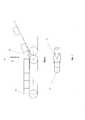
На фиг. 1 представлена общая компоновка устройства; на фиг. 2 - схема узла продольного разделения потоков; на фиг. 3 - схема узла контроля торцевой поверхности первого торца изделия; на фиг. 4 - схема узла контроля торцевой поверхности второго торца изделия.In FIG. 1 shows a general arrangement of a device; in FIG. 2 is a diagram of a longitudinal flow separation unit; in FIG. 3 is a diagram of the control unit of the end surface of the first end of the product; in FIG. 4 is a diagram of the control unit of the end surface of the second end of the product.
ПРИМЕР ОСУЩЕСТВЛЕНИЯ ИЗОБРЕТЕНИЯMODE FOR CARRYING OUT THE INVENTION
Изделия 1 с предыдущего технологического оборудования с заданными промежутками при помощи узла разделения потока 10 попадают на ленточный транспортер 2 с регулируемой скоростью ленты FR-15E (например, фирмы RNA). При необходимости за счет разницы скоростей между ленточными транспортерами 2 и 3 можно скорректировать заданные интервалы между изделиями. Во всем устройстве применяются ленточные транспортеры 2, 3, 4, 5 одного типа, отличающиеся только длиной.
Над вершиной ленточного транспортера 3 под определенным углом находится узел контроля первого торца изделия 6, состоящий из матричной ПЗС камеры высокого разрешения 7, осветителя 8 и узла сдува бракованных таблеток 9. В верхней точке перегиба ленточного транспортера 3 изделия проходят узел контроля первого торца, поочередно освещаясь пучком прямого направленного излучения видимого спектра 8, замыкают оптический датчик 5 Opto BERO (например, фирмы SIEMENS), по команде от которого включается ПЗС камера 7, производится осмотр торца изделия. Полученное изображение переводится в цифровой формат и передается в аналитическое устройство, где на основе логических решающих правил принимается решение о годности изделия.Above the top of the
На следующей позиции изделия проходят узел сдува 9, в котором замыкают оптический датчик 11, по команде которого отличающиеся от заданных параметров изделия сдуваются форсункой 12 как забракованные.At the next position of the product, there is a blowing
Годные изделия перемещаются на промежуточный ленточный транспортер 4, где формируется столб изделий 13 для последующей их подачи по одному с помощью узла разделения потока 10. При необходимости за счет разницы скоростей между ленточными транспортерами 4 и 5 можно скорректировать заданные интервалы между изделиями.Suitable products are moved to an
Над вершиной ленточного транспортера 5 под определенным углом находится узел контроля второго торца изделий 14, состоящий из матричной ПЗС камеры высокого разрешения 15, осветителя 16 и узла сдува бракованных изделий 14. В верхней точке за перегибом ленточного транспортера изделия проходят узел контроля второго торца, поочередно освещаясь пучком прямого направленного излучения видимого спектра 16, замыкают оптический датчик 17, по команде которого включается ПЗС камера 15, производится осмотр второго торца изделия. Полученное изображение переводится в цифровой формат и передается в аналитическое устройство, где на основе логических решающих правил принимается решение о годности изделия. Таким образом, контроль торцов изделий производится последовательно, сначала первого, затем второго без переворачиваний и поперечных перемещений, без торможений, остановок и разгонов на вершинах ленточных транспортеров, имеющих вид равнобедренного треугольника.Above the top of the
На следующей позиции топливные изделия проходят узел сдува 14, в котором замыкают оптический датчик 18, по команде которого отличающиеся от заданных параметров изделия сдуваются форсункой 19 как забракованные.In the next position, the fuel products pass through the blowing
Годные изделия перемещаются на ленточный транспортер 20 для передачи далее в технологический процесс.Suitable products are moved to a
Claims (11)
Translated fromRussianPriority Applications (1)
| Application Number | Priority Date | Filing Date | Title |
|---|---|---|---|
| RU2016146604ARU2645436C1 (en) | 2016-11-28 | 2016-11-28 | Device for detecting defects on the end surface of cylindrical products |
Applications Claiming Priority (1)
| Application Number | Priority Date | Filing Date | Title |
|---|---|---|---|
| RU2016146604ARU2645436C1 (en) | 2016-11-28 | 2016-11-28 | Device for detecting defects on the end surface of cylindrical products |
Publications (1)
| Publication Number | Publication Date |
|---|---|
| RU2645436C1true RU2645436C1 (en) | 2018-02-21 |
Family
ID=61258895
Family Applications (1)
| Application Number | Title | Priority Date | Filing Date |
|---|---|---|---|
| RU2016146604ARU2645436C1 (en) | 2016-11-28 | 2016-11-28 | Device for detecting defects on the end surface of cylindrical products |
Country Status (1)
| Country | Link |
|---|---|
| RU (1) | RU2645436C1 (en) |
Cited By (1)
| Publication number | Priority date | Publication date | Assignee | Title |
|---|---|---|---|---|
| RU2797858C1 (en)* | 2022-01-21 | 2023-06-08 | Акционерное общество "Прорыв" | Method for controlling the chipping of fuel pellets in the assembled fuel cell |
Citations (3)
| Publication number | Priority date | Publication date | Assignee | Title |
|---|---|---|---|---|
| US4226539A (en)* | 1976-12-24 | 1980-10-07 | Hitachi, Ltd. | Cylindrical body appearance inspection apparatus |
| UA27073C2 (en)* | 1993-05-05 | 2000-02-28 | Брітіш Нюклеар Ф'Юелз Пі-Ел-Сі | Appliance for reveal of surface defects |
| RU88838U1 (en)* | 2009-09-07 | 2009-11-20 | Открытое акционерное общество "Машиностроительный завод" | DEVICE FOR DETECTING SURFACE DEFECTS IN CYLINDRICAL PRODUCTS |
- 2016
- 2016-11-28RURU2016146604Apatent/RU2645436C1/enactive
Patent Citations (3)
| Publication number | Priority date | Publication date | Assignee | Title |
|---|---|---|---|---|
| US4226539A (en)* | 1976-12-24 | 1980-10-07 | Hitachi, Ltd. | Cylindrical body appearance inspection apparatus |
| UA27073C2 (en)* | 1993-05-05 | 2000-02-28 | Брітіш Нюклеар Ф'Юелз Пі-Ел-Сі | Appliance for reveal of surface defects |
| RU88838U1 (en)* | 2009-09-07 | 2009-11-20 | Открытое акционерное общество "Машиностроительный завод" | DEVICE FOR DETECTING SURFACE DEFECTS IN CYLINDRICAL PRODUCTS |
Cited By (1)
| Publication number | Priority date | Publication date | Assignee | Title |
|---|---|---|---|---|
| RU2797858C1 (en)* | 2022-01-21 | 2023-06-08 | Акционерное общество "Прорыв" | Method for controlling the chipping of fuel pellets in the assembled fuel cell |
Similar Documents
| Publication | Publication Date | Title |
|---|---|---|
| US11306016B2 (en) | Method of producing glass products from glass product material and an assembly for performing said method | |
| EP3394599B1 (en) | Apparatus for optical inspection of objects | |
| CN103240863B (en) | preform inspection device and inspection method | |
| CN108387590A (en) | A kind of low module stem gear appearance defect detection device | |
| JP6827060B2 (en) | Glass bottle inspection device | |
| FI921807A0 (en) | FOERFARANDE OCH ANORDNING FOER ATT BILDA GRUPPER UR OLIKA SLAGS TRYCKALSTER. | |
| WO2012153662A1 (en) | Method for inspecting minute defect of translucent board-like body, and apparatus for inspecting minute defect of translucent board-like body | |
| JPH04107000A (en) | Part appearance selector | |
| KR102580389B1 (en) | Apparatus and method for inspecting a glass sheet | |
| JPH01250845A (en) | Automatic external appearance inspection machine for chip-shaped component | |
| EP4132763B1 (en) | Device and method for inspecting parisons | |
| CN204503595U (en) | Plume packaging imaging detection device | |
| US20170236270A1 (en) | Video Parts Inspection System | |
| KR20220065518A (en) | Apparatus and System for Inspecting the Glass | |
| RU2645436C1 (en) | Device for detecting defects on the end surface of cylindrical products | |
| JP6897929B2 (en) | Inspection device for transparent articles | |
| JP2019023592A (en) | Article inspection device | |
| RU2638179C1 (en) | Device for detecting defects on forming surface of cylindrical products | |
| WO2010008303A1 (en) | Improved method and apparatus for article inspection | |
| JP2019030853A (en) | Shaft body inspection separating device | |
| US20100118134A1 (en) | Automated visual checking device | |
| JP6913811B2 (en) | Glass bottle inspection device | |
| RU88838U1 (en) | DEVICE FOR DETECTING SURFACE DEFECTS IN CYLINDRICAL PRODUCTS | |
| CN204479483U (en) | A kind of steel ball surface defect detects expanding unit | |
| JP4177204B2 (en) | Container foreign matter inspection system |