RU2642192C2 - Bottom-hole insert injector device - Google Patents
Bottom-hole insert injector deviceDownload PDFInfo
- Publication number
- RU2642192C2 RU2642192C2RU2015137796ARU2015137796ARU2642192C2RU 2642192 C2RU2642192 C2RU 2642192C2RU 2015137796 ARU2015137796 ARU 2015137796ARU 2015137796 ARU2015137796 ARU 2015137796ARU 2642192 C2RU2642192 C2RU 2642192C2
- Authority
- RU
- Russia
- Prior art keywords
- oil
- injector
- splitter
- gas
- annular chamber
- Prior art date
Links
Images


Classifications
- E—FIXED CONSTRUCTIONS
- E21—EARTH OR ROCK DRILLING; MINING
- E21B—EARTH OR ROCK DRILLING; OBTAINING OIL, GAS, WATER, SOLUBLE OR MELTABLE MATERIALS OR A SLURRY OF MINERALS FROM WELLS
- E21B43/00—Methods or apparatus for obtaining oil, gas, water, soluble or meltable materials or a slurry of minerals from wells
- E21B43/12—Methods or apparatus for controlling the flow of the obtained fluid to or in wells
- E21B43/121—Lifting well fluids
- E21B43/122—Gas lift
- E—FIXED CONSTRUCTIONS
- E21—EARTH OR ROCK DRILLING; MINING
- E21B—EARTH OR ROCK DRILLING; OBTAINING OIL, GAS, WATER, SOLUBLE OR MELTABLE MATERIALS OR A SLURRY OF MINERALS FROM WELLS
- E21B43/00—Methods or apparatus for obtaining oil, gas, water, soluble or meltable materials or a slurry of minerals from wells
- E21B43/16—Enhanced recovery methods for obtaining hydrocarbons
- E21B43/24—Enhanced recovery methods for obtaining hydrocarbons using heat, e.g. steam injection
- E—FIXED CONSTRUCTIONS
- E21—EARTH OR ROCK DRILLING; MINING
- E21B—EARTH OR ROCK DRILLING; OBTAINING OIL, GAS, WATER, SOLUBLE OR MELTABLE MATERIALS OR A SLURRY OF MINERALS FROM WELLS
- E21B36/00—Heating, cooling or insulating arrangements for boreholes or wells, e.g. for use in permafrost zones
- E21B36/04—Heating, cooling or insulating arrangements for boreholes or wells, e.g. for use in permafrost zones using electrical heaters
- E—FIXED CONSTRUCTIONS
- E21—EARTH OR ROCK DRILLING; MINING
- E21F—SAFETY DEVICES, TRANSPORT, FILLING-UP, RESCUE, VENTILATION, OR DRAINING IN OR OF MINES OR TUNNELS
- E21F7/00—Methods or devices for drawing- off gases with or without subsequent use of the gas for any purpose
Landscapes
- Engineering & Computer Science (AREA)
- Mining & Mineral Resources (AREA)
- Life Sciences & Earth Sciences (AREA)
- Geology (AREA)
- General Life Sciences & Earth Sciences (AREA)
- Geochemistry & Mineralogy (AREA)
- Physics & Mathematics (AREA)
- Environmental & Geological Engineering (AREA)
- Fluid Mechanics (AREA)
- Nozzles For Spraying Of Liquid Fuel (AREA)
- Nozzles (AREA)
- Heat-Exchange Devices With Radiators And Conduit Assemblies (AREA)
- Jet Pumps And Other Pumps (AREA)
- Earth Drilling (AREA)
Abstract
Description
Translated fromRussianПРЕДПОСЫЛКИ ИЗОБРЕТЕНИЯBACKGROUND OF THE INVENTION
[0001] Для увеличения дебита эксплуатационной нефтяной скважины применяются методики механизированной добычи. Одним доступным для промышленного применения видом механизированной добычи является газлифт. При газлифте в скважину нагнетается сжатый газ для увеличения дебита добываемой текучей среды с помощью уменьшения потерь напора, связанных с весом столба добываемых текучих сред. В частности, нагнетаемый газ уменьшает давление на дне забоя скважины, уменьшая объемную плотность текучей среды в скважине. Уменьшенная плотность облегчает выход текучей среды из скважины. Газлифт, вместе с тем, работает не во всех ситуациях. Например, газлифт не работает в скважинах, разрабатывающих запасы нефти высокой вязкости (тяжелой нефти). Обычно применяют термические способы для извлечения тяжелой нефти из коллектора. В обычном термическом способе пар, вырабатываемый на поверхности, закачивается через нагнетательную скважину в коллектор. В результате теплообмена между паром, нагнетаемым в скважину, и текучими средами на забое вязкость нефти уменьшается до величины, обеспечивающей подачу насосом из отдельной эксплуатационной скважины. Газлифт нет смысла применять в термической системе, поскольку относительно низкая температура газа снижает эффект теплообмена между паром и тяжелой нефтью, увеличивая вязкость нефти, и отрицательно влияет на эффективность работы термической системы. Подача пара или другая обработка пласта для интенсификации притока обычно требует значительных геотехнических мероприятий или капремонта в скважине. Во время капремонта в скважине заканчивание выполняется повторно для получения нефти вместо нагнетания пара или наоборот, что уменьшает производительное время и, соответственно, объем добытой нефти.[0001] To increase the production rate of an oil well, mechanized production techniques are used. One type of mechanized mining available for industrial use is gas lift. During a gas lift, compressed gas is injected into the well to increase the flow rate of the produced fluid by reducing the pressure loss associated with the weight of the column of produced fluids. In particular, the injected gas reduces the pressure at the bottom of the bottom of the well, reducing the bulk density of the fluid in the well. Reduced density facilitates fluid exit from the well. Gas lift, however, does not work in all situations. For example, gas lift does not work in wells that develop reserves of high viscosity oil (heavy oil). Thermal methods are commonly used to recover heavy oil from a reservoir. In the conventional thermal method, steam generated at the surface is pumped through an injection well into a collector. As a result of heat exchange between the steam injected into the well and the downhole fluids, the oil viscosity decreases to a value that ensures that the pump delivers from a separate production well. Gas lift does not make sense to use in a thermal system, since a relatively low gas temperature reduces the effect of heat transfer between steam and heavy oil, increasing the viscosity of the oil, and adversely affects the efficiency of the thermal system. The supply of steam or other treatment of the formation to stimulate the flow usually requires significant geotechnical measures or overhaul in the well. During the overhaul in the well, completion is repeated to obtain oil instead of injecting steam or vice versa, which reduces production time and, accordingly, the volume of oil produced.
[0002] По причинам, указанным выше и по другим причинам, изложенным ниже, понятным специалисту в данной области в техники, рассматривающему данное описание, существует необходимость создания эффективного и высокопроизводительного устройства для подачи на забой пара или другого вещества интенсификации притока и/или текучей среды без проведения значительных геотехнических мероприятий или капремонта в скважине.[0002] For the reasons stated above and for other reasons set forth below, which are understood by one of ordinary skill in the art considering this description, there is a need to provide an efficient and high-performance device for feeding steam or another substance to intensify the influx and / or fluid without significant geotechnical measures or overhaul in the well.
СУЩНОСТЬ ИЗОБРЕТЕНИЯSUMMARY OF THE INVENTION
[0003] Упомянутые выше проблемы существующих систем решаются с помощью вариантов осуществления настоящего изобретения, которые становятся понять из приведенного ниже подробного описания изобретения. Сущность изобретения приведена в качестве примера и не служит ограничением. Сущность изобретения приведена для помощи пользователю в понимании некоторых аспектов изобретения.[0003] The above problems of existing systems are solved by embodiments of the present invention, which will become apparent from the following detailed description of the invention. The invention is given as an example and is not intended to be limiting. The invention is provided to assist the user in understanding some aspects of the invention.
[0004] В одном варианте осуществления, создано вставное инжекторное устройство. Вставное инжекторное устройство включает в себя корпус, который имеет внутренний нефтяной канал, выполненный с возможностью обеспечивать сквозной проход нефти. Корпус дополнительно имеет кольцевую камеру, выполненную вокруг внутреннего нефтяного канала. Кольцевая камера имеет отверстие камеры, выполненное с возможностью соединения для приема потока газового теплоносителя. Корпус также имеет по меньшей мере одно инжекторное отверстие, обеспечивающее проход между кольцевой камерой и внутренним нефтяным каналом. По меньшей мере одно инжекторное отверстие выполнено с возможностью нагнетания газового теплоносителя в нефть, пропускаемую по внутреннему нефтяному каналу. По меньшей мере одно инжекторное отверстие выполнено с возможностью нагнетания стимулирующего газлифт теплоносителя в нефть, проходящую по внутренний нефтяной канал.[0004] In one embodiment, a plug-in injector device is provided. The plug-in injector device includes a housing that has an internal oil channel configured to provide a through passage for oil. The housing additionally has an annular chamber made around the internal oil channel. The annular chamber has a chamber opening configured to connect to receive a gas coolant stream. The housing also has at least one injection opening allowing passage between the annular chamber and the internal oil channel. At least one injector orifice is configured to pump the gas coolant into the oil passing through the internal oil channel. At least one injector orifice is configured to inject a gas-lift stimulating coolant into the oil passing through the internal oil channel.
[0005] В другом варианте осуществления создана забойная система. Система включает в себя разветвитель для скважинного байпаса, обходящего установку электроцентробежного погружного насоса (УЭЦН) и вставной инжектор. Разветвитель для скважинного байпаса, обходящего УЭЦН установлен для создания пути между первым стволом скважины и вторым стволом скважины. Вставное инжекторное устройство установлен в разветвителе для скважинного байпаса, обходящего УЭЦН. Вставной инжектор имеет корпус и внутренний нефтяной канал, который выполнен с возможностью обеспечивать сквозной проход нефти. Корпус дополнительно имеет кольцевую камеру, выполненную вокруг внутреннего нефтяного канала. Кольцевая камера имеет отверстие камеры, выполненное с возможностью соединения для приема потока газового теплоносителя из второго ствола скважины. Корпус также имеет по меньшей мере одно инжекторное отверстие, обеспечивающее проход между кольцевой камерой и внутренним нефтяным каналом. По меньшей мере одно инжекторное отверстие выполнено с возможностью нагнетания газового теплоносителя во внутренний нефтяной канал.[0005] In another embodiment, a downhole system is provided. The system includes a splitter for the borehole bypass, bypassing the installation of an electric centrifugal submersible pump (ESP) and a plug-in injector. A splitter for the downhole bypass bypassing the ESP is installed to create a path between the first wellbore and the second wellbore. A plug-in injector device is installed in the splitter for the downhole bypass, bypassing the ESP. The plug-in injector has a housing and an internal oil channel, which is configured to provide a through passage of oil. The housing additionally has an annular chamber made around the internal oil channel. The annular chamber has a chamber opening configured to connect to receive a gas coolant stream from a second wellbore. The housing also has at least one injection opening allowing passage between the annular chamber and the internal oil channel. At least one injector orifice is configured to pump the gas coolant into the internal oil channel.
[0006] В еще одном варианте осуществления создан способ интенсификации добычи нефти для нефтяного коллектора. Способ включает в себя: подачу высокоскоростного газового теплоносителя в кольцевую камеру, окружающую нефтяной канал в первой скважине; и нагнетание газового теплоносителя через по меньшей мере одно инжекторное отверстие в нефтяной поток, проходящий через нефтяной канал.[0006] In yet another embodiment, a method for enhancing oil production for an oil reservoir is provided. The method includes: supplying a high-speed gas coolant to the annular chamber surrounding the oil channel in the first well; and forcing the gas coolant through at least one injection hole into the oil stream passing through the oil channel.
КРАТКОЕ ОПИСАНИЕ ЧЕРТЕЖЕЙBRIEF DESCRIPTION OF THE DRAWINGS
[0007] Настоящее изобретение и его дополнительные преимущества и варианты применения можно лучше понять, из приведенного ниже подробного описания с прилагаемыми фигурами, на которых показано следующее.[0007] The present invention and its additional advantages and applications can be better understood from the following detailed description with the accompanying figures, which show the following.
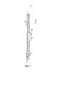
[0008] На фиг.1 показан вид сбоку забойной системы одного варианта осуществления настоящего изобретения.[0008] Figure 1 shows a side view of a downhole system of one embodiment of the present invention.
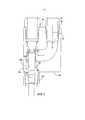
[0009] На фиг.2 показан с увеличением вид сбоку вставки узла форсунки одного варианта осуществления настоящего изобретения.[0009] FIG. 2 is an enlarged side view of an insert of a nozzle assembly of one nozzle of one embodiment of the present invention.
[0010] На фиг.3 показан с увеличением вид сбоку вставки узла форсунки фиг.2 и установка пробки в одном варианте осуществления настоящего изобретения.[0010] FIG. 3 is an enlarged side view of the insert of the nozzle assembly of FIG. 2 and plugging in one embodiment of the present invention.
[0011] На фиг.4 показан с увеличением вид сбоку вставки узла форсунки фиг.2 и установка пробки в другом месте в другом варианте осуществления настоящего изобретения.[0011] FIG. 4 is an enlarged side view of the insert of the nozzle assembly of FIG. 2 and the installation of the plug elsewhere in another embodiment of the present invention.
[0012] На фиг.5 показан с увеличением вид сбоку другого варианта осуществления вставки узла форсунки.[0012] FIG. 5 is an enlarged side view of another embodiment of an insert of an injector assembly.
[0013] Согласно обычной практике различные описанные элементы вычерчены без соблюдения масштаба для выделения конкретных признаков, релевантных для настоящего изобретения. Одинаковые позиции ссылки присвоены одинаковым элементам на фигурах и по тексту.[0013] According to ordinary practice, the various elements described are drawn without scaling to highlight specific features relevant to the present invention. The same reference position is assigned to the same elements in the figures and in the text.
ПОДРОБНОЕ ОПИСАНИЕ ИЗОБРЕТЕНИЯDETAILED DESCRIPTION OF THE INVENTION
[0014] В следующем подробном описании с прилагаемыми чертежами даны примеры иллюстративных конкретных вариантов осуществления изобретения. Данные варианты осуществления описаны достаточно подробно, при этом, специалисту в данной области техники, реализующему изобретение, понятно, что можно применять другие варианты осуществления, и что изменения можно выполнять без отхода от сущности и объема настоящего изобретения. Следующее подробное описание таким образом, нельзя считать ограничивающим, и объем настоящего изобретения определяется только формулой изобретения и его эквивалентами.[0014] In the following detailed description with the accompanying drawings, examples of illustrative specific embodiments of the invention are given. These options for implementation are described in sufficient detail, however, the specialist in the field of technology implementing the invention, it is clear that you can apply other options for implementation, and that changes can be made without departing from the essence and scope of the present invention. The following detailed description, therefore, cannot be considered limiting, and the scope of the present invention is defined only by the claims and their equivalents.
[0015] В варианте осуществления кольцевое расширяющееся и сужающееся сопло установлено в разветвитель для скважинного байпаса, обходящего УЭЦН, на выходе парогенератора или генератора другой горячей текучей среды. Кольцевое сопло перенаправляет поток газа параллельно потоку добываемой нефти и должно действовать, как забойный эжекторный насос, передающий кинетическую энергию добываемой нефти. В другом варианте осуществления продукт, выходящий из сопла насоса должен нагнетаться в поток под небольшим углом. Данное нагнетание должно располагаться выше по потоку от отклоняющегося контура. Нагнетаемый поток приводящего в движение носителя должен автоматически дросселироваться до числа Маха меньше 1.[0015] In an embodiment, an annular expanding and tapering nozzle is installed in a splitter for a downhole bypass bypassing the ESP at the output of a steam generator or other hot fluid generator. An annular nozzle redirects the gas flow parallel to the flow of the produced oil and should act as a downhole ejector pump that transfers the kinetic energy of the produced oil. In another embodiment, the product exiting the pump nozzle is to be injected into the stream at a slight angle. This discharge should be located upstream of the deviating circuit. The pressure flow of the propelling carrier should be automatically throttled to a Mach number less than 1.
[0016] Кроме того, в вариантах осуществления настоящего изобретения создано вставное инжекторное устройство, которое образует забойный струйный насос с источником газа. Изобретение увеличивает добычу скважины, как средство механизированной добычи и обеспечивает добычу нефти вокруг забойного парогенератора, такого как теплообменник. В варианте осуществления, забойный генератор является соединением парогазогенератора и теплообменника прямого контакта. Пример парогазогенератора имеется в патентной заявке совместного правообладания Patent Application No. 13/782865 под названием "HIGH PRESSURE IGNITION OF GASEOUS HYDROCARBONS WITH HOT SURFACE IGNITION," выложена 1 марта 2013 г., которая включена в состав данного документа. Пример теплообменника имеется в патентной заявке совместного правообладания Patent Application No. 13/793891 под названием "HIGH EFFICIENCY DIRECT CONTACT HEAT EXCHANGER" выложена 1 марта 2003 г., которая включена в данном документе в виде ссылки. Теплообменник в вариантах осуществления может охлаждаться любым из следующего: жидкостью, например, водой (режим пара), пропаном, другими углеводородами или другой текучей средой, например, CO, C02, N2, и т.д. В варианте осуществления теплообменник прямого контакта забирает высокотемпературный под высоким давлением выхлоп из забойного парогазогенератора и нагнетает газообразный выходящий поток в воду для создания пара, который является стимулирующим теплоносителем газлифта, в общем описываемым, как газовый теплоноситель. В других вариантах осуществления, как рассмотрено выше, может применятьcя охлаждающее вещество, например, пропан, или различные углеводороды или другие газы, например CO, C02, N2, и т.д., которые смешиваются с выхлопными газами парогазогенератора для образования газового теплоносителя. Таким образом, вещество, подаваемое теплообменником должно в общем, называться газовым теплоносителем. Вставное инжекторное устройство с соплом вариантов осуществления устанавливается в разветвитель для скважинного байпаса, обходящего УЭЦН, который перенаправляет поток газового теплоносителя, идущего в скважину из теплообменника, на выход из скважины. При этом сопло функционирует, как эжектор, что рассмотрено ниже. В варианте осуществления применяется кольцевое сопло, выполняющее работу на нефти, перекачиваемой, благодаря передаче кинетической энергии и снижению статического давления на выходе сопла. Массовый расход должен при этом увеличиваться благодаря лифтовым свойствам газовой смеси, дополнительно увеличивая добычу. Устройство нагнетательной вставки дает возможность стимуляции более высокопроизводительной работы скважины и ведения добычи из скважины без значительного капремонта, что дает значительную экономию затрат и увеличивает кпд.[0016] Furthermore, in embodiments of the present invention, an insertion injector device is provided that forms a downhole jet pump with a gas source. The invention increases well production as a means of mechanized production and provides oil production around a bottomhole steam generator, such as a heat exchanger. In an embodiment, the downhole generator is a combination of a steam and gas generator and a direct contact heat exchanger. An example of a steam and gas generator is available in Patent Application No. Patent Application No. 13/782865 entitled "HIGH PRESSURE IGNITION OF GASEOUS HYDROCARBONS WITH HOT SURFACE IGNITION," published March 1, 2013, which is included in this document. An example of a heat exchanger is available in Patent Application No. Patent Application No. 13/793891, entitled "HIGH EFFICIENCY DIRECT CONTACT HEAT EXCHANGER", published March 1, 2003, which is incorporated herein by reference. The heat exchanger in the embodiments may be cooled by any of the following: a liquid, for example, water (steam mode), propane, other hydrocarbons or other fluid, for example, CO, C02 , N2 , etc. In an embodiment, the direct contact heat exchanger takes the high-temperature, high-pressure exhaust from the bottomhole gas generator and injects a gaseous effluent into the water to generate steam, which is a stimulating gas lift fluid, generally described as a gas coolant. In other embodiments, as discussed above, a coolant, such as propane, or various hydrocarbons or other gases, such as CO, C02 , N2 , etc., which are mixed with the exhaust gases of the steam generator to form a gas coolant, can be used. . Thus, the substance supplied by the heat exchanger should generally be called a gas heat transfer medium. An insertion injector device with a nozzle of embodiments is installed in a splitter for a bypass bypassing the ESP, which redirects the flow of the gas coolant going into the well from the heat exchanger to the well exit. In this case, the nozzle functions as an ejector, which is discussed below. In an embodiment, an annular nozzle is used that performs work on oil pumped through the transfer of kinetic energy and the reduction of static pressure at the nozzle exit. The mass flow rate should increase due to the lift properties of the gas mixture, further increasing production. The injection insert device makes it possible to stimulate higher productivity of the well and conduct production from the well without significant overhaul, which gives significant cost savings and increases efficiency.
[0017] На фиг. 1 показана забойная система 50 одного варианта осуществления. В варианте осуществления забойная система 50 включает в себя парогазогенератор и теплообменник 100, рассмотренные выше, которые установлены продольно сбоку эксплуатационной колонны 120 в одной скважине. Систему 100 парогазогенератора и теплообмена можно в общем, называть системой 100 подачи горячей текучей среды, которая подает газовый теплоноситель. Система 100 подачи горячей текучей среды показана с наружным кожухом 103, который защищает внутренние компоненты 102. Забойная система 50 дополнительно включает в себя разветвитель 200 для скважинного байпаса, обходящего УЭЦН, который создает путь для эксплуатационной колонны 120. Нефть подлежит извлечению из эксплуатационной колонны 120. В разветвитель для скважинного байпаса, обходящего УЭЦН установлено вставное инжекторное устройство 400 варианта осуществления.[0017] FIG. 1 shows a
[0018] На фиг.2 показан с увеличением разветвитель 200 для скважинного байпаса, обходящего УЭЦН, с вставным инжекторным устройством 300 варианта осуществления. Вставное инжекторное устройство 300 включает в себя удлиненный кольцевой корпус 300a, который включает в себя внутренний канал 302, создающий путь прохода между верхним участком 120a эксплуатационной колонны 120, который ведет на поверхность, и нижним участком 120b, который ведет в нефтяной коллектор. Кольцевой корпус 300a имеет первый конец 320a, который устанавливается в направлении к нефтяному коллектору и противоположный второй конец 320b, который устанавливается в направлении к оборудованию устья скважины. Кольцевой корпус 300a дополнительно включает в себя кольцевую камеру 304 (кольцевую камеру повышенного давления), которая выполнена в корпусе 300a вставного инжекторного устройства 300. Кольцевая камера 304 проходит вокруг внутреннего нефтяного канала 302. Кольцевая камера 304 имеет отверстие 322 сообщающееся текучей средой с разветвителем для скважинного байпаса, обходящего УЭЦН, для приема теплоносителя 101 газлифта из системы 100 подачи горячей текучей среды. Узкое калиброванное отверстие 306 эжектора (кольцевой инжектор) между кольцевой камерой 304 и внутренним нефтяным каналом 302 создает путь для теплоносителя газлифта в нефть во внутреннем нефтяном канале 302. Как показано, калиброванное отверстие 306 эжектора (калиброванное отверстие кольцевого инжектора в данном варианте осуществления) выполнено с возможностью направлять теплоноситель газлифта вверх в направлении к поверхности в данном варианте осуществления. Калиброванное отверстие 306 эжектора также установлено вблизи второго конца 320b вставного инжекторного устройства 300 в данном варианте осуществления. Теплоноситель газлифта, входящий в нефть 115 должен выполнять работу на нефти, 115, перекачиваемой на выход из скважины, передавая кинетическую энергию и снижая статическое давление на выходе сопла. Массовый расход должен при этом увеличиваться благодаря подъемной силе газовой смеси для дополнительного увеличения добычи.[0018] FIG. 2 shows an
[0019] В частности, газовый теплоноситель 101, например, горячий газ из системы 100 подачи горячего газа подается в кольцевую камеру 304 (кольцевую камеру повышенного давления) под давлением достаточным для обеспечения достижения газовым теплоносителем 101 высокой скорости. В некоторых конфигурациях скорость должна быть звуковой, а в других скорость должна быть дозвуковой. Теплоноситель 101 газлифта получает ускорение при проходе через калиброванное отверстие 306 инжектора, при этом статическое давление ниже по потоку от точки нагнетания уменьшается, таким образом увеличивая потенциал приведения в движение текучей среды коллектора. Конечную скорость теплоносителя 101 газлифта для интенсификации добычи и, следовательно, максимальную кинетическую энергию, которая может передаваться углеводородному потоку, диктует геометрия кольцевого нагнетания, а также эффективное кольцевое пространство, создаваемое между контуром стенки с внутренней поверхностью 300b вставки 300 и перекачиваемой углеводородной текучей средой. В данном случае наружная граница является фиксированной и задается геометрией вставки 300, а внутренняя граница образуется благодаря неоднородности плотности между углеводородным потоком и горячей текучей средой.[0019] In particular, the
[0020] Вставное инжекторное устройство 300, с внутренним нефтяным каналом 302, вариантов осуществления обеспечивает вставление пробок либо выше вставного инжекторного устройства 300 или ниже вставного инжекторного устройства 300. Например, как показано на фиг.3, пробка 350 пропущена через внутренний нефтяной канал 302 и установлена ниже узкого калиброванного отверстия 306 эжектора. Пробка 350 в данном положении изолирует нефтяной коллектор от поверхности и вставное инжекторное устройство 300 можно удалять до обработки коллектора для интенсификации притока и проводить ее техобслуживание и ремонт до следующего периода добычи. Данное обеспечивает ускоренное и менее дорогостоящее техобслуживание, а также более продолжительную и надежную работу между полными капитальными ремонтами. Пробка 350 в данном положении также предотвращает вход нефти в систему 100 подачи горячего газа, когда система не работает, в период времени между закачкой пара и извлечением нефти при циклической обработке пласта паром для интенсификации притока или стимуляции циклической закачкой пара. На фиг.4 показана пробка 360, установленная выше узкого калиброванного отверстие 306 эжектора. В данной конфигурации выходящему из системы 100 подачи потоку горячего газа обеспечен проход на забой скважины в нефтяной коллектор. Данное обеспечивает обработку горячим газом нефти в коллекторе для интенсификации притока. Как показано другими способами добычи с циклической закачкой пара, резкое увеличение добычи нефти получают при термической обработке пласта для интенсификации притока. Некоторые показатели проводимых работ указывают, когда вставка 300 должна оставаться в разветвителе 200 для скважинного байпаса, обходящего УЭЦН, во время обработки пласта для интенсификации притока циклической закачкой пара, как показано на фиг. 4 и когда наступает наилучший момент для удаления вставки 300 до обработки коллектора для интенсификации притока, как показано на фиг. 3.[0020] An
[0021] Другой вариант осуществления вставного инжекторного устройства 400 показан на фиг. 5. В данном варианте осуществления кольцевая камера 502 (наружный канал горячего газа) выполнена с возможностью придания ускорения газовому теплоносителю до выброса газового теплоносителя через зауженное калиброванное отверстие 504 в поток нефти в верхнем скважинном участке 120a. В данном варианте осуществления, ускорение газовому теплоносителю 101 придается в кольцевой камере 502. Вставное инжекторное устройство 400 включает в себя удлиненный кольцевой корпус 400a, который включает в себя наружную стенку 402a и внутреннюю стенку 402b. Кольцевая камера 502 образована между наружной стенкой 402a и внутренней стенкой 402b. Дополнительно в данном варианте осуществления, расположенные на расстоянии друг от друга выступы 404 проходят от внутренней стенки 402b в кольцевое пространство 502. Выступы 404 действуют, как конструктивные опоры внутренней стенки и могут улучшать теплопередачу от горячей текучей среды в углеводородный поток. Корпус 400a имеет первый конец 420a, установленный направленным к нефтяному коллектору, и противоположный второй конец 420b установленный направленным к поверхности. Узкое калиброванное отверстие 504 установлено вблизи второго конца 420b корпуса 400a. Также на фиг. 5 показано отверстие 422 камеры, которое обеспечивает вход теплоносителя 101 газлифта в кольцевую камеру 502.[0021] Another embodiment of the
[0022] Хотя в данном документе показаны и описаны конкретные варианты осуществления изобретения, специалисту в данной области техники понятно, что любое показанное устройство в таком варианте осуществления, можно заменить другим устройством аналогичной функциональности. Например, хотя выше в вариантах осуществления показана фиксированная геометрия, вариации данного инжекторного вставного устройства могут включать в себя изменяемую минимальную площадь, которая должна обеспечивать существенные изменения соотношения объемов "потока подачи пара" и "стимулируемого потока". Другие вариации относятся к подаче стимулируемой текучей среды и давлению с величинами, ниже которых звуковая скорость создается в кольцевого инжекторном механизме и дискретных отверстиях нагнетания, расположенных на расстоянии друг от друга вокруг внутреннего цилиндра вставки 300. Таким образом, данная заявка не описывает все возможные адаптации или вариации настоящего изобретения. Таким образом, установлено, что данное изобретение ограничено только формулой изобретения и его эквивалентами.[0022] Although specific embodiments of the invention are shown and described herein, one skilled in the art will recognize that any device shown in such an embodiment can be replaced with another device of similar functionality. For example, although fixed geometry is shown in the embodiments above, variations of this injector insertion device may include a variable minimum area, which should provide significant changes in the ratio of the volumes of the "steam supply stream" and the "stimulated stream". Other variations relate to the supply of stimulated fluid and pressures with values below which sound velocity is created in the annular injection mechanism and discrete discharge openings spaced apart from each other around the inner cylinder of
Claims (28)
Translated fromRussianApplications Claiming Priority (5)
| Application Number | Priority Date | Filing Date | Title |
|---|---|---|---|
| US201361761629P | 2013-02-06 | 2013-02-06 | |
| US61/761,629 | 2013-02-06 | ||
| US13/832,992 | 2013-03-15 | ||
| US13/832,992US9291041B2 (en) | 2013-02-06 | 2013-03-15 | Downhole injector insert apparatus |
| PCT/US2014/010834WO2014123655A2 (en) | 2013-02-06 | 2014-01-09 | Downhole injector insert apparatus |
Publications (2)
| Publication Number | Publication Date |
|---|---|
| RU2015137796A RU2015137796A (en) | 2017-03-14 |
| RU2642192C2true RU2642192C2 (en) | 2018-01-24 |
Family
ID=51258311
Family Applications (1)
| Application Number | Title | Priority Date | Filing Date |
|---|---|---|---|
| RU2015137796ARU2642192C2 (en) | 2013-02-06 | 2014-01-09 | Bottom-hole insert injector device |
Country Status (9)
| Country | Link |
|---|---|
| US (1) | US9291041B2 (en) |
| EP (1) | EP2954157B1 (en) |
| CN (1) | CN105189916B (en) |
| BR (1) | BR112015018802A2 (en) |
| CA (1) | CA2899999C (en) |
| ES (1) | ES2685630T3 (en) |
| MX (1) | MX357025B (en) |
| RU (1) | RU2642192C2 (en) |
| WO (1) | WO2014123655A2 (en) |
Families Citing this family (2)
| Publication number | Priority date | Publication date | Assignee | Title |
|---|---|---|---|---|
| CN104234678B (en)* | 2014-08-25 | 2016-08-03 | 中国石油天然气股份有限公司 | Gas-liquid mixing device for fireflooding gas injection well and gas injection tubular column |
| CA2902548C (en)* | 2015-08-31 | 2019-02-26 | Suncor Energy Inc. | Systems and method for controlling production of hydrocarbons |
Citations (6)
| Publication number | Priority date | Publication date | Assignee | Title |
|---|---|---|---|---|
| US2642889A (en)* | 1951-03-19 | 1953-06-23 | Cummings Inc | Gas lift valve |
| US3407830A (en)* | 1966-08-12 | 1968-10-29 | Otis Eng Co | Gas lift valve |
| RU2055170C1 (en)* | 1993-05-18 | 1996-02-27 | Всесоюзный нефтяной научно-исследовательский геологоразведочный институт | Method for stimulation of oil recovery |
| RU2067168C1 (en)* | 1994-01-05 | 1996-09-27 | Государственное научно-производственное предприятие "Пилот" | Method for heat displacement of oil from horizontal well |
| RU2206728C1 (en)* | 2002-05-18 | 2003-06-20 | Всероссийский нефтегазовый научно-исследовательский институт (ОАО ВНИИнефть) | Method of high-viscocity oil production |
| EA200702306A1 (en)* | 2005-04-22 | 2008-02-28 | Шелл Интернэшнл Рисерч Маатсхаппий Б.В. | HEATER, CONTAINING ISOLATED CONDUCTOR, WITH LIMITING OPERATING TEMPERATURES, INTENDED FOR UNDERGROUND HEATING, UNITED TO THREE-PHASE CONNECTION STAR |
Family Cites Families (63)
| Publication number | Priority date | Publication date | Assignee | Title |
|---|---|---|---|---|
| US2803305A (en) | 1953-05-14 | 1957-08-20 | Pan American Petroleum Corp | Oil recovery by underground combustion |
| US3426786A (en) | 1966-09-06 | 1969-02-11 | Otis Eng Corp | Gas lift valve |
| US3456721A (en) | 1967-12-19 | 1969-07-22 | Phillips Petroleum Co | Downhole-burner apparatus |
| US3482630A (en) | 1967-12-26 | 1969-12-09 | Marathon Oil Co | In situ steam generation and combustion recovery |
| US4237973A (en) | 1978-10-04 | 1980-12-09 | Todd John C | Method and apparatus for steam generation at the bottom of a well bore |
| US4243098A (en) | 1979-11-14 | 1981-01-06 | Thomas Meeks | Downhole steam apparatus |
| US4431069A (en) | 1980-07-17 | 1984-02-14 | Dickinson Iii Ben W O | Method and apparatus for forming and using a bore hole |
| US4411618A (en) | 1980-10-10 | 1983-10-25 | Donaldson A Burl | Downhole steam generator with improved preheating/cooling features |
| US4336839A (en) | 1980-11-03 | 1982-06-29 | Rockwell International Corporation | Direct firing downhole steam generator |
| US4390062A (en) | 1981-01-07 | 1983-06-28 | The United States Of America As Represented By The United States Department Of Energy | Downhole steam generator using low pressure fuel and air supply |
| US4380267A (en) | 1981-01-07 | 1983-04-19 | The United States Of America As Represented By The United States Department Of Energy | Downhole steam generator having a downhole oxidant compressor |
| US4385661A (en) | 1981-01-07 | 1983-05-31 | The United States Of America As Represented By The United States Department Of Energy | Downhole steam generator with improved preheating, combustion and protection features |
| US4377205A (en) | 1981-03-06 | 1983-03-22 | Retallick William B | Low pressure combustor for generating steam downhole |
| US4397356A (en) | 1981-03-26 | 1983-08-09 | Retallick William B | High pressure combustor for generating steam downhole |
| US4502535A (en)* | 1981-05-18 | 1985-03-05 | Kofahl William M | Jet engine pump and downhole heater |
| US4421163A (en) | 1981-07-13 | 1983-12-20 | Rockwell International Corporation | Downhole steam generator and turbopump |
| US4458756A (en) | 1981-08-11 | 1984-07-10 | Hemisphere Licensing Corporation | Heavy oil recovery from deep formations |
| US4442898A (en) | 1982-02-17 | 1984-04-17 | Trans-Texas Energy, Inc. | Downhole vapor generator |
| US4463803A (en) | 1982-02-17 | 1984-08-07 | Trans Texas Energy, Inc. | Downhole vapor generator and method of operation |
| US4498531A (en) | 1982-10-01 | 1985-02-12 | Rockwell International Corporation | Emission controller for indirect fired downhole steam generators |
| US4471839A (en) | 1983-04-25 | 1984-09-18 | Mobil Oil Corporation | Steam drive oil recovery method utilizing a downhole steam generator |
| US4648835A (en) | 1983-04-29 | 1987-03-10 | Enhanced Energy Systems | Steam generator having a high pressure combustor with controlled thermal and mechanical stresses and utilizing pyrophoric ignition |
| US4558743A (en) | 1983-06-29 | 1985-12-17 | University Of Utah | Steam generator apparatus and method |
| US4522263A (en) | 1984-01-23 | 1985-06-11 | Mobil Oil Corporation | Stem drive oil recovery method utilizing a downhole steam generator and anti clay-swelling agent |
| US4682471A (en) | 1985-11-15 | 1987-07-28 | Rockwell International Corporation | Turbocompressor downhole steam-generating system |
| US4699213A (en) | 1986-05-23 | 1987-10-13 | Atlantic Richfield Company | Enhanced oil recovery process utilizing in situ steam generation |
| US4783585A (en) | 1986-06-26 | 1988-11-08 | Meshekow Oil Recovery Corp. | Downhole electric steam or hot water generator for oil wells |
| US4718489A (en) | 1986-09-17 | 1988-01-12 | Alberta Oil Sands Technology And Research Authority | Pressure-up/blowdown combustion - a channelled reservoir recovery process |
| CA1325969C (en)* | 1987-10-28 | 1994-01-11 | Tad A. Sudol | Conduit or well cleaning and pumping device and method of use thereof |
| US4834174A (en) | 1987-11-17 | 1989-05-30 | Hughes Tool Company | Completion system for downhole steam generator |
| US4805698A (en) | 1987-11-17 | 1989-02-21 | Hughes Tool Company | Packer cooling system for a downhole steam generator assembly |
| US5052482A (en) | 1990-04-18 | 1991-10-01 | S-Cal Research Corp. | Catalytic downhole reactor and steam generator |
| CA2058255C (en) | 1991-12-20 | 1997-02-11 | Roland P. Leaute | Recovery and upgrading of hydrocarbons utilizing in situ combustion and horizontal wells |
| US5211230A (en) | 1992-02-21 | 1993-05-18 | Mobil Oil Corporation | Method for enhanced oil recovery through a horizontal production well in a subsurface formation by in-situ combustion |
| CA2128761C (en) | 1993-07-26 | 2004-12-07 | Harry A. Deans | Downhole radial flow steam generator for oil wells |
| US5525044A (en) | 1995-04-27 | 1996-06-11 | Thermo Power Corporation | High pressure gas compressor |
| US5775426A (en) | 1996-09-09 | 1998-07-07 | Marathon Oil Company | Apparatus and method for perforating and stimulating a subterranean formation |
| EP1234099B1 (en) | 1999-11-29 | 2005-01-19 | Shell Internationale Researchmaatschappij B.V. | Downhole pulser |
| US7493952B2 (en) | 2004-06-07 | 2009-02-24 | Archon Technologies Ltd. | Oilfield enhanced in situ combustion process |
| US7665525B2 (en) | 2005-05-23 | 2010-02-23 | Precision Combustion, Inc. | Reducing the energy requirements for the production of heavy oil |
| US7640987B2 (en) | 2005-08-17 | 2010-01-05 | Halliburton Energy Services, Inc. | Communicating fluids with a heated-fluid generation system |
| US8091625B2 (en) | 2006-02-21 | 2012-01-10 | World Energy Systems Incorporated | Method for producing viscous hydrocarbon using steam and carbon dioxide |
| US7658229B2 (en)* | 2006-03-31 | 2010-02-09 | BST Lift Systems, LLC | Gas lift chamber purge and vent valve and pump systems |
| US20070284107A1 (en) | 2006-06-02 | 2007-12-13 | Crichlow Henry B | Heavy Oil Recovery and Apparatus |
| US20080017381A1 (en) | 2006-06-08 | 2008-01-24 | Nicholas Baiton | Downhole steam generation system and method |
| US7784533B1 (en) | 2006-06-19 | 2010-08-31 | Hill Gilman A | Downhole combustion unit and process for TECF injection into carbonaceous permeable zones |
| US7497253B2 (en) | 2006-09-06 | 2009-03-03 | William B. Retallick | Downhole steam generator |
| US20080078552A1 (en) | 2006-09-29 | 2008-04-03 | Osum Oil Sands Corp. | Method of heating hydrocarbons |
| US7712528B2 (en) | 2006-10-09 | 2010-05-11 | World Energy Systems, Inc. | Process for dispersing nanocatalysts into petroleum-bearing formations |
| CN101563524B (en) | 2006-10-13 | 2013-02-27 | 埃克森美孚上游研究公司 | Combination of in-situ heating to develop oil shale and develop deeper hydrocarbon sources |
| US7628204B2 (en) | 2006-11-16 | 2009-12-08 | Kellogg Brown & Root Llc | Wastewater disposal with in situ steam production |
| WO2009114913A1 (en) | 2008-03-19 | 2009-09-24 | VALE SOLUςόES EM ENERGIA S.A. | Vitiated steam generator |
| US20090260811A1 (en) | 2008-04-18 | 2009-10-22 | Jingyu Cui | Methods for generation of subsurface heat for treatment of a hydrocarbon containing formation |
| CA2631977C (en) | 2008-05-22 | 2009-06-16 | Gokhan Coskuner | In situ thermal process for recovering oil from oil sands |
| DE102008047219A1 (en) | 2008-09-15 | 2010-03-25 | Siemens Aktiengesellschaft | Process for the extraction of bitumen and / or heavy oil from an underground deposit, associated plant and operating procedures of this plant |
| US9127541B2 (en)* | 2008-11-06 | 2015-09-08 | American Shale Oil, Llc | Heater and method for recovering hydrocarbons from underground deposits |
| US8333239B2 (en) | 2009-01-16 | 2012-12-18 | Resource Innovations Inc. | Apparatus and method for downhole steam generation and enhanced oil recovery |
| GB0902476D0 (en)* | 2009-02-13 | 2009-04-01 | Statoilhydro Asa | Method |
| US7946342B1 (en) | 2009-04-30 | 2011-05-24 | The United States Of America As Represented By The United States Department Of Energy | In situ generation of steam and alkaline surfactant for enhanced oil recovery using an exothermic water reactant (EWR) |
| CA2896436C (en) | 2009-07-17 | 2017-02-07 | World Energy Systems Incorporated | Method and apparatus for a downhole gas generator |
| US8656998B2 (en) | 2009-11-23 | 2014-02-25 | Conocophillips Company | In situ heating for reservoir chamber development |
| US8899327B2 (en) | 2010-06-02 | 2014-12-02 | World Energy Systems Incorporated | Method for recovering hydrocarbons using cold heavy oil production with sand (CHOPS) and downhole steam generation |
| US9228738B2 (en)* | 2012-06-25 | 2016-01-05 | Orbital Atk, Inc. | Downhole combustor |
- 2013
- 2013-03-15USUS13/832,992patent/US9291041B2/enactiveActive
- 2014
- 2014-01-09MXMX2015010072Apatent/MX357025B/enactiveIP Right Grant
- 2014-01-09BRBR112015018802Apatent/BR112015018802A2/ennot_activeApplication Discontinuation
- 2014-01-09CACA2899999Apatent/CA2899999C/ennot_activeExpired - Fee Related
- 2014-01-09CNCN201480012901.0Apatent/CN105189916B/ennot_activeExpired - Fee Related
- 2014-01-09RURU2015137796Apatent/RU2642192C2/ennot_activeIP Right Cessation
- 2014-01-09WOPCT/US2014/010834patent/WO2014123655A2/enactiveApplication Filing
- 2014-01-09ESES14701262.9Tpatent/ES2685630T3/enactiveActive
- 2014-01-09EPEP14701262.9Apatent/EP2954157B1/ennot_activeNot-in-force
Patent Citations (6)
| Publication number | Priority date | Publication date | Assignee | Title |
|---|---|---|---|---|
| US2642889A (en)* | 1951-03-19 | 1953-06-23 | Cummings Inc | Gas lift valve |
| US3407830A (en)* | 1966-08-12 | 1968-10-29 | Otis Eng Co | Gas lift valve |
| RU2055170C1 (en)* | 1993-05-18 | 1996-02-27 | Всесоюзный нефтяной научно-исследовательский геологоразведочный институт | Method for stimulation of oil recovery |
| RU2067168C1 (en)* | 1994-01-05 | 1996-09-27 | Государственное научно-производственное предприятие "Пилот" | Method for heat displacement of oil from horizontal well |
| RU2206728C1 (en)* | 2002-05-18 | 2003-06-20 | Всероссийский нефтегазовый научно-исследовательский институт (ОАО ВНИИнефть) | Method of high-viscocity oil production |
| EA200702306A1 (en)* | 2005-04-22 | 2008-02-28 | Шелл Интернэшнл Рисерч Маатсхаппий Б.В. | HEATER, CONTAINING ISOLATED CONDUCTOR, WITH LIMITING OPERATING TEMPERATURES, INTENDED FOR UNDERGROUND HEATING, UNITED TO THREE-PHASE CONNECTION STAR |
Also Published As
| Publication number | Publication date |
|---|---|
| US20140216737A1 (en) | 2014-08-07 |
| ES2685630T3 (en) | 2018-10-10 |
| CN105189916B (en) | 2017-09-26 |
| EP2954157A2 (en) | 2015-12-16 |
| CA2899999C (en) | 2018-09-18 |
| MX2015010072A (en) | 2016-04-21 |
| RU2015137796A (en) | 2017-03-14 |
| WO2014123655A2 (en) | 2014-08-14 |
| US9291041B2 (en) | 2016-03-22 |
| CN105189916A (en) | 2015-12-23 |
| CA2899999A1 (en) | 2014-08-14 |
| WO2014123655A3 (en) | 2014-12-31 |
| BR112015018802A2 (en) | 2017-07-18 |
| MX357025B (en) | 2018-06-25 |
| EP2954157B1 (en) | 2018-05-30 |
Similar Documents
| Publication | Publication Date | Title |
|---|---|---|
| AU2015376362B2 (en) | Method for integrated drilling, slotting and oscillating thermal injection for coal seam gas extraction | |
| CN106164413B (en) | Utilize the fracturing device and its shale gas extracting process of plasma reaction shock wave | |
| US9976385B2 (en) | Velocity switch for inflow control devices and methods for using same | |
| RU2106540C1 (en) | Well jet pumping unit | |
| UA73396C2 (en) | Well jet unit | |
| EA015740B1 (en) | Well jet device | |
| RU2008140641A (en) | METHOD FOR PREPARING AND PUMPING HETEROGENEOUS MIXTURES INTO THE PLAST AND INSTALLATION FOR ITS IMPLEMENTATION | |
| RU2642192C2 (en) | Bottom-hole insert injector device | |
| CN106337654A (en) | Drilling device and method utilizing supercritical carbon dioxide | |
| CN104033138A (en) | Device and method for integrating functions of steam injection fluctuation and chemical blocking removal of heavy oil reservoir without removing tubular columns | |
| RU2003784C1 (en) | Method of exploitation of well and submersible pump unit for its implementation | |
| US6926080B2 (en) | Operation method of an oil well pumping unit for well development and device for performing said operation method | |
| WO2021057760A1 (en) | Method, device, and system for low-frequency variable-pressure oil reservoir exploitation of remaining oil in pores | |
| RU2558031C1 (en) | Steam-gas generator for production of oil and gas condensate | |
| CN105735958A (en) | Method and system for increasing coal bed gas permeability based on water vapor injection | |
| CN211201915U (en) | Pulse jet generating device for general water injection and water injection blockage removal integrated tubular column | |
| US20210131240A1 (en) | Hydraulic Jet Pump and Method for Use of Same | |
| RU2680563C1 (en) | Method and device for formation geomechanical impact | |
| RU2014119062A (en) | METHOD FOR PRODUCING A SINGLE-PLASTED BOREHOLINE AND A PUMP-EJECTOR INSTALLATION FOR ITS IMPLEMENTATION | |
| CN210483682U (en) | Steam pulsation device for layered steam injection and steam injection blockage removal integrated pipe column | |
| RU194748U1 (en) | Pump jet installation with gap seal of a geophysical cable | |
| US10975675B2 (en) | Vacuum generator device through supersonic impulsion for oil wells | |
| RU125250U1 (en) | SUBMERSHIP PUMP INSTALLATION | |
| WO2013095196A1 (en) | Method for the treatment of the face of a formation and borehole apparatus for implementing same | |
| RU2181445C1 (en) | Downhole jet plant for well testing and completion |
Legal Events
| Date | Code | Title | Description |
|---|---|---|---|
| MM4A | The patent is invalid due to non-payment of fees | Effective date:20210110 |