RU2639975C1 - Dispenser for stack of tissues - Google Patents
Dispenser for stack of tissuesDownload PDFInfo
- Publication number
- RU2639975C1 RU2639975C1RU2016127543ARU2016127543ARU2639975C1RU 2639975 C1RU2639975 C1RU 2639975C1RU 2016127543 ARU2016127543 ARU 2016127543ARU 2016127543 ARU2016127543 ARU 2016127543ARU 2639975 C1RU2639975 C1RU 2639975C1
- Authority
- RU
- Russia
- Prior art keywords
- dispenser
- container
- side walls
- wall
- napkins
- Prior art date
Links
Images


Classifications
- A—HUMAN NECESSITIES
- A47—FURNITURE; DOMESTIC ARTICLES OR APPLIANCES; COFFEE MILLS; SPICE MILLS; SUCTION CLEANERS IN GENERAL
- A47K—SANITARY EQUIPMENT NOT OTHERWISE PROVIDED FOR; TOILET ACCESSORIES
- A47K10/00—Body-drying implements; Toilet paper; Holders therefor
- A47K10/24—Towel dispensers, e.g. for piled-up or folded textile towels; Toilet paper dispensers; Dispensers for piled-up or folded textile towels provided or not with devices for taking-up soiled towels as far as not mechanically driven
- A47K10/32—Dispensers for paper towels or toilet paper
- A47K10/42—Dispensers for paper towels or toilet paper dispensing from a store of single sheets, e.g. stacked
- A47K10/421—Dispensers for paper towels or toilet paper dispensing from a store of single sheets, e.g. stacked dispensing from the top of the dispenser
- A47K10/423—Dispensers for paper towels or toilet paper dispensing from a store of single sheets, e.g. stacked dispensing from the top of the dispenser with hold-down means riding on the top of the stack, e.g. a press plate with dispensing opening
- A—HUMAN NECESSITIES
- A47—FURNITURE; DOMESTIC ARTICLES OR APPLIANCES; COFFEE MILLS; SPICE MILLS; SUCTION CLEANERS IN GENERAL
- A47K—SANITARY EQUIPMENT NOT OTHERWISE PROVIDED FOR; TOILET ACCESSORIES
- A47K10/00—Body-drying implements; Toilet paper; Holders therefor
- A47K10/24—Towel dispensers, e.g. for piled-up or folded textile towels; Toilet paper dispensers; Dispensers for piled-up or folded textile towels provided or not with devices for taking-up soiled towels as far as not mechanically driven
- A47K10/32—Dispensers for paper towels or toilet paper
- A47K10/42—Dispensers for paper towels or toilet paper dispensing from a store of single sheets, e.g. stacked
- A—HUMAN NECESSITIES
- A47—FURNITURE; DOMESTIC ARTICLES OR APPLIANCES; COFFEE MILLS; SPICE MILLS; SUCTION CLEANERS IN GENERAL
- A47K—SANITARY EQUIPMENT NOT OTHERWISE PROVIDED FOR; TOILET ACCESSORIES
- A47K10/00—Body-drying implements; Toilet paper; Holders therefor
- A47K10/24—Towel dispensers, e.g. for piled-up or folded textile towels; Toilet paper dispensers; Dispensers for piled-up or folded textile towels provided or not with devices for taking-up soiled towels as far as not mechanically driven
- A47K10/32—Dispensers for paper towels or toilet paper
- A47K2010/3233—Details of the housing, e.g. hinges, connection to the wall
Landscapes
- Health & Medical Sciences (AREA)
- Public Health (AREA)
- Containers And Packaging Bodies Having A Special Means To Remove Contents (AREA)
- Stackable Containers (AREA)
- Absorbent Articles And Supports Therefor (AREA)
Abstract
Description
Translated fromRussianОБЛАСТЬ ТЕХНИКИ, К КОТОРОЙ ОТНОСИТСЯ ИЗОБРЕТЕНИЕFIELD OF THE INVENTION
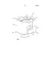
Изобретение относится к диспенсеру для стопы салфеток, при этом диспенсер содержит контейнер, имеющий нижнюю стенку, проходящую в горизонтальной плоскости, и боковые стенки, проходящие от нижней стенки в вертикальном направлении, перпендикулярном к ней, и определяющие границы выдачного отверстия, расположенного напротив нижней стенки, при этом боковые стенки окружают прямоугольную опорную поверхность для обеспечения опоры для стопы салфеток, вложенных друг в друга, при этом диспенсер дополнительно содержит закрывающий элемент, в котором образована выдачная выходная часть и который имеет по меньшей мере верхнее положение, так что пространство для удерживания стопы салфеток, вложенных друг в друга, образуется между опорной поверхностью и закрывающим элементом, когда закрывающий элемент находится в верхнем положении.The invention relates to a dispenser for a stack of wipes, the dispenser comprising a container having a lower wall extending in a horizontal plane and side walls extending from the lower wall in a vertical direction perpendicular to it and defining the boundaries of the dispensing opening opposite the lower wall, wherein the side walls surround a rectangular supporting surface to provide support for the foot of napkins embedded in each other, while the dispenser further comprises a closure element in which ohm dispensing outlet portion is formed and which has at least an upper position, so that the space for holding the stack of napkins, nested into each other, is formed between the support surface and the closure member when the closure member is in the upper position.
УРОВЕНЬ ТЕХНИКИBACKGROUND
Салфетки в виде листов материала, предназначенных для вытирания и для гигиенических целей, представляют собой распространенные бытовые предметы, которые могут быть предусмотрены в виде стоп салфеток, из которых отдельные салфетки могут быть без труда извлечены в случае необходимости. Диспенсер для салфеток должен быть сравнительно недорогим, простым в обращении, он должен защищать салфетки перед использованием и должен быть таким, чтобы его можно было легко переместить в место, где требуются салфетки, например, на стол, рабочую поверхность кухни и т.д.Napkins in the form of sheets of material intended for wiping and for hygienic purposes are common household items that can be provided in the form of stop napkins, from which individual napkins can be easily removed if necessary. The napkin dispenser should be relatively inexpensive, easy to handle, it should protect the napkins before use and should be such that it can be easily moved to a place where napkins are required, for example, on a table, kitchen worktop, etc.
Распространенным типом диспенсера для салфеток данного вида является открытая картонная коробка, в которой салфетки размещены в стопе, опирающейся краем салфеток, при этом часть салфеток выступает через отверстие в коробке для обеспечения захватываемой части. Это представляет собой простой и недорогой способ выдачи салфеток. Однако пополнение подобных диспенсеров является довольно сложным. Если слишком мало салфеток было вставлено в коробку, стопа не заполняет ширину контейнера, в результате чего стопа может выгибаться внутри контейнера, что способствует деформированию салфеток и делает захват салфеток более трудным. Если слишком много салфеток было вставлено, сила трения между салфетками будет слишком большой, что приводит к необходимости увеличенного тянущего усилия, прикладываемого пользователем, что может вызвать повреждение салфеток, которые выдаются, и сделать данные салфетки непригодными.A common type of napkin dispenser of this kind is an open cardboard box in which napkins are placed in a foot resting on the edge of the napkins, with part of the napkins protruding through an opening in the box to provide a grip portion. This is a simple and inexpensive way to dispense napkins. However, replenishment of such dispensers is rather complicated. If too few napkins have been inserted into the box, the foot does not fill the width of the container, as a result of which the foot can bend inside the container, which contributes to the deformation of the napkins and makes it more difficult to grip the napkins. If too many wipes have been inserted, the frictional force between the wipes will be too high, which necessitates an increased pulling force exerted by the user, which may damage the wipes that are dispensed and render these wipes unusable.
Дополнительной широко используемой опцией является размещение салфеток в виде стопы салфеток, вложенных друг в друга, которая размещена так, что она опирается нижней поверхностью внутри контейнера, имеющего выдачное отверстие в верхней части контейнера. В этом случае салфетки последовательно извлекают из верхней части стопы через выдачное отверстие.An additional widely used option is the placement of napkins in the form of a stack of napkins nested in each other, which is placed so that it rests on the bottom surface inside the container having a dispensing hole in the upper part of the container. In this case, the wipes are sequentially removed from the upper part of the foot through the dispensing opening.
Подобные диспенсеры обычно пополняют путем открытия части диспенсера и вставки новой стопы салфеток во внутреннее отделение диспенсера. Однако даже при данном типе диспенсеров остается проблема пополнения. Если слишком мало салфеток было вставлено в диспенсер, стопа не будет заполнять контейнер в вертикальном направлении, в результате чего стопа, опирающаяся на опорную поверхность контейнера, не будет доходить до выдачного отверстия, что препятствует захвату переднего конца самой верхней салфетки в стопе. Если слишком много салфеток было вставлено, сила трения между салфетками будет слишком большой, что приводит к более трудному захвату переднего конца самой верхней салфетки и к необходимости в увеличенной тянущей силе, прикладываемой пользователем при выдаче салфеток, что может вызывать повреждение салфеток, которые выдаются, и сделать данные салфетки непригодными.Such dispensers are usually replenished by opening part of the dispenser and inserting a new stack of wipes into the interior of the dispenser. However, even with this type of dispenser, the replenishment problem remains. If too few napkins have been inserted into the dispenser, the foot will not fill the container in the vertical direction, as a result of which the foot resting on the supporting surface of the container will not reach the dispensing opening, which prevents the front end of the uppermost napkin from being caught in the foot. If too many wipes have been inserted, the frictional force between the wipes will be too large, making it more difficult to grip the front end of the uppermost wipe and the need for increased pulling force exerted by the user when dispensing wipes, which may damage the wipes that are dispensed, and make these wipes unsuitable.
Стопа салфеток может представлять собой одну из нескольких обычных альтернатив для образования подобных стоп. Как правило, предпочтительно поставлять салфетки в виде стопы сложенных салфеток. Салфетки может быть сложены по одной и расположены друг поверх друга для формирования стопы, или они могут быть вложены друг в друга.Foot wipes can be one of several common alternatives for forming such feet. As a rule, it is preferable to supply napkins in the form of a stack of folded napkins. Napkins can be folded one at a time and placed on top of each other to form a stack, or they can be nested in each other.
Вложенные друг в друга салфетки представляют собой листы материалов, расположенные в стопе наложенных друг на друга листов, каждый из которых сложен по меньшей мере один раз. Листы соединены друг с другом таким образом, что отдельные сложенные листы материала образуют цепь листов, в которой каждый лист имеет переднюю панель и заднюю панель, при этом задняя панель по меньшей мере частично перекрывается передней панелью последующего листа в стопе. Таким образом, отдельные листы удерживаются без скрепления вместе посредством сил трения, возникающих между перекрывающимися частями. За исключением первой и последней салфеток в стопе каждая задняя панель каждой салфетки соединена за счет вложения друг в друга с передней панелью следующей салфетки в стопе. Листы могут выдаваться из диспенсера за счет вытягивания передней панели первого листа в стопе. Таким образом, первый лист материала извлекается одновременно с подачей заданной части передней панели последующего листа материала в положение выдачи в диспенсере.Napkins inserted into each other are sheets of materials located in the stack of sheets superimposed on each other, each of which is folded at least once. The sheets are connected to each other so that the individual folded sheets of material form a chain of sheets in which each sheet has a front panel and a rear panel, with the rear panel at least partially overlapping the front panel of the subsequent sheet in the stack. Thus, the individual sheets are held together without bonding by means of friction forces arising between the overlapping parts. With the exception of the first and last napkins in the foot, each rear panel of each napkin is connected by nesting one another with the front panel of the next napkin in the foot. Sheets can be ejected from the dispenser by pulling the front panel of the first sheet in the stack. Thus, the first sheet of material is removed at the same time as the predetermined portion of the front panel of the subsequent sheet of material is fed to the dispensing position.
Диспенсер обычно имеет закрывающий элемент с выдачным отверстием, которое ограничивает ширину выдаваемой салфетки для удерживания передней панели следующей салфетки, подлежащей выдаче, от опускания назад в диспенсер.The dispenser typically has a cover element with a dispensing opening that limits the width of the dispensed wipe to keep the front panel of the next wipe to be dispensed from being lowered back into the dispenser.
В документе JP2008162660 описан держатель для санитарно-гигиенической бумаги, содержащий контейнер для удерживания стопы салфеток, при этом контейнер определяет границы направленного вверх, выдачного отверстия, в котором размещен подвижный закрывающий элемент, при этом закрывающий элемент образует груз, опирающийся на стопу. В закрывающем элементе образована выдачная выходная часть.JP2008162660 describes a holder for sanitary paper containing a container for holding a stack of napkins, the container defining the boundaries of the upward dispensing opening in which the movable closure element is placed, wherein the closure element forms a load resting on the stack. In the closing element, a dispensing output part is formed.
В документе WO2010/132005 описана конструкция диспенсера для салфеток, вложенных друг в друга, при этом диспенсер содержит контейнер для удерживания стопы салфеток, причем контейнер определяет границы выдачного отверстия. По меньшей мере, один груз, имеющий рельефную поверхность на нижней стенке, которая меньше или равна одной трети поверхности, служащей опорой для стопы, размещен в контейнере и предназначен для опирания на стопу.WO2010 / 132005 describes the design of a dispenser for napkins nested in each other, the dispenser comprising a container for holding a stack of napkins, the container defining the boundaries of the dispensing opening. At least one load having a relief surface on the bottom wall that is less than or equal to one third of the surface serving as a support for the foot is placed in the container and is designed to support the foot.
В предшествующих конструкциях, а именно конструкциях, содержащих грузы, опирающиеся на стопу, и конструкциях с другими типами закрывающих элементов существует риск того, что диспенсер будет заполнен слишком большим количеством салфеток, что приводит к ухудшенным характеристикам диспенсера при его использовании.In previous designs, namely, designs containing loads based on the foot, and designs with other types of closure elements, there is a risk that the dispenser will be filled with too many wipes, which leads to poor performance of the dispenser when used.
Задача настоящего изобретения состоит в разработке усовершенствованного или альтернативного диспенсера для выдачи салфеток.An object of the present invention is to provide an improved or alternative dispenser for dispensing wipes.
СУЩНОСТЬ ИЗОБРЕТЕНИЯSUMMARY OF THE INVENTION
Вышеупомянутая задача решается посредством диспенсера в соответствии с пунктом 1 формулы изобретения.The above problem is solved by means of a dispenser in accordance with
Термин «выдачное отверстие» (“dispensing opening”) означает часть контейнера, открытую по направлению к окружающей среде и используемую для обеспечения доступа к внутреннему пространству контейнера.The term “dispensing opening” means a part of a container that is open towards the environment and used to provide access to the interior of the container.
Термин «выдачная выходная часть» (“dispensing mouth”) означает отверстие, через которое предметы выдаются.The term “dispensing mouth” means a hole through which objects are dispensed.
В используемом в данном документе смысле выражение «в контакте с» означает, что две поверхности расположены на расстоянии друг от друга, которое настолько мало, насколько это возможно, и при этом достаточно для обеспечения возможности перемещения поверхностей вдоль друг друга.As used herein, the term “in contact with” means that the two surfaces are spaced apart from one another, which is as small as possible and yet sufficient to allow the surfaces to move along each other.
Термин «соседний» используется для обозначения предметов, ближайших в пространстве или по месторасположению, непосредственно прилегающих друг к другу при отсутствии пространства, разделяющего их, касающихся, а также предметов, находящихся рядом друг с другом или близко друг от друга, но необязательно касающихся друг друга.The term "neighboring" is used to denote objects that are closest in space or location, directly adjacent to each other in the absence of a space separating them, touching, as well as objects located next to each other or close to each other, but not necessarily touching each other .
Под термином «магнитный замок» понимается устройство для удерживания кусков материала вместе посредством магнетизма.The term "magnetic lock" refers to a device for holding pieces of material together by means of magnetism.
Термин «магнит» в контексте настоящей заявки означает постоянный магнит.The term "magnet" in the context of this application means a permanent magnet.
Термин «соответствующий магнитный материал» в контексте настоящей заявки означает материал, притягиваемый к определенному магниту. Данный материал может представлять собой другой постоянный магнит, или он может представлять собой материал, притягиваемый к определенному магниту, такому как мягкий или твердый ферромагнитный материал.The term "appropriate magnetic material" in the context of this application means material attracted to a particular magnet. This material may be another permanent magnet, or it may be material attracted to a particular magnet, such as soft or hard ferromagnetic material.
В соответствии с настоящим изобретением разработан диспенсер для салфеток, вложенных друг в друга, который позволяет по существу устранить недостатки диспенсеров, рассмотренных выше.In accordance with the present invention, a dispenser for napkins embedded in each other is developed which substantially eliminates the disadvantages of the dispensers discussed above.
В соответствии с изобретением разработан диспенсер для салфеток, вложенных друг в друга. Диспенсер содержит контейнер, имеющий нижнюю стенку, проходящую в горизонтальной плоскости и расположенную в нижней части диспенсера. Контейнер дополнительно содержит боковые стенки, проходящие от нижней стенки в вертикальном направлении, перпендикулярном к горизонтальной плоскости нижней стенки, и определяющие границы выдачного отверстия, расположенного напротив нижней стенки. Боковые стенки окружают прямоугольную опорную поверхность для обеспечения опоры для стопы салфеток, вложенных друг в друга.In accordance with the invention, a dispenser for napkins embedded in each other is developed. The dispenser comprises a container having a bottom wall extending horizontally and located at the bottom of the dispenser. The container further comprises side walls extending from the lower wall in a vertical direction perpendicular to the horizontal plane of the lower wall, and defining the boundaries of the dispensing hole located opposite the lower wall. The side walls surround a rectangular supporting surface to provide support for the foot of napkins embedded in each other.
Диспенсер дополнительно содержит закрывающий элемент, в котором образована выдачная выходная часть, через которую извлекаются салфетки. Закрывающий элемент имеет по меньшей мере верхнее положение, так что пространство для удерживания стопы салфеток, вложенных друг в друга, образуется между указанной опорной поверхностью и указанным закрывающим элементом, когда указанный закрывающий элемент находится в указанном верхнем положении. Следовательно, пространство для удерживания стопы салфеток, вложенных друг в друга, образуется между опорной поверхностью и закрывающим элементом, когда закрывающий элемент находится в верхнем положении.The dispenser further comprises a closure element in which a dispensing outlet part is formed, through which wipes are removed. The closure element has at least an upper position, so that a space for holding a stack of napkins nested in each other is formed between said support surface and said closure element when said closure element is in said upper position. Therefore, a space for holding a stack of wipes nested in each other is formed between the supporting surface and the closing element when the closing element is in the upper position.
Закрывающий элемент может быть выполнен с возможностью отделения или отсоединения от боковых стенок, в результате чего закрывающий элемент образует открываемую крышку, или закрывающий элемент может быть образован как одно целое с боковыми стенками.The closure element may be configured to separate or detach from the side walls, whereby the closure element forms an openable lid, or the closure element may be integrally formed with the side walls.
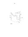
Контейнер разделен вдоль горизонтальной плоскости, которая параллельна горизонтальной плоскости нижней стенки, так, чтобы образовать нижнюю часть, содержащую нижнюю стенку, и стеновую часть, содержащую по меньшей мере часть боковых стенок. Нижняя часть прикреплена с возможностью отсоединения к стеновой части посредством магнитного замка для обеспечения возможности добавления салфеток с нижней стороны диспенсера.The container is divided along a horizontal plane that is parallel to the horizontal plane of the lower wall, so as to form the lower part containing the lower wall, and the wall part containing at least part of the side walls. The lower part is detachably attached to the wall part by means of a magnetic lock to enable the addition of napkins from the lower side of the dispenser.
Нижняя стенка контейнера может иметь любую пригодную форму периферии, такую как круглая, прямоугольная с прямыми углами или скругленными угловыми частями, квадратная, треугольная, ромбическая или неправильная, при условии, что нижняя стенка обеспечивает достаточно большую опорную поверхность для стопы салфеток, вложенных друг в друга. Нижняя стенка контейнера предпочтительно имеет по существу прямоугольную форму, соответствующую форме стопы салфеток, подлежащей вставке в контейнер. Термин «прямоугольный» предназначен для охвата всех четырехсторонних плоских фигур с четырьмя по существу прямыми углами.The bottom wall of the container can have any suitable shape of the periphery, such as round, rectangular with right angles or rounded corner parts, square, triangular, rhombic or irregular, provided that the bottom wall provides a sufficiently large supporting surface for the stack of napkins embedded in each other . The bottom wall of the container preferably has a substantially rectangular shape corresponding to the shape of the stack of wipes to be inserted into the container. The term “rectangular” is intended to encompass all four-sided planar figures with four substantially right angles.
Нижняя стенка контейнера может образовывать самую наружную нижнюю поверхность контейнера. Это обеспечивает простое и компактное решение.The bottom wall of the container may form the outermost lower surface of the container. This provides a simple and compact solution.
Тем не менее, диспенсер может быть выполнен с дополнительной наружной нижней поверхностью, расположенной на некотором расстоянии от нижней стенки контейнера, определяемом в вертикальном направлении, если это желательно, например, по соображениям, связанным с дизайном, или для прикрепления диспенсера к нижерасположенной поверхности.However, the dispenser can be made with an additional outer bottom surface located at some distance from the bottom wall of the container, defined in the vertical direction, if desired, for example, for reasons related to design, or for attaching the dispenser to the underlying surface.
Боковые стенки контейнера проходят перпендикулярно к плоскости нижней стенки контейнера и перпендикулярно к опорной поверхности.The side walls of the container are perpendicular to the plane of the lower wall of the container and perpendicular to the supporting surface.
Боковые стенки ограничивают пространство контейнера и размер выдачного отверстия и расположены с возможностью удерживания и обеспечения опоры для стопы салфеток, вложенных друг в друга, без деформирования салфеток. Следовательно, боковые стенки также обеспечивают боковую опору для стопы салфеток и груза при использовании контейнера.The side walls limit the space of the container and the size of the dispensing hole and are arranged to hold and provide support for the stack of napkins nested into each other without deforming the napkins. Therefore, the side walls also provide lateral support for the stack of wipes and cargo when using the container.
Опорная поверхность должна быть прямоугольной, что означает, что опорная поверхность должна обеспечить возможность создания опоры для прямоугольной стопы салфеток. Для этого желательно иметь по существу прямоугольную форму, хотя возможны незначительные отклонения от общей конфигурации, такие как скругленные угловые части. Предпочтительно, чтобы опорная поверхность образовывала по существу полную поверхность, то есть стенку. Тем не менее, также возможно формирование опорной поверхности с использованием, например, ребер или выступов для создания опоры для стопы салфеток.The supporting surface should be rectangular, which means that the supporting surface should provide the ability to create support for the rectangular foot of napkins. To do this, it is desirable to have a substantially rectangular shape, although slight deviations from the general configuration, such as rounded corner parts, are possible. Preferably, the abutment surface forms an essentially complete surface, i.e. a wall. However, it is also possible to form a support surface using, for example, ribs or protrusions to create support for the foot of the napkins.
Для обеспечения опоры для стопы в горизонтальных направлениях боковые стенки должны проходить вертикально так, чтобы они окружали и поддерживали стопу вокруг ее прямоугольной периферии. Для этого необходимо, чтобы боковые стенки имели определенную протяженность вдоль периферии прямоугольной опорной поверхности. Тем не менее, следует понимать, что боковые поверхности необязательно должны образовывать сплошную поверхность стенок, и они при желании могут быть выполнены с отверстиями или пазами. Альтернативно, боковые стенки могут быть образованы некоторым количеством ребер, расположенных вертикально и на некотором расстоянии друг от друга. В предпочтительном альтернативном варианте боковые стенки образуют сплошные боковые стенки, проходящие вдоль по меньшей мере 50% от прямоугольной периферии опорной поверхности.To provide support for the foot in horizontal directions, the side walls should extend vertically so that they surround and support the foot around its rectangular periphery. For this, it is necessary that the side walls have a certain extent along the periphery of the rectangular supporting surface. However, it should be understood that the side surfaces do not have to form a continuous surface of the walls, and if desired, they can be made with holes or grooves. Alternatively, the side walls may be formed by a number of ribs arranged vertically and at some distance from each other. In a preferred alternative embodiment, the side walls form solid side walls extending along at least 50% of the rectangular periphery of the abutment surface.
Боковые стенки предпочтительно могут формировать самую дальнюю от центра конфигурацию, образованную стенками диспенсера. Это обеспечивает простое и компактное решение. Тем не менее, диспенсер может быть выполнен с дополнительными наружными стенками, окружающими боковые стенки контейнера. Это может быть желательным, если, например, желателен диспенсер, имеющий скругленную наружную конструкцию.The side walls can preferably form the farthest configuration from the center formed by the walls of the dispenser. This provides a simple and compact solution. However, the dispenser can be made with additional outer walls surrounding the side walls of the container. This may be desirable if, for example, a dispenser having a rounded outer structure is desired.
Как упомянуто выше, боковые стенки определяют границы выдачного отверстия, расположенного в верхней части диспенсера. Выдачное отверстие в контексте настоящего изобретения представляет собой часть контейнера, открытую по направлению к окружающей среде и обеспечивающую доступ к внутреннему пространству контейнера. Контур выдачного отверстия по существу соответствует форме опорной поверхности.As mentioned above, the side walls define the boundaries of the dispensing hole located in the upper part of the dispenser. The dispensing opening in the context of the present invention is a part of the container that is open towards the environment and providing access to the interior of the container. The contour of the dispensing opening substantially matches the shape of the abutment surface.
Размер выдачного отверстия предпочтительно по существу соответствует размеру опорной поверхности в отношении наружных размеров выдачного отверстия и опорной поверхности. Следовательно, если закрывающий элемент будет извлечен из диспенсера, вся верхняя поверхность стопы салфеток, опирающейся на опорную поверхность в контейнере, будет легкодоступной посредством выдачного отверстия.The size of the dispensing opening preferably substantially corresponds to the size of the supporting surface with respect to the outer dimensions of the dispensing opening and the supporting surface. Therefore, if the closure element is removed from the dispenser, the entire upper surface of the stack of wipes resting on the supporting surface in the container will be easily accessible through the dispensing opening.
Боковые стенки образуют верхние края в верхней части диспенсера по направлению к выдачному отверстию. Форма верхних краев контейнера может варьироваться, например, верхние края могут быть прямолинейными или иметь неправильную форму, такую как волнистая, зубчатая, полукруглая или тому подобная.The side walls form the upper edges in the upper part of the dispenser in the direction of the dispensing hole. The shape of the upper edges of the container may vary, for example, the upper edges may be rectilinear or irregular in shape, such as wavy, jagged, semicircular, or the like.
Верхние края предпочтительно образуют множество самых верхних краевых частей, которые могут находиться в пределах горизонтальной плоскости, параллельной к плоскости нижней стенки. По существу, если диспенсер будет перевернут вверх дном, он может опираться в устойчивом положении множеством самых верхних краевых частей, находящихся в пределах указанной горизонтальной плоскости. Для обеспечения устойчивого перевернутого положения самые верхние краевые части на по меньшей мере двух противоположных боковых стенках контейнера предпочтительно должны находиться в пределах горизонтальной плоскости.The upper edges preferably form a plurality of uppermost edge portions, which may lie within a horizontal plane parallel to the plane of the lower wall. Essentially, if the dispenser is turned upside down, it can be supported in a stable position by a plurality of uppermost edge portions within a specified horizontal plane. To ensure a stable inverted position, the uppermost edge portions on at least two opposite side walls of the container should preferably be in a horizontal plane.
Самые верхние краевые части предпочтительно могут образовывать непрерывные верхние края, проходящие вдоль по меньшей мере двух противоположных боковых стенок контейнера и находящиеся в пределах плоскости (в этом случае все верхние края будут образовывать указанные самые верхние краевые части), предпочтительно в пределах по существу горизонтальной плоскости, в результате чего обеспечивается возможность особенно устойчивого перевернутого положения диспенсера.The uppermost edge portions can preferably form continuous upper edges extending along at least two opposite side walls of the container and within a plane (in this case, all the upper edges will form the indicated uppermost edge portions), preferably within a substantially horizontal plane, as a result, the possibility of a particularly stable inverted position of the dispenser is provided.
Кроме того, в соответствии с настоящим изобретением предлагается, чтобы нижняя часть диспенсера была прикреплена с возможностью отсоединения к стеновой части посредством магнитного замка.In addition, in accordance with the present invention, it is proposed that the lower part of the dispenser be detachably attached to the wall part by means of a magnetic lock.
Магнитный замок обеспечит определенную удерживающую силу в зависимости от типа, размера и количества используемых магнитов и соответствующих магнитных материалов. Соответственно, магнитный замок может быть отрегулирован таким образом, что он будет иметь удерживающую силу, достаточную для обеспечения удерживания нижней части и стеновой части вместе во время использования диспенсера, то есть сила притяжения может противодействовать воздействию силы тяжести на стопу салфеток на опорной поверхности, а также на нижнюю стенку. Кроме того, магнитный замок может быть отрегулирован так, что он будет предотвращать вставку слишком большого числа салфеток с усилием в диспенсер. Другими словами, если слишком большая стопа будет размещена внутри контейнера и будет предпринята попытка закрыть нижнюю часть, в результате чего салфетки будут сжиматься, магнитный замок не закроется, поскольку сила упругости, действующая со стороны стопы, «пытающейся» восстановить свою исходную форму, будет превышать силу притяжения магнитного замка. Соответственно, магнитный замок может быть выбран таким, что он будет открываться, когда сила упругости превышает пороговое значение силы притяжения магнитного замка.A magnetic lock will provide a certain holding force depending on the type, size and number of magnets used and the corresponding magnetic materials. Accordingly, the magnetic lock can be adjusted so that it has a holding force sufficient to ensure that the lower part and the wall part are held together while using the dispenser, that is, the attractive force can counteract the effect of gravity on the stack of wipes on the supporting surface, and to the bottom wall. In addition, the magnetic lock can be adjusted so that it prevents the insertion of too many napkins with force into the dispenser. In other words, if an excessively large foot is placed inside the container and an attempt is made to close the lower part, as a result of which the wipes are compressed, the magnetic lock will not close, since the elastic force acting from the side of the foot “trying” to restore its original shape will exceed the force of attraction of the magnetic lock. Accordingly, the magnetic lock can be selected so that it will open when the elastic force exceeds a threshold value of the attractive force of the magnetic lock.
Следовательно, магнитный замок может быть использован для формирования эффективного средства защиты от переполнения за счет того, что невозможно будет заставить замок закрыться и поддерживать функционирование замка, если будет слишком много салфеток в виде сжатой стопы, имеющейся в контейнере.Therefore, a magnetic lock can be used to form an effective means of protection against overflow due to the fact that it will not be possible to force the lock to close and maintain the functioning of the lock if there are too many napkins in the form of a compressed foot in the container.
Можно избежать недостатков, таких как увеличенная тянущая сила, необходимая для извлечения салфетки из диспенсера, которые возникают вследствие наличия сжатой стопы в контейнере и которые могут привести к тому, что салфетки окажутся поврежденными.Deficiencies such as the increased pulling force required to remove the wipes from the dispenser, which arise due to the presence of a compressed foot in the container and which may cause the wipes to be damaged, can be avoided.
Горизонтальная плоскость, разделяющая контейнер на нижнюю часть и стеновую часть, может быть расположена так, что она будет иметь любую координату вдоль протяженности боковых стенок по вертикали. Следовательно, может быть задана подобная горизонтальная плоскость, разделяющая контейнер в средней точке протяженности боковых стенок по вертикали, в результате чего обеспечиваются нижняя часть и стеновая часть, имеющие одинаковую протяженность по вертикали. Данная горизонтальная плоскость предпочтительно расположена рядом с горизонтальной плоскостью нижней стенки так, что нижняя часть будет состоять из нижней стенки и стеновая часть будет содержать полные боковые стенки, включая нижние края боковых стенок.The horizontal plane dividing the container into the lower part and the wall part can be located so that it will have any coordinate along the length of the side walls vertically. Therefore, a similar horizontal plane can be defined, dividing the container at a midpoint of the vertical extent of the side walls, as a result of which a lower part and a wall part having the same vertical length are provided. This horizontal plane is preferably located next to the horizontal plane of the lower wall so that the lower part will consist of a lower wall and the wall part will contain full side walls, including the lower edges of the side walls.
При такой конструкции пространство, доступное для стопы салфеток, соответствует всему пространству, подлежащему заполнению внутри стеновой части диспенсера, что облегчает процесс пополнения.With this design, the space available for the stack of wipes corresponds to the entire space to be filled inside the wall of the dispenser, which facilitates the replenishment process.
Магнитный замок, обеспечивающий прикрепление нижней части к стеновой части с возможностью разъединения, обеспечивает возможность открытия замка таким образом, что нижняя часть отделяется от стеновой части, что обеспечивает возможность вставки новых салфеток с нижнего конца стеновой части. Нижняя часть может быть выполнена с возможностью ее полного отделения от стеновой части при открывании/разъединении магнитного замка. Альтернативно, нижняя часть может быть выполнена с возможностью ее наклона в сторону от нижнего конца стеновой части при открывании/разъединении магнитного замка, при этом нижняя часть остается прикрепленной к стеновой части. Например, нижняя часть может оставаться прикрепленной к стеновой части посредством шарнира.The magnetic lock, which allows the lower part to be attached to the wall part with the possibility of separation, makes it possible to open the lock so that the lower part is separated from the wall part, which makes it possible to insert new napkins from the lower end of the wall part. The lower part can be made with the possibility of its complete separation from the wall part when opening / disconnecting the magnetic lock. Alternatively, the lower part can be tilted away from the lower end of the wall part when opening / disconnecting the magnetic lock, while the lower part remains attached to the wall part. For example, the lower portion may remain attached to the wall portion through a hinge.
Магнитный замок может быть выполнен так, что по меньшей мере один постоянный магнит и соответствующий магнитный материал будут размещены соответственно в нижней части и стеновой части. Другими словами, нижняя часть может содержать по меньшей мере один постоянный магнит, в то время как стеновая часть содержит по меньшей мере один соответствующий магнитный материал.The magnetic lock can be made so that at least one permanent magnet and the corresponding magnetic material will be placed respectively in the lower part and the wall part. In other words, the lower part may contain at least one permanent magnet, while the wall part contains at least one corresponding magnetic material.
Кроме того, магнитный замок может быть выполнен так, что он будет содержать по меньшей мере один постоянный магнит и соответствующий магнитный материал, размещенные соответственно в стеновой части и нижней части, что означает, что стеновая часть будет содержать по меньшей мере один постоянный магнит, в то время как нижняя часть будет содержать по меньшей мере один соответствующий магнитный материал.In addition, the magnetic lock can be made so that it will contain at least one permanent magnet and corresponding magnetic material located respectively in the wall part and the lower part, which means that the wall part will contain at least one permanent magnet, while the lower part will contain at least one corresponding magnetic material.
Само собой разумеется, также возможно выполнение каждой из стеновой части и нижней части как с по меньшей мере одним постоянным магнитом, так и с по меньшей мере одним соответствующим магнитным материалом.It goes without saying that it is also possible to perform each of the wall part and the lower part with both at least one permanent magnet and at least one corresponding magnetic material.
Для образования магнитного замка магниты и соответствующие магнитные материалы должны быть размещены соответственно в стеновой части и/или в нижней части напротив друг друга. Стыковочные поверхности, образуемые магнитами и соответствующими магнитными материалами, могут по существу соответствовать друг другу по размеру и форме. Под «стыковочными поверхностями» понимаются поверхности, которые обращены друг к другу и которые притягиваются друг к другу посредством магнетизма. Магниты и соответствующие магнитные материалы могут быть расположены так, что их стыковочные поверхности будут находиться в прямом контакте друг с другом, когда магнитный замок закрыт. Тем не менее, магниты и соответствующие магнитные материалы также могут быть размещены таким образом, что их стыковочные поверхности будут разделены, например, посредством куска другого материала при условии, что притяжение между стыковочными поверхностями будет по-прежнему достаточным для закрытия магнитного замка. Это может иметь место, когда магниты и/или соответствующие магнитные материалы заделаны в стеновую часть и/или нижнюю часть.In order to form a magnetic lock, magnets and corresponding magnetic materials must be placed in the wall part and / or in the lower part, respectively, opposite each other. The mating surfaces formed by the magnets and the corresponding magnetic materials may substantially correspond to each other in size and shape. By “docking surfaces” are meant surfaces that are facing each other and that are attracted to each other by magnetism. The magnets and the corresponding magnetic materials can be arranged so that their connecting surfaces will be in direct contact with each other when the magnetic lock is closed. However, magnets and corresponding magnetic materials can also be arranged so that their joint surfaces are separated, for example, by means of a piece of another material, provided that the attraction between the joint surfaces is still sufficient to close the magnetic lock. This may occur when magnets and / or corresponding magnetic materials are embedded in the wall portion and / or lower portion.
Когда соответствующий магнитный материал также представляет собой постоянный магнит, он должен быть размещен таким образом, чтобы он притягивался к другому постоянному магниту, то есть так, чтобы магнитные полюса постоянного магнита и соответствующего постоянного магнита были расположены комплементарно, то есть «север» по направлению к «югу».When the corresponding magnetic material is also a permanent magnet, it must be positioned so that it is attracted to another permanent magnet, that is, so that the magnetic poles of the permanent magnet and the corresponding permanent magnet are complementary, that is, the "north" towards "Sub".
Количество и схема расположения постоянных магнитов и соответствующего магнитного материала могут варьироваться. Можно использовать только один постоянный магнит, расположенный в одной из нижней части и стеновой части, и один соответствующий магнитный материал, размещенный в другой из нижней части и стеновой части. Кроме того, можно выполнить всю периферию нижней части и стеновой части с постоянными магнитами и соответствующим магнитным материалом.The number and arrangement of permanent magnets and the corresponding magnetic material may vary. You can use only one permanent magnet located in one of the lower part and the wall part, and one corresponding magnetic material located in the other of the lower part and the wall part. In addition, you can perform the entire periphery of the lower part and the wall part with permanent magnets and the corresponding magnetic material.
Постоянные магниты и/или соответствующие магнитные материалы могут быть размещены с использованием кусков материала, имеющих разные формы и размеры. Таким образом, куски материала, пригодные для настоящего изобретения, могут иметь площадь, составляющую 0,25 см2–150 см2. Куски материала могут быть квадратными, прямоугольными, круглыми, овальными, звездообразными или иметь любую другую форму, пригодную для данной цели.Permanent magnets and / or corresponding magnetic materials can be placed using pieces of material having different shapes and sizes. Thus, pieces of material suitable for the present invention may have an area of 0.25 cm2 to 150 cm2 . The pieces of material can be square, rectangular, round, oval, star-shaped or have any other shape suitable for this purpose.
Постоянные магниты и/или соответствующие магнитные материалы могут быть прикреплены, например, приклеены непосредственно к соответствующим частям, при этом в данном случае магнит и/или магнитные материалы будут видны пользователю.Permanent magnets and / or corresponding magnetic materials can be attached, for example, glued directly to the corresponding parts, in this case, the magnet and / or magnetic materials will be visible to the user.
Другая возможность состоит во включении магнитов и/или магнитных материалов в соответствующие части, то есть заделывание внутри или размещение за другим материалом. В этом случае магниты и/или магнитные материалы будут скрыты, а не будут выставлены напоказ. Заделывание магнитов и/или магнитных материалов в материал диспенсера имеет преимущество, заключающееся в обеспечении более надежного магнитного замка, поскольку в том случае, когда куски магнитов и/или соответствующих магнитных материалов прикреплены к диспенсеру, например, посредством приклеивания и место прикрепления подвергается воздействию повторяющихся нагрузок вследствие тянущих сил, прикладываемых пользователем при пополнении диспенсера, крепление может быть разрушено, что сделает замок непригодным.Another possibility is to incorporate magnets and / or magnetic materials into the appropriate parts, that is, embedment inside or placement behind another material. In this case, the magnets and / or magnetic materials will be hidden, and not displayed. The incorporation of magnets and / or magnetic materials into the dispenser material has the advantage of providing a more reliable magnetic lock, since when pieces of magnets and / or corresponding magnetic materials are attached to the dispenser, for example by gluing and the attachment point is subjected to repeated loads due to the pulling forces exerted by the user when replenishing the dispenser, the fastening may be destroyed, which will make the lock unusable.
Например, магниты и/или магнитные материалы могут быть включены в нижнюю стенку, изготовленную из пластика, посредством включения магнитов и/или магнитных материалов в пластик во время литья нижней стенки.For example, magnets and / or magnetic materials can be incorporated into a lower wall made of plastic by incorporating magnets and / or magnetic materials into the plastic during casting of the lower wall.
При желании соединитель может быть предусмотрен между нижней частью и стеновой частью. Использование соединителя может облегчить повторное прикрепление нижней части к стеновой части, поскольку перемещения частей друг относительно друга ограничиваются соединителем. Назначение соединителя главным образом состоит в обеспечении того, чтобы стеновая часть и нижняя часть оставались соединенными при отсоединении нижней части от стеновой части. Сила притяжения, действующая со стороны магнитного замка, как правило, будет достаточной для обеспечения необходимого направления стеновой части и нижней части при их перемещении по направлению друг к другу для фиксации их вместе. Следовательно, можно, но необязательно, предусмотреть соединитель, выполняющий также достаточное направление перемещения стеновой части и нижней части друг относительно друга, такой как соединитель, подобный жесткому шарниру.If desired, a connector may be provided between the lower part and the wall part. The use of the connector can facilitate the reattachment of the lower part to the wall part, since the movement of the parts relative to each other is limited by the connector. The purpose of the connector is mainly to ensure that the wall part and the lower part remain connected when the lower part is disconnected from the wall part. The force of attraction acting from the side of the magnetic lock, as a rule, will be sufficient to provide the necessary direction of the wall part and the lower part when moving them towards each other to fix them together. Therefore, it is possible, but not necessary, to provide a connector that also provides a sufficient direction of movement of the wall part and the lower part relative to each other, such as a connector similar to a rigid hinge.
Соединитель может представлять собой так называемый соединитель типа мягкого шарнира, образованный мягким материалом, таким как пластик или текстильный материал, например, таким как термопластичный эластомер (ТРЕ), силикон, сложный полиэфир или хлопковый текстильный материал. Подобные соединители имеют преимущество, заключающееся в том, что они могут быть образованы так, что они будут занимать только очень ограниченное пространство.The connector may be a so-called soft-joint type connector formed by a soft material such as plastic or textile material, such as a thermoplastic elastomer (TPE), silicone, polyester or cotton textile material. Such connectors have the advantage that they can be formed so that they occupy only a very limited space.
Контейнер может содержать раму, расположенную вдоль боковых стенок, окружающих опорную поверхность, при этом рама может содержать элемент, предназначенный для соединения с контейнером. Рама может быть расположена рядом с нижней стенкой у нижнего края боковых стенок. Например, рама может быть запрессована внутри контейнера у нижнего края боковых стенок. Рама может быть выполнена из пластика или из любого другого материала, пригодного для данных целей.The container may comprise a frame located along the side walls surrounding the abutment surface, the frame may comprise an element for connecting to the container. The frame may be located next to the bottom wall at the lower edge of the side walls. For example, the frame may be pressed inside the container at the lower edge of the side walls. The frame can be made of plastic or any other material suitable for this purpose.
Рама, подобная описанной выше, может быть предпочтительно использована для обеспечения магнитов и/или соответствующих магнитных материалов для стеновой части контейнера. Например, магниты и/или магнитные материалы могут быть размещены между рамой и боковыми стенками. В альтернативном варианте или в качестве дополнения к этому рама может быть полезной для обеспечения соединителя, предпочтительно мягкого шарнира, соединяющего стеновую часть с нижней частью.A frame similar to that described above can preferably be used to provide magnets and / or corresponding magnetic materials to the wall of the container. For example, magnets and / or magnetic materials can be placed between the frame and side walls. Alternatively, or in addition to this, the frame may be useful for providing a connector, preferably a soft hinge, connecting the wall portion to the bottom portion.
Нижняя часть может быть выполнена с захватываемым средством для облегчения отделения нижней части от стеновой части. Захватываемое средство предпочтительно может быть выполнено в виде выемки в нижней части.The lower part can be made with gripping means to facilitate separation of the lower part from the wall part. The gripping means may preferably be in the form of a recess in the lower part.
В контейнере может быть образован по меньшей мере один вертикальный паз в по меньшей мере одной из боковых стенок. Протяженность паза по горизонтали может быть достаточной для обеспечения возможности ручного доступа к салфеткам, находящимся в контейнере, через паз.At least one vertical groove in at least one of the side walls may be formed in the container. The horizontal length of the groove may be sufficient to allow manual access to the napkins in the container through the groove.
Следовательно, паз может быть полезным для захвата первого переднего конца новой стопы салфеток, который подлежит вводу в выдачную выходную часть для первоначальной «настройки» диспенсера.Therefore, the groove may be useful for gripping the first front end of a new stack of wipes, which is to be inserted into the dispensing outlet for the initial “adjustment” of the dispenser.
Кроме того, в определенных вариантах осуществления подобный паз может быть полезным при пополнении диспенсера, как будет описано ниже. Кроме того, паз может быть полезным для обеспечения визуальной индикации потребности в пополнении.In addition, in certain embodiments, a similar groove may be useful in replenishing the dispenser, as will be described below. In addition, a groove may be useful to provide a visual indication of replenishment needs.
При повороте диспенсера вверх дном для его пополнения пользователь может удерживать любые салфетки, оставшиеся в диспенсере, посредством вертикального паза, как описано выше, для гарантирования того, что оставшиеся салфетки не окажутся сложенными или не изменят свое положение в диспенсере иным образом во время его поворота. Как только диспенсер примет перевернутое положение, оставшиеся салфетки отпускают, и в результате этого они станут опираться на нижнюю сторону закрывающего элемента.When the dispenser is turned upside down to replenish it, the user can hold any napkins remaining in the dispenser by means of a vertical groove, as described above, to ensure that the remaining napkins will not be folded or otherwise change their position in the dispenser during its rotation. As soon as the dispenser takes an inverted position, the remaining wipes are released, and as a result, they will lean on the lower side of the closure element.
Однако в других вариантах осуществления можно выполнить поворот диспенсера вверх дном без необходимости удерживания салфеток.However, in other embodiments, the dispenser can be turned upside down without having to hold the napkins.
Диспенсер дополнительно содержит закрывающий элемент, который проходит между боковыми стенками в по меньшей мере одном горизонтальном направлении и в котором образована выдачная выходная часть. Закрывающий элемент может быть неподвижно или с возможностью перемещения размещен в выдачном отверстии.The dispenser further comprises a closure element which extends between the side walls in at least one horizontal direction and in which a dispensing outlet part is formed. The closure element may be fixedly or movably placed in the dispensing opening.
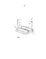
Закрывающий элемент может представлять собой опирающийся на стопу, закрывающий элемент, содержащий груз, расположенный между боковыми стенками. Следовательно, когда стопа салфеток будет вставлена в диспенсер, груз будет опираться на стопу. Соответственно, когда диспенсер будет полностью заполнен салфетками, груз будет находиться рядом с выдачным отверстием контейнера, в то время как в том случае, когда диспенсер будет почти пустым или пустым, груз будет находиться рядом с опорной поверхностью контейнера. Груз выполнен с возможностью перемещения в вертикальном направлении внутри контейнера между верхним положением, соседним с выдачным отверстием контейнера, и нижним положением, соседним с опорной поверхностью контейнера, как в направлении вверх, так и в направлении вниз.The closure element may be a foot-supported closure element comprising a load located between the side walls. Therefore, when a stack of wipes is inserted into the dispenser, the load will rest on the stack. Accordingly, when the dispenser is completely filled with napkins, the cargo will be near the dispensing opening of the container, while in the case when the dispenser is almost empty or empty, the cargo will be near the supporting surface of the container. The load is arranged to move vertically inside the container between the upper position adjacent to the dispensing opening of the container and the lower position adjacent to the supporting surface of the container, both in the upward and downward directions.
Фактическая масса груза должна быть достаточной для выдерживания тянущей силы, прикладываемой пользователем, извлекающим салфетку из диспенсера, и может быть выбрана так, чтобы она соответствовала определенному диспенсеру и/или определенной стопе салфеток.The actual mass of the load must be sufficient to withstand the pulling force exerted by the user removing the napkin from the dispenser, and can be selected so that it matches a specific dispenser and / or a specific stack of napkins.
Таким образом, масса груза может составлять от 50 до 1000 г, предпочтительно от 50 до 500 г, наиболее предпочтительно - от 100 до 200 г.Thus, the mass of the cargo can be from 50 to 1000 g, preferably from 50 to 500 g, most preferably from 100 to 200 g.
При использовании закрывающего элемента, опирающегося на стопу, магнитный замок, естественно, должен быть адаптирован так, чтобы он обеспечивал силу притяжения, достаточную для противодействия воздействию силы тяжести на опорную поверхность, возникающей в результате наличия как стопы салфеток, так и опирающего на стопу, закрывающего элемента, который опирается на стопу.When using the closure element resting on the foot, the magnetic lock should naturally be adapted so that it provides an attractive force that is sufficient to counter the effect of gravity on the supporting surface resulting from the presence of both a stack of napkins and a resting base that closes an element that rests on the foot.
Для выполнения груза, имеющего подходящую массу, груз может содержать первый и второй материалы, при этом второй материал имеет бóльшую плотность по сравнению с первым материалом для придания дополнительной массы грузу. Например, первый материал, образующий бóльшую часть груза, может представлять собой пластик, преимуществом которого является легкость его формования до заданных форм, но который не является особо тяжелым. Для увеличения массы груза второй материал в виде металла, такого как свинец, железо, медь или никель, или сплава, такого как нержавеющая сталь, чугун или любые другие сплавы с высокой плотностью, может быть добавлен к первому материалу.To carry a load having a suitable mass, the load may contain first and second materials, while the second material has a higher density compared to the first material to give additional weight to the cargo. For example, the first material that forms most of the cargo may be plastic, the advantage of which is the ease of its molding to desired shapes, but which is not particularly heavy. To increase the mass of the load, a second material in the form of a metal, such as lead, iron, copper or nickel, or an alloy, such as stainless steel, cast iron or any other alloys with a high density, can be added to the first material.
Например, груз может быть образован двумя половинами из первого материала, которые соединены вместе для формирования полного груза. Куски второго, более тяжелого материала могут быть добавлены между двумя половинами перед их соединением до полного груза.For example, a load may be formed by two halves of a first material that are joined together to form a full load. Pieces of a second, heavier material can be added between the two halves before joining them to the full load.
Другая опция состоит в образовании груза путем литья первого материала в форме, содержащей куски второго материала, размещенные внутри формы так, что второй материал оказывается заделанным в первый материал.Another option is to form a load by casting the first material in a mold containing pieces of the second material placed inside the mold so that the second material is embedded in the first material.
В соответствии с тем, что предложено в данном документе, груз образует наружную краевую часть, содержащую по меньшей мере два противоположных участка краевой части. Кроме того, груз простирается поверх всего выдачного отверстия в по меньшей мере одном горизонтальном направлении между по меньшей мере двумя противоположными боковыми стенками контейнера так, что два противоположных участка краевой части находятся в контакте с двумя противоположными боковыми стенками контейнера.In accordance with what is proposed in this document, the load forms an outer edge portion containing at least two opposite portions of the edge portion. In addition, the load extends over the entire dispensing opening in at least one horizontal direction between at least two opposite side walls of the container so that two opposite portions of the edge portion are in contact with two opposite side walls of the container.
Для гарантирования того, чтобы груз оставался в заданном положении внутри контейнера, то есть в таком положении, чтобы выдачная выходная часть была расположена в нем надлежащим образом, предпочтительно, если наружная краевая часть содержит два противоположных участка краевой части, которые находятся в контакте с соответствующими частями двух противоположных боковых стенок контейнера. Соответственно, обеспечивается определенный контроль местоположения и перемещения груза в контейнере.In order to guarantee that the load remains in a predetermined position inside the container, that is, in such a position that the dispensing outlet is properly positioned therein, it is preferable if the outer edge part contains two opposite portions of the edge part that are in contact with the corresponding parts two opposite side walls of the container. Accordingly, a certain control of the location and movement of the cargo in the container is provided.
Груз предпочтительно может простираться поверх всего выдачного отверстия так, что вся внутренняя периферия боковых стенок будет находиться в контакте с грузом.The load may preferably extend over the entire dispensing opening so that the entire inner periphery of the side walls will be in contact with the load.
Существует возможность того, что груз будет включать в себя некоторые выступающие части, которые будут выступать за внутреннюю периферию боковых стенок, например, через вертикальный паз, выполненный в боковой стенке. Тем не менее, предпочтительно, чтобы груз находился в пределах, определяемых боковыми стенками, так что никакие перемещающиеся части груза не будут выступать наружу от боковых стенок, в результате чего устраняется риск того, что предметы, расположенные рядом с диспенсером, окажутся непреднамеренно захваченными грузом при использовании диспенсера. Кроме того, внешний вид диспенсера может быть сделан более эстетически привлекательным, если не имеется никаких выступающих частей.There is a possibility that the cargo will include some protruding parts that will protrude beyond the inner periphery of the side walls, for example, through a vertical groove made in the side wall. However, it is preferable that the load be within the limits defined by the side walls, so that no moving parts of the load will protrude outward from the side walls, thereby eliminating the risk that objects located next to the dispenser will be unintentionally caught by the load using a dispenser. In addition, the appearance of the dispenser can be made more aesthetically pleasing if there are no protruding parts.
Общая площадь проекции груза на горизонтальную плоскость, включая выдачную выходную часть, может составлять по меньшей мере 60% и предпочтительно по меньшей мере 80% от площади опорной поверхности. Общая площадь проекции груза на горизонтальную плоскость предпочтительно по существу соответствует площади опорной поверхности.The total projection area of the load onto the horizontal plane, including the dispensing outlet, may be at least 60% and preferably at least 80% of the area of the supporting surface. The total projection area of the load onto the horizontal plane preferably substantially corresponds to the area of the supporting surface.
Естественно, груз будет иметь некоторую протяженность по вертикали или высоту в вертикальном направлении. Высота в вертикальном направлении, рассматриваемая в данном документе, представляет собой максимальную высоту груза в вертикальном направлении, если смотреть на всей горизонтальной поверхности груза. Высота груза в вертикальном направлении предпочтительно может быть задана такой, чтобы способствовать надлежащей выдаче и выставлению переднего конца самой верхней салфетки в стопе, размещенной в диспенсере. Например, понятно, что передний конец, имеющий определенную протяженность по вертикали, может обладать способностью принимать вертикальное положение, когда он выступает из выдачной выходной части диспенсера, в то время как в том случае, если более длинный передний конец салфетки выступает из выдачной выходной части, передний конец может принимать нежелательное свисающее положение.Naturally, the load will have some vertical extension or height in the vertical direction. The vertical height discussed in this document represents the maximum height of the load in the vertical direction when viewed on the entire horizontal surface of the load. The height of the load in the vertical direction can preferably be set so as to facilitate proper delivery and exposure of the front end of the uppermost napkin in the foot placed in the dispenser. For example, it is understood that a front end having a certain vertical extent may have the ability to take a vertical position when it protrudes from the dispensing outlet of the dispenser, while if the longer front end of the napkin protrudes from the dispensing outlet, the front end may take an undesirable drooping position.
Высота груза в вертикальном направлении будет определять длину той части салфетки, которая выступает от самой верхней поверхности стопы в выдачной выходной части, и будет соответственно влиять на длину переднего конца, выступающего из выдачной выходной части для его выставления для пользователя.The height of the load in the vertical direction will determine the length of the part of the napkin that protrudes from the uppermost surface of the foot in the dispensing output part, and will accordingly affect the length of the front end protruding from the dispensing output part to be exposed to the user.
Для некоторых полезных применений высота груза в вертикальном направлении может составлять 1-10 см, предпочтительно 1-5 см, наиболее предпочтительно - 2-5 см.For some useful applications, the height of the load in the vertical direction can be 1-10 cm, preferably 1-5 cm, most preferably 2-5 cm.
Груз может быть образован с постоянной высотой в вертикальном направлении на всей протяженности его горизонтальной поверхности. Тем не менее, он также может быть образован с по существу плоской нижней поверхностью, то есть поверхностью, обращенной внутрь контейнера, когда груз расположен между боковыми стенками контейнера, при этом нижняя поверхность груза также имеет выступы. Выступы могут быть непрерывными, то есть проходящими вдоль всей нижней поверхности груза, или прерывистыми, то есть расположенными в находящихся на расстоянии друг от друга местах на нижней поверхности груза. Прерывистые выступы могут иметь форму цилиндров, конусов, кубов, пирамид или тому подобного. Выступы предпочтительно представляют собой непрерывные выступы в виде ребер, проходящих в продольном направлении. Следовательно, протяженность выступов по вертикали будет определять высоту груза в вертикальном направлении.A load can be formed with constant height in the vertical direction over the entire length of its horizontal surface. However, it can also be formed with a substantially flat bottom surface, that is, a surface facing the inside of the container when the load is located between the side walls of the container, while the lower surface of the cargo also has protrusions. The protrusions may be continuous, that is, extending along the entire lower surface of the load, or discontinuous, that is, located at locations spaced apart from each other on the lower surface of the cargo. Intermittent protrusions may take the form of cylinders, cones, cubes, pyramids, or the like. The protrusions are preferably continuous protrusions in the form of ribs extending in the longitudinal direction. Therefore, the length of the protrusions vertically will determine the height of the load in the vertical direction.
Выступы могут быть расположены на некотором расстоянии от выдачной выходной части. Соответственно, выступы гарантируют то, что будет иметься зазор между нижней поверхностью груза, непосредственно окружающей выдачную выходную часть, и верхней частью стопы салфеток, вставленной в диспенсер. Такой зазор гарантирует то, что стопа не будет прижата к выдачной выходной части, что усложнило бы извлечение салфеток из стопы.The protrusions may be located at some distance from the dispensing output part. Accordingly, the protrusions guarantee that there will be a gap between the lower surface of the load immediately surrounding the dispensing outlet, and the upper part of the stack of wipes inserted into the dispenser. Such a gap ensures that the foot will not be pressed against the dispensing output part, which would complicate the removal of napkins from the foot.
Груз предпочтительно может содержать выдачную выходную часть, то есть отверстие, через которое выдаются предметы, при этом выдачная выходная часть проходит в продольном направлении груза, совпадающем с продольным направлением диспенсера, и расположена над предметами, находящимися внутри контейнера, когда груз расположен над выдачным отверстием контейнера.The cargo may preferably comprise a dispensing outlet, that is, an opening through which objects are dispensed, wherein the dispensing outlet extends in the longitudinal direction of the cargo, coinciding with the longitudinal direction of the dispenser, and is located above the objects inside the container when the cargo is located above the dispensing opening of the container .
В том случае, когда диспенсер предназначен для удерживания стопы салфеток, вложенных друг в друга, груз, содержащий выдачную выходную часть, одновременно обеспечит выставление переднего конца самой верхней салфетки в стопе через выдачную выходную часть и удерживание оставшейся части стопы, так что дополнительные, нежелательные салфетки не будут извлекаться из стопы вместе с самой верхней салфеткой. Вместо этого благодаря вложению салфеток друг в друга извлечение самой верхней салфетки приведет к тому, что передний конец следующей салфетки будет выставлен в выдачной выходной части.In the case where the dispenser is designed to hold a stack of napkins nested inside each other, the load containing the dispensing outlet will simultaneously expose the front end of the uppermost napkin in the stack through the dispensing outlet and holding the remaining part of the stack, so that additional, undesirable wipes will not be removed from the foot along with the uppermost napkin. Instead, by inserting napkins into each other, removing the topmost napkin will cause the front end of the next napkin to be exposed in the dispensing outlet.
Посредством груза, образующего выдачную выходную часть, избегают ситуации, при которой захватываемая часть самой верхней салфетки в стопе салфеток, вложенных друг в друга, будет опускаться назад, при отсутствии риска разрыва или сморщивания вытягиваемой салфетки или следующей за ней салфетки. Конструкция диспенсера в соответствии с изобретением будет также определять то, что только одна салфетка будет выдаваться за раз. Диспенсером можно легко манипулировать только одной рукой, и диспенсер имеет простую и надежную конструкцию.By means of the cargo forming the dispensing outlet, a situation is avoided in which the gripping part of the uppermost napkin in the stack of napkins nested in each other will be lowered back, in the absence of the risk of tearing or wrinkling of the drawn napkin or the next napkin. The design of the dispenser in accordance with the invention will also determine that only one napkin will be issued at a time. The dispenser can be easily manipulated with just one hand, and the dispenser has a simple and robust design.
Если груз простирается над выдачным отверстием по существу на всей протяженности между по меньшей мере двумя противоположными боковыми стенками контейнера, выдачная выходная часть может быть при этом расположена так, что она будет проходить в продольном направлении диспенсера между противоположными участками краевой части.If the load extends over the dispensing opening substantially over the entire length between at least two opposite side walls of the container, the dispensing outlet can be positioned so that it extends in the longitudinal direction of the dispenser between opposite portions of the edge part.
Предпочтительно независимо от того, образован ли закрывающий элемент грузом, как описано выше, или нет, выдачная выходная часть предпочтительно является удлиненной и имеет максимальный размер по длине, проходя параллельно двум противоположным боковым стенкам.Preferably, regardless of whether or not the closure member is formed by the load as described above, the dispensing outlet is preferably elongated and has a maximum length dimension extending parallel to two opposite side walls.
Диспенсер может дополнительно содержать средство регулирования закрывающего элемента для дополнительного регулирования перемещения и/или местоположения закрывающего элемента внутри контейнера и ограничения перемещения закрывающего элемента за его верхнее положение. Это предпочтительно, поскольку в этом случае диспенсер может быть перевернут вверх дном для принятия перевернутого положения без необходимости вручную удерживать закрывающий элемент на месте в верхнем положении. Соответственно, средство регулирования закрывающего элемента будет расположено внутри диспенсера и будет соединять закрывающий элемент с контейнером. Следовательно, средство регулирования закрывающего элемента будет гарантировать то, что закрывающий элемент невозможно будет полностью отделить от контейнера.The dispenser may further comprise means for adjusting the closure element to further control the movement and / or location of the closure element within the container and limit the movement of the closure element to its upper position. This is preferable since in this case the dispenser can be turned upside down to take an inverted position without having to manually hold the closure element in place in the upper position. Accordingly, the control means of the closure element will be located inside the dispenser and will connect the closure element to the container. Therefore, the control means of the closure element will ensure that the closure element cannot be completely separated from the container.
Кроме того, когда закрывающий элемент выполнен с возможностью перемещения между верхним и нижним положениями, средство регулирования закрывающего элемента будет способствовать регулированию перемещения закрывающего элемента внутри диспенсера между верхним положением и нижним положением. В зависимости от местоположения и конфигурации средства регулирования закрывающего элемента может быть обеспечена возможность регулирования положения/перемещения закрывающего элемента в боковом направлении.In addition, when the closure member is movable between the upper and lower positions, the adjusting means of the closure element will help to control the movement of the closure element within the dispenser between the upper position and the lower position. Depending on the location and configuration of the control means of the closure element, it may be possible to adjust the position / movement of the closure element in the lateral direction.
Кроме того, средство регулирования закрывающего элемента определяет верхнее положение закрывающего элемента внутри контейнера. Данное верхнее положение будет определять максимальный размер стопы, подлежащей вставке в диспенсер.In addition, the closure adjusting means determines the upper position of the closure inside the container. This upper position will determine the maximum foot size to be inserted into the dispenser.
Диспенсер предпочтительно содержит два средства регулирования закрывающего элемента, соединяющие закрывающий элемент и контейнер друг с другом. В этом случае средства регулирования закрывающего элемента расположены по одному у каждой противоположной боковой стенки и у каждого соответствующего участка краевой части закрывающего элемента.The dispenser preferably comprises two means for adjusting the closure member connecting the closure member and the container to each other. In this case, the control means of the closing element are located one at each opposite side wall and at each corresponding portion of the edge part of the closing element.
При двух средствах регулирования закрывающего элемента, находящихся с противоположных сторон диспенсера, может быть обеспечена возможность дополнительного регулирования положения/перемещения закрывающего элемента в боковом направлении. Кроме того, при двух средствах регулирования закрывающего элемента будут более четко определены верхнее положение закрывающего элемента внутри диспенсера, а также максимальный размер стопы, подлежащей вставке в диспенсер. Средства регулирования закрывающего элемента могут быть расположены в любом месте вдоль внутренней периферии диспенсера, то есть вдоль любой из боковых стенок, проходящих или в продольном, или в поперечном направлениях. Когда диспенсер содержит два средства регулирования закрывающего элемента, предпочтительно разместить средства регулирования закрывающего элемента напротив друг друга для обеспечения оптимального распределения тянущей силы, прикладываемой пользователем, извлекающим предмет из диспенсера.With two means of regulating the closing element located on opposite sides of the dispenser, it may be possible to further control the position / movement of the closing element in the lateral direction. In addition, with two means of adjusting the closure element, the upper position of the closure element inside the dispenser, as well as the maximum foot size to be inserted into the dispenser, will be more clearly defined. The control means of the closure element can be located anywhere along the inner periphery of the dispenser, that is, along any of the side walls extending either in the longitudinal or transverse directions. When the dispenser comprises two means for adjusting the closing element, it is preferable to place the means for adjusting the closing element opposite each other to ensure optimal distribution of the pulling force exerted by the user extracting the object from the dispenser.
Следует понимать, что диспенсер предпочтительно содержит по меньшей мере два средства регулирования груза и может быть предусмотрен, например, с тремя или четырьмя средствами регулирования груза. Например, одно средство регулирования груза может быть размещено у каждой угловой части груза.It should be understood that the dispenser preferably contains at least two means for regulating the load and can be provided, for example, with three or four means for regulating the load. For example, one means of regulating cargo may be placed at each corner of the cargo.
Важно то, чтобы средство регулирования закрывающего элемента было достаточно гибким для обеспечения возможности перемещения средства регулирования закрывающего элемента в вертикальном направлении между верхним и нижним положениями. Средство регулирования закрывающего элемента предпочтительно содержит гибкий шнур, например, в виде ленты или цепи. Соответствующая лента может быть выполнена из полиэфирного материала.It is important that the adjusting means of the closure element is flexible enough to allow the adjusting means of adjusting the closure element in the vertical direction between the upper and lower positions. The closure control means preferably comprises a flexible cord, for example in the form of a tape or chain. The corresponding tape may be made of polyester material.
При использовании передний конец самой верхней салфетки в стопе, расположенной в диспенсере, проходит между двумя противоположными боковыми стенками. Соответственно, выдачная выходная часть будет проходить в продольном направлении вдоль ширины переднего конца, так что салфетки могут быть извлечены через выдачную выходную часть при незначительном сморщивании или при отсутствии сморщивания. Протяженность выдачной выходной части предпочтительно является по меньшей мере такой же, как ширина стопы салфеток, вставленной в диспенсер.In use, the front end of the uppermost napkin in the foot located in the dispenser extends between two opposite side walls. Accordingly, the dispensing outlet will extend longitudinally along the width of the front end, so that the wipes can be removed through the dispensing outlet with little wrinkling or no wrinkling. The extension of the dispensing outlet is preferably at least the same as the width of the stack of wipes inserted in the dispenser.
Выдачная выходная часть может иметь протяженность в продольном направлении, составляющую по меньшей мере 75%, предпочтительно по меньшей мере 85%, наиболее предпочтительно по меньшей мере 90% от определяемой в продольном направлении протяженности опорной поверхности, простирающейся между боковыми стенками, если выразить протяженность выдачной выходной части относительно протяженности опорной поверхности контейнера в продольном направлении. Кроме того, протяженность выдачной выходной части в продольном направлении может составлять 100% от протяженности опорной поверхности в продольном направлении, то есть протяженность выдачной выходной части в продольном направлении будет равна протяженности опорной поверхности в продольном направлении.The dispensing outlet may have a length in the longitudinal direction of at least 75%, preferably at least 85%, most preferably at least 90% of the longitudinally defined length of the abutment surface extending between the side walls, if the length of the dispensing outlet is expressed parts relative to the length of the supporting surface of the container in the longitudinal direction. In addition, the length of the dispensing output part in the longitudinal direction can be 100% of the length of the supporting surface in the longitudinal direction, that is, the length of the dispensing output part in the longitudinal direction will be equal to the length of the supporting surface in the longitudinal direction.
Выдачная выходная часть будет также иметь протяженность в поперечном направлении, или ширину в поперечном направлении груза, соответствующем поперечному направлению диспенсера. Ширина выдачной выходной части должна быть достаточной для того, чтобы салфетка легко проходила через нее. Кроме того, выдачная выходная часть может быть выполнена с по меньшей мере одной частью, имеющей бóльшую ширину по сравнению с остальными частями выдачной выходной части. Например, подобная часть может быть расположена в центре выдачной выходной части. Часть с большей шириной может быть выполнена с такой конструкцией, чтобы облегчить захват салфетки. Кроме того, достаточно большая ширина может быть предусмотрена для обеспечения возможности захвата первого переднего конца самой верхней салфетки в стопе, вставленной в диспенсер, когда передний конец лежит плоско на самой верхней поверхности стопы.The dispensing outlet will also have a length in the transverse direction, or a width in the transverse direction of the load, corresponding to the transverse direction of the dispenser. The width of the dispensing outlet should be sufficient so that the napkin easily passes through it. In addition, the dispensing output part can be made with at least one part having a larger width than the rest of the dispensing output part. For example, such a part may be located in the center of the dispensing output part. The part with a larger width can be made in such a way as to facilitate the capture of napkins. In addition, a sufficiently large width may be provided to enable the first front end of the uppermost napkin to be gripped in the foot inserted in the dispenser when the front end lies flat on the uppermost surface of the foot.
Кроме того, тем не менее, может быть желательным выполнить части выдачной выходной части, имеющие сравнительно малую ширину, например, части выдачной выходной части, расположенные рядом с боковыми стенками, когда груз размещен внутри контейнера, поскольку такие части могут обеспечить опору для переднего конца, выступающего через выдачную выходную часть, так что передний конец будет выставлен в вертикальном положении для его захвата пользователем. Подобная малая ширина, пригодная для обеспечения опоры для переднего конца, находящегося в вертикальном положении, может составлять, например, приблизительно 10-15 мм.In addition, however, it may be desirable to make parts of the dispensing outlet part having a relatively small width, for example, parts of the dispensing outlet part located adjacent to the side walls when the load is placed inside the container, since such parts can provide support for the front end, protruding through the dispensing output part, so that the front end will be exposed in a vertical position for its capture by the user. Such a small width suitable for supporting the upright front end may be, for example, about 10-15 mm.
Выдачная выходная часть может иметь любую пригодную форму, такую как овальная или прямоугольная, при условии, что выдачная выходная часть не вызывает образования складок на салфетке, подлежащей выдаче, или не повреждает иным образом салфетку, подлежащую выдаче, и что выдачная выходная часть обеспечивает достаточную опору для переднего конца салфетки так, что передний конец салфетки будет находиться в его вертикальном положении перед использованием.The dispensing outlet can be of any suitable shape, such as oval or rectangular, provided that the dispensing outlet does not cause wrinkling on the napkin to be dispensed or otherwise damages the napkin to be dispensed and that the dispensing outlet provides sufficient support for the front end of the wipe so that the front end of the wipe will be in its upright position before use.
При использовании закрывающего элемента, опирающегося на стопу и состоящего из груза, средство регулирования закрывающего элемента может представлять собой средство регулирования груза, соединяющее груз и контейнер друг с другом и проходящее внутри контейнера между элементом, предназначенным для соединения с контейнером, и элементом, предназначенным для соединения с грузом, в результате чего ограничивается перемещение груза за верхнее положение.When using a closure element supported by a foot and consisting of a load, the closure control means may be a load control means connecting the load and the container to each other and passing inside the container between the element for connecting to the container and the element for connecting with the load, as a result of which the movement of the load beyond the upper position is limited.
Длина средства регулирования закрывающего элемента между элементом, предназначенным для соединения с контейнером, и элементом, предназначенным для соединения с закрывающим элементом, может по существу соответствовать расстоянию по вертикали от элемента, предназначенного для соединения с контейнером, до выдачного отверстия. Поскольку, как упомянуто ранее, выдачное отверстие ограничено верхними краями боковых стенок, длина средства регулирования закрывающего элемента между элементом, предназначенным для соединения с контейнером, и элементом, предназначенным для соединения с закрывающим элементом, может по существу соответствовать максимальному расстоянию по вертикали от элемента, предназначенного для соединения с контейнером, до верхнего края боковых стенок. В тех случаях, когда верхний край боковых стенок имеет неправильную форму, длина средства регулирования закрывающего элемента между элементом, предназначенным для соединения с контейнером, и элементом, предназначенным для соединения с закрывающим элементом, может по существу соответствовать расстоянию по вертикали от элемента, предназначенного для соединения с контейнером, до самой высокой точки верхнего края боковых стенок. Соответственно, по существу полная длина контейнера по вертикали от опорной поверхности до выдачного отверстия будет «доступной» для стопы салфеток.The length of the closure adjusting means between the element for connecting to the container and the element for connecting to the closure may substantially correspond to the vertical distance from the element for connecting to the container to the dispensing opening. Since, as mentioned earlier, the dispensing opening is bounded by the upper edges of the side walls, the length of the closure adjusting means between the element for connecting to the container and the element for connecting to the closure may substantially correspond to the maximum vertical distance from the element for connection with the container, to the upper edge of the side walls. In cases where the upper edge of the side walls has an irregular shape, the length of the closure adjusting means between the element for connecting to the container and the element for connecting to the closure may substantially correspond to the vertical distance from the element for connecting with container, to the highest point of the top edge of the side walls. Accordingly, the substantially total vertical length of the container from the abutment surface to the dispensing opening will be “accessible” to the stack of wipes.
Также можно разместить элемент, предназначенный для соединения с контейнером, в любой точке вдоль протяженности боковых стенок по вертикали, например, в середине расстояния по вертикали между опорной поверхностью и выдачным отверстием.You can also place the element intended for connection with the container, at any point along the length of the side walls vertically, for example, in the middle of the vertical distance between the supporting surface and the dispensing hole.
Элемент, предназначенный для соединения с контейнером, и элемент, предназначенный для соединения с закрывающим элементом, могут представлять собой соединительные элементы любого подходящего типа, известные в данной области техники в качестве соединительных элементов, предназначенных для скрепления деталей вместе.The element intended to be connected to the container and the element intended to be connected to the closure element may be any suitable type of connecting elements known in the art as connecting elements for fastening parts together.
В определенных вариантах осуществления элемент, предназначенный для соединения с контейнером, может представлять собой защелкивающийся соединительный элемент. В этом случае первая защелкивающаяся соединительная часть может быть предусмотрена в контейнере, и вторая защелкивающаяся соединительная часть может быть предусмотрена на концевой части средства регулирования закрывающего элемента.In certain embodiments, an element for connecting to a container may be a snap-in connector. In this case, the first snap-in connecting portion may be provided in the container, and the second snap-in connecting portion may be provided at the end portion of the adjusting means of the closure member.
Элемент, предназначенный для соединения с закрывающим элементом, может быть расположен у краевой части закрывающего элемента или рядом с краевой частью закрывающего элемента. Например, если закрывающий элемент образован двумя половинами, соединенными вместе, концевая часть средства регулирования закрывающего элемента может быть вставлена между данными половинами и присоединена к закрывающему элементу при соединении данных двух половин.An element intended to be connected to the closure element may be located at or near the edge of the closure element. For example, if the closing element is formed by two halves connected together, the end part of the adjustment means of the closing element can be inserted between these halves and attached to the closing element when connecting these two halves.
Соответственно, средство регулирования закрывающего элемента будет проходить вдоль стороны стопы салфеток, расположенной в диспенсере.Accordingly, the control means of the closure element will extend along the side of the foot of the napkins located in the dispenser.
Как упомянуто выше, верхний край боковых стенок может находиться в пределах плоскости, предпочтительно по существу горизонтальной плоскости, в результате чего обеспечивается возможность устойчивого перевернутого положения диспенсера. Соответственно, диспенсер может быть удобным образом размещен так, что он будет опираться верхним краем боковых стенок в перевернутом положении для пополнения диспенсера с его нижней стороны.As mentioned above, the upper edge of the side walls may lie within a plane, preferably a substantially horizontal plane, whereby a stable inverted position of the dispenser is provided. Accordingly, the dispenser can be conveniently placed so that it will be supported by the upper edge of the side walls in an inverted position to replenish the dispenser from its lower side.
Когда диспенсер используется, стопа салфеток расположена на опорной поверхности нижней стенки внутри пространства, образованного между опорной поверхностью и закрывающим элементом. Стопа салфеток может иметь прямоугольную форму с прямоугольной или квадратной нижней поверхностью, которая образована задней панелью последней салфетки в стопе. Стопа может иметь любые соответствующие размеры, такие как любые соответствующие высота, ширина и длина. Размеры по ширине и длине определяются размерами нижней поверхности стопы, и высоту измеряют перпендикулярно нижней поверхности, и высота определяется количеством салфеток в стопе, а также числом слоев и панелей в каждой салфетке. Отдельные салфетки могут иметь один или более слоев (plies) или слоев (layers) и могут быть сложены с двумя или более панелями.When the dispenser is used, a stack of wipes is located on the abutment surface of the lower wall within the space formed between the abutment surface and the closure member. The napkin stop may have a rectangular shape with a rectangular or square bottom surface, which is formed by the back panel of the last napkin in the foot. The foot may be of any suitable size, such as any corresponding height, width and length. The dimensions in width and length are determined by the dimensions of the lower surface of the foot, and the height is measured perpendicular to the lower surface, and the height is determined by the number of napkins in the foot, as well as the number of layers and panels in each napkin. Individual wipes can have one or more layers (plies) or layers (layers) and can be stacked with two or more panels.
Салфетки могут представлять собой бытовые салфетки, влажные салфетки, бумажные полотенца любого вида и т.д. Материал может представлять собой волокнистый материал любого пригодного вида, такой как бумажные материалы на целлюлозной основе с добавлением или без добавления искусственных волокон, связующих и наполнителей. Салфетки могут содержать только искусственные волокна. Тем не менее, обычно желательно, чтобы салфетка имела определенный уровень впитывающей способности или чтобы она была по меньшей мере смачиваемой. Если волокнистый материал содержит большую долю волокон гидрофобного характера, что означает, что волокна являются несмачиваемыми, может быть целесообразной обработка материала смачивающим средством. Смачивающие средства и другие добавки хорошо известны специалисту в данной области техники и не будут дополнительно рассматриваться в данном документе. Салфетки могут иметь любые пригодные форму и/или размер и могут быть выполнены с тиснением, перфорацией, печатью и быть окрашенными, если это желательно. Салфетки могут представлять собой однослойные листы материала или могут содержать два или более слоев одного и того же материала или разных материалов. В стопе салфетки сложены по меньшей мере один раз для получения конфигурации с вложением их друг в друга и соединенными панелями. Тем не менее, салфетки могут быть дополнительно сложены для уменьшения их размера в плоскости до размера, целесообразного на практике, как хорошо известно в данной области техники. Соответственно, может быть использован любой тип вкладывания салфеток друг в друга, известный в данной области техники. Салфетки предпочтительно могут быть вложены друг в друга.Wipes can be household wipes, wet wipes, paper towels of any kind, etc. The material may be any suitable type of fibrous material, such as cellulosic paper materials with or without artificial fibers, binders and fillers. Wipes may contain only artificial fibers. However, it is usually desirable that the napkin has a certain level of absorbency or that it is at least wettable. If the fibrous material contains a large proportion of hydrophobic fibers, which means that the fibers are non-wettable, it may be appropriate to treat the material with a wetting agent. Wetting agents and other additives are well known to the person skilled in the art and will not be further discussed herein. The wipes can be of any suitable shape and / or size and can be embossed, perforated, printed and dyed, if desired. Napkins may be single-layer sheets of material or may contain two or more layers of the same material or different materials. In the stack, the wipes are folded at least once to obtain a configuration with their nesting in each other and connected panels. However, the wipes can be further folded to reduce their size in the plane to a size practical in practice, as is well known in the art. Accordingly, any type of napkin insertion into one another known in the art can be used. Napkins can preferably be nested within each other.
Физическая форма контейнера может представлять собой по существу жесткую коробку.The physical form of the container may be a substantially rigid box.
Материал контейнера и материал закрывающего элемента может представлять собой любой материал, пригодный для данной цели, такой как пластик, дерево, керамика, металл. Контейнер может быть сформирован, например, посредством сгибания листа материала, формования, пневмоформования, экструзии, резки, выпиливания и т.д. Контейнер и закрывающий элемент могут быть выполнены из одного и того же материала или из разных материалов. Контейнер и/или закрывающий элемент также могут быть выполнены посредством комбинации различных материалов. Следует отметить, что диспенсер в соответствии с настоящим изобретением предназначен для многократного использования. Другими словами, диспенсер предназначен для его пополнения, а не для удаления при его опорожнении.The material of the container and the material of the closure element can be any material suitable for this purpose, such as plastic, wood, ceramics, metal. The container may be formed, for example, by folding a sheet of material, molding, blow molding, extrusion, cutting, sawing, etc. The container and the closing element may be made of the same material or of different materials. The container and / or closure element may also be formed by a combination of various materials. It should be noted that the dispenser in accordance with the present invention is intended for repeated use. In other words, the dispenser is designed to replenish it, and not to remove it when empty.
Диспенсер в соответствии с изобретением имеет простую конструкцию и может быть выполнен из недорогих и легкодоступных материалов. Кроме того, конструкция диспенсера такова, что он функционирует поразительно надежно и не вызывает повреждения выдаваемых салфеток.The dispenser in accordance with the invention has a simple design and can be made of inexpensive and readily available materials. In addition, the design of the dispenser is such that it functions amazingly reliably and does not cause damage to the dispensed wipes.
Кроме того, диспенсер может быть изготовлен так, что он будет иметь аккуратный и изысканный внешний вид за счет выбора эксклюзивных материалов, таких как матированная сталь, алюминий или дерево. Это может быть желательным, когда диспенсер предназначен для его использования в соответствующих определенным правилам и элегантных средах.In addition, the dispenser can be made so that it will have a neat and sophisticated appearance by choosing exclusive materials such as brushed steel, aluminum or wood. This may be desirable when the dispenser is intended for use in specific rules and elegant environments.
КРАТКОЕ ОПИСАНИЕ ЧЕРТЕЖЕЙBRIEF DESCRIPTION OF THE DRAWINGS
Варианты осуществления изобретения будут описаны далее только в качестве примера и со ссылкой на сопровождающие чертежи, на которых:Embodiments of the invention will now be described by way of example only and with reference to the accompanying drawings, in which:
фиг. 1 показывает диспенсер в соответствии с настоящим изобретением, стоящий в вертикальном положении;FIG. 1 shows a dispenser in accordance with the present invention, standing upright;
фиг. 1А показывает выполненный с пространственным разделением элементов вид в перспективе диспенсера, проиллюстрированного на фиг. 1;FIG. 1A shows an exploded perspective view of the dispenser illustrated in FIG. one;
фиг. 2 показывает контейнер в соответствии с настоящим изобретением;FIG. 2 shows a container in accordance with the present invention;
фиг. 3 показывает груз диспенсера по фиг. 1, имеющего два средства регулирования груза;FIG. 3 shows the dispenser load of FIG. 1, having two means for regulating the cargo;
фиг. 4 показывает груз диспенсера по фиг. 1 в перевернутом положении;FIG. 4 shows the dispenser load of FIG. 1 upside down;
фиг. 5 показывает раму и нижнюю стенку диспенсера по фиг. 1;FIG. 5 shows the frame and bottom wall of the dispenser of FIG. one;
фиг. 6 иллюстрирует диспенсер, показанный на фиг. 1, в перевернутом положении;FIG. 6 illustrates the dispenser shown in FIG. 1, inverted;
фиг. 7 иллюстрирует диспенсер по фиг. 1, содержащий салфетки, подлежащие выдаче;FIG. 7 illustrates the dispenser of FIG. 1 containing wipes to be dispensed;
фиг. 8 иллюстрирует диспенсер, показанный на фиг. 1, в почти пустом состоянии.FIG. 8 illustrates the dispenser shown in FIG. 1, in an almost empty state.
ПОДРОБНОЕ ОПИСАНИЕDETAILED DESCRIPTION
Фиг. 1 иллюстрирует диспенсер 1 для салфеток, вложенных друг в друга. Диспенсер 1 содержит контейнер 2, имеющий нижнюю стенку 5, проходящую в горизонтальной плоскости и расположенную в нижней части 1b диспенсера 1. Контейнер 2 дополнительно содержит боковые стенки 6, имеющие верхние края 6b и нижние края 6с и проходящие от нижней стенки 5 в вертикальном направлении, перпендикулярном к горизонтальной плоскости нижней стенки 5, и определяющие границы выдачного отверстия 7, расположенного в верхней части 1а диспенсера 1 и напротив нижней стенки 5. Боковые стенки 6 окружают опорную поверхность 8, предназначенную для обеспечения опоры для стопы салфеток, предпочтительно стопы салфеток, вложенных друг в друга.FIG. 1 illustrates a
Диспенсер 1 дополнительно содержит закрывающий элемент в виде груза 4, расположенного между боковыми стенками 6 так, что он образует опирающийся на стопу, закрывающий элемент диспенсера 1. В грузе 4 образована выдачная выходная часть 9, через которую извлекаются салфетки. Груз 4 выполнен с возможностью перемещения между верхним положением, соседним с выдачным отверстием 7 контейнера 2, и нижним положением, соседним с опорной поверхностью 8 контейнера 2.The
В варианте осуществления, показанном на фиг. 1, нижняя стенка 5 контейнера 2 образует опорную поверхность 8 контейнера 2. Это обеспечивает простое и компактное решение.In the embodiment shown in FIG. 1, the
Как видно на фиг. 1, верхний край 6b боковых стенок 6 находится в пределах горизонтальной плоскости, в результате чего обеспечивается возможность устойчивого перевернутого положения диспенсера 1, подобного показанному на фиг. 2. Соответственно, диспенсер 1 может быть удобным образом размещен так, что он будет опираться верхним краем 6b боковых стенок 6 в перевернутом положении, для пополнения диспенсера 1 с его нижней стороны.As seen in FIG. 1, the
Когда диспенсер 1 собирают, раму 21 размещают внутри контейнера 2 у нижнего края 6с боковых стенок 6 контейнера 2. Нижнюю стенку 5 закрепляют у нижнего края 6с контейнера 2 посредством магнитного замка 27 так, что контейнер 2 будет открыт по направлению к окружающей среде только в выдачном отверстии 7 контейнера. В завершение груз 4 прикрепляют к диспенсеру 1 посредством элемента 17, предназначенного для соединения с контейнером, показанного на фиг. 1А. Когда диспенсер 1 пустой или почти пустой, груз 4 будет находиться в его нижнем положении рядом с опорной поверхностью 8 контейнера 2.When the
Когда диспенсер 1 должен быть заполнен или пополнен предметами, подлежащими выдаче, диспенсер 1 переводят в перевернутое положение так, чтобы диспенсер 1 опирался верхними краями 6b боковых стенок 6 контейнера 2. При переворачивании диспенсера 1 может быть целесообразным обеспечение опоры для груза 4 с тем, чтобы груз 4 и предметы, оставшиеся внутри контейнера, в случае их наличия не опускались вниз неконтролируемым образом под действием силы тяжести, что может вызвать чрезмерно высокую и, возможно, вызывающую повреждение нагрузку на средство регулирования груза, а также сморщивание, образование складок или другое изменение положения предметов, оставшихся внутри контейнера, что может вызвать повреждение предметов и ухудшить выдачу.When the
Когда диспенсер 1 находится в его перевернутом положении, нижнюю стенку 5 отсоединяют путем захвата захватываемого средства 28 и открытия замка 27. После отсоединения нижней стенки 5, как показано на фиг. 3, стопу салфеток, вложенных друг в друга, вставляют в диспенсер 1 и нижнюю стенку 5 снова прикрепляют к диспенсеру 1. В завершение диспенсер 1 еще раз переворачивают, переводя его в вертикальное положение, и передний конец самой верхней салфетки извлекают через выдачную выходную часть, так что диспенсер 1 становится готовым к использованию.When
Магнитный замок 27 обеспечит определенную удерживающую силу в зависимости от типа, размера и количества используемых магнитов и соответствующих магнитных материалов. Соответственно, магнитный замок отрегулирован таким образом, что он будет иметь удерживающую силу, достаточную для обеспечения удерживания нижней части и стеновой части вместе во время использования диспенсера 1, то есть сила притяжения противодействует воздействию силы тяжести на стопу салфеток на опорной поверхности 8, а также на нижнюю стенку 5. Кроме того, магнитный замок 27 отрегулирован так, что он будет предотвращать вставку слишком большого числа салфеток с усилием в диспенсер. Если слишком большая стопа будет размещена внутри контейнера 2 и будет предпринята попытка закрыть нижнюю часть, в результате чего салфетки будут сжиматься, магнитный замок 27 не закроется, поскольку сила упругости, действующая со стороны стопы, «пытающейся» восстановить свою исходную форму, будет превышать силу притяжения магнитного замка. Соответственно, магнитный замок 27 может быть выбран таким, что он будет открываться, когда сила упругости превышает пороговое значение силы притяжения магнитного замка 27.
Следовательно, магнитный замок 27 используется для формирования эффективного средства защиты от переполнения за счет того, что невозможно будет заставить замок закрыться и поддерживать функционирование замка, если будет слишком много салфеток в виде сжатой стопы, имеющейся в контейнере.Therefore, the
Магниты и соответствующие магнитные материалы магнитного замка 27 расположены по существу напротив друг друга. Стыковочные поверхности, образованные между магнитами и соответствующими магнитными материалами, в данном варианте осуществления аналогичны по размеру и форме.The magnets and the corresponding magnetic materials of the
Магнитный замок 27, показанный на фиг. 5, расположен так, что восемь кусков постоянных магнитов и пять кусков соответствующего магнитного материала размещены соответственно в стеновой части и нижней части. Другими словами, нижняя часть содержит пять кусков металлического материала (образующего соответствующий магнитный материал), в то время как стеновая часть содержит восемь кусков постоянных магнитов. Естественно, число магнитов и кусков материала может варьироваться.The
Фиг. 5 также иллюстрирует раму 21, подлежащую размещению вдоль боковых стенок 6, окружающих опорную поверхность 8, как показано на фиг. 1. Рама 21 содержит сопрягаемую часть 17’ элемента 17, предназначенного для соединения с контейнером, и расположена рядом с нижней стенкой 5 у нижнего края 6b боковых стенок 6.FIG. 5 also illustrates the
В диспенсере образованы нижняя часть, которая в варианте осуществления, показанном на фиг. 1А, образована нижней стенкой 5, и стеновая часть, содержащая часть боковых стенок 6, включая нижний край 6с боковых стенок 6, и раму 21. Нижняя часть прикреплена с возможностью отсоединения к стеновой части. Соответственно, нижняя часть может быть отделена от стеновой части для добавления салфеток с нижнего конца диспенсера.A lower part is formed in the dispenser, which in the embodiment shown in FIG. 1A is formed by a
Следовательно, пополнение возможно, даже несмотря на то, что груз 4 остается в выдачном отверстии 7 контейнера, будучи прикрепленным посредством средства 15 регулирования груза к боковым стенкам 6 контейнера 2.Consequently, replenishment is possible, even though the
Рама 21, подобная описанной выше, используется для обеспечения соединения между нижней частью и стеновой частью диспенсера 1. Нижняя часть прикреплена с возможностью отсоединения к стеновой части посредством магнитного замка 27. Преимущества использования магнитного замка были упомянуты выше.A
Рама 21, показанная на фиг. 5, используется для обеспечения магнитов для стеновой части диспенсера. Соответствующие магнитные материалы предусмотрены в нижней части, как показано на фиг. 5.The
Кроме того, рама 21 используется для обеспечения соединителя 29 между стеновой частью и нижней частью диспенсера. В проиллюстрированном варианте осуществления соединитель 29 имеет вид соединителя типа мягкого шарнира. Соединитель типа мягкого шарнира содержит ленту из мягкого материала, которая вставляется в соответствующий паз в раме, в результате чего обеспечивается соединитель 29.In addition,
Нижняя стенка 5 выполнена с захватываемым средством 28 в виде круглой выемки для облегчения отделения нижней стенки от стеновой части диспенсера 1.The
Контейнер показан более подробно на фиг. 2. Боковые стенки 6 контейнера 2 перпендикулярны к плоскости нижней стенки 5 контейнера 2. Боковые стенки 6 ограничивают пространство контейнера и размер выдачного отверстия 7 и расположены так, чтобы удерживать стопу салфеток, вложенных друг в друга, и обеспечивать опору для стопы салфеток, вложенных друг в друга, без деформирования салфеток.The container is shown in more detail in FIG. 2. The
Боковые стенки 6 определяют границы выдачного отверстия 7, расположенного в верхней части диспенсера. Выдачное отверстие 7 представляет собой часть контейнера, открытую по направлению к окружающей среде и обеспечивающую доступ к внутреннему пространству контейнера 2. Контур выдачного отверстия 7 соответствует форме нижней стенки 5, так что контейнер 2, показанный на фиг. 2, является симметричным.The
Когда диспенсер 1 полностью заполнен, груз 4 образует опирающийся на стопу, закрывающий элемент диспенсера 1, что означает, что когда стопа салфеток будет вставлена в диспенсер 1, груз 4 будет опираться на стопу. Соответственно, когда диспенсер 1 будет полностью заполнен салфетками, груз 4 будет находиться в его верхнем положении, находящемся рядом с выдачным отверстием 7 контейнера.When
Груз 4, содержащий выдачную выходную часть 9, будет одновременно обеспечивать выставление переднего конца самой верхней салфетки в стопе через выдачную выходную часть 9 и удерживание остальной части стопы, так что дополнительные, нежелательные салфетки не будут извлекаться из стопы вместе с самой верхней салфеткой. Вместо этого благодаря вложению салфеток друг в друга извлечение самой верхней салфетки приведет к тому, что передний конец следующей салфетки будет выставлен в выдачной выходной части, как упомянуто ранее.A
Посредством груза 4, образующего выдачную выходную часть 9, избегают опускания назад переднего конца самой верхней салфетки в стопе салфеток, вложенных друг в друга, без риска разрыва или сморщивания вытягиваемой салфетки или следующей за ней салфетки.By means of the
Фиг. 3 иллюстрирует груз 4 в соответствии с настоящим изобретением. Груз 4 образует наружную краевую часть 13, содержащую по меньшей мере два противоположных участка 13а краевой части. Кроме того, как можно видеть на фиг. 1, груз 4 простирается над всем выдачным отверстием 7 в горизонтальной плоскости между боковыми стенками 6 контейнера 2, так что наружная краевая часть 13 находится в контакте с боковыми стенками 6 контейнера 2. Как упомянуто ранее, «в контакте» в контексте настоящего изобретения означает то, что имеется минимальный зазор между краевой частью 13 и боковыми стенками 6, достаточный для обеспечения возможности перемещения краевой части 13 вдоль боковой стенки 6.FIG. 3 illustrates a
Груз, показанный на фиг. 3, содержит выдачную выходную часть 9, то есть отверстие, через которое выдаются предметы, при этом она проходит в продольном направлении x груза 4, совпадающем с продольным направлением x диспенсера 1.The load shown in FIG. 3, contains a dispensing
Груз, проиллюстрированный на фиг. 3, содержит два выступа 23 в виде непрерывных ребер, проходящих в продольном направлении и расположенных на некотором расстоянии от выдачной выходной части 9, что видно более детально на фиг. 4. Соответственно, выступы гарантируют то, что будет иметься зазор между нижней поверхностью груза 4, непосредственно окружающей выдачную выходную часть 9, и верхней частью стопы салфеток, вставленной в диспенсер. Такой зазор будет гарантировать то, что стопа не будет прижата к выдачной выходной части 9, что усложнило бы извлечение салфеток из стопы.The load illustrated in FIG. 3 contains two
Как показано на фиг. 1, груз 4 простирается над выдачным отверстием 7 по существу на всем расстоянии между двумя противоположными боковыми стенками 6а контейнера 2, и выдачная выходная часть 9 расположена так, что она проходит в продольном направлении x диспенсера 1 между противоположными участками 13а краевой части на по существу всей протяженности груза 4 в продольном направлении.As shown in FIG. 1, the
Выдачная выходная часть 9 также имеет протяженность в поперечном направлении, или ширину в поперечном направлении груза 4, соответствующем поперечному направлению y диспенсера 1. Ширина выдачной выходной части должна быть достаточной для того, чтобы салфетка легко проходила через нее. Кроме того, выдачная выходная часть 9 выполнена с частью 9а, имеющей бóльшую ширину по сравнению с остальными частями 9b выдачной выходной части 9. Часть 9а с большей шириной предназначена для облегчения захвата салфетки. Кроме того, по-прежнему желательно выполнить части 9b выдачной выходной части 9, расположенные рядом с боковыми стенками 6а и имеющие сравнительно малую ширину. Подобные части служат опорой для переднего конца, выступающего через выдачную выходную часть 9, так что передний конец будет выставлен в вертикальном положении для его захвата пользователем.The dispensing
Выдачная выходная часть 9, показанная на фиг. 3, является по существу прямоугольной со скругленными угловыми частями, так что контур выдачной выходной части 9 соответствует контуру груза 4, что является эстетически привлекательным.The dispensing
Диспенсер 1 дополнительно содержит два средства 15 регулирования груза, которые видны на фиг. 3 и 4. Средства 15 регулирования груза соединяют груз 4 и контейнер 2 друг с другом и расположены внутри диспенсера 1, когда диспенсер 1 собран, и проходят внутри контейнера 2 между элементом 17, предназначенным для соединения с контейнером и расположенным в нижней части 1b диспенсера 1, и элементом 19, предназначенным для соединения с грузом и расположенным в верхней части 1а диспенсера 1, когда диспенсер собран. Средство 15 регулирования груза ограничивает перемещение груза 4 в вертикальном направлении вдоль боковых стенок 6 для задания определенного местонахождения верхнего положения груза 4, в результате чего будет определен максимальный размер стопы, подлежащей вставке в диспенсер. Кроме того, средство 15 регулирования груза гарантирует невозможность полного отделения груза 4 от контейнера 2.
Кроме того, средство 15 регулирования груза будет способствовать регулированию перемещения груза 4 внутри диспенсера 1 между верхним положением и нижним положением.In addition, the load control means 15 will help to regulate the movement of the
Как можно видеть на фиг. 4, два средства 15 регулирования груза расположены диагонально противоположно для обеспечения оптимального распределения тянущей силы, прикладываемой пользователем, извлекающим изделие из диспенсера.As can be seen in FIG. 4, two load control means 15 are located diagonally opposite to ensure optimal distribution of the pulling force exerted by the user extracting the product from the dispenser.
Длина средства 15 регулирования груза между элементом 17, предназначенным для соединения с контейнером, и элементом 19, предназначенным для соединения с грузом, по существу соответствует расстоянию по вертикали от элемента 17, предназначенного для соединения с контейнером, до выдачного отверстия 7, как видно на фиг. 4. Соответственно, по существу полная длина контейнера 2 по вертикали от опорной поверхности 8 до выдачного отверстия 7 будет доступной для стопы салфеток. Элемент 19, предназначенный для соединения с грузом и показанный на фиг. 4, расположен у краевой части 13 груза 4.The length of the cargo control means 15 between the
В контейнере 2, показанном на фиг. 2, образован один вертикальный паз 25 в каждой из продольных боковых стенок 6. Протяженность вертикального паза 25 по горизонтали достаточна для обеспечения возможности ручного доступа к салфеткам, находящимся в контейнере 2, через паз 25.In the
При использовании передний конец самой верхней салфетки в стопе, расположенной в диспенсере 1, выступает между двумя противоположными боковыми стенками 6а. Соответственно, выдачная выходная часть 9 проходит в продольном направлении вдоль ширины переднего конца салфетки, так что салфетки могут быть извлечены через выдачную выходную часть 9 при минимальном сморщивании или при отсутствии сморщивания, что обеспечивает аккуратную и привлекательную салфетку как перед выдачей, так и после выдачи.When using the front end of the uppermost napkin in the foot located in the
По мере выдачи салфеток протяженность стопы по вертикали внутри диспенсера будет уменьшаться. Поскольку груз опирается на стопу салфеток, груз будет опускаться по направлению к опорной поверхности контейнера при уменьшении высоты стопы в вертикальном направлении. Следовательно, когда диспенсер будет почти пустым или пустым, груз будет находиться рядом с опорной поверхностью контейнера. Груз выполнен с возможностью перемещения в вертикальном направлении внутри контейнера между верхним положением, соседним с выдачным отверстием контейнера, и нижним положением, соседним с опорной поверхностью контейнера, как в направлении вверх, так и в направлении вниз, благодаря гибкому характеру средства обеспечения опоры для груза.As napkins are dispensed, the length of the foot vertically inside the dispenser will decrease. Since the load rests on a stack of wipes, the load will fall towards the supporting surface of the container while decreasing the height of the foot in the vertical direction. Therefore, when the dispenser is almost empty or empty, the load will be next to the supporting surface of the container. The cargo is arranged to move vertically inside the container between the upper position adjacent to the dispensing opening of the container and the lower position adjacent to the supporting surface of the container, both in the up and down directions, due to the flexible nature of the means of supporting the load.
Несмотря на то что настоящее изобретение было описано со ссылкой на различные варианты осуществления, специалистам в данной области технике будет понятно, что изменения могут быть выполнены без отхода от объема изобретения. Предусмотрено, что подробное описание должно рассматриваться как иллюстративное и что приложенная формула изобретения, включающая в себя все эквиваленты, предназначена для определения объема изобретения.Although the present invention has been described with reference to various embodiments, those skilled in the art will understand that changes can be made without departing from the scope of the invention. It is envisaged that the detailed description is to be regarded as illustrative and that the appended claims, including all equivalents, are intended to determine the scope of the invention.
Claims (12)
Translated fromRussianApplications Claiming Priority (1)
| Application Number | Priority Date | Filing Date | Title |
|---|---|---|---|
| PCT/SE2013/051473WO2015088401A1 (en) | 2013-12-09 | 2013-12-09 | Dispenser for a stack of napkins |
Publications (1)
| Publication Number | Publication Date |
|---|---|
| RU2639975C1true RU2639975C1 (en) | 2017-12-25 |
Family
ID=53371559
Family Applications (1)
| Application Number | Title | Priority Date | Filing Date |
|---|---|---|---|
| RU2016127543ARU2639975C1 (en) | 2013-12-09 | 2013-12-09 | Dispenser for stack of tissues |
Country Status (8)
| Country | Link |
|---|---|
| US (1) | US20160302628A1 (en) |
| EP (1) | EP3079548A4 (en) |
| CN (1) | CN105813524A (en) |
| AU (1) | AU2013407361B2 (en) |
| CA (1) | CA2933284A1 (en) |
| MX (1) | MX2016007465A (en) |
| RU (1) | RU2639975C1 (en) |
| WO (1) | WO2015088401A1 (en) |
Cited By (2)
| Publication number | Priority date | Publication date | Assignee | Title |
|---|---|---|---|---|
| RU2753786C1 (en)* | 2018-03-19 | 2021-08-23 | Эссити Хайджин Энд Хелт Актиеболаг | Dispenser for sheet products, in particular, napkins |
| RU227642U1 (en)* | 2024-06-20 | 2024-07-29 | Общество с ограниченной ответственностью "МИНДПЛАСТ" | Paper Napkin Dispenser |
Families Citing this family (3)
| Publication number | Priority date | Publication date | Assignee | Title |
|---|---|---|---|---|
| IT201800020671A1 (en) | 2018-12-21 | 2020-06-21 | Sofidel Spa | A DISPENSER OF CELLULOSE PRODUCTS IN SHEET |
| US11744413B2 (en) | 2021-10-07 | 2023-09-05 | Deb Ip Limited | Dispenser assembly |
| USD1039862S1 (en)* | 2023-01-18 | 2024-08-27 | NuBox Products Inc. | Tissue dispenser |
Citations (5)
| Publication number | Priority date | Publication date | Assignee | Title |
|---|---|---|---|---|
| US343716A (en)* | 1886-06-15 | Shutter-worker | ||
| US4896773A (en)* | 1987-01-16 | 1990-01-30 | Tiziano Zilio | Plastic box containing bags made of polyethylene for hygienic use grouped together with a double fold |
| CN2785524Y (en)* | 2005-02-06 | 2006-06-07 | 吕彦文 | Paper tissue box |
| JP2008162660A (en)* | 2006-12-28 | 2008-07-17 | Kaneko Seizai Kk | Holder |
| JP2011168310A (en)* | 2010-02-19 | 2011-09-01 | Aim Co Ltd | Tissue box case |
Family Cites Families (13)
| Publication number | Priority date | Publication date | Assignee | Title |
|---|---|---|---|---|
| US1707578A (en)* | 1926-06-28 | 1929-04-02 | Fort Howard Paper Co | Dispenser for napkins and the like |
| US3343716A (en)* | 1966-03-22 | 1967-09-26 | Peebles David Meade | Dispensers for facial tissues and the like |
| CA1214048A (en)* | 1984-09-13 | 1986-11-18 | Denis G. Donnelly | Napkin holder |
| US5080255A (en)* | 1987-03-23 | 1992-01-14 | Minnesota Mining And Manufacturing Company | Dispenser for a stack of note paper |
| US4796781A (en)* | 1987-03-23 | 1989-01-10 | Minnesota Mining And Manufacturing Company | Dispenser for a stack of notepaper |
| US6000538A (en)* | 1999-01-15 | 1999-12-14 | Lee; Jen-Song | Toilet paper holder |
| JP2000254034A (en)* | 1999-03-10 | 2000-09-19 | Tomio Yamada | Device for suspending/clamping tissue paper box |
| CN2737291Y (en)* | 2004-10-11 | 2005-11-02 | 吴文杰 | Paper towel box |
| JP2009201659A (en)* | 2008-02-27 | 2009-09-10 | Shimodaira:Kk | Fraud prevention device in game machine |
| US20110315707A1 (en)* | 2009-03-13 | 2011-12-29 | Sca Hygiene Products Ab | Dispenser for dispensing tissue paper |
| KR20110008812A (en)* | 2009-07-21 | 2011-01-27 | 김소은 | Wipes case |
| TW201325523A (en)* | 2011-12-22 | 2013-07-01 | Jiu-Yao Yan | Face tray |
| WO2014019037A1 (en)* | 2012-08-03 | 2014-02-06 | Ng Wei Chiang | A container for placing on a table |
- 2013
- 2013-12-09MXMX2016007465Apatent/MX2016007465A/enunknown
- 2013-12-09WOPCT/SE2013/051473patent/WO2015088401A1/enactiveApplication Filing
- 2013-12-09CACA2933284Apatent/CA2933284A1/ennot_activeAbandoned
- 2013-12-09EPEP13899283.9Apatent/EP3079548A4/ennot_activeWithdrawn
- 2013-12-09USUS15/101,024patent/US20160302628A1/ennot_activeAbandoned
- 2013-12-09CNCN201380081467.7Apatent/CN105813524A/enactivePending
- 2013-12-09AUAU2013407361Apatent/AU2013407361B2/ennot_activeCeased
- 2013-12-09RURU2016127543Apatent/RU2639975C1/ennot_activeIP Right Cessation
Patent Citations (5)
| Publication number | Priority date | Publication date | Assignee | Title |
|---|---|---|---|---|
| US343716A (en)* | 1886-06-15 | Shutter-worker | ||
| US4896773A (en)* | 1987-01-16 | 1990-01-30 | Tiziano Zilio | Plastic box containing bags made of polyethylene for hygienic use grouped together with a double fold |
| CN2785524Y (en)* | 2005-02-06 | 2006-06-07 | 吕彦文 | Paper tissue box |
| JP2008162660A (en)* | 2006-12-28 | 2008-07-17 | Kaneko Seizai Kk | Holder |
| JP2011168310A (en)* | 2010-02-19 | 2011-09-01 | Aim Co Ltd | Tissue box case |
Cited By (2)
| Publication number | Priority date | Publication date | Assignee | Title |
|---|---|---|---|---|
| RU2753786C1 (en)* | 2018-03-19 | 2021-08-23 | Эссити Хайджин Энд Хелт Актиеболаг | Dispenser for sheet products, in particular, napkins |
| RU227642U1 (en)* | 2024-06-20 | 2024-07-29 | Общество с ограниченной ответственностью "МИНДПЛАСТ" | Paper Napkin Dispenser |
Also Published As
| Publication number | Publication date |
|---|---|
| AU2013407361B2 (en) | 2016-11-24 |
| EP3079548A4 (en) | 2017-06-21 |
| CN105813524A (en) | 2016-07-27 |
| AU2013407361A1 (en) | 2016-06-23 |
| CA2933284A1 (en) | 2015-06-18 |
| US20160302628A1 (en) | 2016-10-20 |
| WO2015088401A1 (en) | 2015-06-18 |
| MX2016007465A (en) | 2016-09-08 |
| EP3079548A1 (en) | 2016-10-19 |
Similar Documents
| Publication | Publication Date | Title |
|---|---|---|
| RU2641946C2 (en) | Dispenser for napkins nested in each other | |
| AU2002227090B2 (en) | Optionally hangable container and dispensing method | |
| US10264930B2 (en) | Dispenser for interfolded napkins | |
| AU2014404728B2 (en) | Dispenser for interfolded napkins | |
| CN104736031B (en) | dispenser for sheet products | |
| CN104023609B (en) | Angled Dispensing Wipe Dispenser | |
| RU2639975C1 (en) | Dispenser for stack of tissues | |
| WO2015088399A1 (en) | Dispenser for interfolded napkins | |
| JP3196046U (en) | Tissue box | |
| JP3251370U (en) | Film Wrapped Tissue Box | |
| JP2005001720A (en) | Paper dispenser paper support auxiliary device | |
| JP2019025069A (en) | Paper towel housing |
Legal Events
| Date | Code | Title | Description |
|---|---|---|---|
| MM4A | The patent is invalid due to non-payment of fees | Effective date:20181210 |