RU2635451C1 - Method for optical medical navigation system application for visualization and quantitative evaluation of quality of fragments reposition in case of pelvic bone fracture - Google Patents
Method for optical medical navigation system application for visualization and quantitative evaluation of quality of fragments reposition in case of pelvic bone fractureDownload PDFInfo
- Publication number
- RU2635451C1 RU2635451C1RU2016134502ARU2016134502ARU2635451C1RU 2635451 C1RU2635451 C1RU 2635451C1RU 2016134502 ARU2016134502 ARU 2016134502ARU 2016134502 ARU2016134502 ARU 2016134502ARU 2635451 C1RU2635451 C1RU 2635451C1
- Authority
- RU
- Russia
- Prior art keywords
- pelvic bone
- positioner
- passive markers
- fixed part
- movable part
- Prior art date
Links
- 210000003049pelvic boneAnatomy0.000titleclaimsabstractdescription118
- 230000003287optical effectEffects0.000titleclaimsabstractdescription24
- 238000000034methodMethods0.000titleclaimsabstractdescription21
- 239000012634fragmentSubstances0.000titleclaimsdescription9
- 238000012800visualizationMethods0.000titledescription3
- 208000010392Bone FracturesDiseases0.000title1
- 238000011158quantitative evaluationMethods0.000title1
- 238000005553drillingMethods0.000claimsabstractdescription14
- 238000012545processingMethods0.000claimsabstractdescription7
- 206010017076FractureDiseases0.000claimsdescription16
- 238000009940knittingMethods0.000claimsdescription15
- 210000000988bone and boneAnatomy0.000claimsdescription13
- 206010034246Pelvic fracturesDiseases0.000claimsdescription4
- 208000027418Wounds and injuryDiseases0.000claimsdescription4
- 238000009434installationMethods0.000claimsdescription4
- 238000002591computed tomographyMethods0.000claimsdescription2
- 238000012544monitoring processMethods0.000claimsdescription2
- 238000001356surgical procedureMethods0.000abstractdescription3
- 239000003814drugSubstances0.000abstract1
- 230000000694effectsEffects0.000abstract1
- 238000007726management methodMethods0.000abstract1
- 230000005855radiationEffects0.000abstract1
- 239000000126substanceSubstances0.000abstract1
- 210000004197pelvisAnatomy0.000description10
- 0C[C@]1C*CC1Chemical compoundC[C@]1C*CC10.000description2
- 230000005540biological transmissionEffects0.000description1
- 238000010276constructionMethods0.000description1
- 238000013479data entryMethods0.000description1
- 238000010586diagramMethods0.000description1
- 238000002594fluoroscopyMethods0.000description1
- 238000005286illuminationMethods0.000description1
- 208000014674injuryDiseases0.000description1
- 238000002690local anesthesiaMethods0.000description1
- 230000000399orthopedic effectEffects0.000description1
- 238000011155quantitative monitoringMethods0.000description1
- 230000008733traumaEffects0.000description1
Images


Classifications
- A—HUMAN NECESSITIES
- A61—MEDICAL OR VETERINARY SCIENCE; HYGIENE
- A61B—DIAGNOSIS; SURGERY; IDENTIFICATION
- A61B17/00—Surgical instruments, devices or methods
- A61B17/56—Surgical instruments or methods for treatment of bones or joints; Devices specially adapted therefor
Landscapes
- Surgical Instruments (AREA)
Abstract
Description
Translated fromRussianСпособ использования оптической медицинской навигационной системы для визуализации и количественной оценки качества репозиции отломков при переломе кости таза относится к способам планирования и контроля выполнения хирургических операций и может быть использован при проведении хирургических операций в травматологии для обеспечения количественного контроля и визуализации в режиме реального времени совмещения отломков кости таза и движения хирургических инструментов в операционном поле на основе 3D рентгеновских компьютерных томографических изображений, полученных при предварительных обследованиях пациента.The method of using an optical medical navigation system for visualizing and quantifying the quality of reposition of fragments during pelvic fracture relates to methods for planning and controlling the performance of surgical operations and can be used in surgical operations in traumatology to provide quantitative monitoring and real-time visualization of combining bone fragments the pelvis and the movement of surgical instruments in the surgical field based on a 3D X-ray computer volume graphic images obtained during a preliminary survey of the patient.
Известен способ: «Three - Dimensional Fluoroscopy - Navigated Percutaneous Screw Fixation of Acetabular» Fractures. // Philipp Schwabe, Burak Altintas, Klaus-Dieter Schaser, Claudia Druschel, Christian Kleber, Norbert P. Haas, Sven Maerdian. Journal of Orthopaedic Trauma, 2014, - Volume 28, - Number 12, - p. 700-706.The known method: "Three - Dimensional Fluoroscopy - Navigated Percutaneous Screw Fixation of Acetabular" Fractures. // Philipp Schwabe, Burak Altintas, Klaus-Dieter Schaser, Claudia Druschel, Christian Kleber, Norbert P. Haas, Sven Maerdian. Journal of Orthopedic Trauma, 2014, - Volume 28, -
Этот способ включает контроль во время операции положения неподвижной части кости таза, подвижной части кости таза и области перелома по 3D рентгеновскому изображению, установку референтного позиционера с пассивными маркерами на неподвижной части кости таза, определение по 3D рентгеновскому изображению, через какие области неподвижной части кости таза и подвижной части кости таза во время операции будет осуществляться фиксация подвижной части кости таза к неподвижной части кости таза винтом, установку первого позиционера с пассивными маркерами на направляющую спицы, контроль направления спицы с помощью оптической медицинской навигационной системы по схематическому изображению на экране монитора первого позиционера с пассивными маркерами, установленного на направляющей спицы, засверливание дрелью спицы в неподвижную часть кости таза и подвижную часть кости таза. Контроль глубины засверливания спицы осуществляется по постоянно регистрируемому 3D рентгеновскому изображению конца спицы относительно неподвижной части кости таза и подвижной части кости таза. После засверливания спицы проводят удаление направляющей спицы, установку скрепляющего подвижную часть кости таза и неподвижную часть кости таза винта, удаление спицы и зашивание раны. Этот способ выбран в качестве прототипа предложенного решения.This method includes monitoring during the operation the position of the fixed part of the pelvic bone, the movable part of the pelvic bone and the fracture area in a 3D x-ray image, installing a reference positioner with passive markers on the fixed part of the pelvic bone, determining from the 3D X-ray image through which areas of the fixed part of the pelvic bone and the movable part of the pelvic bone during the operation, the movable part of the pelvic bone will be fixed to the fixed part of the pelvic bone with a screw, the installation of the first positioner with passive Archer on the guide spokes, controlling the direction of the spokes with the optical medical navigation system on the schematic image on the monitor screen of the first positioner with passive markers mounted on the guide pin, drill pilot drilling needles in the stationary part of the pelvis and the moving part of the pelvic bone. The control of the depth of drilling of the knitting needles is carried out according to a constantly recorded 3D X-ray image of the end of the spoke relative to the fixed part of the pelvic bone and the movable part of the pelvic bone. After drilling the knitting needles, the guide knitting needle is removed, the screw fastening the movable part of the pelvic bone and the fixed part of the pelvic bone is fixed, the knitting needle is removed and the wound is sutured. This method is selected as a prototype of the proposed solution.
Недостаток этого способа заключается в том, что во время операции многократно используется регистрация 3D рентгеновского изображения области перелома кости таза, отломков и хирургических инструментов. В результате этого происходит многократное рентгеновское облучение пациента и медицинского персонала, что является вредным и нежелательным. К тому же 3D рентгеновское изображение не является изображением высокого качества, контраста, четкости и разрешающей способности и не позволяет видеть мелкие детали костей. Кроме того, данный способ не дает количественной оценки сближения неподвижной и подвижной частей кости таза, а только визуализируемое на экране рентгеновского прибора расположение костей относительно друг друга. Это снижает функциональные возможности, безопасность и точность репозиции отломков известного способа.The disadvantage of this method is that during the operation, registration of a 3D X-ray image of the pelvic fracture area, fragments and surgical instruments is repeatedly used. As a result of this, multiple x-ray irradiation of the patient and medical personnel occurs, which is harmful and undesirable. In addition, the 3D X-ray image is not an image of high quality, contrast, clarity and resolution and does not allow to see small details of bones. In addition, this method does not quantify the approximation of the stationary and moving parts of the pelvic bone, but only the location of the bones relative to each other, visualized on the screen of the x-ray device. This reduces the functionality, security and accuracy of the reposition of fragments of the known method.
Технический результат изобретения заключается в том, что во время операции получают количественную оценку, характеризующую точность совмещения неподвижной части кости таза и подвижной части кости таза в области перелома, что приводит к расширению функциональных возможностей предложенного способа за счет повышения точности репозиции неподвижной и подвижной частей кости таза. Предложенный способ позволяет значительно снизить лучевую нагрузку на пациента, так как пациент подвергается только предварительному обследованию на рентгеновском компьютерном томографе. Медицинский персонал во время выполнения операции вообще не подвергается рентгеновскому облучению.The technical result of the invention is that during the operation, a quantitative assessment is obtained that characterizes the accuracy of combining the fixed part of the pelvic bone and the movable part of the pelvic bone in the fracture area, which leads to the expansion of the functionality of the proposed method by improving the accuracy of reposition of the fixed and movable parts of the pelvic bone . The proposed method can significantly reduce radiation exposure to the patient, since the patient is subjected only to preliminary examination on an x-ray computer tomograph. During the operation, medical personnel are not exposed to x-rays at all.
Указанный технический результат достигается тем, что в способе использования оптической медицинской навигационной системы для визуализации и количественной оценки качества репозиции отломков при переломе кости таза используется обследование пациента на рентгеновском компьютерном томографе с установленными на неподвижной и подвижной частях кости таза пациента позиционеров с пассивными маркерами, построение 3D сегментированного изображения неподвижной части кости таза и подвижной части кости таза и установленных на них позиционерах с пассивными маркерами. Осуществляется пространственная геометрическая привязка изображений позиционеров, установленных на неподвижной части кости таза и подвижной части кости, а также направляющих спицы и засверливающей ее дрели, видимых стереовидеокамерами, и 3D сегментированных изображений, что обеспечивает слежение в реальном масштабе времени за геометрическим расстоянием между указанными хирургом в области перелома точками соответствия на неподвижной и подвижной частях кости таза, которые во время хирургической операции необходимо максимально сблизить, чтобы ликвидировать щель в области переломаThe specified technical result is achieved by the fact that in the method of using an optical medical navigation system to visualize and quantify the quality of reposition of fragments during pelvic fracture, a patient is examined on an X-ray computer tomograph with positioners with passive markers mounted on the stationary and moving parts of the pelvic bone, 3D construction segmented image of the fixed part of the pelvic bone and the moving part of the pelvic bone and the positioner installed on them x passive markers. Geometric spatial reference is made of images of positioners mounted on the fixed part of the pelvic bone and the movable part of the bone, as well as guide knitting needles and drills drilling it, visible with stereo video cameras, and 3D segmented images, which provides real-time tracking of the geometric distance between the specified surgeon in the area fracture points of correspondence on the stationary and moving parts of the pelvic bone, which during surgery must be brought as close as possible to eliminate the gap in the fracture area
На фиг. 1 изображена схема приборного комплекса оптической медицинской навигационной системы для реализации предложенного способа.In FIG. 1 shows a diagram of an instrument complex of an optical medical navigation system for implementing the proposed method.
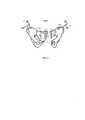
На фиг. 2 изображено 3D сегментированное изображение неподвижной и подвижной частей кости таза с установленными на них позиционерами с пассивными маркерами. В области перелома указаны точки соответствия.In FIG. 2 shows a 3D segmented image of the stationary and moving parts of the pelvic bone with positioners with passive markers mounted on them. In the fracture area, match points are indicated.
На фиг. 3 изображено 3D сегментированное изображение кости таза с позиционерами с пассивными маркерами после фиксации отломков винтом.In FIG. Figure 3 shows a 3D segmented image of the pelvic bone with positioners with passive markers after fixing the fragments with a screw.
Приборный комплекс (оптическая медицинская навигационная система) для реализации предложенного способа включает оптическую медицинскую навигационную систему 1 (фиг. 1), содержащую компьютер 2, монитор 3 и стереовидеокамеры 4. Также в состав приборного комплекса входят первый позиционер с пассивными маркерами 9, устанавливаемый на направляющую спицы 7, второй позиционер с пассивными маркерами 10, устанавливаемый на дрель 11, референтный позиционер с пассивными маркерами 12 и третий позиционер с пассивными маркерами 13. Приборный комплекс использует зарегистрированные на рентгеновском компьютерном томографе 5 и обработанные на входящей в его состав рабочей станции 6 изображения.The instrument complex (optical medical navigation system) for implementing the proposed method includes an optical medical navigation system 1 (Fig. 1) comprising a
Стереовидеокамеры 4 способны обеспечивать захват стереоизображения операционного поля на расстоянии 1,5 м и объемом не менее 1 м. Для увеличения контраста изображения пассивных маркеров и более качественного выделения пассивных маркеров на получаемом видеоизображении используется инфракрасная подсветка, выполненная светодиодами (не показаны), которые располагаются вокруг обоих объективов стереовидеокамер 4. Для уменьшения негативного влияния осветительных хирургических ламп диапазон пропускания видеокамер 4 установлен от 950 нм, максимальное разрешение видеокамер 2048⋅2048 пикселей. Для одномоментной регистрации изображений с двух видеокамер введена их синхронизация.Stereo-
В качестве пассивных маркеров используют светоотражающие маркеры, имеющие форму шариков диаметром не менее 9 мм. Программное обеспечение оптической медицинской навигационной системы 1 работает на компьютере 2. Программное обеспечение выполняет геометрическую привязку координат, видимых стереовидеокамерами 4 на теле пациента референтного позиционера с пассивными маркерами 12, установленного на неподвижной части кости таза и третьего позиционера с пассивными маркерами 13, установленного на подвижную часть кости таза 16, с пространственными координатами сегментированных 3D изображений референтного позиционера с пассивными маркерами 12 и соответствующего ему сегментированного изображения неподвижной части кости таза 15 и третьего позиционера с пассивными маркерами 13 и соответствующего ему сегментированного изображения подвижной части кости таза 16. Также программное обеспечение оптической медицинской навигационной системы 1, работающее на компьютере 2, выполняет геометрическую привязку координат, видимых стереовидеокамерами 4, направляющей спицы 8 по установленному на ней первому позиционеру с пассивными маркерами 9 и координат дрели по установленному на ней второму позиционеру с пассивными маркерами 10, с пространственными координатами 3D сегментированного изображения неподвижной части кости таза 15 и подвижной части кости таза 16.As passive markers, reflective markers are used, having the shape of balls with a diameter of at least 9 mm. The software of the optical
В качестве компьютера 2 может быть использован персональный компьютер с характеристиками не хуже: Intel Core i7-5960X 3.0GHz 8 Cores 20MB.As
Ввод данных в приборный комплекс во время операции осуществляется с помощью сенсорного монитора 3 с размером диагонали не менее 60 см.Data entry into the instrument complex during the operation is carried out using the
Предложенный способ реализуется следующим образом.The proposed method is implemented as follows.
Хирург выполняет установку референтного позиционера с пассивными маркерами 12 (фиг. 1) на неподвижной части кости таза 15. На подвижной части кости таза 16 устанавливают третий позиционер с пассивными маркерами 13. Позиционеры устанавливают на соответствующие кости таза при местном обезболивании. Затем на рентгеновском компьютерном томографе 5 проводят регистрацию 3D изображения неподвижной части кости таза 15 с установленным на ней референтным позиционером с пассивными маркерами 12 и подвижной части кости таза 16 с установленным на ней третьим позиционером с пассивными маркерами 13. Далее на рабочей станции 6 рентгеновского компьютерного томографа 5 проводят обработку изображений и строят 3D сегментированное изображение (Фиг. 2) неподвижной части кости таза 15 с установленным на ней референтным позиционером с пассивными маркерами 12 и 3D сегментированное изображение подвижной части кости таза 16 с установленным на ней третьим позиционером с пассивными маркерами 13. Результаты обработки по вычислительной сети передаются в компьютер 2 оптической медицинской навигационной системы 1 и отображаются на экране монитора 3 хирургу для планирования операции по выбору направления и глубины засверливания спицы 7 и последующей установки по ней скрепляющего винта 14.The surgeon installs a reference positioner with passive markers 12 (Fig. 1) on the fixed part of the
На 3D сегментированном изображении (Фиг. 2) неподвижной части 15 и подвижной части 16 кости таза хирургом в области перелома 17 указываются точки соответствия. Для этого на экране монитора 3 на 3D сегментированном изображении неподвижной части кости таза 15 хирург указывает точки 18, 20, 22 и т.д., на подвижной части кости таза 16 хирург указывает точки 19, 21, 23 и т.д. Для установки точек выбираются характерные анатомические ориентиры на костях в области перелома. Эти точки во время операции для устранения щели в области перелома 17 должны быть максимально совмещены друг с другом следующим образом: точка 18 с точкой 19, точка 20 с точкой 21, точка 22 с точкой 23 и т.д. Для достижения хорошей точности соответствия репозиции отломков достаточно использовать 6-7 пар точек.On a 3D segmented image (Fig. 2) of the
Во время операции видеоизображение со стереовидеокамер 4 по USB-интерфейсу передается в компьютер 2, где подвергается математической обработке для вычисления пространственных координат референтного позиционера с пассивными маркерами 12 на неподвижной части кости таза, третьего позиционера с пассивными маркерами 13, первого позиционера с пассивными маркерами 9, установленного на направляющую спицы 8, и третьего позиционера с пассивными маркерами 10, установленного на дрель 11. Далее программное обеспечение оптической стереоскопической навигационной системы 1 производит геометрическую привязку пространственных координат референтного позиционера с пассивными маркерами 12 и третьего позиционера с пассивными маркерами 13, видимых на теле пациенте стереовидеокамерами 4 и схематически отображаемых на экране монитора 3 в процессе их движения в реальном масштабе времени с 3D сегментированными изображениями референтного позиционера с пассивными маркерами 12, соединенного в единое целое с неподвижной частью кости таза 15, и третьего позиционера с пассивными маркерами 13, соединенного в единое целое с подвижной частью кости таза 16.During the operation, the video image from the
Хирург во время операции старается сблизить неподвижную часть кости таза 15 и подвижную часть кости таза 16 в области перелома 17 и установить их в оптимальном положении для последующей фиксации винтом 14. При этом программное обеспечение, работающее на компьютере 3 оптической медицинской навигационной системы 1, обеспечивает слежение за перемещением неподвижной части кости таза 15 и подвижной части кости таза 16 как их 3D сегментированных изображений и отображает их перемещения относительно друг друга на экране монитора 3. Также на монитор 3 выводится дополнительная информация о расстояниях в миллиметрах между парами точек соответствия на неподвижной части кости таза 15 и подвижной части кости таза 16 (18-20, 20-22, 21-23 и т.д.), которые необходимо максимально сблизить для обеспечения совмещения неподвижной 15 и подвижной 16 частей таза в области перелома 17.During the operation, the surgeon tries to bring together the fixed part of the
Далее хирург определяет, через какие области неподвижной части кости таза 15 и подвижной части кости таза 16 во время операции будет осуществляться их фиксация винтом 14.Further, the surgeon determines through which areas of the fixed part of the bone of the
Затем хирург выполняет установку первого позиционера с пассивными маркерами 9 на направляющую спицы 8 и устанавливает второй позиционер с пассивными маркерами 10 на дрель 11.Then the surgeon installs the first positioner with
Во время операции стереовидеокамеры 4 системы оптической медицинской навигационной системы 1 регистрируют видеоизображение первого позиционера с пассивными маркерами 9 направляющей спицы 7 и второго позиционера с пассивными маркерами 10 дрели 11. Программное обеспечение, работающее на компьютере 3, обеспечивает перерасчет их пространственных координат в координаты 3D сегментированного изображения неподвижной 15 и подвижной 16 частей костей таза и обеспечивает схематическую визуализацию направления и глубины засверливания спицы 7 на мониторе 3.During the operation of the
Хирург задает направление засверливания спицы 7 по схематическому изображению на экране монитора 3 пассивных маркеров первого позиционера с пассивными маркерами 9, расположенного на направляющей спицы 8 относительно 3D сегментированного изображения неподвижной части кости таза 15 и подвижной части кости таза 16, отображаемых на экране монитора 3 оптической медицинской навигационной системы 1. Хирург начинает засверливание спицы 7, контролируя глубину засверливания, наблюдая на экране монитора 3 схематическое изображение конца спицы 7 по второму позиционеру с пассивными маркерами 10, установленного на дрели 11, относительно 3D изображения неподвижной части кости таза 15 и подвижной части кости таза 16. Затем хирург удаляет направляющую спицы 8 и по спице 7 устанавливает скрепляющий подвижную часть кости таза 16 и неподвижную часть кости таза 15 винт 14 (Фиг. 3), удаляет спицу 7 и проводит зашивание раны.The surgeon sets the direction of drilling of the
Применение в предложенном способе координируемых в пространстве видимых стереовидеокамерами 4 оптической медицинской навигационной системы 1 референтного позиционера 12, установленного на неподвижную часть кости таза 15, третьего позиционера с пассивными маркерами 13, установленного на подвижную часть кости таза 16, направляющей спицы 8 по установленному на нее позиционеру с пассивными маркерами 9 и дрели 11 по установленному на нее второму позиционеру с пассивными маркерами 10, с построенным 3D сегментированным изображением референтного позиционера 12 и третьего позиционера с пассивными маркерами 13, однозначно связанных с соответствующими неподвижной 15 и подвижной 16 частями костей таза, приводит к возможности контролировать в реальном масштабе времени по изображению на экране монитора 3 направление и глубину засверливания спицы 7, получать количественную оценку, характеризующую точность совмещения неподвижной части кости таза 15 и подвижной части кости таза 16 в области перелома 17, что обеспечивает расширение функциональных возможностей предложенного способа. Предложенный способ позволяет значительно снизить лучевую нагрузку на пациента, так как пациент подвергается только предварительному обследованию на рентгеновском компьютерном томографе.The use in the proposed method coordinated in space of visible
Claims (2)
Translated fromRussianPriority Applications (1)
| Application Number | Priority Date | Filing Date | Title |
|---|---|---|---|
| RU2016134502ARU2635451C1 (en) | 2016-08-24 | 2016-08-24 | Method for optical medical navigation system application for visualization and quantitative evaluation of quality of fragments reposition in case of pelvic bone fracture |
Applications Claiming Priority (1)
| Application Number | Priority Date | Filing Date | Title |
|---|---|---|---|
| RU2016134502ARU2635451C1 (en) | 2016-08-24 | 2016-08-24 | Method for optical medical navigation system application for visualization and quantitative evaluation of quality of fragments reposition in case of pelvic bone fracture |
Publications (1)
| Publication Number | Publication Date |
|---|---|
| RU2635451C1true RU2635451C1 (en) | 2017-11-13 |
Family
ID=60328635
Family Applications (1)
| Application Number | Title | Priority Date | Filing Date |
|---|---|---|---|
| RU2016134502ARU2635451C1 (en) | 2016-08-24 | 2016-08-24 | Method for optical medical navigation system application for visualization and quantitative evaluation of quality of fragments reposition in case of pelvic bone fracture |
Country Status (1)
| Country | Link |
|---|---|
| RU (1) | RU2635451C1 (en) |
Cited By (3)
| Publication number | Priority date | Publication date | Assignee | Title |
|---|---|---|---|---|
| CN109820590A (en)* | 2019-02-15 | 2019-05-31 | 中国人民解放军总医院 | An intelligent monitoring system for pelvic fracture reduction |
| RU2739109C1 (en)* | 2020-08-08 | 2020-12-21 | Государственное бюджетное учреждение здравоохранения города Москвы «Научно-исследовательский институт скорой помощи им. Н.В. Склифосовского Департамента здравоохранения города Москвы» (ГБУЗ "НИИ СП ИМ. Н.В.СКЛИФОСОВСКОГО ДЗМ") | Method for determining the tactics of treating patients with pubic bone fractures |
| RU2816246C1 (en)* | 2023-09-17 | 2024-03-27 | Федеральное государственное бюджетное образовательное учреждение высшего образования "Московский государственный университет имени М.В.Ломоносова" (МГУ) | Method of obtaining high-definition x-ray images on pulsed source |
Citations (2)
| Publication number | Priority date | Publication date | Assignee | Title |
|---|---|---|---|---|
| US5527310A (en)* | 1994-07-01 | 1996-06-18 | Cole; J. Dean | Modular pelvic fixation system and method |
| RU2334465C1 (en)* | 2006-11-20 | 2008-09-27 | Закрытое акционерное общество "ДАТА-ЦЕНТР Икс-Рэй" (ЗАО "ДАТА-ЦЕНТР-Икс-Рэй") | Mobile compact x-ray apparatus |
- 2016
- 2016-08-24RURU2016134502Apatent/RU2635451C1/enactive
Patent Citations (2)
| Publication number | Priority date | Publication date | Assignee | Title |
|---|---|---|---|---|
| US5527310A (en)* | 1994-07-01 | 1996-06-18 | Cole; J. Dean | Modular pelvic fixation system and method |
| RU2334465C1 (en)* | 2006-11-20 | 2008-09-27 | Закрытое акционерное общество "ДАТА-ЦЕНТР Икс-Рэй" (ЗАО "ДАТА-ЦЕНТР-Икс-Рэй") | Mobile compact x-ray apparatus |
Non-Patent Citations (2)
| Title |
|---|
| PHILIPP SCHWABE et al. Three-Dimensional Fluoroscopy-Navigated Percutaneous Screw Fixation of Acetabular Fracture. J Orthop Trauma, 2014, vol. 28, N 12, p.700-706.* |
| АНКИН Л.Н. и др. Практическая травматология. М.: Книга плюс, 2002, с. 160-161.* |
Cited By (4)
| Publication number | Priority date | Publication date | Assignee | Title |
|---|---|---|---|---|
| CN109820590A (en)* | 2019-02-15 | 2019-05-31 | 中国人民解放军总医院 | An intelligent monitoring system for pelvic fracture reduction |
| CN109820590B (en)* | 2019-02-15 | 2024-04-12 | 中国人民解放军总医院 | Pelvis fracture resets intelligent monitoring system |
| RU2739109C1 (en)* | 2020-08-08 | 2020-12-21 | Государственное бюджетное учреждение здравоохранения города Москвы «Научно-исследовательский институт скорой помощи им. Н.В. Склифосовского Департамента здравоохранения города Москвы» (ГБУЗ "НИИ СП ИМ. Н.В.СКЛИФОСОВСКОГО ДЗМ") | Method for determining the tactics of treating patients with pubic bone fractures |
| RU2816246C1 (en)* | 2023-09-17 | 2024-03-27 | Федеральное государственное бюджетное образовательное учреждение высшего образования "Московский государственный университет имени М.В.Ломоносова" (МГУ) | Method of obtaining high-definition x-ray images on pulsed source |
Similar Documents
| Publication | Publication Date | Title |
|---|---|---|
| TWI615126B (en) | An image guided augmented reality method and a surgical navigation of wearable glasses using the same | |
| US12137981B2 (en) | Surgical systems and methods for facilitating tissue treatment | |
| US20200030038A1 (en) | Optical targeting and visualization of trajectories | |
| US9554117B2 (en) | System and method for non-invasive patient-image registration | |
| DE10108547B4 (en) | Operating system for controlling surgical instruments based on intra-operative X-ray images | |
| US11672607B2 (en) | Systems, devices, and methods for surgical navigation with anatomical tracking | |
| US20210196404A1 (en) | Implementation method for operating a surgical instrument using smart surgical glasses | |
| US20140107473A1 (en) | Laser Guidance System for Interventions | |
| US11576557B2 (en) | Method for supporting a user, computer program product, data medium and imaging system | |
| US20230015717A1 (en) | Anatomical scanning, targeting, and visualization | |
| US12324630B2 (en) | Method of fluoroscopic surgical registration | |
| Fallavollita et al. | An augmented reality C-arm for intraoperative assessment of the mechanical axis: a preclinical study | |
| JPH09173352A (en) | Medical navigation system | |
| RU2635451C1 (en) | Method for optical medical navigation system application for visualization and quantitative evaluation of quality of fragments reposition in case of pelvic bone fracture | |
| CN111870343A (en) | Surgical Robot System | |
| Zhang et al. | 3D augmented reality based orthopaedic interventions | |
| WO2025088616A1 (en) | Method and apparatus for procedure navigation | |
| CN109155068A (en) | Motion compensation in combined X-ray/camera intervention | |
| US20230190377A1 (en) | Technique Of Determining A Scan Region To Be Imaged By A Medical Image Acquisition Device | |
| y Alvarado et al. | Image-guided fiberoptic molecular imaging in a VX2 rabbit lung tumor model | |
| CN108852513A (en) | A kind of instrument guidance method of bone surgery guidance system | |
| Merloz et al. | Computer-assisted pedicle screw insertion | |
| US12408989B2 (en) | Method and system for surgical navigation | |
| Xing et al. | Virtual fluoroscopy for interventional guidance using magnetic tracking | |
| Zhang et al. | Exploratory development and clinical research of a mixed reality guided radiotherapy positioning system |
Legal Events
| Date | Code | Title | Description |
|---|---|---|---|
| PD4A | Correction of name of patent owner | ||
| PC41 | Official registration of the transfer of exclusive right | Effective date:20201008 |