RU2633813C1 - Stock of horizontal injection moulding machine - Google Patents
Stock of horizontal injection moulding machineDownload PDFInfo
- Publication number
- RU2633813C1 RU2633813C1RU2016112901ARU2016112901ARU2633813C1RU 2633813 C1RU2633813 C1RU 2633813C1RU 2016112901 ARU2016112901 ARU 2016112901ARU 2016112901 ARU2016112901 ARU 2016112901ARU 2633813 C1RU2633813 C1RU 2633813C1
- Authority
- RU
- Russia
- Prior art keywords
- rod
- longitudinal channel
- stock
- piston
- gap
- Prior art date
Links
Images
Classifications
- B—PERFORMING OPERATIONS; TRANSPORTING
- B22—CASTING; POWDER METALLURGY
- B22D—CASTING OF METALS; CASTING OF OTHER SUBSTANCES BY THE SAME PROCESSES OR DEVICES
- B22D17/00—Pressure die casting or injection die casting, i.e. casting in which the metal is forced into a mould under high pressure
- B22D17/20—Accessories: Details
Landscapes
- Pistons, Piston Rings, And Cylinders (AREA)
Abstract
Description
Translated fromRussianИзобретение пригодно в металлургическом производстве, и такой шток пригоден как элемент оснастки этих машин, используемой при литье цветных отливок.The invention is suitable in metallurgical production, and such a rod is suitable as a tooling element for these machines used in casting non-ferrous castings.
Известен охлаждаемый шток с наружным присоединительным участком под поршень в передней части, радиальными каналами в его задней части, выходящими в его продольный канал, где установлен стержень с закрепленной в нем трубкой, расположенной с зазором в этом канале; в этот зазор выходит одно поперечное окно задней части штока, а другое окно ее открыто через поперечное окно стержня в полость трубки с ее заднего торца; стержень неразъемно (сваркой) соединен со штоком, а задняя часть штока торцом ее передней части не доходит до заднего торца камеры прессования в крайнем переднем положении штока при выталкивании из нее пресс-остатка полученной отливки (см. приложение).Known cooled rod with an external connecting section for a piston in the front part, radial channels in its rear part, extending into its longitudinal channel, where a rod is installed with a tube fixed in it, located with a gap in this channel; this gap leaves one transverse window of the rear of the rod, and another window is open through the transverse window of the rod into the cavity of the tube from its rear end; the rod is inseparably connected (by welding) to the rod, and the back of the rod with the end of its front end does not reach the rear end of the pressing chamber in the extreme front position of the rod when the press residue of the casting is ejected from it (see the appendix).
Его недостатки: наличие сквозного ступенчатого канала соответственно под трубку и стержень усложняет конструкцию штока, а неразъемное соединение его со стержнем делает шток не пригодны для ремонта; нецелесообразное применение стержня такой конструкции, не разделяющего между собой поперечные окна подвода и отвода хладагента в шток и из него вследствие чего часть подводимого хладагента сразу отводится из штока, не достигая поршня. Известен охлаждаемый шток в виде передней части малого диаметра под поршень, задней части максимального диаметра для присоединения к литейной машине и средней части меньшего диаметра, чем диаметр полости камеры прессования; с переднего торца его образован продольный канал, в котором с зазором зафиксирована трубка с уплотнительным элементом на заднем конце, упертым в коническое дно этого канала; в это открыто поперечное окно задней части штока, а другое окно ее открыто в продольный канал (см. авторское свидетельство 1783209 А1 от 21.01.1989).Its disadvantages: the presence of a through step channel, respectively, under the tube and the rod complicates the design of the rod, and its integral connection with the rod makes the rod not suitable for repair; inappropriate use of a rod of such a design that does not separate the transverse windows of supply and removal of refrigerant to and from the rod, as a result of which part of the supplied refrigerant is immediately removed from the rod without reaching the piston. Known cooled rod in the form of the front of a small diameter under the piston, the rear of the maximum diameter for connection to a casting machine and the middle part of a smaller diameter than the diameter of the cavity of the pressing chamber; a longitudinal channel is formed from its front end, in which a tube is fixed with a gap with a sealing element at the rear end, abutted in the conical bottom of this channel; the transverse window of the back of the stem is open into this, and another window is open into the longitudinal channel (see copyright certificate 1783209 A1 of January 21, 1989).
Его недостатки: при износе передней резьбовой под шток части шток ремонтируется несколько раз и затем заменяется новым при неизношенных средней и задней частях; последняя часть максимального диаметра и определяет диаметр исходной заготовки, увеличивающей расход металла на шток и его трудоемкость; при смещении механизма прессования машины литья под давлением (МЛПД) из начального положения шток перекашивается относительно ее линии центров и ускоряются износ поршня и камеры прессования.Its disadvantages: when the front threaded part under the rod is worn, the rod is repaired several times and then replaced with a new one with unworn middle and rear parts; the last part of the maximum diameter determines the diameter of the initial billet, which increases the consumption of metal on the rod and its complexity; when the pressing mechanism of the injection molding machine (MLPD) is displaced from its initial position, the rod is skewed relative to its center line and the wear of the piston and pressing chamber is accelerated.
Задачей предлагаемого решения является устранение перекоса штока на машине и повышение надежности его, поршня и камеры прессования со снижением стоимости первого.The objective of the proposed solution is to eliminate the distortion of the rod on the machine and increase the reliability of it, the piston and the pressing chamber with a decrease in the cost of the first.
Технический результат от предлагаемого: повышение стойкости поршня и камеры прессования устранением перекоса штока при работе МЛПД с одновременным уменьшением его материалоемкости и трудоемкости. Это достигается тем, что у штока машины литья под давлением (МЛПД) в виде передней под поршень части минимального диаметра, задней присоединительной к МЛПД части максимального диаметра и средней между ними части с промежуточным диаметром, имеющего с торца передней части продольный канал под зафиксированную в нем с зазором трубку с уплотнительным элементом на конце, упертым в его дно, расположенное в начале задней части с открытым в него поперечным окном, а другое окно ее открыто в зазор между трубкой и каналом, НОВЫМ ЯВЛЯЕТСЯ ТО, ЧТО задняя часть штока выполнена сборной в виде двух элементов: переднего со сферической полостью на торце, отделенной стенками в центре от дна продольного канала и на периферии от боковой поверхности его и соприкасающейся с радиусным торцом заднего элемента, заканчивающимся на периферии плоским торцом, отделенным зазором от такого же торца предыдущего элемента; эти элементы соединены между собой накидной гайки, расположенной на первом из них с контактом его радиусного бурта с радиусным дном ее полости, а ее резьба с резьбовой поверхностью второго элемента; в задний торец накидной гайки уперта торцом контргайка, расположенная на втором элементе задней части штока.The technical result of the proposed: increasing the resistance of the piston and the pressing chamber by eliminating the misalignment of the rod during operation of the MLPD while reducing its material consumption and complexity. This is achieved by the fact that at the stem of the injection molding machine (MLPD) in the form of a front part of the minimum diameter for the piston, a back part of the maximum diameter connecting to the MLPD and a middle part between them with an intermediate diameter, having a longitudinal channel from the front of the front part under it fixed with a gap the tube with a sealing element at the end, abutted at its bottom, located at the beginning of the rear with a transverse window open into it, and another window open into the gap between the tube and the channel, NEW IS WHAT the back part of the rod is made by the national team in the form of two elements: the front one with a spherical cavity at the end, separated by walls in the center from the bottom of the longitudinal channel and on the periphery from its lateral surface and in contact with the radial end of the rear element, ending on the periphery with a flat end separated by a gap from the same end face of the previous element; these elements are interconnected with a union nut located on the first of them with the contact of its radius shoulder with the radius bottom of its cavity, and its thread with the threaded surface of the second element; the counter nut located on the second element of the rear part of the rod is pressed against the rear end of the union nut.
Выполнением задней части штока из двух элементов: переднего и заднего, соединенных между собой шарнирно, обеспечивается совмещение его продольной оси, кроме оси последнего элемента, с продольной осью камеры прессования при смещении механизма прессования МЛПД относительно начального положения.By performing the back of the rod of two elements: the front and rear, pivotally interconnected, the longitudinal axis, except for the axis of the last element, is aligned with the longitudinal axis of the pressing chamber when the MLPD pressing mechanism is offset from its initial position.
Образованием на торце переднего элемента задней части сферической полости, которая отделена стенками от конического дна продольного канала штока, соприкасающейся с радиусным торцом заднего элемента, создается шарнирная связь между этими элементами.The formation at the end of the front element of the rear of the spherical cavity, which is separated by the walls from the conical bottom of the longitudinal channel of the rod in contact with the radial end of the rear element, creates an articulated connection between these elements.
Использованием накидной гайки, размещенной на переднем элементе задней части штока и соединенной своей резьбой с резьбовой поверхностью заднего элемента ее, соприкасаются без зазоров сферическая полость и радиусный торец этих элементов задней части штока.Using a union nut located on the front element of the rear of the rod and connected by its thread to the threaded surface of its rear element, the spherical cavity and the radius end of these elements of the rear of the rod are in contact without gaps.
Применением накидной гайки с радиусным дном, взаимодействующим с радиусным буртом переднего элемента, расположенного у торца переднего элемента, обеспечивается поворот переднего элемента задней части штока и расположенных перед ним средней и передней частей его относительно заднего элемента задней части штока при смещении механизма прессования МЛПД из своего начального положения.The use of a union nut with a radius bottom interacting with the radius collar of the front element located at the end of the front element ensures rotation of the front element of the back of the rod and its front and middle and front parts relative to the rear element of the back of the rod when the MLPD pressing mechanism is shifted from its initial provisions.
Наличием контргайки на заднем элементе задней части штока, упертой передним торцом в задний торец накидной гайки, исключается отворачивание последней при работе машины и износ поверхностей образованного шарнирного соединения элементами этой части штока.The presence of a lock nut on the rear element of the rear part of the stem, which is abutted by the front end against the rear end of the union nut, prevents the latter from turning off during operation of the machine and the wear of the surfaces of the joint formed by elements of this part of the rod.
Разделением зазором торцов переднего и заднего элементов задней части штока обеспечивается поворот их относительно друг друга при смещении механизма прессования МЛПД в процессе ее работы.Separation of the ends of the front and rear elements of the rear part of the rod by a gap ensures their rotation relative to each other when the MLPD pressing mechanism is displaced during its operation.
Сравнительный анализ предлагаемого с известными в настоящее время техническими решениями показывает, что оно ново, с существенными отличиями, промышленной пригодностью и поэтому полностью соответствует критерию ИЗОБРЕТЕНИЕ.A comparative analysis of the proposed with currently known technical solutions shows that it is new, with significant differences, industrial suitability and therefore fully meets the criterion of the INVENTION.
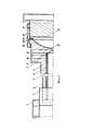
Шток представлен чертежом, где на фиг. 1 приведены решения п. 1 и 2 формулы изобретения. Он имеет переднюю часть 1 малого диаметра под поршень 2, расположенный передней частью в задней части камеры прессования 3 в крайнем (начальном) заднем положении; эта часть переходит в среднюю часть 4 большего диаметра, но меньше диаметра полости камеры 3, доходящую до задней части 5 максимального диаметра с наибольшим диаметром бурта 6, закрепленного в механизме прессования МЛПД; при этом передний торец этой части не доходит до заднего торца камеры прессования при выталкивании из нее пресс-остатка получаемой отливки и последней из неподвижной части пресс-формы; с переднего торца штока выполнен глухой продольный канал 7, в котором зафиксирована с зазором трубка 8, упертая через уплотнительный элемент 9 в коническое дно этого канала и зафиксированная передней частью в нем, например, штифтом, не показанным на фиг. 1; в это дно, расположенное в начале задней части 5, открыто поперечное окно 10 под хладагент, а другое окно 11 ее, расположенное перед предыдущим, выходит в канал 7, чем обеспечивается циркуляция хладагента по нему и полости трубки 8 для охлаждения нагревающегося при работе поршня 2; задняя часть 5 выполнена сборной и содержит передний элемент 12, имеющий с торца сферическую полость, отделенную стенками в центре от дна канала 7 и на периферии от его боковой поверхности; с поверхностью этой полости контактирует радиусный торец заднего элемента 13 благодаря накидной гайке 14, расположенной на предыдущем элементе 12 и контактирующей своим радиусным дном с радиусным выступом 15, образованным у торца элемента 12; гайка 14 своей резьбой соединена с резьбовой поверхностью 16 заднего элемента 13; в задний торец гайки 14 упирается передним торцом контргайка 17, расположенная на резьбовой поверхности 16 элемента 13 штока для исключения самоотвинчивания гайки 14 от усилия запрессовки, действующего на шток со стороны механизма прессования при работе МЛПД; между торцами переднего 12 и заднего 13 элементов задней части 5 штока имеется осевой зазор 18, необходимый для поворота этих элементов относительно друг друга при смещении механизма прессования МЛПД от начального положения в процессе работы этой машины.The stem is shown in the drawing, where in FIG. 1 shows the solutions of
При отсутствии смещения этого механизма относительно начального положения, что показано на фиг. 1, нет перекоса штока относительно линии центров МЛПД, и он с поршнем, расположенным боковой поверхностью его нижней части на такой же поверхности полости камеры прессования, беспрепятственно перемещаются по камере прессования 3 с поперечным смещением поршня в ней благодаря его передней фаске с воздействующим на нее сплавом, собираемым из нижней части ее полости в цилиндрический столбик; к моменту его образования продольная ось поршня совмещается с продольной осью камеры прессования, т.к. на фаску поршня по всему периметру ее действует под давлением сплав; сцентрированный таким образом поршень с равномерными радиальными зазорами относительно боковой поверхности полости камеры перемещается по ней с вытеснением сплав в пресс-форму, не показанную на фиг. 1; при этом и с таким расположением их между собой они минимально изнашиваются, чем повышается их стойкость. При наличии смещения этого механизма, например вверх, нарушается линия центров МЛПД: появляется смещение заднего элемента 13 штока совместно с этим механизмом на определенную величину относительно продольной оси камеры прессования 3; т.к. в ней находится передней частью поршень 2, закрепленный на штоке, то поршень 2 может сместиться относительно камеры 3 только на величину бокового зазора между этими элементами, определяемого их допусками (у камеры он на полость равен 0,04 мм, а у поршня на диаметр не более 0.03 мм и тогда максимальный зазор равен 0,07 мм); в этом случае поршень перекашивается в камере прессования: его передняя нижняя часть контактирует с нижней боковой поверхностью полости камеры, а его задняя верхняя часть с верхней боковой поверхностью полости камеры; при величине смещения штока больше этого зазора происходит поворот переднего элемента 12 его относительно заднего элемента 13 и продольная ось его средней и передней частей совпадают с продольной осью камеры прессования 3; этим самым обеспечивается без вышеуказанного перекоса перемещение поршня 2 по полости камеры 3 с минимальным износом их рабочих поверхностей и, таким образом, повышением их стойкости и, следовательно, надежности в целом.In the absence of displacement of this mechanism relative to the initial position, as shown in FIG. 1, there is no misalignment of the rod relative to the line of MLPD centers, and it with the piston located on the side surface of its lower part on the same surface of the cavity of the pressing chamber moves freely along the pressing chamber 3 with a transverse displacement of the piston in it due to its front facet with an alloy acting on it collected from the lower part of its cavity into a cylindrical column; by the time of its formation, the longitudinal axis of the piston is aligned with the longitudinal axis of the pressing chamber, because an alloy acts on the piston facet around its entire perimeter under pressure; the piston so concentrated with uniform radial clearances relative to the side surface of the chamber cavity moves along it with the displacement of the alloy into a mold not shown in FIG. one; at the same time, and with such an arrangement between them, they wear out minimally, which increases their durability. In the presence of an offset of this mechanism, for example, upward, the line of MLPD centers is violated: an offset of the
Выполнением задней части штока сборной (из переднего и заднего элементов) при предельном износе его передней части ее заменяют новой, имеющей выполненные совместно переднюю, среднюю части и передний элемент задней части и используют с нею годный для эксплуатации задний элемент задней части штока, что позволяет сократить расход металла на него и уменьшить его трудоемкость.By performing the rear part of the national team rod (from the front and rear elements) with extreme wear of its front part, it is replaced by a new one having the front, middle parts and front rear element made together and use the rear element of the rear part of the rod that is suitable for operation, which allows to reduce metal consumption on it and reduce its complexity.
Это подтверждается примером: при диаметре заготовки-прутка 100 мм на шток длиной 530 мм ее масса равна М=0,53*0,1*0,1*0,785*7800=32,45 кг; при длине заготовки-прутка 0,43 мм диаметром 85 мм для предлагаемого штока ее масса равна М=0,43*0,085*0,085*0,785*7800=19,02 кг (размеры взяты из приложения), что примерно в 2 раза меньше, чем у аналога и прототипа; такое же соотношение их и по трудоемкости штоков. При этом длина заднего элемента задней части штока порядка 70-75 мм при максимальном диаметре 80 мм и резьбе накидной гайки и заднего элемента штока М 60*3 или М64*3.This is confirmed by an example: when the diameter of the bar stock is 100 mm per rod 530 mm long, its mass is M = 0.53 * 0.1 * 0.1 * 0.785 * 7800 = 32.45 kg; when the length of the bar stock 0.43 mm with a diameter of 85 mm for the proposed rod, its mass is M = 0.43 * 0.085 * 0.085 * 0.785 * 7800 = 19.02 kg (dimensions taken from the application), which is about 2 times less than the analogue and prototype; the same ratio of them and the complexity of the stocks. The length of the rear element of the rear of the stem is about 70-75 mm with a maximum diameter of 80 mm and the thread of the union nut and the rear stem element of M 60 * 3 or M64 * 3.
Таким образом, предлагаемым штоком уменьшается примерно в 2 раза масса его заготовки и трудоемкость, а также повышается стойкость поршня и камеры прессования из-за отсутствия перекоса его части относительно последней.Thus, the proposed rod decreases by about 2 times the mass of its billet and the complexity, and also increases the resistance of the piston and the pressing chamber due to the absence of distortion of its part relative to the latter.
Claims (2)
Translated fromRussianPriority Applications (1)
| Application Number | Priority Date | Filing Date | Title |
|---|---|---|---|
| RU2016112901ARU2633813C1 (en) | 2016-04-05 | 2016-04-05 | Stock of horizontal injection moulding machine |
Applications Claiming Priority (1)
| Application Number | Priority Date | Filing Date | Title |
|---|---|---|---|
| RU2016112901ARU2633813C1 (en) | 2016-04-05 | 2016-04-05 | Stock of horizontal injection moulding machine |
Publications (1)
| Publication Number | Publication Date |
|---|---|
| RU2633813C1true RU2633813C1 (en) | 2017-10-18 |
Family
ID=60125227
Family Applications (1)
| Application Number | Title | Priority Date | Filing Date |
|---|---|---|---|
| RU2016112901ARU2633813C1 (en) | 2016-04-05 | 2016-04-05 | Stock of horizontal injection moulding machine |
Country Status (1)
| Country | Link |
|---|---|
| RU (1) | RU2633813C1 (en) |
Cited By (1)
| Publication number | Priority date | Publication date | Assignee | Title |
|---|---|---|---|---|
| RU2679856C1 (en)* | 2018-01-15 | 2019-02-13 | Тимофей Иванович Кожокин | Device for fastening rod with a piston on a horizontal injection molding machine |
Citations (3)
| Publication number | Priority date | Publication date | Assignee | Title |
|---|---|---|---|---|
| JP2000158114A (en)* | 1998-11-26 | 2000-06-13 | Masashi Katsumi | Plunger for die cast equipment |
| US6581670B1 (en)* | 1999-06-01 | 2003-06-24 | Oskar Frech Gmbh & Co. | Injection unit for a pressure die casting machine |
| RU2522510C1 (en)* | 2013-03-12 | 2014-07-20 | Открытое акционерное общество "Завод им. В.А. Дегтярева" | Injection moulding machine piston assy |
- 2016
- 2016-04-05RURU2016112901Apatent/RU2633813C1/enactive
Patent Citations (3)
| Publication number | Priority date | Publication date | Assignee | Title |
|---|---|---|---|---|
| JP2000158114A (en)* | 1998-11-26 | 2000-06-13 | Masashi Katsumi | Plunger for die cast equipment |
| US6581670B1 (en)* | 1999-06-01 | 2003-06-24 | Oskar Frech Gmbh & Co. | Injection unit for a pressure die casting machine |
| RU2522510C1 (en)* | 2013-03-12 | 2014-07-20 | Открытое акционерное общество "Завод им. В.А. Дегтярева" | Injection moulding machine piston assy |
Cited By (1)
| Publication number | Priority date | Publication date | Assignee | Title |
|---|---|---|---|---|
| RU2679856C1 (en)* | 2018-01-15 | 2019-02-13 | Тимофей Иванович Кожокин | Device for fastening rod with a piston on a horizontal injection molding machine |
Similar Documents
| Publication | Publication Date | Title |
|---|---|---|
| CA2625099C (en) | Multi-piece piston for a cold chamber casting machine | |
| JP2006247747A (en) | Expansion device for hollow body | |
| RU2633813C1 (en) | Stock of horizontal injection moulding machine | |
| CN102472379A (en) | Cam follower and method for producing cam follower | |
| EP3108979B1 (en) | A dummy block for an extrusion press | |
| US20150096439A1 (en) | Piston for cold chamber die-casting machines | |
| RU2680320C1 (en) | Injection molding machine piston assembly | |
| JPH0417745B2 (en) | ||
| EP2431112B1 (en) | Diecast piston | |
| JP6144664B2 (en) | Slide pin cooling device | |
| KR101648273B1 (en) | Backlash mesurement apparatus | |
| RU2679855C1 (en) | Injection molding machine piston assembly | |
| KR101141540B1 (en) | Jaw crusher for heavy equipment | |
| RU2592011C1 (en) | Composite mill roll | |
| CN109789480A (en) | Piston for die casting machine | |
| CN205414364U (en) | Die cavity adjustable die casting die | |
| JP7134975B2 (en) | Die-casting piston and die-casting device with the same | |
| RU2706903C1 (en) | Piston unit of injection molding machine | |
| RU2338619C1 (en) | Device for on mandrel tube forging | |
| RU2709300C1 (en) | Piston unit of injection moulding machine | |
| KR101205277B1 (en) | Multipart Roll | |
| RU2679856C1 (en) | Device for fastening rod with a piston on a horizontal injection molding machine | |
| RU2542223C1 (en) | Radial squeezing machine driver centre | |
| KR102483588B1 (en) | device for exchanging a sleeve contact ring of plunger in die casting machine | |
| US9962761B2 (en) | Replaceable piston ring for die casting machine plunger |