RU2633325C2 - Flower catheter for venous and other tubular areas mapping and ablation - Google Patents
Flower catheter for venous and other tubular areas mapping and ablationDownload PDFInfo
- Publication number
- RU2633325C2 RU2633325C2RU2013112613ARU2013112613ARU2633325C2RU 2633325 C2RU2633325 C2RU 2633325C2RU 2013112613 ARU2013112613 ARU 2013112613ARU 2013112613 ARU2013112613 ARU 2013112613ARU 2633325 C2RU2633325 C2RU 2633325C2
- Authority
- RU
- Russia
- Prior art keywords
- branch
- catheter
- distal
- electrode
- branches
- Prior art date
Links
- 238000002679ablationMethods0.000titleclaimsabstractdescription44
- 238000013507mappingMethods0.000titledescription16
- 238000000034methodMethods0.000claimsabstractdescription24
- 230000000694effectsEffects0.000claimsabstractdescription16
- 230000007935neutral effectEffects0.000claimsabstractdescription10
- 230000002262irrigationEffects0.000claimsdescription50
- 238000003973irrigationMethods0.000claimsdescription50
- 238000003780insertionMethods0.000abstractdescription4
- 230000037431insertionEffects0.000abstractdescription4
- 239000003814drugSubstances0.000abstract1
- 239000000126substanceSubstances0.000abstract1
- 239000011248coating agentSubstances0.000description22
- 238000000576coating methodMethods0.000description22
- 210000001519tissueAnatomy0.000description22
- WABPQHHGFIMREM-UHFFFAOYSA-Nlead(0)Chemical compound[Pb]WABPQHHGFIMREM-UHFFFAOYSA-N0.000description16
- 239000012530fluidSubstances0.000description14
- 210000005003heart tissueAnatomy0.000description11
- 239000000463materialSubstances0.000description11
- 239000004814polyurethaneSubstances0.000description11
- 229920002635polyurethanePolymers0.000description11
- 239000000853adhesiveSubstances0.000description8
- 230000001070adhesive effectEffects0.000description8
- 230000008859changeEffects0.000description8
- 238000013461designMethods0.000description8
- 229920003023plasticPolymers0.000description7
- 239000004033plasticSubstances0.000description7
- 239000004020conductorSubstances0.000description6
- 230000007246mechanismEffects0.000description6
- 230000001575pathological effectEffects0.000description6
- 239000010935stainless steelSubstances0.000description6
- 229910001220stainless steelInorganic materials0.000description6
- 239000004642PolyimideSubstances0.000description5
- 229920001721polyimidePolymers0.000description5
- 231100000241scarToxicity0.000description4
- 208000007536ThrombosisDiseases0.000description3
- 230000003126arrythmogenic effectEffects0.000description3
- 230000011128cardiac conductionEffects0.000description3
- 230000006870functionEffects0.000description3
- 238000010438heat treatmentMethods0.000description3
- 239000007788liquidSubstances0.000description3
- 229910052751metalInorganic materials0.000description3
- 239000002184metalSubstances0.000description3
- 238000005476solderingMethods0.000description3
- 210000003462veinAnatomy0.000description3
- RYGMFSIKBFXOCR-UHFFFAOYSA-NCopperChemical compound[Cu]RYGMFSIKBFXOCR-UHFFFAOYSA-N0.000description2
- FAPWRFPIFSIZLT-UHFFFAOYSA-MSodium chlorideChemical compound[Na+].[Cl-]FAPWRFPIFSIZLT-UHFFFAOYSA-M0.000description2
- 230000009471actionEffects0.000description2
- 230000006793arrhythmiaEffects0.000description2
- 206010003119arrhythmiaDiseases0.000description2
- 230000008901benefitEffects0.000description2
- 230000000903blocking effectEffects0.000description2
- 210000004369bloodAnatomy0.000description2
- 239000008280bloodSubstances0.000description2
- 230000006835compressionEffects0.000description2
- 238000007906compressionMethods0.000description2
- 238000010276constructionMethods0.000description2
- 230000006378damageEffects0.000description2
- 238000006073displacement reactionMethods0.000description2
- 210000001174endocardiumAnatomy0.000description2
- 238000002955isolationMethods0.000description2
- 210000005240left ventricleAnatomy0.000description2
- 229910001000nickel titaniumInorganic materials0.000description2
- 230000033764rhythmic processEffects0.000description2
- 239000000565sealantSubstances0.000description2
- 239000011780sodium chlorideSubstances0.000description2
- 238000003466weldingMethods0.000description2
- 208000032544CicatrixDiseases0.000description1
- 229910001006ConstantanInorganic materials0.000description1
- 239000004593EpoxySubstances0.000description1
- 239000004677NylonSubstances0.000description1
- 239000004952PolyamideSubstances0.000description1
- 239000004721Polyphenylene oxideSubstances0.000description1
- 229910000746Structural steelInorganic materials0.000description1
- 230000003213activating effectEffects0.000description1
- 230000004913activationEffects0.000description1
- 238000004026adhesive bondingMethods0.000description1
- 210000001367arteryAnatomy0.000description1
- 230000015572biosynthetic processEffects0.000description1
- 238000003763carbonizationMethods0.000description1
- 229910052802copperInorganic materials0.000description1
- 239000010949copperSubstances0.000description1
- 238000013480data collectionMethods0.000description1
- 229910003460diamondInorganic materials0.000description1
- 239000010432diamondSubstances0.000description1
- 238000009826distributionMethods0.000description1
- 238000005553drillingMethods0.000description1
- 230000005684electric fieldEffects0.000description1
- 238000010292electrical insulationMethods0.000description1
- 239000012777electrically insulating materialSubstances0.000description1
- 230000007613environmental effectEffects0.000description1
- 239000003822epoxy resinSubstances0.000description1
- 239000004744fabricSubstances0.000description1
- 239000003292glueSubstances0.000description1
- 210000002837heart atriumAnatomy0.000description1
- 230000001771impaired effectEffects0.000description1
- 238000009434installationMethods0.000description1
- 238000009413insulationMethods0.000description1
- HLXZNVUGXRDIFK-UHFFFAOYSA-Nnickel titaniumChemical compound[Ti].[Ti].[Ti].[Ti].[Ti].[Ti].[Ti].[Ti].[Ti].[Ti].[Ti].[Ni].[Ni].[Ni].[Ni].[Ni].[Ni].[Ni].[Ni].[Ni].[Ni].[Ni].[Ni].[Ni].[Ni]HLXZNVUGXRDIFK-UHFFFAOYSA-N0.000description1
- 238000010606normalizationMethods0.000description1
- 229920001778nylonPolymers0.000description1
- 238000013021overheatingMethods0.000description1
- 230000009745pathological pathwayEffects0.000description1
- 230000035699permeabilityEffects0.000description1
- 229920002647polyamidePolymers0.000description1
- 229920000647polyepoxidePolymers0.000description1
- 229920000570polyetherPolymers0.000description1
- 230000008569processEffects0.000description1
- 210000003492pulmonary veinAnatomy0.000description1
- 230000037387scarsEffects0.000description1
- 238000000926separation methodMethods0.000description1
- APSBXTVYXVQYAB-UHFFFAOYSA-Msodium docusateChemical compound[Na+].CCCCC(CC)COC(=O)CC(S([O-])(=O)=O)C(=O)OCC(CC)CCCCAPSBXTVYXVQYAB-UHFFFAOYSA-M0.000description1
- 210000004872soft tissueAnatomy0.000description1
- 229960000103thrombolytic agentDrugs0.000description1
- 230000002537thrombolytic effectEffects0.000description1
- 230000007704transitionEffects0.000description1
- 238000009827uniform distributionMethods0.000description1
- 239000011345viscous materialSubstances0.000description1
Images


Classifications
- A—HUMAN NECESSITIES
- A61—MEDICAL OR VETERINARY SCIENCE; HYGIENE
- A61B—DIAGNOSIS; SURGERY; IDENTIFICATION
- A61B18/00—Surgical instruments, devices or methods for transferring non-mechanical forms of energy to or from the body
- A61B18/04—Surgical instruments, devices or methods for transferring non-mechanical forms of energy to or from the body by heating
- A61B18/12—Surgical instruments, devices or methods for transferring non-mechanical forms of energy to or from the body by heating by passing a current through the tissue to be heated, e.g. high-frequency current
- A61B18/14—Probes or electrodes therefor
- A61B18/1492—Probes or electrodes therefor having a flexible, catheter-like structure, e.g. for heart ablation
- A—HUMAN NECESSITIES
- A61—MEDICAL OR VETERINARY SCIENCE; HYGIENE
- A61B—DIAGNOSIS; SURGERY; IDENTIFICATION
- A61B18/00—Surgical instruments, devices or methods for transferring non-mechanical forms of energy to or from the body
- A61B18/04—Surgical instruments, devices or methods for transferring non-mechanical forms of energy to or from the body by heating
- A61B18/12—Surgical instruments, devices or methods for transferring non-mechanical forms of energy to or from the body by heating by passing a current through the tissue to be heated, e.g. high-frequency current
- A—HUMAN NECESSITIES
- A61—MEDICAL OR VETERINARY SCIENCE; HYGIENE
- A61B—DIAGNOSIS; SURGERY; IDENTIFICATION
- A61B5/00—Measuring for diagnostic purposes; Identification of persons
- A61B5/24—Detecting, measuring or recording bioelectric or biomagnetic signals of the body or parts thereof
- A61B5/25—Bioelectric electrodes therefor
- A61B5/279—Bioelectric electrodes therefor specially adapted for particular uses
- A61B5/28—Bioelectric electrodes therefor specially adapted for particular uses for electrocardiography [ECG]
- A61B5/283—Invasive
- A61B5/287—Holders for multiple electrodes, e.g. electrode catheters for electrophysiological study [EPS]
- A—HUMAN NECESSITIES
- A61—MEDICAL OR VETERINARY SCIENCE; HYGIENE
- A61B—DIAGNOSIS; SURGERY; IDENTIFICATION
- A61B5/00—Measuring for diagnostic purposes; Identification of persons
- A61B5/48—Other medical applications
- A61B5/4848—Monitoring or testing the effects of treatment, e.g. of medication
- A—HUMAN NECESSITIES
- A61—MEDICAL OR VETERINARY SCIENCE; HYGIENE
- A61B—DIAGNOSIS; SURGERY; IDENTIFICATION
- A61B5/00—Measuring for diagnostic purposes; Identification of persons
- A61B5/68—Arrangements of detecting, measuring or recording means, e.g. sensors, in relation to patient
- A61B5/6846—Arrangements of detecting, measuring or recording means, e.g. sensors, in relation to patient specially adapted to be brought in contact with an internal body part, i.e. invasive
- A61B5/6847—Arrangements of detecting, measuring or recording means, e.g. sensors, in relation to patient specially adapted to be brought in contact with an internal body part, i.e. invasive mounted on an invasive device
- A61B5/6852—Catheters
- A61B5/6859—Catheters with multiple distal splines
- A—HUMAN NECESSITIES
- A61—MEDICAL OR VETERINARY SCIENCE; HYGIENE
- A61B—DIAGNOSIS; SURGERY; IDENTIFICATION
- A61B17/00—Surgical instruments, devices or methods
- A61B2017/00831—Material properties
- A61B2017/00867—Material properties shape memory effect
- A—HUMAN NECESSITIES
- A61—MEDICAL OR VETERINARY SCIENCE; HYGIENE
- A61B—DIAGNOSIS; SURGERY; IDENTIFICATION
- A61B18/00—Surgical instruments, devices or methods for transferring non-mechanical forms of energy to or from the body
- A61B2018/00053—Mechanical features of the instrument of device
- A61B2018/0016—Energy applicators arranged in a two- or three dimensional array
- A—HUMAN NECESSITIES
- A61—MEDICAL OR VETERINARY SCIENCE; HYGIENE
- A61B—DIAGNOSIS; SURGERY; IDENTIFICATION
- A61B18/00—Surgical instruments, devices or methods for transferring non-mechanical forms of energy to or from the body
- A61B2018/00315—Surgical instruments, devices or methods for transferring non-mechanical forms of energy to or from the body for treatment of particular body parts
- A61B2018/00345—Vascular system
- A61B2018/00351—Heart
- A61B2018/00357—Endocardium
- A—HUMAN NECESSITIES
- A61—MEDICAL OR VETERINARY SCIENCE; HYGIENE
- A61B—DIAGNOSIS; SURGERY; IDENTIFICATION
- A61B18/00—Surgical instruments, devices or methods for transferring non-mechanical forms of energy to or from the body
- A61B2018/00571—Surgical instruments, devices or methods for transferring non-mechanical forms of energy to or from the body for achieving a particular surgical effect
- A61B2018/00577—Ablation
- A—HUMAN NECESSITIES
- A61—MEDICAL OR VETERINARY SCIENCE; HYGIENE
- A61B—DIAGNOSIS; SURGERY; IDENTIFICATION
- A61B18/00—Surgical instruments, devices or methods for transferring non-mechanical forms of energy to or from the body
- A61B2018/00636—Sensing and controlling the application of energy
- A61B2018/00773—Sensed parameters
- A61B2018/00839—Bioelectrical parameters, e.g. ECG, EEG
- A—HUMAN NECESSITIES
- A61—MEDICAL OR VETERINARY SCIENCE; HYGIENE
- A61B—DIAGNOSIS; SURGERY; IDENTIFICATION
- A61B18/00—Surgical instruments, devices or methods for transferring non-mechanical forms of energy to or from the body
- A61B18/04—Surgical instruments, devices or methods for transferring non-mechanical forms of energy to or from the body by heating
- A61B18/12—Surgical instruments, devices or methods for transferring non-mechanical forms of energy to or from the body by heating by passing a current through the tissue to be heated, e.g. high-frequency current
- A61B18/14—Probes or electrodes therefor
- A61B2018/1467—Probes or electrodes therefor using more than two electrodes on a single probe
- A—HUMAN NECESSITIES
- A61—MEDICAL OR VETERINARY SCIENCE; HYGIENE
- A61B—DIAGNOSIS; SURGERY; IDENTIFICATION
- A61B2218/00—Details of surgical instruments, devices or methods for transferring non-mechanical forms of energy to or from the body
- A61B2218/001—Details of surgical instruments, devices or methods for transferring non-mechanical forms of energy to or from the body having means for irrigation and/or aspiration of substances to and/or from the surgical site
- A61B2218/002—Irrigation
Landscapes
- Health & Medical Sciences (AREA)
- Life Sciences & Earth Sciences (AREA)
- Surgery (AREA)
- Engineering & Computer Science (AREA)
- Public Health (AREA)
- Veterinary Medicine (AREA)
- Biomedical Technology (AREA)
- Heart & Thoracic Surgery (AREA)
- Medical Informatics (AREA)
- Molecular Biology (AREA)
- Physics & Mathematics (AREA)
- Animal Behavior & Ethology (AREA)
- General Health & Medical Sciences (AREA)
- Pathology (AREA)
- Biophysics (AREA)
- Cardiology (AREA)
- Plasma & Fusion (AREA)
- Nuclear Medicine, Radiotherapy & Molecular Imaging (AREA)
- Otolaryngology (AREA)
- Physiology (AREA)
- Surgical Instruments (AREA)
- Measurement And Recording Of Electrical Phenomena And Electrical Characteristics Of The Living Body (AREA)
- Media Introduction/Drainage Providing Device (AREA)
Abstract
Description
Translated fromRussianПРЕДПОСЫЛКИ СОЗДАНИЯ ИЗОБРЕТЕНИЯBACKGROUND OF THE INVENTION
Электродные катетеры широко применяются в медицинской практике в течение многих лет. Они используются для стимуляции и картирования электрической активности сердца, а также для абляции участков нарушенной электрической активности. В процессе применения электродный катетер вводится в полость сердца. После установки катетера определяется местоположение очага патологической электрической активности в ткани сердца.Electrode catheters have been widely used in medical practice for many years. They are used to stimulate and map the electrical activity of the heart, as well as to ablate areas of impaired electrical activity. During use, an electrode catheter is inserted into the cavity of the heart. After the catheter is installed, the location of the focus of pathological electrical activity in the heart tissue is determined.
Одна из техник определения местонахождения включает процедуру электрофизиологического картирования, в рамках которой исходящие от тканей проводящей системы сердца электрические сигналы систематически регистрируются и на их основе составляется карта. Анализируя карту, врач может выявить патологический проводящий путь. Общепринятым методом картирования электрических сигналов от тканей проводящей системы сердца является чрескожное введение электрофизиологического (электродного) катетера, на дистальном конце которого установлены электроды для картирования. Катетер перемещают с целью расположить эти электроды на эндокарде или как можно ближе к нему. Отслеживая электрические сигналы с эндокарда, можно точно определить местоположение участков патологической проводимости, ответственных за возникновение аритмии.One of the techniques for determining the location involves the electrophysiological mapping procedure, in which the electrical signals emanating from the tissues of the cardiac conduction system are systematically recorded and a map is made based on them. By analyzing the map, the doctor can identify a pathological pathway. A common method for mapping electrical signals from tissues of the cardiac conduction system is the transdermal insertion of an electrophysiological (electrode) catheter, at the distal end of which electrodes for mapping are installed. The catheter is moved to position these electrodes on the endocardium or as close to it as possible. By tracking electrical signals from the endocardium, it is possible to accurately determine the location of the pathological conduction sites responsible for the occurrence of arrhythmia.
Для проведения картирования желательно наличие относительно небольшого картирующего электрода. Было обнаружено, что с электродов меньших размеров записываются более точные и дискретные электрограммы. К тому же, если используется биполярная картировочная сборка, для получения более точных и клинически полезных электрограмм желательно, чтобы электроды биполярной сборки находились как можно ближе друг к другу и имели одинаковый размер.For mapping, a relatively small mapping electrode is desirable. It was found that smaller, more accurate and discrete electrograms were recorded from smaller electrodes. In addition, if a bipolar grading assembly is used, to obtain more accurate and clinically useful electrograms, it is desirable that the electrodes of the bipolar assembly are as close to each other as possible and have the same size.
Как только в тканях выявляется аритмогенная точка, врач использует процедуру абляции, разрушая аритмогенную ткань в попытке устранить нарушения электрического сигнала, восстановить нормальный ритм сердца или хотя бы добиться частичной нормализации сердечного ритма. Успешная абляция тканей проводящей системы сердца в аритмогенной зоне обычно устраняет аритмию или хотя бы доводит сердечный ритм до приемлемого уровня.As soon as an arrhythmogenic point is detected in the tissues, the doctor uses the ablation procedure, destroying the arrhythmogenic tissue in an attempt to eliminate the disturbance of the electrical signal, restore the normal heart rhythm, or at least achieve a partial normalization of the heart rhythm. Successful ablation of the tissues of the cardiac conduction system in the arrhythmogenic zone usually eliminates arrhythmia or at least brings the heart rate to an acceptable level.
Типичная процедура абляции включает подсоединение отводящего электрода, закрепляемого на коже пациента пластырем. На электрод на кончике катетера подается ток радиочастоты, который течет сквозь окружающие среды, например кровь и ткани, к отводящему электроду. Другой вариант - размещение на катетере биполярных электродов; в этом случае ток течет от одного электрода на кончике катетера через ткани к другому электроду, также установленному на кончике катетера. В любом случае распределение тока зависит от площади поверхности электрода, находящейся в контакте с тканями и кровью, проводимость которой выше, чем у тканей. Воздействие тока вызывает нагрев тканей. Этот нагрев достаточен, чтобы вызвать разрушение клеток ткани сердца, в результате чего в ней формируется поврежденный участок, который не проводит электрический ток.A typical ablation procedure involves connecting a discharge electrode fixed to the patient’s skin with a patch. A radio frequency current is supplied to the electrode at the tip of the catheter, which flows through environmental media, such as blood and tissues, to the discharge electrode. Another option is to place bipolar electrodes on the catheter; in this case, current flows from one electrode at the tip of the catheter through the tissue to another electrode, also mounted on the tip of the catheter. In any case, the current distribution depends on the surface area of the electrode in contact with tissues and blood, the conductivity of which is higher than that of tissues. Exposure to current causes tissue heating. This heating is sufficient to cause the destruction of the cells of the heart tissue, as a result of which a damaged area is formed in it that does not conduct electric current.
Неудобство токопроводящих катетеров выявляется в случае обнаружения области патологической активности в вене или ином трубчатом образовании, исходящем от полости сердца. При расположении очагов патологической активности в подобных областях общепринятой альтернативой абляции самого очага служит абляция тканей вокруг очага с созданием блокирующей линии для прерывания распространения патологических импульсов. Если эта процедура применяется к трубчатой области внутри сердца или близко к нему, блокирующая линия должна быть сформирована по всему периметру трубчатой области. При этом возникают трудности с манипуляцией и контролем дистального конца прямого катетера для эффективной абляции вокруг устья. Более того, хотя большинство сосудов имеют круглое сечение, многие имеют иную форму на срезе и разные размеры. Соответственно, имеется спрос на улучшенный катетер, особо эффективный в подобных случаях.The inconvenience of conductive catheters is detected if a region of pathological activity is detected in a vein or other tubular formation emanating from the heart cavity. When the foci of pathological activity are located in such areas, the ablation of tissues around the foci with the creation of a blocking line to interrupt the spread of pathological impulses is a generally accepted alternative to ablation of the foci. If this procedure is applied to or close to the tubular region inside the heart, a blocking line should be formed around the perimeter of the tubular region. In this case, difficulties arise with the manipulation and control of the distal end of the direct catheter for effective ablation around the mouth. Moreover, although most vessels have a circular cross section, many have a different shape on the cut and different sizes. Accordingly, there is a demand for an improved catheter that is particularly effective in such cases.
Цветковые катетеры для картирования известны в медицинской практике, однако традиционные цветковые катетеры имеют электроды малых размеров, что делает их малоприменимыми для абляции. Кроме того, существующие цветковые катетеры изначально создавались для исследования предсердий, а не картирования вен и абляции, которые имеют определенную специфику.Flower catheters for mapping are known in medical practice, however, traditional flower catheters have small electrodes, which makes them of little use for ablation. In addition, existing flower catheters were originally created for the study of atria, rather than vein mapping and ablation, which are of a specific nature.
Известны также катетеры-лассо. Основной отрезок длины катетера-лассо имеет круглое сечение, что не всегда позволяет применять его для трубчатых структур, имеющих иное сечение. Более того, основная часть длины катетера круглого сечения чаще всего располагается по одному из внутренних периметров трубчатой структуры для формирования изолирующей линии. Поэтому для проверки непрерывности изолирующей линии требуется либо изменение положения катетера, либо использования второго катетера, что увеличивает продолжительность, сложность и (или) стоимость процедуры абляции.Lasso catheters are also known. The main length of the catheter-lasso has a circular cross section, which does not always allow its use for tubular structures having a different cross section. Moreover, the main part of the length of the catheter of circular cross section is most often located along one of the inner perimeters of the tubular structure to form an insulating line. Therefore, to check the continuity of the insulating line, either a change in the position of the catheter or the use of a second catheter is required, which increases the duration, complexity and (or) cost of the ablation procedure.
Таким образом, существует потребность в катетере, приспособленном для картирования и абляции в трубчатой структуре, особенно в трубчатой структуре некруглого сечения. Кроме того, желательно, чтобы катетер был применим для проведения проверки непрерывности рубцовых изолирующих линий без необходимости изменения положения катетера или использования дополнительного катетера.Thus, there is a need for a catheter adapted for mapping and ablation in a tubular structure, especially a non-circular tubular structure. In addition, it is desirable that the catheter be applicable for checking the continuity of cicatricial isolation lines without the need to change the position of the catheter or use an additional catheter.
КРАТКОЕ ОПИСАНИЕ ИЗОБРЕТЕНИЯSUMMARY OF THE INVENTION
Предметом данного изобретения является улучшенный катетер для абляции трубчатых структур в сердце или близко к нему. Катетер включает в себя дистальный узел, включающий несколько ветвей, каждая из которых способна как производить абляцию, так и получать данные об электрической активности тканей сердца. Использование нескольких ветвей, выходящих из катетера по окружности, обеспечивает контакт между ветвями и окружающими тканями, как правило, вне зависимости от размеров или формы трубчатой области. Поскольку каждая ветвь зафиксирована только на проксимальном конце, свободный дистальный конец ветви может независимо устанавливаться в трубчатой области, особенно если трубчатая структура имеет некруглое поперечное сечение. Каждая ветвь имеет L-образную форму с практически прямым проксимальным участком, в общем, ортогональным дистальному. Преимуществом такой конструкции является то, что практически L-образная форма превращается в практически U-образную, причем дистальный участок располагается на окружающих тканях для лучшего контакта с ними, когда проксимальный участок продвигается или проталкивается в трубчатую полость. Понятно, что изменение конфигурации возможно и происходит там, где радиус трубчатой полости существенно мал по сравнению с длиной или «досягаемостью» дистального участка, так что дистальный конец дистального участка может контактировать с окружающими тканями трубчатой полости. Такой увеличенный контакт на дистальном участке позволяет концевому электроду и как минимум одному кольцевому электроду, находящимся на дистальном участке ветви, установить одновременный контакт с окружающей сердечной тканью по ходу двух разных внутренних периметров трубчатой области, где первый внутренний периметр определяется контактом с концевым электродом каждой ветви, а как минимум второй внутренний периметр (преимущественно глубже в трубчатой области) определяется контактом как минимум с одним кольцевым электродом каждой ветви.The subject of this invention is an improved catheter for ablation of tubular structures in the heart or close to it. The catheter includes a distal node, including several branches, each of which is capable of both ablating and receiving data on the electrical activity of heart tissue. The use of several branches extending from the catheter in a circle provides contact between the branches and surrounding tissues, as a rule, regardless of the size or shape of the tubular region. Since each branch is fixed only at the proximal end, the free distal end of the branch can be independently mounted in the tubular region, especially if the tubular structure has a non-circular cross section. Each branch is L-shaped with an almost direct proximal portion, generally orthogonal to the distal. The advantage of this design is that the almost L-shape is transformed into a practically U-shape, with the distal section being located on the surrounding tissues for better contact with them when the proximal section is advanced or pushed into the tubular cavity. It is understood that a configuration change is possible and occurs where the radius of the tubular cavity is substantially small compared to the length or “reach” of the distal portion, so that the distal end of the distal portion can come into contact with the surrounding tissues of the tubular cavity. This increased contact at the distal section allows the terminal electrode and at least one ring electrode located on the distal section of the branch to establish simultaneous contact with the surrounding heart tissue along two different internal perimeters of the tubular region, where the first internal perimeter is determined by the contact with the end electrode of each branch, and at least the second inner perimeter (mainly deeper in the tubular region) is determined by the contact with at least one ring electrode of each vet in and.
В одном из вариантов осуществления изобретения катетер включает удлиненный корпус, имеющий проксимальный конец, дистальный конец и по крайней мере один сквозной просвет, проходящий по всей длине катетера. Дистальный узел включает около 5 ветвей. Каждая ветвь имеет изолирующее покрытие и поддерживающий рычаг с памятью формы, вводимый через катетер. Дистальный узел включает узел для установки ветвей, фиксирующий каждый проксимальный конец каждой ветви к дистальному концу корпуса катетера. Каждая ветвь имеет практически L-образную форму с практически прямым проксимальным участком и дистальным участком, в общем, ортогональным проксимальному участку, с присоединенным концевым электродом и как минимум одним кольцевым электродом. В зависимости от различных параметров, включая длину и (или) кривизну каждой части ветви, дистальный конец или концевой электрод ветви образует угол θ с проксимальным концом ветви, когда он принимает U-образную форму в трубчатой полости. Угол θ имеет диапазон примерно от 45 до 135 градусов, предпочтительно - примерно от 65 до 115 градусов, предпочтительно около 90 градусов. Если угол θ меньше 90 градусов, дистальный конец удален от проксимального конца ветви. Если угол θ приближен к 90 градусам, дистальный конец находится практически на одном уровне с проксимальным концом ветви 14. Если угол θ превышает 90 градусов, дистальный конец находится проксимальнее проксимального конца ветви. Тем не менее, вне зависимости от величины угла θ практически U-образная форма, которую принимает ветвь при введении проксимального участка в трубчатую полость, гарантирует, что кольцевые электроды предсказуемо и последовательно установлены в трубчатой области глубже, чем концевые электроды. В альтернативных вариантах осуществления изобретения каждая ветвь может иметь нелинейную дистальную часть изогнутой или зигзагообразной конфигурации.In one embodiment, the catheter includes an elongated body having a proximal end, a distal end, and at least one through lumen extending along the entire length of the catheter. The distal node includes about 5 branches. Each branch has an insulating coating and a support arm with shape memory inserted through the catheter. The distal node includes a node for installing branches, fixing each proximal end of each branch to the distal end of the catheter body. Each branch has an almost L-shape with an almost straight proximal section and a distal section, generally orthogonal to the proximal section, with an attached end electrode and at least one ring electrode. Depending on various parameters, including the length and / or curvature of each part of the branch, the distal end or end electrode of the branch forms an angle θ with the proximal end of the branch when it takes a U-shape in the tubular cavity. The angle θ has a range of from about 45 to 135 degrees, preferably from about 65 to 115 degrees, preferably about 90 degrees. If the angle θ is less than 90 degrees, the distal end is removed from the proximal end of the branch. If the angle θ is close to 90 degrees, the distal end is almost at the same level with the proximal end of the
Катетер по данному изобретению содержит механизм управления для отклонения в одном или двух направлениях. В одном из вариантов осуществления изобретения промежуточный гибкий участок продолжается от корпуса катетера до дистального узла и отклонение осуществляется одним натягивающим проводом или парой натягивающих проводов от рукояти управления до дистального конца промежуточного гибкого участка. Каждый натягивающий провод в корпусе катетера окружен компрессионной спиралью. Механизм задействования натягивающих проводов находится в рукояти управления, которой работает пользователь.The catheter of this invention comprises a control mechanism for deflection in one or two directions. In one embodiment, the intermediate flexible portion extends from the catheter body to the distal assembly and is deflected by a single tensioning wire or a pair of tensioning wires from the control handle to the distal end of the intermediate flexible portion. Each tensioning wire in the catheter body is surrounded by a compression coil. The mechanism for activating the tension wires is located in the control handle, which the user operates.
Предметом данного изобретения также является способ абляции в трубчатой зоне в сердце или вблизи него. Способ абляции трубчатой структуры в сердце включает введение дистального узла вышеописанного катетера с L-образными ветвями в трубчатую область и установку дистального узла так, чтобы концевой электрод каждой ветви контактировал с тканью сердца. Способ включает продвижение дистального узла глубже в трубчатую область так, чтобы L-образные ветви приняли U-образную форму, чтобы концевой электрод каждой ветви контактировал с тканью сердца по первому периметру трубчатой структуры, а хотя бы один кольцевой электрод каждой ветви контактировал с тканью сердца по второму внутреннему периметру трубчатой структуры глубже в трубчатой области, чем первое внутреннее кольцо. Способ включает подачу напряжения на как минимум один электрод (концевой или кольцевой) на каждой ветви для проведения абляции по соответствующему общему периметру. Способ включает определение электрической активности в трубчатой области с использованием других электродов на каждой ветви во время, после или в промежутке между абляциями для оценки повреждений, формируемых абляционными электродами. Предпочтительно данные об электрической активности регистрируются без изменения положения дистального узла, а также в продолжение контакта электродов для абляции с тканью сердца.The subject of this invention is also a method of ablation in the tubular zone in or near the heart. A method of ablation of a tubular structure in the heart involves introducing a distal node of the above-described catheter with L-shaped branches into the tubular region and installing a distal node so that the end electrode of each branch contacts the heart tissue. The method includes moving the distal node deeper into the tubular region so that the L-shaped branches take a U-shape, so that the end electrode of each branch contacts the heart tissue along the first perimeter of the tubular structure, and at least one ring electrode of each branch contacts the heart tissue the second inner perimeter of the tubular structure is deeper in the tubular region than the first inner ring. The method includes applying voltage to at least one electrode (terminal or ring) on each branch to conduct ablation along the corresponding common perimeter. The method includes determining the electrical activity in the tubular region using other electrodes on each branch during, after or in the interval between ablations to assess the damage caused by the ablative electrodes. Preferably, electrical activity data is recorded without changing the position of the distal site, as well as during continued contact of the ablation electrodes with the heart tissue.
ОПИСАНИЕ ФИГУРDESCRIPTION OF FIGURES
Эти и другие особенности и преимущества настоящего изобретения станут более понятными на примере следующего подробного описания в сочетании с сопроводительными фигурами.These and other features and advantages of the present invention will become more apparent on the example of the following detailed description in combination with the accompanying figures.
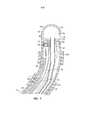
Фиг. 1 - это внешний вид катетера в перспективе в соответствии с одним из вариантов осуществления изобретения.FIG. 1 is a perspective view of a catheter in accordance with one embodiment of the invention.
Фиг. 1А - это увеличенное изображение дистального узла согласно фиг. 1.FIG. 1A is an enlarged view of the distal assembly of FIG. one.
Фиг. 2 - это вид сбоку на сечение части катетера согласно фиг. 1, включая сочленение корпуса катетера и ветви, выполненное по линии 2-2.FIG. 2 is a sectional side view of a portion of the catheter according to FIG. 1, including the articulation of the catheter body and the branches, made along the line 2-2.
Фиг. 3 - это вид сбоку на сечение ветви согласно фиг. 1, выполненное по линии 3-3.FIG. 3 is a side view in section of a branch according to FIG. 1, taken along line 3-3.
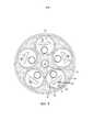
Фиг. 4 - это вид с торца на сечение сочленения согласно, фиг. 2, выполненное по линии 4-4.FIG. 4 is an end view of a section of an articulation according to FIG. 2, taken along line 4-4.
Фиг. 5 - это вид с торца на сечение сочленения согласно фиг. 2, выполненное по линии 5-5.FIG. 5 is an end view of a section of the joint according to FIG. 2, taken along lines 5-5.
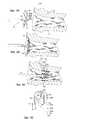
Фиг. 6А - это вид сбоку на дистальный узел, продвигающийся к трубчатой области, в соответствии с одним из вариантов осуществления изобретения с ветвями дистального узла в свободной L-образной конфигурации.FIG. 6A is a side view of a distal node advancing towards a tubular region, in accordance with one embodiment of the invention, with branches of a distal node in a free L-shaped configuration.
Фиг. 6В - это вид сбоку на дистальный узел согласно фиг. 6А, входящий в трубчатую область, с ветвями дистального узла.FIG. 6B is a side view of the distal assembly of FIG. 6A, entering the tubular region, with branches of the distal node.
Фиг. 6С - это вид сбоку на дистальный узел согласно фиг. 6А, находящийся в трубчатой области, с ветвями дистального узла в U-образной конфигурации.FIG. 6C is a side view of the distal assembly of FIG. 6A, located in the tubular region, with branches of the distal node in a U-shaped configuration.
Фиг. 6D - это схематическое представление различных вариантов исполнения ветви в U-образной конфигурации в соответствии с данным изобретением.FIG. 6D is a schematic representation of various branch designs in a U-shaped configuration in accordance with this invention.
Фиг. 7 - это вид сбоку на сечение части катетера в соответствии с другим вариантом осуществления, который включает сочленение между корпусом катетера и ветвью.FIG. 7 is a cross-sectional side view of a portion of a catheter in accordance with another embodiment, which includes an articulation between the catheter body and the branch.
Фиг. 8 - это вид с торца на сечение сочленения согласно фиг. 7, выполненное по линии 8-8.FIG. 8 is an end view of a section of the joint according to FIG. 7, taken along lines 8-8.
Фиг. 9 - это вид сбоку на сечение части ветви в соответствии с другим вариантом осуществления.FIG. 9 is a sectional side view of a portion of a branch in accordance with another embodiment.
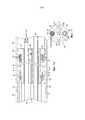
Фиг. 10 - это вид сбоку на сечение части катетера в соответствии с еще одним вариантом осуществления, который включает промежуточный отклоняемый участок.FIG. 10 is a sectional side view of a portion of a catheter in accordance with yet another embodiment, which includes an intermediate deflectable portion.
Фиг. 11 - это вид с торца на сечение промежуточного отклоняемого участка согласно фиг. 10, выполненное по линии 11-11.FIG. 11 is an end view of a section of an intermediate deflected portion according to FIG. 10, performed along the line 11-11.
Фиг. 12 - это вид в перспективе на дистальный узел (с ветвями в нейтральном положении) в соответствии с другим вариантом осуществления.FIG. 12 is a perspective view of a distal node (with branches in a neutral position) in accordance with another embodiment.
Фиг. 13А - это вид в перспективе на дистальный узел (с ветвями в нейтральном положении) в соответствии с еще одним вариантом осуществления изобретения.FIG. 13A is a perspective view of a distal node (with branches in a neutral position) in accordance with yet another embodiment of the invention.
Фиг. 13В - это вид сверху на дистальный узел согласно фиг. 13А.FIG. 13B is a plan view of the distal assembly of FIG. 13A.
Фиг. 13С - это вид сбоку на дистальный узел согласно фиг. 13В, выполненный по линии С-С.FIG. 13C is a side view of the distal assembly of FIG. 13B made along line CC.
Фиг. 13D - это вид в перспективе на дистальный узел согласно фиг. 13А в трубчатой области.FIG. 13D is a perspective view of a distal assembly according to FIG. 13A in the tubular region.
ПОДРОБНОЕ ОПИСАНИЕ ИЗОБРЕТЕНИЯDETAILED DESCRIPTION OF THE INVENTION
Предметом изобретения является катетер 10, показанный на фиг. 1, имеющий дистальный узел 18, включающий несколько ветвей 14. На каждой ветви установлен как минимум один электрод, предпочтительно концевой электрод 20, и как минимум один кольцевой электрод 28, так что, когда ветви находятся в контакте с тканями трубчатой структуры в сердце или рядом с ним, каждая ветвь имеет возможность получать данные электрической активности и производить абляцию. Как показано на фиг. 1, катетер 10 включает удлиненный корпус катетера 12 с проксимальным и дистальным концами, рукоять управления 16 на проксимальном конце 12 и дистальный узел 18, состоящий из множества ветвей 14, размещенный на дистальном конце корпуса катетера 12.A subject of the invention is the
Как показано на фиг. 1 и 2, корпус катетера 12 представляет собой продолговатую трубчатую конструкцию, включающую единственный аксиальный или центральный просвет 15; по желанию катетер может иметь множество просветов на всю длину или часть длины. Корпус катетера 12 является гибким, т.е. поддающимся изгибу, но по существу несжимаемым по всей длине. Корпус катетера 12 может иметь любую приемлемую конструкцию и может быть изготовлен из любого приемлемого материала.As shown in FIG. 1 and 2, the
Предпочтительная на данный момент конструкция тела катетера 12 включает наружную стенку 13 из полиуретана или материала РЕВАХ® (полиэфирблокамида). Внешняя стенка 13 может содержать внедренную плетеную сетку из нержавеющей стали или подобного материала для увеличения жесткости корпуса катетера 12 при кручении, чтобы при повороте рукояти управления 16 дистальный конец корпуса катетера 12 вращался предусмотренным образом.The currently preferred
Длина корпуса катетера 12 не имеет решающего значения, однако предпочтительная длина составляет от примерно 90 см до примерно 120 см (наиболее предпочтительно - примерно 110 см). Внешний диаметр корпуса катетера 12 также не имеет решающего значения, однако предпочтительный диаметр составляет не более чем примерно 2,7 мм (8 Fr), более предпочтительно - около 2,3 мм (7 Fr). Аналогичным образом толщина наружной стенки 13 не имеет решающего значения, но предпочтительно является достаточно тонкой, чтобы центральный просвет 15 мог пропускать подводящие проводники, кабели датчиков и любые другие провода, кабели и трубки. При необходимости внутренняя поверхность наружной стенки 13 выстилается трубкой жесткости (не показана) для обеспечения дополнительной устойчивости к скручиванию. Пример конструкции корпуса катетера, подходящей для использования совместно с представленным изобретением, описан и представлен в патенте США №6064905, полное содержание которого включено в настоящий документ посредством ссылки.The length of the
В показанном варианте осуществления изобретения дистальный узел 18 включает 5 ветвей 14. Каждая ветвь 14 включает проксимальный конец, прикрепленный к дистальному концу корпуса катетера 12, и свободный дистальный конец, который не прикреплен ни к одной из других ветвей, к корпусу катетера или к иной структуре, ограничивающей движение дистального конца. Каждая ветвь 14 включает поддерживающий рычаг 24, имеющий в составе металл или пластик, обладающий памятью формы, так что поддерживающий рычаг 24 принимает начальную форму, когда к нему не прилагается внешняя сила, принимает форму с отклонением в случае приложения внешней силы и возвращается к первоначальной форме, когда действие внешней силы прекращается. В предпочтительном варианте осуществления поддерживающий рычаг 24 включает суперэластичный материал, например никель-титановый сплав, такой как нитинол. Каждая ветвь 14 также включает изолирующее покрытие 26 вблизи областей прилегания рычага 24. В предпочтительном варианте осуществления изолирующее покрытие 26 включает биосовместимую пластиковую трубку, например, из полиуретана или полиимида.In the shown embodiment, the
Опытным специалистам будет очевидно, что количество ветвей 14 может подбираться по желанию в зависимости от конкретной цели применения, так что катетер 10 имеет как минимум две ветви, предпочтительно - три ветви, более предпочтительно - как минимум пять, а также множество (восемь, десять или более) ветвей. Для наглядности на фиг. 2 показаны только две ветви. Как будет подробно описано ниже, ветви 14 могут быть приведены из развернутого состояния, в котором, например, все ветви выступают радиально из корпуса катетера 12 (как правило, в L-образной конфигурации), в свернутое состояние, в котором, например, все ветви 14 располагаются практически вдоль продольной оси корпуса катетера 12 так, что они помещаются в просвет интродьюсера (подробное описание см. ниже).Experienced professionals will be obvious that the number of
Каждая ветвь 14 (см. фиг. 3) несет как минимум один электрод, закрепленный по всей ее длине или в области ее дистального конца. В показанном варианте осуществления концевой электрод 20 смонтирован на дистальном конце каждого изолирующего покрытия 26 и как минимум первый кольцевой электрод 28а смонтирован на каждом изолирующем покрытии 26 на дистальном конце изолирующего покрытия 26. Расстояние между концевым электродом 20 и кольцевым электродом 28а по желанию варьируется от примерно 0,5 мм до примерно 2,0 мм. Дополнительный кольцевой электрод или пара кольцевых электродов 28b-28d могут быть смонтированы на каждом изолирующем покрытии 26 проксимально относительно первого кольцевого электрода 28а. В показанном варианте осуществления катетер устроен таким образом, что концевой электрод функционирует совместно с наиболее удаленным кольцевым электродом как пара дистальных электродов. В альтернативном варианте осуществления концевой электрод может использоваться только дня снятия монополярных электрограмм, где расстояние между концевым электродом и наиболее дистально расположенным кольцевым электродом 28а будет больше. В показанном варианте осуществления расстояние между первым кольцевым электродом 28а и примыкающим электродом 28b варьирует от примерно 0,5 мм до примерно 2,0 мм. Расстояние между смежными парами электродов находится в диапазоне от примерно 2,0 мм до примерно 8,0 мм. Расстояние между кольцевыми электродами из одной пары находится в диапазоне от примерно 0,5 мм до примерно 2,0 мм. Любой из кольцевых электродов 28a-28d может быть использован для снятия как монополярной, так и биполярной электрограммы. Это означает, что концевые и кольцевые электроды могут быть использованы в связке с одним или несколькими отводящими электродами, подсоединенными к внешней поверхности тела пациента (например, в форме пластыря), а также любой из кольцевых электродов может функционировать как отводящий электрод.Each branch 14 (see Fig. 3) carries at least one electrode fixed along its entire length or in the region of its distal end. In the shown embodiment, the
Длина каждого концевого электрода 20 в развернутом состоянии находится в диапазоне от примерно 0,5 мм до примерно 4,0 мм, более предпочтительно - от 0,5 мм до 2,0 мм, еще более предпочтительно - около 1,0 мм. Каждый кольцевой электрод 28 имеет длину предпочтительно около 2,0 мм, более предпочтительно - от примерно 0,5 мм до примерно 1,0 мм.The length of each
Каждый концевой электрод 20 и каждый кольцевой электрод 28 соединены с подводящим проводом 29, который, в свою очередь, подключен к соединителю 17 (фиг. 1). Соединитель 17 подключен к соответствующей системе картирования или наблюдения (не показано). Каждый подводящий провод 29 проходит от соединителя 17 через рукоять управления 16 и центральный просвет 15 в корпусе катетера 12 и уходит под изолирующее покрытие 26 ветви 14, где подключается к соответствующему концевому 20 или кольцевому электроду 28. Каждый подводящий провод 29, включающий изолирующее покрытие (не показано), практически по всей своей длине прикреплен к соответствующему концевому электроду 20 или кольцевому электроду 28 любым способом, обеспечивающим электропроводимость.Each
Один из способов подключения подводящего провода 29 к кольцевому электроду 28 включает проделывание отверстия малых размеров в наружном слое изолирующего покрытия 26. Такое отверстие можно проделать, например, приставив к наружному слою изолирующего покрытия иглу и нагревая 26 ее до образования постоянного отверстия в изоляции. После этого подводящий провод 29 протягивается через это отверстие при помощи микрокрючка или подобного инструмента. Конец подводящего провода 29 очищается от любого покрытия и припаивается к нижней стороне кольцевидного электрода 28, который затем помещают в нужное положение и фиксируют полиуретановым клеем или подобным материалом. Альтернативный вариант: кольцевой электрод 28 можно изготовить, намотав несколько витков подводящего провода 29 вокруг изолирующего покрытия 26 и зачистив подводящий провод от изоляционного покрытия на внешних поверхностях. В подобных случаях подводящий провод 29 функционирует в роли кольцевого электрода.One way to connect the
Каждая ветвь 14 может также включать как минимум один датчик температуры, например термопару или термистор, для одного из концевых электродов 20 или любого из кольцевых электродов. В показанном варианте осуществления термопара представлена эмалированной проводниковой парой. Один проводник из проводниковой пары представляет собой медный проводник 41, например медную проволоку №40. Другой проводник из проводниковой пары представляет собой проводник из константана 45. Провода 41 и 45 термопары электроизолированы друг от друга за исключением их дистальных концов, которые скручены вместе и покрыты коротким тонким куском пластиковой трубки 58, например, из полиамида, и эпоксидной смолой с хорошим коэффициентом теплопроводности.Each
Провода 41 и 45 проходят через центральный просвет 15 корпуса катетера 12 (фиг. 2). В центральном просвете 15 провода 41 и 45 протягиваются через интродьюсер (не показан) вместе с подводящим проводом 29. Провода 41 и 45 затем проходят через рукоять управления 16 к соединителю (не показан) с возможностью подключения к монитору температуры (не показан). В качестве альтернативы средством для измерения температуры может быть термистор. Один из применимых для работы с настоящим изобретением термистор - термистор модели AB6N2-GC14KA143E/37C), распространяемый фирмой Thermometrics (New Jersey).The
Фиг. 3 иллюстрирует применимую технику установки подводящего провода 29 концевого электрода, проводов термопары 41 и 45 и поддерживающего рычага 24 концевого электрода 20. Дистальный конец подводящего провода 29 электрода можно прикрепить к концевому электроду 20, высверлив слепое отверстие 48 в концевом электроде 20, зачистив подводящий провод 29 от любого покрытия и поместив подводящий провод 29 внутрь первого слепого отверстия 48, где он соединяется с концевым электродом 20 применимым способом, например при помощи пайки или сварки. После этого подводящий провод 29 можно зафиксировать, например, с помощью полиуретанового клея или подобного материала. Поддерживающий рычаг 24 может таким же образом быть зафиксирован в концевом электроде 20. Например, можно рассверлить в концевом электроде 20 второе слепое отверстие 52, установить во второе слепое отверстие 52 дистальный конец поддерживающего рычага 24 и зафиксировать его там, например, с помощью полиуретанового клея или подобного материала. Более того, можно рассверлить в концевом электроде 20 третье слепое отверстие 53, вставить в третье слепое отверстие пластиковую трубку 58, в которую заключены дистальные концы проводов термопары 41 и 45, и зафиксировать ее с помощью полиуретанового клея или подобного материала. Согласно другому способу провода 41 и 45 могут быть заведены непосредственно в слепое отверстие 53.FIG. 3 illustrates the applicable technique for installing the
Согласно еще одному способу единственное слепое отверстие (не показано) в проксимальном конце концевого электрода 20 можно использовать для установки поддерживающего рычага 24 и проводов термопары 41 и 45, а дистальный конец подводящего провода 29 можно обернуть вокруг внешнего проксимального конца концевого электрода, который не оголен, и закрепить пайкой, сваркой или иным подходящим методом. Может быть использован любой способ закрепления этих компонентов на ветви.According to another method, a single blind hole (not shown) in the proximal end of the
Применимая конструкция дистального конца корпуса катетера 12 с установленными ветвями 14 показана на фиг. 2 и 4. Для наглядности на фиг. 2 показаны только две ветви 14. На дистальном конце просвета 15 корпуса катетера 12 находится узел для установки ветвей 31, с помощью которого свободные проксимальные концы ветвей прикрепляются к корпусу катетера. В показанном варианте осуществления узел для установки ветвей 31 включает внешнее установочное кольцо 32, расположенное во внешней стенке 13 корпуса катетера 12. Внешнее установочное кольцо 32 предпочтительно выполнено из металла, например нержавеющей стали (в частности, нержавеющей стали марки 303), и может быть прикреплено к дистальному концу корпуса катетера 12 множеством способов например, пайкой или склейкой, например, при помощи полиуретанового клея. Внешнее установочное кольцо 32 может быть также выполнено из пластика. Установочное приспособление 34 располагается коаксиально внутри внешнего установочного кольца 32. В показанном варианте осуществления установочное приспособление 34 является многосторонним и выполнено из металла, например нержавеющей стали (в частности, нержавеющей стали марки 303). Установочное приспособление 34 может быть также выполнено из пластика. Внешнее установочное кольцо 32 и установочное приспособление 34 образуют просвет 38, в который устанавливается проксимальный конец каждого поддерживающего рычага 24. Точнее, каждая ветвь 14 монтируется на корпусе катетера 12 посредством удаления части изолирующего покрытия 26 на проксимальном конце каждой ветви 14, введения зачищенного проксимального конца каждого поддерживающего рычага 24 в просвет 38 между внешним установочным кольцом 32 и многосторонним установочным приспособлением 34 и его закрепления внутри просвета 38 любым применимым способом, например при помощи полиуретанового клея или другого похожего материала. Подводящие провода 29 и провода термопары 41 и 45 также проходят через просвет 38 между внешним установочным кольцом 32 и установочным приспособлением 34.The applicable design of the distal end of the
В одном из вариантов осуществления поддерживающий рычаг 24 имеет поперечное сечение в виде трапеции с изогнутыми сторонами, как показано на фиг. 4 и 5. В такой конфигурации, когда каждый поддерживающий рычаг 24 вводится в просвет 38, плоская поверхность каждого поддерживающего рычага 24 (предпочтительно основание трапециевидного поперечного сечения) примыкает к плоской грани многостороннего установочного приспособления 34. Предпочтительное количество плоских наружных граней на многостороннем установочном приспособлении 34 должно соответствовать количеству ветвей 14. В этом случае поддерживающий рычаг 24 каждой ветви 14 может быть смонтирован внутри просвета 38, примыкая к соответствующей грани многостороннего установочного приспособления 34, что позволяет поддерживающим рычагам 24 и ветвям 14 равномерно распределиться вокруг многостороннего установочного приспособления 34. Многостороннее установочное приспособление 34 может располагаться примерно коаксиально продольной оси корпуса катетера 12, обеспечивая равномерное распределение ветвей 14 внутри корпуса катетера 12. после того как все поддерживающие рычаги 24 правильно установились внутри просвета 38, каждый поддерживающий рычаг 24 можно зафиксировать внутри просвета 38 любым применимым способом, например с помощью клея, такого как полиуретановый клей. Установочное приспособление 34 может также иметь круглую внешнюю поверхность, хотя в таком варианте осуществления равномерное распределение поддерживающих рычагов 24 вокруг установочного приспособления является более трудоемкой задачей.In one embodiment, the
В показанном варианте осуществления первая изолирующая трубка 40 расположена между внешним установочным кольцом 32 и поддерживающими рычагами 24, а вторая изолирующая трубка 42 расположена между поддерживающими рычагами 24 и установочным приспособлением 34. Изолирующие трубки 40 и 42, которые могут быть изготовлены из полиимида, обеспечивают электроизоляцию всех поддерживающих рычагов 24.In the shown embodiment, the first insulating
В соответствии с одним из аспектов настоящего изобретения каждая ветвь 14 имеет практически L-образную форму, сохраняемую поддерживающим рычагом 24. В показанном на фиг. 1 и фиг. 6 варианте осуществления изобретения практически L-образная конфигурация каждой ветви задается практически прямым проксимальным участком 60 и практически прямым дистальным участком 64, в общем, ортогональным проксимальному участку 60. Когда дистальный узел 18 находится на начальном этапе установки в трубчатой полости 71, как показано на фиг. 6А, ветви 14 принимают свою практически нейтральную, свободную L-образную форму. По мере введения дистального узла в трубчатую полость, как показано на фиг. 6В, дистальные концы ветвей входят в контакт со входом или устьем 70 трубчатой полости, где L-образная форма ветвей 14 начинает изменяться под действием контактной силы, прилагаемой устьем к дистальным концам ветвей. По мере продвижения дистального узла 18 вперед проксимальный участок 60 ветвей проникает глубже в трубчатую полость и дистальные концы ветвей 14 входят в соприкосновение с тканями, выстилающими трубчатую полость 71. Когда дистальный узел 18 проводится глубже, дистальные участки 64 все больше перегибаются через дистальные концы, пока еще большее количество дистальных участков 64 не вступит в контакт с мягкими тканями в трубчатой полости 71, где ветви 14 находятся теперь в практически U-образной форме, как показано на фиг. 6С. В зависимости от различных параметров дистальный конец или концевой электрод 20 на ветви, находящийся в практически U-образной форме, образует угол θ с проксимальным концом ветви. Угол θ имеет диапазон примерно от 45 до 135 градусов (предпочтительно примерно от 80 до 100 градусов) и предпочтительно равен приблизительно 90 градусам, как показано на фиг. 6D. Если угол θ меньше 90 градусов, концевой электрод 20 располагается дистально относительно проксимального конца ветви 14 на узле для установки ветвей 31. Если угол θ близок к 90 градусам, концевой электрод 20 находится практически на одном уровне с проксимальным концом ветви 14. Если угол θ превышает 90 градусов, концевой электрод 20 находится проксимально относительно проксимального конца ветви 14. Тем не менее, вне зависимости от величины угла θ практически U-образная форма поддерживающего рычага 24 (а следовательно, и ветви 14) гарантирует, что дистальный участок 64 практически параллелен прямому проксимальному участку 60, а кольцевые электроды 28 последовательно устанавливаются в трубчатой структуре глубже, чем концевой электрод 20. Как показано на фиг. 6D, длина и (или) кривизна каждого отрезка 60 и 64 может меняться в зависимости от желания и необходимости. Более того, длина, кривизна и (или) угол θ не обязательно должны быть одинаковы для всех ветвей на дистальном узле. Например, первый набор ветвей может иметь одно значение длины, кривизны и (или) угла θ, а второй набор - другие значения длины, кривизны и (или) угла θ. Хотя в показанных вариантах осуществления изобретения ветви радиально расположены на равном расстоянии друг от друга, шаг их расположения также может быть изменен по желанию или необходимости. В варианте осуществления, показанном на фиг. 6С, изображен внешний вид катетера во время его введения в трубчатую полость. Изменение конфигурации ветви из свободной (L-образной) формы на фиг. 6А в ограниченную (U-образную) на фиг. 6С отражает увеличение угла θ с продвижением дистального узла вглубь трубчатой полости. Длина ветви 14 на участке между открытым проксимальным концом покрытия 26 до дистальной верхушки ветви может составлять от примерно 1,0 см до примерно 5,0 см.In accordance with one aspect of the present invention, each
В соответствии с одним из аспектов настоящего изобретения, когда дистальный узел 18 проводится и закрепляется в трубчатой структуре, концевые электроды 20 дистального узла 18 легко меняют форму, вступая в контакт с окружающими тканями трубчатой структуры 71 в областях, располагающихся преимущественно вдоль внутреннего периметра С трубчатой структуры. Аналогичным образом первые кольцевые электроды 28а на ветвях 14 легко меняют форму, вступая в контакт с тканями в областях, располагающихся преимущественно вдоль еще одного или первого примыкающего внутреннего периметра Са глубже в трубчатой структуре. Таким же образом дополнительные кольцевые электроды 28b-28d легко меняют форму, вступая в контакт с тканями в областях, располагающихся преимущественно вдоль других или примыкающих внутренних периметров Cb-Cd, глубже в трубчатой структуре. Вращение катетера с помощью рукояти управления поворачивает дистальный узел 18 и приводит к перемещению электродов на другие внутренние контактные поверхности вдоль каждого внутреннего периметра. Например, в зоне, где концевые электроды 20 заняли положение для выполнения абляции, может быть создана изолирующая линия у периметра С, а целостность или завершенность изолирующей линии по окружности С может быть определена кольцевыми электродами 28a-28d в местах вдоль примыкающих окружностей Ca-Cd глубже в трубчатой структуре. Любой из наборов кольцевых электродов 28i может быть также использован для абляции и создания рубцовой изолирующей линии по периметру Ci, а любые перерывы в изолирующей линии по окружности Ci могут быть определены любым неабляционным набором концевых или кольцевых электродов. Таким образом, абляция и контроль результирующих рубцов могут быть успешно выполнены с помощью катетера 10 без изменения положения дистального узла 18 или использования дополнительного катетера.In accordance with one aspect of the present invention, when the
Как показано на фиг. 2 и 4, главная оросительная трубка 44 проходит, например, коаксиально через установочное приспособление 34. Промывная трубка 44 выполнена из электроизолирующего материала типа РЕВАХ, полиимида или полиуретана. Оросительная трубка 44 проходит через корпус катетера 12 и выводится через рукоять управления 16 или боковой рычаг (не показан), как известно в медицинской практике и описано в патенте США №6120476, содержание которого включено в настоящий документ посредством ссылки. Далее будет показано, что оросительная трубка 44 используется для подведения орошающей жидкости в область между ветвями 14 и концевым электродом ветвей 20. Область между ветвями имеет склонность к образованию тромбов, а абляционные электроды могут перегреваться, вызывая обугливание. Дистальный конец основной оросительной трубки 44 предпочтительно вклеить между ветвями 14.As shown in FIG. 2 and 4, the
Как показано на фиг. 4 и 5, дистальный конец основной оросительной трубки 44 принимает проксимальные концы короткой оросительной трубки 47 для обработки области между ветвями, а также множества отдельных оросительных трубок 49, по одной на каждую ветвь. В показанном варианте осуществления короткая оросительная трубка 47 располагается по центру и окружена радиально оросительными трубками для ветвей 49. Просвет короткой трубки для орошения 47 создает путь движения жидкости (стрелка 61) от дистального конца главной оросительной трубки 44 до выхода из корпуса катетера в области между ветвями.As shown in FIG. 4 and 5, the distal end of the
Все оросительные трубки для ветвей 49, установленные вокруг короткой оросительной трубки 47, выходят из дистального конца основной оросительной трубки 44 и подводятся к соответствующим ветвям дистального узла 18. Как показано на фиг. 2 и 3, каждая оросительная трубка для ветви 49 проходит через соответствующее изолирующее покрытие 26 вместе с подводящими проводами 29, проводами термопары 41 и 45 и поддерживающим рычагом 24 для соответствующей ветви; дистальный конец 44 оросительной трубки для ветви завершается в оросительном протоке 75, ведущем к жидкостной камере 76 (оба находятся внутри концевого электрода 20). В дистальной стенке 78 концевого электрода 20 сформированы оросительные отверстия 74, которые обеспечивают подачу жидкости из жидкостной камеры 76 и ее выход через концевой электрод 20.All
Как показано на фиг. 2, орошающая жидкость, проходя через оросительную трубку 44, далее направляется к рукояти управления 16 и в ствол катетера 12. На дистальном конце оросительной трубки 44 часть жидкости покидает катетер через короткую оросительную трубку 47 (стрелка 61), а другие части продолжают движение к ветвям (стрелка 63) по оросительным трубками для ветвей 49. У концевого электрода 20 орошающая жидкость входит в жидкостную камеру 76 через оросительный проток 75 и покидает концевой электрод 20 через оросительные отверстия 74. Дистальный конец основной оросительной трубки 44 закупорен вязким материалом или герметиком 82, который одновременно фиксирует короткую оросительную трубку 47 и проксимальные концы оросительных трубок для ветвей 49 в дистальном конце основной оросительной трубки 44. Опытным специалистам будет очевидно, что основная оросительная трубка 44 может включать множество элементов, обеспечивающих прохождение жидкости через корпус катетера 12 в рукоять управления 16, включая сочетание одного или нескольких просветов и одной или более трубок. Дистальный конец оросительных трубок для ветвей 49 закреплен на оросительном протоке 75 концевого электрода 20 клеем, таким как EPOXY, или герметиком.As shown in FIG. 2, the irrigation fluid, passing through the
Как указывалось выше, при установке поддерживающих рычагов 24 на узле для установки ветвей 31 часть изолирующего покрытия 26 на проксимальном конце каждой ветви 14 удаляется для обнажения поддерживающего рычага 24. Удаление части изолирующего покрытия 26 на проксимальном конце каждой из ветвей 14 обеспечивает выход подводящих проводов 29 электрода и проводов термопары 41 и 45 через просвет 15 катетера 12 сквозь отверстие 46 установочного кольца 32 и их подвод к каждому изолирующему покрытию 26. Как показано на фиг. 2, введенные в изолирующее покрытие 26 подводящие провода 29 электрода и провода термопары 41 и 45 проходят внутри изолирующего покрытия 26, а затем дистальные концы подводящих проводов 29 соединяются с соответствующими им концевыми электродами 20 и кольцевыми электродами 28.As mentioned above, when supporting
Согласно альтернативному варианту осуществления изобретения, показанному на фиг. 7, 8 и 9, каждая ветвь 114, содержит многоканальную трубку 100 с как минимум двумя просветами, включая просвет 110 для подводящих проводов 29, проводов термопары 41 и 45 и (или) поддерживающий рычаг 24, а также просвет 112 для орошающей жидкости. Множество коротких соединительных трубок 47 проходит между дистальным концом основной оросительной трубки 44 и проксимальным концом оросительного просвета 112 для соответствующей направляющей. Просвет 112 доставляет орошающую жидкость к орошаемым кольцевым электродам 128 и концевому электроду 20 посредством короткой оросительной соединительной трубки 95, которая соединяет оросительный проток 75 с просветом 112. Орошаемые кольцевые электроды 128, смонтированные на трубке, могут быть настроены для картирования, сбора данных и (или) для абляции и конфигурируются с приподнятой средней частью 114 (фиг. 9) для формирования круговой жидкостной камеры 116 с внешней стенкой 118 трубки 100. Жидкость проходит из просвета 112 через отверстие 122 во внешней стенке 118 и распределяется в круговой жидкостной камере 116, после чего удаляется из электрода 128 через отверстие 124, сформированное приподнятой средней частью 114.According to an alternative embodiment of the invention shown in FIG. 7, 8 and 9, each
По желанию катетер согласно настоящему изобретению может включать управляющий механизм для отклонения дистального узла корпуса катетера 12. Как показано на фиг. 10 и 11, катетер включает промежуточный гибкий участок 30, расположенный между корпусом катетера 12 и ветвями 14. Корпус катетера 12 включает наружную стенку 22 из полиуретана или материала РЕВАХ. Внешняя стенка 22 может содержать внедренную плетеную сетку из высокопрочной конструкционной стали, нержавеющей стали или подобного материала для увеличения жесткости корпуса катетера 12 при кручении, чтобы при повороте рукояти управления 16 ветвь 14 с точечным электродом катетера 10 вращалась предусмотренным образом.Optionally, the catheter according to the present invention may include a control mechanism for deflecting the distal assembly of the
Внутренняя поверхность наружной стенки 22 выстилается трубкой жесткости 23, которая может быть изготовлена из любого применимого материала, такого как полиимид или нейлон. Трубка жесткости 23 вместе с плетеной внешней стенкой 22 обеспечивает повышенную устойчивость при скручивании, в то же время сокращая до минимума толщину стенок катетера, за счет чего увеличивается диаметр центрального просвета 18. Внешний диаметр трубки жесткости 23 имеет приблизительно такую же величину или немногим меньше внутреннего диаметра внешней стенки 22. Трубка жесткости 23 может быть изготовлена из полиимида, поскольку этот материал обеспечивает отличную жесткость даже при малой толщине стенки. Это позволяет максимально увеличить диаметр центрального просвета 18 без ущерба для прочности и жесткости.The inner surface of the
Промежуточный гибкий участок 30 включает в себя короткий отрезок трубки 35 длиной, например, от 2,0 до 10,2 см (4,0 дюйма); этот отрезок более гибкий, чем остальная часть корпуса катетера 12. Трубка 35 является многоканальной и включает просветы 54, 55, 56, 65 и 66. Через просвет 65 проходят подводящие провода 29 и провода термопары 41 и 45. Может быть предоставлен изолирующий интродьюсер 69, проходящий через корпус катетера 12 и промежуточный гибкий участок 30. Через просвет 66 проходит основная оросительная трубка 44.The intermediate
Применимый механизм управления включает один или два натягивающих провода 37, проходящих от проксимального конца в рукояти управления 16 через центральный просвет 15 в корпусе катетера 12 в диаметрально противоположные неосевые просветы 54 и 55 в короткой части трубки 35. Внутри корпуса катетера 12 каждый натягивающий провод 37 проходит через соответствующую туго намотанную компрессионную пружину 57, которая может гнуться, но практически несжимаема. Пружины 57 имеют проксимальный и дистальный концы, которые зафиксированы вблизи соответственно проксимального и дистального концов корпуса катетера 12 для предотвращения отклонения корпуса катетера 12. Дистальный конец каждого натягивающего провода 37 укреплен на дистальном конце трубки малой длины в ее относительном неосевом просвете посредством Т-образного фиксатора 59 (фиг. 10). Специалисту с некоторым опытом в данной области будет очевидно, что проксимальный конец каждого натягивающего провода 37 прикреплен к подвижному элементу (например, пальцевому регулятору 85 на фиг. 1) на рукоятке 16 и может смещаться относительно корпуса катетера 12. Проксимальное смещение подвижного элемента относительно корпуса катетера 12 вызывает отклонение короткого участка трубки в одну или в другую сторону (как правило, в одной плоскости) в зависимости задействованного натягивающего провода. Пример подобного управляющего механизма и его устройство подробно описаны в патенте США №6064905, содержание которого включено в настоящий документ посредством ссылки.The applicable control mechanism includes one or two
Также может быть желательно, чтобы катетер согласно настоящему изобретению включал в себя датчик положения, особенно при наличии механизма управления катетером. В показанном варианте осуществления изобретения (см. фиг. 10 и 11) трубка 35 на промежуточном гибком участке 30 имеет специальный просвет 56 для датчика положения 90 и кабеля датчика 92. Датчик положения 90 расположен на дистальном конце трубки 35 или близко к нему и используется для определения координат дистального узла 18, например, в каждый момент, когда электроды 20 и 28 используются для получения точек данных для построения карты электрического поля либо данных об электрической активности структур (например, ЭКГ) и (или) выполнения абляции.It may also be desirable for the catheter of the present invention to include a position sensor, especially with a catheter control mechanism. In the shown embodiment of the invention (see FIGS. 10 and 11), the
Кабель датчика 92 проходит через просвет 56 промежуточного участка 30, центральный просвет 15 корпуса катетера 12 и рукоять управления 16 и выводится наружу через проксимальный конец рукояти управления 16 внутри шнура с электроразрывным соединителем (не показан) к модулю управления датчиками (не показан) с печатной платой (не показан). Как вариант, печатная плата может быть размещена в рукояти управления 16, как описано, например, в патенте США №6024739, полное содержание которого включено в настоящий документ посредством ссылки. Кабель датчика 92 объединяет несколько жил, заключенных в оболочку с пластиковым покрытием. В модуле управления датчиками жилы кабеля датчика 92 подключаются к печатной плате. Печатная плата усиливает сигнал, полученный от соответствующего датчика 90, и передает его на компьютер в понятной для компьютера форме посредством соединителя датчика на проксимальном конце модуля управления датчиками.The
Датчик положения 90 может представлять собой электромагнитный датчик положения. Например, датчик положения 90 может включать катушку, чувствительную к ЭМ полю, описанную в патенте США №5391199, или несколько таких катушек, как описано в документе International Publication WO 96/05758. Набор катушек позволяет получать координаты в 6 измерениях (например, три координаты положения и три координаты ориентации) для датчика положения 90. В качестве альтернативы может быть использован любой известный датчик, например электрический, магнитный или акустический. Применимые датчики для использования с данным изобретением также описаны, например, в патентах США №5558091, 5443489, 5480422, 5546951 и 5568809, а также в документах International Publication №WO 95/02995, WO 97/24983 и WO 98/29033, содержание которых включено в настоящий документ посредством ссылки. Также в качестве датчиков положения 90 могут использоваться одноосевые датчики, например, описанные в заявке на патент США №09/882125 под названием «Position Sensor Having Core with High Permeability Material» (Датчик положения с сердечником из материала высокой проницаемости), оформленной 15 июня 2001 г., и в заявке на патент США №12/982765 под названием «Catheter with Single Axial Sensors» (Катетер с одноосными датчиками), оформленной 30 декабря 2010 г., содержание которых включено в настоящий документ посредством ссылки.The
В качестве альтернативы или дополнения к вышеупомянутому одиночному датчику положения 90 можно установить датчики положения на каждой ветви, например, на концевом электроде 20 или вблизи него. Для этой цели особенно желательно использование датчиков малого размера, поскольку диаметр ветвей 14 должен оставаться достаточно маленьким, чтобы все направляющие поместились в основной просвет интродьюсера.As an alternative or addition to the aforementioned
Дистальнее промежуточного гибкого участка 30 находится короткая соединительная трубка 113, которая по конструкции и дизайну сравнима с ранее упоминавшейся трубкой 13 на корпусе катетера 12 согласно фиг. 2 или фиг. 7. Очевидно, что дистальный конец соединительной трубки 113 может быть устроен так же, как дистальный конец трубки 13 согласно фиг. 2 или фиг. 7, чтобы обеспечить закрепление проксимального конца ветвей 14 в дистальном узле 18 посредством установочного приспособления 31.Distant to the intermediate
Для использования катетера 10 согласно настоящему изобретению кардиолог или кардиоэлектрофизиолог вводит интродьюсер и расширитель в тело пациента обычным способом, размещая дистальные концы интродьюсера и расширителя в области сердца, подлежащей картированию. Затем расширитель удаляется из интродьюсера и через интродьюсер в тело пациента вводится катетер 10. Чтобы вставить катетер 10 в интродьюсер, сборка для картирования 18 должна находиться в сложенном состоянии, когда каждая ветвь 14 располагается преимущественно вдоль продольной оси корпуса катетера 12. Для использования с катетером 10 рекомендуется интродьюсер PREFACE™ Braided Guiding Sheath (доступен для приобретения от компании Biosense Webster, Inc., Diamond Bar, California). Такой интродьюсер достаточно прочен, чтобы удерживать каждый поддерживающий рычаг 24 в свернутом состоянии так, чтобы ветви 14 и остальная часть катетера 10 могли перемещаться внутри интродьюсера от точки ввода в тело пациента по ходу вены или артерии до целевой области в сердце.To use the
Когда дистальный конец катетера достигает целевой области, например располагается в левом желудочке сердца, обеспечивается относительное продольное движение между катетером 10 и интродьюсером, позволяющее по крайней мере одному участку каждой ветви 14 выдвинуться из интродьюсера. Предпочтительно, чтобы для обнажения ветвей 14 интродьюсер смещался проксимально относительно дистального конца катетера. Когда все ветви 14 выдвинулись из интродьюсера и сила сдавливания, создаваемая интродьюсером, больше не сдерживает их, память формы поддерживающих рычагов 24 позволяет поддерживающим рычагам перейти в развернутую форму. Дистальный узел 18 может быть проведен в трубчатую структуру левого желудочка, например легочную вену, как показано на фиг. 6А. Когда дистальный узел находится в развернутом состоянии, как показано на фиг. 6В, как минимум один электрод каждой ветви 14 может войти в контакт с тканью сердца в нескольких областях и получить информацию об электрической активности, положении и механических характеристиках ткани на этих участках, после чего на основе этих данных создается трехмерная карта ткани. Кроме того, когда электроды 20 и 28 находятся в контакте с сердечной тканью, как на концевой электрод, так и на отдельные кольцевые электроды может быть подано напряжение для абляции, при которой по периметру прижигающих ткань электродов создается рубцовая изолирующая линия. При этом катетер можно вращать вокруг его продольной оси (например, поворачивая рукоятку управления вдоль продольной оси), изменяя положение электродов 20 и 28 для проведения абляции по всему периметру и создания практически непрерывной изолирующей линии. Поскольку концевой и кольцевой электроды контактируют с тканью сердца по разным периметрам, практически параллельным периметру абляции, любые электроды в других областях могут быть использованы для изучения электрической активности в таких смежных периметрах с целью определения патологической электроактивности, которая может означать наличие перерывов в рубцовой изолирующей линии. Такое определение может преимущественно проводиться во время абляции или в перерывах между абляциями без использования другого катетера либо изменения положения катетера. После завершения картирования и абляции катетер перемещается проксимально относительно интродьюсера, чтобы втянуть ветви обратно в интродьюсер.When the distal end of the catheter reaches the target area, for example, located in the left ventricle of the heart, a relative longitudinal movement between the
Во время картирования и абляции область между ветвями 14 и на электродах 20 и 28 может подвергаться тромбообразованию и (или) перегреву. Поэтому до, во время и (или) после картирования и абляции по оросительной трубке 44 подается орошающая жидкость для промывания области между ветвями 14 и электродами. Предпочтительно непрерывное проведение орошения во время процедуры для сведения к минимуму возможности закупоривания оросительной трубки кровяными сгустками. Для применения в рамках настоящего изобретения рекомендуются такие орошающие жидкости, как физиологический раствор, гепаринизированный физиологический раствор и тромболитики. Хотя оросительная трубка 44 предпочтительно устанавливается коаксиально с корпусом катетера 12, занимая место в центре между всеми ветвями, настоящее изобретение предусматривает и иное расположение оросительной трубки на дистальном конце катетера или рядом с ним.During mapping and ablation, the area between the
В развернутой форме ветви 14 в нейтральном состоянии могут иметь различные конфигурации. В альтернативном варианте осуществления изобретения, показанном на фиг. 12, дистальный узел 18' включает ветви 14', каждая из которых имеет практически прямую проксимальной частью 60' и нелинейную или изогнутую дистальную часть 64', которая выходит из корпуса катетера 12. Ветви 14' принимают U-образную форму, когда дистальный узел 18' проводится в трубчатую область.In expanded form, the
Еще в одном варианте осуществления изобретения, показанном на фиг. 13А, дистальный узел 18'' включает ветви 14'', каждая из которых имеет прямую проксимальную часть 60'' и дистальную часть 64'', имеющую зигзагообазный участок 68, состоящий из как минимум двух прямых сегментов, расположенных под углом ϕ в диапазоне от примерно 45 до примерно 90 градусов относительно соседнего с ними сегмента. В показанном варианте осуществления конструкция состоит из 3 частей: проксимального участка 91 с кольцевым электродом 28d, среднего участка 92 с кольцевыми электродами 28b и 28с и дистального участка 93 с кольцевым электродом 28а и концевым электродом 20. Как показано на фиг. 13В, ветви 14'' преимущественно располагаются в форме «колеса со спицами», так что угловые сегменты 85 (определенные углом отстояния ϕ) ветвей направлены по часовой стрелке (стрелка 87) или против часовой стрелки (стрелка 89) при взгляде на дистальный узел 18'' (в особенности с ветвями в нейтральном состоянии) по продольной оси. В отличие от этого при взгляде на дистальный узел сбоку, как показано на фиг. 13С (с ветвями в нейтральном положении), каждая ветвь 14'' располагается практически в одной плоскости. В зигзагообразной конфигурации «колеса со спицами» ветви 14'' менее подвержены соскальзыванию в радиальные бороздки 77 трубчатой области 78 и с большей вероятностью прилегают к ткани плоско, как показано на фиг. 13D.In another embodiment of the invention shown in FIG. 13A, the
Используя описанный в настоящем изобретении катетер 10 с множественными ветвями 14, каждая из которых имеет возможность выполнения механического и электрического картирования и абляции, кардиолог может картировать местное время активации для создания вольтажных карт и проводить круговую абляцию с целью создания рубцовой изолирующей линии в трубчатой области сердца. Кардиолог может проводить абляцию на первой зоне с использованием концевых электродов, одновременно снимая кардиограмму с помощью кольцевых электродов на близлежащих зонах, чтобы выявить наличие перерывов в абляционной изолирующей линии в первой зоне, как во время абляции, так и в перерывах между абляциями без необходимости использования дополнительного катетера или изменения положения абляционного катетера, что снижает стоимость и продолжительность процедуры.Using the
Приведенное выше описание опирается на варианты осуществления изобретения, предпочтительные в настоящее время. Специалистам в области, к которой относится настоящее изобретение, будет очевидно, что описанная конструкция может применяться в различных вариациях в пределах концепции и объема настоящего изобретения. Специалисту с некоторым опытом в данной области будет очевидно, что приведенные фигуры выполнены без соблюдения масштаба. Исходя из этого вышеприведенное описание не должно пониматься применительно только к описанным и показанным на прилагаемых чертежах вариантам конструкции; его следует толковать в духе и в рамках нижеследующей формулы изобретения, которая определяет изобретение в его наиболее полном объеме.The above description is based on currently preferred embodiments of the invention. Specialists in the field to which the present invention relates, it will be obvious that the described design can be applied in various variations within the concept and scope of the present invention. It will be apparent to those skilled in the art that the figures shown are not to scale. Based on this, the above description should not be understood in relation only to the design options described and shown in the accompanying drawings; it should be interpreted in the spirit and within the framework of the following claims, which defines the invention in its fullest extent.
Claims (28)
Translated fromRussianApplications Claiming Priority (2)
| Application Number | Priority Date | Filing Date | Title |
|---|---|---|---|
| US13/425,895US9314299B2 (en) | 2012-03-21 | 2012-03-21 | Flower catheter for mapping and ablating veinous and other tubular locations |
| US13/425,895 | 2012-03-21 |
Publications (2)
| Publication Number | Publication Date |
|---|---|
| RU2013112613A RU2013112613A (en) | 2014-09-27 |
| RU2633325C2true RU2633325C2 (en) | 2017-10-11 |
Family
ID=47915498
Family Applications (1)
| Application Number | Title | Priority Date | Filing Date |
|---|---|---|---|
| RU2013112613ARU2633325C2 (en) | 2012-03-21 | 2013-03-20 | Flower catheter for venous and other tubular areas mapping and ablation |
Country Status (8)
| Country | Link |
|---|---|
| US (1) | US9314299B2 (en) |
| EP (2) | EP2641556B8 (en) |
| JP (1) | JP6165475B2 (en) |
| CN (1) | CN103315806B (en) |
| AU (1) | AU2013201681B2 (en) |
| CA (1) | CA2809464A1 (en) |
| IL (1) | IL224948A (en) |
| RU (1) | RU2633325C2 (en) |
Families Citing this family (91)
| Publication number | Priority date | Publication date | Assignee | Title |
|---|---|---|---|---|
| WO2008070189A2 (en) | 2006-12-06 | 2008-06-12 | The Cleveland Clinic Foundation | Method and system for treating acute heart failure by neuromodulation |
| US8954161B2 (en) | 2012-06-01 | 2015-02-10 | Advanced Cardiac Therapeutics, Inc. | Systems and methods for radiometrically measuring temperature and detecting tissue contact prior to and during tissue ablation |
| US9277961B2 (en) | 2009-06-12 | 2016-03-08 | Advanced Cardiac Therapeutics, Inc. | Systems and methods of radiometrically determining a hot-spot temperature of tissue being treated |
| US9226791B2 (en) | 2012-03-12 | 2016-01-05 | Advanced Cardiac Therapeutics, Inc. | Systems for temperature-controlled ablation using radiometric feedback |
| US8926605B2 (en) | 2012-02-07 | 2015-01-06 | Advanced Cardiac Therapeutics, Inc. | Systems and methods for radiometrically measuring temperature during tissue ablation |
| US10537286B2 (en) | 2013-01-08 | 2020-01-21 | Biosense Webster (Israel) Ltd. | Catheter with multiple spines of different lengths arranged in one or more distal assemblies |
| US20140200639A1 (en) | 2013-01-16 | 2014-07-17 | Advanced Neuromodulation Systems, Inc. | Self-expanding neurostimulation leads having broad multi-electrode arrays |
| PL2859860T3 (en) | 2013-10-08 | 2017-12-29 | Erbe Elektromedizin Gmbh | Multifunctional instrument |
| US10105073B2 (en)* | 2013-11-21 | 2018-10-23 | Biosense Webster (Israel) Ltd | Flexible multiple-arm diagnostic catheter |
| US11096736B2 (en)* | 2013-12-09 | 2021-08-24 | Biosense Webster (Israel) Ltd. | Pericardial catheter with temperature sensing array |
| CN104799937B (en)* | 2014-01-27 | 2019-02-19 | 深圳市信立泰生物医疗工程有限公司 | A kind of renal nerve ablation catheter and its application |
| DE102014201859A1 (en)* | 2014-02-03 | 2015-08-06 | Olympus Winter & Ibe Gmbh | Electrosurgical instrument |
| US9750422B2 (en)* | 2014-02-12 | 2017-09-05 | Biosense Webster (Israel) Ltd | Catheter with transverse branches |
| CA2946791C (en)* | 2014-05-22 | 2023-09-19 | CARDIONOMIC, Inc. | Catheter and catheter system for electrical neuromodulation |
| US10016234B2 (en)* | 2014-06-05 | 2018-07-10 | St. Jude Medical, Cardiology Division, Inc. | Flex tip fluid lumen assembly with thermal sensor |
| ES2529702B1 (en)* | 2014-09-12 | 2015-09-29 | Universitat Politècnica De València | Catheter and method for detecting electrical activity in an organ |
| US10709492B2 (en)* | 2014-10-14 | 2020-07-14 | Biosense Webster (Israel) Ltd. | Effective parasitic capacitance minimization for micro ablation electrode |
| WO2016081611A1 (en) | 2014-11-19 | 2016-05-26 | Advanced Cardiac Therapeutics, Inc. | High-resolution mapping of tissue with pacing |
| JP6825789B2 (en) | 2014-11-19 | 2021-02-03 | エピックス セラピューティクス,インコーポレイテッド | Systems and methods for high resolution mapping of tissues |
| JP6725178B2 (en) | 2014-11-19 | 2020-07-15 | エピックス セラピューティクス,インコーポレイテッド | Ablation apparatus, systems and methods using high resolution electrode assemblies |
| US9820664B2 (en) | 2014-11-20 | 2017-11-21 | Biosense Webster (Israel) Ltd. | Catheter with high density electrode spine array |
| CN107205774B (en) | 2015-01-28 | 2020-05-29 | 圣犹达医疗用品心脏病学部门有限公司 | Thermal mapping catheter |
| US9636164B2 (en) | 2015-03-25 | 2017-05-02 | Advanced Cardiac Therapeutics, Inc. | Contact sensing systems and methods |
| CN107666859A (en) | 2015-06-03 | 2018-02-06 | 圣犹达医疗用品国际控股有限公司 | Active magnetic position sensor |
| US10537259B2 (en)* | 2015-06-29 | 2020-01-21 | Biosense Webster (Israel) Ltd. | Catheter having closed loop array with in-plane linear electrode portion |
| US9949656B2 (en) | 2015-06-29 | 2018-04-24 | Biosense Webster (Israel) Ltd. | Catheter with stacked spine electrode assembly |
| WO2017004271A1 (en)* | 2015-06-30 | 2017-01-05 | Boston Scientific Scimed Inc. | Robust miniature magnetic sensor |
| US10575742B2 (en)* | 2015-06-30 | 2020-03-03 | Biosense Webster (Israel) Ltd. | Catheter having closed electrode assembly with spines of uniform length |
| US10376170B2 (en) | 2015-08-10 | 2019-08-13 | Boston Scientific Scimed, Inc. | Catheter with annular lumen to provide distal flushing |
| US20170071543A1 (en)* | 2015-09-14 | 2017-03-16 | Biosense Webster (Israel) Ltd. | Convertible basket catheter |
| US10357173B2 (en)* | 2015-09-14 | 2019-07-23 | Biosense Webster (Israel) Ltd. | Dual multiray electrode catheter |
| US10130420B2 (en)* | 2015-10-08 | 2018-11-20 | Biosense Webster (Israel) Ltd. | Catheter with membraned spines for pulmonary vein isolation |
| US11007007B2 (en)* | 2015-10-13 | 2021-05-18 | Biosense Webster (Israel) Ltd. | Self-centering multiray ablation catheter |
| EP4205685B1 (en) | 2015-10-21 | 2024-08-28 | St. Jude Medical, Cardiology Division, Inc. | High density electrode mapping catheter |
| CN114668490B (en) | 2015-10-21 | 2025-10-03 | 圣犹达医疗用品心脏病学部门有限公司 | High-density electrode mapping catheter |
| US10362953B2 (en) | 2015-12-11 | 2019-07-30 | Biosense Webster (Israel) Ltd. | Electrode array catheter with interconnected framework |
| US9907480B2 (en)* | 2016-02-08 | 2018-03-06 | Biosense Webster (Israel) Ltd. | Catheter spine assembly with closely-spaced bipole microelectrodes |
| AU2017229496B2 (en) | 2016-03-09 | 2022-03-31 | CARDIONOMIC, Inc. | Cardiac contractility neurostimulation systems and methods |
| WO2017160808A1 (en) | 2016-03-15 | 2017-09-21 | Advanced Cardiac Therapeutics, Inc. | Improved devices, systems and methods for irrigated ablation |
| US10285610B2 (en)* | 2016-03-23 | 2019-05-14 | Biosense Webster (Israel) Ltd. | Dispersed irrigation configuration for catheter tip design |
| WO2017192510A2 (en) | 2016-05-02 | 2017-11-09 | Affera, Inc. | Pulsed radiofrequency ablation |
| EP3858277B1 (en) | 2016-05-03 | 2023-02-22 | St. Jude Medical, Cardiology Division, Inc. | Irrigated high density electrode catheter |
| CN105935314B (en)* | 2016-06-17 | 2018-09-18 | 赵学 | A kind of radio frequency ablation catheter with multiple spot mapping function |
| JP6512611B2 (en)* | 2016-07-06 | 2019-05-15 | 日本ライフライン株式会社 | Electrode catheter |
| US10702177B2 (en)* | 2016-08-24 | 2020-07-07 | Biosense Webster (Israel) Ltd. | Catheter with bipole electrode spacer and related methods |
| US11172858B2 (en) | 2016-10-28 | 2021-11-16 | St. Jude Medical, Cardiology Division, Inc. | Flexible high-density mapping catheter |
| US20180125576A1 (en)* | 2016-11-09 | 2018-05-10 | Biosense Webster (Israel) Ltd. | Multi-electrode catheter for preventing physiological fluid flow restriction |
| US20180192958A1 (en)* | 2017-01-06 | 2018-07-12 | Biosense Webster (Israel) Ltd. | Multi-electrode assembly with controlled folding mechanism |
| CN110809448B (en) | 2017-04-27 | 2022-11-25 | Epix疗法公司 | Determining properties of contact between catheter tip and tissue |
| EP4226859A3 (en) | 2017-07-07 | 2023-10-04 | St. Jude Medical, Cardiology Division, Inc. | Layered high density electrode mapping catheter |
| US11647935B2 (en) | 2017-07-24 | 2023-05-16 | St. Jude Medical, Cardiology Division, Inc. | Masked ring electrodes |
| US10500331B2 (en) | 2017-08-18 | 2019-12-10 | Ayman H. Al-Jazaeri | Drainage catheter with retractable internal drains |
| WO2019055434A1 (en) | 2017-09-13 | 2019-03-21 | CARDIONOMIC, Inc. | Neurostimulation systems and methods for affecting cardiac contractility |
| CN116392238A (en) | 2017-10-13 | 2023-07-07 | 圣犹达医疗用品心脏病学部门有限公司 | Catheters with High Density Mapping Electrodes |
| US11484359B2 (en)* | 2017-10-31 | 2022-11-01 | Biosense Webster (Israel) Ltd. | Method and system for gap detection in ablation lines |
| US10945626B2 (en)* | 2018-02-06 | 2021-03-16 | Biosense Webster (Israel) Ltd. | Catheter with staggered electrodes spine assembly |
| US11058315B2 (en)* | 2018-02-06 | 2021-07-13 | Biosense Webster (Israel) Ltd. | Catheter with electrode spine assembly having preformed configurations for improved tissue contact |
| EP3749191A1 (en)* | 2018-02-06 | 2020-12-16 | Biosense Webster (Israel) Ltd | Medical probe with staggered microelectrode configuration |
| US10905347B2 (en)* | 2018-02-06 | 2021-02-02 | Biosense Webster (Israel) Ltd. | Catheter with increased electrode density spine assembly having reinforced spine covers |
| US11426111B2 (en) | 2018-03-13 | 2022-08-30 | St. Jude Medical, Cardiology Division, Inc. | Variable density mapping catheter |
| US20190314083A1 (en) | 2018-04-11 | 2019-10-17 | Biosense Webster (Israel) Ltd. | Flexible Multi-Arm Catheter with Diametrically Opposed Sensing Electrodes |
| EP3768185B1 (en) | 2018-05-21 | 2023-06-14 | St. Jude Medical, Cardiology Division, Inc. | Radio-frequency ablation and direct current electroporation catheters |
| WO2019234687A2 (en)* | 2018-06-07 | 2019-12-12 | St. Jude Medical, Cardiology Division, Inc. | Sensing, mapping, and therapy catheter with multiple catheterlets |
| US20200038101A1 (en)* | 2018-08-03 | 2020-02-06 | Biosense Webster (Israel) Ltd. | Unipolar reference electrode for electrophysiology mapping catheter |
| EP3836859B1 (en) | 2018-08-13 | 2025-03-05 | Cardionomic, Inc. | Systems for affecting cardiac contractility and/or relaxation |
| WO2020039392A2 (en) | 2018-08-23 | 2020-02-27 | St. Jude Medical, Cardiology Division, Inc. | Curved high density electrode mapping catheter |
| CN111374658A (en)* | 2018-12-29 | 2020-07-07 | 上海微创电生理医疗科技股份有限公司 | Electrophysiology catheter |
| US11219398B2 (en)* | 2019-03-07 | 2022-01-11 | Biosense Webster (Israel) Ltd. | Device, system and use of a catheter system to record and map cardiac rhythm |
| US11850051B2 (en) | 2019-04-30 | 2023-12-26 | Biosense Webster (Israel) Ltd. | Mapping grid with high density electrode array |
| AU2020269601A1 (en) | 2019-05-06 | 2021-12-02 | CARDIONOMIC, Inc. | Systems and methods for denoising physiological signals during electrical neuromodulation |
| KR20220035405A (en)* | 2019-07-09 | 2022-03-22 | 엘릭서 메디컬 코포레이션 | Methods and devices for delivering implantable prostheses |
| US20210015550A1 (en)* | 2019-07-17 | 2021-01-21 | Biosense Webster (Israel) Ltd. | Catheter for endovascular sympathetic denervation of spasmed intracranial arteries |
| US11540878B2 (en) | 2019-07-17 | 2023-01-03 | Biosense Webster (Israel) Ltd. | Blooming leaflet catheter with high density electrode array |
| US12178500B2 (en) | 2019-09-03 | 2024-12-31 | Biosense Webster (Israel) Ltd. | Mapping catheter with flex panel electrode assembly |
| US12426945B2 (en) | 2019-09-18 | 2025-09-30 | Biosense Webster (Israel) Ltd. | Catheter with thin-film electrodes on expandable mechanical structure |
| US10765847B1 (en) | 2019-12-10 | 2020-09-08 | Ayman H. Al-Jazaeri | Single lumen drainage catheter with extendable and retractable drains |
| WO2021126980A1 (en) | 2019-12-16 | 2021-06-24 | Affera, Inc. | Pulmonary vein isolation catheters and associated devices, systems, and methods |
| US12171484B2 (en)* | 2020-05-27 | 2024-12-24 | Medtronic, Inc. | Safety default return path for electric field therapy |
| EP4159124B1 (en)* | 2020-05-29 | 2024-04-03 | Biosense Webster (Israel) Ltd. | Intraluminal reference electrode for cardiovascular treatment apparatus |
| US12232874B2 (en) | 2020-05-29 | 2025-02-25 | Biosense Webster (Israel) Ltd. | Electrode apparatus for diagnosis of arrhythmias |
| WO2022038546A1 (en) | 2020-08-18 | 2022-02-24 | St. Jude Medical, Cardiology Division, Inc. | High-density electrode catheters with magnetic position tracking |
| CN112244846B (en)* | 2020-10-29 | 2025-07-18 | 苏州赛纳思医疗技术有限公司 | Inflorescence electrophysiology mapping catheter device |
| CN112244847A (en)* | 2020-10-29 | 2021-01-22 | 深圳市赛诺思医疗科技有限公司 | Electrophysiological Mapping Catheter Device |
| US20220192576A1 (en)* | 2020-12-22 | 2022-06-23 | Biosense Webster (Israel) Ltd. | Cardiac mapping via near-field identification from physiological signals |
| USD1014762S1 (en) | 2021-06-16 | 2024-02-13 | Affera, Inc. | Catheter tip with electrode panel(s) |
| EP4376745A1 (en)* | 2021-07-30 | 2024-06-05 | Biosense Webster (Israel) Ltd. | Planar end effector with irrigation |
| US20230050489A1 (en)* | 2021-08-10 | 2023-02-16 | Biosense Webster(israel) Ltd. | Method for Renal Denervation |
| US20230058649A1 (en)* | 2021-08-17 | 2023-02-23 | Biosense Webster (Israel) Ltd. | Sheath, catheter, and method of controlling radial orientation thereof |
| US12213846B2 (en) | 2021-08-19 | 2025-02-04 | Sterilmed, Inc. | Apparatus and method to inspect microlumen of catheter |
| CN113598935A (en)* | 2021-09-03 | 2021-11-05 | 乐普(北京)医疗器械股份有限公司 | A cardiac pulse electric field ablation catheter |
| US20250195132A1 (en)* | 2023-12-18 | 2025-06-19 | Biosense Webster (Israel) Ltd. | Medical probe with spines for pulmonary vein isolation |
Citations (4)
| Publication number | Priority date | Publication date | Assignee | Title |
|---|---|---|---|---|
| US20020087157A1 (en)* | 1996-10-22 | 2002-07-04 | Epicor, Inc. | Methods and devices for ablation |
| RU2207823C2 (en)* | 1998-08-21 | 2003-07-10 | Ви-Эн-Ю-Эс Медикал Текнолоджиз Инк. | Electric catheter having two sets of divergent electrodes for causing blood vessel stenosis |
| US6961602B2 (en)* | 2001-12-31 | 2005-11-01 | Biosense Webster, Inc. | Catheter having multiple spines each having electrical mapping and location sensing capabilities |
| US7818048B2 (en)* | 2003-06-02 | 2010-10-19 | Biosense Webster, Inc. | Catheter and method for mapping a pulmonary vein |
Family Cites Families (106)
| Publication number | Priority date | Publication date | Assignee | Title |
|---|---|---|---|---|
| US3769984A (en) | 1971-03-11 | 1973-11-06 | Sherwood Medical Ind Inc | Pacing catheter with frictional fit lead attachment |
| US3995623A (en) | 1974-12-23 | 1976-12-07 | American Hospital Supply Corporation | Multipurpose flow-directed catheter |
| US4172451A (en) | 1978-04-06 | 1979-10-30 | Medical Evaluation Devices And Instruments Corp. | Intracardial electrode and a method of manufacture thereof |
| US4444195A (en) | 1981-11-02 | 1984-04-24 | Cordis Corporation | Cardiac lead having multiple ring electrodes |
| US4522212A (en) | 1983-11-14 | 1985-06-11 | Mansfield Scientific, Inc. | Endocardial electrode |
| US4592372A (en) | 1984-05-22 | 1986-06-03 | Cordis Corporation | Pacing/sensing electrode sleeve and method of forming same |
| US4777955A (en) | 1987-11-02 | 1988-10-18 | Cordis Corporation | Left ventricle mapping probe |
| US4960134A (en) | 1988-11-18 | 1990-10-02 | Webster Wilton W Jr | Steerable catheter |
| US5282845A (en) | 1990-10-01 | 1994-02-01 | Ventritex, Inc. | Multiple electrode deployable lead |
| US5327889A (en) | 1992-12-01 | 1994-07-12 | Cardiac Pathways Corporation | Mapping and ablation catheter with individually deployable arms and method |
| US5237996A (en) | 1992-02-11 | 1993-08-24 | Waldman Lewis K | Endocardial electrical mapping catheter |
| US5555883A (en) | 1992-02-24 | 1996-09-17 | Avitall; Boaz | Loop electrode array mapping and ablation catheter for cardiac chambers |
| US5772590A (en) | 1992-06-30 | 1998-06-30 | Cordis Webster, Inc. | Cardiovascular catheter with laterally stable basket-shaped electrode array with puller wire |
| US5411025A (en) | 1992-06-30 | 1995-05-02 | Cordis Webster, Inc. | Cardiovascular catheter with laterally stable basket-shaped electrode array |
| US5782239A (en) | 1992-06-30 | 1998-07-21 | Cordis Webster, Inc. | Unique electrode configurations for cardiovascular electrode catheter with built-in deflection method and central puller wire |
| US5309910A (en) | 1992-09-25 | 1994-05-10 | Ep Technologies, Inc. | Cardiac mapping and ablation systems |
| US5313943A (en)* | 1992-09-25 | 1994-05-24 | Ep Technologies, Inc. | Catheters and methods for performing cardiac diagnosis and treatment |
| US5433198A (en) | 1993-03-11 | 1995-07-18 | Desai; Jawahar M. | Apparatus and method for cardiac ablation |
| US5893847A (en) | 1993-03-16 | 1999-04-13 | Ep Technologies, Inc. | Multiple electrode support structures with slotted hub and hoop spline elements |
| WO1994021170A1 (en) | 1993-03-16 | 1994-09-29 | Ep Technologies, Inc. | Flexible circuit assemblies employing ribbon cable |
| US5611777A (en) | 1993-05-14 | 1997-03-18 | C.R. Bard, Inc. | Steerable electrode catheter |
| US5551426A (en) | 1993-07-14 | 1996-09-03 | Hummel; John D. | Intracardiac ablation and mapping catheter |
| US6285898B1 (en) | 1993-07-20 | 2001-09-04 | Biosense, Inc. | Cardiac electromechanics |
| US5391199A (en) | 1993-07-20 | 1995-02-21 | Biosense, Inc. | Apparatus and method for treating cardiac arrhythmias |
| IL116699A (en) | 1996-01-08 | 2001-09-13 | Biosense Ltd | Method of constructing cardiac map |
| US5607462A (en) | 1993-09-24 | 1997-03-04 | Cardiac Pathways Corporation | Catheter assembly, catheter and multi-catheter introducer for use therewith |
| US5908446A (en) | 1994-07-07 | 1999-06-01 | Cardiac Pathways Corporation | Catheter assembly, catheter and multi-port introducer for use therewith |
| US5558091A (en) | 1993-10-06 | 1996-09-24 | Biosense, Inc. | Magnetic determination of position and orientation |
| US6071280A (en) | 1993-11-08 | 2000-06-06 | Rita Medical Systems, Inc. | Multiple electrode ablation apparatus |
| US5728143A (en) | 1995-08-15 | 1998-03-17 | Rita Medical Systems, Inc. | Multiple antenna ablation apparatus and method |
| US5683384A (en) | 1993-11-08 | 1997-11-04 | Zomed | Multiple antenna ablation apparatus |
| AU680569B2 (en) | 1993-11-10 | 1997-07-31 | Cardiorhythm | Electrode array catheter |
| JP3400835B2 (en) | 1993-12-20 | 2003-04-28 | テルモ株式会社 | Secondary conduction path detector |
| AU1693095A (en) | 1994-08-19 | 1996-03-14 | Biosense, Inc. | Medical diagnosis, treatment and imaging systems |
| US5595264A (en) | 1994-08-23 | 1997-01-21 | Trotta, Jr.; Frank P. | System and method for automated shopping |
| US5524337A (en) | 1994-09-21 | 1996-06-11 | Ep Technologies, Inc. | Method of securing ring electrodes onto catheter |
| US5885278A (en) | 1994-10-07 | 1999-03-23 | E.P. Technologies, Inc. | Structures for deploying movable electrode elements |
| US5722402A (en) | 1994-10-11 | 1998-03-03 | Ep Technologies, Inc. | Systems and methods for guiding movable electrode elements within multiple-electrode structures |
| US5722401A (en) | 1994-10-19 | 1998-03-03 | Cardiac Pathways Corporation | Endocardial mapping and/or ablation catheter probe |
| US5567901A (en) | 1995-01-18 | 1996-10-22 | Ivl Technologies Ltd. | Method and apparatus for changing the timbre and/or pitch of audio signals |
| US5868740A (en) | 1995-03-24 | 1999-02-09 | Board Of Regents-Univ Of Nebraska | Method for volumetric tissue ablation |
| US5702438A (en) | 1995-06-08 | 1997-12-30 | Avitall; Boaz | Expandable recording and ablation catheter system |
| US6023638A (en) | 1995-07-28 | 2000-02-08 | Scimed Life Systems, Inc. | System and method for conducting electrophysiological testing using high-voltage energy pulses to stun tissue |
| US5951547A (en) | 1995-08-15 | 1999-09-14 | Rita Medical Systems, Inc. | Multiple antenna ablation apparatus and method |
| US6235023B1 (en) | 1995-08-15 | 2001-05-22 | Rita Medical Systems, Inc. | Cell necrosis apparatus |
| AU710236B2 (en) | 1996-01-08 | 1999-09-16 | Biosense, Inc. | Cardiac electro-mechanics |
| SE9602574D0 (en) | 1996-06-28 | 1996-06-28 | Siemens Elema Ab | Method and arrangement for locating a measurement and / or treatment catheter in a vessel or organ of a patient |
| US6144870A (en) | 1996-10-21 | 2000-11-07 | Procath Corporation | Catheter with improved electrodes and method of fabrication |
| US6237605B1 (en) | 1996-10-22 | 2001-05-29 | Epicor, Inc. | Methods of epicardial ablation |
| US6076012A (en) | 1996-12-19 | 2000-06-13 | Ep Technologies, Inc. | Structures for supporting porous electrode elements |
| US6332880B1 (en) | 1996-12-19 | 2001-12-25 | Ep Technologies, Inc. | Loop structures for supporting multiple electrode elements |
| US6071279A (en) | 1996-12-19 | 2000-06-06 | Ep Technologies, Inc. | Branched structures for supporting multiple electrode elements |
| IL126016A (en) | 1997-01-03 | 2003-06-24 | Biosense Inc | Conformal catheter |
| US5916213A (en) | 1997-02-04 | 1999-06-29 | Medtronic, Inc. | Systems and methods for tissue mapping and ablation |
| US5897554A (en) | 1997-03-01 | 1999-04-27 | Irvine Biomedical, Inc. | Steerable catheter having a loop electrode |
| US6024740A (en) | 1997-07-08 | 2000-02-15 | The Regents Of The University Of California | Circumferential ablation device assembly |
| US5792140A (en) | 1997-05-15 | 1998-08-11 | Irvine Biomedical, Inc. | Catheter having cooled multiple-needle electrode |
| US6966908B2 (en) | 1997-07-08 | 2005-11-22 | Atrionix, Inc. | Tissue ablation device assembly and method for electrically isolating a pulmonary vein ostium from an atrial wall |
| US6123699A (en) | 1997-09-05 | 2000-09-26 | Cordis Webster, Inc. | Omni-directional steerable catheter |
| US6024739A (en) | 1997-09-05 | 2000-02-15 | Cordis Webster, Inc. | Method for detecting and revascularizing ischemic myocardial tissue |
| US5897529A (en) | 1997-09-05 | 1999-04-27 | Cordis Webster, Inc. | Steerable deflectable catheter having improved flexibility |
| US6183463B1 (en) | 1997-12-01 | 2001-02-06 | Cordis Webster, Inc. | Bidirectional steerable cathether with bidirectional control handle |
| US6120476A (en) | 1997-12-01 | 2000-09-19 | Cordis Webster, Inc. | Irrigated tip catheter |
| US6171277B1 (en) | 1997-12-01 | 2001-01-09 | Cordis Webster, Inc. | Bi-directional control handle for steerable catheter |
| US6093185A (en) | 1998-03-05 | 2000-07-25 | Scimed Life Systems, Inc. | Expandable PMR device and method |
| US6115626A (en) | 1998-03-26 | 2000-09-05 | Scimed Life Systems, Inc. | Systems and methods using annotated images for controlling the use of diagnostic or therapeutic instruments in instruments in interior body regions |
| SE9801238D0 (en) | 1998-04-08 | 1998-04-08 | Siemens Elema Ab | Apparatus and method for locating electrically active sites within an animal |
| US6064902A (en) | 1998-04-16 | 2000-05-16 | C.R. Bard, Inc. | Pulmonary vein ablation catheter |
| US6064905A (en) | 1998-06-18 | 2000-05-16 | Cordis Webster, Inc. | Multi-element tip electrode mapping catheter |
| WO1999065561A1 (en) | 1998-06-19 | 1999-12-23 | Cordis Webster, Inc. | Method and apparatus for transvascular treatment of tachycardia and fibrillation |
| US6221107B1 (en) | 1998-08-03 | 2001-04-24 | Mark E. Steiner | Ligament fixation device and method |
| US6374476B1 (en) | 1999-03-03 | 2002-04-23 | Codris Webster, Inc. | Method for making a catheter tip section |
| US6852120B1 (en) | 1999-08-10 | 2005-02-08 | Biosense Webster, Inc | Irrigation probe for ablation during open heart surgery |
| US6542781B1 (en) | 1999-11-22 | 2003-04-01 | Scimed Life Systems, Inc. | Loop structures for supporting diagnostic and therapeutic elements in contact with body tissue |
| US6628976B1 (en) | 2000-01-27 | 2003-09-30 | Biosense Webster, Inc. | Catheter having mapping assembly |
| JP4723156B2 (en) | 2000-03-31 | 2011-07-13 | アンジオ ダイナミクス インコーポレイテッド | Tissue biopsy and treatment equipment |
| DE10027782A1 (en) | 2000-06-07 | 2001-12-13 | Biotronik Mess & Therapieg | System for determining the intracorporeal position of a working catheter |
| US6638277B2 (en) | 2000-07-06 | 2003-10-28 | Scimed Life Systems, Inc. | Tumor ablation needle with independently activated and independently traversing tines |
| AU2001271586A1 (en) | 2000-07-10 | 2002-01-21 | The Government Of The United States Of America, Represented By The Secretary Department Of Health And Human Services National Institutes Of Health | Radiofrequency probes for tissue treatment and methods of use |
| US7387628B1 (en) | 2000-09-15 | 2008-06-17 | Boston Scientific Scimed, Inc. | Methods and systems for focused bipolar tissue ablation |
| US7160296B2 (en) | 2001-05-10 | 2007-01-09 | Rita Medical Systems, Inc. | Tissue ablation apparatus and method |
| US6992477B2 (en) | 2001-06-15 | 2006-01-31 | Biosense, Inc. | Medical device with position sensor having core with high permeability material for determining location coordinates of a portion of the medical device |
| AUPS226402A0 (en) | 2002-05-13 | 2002-06-13 | Advanced Metal Coatings Pty Limited | An ablation catheter |
| US7089045B2 (en)* | 2002-08-30 | 2006-08-08 | Biosense Webster, Inc. | Catheter and method for mapping Purkinje fibers |
| US20040153056A1 (en) | 2002-11-11 | 2004-08-05 | Berchtold Holding Gmbh, A German Corporation | Probe |
| US7025768B2 (en) | 2003-05-06 | 2006-04-11 | Boston Scientific Scimed, Inc. | Systems and methods for ablation of tissue |
| US7569052B2 (en) | 2003-09-12 | 2009-08-04 | Boston Scientific Scimed, Inc. | Ablation catheter with tissue protecting assembly |
| US7416549B2 (en) | 2003-10-10 | 2008-08-26 | Boston Scientific Scimed, Inc. | Multi-zone bipolar ablation probe assembly |
| US7366557B2 (en)* | 2003-11-07 | 2008-04-29 | Biosense Webster, Inc. | Flower catheter |
| US8142427B2 (en) | 2004-04-23 | 2012-03-27 | Boston Scientific Scimed, Inc. | Invasive ablation probe with non-coring distal tip |
| US7496394B2 (en)* | 2004-11-15 | 2009-02-24 | Biosense Webster, Inc. | Internal reference coronary sinus catheter |
| US7806893B2 (en) | 2005-04-26 | 2010-10-05 | Boston Scientific Scimed, Inc. | Apparatus and method for making a spherical lesion |
| EP2068739A4 (en) | 2006-09-14 | 2013-01-23 | Lazure Technologies Llc | Device and method for destruction of cancer cells |
| US7951143B2 (en)* | 2006-12-28 | 2011-05-31 | St. Jude Medical, Artial Fibrillation Divsion, Inc. | Cooled ablation catheter with reciprocating flow |
| US10166066B2 (en)* | 2007-03-13 | 2019-01-01 | University Of Virginia Patent Foundation | Epicardial ablation catheter and method of use |
| US8224416B2 (en) | 2007-05-09 | 2012-07-17 | St. Jude Medical, Atrial Fibrillation Division, Inc. | Basket catheter having multiple electrodes |
| AU2008202055A1 (en) | 2007-05-17 | 2008-12-04 | Cathrx Ltd | A catheter sheath |
| CN101306220A (en)* | 2007-05-18 | 2008-11-19 | 导管治疗有限公司 | A catheter sheath |
| EP2259740A2 (en) | 2008-02-20 | 2010-12-15 | Guided Delivery Systems, Inc. | Electrophysiology catheter system |
| US20100049099A1 (en)* | 2008-07-18 | 2010-02-25 | Vytronus, Inc. | Method and system for positioning an energy source |
| US8600472B2 (en)* | 2008-12-30 | 2013-12-03 | Biosense Webster (Israel), Ltd. | Dual-purpose lasso catheter with irrigation using circumferentially arranged ring bump electrodes |
| US8608735B2 (en)* | 2009-12-30 | 2013-12-17 | Biosense Webster (Israel) Ltd. | Catheter with arcuate end section |
| EP2380517A1 (en)* | 2010-04-20 | 2011-10-26 | VascoMed GmbH | Electrode for an electrophysiological ablation catheter |
| US8792962B2 (en) | 2010-12-30 | 2014-07-29 | Biosense Webster, Inc. | Catheter with single axial sensors |
| US10743932B2 (en)* | 2011-07-28 | 2020-08-18 | Biosense Webster (Israel) Ltd. | Integrated ablation system using catheter with multiple irrigation lumens |
| US9050105B2 (en)* | 2012-03-20 | 2015-06-09 | Biosense Webster (Israel) Ltd. | Catheter with multiple irrigated electrodes and a force sensor |
- 2012
- 2012-03-21USUS13/425,895patent/US9314299B2/ennot_activeExpired - Fee Related
- 2013
- 2013-02-27ILIL224948Apatent/IL224948A/enactiveIP Right Grant
- 2013-03-12CACA2809464Apatent/CA2809464A1/ennot_activeAbandoned
- 2013-03-19JPJP2013056162Apatent/JP6165475B2/ennot_activeExpired - Fee Related
- 2013-03-20EPEP13160122.1Apatent/EP2641556B8/enactiveActive
- 2013-03-20RURU2013112613Apatent/RU2633325C2/ennot_activeIP Right Cessation
- 2013-03-20AUAU2013201681Apatent/AU2013201681B2/ennot_activeCeased
- 2013-03-20EPEP19218563.5Apatent/EP3659538A1/ennot_activeWithdrawn
- 2013-03-21CNCN201310091248.9Apatent/CN103315806B/ennot_activeExpired - Fee Related
Patent Citations (4)
| Publication number | Priority date | Publication date | Assignee | Title |
|---|---|---|---|---|
| US20020087157A1 (en)* | 1996-10-22 | 2002-07-04 | Epicor, Inc. | Methods and devices for ablation |
| RU2207823C2 (en)* | 1998-08-21 | 2003-07-10 | Ви-Эн-Ю-Эс Медикал Текнолоджиз Инк. | Electric catheter having two sets of divergent electrodes for causing blood vessel stenosis |
| US6961602B2 (en)* | 2001-12-31 | 2005-11-01 | Biosense Webster, Inc. | Catheter having multiple spines each having electrical mapping and location sensing capabilities |
| US7818048B2 (en)* | 2003-06-02 | 2010-10-19 | Biosense Webster, Inc. | Catheter and method for mapping a pulmonary vein |
Also Published As
| Publication number | Publication date |
|---|---|
| IL224948A (en) | 2017-04-30 |
| JP6165475B2 (en) | 2017-07-19 |
| EP2641556B1 (en) | 2020-01-08 |
| CN103315806A (en) | 2013-09-25 |
| AU2013201681B2 (en) | 2015-02-19 |
| IL224948A0 (en) | 2013-07-31 |
| CA2809464A1 (en) | 2013-09-21 |
| RU2013112613A (en) | 2014-09-27 |
| JP2013192948A (en) | 2013-09-30 |
| AU2013201681A1 (en) | 2013-10-10 |
| EP2641556A1 (en) | 2013-09-25 |
| EP2641556B8 (en) | 2020-03-04 |
| US20130253504A1 (en) | 2013-09-26 |
| US9314299B2 (en) | 2016-04-19 |
| CN103315806B (en) | 2017-06-20 |
| EP3659538A1 (en) | 2020-06-03 |
Similar Documents
| Publication | Publication Date | Title |
|---|---|---|
| RU2633325C2 (en) | Flower catheter for venous and other tubular areas mapping and ablation | |
| CN107041744B (en) | Catheter spine assembly with closely spaced miniature bipolar electrodes | |
| AU2013205790B2 (en) | Catheter with helical end section for vessel ablation | |
| AU2015261570B2 (en) | Catheter with soft distal tip for mapping and ablating tubular region | |
| JP6494912B2 (en) | Catheter with multiple spines of different lengths disposed within one or more distal assemblies | |
| JP4796713B2 (en) | Bipolar depiction of intracardiac potential | |
| US7818048B2 (en) | Catheter and method for mapping a pulmonary vein | |
| EP2777746B1 (en) | Catheter adapted for use with guide wire for accessing vessels | |
| JP2005007167A (en) | Catheter and method for mapping tubular area of heart or near heart | |
| CN106264716A (en) | There is the conduit of stacking ridge electrode assemblie |
Legal Events
| Date | Code | Title | Description |
|---|---|---|---|
| MM4A | The patent is invalid due to non-payment of fees | Effective date:20210321 |