RU2628916C2 - Method and system of controlling stationary camera - Google Patents
Method and system of controlling stationary cameraDownload PDFInfo
- Publication number
- RU2628916C2 RU2628916C2RU2015144115ARU2015144115ARU2628916C2RU 2628916 C2RU2628916 C2RU 2628916C2RU 2015144115 ARU2015144115 ARU 2015144115ARU 2015144115 ARU2015144115 ARU 2015144115ARU 2628916 C2RU2628916 C2RU 2628916C2
- Authority
- RU
- Russia
- Prior art keywords
- camera
- mode
- vehicle
- grz
- regions
- Prior art date
Links
Images

Classifications
- G—PHYSICS
- G06—COMPUTING OR CALCULATING; COUNTING
- G06V—IMAGE OR VIDEO RECOGNITION OR UNDERSTANDING
- G06V30/00—Character recognition; Recognising digital ink; Document-oriented image-based pattern recognition
- G06V30/40—Document-oriented image-based pattern recognition
- G06V30/41—Analysis of document content
- G06V30/412—Layout analysis of documents structured with printed lines or input boxes, e.g. business forms or tables
- G—PHYSICS
- G06—COMPUTING OR CALCULATING; COUNTING
- G06T—IMAGE DATA PROCESSING OR GENERATION, IN GENERAL
- G06T7/00—Image analysis
- G—PHYSICS
- G06—COMPUTING OR CALCULATING; COUNTING
- G06V—IMAGE OR VIDEO RECOGNITION OR UNDERSTANDING
- G06V10/00—Arrangements for image or video recognition or understanding
- G06V10/70—Arrangements for image or video recognition or understanding using pattern recognition or machine learning
- G06V10/74—Image or video pattern matching; Proximity measures in feature spaces
- G06V10/75—Organisation of the matching processes, e.g. simultaneous or sequential comparisons of image or video features; Coarse-fine approaches, e.g. multi-scale approaches; using context analysis; Selection of dictionaries
- G06V10/758—Involving statistics of pixels or of feature values, e.g. histogram matching
Landscapes
- Engineering & Computer Science (AREA)
- Computer Vision & Pattern Recognition (AREA)
- Theoretical Computer Science (AREA)
- Physics & Mathematics (AREA)
- General Physics & Mathematics (AREA)
- Multimedia (AREA)
- Artificial Intelligence (AREA)
- Health & Medical Sciences (AREA)
- Computing Systems (AREA)
- Databases & Information Systems (AREA)
- Evolutionary Computation (AREA)
- General Health & Medical Sciences (AREA)
- Medical Informatics (AREA)
- Software Systems (AREA)
- Studio Devices (AREA)
Abstract
Description
Translated fromRussianОБЛАСТЬ ТЕХНИКИFIELD OF TECHNOLOGY
Заявленное изобретение относится к области вычислительной техники, в частности к способу и системе управления стационарной камерой машинного зрения, предназначенной для фиксации транспортных средств (ТС).The claimed invention relates to the field of computer technology, in particular to a method and a control system for a stationary machine vision camera for fixing vehicles (TS).
УРОВЕНЬ ТЕХНИКИBACKGROUND
Для камер машинного зрения основной проблемой является тот факт, что в сложных условиях освещения, например на ярком солнце или ночью при использовании ИК подсветки, номер машины переэкспонирован или недоэкспонирован, так как алгоритм управления экспонированием камеры анализирует кадр в целом, а автомобильный номер занимают небольшую часть кадра.For machine vision cameras, the main problem is the fact that in difficult lighting conditions, for example in bright sunlight or at night when using IR illumination, the car number is overexposed or underexposed, since the algorithm for controlling the exposure of the camera analyzes the frame as a whole, and a small part occupies the car number frame.
Из уровня техники известна система управления цифровой камерой (WO 2010002379, 07.01.2010), реализующая управление экспозицией камеры, фиксирующей ТС, с помощью модели поведения (работы) камеры, подстраивающейся под изменение таких параметров, влияющих на зону видимости камеры, как солнечный свет, положение теней и блики ТС.A digital camera control system is known from the prior art (WO 2010002379, 01/07/2010), which controls the exposure of a camera fixing a vehicle using a camera behavior (work) model that adjusts to changes in parameters that affect the camera’s field of view, such as sunlight, the position of the shadows and highlights of the vehicle.
Известное решение не обеспечивает достаточной точности распознавания ТС в условиях с динамическим изменением освещения, поскольку не предполагает адаптивную настройку по различным режимам работы камеры и калибровку по областям интереса захвата изображения (области государственных регистрационных знаков (ГРЗ)).The known solution does not provide sufficient accuracy of vehicle recognition in conditions with a dynamic change in lighting, since it does not imply adaptive adjustment for various camera operating modes and calibration for areas of interest in image capture (state registration plate (GRS) areas).
РАСКРЫТИЕ ИЗОБРЕТЕНИЯSUMMARY OF THE INVENTION
Задачей заявленного изобретения является создание способа и реализующей его системы для управления стационарной камерой видеонаблюдения, которые устраняют недостаток, заключающийся в снижении точности распознавания объектов в зонах с динамическим изменением параметров освещенности.The objective of the claimed invention is to provide a method and a system that implements it for controlling a stationary CCTV camera, which eliminate the disadvantage of reducing the accuracy of recognition of objects in areas with a dynamic change in light parameters.
Техническим результатом является повышение точности распознавания объектов.The technical result is to increase the accuracy of recognition of objects.
Заявленный технический результат достигается за счет способа управления стационарной камерой машинного зрения, фиксирующей ТС, содержащего этапы, на которых:The claimed technical result is achieved due to the method of controlling a stationary camera of machine vision, fixing the vehicle, containing the stages in which:
- активируют первый режим работы камеры, при котором осуществляется настройка камеры по фиксированной области кадра, видимой камерой;- activate the first mode of the camera, in which the camera is configured for a fixed area of the frame visible by the camera;
- осуществляют фиксацию ТС;- carry out the fixation of the vehicle;
- в ответ на фиксацию ТС активируют второй режим работы камеры, при котором:- in response to fixing the vehicle, a second camera mode is activated, in which:
- получают набор кадров с изображениями областей, идентифицирующих государственный регистрационный знак (ГРЗ) ТС, за определенный промежуток времени;- receive a set of frames with images of areas identifying the state registration plate (GRZ) of the vehicle for a certain period of time;
- извлекают из полученного набора кадров изображения областей ГРЗ;- extract from the obtained set of frames the image of the regions of the GRZ;
- осуществляют объединение всех полученных изображений областей ГРЗ;- carry out the union of all received images of the regions of GRZ;
- выполняют построение гистограммы распределения серого цвета упомянутых областей ГРЗ;- perform the construction of a histogram of the gray distribution of the mentioned areas of GRZ;
- определяют характеристики распределения полученной гистограммы;- determine the distribution characteristics of the obtained histogram;
- выполняют настройку камеры на основании полученных характеристик распределения.- configure the camera based on the obtained distribution characteristics.
В частном варианте осуществления заявленного изобретения при отсутствии фиксаций за определенный период работы первого режима активируется третий режим, при котором:In a private embodiment of the claimed invention in the absence of fixations for a certain period of operation of the first mode, the third mode is activated, in which:
- запоминаются настройки экспонирования достигнутые в первом режиме;- memorized exposure settings achieved in the first mode;
- совершается ограниченное количество шагов в затемнение и осветление кадра;- a limited number of steps are taken to darken and lighten the frame;
- при появлении фиксаций ТС активируется второй режим работы камеры;- when the vehicle fixes, the second camera operation mode is activated;
- если по завершении прохода шагов фиксации ТС не появились, то происходит применение сохраненных настроек и активируется первый режим.- if, at the end of the passage, the vehicle’s fixing steps did not appear, then the saved settings are applied and the first mode is activated.
Заявленный результат достигается также с помощью системы управления стационарной камерой машинного зрения, фиксирующей ТС, которая содержит по меньшей мере один процессор и по меньшей мере одно средство памяти, содержащее исполняемые по меньшей мере одним процессором машиночитаемые инструкции, которые при их выполнении упомянутым процессором реализуют вышеуказанный способ управления стационарной камерой машинного зрения.The claimed result is also achieved using a control system of a stationary machine vision camera, fixing a vehicle, which contains at least one processor and at least one memory tool containing machine-readable instructions executed by at least one processor, which, when executed by the said processor, implement the above method control of a stationary camera of machine vision.
ГРАФИЧЕСКИЕ МАТЕРИАЛЫGRAPHIC MATERIALS
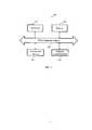
Фиг. 1 иллюстрирует схему выполнения этапов заявленного способа.FIG. 1 illustrates a flow chart of the steps of the claimed method.
Фиг. 2 иллюстрирует систему для выполнения заявленного способа.FIG. 2 illustrates a system for performing the claimed method.
ОСУЩЕСТВЛЕНИЕ ИЗОБРЕТЕНИЯDETAILED DESCRIPTION OF THE INVENTION
На Фиг. 1 изображена последовательность выполнения этапов заявленного способа управления стационарной камерой машинного зрения - 100.In FIG. 1 shows the sequence of steps of the claimed method of controlling a stationary camera of machine vision - 100.
На этапе 101 камера осуществляет работу в первом режиме, при котором осуществляется в заданный промежуток времени подстройка настроек по фиксированной области кадра. Камера по получаемому изображению получает структуру настроек, характеризующую область, по которой осуществляется калибровка камеры.At
При осуществлении фиксации ТС, в частности при распознавании области ГРЗ, на этапе 102 осуществляется активация второго режима работы (этап 103).When fixing the vehicle, in particular when recognizing the gas distribution area, at
При работе во втором режиме на этапе 104 осуществляется обработка набора кадров с изображениями зафиксированных ТС и проверяется достаточность количества кадров (этап 105) для осуществления калибровки режима работы камеры на основании извлеченных изображений областей ГРЗ (этап 106). Ряд кадров с изображениями ТС получается за определенный промежуток времени (этап 116).When working in the second mode, at
На этапе 107 по полученным на этапе 106 областям ГРЗ выполняется построение гистограммы распределения серого цвета, по которой осуществляется определение характеристики распределения цвета областей ГРЗ, для чего осуществляется склейка всех упомянутых областей ГРЗ.At
На этапе 109, на основании проведенного на этапе 108 определения характеристик распределения, получают параметры калибровки работы камеры, которые применяются и сохраняются.At
Если на этапе 102 в заданный промежуток времени (этап 110) не происходит фиксации ТС, то выполняется активация третьего режима работы (этап 111).If, at
При активации третьего режима работы 111 запоминаются настройки экспонирования, достигнутые в первом режиме.When the
На этапе 112 выполняется ограниченное количество шагов в затемнение и осветление кадра, получаемого при текущих настройках камеры. При появлении фиксации ТС (этап 113) осуществляется активация второго режима работы камеры.At 112, a limited number of steps are taken to darken and lighten the frame obtained with the current camera settings. When the vehicle fixes (step 113), the second camera operation mode is activated.
Если на этапе 113 не происходит фиксации ТС за определенное количество шагов регулировки зоны видимости камерой (этап 114), то применяются настройки, полученные при первом режиме работы камеры (этап 115) и камера продолжает работать в этом режиме.If, at
На Фиг. 2 изображен общий вид системы 200 для выполнения способа управления камерой машинного зрения.In FIG. 2 is a perspective view of a
Система 200 представляет собой совокупность аппаратных элементов, входящих в состав камеры наблюдения.
Система 200 содержит объединенные шиной передачи данных 250 один или более процессоров 210, одно или более средств памяти 220 (ОЗУ, ПЗУ, флэш и т.п.), оптический модуль 230, предназначенный для обеспечения фотовидеофиксации объектов, и средства коммуникации 240, такие как GPS приемник, GSM модуль (3G, 4G), Wi-Fi модуль.
В памяти 220 хранятся исполняемый процессором 210 код, который реализует этапы способа 100, на которых выполняются действия, соответствующие этапам 101-116.The
Claims (16)
Translated fromRussianPriority Applications (1)
| Application Number | Priority Date | Filing Date | Title |
|---|---|---|---|
| RU2015144115ARU2628916C2 (en) | 2015-10-14 | 2015-10-14 | Method and system of controlling stationary camera |
Applications Claiming Priority (1)
| Application Number | Priority Date | Filing Date | Title |
|---|---|---|---|
| RU2015144115ARU2628916C2 (en) | 2015-10-14 | 2015-10-14 | Method and system of controlling stationary camera |
Publications (2)
| Publication Number | Publication Date |
|---|---|
| RU2015144115A RU2015144115A (en) | 2017-04-20 |
| RU2628916C2true RU2628916C2 (en) | 2017-08-22 |
Family
ID=58641766
Family Applications (1)
| Application Number | Title | Priority Date | Filing Date |
|---|---|---|---|
| RU2015144115ARU2628916C2 (en) | 2015-10-14 | 2015-10-14 | Method and system of controlling stationary camera |
Country Status (1)
| Country | Link |
|---|---|
| RU (1) | RU2628916C2 (en) |
Cited By (1)
| Publication number | Priority date | Publication date | Assignee | Title |
|---|---|---|---|---|
| RU2667790C1 (en)* | 2017-09-01 | 2018-09-24 | Самсунг Электроникс Ко., Лтд. | Method of automatic adjustment of exposition for infrared camera and user computer device using this method |
Citations (5)
| Publication number | Priority date | Publication date | Assignee | Title |
|---|---|---|---|---|
| WO1993019441A1 (en)* | 1992-03-20 | 1993-09-30 | Commonwealth Scientific And Industrial Research Organisation | An object monitoring system |
| US20070052803A1 (en)* | 2005-09-08 | 2007-03-08 | Objectvideo, Inc. | Scanning camera-based video surveillance system |
| WO2010002379A1 (en)* | 2008-06-30 | 2010-01-07 | Alves James F | Digital camera control system |
| RU2452033C2 (en)* | 2005-01-03 | 2012-05-27 | Опсигал Контрол Системз Лтд. | Systems and methods for night surveillance |
| RU130728U1 (en)* | 2012-11-16 | 2013-07-27 | Евгений Васильевич Серга | CAR RECOGNITION RECOGNITION DEVICE |
- 2015
- 2015-10-14RURU2015144115Apatent/RU2628916C2/enactiveIP Right Revival
Patent Citations (5)
| Publication number | Priority date | Publication date | Assignee | Title |
|---|---|---|---|---|
| WO1993019441A1 (en)* | 1992-03-20 | 1993-09-30 | Commonwealth Scientific And Industrial Research Organisation | An object monitoring system |
| RU2452033C2 (en)* | 2005-01-03 | 2012-05-27 | Опсигал Контрол Системз Лтд. | Systems and methods for night surveillance |
| US20070052803A1 (en)* | 2005-09-08 | 2007-03-08 | Objectvideo, Inc. | Scanning camera-based video surveillance system |
| WO2010002379A1 (en)* | 2008-06-30 | 2010-01-07 | Alves James F | Digital camera control system |
| RU130728U1 (en)* | 2012-11-16 | 2013-07-27 | Евгений Васильевич Серга | CAR RECOGNITION RECOGNITION DEVICE |
Cited By (2)
| Publication number | Priority date | Publication date | Assignee | Title |
|---|---|---|---|---|
| RU2667790C1 (en)* | 2017-09-01 | 2018-09-24 | Самсунг Электроникс Ко., Лтд. | Method of automatic adjustment of exposition for infrared camera and user computer device using this method |
| US11265459B2 (en) | 2017-09-01 | 2022-03-01 | Samsung Electronics Co., Ltd. | Electronic device and control method therefor |
Also Published As
| Publication number | Publication date |
|---|---|
| RU2015144115A (en) | 2017-04-20 |
Similar Documents
| Publication | Publication Date | Title |
|---|---|---|
| EP2946249B1 (en) | Imaging apparatus with scene adaptive auto exposure compensation | |
| US10136076B2 (en) | Imaging device, imaging system, and imaging method | |
| US9214034B2 (en) | System, device and method for displaying a harmonized combined image | |
| JP4389999B2 (en) | Exposure control device and exposure control program | |
| US20190092239A1 (en) | Image-pickup apparatus, image-pickup display method, and image-pickup display program | |
| JP5435307B2 (en) | In-vehicle camera device | |
| JP2020522937A (en) | Shutterless Far Infrared (FIR) Camera for Automotive Safety and Driving Systems | |
| US8885092B2 (en) | Camera device, exposure control method, and program | |
| US20120121129A1 (en) | Image processing apparatus | |
| JP2013005234A5 (en) | ||
| US12101569B2 (en) | Techniques for correcting oversaturated pixels in shutterless FIR cameras | |
| RU2628916C2 (en) | Method and system of controlling stationary camera | |
| CN105721773A (en) | Video acquisition system and method | |
| US20130222632A1 (en) | Electronic camera | |
| US10769762B2 (en) | Motor vehicle camera device with histogram spreading | |
| US10102436B2 (en) | Image processing device, warning device and method for processing image | |
| KR20220004921A (en) | Night image correction control system and method | |
| JP2017092876A (en) | Imaging device, imaging system and imaging method | |
| KR101546917B1 (en) | System and method for controlling night image correction | |
| US11252344B2 (en) | Method and system for generating multiple synchronized thermal video streams for automotive safety and driving systems | |
| KR102726914B1 (en) | Apparatus and method for improving image quality of cctv images | |
| JP2008286943A (en) | Image display device | |
| US20130182141A1 (en) | Electronic camera | |
| US20130093920A1 (en) | Electronic camera | |
| KR101545323B1 (en) | System and method for adjusting auto white balance(AWB) |
Legal Events
| Date | Code | Title | Description |
|---|---|---|---|
| MM4A | The patent is invalid due to non-payment of fees | Effective date:20181015 | |
| NF4A | Reinstatement of patent | Effective date:20201112 |