RU2628054C2 - Staple cartridge, including crushable plate - Google Patents
Staple cartridge, including crushable plateDownload PDFInfo
- Publication number
- RU2628054C2 RU2628054C2RU2014116242ARU2014116242ARU2628054C2RU 2628054 C2RU2628054 C2RU 2628054C2RU 2014116242 ARU2014116242 ARU 2014116242ARU 2014116242 ARU2014116242 ARU 2014116242ARU 2628054 C2RU2628054 C2RU 2628054C2
- Authority
- RU
- Russia
- Prior art keywords
- brackets
- cassette
- view
- layer
- legs
- Prior art date
Links
- 230000008093supporting effectEffects0.000claimsabstractdescription178
- 239000012636effectorSubstances0.000claimsabstractdescription16
- 230000037303wrinklesEffects0.000claimsdescription7
- 239000003814drugSubstances0.000abstractdescription50
- 230000009471actionEffects0.000abstractdescription13
- 230000000694effectsEffects0.000abstractdescription3
- 239000000126substanceSubstances0.000abstract1
- 210000001519tissueAnatomy0.000description858
- 239000010410layerSubstances0.000description663
- 239000004744fabricSubstances0.000description398
- 239000011159matrix materialSubstances0.000description334
- 239000000463materialSubstances0.000description238
- 238000005520cutting processMethods0.000description170
- 230000033001locomotionEffects0.000description104
- 229920000954PolyglycolidePolymers0.000description86
- 239000004633polyglycolic acidSubstances0.000description85
- 230000036961partial effectEffects0.000description84
- 239000000203mixtureSubstances0.000description69
- 229920001610polycaprolactonePolymers0.000description68
- 239000004632polycaprolactoneSubstances0.000description68
- 229920000642polymerPolymers0.000description62
- 230000007246mechanismEffects0.000description55
- 229920000747poly(lactic acid)Polymers0.000description55
- 239000000853adhesiveSubstances0.000description52
- 230000001070adhesive effectEffects0.000description52
- 238000007906compressionMethods0.000description51
- 230000006835compressionEffects0.000description51
- 238000010586diagramMethods0.000description48
- 229940079593drugDrugs0.000description46
- 238000000034methodMethods0.000description46
- 229920000117poly(dioxanone)Polymers0.000description46
- 210000002105tongueAnatomy0.000description46
- -1for exampleSubstances0.000description43
- 239000005014poly(hydroxyalkanoate)Substances0.000description37
- 239000006260foamSubstances0.000description33
- 238000004132cross linkingMethods0.000description31
- 230000015572biosynthetic processEffects0.000description30
- 229920003023plasticPolymers0.000description29
- 239000004033plasticSubstances0.000description29
- 238000011068loading methodMethods0.000description28
- 229920002463poly(p-dioxanone) polymerPolymers0.000description27
- 239000000622polydioxanoneSubstances0.000description27
- 238000000576coating methodMethods0.000description26
- 238000013461designMethods0.000description26
- 229920001432poly(L-lactide)Polymers0.000description26
- 230000008569processEffects0.000description26
- JVTAAEKCZFNVCJ-REOHCLBHSA-NL-lactic acidChemical compoundC[C@H](O)C(O)=OJVTAAEKCZFNVCJ-REOHCLBHSA-N0.000description25
- 230000001681protective effectEffects0.000description25
- 229920000903polyhydroxyalkanoatePolymers0.000description24
- 238000000926separation methodMethods0.000description24
- 238000003780insertionMethods0.000description22
- 230000037431insertionEffects0.000description22
- 230000002085persistent effectEffects0.000description22
- 239000011148porous materialSubstances0.000description21
- 239000011248coating agentSubstances0.000description19
- 239000010935stainless steelSubstances0.000description19
- 229910001220stainless steelInorganic materials0.000description19
- 239000004626polylactic acidSubstances0.000description18
- LCSKNASZPVZHEG-UHFFFAOYSA-N3,6-dimethyl-1,4-dioxane-2,5-dione;1,4-dioxane-2,5-dioneChemical groupO=C1COC(=O)CO1.CC1OC(=O)C(C)OC1=OLCSKNASZPVZHEG-UHFFFAOYSA-N0.000description17
- RTAQQCXQSZGOHL-UHFFFAOYSA-NTitaniumChemical compound[Ti]RTAQQCXQSZGOHL-UHFFFAOYSA-N0.000description17
- 238000003825pressingMethods0.000description17
- 239000010936titaniumSubstances0.000description17
- 239000002775capsuleSubstances0.000description16
- 230000007423decreaseEffects0.000description16
- 229910052751metalInorganic materials0.000description15
- 239000002184metalSubstances0.000description15
- 230000002439hemostatic effectEffects0.000description14
- 238000002513implantationMethods0.000description14
- 238000009434installationMethods0.000description14
- 102000009123FibrinHuman genes0.000description13
- 108010073385FibrinProteins0.000description13
- BWGVNKXGVNDBDI-UHFFFAOYSA-NFibrin monomerChemical compoundCNC(=O)CNC(=O)CNBWGVNKXGVNDBDI-UHFFFAOYSA-N0.000description13
- 230000000903blocking effectEffects0.000description13
- 229920001577copolymerPolymers0.000description13
- 229950003499fibrinDrugs0.000description13
- 239000000017hydrogelSubstances0.000description13
- 210000003739neckAnatomy0.000description13
- 230000014759maintenance of locationEffects0.000description12
- 230000001960triggered effectEffects0.000description12
- 230000002441reversible effectEffects0.000description11
- 229920001198elastomeric copolymerPolymers0.000description10
- 238000004519manufacturing processMethods0.000description10
- 102000004169proteins and genesHuman genes0.000description10
- 108090000623proteins and genesProteins0.000description10
- 239000004627regenerated celluloseSubstances0.000description10
- PAPBSGBWRJIAAV-UHFFFAOYSA-Nε-CaprolactoneChemical compoundO=C1CCCCCO1PAPBSGBWRJIAAV-UHFFFAOYSA-N0.000description10
- 238000002224dissectionMethods0.000description9
- 229910052719titaniumInorganic materials0.000description9
- 229910001200FerrotitaniumInorganic materials0.000description8
- 230000000740bleeding effectEffects0.000description8
- 230000001225therapeutic effectEffects0.000description8
- YFHICDDUDORKJB-UHFFFAOYSA-Ntrimethylene carbonateChemical compoundO=C1OCCCO1YFHICDDUDORKJB-UHFFFAOYSA-N0.000description8
- RKDVKSZUMVYZHH-UHFFFAOYSA-N1,4-dioxane-2,5-dioneChemical compoundO=C1COC(=O)CO1RKDVKSZUMVYZHH-UHFFFAOYSA-N0.000description7
- 239000004696Poly ether ether ketoneSubstances0.000description7
- 230000003213activating effectEffects0.000description7
- 238000005452bendingMethods0.000description7
- 230000003993interactionEffects0.000description7
- JJTUDXZGHPGLLC-UHFFFAOYSA-NlactideChemical compoundCC1OC(=O)C(C)OC1=OJJTUDXZGHPGLLC-UHFFFAOYSA-N0.000description7
- 238000000465mouldingMethods0.000description7
- 229920002530polyetherether ketonePolymers0.000description7
- 229920001296polysiloxanePolymers0.000description7
- 230000002028prematureEffects0.000description7
- 238000012546transferMethods0.000description7
- PEDCQBHIVMGVHV-UHFFFAOYSA-NGlycerineChemical compoundOCC(O)COPEDCQBHIVMGVHV-UHFFFAOYSA-N0.000description6
- 239000013543active substanceSubstances0.000description6
- 230000005540biological transmissionEffects0.000description6
- 239000007788liquidSubstances0.000description6
- 230000002829reductive effectEffects0.000description6
- VPVXHAANQNHFSF-UHFFFAOYSA-N1,4-dioxan-2-oneChemical compoundO=C1COCCO1VPVXHAANQNHFSF-UHFFFAOYSA-N0.000description5
- 108090000190ThrombinProteins0.000description5
- XEFQLINVKFYRCS-UHFFFAOYSA-NTriclosanChemical compoundOC1=CC(Cl)=CC=C1OC1=CC=C(Cl)C=C1ClXEFQLINVKFYRCS-UHFFFAOYSA-N0.000description5
- 230000004913activationEffects0.000description5
- 239000002131composite materialSubstances0.000description5
- 239000013013elastic materialSubstances0.000description5
- 239000012530fluidSubstances0.000description5
- 230000006870functionEffects0.000description5
- 238000001746injection mouldingMethods0.000description5
- JVTAAEKCZFNVCJ-UHFFFAOYSA-Nlactic acidChemical compoundCC(O)C(O)=OJVTAAEKCZFNVCJ-UHFFFAOYSA-N0.000description5
- 239000007858starting materialSubstances0.000description5
- 229920001059synthetic polymerPolymers0.000description5
- 229960004072thrombinDrugs0.000description5
- 229960003500triclosanDrugs0.000description5
- 235000014676Phragmites communisNutrition0.000description4
- 239000004743PolypropyleneSubstances0.000description4
- 229940030225antihemorrhagicsDrugs0.000description4
- 230000008901benefitEffects0.000description4
- 239000008280bloodSubstances0.000description4
- 210000004369bloodAnatomy0.000description4
- 230000008859changeEffects0.000description4
- 238000006073displacement reactionMethods0.000description4
- 229920001971elastomerPolymers0.000description4
- 239000013536elastomeric materialSubstances0.000description4
- 239000002874hemostatic agentSubstances0.000description4
- 210000002429large intestineAnatomy0.000description4
- 230000000670limiting effectEffects0.000description4
- 229920000728polyesterPolymers0.000description4
- 229920001155polypropylenePolymers0.000description4
- 238000007789sealingMethods0.000description4
- 238000003466weldingMethods0.000description4
- JJTUDXZGHPGLLC-IMJSIDKUSA-N4511-42-6Chemical compoundC[C@@H]1OC(=O)[C@H](C)OC1=OJJTUDXZGHPGLLC-IMJSIDKUSA-N0.000description3
- 102000008186CollagenHuman genes0.000description3
- 108010035532CollagenProteins0.000description3
- 239000004677NylonSubstances0.000description3
- 230000000845anti-microbial effectEffects0.000description3
- 210000001124body fluidAnatomy0.000description3
- 239000010839body fluidSubstances0.000description3
- 238000004140cleaningMethods0.000description3
- 229920001436collagenPolymers0.000description3
- 239000003292glueSubstances0.000description3
- 230000035876healingEffects0.000description3
- 235000014655lactic acidNutrition0.000description3
- 239000004310lactic acidSubstances0.000description3
- 230000007774longtermEffects0.000description3
- 239000007769metal materialSubstances0.000description3
- 238000012986modificationMethods0.000description3
- 230000004048modificationEffects0.000description3
- 229920001778nylonPolymers0.000description3
- 230000035515penetrationEffects0.000description3
- 229920000515polycarbonatePolymers0.000description3
- 229920000139polyethylene terephthalatePolymers0.000description3
- 239000005020polyethylene terephthalateSubstances0.000description3
- 229920001343polytetrafluoroethylenePolymers0.000description3
- 239000004810polytetrafluoroethyleneSubstances0.000description3
- 230000004044responseEffects0.000description3
- 239000005060rubberSubstances0.000description3
- 239000000565sealantSubstances0.000description3
- 238000009958sewingMethods0.000description3
- 229910052709silverInorganic materials0.000description3
- 239000004332silverSubstances0.000description3
- 238000005476solderingMethods0.000description3
- 239000000758substrateSubstances0.000description3
- 210000003813thumbAnatomy0.000description3
- RTZKZFJDLAIYFH-UHFFFAOYSA-NDiethyl etherChemical compoundCCOCCRTZKZFJDLAIYFH-UHFFFAOYSA-N0.000description2
- AOJJSUZBOXZQNB-TZSSRYMLSA-NDoxorubicinChemical compoundO([C@H]1C[C@@](O)(CC=2C(O)=C3C(=O)C=4C=CC=C(C=4C(=O)C3=C(O)C=21)OC)C(=O)CO)[C@H]1C[C@H](N)[C@H](O)[C@H](C)O1AOJJSUZBOXZQNB-TZSSRYMLSA-N0.000description2
- 239000004812Fluorinated ethylene propyleneSubstances0.000description2
- 108010010803GelatinProteins0.000description2
- OUYCCCASQSFEME-QMMMGPOBSA-NL-tyrosineChemical compoundOC(=O)[C@@H](N)CC1=CC=C(O)C=C1OUYCCCASQSFEME-QMMMGPOBSA-N0.000description2
- 244000273256Phragmites communisSpecies0.000description2
- 239000004698PolyethyleneSubstances0.000description2
- 239000002202Polyethylene glycolSubstances0.000description2
- BQCADISMDOOEFD-UHFFFAOYSA-NSilverChemical compound[Ag]BQCADISMDOOEFD-UHFFFAOYSA-N0.000description2
- 229910000831SteelInorganic materials0.000description2
- 229920004738ULTEM®Polymers0.000description2
- 239000003242anti bacterial agentSubstances0.000description2
- 239000004599antimicrobialSubstances0.000description2
- 238000013459approachMethods0.000description2
- 239000000560biocompatible materialSubstances0.000description2
- 238000005266castingMethods0.000description2
- 229910010293ceramic materialInorganic materials0.000description2
- 238000006243chemical reactionMethods0.000description2
- 239000003795chemical substances by applicationSubstances0.000description2
- 238000004891communicationMethods0.000description2
- 230000005489elastic deformationEffects0.000description2
- 238000001125extrusionMethods0.000description2
- 239000000835fiberSubstances0.000description2
- 238000010304firingMethods0.000description2
- 229920000159gelatinPolymers0.000description2
- 239000008273gelatinSubstances0.000description2
- 235000019322gelatineNutrition0.000description2
- 235000011852gelatine dessertsNutrition0.000description2
- 150000004676glycansChemical class0.000description2
- 238000000227grindingMethods0.000description2
- JYGXADMDTFJGBT-VWUMJDOOSA-NhydrocortisoneChemical compoundO=C1CC[C@]2(C)[C@H]3[C@@H](O)C[C@](C)([C@@](CC4)(O)C(=O)CO)[C@@H]4[C@@H]3CCC2=C1JYGXADMDTFJGBT-VWUMJDOOSA-N0.000description2
- 239000007943implantSubstances0.000description2
- 230000013011matingEffects0.000description2
- 238000002483medicationMethods0.000description2
- 239000012528membraneSubstances0.000description2
- 239000002991molded plasticSubstances0.000description2
- 229920009441perflouroethylene propylenePolymers0.000description2
- 229920003229poly(methyl methacrylate)Polymers0.000description2
- 239000004417polycarbonateSubstances0.000description2
- 229920000573polyethylenePolymers0.000description2
- 229920001223polyethylene glycolPolymers0.000description2
- 229920001195polyisoprenePolymers0.000description2
- 239000004926polymethyl methacrylateSubstances0.000description2
- 229920001282polysaccharidePolymers0.000description2
- 239000005017polysaccharideSubstances0.000description2
- 229920002620polyvinyl fluoridePolymers0.000description2
- 239000011241protective layerSubstances0.000description2
- 230000005855radiationEffects0.000description2
- 238000011084recoveryMethods0.000description2
- 230000000284resting effectEffects0.000description2
- 239000010959steelSubstances0.000description2
- 238000003860storageMethods0.000description2
- 238000001356surgical procedureMethods0.000description2
- OUYCCCASQSFEME-UHFFFAOYSA-NtyrosineNatural productsOC(=O)C(N)CC1=CC=C(O)C=C1OUYCCCASQSFEME-UHFFFAOYSA-N0.000description2
- 230000002792vascularEffects0.000description2
- XLYOFNOQVPJJNP-UHFFFAOYSA-NwaterSubstancesOXLYOFNOQVPJJNP-UHFFFAOYSA-N0.000description2
- KKGSHHDRPRINNY-UHFFFAOYSA-N1,4-dioxan-2-oneChemical compoundO=C1COCCO1.O=C1COCCO1KKGSHHDRPRINNY-UHFFFAOYSA-N0.000description1
- MFRCZYUUKMFJQJ-UHFFFAOYSA-N1,4-dioxane-2,5-dione;1,3-dioxan-2-oneChemical compoundO=C1OCCCO1.O=C1COC(=O)CO1MFRCZYUUKMFJQJ-UHFFFAOYSA-N0.000description1
- 229910000838Al alloyInorganic materials0.000description1
- BSYNRYMUTXBXSQ-UHFFFAOYSA-NAspirinChemical compoundCC(=O)OC1=CC=CC=C1C(O)=OBSYNRYMUTXBXSQ-UHFFFAOYSA-N0.000description1
- 241000894006BacteriaSpecies0.000description1
- 208000031872Body RemainsDiseases0.000description1
- 229920000049Carbon (fiber)Polymers0.000description1
- 229920001651CyanoacrylatePolymers0.000description1
- 229920004937Dexon®Polymers0.000description1
- 102000016942ElastinHuman genes0.000description1
- 108010014258ElastinProteins0.000description1
- 235000009161Espostoa lanataNutrition0.000description1
- 240000001624Espostoa lanataSpecies0.000description1
- 206010073306Exposure to radiationDiseases0.000description1
- 241000282326Felis catusSpecies0.000description1
- IWDQPCIQCXRBQP-UHFFFAOYSA-MFenaminosulfChemical compound[Na+].CN(C)C1=CC=C(N=NS([O-])(=O)=O)C=C1IWDQPCIQCXRBQP-UHFFFAOYSA-M0.000description1
- CEAZRRDELHUEMR-URQXQFDESA-NGentamicinChemical compoundO1[C@H](C(C)NC)CC[C@@H](N)[C@H]1O[C@H]1[C@H](O)[C@@H](O[C@@H]2[C@@H]([C@@H](NC)[C@@](C)(O)CO2)O)[C@H](N)C[C@@H]1NCEAZRRDELHUEMR-URQXQFDESA-N0.000description1
- 229930182566GentamicinNatural products0.000description1
- AEMRFAOFKBGASW-UHFFFAOYSA-NGlycolic acidPolymersOCC(O)=OAEMRFAOFKBGASW-UHFFFAOYSA-N0.000description1
- 102000003886GlycoproteinsHuman genes0.000description1
- 108090000288GlycoproteinsProteins0.000description1
- 229920000544Gore-TexPolymers0.000description1
- 244000043261Hevea brasiliensisSpecies0.000description1
- 240000006240Linum usitatissimumSpecies0.000description1
- 235000004431Linum usitatissimumNutrition0.000description1
- MWCLLHOVUTZFKS-UHFFFAOYSA-NMethyl cyanoacrylateChemical compoundCOC(=O)C(=C)C#NMWCLLHOVUTZFKS-UHFFFAOYSA-N0.000description1
- 229930192392MitomycinNatural products0.000description1
- 101100004031Mus musculus Aven geneProteins0.000description1
- NWIBSHFKIJFRCO-WUDYKRTCSA-NMytomycinChemical compoundC1N2C(C(C(C)=C(N)C3=O)=O)=C3[C@@H](COC(N)=O)[C@@]2(OC)[C@@H]2[C@H]1N2NWIBSHFKIJFRCO-WUDYKRTCSA-N0.000description1
- CMWTZPSULFXXJA-UHFFFAOYSA-NNaproxenNatural productsC1=C(C(C)C(O)=O)C=CC2=CC(OC)=CC=C21CMWTZPSULFXXJA-UHFFFAOYSA-N0.000description1
- 229920002292Nylon 6Polymers0.000description1
- 208000034530PLAA-associated neurodevelopmental diseaseDiseases0.000description1
- 239000002033PVDF binderSubstances0.000description1
- 229930182556PolyacetalNatural products0.000description1
- 239000004952PolyamideSubstances0.000description1
- 229920002732PolyanhydridePolymers0.000description1
- 229920000331PolyhydroxybutyratePolymers0.000description1
- 108010093965Polymyxin BProteins0.000description1
- 229920001710PolyorthoesterPolymers0.000description1
- 239000004793PolystyreneSubstances0.000description1
- 229920005830Polyurethane FoamPolymers0.000description1
- 239000004792ProleneSubstances0.000description1
- 102000016611ProteoglycansHuman genes0.000description1
- 108010067787ProteoglycansProteins0.000description1
- 108091027981Response elementProteins0.000description1
- 241000158147SatorSpecies0.000description1
- 229910001069Ti alloyInorganic materials0.000description1
- 239000004775TyvekSubstances0.000description1
- 229920000690TyvekPolymers0.000description1
- 235000018936Vitellaria paradoxaNutrition0.000description1
- 230000002745absorbentEffects0.000description1
- 239000002250absorbentSubstances0.000description1
- 229960001138acetylsalicylic acidDrugs0.000description1
- 239000002253acidSubstances0.000description1
- 229940009456adriamycinDrugs0.000description1
- 125000001931aliphatic groupChemical group0.000description1
- 229910045601alloyInorganic materials0.000description1
- 239000000956alloySubstances0.000description1
- 229910052782aluminiumInorganic materials0.000description1
- XAGFODPZIPBFFR-UHFFFAOYSA-NaluminiumChemical compound[Al]XAGFODPZIPBFFR-UHFFFAOYSA-N0.000description1
- 150000001413amino acidsChemical class0.000description1
- 229960000723ampicillinDrugs0.000description1
- AVKUERGKIZMTKX-NJBDSQKTSA-NampicillinChemical compoundC1([C@@H](N)C(=O)N[C@H]2[C@H]3SC([C@@H](N3C2=O)C(O)=O)(C)C)=CC=CC=C1AVKUERGKIZMTKX-NJBDSQKTSA-N0.000description1
- 230000003872anastomosisEffects0.000description1
- 229940124599anti-inflammatory drugDrugs0.000description1
- 229940088710antibiotic agentDrugs0.000description1
- 239000002246antineoplastic agentSubstances0.000description1
- 229910052785arsenicInorganic materials0.000description1
- 239000011230binding agentSubstances0.000description1
- 230000003115biocidal effectEffects0.000description1
- 229920002988biodegradable polymerPolymers0.000description1
- 239000004621biodegradable polymerSubstances0.000description1
- 229920001400block copolymerPolymers0.000description1
- 210000000481breastAnatomy0.000description1
- 230000002308calcificationEffects0.000description1
- 239000004917carbon fiberSubstances0.000description1
- 229910052729chemical elementInorganic materials0.000description1
- 229960005091chloramphenicolDrugs0.000description1
- WIIZWVCIJKGZOK-RKDXNWHRSA-NchloramphenicolChemical compoundClC(Cl)C(=O)N[C@H](CO)[C@H](O)C1=CC=C([N+]([O-])=O)C=C1WIIZWVCIJKGZOK-RKDXNWHRSA-N0.000description1
- DQLATGHUWYMOKM-UHFFFAOYSA-LcisplatinChemical compoundN[Pt](N)(Cl)ClDQLATGHUWYMOKM-UHFFFAOYSA-L0.000description1
- 229960004316cisplatinDrugs0.000description1
- 238000005253claddingMethods0.000description1
- 239000003086colorantSubstances0.000description1
- 150000001875compoundsChemical class0.000description1
- 230000001010compromised effectEffects0.000description1
- 230000008878couplingEffects0.000description1
- 238000010168coupling processMethods0.000description1
- 238000005859coupling reactionMethods0.000description1
- 230000000881depressing effectEffects0.000description1
- 230000000994depressogenic effectEffects0.000description1
- 229910003460diamondInorganic materials0.000description1
- 239000010432diamondSubstances0.000description1
- 229960001259diclofenacDrugs0.000description1
- DCOPUUMXTXDBNB-UHFFFAOYSA-NdiclofenacChemical compoundOC(=O)CC1=CC=CC=C1NC1=C(Cl)C=CC=C1ClDCOPUUMXTXDBNB-UHFFFAOYSA-N0.000description1
- 229920002549elastinPolymers0.000description1
- 239000000806elastomerSubstances0.000description1
- 238000004049embossingMethods0.000description1
- 238000002674endoscopic surgeryMethods0.000description1
- HQQADJVZYDDRJT-UHFFFAOYSA-Nethene;prop-1-eneChemical groupC=C.CC=CHQQADJVZYDDRJT-UHFFFAOYSA-N0.000description1
- VJYFKVYYMZPMAB-UHFFFAOYSA-NethoprophosChemical compoundCCCSP(=O)(OCC)SCCCVJYFKVYYMZPMAB-UHFFFAOYSA-N0.000description1
- 239000011152fibreglassSubstances0.000description1
- 238000007667floatingMethods0.000description1
- 239000006261foam materialSubstances0.000description1
- 229920001821foam rubberPolymers0.000description1
- 239000012634fragmentSubstances0.000description1
- 210000001035gastrointestinal tractAnatomy0.000description1
- 239000000499gelSubstances0.000description1
- 229960002518gentamicinDrugs0.000description1
- 238000010438heat treatmentMethods0.000description1
- 229960000890hydrocortisoneDrugs0.000description1
- 230000001976improved effectEffects0.000description1
- 238000007373indentationMethods0.000description1
- 208000015181infectious diseaseDiseases0.000description1
- 238000002347injectionMethods0.000description1
- 239000007924injectionSubstances0.000description1
- 230000001788irregularEffects0.000description1
- 238000005304joiningMethods0.000description1
- 238000002357laparoscopic surgeryMethods0.000description1
- 238000012830laparoscopic surgical procedureMethods0.000description1
- 238000002844meltingMethods0.000description1
- 230000008018meltingEffects0.000description1
- 150000002739metalsChemical class0.000description1
- VNWKTOKETHGBQD-UHFFFAOYSA-NmethaneChemical compoundCVNWKTOKETHGBQD-UHFFFAOYSA-N0.000description1
- 238000012978minimally invasive surgical procedureMethods0.000description1
- 229960004857mitomycinDrugs0.000description1
- GKTNLYAAZKKMTQ-UHFFFAOYSA-Nn-[bis(dimethylamino)phosphinimyl]-n-methylmethanamineChemical compoundCN(C)P(=N)(N(C)C)N(C)CGKTNLYAAZKKMTQ-UHFFFAOYSA-N0.000description1
- 229960002009naproxenDrugs0.000description1
- CMWTZPSULFXXJA-VIFPVBQESA-NnaproxenChemical compoundC1=C([C@H](C)C(O)=O)C=CC2=CC(OC)=CC=C21CMWTZPSULFXXJA-VIFPVBQESA-N0.000description1
- 229920003052natural elastomerPolymers0.000description1
- 229920001194natural rubberPolymers0.000description1
- ORQBXQOJMQIAOY-UHFFFAOYSA-NnobeliumChemical compound[No]ORQBXQOJMQIAOY-UHFFFAOYSA-N0.000description1
- 239000004745nonwoven fabricSubstances0.000description1
- 238000002355open surgical procedureMethods0.000description1
- 210000000056organAnatomy0.000description1
- 230000000149penetrating effectEffects0.000description1
- 239000002985plastic filmSubstances0.000description1
- 229920001308poly(aminoacid)Polymers0.000description1
- 229920002492poly(sulfone)Polymers0.000description1
- 229920002647polyamidePolymers0.000description1
- 229920000223polyglycerolPolymers0.000description1
- 239000002861polymer materialSubstances0.000description1
- 229920000024polymyxin BPolymers0.000description1
- 229960005266polymyxin bDrugs0.000description1
- 229920006324polyoxymethylenePolymers0.000description1
- 229920000166polytrimethylene carbonatePolymers0.000description1
- 229920002635polyurethanePolymers0.000description1
- 239000004814polyurethaneSubstances0.000description1
- 239000011496polyurethane foamSubstances0.000description1
- 239000004800polyvinyl chlorideSubstances0.000description1
- 229920000131polyvinylidenePolymers0.000description1
- 229920002981polyvinylidene fluoridePolymers0.000description1
- 239000013354porous frameworkSubstances0.000description1
- 238000002360preparation methodMethods0.000description1
- 238000004321preservationMethods0.000description1
- 238000012545processingMethods0.000description1
- 238000010791quenchingMethods0.000description1
- 230000003014reinforcing effectEffects0.000description1
- 230000008439repair processEffects0.000description1
- 230000000717retained effectEffects0.000description1
- 239000012056semi-solid materialSubstances0.000description1
- 239000010802sludgeSubstances0.000description1
- 210000004872soft tissueAnatomy0.000description1
- 239000011343solid materialSubstances0.000description1
- 238000007711solidificationMethods0.000description1
- 230000008023solidificationEffects0.000description1
- 239000000243solutionSubstances0.000description1
- 125000006850spacer groupChemical group0.000description1
- 238000010561standard procedureMethods0.000description1
- 230000001954sterilising effectEffects0.000description1
- 238000004659sterilization and disinfectionMethods0.000description1
- 229960000894sulindacDrugs0.000description1
- MLKXDPUZXIRXEP-MFOYZWKCSA-NsulindacChemical compoundCC1=C(CC(O)=O)C2=CC(F)=CC=C2\C1=C/C1=CC=C(S(C)=O)C=C1MLKXDPUZXIRXEP-MFOYZWKCSA-N0.000description1
- 238000013268sustained releaseMethods0.000description1
- 239000012730sustained-release formSubstances0.000description1
- 229940126585therapeutic drugDrugs0.000description1
- 239000003106tissue adhesiveSubstances0.000description1
- 150000003608titaniumChemical class0.000description1
- 238000013519translationMethods0.000description1
- 238000011144upstream manufacturingMethods0.000description1
- 239000011800void materialSubstances0.000description1
Images


Classifications
- A—HUMAN NECESSITIES
- A61—MEDICAL OR VETERINARY SCIENCE; HYGIENE
- A61B—DIAGNOSIS; SURGERY; IDENTIFICATION
- A61B17/00—Surgical instruments, devices or methods
- A61B17/068—Surgical staplers, e.g. containing multiple staples or clamps
- A61B17/072—Surgical staplers, e.g. containing multiple staples or clamps for applying a row of staples in a single action, e.g. the staples being applied simultaneously
- A61B17/07207—Surgical staplers, e.g. containing multiple staples or clamps for applying a row of staples in a single action, e.g. the staples being applied simultaneously the staples being applied sequentially
- A—HUMAN NECESSITIES
- A61—MEDICAL OR VETERINARY SCIENCE; HYGIENE
- A61B—DIAGNOSIS; SURGERY; IDENTIFICATION
- A61B17/00—Surgical instruments, devices or methods
- A61B17/10—Surgical instruments, devices or methods for applying or removing wound clamps, e.g. containing only one clamp or staple; Wound clamp magazines
- A61B17/105—Wound clamp magazines
- A—HUMAN NECESSITIES
- A61—MEDICAL OR VETERINARY SCIENCE; HYGIENE
- A61B—DIAGNOSIS; SURGERY; IDENTIFICATION
- A61B17/00—Surgical instruments, devices or methods
- A61B17/00491—Surgical glue applicators
- A—HUMAN NECESSITIES
- A61—MEDICAL OR VETERINARY SCIENCE; HYGIENE
- A61B—DIAGNOSIS; SURGERY; IDENTIFICATION
- A61B17/00—Surgical instruments, devices or methods
- A61B17/064—Surgical staples, i.e. penetrating the tissue
- A61B17/0643—Surgical staples, i.e. penetrating the tissue with separate closing member, e.g. for interlocking with staple
- A—HUMAN NECESSITIES
- A61—MEDICAL OR VETERINARY SCIENCE; HYGIENE
- A61B—DIAGNOSIS; SURGERY; IDENTIFICATION
- A61B17/00—Surgical instruments, devices or methods
- A61B17/068—Surgical staplers, e.g. containing multiple staples or clamps
- A61B17/072—Surgical staplers, e.g. containing multiple staples or clamps for applying a row of staples in a single action, e.g. the staples being applied simultaneously
- A61B17/07292—Reinforcements for staple line, e.g. pledgets
- A—HUMAN NECESSITIES
- A61—MEDICAL OR VETERINARY SCIENCE; HYGIENE
- A61B—DIAGNOSIS; SURGERY; IDENTIFICATION
- A61B17/00—Surgical instruments, devices or methods
- A61B17/11—Surgical instruments, devices or methods for performing anastomosis; Buttons for anastomosis
- A61B17/115—Staplers for performing anastomosis, e.g. in a single operation
- A61B17/1155—Circular staplers comprising a plurality of staples
- A—HUMAN NECESSITIES
- A61—MEDICAL OR VETERINARY SCIENCE; HYGIENE
- A61B—DIAGNOSIS; SURGERY; IDENTIFICATION
- A61B17/00—Surgical instruments, devices or methods
- A61B17/064—Surgical staples, i.e. penetrating the tissue
- A61B17/0644—Surgical staples, i.e. penetrating the tissue penetrating the tissue, deformable to closed position
- A—HUMAN NECESSITIES
- A61—MEDICAL OR VETERINARY SCIENCE; HYGIENE
- A61B—DIAGNOSIS; SURGERY; IDENTIFICATION
- A61B17/00—Surgical instruments, devices or methods
- A61B17/068—Surgical staplers, e.g. containing multiple staples or clamps
- A—HUMAN NECESSITIES
- A61—MEDICAL OR VETERINARY SCIENCE; HYGIENE
- A61B—DIAGNOSIS; SURGERY; IDENTIFICATION
- A61B17/00—Surgical instruments, devices or methods
- A61B17/068—Surgical staplers, e.g. containing multiple staples or clamps
- A61B17/0682—Surgical staplers, e.g. containing multiple staples or clamps for applying U-shaped staples or clamps, e.g. without a forming anvil
- A—HUMAN NECESSITIES
- A61—MEDICAL OR VETERINARY SCIENCE; HYGIENE
- A61B—DIAGNOSIS; SURGERY; IDENTIFICATION
- A61B17/00—Surgical instruments, devices or methods
- A61B2017/00004—(bio)absorbable, (bio)resorbable or resorptive
- A—HUMAN NECESSITIES
- A61—MEDICAL OR VETERINARY SCIENCE; HYGIENE
- A61B—DIAGNOSIS; SURGERY; IDENTIFICATION
- A61B17/00—Surgical instruments, devices or methods
- A61B17/00234—Surgical instruments, devices or methods for minimally invasive surgery
- A61B2017/00292—Surgical instruments, devices or methods for minimally invasive surgery mounted on or guided by flexible, e.g. catheter-like, means
- A61B2017/003—Steerable
- A61B2017/00305—Constructional details of the flexible means
- A61B2017/00314—Separate linked members
- A—HUMAN NECESSITIES
- A61—MEDICAL OR VETERINARY SCIENCE; HYGIENE
- A61B—DIAGNOSIS; SURGERY; IDENTIFICATION
- A61B17/00—Surgical instruments, devices or methods
- A61B17/00234—Surgical instruments, devices or methods for minimally invasive surgery
- A61B2017/00292—Surgical instruments, devices or methods for minimally invasive surgery mounted on or guided by flexible, e.g. catheter-like, means
- A61B2017/003—Steerable
- A61B2017/00318—Steering mechanisms
- A61B2017/00323—Cables or rods
- A61B2017/00327—Cables or rods with actuating members moving in opposite directions
- A—HUMAN NECESSITIES
- A61—MEDICAL OR VETERINARY SCIENCE; HYGIENE
- A61B—DIAGNOSIS; SURGERY; IDENTIFICATION
- A61B17/00—Surgical instruments, devices or methods
- A61B17/00234—Surgical instruments, devices or methods for minimally invasive surgery
- A61B2017/00353—Surgical instruments, devices or methods for minimally invasive surgery one mechanical instrument performing multiple functions, e.g. cutting and grasping
- A—HUMAN NECESSITIES
- A61—MEDICAL OR VETERINARY SCIENCE; HYGIENE
- A61B—DIAGNOSIS; SURGERY; IDENTIFICATION
- A61B17/00—Surgical instruments, devices or methods
- A61B17/00491—Surgical glue applicators
- A61B2017/00495—Surgical glue applicators for two-component glue
- A—HUMAN NECESSITIES
- A61—MEDICAL OR VETERINARY SCIENCE; HYGIENE
- A61B—DIAGNOSIS; SURGERY; IDENTIFICATION
- A61B17/00—Surgical instruments, devices or methods
- A61B2017/00526—Methods of manufacturing
- A—HUMAN NECESSITIES
- A61—MEDICAL OR VETERINARY SCIENCE; HYGIENE
- A61B—DIAGNOSIS; SURGERY; IDENTIFICATION
- A61B17/00—Surgical instruments, devices or methods
- A61B2017/00526—Methods of manufacturing
- A61B2017/0053—Loading magazines or sutures into applying tools
- A—HUMAN NECESSITIES
- A61—MEDICAL OR VETERINARY SCIENCE; HYGIENE
- A61B—DIAGNOSIS; SURGERY; IDENTIFICATION
- A61B17/00—Surgical instruments, devices or methods
- A61B2017/00743—Type of operation; Specification of treatment sites
- A61B2017/00818—Treatment of the gastro-intestinal system
- A—HUMAN NECESSITIES
- A61—MEDICAL OR VETERINARY SCIENCE; HYGIENE
- A61B—DIAGNOSIS; SURGERY; IDENTIFICATION
- A61B17/00—Surgical instruments, devices or methods
- A61B2017/00831—Material properties
- A61B2017/00884—Material properties enhancing wound closure
- A—HUMAN NECESSITIES
- A61—MEDICAL OR VETERINARY SCIENCE; HYGIENE
- A61B—DIAGNOSIS; SURGERY; IDENTIFICATION
- A61B17/00—Surgical instruments, devices or methods
- A61B2017/00831—Material properties
- A61B2017/00893—Material properties pharmaceutically effective
- A—HUMAN NECESSITIES
- A61—MEDICAL OR VETERINARY SCIENCE; HYGIENE
- A61B—DIAGNOSIS; SURGERY; IDENTIFICATION
- A61B17/00—Surgical instruments, devices or methods
- A61B17/068—Surgical staplers, e.g. containing multiple staples or clamps
- A61B17/072—Surgical staplers, e.g. containing multiple staples or clamps for applying a row of staples in a single action, e.g. the staples being applied simultaneously
- A61B2017/07214—Stapler heads
- A61B2017/07228—Arrangement of the staples
- A—HUMAN NECESSITIES
- A61—MEDICAL OR VETERINARY SCIENCE; HYGIENE
- A61B—DIAGNOSIS; SURGERY; IDENTIFICATION
- A61B17/00—Surgical instruments, devices or methods
- A61B17/068—Surgical staplers, e.g. containing multiple staples or clamps
- A61B17/072—Surgical staplers, e.g. containing multiple staples or clamps for applying a row of staples in a single action, e.g. the staples being applied simultaneously
- A61B2017/07214—Stapler heads
- A61B2017/07235—Stapler heads containing different staples, e.g. staples of different shapes, sizes or materials
- A—HUMAN NECESSITIES
- A61—MEDICAL OR VETERINARY SCIENCE; HYGIENE
- A61B—DIAGNOSIS; SURGERY; IDENTIFICATION
- A61B17/00—Surgical instruments, devices or methods
- A61B17/068—Surgical staplers, e.g. containing multiple staples or clamps
- A61B17/072—Surgical staplers, e.g. containing multiple staples or clamps for applying a row of staples in a single action, e.g. the staples being applied simultaneously
- A61B2017/07214—Stapler heads
- A61B2017/07242—Stapler heads achieving different staple heights during the same shot, e.g. using an anvil anvil having different heights or staples of different sizes
- A—HUMAN NECESSITIES
- A61—MEDICAL OR VETERINARY SCIENCE; HYGIENE
- A61B—DIAGNOSIS; SURGERY; IDENTIFICATION
- A61B17/00—Surgical instruments, devices or methods
- A61B17/068—Surgical staplers, e.g. containing multiple staples or clamps
- A61B17/072—Surgical staplers, e.g. containing multiple staples or clamps for applying a row of staples in a single action, e.g. the staples being applied simultaneously
- A61B2017/07214—Stapler heads
- A61B2017/0725—Stapler heads with settable gap between anvil and cartridge, e.g. for different staple heights at different shots
- A—HUMAN NECESSITIES
- A61—MEDICAL OR VETERINARY SCIENCE; HYGIENE
- A61B—DIAGNOSIS; SURGERY; IDENTIFICATION
- A61B17/00—Surgical instruments, devices or methods
- A61B17/068—Surgical staplers, e.g. containing multiple staples or clamps
- A61B17/072—Surgical staplers, e.g. containing multiple staples or clamps for applying a row of staples in a single action, e.g. the staples being applied simultaneously
- A61B2017/07214—Stapler heads
- A61B2017/07257—Stapler heads characterised by its anvil
- A61B2017/07264—Stapler heads characterised by its anvil characterised by its staple forming cavities, e.g. geometry or material
- A—HUMAN NECESSITIES
- A61—MEDICAL OR VETERINARY SCIENCE; HYGIENE
- A61B—DIAGNOSIS; SURGERY; IDENTIFICATION
- A61B17/00—Surgical instruments, devices or methods
- A61B17/068—Surgical staplers, e.g. containing multiple staples or clamps
- A61B17/072—Surgical staplers, e.g. containing multiple staples or clamps for applying a row of staples in a single action, e.g. the staples being applied simultaneously
- A61B2017/07214—Stapler heads
- A61B2017/07271—Stapler heads characterised by its cartridge
- A—HUMAN NECESSITIES
- A61—MEDICAL OR VETERINARY SCIENCE; HYGIENE
- A61B—DIAGNOSIS; SURGERY; IDENTIFICATION
- A61B17/00—Surgical instruments, devices or methods
- A61B17/068—Surgical staplers, e.g. containing multiple staples or clamps
- A61B17/072—Surgical staplers, e.g. containing multiple staples or clamps for applying a row of staples in a single action, e.g. the staples being applied simultaneously
- A61B2017/07214—Stapler heads
- A61B2017/07278—Stapler heads characterised by its sled or its staple holder
- A—HUMAN NECESSITIES
- A61—MEDICAL OR VETERINARY SCIENCE; HYGIENE
- A61B—DIAGNOSIS; SURGERY; IDENTIFICATION
- A61B17/00—Surgical instruments, devices or methods
- A61B17/068—Surgical staplers, e.g. containing multiple staples or clamps
- A61B17/072—Surgical staplers, e.g. containing multiple staples or clamps for applying a row of staples in a single action, e.g. the staples being applied simultaneously
- A61B2017/07214—Stapler heads
- A61B2017/07285—Stapler heads characterised by its cutter
- A—HUMAN NECESSITIES
- A61—MEDICAL OR VETERINARY SCIENCE; HYGIENE
- A61B—DIAGNOSIS; SURGERY; IDENTIFICATION
- A61B17/00—Surgical instruments, devices or methods
- A61B17/28—Surgical forceps
- A61B17/29—Forceps for use in minimally invasive surgery
- A61B2017/2901—Details of shaft
- A61B2017/2908—Multiple segments connected by articulations
- A—HUMAN NECESSITIES
- A61—MEDICAL OR VETERINARY SCIENCE; HYGIENE
- A61B—DIAGNOSIS; SURGERY; IDENTIFICATION
- A61B17/00—Surgical instruments, devices or methods
- A61B17/28—Surgical forceps
- A61B17/29—Forceps for use in minimally invasive surgery
- A61B17/2909—Handles
- A61B2017/2912—Handles transmission of forces to actuating rod or piston
- A61B2017/2919—Handles transmission of forces to actuating rod or piston details of linkages or pivot points
- A—HUMAN NECESSITIES
- A61—MEDICAL OR VETERINARY SCIENCE; HYGIENE
- A61B—DIAGNOSIS; SURGERY; IDENTIFICATION
- A61B17/00—Surgical instruments, devices or methods
- A61B17/28—Surgical forceps
- A61B17/29—Forceps for use in minimally invasive surgery
- A61B17/2909—Handles
- A61B2017/2912—Handles transmission of forces to actuating rod or piston
- A61B2017/2923—Toothed members, e.g. rack and pinion
- A—HUMAN NECESSITIES
- A61—MEDICAL OR VETERINARY SCIENCE; HYGIENE
- A61B—DIAGNOSIS; SURGERY; IDENTIFICATION
- A61B17/00—Surgical instruments, devices or methods
- A61B17/28—Surgical forceps
- A61B17/29—Forceps for use in minimally invasive surgery
- A61B2017/2926—Details of heads or jaws
- A61B2017/2927—Details of heads or jaws the angular position of the head being adjustable with respect to the shaft
- A—HUMAN NECESSITIES
- A61—MEDICAL OR VETERINARY SCIENCE; HYGIENE
- A61B—DIAGNOSIS; SURGERY; IDENTIFICATION
- A61B17/00—Surgical instruments, devices or methods
- A61B17/28—Surgical forceps
- A61B17/29—Forceps for use in minimally invasive surgery
- A61B2017/2926—Details of heads or jaws
- A61B2017/2932—Transmission of forces to jaw members
- A61B2017/2933—Transmission of forces to jaw members camming or guiding means
- A61B2017/2936—Pins in guiding slots
- A—HUMAN NECESSITIES
- A61—MEDICAL OR VETERINARY SCIENCE; HYGIENE
- A61B—DIAGNOSIS; SURGERY; IDENTIFICATION
- A61B17/00—Surgical instruments, devices or methods
- A61B17/28—Surgical forceps
- A61B17/29—Forceps for use in minimally invasive surgery
- A61B2017/2946—Locking means
- A—HUMAN NECESSITIES
- A61—MEDICAL OR VETERINARY SCIENCE; HYGIENE
- A61B—DIAGNOSIS; SURGERY; IDENTIFICATION
- A61B17/00—Surgical instruments, devices or methods
- A61B17/32—Surgical cutting instruments
- A61B2017/320052—Guides for cutting instruments
Landscapes
- Health & Medical Sciences (AREA)
- Life Sciences & Earth Sciences (AREA)
- Surgery (AREA)
- Heart & Thoracic Surgery (AREA)
- Engineering & Computer Science (AREA)
- Biomedical Technology (AREA)
- Nuclear Medicine, Radiotherapy & Molecular Imaging (AREA)
- Medical Informatics (AREA)
- Molecular Biology (AREA)
- Animal Behavior & Ethology (AREA)
- General Health & Medical Sciences (AREA)
- Public Health (AREA)
- Veterinary Medicine (AREA)
- Surgical Instruments (AREA)
Abstract
Description
Translated fromRussianПРЕДПОСЫЛКИ СОЗДАНИЯ ИЗОБРЕТЕНИЯBACKGROUND OF THE INVENTION
Настоящее изобретение относится к хирургическим инструментам и в различных вариантах осуществления к хирургическим рассекающим и сшивающим инструментам и используемым в них кассетам со скобами, которые разработаны для рассечения и сшивания скобами ткани.The present invention relates to surgical instruments and, in various embodiments, to surgical dissecting and stapling instruments and cassette staples used therein, which are designed to cut and staple tissue staples.
КРАТКОЕ ОПИСАНИЕ ЧЕРТЕЖЕЙBRIEF DESCRIPTION OF THE DRAWINGS
Особенности и преимущества настоящего изобретения, а также способы их осуществления будут очевидны, а сущность изобретения будет более понятна после ознакомления со следующим описанием вариантов осуществления настоящего изобретения в совокупности с сопроводительными чертежами.Features and advantages of the present invention, as well as methods for their implementation, will be apparent, and the essence of the invention will be better understood after reading the following description of embodiments of the present invention in conjunction with the accompanying drawings.
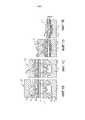
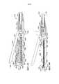
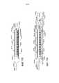
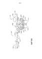
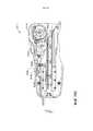
На ФИГ. 1 представлен вид в сечении варианта осуществления хирургического аппарата.In FIG. 1 is a sectional view of an embodiment of a surgical apparatus.
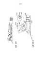
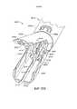
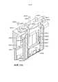
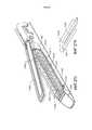
На ФИГ. 1A представлен вид в перспективе одного варианта осуществления имплантируемой кассеты со скобками.In FIG. 1A is a perspective view of one embodiment of an implantable cassette with brackets.
На ФИГ. 1B-1E представлены части концевого рабочего органа, зажимающего и сшивающего ткань, с имплантируемой кассетой со скобками.In FIG. 1B-1E show portions of an end member that clamps and stitches a tissue with an implantable cassette with brackets.
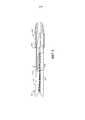
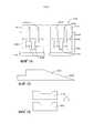
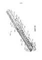
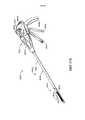
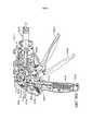
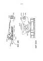
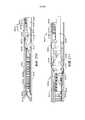
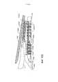
На ФИГ. 2 представлен частичный вид сбоку в сечении другого концевого рабочего органа, соединенного с частью хирургического аппарата, причем концевой рабочий орган поддерживает хирургическую кассету со скобками, а его упор находится в открытом положении.In FIG. 2 is a partial cross-sectional side view of another end working body connected to a part of the surgical apparatus, the end working body supporting the surgical cassette with brackets, and its emphasis in the open position.
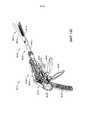
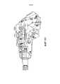
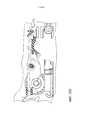
На ФИГ. 3 представлен другой частичный вид сбоку в сечении концевого рабочего органа, представленного на ФИГ. 2, в закрытом положении.In FIG. 3 shows another partial side view in cross section of the end working body shown in FIG. 2, in the closed position.
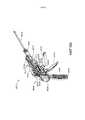
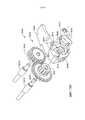
На ФИГ. 4 представлен другой частичный вид сбоку в сечении концевого рабочего органа, представленного на ФИГ. 2 и 3, на котором держатель режущего элемента начинает продвижение через концевой рабочий орган.In FIG. 4 shows another partial side view in cross section of the end working body shown in FIG. 2 and 3, on which the holder of the cutting element begins to advance through the end working body.
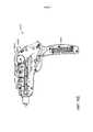
На ФИГ. 5 представлен другой частичный вид сбоку в сечении концевого рабочего органа, представленного на ФИГ. 2-4, на котором держатель режущего элемента частично продвинут через него.In FIG. 5 shows another partial side view in cross section of the end working body shown in FIG. 2-4, on which the holder of the cutting element is partially advanced through it.
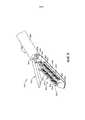
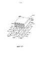
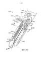
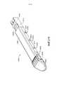
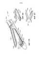
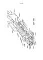
На ФИГ. 6 представлен вид в перспективе альтернативного варианта осуществления кассеты со скобками, установленного в хирургическом рассекающем и сшивающем устройстве.In FIG. 6 is a perspective view of an alternative embodiment of a cassette with brackets mounted in a surgical dissecting and stapling device.
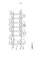
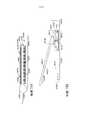
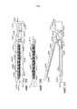
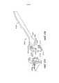
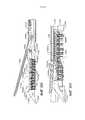
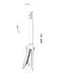
На ФИГ. 7 представлен вид сверху хирургической кассеты со скобками и удлиненного желоба устройства, представленного на ФИГ. 6.In FIG. 7 is a top view of a surgical cassette with brackets and an elongated groove of the device of FIG. 6.
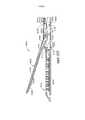
На ФИГ. 8 представлен вид сверху другого варианта осуществления хирургической кассеты со скобками, установленной в удлиненный желоб концевого рабочего органа.In FIG. 8 is a top view of another embodiment of a surgical cassette with brackets mounted in an elongated groove of an end tool.
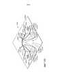
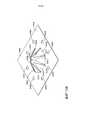
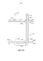
На ФИГ. 9 представлен вид снизу упора.In FIG. 9 is a bottom view of the stop.
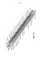
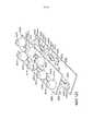
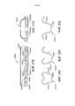
На ФИГ. 10 представлен частичный вид в перспективе множества скобок, образующих часть ряда скобок.In FIG. 10 is a partial perspective view of a plurality of brackets forming part of a series of brackets.
На ФИГ. 11 представлен другой частичный вид в перспективе ряда скобок, представленного на ФИГ. 10, причем скобки показаны после формирования в результате контакта с упором хирургического рассекающего и сшивающего устройства.In FIG. 11 is another partial perspective view of a series of brackets shown in FIG. 10, wherein the brackets are shown after forming a surgical dissecting and stapling device as a result of contact with the abutment.
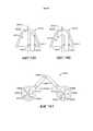
На ФИГ. 12 представлен частичный вид в перспективе альтернативных скобок, образующих часть другого ряда скобок.In FIG. 12 is a partial perspective view of alternative brackets forming part of another row of brackets.
На ФИГ. 13 представлен частичный вид в перспективе альтернативных скобок, образующих часть другого ряда скобок.In FIG. 13 is a partial perspective view of alternative brackets forming part of another row of brackets.
На ФИГ. 14 представлен частичный вид в перспективе альтернативных скобок, образующих часть другого варианта осуществления ряда скобок.In FIG. 14 is a partial perspective view of alternative brackets forming part of another embodiment of a series of brackets.
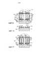
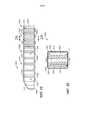
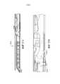
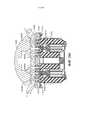
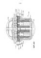
На ФИГ. 15 представлен вид в сечении концевого рабочего органа, поддерживающего кассету со скобками.In FIG. 15 is a sectional view of an end tool supporting the cassette with brackets.
На ФИГ. 16 представлен вид в сечении части удлиненного желоба концевого рабочего органа, представленного на ФИГ. 15, после извлечения из него части корпуса имплантируемой кассеты со скобками и скобок.In FIG. 16 is a sectional view of a portion of an elongated trough of an end tool member shown in FIG. 15, after removing from it parts of the body of the implantable cassette with brackets and brackets.
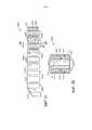
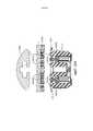
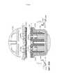
На ФИГ. 17 представлен вид в сечении концевого рабочего органа, поддерживающего другую кассету со скобками.In FIG. 17 is a cross-sectional view of an end tool body supporting another cassette with brackets.
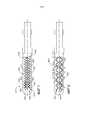
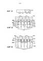
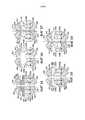
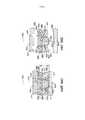
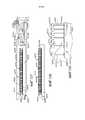
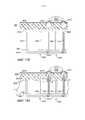
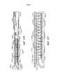
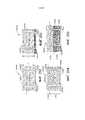
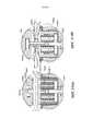
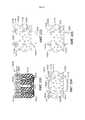
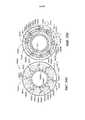
На ФИГ. 18A-18D представлена схема деформации хирургической скобки, расположенной в корпусе сминаемой кассеты со скобками в соответствии по меньшей мере с одним вариантом осуществления.In FIG. 18A-18D illustrate a deformation diagram of a surgical brace located in a case of a crushable cassette with brackets in accordance with at least one embodiment.
На ФИГ. 19A представлена схема, показывающая скобку, расположенную в корпусе сминаемой кассеты со скобками.In FIG. 19A is a diagram showing a bracket located in a case of a crushable cassette with brackets.
На ФИГ. 19B представлена схема, иллюстрирующая процесс сминания корпуса сминаемой кассеты со скобками, представленной на ФИГ. 19A, упором.In FIG. 19B is a diagram illustrating a process of creasing a crumple cassette body with brackets shown in FIG. 19A, focusing.
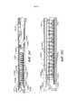
На ФИГ. 19C представлена схема, иллюстрирующая процесс дальнейшего сминания корпуса сминаемой кассеты со скобками, представленной на ФИГ. 19A, упором.In FIG. 19C is a diagram illustrating a process for further creasing the crumpled cassette body with brackets shown in FIG. 19A, focusing.
На ФИГ. 19D представлена схема, иллюстрирующая скобку, представленную на ФИГ. 19A, в полностью сформированной конфигурации, а также сминаемую кассету со скобками, представленную на ФИГ. 19A, в полностью раздавленном состоянии.In FIG. 19D is a diagram illustrating a bracket shown in FIG. 19A, in a fully formed configuration, as well as a collapsible cassette with brackets shown in FIG. 19A, in a completely crushed state.
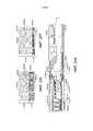
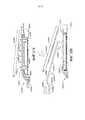
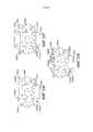
На ФИГ. 20 представлена схема, иллюстрирующая скобку, расположенную напротив опорной поверхности кассеты со скобками, и ее возможное относительное перемещение.In FIG. 20 is a diagram illustrating a bracket located opposite the supporting surface of the cassette with brackets, and its possible relative movement.
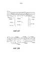
На ФИГ. 21 представлен вид в сечении опорной поверхности кассеты со скобками, содержащей паз, или желобок, выполненный с возможностью стабилизации основания скобки, представленной на ФИГ. 20.In FIG. 21 is a sectional view of the supporting surface of the cartridge with brackets containing a groove or groove configured to stabilize the base of the bracket shown in FIG. twenty.
На ФИГ. 22 представлен вид в сечении скобки, содержащей заформованную головку и паз, или желобок, выполненный с возможностью приема части головки в соответствии по меньшей мере с одним альтернативным вариантом осуществления.In FIG. 22 is a sectional view of a bracket containing a molded head and a groove or groove configured to receive a portion of the head in accordance with at least one alternative embodiment.
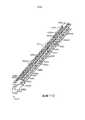
На ФИГ. 23 представлен вид сверху кассеты со скобками в соответствии по меньшей мере с одним вариантом осуществления, содержащей скобки, помещенные в корпус сминаемой кассеты со скобками.In FIG. 23 is a plan view of a cassette with brackets in accordance with at least one embodiment comprising brackets placed in a casing of the crumpled cassette with brackets.
На ФИГ. 24 представлен вид в вертикальной проекции кассеты со скобками, представленной на ФИГ. 23.In FIG. 24 is a perspective view of a cassette with brackets shown in FIG. 23.
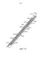
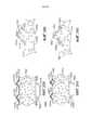
На ФИГ. 25 представлен вид в вертикальной проекции кассеты со скобками в соответствии по меньшей мере с одним вариантом осуществления, содержащего защитный слой, окружающий скобки, расположенные в корпусе сминаемой кассеты со скобками.In FIG. 25 is a perspective view of a cassette with brackets in accordance with at least one embodiment comprising a protective layer surrounding the brackets located in the body of the crush cassette with brackets.
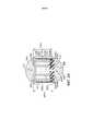
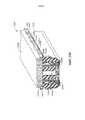
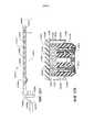
На ФИГ. 26 представлен вид в сечении кассеты со скобками, представленной на ФИГ. 25, вдоль линии 26-26, обозначенной на ФИГ. 25.In FIG. 26 is a sectional view of the cassette with brackets shown in FIG. 25 along line 26-26 shown in FIG. 25.
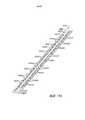
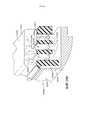
На ФИГ. 27 представлен вид в вертикальной проекции кассеты со скобками в соответствии по меньшей мере с одним вариантом осуществления, содержащего скобки, которые по меньшей мере частично продолжаются за пределы корпуса сминаемой кассеты со скобками и защитного слоя, окружающего корпус кассеты со скобками.In FIG. 27 is a perspective view of a cassette with brackets in accordance with at least one embodiment comprising brackets that extend at least partially outside the casing of the crumpled cassette with brackets and a protective layer surrounding the cassette with brackets.
На ФИГ. 28 представлен вид в сечении кассеты со скобками, представленной на ФИГ. 27, вдоль линии 28-28, обозначенной на ФИГ. 27.In FIG. 28 is a sectional view of the cassette with brackets shown in FIG. 27 along line 28-28 shown in FIG. 27.
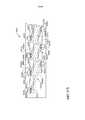
На ФИГ. 29 представлен частичный вид в сечении кассеты со скобками в соответствии по меньшей мере с одним вариантом осуществления, содержащей скобки, по меньшей мере частично помещенные в корпус сминаемой кассеты со скобками, причем скобки по меньшей мере частично расположены в пустотах полостей скобок в корпусе кассеты со скобками.In FIG. 29 is a partial sectional view of a cassette with brackets in accordance with at least one embodiment comprising brackets at least partially placed in a cassette cassette with brackets, the brackets at least partially located in the voids of the brackets in the cassette with brackets .
На ФИГ. 30 представлен вид в сечении кассеты со скобками, представленной на ФИГ. 29, вдоль линии 30-30, обозначенной на ФИГ. 29.In FIG. 30 is a sectional view of the cassette with brackets shown in FIG. 29, along the line 30-30 indicated in FIG. 29.
На ФИГ. 31 представлен частичный вид в сечении кассеты со скобками в соответствии по меньшей мере с одним вариантом осуществления.In FIG. 31 is a partial sectional view of a cassette with brackets in accordance with at least one embodiment.
На ФИГ. 32 представлен частичный вид в сечении кассеты со скобками в соответствии по меньшей мере с одним вариантом осуществления, содержащего скобки, по меньшей мере частично помещенные в корпус сминаемой кассеты со скобками, и выравнивающую матрицу, соединяющую скобки и выравнивающую скобки относительно друг друга.In FIG. 32 is a partial cross-sectional view of a cassette with brackets in accordance with at least one embodiment, comprising brackets at least partially placed in a cassette cassette with brackets, and an alignment matrix connecting the brackets and the alignment brackets with respect to each other.
На ФИГ. 33 представлен вид в сечении кассеты со скобками, представленной на ФИГ. 32, вдоль линии 33-33, обозначенной на ФИГ. 32.In FIG. 33 is a sectional view of the cassette with brackets shown in FIG. 32 along the line 33-33 indicated in FIG. 32.
На ФИГ. 34 представлен частичный вид в частичном разрезе внутреннего слоя корпуса сжимаемой кассеты со скобками.In FIG. 34 is a partial partial cross-sectional view of the inner layer of the body of a compressible cartridge with brackets.
На ФИГ. 35 представлена схема, иллюстрирующая внутренний слой, представленный на ФИГ. 34, сжатый между передаточной пластиной и опорной пластиной.In FIG. 35 is a diagram illustrating an inner layer shown in FIG. 34, compressed between the transfer plate and the support plate.
На ФИГ. 36 представлена схема, иллюстрирующая скобки, вложенные в сжатый внутренний слой, представленный на ФИГ. 35.In FIG. 36 is a diagram illustrating brackets embedded in a compressed inner layer shown in FIG. 35.
На ФИГ. 37 представлена схема опорной пластины, представленной на ФИГ. 35, в процессе отделения от внутреннего слоя.In FIG. 37 is a schematic diagram of a support plate shown in FIG. 35, in the process of separation from the inner layer.
На ФИГ. 38 представлена схема подузла, содержащего внутренний слой, представленный на ФИГ. 34, и скобки, представленные на ФИГ. 36, в процессе вкладывания во внешний слой.In FIG. 38 is a diagram of a subassembly containing an inner layer shown in FIG. 34, and the brackets shown in FIG. 36 during insertion into the outer layer.
На ФИГ. 39 представлена схема, иллюстрирующая процесс герметизации внешнего слоя, представленного на ФИГ. 38, для образования герметичной кассеты со скобками.In FIG. 39 is a diagram illustrating the sealing process of the outer layer shown in FIG. 38 to form a sealed cassette with brackets.
На ФИГ. 40 представлен вид в сечении герметичной кассеты со скобками, представленной на ФИГ. 39.In FIG. 40 is a sectional view of a sealed cassette with brackets shown in FIG. 39.
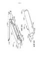
На ФИГ. 41 представлен вид в сечении кассеты со скобками и желоба для кассеты со скобками в соответствии по меньшей мере с одним вариантом осуществления.In FIG. 41 is a sectional view of a cassette with brackets and a groove for a cassette with brackets in accordance with at least one embodiment.
На ФИГ. 42 представлена схема, иллюстрирующая часть кассеты со скобками, представленной на ФИГ. 41, в деформированном состоянии.In FIG. 42 is a diagram illustrating a portion of the cassette with brackets shown in FIG. 41, in a deformed state.
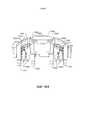
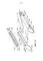
На ФИГ. 43 представлен вид в вертикальной проекции концевого рабочего органа хирургического сшивающего аппарата, содержащего упор в открытом положении и кассету со скобками, расположенную в желобе для кассеты со скобками.In FIG. 43 is a perspective view of an end member of a surgical stapler containing an emphasis in an open position and a cassette with brackets located in a groove for the cassette with brackets.
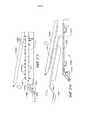
На ФИГ. 44 представлен вид в вертикальной проекции концевого рабочего органа, представленного на ФИГ. 43, иллюстрирующий упор в закрытом положении и кассету со скобками, зажатую между упором и желобом кассеты со скобками.In FIG. 44 is a perspective view of an end working member shown in FIG. 43 illustrating the stop in the closed position and the cassette with brackets sandwiched between the stop and the groove of the cassette with brackets.
На ФИГ. 45 представлен вид в вертикальной проекции концевого рабочего органа, представленного на ФИГ. 43, иллюстрирующий кассету со скобками, представленную на ФИГ. 43, расположенную альтернативным способом в желобе кассеты со скобками.In FIG. 45 is a perspective view of an end working member shown in FIG. 43 illustrating a cassette with brackets shown in FIG. 43, located alternatively in the groove of the cassette with brackets.
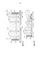
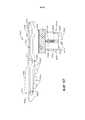
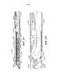
На ФИГ. 46 представлен вид в сечении концевого рабочего органа хирургического сшивающего аппарата, содержащего сжимаемую кассету со скобками, расположенную в желобе кассеты со скобками, и фрагмент поддерживающего материала, присоединенного к упору.In FIG. 46 is a sectional view of an end member of a surgical stapler comprising a compressible cassette with brackets located in the groove of the cassette with brackets and a fragment of supporting material attached to the stop.
На ФИГ. 47 представлен вид в сечении концевого эффектора, представленного на ФИГ. 46, иллюстрирующий упор в закрытом положении.In FIG. 47 is a sectional view of an end effector shown in FIG. 46 illustrating a stop in a closed position.
На ФИГ. 48 представлен вид в сечении альтернативного варианта осуществления концевого рабочего органа хирургического сшивающего аппарата, содержащего кассету со скобками, содержащую водонепроницаемый слой.In FIG. 48 is a cross-sectional view of an alternative embodiment of a terminal member of a surgical stapler containing a cassette with brackets containing a waterproof layer.
На ФИГ. 49 представлен вид в сечении другого альтернативного варианта осуществления концевого рабочего органа хирургического сшивающего аппарата.In FIG. 49 is a cross-sectional view of another alternative embodiment of an end member of a surgical stapler.
На ФИГ. 50 представлен вид в сечении альтернативного варианта осуществления концевого рабочего органа хирургического сшивающего аппарата, содержащего ступенчатый упор и кассету со скобками, содержащую ступенчатый корпус кассеты.In FIG. 50 is a cross-sectional view of an alternative embodiment of a terminal member of a surgical stapler comprising a stepped stop and a cassette with brackets comprising a staged cassette body.
На ФИГ. 51 представлен вид в сечении другого альтернативного варианта осуществления концевого рабочего органа хирургического сшивающего инструмента.In FIG. 51 is a cross-sectional view of another alternative embodiment of an end working body of a surgical stapling instrument.
На ФИГ. 52 представлен вид в сечении альтернативного варианта осуществления концевого рабочего органа хирургического сшивающего аппарата, содержащего наклонные, контактирующие с тканью поверхности.In FIG. 52 is a cross-sectional view of an alternative embodiment of an end working member of a surgical stapler comprising inclined, tissue-contacting surfaces.
На ФИГ. 53 представлен вид в сечении другого альтернативного варианта осуществления концевого рабочего органа хирургического сшивающего инструмента, содержащего наклонные, контактирующие с тканью поверхности.In FIG. 53 is a cross-sectional view of another alternative embodiment of an end working body of a surgical stapling instrument comprising inclined, tissue-contacting surfaces.
На ФИГ. 54 представлен вид в сечении альтернативного варианта осуществления концевого рабочего органа хирургического сшивающего аппарата, содержащего опорную вставку, выполненную с возможностью поддерживания кассеты со скобками.In FIG. 54 is a cross-sectional view of an alternative embodiment of a terminal member of a surgical stapler comprising a support insert configured to support a cassette with brackets.
На ФИГ. 55 представлен вид в сечении альтернативного варианта осуществления концевого рабочего органа хирургического сшивающего аппарата, содержащего кассету со скобками, содержащую множество сжимаемых слоев.In FIG. 55 is a cross-sectional view of an alternative embodiment of a terminal member of a surgical stapler comprising a cassette with brackets containing a plurality of compressible layers.
На ФИГ. 56 представлен вид в сечении альтернативного варианта осуществления концевого рабочего органа хирургического сшивающего аппарата, содержащего кассету со скобками, содержащую ступенчатый корпус сжимаемого блока.In FIG. 56 is a cross-sectional view of an alternative embodiment of a terminal member of a surgical stapler comprising a cassette with brackets comprising a stepped housing of a compressible block.
На ФИГ. 57 представлен вид в сечении другого альтернативного варианта осуществления концевого рабочего органа хирургического сшивающего аппарата, содержащего кассету со скобками, содержащую ступенчатый корпус сминаемого блока.In FIG. 57 is a cross-sectional view of another alternative embodiment of an end working member of a surgical stapler comprising a cassette with brackets comprising a stepped case of a crush unit.
На ФИГ. 58 представлен вид в сечении альтернативного варианта осуществления концевого рабочего органа хирургического сшивающего аппарата, содержащего кассету со скобками, содержащую изогнутую, контактирующую с тканью поверхность.In FIG. 58 is a cross-sectional view of an alternative embodiment of a terminal member of a surgical stapler comprising a cassette with brackets containing a curved surface in contact with tissue.
На ФИГ. 59 представлен вид в сечении альтернативного варианта осуществления концевого рабочего органа хирургического сшивающего аппарата, содержащего кассету со скобками, имеющую наклонную, контактирующую с тканью поверхность.In FIG. 59 is a cross-sectional view of an alternative embodiment of a terminal member of a surgical stapler comprising a cassette with brackets having an inclined surface in contact with the tissue.
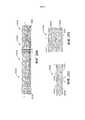
На ФИГ. 60 представлен вид в сечении сминаемой кассеты со скобками, содержащей скобки и по меньшей мере одно хранящееся в нем лекарственное средство.In FIG. 60 is a sectional view of a crushable cassette with brackets containing brackets and at least one drug stored therein.
На ФИГ. 61 представлена схема, иллюстрирующая сминаемую кассету со скобками, представленную на ФИГ. 60, после ее сжатия и деформации содержащихся в ней скобок.In FIG. 61 is a diagram illustrating a crease cassette with brackets shown in FIG. 60, after compression and deformation of the brackets contained therein.
На ФИГ. 62 представлен частичный вид в частичном разрезе кассеты со скобками в соответствии по меньшей мере с одним вариантом осуществления.In FIG. 62 is a partial partial cross-sectional view of a cassette with brackets in accordance with at least one embodiment.
На ФИГ. 63 представлен вид в сечении кассеты со скобками, представленной на ФИГ. 62.In FIG. 63 is a sectional view of a cassette with brackets shown in FIG. 62.
На ФИГ. 64 представлен вид в перспективе имплантированной кассеты со скобками в соответствии по меньшей мере с одним альтернативным вариантом осуществления.In FIG. 64 is a perspective view of an implanted cassette with brackets in accordance with at least one alternative embodiment.
На ФИГ. 65 представлен вид в сечении имплантированной кассеты со скобками, представленной на ФИГ. 64.In FIG. 65 is a sectional view of the implanted cassette with brackets shown in FIG. 64.
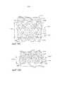
На ФИГ. 66 представлен вид в перспективе альтернативного варианта осуществления кассеты со скобками, содержащей деформируемые элементы, продолжающиеся от внешнего слоя кассеты со скобками.In FIG. 66 is a perspective view of an alternative embodiment of a cassette with brackets containing deformable elements extending from the outer layer of the cassette with brackets.
На ФИГ. 67 представлен вид в перспективе альтернативного варианта осуществления кассеты со скобками, содержащей внешний слой кассеты со скобками, прикрепленный к внутреннему слою.In FIG. 67 is a perspective view of an alternative embodiment of a cassette with brackets comprising an outer layer of a cassette with brackets attached to the inner layer.
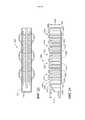
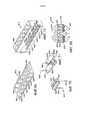
На ФИГ. 68 представлен вид в сечении альтернативного варианта осуществления кассеты со скобками, содержащей множество скобок, сжимаемый слой и слой прокладок.In FIG. 68 is a sectional view of an alternative embodiment of a cassette with brackets comprising a plurality of brackets, a compressible layer and a layer of gaskets.
На ФИГ. 69 представлен вид в перспективе слоя прокладок, представленного на ФИГ. 68.In FIG. 69 is a perspective view of the gasket layer of FIG. 68.
На ФИГ. 70 представлен вид в перспективе прокладки, отделенной от слоя прокладки, представленного на ФИГ. 68, и скобки, выровненной с канавкой в прокладке.In FIG. 70 is a perspective view of a gasket separated from the gasket layer of FIG. 68, and brackets aligned with a groove in the gasket.
На ФИГ. 71 представлен вид в перспективе двух соединенных друг с другом прокладок из слоя прокладки, представленного на ФИГ. 68.In FIG. 71 is a perspective view of two interconnected gaskets from the gasket layer of FIG. 68.
На ФИГ. 72 представлен вид в перспективе опорной рамы для прокладки слоя прокладок, представленного на ФИГ. 68, которую снимают с отделенных прокладок.In FIG. 72 is a perspective view of a support frame for laying the gasket layer shown in FIG. 68, which is removed from the separated gaskets.
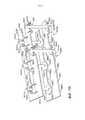
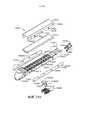
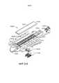
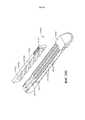
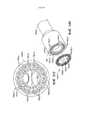
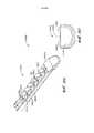
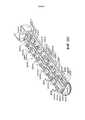
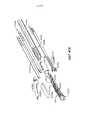
На ФИГ. 73 представлен вид в перспективе с пространственным разделением компонентов альтернативного варианта осуществления сминаемой кассеты со скобками, содержащего скобки и систему продвижения скобок вплотную к упору.In FIG. 73 is a perspective view with a spatial separation of the components of an alternative embodiment of a crushable cassette with brackets containing brackets and a bracket advancement system close to the stop.
На ФИГ. 73A представлен частичный вид в частичном разрезе альтернативного варианта осуществления кассеты со скобками, представленной на ФИГ. 73.In FIG. 73A is a partial partial cross-sectional view of an alternative embodiment of the cassette with brackets shown in FIG. 73.
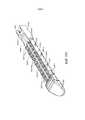
На ФИГ. 74 представлен вид в сечении кассеты со скобками, представленной на ФИГ. 73.In FIG. 74 is a sectional view of the cassette with brackets shown in FIG. 73.
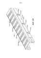
На ФИГ. 75 представлен вид в вертикальной проекции салазок, выполненных с возможностью передвижения по кассете со скобками, представленной на ФИГ. 73, и перемещения скобок в направлении упора.In FIG. 75 is a perspective view of a slide arranged to move around a cassette with brackets shown in FIG. 73, and moving the brackets in the direction of the stop.
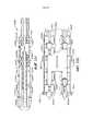
На ФИГ. 76 представлена схема толкателя скобок, который может быть поднят к упору салазками, представленными на ФИГ. 75.In FIG. 76 is a diagram of a pusher of brackets that can be lifted against the stop by the slide provided in FIG. 75.
На ФИГ. 77 представлен частичный вид в сечении кассеты со скобками в соответствии по меньшей мере с одним альтернативным вариантом осуществления, содержащего скобки, расположенные в толкателях скобок.In FIG. 77 is a partial cross-sectional view of a cassette with brackets in accordance with at least one alternative embodiment comprising brackets located in the pushers of the brackets.
На ФИГ. 78 представлен вид в сечении кассеты со скобками, представленной на ФИГ. 77, расположенной в желобе кассеты со скобками.In FIG. 78 is a sectional view of a cassette with brackets shown in FIG. 77 located in the groove of the cassette with brackets.
На ФИГ. 79 представлен вид в сечении кассеты со скобками, представленной на ФИГ. 77, иллюстрирующий упор, перемещенный в закрытое положение, и скобки, находящиеся в кассете со скобками, деформированной упором.In FIG. 79 is a sectional view of a cassette with brackets shown in FIG. 77, illustrating the emphasis moved to the closed position and the brackets in the cassette with brackets deformed by the emphasis.
На ФИГ. 80 представлен вид в сечении кассеты со скобками, представленной на ФИГ. 77, иллюстрирующий скобки, перемещенные вверх в направлении упора.In FIG. 80 is a sectional view of a cassette with brackets shown in FIG. 77 illustrating brackets moved up in the direction of the stop.
На ФИГ. 81 представлен вид в перспективе альтернативного варианта осуществления кассеты со скобками, содержащей перемычки, соединяющие гибкие боковые стенки кассеты со скобками.In FIG. 81 is a perspective view of an alternative embodiment of a cassette with brackets containing jumpers connecting the flexible side walls of the cassette with brackets.
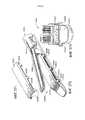
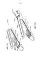
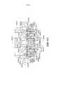
На ФИГ. 82 представлен вид в перспективе узла салазок и режущего элемента.In FIG. 82 is a perspective view of a slide assembly and a cutting member.
На ФИГ. 83 представлена схема узла салазок и режущего элемента, представленного на ФИГ. 82, который используют для поднятия скобок из кассеты со скобками, представленной на ФИГ. 77.In FIG. 83 is a schematic diagram of a slide assembly and a cutting member shown in FIG. 82, which is used to raise the brackets from the cassette with brackets shown in FIG. 77.
На ФИГ. 84 представлена схема, иллюстрирующая салазки, выполненные с возможностью входа в зацепление со скобками и подъема скобок к упору, а также систему блокировки, выполненную с возможностью избирательно обеспечивать дистальное перемещение салазок.In FIG. 84 is a diagram illustrating a slide configured to engage with brackets and raise the brackets to the stop, as well as a locking system configured to selectively provide distal movement of the slide.
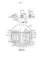
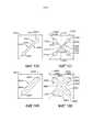
На ФИГ. 85A-85C представлена последовательность стадий процесса вкладывания скобки в головку скобки.In FIG. 85A-85C show a sequence of steps for inserting a bracket into a bracket head.
На ФИГ. 86 представлен вид в сечении кассеты со скобками, содержащей опорный лоток или держатель.In FIG. 86 is a sectional view of a cassette with brackets containing a support tray or holder.
На ФИГ. 87 представлен частичный вид в сечении сминаемой кассеты со скобками в соответствии по меньшей мере с одним альтернативным вариантом осуществления.In FIG. 87 is a partial cross-sectional view of a crushable cassette with brackets in accordance with at least one alternative embodiment.
На ФИГ. 88 представлена схема, иллюстрирующая кассету со скобками, представленную на ФИГ. 87, в имплантированном состоянии.In FIG. 88 is a diagram illustrating a cassette with brackets shown in FIG. 87, in an implanted state.
На ФИГ. 89 представлен частичный вид в частичном разрезе сминаемой кассеты со скобками в соответствии по меньшей мере с одним альтернативным вариантом осуществления.In FIG. 89 is a partial partial cross-sectional view of a crushable cassette with brackets in accordance with at least one alternative embodiment.
На ФИГ. 90 представлен частичный вид в сечении кассеты со скобками, представленной на ФИГ. 89.In FIG. 90 is a partial sectional view of the cassette with brackets shown in FIG. 89.
На ФИГ. 91 представлена схема, иллюстрирующая кассету со скобками, представленную на ФИГ. 89, в имплантированном состоянии.In FIG. 91 is a diagram illustrating a cassette with brackets shown in FIG. 89, in the implanted state.
На ФИГ. 92 представлен частичный вид в сечении сминаемой кассеты со скобками в соответствии по меньшей мере с одним альтернативным вариантом осуществления.In FIG. 92 is a partial cross-sectional view of a crushable cassette with brackets in accordance with at least one alternative embodiment.
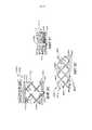
На ФИГ. 93 представлен частичный вид в частичном разрезе сминаемой кассеты со скобками в соответствии по меньшей мере с одним вариантом осуществления, содержащего множество сминаемых элементов.In FIG. 93 is a partial partial cross-sectional view of a crease cartridge with brackets according to at least one embodiment comprising a plurality of crease elements.
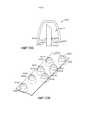
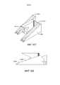
На ФИГ. 94 представлен вид в перспективе сминаемого элемента, представленного на ФИГ. 93, в несмятом состоянии.In FIG. 94 is a perspective view of a crease member shown in FIG. 93, in an unregulated state.
На ФИГ. 95 представлен вид в перспективе сминаемого элемента, представленного на ФИГ. 94, в смятом состоянии.In FIG. 95 is a perspective view of a crease member shown in FIG. 94, in a crumpled state.
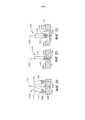
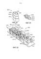
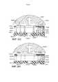
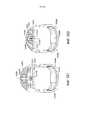
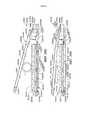
На ФИГ. 96A представлен частичный вид в сечении концевого рабочего органа хирургического сшивающего аппарата, содержащего браншу, расположенный напротив бранши желоб кассеты со скобками и кассету, расположенную в желобе кассеты со скобками, причем бранша содержит присоединенную к ней удерживающую матрицу.In FIG. 96A is a partial sectional view of an end member of a surgical stapler containing a jaw located opposite the jaw of the cassette groove with brackets and a cassette located in the groove of the cassette with brackets, the jaw containing a holding matrix attached to it.
На ФИГ. 96B представлен частичный вид в сечении концевого рабочего органа, представленного на ФИГ. 96A, иллюстрирующий браншу, перемещаемую к желобу кассеты со скобками, причем кассета сжимается упором и удерживающей матрицей, а скобка по меньшей мере частично проходит через ткань, расположенную между удерживающей матрицей и кассетой со скобками.In FIG. 96B is a partial cross-sectional view of an end tool body shown in FIG. 96A, illustrating the jaw moved to the gutter of the cassette with brackets, the cassette being compressed by the stop and the holding matrix, and the bracket is at least partially passing through the fabric located between the holding matrix and the cassette with brackets.
На ФИГ. 96C представлен частичный вид в сечении концевого рабочего органа, представленного на ФИГ. 96A, иллюстрирующий браншу в конечном положении и удерживающую матрицу в зацеплении со скобкой, представленной на ФИГ. 96B.In FIG. 96C is a partial cross-sectional view of the end working member shown in FIG. 96A illustrating the jaw in the final position and holding the matrix in mesh with the bracket shown in FIG. 96B.
На ФИГ. 96D представлен частичный вид в сечении концевого рабочего органа, представленного на ФИГ. 96A, иллюстрирующий браншу и желоб кассеты со скобками, перемещаемые от имплантированной кассеты со скобками и удерживающей матрицы.In FIG. 96D is a partial cross-sectional view of an end tool body shown in FIG. 96A illustrating the jaw and gutter of a cassette with brackets moved from an implanted cassette with brackets and a holding matrix.
На ФИГ. 97 представлен вид в перспективе удерживающего отверстия удерживающей матрицы в соответствии по меньшей мере с одним альтернативным вариантом осуществления, которое содержит множество удерживающих элементов, выполненных с возможностью зацепления с проходящей через них ножкой сшивающего элемента.In FIG. 97 is a perspective view of a holding hole of a holding matrix in accordance with at least one alternative embodiment, which comprises a plurality of holding elements configured to engage with a leg of a stapling element passing through them.
На ФИГ. 98 представлен вид в перспективе удерживающего отверстия удерживающей матрицы в соответствии по меньшей мере с одним альтернативным вариантом осуществления, содержащего шесть удерживающих элементов.In FIG. 98 is a perspective view of a holding hole of a holding matrix in accordance with at least one alternative embodiment comprising six holding elements.
На ФИГ. 99 представлен вид в перспективе удерживающего отверстия удерживающей матрицы в соответствии по меньшей мере с одним альтернативным вариантом осуществления, содержащего восемь удерживающих элементов.In FIG. 99 is a perspective view of a holding hole of a holding matrix in accordance with at least one alternative embodiment comprising eight holding elements.
На ФИГ. 100 представлен вид в перспективе удерживающего отверстия удерживающей матрицы в соответствии по меньшей мере с одним альтернативным вариантом осуществления, содержащего множество удерживающих элементов, выполненных с возможностью входа в зацепление с проходящей через них ножкой сшивающего элемента.In FIG. 100 is a perspective view of a holding hole of a holding matrix in accordance with at least one alternative embodiment comprising a plurality of holding elements configured to engage with a leg of a stapling element passing through them.
На ФИГ. 101 представлен вид в перспективе удерживающего отверстия удерживающей матрицы в соответствии по меньшей мере с одним альтернативным вариантом осуществления, содержащего шесть удерживающих элементов.In FIG. 101 is a perspective view of a holding hole of a holding matrix in accordance with at least one alternative embodiment comprising six holding elements.
На ФИГ. 102 представлен вид в перспективе удерживающего отверстия удерживающей матрицы в соответствии по меньшей мере с одним альтернативным вариантом осуществления, содержащего восемь удерживающих элементов.In FIG. 102 is a perspective view of a holding hole of a holding matrix in accordance with at least one alternative embodiment comprising eight holding elements.
На ФИГ. 103 представлен вид в перспективе удерживающего отверстия удерживающей матрицы в соответствии по меньшей мере с одним альтернативным вариантом осуществления, содержащего множество удерживающих элементов, изготовленных штамповкой из листа металла.In FIG. 103 is a perspective view of a holding hole of a holding matrix in accordance with at least one alternative embodiment comprising a plurality of holding elements made by stamping from a metal sheet.
На ФИГ. 104 представлен вид в перспективе удерживающего отверстия удерживающей матрицы в соответствии по меньшей мере с одним альтернативным вариантом осуществления, содержащего множество отверстий, проходящих по периметру удерживающего отверстия.In FIG. 104 is a perspective view of a holding hole of a holding matrix in accordance with at least one alternative embodiment comprising a plurality of holes extending around the perimeter of the holding hole.
На ФИГ. 105 представлен вид сверху удерживающего отверстия удерживающей матрицы в соответствии по меньшей мере с одним альтернативным вариантом осуществления.In FIG. 105 is a plan view of a holding hole of a holding matrix in accordance with at least one alternative embodiment.
На ФИГ. 106 представлен вид сверху удерживающего отверстия удерживающей матрицы в соответствии по меньшей мере с одним альтернативным вариантом осуществления.In FIG. 106 is a plan view of a holding hole of a holding matrix in accordance with at least one alternative embodiment.
На ФИГ. 107 представлен вид сверху удерживающего отверстия удерживающей матрицы в соответствии по меньшей мере с одним альтернативным вариантом осуществления.In FIG. 107 is a plan view of a holding hole of a holding matrix in accordance with at least one alternative embodiment.
На ФИГ. 108 представлен вид сверху удерживающего отверстия удерживающей матрицы в соответствии по меньшей мере с одним альтернативным вариантом осуществления.In FIG. 108 is a plan view of a holding hole of a holding matrix in accordance with at least one alternative embodiment.
На ФИГ. 109 представлен вид сверху удерживающего отверстия удерживающей матрицы в соответствии по меньшей мере с одним альтернативным вариантом осуществления.In FIG. 109 is a plan view of a holding hole of a holding matrix in accordance with at least one alternative embodiment.
На ФИГ. 110 представлен вид сверху удерживающего отверстия удерживающей матрицы, содержащего удерживающий язычок, проходящий в удерживающее отверстие, в соответствии по меньшей мере с одним вариантом осуществления.In FIG. 110 is a plan view of a holding hole of a holding matrix comprising a holding tab extending into the holding hole in accordance with at least one embodiment.
На ФИГ. 111 представлен вид сверху удерживающего отверстия удерживающей матрицы, содержащего удерживающий язычок, проходящий в удерживающее отверстие, в соответствии по меньшей мере с одним альтернативным вариантом осуществления.In FIG. 111 is a plan view of a holding hole of a holding matrix comprising a holding tab extending into the holding hole in accordance with at least one alternative embodiment.
На ФИГ. 112 представлен вид в перспективе сшивающей системы, содержащей множество скобок, удерживающую матрицу, находящуюся в зацеплении со скобками, и выравнивающую матрицу, выполненную с возможностью выравнивания скобок.In FIG. 112 is a perspective view of a crosslinking system comprising a plurality of brackets, a holding matrix engaged with the brackets, and an alignment matrix configured to align the brackets.
На ФИГ. 113 представлен вид в перспективе удерживающей матрицы, представленной на ФИГ. 112.In FIG. 113 is a perspective view of a holding matrix shown in FIG. 112.
На ФИГ. 114 представлен вид в перспективе выравнивающей матрицы, представленной на ФИГ. 112.In FIG. 114 is a perspective view of the alignment matrix shown in FIG. 112.
На ФИГ. 115 представлен частичный вид сверху удерживающей матрицы, представленной на ФИГ. 112, в зацеплении со скобками, представленными на ФИГ. 112.In FIG. 115 is a partial top view of a retaining matrix shown in FIG. 112, engaged with the brackets shown in FIG. 112.
На ФИГ. 116 представлен частичный вид снизу удерживающей матрицы, представленной на ФИГ. 112, в зацеплении со скобками, представленными на ФИГ. 112.In FIG. 116 is a partial bottom view of a holding matrix shown in FIG. 112, engaged with the brackets shown in FIG. 112.
На ФИГ. 117 представлен частичный вид в вертикальной проекции сшивающей системы, представленной на ФИГ. 112.In FIG. 117 is a partial elevational view of the crosslinking system shown in FIG. 112.
На ФИГ. 118 представлен частичный вид в перспективе сшивающей системы, представленной на ФИГ. 112.In FIG. 118 is a partial perspective view of the crosslinking system shown in FIG. 112.
На ФИГ. 119 представлен частичный вид в сечении удерживающей матрицы, представленной на ФИГ. 112, в зацеплении со скобками, представленными на ФИГ. 112.In FIG. 119 is a partial cross-sectional view of a holding matrix shown in FIG. 112, engaged with the brackets shown in FIG. 112.
На ФИГ. 120 представлен частичный вид в сечении сшивающей системы, представленной на ФИГ. 112.In FIG. 120 is a partial cross-sectional view of the crosslinking system of FIG. 112.
На ФИГ. 121 представлен вид в перспективе сшивающей системы, представленной на ФИГ. 112, дополнительно содержащей защитные колпачки, установленные на ножки скобок.In FIG. 121 is a perspective view of a crosslinking system shown in FIG. 112, further comprising protective caps mounted on the legs of the brackets.
На ФИГ. 122 представлен вид в перспективе снизу конструкции сшивающей системы, представленной на ФИГ. 121.In FIG. 122 is a perspective view from below of the structure of the crosslinking system shown in FIG. 121.
На ФИГ. 123 представлен частичный вид в перспективе конструкции сшивающей системы, представленной на ФИГ. 121.In FIG. 123 is a partial perspective view of the structure of the crosslinking system shown in FIG. 121.
На ФИГ. 124 представлен частичный вид в сечении конструкции сшивающей системы, представленной на ФИГ. 121.In FIG. 124 is a partial cross-sectional view of the structure of the crosslinking system shown in FIG. 121.
На ФИГ. 125 представлен вид в вертикальной проекции концевого рабочего органа в соответствии по меньшей мере с одним вариантом осуществления, содержащего браншу в открытом положении, удерживающую матрицу и множество защитных колпачков, расположенных в бранше, а также кассету со скобками, расположенную в желобе кассеты со скобками.In FIG. 125 is a perspective view of an end tool according to at least one embodiment comprising a jaw in an open position, a holding matrix and a plurality of protective caps located in a jaw, as well as a cassette with brackets located in the groove of the cassette with brackets.
На ФИГ. 126 представлен вид в вертикальной проекции концевого рабочего органа, представленного на ФИГ. 125, в закрытом положении.In FIG. 126 presents a view in vertical projection of the end of the working body shown in FIG. 125, in the closed position.
На ФИГ. 127 представлен вид в вертикальной проекции концевого рабочего органа, представленного на ФИГ. 125, в положении срабатывания.In FIG. 127 is a perspective view of an end working member shown in FIG. 125, in the actuation position.
На ФИГ. 128 представлен вид в вертикальной проекции удерживающей матрицы и защитных колпачков, представленных на ФИГ. 125, установленных на кассету со скобками, представленную на ФИГ. 125.In FIG. 128 is a perspective view of a holding matrix and protective caps shown in FIG. 125 mounted on the cassette with brackets shown in FIG. 125.
На ФИГ. 129 представлен подробный вид конструкции, представленной на ФИГ. 128.In FIG. 129 is a detailed view of the structure shown in FIG. 128.
На ФИГ. 130 представлен вид в вертикальной проекции концевого рабочего органа, представленного на ФИГ. 125, иллюстрирующий браншу в открытом положении с более тонкой тканью, расположенной между удерживающей матрицей и кассетой со скобками.In FIG. 130 is a perspective view of an end tool member shown in FIG. 125, illustrating the jaw in the open position with a thinner tissue located between the holding matrix and the cassette with brackets.
На ФИГ. 131 представлен вид в вертикальной проекции концевого рабочего органа, представленного на ФИГ. 125, иллюстрирующий браншу в закрытом положении вплотную к более тонкой ткани, представленной на ФИГ. 130.In FIG. 131 presents a view in vertical projection of the end of the working body shown in FIG. 125, illustrating the jaw in the closed position close to the thinner fabric shown in FIG. 130.
На ФИГ. 132 представлен вид в вертикальной проекции концевого рабочего органа, представленного на ФИГ. 125, иллюстрирующий браншу в положении срабатывания для захвата более тонкой ткани, представленной на ФИГ. 130, между удерживающей матрицей и кассетой со скобками.In FIG. 132 presents a view in vertical projection of the end of the working body shown in FIG. 125, illustrating the jaw in the actuation position for gripping the thinner tissue shown in FIG. 130, between the holding matrix and the cassette with brackets.
На ФИГ. 133 представлен вид в вертикальной проекции удерживающей матрицы и защитных колпачков, представленных на ФИГ. 125, установленных на кассете со скобками, представленной на ФИГ. 125, с размещенной между ними тонкой тканью, представленной на ФИГ. 130.In FIG. 133 is a perspective view of the holding matrix and the protective caps shown in FIG. 125 mounted on a cassette with brackets shown in FIG. 125, with the thin fabric interposed between them, shown in FIG. 130.
На ФИГ. 134 представлен подробный вид конструкции, представленной на ФИГ. 133.In FIG. 134 is a detailed view of the structure shown in FIG. 133.
На ФИГ. 135 представлен вид в сечении защитного колпачка, расположенного на наконечнике ножки скобки в соответствии по меньшей мере с одним альтернативным вариантом осуществления.In FIG. 135 is a cross-sectional view of a protective cap located on the tip of a bracket leg in accordance with at least one alternative embodiment.
На ФИГ. 136 представлен вид в перспективе множества защитных колпачков, помещенных в лист материала.In FIG. 136 is a perspective view of a plurality of protective caps placed on a sheet of material.
На ФИГ. 137 представлен вид в перспективе бранши, содержащей множество выемок, выполненных с возможностью приема множества защитных колпачков.In FIG. 137 is a perspective view of a jaw containing a plurality of recesses configured to receive a plurality of protective caps.
На ФИГ. 138 представлен подробный вид части бранши, содержащей лист, покрывающий защитные колпачки, расположенные в бранше, представленной на ФИГ. 137.In FIG. 138 is a detailed view of a portion of a jaw containing a sheet covering the protective caps located in the jaw shown in FIG. 137.
На ФИГ. 139 представлен вид в сечении защитного колпачка, расположенного на наконечнике ножки скобки в соответствии по меньшей мере с одним альтернативным вариантом осуществления, в котором защитный колпачок содержит внутреннюю формирующую поверхность.In FIG. 139 is a cross-sectional view of a protective cap located on the tip of a bracket leg in accordance with at least one alternative embodiment, in which the protective cap comprises an inner forming surface.
На ФИГ. 140 представлен другой вид в сечении защитного колпачка, представленного на ФИГ. 139, иллюстрирующий ножку скобки, которая деформируется о формирующую поверхность.In FIG. 140 is another cross-sectional view of the protective cap shown in FIG. 139 illustrating a bracket leg that deforms against a forming surface.
На ФИГ. 141 представлен вид сверху альтернативного варианта осуществления удерживающей матрицы, содержащей множество связанных элементов матрицы.In FIG. 141 is a top view of an alternative embodiment of a holding matrix comprising a plurality of related matrix elements.
На ФИГ. 142 представлен вид сверху альтернативного варианта осуществления удерживающей матрицы, содержащей множество связанных элементов матрицы.In FIG. 142 is a top view of an alternative embodiment of a holding matrix comprising a plurality of related matrix elements.
На ФИГ. 143 представлен вид сверху альтернативного варианта осуществления удерживающей матрицы, содержащей множество связанных элементов матрицы.In FIG. 143 is a plan view of an alternative embodiment of a holding matrix comprising a plurality of related matrix elements.
На ФИГ. 144 представлен вид сверху альтернативного варианта осуществления массива удерживающих матриц, содержащих множество связанных элементов матрицы.In FIG. 144 is a top view of an alternative embodiment of an array of holding matrices containing a plurality of related matrix elements.
На ФИГ. 145 представлен вид сверху альтернативного варианта осуществления удерживающей матрицы, содержащей множество связанных элементов матрицы.In FIG. 145 is a top view of an alternative embodiment of a holding matrix comprising a plurality of related matrix elements.
На ФИГ. 146 представлен частичный вид с пространственным разделением компонентов бранши, содержащей удерживающую матрицу, включающую сжимаемое покрытие.In FIG. 146 is a partial exploded view of the components of a jaw containing a holding matrix including a compressible coating.
На ФИГ. 147 представлен подробный вид удерживающей матрицы, представленной на ФИГ. 146.In FIG. 147 is a detailed view of a holding matrix shown in FIG. 146.
На ФИГ. 148 представлен частичный вид в сечении сшивающей системы, содержащей удерживающую матрицу, включая сжимаемый слой и множество ячеек, герметично закрывающих одно или более лекарственных средств.In FIG. 148 is a partial cross-sectional view of a cross-linking system comprising a retaining matrix, including a compressible layer and a plurality of cells hermetically sealing one or more drugs.
На ФИГ. 149 представлена схема, иллюстрирующая ножки скобки, которые прокололи ячейки, представленные на ФИГ. 148, при входе в зацепление с удерживающей матрицей.In FIG. 149 is a diagram illustrating the brace legs that pierced the cells shown in FIG. 148, when entering meshing with a holding matrix.
На ФИГ. 150 представлен частичный вид в сечении сшивающей системы, содержащей удерживающую матрицу, включая сжимаемый слой.In FIG. 150 is a partial cross-sectional view of a crosslinking system comprising a retaining matrix, including a compressible layer.
На ФИГ. 151 представлен вид в вертикальной проекции узла вкладывания блока со сшивающими элементами, содержащего держатель, первый блок со сшивающими элементами и второй блок со сшивающими элементами.In FIG. 151 is a perspective view of a nesting unit of a block with stapling elements comprising a holder, a first block with stapling elements and a second block with stapling elements.
На ФИГ. 152 представлен вид в вертикальной проекции концевого рабочего органа хирургического сшивающего аппарата, содержащего первую браншу и вторую браншу, причем вторая бранша показана в открытой конфигурации.In FIG. 152 is a perspective view of an end member of a surgical stapler containing a first jaw and a second jaw, the second jaw being shown in an open configuration.
На ФИГ. 153 представлен вид в вертикальной проекции концевого рабочего органа, представленного на ФИГ. 152, иллюстрирующий вторую браншу в закрытой конфигурации и узел вкладывания блока со сшивающими элементами, представленный на ФИГ. 151, используемый для загрузки первого блока в первую браншу и второго блока во вторую браншу.In FIG. 153 is a perspective view of an end tool member shown in FIG. 152, illustrating the second jaw in a closed configuration and the insertion unit of the block with stapling elements shown in FIG. 151 used to load the first block into the first jaw and the second block into the second jaw.
На ФИГ. 154 представлен вид в вертикальной проекции заряженного концевого рабочего органа, представленного на ФИГ. 153, иллюстрирующий узел вкладывания блока, удаленный из концевого рабочего органа, вторую браншу в открытой конфигурации и ткань, размещенную между первой браншей и второй браншей.In FIG. 154 is a perspective view of a charged end working body shown in FIG. 153 illustrating a block insertion unit removed from an end tool, a second jaw in an open configuration, and tissue located between the first jaw and the second jaw.
На ФИГ. 155 представлен вид в вертикальной проекции заряженного концевого рабочего органа, представленного на ФИГ. 154, в приведенной в действие конфигурации.In FIG. 155 presents a view in vertical projection of a charged end working body, presented in FIG. 154, in a powered configuration.
На ФИГ. 156 представлен вид в вертикальной проекции первого блока и второго блока в имплантированном состоянии.In FIG. 156 is a perspective view of the first block and the second block in an implanted state.
На ФИГ. 157 представлен вид в вертикальной проекции концевого рабочего органа, представленного на ФИГ. 152, иллюстрирующий часть первого блока, все еще находящегося в зацеплении с первой браншей в соответствии по меньшей мере с одним вариантом осуществления.In FIG. 157 is a perspective view of an end working member shown in FIG. 152 illustrating a portion of a first block still engaged with a first jaw in accordance with at least one embodiment.
На ФИГ. 158 представлен вид в вертикальной проекции альтернативного варианта осуществления узла вкладывания блока со сшивающими элементами, содержащего держатель, первый блок со сшивающими элементами и второй блок со сшивающими элементами.In FIG. 158 is a perspective view of an alternative embodiment of an insertion unit of a block with stapling elements comprising a holder, a first block with stapling elements, and a second block with stapling elements.
На ФИГ. 159 представлен вид в вертикальной проекции узла вкладывания блока со сшивающими элементами, представленного на ФИГ. 158 и используемого для загрузки первой кассеты в первую браншу концевого рабочего органа и второй кассеты во вторую браншу.In FIG. 159 is a perspective view of a block insertion unit with stapling elements shown in FIG. 158 and used to load the first cartridge into the first jaw of the end tool and the second cartridge into the second jaw.
На ФИГ. 160 представлен вид в сечении заряженного концевого рабочего органа, представленного на ФИГ. 159.In FIG. 160 is a sectional view of a charged end working member shown in FIG. 159.
На ФИГ. 161 представлен вид в перспективе хирургического сшивающего аппарата, содержащего нижнюю браншу и верхнюю браншу в соответствии по меньшей мере с одним вариантом осуществления, в котором удалены некоторые части хирургического сшивающего аппарата.In FIG. 161 is a perspective view of a surgical stapler comprising a lower jaw and an upper jaw in accordance with at least one embodiment in which some parts of the surgical stapler are removed.
На ФИГ. 162 представлен вид в перспективе хирургического сшивающего аппарата, представленного на ФИГ. 161, с удаленной верхней браншей.In FIG. 162 is a perspective view of a surgical stapler shown in FIG. 161, with the upper jaw removed.
На ФИГ. 163 представлен вид в перспективе системы скользящего упора верхней бранши хирургического сшивающего аппарата, представленного на ФИГ. 161, содержащей первый скользящий упор и второй скользящий упор.In FIG. 163 is a perspective view of a sliding stop system of the upper jaw of a surgical stapler shown in FIG. 161 comprising a first sliding stop and a second sliding stop.
На ФИГ. 164 представлен вид с торца системы скользящего упора, представленной на ФИГ. 163.In FIG. 164 is an end view of the sliding stop system shown in FIG. 163.
На ФИГ. 165 представлен вид сверху системы скользящего упора, представленной на ФИГ. 163.In FIG. 165 is a plan view of the sliding stop system shown in FIG. 163.
На ФИГ. 166 представлена схема, иллюстрирующая систему скользящего упора, представленную на ФИГ. 163, в нерабочем состоянии.In FIG. 166 is a diagram illustrating a sliding stop system shown in FIG. 163, inoperative.
На ФИГ. 167 представлена схема, иллюстрирующая первый скользящий упор системы скользящего упора, представленной на ФИГ. 163, в нерабочем положении, а также скобки, расположенные в нижней бранше в не приведенном в действие положении.In FIG. 167 is a diagram illustrating a first sliding stop of the sliding stop system shown in FIG. 163, in the idle position, as well as brackets located in the lower jaw in the un-actuated position.
На ФИГ. 168 представлена схема, иллюстрирующая скобки в нижней бранше в размещенной конфигурации и первый скользящий упор, представленный на ФИГ. 167, выдвигаемый проксимально для деформации первой группы ножек скобок.In FIG. 168 is a diagram illustrating the brackets in the lower jaw in the deployed configuration and the first sliding stop shown in FIG. 167, advanced proximally to deform the first group of brace legs.
На ФИГ. 169 представлена схема, иллюстрирующая первую группу скобок, представленных на ФИГ. 168, деформированных до полностью деформированного состояния.In FIG. 169 is a diagram illustrating a first group of brackets shown in FIG. 168 deformed to a fully deformed state.
На ФИГ. 170 представлена схема, иллюстрирующая второй скользящий упор системы скользящего упора, представленный на ФИГ. 163, выталкиваемый дистально для деформации второй группы ножек скобок.In FIG. 170 is a diagram illustrating a second sliding stop of the sliding stop system shown in FIG. 163 distally pushed to deform the second group of legs of brackets.
На ФИГ. 171 представлен частичный вид в перспективе упора, содержащего множество формирующих углублений по меньшей мере в одном варианте осуществления.In FIG. 171 is a partial perspective view of an abutment comprising a plurality of forming recesses in at least one embodiment.
На ФИГ. 172 представлен вид с торца в сечении упора, представленного на ФИГ. 171.In FIG. 172 is an end view in cross-section of an abutment shown in FIG. 171.
На ФИГ. 173 представлена схема, иллюстрирующая первую стадию производства формирующих углублений, представленных на ФИГ. 171.In FIG. 173 is a diagram illustrating a first stage in the production of forming recesses shown in FIG. 171.
На ФИГ. 174 представлена схема, иллюстрирующая вторую стадию производства формирующих углублений, представленных на ФИГ. 171.In FIG. 174 is a diagram illustrating a second stage of the production of forming depressions shown in FIG. 171.
На ФИГ. 175 представлен вид сверху варианта расположения формирующих углублений упора, представленного на ФИГ. 171.In FIG. 175 is a plan view of an arrangement of formative recesses of an abutment shown in FIG. 171.
На ФИГ. 176 представлена схема, иллюстрирующая первую стадию процесса производства, используемого для получения упора.In FIG. 176 is a diagram illustrating the first stage of the manufacturing process used to produce the stop.
На ФИГ. 177 представлена схема, иллюстрирующая вторую стадию процесса производства, представленного на ФИГ. 176.In FIG. 177 is a diagram illustrating a second stage of the manufacturing process shown in FIG. 176.
На ФИГ. 178 представлена схема, иллюстрирующая третью стадию процесса производства, представленного на ФИГ. 176.In FIG. 178 is a diagram illustrating a third stage of the manufacturing process shown in FIG. 176.
На ФИГ. 179 представлен вид в перспективе слева и спереди хирургического сшивающего и рассекающего аппарата с рукояткой, включающей в себя рычажный автоматический механизм отведения назад и храповой механизм ручного отведения назад.In FIG. 179 is a perspective view of the left and front surgical stapling and dissecting apparatus with a handle including a lever automatic retraction mechanism and a ratchet manual retraction mechanism.
На ФИГ. 180 представлен вид в перспективе справа и сзади хирургического рассекающего и сшивающего аппарата, представленного на ФИГ. 179, на котором часть удлиненного стержня обрезана и правая полуоболочка корпуса рукоятки удалена, чтобы показать автоматический механизм послепускового отведения назад и ручной механизм пускового отведения назад.In FIG. 180 is a perspective view of the right and rear surgical dissecting and stapling apparatus shown in FIG. 179, on which a portion of the elongated shaft is cut off and the right half shell of the handle body is removed to show an automatic post-launch retraction mechanism and a manual trigger retraction mechanism.
На ФИГ. 181 представлен вид в перспективе справа и сзади с пространственным разделением компонентов рукоятки и удлиненного стержня хирургического сшивающего и рассекающего инструмента, представленного на ФИГ. 179.In FIG. 181 is a perspective view of the right and rear with a spatial separation of the components of the handle and the elongated shaft of the surgical stapling and dissecting instrument shown in FIG. 179.
На ФИГ. 182 представлен вид в перспективе справа и сзади хирургического сшивающего и рассекающего аппарата, представленного на ФИГ. 31, на котором правая половина оболочки и внешние части рабочей части удалены, чтобы показать механизм закрытия и пусковой механизм в исходном состоянии.In FIG. 182 is a perspective view of the right and rear surgical stapling and dissecting apparatus of FIG. 31, in which the right half of the shell and the outer parts of the working part are removed to show the closing mechanism and the trigger mechanism in the initial state.
На ФИГ. 183 представлен вид справа в вертикальной проекции частично разобранного хирургического сшивающего и рассекающего инструмента, представленного на ФИГ. 182.In FIG. 183 is a right side elevational view of a partially disassembled surgical stapling and dissecting instrument of FIG. 182.
На ФИГ. 184 представлен вид в перспективе справа и сзади частично разобранного хирургического сшивающего и рассекающего аппарата, представленного на ФИГ. 182, с механизмом закрытия, находящимся в закрытом и зажатом состоянии, и пусковым механизмом с боковым предохранителем, совершающим первый такт, и с убранным механизмом ручного отведения назад, чтобы показать дистальное звено соединительной рейки, которое запускает автоматическое отведение назад пускового механизма.In FIG. 184 is a perspective view of the partially and partially disassembled surgical stapling and dissecting apparatus shown in FIG. 182, with a closing mechanism in a closed and clamped state, and a trigger mechanism with a side fuse that performs the first cycle, and with a manual retraction mechanism retracted to show the distal link of the connecting rail that triggers the automatic retraction of the trigger mechanism.
На ФИГ. 185 представлен вид в перспективе справа и сзади частично разобранного хирургического сшивающего и рассекающего аппарата, представленного на ФИГ. 183, от которого отсоединен пусковой механизм с боковым предохранителем и в котором дистальное звено приближается к автоматическому отведению назад.In FIG. 185 is a perspective view of the partially and partially disassembled surgical stapling and dissecting apparatus shown in FIG. 183, from which the trigger with the side fuse is disconnected, and in which the distal link approaches the automatic retraction.
На ФИГ. 186 представлен вид слева в вертикальной проекции частично разобранного хирургического сшивающего и рассекающего инструмента, представленного на ФИГ. 183, в исходном состоянии с открытым концевым рабочим органом и задействованным механизмом блокировки обратного хода.In FIG. 186 is a left side elevational view of a partially disassembled surgical stapling and dissecting instrument shown in FIG. 183, in the initial state with an open end working body and the involved mechanism for blocking the reverse stroke.
На ФИГ. 187 представлен подробный вид слева правой половины оболочки и рычага высвобождения блокировки обратного хода рукояти, представленной на ФИГ. 186.In FIG. 187 is a detailed left side view of the right half of the shell and the lever for releasing the reverse lock of the handle shown in FIG. 186.
На ФИГ. 188 представлен подробный вид слева в вертикальной проекции разобранного хирургического сшивающего и рассекающего аппарата, представленного на ФИГ. 179, на котором закрывающий спусковой механизм зажат, пусковой крючок выполняет конечный такт и дистальное звено находится в положении захвата для автоматического отведения назад.In FIG. 188 is a detailed left side elevational view of the disassembled surgical stapler and dissecting apparatus shown in FIG. 179, on which the closing trigger is clamped, the trigger hook performs the final cycle and the distal link is in the gripping position for automatic retraction.
На ФИГ. 189 представлен подробный вид слева в вертикальной проекции разобранного хирургического сшивающего и рассекающего аппарата, представленного на ФИГ. 188, сразу после того, как дистальное звено активировало и зафиксировало в переднем положении рычаг высвобождения блокировки обратного хода, делая возможным отведение назад соединительной рейки.In FIG. 189 is a detailed left side elevational view of the disassembled surgical stapler and dissecting apparatus shown in FIG. 188, immediately after the distal link has activated and locked in the forward position the release lever of the backstop, making it possible to retract the connecting rail.
На ФИГ. 190 представлен вид в перспективе справа с пространственным разделением компонентов промежуточной и задней шестерен, рычага ручного отведения назад и предохранителя храпового механизма ручного отведения назад хирургического сшивающего и рассекающего аппарата, представленного на ФИГ. 179.In FIG. 190 is a perspective view of the right side with a spatial separation of the components of the intermediate and rear gears, the manual retraction lever and the ratchet safety mechanism of the manual retraction mechanism of the surgical stapling and dissecting apparatus shown in FIG. 179.
На ФИГ. 191 представлен вид в перспективе справа механизма ручного отведения назад, представленного на ФИГ. 190, с частично срезанным рычагом ручного отведения назад, чтобы показать храповую шестерню меньшего диаметра, расположенную на задней шестерне и зацепляющую предохранитель храпового механизма.In FIG. 191 is a perspective view on the right of the manual retraction mechanism shown in FIG. 190, with the manual back lever partially cut away to show a smaller diameter ratchet gear located on the rear gear and engaging the ratchet mechanism safety catch.
На ФИГ. 192 представлен вид слева в вертикальной проекции частично разобранного хирургического сшивающего и рассекающего аппарата, представленного на ФИГ. 179, с механизмом блокировки обратного хода, сцепленным с полностью активированной соединительной рейкой, которая не соединена с комбинированной пружиной натяжения/сжатия, перед активацией рычага ручного отведения назад, представленного на ФИГ. 190.In FIG. 192 is a left side elevational view of a partially disassembled surgical stapler and dissecting apparatus shown in FIG. 179, with a backstop locking mechanism coupled to a fully activated connecting rail that is not connected to the combined tension / compression spring before activating the manual backward lever shown in FIG. 190.
На ФИГ. 193 представлен вид слева в вертикальной проекции частично разобранного хирургического сшивающего и рассекающего инструмента, представленного на ФИГ. 192, со скрытыми частями рычага высвобождения блокировки обратного хода, задней шестерни и рычага ручного пуска, показанными в полуразрезе.In FIG. 193 is a left side elevational view of a partially disassembled surgical stapling and dissecting instrument of FIG. 192, with hidden parts of the reverse lock release lever, rear gear and manual start lever, shown in half section.
На ФИГ. 194 представлен вид слева в вертикальной проекции частично разобранного хирургического сшивающего и рассекающего аппарата, представленного на ФИГ. 193, после того как приведение в действие рычага ручного пуска вызвало ручное отведение назад соединительной рейки.In FIG. 194 is a left side elevational view of a partially disassembled surgical stapler and dissecting apparatus shown in FIG. 193, after the actuation of the manual start lever caused a manual retraction of the connecting rail.
На ФИГ. 195 представлен вид слева в вертикальной проекции частично разобранного хирургического сшивающего и рассекающего инструмента, представленного на ФИГ. 194, с отсутствующей соединительной рейкой, где показан рычаг ручного пуска, отсоединяющийся от механизма блокировки обратного хода.In FIG. 195 is a left side elevational view of a partially disassembled surgical stapling and dissecting instrument shown in FIG. 194, with a missing connecting rail, showing a manual start lever detachable from a backstop.
На ФИГ. 196 представлен подробный вид слева альтернативного рычага высвобождения блокировки обратного хода и корпуса рукоятки хирургического сшивающего и рассекающего инструмента, представленного на ФИГ. 179.In FIG. 196 is a detailed left side view of an alternative backstop release lever and handle body of a surgical stapling and dissecting instrument shown in FIG. 179.
На ФИГ. 197 представлен вид в перспективе слева с пространственным разделением компонентов альтернативного рычага высвобождения блокировки обратного хода, вала задней шестерни и кулачкового круга механизма автоматического отведения назад, представленных на ФИГ. 196.In FIG. 197 shows a perspective view from the left with a spatial separation of the components of the alternative lever release the reverse lock, the shaft of the rear gear and the cam circle of the automatic backward mechanism shown in FIG. 196.
На ФИГ. 198 представлен вид справа в вертикальной проекции альтернативного механизма высвобождения блокировки обратного хода, представленного на ФИГ. 196, в котором соединительная рейка находится в отведенном назад положении, и рычаг высвобождения блокировки обратного хода расположен проксимально к пластине блокировки обратного хода, находящейся в зацеплении с пусковым стержнем.In FIG. 198 is a right side elevational view of an alternative backstop release mechanism shown in FIG. 196, wherein the connecting rail is in a retracted position and the backstop release lever is located proximal to the backstop lock plate meshed with the starter rod.
На ФИГ. 198A представлен подробный вид справа в вертикальной проекции задней шестерни, кулачкового круга механизма автоматического отведения назад и наиболее дистального звена, представленных на ФИГ. 198.In FIG. 198A is a detailed right side elevational view of the rear gear, the cam circle of the automatic retraction mechanism, and the most distal link shown in FIG. 198.
На ФИГ. 199 представлен вид справа в вертикальной проекции механизма высвобождения блокировки обратного хода, представленного на ФИГ. 198, после первого такта пуска.In FIG. 199 is a right side elevational view of the backstop release mechanism shown in FIG. 198, after the first start cycle.
На ФИГ. 199A представлен подробный вид справа в вертикальной проекции задней шестерни, кулачкового круга механизма автоматического отведения назад и второго звена, представленных на ФИГ. 199.In FIG. 199A is a detailed right side elevational view of the rear gear, the cam circle of the automatic backward mechanism, and the second link shown in FIG. 199.
На ФИГ. 200 представлен вид справа в вертикальной проекции механизма высвобождения блокировки обратного хода, представленного на ФИГ. 199, после второго такта пуска.In FIG. 200 is a right side elevational view of the backstop release mechanism shown in FIG. 199, after the second start cycle.
На ФИГ. 200A представлен подробный вид справа в вертикальной проекции задней шестерни, кулачкового круга механизма автоматического отведения назад и третьего звена, представленных на ФИГ. 200.In FIG. 200A is a detailed right side elevational view of the rear gear, the cam circle of the automatic retraction mechanism, and the third link shown in FIG. 200.
На ФИГ. 201 представлен подробный вид справа в вертикальной проекции механизма высвобождения блокировки обратного хода, представленного на ФИГ. 200, после третьего и конечного такта пуска.In FIG. 201 is a detailed right side elevational view of the backstop release mechanism shown in FIG. 200, after the third and final start cycle.
На ФИГ. 201A представлен подробный вид справа в вертикальной проекции задней шестерни, кулачкового круга механизма автоматического отведения назад и наиболее проксимального четвертого звена, представленных на ФИГ. 201.In FIG. 201A is a detailed right side elevational view of the rear gear, the cam circle of the automatic retraction mechanism and the most proximal fourth link shown in FIG. 201.
На ФИГ. 202 представлен вид справа в вертикальной проекции механизма автоматического высвобождения, представленного на ФИГ. 201, после того, как конечный такт пуска привел к тому, что кулачковый круг механизма автоматического отведения назад задвинул в дистальное положение и зафиксировал рычаг высвобождения блокировки обратного хода, рассоединив механизм блокировки обратного хода.In FIG. 202 is a right side elevational view of the automatic release mechanism shown in FIG. 201, after the final start-up stroke caused the cam circle of the automatic retraction mechanism to slide into the distal position and lock the release lever of the backstop by disconnecting the backstop.
На ФИГ. 203 представлен вид в перспективе слева и спереди открытого узла наложения скоб с правой половиной сменной кассеты со скобами, включенной в желоб для скоб.In FIG. 203 is a perspective view on the left and front of an open stapling unit with a right half of a removable staple cartridge included in a staple groove.
На ФИГ. 204 представлен вид в перспективе с пространственным разделением компонентов узла наложения скобок, представленного на ФИГ. 203, с полностью собранной сменной кассетой и нешарнирной конфигурацией стержня.In FIG. 204 is a perspective view with a spatial separation of the components of the overlay bracket shown in FIG. 203, with a fully assembled removable cartridge and a non-articulated rod configuration.
На ФИГ. 205 представлен вид в перспективе двухкомпонентного режущего элемента и пускового стержня (трехрогий элемент) узла наложения скобок, представленного на ФИГ. 203.In FIG. 205 is a perspective view of a two-component cutting element and a trigger rod (three-horned element) of the brace overlay assembly shown in FIG. 203.
На ФИГ. 206 представлен вид в перспективе клиновидных салазок кассеты со скобками узла наложения скобок.In FIG. 206 is a perspective view of a wedge-shaped slide of a cassette with brackets of a bracket overlay assembly.
На ФИГ. 207 представлен вид слева в вертикальной проекции, выполненной по продольному сечению вдоль центральной линии 207-207 узла наложения скобок, представленного на ФИГ. 203.In FIG. 207 is a left side elevational view taken in longitudinal section along the center line 207-207 of the brace overlay assembly shown in FIG. 203.
На ФИГ. 208 представлен вид в перспективе открытого узла наложения скобок, представленного на ФИГ. 203, без сменного кассеты со скобками, причем часть желоба скобок находится рядом со средним штифтом двухкомпонентного режущего элемента и пускового стержня, и без дистальной части желоба скобок.In FIG. 208 is a perspective view of an open bracket overlay assembly shown in FIG. 203, without a removable cartridge with brackets, and a part of the brackets groove is located next to the middle pin of the two-component cutting element and the launch rod, and without the distal part of the brackets groove.
На ФИГ. 209 представлен вид спереди в вертикальной проекции, выполненной по линии сечения 209-209 узла наложения скобок, представленного на ФИГ. 203, показывающий внутренние толкатели скобок кассеты со скобками и части двухкомпонентного режущего элемента и пускового стержня.In FIG. 209 is a front elevational view taken along section line 209-209 of the parenthesis overlay assembly shown in FIG. 203, showing the internal pushers of the brackets of the cassette with brackets and parts of a two-component cutting element and a trigger rod.
На ФИГ. 210 представлен вид слева в вертикальной проекции, выполненной по существу вдоль продольной осевой линии 207-207 закрытого узла наложения скобок, представленного на ФИГ. 203, для включения центральных точек контакта между двухкомпонентным режущим элементом и клиновидными салазками, но также с боковым смещением, чтобы показать скобки и толкатели скобок внутри кассеты со скобками.In FIG. 210 is a left side elevational view made substantially along the longitudinal center line 207-207 of the closed brace overlay assembly shown in FIG. 203, to include central points of contact between the two-component cutting element and the wedge-shaped slide, but also with a lateral offset, to show the brackets and pushers of the brackets inside the bracket with brackets.
На ФИГ. 211 представлен подробный вид слева в вертикальной проекции узла наложения скобок, представленного на ФИГ. 210, причем двухкомпонентный режущий элемент отведен назад немного дальше, чем типично для замены кассеты со скобками.In FIG. 211 is a detailed left side elevational view of the brace overlay assembly shown in FIG. 210, with the two-component cutting element retracted a little further than is typical for replacing the cartridge with brackets.
На ФИГ. 212 представлен подробный вид слева в вертикальной проекции узла наложения скобок, представленного на ФИГ. 211, где начинает приводиться в действие двухкомпонентный режущий элемент, в соответствии с конфигурацией, представленной на ФИГ. 210.In FIG. 212 is a detailed left side elevational view of the parenthesis overlay assembly shown in FIG. 211, where the two-component cutting element begins to be driven, in accordance with the configuration shown in FIG. 210.
На ФИГ. 213 представлен вид слева в сечении в вертикальной проекции закрытого узла наложения скобок, представленного на ФИГ. 210, после приведения в действие двухкомпонентного режущего элемента и пускового стержня в дистальном направлении.In FIG. 213 is a left side elevational cross-sectional view of the closed brace overlay assembly shown in FIG. 210, after the actuation of the two-component cutting element and the launch rod in the distal direction.
На ФИГ. 214 представлен вид слева в сечении в вертикальной проекции закрытого узла наложения скобок, представленного на ФИГ. 213, после приведения в действие кассеты со скобками и отведения назад двухкомпонентного режущего элемента.In FIG. 214 is a left side elevational cross-sectional view of the closed brace overlay assembly shown in FIG. 213, after activating the cassette with brackets and retracting the two-component cutting element.
На ФИГ. 215 представлен подробный вид слева в сечении в вертикальной проекции узла наложения скобок, представленного на ФИГ. 214, где двухкомпонентному режущему элементу дается возможность перейти в положение блокировки.In FIG. 215 is a detailed left side elevational sectional view of the parenthesis overlay assembly shown in FIG. 214, where the two-component cutting element is given the opportunity to move to the locked position.
На ФИГ. 216 представлен вид в перспективе кассеты со скобками, содержащей жесткую опорную часть и сжимаемый компенсатор толщины ткани и предназначенной для использования с хирургическим сшивающим аппаратом в соответствии по меньшей мере с одним вариантом осуществления настоящего изобретения.In FIG. 216 is a perspective view of a cassette with brackets comprising a rigid support portion and a compressible tissue thickness compensator for use with a surgical stapler in accordance with at least one embodiment of the present invention.
На ФИГ. 217 представлен вид с частичным пространственным разделением компонентов кассеты со скобками, представленной на ФИГ. 216.In FIG. 217 is a partially exploded view of the components of the cassette with brackets shown in FIG. 216.
На ФИГ. 218 представлен вид с полным пространственным разделением компонентов кассеты со скобками, представленной на ФИГ. 216.In FIG. 218 is a view with a complete spatial separation of the components of the cartridge with brackets shown in FIG. 216.
На ФИГ. 219 другой вид с пространственным разделением компонентов кассеты со скобками, представленной на ФИГ. 216, без оболочки, покрывающей компенсатор толщины ткани.In FIG. 219 is another view of the spatially separated components of the cassette with brackets shown in FIG. 216, without a sheath covering the tissue thickness compensator.
На ФИГ. 220 представлен вид в перспективе корпуса, или опорной части, кассеты со скобками, представленной на ФИГ. 216.In FIG. 220 is a perspective view of a housing, or support portion, of a cassette with brackets shown in FIG. 216.
На ФИГ. 221 представлен вид в перспективе сверху салазок, выполненных с возможностью перемещения внутри кассеты со скобками, представленной на ФИГ. 216, для приведения в рабочее положение скобок из кассеты со скобками.In FIG. 221 is a top perspective view of a slide arranged to move within a cassette with brackets shown in FIG. 216, to bring into operation the brackets from the cassette with brackets.
На ФИГ. 222 представлен вид в перспективе снизу салазок, представленных на ФИГ. 221.In FIG. 222 is a perspective view from below of the slide shown in FIG. 221.
На ФИГ. 223 представлен вид в вертикальной проекции салазок, представленных на ФИГ. 221.In FIG. 223 is a perspective view of the slide shown in FIG. 221.
На ФИГ. 224 представлен вид в перспективе сверху толкателя, выполненного с возможностью удерживания одной или более скобок и с возможностью подъема вверх при помощи салазок, представленных на ФИГ. 221, для выталкивания скобок из кассеты со скобками.In FIG. 224 is a perspective view from above of a pusher configured to hold one or more brackets and to be lifted up using the slide shown in FIG. 221 to eject the brackets from the cassette with brackets.
На ФИГ. 225 представлен вид в перспективе снизу толкателя, представленного на ФИГ. 224.In FIG. 225 is a perspective view from below of the plunger shown in FIG. 224.
На ФИГ. 226 представлена оболочка, выполненная с возможностью по меньшей мере частичного окружения сжимаемого компенсатора толщины ткани кассеты со скобками.In FIG. 226 shows a shell configured to at least partially surround a compressible tissue thickness compensator of a cassette with brackets.
На ФИГ. 227 представлен частичный вид в частичном разрезе кассеты со скобками, содержащей жесткую опорную часть и сжимаемый компенсатор толщины ткани, с изображением скобок, перемещаемых в ходе первой последовательности из нерабочего положения в положение срабатывания.In FIG. 227 is a partial partial cross-sectional view of a cassette with brackets comprising a rigid support portion and a compressible tissue thickness compensator, showing brackets moving during the first sequence from the idle position to the actuation position.
На ФИГ. 228 представлен вид в вертикальной проекции кассеты со скобками, представленной на ФИГ. 227.In FIG. 228 is a perspective view of a cassette with brackets shown in FIG. 227.
На ФИГ. 229 представлен подробный вид в вертикальной проекции кассеты со скобками, представленной на ФИГ. 227.In FIG. 229 is a detailed perspective view of a cassette with brackets shown in FIG. 227.
На ФИГ. 230 представлен вид с торца в сечении кассеты со скобками, представленной на ФИГ. 227.In FIG. 230 is an end view in section of a cassette with brackets shown in FIG. 227.
На ФИГ. 231 представлен вид снизу кассеты со скобками, представленной на ФИГ. 227.In FIG. 231 is a bottom view of a cassette with brackets shown in FIG. 227.
На ФИГ. 232 представлен подробный вид снизу кассеты со скобками, представленной на ФИГ. 227.In FIG. 232 is a detailed bottom view of the cassette with brackets shown in FIG. 227.
На ФИГ. 233 представлен вид в продольном сечении упора, находящегося в закрытом положении, и кассеты со скобками, содержащей жесткую опорную часть и сжимаемый компенсатор толщины ткани, с изображением скобок, перемещаемых в ходе первой последовательности из нерабочего положения в положение срабатывания.In FIG. 233 is a longitudinal sectional view of an abutment in a closed position and a cassette with brackets containing a rigid support part and a compressible tissue thickness compensator, showing brackets moving during the first sequence from an inoperative position to the actuation position.
На ФИГ. 234 представлен другой вид в сечении упора и кассеты со скобками, представленной на ФИГ. 233, с изображением упора в открытом положении после завершения пусковой последовательности.In FIG. 234 is another cross-sectional view of the stop and the cassette with brackets shown in FIG. 233, depicting a stop in the open position after the completion of the starting sequence.
На ФИГ. 235 представлен частичный подробный вид кассеты со скобками, представленной на ФИГ. 233, с изображением скобок в нерабочем положении.In FIG. 235 is a partial detailed view of the cassette with brackets shown in FIG. 233, with the image of the brackets in the idle position.
На ФИГ. 236 представлен вид в сечении в вертикальной проекции кассеты со скобками, содержащей жесткую опорную часть и сжимаемый компенсатор толщины ткани, с изображением скобок в нерабочем положении.In FIG. 236 is a vertical sectional view of a cassette with brackets comprising a rigid support portion and a compressible tissue thickness compensator, showing brackets in an inactive position.
На ФИГ. 237 представлен подробный вид кассеты со скобками, представленной на ФИГ. 236.In FIG. 237 is a detailed view of the cassette with brackets shown in FIG. 236.
На ФИГ. 238 представлен вид в вертикальной проекции упора в открытом положении и кассеты со скобками, содержащей жесткую опорную часть и сжимаемый компенсатор толщины ткани, с изображением скобок в нерабочем положении.In FIG. 238 is a perspective view of an abutment in an open position and a cassette with brackets comprising a rigid support portion and a compressible tissue thickness compensator, showing the brackets in the idle position.
На ФИГ. 239 представлен вид в вертикальной проекции упора в закрытом положении и кассеты со скобками, содержащей жесткую опорную часть и сжимаемый компенсатор толщины ткани, с изображением скобок в нерабочем положении и ткани, зажатой между упором и компенсатором толщины ткани.In FIG. 239 is a perspective view of an abutment in the closed position and a cassette with brackets containing a rigid support portion and a compressible tissue thickness compensator, showing brackets in the idle position and tissue sandwiched between the abutment and tissue thickness compensator.
На ФИГ. 240 представлен подробный вид упора и кассеты со скобками, представленных на ФИГ. 239.In FIG. 240 is a detailed view of the stop and cartridge with brackets shown in FIG. 239.
На ФИГ. 241 представлен вид в вертикальной проекции упора в закрытом положении и кассеты со скобками, содержащей жесткую опорную часть и сжимаемый компенсатор толщины ткани, с изображением скобок в нерабочем положении и более толстой ткани, расположенной между упором и кассетой со скобками.In FIG. 241 is a perspective view of a stop in a closed position and a cassette with brackets containing a rigid support part and a compressible compensator for the thickness of the fabric, with the brackets in the idle position and a thicker fabric located between the stop and the cassette with brackets.
На ФИГ. 242 представлен подробный вид упора и кассеты со скобками, представленных на ФИГ. 241.In FIG. 242 is a detailed view of the stop and cartridge with brackets shown in FIG. 241.
На ФИГ. 243 представлен вид в вертикальной проекции упора и кассеты со скобками, представленных на ФИГ. 241, с изображением ткани разной толщины, расположенной между упором и кассетой со скобками.In FIG. 243 is a perspective view of a stop and a cassette with brackets shown in FIG. 241, depicting tissue of different thicknesses, located between the emphasis and the cassette with brackets.
На ФИГ. 244 представлен подробный вид упора и кассеты со скобками, представленных на ФИГ. 241, как представлено на ФИГ. 243.In FIG. 244 is a detailed view of the stop and cartridge with brackets shown in FIG. 241, as presented in FIG. 243.
На ФИГ. 245 представлена схема, иллюстрирующая компенсатор толщины ткани, который обеспечивает компенсацию различной толщины ткани, зажатой в различных скобках.In FIG. 245 is a diagram illustrating a tissue thickness compensator that compensates for different tissue thicknesses clamped in different brackets.
На ФИГ. 246 представлена схема, иллюстрирующая компенсатор толщины ткани, прикладывающий сжимающее давление к одному или более сосудам, рассеченным рядом скобок.In FIG. 246 is a diagram illustrating a tissue thickness compensator applying compressive pressure to one or more vessels dissected by a series of brackets.
На ФИГ. 247 представлена схема, иллюстрирующая ситуацию, при которой одна или более скобок сформированы ненадлежащим образом.In FIG. 247 is a diagram illustrating a situation in which one or more brackets are improperly formed.
На ФИГ. 248 представлена схема, иллюстрирующая компенсатор толщины ткани, способный обеспечить компенсацию неправильно сформированных скобок.In FIG. 248 is a diagram illustrating a tissue thickness compensator capable of compensating for malformed brackets.
На ФИГ. 249 представлена схема, иллюстрирующая компенсатор толщины ткани, расположенный в участке ткани, где пересекается множество рядов скобок.In FIG. 249 is a diagram illustrating a tissue thickness compensator located in a tissue site where a plurality of rows of brackets intersect.
На ФИГ. 250 представлена схема, иллюстрирующая ткань, захваченную скобкой.In FIG. 250 is a diagram illustrating a fabric gripped by a bracket.
На ФИГ. 251 представлена схема, показывающая ткань и компенсатор толщины ткани, захваченные скобкой.In FIG. 251 is a diagram showing a fabric and tissue thickness compensator captured by a bracket.
На ФИГ. 252 представлена схема, иллюстрирующая ткань, захваченную скобкой.In FIG. 252 is a diagram illustrating a fabric gripped by a bracket.
На ФИГ. 253 представлена схема, иллюстрирующая толстую ткань и компенсатор толщины ткани, захваченные скобкой.In FIG. 253 is a diagram illustrating thick tissue and a tissue thickness compensator captured by a bracket.
На ФИГ. 254 представлена схема, иллюстрирующая тонкую ткань и компенсатор толщины ткани, захваченные скобкой.In FIG. 254 is a diagram illustrating thin tissue and a tissue thickness compensator trapped in a bracket.
На ФИГ. 255 представлена схема, иллюстрирующая ткань промежуточной толщины и компенсатор толщины ткани, захваченные скобкой.In FIG. 255 is a diagram illustrating an intermediate thickness fabric and a tissue thickness compensator captured by a bracket.
На ФИГ. 256 представлена схема, иллюстрирующая ткань другой промежуточной толщины и компенсатор толщины ткани, захваченные скобкой.In FIG. 256 is a diagram illustrating a fabric of a different intermediate thickness and a tissue thickness compensator captured by a bracket.
На ФИГ. 257 представлена схема, иллюстрирующая толстую ткань и компенсатор толщины ткани, захваченные скобкой.In FIG. 257 is a diagram illustrating thick tissue and a tissue thickness compensator trapped in a bracket.
На ФИГ. 258 показан частичный вид в сечении концевого рабочего органа хирургического сшивающего аппарата, иллюстрирующий пусковой стержень и салазки для приведения в действие скобок в отведенном назад, нерабочем положении.In FIG. 258 is a partial cross-sectional view of an end member of a surgical stapler illustrating a launch rod and a slide for actuating brackets in a retracted, inactive position.
На ФИГ. 259 показан другой частичный вид в сечении концевого рабочего органа, представленного на ФИГ. 258, иллюстрирующий пусковой стержень и салазки для приведения в действие скобок в частично выдвинутом положении.In FIG. 259 shows another partial cross-sectional view of the end working member shown in FIG. 258 illustrating a launch rod and a slide for actuating the brackets in a partially extended position.
На ФИГ. 260 показан вид в сечении концевого рабочего органа, представленного на ФИГ. 258, иллюстрирующий пусковой стержень в полностью выдвинутом, или приведенном в действие, положении.In FIG. 260 shows a cross-sectional view of an end working member shown in FIG. 258 illustrating a launch rod in a fully extended, or actuated, position.
На ФИГ. 261 показан вид в сечении концевого рабочего органа, представленного на ФИГ. 258, иллюстрирующий пусковой стержень в отведенном назад, после приведения в действие, положении и салазки для приведения в действие скобок, оставшиеся в положении срабатывания.In FIG. 261 shows a cross-sectional view of an end working member shown in FIG. 258 illustrating the launch rod in the retracted position after actuation, position and slide for actuating the brackets remaining in the actuation position.
На ФИГ. 262 представлен подробный вид пускового стержня в отведенном назад положении, представленного на ФИГ. 261.In FIG. 262 is a detailed view of the launch rod in the retracted position shown in FIG. 261.
На ФИГ. 263 представлен частичный вид в сечении концевого рабочего органа хирургического сшивающего аппарата, включающего в себя кассету со скобками, содержащую компенсатор толщины ткани и по меньшей мере частично расположенные внутри него скобки.In FIG. 263 is a partial sectional view of an end member of a surgical stapler including a cassette with brackets containing a tissue thickness compensator and at least partially located brackets inside it.
На ФИГ. 264 представлен другой частичный вид в сечении концевого рабочего органа, представленного на ФИГ. 263, иллюстрирующий скобки, по меньшей мере частично перемещенные и/или повернутые относительно упора, расположенного напротив кассеты со скобками.In FIG. 264 is another partial cross-sectional view of the end working member shown in FIG. 263 illustrating brackets at least partially moved and / or rotated relative to a stop located opposite the cassette with brackets.
На ФИГ. 265 представлен частичный вид в сечении концевого рабочего органа хирургического сшивающего аппарата в соответствии по меньшей мере с одним вариантом осуществления.In FIG. 265 is a partial cross-sectional view of an end member of a surgical stapler in accordance with at least one embodiment.
На ФИГ. 266 представлен частичный вид в сечении концевого рабочего органа в соответствии по меньшей мере с одним альтернативным вариантом осуществления.In FIG. 266 is a partial cross-sectional view of an end tool in accordance with at least one alternative embodiment.
На ФИГ. 267 представлен частичный вид в сечении концевого рабочего органа в соответствии с другим альтернативным вариантом осуществления.In FIG. 267 is a partial sectional view of an end tool according to another alternative embodiment.
На ФИГ. 268 представлен вид в перспективе концевого рабочего органа хирургического сшивающего аппарата в соответствии по меньшей мере с одним вариантом осуществления.In FIG. 268 is a perspective view of an end member of a surgical stapler in accordance with at least one embodiment.
На ФИГ. 269 представлен частичный вид в сечении концевого рабочего органа, представленного на ФИГ. 268, в согнутом состоянии.In FIG. 269 is a partial cross-sectional view of an end tool body shown in FIG. 268, in a bent state.
На ФИГ. 270 представлен частичный вид в сечении концевого рабочего органа, представленного на ФИГ. 269, в освобожденном состоянии.In FIG. 270 is a partial cross-sectional view of an end tool body shown in FIG. 269, in an exempted state.
На ФИГ. 271 представлен вид в перспективе концевого рабочего органа, содержащего сошник компенсатора толщины ткани.In FIG. 271 is a perspective view of an end working body comprising a coulter for a tissue thickness compensator.
На ФИГ. 272 представлен вид в перспективе сзади сошника компенсатора толщины ткани, представленного на ФИГ. 271.In FIG. 272 is a perspective view from the rear of the coulter of the tissue thickness compensator shown in FIG. 271.
На ФИГ. 273 представлен вид в перспективе концевого рабочего органа, содержащего множество рельсовых направляющих, проходящих от опорной части, и компенсатор толщины ткани, имеющий образованную в нем продольную полость.In FIG. 273 is a perspective view of an end tool body comprising a plurality of rail guides extending from a support portion and a tissue thickness compensator having a longitudinal cavity formed therein.
На ФИГ. 274 представлен вид в перспективе компенсатора толщины ткани, представленного на ФИГ. 273.In FIG. 274 is a perspective view of a tissue thickness compensator shown in FIG. 273.
На ФИГ. 275 представлен вид в перспективе концевого рабочего органа, содержащего множество зубцов, проходящих от опорной части, и компенсатор толщины ткани, находящийся в зацеплении с ними.In FIG. 275 is a perspective view of an end working member containing a plurality of teeth extending from a support portion and a tissue thickness compensator engaged with them.
На ФИГ. 276 представлен вид в перспективе упора, содержащего массив углублений в соответствии по меньшей мере с одним вариантом осуществления.In FIG. 276 is a perspective view of a stop containing an array of recesses in accordance with at least one embodiment.
На ФИГ. 277 представлен частичный подробный вид упора, представленного на ФИГ. 276.In FIG. 277 is a partial detailed view of the emphasis shown in FIG. 276.
На ФИГ. 278 представлен частичный вид в продольном сечении упора, представленного на ФИГ. 276.In FIG. 278 is a partial longitudinal sectional view of an abutment shown in FIG. 276.
На ФИГ. 279 представлен вид в поперечном сечении упора, представленного на ФИГ. 276.In FIG. 279 is a cross-sectional view of an abutment shown in FIG. 276.
На ФИГ. 280 представлен вид в вертикальной проекции приведенной в действие скобки, имеющей по существу B-образную конфигурацию.In FIG. 280 is a perspective view of a powered bracket having a substantially B-shaped configuration.
На ФИГ. 281 представлен вид в вертикальной проекции приведенной в действие скобки, одна ножка которой деформирована вовнутрь и одна ножка деформирована наружу.In FIG. 281 is a perspective view of a powered bracket, one leg of which is deformed inward and one leg is deformed outward.
На ФИГ. 282 представлен вид в вертикальной проекции приведенной в действие скобки, обе ножки которой изогнуты наружу.In FIG. 282 is a perspective view of a powered bracket, both legs of which are curved outward.
На ФИГ. 283 представлен частичный вид в перспективе опорной части кассеты со скобками, содержащей отсоединяемые и/или заменяемые направляющие ножек скобок.In FIG. 283 is a partial perspective view of a support portion of a cassette with brackets comprising detachable and / or replaceable guide legs of the brackets.
На ФИГ. 284 представлен частичный вид в сечении кассеты со скобками, представленной на ФИГ. 283, после выведения в рабочее положение скобок из кассеты со скобками.In FIG. 284 is a partial cross-sectional view of the cassette with brackets shown in FIG. 283, after putting into operation the brackets from the cassette with brackets.
На ФИГ. 285 подробно представлен вид в сечении, представленный на ФИГ. 284, после приведения в действие кассеты со скобками.In FIG. 285 is a detailed sectional view shown in FIG. 284, after activating the cassettes with brackets.
На ФИГ. 286 представлен вид с пространственным разделением компонентов кассеты со скобками, включающей компенсатор толщины ткани, содержащий образованные в нем пустоты.In FIG. 286 is a perspective view of the components of the cassette with brackets including a tissue thickness compensator containing voids formed therein.
На ФИГ. 287 представлена схема, иллюстрирующая компенсатор толщины ткани, представленный на ФИГ. 286, имплантированный вплотную к ткани.In FIG. 287 is a diagram illustrating a tissue thickness compensator shown in FIG. 286 implanted close to the tissue.
На ФИГ. 288 представлена другая схема, иллюстрирующая компенсатор толщины ткани, представленный на ФИГ. 286, имплантированный вплотную к ткани.In FIG. 288 is another diagram illustrating a tissue thickness compensator shown in FIG. 286 implanted close to the tissue.
На ФИГ. 289 представлен вид в перспективе в сечении кассеты со скобками, содержащей боковые удерживающие элементы, продолжающиеся от его опорной части, выполненные с возможностью удерживания компенсатора толщины ткани в необходимом положении.In FIG. 289 is a perspective view in section of a cassette with brackets containing lateral retaining elements extending from its supporting part, configured to hold the tissue thickness compensator in a desired position.
На ФИГ. 290 представлен вид в сечении кассеты со скобками, представленной на ФИГ. 289, которую используют для сшивания ткани.In FIG. 290 is a sectional view of the cassette with brackets shown in FIG. 289, which is used for stitching tissue.
На ФИГ. 291 представлен другой вид в сечении кассеты со скобками, представленной на ФИГ. 289, иллюстрирующий опорную часть, отделенную от имплантированного компенсатора толщины ткани.In FIG. 291 is another cross-sectional view of the cassette with brackets shown in FIG. 289 illustrating a support portion separated from an implanted tissue thickness compensator.
На ФИГ. 292 представлен вид в перспективе в сечении кассеты со скобками, содержащей боковые удерживающие элементы, выполненные с возможностью удерживания компенсатора толщины ткани на опорной части.In FIG. 292 is a perspective cross-sectional view of a cassette with brackets containing side holding elements configured to hold a tissue thickness compensator on a support portion.
На ФИГ. 293 представлен вид в сечении кассеты со скобками, представленной на ФИГ. 292, которую используют для сшивания ткани.In FIG. 293 is a sectional view of a cassette with brackets shown in FIG. 292, which is used for stitching tissue.
На ФИГ. 294 представлен другой вид в сечении кассеты со скобками, представленной на ФИГ. 292, иллюстрирующий опорную часть, отделенную от имплантированного компенсатора толщины ткани.In FIG. 294 is another cross-sectional view of the cassette with brackets shown in FIG. 292 illustrating a support portion separated from an implanted tissue thickness compensator.
На ФИГ. 295 представлен подробный вид в сечении удерживающего элемента, который удерживает компенсатор толщины ткани на опорной части кассеты со скобками в соответствии по меньшей мере с одним вариантом осуществления.In FIG. 295 is a detailed sectional view of a holding member that holds a tissue thickness compensator on a support portion of a cassette with brackets in accordance with at least one embodiment.
На ФИГ. 296 представлен частичный вид в частичном разрезе кассеты со скобками, содержащей толкатели скобок, имеющие различную высоту в соответствии по меньшей мере с одним вариантом осуществления.In FIG. 296 is a partial partial cross-sectional view of a cassette with brackets comprising pushers of brackets having different heights in accordance with at least one embodiment.
На ФИГ. 296A представлена схема, иллюстрирующая толкатели скобок, представленные на ФИГ. 296, и удерживаемые на них скобки, имеющие различную высоту в нерабочем состоянии.In FIG. 296A is a diagram illustrating bracket pushers shown in FIG. 296, and brackets held thereon having different heights in an idle state.
На ФИГ. 297 представлена схема, иллюстрирующая компенсатор толщины ткани, имеющий различную толщину, толкатели скобок, имеющие различную высоту, и скобки, имеющие различную высоту в несформированном состоянии.In FIG. 297 is a diagram illustrating a tissue thickness compensator having different thicknesses, bracket pushers having different heights, and brackets having different heights in an unformed state.
На ФИГ. 298 представлена схема, иллюстрирующая скобы и компенсатор толщины ткани, представленный на ФИГ. 297, имплантированный в ткань.In FIG. 298 is a diagram illustrating the staples and tissue thickness compensator shown in FIG. 297 implanted in tissue.
На ФИГ. 299 представлен частичный вид в сечении кассеты со скобками, содержащей компенсатор толщины ткани, имеющий различную толщину в соответствии по меньшей мере с одним вариантом осуществления.In FIG. 299 is a partial sectional view of a cassette with brackets comprising a tissue thickness compensator having different thicknesses in accordance with at least one embodiment.
На ФИГ. 300 представлен вид в сечении концевого рабочего органа хирургического сшивающего инструмента в открытой конфигурации.In FIG. 300 is a cross-sectional view of an end member of a surgical stapling instrument in an open configuration.
На ФИГ. 301 представлен вид в сечении концевого рабочего органа, представленного на ФИГ. 300, в частично приведенной в действие конфигурации.In FIG. 301 is a cross-sectional view of an end tool body shown in FIG. 300, in a partially powered configuration.
На ФИГ. 302 представлен вид в сечении концевого рабочего органа, представленного на ФИГ. 300, в повторно открытой конфигурацииIn FIG. 302 is a cross-sectional view of an end tool body shown in FIG. 300 in reopened configuration
На ФИГ. 303 представлен вид в сечении концевого рабочего органа хирургического сшивающего аппарата, содержащего толкатели скобок, имеющие различную высоту, и оконтуренную поверхность пластины в соответствии по меньшей мере с одним вариантом осуществления.In FIG. 303 is a cross-sectional view of an end member of a surgical stapler comprising pushers of brackets having different heights and a contoured surface of a plate in accordance with at least one embodiment.
На ФИГ. 304 представлен вид в сечении концевого рабочего органа хирургического сшивающего аппарата, содержащего толкатели скобок, имеющие различную высоту, и ступенчатую поверхность пластины в соответствии по меньшей мере с одним вариантом осуществления.In FIG. 304 is a cross-sectional view of an end member of a surgical stapler comprising pushers of brackets having different heights and a stepped surface of a plate in accordance with at least one embodiment.
На ФИГ. 305 представлен вид в перспективе кассеты со скобками, загруженной в рабочий орган хирургического сшивающего аппарата, в котором используется аппликатор кассеты со скобками.In FIG. 305 is a perspective view of a cassette with brackets loaded into a working body of a surgical stapler using a cassette applicator with brackets.
На ФИГ. 306 представлен вид в перспективе снизу аппликатора кассеты со скобками, представленной на ФИГ. 305.In FIG. 306 is a perspective view from below of the cassette applicator with brackets shown in FIG. 305.
На ФИГ. 307 представлен вид сбоку аппликатора кассеты со скобками, представленной на ФИГ. 305, в сборе с кассетой со скобками.In FIG. 307 is a side view of the cassette applicator with brackets shown in FIG. 305, complete with cassette with brackets.
На ФИГ. 308 представлен вид в сечении узла, представленного на ФИГ. 307.In FIG. 308 is a sectional view of the assembly of FIG. 307.
На ФИГ. 309 представлен вид в перспективе узла аппликатора кассеты со скобками, дополнительно включающего в себя верхний компенсатор толщины ткани, расположенный на верхней поверхности аппликатора кассеты со скобками в соответствии по меньшей мере с одним вариантом осуществления.In FIG. 309 is a perspective view of a cartridge applicator assembly with brackets further including an upper tissue thickness compensator located on an upper surface of the cartridge applicator with brackets in accordance with at least one embodiment.
На ФИГ. 310 представлен вид с пространственным разделением компонентов верхнего компенсатора толщины ткани и аппликатора кассеты со скобами, представленных на ФИГ. 309.In FIG. 310 is an exploded view of the components of the upper tissue thickness compensator and the cartridge applicator with brackets shown in FIG. 309.
На ФИГ. 310A представлен вид с пространственным разделением компонентов узла аппликатора кассеты со скобами, содержащего толкающий элемент, выполненный с возможностью отсоединения верхнего компенсатора толщины ткани, адгезивно прикрепленного к аппликатору кассеты со скобами.In FIG. 310A is a spatially separated view of the components of a cassette applicator assembly with brackets comprising a push member configured to detach an upper tissue thickness compensator adherently attached to the bracket cassette applicator.
На ФИГ. 311 представлен частичный вид с пространственным разделением компонентов узла аппликатора кассеты со скобами в соответствии по меньшей мере с одним альтернативным вариантом осуществления.In FIG. 311 is a partial exploded view of the components of a cartridge applicator assembly with brackets in accordance with at least one alternative embodiment.
На ФИГ. 312 представлен вид в перспективе узла аппликатора кассеты со скобками, содержащей верхний компенсатор толщины ткани, включающий в себя множество проходящих от него удерживающих элементов, и кассеты со скобками, содержащей нижний компенсатор толщины ткани.In FIG. 312 is a perspective view of a cartridge applicator assembly with brackets containing an upper tissue thickness compensator including a plurality of retaining elements extending from it, and a bracket cartridge containing a lower tissue thickness compensator.
На ФИГ. 313 представлен вид в вертикальной проекции узла аппликатора кассеты со скобками, представленной на ФИГ. 312, расположенного внутри желоба для кассеты со скобками, и упора, закрываемого на узле аппликатора кассеты со скобками.In FIG. 313 is a perspective view of a cartridge applicator assembly with brackets shown in FIG. 312 located inside the gutter for the cassette with brackets, and the stop, which is closed on the node of the applicator of the cassette with brackets.
На ФИГ. 314 представлен вид в вертикальной проекции упора, представленного на ФИГ. 313, в повторно открытом положении и аппликатора кассеты со скобками, представленной на ФИГ. 312, извлекаемого из концевого рабочего органа.In FIG. 314 is a perspective view of the stop shown in FIG. 313, in the re-opened position and the cassette applicator with brackets shown in FIG. 312, extracted from the end of the working body.
На ФИГ. 314A представлен вид в сечении ткани, расположенной между верхним компенсатором толщины ткани и нижним компенсатором толщины ткани, представленными на ФИГ. 312.In FIG. 314A is a cross-sectional view of a fabric located between the upper fabric thickness compensator and the lower fabric thickness compensator shown in FIG. 312.
На ФИГ. 314B представлен вид в сечении, иллюстрирующий верхний компенсатор толщины ткани и нижний компенсатор толщины ткани, пришитые к ткани и рассеченные режущим элементом.In FIG. 314B is a cross-sectional view illustrating an upper fabric thickness compensator and a lower fabric thickness compensator sewn to the fabric and dissected by a cutting member.
На ФИГ. 315 представлена схема, иллюстрирующая компенсатор толщины ткани, вставляемый в упор в соответствии по меньшей мере с одним вариантом осуществления.In FIG. 315 is a diagram illustrating a tissue thickness compensator inserted in an abutment according to at least one embodiment.
На ФИГ. 316 представлен вид в сечении компенсатора толщины ткани, представленного на ФИГ. 315.In FIG. 316 is a cross-sectional view of a tissue thickness compensator shown in FIG. 315.
На ФИГ. 317 представлен вид с пространственным разделением компонентов компенсатора толщины ткани и упора в соответствии по меньшей мере с одним альтернативным вариантом осуществления.In FIG. 317 is an exploded view of components of a tissue thickness compensator and an abutment according to at least one alternative embodiment.
На ФИГ. 318 представлен вид в перспективе узла аппликатора кассеты со скобками, содержащей верхний компенсатор толщины ткани, выполненный с возможностью присоединения к упору в соответствии по меньшей мере с одним вариантом осуществления.In FIG. 318 is a perspective view of a cartridge applicator assembly with brackets comprising an upper tissue thickness compensator configured to attach to a stop in accordance with at least one embodiment.
На ФИГ. 319 представлен вид в вертикальной проекции узла аппликатора кассеты со скобками, представленной на ФИГ. 318, расположенного внутри желоба для кассеты со скобками, и упора, перемещающегося к верхнему компенсатору толщины ткани.In FIG. 319 is a perspective view of the cartridge applicator assembly with brackets shown in FIG. 318 located inside the gutter for the cassette with brackets, and a stop moving to the upper compensator for the thickness of the fabric.
На ФИГ. 320 представлен аппликатор кассеты со скобками, представленной на ФИГ. 318, извлекаемый из концевого рабочего органа после сцепления верхнего компенсатора толщины ткани с упором.In FIG. 320 shows a cartridge applicator with brackets shown in FIG. 318, removed from the end of the working body after the adhesion of the upper compensator tissue thickness with emphasis.
На ФИГ. 321 представлен вид с торца в сечении упора, перемещаемого к верхнему компенсатору толщины ткани, представленному на ФИГ. 318.In FIG. 321 is an end view in cross-section of an abutment moved to the upper tissue thickness compensator shown in FIG. 318.
На ФИГ. 322 представлен вид с торца в сечении упора, находящегося в зацеплении с верхним компенсатором толщины ткани.In FIG. 322 is an end view in cross section of an abutment meshed with an upper compensator for tissue thickness.
На ФИГ. 323 представлен вид в сечении концевого рабочего органа хирургического сшивающего аппарата, содержащего кассету со скобками, включающую в себя сегментируемый компенсатор толщины ткани, прикрепленный к опорной части кассеты со скобками при помощи множества крепежных элементов.In FIG. 323 is a sectional view of an end member of a surgical stapler comprising a cassette with brackets including a segmentable tissue thickness compensator attached to a supporting portion of the cassette with brackets using a plurality of fasteners.
На ФИГ. 324 представлен вид в сечении концевого рабочего органа, представленного на ФИГ. 323, иллюстрирующий элемент срабатывания в частично приведенном в действие положении.In FIG. 324 is a cross-sectional view of an end working member shown in FIG. 323 illustrating a tripping element in a partially actuated position.
На ФИГ. 325 представлен вид в сечении концевого рабочего органа, представленного на ФИГ. 323, иллюстрирующий опорную часть, перемещаемую от частично имплантированного компенсатора толщины ткани.In FIG. 325 is a cross-sectional view of an end working member shown in FIG. 323 illustrating a support portion moved from a partially implanted tissue thickness compensator.
На ФИГ. 326 представлен частичный вид в перспективе опорной части, представленной на ФИГ. 323.In FIG. 326 is a partial perspective view of the support portion shown in FIG. 323.
На ФИГ. 327 представлен вид в перспективе салазок для размещения скобок в соответствии по меньшей мере с одним вариантом осуществления.In FIG. 327 is a perspective view of a slide for mounting brackets in accordance with at least one embodiment.
На ФИГ. 328 представлен вид в вертикальной проекции салазок, представленных на ФИГ. 327.In FIG. 328 is a perspective view of the slide shown in FIG. 327.
На ФИГ. 329 представлен вид в перспективе концевого рабочего органа хирургического сшивающего аппарата, содержащего кассету со скобками, включающую в себя компенсатор толщины ткани и множество направляющих скобок, расположенных на компенсаторе толщины ткани.In FIG. 329 is a perspective view of an end member of a surgical stapler comprising a cassette with brackets including a tissue thickness compensator and a plurality of guide brackets located on a tissue thickness compensator.
На ФИГ. 330 представлен частичный вид в сечении компенсатора толщины ткани и направляющих скобок, представленных на ФИГ. 329, в нерабочей конфигурации.In FIG. 330 is a partial sectional view of a tissue thickness compensator and guide brackets shown in FIG. 329, in an idle configuration.
На ФИГ. 331 представлен частичный вид в сечении компенсатора толщины ткани и направляющих скобок, представленных на ФИГ. 329, в приведенной в действие конфигурации.In FIG. 331 is a partial sectional view of a tissue thickness compensator and guide brackets shown in FIG. 329, in the powered configuration.
На ФИГ. 332 представлен вид в сечении кассеты со скобками, содержащей компенсатор толщины ткани и опорную часть в соответствии по меньшей мере с одним вариантом осуществления.In FIG. 332 is a cross-sectional view of a cassette with brackets comprising a tissue thickness compensator and a support portion in accordance with at least one embodiment.
На ФИГ. 333 представлен частичный вид в сечении компенсатора толщины ткани, слоя направляющих скобок и скобки в нерабочем положении.In FIG. 333 is a partial cross-sectional view of a tissue thickness compensator, a layer of guide brackets, and a bracket in an idle position.
На ФИГ. 334 представлен частичный вид в сечении компенсатора толщины ткани, слоя направляющих скобок и скобки в нерабочем положении в соответствии по меньшей мере с одним альтернативным вариантом осуществления.In FIG. 334 is a partial cross-sectional view of a tissue thickness compensator, a layer of guide brackets, and a bracket in an idle position in accordance with at least one alternative embodiment.
На ФИГ. 335 представлен частичный вид в сечении компенсатора толщины ткани, слоя направляющих скобок и скобки в нерабочем положении в соответствии по меньшей мере с одним альтернативным вариантом осуществления.In FIG. 335 is a partial cross-sectional view of a tissue thickness compensator, a layer of guide brackets, and a bracket in an idle position in accordance with at least one alternative embodiment.
На ФИГ. 336 представлен частичный вид в сечении компенсатора толщины ткани, слоя направляющих скобок и скобки в нерабочем положении в соответствии по меньшей мере с одним альтернативным вариантом осуществления.In FIG. 336 is a partial cross-sectional view of a tissue thickness compensator, a layer of guide brackets, and a bracket in an idle position in accordance with at least one alternative embodiment.
На ФИГ. 337 представлен частичный вид в сечении компенсатора толщины ткани, слоя толкателей скобок и скобки в нерабочем положении в соответствии по меньшей мере с одним альтернативным вариантом осуществления.In FIG. 337 is a partial cross-sectional view of a tissue thickness compensator, a bracket pusher layer, and a bracket in an idle position in accordance with at least one alternative embodiment.
На ФИГ. 338 представлен частичный вид в сечении компенсатора толщины ткани, слоя толкателей скобок и скобки в нерабочем положении в соответствии по меньшей мере с одним альтернативным вариантом осуществления.In FIG. 338 is a partial cross-sectional view of a tissue thickness compensator, a bracket pusher layer, and a bracket in an idle position in accordance with at least one alternative embodiment.
На ФИГ. 339 представлен частичный вид в сечении компенсатора толщины ткани, слоя толкателей скобок и скобки в нерабочем положении в соответствии по меньшей мере с одним альтернативным вариантом осуществления.In FIG. 339 is a partial cross-sectional view of a tissue thickness compensator, a bracket pusher layer, and a bracket in an idle position in accordance with at least one alternative embodiment.
На ФИГ. 340 представлен подробный вид участка, окружающего кончик скобы, представленной на ФИГ. 339.In FIG. 340 is a detailed view of the area surrounding the tip of the bracket shown in FIG. 339.
На ФИГ. 341 представлен частичный вид в сечении компенсатора толщины ткани, слоя толкателей скобок и скобки в нерабочем положении в соответствии по меньшей мере с одним альтернативным вариантом осуществления.In FIG. 341 is a partial cross-sectional view of a tissue thickness compensator, a bracket pusher layer, and a bracket in an idle position in accordance with at least one alternative embodiment.
На ФИГ. 342 представлен подробный вид участка, окружающего кончик скобы, представленной на ФИГ. 341.In FIG. 342 is a detailed view of the portion surrounding the tip of the bracket shown in FIG. 341.
На ФИГ. 343 представлен частичный вид в сечении компенсатора толщины ткани, слоя направляющих скобок и скобки в нерабочем положении в соответствии по меньшей мере с одним альтернативным вариантом осуществления.In FIG. 343 is a partial cross-sectional view of a tissue thickness compensator, a layer of guide brackets, and a bracket in an idle position in accordance with at least one alternative embodiment.
На ФИГ. 344 представлен вид в перспективе слоя направляющих скобок и множества скобок в нерабочем положении в соответствии по меньшей мере с одним альтернативным вариантом осуществления.In FIG. 344 is a perspective view of a layer of guide brackets and a plurality of brackets in the idle position in accordance with at least one alternative embodiment.
На ФИГ. 345 представлен вид с торца компенсатора толщины ткани, выполненного с возможностью применения с круговым хирургическим сшивающим аппаратом.In FIG. 345 is an end view of a tissue thickness compensator configured to be used with a circular surgical stapler.
На ФИГ. 346 представлен вид в перспективе компенсатора толщины ткани и кругового хирургического сшивающего инструмента, представленного на ФИГ. 345.In FIG. 346 is a perspective view of a tissue thickness compensator and a circular surgical stapling instrument shown in FIG. 345.
На ФИГ. 347 представлен вид с торца компенсатора толщины ткани, выполненного с возможностью использования с круговым хирургическим сшивающим инструментом в соответствии по меньшей мере с одним альтернативным вариантом осуществления.In FIG. 347 is an end view of a tissue thickness compensator adapted for use with a circular surgical stapling instrument in accordance with at least one alternative embodiment.
На ФИГ. 348 представлен вид в перспективе компенсатора толщины ткани и кругового хирургического сшивающего инструмента, представленного на ФИГ. 347.In FIG. 348 is a perspective view of a tissue thickness compensator and a circular surgical stapling instrument shown in FIG. 347.
На ФИГ. 349 представлен вид с торца компенсатора толщины ткани, выполненного с возможностью применения с круговым хирургическим сшивающим инструментом.In FIG. 349 is an end view of a tissue thickness compensator configured to be used with a circular surgical stapling instrument.
На ФИГ. 350 представлен вид с торца компенсатора толщины ткани, представленного на ФИГ. 349, в частично разобранной конфигурации.In FIG. 350 is an end view of the tissue thickness compensator shown in FIG. 349, in a partially disassembled configuration.
На ФИГ. 351 представлен вид в вертикальной проекции хирургического сшивающего инструмента, содержащего кассету со скобами в соответствии по меньшей мере с одним вариантом осуществления.In FIG. 351 is a perspective view of a surgical stapling instrument comprising a cassette with brackets in accordance with at least one embodiment.
На ФИГ. 352 представлен вид с торца хирургического сшивающего инструмента, представленного на ФИГ. 351, размещенного относительно ткани.In FIG. 352 is an end view of a surgical stapling instrument shown in FIG. 351 located relative to the fabric.
На ФИГ. 353 представлен вид с торца хирургического сшивающего инструмента, представленного на ФИГ. 351, дополнительно содержащего компенсатор толщины ткани, расположенный между кассетой со скобами и тканью.In FIG. 353 is an end view of a surgical stapling instrument shown in FIG. 351, further comprising a tissue thickness compensator located between the staple cassette and the fabric.
На ФИГ. 354 представлен частичный вид в перспективе скобок, выведенных в рабочее положение в ткань из хирургического сшивающего аппарата, представленного на ФИГ. 351, без компенсатора толщины ткани.In FIG. 354 is a partial perspective view of the brackets brought into position from the surgical stapler shown in FIG. 351, without compensator for tissue thickness.
На ФИГ. 355 представлен частичный вид в перспективе скобок, выведенных в рабочее состояние в ткань из хирургического сшивающего аппарата, представленного на ФИГ. 351, с компенсатором толщины ткани.In FIG. 355 is a partial perspective view of the brackets brought into working condition into the tissue from the surgical stapler shown in FIG. 351, with compensator for tissue thickness.
На ФИГ. 356 представлен частичный вид в сечении концевого рабочего органа хирургического сшивающего инструмента, представленного на ФИГ. 351, содержащего упорную пластину в первом положении.In FIG. 356 is a partial cross-sectional view of an end working body of a surgical stapling instrument shown in FIG. 351 comprising a thrust plate in a first position.
На ФИГ. 357 представлен частичный вид в сечении концевого рабочего органа хирургического сшивающего инструмента, представленного на ФИГ. 351, иллюстрирующий упорную пластину, представленную на ФИГ. 356, во втором положении.In FIG. 357 is a partial cross-sectional view of an end working body of a surgical stapling instrument shown in FIG. 351 illustrating the thrust plate shown in FIG. 356, in the second position.
На ФИГ. 358 представлен вид в сечении концевого рабочего органа хирургического сшивающего аппарата, содержащего кассету со скобками, включающую в себя элемент формирования зазора.In FIG. 358 is a sectional view of an end member of a surgical stapler comprising a cassette with brackets including a gap forming member.
На ФИГ. 359 представлен вид в перспективе, иллюстрирующий элемент срабатывания, рассекающий элемент формирования зазора, представленный на ФИГ. 358, в конце такта пуска элемента срабатывания.In FIG. 359 is a perspective view illustrating an actuation element dissecting a gap forming element shown in FIG. 358, at the end of the trigger cycle of the response element.
На ФИГ. 360 представлен вид в сечении концевого рабочего органа хирургического сшивающего аппарата, содержащего кассету со скобками, включающую в себя гибкую носовую часть.In FIG. 360 is a sectional view of an end member of a surgical stapler comprising a cassette with brackets including a flexible nose.
На ФИГ. 361 представлен вид в сечении концевого рабочего органа, представленного на ФИГ. 360, иллюстрирующий носовую часть в согнутой конфигурации.In FIG. 361 is a cross-sectional view of an end tool body shown in FIG. 360 illustrating the bow in a bent configuration.
На ФИГ. 362 представлен вид в сечении концевого рабочего органа хирургического сшивающего аппарата, содержащего кассету со скобками, включающую в себя скользящую часть.In FIG. 362 is a sectional view of an end member of a surgical stapler comprising a cassette with brackets including a sliding portion.
На ФИГ. 363 представлен вид в сечении концевого рабочего органа, представленного на ФИГ. 362, иллюстрирующий скользящую часть при дистальном скольжении.In FIG. 363 is a cross-sectional view of an end working member shown in FIG. 362 illustrating a sliding portion in distal sliding.
На ФИГ. 364 представлен вид в сечении концевого рабочего органа хирургического сшивающего инструмента, содержащего опорную часть, содержащую наклонную поверхность пластины, и компенсатор толщины ткани, имеющий различную толщину.In FIG. 364 is a cross-sectional view of an end member of a surgical stapling instrument containing a support portion containing an inclined surface of a plate and a tissue thickness compensator having a different thickness.
На ФИГ. 365 представлен вид в сечении концевого рабочего органа хирургического сшивающего аппарата, содержащего опорную часть, содержащую наклонную поверхность пластины, и компенсатор толщины ткани, имеющий однородную толщину.In FIG. 365 is a sectional view of an end member of a surgical stapler comprising a support portion comprising an inclined surface of a plate and a tissue thickness compensator having a uniform thickness.
На ФИГ. 366 представлен вид в перспективе кассеты со скобками, содержащей компенсатор толщины ткани, имеющий различную толщину.In FIG. 366 is a perspective view of a cassette with brackets containing a tissue thickness compensator having different thicknesses.
На ФИГ. 367 представлен вид с торца кассеты со скобками, представленной на ФИГ. 366.In FIG. 367 is an end view of a cassette with brackets shown in FIG. 366.
На ФИГ. 368 представлен вид в перспективе в сечении компенсатора толщины ткани, содержащего продольные слои.In FIG. 368 is a perspective view in cross section of a tissue thickness compensator comprising longitudinal layers.
На ФИГ. 369 представлен вид в перспективе в сечении компенсатора толщины ткани, содержащего множество слоев в соответствии по меньшей мере с одним альтернативным вариантом осуществления.In FIG. 369 is a perspective sectional view of a tissue thickness compensator comprising multiple layers in accordance with at least one alternative embodiment.
На ФИГ. 370 представлен вид в перспективе одноразового загрузочного устройства, содержащего удерживающие элементы, выполненные с возможностью разъемного удерживания на себе компенсатора толщины ткани.In FIG. 370 is a perspective view of a disposable loading device comprising holding elements configured to detachably hold a tissue thickness compensator.
На ФИГ. 371 представлен вид в перспективе компенсатора толщины ткани, включающего в себя удерживающие элементы, выполненные с возможностью разъемного удерживания компенсатора толщины ткани на одноразовом загрузочном устройстве.In FIG. 371 is a perspective view of a tissue thickness compensator including retaining elements configured to detachably hold a tissue thickness compensator on a disposable loading device.
На ФИГ. 372 представлен вид в перспективе компенсатора толщины ткани, представленного на ФИГ. 371, прикрепленного к одноразовому загрузочному устройству.In FIG. 372 is a perspective view of a tissue thickness compensator shown in FIG. 371 attached to a disposable boot device.
На ФИГ. 373 представлен вид с торца одноразового загрузочного устройства, представленного на ФИГ. 372.In FIG. 373 is an end view of a disposable loading device shown in FIG. 372.
На ФИГ. 374 представлен вид в перспективе компенсатора толщины ткани, включающего в себя удерживающие элементы, выполненные с возможностью разъемного удерживания компенсатора толщины ткани на одноразовом загрузочном устройстве.In FIG. 374 is a perspective view of a tissue thickness compensator including retaining elements configured to detachably hold a tissue thickness compensator on a disposable loading device.
На ФИГ. 375 представлен вид в перспективе компенсатора толщины ткани, представленного на ФИГ. 374, прикрепленного к одноразовому загрузочному устройству.In FIG. 375 is a perspective view of a tissue thickness compensator shown in FIG. 374 attached to a disposable boot device.
На ФИГ. 376 представлен вид с торца одноразового загрузочного устройства, представленного на ФИГ. 375.In FIG. 376 is an end view of a disposable loading device shown in FIG. 375.
На ФИГ. 377 представлен вид в перспективе компенсатора толщины ткани, включающего в себя удерживающий элемент, выполненный с возможностью разъемного удерживания компенсатора толщины ткани на одноразовом загрузочном устройстве.In FIG. 377 is a perspective view of a tissue thickness compensator including a holding member configured to detachably hold a tissue thickness compensator on a disposable loading device.
На ФИГ. 378 представлен вид в перспективе компенсатора толщины ткани, представленного на ФИГ. 377, прикрепленного к одноразовому загрузочному устройству.In FIG. 378 is a perspective view of a tissue thickness compensator shown in FIG. 377 attached to a disposable boot device.
На ФИГ. 379 представлен вид в перспективе аппликатора компенсатора толщины ткани, расположенного внутри рабочего органа одноразового загрузочного устройства.In FIG. 379 is a perspective view of a tissue thickness compensator applicator located inside a working body of a disposable loading device.
На ФИГ. 380 представлен вид в перспективе сверху аппликатора компенсатора толщины ткани, представленного на ФИГ. 379.In FIG. 380 is a perspective view from above of a tissue thickness compensator applicator shown in FIG. 379.
На ФИГ. 381 представлен вид в перспективе снизу аппликатора компенсатора толщины ткани, представленного на ФИГ. 379.In FIG. 381 is a perspective view from below of the tissue thickness compensator applicator shown in FIG. 379.
На ФИГ. 382 представлен вид в перспективе аппликатора компенсатора толщины ткани, расположенного внутри рабочего органа одноразового загрузочного устройства в соответствии по меньшей мере с одним альтернативным вариантом осуществления.In FIG. 382 is a perspective view of a tissue thickness compensator applicator located within a working body of a disposable loading device in accordance with at least one alternative embodiment.
На ФИГ. 383 представлен вид в перспективе сверху аппликатора компенсатора толщины ткани, представленного на ФИГ. 382.In FIG. 383 is a top perspective view of the tissue thickness compensator applicator shown in FIG. 382.
На ФИГ. 384 представлен вид в перспективе снизу аппликатора компенсатора толщины ткани, представленного на ФИГ. 382.In FIG. 384 is a perspective view from below of the tissue thickness compensator applicator shown in FIG. 382.
На ФИГ. 385 представлен вид в вертикальной проекции одноразового загрузочного устройства, включающего в себя браншу, выполненную с возможностью поворота и поддерживания кассеты со скобами.In FIG. 385 is a perspective view of a disposable loading device including a jaw configured to rotate and support a cassette with brackets.
На ФИГ. 386 представлен вид в сечении кассеты со скобами, содержащей компенсатор толщины ткани, прикрепленный к опорной части кассеты со скобами, в соответствии по меньшей мере с одним вариантом осуществления.In FIG. 386 is a cross-sectional view of a staple cassette comprising a tissue thickness compensator attached to a support portion of a staple cassette in accordance with at least one embodiment.
На ФИГ. 387 представлен вид в сечении кассеты со скобками, содержащей компенсатор толщины ткани, прикрепленный к опорной части кассеты со скобками, в соответствии по меньшей мере с одним вариантом осуществления.In FIG. 387 is a cross-sectional view of a cassette with brackets comprising a tissue thickness compensator attached to the supporting portion of the cassette with brackets, in accordance with at least one embodiment.
На ФИГ. 388 представлен вид в сечении кассеты со скобками, содержащей компенсатор толщины ткани, прикрепленный к опорной части кассеты со скобками, в соответствии по меньшей мере с одним вариантом осуществления.In FIG. 388 is a cross-sectional view of a cassette with brackets comprising a tissue thickness compensator attached to the supporting portion of the cassette with brackets in accordance with at least one embodiment.
На ФИГ. 389 представлен вид в перспективе компенсатора толщины ткани, представленного на ФИГ. 387.In FIG. 389 is a perspective view of a tissue thickness compensator shown in FIG. 387.
На ФИГ. 390 представлен в разобранном виде стержень и концевой рабочий орган хирургического сшивающего инструмента, проиллюстрированный кассетой со скобками, расположенной внутри концевого рабочего органа в соответствии по меньшей мере с одним вариантом осуществления изобретения.In FIG. 390 is an exploded view of the shaft and end member of a surgical suturing instrument, illustrated with a cassette with brackets located inside the end member in accordance with at least one embodiment of the invention.
На ФИГ. 391 представлен в разобранном виде концевой рабочий орган и кассета со скобками, показанные на фиг. 390.In FIG. 391 is an exploded view of the end tool and the cassette with brackets shown in FIG. 390
На ФИГ. 392 показана в разобранном виде опорная бранша концевого рабочего органа и кассета со скобками, приведенные на ФИГ. 390, при этом некоторые комплектующие удалены.In FIG. 392 shows an exploded view of the supporting jaw of the end tool and the cassette with brackets shown in FIG. 390, with some components removed.
На ФИГ. 393 показано поперечное сечение в вертикальной проекции концевого рабочего органа, показанного на ФИГ. 390, в открытой конфигурации с сосудом, расположенным между кассетой со скобками и упорной браншей концевого рабочего органа.In FIG. 393 shows a cross section in vertical projection of the end working body shown in FIG. 390, in an open configuration with a vessel located between the cassette with brackets and the persistent branch of the end of the working body.
На ФИГ. 394 показано поперечное сечение в вертикальной проекции концевого рабочего органа, представленного на ФИГ. 390, в частично закрытой конфигурации.In FIG. 394 shows a cross section in vertical projection of the end working body shown in FIG. 390, in a partially closed configuration.
На ФИГ. 395 представлено поперечное сечение в вертикальной проекции концевого рабочего органа, представленного на ФИГ. 390, в закрытом и частично отработанном виде.In FIG. 395 shows a cross-section in vertical projection of the end working body shown in FIG. 390, in closed and partially worked out form.
На ФИГ. 396 показано поперечное сечение в вертикальной проекции концевого рабочего органа, представленного на ФИГ. 390, в полностью отработанной конфигурации.In FIG. 396 shows a cross section in vertical projection of the end working body shown in FIG. 390, in a fully developed configuration.
На ФИГ. 397 показано перспективное поперечное сечение концевого рабочего органа, представленного на ФИГ. 390, в частично закрытой конфигурации до срабатывания.In FIG. 397 shows a perspective cross-section of an end working member shown in FIG. 390, in a partially closed configuration before tripping.
На ФИГ. 398 показано перспективное поперечное сечение концевого рабочего органа, представленного на ФИГ. 390, в частично закрытой конфигурации после частичного срабатывания.In FIG. 398 shows a perspective cross section of an end working member shown in FIG. 390, in a partially closed configuration after partial operation.
На ФИГ. 399 представлен вид в поперечном сечении концевого рабочего органа, представленного на ФИГ. 390, в открытой конфигурации.In FIG. 399 is a cross-sectional view of an end tool body shown in FIG. 390, in an open configuration.
На ФИГ. 400 представлен вид в боковом разрезе концевого рабочего органа, представленного на ФИГ. 390 в частично закрытом положении.In FIG. 400 is a side cross-sectional view of an end tool body shown in FIG. 390 in a partially closed position.
На ФИГ. 401 показано торцевое поперечное сечение концевого рабочего органа, представленного на ФИГ. 390, после срабатывания.In FIG. 401 shows an end cross section of an end tool member shown in FIG. 390, after operation.
На ФИГ. 402 показано торцевое поперечное сечение концевого рабочего органа, представленного на ФИГ. 390, в несработавшей конфигурации с изъятием некоторых элементов.In FIG. 402 shows an end cross section of an end tool member shown in FIG. 390, in a failed configuration with the removal of some elements.
На ФИГ. 403 показано торцевое поперечное сечение концевого рабочего органа, представленного на ФИГ. 390, в сработавшей конфигурации с изъятием некоторых элементов.In FIG. 403 shows an end cross section of an end working member shown in FIG. 390, in the triggered configuration with the removal of some elements.
На ФИГ. 404 показан концевой рабочий орган, представленный на ФИГ. 390, в виде сверху в перспективе.In FIG. 404 shows the end working member shown in FIG. 390, in a top view in perspective.
На ФИГ. 405 показан в разобранном виде концевой рабочий орган хирургического сшивающего инструмента и кассета со скобками в соответствии по меньшей мере с одним вариантом осуществления изобретения.In FIG. 405 shows an exploded view of the end tool of a surgical stapling instrument and a cassette with brackets in accordance with at least one embodiment of the invention.
На ФИГ. 406 представлено перспективное изображение в разобранном виде концевого рабочего органа и стержня хирургического сшивающего инструмента с ФИГ. 405.In FIG. 406 is an exploded perspective view of the end tool and the shaft of the surgical stapling instrument of FIG. 405.
На ФИГ. 407 показан в разобранном виде концевой рабочий орган, представленный на ФИГ. 405.In FIG. 407 shows an exploded view of the end working body shown in FIG. 405.
На ФИГ. 408 показано поперечное сечение в вертикальной проекции концевого рабочего органа, представленного на ФИГ. 405, в частично сработавшей конфигурации.In FIG. 408 shows a cross section in vertical projection of the end working body shown in FIG. 405, in a partially triggered configuration.
Для указания аналогичных элементов на разных изображениях используются аналогичные цифровые обозначения. Иллюстрации, прилагаемые к настоящему документу, предназначены исключительно для демонстрации определенных вариантов осуществления настоящего изобретения и не ограничивают объем настоящего изобретения.To indicate similar elements in different images, similar numeric notations are used. The illustrations attached to this document are intended solely to demonstrate certain embodiments of the present invention and do not limit the scope of the present invention.
ПОДРОБНОЕ ОПИСАНИЕDETAILED DESCRIPTION
Заявитель по данной заявке также является владельцем патентных заявок США, указанных ниже, каковые заявки считаются включенными в текст данного документа во всей полноте путем их упоминания:The applicant for this application also owns the US patent applications listed below, which applications are considered to be included in the text of this document in its entirety by mentioning them:
заявка на патент США № 12/894,360 под названием «Хирургический сшивающий аппарат с изменяемой системой формирования скобок»;US Patent Application No. 12 / 894,360, entitled “Surgical Stapler with a Variable Bracket Formation System”;
заявка на патент США № 12/894,322 под названием «Хирургический сшивающий аппарат с взаимозаменяемыми конструкциями кассеты со скобками»;US Patent Application No. 12 / 894,322, entitled “Surgical Stapler with Interchangeable Cassette Bracket Designs”;
заявка на патент США № 12/894,351 под названием «Хирургические рассекающие и сшивающие аппараты с отдельными и раздельными системами приведения в действие сшивающих элементов и рассечения ткани»;US patent application No. 12 / 894,351 entitled "Surgical dissecting and stapling apparatus with separate and separate systems for actuating the stapling elements and dissecting tissue";
заявка на патент США № 12/894,339 под названием «Хирургический сшивающий инструмент с компактной конструкцией шарнирного управления»;US Patent Application No. 12 / 894,339, entitled “Surgical Stapler with Compact Joint Design”;
заявка на патент США № 12/894,327 под названием «Конструкции закрытия бранши для хирургических инструментов»;US Patent Application No. 12 / 894,327 entitled “Surgical Instrument Closure Closure Designs”;
заявка на патент США № 12/894,311 под названием «Хирургические инструменты, содержащие сегменты стержня с перестраиваемой конфигурацией»;US Patent Application No. 12 / 894,311 entitled “Surgical Instruments Containing Reconfigurable Shaft Segments”;
заявка на патент США № 12/894,340 под названием «Хирургические кассеты со скобками, поддерживающие нелинейно расположенные скобки, и хирургические сшивающие аппараты с общими углублениями для формирования скобок»;US patent application No. 12 / 894,340 entitled “Surgical cassettes with brackets supporting non-linearly arranged brackets, and surgical staplers with common recesses for forming brackets”;
заявка на патент США № 12/894,350 под названием «Хирургические кассеты со скобками с отделяемыми опорными конструкциями и хирургические сшивающие аппараты с системами для предотвращения пусковых движений в отсутствие блока»;US patent application No. 12 / 894,350 entitled "Surgical cassettes with brackets with detachable support structures and surgical staplers with systems to prevent starting movements in the absence of a block";
заявка на патент США № 12/894,338 под названием «Имплантируемые блок со сшивающими элементами, имеющий неоднородное расположение элементов»;US patent application No. 12 / 894,338 entitled "Implantable block with stapling elements having a heterogeneous arrangement of elements";
заявка на патент США № 12/894,312 под названием «Имплантируемый блок со сшивающими элементами, содержащий множество слоев»;US patent application No. 12 / 894,312 entitled "Implantable block with stapling elements containing multiple layers";
заявка на патент США № 12/894,377 под названием «Избирательно ориентируемый имплантируемый блок со сшивающими элементами»;US Patent Application No. 12 / 894,377 entitled “Selectively Oriented Implantable Unit with Stapling Elements”;
заявка на патент США № 12/894,383 под названием «Имплантируемый блок со сшивающими элементами, содержащий биорассасывающиеся слои»;US patent application No. 12 / 894,383 entitled "Implantable block with stapling elements containing bioabsorbable layers";
заявка на патент США № 12/894,389 под названием «Сминаемый блок со сшивающими элементами»;US Patent Application No. 12 / 894,389 entitled “Crumpled Block with Staple Elements”;
заявка на патент США № 12/894,345 под названием «Сшивающие элементы, поддерживаемые опорным элементом блока со сшивающими элементами»;US patent application No. 12 / 894,345 entitled "Staple Elements Supported by a Supporting Element of a Block with Staple Elements";
заявка на патент США № 12/894,306 под названием «Сминаемый блок со сшивающими элементами»;US Patent Application No. 12 / 894,306 entitled “Crumpled Unit with Staple Elements”;
заявка на патент США № 12/894,318 под названием «Сшивающая система, содержащая множество связанных элементов удерживающей матрицы»;US Patent Application No. 12 / 894,318, entitled “A Crosslinking System Containing Many Related Elements of a Retention Matrix”;
заявка на патент США № 12/894,330 под названием «Сшивающая система, содержащая удерживающую матрицу и выравнивающую матрицу»;US Patent Application No. 12 / 894,330 entitled “Crosslinking System Containing a Retention Matrix and an Alignment Matrix”;
заявка на патент США № 12/894,361 под названием «Сшивающая система, содержащая удерживающую матрицу»;US patent application No. 12 / 894,361 entitled "Crosslinking System Containing a Retention Matrix";
заявка на патент США № 12/894,367 под названием «Сшивающий инструмент для размещения сшивающей системы, содержащей удерживающую матрицу»;US Patent Application No. 12 / 894,367 entitled “Staple Tool for Placing a Staple System Containing a Retention Matrix”;
заявка на патент США № 12/894,388 под названием «Сшивающая система, содержащая удерживающую матрицу и покрытие»;US patent application No. 12 / 894,388 entitled "Crosslinking System Containing a Retention Matrix and a Coating";
заявка на патент США № 12/894,376 под названием «Сшивающая система, содержащая множество блоков со сшивающими элементами»;US Patent Application No. 12 / 894,376, entitled “Crosslinking System Containing Multiple Blocks with Crosslinking Elements”;
заявка на патент США, порядковый номер 12/894 369, озаглавленная «Кассеты для имплантируемых крепежных устройств, имеющих опорный стопор»;US Patent
заявка на патент США, порядковый номер 13/097 907, озаглавленная «Модуль сминаемой кассеты со скобками»;US Patent
заявка на патент США, порядковый номер 13/097 861, озаглавленная «Компенсатор толщины тканей, имеющий части, обладающие различными свойствами»;US Patent
заявка на патент США, порядковый номер 13/097 948, озаглавленная «Кассета со скобками, имеющая регулируемый дистальный участок»;US Patent
заявка на патент США, порядковый номер 13/097 936, озаглавленная «Компенсатор толщины тканей для хирургического степлера»;US Patent
заявка на патент США, порядковый номер 13/097 865, озаглавленная «Упор для хирургического степлера, имеющий множество формирующих карманов»;US Patent
заявка на патент США, порядковый номер 13/097 869, озаглавленная «Загрузочный модуль кассеты со скобками»;US Patent
заявка на патент США, порядковый номер 13/097 954, озаглавленная «Кассета со скобками, имеющая участок переменной толщины»;US Patent
заявка на патент США, порядковый номер 13/097 928, озаглавленная «Компенсатор толщины тканей, имеющий отделяемые части»;US Patent
заявка на патент США, порядковый номер 13/097 891, озаглавленная «Компенсатор толщины тканей для хирургического степлера, имеющий регулируемый упор»;US Patent
заявка на патент США, порядковый номер 13/097 917, озаглавленная «Сжимаемая кассета со скобками, содержащая выравнивающие элементы»;US Patent
заявка на патент США, порядковый номер 13/097 873, озаглавленная «Кассета со скобками, имеющая отделяющийся участок»;US Patent
заявка на патент США, порядковый номер 13/097 938, озаглавленная «Кассета со скобками, включающая сжимаемые составляющие, сопротивляющиеся искривлению»;US Patent
заявка на патент США, порядковый номер 13/097 924, озаглавленная «Кассета со скобками, включающая компенсатор толщины тканей».US Patent
Автору настоящей заявки также принадлежат указанные ниже заявки на патент США, поданные в тот же день, что и настоящая заявка, и в полном объеме включенные в настоящую заявку путем ссылки:The author of this application also owns the following US patent applications, filed on the same day as this application, and fully incorporated into this application by reference:
заявка на патент США, серийный № _________, озаглавленная «Искривленный концевой рабочий орган для хирургического инструмента», номер патентного реестра END6841USCIP3/100526CIP3;US Patent Application Serial No. _________ entitled “Curved End Tool for a Surgical Instrument”, Patent Register Number END6841USCIP3 / 100526CIP3;
заявка на патент США, порядковый номер _______________, озаглавленная «Хирургический степлер с неподвижными рычагами для подачи скобок», номер патентного реестра END7013USNP/110377;US Patent Application Serial Number _______________, entitled “Surgical Stapler with Fixed Levers for Brackets,” Patent Register Number END7013USNP / 110377;
заявка на патент США, порядковый номер _______________, озаглавленная «Кассета со скобками, включающая сминаемое верхнее покрытие», номер патентного реестра END7019USNP/110375;US Patent Application Serial Number _______________ entitled “Cassette with Brackets Including a Crumpled Top Coat,” Patent Register Number END7019USNP / 110375;
заявка на патент США, порядковый номер _______________, озаглавленная «Хирургический степлер с плавающим упором», номер патентного реестра END6841USCIP2/100526CIP2;US Patent Application Serial Number _______________ entitled “Surgical Stapler with Floating Stop” Patent Registry Number END6841USCIP2 / 100526CIP2;
заявка на патент США, порядковый номер _______________, озаглавленная «Хирургический инструмент с селективно изгибаемым шарнирным концевым рабочим органом», номер патентного реестра END6888USNP2/110379;US Patent Application Serial Number _______________, entitled “Surgical Instrument With Selectively Bendable Swivel End Body”, Patent Registry Number END6888USNP2 / 110379;
заявка на патент США, порядковый номер _______________, озаглавленная «Хирургический инструмент с курковым модулем для генерирования многократных движений срабатывания», номер патентного реестра END6888USNP3/110378.US Patent Application Serial Number _______________, entitled “Surgical Instrument with Trigger Module for Generating Multiple Trigger Movements,” Patent Registry Number END6888USNP3 / 110378.
Для общего понимания конструкции, принципов работы, производства и использования устройств и способов, описанных в настоящем документе, ниже приведено описание отдельных примеров осуществления настоящего изобретения. Один или более примеров таких вариантов осуществления представлены на сопроводительных фигурах. Специалистам в данной области будет понятно, что устройства и способы, подробно описанные в настоящем документе и представленные на сопроводительных фигурах, являются неограничивающими примерами осуществления и объем различных вариантов осуществления настоящего изобретения определяет только формула изобретения. Особенности, проиллюстрированные или описанные применительно к одному примеру осуществления, могут сочетаться с особенностями других вариантов осуществления. Предполагается, что объем настоящего изобретения охватывает все такие модификации и изменения.For a general understanding of the design, principles of operation, production and use of the devices and methods described herein, the following is a description of individual embodiments of the present invention. One or more examples of such embodiments are presented in the accompanying figures. Those skilled in the art will understand that the devices and methods described in detail herein and shown in the accompanying figures are non-limiting examples of implementation and the scope of various embodiments of the present invention is determined only by the claims. Features illustrated or described with reference to one embodiment may be combined with features of other embodiments. The scope of the present invention is intended to cover all such modifications and changes.
В настоящем документе ссылка на «различные варианты осуществления», «некоторые варианты осуществления», «один вариант осуществления», «один из вариантов осуществления» и т.п. означает, что конкретная конструктивная особенность, элемент конструкции или характеристика, описанные в связи с данным вариантом осуществления, включены по меньшей мере в один вариант осуществления настоящего изобретения. Таким образом, фразы «в различных вариантах осуществления», «в некоторых вариантах осуществления», «в одном варианте осуществления», «в одном из вариантов осуществления» и т.п., используемые в настоящем документе, не обязательно относятся к одному и тому же варианту осуществления. Кроме того, конкретные конструктивные особенности, структуры или характеристики могут быть скомбинированы любым подходящим способом в одном или более вариантах осуществления. Таким образом, конкретные конструктивные особенности, структуры или характеристики, показанные или описанные в связи с одним вариантом осуществления, могут без ограничений быть скомбинированы полностью или частично с конструктивными особенностями, структурами или характеристиками одного или более других вариантов осуществления. Предполагается, что объем настоящего изобретения охватывает все такие модификации и изменения.Throughout this document, reference is made to “various embodiments”, “certain embodiments”, “one embodiment”, “one embodiment”, and the like. means that a particular design feature, structural member, or characteristic described in connection with this embodiment is included in at least one embodiment of the present invention. Thus, the phrases “in various embodiments,” “in some embodiments,” “in one embodiment,” “in one embodiment,” and the like, as used herein, do not necessarily refer to the same same embodiment. In addition, specific design features, structures, or characteristics may be combined in any suitable manner in one or more embodiments. Thus, the specific design features, structures, or characteristics shown or described in connection with one embodiment may, without limitation, be combined in whole or in part with the design features, structures, or characteristics of one or more other embodiments. The scope of the present invention is intended to cover all such modifications and changes.
Термины «проксимальный» и «дистальный» в настоящем документе определяются относительно врача, управляющего рукояткой хирургического инструмента. Термин «проксимальный» относится к части, находящейся ближе к врачу, а термин «дистальный» относится к части, удаленной от врача. Предлагается также для удобства и ясности применительно к фигурам использовать в настоящем документе такие пространственные термины, как «вертикальный», «горизонтальный», «верх» и «низ». Однако хирургические инструменты можно использовать во многих ориентациях и положениях, поэтому указанные термины не являются абсолютными и/или не ограничивают настоящее изобретение.The terms "proximal" and "distal" in this document are defined with respect to the physician managing the handle of the surgical instrument. The term "proximal" refers to the part closer to the doctor, and the term "distal" refers to the part removed from the doctor. It is also proposed for convenience and clarity in relation to the figures to use in this document such spatial terms as “vertical”, “horizontal”, “top” and “bottom”. However, surgical instruments can be used in many orientations and positions, therefore, these terms are not absolute and / or do not limit the present invention.
В настоящем документе предложены различные примеры устройств и способов проведения лапароскопических и минимально инвазивных хирургических процедур. Однако специалистам в данной области будет понятно, что различные способы и устройства, описанные в настоящем документе, можно использовать для проведения множества хирургических процедур, а также во многих сферах применения, включая, например, связанные с проведением открытых хирургических процедур. По ходу данного подробного описания специалисты с достаточным опытом работы в данной области смогут еще в больше мере оценить, что разнообразные аппараты, описанные в данном документе, могут быть введены в тело любым способом - как через естественные отверстия, так и через разрез или пункционное отверстие, проделанное в тканях, и т.п. Рабочие органы или дистальные рабочие насадки таких аппаратов могут быть введены непосредственно в тело пациента либо через устройство доступа, имеющее рабочий канал, через который можно ввести концевой рабочий орган и удлиненный вал хирургического аппарата.Various examples of devices and methods for performing laparoscopic and minimally invasive surgical procedures are provided herein. However, it will be understood by those skilled in the art that the various methods and devices described herein can be used to perform a variety of surgical procedures, as well as in many fields of application, including, for example, those associated with open surgical procedures. In the course of this detailed description, specialists with sufficient experience in this field will be able to further appreciate that the various devices described in this document can be inserted into the body in any way - either through natural openings, or through an incision or a puncture opening, done in tissues, etc. The working bodies or distal working tips of such devices can be inserted directly into the patient’s body or through an access device having a working channel through which the end working body and the elongated shaft of the surgical device can be inserted.
Если обратиться к чертежам, для обозначения аналогичных элементов на разных изображениях используются аналогичные численные значения, на ФИГ. 1 представлен хирургический аппарат 10, в котором реализован ряд уникальных преимуществ. Хирургический сшивающий инструмент 10 выполнен с возможностью регулировать и/или активировать функционально закрепленные на нем рабочие инструменты 12 различных форм и размеров. Например, в варианте осуществления, представленном на ФИГ. 1-1E, концевой рабочий орган 12 включает в себя удлиненный желоб 14, образующий нижнюю браншу 13 концевого рабочего органа 12. Удлиненный канал 14 выполнен с возможностью поддерживать имплантируемую кассету со скобами 30, а также поддерживать с возможностью перемещения упор 20, который выполняет функцию верхней бранши 15 рабочего инструмента 12.Turning to the drawings, similar numerical values are used to denote similar elements in different images, in FIG. 1 shows a
В различных вариантах осуществления удлиненный канал 14 может быть изготовлен, например, из нержавеющей стали марки 300 & 400, 17-4 & 17-7, из титана и т.п., а также быть образован боковыми стенками, расположенными на некотором расстоянии друг от друга 16. Упорная пластина 20 может быть изготовлена, например, из нержавеющей стали марки 300 & 400, 17-4 & 17-7, из титана и т.п. и иметь внутреннюю поверхность, служащую для формирования скобок, которая обычно обозначается номером 22 и, в свою очередь, имеет множество углублений для формирования скобок 23. См. ФИГ. 1B-1E. Кроме того, упор 20 имеет узел раздвоенной наклонной поверхности 24, выступающий из него проксимально. С каждой боковой стороны узла наклонной поверхности 24 выступает штифт упора 26, заходящий в соответствующий паз или отверстие 18 в боковых стенках 16 удлиненного канала 14 для облегчения его закрепления на канале с возможностью перемещения или шарнирного вращения.In various embodiments, the
С различными вариантами осуществления описанных в настоящем документе хирургических инструментов можно использовать различные формы имплантируемых кассет со скобами. Конкретные конфигурации и конструкции кассет со скобами подробно описаны ниже. Однако в варианте осуществления, представленном на ФИГ. 1A, показана имплантируемая кассета со скобками 30. По меньшей мере в одном варианте осуществления кассета со скобами 30 имеет часть корпуса 31, которая состоит из сжимаемого кровоостанавливающего материала, такого как, например, окисленная регенерированная целлюлоза (ORC) или биорассасывающийся пеноматериал, в котором находятся размещенные в линию несформированные металлические скобы 32. По меньшей мере в некоторых вариантах осуществления, для того чтобы не допустить воздействия на скобы и активацию кровоостанавливающего материала в процессе введения и размещения кассеты, вся кассета может быть покрыта слоем или завернута в пленку из биорассасывающегося материала 38, такую как пленка из полидиоксанона, доступная в продаже под торговой маркой PDS®, или пленка из полиглицеринсебацината (PGS) или иные рассасывающиеся пленки, изготовленные из PGA (полигликолевой кислоты, доступной на рынке под торговой маркой Vicryl), PCL (поликапролактона), PLA или PLLA (полимолочной кислоты), PHA (полигидроксиалканоата), PGCL (полиглекапрона 25, доступного в продаже под торговой маркой Monocryl) или смеси из PGA, PCL, PLA, PDS, непроницаемых до разрыва пленки. Корпус 31 кассеты со скобами 30 имеет размеры, позволяющие поддерживать ее с возможностью удаления в удлиненном канале 14, как показано на фигурах, так что каждая находящаяся в ней скоба 32 совмещается с соответствующими углублениями для формирования скоб 23 в упоре, когда упор 20 приводится в формирующий контакт с кассетой со скобами 30.With various embodiments of the surgical instruments described herein, various forms of implantable staple cassettes can be used. Specific configurations and designs of cassettes with brackets are described in detail below. However, in the embodiment shown in FIG. 1A, an implantable cassette with
При использовании после размещения рабочего инструмента 12 рядом с целевой тканью рабочим инструментом 12 манипулируют для захвата или блокировки целевой ткани между верхней стороной 36 кассеты со скобами 30 и поверхностью для формирования скоб 22 упора 20. Скобы 32 формируют путем перемещения упора 20 по траектории, которая по существу параллельна удлиненному каналу 14, для приведения поверхности для формирования скоб 22 и, более конкретно, имеющихся на ней углублений для формирования скоб 23 по существу в одновременный контакт с верхней стороной 36 кассеты со скобами 30. Поскольку упор 20 продолжает двигаться к кассете со скобками 30, ножки 34 скобок 32 входят в контакт с соответствующими углублениями 23 для формирования скобок на упоре 20, которые служат для сгибания ножек 34 скобки для придания скобке 32 В-образной формы. Дальнейшее движение упора 20 по удлиненному желобу 14 приводит к дальнейшему сжиманию и формованию скобок 32 до получения окончательной желаемой сформированной высоты FF.When used after placing the working
Описанный выше процесс формирования скобы по существу изображен на ФИГ. 1B-1E. Например, на ФИГ. 1B представлен рабочий инструмент 12 с целевой тканью Т между упором 20 и верхней стороной 36 имплантируемой кассеты со скобами 30. На ФИГ. 1C представлено начальное положение блокировки упора 20, в котором упор 20 закрыт на целевой ткани Т для блокировки целевой ткани Т между упором 20 и верхней стороной 36 кассеты со скобами 30. На ФИГ. 1D представлена первая стадия формирования скобы, на которой упор 20 начал сжимать кассету со скобами 30 таким образом, что начинается формирование ножек 34 скоб 32 углублениями для формирования скоб 23 упора 20. На ФИГ. 1E представлена скоба 32 в конечном сформированном состоянии, проходящая через целевую ткань Т, при этом для ясности упор 20 удален. После формирования скоб 32 и прикрепления их в целевой ткани Т хирург перемещает упор 20 в открытое положение, чтобы позволить корпусу кассеты 31 и скобам 32 оставаться в целевой ткани Т при выведении рабочего инструмента 12 из тела пациента. Рабочий инструмент 12 формирует все скобы одновременно при сжатии вместе двух браншей 13 и 15. Оставшиеся материалы «смятого» корпуса кассеты 31 выполняют функции одновременно кровоостанавливающего средства (ORC) и армирования ряда наложенных скоб (PGA, PDS или пленка любого другого состава из указанных выше 38). Кроме того, поскольку скобам 32 в процессе формирования не нужно выходить из корпуса кассеты 31, вероятность неправильного формирования скоб 32 в процессе формирования сведена к минимуму. В настоящем документе термин «имплантируемый» означает, что помимо скобок материалы корпуса блока, в котором удерживаются скобки, также остаются в теле пациента и в конечном счете могут поглощаться организмом пациента. Такие имплантируемые кассеты со скобками отличаются от конструкций кассет предшествующего уровня техники, которые остаются целиком внутри концевого рабочего органа после приведения их в действие.The above-described staple forming process is essentially depicted in FIG. 1B-1E. For example, in FIG. 1B shows a working
В различных вариантах осуществления рабочий инструмент 12 выполнен с возможностью соединения с узлом удлиненного стержня 40, который выступает из узла рукоятки 100. Рабочий инструмент 12 (в закрытом состоянии) и узел удлиненного стержня 40 могут иметь аналогичные формы сечения и размер, позволяющий функционально проходить через трубку троакара или рабочий канал инструмента доступа другой формы. Используемый в настоящем документе термин «функционально проходить» означает, что рабочий инструмент и по меньшей мере часть узла удлиненного стержня могут быть введены через канал или отверстие трубки и могут подвергаться манипуляции внутри них таким образом, который окажется необходимым для проведения хирургической процедуры по сшиванию ткани. В некоторых вариантах осуществления при нахождении в закрытом положении бранши 13 и 15 рабочего инструмента 12 могут придавать рабочему инструменту приблизительно круглую форму в сечении, что облегчает его проведение через круглое отверстие или канал. Однако рабочие инструменты различных вариантов осуществления настоящего изобретения, а также варианты осуществления узла удлиненного стержня могут иметь иные формы сечения, которые можно по-другому проводить через каналы доступа и отверстия, имеющие некруглую форму сечения. Таким образом, полный размер сечения рабочего инструмента в закрытом положении связан с размером канала или отверстия, через которые его предполагают вводить. Таким образом, например, рабочий инструмент можно обозначить как рабочий инструмент «размером 5 мм», что означает, что его можно функционально проводить через отверстие, которое имеет диаметр по меньшей мере приблизительно 5 мм.In various embodiments, the working
В различных вариантах осуществления узел удлиненного стержня 40 может иметь по существу такой же внешний диаметр, как и внешний диаметр концевого рабочего органа 12 в закрытом положении. Например, рабочий инструмент размером 5 мм может быть соединен с узлом удлиненного стержня 40 с диаметром сечения 5 мм. Однако по мере изложения приведенного ниже подробного описания станет понятно, что различные варианты осуществления настоящего изобретения можно эффективно использовать в связи с рабочими инструментами разных размеров. Например, рабочий инструмент размером 10 мм можно прикрепить к удлиненному стволу с диаметром сечения 5 мм. И наоборот, для сфер применения, в которых есть канал или отверстие доступа размером 10 мм или более, узел удлиненного стержня 40 может иметь диаметр сечения 10 мм (или более), но также может активировать рабочий инструмент размером 5 или 10 мм. Соответственно, внешний ствол 40 может иметь внешний диаметр, равный внешнему диаметру установленного на нем рабочего инструмента 12 в закрытом положении или отличный от него.In various embodiments, the implementation of the node of the
Согласно описанию, узел удлиненного стержня 40 выступает в дистальном направлении из модуля рукоятки 100, образуя практически прямую линию вдоль продольной оси А-А. В различных вариантах осуществления, например, удлиненный ствол 40 может иметь длину около 229-406 мм (9-16 дюймов). Однако удлиненный ствол 40 может также выпускаться с другой длиной и в других вариантах осуществления может иметь шарниры или обладать любой другой конфигурацией, которая облегчает изменение положения дистального концевого рабочего органа 12 относительно других частей стержня или модуля рукоятки, как это будет подробно обсуждено ниже. В различных вариантах осуществления узел удлиненного стержня 40 включает в себя элемент цапфы 50, который проходит от узла рукоятки 100 к рабочему инструменту 12. Проксимальный конец удлиненного желоба 14 концевого рабочего органа 12 имеет пару выступающих из него фиксирующих опор 17, выполненных с возможностью входить в соответствующие опорные отверстия, или гнезда, 52, находящиеся на дистальном конце элемента цапфы 50, что позволяет присоединение с возможностью удаления концевого рабочего органа 12 к узлу удлиненного стержня 40. Элемент цапфы 50 может быть изготовлен, например, из алюминиевого сплава марки 6061 или 7075, нержавеющей стали, титана и т.д.According to the description, the
В различных вариантах осуществления узел рукоятки 100 содержит корпус пистолетного типа, который для облегчения сборки может быть изготовлен из двух или более частей. Например, как показано, узел рукоятки 100 содержит правый элемент 102 корпуса и левый элемент корпуса (не показан), отлитые или иным образом изготовленные из полимерного или пластикового материала и выполненные с возможностью совместного сопряжения. Такие элементы корпуса могут соединяться друг с другом с помощью защелкивающихся элементов, штифтов и углублений, полученных путем литья или иными способами, и/или с помощью клеящих составов, винтов и т.п. Элемент цапфы 50 имеет проксимальный конец 54, который имеет фланец 56, образованный на нем. Фланец 56 выполнен с возможностью поворотной установки в канавке 106, образованной сопрягающимися ребрами 108, которые выступают вовнутрь с каждым из элементов корпуса 102 и 104. Такая конструкция облегчает закрепление элемента цапфы 50 на узле рукоятки 100, позволяя элементу цапфы 50 вращаться относительно узла рукоятки 100 вокруг продольной оси A-A на 360°.In various embodiments, the
Как дополнительно представлено на ФИГ. 1, элемент цапфы 50 проходит через монтажную втулку 60, которая закреплена с возможностью поворота на узле рукоятки 100, и поддерживается ею. Монтажная втулка 60 имеет проксимальный фланец 62 и дистальный фланец 64, которые образуют канавку для вращения 65, выполненную с возможностью принимать носовую часть 101 узла рукоятки 100 с возможностью вращения. Такая конструкция позволяет монтажной втулке 60 вращаться вокруг продольной оси A-A относительно узла рукоятки 100. Элемент цапфы 50 неподвижно закреплен на монтажной втулке 60 с помощью штифта цапфы 66. Кроме того, на монтажной втулке 60 также установлена поворотная ручка 70. Например, в одном варианте осуществления поворотная ручка 70 имеет полую часть монтажного фланца 72, размер которой обеспечивает возможность принимать в себя часть монтажной втулки 60. В различных вариантах осуществления поворотная ручка 70 может быть изготовлена, например, из нейлона, поликарбоната, материала Ultem® и т.д., армированного стекловолокном или углеволокном, и также фиксируется на монтажной втулке 60 с помощью штифта цапфы 66. Кроме того, на части монтажного фланца 72 образован выступающий вовнутрь удерживающий фланец 74, выполненный с возможностью прохождения в радиальную канавку 68, образованную на монтажной втулке 60. Таким образом, хирург может вращать элемент цапфы 50 (и закрепленный на нем рабочий инструмент 12) вокруг продольной оси A-A на 360° путем захвата поворотной ручки 70 и ее поворота относительно узла рукоятки 100.As further presented in FIG. 1, an
В различных вариантах осуществления упор 20 удерживается в открытом положении пружиной упора 21 и/или иной смещающей конструкцией. Упор 20 выполнен с возможностью избирательного перемещения из открытого положения в различные закрытые или фиксирующие и пусковые положения пусковой системой, по существу указанной как элемент 109. Пусковая система 109 включает в себя «элемент срабатывания» 110, который в различных вариантах осуществления представляет собой пустотелую пусковую трубку 110. Пустотелая пусковая трубка 110 выполнена с возможностью аксиального перемещения по элементу цапфы 50 и таким образом образует внешнюю часть узла удлиненного стержня 40. Пусковая трубка 110 может быть изготовлена из полимера или другого подходящего материала и может иметь проксимальный конец, присоединенный к пусковой траверсе 114 пусковой системы 109. Например, в различных вариантах осуществления пусковая траверса 114 может быть изготовлена с использованием многокомпонентного формования на проксимальном конце пусковой трубки 110. Однако могут использоваться и другие конструкции крепежного элемента.In various embodiments, the
Как представлено на ФИГ. 1, пусковая траверса 114 может поддерживаться с возможностью поворота в поддерживающей муфте 120, выполненной с возможностью осевого перемещения в узле рукоятки 100. В различных вариантах осуществления поддерживающая муфта 120 имеет пару поперечно проходящих ребер, размер которых обеспечивает возможность их скользящего поступления в пазы под ребра, образованные на правом и левом элементах корпуса. Таким образом, удерживающая манжета 120 может скользить по оси внутри корпуса рукоятки 100, одновременно с которым пусковой рабочий орган 114 и пусковая трубка 110 вращаются относительно друг друга вокруг продольной оси A-A. В различных вариантах осуществления в пусковой трубке 110 имеется продольная прорезь, которая позволяет выступающему штифту 66 продолжаться вдоль стержня 50, что облегчает осевое перемещение трубчатой пусковой направляющей 110 по элементу 50 цапфы.As represented in FIG. 1, the
Пусковая система 109 дополнительно содержит пусковой крючок 130, который управляет аксиальным перемещением пусковой трубки 110 по элементу цапфы 50. См. фиг. 1. Такое аксиальное движение рабочей трубки 110 в дистальном направлении в рабочем взаимодействии с упорной пластиной 20 в данном документе называется рабочим движением или срабатыванием. Как видно на фиг. 1, пусковой триггер 130 подвижно или поворотно соединен с модулем рукоятки 100 при помощи осевого штифта 132. Для смещения спускового крючка 130 в направлении от части пистолетной рукоятки 107 узла рукоятки 100 в неактивированное «открытое», или исходное, положение используется торсионная пружина 135. Как представлено на ФИГ. 1, пусковой крючок 130 имеет верхнюю часть 134, которая присоединена с возможностью перемещения (при помощи штифтов) к пусковым тягам 136, которые присоединены с возможностью перемещения (при помощи штифтов) к поддерживающей муфте 120. Таким образом, движение пускового устройства 130 из исходного положения (ФИГ. 1) в направлении конечного положения рядом с частью 107 рукоятки пистолетного типа узла рукояти 100, вызывает движение пускового хомута 114 и пусковой трубки 110 в дистальном направлении DD. Движение спускового крючка 130 от части 107 рукоятки пистолетного типа узла рукояти 100 (под действием смещения торсионной пружины 135) вызывает движение пускового хомута 114 и пусковой трубки 110 в проксимальном направлении PD на элементе цапфы 50.The
Можно использовать различные варианты осуществления настоящего изобретения с имплантируемыми кассетами со скобами различных размеров и конфигураций. Например, хирургический инструмент 10 при использовании в комбинации с первым пусковым адаптером 140 можно использовать с рабочим инструментом 12 размером 5 мм и длиной приблизительно 20 мм (или другой длиной), который поддерживает имплантируемую кассету со скобами 30. Такой размер рабочего инструмента может оказаться особенно подходящим, например, для выполнения относительно тонких рассекающих и сосудистых операций. Однако, как более подробно описано ниже, хирургический аппарат 10 можно также использовать, например, в комбинации с концевыми рабочими органами и кассетами со скобками других размеров при замене первого пускового адаптера 140 вторым пусковым адаптером. В других вариантах осуществления узел удлиненного стержня 40 может быть выполнен с возможностью присоединения к рабочему инструменту только одной формы или размера.You can use various embodiments of the present invention with implantable cassettes with brackets of various sizes and configurations. For example, the
Ниже будет описан способ съемного соединения рабочего инструмента 12 с элементом цапфы 50. Процесс соединения начинается с вкладывания удерживающих опор 17 на удлиненном желобе 14 в приемные полости 52 в элементе цапфы 50. Затем хирург продвигает пусковой крючок 130 к рукоятке 107 пистолетного типа узла рукояти 100 для продвижения пусковой трубки 110 и первого пускового адаптера 140 дистально вдоль проксимальной концевой части 47 удлиненного желоба 14, чтобы таким образом зафиксировать опоры 17 в соответствующих гнездах 52. Такое положение первого пускового адаптера 140 поверх цапф 17 называется соединенным положением. Различные варианты осуществления настоящего изобретения могут также иметь узел блокировки для блокировки пускового крючка 130 в определенном положении после того, как концевой рабочий орган 12 присоединен к элементу 50 цапфы.The method of removable connection of the working
Более конкретно, один вариант осуществления узла блокировки концевого рабочего органа 160 включает в себя удерживающий штифт 162, поддерживаемый с возможностью перемещения в верхней части 134 пускового крючка 130. Как описано выше, пусковая трубка 110 сначала должна быть продвинута дистально до соединенного положения, в котором первый пусковой адаптер 140 удерживает удерживающие опоры 17 концевого рабочего органа 12 в приемных полостях 52 в элементе цапфы 50. Хирург продвигает пусковой адаптер 140 дистально до соединенного положения путем подтягивания пускового крючка 130 из начального положения в направлении пистолетной рукоятки 107. После первоначального приведения в действие пускового крючка 130 удерживающий штифт 162 перемещается дистально до тех пор, пока пусковая трубка 110 не продвинет первый пусковой адаптер 140 в соединенное положение, при котором удерживающий штифт 162 смещается в блокирующую полость 164, образованную в элементе корпуса. В различных вариантах осуществления, когда фиксирующий штифт 162 входит в полость блокировки 164, штифт 162 может издать характерный «щелчок» или иной звук, а также обеспечить хирургу тактильный сигнал, что рабочий инструмент 12 заблокирован на элементе цапфы 50. Кроме того, хирург не может непреднамеренно продолжать активацию пускового крючка 130 для начала формирования скоб 32 в рабочем инструменте 12 без целенаправленного смещения фиксирующего штифта 162 из полости блокировки 164. Аналогичным образом, если хирург высвобождает пусковой крючок 130 в соединенном положении, он удерживается в таком положении фиксирующим штифтом 162, не позволяя пусковому крючку 130 вернуться в исходное состояние и тем самым отсоединить рабочий инструмент 12 от элемента цапфы 50.More specifically, one embodiment of the locking assembly of the end tool body 160 includes a holding
Различные варианты осуществления настоящего изобретения могут дополнительно включать в себя кнопку блокировки пусковой системы 137, которая установлена с возможностью шарнирного вращения на узле рукоятки 100. В одной форме кнопка блокировки пусковой системы 137 имеет образованный на дистальном конце фиксатор 138, ориентированный для зацепления пусковой траверсы 114, когда кнопка высвобождения пускового крючка находится в первом положении блокировки. Как представлено на ФИГ. 1, фиксирующая пружина 139 используется для смещения кнопки 137 блокировки пусковой системы в первое положение фиксации. В различных ситуациях фиксатор 138 используется для зацепления пусковой траверсы 114 в точке, в которой положение пусковой траверсы 114 на элементе цапфы 50 соответствует точке, в которой первый пусковой адаптер 140 готов начать продвижение дистально вверх по наклонной поверхности фиксации 28 на упоре 20. Необходимо понимать, что, когда первый пусковой адаптер 140 продвигается аксиально вверх по наклонной поверхности фиксации 28, упор 20 перемещается по такой траектории, что его часть поверхности для формирования скоб 22 остается, по существу, параллельной верхней стороне 36 кассеты со скобами 30.Various embodiments of the present invention may further include a lock button for the
После соединения рабочего инструмента 12 с элементом цапфы 50 начинается процесс формирования скоб, первой стадией которого является нажатие на кнопку блокировки пусковой системы 137 для обеспечения дальнейшего перемещения пусковой траверсы 114 дистально вдоль элемента цапфы 50 и в конечном итоге вжатия упора 20 в кассету со скобами 30. После нажатия на кнопку блокировки пусковой системы 137 хирург продолжает активировать пусковой крючок 130 в направлении пистолетной рукоятки 107, подавая тем самым первый пусковой адаптер 140 вверх по соответствующей наклонной поверхности для формирования скобок 29 для приведения упора 20 в формирующий контакт со скобками 32 в кассете со скобками 30. Кнопка блокировки пусковой системы 137 защищает от непреднамеренного формирования скоб 32 до того момента, когда хирург будет готов начать этот процесс. В данном варианте осуществления хирург должен нажать кнопку блокировки пусковой системы 137, чтобы получить возможность дальнейшей активации пускового крючка 130 для начала процесса формирования скоб.After connecting the working
При желании хирургический инструмент 10 можно использовать исключительно в качестве устройства для сшивания ткани. Однако различные варианты осуществления настоящего изобретения могут также включать в себя систему рассечения ткани, по существу обозначенную как элемент 170. По меньшей мере в одной форме система рассечения ткани 170 содержит режущий элемент 172, который может быть избирательно выдвинут из нерабочего положения рядом с проксимальным концом концевого рабочего органа 12 в рабочее положение путем приведения в действие пускового механизма режущего элемента 200. Элемент скальпеля 172 поддерживается с возможностью перемещения в элементе цапфы 50 и закреплен на стержне скальпеля 180 или иным образом выступает из него. Элемент режущего элемента 172 может быть изготовлен, например, из нержавеющей стали марки 420 или 440 с твердостью более 38 HRC (твердость по Роквеллу, шкала C) и может иметь край для рассечения ткани 176, образованный на его дистальном конце 174, а также может быть выполнен с возможностью скользящего прохождения через паз в упоре 20 и центрально расположенный паз 33 в кассете со скобками 30 для рассечения ткани, зажатой в концевом рабочем органе 12. В различных вариантах осуществления стержень режущего элемента 180 проходит через элемент цапфы 50 и имеет проксимальную концевую часть, выполненную с возможностью передачи усилия на зубчатую передачу привода режущего элемента, функционально присоединенную к спусковому механизму продвижения режущего элемента 200. В различных вариантах осуществления пусковой механизм продвижения скальпеля 200 прикреплен к шарнирному штифту 132 таким образом, что он может вращаться или иным образом активироваться без нажатия на пусковой крючок 130. В различных вариантах осуществления на шарнирном штифте 132 также закреплена первая шестерня скальпеля 192, так что активация пускового механизма продвижения скальпеля 200 также приводит к вращению первой шестерни скальпеля 192. Между первой шестерней скальпеля 192 и корпусом рукоятки 100 закреплена возвратная пружина пускового крючка 202, смещающая пусковой механизм продвижения скальпеля 200 в начальное, или неактивированное, положение.If desired, the
Различные варианты осуществления зубчатой передачи привода режущего элемента также включают в себя вторую шестерню привода режущего элемента 194, которая поддерживается с возможностью поворота на шпинделе второй шестерни и находится в зацеплении с первой шестерней привода режущего элемента 192. Вторая шестерня привода режущего элемента 194 находится в зацеплении с третьей шестерней привода режущего элемента 196, которая поддерживается на шпинделе третьей шестерни. Также на шпинделе третьей шестерни 195 установлена четвертая шестерня скальпеля 198. Четвертая шестерня 198 привода режущего элемента выполнена с возможностью зацепления с передачей приводного усилия на ряд кольцевых зубьев или колец шестерни на проксимальном конце стержня 180 режущего элемента. Таким образом, такая конструкция позволяет четвертой шестерне скальпеля 198 аксиально выталкивать стержень скальпеля 180 в дистальном направлении DD или проксимальном направлении PD, позволяя пусковому стержню 180 вращаться вокруг продольной оси A-A относительно четвертой шестерни скальпеля 198. Соответственно, хирург может аксиально продвигать пусковой стержень 180 и в конечном итоге элемент скальпеля 172 дистально путем подтягивания пускового механизма продвижения скальпеля 200 в направлении пистолетной рукоятки 107 узла рукоятки 100.Various embodiments of the gear drive of the cutting member drive also include a second gear drive of the cutting
Различные варианты осуществления настоящего изобретения дополнительно включают в себя систему блокировки режущего элемента 210, предотвращающую продвижение элемента режущего элемента 172 до тех пор, пока пусковой крючок 130 не будет переведен в положение полного срабатывания. Таким образом, эта особенность конструкции предотвращает срабатывание системы продвижения скальпеля 170 до тех пор, пока в ткани сначала не будут наложены или сформированы скобы. Как показано на ФИГ. 1, различные варианты осуществления системы блокировки скальпеля 210 содержат фиксатор скальпеля 211, который установлен с возможностью шарнирного вращения в части пистолетной рукоятки 107 узла рукоятки 100. Фиксатор скальпеля 211 имеет активирующий конец 212, который выполнен с возможностью зацепления пусковым крючком 130, когда пусковой крючок 130 находится в положении полного срабатывания. Кроме того, на другом конце фиксатор скальпеля 211 имеет удерживающий крючок 214, выполненный с возможностью зацепления за стержень фиксатора 216 на первой шестерне скальпеля 192. Пружина блокировки скальпеля 218 предназначена для смещения фиксатора скальпеля 211 в заблокированное положение, в котором удерживающий крючок 214 находится в зацеплении со стержнем фиксатора 216 и предотвращает активацию пускового механизма продвижения скальпеля 200 до тех пор, пока пусковой крючок 130 не будет переведен в положение полного срабатывания.Various embodiments of the present invention further include a locking system for the
После наложения (формирования) скоб в целевой ткани хирург может нажать на кнопку высвобождения пускового крючка 167, чтобы позволить пусковому крючку 130 вернуться в исходное положение под смещающим действием торсионной пружины 135, что позволяет упору 20 смещаться в открытое положение под действием пружины 21. Когда инструмент находится в открытом положении, хирург может вывести рабочий инструмент 12 из тела пациента, оставив в нем имплантируемую кассету со скобами 30 и скобы 32. В тех сферах применения, в которых рабочий инструмент вводили в тело пациента через отверстие, рабочий канал и т.д., хирург переводит упор 20 обратно в закрытое положение путем нажатия на пусковой крючок 130, чтобы обеспечить возможность выведения рабочего инструмента 12 через отверстие или рабочий канал. Однако, если хирург хочет рассечь целевую ткань после наложения скобок, он приводит в действие спусковой механизм 200 режущего элемента описанным выше способом для выталкивания держателя 172 режущего элемента через целевую ткань к концу концевого рабочего органа. Затем хирург может высвободить спусковой механизм 200 режущего элемента, что позволит пружине 202 возврата спускового механизма вернуть через пусковую зубчатую передачу держатель 172 режущего элемента в исходное (нерабочее) положение. После возврата держателя 172 режущего элемента в исходное положение хирург может открыть бранши 13 и 15 концевого рабочего органа для высвобождения имплантируемой кассеты 30 в теле пациента и затем вывести концевой рабочий орган 12 из пациента. Таким образом, такие хирургические аппараты облегчают применение небольших имплантируемых кассет со скобками, которые можно вводить через рабочие каналы и отверстия относительно небольшого размера, при этом предоставляя хирургу возможность наложения скобок без рассечения ткани или при необходимости также рассечения ткани после наложения скобок.After stapling (forming) staples in the target tissue, the surgeon can press the release button of the trigger 167 to allow the
В различных уникальных и инновационных вариантах осуществления настоящего изобретения используется сжимаемая кассета со скобами, в которой скобы поддерживаются по существу в стационарном положении для формирования контакта с упором. В различных вариантах осуществления упор выталкивается в недеформированные скобы, где по меньшей мере в одном таком варианте осуществления достигаемая степень формирования скоб зависит от того, насколько далеко упор был выдвинут в скобы. Такая конструкция позволяют хирургу регулировать прилагаемое к скобкам формирующее или пусковое усилие и посредством этого изменять конечную высоту скобок в сформированном состоянии. В других различных вариантах осуществления настоящего изобретения в конструкциях для хирургического сшивания могут применяться элементы-толкатели скоб, которые могут поднимать скобы к упору. Такие варианты осуществления более подробно описаны ниже.In various unique and innovative embodiments of the present invention, a compressible cassette with brackets is used in which the brackets are supported in a substantially stationary position to form contact with the stop. In various embodiments, the emphasis is pushed into undeformed braces, where in at least one such embodiment, the degree of staple formation achieved depends on how far the emphasis has been pulled into the brackets. This design allows the surgeon to adjust the forming or starting force applied to the brackets and thereby change the final height of the brackets in the formed state. In various other embodiments of the present invention, staple pusher members that can lift the staples toward the abutment can be used in surgical stitching structures. Such embodiments are described in more detail below.
Принимая во внимание варианты осуществления, подробно описанные выше, в различных вариантах осуществления величина пускового движения, применяемого к упору, выполненному с возможностью перемещения, зависит от степени приведения в действие пускового крючка. Например, если хирург хочет получить лишь частично сформированные скобы, то пусковой крючок лишь частично подается вовнутрь в направлении пистолетной рукоятки 107. Для достижения формирования скоб большей степени хирург просто дополнительно нажимает на пусковой крючок, что приводит к более сильному продвижению упора в формирующий контакт со скобами. Используемый в настоящем документе термин «формирующий контакт» означает, что поверхность для формирования скоб или углубления для формирования скоб контактируют с концами ножек скоб и начали формировать или изгибать ножки для приведения их в сформированное положение. Термин «степень формирования скоб» означает то, в какой степени загнуты ножки скоб, и в конечном итоге относится к высоте формирования скобы, как указано выше. Специалистам в данной области также будет понятно, что, поскольку упор 20 перемещается по существу параллельно по отношению к кассете со скобами при приложении к нему пусковых движений, скобы формируются по существу одновременно с получением по существу одинаковой высоты в сформированном состоянии.Taking into account the embodiments described in detail above, in various embodiments, the magnitude of the trigger movement applied to the stop is movable, depending on the degree of actuation of the trigger. For example, if the surgeon wants to receive only partially formed staples, the trigger is only partially fed inward towards the
На ФИГ. 2 и 3 представлен альтернативный концевой рабочий орган 12'', аналогичный описанному выше концевому рабочему органу 12', за исключением следующих отличий, которые выполнены с возможностью использования режущего элемента 172'. Держатель скальпеля 172' соединен со стержнем скальпеля 180 или выступает из него и в остальном функционирует способом, описанным выше применительно к держателю скальпеля 172. Однако в этом варианте осуществления режущий элемент 172' имеет длину, достаточную для того, чтобы пройти всей длине концевого рабочего органа 12'', и, следовательно, в концевом рабочем органе 12'' отсутствует отдельный дистальный режущий элемент. Режущий элемент 172' имеет верхний поперечный сегмент 173' и нижний поперечный сегмент 175', сформированные на нем. Верхний поперечный элемент 173' ориентирован таким образом, чтобы свободно скользить в соответствующем удлиненном пазу 250 в упорной пластине 20'', а нижний поперечный элемент 175' ориентирован так, чтобы скользить в удлиненном пазу 252 удлиненного желоба 14'' дистального концевого рабочего органа 12''. В упорной пластине 20'' также имеется паз расцепления (не показано), который устроен таким образом, что, когда режущий элемент 172' выдвигается до конечного положения с тонким концевым рабочим органом, верхний поперечный элемент 173' выскальзывает из соответствующего паза, обеспечивая перемещение упорной пластины 20'' в открытое положение для выхода из зацепления со сшитой скобками и рассеченной тканью. В остальном упор 20'' может быть идентичен описанному выше упору 20, а удлиненный канал 14'' в остальном может быть идентичен описанному выше удлиненному каналу 14.In FIG. 2 and 3, an alternative
В этом варианте осуществления упор 20'' перемещается в полностью открытое положение (ФИГ. 2) под действием пружины или другого открывающего механизма (не показано). Упор 20'' перемещается между открытым положением и положением полной фиксации путем аксиального перемещения пускового адаптера 150 описанным выше способом. После того как рабочий адаптер 150 выдвигается в положение полного сжатия (ФИГ. 3), хирург может выдвинуть режущий элемент 172'' дистально, как это описано выше. Если хирургу необходимо использовать концевой рабочий орган в качестве захватывающего устройства для работы с тканью, он может переместить пусковой адаптер проксимально, чтобы обеспечить перемещение упора 20'' от удлиненного канала 14'', как показано пунктиром на ФИГ. 4. В этом варианте осуществления по мере того, как режущий элемент 172'' перемещается дистально, верхний поперечный элемент 173' и нижний поперечный элемент 175' сближают между собой упорную пластину 20'' и удлиненный желоб 14'', обеспечивая желаемую степень формирования скобок по мере того, как режущий элемент 172'' выдвигается в дистальном направлении через концевой рабочий орган 12''. См. ФИГ. 5. Таким образом, в этом варианте осуществления формирование скоб осуществляется одновременно с рассечением ткани, но сами скобы могут быть сформированы последовательно по мере выталкивания держателя скальпеля 172'' дистально.In this embodiment, the
Уникальные и новые признаки различных хирургических кассет со скобами и хирургических инструментов настоящего изобретения позволяют располагать скобы в данных кассетах в виде одного или более линейного или нелинейного рядов. Множество таких линий скоб можно выполнить на каждой стороне удлиненного паза, который проходит по центру кассеты со скобами для вхождения в него режущего ткань элемента. В одном варианте расположения, например, скобы в одной линии могут быть по существу параллельны скобам в соседней(их) линии(ях) скоб, однако со смещением относительно них. В других вариантах осуществления одна или более линий скоб могут иметь нелинейный вид. Это означает, что основание по меньшей мере одной скобы в линии скоб может проходить вдоль оси, которая по существу пересекает основания других скоб, расположенных в той же линии скоб. Например, как более подробно описано ниже, в альтернативных вариантах осуществления линии скоб на каждой стороне удлиненного паза могут иметь зигзагообразный вид. Такое нелинейное расположение скобок может приводить к лучшим результатам сшивания ткани при использовании меньшего количества скобок по сравнению с различными вариантами линейного расположения скобок, используемых в кассетах со скобками предшествующего уровня техники.Unique and new features of various surgical cassettes with brackets and surgical instruments of the present invention allow staples to be placed in these cassettes in the form of one or more linear or non-linear rows. Many of these staple lines can be made on each side of the elongated groove that extends along the center of the cassette with staples to allow the tissue-cutting member to enter into it. In one embodiment, for example, the brackets in one line can be substantially parallel to the staples in the adjacent staple line (s), but offset from them. In other embodiments, one or more lines of staples may be non-linear. This means that the base of at least one bracket in the staple line can extend along an axis that substantially intersects the bases of other staples located in the same staple line. For example, as described in more detail below, in alternative embodiments, the staple lines on each side of the elongated groove may be zigzag. Such a non-linear arrangement of the brackets can lead to better stitching of the fabric when using fewer brackets compared to the different options for the linear arrangement of brackets used in cartridges with brackets of the prior art.
На ФИГ. 6 представлено использование варианта осуществления хирургической кассеты со скобками 900 в варианте осуществления концевого рабочего органа 612'. Как представлено на ФИГ. 6 и 7, вариант осуществления хирургической кассеты со скобками 900 имеет корпус 902 блока, который имеет центрально расположенный удлиненный паз 904, проходящий через проксимальный конец 903 до области, смежной с дистальным концом 905. Удлиненный паз 904 выполнен с возможностью обеспечения осевого перемещения через него режущего элемента во время проведения оперативного вмешательства по рассечению ткани описанным выше способом. По меньшей мере в одном варианте осуществления корпус кассеты 902 состоит из сжимаемого кровоостанавливающего материала, такого как, например, окисленная регенерированная целлюлоза (ORC), или из биорассасывающегося пеноматериала, изготовленного, например, из PGA (полигликолевой кислоты, доступной в продаже под торговой маркой Vicryl), PCL (поликапролактона), PLA или PLLA (полимолочной кислоты), PDS (полидиоксанона), PHA (полигидроксиалканоата), PGCL (полиглекапрона 25, доступного в продаже под торговой маркой Monocryl) или из смеси PGA, PCL, PLA и PDS, где поддерживаются линии 920, 930 несформированных скоб 922. Однако корпус 902 блока можно изготовить из других материалов, обеспечивающих поддерживание несформированных скобок 922 в необходимом положении так, что они могут быть сжаты под воздействием упора 910' при контакте с ним. Как и в других различных вариантах осуществления, описанных выше, кассета со скобами 900 является имплантируемой и остается прикрепленной к сшитой ткани после завершения процедуры сшивания. По меньшей мере в некоторых вариантах осуществления, для того чтобы не допустить воздействия на скобы 922 и активации кровоостанавливающего материала в процессе введения и размещения кассеты, всю кассету 900 можно покрыть слоем или завернуть в биологически разлагаемую пленку 906, такую как пленка из полидиоксанона, доступного в продаже под торговой маркой PDS®, или пленка из полиглицеринсебацината (PGS), либо другие биологически разлагаемые пленки, изготовленные, например, из PGA (полигликолевой кислоты, доступной в продаже под торговой маркой Vicryl), PCL (поликапролактона), PLA или PLLA (полимолочной кислоты), PHA (полигидроксиалканоата), PGCL (полиглекапрона 25, доступного в продаже под торговой маркой Monocryl) или смеси из PGA, PCL, PLA, PDS, непроницаемых до момента разрыва пленки. Корпус 902 кассеты со скобками 900 имеет размер, который позволяет съемно поддерживать его в удлиненном желобе концевого рабочего органа 612'.In FIG. 6 illustrates the use of an embodiment of a surgical cassette with
В варианте осуществления, представленном на ФИГ. 6, 10 и 11, хирургическая кассета со скобками 900 функционально поддерживает первый ряд 920 скобок 922 на одной боковой стороне 907 удлиненного паза 904 и второй ряд 930 скобок 922 на другой боковой стороне 909 удлиненного паза 904. В различных вариантах осуществления скобы 922 можно изготовить из металлического материала, такого как, например, титан, сплавы титана (например, титан класса 6AI-4V, 3al-2.5V), нержавеющая сталь и т.п., и они имеют основание скобы 924 и две выступающие из него вертикальные ножки скобы 926. Каждая ножка скобы 926 может иметь образованный на ней кончик для прокалывания ткани 928. В первой линии 920 скоб 922 основание 924 по меньшей мере одной скобы 922 перекрывает основание другой скобы 922. В предпочтительном варианте осуществления основание 924 каждой скобы 922 перекрывает основания 924 двух соседних скоб 922, за исключением основания 924 крайней скобы 922 на каждом конце первой линии скоб 920. См. ФИГ. 10. Таким образом, первая линия скоб 920 имеет по существу нелинейную форму. В частности, на виде сверху первая линия скоб 920 имеет, по существу, зигзагообразный вид.In the embodiment shown in FIG. 6, 10, and 11, the surgical cassette with
Как представлено на ФИГ. 9, упор 90 имеет два последовательных продольных углубления 912 для формирования скобок, каждое из которых имеет, по существу, зигзагообразную форму, соответствующую форме первого ряда 920 скобок 922, таким образом, что, когда упор 910 приводят в формирующий контакт со скобками 922, происходит формирование ножек 926, как представлено на ФИГ. 11. Таким образом, дистальная ножка одной скобы попадает в то же углубление, что и проксимальная ножка скобы, следующей за ней в продольном направлении. Такая конструкция позволяет обеспечить более плотное расположение углублений вплоть до положения, при котором скобы воздействуют друг на друга (например, вложены одна в другую). В предшествующих вариантах расположения углублений для скоб, как правило, было от 0,127 до 0,381 мм (от 0,005 до 0,015 дюйма) металла/пространства от одного набора углублений до другого. Однако в данном варианте осуществления настоящего изобретения пространственное расположение предусматривает от 0 до 0,508 мм (от 0 до 0,02 дюйма) участков взаимодействия/перекрывания (по существу -0,508 мм (-0,020 дюйма)), поскольку, например, одна скоба сопрягается со следующей скобой. Такие варианты расположения позволяют разместить на 15-30% больше скоб в том же пространстве. Более того, когда скобы зацепляются друг за друга, уменьшается потребность во множестве поперечных рядов скоб. Предшествующие варианты расположения, как правило, включали в себя три ряда скоб на каждой стороне линии разреза ткани для предотвращения возможности появления незамкнутых участков, которые могут пропускать кровь. При использовании линий взаимосвязанных друг с другом скоб сохранение незамкнутых участков, которые могут пропускать кровь, менее вероятно. Другое заметное преимущество при использовании различных схем расположения взаимосвязанных друг с другом скоб, составляющих предмет настоящего изобретения, относится к увеличению «прочности на разрыв», которая относится к величине силы, необходимой для разрыва шва, образуемого линией скоб.As represented in FIG. 9, the stop 90 has two successive
Другой вариант расположения углублений для формирования скобок может содержать общее углубление для формирования скобок. В настоящем документе термин «общее углубление для формирования скоб» подразумевает, что одно формирующее углубление может обеспечивать расположение всех скоб на одной линии скоб в отличие от конструкций упора предшествующего уровня техники, где предусматривается отдельное формирующее углубление для каждой ножки каждой скобы.Another arrangement of the recesses for forming the brackets may comprise a common recess for forming the brackets. As used herein, the term “general recess for forming brackets” means that one forming recess can arrange all brackets on the same line of brackets, in contrast to prior art emphasis designs that provide a separate forming recess for each leg of each bracket.
На ФИГ. 12 представлен еще один вариант осуществления скобки 922', в котором основание 924' имеет смещенную часть 929 для обеспечения более тесного перекрывания оснований 924'. Как указано выше, кассета со скобами 900 имеет вторую линию 930 скоб 922, расположенную на второй боковой стороне 909 удлиненного паза 904. Вторая линия 930 скоб 922, по существу, идентична первой линии 920 скоб 922. Таким образом, упор 910 имеет второе общее углубление для формирования скоб 912, которое соответствует второй линии скоб 930 и предназначено для формирования скоб при контакте с ними. Однако в альтернативных вариантах осуществления вторая линия 930 скоб 922 может отличаться от первой линии 920 скоб по форме и, возможно, количеству скоб.In FIG. 12 shows yet another embodiment of the bracket 922 ', in which the base 924' has an offset
На ФИГ. 8 представлена хирургическая кассета со скобками 900', которая, по существу, идентична кассете 900, описанной выше, за исключением рядов 920', 930' скобок 922, которые поддерживаются в ней. Например, в данном варианте осуществления линия 920' скоб 922 расположена относительно другой таким образом, чтобы ось основания S-S по меньшей мере одного основания скобы 924, по существу, пересекалась с осью S-S основания 924 по меньшей мере одной другой соседней скобы 922. Такое заранее заданное расположение скоб на виде сверху имеет, по существу, зигзагообразный вид. В варианте осуществления, представленном на ФИГ. 13, соответствующие основания 924 скобок 922 могут дополнительно иметь опорный элемент 927 основания, сформованный поверх скобки, как представлено на фигуре. В различных вариантах осуществления опорный элемент основания 927 может состоять, например, из нерассасывающегося пластика, такого как полиэфирэфиркетон (ПЭЭК), или рассасывающегося пластика, такого как, например, полигликолевая кислота (PGA), полимолочная кислота (PLA или PLLA), полидиоксанон (PDS), PCL (поликапролактон), PHA (полигидроксиалканоат), PGCL (полиглекапрон 25, доступный в продаже под торговой маркой Monocryl) или различные композитные смеси из PGS, PDS, PLA, PGA и PCL. Опорные элементы основания 927 обеспечивают зацепление между скобами без перекрывания скоб. Таким образом, такие схемы расположения могут способствовать формированию скобы в форме буквы B или перевернутой буквы W без перекрывания ножек скоб. Однако головки соединены за счет опорных элементов основания, таким образом, они функционируют как перекрывающие скобы. Такие схемы расположения позволяют использовать комбинированные углубления для получения двух отдельных путей для каждой ножки.In FIG. 8 shows a surgical cassette with brackets 900 ', which is essentially identical to the
Вариант осуществления, представленный на ФИГ. 14, содержит ряд 920'' скобок, в котором ножки 926 смежных скобок 922 соединены друг с другом за счет соединительной части 929, прикрепленной к ним путем формовочного литья или другим способом. Каждую соединительную часть 929 можно изготовить, например, из нерассасывающегося пластика, такого как полиэфирэфиркетон (ПЭЭК), или рассасывающегося пластика, такого как, например, полигликолевая кислота (PG), полимолочная кислота (PLA или PLLA), полидиоксанон (PDS), PCL (поликапролактон), PHA (полигидроксиалканоат), PGCL (полиглекапрон 25, доступный в продаже под торговой маркой Monocryl) или различные композитные смеси из PGS, PDS, PLA, PGA и PCL. Такая линия скоб 920'' на виде сверху имеет по существу зигзагообразный вид. Хотя различные варианты осуществления хирургической кассеты со скобками 900, 900' были описаны в сочетании с использованием концевого рабочего органа 612', предполагается, что кассеты со скобками 900, 900' можно эффективно использовать с другими различными концевыми рабочими органами и хирургическими аппаратами, описанными выше в настоящем документе, если в упорах данных аппаратов будут находиться соответствующим образом расположенные углубления для формирования скобок для формирования необходимого количества скобок при перемещении упоров в формирующий контакт со скобками.The implementation option presented in FIG. 14 comprises a row of
На ФИГ. 15 и 16 представлен другой вариант осуществления хирургической кассеты со скобками 940, расположенной в удлиненном желобе 14 хирургического аппарата 10. По меньшей мере в одном варианте осуществления хирургическая кассета со скобами 940 включает в себя корпус кассеты 942, который имеет центральный удлиненный паз 944, по меньшей мере частично проходящий через корпус кассеты. Удлиненный паз 944 выполнен с возможностью обеспечения перемещения через него корпуса скальпеля хирургического инструмента 10 в аксиальном направлении во время проведения операции по рассечению ткани описанным выше способом. В различных вариантах осуществления корпус кассеты 942 состоит из сжимаемого кровоостанавливающего материала, такого как, например, окисленная регенерированная целлюлоза (ORC) или биорассасывающийся пеноматериал выше - или нижеописанных типов, в котором находятся линии 946, 948, 950, 952 несформированных скоб 922. По меньшей мере в некоторых вариантах осуществления, для того чтобы не допустить воздействия на скобы 922 и активации кровоостанавливающего материала в процессе введения и размещения кассеты, всю кассету 940 можно покрыть слоем или завернуть в биологически разлагаемую пленку 954, такую как пленка из полидиоксанона, доступного в продаже под торговой маркой PDS®, или пленка из полиглицеринсебацината (PGS), либо другие биологически разлагаемые пленки, изготовленные, например, из PGA (полигликолевой кислоты, доступной в продаже под торговой маркой Vicryl), PCL (поликапролактона), PLA или PLLA (полимолочной кислоты), PHA (полигидроксиалканоата), PGCL (полиглекапрона 25, доступного в продаже под торговой маркой Monocryl) или смеси из PGA, PCL, PLA, PDS, непроницаемых до момента разрыва пленки.In FIG. 15 and 16 show another embodiment of a surgical cassette with
В варианте осуществления, представленном на ФИГ. 15, блок 940 дополнительно включает в себя опорный элемент 960 блока, соединенный с корпусом 942 блока. В различных вариантах осуществления опорный элемент кассеты 960 может быть изготовлен из жесткого материала, такого как, например, титан, нержавеющая сталь, алюминий или сплав любого из перечисленных выше металлов и т.п., и его можно частично встроить в корпус кассеты 942. В различных вариантах осуществления опорный элемент кассеты 960 может удерживаться на месте, например, пленкой 954. В других вариантах осуществления, в которых необходимо использование ограниченной связи, можно использовать цианакрилат для «склеивания» двух компонентов вместе. В других вариантах осуществления корпус кассеты 942 можно нагреть и «сварить» или «сплавить» с опорным элементом кассеты 960. В различных вариантах осуществления опорный элемент кассеты 960 образует по меньшей мере часть нижней поверхности корпуса кассеты 942 для сопряжения с удлиненным каналом 14. По меньшей мере в одном варианте осуществления опорный элемент 960 блока имеет один или более защелкивающих элементов 962, выступающих из него и предназначенных для разъемного соединения опорного элемента 960 блока с удлиненным желобом 14. Для съемного соединения опорного элемента кассеты 960 и удлиненного канала 14 можно использовать другие формы зажимных элементов/сшивающих конструкций.In the embodiment shown in FIG. 15, the
В различных вариантах осуществления опорный элемент 960 блока имеет серию опорных ребер 964, 966, 968, 970, 972, 974, 976, образованных на нем для обеспечения некоторой боковой поддержки оснований 924 скобок 922 в рядах 946, 948, 950, 952 скобок, как представлено на ФИГ. 15. Таким образом, по меньшей мере в некоторых вариантах осуществления опорные ребра по существу одинаковы по протяженности с линиями скоб. На ФИГ. 17 представлен альтернативный вариант осуществления кассеты со скобками 940', который, по существу, идентичен блоку 940, за исключением включения вертикальных частей ребер 978, 979, 980, 981, 982, 983, которые выступают из опорных ребер 964, 966, 968, 970, 972, 976 соответственно для обеспечения дополнительной боковой поддержки скобок 922. В различных вариантах осуществления части ребер могут быть образованы заодно с опорным элементом кассеты 960 и их высота может составлять приблизительно Ѕ или менее от высоты кассеты. Таким образом, в различных вариантах осуществления, например, высота любых вертикальных элементов, поддерживающих пеноматериал, не может быть больше максимальной высоты пеноматериала в сжатом состоянии. Таким образом, если кассета предназначена, например, для сжатия на 1/3 от исходной высоты, высота ребер может составлять от 66% высоты до сжатия до 10% высоты до сжатия.In various embodiments, the
При использовании после формирования скоб 922 при контакте с упором 20 описанным выше способом упор 20 переходит в открытое положение, а рабочий инструмент 12 вытягивают из сшитой ткани. Когда рабочий инструмент 12 вытягивают из сшитой ткани, корпус кассеты 942 остается прикрепленным к сшитой ткани и затем отсоединяется от опорного элемента кассеты 960, который остается соединенным с удлиненным каналом 14. В различных вариантах осуществления опорный элемент кассеты 960 имеет цвет, отличающийся от цвета материала, из которого изготавливают корпус кассеты 942, а также от цвета удлиненного канала 14. Такая конструкция позволяет хирургу четко видеть, что внутри рабочего инструмента отсутствует кассета со скобами. Таким образом, это освобождает хирурга от случайных попыток повторного введения/использования рабочего инструмента до предварительной вставки в него кассеты со скобами. Для этого хирург просто отсоединяет зажимные элементы опорного элемента кассеты 960 от удлиненного канала 14 для обеспечения возможности вставки новой кассеты со скобами 940 в опорный элемент кассеты 960. Хотя в настоящем документе описано использование кассет со скобами 940, 940' в сочетании с хирургическим инструментом 10, предполагается, что данные кассеты можно эффективно использовать со многими другими вариантами осуществления хирургического инструмента, описанными в настоящем документе, без отступления от сущности и объема настоящего изобретения.When used after forming the
В различных вариантах осуществления кассета со скобами может содержать корпус кассеты и множество скоб, расположенных внутри корпуса кассеты. При использовании кассету со скобами можно поместить в операционное поле и расположить на одной стороне от обрабатываемой ткани. Кроме того, на противоположной стороне ткани можно расположить формирующий скобы упор. В различных вариантах осуществления упор можно расположить на первой бранше, а кассету со скобами можно расположить на второй бранше, причем первая бранша и/или вторая бранша могут перемещаться по направлению друг к другу. После расположения кассеты со скобами и упора относительно ткани скобы можно извлекать из корпуса кассеты со скобами таким образом, чтобы скобы могли прокалывать ткань и взаимодействовать с формирующим скобы упором. После размещения скоб из корпуса кассеты со скобами его можно убрать из операционного поля. В различных вариантах осуществления, описанных в настоящем документе, кассету со скобами или по меньшей мере часть кассеты со скобами можно имплантировать вместе со скобами. По меньшей мере в одном таком варианте осуществления, который более подробно описан ниже, кассета со скобами может содержать корпус кассеты, который может быть сжат, разрушен и/или смят при взаимодействии с упором при его перемещении из открытого положения в закрытое положение. При сжатии, разрушении и/или сминании корпуса кассеты упор может деформировать скобы, расположенные в корпусе кассеты. В альтернативном варианте осуществления браншу, несущую кассету со скобами, можно переместить в направлении упора в закрытое положение. В любом случае в различных вариантах осуществления скобы могут быть деформированы, когда они по меньшей мере частично расположены в корпусе кассеты. В определенных вариантах осуществления скобы можно не извлекать из кассеты со скобами, тогда как в некоторых вариантах осуществления скобы можно извлекать из кассеты со скобами вместе с частью корпуса кассеты.In various embodiments, the staple cartridge may comprise a cartridge case and a plurality of brackets located inside the cartridge case. When using the cartridge with brackets can be placed in the surgical field and placed on one side of the treated tissue. In addition, on the opposite side of the fabric, a staple-forming stop can be arranged. In various embodiments, the emphasis can be positioned on the first jaw, and the cassette with brackets can be positioned on the second jaw, wherein the first jaw and / or the second jaw can move toward each other. After positioning the cassette with brackets and stop relative to the fabric, the brackets can be removed from the cassette body with brackets so that the staples can pierce the fabric and interact with the forming bracket. After placing the brackets from the cassette case with brackets, it can be removed from the surgical field. In various embodiments described herein, a cassette with brackets or at least a portion of the cassette with brackets can be implanted together with braces. In at least one such embodiment, which is described in more detail below, the cassette with brackets may include a cassette body that can be compressed, destroyed and / or wrinkled when interacting with the stop when moving from an open position to a closed position. When compressing, destroying and / or creasing the cassette body, the emphasis may deform the brackets located in the cassette body. In an alternative embodiment, the jaw carrying the cassette with brackets can be moved in the direction of the stop in the closed position. In any case, in various embodiments, the brackets may be deformed when they are at least partially located in the cassette body. In certain embodiments, the staples may not be removed from the cassette with staples, while in some embodiments, the staples can be removed from the cassette with staples along with part of the cassette body.
Как представлено на ФИГ. 18A-18D, сминаемая кассета, такая как, например, кассета 1000, может содержать корпус сминаемой имплантируемой кассеты 1010 и, кроме того, множество скобок 1020, расположенных в корпусе сминаемого блока 1010, хотя на ФИГ. 18A-18D представлена только одна скобка 1020. На ФИГ. 18A представлена кассета со скобками 1000, поддерживаемая опорным элементом кассеты со скобками или желобом для кассеты со скобками 1030, причем кассета 1000 показана в несжатом состоянии. В таком несжатом положении упор 1040 может находиться контакте с тканью Т или не контактировать с нею. При использовании упор 1040 может быть перемещен из открытого положения в контакт с тканью Т, как показано на ФИГ. 18B, тем самым приводя ткань Т в определенное положение относительно корпуса 1010 блока. Хотя упор 1040 может обеспечить расположение ткани T вплотную к контактирующей с тканью поверхности 1019 корпуса кассеты со скобками 1010, как представлено на ФИГ. 18B, корпус кассеты со скобками 1010 в таком положении может испытывать несущественное сжимающее воздействие или давление (если применимо), а скобки 1020 могут оставаться в несформированном, или нерабочем, состоянии. Как представлено на ФИГ. 18A и 18B, корпус кассеты со скобками 1010 может содержать один или более слоев и ножки 1021 скобок 1020 могут проходить вверх через данные слои. В различных вариантах осуществления корпус кассеты 1010 может содержать первый слой 1011, второй слой 1012, третий слой 1013, причем второй слой 1012 может располагаться между первым слоем 1011, третьим слоем 1013 и четвертым слоем 1014, причем третий слой 1013 может располагаться между вторым слоем 1012 и четвертым слоем 1014. По меньшей мере в одном варианте осуществления основания 1022 скоб 1020 могут быть расположены в полостях 1015 в четвертом слое 1014, а ножки скоб 1021 могут проходить вверх от оснований 1022 и, например, через четвертый слой 1014, третий слой 1013 и второй слой 1012. В различных вариантах осуществления каждая ножка 1021, выполненная с возможностью деформации, может содержать кончик, такой как, например, острый кончик 1023, который, например, может располагаться во втором слое 1012, когда кассета со скобами 1000 находится в несжатом состоянии. По меньшей мере в одном таком варианте осуществления кончики 1023 могут не проходить в и/или через первый слой 1011, причем по меньшей мере в одном варианте осуществления кончики 1023 могут не выступать через контактирующую с тканью поверхность 1019, когда кассета со скобами 1000 находится в несжатом состоянии. В других определенных вариантах осуществления острые кончики 1023 могут располагаться в третьем слое 1013 и/или любом другом соответствующем слое, когда кассета со скобами находится в несжатом состоянии. В различных альтернативных вариантах осуществления корпус кассеты со скобами может иметь любое соответствующее количество слоев, такое как, например, менее четырех слоев или более четырех слоев.As represented in FIG. 18A-18D, a crushable cassette, such as, for example,
В различных вариантах осуществления, которые более подробно описаны ниже, первый слой 1011 может состоять из поддерживающего материала и/или пластикового материала, такого как, например, полидиоксанон (PDS) и/или полигликолевая кислота (PGA), а второй слой 1012 может состоять из биорассасывающегося пеноматериала и/или сжимаемого гемостатического материала, такого как, например, окисленная регенерированная целлюлоза (ORC). В различных вариантах осуществления один или более из первого слоя 1011, второго слоя 1012, третьего слоя 1013 и четвертого слоя 1014 могут удерживать скобы 1020 внутри корпуса кассеты со скобами 1010 и, кроме того, обеспечивать необходимое расположение скоб 1020 относительно друг друга. В различных вариантах осуществления третий слой 1013 может состоять из поддерживающего материала или совершенно несжимаемого или неэластичного материала, который может быть выполнен с возможностью удержания ножек 1021 скоб 1020 в положении относительно друг друга. Более того, второй слой 1012 и четвертый слой 1014, которые расположены на противоположных сторонах третьего слоя 1013, могут стабилизировать или уменьшать перемещение скоб 1020, даже если второй слой 1012 и четвертый слой 1014 могут состоять из сжимаемого пеноматериала или эластичного материала. В определенных вариантах осуществления кончики 1023 ножек скоб 1021 могут быть по меньшей мере частично вставлены в первый слой 1011. По меньшей мере в одном таком варианте осуществления первый слой 1011 и третий слой 1013 могут быть выполнены с возможностью совместного и плотного удержания ножек скоб 1021 на месте. По меньшей мере в одном варианте осуществления первый слой 1011 и третий слой 1013 могут представлять собой листы из биорассасывающегося пластика, такого как, например, полигликолевая кислота (PGA), доступная в продаже под торговым названием Vicryl, полимолочная кислота (PLA или PLLA), полидиоксанон (PDS), полигидроксиалканоат (PHA), полиглекапрон 25 (PGCL), доступный в продаже под торговым названием Monocryl, поликапролактон (PCL) и/или смесь из PGA, PLA, PDS, PHA, PGCL и/или PCL, а каждый из второго слоя 1012 и четвертого слоя 1014 может состоять из по меньшей мере одного гемостатического материала или агента.In various embodiments, which are described in more detail below, the first layer 1011 may consist of a support material and / or plastic material, such as, for example, polydioxanone (PDS) and / or polyglycolic acid (PGA), and the
Хотя первый слой 1011 может быть сжимаемым, второй слой 1012 может быть, по существу, более сжимаемым, чем первый слой 1011. Например, второй слой 1012 может быть, например, приблизительно в два раза более сжимаемым, приблизительно в три раза более сжимаемым, приблизительно в четыре раза более сжимаемым, приблизительно в пять раз более сжимаемым и/или приблизительно в десять раз более сжимаемым, чем первый слой 1011. Другими словами, при данном усилии второй слой 1012 можно сжимать приблизительно в два раза, приблизительно в три раза, приблизительно в четыре раза, приблизительно в пять раз и/или приблизительно в десять раз сильнее, чем первый слой 1011. В определенных вариантах осуществления второй слой 1012 может быть, например, приблизительно в два-десять раз более сжимаемым, чем первый слой 1011. По меньшей мере в одном варианте осуществления второй слой 1012 может содержать в себе множество образованных в нем воздушных пустот, причем количество и/или размеры воздушных пустот во втором слое 1012 можно контролировать для обеспечения необходимой сжимаемости второго слоя 1012. Аналогично описанному выше, хотя третий слой 1013 может быть сжимаемым, четвертый слой 1014 может быть, по существу, более сжимаемым, чем третий слой 1013. Например, четвертый слой 1014 может быть, например, приблизительно в два раза более сжимаемым, приблизительно в три раза более сжимаемым, приблизительно в четыре раза более сжимаемым, приблизительно в пять раз более сжимаемым и/или приблизительно в десять раз более сжимаемым, чем третий слой 1013. Другими словами, при данном усилии четвертый слой 1014 можно сжимать приблизительно в два раза, приблизительно в три раза, приблизительно в четыре раза, приблизительно в пять раз и/или приблизительно в десять раз сильнее, чем третий слой 1013. В определенных вариантах осуществления четвертый слой 1014 может быть, например, приблизительно в два-десять раз более сжимаемым, чем третий слой 1013. По меньшей мере в одном варианте осуществления четвертый слой 1014 может содержать множество образованных в нем воздушных пустот, причем количество и размеры воздушных пустот в четвертом слое 1014 можно контролировать для обеспечения необходимой сжимаемости четвертого слоя 1014. В различных ситуациях сжимаемость корпуса кассеты или слоя корпуса кассеты можно описать как коэффициент сжатия, т.е. расстояние, на которое сжимается слой при приложении определенного усилия. Например, слой с более высоким коэффициентом сжатия будет сжиматься на большее расстояние при приложении к нему определенного сжимающего усилия по сравнению со слоем с более низким коэффициентом сжатия. Это означает, что второй слой 1012 может иметь более высокий коэффициент сжатия, чем первый слой 1011, а четвертый слой 1014 аналогичным образом может иметь более высокий коэффициент сжатия, чем третий слой 1013. В различных вариантах осуществления второй слой 1012 и четвертый слой 1014 могут состоять из одного и того же материала и могут иметь один и тот же коэффициент сжатия. В различных вариантах осуществления второй слой 1012 и четвертый слой 1014 могут состоять из материалов с разными коэффициентами сжатия. Первый слой 1011 и третий слой 1013 аналогичным образом могут состоять из одного и того же материала и могут иметь один и тот же коэффициент сжатия. В определенных вариантах осуществления первый слой 1011 и третий слой 1013 могут состоять из материалов с разными коэффициентами сжатия.Although the first layer 1011 may be compressible, the
Когда упор 1040 перемещается в свое закрытое положение, он может контактировать с тканью T и прилагать сжимающее усилие к ткани T и кассете со скобами 1000, как представлено на ФИГ. 18C. В таких ситуациях упор 1040 может протолкнуть верхнюю поверхность, или контактирующую с тканью поверхность 1019, корпуса кассеты 1010 вниз в направлении опорного элемента кассеты со скобами 1030. В различных вариантах осуществления опорный элемент кассеты со скобами 1030 может содержать поверхность для опоры кассеты 1031, которая может быть выполнена с возможностью поддерживания кассеты со скобами 1000, когда кассета со скобами 1000 сжимается между поверхностью для опоры кассеты 1031 и контактирующей с тканью поверхностью 1041 упора 1040. За счет давления, прилагаемого упором 1040, корпус кассеты 1010 может сжиматься, а упор 1040 может взаимодействовать со скобами 1020. Более конкретно, в различных вариантах осуществления сжатие корпуса кассеты 1010 и перемещение контактирующей с тканью поверхности 1019 в направлении вниз может обеспечить прокалывание кончиками 1023 ножек скоб 1021 первого слоя 1011 корпуса кассеты 1010, прокалывание ткани T и их вхождение в формирующие углубления 1042 на упоре 1040. При дальнейшем сжатии корпуса 1010 блока под воздействием упора 1040 кончики 1023 могут контактировать со стенками, образующими формирующие углубления 1042, и, таким образом, ножки 1021 могут, например, деформироваться или загибаться вовнутрь, как представлено на ФИГ. 18C. После деформации ножек 1021 скобок, как представлено на ФИГ. 18C, основания 1022 скобок 1020 могут контактировать с опорным элементом кассеты со скобками 1030 или поддерживаться им. В различных вариантах осуществления, как более подробно описано ниже, опорный элемент кассеты со скобами 1030 может содержать множество опорных элементов, таких как, например, опорные канавки, пазы или желобки 1032, которые могут быть выполнены с возможностью поддерживания скоб 1020 или по меньшей мере оснований 1022 скоб 1020 после деформации скоб 1020. Как представлено на ФИГ. 18C, полости 1015 в четвертом слое 1014 могут сминаться при приложении сжимающего усилия к корпусу кассеты со скобками 1010. Помимо полостей 1015, корпус кассеты со скобами 1010 может дополнительно содержать одну или более пустот, таких как, например, пустоты 1016, которые могут содержать или не содержать часть расположенной в них скобы и которые могут быть выполнены с возможностью сминать корпус кассеты 1010. В различных вариантах осуществления полости 1015 и/или пустоты 1016 могут быть выполнены с возможностью сминаться таким образом, чтобы стенки, образующие полости, отклонялись вниз и контактировали с поверхностью для опоры кассеты 1031 и/или контактировали со слоем корпуса кассеты 1010, расположенным под полостями и/или пустотами.When the
Из сравнения ФИГ. 18B и 18C очевидно, что второй слой 1012 и четвертый слой 1014 были, по существу, сжаты при приложении сжимающего усилия упором 1040. Также можно отметить, что первый слой 1011 и третий слой 1013 также были сжаты. Когда упор 1040 перемещают в закрытое положение, он может продолжить сжимание корпуса кассеты 1010, проталкивая контактирующую с тканью поверхность 1019 вниз в направлении опорного элемента кассеты со скобами 1030. При дальнейшем сжимании корпуса 1010 блока упор 1040 может деформировать скобки 1020, придавая им окончательную форму, как представлено на ФИГ. 18D. Как представлено на ФИГ. 18D, ножки 1021 каждой скобки 1020 могут быть деформированы вниз к основанию 1022 каждой скобки 1020 для захвата по меньшей мере части ткани T, первого слоя 1011, второго слоя 1012, третьего слоя 1013 и четвертого слоя 1014 между деформируемыми ножками 1021 и основанием 1022. Из сравнения ФИГ. 18C и 18D также очевидно, что второй слой 1012 и четвертый слой 1014 были по существу дополнительно сжаты при приложении упором 1040 сжимающего усилия. При сравнении ФИГ. 18D и 18C также можно отметить, что первый слой 1011 и третий слой 1013 также были дополнительно сжаты. После полного или по меньшей мере достаточного формирования скоб 1020 упор 1040 можно приподнять от ткани T, а опорный элемент кассеты со скобами 1030 можно отвести и/или отсоединить от кассеты со скобами 1000. Как представлено на ФИГ. 18D, в результате описанного выше корпус 1010 блока можно имплантировать вместе со скобками 1020. В различных ситуациях имплантированный корпус кассеты 1010 может поддерживать ткань вдоль линии скоб. В некоторых ситуациях гемостатический агент и/или любое другое соответствующее терапевтическое лекарственное средство, содержащееся в имплантированном корпусе кассеты 1010, может воздействовать на ткань в течение некоторого времени. Гемостатический агент, как указано выше, может уменьшать кровотечение сшитой и/или разрезанной ткани, тогда как связывающий агент или тканевой адгезив может обеспечивать прочность ткани в течение длительного времени. Имплантированный корпус кассеты 1010 может состоять из таких материалов, как, например, ORC (окисленная регенерированная целлюлоза), белковый матрикс, полигликолевая кислота (PGA), доступная в продаже под торговой маркой Vicryl, полимолочная кислота (PLA или PLLA), полидиоксанон (PDS), полигидроксиалканоат (PHA), полиглекапрон 25 (PGCL), доступный в продаже под торговой маркой Monocryl, поликапролактон (PCL) и/или смесь из PGA, PLA, PDS, PHA, PGCL и/или PCL. В определенных ситуациях корпус кассеты 1010 может содержать антибиотик и/или противомикробный материал, такой как, например, коллоидное серебро и/или триклозан, который может снизить риск возникновения инфекции в операционном поле.From a comparison of FIG. 18B and 18C, it will be appreciated that the
В различных вариантах осуществления слои корпуса кассеты 1010 можно соединить друг с другом. По меньшей мере в одном варианте осуществления второй слой 1012 можно присоединить к первому слою 1011, третий слой 1013 можно присоединить ко второму слою 1012, а четвертый слой 1014 можно присоединить к третьему слою 1013 с использованием по меньшей мере одного адгезива, такого как, например, фибрин и/или белковый гидрогель. В определенных вариантах осуществления, хотя это не показано на фигурах, слои корпуса кассеты 1010 можно соединить друг с другом за счет взаимосвязанных механических элементов. По меньшей мере в одном таком варианте осуществления каждый из первого слоя 1011 и второго слоя 1012 может содержать соответствующие взаимосвязанные элементы, такие как, например, конструкция язычков и канавок и/или конструкция соединительных элементов типа «ласточкин хвост». Каждый из второго слоя 1012 и третьего слоя 1013 может аналогичным образом содержать соответствующие взаимосвязанные элементы, тогда как каждый из третьего слоя 1013 и четвертого слоя 1014 может содержать соответствующие взаимосвязанные элементы. В определенных вариантах осуществления, хотя это не показано на фигурах, кассета со скобами 1000 может содержать одну или более заклепок, которые, например, могут проходить через один или более слоев корпуса кассеты 1010. По меньшей мере в одном таком варианте осуществления каждая заклепка может содержать первый конец, или головку, расположенную рядом с первым слоем 1011, и вторую головку, расположенную рядом с четвертым слоем 1014, которые могут быть образованы за счет второго конца заклепки или прикреплены к нему. За счет сжимаемости корпуса кассеты 1010 по меньшей мере в одном варианте осуществления заклепки могут сжимать корпус кассеты 1010 таким образом, чтобы головки заклепок могли быть утоплены, например, относительно контактирующей с тканью поверхности 1019 и/или нижней поверхности 1018 корпуса кассеты 1010. По меньшей мере в одном таком варианте осуществления заклепки могут состоять из таких биорассасывающихся материалов, как, например, полигликолевая кислота (PGA), доступная в продаже под торговой маркой Vicryl, полимолочная кислота (PLA или PLLA), полидиоксанон (PDS), полигидроксиалканоат (PHA), полиглекапрон 25 (PGCL), доступный в продаже под торговой маркой Monocryl, поликапролактон (PCL) и/или смесь из PGA, PLA, PDS, PHA, PGCL и/или PCL. В определенных вариантах осуществления слои корпуса кассеты 1010 можно соединять друг с другом только входящими в них скобами 1020. По меньшей мере в одном таком варианте осуществления зацепление силой трения между ножками скоб 1021 и корпусом кассеты 1010, например, может удерживать слои корпуса кассеты 1010 вместе, и после формирования скоб слои могут быть захвачены скобами 1020. В определенных вариантах осуществления по меньшей мере часть ножек скоб 1021 может содержать шероховатую поверхность или шероховатое покрытие, которое может усиливать силу трения между скобами 1020 и корпусом кассеты 1010.In various embodiments, the layers of the
Как описано выше, хирургический инструмент может содержать первую браншу, включающую в себя опорный элемент кассеты со скобами 1030, и вторую браншу, включающую в себя упор 1040. В различных вариантах осуществления, которые более подробно описаны ниже, кассета со скобами 1000 может содержать один или более удерживающих элементов, которые могут быть выполнены с возможностью зацепления с опорным элементом кассеты со скобами 1030 и, таким образом, могут обеспечивать съемное удерживающее соединение кассеты со скобами 1000 с опорным элементом кассеты со скобами 1030. В определенных вариантах осуществления кассету со скобами 1000 можно соединить с опорным элементом кассеты со скобами 1030 с использованием по меньшей мере одного адгезива, такого как, например, фибрин и/или белковый гидрогель. При использовании по меньшей мере в одной ситуации, особенно в лапароскопической и/или эндоскопической хирургии, вторую браншу можно перемещать в закрытое положение противоположно первой бранше, например, таким образом, чтобы первую и вторую бранши можно было вставить через троакар в операционное поле. По меньшей мере в одном таком варианте осуществления троакар может образовывать просвет, или канюлю, размером приблизительно 5 мм, в которую можно вставить первую и вторую бранши. В определенных вариантах осуществления вторую браншу можно перемещать в частично закрытое положение между открытым и закрытым положениями таким образом, чтобы первую и вторую бранши можно было вставить через троакар без деформации скоб 1020, содержащихся в корпусе кассеты со скобами 1010. По меньшей мере в одном таком варианте осуществления упор 1040 может не прилагать сжимающего усилия к корпусу кассеты со скобами 1010, когда вторая бранша находится в частично закрытом промежуточном положении, тогда как в других определенных вариантах осуществления упор 1040 может сжимать корпус кассеты со скобами 1010, когда вторая бранша находится в частично закрытом промежуточном положении. Даже если упор 1040 может сжимать корпус кассеты со скобами 1010, когда он находится в таком промежуточном положении, упор 1040 может недостаточно сжимать корпус кассеты со скобами 1010 таким образом, чтобы упор 1040 мог контактировать со скобами 1020, и/или таким образом, чтобы скобы 1020 деформировались под воздействием упора 1040. После того как первую и вторую бранши вставили через троакар в операционное поле, вторую браншу можно снова открыть, а упор 1040 и кассету со скобами 1000 можно расположить в необходимом положении относительно ткани, как описано выше.As described above, the surgical instrument may comprise a first jaw including a cassette support member with
В различных вариантах осуществления, как представлено на ФИГ. 19A-19D, концевой рабочий орган хирургического сшивающего аппарата может содержать имплантируемую кассету со скобками 1100, расположенную между упором 1140 и опорным элементом 1130 кассеты со скобками. Аналогично описанному выше упор 1140 может содержать контактирующую с тканью поверхность 1141, кассета со скобами 1100 может содержать контактирующую с тканью поверхность 1119, а опорный элемент кассеты со скобами 1130 может содержать опорную поверхность 1131, которая может быть выполнена с возможностью поддерживания кассеты со скобами 1100. Как представлено на ФИГ. 19A, упор 1140 можно использовать для расположения ткани T вплотную к контактирующей с тканью поверхности 1119 кассеты со скобками 1100 без деформации кассеты со скобками 1100, и, когда упор 1140 находится в таком положении, контактирующая с тканью поверхность 1141 может располагаться на расстоянии 1101a от опорной поверхности 1131 кассеты со скобками, а контактирующая с тканью поверхность 1119 может располагаться на расстоянии 1102a [A1] от опорной поверхности 1131 кассеты со скобками. После этого, когда упор 1140 перемещают к опорному элементу 1130 кассеты со скобками, как представлено на ФИГ. 19B, упор 1140 может протолкнуть верхнюю поверхность, или контактирующую с тканью поверхность 1119, кассеты со скобками 1100 вниз и сжать первый слой 1111 и второй слой 1112 корпуса блока 1110. По мере сжатия слоев 1111 и 1112, если обратиться снова к ФИГ. 19B, второй слой 1112 может быть раздавлен, ножки 1121 скобок 1120 могут проколоть первый слой 1111 и войти в ткани Т. По меньшей мере в одном варианте осуществления скобки 1120 могут быть по меньшей мере частично расположены в полостях или пустотах 1115 для скобок во втором слое 1112 и, когда второй слой 1112 сжимается, полости 1115 могут быть смяты и, как следствие, позволят второму слою 1112 смяться вокруг скобок 1120. В различных вариантах осуществления второй слой 1112 может содержать покрывающие части 1116, которые могут проходить над полостями для скоб 1115 и закрывать или по меньшей мере частично закрывать полости для скоб 1115. На ФИГ. 19B представлены покрывающие части 1116, которые при разрушении проваливаются вниз в полости 1115 для скобок. В определенных вариантах осуществления второй слой 1112 может содержать одну или более ослабленных частей, которые могут обеспечивать сминание второго слоя 1112. В различных вариантах осуществления такие ослабленные части могут содержать, например, насечки, перфорации и/или тонкие в сечении части, которые могут обеспечивать контролируемое сминание корпуса кассеты 1110. По меньшей мере в одном варианте осуществления первый слой 1111 может содержать одну или более ослабленных частей, которые могут обеспечивать прохождение ножек скоб 1121 через первый слой 1111. В различных вариантах осуществления такие ослабленные части могут содержать, например, насечки, перфорации и/или тонкие в сечении части, которые можно совместить или по меньшей мере по существу совместить с ножками скоб 1121.In various embodiments, as presented in FIG. 19A-19D, the end member of the surgical stapler may include an implantable cassette with
Когда упор 1140 находится в частично закрытом, нерабочем положении, как представлено на ФИГ. 19A, он может быть расположен на расстоянии 1101a от опорной поверхности кассеты со скобками 1131 так, что между ними образовывается зазор. Этот зазор может быть заполнен кассетой со скобками 1100 высотой 1102а и тканями тела Т. По мере того как упор 1140 движется вниз, чтобы сжать блок 1100, если обратиться вновь к ФИГ. 19В, расстояние между контактной поверхностью 1141 и опорной поверхностью 1131 может быть определено как расстояние 1101b, которое короче расстояния 1101а. В различных ситуациях пространство между контактирующей с тканью поверхностью 1141 упора 1140 и опорной поверхностью для кассеты 1131, обозначенное расстоянием 1101b, может быть больше исходной высоты недеформированной кассеты со скобами 1102a. Когда упор 1140 перемещают ближе к опорной поверхности 1131 блока, как представлено на ФИГ. 19C, второй слой 1112 может продолжать сминаться, и расстояние между ножками 1121 скобки и формирующими углублениями 1142 может уменьшаться. Аналогично расстояние между контактирующей с тканью поверхностью 1141 и опорной поверхностью для кассеты 1131 может уменьшаться до расстояния 1101c, которое в различных вариантах осуществления может быть больше, меньше исходной высоты недеформированной кассеты 1102a или равно ей. Как представлено на ФИГ. 19D, упор 1140 можно переместить в конечное положение срабатывания, в котором скобки 1120 оказываются полностью сформированными или по меньшей мере сформированными до необходимой высоты. В таком положении контактирующая с тканью поверхность 1141 упора 1140 может находиться на расстоянии 1101d от опорной поверхности для кассеты 1131, причем расстояние 1101d может быть меньше исходной высоты недеформированной кассеты 1102a. Как представлено на ФИГ. 19D, полости 1115 скобок могут быть полностью или по меньшей мере по существу смяты и скобки 1120 могут быть полностью или по меньшей мере по существу окружены смятым вторым слоем 1112. В различных ситуациях после этого упор 1140 можно переместить от кассеты со скобами 1100. После отцепления упора 1140 от кассеты со скобами 1100 корпус кассеты 1110 может по меньшей мере частично испытать обратное расширение на различных участках, т.е., например, на участках между соседними скобами 1120. По меньшей мере в одном варианте осуществления смятый корпус кассеты 1110 может испытать неэластичное обратное расширение. В различных вариантах осуществления сформированные скобы 1120, а также корпус кассеты 1110, расположенный между соседними скобами 1120, могут прилагать давление или сжимающее усилие к ткани T, что может обеспечивать различные терапевтические эффекты.When the
Как описано выше, в варианте осуществления, представленном на ФИГ. 19A, каждая скобка 1120 может содержать проходящие от нее ножки 1121 скобки. Хотя скобы 1120, изображенные на фигурах, содержат две ножки скобы 1121, можно использовать различные скобы, которые могут содержать одну ножку скобы или в альтернативном варианте осуществления более двух ножек скобы, как например, три ножки скобы или четыре ножки скобы. Как представлено на ФИГ. 19A, каждая ножка 1121 скобки может быть помещена во второй слой 1112 корпуса 1110 блока таким образом, чтобы закрепить скобки 1120 во втором слое 1112. В различных вариантах осуществления скобы 1120 могут быть вставлены в полости для скоб 1115 в корпусе кассеты 1110 таким образом, чтобы кончики 1123 ножек скобы 1121 входили в полости 1115 раньше оснований 1122. После вставки кончиков 1123 в полости 1115 в различных вариантах осуществления кончики 1123 можно вдавить в покрывающие части 1116 и разрезать второй слой 1112. В различных вариантах осуществления скобы 1120 можно установить во второй слой 1112 на достаточную глубину таким образом, чтобы скобы 1120 были неподвижны или по меньшей мере по существу неподвижны относительно второго слоя 1112. В определенных вариантах осуществления скобы 1120 можно установить во второй слой 1112 на достаточную глубину таким образом, чтобы основания 1122 были расположены или установлены в полости для скоб 1115. В других различных вариантах осуществления основания 1122 могут не быть расположены или установлены во втором слое 1112. В определенных вариантах осуществления, как представлено на ФИГ. 19A, основания 1122 могут проходить под нижней поверхностью 1118 корпуса 1110 блока. В определенных вариантах осуществления основания 1122 могут лежать на опорной поверхности для кассеты 1130 или могут быть расположены непосредственно напротив нее. В различных вариантах осуществления опорная поверхность для кассеты 1130 может содержать опорные элементы, проходящие от нее и/или образованные в ней, причем по меньшей мере в одном таком варианте осуществления основания 1122 скоб 1120 могут поддерживаться, например, одной или более поддерживающими канавками, пазами или желобками 1132 на опорном элементе кассеты со скобами 1130, как более подробно описано ниже.As described above, in the embodiment shown in FIG. 19A, each
В дополнение к описанному выше, как представлено на ФИГ. 20, основания 1122 скобок 1120 можно расположить непосредственно напротив опорной поверхности 1131 опорного элемента 1130 кассеты со скобками. В различных вариантах осуществления, включая варианты осуществления, где основания скоб 1122, например, содержат круговые или дугообразные нижние поверхности 1124, основания скоб 1122 могут перемещаться или скользить вдоль опорной поверхности для кассеты со скобами 1131. Такое скольжение может происходить, когда упор 1140 оказывает давление на кончики 1123 ножек скобы 1121 в процессе формирования скоб. В определенных вариантах осуществления, как описано выше и представлено на ФИГ. 21, опорный элемент 1130 кассеты со скобками может содержать один или более опорных пазов 1132, которые могут быть выполнены с возможностью устранения или по меньшей мере уменьшения относительного перемещения между основаниями 1122 скобок и опорной поверхностью 1131 блока. По меньшей мере в одном таком варианте осуществления каждый опорный паз 1132 можно образовать за счет контура поверхности, который совпадает или по меньшей мере по существу совпадает с контуром нижней поверхности расположенной на ней скобы. Например, нижняя поверхность 1124 основания 1122, представленного на ФИГ. 21, может содержать круговую или по меньшей мере по существу круговую поверхность, и опорный паз 1132 также может содержать круговую или по меньшей мере по существу круговую поверхность. По меньшей мере в одном таком варианте осуществления радиус кривизны поверхности, образующей паз 1132, может быть больше радиуса кривизны нижней поверхности 1124 или равен ему. Хотя пазы 1132 могут способствовать предотвращению или сокращению относительного скользящего перемещения между скобами 1120 и опорным элементом кассеты со скобами 1130, пазы 1132 также могут быть выполнены с возможностью предотвращения или сокращения относительного вращательного перемещения между скобами 1120 и опорным элементом кассеты со скобами 1130. В частности, по меньшей мере в одном варианте осуществления пазы 1132 могут быть выполнены с возможностью плотного введения в них оснований 1122 для предотвращения или сокращения вращения скоб 1120, например, вокруг осей 1129 таким образом, чтобы скобы 1120 не могли вращаться или закручиваться во время процесса деформации.In addition to the above, as shown in FIG. 20, the
В различных вариантах осуществления в дополнение к описанному выше каждую скобу 1120 можно сформировать из круглой или по меньшей мере по существу круглой в сечении проволоки. В определенных вариантах осуществления ножки и основание каждой скобы можно выполнить из проволоки с некруговым сечением, таким как, например, прямоугольное сечение. По меньшей мере в одном таком варианте осуществления опорный элемент кассеты со скобами 1130 может содержать соответствующие некруговые пазы, такие как, например, прямоугольные пазы, выполненные с возможностью принимать основания таких скоб. В различных вариантах осуществления, как представлено на ФИГ. 22, каждая скоба 1120 может содержать головку, такую как, например, головка 1125, заформованная на основании 1122, причем каждую головку 1125 можно расположить внутри опорного паза в опорном элементе кассеты со скобами 1130. По меньшей мере в одном таком варианте осуществления каждая головка 1125 может иметь, например, квадратное и/или прямоугольное сечение, которое может быть выполнено с возможностью поступления, например, в квадратные и/или прямоугольные пазы 1134 в опорном элементе кассеты со скобами 1130. В различных вариантах осуществления головки 1125 могут состоять из биорассасывающегося пластика, такого как, например, полигликолевая кислота (PGA), доступная в продаже под торговым названием Vicryl, полимолочная кислота (PLA или PLLA), полидиоксанон (PDS), полигидроксиалканоат (PHA), полиглекапрон 25 (PGCL), доступный в продаже под торговым названием Monocryl, поликапролактон (PCL) и/или смесь из PGA, PLA, PDS, PHA, PGCL и/или PCL, и она может быть сформирована вокруг оснований 1122 скоб 1120, например, способом литья под давлением. Различные головки и способы получения различных головок раскрыты в заявке на патент США № 11/541,123 под названием «ХИРУРГИЧЕСКИЕ СКОБЫ, ИМЕЮЩИЕ СЖИМАЕМЫЕ ИЛИ СМИНАЕМЫЕ ЭЛЕМЕНТЫ ДЛЯ ЗАКРЕПЛЕНИЯ ТКАНЕЙ В НИХ, И СШИВАЮЩИЕ ИНСТРУМЕНТЫ ДЛЯ РАЗМЕЩЕНИЯ ТАКИХ СКОБ», поданной 29 сентября 2006 г., описание которой полностью включено в настоящий документ путем ссылки. Как представлено на ФИГ. 22, пазы 1134 могут дополнительно содержать направители, или фаски, 1135, которые могут быть выполнены с возможностью облегчения вставки головок 1125 в пазы 1134. В различных вариантах осуществления основания и/или головки скоб 1120 могут располагаться внутри пазов 1134, когда кассету со скобами 1100 устанавливают в опорный элемент кассеты со скобами 1130. В определенных вариантах осуществления головки 1125 скоб 1120 можно совместить с пазами 1134, когда кассету со скобами 1100 устанавливают в опорный элемент кассеты со скобами 1130. По меньшей мере в одном таком варианте осуществления головки 1125 могут не входить в пазы 1134 до тех пор, пока к ножкам скоб 1121 не будет приложено сжимающее усилие и основания и/или головки скоб 1120 не протолкнут вниз в пазы 1134.In various embodiments, in addition to the above, each
В различных вариантах осуществления, как представлено на ФИГ. 23 и 24, кассета со скобками, такая как, например, кассета 1200, может содержать корпус 1210 сминаемой имплантируемой кассеты со скобками, содержащий внешний слой 1211 и внутренний слой 1212. Аналогично описанному выше кассета со скобами 1200 может содержать множество скоб 1220, расположенных внутри корпуса кассеты 1210. В различных вариантах осуществления каждая скоба 1220 может содержать основание 1222 и одну или более проходящих от него ножек скобы 1221. По меньшей мере в одном таком варианте осуществления ножки скобы 1221 можно вставить во внутренний слой 1212 и установить на глубину, при которой, например, основания 1222 скоб 1220 примыкают к нижней поверхности 1218 внутреннего слоя 1212 и/или располагаются рядом с ней. В варианте осуществления, представленном на ФИГ. 23 и 24, внутренний слой 1212 не содержит полости для скобок, выполненные с возможностью приема части скобок 1220, тогда как в других вариантах осуществления внутренний слой 1212 может содержать такие полости для скобок. В различных вариантах осуществления в дополнение к описанному выше внутренний слой 1212 может состоять из сжимаемого материала, такого как, например, биорассасывающийся пеноматериал и/или окисленная регенерированная целлюлоза (ORC), который может быть выполнен с возможностью обеспечения сминания корпуса кассеты 1210 при приложении к нему сжимающей нагрузки. В различных вариантах осуществления внутренний слой 1212 может состоять из лиофилизированного пеноматериала, содержащего, например, полимолочную кислоту (PLA) и/или полигликолевую кислоту (PGA). ОВЦ продается под торговым названием Surgicel и может иметь вид ткани редкого плетения (наподобие хирургических тампонов), рыхлого волокна (ватные шарики) и/или пены. По меньшей мере в одном из вариантов осуществления внутренний слой 1212 может состоять из материала, включающего медикаменты, такие как замороженный высушенный тромбин и/или фибрин, которые находятся внутри слоя или нанесены на него как покрытие и могут, например, активироваться под воздействием воды и/или физиологических жидкостей организма пациента. По меньшей мере в одном из таких вариантов осуществления сухой замороженный тромбин и/или фибрин могут быть нанесены, например, на матрицу из материала Vicryl (ПГК). При определенных обстоятельствах, однако, активируемые медикаменты могут быть непреднамеренно активированы при введении кассеты со скобками 1200 в операционное поле. В различных вариантах осуществления, как представлено на ФИГ. 23 и 24, внешний слой 1211 может быть образован из водонепроницаемого или по меньшей мере по существу водонепроницаемого материала таким образом, что жидкости не могут входить в контакт или по меньшей мере по существу не могут входить в контакт с внутренним слоем 1212 до момента сжатия корпуса 1210 блока и проникновения ножек скобок через внешний слой 1211 и/или до момента рассечения внешнего слоя 1211 тем или иным образом. В различных вариантах осуществления внешний слой 1211 может состоять из поддерживающего материала и/или пластикового материала, такого как, например, полидиоксанон (PDS) и/или полигликолевая кислота (PGA). В определенных вариантах осуществления внешний слой 1211 может содержать обертку, окружающую внутренний слой 1212 и скобы 1220. В частности, по меньшей мере в одном варианте осуществления скобы 1220 можно вставить во внутренний слой 1212, а внешний слой 1211 можно обернуть вокруг подузла, содержащего внутренний слой 1212 и скобы 1220, а затем герметизировать.In various embodiments, as presented in FIG. 23 and 24, a cassette with brackets, such as, for example,
В различных вариантах осуществления, как представлено на ФИГ. 25 и 26, кассета со скобками, такая как, например, кассета 1300, может содержать корпус 1310 сминаемой имплантируемой кассеты, включающий в себя внешний слой 1311 и внутренний слой 1312. Аналогично описанному выше кассета со скобами 1300 может дополнительно содержать скобы 1320, расположенные внутри корпуса кассеты 1310, причем каждая скоба 1320 может содержать основание 1322 и одну или более проходящих от него ножек 1321. Аналогично кассете со скобами 1200 основания 1322 скоб 1320 могут проходить под нижней поверхностью 1318 внутреннего слоя 1312, и внешний слой 1311 может окружать основания 1322. По меньшей мере в одном таком варианте осуществления внешний слой 1311 может быть достаточно гибким, чтобы окружать основание каждой скобы 1322 таким образом, чтобы внешний слой 1311 соответствовал контуру оснований 1322. По меньшей мере в одном альтернативном варианте осуществления, как представлено на ФИГ. 24, внешний слой 1211 может быть достаточно жестким, чтобы проходить вокруг оснований 1222 без соответствия контуру каждого основания 1222. В любом случае в различных вариантах осуществления внешний слой 1311 может располагаться между основаниями 1322 скоб 1320 и опорной поверхностью для кассеты со скобами, такой как, например, опорные поверхности 1031 или 1131, поддерживающие кассету со скобами 1300. По меньшей мере в одном таком варианте осуществления внешний слой 1311 может располагаться между основаниями 1322 и опорными пазами, такими как, например, пазы 1032 или 1132, образованные в опорной поверхности для кассеты со скобами. По меньшей мере в одном таком варианте осуществления в дополнение к описанному выше внешний слой 1311 может быть выполнен с возможностью ограничения перемещения оснований 1322 и/или увеличения коэффициента трения между основаниями 1322 и опорной поверхностью для кассеты со скобами и/или опорными пазами для уменьшения их перемещения относительно друг друга. В различных альтернативных вариантах осуществления, как представлено на ФИГ. 27 и 28, внешний слой кассеты со скобками, такой как, например, кассета 1400, может не полностью окружать расположенные в ней скобки. По меньшей мере в одном таком варианте осуществления внешний слой 1411 корпуса сжимаемой имплантируемой кассеты 1410 можно присоединить к внутреннему слою 1412 до вставки ножек 1421 скоб 1420 в корпус кассеты 1410. В результате описанного выше основания 1422 скоб 1420 могут проходить наружу от внешнего слоя 1411, и по меньшей мере в одном таком варианте осуществления основания 1422 могут быть расположены, например, непосредственно в опорных пазах 1032 или 1132 опорных поверхностей для кассеты со скобами 1031 или 1131. В различных вариантах осуществления ножки скобы 1421 могут разрезать внешний слой 1411 во время вставки. В различных ситуациях отверстия, созданные ножками скоб 1421, могут плотно окружать ножки скоб 1421 таким образом, чтобы утечка текучей среды между ножками скоб 1421 и внешним слоем 1411 была очень незначительной или отсутствовала, что может снизить или устранить риск преждевременной активации и/или утечки лекарственного средства, содержащегося внутри корпуса кассеты со скобами 1410.In various embodiments, as presented in FIG. 25 and 26, a cassette with brackets, such as, for example,
Как описано выше и представлено на ФИГ. 23 и 24, ножки 1221 скобок 1220 могут быть помещены в корпус 1210 блока, и основания 1222 скобок 1220 могут продолжаться наружу из нижней поверхности 1218 внутреннего слоя 1212. В различных вариантах осуществления в дополнение к описанному выше внутренний слой 1212 может не содержать полости для скоб, выполненные с возможностью принимать скобы 1220. В других различных вариантах осуществления, как представлено на ФИГ. 29 и 30, кассета со скобками, такая как, например, кассета 1500, может содержать корпус 1510 сминаемой имплантируемой кассеты 1510, содержащий полости 1515 скобок, которые могут быть выполнены с возможностью приема по меньшей мере части скобок 1520. По меньшей мере в одном таком варианте осуществления верхняя часть ножек 1521 скоб 1520 может быть установлена во внутреннем слое 1512, тогда как нижняя часть ножек скоб 1521 и основания 1522 могут быть расположены в полостях для скоб 1515. В определенных вариантах осуществления основания 1522 могут полностью располагаться в полостях для скоб 1515, тогда как в некоторых вариантах осуществления основания 1522 могут по меньшей мере частично проходить под нижней поверхностью 1518 внутреннего слоя 1512. Аналогично описанному выше внешний слой 1511 может включать в себя внутренний слой 1512 и расположенные в нем скобы 1520. В других определенных вариантах осуществления, как представлено на ФИГ. 31, кассета 1600 может содержать скобки 1620, расположенные в полостях 1615 скобок в корпусе 1610 сминаемой имплантируемой кассеты 1610, причем по меньшей мере часть скобок 1620 не окружена внешним слоем 1611. По меньшей мере в одном таком варианте осуществления каждая скоба 1620 может содержать ножки скобы 1621, которые по меньшей мере частично установлены во внутренний слой 1612, а также основания 1622, которые проходят наружу вокруг внешнего слоя 1611.As described above and presented in FIG. 23 and 24, the
В различных вариантах осуществления, как представлено на ФИГ. 32 и 33, кассета со скобками, такая как, например, кассета 1700, может содержать корпус 1710 сминаемой имплантируемой кассеты 1710 и множество скобок 1720, по меньшей мере частично расположенных внутри корпуса 1710 блока. Корпус кассеты 1710 может содержать внешний слой 1711, внутренний слой 1712, а также выравнивающую матрицу 1740, которая может быть выполнена с возможностью выравнивания и/или удержания скоб 1720 в необходимом положении внутри корпуса кассеты 1710. По меньшей мере в одном варианте осуществления внутренний слой 1712 может содержать выемку 1741, которая может быть выполнена с возможностью принимать в себя выравнивающую матрицу 1740. В различных вариантах осуществления выравнивающую матрицу 1140 можно закрепить в выемке 1741 при помощи прессования и/или другим соответствующим способом закрепить во внутреннем слое 1712 с использованием по меньшей мере одного адгезива, такого как, например, фибрин и/или протеиновый гидрогель. По меньшей мере в одном варианте осуществления выемка 1741 может быть выполнена таким образом, чтобы нижняя поверхность 1742 выравнивающей матрицы 1740 совмещалась или по меньшей мере по существу совмещалась с нижней поверхностью 1718 внутреннего слоя 1712. В определенных вариантах осуществления нижняя поверхность 1742 выравнивающей матрицы может быть утоплена в нижней поверхности 1718 второго слоя 1712 и/или может проходить от нее. В различных вариантах осуществления каждая скоба 1720 может содержать основание 1722 и одну или более ножек 1721, проходящих от основания 1722, причем по меньшей мере часть ножек скобы 1721 может проходить через выравнивающую матрицу 1740. Выравнивающая матрица 1740 может дополнительно содержать множество проходящих через нее отверстий и/или пазов, которые могут быть выполнены с возможностью принимать в себя ножки скоб 1721. По меньшей мере в одном таком варианте осуществления каждое отверстие может быть выполнено с возможностью плотного введения ножки скобы 1721 таким образом, чтобы относительное перемещение между ножкой скобы 1721 и боковыми стенками отверстия было незначительным или отсутствовало. В определенных вариантах осуществления отверстия выравнивающей матрицы могут не полностью проходить через выравнивающую матрицу 1740 и может потребоваться разрезание выравнивающей матрицы 1740 ножками скобы 1721 при проталкивании через нее ножек скобы 1721.In various embodiments, as presented in FIG. 32 and 33, a cassette with brackets, such as, for example,
В различных вариантах осуществления выравнивающая матрица 1740 может состоять из литого пластикового корпуса, который по меньшей мере в одном варианте осуществления может быть более жестким и менее сжимаемым, чем внутренний слой 1712 и/или внешний слой 1711. По меньшей мере в одном таком варианте осуществления выравнивающая матрица 1740 может состоять из пластикового материала и/или любого другого соответствующего материала, такого как, например, полидиоксанон (PDS) и/или полигликолевая кислота (PGA). В определенных вариантах осуществления выравнивающую матрицу 1740 можно присоединить к внутреннему слою 1712, и после этого ножки скобы 1721 можно вставить через выравнивающую матрицу 1740 и установить во внутренний слой 1712. В различных вариантах осуществления нижняя поверхность 1742 выравнивающей матрицы 1740 может содержать, например, одну или более канавок, пазов или желобков, которые могут быть выполнены с возможностью по меньшей мере частично принимать основания 1722 скоб 1720. Аналогично описанному выше внешний слой 1711 можно затем расположить вокруг подузла, содержащего внутренний слой 1712, выравнивающую матрицу 1740 и скобы 1720. В альтернативном варианте осуществления внешний слой 1711 можно расположить вокруг подузла, содержащего внутренний слой 1712 и выравнивающую матрицу 1740, причем после этого скобы 1720 можно вставить через внешний слой 1711, выравнивающую матрицу 1740 и внутренний слой 1712. В любом случае в результате описанного выше внутренний слой 1712, выравнивающая матрица 1740 и/или внешний слой 1711 могут быть выполнены с возможностью удержания скоб 1720 в необходимом положении до момента и/или после их деформации под воздействием упора, как описано выше. По меньшей мере в одном таком варианте осуществления выравнивающая матрица 1740 может служить для удержания скоб 1720 в необходимом положении до имплантации кассеты со скобами 1700 в тело пациента, а также для прикрепления ткани вдоль линии скоб после имплантации кассеты со скобами 1700. По меньшей мере в одном варианте осуществления скобы 1720 можно закрепить, например, в выравнивающей матрице 1740 без установки во внутренний слой 1712 и/или внешний слой 1711.In various embodiments, the
В различных вариантах осуществления, как представлено на ФИГ. 34-40, кассета со скобками, такая как, например, кассета 1800, можно установить путем сжатия внутреннего слоя 1812, введения скобок, таких как, например, скобки 1820, во внутренний слой 1812, а также оборачивания внутреннего слоя 1812 внешним слоем 1811. Как главным образом представлено на ФИГ. 34, сжимаемый внутренний слой 1812 содержит множество образованных в нем полостей 1815 скобок, хотя возможны другие варианты осуществления, в которых внутренний слой 1812 не содержит полости для скобок, как описано выше. Как представлено на ФИГ. 35, сжимаемый внутренний слой 1812 может быть расположен между передаточной пластиной 1850 и опорной пластиной 1860 и сжат между поверхностями сжатия пластин 1852 и 1862 соответственно. Как представлено на ФИГ. 35, верхнюю и нижнюю поверхности внутреннего слоя 1812 можно прижать друг к другу, и, таким образом, внутренний слой 1812 может выступать наружу в боковых направлениях. В определенных вариантах осуществления внутренний слой 1812 можно сжать, например, на высоту приблизительно одной трети от его исходной высоты и его высота или толщина могут составлять, например, от приблизительно 1,52 мм (0,06 дюйма) до приблизительно 2,03 мм (0,08 дюйма) в сжатом состоянии. Как представлено на ФИГ. 35, передаточная пластина 1850 может дополнительно содержать множество скоб, таких как, например, скобы 1820, расположенных во множестве выемок для скоб 1853. Кроме того, передаточная пластина 1850 может дополнительно содержать множество толкателей 1851, которые могут быть выполнены с возможностью выталкивания скоб 1820 вверх и наружу из выемок для скоб 1853. Как представлено на ФИГ. 36, толкатели 1851 можно использовать для выталкивания ножек 1821 скоб 1820 внутрь и через сжатый внутренний слой 1812. В различных вариантах осуществления толкатели 1851 могут быть выполнены таким образом, чтобы их верхние поверхности располагались на одном уровне или по меньшей мере почти на одном уровне с поверхностью сжатия 1852 передаточной пластины 1850, когда скобы 1820 полностью размещены из выемок для скоб 1853 передаточной пластины 1850. В определенных вариантах осуществления, как представлено на ФИГ. 36, опорная пластина 1860 может содержать множество принимающих отверстий 1861, которые могут быть выполнены с возможностью принимать ножки скоб 1821 или по меньшей мере кончики ножек скоб 1821 после выталкивания их через внутренний слой 1812. Принимающие отверстия 1861 или т.п. могут быть необходимы в вариантах осуществления, где внутренний слой 1812 сжимают до высоты, которая меньше высоты скоб 1820, и, таким образом, при полном извлечении скоб 1820 из выемок для скоб 1853 ножки скоб 1821 могут выступать из верхней поверхности сжатого внутреннего слоя 1812. В других определенных вариантах осуществления внутренний слой 1812 можно сжать до высоты, которая больше высоты скоб 1820, и, таким образом, принимающие отверстия 1861 в опорной пластине 1860 могут быть необязательны.In various embodiments, as presented in FIG. 34-40, a cassette with brackets, such as, for example,
После вставки скоб 1820 во внутренний слой 1812, как представлено на ФИГ. 37, опорную пластину 1860 можно переместить от передаточной пластины 1850 для декомпрессии внутреннего слоя 1812. В таких ситуациях внутренний слой 1812 может испытать эластичное обратное расширение до исходной или по меньшей мере близкой к исходной высоте до сжатия. Когда внутренний слой 1812 подвергается обратному расширению, высота внутреннего слоя 1812 может увеличиться таким образом, что она станет больше высоты скоб 1820 и что ножки 1821 скоб 1820 больше не будут выступать из верхней поверхности внутреннего слоя 1812. В различных ситуациях принимающие отверстия 1861 могут быть выполнены с возможностью удержания ножек скоб 1821 в необходимом положении по меньшей мере до момента, когда опорная пластина 1860 будет перемещена на достаточное расстояние таким образом, чтобы ножки 1821 больше не располагались в принимающих отверстиях 1861. В таких ситуациях принимающие отверстия 1861 могут способствовать сохранению взаимного выравнивания скоб 1820 во внутреннем слое 1812 после его обратного расширения. В различных ситуациях внутренний слой 1812 и расположенные в нем скобы 1820 могут содержать подузел 1801, который, как представлено на ФИГ. 38, можно вставить, например, во внешний слой 1811. По меньшей мере в одном таком варианте осуществления внешний слой 1811 может содержать полость 1802, которая может быть выполнена с возможностью принимать в себя подузел 1801. В различных ситуациях можно использовать такой инструмент, как, например, щипцы 1855, для натягивания внешнего слоя 1811 на подузел 1801. После достаточного расположения подузла 1801 внутри внешнего слоя 1811, как представлено на ФИГ. 39, внешний слой 1811 можно загерметизировать. В различных вариантах осуществления внешний слой 1811 можно загерметизировать с использованием приложения к его части тепловой энергии. В частности, по меньшей мере в одном варианте осуществления внешний слой 1811 может состоять из пластикового материала, причем открытый конец внешнего слоя 1811 можно подвергнуть термосварке с использованием одного или более нагревательных элементов, или устройств для термосклеивания, 1856 для связывания и/или герметизации периметра открытого конца внешнего слоя 1811. По меньшей мере в одном таком варианте осуществления, как представлено на ФИГ. 40, избыточную часть 1857 внешнего слоя 1811 можно удалить, и затем кассету со скобками 1800 можно использовать, как описано в настоящем документе.After inserting the
Как описано выше, кассету со скобами можно расположить внутри части для прикрепления кассеты со скобами и/или закрепить на ней. В различных вариантах осуществления, как представлено на ФИГ. 41 и 42, часть для закрепления кассеты со скобками может содержать желоб для кассеты со скобками, такой как, например, желоб для кассеты со скобками 1930, который может быть выполнен с возможностью принимать по меньшей мере часть кассеты со скобками, такой как, например, кассета 1900. По меньшей мере в одном варианте осуществления канал для кассеты со скобами 1930 может содержать нижнюю опорную поверхность 1931, первую поперечную опорную стенку 1940 и вторую поперечную опорную стенку 1941. При использовании кассету со скобами 1900 можно расположить внутри канала для кассеты со скобами 1930 таким образом, чтобы кассета со скобами 1900 располагалась на нижней опорной поверхности 1931 и/или рядом с ней, а также между первой поперечной опорной стенкой 1940 и второй поперечной опорной стенкой 1941. В определенных вариантах осуществления между первой поперечной опорной стенкой 1940 и второй поперечной опорной стенкой 1941 может находиться поперечное пространство. По меньшей мере в одном таком варианте осуществления кассета со скобами 1900 может иметь такую ширину в поперечном направлении 1903, которая равна ширине поперечного пространства, образованного между опорными стенками 1940 и 1941 таким образом, чтобы корпус 1910 сжимаемой имплантируемой кассеты со скобами 1900 мог плотно входить между стенками 1940 и 1941, и/или больше этой ширины. В других определенных вариантах осуществления ширина в поперечном направлении 1903 кассеты со скобами 1900 может быть меньше ширины пространства, образованного между первой и второй боковыми стенками 1940 и 1941. В различных вариантах осуществления по меньшей мере часть стенок 1940 и 1941 и нижняя опорная поверхность 1931 могут быть образованы каналом из штампованного металла, тогда как по меньшей мере в одном варианте осуществления по меньшей мере часть поперечной опорной стенки 1940 и/или поперечной опорной стенки 1941 может состоять из гибкого материала, такого как, например, эластомерный материал. Как главным образом представлено на ФИГ. 41, каждая из первой боковой стенки 1940 и второй боковой стенки 1941 канала для кассеты со скобами 1930 может быть образована из жесткой части 1933, проходящей вверх от нижней опорной поверхности 1931, и гибкой части 1934, проходящей вверх от жестких частей 1933.As described above, the cassette with brackets can be placed inside the part for attaching the cassette with brackets and / or fixed on it. In various embodiments, as presented in FIG. 41 and 42, the bracket-mounting portion of the cartridge may include a bracket for the cartridge with brackets, such as, for example, a bracket for the cartridge with
В различных вариантах осуществления в дополнение к описанному выше корпус 1910 кассеты со скобами 1900 может состоять из одного или более сжимаемых слоев, таких как, например, первый слой 1911 и второй слой 1912. Когда корпус кассеты 1910 сжимается до нижней опорной поверхности 1931 под воздействием упора, как описано выше, боковые части корпуса кассеты 1910 могут расширяться в поперечном направлении. В вариантах осуществления, где кассета со скобами 1930 состоит из жестких боковых стенок, расширение корпуса кассеты 1910 в поперечном направлении можно предотвратить или по меньшей мере ограничить при помощи жестких боковых стенок и, таким образом, внутри корпуса кассеты 1910 может возникать значительное внутреннее давление, или напряжение. В вариантах осуществления, где по меньшей мере часть кассеты со скобами 1930 состоит из гибких боковых стенок, гибкие боковые стенки могут быть выполнены с возможностью разгибания в поперечном направлении, что способствует расширению боковых частей корпуса кассеты 1910 в поперечном направлении и приводит к снижению внутреннего давления, или напряжения, возникающего внутри корпуса кассеты 1910. В вариантах осуществления, где канал для кассеты не содержит поперечных боковых стенок или содержит поперечные боковые стенки, которые относительно короче кассеты со скобами, боковые части кассеты со скобами могут неограниченно или по меньшей мере по существу неограниченно расширяться в поперечном направлении. В любом случае, как представлено на ФИГ. 42, канал для кассеты со скобами 2030 может содержать боковые стенки 2040 и 2041, которые могут быть полностью образованы из гибкого материала, такого как, например, эластомерный материал. Канал для кассеты со скобами 2030 может дополнительно содержать поперечные пазы 2033, проходящие вдоль сторон нижней опорной поверхности 2031 канала для кассеты со скобами 2030, которые могут быть выполнены с возможностью принимать в себя и закреплять по меньшей мере часть поперечных боковых стенок 2040 и 2041. В определенных вариантах осуществления поперечные боковые стенки 2040 и 2041 можно закрепить в пазах 2033 при помощи механизмов защелкивания и/или прессования, тогда как по меньшей мере в некоторых вариантах осуществления поперечные боковые стенки 2040 и 2041 можно закрепить в пазах 2033 при помощи одного или более адгезивов. По меньшей мере в одном варианте осуществления боковые стенки 2040 и 2041 можно отсоединять от нижней опорной поверхности 2031 в ходе использования. В любом случае корпус сжимаемой имплантируемой кассеты 2010 можно отцеплять и/или отсоединять от поперечных боковых стенок 2040 и 2041 после имплантации корпуса кассеты 2010 со скобами 2020.In various embodiments, in addition to the above, the
В различных вариантах осуществления, как представлено на ФИГ. 43, хирургический инструмент может содержать стержень 2150 и концевой рабочий орган, проходящий от дистального конца стержня 2150. Аналогично описанному выше рабочий инструмент может содержать канал для кассеты со скобами 2130, упор 2140, выполненный с возможностью перемещения между открытым положением и закрытым положением, и кассету со скобами 2100, расположенную между каналом для кассеты со скобами 2130 и упором 2140. Также аналогично описанному выше кассета со скобами 2100 может содержать корпус сжимаемой имплантируемой кассеты 2110 и множество скоб 2120, расположенных в корпусе кассеты 2110. В различных вариантах осуществления канал для кассеты со скобами 2130 может содержать, во-первых, нижнюю опорную поверхность 2131, на которой может располагаться кассета со скобами 2100, во-вторых, дистальный конец 2135 и, в-третьих, проксимальный конец 2136. По меньшей мере в одном варианте осуществления, как представлено на ФИГ. 43, кассета 2100 может содержать первый конец 2105, который может быть выполнен с возможностью установки в дистальном конце 2135 желоба 2130 кассеты со скобками, и второй конец 2106, который может быть выполнен с возможностью установки в проксимальном конце 2136 желоба 2130 кассеты со скобками. В различных вариантах осуществления дистальный конец 2135 канала для кассеты со скобами 2130 может содержать по меньшей мере один дистальный удерживающий элемент, такой как, например, удерживающая стенка 2137, и проксимальный конец 2136 аналогично может содержать по меньшей мере один проксимальный удерживающий элемент, такой как, например, удерживающая стенка 2138. По меньшей мере в одном таком варианте осуществления между дистальной удерживающей стенкой 2137 и проксимальной удерживающей стенкой 2138 может быть образовано пространство, которое может быть равно длине кассеты со скобами 2100 или меньше нее, таким образом, что кассета со скобами 2100 может плотно удерживаться внутри канала для кассеты со скобами 2130 после вставки в него кассеты со скобами 2100.In various embodiments, as presented in FIG. 43, the surgical instrument may comprise a
В различных вариантах осуществления, как представлено на ФИГ. 23 и 24, кассета со скобками, такая как, например, кассета 1200, может содержать плоскую или по меньшей мере по существу плоскую, контактирующую с тканью поверхность 1219. По меньшей мере в одном таком варианте осуществления корпус 1210 кассеты со скобами 1200 может содержать первый конец 1205, который может быть определен первой высотой, или толщиной, 1207, и второй конец 1206, который может быть определен второй высотой, или толщиной, 1208, где первая высота 1207 может быть равна или меньшей мере по существу равна второй высоте 1208. В определенных вариантах осуществления корпус кассеты 1210 может содержать постоянную или по меньшей мере по существу постоянную высоту, или толщину, между первым концом 1205 и вторым концом 1206. По меньшей мере в одном таком варианте осуществления контактирующая с тканью поверхность 1219 может быть параллельна или по меньшей мере по существу параллельна нижней поверхности 1218 корпуса кассеты 1210. В различных вариантах осуществления, как представлено на ФИГ. 43, первый конец 2105 корпуса 2110 кассеты со скобами 2100 может быть определен первой высотой 2107, которая отличается от второй высоты 2108 второго конца 2106. В проиллюстрированном варианте осуществления первая высота 2107 больше второй высоты 2108, хотя в альтернативных вариантах осуществления вторая высота 2108 может быть больше первой высоты 2107. В различных вариантах осуществления высота корпуса кассеты 2110 может уменьшаться линейно и/или в геометрической прогрессии между первым концом 2105 и вторым концом 2106. По меньшей мере в одном таком варианте осуществления контактирующая с тканью поверхность 2119, проходящая между первым концом 2105 и вторым концом 2106, может быть ориентирована вдоль угла, образованного между ними. По меньшей мере в одном таком варианте осуществления контактирующая с тканью поверхность 2119 может не быть параллельной нижней поверхности 2118 корпуса кассеты 2110 и/или параллельна опорной поверхности 2131 канала для кассеты со скобами 2130.In various embodiments, as presented in FIG. 23 and 24, a cassette with brackets, such as, for example,
В различных вариантах осуществления, как представлено на ФИГ. 43 и 44, упор 2140 может содержать контактирующую с тканью поверхность 2141, которая может быть параллельна или по меньшей мере по существу параллельна опорной поверхности 2131 желоба 2130 кассеты со скобками, когда упор 2140 находится в закрытом положении, как представлено на ФИГ. 44. Когда упор 2140 находится в закрытом положении, он может быть выполнен с возможностью сжатия первого конца 2105 кассеты со скобами 2100 в большей степени, чем второго конца 2106 из-за большей высоты первого конца 2105 и меньшей высоты второго конца 2106. В некоторых ситуациях, включая ситуации, где ткань T, расположенная между контактирующими с тканью поверхностями 2119 и 2141, имеет постоянную или по меньшей мере по существу постоянную толщину, давление, образованное внутри ткани T и кассеты 2100, может быть больше на дистальном конце рабочего инструмента, чем на проксимальном конце рабочего инструмента. Более конкретно, когда ткань T, находящаяся между упором 2140 и кассетой со скобами 2100, имеет по существу постоянную толщину, ткань T, расположенная между дистальным концом 2145 упора 2140 и первым концом 2105 кассеты со скобами 2100, может быть сжата в большей степени, чем ткань T, расположенная между проксимальным концом 2146 упора 2140 и вторым концом 2106 кассеты со скобами 2100. В различных вариантах осуществления внутри ткани Т можно создать градиент давления между проксимальным концом и дистальным концом рабочего инструмента. Более конкретно, по меньшей мере в одном варианте осуществления, когда ткань T, находящаяся между упором 2140 и кассетой со скобами 2100, имеет по существу постоянную толщину и высота кассеты со скобами 2100 линейно уменьшается от дистального конца к проксимальному концу рабочего инструмента, давление внутри ткани Т может линейно уменьшаться от дистального конца рабочего инструмента к проксимальному концу рабочего инструмента. Аналогичным образом по меньшей мере в одном варианте осуществления, когда ткань T, находящаяся между упором 2140 и кассетой со скобами 2100, имеет по существу постоянную толщину и высота кассеты со скобами 2100 уменьшается в геометрической прогрессии от дистального конца к проксимальному концу рабочего инструмента, давление внутри ткани Т может уменьшаться в геометрической прогрессии от дистального конца рабочего инструмента к проксимальному концу рабочего инструмента.In various embodiments, as presented in FIG. 43 and 44, the
В различных вариантах осуществления, как представлено на ФИГ. 43, ткань T, расположенная между кассетой со скобками 2100 и упором 2140, может не иметь постоянной толщины на всем своем протяжении. По меньшей мере в одной такой ситуации ткань T, расположенная между проксимальным концом 2146 упора 2140 и вторым концом 2106 кассеты со скобами 2100, может быть толще ткани T, расположенной между дистальным концом 2145 упора 2140 и первым концом 2105 кассеты со скобами 2100. Таким образом, в таких ситуациях более толстая ткань T может по существу располагаться над более коротким проксимальным концом 2106 кассеты со скобами 2100, а более тонкая ткань T может по существу располагаться над более высоким дистальным концом 2105. В процессе использования пусковую муфту 2152 стержня 2150 можно продвинуть дистально вдоль цапфы стержня 2151 так, что пусковая муфта 2152 входит в зацепление с кулачковой частью 2143 упора 2140 и поворачивает упор 2140 к кассете со скобками 2100, как представлено на ФИГ. 44. После поворота упора 2140 в полностью закрытое положение ткань Т может быть сжата между контактирующими с тканью поверхностями 2119 и 2141, и давление или сжимающее усилие, приложенное к ткани Т, может быть постоянным или по меньшей мере по существу постоянным по всей толщине даже с учетом того, что высота кассеты со скобами 2100 между проксимальным и дистальным концами рабочего инструмента может быть непостоянной. Более конкретно, поскольку более толстая ткань T может быть связана с более высокой кассетой со скобами 2100, а более тонкая ткань Т может быть связана с более низкой кассетой со скобами 2100, совокупная, или суммарная, высота ткани Т и кассеты со скобами 2100 может быть постоянной или по меньшей мере по существу постоянной между проксимальным и дистальным концами рабочего инструмента, и, таким образом, сжатие данной совокупной высоты упором 2140 может быть постоянным или по меньшей мере по существу постоянным по всей толщине.In various embodiments, as presented in FIG. 43, the fabric T located between the cassette with
В различных вариантах осуществления, как представлено на ФИГ. 43 и 44, кассета со скобками 2100 может иметь асимметричную конфигурацию. По меньшей мере в одном таком варианте осуществления высота кассеты со скобами 2100 на ее первом конце 2105 может быть, например, больше высоты кассеты со скобами 2100 на ее втором конце 2106. В определенных вариантах осуществления кассета со скобами 2100 и/или канал для кассеты со скобами 2130 может содержать один или более выравнивающих и/или удерживающих элементов, которые могут быть выполнены с возможностью обеспечения того, чтобы кассета со скобами 2100 могла располагаться внутри канала для кассеты со скобами 2130 только в одной ориентации, т.е. в ориентации, в которой первый конец 2105 расположен на дистальном конце 2135 канала для кассеты со скобами 2130, а второй конец 2106 расположен на проксимальном конце 2136. В различных альтернативных вариантах осуществления кассета со скобами 2100 и/или канал для кассеты со скобами 2130 может содержать один или более выравнивающих и/или удерживающих элементов, которые могут быть выполнены с возможностью обеспечения расположения кассеты со скобами 2100 в канале для кассеты со скобами 2130 в более чем одной ориентации. Например, как представлено на ФИГ. 45, кассета со скобками 2100 может располагаться внутри желоба 2130 кассеты со скобками так, что первый конец 2105 кассеты со скобками 2100 мог располагаться в проксимальном конце 2136 желоба 2130 кассеты со скобками, а второй конец 2106 мог располагаться в дистальном конце 2135. Таким образом, в различных вариантах осуществления меньшая высота кассеты со скобами 2100 может располагаться в непосредственной близости к дистальной удерживающей стенке 2137, а большая высота кассеты со скобами 2100 может располагаться в непосредственной близости к проксимальной удерживающей стенке 2138. По меньшей мере в одном таком варианте осуществления кассета со скобами 2100 может быть надлежащим образом расположена для приложения постоянного или по меньшей мере по существу постоянного фиксирующего давления к ткани T таким образом, чтобы более толстая часть располагалась внутри дистального конца рабочего инструмента, а более тонкая часть - внутри проксимального конца рабочего инструмента. В различных вариантах осуществления кассета со скобами 2100, например, может быть избирательно ориентирована внутри канала для кассеты со скобами 2130. По меньшей мере в одном таком варианте осуществления выравнивающие и/или удерживающие элементы кассеты со скобками 2100 могут быть симметричны, и хирург может избирательно ориентировать кассету со скобками 2100 внутри желоба 2130 кассеты со скобками 2130 в ориентациях, представленных, например, на ФИГ. 43 и 45.In various embodiments, as presented in FIG. 43 and 44, the cassette with
В дополнение к описанному выше корпус имплантируемой кассеты 2110 может содержать продольную ось 2109, которая может проходить между проксимальным и дистальным концами рабочего инструмента, когда кассета со скобами 2100 располагается в канале для кассеты со скобами 2130. В различных вариантах осуществления толщина корпуса кассеты 2110 может по существу уменьшаться и/или по существу увеличиваться между первым концом 2105 и вторым концом 2106 вдоль продольной оси 2109. По меньшей мере в одном таком варианте осуществления расстояние, или высота, между нижней поверхностью 2118 и контактирующей с тканью поверхностью 2119 может, по существу, уменьшаться и/или, по существу, увеличиваться между первым концом 2105 и вторым концом 2106. В определенных вариантах осуществления толщина корпуса кассеты 2110 может как увеличиваться, так и уменьшаться вдоль продольной оси 2109. По меньшей мере в одном таком варианте осуществления толщина корпуса кассеты 2110 может содержать одну или более частей, толщина которых увеличивается, и одну или более частей, толщина которых может уменьшаться. В различных вариантах осуществления, кассета со скобками 2100 может содержать множество расположенных в нем скобок 2120. В процессе использования, как описано выше, скобы 2120 могут деформироваться при перемещении упора 2140 в закрытое положение. В определенных вариантах осуществления каждая скоба 2120 может иметь одинаковую или по меньшей мере по существу одинаковую высоту. По меньшей мере в одном таком варианте осуществления высоту скобы можно измерить, например, от нижней части основания до верхней части, или кончика, самой высокой ножки скобы.In addition to the above, the body of the
В различных вариантах осуществления скобы внутри кассеты со скобами могут иметь разную высоту. По меньшей мере в одном таком варианте осуществления кассета со скобами может содержать первую группу скоб, имеющих первую высоту скобы, которая располагается в первой части корпуса сжимаемой кассеты, и вторую группу скоб, имеющих вторую высоту скобы, которая располагается во второй части корпуса сжимаемой кассеты. По меньшей мере в одном варианте осуществления первая высота скобы может быть больше второй высоты скобы и первая группа скоб может располагаться на первом конце 2105 кассеты со скобами 2100, а вторая группа скоб может располагаться на втором конце 2106. В альтернативном варианте осуществления более высокая первая группа скоб может располагаться на втором конце 2106 кассеты со скобами 2100, а менее высокая вторая группа скоб может располагаться на первом конце 2105. В определенных вариантах осуществления можно использовать множество групп скоб, каждая из которых имеет разную высоту скоб. По меньшей мере в одном таком варианте осуществления третья группа, имеющая промежуточную высоту скоб, может располагаться в корпусе кассеты 2110 между первой группой скоб и второй группой скоб. В различных вариантах осуществления каждая скоба в ряду скоб в кассете со скобами может иметь разную высоту. По меньшей мере в одном варианте осуществления самая высокая скоба в ряду может располагаться на первом конце ряда скоб, а самая короткая скоба может располагаться на противоположном конце ряда скоб. По меньшей мере в одном таком варианте осуществления скобы, расположенные между самой высокой скобой и самой короткой скобой, могут, например, располагаться таким образом, чтобы высота скоб уменьшалась между самой высокой скобой и самой короткой скобой.In various embodiments, the staples inside the cassette with brackets may have different heights. In at least one such embodiment, the staple cartridge may comprise a first group of staples having a first staple height that is located in a first portion of the compressible cassette body and a second group of staples having a second staple height that is located in a second part of the compressible cassette body. In at least one embodiment, the first staple height may be greater than the second staple height and the first group of staples can be located on the
В различных вариантах осуществления, как представлено на ФИГ. 46, концевой рабочий орган хирургического сшивающего аппарата может содержать упор 2240, желоб для кассеты со скобками 2230 и кассету со скобками 2200, поддерживаемую желобом 2230 кассеты со скобками. Кассета со скобами 2200 может содержать корпус сжимаемой имплантируемой кассеты 2210 и множество расположенных в нем скоб, таких как, например, скобы 2220a и 2220b. В различных вариантах осуществления канал для кассеты со скобами 2230 может содержать опорную поверхность для кассеты 2231 и множество образованных в ней опорных пазов для скоб, таких как, например, опорные пазы 2232a и 2232b. По меньшей мере в одном таком варианте осуществления кассета со скобами 2200 может содержать два внешних ряда скоб 2220a и два внутренних ряда скоб 2220b, причем опорные пазы 2232a могут быть выполнены с возможностью поддержки скоб 2220a, а опорные пазы 2232b могут быть выполнены с возможностью поддержки скоб 2220b. Как представлено на ФИГ. 46 и 47, упор 2240 может содержать множество образованных в нем углублений 2242 для формирования скобок, которые могут быть выполнены с возможностью принимать и деформировать скобки 2220a и 2220b, когда упор 2240 перемещается к кассете со скобками 2200. По меньшей мере в одном таком варианте осуществления нижние поверхности опорных пазов 2232a могут располагаться на первом расстоянии 2201a от верхних поверхностей углублений для формирования скоб 2242, а нижние поверхности опорных пазов 2232b могут располагаться на втором расстоянии 2201b от верхних поверхностей углублений для формирования скоб 2242. По меньшей мере в одном таком варианте осуществления опорные пазы 2232b расположены ближе к упору 2240 из-за приподнятой ступеньки на опорной поверхности 2231, в которой они образованы. Из-за разных расстояний 2201a и 2201b в различных вариантах осуществления внешние ряды скоб 2220a и внутренние ряды скоб 2220b могут при деформации приобретать разную высоту в сформированном состоянии. В различных ситуациях скобы, которые при деформации приобрели разную высоту в сформированном состоянии, могут прилагать разное фиксирующее давление или усилие на сшиваемую ткань Т. Помимо описанного выше, скобы могут иметь разную высоту несформированной скобы. По меньшей мере в одном таком варианте осуществления, как представлено на ФИГ. 46, внешние скобы 2220a могут иметь первоначальную высоту в несформированном состоянии, которая больше первоначальной высоты в несформированном состоянии внутренних скоб 2220b. Как представлено на ФИГ. 46 и 47, внутренние скобки 2220b, имеющие меньшую высоту в несформированном состоянии, чем внешние скобки 2220a, также могут иметь меньшую высоту в сформированном состоянии, чем внешние скобки 2220a. В различных альтернативных вариантах осуществления внутренние скобы 2220b могут иметь большую высоту в несформированном состоянии, чем внешние скобы 2220a, и при этом иметь меньшую высоту деформированной скобы, чем внешние скобы 2220a.In various embodiments, as presented in FIG. 46, the end member of the surgical stapler may include an
В различных вариантах осуществления в дополнение к описанному выше упор 2240 можно переместить в закрытое положение, как представлено на ФИГ. 47, для сжатия корпуса 2210 блока и деформации скобок 2220a и 2220b. В определенных вариантах осуществления хирургический сшивающий аппарат, содержащий концевой рабочий орган, представленный на ФИГ. 46 и 47, может, например, дополнительно содержать режущий элемент, который может быть выполнен с возможностью рассечения ткани T, расположенной между упором 2240 и кассетой со скобками 2200. По меньшей мере в одном таком варианте осуществления упор 2240, канал для кассеты со скобами 2230 и/или кассета со скобами 2200 могут образовывать паз, выполненный с возможностью скользящего введения в него режущего элемента. Более конкретно, упор 2240 может содержать часть паза 2249, канал для кассеты со скобами 2230 может содержать часть паза 2239, и кассета со скобами 2200 может содержать часть паза 2203, и эти части могут быть совмещены или по меньшей мере по существу совмещены относительно друг друга, когда упор 2240 находится в закрытом или по меньшей мере по существу закрытом положении. В различных вариантах осуществления режущий элемент можно переместить от проксимального конца рабочего инструмента к дистальному концу рабочего инструмента после закрытия упора 2240 и деформации скоб 2220a, 2220b. По меньшей мере в одном варианте осуществления режущий элемент можно перемещать независимо от процесса деформации скоб. В определенных вариантах осуществления режущий элемент можно продвигать вперед одновременно с деформацией скоб. В любом случае по меньшей мере в одном варианте осуществления режущий элемент может быть выполнен с возможностью разрезания ткани вдоль траектории, проходящей между внутренними рядами скоб 2220b.In various embodiments, in addition to the above, the
В различных вариантах осуществления, как представлено на ФИГ. 47, внутренние скобки 2220b могут иметь меньшую высоту после формирования, чем внешние скобки 2220a, причем внутренние скобки 2220b могут прилагать более высокое фиксирующее давление или усилие к ткани смежно с линией разреза, созданной режущим элементом. По меньшей мере в одном таком варианте осуществления более высокое фиксирующее давление или усилие, созданное внутренними скобами 2220b, может обеспечивать различные терапевтические эффекты, такие как уменьшение кровотечения из разрезанной ткани T, тогда как более низкое фиксирующее давление, созданное внешними скобами 2220a, может обеспечивать гибкость внутри сшитой ткани. В различных вариантах осуществления, как представлено на ФИГ. 46 и 47, упор 2240 может дополнительно содержать прикрепленную к нему по меньшей мере одну часть поддерживающего материала, такого как, например, поддерживающий материал 2260. По меньшей мере в одном таком варианте осуществления ножки скоб 2220a, 2220b могут быть выполнены с возможностью разрезания поддерживающего материала 2260 и/или прохождения через отверстия в поддерживающем материале 2260, когда кассета со скобами 2200 сжимается упором 2240 с последующим взаимодействием с углублениями для формирования скоб 2242 в упоре 2240. При деформации ножек скоб 2220a, 2220b ножки могут снова контактировать с поддерживающим материалом 2260 и/или разрезать его. В различных вариантах осуществления поддерживающий материал 2260 может улучшать остановку кровотечения и/или придавать дополнительную прочность сшиваемой ткани.In various embodiments, as presented in FIG. 47, the
В различных вариантах осуществления, как представлено на ФИГ. 46 и 47, нижняя поверхность корпуса 2210 блока может иметь ступенчатый контур, совпадающий или по меньшей мере по существу совпадающий со ступенчатым контуром опорной поверхности 2231 блока. В определенных вариантах осуществления нижняя поверхность корпуса кассеты 2210 может деформироваться для согласования или по меньшей мере по существу согласования с контуром опорной поверхности для кассеты 2231. В различных вариантах осуществления, как представлено на ФИГ. 48, концевой рабочий орган, например аналогичный концевому рабочему органу, представленному на ФИГ. 46, может содержать расположенную в нем кассету со скобками 2300. Кассета со скобами 2300 может иметь корпус 2310 сжимаемой имплантируемой кассеты, содержащий внутренний слой 2312 и внешний слой 2311, причем в дополнение к описанному выше по меньшей мере в одном варианте осуществления внешний слой 2311 может быть выполнен из водонепроницаемого материала. В различных вариантах осуществления внешний слой 2311 может проходить вокруг скоб 2220a, 2220b и может располагаться между скобами 2220a, 2220b и опорными пазами 2232a, 2232b соответственно. В различных вариантах осуществления, как представлено на ФИГ. 49, концевой рабочий орган, например аналогичный концевому рабочему органу, представленному на ФИГ. 46, может содержать расположенную в нем кассету со скобками 2400. Аналогично кассете 2300 сминаемый, имплантируемый корпус 2410 кассеты 2400 может содержать внутренний слой 2412 и внешний слой 2411. Тем не менее по меньшей мере в одном варианте осуществления корпус 2410 блока может не иметь паза для режущего элемента. По меньшей мере в одном таком варианте осуществления режущий элемент может быть необходим, например, для разрезания внутреннего слоя 2412 и/или внешнего слоя 2411 при продвижении через кассету со скобами.In various embodiments, as presented in FIG. 46 and 47, the lower surface of the
В различных вариантах осуществления, как представлено на ФИГ. 50, концевой рабочий орган хирургического сшивающего аппарата может содержать упор 2540, желоб 2530 кассеты со скобками и кассету со скобками 2500, расположенную в желобе 2530 кассеты со скобками. Аналогично описанному выше кассета со скобами 2500 может содержать корпус сжимаемой имплантируемой кассеты 2510, внешние ряды скоб 2220a и внутренние ряды скоб 2220b. Канал для кассеты со скобами 2530 может содержать плоскую или по меньшей мере по существу плоскую опорную поверхность для кассеты 2531 и образованные в ней опорные пазы для скоб 2532. Упор 2540 может содержать ступенчатую поверхность 2541 и множество углублений для формирования скоб, таких как, например, образованные в нем формующие углубления 2542a и 2542b. Аналогично описанному выше расстояние, образованное между формующими углублениями 2542a и опорными пазами 2532, может быть больше расстояния между формующими углублениями 2452b и опорными пазами 2532. В различных вариантах осуществления упор 2540 может дополнительно содержать часть поддерживающего материала 2560, прикрепленного к ступенчатой поверхности 2541 упора 2540. По меньшей мере в одном таком варианте осуществления поддерживающий материал 2560 может прилегать или по меньшей мере по существу прилегать к ступенчатой поверхности 2541. В различных вариантах осуществления поддерживающий материал 2560 может быть присоединен с возможностью удаления к поверхности 2541 при помощи по меньшей мере одного адгезива, такого как, например, фибрин и/или белковый гидрогель. В определенных вариантах осуществления корпус кассеты 2510 также может иметь ступенчатый профиль, который по меньшей мере в одном варианте осуществления параллелен или по меньшей мере по существу параллелен ступенчатой поверхности 2541 упора 2540. Более конкретно, по меньшей мере в одном варианте осуществления упор 2540 может содержать ступеньки 2548, проходящие в сторону кассеты со скобами 2500, причем указанные ступеньки 2548 могут иметь высоту, равную или по меньшей мере по существу равную высоте ступенек 2508, проходящих из корпуса кассеты 2510. По меньшей мере в одном таком варианте осуществления в результате описанного выше величина корпуса сжимаемой кассеты 2510, который может быть захвачен в первые скобы 2220a, может, например, отличаться от величины корпуса сжимаемой кассеты 2510, который может быть захвачен во вторые скобы 2220b.In various embodiments, as presented in FIG. 50, the end member of the surgical stapler may include a
В различных вариантах осуществления, как представлено на ФИГ. 51, концевой рабочий орган может содержать упор 2640, желоб 2530 кассеты со скобками 2530 и расположенную между ними кассету со скобками 2600. Кассета со скобами 2600 может содержать корпус сжимаемой имплантируемой кассеты 2610, включающий в себя внутренний слой 2612, внешний слой 2611 и множество расположенных внутри скоб, таких как, например, скобы 2220a и 2200b. В различных вариантах осуществления упор 2640 может содержать множество углублений для формирования скоб 2642 в поверхности 2641, а канал для кассеты со скобами 2530 может содержать множество пазов для формирования скоб 2532, образованных в опорной поверхности 2531. Как представлено на ФИГ. 51, поверхность упора 2641 может быть параллельна или по меньшей мере по существу параллельна опорной поверхности 2531 блока, в которой каждое формирующее углубление 2642 может располагаться на равном или по меньшей мере по существу равном расстоянии от противоположного и соответствующего опорного паза 2532 для скобки. В различных вариантах осуществления кассета со скобами 2600 может содержать скобы, имеющие одинаковую или по меньшей мере по существу одинаковую первоначальную высоту несформированной скобы, а также одинаковую или по меньшей мере по существу одинаковую высоту сформированной скобы. В других определенных вариантах осуществления внешние ряды скоб могут содержать скобы 2220a, а внутренние ряды скоб могут содержать скобы 2220b, причем, как описано выше, скобы 2220a и 2220b могут иметь разную высоту несформированной скобы. Когда упор 2640 перемещают в сторону кассеты со скобами 2600 в закрытое положение, скобы 2220a и 2220b могут быть сформированы таким образом, чтобы они имели одинаковую или по меньшей мере по существу одинаковую высоту сформированной скобы. По меньшей мере в одном подобном варианте осуществления деформированные внешние скобки 2220a и внутренние скобки 2220b могут иметь одинаковое (или практически одинаковое) количество сжимаемого корпуса кассеты 2610, тем не менее из-за того, что внешние скобки 2220a имеют большую высоту в недеформированном состоянии, чем внутренние скобки 2220b, и при этом могут иметь такую же высоту в деформированном состоянии, внешние скобки 2220a могут создавать большее прижимное усилие, чем внутренние скобки 2220b.In various embodiments, as presented in FIG. 51, the end working body may include a
В различных вариантах осуществления, как представлено на ФИГ. 52, концевой рабочий орган хирургического сшивающего аппарата может содержать упор 2740, желоб 2530 кассеты со скобками 2530 и кассету со скобками 2700, расположенную внутри желоба 2530 кассеты со скобками. Аналогично описанному выше кассета со скобами 2700 может содержать корпус сжимаемой имплантируемой кассеты 2710, содержащий внутренний слой 2712, внешний слой 2711 и множество расположенных в ней скоб, таких как, например, скобы 2220a и 2220b. По меньшей мере в одном варианте осуществления толщина корпуса кассеты 2710 может меняться по его ширине. По меньшей мере в одном таком варианте осуществления корпус кассеты 2710 может содержать центральную часть 2708 и боковые части 2709, причем центральная часть 2708 может иметь толщину, которая больше толщины боковых частей 2709. В различных вариантах осуществления самая высокая часть корпуса кассеты 2710 может быть размещена в центральной части 2708, а самая низкая часть корпуса кассеты 2710 может быть размещена в боковых частях 2709. По меньшей мере в одном таком варианте осуществления толщина корпуса кассеты 2710 может постепенно уменьшаться между центральной частью 2708 и боковыми частями 2709. В определенных вариантах осуществления толщина корпуса кассеты 2710 может уменьшаться линейно и/или в геометрической прогрессии между центральной частью 2708 и боковыми частями 2709. По меньшей мере в одном таком варианте осуществления контактирующая с тканью поверхность 2719 корпуса кассеты 2710 может содержать две отклоненные, или наклоненные, поверхности, скошенные вниз в направлении от центральной части 2708 к боковым частям 2709. В различных вариантах осуществления упор 2740 может содержать две отклоненные, или наклоненные, поверхности, параллельные или по меньшей мере по существу параллельные отклоненным, контактирующим с тканью поверхностям 2719. По меньшей мере в одном варианте осуществления упор 2740 может дополнительно содержать по меньшей мере одну часть поддерживающего материала 2760, прикрепленную к отклоненным поверхностям упора 2740.In various embodiments, as presented in FIG. 52, the end member of the surgical stapler may include an
В различных вариантах осуществления в дополнение к описанному выше внутренние ряды скоб в кассете со скобами 2700 могут содержать более высокие скобы 2220a, а внешние ряды скоб могут содержать более короткие скобы 2220b. По меньшей мере в одном варианте осуществления более высокие скобы 2220a могут располагаться внутри более высокой центральной части 2708 и/или рядом с ней, тогда как скобы 2220b могут располагаться внутри боковых частей 2709 и/или рядом с ними. По меньшей мере в одном таком варианте осуществления в результате описанного выше более высокие скобы 2220a могут захватывать больше материала корпуса имплантируемой кассеты 2710, чем более короткие скобы 2220b. Такие ситуации могут приводить к тому, что скобы 2220a будут прилагать большее фиксирующее давление к ткани T, чем скобы 2220b. В определенных вариантах осуществления, хотя более высокие скобы 2220a могут захватывать больше материала корпуса кассеты 2710, чем более короткие скобы 2220b, более высокие скобы 2220a могут иметь большую высоту сформированной скобы, чем более короткие скобы 2220b из-за наклонного расположения углублений для формирования скоб 2742a и 2742b. Такие соображения можно использовать для достижения необходимого фиксирующего давления внутри ткани, захваченной скобами 2220a и 2220b, причем, таким образом, фиксирующее давление в скобах 2220a может быть, например, более высоким, более низким или равным фиксирующему давлению, приложенному к ткани скобами 2220b. В различных альтернативных вариантах осуществления концевого рабочего органа, представленного на ФИГ. 52, более короткие скобки 2220b могут располагаться внутри и/или смежно с более толстой центральной частью 2708 корпуса 2710 блока, а более высокие скобки 2220a могут располагаться внутри более тонких боковых частей 2709 и/или смежно с ними. Более того, хотя на фигуре кассета со скобами 2700 содержит внутренний и внешний ряды скоб, кассета со скобами 2700 может содержать дополнительные ряды скоб, такие как, например, ряды скоб, расположенные между внутренними и внешними рядами скоб. По меньшей мере в одном таком варианте осуществления промежуточные ряды скоб могут содержать скобы, имеющие, например, высоту несформированной скобы, которая является промежуточной между высотами несформированных скоб 2220a и 2220b, и высоту сформированной скобы, которая является промежуточной между высотами сформированных скоб 2220a и 2220b.In various embodiments, in addition to the above, the inner rows of staples in the cassette with
В различных вариантах осуществления, как представлено на ФИГ. 53, концевой рабочий орган хирургического сшивающего аппарата может содержать упор 2840, желоб 2530 кассеты со скобками и кассету со скобками 2800, расположенную внутри желоба 2530 кассеты со скобками. Аналогично описанному выше кассета со скобами 2800 может содержать корпус сжимаемой имплантируемой кассеты 2810, содержащий внутренний слой 2812, внешний слой 2811 и множество расположенных в ней скоб, таких как, например, скобы 2220a и 2220b. По меньшей мере в одном варианте осуществления толщина корпуса кассеты 2810 может меняться по его ширине. По меньшей мере в одном таком варианте осуществления корпус кассеты 2810 может содержать центральную часть 2808 и боковые части 2809, причем центральная часть 2808 может иметь толщину, которая меньше толщины боковых частей 2809. В различных вариантах осуществления самая низкая часть корпуса кассеты 2810 может быть размещена в центральной части 2810, а самая высокая часть корпуса кассеты 2808 может быть размещена в боковых частях 2809. По меньшей мере в одном таком варианте осуществления толщина корпуса кассеты 2810 может постепенно увеличиваться между центральной частью 2808 и боковыми частями 2809. В определенных вариантах осуществления толщина корпуса кассеты 2810 может увеличиваться линейно и/или в геометрической прогрессии между центральной частью 2808 и боковыми частями 2809. По меньшей мере в одном таком варианте осуществления контактирующая с тканью поверхность 2819 корпуса кассеты 2810 может содержать две отклоненные, или наклоненные, поверхности, отлого поднимающиеся вверх в направлении от центральной части 2808 к боковым частям 2809. В различных вариантах осуществления упор 2840 может содержать две отклоненные, или наклоненные, поверхности, параллельные или по меньшей мере по существу параллельные отклоненным, контактирующим с тканью поверхностям 2819. По меньшей мере в одном варианте осуществления упор 2840 может дополнительно содержать по меньшей мере одну часть поддерживающего материала 2860, прикрепленную к отклоненным поверхностям упора 2840. В различных вариантах осуществления в дополнение к описанному выше внешние ряды скоб в кассете со скобами 2800 могут содержать более высокие скобы 2220a, а внутренние ряды скоб могут содержать более короткие скобы 2220b. По меньшей мере в одном варианте осуществления более высокие скобы 2220a могут располагаться внутри более высоких боковых частей 2809 и/или рядом с ними, тогда как скобы 2220b могут располагаться внутри центральной части 2808 и/или рядом с ней. По меньшей мере в одном таком варианте осуществления в результате описанного выше более высокие скобы 2220a могут захватывать больше материала корпуса имплантируемой кассеты 2810, чем более короткие скобы 2220b.In various embodiments, as presented in FIG. 53, the end member of the surgical stapler may include a
Как описано выше применительно к варианту осуществления, представленному на ФИГ. 46, например, желоб 2230 кассеты со скобками может содержать ступенчатую опорную поверхность 2231, которая может быть выполнена с возможностью поддерживания скобок 2220a и 2220b на разной высоте относительно упора 2240. В различных вариантах осуществления канал для кассеты со скобами 2230 может состоять из металла и ступеньки опорной поверхности 2231 могут быть сформированы на опорной поверхности 2231, например, методом шлифовки. В различных вариантах осуществления, как представлено на ФИГ. 54, концевой рабочий орган хирургического аппарата может содержать желоб 2930 кассеты со скобками, содержащий расположенную в нем опорную вставку 2935. Более конкретно, по меньшей мере в одном варианте осуществления канал для кассеты со скобами 2930 может быть сформирован таким образом, чтобы он имел плоскую или по меньшей мере по существу плоскую опорную поверхность 2931, например выполненную с возможностью поддерживания вставки 2935, содержащей ступенчатые поверхности для поддерживания скоб 2220a и 2220b в кассете со скобами 2200 на разной высоте. По меньшей мере в одном таком варианте осуществления вставка 2935 может содержать плоскую или по меньшей мере по существу плоскую нижнюю поверхность, которая может располагаться напротив опорной поверхности 2931. Вставка 2935 может дополнительно содержать опорные пазы, канавки или желобки 2932a и 2932b, которые могут быть выполнены с возможностью поддерживания скоб 2220a и 2220b соответственно на разной высоте. Аналогично описанному выше вставка 2935 может содержать паз для скальпеля 2939, выполненный с возможностью пропускания через него режущего элемента. В различных вариантах осуществления канал для кассеты со скобами 2930 может состоять из того же материала, что и опорная вставка 2935, или из другого материала. По меньшей мере в одном варианте осуществления как канал для кассеты со скобами 2930, так и опорная вставка 2935 могут, например, состоять из металла, тогда как в других вариантах осуществления канал для кассеты со скобами 2930 может, например, состоять из металла, а опорная вставка 2935 может, например, состоять из пластика. В различных вариантах осуществления опорная вставка 2935 может быть прикреплена и/или приварена к каналу для кассеты со скобами 2930. В определенных вариантах осуществления опорная вставка 2935 может быть установлена в канал для кассеты со скобами 2930 с защелкиванием и/или натягом. По меньшей мере в одном варианте осуществления опорная вставка 2935 может быть закреплена в канале для кассеты со скобами 2930 при помощи адгезива.As described above in relation to the embodiment presented in FIG. 46, for example, the
В различных вариантах осуществления, как представлено на ФИГ. 55, концевой рабочий орган хирургического сшивающего аппарата может содержать упор 3040, желоб 3030 кассеты со скобками и сминаемую имплантируемую кассету со скобками 3000, расположенную в желобе 3030 кассеты со скобками. Аналогично описанному выше упор 3040 может содержать множество образованных в нем углублений для формирования скоб 3042 и паз для скальпеля 3049, который может быть выполнен с возможностью скользящего введения в него режущего элемента. Также аналогично описанному выше канал для кассеты со скобами 3030 может содержать множество образованных в нем опорных пазов для скоб 3032 и паз для скальпеля 3039, который также может быть выполнен с возможностью скользящего введения в него режущего элемента. В различных вариантах осуществления кассета со скобами 3000 может содержать первый слой 3011, второй слой 3012 и множество расположенных в ней скоб, таких как, например, скобы 3020a и 3020b. По меньшей мере в одном варианте осуществления высота несформированных скоб 3020a может быть больше высоты несформированных скоб 3020b. В различных вариантах осуществления первый слой 3011 может состоять из первого сжимаемого материала, а второй слой 3012 может состоять из второго сжимаемого материала. В определенных вариантах осуществления первый сжимаемый материал может быть сжат с большим усилием, чем второй сжимаемый материал, тогда как в других определенных вариантах осуществления первый сжимаемый материал может быть сжат с меньшим усилием, чем второй сжимаемый материал. По меньшей мере в одном варианте осуществления первый сжимаемый материал может состоять из упругого материала с первым коэффициентом упругости, а второй сжимаемый материал может состоять из упругого материала со вторым коэффициентом упругости, отличающимся от первого коэффициента упругости. В различных вариантах осуществления первый сжимаемый материал может иметь более высокий коэффициент упругости, чем второй сжимаемый материал. В других определенных вариантах осуществления первый сжимаемый материал может иметь более низкий коэффициент упругости, чем второй сжимаемый материал. В различных вариантах осуществления первый сжимаемый слой может иметь первую жесткость, а второй сжимаемый слой может иметь вторую жесткость, причем первая жесткость отличается от второй жесткости. В различных вариантах осуществления первый сжимаемый слой может иметь более высокую жесткость, чем второй сжимаемый слой. В других определенных вариантах осуществления первый сжимаемый слой может иметь более низкую жесткость, чем второй сжимаемый слой.In various embodiments, as presented in FIG. 55, the end member of the surgical stapler may include an
В различных вариантах осуществления, как представлено на ФИГ. 55, второй слой 3012 кассеты со скобами 3000 может иметь постоянную или по меньшей мере по существу постоянную толщину по всей ширине. По меньшей мере в одном варианте осуществления первый слой 3011 может иметь толщину, меняющуюся по его ширине. По меньшей мере в одном таком варианте осуществления первый слой 3011 может содержать одну или более ступенек 3008, которые могут увеличивать толщину корпуса кассеты 3010 в определенных частях корпуса кассеты 3010, таких как, например, центральная часть. Как представлено на ФИГ. 55, более короткие скобки 3020b могут быть размещены в ступеньках 3008 или выровнены с ними, т.е. более толстые части корпуса 3010 блока и более высокие скобки 3020a могут располагаться внутри более тонких частей корпуса 3010 блока или могут быть выровнены с ними. В различных вариантах осуществления в результате наличия более высоких и более низких частей корпуса кассеты 3010 жесткость корпуса кассеты 3010 может быть больше вдоль внутренних рядов скоб 3020b, чем вдоль внешних рядов скоб 3020a. В различных вариантах осуществления первый слой 3011 может контактировать со вторым слоем 3012. По меньшей мере в одном таком варианте осуществления первый слой 3011 и второй слой 3012 могут содержать взаимосвязанные элементы, которые могут удерживать слои 3011 и 3012 вместе. В определенных вариантах осуществления первый слой 3011 может представлять собой первую слоистую пластину, а второй слой 3012 может представлять собой вторую слоистую пластину, причем первая слоистая пластина может быть приклеена ко второй слоистой пластине при помощи одного или более адгезивов. В различных вариантах осуществления кассета со скобами 3000 может содержать паз для скальпеля 3003, который может быть выполнен с возможностью скользящего введения в него режущего элемента.In various embodiments, as presented in FIG. 55, the
В различных вариантах осуществления, как представлено на ФИГ. 56, кассета со скобками 3100 может содержать корпус 3110 сминаемой имплантируемой кассеты, содержащий один слой сжимаемого материала, а также множество расположенных в нем скобок, таких как, например, скобки 3020b. По меньшей мере в одном варианте осуществления толщина корпуса кассеты 3110 может меняться по его ширине. По меньшей мере в одном таком варианте осуществления корпус кассеты 3110 может содержать ступеньки 3108, проходящие вдоль его боковых частей. В различных вариантах осуществления, как представлено на ФИГ. 57, кассета со скобками 3200 может содержать корпус 3210 сминаемой имплантируемой кассеты, содержащий один слой сжимаемого материала, а также множество расположенных в нем скобок, таких как, например, скобки 3020b. По меньшей мере в одном варианте осуществления толщина корпуса кассеты 3210 может меняться по его ширине. По меньшей мере в одном таком варианте осуществления корпус кассеты 3210 может содержать ступеньки 3208, проходящие вдоль его центральной части. В различных вариантах осуществления, как представлено на ФИГ. 58, кассета со скобками 3300 может содержать корпус 3310 сминаемой имплантируемой кассеты, причем аналогично описанному выше толщина корпуса 3310 блока может меняться по его ширине. По меньшей мере в одном варианте осуществления толщина корпуса кассеты 3310 может увеличиваться в геометрической прогрессии между боковыми частями и центральной частью корпуса кассеты 3310. По меньшей мере в одном таком варианте осуществления толщина корпуса кассеты 3310 может определяться дугообразным или изогнутым профилем и может содержать дугообразную или изогнутую, контактирующую с тканью поверхность 3319. В определенных вариантах осуществления толщина корпуса кассеты 3310 и контур контактирующей с тканью поверхности 3319 может определяться одним радиусом кривизны или в альтернативном варианте осуществления, например, несколькими радиусами кривизны. В различных вариантах осуществления, как представлено на ФИГ. 59, кассета со скобками 3400 может содержать корпус 3410 сминаемой имплантируемой кассеты, причем толщина корпуса 3410 блока может увеличиваться линейно или по меньшей мере по существу линейно между боковыми частями и центральной частью корпуса 3410 блока.In various embodiments, as presented in FIG. 56, the cassette with
В различных вариантах осуществления, как представлено на ФИГ. 60, кассета со скобками 3500 может содержать корпус 3510 сминаемой имплантируемой кассеты и множество расположенных в нем скобок 3520. Корпус имплантируемой кассеты 3510 может содержать первый внутренний слой 3512, второй внутренний слой 3513 и внешний слой 3511. По меньшей мере в одном варианте осуществления первый внутренний слой 3512 может иметь первую толщину, а второй внутренний слой 3513 может иметь вторую толщину, причем второй внутренний слой 3513 может быть толще первого внутреннего слоя 3512. По меньшей мере в одном альтернативном варианте осуществления первый внутренний слой 3512 может быть толще второго внутреннего слоя 3513. В другом альтернативном варианте осуществления первый внутренний слой 3512 может иметь такую же или по меньшей мере по существу такую же толщину, как и второй внутренний слой 3513. В определенных вариантах осуществления каждая скоба 3520 может содержать основание 3522 и одну или более деформируемых ножек 3521, проходящих от основания 3522. В различных вариантах осуществления каждая ножка 3521 может содержать кончик 3523, вставленный в первый внутренний слой 3511, а также каждое основание 3522 скоб 3520 может быть вставлено во второй внутренний слой 3512. По меньшей мере в одном варианте осуществления первый внутренний слой 3512 и/или второй внутренний слой 3513 может содержать по меньшей мере одно хранящееся в нем лекарственное средство, и в различных вариантах осуществления внешний слой 3511 может инкапсулировать и изолировать первый внутренний слой 3512 и второй внутренний слой 3513 таким образом, чтобы лекарственное средство не вытекало из корпуса кассеты со скобами 3510 до того момента, когда скобы 3520 проткнут внешний слой 3511. Более конкретно, в дополнение к описанному выше упор можно надавить вниз, на ткань, расположенную напротив контактирующей с тканью поверхностью 3519 кассеты со скобами 3500 таким образом, чтобы корпус кассеты 3510 сжимался и поверхность 3519 перемещалась вниз и по меньшей мере частично ниже кончиков скоб 3523 таким образом, чтобы кончики скоб 3523 прорывали или прокалывали внешний слой 3511. После прокалывания внешнего слоя 3511 ножками скоб 3521 по меньшей мере одно лекарственное средство M может вытекать из корпуса кассеты 3510 вокруг ножек скоб 3521. В различных ситуациях дополнительное сжатие корпуса 3510 блока может привести к выдавливанию дополнительного количества лекарственного средства М из корпуса 3510 блока, как представлено на ФИГ. 61.In various embodiments, as presented in FIG. 60, the cassette with
В различных вариантах осуществления, как представлено на ФИГ. 60, внешний слой 3511 может содержать водонепроницаемую или по меньшей мере по существу водонепроницаемую оболочку, которая может быть выполнена с возможностью, во-первых, удержать лекарственное средство от преждевременного вытекания из кассеты со скобками 3500, во-вторых, предотвращать преждевременное попадание текучей среды в операционном поле, например, в кассету со скобками 3500. В определенных вариантах осуществления первый внутренний слой 3512 может содержать первое лекарственное средство, хранящееся или рассасывающееся в данном слое, а второй внутренний слой 3513 может содержать второе лекарственное средство, хранящееся или рассасывающееся в данном слое, причем второе лекарственное средство может отличаться от первого лекарственного средства. По меньшей мере в одном варианте осуществления первоначальное сжатие корпуса кассеты 3510, приводящее к прорыванию внешнего слоя 3511, может по существу приводить к освобождению первого лекарственного средства из первого внутреннего слоя 3512, а дальнейшее сжатие корпуса кассеты 3510 может по существу приводить к освобождению второго лекарственного средства из второго внутреннего слоя 3513. Однако в таких вариантах осуществления части первого лекарственного средства и второго лекарственного средства могут отцепляться одновременно, хотя большая часть первого освобождающегося лекарственного средства может состоять из первого лекарственного средства, а большая часть лекарственного средства, освобождающегося после этого, может состоять из второго лекарственного средства. В определенных вариантах осуществления в дополнение к описанному выше первый внутренний слой 3512 может состоять из более сжимаемого материала, чем второй внутренний слой 3513, так что первоначальное сжимающее усилие или давление, которое может быть слабее последующего сжимающего усилия или давления, может приводить к более сильной первоначальной деформации в первом внутреннем слое 3512, чем во втором внутреннем слое 3513. Более сильная первоначальная деформация внутри первого внутреннего слоя 3512 может приводить к освобождению большей части первого лекарственного средства из первого внутреннего слоя 3512, чем второго лекарственного средства из второго внутреннего слоя 3513. По меньшей мере в одном варианте осуществления первый внутренний слой 3512 может быть более пористым и/или более гибким, чем второй внутренний слой 3513. По меньшей мере в одном таком варианте осуществления первый внутренний слой 3512 может содержать множество образованных в нем пор, или пустот, 3508 и второй внутренний слой 3513 может содержать множество образованных в нем пор, или пустот, 3509, причем в различных вариантах осуществления поры 3508 могут быть выполнены с возможностью хранения первого лекарственного средства в первом внутреннем слое 3512, а поры 3509 могут быть выполнены с возможностью хранения второго лекарственного средства во втором внутреннем слое 3513. В определенных вариантах осуществления размер и плотность пор 3508 внутри первого внутреннего слоя 3512 и пор 3509 внутри второго внутреннего слоя 3513 могут быть выбраны таким образом, чтобы обеспечивать необходимый результат, описанный в настоящем документе.In various embodiments, as presented in FIG. 60, the
В различных вариантах осуществления, как представлено на ФИГ. 60 и 61, внешний слой 3511, первый внутренний слой 3512 и/или второй внутренний слой 3513 могут быть образованы из биорассасывающегося материала. По меньшей мере в одном варианте осуществления первый внутренний слой 3512 может состоять из первого биорассасывающегося материала, второй внутренний слой 3513 может состоять из второго биорассасывающегося материала, а внешний слой 3511 может состоять из третьего биорассасывающегося материала, причем первый биорассасывающийся материал, второй биорассасывающийся материал и/или третий биорассасывающийся материал могут представлять собой разные материалы. В определенных вариантах осуществления первый биорассасывающийся материал может биологически рассасываться с первой скоростью, второй биорассасывающийся материал может биологически рассасываться со второй скоростью, а третий биорассасывающийся материал может биологически рассасываться с третьей скоростью, причем первая скорость, вторая скорость и/или третья скорость могут быть разными. По меньшей мере в одном таком варианте осуществления, когда материал биологически рассасывается с определенной скоростью, такую скорость можно определить как величину массы материала, рассасываемой организмом пациента за единицу времени. Как известно, организмы разных пациентов могут рассасывать разные материалы с разной скоростью, и, таким образом, для учета такой вариативности такие скорости могут быть описаны в виде средних скоростей. В любом случае более высокой может быть скорость, при которой за единицу времени биологически рассасывается большая масса материала, чем при более низкой скорости. В различных вариантах осуществления, как представлено на ФИГ. 60 и 61, первый внутренний слой 3512 и/или второй внутренний слой 3513 могут быть образованы из материала, который биологически рассасывается быстрее, чем материал, из которого состоит внешний слой 3511. По меньшей мере в одном таком варианте осуществления первый внутренний слой 3512 и/или второй внутренний слой 3513 могут состоять из биорассасывающегося пеноматериала, тканевого уплотнителя и/или гемостатического материала, такого как, например, окисленная регенерированная целлюлоза (ORC), внешний слой 3511 может состоять из поддерживающего материала и/или пластикового материала, такого как, например, полигликолевая кислота (PGA), доступная в продаже под торговым наименованием Vicryl, полимолочная кислота (PLA или PLLA), полидиоксанон (PDS), полигидроксиалканоат (PHA), полиглекапрон 25 (PGCL), доступный в продаже под торговым наименованием Monocryl, поликапролактон (PCL) и/или смесь из PGA, PLA, PDS, PHA, PGCL и/или PCL. В таких вариантах осуществления первый внутренний слой 3512 и/или второй внутренний слой 3513 могут оказывать немедленное воздействие на ткань, например уменьшая кровотечение из ткани, причем внешний слой 3514 может обеспечивать долговременную структурную опору и биологически рассасываться с более низкой скоростью.In various embodiments, as presented in FIG. 60 and 61, the
Из-за более низкой скорости биорассасывания внешнего слоя 3511 в дополнение к описанному выше внешний слой 3511 может поддерживать или упрочнять структуру ткани внутри линии скоб в процессе заживления. В определенных вариантах осуществления один из первого внутреннего слоя 3512 и второго внутреннего слоя 3513 может состоять из материала, который может биологически рассасываться быстрее, чем другой материал, так что по меньшей мере в одном варианте осуществления один из слоев может обеспечивать первоначальное высвобождение терапевтического материала, а другой слой может обеспечивать замедленное высвобождение того же терапевтического материала и/или другого терапевтического материала. По меньшей мере в одном таком варианте осуществления скорость высвобождения терапевтического материала из слоя 3512, 3513 может являться функцией биорассасывания слоя подложки, в котором лекарственное средство рассасывается или диспергируется. Например, по меньшей мере в одном варианте осуществления подложка, содержащая первый внутренний слой 3512, может биологически рассасываться быстрее, чем подложка, содержащая второй внутренний слой 3513, и, таким образом, лекарственное средство может, например, высвобождаться из первого внутреннего слоя 3512 быстрее, чем из второго внутреннего слоя 3513. В различных вариантах осуществления, как описано в настоящем документе, один или более слоев 3511, 3512 и 3513 корпуса кассеты 3510 могут быть приклеены друг к другу при помощи по меньшей мере одного адгезива, такого как, например, фибрин и/или белковый гидрогель. В определенных вариантах осуществления адгезив может быть водорастворимым и может быть выполнен с возможностью разрывать связь между слоями при имплантации кассеты со скобами 3500 и/или по прошествии некоторого времени. По меньшей мере в одном таком варианте осуществления адгезив может быть выполнен с возможностью биологического рассасывания с больше скоростью, чем внешний слой 3511, первый внутренний слой 3512 и/или второй внутренний слой 3513.Due to the lower bioabsorption rate of the
В различных вариантах осуществления, как представлено на ФИГ. 62 и 63, кассета со скобками, такая как, например, кассета 3600, может содержать корпус 3610 блока, включающий в себя сжимаемый первый слой 3611, второй слой 3612, присоединенный к первому слою 3611, и съемный сжимаемый слой 3613, присоединенный ко второму слою 3612. По меньшей мере в одном таком варианте осуществления первый слой 3611 может состоять из сжимаемого пеноматериала, второй слой 3612 может состоять из слоистого материала, приклеенного к первому слою 3611 при помощи одного или более адгезивов, а третий слой 3613 может состоять из сжимаемого пеноматериала, приклеенного с возможностью удаления ко второму слою 3612, например, при помощи одного или более адгезивов. В различных вариантах осуществления кассета со скобами 3600 может дополнительно содержать множество скоб, таких как, например, скобы 3620, расположенных внутри корпуса кассеты 3610. По меньшей мере в одном таком варианте осуществления каждая скоба 3620 может, например, содержать основание 3622, расположенное в третьем слое 3613, и одну или более деформируемых ножек 3621, проходящих вверх из основания 3622 через второй слой 3612 и внутрь первого слоя 3611. В процессе использования в дополнение к описанному выше верхняя поверхность 3619 корпуса кассеты со скобами 3610 может быть вдавлена вниз упором до тех пор, пока ножки скоб 3621 не пройдут через верхнюю поверхность 3619 и целевую ткань до контакта с упором. После достаточной деформации ножек скоб 3621 упор можно переместить от кассеты со скобами 3600 таким образом, чтобы ее сжимаемые слои могли по меньшей мере частично испытать обратное расширение. В различных ситуациях вставка скоб через ткань может вызывать кровотечение в ткани. По меньшей мере в одном варианте осуществления третий слой 3613 может состоять из абсорбирующего материала, такого как, например, белковый гидрогель, который может отводить кровь от сшитой ткани. В дополнение к описанному выше или взамен него третий слой 3613 может состоять из гемостатического материала и/или тканевого уплотнителя, такого как, например, лиофилизированный тромбин и/или фибрин, который может быть выполнен с возможностью уменьшения кровотечения из ткани. В определенных вариантах осуществления третий слой 3613 может служить структурной опорой для первого слоя 3611 и второго слоя 3612, причем третий слой 3613 может состоять из биорассасывающегося и/или небиорассасывающегося материала. В любом случае в различных вариантах осуществления третий слой 3613 может быть отделен от второго слоя 3612 после имплантации кассеты со скобами 3610. В вариантах осуществления, где третий слой 3613 содержит материал пригодного для имплантации качества, хирург может выбирать, следует ли удалять третий слой 3613 с корпуса кассеты 3610. По меньшей мере в одном варианте осуществления третий слой 3613 может быть выполнен с возможностью отделения от второго слоя 3612 целиком.In various embodiments, as presented in FIG. 62 and 63, a cassette with brackets, such as, for example,
В различных вариантах осуществления первый слой 3611 может состоять из первого пеноматериала, а третий слой 3613 может состоять из второго пеноматериала, который может отличаться от первого пеноматериала. По меньшей мере в одном варианте осуществления первый пеноматериал может иметь первую плотность, а второй пеноматериал может иметь вторую плотность, причем первая плотность может отличаться от второй плотности. По меньшей мере в одном таком варианте осуществления вторая плотность может быть выше первой плотности, причем, таким образом, третий слой 3613 может быть менее сжимаемым или иметь более низкий коэффициент сжатия, чем первый слой 3611. По меньшей мере в одном альтернативном варианте осуществления первая плотность может быть выше второй плотности, причем, таким образом, первый слой 3611 может быть менее сжимаемым или иметь более низкий коэффициент сжатия, чем третий слой 3613. В различных вариантах осуществления, как представлено на ФИГ. 64 и 65, кассета со скобками 3700, аналогичная кассете со скобками 3600, может содержать корпус 3710 блока, содержащий первый слой из сжимаемого пеноматериала 3711, второй слой 3712, прикрепленный к первому слою 3711, и третий слой из сжимаемого пеноматериала 3713, выполненный с возможностью отделения и съемно прикрепленный ко второму слою 3712. По меньшей мере в одном таком варианте осуществления третий слой 3713 может содержать множество приемных пазов, или выемок, для скоб 3709, каждый из которых может быть выполнен с возможностью принимать по меньшей мере часть скобы 3620, такую как, например, основание скобы 3622. В определенных вариантах осуществления скобы 3620 могут быть выполнены с возможностью скользящего введения в приемные пазы для скоб 3709 или, говоря иными словами, третий слой 3713 может быть выполнен с возможностью скользящего перемещения относительно скоб 3620, когда, например, кассета со скобами 3700 расположена напротив целевой ткани и сжимается упором. По меньшей мере в одном варианте осуществления приемные пазы 3709 могут быть выполнены таким образом, чтобы между скобами 3620 и боковыми стенками приемных пазов 3709 находился просвет. По меньшей мере в одном таком варианте осуществления в результате описанного выше скобы 3620 могут не захватывать часть третьего слоя 3713, когда скобы 3620 подвергаются деформации, как представлено на ФИГ. 64 и 65. В других определенных вариантах осуществления концы приемных пазов для скоб 3709 рядом со вторым слоем 3712 могут быть закрыты частью третьего слоя 3713 и, таким образом, по меньшей мере часть третьего слоя 3713 может быть захвачена скобами 3620 при их деформации. В любом случае третий слой 3713 может содержать, например, одну или более перфораций и/или насечек 3708, которые могут быть выполнены с возможностью обеспечения отделения третьего слоя 3713 от второго слоя 3712 двумя или более частями, как представлено на ФИГ. 64. На ФИГ. 64 представлено отделение одной из частей третьего слоя 3713 при помощи инструмента 3755. В различных вариантах осуществления перфорации 3708 могут быть расположены вдоль линии, проходящей между первым рядом скоб и вторым рядом скоб.In various embodiments, the
В различных вариантах осуществления, как представлено на ФИГ. 64 и 65, основания 3622 скоб 3620 могут располагаться внутри приемных пазов 3709, причем по меньшей мере в одном варианте осуществления боковые стенки приемных пазов 3709 могут быть выполнены с возможностью вхождения в контакт и удержания с возможностью высвобождения ножек скоб 3621 в положении. В определенных вариантах осуществления, хотя это и не показано на фигурах, третий слой 3713 может содержать удлиненный паз, окружающий все скобы в линии скоб. По меньшей мере в одном таком варианте осуществления кассета со скобами, содержащая, например, четыре ряда скоб, может содержать удлиненный паз, совмещенный с каждым рядом скоб в нижнем слое кассеты со скобами. В дополнение к описанному выше по меньшей мере часть кассеты со скобами 3600 и/или кассеты со скобами 3700 может быть имплантирована в тело пациента и по меньшей мере часть кассеты со скобами может быть выполнена с возможностью извлечения из тела пациента. По меньшей мере в одном варианте осуществления, как представлено на ФИГ. 64 и 65, первый слой 3711 и второй слой 3712 могут быть захвачены скобами 3620 и имплантированы со скобами 3620, тогда как третий слой 3713 может быть необязательно извлечен или отделен от кассеты со скобами 3700. В различных ситуациях удаление части имплантированной кассеты со скобами может уменьшить количество материала, которое должен абсорбировать организм пациента, что может обеспечивать различные терапевтические эффекты. В случае отделения или удаления части кассеты со скобами при помощи инструмента, такого как, например, лапароскопический инструмент 3755, отделенная часть кассеты со скобами может быть удалена из операционного поля через троакар, такой как, например, троакар с отверстием 5 мм. В определенных вариантах осуществления корпус кассеты может содержать более одного слоя, которые могут быть удалены. Например, корпус кассеты 3710 может содержать четвертый слой, причем третий слой 3713 корпуса кассеты 3710 может состоять из гемостатического материала, а четвертый слой может состоять из опорного слоя. По меньшей мере в одном таком варианте осуществления хирург может удалить опорный слой и затем, например, решить, следует ли удалить гемостатический слой.In various embodiments, as presented in FIG. 64 and 65, the
В различных вариантах осуществления, как представлено на ФИГ. 66, кассета со скобками, такая как, например, кассета 3800, может содержать корпус 3810 блока, включающий в себя внешний слой 3811 и внутренний слой 3812. Внутренний слой 3812 может состоять из сжимаемого пеноматериала, а внешний слой 3811 может по меньшей мере частично окружать внутренний слой 3812. По меньшей мере в одном варианте осуществления внешний слой 3811 может содержать первую часть 3811a, выполненную с возможностью расположения на первой стороне внутреннего слоя 3812, и вторую часть 3811b, выполненную с возможностью расположения на второй стороне внутреннего слоя 3812, причем первая часть 3811a и вторая часть 3811b могут быть соединены гибким шарниром, таким как, например, шарнир 3809. По меньшей мере в одном таком варианте осуществления по меньшей мере один адгезив, такой как, например, фибрин и/или белковый гидрогель, может быть нанесен на первую сторону и/или вторую сторону внутреннего слоя 3812 для прикрепления на нем частей внешнего слоя 3811. В различных вариантах осуществления внешний слой 3811 может содержать один или более проходящих от него крепежных элементов. По меньшей мере в одном таком варианте осуществления внешний слой 3811 может содержать множество деформируемых ножек 3821, проходящих от одной стороны внешнего слоя 3811, которые могут быть установлены в сжимаемый внутренний слой 3812. По меньшей мере в одном таком варианте осуществления ножки 3821 могут не выступать из второй стороны внутреннего слоя 3812, тогда как по меньшей мере в одном альтернативном варианте осуществления ножки 3821 могут по меньшей мере частично выступать из внутреннего слоя 3812. Ножки 3821 могут быть выполнены с возможностью прокалывания внутреннего слоя 3812 и второй части 3811b внешнего слоя 3811, если в процессе использования корпус сжимаемой кассеты 3810 сжимается. В определенных вариантах осуществления вторая часть 3811b внешнего слоя 3811 может содержать отверстия, такие как, например, отверстия 3808, которые могут быть выполнены с возможностью принимать ножки скобок 3821. В определенных вариантах осуществления по меньшей мере части кассеты со скобами 3800 могут содержать паз для скальпеля 3803, который может быть выполнен с возможностью скользящего введения в него режущего элемента. По меньшей мере в одном таком варианте осуществления паз для скальпеля 3803 может не полностью проходить через толщину корпуса кассеты 3810 и, таким образом, режущий элемент может разрезать корпус кассеты 3810 при перемещении относительно него.In various embodiments, as presented in FIG. 66, a cassette with brackets, such as, for example, cassette 3800, may comprise a
В различных вариантах осуществления, как представлено на ФИГ. 67, аналогично кассете со скобками 3800 кассета со скобками 3900 может содержать корпус 3910 блока, включающий в себя внутренний слой 3812 и внешний слой 3811, причем внешний слой 3811 может содержать первую часть 3811a, расположенную смежно с первой стороной внутреннего слоя 3812, и вторую часть 3811b, расположенную смежно со второй стороной внутреннего слоя 3812. По меньшей мере в одном варианте осуществления аналогично описанному выше внешний слой 3811 может содержать один или более проходящих от него крепежных элементов. По меньшей мере в одном таком варианте осуществления внешний слой 3811 может содержать множество деформируемых ножек 3921, проходящих от одной стороны внешнего слоя 3811, которые могут быть установлены в сжимаемый внутренний слой 3812. В определенных вариантах осуществления каждая деформируемая ножка 3921 может содержать по меньшей мере один выступающий из нее крючок, или зазубрину, 3923, который может быть выполнен с возможностью зацепления второй части 3811b внешнего слоя 3811 и, таким образом, удержания внешнего слоя 3811 с внутренним слоем 3812. По меньшей мере в одном таком варианте осуществления зазубрины 3923 могут быть выполнены с возможностью выступать из второй стороны внутреннего слоя 3812 и проходить через отверстия 3808 во второй части 3811b внешнего слоя 3811 таким образом, чтобы зазубрины 3923 могли зацепляться за внешнюю поверхность внешнего слоя 3811 и блокировать внешний слой 3811 с внутренним слоем 3812. Для изготовления кассеты со скобами 3900 внутренний слой 3812 может быть по меньшей мере частично сжат для того, чтобы зазубрины могли выступать из него и входить в отверстия 3808. По меньшей мере в одном таком варианте осуществления кассета со скобами 3900 может быть, например, по меньшей мере частично предварительно сжата при вставке в кассету со скобами. В определенных вариантах осуществления в дополнение к описанному выше по меньшей мере часть ножек 3921 может быть вставлена в первую часть 3811a внешнего слоя 3811, причем по меньшей мере в одном варианте осуществления внешний слой 3811 может состоять из пластикового материала, такого как, например, полидиоксанон (PDS) и/или полигликолевая кислота (PGA), и пластиковый материал может быть сформирован вокруг по меньшей мере части ножек 3921.In various embodiments, as presented in FIG. 67, similar to the cassette with brackets 3800, the cassette with
В различных вариантах осуществления, как представлено на ФИГ. 68-72, кассета со скобками, такая как, например, кассета 4000, может содержать корпус 4010 блока, включающий в себя сжимаемый первый слой 4011 и второй слой 4012, а также множество скобок 4020, расположенных внутри корпуса 4010 блока. В определенных вариантах осуществления, как представлено на ФИГ. 70, каждая скобка 4020 может содержать основание 4022 и по меньшей мере одну деформируемую ножку 4023, проходящую от основания 4022. По меньшей мере в одном варианте осуществления, как представлено на ФИГ. 68, кассета со скобками 4000 может располагаться между желобом 4030 кассеты со скобками и упором 4040 концевого рабочего органа хирургического сшивающего аппарата, причем второй слой 4012 корпуса 4010 блока и/или основания 4022 скобок 4020 могут располагаться вплотную к желобу 4030 кассеты со скобками. В различных вариантах осуществления, как представлено на ФИГ. 69, второй слой 4012 может содержать слой прокладок 4060, которые соединяются друг с другом при помощи опорной рамы 4061 прокладок. По меньшей мере в одном таком варианте осуществления тампоны 4060 и опорная рама для тампонов 4061 могут состоять из литого пластикового материала, такого как, например, полигликолевая кислота (PGA). Каждая прокладка 4060 может содержать одно или более отверстий или пазов 4062, которые могут быть выполнены с возможностью принимать проходящую через них ножку 4021 скобки, как представлено на ФИГ. 70 и 71. Каждый тампон 4060 может дополнительно содержать образованный в нем приемный паз 4063, который может быть выполнен с возможностью принимать основание 4022 скобы 4020. В различных вариантах осуществления, как представлено на ФИГ. 69, прокладки 4060 и/или опорная рама 4061 прокладок могут содержать множество насечек, перфораций или т.п., которые могут быть выполнены с возможностью обеспечения отделения прокладок 4060 от опорной рамы 4061 прокладок в требуемом месте. Аналогичным образом, как представлено на ФИГ. 71, одна или более прокладок 4060 могут соединяться друг с другом вдоль линии, содержащей, например, перфорации и/или насечки 4064. В процессе использования сжимаемый слой пеноматериала 4011 может располагаться напротив целевой ткани T, и корпус кассеты 4010 может быть сжат упором 4040 таким образом, чтобы упор 4040 мог деформировать скобы 4020. При деформации скоб 4020 ножки 4021 каждой скобы 4020 могут захватывать ткань T, часть первого слоя 4011 и тампон 4060 внутрь деформированной скобы. Когда канал для кассеты со скобами 4030 перемещают, например, от имплантированной кассеты со скобами 4060, опорная рама для тампонов 4061 может быть отделена от тампонов 4060 и/или тампоны 4060 могут быть отделены друг от друга. В определенных ситуациях тампоны 4060 могут быть отделены от рамы 4061 и/или друг от друга в процессе деформации скоб 4020 упором 4040, как описано выше.In various embodiments, as presented in FIG. 68-72, a cassette with brackets, such as, for example,
В различных вариантах осуществления, описанных в настоящем документе, скобы из кассеты со скобами полностью формируются упором при его перемещении в закрытое положение. В других различных вариантах осуществления, как представлено на ФИГ. 73-76, скобки кассеты со скобками, такой как, например, кассета со скобками 4100, могут деформироваться упором при его перемещении в закрытое положение, а также системой толкателей скобок, которая перемещает скобки к закрытому упору. Кассета со скобами 4100 может содержать корпус сжимаемой кассеты 4110, который может состоять, например, из пеноматериала, а также множество скоб 4120, по меньшей мере частично расположенных внутри корпуса сжимаемой кассеты 4110. В различных вариантах осуществления система толкателей скоб может содержать держатель толкателей 4160, множество толкателей скоб 4162, расположенных внутри держателя толкателей 4160, и поддон для кассеты со скобами 4180, который может быть выполнен с возможностью удержания толкателей скоб 4162 в держателе толкателей 4160. По меньшей мере в одном таком варианте осуществления толкатели скоб 4162 могут располагаться внутри одного или более пазов 4163 в держателе толкателей 4160, причем боковые стенки пазов 4163 могут помогать направлять толкатели скоб 4162 вверх в направлении упора. В различных вариантах осуществления скобы 4120 могут поддерживаться в пазах 4163 при помощи толкателей скоб 4162, причем по меньшей мере в одном варианте осуществления скобы 4120 могут полностью находиться внутри пазов 4163, когда скобы 4120 и толкатели скоб 4162 находятся в нерабочих положениях. В других определенных вариантах осуществления по меньшей мере часть скоб 4120 может проходить вверх через открытые концы 4161 пазов 4163, когда скобы 4120 и толкатели скоб 4162 находятся в нерабочих положениях. По меньшей мере в одном таком варианте осуществления, как главным образом представлено на ФИГ. 74, основания скобок 4120 могут располагаться внутри держателя 4160 толкателя, а кончики скобок 4120 могут быть помещены внутрь корпуса сминаемого блока 4110. В определенных вариантах осуществления приблизительно одна треть высоты скоб 4120 может располагаться внутри держателя толкателей 4160 и приблизительно две трети высоты скоб 4120 может располагаться внутри корпуса кассеты 4110. По меньшей мере в одном варианте осуществления, как представлено на ФИГ. 73A, кассета со скобками 4100 может дополнительно содержать, например, водонепроницаемую оболочку или мембрану 4111, окружающую корпус 4110 блока и держатель 4160 толкателей.In the various embodiments described herein, staples from a cassette with brackets are completely formed by the stop when it is moved to the closed position. In other various embodiments, implementation, as shown in FIG. 73-76, the brackets of the cassette with brackets, such as, for example, the cassette with
В процессе использования кассета со скобами 4100 может быть расположена, например, внутри канала для кассеты со скобами и упор может быть перемещен в сторону кассеты со скобами 4100 в закрытое положение. В различных вариантах осуществления упор может входить в контакт и сжимать корпус сжимаемой кассеты 4110 в процессе его перемещения в закрытое положение. В определенных вариантах осуществления упор может не контактировать со скобами 4120, когда он находится в закрытом положении. В других определенных вариантах осуществления упор может контактировать с ножками скоб 4120 и по меньшей мере частично деформировать скобы 4120 при его перемещении в закрытое положение. В любом случае кассета со скобами 4100 может дополнительно содержать одни или более салазок 4170, которые могут быть продвинуты продольно внутри кассеты со скобами 4100 таким образом, чтобы салазки 4170 могли последовательно зацеплять толкатели скоб 4162 и перемещать толкатели скоб 4162 и скобы 4120 к упору. В различных вариантах осуществления салазки 4170 могут скользить между поддоном для кассеты со скобами 4180 и толкателями скоб 4162. В вариантах осуществления, где закрытие упора запускает процесс формирования скоб 4120, перемещение скоб 4120 вверх к упору может завершать процесс формирования и деформировать скобы 4120 до их полностью сформированного состояния или по меньшей мере до необходимой высоты. В вариантах осуществления, где закрытие упора не деформирует скобы 4120, перемещение скоб 4120 вверх к упору может запускать и завершать процесс формирования и деформировать скобы 4120 до их полностью сформированного состояния или по меньшей мере до необходимой высоты. В различных вариантах осуществления салазки 4170 могут быть продвинуты от проксимального конца кассеты со скобами 4100 к дистальному концу кассеты со скобами 4100 таким образом, чтобы скобы 4120, расположенные на проксимальном конце кассеты со скобами 4100, оказывались полностью сформированными, до того как будут полностью сформированы скобы 4120, расположенные на дистальном конце кассеты со скобами 4100. По меньшей мере в одном варианте осуществления, как представлено на ФИГ. 75, каждые салазки 4170 могут содержать по меньшей мере одну наклоненную, или отклоненную, поверхность 4711, которая может быть выполнена с возможностью проскальзывать под толкателями 4162 скобок и приподнимать толкатели 4162 скобок, как представлено на ФИГ. 76.During use, the cassette with
В различных вариантах осуществления в дополнение к описанному выше скобы 4120 могут быть сформированы таким образом, чтобы захватывать по меньшей мере часть ткани T и по меньшей мере часть корпуса 4110 сжимаемой кассеты со скобами 4100. После формирования скоб 4120 упор и канал для кассеты со скобами 4130 хирургического сшивающего инструмента могут быть перемещены от имплантированной кассеты со скобами 4100. В различных ситуациях поддон для кассеты 4180 может быть неподвижно зацеплен с каналом для кассеты со скобами 4130, причем, таким образом, поддон для кассеты 4180 может отделяться от корпуса сжимаемой кассеты 4110 при оттягивании канала для кассеты со скобами 4130 от имплантированного корпуса кассеты 4110. В различных вариантах осуществления, как представлено на ФИГ. 73, лоток 4180 блока может содержать противоположные боковые стенки 4181, между которыми может быть расположен с возможностью удаления корпус 4110 блока. По меньшей мере в одном таком варианте осуществления корпус сжимаемой кассеты 4110 может быть сжат между боковыми стенками 4181 таким образом, чтобы в процессе использования корпус кассеты 4110 мог быть заблокирован между ними с возможностью удаления, а при вытягивании поддона для кассеты 4180 мог быть расцеплен с возможностью удаления от поддона для кассеты 4180. По меньшей мере в одном таком варианте осуществления держатель толкателей 4160 может быть присоединен к поддону для кассеты 4180 таким образом, чтобы держатель толкателей 4160, толкатели 4162 и/или салазки 4170 могли оставаться в поддоне для кассеты 4180 при удалении поддона для кассеты 4180 из операционного поля. В других определенных вариантах осуществления толкатели 4162 можно извлечь из держателя толкателей 4160 и оставить в операционном поле. По меньшей мере в одном таком варианте осуществления толкатели 4162 могут состоять из биорассасывающегося материала, такого как, например, полигликолевая кислота (PGA), доступная в продаже под торговым наименованием Vicryl, полимолочная кислота (PLA или PLLA), полидиоксанон (PDS), полигидроксиалканоат (PHA), полиглекапрон 25 (PGCL), доступный в продаже под торговым наименованием Monocryl, поликапролактон (PCL) и/или смесь из PGA, PLA, PDS, PHA, PGCL и/или PCL. В различных вариантах осуществления толкатели 4162 могут быть присоединены к скобам 4120 таким образом, чтобы толкатели 4162 размещались вместе со скобами 4120. По меньшей мере в одном таком варианте осуществления каждый выталкиватель 4162 может содержать желобок, выполненный с возможностью принимать, например, основания скоб 4120, причем по меньшей мере в одном варианте осуществления желобки могут быть выполнены с возможностью принимать основания скоб методом запрессовки или защелкивания.In various embodiments, in addition to the above, the
В определенных вариантах осуществления в дополнение к описанному выше держатель толкателей 4160 и/или салазки 4170 можно извлекать из поддона для кассеты 4180. По меньшей мере в одном таком варианте осуществления салазки 4170 могут скользить между поддоном для кассеты 4180 и держателем толкателей 4160 таким образом, чтобы салазки 4170 могли перемещать держатель толкателей 4160 вверх из поддона для кассеты 4180, когда салазки 4170 перемещаются для выталкивания толкателей скоб 4162 и скоб 4120 вверх. По меньшей мере в одном таком варианте осуществления держатель толкателей 4160 и/или салазки 4170 могут состоять из биорассасывающегося материала, такого как, например, полигликолевая кислота (PGA), доступная в продаже под торговым наименованием Vicryl, полимолочная кислота (PLA или PLLA), полидиоксанон (PDS), полигидроксиалканоат (PHA), полиглекапрон 25 (PGCL), доступный в продаже под торговым наименованием Monocryl, поликапролактон (PCL) и/или смесь из PGA, PLA, PDS, PHA, PGCL и/или PCL. В различных вариантах осуществления салазки 4170 могут быть образованы заодно и/или могут быть присоединены к толкающей штанге или режущему элементу, который проталкивает салазки 4170 через кассету со скобами 4100. В таких вариантах осуществления салазки 4170 можно не извлекать из поддона для кассеты 4180 и можно оставлять на хирургическом сшивающем инструменте, тогда как в других вариантах осуществления, в которых салазки 4170 не присоединены к толкающей штанге, салазки 4170 можно оставлять в операционном поле. В любом случае в дополнение к описанному выше сжимаемость корпуса кассеты 4110 позволяет использовать более широкие кассеты со скобами внутри рабочего инструмента хирургического сшивающего инструмента, поскольку корпус кассеты 4110 может сжиматься, когда упор сшивающего инструмента закрыт. В определенных вариантах осуществления в результате по меньшей мере частичной деформации скоб при закрытии упора можно использовать более высокие скобы, такие как, например, скобы высотой приблизительно 4,57 мм (0,18 дюйма), причем приблизительно 3,05 мм (0,12 дюйма) от высоты скоб могут располагаться внутри сжимаемого слоя 4110 и причем сжимаемый слой 4110 в несжатом виде может иметь высоту, например, приблизительно 3,56 мм (0,14 дюйма).In certain embodiments, in addition to the above, the
В различных вариантах осуществления, как представлено на ФИГ. 77-80, кассета со скобками, такая как, например, кассета 4200, может содержать корпус 4210 сминаемого блока, множество расположенных в нем скобок 4220 и множество гибких боковых опорных элементов 4234. В различных вариантах осуществления, как представлено на ФИГ. 78, кассета со скобками 4200 может располагаться между упором 4240 и желобом 4230 кассеты со скобками, причем по меньшей мере в одном варианте осуществления к желобу 4230 кассеты со скобками могут быть прикреплены боковые опорные элементы 4234. При перемещении вниз упор 4240 сжимает корпус 4210 кассеты и по меньшей мере частично деформирует скобки 4220, как представлено на ФИГ. 79, боковые части корпуса 4210 блока могут раздаваться по бокам и выталкивать боковые опорные элементы 4234 наружу. По меньшей мере в одном таком варианте осуществления боковые опорные элементы 4234 могут быть прикреплены к корпусу 4210 блока и боковые опорные элементы 4234 могут отделяться от корпуса 4210 блока, как представлено на ФИГ. 79, когда корпус 4210 блока раздается по бокам, как описано выше. По меньшей мере в одном варианте осуществления поперечные опорные элементы 4234 могут быть приклеены к корпусу кассеты 4210 при помощи по меньшей мере одного адгезива, такого как, например, фибрин и/или белковый гидрогель. Аналогично описанному выше закрытие упора 4240 может лишь частично деформировать скобки 4220, причем формирование скобок 4220 может заканчиваться продвижением одних или более салазок 4270 через кассету со скобками 4200, как представлено на ФИГ. 80. В различных вариантах осуществления, как представлено на ФИГ. 82 и 83, салазки 4270 могут продвигаться от проксимального конца кассеты со скобками 4200 к дистальному концу кассеты со скобками 4200 при помощи режущего элемента 4280. По меньшей мере в одном таком варианте осуществления режущий элемент 4280 может представлять собой режущий элемент, или скальпель, 4283, который может продвигаться через ткань T и/или корпус сжимаемой кассеты 4210. В определенных вариантах осуществления режущий элемент 4280 может содержать кулачковые элементы 4282, которые могут двигаться вдоль внешних поверхностей бранш 4230 и 4240 и перемещать или удерживать бранши в необходимом положении. В различных вариантах осуществления в результате описанного выше окончательная форма может придаваться скобам 4220 одновременно или по меньшей мере по существу одновременно с разрезанием ткани T. По меньшей мере в одном таком варианте осуществления салазки 4270 могут располагаться дистально относительно скальпеля 4283 таким образом, чтобы ткань T, например, разрезалась только тогда, когда предыдущая часть ткани будет полностью скреплена скобами.In various embodiments, as presented in FIG. 77-80, a cassette with brackets, such as, for example,
В различных вариантах осуществления, как представлено на ФИГ. 82 и 83, салазки 4270 могут содержать отдельные элементы, выполненные с возможностью скольжения, которые продвигаются вместе при помощи режущего элемента 4280. По меньшей мере в одном таком варианте осуществления салазки 4270 могут находиться внутри кассеты со скобами 4200 и элемент срабатывания 4280 может продвигаться в кассету со скобами 4200 при помощи спускового стержня 4281 таким образом, чтобы режущий элемент 4280 зацеплял салазки 4270 и продвигал их дистально. В определенных вариантах осуществления салазки 4270 могут быть соединены друг с другом. В любом случае каждые салазки 4270 могут содержать наклоненную поверхность, или кулачок, 4271, которая может быть выполнена с возможностью приподнимать скобы 4220, выровненные внутри ряда скоб. В определенных вариантах осуществления наклоненные поверхности 4271 могут быть образованы заодно с режущим элементом 4280. По меньшей мере в одном варианте осуществления, как представлено на ФИГ. 82 и 83, каждая скобка 4200 может содержать основание, по меньшей мере один деформируемый элемент, проходящий от основания, и головку 4229, заформованную на и/или расположенную вокруг по меньшей мере части основания и/или деформируемых элементов скобки 4200. В различных вариантах осуществления такие головки 4229 могут быть выполнены с возможностью непосредственного выталкивания, например, салазками 4270. Более конкретно, по меньшей мере в одном варианте осуществления головки 4229 скоб 4220 могут быть выполнены таким образом, чтобы наклоненные поверхности 4271 салазок 4270 могли проскальзывать под головками 4229 и непосредственно контактировать с ними без размещения между ними толкателя скоб. В таких вариантах осуществления каждая головка 4229 может содержать по меньшей мере одну взаимодействующую наклоненную, или отклоненную, поверхность, которая может зацепляться наклоненной поверхностью 4271 салазок 4270 таким образом, чтобы взаимодействующие наклоненные поверхности могли выталкивать скобы 4220 вверх, когда салазки 4270 проскальзывают под скобами 4220.In various embodiments, as presented in FIG. 82 and 83, the
В различных вариантах осуществления, как представлено на ФИГ. 81, кассета со скобками, такая как, например, кассета 4300, может содержать корпус 4310 сминаемого блока и множество скобок 4320, расположенных внутри корпуса 4310 сминаемого блока. Аналогично описанному выше кассета со скобами 4300 может содержать гибкие поперечные опорные элементы 4334, которые могут быть присоединены к каналу для кассеты со скобами и/или приклеены к сжимаемому корпусу 4310. В дополнение к описанному выше гибкие поперечные опорные элементы 4334 могут соединяться друг с другом при помощи одной или более балок, или соединительных элементов, 4335, которые могут быть выполнены с возможностью удержания поперечных опорных элементов 4334 вместе. В процессе использования соединительные элементы 4335 могут быть выполнены с возможностью предотвращать или по меньшей мере препятствовать преждевременному отделению поперечных опорных элементов 4334 от корпуса кассеты 4310. В определенных вариантах осуществления соединительные элементы 4335 могут быть выполнены с возможностью удержания поперечных опорных элементов 4334 вместе после сжимания кассеты со скобами 4300 упором. В таких вариантах осуществления поперечные опорные элементы 4334 могут сопротивляться поперечному выгибанию или смещению поперечных частей корпуса кассеты 4310. В определенных вариантах осуществления режущий элемент, такой как, например, режущий элемент 4280, может быть выполнен с возможностью поперечного рассечения соединительных элементов 4335 при перемещении режущего элемента 4280 дистально внутри корпуса кассеты 4310. По меньшей мере в одном таком варианте осуществления режущий элемент 4280 может быть выполнен с возможностью проталкивания одних или более салазок, таких как, например, салазки 4270, дистально для формирования скоб 4320 упором. Салазки 4270 могут направлять режущий край 4283 таким образом, чтобы режущий элемент 4280 не рассекал соединительный элемент 4335 до тех пор, пока скобы 4320, расположенные рядом с данным соединительным элементом 4335, не будут полностью сформированы или по меньшей мере сформированы до необходимой высоты. В различных ситуациях соединительные элементы 4335 вместе с поперечными опорными элементами 4334 могут предотвращать или по меньшей мере сокращать поперечное перемещение корпуса сжимаемой кассеты 4310 и одновременно предотвращать или по меньшей мере сокращать поперечное перемещение скоб 4320, расположенных внутри корпуса кассеты 4310. В таких ситуациях соединительные элементы 4335 могут удерживать скобы 4320 в необходимом положении до тех пор, пока они не будут деформированы, после чего соединительные элементы 4335 могут быть рассечены для высвобождения поперечных частей корпуса кассеты 4310. Как указано выше, поперечные опорные элементы 4334 могут быть соединены с каналом для кассеты со скобами и, таким образом, могут быть удалены из операционного поля с каналом для кассеты со скобами после имплантации кассеты со скобами 4300. В определенных вариантах осуществления поперечные опорные элементы 4334 могут состоять из имплантируемого материала и оставаться в операционном поле. По меньшей мере в одном варианте осуществления соединительные элементы 4335 могут располагаться между корпусом кассеты 4310 и тканью T, и после отделения соединительных элементов 4335 от поперечных опорных элементов 4334 соединительные элементы 4335 могут оставаться имплантированными в организм пациента. По меньшей мере в одном таком варианте осуществления соединительные элементы 4335 могут состоять из имплантируемого материала, а в определенных вариантах осуществления соединительные элементы 4335 могут состоять, например, из того же материала, что и поперечные опорные элементы 4334. В различных вариантах осуществления соединительные элементы 4335 и/или поперечные опорные элементы 4334 могут состоять из гибкого биорассасывающегося материала, такого как, например, полигликолевая кислота (PGA), доступная в продаже под торговым наименованием Vicryl, полимолочная кислота (PLA или PLLA), полидиоксанон (PDS), полигидроксиалканоат (PHA), полиглекапрон 25 (PGCL), доступный в продаже под торговым наименованием Monocryl, поликапролактон (PCL) и/или смесь из PGA, PLA, PDS, PHA, PGCL и/или PCL. В различных вариантах осуществления соединительный элемент может содержать лист материала, соединяющийся с поперечными опорными элементами 4334. В определенных вариантах осуществления кассета со скобами может содержать соединительные элементы, проходящие через верхнюю поверхность корпуса кассеты 4310, а также соединительные элементы, проходящие вокруг нижней поверхности корпуса кассеты 4310.In various embodiments, as presented in FIG. 81, a cassette with brackets, such as, for example, a
В различных вариантах осуществления, как представлено на ФИГ. 84, кассета со скобками может содержать скобки, такие как, например, скобки 4420, которые могут содержать проволочную часть, вставленную в часть головки. По меньшей мере в одном варианте осуществления проволочная часть может состоять из металла, такого как, например, титан и/или нержавеющая сталь, и/или пластика, такого как, например, полидиоксанон (PDS) и/или полигликолевая кислота (PGA). По меньшей мере в одном варианте осуществления часть головки может состоять из металла, такого как, например, титан и/или нержавеющая сталь, и/или пластика, такого как, например, полидиоксанон (PDS) и/или полигликолевая кислота (PGA). В определенных вариантах осуществления проволочная часть каждой скобы 4420 может содержать основание 4422 и деформируемые ножки 4421, проходящие от основания 4422, причем часть головки каждой скобы 4420 может содержать головку 4429, которая может быть выполнена с возможностью принимать по меньшей мере часть основания 4422. Чтобы собрать вместе части каждой скобы 4420, как представлено на ФИГ. 85A-85C, ножки 4421 проволочной части могут быть вставлены в отверстие 4426 в головке 4429, причем отверстие 4426 может быть выполнено с возможностью направления ножек 4421 в камеру для основания 4427. Проволочная часть может быть дополнительно вставлена в головку 4429 таким образом, чтобы ножки 4421 выходили из камеры для основания 4427, а основание 4422 проволочной части входило в камеру для основания 4427. По меньшей мере в одном таком варианте осуществления камера для основания 4427 может быть выполнена с возможностью поворота проволочной части внутри головки 4429 при вводе основания 4422 в камеру для основания 4427 таким образом, чтобы ножки скобы 4421 были направлены вверх или по меньшей мере по существу вверх. В различных вариантах осуществления, как представлено на ФИГ. 84, головка 4429 может содержать выходные отверстия 4425, которые могут быть выполнены с возможностью принимать ножки скоб 4421.In various embodiments, as presented in FIG. 84, the cassette with brackets may include brackets, such as, for example,
В различных вариантах осуществления в дополнение к описанному выше хирургический сшивающий инструмент может содержать салазки 4470, выполненные с возможностью прохождения в поперечном направлении через кассету со скобами 4400 и канал для кассеты со скобами 4430 и перемещения скоб 4420, расположенных внутри корпуса кассеты 4410 в направлении упора. В различных ситуациях салазки 4470 могут перемещаться от проксимального конца канала для кассеты со скобами 4430 к дистальному концу канала для кассеты 4430 для имплантации корпуса кассеты 4410 и скоб 4420. В определенных ситуациях салазки 4470 могут быть втянуты или возвращены к проксимальному концу канала для кассеты 4430 и в канал для кассеты 4430 может быть вставлена другая кассета со скобами 4400. После размещения новой кассеты со скобами 4400 внутри канала для кассеты 4430 салазки 4470 можно снова продвигать дистально. В различных вариантах осуществления хирургический сшивающий инструмент может содержать один или более блокирующих элементов, которые могут предотвращать повторное продвижение салазок 4470 дистально без размещения новой кассеты со скобами 4400 внутри канала для кассеты 4430. По меньшей мере в одном таком варианте осуществления, как представлено на ФИГ. 84, желоб 4430 кассеты со скобками может содержать блокирующее плечо 4439, которое может быть выполнено с возможностью предотвращения или по меньшей мере ограничения дистального перемещения салазок 4470. Более конкретно, салазки 4470 могут быть выполнены с возможностью упора в плечо 4439, если салазки 4470 не будут по меньшей мере частично приподняты вверх над плечом 4439 при помощи, например, подъемного элемента 4428, проходящего между наиболее проксимальными скобами 4420 внутри кассеты со скобами 4400. Иными словами, салазки 4470 невозможно продвинуть вперед в отсутствие наиболее проксимальных скоб 4420 в новой кассете со скобами 4400. Таким образом, если в канале для кассеты 4430 находится использованная кассета со скобами 4400 или если в канале для кассеты 4430 полностью отсутствует кассета со скобами 4400, салазки 4470 со скобами невозможно продвинуть в канал для кассеты 4430.In various embodiments, in addition to the above, the surgical stapling instrument may include a
В дополнение к описанному выше, как представлено на ФИГ. 86, кассета со скобками, такая как, например, кассета 4500, может находиться внутри желоба 4530 кассеты со скобками 4530 и может содержать корпус 4510 сминаемого блока, множество скобок 4520, расположенных в корпусе 4510 блока, и лоток, или держатель, 4580 блока. В различных вариантах осуществления корпус сжимаемой кассеты 4510 может содержать внешний слой 4511 и внутренний слой 4512, причем по меньшей мере в одном варианте осуществления внешний слой 4511 может герметично заключать в себе внутренний слой 4512. По меньшей мере в одном таком варианте осуществления внешний слой 4511 может проходить между внутренним слоем 4512 и поддоном для кассеты 4580. В других определенных вариантах осуществления внешний слой 4511 может лишь частично окружать внутренний слой 4512, и по меньшей мере в одном таком варианте осуществления внешний слой 4511 и поддон для кассеты 4580 могут вместе заключать в себе или по меньшей мере по существу заключать в себе внутренний слой 4512. В различных вариантах осуществления в дополнение к описанному выше скобы 4520 могут поддерживаться поддоном для кассеты 4580, причем поддон для кассеты 4580 может содержать один или более поддерживающих скобы каналов, выполненных с возможностью поддерживания скоб 4520. В определенных вариантах осуществления поддон для кассеты 4580 может быть присоединен к корпусу кассеты 4510, причем по меньшей мере в одном таком варианте осуществления корпус кассеты 4510 может быть зажат в поперечном направлении между противоположными боковыми стенками поддона для кассеты 4580. В различных вариантах осуществления боковые стенки поддона для кассеты 4580 могут поддерживать корпус кассеты 4510 в поперечном направлении, и по меньшей мере в одном таком варианте осуществления поддон для кассеты 4580 может содержать одну или более стенок, или ребер, 4582, проходящих вверх от нижнего опорного элемента 4583 внутрь корпуса кассеты 4510. По меньшей мере в одном таком варианте осуществления корпус кассеты 4510 может содержать один или более пазов, или каналов, которые могут быть выполнены с возможностью принимать и/или зацеплять стенки 4582. В различных вариантах осуществления стенки 4582 могут проходить частично или почти по всей протяженности корпуса кассеты 4510. По меньшей мере в одном таком варианте осуществления стенки 4582 могут проходить через кассету 4500 продольно между первым рядом скоб 4520 и вторым рядом скоб 4520.In addition to the above, as shown in FIG. 86, a cassette with brackets, such as, for example, a cassette 4500, may be located inside the
В различных вариантах осуществления корпус кассеты 4510 и/или поддон для кассеты 4580 могут содержать взаимодействующие удерживающие элементы, которые могут обеспечить защелкивающееся соединение между поддоном для кассеты 4580 и корпусом кассеты 4510. В определенных вариантах осуществления кассета со скобами 4500 может находиться внутри канала для кассеты 4530 таким образом, чтобы поддон для кассеты 4580 был расположен вплотную к каналу для кассеты 4530 и/или был присоединен к нему. По меньшей мере в одном варианте осуществления поддон для кассеты 4580 может быть разъемно соединен с каналом для кассеты 4530 таким образом, чтобы после сжатия кассеты со скобами 4500 упором 4540 и деформации скоб 4520 поддон для кассеты 4580 можно было отделить от канала для кассеты 4530 и имплантировать в корпус кассеты 4510. По меньшей мере в одном таком варианте осуществления поддон для кассеты 4580 может состоять из биорассасывающегося материала, такого как, например, полигликолевая кислота (PGA), доступная в продаже под торговым наименованием Vicryl, полимолочная кислота (PLA или PLLA), полидиоксанон (PDS), полигидроксиалканоат (PHA), полиглекапрон 25 (PGCL), доступный в продаже под торговым наименованием Monocryl, поликапролактон (PCL) и/или смесь из PGA, PLA, PDS, PHA, PGCL и/или PCL. В определенных вариантах осуществления хирургический сшивающий инструмент может дополнительно содержать пусковой механизм и/или выталкиватель, который может скользить между каналом для кассеты со скобами 4530 и нижней выталкивающей поверхностью на поддоне для кассеты 4580, который может быть выполнен с возможностью подъема или извлечения поддона для кассеты 4580 из канала для кассеты 4530. В определенных вариантах осуществления корпус кассеты 4510 может быть разъемно соединен с поддоном для кассеты 4580 таким образом, чтобы после сжатия кассеты со скобами 4500 упором 4540 и деформации скоб 4520 корпус кассеты 4510 можно было отделить от поддона для кассеты 4580. По меньшей мере в одном таком варианте осуществления поддон для кассеты 4580 может оставаться в неподвижном зацеплении с каналом для кассеты 4530 таким образом, чтобы поддон для кассеты 4580 извлекался из операционного поля вместе с каналом для кассеты 4530. В определенных вариантах осуществления хирургический сшивающий инструмент может дополнительно содержать пусковой механизм и/или выталкиватель, который может скользить между поддоном для кассеты со скобами 4580 и нижней выталкивающей поверхностью корпуса кассеты 4510, который может быть выполнен с возможностью подъема или извлечения корпуса кассеты 4510 из поддона для кассеты 4580. По меньшей мере в одном таком варианте осуществления кассета со скобами 4500 может дополнительно содержать толкатели скоб, расположенные между поддоном для кассеты 4580 и скобами 4520 таким образом, чтобы при скольжении пускового механизма дистально толкатели скоб и скобы 4520 могли выталкиваться вверх в сторону упора. По меньшей мере в одном таком варианте осуществления толкатели скоб могут быть по меньшей мере частично вставлены внутрь корпуса сжимаемой кассеты 4510.In various embodiments, the
В различных вариантах осуществления, аналогичных описанным выше, кассета со скобами 4500 может содержать блокирующий элемент, который может быть выполнен с возможностью предотвращения или по меньшей мере ограничения дистального перемещения режущего элемента, пока внутри канала для кассеты со скобами 4530 не будет расположена неактивированная кассета со скобами 4500. В определенных вариантах осуществления поддон для кассеты со скобами 4580 может содержать поверхность, которая приподнимает режущий элемент вверх и над поверхностью блокировки внутри, например, канала для кассеты со скобами 4530. Если в канале для кассеты 4530 отсутствует кассета со скобами 4500, содержащая поддон для кассеты 4580, продвижение режущего элемента невозможно. По меньшей мере в одном варианте осуществления наиболее проксимальные скобы и/или любые другие соответствующие скобы внутри кассеты со скобами 4500 могут содержать подъемную поверхность, способную в достаточной мере приподнимать режущий элемент над поверхностью блокировки. В дополнение или вместо описанного выше различные части кассеты со скобами 4500 могут состоять из материалов, имеющих разные цвета. В таких вариантах осуществления хирург может иметь возможность визуально идентифицировать наличие неактивированной и/или активированной кассеты со скобами в канале для кассеты со скобами 4530. По меньшей мере в одном таком варианте осуществления внешний слой 4511 корпуса кассеты 4510 может иметь первый цвет, поддон для кассеты 4580 может иметь второй цвет, а канал для кассеты со скобами 4530 может иметь третий цвет. Когда хирург видит первый цвет, он может определить, что в канале для кассеты со скобами 4530 находится неактивированная кассета 4500. Когда хирург видит второй цвет, он может определить, что в канале для кассеты со скобами 4530 находится активированная кассета 4500 и что необходимо удалить оставшийся поддон для кассеты 4580. Когда хирург видит третий цвет, он может определить, что в канале для кассеты со скобами 4530 отсутствуют части кассеты со скобами 4500.In various embodiments similar to those described above, the cassette with brackets 4500 may include a blocking element that can be configured to prevent or at least limit the distal movement of the cutting element until an inactive cassette with brackets is located inside the channel for the cassette with
В различных вариантах осуществления, как представлено на ФИГ. 87, кассета со скобками, такая как, например, кассета 4600, может содержать корпус 4610 сминаемой имплантируемой кассеты и множество расположенных в нем скобок 4620. Корпус кассеты 4610 может содержать внешний слой 4611 и внутренний слой 4612. В определенных вариантах осуществления внутренний слой 4612 может содержать множество образованных в нем углублений, таких как, например, углубления, или полости, 4615, которые могут способствовать сминанию корпуса кассеты 4610. По меньшей мере в одном таком варианте осуществления внутренний слой 4612 может содержать складчатый, или сотовидный, каркас, который может быть выполнен с возможностью выдерживать сжимающее усилие, или давление, пока сжимающее усилие, или давление, не превысит определенного порогового значения. Если пороговое значение не превышено, внутренний слой 4612 может деформироваться с линейной или по меньшей мере по существу линейной зависимостью относительно прилагаемого сжимающего усилия, или давления. Если сжимающее усилие, или давление, превышает пороговое значение, внутренний слой 4612 может резко поддаться сжимающей нагрузке и сильно искривиться или смяться. В различных вариантах осуществления каркас внутреннего слоя 4612 может состоять из множества подслоев 4612a, которые могут быть соединены друг с другом. По меньшей мере в одном варианте осуществления каждый подслой 4612a может содержать множество перемежающихся канавок и ребер, или волн, которые могут быть совмещены с перемежающимися канавками и ребрами соседнего подслоя 4612a. По меньшей мере в одном таком варианте осуществления канавки первого подслоя 4612a могу быть расположены рядом с ребрами второго подслоя 4612a, а ребра первого подслоя 4612a могут быть аналогичным образом расположены рядом с канавками второго подслоя 4612a. В различных вариантах осуществления соседние подслои 4612a могут быть приклеены друг к другу и/или к внешнему слою 4611 при помощи по меньшей мере одного адгезива, такого как, например, фибрин и/или белковый гидрогель. На ФИГ. 88 представлена кассета со скобками 4600 после сминания корпуса 4610 блока и деформации скобок 4620 для захвата и удержания ткани T вплотную к корпусу 4610 блока.In various embodiments, as presented in FIG. 87, a cassette with brackets, such as, for example,
В различных вариантах осуществления, как представлено на ФИГ. 89-91, кассета со скобками, такая как, например, кассета 4700, может содержать корпус 4710 сминаемой имплантируемой кассеты и множество скобок 4720, расположенных внутри корпуса 4710 блока. Аналогично описанному выше корпус кассеты 4710 может содержать внешний слой 4711 и внутренний слой 4712, причем внутренний слой 4712 может содержать множество подслоев 4712a. Также аналогично описанному выше каждый подслой 4712a может содержать перемежающиеся канавки 4717 и ребра 4718, которые могут быть совмещены друг с другом для образования между ними углублений, или полостей, 4715. По меньшей мере в одном таком варианте осуществления канавки 4717 и/или ребра 4718 могут проходить вдоль осей, которые параллельны друг другу и/или параллельны продольной оси 4709. В различных вариантах осуществления скобы 4720 могут быть совмещены во множество рядов скоб, которые могут проходить вдоль осей, которые параллельны друг другу и/или параллельны продольной оси 4709. В различных альтернативных вариантах осуществления, как представлено на ФИГ. 87 и 88, скобки 4620, содержащиеся в корпусе 4600 блока, могут проходить вдоль осей, которые поперечны или перпендикулярны осям, образованным канавками и ребрами подслоев 4612a. Как представлено на ФИГ. 89-91, скобки 4720 могут проходить через канавки 4717 и ребра 4718, причем сила трения между скобками 4720 и подслоями 4712a может удерживать скобки 4720 внутри корпуса 4710 блока. В определенных вариантах осуществления множество подслоев 4712a может быть образовано из поддерживающего материала и/или пластикового материала, такого как, например, полидиоксанон (PDS) и/или полигликолевая кислота (PGA), который может быть выполнен с возможностью удержания скоб 4720, например, в стоячем положении и/или удержания скоб 4720 выровненными относительно друг друга, как представлено на ФИГ. 89 и 90. На ФИГ. 91 представлена кассета со скобками 4700 после сминания корпуса 4710 блока и деформации скобок 4720 для захвата и удержания ткани T вплотную к корпусу 4710 блока.In various embodiments, as presented in FIG. 89-91, a cassette with brackets, such as, for example,
В различных вариантах осуществления, как представлено на ФИГ. 89-91, корпус 4710 блока может упруго или эластично сминаться при сжатии. По меньшей мере в одном таком варианте осуществления волны, образованные в каждом подслое 4712a канавками 4717 и ребрами 4718, могут становиться плоскими или по меньшей мере по существу плоскими при сжатии корпуса кассеты 4710, в результате чего сминаются или по меньшей мере по существу сминаются образованные между ними полости 4715. В различных ситуациях корпус кассеты 4710 или по меньшей мере части корпуса кассеты 4710 могут испытывать упругое или эластичное обратное расширение после снятия с корпуса кассеты 4710 сжимающего усилия, или давления. По меньшей мере в одном таком варианте осуществления зацепления между канавками 4717 и ребрами 4718 соседних подслоев 4712a могут оставаться интактными или по меньшей мере по существу интактными при сжатии корпуса кассеты 4710 таким образом, чтобы после снятия сжимающего усилия с корпуса кассеты 4710 подслои 4712a могли сместиться относительно друг друга и, таким образом, по меньшей мере частично снова расширить корпус кассеты 4710. В определенных вариантах осуществления корпус кассеты 4710 может подвергаться пластической деформации или сминанию при сжатии и, таким образом, корпус кассеты 4710 может не испытать обратного расширения после снятия с него сжимающего усилия, или давления. В определенных вариантах осуществления, как представлено на ФИГ. 92, кассета со скобками, такая как, например, кассета 4800, может содержать корпус 4810 сминаемого блока, содержащий внешний слой 4811 и внутренний слой 4812, причем внутренний слой 4812 может содержать складчатый, сотовидный, каркас, имеющий множество образованных в нем углублений, или полостей, 4815. В различных вариантах осуществления стенки, образующие каркас внутреннего слоя 4812, могут содержать одно или более ослабленных, или тонких, сечений 4819, которые могут быть выполнены таким образом, чтобы стенки, образующие каркас, сломались при сжатии корпуса кассеты 4810. В таких ситуациях корпус кассеты 4810 может быть смят при имплантации кассеты со скобами 4800.In various embodiments, as presented in FIG. 89-91, the
В различных вариантах осуществления, как представлено на ФИГ. 93-95, кассета со скобками, такая как, например, кассета 4900, может содержать корпус 4910 блока, содержащий внешний слой 4911 и множество сминаемых элементов 4912, расположенных, например, между верхней и нижней частями внешнего слоя 4911. Как главным образом представлено на ФИГ. 93 и 94, кассета со скобками 4900 может дополнительно содержать множество скобок 4920, причем каждая скобка 4920 может располагаться внутри сминаемого элемента 4912. Более конкретно, каждый сминаемый элемент 4912 может содержать первую часть 4912a, вторую часть 4012b и третью часть 4012c, которые могут вместе образовывать полость 4915, выполненную с возможностью принимать скобу 4920. В дополнение к описанному выше в процессе использования кассета со скобами 4900 может располагаться внутри канала для кассеты со скобами и к контактирующей с тканью поверхности 4919 может быть приложено сжимающее усилие для сжатия корпуса кассеты 4910. При перемещении контактирующей с тканью поверхности 4919 вниз сминаемые элементы 4912 могут сминаться. В таких ситуациях вторая часть 4912b каждого сминаемого элемента 4912 может сминаться в соответствующую первую часть 4912a, и аналогичным образом третья часть 4912c каждого сминаемого элемента 4912 может сминаться в соответствующую вторую часть 4912b. При сжимании корпуса 4910 блока и сминании сминаемых элементов 4912 скобки 4920, расположенные внутри сминаемых элементов 4912, могут деформироваться, как представлено на ФИГ. 95. В различных вариантах осуществления вторая часть 4912b каждого сминаемого элемента 4912 может с помощью трения быть прижата к соответствующей первой части 4912a. После того как сжимающее усилие, применяемое к сминаемому элементу 4912, превысит удерживающее усилие первой части 4912a и второй части 4912b в развернутом положении (ФИГ. 94), первая часть 4912a и вторая часть 4912b могут начать скользить относительно друг друга. Схожим образом третья часть 4912c каждого сминаемого элемента 4912 может с помощью трения быть прижата к соответствующей второй части 4912b. После того как сжимающее усилие, применяемое к сминаемому элементу 4912, превысит удерживающее усилие второй части 4912b и третьей части 4912c в развернутом положении (фиг. 94), вторая часть 4912b и третья часть 4912c могут начать скользить относительно друг друга.In various embodiments, as presented in FIG. 93-95, a cassette with brackets, such as, for example,
Во многих вариантах осуществления, описанных в настоящем документе, кассета со скобами может содержать множество скоб. В различных вариантах осуществления такие скобы могут состоять из металлической проволоки, деформированной в конфигурацию по существу U-образной формы с двумя ножками скобы. Возможны другие варианты осуществления, в которых скобы могут иметь разные конфигурации, такие как две или более проволоки, соединенные вместе, содержащие три или больше ножки скобы. В различных вариантах осуществления проволока или проволоки, используемые для формирования скоб, могут иметь круглое или по меньшей мере по существу круглое сечение. По меньшей мере в одном варианте осуществления проволоки для скоб могут иметь любое другое соответствующее сечение, такое как, например, квадратное и/или прямоугольное сечения. В определенных вариантах осуществления скобы могут состоять из пластиковой проволоки. По меньшей мере в одном варианте осуществления скобы могут состоять из металлической проволоки с пластиковым покрытием. В различных вариантах осуществления кассета может содержать крепежный элемент любого соответствующего типа в дополнение к скобам или вместо скоб. По меньшей мере в одном таком варианте осуществления такой крепежный элемент может содержать плечи, выполненные с возможностью поворота, которые складываются при зацеплении упором. В определенных вариантах осуществления можно использовать крепежные элементы, состоящие из двух частей. По меньшей мере в одном таком варианте осуществления кассета со скобами может содержать множество первых частей крепежного элемента, а упор может содержать множество вторых частей крепежного элемента, которые соединяются с первыми частями крепежного элемента, когда упор прижимается к кассете со скобами. В определенных вариантах осуществления, как описано выше, салазки или выталкиватель могут продвигаться внутри кассеты со скобами для завершения процесса формирования скоб. В определенных вариантах осуществления салазки или выталкиватель могут продвигаться внутри упора для перемещения одного или более формирующих элементов вниз для введения их в зацепление с противоположной кассетой и со скобами, или крепежными элементами, расположенными внутри кассеты.In many of the embodiments described herein, a staple cartridge may comprise a plurality of staples. In various embodiments, such staples may consist of a metal wire deformed into a substantially U-shape configuration with two staple legs. Other embodiments are possible in which the brackets may have different configurations, such as two or more wires connected together containing three or more legs of the bracket. In various embodiments, the wire or wires used to form the brackets may have a circular or at least substantially circular cross-section. In at least one embodiment, the staple wires may have any other suitable cross-section, such as, for example, square and / or rectangular cross-sections. In certain embodiments, the staples may consist of plastic wire. In at least one embodiment, the staples may consist of plastic coated metal wire. In various embodiments, the cartridge may comprise a fastener of any appropriate type in addition to or instead of staples. In at least one such embodiment, such a fastener may comprise pivotable arms that fold when engaged with the stop. In certain embodiments, two-part fasteners may be used. In at least one such embodiment, the cassette with brackets may comprise a plurality of first parts of the fastener, and the stop may comprise a plurality of second parts of the fastener that connect to the first parts of the fastener when the stop is pressed against the cassette with brackets. In certain embodiments, as described above, the slide or ejector can advance inside the staple cassette to complete the staple formation process. In certain embodiments, the slide or ejector can advance inside the abutment to move one or more forming elements down to engage them with the opposite cassette and with staples or fasteners located inside the cassette.
В различных вариантах осуществления, описанных в настоящем документе, кассета со скобами может содержать четыре ряда расположенных в ней скоб. По меньшей мере в одном варианте осуществления четыре ряда скоб могут быть расположены в два внутренних ряда скоб и два внешних ряда скоб. По меньшей мере в одном таком варианте осуществления внутренний ряд скоб и внешний ряд скоб могут располагаться на первой стороне паза для режущего элемента, или скальпеля, внутри кассеты со скобами и внутренний ряд скоб и внешний ряд скоб аналогичным образом могут располагаться на второй стороне паза для режущего элемента, или скальпеля. В определенных вариантах осуществления кассета со скобами может не содержать паз для режущего элемента, однако вместо паза для кассеты со скобами такая кассета со скобами может содержать специальную часть, выполненную с возможностью разрезания режущим элементом. В различных вариантах осуществления внутренние ряды скоб могут располагаться внутри кассеты со скобами таким образом, чтобы они находились на равном или по меньшей мере по существу равном расстоянии от паза для режущего элемента. Аналогичным образом внешние ряды скоб могут располагаться внутри кассеты со скобами таким образом, чтобы они находились на равном или по меньшей мере по существу равном расстоянии от паза для режущего элемента. В различных вариантах осуществления кассета со скобами может содержать больше или меньше четырех рядов расположенных в ней скоб. По меньшей мере в одном варианте осуществления кассета со скобами может содержать шесть рядов скоб. По меньшей мере в одном таком варианте осуществления кассета со скобами может содержать три ряда скоб на первой стороне паза для режущего элемента и три ряда скоб на второй стороне паза для режущего элемента. В определенных вариантах осуществления кассета со скобами может содержать нечетное количество рядов скоб. Например, кассета со скобами может содержать два ряда скоб на первой стороне паза для режущего элемента и три ряда скоб на второй стороне паза для режущего элемента. В различных вариантах осуществления ряды скоб могут содержать скобы одинаковой или по меньшей мере по существу одинаковой высоты несформированной скобы. В других определенных вариантах осуществления один или более рядов скоб могут содержать скобы с высотой несформированной скобы, отличной от высоты других скоб. По меньшей мере в одном таком варианте осуществления скобы на первой стороне паза для режущего элемента могут иметь первую высоту в несформированном состоянии, а скобы на второй стороне паза для режущего элемента могут иметь вторую высоту в несформированном состоянии, которая, например, отличается от первой высоты.In various embodiments described herein, a cassette with brackets may comprise four rows of brackets located therein. In at least one embodiment, four rows of brackets may be located in two inner rows of brackets and two outer rows of brackets. In at least one such embodiment, the inner row of brackets and the outer row of brackets can be located on the first side of the groove for the cutting element, or the scalpel, inside the cassette with brackets and the inner row of brackets and the outer row of brackets can likewise be located on the second side of the groove for the cutting element, or scalpel. In certain embodiments, the cassette with brackets may not contain a groove for the cutting element, however, instead of the groove for the cartridge with brackets, such a cassette with brackets may contain a special part adapted to be cut by the cutting element. In various embodiments, the implementation of the inner rows of staples can be located inside the cassette with staples so that they are at equal or at least substantially equal distance from the groove for the cutting element. Similarly, the outer rows of staples can be located inside the cassette with staples so that they are at equal or at least substantially equal distance from the groove for the cutting element. In various embodiments, the cassette with brackets may contain more or less than four rows of brackets located therein. In at least one embodiment, the staple cartridge may comprise six rows of staples. In at least one such embodiment, the staple cartridge may comprise three rows of staples on the first side of the groove for the cutting element and three rows of staples on the second side of the groove for the cutting element. In certain embodiments, the staple cartridge may contain an odd number of rows of staples. For example, a cassette with brackets may contain two rows of brackets on the first side of the groove for the cutting element and three rows of brackets on the second side of the groove for the cutting element. In various embodiments, the rows of staples may comprise staples of the same or at least substantially the same height of the unformed staple. In other specific embodiments, one or more rows of staples may comprise staples with a height of unformed staple other than the height of the other staples. In at least one such embodiment, the brackets on the first side of the groove for the cutting element may have a first height in the unformed state, and the brackets on the second side of the groove for the cutting element may have a second height in the unformed state, which, for example, differs from the first height.
В различных вариантах осуществления, как представлено на ФИГ. 96A-96D, концевой рабочий орган хирургического сшивающего аппарата может содержать часть для прикрепления блока, такую как, например, желоб 5030 кассеты со скобками, блок со сшивающими элементами, съемно расположенный в желобе 5030 кассеты со скобками, такой как, например, кассета со скобками 5000, и браншу 5040, расположенную напротив кассеты со скобками 5000 и желоба 5030 кассеты со скобками. Кассета со скобами 5000 может содержать корпус сжимаемой кассеты 5010 и множество скоб 5020 и/или любых других крепежных элементов, по меньшей мере частично расположенных в корпусе сжимаемой кассеты 5010. По меньшей мере в одном таком варианте осуществления каждая скоба 5020 может содержать основание 5022, а также ножки 5021, проходящие вверх от основания 5022, причем по меньшей мере часть ножек 5021 может быть вставлена в корпус кассеты 5010. В различных вариантах осуществления корпус сжимаемой кассеты 5010 может содержать верхнюю, или контактирующую с тканью, поверхность 5019 и нижнюю поверхность 5018, причем нижняя поверхность 5018 может располагаться вплотную к опорной поверхности 5031 канала для кассеты со скобами 5030 и поддерживаться ею. Подобно указанному выше, поддерживающая поверхность 5031 может включать множество образованных в ней поддерживающих пазов 5032 (фиг. 96D), например, которые могут быть выполнены для приема и поддержки оснований 5022 скобок 5020. В различных вариантах осуществления рабочий инструмент хирургического сшивающего инструмента может дополнительно содержать удерживающую матрицу, такую как, например, удерживающая матрица 5050, которая может быть выполнена с возможностью зацепления скоб 5020 и захвата ткани между матрицей и скобами. По меньшей мере в одном таком варианте осуществления удерживающая матрица 5050 может быть установлена с возможностью удаления на браншу 5040. В процессе использования после расположения кассеты со скобами 5000 в канале для кассеты со скобами 5030 бранша 5040 и присоединенная к ней удерживающая матрица 5050 могут перемещаться в направлении кассеты со скобами 5000 и канала для кассеты со скобами 5030. По меньшей мере в одном варианте осуществления бранша 5040 может перемещаться вниз вдоль оси 5099 таким образом, чтобы бранша 5040 и канал для кассеты со скобами 5030 оставались параллельны или по меньшей мере по существу параллельны друг другу, когда бранша 5040 закрыта. Более конкретно, по меньшей мере в одном таком варианте осуществления бранша 5040 может закрываться таким образом, чтобы контактирующая с тканью поверхность 5051 удерживающей матрицы 5050 оставалась параллельна или по меньшей мере по существу параллельна контактирующей с тканью поверхности 5019 кассеты со скобами 5000 при перемещении бранши 5040 в направлении кассеты со скобами 5000.In various embodiments, as presented in FIG. 96A-96D, the end member of a surgical stapler may include a part for attaching a block, such as, for example, a
В различных вариантах осуществления, как представлено на ФИГ. 96A, удерживающая матрица 5050 может быть разъемно закреплена на бранше 5040 таким образом, чтобы относительное перемещение между удерживающей матрицей 5050 и браншей 5040, когда матрица 5050 присоединена к бранше 5040, было небольшим или отсутствовало. По меньшей мере в одном варианте осуществления бранша 5040 может содержать один или более удерживающих элементов, которые могут быть выполнены с возможностью удержания удерживающей матрицы 5050 в необходимом положении. По меньшей мере в одном таком варианте осуществления удерживающая матрица 5050 может быть установлена в браншу 5040 с защелкиванием и/или с натягом. В определенных вариантах осуществления удерживающая матрица 5050 может быть приклеена к бранше 5040 при помощи по меньшей мере одного адгезива. В любом случае бранша 5040 может быть перемещена в положение, в котором удерживающая матрица 5050 соприкасается с тканью T, а ткань T располагается вплотную к контактирующей с тканью поверхности 5019 кассеты со скобами 5000. Когда ткань T располагается вплотную к кассете со скобами 5000 при помощи бранши 5040, корпус 5010 кассеты со скобами 5000 может сжиматься или не сжиматься браншей 5040. В любой ситуации в различных вариантах осуществления ножки 5021 скобок 5200 могут не выступать через контактирующую с тканью поверхность 5019 кассеты со скобками 5000, как представлено на ФИГ. 96A. Более того, как представлено на ФИГ. 96A, бранша 5040 может удерживать ткань T вплотную к сжимаемому корпусу 5010 без зацепления удерживающей матрицы 5050 скобами 5020. Подобные варианты осуществления могут позволить хирургу открывать и закрывать браншу 5040 несколько раз, чтобы добиться требуемого положения дистальной рабочей насадки в операционном поле, не повредив ткань T. Существуют другие варианты осуществления, в которых кончики скобок 5023 могут выступать сквозь обращенную к ткани поверхность 5019 еще до того, как корпус 5010 блока будет сжат упорной пластиной 5040. После расположения концевого рабочего органа подходящим образом, как представлено на ФИГ. 96B, бранша 5040 может быть перемещена вниз к желобу 5030 кассеты со скобками так, чтобы сжимаемый корпус 5010 был сжат упором 5040 и чтобы контактирующая с тканью поверхность 5019 была продвинута вниз относительно скобок 5020. По мере продвижения вниз обращенной к ткани поверхности 5019 кончики 5023 ножек скобок 5021 могут прокалывать обращенную к ткани поверхность 5019 и по меньшей мере частично прокалывать ткань T. При подобных обстоятельствах удерживающая матрица 5050 может быть расположена над скобками 5020 таким образом, что удерживающие отверстия 5052 удерживающей матрицы 5050 сопоставляются (или практически сопоставляются) с кончиками 5023 ножек скобок 5021.In various embodiments, as presented in FIG. 96A, the holding
При проталкивании вниз удерживающей матрицы 5050 вдоль оси 5099, как представлено на ФИГ. 96C, ножки 5021 скоб 5020 могут входить в удерживающие отверстия 5052. В различных вариантах осуществления ножки скоб 5021 могут зацеплять боковые стенки удерживающих отверстий 5052. В определенных вариантах осуществления, как более подробно описано ниже, удерживающая матрица 5050 может содержать один или более удерживающих элементов, проходящих внутрь и/или вокруг удерживающих отверстий 5052, которые могут зацеплять ножки скоб 5021. В любом случае ножки скоб 5021 могут удерживаться в удерживающих отверстиях 5052. В различных ситуациях кончики 5023 ножек скоб 5021 могут входить в удерживающие отверстия 5052 и посредством силы трения зацеплять удерживающие элементы и/или боковые стенки отверстий 5052. При проталкивании удерживающей матрицы 5050 в сторону оснований 5022 скоб 5020 ножки скоб 5021 могут скользить относительно боковых стенок и/или удерживающих элементов. В результате описанного выше может создаваться сила трения скольжения между ножками скоб 5021 и удерживающей матрицей 5050, причем такая сила трения скольжения может создавать сопротивление при насаживании удерживающей матрицы 5050 на скобы 5020. В различных вариантах осуществления при скольжении удерживающей матрицы 5050 вниз вдоль ножек 5021 скоб 5020 сила трения скольжения между удерживающей матрицей 5050 и скобами 5020 может быть постоянной или по меньшей мере по существу постоянной. В определенных вариантах осуществления сила трения скольжения может увеличиваться и/или уменьшаться в процессе скольжения удерживающей матрицы 5050 вниз вдоль ножек скоб 5021 из-за вариаций геометрической формы ножек скоб 5021, удерживающих отверстий 5052 и/или удерживающих элементов, проходящих внутрь и/или вокруг, например, удерживающих отверстий 5052. В различных вариантах осуществления корпус 5010 сжимаемой кассеты со скобами 5000 также может оказывать сопротивление при насаживании удерживающей матрицы 5050 на скобы 5020. Более конкретно, корпус сжимаемой кассеты 5010 может состоять, например, из эластичного материала, который может прилагать противодействующую силу к удерживающей матрице 5050, которая увеличивается по мере увеличения расстояния, на которое сжимается корпус 5010 сжимаемой кассеты. По меньшей мере в одном таком варианте осуществления увеличение противодействующей силы, создаваемой корпусом кассеты 5010, может быть линейно пропорционально или по меньшей мере по существу линейно пропорционально расстоянию, на которое сжимается корпус кассеты 5010. В определенных вариантах осуществления увеличение противодействующей силы, создаваемой корпусом кассеты 5010, может быть пропорционально или по меньшей мере по существу пропорционально в геометрической прогрессии расстоянию, на которое сжимается корпус кассеты 5010.By pushing down the holding
В различных вариантах осуществления в дополнение к описанному выше к бранше 5040 и удерживающей матрице 5050 может быть приложена пусковая сила, достаточная для преодоления противодействующей силы и силы трения, описанных выше. В процессе использования удерживающая матрица 5050 может быть установлена на любую соответствующую глубину относительно скоб 5020. По меньшей мере в одном варианте осуществления удерживающая матрица 5050 может быть установлена на такую глубину относительно оснований 5022 скоб 5020, чтобы закрепить вместе два или более слоя ткани и создать внутри ткани сжимающее усилие, или давление. В различных ситуациях система, содержащая удерживающую матрицу 5050 и скобы 5020, может позволить хирургу выбирать величину сжимающего усилия, или давления, прилагаемого к ткани, выбирая глубину, на которую устанавливается удерживающая матрица 5050. Например, удерживающую матрицу 5050 можно сдвигать вниз к основаниям 5022 скобок 5020 до тех пор, пока не будет достигнута определенная глубина 5011 размещения удерживающей матрицы 5050 (расстояние до низа поддерживающих пазов 5032). Меньшая глубина 5011 может привести к увеличению сжимающего усилия (давления), которое будет применено к ткани T. Большая глубина 5011 может привести к уменьшению сжимающего усилия (давления), которое будет применено к ткани T. В различных вариантах осуществления сжимающее усилие, прилагаемое к ткани T, может быть линейно пропорционально (или практически линейно пропорционально) глубине 5011, на которой расположена удерживающая матрица 5050. В различных ситуациях сжимающие усилия, или давления, приложенные к ткани T, могут зависеть от толщины ткани Т, расположенной между удерживающей матрицей 5050 и кассетой со скобами 5020. Более конкретно, при заданном расстоянии 5011 сжимающие усилия, или давления, при более толстом слое ткани T могут быть больше, чем при более тонком слое ткани T.In various embodiments, in addition to the one described above, a trigger force sufficient to overcome the opposing and frictional forces described above can be applied to the
В различных ситуациях в дополнение к описанному выше хирург может регулировать глубину, на которую устанавливается удерживающая матрица 5050, для учета более толстой и/или более тонкой ткани, расположенной в рабочем инструменте, а также для приложения определенного или заранее заданного давления к ткани Т независимо от ее толщины. Например, хирург может установить удерживающую матрицу 5050 на меньшую глубину 5011 при сшивании более тонкой ткани T или на большую глубину 5011 при сшивании более толстой ткани T, чтобы получить одинаковое или по меньшей мере по существу одинаковое сжимающее давление внутри ткани. В определенных вариантах осуществления в дополнение к описанному выше хирург может избирательно определять величину сжимающего давления, прилагаемого к ткани Т, расположенной между удерживающей матрицей 5050 и кассетой со скобами 5010. В различных ситуациях хирург может зацеплять удерживающую матрицу 5050 скобами 5020 и располагать ее на первом расстоянии от оснований 5022 скоб 5020, чтобы приложить к ткани первое сжимающее давление. В альтернативном варианте осуществления хирург может установить удерживающую матрицу 5050 на втором расстоянии от оснований 5022, которое меньше первого расстояния, чтобы приложить к ткани второе сжимающее давление, которое больше первого давления. В альтернативном варианте осуществления хирург может установить удерживающую матрицу 5050 на третьем расстоянии от оснований 5022, которое меньше второго расстояния, чтобы приложить к ткани третье сжимающее давление, которое больше второго давления. В различных вариантах осуществления сшивающая система, содержащая удерживающую матрицу 5050 и скобы 5020, может быть выполнена таким образом, чтобы хирург имел возможность прилагать широкий спектр сжимающих давлений к целевой ткани.In various situations, in addition to the above, the surgeon can adjust the depth at which the holding
В различных вариантах осуществления, как представлено на ФИГ. 96D, ножки скоб 5021 могут быть вставлены через удерживающую матрицу 5050 таким образом, чтобы кончики ножек скоб 5023 проходили над верхней поверхностью удерживающей матрицы 5050. По меньшей мере в одном варианте осуществления, как представлено на ФИГ. 96C, бранша 5040 может дополнительно содержать образованные в ней разделяющие отверстия 5042, которые могут быть выполнены с возможностью принимать кончики ножек скоб 5023 при их прохождении через удерживающие отверстия 5052 в удерживающей матрице 5050. По меньшей мере в одном таком варианте осуществления разделяющие отверстия 5042 могут быть совмещены с удерживающими отверстиями 5052 таким образом, чтобы ножки 5021 не соприкасались с браншей 5040. В различных вариантах осуществления разделяющие отверстия 5042 могут иметь глубину, достаточную для того, чтобы ножки скоб 5021 не соприкасались с браншей 5040 независимо от того, на какую глубину устанавливается удерживающая матрица 5050. После того как удерживающая матрица 5050 вступила в контакт со скобками 5020 и расположена в требуемом положении, если обратиться к ФИГ. 96D, желоб 5030 кассеты со скобками 5030 и браншу 5040 можно убрать от ткани T. Более конкретно желоб 5030 кассеты со скобками может быть отсоединен от имплантированной кассеты со скобками 5000, а упор 5040 может быть отсоединен от имплантированной удерживающей матрицы 5050. При перемещении бранши 5040 от удерживающей матрицы 5050 и перемещении опорных элементов скоб 5032 от оснований скоб 5022 расстояние 5011 между удерживающей матрицей 5050 и нижней частью оснований 5022 может сохраняться, даже если бранша 5040 и канал для кассеты со скобами 5030 более не поддерживают их. В различных вариантах осуществления сила трения покоя между ножками 5021 скобок и удерживающей матрицей 5050 может оказаться достаточной для удержания матрицы 5050 на месте, несмотря на смещающее усилие, оказываемое на удерживающую матрицу 5050 сжатым блоком 5010 и/или сжатой тканью T. По меньшей мере в одном подобном варианте осуществления корпус 5010 блока может состоять из эластичного материала, который при сжатии способен оказывать упругое смещающее усилие на удерживающую матрицу 5050 и скобки 5020, которое может разъединить удерживающую матрицу 5050 и скобки 5020. Этому смещающему усилию противодействует сила трения между ножками 5021 скобок и удерживающей матрицей 5050.In various embodiments, as presented in FIG. 96D, the legs of the
В различных вариантах осуществления, как описано выше, удерживающая матрица может содержать множество удерживающих отверстий, причем каждое удерживающее отверстие может быть выполнено с возможностью принимать ножку крепежного элемента. По меньшей мере в одном варианте осуществления, как представлено на ФИГ. 97, часть удерживающей матрицы 5150 может содержать удерживающее отверстие 5152, которое определяется периметром 5156. В различных вариантах осуществления периметр 5156 отверстия 5152 может иметь круговой или по меньшей мере по существу круговой профиль и/или любой другой соответствующий профиль. В определенных вариантах осуществления удерживающая матрица 5150 может содержать один или более удерживающих элементов, таких как, например, удерживающие элементы 5153, которые могут проходить внутрь отверстия 5152 и могут быть выполнены с возможностью зацепления ножки крепежного элемента при ее вставке в отверстие. По меньшей мере в одном таком варианте осуществления каждый удерживающий элемент 5153 может содержать кантилевер, проходящий вовнутрь в направлении центральной оси 5159, т.е. в направлении центра отверстия 5152. В различных вариантах осуществления каждый кантилевер может содержать первый конец, присоединенный к корпусу удерживающей матрицы 5158, и второй конец, формирующий периметр 5156 удерживающего отверстия 5152. В определенных вариантах осуществления периметр 5156 удерживающего отверстия 5152 может быть определен первым диаметром, или шириной, а ножка крепежного элемента может быть определена вторым диаметром, или шириной, причем второй диаметр может быть больше первого диаметра. По меньшей мере в одном таком варианте осуществления ножка крепежного элемента может быть выполнена с возможностью вхождения в контакт и отклонения одного или более удерживающих элементов 5153 для увеличения диаметра удерживающего отверстия 5152 при вставке через него ножки крепежного элемента. В определенных вариантах осуществления в дополнение к описанному выше ножка крепежного элемента может быть определена периметром, который больше периметра 5156 удерживающего отверстия 5152 таким образом, чтобы ножка крепежного элемента могла расширять периметр 5156 при ее вставке в удерживающее отверстие.In various embodiments, as described above, the holding matrix may comprise a plurality of holding holes, with each holding hole being able to receive a leg of the fastener. In at least one embodiment, as shown in FIG. 97, a portion of the holding
В различных вариантах осуществления, как представлено на ФИГ. 97, отверстие 5152 может быть определено деформируемыми элементами 5153, причем каждый деформируемый элемент 5153 может быть выполнен с возможностью отклонения относительно или независимо от других деформируемых элементов 5153. По меньшей мере в одном таком варианте осуществления соседние деформируемые элементы 5153 могут быть разделены пазами 5154, которые могут быть выполнены таким образом, чтобы позволять каждому деформируемому элементу 5153 разгибаться относительно других элементов. В определенных вариантах осуществления каждый паз 5154 может содержать первый конец 5155, расположенный в корпусе удерживающей матрицы 5158, второй конец, открывающийся внутрь удерживающего отверстия 5152, и постоянную или по меньшей мере по существу постоянную ширину между первым концом 5155 и вторым концом. В других различных вариантах осуществления ширина каждого паза 5154 может быть непостоянной и ширина каждого паза 5154 может увеличиваться и/или уменьшаться между его первым и вторым концами. В определенных вариантах осуществления первые концы 5155 пазов 5154 могут содержать расширенную часть, такую как кольцевая часть, которая может обеспечить, во-первых, уменьшение напряжения оснований деформируемых элементов 5153, присоединенных к корпусу удерживающей матрицы 5158, и, во-вторых, способ увеличения гибкости деформируемых элементов 5153. В различных вариантах осуществления геометрическая форма деформируемых элементов 5153 и/или пазов 5154 может быть выбрана таким образом, чтобы обеспечить деформируемым элементам 5153 необходимую гибкость. В определенных вариантах осуществления пазы 5154, например, могут быть удлинены для создания более длинных деформируемых элементов 5153, которые могут быть более гибкими, чем деформируемые элементы 5153 меньшей длины. По меньшей мере в одном варианте осуществления ширина каждого деформируемого элемента 5153 может быть выбрана таким образом, чтобы обеспечить ему необходимую гибкость. Более конкретно, деформируемые элементы с меньшей шириной могут быть более гибкими, чем деформируемые элементы с большей шириной. В определенных вариантах осуществления, как представлено на ФИГ. 97, первые концы кантилеверов деформируемых элементов 5153, присоединенных к корпусу удерживающей матрицы 5158, могут быть шире вторых концов кантилеверов. По меньшей мере в одном таком варианте осуществления кантилеверы могут линейно или по меньшей мере по существу линейно сужаться между их первым и вторым концами.In various embodiments, as presented in FIG. 97, the
В различных вариантах осуществления, как представлено на ФИГ. 97, корпус удерживающей матрицы 5158 может содержать плоский или по меньшей мере по существу плоский лист материала, имеющий контактирующую с тканью поверхность 5151 и верхнюю поверхность 5157. По меньшей мере в одном таком варианте осуществления контактирующая с тканью поверхность 5151 и верхняя поверхность 5157 могут быть параллельны или по меньшей мере по существу параллельны друг другу. В различных вариантах осуществления каждый деформируемый элемент 5153 может содержать первую часть 5153a и вторую часть 5153b, причем первая часть 5153a может проходить в первом направлении, а вторая часть 5153b может проходить в другом, или втором, направлении. По меньшей мере в одном таком варианте осуществления корпус удерживающей матрицы 5158 может образовывать плоскость, и первые части 5153a деформируемых элементов 5153 могут лежать в такой плоскости. В различных вариантах осуществления вторые части 5153b деформируемых элементов 5153 могут проходить под углом относительно первых частей 5153a. По меньшей мере в одном таком варианте осуществления вторые части 5153b могут проходить в направлениях, проходящих от верхней поверхности 5157 корпуса удерживающей матрицы 5158, а в определенных вариантах осуществления вторые части 5153b могут сходиться к центральной оси 5159 удерживающего отверстия 5152. В любом случае в различных вариантах осуществления вторые части 5153b могут быть выполнены с возможностью отклонения от центральной оси 5159 при вставке ножки крепежного элемента через отверстие. В вариантах осуществления, где ножка 5021 скобы 5020 вставлена в удерживающее отверстие 5152, деформируемые элементы 5153 могут деформироваться в направлении по существу от оснований 5122 скоб 5120. Таким образом, в определенных вариантах осуществления деформируемые элементы 5153 могут отклоняться в общем направлении, совпадающем или по меньшей мере по существу совпадающем с направлением, в котором вставляются ножки скоб 5021.In various embodiments, as presented in FIG. 97, the housing of the holding
В различных вариантах осуществления, как показано на ФИГ. BD, каждая из вторых частей 5153b деформируемых элементов 5153 может содержать острый кончик, который, например, может быть выполнен с возможностью скольжения относительно ножки скобы 5021 при вставке ножки скобы 5021. Острые кончики вторых частей 5153b также могут быть выполнены с возможностью упираться в ножку скобы 5021, если ножка скобы 5021 должна вытягиваться в противоположном направлении, т.е. в направлении извлечения ножки скобы 5021 из удерживающего отверстия 5052. В определенных ситуациях вторые части 5153b могут быть отклонены относительно боковой поверхности ножки скобы 5021 под углом, превышающим 90 градусов, и, таким образом, вторые части 5153b могут углубляться или внедряться в боковую поверхность ножки скобы 5021, когда на ножку скобы 5021 воздействует сила, стремящаяся вытянуть ножку скобы 5021 из удерживающего отверстия 5052. В определенных вариантах осуществления поверхности ножек скобы 5021 могут содержать вырезы и/или углубления, такие как, например, микровырезы, которые, например, могут быть выполнены с возможностью принимать кончики деформируемых элементов 5053. По меньшей мере в одном таком варианте осуществления кончики деформируемых элементов 5053 могут захватываться и внедряться в вырезы в ножках скобы 5021 при приложении к ножкам скобы 5021 вытягивающей силы. В различных вариантах осуществления в результате внедрения вторых частей 5153b в ножки скобы 5021 силы, стремящиеся извлечь ножки скобы 5021 из удерживающих отверстий 5022, могут лишь глубже установить вторые части 5153b в ножки скобы 5021 и увеличивать усилие, необходимое для извлечения ножек скобы 5021. Более того, из-за отклонения вверх вторых частей 5153b по меньшей мере в одном варианте осуществления вторые части 5153b могут быть более податливыми к вставке ножки скобы 5021 в удерживающее отверстие 5152 и оказывать большее сопротивление вытягиванию ножки скобы 5021. Таким образом, по меньшей мере в одном варианте осуществления сила, необходимая для вставки ножки скобы 5021 в удерживающее отверстие 5022, может быть меньше силы, необходимой для извлечения ножки скобы 5021 из удерживающего отверстия 5022. В различных вариантах осуществления сила, необходимая для извлечения ножки скобы 5021 из удерживающего отверстия 5022, может быть, например, приблизительно на 50 процентов больше силы, необходимой для вставки ножки скобы 5021 в удерживающее отверстие 5022. В различных других вариантах осуществления сила, необходимая для извлечения ножки скобы 5021, может быть, например, от приблизительно 10 до приблизительно 100 процентов больше силы, необходимой для вставки ножки скобы 5021. В определенных вариантах осуществления сила, необходимая для извлечения ножки скобы 5021, может быть, например, на приблизительно 100 процентов, приблизительно 150 процентов, приблизительно 200 процентов и/или более приблизительно 200 процентов больше силы, необходимой для вставки ножки скобы 5021.In various embodiments, as shown in FIG. BD, each of the
В определенных вариантах осуществления, как представлено на ФИГ. 97, вторые части 5153b могут быть расположены по окружности вокруг отверстия 5152 и между ними может быть образовано углубление. Более конкретно, вторые части 5153b могут образовывать углубление 5160, которое может быть выполнено с возможностью принимать конец ножки крепежного элемента, когда его вставляют в удерживающее отверстие 5152. В различных вариантах осуществления вторые части 5153b деформируемых элементов 5153 могут содержать кольцевые или по меньшей мере по существу кольцевые контуры, которые могут вместе образовывать, например, кольцевой или по меньшей мере по существу кольцевой профиль углубления 1560. По меньшей мере в одном таком варианте осуществления вторые части 5153b могут образовывать углубление в форме конуса или усеченного конуса. В различных вариантах осуществления углубление может быть выполнено подходящим числом деформируемых элементов, например 4 деформируемыми элементами 5153 (см. ФИГ. 97), 6 деформируемыми элементами 5153 (см. ФИГ. 98) или 8 деформируемыми элементами 5153 (см. ФИГ. 99), например. В определенных вариантах осуществления, как представлено на ФИГ. 100, деформируемые элементы удерживающей матрицы, такой как, например, удерживающая матрица 5250, могут образовывать пирамидальный контур или по меньшей мере по существу пирамидальный контур. В различных вариантах осуществления удерживающая матрица 5250 может содержать множество удерживающих отверстий, таких как, например, удерживающее отверстие 5252, которые могут быть образованы периметром 5256. В различных вариантах осуществления периметр 5256 может иметь многоугольный или по меньшей мере по существу многоугольный профиль и/или любой другой соответствующий профиль. В определенных вариантах осуществления удерживающая матрица 5250 может содержать один или более удерживающих элементов, таких как, например, удерживающие элементы 5253, которые проходят внутрь отверстия 5252 и могут быть выполнены с возможностью зацепления ножки крепежного элемента при ее вставке через отверстие. По меньшей мере в одном таком варианте осуществления каждый удерживающий элемент 5253 может содержать кантилевер, проходящий вовнутрь в направлении центральной оси 5259, т.е. в сторону центра отверстия 5252. В различных вариантах осуществления каждый кантилевер может содержать первый конец, присоединенный к корпусу удерживающей матрицы 5258, и второй конец, формирующий периметр 5256 удерживающего отверстия 5252. В определенных вариантах осуществления периметр 5256 удерживающего отверстия 5252 может быть определен первым диаметром, или шириной, а ножка крепежного элемента может быть определена вторым диаметром, или шириной, причем второй диаметр может быть больше первого диаметра. По меньшей мере в одном таком варианте осуществления ножка крепежного элемента может быть выполнена с возможностью вхождения в контакт и отклонения одного или более удерживающих элементов 5253 для увеличения диаметра удерживающего отверстия 5252 при вставке через него ножки крепежного элемента. В определенных вариантах осуществления в дополнение к описанному выше ножка крепежного элемента может быть определена периметром, который больше периметра 5256 удерживающего отверстия 5252 таким образом, чтобы ножка крепежного элемента могла расширять периметр 5256 при ее вставке в удерживающее отверстие.In certain embodiments, as presented in FIG. 97, the
В различных вариантах осуществления, как представлено на ФИГ. 100, отверстие 5252 может быть определено деформируемыми элементами 5253, причем каждый деформируемый элемент 5253 может быть выполнен с возможностью отклонения относительно или независимо от других деформируемых элементов 5253. По меньшей мере в одном таком варианте осуществления соседние деформируемые элементы 5253 могут быть разделены пазами 5254, которые могут быть выполнены таким образом, чтобы позволять каждому деформируемому элементу 5253 разгибаться относительно других элементов. В различных вариантах осуществления корпус удерживающей матрицы 5258 может содержать плоский или по меньшей мере по существу плоский лист материала, имеющий контактирующую с тканью поверхность 5251 и верхнюю поверхность 5257. По меньшей мере в одном таком варианте осуществления контактирующая с тканью поверхность 5251 и верхняя поверхность 5257 могут быть параллельны или по меньшей мере по существу параллельны друг другу. В различных вариантах осуществления каждый деформируемый элемент 5253 может содержать первую часть 5253a и вторую часть 5253b, причем первая часть 5253a может проходить в первом направлении, а вторая часть 5253b может проходить в другом, или втором, направлении. По меньшей мере в одном таком варианте осуществления корпус удерживающей матрицы 5258 может образовывать плоскость и первые части 5253a деформируемых элементов 5253 могут лежать в такой плоскости. В различных вариантах осуществления вторые части 5253b деформируемых элементов 5253 могут проходить под углом относительно первых частей 5253a. По меньшей мере в одном таком варианте осуществления вторые части 5253b могут проходить в направлениях, проходящих от верхней поверхности 5257 корпуса удерживающей матрицы 5258, а в определенных вариантах осуществления вторые части 5253b могут сходиться к центральной оси 5259 удерживающего отверстия 5252. В любом случае в различных вариантах осуществления вторые части 5253b могут быть выполнены с возможностью отклонения от центральной оси 5259 при вставке ножки крепежного элемента через отверстие. В определенных вариантах осуществления, как представлено на ФИГ. 100, вторые части 5253b могут быть расположены по окружности вокруг отверстия 5252 и между ними может быть образовано углубление. Более конкретно, вторые части 5253b могут образовывать углубление, которое может быть выполнено с возможностью принимать конец ножки крепежного элемента, когда его вставляют в удерживающее отверстие 5252. В различных вариантах осуществления вторые части 5253b деформируемых элементов 5253 могут образовывать, например, многоугольное или по меньшей мере по существу многоугольное углубление. В различных вариантах осуществления, углубление может быть образовано подходящим числом деформируемых элементов, например 4 деформируемыми элементами 5253 (ФИГ. 100), которые образуют квадрат, 6 деформируемыми элементами 5253 (ФИГ. 101), которые образуют шестиугольник, или 8 деформируемыми элементами 5253 (ФИГ. 102), которые образуют восьмиугольник.In various embodiments, as presented in FIG. 100, the
В различных вариантах осуществления, как представлено на ФИГ. 103, удерживающая матрица, такая как, например, удерживающая матрица 5350, может быть образована из плоского или по меньшей мере по существу плоского листа материала, такого как, например, титан и/или нержавеющая сталь. По меньшей мере в одном таком варианте осуществления множество отверстий 5352 может быть образовано в корпусе 5358 удерживающей матрицы 5350 при помощи одного или более штамповочных процессов. Лист материала может быть помещен в чеканочный штамп, который при активации может пробивать определенные части материала для образования, например, пазов 5354, отверстий 5355 пазов 5354 и/или периметра 5356 удерживающего отверстия 5352. Чеканочный штамп также может быть выполнен с возможностью сгибания деформируемых элементов 5353 в соответствующую конфигурацию. По меньшей мере в одном таком варианте осуществления чеканочный штамп может деформировать вторые части 5353b, сгибая их вверх относительно первых частей 5353a вдоль линии сгиба 5353c. В различных вариантах осуществления, как показано на ФИГ. 104, удерживающая матрица, такая как, например, удерживающая матрица 5450, может содержать множество удерживающих отверстий 5452. Аналогично описанному выше периметр 5456 каждого удерживающего отверстия 5452 может быть образован множеством деформируемых элементов 5453, разделенных пазами, или прорезями, 5454. По меньшей мере в одном таком варианте осуществления каждый деформируемый элемент 5453 может быть полностью изогнут вверх, причем свободные концы кантилеверов, содержащих деформируемые элементы 5453, могут образовывать периметр 5456. В различных вариантах осуществления удерживающая матрица 5450 может содержать множество отверстий 5455, окружающих или по меньшей мере по существу окружающих удерживающее отверстие 5452. По меньшей мере в одном таком варианте осуществления отверстия 5455 могут быть расположены в кольцевом массиве, окружая или заключая в себе периметр, образованный закрепленными концами кантилеверов деформируемых элементов 5453. В определенных вариантах осуществления каждое отверстие 5455 может иметь круговой или по меньшей мере по существу круговой периметр и/или любой другой соответствующий периметр. В процессе использования отверстия 5455 могут, во-первых, обеспечивать ослабление напряжения оснований деформируемых элементов 5453, присоединенных к корпусу удерживающей матрицы 5458, и, во-вторых, способ повышения гибкости деформируемых элементов 5453. В различных вариантах осуществления отверстия 5455 большего размера могут обеспечивать большую гибкость деформируемым элементам 5453, чем отверстия 5455 меньшего размера. Более того, отверстия 5455, расположенные ближе к деформируемым элементам 5453, могут обеспечивать большую гибкость, чем отверстия 5455, расположенные дальше от деформируемых элементов.In various embodiments, as presented in FIG. 103, a holding matrix, such as, for example, a holding
В различных вариантах осуществления, как показано на ФИГ. 105, удерживающая матрица, такая как, например, удерживающая матрица 5550, может содержать множество удерживающих отверстий 5552. Каждое удерживающее отверстие 5552 может содержать удлиненный паз 5554 с увеличенными круговыми или по меньшей мере по существу круговыми концами 5555. По меньшей мере в одном таком варианте осуществления концы 5555 могут определяться диаметром, который больше паза 5554. В определенных вариантах осуществления удлиненный паз 5554 и концы 5555 могут быть расположены и/или центрированы вдоль продольной оси 5559. В различных вариантах осуществления паз 5554 и концы 5555 могут образовывать два противоположных язычка 5553, которые могут быть выполнены с возможностью зацепления ножки крепежного элемента и отклонения при ее вставке через паз. По меньшей мере в одном варианте осуществления концы 5555 с большим периметром, или диаметром, могут образовывать более длинные язычки 5553, которые могут быть более гибкими, чем язычки 5553, образованные концами 5555 с меньшим периметром, или диаметром. В различных вариантах осуществления концы 5555 могут иметь одинаковый периметр и диаметр, и по меньшей мере в одном таком варианте осуществления каждый язычок 5553 может быть симметричным относительно оси, перпендикулярной или по меньшей мере по существу перпендикулярной продольной оси 5559. В альтернативном варианте осуществления концы 5555 могут иметь другие периметры и/или диаметры, причем по меньшей мере в одном варианте осуществления каждый язычок 5553 может не быть симметричным относительно своей оси. По меньшей мере в одном таком альтернативном варианте осуществления язычки 5553 могут поворачиваться вокруг своей оси при вставке ножки крепежного элемента через удерживающее отверстие 5552. В различных вариантах осуществления, как показано на ФИГ. 106, удерживающая матрица, такая как, например, удерживающая матрица 5650, может содержать множество удерживающих отверстий 5652. Каждое удерживающее отверстие 5652 может содержать удлиненный паз 5654 с круговыми или по меньшей мере по существу круговыми концами 5655. По меньшей мере в одном таком варианте осуществления удлиненный паз 5654 и концы 5655 могут быть расположены и/или центрированы вдоль продольной оси 5659. В различных вариантах осуществления каждый конец 5655 может определяться диаметром, совпадающим или по меньшей мере по существу совпадающим с шириной паза 5654.In various embodiments, as shown in FIG. 105, a holding matrix, such as, for example, a holding
В различных вариантах осуществления, как показано на ФИГ. 107, удерживающая матрица, такая как, например, удерживающая матрица 5750, может содержать множество удерживающих отверстий 5752. Каждое удерживающее отверстие 5752 может содержать множество пазов, таких как, например, пазы 5754, с расширенными концами 5755. По меньшей мере в одном таком варианте осуществления пазы 5754 и концы 5755 могут быть расположены и/или центрированы вдоль продольной оси 5759. В различных вариантах осуществления оси 5759 могут проходить в перпендикулярных или пересекающих друг друга направлениях. В определенных вариантах осуществления пазы 5754 и концы 5755 могут образовывать, например, четыре язычка 5753, которые могут быть выполнены с возможностью зацепления ножки крепежного элемента и отклонения при ее вставке через удерживающее отверстие 5752. По меньшей мере в одном варианте осуществления каждый язычок 5753 может иметь треугольную или по меньшей мере по существу треугольную конфигурацию, такую как, например, равносторонний треугольник. В различных вариантах осуществления, как представлено на ФИГ. 108, удерживающая матрица, такая как, например, удерживающая матрица 5850, может содержать множество удерживающих отверстий 5852. Каждое удерживающее отверстие 5852 может содержать множество пазов, таких как, например, пазы 5854, имеющих концы 5855, причем пазы 5854 и концы 5855 могут быть расположены и/или центрированы вдоль продольных осей 5859. В различных вариантах осуществления оси 5859 могут проходить в перпендикулярных или пересекающих друг друга направлениях. В определенных вариантах осуществления пазы 5854 и концы 5855 могут образовывать язычки 5853, которые могут быть выполнены с возможностью зацепления ножки крепежного элемента и отклонения при ее вставке через удерживающее отверстие 5852. По меньшей мере в одном варианте осуществления каждый язычок 5853 может иметь дугообразный профиль. Более конкретно, каждый язычок 5853 может содержать изогнутый конец по сравнению с заостренным концом, представленным на ФИГ. 105, который может быть выполнен с возможностью контактирования с ножкой крепежного элемента.In various embodiments, as shown in FIG. 107, a holding matrix, such as, for example, a holding
В различных вариантах осуществления, как показано на ФИГ. 109, удерживающая матрица, такая как, например, удерживающая матрица 5950, может содержать множество удерживающих отверстий 5952. Каждое удерживающее отверстие 5952 может содержать множество пазов, таких как, например, пазы 5954, причем каждый паз 5954 может проходить и/или быть центрирован вдоль оси 5959. В различных вариантах осуществления оси 5959 могут пересекаться друг с другом, и по меньшей мере в одном таком варианте осуществления оси 5959 могут быть расположены таким образом, чтобы все оси 5959 проходили через центр удерживающего отверстия 5952 и отстояли на одинаковом или по меньшей мере по существу одинаковом расстоянии друг от друга. По меньшей мере в одном варианте осуществления каждый паз 5954 может содержать открытый конец, направленный к центру удерживающего отверстия 5952, и второй, закрытый, конец 5955 на противоположном конце паза 5954. Аналогично описанному выше пазы 5954 и концы 5955 могут образовывать, например, три язычка 5953, которые могут быть выполнены с возможностью зацепления ножки крепежного элемента и отклонения при ее вставке через удерживающее отверстие 5952. В различных вариантах осуществления каждый язычок 5953 может иметь дугообразную конфигурацию между соседними концами 5955 пазов 5954. В различных вариантах осуществления, как показано на ФИГ. 110, удерживающая матрица, такая как, например, удерживающая матрица 6050, может содержать множество удерживающих отверстий 6052. Каждое удерживающее отверстие 6052 может содержать язычок 6053, который может быть выполнен с возможностью зацепления ножки крепежного элемента и отклонения при ее вставке через удерживающее отверстие 6052. По меньшей мере в одном таком варианте осуществления язычок 6053 может содержать основание, прикрепленное к корпусу удерживающей матрицы 6058, и свободный конец, имеющий дугообразный или изогнутый профиль 6056, который может быть выполнен с возможностью контактировать с ножкой крепежного элемента. В определенных вариантах осуществления ножка крепежного элемента может представлять собой ножку скобы, состоящую из круглой проволоки, причем изогнутый профиль 6056 может быть выполнен таким образом, чтобы согласовываться или по меньшей мере по существу согласовываться с изогнутой внешней поверхностью круглой проволоки.In various embodiments, as shown in FIG. 109, a holding matrix, such as, for example, a holding
В различных вариантах осуществления, как представлено на ФИГ. 110, корпус удерживающей матрицы 6058 может содержать множество пазов 6054 и отверстий 6055, которые могут быть выполнены с возможностью образования язычка 6053 и различных частей удерживающего отверстия 6052. По меньшей мере в одном варианте осуществления язычок 6053 может иметь прямоугольную конфигурацию с параллельными или по меньшей мере по существу параллельными сторонами. В различных вариантах осуществления, как представлено на ФИГ. 111, удерживающая матрица, такая как, например, удерживающая матрица 6150, может содержать множество удерживающих отверстий 6152. Каждое удерживающее отверстие 6152 может содержать язычок 6153, который может быть выполнен с возможностью зацепления ножки крепежного элемента и отклонения при ее вставке через удерживающее отверстие 6152. По меньшей мере в одном таком варианте осуществления язычок 6153 может содержать основание, прикрепленное к корпусу удерживающей матрицы 6158, и свободный конец, имеющий дугообразный или изогнутый профиль 6156, который может быть выполнен с возможностью контактировать с ножкой крепежного элемента. В различных вариантах осуществления корпус удерживающей матрицы 6158 может содержать множество пазов 6154 и отверстий 6155, которые могут быть выполнены с возможностью образования язычка 6153 и различных частей удерживающего отверстия 6152. По меньшей мере в одном варианте осуществления язычок 6153 может иметь конфигурацию конуса с дугообразными сторонами. По меньшей мере в одном таком варианте осуществления язычок 6153, например, может сужаться в геометрической прогрессии, причем основание является более широким, чем свободный конец.In various embodiments, as presented in FIG. 110, the housing of the holding matrix 6058 may comprise a plurality of
В различных вариантах осуществления, как описано выше, сшивающая система может содержать множество скоб, содержащих ножки скобы, которые вставляются через множество удерживающих отверстий в удерживающей матрице. В определенных вариантах осуществления, как более подробно описано ниже, скобы могут удерживаться в первой бранше, а удерживающая матрица может удерживаться во второй бранше, причем по меньшей мере одна из первой бранши и второй бранши может перемещаться в сторону другой. В различных ситуациях скобы, расположенные внутри первой бранши, могут быть закреплены в ней таким образом, чтобы ножки скоб совмещались с удерживающими отверстиями при зацеплении удерживающей матрицы ножками скоб. В определенных вариантах осуществления, как представлено на ФИГ. 112 и 113, сшивающая система может содержать, например, кассету со скобками 6200, расположенную в первой бранше хирургического сшивающего аппарата, и, например, удерживающую матрицу 6250, расположенную во второй бранше хирургического сшивающего аппарата. Как представлено на ФИГ. 119 и 120, в дополнение к описанному выше удерживающая матрица 6250 может содержать множество удерживающих отверстий 6252, причем каждое удерживающее отверстие 6252 может иметь периметр 6256, образованный одним или более изгибаемыми элементами 6253. По меньшей мере в одном таком варианте осуществления в дополнение к описанному выше изгибаемые элементы 6253, образующие каждое отверстие 6252, могут образовывать углубление 6201. В различных вариантах осуществления каждое углубление 6201 может иметь, например, изогнутую и/или вогнутую поверхность, которая может быть выполнена с возможностью направления кончика ножки скобы в отверстие 6252 в том случае, если ножка скобы будет смещена относительно удерживающего отверстия 6252 и первоначально будет контактировать, например, с изгибаемыми элементами 6253 и/или контактирующей с тканью поверхностью 6251.In various embodiments, as described above, the crosslinking system may comprise a plurality of staples comprising staple legs that are inserted through a plurality of holding holes in the holding matrix. In certain embodiments, as described in more detail below, the brackets can be held in the first jaw, and the holding matrix can be held in the second jaw, at least one of the first jaw and the second jaw can move to the other. In various situations, the brackets located inside the first jaw can be fixed in it so that the legs of the brackets are aligned with the retaining holes when the retaining matrix is engaged by the legs of the brackets. In certain embodiments, as presented in FIG. 112 and 113, the stapling system may comprise, for example, a cassette with
В различных вариантах осуществления в дополнение к описанному выше сшивающая система может дополнительно содержать множество скоб 6220, содержащих ножки скобы 6221, которые могут вставляться через удерживающие отверстия 6252 в удерживающей матрице 6250. По меньшей мере в одном таком варианте осуществления каждая скоба 6220 может иметь, например, по существу U-образную конфигурацию, содержащую основание 6222, от которого могут проходить вверх ножки скобы 6221. В различных вариантах осуществления, как представлено на ФИГ. 115 и 116, удерживающие отверстия 6252 в удерживающей матрице 6250 могут располагаться, например, двумя параллельными или по меньшей мере по существу параллельными продольными рядами, которые могут проходить вдоль, или параллельно, продольной оси удерживающей матрицы. В определенных вариантах осуществления удерживающие отверстия 6252 в первом ряду могут быть смещены, или расположены в шахматном порядке, относительно удерживающих отверстий 6252 во втором ряду. По меньшей мере в одном таком варианте осуществления каждая скоба 6220 может содержать первую ножку скобы 6221, расположенную в удерживающем отверстии 6252 в первом ряду, и вторую ножку скобы 6221, расположенную в удерживающем отверстии 6252 во втором ряду, причем, таким образом, основания 6222 могут проходить в направлении, пересекающем продольную ось удерживающей матрицы 6250. По меньшей мере в одном таком варианте осуществления скобы 6220 могут быть параллельны или по меньшей мере по существу параллельны друг другу. Более конкретно, основание 6222a скобы 6220a, например, может быть параллельно или по меньшей мере по существу параллельно основанию 6222b скобы 6220b, которое может быть параллельно или по меньшей мере по существу параллельно основанию 6222c скобы 6220c. По меньшей мере в одном варианте осуществления ножки 6221a скобы 6220a, например, могут образовывать плоскость, параллельную или по меньшей мере по существу параллельную плоскости, образованной ножками 6221b скобы 6220b, которая может быть параллельна или по меньшей мере по существу параллельна плоскости, образованной ножками 6221 скобы 6220c.In various embodiments, in addition to the above, the crosslinking system may further comprise a plurality of
В различных вариантах осуществления, как представлено на ФИГ. 112 и 114, кассета со скобками 6200 может содержать множество скобок 6220, а также выравнивающую матрицу 6260, содержащую множество направляющих для выравнивания, таких как, например, пазы, канавки и/или отверстия, которые могут быть выполнены с возможностью выравнивания скобок 6220. В различных ситуациях выравнивающая матрица 6260 может быть выполнена таким образом, чтобы ножки 6221 скоб 6220 совмещались с удерживающими отверстиям 6252 в удерживающей матрице 6250 до введения удерживающей матрицы 6250 в зацепление с ножками скоб 6221. В различных вариантах осуществления, как представлено на ФИГ. 117 и 118, выравнивающая матрица 6260 может содержать множество выравнивающих отверстий 6262, которые могут быть выполнены с возможностью плотно принимать ножки 6221 скобок 6220. По меньшей мере в одном таком варианте осуществления каждая скоба 6220 может содержать основание 6222 и две ножки скобы 6221, проходящие от основания 6222, причем основания 6222 скоб 6220 могут проходить вокруг нижней поверхности 6264 удерживающей матрицы 6260, а ножки скоб 6221 могут проходить вверх через выравнивающие отверстия 6262. В определенных вариантах осуществления каждое выравнивающее отверстие 6262 может быть круговым или по меньшей мере по существу круговым и может быть определено диаметром, который равен или чуть больше диаметра проходящей через него ножки скобы 6221. В различных вариантах осуществления выравнивающая матрица 6260 может дополнительно содержать множество выпуклых элементов 6263, которые могут проходить вверх из верхней поверхности 6261 выравнивающей матрицы 6260 и окружать или по меньшей мере частично окружать выравнивающие отверстия 6262. В определенных вариантах осуществления выпуклые элементы 6263 позволяют получить более длинные выравнивающие отверстия 6262, причем в различных ситуациях более длинные отверстия 6262 позволяют лучше контролировать совмещение ножек скоб 6221, чем более короткие отверстия 6262.In various embodiments, as presented in FIG. 112 and 114, the cassette with
В процессе использования в различных вариантах осуществления первая бранша, поддерживающая кассету со скобами 6200, может быть расположена на одной стороне сшиваемой ткани, а вторая бранша, поддерживающая удерживающую матрицу 6250, может быть расположена на другой стороне ткани. В определенных вариантах осуществления после размещения браншей надлежащим образом относительно ткани вторая бранша и удерживающая матрица 6250 могут быть перемещены в сторону кассеты со скобами 6200. В различных вариантах осуществления в процессе вставки ножек скоб 6221 через удерживающие отверстия 6252 в удерживающей матрице 6250 контактирующая с тканью, или нижняя, поверхность 6251 удерживающей матрицы 6250 может контактировать с тканью и прижимать ее к контактирующей с тканью, или верхней, поверхности 6261 выравнивающей матрицы 6260. В других различных вариантах осуществления, как более подробно описано ниже, кассета со скобами 6200 может дополнительно содержать корпус сжимаемой кассеты, расположенный, например, над верхней поверхностью 6261 выравнивающей матрицы 6260, которая может контактировать с тканью. В определенных вариантах осуществления, как представлено на ФИГ. 114 и 118, выравнивающая матрица 6260 может дополнительно содержать одно или более образованных в ней отверстий 6203, которые могут быть выполнены с возможностью принимать часть ткани при размещении выравнивающей матрицы 6260 вплотную к ткани. В вариантах осуществления, где корпус сжимаемой кассеты располагается над выравнивающей матрицей 6260 и/или вплотную к ней, часть корпуса сжимаемой кассеты может входить в отверстия 6203 при сжатии корпуса кассеты. Удерживающая матрица 6250 может аналогичным образом содержать множество отверстий 6202, которые могут быть выполнены с возможностью принимать по меньшей мере часть ткани при размещении удерживающей матрицы 6250 вплотную к ткани.During use in various embodiments, the first jaw supporting the cassette with
В дополнение к описанному выше при вставке ножек 6221 скоб 6220 через удерживающие отверстия 6252 удерживающей матрицы 6250 кончики ножек скоб 6221 могут выступать вверх из верхней поверхности 6257 удерживающей матрицы 6250. В различных ситуациях, как описано выше, кончики ножек скоб 6221 могут оставаться несогнутыми после вставки через удерживающие отверстия 6252. В определенных вариантах осуществления, как представлено на ФИГ. 121-124, сшивающая система, содержащая кассету со скобками 6200 и удерживающую матрицу 6250, может дополнительно содержать множество защитных колпачков или крышек, таких как, например, колпачки 6270, которые могут быть присоединены к ножкам 6221 скобок, выступающим над удерживающей матрицей 6250. В различных вариантах осуществления каждый колпачок 6270 может полностью или по меньшей мере частично закрывать острый конец ножки скобы 6221 таким образом, чтобы острый конец не контактировал с расположенной рядом тканью. По меньшей мере в одном варианте осуществления, как представлено на ФИГ. 124, каждый колпачок 6270 может содержать отверстие 6271, которое может быть выполнено с возможностью плотно принимать в себя кончик ножки 6221 скобки. В различных вариантах осуществления колпачки 6270 могут состоять из эластомерного материала, такого как, например, силикон, полиизопрен, санопрен и/или натуральный каучук. По меньшей мере в одном варианте осуществления отверстие 6271 может иметь периметр или диаметр, который меньше периметра или диаметра вставленной в него ножки скобы 6221. По меньшей мере в одном таком варианте осуществления отверстие 6271 в защитном колпачке 6270 может расширяться для приема ножки скобы 6221. В различных альтернативных вариантах осуществления колпачки 6270 могут не содержать отверстий и кончики ножек скоб 6221 могут быть выполнены с возможностью разрезания колпачков 6270 при вставке в них ножек 6221. В любом случае в различных вариантах осуществления каждый колпачок 6270 может быть установлен на ножку скобы 6221 до тех пор, пока основание 6272 колпачка 6270 не будет упираться или располагаться рядом с верхней поверхностью 6257 удерживающей матрицы 6250. В различных ситуациях колпачки 6270 могут быть выполнены таким образом, чтобы их можно было плотно устанавливать на кончики ножек скоб 6221 и нельзя было легко с них снять. В определенных вариантах осуществления каждый колпачок 6270 может иметь, например, коническую или по меньшей мере по существу коническую внешнюю поверхность. В различных вариантах осуществления колпачки 6270 могут иметь любой соответствующий контур, такой как, например, контуры, содержащие параболическую или по меньшей мере по существу параболическую внешнюю поверхность.In addition to the above, when inserting the
В различных вариантах осуществления сшивающая система, описанная выше, может быть размещена, например, при помощи хирургического сшивающего инструмента, представленного на ФИГ. 125-127. В различных вариантах осуществления рабочий инструмент может содержать первую браншу, или канал для кассеты со скобами, 6230, которая может быть выполнена с возможностью поддерживания кассеты со скобами 6200, и вторую браншу 6240, которая может быть выполнена с возможностью поддерживания удерживающей матрицы 6250 и множества защитных колпачков 6270. Как главным образом представлено на ФИГ. 125, на котором представлена вторая бранша 6240 в открытой конфигурации, бранши 6230 и 6240 могут быть расположены относительно ткани T таким образом, чтобы ткань T располагалась между удерживающей матрицей 6250 и кассетой со скобками 6200. В различных вариантах осуществления, как описано выше, кассета со скобами 6200 может дополнительно содержать корпус сжимаемой кассеты, такой как, например, корпус кассеты 6210, в котором могут размещаться скобы 6220 и выравнивающая матрица 6260. По меньшей мере в одном таком варианте осуществления ткань T может располагаться вплотную к верхней поверхности корпуса кассеты 6210. В определенных вариантах осуществления вторая бранша 6240 может содержать множество выемок, или отверстий, 6245, выполненных с возможностью принимать множество защитных колпачков 6270, а также один или более удерживающих элементов, или защелок, которые могут быть выполнены с возможностью удержания удерживающей матрицы 6250 в положении над колпачками 6270. По меньшей мере в одном таком варианте осуществления удерживающая матрица 6250 может быть выполнена с возможностью удерживать колпачки 6270 в отверстиях 6245. В различных вариантах осуществления, как представлено на ФИГ. 137, каждое отверстие 6245 может быть выполнено с возможностью принимать весь колпачок 6270 или его часть. В определенных вариантах осуществления отверстия 6245 могут иметь достаточный размер и быть выполнены таким образом, чтобы колпачки 6270 могли закрепляться в них при помощи, например, по меньшей мере одного из запрессованных и/или защелкивающихся соединений. В некоторых вариантах осуществления для прикрепления колпачков 6270 в отверстиях 6245 можно использовать по меньшей мере один адгезив. По меньшей мере в одном таком варианте осуществления адгезив может быть выбран таким образом, чтобы колпачки 6270 могли отделяться от второй бранши 6240 после зацепления колпачков 6270 ножками скоб 6221 и перемещения второй бранши 6240 от имплантированного узла крепежного элемента. В определенных вариантах осуществления, как представлено на ФИГ. 138, вторая бранша 6240 может дополнительно содержать по меньшей мере один покровный лист 6246, который может быть присоединен ко второй бранше 6240 и может проходить поверх колпачков 6270 и удерживать их в отверстиях 6245. По меньшей мере в одном таком варианте осуществления по меньшей мере часть покровного листа 6246 может быть закреплена на бранше 6240, например, при помощи по меньшей мере одного адгезива. По меньшей мере в одном варианте осуществления в процессе использования покровный лист 6246 может быть по меньшей мере частично отделен от бранши 6240 перед вставкой рабочего инструмента в хирургическое поле. В определенных вариантах осуществления покровный лист 6246 может состоять из имплантируемого материала, такого как, например, PDS и/или PGA, который могут прорезать ножки скоб 6221, выступающие из удерживающей матрицы 6250. По меньшей мере в одном таком варианте осуществления покровный лист 6246 может быть закреплен в сшивающей системе между крышками 6270 и удерживающей матрицей 6250.In various embodiments, the crosslinking system described above can be placed, for example, using the surgical crosslinking tool of FIG. 125-127. In various embodiments, the implementation of the working tool may include a first jaw, or channel for a cassette with brackets, 6230, which can be configured to support a cassette with
В дополнение к описанному выше, как представлено на ФИГ. 126, бранша 6240 может перемещаться из открытого положения в закрытое положение, в котором ткань T располагается вплотную к удерживающей матрице 6250 и корпусу 6210 блока. В таком положении удерживающая матрица 6250 может еще не входить в зацепление со скобами 6220. В различных вариантах осуществления бранша 6240 может перемещаться между открытым положением и закрытым положением при помощи привода 6235. По меньшей мере в одном таком варианте осуществления бранша 6240 может содержать проходящие от нее дистальный штифт 6243 и проксимальный штифт 6244, причем дистальный штифт 6243 может скользить вертикально или по меньшей мере по существу вертикально в дистальном пазу 6233, образованном в канале для кассеты 6230, а проксимальный штифт 6244 может скользить вертикально или по меньшей мере по существу вертикально в проксимальном пазу 6234, также образованном в канале для кассеты со скобами 6230. В процессе использования привод 6235 может быть втянут проксимально для выталкивания штифтов 6243 и 6244 в верхние концы соответствующих пазов 6233 и 6234, как представлено на ФИГ. 126. По меньшей мере в одном таком варианте осуществления привод 6235 может содержать дистальный приводной паз 6236 и проксимальный приводной паз 6237, причем боковые стенки приводных пазов 6236 и 6237 могут быть выполнены с возможностью контактирования с дистальным штифтом 6243 и проксимальным штифтом 6244 соответственно и выталкивания штифтов 6243 и 6244 вверх при перемещении привода 6235 проксимально. Более конкретно, при перемещении привода 6235 проксимально дистальный штифт 6243 может скользить вверх по наклонной первой части 6236a дистального приводного паза 6236 в промежуточную, или вторую, часть 6236b, и проксимальный штифт 6244 может аналогичным образом скользить вверх по наклонной первой части 6237a дистального приводного паза 6237 в промежуточную, или вторую, часть 6237b. Когда оба штифта 6243 и 6244 перемещаются вверх, бранша 6240 может поворачиваться вниз в сторону ткани T в закрытое положение.In addition to the above, as shown in FIG. 126, the
В дополнение к описанному выше, как представлено на ФИГ. 127, привод 6235 может быть дополнительно вытянут проксимально для выталкивания второй бранши 6240 вниз к первой бранше 6230, сжатия корпуса 6210 блока и зацепления удерживающей матрицы 6250 и множества защитных колпачков 6270 ножками скобок 6220. По меньшей мере в одном таком варианте осуществления дополнительное проксимальное перемещение привода 6235 может привести к контакту боковых стенок приводных пазов 6236 и 6237 со штифтами 6243 и 6244 соответственно и выталкиванию штифтов 6243 и 6244 вниз в сторону нижних концов пазов 6233 и 6234 соответственно. В таких ситуациях привод 6235 может быть вытянут проксимально таким образом, чтобы, во-первых, дистальный штифт 6243 выходил из второй части 6236b приводного паза 6236 и входил в наклонную третью часть 6236c, а проксимальный штифт 6244 аналогичным образом выходил из второй части 6237b приводного паза 6237 и входил в наклонную третью часть 6237c. При перемещении обоих штифтов 6243 и 6244 вниз вторая бранша 6240 может перемещаться вниз в сторону первой бранши 6230 в положение срабатывания. По меньшей мере в одном таком варианте осуществления вторая бранша 6240 может перемещаться вниз таким образом, чтобы удерживающая матрица 6250 оставалась параллельна или по меньшей мере по существу параллельна верхней поверхности корпуса кассеты 6210 и/или параллельна или по меньшей мере по существу параллельна выравнивающей матрице 6260. В любом случае после вхождения удерживающей матрицы 6250 и защитных колпачков 6270 в зацепление с ножками 6221 скобок 6220, как представлено на ФИГ. 129, вторую браншу 6240 можно вернуть в открытое или по меньшей мере по существу открытое положение. По меньшей мере в одном таком варианте осуществления привод 6235 можно выталкивать дистально для перемещения штифтов 6243 и 6244 в верхние концы пазов 6233 и 6234 соответственно, а затем вниз к нижним концам пазов 6233 и 6234, как только штифты пройдут через промежуточные части 6236b и 6237b соответствующих приводных пазов 6236 и 6237. После открытия второй бранши 6240 первую браншу 6230 можно отсоединить от имплантированной кассеты со скобками 6200, и первую и вторую бранши 6230, 6240 можно убрать от имплантированного узла со сшивающими элементами, как представлено на ФИГ. 128.In addition to the above, as shown in FIG. 127, the
На ФИГ. 127 штифты 6243 и 6244 не представлены установленными на самое дно соответствующих пазов 6233 и 6234, хотя удерживающая матрица 6250 и колпачки 6270 вошли в зацепление с ножками 6221 скобок. Такая ситуация может возникнуть, когда между удерживающей матрицей 6250 и корпусом кассеты 6210 расположена толстая ткань T. Как представлено на ФИГ. 130, в ситуациях, когда между удерживающей матрицей 6250 и корпусом 6210 блока расположена более тонкая ткань T, штифты 6243 и 6244 могут выталкиваться вниз в соответствующие пазы 6233 и 6234, как представлено на ФИГ. 132. В целом по меньшей мере в одном таком варианте осуществления привод 6235 можно вытягивать проксимально для выталкивания штифтов 6243 и 6244 вверх и вниз в соответствии с описанными выше и представленными на ФИГ. 130-132 сериями движений, и благодаря меньшей толщине ткани T удерживающая матрица 6250 и защитные колпачки 6270 могут проходить далее на ножки 6221 скоб 6220, как представлено на ФИГ. 133 и 134. В различных вариантах осуществления благодаря возможностям регулирования, которые обеспечивает удерживающая матрица 6250, возможно получить одинаковое или по существу одинаковое сжимающее усилие в зафиксированной ткани независимо от толщины ткани, захваченной рабочим инструментом. В ряде вариантов осуществления возможности регулирования, которые обеспечивает удерживающая матрица 6250, могут позволить хирургу выбрать большее сжимающее усилие или меньшее сжимающее усилие, прилагаемое к ткани, путем выбора глубины, на которую устанавливается удерживающая матрица 6250. По меньшей мере в одном таком варианте осуществления диапазон установки удерживающей матрицы 6250 на ножки скоб 6221 может определяться, например, длиной или диапазоном длин пазов 6233 и 6234.In FIG. 127
В различных вариантах осуществления, как описано выше, защитные колпачки 6270 могут быть изготовлены, например, из мягкого или гибкого материала, который может быть выполнен с возможностью захвата концов ножек скоб 6221. В ряде вариантов осуществления защитные колпачки 6270 могут быть изготовлены из биорассасывающегося пластика, полигликолевой кислоты (PGA), доступной в продаже под торговой маркой Vicryl, полимолочной кислоты (PLA или PLLA), полидиоксанона (PDS), полигидроксиалканоата (PHA), полиглекапрона 25 (PGCL), доступного в продаже под торговой маркой Monocryl, поликапролактона (PCL), и/или, например, смеси PGA, PLA, PDS, PHA, PGCL и/или PCL, и/или биосовместимого металла, такого как, например, титан и/или нержавеющая сталь. Как представлено на ФИГ. 124, по меньшей мере в одном варианте осуществления каждый колпачок 6270 может не быть соединен с другими колпачками 6270. В ряде других вариантов осуществления один или более колпачков 6270 могут быть установлены на удерживающей матрице 6250. По меньшей мере в одном таком варианте осуществления колпачки 6270 могут быть соединены с удерживающей матрицей 6250 с использованием, например, по меньшей мере одного адгезива, причем отверстия 6271 в колпачках 6270 могут быть совмещены или по меньшей мере по существу совмещены с удерживающими отверстиями 6252 в удерживающей матрице 6270. Как представлено на ФИГ. 135, в различных вариантах осуществления защитный колпачок, такой как, например, колпачок 6370, может образовывать внутреннюю полость, или купол, 6374, который может быть выполнен с возможностью принимать, например, кончик ножки скобы 6221. По меньшей мере в одном таком варианте осуществления колпачок 6370 может содержать дно 6372 и отверстие 6371, проходящее насквозь дна 6372. В различных вариантах осуществления отверстие 6371 может быть сформировано одним или более отклоняемыми элементами 6373, которые могут быть выполнены с возможностью отклоняться в момент прохождения через них ножки скобы 6221. В ряде вариантов осуществления, например, два или более колпачка 6370 могут быть соединены вместе для образования массива колпачков 6370. Как представлено на ФИГ. 136, по меньшей мере в одном таком варианте осуществления множество колпачков 6370 могут быть соединены листом материала 6375. В ряде вариантов осуществления лист 6375 может быть достаточно жестким для поддержания требуемого взаимного расположения и/или совмещения колпачков 6370. По меньшей мере в одном варианте осуществления колпачки 6370 могут быть изготовлены из биосовместимого металла, такого как титан и/или нержавеющая сталь, а лист 6375 может быть изготовлен из биорассасывающегося пластика, полигликолевой кислоты (PGA), доступной в продаже под торговой маркой Vicryl, полимолочной кислоты (PLA или PLLA), полидиоксанона (PDS), полигидроксиалканоата (PHA), полиглекапрона 25 (PGCL), доступного в продаже под торговой маркой Monocryl, поликапролактона (PCL) и/или, например, смеси PGA, PLA, PDS, PHA, PGCL и/или PCL. В различных вариантах осуществления лист 6375 может быть изготовлен из биорассасывающегося полимера, включающего противомикробный агент, такой как, например, коллоидное серебро и/или триклозан, внедренный и/или диспергированный, например, в листе 6375 и высвобождаемый при его биорассасывании.In various embodiments, as described above, the
В дополнение к вышесказанному в различных вариантах осуществления лист 6375 может быть сформирован вокруг колпачков 6370, например, методом литья под давлением, так что колпачки 6370 внедряются в материал листа 6375. В ряде других вариантов осуществления лист 6375 может быть образован, например, методом литья под давлением, при этом отверстия 6376 могут быть образованы в листе 6375 в процессе литья под давлением и/или после завершения процесса литья под давлением, например, методом штамповки. В любом случае колпачки 6370 могут быть вставлены в отверстия 6376 и закреплены в них с использованием прессования и/или защелкивания и/или по меньшей мере одного адгезива. В ряде вариантов осуществления каждый колпачок 6370 может содержать кольцевой паз, который полностью или по меньшей мере частично окружает периметр колпачка 6370 и который может быть выполнен с возможностью принимать периметр отверстия 6376. В ряде вариантов осуществления лист 6375 может быть изготовлен из гибкого и/или податливого материала, допускающего относительное перемещение между колпачками 6370. По меньшей мере в одном таком варианте осуществления гибкий лист 6375 может быть изготовлен, например, из каучука, пластика или силиконового материала, а колпачки 6370 могут быть изготовлены из жесткого материала, такого как, например, металл. По меньшей мере в одном таком варианте осуществления аналогично указанному выше гибкий материал может быть отлит вокруг колпачков 6370. В ряде вариантов осуществления колпачки 6370 могут быть, например, запрессованы в заранее отлитый лист 6375. В различных вариантах осуществления можно выбрать показатель твердости используемого гибкого материала для получения требуемой жесткости листа 6375. В ряде вариантов осуществления лист 6375 может быть выполнен с возможностью содержания гибкой полосы. В любом случае лист 6375 может облегчить установку колпачков 6370 в рабочий инструмент, так как при этом в рабочем инструменте можно расположить и/или совместить множество колпачков 6370 одновременно. Кроме того, после имплантации лист 6375, соединяющий колпачки 6370, может, например, выполнять функции упрочняющего или поддерживающего элемента для ткани вдоль линии скоб. В дополнение к использованию листа или вместо этого для соединения колпачков 6370 колпачки 6370 могут быть соединены вместе множеством звеньев. По меньшей мере в одном таком варианте осуществления такие звенья могут быть гибкими и могут допускать относительное перемещение между колпачками 6370.In addition to the above, in various embodiments, the
Как представлено на ФИГ. 139 и 140, в различных вариантах осуществления защитный колпачок, такой как, например, колпачок 6470, может содержать формирующую поверхность, которая может быть выполнена с возможностью деформации кончика ножки скобы. По меньшей мере в одном таком варианте осуществления колпачок 6470 может содержать основание 6472, которое может включать в себя проходящее через него отверстие 6471. В различных вариантах осуществления отверстие 6471 может быть выполнено с возможностью с большей точностью принимать в себя ножку скобы, например ножку скобы 6221. По меньшей мере в одном варианте осуществления отверстие 6471 может быть образовано диаметром или периметром, которые могут быть равны диаметру или периметру ножки скобы 6221 или могут превышать их. В различных вариантах осуществления колпачок 6470 может дополнительно содержать полость, или купол, 6474, который может быть выполнен с возможностью принимать кончик ножки скобы 6221 в процессе ее вставки в колпачок 6470. Как главным образом представлено на ФИГ. 140, колпачок 6470 может дополнительно содержать упор, или формирующую поверхность, 6473, которая может быть выполнена с возможностью отклонения и деформации ножки 6221 скобки. В различных обстоятельствах формирующая поверхность 6473 может быть, например, изогнутой и/или вогнутой и может быть выполнена с возможностью изгиба ножки скобы 6221 в процессе ее вставки в колпачок 6470. В ряде вариантов осуществления ножка скобы 6221 может быть деформирована настолько, что ее нельзя вытянуть обратно через отверстие 6471, и, таким образом, колпачок 6470 может быть заблокирован на ножке скобы 6221. По меньшей мере в одном таком варианте осуществления основание 6472 колпачка 6470 может образовывать бортик, проходящий вокруг отверстия 6471, который может препятствовать выведению деформированной ножки скобы 6221 из полости 6474. В различных обстоятельствах в результате указанного выше один или более колпачков 6470 могут удерживать или не допускать обратный ход удерживающей матрицы, такой как, например, удерживающая матрица 6250, или ее расцепление от скоб 6220. Хотя это не показано на фигурах, в различных вариантах осуществления колпачок 6470 может быть образован симметричным или по меньшей мере по существу симметричным, а отверстие 6471 может размещаться на центральной оси 6479, проходящей через колпачок 6470. Как также представлено на ФИГ. 139, в различных альтернативных вариантах осуществления отверстие 6471 может быть смещено относительно центральной оси 6479. По меньшей мере в одном таком варианте осуществления смещенное отверстие 6471 может позволять ножке скобы 6221 контактировать с боковой стороной формирующей поверхности 6473 и изгибаться в направлении другой стороны формирующей поверхности 6473 вместо контакта с центром формирующей поверхности 6473, который может иметь место в вариантах осуществления с указанными выше центрированными отверстиями 6471.As represented in FIG. 139 and 140, in various embodiments, the implementation of a protective cap, such as, for example,
Как было указано выше, в различных вариантах осуществления удерживающая матрица, такая как, например, удерживающая матрица 6250, может быть изготовлена из листа материала и множества проходящих через него удерживающих отверстий 6252. По меньшей мере в ряде вариантов осуществления лист материала, содержащий удерживающую матрицу 6250, может быть жестким или по существу негибким. В ряде других вариантов осуществления удерживающая матрица может состоять из массива элементов удерживающей матрицы и множества гибких соединителей, или звеньев, соединяющих элементы удерживающей матрицы. Как представлено на ФИГ. 141, в различных вариантах осуществления удерживающая матрица, или часть удерживающей матрицы, 6550 может содержать множество корпусов элементов 6505, которые могут быть соединены вместе одним или более соединительными звеньями 6507. По меньшей мере в одном варианте осуществления каждый корпус элемента 6505 может содержать множество деформируемых элементов 6553, которые образуют в нем удерживающее отверстие 6552. В ряде вариантов осуществления корпуса элементов 6505 и соединительные звенья 6507 удерживающей матрицы 6550 могут быть образованы заодно и могут представлять собой единый фрагмент материала. В различных вариантах осуществления удерживающая матрица 6550 может быть, например, штампованной или литой и изготовленной из металлического материала, такого как, например, титан и/или нержавеющая сталь. По меньшей мере в одном варианте осуществления удерживающая матрица 6550 может состоять из пластмассы, например полиэфирэфиркетона (PEEK), полипропилена (торговое наименование - Prolene), полиэстера, терефталата полиэтилена (торговые наименования - Ethibond и Mersilene), поливинилиденфторида, поливинилиденфторид-со-гексафторпропилена, полигексафторпропилен-винилиденфторида (торговое наименование - Pronova) и (или) алифатических полимеров с длинной цепью найлона 6 и найлона 6,6 (торговое наименование – Ethilon & Nurolon), и может быть сформирована посредством инжекционной формовки. В ряде вариантов осуществления корпуса элементов 6505 могут не быть образованы заодно с соединительными звеньями 6507. В различных вариантах осуществления возможно изготовление множества отдельных корпусов элементов 6505, которые затем соединяют вместе и внедряют в удерживающую матрицу. По меньшей мере в одном таком варианте осуществления корпуса элементов 6505 могут быть изготовлены штамповкой из металлического материала, такого как, например, титан и/или нержавеющая сталь, и помещены в форму для литья пластиковых изделий, при этом пластиковый материал может быть введен в форму под давлением для создания, во-первых, ободка 6506 материала, окружающего или по меньшей мере частично окружающего корпуса элементов 6505, и, во-вторых, соединительные звенья 6507, проходящие из ободков 6506. В ряде других вариантов осуществления может быть образована одна или более соединительных решеток, содержащих отверстия, образованные во множестве ободков 6506, при этом каждое такое отверстие может быть выполнено с возможностью принимать в себя корпус элемента 6505. По меньшей мере в одном варианте осуществления каждый корпус элемента 6505 может содержать кольцевой или по меньшей мере по существу кольцевой внешний периметр и аналогичным образом каждый ободок 6506 может образовывать внутри себя круглое или по меньшей мере по существу круглое отверстие, при этом диаметр отверстия может быть равен диаметру корпуса элемента 6505 или быть меньше него. По меньшей мере в одном таком варианте осуществления корпуса элементов 6505 могут быть запрессованы или внедрены в отверстия ободков 6505. В ряде вариантов осуществления корпуса элементов 6505 могут быть зафиксированы в отверстиях с помощью по меньшей мере одного адгезива.As indicated above, in various embodiments, the holding matrix, such as, for example, the holding
В дополнение к описанному выше в различных вариантах осуществления удерживающая матрица может содержать множество корпусов 6505 элементов и множество соединительных звеньев 6507, которые могут соединять корпуса 6505 элементов в любой подходящий массив, например, как представлено на ФИГ. 142-145. Независимо от расположения массива в различных вариантах осуществления соединительные звенья 6507 могут быть выполнены с возможностью относительного перемещения корпусов элементов 6505 и удерживающих отверстий 6552. По меньшей мере в одном таком варианте осуществления решетка корпусов элементов 6505 и соединительных звеньев 6507, образующих удерживающую матрицу 6550, после зацепления с тканью может быть растянута, скручена, сжата и/или иным образом деформирована, чтобы обеспечить по меньшей мере некоторую подвижность в ткани, но в то же время предотвращать ее значительные перемещения. В различных вариантах осуществления каждое соединительное звено 6507 может содержать гибкий элемент, выполненный с возможностью растяжения, скручивания и/или сжатия для обеспечения возможности деформации удерживающей матрицы 6550, например, между удерживающими элементами матрицы 6505. Как представлено на ФИГ. 141, каждое проходящее от ободка 6506 звено 6507 может иметь ширину, которая меньше ширины корпуса элемента 6505 и/или ободка 6506. Как представлено на ФИГ. 142-145, в определенных вариантах осуществления одно или более звеньев 6507 могут содержать прямые участки, которые, например, проходят вдоль линии, соединяющей смежные корпуса элементов 6506. По меньшей мере в одном таком варианте осуществления каждое звено 6507 может содержать первый конец, прикрепленный к первому ободку 6506, и второй конец, прикрепленный ко второму ободку 6506. Как также представлено на ФИГ. 141, в определенных вариантах осуществления два или более звена 6507 могут быть соединены друг с другом. По меньшей мере в одном таком варианте осуществления два или более звена 6507 могут быть соединены, например, в промежуточном шарнире 6509. В различных вариантах осуществления шарнир 6509 может содержать сужение в поперечном сечении по одному или более направлениям в сравнении с толщиной в поперечном сечении звеньев 6507, что может обеспечивать, например, возможность перемещения связанных звеньев 6507 относительно друг друга. В ряде вариантов осуществления удерживающая матрица 6550 может дополнительно содержать шарниры 6508, которые могут соединять звенья 6507 с ободками 6506 и обеспечивать возможность относительного перемещения звеньев 6507 и ободков 6506. Аналогично шарнирам 6509 шарниры 6508 могут содержать, например, сужение в поперечном сечении по одному или более направлениям в сравнении с толщиной звеньев 6507 в поперечном сечении.In addition to the above described in various embodiments, the holding matrix may comprise a plurality of
В дополнение к указанному выше в различных вариантах осуществления соединенные звенья 6507 могут проходить в разных направлениях. По меньшей мере в одном таком варианте осуществления первое звено 6507 может проходить в первом направлении, а второе звено 6507 может проходить во втором направлении, при этом первое направление может отличаться от второго направления. В ряде вариантов осуществления первое звено 6507 может проходить вдоль первой линии, а второе звено 6507 может проходить вдоль второй линии, при этом первая линия и вторая линия могут пересекаться под углом, таким как, например, приблизительно 30 градусов, приблизительно 45 градусов, приблизительно 60 градусов и/или приблизительно 90 градусов. В различных вариантах осуществления шарниры 6508 и/или шарниры 6509 могут представлять собой гибкие шарниры, позволяющие звеньям 6507 перемещаться относительно друг друга несколько раз без разрушения шарнира. В ряде вариантов осуществления шарниры 6508 и/или шарниры 6509 могут содержать хрупкие или легко разрушающиеся части, которые можно разрушить при достаточно сильной или излишне многократной деформации. По меньшей мере в одном таком варианте осуществления такие хрупкие части могут позволять отделять одну или более частей удерживающей матрицы 6550 от другой части удерживающей матрицы 6550. В различных вариантах осуществления шарниры 6508 и/или шарниры 6509 могут, например, содержать секции удерживающей матрицы 6550, которые проще разрезать, чем другие части удерживающей матрицы 6550. Более конкретно, нередко имплантированную удерживающую матрицу и ткань, зафиксированную имплантированной удерживающей матрицей, могут рассекать режущим элементом для различных целей, и для облегчения такого поперечного рассечения в шарнирах 6508 и/или шарнирах 6509 могут быть предусмотрены, например, дорожки, или тонкие секции, по которым режущему элементу будет проще проходить через удерживающую матрицу 6550. В дополнение к вышесказанному в различных вариантах осуществления соединительные звенья 6507 могут содержать, например, выполненные на них один или более штампованных или расплющенных участков для облегчения изгиба, отрыва и/или надреза соединительных звеньев 6507.In addition to the above, in various embodiments, the
В различных вариантах осуществления удерживающая матрица может содержать множество элементов удерживающей матрицы, таких как корпуса элементов матрицы 6505, которые могут быть внедрены в гибкий лист или полосу материала. По меньшей мере в одном варианте осуществления гибкий лист материала может быть образован из биорассасывающегося эластомерного материала, такого как, например, силикон, при этом гибкий лист может быть изготовлен со множеством образовнных в нем отверстий. По меньшей мере в одном таком варианте осуществления сначала может быть отлит сплошной гибкий лист, а затем в гибком листе может быть пробито множество отверстий. В различных альтернативных вариантах осуществления в процессе литья может быть отлит гибкий лист и в нем могут быть образованы отверстия. В любом случае, например, элементы удерживающей матрицы 6505 могут быть введены и зафиксированы в гибком листе. Аналогично вышесказанному в ряде других вариантов осуществления гибкий лист может быть образован вокруг элементов матрицы 6505. По меньшей мере в одном варианте осуществления гибкий лист может представлять собой, например, тканую сетку и/или любой другой подходящий материал. В дополнение к вышесказанному такую тканую сетку можно легко разрезать.In various embodiments, the holding matrix may comprise a plurality of holding matrix elements, such as
Как представлено на ФИГ. 146 и 147, в различных вариантах осуществления сшивающая система, содержащая удерживающую матрицу, такую как, например, удерживающая матрица 6250, может дополнительно содержать покрытие, такое как, например, покрытие 6670, которое может закрывать кончики ножек скоб 6221, когда они проходят над верхней поверхностью 6257 удерживающей матрицы 6250. В различных вариантах осуществления покрытие 6670 может быть прикреплено к удерживающей матрице 6250. В ряде вариантов осуществления покрытие 6670 и/или удерживающая матрица 6250 могут содержать удерживающие элементы, которые могут быть выполнены с возможностью удержания покрытия 6670 на удерживающей матрице 6250. По меньшей мере в одном варианте осуществления для прикрепления покрытия 6670 на удерживающей матрице 6250 можно использовать по меньшей мере один адгезив. По меньшей мере в одном варианте осуществления покрытие 6670 может состоять из одного слоя, хотя показанное на фигуре покрытие 6670 содержит два слоя, как более подробно описано ниже. Как главным образом представлено на ФИГ. 147, в различных вариантах осуществления кончики ножек 6221 скобок могут проходить через нижнюю поверхность 6673 покрытия 6670, однако покрытие 6670 может иметь достаточную толщину, чтобы кончики ножек скоб не проходили через верхнюю поверхность 6675 покрытия 6670. В результате этого по меньшей мере в одном таком варианте осуществления кончики ножек скоб 6221 могут не выступать из покрытия 6670. В различных вариантах осуществления покрытие 6670 может содержать множество слоев. По меньшей мере в одном таком варианте осуществления покрытие 6670 может содержать первый слой 6671 и второй слой 6672. По меньшей мере в одном варианте осуществления первый слой 6671 и второй слой 6672 могут быть скреплены друг с другом, при этом по меньшей мере в одном варианте осуществления второй слой 6672 может содержать нижнюю поверхность 6676, приклеенную к первому слою 6671. В различных вариантах осуществления первый слой 6671 и второй слой 6672 могут иметь разную толщину, хотя в ряде вариантов осуществления они могут быть одинаковой толщины. По меньшей мере в одном варианте осуществления первый слой 6671 и второй слой 6672 могут иметь по существу одинаковые ширину и/или длину. В альтернативных вариантах осуществления слои 6671 и 6672 могут иметь разные ширину и/или длину.As represented in FIG. 146 and 147, in various embodiments, a crosslinking system comprising a retaining matrix, such as, for example, a holding
В дополнение к вышесказанному, в различных вариантах осуществления первый слой 6671 может состоять, например, из сжимаемого пеноматериала, сетчатого материала и/или гидрогеля, которые могут надрезаться ножками скоб 6211. По меньшей мере в одном варианте осуществления второй слой 6672 может состоять из более прочного материала, или оболочки, такого как, например, PGA и/или PDS, и/или любого подходящего поддерживающего материала. По меньшей мере в одном таком варианте осуществления ножки скоб 6221 могут быть выполнены с возможностью прокалывания первого слоя 6671, однако в различных вариантах осуществления ножки скоб 6221 могут быть не способны прокалывать второй слой 6672. В ряде вариантов осуществления второй слой 6672 может состоять из материала, обладающего достаточной упругостью и/или прочностью для контакта и смещения второго слоя 6672 ножкой скобы 6221, но без надреза или с минимальным надрезом кончиком ножки скобы 6221. Хотя на фигурах это не показано, покрытие может состоять более чем из двух слоев, при этом один или более из этих слоев могут быть устойчивы к прокалыванию. В процессе использования по меньшей мере в одном таком варианте осуществления удерживающая матрица 6250 может быть расположена на требующей фиксации ткани и подана вниз таким образом, что ножки 6221 скоб 6220 проходят через ткань T и удерживающие отверстия 6252 в удерживающей матрице 6250 и входят в первый слой 6271 покрытия 6270. В различных вариантах осуществления кончики ножек скобок 6221 могут не входить или по меньшей мере по существу не входить во второй слой 6272 покрытия 6270. После расположения удерживающей матрицы 6250 подходящим образом бранша 6240 может быть открыта, так что покрытие 6670 и удерживающая матрица 6250 могут отделяться от бранши 6240, как показано на ФИГ. 146. Как представлено на ФИГ. 146, бранша 6640 может быть выполнена с возможностью удерживать более одной удерживающей матрицы 6250 и покрытия 6670. По меньшей мере в одном таком варианте осуществления бранша 6640 может содержать два канала 6679, каждый из которых может быть выполнен с возможностью принимать покрытие 6670 и расположенную под ней удерживающую матрицу 6250 таким образом, что контактирующая с тканью поверхность 6251 каждой удерживающей матрицы 6250 будет смотреть вниз с основания бранши 6240. По меньшей мере в одном таком варианте осуществления удерживающая матрица 6250 и покрытие 6270 могут быть размещены в бранше 6640 на каждой стороне паза скальпеля 6678. В процессе использования удерживающие матрицы 6250 и покрытия 6670 могут быть размещены одновременно и/или на одной и той же глубине по отношению к расположенным напротив них кассетам со скобами, таким как кассеты 6200, например, расположенными по всей глубине. Затем в различных вариантах осуществления зафиксированная ткань может быть рассечена вдоль линии разреза режущим элементом, перемещаемым по пазу скальпеля 6678, при этом бранша 6640 может быть снова открыта. В ряде вариантов осуществления покрытия 6670 могут быть не прикреплены к удерживающей матрице 6250. По меньшей мере в одном таком варианте осуществления покрытия 6670 могут быть расположены в каналах 6679 и могут удерживаться в каналах 6679 удерживающими матрицами 6250, которые могут быть закреплены в бранше 6640. В различных вариантах осуществления каждая удерживающая матрица 6250 может иметь большую ширину и/или длину по сравнению с соответствующими покрытиями 6670, так что удерживающие матрицы 6250 могут полностью удерживать соответствующие покрытия 6670 в требуемом положении. В ряде вариантов осуществления каждая удерживающая матрица 6250 может иметь, например, такую же длину и/или ширину, как и соответствующее покрытие 6670.In addition to the above, in various embodiments, the
В различных вариантах осуществления, как описано выше, сшивающая система может содержать слой материала, который может быть прикреплен к удерживающей матрице, такой как, например, удерживающая матрица 6250. Как представлено на ФИГ. 150, по меньшей мере в одном варианте осуществления к нижней поверхности 6251 удерживающей матрицы 6250 может быть прикреплен слой материала 6870. В ряде вариантов осуществления слой 6870 и/или удерживающая матрица 6250 могут содержать удерживающие элементы, выполненные с возможностью удержания слоя 6870 на удерживающей матрице 6250. По меньшей мере в одном варианте осуществления для приклеивания слоя 6870 к удерживающей матрице 6250 можно использовать по меньшей мере один адгезив. В любом случае слой 6870 может содержать нижнюю, или обращенную к ткани, поверхность 6873, которая может быть выполнена с возможностью контакта с тканью T при перемещении удерживающей матрицы 6250 вниз в направлении скоб 6220 для зацепления удерживающих отверстий 6252 ножками скоб 6221. По меньшей мере в одном подобном варианте осуществления слой 6870 может состоять из сжимаемого материала, например биорассасывающейся пены, которая может быть сжата между нижней поверхностью 6251 удерживающей матрицы 6250 и тканью T. В различных вариантах осуществления слой 6870 может также включать по меньшей мере одно лекарственное средство, хранимое и (или) распределенное в слое. Это лекарственное средство может высвобождаться из слоя 6870 по мере его сжатия. По меньшей мере в одном варианте осуществления лекарственное средство может содержать по меньшей мере один тканевый герметик, гемостатический агент и/или противомикробный материал, такой как, например, ионы серебра и/или триклозан. В различных вариантах осуществления сжатие слоя 6870 может приводить к выдавливанию лекарственного средства из слоя 6870, так что вся или по меньшей мере значительная часть поверхности ткани T будет покрыта лекарственным средством. Кроме того, по мере сжатия слоя 6870 и прокалывания ткани T и слоя 6870 ножками скоб 6221 лекарственное средство может течь по ножкам скоб 6221 и, например, обрабатывать ткань, только что надрезанную ножками скоб 6221. В различных вариантах осуществления корпус удерживающей матрицы 6250 может содержать первый слой, состоящий из биосовместимого материала, такого как, например, титан и/или нержавеющая сталь, а нижний слой 6870 может содержать второй слой, содержащий биорассасывающийся материал, такой как окисленная регенерированная целлюлоза (ORC), биологически активные вещества, такие как фибрин и/или тромбин (в жидком или лиофилизированном виде), глицерин, рассасываемый свиной желатин в виде либо газа, либо пены и/или противомикробные вещества, такие как, например, ионы серебра и/или триклозан. Дополнительные биорассасывающиеся материалы могут содержать, например, материалы Surgicel Nu-Knit, Surgicel Fibrillar, коллаген/ORC, который представляет собой гибридный материал со встроенной коллагеновой матрицей и доступен в продаже под торговой маркой Promogran, полигликолевую кислоту (PGA), доступную в продаже под торговой маркой Vicryl, полимолочную кислоту (PLA или PLLA), полидиоксанон (PDS), полигидроксиалканоат (PHA), полиглекапрон 25 (PGCL), доступный в продаже под торговой маркой Monocryl, поликапролактон (PCL) и/или смесь из PGA, PLA, PDS, PHA, PGCL и/или PCL. Хотя на ФИГ. 150 представлен только один слой 6870, можно использовать любое подходящее количество слоев. По меньшей мере в одном варианте осуществления первый слой, содержащий первое лекарственное средство, может быть прикреплен к удерживающей матрице 6250, а второй слой, содержащий второе, или другое, лекарственное средство, может быть прикреплен к первому слою. По меньшей мере в одном таком варианте осуществления можно использовать множество слоев, при этом каждый слой может содержать в себе разные лекарственные средства и/или разную комбинацию лекарственных средств.In various embodiments, as described above, the crosslinking system may comprise a layer of material that can be attached to a holding matrix, such as, for example, a holding
Как представлено на ФИГ. 148, в различных вариантах осуществления сшивающая система может содержать слой материала 6770, прикрепленный к нижней поверхности 6251 удерживающей матрицы 6250. В ряде вариантов осуществления слой 6770 и/или удерживающая матрица 6250 могут содержать удерживающие элементы, выполненные с возможностью удержания слоя 6770 на удерживающей матрице 6250. По меньшей мере в одном варианте осуществления для приклеивания слоя 6770 к удерживающей матрице 6250 можно использовать по меньшей мере один адгезив. В любом случае слой 6770 может содержать нижнюю, или обращенную к ткани, поверхность 6773, которая может быть выполнена с возможностью контакта с тканью T при перемещении удерживающей матрицы 6250 вниз в направлении скоб 6220 для зацепления удерживающих отверстий 6252 ножками скоб 6221. По меньшей мере в одном подобном варианте осуществления слой 6770 может состоять из сжимаемого материала, например из биорассасывающейся пены, которая может быть сжата между нижней поверхностью 6251 удерживающей матрицы 6250 и тканью T. В различных вариантах осуществления слой 6770 может также включать одну (или более) капсулу (ячейку) 6774, в которой может храниться по меньшей мере одно лекарственное средство. Как представлено на ФИГ. 149, в определенных вариантах осуществления капсулы 6774 могут быть выровнены или по меньшей мере по существу выровнены с удерживающими отверстиями 6252, так что при проталкивании ножек скоб 6221 через ткань T и слой 6770 ножки скоб 6221 могут прокалывать и/или иным образом нарушать целостность капсул 6774. После нарушения целостности капсул 6774 по меньшей мере одно лекарственное средство M, хранящееся в капсулах 6774, может вытекать на ткань T. По меньшей мере в одном подобном варианте осуществления лекарственное средство M может включать жидкость, которая может стекать вниз по ножкам скобок 6221 и оказывать лечебное воздействие на ткань T, прорезанную ножками скобок. В результате этого находящееся в капсулах 6774 лекарственное средство может обеспечивать местную обработку ткани. В ряде вариантов осуществления капсулы 6774 в листе 6770 могут содержать в себе различные лекарственные средства. Например, первая группа капсул 6774 может содержать в себе первое лекарственное средство или первую комбинацию лекарственных средств, а вторая группа капсул может содержать в себе другое лекарственное средство или другую комбинацию лекарственных средств. В различных вариантах осуществления слой 6770 может состоять из гибкого силиконового листа, а капсулы 6774 могут представлять собой пустоты в силиконовом листе. По меньшей мере в одном таком варианте осуществления силиконовый лист может содержать два слоя, которые могут быть прикреплены друг к другу, при этом капсулы 6774 могут быть образованы между двумя слоями. В различных вариантах осуществления слой 6770 может содержать одну или более тонких или ослабленных частей, например, в виде частично перфорированных участков, что может облегчать надрез слоя 6770 и нарушение целостности капсул 6774 ножками 6221. В ряде вариантов осуществления по меньшей мере часть капсул 6774 может быть расположена в куполах 6777, при этом купола 6777 могут проходить вверх из листа 6770. По меньшей мере в одном таком варианте осуществления купола 6777 и/или по меньшей мере часть капсул 6774 могут быть расположены в углублениях 6201, образованных в удерживающей матрице 6250. В ряде вариантов осуществления капсулы 6774 могут содержать отдельные ячейки, не связанные друг с другом. В ряде других вариантов осуществления одна или более капсул 6774 могут сообщаться по текучей среде друг с другом, например, через один или более каналов, проходов и/или протоков, проходящих через слой 6770. Описание патента США № 7,780,685 под заголовком «АДГЕЗИОННЫЙ И МЕХАНИЧЕСКИЙ КРЕПЕЖНЫЙ ЭЛЕМЕНТ», выданного 24 августа 2010 г., полностью включено в настоящую заявку путем ссылки.As represented in FIG. 148, in various embodiments, the crosslinking system may comprise a layer of
В дополнение к вышесказанному в различных вариантах осуществления кассета со скобами, содержащая корпус кассеты, скобы и/или выравнивающую матрицу, может быть загружена в первую браншу рабочего инструмента и аналогичным образом удерживающая матрица и/или одно или более покрытий могут быть загружены во вторую браншу рабочего инструмента. Как представлено на ФИГ. 151, в определенных вариантах осуществления, для вкладывания одновременно двух или более блоков со сшивающими элементами в концевой рабочий орган можно использовать специальный аппарат, такой как, например, загрузчик 6990 блоков. По меньшей мере в одном варианте осуществления загрузчик кассет 6990 может содержать рукоятку 6991 и держатель кассет 6992, при этом держатель кассет 6992 может содержать первую удерживающую часть, выполненную с возможностью удержания корпуса 6210 кассеты со скобами 6200, а также дополнительно вторую удерживающую часть, выполненную с возможностью удержания корпуса кассеты 6980, который поддерживает, например, во-первых, множество защитных колпачков 6270 и, во-вторых, удерживающую матрицу 6250 вдоль его нижней поверхности. В различных вариантах осуществления каждая из первой и второй удерживающих частей может содержать один или более удерживающих элементов, выполненных с возможностью разъемного зацепления корпусов кассет 6210 и 6980. В процессе использования, как представлено на ФИГ. 152 и 153, концевой рабочий орган может содержать первую, или нижнюю, браншу 6230 и вторую, или верхнюю, браншу 6940, причем кассета со скобками 6200 может быть загружен в первую браншу 6230, а корпус 6980 блока загружен во вторую браншу 6940. При различных обстоятельствах верхняя бранша 6940 может быть переведена из открытого положения (ФИГ. 152) в закрытое положение (ФИГ. 153) с помощью подающего устройства 6235. Использование подающего устройства 6235 описано выше и не приводится повторно в целях краткости изложения. После перемещения верхней бранши 6940 в закрытое положение, как представлено на ФИГ. 153, дистальный конец 6993 держателя 6992 блока может быть вставлен в концевой рабочий орган таким образом, что кассета со скобками 6200 проскальзывает через дистальный конец 6938 первой бранши 6930 в первую закрепляющую часть, или желоб, 6939, первой бранши 6230. Аналогичным образом дистальный конец 6993 держателя кассеты 6992 может быть введен в рабочий инструмент таким образом, что корпус кассеты 6980 проскальзывает через дистальный конец 6948 второй бранши 6940 во вторую закрепляющую часть, или канал, 6949 второй бранши 6940. Хирург или другой медицинский работник, удерживая рукоятку 6991 загрузчика кассеты 6990, может проталкивать кассету со скобами 6200 и корпус кассеты 6980 по каналам 6939 и 6949 соответственно до тех пор, пока кассета со скобами 6200 и корпус кассеты 6980 не будут полностью установлены в каналах.In addition to the foregoing, in various embodiments, a cassette with brackets comprising a cassette body, staples and / or leveling matrix can be loaded into the first jaw of the working tool and similarly, the holding matrix and / or one or more coatings can be loaded into the second jaw of the working tool. As represented in FIG. 151, in certain embodiments, for inserting simultaneously two or more blocks with cross-linking elements into the end working body, a special apparatus can be used, such as, for example, a
При установке кассеты со скобами 6200 и корпуса кассеты 6980 каждый из кассеты со скобами 6200 и корпуса кассеты 6980 может войти в зацепление с одной или более удерживающими частями соответствующих браншей 6230 и 6940, как более подробно описано ниже. В любом случае после установки кассеты со скобками 6200 и корпуса 6980 блока, как представлено на ФИГ. 154, загрузчик 6990 блока может быть отсоединен от кассеты со скобками 6200 и корпуса 6980 блока и удален из концевого рабочего органа. По меньшей мере в одном таком варианте осуществления удерживающее усилие, фиксирующее кассету со скобами 6200 в первой бранше 6230, может превышать удерживающее усилие, фиксирующее кассету со скобами 6200 на держателе кассеты 6992, так что при вытягивании держателя кассеты 6992 дистально из рабочего инструмента кассета со скобами 6200 может оставаться в первой бранше 6230. Аналогичным образом удерживающее усилие, фиксирующее корпус кассеты 6980 во второй бранше 6940, может превышать удерживающее усилие, фиксирующее корпус кассеты 6940 на держателе кассеты 6992, так что при вытягивании держателя кассеты 6992 дистально из рабочего инструмента корпус кассеты 6940 может оставаться во второй бранше 6940. После извлечения загрузчика кассеты 6990 из рабочего инструмента первая загруженная бранша 6230 и вторая загруженная бранша 6940 могут быть расположены относительно сшиваемой ткани T. Обращаясь к ФИГ. 155, вторая бранша 6940 может быть смещена из открытого положения (ФИГ. 154) в положение срабатывания (ФИГ. 155) для обеспечения контакта между удерживающей матрицей 6250 и множества защитных колпачков 6270 на корпусе 6980 блока и скобками 6220, расположенными в блоке 6200.When installing a cartridge with
Как представлено на ФИГ. 156 и 157, вторая бранша 6940 может быть снова открыта и множество защитных колпачков 6270 и удерживающая матрица 6250 могут быть отсоединены от корпуса 6980 блока таким образом, что колпачки 6270 и удерживающая матрица 6250 могут оставаться в зацеплении с тканью T и кассетой со скобками 6200. По меньшей мере в одном варианте осуществления корпус кассеты 6980 может содержать множество углублений, в которых могут размещаться с возможностью удаления множество колпачков 6270, а также один или более удерживающих пазов, выполненных с возможностью удержания удерживающей матрицы 6250 с возможностью удаления. В различных вариантах осуществления удерживающие элементы второй бранши 6940, вошедшие в зацепление с корпусом кассеты 6980, могут удерживать корпус кассеты 6980 во второй бранше 6940 после перевода второй бранши 6940 в открытое положение. В ряде вариантов осуществления корпус кассеты 6980 может быть выполнен с возможностью разрыва в момент перевода второй бранши 6940 в открытое положение, так что часть корпуса кассеты 6980 имплантируется вместе с колпачками 6270 и удерживающей матрицей 6250, а часть корпуса кассеты 6980 остается во второй бранше 6940. Аналогичным образом, как представлено на ФИГ. 156 и 157, удерживающие элементы первой бранши 6230, вошедшие в зацепление с корпусом 6210 блока, могут удерживать корпус 6210 блока в первой бранше 6230 после перемещения второй бранши 6940 в открытое положение. В ряде вариантов осуществления корпус кассеты 6210 может быть выполнен с возможностью разрыва в момент отведения первой бранши 6230 от имплантированной кассеты 6200, так что часть корпуса кассеты 6210 имплантируется вместе со скобами 6220 и выравнивающей матрицей 6260, а часть корпуса кассеты 6210 остается в первой бранше 6230. Как представлено на ФИГ. 158-160, в различных вариантах осуществления кассета со скобками, такая как, например, кассета 6900, может содержать один или более продольных удерживающих пазов 6913, проходящих по длине корпуса 6910 блока, которые могут быть выполнены с возможностью приема одного или более продольных удерживающих рельсовых направляющих 6916, проходящих от бранши 6930, например, при вкладывании кассеты со скобками 6900 в браншу 6930. По меньшей мере в одном варианте осуществления в процессе использования перед проскальзыванием кассеты со скобами 6900 через дистальный конец 6938 удерживающего канала 6939 конец удерживающих пазов 6913 может быть совмещен, например, с дистальными концами удерживающих рельсов 6916.As represented in FIG. 156 and 157, the
Как представлено на ФИГ. 160, в различных вариантах осуществления бранша 6940 может содержать два удерживающих желоба 6949, причем каждый удерживающий желоб 6949 может быть выполнен с возможностью приема корпуса 6980 блока, содержащего множество колпачков 6270 и удерживающую матрицу 6250. В ряде вариантов осуществления каждый корпус кассеты 6980 может содержать один или более продольных удерживающих бортиков 6917, которые могут быть выполнены с возможностью скольжения вдоль одного или более продольных удерживающих рельсов 6918 второй бранши 6940 при введении корпусов кассеты 6980 в соответствующие удерживающие каналы 6949 бранши 6940. В различных вариантах осуществления удерживающие ребра 6918 и удерживающие бортики 6917 могут вместе удерживать корпус кассеты 6980 во второй бранше 6940 при откреплении корпусов кассеты 6980 от находящихся в нем колпачков 6270 и удерживающей матрицы 6250. Как представлено на ФИГ. 159, в различных вариантах осуществления вторая бранша 6940 может дополнительно содержать проходящие из нее один или более дистальных выступов, или фиксирующих элементов, 6915, которые могут быть выполнены с возможностью съемной блокировки корпусов 6980 блоков в соответствующих удерживающих желобах. По меньшей мере в одном таком варианте осуществления вторая бранша 6940 может содержать дистальный выступ 6915, выполненный и расположенный относительно каждого удерживающего канала 6949 таким образом, что каждый корпус кассеты 6980 может сгибаться от выступов 6915 при вставке корпусов кассет 6980 в каналы 6949, при этом, когда корпуса кассет 6915 полностью устанавливаются в каналах 6949, дистальные концы корпусов кассет 6980 могут сходить с выступов 6915 и защелкиваться на них. Для извлечения корпусов кассет 6980 после их использования, как было описано выше, корпуса кассет 6980 могут быть вытянуты обратно поверх выступов 6915 и извлечены из удерживающих каналов 6949. Подобно указанному выше, первая бранша 6930 может включать одну (или более) дистальную удерживающую выпуклость 6914, которая выступает из бранши и может принимать один (или более) удерживающий желоб (паз) 6912 (фиг. 158) корпуса 6910 блока, когда кассета со скобками 6900 полностью установлена.As represented in FIG. 160, in various embodiments,
В дополнение к указанному выше в различных вариантах осуществления первая кассета с крепежными элементами, содержащая множество размещенных в ней первых крепежных элементов, может быть расположена в первой бранше хирургического сшивающего устройства, а вторая кассета с крепежными элементами, содержащая множество размещенных в ней вторых крепежных элементов, может быть размещена во второй бранше хирургического сшивающего устройства. В процессе использования первая бранша и/или вторая бранша могут быть перемещены в направлении друг к другу для зацепления первых крепежных элементов за вторые крепежные элементы и фиксации ткани между ними. В ряде вариантов осуществления первая кассета с крепежными элементами и вторая кассета с крепежными элементами могут входить в контакт друг с другом, когда первые крепежные элементы входят в зацепление со вторыми крепежными элементами. По меньшей мере в одном варианте осуществления корпус первой кассеты с крепежными элементами может быть изготовлен из первого сжимаемого материала и корпус второй кассеты с крепежными элементами может быть изготовлен из второго сжимаемого материала, при этом первый корпус и/или второй корпус могут быть вжаты в закрепляемую ткань. После прикрепления ткани первая бранша может быть перемещена от имплантированной первой кассеты с крепежными элементами и вторая бранша может быть перемещена от имплантированной второй кассеты с крепежными элементами. Затем первая бранша может быть перезаряжена другой первой кассетой с крепежными элементами и т.п., вторая бранша может быть перезаряжена другой второй кассетой с крепежными элементами и т.п., и хирургический сшивающий инструмент может быть использован снова. Хотя в ряде вариантов осуществления могут использоваться скобы, предусмотрены и другие варианты осуществления с использованием крепежных элементов других типов, таких как, например, двухэлементные крепежные элементы, которые блокируются вместе при зацеплении друг за друга. По меньшей мере в одном таком варианте осуществления первая кассета с крепежными элементами может содержать первую часть для хранения для размещения первых частей крепежных элементов и вторая кассета с крепежными элементами может содержать вторую часть для хранения для размещения вторых частей крепежных элементов. В различных вариантах осуществления в описанных в настоящей заявке сшивающих системах можно использовать крепежные элементы любой применимой формы и/или изготовленные из любого применимого материала. В ряде вариантов осуществления крепежные элементы могут содержать прокалывающие элементы. Такие прокалывающие элементы могут быть изготовлены, например, из полимерного или композитного материала и/или из многослойного носителя. Примером многослойного носителя может служить проволочный или листовой носитель с эластомерным или полимерным покрытием. Он может представлять собой тонкий лист, образованный таким образом, что прокалывающие элементы ориентированы перпендикулярно или по меньшей мере по существу перпендикулярно соединительному элементу. Прокалывающие элементы могут иметь прямоугольный профиль, полукруглый профиль и/или профиль любой балки. В различных вариантах осуществления описанные в настоящей заявке крепежные элементы могут быть изготовлены с использованием любого подходящего способа, такого как, например, способ выпрессовки проволоки. Другая возможность заключается в использовании микрообработки для создания полых прокалывающих элементов. Такие прокалывающие элементы могут быть изготовлены способом, отличным от способа выпрессовки проволоки, и могут включать комбинацию материалов.In addition to the above, in various embodiments, a first cassette with fasteners containing a plurality of first fasteners housed therein may be located in a first branch of a surgical stapler, and a second cassette with fasteners containing a plurality of second fasteners housed therein, can be placed in the second branch of the surgical stapler. In use, the first jaw and / or second jaw can be moved toward each other to engage the first fasteners with the second fasteners and fix the fabric between them. In some embodiments, the first cassette with fasteners and the second cassette with fasteners may come into contact with each other when the first fasteners engage with the second fasteners. In at least one embodiment, the housing of the first cartridge with fasteners can be made of a first compressible material and the housing of the second cartridge with fasteners can be made of a second compressible material, while the first housing and / or second housing can be pressed into a fixed fabric . After tissue is attached, the first jaw can be moved away from the implanted first cassette with fasteners and the second jaw can be moved away from the implanted second cassette with fasteners. Then, the first jaw can be recharged with another first cassette with fasteners and the like, the second jaw can be recharged with another second cassette with fasteners and the like, and the surgical stapler can be used again. Although brackets may be used in a number of embodiments, other embodiments are provided using other types of fasteners, such as, for example, two-piece fasteners that lock together when engaged. In at least one such embodiment, the first cassette with fasteners may comprise a first storage part for accommodating the first parts of the fasteners and the second cassette with fasteners may comprise a second storage part for accommodating the second parts of the fasteners. In various embodiments, fasteners of any applicable shape and / or made of any applicable material may be used in the crosslinking systems described herein. In some embodiments, fasteners may include piercing elements. Such piercing elements can be made, for example, of a polymer or composite material and / or of a multilayer carrier. An example of a multilayer carrier is a wire or sheet carrier with an elastomeric or polymer coating. It can be a thin sheet formed so that the piercing elements are oriented perpendicularly or at least substantially perpendicularly to the connecting element. The piercing elements may have a rectangular profile, a semicircular profile and / or the profile of any beam. In various embodiments, the fasteners described herein may be fabricated using any suitable method, such as, for example, a wire extrusion method. Another possibility is to use microprocessing to create hollow piercing elements. Such piercing elements may be made in a manner different from the method of extruding the wire, and may include a combination of materials.
Как указано выше, кончики ножек скоб, проходящие через удерживающую матрицу, могут быть закрыты одним или более колпачками и/или крышками. В ряде вариантов осуществления кончики ножек скоб могут быть деформированы после их проведения через удерживающую матрицу. По меньшей мере в одном варианте осуществления бранша, несущая удерживающую матрицу, может дополнительно содержать углубления упора, расположенные над и/или совмещенные с удерживающими отверстиями, которые могут быть выполнены с возможностью деформирования ножек скоб, выступающих над удерживающей матрицей. В различных вариантах осуществления ножки каждой скобы могут быть загнуты вовнутрь, например, по направлению друг к другу и/или к центру скобы. В ряде других вариантов осуществления одна или более ножек скобы могут быть отогнуты наружу в направлении от других ножек скобы и/или от центра скобы. В различных вариантах осуществления независимо от направления изгиба ножек скоб кончики ножек скоб могут контактировать с корпусом удерживающей матрицы и могут не заходить в скрепленную скобами ткань. По меньшей мере в одном варианте осуществления деформация ножек скоб после их проведения через удерживающую матрицу может блокировать удерживающую матрицу на месте.As indicated above, the ends of the legs of the brackets passing through the holding matrix can be closed with one or more caps and / or caps. In some embodiments, the ends of the legs of the staples may be deformed after being held through the holding matrix. In at least one embodiment, the jaw supporting the holding matrix may further comprise stop recesses located above and / or aligned with the holding holes, which may be able to deform the legs of the brackets protruding above the holding matrix. In various embodiments, the legs of each bracket may be folded inward, for example, toward each other and / or toward the center of the bracket. In a number of other embodiments, one or more legs of the bracket can be bent outward in the direction from the other legs of the bracket and / or from the center of the bracket. In various embodiments, regardless of the direction of bending of the staple legs, the ends of the staple legs may come in contact with the housing of the holding matrix and may not go into the stapled fabric. In at least one embodiment, deformation of the legs of the staples after passing them through the holding matrix may block the holding matrix in place.
Как представлено на ФИГ. 161 и 162, в различных вариантах осуществления хирургический сшивающий инструмент, такой как, например, хирургический сшивающий инструмент 7000, может содержать первую браншу 7030 и вторую браншу 7040, причем вторая бранша 7040 может перемещаться к первой бранше 7030 и от нее посредством перемещения привода 6235. Работа привода 6235 описана выше и не повторяется для краткости изложения. В различных вариантах осуществления первая бранша 7030 может содержать дистальный конец 7031 и проксимальный конец 7032, при этом первая бранша 7030 может образовывать канал, проходящий между дистальным концом 7031 и проксимальным концом 7032, который выполнен с возможностью приема кассеты со скобами. Для иллюстрации корпус такой кассеты со скобками не представлен на ФИГ. 161, однако такая кассета может содержать корпус кассеты, размещенные в корпусе кассеты скобки 6220 и размещенные под скобками 6220 толкатели 7012 скобок. В определенных вариантах осуществления, хотя это не показано на ФИГ. 161 для ясности, вторая бранша 7040 может быть выполнена с возможностью размещения в ней удерживающей матрицы, такой как, например, удерживающая матрица 6250, над скобками 6220 и/или перемещения удерживающей матрицы до зацепления с ножками скобок 6220, как описано выше. По меньшей мере в одном варианте осуществления хирургический сшивающий инструмент 7000 может дополнительно содержать расположенные в первой бранше 7030 салазки 7010, которые могут скользить, например, от дистального конца 7031 первой бранши 7030 к проксимальному концу 7032 и поднимать толкатели скоб 7012 и поддерживаемые на них скобы 6220 в направлении удерживающей матрицы и второй бранши 7040. В других различных вариантах осуществления для размещения скоб 6020 салазки 7010 могут перемещаться, например, от проксимального конца 7032 к дистальному концу 7031. По меньшей мере в одном варианте осуществления салазки 7010 могут содержать одну или более наклонных, или кулачковых, поверхностей 7011, которые могут быть выполнены с возможностью проскальзывания под выталкивателями скоб 7012 и подъема толкателей скоб 7012 вверх. В различных вариантах осуществления хирургический сшивающий инструмент 7000 может дополнительно содержать функционально связанный с салазками 7010 вытягивающий или выталкивающий стержень, который может перемещаться проксимально и/или дистально посредством привода, размещенного, например, на рукоятке и/или стволе хирургического сшивающего инструмента 7000.As represented in FIG. 161 and 162, in various embodiments, a surgical stapler, such as, for example, a
Как также представлено на ФИГ. 161, в различных вариантах осуществления вторая бранша 7040 хирургического сшивающего инструмента 7000 может содержать раму 7041, дистальный конец 7048 и проксимальный конец 7049, расположенный напротив дистального конца 7048. В ряде вариантов осуществления вторая бранша 7040 может дополнительно содержать направляющую систему, содержащую одну или более направляющих, таких как, например, направляющие 7045 и 7046, проходящие вдоль продольной оси рамы 7041, которые, как более подробно описано ниже, могут быть выполнены с возможностью направления одного или более упоров, или кулачковых элементов, которые могут зацеплять и деформировать ножки скоб 6220 после прохождения ножек 6221 скоб 6220 через удерживающую матрицу. По меньшей мере в одном таком варианте осуществления направляющие 7045 и 7046 могут содержать направляющую проволоку или тягу, проходящую, например, вдоль верхней части или поверхности рамы 7041, вокруг дистального стержня 7047 и обратно вдоль верхней части или поверхности рамы 7041. В различных вариантах осуществления, как было указано выше и главным образом представлено на ФИГ. 163 и 165, вторая бранша 7040 может дополнительно содержать один или более упоров, или кулачков, таких как, например, первый упор 7050 и второй упор 7060, которые могут перемещаться продольно вдоль второй бранши 7040 для деформации ножек скоб 6220 после их прохождения через удерживающую матрицу. По меньшей мере в одном варианте осуществления хирургический сшивающий инструмент 7000 может дополнительно содержать толкатель, или привод, первого упора 7051, соединенный и/или функционально соединенный с первым упором 7050, который может быть выполнен с возможностью вытягивания первого упора 7050 проксимально и/или выталкивания первого упора 7050 дистально. Аналогичным образом по меньшей мере в одном варианте осуществления хирургический сшивающий инструмент 7000 может дополнительно содержать толкатель, или привод, второго упора, соединенный и/или функционально соединенный со вторым упором 7060, который может быть выполнен с возможностью выталкивания второго упора 7060 дистально и/или вытягивания второго упора 7060 проксимально. В различных вариантах осуществления первый упор 7050 может содержать направляющие пазы 7052 и второй упор 7060 может содержать направляющие пазы 7062, каждый из которых может быть выполнен с возможностью приема в себя направляющей 7045 или направляющей 7046 с возможностью скольжения. По меньшей мере в одном таком варианте осуществления направляющие 7045 и 7046 могут быть плотно приняты в направляющие пазы 7052 и 7062 таким образом, чтобы не допускать или по меньшей мере свести к минимуму поперечное, или боковое, перемещение между ними.As also presented in FIG. 161, in various embodiments, the
В дополнение к указанному выше в ряде вариантов осуществления первый упор 7050 можно вытягивать проксимально, а второй упор 7060 можно вытягивать дистально. Как представлено на ФИГ. 161, по меньшей мере в одном варианте осуществления направляющие 7045 и 7046 и дистальный стержень 7047 могут содержать блочную систему, выполненную с возможностью вытягивания второго упора 7060 дистально и/или вытягивания второго упора 7060 проксимально. По меньшей мере в одном таком варианте осуществления направляющая 7045 и направляющая 7046 могут содержать непрерывную проволоку или тягу, проходящую вокруг дистального стержня 7047, при этом часть непрерывной проволоки можно протянуть для проведения проволочной тяги вокруг дистального стержня 7047. В различных вариантах осуществления направляющая 7046, например, может быть закреплена на втором упоре 7060 таким образом, что при протягивании непрерывной тяги в первом направлении второй упор 7060 можно вытягивать дистально к дистальному концу 7048 бранши 7040, а при протягивании непрерывной тяги во втором, или противоположном, направлении второй упор 7060 можно вытягивать проксимально к проксимальному концу 7049. Как представлено на ФИГ. 163, по меньшей мере в одном варианте осуществления направляющая 7046 может быть закреплена в направляющем пазу 7062 таким образом, чтобы между ними могло передаваться вытягивающее усилие. По меньшей мере в одном таком варианте осуществления направляющая 7045 может быть выполнена с возможностью скольжения в другом направляющем пазу 7062. В различных вариантах осуществления первый упор 7050 может работать независимо от второго упора 7060 и блочной системы, а предусмотренные в первом упоре 7050 направляющие пазы 7052 могут быть выполнены с возможностью приема направляющих 7045 и 7046 с возможностью скольжения таким образом, чтобы обеспечить возможность их относительного перемещения. В различных вариантах осуществления непрерывная тяга, представляющая собой направляющие 7045 и 7046, может быть достаточно гибкой, чтобы обеспечивать открытие и закрытие верхней бранши 7040. Непрерывная тяга также может быть достаточно гибкой, чтобы обеспечивать вертикальное перемещение второго упора 7060 в направлении к нижней бранше 7030 и от нее, как более подробно описано ниже.In addition to the above, in a number of embodiments, the
В различных вариантах осуществления, если обратиться вновь к ФИГ. 163 и 165, первый упор 7050 может включать кулачковые толкатели 7055, которые могут заходить в кулачковые пазы или направляющие пазы, такие как кулачковый паз 7070 (ФИГ. 166), образованные в раме 7041 второй бранши 7040. Более конкретно, по меньшей мере в одном варианте осуществления рама 7041 может содержать первый кулачковый паз 7070, проходящий продольно вдоль первой стороны рамы 7041, и второй кулачковый паз 7070, проходящий продольно вдоль второй, или противоположной, стороны рамы 7041, при этом опорные ролики 7055, проходящие от первой стороны первого упора 7050, могут перемещаться по первому кулачковому пазу 7070, а опорные ролики 7055, проходящие от второй стороны первого упора 7050, могут перемещаться по второму кулачковому пазу 7070. По меньшей мере в одном таком варианте осуществления контуры каждого кулачкового паза 7070 могут быть идентичными или по меньшей мере по существу идентичными и пазы могут быть совмещены или по меньшей мере по существу совмещены друг с другом. Схожим образом в различных вариантах осуществления вторая упорная пластина 7060 может включать кулачковые толкатели 7065, которые могут заходить в кулачковые пазы 7070 (фиг. 166), образованные в раме 7041 второй бранши 7040. Более конкретно, по меньшей мере в одном варианте осуществления опорные ролики 7065, проходящие от первой стороны второго упора 7060, могут перемещаться по первому кулачковому пазу 7070, а опорные ролики 7065, проходящие от второй стороны второго упора 7060, могут перемещаться по второму кулачковому пазу 7070. В процессе использования опорные ролики 7055 первого упора 7050 и опорные ролики 7065 второго упора 7060 могут скользить в кулачковых пазах 7070 таким образом, что при вытягивании проксимально и/или выталкивании дистально первого упора 7050 и второго упора 7060 первый упор 7050 и второй упор 7060 будут повторять контуры кулачковых пазов 7070. В различных вариантах осуществления каждый кулачковый паз 7070 может содержать множество стопорных, или верхних, частей 7071 и множество направляющих, или нижних, частей 7072, которые могут быть выполнены с возможностью перемещения упоров 7050 и 7060 по вертикали, то есть в направлении к нижней бранше 7030 и от нее, во время продольного перемещения упоров 7050 и 7060, то есть между дистальным концом 7048 и проксимальным концом 7049 рамы 7041, как более подробно описано ниже.In various embodiments, referring again to FIG. 163 and 165, the
Как представлено на ФИГ. 166, когда хирургический сшивающий аппарат 7000 находится в нерабочем положении, первый упор 7050 может быть расположен у дистального конца 7048 рамы 7041, а второй упор 7060 может быть расположен у проксимального конца 7049 рамы 7041. Кроме того, как представлено на ФИГ. 167, когда хирургический сшивающий аппарат 7000 находится в нерабочем положении, расположенные в первой бранше 7030 скобки 6220 могут еще не быть введены в ткань T и/или в расположенную над ней удерживающую матрицу. В процессе использования, как представлено на ФИГ. 168, скобки 6220 могут выталкиваться вверх в полостях 7033 скобок кассеты со скобками при помощи толкателей скобок 7012. Кроме того, первый упор 7050 может перемещаться проксимально от дистального конца 7048 рамы 7041 к проксимальному концу 7049 для вхождения в зацепление с ножками 6221 скобок 6220. По меньшей мере в одном варианте осуществления скобы 6220 могут выталкиваться вверх до вхождения первого упора 7050 в зацепление с их ножками скобы 6221. В различных вариантах осуществления все скобы 6220 могут быть размещены в направлении вверх салазками 7010 до того, как первый упор 7050 будет перемещен до контакта с ножками скоб 6221, или в альтернативном варианте осуществления салазки 7010 могут перемещаться проксимально одновременно с проксимальным перемещением первого упора 7050, хотя салазки 7010 могут в достаточной степени опережать первый упор 7050 для размещения скоб 6220 до их контакта с первым упором 7050. Как представлено на ФИГ. 168, в различных вариантах осуществления кулачковые пазы 7070 могут быть выполнены и размещены таким образом, чтобы формирующие поверхности, такие как, например, формирующие, или кулачковые, поверхности 7053 и 7054 первого кулачка 7050 могли контактировать по меньшей мере с частью ножек скоб 6221 при проведении первого кулачка 7050 через положение остановки, или верхнее положение. В различных обстоятельствах каждый из опорных роликов 7055 первого упора 7050 может быть размещен в стопорной части 7071 кулачковых пазов 7070 таким образом, что формирующие поверхности 7053 и 7054 находятся в приподнятом положении и при проведении упора 7050 в положение останова происходит лишь частичное формирование ножек скоб 6221. Как представлено на ФИГ. 169, при дальнейшем перемещении первого кулачка 7050 вдоль кулачковых пазов 7070 кулачковые следящие элементы 7055 первого упора 7050 могут быть заведены в направляющие, или нижние, части 7072 кулачковых пазов 7070 таким образом, что формирующие поверхности 7053 и 7054 перемещаются вертикально вниз к ножкам скоб 6021 для приведения ножек скоб 6021 в их окончательно сформированные конфигурации. Затем при дальнейшем перемещении первого упора 7050 вдоль кулачковых пазов 7070 первый упор 7050 может быть подан вертикально вверх в другой набор стопорных частей 7071 кулачковых пазов 7070. Как представлено на ФИГ. 168 и 169, можно отметить, что первый упор 7050 может войти в зацепление только с частью ножек скоб, не зацепляя остальные ножки скоб. По меньшей мере в одном таком варианте осуществления первый упор 7050 может быть выполнен с возможностью деформации только группы ножек скоб, например содержащей дистальные ножки 6221 скоб 6220. По меньшей мере в одном таком варианте осуществления первый упор 7050 может быть выполнен с возможностью деформации дистальных ножек скоб 6221 в направлении к центру скоб 6220. В различных вариантах осуществления первый упор 7050 может контактировать с каждой проксимальной ножкой скобы 6221 дважды, то есть первой формирующей поверхностью 7053 и второй формирующей поверхностью 7054, которая совмещена с первой формирующей поверхностью 7053. По меньшей мере в одном таком варианте осуществления первые формирующие поверхности 7053 могут деформировать дистальные ножки скоб 6221 в частично деформированную конфигурацию, когда первый упор 7050 находится в положении останова, или в верхнем положении, а вторые формирующие поверхности 7054 могут деформировать дистальные ножки скоб 6221 в полностью сформированную конфигурацию, когда первый упор 7050 перемещается в возбужденное, или нижнее, положение. Как представлено на ФИГ. 163 и 164, в различных вариантах осуществления первый упор 7050 может содержать множество первых формирующих поверхностей 7053 и множество вторых формирующих поверхностей 7054 для деформирования дистальных ножек 6221 скоб 6220, когда ножки скоб 6221 расположены более чем в один ряд или линию. В различных вариантах осуществления, как более подробно описано ниже, деформирование проксимальных ножек 6221 скоб 6020 может производиться, например, вторым упором 7060.As represented in FIG. 166, when the
В дополнение к указанному выше в различных вариантах осуществления первый упор 7050 может перемещаться от дистального конца 7048 рамы 7041 к проксимальному концу 7049 для деформации всех дистальных ножек 6221 скобы 6220. Читатель заметит, что первая упорная пластина 7050 может двигаться вверх и вниз относительно недеформированных проксимальных ножек скобок 6221. Для компенсации подобных относительных движений в различных вариантах осуществления первая упорная пластина 7050 может включать один или более просветов 7057 (фиг. 165), которые могут быть выполнены с возможностью приема несогнутых проксимальных ножек 6221 скобок по мере того, как первый упор 7050 сгибает дистальные ножки 6221 скобок. Аналогичным образом, как также представлено на ФИГ. 163, второй упор 7060 может содержать формирующий зазор паз 7067, который может быть выполнен с возможностью использования вертикального перемещения привода первого кулачка 7051, который перемещается вверх и вниз при перемещении первого упора 7050 между положениями останова и возбужденным положением, как описано выше. После загиба всех дистальных ножек скоб 6221 по меньшей мере в одном варианте осуществления второй упор 7060 может быть перемещен от проксимального конца 7049 рамы 7041 к дистальному концу 7048 посредством привода упора 7061. Аналогично описанному выше, как представлено на ФИГ. 170, кулачковые следящие элементы 7065 второго упора 7060 могут скользить в кулачковых пазах 7070 таким образом, что второй упор 7060 перемещается между положениями останова, или верхними положениями, и возбужденными, или нижними, положениями, для деформации проксимальных ножек скоб 6221, например, вовнутрь к центрам скоб 6220. Аналогично указанному выше, второй упор 7060 может содержать множество первых формирующих, или кулачковых, поверхностей 7063 и множество вторых формирующих, или кулачковых, поверхностей 7064, каждая из которых может быть выполнена с возможностью по меньшей мере частичной деформации и/или полной деформации одной или более проксимальных ножек скобы 6021. Как также представлено на ФИГ. 164, второй упор 7060 может содержать множество первых формирующих поверхностей 7063 и множество вторых формирующих поверхностей 7064, которые могут быть выполнены с возможностью деформации проксимальных ножек 6221 скоб 6220, расположенных, например, в виде множества рядов или линий. Как также представлено на ФИГ. 164, первые формирующие поверхности 7063 и вторые формирующие поверхности 7064 второго упора 7060 могут не быть выровнены с первыми формирующими поверхностями 7053 и вторыми формирующими поверхностями 7054 первого упора 7050, причем, таким образом, проксимальные ножки 6221 скоб 6220 могут быть расположены другими рядами, или линиями, по сравнению с дистальными ножками 6221 скоб 6220. Как также может отметить читатель, второй упор 7060 может толкать первый упор 7050 при перемещении второго упора 7060 дистально. По меньшей мере в одном таком варианте осуществления второй упор 7060 может толкать первый упор 7050 обратно в дистальный конец 7048 рамы 7041 таким образом, что первый упор 7050 может быть возвращен в исходное неактивированное положение. После деформации всех проксимальных ножек 6221 скоб 6220 второй упор 7060 может быть вытянут проксимально и возвращен в исходное неактивированное положение. Таким образом, хирургический сшивающий инструмент 7000 может быть возвращен в начальное положение, так что в первой бранше 7030 может быть расположена новая кассета со скобами, а во второй бранше 7040 может быть расположена новая удерживающая матрица для повторного использования хирургического сшивающего инструмента 7000.In addition to the above, in various embodiments, the
В различных вариантах осуществления, как описано выше, хирургический сшивающий инструмент может содержать два или более упора, которые могут перемещаться продольно для зацепления с ножками множества скоб в поперечном направлении. В ряде вариантов осуществления хирургический сшивающий инструмент может содержать упор, который перемещается, например, проксимально для деформации первой группы ножек скоб и, например, дистально для деформации второй группы ножек скоб. По меньшей мере в одном таком варианте осуществления такой упор может содержать, например, проксимально обращенные формирующие поверхности и дистально обращенные формирующие поверхности.In various embodiments, as described above, the surgical stapling instrument may comprise two or more stops that can be moved longitudinally to engage multiple staples in the transverse direction with the legs. In some embodiments, the surgical stapling instrument may include an abutment that moves, for example, proximal to deform the first group of staple legs and, for example, distally to deform the second group of staple legs. In at least one such embodiment, such an abutment may comprise, for example, proximal facing forming surfaces and distally facing forming surfaces.
Как представлено на ФИГ. 171, в различных вариантах осуществления упор, такой как, например, упор 7140, может содержать нижнюю, или контактирующую с тканью, поверхность 7141 и множество образованных в ней формирующих углублений 7142. По меньшей мере в одном варианте осуществления упор 7140 может содержать более одной пластины, такой как, например, пластина с углублениями 7143, которые могут быть приварены к раме 7144. По меньшей мере в одном таком варианте осуществления каждая пластина с углублениями 7143 может быть размещена в канале для пластины 7145 в раме 7144 и приварена к раме 7144 через проходящий через раму 7144 сварной паз 7146 для получения продольного шва 7147. В различных обстоятельствах продольный шов 7147 может представлять собой непрерывный сварной шов, проходящий по всей длине сварного паза 7146, или, например, ряд отстоящих точечных сварок, проходящих по всей его длине. В различных вариантах осуществления каждая пластина с углублениями 7143 может содержать две или более сваренные вместе части пластины. По меньшей мере в одном таком варианте осуществления каждая пластина с углублениями 7143 может содержать первую часть пластины 7143a и вторую часть пластины 7143b, которые могут быть сварены вместе по шву 7148. В различных вариантах осуществления первая часть пластины 7143a и вторая часть пластины 7143b каждой пластины 7143 могут быть сварены друг с другом до приварки пластин 7143 к каналам для пластин 7145 в раме 7144. По меньшей мере в одном таком варианте осуществления первая часть пластины 7143a и вторая часть пластины 7143b могут иметь взаимодействующие профили, такие как, например, представленные на ФИГ. 171 зигзагообразные профили, которые могут быть подогнаны друг к другу для образования плотного шва 7148. По меньшей мере в одном варианте осуществления каждая пластина 7143 может иметь высоту, например, приблизительно 0,51 мм (0,02 дюйма), что может превышать глубину каналов для пластин 7145, так что их контактирующие с тканью поверхности 7141 проходят от рамы 7044 упора 7040. Как представлено на ФИГ. 172, в определенных вариантах осуществления пластины 7143 могут быть соединены вместе, например, с помощью по меньшей мере одного сварного шва 7149 у дистальных концов пластин 7143.As represented in FIG. 171, in various embodiments, an abutment, such as, for example, an
Как представлено на ФИГ. 171 и 172, каждая пластина с углублениями 7143 может содержать множество образованных в ней формирующих углублений 7142. В различных вариантах осуществления формирующие углубления 7142 могут быть образованы в пластинах 7143 с использованием любого подходящего производственного процесса, такого как, например, шлифование и/или электродное выжигание. Как представлено на ФИГ. 173 и 174, по меньшей мере в одном таком варианте осуществления каждое формирующее углубление 7142 может быть произведено, например, путем образования сначала глубокой лунки 7150, затем образования дугообразной или изогнутой поверхности 7151 вокруг глубокой лунки 7150, а затем образования направляющей канавки для ножки скобы 7152 в изогнутой поверхности 7151. В других различных вариантах осуществления указанные стадии можно выполнять в любом применимом порядке. Как представлено на ФИГ. 175, в различных вариантах осуществления углубления для формирования скоб 7142 могут быть образованы таким образом, что внутренние кромки 7153 формирующих углублений разделены постоянным или по меньшей мере по существу постоянным зазором 7154. По меньшей мере в одном таком варианте осуществления пространство 7154 может составлять, например, приблизительно 0,203 мм (0,008 дюйма). Кроме того, по меньшей мере в одном таком варианте осуществления формирующие углубления 7142 могут быть расположены в два или более ряда, или линии, центральные линии которых могут быть разделены постоянным или по меньшей мере по существу постоянным интервалом 7155. По меньшей мере в одном таком варианте осуществления интервал 7155 между центральными линиями может составлять, например, приблизительно 0,89 мм (0,035 дюйма). Как также представлено на ФИГ. 175, в различных вариантах осуществления каждое формирующее углубление 7142 может плавно сужаться между меньшей шириной 7156 и большей шириной 7157. По меньшей мере в одном таком варианте осуществления меньшая ширина 7156 может составлять, например, приблизительно 1,14 мм (0,045 дюйма), а большая ширина 7157 может составлять приблизительно 1,91 мм (0,075 дюйма). В различных вариантах осуществления пластины 7143 могут быть изготовлены из того же материала, что и рама 7144. По меньшей мере в одном таком варианте осуществления и пластины 7143, и рама 7144 могут быть изготовлены из нержавеющей стали, такой как, например, нержавеющая сталь марки 300 или 400, и/или, например, из титана. В различных других вариантах осуществления пластины 7143 и рама 7144 могут быть изготовлены из разных материалов. По меньшей мере в одном таком варианте осуществления пластины 7143 могут быть изготовлены, например, из керамического материала, а рама 7144 может быть изготовлена, например, из нержавеющей стали и/или титана. В различных обстоятельствах в зависимости от используемых материалов для прикрепления пластин 7143 в раме 7144 можно использовать, например, по меньшей мере один процесс пайки в дополнение или вместо описанных выше процессов сварки.As represented in FIG. 171 and 172, each plate with
Как представлено на ФИГ. 176-178, в различных вариантах осуществления упор 7240 может содержать раму 7244 и множество пластин с углублениями 7243, которые могут быть вставлены в раму 7244. Аналогично указанному выше каждая пластина с углублениями 7243 может содержать множество образованных в ней формирующих углублений 7242. По меньшей мере в одном варианте осуществления рама упора 7244 может содержать образованные в ней удерживающие пазы 7246, каждый из которых может быть выполнен с возможностью принимать удерживающий рельс 7247, проходящий из пластины с углублениями 7243. Для установки пластин с углублениями 7243 на раму упора 7244 боковые стенки 7245 рамы упора 7244 могут быть изогнуты или разведены в стороны, как представлено на ФИГ. 177, для увеличения ширины удерживающих пазов 7246 таким образом, чтобы каждый удерживающий паз 7246 мог принимать удерживающую рельсовую направляющую 7247 пластины с углублениями 7243. После размещения удерживающих рельсовых направляющих 7247 в удерживающих пазах 7246 боковые стенки 7245 можно высвободить, как представлено на ФИГ. 178, позволяя таким образом раме 7244 упруго сжиматься и/или возвращаться в расправленное состояние. В таких обстоятельствах удерживающие пазы 7246 могут сжиматься и таким образом захватывать удерживающие рельсы 7247. В ряде вариантов осуществления удерживающие рельсы 7247 и/или удерживающие пазы 7246 могут содержать одну или более сопряженных конусообразных поверхностей, которые после высвобождения изогнутых удерживающих пазов 7246 могут образовывать конусообразный замок, который может удерживать удерживающие рельсы 7247 в удерживающих пазах 7246. Аналогично указанному выше пластины с углублениями 7243 могут быть изготовлены из того же материала, что и рама 7244, или из другого материала. По меньшей мере в одном таком варианте осуществления пластины 7243 могут быть изготовлены, например, из керамического материала, а рама 7244 может быть изготовлена, например, из нержавеющей стали и/или титана. В различных обстоятельствах в зависимости от используемых материалов, для прикрепления пластин 7243 в раме 7244 можно использовать, например, по меньшей мере один процесс пайки и/или по меньшей мере один процесс сварки.As represented in FIG. 176-178, in various embodiments, the abutment 7240 may comprise a
Показанный на ФИГ. 179 и 180 хирургический сшивающий и рассекающий инструмент 8010 может содержать упор 8014, способный многократно открываться и закрываться при помощи поворотного крепления к удлиненному каналу для скоб 8016. Узел наложения скоб 8012 может содержать упор 8014 и канал 8016, причем узел 8012 может проксимально прикрепляться к удлиненному стержню 8018, образуя рабочую часть 8022. Когда узел наложения скобок 8012 закрыт или по меньшей мере по существу закрыт, рабочая часть 8022 может иметь достаточно небольшое поперечное сечение, подходящее для введения узла наложения скобок 8012 через троакар. В различных вариантах осуществления манипуляции с узлом 8012 можно производить при помощи рукоятки 8020, соединенной со стержнем 8018. Рукоятка 8020 может содержать пользовательские элементы управления, такие как поворотная ручка 8030, которая вращает удлиненный стержень 8018 и узел наложения скобок 8012 вокруг продольной оси стержня 8018. Закрывающий спусковой механизм 8026, который может поворачиваться впереди рукоятки 8036 пистолетного типа вокруг штыря 8152 закрывающего пускового механизма (ФИГ. 181), находящегося в зацеплении сбоку поперек корпуса 8154 рукояти, может быть отжат для закрытия узла 8012 наложения скобок. В различных вариантах осуществления кнопка высвобождения закрывающего спускового механизма 8038 может выступить наружу на рукоятке 8020 при сжатии закрывающего спускового механизма 8026 таким образом, чтобы кнопку высвобождения 8038 можно было нажать для разжатия закрывающего спускового механизма 8026 и открытия узла наложения скоб 8012, как описано ниже более подробно. Пусковой крючок 8034, способный поворачиваться перед закрывающим спусковым механизмом 8026, может воздействовать на узел наложения скоб 8012 для одновременного рассекания и сшивания зажатой в нем ткани. В различных ситуациях, описанных более подробно ниже, может использоваться множество пусковых тактов, выполняемых с помощью пускового крючка 8034, чтобы уменьшить усилие, которое должен приложить хирург своей рукой в каждом такте. В некоторых вариантах осуществления, рукоять 8020 может содержать вращающиеся правые и/или левые колеса 8040, 8041 индикатора (ФИГ. 181), которые могут обозначать прогрессирование запуска. Например, для полной пусковой траектории может потребоваться три полных пусковых такта пускового крючка 8034, и, следовательно, индикаторные колеса 8040, 8041 могут поворачиваться на величину до трети оборота за каждый такт пускового крючка 8034. Как более подробно описывается ниже, рычаг ручного пуска 8042 может при необходимости позволить втянуть пусковую систему назад до полного прохождения пусковой траектории, и, кроме этого, рычаг пуска 8042 может позволить хирургу или другому врачу втянуть пусковую систему назад том в случае, если пусковая система застряла и/или вышла из строя.Shown in FIG. 179 and 180, the surgical stapling and dissecting
Как показано на ФИГ. 179 и 181, удлиненный стержень 8018 может содержать наружную деталь, включающую в себя совершающую продольные возвратно-поступательные движения закрывающую трубку 8024, которая поворачивает упор 8014 в закрытое положение при проксимальном нажатии закрывающего спускового механизма 8026 рукоятки 8020. Удлиненный желоб 8018 может быть соединен с рукоятью 8020 рамой 8028 (ФИГ. 181), которая находится внутри по отношению к закрывающей трубке 8024. Рама 8028 может находиться в зацеплении с возможностью поворота с рукоятью 8020, так что вращение поворотной ручки 8030 (ФИГ. 179) может привести к вращению рабочей части 8022. Как, в частности, показано на ФИГ. 181, поворотная ручка 8030 может быть образована из двух полуоболочек, которые могут включать в себя один или более внутренних выступов 8031, которые могут проходить через одно или более удлиненных боковых отверстий 8070 в закрывающей трубке 8024 и зацеплять раму 8028. В результате вышеизложенного поворотная ручка 8030 и рама 8028 могут поворачиваться вместе или синхронно, так что позиция поворота ручки 8030 определяет позицию поворота рабочей части 8022. В различных вариантах осуществления продольная длина более длинного отверстия 8070 является достаточно большой, чтобы обеспечить продольное закрывающее и открывающее движение закрывающей трубки 8024. Применительно к обеспечению закрывающего движения закрывающей трубки 8024, как показано главным образом на ФИГ. 181 и 183, верхняя часть 8160 закрывающего спускового механизма 8026 может толкать вперед закрывающую траверсу 8162 посредством закрывающего звена 8164. Закрывающее звено 8164 шарнирно прикреплено на своем дистальном конце посредством штифта закрывающей траверсы 8166 к закрывающей траверсе 8162, а также шарнирно прикреплено на своем проксимальном конце посредством штифта закрывающей траверсы 8168. В различных вариантах осуществления закрывающий спусковой механизм 8026 может быть переведен в открытое положение посредством пружины натяжения закрывающего спускового механизма 8246, которая проксимально соединена с верхней частью 8160 закрывающего спускового механизма 8026 и корпусом рукоятки 8154, образованным правой и левой полуоболочками 8156, 8158. Сила натяжения, прикладываемая пружиной натяжения 8246, может быть преодолена путем приложения закрывающего усилия к закрывающему спусковому механизму 8026 для дистального продвижения траверсы 8162, закрывающего звена 8164 и закрывающей трубки 8024.As shown in FIG. 179 and 181, the
При активации или нажатии на закрывающий спусковой механизм 8026, как описано выше, кнопка высвобождения закрывающего спускового механизма 8038 может принять такое положение, чтобы хирург или другой врач мог при необходимости нажать на кнопку высвобождения закрывающего спускового механизма 8038, позволяя закрывающему спусковому механизму 8026 и остальной части хирургического инструмента вернуться в неактивированное положение. В различных вариантах осуществления кнопка высвобождения закрывающего спускового механизма 8038 может быть соединена с поворотным запорным рычагом 8172 посредством центрального латерального шарнира 8173 таким образом, чтобы можно было передать движение между кнопкой высвобождения 8038 и запорным рычагом 8172. Снова обратимся к ФИГ. 181. Пружина сжатия 8174 может смещать кнопку высвобождения закрывающего спускового механизма 8038 проксимально, т.е. по часовой стрелке вокруг центрального латерального шарнира 8173, если смотреть справа, и верхняя часть 8160 закрывающего спускового механизма 8026 может включать в себя проксимальный гребень 8170 с задней прорезью 8171. При нажатии на закрывающий спусковой механизм 8026 поворотный запорный рычаг 8172 может наезжать на проксимальный гребень 8170, а когда закрывающий спусковой механизм 8026 достигнет полностью нажатого положения, следует понимать, что под поворотным запорным рычагом 8172 окажется задняя прорезь 8171 и рычаг попадет в эту заднюю прорезь 8171 и будет заблокирован в ней под давлением пружины сжатия 8174. В этот момент при нажатии вручную на кнопку высвобождения закрывающего спускового механизма 8038 происходит вращение поворотного запорного рычага 8172 вверх и из задней прорези 8171, в результате чего закрывающий спусковой механизм 8026 будет разблокирован и вернется в разжатое положение.By activating or depressing the
После проксимального сжатия закрывающего спускового механизма 8026, как описано выше, пусковой крючок 8034 можно притянуть к пистолетной рукоятке 8036 для дистального продвижения пускового стержня 8032 от рукоятки 8020. В различных вариантах осуществления пусковой крючок 8034 может поворачиваться вокруг штифта пускового крючка 8202, который проходит латерально и соединяется с правой и левой полуоболочками 8156, 8158 рукоятки 8020. Приведенный в действие пусковой крючок 8034 может продвинуть пусковой механизм 8150 со сцепленной передачей. Пусковой механизм 8150 со сцепленной передачей может быть приведен в задвинутое, нерабочее положение пружиной 8184, которая, во-первых, прикреплена к рукоятке 8036 пистолетного типа рукояти 8020 и, во-вторых, прикреплена к одному из звеньев, например, пускового механизма 8150 со сцепленной передачей, как более подробно описано ниже. Пружина 8184 может содержать неподвижный конец 8186, соединенный с корпусом 8154, и подвижный конец 8188, соединенный с проксимальным концом 8190 стальной полосы 8192. Дистально расположенный конец 8194 стальной полосы 8192 может быть прикреплен к соединительному элементу 8195 на переднем звене 8196a из множества звеньев 8196a-8196d, образующих соединительную рейку 8200. Соединительная рейка 8200 может быть гибкой, так что может легко втягиваться в пистолетную рукоятку 8036 и минимизировать длину рукоятки 8020 и все же образовывать прямой жесткий реечный узел, способный передавать значительное пусковое усилие на пусковой стержень 8032 и/или через него. Как более подробно описывается ниже, пусковой крючок 8034 может входить в контакт с первым звеном 8196a при первом приведении в действие пускового крючка 8034, входить в контакт со вторым звеном 8196b при втором приведении в действие пускового крючка 8034, входить в контакт с третьим звеном 8196c при третьем приведении в действие пускового крючка 8034 и входить в контакт с четвертым звеном 8196d при четвертом приведении в действие пускового крючка 8034, причем каждое приведение в действие пускового крючка 8034 может дистально поступательно продвигать соединительную рейку 8200 на некоторое расстояние. В различных вариантах осуществления в дополнение к вышеизложенному множество тактов пускового крючка 1034 могут поворачивать правое и левое индикаторные контрольные колеса 1040, 1041, чтобы показать расстояние, на которое была продвинута соединительная рейка 8200.After the proximal compression of the
Как показано на ФИГ. 181 и 183, механизм блокировки обратного хода 8250 может предотвратить втягивание соединительной рейки 8200 с помощью комбинированной пружины натяжения/сжатия 8184 между пусковыми тактами. В различных вариантах осуществления соединительная скользящая трубка 8131 упирается в первое звено 8196a и соединяется с пусковым стержнем 8032 для передачи пускового движения. Пусковой стержень 8032 проходит проксимально через проксимальный конец рамы 8028 и через сквозное отверстие 8408 пластины блокировки обратного хода 8266. Размер сквозного отверстия 8408 позволяет принимать с возможностью скольжения пусковой стержень 8032 при перпендикулярном выравнивании и удерживать его при наклонном расположении. Нижний язычковый элемент крепления 8271 проходит проксимально от нижнего выступа проксимального конца рамы 8028, проходя через отверстие 8269 на нижнем краю пластины блокировки обратного хода 8266. Этот нижний язычковый элемент крепления 8271 направляет нижнюю часть пластины блокировки обратного хода 8266 вблизи рамы 8028 таким образом, что пластина блокировки обратного хода 8266 располагается перпендикулярно, когда пусковой стержень 8032 продвигается дистально, и позволяет верхней задней части отклониться в положение удержания при попытке пускового стержня 8032 втянуться. Пружина сжатия блокировки обратного хода 8264 сжимается дистально посредством проксимального конца рамы 8028 и проксимально упирается в верхнюю часть пластины блокировки обратного хода 8266, отклоняя пластину блокировки обратного хода 8266 в блокирующее состояние. Противодействуя смещению пружины, кулачковая трубка блокировки обратного хода 8268 охватывает с возможностью скольжения соединительную скользящую трубку 8131 и упирается в пластину блокировки обратного хода 8266. Проксимально выступающая траверса блокировки обратного хода 8256, прикрепленная к кулачковой трубке блокировки обратного хода 8268, проходит поверх закрывающей траверсы 8162.As shown in FIG. 181 and 183, the 8250 backstop can prevent the connecting
Как показано на ФИГ. 181, рычажный автоматический механизм втягивания 8289 встроен в хирургический сшивающий и рассекающий инструмент 8010 и вызывает втягивание скальпеля в конце полной пусковой траектории. С этой целью дистальное звено 8196d содержит хвостовик 8290, выступающий вверх, когда дистальное звено 8196d выдвигается в желоб 8291 рейки (ФИГ. 181), образованный в закрывающей траверсе 8162. Этот хвостовик 8290 выровнен для активации нижнего проксимального кулачка 8292 на рычаге высвобождения блокировки обратного хода 8248 (ФИГ. 186). Как показано, в частности, на ФИГ. 186 и 187, детали, образованные в правой и левой полуоболочках 8156, 8158, ограничивают перемещения рычага высвобождения блокировки обратного хода 8248. Гнездо 8296 штифта и круглый штифт 8293, образованные соответственно между правой и левой полуоболочками 8156, 8158, принимаются через продольно удлиненное отверстие 8294, выполненное в рычаге высвобождения блокировки обратного хода 8248, дистальнее нижнего проксимального кулачка 8292, что позволяет осуществлять продольное перемещение, а также вращение вокруг круглого штифта 8293. В правой полуоболочке 8156 проксимально открытый желоб 8295 включает проксимальную горизонатльную часть 8295a, которая сообщается с наклоненной вверх и дистально частью 8295b, которая принимает правый задний штифт 8297 (ФИГ. 187) рядом с проксимальным концом рычага высвобождения блокировки обратного хода 8248, передавая, таким образом, направленное вверх вращение по мере того, как рычаг высвобождения блокировки обратного хода 8248 достигает наиболее дистальной части этого перемещения. Блокирующая деталь, образованная в правой полуоболочке 8156 проксимальнее рычага высвобождения блокировки обратного хода 8248, предотвращает его проксимальное перемещение в собранном виде, удерживая правосторонний задний штифт 8297 в проксимально открытом канале 8295.As shown in FIG. 181, an automatic pull-
В дополнение к вышеизложенному, как показано на ФИГ. 187 и 188, дистальный конец 8254 рычага высвобождения блокировки обратного хода 8248, таким образом, переводится дистальнее и вниз, в результате чего передний правосторонний штифт попадает в дистально открытую ступенчатую деталь 8299, образованную в правой полуоболочке 8156, которую вводит в данный контакт пружина сжатия 8300 (ФИГ. 188), прикрепленная к левостороннему крючку 8301 на рычаге высвобождения блокировки обратного хода 8248 между правосторонним передним штифтом 8298 и продольно удлиненным отверстием 8294. Другой конец пружины 8300 сжатия прикреплен к крючку 8302 (ФИГ. 186, 188, 189), образованному в правой полуоболочке 8156 в более проксимальном и низком положении как раз под закрывающей траверсой 8266. Таким образом, пружина сжатия 8300 тянет дистальный конец 8254 рычага высвобождения блокировки обратного хода 8248 вниз и назад, в результате чего передний правосторонний штифт 8298 блокируется в дистально открытой ступенчатой детали 8299 при дистальном продвижении. Таким образом, после зацепления, как показано на ФИГ. 189, рычаг высвобождения блокировки обратного хода 8248 остается впереди, удерживая пластину блокировки обратного хода 8266 в перпендикулярном положении и, следовательно, предоставляя возможность втянуть назад соединительную рейку 8200. Когда затем закрывающая траверса 8266 задвигается назад при разжимании концевого рабочего органа 8012, выступающий вверх хвостовик 8303 сброса на закрывающей траверсе 8266 вступает в контакт с нижним дистальным кулачком 8305 рычага высвобождения блокировки обратного хода 8248, поднимая передний правосторонний штифт 8298 из дистально открытой ступенчатой детали 8299 так, что пружина сжатия блокировки обратного хода 8264 может проксимально вытолкнуть кулачковую трубку 8268 блокировки обратного хода и рычаг высвобождения блокировки обратного хода 8248 в задвинутое положение (ФИГ. 186).In addition to the foregoing, as shown in FIG. 187 and 188, the
В различных вариантах осуществления, показанных на ФИГ. 179 и 189, пусковой крючок 8034 может быть функционально соединен с соединительной рейкой 8200 любым соответствующим способом. Как показано, в частности, на ФИГ. 180 и 185, пусковой крючок 8034 поворачивается вокруг штифта пускового крючка 8202, который соединен с корпусом 8154. Верхняя часть 8204 пускового устройства 8034 перемещается дистально кругом штифта 8202 пускового механизма по мере того, как пусковой крючок 8034 прижимается к рукоятке 8036 пистолетного типа, растягивая проксимально расположенную пружину 8206 натяжения пускового крючка (ФИГ. 181), проксимально соединенную между верхней частью 8204 пускового крючка 8034 и корпусом 8154. Верхняя часть 8204 пускового крючка 8034 зацепляет соединительную рейку 8200 при каждом нажатии на пусковой крючок при помощи отклоняемого пружиной бокового предохранительного механизма 8210. При высвобождении пускового крючка боковой предохранительный механизм выходит из зацепления с соединительной рейкой 8200, и пусковой крючок может вернуться в ненажатое, или нерабочее, положение. В процессе использования наклонная правосторонняя дорожка, образованная проксимальной и направленной вправо скошенной поверхностью 8284 в каждом из звеньев 8196a-8196d, сцепляется с боковым предохранительным узлом 8285. В частности, предохранительный ползунок 8270 (ФИГ. 181 и 183) имеет правую и левую нижние направляющие 8272, которые скользят соответственно в левой канавке 8274 (ФИГ. 181), образованной в закрывающей траверсе 8266 под желобом 8291 рейки, и правой канавке 8275 в рельсе закрывающей траверсы 8276, проходящей параллельно желобу 8291 рейки и прикрепленной к крышке желоба 8277 рейки, закрывающей открытую справа часть желоба 8291 рейки в закрывающей траверсе 8266, расположенной дистальнее траектории ползунка 8270 предохранителя. На ФИГ. 181, 182 и 185 пружина сжатия 8278 прикрепляется между крючком 8279 на верхнем проксимальном положении рельсы закрывающей траверсы 8276 и крючком 8280 на дистальном правом ползунке предохранителя 8270 и удерживает ползунок предохранителя 8270 притянутым проксимально до контакта с верхней частью 8204 пускового крючка 8034.In various embodiments shown in FIG. 179 and 189, the
Как показано, в частности, на ФИГ. 181, блок предохранителя 8318 располагается на ползунке предохранителя 8270, поворачиваясь вокруг вертикального заднего штифта 8320, который проходит через левый проксимальный угол блока предохранителя 8318 и ползунка предохранителя 8270. Выемка для выталкивающего блока 8322 образована на дистальной части верхней поверхности блока 8318 для принятия в нее выталкивающего блока 8324, шарнирно соединенного вертикальным штифтом 8326, нижний конец которого проходит в выемку для пружины предохранителя 8328 на верхней поверхности ползунка предохранителя 8270. Пружина предохранителя 8330 в выемке для пружины предохранителя 8328 выступает вправо от вертикального переднего штифта 8326 и заставляет блок предохранителя 8318 поворачиваться против часовой стрелки, если смотреть сверху, входя в зацепление с наклонной правосторонней дорожкой 8282. Небольшая спиральная пружина 8332 в выемке для выталкивающего блока 8322 заставляет выталкивающий блок 8324 поворачиваться по часовой стрелке, если смотреть сверху, вводит его проксимальный конец в контакт с моделированным выступом 8334, образованным в закрывающей траверсе 8266 над каналом для рейки 8291. Как показано на ФИГ. 184, более механически сильная пружина предохранителя 8330, превосходящая малую спиральную пружину 8332, приводит к тому, что блок предохранителя 8318 стремится к зацеплению с выталкивающим блоком 8324, повернутым по часовой стрелке. Как показано на ФИГ. 185, когда пусковой крючок 8034 полностью нажат и начинается его высвобождение, выталкивающий блок 8324 наталкивается на ребро 8336 в моделированном выступе 8334 по мере отведения ползунка 8270 предохранителя, заставляя выталкивающий блок 8324 поворачиваться по часовой стрелке, если смотреть сверху, и таким образом выталкивая блок предохранителя 8318 из зацепления с соединительной рейкой 8200. Форма выемки для выталкивающего блока 8322 препятствует повороту выталкивающего блока 8324 по часовой стрелке в положение, перпендикулярное моделированному выступу 8334, и такое нарушение соединения сохраняется в течение всего отведения назад, в результате чего исключены помехи храпового механизма.As shown, in particular, in FIG. 181, the
На ФИГ. 181, 183, 190 и 195 хирургический сшивающий и рассекающий аппарат 8010 может включать в себя механизм 8500 ручного отведения назад, предназначенный для ручного высвобождения пускового механизма, ручного отведения назад и в одном варианте (ФИГ. 196-202) дополнительно осуществляет автоматическое отведение назад в конце полной пусковой траектории. Как показано на ФИГ. 181, 190 и 191, в частности, передняя промежуточная шестерня 8220 сцеплена с верхней левой зубчатой поверхностью 8222 соединительной рейки 8200, причем передняя промежуточная шестерня 8220 также сцеплена с задней промежуточной шестерней 8230, имеющей меньшую правостороннюю храповую шестерню 8231. Как передняя промежуточная шестерня 8220, так и задняя промежуточная шестерня 8230 соединены с возможностью поворота с корпусом рукоятки 8154, соответственно, при помощи вала передней промежуточной шестерни 8232 и вала задней промежуточной шестерни 8234. Концы заднего вала 8232 проходят через соответствующие правую и левую полуоболочки корпуса 8156, 8158 и прикрепляются к левому и правому индикаторным контрольным колесам 8040, 8041, и, поскольку задний вал 8234 свободно вращается в корпусе рукоятки 8154 и соединен шпунтом с задней шестерней 8230, индикаторные контрольные колеса 8040, 8041 поворачиваются вместе с задней шестерней 8230. Передаточное отношение между соединительной рейкой 8200, промежуточной шестерней 8220 и задней шестерней 8230 может быть преимущественно выбрано таким образом, чтобы при соответствующем размере зубьев зубчатой передней поверхности 8222 задняя шестерня 8230 совершала не более одного оборота во время полной пусковой траектории пускового механизма со сцепленной передачей 8150. Помимо того что зубчатый механизм 8502 наглядно показывает пройденную пусковую траекторию или ход выполнения, зубчатый механизм 8502 также может использоваться для ручного отведения назад режущего элемента. В различных вариантах осуществления меньшая правосторонняя храповая шестерня 8231 задней промежуточной шестерни 8230 продолжается во втулку 8506 рычага 8042 ручного отведения назад, который специально выровнен с вертикальным, продольно выровненным пазом 8508 (ФИГ. 190), разделяющим втулку 8506 пополам. Латеральное сквозное отверстие 8510 втулки 8506 сообщается с верхней выемкой 8512. Передняя часть 8514 имеет форму, выполненную с возможностью принимать проксимально направленный блокирующий предохранитель 8516, который поворачивается вокруг правостороннего бокового штифта 8518, образованного на дистальном конце верхней выемки 8512. Задняя часть 8520 имеет форму, выполненную с возможностью принимать L-образный пружинный язычок 8522, который толкает блокирующий предохранитель 8516 вниз в зацепление с меньшей правосторонней храповой шестерней 8231. Удерживающая деталь 8524 (ФИГ. 186 и 193) выступает из правой полуоболочки 8156 в верхнюю выемку 8512, удерживая блокирующий предохранитель 8516 от зацепления с меньшей правосторонней храповой шестерней 8231, когда опущен рычаг 8042 ручного отведения назад (ФИГ. 193). Спиральная пружина 8525 (ФИГ. 181) вынуждает рычаг 8042 ручного отведения перемещаться назад.In FIG. 181, 183, 190 and 195, the surgical stapling and dissecting
В процессе использования, как показано на ФИГ. 192 и 193, комбинированная пружина натяжения/сжатия 8184 может отсоединяться от соединительной рейки, находящейся в дистальном положении. Как показано на ФИГ. 194 и 195, при поднятии рычага 8042 ручного отведения назад блокирующий предохранитель 8516 поворачивается по часовой стрелке и более не удерживается удерживающей деталью 8524 и зацепляется за меньшую правостороннюю храповую шестерню 8231, поворачивая заднюю промежуточную шестерню 8230 по часовой стрелке, если смотреть слева. В ответ на это передняя промежуточная шестерня 8220 поворачивается против часовой стрелки, втягивая соединительную рейку 8200. Кроме того, из втулки 8506 выступает правостороннее изогнутое ребро 8510, размер которого позволяет ему контактировать с рычагом высвобождения блокировки обратного хода 8248 и дистально перемещать его, высвобождая механизм блокировки обратного хода 8250 при повороте рычага 8042 ручного отведения назад.In use, as shown in FIG. 192 and 193, the combined tension /
Как показано на ФИГ. 196-202, механизм автоматического втягивания 8600 для хирургического сшивающего и рассекающего инструмента 8010a может предусматривать автоматическое втягивание в конце полной пусковой траектории, реализуемое с использованием передней промежуточной шестерни 8220a, имеющей зубец 8602, который движется внутри круговой канавки 8604 в кулачковой шестерне 8606 до столкновения с блокировщиком 8608 после почти полного оборота, соответствующего трем тактам пуска. В этой ситуации правостороннее ребро 8610 поворачивается вверх до контакта с выемкой нижнего кулачка 8612 для дистального перемещения рычага высвобождения блокировки обратного хода 8248a. Как показано, в частности, на ФИГ. 197, рычаг высвобождения блокировки обратного хода 8248a включает в себя дистальный конец 8254, работающий, как описано выше. Круглый штифт 8293 и гнездо 8296 штифта, образованные между правой и левой полуоболочками 8156, 8158, проходят через по существу прямоугольное отверстие 8294a, образованное в рычаге высвобождения блокировки обратного хода 8248a позади нижнего кулачка 8192, что позволяет совершать продольные движения, а также блокирующее движение вниз дистального конца 8254 рычага высвобождения блокировки обратного хода 8248a. В правой полуоболочке 8156 горизонтальный, проксимально открытый канал 8295a вблизи проксимального конца рычага высвобождения блокировки обратного хода 8248a принимает правосторонний задний штифт 8297.As shown in FIG. 196-202, the automatic retraction mechanism 8600 for surgical stapling and dissecting
В ходе работы до пуска, как показано на ФИГ. 198, 198A, соединительная рейка 8200 и кулачковая трубка блокировки обратного хода 8268 находятся во втянутом положении, блокируя механизм блокировки обратного хода 8250, тогда как пружина сжатия блокировки обратного хода 8264 проксимально наклоняет пластину блокировки обратного хода 8266. Механизм 8600 автоматического отведения назад находится в исходном положении, и рычаг высвобождения блокировки обратного хода 8248a втянут так, что звено 8196a контактирует с передней промежуточной шестерней 8220a. Зубец 8602 находится в положении «на шесть часов», и полная траектория круговой канавки 8604 проходит против часовой стрелки от него, а правостороннее ребро 8610 находится непосредственно вблизи зубца 8602. Как показано на ФИГ. 199, 199A, выполнен один такт пуска, сместив одно дистальное звено 8196b в контакт с передней промежуточной шестерней 8220a. Зубец 8602 прошел одну треть своего пути по круговой канавке 8604 неподвижной кулачковой шестерни 8606. Как показано на ФИГ. 200, 200A, выполнен второй такт пуска, что смещает еще одно звено 8196c в контакт с передней промежуточной шестерней 8220a. Зубец 8602 прошел две трети своего пути по круговой канавке 8604 неподвижной кулачковой шестерни 8606. Как показано на ФИГ. 201, 201A, выполнен третий такт пуска, что смещает одно дистальное звено 8196d в контакт с передней промежуточной шестерней 8220a. Зубец 8602 прошел по всей окружности круговой канавки 8604 до контакта с блокировщиком 8608, спровоцировав поворот кулачковой шестерни 8606 против часовой стрелки (если смотреть справа), в результате чего произошел контакт правостороннего ребра 8608 с рычагом высвобождения блокировки обратного хода 8248a. Как показано на ФИГ. 202, в результате рычаг высвобождения блокировки обратного хода 8248a переместился дистально, заблокировав правосторонний передний штифт 8298 в дистально открытой ступенчатой детали 8299 и освободив механизм блокировки обратного хода 8250. Похожие хирургические сшивающие инструменты раскрыты в патенте США № 7,083,075, выданном 1 августа 2006 года, содержание которого полностью включено в настоящую заявку путем ссылки.During operation prior to start-up, as shown in FIG. 198, 198A, the connecting
Как показано на ФИГ. 203, узел наложения скоб 9012 хирургического сшивающего инструмента 9010 выполняет функции зажатия ткани, выталкивания скоб и сшивания ткани посредством двух отдельных движений, продольно переданных вниз по стержню 9016 относительно рамы стержня 9070. Рама стержня 9070 прикреплена проксимально к рукоятке хирургического сшивающего инструмента и соединена с ней для вращения вокруг продольной оси. Иллюстративная многотактовая рукоятка для хирургического сшивающего и рассекающего аппарата более подробно описана в одновременно поданной и принадлежащей тем же авторам заявке на патент США под названием «ХИРУРГИЧЕСКИЙ СШИВАЮЩИЙ АППАРАТ С ИНДИКАТОРОМ ПОЛОЖЕНИЯ МНОГОТАКТОВОГО ПУСКА И МЕХАНИЗМОМ ОТВЕДЕНИЯ НАЗАД», сер. № 10/374,026, описание которого полностью включено в настоящий документ путем отсылки. Другие заявки, соответствующие настоящему изобретению, могут включать однотактовый пуск, как описано в одновременно поданной и принадлежащей тем же авторам заявке на патент США под названием «ХИРУРГИЧЕСКИЙ СШИВАЮЩИЙ АППАРАТ, ИМЕЮЩИЙ ОТДЕЛЬНЫЕ НЕЗАВИСИМЫЕ СИСТЕМЫ ЗАКРЫТИЯ И ПУСКА», сер. № 10/441,632, описание которого полностью включено в настоящий документ путем отсылки.As shown in FIG. 203, the
Как показано, в частности, на ФИГ. 204, дистальный конец рамы стержня 9070 прикреплен к каналу для скоб 9018. Упор 9022 имеет проксимальный поворотный конец 9072, который с возможностью поворота принимается в проксимальный конец 9074 канала для скоб 9018 непосредственно дистальнее места его соединения с рамой стержня 9070. При повороте упора 9022 вниз упор 9022 перемещает контактирующую с тканью поверхность 9028 и формирующие углубления 9026 к противолежащей кассете со скобками, описанной ниже более подробно. Поворотный конец 9072 упора 9022 включает в себя закрывающий элемент 9076, расположенный вблизи, но дистальнее своего поворотного крепления к желобу 9018 скобок. Таким образом, закрывающая трубка 9078, дистальный конец которой включает в себя подковообразное отверстие 9080, зацепляющееся с данным закрывающим элементом 9076, избирательно вынуждает упор 9022 совершать открывающее движение при проксимальном продольном перемещении и закрывающее движение при дистальном продольном перемещении закрывающей трубки 9078, скользящей поверх рамы стержня 9070 в ответ на действие закрывающего спускового механизма, сходного с вышеописанным. Рама стержня 9070 выполняет и направляет пусковое движение от рукоятки к совершающему продольные возвратно-поступательные движения двухкомпонентному режущему элементу и пусковому стержню 9090. В частности, рама стержня 9070 включает в себя продольную прорезь пускового стержня 9092, в которую входит проксимальная часть двухкомпонентного режущего элемента и пускового стержня 9090, в частности многослойный сужающийся пусковой стержень 9094. Следует понимать, что многослойный сужающийся пусковой стержень 9094 можно заменить на пусковой стержень из сплошного и/или любого другого подходящего материала.As shown, in particular, in FIG. 204, the distal end of the
Трехрогий элемент 9102 представляет собой дистальную часть двухкомпонентного режущего элемента и пускового стержня 9090, которая облегчает раздельное закрытие и пуск, а также отделяет упор 9022 от удлиненного желоба 9018 скобок при приведении в действие. Как показано, в частности, на ФИГ. 204 и 205, в дополнение к любому варианту крепления, например, при помощи пайки или адгезива режущий элемент и пусковой стержень 9090 выполняются так, что в вертикальное крепежное приемное отверстие 9104, образованное проксимально в трехрогом элементе 9102, принимается соответствующий штырьковый крепежный элемент 9106, расположенный дистально на многослойном сужающемся пусковом стержне 9094, что позволяет образовывать каждую часть из выбранного материала и обрабатывать их отдельно с учетом их неодинаковых функций (например, прочность, гибкость, трение). Трехрогий элемент 9102 может быть преимущественно изготовлен из материала, имеющего свойства, подходящие для образования пары верхних штифтов 9110, пары средних штифтов 9112 и нижнего штифта или опоры 9114, а также подходящие для создания острого режущего края 9116. Кроме этого, выполненные заодно и выступающие проксимально верхний направитель 9118 и средний направитель 9120, охватывающие с каждого вертикального конца режущий край 9116, дополнительно образуют область подготовки ткани 9122, помогая направить ткань к острому режущему краю 9116 перед рассечением. Средний выталкиватель 9120 также служит для зацепления и пуска аппарата 9012 наложения скобок посредством упирания ступенчатого центрального элемента 9124 клиновидных салазок 9126 (ФИГ. 206), который воздействует на формирование скобок с помощью узла 9012 наложения скобок, как более подробно описано ниже. Благодаря тому, что эти элементы (например, верхние штифты 9110, средние штифты 9112 и нижняя опора 9114) образуют единое целое с трехрогим элементом 9102, упрощается их изготовление с более строгими допусками относительно друг друга в сравнении со сборкой из множества деталей и обеспечивается желаемое функционирование при запуске и/или эффективное взаимодействие с различными блокирующими элементами узла наложения скоб 9012.The three-
На ФИГ. 207 и 208 показан узел наложения скоб 9012 в открытом состоянии с полностью отведенным трехрогим элементом 9102. В процессе сборки нижняя опора 9114 трехрогого элемента 9102 проходит через расширенное отверстие 9130 в канале для скоб 9018, и затем трехрогий элемент 9102 продвигается дальше таким образом, что трехрогий элемент 9102 дистально скользит по нижней дорожке 9132, образованной в канале для скоб 9018. В частности, нижняя дорожка 9132 включает в себя узкий паз 9133, открывающийся в виде расширенного паза 9134 на нижней поверхности канала для скоб 9018 с образованием перевернутой T-образной конфигурации в боковом поперечном сечении, как, в частности, показано на ФИГ. 208 и 209, которая сообщается с расширенным пазом 9130. В собранном виде компоненты, проксимально соединенные с многослойным сужающимся пусковым стержнем 9094, не позволяют нижней опоре 9114 продвинуться проксимально дальше в расширенное отверстие 9130 и допустить расцепление. Как показано на ФИГ. 210, многослойный сужающийся пусковой стержень 9094 облегчает вставку узла наложения скоб 9012 через троакар. В частности, более дистальный, направленный вниз выступ 9136 поднимает трехрогий элемент 9102 в полностью втянутом положении. Это достигается благодаря установке направленного вниз выступа 9136 в место, в котором он поднимается вверх на проксимальном крае расширенного отверстия 9130 канала для скоб 9018. Как показано на ФИГ. 211, многослойный сужающийся пусковой стержень 9094 также улучшает эксплуатацию некоторых блокирующих элементов, которые могут быть встроены в желоб 9018 для скобок посредством более проксимально направленного вверх выступа 9138, который толкает вниз рама стержня 9070 на начальном этапе пусковой траектории. В частности, между парой квадратных отверстий 9142 в раме 9070 стержня размещается боковой стержень 9140 (ФИГ. 204). Зажимная пружина 9144, которая охватывает боковой стержень 9140, толкает вниз участок многослойного сужающегося пускового стержня 9094, выступающий дистально из продольного паза для пускового стержня 9092, чем в подходящий момент обеспечивается зацепление некоторых преимущественных блокирующих элементов. Такое выталкивание является более выраженным или ограничивается исключительно тем участком пусковой траектории, на котором направленный вверх выступ 9138 контактирует с зажимной пружиной 9144.In FIG. 207 and 208, the
На ФИГ. 207 и 208 трехрогий элемент 9102 втянут и его верхние штифты 9110 находятся внутри углубления упора 9150 вблизи поворотного проксимального конца упора 9022. Открытый вниз вертикальный паз 9152 упора (ФИГ. 203) расширяется в упоре 9022 в стороны, переходя во внутреннюю дорожку 9154 упора, которая захватывает верхние штифты 9110 трехрогого элемента 9102 в ходе их дистального перемещения при пуске, как показано на ФИГ. 210 и 211, конструктивно отделяя упор 9022 от желоба 9018 для скобок. Таким образом, когда трехрогий элемент 9102 втянут, хирург может многократно открывать и закрывать узел наложения скоб 9012 до тех пор, пока расположение и ориентация захваченной в нем для рассечения и сшивания ткани не будет удовлетворительной, причем трехрогий элемент 9102 помогает правильно расположить ткань даже в случае использования узла наложения скоб 9012 уменьшенного диаметра и, следовательно, пониженной жесткости. На ФИГ. 203, 204, 206, 207, 209 и 215 представлен узел наложения скобок 9012 со сменной кассетой 9020, содержащей клиновидные салазки 9126. Выровненное в продольном направлении и параллельное множество открытых вниз пазов 9202 клиньев (ФИГ. 209) принимает соответствующие клинья 9204, выполненные как единое целое с клиновидными салазками 9126. Как показано на ФИГ. 209-211, клиновидные салазки 9126 таким образом поднимают вверх множество толкателей 9206 скобок, выполненных с возможностью вертикального скольжения внутри выемок 9208 толкателей скобок. В данном иллюстративном варианте каждый выталкиватель 9206 скобки включает в себя два вертикальных штырька, каждый из которых перемещается вверх в соответствующее отверстие 9210 или полость 9024 скобки с целью выталкивания вверх и деформирования размещенной в нем скобки 9023 формирующей скобки поверхностью 9214 (ФИГ. 211) упора 9022. Центральная пусковая выемка 9216 (ФИГ. 204), образованная в скобочном блоке 9020 в непосредственной близости к желобу 9018 скобок, обеспечивает прохождение нижней, горизонтальной, части 9218 (ФИГ. 206) клиновидных салазок 9126, а также средних штифтов 9112 трехрогого элемента 9102. Точнее говоря, лоток 9220 скобочного блока (ФИГ. 204, 209) прикреплен к полимерному корпусу 9222 кассеты со скобками и расположен под ним, имеет выемки для толкателей 9208 скобок, отверстия 9210 скобок и центральную пусковую выемку 9216. По мере того как скобы 9023 формируются таким образом на любой из сторон, острый режущий край 9116 входит в вертикальный сквозной паз 9230, проходящий по всей продольной оси кассеты со скобами 9020, за исключением лишь ее наиболее дистального конца.In FIG. 207 and 208, the three-
Пуск узла наложения скобок 9012 начинается, как показано на ФИГ. 211, с того, что двухкомпонентный режущих элемент и пусковой стержень 9090 оттягиваются проксимально, пока направленный вниз выступ 9136 не поднимет средний выталкиватель 9120 на трехрогом элементе 9102 вверх и назад, что позволит вставить новую кассету со скобками 9020 в желоб 9018 для скобок при открытом упоре 9022, как показано на ФИГ. 203 и 207. Как показано на ФИГ. 212, двухкомпонентный режущий элемент и пусковой стержень 9090 продвинуты дистально на небольшое расстояние, позволяя направленному вниз выступу 9136 попасть в расширенное отверстие 9130 нижней дорожки 9132 под действием зажимной пружины 9144, находящейся напротив направленного вверх выступа 9138 многослойного сужающегося пускового стержня 9094. Средний выталкиватель 9120 предотвращает дополнительный поворот вниз, поскольку он расположен на ступенчатом центральном элементе 9124 клиновидных салазок 9126, в результате чего средний штифт 9112 трехрогого элемента остается внутри центральной пусковой выемки 9216. Как показано на ФИГ. 213, двухкомпонентный режущий элемент и пусковой стержень 9090 приведены в действие дистально, с помощью продвижения вперед клиновидных салазок 9126, что приводит к формированию скобок 9023 и рассечению ткани 9242, зажатой между упором 9022 и кассетой со скобками 9020, при помощи острой режущей кромки 9116. Далее, как показано на ФИГ. 214, двухкомпонентный режущий элемент и пусковой стержень 9090 задвинуты, оставляя клиновидные салазки 9126 в дистальном положении. Как показано на ФИГ. 215, средний штифт 9112 получает возможность переместиться вниз в блокирующую выемку 9240, образованную в канале для скоб 9018 (также см. ФИГ. 208, 211). Таким образом, в случае если клиновидные салазки 9126 (не показаны на ФИГ. 215) окажутся не в проксимальном положении (т.е. если кассета со скобками 9020 отсутствует или израсходована), оператор сможет тактильно почувствовать, что средний штифт 9112 уперся в дистальный край блокирующей выемки 9240. Похожие хирургические сшивающие аппараты раскрыты в патенте США № 7,380,696, выданном 3 июня 2008 года, содержание которого полностью включено в настоящую заявку путем отсылки.The start of the
В различных вариантах осуществления, как описано выше, кассета со скобками может содержать корпус блока, включающий в себя множество образованных в нем полостей для скобок. Корпус кассеты может содержать пластину и верхнюю поверхность пластины, причем каждая полость скобки может образовывать в поверхности пластины отверстие. Как описано выше, скобки также могут располагаться внутри каждой полости скобки так, чтобы скобки хранились внутри корпуса блока до их выталкивания. Перед выталкиванием из корпуса блока в различных вариантах осуществления скобки могут содержаться внутри корпуса блока так, что скобки не выступают над поверхностью пластины. Поскольку в таких вариантах осуществления скобки находятся под поверхностью пластины, возможность их повреждения и/или преждевременного контакта с целевой тканью можно сократить. В различных ситуациях скобки могут перемещаться между нерабочим положением, при котором они не выступают из корпуса блока, и положением срабатывания, при котором они выступают из корпуса блока и могут вступать в контакт с упором, расположенным напротив кассеты со скобками. В различных вариантах осуществления упор и/или формирующие углубления, образованные в упоре, могут располагаться на заданном расстоянии от поверхности пластины так, что при выведении скобок из корпуса блока в рабочее состояние скобки подвергаются деформации, приобретая заданную высоту в сформированном состоянии. В некоторых ситуациях толщину ткани, захваченной между упором и кассетой со скобками, можно изменять и, следовательно, некоторыми скобками можно захватить более толстую ткань, а некоторыми другими скобками можно захватить более тонкую ткань. В любом случае давление или усилие рабочего органа, прикладываемое к ткани скобками, может, например, отличаться для разных скобок или различаться между скобками в одном конце ряда скобок и в другом конце ряда скобок. В некоторых ситуациях зазор между упором и пластиной кассеты со скобками можно контролировать таким образом, чтобы скобки накладывались с созданием некоторого минимального усилия рабочего органа внутри каждой скобки. Однако в некоторых таких ситуациях все же может существовать значительная изменчивость усилия рабочего органа внутри разных скобок.In various embodiments, as described above, the cassette with brackets may comprise a block body including a plurality of brackets formed therein. The cartridge case may comprise a plate and an upper surface of the plate, each cavity of the bracket may form an opening in the surface of the plate. As described above, the brackets can also be located inside each cavity of the bracket so that the brackets are stored inside the block body until they are pushed out. Before being pushed out of the block body in various embodiments, the brackets may be contained within the block body so that the brackets do not protrude above the surface of the plate. Since in such embodiments, the brackets are under the surface of the plate, the possibility of damage and / or premature contact with the target tissue can be reduced. In various situations, the brackets can move between the idle position, in which they do not protrude from the block body, and the actuation position, in which they protrude from the block body and can come into contact with the stop located opposite the cassette with brackets. In various embodiments, the abutment and / or forming recesses formed in the abutment can be located at a predetermined distance from the plate surface so that when brackets are brought out of the block body into working condition, the brackets undergo deformation, acquiring a predetermined height in the formed state. In some situations, the thickness of the fabric trapped between the emphasis and the cassette with brackets can be changed, and therefore, with some brackets you can grab a thicker fabric, and with some other brackets you can grab a thinner fabric. In any case, the pressure or force of the working body applied to the fabric by brackets may, for example, differ for different brackets or differ between brackets at one end of a series of brackets and at the other end of a series of brackets. In some situations, the gap between the stop and the cassette plate with brackets can be controlled so that the brackets overlap with the creation of some minimum effort of the working body inside each bracket. However, in some such situations, there may still be significant variability in the effort of the working body within different brackets.
В различных вариантах осуществления, описанных в настоящем документе, кассета со скобками может содержать средства для компенсации толщины ткани, захваченной скобками, установленными из кассеты со скобками. В различных вариантах осуществления, как показано на ФИГ. 216, кассета со скобками, например кассета со скобками 10000, может содержать жесткую первую часть, например опорную часть 10010, и сжимаемую вторую часть, например компенсатор толщины ткани 10020. По меньшей мере в одном варианте осуществления, как показано главным образом на ФИГ. 218, опорная часть 10010 может содержать корпус блока, верхнюю поверхность пластины 10011 и множество полостей 10012 скобок, где аналогично вышеизложенному каждая полость 10012 скобки может образовывать отверстие на поверхности пластины 10011. Скобка 10030, например, может съемно устанавливаться в полость 10012 скобки. По меньшей мере в одном таком варианте осуществления, как показано главным образом на ФИГ. 245 и как описано ниже более подробно, каждая скобка 10030 может содержать основание 10031 и одну или более ножек 10032, проходящих от основания 10031. Перед размещением скобок 10030, что также описывается ниже более подробно, основания 10031 скобок 10030 могут поддерживаться выталкивателями скобок, расположенными внутри опорной части 10010, и одновременно ножки 10032 скобок 10030 могут по меньшей мере частично содержаться внутри полостей 10012 скобок. В различных вариантах осуществления скобки 10030 могут запускаться из нерабочего положения в положение срабатывания таким, чтобы ножки 10032 проходят через компенсатор толщины ткани 10020, проникают через верхнюю поверхность компенсатора толщины ткани 10020, проникают через ткань T и вступают в контакт с упором, расположенным напротив кассеты со скобками 10000. Когда ножки 10032 деформируются об упор, эти ножки 10032 каждой скобы 10030 могут захватить часть компенсатора толщины ткани 10020 и часть ткани T внутрь каждой скобы 10030 и приложить к ткани сжимающее усилие. В дополнение к вышеизложенному ножки 10032 каждой скобы 10030 могут быть деформированы вниз, к основанию 10031 скобы, для образования области захвата скобы 10039, в которую может быть захвачена ткань Т и компенсатор толщины ткани 10020. В различных ситуациях область захвата скобы 10039 может быть образована между внутренними поверхностями деформированных ножек 10032 и внутренней поверхностью основания 10031. Размер области захвата скобы может зависеть от нескольких факторов, например от длины ножек, диаметра ножек, ширины основания и/или от степени деформации ножек.In the various embodiments described herein, the cassette with brackets may include means for compensating for the thickness of the tissue captured by the brackets installed from the cassette with brackets. In various embodiments, as shown in FIG. 216, a cassette with brackets, such as a cassette with
В предыдущих вариантах осуществления хирургу часто было необходимо выбирать скобы, по высоте подходящие для сшиваемой ткани. Например, хирург мог выбрать высокие скобы для применения на толстой ткани и короткие скобы для применения на тонкой ткани. Однако в некоторых ситуациях толщина сшиваемой ткани была неравномерной, и, следовательно, некоторые скобки могли не достичь желательной конфигурации при приведении в действие. Например, на ФИГ. 250 показана высокая скоба, использованная при работе с тонкой тканью. Как показано на ФИГ. 251, когда при работе, например, с тонкой тканью используется компенсатор толщины ткани, например компенсатор толщины ткани 10020, скобке большей высоты можно придать предпочтительную конфигурацию при приведении в действие.In previous embodiments, the surgeon often needed to select staples suitable for stitched tissue in height. For example, the surgeon could choose high staples for use on thick tissue and short staples for use on thin tissue. However, in some situations, the thickness of the stitched fabric was uneven, and therefore, some brackets might not achieve the desired configuration when activated. For example, in FIG. 250 shows the high staple used when working with a thin cloth. As shown in FIG. 251, when a tissue thickness compensator, such as a
Благодаря своей сжимаемости компенсатор толщины ткани может скомпенсировать толщину ткани, захваченной каждой скобой. Более конкретно, как показано на ФИГ. 245 и 246, компенсатор толщины ткани, например компенсатор толщины ткани 10020, может использовать большую и/или меньшую часть области захвата 10039 каждой скобы 10030 в зависимости от толщины и/или типа ткани, находящейся в области захвата скобы 10039. Например, если в скобу 10030 захватывается более тонкая ткань T, компенсатор толщины ткани 10020 может занять большую часть области захвата скобы 10039, чем в ситуации, когда внутрь скобы 10030 захватывается более толстая ткань T. Соответственно, если в скобу 10030 захватывается более толстая ткань T, компенсатор толщины ткани 10020 может занять меньшую часть области захвата скобы 10039, чем в ситуации, когда внутрь скобы 10030 захватывается более тонкая ткань T. Таким образом, компенсатор толщины ткани может скомпенсировать более тонкую и/или более толстую ткань и обеспечить применение сжимающего давления на ткань независимо или по меньшей мере по существу независимо от толщины ткани, захваченной скобами. В дополнение к вышеизложенному компенсатор толщины ткани 10020 может компенсировать разницу типов или коэффициентов сжатия тканей, захваченных различными скобами 10030. Если обратиться теперь к ФИГ. 246, компенсатор толщины ткани 10020 может прикладывать сжимающее усилие к сосудистой ткани T, которая может включать сосуды V, и в результате ограничивать кровотечение через более сжимаемые сосуды V, все еще прикладывая при этом требуемое давление сжатия к окружающей ткани T. При различных обстоятельствах в дополнение к вышеизложенному компенсатор толщины ткани 10020 может также компенсировать условия, возникшие из-за неправильно сформированных скобок. Как показано на ФИГ. 247, неправильное формирование различных скоб 10030 может приводить к образованию более обширных областей захвата 10039 в таких скобах. Благодаря эластичности компенсатора толщины ткани 10020, как показано на ФИГ. 248, компенсатор толщины ткани 10020, расположенный внутри неправильно сформированных скоб 10030, все же может оказать достаточное сжимающее давление на ткань T несмотря на то, что области захвата 10039, образованные такими неправильно сформированными скобами 10030, могут быть увеличены. В различных ситуациях компенсатор толщины ткани 10020, размещенный между смежными скобами 10030, может смещаться относительно ткани T правильно сформированными скобами 10030, окружающими неправильно сформированную скобу 10030, и в результате прилагать сжимающее давление к ткани, окружающей и/или захваченной внутрь неправильно сформированной скобы 10030. В различных ситуациях компенсатор толщины ткани может скомпенсировать различие в плотности ткани, которое может быть обусловлено, например, кальцификацией, фиброзными зонами и/или тканью, ранее уже подвергавшейся сшиванию или обработке.Due to its compressibility, the tissue thickness compensator can compensate for the thickness of the fabric trapped by each bracket. More specifically, as shown in FIG. 245 and 246, a tissue thickness compensator, for example a
В различных вариантах осуществления между опорной частью и упором может быть образован фиксированный или неизменяемый тканевый зазор, в результате чего скобы могут деформироваться до заданной высоты независимо от толщины захваченной скобами ткани. При использовании компенсатора толщины ткани в таких вариантах осуществления компенсатор толщины ткани может адаптироваться к ткани, захваченной между упором и опорной частью кассеты со скобами, и благодаря своей эластичности компенсатор толщины ткани может прилагать к ткани дополнительное сжимающее давление. Если обратиться теперь к ФИГ. 252-257, скобка 10030 сформирована до заданной высоты H. Применительно ФИГ. 252 компенсатор толщины ткани не использовался и ткань T занимает всю площадь 10039, захваченную скобкой. На ФИГ. 259 скобой 10030 захвачена часть компенсатора толщины ткани 10020, сжата ткань T и занята по меньшей мере часть области захвата скобы 10039. На ФИГ. 254 скобой 10030 захвачена тонкая ткань T. В данном варианте осуществления сжатая ткань Т имеет высоту приблизительно 2/9H и сжатый компенсатор толщины ткани 10020 имеет высоту, например, приблизительно 7/9H. Как показано на ФИГ. 255, ткань Т, имеющая промежуточную толщину, захвачена скобой 10030. В данном варианте осуществления сжатая ткань Т имеет высоту приблизительно 4/9 H и сжатый компенсатор толщины ткани 10020 имеет высоту, например, приблизительно 5/9 H. Как показано на ФИГ. 256, ткань Т, имеющая промежуточную толщину, захвачена скобой 10030. В данном варианте осуществления сжатая ткань Т имеет высоту приблизительно 2/3H и сжатый компенсатор толщины ткани 10020 имеет высоту, например, приблизительно 1/3 H. На ФИГ. 255 скобой 10030 захвачена толстая ткань T. В данном варианте осуществления сжатая ткань Т имеет высоту приблизительно 8/9H и сжатый компенсатор толщины ткани 10020 имеет высоту, например, приблизительно 1/9 H. В различных ситуациях компенсатор толщины ткани может иметь высоту в сжатом состоянии, составляющую, например, приблизительно 10% высоты захвата скобы, приблизительно 20% высоты захвата скобы, приблизительно 30% высоты захвата скобы, приблизительно 40% высоты захвата скобы, приблизительно 50% высоты захвата скобы, приблизительно 60% высоты захвата скобы, приблизительно 70% высоты захвата скобы, приблизительно 80% высоты захвата скобы и/или приблизительно 90% высоты захвата скобы.In various embodiments, a fixed or unchanged tissue gap can be formed between the support portion and the abutment, as a result of which the staples can be deformed to a predetermined height regardless of the thickness of the tissue gripped by the brackets. When using a tissue thickness compensator in such embodiments, the tissue thickness compensator can adapt to the tissue trapped between the stop and the supporting portion of the cassette with brackets, and due to its elasticity, the tissue thickness compensator can apply additional compressive pressure to the fabric. If you turn now to FIG. 252-257, the
В различных вариантах осуществления скобы 10030 в несформированном состоянии могут иметь любую подходящую высоту. Например, в некоторых вариантах осуществления скобы 10030 могут иметь в несформированном состоянии высоту от приблизительно 2 мм до приблизительно 4,8 мм. Например, скобы 10030 могут иметь в несформированном состоянии высоту приблизительно 2,0 мм, приблизительно 2,5 мм, приблизительно 3,0 мм, приблизительно 3,4 мм, приблизительно 3,5 мм, приблизительно 3,8 мм, приблизительно 4,0 мм, приблизительно 4,1 мм и/или приблизительно 4,8 мм. В различных вариантах осуществления высота H, которую скобы могут приобрести после деформации, может быть обусловлена расстоянием между поверхностью пластины 10011 опорной части 10010 и расположенным напротив упором. Например, по меньшей мере в одном варианте осуществления расстояние между поверхностью пластины 10011 и контактирующей с тканью поверхностью упора может составлять приблизительно 2,464 мм (0,097 дюйма). Высота H также может быть обусловлена глубиной формирующих углублений, образованных в упоре. По меньшей мере в одном варианте осуществления глубина формирующих углублений может измеряться, например, от контактирующей с тканью поверхности. В различных вариантах осуществления, как описано ниже более подробно, кассета со скобками 10000 может дополнительно содержать толкатели скобок, способные поднимать скобки 10030 к упору, а по меньшей мере в одном варианте осуществления способны поднимать или «выдавливать» скобки выше поверхности пластины 10011. В таких вариантах осуществления высота H, которую скобки 10030 приобретают при формировании, также может определяться расстоянием, на которое скобки 10030 выведены относительно поверхности пластины. По меньшей мере в одном таком варианте осуществления скобки 10030 могут быть выведены приблизительно на 0,71 мм (0,028 дюйма), например, что приведет к тому, что скобки 10030 будут, например, формироваться с высотой 4,801 мм (0,189 дюйма). Например, в различных вариантах осуществления, высота скобок 10030 после формирования может составлять примерно 0,8 мм, примерно 1,0 мм, примерно 1,5 мм, примерно 1,8 мм, примерно 2,0 мм и/или примерно 2,25 мм. Например, в некоторых вариантах осуществления, высота скобок после формирования может составлять от примерно 2,25 мм до примерно 3,0 мм. В дополнение к вышеизложенному высота области захвата скобки может определяться высотой скобки в сформированном состоянии и толщиной или диаметром проволоки, из которой изготовлена скобка. В различных вариантах осуществления высота области захвата 10039 скобки 10030 может определяться как высота скобки в сформированном состоянии H за вычетом двух диаметров проволоки. Например, в некоторых вариантах осуществления диаметр проволоки для скобы может составлять приблизительно 0,2261 мм (0,0089 дюйма). В различных вариантах осуществления диаметр проволоки для скобы, например, может составлять от приблизительно 0,1753 мм (0,0069 дюйма) до приблизительно 0,3023 мм (0,0119 дюйма). По меньшей мере в одном из примеров осуществления изобретения высота H скобки 10030 может составлять около 4,801 мм (0,189 дюйма), а диаметр проволоки, из которой изготавливают скобки, может составлять 0,2261 мм (0,0089 дюйма), что приводит к высоте, равной 4,343 мм (0,171 дюйма), например.In various embodiments,
В различных вариантах осуществления в дополнение к вышеизложенному компенсатор толщины ткани может иметь высоту в несжатом (до установки) состоянии и может быть выполнен с возможностью деформации до одной из множества высот в сжатом состоянии. В некоторых вариантах осуществления высота компенсатора толщины ткани в несжатом состоянии может составлять, например, приблизительно 3,175 мм (0,125 дюйма). В различных вариантах осуществления высота компенсатора толщины ткани в несжатом состоянии может составлять, например, приблизительно 2,032 мм (0,080 дюйма) или более. По меньшей мере в одном варианте осуществления высота компенсатора толщины ткани в несжатом (до установки) состоянии может превышать высоту скобок в нерабочем положении. По меньшей мере в одном варианте осуществления высота несжатого (до установки) компенсатора толщины ткани может быть, например, примерно на 10% больше, примерно на 20% больше, примерно на 30% больше, примерно на 40% больше, примерно на 50% больше, примерно на 60% больше, примерно на 70% больше, примерно на 80% больше, примерно на 90% больше и/или примерно на 100% больше, чем высота скобок в нерабочем положении. По меньшей мере в одном варианте осуществления высота несжатого (до установки) компенсатора толщины ткани может быть, например, не более чем примерно на 100% больше высоты скобок в нерабочем положении. В некоторых вариантах осуществления высота несжатого (до установки) компенсатора толщины ткани может быть, например, более чем на 100% больше высоты скобок в нерабочем положении. По меньшей мере в одном варианте осуществления компенсатор толщины ткани может иметь высоту в несжатом состоянии, равную высоте скобок в нерабочем положении. По меньшей мере в одном варианте осуществления компенсатор толщины ткани может иметь высоту в несжатом состоянии, которая меньше высоты скобок в нерабочем положении. Например, по меньшей мере в одном варианте осуществления высота несжатого (до установки) компенсатора толщины ткани может быть примерно на 10% меньше, примерно на 20% меньше, примерно на 30% меньше, примерно на 40% меньше, примерно на 50% меньше, примерно на 60% меньше, примерно на 70% меньше, примерно на 80% меньше и/или примерно на 90% меньше высоты скобок в нерабочем положении. В различных вариантах осуществления сжимаемая вторая часть может иметь высоту в несжатом состоянии, которая превышает высоту сшиваемой ткани Т в несжатом состоянии. В некоторых вариантах осуществления компенсатор толщины ткани может иметь высоту в несжатом состоянии, которая равна высоте сшиваемой ткани Т в несжатом состоянии. В различных вариантах осуществления компенсатор толщины ткани может иметь высоту в несжатом состоянии, которая меньше высоты сшиваемой ткани Т в несжатом состоянии.In various embodiments, in addition to the foregoing, the tissue thickness compensator may have a height in an uncompressed (prior to installation) state and may be configured to deform to one of a plurality of heights in a compressed state. In some embodiments, the height of the tissue thickness compensator when uncompressed may be, for example, about 3.175 mm (0.125 in). In various embodiments, the height of the tissue thickness compensator when uncompressed may be, for example, approximately 2.032 mm (0.080 inches) or more. In at least one embodiment, the height of the tissue thickness compensator in an uncompressed (prior to installation) state may exceed the height of the brackets in the idle position. In at least one embodiment, the height of the uncompressed (prior to installation) tissue thickness expansion joint can be, for example, about 10% more, about 20% more, about 30% more, about 40% more, about 50% more , about 60% more, about 70% more, about 80% more, about 90% more and / or about 100% more than the height of the brackets in the idle position. In at least one embodiment, the height of the uncompressed (prior to installation) tissue thickness compensator may, for example, be no more than about 100% greater than the height of the brackets in the idle position. In some embodiments, the height of the uncompressed (prior to installation) tissue thickness compensator may be, for example, more than 100% greater than the height of the brackets in the idle position. In at least one embodiment, the tissue thickness compensator may have an uncompressed height equal to the height of the brackets in the idle position. In at least one embodiment, the tissue thickness compensator may have an uncompressed height that is less than the height of the brackets in the idle position. For example, in at least one embodiment, the height of the uncompressed (before installation) tissue thickness expansion joint can be about 10% less, about 20% less, about 30% less, about 40% less, about 50% less, about 60% less, about 70% less, about 80% less and / or about 90% less than the height of the brackets in the idle position. In various embodiments, the compressible second portion may have a height in the uncompressed state that is greater than the height of the stitched fabric T in the uncompressed state. In some embodiments, the tissue thickness compensator may have an uncompressed height that is equal to the height of the stitched fabric T in the uncompressed state. In various embodiments, the tissue thickness compensator may have a height in an uncompressed state that is less than a height of a stitched fabric T in an uncompressed state.
Как описано выше, компенсатор толщины ткани может зажиматься внутрь множества сформированных скоб независимо от того, захватывается в скобы тонкая или толстая ткань. По меньшей мере в одном примере осуществления скобы в пределах одной линии или ряда скоб могут деформироваться таким образом, что высота области захвата каждой скобы будет составлять, например, приблизительно 2,0 мм, причем ткань T и компенсатор толщины ткани могут быть сжаты до этой высоты. Например, в некоторых ситуациях высота ткани Т в сжатом состоянии может составлять приблизительно 1,75 мм в области захвата скобы, тогда как высота компенсатора толщины ткани в сжатом состоянии может составлять приблизительно 0,25 мм в области захвата скобы, в итоге общая высота области захвата скобы составит приблизительно 2,0 мм. Например, в некоторых ситуациях высота ткани Т в сжатом состоянии может составлять приблизительно 1,50 мм в области захвата скобы, тогда как высота компенсатора толщины ткани в сжатом состоянии может составлять приблизительно 0,50 мм в области захвата скобы, в итоге общая высота области захвата скобы составит приблизительно 2,0 мм. Например, в некоторых ситуациях высота ткани Т в сжатом состоянии может составлять приблизительно 1,25 мм в области захвата скобы, тогда как высота компенсатора толщины ткани в сжатом состоянии может составлять приблизительно 0,75 мм в области захвата скобы, в итоге общая высота области захвата скобы составит приблизительно 2,0 мм. Например, в некоторых ситуациях высота ткани Т в сжатом состоянии может составлять приблизительно 1,0 мм в области захвата скобы, тогда как высота компенсатора толщины ткани в сжатом состоянии может составлять приблизительно 1,0 мм в области захвата скобы, в итоге общая высота области захвата скобы составит приблизительно 2,0 мм. Например, в некоторых ситуациях высота ткани Т в сжатом состоянии может составлять приблизительно 0,75 мм в области захвата скобы, тогда как высота компенсатора толщины ткани в сжатом состоянии может составлять приблизительно 1,25 мм в области захвата скобы, в итоге общая высота области захвата скобы составит приблизительно 2,0 мм. Например, в некоторых ситуациях высота ткани Т в сжатом состоянии может составлять приблизительно 1,50 мм в области захвата скобы, тогда как высота компенсатора толщины ткани в сжатом состоянии может составлять приблизительно 0,50 мм в области захвата скобы, в итоге общая высота области захвата скобы составит приблизительно 2,0 мм. Например, в некоторых ситуациях высота ткани Т в сжатом состоянии может составлять приблизительно 0,25 мм в области захвата скобы, тогда как высота компенсатора толщины ткани в сжатом состоянии может составлять приблизительно 1,75 мм в области захвата скобы, в итоге общая высота области захвата скобы составит приблизительно 2,0 мм.As described above, a tissue thickness compensator can be clamped inside a plurality of formed staples regardless of whether thin or thick tissue is gripped into the staples. In at least one embodiment, the staples within one line or row of staples can be deformed such that the height of the grip area of each staple is, for example, approximately 2.0 mm, with fabric T and fabric thickness compensator being compressed to this height . For example, in some situations, the compressed tissue height T can be approximately 1.75 mm in the grip area of the staple, while the compressed tissue thickness compensator height can be approximately 0.25 mm in the grip area, resulting in a total height of the grip area the staples will be approximately 2.0 mm. For example, in some situations, the height of the tissue T in a compressed state can be approximately 1.50 mm in the grip area of the staple, while the height of the fabric thickness compensator in the compressed state can be approximately 0.50 mm in the grip area of the staple, resulting in a total height of the grip area the staples will be approximately 2.0 mm. For example, in some situations, the compressed tissue height T may be approximately 1.25 mm in the grip area of the staple, while the compressed tissue thickness compensator height can be approximately 0.75 mm in the grip area of the staple, resulting in a total height of the grip area the staples will be approximately 2.0 mm. For example, in some situations, the height of the fabric T in a compressed state can be approximately 1.0 mm in the grip area of the staple, while the height of the fabric thickness compensator in a compressed state can be approximately 1.0 mm in the grip area of the staple, resulting in a total height of the grip area the staples will be approximately 2.0 mm. For example, in some situations, the compressed tissue height T may be approximately 0.75 mm in the grip area of the staple, while the compressed tissue thickness compensator height can be approximately 1.25 mm in the grip area, resulting in a total height of the grip area the staples will be approximately 2.0 mm. For example, in some situations, the height of the tissue T in a compressed state can be approximately 1.50 mm in the grip area of the staple, while the height of the fabric thickness compensator in the compressed state can be approximately 0.50 mm in the grip area of the staple, resulting in a total height of the grip area the staples will be approximately 2.0 mm. For example, in some situations, the compressed tissue height T may be approximately 0.25 mm in the grip area of the staple, while the compressed tissue thickness compensator height can be approximately 1.75 mm in the grip area of the staple, resulting in a total height of the grip area the staples will be approximately 2.0 mm.
В различных вариантах осуществления в дополнение к вышеизложенному высота компенсатора толщины ткани в несжатом состоянии может быть меньше высоты скобок в нерабочем положении. В некоторых вариантах осуществления высота компенсатора толщины ткани в несжатом состоянии может быть равна высоте приведенных в действие скобок. В некоторых других вариантах осуществления высота компенсатора толщины ткани в несжатом состоянии может быть больше высоты приведенных в действие скобок. По меньшей мере в одном таком варианте осуществления высота компенсатора толщины ткани в несжатом состоянии может составлять, например, примерно 110% высоты сформированной скобки, примерно 120% высоты сформированной скобки, примерно 130% высоты сформированной скобки, примерно 140% высоты сформированной скобки, примерно 150% высоты сформированной скобки, примерно 160% высоты сформированной скобки, примерно 170% высоты сформированной скобки, примерно 180% высоты сформированной скобки, примерно 190% высоты сформированной скобки и/или примерно 200% высоты сформированной скобки. В некоторых вариантах осуществления высота компенсатора толщины ткани в несжатом состоянии может более чем вдвое превышать высоту приведенных в действие скобок. В различных вариантах осуществления высота компенсатора толщины ткани в сжатом состоянии может составлять, например, от примерно 85% до примерно 150% высоты сформированной скобки. В различных вариантах осуществления, как описано выше, высота компенсатора толщины ткани может изменяться от толщины в несжатом состоянии до толщины в сжатом состоянии. В некоторых вариантах осуществления толщина компенсатора толщины ткани в сжатом состоянии может составлять, например, примерно 10% его толщины в несжатом состоянии, примерно 20% его толщины в несжатом состоянии, примерно 30% его толщины в несжатом состоянии, примерно 40% его толщины в несжатом состоянии, примерно 50% его толщины в несжатом состоянии, примерно 60% его толщины в несжатом состоянии, примерно 70% его толщины в несжатом состоянии, примерно 80% его толщины в несжатом состоянии и/или примерно 90% его толщины в несжатом состоянии. В различных вариантах осуществления толщина компенсатора толщины ткани в несжатом состоянии может, например, примерно вдвое, примерно в десять раз, примерно в пятьдесят раз и/или примерно в сто раз превышать его толщину в сжатом состоянии. По меньшей мере в одном варианте осуществления толщина компенсатора толщины ткани в сжатом состоянии может составлять, например, от примерно 60% до примерно 99% его толщины в несжатом состоянии. По меньшей мере в одном варианте осуществления толщина компенсатора толщины ткани в несжатом состоянии может быть по меньшей мере на 50% больше его толщины в сжатом состоянии. По меньшей мере в одном варианте осуществления толщина компенсатора толщины ткани в несжатом состоянии может быть в сто раз больше его толщины в сжатом состоянии. В различных вариантах осуществления сжимаемая вторая часть может быть эластичной или по меньшей мере частично эластичной и может смещать ткань T вплотную к деформированным ножкам скобок. По меньшей мере в одном таком варианте осуществления сжимаемая вторая часть может упруго расширяться между тканью Т и основанием скобки, толкая ткань Т вплотную к ножкам скобки. В некоторых вариантах осуществления, описанных ниже более подробно, компенсатор толщины ткани может располагаться между тканью T и деформированными ножками скобки. В различных ситуациях в результате вышеизложенного компенсатор толщины ткани может быть выполнен с возможностью заполнения любых зазоров в пределах области захвата скобки.In various embodiments, in addition to the foregoing, the height of the fabric thickness compensator in an uncompressed state may be less than the height of the brackets in the idle position. In some embodiments, the height of the tissue thickness compensator in an uncompressed state may be equal to the height of the activated brackets. In some other embodiments, the height of the tissue thickness compensator in an uncompressed state may be greater than the height of the activated brackets. In at least one such embodiment, the height of the fabric thickness compensator in an uncompressed state may be, for example, about 110% of the height of the formed bracket, about 120% of the height of the formed bracket, about 130% of the height of the formed bracket, about 140% of the height of the formed bracket, about 150 % of the height of the formed bracket, about 160% of the height of the formed bracket, about 170% of the height of the formed bracket, about 180% of the height of the formed bracket, about 190% of the height of the formed bracket, and / or about 200% of the height formed brackets. In some embodiments, the height of the tissue thickness compensator in an uncompressed state can be more than double the height of the brackets activated. In various embodiments, the height of the tissue thickness compensator in a compressed state may be, for example, from about 85% to about 150% of the height of the formed brace. In various embodiments, as described above, the height of the tissue thickness compensator may vary from a thickness in an uncompressed state to a thickness in a compressed state. In some embodiments, the thickness of the fabric thickness compensator in a compressed state can be, for example, about 10% of its thickness in an uncompressed state, about 20% of its thickness in an uncompressed state, about 30% of its thickness in an uncompressed state, about 40% of its thickness in an uncompressed state state, about 50% of its thickness in an uncompressed state, about 60% of its thickness in an uncompressed state, about 70% of its thickness in an uncompressed state, about 80% of its thickness in an uncompressed state and / or about 90% of its thickness in an uncompressed state. In various embodiments, the thickness of the tissue thickness compensator in an uncompressed state may, for example, be about twice, about ten times, about fifty times, and / or about one hundred times its thickness in a compressed state. In at least one embodiment, the thickness of the tissue thickness compensator in a compressed state can be, for example, from about 60% to about 99% of its thickness in an uncompressed state. In at least one embodiment, the thickness of the tissue thickness compensator in an uncompressed state can be at least 50% greater than its thickness in a compressed state. In at least one embodiment, the thickness of the tissue thickness compensator in an uncompressed state can be one hundred times greater than its thickness in a compressed state. In various embodiments, the compressible second portion may be elastic or at least partially elastic and may bias the fabric T against the deformed brace legs. In at least one such embodiment, the compressible second portion may elastically expand between the fabric T and the base of the bracket, pushing the fabric T against the legs of the bracket. In some embodiments, described in more detail below, a tissue thickness compensator may be located between tissue T and deformed brace legs. In various situations, as a result of the foregoing, a tissue thickness compensator can be configured to fill any gaps within the grip area of the bracket.
В различных вариантах осуществления компенсатор толщины ткани может содержать полимерную композицию. Полимерная композиция может содержать один или более синтетических полимеров и/или один или более несинтетических полимеров. Синтетический полимер может содержать синтетический рассасывающийся полимер и/или синтетический нерассасывающийся полимер. В различных вариантах осуществления полимерная композиция может содержать, например, биосовместимый пеноматериал. Биосовместимый пеноматериал может содержать, например, пористый пеноматериал с открытыми ячейками и/или закрытыми ячейками. Биосовместимый пеноматериал может иметь однородную морфологию пор или градиентную морфологию пор (т.е. маленькие поры постепенно увеличиваются в размерах до больших пор в одном направлении по толщине материала). В различных вариантах осуществления полимерная композиция может содержать один или более из пористого каркаса, пористого матрикса, гелевого матрикса, гидрогелевого матрикса, матрикса в виде раствора, волокнистого матрикса, трубчатого матрикса, композитного матрикса, мембранного матрикса, биостабильного полимера, биоразлагаемого полимера и их комбинаций. Например, компенсатор толщины ткани может содержать пеноматериал, армированный волокнистым матриксом, или может содержать пеноматериал, имеющий дополнительный слой гидрогеля, расширяющийся в присутствии жидкостей организма для дополнительного обеспечения сжатия ткани. В различных вариантах осуществления компенсатор толщины ткани также может содержать покрытие на материале и/или второй или третий слой, расширяющийся в присутствии жидкостей организма для дополнительного обеспечения сжатия ткани. Такой слой может представлять собой гидрогель, например, синтетического и/или природного происхождения, который может быть биологически устойчивым и/или биоразлагаемым. В конкретных вариантах осуществления компенсатор толщины ткани может быть армирован, например, волокнистым нетканым материалом или волокнистыми элементами сетчатого типа, которые могут обеспечивать дополнительную гибкость, жесткость и/или прочность. В различных вариантах осуществления компенсатор толщины ткани имеет пористую морфологию, показывающую градиентную структуру, например малые поры на одной поверхности и более крупные поры на другой поверхности. Такая морфология может быть более оптимальной для врастания ткани или гемостатических свойств. Дополнительно градиент может быть комбинированным с изменяемым профилем биорассасывания. Профиль краткосрочного рассасывания может быть предпочтительным для остановки кровотечения, тогда как профиль долгосрочного рассасывания может обеспечивать лучшее заживление ткани без отделения жидкостей.In various embodiments, the tissue thickness compensator may comprise a polymer composition. The polymer composition may contain one or more synthetic polymers and / or one or more non-synthetic polymers. The synthetic polymer may comprise a synthetic absorbable polymer and / or a synthetic non-absorbable polymer. In various embodiments, the polymer composition may comprise, for example, a biocompatible foam. The biocompatible foam may comprise, for example, porous foam with open cells and / or closed cells. The biocompatible foam may have a uniform pore morphology or gradient pore morphology (i.e., small pores gradually increase in size to large pores in one direction across the thickness of the material). In various embodiments, the polymer composition may comprise one or more of a porous framework, a porous matrix, a gel matrix, a hydrogel matrix, a solution matrix, a fibrous matrix, a tubular matrix, a composite matrix, a membrane matrix, a biostable polymer, a biodegradable polymer, and combinations thereof. For example, a tissue thickness compensator may include foam reinforced with a fiber matrix, or may contain foam having an additional hydrogel layer that expands in the presence of body fluids to further compress tissue. In various embodiments, the tissue thickness compensator may also comprise a coating on the material and / or a second or third layer expanding in the presence of body fluids to further provide tissue compression. Such a layer may be a hydrogel, for example, of synthetic and / or natural origin, which may be biologically stable and / or biodegradable. In specific embodiments, the tissue thickness compensator may be reinforced, for example, with fibrous nonwoven fabric or mesh-type fibrous elements that can provide additional flexibility, rigidity, and / or strength. In various embodiments, the tissue thickness compensator has a porous morphology showing a gradient structure, for example, small pores on one surface and larger pores on another surface. Such morphology may be more optimal for tissue ingrowth or hemostatic properties. Additionally, the gradient can be combined with a variable bioabsorption profile. A short-term resorption profile may be preferable to stop bleeding, while a long-term resorption profile can provide better healing of the tissue without separation of fluids.
Примеры несинтетических полимеров включают в себя без ограничений лиофилизированный полисахарид, гликопротеин, эластин, протеогликан, желатин, коллаген и окисленную регенерированную целлюлозу (ORC). Примеры синтетических рассасываемых полимеров включают в себя без ограничений поли(молочную кислоту) (PLA), поли(L-молочную кислоту) (PLLA), поликапролактон (PCL), полигликолевую кислоту (PGA), поли(триметиленкарбонат) (TMC), полиэтилентерефталат (PET), полигидроксиалканоат (PHA), сополимер гликолида и ε-капролактона (PGCL), сополимер гликолида и триметиленкарбоната, поли(глицеринсебацинат) (PGS), полидиоксанон, поли(ортоэфиры), полиангидриды, полисахариды, поли(эфирамиды), полиарилаты на тирозиновой основе, полииминокарбонаты на тирозиновой основе, поликарбонаты на тирозиновой основе, поли(D,L-лактид-уретан), поли(B-гидроксибутират), поли(E-капролактон), полиэтиленгликоль (PEG), поли[бис(карбоксилатфенокси)фосфазен], поли(аминокислоты), псевдополи(аминокислоты), рассасываемые полиуретаны и их комбинации. В различных вариантах осуществления полимерная композиция может, например, содержать от приблизительно 50% до приблизительно 90% вес. полимерной композиции PLLA и от приблизительно 50% до приблизительно 10% вес. полимерной композиции PCL. По меньшей мере в одном варианте осуществления полимерная композиция может содержать, например, приблизительно 70% вес. PLLA и приблизительно 30% вес. PCL. В различных вариантах осуществления полимерная композиция может, например, содержать от приблизительно 55% до приблизительно 85% вес. полимерной композиции PGA и от 15 до 45% вес. полимерной композиции PCL. По меньшей мере в одном варианте осуществления полимерная композиция может содержать, например, приблизительно 65% вес. PGA и приблизительно 35% вес. PCL. В различных вариантах осуществления полимерная композиция может, например, содержать от приблизительно 90% до приблизительно 95% вес. полимерной композиции PGA и приблизительно от 5% до приблизительно 10% вес. полимерной композиции PLA.Examples of non-synthetic polymers include, but are not limited to, lyophilized polysaccharide, glycoprotein, elastin, proteoglycan, gelatin, collagen, and oxidized regenerated cellulose (ORC). Examples of synthetic resorbable polymers include, but are not limited to, poly (lactic acid) (PLA), poly (L-lactic acid) (PLLA), polycaprolactone (PCL), polyglycolic acid (PGA), poly (trimethylene carbonate) (TMC), polyethylene terephthalate ( PET), polyhydroxyalkanoate (PHA), a copolymer of glycolide and ε-caprolactone (PGCL), a copolymer of glycolide and trimethylene carbonate, poly (glycerol sebacinate) (PGS), polydioxanone, poly (orthoesters), polyanhydrides, polysaccharides, polyesters basis, tyrosine-based polyiminocarbonates, polycarb tyrosine-based nats, poly (D, L-lactide-urethane), poly (B-hydroxybutyrate), poly (E-caprolactone), polyethylene glycol (PEG), poly [bis (carboxylate phenoxy) phosphazene], poly (amino acids), pseudo-fields (amino acids), absorbable polyurethanes and their combinations. In various embodiments, the polymer composition may, for example, contain from about 50% to about 90% by weight. the polymer composition PLLA and from about 50% to about 10% weight. PCL polymer composition. In at least one embodiment, the polymer composition may comprise, for example, about 70% by weight. PLLA and approximately 30% weight. PCL. In various embodiments, the polymer composition may, for example, contain from about 55% to about 85% by weight. polymer composition PGA and from 15 to 45% weight. PCL polymer composition. In at least one embodiment, the polymer composition may contain, for example, about 65% weight. PGA and approximately 35% weight. PCL. In various embodiments, the polymer composition may, for example, contain from about 90% to about 95% by weight. PGA polymer composition and from about 5% to about 10% weight. polymer composition PLA.
В различных вариантах осуществления синтетический рассасывающийся полимер может содержать биорассасывающийся биосовместимый эластомерный сополимер. Подходящие биорассасывающиеся биосовместимые эластомерные сополимеры включают в себя без ограничений сополимеры эпсилон-капролактона и гликолида (предпочтительно с молярным соотношением эпсилон-капролактона к гликолиду от приблизительно 30:70 до приблизительно 70:30, предпочтительно от 35:65 до приблизительно 65:35, более предпочтительно от 45:55 до 35:65); эластомерные сополимеры эпсилон-капролактона и лактида, в том числе L-лактида, D-лактида или их смесей, или сополимеры молочной кислоты (предпочтительно с молярным соотношением эпсилон-капролактона и лактида от приблизительно 35:65 до приблизительно 65:35 и более предпочтительно от 45:55 до 30:70), эластомерные сополимеры p-диоксанона (1,4-диоксан-2-он) и лактида, включая L-лактид, D-лактид и молочную кислоту (предпочтительно с молярным соотношением p-диоксанона и лактида от приблизительно 40:60 до приблизительно 60:40); эластомерные сополимеры эпсилон-капролактона и p-диоксанона (предпочтительно с молярным соотношением эпсилон-капролактона и p-диоксанона от приблизительно 30:70 до приблизительно 70:30); эластомерные сополимеры p-диоксанона и триметиленкарбоната (предпочтительно с молярным соотношением p-диоксанона и триметиленкарбоната от приблизительно 30:70 до приблизительно 70:30); эластомерные сополимеры триметиленкарбоната и гликолида (предпочтительно с молярным соотношением триметиленкарбоната и гликолида от приблизительно 30:70 до приблизительно 70:30); эластомерный сополимер триметиленкарбоната и лактида, включая L-лактид, D-лактид, их смеси или сополимеры молочной кислоты (предпочтительно с молярным соотношением триметиленкарбоната и лактида от приблизительно 30:70 до приблизительно 70:30) и их смеси. В одном варианте осуществления эластомерный сополимер представляет собой сополимер гликолида и эпсилон-капролактона. В другом варианте осуществления эластомерный сополимер представляет собой сополимер лактида и эпсилон-капролактона.In various embodiments, the synthetic resorbable polymer may comprise a bioresorbable biocompatible elastomeric copolymer. Suitable bioresorbable biocompatible elastomeric copolymers include, but are not limited to, epsilon-caprolactone and glycolide copolymers (preferably with a molar ratio of epsilon-caprolactone to glycolide of from about 30:70 to about 70:30, preferably from 35:65 to about 65:35, more preferably from 45:55 to 35:65); elastomeric copolymers of epsilon-caprolactone and lactide, including L-lactide, D-lactide or mixtures thereof, or copolymers of lactic acid (preferably with a molar ratio of epsilon-caprolactone and lactide from about 35:65 to about 65:35 and more preferably from 45:55 to 30:70), elastomeric copolymers of p-dioxanone (1,4-dioxan-2-one) and lactide, including L-lactide, D-lactide and lactic acid (preferably with a molar ratio of p-dioxanone and lactide from approximately 40:60 to approximately 60:40); elastomeric copolymers of epsilon-caprolactone and p-dioxanone (preferably with a molar ratio of epsilon-caprolactone to p-dioxanone from about 30:70 to about 70:30); elastomeric copolymers of p-dioxanone and trimethylene carbonate (preferably with a molar ratio of p-dioxanone and trimethylene carbonate from about 30:70 to about 70:30); elastomeric copolymers of trimethylene carbonate and glycolide (preferably with a molar ratio of trimethylene carbonate and glycolide from about 30:70 to about 70:30); an elastomeric copolymer of trimethylene carbonate and lactide, including L-lactide, D-lactide, mixtures thereof or lactic acid copolymers (preferably with a molar ratio of trimethylene carbonate and lactide from about 30:70 to about 70:30) and mixtures thereof. In one embodiment, the elastomeric copolymer is a copolymer of glycolide and epsilon-caprolactone. In another embodiment, the elastomeric copolymer is a copolymer of lactide and epsilon-caprolactone.
Описания, приведенные в патенте США № 5,468,253 под названием «ЭЛАСТОМЕРНОЕ МЕДИЦИНСКОЕ УСТРОЙСТВО», выданном 21 ноября 1995 г., и в патенте США № 6,325,810 под названием «ПОРИСТЫЙ ПОДДЕРЖИВАЮЩИЙ ЭЛЕМЕНТ ДЛЯ СШИВАЮЩЕГО АППАРАТА», выданном 4 декабря 2001 г., включены в соответствующей полноте в настоящий документ путем ссылки.The descriptions given in US Pat. No. 5,468,253 under the name "ELASTOMERIC MEDICAL DEVICE", issued November 21, 1995, and US Pat. the entirety of this document by reference.
В различных вариантах осуществления синтетический рассасывающийся полимер может содержать, например, один или более из сополимера 90/10 поли(гликолид-L-лактид), представленного на рынке компанией Ethicon, Inc. под торговым наименованием VICRYL (polyglactic 910), полигликолида, представленного на рынке компанией American Cyanamid Co. под торговым наименованием DEXON, полидиоксанона, представленного на рынке компанией Ethicon, Inc. под торговым наименованием PDS, статистического блок-сополимера поли(гликолид-триметиленкарбоната), представленного на рынке компанией American Cyanamid Co. под торговым наименованием MAXON, сополимера 75/25 поли(гликолид-E-капролактон-полиглекапролактон 25), представленного на рынке компанией Ethicon под торговым наименованием MONOCRYL.In various embodiments, the synthetic resorbable polymer may comprise, for example, one or more of a 90/10 poly (glycolide-L-lactide) copolymer commercially available from Ethicon, Inc. under the trade name VICRYL (polyglactic 910), a polyglycolide marketed by American Cyanamid Co. under the trade name DEXON, a polydioxanone marketed by Ethicon, Inc. under the trade name PDS, a statistical block copolymer of poly (glycolide trimethylene carbonate) marketed by American Cyanamid Co. under the trade name MAXON, a copolymer of 75/25 poly (glycolide-E-caprolactone-polyglexaprolactone 25) marketed by Ethicon under the trade name MONOCRYL.
Примеры синтетических нерассасывающихся полимеров включают в себя без ограничений пенополиуретан, полипропилен (PP), полиэтилен (PE), поликарбонат, полиамиды, такие как нейлон, поливинилхлорид (PVC), полиметилметакрилат (PMMA), полистирол (PS), полиэфир, полиэфирэфиркетон (PEEK), политетрафторэтилен (PTFE), политрифторхлорэтилен (PTFCE), поливинилфторид (PVF), фторированный этиленпропилен (FEP), полиацеталь, полисульфон и их комбинации. Синтетические нерассасывающиеся полимеры могут включать в себя без ограничений пеноэластомеры и пористые эластомеры, например силикон, полиизопрен и каучук. В различных вариантах осуществления синтетические полимеры могут содержать пористый политетрафторэтилен (ePTFE), представленный на рынке компанией W. L. Gore & Associates, Inc. под торговым наименованием GORE-TEX Soft Tissue Patch, и пеносополимер полиэфира, содержащего сложноэфирные группы уретана, представленный на рынке компанией Polyganics под торговым наименованием NASOPORE.Examples of synthetic non-absorbable polymers include, but are not limited to, polyurethane foam, polypropylene (PP), polyethylene (PE), polycarbonate, polyamides such as nylon, polyvinyl chloride (PVC), polymethyl methacrylate (PMMA), polystyrene (PS), polyester, polyester ether (PEEK) polytetrafluoroethylene (PTFE), polytrifluorochloroethylene (PTFCE), polyvinyl fluoride (PVF), fluorinated ethylene propylene (FEP), polyacetal, polysulfone and combinations thereof. Synthetic non-absorbable polymers can include, but are not limited to, foam elastomers and porous elastomers, for example silicone, polyisoprene, and rubber. In various embodiments, synthetic polymers may contain porous polytetrafluoroethylene (ePTFE) marketed by W. L. Gore & Associates, Inc. under the trade name GORE-TEX Soft Tissue Patch, and a urethane ester foam copolymer marketed by Polyganics under the trade name NASOPORE.
Полимерная композиция компенсатора толщины ткани может характеризоваться, например, коэффициентом пористости, размером пор и/или твердостью. Например, в различных вариантах осуществления коэффициент пористости полимерной композиции может составлять от приблизительно 30% об. до приблизительно 99% об. Например, в некоторых вариантах осуществления коэффициент пористости полимерной композиции может составлять от приблизительно 60% об. до приблизительно 98% об. Например, в различных вариантах осуществления коэффициент пористости полимерной композиции может составлять от приблизительно 85% об. до приблизительно 97% об. По меньшей мере в одном варианте осуществления полимерная композиция может содержать, например, приблизительно 70% вес. PLLA и приблизительно 30% вес. PCL и ее коэффициент пористости может составлять приблизительно 90% об. В результате по меньшей мере в одном таком варианте осуществления полимерная композиция будет содержать приблизительно 10% об. сополимера. По меньшей мере в одном варианте осуществления полимерная композиция может содержать, например, приблизительно 65% вес. PGA и приблизительно 35% вес. PCL и ее коэффициент пористости может составлять от приблизительно 93% об. до приблизительно 95% об. В различных вариантах осуществления коэффициент пористости полимерной композиции может составлять более 85% об. Размер пор полимерной композиции может составлять, например, от приблизительно 5 микрометров до приблизительно 2000 микрометров. В различных вариантах осуществления размер пор полимерной композиции может, например, составлять от приблизительно 10 микрометров до приблизительно 100 микрометров. По меньшей мере в одном таком варианте осуществления полимерная композиция, например, может содержать сополимер PGA и PCL. В некоторых вариантах осуществления размер пор полимерной композиции может, например, составлять от приблизительно 100 микрометров до приблизительно 1000 микрометров. По меньшей мере в одном таком варианте осуществления полимерная композиция, например, может содержать сополимер PLLA и PCL. В соответствии с некоторыми аспектами твердость полимерной композиции может быть выражена в виде твердости по Шору, которая определяется как устойчивость материала к длительному вдавливанию и измеряется дюрометром, например, дюрометром Шора. Чтобы измерить значение дюрометра для конкретного материала, к нему прилагают давление при помощи вдавливающего наконечника дюрометра в соответствии с процедурой ASTM D2240-00 под названием «Стандартный метод анализа твердости резины на дюрометре», которая полностью включена в настоящий документ путем ссылки. Вдавливающий наконечник дюрометра может воздействовать на материал в течение достаточного времени, например 15 секунд, после чего с соответствующей шкалы снимаются показания. В зависимости от типа используемой шкалы значение 0 может быть получено, если вдавливающий наконечник полностью проник в материал, а значение 100 - если проникновение наконечника в материал не наблюдается. Такое значение является безразмерным. В различных вариантах осуществления значение дюрометра может быть определено по любой подходящей шкале, например по шкалам типа A и/или типа OO в соответствии с ASTM D2240-00. В различных вариантах осуществления полимерная композиция компенсатора толщины ткани может иметь значение твердости по Шору А, например, от приблизительно 4 A до приблизительно 16 A, что соответствует значениям от приблизительно 45 OO до приблизительно 65 OO по шкале Шора OO. По меньшей мере в одном таком варианте осуществления полимерная композиция может содержать, например, сополимер PLLA/PCL или сополимер PGA/PCL. В различных вариантах осуществления полимерная композиция компенсатора толщины ткани может иметь значение твердости по Шору, составляющее менее 15 A. В различных вариантах осуществления полимерная композиция компенсатора толщины ткани может иметь значение твердости по Шору А, составляющее менее 10 A. В различных вариантах осуществления полимерная композиция компенсатора толщины ткани может иметь значение твердости по Шору А, составляющее менее 5 A. В некоторых вариантах осуществления полимерный материал может иметь значение твердости по Шору OO от примерно 35 OO до примерно 75 OO, например.The polymer composition of the tissue thickness compensator may be characterized, for example, by a coefficient of porosity, pore size and / or hardness. For example, in various embodiments, the porosity coefficient of the polymer composition may be from about 30% vol. up to about 99% vol. For example, in some embodiments, the porosity coefficient of the polymer composition may be from about 60% vol. up to about 98% vol. For example, in various embodiments, the porosity coefficient of the polymer composition may be from about 85% vol. up to approximately 97% vol. In at least one embodiment, the polymer composition may comprise, for example, about 70% by weight. PLLA and approximately 30% weight. PCL and its porosity coefficient can be approximately 90% vol. As a result, in at least one such embodiment, the polymer composition will contain about 10% vol. copolymer. In at least one embodiment, the polymer composition may contain, for example, about 65% weight. PGA and approximately 35% weight. PCL and its porosity coefficient may be from about 93% vol. up to about 95% vol. In various embodiments, the porosity coefficient of the polymer composition may be more than 85% vol. The pore size of the polymer composition can be, for example, from about 5 micrometers to about 2000 micrometers. In various embodiments, the pore size of the polymer composition may, for example, be from about 10 micrometers to about 100 micrometers. In at least one such embodiment, the polymer composition, for example, may comprise a copolymer of PGA and PCL. In some embodiments, the pore size of the polymer composition may, for example, be from about 100 micrometers to about 1000 micrometers. In at least one such embodiment, the polymer composition, for example, may comprise a copolymer of PLLA and PCL. In accordance with some aspects, the hardness of the polymer composition can be expressed as Shore hardness, which is defined as the long-term indentation resistance of a material and is measured by a durometer, for example, a Shore durometer. To measure the value of the durometer for a particular material, pressure is applied to it using the pressure tip of the durometer in accordance with ASTM D2240-00, entitled "Standard Method for Analyzing the Hardness of Rubber on a Durometer", which is incorporated herein by reference in its entirety. The pressing tip of the durometer can act on the material for a sufficient time, for example 15 seconds, after which readings are taken from the corresponding scale. Depending on the type of scale used, a value of 0 can be obtained if the pressing tip has completely penetrated into the material, and a value of 100 can be obtained if the penetration of the tip into the material is not observed. This value is dimensionless. In various embodiments, the value of the durometer can be determined on any suitable scale, for example, scales of type A and / or type OO in accordance with ASTM D2240-00. In various embodiments, the implementation of the polymer composition of the tissue thickness compensator may have a Shore A value of, for example, from about 4 A to about 16 A, which corresponds to values from about 45 OO to about 65 OO on a Shore OO scale. In at least one such embodiment, the polymer composition may comprise, for example, a PLLA / PCL copolymer or a PGA / PCL copolymer. In various embodiments, the polymer composition of the tissue thickness compensator may have a Shore hardness value of less than 15 A. In various embodiments, the polymer composition of the tissue thickness compensator may have a Shore A hardness of less than 10 A. In various embodiments, the polymer composition of the compensator the thickness of the fabric may have a Shore A hardness value of less than 5 A. In some embodiments, the polymeric material may have a hardness n Shore OO from about 35 to about 75 OO OO, for example.
В различных вариантах осуществления полимерная композиция может иметь по меньшей мере два из описанных выше свойств. В различных вариантах осуществления полимерная композиция может иметь по меньшей мере три из описанных выше свойств. Полимерная композиция может иметь пористость, например, от 85 до 97% об., размер пор от 5 до 2000 микрометров, твердость по Шору A от 4 до 16 A, твердость по Шору OO от 45 до 65 OO. По меньшей мере в одном варианте осуществления полимерная композиция может содержать, например, 70% вес. полимерной композиции PLLA и 30% вес. полимерной композиции PCL, иметь пористость 90% об., размер пор от 100 до 1000 микрометров, твердость по Шору A от 4 до 16 A и твердость по Шору OO от 45 до 65 OO. По меньшей мере в одном варианте осуществления полимерная композиция может содержать, например, 65% вес. полимерной композиции PGA и 35% вес. полимерной композиции PCL, иметь пористость от 93 до 95% об., размер пор от 10 до 100 микрометров, твердость по Шору A от 4 до 16 A и твердость по Шору OO от 45 до 65 OO.In various embodiments, the polymer composition may have at least two of the properties described above. In various embodiments, the polymer composition may have at least three of the properties described above. The polymer composition may have a porosity, for example, from 85 to 97% vol., Pore size from 5 to 2000 micrometers, shore hardness A from 4 to 16 A, shore hardness OO from 45 to 65 OO. In at least one embodiment, the polymer composition may contain, for example, 70% by weight. the polymer composition PLLA and 30% weight. PCL polymer composition, have a porosity of 90% vol., pore size from 100 to 1000 micrometers, shore hardness A from 4 to 16 A and shore hardness OO from 45 to 65 OO. In at least one embodiment, the polymer composition may contain, for example, 65% by weight. PGA polymer composition and 35% weight. PCL polymer composition, have a porosity of 93 to 95% vol., pore size of 10 to 100 micrometers, shore hardness A from 4 to 16 A and shore hardness OO from 45 to 65 OO.
В различных вариантах осуществления полимерная композиция может содержать фармацевтически активный агент. Полимерная композиция может выделять терапевтически эффективное количество фармацевтически активного агента. В различных вариантах осуществления фармацевтически активный агент может выделяться по мере растворения/рассасывания полимерной композиции. В различных вариантах осуществления фармацевтически активный агент может выделяться в жидкость, например в кровь, проходя через полимерную композицию или поверх нее. Примеры фармацевтически активных агентов включают в себя без ограничений гемостатические агенты и лекарственные средства, например фибрин, тромбин и окисленную регенерированную целлюлозу (ORC); противовоспалительные лекарственные средства, например диклофенак, аспирин, напроксен, сулиндак и гидрокортизон; антибиотики и противомикробные лекарственные средства или агенты, например триклозан, ионы серебра, ампициллин, гентамицин, полимиксин В, хлорамфеникол; и противораковые агенты, например цисплатин, митомицин, адриамицин.In various embodiments, the polymer composition may comprise a pharmaceutically active agent. The polymer composition may release a therapeutically effective amount of a pharmaceutically active agent. In various embodiments, the pharmaceutically active agent may be released as the polymer composition is dissolved / resorbed. In various embodiments, the pharmaceutically active agent may be released into a liquid, for example into the blood, passing through or on top of the polymer composition. Examples of pharmaceutically active agents include, but are not limited to, hemostatic agents and drugs, for example fibrin, thrombin, and oxidized regenerated cellulose (ORC); anti-inflammatory drugs, for example diclofenac, aspirin, naproxen, sulindac and hydrocortisone; antibiotics and antimicrobial drugs or agents, for example triclosan, silver ions, ampicillin, gentamicin, polymyxin B, chloramphenicol; and anti-cancer agents, for example cisplatin, mitomycin, adriamycin.
В различных вариантах осуществления, как показано на ФИГ. 216, кассета со скобками, такая как, например, кассета 10000, может содержать опорную часть 10010 и сжимаемый компенсатор толщины ткани 10020. Как показано на ФИГ. 218-220, опорная часть 10010 может содержать поверхность пластины 10011 и множество полостей 10012 скобок, образованных в опорной части 10010. Каждая полость 10012 скобки может иметь форму и размер, позволяющие содержать в себе с возможностью извлечения из него скобку, например скобку 10030. Скобочный блок 10000 может дополнительно содержать множество толкателей 10040 скобок, каждый из которых может быть выполнен с возможностью поддержки одной или более скобок 10030 внутри полостей 10012 скобок, когда скобки 10030 и толкатели 10040 скобок находятся в нерабочем положении. По меньшей мере в одном таком варианте осуществления, как показано главным образом на ФИГ. 224 и 225, каждый выталкиватель 10040 скобок может содержать, например, одно или более гнезд, или желобков, 10041, например, которые могут быть выполнены с возможностью поддерживать скобки и ограничивать относительное перемещение между скобками 10030 и выталкивателями 10040 скобок. В различных вариантах осуществления, как показано на ФИГ. 218, кассета со скобками 10000 может дополнительно содержать салазки 10050 для приведения в действие скобок, которые можно перемещать от проксимального конца 10001 к дистальному концу 10002 кассеты со скобками для последовательного поднимания толкателей 10040 скобок и скобок 10030 из их нерабочего положения к упору, расположенному напротив кассеты со скобками 10000. В некоторых вариантах осуществления, как показано главным образом на ФИГ. 218 и 220, каждая скоба 10030 может содержать основание 10031 и одну или более ножек 10032, проходящих от основания 10031, причем каждая скоба может иметь, например, по меньшей мере одну из по существу U-образной и по существу V-образной форм. По меньшей мере в одном варианте осуществления скобки 10030 могут быть выполнены таким образом, чтобы кончики ножек 10032 скобок углублены относительно поверхности 10011 пластины опорной части 10010, когда скобки 10030 находятся в нерабочем положении. По меньшей мере в одном варианте осуществления скобки 10030 могут быть выполнены так, что кончики ножек 10032 скобок находятся на одном уровне с поверхностью 10011 пластины опорной части 10010, когда скобки 10030 находятся в нерабочем положении. По меньшей мере в одном варианте осуществления скобки 10030 могут быть выполнены так, что кончики ножек 10032 скобки или по меньшей мере какая-либо часть ножек 10032 скобки выступают над поверхностью 10011 пластины опорной части 10010, когда скобки 10030 находятся в нерабочем положении. В таких вариантах осуществления ножки 10032 скобки могут проходить через компенсатор толщины ткани 10020 и могут быть помещены в него, когда скобки 10030 находятся в нерабочем положении. По меньшей мере в одном таком варианте осуществления ножки скоб 10032 могут выступать над поверхностью пластины 10011, например, приблизительно на 1,905 мм (0,075 дюйма). В различных вариантах осуществления ножки скоб 10032 могут выступать над поверхностью пластины 10011 на расстояние, например, от приблизительно 0,635 мм (0,025 дюйма) до приблизительно 3,175 мм (0,125 дюйма). В некоторых вариантах осуществления в дополнение к вышеизложенному компенсатор толщины ткани 10020 может в несжатом состоянии иметь толщину от приблизительно 2,03 мм (0,08 дюйма) до приблизительно 3,175 мм (0,125 дюйма).In various embodiments, as shown in FIG. 216, a cassette with brackets, such as, for example,
В процессе использования в дополнение к вышеизложенному, если обратиться главным образом к ФИГ. 233, упор, например упор 10060, может быть перемещен в закрытое положение напротив кассеты со скобками 10000. Как более подробно описано ниже, упор 10060 может расположить ткань, например, вплотную к компенсатору толщины ткани 10020 и в различных вариантах осуществления прижать компенсатор толщины ткани 10020 вплотную к поверхности пластины 10011 опорной части 10010. После того как упор 10060 занял подходящее положение, возможно размещение скоб 10030, как показано на ФИГ. 233. В различных вариантах осуществления, как отмечалось выше, салазки для приведения в действие скобок 10050 можно переместить от проксимального конца 10001 кассеты со скобками 10000 к дистальному концу 10002, как показано на ФИГ. 234. При продвижении салазок 10050 эти салазки 10050 могут входить в контакт с выталкивателями 10040 скобок и поднимать толкатели 10040 скобок вверх внутри полостей 10012 скобок. По меньшей мере в одном варианте осуществления салазки 10050 и толкатели 10040 скобок каждые могут содержать одну или более наклонных поверхностей, которые могут совместно перемещать толкатели 10040 скобок вверх из их нерабочего положения. По меньшей мере в одном таком варианте осуществления, как показано на ФИГ. 221-225, каждый выталкиватель 10040 скобки может содержать по меньшей мере одну наклонную поверхность 10042, а салазки 10050 могут содержать одну или более наклонных поверхностей 10052, которые могут быть выполнены так, что эти наклонные поверхности 10052 могут скользить под наклонной поверхностью 10042 при дистальном продвижении салазок 10050 в кассете со скобками. Когда толкатели скобок 10040 поднимаются вверх в соответствующих полостях 10012 скобок, толкатели скобок 10040 могут поднимать скобки 10030 вверх таким образом, что скобки 10030 могут выходить из полостей 10012 скобок через отверстия в пластины скобок 10011. В одном примере пусковой последовательности, как показано главным образом на ФИГ. 227-229, салазки 10050 сначала могут контактировать со скобой 10030a и начать поднимать скобу 10030a вверх. При дальнейшем дистальном продвижении салазки 10050 могут начать поднимать скобы 10030b, 10030c, 10030d, 10030e и 10030f и все прочие последующие скобы по очереди. Как показано на ФИГ. 229, салазки 10050 могут выталкивать скобы 10030 вверх таким образом, что ножки 10032 скоб контактируют с находящимся напротив упором, деформируются, приобретая желательную форму, и выталкиваются из опорной части 10010. В различных ситуациях салазки 10030 в ходе пусковой последовательности могут перемещать вверх несколько скоб одновременно. Если рассматривать пусковую последовательность, показанную на ФИГ. 229, скобки 10030a и 10030b перемещены в положение полного срабатывания и вытолкнуты из опорной части 10010, скобки 10030c и 10030d находятся в процессе приведения в действие и по меньшей мере частично размещаются в опорной части 10010, а скобки 10030e и 10030f по-прежнему находятся в нерабочем положении.In use, in addition to the foregoing, if we turn mainly to FIG. 233, an emphasis, such as an
Как описано выше и как показано на ФИГ. 235, ножки 10032 скобки 10030 могут выступать над поверхностью 10011 пластины опорной части 10010, когда эти скобки 10030 находятся в нерабочем положении. Если дополнительно рассмотреть пусковую последовательность, показанную на ФИГ. 229, скобки 10030e и 10030f изображены в нерабочем положении и их ножки 10032 скобки выступают над поверхностью 10011 пластины и входят в компенсатор толщины ткани 10020. В различных вариантах осуществления кончики ножек 10032 скобки или какая-либо другая часть ножек 10032 скобки может не проходить сквозь верхнюю, контактирующую с тканью поверхность 10021 компенсатора толщины ткани 10020, когда скобки 10030 находятся в нерабочем положении. По мере того как скобки 10030 перемещаются из нерабочего положения в положение срабатывания, как показано на ФИГ. 229, кончики ножек скобки могут пройти сквозь контактирующую с тканью поверхность 10032. В различных вариантах осуществления кончики ножек 10032 скобки могут содержать острые кончики, способные надсечь компенсатор толщины ткани 10020 и проникнуть сквозь него. В некоторых вариантах осуществления компенсатор толщины ткани 10020 может содержать множество отверстий, которые могут быть выполнены с возможностью принимать в них ножки скоб 10032 и позволять ножкам скоб 10032 скользить относительно компенсатора толщины ткани 10020. В некоторых вариантах осуществления опорная часть 10010 может дополнительно содержать множество направителей 10013, выступающих из поверхности пластины 10011. Выталкиватели 10013 могут располагаться смежно с отверстиями полостей скобок в поверхности пластины 10011 таким образом, что ножки скобок 10032 могут по меньшей мере частично поддерживаться этими выталкивателями 10013. В некоторых вариантах осуществления выталкиватель 10013 может располагаться на проксимальном конце и/или дистальном конце отверстия полости скобки. В различных вариантах осуществления первый выталкиватель 10013 может располагаться на первом конце каждого отверстия полости скобки, а второй выталкиватель 10013 может располагаться на втором конце каждого отверстия полости скобки таким образом, чтобы каждый первый выталкиватель 10013 мог поддерживать первую ножку 10032 скобки 10030, а каждый второй выталкиватель 10013 мог поддерживать вторую ножку 10032 скобки. По меньшей мере в одном варианте осуществления, как показано на ФИГ. 235, каждый направитель 10013 может содержать канавку или паз, например канавку 10016, внутрь которой может быть принята с возможностью скольжения ножка скобы 10032. В различных вариантах осуществления каждый направитель 10013 может содержать зацеп, выступ и/или шип, который может выступать из поверхности пластины 10011 и проходить в компенсатор толщины ткани 10020. По меньшей мере в одном варианте осуществления, как более подробно описано ниже, эти зацепы, выступы и/или шипы могут уменьшать относительные перемещения компенсатора толщины ткани 10020 и опорной части 10010. В некоторых вариантах осуществления кончики ножек 10032 скобки могут располагаться внутри толкателей 10013 и могут не выступать над верхней поверхностью толкателей 10013, когда скобки 10030 находятся в нерабочем положении. По меньшей мере в одном таком варианте осуществления толкатели 10013 могут определять высоту толкателя и скобки 10030 могут не выступать выше этой высоты толкателя, когда скобки находятся в нерабочем положении.As described above and as shown in FIG. 235, the
В различных вариантах осуществления компенсатор толщины ткани, например компенсатор толщины ткани 10020, может быть образован из одного листа материала. По меньшей мере в одном варианте осуществления компенсатор толщины ткани может содержать непрерывный лист материала, способный покрыть всю верхнюю поверхность пластины 10011 опорной части 10010 или в альтернативном варианте осуществления покрыть не всю поверхность пластины 10011. В некоторых вариантах осуществления лист материала может покрывать отверстия полости скобок в опорной части 10010, тогда как в других вариантах осуществления лист материала может содержать отверстия, которые могут быть выровнены или по меньшей мере частично выровнены с отверстиями полостей скобок. В различных вариантах осуществления компенсатор толщины ткани может быть образован из множества слоев материала. В некоторых вариантах осуществления, как показано на ФИГ. 217, компенсатор толщины ткани может содержать сжимаемую сердцевину и оболочку, окружающую эту сжимаемую сердцевину. В некоторых вариантах осуществления оболочка 10022 может быть выполнена с возможностью разъемного удерживания сжимаемой сердцевины на опорной части 10010. По меньшей мере в одном таком варианте осуществления опорная часть 10010 может содержать один или более выступов, таких как выступы 10014 (ФИГ. 220), например продолжающиеся из нее, которые могут быть вложены в одно или более отверстий и/или пазов, таких как отверстия 10024, например образованные в оболочке 10022. Выступы 10014 и отверстия 10024 могут быть выполнены таким образом, чтобы выступы 10014 могли удерживать оболочку 10022 на опорной части 10010. По меньшей мере в одном варианте осуществления концы выступов 10014 могут быть деформированы, например, при помощи термического растягивания, чтобы увеличить концы выступов 10014 и в результате ограничить относительное перемещение между оболочкой 10022 и опорной частью 10010. По меньшей мере в одном варианте осуществления оболочка 10022 может содержать одно или более отверстий 10025, которые могут облегчать высвобождение оболочки 10022 из опорной части 10010, как показано на ФИГ. 217. Как показано на ФИГ. 226, компенсатор толщины ткани может содержать оболочку 10222, включающую в себя множество отверстий 10223, причем отверстия 10223 могут быть выровнены или по меньшей мере частично выровнены с отверстиями полостей скобок в опорной части 10010. В некоторых вариантах осуществления сердцевина компенсатора толщины ткани также может содержать отверстия, которые выровнены или по меньшей мере частично выровнены с отверстиями 10223 в оболочке 10222. В других вариантах осуществления сердцевина компенсатора толщины ткани может иметь непрерывное тело и может продолжаться под отверстиями 10223 так, что непрерывное тело покрывает отверстия полостей скобок в поверхности 10011 пластины.In various embodiments, a tissue thickness compensator, such as a
В различных вариантах осуществления, как описано выше, компенсатор толщины ткани может содержать оболочку для разъемного удерживания сжимаемой сердцевины на опорной части 10010. По меньшей мере в одном таком варианте осуществления, как показано на ФИГ. 218, кассета со скобками может дополнительно содержать удерживающие зажимы 10026, которые могут быть выполнены с возможностью предотвращения преждевременного отделения оболочки и сжимаемой сердцевины от опорной части 10010. В различных вариантах осуществления каждый удерживающий рабочий орган 10026 может содержать отверстия 10028, которые могут быть выполнены с возможностью принимать в них выступы 10014, проходящие от опорной части 10010 так, чтобы удерживающие зажимы 10026 могли удерживаться на опорной части 10010. В некоторых вариантах осуществления каждый удерживающий рабочий орган 10026 может содержать по меньшей мере одну часть поддона 10027, которая может проходить под опорной частью 10010 и поддерживать и удерживать толкатели скоб 10040 внутри опорной части 10010. В некоторых вариантах осуществления, как описано выше, компенсатор толщины ткани может съемно крепиться на опорной части 10010 при помощи скоб 10030. Более конкретно, что также описано выше, ножки 10030 скобки могут проходить в компенсатор толщины ткани 10020, когда скобки 10030 находятся в нерабочем положении, в результате удерживая с возможностью удаления компенсатора толщины ткани 10020 на опорной части 10010. По меньшей мере в одном варианте осуществления ножки скобок 10030 могут контактировать с боковыми стенками соответствующих полостей 10012 скобок, причем благодаря трению между ножками 10032 скобок и боковыми стенками, скобки 10030 и компенсатор толщины ткани 10020 могут удерживаться в положении до размещения скобок 10030 из кассеты со скобками 10000. Когда скобки 10030 выводятся в рабочее положение, компенсатор толщины ткани 10020 может быть захвачен в скобки 10030 и удержан вплотную к сшиваемой ткани T. После этого, когда упор перемещается в открытое положение для высвобождения ткани T, опорная часть 10010 может быть передвинута от компенсатора толщины ткани 10020, который остается пришитым к ткани. В некоторых вариантах осуществления для съемного прикрепления компенсатора толщины ткани 10020 к опорной части 10010 может использоваться адгезив. По меньшей мере в одном варианте осуществления можно применять двухкомпонентный адгезив, причем по меньшей мере в одном варианте осуществления первый компонент адгезива может наноситься на поверхность пластины 10011, а второй компонент адгезива может наноситься на компенсатор толщины ткани 10020 таким образом, что, когда компенсатор толщины ткани 10020 размещается вплотную к поверхности пластины 10011, первый компонент может контактировать со вторым компонентом, в результате чего адгезив активируется с образованием разъемного соединения между компенсатором толщины ткани 10020 и опорной частью 10010. В различных вариантах осуществления могут применяться любые другие подходящие средства создания разъемного удерживающего соединения между компенсатором толщины ткани и опорной частью кассеты со скобами.In various embodiments, as described above, the tissue thickness compensator may comprise a sheath for releasably holding the compressible core on the
В различных вариантах осуществления в дополнение к вышеизложенному салазки 10050 могут продвигаться от проксимального конца 10001 к дистальному концу 10002, полностью размещая все скобы 10030, содержащиеся внутри кассеты со скобами 10000. По меньшей мере в одном варианте осуществления, как показано на ФИГ. 258-262, салазки 10050 могут продвигаться дистально внутри продольной полости 10016 в опорной части 10010 посредством элемента срабатывания или держателя 10052 режущего элемента хирургического сшивающего аппарата. В процессе использования кассету со скобками 10000 можно вставить в желоб кассеты со скобками в бранше хирургического сшивающего аппарата, например в желоб 10070 кассеты со скобками, и продвинуть элемент срабатывания 10052 до входа в контакт с салазками 10050, как показано на ФИГ. 258. При дистальном продвижении салазок 10050 элементом срабатывания 10052 салазки 10050 могут вступать в контакт с крайним проксимальным толкателем или выталкивателями 10040 скобок и приводить в действие или выталкивать скобки 10030 из корпуса кассеты со скобками 10010, как описано выше. Как показано на ФИГ. 258, элемент срабатывания 10052 может дополнительно содержать режущую кромку 10053, которая может продвигаться дистально по пазу для режущего элемента, выполненному в опорной части 10010, по мере приведения в действие скобок 10030. В различных вариантах осуществления соответствующий паз режущего элемента может проходить через упор, расположенный напротив кассеты со скобками 10000, так что по меньшей мере в одном варианте осуществления режущий край 10053 может выступать между упором и опорной частью 10010 и рассекать расположенные между ними ткань и компенсатор толщины ткани. В различных ситуациях элемент срабатывания 10052 может продвигать салазки 10050 дистально до достижения салазками 10050 дистального конца 10002 кассеты со скобами 10000, как показано на ФИГ. 260. В этот момент элемент срабатывания 10052 можно втянуть проксимально. В некоторых вариантах осуществления элемент срабатывания 10052 может втягивать салазки 10050 проксимально, однако в различных вариантах осуществления, как показано на ФИГ. 261, при отведении назад элемента срабатывания 10052 салазки 10050 могут остаться в дистальном конце 10002 кассеты со скобками 10000. После достаточного выдвижения назад элемента срабатывания 10052 упор снова может быть открыт, компенсатор толщины ткани 10020 может быть отделен от опорной части 10010, а оставшаяся неимплантированная часть использованного кассеты со скобками 10000, включая опорную часть 10010, может быть извлечена из желоба 10070 кассеты со скобками.In various embodiments, in addition to the foregoing, the
После извлечения использованной кассеты со скобками 10000 из желоба кассеты со скобками в дополнение к вышеизложенному в желоб 10070 кассеты со скобками можно вставить новую кассету со скобками 10000 или любую другую подходящую кассету со скобками. В различных вариантах осуществления в дополнение к вышеизложенному канал для кассеты со скобами 10070, элемент срабатывания 10052 и/или кассета со скобами 10000 могут содержать вспомогательные элементы, способные предотвратить дистальное продвижение элемента срабатывания 10052 во второй, последующий раз без установки новой, неактивированной кассеты со скобами 10000 в канал для кассеты со скобками 10070. Более конкретно, как показано на ФИГ. 258, при продвижении элемента срабатывания 10052 до контакта с салазками 10050, а также когда салазки 10050 находятся в проксимальном нерабочем положении, опорная носовая часть 10055 элемента срабатывания 10052 может располагаться на опорном выступе 10056 на салазках 10050 и/или поверх него так, что элемент срабатывания 10052 удерживается в достаточно высоком положении, чтобы предотвратить попадание предохранителя, или перекладины, 10054, продолжающегося от элемента срабатывания 10052, в выемку для предохранителя, образованную в желобе для кассеты со скобками. Поскольку предохранитель 10054 не попадет в выемку для предохранителя, в такой ситуации предохранитель 10054 не сможет упереться в дистальную боковую стенку 10057 выемки для предохранителя при продвижении элемента срабатывания 10052. По мере того как элемент срабатывания 10052 дистально толкает салазки 10050, элемент срабатывания 10052 может поддерживаться в верхнем пусковом положении благодаря тому, что опорная носовая часть 10055 лежит на опорном выступе 10056. Когда элемент срабатывания 10052 втягивается относительно салазок 10050, как описано выше и показано на ФИГ. 261, элемент срабатывания 10052 может выйти из приподнятого положения и упасть вниз, поскольку опорная носовая часть 10055 уже не лежит на опорном выступе 10056 салазок 10050. По меньшей мере в одном таком варианте осуществления хирургическая скоба может содержать пружину 10058 и/или любой другой подходящий смещающий элемент, который может быть выполнен с возможностью смещения элемента срабатывания 10052 в нижнее положение. После полного выдвижения назад элемента срабатывания 10052, как показано на ФИГ. 262, элемент срабатывания 10052 нельзя снова дистально продвинуть через использованную кассету со скобками 10000. Более конкретно, элемент срабатывания 10052 не может удерживаться в верхнем положении салазками 10050, т.к. салазки 10050 на этот момент рабочей последовательности остаются в дистальном конце 10002 кассеты со скобками 10000. Следовательно, как отмечалось выше, в том случае, если элемент срабатывания 10052 будет снова продвинут вперед без замены кассеты со скобками, перекладина предохранителя 10054 будет контактировать с боковой стенкой 10057 выемки для предохранителя, что не позволит еще раз дистально продвинуть элемент срабатывания 10052 в кассету со скобками 10000. Иными словами, после замены использованной кассеты со скобками 10000 на новую новая кассета будет иметь салазки 10050, расположенные проксимально, которые смогут удерживать элемент срабатывания 10052 в верхнем положении и обеспечат возможность снова дистально продвинуть элемент срабатывания 10052.After removing the used cassette with
Как описывалось выше, салазки 10050 могут быть выполнены с возможностью перемещения толкателей 10040 скобок между первым нерабочим положением и вторым положением срабатывания с целью выталкивания скобок 10030 из опорной части 10010. В различных вариантах осуществления толкатели 10040 скобок после выталкивания скобок 10030 из опорной части 10010 могут находиться внутри полостей 10012 скобок. В некоторых вариантах осуществления опорная часть 10010 может содержать один или более удерживающих элементов, которые могут быть выполнены с возможностью предотвращения выталкивания или выпадения толкателей 10040 скобок из полостей 10012 скобок. В различных других вариантах осуществления салазки 10050 могут быть выполнены с возможностью выталкивания толкателей 10040 скобок из опорной части 10010 вместе со скобками 10030. По меньшей мере в таком одном варианте осуществления толкатели 10040 скобок могут быть образованы из такого биорассасывающегося и/или биосовместимого материала, как, например, Ultem. В некоторых вариантах осуществления толкатели скобок могут быть соединены со скобками 10030. По меньшей мере в одном таком варианте осуществления выталкиватель скобки может быть заформован поверх и/или вокруг основания каждой скобки 10030 так, что выталкиватель выполнен как единое целое со скобкой. Заявка на патент США № 11/541,123 под названием «ХИРУРГИЧЕСКИЕ СКОБКИ, ИМЕЮЩИЕ СЖИМАЕМЫЕ ИЛИ СМИНАЕМЫЕ ЭЛЕМЕНТЫ ДЛЯ ЗАКРЕПЛЕНИЯ В НИХ ТКАНИ, И СШИВАЮЩИЕ АППАРАТЫ ДЛЯ ПРИМЕНЕНИЯ ТАКИХ СКОБОК», поданная 29 сентября 2006 г., полностью включена в настоящий документ путем отсылки.As described above, the
В различных ситуациях в дополнение к вышеизложенному сжимаемый компенсатор толщины ткани может перемещаться, скручиваться и/или отклоняться относительно нижележащей жесткой опорной части кассеты со скобами. В различных вариантах осуществления опорная часть и/или любая другая подходящая часть кассеты со скобами может содержать один или более элементов, выполненных с возможностью ограничения относительного перемещения между компенсатором толщины ткани и опорной частью. Как описано выше, по меньшей мере часть скоб 10030 может выступать над поверхностью пластины 10011 опорной части 10010, причем в некоторых ситуациях, как показано на ФИГ. 263 и 264, боковым нагрузкам, прилагаемым к компенсатору толщины ткани 10120, например, могут противостоять скобы 10030 и/или зацепы 10013, проходящие от опорной части 10010. В различных ситуациях скобки 10030, сопротивляясь боковому перемещению компенсатора толщины ткани 10120, могут наклоняться и/или сгибаться внутри полостей 10012 скобок, причем в различных вариантах осуществления полости 10012 скобок и скобки 10030 могут быть выполнены по форме и размеру с возможностью поддерживать относительное выравнивание ножек 10032 скобок 10030 и формирующих углублений 10062 в расположенном напротив упоре 10060, в результате чего скобки 10000 приобретают надлежащую форму в процессе формирования. В различных вариантах осуществления скобы 10030 и/или зацепы 10013 могут быть выполнены с возможностью предотвращения или по меньшей мере ограничения боковой деформации внутри компенсатора толщины ткани 10020, как показано на ФИГ. 264. По меньшей мере в одном варианте осуществления скобы 10030 и/или зацепы 10013, например, могут быть выполнены с возможностью обеспечения жесткости или ограничения бокового и/или продольного перемещения первой контактирующей с тканью поверхности 10021 компенсатора толщины ткани относительно второй, или нижней, поверхности 10029. В различных вариантах осуществления кассета со скобками и/или желоб кассеты со скобками, в котором располагается кассета со скобками, может содержать по меньшей мере один минимизирующий деформацию элемент, который может выступать вверх и ограничивать боковое и/или продольное перемещение или деформацию компенсатора толщины ткани. Оболочка, которая по меньшей мере частично окружает компенсатор толщины ткани, как описано выше, также может предотвращать или по меньшей мере ограничивать боковое и/или продольное перемещение или деформацию компенсатора толщины ткани.In various situations, in addition to the foregoing, a compressible tissue thickness compensator can move, twist and / or deviate relative to the underlying rigid supporting part of the cassette with brackets. In various embodiments, the support portion and / or any other suitable portion of the cassette with brackets may comprise one or more elements configured to limit relative movement between the tissue thickness compensator and the support portion. As described above, at least a portion of the
В различных вариантах осуществления, также показанных на ФИГ. 263 и 264, компенсатор толщины ткани, например компенсатор толщины ткани 10120, может содержать сердцевину 10128 и оболочку 10122. Оболочка 10122 и сжимаемая сердцевина 10128 могут быть образованы из разных материалов или в альтернативном варианте осуществления из одного материала. В любом случае оболочка 10122 может иметь более высокую плотность, чем сердцевина 10128. В тех случаях, когда оболочка 10122 содержит верхнюю часть компенсатора толщины ткани 10120, кончики ножек скоб 10032 могут быть помещены в оболочку 10122. В вариантах осуществления, в которых оболочка содержит нижнюю часть компенсатора толщины ткани 10120, ножки скоб 10032 могут проходить через оболочку, а также в сердцевину. В любом случае оболочка компенсатора толщины ткани может помогать удерживать ножки скоб 10032 выровненными с формирующими углублениями 10062 упора 10060. В различных вариантах осуществления оболочка 10122 может иметь плотность, которая, например, приблизительно на 10% больше плотности сердцевины 10128, приблизительно на 20% больше плотности сердцевины 10128, приблизительно на 30% больше плотности сердцевины 10128, приблизительно на 40% больше плотности сердцевины 10128, приблизительно на 50% больше плотности сердцевины 10128, приблизительно на 60% больше плотности сердцевины 10128, приблизительно на 70% больше плотности сердцевины 10128, приблизительно на 80% больше плотности сердцевины 10128, приблизительно на 90% больше плотности сердцевины 10128 и/или приблизительно на 100% больше плотности сердцевины 10128. В различных вариантах осуществления оболочка 10122 может, например, иметь плотность, которая больше плотности сердцевины 10128 и меньше удвоенной плотности сердцевины 10128. В различных вариантах осуществления оболочка 10122 может, например, иметь плотность, которая больше удвоенной плотности сердцевины 10128. В различных вариантах осуществления в дополнение к вышеизложенному оболочка 10122 и сердцевина 10128 могут быть образованы или изготовлены одновременно. По меньшей мере в одном таком варианте осуществления жидкость, содержащая любой подходящий материал, описанный в настоящем документе, может быть отлита в блюдо или форму, и после затвердевания жидкости может быть получена оболочка, или слой, имеющая более высокую плотность, чем остальная часть материала. В различных вариантах осуществления множество слоев материала могут быть образованы в ходе процесса, в котором один или более последовательных слоев материала наливают на ранее затвердевший слой. В некоторых вариантах осуществления два или более слоя могут быть склеены друг с другом, например, при помощи адгезива. В некоторых вариантах осуществления два или более слоя, например, могут быть скреплены друг с другом одним или более крепежными элементами и/или одним или более механическими взаимозацепляющимися элементами. По меньшей мере в одном варианте осуществления смежные слои могут, например, соединяться вместе одним или более соединениями типа «ласточкин хвост». В некоторых вариантах осуществления оболочка может содержать герметичную поверхность, способную предотвратить или по меньшей мере ограничить проникновение через нее жидкости. В некоторых других вариантах осуществления оболочка может содержать, например, пористую структуру с открытыми ячейками.In various embodiments, also shown in FIG. 263 and 264, a tissue thickness compensator, for example a
В различных вариантах осуществления в дополнение к вышеизложенному оболочка может быть срезана с компенсатора толщины ткани. По меньшей мере в одном варианте осуществления компенсатор толщины ткани может быть отрезан от более крупного блока материала так, чтобы компенсатор толщины ткани не содержал оболочку. По меньшей мере в одном таком варианте осуществления компенсатор толщины ткани может быть образован, например, из однородного или по меньшей мере по существу однородного материала, содержащего крупные поры.In various embodiments, in addition to the foregoing, the sheath may be cut from the tissue thickness compensator. In at least one embodiment, the tissue thickness compensator may be cut from a larger block of material so that the tissue thickness compensator does not contain a sheath. In at least one such embodiment, the tissue thickness compensator may be formed, for example, from a homogeneous or at least substantially homogeneous material containing large pores.
В различных вариантах осуществления кассета со скобками может содержать множество полостей скобок, внутри каждой из которых содержится скобка, причем полости скобок могут располагаться во множество рядов, и упор, расположенный напротив кассеты со скобками, может содержать множество формирующих углублений, соответствующих полостям скобок в кассете со скобками. Иными словами, упор может содержать множество рядов формирующих углублений, где каждое формирующее углубление может располагаться напротив полости скобки в кассете со скобками. В различных вариантах осуществления каждое формирующее углубление может содержать, например, две формирующие лунки, выполненные с возможностью принимать в них ножки 10032 скобки 10030, причем каждая формирующая лунка выполнена с возможностью принимать в нее ножку 10032 скобки и формировать или изгибать ножку 10032 скобки в сторону другой ножки 10032 скобки. В различных ситуациях ножки 10032 могут не попадать или неправильно попадать в формирующие лунки, в результате чего ножки 10032 скобки могут в ходе пусковой последовательности приобрести неправильную форму. В различных вариантах осуществления, описанных в настоящем документе, упор может содержать массив или сетку из формирующих углублений, каждый из которых выполнен с возможностью принимать и формировать ножку скобы. По меньшей мере в одном таком варианте осуществления массив формирующих углублений может содержать некоторое количество формирующих углублений, которое превышает количество скобок, содержащихся в кассете со скобками. По меньшей мере в одном варианте осуществления кассета со скобками может содержать, например, шесть продольных рядов полостей скобок, причем упор может содержать шесть рядов формирующих углублений, выровненных с шестью рядами полостей скобок, и, кроме этого, может содержать формирующие углубления, расположенные между указанными рядами формирующих углублений. Например, на одной стороне упора может содержаться первый ряд формирующих углублений, который можно расположить над первым рядом полостей скобок, второй ряд формирующих углублений, который можно расположить над вторым рядом полостей скобок, который является смежным с первым рядом полостей скобок, и, кроме этого, ряд формирующих углублений, расположенных между первым рядом формирующих углублений и вторым рядом формирующих углублений. В различных вариантах осуществления, как показано на ФИГ. 276-279, упор 10260 может содержать шесть рядов формирующих углублений 10261, которые могут быть выполнены с возможностью размещения над шестью соответствующими рядами полостей скобок в кассете со скобками 10200. По меньшей мере в одном таком варианте осуществления ряды промежуточных формирующих углублений 10262 могут располагаться между и/или смежно с рядами формирующих углублений 10261. В некоторых вариантах осуществления, как показано на ФИГ. 277, 278 и 280, каждое формирующее углубление 10261 и 10262 может иметь две формирующие лунки, причем каждая формирующая лунка может содержать дистальную часть 10263, которая может быть выполнена с возможностью формирования или проксимального изгибания ножки 10032 скобки, и проксимальную часть 10264, которая может быть выполнена с возможностью формирования или дистального изгибания ножки 10032 скобки. В различных других ситуациях формирование скобок 10030 может выполняться различными другими способами. Например, скобка 10030 может быть сформирована так, что одна ножка 10032 изогнута наружу, а другая ножка 10032 изогнута вовнутрь (ФИГ. 281), или так, что обе ножки 10032 изогнуты наружу (ФИГ. 282) в зависимости от того, во-первых, в какую формирующую лунку входит ножка 10032 скобки, и/или, во-вторых, входит ли ножка 10032 в проксимальную часть 10263 или дистальную часть 10064 каждой формирующей лунки, например.In various embodiments, the cassette with brackets may comprise a plurality of brace cavities, each of which contains a bracket, the cavity of the brackets may be arranged in many rows, and the emphasis opposite the cassette with brackets may comprise a plurality of forming recesses corresponding to the cavity of the brackets in the cassette brackets. In other words, the emphasis may contain many rows of forming recesses, where each forming recess can be located opposite the cavity of the bracket in the cassette with brackets. In various embodiments, each forming cavity may comprise, for example, two forming holes configured to receive
В различных вариантах осуществления в дополнение к вышеизложенному каждое формирующее углубление 10261 и/или формирующее углубление 10262, например, может иметь треугольную или ромбовидную форму. По меньшей мере в одном варианте осуществления каждая дистальная часть 10263 и/или каждая проксимальная часть 10264 формирующих углублений может иметь треугольную форму, причем по меньшей мере в одном таком варианте осуществления треугольные дистальные части 10263 и проксимальные части 10264 могут располагаться так, чтобы их вершины были направлены в противоположные стороны. В некоторых вариантах осуществления упор может содержать, например, массив из по существу квадратных формирующих углублений. По меньшей мере в одном таком варианте осуществления формирующая поверхность каждого квадратного формирующего углубления может содержать дугообразную поверхность, проходящую между сторонами квадрата. В некоторых вариантах осуществления упор может содержать, например, массив из круглых или сферических лунок. В различных вариантах осуществления в дополнение к вышеизложенному формирующие углубления 10261 могут располагаться вдоль одной или более линий, аналогично формирующие углубления 10262 также могут располагаться вдоль одной или более линий. В различных других вариантах осуществления формирующие углубления 10261 и/или формирующие углубления 10262 могут располагаться в один или более круговых рядов. По меньшей мере в одном таком варианте осуществления формирующие углубления 10261 могут располагаться вдоль основной окружности, а формирующие углубления 10262 могут располагаться вдоль другой окружности. В различных вариантах осуществления основная окружность и другая окружность могут быть концентрическими или по меньшей мере по существу концентрическими. В некоторых вариантах осуществления формирующие углубления 10262 могут располагаться, например, по внутренней окружности, расположенной радиально внутри относительно основной окружности, и/или по внешней окружности, расположенной радиально снаружи от основной окружности. В различных вариантах осуществления основная окружность может определяться основным диаметром, внутренняя окружность может определяться внутренним диаметром, а внешняя окружность может определяться внешним диаметром. По меньшей мере в одном таком варианте осуществления внутренний диаметр может быть меньше, чем основной диаметр, а внешний диаметр может быть больше, чем основной диаметр.In various embodiments, in addition to the foregoing, each forming
В различных вариантах осуществления, как описано выше, упор может перемещаться из открытого положения в закрытое положение и сжимать ткань компенсатором толщины ткани кассеты со скобами, например компенсатором толщины ткани 10020. В различных ситуациях компенсатор толщины ткани перед его размещением относительно ткани может располагаться смежно с опорной частью кассеты со скобами. В некоторых вариантах осуществления перед перемещением упора в закрытое положение компенсатор толщины ткани 10020 может занимать положение, в котором он упирается в опорную часть 10018. В некоторых других вариантах осуществления компенсатор толщины ткани 10020 может находиться в таком положении, в котором между компенсатором толщины ткани 10020 и опорной частью 10018 существует зазор. По меньшей мере в одном таком варианте осуществления упор может смещать ткань и компенсатор толщины ткани 10020 вниз до тех пор, пока компенсатор толщины ткани 10020 не упрется в опорную часть 10018, причем в этот момент упор может быть перемещен в закрытое положение и создавать внутри ткани давление. В том случае, если хирурга не удовлетворяет расположение ткани между упором и кассетой со скобками, хирург может открыть упор, отрегулировать положение упора и кассеты со скобками и снова закрыть упор. Из-за такой установки и переустановки кассеты со скобами относительно ткани в различных ситуациях дистальный конец компенсатора толщины ткани 10020 может, например, отделиться от опорной части 10010. В некоторых таких ситуациях дистальный конец компенсатора толщины ткани 10020 может контактировать с тканью и отслаиваться или заворачиваться относительно опорной части 10010. В различных вариантах осуществления, как более подробно описано ниже, кассета со скобками может содержать один или более элементов, выполненных с возможностью разъемного удерживания компенсатора толщины ткани на нижележащей опорной части кассеты со скобками.In various embodiments, as described above, the emphasis can move from the open position to the closed position and compress the fabric with a tissue thickness compensator of the cassette with brackets, for example
В различных вариантах осуществления, как показано на ФИГ. 265, кассета со скобками 10300 может содержать опорную часть 10310, компенсатор толщины ткани 10320, удерживаемый опорной частью 10310, и дистальный конец 10302, включающий в себя носовую часть 10303, выполненную с возможностью разъемного удерживания дистального конца 10325 компенсатора 10320 толщины ткани в необходимом положении. По меньшей мере в одном варианте осуществления носовая часть 10303 может содержать паз 10305, выполненный с возможностью принимать дистальный конец 10325 компенсатора 10320 толщины ткани. В различных вариантах осуществления дистальный конец 10325 может быть вжат или защемлен в пазу 10305 таким образом, что дистальный конец 10325 может удерживаться на месте при расположении кассеты со скобами 10300 относительно ткани. По меньшей мере в одном таком варианте осуществления паз 10305 может быть ориентирован в направлении, параллельном или по меньшей мере по существу параллельном поверхности пластины 10311 опорной части 10310. В различных вариантах осуществления паз 10305 может располагаться горизонтально относительно поверхности пластины 10311. В различных других вариантах осуществления, как показано на ФИГ. 266, кассета со скобками 10400 может содержать опорную часть, компенсатор толщины ткани 10420, поддерживаемый опорной частью, и дистальный конец 10402, включающий в себя носовую часть 10403, выполненную с возможностью разъемного удерживания дистального конца 10425 компенсатора толщины ткани 10420 в необходимом положении. По меньшей мере в одном варианте осуществления дистальный конец 10425 может содержать отходящий от него выступ, а носовая часть 10403 может содержать вертикальный паз 10405, выполненный с возможностью принимать выступ дистального конца 10425. В различных вариантах осуществления дистальный конец 10425 и/или отходящий от него выступ может быть вжат или защемлен в пазу 10405 таким образом, что дистальный конец 10425 может удерживаться на месте при расположении кассеты со скобами 10400 относительно ткани. В некоторых вариантах осуществления компенсатор толщины ткани 10420 может содержать паз, например паз 10429, который может быть выполнен с возможностью принимать в себя по меньшей мере часть носовой части 10403. По меньшей мере в одном варианте осуществления паз 10405 может быть ориентирован в направлении, перпендикулярном или по меньшей мере по существу перпендикулярном поверхности пластины 10411 опорной части. В различных вариантах осуществления, как показано на ФИГ. 267, кассета со скобками 10500 может содержать опорную часть, компенсатор толщины ткани 10520, поддерживаемый опорной частью, и дистальный конец 10502, включающий в себя носовую часть, выполненную с возможностью разъемного удерживания дистального конца 10525 компенсатора толщины ткани 10520 в необходимом положении. По меньшей мере в одном варианте осуществления носовая часть может содержать вертикальный паз 10505, выполненный с возможностью принимать дистальный конец 10525 компенсатора толщины ткани 10520. В различных вариантах осуществления дистальный конец 10525 может быть зажат или защемлен в пазу 10505 таким образом, что дистальный конец 10525 может удерживаться на месте при расположении кассеты со скобами 10500 относительно ткани.In various embodiments, as shown in FIG. 265, the cassette with
В различных вариантах осуществления, как показано на ФИГ. 265, компенсатор толщины ткани 10320 может содержать верхнюю поверхность 10324, которая может быть расположена выше верхней поверхности 10304 носовой части 10303. Другой пример осуществления, в котором верхняя поверхность компенсатора толщины ткани располагается выше носовой части кассеты со скобами, показан на ФИГ. 238, причем верхняя поверхность 10721 компенсатора толщины ткани 10720 располагается, например, выше верхней поверхности 10004 носовой части 10003. В ходе использования, как показано на ФИГ. 265, ткань может наползать на верхнюю поверхность 10304 носовой части 10303 и в определенной ситуации ткань может контактировать с дистальным концом 10325 компенсатора толщины ткани 10320 и прилагать усилие к компенсатору толщины ткани 10320, что может привести к отделению компенсатора толщины ткани 10320 от опорной части 10310. В вариантах осуществления, описанных в настоящем документе, этому отделяющему усилию может оказывать сопротивление часть дистального конца 10325, зажатая в носовой части 10303. В любом случае после оптимального расположения ткани относительно кассеты со скобами 13000 упор можно повернуть в закрытое положение и прижать ткань и компенсатор толщины ткани 10320 вплотную к опорной части 10310. По меньшей мере в одном таком варианте осуществления упор можно повернуть в положение, в котором он контактирует с верхней поверхностью 10304 носовой части 10303, в результате чего предотвращается дальнейший поворот упора. В различных ситуациях из-за того, что верхняя поверхность 10324 компенсатора толщины ткани 10320 расположена над верхней поверхностью 10304 носовой части 10303, верхняя поверхность 10324 может быть вдавлена вниз в сторону опорной части 10310 при закрытии упора, и в некоторых ситуациях верхняя поверхность 10324 может быть, например, вдавлена ниже верхней поверхности 10304 носовой части 10303. После размещения скоб, содержащихся внутри кассеты со скобами 10300, и рассечения компенсатора толщины ткани 10320, как описано в настоящем документе, опорная часть 10310 и носовая часть 10303 могут быть перемещены от компенсатора толщины ткани 10320 таким образом, что дистальный конец 10325 компенсатора толщины ткани 10320 сможет соскользнуть из паза 10305.In various embodiments, as shown in FIG. 265, the
Как описывалось выше, упор, например упор 10060, может быть повернут в закрытое положение, в котором упор 10060 контактирует с верхней поверхностью носовой части 10004 кассеты со скобами, например кассеты со скобами 10000. После того как упор достиг закрытого положения, степень сжатия компенсатора толщины ткани, например компенсатора толщины ткани 10020, будет зависеть среди прочего от толщины в несжатом состоянии или высоты компенсатора толщины ткани, а также от толщины ткани. Как показано на ФИГ. 236 и 237, компенсатор толщины ткани 10920 может содержать верхнюю поверхность, расположенную на одном уровне или по меньшей мере по существу на одном уровне с верхней поверхностью 10004 носовой части 10003. В таких вариантах осуществления верхняя поверхность компенсатора толщины ткани 10920 может быть вжата ниже верхней поверхности 10004 носовой части 10003. Как показано на ФИГ. 241 и 242, компенсатор толщины ткани, например компенсатор толщины ткани 10820, может содержать верхнюю поверхность 10821, расположенную ниже верхней поверхности носовой части 10004, до того, как компенсатор толщины ткани 10820 будет сжат тканью T и упором 10060. В ситуациях, когда ткань T является относительно тонкой, как показано на ФИГ. 239 и 240, компенсатор толщины ткани 10920 может подвергаться относительно небольшому сжатию. Как показано на ФИГ. 241 и 242, компенсатор толщины ткани 10820 может подвергаться более сильному сжатию, если ткань Т является относительно более толстой. В ситуациях, когда ткань T имеет как тонкие, так и более толстые участки, как показано на ФИГ. 243 и 244, компенсатор толщины ткани 10820 может сжиматься в большей степени, находясь под более толстой тканью T, и в меньшей степени, находясь под более тонкой тканью T. Таким образом, как описано выше, компенсатор толщины ткани может скомпенсировать различия толщины ткани.As described above, the emphasis, such as
В различных вариантах осуществления, как показано на ФИГ. 268-270, хирургический сшивающий аппарат может содержать, во-первых, желоб 16670 блока, выполненный с возможностью принимать кассету со скобками 16600, и, во-вторых, упор 16660, шарнирно соединенный с желобом 16670 блока. Скобочный блок 16600 может содержать опорную часть 16610 и компенсатор толщины ткани 16620, причем дистальный конец 16625 компенсатора толщины ткани 16620 может удерживаться с возможностью удаления на опорной части 16610 посредством носовой части 16603 на дистальном конце 16602 кассеты со скобками 16600. По меньшей мере в одном варианте осуществления носовая часть 16603 может содержать паз 16605 и может быть образована из гибкого материала. В процессе использования, как показано главным образом на ФИГ. 269, носовая часть 16603 может изгибаться вниз для расширения отверстия паза 16605. В некоторых вариантах осуществления носовая часть 16603 может содержать прорези или вырезы 16606, которые могут быть выполнены так, чтобы позволять носовой части 16603 изгибаться вниз. В любом случае в различных ситуациях расширенное отверстие паза 16605 может упростить вставку дистального конца 16625 компенсатора толщины ткани 16620 в паз 16605. После надлежащего расположения компенсатора толщины ткани 16620 носовую часть 16603 можно высвободить, и благодаря эластичности материала, из которого состоит носовая часть 16603, носовая часть 16603 может вернуться или по меньшей мере по существу вернуться в несогнутое состояние и зажать дистальный конец 16625 компенсатора толщины ткани 16620 вплотную к поверхности пластины 16611, как показано на ФИГ. 270. В процессе использования аналогично вышеизложенному дистальный конец 16625 можно вытянуть из паза 16605, когда опорная часть 16610 будет перемещена от сшитой ткани. В различных ситуациях гибкая носовая часть 16603 может быть выполнена с возможностью отклонения при отсоединении компенсатора толщины ткани 16620 от опорной части 16610. В различных вариантах осуществления, как показано на ФИГ. 270, компенсатор толщины ткани 16620 может содержать верхнюю поверхность 16621, выровненную или по меньшей мере по существу выровненную с верхней поверхностью 16604 носовой части 16603.In various embodiments, as shown in FIG. 268-270, the surgical stapler may comprise, firstly, a
В различных вариантах осуществления, как показано на ФИГ. 271, хирургический сшивающий аппарат может содержать, во-первых, желоб 10770, выполненный с возможностью принимать кассету со скобками 10700, и, во-вторых, упор 10760, соединенный с возможностью поворота с желобом 10770 блока. Скобочный блок 10700 может содержать опорную часть 10710 и компенсатор толщины ткани 10720. В различных вариантах осуществления компенсатор толщины ткани 10720 может удерживаться на месте сошником носовой части 10703, который может скользить по опорной части 10710. По меньшей мере в одном варианте осуществления, как показано главным образом на ФИГ. 272, сошник носовой части 10703 может содержать один или более боковых пазов 10707, которые, например, могут быть выполнены с возможностью принимать с возможностью удаления одну или более рельсовых направляющих, проходящих вдоль опорной части 10710. В различных вариантах осуществления компенсатор толщины ткани 10720 может располагаться между боковыми пазами 10707. В некоторых вариантах осуществления сошник носовой части 10703 может дополнительно содержать дистальный конец 10702 и полость 10706, образованную в дистальном конце 10702, причем полость 10706 также может быть выполнена с возможностью принимать в себя по меньшей мере часть опорной части 10710. В процессе использования сошник носовой части 10703 может надеваться на опорную часть 10710 в направлении от дистального к проксимальному концу. В различных вариантах осуществления компенсатор толщины ткани 10720 может разъемно крепиться к сошнику 10703 носовой части так, что после приведения в действие скобок через компенсатор толщины ткани 10720 компенсатор толщины ткани 10720 может быть отделен от сошника 10703 носовой части при перемещении опорной части 10710 и сошника 10703 носовой части от компенсатора толщины ткани 10720. В различных вариантах осуществления верхняя поверхность 10721 компенсатора толщины ткани 10720 может быть расположена ниже верхней поверхности 10704 носовой части 10703.In various embodiments, as shown in FIG. 271, the surgical stapler may include, firstly, a
В различных вариантах осуществления, как показано на ФИГ. 273 и 274, хирургический сшивающий аппарат может содержать, во-первых, желоб для кассеты со скобками 11070, выполненный с возможностью приема кассеты со скобками 11000, и, во-вторых, упор 11060, соединенный с возможностью поворота с желобом 11070. Скобочный блок 11000 может содержать опорную часть 11010 и компенсатор толщины ткани 11020. В различных вариантах осуществления компенсатор толщины ткани 11020 может удерживаться в положении одной или более продольными рельсовыми направляющими 11019, проходящими от пластины 11011 опорной части 11010. По меньшей мере в одном варианте осуществления продольные рельсовые направляющие 11019 могут быть помещены в компенсатор толщины ткани 11020. В некоторых вариантах осуществления, как показано главным образом на ФИГ. 274, компенсатор толщины ткани 11020 может содержать продольную выемку 11029, которая может быть выполнена с возможностью принимать продольные рельсовые направляющие 11019. По меньшей мере в одном таком варианте осуществления выемка 11029 по форме и размеру может быть выполнена, например, с возможностью принимать рельсовые направляющие 11019 путем установки с натягом. Подобные элементы, в дополнение к вышеизложенному, могут быть выполнены, например, с возможностью предотвращения или по меньшей мере ограничения относительных поперечных перемещений между компенсатором толщины ткани 11020 и опорной частью 11010 и, кроме этого, ограничения преждевременного отделения компенсатора толщины ткани 11020 от опорной части 11010. В различных вариантах осуществления, как показано на ФИГ. 275, хирургический сшивающий аппарат может содержать, во-первых, желоб для кассеты со скобками 11170, выполненный с возможностью приема кассеты со скобками 11100, и, во-вторых, упор 11160, соединенный с возможностью поворота с желобом 11170. Скобочный блок 11100 может содержать опорную часть 11110 и компенсатор толщины ткани 11120. В различных вариантах осуществления компенсатор толщины ткани 11120 может удерживаться в положении одним или более продольными рядами шипов или зубцов 11119, отходящими от пластины 11111 опорной части 11110. По меньшей мере в одном варианте осуществления продольные ряды шипов 11119 могут быть помещены в компенсатор толщины ткани 11120.In various embodiments, as shown in FIG. 273 and 274, the surgical stapler may comprise, firstly, a cassette groove with
В отношении варианта осуществления, показанного на ФИГ. 273, в дополнение к вышесказанному компенсатор толщины ткани 11020 кассеты со скобками 11000 может постепенно отделяться от опорной части 11010 по мере выталкивания скобок из образованных в нем полостей 10012 скобок. Более конкретно, в дополнение к вышесказанному расположенные в полостях 10012 скобок скобки могут выталкиваться последовательно от проксимального конца 11001 кассеты со скобками 11000 до дистального конца 11002 кассеты со скобками 11000 так, что скобки при выталкивании могут прикладывать направленное вверх смещающее усилие к компенсатору толщины ткани 11020, что приводит к сдвигу компенсатора толщины ткани 11020 с рельсовых направляющих 11019. При таких обстоятельствах проксимальный конец 11006 компенсатора толщины ткани 11020 может отделяться от опорной части 11010 по мере выталкивания скобок из наиболее проксимальных полостей 10012 скобок. Тогда компенсатор толщины ткани 11020 может постепенно отделяться от опорной части 11010 по мере постепенного выталкивания скоб из опорной части 11010 от проксимального конца 11001 до дистального конца 11002 кассеты со скобами 11000. При выталкивании скобок, расположенных в наиболее дистальных полостях 10012 скобок, из опорной части 11010 дистальный конец 11007 компенсатора толщины ткани 11020 может отделиться от опорной части 11010. В отношении варианта осуществления, показанного на ФИГ. 275, компенсатор толщины ткани 11120 может постепенно отделяться от шипов 1119, проходящих из опорной части 11110, по мере постепенного выталкивания скоб из кассеты со скобами от проксимального конца 11101 до дистального конца 11102.With respect to the embodiment shown in FIG. 273, in addition to the foregoing, the
Как описано выше, компенсатор толщины ткани может постепенно отделяться от опорной части кассеты со скобами по мере постепенного выталкивания скоб из опорной части и их контактирования с компенсатором толщины ткани. В различных вариантах осуществления ножки скобы, такие как, например, ножки скобы 10032, могут быть способны проходить через компенсатор толщины ткани без отделения компенсатора толщины ткани от опорной части. В таких вариантах осуществления компенсатор толщины ткани может оставаться сцепленным с опорной частью до тех пор, пока основания скоб, такие как основания 10031, не придут в контакт с компенсатором толщины ткани и не вытолкнут его вверх. Однако в различных вариантах осуществления планки и/или другие удерживающие элементы, проходящие из опорной части, могут, например, противодействовать отделению компенсатора толщины ткани от опорной части. В некоторых вариантах осуществления, как более подробно описано ниже, опорная часть может содержать удерживающие элементы, которые могут быть выполнены с возможностью постепенно отделять компенсатор толщины ткани от опорной части по мере постепенного приведения в действие скобок из кассеты со скобками. Обращаясь теперь к ФИГ. 283, кассета со скобками, такая как, например, кассета 11200, может содержать опорную часть 11210, включающую в себя удерживающие элементы 11213, которые могут быть выполнены с возможностью разъемного удерживания компенсатора толщины ткани 11220 (ФИГ. 284) на опорной части 11210. В различных вариантах осуществления удерживающие элементы 11213 могут размещаться, например, на концах каждой полости 11212 скобки, причем каждый удерживающий элемент 11213 может содержать образованную в нем направляющую канавку 11216, выполненную с возможностью принимать в себя с возможностью скольжения ножку 10032 скобки 10030. В таких вариантах осуществления как ножки скоб 10032, так и удерживающие элементы 11213 могут быть выполнены с возможностью разъемно удерживать компенсатор толщины ткани 11220 на опорной части 11210. При использовании, как показано на ФИГ. 284, толкатели скобок 10040, содержащиеся внутри опорной части 11210, могут выталкиваться вверх салазками 10050, как описано выше, причем толкатели скобок 10040 могут быть выполнены с возможностью контакта с удерживающими элементами 11213, по меньшей мере частичного отделения удерживающих элементов 11213 от опорной части 11210 и перемещения удерживающих элементов 11213 наружу от скобок 10030 и полости 11212 скобок. При отделении удерживающих элементов 11213 от опорной части 11210 и/или их смещении наружу, как показано на ФИГ. 284, удерживающие элементы 11213 могут уже оказаться неспособными удерживать компенсатор толщины ткани 11220 на опорной части 11210, и в результате компенсатор толщины ткани 11220 может отделиться от опорной части 11210. Аналогично вышесказанному компенсатор толщины ткани 11220 может постепенно отделяться от опорной части 11210 по мере постепенного выталкивания скоб 10030 из кассеты со скобами в направлении упора, такого как, например, упор 11260. В различных вариантах осуществления толкатели скоб 10040 могут контактировать с удерживающими элементами 11213, когда верхние поверхности толкателей скоб 10040 выходят на тот же уровень или по меньшей мере по существу на тот же уровень, где находится, например, поверхность пластины 11211 опорной части 11210. В таких вариантах осуществления компенсатор толщины ткани 11220 может отделяться от опорной части 11210 в тот момент и/или непосредственно перед тем, как скобки 10030 будут сформированы до их полностью сформированной, или полностью приведенной в действие, конфигурации. По меньшей мере в одном таком варианте осуществления, как показано главным образом на ФИГ. 285, толкатели 10040 могут быть вытолкнуты настолько, что они пройдут дальше поверхности 11211 пластины для полного формирования скобок 10030 и в процессе такого выталкивания отделят удерживающие элементы 11213 от опорной части 11210. В различных вариантах осуществления, как также показано на ФИГ. 284, удерживающие элементы 11213 могут продолжаться над полостями 11212 скобок или заходить в полости 11212 скобок до их отделения или смещения наружу, так что толкатели 10040 могут вступать в контакт с удерживающими элементами 11213 как раз в тот момент, когда толкатели 10040 достигнут поверхности пластины 11211. В любом случае после отделения компенсатора толщины ткани 11220 от опорной части 11210, как показано на ФИГ. 285, опорную часть 11210 можно переместить от имплантированного компенсатора толщины ткани 11220.As described above, the tissue thickness compensator can gradually be detached from the support portion of the cassette with the brackets as the brackets are gradually ejected from the support portion and contacted with the tissue thickness compensator. In various embodiments, the legs of the bracket, such as, for example, the legs of the
Как описано выше, сжимаемый компенсатор толщины ткани кассеты со скобками может постепенно отделяться от опорной части, или корпуса, кассеты со скобками по мере того, как скобки приводятся в действие, или выталкиваются, из кассеты со скобками. В различных обстоятельствах такое отделение может содержать постепенное открепление компенсатора толщины ткани от опорной части, причем в некоторых обстоятельствах полного отделения компенсатора толщины ткани от опорной части может не происходить до открытия упора и перемещения опорной части от имплантированного компенсатора толщины ткани. В различных вариантах осуществления, как показано на ФИГ. 289, кассета со скобками, такая как, например, кассета 11300, может содержать компенсатор толщины ткани 11320, который закреплен с возможностью отделения на опорной части 11310. По меньшей мере в одном варианте осуществления опорная часть 11310 может содержать множество выступающих из нее удерживающих элементов 11313, выполненных с возможностью отделяемым образом сжимать и удерживать продольные стороны компенсатора толщины ткани 11320 на опорной части 11310. По меньшей мере в одном таком варианте осуществления каждый удерживающий элемент 11313 может содержать обращенный внутрь канал или паз 11316, который может быть выполнен с возможностью принимать в него продольные стороны компенсатора толщины ткани 11320. В различных обстоятельствах множество удерживающих элементов 11313 может выступать вдоль первой продольной стороны опорной части 11310 и множество удерживающих элементов 11313 может выступать вдоль второй продольной стороны опорной части 11310, причем в некоторых обстоятельствах удерживающие элементы 11313 могут быть выполнены с возможностью предотвращения или по меньшей мере ограничения относительного бокового перемещения компенсатора толщины ткани 11320 и опорной части 11310, а также предотвращения или по меньшей мере ограничения преждевременного отделения компенсатора толщины ткани 11320 от опорной части 11310. В различных вариантах осуществления удерживающие элементы 11313 могут быть выполнены заодно с опорной частью 11310, и по меньшей мере в одном варианте осуществления, как показано на ФИГ. 290, удерживающие элементы 11313 могут быть выполнены с возможностью открепления или по меньшей мере частичного открепления от опорной части 11310, чтобы позволить компенсатору толщины ткани 11320 отделиться от опорной части 11310, как показано, например, на ФИГ. 291. В некоторых вариантах осуществления упор, такой как, например, упор 11360, может быть выполнен с возможностью сжатия компенсатора толщины ткани 11320 и в ответ на давление, созданное внутри компенсатора толщины ткани 11320, компенсатор толщины ткани 11320 может расширяться вбок для по меньшей мере частичного открепления, или отделения, удерживающих элементов 11313 от компенсатора толщины ткани 11320. В различных вариантах осуществления описанное выше продвижение элемента режущего элемента через упор 11360 и кассету со скобками 11300 может приводить к размещению содержащихся в кассете со скобками и одновременному, более близкому прижатию упора 11360 и кассеты со скобками 11300 друг к другу, что может приложить дополнительное сжимающее усилие к компенсатору толщины ткани 11320 и тем самым привести к последовательному откреплению удерживающих элементов 11313 по мере прохождения элемента режущего элемента через кассету со скобками 11300.As described above, the compressible tissue thickness compensator of the cassette with brackets can gradually be separated from the supporting part, or the housing, of the cassette with brackets as the brackets are actuated, or pushed out of the cassette with brackets. In various circumstances, this separation may include the gradual detachment of the tissue thickness compensator from the support portion, and in some circumstances, complete separation of the tissue thickness compensator from the support portion may not occur until the stop is opened and the support portion moves from the implanted tissue thickness compensator. In various embodiments, as shown in FIG. 289, the cassette with brackets, such as, for example,
В различных вариантах осуществления, как показано на ФИГ. 292-294, кассета со скобками, такая как, например, кассета 11400, может содержать компенсатор толщины ткани 11420, закрепленный с возможностью съема на опорной части 11410. По меньшей мере в одном варианте осуществления кассета со скобками 11400 может содержать одну или более удерживающих планок 11413, которые могут быть выполнены с возможностью удерживать продольные стороны компенсатора толщины ткани 11420 на поверхности пластины 11411. По меньшей мере в одном таком варианте осуществления каждая удерживающая планка 11413 может содержать расположенные напротив друг друга плечи 11418, которые могут образовывать между собой канал 11416. В таких вариантах осуществления одно из плеч 11418 может быть выполнено с возможностью проходить над компенсатором толщины ткани 11420 и другое плечо 11418 может быть выполнено с возможностью проходить под выступом 11419, проходящим из опорной части 11410. Как показано главным образом на ФИГ. 292, размер и конфигурация канала 11416 каждой удерживающей планки 11413 может быть выбран для приложения сжимающего усилия к продольным сторонам компенсатора толщины ткани 11420 перед использованием кассеты со скобами 11400. В процессе использования, как показано главным образом на ФИГ. 293, кассета со скобками 11400 может размещаться внутри желоба для кассеты со скобками, и после соответствующего размещения кассеты со скобками 11400 упор, такой как, например, упор 11460, можно переместить в положение, в котором он может сжать компенсатор толщины ткани 11420. Аналогично вышесказанному компенсатор толщины ткани 11420 при сжатии может расшириться в боковом направлении, или наружу, и в результате отделить удерживающие планки 11413 от кассеты со скобками 11400. В некоторых других вариантах осуществления закрытие упора 11460 может не приводить к отделению или не приводить к полному отделению удерживающих планок 11413 от кассеты со скобами. По меньшей мере в одном таком варианте осуществления описанное выше продвижение пускового стержня через кассету со скобками 11400 может привести к размещению скобок 10030 из опорной части 11410 и одновременному прижиманию упора 11460 и кассеты со скобками 11400 ближе друг к другу для приложения сжимающего усилия к компенсатору толщины ткани 11420, достаточного для расширения компенсатора толщины ткани 11420 вбок и отделения удерживающих планок 11413 от кассеты со скобками 11400. После отделения удерживающих планок 11413 от кассеты со скобами 11400, как показано на ФИГ. 294, опорная часть 11410 может быть перемещена от имплантированного компенсатора толщины ткани 11420 и извлечена из операционного поля. В некоторых альтернативных вариантах осуществления, как показано на ФИГ. 295, кассета со скобками 11400' может содержать удерживающие планки 11413', которые аналогично вышесказанному могут содержать проходящие из них плечи 11418'. По меньшей мере в одном таком варианте осуществления каждое из плеч 11418' может содержать клиновидный фиксатор 11417', который может быть выполнен с возможностью разъемным образом фиксировать удерживающие планки 11413' на кассете со скобками 11400'. Более конкретно, по меньшей мере в одном варианте осуществления опорная часть 11410' кассеты со скобками 11400' может содержать нижние проточки 11419', которые совместно с клиновидными фиксаторами 11417' могут быть выполнены с возможностью разъемным образом удерживать удерживающие планки 11413' на кассете со скобками 11400 и блокировать преждевременное отделение компенсатора толщины ткани 11420 от опорной части 11410'. В процессе использования аналогично вышесказанному удерживающие планки 11413' могут отделиться от кассеты со скобками 11400', например, при приложении достаточного сжимающего усилия к компенсатору толщины ткани 11420.In various embodiments, as shown in FIG. 292-294, a cassette with brackets, such as, for example,
В различных обстоятельствах, как описано выше и как также показано на ФИГ. 259 и 260, салазки 10050 кассеты со скобками и элемент срабатывания 10052 хирургического сшивающего аппарата можно перемещать от проксимального конца 10001 кассеты со скобками 10000 к дистальному концу 10002 (ФИГ. 219) скобочного блока 10000 для выведения в рабочее положение скобки 10030 из опорной части 10010. По меньшей мере в одних таких обстоятельствах каждая скобка 10030 может быть перемещена из нерабочего положения в положение срабатывания и может выталкиваться из опорной части 10010 для захвата всего компенсатора толщины ткани 10020 вплотную к ткани, расположенной между упором 10060 и кассетой со скобками 10000. В некоторых обстоятельствах хирургу может потребоваться привести в действие не все скобки 10030 из кассеты со скобками 10000 и хирург может остановить продвижение салазок 10050 и пускового стержня 10052 в точке между проксимальным концом 10001 и дистальным концом 10002 кассеты со скобками 10000. В таких обстоятельствах компенсатор толщины ткани 10020 может быть только частично имплантирован в ткань T и, чтобы отделить неимплантированную часть компенсатора толщины ткани 10020 от опорной части 10010, хирург может вытянуть опорную часть 10010 от частично имплантированного компенсатора толщины ткани 10020 таким образом, что неимплантированная часть отделится или открепится от опорной части 10010. Хотя такие варианты осуществления вполне могут использоваться в различных обстоятельствах, на ФИГ. 300-302 показан улучшенный вариант, в котором компенсатор толщины ткани, такой как, например, компенсатор толщины ткани 11520 кассеты со скобами 11500, может содержать множество соединенных сегментов, которые могут быть выполнены с возможностью отделения друг от друга. По меньшей мере в одном таком варианте осуществления компенсатор толщины ткани 11520 может, например, содержать первый, или наиболее проксимальный, сегмент 11520a, второй сегмент 11520b, соединенный с возможностью отделения с первым сегментом 11520a, третий сегмент 11520c, соединенный с возможностью отделения со вторым сегментом 11520b, четвертый сегмент 11520d, соединенный с возможностью отделения с третьим сегментом 11520c, и пятый сегмент 11520e, соединенный с возможностью отделения с четвертым сегментом 11520d. В различных вариантах осуществления компенсатор толщины ткани 11520 может содержать по меньшей мере один тонкий участок 11529, расположенный между любыми двумя смежными сегментами 11520a-11520e, который может быть выполнен с возможностью образования предварительно заданной точки отрыва или разделения, в которой сегменты компенсатора толщины ткани могут отделиться друг от друга. В некоторых вариантах осуществления компенсатор толщины ткани может включать в себя любой подходящий набор перфорированных отверстий, тонких участков и/или любых других средств создания точки разделения внутри компенсатора толщины ткани. Если обратиться в первую очередь к ФИГ. 301, упор 11560 показан в закрытом положении и элемент срабатывания 10052 показан в частично выдвинутом положении через кассету со скобками 11500 так, что скобки 10030, лежащие в основании первого сегмента 11520a, второго сегмента 11520b и третьего сегмента 11520c выдвинуты в рабочее положение для захвата компенсатора толщины ткани 11520 вплотную к ткани T. В таком положении элемент срабатывания 10052 еще не выдвинут для выведения в рабочее положение скобок 10030, лежащих в основании четвертого сегмента 11520d и пятого сегмента 11520e, например. В положении, показанном на ФИГ. 302, упор 11560 перемещен в открытое положение и опорная часть 11510 кассеты со скобками 11500 перемещена от той части компенсатора толщины ткани 11520, которая была имплантирована. Как показано на ФИГ. 302, тонкий участок 11529 (ФИГ. 300), расположенный между третьим сегментом 11520c и четвертым сегментом 11520d, позволил неимплантированной части компенсатора толщины ткани 11520 отделиться от его имплантированной части.In various circumstances, as described above and as also shown in FIG. 259 and 260, the
В различных вариантах осуществления в дополнение к вышесказанному кассета со скобками может содержать множество сшивающих элементов, выполненных с возможностью удерживать c возможностью высвобождения компенсатор толщины ткани на опорной части кассеты со скобками. В некоторых вариантах осуществления опорная часть может содержать множество отверстий, образованных, например, в поверхности пластины, причем сшивающие элементы могут проходить через компенсатор толщины ткани и могут разъемным образом удерживаться в отверстиях опорной части. При использовании крепежные элементы могут постепенно отделяться от опорной части по мере постепенного выталкивания скобок из опорной части. По меньшей мере в одном таком варианте осуществления крепежные элементы могут быть имплантированы вместе с компенсатором толщины ткани, и по меньшей мере в одном варианте осуществления крепежные элементы могут быть образованы, например, из по меньшей мере одного биорассасывающегося материала. В некоторых вариантах осуществления крепежные элементы могут отделяться от опорной части после по меньшей мере частичной имплантации компенсатора толщины ткани и при перемещении опорной части от имплантированного компенсатора толщины ткани. В различных вариантах осуществления, как показано на ФИГ. 323-325, кассета со скобками, такая как, например, кассета со скобками 11600, может содержать компенсатор толщины ткани 11620, закрепленный с возможностью разъема на опорной части 11610 множеством крепежных элементов 11613. Каждый крепежный элемент 11613 может содержать первый конец 11618, помещенный внутрь и/или иным образом связанный с компенсатором толщины ткани 11620, второй конец 11618, связанный с опорной частью 11610, и соединитель 11616, который соединяет первый конец 11618 со вторым концом 11618. В различных вариантах осуществления крепежные элементы 11613 могут проходить через паз 11615 режущего элемента, образованный в опорной части 11610. При использовании элемент срабатывания 10052, описанный выше, может перемещать режущую кромку через паз 11615 режущего элемента в опорной части 11610 и надрезать крепежные элементы 11613 для отделения компенсатора толщины ткани 11620 от опорной части 11610. По меньшей мере в одном таком варианте осуществления пусковой стержень 10052 может продвигаться от проксимального конца 11601 кассеты со скобками 11600 к дистальному концу 11602 кассеты со скобками 11600, чтобы, во-первых, дистально продвигать салазки 10050 и постепенно приводить в действие скобки 10030, как описано выше, и, во-вторых, постепенно рассекать и/или сминать крепежные элементы 11613 для постепенного отделения компенсатора толщины ткани 11620 от опорной части 11610. В некоторых вариантах осуществления аналогично вышесказанному компенсатор толщины ткани 11620 может содержать множество отделяемых сегментов 11620a-11620e, каждый из которых, например, может удерживаться на опорной части 11610 одним или более крепежными элементами 11613. Если элемент срабатывания 10052 будет остановлен между проксимальным концом 11601 и дистальным концом 11602 кассеты со скобами 11600, как показано на ФИГ. 324, крепежные элементы 11613 могут способствовать удержанию неимплантированной части компенсатора толщины ткани 11620 на опорной части 11610 после открытия упора 11660 и перемещения опорной части 11610 от ткани T, как показано на ФИГ. 325. В различных вариантах осуществления в дополнение к вышесказанному режущий край 10053 элемента срабатывания 10052 может быть выполнен с возможностью надрезать и/или ломать крепежные элементы 11613. В некоторых альтернативных вариантах осуществления, как показано на ФИГ. 327 и 328, салазки для размещения скоб, такие как, например, салазки 11650, могут содержать режущую кромку 11653, которая может быть выполнена с возможностью надреза соединителей 11616 крепежных элементов 11613 при перемещении салазок 11650 по кассете со скобками 11600. По меньшей мере в одном таком варианте осуществления каждый соединитель 11616 может содержать цилиндрический элемент, проходящий между T-образными концами 11618 крепежных элементов 11613, причем режущая кромка 11653 может содержать вогнутый профиль 11653, который, например, может быть выполнен с возможностью приема цилиндрического соединителя 11616.In various embodiments, in addition to the foregoing, the cassette with brackets may comprise a plurality of stitching elements configured to hold the tissue thickness compensator on the supporting portion of the cassette with brackets with the possibility of release. In some embodiments, the support portion may comprise a plurality of holes formed, for example, in the surface of the plate, and the crosslinking elements may extend through the tissue thickness compensator and may be releasably held in the holes of the support portion. In use, the fasteners may gradually separate from the support portion as the brackets gradually eject from the support portion. In at least one such embodiment, the fasteners can be implanted together with a tissue thickness compensator, and in at least one embodiment, the fasteners can be formed, for example, from at least one bioabsorbable material. In some embodiments, the fasteners may separate from the support portion after at least partially implanting the tissue thickness compensator and while moving the support portion from the implanted tissue thickness compensator. In various embodiments, as shown in FIG. 323-325, a cassette with brackets, such as, for example, a cassette with
Как описано выше, кассета со скобками может быть загружена в желоб кассеты со скобками хирургического сшивающего аппарата. В различных обстоятельствах хирург или другой врач могут вставить кассету со скобками в желоб кассеты со скобками путем приложения к кассете со скобками направленного вниз усилия для фиксации кассеты со скобками на месте. В некоторых таких обстоятельствах для приложения такого направленного вниз усилия врач может, например, поместить свой большой палец на верхнюю поверхность кассеты со скобами. В различных вариантах осуществления верхняя поверхность кассеты со скобами может содержать верхнюю поверхность компенсатора толщины ткани, причем, как описано выше, компенсатор толщины ткани может быть сжимаемым, и в некоторых вариантах осуществления направленное вниз усилие, приложенное к компенсатору толщины ткани, может привести к сжатию компенсатора толщины ткани до такой степени, что большой палец врача коснется кончиков скоб, находящихся в опорной части. В различных вариантах осуществления для вставки кассеты со скобками в желоб для кассеты со скобками может использоваться аппликатор для кассеты со скобками, который может быть выполнен с возможностью предотвращения или по меньшей мере ограничения вероятности прикосновения врачом к скобкам, находящимся в кассете со скобками. После надлежащего размещения кассеты со скобками внутри желоба кассеты со скобками, как более подробно описано ниже, аппликатор может быть отделен от кассеты со скобками.As described above, the cassette with brackets can be loaded into the groove of the cassette with brackets of a surgical stapler. In various circumstances, the surgeon or other doctor can insert the cassette with brackets into the gutter of the cassette with brackets by applying downward force to the cassette with brackets to fix the cassette with brackets in place. In some such circumstances, for the application of such a downward force, the doctor may, for example, place his thumb on the upper surface of the staple cassette. In various embodiments, the upper surface of the cassette with brackets may comprise the upper surface of the tissue thickness compensator, wherein, as described above, the tissue thickness compensator can be compressible, and in some embodiments, the downward force exerted on the tissue thickness compensator can compress the compensator tissue thickness to such an extent that the doctor’s thumb touches the ends of the staples located in the supporting part. In various embodiments, a bracket cartridge applicator may be used to insert a bracketed cartridge into the bracket tray, which may be configured to prevent or at least limit the likelihood of a physician touching the brackets in the bracket bracket. After properly placing the cassette with brackets inside the gutter of the cassette with brackets, as described in more detail below, the applicator can be separated from the cassette with brackets.
В некоторых вариантах осуществления, как показано на ФИГ. 305 и 306, аппликатор для кассеты со скобками может содержать жесткую крышку, такую как, например, крышка 10080, которая может быть закреплена на кассете со скобками 10000. В дополнение к вышесказанному крышка 10080 может быть выполнена с возможностью предотвращения или по меньшей мере ограничения вероятности контакта, например, большого пальца врача с кончиками скобок 10030, находящихся в кассете со скобками 10000, при вкладывании кассеты со скобками 10000 в желоб кассеты со скобками. Как показано на ФИГ. 307 и 308, крышка 10080 может быть распределена по верхней поверхности 10021 или по меньшей мере части верхней поверхности 10021 компенсатора толщины ткани 10020 и может включать в себя, во-первых, нижнюю поверхность 10081, которая может быть распределена по и/или упираться в компенсатор толщины ткани 10020, и, во-вторых, верхнюю поверхность 10082, которая может, например, обеспечивать поверхность, на которую врач может нажать для приложения требуемого, направленного вниз усилия. При использовании врач может взять рукоятку 10084 крышки 10080, выровнять опорную часть 10010 кассеты со скобками 10000 относительно желоба для кассеты со скобками и по меньшей мере частично вставить кассету со скобками 10000 в желоб кассеты со скобками. Затем врач может полностью поместить кассету со скобками 10000 в желоб кассеты со скобками путем приложения направленного вниз усилия к верхней поверхности 10082 крышки 10880, которая может в различных вариантах осуществления передать направленное вниз усилие непосредственно к опорной части 10010. По меньшей мере в одном таком варианте осуществления крышка 10080 может содержать проксимальные опоры 10087, которые могут проходить вниз и контактировать с поверхностью пластины 10011 опорной части. В некоторых вариантах осуществления крышка 10080 может дополнительно содержать дистальную опорную часть 10083, которая может быть выполнена с возможностью упора в носовую часть 10003. При приложении направленного вниз усилия к крышке 10080 направленное вниз усилие может быть передано через проксимальные опоры 10087 и/или дистальную опорную часть 10083 без передачи или по меньшей мере по существу без передачи направленного вниз усилия к опорной части 10010 через компенсатор толщины ткани 10020. В различных обстоятельствах в результате вышеописанного врач не может непосредственно контактировать с компенсатором толщины ткани 10020. Также в результате вышеописанного крышка 10080 может не сжать или по меньшей мере по существу не сжать компенсатор толщины ткани 10020 при вставке кассеты со скобами 10000 внутрь канала для кассеты со скобами. В различных вариантах осуществления крышка может содержать любое подходящее количество опор, выполненных с возможностью передачи направленного вниз усилия к опорной части без передачи или по меньшей мере по существу без передачи направленного вниз усилия через компенсатор толщины ткани. В некоторых вариантах осуществления опоры могут проходить вдоль дистального конца, проксимального конца и/или продольных сторон компенсатора толщины ткани. В некоторых вариантах осуществления опоры могут проходить через компенсатор толщины ткани. По меньшей мере в одном таком варианте осуществления опоры могут проходить через отверстия в компенсаторе толщины ткани и упираться в пластину опорной части. В некоторых вариантах осуществления по меньшей мере некоторые опоры могут не контактировать с пластиной до приложения к крышке направленного вниз усилия, однако в различных вариантах осуществления крышка может быть выполнена с возможностью изгиба, или перемещения, вниз до контакта опор с пластиной опорной части. В этот момент изгибание или перемещение крышки вниз может быть прекращено или по меньшей мере по существу прекращено.In some embodiments, implementation, as shown in FIG. 305 and 306, the applicator for the cassette with brackets may include a hard cover, such as, for example, a
Как описано выше, крышка 10080 может прикрепляться к кассете со скобками 10000 и использоваться для управления положением кассеты со скобками 10000. В различных вариантах осуществления крышка 10080 может содержать любое подходящее количество элементов захвата, которые могут быть выполнены, например, с возможностью разъемным образом удерживать крышку 10080 на опорной части 10010 кассеты со скобами 10000. По меньшей мере в одном таком варианте осуществления крышка 10080 может дополнительно содержать один или более удерживающих элементов, таких как, например, защелки 10088 и/или 10089. В различных вариантах осуществления защелки 10089 могут быть выполнены с возможностью продолжения вокруг сторон носовой части 10003 и входа в зацепление с нижней поверхностью 10009 (ФИГ. 306) носовой части 10003. Аналогичным образом защелки 10088 могут проходить вокруг сторон фиксаторных выступов 10008, проходящих из опорной части 10010, и входить в зацепление с нижними поверхностями фиксаторных выступов 10008. Такие защелки в различных вариантах осуществления могут быть выполнены с возможностью размещения крышки 10080 над зоной или областью, в которой находятся скобы внутри опорной части 10010. В любом случае после надлежащего размещения кассеты со скобами 10000 крышка 10080 может быть отделена от кассеты со скобами 10000. По меньшей мере в одном варианте осуществления врач может приложить к рукоятке 10084 направленное вверх подъемное усилие для отделения дистального конца крышки 10080 от дистального конца 10002 кассеты со скобами 10000. По меньшей мере в одном таком варианте осуществления защелки 10088 и 10089 могут разогнуться наружу при подъеме рукоятки 10084 вверх таким образом, что защелки 10088 и 10089 могут разогнуться вокруг фиксаторных выступов 10008 и носовой части 10003 соответственно. Затем проксимальный конец крышки 10080 может быть поднят с проксимального конца 10001 кассеты со скобами, и крышка 10080 может быть перемещена от кассеты со скобами 10000.As described above, the
В некоторых вариантах осуществления, как показано на ФИГ. 309 и 310, аппликатор для кассеты со скобками, такой как, например, аппликатор 10680 кассеты со скобками, может быть выполнен с возможностью размещения верхнего компенсатора толщины ткани, такого как, например, компенсатор толщины ткани 10690, относительно упора в дополнение к размещению кассеты со скобками, такого как, например, кассеты 10600, в желоб кассеты со скобками. Аналогично вышесказанному аппликатор 10680 может содержать защелки 10688, которые могут входить в разъемное зацепление с фиксаторными выступами 10608, проходящими из опорной части 10610 кассеты со скобами 10600 таким образом, что аппликатор 10680 можно удерживать в положении над компенсатором толщины ткани 10620 кассеты со скобами 10600. В различных вариантах осуществления верхний компенсатор толщины ткани 10690 можно съемным образом закрепить на аппликаторе для кассеты со скобами 10680 таким образом, что упор хирургического инструмента, такой как, например, упор 10060, можно закрыть на аппликаторе 10680, войти в зацепление с компенсатором толщины ткани 10690 и отделить компенсатор толщины ткани 10690 от аппликатора 10680. В различных вариантах осуществления компенсатор толщины ткани 10690 и/или упор 10060 может содержать один или более удерживающих элементов, которые могут быть выполнены с возможностью разъемным образом удерживать компенсатор толщины ткани 10690 на упоре 10060. По меньшей мере в одном таком варианте осуществления компенсатор толщины ткани 10690 может содержать, например, продольную рельсовую направляющую 10695, проходящую из верхней поверхности 10691 компенсатора толщины ткани 10690, который может приниматься в продольный паз 10065 режущего элемента, образованный в упоре 10060. В различных вариантах осуществления компенсатор толщины ткани 10690 и продольная рельсовая направляющая 10695 могут быть образованы из любого подходящего сжимаемого материала, например, такого, как описанные в настоящей заявке, причем продольная рельсовая направляющая 10695 может быть, например, вжата и/или вставлена клином в паз 10065 режущего элемента. После вхождения упора 10060 в зацепление с компенсатором толщины ткани 10690 упор 10060 может быть переведен обратно в открытое положение, и в таких обстоятельствах компенсатор толщины ткани 10690 может отделиться от аппликатора 10680. Затем аппликатор 10680 может быть отделен от кассеты со скобками 10600, так что упор 10060 и кассету со скобками 10600 можно будет расположить относительно ткани, которую требуется сшить и/или рассечь. При использовании приводящие скобки в рабочее положение салазки, такие как салазки 10050 (ФИГ. 236), например, могут быть выдвинуты дистально через кассету со скобками 10600 элементом срабатывания 10052 (ФИГ. 236), например, для того, чтобы вытолкнуть скобки из кассеты со скобками 10060, как раскрыто выше. При деформировании скобок каждая скобка может захватывать часть компенсатора толщины ткани 10690 вплотную к верхней поверхности ткани и часть компенсатора толщины ткани 10620 вплотную к нижней поверхности ткани. В то же время элемент срабатывания 10052 может выдвигать режущую кромку 10053 (ФИГ. 236) через компенсатор толщины ткани 10620 и/или компенсатор толщины ткани 10690, причем по меньшей мере в одном варианте осуществления режущая кромка 10053 может продвигаться через продольную рельсовую направляющую 10695 для надрезания рельсовой направляющей 10695 и постепенного отделения компенсатора толщины ткани 10690 от упора 10060. После размещения скоб упор 10060 может быть снова открыт и перемещен от имплантированного компенсатора толщины ткани 10690, и аналогичным образом опорная часть 10610 кассеты со скобами 10600 может быть перемещена от имплантированного компенсатора толщины ткани 10620. В различных вариантах осуществления в дополнение к вышесказанному компенсатор толщины ткани 10620 и/или компенсатор толщины ткани 10690 может содержать множество отделяемых сегментов, которые могут быть выполнены с возможностью отделения друг от друга в том случае, если скобами будут имплантированы только части компенсаторов толщины ткани 10620 и 10690.In some embodiments, implementation, as shown in FIG. 309 and 310, a cassette applicator with brackets, such as, for example, a
В различных вариантах осуществления в дополнение к вышесказанному аппликатор 10680 может содержать один или более удерживающих элементов, которые могут быть выполнены с возможностью разъемным образом удерживать компенсатор толщины ткани 10690 на аппликаторе 10680. По меньшей мере в одном таком варианте осуществления, как показано главным образом на ФИГ. 310, аппликатор 10680 может содержать продольную удерживающую рельсовую направляющую 10685, которая может быть выполнена с возможностью приема в продольный удерживающий паз 10694, образованный в нижней поверхности 10692 компенсатора толщины ткани 10690, например, при установке с натягом. В различных обстоятельствах удерживающая рельсовая направляющая 10685 и удерживающий паз 10694 могут быть выполнены с возможностью удержания компенсатора толщины ткани 10690 в аппликаторе 10680 до приложения упором 10060 к компенсатору толщины ткани 10690 достаточного, направленного вверх подъемного усилия, как описано выше. По меньшей мере в одном таком варианте осуществления удерживающая рельсовая направляющая 10685, проходящая из аппликатора 10680, может дополнительно содержать концевые упоры 10686, расположенные на проксимальном и дистальном концах удерживающей рельсовой направляющей 10685, которые могут быть выполнены с возможностью предотвращения или по меньшей мере ограничения относительного продольного перемещения компенсатора толщины ткани 10690 и аппликатора 10680. В некоторых вариантах осуществления, как также показано на ФИГ. 310, на контактную поверхность 10691 компенсатора толщины ткани 10690 можно поместить один или более адгезивов, таких как, например, продольные адгезивные полоски 10693, таким образом, что при контакте упора 10060 с компенсатором толщины ткани 10690, как описано выше, адгезивы могут разъемным образом закреплять компенсатор толщины ткани 10690 на упоре 10060. В различных вариантах осуществления могут использоваться один или более адгезивов, например, в дополнение к описанным выше сжимаемым удерживающим элементам или вместо них. В некоторых вариантах осуществления могут использоваться один или более адгезивов, чтобы разъемным образом удерживать компенсатор толщины ткани на аппликаторе для кассеты со скобами. По меньшей мере в одном варианте осуществления, как показано на ФИГ. 310A, крышка 10080, например, может включать в себя одну или более адгезивных площадок 12185, которые могут быть выполнены с возможностью разъемным образом удерживать верхний компенсатор толщины ткани, такой как, например, компенсатор толщины ткани 12190, на верхней поверхности 10082 крышки 10080. По меньшей мере в одном таком варианте осуществления аналогично описанным выше вариантам осуществления упор может быть закрыт на компенсаторе толщины ткани 12190 для вхождения в зацепление с продольной удерживающей рельсовой направляющей 12195 компенсатора толщины ткани 12190. В некоторых вариантах осуществления между компенсатором толщины ткани 12190 и крышкой 10080 может быть размещен механизм высвобождения, который можно использовать для разрыва адгезивных связей, удерживающих вместе компенсатор толщины ткани 12190 и крышку 10080, и отделения компенсатора толщины ткани 12190 от крышки 10080. По меньшей мере в одном варианте осуществления механизм высвобождения может содержать язычок 12196 и петлю 12197, причем петля 12197 может содержать первый и второй концы, закрепленные на язычке 12196. Петля 12197 может содержать, например, нить, которая может образовывать периметр, окружающий адгезивные площадки 12185 таким образом, что при дистальном вытягивании язычка 12196 нить может скользить между компенсатором толщины ткани 12190 и крышкой 10080 и контактировать с адгезивными площадками 12185. В таких обстоятельствах нить может привести по меньшей мере к одному из, например, отделения адгезивных площадок 12185 от компенсатора толщины ткани 12190, отделения адгезивных площадок 12185 от крышки 10080 и/или рассечения адгезивных площадок 12185.In various embodiments, in addition to the foregoing, the
В различных вариантах осуществления, как показано на ФИГ. 311, кассета со скобками может содержать, например, опорную часть 10710, которая аналогично вышесказанному может содержать проходящий через нее продольный паз 10715 режущего элемента. По меньшей мере в одном таком варианте осуществления аппликатор для кассеты со скобками, такой как, например, аппликатор 10780, может содержать продольный удерживающий и выравнивающий элемент 10786, который может проходить в паз 10715 режущего элемента в опорной части 10710. В некоторых вариантах осуществления удерживающий элемент 10786 может быть выполнен с возможностью вхождения в зацепление с боковыми стенками паза 10715 режущего элемента, например, при установке с натягом, так что аппликатор 10780 может разъемным образом удерживаться на опорной части 10710. В различных вариантах осуществления, хотя это не показано, первая часть компенсатора толщины ткани может располагаться на первой стороне удерживающего элемента 10786 и вторая часть компенсатора толщины ткани может располагаться на противоположной, или второй, стороне удерживающего элемента 10786. Аналогично вышесказанному первая и вторая части компенсатора толщины ткани могут закрепляться на опорной части 10710 кассеты со скобами с помощью, например, удерживающих элементов 10013. Также аналогично вышесказанному верхний компенсатор толщины ткани 10790 может быть разъемным образом закреплен на аппликаторе 10780 с помощью продольного удерживающего элемента 10785, проходящего из загрузочной поверхности 10782 аппликатора 10780, причем удерживающий элемент 10785 может быть разъемным образом установлен с натягом в продольном пазу 10794, образованном, например, на нижней поверхности 10792 компенсатора толщины ткани 10790. В различных вариантах осуществления также аналогично вышесказанному компенсатор толщины ткани 10790 может дополнительно содержать продольный удерживающий элемент 10795, проходящий из верхней поверхности 10791 компенсатора толщины ткани 10790, который может разъемным образом удерживаться, например, в продольном пазу 10065 режущего элемента, образованном в упоре 10060. По меньшей мере в одном таком варианте осуществления продольный удерживающий элемент 10795 может иметь клиновидное сечение, содержащее верхнюю часть, которая больше нижней части, причем нижняя часть может, например, закреплять удерживающий элемент 10795 на компенсаторе толщины ткани 10790.In various embodiments, as shown in FIG. 311, the cassette with brackets may comprise, for example, a
В различных вариантах осуществления, как показано на ФИГ. 312 и 313, кассета со скобками 10800, содержащая опорную часть 10810 и компенсатор толщины ткани 10820, может быть загружена в желоб кассеты со скобками, например, с аппликатором 10880 кассеты со скобками. Аналогично вышесказанному аппликатор 10880 кассеты со скобками может также быть выполнен с возможностью размещения верхнего компенсатора толщины ткани 10890, например, относительно упора, такого как, например, упор 10060, таким образом, что при закрытии упора 10060 упор 10060 может контактировать с компенсатором толщины ткани 10890 и входить с ним в зацепление. По меньшей мере в одном варианте осуществления компенсатор толщины ткани 10890 может содержать множество удерживающих ножек 10895, проходящих из верхней поверхности 10891 компенсатора толщины ткани 10890, которые могут быть выполнены с возможностью вхождения в зацепление с упором 10060 и удержания разъемным образом компенсатора толщины ткани 10890 на упоре 10060. По меньшей мере в одном таком варианте осуществления ножки 10895 могут быть расположены в виде продольного ряда, причем каждая ножка 10895 может содержать по меньшей мере одну лапку, выполненную с возможностью вхождения в образованный в упоре 10060 паз 10065 режущего элемента и зацепления с ним. В некоторых вариантах осуществления некоторые лапки ножек 10895 могут проходить в одном направлении, а остальные лапки могут проходить в другом направлении. По меньшей мере в одном варианте осуществления некоторые лапки могут проходить в противоположных направлениях. В любом случае после вхождения упора 10060 в зацепление с компенсатором толщины ткани 10890, как показано на ФИГ. 313 и 314, упор 10060 может быть снова открыт и врач может переместить аппликатор для кассеты со скобами 10880 от компенсаторов толщины ткани 10820 и 10890. Затем, как показано на ФИГ. 314A, верхний компенсатор толщины ткани 10890 может быть расположен на первой стороне целевой ткани, а компенсатор толщины ткани 10820, который может содержать нижний компенсатор толщины ткани, может быть расположен на второй стороне ткани. После надлежащего расположения компенсаторов толщины ткани 10820 и 10890, как показано на ФИГ. 314B, режущая кромка элемента срабатывания, такая как, например, режущая кромка 10053, может быть продвинута через ткань и через компенсаторы толщины ткани. В различных вариантах осуществления, как показано на ФИГ. 318, аппликатор для кассеты со скобами, такой как, например, аппликатор 12280, может содержать установленный на нем с возможностью отделения компенсатор толщины ткани 12290, который аналогично вышесказанному может быть вставлен в канал для кассеты со скобами, как показано на ФИГ. 319, и в зацепление с упором 10060 при перемещении упора 10060 в закрытое положение. По меньшей мере в одном таком варианте осуществления компенсатор толщины ткани 12290 может содержать множество удерживающих элементов 12295, проходящих вверх из верхней поверхности 12291 компенсатора толщины ткани 12290, причем каждый удерживающий элемент 12295 может содержать множество гибких ножек 12296, которые могут быть выполнены с возможностью вставки в паз 10065 режущего элемента упора 10060. Как показано главным образом на ФИГ. 321 и 322, гибкие ножки 12296 каждого удерживающего элемента 12295 могут быть разделены зазором 12298 таким образом, что при вкладывании ножек 12296 в паз 10065 режущего элемента ножки 12296 могут изгибаться вовнутрь и затем упруго возвращаться обратно наружу после прохождения увеличенных лапок гибких ножек 12296 через паз 10065 режущего элемента. В различных вариантах осуществления увеличенные лапки гибких ножек 12296 могут изгибаться за противоположно расположенными удерживающими выступами 12297, образованными на упоре 10060, и в результате взаимодействия между ножками 12296 и выступами 12297 компенсатор толщины ткани 12290 может удерживаться на упоре 10060. Затем аппликатор для кассеты со скобами 12280 может быть перемещен от компенсатора толщины ткани 12290, как показано на ФИГ. 320. При использовании после имплантации компенсатора толщины ткани 12290 вплотную к ткани, например, скобками, размещенными из кассеты со скобками 10000, упор 10060 может быть снова открыт, и при перемещении упора 10060 от имплантированного компенсатора толщины ткани 12290 ножки 12296 удерживающих элементов 12995 могут изгибаться вовнутрь так, что их можно вытянуть из паза 10065 режущего элемента.In various embodiments, as shown in FIG. 312 and 313, a cassette with
В различных вариантах осуществления, как показано на ФИГ. 315 и 316, компенсатор толщины ткани, такой как, например, компенсатор толщины ткани 11990, может быть продольно загружен в упор, такой как, например, упор 11960. Более конкретно, по меньшей мере в одном варианте осуществления компенсатор толщины ткани 11990 может содержать одну или более продольных рельсовых направляющих 11995, которые могут быть вставлены в дистальное отверстие в пазу 11965 режущего элемента упора 11960 и затем проксимально вытолкнуты до надлежащего размещения компенсатора толщины ткани 11990 в упоре 11960. По меньшей мере в одном таком варианте осуществления каждая рельсовая направляющая 11995 может содержать продольную удерживающую лапку 11996, которая может располагаться, например, за продольным удерживающим выступом 11997, который по меньшей мере частично образует паз 11965 режущего элемента. Как показано на ФИГ. 316, лапка 11996 может проходить в противоположных направлениях для размещения за удерживающими выступами 11997, находящимися на противоположных сторонах паза 11965 режущего элемента. В различных вариантах осуществления между рельсовыми направляющими 11995 может образовываться продольный зазор 11998, который может быть выполнен с возможностью допускать изгиб рельсовых направляющих 11995 внутрь друг к другу при отделении компенсатора толщины ткани 11990 от упора 11960. В некоторых вариантах осуществления, как показано на ФИГ. 317, компенсатор толщины ткани, такой как, например, компенсатор толщины ткани 12090, может содержать одну или более защелок 12098, которые могут проходить вокруг сторон упора, такого как, например, упор 12060. При использовании защелки 12098 могут входить в зацепление с упором 12060 и разъемным образом удерживать компенсатор толщины ткани 12090 на упоре 12060. По меньшей мере в одном таком варианте осуществления упор 12060 может содержать, например, одно или более углублений, или плеч фиксатора, 12097, каждое из которых может быть выполнено с возможностью принимать в себя проходящую из защелки 12098 лапку. При использовании защелки 12098 могут изгибаться наружу и отделяться от упора 12060 при перемещении упора 12060 от компенсатора толщины ткани 12090 после по меньшей мере частичной имплантации компенсатора толщины ткани 12090.In various embodiments, as shown in FIG. 315 and 316, a fabric thickness compensator, such as, for example,
Как описано выше, хирургический сшивающий аппарат может содержать желоб для кассеты со скобками, выполненный с возможностью принимать в себя кассету со скобками, упор, соединенный с возможностью поворота с желобом для кассеты со скобками, и элемент срабатывания, содержащий режущую кромку, которая выполнена с возможностью перемещения относительно упора и желоба для кассеты со скобками. При использовании кассета со скобками может размещаться внутри желоба кассеты со скобками, и после по меньшей мере частичного расходования кассеты со скобками ее можно извлечь из желоба кассеты со скобками и заменить на новую кассету со скобками. В некоторых таких вариантах осуществления желоб для кассеты со скобками, упор и/или элемент срабатывания хирургического сшивающего аппарата можно использовать повторно со сменной кассетой со скобками. В некоторых других вариантах осуществления кассета со скобками может содержать часть одноразового узла модуля загрузки, который может включать в себя, например, желоб для кассеты со скобками, упор и/или элемент срабатывания, которые можно заменить вместе с кассетой со скобками как часть замены одноразового узла модуля загрузки. Некоторые варианты одноразового узла модуля загрузки раскрыты в заявке на патент США № 12/031,817 под названием «КОНСТРУКЦИИ ДЛЯ СОЕДИНЕНИЯ КОНЦЕВОГО РАБОЧЕГО ОРГАНА ДЛЯ ХИРУРГИЧЕСКОГО РАССЕКАЮЩЕГО И СШИВАЮЩЕГО ИНСТРУМЕНТА», поданной 15 февраля 2008 г., полное описание которой включено в настоящий документ путем ссылки. Как показано на ФИГ. 370, одноразовый модуль загрузки, такой как, например, одноразовый модуль загрузки 12500, может содержать опорную часть 12510, упор 12560, соединенный с возможностью поворота с опорной частью 12510, и удлиненный стержень 12570, проходящий из опорной части 12510. Аналогично кассетам, описанным в настоящем документе, опорная часть 12510 может содержать множество полостей 10012 скобок и скобки, такие как, например, скобки 10030, размещенные, например, в каждой полости 10012 скобки. Одноразовый модуль загрузки 12500 может дополнительно содержать элемент срабатывания 12552, который может продвигаться дистально для перемещения упора 12560 из открытого положения, как показано на ФИГ. 370, в закрытое положение. В различных вариантах осуществления одноразовый модуль загрузки 12500 может дополнительно содержать компенсатор толщины ткани 12520, размещенный и/или закрепленный на опорной части 12510, причем, когда упор 12560 находится в своем закрытом положении, упор 12560 может располагаться напротив компенсатора толщины ткани 12520, и в некоторых вариантах осуществления упор 12560 может по меньшей мере частично сжимать компенсатор толщины ткани 12520, когда упор 12560 находится в своем закрытом положении. В любом случае элемент срабатывания 12552 может быть продвинут дальше для выталкивания скоб из опорной части 12510. По мере выталкивания скобы могут деформироваться упором 12560 и захватывать внутрь по меньшей мере часть компенсатора толщины ткани 12520. Затем элемент срабатывания 12552 может быть втянут проксимально, упор 12560 может быть снова открыт, и опорная часть 12510 может быть перемещена от имплантированного компенсатора толщины ткани 12520.As described above, the surgical stapler may include a cassette groove with brackets configured to receive a cassette with brackets, an emphasis rotatably connected with a groove for the cassette with brackets, and a trigger element containing a cutting edge that is configured to movements relative to the stop and the gutter for the cassette with brackets. In use, a cassette with brackets can be placed inside the gutter of the cassette with brackets, and after at least partial expenditure of the cassette with brackets it can be removed from the gutter of the cassette with brackets and replaced with a new cassette with brackets. In some such embodiments, the implementation of the cassette groove with brackets, the emphasis and / or trigger element of the surgical stapler can be reused with a removable cassette with brackets. In some other embodiments, the cassette with brackets may comprise a portion of a disposable assembly of the loading module, which may include, for example, a chute for the cassette with brackets, an emphasis and / or trigger element that can be replaced with the cassette with brackets as part of a replacement of the disposable assembly loading module. Some variations of the disposable loading module assembly are disclosed in US Patent Application No. 12 / 031,817 entitled “DESIGNS FOR CONNECTING AN END WORKING BODY FOR A SURGICAL CUTTING AND BINDING INSTRUMENT”, filed February 15, 2008, the entire disclosure of which is incorporated herein by reference. As shown in FIG. 370, a disposable loading module, such as, for example, a
В различных вариантах осуществления в дополнение к вышесказанному компенсатор толщины ткани 12520 может быть установлен с возможностью отделения на опорной части 12510. По меньшей мере в одном таком варианте осуществления опорная часть 12510 может содержать продольную удерживающую рельсовую направляющую 12526, установленную по ее обеим сторонам, причем каждая рельсовая направляющая 12526 может содержать одно или более отверстий 12528, которые могут быть выполнены с возможностью принимать в себя по меньшей мере часть компенсатора толщины ткани 12520. После по меньшей мере частичной имплантации компенсатора толщины ткани 12520 компенсатор толщины ткани 12520 может быть вытянут из отверстий 12528 при перемещении опорной части 12510. В различных вариантах осуществления, как показано на ФИГ. 371-373, одноразовый модуль загрузки 12600 может содержать опорную часть 12610, компенсатор толщины ткани 12620, установленный с возможностью отделения на опорной части 12610, и один или более удерживающих рельсовых направляющих 12626, которые могут быть выполнены с возможностью проходить под компенсатором толщины ткани 12620 и закреплять компенсатор толщины ткани 12620 на опорной части 12610. Каждая удерживающая рельсовая направляющая 12626 может содержать, например, множество удерживающих крючков 12628, которые могут входить в зацепление с опорной частью 12610, например, через удерживающие пазы 12614, образованные в опорной части 12610. При использовании по меньшей мере в одном таком варианте осуществления компенсатор толщины ткани 12620 может быть выполнен с возможностью отделения от удерживающих рельсовых направляющих 12626 после по меньшей мере частичной имплантации компенсатора толщины ткани 12620 и перемещения опорной части 12610 от компенсатора толщины ткани 12620. В различных вариантах осуществления, как показано на ФИГ. 374-376, одноразовый модуль загрузки 12700 может содержать один или более удерживающих рельсовых направляющих 12726, каждая из которых может содержать нижнюю планку 12725, которая может проходить под компенсатором толщины ткани 12720, и верхнюю планку 12727, которая может проходить над верхней поверхностью 12621 компенсатора толщины ткани 12620. В некоторых вариантах осуществления компенсатор толщины ткани 12620 может быть по меньшей мере частично сжат между верхними планками 12727 и нижними планками 12725 таким образом, что удерживающие рельсовые направляющие 12726 могут разъемным образом удерживать компенсатор толщины ткани 12620 относительно опорной части 12610. По меньшей мере в одном таком варианте осуществления каждая удерживающая рельсовая направляющая 12726 может содержать один или более удерживающих крючков 12728, которые могут входить в зацепление с опорной частью 12610 для удержания удерживающих рельсовых направляющих 12726 на опорной части 12610.In various embodiments, in addition to the foregoing, the
В различных вариантах осуществления, как показано на ФИГ. 377 и 378, одноразовый модуль загрузки 12800 может содержать удерживающий элемент 12822, который может быть выполнен с возможностью установки компенсатора толщины ткани 12620 на опорной части 12610. По меньшей мере в одном таком варианте осуществления удерживающий элемент 12822 может содержать лист материала, размещенный вплотную к поверхности пластины 12611 опорной части, причем компенсатор толщины ткани 12620 может быть прикреплен к листу материала, например, по меньшей мере одним адгезивом. Удерживающий элемент 12822 может дополнительно содержать продольную удерживающую рельсовую направляющую 12825, выполненную с возможностью проходить вниз в паз 12615 режущего элемента, образованный в опорной части 12610. По меньшей мере в одном таком варианте осуществления размеры и конфигурация удерживающей рельсовой направляющей 12825 могут быть выбраны таким образом, что она окажется зажата между боковыми стенками паза 12615 режущего элемента. При использовании элемент срабатывания 12552 может содержать режущую кромку, которая может проходить через паз 12615 режущего элемента при дистальном продвижении элемента срабатывания 12552 и продольно разрезать компенсатор толщины ткани 12620 и удерживающую рельсовую направляющую 12825. Также при использовании скобы, выталкиваемые из опорной части 12610, могут прокалывать удерживающий элемент 12822, компенсатор толщины ткани 12820 и ткань, находящуюся между компенсатором толщины ткани 12820 и упором 12560. В различных вариантах осуществления удерживающий элемент 12822 может быть образован из биосовместимого и/или биорассасывающегося материала. В некоторых вариантах осуществления удерживающий элемент 12822 может быть образован из достаточно сжимаемого материала, чтобы содержать компенсатор толщины ткани, определяющий компенсатор толщины ткани 12620. В различных вариантах осуществления, как показано на ФИГ. 379-381, одноразовый модуль загрузки 12900 может содержать загрузочный узел, включающий в себя нижнюю часть 12922, которая может быть закреплена с возможностью удаления на опорной части 12610, верхнюю часть 12990, которая может быть закреплена с возможностью удаления на упоре 12560, и гибкий соединительный элемент 12991, соединяющий нижнюю часть 12922 и верхнюю часть 12990. Аналогично вышесказанному продольная удерживающая рельсовая направляющая 12825 может проходить вниз от нижней части 12922 и в паз 12615 режущего элемента, образованный в опорной части 12610, таким образом, что нижняя часть 12922 может разъемным образом удерживаться на опорной части 12610. Аналогичным образом продольная удерживающая рельсовая направляющая 12995 может проходить вверх от верхней части 12990 в паз режущего элемента, образованный в упоре 12560, таким образом, что верхняя часть 12990 может разъемным образом удерживаться на упоре 12560. Как показано на ФИГ. 380 и 381, компенсатор толщины ткани 12620 может быть установлен на нижней части 12922 загрузочного узла, причем для размещения компенсатора толщины ткани 12620 относительно опорной части 12610 врач может изогнуть верхнюю часть 12990 и нижнюю часть 12922 друг к другу, разместить загрузочный узел между упором 12560 и опорной частью 12610 и освободить изогнутый загрузочный узел таким образом, что он сможет упруго расшириться и сместить верхнюю часть 12990 вплотную к упору 12560 и нижнюю часть 12922 вплотную к опорной части 12610. По меньшей мере в одном варианте осуществления, как показано на ФИГ. 382-384, загрузочный узел может дополнительно содержать проходящие из него один или более фиксаторных крючков, таких как, например, фиксаторные крючки 12994, которые могут быть выполнены с возможностью разъемным образом соединять верхнюю часть 12990 с упором 12560 и/или разъемным образом соединять нижнюю часть 12922 с опорной частью 12610.In various embodiments, as shown in FIG. 377 and 378, the
В различных вариантах осуществления, как показано на ФИГ. 385, одноразовый модуль загрузки 15900 может, например, содержать упор 15960 и канал для кассеты со скобами 15970, причем канал для кассеты со скобами 15970 может поворачиваться относительно упора 15960. По меньшей мере в одном таком варианте осуществления упор 15960 может не иметь возможности поворачиваться. В некоторых вариантах осуществления ткань может располагаться между упором 15960 и каналом для кассеты со скобами 15970 и затем канал для кассеты со скобами 15970 может быть повернут к ткани для прижатия ткани вплотную к упору. По меньшей мере в одном таком варианте осуществления одноразовый модуль загрузки 15900 может дополнительно содержать компенсатор толщины ткани 15920, который может быть выполнен с возможностью контактировать с тканью.In various embodiments, as shown in FIG. 385, the
Как обсуждалось выше и как показано на ФИГ. 332, кассета со скобками, такая как, например, кассета 10000, может содержать опорную часть 10010 и компенсатор толщины ткани 10020, причем множество скобок 10030 могут по меньшей мере частично храниться в опорной части 10010 и могут проходить в компенсатор толщины ткани 10020, когда скобки 10030 находятся в своих нерабочих положениях. В различных вариантах осуществления кончики скобок 10030 не выступают из компенсатора толщины ткани 10020, когда скобки 10030 находятся в своих нерабочих положениях. При перемещении скобок 10030 из их нерабочих положений в их положения срабатывания выталкивателями 10040 скобок, как обсуждалось выше, кончики скобок 10030 могут прокалывать компенсатор толщины ткани 10020 и/или прокалывать верхний слой, или оболочку, 10022. В некоторых альтернативных вариантах осуществления кончики скобок 10030 могут проходить через верхнюю поверхность компенсатора толщины ткани 10020 и/или оболочку 10022, когда скобки 10030 находятся в своих нерабочих положениях. В любом случае скобки 10030, проходя вверх из опорной части 10010 перед установкой, могут наклоняться и/или отклоняться относительно опорной части, как также обсуждалось выше. В различных вариантах осуществления, как показано на ФИГ. 329, кассета со скобками, такая как, например, кассета 13000, может содержать множество направляющих элементов, или ограничителей, которые могут быть выполнены с возможностью ограничивать относительное перемещение опорной части 13010 кассеты со скобками 13000 и кончиков расположенных в нем скобок. Как показано главным образом на ФИГ. 330, кассета со скобками 13000 может содержать компенсатор толщины ткани 13020, установленный на опорной части 13010, и, кроме того, множество прокладок 13022, закрепленных на верхней поверхности 13021 компенсатора толщины ткани 13020. В различных вариантах осуществления каждая прокладка 13022 может содержать множество образованных в ней отверстий 13029, которые могут быть выполнены с возможностью принимать с возможностью скольжения и/или направлять в себя ножки 13022 скобки 13030. В дополнение к таким отверстиям или вместо них прокладка может содержать любое подходящее отверстие, такое как, например, паз, направляющая и/или канавка, которые могут быть выполнены с возможностью принимать с возможностью скольжения и/или направлять ножки 13022. В некоторых вариантах осуществления, как показано на ФИГ. 330, кончики ножек 13032 скобки могут располагаться внутри отверстий 13029, когда скобки 13030 находятся в своих нерабочих положениях. По меньшей мере в одном таком варианте осуществления кончики ножек 13032 скобки могут выступать над прокладками 13022, когда скобки находятся в своих нерабочих положениях. В некоторых других вариантах осуществления кончики ножек 13032 скобок могут располагаться непосредственно под прокладками 13022, когда скобки 13030 находятся в своих нерабочих положениях, таким образом, что при перемещении скобок 13030 вверх через компенсатор толщины ткани 13020 ножки 13032 скобки могут войти в отверстия 13029 прокладок 13022 и скользить через них. В любом случае, когда ножки 13032 скобки 13030 находятся внутри прокладок, поперечное и/или продольное перемещение ножек 13032 скобки может быть ограниченно без блокирования вертикального перемещения ножек 13032 скобки при выведении скобок 13030 в рабочее положение. При размещении скобок 13030, как показано на ФИГ. 331, ножки 13032 скобки могут скользить вверх через прокладки 13022 и прокалывать ткань T, вступать в контакт с упором, расположенным напротив кассеты со скобками 13030, и деформироваться по направлению вниз с захватом ткани T и компенсатора толщины ткани 13030.As discussed above and as shown in FIG. 332, a cassette with brackets, such as, for example, a
В различных вариантах осуществления в дополнение к вышесказанному прокладки 13022 могут быть закреплены на компенсаторе толщины ткани 13020 с использованием, например, по меньшей мере одного биосовместимого и/или биорассасывающегося адгезива. В некоторых вариантах осуществления прокладки 13022 и/или удерживающий элемент, проходящий через каждую прокладку, могут быть по меньшей мере частично помещены в компенсатор толщины ткани 13020. По меньшей мере в одном таком варианте осуществления компенсатор толщины ткани 13020 может содержать образованные в нем углубления, которые выполнены с возможностью по меньшей мере частичного приема прокладки 13022. В некоторых вариантах осуществления компенсатор толщины ткани 13020 может быть сформирован заодно с прокладками 13022 или вокруг них в процессе формования в ходе изготовления. В различных вариантах осуществления прокладки 13022 могут содержать отдельные ограничители, которые могут перемещаться независимо друг от друга. По меньшей мере в одном варианте осуществления, как показано главным образом на ФИГ. 330, каждая прокладка 13022 может содержать взаимозацепляющиеся и/или фигурные элементы, которые могут быть выполнены с возможностью допускать и в некоторой степени ограничивать относительное боковое и продольное перемещение прокладок 13022. По меньшей мере в одном таком варианте осуществления каждая прокладка 13022 может содержать, например, выступ 13026 и одну или более выемок 13027, причем выступ 13026 первой прокладки 13022 может быть размещен внутри и/или выровнен относительно выемок 13027 смежных с ней второй и третьей прокладки 13022. В различных вариантах осуществления между смежными прокладками 13022 могут иметься зазоры, которые могут позволить прокладкам 13022 перемещаться или скользить относительно друг друга до контакта со смежной прокладкой 13022. В некоторых вариантах осуществления прокладки 13022 могут быть свободно соединены друг с другом. В различных вариантах осуществления прокладки 13022 могут быть соединены друг с другом с возможностью отделения. По меньшей мере в одном таком варианте осуществления прокладки 13022 могут быть изготовлены в виде листа соединенных друг с другом прокладок, причем при приложении к такому листу достаточного усилия одна или более прокладок 13022 могут отделиться от остальных. В некоторых вариантах осуществления, как также показано на ФИГ. 329, первый лист 13024 прокладок 13022 может быть размещен на первой стороне продольного паза 13025 и второй лист 13024 прокладок 13022 может быть размещен на второй стороне паза 13025. По меньшей мере в одном варианте осуществления в дополнение к вышесказанному проходящий через компенсатор толщины ткани 13020 продольный паз 13025 может быть выполнен с возможностью облегчения прохождения режущей кромки элемента срабатывания через компенсатор толщины ткани 13020, и при прохождении элемента срабатывания элемент срабатывания может прикладывать к листам 13024 сжимающее усилие и разделять или отделять по меньшей мере некоторые прокладки 13022.In various embodiments, in addition to the foregoing,
В различных вариантах осуществления прокладки 13022 могут быть образованы, например, из биосовместимого и/или биорассасывающегося пластика. В некоторых вариантах осуществления прокладки 13022 могут быть образованы, например, из твердого материала, полутвердого материала и/или гибкого материала. В некоторых вариантах осуществления прокладки 13022 могут быть помещены в компенсатор толщины ткани так, что прокладки 13022 перемещаются вместе с компенсатором толщины ткани. По меньшей мере в одном таком варианте осуществления прокладки 13022 могут быть достаточно гибкими, чтобы они могли изгибаться вместе с верхней поверхностью компенсатора толщины ткани. В некоторых вариантах осуществления прокладки 13022 могут быть выполнены с возможностью оставаться в компенсаторе толщины ткани, тогда как в некоторых других вариантах осуществления прокладки 13022 могут быть выполнены с возможностью выходить из или отделяться от компенсатора толщины ткани. В различных вариантах осуществления прокладки 13022 могут содержать верхнюю поверхность, которая находится на одном уровне с верхней поверхностью компенсатора толщины ткани. В некоторых вариантах осуществления верхние поверхности прокладок 13022 могут располагаться выше и/или ниже верхней поверхности компенсатора толщины ткани. В различных вариантах осуществления верхние поверхности прокладок 13022 могут располагаться таким образом, что они будут видны при взгляде на верхнюю поверхность компенсатора толщины ткани, тогда как в других вариантах осуществления верхние поверхности прокладок 13022 могут располагаться, например, ниже слоя компенсатора толщины ткани. В некоторых вариантах осуществления на верхней поверхности компенсатора толщины ткани могут быть сформированы, например, направляющие элементы. По меньшей мере в одном таком варианте осуществления компенсатор толщины ткани может не содержать композитный материал и может, например, быть изготовлен из единого фрагмента материала.In various embodiments, the
В различных вариантах осуществления, как показано на ФИГ. 338, кассета со скобками может содержать, например, компенсатор толщины ткани 13620 и оболочку, или верхний слой, 13621. По меньшей мере в одном таком варианте осуществления в оболочку 13621 может быть помещен, например, один или более прокладок, или ограничителей, 13622. В некоторых вариантах осуществления каждый ограничитель 13622 может содержать одно или более образованных в нем отверстий 13629, которые могут быть выполнены с возможностью принимать ножки 13032 скобки 13030, когда скобки 13030 находятся в своих нерабочих положениях, как показано на ФИГ. 338. При использовании в дополнение к вышесказанному ножки 10032 скобки могут скользить через отверстия 13629, когда скобки 13030 перемещаются из своего нерабочего положения в свое положение срабатывания до тех пор, пока основания 13031 скобок 13030 не будут контактировать с компенсатором толщины ткани 13620 и, например, не прижмут по меньшей мере часть компенсатора толщины ткани 13620 вплотную к нижним поверхностям прокладок 13622. В различных вариантах осуществления, как показано на ФИГ. 333, кассета со скобками может содержать, например, компенсатор толщины ткани 13120 и оболочку, или верхний слой, 13122. По меньшей мере в одном таком варианте осуществления компенсатор толщины ткани 13120 может содержать, например, конические ножки, выросты и/или выступы 13128, которые могут проходить вверх из верхней поверхности 13121 компенсатора толщины ткани 13120. Выступы 13128 могут быть выполнены с возможностью принимать и охватывать кончики ножек 13032 скобки 13030, когда скобки 13030 находятся в своих нерабочих положениях, как показано на ФИГ. 333. Верхний слой 13122 также может содержать конические ножки, выросты и/или выступы 13129, которые могут быть выровнены, или по меньшей мере по существу выровнены, с выступами 13128. При использовании ножки 10032 скобки могут прокалывать выступы 13128 и 13129 и выходить из компенсатора толщины ткани 13120. В различных вариантах осуществления, как показано на ФИГ. 337, кассета со скобками может содержать, например, компенсатор толщины ткани 13520 и оболочку, или верхний слой, 13522. По меньшей мере в одном таком варианте осуществления оболочка 13522 может содержать, например, конические ножки, выросты и/или выступы 13529, которые могут проходить вверх из верхней поверхности 13521 компенсатора толщины ткани 13520. Аналогично вышесказанному, выступы 13529 могут быть выполнены с возможностью принимать и охватывать кончики ножек 13032 скобки 13030, когда скобки 13030 находятся в своих нерабочих положениях, как показано на ФИГ. 337. При использовании ножки 10032 скобки могут прокалывать выступы 13529 и выходить из оболочки 13522.In various embodiments, as shown in FIG. 338, the cassette with brackets may comprise, for example, a
В различных вариантах осуществления, как показано на ФИГ. 334, кассета со скобками может содержать, например, компенсатор толщины ткани 13220 и оболочку, или верхний слой, 13222. По меньшей мере в одном таком варианте осуществления компенсатор толщины ткани 13220 может содержать, например, конические ямки и/или выемки 13128, которые могут проходить вниз в верхнюю поверхность 13221 компенсатора толщины ткани 13220. В различных вариантах осуществления кончики ножек 13032 скобки могут проходить через выемки 13128, когда скобки 13030 находятся в своих нерабочих положениях, как показано на ФИГ. 334. По меньшей мере в одном варианте осуществления верхний слой 13222 также может содержать конические ямки и/или выемки 13229, которые могут быть выровнены или по меньшей мере по существу выровнены с выемками 13228. В различных вариантах осуществления, как показано на ФИГ. 335, кассета со скобками может содержать, например, компенсатор толщины ткани 13320 и оболочку, или верхний слой, 13322. По меньшей мере в одном таком варианте осуществления оболочка 13320 может содержать утолщенные части 13329, которые могут проходить вниз в верхнюю поверхность 13321 компенсатора толщины ткани 13320. В различных обстоятельствах утолщенные части 13329 могут быть выполнены с возможностью принимать в себя по меньшей мере часть ножек 13032 скобки 13030, когда скобки 13030 находятся в своих нерабочих положениях, как показано на ФИГ. 335. В таких вариантах осуществления утолщенные части 13329 могут удерживать ножки 13032 скобки в положении так, что ножки 13032 будут выровнены или по меньшей мере по существу выровнены с углублениями для формирования скобок упора, расположенного напротив компенсатора толщины ткани 13320. В различных вариантах осуществления, как показано на ФИГ. 336, кассета со скобами может содержать, например, компенсатор толщины ткани 13420 и оболочку, или верхний слой, 13422. По меньшей мере в одном таком варианте осуществления оболочка 13422 может содержать утолщенные части 13429, которые могут выходить вверх из верхней поверхности 13421 компенсатора толщины ткани 13420. В различных обстоятельствах утолщенные части 13429 могут быть выполнены с возможностью принимать в себя по меньшей мере часть ножек 13032 скобки 13030, когда скобки 13030 находятся в своих нерабочих положениях, как показано на ФИГ. 336. В таких вариантах осуществления утолщенные части 13429 могут удерживать ножки 13032 скобки в положении таким образом, что ножки 13032 будут выровнены или по меньшей мере по существу выровнены с углублениями для формирования скобок упора, расположенного напротив компенсатора толщины ткани 13420.In various embodiments, as shown in FIG. 334, the cassette with brackets may comprise, for example, a
В различных вариантах осуществления, как показано на ФИГ. 339 и 340, кассета со скобками может содержать, например, компенсатор толщины ткани 13720 и оболочку, или верхний слой, 13721. По меньшей мере в одном таком варианте осуществления компенсатор толщины ткани 13720 может содержать, например, пирамидальные и/или ступенчатые ножки, выросты и/или выступы 13728, которые могут проходить вверх из верхней поверхности 13721 компенсатора толщины ткани 13720. Выступы 13728 могут быть выполнены с возможностью принимать и охватывать кончики ножек 13032 скобки 13030, когда скобки 13030 находятся в своих нерабочих положениях, как показано на ФИГ. 340. Аналогичным образом верхний слой 13721 может содержать пирамидальные и/или ступенчатые ножки, выросты и/или выступы 13729, которые могут быть выровнены, или по меньшей мере по существу выровнены, с выступами 13728. В различных вариантах осуществления оболочка 13721 может дополнительно содержать один или более зубцов 13727, проходящих вверх из выступов 13729, которые могут быть выполнены с возможностью входить в зацепление с тканью, расположенной вплотную к верхнему слою 13721, и блокировать или по меньшей мере ограничивать относительное боковое и/или продольное перемещение ткани, верхнего слоя 13721 и/или кончиков ножек скоб 13032. При использовании ножки 13032 скобки могут прокалывать выступы 13728 и 13729 и выходить из компенсатора толщины ткани 13720, когда скобки 13030 перемещаются из своих нерабочих положений в свои положения срабатывания. В различных вариантах осуществления, как показано на ФИГ. 341 и 342, кассета со скобками может содержать, например, компенсатор толщины ткани 13820 и оболочку, или верхний слой, 13821. По меньшей мере в одном таком варианте осуществления компенсатор толщины ткани 13820 может содержать, например, пирамидальные и/или ступенчатые ножки, выросты и/или выступы 13828, которые могут проходить вверх из верхней поверхности 13821 компенсатора толщины ткани 13820. Выступы 13828 могут быть выполнены с возможностью принимать и охватывать кончики ножек 13032 скобки 13030, когда скобки 13030 находятся в своих нерабочих положениях, как показано на ФИГ. 342. Аналогичным образом верхний слой 13821 может содержать пирамидальные и/или ступенчатые ножки, выросты и/или выступы 13829, которые могут быть выровнены или по меньшей мере по существу выровнены с выступами 13828. В различных вариантах осуществления верхний слой 13821 может дополнительно содержать один или более зубцов 13827, проходящих вниз в компенсатор толщины ткани 13820, который может быть выполнен с возможностью предотвращать или по меньшей мере ограничивать относительное боковое и/или продольное перемещение, например, верхнего слоя 13821 и компенсатора толщины ткани 13820. При использовании ножки 10032 скобки могут прокалывать выступы 13828 и 13829 и выходить из компенсатора толщины ткани 13820, когда скобки 13030 перемещаются из своих нерабочих положений в свои положения срабатывания.In various embodiments, as shown in FIG. 339 and 340, the cassette with brackets may comprise, for example, a
В различных вариантах осуществления, как показано на ФИГ. 343, кассета со скобками может содержать компенсатор толщины ткани, такой как, например, компенсатор толщины ткани 13920, который может включать в себя образованные на нем ребра 13923 и канавки 13924, причем по меньшей мере в одном варианте осуществления канавки 13924 могут быть образованы между ребрами 13923. В различных вариантах осуществления каждое ребро 13923 может иметь одну и ту же высоту, по существу одну и ту же высоту или разные высоты. Аналогичным образом каждая канавка 13924 может иметь одну и ту же глубину, по существу одну и ту же глубину или разные глубины. В различных вариантах осуществления множество скоб 13030 может по меньшей мере частично размещаться внутри компенсатора толщины ткани 13920 таким образом, что кончики скоб 13030 могут быть размещены внутри ребер 13923. По меньшей мере в одном таком варианте осуществления ножки 13032 скобки 13030 могут, например, не выступать из компенсатора толщины ткани 13920 и/или оболочки, или верхнего слоя, 13921, закрепленного на компенсаторе толщины ткани 13920, когда скобки 13030 находятся в своих нерабочих положениях. В различных вариантах осуществления ребра 13923 и/или канавки 13924 могут проходить поперечно по кассете со скобками. По меньшей мере в одном таком варианте осуществления кассета со скобками может содержать продольный паз для режущего элемента, причем ребра 13923 и канавки 13924 могут проходить в направлении, поперечном и/или перпендикулярном пазу для режущего элемента. В различных обстоятельствах ребра 13923 могут быть выполнены с возможностью удержания кончиков ножек 13032 скобки в положении до тех пор, пока скобки 13030 не будут перемещены из своего нерабочего положения в свое положение срабатывания. В различных вариантах осуществления, как показано на ФИГ. 344, компенсатор толщины ткани и/или оболочка, покрывающая компенсатор толщины ткани, может содержать продольные ребра и/или канавки. По меньшей мере в одном таком варианте осуществления компенсатор толщины ткани может содержать верхнюю поверхность, образованную ребрами 14023 и канавками 14024, причем канавки 14024 могут, например, быть выполнены между ребрами 14023. В различных вариантах осуществления компенсатор толщины ткани может содержать оболочку 14021, которая может включать в себя множество образованных в ней отверстий 14029, каждое из которых может быть выполнено с возможностью принимать ножку скобы 13032. В некоторых вариантах осуществления отверстия 14029 могут быть образованы в ребрах 14023, причем кончики ножек скоб 13032 могут располагаться ниже вершин 14028 ребер 14029, располагаться на одном уровне с вершинами 14028 и/или располагаться выше вершин 14028. В некоторых вариантах осуществления в дополнение к вышеописанному или вместо этого отверстия 14029 могут быть образованы, например, в канавках 14024. В некоторых вариантах осуществления каждое отверстие может быть окружено или по меньшей мере частично окружено, например, утолщением, которое может усилить оболочку и/или компенсатор толщины ткани вокруг отверстий. В любом случае в дополнение к вышесказанному оболочка 14021 может быть закреплена на компенсаторе толщины ткани любым подходящим способом, включая, например, использование по меньшей мере одного адгезива.In various embodiments, as shown in FIG. 343, the cassette with brackets may comprise a tissue thickness compensator, such as, for example, a
Как описано выше и как также показано на ФИГ. 233, хирургический сшивающий инструмент может содержать упор, такой как, например, упор 10060, который может перемещаться между открытым положением и закрытым положением, например, для сжимания ткани T вплотную к компенсатору толщины ткани 10020 кассеты со скобами 10000. В различных обстоятельствах упор 10060 может поворачиваться к кассете со скобками 10000, пока его перемещение вниз не будет остановлено некоторой частью кассеты со скобками 10000 и/или некоторой частью желоба, в котором расположена кассета со скобками 10000. По меньшей мере в одних таких обстоятельствах упор 10060 может поворачиваться вниз, пока его перемещению не начнет препятствовать носовая часть 10003 кассеты со скобками 10000 и/или ткань T, расположенная между носовой частью 10003 и кассетой 10000. В некоторых обстоятельствах упор 10060 может сжать компенсатор толщины ткани 10020 достаточно сильно, чтобы обеспечить контакт ткани T с кончиками скоб 10030. В определенных обстоятельствах в зависимости от толщины ткани T упор 10060 может сжать компенсатор толщины ткани 10020 достаточно сильно, чтобы обеспечить контакт упора 10060 со скобами 10030 к тому моменту, когда упор 10060 достигнет своего полностью закрытого положения. Другими словами, в таких обстоятельствах упор 10060 может деформировать скобки 10030 раньше, чем элемент срабатывания 10052 будет продвинут в кассету со скобками 10000 для приведения скобок 10030 в рабочее положение. Такие обстоятельства могут быть приемлемы в некоторых вариантах осуществления, однако, как показано на ФИГ. 358 и 359, предусматриваются и другие варианты осуществления, в которых для ограничения расстояния, на котором упор 10060 может быть закрыт раньше, чем пусковой стержень 10052 будет продвинут в кассету со скобками 10000, используется дистальный, устанавливающий зазор элемент, такой как, например, элемент 10059. В различных вариантах осуществления элемент 10059 может проходить вверх из верхней поверхности 10021 компенсатора толщины ткани 10020 таким образом, что направленное вниз перемещение упора 10060 может быть блокировано при прижатии ткани T вплотную к элементу 10059 и создании между ними усилия сопротивления. При использовании, как описано выше, элемент срабатывания 10052 может продвигаться дистально в кассету со скобками 10000 к дистальному концу 10002 кассеты со скобками 10000 для выталкивания скобок 10030 из опорной части 10010. Одновременно элемент срабатывания 10052 может входить в зацепление с упором 10060 и размещать упор 10060 на требуемом расстоянии от поверхности пластины 10011 (ФИГ. 218) опорной части 10010 над формируемыми скобками 10030. Таким образом, элемент срабатывания 10052 может контролировать расстояние, или зазор, между контактирующей с тканью поверхностью упора 10060 и поверхностью пластины 10011 в конкретном месте, причем данное конкретное место может продвигаться дистально при дистальном продвижении элемента срабатывания 10052. В различных обстоятельствах величина данного зазора может быть меньше величины зазора между упором 10060 и поверхностью пластины 10011 и контролируется или задается дистальным устанавливающим зазор элементом 10059 на дистальном конце компенсатора толщины ткани 10020. В различных вариантах осуществления, как показано на ФИГ. 359, кромка 10053 режущей части элемента срабатывания 10052 может быть выполнена с возможностью рассечения дистального, устанавливающего зазор элемента 10059, когда элемент срабатывания 10052 достигает дистального конца компенсатора толщины ткани 10020, так что после рассечения элемента 10059 элемент срабатывания 10052 может вытянуть упор 10060 вниз к опорной части 10010 и сократить зазор до требуемой высоты при приведении в действие скобок 10030 на дистальном конце кассеты со скобками 10000. В некоторых альтернативных вариантах осуществления дистальный, устанавливающий зазор элемент может быть выполнен с возможностью сминания при приближении элемента срабатывания к дистальному концу кассеты со скобами. По меньшей мере в одном таком варианте осуществления дистальный, устанавливающий зазор элемент может содержать колонну, которая может обеспечивать сопротивление упору, как описано выше, и затем резко сминаться при достижении прочности на сминание устанавливающего зазор элемента при приближении элемента срабатывания к дистальному концу кассеты со скобами. По меньшей мере в одном варианте осуществления это сминающее усилие может составлять 10 фунто-футов, например. В некоторых вариантах осуществления устанавливающий зазор элемент может быть выполнен с возможностью падения вниз на пластину опорной части, например, при приложении к устанавливающему зазор элементу усилия, превышающего предварительно заданное значение. В некоторых других вариантах осуществления дистальный зазор можно контролировать с помощью носовой части кассеты со скобами. По меньшей мере в одном таком варианте осуществления перемещение упора 10060 вниз может ограничиваться носовой частью до тех пор, пока элемент срабатывания не достигнет дистального конца блока, причем в этот момент приложенное к носовой части сжимающее усилие может привести к сминанию носовой части. В некоторых вариантах осуществления носовая часть может содержать полость, образованную стенками полости, которые могут позволить полости смяться при приложении к ней сжимающего усилия, превышающего предварительно заданное значение. По меньшей мере в одном таком варианте осуществления полость может быть образована сминаемыми стенками.As described above and as also shown in FIG. 233, the surgical stapling instrument may include an abutment, such as, for example, an
В различных вариантах осуществления, как описано выше, упор, такой как, например, упор 10060, может перемещаться между открытым положением и закрытым положением для сжатия компенсатора толщины ткани между упором и опорной частью кассеты со скобами. В определенных обстоятельствах, как показано на ФИГ. 360 и 361, компенсатор толщины ткани кассеты со скобами, такой как, например, компенсатор толщины ткани 14120 кассеты со скобами 14100, может расширяться в боковом и/или продольном направлении, когда компенсатор толщины ткани 14120 прижимается вплотную к опорной части 14110 кассеты со скобами 14100. В некоторых вариантах осуществления концы и/или стороны компенсатора толщины ткани 14120 могут не быть ограничены опорной частью 14110 и/или упором 10060, и в результате компенсатор толщины ткани 14120 может расширяться в указанных направлениях без создания сжимающего давления или по меньшей мере нежелательного сжимающего давления внутри компенсатора толщины ткани 14120. В таких вариантах осуществления элемент срабатывания, такой как элемент срабатывания 10052 (ФИГ. 236), например продолжающийся через компенсатор толщины ткани 14120, может не испытывать излишнего сопротивления со стороны нежелательного сжимающего давления внутри компенсатора толщины ткани 14120. В некоторых других вариантах осуществления, как также показано на ФИГ. 360, дистальный конец 14125 компенсатора толщины ткани 14120 может быть ограничен, например, носовой частью 14103 кассеты со скобами 14100. В данном конкретном варианте осуществления аналогично вышесказанному дистальный конец 14125 компенсатора толщины ткани 14120 может быть ограничен носовой частью 14103 для снижения вероятности преждевременного отделения компенсатора толщины ткани 14120 от опорной части 14110. В любом случае в результате вышеописанного внутри дистального конца 14125 может создаваться значительное внутреннее давление, которое может препятствовать продвижению элемента срабатывания 10052, особенно когда элемент срабатывания 10052 достигает дистального конца 14125. Более конкретно, в определенных обстоятельствах элемент срабатывания 10052 может дистально вытолкнуть, приподнять и/или сместить компенсатор толщины ткани 14120 при пересечении им компенсатора толщины ткани 14120, и в результате внутри дистального конца 14125 компенсатора толщины ткани 14120 может быть создано еще большее внутреннее давление. Чтобы по меньшей мере частично погасить это давление внутри компенсатора толщины ткани 14120, носовая часть 14103 может быть образована из гибкого материала, который может позволить носовой части 14103, например, дистально изгибаться и создавать дополнительное пространство для компенсатора толщины ткани 14120. В некоторых вариантах осуществления, как показано на ФИГ. 362 и 363, носовая часть кассеты со скобами может содержать часть, которая может скользить дистально. Более конкретно, носовая часть 14203 кассеты со скобами 14200 может содержать скользящую часть 14204, которая может быть соединена с возможностью скольжения с носовой частью 14203 таким образом, что при закрытии упора 10060 и/или продвижении элемента срабатывания 10052 в дистальный конец кассеты со скобами 14200 скользящая часть 14204 может скользить дистально и создавать дополнительное пространство для компенсатора толщины ткани 14200 и тем самым по меньшей мере частично ослаблять создаваемое в нем внутреннее давление. По меньшей мере в одном варианте осуществления одна из носовой части 14203 и скользящей части 14204 может содержать одну или более рельсовых направляющих, а другая из носовой части 14203 и скользящей части 14204 может содержать один или более каналов, выполненных с возможностью скользящим образом принимать в них рельсы. По меньшей мере в одном таком варианте осуществления каналы и рельсовые направляющие могут быть выполнены с возможностью совместно ограничивать перемещение скользящей части 14204, например, продольной дистальной траекторией.In various embodiments, as described above, an emphasis, such as, for example,
В различных обстоятельствах в дополнение к вышесказанному некоторые скобки, такие как, например, наиболее дистальные скобки в кассете со скобками, могут захватывать большую часть компенсатора толщины ткани по сравнению с проксимальными скобками в кассете со скобками. В результате в таких обстоятельствах к ткани, захваченной в дистальные скобки, будет приложено большее сжимающее усилие по сравнению с тканью в проксимальных скобках. Такие обстоятельства могут возникнуть, когда по меньшей мере часть компенсатора толщины ткани сдвигается к дистальному концу кассеты со скобами и/или собирается у него при использовании, как описано выше, даже несмотря на то, что компенсатор толщины ткани может быть образован из по существу однородного материала, имеющего по существу постоянную толщину. В различных обстоятельствах может оказаться желательным, чтобы некоторые скобки прикладывали большее сжимающее усилие к ткани, чем остальные скобки, причем в различных вариантах осуществления конструкция опорной части и/или компенсатора толщины ткани может быть выбрана таким образом, чтобы контролировать, какие скобки могут прикладывать к ткани большее сжимающее усилие и какие скобки могут прикладывать к ткани меньшее сжимающее усилие. Как показано на ФИГ. 364, кассета со скобками 14300 может содержать опорную часть 14310 и, кроме того, компенсатор толщины ткани 14320, расположенный на поверхности пластины 14311 опорной части 14310. По сравнению с раскрытыми в настоящей заявке вариантами осуществления, которые содержат опорную часть 14310, имеющую плоскую или по меньшей мере по существу плоскую поверхность пластины, поверхность пластины 14311 может быть наклонена в ту или другую сторону между дистальным концом 14305 и проксимальным концом 14306 опорной части 14310. По меньшей мере в одном варианте осуществления поверхность пластины 14311 опорной части 14310 может иметь высоту поверхности у ее дистального конца 14305, которая меньше высоты поверхности у ее проксимального конца 14306. По меньшей мере в одном таком варианте осуществления скобы 10030 у дистального конца кассеты со скобами 14300 могут проходить над поверхностью пластины 14311 на большее расстояние, чем скобы 10030 у проксимального конца. В различных альтернативных вариантах осуществления поверхность пластины опорной части может иметь высоту поверхности у ее дистального конца, которая больше высоты поверхности у ее проксимального конца. Как также показано на ФИГ. 364, компенсатор толщины ткани 14320 может иметь толщину, изменяющуюся вдоль его продольной длины. В различных вариантах осуществления компенсатор толщины ткани 14320 может, например, иметь толщину у его дистального конца 14325, превышающую толщину у его проксимального конца 14326. По меньшей мере в одном таком варианте осуществления компенсатор толщины ткани 14322 может содержать нижнюю поверхность 14322, которая может быть наклонена в ту или иную сторону для соответствия или по меньшей мере по существу соответствия наклоненной в ту или иную сторону поверхности пластины 14311 опорной части 14310. В результате верхняя, или контактирующая с тканью, поверхность 14321 компенсатора толщины ткани 14320 может содержать плоскую или по меньшей мере по существу плоскую поверхность, на которой может быть размещена ткань T. В любом случае, поскольку компенсатор толщины ткани 14320 толще на своем дистальном конце 14325, дистальные скобы 10030 могут захватить большую часть компенсатора толщины ткани 14320 по сравнению с проксимальными скобами 10030, и в результате дистальные скобы 10030 могут приложить большее сжимающее усилие к ткани T, особенно при постоянном или по меньшей мере по существу постоянном зазоре между упором 10060 и поверхностью пластины 14311 у проксимального и дистального концов кассеты со скобами. В определенных обстоятельствах, однако, упор 10060 может не достичь полностью закрытого положения и в результате зазор между упором 10060 и поверхностью пластины 14311 может оказаться больше у дистального конца кассеты со скобами 14300, чем у проксимального конца. При различных обстоятельствах дистальные скобки 10030 могут быть сформированы не полностью и в результате дистальные скобки 10030 могут не прикладывать необходимого сжимающего давления к ткани T. В вариантах осуществления, где компенсатор толщины ткани толще на дистальном конце скобочного блока, компенсатор толщины ткани может компенсировать условия, создавшиеся в результате недеформирования скобок, и приложить достаточное давление на ткань T.In various circumstances, in addition to the foregoing, some brackets, such as, for example, the most distal brackets in the bracket cassette, can capture most of the tissue thickness compensator compared to the proximal brackets in the bracket cassette. As a result, in such circumstances, a greater compressive force will be applied to the tissue trapped in the distal brackets than the tissue in the proximal brackets. Such circumstances may occur when at least a portion of the tissue thickness compensator is moved toward the distal end of the cassette with brackets and / or is assembled using it as described above, even though the tissue thickness compensator can be formed from a substantially uniform material having a substantially constant thickness. In various circumstances, it may be desirable for some brackets to apply a greater compressive force to the fabric than the rest of the brackets, and in various embodiments, the design of the support portion and / or the tissue thickness compensator may be selected so as to control which brackets can be applied to the fabric more compressive force and which brackets can apply less compressive force to the fabric. As shown in FIG. 364, the cassette with
В различных вариантах осуществления, как показано на ФИГ. 365, кассета со скобками, такая как, например, кассета 14400, может содержать опорную часть 14410 и в дополнение компенсатор толщины ткани 14420, расположенный на поверхности пластины 14411 опорной части 14410. Аналогично вышесказанному поверхность пластины 14411 может быть наклонена в ту и/или иную сторону таким образом, что по меньшей мере в одном варианте осуществления дистальный конец 14405 опорной части 14410 может, например, иметь высоту поверхности пластины, которая меньше высоты поверхности пластины у проксимального конца 14406. В некоторых вариантах осуществления компенсатор толщины ткани 14420 может иметь постоянную или по меньшей мере по существу постоянную толщину вдоль своей длины и в результате верхняя, или контактирующая с тканью, поверхность 14421 компенсатора толщины ткани 14420 может быть параллельной или по меньшей мере по существу параллельной контуру поверхности пластины 14411. В различных вариантах осуществления скобки 10030 кассеты со скобками 14400 могут быть полностью помещены в компенсатор толщины ткани 14420 и опорную часть 14410, когда скобки 10030 находятся в своем нерабочем положении. В некоторых вариантах осуществления скобки 10030, расположенные у проксимального конца кассеты со скобками 14400, могут быть полностью помещены в компенсатор толщины ткани 14420 и опорную часть 14410, когда скобки 10030 находятся в своем нерабочем положении, в то время как благодаря наклону вниз поверхности пластины 14411 и верхней поверхности 14421 кончики некоторых скобок 10030, включая скобки 10030, расположенные у дистального конца кассеты со скобками 14400, могут выступать из верхней поверхности 14421 компенсатора толщины ткани 14420, когда скобки 10030 находятся в своем нерабочем положении.In various embodiments, as shown in FIG. 365, a cassette with brackets, such as, for example,
В различных вариантах осуществления, как описано выше, компенсатор толщины ткани может быть образован из одного материала, причем весь компенсатор толщины ткани может иметь одинаковые или по меньшей мере по существу одинаковые свойства материала, такие как, например, плотность, жесткость, коэффициент упругости, прочность и/или упругость в каждой своей точке. В различных других вариантах осуществления, как показано на ФИГ. 368, компенсатор толщины ткани, такой как, например, компенсатор толщины ткани 14520, может содержать множество материалов или слоев материалов. По меньшей мере в одном варианте осуществления компенсатор толщины ткани 14520 может содержать первый, или центральный, слой 14520a, вторые, или промежуточные, слои 14520b, закрепленные на первом слое 14520a с его обеих сторон, и третий, или внешний, слой 14520c, закрепленный на каждом из вторых слоев 14520b. В некоторых вариантах осуществления промежуточные слои 14520b могут быть закреплены на центральном слое 14520a с использованием по меньшей мере одного адгезива и аналогичным образом внешние слои 14520c могут быть закреплены на вторых слоях 14520 с использованием по меньшей мере одного адгезива. В дополнение к адгезиву или вместо него слои 14520a-14520c могут быть скреплены вместе, например, одной или более парами взаимозацепляющихся элементов и/или крепежных элементов. В любом случае внутренний слой 14520a может быть образован, например, из первого материала, имеющего первый набор свойств материала, промежуточные слои 14520b могут быть образованы из второго материала, имеющего второй набор свойств материала, и внешние слои 14520c могут быть образованы из третьего материала, имеющего третий набор свойств материала. Такие наборы свойств материала могут включать в себя, например, плотность, жесткость, коэффициент упругости, прочность и/или упругость. В некоторых вариантах осуществления кассета со скобками может содержать, например, шесть рядов скобок 10030, причем ряд скобок 10030 может быть по меньшей мере частично расположен, например, в каждом из внешних слоев 14520c и в каждом из внутренних слоев 14520b, причем два ряда скобок 10030 могут быть по меньшей мере частично расположены во внутреннем слое 14520a. При использовании аналогично вышесказанному скобки 10030 могут выталкиваться из кассеты со скобками таким образом, что ножки 10032 скобок 10030 прокалывают верхнюю поверхность 14521 компенсатора толщины ткани 14520, прокалывают ткань, прижатую вплотную к верхней поверхности 14521 упором, и затем контактируют с упором таким образом, что ножки 10032 деформируются с захватом компенсатора толщины ткани 14520 и ткани внутри скобок 10030. Также аналогично вышесказанному компенсатор толщины ткани 14520 может быть рассечен элементом срабатывания при продвижении элемента срабатывания через кассету со скобками. По меньшей мере в одном таком варианте осуществления элемент срабатывания может рассечь внутренний слой 14520a и ткань вдоль пути, определяемого, например, осью 14529.In various embodiments, as described above, the tissue thickness compensator may be formed of one material, the entire tissue thickness compensator may have the same or at least substantially the same material properties, such as, for example, density, stiffness, coefficient of elasticity, strength and / or elasticity at each of its points. In various other embodiments, as shown in FIG. 368, a fabric thickness compensator, such as, for example,
В различных вариантах осуществления в дополнение к вышесказанному ряды скоб 10030, расположенные внутри внутреннего слоя 14520a, могут содержать ряды скоб, наиболее близкие к краям рассеченной ткани. Соответственно, ряды скоб 10030, расположенные внутри внешних слоев 14520c, могут содержать ряды скоб, наиболее удаленные от краев рассеченной ткани. В некоторых вариантах осуществления первый материал, составляющий внутренний слой 14520a, может, например, иметь плотность, превышающую плотность второго материала, составляющего промежуточные слои 14520b, и аналогичным образом плотность второго материала может превышать плотность третьего материала, составляющего внешние слои 14520c. В результате в различных обстоятельствах скобы 10030, расположенные внутри внутреннего слоя 14520a, могут создать большее сжимающее усилие по сравнению со скобами 10030, расположенными внутри промежуточных слоев 14520b и внешних слоев 14520c. Аналогичным образом скобы 10030, расположенные внутри промежуточных слоев 14520b, могут, например, создать большее сжимающее усилие по сравнению со скобами 10030, расположенными внутри внешних слоев 14520c. В различных альтернативных вариантах осуществления первый материал, составляющий внутренний слой 14520a, может, например, иметь плотность, которая меньше плотности второго материала, составляющего промежуточные слои 14520b, и аналогичным образом плотность второго материала может быть меньше плотности третьего материала, составляющего внешние слои 14520c. В результате в различных обстоятельствах скобы 10030, расположенные внутри внешних слоев 14520c, могут создать большее сжимающее усилие по сравнению со скобами 10030, расположенными внутри промежуточных слоев 14520b и внутреннего слоя 14520a. Аналогичным образом скобы 10030, расположенные внутри промежуточных слоев 14520b, могут, например, создать большее сжимающее усилие по сравнению со скобами 10030, расположенными внутри внутреннего слоя 14520a. В различных других вариантах осуществления может использоваться любое другое подходящее сочетание слоев, материалов и/или свойств материалов. В любом случае в различных вариантах осуществления слои 14520a-14520c компенсатора толщины ткани 14520 могут быть выполнены с возможностью оставаться скрепленными друг с другом после их имплантации. В некоторых других вариантах осуществления слои 14520a-14520c компенсатора толщины ткани 14520 могут быть выполнены с возможностью отделения друг от друга после их имплантации. По меньшей мере в одном таком варианте осуществления слои 14520a-14520c могут быть склеены вместе с использованием одного или более биорассасывающихся адгезивов, которые могут исходно удерживать слои вместе и затем со временем позволить слоям отделиться друг от друга.In various embodiments, in addition to the foregoing, rows of
Как описано выше, компенсатор толщины ткани кассеты со скобами, такой как, например, компенсатор толщины ткани 14520, может содержать множество продольных слоев. В различных других вариантах осуществления, как показано на ФИГ. 369, кассета со скобками может содержать компенсатор толщины ткани, такой как, например, компенсатор толщины ткани 14620, который может содержать множество горизонтальных слоев. По меньшей мере в одном таком варианте осуществления компенсатор толщины ткани 14620 может содержать первый, или нижний, слой 14620a, второй, или промежуточный, слой 14620b, закрепленный на нижнем слое 14620a, и третий, или верхний, слой 14620c, закрепленный на промежуточном слое 14620b. В различных вариантах осуществления первый слой 14620a может содержать, например, плоскую или по существу плоскую нижнюю поверхность 14626a и треугольную, или пирамидальную, верхнюю поверхность 14625a. По меньшей мере в одном таком варианте осуществления второй слой 14620b может содержать треугольную, или пирамидальную, нижнюю поверхность 14626b, которая может быть выполнена с возможностью проходить параллельно и упираться в верхнюю поверхность 14625a первого слоя 14620a. Аналогично вышесказанному второй слой 14620b может содержать, например, треугольную, или пирамидальную, верхнюю поверхность 14625b, которая может проходить параллельно и упираться в нижнюю треугольную, или пирамидальную, поверхность 14626c третьего слоя 14620c. В различных вариантах осуществления верхняя поверхность третьего слоя 14626c может содержать плоскую или по меньшей мере по существу плоскую, контактирующую с тканью поверхность 14621. Также аналогично вышесказанному компенсатор толщины ткани 14620 может быть выполнен с возможностью по меньшей мере частично размещать в себе шесть рядов скоб, таких как, например, скобы 10030, причем элемент срабатывания может рассечь компенсатор толщины ткани 14620 между двумя самыми внутренними рядами скоб вдоль пути, проходящего, например, вдоль оси 14629. Аналогично вышесказанному каждый слой 14620a, 14620b и 14620c может быть изготовлен из разных материалов, которые могут иметь разные свойства материалов, и в результате треугольной, или пирамидальной, конфигурации слоев 14620a-14620c компенсатор толщины ткани 14620 как целое может иметь разные свойства в своих разных точках. Например, самые внешние ряды скоб 10030 могут захватывать в себя больше третьего слоя 14620c, чем первого слоя 14620a, тогда как самые внутренние ряды скоб 10030 могут захватывать в себя меньше третьего слоя 14620c, чем первого слоя 14620a, и в результате компенсатор толщины ткани 14620 может, например, сжимать ткань, захваченную самыми внешними скобами 10030, не так, как ткань, захваченную самыми внутренними скобами 10030, даже несмотря на то, что компенсатор толщины ткани 14620 может иметь одну и ту же или по меньшей мере по существу одну и ту же общую во всех точках толщину.As described above, a tissue thickness compensator of a cassette with brackets, such as, for example, a
В различных вариантах осуществления, как показано на ФИГ. 286, компенсатор толщины ткани кассеты со скобами, такой как, например, компенсатор толщины ткани 14720 кассеты со скобами 14700, может содержать, например, образованные в нем пустоты, углубления, каналы и/или канавки, которые могут изменять толщину компенсатора толщины ткани 14720. По меньшей мере в одном таком варианте осуществления компенсатор толщины ткани 14720 может быть размещен вплотную к поверхности пластины 14711 опорной части 14710 кассеты со скобками 14700 таким образом, что пустоты 14723, образованные в нижней поверхности 14722 компенсатора толщины ткани 14720, могут находиться напротив определенных полостей 10012 скобок, но не других. В различных вариантах осуществления пустоты 14723 могут проходить, например, поперечно пазу 14715 режущего элемента опорной части 14710, перпендикулярно к пазу 14715 режущего элемента и/или параллельно пазу 14715 режущего элемента. В некоторых вариантах осуществления пустоты 14723 могут задавать схему расположения выступов на нижней поверхности 14722 компенсатора толщины ткани 14720. В любом случае при размещении скоб, таких как, например, скобы 10030, из опорной части 14710, как показано на ФИГ. 287 и 288, некоторые скобы 10030 могут захватывать компенсатор толщины ткани 14720 внутри области, содержащей пустоту 14723, тогда как другие скобы 10030 могут захватывать компенсатор толщины ткани 14720 внутри области, расположенной между пустотами 14723. В дополнение к вышеуказанному или вместо этого компенсатор толщины ткани 14720 может содержать, например, пустоты, углубления, каналы и/или канавки, выполненные в верхней, или контактирующей с тканью, поверхности 14721. В некоторых вариантах осуществления, как показано на ФИГ. 366 и 367, кассета со скобками 14800, например, может содержать компенсатор толщины ткани 14820, который может включать в себя множество площадок 14823, проходящих по меньшей мере в одном из направлений вверх из верхней поверхности 14821 компенсатора толщины ткани 14820, внутрь к центральной канавке 14825 и/или дистально к дистальному концу кассеты со скобками 14800. По меньшей мере в одном таком варианте осуществления площадки 14823 могут быть разделены желобами, пазами и/или канавками, такими как, например, желоба 14824. В результате вышесказанного в различных обстоятельствах полная толщина компенсатора толщины ткани может изменяться между рядами скоб и/или изменяться между скобами в одном ряду скоб. В некоторых обстоятельствах выступы, или утолщенные части, могут быть выполнены и организованы таким образом, что они могут продвигаться в требуемом направлении, например вовнутрь, при сжатии компенсатора толщины ткани.In various embodiments, as shown in FIG. 286, a tissue thickness compensator of a cassette with brackets, such as, for example, a
В различных вариантах осуществления, как показано на ФИГ. 303, кассета со скобками, такая как, например, кассета 14900, может содержать опорную часть 14910 и, кроме того, компенсатор толщины ткани 14920, расположенный вплотную к опорной части 14910. Аналогично вышесказанному опорная часть 14910 может содержать толкатели скобок, которые могут подниматься вверх выводящими скобки в рабочее положение салазками для поднятия скобок, таких как, например, скобки 10030, по меньшей мере частично расположенных внутри опорной части 14910, к упору, такому как, например, упор 10060, расположенному напротив кассеты со скобками 14900. В некоторых вариантах осуществления опорная часть 14910 может содержать шесть рядов полостей скобок, таких как, например, два внешних ряда полостей скобок, два внутренних ряда полостей скобок и два промежуточных ряда полостей скобок, расположенных между внутренними рядами и внешними рядами, причем упор 10060 может содержать шесть рядов формирующих углублений 10062, выровненных или по меньшей мере по существу выровненных с полостями скобок. В различных вариантах осуществления внутренние ряды полостей скобок могут включать в себя расположенные в них толкатели 14940a скобок, промежуточные ряды полостей скобок могут включать в себя расположенные в них толкатели 14940b скобок и внешние ряды полостей скобок могут включать в себя расположенные в них толкатели 14940c скобок, причем каждый из толкателей 14940a скобок может включать в себя гнездо 14949a, выполненное с возможностью поддержки скобки 10030, каждый из толкателей 14940b скобок может включать в себя гнездо 14949b, выполненное с возможностью поддержки скобки 10030, и каждый из толкателей скобок 14940c может включать в себя гнездо 14949c, выполненное с возможностью поддержки скобки 10030. В своих нерабочих положениях, т.е. когда толкатели 14940a-14940c скобок находятся на опорах 14926 толкателей, которые проходят под опорной частью 14910, гнезда 14949a толкателей 14940a скобок можно разместить ближе к упору 10060, чем гнезда 14949b толкателей 14940b скобок и гнезда 14949c толкателей 14940c скобок. В таком положении можно определить первое формирующее расстояние между гнездами 14949a и формирующими углублениями 10062, расположенными над гнездами 14949a, можно определить второе формирующее расстояние между гнездами 14949b и формирующими углублениями 10062, расположенными над гнездами 14949b, и можно определить третье формирующее расстояние между гнездами 14949c и формирующими углублениями 10062, расположенными над гнездами 14949c, причем в различных вариантах осуществления, например, первое формирующее расстояние может быть меньше, чем второе формирующее расстояние, а второе формирующее расстояние может быть меньше, чем третье формирующее расстояние. Когда толкатели 14940a-14940c скобок перемещаются из своего нерабочего положения (ФИГ. 303) в свое положение срабатывания, каждый выталкиватель скобки может переместиться вверх на равное или по меньшей мере по существу равное расстояние к упору 10060 под действием приводящих скобки в действие салазок так, что первые толкатели 14940a вытолкнут соответствующие им скобки 10030 на первую высоту в сформированном состоянии, вторые толкатели 14940b вытолкнут соответствующие им скобки 10030 на вторую высоту в сформированном состоянии и третьи толкатели 14940c вытолкнут соответствующие им скобки 10030 на третью высоту в сформированном состоянии, причем, например, первая высота в сформированном состоянии может быть меньше, чем вторая высота в сформированном состоянии, а вторая высота в сформированном состоянии может быть меньше, чем третья высота в сформированном состоянии. Предусматриваются также различные другие варианты осуществления, в которых первые толкатели скоб 14940a смещаются вверх на первое расстояние, вторые толкатели скоб 14940b смещаются вверх на второе расстояние и третьи толкатели скоб 14940c смещаются вверх на третье расстояние, причем одно или более из первого расстояния, второго расстояния и третьего расстояния могут быть разными.In various embodiments, as shown in FIG. 303, a cassette with brackets, such as, for example,
В различных вариантах осуществления, как также показано на ФИГ. 303, поверхность пластины 14911 опорной части 14910 может иметь переменную высоту относительно контактирующей с тканью поверхности 10061 упора 10060. В некоторых вариантах осуществления такое изменение высоты может происходить в поперечном направлении, и по меньшей мере в одном варианте осуществления, например, высота поверхности пластины 14911, окружающей внутренние ряды полостей скобок, может быть больше высоты поверхности пластины 14911, окружающей внешние ряды полостей скобок. В различных вариантах осуществления нижняя поверхность 14922 компенсатора толщины ткани 14920 может быть выполнена параллельной или по меньшей мере по существу параллельной поверхности пластины 14911 опорной части 14910. В дополнение к вышесказанному компенсатор толщины ткани 14920 также может иметь переменную толщину, причем по меньшей мере в одном варианте осуществления верхняя, или контактирующая с тканью, поверхность 14921 компенсатора толщины ткани 14920 может быть наклонена внутрь от его внешних, или боковых, краев. По меньшей мере в одном таком варианте осуществления в результате вышесказанного компенсатор толщины ткани 14920, например, может быть тоньше в области, расположенной над внутренними рядами полостей скобок, и толще в области, расположенной над внешними рядами полостей скобок. В различных вариантах осуществления, как показано на ФИГ. 304, поверхность пластины опорной части 15010 может содержать, например, ступенчатую поверхность пластины, причем, например, самые высокие участки ступенчатой поверхности могут окружать внутренние ряды полостей скобок и самые низкие участки ступенчатой поверхности могут окружать внешние ряды полостей скобок. По меньшей мере в одном таком варианте осуществления участки с промежуточной высотой могут окружать промежуточные ряды полостей скобок. В некоторых вариантах осуществления компенсатор толщины ткани, такой как, например, компенсатор толщины ткани 15020, может содержать нижнюю поверхность, которая может проходить параллельно и упираться в поверхность пластины опорной части 15010. По меньшей мере в одном варианте осуществления верхняя, или контактирующая с тканью, поверхность 15021 компенсатора толщины ткани может содержать, например, дугообразную, параболическую и/или изогнутую поверхность, которая по меньшей мере в одном таком варианте осуществления может проходить от первой боковой стороны компенсатора толщины ткани 15020 до второй боковой стороны компенсатора толщины ткани 15020, а ее вершина, например, будет выровнена или по меньшей мере по существу выровнена с центром кассеты со скобами 15000. В различных вариантах осуществления, как показано на ФИГ. 299, кассета со скобками 15300, например, может содержать опорную часть 15310, множество толкателей 15340 скобок, расположенных с возможностью перемещения в полостях скобок, образованных в опорной части 15310, и компенсатор толщины ткани 15320, расположенный над поверхностью пластины 15311 опорной части 15310. Скобочный блок 15300 может дополнительно содержать одну или более частей лотка 15326, которые могут быть закреплены на опорной части 15310 и проходить вокруг нижней части опорной части 15310 и поддерживать толкатели 15340 и скобки 15330 в их нерабочих положениях. При продвижении салазок, приводящих скобки в рабочее положение, через кассету со скобками салазки также могут поддерживаться нижними частями лотка 15326 при поднятии салазками толкателей 15340 и 15330 скобок вверх через компенсатор толщины ткани 15320. По меньшей мере в одном варианте осуществления компенсатор толщины ткани 15320 может содержать первую, или внутреннюю, часть 15322a, расположенную над внутренним рядом полостей скобок, вторую, или промежуточную, часть 15322b, расположенную над промежуточным рядом полостей скобок, и третью, или внешнюю, часть 15322c, расположенную над внешним рядом полостей скобок, причем, например, внутренняя часть 15322a может иметь большую толщину, чем промежуточная часть 15322b, и промежуточная часть 15322b может иметь большую толщину, чем внешняя часть 15322c. По меньшей мере в одном варианте осуществления компенсатор толщины ткани 15320 может содержать, например, образованные в нем продольные каналы, которые могут создавать более тонкие части 15322b и 15322c компенсатора толщины ткани 15320. В различных альтернативных вариантах осуществления продольные каналы могут быть образованы в верхней поверхности и/или в нижней поверхности компенсатора толщины ткани. По меньшей мере в одном варианте осуществления верхняя поверхность 15321 компенсатора толщины ткани 15320 может содержать, например, плоскую или по меньшей мере по существу плоскую поверхность.In various embodiments, as also shown in FIG. 303, the surface of the
В различных вариантах осуществления, как показано на ФИГ. 296, кассета со скобками может содержать компенсатор толщины ткани, такой как, например, компенсатор толщины ткани 15120, который может содержать множество частей, имеющих разную толщину. По меньшей мере в одном варианте осуществления компенсатор толщины ткани 15120 может содержать первую, или внутреннюю, часть 15122a, которая может иметь первую толщину, вторые, или промежуточные, части 15122b, проходящие из первой части 15122b, каждая из которых может иметь вторую толщину, и третьи, или внешние, части 15122c, проходящие из вторых частей 15122b, каждая из которых может иметь третью толщину. По меньшей мере в одном таком варианте осуществления, например, третья толщина может превышать вторую толщину и вторая толщина может превышать первую толщину, хотя в различных других вариантах осуществления можно использовать любые подходящие значения толщины. В различных вариантах осуществления части 15122a-15122c компенсатора толщины ткани 15120 могут содержать ступенчатые участки с разной толщиной. По меньшей мере в одном варианте осуществления аналогично вышесказанному кассета со скобками может содержать несколько рядов скобок 10030 и множество толкателей скобок, имеющих разную высоту, которые могут деформировать скобки 10030 до различных высот в сформированном состоянии. Также аналогично вышесказанному кассета со скобками может содержать первые толкатели 15140a скобок, которые могут выталкивать поддерживаемые ими скобки 10030 до первой высоты в сформированном состоянии, вторые толкатели 15140b скобок, которые могут выталкивать поддерживаемые ими скобки 10030 до второй высоты в сформированном состоянии, и третьи толкатели скобок, которые могут выталкивать поддерживаемые ими скобки 10030 до третьей высоты в сформированном состоянии, причем, например, первая высота в сформированном состоянии может быть меньше второй высоты в сформированном состоянии, а вторая высота в сформированном состоянии может быть меньше третьей высоты в сформированном состоянии. В различных вариантах осуществления, как показано на ФИГ. 296, каждая скобка 10030 может иметь одну и ту же или по существу одну и ту же высоту в несформированном, или нерабочем, состоянии. В некоторых других вариантах осуществления, как показано на ФИГ. 296A, первые толкатели 15140a, вторые толкатели 15140b и/или третьи толкатели 15140c могут поддерживать скобы с разной высотой в несформированном состоянии. По меньшей мере в одном таком варианте осуществления первые толкатели скоб 15140a могут поддерживать скобы 15130a, имеющие первую высоту в несформированном состоянии, вторые толкатели скоб 15140b могут поддерживать скобы 15130b, имеющие вторую высоту в несформированном состоянии, и третьи толкатели скоб 15140c могут поддерживать скобы 15130c, имеющие третью высоту в несформированном состоянии, причем, например, первая высота в несформированном состоянии может быть меньше второй высоты в несформированном состоянии, а вторая высота в несформированном состоянии может быть меньше третьей высоты в несформированном состоянии. В различных вариантах осуществления, как также показано на ФИГ. 296A, кончики скоб 15130a, 15130b и/или 15130c могут лежать или по меньшей мере по существу лежать в одной плоскости, тогда как в других вариантах осуществления кончики скоб 15130a, 15130b и/или 15130c могут не лежать в одной плоскости. В некоторых вариантах осуществления, как показано на ФИГ. 297, кассета со скобками может включать в себя компенсатор толщины ткани 15220, имеющий множество частей с различной толщиной, который можно имплантировать вплотную к ткани T скобками 15130a, 15130b и 15130c, как описано выше. По меньшей мере в одном варианте осуществления, как показано на ФИГ. 298, скобки 15130a, 15130b и/или 15130c могут деформироваться до разной высоты в сформированном состоянии, причем первые скобки 15130a могут быть сформированы до первой высоты в сформированном состоянии, вторые скобки 15130b могут быть сформированы до второй высоты в сформированном состоянии и третьи скобки 15130c могут быть сформированы до третьей высоты в сформированном состоянии и причем, например, первая высота в сформированном состоянии может быть меньше второй высоты в сформированном состоянии, а вторая высота в сформированном состоянии может быть меньше третьей высоты в сформированном состоянии. Также предусматриваются другие варианты осуществления, в которых скобки 15130a, 15130b и 15130c могут быть сформированы до любых соответствующих значений высоты в сформированном состоянии и/или любых относительных значений высоты в сформированном состоянии.In various embodiments, as shown in FIG. 296, the cassette with brackets may comprise a tissue thickness compensator, such as, for example, a
В различных вариантах осуществления, как описано выше, упор хирургического сшивающего инструмента может перемещаться между открытым положением и закрытым положением. В таких обстоятельствах контактирующую с тканью поверхность упора можно перемещать в ее конечное, или формирующее, положение при перемещении упора в его закрытое положение. После перемещения упора в закрытое положение в некоторых вариантах осуществления контактирующую с тканью поверхность больше невозможно регулировать. В некоторых других вариантах осуществления, как показано на ФИГ. 351, хирургический сшивающий инструмент, такой как, например, хирургический сшивающий инструмент 15500, может содержать канал упора 15560 и регулируемую, контактирующую с тканью пластину регулировки упора 15561, расположенную внутри канала упора 15560. В таких вариантах осуществления пластина упора 15561 может быть поднята и/или опущена внутри канала упора 15560 для регулировки положения контактирующей с тканью поверхности пластины упора 15561 относительно кассеты со скобами, расположенной напротив пластины упора 15561. В различных вариантах осуществления хирургический сшивающий аппарат 15500 может содержать регулировочный скользящий элемент 15564, который, как показано на ФИГ. 356 и 357, может скользить между желобом упора 15560 и пластиной упора 15561 для регулировки расстояния между пластиной упора 15561 и кассетой со скобками. В некоторых вариантах осуществления, как также показано на ФИГ. 351 и 352, хирургический сшивающий инструмент 15500 может дополнительно содержать привод 15562, связанный с регулировочным скользящим элементом 15564, который может быть продвинут проксимально для проксимального продвижения регулировочного скользящего элемента 15564 и/или продвинут дистально для дистального продвижения регулировочного скользящего элемента 15564. В различных вариантах осуществления, как также показано на ФИГ. 356 и 357, привод 15562 может продвигаться между двумя или более предварительно заданными положениями для регулирования пластины упора 15561 соответственно между двумя и более положениями. По меньшей мере в одном варианте осуществления такие предварительно заданные положения могут быть отмечены на хирургическом сшивающем аппарате 15500 как метки 15563 (ФИГ. 351). В некоторых вариантах осуществления, как показано на ФИГ. 357, регулировочный скользящий элемент 15564 может содержать множество опорных поверхностей, таких как, например, первая опорная поверхность 15565a, вторая опорная поверхность 15565b и третья опорная поверхность 15565c, которые могут быть выровнены с множеством позиционирующих пластину поверхностей, таких как, например, первая позиционирующая поверхность 15569a, вторая позиционирующая поверхность 15569b и третья позиционирующая поверхность 15569c соответственно, на обратной стороне пластины упора 15561 для установки пластины упора 15561 в первое положение. Для установки пластины упора 15561 во второе положение привод 15562 и скользящий элемент 15564 могут быть, например, продвинуты проксимально, чтобы повторно выровнять опорные поверхности 15565a-15565c скользящего элемента 15564 с позиционирующими поверхностями 15569a-15569c пластины упора 15561. Более конкретно, как показано на ФИГ. 356, скользящий элемент 15564 может быть продвинут дистально таким образом, что первая опорная поверхность 15565a скользящего элемента 15564 может быть расположена за второй позиционирующей поверхностью 15569b пластины упора 15561, и таким образом, что вторая опорная поверхность 15565b скользящего элемента 15564 может быть расположена за третьей позиционирующей поверхностью 15569c пластины упора 15561, чтобы переместить пластину упора 15561 ближе к кассете со скобками. Когда пластина упора 15561 перемещается из своего первого положения в свое второе положение, то в таких обстоятельствах регулируемая пластина 15561 упора может дополнительно сжать ткань T, расположенную между пластиной 15561 упора и кассетой со скобками. В дополнение к вышесказанному высота скоб в сформированном состоянии может регулироваться положением пластины упора 15561 относительно кассеты со скобами, поскольку формирующие углубления, образованные в пластине упора 15561, при регулировке пластины упора 15561 переместятся ближе к кассете со скобами и/или дальше от нее. Хотя выше обсуждались только два положения, скользящий элемент 15564 может продвигаться в подходящее количество положений для перемещения пластины упора 15561 ближе к кассете со скобами и/или дальше от нее. В любом случае после подходящего размещения пластины упора 15561 салазки для размещения скоб 15550 могут быть продвинуты дистально внутри кассеты со скобами для подъема толкателей скоб 15540 и скоб 15530 к пластине упора 15561 и сшивания ткани T, как показано на ФИГ. 354. Аналогичные хирургические сшивающие инструменты описаны в заявке на патент США № 13/036,647 под названием «ХИРУРГИЧЕСКИЙ СШИВАЮЩИЙ ИНСТРУМЕНТ», поданной 28 февраля 2011 г., описание которой полностью включено в настоящий документ путем ссылки.In various embodiments, implementation, as described above, the emphasis of the surgical stapling instrument may move between the open position and the closed position. In such circumstances, the abutment surface in contact with the fabric can be moved to its final or forming position when the abutment moves to its closed position. After moving the stop to the closed position, in some embodiments, the tissue-contacting surface can no longer be adjusted. In some other embodiments, implementation, as shown in FIG. 351, a surgical stapling instrument, such as, for example, a
В различных вариантах осуществления, как показано на ФИГ. 353, кассета со скобками может размещаться внутри желоба 15570 кассеты со скобками 15570 хирургического сшивающего аппарата 15500, который может содержать компенсатор толщины ткани, такой как, например, компенсатор толщины ткани 15520. При перемещении пластины упора 15561 к кассете со скобками, как описано выше, пластина упора 15561 может сжать компенсатор толщины ткани 15520 и/или ткань T, расположенную между пластиной 15561 упора и компенсатором толщины ткани 15520. По мере выведения в рабочее положение скобок 15530 из кассеты со скобками, если обратиться к ФИГ. 355, скобки 15530 могут сжимать или проникать в компенсатор толщины ткани 15520 вплотную к ткани T. В различных вариантах осуществления, когда пластина 15561 упора располагается напротив скользящего элемента 15564 и ткань еще не размещена между пластиной 15561 упора и компенсатором толщины ткани 15520, может быть образован зазор между пластиной 15561 упора и верхней поверхностью 15521 компенсатора толщины ткани 15520, когда пластина 15561 упора находится в первом положении. При перемещении пластины упора 15561 во второе положение пластина упора 15561 может контактировать с компенсатором толщины ткани 15520. В различных альтернативных вариантах осуществления, когда пластина упора 15561 располагается вплотную к скользящему элементу 15564 и между пластиной упора 15561 и компенсатором толщины ткани 15520 еще не помещена ткань, между пластиной упора 15561 и верхней поверхностью 15521 компенсатора толщины ткани 15520 может быть образован зазор, когда пластина упора 15561 находится в первом положении и/или втором положении. По меньшей мере в одном таком варианте осуществления пластина упора 15561 не может контактировать с компенсатором толщины ткани 15520. В дополнительных альтернативных вариантах осуществления, когда пластина упора 15561 располагается вплотную к скользящему элементу 15564 и между пластиной упора 15561 и компенсатором толщины ткани 15520 еще не помещена ткань, пластина упора 15561, например, может контактировать с верхней поверхностью 15521 компенсатора толщины ткани 15520 независимо от того, находится пластина упора 15561 в первом положении и/или втором положении. Хотя в настоящем документе описаны только два положения пластины упора 15611, пластина упора 15611 может помещаться, или переводиться, в любое подходящее число положений.In various embodiments, as shown in FIG. 353, the cassette with brackets can be placed inside the
В различных вариантах осуществления в результате вышесказанного хирургический сшивающий инструмент может содержать средства для регулировки высоты скоб в сформированном состоянии, которые в различных обстоятельствах могут компенсировать различие в толщине ткани. Кроме того, хирургический сшивающий инструмент может содержать другие средства для компенсации различий в толщине ткани и/или, например, вариаций толщины ткани. По меньшей мере в одном таком варианте осуществления пластина упора 15561 может быть поднята вверх, или наружу, от расположенной напротив нее кассеты со скобками для увеличения высоты скобки в сформированном, или приведенном в действие, состоянии. Соответственно, пластина упора 15561 может быть опущена вниз, или внутрь, к расположенной напротив нее кассете со скобками для уменьшения высоты скобок в сформированном, или приведенном в действие, состоянии. В различных вариантах осуществления регулировка пластины 15561 упора, например, может регулировать, например, зазор между формирующими углублениями, образованными в пластине 15561 упора, и высотой толкателей скобок в приведенном в действие состоянии, или, более конкретно, высотой гнезд толкателей скобок в приведенном в действие состоянии. Даже при таких возможностях регулировать высоту скоб в сформированном состоянии, например, для работы с более толстыми и/или более тонкими тканями компенсатор толщины ткани также позволяет выполнить компенсацию для работы с более толстыми и/или более тонкими тканями и/или компенсацию на вариацию толщины ткани, как описано выше. В таких вариантах осуществления хирург может иметь в своем распоряжении несколько средств компенсации в одном и том же хирургическом сшивающем инструменте.In various embodiments, as a result of the foregoing, a surgical stapler may include means for adjusting the height of the staples in the formed state, which in various circumstances can compensate for the difference in tissue thickness. In addition, the surgical stapling instrument may contain other means to compensate for differences in tissue thickness and / or, for example, variations in tissue thickness. In at least one such embodiment, the
Как описано выше и показано в нескольких вариантах осуществления, в хирургическом сшивающем инструменте может использоваться кассета со скобами с линейным расположением гнезд для скоб и скоб, причем для размещения скоб из гнезд для скоб элемент срабатывания может продвигаться дистально через кассету со скобами. В некоторых вариантах осуществления кассета со скобками может содержать ряды полостей скобок и скобки, которые являются изогнутыми. По меньшей мере в одном варианте осуществления, как показано на ФИГ. 345 и 346, хирургический сшивающий аппарат, такой как, например, сшивающий аппарат 15600, может содержать один или более круговых или кольцевых рядов полостей скобок, образованных в круговой или кольцевой опорной части 15610. Такие круговые ряды скобок могут содержать, например, круговой ряд внутренних полостей 15612 скобок и круговой ряд внешних полостей 15613 скобок. По меньшей мере в одном таком варианте осуществления круговые ряды полостей скобок могут окружать круговое или кольцевое отверстие 15615, образованное в сшивающем аппарате 15600, в котором может располагаться с возможностью перемещения круговой или кольцевой режущий элемент. При использовании ткань может быть размещена вплотную к поверхности 15611 пластины опорной части 15610 и на хирургическом сшивающем аппарате 15600 может быть установлен упор (не показан) через привод, проходящий через и/или размещенный внутри отверстия 15615 таким образом, что при приведении в действие привода упор может быть прижат к опорной части 15610 и может прижать ткань вплотную к поверхности 15611 пластины. После достаточного прижатия ткани скобки, расположенные в полостях 15612 и 15613 скобок, могут быть вытолкнуты из опорной части 15610 и могут пройти сквозь ткань таким образом, что скобки могут вступать в контакт с упором и быть в достаточной степени деформированы для захвата в себя ткани. По мере приведения в действие скобок и/или после приведения в действие всех скобок можно продвинуть круговой режущий элемент для рассечения ткани. Затем упор может быть перемещен от опорной части 15610 и/или отделен от хирургического сшивающего инструмента 15600 таким образом, что упор и хирургический сшивающий инструмент 15600 можно будет извлечь из операционного поля. Такие хирургические сшивающие инструменты 15600 и такие хирургические способы в различных вариантах осуществления можно использовать, например, для соединения двух частей толстого кишечника. В различных обстоятельствах круговые линии скоб могут быть выполнены с возможностью удерживать вместе части большого кишечника на время заживления ткани и в то же время позволять удерживаемым частям большого кишечника упруго расширяться. Аналогичные хирургические сшивающие инструменты и хирургические способы раскрыты в патенте США № 5,285,945 под названием «ХИРУРГИЧЕСКИЙ СШИВАЮЩИЙ ИНСТРУМЕНТ ДЛЯ НАЛОЖЕНИЯ АНАСТОМОЗА», выданном 15 февраля 1994 года, содержание которого полностью включено в настоящую заявку путем ссылки.As described above and shown in several embodiments, a cassette with staples with a linear arrangement of staples and staples can be used in a surgical stapling instrument, the trigger element can be moved distally through the staple cassette to accommodate staples from staples. In some embodiments, the cassette with brackets may include rows of cavity brackets and brackets that are curved. In at least one embodiment, as shown in FIG. 345 and 346, a surgical stapler, such as, for example, a
В различных вариантах осуществления в дополнение к вышесказанному компенсатор толщины ткани может, например, размещаться и/или закрепляться вплотную к опорной части 15610 хирургического сшивающего инструмента 15600. По меньшей мере в одном варианте осуществления компенсатор толщины ткани может быть образован из кругового или кольцевого фрагмента материала, имеющего, например, внутренний радиус и внешний радиус. В некоторых обстоятельствах ткань может располагаться вплотную к данному кольцу материала и, если упор используется для перемещения ткани к опорной части 15610, компенсатор толщины ткани может быть сжат между тканью и поверхностью пластины 15611. В процессе использования скобки могут быть приведены в действие через компенсатор толщины ткани и ткань таким образом, что скобки могут вступать в контакт с упором и деформироваться для достижения своего положения срабатывания для захвата в скобки частей ткани и компенсатора толщины ткани. В различных обстоятельствах в дополнение к вышесказанному кольцо материала, содержащего компенсатор толщины ткани, должно быть достаточно упругим, чтобы позволить частям толстого кишечника, окружающим линии скоб, расширяться. В различных вариантах осуществления, как также показано на ФИГ. 345 и 346, гибкий компенсатор толщины ткани 15620 может содержать, например, круговое или кольцевое гибкое внутреннее кольцо 15624, которое по меньшей мере в одном варианте осуществления может образовывать круговое или кольцевое отверстие 15625. В некоторых вариантах осуществления внутреннее кольцо 15624 может быть выполнено таким образом, чтобы оно не захватывалось скобами, установленными из хирургического сшивающего инструмента 15600; вместо этого по меньшей мере в одном варианте осуществления внутреннее кольцо 15624 может быть размещено радиально внутри по отношению к внутреннему ряду полостей 15612 скобок. По меньшей мере в одном таком варианте осуществления компенсатор толщины ткани 15620 может содержать множество язычков, таких как, например, внутренние язычки 15622 и внешние язычки 15623, проходящих из него таким образом, что язычки могут быть по меньшей мере частично захвачены в скобы при их деформировании. Более конкретно, как показано главным образом на ФИГ. 345, каждый внутренний язычок 15622 может содержать головку, расположенную над полостью 15612 скобки, образованной в хирургическом сшивающем аппарате 15600, причем головка может прикрепляться к внутреннему кольцу 15624, например, шейкой 15626, и аналогичным образом каждый внешний язычок 15623 может содержать головку, расположенную над гнездом для скобки 15613, образованным в хирургическом сшивающем аппарате 15600, причем головка может прикрепляться к внутреннему кольцу 15624, например, шейкой 15627. В различных вариантах осуществления головки внутренних язычков 15622 и внешних язычков 15623 могут иметь любую подходящую форму, такую как, например, круглая, овальная и/или эллиптическая. Шейки 15626 и/или 15627 также могут иметь любую подходящую форму, причем по меньшей мере в одном варианте осуществления шейки 15627, соединяющие головки внешних язычков 15623 с внутренним кольцом 15624, могут быть выполнены с возможностью проходить между смежными внутренними полостями 15612 скобок в опорной части 15610 таким образом, чтобы шейки 15627 не захватывались внутрь скобок, размещенных из внутренних полостей 15612 скобок.In various embodiments, in addition to the foregoing, the tissue thickness compensator may, for example, be placed and / or fastened close to the
В различных вариантах осуществления, как показано на ФИГ. 347 и 348, гибкий компенсатор толщины ткани 15720 может содержать, например, круговое или кольцевое гибкое внешнее кольцо 15724. В некоторых вариантах осуществления внешнее кольцо 15724 может быть выполнено таким образом, чтобы оно не захватывалось скобами, установленными из хирургического сшивающего инструмента 15600; вместо этого по меньшей мере в одном варианте осуществления внешнее кольцо 15724 может быть расположено радиально наружу по отношению к внешнему ряду полостей 15613 скобок. По меньшей мере в одном таком варианте осуществления компенсатор толщины ткани 15720 может содержать множество язычков, таких как, например, внутренние язычки 15622 и внешние язычки 15623, проходящих из него таким образом, что язычки могут быть по меньшей мере частично захвачены в скобки при их деформировании. Более конкретно, как показано главным образом на ФИГ. 347, каждый внутренний язычок 15622 может содержать головку, расположенную над полостью 15612 скобки, образованной в хирургическом сшивающем аппарате 15600, причем головку можно прикрепить к внешнему кольцу 15724, например, шейкой 15726, и аналогичным образом каждый внешний язычок 15623 может содержать головку, расположенную над гнездом для скобки 15613, образованным в хирургическом сшивающем аппарате 15600, причем головка может прикрепляться к внешнему кольцу 15724, например, шейкой 15727. В различных вариантах осуществления головки внутренних язычков 15622 и внешних язычков 15623 могут иметь любую подходящую форму, такую как, например, круглая, овальная и/или эллиптическая. Шейки 15726 и/или 15727 также могут иметь любую подходящую форму, причем по меньшей мере в одном варианте осуществления шейки 15726, соединяющие головки внутренних язычков 15622 с внешним кольцом 15724, могут быть выполнены с возможностью проходить между смежными внешними полостями 15613 скобок так, что шейки 15726 не захватываются в скобки, выведенные в рабочее положение из внешних полостей 15613 скобок. В некоторых альтернативных вариантах осуществления компенсатор толщины ткани может содержать круговое или кольцевое гибкое внутреннее кольцо, круговое или кольцевое гибкое внешнее кольцо и, кроме того, множество язычков, которые могут быть соединены с внутренним кольцом и/или внешним кольцом. По меньшей мере в одном варианте осуществления некоторые язычки могут быть соединены с внутренним кольцом и некоторые другие язычки могут быть соединены с внешним кольцом. В некоторых вариантах осуществления по меньшей мере некоторые язычки могут быть одновременно соединены как с внутренним кольцом, так и с внешним кольцом. В любом случае в дополнение к вышесказанному внутреннее кольцо 15624 компенсатора толщины ткани 15620, внешнее кольцо 15724 компенсатора толщины ткани 15720 и/или любой другой подходящий компенсатор толщины ткани могут быть выполнены с возможностью упруго расширяться и/или сжиматься для выполнения расширения и/или сжатия ткани, к которой его имплантировали. Кроме того, хотя в различных вариантах осуществления, описанных в настоящем изобретении, использованы круговые или кольцевые опорные кольца, компенсатор толщины ткани может содержать опорную структуру любой подходящей формы для соединения с ней язычков. В различных вариантах осуществления в дополнение к вышесказанному круговой режущий элемент, продвигаемый хирургическим сшивающим аппаратом для рассечения ткани, зажатой между упором и опорной частью, также может рассекать и поддерживающий материал. По меньшей мере в одном таком варианте осуществления режущий элемент может, например, отделять внутреннее опорное кольцо от язычков путем рассечения их шеек.In various embodiments, as shown in FIG. 347 and 348, the flexible
В различных вариантах осуществления в дополнение к вышесказанному компенсатор толщины ткани может содержать отделяемые и/или относительно подвижные участки, которые могут быть выполнены с возможностью позволить компенсатору толщины ткани расширяться и/или сжиматься для выполнения перемещения ткани, к которой его имплантировали. Если обратиться теперь к ФИГ. 349 и 350, круглый или круговой компенсатор толщины ткани 15820 может быть расположен вплотную и/или поддерживаться поверхностью 15611 пластины хирургического сшивающего аппарата 15600, который может удерживаться в неразвернутом положении (ФИГ. 349) по мере того, как вводится в ткань, и после имплантирования компенсатор толщины ткани 15820 может быть выполнен с возможностью расширения наружу, как показано на ФИГ. 350. В различных вариантах осуществления компенсатор толщины ткани 15820 может содержать множество дугообразных частей 15822, которые могут быть соединены вместе, например, внутренним кольцом 15824. По меньшей мере в одном варианте осуществления дугообразные части 15822 могут быть отделены друг от друга швами 15828. По меньшей мере в одном другом варианте осуществления дугообразные части 15822 могут быть соединены друг с другом, причем по меньшей мере в одном таком варианте осуществления расположение перфораций может позволить дугообразным частям 15822 отделяться друг от друга. В любом случае в различных вариантах осуществления каждая из дугообразных частей 15822 может содержать взаимозацепляющиеся элементы, такие как, например, выступы 15826 и углубления 15823, которые могут совместно ограничивать относительное перемещение дугообразных частей 15822 до имплантации компенсатора толщины ткани 15820. В дополнение к вышесказанному каждая дугообразная часть 15822 может быть соединена с внутренним кольцом 15824, например, одним или более соединителями 15827, которые могут быть выполнены с возможностью разъемным образом удерживать дугообразные части 15822 в положении. После использования скоб, таких как, например, скобы 10030, хранящихся внутри опорной части 15610, для имплантации компенсатора толщины ткани 15620 вплотную к ткани, как показано главным образом на ФИГ. 350, соединители 15827 могут отделиться от внутреннего кольца 15824 и позволить компенсатору толщины ткани 15820 по меньшей мере частично расширяться для выполнения перемещения в пределах соответствующей ткани. В различных обстоятельствах все дугообразные части 15822 могут отделяться от внутреннего кольца 15824, тогда как в других обстоятельствах только некоторые из дугообразных частей 15822 могут отделяться от внутреннего кольца 15824. В некоторых альтернативных вариантах осуществления дугообразные части 15822 могут быть соединены гибкими частями, которые могут позволять дугообразным частям 15822 перемещаться относительно друг друга, но не отделяться друг от друга. По меньшей мере в одном таком варианте осуществления гибкие части не могут принимать в себя скобы и могут быть выполнены с возможностью растягиваться и/или сжиматься для выполнения относительного перемещения дугообразных частей 15822. В варианте осуществления, показанном на ФИГ. 349 и 350, компенсатор толщины ткани 15820 может содержать, например, восемь дугообразных частей 15822. В некоторых других вариантах осуществления компенсатор толщины ткани может содержать любое подходящее количество дугообразных частей, такое как, например, две или более дугообразные части.In various embodiments, in addition to the foregoing, the tissue thickness compensator may include detachable and / or relatively movable portions that can be configured to allow the tissue thickness compensator to expand and / or contract to move the tissue to which it was implanted. If you turn now to FIG. 349 and 350, a circular or circular
В дополнение к вышесказанному компенсаторы толщины ткани 15620, 15720 и/или 15820, например, могут быть выполнены с возможностью компенсации большей и/или меньшей толщины ткани, захваченной между упором и опорной частью 15610 хирургического инструмента 15600. В различных вариантах осуществления аналогично вышесказанному высоту скобок в сформированном, или приведенном в действие, состоянии можно корректировать перемещением упора к и/или от опорной части 15610. Более конкретно, упор можно переместить ближе к опорной части 15610 для уменьшения высоты скоб в формированном состоянии, и, соответственно, упор можно переместить дальше от опорной части 15610 для увеличения высоты скоб в формированном состоянии. В результате в таких вариантах осуществления хирург может отводить упор от опорной части 15610 для работы с толстой тканью и подводить упор к опорной части 15610 для работы с тонкой тканью. В различных других обстоятельствах хирург может решить не корректировать положение упора и положиться на компенсатор толщины ткани для работы с более тонкой и/или более толстой тканью. В результате в различных вариантах осуществления хирургический инструмент 15600 может содержать по меньшей мере два средства для компенсации различных значений толщины ткани и/или вариаций значений толщины ткани.In addition to the foregoing,
В различных вариантах осуществления, как описано выше, компенсатор толщины ткани может быть закреплен на опорной части кассеты со скобами. В некоторых вариантах осуществления нижняя поверхность компенсатора толщины ткани может содержать один из слоя крючков или слоя петель, а поверхность пластины опорной части может содержать другой из слоя крючков или слоя петель. По меньшей мере в одном таком варианте осуществления крючки и петли могут быть выполнены с возможностью входить в зацепление друг с другом и разъемным образом удерживать компенсатор толщины ткани на опорной части. В различных вариантах осуществления каждый крючок может содержать, например, проходящую из шейки увеличенную головку. В некоторых вариантах осуществления, например, на нижнюю поверхность компенсатора толщины ткани можно наклеить множество накладок, содержащих петли, а на поверхность пластины опорной части можно наклеить множество накладок, содержащих крючки. По меньшей мере в одном варианте осуществления опорная часть может содержать, например, одно или более отверстий и/или углублений, которые могут быть выполнены с возможностью принимать в себя вставку, содержащую крючки и/или петли. В дополнение к вышесказанному или вместо этого компенсатор толщины ткани можно, например, устанавливать с возможностью удаления на упоре с использованием таких конструкций на основе крючков и петель. В различных вариантах осуществления крючки и петли могут содержать, например, волокнистую поверхность.In various embodiments, as described above, a tissue thickness compensator may be secured to a support portion of a cassette with brackets. In some embodiments, the bottom surface of the tissue thickness compensator may comprise one of a layer of hooks or a layer of loops, and the surface of the plate of the support portion may comprise another of a layer of hooks or a layer of loops. In at least one such embodiment, the hooks and loops can be adapted to engage with each other and detachably hold the tissue thickness compensator on the support portion. In various embodiments, each hook may comprise, for example, an enlarged head extending from the neck. In some embodiments, for example, a plurality of pads containing loops can be glued to the lower surface of the fabric thickness compensator, and a plurality of hooks can be glued to the surface of a support portion plate. In at least one embodiment, the support portion may comprise, for example, one or more holes and / or recesses, which may be configured to receive an insert comprising hooks and / or loops. In addition to the foregoing, or instead, a tissue thickness compensator can, for example, be mounted removably on an abutment using such structures based on hooks and loops. In various embodiments, hooks and loops may comprise, for example, a fibrous surface.
В различных вариантах осуществления, как описано выше, кассета со скобками может содержать опорную часть и компенсатор толщины ткани, закрепленный на опорной части. В некоторых вариантах осуществления, как также описано выше, опорная часть может содержать продольный паз, выполненный с возможностью принимать в себя режущий элемент, а компенсатор толщины ткани может содержать удерживающий элемент, который может удерживаться в продольном пазу. По меньшей мере в одном варианте осуществления, как показано на ФИГ. 386, кассета со скобками 16000 может содержать опорную часть 16010, включающую в себя поверхность пластины 16011 и продольный паз 16015. Скобочный блок 16000 может дополнительно содержать компенсатор толщины ткани 16020, размещенный над поверхностью пластины 16011. В различных вариантах осуществления компенсатор толщины ткани 16020 может включать в себя продольный удерживающий элемент 16025, который проходит вниз в продольный паз 16015. По меньшей мере в одном таком варианте осуществления удерживающий элемент 16025 может быть вжат в паз 16015 таким образом, что взаимодействие между удерживающим элементом 16025 и пазом 16015 может препятствовать относительному перемещению опорной части 16010 и компенсатора толщины ткани 16020. В различных вариантах осуществления корпус компенсатора толщины ткани 16020 может быть образован из первого материала и удерживающий элемент 16025 может быть образован из второго, или другого, материала. В некоторых вариантах осуществления корпус компенсатора толщины ткани 16020 может быть образован из материала, имеющего первую прочность, а удерживающий элемент 16025 может быть образован из материала, имеющего вторую прочность, причем вторая прочность может быть, например, выше, чем первая прочность. При использовании по меньшей мере в одном варианте осуществления скобы 10030 могут подаваться вверх выталкивателями скоб 10040 таким образом, что наконечники скоб 10030 могут пройти через корпус компенсатора толщины ткани 16020, выйти из контактирующей с тканью поверхности 16021 и захватить по меньшей мере часть компенсатора толщины ткани 16020 вплотную к целевой ткани. В различных вариантах осуществления режущий элемент, проходящий по пазу 16015, может рассекать удерживающий элемент 16025 по мере размещения скоб 10030. В различных вариантах осуществления после имплантации компенсатора толщины ткани 16020 удерживающий элемент 16025 можно вытянуть из паза 16015. В некоторых других вариантах осуществления корпус компенсатора толщины ткани 16020 может быть выполнен с возможностью отделения от удерживающего элемента 16025.In various embodiments, as described above, the cassette with brackets may comprise a support portion and a tissue thickness compensator fixed to the support portion. In some embodiments, as also described above, the support portion may comprise a longitudinal groove configured to receive the cutting element, and the tissue thickness compensator may comprise a retaining element that can be held in the longitudinal groove. In at least one embodiment, as shown in FIG. 386, the cassette with
Как показано на ФИГ. 387 и 389, кассета со скобками 17000 может содержать опорную часть 17010, включающую в себя поверхность пластины 17011 и продольный паз 17015. Скобочный блок 17000 может дополнительно содержать компенсатор толщины ткани 17020, расположенный над поверхностью пластины 17011. В различных вариантах осуществления компенсатор толщины ткани 17020 может включать в себя продольный удерживающий элемент 17025, который проходит вниз в продольный паз 17015. По меньшей мере в одном таком варианте осуществления удерживающий элемент 17025 может быть вжат в паз 17015 таким образом, что взаимодействие между удерживающим элементом 17025 и пазом 17015 может препятствовать относительному перемещению опорной части 17010 и компенсатора толщины ткани 17020. В различных вариантах осуществления удерживающий элемент 17025 может проходить через весь компенсатор толщины ткани 17020 до его верхней поверхности 17021, причем части корпуса 17024 компенсатора толщины ткани 17020 могут быть закреплены на противоположных сторонах удерживающего элемента 17025. По меньшей мере в одном таком варианте осуществления удерживающий элемент 17025 также может быть выполнен с возможностью сопротивления, например, боковому отклонению компенсатора толщины ткани 17020. В различных вариантах осуществления части корпуса 17024 могут быть образованы из первого материала, а удерживающий элемент 17025 может быть образован из второго, или другого, материала. В некоторых вариантах осуществления части корпуса 17024 могут быть образованы из материала, имеющего первую прочность, а удерживающий элемент 17025 может быть образован из материала, имеющего вторую прочность, причем вторая прочность может быть, например, выше, чем первая прочность. В различных вариантах осуществления в дополнение к вышесказанному режущий элемент, проходящий по пазу 17015, может рассекать удерживающий элемент 17025 по мере размещения скоб 10030. В различных вариантах осуществления после имплантации компенсатора толщины ткани 17020 удерживающий элемент 17025 можно вытянуть из паза 17015. В некоторых других вариантах осуществления части корпуса 17024 могут быть выполнены с возможностью отделения от удерживающего элемента 17025.As shown in FIG. 387 and 389, the cassette with
Как показано на ФИГ. 388, кассета со скобками 18000 может содержать опорную часть 18010, включающую в себя поверхность пластины 18011 и продольный паз 18015. Скобочный блок 18000 может дополнительно содержать компенсатор толщины ткани 18020, расположенный над поверхностью пластины 18011. В различных вариантах осуществления компенсатор толщины ткани 18020 может включать в себя продольный удерживающий элемент 18025, который проходит вниз в продольный паз 18015. По меньшей мере в одном таком варианте осуществления удерживающий элемент 18025 может быть вжат в паз 18015 таким образом, что взаимодействие между удерживающим элементом 18025 и пазом 18015 может препятствовать относительному перемещению опорной части 18010 и компенсатора толщины ткани 18020. В различных вариантах осуществления удерживающий элемент 18025 может проходить через весь компенсатор толщины ткани 18020 до его верхней поверхности 18021, причем части корпуса 18024 компенсатора толщины ткани 18020 могут быть закреплены на противоположных сторонах удерживающего элемента 18025. По меньшей мере в одном варианте осуществления удерживающий элемент 18025 может содержать увеличенную часть 18026, которую можно ввести в полость 18016, образованную в пазу 18015. По меньшей мере в одном таком варианте осуществления увеличенная часть 18026 может препятствовать выведению удерживающего элемента 18025 из паза 18015.As shown in FIG. 388, the cassette with brackets 18000 may include a
В различных вариантах, показанных на ФИГ. 405-408, кассета со скобками, такая как кассета 21000, например, может включать корпус кассеты 21010 со множеством углублений для скобок 21011, множество скобок 21030, которые подвижно расположены в углублениях для скобок 21011, и множество рычагов для подачи скобок 21090, которые могут быть настроены таким образом, чтобы они выталкивали скобки 21030 из соответствующих углублений 21011. Кассета со скобками 21000 может также включать поддон, или стопор, 21070, который может быть прикреплен к корпусу кассеты 21010 и удерживать рычаги для подачи скобок 21090 в нужном положении. В различных вариантах осуществления стопор 21070 может включать одну или несколько запорных дуг 21071, которые могут быть настроены таким образом, чтобы обхватывать корпус кассеты 21010, и один или несколько запорных пазов 21072, устроенных так, что в них входят выступы или выпуклости 21018, выступающие из корпуса кассеты 21010. В различных вариантах осуществления в дополнение к описанному выше держатель 21070 и/или корпус кассеты 21010 могут содержать один или более компонентов, выполненных с возможностью фиксирования кассеты со скобками 21000 в канале кассеты 21040 хирургического сшивателя. Подобно вышесказанному, могут быть предусмотрены салазки 21080, устроенные поперек продольной полости, образованной внутри корпуса кассеты 21010, чтобы приподнимать толкатели скобок 21090 и скобки 21030 кверху в направлении упора, например упора 21060, расположенного напротив кассеты 21000. В различных вариантах осуществления хирургический сшиватель может дополнительно содержать стержень 21050 с элементом срабатывания 21052, который может продвигаться продольно до захвата салазок 21080 и продвинуть салазки 21080 дистально. По меньшей мере в одном варианте осуществления стержень 21050 может включать наружный корпус 21051, шарнирное соединение 21057 и один или несколько управляющих шарнирных рычагов 21059, при помощи которых концевому рабочему органу хирургического инструмента можно придавать различные устойчивые положения. Различные системы для продвижения наружного корпуса 21051 с целью смыкания упора 20060 и различные системы эксплуатации управляющих шарнирных рычагов 21059 описаны в недавно поданной, ожидающей рассмотрения заявке, озаглавленной «ХИРУРГИЧЕСКИЙ ИНСТРУМЕНТ С ВОЗМОЖНОСТЬЮ ПРИДАНИЯ ЕГО КОНЦЕВОМУ РАБОЧЕМУ ОРГАНУ ВЫБОРОЧНЫХ ПОЛОЖЕНИЙ», номер патентного реестра END6888USNP2/110379, содержание которой считается полностью раскрытым в данном документе путем упоминания.In various embodiments shown in FIG. 405-408, a cassette with brackets, such as
В различных вариантах исполнения, преимущественно представленных ФИГ. 405, корпус кассеты 21010 может быть изогнут. По меньшей мере в одном из вариантов осуществления изобретения корпус кассеты 21010 может быть искривлен относительно продольной оси, например оси 21019. По меньшей мере в одном из таких вариантов осуществления корпус кассеты 21010 может включать линейную проксимальную часть, которая задает продольную ось 21019, и промежуточный и дистальный участки, которые могут отклоняться вбок от указанной оси 21019, например. В некоторых вариантах осуществления изобретения проксимальная часть корпуса кассеты 21010 может отклоняться вбок от горизонтальной оси 21019. Как показано на ФИГ. 405 и 406, корпус кассеты 21010 может иметь продольную прорезь 21015, образованную таким образом, чтобы режущий элемент 21053 элемента срабатывания 21052 мог проходить сквозь нее. По меньшей мере в одном варианте осуществления изобретения продольная прорезь 21015 может определять ось изгиба и/или осевую линию корпуса кассеты 21010. Как показано на ФИГ. 405, стопор 21070, прикрепленный к корпусу кассеты 21010, может также иметь искривленную продольную прорезь 21075, которая может быть параллельна или в значительной мере параллельна продольной прорези 21015, образованной в корпусе кассеты 21010. Подобным же образом канал кассеты 21040 может также иметь искривленную продольную прорезь 21045, которая может быть параллельна или в значительной мере параллельна продольной прорези 21015, образованной в корпусе кассеты 21010. В различных вариантах, показанных на ФИГ. 405 и 406, элемент срабатывания 21052 может изгибаться или гнуться, пересекая прорези 21015, 21045 и 21075, когда этот элемент срабатывания 21052 перемещается дистально через кассету со скобками 21000. По меньшей мере в одном варианте осуществления изобретения элемент срабатывания 21052 может включать отверстия 21054, конструкция которых может быть такова, что они позволяют элементу срабатывания 21052 изгибаться по мере прохождения через изогнутый корпус кассеты 21010. В различных вариантах осуществления изобретения по меньшей мере часть элемента срабатывания 21052 может быть изготовлена таким образом, что искривление формируется заранее, то есть до того, как элемент поместят в корпус кассеты 21010. По меньшей мере в одном таком варианте осуществления дистальный участок ножа 21053 элемента срабатывания 21052 может быть изготовлен таким образом, что его вид определяется радиусом кривизны, который равен или по меньшей мере значительно подобен радиусу кривизны, определяющему форму продольных прорезей 21015, 20145 и 21075.In various embodiments, mainly represented by FIG. 405, the
В различных вариантах осуществления изобретения проксимальный участок, промежуточный участок и/или дистальный участок корпуса кассеты 21010 могут быть изогнуты в одном и том же направлении или в различных направлениях. В некоторых вариантах осуществления изобретения проксимальный участок, промежуточный участок и/или дистальный участок корпуса кассеты 21010 могут быть заданы вдоль одного и того же радиуса кривизны или различных радиусов кривизны. В различных вариантах осуществления изобретения, в основном представленных на ФИГ. 405, углубления для скобок 21011 могут быть расположены в несколько изогнутых рядов. По меньшей мере в одном варианте осуществления изобретения корпус кассеты 21010 может включать первый ряд углублений для скобок 21011, располагающийся вдоль первого радиуса кривизны 21011a, второй ряд углублений для скобок 21011, располагающийся вдоль второго радиуса кривизны 21011b, третий ряд углублений для скобок 21011, располагающийся вдоль третьего радиуса кривизны 21011c, и/или четвертый ряд углублений для скобок 21011, располагающийся вдоль четвертого радиуса кривизны 21011d, например. В различных других вариантах осуществления изобретения предусматриваются дополнительные ряды углублений для скобок. Каждое углубление для скобок 21011 внутри первого ряда таких углублений 21011 может содержать продольную ось или быть определено продольной осью, которая проходит от проксимального до дистального конца такого углубления, при этом в результате изогнутого расположения углублений для скобок 21011 в первом ряду продольные оси углублений для скобок 21011 в первом ряду могут не быть коллинеарны и могут проходить под углом друг к другу. Продольные оси 21019a для некоторых углублений для скобок 21011 показаны на ФИГ. 406. Соответственно, каждое углубление для скобок 21011 внутри второго ряда таких углублений 21011 может содержать продольную ось или быть определено продольной осью, которая проходит от проксимального до дистального конца такого углубления, при этом в результате изогнутого расположения углублений для скобок 21011 во втором ряду продольные оси углублений для скобок 21011 во втором ряду могут не быть коллинеарны и могут проходить под углом друг к другу. Также каждое углубление для скобок 21011 внутри третьего ряда таких углублений 21011 может включать в себя продольную ось или быть определено продольной осью, которая проходит от проксимального до дистального конца такого углубления, при этом в результате изогнутого расположения углублений для скобок 21011 в третьем ряду продольные оси углублений для скобок 21011 в третьем ряду могут не быть коллинеарны и могут проходить под углом друг к другу. Кроме того, каждое углубление для скобок 21011 внутри четвертого ряда таких углублений 21011 может включать в себя продольную ось или быть определено продольной осью, которая проходит от проксимального до дистального конца такого углубления, при этом в результате изогнутого расположения углублений для скобок 21011 в четвертом ряду продольные оси углублений для скобок 21011 в четвертом ряду могут не быть коллинеарны и могут проходить под углом друг к другу.In various embodiments, the proximal portion, the intermediate portion, and / or the distal portion of the
В дополнение к вышесказанному первый радиус кривизны 21011, которым определяется первый ряд скобок 21011, может быть больше, чем второй радиус кривизны 21011b, которым определяется второй ряд скобок 21011. В различных вариантах осуществления изобретения второй радиус кривизны 21011b, которым определяется второй ряд скобок 21011, может быть больше, чем радиус кривизны, которым определяется изогнутая продольная прорезь 21015. По меньшей мере в одном варианте осуществления изобретения радиус кривизны, которым определяется изогнутая продольная прорезь 21015, может быть больше, чем радиус кривизны 21011с, которым определяется третий ряд скобок 21011. Соответственно, радиус кривизны 21011с, которым определяется третий ряд скобок 21011, может быть больше, чем радиус кривизны 21011d, которым определяется четвертый ряд скобок 21011. В различных вариантах осуществления изобретения, показанных на ФИГ. 405, кассета со скобками 21000 может, кроме того, включать компенсатор толщины тканей 21020, который может располагаться поверх верхнего покрытия 21012 корпуса кассеты 21010. Подобно сказанному выше, компенсатор толщины тканей 21020 может быть прикреплен к корпусу кассеты 21010 любым пригодным образом, и по меньшей мере в одном варианте осуществления изобретения компенсатор толщины тканей 21020 может быть в контакте с ножками скобок 21030, которые простираются наружу за пределы верхнего покрытия 21012. Также, подобно сказанному выше, компенсатор толщины тканей 21020 может быть захвачен скобками 21030 после их размещения в тканях, т.е. после того, как они будут прижаты к упору 21060 салазками 21080, и приносить разнообразную пользу, такую как приложение сжимающего усилия к сшиваемой скобками ткани и компенсация изменения толщины тканей по длине ряда скобок среди прочего. В таких вариантах осуществления изобретения компенсатор толщины тканей 21020 может содержать часть имплантируемой кассеты со скобками 20000. По меньшей мере в одном таком варианте осуществления компенсатор толщины тканей 21020 кассеты со скобками 20000 может удерживать кончики скобок 21030 в нужном положении, пока скобки 21030 находятся в нерабочем положении.In addition to the above, the first radius of
В различных вариантах осуществления изобретения корпус кассеты 21010 может иметь внутреннюю закругленную часть 21013, определяемую радиусом кривизны, который по меньшей мере в одном из вариантов изобретения меньше радиуса кривизны 21011d, которым определяется четвертый ряд углублений для скобок 21011. По меньшей мере в одном из вариантов осуществления изобретения компенсатор толщины тканей 21020 может содержать сторону, которая параллельна, почти параллельна и/или совпадает с кривизной внутреннего закругленного участка 21013. Когда компенсатор толщины тканей 21020 располагается поверх и/или напротив верхнего покрытия 21012 корпуса кассеты 21010, внутренняя искривленная часть компенсатора толщины тканей 21020 может быть совмещена или по меньшей мере частично совмещена с внутренним искривленным участком 21013 корпуса кассеты 21010. Подобным же образом в различных вариантах осуществления изобретения корпус кассеты 21010 может иметь наружную закругленную часть 21014, определяемую радиусом кривизны, который по меньшей мере в одном из вариантов изобретения больше радиуса кривизны 21011а, которым определяется первый ряд углублений для скобок 21011. По меньшей мере в одном из вариантов осуществления изобретения компенсатор толщины тканей 21020 может содержать сторону, которая параллельна, почти параллельна и/или совпадает с кривизной внутреннего закругленного участка 21014. Когда компенсатор толщины ткани 21020 расположен над верхней поверхностью 21012 корпуса кассеты 21010 и/или напротив нее, внешняя изогнутая часть компенсатора толщины ткани 21020 может быть отрегулирована или по меньшей мере значительно отрегулирована относительно внешней изогнутой части 21014 корпуса кассеты 21010.In various embodiments, the
Как обсуждалось выше, углубления для скобок 21011 могут располагаться вдоль изогнутых рядов в корпусе кассеты 21010. В различных вариантах осуществления изобретения рычаги для подачи скобок 21090 могут подвижным образом располагаться внутри углублений для скобок 21011 таким образом, что наклонные плоскости 21081 на салазках 21080 могут проскальзывать под рычаги для подачи скобок 21090 и приподнимать рычаги для подачи скобок 21090, и опирающиеся на них скобки 21030 переходят из нерабочего положения в положение срабатывания. В некоторых вариантах осуществления изобретения рычаги для подачи скобок 21090 могут быть устроены так, что каждый рычаг поддерживает только одну скобку 21030. По меньшей мере в одном варианте осуществления изобретения толкатели скобок 21090 могут быть загружены в углубления для скобок 21011 и ориентированы друг к другу под разными углами. В различных других вариантах осуществления рычаг для подачи скобок 21090 может быть выполнен с возможностью поддерживания более чем одной скобки 21030. По меньшей мере в одном таком варианте осуществления рычаги для подачи скобок 21090 могут быть изогнуты таким образом, чтобы соответствовать радиусу кривизны, которым определяется кривизна того ряда скобок, в котором располагаются поддерживаемые им скобки 20030. В различных вариантах осуществления изобретения наклонные плоскости 21081 салазок 21080 могут быть линейными, тогда как в некоторых вариантах осуществления изобретения наклонные плоскости 21081 могут быть изогнуты. По меньшей мере в одном из таких вариантов осуществления наклонные плоскости 21081 могут быть изогнуты таким образом, что они оказываются параллельны, почти параллельны одному или нескольким радиусам кривизны, которыми определяются ряды скобок, совпадают и/или почти совпадают с ними. В различных вариантах осуществления изобретения боковые участки салазок 21080 могут быть изогнуты таким образом, чтобы быть параллельными или почти параллельными изогнутым боковым стенкам, определяемым корпусом кассеты 21010, либо совпадать или почти совпадать с ними. По меньшей мере в одном варианте осуществления в дополнение к перечисленному выше салазки 21080 могут пересекать продольную полость, образующуюся внутри корпуса кассеты 21010, по мере того, как салазки 21080 продвигаются от проксимального конца кассеты со скобками 21000 к дистальному концу кассеты со скобками 21000, тогда как внутренние и наружные стенки этой продольной полости могут быть изогнуты таким образом, чтобы соответствовать кривизне корпуса кассеты 21010. В таких вариантах осуществления изобретения боковые стороны салазок 21080 могут быть изогнуты таким образом, чтобы быть параллельными, почти параллельными кривизне этих стенок, совпадать и/или почти совпадать с ней. В любом случае изогнутые салазки 21080, наклонные плоскости 21081 и/или толкатели скобок 21090 могут быть изогнуты таким образом, чтобы упрощать выстреливание скобок 21030 из соответствующих полостей 21011 и уменьшить вероятность сцепления и/или застревания внутри кассеты 21000 и/или внутри хирургического сшивающего инструмента.As discussed above, the recesses for the
В различных вариантах осуществления изобретения, отраженных на ФИГ. 390, хирургический сшивающий инструмент может иметь стержень 20050 и концевой рабочий орган, включающий опорную браншу 20040 и подвижную браншу с упором 20060. Хирургический сшивающий инструмент может дополнительно содержать систему установки скобок, устройство которой таково, чтобы выдвигать и/или вдвигать элемент срабатывания 20052 относительно концевого рабочего органа. Пример системы установки скобок раскрыт выше, и, кроме того, другие примеры систем установки скобок раскрыты в одновременно поданной и ожидающей утверждения патентной заявке, озаглавленной «ХИРУРГИЧЕСКИЙ ИНСТРУМЕНТ С КУРКОВЫМ МОДУЛЕМ ДЛЯ СОЗДАНИЯ МНОГОЧИСЛЕННЫХ РАБОЧИХ ДВИЖЕНИЙ», номер патентного реестра END6888USNP3/110378, содержание которой полностью раскрыто в данном документе посредством упоминания. Как показано на ФИГ. 390 и 391, опорная бранша 20040 может иметь такую конструкцию, чтобы принимать кассету для скобок и поддерживать ее, например кассету со скобками 20000, которая может включать пластину кассеты 20010, множество скобок 20030, обратимо зафиксированных внутри пластины 20010, и компенсатор толщины тканей 20020. Как будет более подробно рассказано ниже, элемент срабатывания 20052 может перемещаться дистально в направлении дистальных концов браншей 20040 и 20060 с тем, чтобы, во-первых, перемещать упорную браншу 20060 в закрытое положение для того, чтобы прижать ткани к компенсатору толщины тканей 20020, во-вторых, деформировать скобки 20030 и/или, в-третьих, разрезать ткани.In various embodiments of the invention reflected in FIG. 390, the surgical stapling instrument may have a
В различных вариантах исполнения изобретения, показанных на ФИГ. 390 и 391, упор 20060 может иметь проксимальный конец 20065, дистальный конец 20066 и продольную прорезь 20064 между ними. Аналогично опора 20040 может дополнительно содержать продольную выемку 20045, проходящую через нее. Ниже более подробно будет рассказано о том, что прорези 20064 и 20045 могут иметь такую конструкцию, чтобы в них по меньшей мере частично входил элемент срабатывания 20052 по мере того, как он перемещается дистально и/или втягивается проксимально. По меньшей мере в одном таком варианте осуществления изобретения в прорезях может быть закрытый дистальный конец, например дистальный конец 20068, который ограничивает перемещение элемента срабатывания 20052. В различных вариантах осуществления, если вернуться опять к ФИГ. 390, ствол 20050 может содержать шарнирное соединение 20057, которое позволяет концевому рабочему органу хирургического инструмента, включая бранши 20040 и 20060, поворачиваться относительно части стержня 20050. Подобно описанному выше, стержень 20050 может иметь наружный корпус 20051 и управляющие рычаги 20059, которые скользящим образом закреплены внутри, при этом каждый рычаг 20059 может иметь элемент крепления 20058, находящийся в зацеплении с опорной браншей 20040 концевого рабочего органа, например, и такую конструкцию, чтобы толкать и/или тянуть концевой рабочий орган и поворачивать его в различных направлениях. Как показано в основном на ФИГ. 392, пластина кассеты 20010 в различных вариантах может быть изготовлена из разнообразных материалов, таких как те материалы, которые описаны в данном варианте применения, например, и может иметь различную геометрическую форму. В приведенном на иллюстрации примере пластина кассеты 20010 имеет в значительной мере прямоугольный корпус с проходящими вдоль него продольными каналами 20016.In various embodiments of the invention shown in FIG. 390 and 391, the
Как указано выше, кассета со скобками 20000 может содержать пластину 20010 и множество скобок 20030, по меньшей мере частично расположенных на пластине 20010. Как показано в основном на ФИГ. 391 и 392, пластина 20010 может иметь множество сквозных отверстий 20013, которые могут быть расположены таким образом, чтобы в них размещались скобки 20030 (по меньшей мере частично). По меньшей мере в одном из вариантов осуществления изобретения каждая скобка 20030 может иметь основание 20031 и две ножки 20032, которые выходят из основания 20031, придавая скобке в значительной мере U- или V-образную форму. В различных вариантах осуществления изобретения каждое отверстие 20013 может иметь прорези или бороздки 20015 на проксимальном и дистальном концах отверстия, конструкция которых позволяет скользить в них ножкам 20032 скобок 20030. Как показано на ФИГ. 392, плоскость 20010 может иметь дополнительно верхнюю поверхность 20012 и множество выступов, или направляющих, 20014, которые торчат кверху из верхней поверхности 20012. По меньшей мере в одном из вариантов осуществления направляющие 20014 могут выступать вокруг проксимального и/или дистального концов каждого из отверстий 20013 или окружать их. В различных вариантах осуществления направляющие прорези 20015 могут быть направлены кверху относительно направляющих 20014. В некоторых вариантах осуществления каждая направляющая прорезь 20015 может быть определена ее вертикальной продольной осью. По меньшей мере в одном из вариантов осуществления изобретения каждая направляющая прорезь 20015 может быть определена осью, которая перпендикулярна плоскости, определяемой верхней поверхностью 20012 плоскости кассеты 20010. В некоторых других вариантах осуществления изобретения направляющие прорези 20015 могут определяться осями, направленными невертикально. По меньшей мере в одном из таких вариантов осуществления изобретения каждая направляющая прорезь 20015 может определяться осью, которая является секущей или наклонена под углом к плоскости верхней поверхности 20012 плоскости кассеты 20010. В любом случае ножки 20032 скобок 20030 могут свободно отклоняться в пределах направляющей прорези 20015. В таких вариантах осуществления изобретения расстояние между ножками 20032 в их неизогнутом положении может быть шире, чем расстояние между направляющими прорезями 20015, настолько, что ножки 20032 упруго сгибаются внутрь, когда скобки 20030 располагаются в отверстиях 20013. По меньшей мере в одном из вариантов осуществления изобретения расстояние между кончиками определяется по кончикам ножек скобок 20032, причем расстояние шире ширины отверстия 20013 и/или шире расстояния между направляющими прорезями 20015. С целью сборки такой кассеты со скобками в различных вариантах осуществления изобретения ножки 20032 могут отклониться вовнутрь, когда скобки 20030 располагаются внутри отверстий 20013, при этом в результате возникающей силы трения между ножками скобок 20032 и пластиной кассеты 20010 скобки 20030 удерживаются на месте.As indicated above, the cassette with
В различных вариантах осуществления изобретения, помимо описанных выше, направляющие прорези 20015 могут иметь такую конструкцию, которая бы не допускала или по крайней мере ограничивала бы относительное движение скобок 20030 и пластины кассеты 20010 относительно друг друга. По меньшей мере в одном из вариантов осуществления изобретения стенки направляющих прорезей имели такую конфигурацию, что ножки 20032 скобок 20030 оказываются тесно зажатыми между ними и в результате боковое смещение ножек скобок 20032 относительно пластины кассеты 20010 исключается или по меньшей мере ограничивается. Подобным же образом в дополнение к вышесказанному относительное продольное движение ножек 20032 и пластины кассеты 20010 может быть предупреждено или по меньшей мере ограниченно, когда ножки 20032 упруго отклоняются вовнутрь относительно проксимальной и дистальной торцевых стенок направляющих прорезей 20015. В различных вариантах осуществления, как результат, относительное движение между скобками 20030 и пластиной кассеты со скобками 20010 может быть сведено к движению вдоль оси размещения в направлении к упору, расположенному напротив кассеты со скобками 20000.In various embodiments of the invention, in addition to those described above, the
Как показано на ФИГ. 392, скобки 20030 могут быть вставлены в отверстия 20013 плоскости 20010 таким образом, что скобки 20030 оказываются подвижно закреплены относительно плоскости 20010 в нерабочем положении. Когда кассета 20000 устанавливается, вставляется и/или иным образом соединяется с опорной браншей 20040, как показано на ФИГ. 390, основания 20031 скобок 20030 могут быть совмещены с неподвижными толкателями скобок 20043, которые выступают кверху из нижней поверхности 20042 опорной бранши 20040, как показано на ФИГ. 391 и 397, например. В различных вариантах осуществления изобретения неподвижные рычаги для подачи скобок 20043 могут быть неподвижными относительно опорной бранши 20040 и могут быть зафиксированы в определенном положении. В определенных вариантах осуществления изобретения неподвижные рычаги для подачи скобок 20043 могут быть выполнены как одно целое с опорной браншей 20040, и по меньшей мере в одном варианте осуществления изобретения опорная бранша 20040 и неподвижные рычаги для подачи скобок 20043 могут быть выточены из одного куска материала, такого как нержавеющая сталь или титан. В некоторых вариантах осуществления неподвижные толкатели скобок 20043 могут быть прикреплены к опорной бранше 20040 или соединены с ней любым подходящим способом, например с помощью сварки или клея. В любом случае основания 20031 могут располагаться поверх верхних поверхностей неподвижных толкателей скобок 20043 таким образом, что неподвижные толкатели 20043 могут поддерживать скобки 20030 по мере их деформации, как это будет подробнее объяснено ниже. В различных вариантах осуществления изобретения, показанных в основном на ФИГ. 391, каждый неподвижный толкатель 20043 может включать опорную канавку или прорезь 20044 такой конструкции, чтобы в них по меньшей мере частично помещались основания 20031 скобок 20030, располагающихся внутри. По меньшей мере в одном варианте осуществления изобретения глубина опорной канавки 20044 может быть больше, чем диаметр основания скобки 20031, расположенной в такой канавке. По меньшей мере в одном таком варианте осуществления изобретения основание 20031 может полностью помещаться внутри опорной канавки 20044. В некоторых других вариантах осуществления изобретения глубина опорной канавки 20044 может быть меньше, чем диаметр основания скобки 20031, расположенной в такой канавке. По меньшей мере в одном таком варианте осуществления изобретения верхняя часть каждого основания скобки 20031 может выступать над верхней поверхностью соответствующего неподвижного толкателя скобок 20043. В любом случае каждая такая опорная канавка 20044 может иметь контур, который совпадает или по меньшей мере существенно совпадает с контуром расположенного в такой канавке основания скобки 20031. По меньшей мере в одном таком варианте осуществления изобретения опорные канавки 20044 могут по меньшей мере частично определяться радиусом кривизны, который равен или по меньшей мере почти равен радиусу кривизны, определяющему форму нижней части оснований скобок 20031. В некоторых других вариантах осуществления изобретения опорные канавки 20044 могут по меньшей мере частично определяться радиусом кривизны, который больше радиуса кривизны, определяющего форму нижней части оснований скобок 20031. Тогда как скобки 20030 могут быть выполнены из проволоки круглого сечения (или почти круглого), в других вариантах осуществления изобретения возможны иные формы сечения проволоки, такие как квадратное, овальное и/или прямоугольное. В таких вариантах осуществления изобретения неподвижные толкатели 20043 могут иметь квадратный, овальный и/или прямоугольный профили, предназначенные для того, чтобы принимать соответствующие основания скобок.As shown in FIG. 392, the
В различных вариантах осуществления изобретения, помимо упомянутых выше, неподвижные толкатели скобок 20043 и опорные канавки 20044, выполненные в них, могут быть образованы так, чтобы располагаться параллельно продольной прорези 20018, проходящей через пластину кассеты 20010. В таких вариантах осуществления изобретения скобки 20030 могут располагаться рядами линейно или по меньшей мере почти линейно или рядами, в которых скобки 20030 располагаются непрерывной линией торец в торец. В различных других вариантах осуществления изобретения неподвижные толкатели 20043 и/или опорные канавки 20044 могут располагаться вдоль осей, которые практически перпендикулярны продольной прорези 20018. В таких вариантах осуществления изобретения скобки 20030 могут располагаться в рядах, которые не подразумевают расположения торец в торец.In various embodiments of the invention, in addition to the above, the fixed pushers of the
На ФИГ. 397 показана кассета со скобками 20000 в нерабочем положении, при этом основания 20031 скобок 20030 могут опираться на нижние поверхности опорных канавок 20044, определяемых формой неподвижных толкателей 20043. При таких обстоятельствах вес кассеты со скобками 20000 опирается на неподвижные толкатели 20043. На ФИГ. 397 также показано, что неподвижные толкатели 20043 могут выступать сквозь отверстия 20013 в пластине кассеты 20010, когда скобки в кассете 20000 еще не находятся в рабочем положении. В этом нерабочем положении пластина 20010 располагается над лункой, полостью или углублением 20046, которое находится между неподвижными рычагами для подачи скобок 20043. В различных вариантах осуществления изобретения между боковыми стенками отверстий 20013 и наружным периметром неподвижных толкателей 20043 может существовать зазор. В таких вариантах осуществления изобретения благодаря этим боковым зазорам допускается некоторая подвижность между пластиной кассеты 20010 и неподвижными толкателями скобок 20043. В некоторых других вариантах осуществления изобретения боковые стенки отверстий 20013 могут соприкасаться с периметром толкателей скобок 20043. В таких вариантах может иметь место плотная посадка неподвижных толкателей 20043 относительно боковых стенок отверстий 20013. В различных вариантах осуществления изобретения, как показано ниже, пластина 20010 может скользить относительно неподвижных толкателей 20043 во время срабатывания кассеты 20000. В вариантах осуществления изобретения с плотным контактом между толкателями 20043 и боковыми стенками отверстий 20013 пластина кассеты 20010 может опускаться вдоль толкателей 20043, преодолевая силы трения между рабочей плоскостью 20010 и неподвижными толкателями 20043. В некоторых вариантах осуществления изобретения неподвижные толкатели 20043 могут иметь несужающийся профиль, при этом каждый неподвижный толкатель 20043 имеет постоянный или почти постоянный наружный профиль или окружность, неизменные по высоте. По меньшей мере в одном таком варианте осуществления силы трения, существующие между пластиной 20010 и неподвижными толкателями 20043, могут быть неизменными или почти неизменным и на всем протяжении движения пластины 20010 книзу. В других определенных вариантах осуществления неподвижные рычаги для подачи скобок могут иметь такую сужающуюся конфигурацию, что каждый неподвижный рычаг для подачи скобок 20043 имеет внешний профиль, или окружность, которая меняется по всей своей длине. По меньшей мере в одном таком варианте осуществления основания неподвижных толкателей 20043 или участки неподвижных толкателей 20043, расположенные наиболее близко к нижней поверхности 20042 опорной бранши 20040, могут быть шире, чем верхняя часть неподвижных толкателей 20043. В таких вариантах осуществления изобретения силы трения, возникающие между рабочей плоскостью 20010 и неподвижными толкателями 20043, могут возрастать по мере того, как рабочая плоскость 20010 опускается в направлении нижней поверхности 20042. В любом случае взаимная контактная посадка пластины 20010 относительно неподвижных толкателей 20043 и/или любой другой части опорной бранши 20040 может удерживать кассету со скобками 20000 в определенном положении до тех пор, пока все скобки не будут установлены в рабочее положение, как об этом подробно рассказывается ниже.In FIG. 397 shows a cassette with brackets 20,000 in the inoperative position, while the
Возвращаясь к ФИГ. 392, мы видим, что ножки 20032 скобок 20030 могут выступать над поверхностью пластины 20012 и/или над направляющими скобок 20014, когда кассета 20000 находится в нерабочей конфигурации. Как показано на ФИГ. 397, кассета со скобками 20000 может дополнительно содержать компенсатор толщины тканей 20020, который может быть расположен вблизи и/или напротив верхней поверхности 20012 пластины кассеты 20010. В различных вариантах осуществления изобретения ножки 20032 скобок 20030 могут выступать кверху и входить в компенсатор толщины тканей 20020. По меньшей мере в одном таком варианте осуществления компенсатор толщины тканей 20020 может быть прикреплен к кассете со скобками 20000 путем расположения нижней поверхности 20022 компенсатора толщины тканей 20020 поверх верхней стороны 20012 пластины 20010, а затем погружения скобок 20030 через отверстия 20013 с нижней стороны 20017 пластины 20010. По меньшей мере в одном таком варианте осуществления для закрепления компенсатора толщины тканей 20020 на пластине 20010 используется клей. В некоторых других вариантах осуществления скобки 20030 могут быть вставлены в отверстия 20013, а затем компенсатор толщины тканей 20020 может быть насажен на скобки 20030. В любом случае кончики ножек скобок 20032 могут иметь такую конструкцию, чтобы проникать сквозь компенсатор толщины тканей 20020, и по меньшей мере в одном варианте исполнения изобретения ножки скобок 20032 могут, например, иметь заостренный скошенный кончик, который способен проколоть компенсатор толщины тканей 20020. Читатель может заметить при сравнении ФИГ. 392 и 397, что кассета 20000 изображена с компенсатором толщины тканей 20020 на ФИГ. 397 и без компенсатора толщины тканей 20020 на ФИГ. 392. Хотя компенсатор толщины тканей 20020 отсутствует на ФИГ. 392 по причине необходимости иллюстрации различных аспектов устройства кассеты 20000, предусмотрены также различные варианты осуществления изобретения, в которых кассета со скобками может быть использована без компенсатора толщины тканей. По меньшей мере в одном подобном варианте осуществления концы ножек скобок 20032 могут не выступать из направителей скобок 20014 пластины 20010.Returning to FIG. 392, we see that the
В различных вариантах осуществления изобретения, показанных на ФИГ. 392, опорная бранша 20040 может включать дистальный конец 20048, конструкция которого может быть такова, чтобы он служил направляющей для позиционирования кассеты со скобками 20000 в опорной бранше 20040. По меньшей мере в одном варианте осуществления изобретения дистальный конец пластины кассеты 20010 может быть совмещен с дистальным концом 20048, в этом положении основания 20031 скобок 20030 могут быть совмещены с опорными канавками 20044. В определенных вариантах осуществления изобретения дистальный конец 20048 может ограничивать движение кассеты 20000. В любом случае после того, как кассета со скобками 20000 была вставлена в опорную браншу 20040, как показано на ФИГ. 393, ткань, например сосуд V, может располагаться между упорной браншей 20060 и кассетой 20000. Как показано на ФИГ. 393 и 394, упорная бранша 20060 может перемещаться между открытым положением (ФИГ. 393) и частично закрытым (ФИГ. 394), в котором, как будет показано далее более подробно, хирургический сшивающий инструмент может включать элемент срабатывания 20052, который может перемещаться в дистальном направлении, вступать в зацепление с упорной браншей 20060 и поворачивать упорную браншу 20060 в направлении кассеты со скобками 20000 и опорной бранши 20040. По меньшей мере в одном варианте осуществления изобретения элемент срабатывания 20052 может включать верхний кулачковый толкатель 20054 и нижний кулачковый толкатель 20055, конструкция которых позволяет им захватывать упорную браншу 20060 и опорную браншу 20040 соответственно. Говоря более конкретно, можно выдвинуть элемент срабатывания 20052 из нерабочего положения (ФИГ. 393), в котором кулачковые толкатели 20054 и 20055 не входят в зацепление с браншами 20040 и 20060 в частично выдвинутое положение (ФИГ. 394), в котором верхний кулачковый толкатель 20054 входит в контакт с кулачковой поверхностью 20062 на упорной бранше 20060, а нижний кулачковый толкатель 20055 входит в соприкосновение с кулачковой поверхностью 20039 на опорной бранше 20040. По мере того как элемент срабатывания 20052 продвигается в дистальном направлении, упорная бранша 20060 может перемещаться в направлении опорной бранши 20040, тем самым приводя поверхность 20061, контактирующую с тканями, в контакт с сосудом V и/или с любой другой подходящей тканью, расположенной между браншами 20040 и 20060. По меньшей мере в одном из вариантов осуществления верхний кулачковый толкатель 20054 может скользить относительно кулачковой поверхности 20062 и разворачивать упорную браншу 20060 в направлении кассеты со скобками 20000 до тех пор, пока верхний кулачковый толкатель 20054 не достигнет верхней (или наружной) поверхности 20038 упорной бранши 20060. Подобным же образом нижний кулачковый толкатель 20055 может скользить вдоль кулачковой поверхности 20039 до тех пор, пока нижний кулачковый толкатель 20055 не достигнет нижней (или наружной) поверхности 20037 опорной бранши 20040. В некоторых вариантах осуществления изобретения нижний кулачковый толкатель 20055 может достичь нижней поверхности 20037 опорной бранши 20040 до того, как верхний кулачковый толкатель 20054 достигнет верхней поверхности 20038 упорной бранши 20060. В некоторых вариантах осуществления изобретения нижний кулачковый толкатель 20055 может достичь нижней поверхности 20037 опорной бранши 20040 после того, как верхний кулачковый толкатель 20054 достигнет верхней поверхности 20038 упорной бранши 20060. В некоторых вариантах осуществления изобретения нижний кулачковый толкатель 20055 может достичь нижней поверхности 20037 одновременно с тем, как верхний кулачковый толкатель 20054 достигнет верхней поверхности 20038. В любом случае, как только кулачковые толкатели 20054 и 20055 достигнут соответствующих поверхностей 20038 и 20037, упорная бранша 20060 займет полностью закрытое положение.In various embodiments of the invention shown in FIG. 392, the supporting
В различных вариантах осуществления изобретения, помимо описанных выше, хирург может использовать хирургические сшивающие инструменты для захвата, манипулирования и других действий, связанных с оценкой состояния тканей, расположенных между браншами 20040 и 20060. По меньшей мере в одном варианте осуществления изобретения хирург может только частично продвинуть элемент срабатывания 20052 таким образом, чтобы упор 20060 принял частично закрытое положение, как показано на ФИГ. 394. В случае если хирург желает заново оценить положение концевого рабочего органа, он может втянуть элемент срабатывания 20052, тем самым позволяя упору 20060 вернуться в открытое положение. В различных вариантах осуществления изобретения хирургический инструмент дополнительно может включать пружину, предназначенную для того, чтобы отклонять упор 20060 в открытое положение таким образом, чтобы упор 20060 мог возвращаться в открытое положение после того, как будет втянут элемент срабатывания 20052. В таких вариантах осуществления изобретения хирург может частично закрыть и снова открыть упор 20060 столько раз, сколько сочтет нужным, чтобы правильно расположить ткани тела между упорной браншей 20060 и кассетой со скобками 20000. На ФИГ. 399 и 400 показан торцевой вид упорной бранши 20060 при ее перемещении между открытым положением и частично закрытым. Когда упорная бранша 20060 принимает частично закрытое положение, показанное на ФИГ. 394, читатель может заметить, что сосуд V деформируется из-за приложенного к нему сжимающего усилия, однако читатель может заметить, что компенсатор толщины тканей 20020 не деформируется или почти не деформируется под воздействием того же самого сжимающего усилия. Читатель также может заметить, что ткань T на ФИГ. 399 может быть деформирована, будучи сжатой по меньшей мере частично закрытой упорной браншей 20060, как показано на ФИГ. 400, хотя компенсатор толщины тканей 20020 может при этом остаться недеформированным. В некоторых таких вариантах осуществления компенсатор толщины тканей 20020 может иметь модуль упругости, превышающий модуль упругости для тканей Т и сосуда V, расположенных между компенсатором толщины тканей 20020 и контактной поверхностью 20061 упорной бранши 20060. Такие варианты осуществления могут позволить выполнение манипуляций с тканями и/или сосудами без прижимания тканей или сосудов к кончикам скобок 20030, которые находятся внутри компенсатора толщины тканей 20020. По мере того как упор 20060 проталкивается ближе к опорной бранше 20040, как показано на ФИГ. 395, компенсатор толщины тканей 20020 может сжиматься, двигаясь вниз в направлении пластины 20010. При таких обстоятельствах в зависимости от высоты ножек скобок 20032 кончики ножек 20032 могут по меньшей мере частично пронзать ткани тела или сосуд, но могут и не пронзать их. В любом случае, как показано на ФИГ. 396, элемент срабатывания 20052 может быть продвинут далее по направлению к дистальному концу концевого рабочего органа, чтобы выпустить скобки из кассеты 20000, как более подробно показано ниже.In various embodiments of the invention, in addition to those described above, the surgeon can use surgical stapling tools to capture, manipulate, and other actions related to assessing the condition of tissues located between
Как обсуждалось выше, пластина 20010 может опускаться книзу в направлении нижней поверхности 20042 опорной бранши 20040 по мере срабатывания пластины кассеты 20000. Как показано на ФИГ. 394 и 395, пластина 20010 перемещается между нерабочим положением (ФИГ. 394) и положением срабатывания (ФИГ. 395) по мере дистального перемещения элемента срабатывания 20052. Перемещение пластины кассеты 20010 между нерабочим положением и положением срабатывания также показано на ФИГ. 397 и 398 и, кроме того, на ФИГ. 400 и 401. Сравнивая ФИГ. 397 и 398, можно увидеть, что пластина 20010 может быть вдавлена в лунку 20046 по мере того, как деформируются скобки 20030. Конкретнее, по мере того как упорная бранша 20060 движется книзу в направлении опорной бранши 20040, поверхность контакта с тканями 20061 может войти в соприкосновение с тканями тела, расположенными между контактной поверхностью 20061 и верхней поверхностью 20021 компенсатора толщины тканей 20020, и прижать ткани книзу в направлении опорной бранши 20040. Эта компрессионная сила также оказывает давление на верхнюю поверхность 20021 компенсатора толщины ткани 20020 в направлении к упору 20040, тем самым сдавливая компенсатор толщины ткани 20020. По мере сдавливания компенсатора толщины ткани 20020 верхняя поверхность 20021 может быть сдавлена ниже уровня кончиков ножек скобок 2002 таким образом, что ножки скобок 20032 выступают над компенсатором толщины ткани 20032 и проникают в ткань. Дальнейшее перемещение упора 20060 вниз может привести к тому, что одна или несколько формообразующих поверхностей упорной бранши 20060 войдут в соприкосновение с ножками 20032. В различных вариантах осуществления упорная бранша 20060 может иметь множество формообразующих карманов 20063, предназначенных для того, чтобы в них размещались ножки 20032 скобок 20030, после чего эти ножки 20032 могут, например, сгибаться или искривляться книзу. Наконец, упорная бранша 20060 может опускаться вниз до тех пор, пока скобки 20030 не будут приведены в рабочее положение или достаточно деформированы.As discussed above, the
В различных вариантах осуществления данного изобретения, дополняющих указанные выше, упорная бранша 20060 может двигаться в направлении опорной бранши 20040 до тех пор, пока скобки 20030 не будут деформированы или приведены в рабочее положение на желаемую высоту. В различных вариантах осуществления изобретения элемент срабатывания 20052 может перемещаться в дистальном направлении, чтобы толкать упор 20060 книзу до тех пор, пока не будет достигнута желаемая высота скобок 20030. По меньшей мере в одном варианте элемент срабатывания 20052 может протолкнуть упорную браншу 20060 до окончательной высоты, при которой верхний кулачковый толкатель 20054 достигает верхней поверхности 20038 упорной бранши 20060, а нижний кулачковый толкатель 20055 достигает нижней поверхности 20039 опорной бранши 20040. При таких обстоятельствах перемещение упорной бранши 20060 в полностью закрытое положение достаточно для того, чтобы скобки 20030 были установлены и деформированы до желаемой высоты. По меньшей мере при одном из таких обстоятельств все скобки 20030 могут быть одновременно деформированы до нужной высоты. При различных обстоятельствах упор 20060 может вращаться между открытым положением и закрытым положением, при этом вращение упорной бранши 20060 может осуществляться вокруг оси, определяемой запорными штифтами 20069, выступающими из упорной бранши 20060. Как показано в основном на ФИГ. 391, запорные штифты 20069 могут выступать сбоку из упорной бранши 20060 и могут располагаться вдоль оси вращения. В различных вариантах осуществления изобретения опорная бранша 20040 может включать пазы для штифтов 20049, расположенные напротив и предназначенные для того, чтобы в них входили штифты 20069. Как подробно описано ниже, штифты 20069 могут вращаться и/или перемещаться внутри пазов 20049. Когда упорная бранша 20060 движется из открытого в частично закрытое положение, как показано на ФИГ. 393 и 394, по меньшей мере в одном варианте осуществления изобретения упорная бранша 20060 может вращаться относительно штифтов 20069 после того, как с нею войдет в контакт выдвижной элемент срабатывания 20052. Читая эти строки, можно заметить, что запорные штифты 20069 остаются в верхней части пазов 20049, а это указывает на то, что при данных обстоятельствах упорная бранша 20060 не продвинулась еще книзу. Предусмотрены другие обстоятельства, в которых упорная бранша 20060 совершает взамен вращения или в дополнение к нему поступательное движение при переходе от открытого положения к частично закрытому. Сравнивая ФИГ. 394 и 395, читатель может заметить, что элемент срабатывания 20052 перемещен в дистальном направлении и что упорная бранша 20060 продвинулась далее в направлении опорной бранши 20040. Тогда как упорная бранша 20060 вращается между положениями, показанными на ФИГ. 394 и 395, упор 20060 также движется поступательно в направлении опорной бранши 20040, как это видно по направленному книзу поступательному движению штифтов 20069 в пазах 20049.In various embodiments of the present invention, in addition to the above, the
В различных вариантах осуществления изобретения в дополнение к описанным выше упорная бранша 20060 может колебаться книзу по мере закрытия. Упорная бранша 20060 может поступательно перемещаться и/или вращаться в направлении книзу таким образом, что контактирующая с тканями тела поверхность 20061 упорной бранши 20060 перемещается книзу в горизонтальном или почти горизонтальном направлении равномерно. Когда упорная бранша 20060 располагается горизонтально в закрытом положении, формирующие карманы 20063 упорной бранши 20060 могут деформировать все или почти все скобки 20030 одновременно. Кроме того, по меньшей мере в некоторых вариантах осуществления изобретения формирующие карманы 20063 могут деформировать все или почти все скобки 20030 до одного и того же (или почти до одного и того же) уровня по высоте по мере движения упора книзу. Упор 20060 может опускаться также по мере того, как элемент срабатывания 20052 перемещается дистально и/или вытягивается проксимально. В некоторых вариантах осуществления изобретения упор 20060 может наклоняться проксимально и/или дистально и/или иным образом менять положение по мере того, как, например, срабатывает кассета 20000.In various embodiments, in addition to those described above, the
Как показано выше, штифты 20069 упорной бранши 20060 могут опускаться в прорезях 20049 опорной бранши 20040, когда упорная бранша 20060 переходит между положением, показанным на ФИГ. 394, и положением, показанным на ФИГ. 395. В различных вариантах осуществления изобретения каждый паз для штифта 20049 может описываться как расположенный вдоль продольной оси 20068 и имеющий конструкцию, которая ограничивает движение штифта 20069 вдоль прямой линии (или по меньшей мере приблизительно вдоль прямой линии). В одном из вариантов осуществления продольная ось 20068 может быть перпендикулярна или почти перпендикулярна нижней поверхности 20042 опорной бранши 20040. В таких вариантах осуществления упорная бранша 20060 может перемещаться параллельно или почти параллельно нижней поверхности 20042 опорной бранши 20040. Говоря более конкретно, по меньшей мере в одном из вариантов осуществления изобретения поверхность, контактирующая с тканями 20061, может иметь плоскую поверхность, которая способна опускаться в направлении опорной бранши 20040 таким образом, что контактирующая с тканями поверхность 20061 остается параллельной или почти параллельной плоской поверхности, которой определяется нижняя поверхность 20042. В различных вариантах осуществления изобретения контактирующая с тканями поверхность 20061 может опускаться книзу в направлении верхней поверхности 20021 компенсатора толщины тканей 20020 таким образом, что поверхность, контактирующая с тканями 20061, остается параллельной или почти параллельной верхней поверхности 20021. В некоторых вариантах осуществления изобретения контактирующая с тканями поверхность 20061 может опускаться книзу в направлении поверхности 20012 пластины кассеты 20010 таким образом, что поверхность, контактирующая с тканями 20061, остается параллельной или почти параллельной поверхности 20012. По меньшей мере в одном варианте осуществления рабочая поверхность 20010 может опускаться книзу таким образом, что нижняя поверхность 20017 пластины 20010 остается параллельной или почти параллельной нижней поверхности 20042 опорной бранши 20040. В различных вариантах осуществления в дополнение к вышесказанному продольные оси 20068 могут продолжаться под углом к нижней поверхности 20042 упора бранши 20040, поверхности пластины 20012 кассеты со скобками 20010 и /или верхней поверхности 20021 компенсатора толщины ткани 20020, например. В определенных вариантах осуществления изобретения верхняя поверхность 20038 упорной бранши 20060 может быть параллельной, контактирующей с тканями поверхности 20061 упорной бранши 20060 и сходным образом наружная поверхность 20038 опорной бранши 20040 может быть параллельна нижней поверхности 20042 опорной бранши 20040.As shown above, the
В различных вариантах осуществления изобретения в дополнение к вышесказанным продольная ось 20068 может быть перпендикулярна или почти перпендикулярна плоскости, определяемой верхними поверхностями неподвижных рычагов для подачи скобок 20043. В таких вариантах осуществления упорная бранша 20060 может перемещаться параллельно или почти параллельно этой плоскости. Говоря более конкретно, по меньшей мере в одном из вариантов осуществления изобретения поверхность, контактирующая с тканями 20061, может иметь плоскую поверхность, которая способна опускаться в направлении опорной бранши 20040 таким образом, что контактирующая с тканями поверхность 20061 остается параллельной или почти параллельной верхним поверхностям неподвижных рычагов для подачи скобок 20043. В некоторых вариантах осуществления, однако, не все верхние поверхности неподвижных рычагов для подачи скобок 20043 могут лежать в одной плоскости. В некоторых вариантах осуществления изобретения неподвижные рычаги для подачи скобок 20043 могут иметь разную высоту, следовательно, верхние поверхности таких рычагов для подачи скобок 20043 могут лежать в различных плоскостях. По меньшей мере в одном варианте осуществления изобретения неподвижные рычаги для подачи скобок 20043 в первом ряду могут иметь первую высоту, а неподвижные рычаги для подачи скобок 20043 во втором ряду могут иметь вторую высоту. По меньшей мере в одном варианте осуществления изобретения кончики скобок 20030, опирающиеся на такие неподвижные рычаги для подачи скобок 20043, могут иметь опору на различной высоте относительно нижней поверхности 20042 опорной бранши 20040 в их нерабочем положении. При таких обстоятельствах, особенно в вариантах осуществления изобретения, в которых все скобки 20030 имеют одну и ту же или почти одну и ту же высоту в нерабочем положении, скобки 20030, опирающиеся на более высокие толкатели скобок 20043, могут быть деформированы сильнее, чем скобки 20030, опирающиеся на более короткие неподвижные толкатели скобок 20043. В некоторых вариантах осуществления изобретения скобки 20030 могут иметь разную высоту в нерабочем положении. По меньшей мере в одном таком варианте осуществления скобки 20030 с меньшей высотой в нерабочем состоянии могут быть расположены на более высоких рычагах для подачи скобок 20043, тогда как более высокие в исходном состоянии скобки 20030 могут располагаться на более низких рычагах для подачи скобок 20043, например. В другом таком варианте осуществления скобки 20030 с меньшей высотой в нерабочем состоянии могут быть расположены на более низких рычагах для подачи скобок 20043, тогда как более высокие в исходном состоянии скобки 20030 могут располагаться на более высоких рычагах для подачи скобок 20043, например. В разнообразных вариантах осуществления изобретения опорная бранша 20040 может включать несколько рядов неподвижных рычагов для подачи скобок 20043 первой высоты и несколько рядов неподвижных рычагов для подачи 20043 скобок второй высоты. В некоторых вариантах опорная бранша 20040 может иметь первый ряд неподвижных рычагов для подачи скобок 20043 первой высоты, второй ряд неподвижных рычагов для подачи скобок 20043 второй высоты и один или несколько дополнительных рядов неподвижных рычагов для подачи скобок 20043 с высотой, отличной от первой и второй высоты. В различных вариантах осуществления изобретения, как описано выше, высота неподвижного рычага для подачи скобок 20043 может измеряться между нижней поверхностью 20042 и верхней поверхностью неподвижного рычага для подачи 20043; в качестве альтернативы высота неподвижного рычага для подачи скобок 20043 может определяться от нижней поверхности 20042 до низа опорного желобка 20044, образованного в рычаге. Патентная заявка США номер 11/711 979, поданная 28 февраля 2007 г., озаглавленная «Хирургические сшивающие устройства, которые создают сформированные скобки разной длины», считается включенной в данный документ посредством упоминания.In various embodiments of the invention, in addition to the foregoing, the
Как описывается выше, элемент срабатывания 20052 может быть перемещен дистально с целью установки упорной бранши 20060 в полностью закрытое положение. При некоторых обстоятельствах, как описано выше, элемент срабатывания 20052 способен полностью закрыть упорную браншу 20060, когда верхний кулачковый элемент 20054 элемента срабатывания 20052 впервые входит в контакт с верхней поверхностью 20038 упорной бранши 20060, а нижний кулачковый элемент 20055 впервые входит в контакт с нижней поверхностью 20039 опорной бранши 20040. При различных обстоятельствах, однако, первоначальное дистальное движение элемента срабатывания 20052 может быть недостаточным для того, чтобы передвинуть упор 20060 в полностью закрытое положение и полностью сформировать скобки 20030. При таких обстоятельствах элемент срабатывания 20052 может продолжать перемещать упор 20060 в положение полного срабатывания по мере того, как элемент срабатывания 20052 движется дистально. В различных вариантах осуществления изобретения элемент срабатывания 20052 может сначала сформировать наиболее проксимально расположенные скобки 20030 и вывести их в положение полного срабатывания, а затем продолжить формирование каждой скобки 20030 до конца по мере того, как элемент срабатывания 20052 проходит по скобкам 20030. В таких вариантах осуществления фиксированное расстояние или высота могут быть определены между верхним кулачковым элементом 20054 и нижним кулачковым элементом 20055 таким образом, что расстояние между упорной браншей 20060 и опорной браншей 20040 меньше, чем фиксированное расстояние между кулачковыми элементами 20054 и 20055. Таким образом, высота упорной бранши 20060 может контролироваться по меньшей мере в ограниченной области концевого рабочего органа вблизи кулачковых элементов 20054 и 20055. По мере того как элемент срабатывания 20052 перемещается дистально, скобки 20030 из кассеты 20000 могут быть сформированы до окончательной деформированной высоты к тому моменту, как элемент срабатывания 20052 достигнет дистального конца концевого рабочего органа. После этого элемент срабатывания 20052 может быть извлечен в нерабочее положение, а упорная бранша 20060 может быть снова открыта. При некоторых обстоятельствах элемент срабатывания 20052 можно извлечь еще до достижения дистального конца концевого рабочего органа.As described above, the
По мере того как пластина кассеты 20010 продвигается книзу в выемку 20046, переходя из нерабочего положения в положение полного срабатывания, как показано на ФИГ. 400 и 401, пластина кассеты 20010 может поместиться в выемке 20046. Конкретнее, как показано выше, пластина кассеты 20010 может вступить в зацепление с опорной браншей 20040 в более или менее плотной посадке по мере того, как пластина 20010 продвигается книзу таким образом, что пластина кассеты 20010 может удерживаться в положении срабатывания. При некоторых обстоятельствах скобки 20030 могут не вступать в зацепление с пластиной 20010, когда пластина 20010 находится в положении срабатывания, и, таким образом, когда упорная бранша 20060 снова открывается после срабатывания кассеты 20000, скобки 20030, ткани T, оказавшиеся внутри скобок 20030, и/или компенсатор толщины тканей 20020 могут быть подняты над опорной браншей 20040 и пластиной кассеты 20010. По меньшей мере в некоторых вариантах осуществления изобретения пластина кассеты 20010 может оставаться прикрепленной к опорной бранше 20040 до тех пор, пока пластина кассеты 20010 не будет извлечена из опорной бранши 20040. Как уже обсуждалось выше для различных вариантов осуществления изобретения, боковые стенки отверстий 20013, образованных на пластине 20010, могут иметь конструкцию, благодаря которой они вступают в контакт с неподвижными рычагами для подачи скобок 20043 по мере того, как пластина 20010 опускается в выемку 20046. В некоторых вариантах осуществления изобретения опорная бранша 20040 и пластина кассеты 20010 могут включать другие взаимодействующие детали, которые позволяют создать между ними контакт. Такие взаимодействующие особенности могут включать отверстия, образованные в опорной бранше 20040, и направленные книзу конусы, выступающие из пластины 20010, например, которые могут быть предназначены для попадания в отверстия, образованные в опорной бранше 20040, и контактирования с их стенками. В различных вариантах осуществления изобретения пластина кассеты 20010 может содержать цельную пластину материала, которая опускается по мере срабатывания кассеты 20000. В некоторых других вариантах осуществления изобретения пластина 20010 может содержать несколько частей, движущихся относительно друг друга. По меньшей мере в одном таком варианте осуществления участки пластины 20010 могут соединяться друг с другом одним или несколькими хрупкими соединительными элементами, которые ломаются после того, как кассета 20000 подвергается сжатию со стороны упорной бранши 20060. По меньшей мере в одном из вариантов осуществления соединительные элементы могут быть подобраны так, чтобы удерживать участки пластины 20010 вместе, когда упорная бранша 20060 закрыта, но ломаются после того, как сквозь них пройдет элемент срабатывания 20052. В таких вариантах осуществления изобретения соединительные элементы пластины 20010 могут постепенно отделяться от пластины 20010 по мере продвижения элемента срабатывания 20052 в дистальном направлении. Таким образом, наиболее проксимально расположенные участки пластины 20010 могут быть продвинуты в положение полного срабатывания до того, как средние и дистальные участки пластины 20010 будут выдвинуты в положение полного срабатывания. Например, по мере продвижения элемента срабатывания 20052 средние участки пластины 20010 могут быть перемещены в положение полного срабатывания, а затем уже срабатываются наиболее дистально расположенные участки пластины 20010.As the plate of the
В различных вариантах осуществления изобретения дополнительно к вышесказанным элемент срабатывания 20052 может иметь режущую часть 20053, например лезвие, которое может быть предназначено для надрезания тканей по мере того, как элемент срабатывания продвигается из нерабочего положения в положение полного срабатывания. Режущая часть 20053 может быть расположена и устроена таким образом, чтобы следовать за кулачковыми толкателями 20054 и 20055 и проходить через продольную прорезь 20018. В таких вариантах осуществления изобретения кулачковые толкатели 20054 и 20055 могут постепенно деформировать скобки 20030 до желаемой высоты или по меньшей мере гарантировать, что скобки 20030 будут деформированы до желаемой высоты по мере того, как режущая часть 20053 следует за толкателями 20054 и 20055 и постепенно прорезает ткани тела. В некоторых вариантах осуществления изобретения, как показано на том же ФИГ. 392, пластина 20010 может содержать множество частей, таких как первая и вторая сторона, например, которые могут удерживаться вместе одной или несколькими разрезаемыми связями, которые соединяют множество частей друг с другом. По меньшей мере в одном таком варианте осуществления изобретения пластина 20010 может содержать связи 20019, расположенные внутри прорези 20018, которые могут быть разрезаны и/или сломаны режущей частью 20053 по мере того, как она продвигается из нерабочего положения в положение полного срабатывания. Таким образом, в различных вариантах исполнения изобретения первая и вторая части пластины 20010 могут быть отделены одна от другой по мере того, как продвигается вперед элемент срабатывания 20052. В некоторых вариантах осуществления связи 20019 могут быть достаточно хрупкими для того, чтобы сломаться по мере того, как пластина 20010 прижимается книзу упорной браншей 20060 с целью деформировать скобки 20030. По меньшей мере в одном таком варианте осуществления одна или несколько связей 20019 могут уже быть сломаны до начала продвижения элемента срабатывания 20052.In various embodiments of the invention, in addition to the foregoing, the
Как описано выше, кассета со скобками 20000 может опираться на опорную браншу 20040 любым пригодным способом. В различных вариантах осуществления изобретения, как это показано на ФИГ. 391, опорная бранша 20040 может иметь дополнительно опоры 20047, предназначенные для того, чтобы поддерживать пластину 20010. По меньшей мере в одном таком варианте осуществления изобретения опоры 20047 могут выступать вертикально вверх вдоль неподвижных рычагов для подачи скобок 20043 и каждая из них может иметь верхнюю поверхность, напротив которой располагается пластина кассеты 20010. Как показано на ФИГ. 392, пластина 20010 может включать планки 20006, которые примыкают к опорам 20047. По меньшей мере в одном из таких вариантов осуществления изобретения каждая планка 20006 может по меньшей мере частично определять окончание канала 20007, проходящего через корпус 20011 пластины 20010. Как показано на ФИГ. 402, каждая планка 20006 может быть охарактеризована определенной толщиной, заключенной между нижней поверхностью 20017 планки 20006 и верхней поверхностью, где нижняя поверхность 20017 может контактировать с верхней поверхностью опоры 20047. В некоторых вариантах осуществления нижние поверхности 20017 планок 20006 могут не касаться опор 20047, пока кассета 20000 находится в нерабочем положении, однако в таких вариантах осуществления нижняя поверхность 20017 может входить в контакт с опорами 20047 по мере того, как кассета со скобками 20000 срабатывается и пластина 20010 опускается. Когда планки 20006 пластины 20010 входят в контакт с опорами 20047, опускание пластины 20010 может быть прекращено или хотя бы замедлено до тех пор, пока планки 20006 не деформируются и/или не сломаются, тем самым позволяя пластине 20010 опускаться в положение срабатывания. Как показано на ФИГ. 403, планки 20006 могут иметь конструкцию, которая позволяет им ломаться, складываться и/или иным образом отклоняться внутрь в каналы 20007. Когда планки 20006 сложатся в каналы 20007, возникает достаточный зазор между пластиной 20010 и неподвижными рычагами для подачи скобок 20043, который позволяет пластине 20010 перемещаться относительно них. В различных вариантах осуществления изобретения в дополнение к показанным выше планки 20006 могут ломаться, рваться и/или иным образом пластически деформироваться с целью допустить движение пластины 20010 относительно опорной бранши 20040. В некоторых вариантах планки 20006 могут не ломаться и все равно обеспечивают при этом возможность такого относительного перемещения. По меньшей мере в одном таком варианте осуществления планки 20006 могут быть предназначены для того, чтобы изгибаться, складываться и/или иным образом претерпевать упругую деформацию внутри канала 20007, чтобы пластина 20010 могла двигаться относительно опорной бранши 20040.As described above, the cassette with
В дополнение к вышесказанному вне зависимости от того, будут ли планки 20060 и/или любые другие подходящие опорные элементы пластины 20010 иметь пластическую или упругую деформацию, взаимодействие планок 20006 и опоры 20047 может предотвратить или по меньшей мере замедлить опускание пластины 20010 до тех пор, пока определенное усилие или давление не будет приложено к кассете 20000 упорной браншей 20060 и/или элементом срабатывания 20052. В различных вариантах осуществления изобретения планки 20006 могут быть рассчитаны на слом, то есть на то, что движение между пластиной 20010 и опорной браншей 20040 может начаться внезапно и быстро, как только будет достигнута или превышена определенная величина силы, действующей на планки 20006. По меньшей мере в одном варианте осуществления каждая планка 20006 пластины 20010 может быть сконструирована таким образом, чтобы ломаться под действием одной и той же заранее определенной силы. Предусмотрены другие варианты осуществления, в которых планки 20006 пластины кассеты 20010 могут быть рассчитаны на слом по достижении различных значений силы. В любом случае такие ломающиеся элементы могут принимать определенные очертания, когда кассета со скобками 20000 переходит между нерабочим состоянием и полностью или по меньшей мере частично сработанным состоянием. Как показано на ФИГ. 402 и 403, пластина кассеты 20010 продвигается или отламывается в направлении оснований 20032 скобок 20030 и нижней поверхности 20042 опорной бранши 20040. В некоторых вариантах осуществления изобретения пластина 20010 может проламываться в то самое мгновение, когда упорная бранша 20060 начинает деформировать скобки 20030. В некоторых других вариантах осуществления изобретения пластина 20010 может проламываться в тот момент, когда скобки 20030 принимают окончательную деформированную конфигурацию. В различных вариантах осуществления изобретения пластина 20010 может быть рассчитана на схлопывание по достижении достаточного сдавливающего усилия или давления, прилагаемого к ней. По меньшей мере в одном варианте осуществления изобретения пластина 20010 может включать множество направленных книзу опор, которые могут быть выполнены таким образом, чтобы упираться в нижнюю поверхность 20042 опорной бранши 20040, при этом такие опоры могут быть рассчитаны на то, чтобы схлопываться под действием достаточного сжимающего усилия или давления, приложенного к пластине 20010 или проходящего сквозь нее.In addition to the above, regardless of whether the
Как показано на ФИГ. 402 и 403, пластина кассеты 20010 способна схлопываться в направлении оснований 20032 скобок 20030 и нижней поверхности 20042 опорной бранши 20040. По меньшей мере в одном варианте осуществления изобретения верхняя поверхность 20042 пластины 20010 может двигаться ближе к основаниям 20031 скобок 20030 по мере того, как пластина 20010 перемещается между нерабочим положением (ФИГ. 402) и положением срабатывания (ФИГ. 403). В различных вариантах осуществления изобретения верхняя поверхность 20012 пластины 20010 может быть расположена над верхними поверхностями неподвижных рычагов для подачи скобок 20043, когда пластина 20010 располагается в нерабочем положении, как показано на ФИГ. 402, и ниже верхних поверхностей неподвижных рычагов для подачи скобок 20043, когда пластина 20010 находится в положении срабатывания, как показано на ФИГ. 403. В результате в положении срабатывания пластины 20010 неподвижные рычаги для подачи скобок 20043 могут выступать кверху из пластины 20010. По меньшей мере в одном таком варианте осуществления верхняя поверхность 20012 пластины 20010 может располагаться над основаниями 20031 скобок 20030, когда пластина 20010 находится в нерабочем положении, и в некоторых вариантах осуществления изобретения верхняя поверхность 20012 может находиться вровень или почти вровень с основаниями 20031 скобок 20030, когда пластина 20010 находится в положении срабатывания. По меньшей мере в одном таком варианте осуществления нижняя поверхность 20017 пластины 20010 может располагаться вровень или почти вровень с основаниями 20031 скобок 20030, когда пластина 20010 находится в нерабочем положении, и в некоторых вариантах осуществления изобретения нижняя поверхность 20017 может находиться ниже оснований 20031, когда пластина 20010 находится в положении срабатывания. В нерабочем положении пластины 20010, как это показано на ФИГ. 403, нижняя поверхность 20017 может располагаться над нижней поверхностью 20042 опорной бранши 20040, как показано на ФИГ. 402, и контактировать с нижней поверхностью 20042, когда пластина 20010 перемещается в положение срабатывания, как показано на ФИГ. 403. В любом случае, когда пластина 20010 опускается в направлении нижней поверхности 20042 опорной бранши 20040, пластина 20010 может двигаться в направлении оснований 20031 скобок 20030, например.As shown in FIG. 402 and 403, the
Как обсуждалось выше, неподвижные рычаги для подачи скобок 20043 могут иметь такую конструкцию, чтобы поддерживать расположение скобок 20030 вдоль прямых или почти прямых линий или рядов. В таких вариантах осуществления изобретения неподвижные рычаги для подачи скобок 20043 могут также располагаться вдоль прямых или почти прямых рядов. По меньшей мере в одном из таких вариантов осуществления изобретения опорные канавки 20044, образованные в неподвижных рычагах для подачи скобок 20043, могут располагаться вдоль продольных осей, которые коллинеарны или почти коллинеарны продольным осям, заданным по меньшей мере некоторым из других опорных канавок 20044. В некоторых вариантах исполнения изобретения неподвижные рычаги для подачи скобок 20043 могут иметь такую конструкцию, которая поддерживает расположение скобок 20030 вдоль по меньшей мере частично изогнутых рядов. В таких вариантах осуществления изобретения неподвижные рычаги для подачи скобок 20043 могут тоже располагаться вдоль изогнутых рядов. По меньшей мере в одном из таких вариантов осуществления изобретения опорные канавки 20044, образованные в неподвижных рычагах для подачи скобок 20043, могут располагаться вдоль продольных осей, которые не коллинеарны другим продольным осям, заданным по меньшей мере некоторыми из других опорных канавок 20044, расположенных вдоль закругленного участка ряда скобок.As discussed above, the fixed levers for feeding the
Как показано выше, в различных вариантах осуществления изобретения кассета со скобками 20000 может располагаться с первой стороны от целевой ткани, а упорная бранша 20060 может располагаться со второй, или противоположной, стороны от ткани. При некоторых обстоятельствах дистальные концы опорной бранши 20040 и упорной бранши 20060 могут быть расположены вровень с целевой тканью, а затем протолкнуты в дистальном направлении таким образом, что ткань оказывается между проксимальным и дистальным концами кассеты со скобками 20000. Как описано выше, компенсатор толщины тканей 20020 кассеты со скобками 20000 может иметь разные, контактирующие с тканями поверхности, например 20021. В некоторых вариантах осуществления изобретения компенсатор толщины тканей 20020 может включать любое подходящее количество скошенных кромок, закругленных краев и/или любых других подходящих поверхностей, таких как ведущая поверхность 20028, например, которая может облегчить введение ткани проксимально по отношению к компенсатору толщины тканей 20020 без отделения компенсатора толщины тканей 20020 от кассеты со скобками 20000.As shown above, in various embodiments, the cassette with
Устройства, описанные в настоящей заявке, могут быть выполнены с возможностью утилизации после одноразового использования или могут быть выполнены с возможностью использования множества раз. Однако в каждом случае после по меньшей мере одного использования устройство можно использовать повторно после восстановления. Восстановление может включать в себя любую комбинацию стадий разборки устройства, затем чистки или замены отдельных элементов и последующей повторной сборки. В частности, можно разобрать устройство и избирательно заменить или удалить в любой комбинации любое количество отдельных элементов или частей устройства. После чистки и/или замены отдельных частей устройство можно снова собрать в центрах по ремонту или в операционном блоке непосредственно перед хирургической операцией для последующего использования. Специалистам в данной области будет очевидно, что при восстановлении устройства можно использовать различные способы разборки, чистки/замены и повторной сборки. Использование таких способов, а также полученное в результате восстановленное устройство входят в сферу действия настоящей заявки.The devices described in this application may be configured to be disposed of after a single use, or may be configured to be used multiple times. However, in each case, after at least one use, the device can be reused after recovery. Recovery may include any combination of the steps of disassembling the device, then cleaning or replacing individual items and then reassembling. In particular, you can disassemble the device and selectively replace or remove in any combination any number of individual elements or parts of the device. After cleaning and / or replacing individual parts, the device can be reassembled in repair centers or in the operating unit immediately before surgery for subsequent use. Those skilled in the art will appreciate that various methods of disassembling, cleaning / replacing, and reassembling can be used in rebuilding a device. The use of such methods, as well as the resulting reconditioned device, are within the scope of this application.
Предпочтительно, чтобы настоящее изобретение, описанное в настоящей заявке, прошло обработку перед использованием в хирургической операции. Сначала новый или использованный инструмент получают и при необходимости чистят. Затем инструмент можно стерилизовать. Согласно одному способу стерилизации инструмент помещают в закрытый и герметичный контейнер, такой как пластиковый пакет или пакет из материала Тайвек (TYVEK). Затем контейнер и инструмент помещают в поле воздействия излучения, которое может проникать в контейнер, такого как гамма-излучение, рентгеновские лучи или электроны высокой энергии. Излучение убивает бактерии на поверхности инструмента и в контейнере. Затем стерилизованный инструмент можно хранить в стерильном контейнере. Герметичный контейнер сохраняет инструмент в стерильном состоянии до его открытия в медицинском учреждении.Preferably, the present invention described in this application undergoes processing before use in a surgical operation. First, a new or used tool is obtained and, if necessary, cleaned. Then the instrument can be sterilized. According to one sterilization method, the instrument is placed in a closed and sealed container, such as a plastic bag or a Tyvek bag (TYVEK). The container and instrument are then placed in a field of exposure to radiation that can penetrate into the container, such as gamma radiation, X-rays or high energy electrons. Radiation kills bacteria on the surface of the instrument and in the container. The sterilized instrument can then be stored in a sterile container. A sealed container keeps the instrument in a sterile condition until it is opened in a medical facility.
Любой патент, публикация или другое описание, которое полностью или частично включено в настоящий документ путем ссылки, является составной частью настоящего документа в той степени, в которой она не противоречит определениям, положениям или другому описанию, представленному в настоящем документе. В связи с этим описание, представленное в настоящем документе, в той мере, в которой это необходимо, превалирует над любой информацией, противоречащей положениям настоящего документа, которая была включена в указанный документ путем ссылки. Любой материал или его часть, которая включена в настоящий документ путем ссылки и которая противоречит указанным определениям, положениям или другому описанию, представленному в настоящем документе, включается в настоящий документ в той мере, в которой между включенным путем ссылки материалом и настоящим документом с описанием не возникает противоречий.Any patent, publication, or other description that is fully or partially incorporated herein by reference is an integral part of this document to the extent that it does not contradict the definitions, provisions, or other description presented herein. In this regard, the description provided in this document, to the extent necessary, prevails over any information contrary to the provisions of this document, which was incorporated into this document by reference. Any material or part thereof that is incorporated herein by reference and which contradicts the definitions, provisions or other description presented herein is included in this document to the extent that between the material incorporated by reference and this description document is not contradictions arise.
Хотя в описании настоящего изобретения представлены примеры промышленных образцов, настоящее изобретение можно дополнительно модифицировать в рамках сущности и объема настоящего описания. Таким образом, предполагается, что настоящая заявка охватывает все возможные вариации, способы применения или модификации настоящего изобретения с использованием его основных принципов. Более того, предполагается, что настоящая заявка охватывает такие отклонения от настоящего описания, которые входят в известную или общепринятую практику в области, к которой относится настоящее изобретение.Although examples of industrial designs are presented in the description of the present invention, the present invention can be further modified within the spirit and scope of the present description. Thus, it is intended that the present application cover all possible variations, methods of use, or modifications of the present invention using its basic principles. Moreover, it is intended that the present application cover such deviations from the present description as are included in known or accepted practice in the field to which the present invention relates.
Claims (29)
Translated fromRussianApplications Claiming Priority (5)
| Application Number | Priority Date | Filing Date | Title |
|---|---|---|---|
| US13/242,066US20120080498A1 (en) | 2010-09-30 | 2011-09-23 | Curved end effector for a stapling instrument |
| US13/242,086 | 2011-09-23 | ||
| US13/241,922US9216019B2 (en) | 2011-09-23 | 2011-09-23 | Surgical stapler with stationary staple drivers |
| US13/242,086US9055941B2 (en) | 2011-09-23 | 2011-09-23 | Staple cartridge including collapsible deck |
| PCT/US2012/056108WO2013043717A1 (en) | 2011-09-23 | 2012-09-19 | Staple cartridge including collapsible deck |
Publications (2)
| Publication Number | Publication Date |
|---|---|
| RU2014116242A RU2014116242A (en) | 2015-10-27 |
| RU2628054C2true RU2628054C2 (en) | 2017-08-14 |
Family
ID=50732690
Family Applications (3)
| Application Number | Title | Priority Date | Filing Date |
|---|---|---|---|
| RU2014116261ARU2625772C2 (en) | 2011-09-23 | 2012-09-19 | Surgical stapler with stationary staple supply elements |
| RU2014116242ARU2628054C2 (en) | 2011-09-23 | 2012-09-19 | Staple cartridge, including crushable plate |
| RU2014116252ARU2642325C2 (en) | 2011-09-23 | 2012-09-19 | Curved terminal working body for stapler |
Family Applications Before (1)
| Application Number | Title | Priority Date | Filing Date |
|---|---|---|---|
| RU2014116261ARU2625772C2 (en) | 2011-09-23 | 2012-09-19 | Surgical stapler with stationary staple supply elements |
Family Applications After (1)
| Application Number | Title | Priority Date | Filing Date |
|---|---|---|---|
| RU2014116252ARU2642325C2 (en) | 2011-09-23 | 2012-09-19 | Curved terminal working body for stapler |
Country Status (8)
| Country | Link |
|---|---|
| US (4) | US9055941B2 (en) |
| EP (2) | EP2757965B8 (en) |
| JP (3) | JP6141284B2 (en) |
| CN (3) | CN103945776A (en) |
| MX (3) | MX344593B (en) |
| PL (1) | PL2760346T3 (en) |
| RU (3) | RU2625772C2 (en) |
| WO (3) | WO2013043726A2 (en) |
Families Citing this family (867)
| Publication number | Priority date | Publication date | Assignee | Title |
|---|---|---|---|---|
| US5865361A (en) | 1997-09-23 | 1999-02-02 | United States Surgical Corporation | Surgical stapling apparatus |
| US20070084897A1 (en) | 2003-05-20 | 2007-04-19 | Shelton Frederick E Iv | Articulating surgical stapling instrument incorporating a two-piece e-beam firing mechanism |
| US9060770B2 (en) | 2003-05-20 | 2015-06-23 | Ethicon Endo-Surgery, Inc. | Robotically-driven surgical instrument with E-beam driver |
| US9072535B2 (en) | 2011-05-27 | 2015-07-07 | Ethicon Endo-Surgery, Inc. | Surgical stapling instruments with rotatable staple deployment arrangements |
| US11998198B2 (en) | 2004-07-28 | 2024-06-04 | Cilag Gmbh International | Surgical stapling instrument incorporating a two-piece E-beam firing mechanism |
| US8905977B2 (en) | 2004-07-28 | 2014-12-09 | Ethicon Endo-Surgery, Inc. | Surgical stapling instrument having an electroactive polymer actuated medical substance dispenser |
| US8215531B2 (en) | 2004-07-28 | 2012-07-10 | Ethicon Endo-Surgery, Inc. | Surgical stapling instrument having a medical substance dispenser |
| US11890012B2 (en) | 2004-07-28 | 2024-02-06 | Cilag Gmbh International | Staple cartridge comprising cartridge body and attached support |
| US11484312B2 (en) | 2005-08-31 | 2022-11-01 | Cilag Gmbh International | Staple cartridge comprising a staple driver arrangement |
| US7934630B2 (en) | 2005-08-31 | 2011-05-03 | Ethicon Endo-Surgery, Inc. | Staple cartridges for forming staples having differing formed staple heights |
| US7669746B2 (en) | 2005-08-31 | 2010-03-02 | Ethicon Endo-Surgery, Inc. | Staple cartridges for forming staples having differing formed staple heights |
| US9237891B2 (en) | 2005-08-31 | 2016-01-19 | Ethicon Endo-Surgery, Inc. | Robotically-controlled surgical stapling devices that produce formed staples having different lengths |
| US7673781B2 (en) | 2005-08-31 | 2010-03-09 | Ethicon Endo-Surgery, Inc. | Surgical stapling device with staple driver that supports multiple wire diameter staples |
| US11246590B2 (en) | 2005-08-31 | 2022-02-15 | Cilag Gmbh International | Staple cartridge including staple drivers having different unfired heights |
| US8800838B2 (en) | 2005-08-31 | 2014-08-12 | Ethicon Endo-Surgery, Inc. | Robotically-controlled cable-based surgical end effectors |
| US10159482B2 (en) | 2005-08-31 | 2018-12-25 | Ethicon Llc | Fastener cartridge assembly comprising a fixed anvil and different staple heights |
| US20070106317A1 (en) | 2005-11-09 | 2007-05-10 | Shelton Frederick E Iv | Hydraulically and electrically actuated articulation joints for surgical instruments |
| US8186555B2 (en) | 2006-01-31 | 2012-05-29 | Ethicon Endo-Surgery, Inc. | Motor-driven surgical cutting and fastening instrument with mechanical closure system |
| US20110295295A1 (en) | 2006-01-31 | 2011-12-01 | Ethicon Endo-Surgery, Inc. | Robotically-controlled surgical instrument having recording capabilities |
| US11224427B2 (en) | 2006-01-31 | 2022-01-18 | Cilag Gmbh International | Surgical stapling system including a console and retraction assembly |
| US7753904B2 (en) | 2006-01-31 | 2010-07-13 | Ethicon Endo-Surgery, Inc. | Endoscopic surgical instrument with a handle that can articulate with respect to the shaft |
| US11278279B2 (en) | 2006-01-31 | 2022-03-22 | Cilag Gmbh International | Surgical instrument assembly |
| US7845537B2 (en) | 2006-01-31 | 2010-12-07 | Ethicon Endo-Surgery, Inc. | Surgical instrument having recording capabilities |
| US9861359B2 (en) | 2006-01-31 | 2018-01-09 | Ethicon Llc | Powered surgical instruments with firing system lockout arrangements |
| US8820603B2 (en) | 2006-01-31 | 2014-09-02 | Ethicon Endo-Surgery, Inc. | Accessing data stored in a memory of a surgical instrument |
| US8763879B2 (en) | 2006-01-31 | 2014-07-01 | Ethicon Endo-Surgery, Inc. | Accessing data stored in a memory of surgical instrument |
| US20110024477A1 (en) | 2009-02-06 | 2011-02-03 | Hall Steven G | Driven Surgical Stapler Improvements |
| US8161977B2 (en) | 2006-01-31 | 2012-04-24 | Ethicon Endo-Surgery, Inc. | Accessing data stored in a memory of a surgical instrument |
| US20120292367A1 (en) | 2006-01-31 | 2012-11-22 | Ethicon Endo-Surgery, Inc. | Robotically-controlled end effector |
| US8708213B2 (en) | 2006-01-31 | 2014-04-29 | Ethicon Endo-Surgery, Inc. | Surgical instrument having a feedback system |
| US11793518B2 (en) | 2006-01-31 | 2023-10-24 | Cilag Gmbh International | Powered surgical instruments with firing system lockout arrangements |
| US8236010B2 (en) | 2006-03-23 | 2012-08-07 | Ethicon Endo-Surgery, Inc. | Surgical fastener and cutter with mimicking end effector |
| US8992422B2 (en) | 2006-03-23 | 2015-03-31 | Ethicon Endo-Surgery, Inc. | Robotically-controlled endoscopic accessory channel |
| EP2018248B1 (en) | 2006-05-19 | 2015-11-04 | Applied Medical Resources Corporation | Surgical stapler |
| US8322455B2 (en) | 2006-06-27 | 2012-12-04 | Ethicon Endo-Surgery, Inc. | Manually driven surgical cutting and fastening instrument |
| US7740159B2 (en)* | 2006-08-02 | 2010-06-22 | Ethicon Endo-Surgery, Inc. | Pneumatically powered surgical cutting and fastening instrument with a variable control of the actuating rate of firing with mechanical power assist |
| US10130359B2 (en) | 2006-09-29 | 2018-11-20 | Ethicon Llc | Method for forming a staple |
| US10568652B2 (en) | 2006-09-29 | 2020-02-25 | Ethicon Llc | Surgical staples having attached drivers of different heights and stapling instruments for deploying the same |
| US7506791B2 (en) | 2006-09-29 | 2009-03-24 | Ethicon Endo-Surgery, Inc. | Surgical stapling instrument with mechanical mechanism for limiting maximum tissue compression |
| US11980366B2 (en) | 2006-10-03 | 2024-05-14 | Cilag Gmbh International | Surgical instrument |
| US8584921B2 (en) | 2006-10-06 | 2013-11-19 | Covidien Lp | Surgical instrument with articulating tool assembly |
| US8632535B2 (en) | 2007-01-10 | 2014-01-21 | Ethicon Endo-Surgery, Inc. | Interlock and surgical instrument including same |
| US8459520B2 (en) | 2007-01-10 | 2013-06-11 | Ethicon Endo-Surgery, Inc. | Surgical instrument with wireless communication between control unit and remote sensor |
| US11291441B2 (en) | 2007-01-10 | 2022-04-05 | Cilag Gmbh International | Surgical instrument with wireless communication between control unit and remote sensor |
| US8652120B2 (en) | 2007-01-10 | 2014-02-18 | Ethicon Endo-Surgery, Inc. | Surgical instrument with wireless communication between control unit and sensor transponders |
| US8684253B2 (en) | 2007-01-10 | 2014-04-01 | Ethicon Endo-Surgery, Inc. | Surgical instrument with wireless communication between a control unit of a robotic system and remote sensor |
| US11039836B2 (en) | 2007-01-11 | 2021-06-22 | Cilag Gmbh International | Staple cartridge for use with a surgical stapling instrument |
| US20220061862A1 (en)* | 2007-01-11 | 2022-03-03 | Cilag Gmbh International | Surgical stapling device with a curved end effector |
| US20080169333A1 (en) | 2007-01-11 | 2008-07-17 | Shelton Frederick E | Surgical stapler end effector with tapered distal end |
| US7673782B2 (en) | 2007-03-15 | 2010-03-09 | Ethicon Endo-Surgery, Inc. | Surgical stapling instrument having a releasable buttress material |
| US8893946B2 (en) | 2007-03-28 | 2014-11-25 | Ethicon Endo-Surgery, Inc. | Laparoscopic tissue thickness and clamp load measuring devices |
| US11564682B2 (en) | 2007-06-04 | 2023-01-31 | Cilag Gmbh International | Surgical stapler device |
| US8931682B2 (en) | 2007-06-04 | 2015-01-13 | Ethicon Endo-Surgery, Inc. | Robotically-controlled shaft based rotary drive systems for surgical instruments |
| US7832408B2 (en) | 2007-06-04 | 2010-11-16 | Ethicon Endo-Surgery, Inc. | Surgical instrument having a directional switching mechanism |
| US8534528B2 (en) | 2007-06-04 | 2013-09-17 | Ethicon Endo-Surgery, Inc. | Surgical instrument having a multiple rate directional switching mechanism |
| US8408439B2 (en) | 2007-06-22 | 2013-04-02 | Ethicon Endo-Surgery, Inc. | Surgical stapling instrument with an articulatable end effector |
| US7753245B2 (en) | 2007-06-22 | 2010-07-13 | Ethicon Endo-Surgery, Inc. | Surgical stapling instruments |
| US11849941B2 (en) | 2007-06-29 | 2023-12-26 | Cilag Gmbh International | Staple cartridge having staple cavities extending at a transverse angle relative to a longitudinal cartridge axis |
| US8061576B2 (en) | 2007-08-31 | 2011-11-22 | Tyco Healthcare Group Lp | Surgical instrument |
| US7766209B2 (en)* | 2008-02-13 | 2010-08-03 | Ethicon Endo-Surgery, Inc. | Surgical stapling instrument with improved firing trigger arrangement |
| US8453908B2 (en) | 2008-02-13 | 2013-06-04 | Ethicon Endo-Surgery, Inc. | Surgical stapling instrument with improved firing trigger arrangement |
| US8540133B2 (en) | 2008-09-19 | 2013-09-24 | Ethicon Endo-Surgery, Inc. | Staple cartridge |
| US8561870B2 (en) | 2008-02-13 | 2013-10-22 | Ethicon Endo-Surgery, Inc. | Surgical stapling instrument |
| US7866527B2 (en) | 2008-02-14 | 2011-01-11 | Ethicon Endo-Surgery, Inc. | Surgical stapling apparatus with interlockable firing system |
| US8636736B2 (en) | 2008-02-14 | 2014-01-28 | Ethicon Endo-Surgery, Inc. | Motorized surgical cutting and fastening instrument |
| US8752749B2 (en) | 2008-02-14 | 2014-06-17 | Ethicon Endo-Surgery, Inc. | Robotically-controlled disposable motor-driven loading unit |
| US8657174B2 (en) | 2008-02-14 | 2014-02-25 | Ethicon Endo-Surgery, Inc. | Motorized surgical cutting and fastening instrument having handle based power source |
| US8758391B2 (en) | 2008-02-14 | 2014-06-24 | Ethicon Endo-Surgery, Inc. | Interchangeable tools for surgical instruments |
| US8622274B2 (en) | 2008-02-14 | 2014-01-07 | Ethicon Endo-Surgery, Inc. | Motorized cutting and fastening instrument having control circuit for optimizing battery usage |
| US7793812B2 (en) | 2008-02-14 | 2010-09-14 | Ethicon Endo-Surgery, Inc. | Disposable motor-driven loading unit for use with a surgical cutting and stapling apparatus |
| US11986183B2 (en) | 2008-02-14 | 2024-05-21 | Cilag Gmbh International | Surgical cutting and fastening instrument comprising a plurality of sensors to measure an electrical parameter |
| JP5410110B2 (en) | 2008-02-14 | 2014-02-05 | エシコン・エンド−サージェリィ・インコーポレイテッド | Surgical cutting / fixing instrument with RF electrode |
| US8459525B2 (en) | 2008-02-14 | 2013-06-11 | Ethicon Endo-Sugery, Inc. | Motorized surgical cutting and fastening instrument having a magnetic drive train torque limiting device |
| US8573465B2 (en) | 2008-02-14 | 2013-11-05 | Ethicon Endo-Surgery, Inc. | Robotically-controlled surgical end effector system with rotary actuated closure systems |
| US9179912B2 (en) | 2008-02-14 | 2015-11-10 | Ethicon Endo-Surgery, Inc. | Robotically-controlled motorized surgical cutting and fastening instrument |
| US8584919B2 (en) | 2008-02-14 | 2013-11-19 | Ethicon Endo-Sugery, Inc. | Surgical stapling apparatus with load-sensitive firing mechanism |
| US7819298B2 (en) | 2008-02-14 | 2010-10-26 | Ethicon Endo-Surgery, Inc. | Surgical stapling apparatus with control features operable with one hand |
| US20090206141A1 (en) | 2008-02-15 | 2009-08-20 | Ethicon Endo-Surgery, Inc. | Buttress material having an activatable adhesive |
| US9585657B2 (en) | 2008-02-15 | 2017-03-07 | Ethicon Endo-Surgery, Llc | Actuator for releasing a layer of material from a surgical end effector |
| US11272927B2 (en) | 2008-02-15 | 2022-03-15 | Cilag Gmbh International | Layer arrangements for surgical staple cartridges |
| US20090206131A1 (en) | 2008-02-15 | 2009-08-20 | Ethicon Endo-Surgery, Inc. | End effector coupling arrangements for a surgical cutting and stapling instrument |
| US8608044B2 (en) | 2008-02-15 | 2013-12-17 | Ethicon Endo-Surgery, Inc. | Feedback and lockout mechanism for surgical instrument |
| US8028884B2 (en) | 2008-04-22 | 2011-10-04 | Tyco Healthcare Group Lp | Cartridge for applying varying amounts of tissue compression |
| PL3476312T3 (en) | 2008-09-19 | 2024-03-11 | Ethicon Llc | Surgical stapler with apparatus for adjusting staple height |
| US7954686B2 (en) | 2008-09-19 | 2011-06-07 | Ethicon Endo-Surgery, Inc. | Surgical stapler with apparatus for adjusting staple height |
| US8628544B2 (en) | 2008-09-23 | 2014-01-14 | Covidien Lp | Knife bar for surgical instrument |
| US11648005B2 (en) | 2008-09-23 | 2023-05-16 | Cilag Gmbh International | Robotically-controlled motorized surgical instrument with an end effector |
| US9386983B2 (en) | 2008-09-23 | 2016-07-12 | Ethicon Endo-Surgery, Llc | Robotically-controlled motorized surgical instrument |
| US8210411B2 (en) | 2008-09-23 | 2012-07-03 | Ethicon Endo-Surgery, Inc. | Motor-driven surgical cutting instrument |
| US9050083B2 (en) | 2008-09-23 | 2015-06-09 | Ethicon Endo-Surgery, Inc. | Motorized surgical instrument |
| US9005230B2 (en) | 2008-09-23 | 2015-04-14 | Ethicon Endo-Surgery, Inc. | Motorized surgical instrument |
| US7988028B2 (en) | 2008-09-23 | 2011-08-02 | Tyco Healthcare Group Lp | Surgical instrument having an asymmetric dynamic clamping member |
| US8608045B2 (en) | 2008-10-10 | 2013-12-17 | Ethicon Endo-Sugery, Inc. | Powered surgical cutting and stapling apparatus with manually retractable firing system |
| US7934631B2 (en) | 2008-11-10 | 2011-05-03 | Barosense, Inc. | Multi-fire stapling systems and methods for delivering arrays of staples |
| US8485413B2 (en) | 2009-02-05 | 2013-07-16 | Ethicon Endo-Surgery, Inc. | Surgical stapling instrument comprising an articulation joint |
| US8397971B2 (en) | 2009-02-05 | 2013-03-19 | Ethicon Endo-Surgery, Inc. | Sterilizable surgical instrument |
| US8414577B2 (en) | 2009-02-05 | 2013-04-09 | Ethicon Endo-Surgery, Inc. | Surgical instruments and components for use in sterile environments |
| US8517239B2 (en) | 2009-02-05 | 2013-08-27 | Ethicon Endo-Surgery, Inc. | Surgical stapling instrument comprising a magnetic element driver |
| RU2525225C2 (en) | 2009-02-06 | 2014-08-10 | Этикон Эндо-Серджери, Инк. | Improvement of drive surgical suturing instrument |
| US8444036B2 (en) | 2009-02-06 | 2013-05-21 | Ethicon Endo-Surgery, Inc. | Motor driven surgical fastener device with mechanisms for adjusting a tissue gap within the end effector |
| US8453907B2 (en) | 2009-02-06 | 2013-06-04 | Ethicon Endo-Surgery, Inc. | Motor driven surgical fastener device with cutting member reversing mechanism |
| US9610080B2 (en)* | 2009-10-15 | 2017-04-04 | Covidien Lp | Staple line reinforcement for anvil and cartridge |
| US10842485B2 (en) | 2009-10-15 | 2020-11-24 | Covidien Lp | Brachytherapy buttress |
| US20150231409A1 (en) | 2009-10-15 | 2015-08-20 | Covidien Lp | Buttress brachytherapy and integrated staple line markers for margin identification |
| US20110114697A1 (en) | 2009-11-19 | 2011-05-19 | Ethicon Endo-Surgery, Inc. | Circular stapler introducer with multi-lumen sheath |
| US8851354B2 (en) | 2009-12-24 | 2014-10-07 | Ethicon Endo-Surgery, Inc. | Surgical cutting instrument that analyzes tissue thickness |
| US8220688B2 (en) | 2009-12-24 | 2012-07-17 | Ethicon Endo-Surgery, Inc. | Motor-driven surgical cutting instrument with electric actuator directional control assembly |
| US8267300B2 (en) | 2009-12-30 | 2012-09-18 | Ethicon Endo-Surgery, Inc. | Dampening device for endoscopic surgical stapler |
| US8608046B2 (en) | 2010-01-07 | 2013-12-17 | Ethicon Endo-Surgery, Inc. | Test device for a surgical tool |
| US8801734B2 (en) | 2010-07-30 | 2014-08-12 | Ethicon Endo-Surgery, Inc. | Circular stapling instruments with secondary cutting arrangements and methods of using same |
| US8783543B2 (en) | 2010-07-30 | 2014-07-22 | Ethicon Endo-Surgery, Inc. | Tissue acquisition arrangements and methods for surgical stapling devices |
| US8789740B2 (en) | 2010-07-30 | 2014-07-29 | Ethicon Endo-Surgery, Inc. | Linear cutting and stapling device with selectively disengageable cutting member |
| US8360296B2 (en) | 2010-09-09 | 2013-01-29 | Ethicon Endo-Surgery, Inc. | Surgical stapling head assembly with firing lockout for a surgical stapler |
| US9289212B2 (en) | 2010-09-17 | 2016-03-22 | Ethicon Endo-Surgery, Inc. | Surgical instruments and batteries for surgical instruments |
| US8632525B2 (en) | 2010-09-17 | 2014-01-21 | Ethicon Endo-Surgery, Inc. | Power control arrangements for surgical instruments and batteries |
| US20120078244A1 (en) | 2010-09-24 | 2012-03-29 | Worrell Barry C | Control features for articulating surgical device |
| US8733613B2 (en) | 2010-09-29 | 2014-05-27 | Ethicon Endo-Surgery, Inc. | Staple cartridge |
| RU2013119928A (en) | 2010-09-30 | 2014-11-10 | Этикон Эндо-Серджери, Инк. | A STAPLING SYSTEM CONTAINING A RETAINING MATRIX AND A LEVELING MATRIX |
| US9277919B2 (en) | 2010-09-30 | 2016-03-08 | Ethicon Endo-Surgery, Llc | Tissue thickness compensator comprising fibers to produce a resilient load |
| US9301753B2 (en) | 2010-09-30 | 2016-04-05 | Ethicon Endo-Surgery, Llc | Expandable tissue thickness compensator |
| US8893949B2 (en) | 2010-09-30 | 2014-11-25 | Ethicon Endo-Surgery, Inc. | Surgical stapler with floating anvil |
| US9113862B2 (en) | 2010-09-30 | 2015-08-25 | Ethicon Endo-Surgery, Inc. | Surgical stapling instrument with a variable staple forming system |
| US11925354B2 (en) | 2010-09-30 | 2024-03-12 | Cilag Gmbh International | Staple cartridge comprising staples positioned within a compressible portion thereof |
| US9307989B2 (en) | 2012-03-28 | 2016-04-12 | Ethicon Endo-Surgery, Llc | Tissue stapler having a thickness compensator incorportating a hydrophobic agent |
| US10945731B2 (en) | 2010-09-30 | 2021-03-16 | Ethicon Llc | Tissue thickness compensator comprising controlled release and expansion |
| US9232941B2 (en) | 2010-09-30 | 2016-01-12 | Ethicon Endo-Surgery, Inc. | Tissue thickness compensator comprising a reservoir |
| US11812965B2 (en) | 2010-09-30 | 2023-11-14 | Cilag Gmbh International | Layer of material for a surgical end effector |
| US9016542B2 (en) | 2010-09-30 | 2015-04-28 | Ethicon Endo-Surgery, Inc. | Staple cartridge comprising compressible distortion resistant components |
| US12213666B2 (en) | 2010-09-30 | 2025-02-04 | Cilag Gmbh International | Tissue thickness compensator comprising layers |
| US9055941B2 (en) | 2011-09-23 | 2015-06-16 | Ethicon Endo-Surgery, Inc. | Staple cartridge including collapsible deck |
| US9386988B2 (en) | 2010-09-30 | 2016-07-12 | Ethicon End-Surgery, LLC | Retainer assembly including a tissue thickness compensator |
| US9788834B2 (en) | 2010-09-30 | 2017-10-17 | Ethicon Llc | Layer comprising deployable attachment members |
| US9220501B2 (en) | 2010-09-30 | 2015-12-29 | Ethicon Endo-Surgery, Inc. | Tissue thickness compensators |
| US11298125B2 (en) | 2010-09-30 | 2022-04-12 | Cilag Gmbh International | Tissue stapler having a thickness compensator |
| US9314246B2 (en) | 2010-09-30 | 2016-04-19 | Ethicon Endo-Surgery, Llc | Tissue stapler having a thickness compensator incorporating an anti-inflammatory agent |
| US9364233B2 (en) | 2010-09-30 | 2016-06-14 | Ethicon Endo-Surgery, Llc | Tissue thickness compensators for circular surgical staplers |
| US9301752B2 (en)* | 2010-09-30 | 2016-04-05 | Ethicon Endo-Surgery, Llc | Tissue thickness compensator comprising a plurality of capsules |
| US9351730B2 (en) | 2011-04-29 | 2016-05-31 | Ethicon Endo-Surgery, Llc | Tissue thickness compensator comprising channels |
| US12364466B2 (en) | 2010-09-30 | 2025-07-22 | Cilag Gmbh International | Implantable layer comprising a plurality of layers |
| US9332974B2 (en) | 2010-09-30 | 2016-05-10 | Ethicon Endo-Surgery, Llc | Layered tissue thickness compensator |
| US9629814B2 (en) | 2010-09-30 | 2017-04-25 | Ethicon Endo-Surgery, Llc | Tissue thickness compensator configured to redistribute compressive forces |
| US8695866B2 (en) | 2010-10-01 | 2014-04-15 | Ethicon Endo-Surgery, Inc. | Surgical instrument having a power control circuit |
| US9211122B2 (en) | 2011-03-14 | 2015-12-15 | Ethicon Endo-Surgery, Inc. | Surgical access devices with anvil introduction and specimen retrieval structures |
| US9044229B2 (en) | 2011-03-15 | 2015-06-02 | Ethicon Endo-Surgery, Inc. | Surgical fastener instruments |
| US8926598B2 (en) | 2011-03-15 | 2015-01-06 | Ethicon Endo-Surgery, Inc. | Surgical instruments with articulatable and rotatable end effector |
| US8800841B2 (en) | 2011-03-15 | 2014-08-12 | Ethicon Endo-Surgery, Inc. | Surgical staple cartridges |
| DE102011001973A1 (en)* | 2011-04-12 | 2012-10-18 | Aesculap Ag | control device |
| AU2012250197B2 (en) | 2011-04-29 | 2017-08-10 | Ethicon Endo-Surgery, Inc. | Staple cartridge comprising staples positioned within a compressible portion thereof |
| US11207064B2 (en) | 2011-05-27 | 2021-12-28 | Cilag Gmbh International | Automated end effector component reloading system for use with a robotic system |
| US8833632B2 (en) | 2011-09-06 | 2014-09-16 | Ethicon Endo-Surgery, Inc. | Firing member displacement system for a stapling instrument |
| US9050084B2 (en) | 2011-09-23 | 2015-06-09 | Ethicon Endo-Surgery, Inc. | Staple cartridge including collapsible deck arrangement |
| US8740036B2 (en) | 2011-12-01 | 2014-06-03 | Covidien Lp | Surgical instrument with actuator spring arm |
| US9220505B2 (en)* | 2011-12-16 | 2015-12-29 | Ethicon Endo-Surgery, Inc. | Surgical stapling instrument with locking feature to lock anvil actuator |
| US9044230B2 (en) | 2012-02-13 | 2015-06-02 | Ethicon Endo-Surgery, Inc. | Surgical cutting and fastening instrument with apparatus for determining cartridge and firing motion status |
| ES2422332B1 (en)* | 2012-03-05 | 2014-07-01 | Iv�n Jes�s ARTEAGA GONZ�LEZ | Surgical device |
| US9078653B2 (en) | 2012-03-26 | 2015-07-14 | Ethicon Endo-Surgery, Inc. | Surgical stapling device with lockout system for preventing actuation in the absence of an installed staple cartridge |
| JP6224070B2 (en) | 2012-03-28 | 2017-11-01 | エシコン・エンド−サージェリィ・インコーポレイテッドEthicon Endo−Surgery,Inc. | Retainer assembly including tissue thickness compensator |
| US20130256373A1 (en)* | 2012-03-28 | 2013-10-03 | Ethicon Endo-Surgery, Inc. | Devices and methods for attaching tissue thickness compensating materials to surgical stapling instruments |
| MX358135B (en) | 2012-03-28 | 2018-08-06 | Ethicon Endo Surgery Inc | Tissue thickness compensator comprising a plurality of layers. |
| US9198662B2 (en) | 2012-03-28 | 2015-12-01 | Ethicon Endo-Surgery, Inc. | Tissue thickness compensator having improved visibility |
| EP3275378B1 (en)* | 2012-03-28 | 2019-07-17 | Ethicon LLC | Tissue thickness compensator comprising a plurality of capsules |
| BR112014024098B1 (en) | 2012-03-28 | 2021-05-25 | Ethicon Endo-Surgery, Inc. | staple cartridge |
| US12226070B2 (en) | 2012-05-20 | 2025-02-18 | Cilag Gmbh International | System comprising control circuit to determine a property of a fluid at a surgical site |
| US9101358B2 (en) | 2012-06-15 | 2015-08-11 | Ethicon Endo-Surgery, Inc. | Articulatable surgical instrument comprising a firing drive |
| US9408606B2 (en) | 2012-06-28 | 2016-08-09 | Ethicon Endo-Surgery, Llc | Robotically powered surgical device with manually-actuatable reversing system |
| US11278284B2 (en) | 2012-06-28 | 2022-03-22 | Cilag Gmbh International | Rotary drive arrangements for surgical instruments |
| BR112014032776B1 (en) | 2012-06-28 | 2021-09-08 | Ethicon Endo-Surgery, Inc | SURGICAL INSTRUMENT SYSTEM AND SURGICAL KIT FOR USE WITH A SURGICAL INSTRUMENT SYSTEM |
| US9101385B2 (en) | 2012-06-28 | 2015-08-11 | Ethicon Endo-Surgery, Inc. | Electrode connections for rotary driven surgical tools |
| US9289256B2 (en) | 2012-06-28 | 2016-03-22 | Ethicon Endo-Surgery, Llc | Surgical end effectors having angled tissue-contacting surfaces |
| US9072536B2 (en) | 2012-06-28 | 2015-07-07 | Ethicon Endo-Surgery, Inc. | Differential locking arrangements for rotary powered surgical instruments |
| US9028494B2 (en) | 2012-06-28 | 2015-05-12 | Ethicon Endo-Surgery, Inc. | Interchangeable end effector coupling arrangement |
| US20140001231A1 (en) | 2012-06-28 | 2014-01-02 | Ethicon Endo-Surgery, Inc. | Firing system lockout arrangements for surgical instruments |
| US12383267B2 (en) | 2012-06-28 | 2025-08-12 | Cilag Gmbh International | Robotically powered surgical device with manually-actuatable reversing system |
| JP6290201B2 (en) | 2012-06-28 | 2018-03-07 | エシコン・エンド−サージェリィ・インコーポレイテッドEthicon Endo−Surgery,Inc. | Lockout for empty clip cartridge |
| US9282974B2 (en) | 2012-06-28 | 2016-03-15 | Ethicon Endo-Surgery, Llc | Empty clip cartridge lockout |
| US9119657B2 (en) | 2012-06-28 | 2015-09-01 | Ethicon Endo-Surgery, Inc. | Rotary actuatable closure arrangement for surgical end effector |
| US20140005718A1 (en) | 2012-06-28 | 2014-01-02 | Ethicon Endo-Surgery, Inc. | Multi-functional powered surgical device with external dissection features |
| US8747238B2 (en) | 2012-06-28 | 2014-06-10 | Ethicon Endo-Surgery, Inc. | Rotary drive shaft assemblies for surgical instruments with articulatable end effectors |
| US9125662B2 (en) | 2012-06-28 | 2015-09-08 | Ethicon Endo-Surgery, Inc. | Multi-axis articulating and rotating surgical tools |
| US9561038B2 (en) | 2012-06-28 | 2017-02-07 | Ethicon Endo-Surgery, Llc | Interchangeable clip applier |
| US9572576B2 (en)* | 2012-07-18 | 2017-02-21 | Covidien Lp | Surgical apparatus including surgical buttress |
| US9386985B2 (en) | 2012-10-15 | 2016-07-12 | Ethicon Endo-Surgery, Llc | Surgical cutting instrument |
| US20140158747A1 (en)* | 2012-12-06 | 2014-06-12 | Ethicon Endo-Surgery, Inc. | Surgical stapler with varying staple widths along different circumferences |
| CN103156660B (en)* | 2012-12-26 | 2015-05-06 | 苏州天臣国际医疗科技有限公司 | Circular tube type anastomat |
| BR112015018334B1 (en)* | 2013-02-08 | 2021-12-07 | Ethicon Endo-Surgery, Inc | STAPLES CARTRIDGE |
| US20140224857A1 (en) | 2013-02-08 | 2014-08-14 | Ethicon Endo-Surgery, Inc. | Staple cartridge comprising a compressible portion |
| US9386984B2 (en) | 2013-02-08 | 2016-07-12 | Ethicon Endo-Surgery, Llc | Staple cartridge comprising a releasable cover |
| CN105120771B (en) | 2013-02-08 | 2018-07-24 | 伊西康内外科公司 | Multi-thickness for surgical stapling device can plant layer |
| US9622746B2 (en) | 2013-02-28 | 2017-04-18 | Ethicon Endo-Surgery, Llc | Distal tip features for end effector of surgical instrument |
| US10092292B2 (en) | 2013-02-28 | 2018-10-09 | Ethicon Llc | Staple forming features for surgical stapling instrument |
| US9468438B2 (en) | 2013-03-01 | 2016-10-18 | Eticon Endo-Surgery, LLC | Sensor straightened end effector during removal through trocar |
| BR112015021082B1 (en) | 2013-03-01 | 2022-05-10 | Ethicon Endo-Surgery, Inc | surgical instrument |
| RU2672520C2 (en) | 2013-03-01 | 2018-11-15 | Этикон Эндо-Серджери, Инк. | Hingedly turnable surgical instruments with conducting ways for signal transfer |
| US9668729B2 (en) | 2013-03-13 | 2017-06-06 | Covidien Lp | Surgical stapling apparatus |
| US9814463B2 (en) | 2013-03-13 | 2017-11-14 | Covidien Lp | Surgical stapling apparatus |
| US9345481B2 (en) | 2013-03-13 | 2016-05-24 | Ethicon Endo-Surgery, Llc | Staple cartridge tissue thickness sensor system |
| US9717498B2 (en) | 2013-03-13 | 2017-08-01 | Covidien Lp | Surgical stapling apparatus |
| US9629628B2 (en) | 2013-03-13 | 2017-04-25 | Covidien Lp | Surgical stapling apparatus |
| US12161322B2 (en) | 2013-03-13 | 2024-12-10 | Covidien Lp | Surgical stapling apparatus |
| US9629629B2 (en) | 2013-03-14 | 2017-04-25 | Ethicon Endo-Surgey, LLC | Control systems for surgical instruments |
| US9808244B2 (en) | 2013-03-14 | 2017-11-07 | Ethicon Llc | Sensor arrangements for absolute positioning system for surgical instruments |
| EP2967564B1 (en)* | 2013-03-14 | 2018-09-12 | Applied Medical Resources Corporation | Surgical stapler with partial pockets |
| KR102526549B1 (en) | 2013-03-15 | 2023-04-27 | 어플라이드 메디컬 리소시스 코포레이션 | Surgical stapler having actuation mechanism with rotatable shaft |
| US9820742B2 (en) | 2013-03-15 | 2017-11-21 | Applied Medical Resources Corporation | Surgical stapler with expandable jaw |
| US9795384B2 (en) | 2013-03-27 | 2017-10-24 | Ethicon Llc | Fastener cartridge comprising a tissue thickness compensator and a gap setting element |
| US20140291379A1 (en) | 2013-03-27 | 2014-10-02 | Ethicon Endo-Surgery, Inc. | Tissue thickness compensator comprising a cutting member path |
| US9572577B2 (en) | 2013-03-27 | 2017-02-21 | Ethicon Endo-Surgery, Llc | Fastener cartridge comprising a tissue thickness compensator including openings therein |
| US9332984B2 (en) | 2013-03-27 | 2016-05-10 | Ethicon Endo-Surgery, Llc | Fastener cartridge assemblies |
| US9826976B2 (en) | 2013-04-16 | 2017-11-28 | Ethicon Llc | Motor driven surgical instruments with lockable dual drive shafts |
| BR112015026109B1 (en) | 2013-04-16 | 2022-02-22 | Ethicon Endo-Surgery, Inc | surgical instrument |
| US9574644B2 (en) | 2013-05-30 | 2017-02-21 | Ethicon Endo-Surgery, Llc | Power module for use with a surgical instrument |
| US9775609B2 (en) | 2013-08-23 | 2017-10-03 | Ethicon Llc | Tamper proof circuit for surgical instrument battery pack |
| MX369362B (en) | 2013-08-23 | 2019-11-06 | Ethicon Endo Surgery Llc | Firing member retraction devices for powered surgical instruments. |
| US9662108B2 (en) | 2013-08-30 | 2017-05-30 | Covidien Lp | Surgical stapling apparatus |
| US20140171986A1 (en) | 2013-09-13 | 2014-06-19 | Ethicon Endo-Surgery, Inc. | Surgical Clip Having Comliant Portion |
| CN105682568B (en) | 2013-11-04 | 2018-10-23 | 柯惠Lp公司 | Surgical fasteners bringing device |
| JP6366708B2 (en) | 2013-11-04 | 2018-08-01 | コヴィディエン リミテッド パートナーシップ | Surgical fastener application device |
| CN105682567B (en) | 2013-11-04 | 2021-09-10 | 柯惠Lp公司 | Surgical fastener applying apparatus |
| US9554802B2 (en)* | 2013-11-13 | 2017-01-31 | Covidien Lp | Anvil assembly with frangible retaining member |
| MX369672B (en) | 2013-12-17 | 2019-11-15 | Standard Bariatrics Inc | Resection line guide for a medical procedure and method of using same. |
| US9867613B2 (en) | 2013-12-19 | 2018-01-16 | Covidien Lp | Surgical staples and end effectors for deploying the same |
| US9642620B2 (en) | 2013-12-23 | 2017-05-09 | Ethicon Endo-Surgery, Llc | Surgical cutting and stapling instruments with articulatable end effectors |
| US9839428B2 (en) | 2013-12-23 | 2017-12-12 | Ethicon Llc | Surgical cutting and stapling instruments with independent jaw control features |
| US20150173749A1 (en) | 2013-12-23 | 2015-06-25 | Ethicon Endo-Surgery, Inc. | Surgical staples and staple cartridges |
| US20150173756A1 (en) | 2013-12-23 | 2015-06-25 | Ethicon Endo-Surgery, Inc. | Surgical cutting and stapling methods |
| US9724092B2 (en) | 2013-12-23 | 2017-08-08 | Ethicon Llc | Modular surgical instruments |
| US9681870B2 (en) | 2013-12-23 | 2017-06-20 | Ethicon Llc | Articulatable surgical instruments with separate and distinct closing and firing systems |
| US9962161B2 (en) | 2014-02-12 | 2018-05-08 | Ethicon Llc | Deliverable surgical instrument |
| US9848874B2 (en) | 2014-02-14 | 2017-12-26 | Covidien Lp | Small diameter endoscopic stapler |
| US20140166724A1 (en) | 2014-02-24 | 2014-06-19 | Ethicon Endo-Surgery, Inc. | Staple cartridge including a barbed staple |
| JP6462004B2 (en) | 2014-02-24 | 2019-01-30 | エシコン エルエルシー | Fastening system with launcher lockout |
| US9913642B2 (en) | 2014-03-26 | 2018-03-13 | Ethicon Llc | Surgical instrument comprising a sensor system |
| BR112016021943B1 (en) | 2014-03-26 | 2022-06-14 | Ethicon Endo-Surgery, Llc | SURGICAL INSTRUMENT FOR USE BY AN OPERATOR IN A SURGICAL PROCEDURE |
| US10004497B2 (en) | 2014-03-26 | 2018-06-26 | Ethicon Llc | Interface systems for use with surgical instruments |
| US12232723B2 (en) | 2014-03-26 | 2025-02-25 | Cilag Gmbh International | Systems and methods for controlling a segmented circuit |
| US20150272580A1 (en) | 2014-03-26 | 2015-10-01 | Ethicon Endo-Surgery, Inc. | Verification of number of battery exchanges/procedure count |
| US10013049B2 (en) | 2014-03-26 | 2018-07-03 | Ethicon Llc | Power management through sleep options of segmented circuit and wake up control |
| WO2015153324A1 (en) | 2014-03-29 | 2015-10-08 | Standard Bariatrics, Inc. | End effectors, surgical stapling devices, and methods of using same |
| AU2015241193B2 (en)* | 2014-03-29 | 2020-01-02 | Standard Bariatrics, Inc. | End effectors surgical stapling devices, and methods of using same |
| US9757126B2 (en) | 2014-03-31 | 2017-09-12 | Covidien Lp | Surgical stapling apparatus with firing lockout mechanism |
| CN106456176B (en) | 2014-04-16 | 2019-06-28 | 伊西康内外科有限责任公司 | Fastener Cartridge Including Extensions With Different Configurations |
| US10470768B2 (en)* | 2014-04-16 | 2019-11-12 | Ethicon Llc | Fastener cartridge including a layer attached thereto |
| BR112016023825B1 (en) | 2014-04-16 | 2022-08-02 | Ethicon Endo-Surgery, Llc | STAPLE CARTRIDGE FOR USE WITH A SURGICAL STAPLER AND STAPLE CARTRIDGE FOR USE WITH A SURGICAL INSTRUMENT |
| US20150297225A1 (en) | 2014-04-16 | 2015-10-22 | Ethicon Endo-Surgery, Inc. | Fastener cartridges including extensions having different configurations |
| US10327764B2 (en) | 2014-09-26 | 2019-06-25 | Ethicon Llc | Method for creating a flexible staple line |
| CN106456159B (en)* | 2014-04-16 | 2019-03-08 | 伊西康内外科有限责任公司 | Fastener Cartridge Assembly and Nail Retainer Cover Arrangement |
| US9668733B2 (en) | 2014-04-21 | 2017-06-06 | Covidien Lp | Stapling device with features to prevent inadvertent firing of staples |
| US9861366B2 (en) | 2014-05-06 | 2018-01-09 | Covidien Lp | Ejecting assembly for a surgical stapler |
| CN103948409A (en)* | 2014-05-12 | 2014-07-30 | 江世华 | Nail bin with various nail heights |
| EP3142569B1 (en) | 2014-05-15 | 2023-12-27 | Covidien LP | Surgical fastener applying apparatus |
| CN104027144A (en)* | 2014-06-06 | 2014-09-10 | 山东威瑞外科医用制品有限公司 | Nail bin assembly |
| US10172611B2 (en)* | 2014-06-10 | 2019-01-08 | Ethicon Llc | Adjunct materials and methods of using same in surgical methods for tissue sealing |
| US9936954B2 (en) | 2014-06-10 | 2018-04-10 | Ethicon Llc | Devices and methods for sealing staples in tissue |
| ES2861258T3 (en)* | 2014-06-11 | 2021-10-06 | Applied Med Resources | Circumferential Shot Surgical Stapler |
| US10045781B2 (en) | 2014-06-13 | 2018-08-14 | Ethicon Llc | Closure lockout systems for surgical instruments |
| US9730694B2 (en)* | 2014-07-01 | 2017-08-15 | Covidien Lp | Loading unit including shipping assembly |
| US10135242B2 (en) | 2014-09-05 | 2018-11-20 | Ethicon Llc | Smart cartridge wake up operation and data retention |
| US11311294B2 (en) | 2014-09-05 | 2022-04-26 | Cilag Gmbh International | Powered medical device including measurement of closure state of jaws |
| WO2016037158A1 (en) | 2014-09-05 | 2016-03-10 | Standard Bariatrics, Inc. | Sleeve gastrectomy calibration tube and method of using same |
| BR112017004361B1 (en) | 2014-09-05 | 2023-04-11 | Ethicon Llc | ELECTRONIC SYSTEM FOR A SURGICAL INSTRUMENT |
| KR102773368B1 (en) | 2014-09-15 | 2025-02-27 | 어플라이드 메디컬 리소시스 코포레이션 | Surgical stapler with self-adjusting staple height |
| US10105142B2 (en) | 2014-09-18 | 2018-10-23 | Ethicon Llc | Surgical stapler with plurality of cutting elements |
| US11523821B2 (en) | 2014-09-26 | 2022-12-13 | Cilag Gmbh International | Method for creating a flexible staple line |
| CN107427300B (en) | 2014-09-26 | 2020-12-04 | 伊西康有限责任公司 | Surgical suture buttresses and auxiliary materials |
| US9924943B2 (en)* | 2014-10-01 | 2018-03-27 | Covidien Lp | Method of manufacturing jaw members for surgical stapling instrument |
| US10076325B2 (en) | 2014-10-13 | 2018-09-18 | Ethicon Llc | Surgical stapling apparatus comprising a tissue stop |
| US9924944B2 (en) | 2014-10-16 | 2018-03-27 | Ethicon Llc | Staple cartridge comprising an adjunct material |
| US10517594B2 (en) | 2014-10-29 | 2019-12-31 | Ethicon Llc | Cartridge assemblies for surgical staplers |
| US11141153B2 (en) | 2014-10-29 | 2021-10-12 | Cilag Gmbh International | Staple cartridges comprising driver arrangements |
| US9844376B2 (en) | 2014-11-06 | 2017-12-19 | Ethicon Llc | Staple cartridge comprising a releasable adjunct material |
| CN105310735B (en)* | 2014-11-27 | 2017-05-10 | 中国人民解放军第二军医大学 | tissue closure staples |
| US10736636B2 (en) | 2014-12-10 | 2020-08-11 | Ethicon Llc | Articulatable surgical instrument system |
| US10117649B2 (en) | 2014-12-18 | 2018-11-06 | Ethicon Llc | Surgical instrument assembly comprising a lockable articulation system |
| MX389118B (en) | 2014-12-18 | 2025-03-20 | Ethicon Llc | SURGICAL INSTRUMENT WITH AN ANVIL THAT CAN BE SELECTIVELY MOVED ON A DISCRETE, NON-MOBILE AXIS RELATIVE TO A STAPLE CARTRIDGE. |
| US10188385B2 (en) | 2014-12-18 | 2019-01-29 | Ethicon Llc | Surgical instrument system comprising lockable systems |
| US10085748B2 (en) | 2014-12-18 | 2018-10-02 | Ethicon Llc | Locking arrangements for detachable shaft assemblies with articulatable surgical end effectors |
| US9943309B2 (en) | 2014-12-18 | 2018-04-17 | Ethicon Llc | Surgical instruments with articulatable end effectors and movable firing beam support arrangements |
| US9844375B2 (en) | 2014-12-18 | 2017-12-19 | Ethicon Llc | Drive arrangements for articulatable surgical instruments |
| US9844374B2 (en) | 2014-12-18 | 2017-12-19 | Ethicon Llc | Surgical instrument systems comprising an articulatable end effector and means for adjusting the firing stroke of a firing member |
| US9987000B2 (en) | 2014-12-18 | 2018-06-05 | Ethicon Llc | Surgical instrument assembly comprising a flexible articulation system |
| US10039545B2 (en) | 2015-02-23 | 2018-08-07 | Covidien Lp | Double fire stapling |
| US10085749B2 (en) | 2015-02-26 | 2018-10-02 | Covidien Lp | Surgical apparatus with conductor strain relief |
| US10285698B2 (en) | 2015-02-26 | 2019-05-14 | Covidien Lp | Surgical apparatus |
| US10159483B2 (en) | 2015-02-27 | 2018-12-25 | Ethicon Llc | Surgical apparatus configured to track an end-of-life parameter |
| US9993258B2 (en) | 2015-02-27 | 2018-06-12 | Ethicon Llc | Adaptable surgical instrument handle |
| US10180463B2 (en) | 2015-02-27 | 2019-01-15 | Ethicon Llc | Surgical apparatus configured to assess whether a performance parameter of the surgical apparatus is within an acceptable performance band |
| US11154301B2 (en) | 2015-02-27 | 2021-10-26 | Cilag Gmbh International | Modular stapling assembly |
| US10617412B2 (en) | 2015-03-06 | 2020-04-14 | Ethicon Llc | System for detecting the mis-insertion of a staple cartridge into a surgical stapler |
| US10441279B2 (en) | 2015-03-06 | 2019-10-15 | Ethicon Llc | Multiple level thresholds to modify operation of powered surgical instruments |
| US9993248B2 (en) | 2015-03-06 | 2018-06-12 | Ethicon Endo-Surgery, Llc | Smart sensors with local signal processing |
| US9901342B2 (en) | 2015-03-06 | 2018-02-27 | Ethicon Endo-Surgery, Llc | Signal and power communication system positioned on a rotatable shaft |
| US9924961B2 (en) | 2015-03-06 | 2018-03-27 | Ethicon Endo-Surgery, Llc | Interactive feedback system for powered surgical instruments |
| US10548504B2 (en) | 2015-03-06 | 2020-02-04 | Ethicon Llc | Overlaid multi sensor radio frequency (RF) electrode system to measure tissue compression |
| US9895148B2 (en) | 2015-03-06 | 2018-02-20 | Ethicon Endo-Surgery, Llc | Monitoring speed control and precision incrementing of motor for powered surgical instruments |
| US10045776B2 (en) | 2015-03-06 | 2018-08-14 | Ethicon Llc | Control techniques and sub-processor contained within modular shaft with select control processing from handle |
| US9808246B2 (en) | 2015-03-06 | 2017-11-07 | Ethicon Endo-Surgery, Llc | Method of operating a powered surgical instrument |
| US10687806B2 (en) | 2015-03-06 | 2020-06-23 | Ethicon Llc | Adaptive tissue compression techniques to adjust closure rates for multiple tissue types |
| JP2020121162A (en) | 2015-03-06 | 2020-08-13 | エシコン エルエルシーEthicon LLC | Time dependent evaluation of sensor data to determine stability element, creep element and viscoelastic element of measurement |
| US10245033B2 (en) | 2015-03-06 | 2019-04-02 | Ethicon Llc | Surgical instrument comprising a lockable battery housing |
| US9918717B2 (en) | 2015-03-18 | 2018-03-20 | Covidien Lp | Pivot mechanism for surgical device |
| US10172617B2 (en)* | 2015-03-25 | 2019-01-08 | Ethicon Llc | Malleable bioabsorbable polymer adhesive for releasably attaching a staple buttress to a surgical stapler |
| US10433844B2 (en) | 2015-03-31 | 2019-10-08 | Ethicon Llc | Surgical instrument with selectively disengageable threaded drive systems |
| CN108135598B (en)* | 2015-03-31 | 2020-10-02 | 伊西康有限责任公司 | Surgical instrument with progressive rotary drive system |
| US10463368B2 (en) | 2015-04-10 | 2019-11-05 | Covidien Lp | Endoscopic stapler |
| US10117650B2 (en) | 2015-05-05 | 2018-11-06 | Covidien Lp | Adapter assembly and loading units for surgical stapling devices |
| US10299789B2 (en) | 2015-05-05 | 2019-05-28 | Covidie LP | Adapter assembly for surgical stapling devices |
| US10039532B2 (en) | 2015-05-06 | 2018-08-07 | Covidien Lp | Surgical instrument with articulation assembly |
| EP4245227A3 (en) | 2015-05-08 | 2024-01-17 | Bolder Surgical, LLC | Surgical stapler |
| CN107635481B (en) | 2015-05-25 | 2021-01-05 | 柯惠有限合伙公司 | Minor diameter surgical suturing device |
| US10172615B2 (en) | 2015-05-27 | 2019-01-08 | Covidien Lp | Multi-fire push rod stapling device |
| US10349941B2 (en) | 2015-05-27 | 2019-07-16 | Covidien Lp | Multi-fire lead screw stapling device |
| JP6808655B2 (en)* | 2015-06-18 | 2021-01-06 | エシコン エルエルシーEthicon LLC | Surgical end effector with double cam actuated jaw closure mechanism |
| US10154841B2 (en) | 2015-06-18 | 2018-12-18 | Ethicon Llc | Surgical stapling instruments with lockout arrangements for preventing firing system actuation when a cartridge is spent or missing |
| US10548599B2 (en) | 2015-07-20 | 2020-02-04 | Covidien Lp | Endoscopic stapler and staple |
| US9987012B2 (en) | 2015-07-21 | 2018-06-05 | Covidien Lp | Small diameter cartridge design for a surgical stapling instrument |
| US10064622B2 (en) | 2015-07-29 | 2018-09-04 | Covidien Lp | Surgical stapling loading unit with stroke counter and lockout |
| US10045782B2 (en) | 2015-07-30 | 2018-08-14 | Covidien Lp | Surgical stapling loading unit with stroke counter and lockout |
| US10194913B2 (en) | 2015-07-30 | 2019-02-05 | Ethicon Llc | Surgical instrument comprising systems for assuring the proper sequential operation of the surgical instrument |
| US11154300B2 (en) | 2015-07-30 | 2021-10-26 | Cilag Gmbh International | Surgical instrument comprising separate tissue securing and tissue cutting systems |
| EP3331455B1 (en) | 2015-08-06 | 2019-10-09 | Applied Medical Resources Corporation | Surgical stapler having locking articulation joint |
| US10835249B2 (en) | 2015-08-17 | 2020-11-17 | Ethicon Llc | Implantable layers for a surgical instrument |
| US10166023B2 (en) | 2015-08-24 | 2019-01-01 | Ethicon Llc | Method of applying a buttress to a surgical stapler end effector |
| RU2725081C2 (en) | 2015-08-26 | 2020-06-29 | ЭТИКОН ЭлЭлСи | Strips with surgical staples allowing the presence of staples with variable properties and providing simple loading of the cartridge |
| MX2022009705A (en) | 2015-08-26 | 2022-11-07 | Ethicon Llc | Surgical staples comprising hardness variations for improved fastening of tissue. |
| US10980538B2 (en) | 2015-08-26 | 2021-04-20 | Ethicon Llc | Surgical stapling configurations for curved and circular stapling instruments |
| MX2018002392A (en) | 2015-08-26 | 2018-08-01 | Ethicon Llc | Staple cartridge assembly comprising various tissue compression gaps and staple forming gaps. |
| US10238390B2 (en) | 2015-09-02 | 2019-03-26 | Ethicon Llc | Surgical staple cartridges with driver arrangements for establishing herringbone staple patterns |
| MX2022006189A (en) | 2015-09-02 | 2022-06-16 | Ethicon Llc | Surgical staple configurations with camming surfaces located between portions supporting surgical staples. |
| US10285837B1 (en) | 2015-09-16 | 2019-05-14 | Standard Bariatrics, Inc. | Systems and methods for measuring volume of potential sleeve in a sleeve gastrectomy |
| US10238386B2 (en) | 2015-09-23 | 2019-03-26 | Ethicon Llc | Surgical stapler having motor control based on an electrical parameter related to a motor current |
| US10076326B2 (en) | 2015-09-23 | 2018-09-18 | Ethicon Llc | Surgical stapler having current mirror-based motor control |
| US10327769B2 (en) | 2015-09-23 | 2019-06-25 | Ethicon Llc | Surgical stapler having motor control based on a drive system component |
| US10105139B2 (en) | 2015-09-23 | 2018-10-23 | Ethicon Llc | Surgical stapler having downstream current-based motor control |
| US10363036B2 (en) | 2015-09-23 | 2019-07-30 | Ethicon Llc | Surgical stapler having force-based motor control |
| US10085751B2 (en) | 2015-09-23 | 2018-10-02 | Ethicon Llc | Surgical stapler having temperature-based motor control |
| US10485548B2 (en)* | 2015-09-24 | 2019-11-26 | Ethicon Llc | Apparatus and method for forming a staple line with trocar passageway |
| US9987013B2 (en)* | 2015-09-24 | 2018-06-05 | Ethicon Llc | Surgical staple buttress with magnetic elements |
| US10299878B2 (en) | 2015-09-25 | 2019-05-28 | Ethicon Llc | Implantable adjunct systems for determining adjunct skew |
| US11890015B2 (en) | 2015-09-30 | 2024-02-06 | Cilag Gmbh International | Compressible adjunct with crossing spacer fibers |
| US10433846B2 (en) | 2015-09-30 | 2019-10-08 | Ethicon Llc | Compressible adjunct with crossing spacer fibers |
| US10478188B2 (en) | 2015-09-30 | 2019-11-19 | Ethicon Llc | Implantable layer comprising a constricted configuration |
| US10980539B2 (en) | 2015-09-30 | 2021-04-20 | Ethicon Llc | Implantable adjunct comprising bonded layers |
| US10213204B2 (en) | 2015-10-02 | 2019-02-26 | Covidien Lp | Micro surgical instrument and loading unit for use therewith |
| US10226251B2 (en)* | 2015-10-15 | 2019-03-12 | Ethicon Llc | Surgical staple actuating sled with actuation stroke having minimized distance relative to distal staple |
| US10772632B2 (en) | 2015-10-28 | 2020-09-15 | Covidien Lp | Surgical stapling device with triple leg staples |
| WO2017079044A1 (en)* | 2015-11-06 | 2017-05-11 | Intuitive Surgical Operations, Inc. | Knife with mechanical fuse |
| US10973517B2 (en) | 2015-11-13 | 2021-04-13 | Intuitive Surgical Operations, Inc. | Stapler with composite cardan and screw drive |
| US10595864B2 (en) | 2015-11-24 | 2020-03-24 | Covidien Lp | Adapter assembly for interconnecting electromechanical surgical devices and surgical loading units, and surgical systems thereof |
| US10111660B2 (en) | 2015-12-03 | 2018-10-30 | Covidien Lp | Surgical stapler flexible distal tip |
| US10292704B2 (en) | 2015-12-30 | 2019-05-21 | Ethicon Llc | Mechanisms for compensating for battery pack failure in powered surgical instruments |
| US10265068B2 (en) | 2015-12-30 | 2019-04-23 | Ethicon Llc | Surgical instruments with separable motors and motor control circuits |
| US10368865B2 (en) | 2015-12-30 | 2019-08-06 | Ethicon Llc | Mechanisms for compensating for drivetrain failure in powered surgical instruments |
| US10966717B2 (en) | 2016-01-07 | 2021-04-06 | Covidien Lp | Surgical fastener apparatus |
| US10660623B2 (en) | 2016-01-15 | 2020-05-26 | Covidien Lp | Centering mechanism for articulation joint |
| BR112018016098B1 (en) | 2016-02-09 | 2023-02-23 | Ethicon Llc | SURGICAL INSTRUMENT |
| US11213293B2 (en) | 2016-02-09 | 2022-01-04 | Cilag Gmbh International | Articulatable surgical instruments with single articulation link arrangements |
| US10413291B2 (en) | 2016-02-09 | 2019-09-17 | Ethicon Llc | Surgical instrument articulation mechanism with slotted secondary constraint |
| US10349937B2 (en) | 2016-02-10 | 2019-07-16 | Covidien Lp | Surgical stapler with articulation locking mechanism |
| US10420559B2 (en)* | 2016-02-11 | 2019-09-24 | Covidien Lp | Surgical stapler with small diameter endoscopic portion |
| US10448948B2 (en) | 2016-02-12 | 2019-10-22 | Ethicon Llc | Mechanisms for compensating for drivetrain failure in powered surgical instruments |
| US11224426B2 (en) | 2016-02-12 | 2022-01-18 | Cilag Gmbh International | Mechanisms for compensating for drivetrain failure in powered surgical instruments |
| US10258331B2 (en) | 2016-02-12 | 2019-04-16 | Ethicon Llc | Mechanisms for compensating for drivetrain failure in powered surgical instruments |
| US10350016B2 (en)* | 2016-03-17 | 2019-07-16 | Intuitive Surgical Operations, Inc. | Stapler with cable-driven advanceable clamping element and dual distal pulleys |
| US10531874B2 (en) | 2016-04-01 | 2020-01-14 | Ethicon Llc | Surgical cutting and stapling end effector with anvil concentric drive member |
| US10413297B2 (en) | 2016-04-01 | 2019-09-17 | Ethicon Llc | Surgical stapling system configured to apply annular rows of staples having different heights |
| US11284890B2 (en) | 2016-04-01 | 2022-03-29 | Cilag Gmbh International | Circular stapling system comprising an incisable tissue support |
| US10617413B2 (en) | 2016-04-01 | 2020-04-14 | Ethicon Llc | Closure system arrangements for surgical cutting and stapling devices with separate and distinct firing shafts |
| US10420552B2 (en) | 2016-04-01 | 2019-09-24 | Ethicon Llc | Surgical stapling system configured to provide selective cutting of tissue |
| JP7010838B2 (en) | 2016-04-01 | 2022-01-26 | エシコン エルエルシー | Surgical staple fasteners |
| WO2017180706A1 (en) | 2016-04-12 | 2017-10-19 | Applied Medical Resources Corporation | Surgical stapler having articulation mechanism |
| KR102388183B1 (en) | 2016-04-12 | 2022-04-19 | 어플라이드 메디컬 리소시스 코포레이션 | Reload Shaft Assembly for Surgical Stapler |
| AU2017250206B2 (en) | 2016-04-12 | 2022-03-24 | Applied Medical Resources Corporation | Surgical stapler having a powered handle |
| US10456137B2 (en) | 2016-04-15 | 2019-10-29 | Ethicon Llc | Staple formation detection mechanisms |
| US10335145B2 (en) | 2016-04-15 | 2019-07-02 | Ethicon Llc | Modular surgical instrument with configurable operating mode |
| US10405859B2 (en) | 2016-04-15 | 2019-09-10 | Ethicon Llc | Surgical instrument with adjustable stop/start control during a firing motion |
| US10828028B2 (en) | 2016-04-15 | 2020-11-10 | Ethicon Llc | Surgical instrument with multiple program responses during a firing motion |
| US10426467B2 (en) | 2016-04-15 | 2019-10-01 | Ethicon Llc | Surgical instrument with detection sensors |
| US11179150B2 (en) | 2016-04-15 | 2021-11-23 | Cilag Gmbh International | Systems and methods for controlling a surgical stapling and cutting instrument |
| US10357247B2 (en) | 2016-04-15 | 2019-07-23 | Ethicon Llc | Surgical instrument with multiple program responses during a firing motion |
| US10492783B2 (en) | 2016-04-15 | 2019-12-03 | Ethicon, Llc | Surgical instrument with improved stop/start control during a firing motion |
| US11607239B2 (en) | 2016-04-15 | 2023-03-21 | Cilag Gmbh International | Systems and methods for controlling a surgical stapling and cutting instrument |
| US20170296173A1 (en) | 2016-04-18 | 2017-10-19 | Ethicon Endo-Surgery, Llc | Method for operating a surgical instrument |
| US11317917B2 (en) | 2016-04-18 | 2022-05-03 | Cilag Gmbh International | Surgical stapling system comprising a lockable firing assembly |
| US10363037B2 (en) | 2016-04-18 | 2019-07-30 | Ethicon Llc | Surgical instrument system comprising a magnetic lockout |
| US10653420B2 (en)* | 2016-04-20 | 2020-05-19 | Ethicon Llc | Compliant compensation features for end effector of surgical stapling instrument |
| US10561419B2 (en) | 2016-05-04 | 2020-02-18 | Covidien Lp | Powered end effector assembly with pivotable channel |
| US11065022B2 (en) | 2016-05-17 | 2021-07-20 | Covidien Lp | Cutting member for a surgical instrument |
| USD850617S1 (en) | 2016-06-24 | 2019-06-04 | Ethicon Llc | Surgical fastener cartridge |
| US10893863B2 (en) | 2016-06-24 | 2021-01-19 | Ethicon Llc | Staple cartridge comprising offset longitudinal staple rows |
| USD826405S1 (en) | 2016-06-24 | 2018-08-21 | Ethicon Llc | Surgical fastener |
| USD822206S1 (en) | 2016-06-24 | 2018-07-03 | Ethicon Llc | Surgical fastener |
| USD847989S1 (en) | 2016-06-24 | 2019-05-07 | Ethicon Llc | Surgical fastener cartridge |
| JP6957532B2 (en) | 2016-06-24 | 2021-11-02 | エシコン エルエルシーEthicon LLC | Staple cartridges including wire staples and punched staples |
| JP6980705B2 (en) | 2016-06-24 | 2021-12-15 | エシコン エルエルシーEthicon LLC | Stapling system for use with wire staples and punched staples |
| US10500000B2 (en) | 2016-08-16 | 2019-12-10 | Ethicon Llc | Surgical tool with manual control of end effector jaws |
| US10707531B1 (en) | 2016-09-27 | 2020-07-07 | New Dominion Enterprises Inc. | All-inorganic solvents for electrolytes |
| US10631857B2 (en) | 2016-11-04 | 2020-04-28 | Covidien Lp | Loading unit for surgical instruments with low profile pushers |
| US11642126B2 (en) | 2016-11-04 | 2023-05-09 | Covidien Lp | Surgical stapling apparatus with tissue pockets |
| US11026686B2 (en) | 2016-11-08 | 2021-06-08 | Covidien Lp | Structure for attaching buttress to anvil and/or cartridge of surgical stapling instrument |
| US10492784B2 (en) | 2016-11-08 | 2019-12-03 | Covidien Lp | Surgical tool assembly with compact firing assembly |
| US10463371B2 (en) | 2016-11-29 | 2019-11-05 | Covidien Lp | Reload assembly with spent reload indicator |
| AU2017258826A1 (en)* | 2016-12-02 | 2018-06-21 | Covidien Lp | Surgical stapling instrument with curved end effector |
| US10898186B2 (en) | 2016-12-21 | 2021-01-26 | Ethicon Llc | Staple forming pocket arrangements comprising primary sidewalls and pocket sidewalls |
| US10758229B2 (en) | 2016-12-21 | 2020-09-01 | Ethicon Llc | Surgical instrument comprising improved jaw control |
| MX2019007295A (en) | 2016-12-21 | 2019-10-15 | Ethicon Llc | Surgical instrument system comprising an end effector lockout and a firing assembly lockout. |
| US10980536B2 (en) | 2016-12-21 | 2021-04-20 | Ethicon Llc | No-cartridge and spent cartridge lockout arrangements for surgical staplers |
| JP6983893B2 (en) | 2016-12-21 | 2021-12-17 | エシコン エルエルシーEthicon LLC | Lockout configuration for surgical end effectors and replaceable tool assemblies |
| US10485543B2 (en) | 2016-12-21 | 2019-11-26 | Ethicon Llc | Anvil having a knife slot width |
| US10542982B2 (en) | 2016-12-21 | 2020-01-28 | Ethicon Llc | Shaft assembly comprising first and second articulation lockouts |
| US20180168615A1 (en)* | 2016-12-21 | 2018-06-21 | Ethicon Endo-Surgery, Llc | Method of deforming staples from two different types of staple cartridges with the same surgical stapling instrument |
| JP7010956B2 (en) | 2016-12-21 | 2022-01-26 | エシコン エルエルシー | How to staple tissue |
| US11419606B2 (en) | 2016-12-21 | 2022-08-23 | Cilag Gmbh International | Shaft assembly comprising a clutch configured to adapt the output of a rotary firing member to two different systems |
| US10687810B2 (en) | 2016-12-21 | 2020-06-23 | Ethicon Llc | Stepped staple cartridge with tissue retention and gap setting features |
| US10426471B2 (en) | 2016-12-21 | 2019-10-01 | Ethicon Llc | Surgical instrument with multiple failure response modes |
| US20180168625A1 (en) | 2016-12-21 | 2018-06-21 | Ethicon Endo-Surgery, Llc | Surgical stapling instruments with smart staple cartridges |
| US10813638B2 (en) | 2016-12-21 | 2020-10-27 | Ethicon Llc | Surgical end effectors with expandable tissue stop arrangements |
| US10945727B2 (en) | 2016-12-21 | 2021-03-16 | Ethicon Llc | Staple cartridge with deformable driver retention features |
| US10993715B2 (en) | 2016-12-21 | 2021-05-04 | Ethicon Llc | Staple cartridge comprising staples with different clamping breadths |
| US11684367B2 (en) | 2016-12-21 | 2023-06-27 | Cilag Gmbh International | Stepped assembly having and end-of-life indicator |
| US10695055B2 (en) | 2016-12-21 | 2020-06-30 | Ethicon Llc | Firing assembly comprising a lockout |
| US10582928B2 (en) | 2016-12-21 | 2020-03-10 | Ethicon Llc | Articulation lock arrangements for locking an end effector in an articulated position in response to actuation of a jaw closure system |
| US10973516B2 (en) | 2016-12-21 | 2021-04-13 | Ethicon Llc | Surgical end effectors and adaptable firing members therefor |
| US20180168648A1 (en) | 2016-12-21 | 2018-06-21 | Ethicon Endo-Surgery, Llc | Durability features for end effectors and firing assemblies of surgical stapling instruments |
| JP7066715B2 (en)* | 2016-12-21 | 2022-05-13 | エシコン エルエルシー | Surgical end effector and adjustable launcher for it |
| US10568625B2 (en) | 2016-12-21 | 2020-02-25 | Ethicon Llc | Staple cartridges and arrangements of staples and staple cavities therein |
| US11134942B2 (en) | 2016-12-21 | 2021-10-05 | Cilag Gmbh International | Surgical stapling instruments and staple-forming anvils |
| JP2020501815A (en) | 2016-12-21 | 2020-01-23 | エシコン エルエルシーEthicon LLC | Surgical stapling system |
| JP7010957B2 (en) | 2016-12-21 | 2022-01-26 | エシコン エルエルシー | Shaft assembly with lockout |
| US11090048B2 (en) | 2016-12-21 | 2021-08-17 | Cilag Gmbh International | Method for resetting a fuse of a surgical instrument shaft |
| CN110087565A (en) | 2016-12-21 | 2019-08-02 | 爱惜康有限责任公司 | Surgical stapling system |
| US10709901B2 (en) | 2017-01-05 | 2020-07-14 | Covidien Lp | Implantable fasteners, applicators, and methods for brachytherapy |
| US10952767B2 (en) | 2017-02-06 | 2021-03-23 | Covidien Lp | Connector clip for securing an introducer to a surgical fastener applying apparatus |
| US10729434B2 (en)* | 2017-02-17 | 2020-08-04 | Ethicon Llc | Surgical stapler with insertable distal anvil tip |
| US10716564B2 (en) | 2017-02-17 | 2020-07-21 | Ethicon Llc | Stapling adjunct attachment |
| US10881402B2 (en)* | 2017-02-17 | 2021-01-05 | Ethicon Llc | Surgical end effector adjunct attachment |
| US20180235618A1 (en) | 2017-02-22 | 2018-08-23 | Covidien Lp | Loading unit for surgical instruments with low profile pushers |
| US11350915B2 (en) | 2017-02-23 | 2022-06-07 | Covidien Lp | Surgical stapler with small diameter endoscopic portion |
| US10849621B2 (en) | 2017-02-23 | 2020-12-01 | Covidien Lp | Surgical stapler with small diameter endoscopic portion |
| US10299790B2 (en) | 2017-03-03 | 2019-05-28 | Covidien Lp | Adapter with centering mechanism for articulation joint |
| US10368868B2 (en) | 2017-03-09 | 2019-08-06 | Covidien Lp | Structure for attaching buttress material to anvil and cartridge of surgical stapling instrument |
| US10660641B2 (en) | 2017-03-16 | 2020-05-26 | Covidien Lp | Adapter with centering mechanism for articulation joint |
| US10603035B2 (en) | 2017-05-02 | 2020-03-31 | Covidien Lp | Surgical loading unit including an articulating end effector |
| US11324502B2 (en) | 2017-05-02 | 2022-05-10 | Covidien Lp | Surgical loading unit including an articulating end effector |
| US10524784B2 (en) | 2017-05-05 | 2020-01-07 | Covidien Lp | Surgical staples with expandable backspan |
| US10390826B2 (en) | 2017-05-08 | 2019-08-27 | Covidien Lp | Surgical stapling device with elongated tool assembly and methods of use |
| US10420551B2 (en) | 2017-05-30 | 2019-09-24 | Covidien Lp | Authentication and information system for reusable surgical instruments |
| US10478185B2 (en) | 2017-06-02 | 2019-11-19 | Covidien Lp | Tool assembly with minimal dead space |
| US10779820B2 (en) | 2017-06-20 | 2020-09-22 | Ethicon Llc | Systems and methods for controlling motor speed according to user input for a surgical instrument |
| USD890784S1 (en) | 2017-06-20 | 2020-07-21 | Ethicon Llc | Display panel with changeable graphical user interface |
| US10307170B2 (en) | 2017-06-20 | 2019-06-04 | Ethicon Llc | Method for closed loop control of motor velocity of a surgical stapling and cutting instrument |
| US11517325B2 (en) | 2017-06-20 | 2022-12-06 | Cilag Gmbh International | Closed loop feedback control of motor velocity of a surgical stapling and cutting instrument based on measured displacement distance traveled over a specified time interval |
| US10368864B2 (en) | 2017-06-20 | 2019-08-06 | Ethicon Llc | Systems and methods for controlling displaying motor velocity for a surgical instrument |
| US10881396B2 (en) | 2017-06-20 | 2021-01-05 | Ethicon Llc | Surgical instrument with variable duration trigger arrangement |
| US10390841B2 (en) | 2017-06-20 | 2019-08-27 | Ethicon Llc | Control of motor velocity of a surgical stapling and cutting instrument based on angle of articulation |
| US10646220B2 (en) | 2017-06-20 | 2020-05-12 | Ethicon Llc | Systems and methods for controlling displacement member velocity for a surgical instrument |
| US10980537B2 (en) | 2017-06-20 | 2021-04-20 | Ethicon Llc | Closed loop feedback control of motor velocity of a surgical stapling and cutting instrument based on measured time over a specified number of shaft rotations |
| US11090046B2 (en) | 2017-06-20 | 2021-08-17 | Cilag Gmbh International | Systems and methods for controlling displacement member motion of a surgical stapling and cutting instrument |
| US10881399B2 (en) | 2017-06-20 | 2021-01-05 | Ethicon Llc | Techniques for adaptive control of motor velocity of a surgical stapling and cutting instrument |
| USD879808S1 (en) | 2017-06-20 | 2020-03-31 | Ethicon Llc | Display panel with graphical user interface |
| US11071554B2 (en) | 2017-06-20 | 2021-07-27 | Cilag Gmbh International | Closed loop feedback control of motor velocity of a surgical stapling and cutting instrument based on magnitude of velocity error measurements |
| US11382638B2 (en) | 2017-06-20 | 2022-07-12 | Cilag Gmbh International | Closed loop feedback control of motor velocity of a surgical stapling and cutting instrument based on measured time over a specified displacement distance |
| US10624633B2 (en) | 2017-06-20 | 2020-04-21 | Ethicon Llc | Systems and methods for controlling motor velocity of a surgical stapling and cutting instrument |
| US10888321B2 (en) | 2017-06-20 | 2021-01-12 | Ethicon Llc | Systems and methods for controlling velocity of a displacement member of a surgical stapling and cutting instrument |
| US10327767B2 (en) | 2017-06-20 | 2019-06-25 | Ethicon Llc | Control of motor velocity of a surgical stapling and cutting instrument based on angle of articulation |
| US10813639B2 (en) | 2017-06-20 | 2020-10-27 | Ethicon Llc | Closed loop feedback control of motor velocity of a surgical stapling and cutting instrument based on system conditions |
| USD879809S1 (en) | 2017-06-20 | 2020-03-31 | Ethicon Llc | Display panel with changeable graphical user interface |
| US11653914B2 (en) | 2017-06-20 | 2023-05-23 | Cilag Gmbh International | Systems and methods for controlling motor velocity of a surgical stapling and cutting instrument according to articulation angle of end effector |
| US10772629B2 (en) | 2017-06-27 | 2020-09-15 | Ethicon Llc | Surgical anvil arrangements |
| US11266405B2 (en) | 2017-06-27 | 2022-03-08 | Cilag Gmbh International | Surgical anvil manufacturing methods |
| US10828029B2 (en)* | 2017-06-27 | 2020-11-10 | Ethicon Llc | Surgical stapler with independently actuated drivers to provide varying staple heights |
| US11324503B2 (en)* | 2017-06-27 | 2022-05-10 | Cilag Gmbh International | Surgical firing member arrangements |
| US10856869B2 (en) | 2017-06-27 | 2020-12-08 | Ethicon Llc | Surgical anvil arrangements |
| US11090049B2 (en) | 2017-06-27 | 2021-08-17 | Cilag Gmbh International | Staple forming pocket arrangements |
| US10993716B2 (en) | 2017-06-27 | 2021-05-04 | Ethicon Llc | Surgical anvil arrangements |
| USD869655S1 (en) | 2017-06-28 | 2019-12-10 | Ethicon Llc | Surgical fastener cartridge |
| US10903685B2 (en) | 2017-06-28 | 2021-01-26 | Ethicon Llc | Surgical shaft assemblies with slip ring assemblies forming capacitive channels |
| US11259805B2 (en) | 2017-06-28 | 2022-03-01 | Cilag Gmbh International | Surgical instrument comprising firing member supports |
| USD906355S1 (en) | 2017-06-28 | 2020-12-29 | Ethicon Llc | Display screen or portion thereof with a graphical user interface for a surgical instrument |
| US10716614B2 (en) | 2017-06-28 | 2020-07-21 | Ethicon Llc | Surgical shaft assemblies with slip ring assemblies with increased contact pressure |
| USD854151S1 (en) | 2017-06-28 | 2019-07-16 | Ethicon Llc | Surgical instrument shaft |
| EP3420947B1 (en) | 2017-06-28 | 2022-05-25 | Cilag GmbH International | Surgical instrument comprising selectively actuatable rotatable couplers |
| US10765427B2 (en) | 2017-06-28 | 2020-09-08 | Ethicon Llc | Method for articulating a surgical instrument |
| US10758232B2 (en) | 2017-06-28 | 2020-09-01 | Ethicon Llc | Surgical instrument with positive jaw opening features |
| US11564686B2 (en) | 2017-06-28 | 2023-01-31 | Cilag Gmbh International | Surgical shaft assemblies with flexible interfaces |
| US11484310B2 (en) | 2017-06-28 | 2022-11-01 | Cilag Gmbh International | Surgical instrument comprising a shaft including a closure tube profile |
| US11246592B2 (en) | 2017-06-28 | 2022-02-15 | Cilag Gmbh International | Surgical instrument comprising an articulation system lockable to a frame |
| USD851762S1 (en) | 2017-06-28 | 2019-06-18 | Ethicon Llc | Anvil |
| US10211586B2 (en) | 2017-06-28 | 2019-02-19 | Ethicon Llc | Surgical shaft assemblies with watertight housings |
| US10258418B2 (en) | 2017-06-29 | 2019-04-16 | Ethicon Llc | System for controlling articulation forces |
| US11007022B2 (en) | 2017-06-29 | 2021-05-18 | Ethicon Llc | Closed loop velocity control techniques based on sensed tissue parameters for robotic surgical instrument |
| US10932772B2 (en) | 2017-06-29 | 2021-03-02 | Ethicon Llc | Methods for closed loop velocity control for robotic surgical instrument |
| US10398434B2 (en) | 2017-06-29 | 2019-09-03 | Ethicon Llc | Closed loop velocity control of closure member for robotic surgical instrument |
| US10898183B2 (en) | 2017-06-29 | 2021-01-26 | Ethicon Llc | Robotic surgical instrument with closed loop feedback techniques for advancement of closure member during firing |
| US11471155B2 (en) | 2017-08-03 | 2022-10-18 | Cilag Gmbh International | Surgical system bailout |
| US11304695B2 (en) | 2017-08-03 | 2022-04-19 | Cilag Gmbh International | Surgical system shaft interconnection |
| US11974742B2 (en) | 2017-08-03 | 2024-05-07 | Cilag Gmbh International | Surgical system comprising an articulation bailout |
| US11944300B2 (en) | 2017-08-03 | 2024-04-02 | Cilag Gmbh International | Method for operating a surgical system bailout |
| US10912562B2 (en) | 2017-08-14 | 2021-02-09 | Standard Bariatrics, Inc. | End effectors, surgical stapling devices, and methods of using same |
| US10624636B2 (en) | 2017-08-23 | 2020-04-21 | Covidien Lp | Surgical stapling device with floating staple cartridge |
| US10806452B2 (en) | 2017-08-24 | 2020-10-20 | Covidien Lp | Loading unit for a surgical stapling instrument |
| US11058428B2 (en)* | 2017-09-27 | 2021-07-13 | Cilag Gmbh International | Circular stapling instrument with asymmetric molded shroud components |
| USD917500S1 (en) | 2017-09-29 | 2021-04-27 | Ethicon Llc | Display screen or portion thereof with graphical user interface |
| USD907648S1 (en) | 2017-09-29 | 2021-01-12 | Ethicon Llc | Display screen or portion thereof with animated graphical user interface |
| US10796471B2 (en) | 2017-09-29 | 2020-10-06 | Ethicon Llc | Systems and methods of displaying a knife position for a surgical instrument |
| USD907647S1 (en) | 2017-09-29 | 2021-01-12 | Ethicon Llc | Display screen or portion thereof with animated graphical user interface |
| US10765429B2 (en) | 2017-09-29 | 2020-09-08 | Ethicon Llc | Systems and methods for providing alerts according to the operational state of a surgical instrument |
| US10729501B2 (en) | 2017-09-29 | 2020-08-04 | Ethicon Llc | Systems and methods for language selection of a surgical instrument |
| US10743872B2 (en) | 2017-09-29 | 2020-08-18 | Ethicon Llc | System and methods for controlling a display of a surgical instrument |
| US11399829B2 (en) | 2017-09-29 | 2022-08-02 | Cilag Gmbh International | Systems and methods of initiating a power shutdown mode for a surgical instrument |
| US11291510B2 (en) | 2017-10-30 | 2022-04-05 | Cilag Gmbh International | Method of hub communication with surgical instrument systems |
| US11925373B2 (en) | 2017-10-30 | 2024-03-12 | Cilag Gmbh International | Surgical suturing instrument comprising a non-circular needle |
| US11510741B2 (en) | 2017-10-30 | 2022-11-29 | Cilag Gmbh International | Method for producing a surgical instrument comprising a smart electrical system |
| WO2019089305A1 (en)* | 2017-10-30 | 2019-05-09 | Ethicon Llc | Surgical suturing instrument configured to manipulate tissue using mechanical and electrical power |
| US11090075B2 (en) | 2017-10-30 | 2021-08-17 | Cilag Gmbh International | Articulation features for surgical end effector |
| US11134944B2 (en) | 2017-10-30 | 2021-10-05 | Cilag Gmbh International | Surgical stapler knife motion controls |
| US10842490B2 (en) | 2017-10-31 | 2020-11-24 | Ethicon Llc | Cartridge body design with force reduction based on firing completion |
| US10779903B2 (en) | 2017-10-31 | 2020-09-22 | Ethicon Llc | Positive shaft rotation lock activated by jaw closure |
| US10925603B2 (en) | 2017-11-14 | 2021-02-23 | Covidien Lp | Reload with articulation stabilization system |
| US10863987B2 (en) | 2017-11-16 | 2020-12-15 | Covidien Lp | Surgical instrument with imaging device |
| US10863988B2 (en) | 2017-11-29 | 2020-12-15 | Intuitive Surgical Operations, Inc. | Surgical instrument with lockout mechanism |
| US11071543B2 (en) | 2017-12-15 | 2021-07-27 | Cilag Gmbh International | Surgical end effectors with clamping assemblies configured to increase jaw aperture ranges |
| US10743875B2 (en) | 2017-12-15 | 2020-08-18 | Ethicon Llc | Surgical end effectors with jaw stiffener arrangements configured to permit monitoring of firing member |
| US10966718B2 (en) | 2017-12-15 | 2021-04-06 | Ethicon Llc | Dynamic clamping assemblies with improved wear characteristics for use in connection with electromechanical surgical instruments |
| US10779825B2 (en) | 2017-12-15 | 2020-09-22 | Ethicon Llc | Adapters with end effector position sensing and control arrangements for use in connection with electromechanical surgical instruments |
| US11033267B2 (en) | 2017-12-15 | 2021-06-15 | Ethicon Llc | Systems and methods of controlling a clamping member firing rate of a surgical instrument |
| US10869666B2 (en) | 2017-12-15 | 2020-12-22 | Ethicon Llc | Adapters with control systems for controlling multiple motors of an electromechanical surgical instrument |
| US11197670B2 (en) | 2017-12-15 | 2021-12-14 | Cilag Gmbh International | Surgical end effectors with pivotal jaws configured to touch at their respective distal ends when fully closed |
| US10743874B2 (en) | 2017-12-15 | 2020-08-18 | Ethicon Llc | Sealed adapters for use with electromechanical surgical instruments |
| US10687813B2 (en) | 2017-12-15 | 2020-06-23 | Ethicon Llc | Adapters with firing stroke sensing arrangements for use in connection with electromechanical surgical instruments |
| US10828033B2 (en) | 2017-12-15 | 2020-11-10 | Ethicon Llc | Handheld electromechanical surgical instruments with improved motor control arrangements for positioning components of an adapter coupled thereto |
| US11006955B2 (en) | 2017-12-15 | 2021-05-18 | Ethicon Llc | End effectors with positive jaw opening features for use with adapters for electromechanical surgical instruments |
| US10779826B2 (en) | 2017-12-15 | 2020-09-22 | Ethicon Llc | Methods of operating surgical end effectors |
| US11045270B2 (en) | 2017-12-19 | 2021-06-29 | Cilag Gmbh International | Robotic attachment comprising exterior drive actuator |
| US10729509B2 (en) | 2017-12-19 | 2020-08-04 | Ethicon Llc | Surgical instrument comprising closure and firing locking mechanism |
| US11020112B2 (en) | 2017-12-19 | 2021-06-01 | Ethicon Llc | Surgical tools configured for interchangeable use with different controller interfaces |
| US10835330B2 (en) | 2017-12-19 | 2020-11-17 | Ethicon Llc | Method for determining the position of a rotatable jaw of a surgical instrument attachment assembly |
| US10716565B2 (en) | 2017-12-19 | 2020-07-21 | Ethicon Llc | Surgical instruments with dual articulation drivers |
| USD910847S1 (en) | 2017-12-19 | 2021-02-16 | Ethicon Llc | Surgical instrument assembly |
| US11129680B2 (en) | 2017-12-21 | 2021-09-28 | Cilag Gmbh International | Surgical instrument comprising a projector |
| US11311290B2 (en) | 2017-12-21 | 2022-04-26 | Cilag Gmbh International | Surgical instrument comprising an end effector dampener |
| US11076853B2 (en) | 2017-12-21 | 2021-08-03 | Cilag Gmbh International | Systems and methods of displaying a knife position during transection for a surgical instrument |
| US12336705B2 (en) | 2017-12-21 | 2025-06-24 | Cilag Gmbh International | Continuous use self-propelled stapling instrument |
| US11179151B2 (en) | 2017-12-21 | 2021-11-23 | Cilag Gmbh International | Surgical instrument comprising a display |
| US11324557B2 (en) | 2017-12-28 | 2022-05-10 | Cilag Gmbh International | Surgical instrument with a sensing array |
| US20190206569A1 (en) | 2017-12-28 | 2019-07-04 | Ethicon Llc | Method of cloud based data analytics for use with the hub |
| US11969216B2 (en) | 2017-12-28 | 2024-04-30 | Cilag Gmbh International | Surgical network recommendations from real time analysis of procedure variables against a baseline highlighting differences from the optimal solution |
| US11179175B2 (en) | 2017-12-28 | 2021-11-23 | Cilag Gmbh International | Controlling an ultrasonic surgical instrument according to tissue location |
| US11257589B2 (en) | 2017-12-28 | 2022-02-22 | Cilag Gmbh International | Real-time analysis of comprehensive cost of all instrumentation used in surgery utilizing data fluidity to track instruments through stocking and in-house processes |
| US11076921B2 (en) | 2017-12-28 | 2021-08-03 | Cilag Gmbh International | Adaptive control program updates for surgical hubs |
| US11969142B2 (en) | 2017-12-28 | 2024-04-30 | Cilag Gmbh International | Method of compressing tissue within a stapling device and simultaneously displaying the location of the tissue within the jaws |
| US12096916B2 (en) | 2017-12-28 | 2024-09-24 | Cilag Gmbh International | Method of sensing particulate from smoke evacuated from a patient, adjusting the pump speed based on the sensed information, and communicating the functional parameters of the system to the hub |
| US11464559B2 (en) | 2017-12-28 | 2022-10-11 | Cilag Gmbh International | Estimating state of ultrasonic end effector and control system therefor |
| US11896322B2 (en) | 2017-12-28 | 2024-02-13 | Cilag Gmbh International | Sensing the patient position and contact utilizing the mono-polar return pad electrode to provide situational awareness to the hub |
| US11998193B2 (en) | 2017-12-28 | 2024-06-04 | Cilag Gmbh International | Method for usage of the shroud as an aspect of sensing or controlling a powered surgical device, and a control algorithm to adjust its default operation |
| US20190201112A1 (en) | 2017-12-28 | 2019-07-04 | Ethicon Llc | Computer implemented interactive surgical systems |
| US12396806B2 (en) | 2017-12-28 | 2025-08-26 | Cilag Gmbh International | Adjustment of a surgical device function based on situational awareness |
| US20190201090A1 (en) | 2017-12-28 | 2019-07-04 | Ethicon Llc | Capacitive coupled return path pad with separable array elements |
| US12062442B2 (en) | 2017-12-28 | 2024-08-13 | Cilag Gmbh International | Method for operating surgical instrument systems |
| US11864728B2 (en) | 2017-12-28 | 2024-01-09 | Cilag Gmbh International | Characterization of tissue irregularities through the use of mono-chromatic light refractivity |
| US11633237B2 (en) | 2017-12-28 | 2023-04-25 | Cilag Gmbh International | Usage and technique analysis of surgeon / staff performance against a baseline to optimize device utilization and performance for both current and future procedures |
| US11304699B2 (en) | 2017-12-28 | 2022-04-19 | Cilag Gmbh International | Method for adaptive control schemes for surgical network control and interaction |
| WO2019133144A1 (en) | 2017-12-28 | 2019-07-04 | Ethicon Llc | Detection and escalation of security responses of surgical instruments to increasing severity threats |
| US12127729B2 (en) | 2017-12-28 | 2024-10-29 | Cilag Gmbh International | Method for smoke evacuation for surgical hub |
| US11202570B2 (en) | 2017-12-28 | 2021-12-21 | Cilag Gmbh International | Communication hub and storage device for storing parameters and status of a surgical device to be shared with cloud based analytics systems |
| US11903601B2 (en) | 2017-12-28 | 2024-02-20 | Cilag Gmbh International | Surgical instrument comprising a plurality of drive systems |
| US11857152B2 (en) | 2017-12-28 | 2024-01-02 | Cilag Gmbh International | Surgical hub spatial awareness to determine devices in operating theater |
| US11013563B2 (en) | 2017-12-28 | 2021-05-25 | Ethicon Llc | Drive arrangements for robot-assisted surgical platforms |
| US11026751B2 (en) | 2017-12-28 | 2021-06-08 | Cilag Gmbh International | Display of alignment of staple cartridge to prior linear staple line |
| US10945732B2 (en) | 2018-01-17 | 2021-03-16 | Covidien Lp | Surgical stapler with self-returning assembly |
| CN111989051B (en)* | 2018-02-12 | 2024-09-24 | 直观外科手术操作公司 | Surgical instruments with locking mechanism |
| USD882782S1 (en) | 2018-02-21 | 2020-04-28 | Ethicon Llc | Three dimensional adjunct |
| US10813637B2 (en)* | 2018-02-21 | 2020-10-27 | Ethicon Llc | Three dimensional adjuncts |
| US11439390B2 (en) | 2018-02-26 | 2022-09-13 | Intuitive Surgical Operations, Inc. | Surgical instrument with lockout mechanism |
| KR20250038836A (en) | 2018-02-27 | 2025-03-19 | 어플라이드 메디컬 리소시스 코포레이션 | Surgical stapler having a powered handle |
| CA3090020A1 (en) | 2018-03-02 | 2019-09-06 | Covidien Lp | Surgical stapling instrument |
| US11259830B2 (en) | 2018-03-08 | 2022-03-01 | Cilag Gmbh International | Methods for controlling temperature in ultrasonic device |
| US11986233B2 (en) | 2018-03-08 | 2024-05-21 | Cilag Gmbh International | Adjustment of complex impedance to compensate for lost power in an articulating ultrasonic device |
| US11090047B2 (en) | 2018-03-28 | 2021-08-17 | Cilag Gmbh International | Surgical instrument comprising an adaptive control system |
| US12029473B2 (en) | 2018-05-31 | 2024-07-09 | Intuitive Surgical Operations, Inc. | Surgical instruments having a jaw locking mechanism |
| US10849622B2 (en) | 2018-06-21 | 2020-12-01 | Covidien Lp | Articulated stapling with fire lock |
| US10736631B2 (en) | 2018-08-07 | 2020-08-11 | Covidien Lp | End effector with staple cartridge ejector |
| US11083458B2 (en) | 2018-08-20 | 2021-08-10 | Cilag Gmbh International | Powered surgical instruments with clutching arrangements to convert linear drive motions to rotary drive motions |
| US11207065B2 (en) | 2018-08-20 | 2021-12-28 | Cilag Gmbh International | Method for fabricating surgical stapler anvils |
| US10779821B2 (en) | 2018-08-20 | 2020-09-22 | Ethicon Llc | Surgical stapler anvils with tissue stop features configured to avoid tissue pinch |
| US10912559B2 (en) | 2018-08-20 | 2021-02-09 | Ethicon Llc | Reinforced deformable anvil tip for surgical stapler anvil |
| US11291440B2 (en) | 2018-08-20 | 2022-04-05 | Cilag Gmbh International | Method for operating a powered articulatable surgical instrument |
| US10856870B2 (en) | 2018-08-20 | 2020-12-08 | Ethicon Llc | Switching arrangements for motor powered articulatable surgical instruments |
| US20200054321A1 (en) | 2018-08-20 | 2020-02-20 | Ethicon Llc | Surgical instruments with progressive jaw closure arrangements |
| US11253256B2 (en) | 2018-08-20 | 2022-02-22 | Cilag Gmbh International | Articulatable motor powered surgical instruments with dedicated articulation motor arrangements |
| US11324501B2 (en) | 2018-08-20 | 2022-05-10 | Cilag Gmbh International | Surgical stapling devices with improved closure members |
| US11039834B2 (en) | 2018-08-20 | 2021-06-22 | Cilag Gmbh International | Surgical stapler anvils with staple directing protrusions and tissue stability features |
| US11045192B2 (en) | 2018-08-20 | 2021-06-29 | Cilag Gmbh International | Fabricating techniques for surgical stapler anvils |
| US10842492B2 (en) | 2018-08-20 | 2020-11-24 | Ethicon Llc | Powered articulatable surgical instruments with clutching and locking arrangements for linking an articulation drive system to a firing drive system |
| USD914878S1 (en) | 2018-08-20 | 2021-03-30 | Ethicon Llc | Surgical instrument anvil |
| US10849620B2 (en) | 2018-09-14 | 2020-12-01 | Covidien Lp | Connector mechanisms for surgical stapling instruments |
| US11510669B2 (en) | 2020-09-29 | 2022-11-29 | Covidien Lp | Hand-held surgical instruments |
| CN118750062A (en) | 2018-10-19 | 2024-10-11 | 直观外科手术操作公司 | Endoscopic purse-line suture surgical device |
| US11090051B2 (en) | 2018-10-23 | 2021-08-17 | Covidien Lp | Surgical stapling device with floating staple cartridge |
| US11197673B2 (en) | 2018-10-30 | 2021-12-14 | Covidien Lp | Surgical stapling instruments and end effector assemblies thereof |
| EP3890625A4 (en)* | 2018-12-06 | 2022-07-27 | Covidien LP | ANVIL ASSEMBLY WITH IMPROVED CUTTING RING ASSEMBLY |
| US11857188B2 (en) | 2018-12-21 | 2024-01-02 | Intuitive Surgical Operations, Inc. | Articulation assemblies for surgical instruments |
| JP7241178B2 (en) | 2018-12-21 | 2023-03-16 | インテュイティブ サージカル オペレーションズ, インコーポレイテッド | Surgical instrument with reinforced staple cartridge |
| WO2020131692A1 (en) | 2018-12-21 | 2020-06-25 | Intuitive Surgical Operations, Inc. | Surgical instruments having mechanisms for identifying and/or deactivating stapler cartridges |
| EP3897405A4 (en) | 2018-12-21 | 2022-09-14 | Intuitive Surgical Operations, Inc. | ACTUATION MECHANISMS FOR SURGICAL INSTRUMENTS |
| US11103245B2 (en)* | 2018-12-31 | 2021-08-31 | Cilag Gmbh International | Knife for surgical stapler and associated method of manufacture with MIM and hip |
| US10912563B2 (en) | 2019-01-02 | 2021-02-09 | Covidien Lp | Stapling device including tool assembly stabilizing member |
| US11331100B2 (en) | 2019-02-19 | 2022-05-17 | Cilag Gmbh International | Staple cartridge retainer system with authentication keys |
| EP3930588B1 (en) | 2019-02-27 | 2025-09-03 | Applied Medical Resources Corporation | Surgical stapling instrument having a two-position lockout mechanism |
| US11344297B2 (en) | 2019-02-28 | 2022-05-31 | Covidien Lp | Surgical stapling device with independently movable jaws |
| US11259808B2 (en) | 2019-03-13 | 2022-03-01 | Covidien Lp | Tool assemblies with a gap locking member |
| US11147553B2 (en) | 2019-03-25 | 2021-10-19 | Cilag Gmbh International | Firing drive arrangements for surgical systems |
| US11172929B2 (en) | 2019-03-25 | 2021-11-16 | Cilag Gmbh International | Articulation drive arrangements for surgical systems |
| US11147551B2 (en) | 2019-03-25 | 2021-10-19 | Cilag Gmbh International | Firing drive arrangements for surgical systems |
| US11696761B2 (en) | 2019-03-25 | 2023-07-11 | Cilag Gmbh International | Firing drive arrangements for surgical systems |
| KR20210145248A (en) | 2019-03-29 | 2021-12-01 | 어플라이드 메디컬 리소시스 코포레이션 | Reload cover for surgical stapling system |
| US11284892B2 (en) | 2019-04-02 | 2022-03-29 | Covidien Lp | Loading unit and adapter with modified coupling assembly |
| US11284893B2 (en) | 2019-04-02 | 2022-03-29 | Covidien Lp | Stapling device with articulating tool assembly |
| US11241228B2 (en) | 2019-04-05 | 2022-02-08 | Covidien Lp | Surgical instrument including an adapter assembly and an articulating surgical loading unit |
| US11944302B2 (en) | 2019-04-15 | 2024-04-02 | Intuitive Surgical Operations, Inc. | Staple cartridge for a surgical instrument |
| WO2020214397A1 (en) | 2019-04-17 | 2020-10-22 | Intuitive Surgical Operations, Inc. | Surgical stapling instrument |
| US11253254B2 (en) | 2019-04-30 | 2022-02-22 | Cilag Gmbh International | Shaft rotation actuator on a surgical instrument |
| US11648009B2 (en) | 2019-04-30 | 2023-05-16 | Cilag Gmbh International | Rotatable jaw tip for a surgical instrument |
| US11452528B2 (en) | 2019-04-30 | 2022-09-27 | Cilag Gmbh International | Articulation actuators for a surgical instrument |
| US11903581B2 (en) | 2019-04-30 | 2024-02-20 | Cilag Gmbh International | Methods for stapling tissue using a surgical instrument |
| US11426251B2 (en) | 2019-04-30 | 2022-08-30 | Cilag Gmbh International | Articulation directional lights on a surgical instrument |
| US11471157B2 (en) | 2019-04-30 | 2022-10-18 | Cilag Gmbh International | Articulation control mapping for a surgical instrument |
| US11432816B2 (en) | 2019-04-30 | 2022-09-06 | Cilag Gmbh International | Articulation pin for a surgical instrument |
| CN113905675B (en) | 2019-05-31 | 2025-01-14 | 直观外科手术操作公司 | Staple cartridge for surgical instruments |
| US11399837B2 (en) | 2019-06-28 | 2022-08-02 | Cilag Gmbh International | Mechanisms for motor control adjustments of a motorized surgical instrument |
| US11627959B2 (en) | 2019-06-28 | 2023-04-18 | Cilag Gmbh International | Surgical instruments including manual and powered system lockouts |
| US11464601B2 (en) | 2019-06-28 | 2022-10-11 | Cilag Gmbh International | Surgical instrument comprising an RFID system for tracking a movable component |
| US11219455B2 (en) | 2019-06-28 | 2022-01-11 | Cilag Gmbh International | Surgical instrument including a lockout key |
| US11051807B2 (en) | 2019-06-28 | 2021-07-06 | Cilag Gmbh International | Packaging assembly including a particulate trap |
| US11241235B2 (en) | 2019-06-28 | 2022-02-08 | Cilag Gmbh International | Method of using multiple RFID chips with a surgical assembly |
| US11523822B2 (en) | 2019-06-28 | 2022-12-13 | Cilag Gmbh International | Battery pack including a circuit interrupter |
| US11376098B2 (en) | 2019-06-28 | 2022-07-05 | Cilag Gmbh International | Surgical instrument system comprising an RFID system |
| US11684434B2 (en) | 2019-06-28 | 2023-06-27 | Cilag Gmbh International | Surgical RFID assemblies for instrument operational setting control |
| US12004740B2 (en) | 2019-06-28 | 2024-06-11 | Cilag Gmbh International | Surgical stapling system having an information decryption protocol |
| US11298132B2 (en)* | 2019-06-28 | 2022-04-12 | Cilag GmbH Inlernational | Staple cartridge including a honeycomb extension |
| US11291451B2 (en) | 2019-06-28 | 2022-04-05 | Cilag Gmbh International | Surgical instrument with battery compatibility verification functionality |
| US11478241B2 (en) | 2019-06-28 | 2022-10-25 | Cilag Gmbh International | Staple cartridge including projections |
| US11638587B2 (en) | 2019-06-28 | 2023-05-02 | Cilag Gmbh International | RFID identification systems for surgical instruments |
| US11298127B2 (en) | 2019-06-28 | 2022-04-12 | Cilag GmbH Interational | Surgical stapling system having a lockout mechanism for an incompatible cartridge |
| US11426167B2 (en) | 2019-06-28 | 2022-08-30 | Cilag Gmbh International | Mechanisms for proper anvil attachment surgical stapling head assembly |
| US11259803B2 (en) | 2019-06-28 | 2022-03-01 | Cilag Gmbh International | Surgical stapling system having an information encryption protocol |
| US11771419B2 (en) | 2019-06-28 | 2023-10-03 | Cilag Gmbh International | Packaging for a replaceable component of a surgical stapling system |
| US11224497B2 (en) | 2019-06-28 | 2022-01-18 | Cilag Gmbh International | Surgical systems with multiple RFID tags |
| US11497492B2 (en) | 2019-06-28 | 2022-11-15 | Cilag Gmbh International | Surgical instrument including an articulation lock |
| US11660163B2 (en) | 2019-06-28 | 2023-05-30 | Cilag Gmbh International | Surgical system with RFID tags for updating motor assembly parameters |
| US11553971B2 (en) | 2019-06-28 | 2023-01-17 | Cilag Gmbh International | Surgical RFID assemblies for display and communication |
| US11246678B2 (en) | 2019-06-28 | 2022-02-15 | Cilag Gmbh International | Surgical stapling system having a frangible RFID tag |
| US11786325B2 (en) | 2019-07-02 | 2023-10-17 | Intuitive Surgical Operations, Inc. | Remotely controlling a system using video |
| US11344309B2 (en) | 2019-07-05 | 2022-05-31 | Covidien Lp | Circular stapling instruments |
| EP3965664A1 (en)* | 2019-07-24 | 2022-03-16 | Boston Scientific Scimed, Inc. | Fastening device |
| US11224424B2 (en) | 2019-08-02 | 2022-01-18 | Covidien Lp | Linear stapling device with vertically movable knife |
| US11229433B2 (en)* | 2019-08-09 | 2022-01-25 | Cilag Gmbh International | Linear surgical stapler |
| US11969169B2 (en)* | 2019-09-10 | 2024-04-30 | Covidien Lp | Anvil buttress loading unit for a surgical stapling apparatus |
| US11490890B2 (en) | 2019-09-16 | 2022-11-08 | Cilag Gmbh International | Compressible non-fibrous adjuncts |
| US11642130B2 (en) | 2019-09-16 | 2023-05-09 | Cilag Gmbh International | Compressible non-fibrous adjuncts |
| US11406385B2 (en) | 2019-10-11 | 2022-08-09 | Covidien Lp | Stapling device with a gap locking member |
| CN114502083A (en) | 2019-10-18 | 2022-05-13 | 直观外科手术操作公司 | Surgical instrument with adjustable jaws |
| BR112022008009A2 (en) | 2019-11-04 | 2022-07-12 | Standard Bariatrics Inc | SYSTEMS AND METHODS OF PERFORMING SURGERY USING LAPLACE'S LAW TENSION RETRACTION DURING SURGERY |
| US12274635B2 (en) | 2019-11-04 | 2025-04-15 | Standard Bariatrics, Inc. | Systems and methods of performing surgery using laplace's law tension retraction during surgery |
| US11123068B2 (en) | 2019-11-08 | 2021-09-21 | Covidien Lp | Surgical staple cartridge |
| US11974743B2 (en) | 2019-12-02 | 2024-05-07 | Covidien Lp | Linear stapling device with a gap locking member |
| US11707274B2 (en) | 2019-12-06 | 2023-07-25 | Covidien Lp | Articulating mechanism for surgical instrument |
| US11109862B2 (en) | 2019-12-12 | 2021-09-07 | Covidien Lp | Surgical stapling device with flexible shaft |
| JP7397646B2 (en)* | 2019-12-12 | 2023-12-13 | グンゼ株式会社 | Suture reinforcement material for automatic suture device |
| US12383260B2 (en) | 2019-12-13 | 2025-08-12 | Covidien Lp | Surgical stapler with universal tip reload |
| US11737747B2 (en) | 2019-12-17 | 2023-08-29 | Covidien Lp | Hand-held surgical instruments |
| US11446029B2 (en) | 2019-12-19 | 2022-09-20 | Cilag Gmbh International | Staple cartridge comprising projections extending from a curved deck surface |
| US11931033B2 (en) | 2019-12-19 | 2024-03-19 | Cilag Gmbh International | Staple cartridge comprising a latch lockout |
| US11529137B2 (en) | 2019-12-19 | 2022-12-20 | Cilag Gmbh International | Staple cartridge comprising driver retention members |
| US11529139B2 (en) | 2019-12-19 | 2022-12-20 | Cilag Gmbh International | Motor driven surgical instrument |
| US11701111B2 (en) | 2019-12-19 | 2023-07-18 | Cilag Gmbh International | Method for operating a surgical stapling instrument |
| US11291447B2 (en) | 2019-12-19 | 2022-04-05 | Cilag Gmbh International | Stapling instrument comprising independent jaw closing and staple firing systems |
| US11576672B2 (en) | 2019-12-19 | 2023-02-14 | Cilag Gmbh International | Surgical instrument comprising a closure system including a closure member and an opening member driven by a drive screw |
| US11559304B2 (en) | 2019-12-19 | 2023-01-24 | Cilag Gmbh International | Surgical instrument comprising a rapid closure mechanism |
| US11607219B2 (en) | 2019-12-19 | 2023-03-21 | Cilag Gmbh International | Staple cartridge comprising a detachable tissue cutting knife |
| US12035913B2 (en) | 2019-12-19 | 2024-07-16 | Cilag Gmbh International | Staple cartridge comprising a deployable knife |
| US11464512B2 (en) | 2019-12-19 | 2022-10-11 | Cilag Gmbh International | Staple cartridge comprising a curved deck surface |
| US11911032B2 (en) | 2019-12-19 | 2024-02-27 | Cilag Gmbh International | Staple cartridge comprising a seating cam |
| US11504122B2 (en) | 2019-12-19 | 2022-11-22 | Cilag Gmbh International | Surgical instrument comprising a nested firing member |
| US11234698B2 (en) | 2019-12-19 | 2022-02-01 | Cilag Gmbh International | Stapling system comprising a clamp lockout and a firing lockout |
| US11844520B2 (en) | 2019-12-19 | 2023-12-19 | Cilag Gmbh International | Staple cartridge comprising driver retention members |
| US11304696B2 (en) | 2019-12-19 | 2022-04-19 | Cilag Gmbh International | Surgical instrument comprising a powered articulation system |
| US11963711B2 (en) | 2019-12-31 | 2024-04-23 | Applied Medical Resources Corporation | Electrosurgical system with tissue and maximum current identification |
| WO2021141971A1 (en) | 2020-01-07 | 2021-07-15 | Intuitive Surgical Operations, Inc. | Surgical instruments for applying multiple clips |
| US11642129B2 (en) | 2020-01-15 | 2023-05-09 | Intuitive Surgical Operations, Inc. | Staple cartridge and drive member for surgical instrument |
| US11452524B2 (en) | 2020-01-31 | 2022-09-27 | Covidien Lp | Surgical stapling device with lockout |
| US11278282B2 (en) | 2020-01-31 | 2022-03-22 | Covidien Lp | Stapling device with selective cutting |
| US12156651B2 (en) | 2020-02-03 | 2024-12-03 | Covidien Lp | Surgical stapling device |
| CN115103642A (en) | 2020-02-14 | 2022-09-23 | 柯惠有限合伙公司 | surgical stapler |
| JP2023523507A (en) | 2020-02-14 | 2023-06-06 | コヴィディエン リミテッド パートナーシップ | A cartridge holder for surgical staples and having ridges on the peripheral wall for gripping tissue |
| US11344301B2 (en) | 2020-03-02 | 2022-05-31 | Covidien Lp | Surgical stapling device with replaceable reload assembly |
| US11344302B2 (en) | 2020-03-05 | 2022-05-31 | Covidien Lp | Articulation mechanism for surgical stapling device |
| US11707278B2 (en) | 2020-03-06 | 2023-07-25 | Covidien Lp | Surgical stapler tool assembly to minimize bleeding |
| US11246593B2 (en) | 2020-03-06 | 2022-02-15 | Covidien Lp | Staple cartridge |
| US11357505B2 (en) | 2020-03-10 | 2022-06-14 | Covidien Lp | Surgical stapling apparatus with firing lockout mechanism |
| US11317911B2 (en) | 2020-03-10 | 2022-05-03 | Covidien Lp | Tool assembly with replaceable cartridge assembly |
| US11406383B2 (en) | 2020-03-17 | 2022-08-09 | Covidien Lp | Fire assisted powered EGIA handle |
| US12108953B2 (en) | 2020-03-24 | 2024-10-08 | Covidien Lp | Surgical stapling device with replaceable staple cartridge |
| US11426159B2 (en) | 2020-04-01 | 2022-08-30 | Covidien Lp | Sled detection device |
| US11331098B2 (en) | 2020-04-01 | 2022-05-17 | Covidien Lp | Sled detection device |
| US11504117B2 (en) | 2020-04-02 | 2022-11-22 | Covidien Lp | Hand-held surgical instruments |
| US11937794B2 (en) | 2020-05-11 | 2024-03-26 | Covidien Lp | Powered handle assembly for surgical devices |
| US11406387B2 (en) | 2020-05-12 | 2022-08-09 | Covidien Lp | Surgical stapling device with replaceable staple cartridge |
| US11191537B1 (en) | 2020-05-12 | 2021-12-07 | Covidien Lp | Stapling device with continuously parallel jaws |
| US11534167B2 (en) | 2020-05-28 | 2022-12-27 | Covidien Lp | Electrotaxis-conducive stapling |
| USD966512S1 (en) | 2020-06-02 | 2022-10-11 | Cilag Gmbh International | Staple cartridge |
| USD975850S1 (en) | 2020-06-02 | 2023-01-17 | Cilag Gmbh International | Staple cartridge |
| USD975851S1 (en) | 2020-06-02 | 2023-01-17 | Cilag Gmbh International | Staple cartridge |
| USD976401S1 (en) | 2020-06-02 | 2023-01-24 | Cilag Gmbh International | Staple cartridge |
| USD967421S1 (en) | 2020-06-02 | 2022-10-18 | Cilag Gmbh International | Staple cartridge |
| USD974560S1 (en) | 2020-06-02 | 2023-01-03 | Cilag Gmbh International | Staple cartridge |
| USD975278S1 (en) | 2020-06-02 | 2023-01-10 | Cilag Gmbh International | Staple cartridge |
| US11191538B1 (en) | 2020-06-08 | 2021-12-07 | Covidien Lp | Surgical stapling device with parallel jaw closure |
| US11844517B2 (en) | 2020-06-25 | 2023-12-19 | Covidien Lp | Linear stapling device with continuously parallel jaws |
| CN115955943A (en) | 2020-06-30 | 2023-04-11 | 标准肥胖病研究公司 | Systems, devices, and methods for preventing or reducing insufflation loss during laparoscopic procedures |
| US11324500B2 (en) | 2020-06-30 | 2022-05-10 | Covidien Lp | Surgical stapling device |
| US12023027B2 (en) | 2020-07-02 | 2024-07-02 | Covidien Lp | Surgical stapling device with compressible staple cartridge |
| US11446028B2 (en) | 2020-07-09 | 2022-09-20 | Covidien Lp | Tool assembly with pivotable clamping beam |
| US12349902B2 (en) | 2020-07-09 | 2025-07-08 | Covidien Lp | Powered handle assembly for surgical devices |
| US11517305B2 (en) | 2020-07-09 | 2022-12-06 | Covidien Lp | Contoured staple pusher |
| EP4185215A4 (en) | 2020-07-21 | 2024-04-03 | Covidien LP | Shipping cover for staple cartridge |
| US11871925B2 (en) | 2020-07-28 | 2024-01-16 | Cilag Gmbh International | Surgical instruments with dual spherical articulation joint arrangements |
| US11266402B2 (en) | 2020-07-30 | 2022-03-08 | Covidien Lp | Sensing curved tip for surgical stapling instruments |
| US11439392B2 (en) | 2020-08-03 | 2022-09-13 | Covidien Lp | Surgical stapling device and fastener for pathological exam |
| US11395654B2 (en) | 2020-08-07 | 2022-07-26 | Covidien Lp | Surgical stapling device with articulation braking assembly |
| US11602342B2 (en) | 2020-08-27 | 2023-03-14 | Covidien Lp | Surgical stapling device with laser probe |
| USD1029255S1 (en) | 2020-09-01 | 2024-05-28 | Cilag Gmbh International | Stapling cartridge assembly with a compressible adjunct |
| US11678878B2 (en) | 2020-09-16 | 2023-06-20 | Covidien Lp | Articulation mechanism for surgical stapling device |
| US11660092B2 (en) | 2020-09-29 | 2023-05-30 | Covidien Lp | Adapter for securing loading units to handle assemblies of surgical stapling instruments |
| US11406384B2 (en) | 2020-10-05 | 2022-08-09 | Covidien Lp | Stapling device with drive assembly stop member |
| US11576674B2 (en) | 2020-10-06 | 2023-02-14 | Covidien Lp | Surgical stapling device with articulation lock assembly |
| US11517390B2 (en) | 2020-10-29 | 2022-12-06 | Cilag Gmbh International | Surgical instrument comprising a limited travel switch |
| US11452526B2 (en) | 2020-10-29 | 2022-09-27 | Cilag Gmbh International | Surgical instrument comprising a staged voltage regulation start-up system |
| US11617577B2 (en) | 2020-10-29 | 2023-04-04 | Cilag Gmbh International | Surgical instrument comprising a sensor configured to sense whether an articulation drive of the surgical instrument is actuatable |
| US11931025B2 (en) | 2020-10-29 | 2024-03-19 | Cilag Gmbh International | Surgical instrument comprising a releasable closure drive lock |
| US11534259B2 (en) | 2020-10-29 | 2022-12-27 | Cilag Gmbh International | Surgical instrument comprising an articulation indicator |
| US11779330B2 (en) | 2020-10-29 | 2023-10-10 | Cilag Gmbh International | Surgical instrument comprising a jaw alignment system |
| US11717289B2 (en) | 2020-10-29 | 2023-08-08 | Cilag Gmbh International | Surgical instrument comprising an indicator which indicates that an articulation drive is actuatable |
| US12053175B2 (en) | 2020-10-29 | 2024-08-06 | Cilag Gmbh International | Surgical instrument comprising a stowed closure actuator stop |
| KR20230096077A (en) | 2020-10-29 | 2023-06-29 | 어플라이드 메디컬 리소시스 코포레이션 | Working Shaft Retaining Mechanism for Surgical Stapler |
| US11844518B2 (en) | 2020-10-29 | 2023-12-19 | Cilag Gmbh International | Method for operating a surgical instrument |
| US11730475B2 (en) | 2020-10-29 | 2023-08-22 | Applied Medical Resources Corporation | Surgical stapler having a powered handle |
| US11896217B2 (en) | 2020-10-29 | 2024-02-13 | Cilag Gmbh International | Surgical instrument comprising an articulation lock |
| USD980425S1 (en) | 2020-10-29 | 2023-03-07 | Cilag Gmbh International | Surgical instrument assembly |
| USD1013170S1 (en) | 2020-10-29 | 2024-01-30 | Cilag Gmbh International | Surgical instrument assembly |
| EP4236819A1 (en) | 2020-10-29 | 2023-09-06 | Applied Medical Resources Corporation | Material combinations and processing methods for a surgical instrument |
| US11540826B2 (en) | 2020-11-04 | 2023-01-03 | Cilag Gmbh International | Surgical stapler end effector sled having cartridge wall support feature |
| USD1072250S1 (en) | 2020-11-04 | 2025-04-22 | Cilag Gmbh International | Surgical stapler end effector sled |
| US11553912B2 (en) | 2020-11-04 | 2023-01-17 | Cilag Gmbh International | Surgical stapler end effector sled having multiple surface finishes |
| US11832814B2 (en)* | 2020-11-04 | 2023-12-05 | Cilag Gmbh International | Surgical stapler end effector sled having tapered distal end |
| US12064112B2 (en) | 2020-11-04 | 2024-08-20 | Cilag Gmbh International | Surgical stapler end effector sled having cartridge biasing feature |
| USD1084333S1 (en) | 2020-11-04 | 2025-07-15 | Cilag Gmbh International | Surgical stapler end effector sled |
| US11701112B2 (en) | 2020-11-04 | 2023-07-18 | Cilag Gmbh International | Surgical stapler end effector sled having staple driver support feature |
| US11890007B2 (en) | 2020-11-18 | 2024-02-06 | Covidien Lp | Stapling device with flex cable and tensioning mechanism |
| US11944296B2 (en) | 2020-12-02 | 2024-04-02 | Cilag Gmbh International | Powered surgical instruments with external connectors |
| US11653915B2 (en) | 2020-12-02 | 2023-05-23 | Cilag Gmbh International | Surgical instruments with sled location detection and adjustment features |
| US11653920B2 (en) | 2020-12-02 | 2023-05-23 | Cilag Gmbh International | Powered surgical instruments with communication interfaces through sterile barrier |
| US11849943B2 (en) | 2020-12-02 | 2023-12-26 | Cilag Gmbh International | Surgical instrument with cartridge release mechanisms |
| US11737751B2 (en) | 2020-12-02 | 2023-08-29 | Cilag Gmbh International | Devices and methods of managing energy dissipated within sterile barriers of surgical instrument housings |
| US11890010B2 (en) | 2020-12-02 | 2024-02-06 | Cllag GmbH International | Dual-sided reinforced reload for surgical instruments |
| US11744581B2 (en) | 2020-12-02 | 2023-09-05 | Cilag Gmbh International | Powered surgical instruments with multi-phase tissue treatment |
| US11627960B2 (en) | 2020-12-02 | 2023-04-18 | Cilag Gmbh International | Powered surgical instruments with smart reload with separately attachable exteriorly mounted wiring connections |
| US11678882B2 (en) | 2020-12-02 | 2023-06-20 | Cilag Gmbh International | Surgical instruments with interactive features to remedy incidental sled movements |
| US11737774B2 (en) | 2020-12-04 | 2023-08-29 | Covidien Lp | Surgical instrument with articulation assembly |
| US11819200B2 (en) | 2020-12-15 | 2023-11-21 | Covidien Lp | Surgical instrument with articulation assembly |
| US11553914B2 (en) | 2020-12-22 | 2023-01-17 | Covidien Lp | Surgical stapling device with parallel jaw closure |
| WO2022140080A1 (en) | 2020-12-23 | 2022-06-30 | Covidien Lp | Surgical instrument including a decoupling mechanism |
| US11744582B2 (en) | 2021-01-05 | 2023-09-05 | Covidien Lp | Surgical stapling device with firing lockout mechanism |
| US11759206B2 (en) | 2021-01-05 | 2023-09-19 | Covidien Lp | Surgical stapling device with firing lockout mechanism |
| US12402883B2 (en) | 2021-01-08 | 2025-09-02 | Intuitive Surgical Operations, Inc. | Surgical instrument with linear and purse string suture staples |
| US12279767B2 (en) | 2021-01-14 | 2025-04-22 | Applied Medical Resources Corporation | Surgical stapler having shaft recognition mechanism |
| US11759207B2 (en) | 2021-01-27 | 2023-09-19 | Covidien Lp | Surgical stapling apparatus with adjustable height clamping member |
| US11517313B2 (en) | 2021-01-27 | 2022-12-06 | Covidien Lp | Surgical stapling device with laminated drive member |
| US12108951B2 (en) | 2021-02-26 | 2024-10-08 | Cilag Gmbh International | Staple cartridge comprising a sensing array and a temperature control system |
| US11793514B2 (en) | 2021-02-26 | 2023-10-24 | Cilag Gmbh International | Staple cartridge comprising sensor array which may be embedded in cartridge body |
| US11950777B2 (en) | 2021-02-26 | 2024-04-09 | Cilag Gmbh International | Staple cartridge comprising an information access control system |
| US11751869B2 (en) | 2021-02-26 | 2023-09-12 | Cilag Gmbh International | Monitoring of multiple sensors over time to detect moving characteristics of tissue |
| US11925349B2 (en) | 2021-02-26 | 2024-03-12 | Cilag Gmbh International | Adjustment to transfer parameters to improve available power |
| US12324580B2 (en) | 2021-02-26 | 2025-06-10 | Cilag Gmbh International | Method of powering and communicating with a staple cartridge |
| US11701113B2 (en) | 2021-02-26 | 2023-07-18 | Cilag Gmbh International | Stapling instrument comprising a separate power antenna and a data transfer antenna |
| US11744583B2 (en) | 2021-02-26 | 2023-09-05 | Cilag Gmbh International | Distal communication array to tune frequency of RF systems |
| US11723657B2 (en) | 2021-02-26 | 2023-08-15 | Cilag Gmbh International | Adjustable communication based on available bandwidth and power capacity |
| US11696757B2 (en) | 2021-02-26 | 2023-07-11 | Cilag Gmbh International | Monitoring of internal systems to detect and track cartridge motion status |
| US11812964B2 (en) | 2021-02-26 | 2023-11-14 | Cilag Gmbh International | Staple cartridge comprising a power management circuit |
| US11730473B2 (en) | 2021-02-26 | 2023-08-22 | Cilag Gmbh International | Monitoring of manufacturing life-cycle |
| US11980362B2 (en) | 2021-02-26 | 2024-05-14 | Cilag Gmbh International | Surgical instrument system comprising a power transfer coil |
| US11749877B2 (en) | 2021-02-26 | 2023-09-05 | Cilag Gmbh International | Stapling instrument comprising a signal antenna |
| US11950779B2 (en) | 2021-02-26 | 2024-04-09 | Cilag Gmbh International | Method of powering and communicating with a staple cartridge |
| US11717300B2 (en) | 2021-03-11 | 2023-08-08 | Covidien Lp | Surgical stapling apparatus with integrated visualization |
| US11806011B2 (en) | 2021-03-22 | 2023-11-07 | Cilag Gmbh International | Stapling instrument comprising tissue compression systems |
| US11826042B2 (en) | 2021-03-22 | 2023-11-28 | Cilag Gmbh International | Surgical instrument comprising a firing drive including a selectable leverage mechanism |
| US11759202B2 (en) | 2021-03-22 | 2023-09-19 | Cilag Gmbh International | Staple cartridge comprising an implantable layer |
| US11826012B2 (en) | 2021-03-22 | 2023-11-28 | Cilag Gmbh International | Stapling instrument comprising a pulsed motor-driven firing rack |
| US11737749B2 (en) | 2021-03-22 | 2023-08-29 | Cilag Gmbh International | Surgical stapling instrument comprising a retraction system |
| US11717291B2 (en) | 2021-03-22 | 2023-08-08 | Cilag Gmbh International | Staple cartridge comprising staples configured to apply different tissue compression |
| US11723658B2 (en) | 2021-03-22 | 2023-08-15 | Cilag Gmbh International | Staple cartridge comprising a firing lockout |
| AU2022242751B2 (en) | 2021-03-23 | 2024-05-02 | Standard Bariatrics, Inc. | Systems and methods for preventing tissue migration in surgical staplers |
| US12102323B2 (en) | 2021-03-24 | 2024-10-01 | Cilag Gmbh International | Rotary-driven surgical stapling assembly comprising a floatable component |
| US11857183B2 (en) | 2021-03-24 | 2024-01-02 | Cilag Gmbh International | Stapling assembly components having metal substrates and plastic bodies |
| US11849945B2 (en) | 2021-03-24 | 2023-12-26 | Cilag Gmbh International | Rotary-driven surgical stapling assembly comprising eccentrically driven firing member |
| US11944336B2 (en) | 2021-03-24 | 2024-04-02 | Cilag Gmbh International | Joint arrangements for multi-planar alignment and support of operational drive shafts in articulatable surgical instruments |
| US11744603B2 (en) | 2021-03-24 | 2023-09-05 | Cilag Gmbh International | Multi-axis pivot joints for surgical instruments and methods for manufacturing same |
| US11849944B2 (en) | 2021-03-24 | 2023-12-26 | Cilag Gmbh International | Drivers for fastener cartridge assemblies having rotary drive screws |
| US11793516B2 (en) | 2021-03-24 | 2023-10-24 | Cilag Gmbh International | Surgical staple cartridge comprising longitudinal support beam |
| US11896218B2 (en)* | 2021-03-24 | 2024-02-13 | Cilag Gmbh International | Method of using a powered stapling device |
| US11903582B2 (en) | 2021-03-24 | 2024-02-20 | Cilag Gmbh International | Leveraging surfaces for cartridge installation |
| US11832816B2 (en) | 2021-03-24 | 2023-12-05 | Cilag Gmbh International | Surgical stapling assembly comprising nonplanar staples and planar staples |
| US11786243B2 (en) | 2021-03-24 | 2023-10-17 | Cilag Gmbh International | Firing members having flexible portions for adapting to a load during a surgical firing stroke |
| US11896219B2 (en) | 2021-03-24 | 2024-02-13 | Cilag Gmbh International | Mating features between drivers and underside of a cartridge deck |
| US11786239B2 (en) | 2021-03-24 | 2023-10-17 | Cilag Gmbh International | Surgical instrument articulation joint arrangements comprising multiple moving linkage features |
| US11974750B2 (en) | 2021-03-26 | 2024-05-07 | Covidien Lp | Surgical staple cartridge |
| US11497495B2 (en) | 2021-03-31 | 2022-11-15 | Covidien Lp | Continuous stapler strip for use with a surgical stapling device |
| US11666330B2 (en) | 2021-04-05 | 2023-06-06 | Covidien Lp | Surgical stapling device with lockout mechanism |
| US11576670B2 (en) | 2021-05-06 | 2023-02-14 | Covidien Lp | Surgical stapling device with optimized drive assembly |
| US11812956B2 (en) | 2021-05-18 | 2023-11-14 | Covidien Lp | Dual firing radial stapling device |
| US11696755B2 (en) | 2021-05-19 | 2023-07-11 | Covidien Lp | Surgical stapling device with reload assembly removal lockout |
| CN117337154A (en) | 2021-05-21 | 2024-01-02 | 柯惠有限合伙公司 | Articulated assemblies for surgical devices |
| US11771423B2 (en) | 2021-05-25 | 2023-10-03 | Covidien Lp | Powered stapling device with manual retraction |
| US11510673B1 (en) | 2021-05-25 | 2022-11-29 | Covidien Lp | Powered stapling device with manual retraction |
| US11701119B2 (en) | 2021-05-26 | 2023-07-18 | Covidien Lp | Powered stapling device with rack release |
| US11826047B2 (en) | 2021-05-28 | 2023-11-28 | Cilag Gmbh International | Stapling instrument comprising jaw mounts |
| US11576675B2 (en) | 2021-06-07 | 2023-02-14 | Covidien Lp | Staple cartridge with knife |
| US11617579B2 (en) | 2021-06-29 | 2023-04-04 | Covidien Lp | Ultra low profile surgical stapling instrument for tissue resections |
| US11707275B2 (en) | 2021-06-29 | 2023-07-25 | Covidien Lp | Asymmetrical surgical stapling device |
| US11602344B2 (en) | 2021-06-30 | 2023-03-14 | Covidien Lp | Surgical stapling apparatus with firing lockout assembly |
| US11540831B1 (en) | 2021-08-12 | 2023-01-03 | Covidien Lp | Staple cartridge with actuation sled detection |
| US12201301B2 (en) | 2021-08-13 | 2025-01-21 | Cilag Gmbh International | Circular surgical stapler end effector having staple line alignment feature |
| US11944310B2 (en) | 2021-08-13 | 2024-04-02 | Cilag Gmbh International | Non-circular end effector features for surgical stapler |
| US11998209B2 (en) | 2021-08-13 | 2024-06-04 | Cilag Gmbh International | Staple forming features for circular surgical stapler |
| US11911039B2 (en)* | 2021-08-13 | 2024-02-27 | Cilag Gmbh International | Circular surgical stapler having staples with expandable crowns |
| US12256934B2 (en) | 2021-08-13 | 2025-03-25 | Cilag Gmbh International | Methods of forming an anastomosis between organs with an expandable pattern |
| US11779334B2 (en) | 2021-08-19 | 2023-10-10 | Covidien Lp | Surgical stapling device including a manual retraction assembly |
| US11576671B1 (en) | 2021-08-20 | 2023-02-14 | Covidien Lp | Small diameter linear surgical stapling apparatus |
| US11707277B2 (en) | 2021-08-20 | 2023-07-25 | Covidien Lp | Articulating surgical stapling apparatus with pivotable knife bar guide assembly |
| US12023028B2 (en) | 2021-08-20 | 2024-07-02 | Covidien Lp | Articulating surgical stapling apparatus with pivotable knife bar guide assembly |
| US11864761B2 (en) | 2021-09-14 | 2024-01-09 | Covidien Lp | Surgical instrument with illumination mechanism |
| US12004744B2 (en) | 2021-09-27 | 2024-06-11 | Cilag Gmbh International | Staple and staple-forming pocket arrangements for surgical staplers |
| US11660094B2 (en) | 2021-09-29 | 2023-05-30 | Covidien Lp | Surgical fastening instrument with two-part surgical fasteners |
| US11653922B2 (en) | 2021-09-29 | 2023-05-23 | Covidien Lp | Surgical stapling device with firing lockout mechanism |
| US11849949B2 (en) | 2021-09-30 | 2023-12-26 | Covidien Lp | Surgical stapling device with firing lockout member |
| US12035909B2 (en) | 2021-10-13 | 2024-07-16 | Covidien Lp | Surgical stapling device with firing lockout mechanism |
| US12279845B2 (en) | 2021-10-18 | 2025-04-22 | Cilag Gmbh International | Cable-driven actuation system for robotic surgical tool attachment |
| US11980363B2 (en) | 2021-10-18 | 2024-05-14 | Cilag Gmbh International | Row-to-row staple array variations |
| US11877745B2 (en) | 2021-10-18 | 2024-01-23 | Cilag Gmbh International | Surgical stapling assembly having longitudinally-repeating staple leg clusters |
| US11957337B2 (en) | 2021-10-18 | 2024-04-16 | Cilag Gmbh International | Surgical stapling assembly with offset ramped drive surfaces |
| US12239317B2 (en) | 2021-10-18 | 2025-03-04 | Cilag Gmbh International | Anvil comprising an arrangement of forming pockets proximal to tissue stop |
| US12251105B2 (en) | 2021-10-20 | 2025-03-18 | Cilag Gmbh International | Lockout arrangements for surgical instruments |
| US11937816B2 (en) | 2021-10-28 | 2024-03-26 | Cilag Gmbh International | Electrical lead arrangements for surgical instruments |
| US12432790B2 (en) | 2021-10-28 | 2025-09-30 | Cilag Gmbh International | Method and device for transmitting UART communications over a security short range wireless communication |
| US12089841B2 (en) | 2021-10-28 | 2024-09-17 | Cilag CmbH International | Staple cartridge identification systems |
| US12268386B2 (en) | 2021-10-29 | 2025-04-08 | Cilag Gmbh International | Displaceable adjunct attachment features for surgical stapler |
| US11950781B2 (en)* | 2021-10-29 | 2024-04-09 | Cilag Gmbh International | Discrete adjunct attachment features for surgical stapler |
| US11998204B2 (en) | 2021-10-29 | 2024-06-04 | Cilag Gmbh International | Compressible adjunct for surgical stapler |
| US12268389B2 (en) | 2021-11-12 | 2025-04-08 | Covidien Lp | Surgical stapling device with firing lockout |
| EP4482400A1 (en)* | 2022-02-24 | 2025-01-01 | Covidien LP | Surgical medical devices |
| US12161331B2 (en) | 2022-03-25 | 2024-12-10 | Cilag Gmbh International | Thermally formed tissue cushion adjunct for surgical stapler end effector |
| US12114882B2 (en) | 2022-03-25 | 2024-10-15 | Cilag Gmbh International | Surgical stapler features for stapling variable thickness tissue |
| US12082834B2 (en) | 2022-03-25 | 2024-09-10 | Cilag Gmbh International | Tissue cushion adjunct with staple leg support features for surgical stapler end effector |
| US12295577B2 (en)* | 2022-03-25 | 2025-05-13 | Cilag Gmbh International | Tissue cushion adjuncts for surgical stapler end effector |
| US12349933B2 (en) | 2022-03-25 | 2025-07-08 | Cilag Gmbh International | Tissue cushion adjunct for surgical stapler end effector |
| US12137905B2 (en) | 2022-05-16 | 2024-11-12 | Covidien Lp | Gas-powered continuous feed surgical fastening device |
| US12193666B2 (en) | 2022-05-27 | 2025-01-14 | Covidien Lp | Replaceable staple cartridge with retractable knife |
| US20240423618A1 (en) | 2023-06-22 | 2024-12-26 | Cilag Gmbh International | Modified surgical adjuncts and stapling assemblies |
Citations (3)
| Publication number | Priority date | Publication date | Assignee | Title |
|---|---|---|---|---|
| WO1996022055A1 (en)* | 1995-01-19 | 1996-07-25 | Inbae Yoon | Surgical stapling system and method of applying staples from multiple staple cartridges |
| RU2161450C1 (en)* | 1999-07-22 | 2001-01-10 | Каншин Николай Николаевич | Surgical suturing device |
| RU61122U1 (en)* | 2006-07-14 | 2007-02-27 | Нина Васильевна Гайгерова | SURGICAL STAPER |
Family Cites Families (2828)
| Publication number | Priority date | Publication date | Assignee | Title |
|---|---|---|---|---|
| US1314601A (en) | 1919-09-02 | Flexible shaft | ||
| DE273689C (en) | 1913-08-07 | 1914-05-08 | ||
| US1306107A (en) | 1919-06-10 | Assigotob to amebxcak | ||
| US66052A (en) | 1867-06-25 | smith | ||
| US662587A (en) | 1900-05-18 | 1900-11-27 | Charles Chandler Blake | Insulated support for electric conductors. |
| US670748A (en) | 1900-10-25 | 1901-03-26 | Paul Weddeler | Flexible shafting. |
| US951393A (en) | 1909-04-06 | 1910-03-08 | John N Hahn | Staple. |
| FR459743A (en) | 1912-09-14 | 1913-11-12 | Bariquant Et Marre Des Atel | Flexible transmission |
| US1677337A (en) | 1924-09-27 | 1928-07-17 | Thomas E Grove | Antrum drill |
| US1794907A (en) | 1929-07-19 | 1931-03-03 | Joseph N Kelly | Worm and gear |
| US2037727A (en) | 1934-12-27 | 1936-04-21 | United Shoe Machinery Corp | Fastening |
| US2132295A (en) | 1937-05-05 | 1938-10-04 | Hawkins Earl | Stapling device |
| US2211117A (en) | 1937-09-06 | 1940-08-13 | Rieter Joh Jacob & Cie Ag | Device for drawing rovings in speeders and spinning machines |
| US2161632A (en) | 1937-12-20 | 1939-06-06 | Martin L Nattenheimer | Fastening device |
| US2214870A (en) | 1938-08-10 | 1940-09-17 | William J West | Siding cutter |
| US2318379A (en) | 1941-04-17 | 1943-05-04 | Walter S Davis | Suture package |
| US2441096A (en) | 1944-09-04 | 1948-05-04 | Singer Mfg Co | Control means for portable electric tools |
| US2448741A (en) | 1945-04-25 | 1948-09-07 | American Cystoscope Makers Inc | Endoscopic surgical instrument |
| US2578686A (en) | 1945-04-27 | 1951-12-18 | Tubing Appliance Co Inc | Open-sided-socket ratchet wrench |
| US2450527A (en) | 1945-10-27 | 1948-10-05 | P & V Quicklocking Co | Semiautomatic coupling |
| US2526902A (en) | 1947-07-31 | 1950-10-24 | Norman C Rublee | Insulating staple |
| US2527256A (en) | 1947-11-07 | 1950-10-24 | Earle R Jackson | Connector for brushes, brooms, and the like |
| FR999646A (en) | 1949-11-16 | 1952-02-04 | Cable clamp device | |
| US2674149A (en) | 1952-03-01 | 1954-04-06 | Jerry S Benson | Multiple pronged fastener device with spreading means |
| US2711461A (en) | 1953-12-24 | 1955-06-21 | Singer Mfg Co | Portable electric tool handle assemblies |
| US2804848A (en) | 1954-09-30 | 1957-09-03 | Chicago Pneumatic Tool Co | Drilling apparatus |
| FR1112936A (en) | 1954-10-20 | 1956-03-20 | Electric motor and three-speed control enclosed in a sheath | |
| US2808482A (en) | 1956-04-12 | 1957-10-01 | Miniature Switch Corp | Toggle switch construction |
| US2853074A (en) | 1956-06-15 | 1958-09-23 | Edward A Olson | Stapling instrument for surgical purposes |
| US2959974A (en) | 1958-05-28 | 1960-11-15 | Melvin H Emrick | Forward and reverse friction drive tapping attachment |
| DE1775926U (en) | 1958-06-11 | 1958-10-16 | Rudolf W Dipl Ing Ihmig | BALLPOINT REFILL. |
| US3032769A (en) | 1959-08-18 | 1962-05-08 | John R Palmer | Method of making a bracket |
| US3078465A (en) | 1959-09-09 | 1963-02-26 | Bobrov Boris Sergueevitch | Instrument for stitching gastric stump |
| GB939929A (en) | 1959-10-30 | 1963-10-16 | Vasilii Fedotovich Goodov | Instrument for stitching blood vessels, intestines, bronchi and other soft tissues |
| US3079606A (en) | 1960-01-04 | 1963-03-05 | Bobrov Boris Sergeevich | Instrument for placing lateral gastrointestinal anastomoses |
| US3075062A (en) | 1960-02-02 | 1963-01-22 | J B T Instr Inc | Toggle switch |
| US3204731A (en) | 1961-05-26 | 1965-09-07 | Gardner Denver Co | Positive engaging jaw clutch or brake |
| US3196869A (en) | 1962-06-13 | 1965-07-27 | William M Scholl | Buttress pad and method of making the same |
| US3166072A (en) | 1962-10-22 | 1965-01-19 | Jr John T Sullivan | Barbed clips |
| US3181708A (en) | 1963-05-27 | 1965-05-04 | Symington Wayne Corp | Automatic coupler |
| US3266494A (en) | 1963-08-26 | 1966-08-16 | Possis Machine Corp | Powered forceps |
| US3317105A (en) | 1964-03-25 | 1967-05-02 | Niiex Khirurgicheskoi Apparatu | Instrument for placing lateral intestinal anastomoses |
| US3269630A (en) | 1964-04-30 | 1966-08-30 | Fleischer Harry | Stapling instrument |
| US3317103A (en) | 1965-05-03 | 1967-05-02 | Cullen | Apparatus for handling hose or similar elongate members |
| US3275211A (en) | 1965-05-10 | 1966-09-27 | United States Surgical Corp | Surgical stapler with replaceable cartridge |
| US3357296A (en) | 1965-05-14 | 1967-12-12 | Keuneth W Lefever | Staple fastener |
| US3494533A (en) | 1966-10-10 | 1970-02-10 | United States Surgical Corp | Surgical stapler for stitching body organs |
| US3490675A (en) | 1966-10-10 | 1970-01-20 | United States Surgical Corp | Instrument for placing lateral gastrointestinal anastomoses |
| GB1210522A (en) | 1966-10-10 | 1970-10-28 | United States Surgical Corp | Instrument for placing lateral gastro-intestinal anastomoses |
| US3499591A (en) | 1967-06-23 | 1970-03-10 | United States Surgical Corp | Instrument for placing lateral gastro-intestinal anastomoses |
| US3503396A (en) | 1967-09-21 | 1970-03-31 | American Hospital Supply Corp | Atraumatic surgical clamp |
| GB1217159A (en) | 1967-12-05 | 1970-12-31 | Coventry Gauge & Tool Co Ltd | Torque limiting device |
| US3583393A (en) | 1967-12-26 | 1971-06-08 | Olympus Optical Co | Bendable tube assembly |
| US3568675A (en) | 1968-08-30 | 1971-03-09 | Clyde B Harvey | Fistula and penetrating wound dressing |
| US3551987A (en) | 1968-09-12 | 1971-01-05 | Jack E Wilkinson | Stapling clamp for gastrointestinal surgery |
| US3640317A (en) | 1969-03-21 | 1972-02-08 | Jack Panfili | Clip for closing fragile stuffed casings |
| US3572159A (en) | 1969-06-12 | 1971-03-23 | Teleflex Inc | Motion transmitting remote control assembly |
| US3643851A (en) | 1969-08-25 | 1972-02-22 | United States Surgical Corp | Skin stapler |
| US3709221A (en) | 1969-11-21 | 1973-01-09 | Pall Corp | Microporous nonadherent surgical dressing |
| US3598943A (en) | 1969-12-01 | 1971-08-10 | Illinois Tool Works | Actuator assembly for toggle switch |
| US3744495A (en) | 1970-01-02 | 1973-07-10 | M Johnson | Method of securing prolapsed vagina in cattle |
| US3608549A (en) | 1970-01-15 | 1971-09-28 | Merrill Edward Wilson | Method of administering drugs and capsule therefor |
| US3662939A (en) | 1970-02-26 | 1972-05-16 | United States Surgical Corp | Surgical stapler for skin and fascia |
| FR2084475A5 (en) | 1970-03-16 | 1971-12-17 | Brumlik George | |
| US3695646A (en) | 1970-06-18 | 1972-10-03 | Metal Matic Inc | Ball and socket pipe joint with clip spring |
| US3661666A (en) | 1970-08-06 | 1972-05-09 | Philip Morris Inc | Method for making swab applicators |
| US3740994A (en) | 1970-10-13 | 1973-06-26 | Surgical Corp | Three stage medical instrument |
| US3717294A (en) | 1970-12-14 | 1973-02-20 | Surgical Corp | Cartridge and powering instrument for stapling skin and fascia |
| US3799151A (en) | 1970-12-21 | 1974-03-26 | Olympus Optical Co | Controllably bendable tube of an endoscope |
| US3746002A (en) | 1971-04-29 | 1973-07-17 | J Haller | Atraumatic surgical clamp |
| CA960189A (en) | 1971-07-12 | 1974-12-31 | Hilti Aktiengesellschaft | Nail holder assembly |
| US3851196A (en) | 1971-09-08 | 1974-11-26 | Xynetics Inc | Plural axis linear motor structure |
| US3734207A (en) | 1971-12-27 | 1973-05-22 | M Fishbein | Battery powered orthopedic cutting tool |
| US3940844A (en) | 1972-02-22 | 1976-03-02 | Pci Group, Inc. | Method of installing an insulating sleeve on a staple |
| US3751902A (en) | 1972-02-22 | 1973-08-14 | Emhart Corp | Apparatus for installing insulation on a staple |
| US4198734A (en) | 1972-04-04 | 1980-04-22 | Brumlik George C | Self-gripping devices with flexible self-gripping means and method |
| GB1339394A (en) | 1972-04-06 | 1973-12-05 | Vnii Khirurgicheskoi Apparatur | Dies for surgical stapling instruments |
| USRE28932E (en) | 1972-09-29 | 1976-08-17 | United States Surgical Corporation | Surgical stapling instrument |
| US3819100A (en) | 1972-09-29 | 1974-06-25 | United States Surgical Corp | Surgical stapling instrument |
| US3892228A (en) | 1972-10-06 | 1975-07-01 | Olympus Optical Co | Apparatus for adjusting the flexing of the bending section of an endoscope |
| US3821919A (en) | 1972-11-10 | 1974-07-02 | Illinois Tool Works | Staple |
| JPS5033988U (en) | 1973-07-21 | 1975-04-11 | ||
| US3885491A (en) | 1973-12-21 | 1975-05-27 | Illinois Tool Works | Locking staple |
| JPS543B2 (en) | 1974-02-28 | 1979-01-05 | ||
| US4169990A (en) | 1974-06-24 | 1979-10-02 | General Electric Company | Electronically commutated motor |
| US3894174A (en) | 1974-07-03 | 1975-07-08 | Emhart Corp | Insulated staple and method of making the same |
| US3955581A (en) | 1974-10-18 | 1976-05-11 | United States Surgical Corporation | Three-stage surgical instrument |
| US4129059A (en) | 1974-11-07 | 1978-12-12 | Eck William F Van | Staple-type fastener |
| US3950686A (en) | 1974-12-11 | 1976-04-13 | Trw Inc. | Series redundant drive system |
| SU566574A1 (en) | 1975-05-04 | 1977-07-30 | Всесоюзный научно-исследовательский и испытательный институт медицинской техники | Apparatus for applying linear agraffe suture on organs and tissue |
| US4060089A (en) | 1975-09-03 | 1977-11-29 | United States Surgical Corporation | Surgical fastening method and device therefor |
| US4054108A (en) | 1976-08-02 | 1977-10-18 | General Motors Corporation | Internal combustion engine |
| US4226242A (en) | 1977-09-13 | 1980-10-07 | United States Surgical Corporation | Repeating hemostatic clip applying instruments and multi-clip cartridges therefor |
| SU674747A1 (en) | 1976-11-24 | 1979-07-25 | Всесоюзный научно-исследовательский и испытательный институт медицинской техники | Apparatus for mechanical suturing of tissues |
| FR2446509A1 (en) | 1977-04-29 | 1980-08-08 | Garret Roger | PROGRAMMER |
| US4304236A (en) | 1977-05-26 | 1981-12-08 | United States Surgical Corporation | Stapling instrument having an anvil-carrying part of particular geometric shape |
| US4573468A (en) | 1977-05-26 | 1986-03-04 | United States Surgical Corporation | Hollow body organ stapling instrument and disposable cartridge employing relief vents |
| CA1124605A (en) | 1977-08-05 | 1982-06-01 | Charles H. Klieman | Surgical stapler |
| US4900303A (en) | 1978-03-10 | 1990-02-13 | Lemelson Jerome H | Dispensing catheter and method |
| US4207898A (en) | 1978-03-27 | 1980-06-17 | Senco Products, Inc. | Intralumenal anastomosis surgical stapling instrument |
| US4321002A (en) | 1978-03-27 | 1982-03-23 | Minnesota Mining And Manufacturing Company | Medical stapling device |
| US4274304A (en) | 1978-03-29 | 1981-06-23 | Cooper Industries, Inc. | In-line reversing mechanism |
| US4198982A (en) | 1978-03-31 | 1980-04-22 | Memorial Hospital For Cancer And Allied Diseases | Surgical stapling instrument and method |
| SU1036324A1 (en) | 1978-03-31 | 1983-08-23 | Всесоюзный научно-исследовательский и испытательный институт медицинской техники | Surgical suturing device |
| GB2024012B (en) | 1978-04-10 | 1982-07-28 | Johnson & Johnson | Oxygen-generating surgical dressing |
| US4180285A (en) | 1978-05-11 | 1979-12-25 | Reneau Bobby J | Articulated ball connector for use with pipeline |
| DE2839990C2 (en) | 1978-09-14 | 1980-05-14 | Audi Nsu Auto Union Ag, 7107 Neckarsulm | Method for remelt hardening the surface of a workpiece rotating about its axis of rotation, which surface is at a different distance from the axis of rotation |
| SE419421B (en) | 1979-03-16 | 1981-08-03 | Ove Larson | RESIDENTIAL ARM IN SPECIAL ROBOT ARM |
| SU886900A1 (en) | 1979-03-26 | 1981-12-07 | Всесоюзный научно-исследовательский и испытательный институт медицинской техники | Surgical apparatus for applying line sutures |
| US4340331A (en) | 1979-03-26 | 1982-07-20 | Savino Dominick J | Staple and anviless stapling apparatus therefor |
| US4512038A (en) | 1979-04-27 | 1985-04-23 | University Of Medicine And Dentistry Of New Jersey | Bio-absorbable composite tissue scaffold |
| US4261244A (en) | 1979-05-14 | 1981-04-14 | Senco Products, Inc. | Surgical staple |
| US4272662A (en) | 1979-05-21 | 1981-06-09 | C & K Components, Inc. | Toggle switch with shaped wire spring contact |
| US4275813A (en) | 1979-06-04 | 1981-06-30 | United States Surgical Corporation | Coherent surgical staple array |
| US4272002A (en) | 1979-07-23 | 1981-06-09 | Lawrence M. Smith | Internal surgical stapler |
| US4296654A (en) | 1979-08-20 | 1981-10-27 | Mercer Albert E | Adjustable angled socket wrench extension |
| US4250436A (en) | 1979-09-24 | 1981-02-10 | The Singer Company | Motor braking arrangement and method |
| SU1022703A1 (en) | 1979-12-20 | 1983-06-15 | Всесоюзный научно-исследовательский и испытательный институт медицинской техники | Device for correcting and fixing vertebral column of patients ill with scoliosis surgical apparatus for applying compression sutures |
| AU534210B2 (en) | 1980-02-05 | 1984-01-12 | United States Surgical Corporation | Surgical staples |
| US4429695A (en) | 1980-02-05 | 1984-02-07 | United States Surgical Corporation | Surgical instruments |
| JPS56112235A (en) | 1980-02-07 | 1981-09-04 | Vnii Ispytatel Med Tech | Surgical suturing implement for suturing staple |
| US4396139A (en) | 1980-02-15 | 1983-08-02 | Technalytics, Inc. | Surgical stapling system, apparatus and staple |
| US4317451A (en) | 1980-02-19 | 1982-03-02 | Ethicon, Inc. | Plastic surgical staple |
| US4289133A (en) | 1980-02-28 | 1981-09-15 | Senco Products, Inc. | Cut-through backup washer for the scalpel of an intraluminal surgical stapling instrument |
| US4428376A (en) | 1980-05-02 | 1984-01-31 | Ethicon Inc. | Plastic surgical staple |
| US4331277A (en) | 1980-05-23 | 1982-05-25 | United States Surgical Corporation | Self-contained gas powered surgical stapler |
| US4380312A (en) | 1980-07-17 | 1983-04-19 | Minnesota Mining And Manufacturing Company | Stapling tool |
| US4606343A (en) | 1980-08-18 | 1986-08-19 | United States Surgical Corporation | Self-powered surgical fastening instrument |
| US4328839A (en) | 1980-09-19 | 1982-05-11 | Drilling Development, Inc. | Flexible drill pipe |
| US4353371A (en) | 1980-09-24 | 1982-10-12 | Cosman Eric R | Longitudinally, side-biting, bipolar coagulating, surgical instrument |
| DE3036217C2 (en) | 1980-09-25 | 1986-12-18 | Siemens AG, 1000 Berlin und 8000 München | Remote-controlled medical device |
| US4349028A (en) | 1980-10-03 | 1982-09-14 | United States Surgical Corporation | Surgical stapling apparatus having self-contained pneumatic system for completing manually initiated motion sequence |
| AU542936B2 (en) | 1980-10-17 | 1985-03-28 | United States Surgical Corporation | Self centering staple |
| JPS5778844A (en) | 1980-11-04 | 1982-05-17 | Kogyo Gijutsuin | Lasre knife |
| US4500024A (en) | 1980-11-19 | 1985-02-19 | Ethicon, Inc. | Multiple clip applier |
| US4347450A (en) | 1980-12-10 | 1982-08-31 | Colligan Wallace M | Portable power tool |
| US4451743A (en) | 1980-12-29 | 1984-05-29 | Citizen Watch Company Limited | DC-to-DC Voltage converter |
| US4409057A (en) | 1981-01-19 | 1983-10-11 | Minnesota Mining & Manufacturing Company | Staple supporting and removing strip |
| US4382326A (en) | 1981-01-19 | 1983-05-10 | Minnesota Mining & Manufacturing Company | Staple supporting and staple removing strip |
| US4379457A (en) | 1981-02-17 | 1983-04-12 | United States Surgical Corporation | Indicator for surgical stapler |
| SU1009439A1 (en) | 1981-03-24 | 1983-04-07 | Предприятие П/Я Р-6094 | Surgical suturing device for application of anastomosis on digestive tract |
| US4526174A (en) | 1981-03-27 | 1985-07-02 | Minnesota Mining And Manufacturing Company | Staple and cartridge for use in a tissue stapling device and a tissue closing method |
| SU982676A1 (en) | 1981-04-07 | 1982-12-23 | Всесоюзный научно-исследовательский и испытательный институт медицинской техники | Surgical cramp |
| DE3115192C2 (en) | 1981-04-15 | 1983-05-19 | Christian Prof. Dr.med. 2400 Lübeck Krüger | Medical instrument |
| US4383634A (en) | 1981-05-26 | 1983-05-17 | United States Surgical Corporation | Surgical stapler apparatus with pivotally mounted actuator assemblies |
| US4485816A (en) | 1981-06-25 | 1984-12-04 | Alchemia | Shape-memory surgical staple apparatus and method for use in surgical suturing |
| FR2509490B1 (en) | 1981-07-09 | 1985-02-22 | Tractel Sa | RELEASE MECHANISM FOR TRACTION EQUIPMENT ACTING ON A CABLE THROUGH IT |
| US4486928A (en) | 1981-07-09 | 1984-12-11 | Magnavox Government And Industrial Electronics Company | Apparatus for tool storage and selection |
| US4373147A (en) | 1981-07-23 | 1983-02-08 | General Signal Corporation | Torque compensated electric motor |
| US4475679A (en) | 1981-08-07 | 1984-10-09 | Fleury Jr George J | Multi-staple cartridge for surgical staplers |
| US4632290A (en) | 1981-08-17 | 1986-12-30 | United States Surgical Corporation | Surgical stapler apparatus |
| US4576167A (en) | 1981-09-03 | 1986-03-18 | United States Surgical Corporation | Surgical stapler apparatus with curved shaft |
| JPS5844033A (en) | 1981-09-11 | 1983-03-14 | 富士写真光機株式会社 | Adaptor type treating tool introducing apparatus for endoscope |
| JPS5861747A (en) | 1981-10-08 | 1983-04-12 | 馬渕 健一 | Beauty tool |
| US4402445A (en) | 1981-10-09 | 1983-09-06 | United States Surgical Corporation | Surgical fastener and means for applying same |
| EP0077526B1 (en) | 1981-10-15 | 1987-09-16 | Olympus Optical Co., Ltd. | Endoscope system with an electric bending mechanism |
| US4809695A (en) | 1981-10-21 | 1989-03-07 | Owen M. Gwathmey | Suturing assembly and method |
| US4416276A (en) | 1981-10-26 | 1983-11-22 | Valleylab, Inc. | Adaptive, return electrode monitoring system |
| US4415112A (en) | 1981-10-27 | 1983-11-15 | United States Surgical Corporation | Surgical stapling assembly having resiliently mounted anvil |
| US4442964A (en) | 1981-12-07 | 1984-04-17 | Senco Products, Inc. | Pressure sensitive and working-gap controlled surgical stapling instrument |
| US4448194A (en) | 1982-02-03 | 1984-05-15 | Ethicon, Inc. | Full stroke compelling mechanism for surgical instrument with drum drive |
| DE3204532C2 (en) | 1982-02-10 | 1983-12-08 | B. Braun Melsungen Ag, 3508 Melsungen | Surgical skin staple |
| SU1114405A1 (en) | 1982-02-23 | 1984-09-23 | Всесоюзный научно-исследовательский и испытательный институт медицинской техники | Surgical suturing apparatus for placing compression anastomoses on the organs of digestive tract |
| DE3210466A1 (en) | 1982-03-22 | 1983-09-29 | Peter Dipl.-Kfm. Dr. 6230 Frankfurt Gschaider | Method and device for carrying out handling processes |
| US4408692A (en) | 1982-04-12 | 1983-10-11 | The Kendall Company | Sterile cover for instrument |
| US4664305A (en) | 1982-05-04 | 1987-05-12 | Blake Joseph W Iii | Surgical stapler |
| US4485817A (en) | 1982-05-28 | 1984-12-04 | United States Surgical Corporation | Surgical stapler apparatus with flexible shaft |
| US4473077A (en) | 1982-05-28 | 1984-09-25 | United States Surgical Corporation | Surgical stapler apparatus with flexible shaft |
| US4467805A (en) | 1982-08-25 | 1984-08-28 | Mamoru Fukuda | Skin closure stapling device for surgical procedures |
| US4488523A (en) | 1982-09-24 | 1984-12-18 | United States Surgical Corporation | Flexible, hydraulically actuated device for applying surgical fasteners |
| US4604786A (en) | 1982-11-05 | 1986-08-12 | The Grigoleit Company | Method of making a composite article including a body having a decorative metal plate attached thereto |
| US4790225A (en) | 1982-11-24 | 1988-12-13 | Panduit Corp. | Dispenser of discrete cable ties provided on a continuous ribbon of cable ties |
| US4676245A (en) | 1983-02-09 | 1987-06-30 | Mamoru Fukuda | Interlocking surgical staple assembly |
| JPS59163608A (en) | 1983-03-08 | 1984-09-14 | Hitachi Koki Co Ltd | jigsaw |
| JPS59168848A (en) | 1983-03-11 | 1984-09-22 | エチコン・インコ−ポレ−テツド | Antiseptic surgical apparatus made of nonmetal having affinity to organism |
| US4652820A (en) | 1983-03-23 | 1987-03-24 | North American Philips Corporation | Combined position sensor and magnetic motor or bearing |
| US4556058A (en) | 1983-08-17 | 1985-12-03 | United States Surgical Corporation | Apparatus for ligation and division with fixed jaws |
| US4506671A (en) | 1983-03-30 | 1985-03-26 | United States Surgical Corporation | Apparatus for applying two-part surgical fasteners |
| GB2138298B (en) | 1983-04-21 | 1986-11-05 | Hundon Forge Ltd | Pellet implanter |
| US4522327A (en) | 1983-05-18 | 1985-06-11 | United States Surgical Corporation | Surgical fastener applying apparatus |
| US4527724A (en) | 1983-06-10 | 1985-07-09 | Senmed, Inc. | Disposable linear surgical stapling instrument |
| US4532927A (en) | 1983-06-20 | 1985-08-06 | Ethicon, Inc. | Two-piece tissue fastener with non-reentry bent leg staple and retaining receiver |
| US4531522A (en) | 1983-06-20 | 1985-07-30 | Ethicon, Inc. | Two-piece tissue fastener with locking top and method for applying same |
| US4573469A (en) | 1983-06-20 | 1986-03-04 | Ethicon, Inc. | Two-piece tissue fastener with coinable leg staple and retaining receiver and method and instrument for applying same |
| US4548202A (en) | 1983-06-20 | 1985-10-22 | Ethicon, Inc. | Mesh tissue fasteners |
| GR81919B (en) | 1983-06-20 | 1984-12-12 | Ethicon Inc | |
| US4693248A (en) | 1983-06-20 | 1987-09-15 | Ethicon, Inc. | Two-piece tissue fastener with deformable retaining receiver |
| SU1175891A1 (en) | 1983-08-16 | 1985-08-30 | Предприятие П/Я А-7840 | Device for moulding articles |
| US4944443A (en) | 1988-04-22 | 1990-07-31 | Innovative Surgical Devices, Inc. | Surgical suturing instrument and method |
| US4669647A (en) | 1983-08-26 | 1987-06-02 | Technalytics, Inc. | Surgical stapler |
| US4589416A (en) | 1983-10-04 | 1986-05-20 | United States Surgical Corporation | Surgical fastener retainer member assembly |
| US4530453A (en) | 1983-10-04 | 1985-07-23 | United States Surgical Corporation | Surgical fastener applying apparatus |
| US4667674A (en) | 1983-10-04 | 1987-05-26 | United States Surgical Corporation | Surgical fastener exhibiting improved hemostasis |
| US4505414A (en) | 1983-10-12 | 1985-03-19 | Filipi Charles J | Expandable anvil surgical stapler |
| US4610383A (en) | 1983-10-14 | 1986-09-09 | Senmed, Inc. | Disposable linear surgical stapler |
| US4571213A (en) | 1983-11-17 | 1986-02-18 | Nikko Co., Ltd. | Direction-converting device for a toy car |
| US4565109A (en) | 1983-12-27 | 1986-01-21 | Tsay Chi Chour | Instantaneous direction changing rotation mechanism |
| JPS60137406U (en) | 1984-02-24 | 1985-09-11 | シ−アイ化成株式会社 | magnetic sheet |
| US4600037A (en) | 1984-03-19 | 1986-07-15 | Texas Eastern Drilling Systems, Inc. | Flexible drill pipe |
| US4612933A (en) | 1984-03-30 | 1986-09-23 | Senmed, Inc. | Multiple-load cartridge assembly for a linear surgical stapling instrument |
| US4619391A (en) | 1984-04-18 | 1986-10-28 | Acme United Corporation | Surgical stapling instrument |
| US4607638A (en) | 1984-04-20 | 1986-08-26 | Design Standards Corporation | Surgical staples |
| US5002553A (en) | 1984-05-14 | 1991-03-26 | Surgical Systems & Instruments, Inc. | Atherectomy system with a clutch |
| US5464013A (en) | 1984-05-25 | 1995-11-07 | Lemelson; Jerome H. | Medical scanning and treatment system and method |
| GB8417562D0 (en) | 1984-07-10 | 1984-08-15 | Surgical Design Services | Fasteners |
| US4605004A (en) | 1984-07-16 | 1986-08-12 | Ethicon, Inc. | Surgical instrument for applying fasteners said instrument including force supporting means (case IV) |
| IN165375B (en) | 1984-07-16 | 1989-10-07 | Ethicon Inc | |
| US4741336A (en) | 1984-07-16 | 1988-05-03 | Ethicon, Inc. | Shaped staples and slotted receivers (case VII) |
| US4591085A (en) | 1984-07-16 | 1986-05-27 | Ethicon, Inc. | Surgical instrument for applying fasteners, said instrument having an improved trigger interlocking mechanism (Case VI) |
| US4585153A (en) | 1984-07-16 | 1986-04-29 | Ethicon, Inc. | Surgical instrument for applying two-piece fasteners comprising frictionally held U-shaped staples and receivers (Case III) |
| US4655222A (en) | 1984-07-30 | 1987-04-07 | Ethicon, Inc. | Coated surgical staple |
| US4754909A (en) | 1984-08-09 | 1988-07-05 | Barker John M | Flexible stapler |
| US4671445A (en) | 1984-08-09 | 1987-06-09 | Baxter Travenol Laboratories, Inc. | Flexible surgical stapler assembly |
| IL73079A (en) | 1984-09-26 | 1989-01-31 | Porat Michael | Gripper means for medical instruments |
| US4580712A (en) | 1984-10-19 | 1986-04-08 | United States Surgical Corporation | Surgical fastener applying apparatus with progressive application of fastener |
| US4566620A (en) | 1984-10-19 | 1986-01-28 | United States Surgical Corporation | Articulated surgical fastener applying apparatus |
| US4767044A (en) | 1984-10-19 | 1988-08-30 | United States Surgical Corporation | Surgical fastener applying apparatus |
| US4573622A (en) | 1984-10-19 | 1986-03-04 | United States Surgical Corporation | Surgical fastener applying apparatus with variable fastener arrays |
| US4608981A (en) | 1984-10-19 | 1986-09-02 | Senmed, Inc. | Surgical stapling instrument with staple height adjusting mechanism |
| US4633874A (en) | 1984-10-19 | 1987-01-06 | Senmed, Inc. | Surgical stapling instrument with jaw latching mechanism and disposable staple cartridge |
| US4605001A (en) | 1984-10-19 | 1986-08-12 | Senmed, Inc. | Surgical stapling instrument with dual staple height mechanism |
| US4787387A (en) | 1984-11-08 | 1988-11-29 | American Cyanamid Company | Surgical closure element |
| US4646722A (en) | 1984-12-10 | 1987-03-03 | Opielab, Inc. | Protective endoscope sheath and method of installing same |
| US4641076A (en) | 1985-01-23 | 1987-02-03 | Hall Surgical-Division Of Zimmer, Inc. | Method and apparatus for sterilizing and charging batteries |
| US4569469A (en) | 1985-02-15 | 1986-02-11 | Minnesota Mining And Manufacturing Company | Bone stapler cartridge |
| JPS635697Y2 (en) | 1985-04-04 | 1988-02-17 | ||
| US4665916A (en) | 1985-08-09 | 1987-05-19 | United States Surgical Corporation | Surgical stapler apparatus |
| US4643731A (en) | 1985-08-16 | 1987-02-17 | Alza Corporation | Means for providing instant agent from agent dispensing system |
| US4750488A (en) | 1986-05-19 | 1988-06-14 | Sonomed Technology, Inc. | Vibration apparatus preferably for endoscopic ultrasonic aspirator |
| US4750902A (en) | 1985-08-28 | 1988-06-14 | Sonomed Technology, Inc. | Endoscopic ultrasonic aspirators |
| US4728020A (en) | 1985-08-30 | 1988-03-01 | United States Surgical Corporation | Articulated surgical fastener applying apparatus |
| CH670753A5 (en) | 1985-09-10 | 1989-07-14 | Vnii Ispytatel Med Tech | |
| SU1377053A1 (en) | 1985-10-02 | 1988-02-28 | В. Г. Сахаутдинов, Р. А. Талипов, Р. М. Халиков и 3. X. Гарифуллин | Surgical suturing apparatus |
| US4610250A (en) | 1985-10-08 | 1986-09-09 | United States Surgical Corporation | Two-part surgical fastener for fascia wound approximation |
| US4715520A (en) | 1985-10-10 | 1987-12-29 | United States Surgical Corporation | Surgical fastener applying apparatus with tissue edge control |
| US4729260A (en) | 1985-12-06 | 1988-03-08 | Desoutter Limited | Two speed gearbox |
| SU1333319A2 (en) | 1985-12-10 | 1987-08-30 | Петрозаводский государственный университет им.О.В.Куусинена | Suture appliance for hollow organs |
| US4634419A (en) | 1985-12-13 | 1987-01-06 | Cooper Lasersonics, Inc. | Angulated ultrasonic surgical handpieces and method for their production |
| US4728876A (en) | 1986-02-19 | 1988-03-01 | Minnesota Mining And Manufacturing Company | Orthopedic drive assembly |
| US4662555A (en) | 1986-03-11 | 1987-05-05 | Edward Weck & Company, Inc. | Surgical stapler |
| US4700703A (en) | 1986-03-27 | 1987-10-20 | Semion Resnick | Cartridge assembly for a surgical stapling instrument |
| US4903697A (en) | 1986-03-27 | 1990-02-27 | Semion Resnick | Cartridge assembly for a surgical stapling instrument |
| US4827911A (en) | 1986-04-02 | 1989-05-09 | Cooper Lasersonics, Inc. | Method and apparatus for ultrasonic surgical fragmentation and removal of tissue |
| US4747820A (en) | 1986-04-09 | 1988-05-31 | Cooper Lasersonics, Inc. | Irrigation/aspiration manifold and fittings for ultrasonic surgical aspiration system |
| US4988334A (en) | 1986-04-09 | 1991-01-29 | Valleylab, Inc. | Ultrasonic surgical system with aspiration tubulation connector |
| US4817847A (en) | 1986-04-21 | 1989-04-04 | Finanzaktiengesellschaft Globe Control | Instrument and a procedure for performing an anastomosis |
| SU1561964A1 (en) | 1986-04-24 | 1990-05-07 | Благовещенский государственный медицинский институт | Surgical suturing apparatus |
| US4691703A (en) | 1986-04-25 | 1987-09-08 | Board Of Regents, University Of Washington | Thermal cautery system |
| FR2598905B1 (en) | 1986-05-22 | 1993-08-13 | Chevalier Jean Michel | DEVICE FOR INTERRUPTING THE CIRCULATION OF A FLUID IN A FLEXIBLE WALL CONDUIT, IN PARTICULAR A HOLLOW VISCERE AND CLIP ASSEMBLY COMPRISING THIS DEVICE |
| US4709120A (en) | 1986-06-06 | 1987-11-24 | Pearson Dean C | Underground utility equipment vault |
| US5190544A (en) | 1986-06-23 | 1993-03-02 | Pfizer Hospital Products Group, Inc. | Modular femoral fixation system |
| US4727308A (en) | 1986-08-28 | 1988-02-23 | International Business Machines Corporation | FET power converter with reduced switching loss |
| US4743214A (en) | 1986-09-03 | 1988-05-10 | Tai Cheng Yang | Steering control for toy electric vehicles |
| US4875486A (en) | 1986-09-04 | 1989-10-24 | Advanced Techtronics, Inc. | Instrument and method for non-invasive in vivo testing for body fluid constituents |
| US4890613A (en) | 1986-09-19 | 1990-01-02 | Ethicon, Inc. | Two piece internal organ fastener |
| US4893622A (en) | 1986-10-17 | 1990-01-16 | United States Surgical Corporation | Method of stapling tubular body organs |
| US4752024A (en) | 1986-10-17 | 1988-06-21 | Green David T | Surgical fastener and surgical stapling apparatus |
| JPH0755222B2 (en) | 1986-12-12 | 1995-06-14 | オリンパス光学工業株式会社 | Treatment tool |
| SE457680B (en) | 1987-01-15 | 1989-01-16 | Toecksfors Verkstads Ab | ELECTRONIC SWITCH INCLUDING ONE IN A MUCH MOVABLE MANUAL |
| US4865030A (en) | 1987-01-21 | 1989-09-12 | American Medical Systems, Inc. | Apparatus for removal of objects from body passages |
| CA1322314C (en) | 1987-02-10 | 1993-09-21 | Paul Mulhauser | Venous cuff applicator |
| US4873977A (en) | 1987-02-11 | 1989-10-17 | Odis L. Avant | Stapling method and apparatus for vesicle-urethral re-anastomosis following retropubic prostatectomy and other tubular anastomosis |
| US4719917A (en) | 1987-02-17 | 1988-01-19 | Minnesota Mining And Manufacturing Company | Surgical staple |
| US5217478A (en) | 1987-02-18 | 1993-06-08 | Linvatec Corporation | Arthroscopic surgical instrument drive system |
| DE3709067A1 (en) | 1987-03-19 | 1988-09-29 | Ewald Hensler | Medical, especially surgical, instrument |
| US4777780A (en) | 1987-04-21 | 1988-10-18 | United States Surgical Corporation | Method for forming a sealed sterile package |
| US4730726A (en) | 1987-04-21 | 1988-03-15 | United States Surgical Corporation | Sealed sterile package |
| US4941623A (en) | 1987-05-12 | 1990-07-17 | United States Surgical Corporation | Stapling process and device for use on the mesentery of the abdomen |
| US5542949A (en) | 1987-05-14 | 1996-08-06 | Yoon; Inbae | Multifunctional clip applier instrument |
| US5285944A (en) | 1987-05-26 | 1994-02-15 | United States Surgical Corporation | Surgical stapler apparatus |
| US4844068A (en) | 1987-06-05 | 1989-07-04 | Ethicon, Inc. | Bariatric surgical instrument |
| US4848637A (en) | 1987-06-11 | 1989-07-18 | Pruitt J Crayton | Staple device for use on the mesenteries of the abdomen |
| US4930503A (en) | 1987-06-11 | 1990-06-05 | Pruitt J Crayton | Stapling process and device for use on the mesenteries of the abdomen |
| US5027834A (en) | 1987-06-11 | 1991-07-02 | United States Surgical Corporation | Stapling process for use on the mesenteries of the abdomen |
| US4773420A (en) | 1987-06-22 | 1988-09-27 | U.S. Surgical Corporation | Purse string applicator |
| DE3723310A1 (en) | 1987-07-15 | 1989-01-26 | John Urquhart | PHARMACEUTICAL PREPARATION AND METHOD FOR THE PRODUCTION THEREOF |
| US4821939A (en) | 1987-09-02 | 1989-04-18 | United States Surgical Corporation | Staple cartridge and an anvilless surgical stapler |
| US5158567A (en) | 1987-09-02 | 1992-10-27 | United States Surgical Corporation | One-piece surgical staple |
| SU1509051A1 (en) | 1987-09-14 | 1989-09-23 | Институт прикладной физики АН СССР | Appliance for suturing organs |
| US5015227A (en) | 1987-09-30 | 1991-05-14 | Valleylab Inc. | Apparatus for providing enhanced tissue fragmentation and/or hemostasis |
| US4931047A (en) | 1987-09-30 | 1990-06-05 | Cavitron, Inc. | Method and apparatus for providing enhanced tissue fragmentation and/or hemostasis |
| US4805617A (en) | 1987-11-05 | 1989-02-21 | Ethicon, Inc. | Surgical fastening systems made from polymeric materials |
| US4830855A (en) | 1987-11-13 | 1989-05-16 | Landec Labs, Inc. | Temperature-controlled active agent dispenser |
| US5106627A (en) | 1987-11-17 | 1992-04-21 | Brown University Research Foundation | Neurological therapy devices |
| US5018515A (en) | 1987-12-14 | 1991-05-28 | The Kendall Company | See through absorbent dressing |
| US4834720A (en) | 1987-12-24 | 1989-05-30 | Becton, Dickinson And Company | Implantable port septum |
| US4951860A (en) | 1987-12-28 | 1990-08-28 | Edward Weck & Co. | Method and apparatus for storing, dispensing and applying surgical staples |
| US4819853A (en) | 1987-12-31 | 1989-04-11 | United States Surgical Corporation | Surgical fastener cartridge |
| GB8800909D0 (en) | 1988-01-15 | 1988-02-17 | Ethicon Inc | Gas powered surgical stapler |
| US5383881A (en) | 1989-07-18 | 1995-01-24 | United States Surgical Corporation | Safety device for use with endoscopic instrumentation |
| US5100420A (en) | 1989-07-18 | 1992-03-31 | United States Surgical Corporation | Apparatus and method for applying surgical clips in laparoscopic or endoscopic procedures |
| US5084057A (en) | 1989-07-18 | 1992-01-28 | United States Surgical Corporation | Apparatus and method for applying surgical clips in laparoscopic or endoscopic procedures |
| JPH01182196A (en) | 1988-01-18 | 1989-07-20 | Sanshin Ind Co Ltd | Auxiliary shift device |
| FR2628488B1 (en) | 1988-03-14 | 1990-12-28 | Ecia Equip Composants Ind Auto | QUICK ATTACHMENT OF THE IMPROVED BAYONET TYPE |
| US4805823A (en) | 1988-03-18 | 1989-02-21 | Ethicon, Inc. | Pocket configuration for internal organ staplers |
| US4880015A (en) | 1988-06-03 | 1989-11-14 | Nierman David M | Biopsy forceps |
| US5185717A (en) | 1988-08-05 | 1993-02-09 | Ryoichi Mori | Tamper resistant module having logical elements arranged in multiple layers on the outer surface of a substrate to protect stored information |
| US5444113A (en) | 1988-08-08 | 1995-08-22 | Ecopol, Llc | End use applications of biodegradable polymers |
| US5024671A (en) | 1988-09-19 | 1991-06-18 | Baxter International Inc. | Microporous vascular graft |
| US5071052A (en) | 1988-09-22 | 1991-12-10 | United States Surgical Corporation | Surgical fastening apparatus with activation lockout |
| US4869415A (en) | 1988-09-26 | 1989-09-26 | Ethicon, Inc. | Energy storage means for a surgical stapler |
| CA1308782C (en) | 1988-10-13 | 1992-10-13 | Gyrus Medical Limited | Screening and monitoring instrument |
| US4892244A (en) | 1988-11-07 | 1990-01-09 | Ethicon, Inc. | Surgical stapler cartridge lockout device |
| DE68924692T2 (en) | 1988-11-11 | 1996-04-25 | United States Surgical Corp | Surgical instrument. |
| US5197648A (en) | 1988-11-29 | 1993-03-30 | Gingold Bruce S | Surgical stapling apparatus |
| US4915100A (en) | 1988-12-19 | 1990-04-10 | United States Surgical Corporation | Surgical stapler apparatus with tissue shield |
| US4978333A (en) | 1988-12-20 | 1990-12-18 | Valleylab, Inc. | Resonator for surgical handpiece |
| US4986808A (en) | 1988-12-20 | 1991-01-22 | Valleylab, Inc. | Magnetostrictive transducer |
| US5098360A (en) | 1988-12-26 | 1992-03-24 | Tochigifujisangyo Kabushiki Kaisha | Differential gear with limited slip and locking mechanism |
| US5108368A (en) | 1990-01-04 | 1992-04-28 | Pilot Cardiovascular System, Inc. | Steerable medical device |
| US5111987A (en) | 1989-01-23 | 1992-05-12 | Moeinzadeh Manssour H | Semi-disposable surgical stapler |
| US5061269A (en) | 1989-02-07 | 1991-10-29 | Joseph J. Berke | Surgical rongeur power grip structure and method |
| EP0389102B1 (en) | 1989-02-22 | 1995-05-10 | United States Surgical Corporation | Skin fastener |
| US4930674A (en) | 1989-02-24 | 1990-06-05 | Abiomed, Inc. | Surgical stapler |
| US5186711A (en) | 1989-03-07 | 1993-02-16 | Albert Einstein College Of Medicine Of Yeshiva University | Hemostasis apparatus and method |
| US5522817A (en) | 1989-03-31 | 1996-06-04 | United States Surgical Corporation | Absorbable surgical fastener with bone penetrating elements |
| US5062563A (en) | 1989-04-10 | 1991-11-05 | United States Surgical Corporation | Fascia stapler |
| US5104397A (en) | 1989-04-14 | 1992-04-14 | Codman & Shurtleff, Inc. | Multi-position latching mechanism for forceps |
| US5009661A (en) | 1989-04-24 | 1991-04-23 | Michelson Gary K | Protective mechanism for surgical rongeurs |
| SU1708312A1 (en) | 1989-05-16 | 1992-01-30 | Всесоюзный научно-исследовательский и испытательный институт медицинской техники | Surgical apparatus for suturing bone tissue |
| US5222976A (en) | 1989-05-16 | 1993-06-29 | Inbae Yoon | Suture devices particularly useful in endoscopic surgery |
| US4955959A (en) | 1989-05-26 | 1990-09-11 | United States Surgical Corporation | Locking mechanism for a surgical fastening apparatus |
| US5040715B1 (en) | 1989-05-26 | 1994-04-05 | United States Surgical Corp | Apparatus and method for placing staples in laparoscopic or endoscopic procedures |
| US4978049A (en)* | 1989-05-26 | 1990-12-18 | United States Surgical Corporation | Three staple drive member |
| US5505363A (en) | 1989-05-26 | 1996-04-09 | United States Surgical Corporation | Surgical staples with plated anvils |
| US5413268A (en) | 1989-05-26 | 1995-05-09 | United States Surgical Corporation | Apparatus and method for placing stables in laparoscopic or endoscopic procedures |
| US5318221A (en) | 1989-05-26 | 1994-06-07 | United States Surgical Corporation | Apparatus and method for placing staples in laparoscopic or endoscopic procedures |
| US5031814A (en) | 1989-05-26 | 1991-07-16 | United States Surgical Corporation | Locking mechanism for surgical fastening apparatus |
| US5106008A (en) | 1989-05-26 | 1992-04-21 | United States Surgical Corporation | Locking mechanism for a surgical fastening apparatus |
| US5035040A (en) | 1989-05-30 | 1991-07-30 | Duo-Fast Corporation | Hog ring fastener, tool and methods |
| US4932960A (en) | 1989-09-01 | 1990-06-12 | United States Surgical Corporation | Absorbable surgical fastener |
| US5155941A (en) | 1989-09-18 | 1992-10-20 | Olympus Optical Co., Ltd. | Industrial endoscope system having a rotary treatment member |
| US4965709A (en) | 1989-09-25 | 1990-10-23 | General Electric Company | Switching converter with pseudo-resonant DC link |
| CH677728A5 (en) | 1989-10-17 | 1991-06-28 | Bieffe Medital Sa | |
| US5264218A (en) | 1989-10-25 | 1993-11-23 | C. R. Bard, Inc. | Modifiable, semi-permeable, wound dressing |
| US5239981A (en) | 1989-11-16 | 1993-08-31 | Effner Biomet Gmbh | Film covering to protect a surgical instrument and an endoscope to be used with the film covering |
| JPH0737603Y2 (en)* | 1989-11-30 | 1995-08-30 | 晴夫 高瀬 | Surgical suture instrument |
| JPH0527929Y2 (en)* | 1989-12-19 | 1993-07-16 | ||
| US5156609A (en) | 1989-12-26 | 1992-10-20 | Nakao Naomi L | Endoscopic stapling device and method |
| US6033378A (en) | 1990-02-02 | 2000-03-07 | Ep Technologies, Inc. | Catheter steering mechanism |
| US5195968A (en) | 1990-02-02 | 1993-03-23 | Ingemar Lundquist | Catheter steering mechanism |
| AU7082091A (en) | 1990-02-13 | 1991-08-15 | Ethicon Inc. | Rotating head skin stapler |
| US5100042A (en) | 1990-03-05 | 1992-03-31 | United States Surgical Corporation | Surgical fastener apparatus |
| US5244462A (en) | 1990-03-15 | 1993-09-14 | Valleylab Inc. | Electrosurgical apparatus |
| US5217457A (en) | 1990-03-15 | 1993-06-08 | Valleylab Inc. | Enhanced electrosurgical apparatus |
| US5088997A (en) | 1990-03-15 | 1992-02-18 | Valleylab, Inc. | Gas coagulation device |
| US5014899A (en) | 1990-03-30 | 1991-05-14 | United States Surgical Corporation | Surgical stapling apparatus |
| SU1722476A1 (en) | 1990-04-02 | 1992-03-30 | Свердловский Филиал Научно-Производственного Объединения "Фтизиопульмонология" | Appliance for temporary occlusion of tubular organs |
| US5005754A (en) | 1990-04-04 | 1991-04-09 | Ethicon, Inc. | Bladder and mandrel for use with surgical stapler |
| US5002543A (en) | 1990-04-09 | 1991-03-26 | Bradshaw Anthony J | Steerable intramedullary fracture reduction device |
| US5343391A (en) | 1990-04-10 | 1994-08-30 | Mushabac David R | Device for obtaining three dimensional contour data and for operating on a patient and related method |
| US5454378A (en) | 1993-02-11 | 1995-10-03 | Symbiosis Corporation | Biopsy forceps having a detachable proximal handle and distal jaws |
| US5290271A (en) | 1990-05-14 | 1994-03-01 | Jernberg Gary R | Surgical implant and method for controlled release of chemotherapeutic agents |
| US5116349A (en) | 1990-05-23 | 1992-05-26 | United States Surgical Corporation | Surgical fastener apparatus |
| US5074454A (en) | 1990-06-04 | 1991-12-24 | Peters Ronald L | Surgical stapler |
| US5342395A (en) | 1990-07-06 | 1994-08-30 | American Cyanamid Co. | Absorbable surgical repair devices |
| SU1752361A1 (en) | 1990-07-10 | 1992-08-07 | Производственное Объединение "Челябинский Тракторный Завод Им.В.И.Ленина" | Surgical sutural material |
| RU2008830C1 (en) | 1990-07-13 | 1994-03-15 | Константин Алексеевич Додонов | Electrosurgical apparatus |
| US5163598A (en) | 1990-07-23 | 1992-11-17 | Rudolph Peters | Sternum stapling apparatus |
| US5234447A (en) | 1990-08-28 | 1993-08-10 | Robert L. Kaster | Side-to-end vascular anastomotic staple apparatus |
| US5094247A (en) | 1990-08-31 | 1992-03-10 | Cordis Corporation | Biopsy forceps with handle having a flexible coupling |
| US5389102A (en) | 1990-09-13 | 1995-02-14 | United States Surgical Corporation | Apparatus and method for subcuticular stapling of body tissue |
| US5653373A (en)* | 1990-09-17 | 1997-08-05 | United States Surgical Corporation | Arcuate apparatus for applying two-part surgical fasteners |
| US5156315A (en) | 1990-09-17 | 1992-10-20 | United States Surgical Corporation | Arcuate apparatus for applying two-part surgical fasteners |
| US5253793A (en) | 1990-09-17 | 1993-10-19 | United States Surgical Corporation | Apparatus for applying two-part surgical fasteners |
| US5156614A (en) | 1990-09-17 | 1992-10-20 | United States Surgical Corporation | Apparatus for applying two-part surgical fasteners |
| US5104025A (en) | 1990-09-28 | 1992-04-14 | Ethicon, Inc. | Intraluminal anastomotic surgical stapler with detached anvil |
| US5080556A (en) | 1990-09-28 | 1992-01-14 | General Electric Company | Thermal seal for a gas turbine spacer disc |
| EP0484677B2 (en) | 1990-10-05 | 2000-07-05 | United States Surgical Corporation | Apparatus for placing staples in laparoscopic or endoscopic procedures |
| US5088979A (en) | 1990-10-11 | 1992-02-18 | Wilson-Cook Medical Inc. | Method for esophageal invagination and devices useful therein |
| US5042707A (en) | 1990-10-16 | 1991-08-27 | Taheri Syde A | Intravascular stapler, and method of operating same |
| USD330699S (en) | 1990-10-19 | 1992-11-03 | W. W. Cross, Inc. | Insulated staple |
| FR2668361A1 (en) | 1990-10-30 | 1992-04-30 | Mai Christian | OSTEOSYNTHESIS CLIP AND PLATE WITH SELF-RETENTIVE DYNAMIC COMPRESSION. |
| US5344454A (en) | 1991-07-24 | 1994-09-06 | Baxter International Inc. | Closed porous chambers for implanting tissue in a host |
| US5658307A (en) | 1990-11-07 | 1997-08-19 | Exconde; Primo D. | Method of using a surgical dissector instrument |
| US5129570A (en) | 1990-11-30 | 1992-07-14 | Ethicon, Inc. | Surgical stapler |
| CA2055943C (en) | 1990-12-06 | 2003-09-23 | Daniel P. Rodak | Surgical fastening apparatus with locking mechanism |
| US5470009A (en) | 1990-12-06 | 1995-11-28 | United States Surgical Corporation | Surgical fastening apparatus with locking mechanism |
| USRE36720E (en) | 1990-12-13 | 2000-05-30 | United States Surgical Corporation | Apparatus and method for applying latchless surgical clips |
| US5209747A (en) | 1990-12-13 | 1993-05-11 | Knoepfler Dennis J | Adjustable angle medical forceps |
| US5122156A (en) | 1990-12-14 | 1992-06-16 | United States Surgical Corporation | Apparatus for securement and attachment of body organs |
| US7384417B2 (en) | 1990-12-14 | 2008-06-10 | Cucin Robert L | Air-powered tissue-aspiration instrument system employing curved bipolar-type electro-cauterizing dual cannula assembly |
| BR9107241A (en) | 1990-12-18 | 1994-02-16 | Minnesota Mining & Mfg | CLAMP CARTRIDGE SET ADAPTED FOR USE IN A SURGICAL STAPLER |
| US5083695A (en) | 1990-12-18 | 1992-01-28 | Minnesota Mining And Manufacturing Company | Stapler and firing device |
| US5141144A (en) | 1990-12-18 | 1992-08-25 | Minnesota Mining And Manufacturing Company | Stapler and firing device |
| CA2055985A1 (en) | 1990-12-20 | 1992-06-21 | Daniel Shichman | Fascia clip |
| US5354303A (en) | 1991-01-09 | 1994-10-11 | Endomedix Corporation | Devices for enclosing, manipulating, debulking and removing tissue through minimal incisions |
| US5222963A (en) | 1991-01-17 | 1993-06-29 | Ethicon, Inc. | Pull-through circular anastomosic intraluminal stapler with absorbable fastener means |
| US5188111A (en) | 1991-01-18 | 1993-02-23 | Catheter Research, Inc. | Device for seeking an area of interest within a body |
| CA2060635A1 (en) | 1991-02-12 | 1992-08-13 | Keith D'alessio | Bioabsorbable medical implants |
| DE4104755A1 (en) | 1991-02-15 | 1992-08-20 | Heidmueller Harald | SURGICAL INSTRUMENT |
| US5571285A (en) | 1991-02-19 | 1996-11-05 | Ethicon, Inc. | Surgical staple for insertion into tissue |
| AU1102192A (en) | 1991-02-19 | 1992-08-27 | Ethicon Inc. | Surgical staple for insertion into tissue |
| US5219111A (en) | 1991-03-11 | 1993-06-15 | Ethicon, Inc. | Pneumatically actuated linear stapling device |
| US5445155A (en) | 1991-03-13 | 1995-08-29 | Scimed Life Systems Incorporated | Intravascular imaging apparatus and methods for use and manufacture |
| US5336232A (en) | 1991-03-14 | 1994-08-09 | United States Surgical Corporation | Approximating apparatus for surgical jaw structure and method of using the same |
| CA2061885A1 (en) | 1991-03-14 | 1992-09-15 | David T. Green | Approximating apparatus for surgical jaw structure |
| US5217453A (en) | 1991-03-18 | 1993-06-08 | Wilk Peter J | Automated surgical system and apparatus |
| SU1814161A1 (en) | 1991-03-19 | 1993-05-07 | Penzen Nii Elektronno Mekh Pri | Electric motor |
| US5171253A (en) | 1991-03-22 | 1992-12-15 | Klieman Charles H | Velcro-like closure system with absorbable suture materials for absorbable hemostatic clips and surgical strips |
| US5065929A (en) | 1991-04-01 | 1991-11-19 | Ethicon, Inc. | Surgical stapler with locking means |
| US5171249A (en) | 1991-04-04 | 1992-12-15 | Ethicon, Inc. | Endoscopic multiple ligating clip applier |
| US5246156A (en) | 1991-09-12 | 1993-09-21 | Ethicon, Inc. | Multiple fire endoscopic stapling mechanism |
| US5171247A (en) | 1991-04-04 | 1992-12-15 | Ethicon, Inc. | Endoscopic multiple ligating clip applier with rotating shaft |
| US5470010A (en) | 1991-04-04 | 1995-11-28 | Ethicon, Inc. | Multiple fire endoscopic stapling mechanism |
| JPH05208014A (en) | 1991-04-10 | 1993-08-20 | Olympus Optical Co Ltd | Treating tool |
| US5297714A (en) | 1991-04-17 | 1994-03-29 | Ethicon, Inc. | Surgical staple with modified "B" shaped configuration |
| US5339799A (en) | 1991-04-23 | 1994-08-23 | Olympus Optical Co., Ltd. | Medical system for reproducing a state of contact of the treatment section in the operation unit |
| US5257713A (en) | 1991-05-07 | 1993-11-02 | United States Surgical Corporation | Surgical fastening device |
| US5413267A (en) | 1991-05-14 | 1995-05-09 | United States Surgical Corporation | Surgical stapler with spent cartridge sensing and lockout means |
| US5137198A (en) | 1991-05-16 | 1992-08-11 | Ethicon, Inc. | Fast closure device for linear surgical stapling instrument |
| DE4116343A1 (en) | 1991-05-18 | 1992-11-19 | Bosch Gmbh Robert | HAND-MADE ELECTRIC TOOL, ESPECIALLY DRILLING MACHINE |
| FI93607C (en) | 1991-05-24 | 1995-05-10 | John Koivukangas | Cutting Remedy |
| US5190517A (en) | 1991-06-06 | 1993-03-02 | Valleylab Inc. | Electrosurgical and ultrasonic surgical system |
| US5221036A (en) | 1991-06-11 | 1993-06-22 | Haruo Takase | Surgical stapler |
| US5190560A (en) | 1991-06-20 | 1993-03-02 | Woods John B | Instrument for ligation and castration |
| US5262678A (en) | 1991-06-21 | 1993-11-16 | Lutron Electronics Co., Inc. | Wallbox-mountable switch and dimmer |
| US5268622A (en) | 1991-06-27 | 1993-12-07 | Stryker Corporation | DC powered surgical handpiece having a motor control circuit |
| US5207697A (en) | 1991-06-27 | 1993-05-04 | Stryker Corporation | Battery powered surgical handpiece |
| US5735290A (en) | 1993-02-22 | 1998-04-07 | Heartport, Inc. | Methods and systems for performing thoracoscopic coronary bypass and other procedures |
| US5383888A (en) | 1992-02-12 | 1995-01-24 | United States Surgical Corporation | Articulating endoscopic surgical apparatus |
| US5391180A (en) | 1991-08-05 | 1995-02-21 | United States Surgical Corporation | Articulating endoscopic surgical apparatus |
| AU2063592A (en) | 1991-08-09 | 1993-02-11 | Emerson Electric Co. | Cordless power tool |
| US5282829A (en) | 1991-08-15 | 1994-02-01 | United States Surgical Corporation | Hollow body implants |
| US5333773A (en) | 1991-08-23 | 1994-08-02 | Ethicon, Inc. | Sealing means for endoscopic surgical anastomosis stapling instrument |
| US5350104A (en) | 1991-08-23 | 1994-09-27 | Ethicon, Inc. | Sealing means for endoscopic surgical anastomosis stapling instrument |
| GR920100358A (en) | 1991-08-23 | 1993-06-07 | Ethicon Inc | Surgical anastomosis stapling instrument. |
| US5259835A (en) | 1991-08-29 | 1993-11-09 | Tri-Point Medical L.P. | Wound closure means and method using flowable adhesive |
| US5263973A (en) | 1991-08-30 | 1993-11-23 | Cook Melvin S | Surgical stapling method |
| US5142932A (en) | 1991-09-04 | 1992-09-01 | The United States Of America As Represented By The Administrator Of The National Aeronautics And Space Administration | Flexible robotic arm |
| US5200280A (en) | 1991-09-05 | 1993-04-06 | Black & Decker Inc. | Terminal cover for a battery pack |
| IT1251206B (en) | 1991-09-18 | 1995-05-04 | Magneti Marelli Spa | ELECTRICAL SYSTEM OF A MOTOR VEHICLE, INCLUDING AT LEAST A SUPER CAPACITOR. |
| US5476479A (en) | 1991-09-26 | 1995-12-19 | United States Surgical Corporation | Handle for endoscopic surgical instruments and jaw structure |
| US5431654A (en) | 1991-09-30 | 1995-07-11 | Stryker Corporation | Bone cement injector |
| US5697909A (en) | 1992-01-07 | 1997-12-16 | Arthrocare Corporation | Methods and apparatus for surgical cutting |
| US5275608A (en) | 1991-10-16 | 1994-01-04 | Implemed, Inc. | Generic endoscopic instrument |
| CA2075141C (en) | 1991-10-17 | 1998-06-30 | Donald A. Morin | Anvil for surgical staplers |
| US5431322A (en) | 1991-10-18 | 1995-07-11 | United States Surgical Corporation | Self contained gas powered surgical apparatus |
| US5478003A (en) | 1991-10-18 | 1995-12-26 | United States Surgical Corporation | Surgical apparatus |
| US5307976A (en) | 1991-10-18 | 1994-05-03 | Ethicon, Inc. | Linear stapling mechanism with cutting means |
| US5395312A (en) | 1991-10-18 | 1995-03-07 | Desai; Ashvin | Surgical tool |
| US5497933A (en) | 1991-10-18 | 1996-03-12 | United States Surgical Corporation | Apparatus and method for applying surgical staples to attach an object to body tissue |
| CA2078794C (en) | 1991-10-18 | 1998-10-06 | Frank J. Viola | Locking device for an apparatus for applying surgical fasteners |
| US5579978A (en) | 1991-10-18 | 1996-12-03 | United States Surgical Corporation | Apparatus for applying surgical fasteners |
| AU657364B2 (en) | 1991-10-18 | 1995-03-09 | United States Surgical Corporation | Self contained gas powered surgical apparatus |
| US5397046A (en) | 1991-10-18 | 1995-03-14 | United States Surgical Corporation | Lockout mechanism for surgical apparatus |
| US5443198A (en) | 1991-10-18 | 1995-08-22 | United States Surgical Corporation | Surgical fastener applying apparatus |
| US5312023A (en) | 1991-10-18 | 1994-05-17 | United States Surgical Corporation | Self contained gas powered surgical apparatus |
| US5326013A (en) | 1991-10-18 | 1994-07-05 | United States Surgical Corporation | Self contained gas powered surgical apparatus |
| US5366134A (en) | 1991-10-18 | 1994-11-22 | United States Surgical Corporation | Surgical fastening apparatus |
| AU660712B2 (en) | 1991-10-18 | 1995-07-06 | United States Surgical Corporation | Apparatus for applying surgical fasteners |
| US5364001A (en) | 1991-10-18 | 1994-11-15 | United States Surgical Corporation | Self contained gas powered surgical apparatus |
| CA2075227C (en) | 1991-10-18 | 2004-02-10 | Robert J. Geiste | Surgical fastening apparatus with shipping interlock |
| US6250532B1 (en) | 1991-10-18 | 2001-06-26 | United States Surgical Corporation | Surgical stapling apparatus |
| US5289963A (en) | 1991-10-18 | 1994-03-01 | United States Surgical Corporation | Apparatus and method for applying surgical staples to attach an object to body tissue |
| US5332142A (en) | 1991-10-18 | 1994-07-26 | Ethicon, Inc. | Linear stapling mechanism with cutting means |
| US5474223A (en) | 1991-10-18 | 1995-12-12 | United States Surgical Corporation | Surgical fastener applying apparatus |
| US5711472A (en) | 1991-10-18 | 1998-01-27 | United States Surgical Corporation | Self contained gas powered surgical apparatus |
| CA2079756A1 (en) | 1991-10-18 | 1993-04-19 | David T. Green | Apparatus for applying surgical fasteners |
| EP0540461A1 (en) | 1991-10-29 | 1993-05-05 | SULZER Medizinaltechnik AG | Sterile puncturing apparatus for blood vessels with non-sterile ultrasound probe and device for preparing the apparatus |
| US5197649A (en) | 1991-10-29 | 1993-03-30 | The Trustees Of Columbia University In The City Of New York | Gastrointestinal endoscoptic stapler |
| US5240163A (en) | 1991-10-30 | 1993-08-31 | American Cyanamid Company | Linear surgical stapling instrument |
| US5350400A (en) | 1991-10-30 | 1994-09-27 | American Cyanamid Company | Malleable, bioabsorbable, plastic staple; and method and apparatus for deforming such staple |
| US5665085A (en) | 1991-11-01 | 1997-09-09 | Medical Scientific, Inc. | Electrosurgical cutting tool |
| US5713896A (en) | 1991-11-01 | 1998-02-03 | Medical Scientific, Inc. | Impedance feedback electrosurgical system |
| US5531744A (en) | 1991-11-01 | 1996-07-02 | Medical Scientific, Inc. | Alternative current pathways for bipolar surgical cutting tool |
| JPH05123325A (en) | 1991-11-01 | 1993-05-21 | Olympus Optical Co Ltd | Treating tool |
| US5395034A (en) | 1991-11-07 | 1995-03-07 | American Cyanamid Co. | Linear surgical stapling instrument |
| CA2106410C (en) | 1991-11-08 | 2004-07-06 | Stuart D. Edwards | Ablation electrode with insulated temperature sensing elements |
| US5439467A (en) | 1991-12-03 | 1995-08-08 | Vesica Medical, Inc. | Suture passer |
| US5458579A (en) | 1991-12-31 | 1995-10-17 | Technalytics, Inc. | Mechanical trocar insertion apparatus |
| WO1993013704A1 (en) | 1992-01-09 | 1993-07-22 | Endomedix Corporation | Bi-directional miniscope |
| US5433721A (en) | 1992-01-17 | 1995-07-18 | Ethicon, Inc. | Endoscopic instrument having a torsionally stiff drive shaft for applying fasteners to tissue |
| US5383880A (en) | 1992-01-17 | 1995-01-24 | Ethicon, Inc. | Endoscopic surgical system with sensing means |
| US6963792B1 (en) | 1992-01-21 | 2005-11-08 | Sri International | Surgical method |
| DE9290164U1 (en) | 1992-01-21 | 1994-09-15 | Valleylab, Inc., Boulder, Col. | Electrosurgical control for a trocar |
| CA2128606C (en) | 1992-01-21 | 2008-07-22 | Philip S. Green | Teleoperator system and method with telepresence |
| US5284128A (en) | 1992-01-24 | 1994-02-08 | Applied Medical Resources Corporation | Surgical manipulator |
| DE9290173U1 (en) | 1992-02-07 | 1994-10-27 | Valleylab, Inc., Boulder, Col. | Ultrasonic surgical device |
| WO1993015648A1 (en) | 1992-02-07 | 1993-08-19 | Wilk Peter J | Endoscope with disposable insertion member |
| US5271543A (en) | 1992-02-07 | 1993-12-21 | Ethicon, Inc. | Surgical anastomosis stapling instrument with flexible support shaft and anvil adjusting mechanism |
| US5348259A (en) | 1992-02-10 | 1994-09-20 | Massachusetts Institute Of Technology | Flexible, articulable column |
| US5514157A (en) | 1992-02-12 | 1996-05-07 | United States Surgical Corporation | Articulating endoscopic surgical apparatus |
| US5626595A (en) | 1992-02-14 | 1997-05-06 | Automated Medical Instruments, Inc. | Automated surgical instrument |
| US5282806A (en) | 1992-08-21 | 1994-02-01 | Habley Medical Technology Corporation | Endoscopic surgical instrument having a removable, rotatable, end effector assembly |
| CA2089999A1 (en) | 1992-02-24 | 1993-08-25 | H. Jonathan Tovey | Resilient arm mesh deployer |
| US5658238A (en) | 1992-02-25 | 1997-08-19 | Olympus Optical Co., Ltd. | Endoscope apparatus capable of being switched to a mode in which a curvature operating lever is returned and to a mode in which the curvature operating lever is not returned |
| US5352235A (en) | 1992-03-16 | 1994-10-04 | Tibor Koros | Laparoscopic grasper and cutter |
| GR1002537B (en) | 1992-03-30 | 1997-01-27 | Ethicon Inc. | Surgical staple for insertion into tissue. |
| US5484095A (en) | 1992-03-31 | 1996-01-16 | United States Surgical Corporation | Apparatus for endoscopically applying staples individually to body tissue |
| US5281216A (en) | 1992-03-31 | 1994-01-25 | Valleylab, Inc. | Electrosurgical bipolar treating apparatus |
| US5223675A (en) | 1992-04-02 | 1993-06-29 | Taft Anthony W | Cable fastener |
| US5314424A (en) | 1992-04-06 | 1994-05-24 | United States Surgical Corporation | Surgical instrument locking mechanism |
| US5314466A (en) | 1992-04-13 | 1994-05-24 | Ep Technologies, Inc. | Articulated unidirectional microwave antenna systems for cardiac ablation |
| WO1993020886A1 (en) | 1992-04-13 | 1993-10-28 | Ep Technologies, Inc. | Articulated systems for cardiac ablation |
| US5563481A (en) | 1992-04-13 | 1996-10-08 | Smith & Nephew Endoscopy, Inc. | Brushless motor |
| US5236440A (en) | 1992-04-14 | 1993-08-17 | American Cyanamid Company | Surgical fastener |
| US5355897A (en) | 1992-04-16 | 1994-10-18 | Ethicon, Inc. | Method of performing a pyloroplasty/pylorectomy using a stapler having a shield |
| US5417203A (en) | 1992-04-23 | 1995-05-23 | United States Surgical Corporation | Articulating endoscopic surgical apparatus |
| GR1002336B (en) | 1992-05-06 | 1996-05-21 | Ethicon Inc. | Endoscopic surgical apparatus capable of ligation and division. |
| US5211655A (en) | 1992-05-08 | 1993-05-18 | Hasson Harrith M | Multiple use forceps for endoscopy |
| US5242457A (en) | 1992-05-08 | 1993-09-07 | Ethicon, Inc. | Surgical instrument and staples for applying purse string sutures |
| US5484451A (en) | 1992-05-08 | 1996-01-16 | Ethicon, Inc. | Endoscopic surgical instrument and staples for applying purse string sutures |
| US5344059A (en) | 1992-05-19 | 1994-09-06 | United States Surgical Corporation | Surgical apparatus and anvil delivery system therefor |
| US5389098A (en) | 1992-05-19 | 1995-02-14 | Olympus Optical Co., Ltd. | Surgical device for stapling and/or fastening body tissues |
| US5197966A (en) | 1992-05-22 | 1993-03-30 | Sommerkamp T Greg | Radiodorsal buttress blade plate implant for repairing distal radius fractures |
| US5192288A (en) | 1992-05-26 | 1993-03-09 | Origin Medsystems, Inc. | Surgical clip applier |
| US5906625A (en) | 1992-06-04 | 1999-05-25 | Olympus Optical Co., Ltd. | Tissue-fixing surgical instrument, tissue-fixing device, and method of fixing tissue |
| US5658300A (en) | 1992-06-04 | 1997-08-19 | Olympus Optical Co., Ltd. | Tissue fixing surgical instrument, tissue-fixing device, and method of fixing tissues |
| JPH0647050A (en) | 1992-06-04 | 1994-02-22 | Olympus Optical Co Ltd | Tissue suture and ligature device |
| US5279416A (en) | 1992-06-05 | 1994-01-18 | Edward Weck Incorporated | Ligating device cartridge with separable retainer |
| US7928281B2 (en) | 1992-06-19 | 2011-04-19 | Arizant Technologies Llc | Wound covering |
| US5263629A (en) | 1992-06-29 | 1993-11-23 | Ethicon, Inc. | Method and apparatus for achieving hemostasis along a staple line |
| US5258012A (en) | 1992-06-30 | 1993-11-02 | Ethicon, Inc. | Surgical fasteners |
| US5221281A (en) | 1992-06-30 | 1993-06-22 | Valleylab Inc. | Electrosurgical tubular trocar |
| US5258009A (en) | 1992-06-30 | 1993-11-02 | American Cyanamid Company | Malleable, bioabsorbable,plastic staple having a knotted configuration; and method and apparatus for deforming such staple |
| US5368606A (en) | 1992-07-02 | 1994-11-29 | Marlow Surgical Technologies, Inc. | Endoscopic instrument system |
| JP3217463B2 (en) | 1992-07-07 | 2001-10-09 | 住友大阪セメント株式会社 | Fiber end face interferometer |
| US5222975A (en) | 1992-07-13 | 1993-06-29 | Lawrence Crainich | Surgical staples |
| US5360428A (en) | 1992-07-22 | 1994-11-01 | Hutchinson Jr William B | Laparoscopic instrument with electrical cutting wires |
| US5511564A (en) | 1992-07-29 | 1996-04-30 | Valleylab Inc. | Laparoscopic stretching instrument and associated method |
| US5657429A (en) | 1992-08-10 | 1997-08-12 | Computer Motion, Inc. | Automated endoscope system optimal positioning |
| US5762458A (en) | 1996-02-20 | 1998-06-09 | Computer Motion, Inc. | Method and apparatus for performing minimally invasive cardiac procedures |
| US5630782A (en) | 1992-09-01 | 1997-05-20 | Adair; Edwin L. | Sterilizable endoscope with separable auxiliary assembly |
| JP3421038B2 (en) | 1992-09-01 | 2003-06-30 | エドウィン エル アデアー, | Sterilizable endoscope having a detachable disposable tube assembly |
| CA2104345A1 (en) | 1992-09-02 | 1994-03-03 | David T. Green | Surgical clamp apparatus |
| US5368215A (en) | 1992-09-08 | 1994-11-29 | United States Surgical Corporation | Surgical apparatus and detachable anvil rod therefor |
| US5285381A (en) | 1992-09-09 | 1994-02-08 | Vanderbilt University | Multiple control-point control system and method of use |
| US5485952A (en) | 1992-09-23 | 1996-01-23 | United States Surgical Corporation | Apparatus for applying surgical fasteners |
| US5465819A (en) | 1992-09-29 | 1995-11-14 | Borg-Warner Automotive, Inc. | Power transmitting assembly |
| US5423471A (en) | 1992-10-02 | 1995-06-13 | United States Surgical Corporation | Apparatus for applying two-part surgical fasteners in laparoscopic or endoscopic procedures |
| US5569161A (en) | 1992-10-08 | 1996-10-29 | Wendell V. Ebling | Endoscope with sterile sleeve |
| US5374277A (en) | 1992-10-09 | 1994-12-20 | Ethicon, Inc. | Surgical instrument |
| US5431323A (en) | 1992-10-09 | 1995-07-11 | Ethicon, Inc. | Endoscopic surgical instrument with pivotable and rotatable staple cartridge |
| US5381943A (en) | 1992-10-09 | 1995-01-17 | Ethicon, Inc. | Endoscopic surgical stapling instrument with pivotable and rotatable staple cartridge |
| US5330502A (en) | 1992-10-09 | 1994-07-19 | Ethicon, Inc. | Rotational endoscopic mechanism with jointed drive mechanism |
| US5626587A (en) | 1992-10-09 | 1997-05-06 | Ethicon Endo-Surgery, Inc. | Method for operating a surgical instrument |
| US5662662A (en) | 1992-10-09 | 1997-09-02 | Ethicon Endo-Surgery, Inc. | Surgical instrument and method |
| US5601224A (en) | 1992-10-09 | 1997-02-11 | Ethicon, Inc. | Surgical instrument |
| US5350391A (en) | 1992-10-19 | 1994-09-27 | Benedetto Iacovelli | Laparoscopic instruments |
| US5718548A (en) | 1992-10-20 | 1998-02-17 | Clipmaster Corporation Pty Ltd | Staple assembly |
| CA2108605A1 (en) | 1992-10-21 | 1994-04-22 | Nagabhushanam Totakura | Bioabsorbable foam pledget |
| US5309927A (en) | 1992-10-22 | 1994-05-10 | Ethicon, Inc. | Circular stapler tissue retention spring method |
| US5259366A (en) | 1992-11-03 | 1993-11-09 | Boris Reydel | Method of using a catheter-sleeve assembly for an endoscope |
| US5409498A (en) | 1992-11-05 | 1995-04-25 | Ethicon, Inc. | Rotatable articulating endoscopic fastening instrument |
| GB2272159A (en) | 1992-11-10 | 1994-05-11 | Andreas G Constantinides | Surgical/diagnostic aid |
| IL103737A (en) | 1992-11-13 | 1997-02-18 | Technion Res & Dev Foundation | Stapler device particularly useful in medical suturing |
| US5441483A (en) | 1992-11-16 | 1995-08-15 | Avitall; Boaz | Catheter deflection control |
| US5389104A (en) | 1992-11-18 | 1995-02-14 | Symbiosis Corporation | Arthroscopic surgical instruments |
| US5346504A (en) | 1992-11-19 | 1994-09-13 | Ethicon, Inc. | Intraluminal manipulator with a head having articulating links |
| US5372602A (en) | 1992-11-30 | 1994-12-13 | Device For Vascular Intervention, Inc. | Method of removing plaque using catheter cutter with torque control |
| AU672227B2 (en) | 1992-11-30 | 1996-09-26 | Sherwood Services Ag | An ultrasonic surgical handpiece and an energy initiator to maintain the vibration and linear dynamics |
| US5333422A (en) | 1992-12-02 | 1994-08-02 | The United States Of America As Represented By The United States Department Of Energy | Lightweight extendable and retractable pole |
| US5356006A (en) | 1992-12-16 | 1994-10-18 | Ethicon, Inc. | Sterile package for surgical devices |
| US5330487A (en) | 1992-12-17 | 1994-07-19 | Tfi Acquistion Corp. | Drive mechanism for surgical instruments |
| US5403312A (en) | 1993-07-22 | 1995-04-04 | Ethicon, Inc. | Electrosurgical hemostatic device |
| US5558671A (en) | 1993-07-22 | 1996-09-24 | Yates; David C. | Impedance feedback monitor for electrosurgical instrument |
| US5807393A (en) | 1992-12-22 | 1998-09-15 | Ethicon Endo-Surgery, Inc. | Surgical tissue treating device with locking mechanism |
| FR2699806B1 (en) | 1992-12-30 | 1995-03-24 | Duthoit Francois | Instrument, intended in particular to allow the extraction of pathological venous sections such as varicose veins. |
| US5468253A (en) | 1993-01-21 | 1995-11-21 | Ethicon, Inc. | Elastomeric medical device |
| US5358510A (en) | 1993-01-26 | 1994-10-25 | Ethicon, Inc. | Two part surgical fastener |
| CA2114282A1 (en) | 1993-01-28 | 1994-07-29 | Lothar Schilder | Multi-layered implant |
| US5304204A (en) | 1993-02-09 | 1994-04-19 | Ethicon, Inc. | Receiverless surgical fasteners |
| US5383895A (en) | 1993-02-10 | 1995-01-24 | Unisurge, Inc. | Endoscopic surgical grasper and method |
| US5342381A (en) | 1993-02-11 | 1994-08-30 | Everest Medical Corporation | Combination bipolar scissors and forceps instrument |
| JPH06237937A (en) | 1993-02-12 | 1994-08-30 | Olympus Optical Co Ltd | Suturing device for surgery |
| JPH08502438A (en) | 1993-02-22 | 1996-03-19 | ヴァリーラブ・インコーポレーテッド | Laparoscopic distraction tension retractor device and method |
| JP2672713B2 (en) | 1993-03-02 | 1997-11-05 | ホロビーム インコーポレイティド | Surgical equipment |
| US5342396A (en) | 1993-03-02 | 1994-08-30 | Cook Melvin S | Staples |
| DE4306786C1 (en) | 1993-03-04 | 1994-02-10 | Wolfgang Daum | Hand-type surgical manipulator for areas hard to reach - has distal components actuated by fingers via Bowden cables |
| US5397324A (en) | 1993-03-10 | 1995-03-14 | Carroll; Brendan J. | Surgical stapler instrument and method for vascular hemostasis |
| US5360305A (en) | 1993-03-19 | 1994-11-01 | Duo-Fast Corporation | Clinch staples and method of manufacturing and applying clinch staples |
| US5312329A (en) | 1993-04-07 | 1994-05-17 | Valleylab Inc. | Piezo ultrasonic and electrosurgical handpiece |
| USD352780S (en) | 1993-04-19 | 1994-11-22 | Valleylab Inc. | Combined suction, irrigation and electrosurgical handle |
| US5370645A (en) | 1993-04-19 | 1994-12-06 | Valleylab Inc. | Electrosurgical processor and method of use |
| US5540375A (en) | 1993-04-20 | 1996-07-30 | United States Surgical Corporation | Endoscopic stapler |
| DE69406845T2 (en) | 1993-04-20 | 1998-04-09 | United States Surgical Corp | Surgical stapling instrument |
| DE69403271T2 (en) | 1993-04-27 | 1997-09-18 | American Cyanamid Co | Automatic laparoscopic applicator for ligation clips |
| US5467911A (en) | 1993-04-27 | 1995-11-21 | Olympus Optical Co., Ltd. | Surgical device for stapling and fastening body tissues |
| US5464300A (en) | 1993-04-29 | 1995-11-07 | Crainich; Lawrence | Medical instrument and coupling apparatus for same |
| US5431668A (en) | 1993-04-29 | 1995-07-11 | Ethicon, Inc. | Ligating clip applier |
| US5407293A (en) | 1993-04-29 | 1995-04-18 | Crainich; Lawrence | Coupling apparatus for medical instrument |
| US5447265A (en) | 1993-04-30 | 1995-09-05 | Minnesota Mining And Manufacturing Company | Laparoscopic surgical instrument with a mechanism for preventing its entry into the abdominal cavity once it is depleted and removed from the abdominal cavity |
| ES2122282T3 (en) | 1993-04-30 | 1998-12-16 | United States Surgical Corp | SURGICAL INSTRUMENT THAT HAS AN ARTICULATED JAW STRUCTURE. |
| US6716232B1 (en) | 1993-04-30 | 2004-04-06 | United States Surgical Corporation | Surgical instrument having an articulated jaw structure and a detachable knife |
| GB9309142D0 (en) | 1993-05-04 | 1993-06-16 | Gyrus Medical Ltd | Laparoscopic instrument |
| US5415334A (en) | 1993-05-05 | 1995-05-16 | Ethicon Endo-Surgery | Surgical stapler and staple cartridge |
| US5364003A (en) | 1993-05-05 | 1994-11-15 | Ethicon Endo-Surgery | Staple cartridge for a surgical stapler |
| US5449370A (en) | 1993-05-12 | 1995-09-12 | Ethicon, Inc. | Blunt tipped ultrasonic trocar |
| US5352229A (en) | 1993-05-12 | 1994-10-04 | Marlowe Goble E | Arbor press staple and washer and method for its use |
| EP0699053B1 (en) | 1993-05-14 | 1999-03-17 | Sri International | Surgical apparatus |
| US5549621A (en) | 1993-05-14 | 1996-08-27 | Byron C. Sutherland | Apparatus and method for performing vertical banded gastroplasty |
| US6406472B1 (en) | 1993-05-14 | 2002-06-18 | Sri International, Inc. | Remote center positioner |
| JPH06327684A (en) | 1993-05-19 | 1994-11-29 | Olympus Optical Co Ltd | Surgical suture instrument |
| CA2124109A1 (en) | 1993-05-24 | 1994-11-25 | Mark T. Byrne | Endoscopic surgical instrument with electromagnetic sensor |
| US5381649A (en) | 1993-06-04 | 1995-01-17 | Webb; Stephen A. | Medical staple forming die and punch |
| US5341724A (en) | 1993-06-28 | 1994-08-30 | Bronislav Vatel | Pneumatic telescoping cylinder and method |
| GB9314391D0 (en) | 1993-07-12 | 1993-08-25 | Gyrus Medical Ltd | A radio frequency oscillator and an electrosurgical generator incorporating such an oscillator |
| US5478354A (en) | 1993-07-14 | 1995-12-26 | United States Surgical Corporation | Wound closing apparatus and method |
| DE9310601U1 (en) | 1993-07-15 | 1993-09-02 | Siemens AG, 80333 München | Cassette for holding medical, in particular dental, instruments |
| US5501654A (en) | 1993-07-15 | 1996-03-26 | Ethicon, Inc. | Endoscopic instrument having articulating element |
| US5805140A (en) | 1993-07-16 | 1998-09-08 | Immersion Corporation | High bandwidth force feedback interface using voice coils and flexures |
| US5792165A (en) | 1993-07-21 | 1998-08-11 | Charles H. Klieman | Endoscopic instrument with detachable end effector |
| ATE209875T1 (en) | 1993-07-21 | 2001-12-15 | Charles H Klieman | SURGICAL INSTRUMENT FOR ENDOSCOPIC AND GENERAL OPERATIONS |
| US5582617A (en) | 1993-07-21 | 1996-12-10 | Charles H. Klieman | Surgical instrument for endoscopic and general surgery |
| US5693051A (en) | 1993-07-22 | 1997-12-02 | Ethicon Endo-Surgery, Inc. | Electrosurgical hemostatic device with adaptive electrodes |
| US5709680A (en) | 1993-07-22 | 1998-01-20 | Ethicon Endo-Surgery, Inc. | Electrosurgical hemostatic device |
| US5688270A (en) | 1993-07-22 | 1997-11-18 | Ethicon Endo-Surgery,Inc. | Electrosurgical hemostatic device with recessed and/or offset electrodes |
| GR940100335A (en) | 1993-07-22 | 1996-05-22 | Ethicon Inc. | Electrosurgical device for placing staples. |
| US5810811A (en) | 1993-07-22 | 1998-09-22 | Ethicon Endo-Surgery, Inc. | Electrosurgical hemostatic device |
| US5817093A (en) | 1993-07-22 | 1998-10-06 | Ethicon Endo-Surgery, Inc. | Impedance feedback monitor with query electrode for electrosurgical instrument |
| US5372596A (en) | 1993-07-27 | 1994-12-13 | Valleylab Inc. | Apparatus for leakage control and method for its use |
| US5441494A (en) | 1993-07-29 | 1995-08-15 | Ethicon, Inc. | Manipulable hand for laparoscopy |
| US5503320A (en) | 1993-08-19 | 1996-04-02 | United States Surgical Corporation | Surgical apparatus with indicator |
| US5447417A (en) | 1993-08-31 | 1995-09-05 | Valleylab Inc. | Self-adjusting pump head and safety manifold cartridge for a peristaltic pump |
| US5441193A (en) | 1993-09-23 | 1995-08-15 | United States Surgical Corporation | Surgical fastener applying apparatus with resilient film |
| CA2133159A1 (en) | 1993-09-30 | 1995-03-31 | Eric J. Butterfield | Surgical instrument having improved manipulating means |
| US5405344A (en) | 1993-09-30 | 1995-04-11 | Ethicon, Inc. | Articulable socket joint assembly for an endoscopic instrument for surgical fastner track therefor |
| US5542594A (en) | 1993-10-06 | 1996-08-06 | United States Surgical Corporation | Surgical stapling apparatus with biocompatible surgical fabric |
| US5496312A (en) | 1993-10-07 | 1996-03-05 | Valleylab Inc. | Impedance and temperature generator control |
| CA2132917C (en) | 1993-10-07 | 2004-12-14 | John Charles Robertson | Circular anastomosis device |
| US5439155A (en) | 1993-10-07 | 1995-08-08 | United States Surgical Corporation | Cartridge for surgical fastener applying apparatus |
| US6210403B1 (en) | 1993-10-07 | 2001-04-03 | Sherwood Services Ag | Automatic control for energy from an electrosurgical generator |
| US5560532A (en) | 1993-10-08 | 1996-10-01 | United States Surgical Corporation | Apparatus and method for applying surgical staples to body tissue |
| US5725554A (en) | 1993-10-08 | 1998-03-10 | Richard-Allan Medical Industries, Inc. | Surgical staple and stapler |
| US5487499A (en) | 1993-10-08 | 1996-01-30 | United States Surgical Corporation | Surgical apparatus for applying surgical fasteners including a counter |
| US5562682A (en) | 1993-10-08 | 1996-10-08 | Richard-Allan Medical Industries, Inc. | Surgical Instrument with adjustable arms |
| RU2098025C1 (en) | 1993-10-11 | 1997-12-10 | Аркадий Вениаминович Дубровский | Rotary device |
| US5556416A (en) | 1993-10-12 | 1996-09-17 | Valleylab, Inc. | Endoscopic instrument |
| US5571100B1 (en) | 1993-11-01 | 1998-01-06 | Gyrus Medical Ltd | Electrosurgical apparatus |
| GB9322464D0 (en) | 1993-11-01 | 1993-12-22 | Gyrus Medical Ltd | Electrosurgical apparatus |
| JP3414455B2 (en) | 1993-11-02 | 2003-06-09 | オリンパス光学工業株式会社 | Suture device |
| US5376095A (en) | 1993-11-04 | 1994-12-27 | Ethicon Endo-Surgery | Endoscopic multi-fire flat stapler with low profile |
| US5531305A (en) | 1993-11-05 | 1996-07-02 | Borg-Warner Automotive, Inc. | Synchronizer clutch assembly for multiple ratio gearing |
| US5503635A (en) | 1993-11-12 | 1996-04-02 | United States Surgical Corporation | Apparatus and method for performing compressional anastomoses |
| US5562690A (en) | 1993-11-12 | 1996-10-08 | United States Surgical Corporation | Apparatus and method for performing compressional anastomoses |
| US5449355A (en) | 1993-11-24 | 1995-09-12 | Valleylab Inc. | Retrograde tissue splitter and method |
| DE4340707C2 (en) | 1993-11-30 | 1997-03-27 | Wolf Gmbh Richard | manipulator |
| US5514129A (en) | 1993-12-03 | 1996-05-07 | Valleylab Inc. | Automatic bipolar control for an electrosurgical generator |
| US5405073A (en) | 1993-12-06 | 1995-04-11 | Ethicon, Inc. | Flexible support shaft assembly |
| US5465894A (en) | 1993-12-06 | 1995-11-14 | Ethicon, Inc. | Surgical stapling instrument with articulated stapling head assembly on rotatable and flexible support shaft |
| US5743456A (en) | 1993-12-16 | 1998-04-28 | Stryker Corporation | Hand actuable surgical handpiece |
| US5422567A (en) | 1993-12-27 | 1995-06-06 | Valleylab Inc. | High frequency power measurement |
| US5441191A (en) | 1993-12-30 | 1995-08-15 | Linden; Gerald E. | Indicating "staples low" in a paper stapler |
| WO1995017855A1 (en) | 1993-12-30 | 1995-07-06 | Valleylab, Inc. | Bipolar ultrasonic surgery |
| US5782397A (en) | 1994-01-04 | 1998-07-21 | Alpha Surgical Technologies, Inc. | Stapling device |
| US5437681A (en) | 1994-01-13 | 1995-08-01 | Suturtek Inc. | Suturing instrument with thread management |
| US5452837A (en) | 1994-01-21 | 1995-09-26 | Ethicon Endo-Surgery, Inc. | Surgical stapler with tissue gripping ridge |
| US5382247A (en) | 1994-01-21 | 1995-01-17 | Valleylab Inc. | Technique for electrosurgical tips and method of manufacture and use |
| JP2925036B2 (en) | 1994-01-31 | 1999-07-26 | ヴァリーラブ・インコーポレーテッド | Telescopic telescopic bipolar electrode for non-invasive therapy |
| US5597107A (en) | 1994-02-03 | 1997-01-28 | Ethicon Endo-Surgery, Inc. | Surgical stapler instrument |
| US5465895A (en) | 1994-02-03 | 1995-11-14 | Ethicon Endo-Surgery, Inc. | Surgical stapler instrument |
| US5487500A (en) | 1994-02-03 | 1996-01-30 | Ethicon Endo-Surgery, Inc. | Surgical stapler instrument |
| US5452836A (en) | 1994-02-07 | 1995-09-26 | Ethicon Endo-Surgery, Inc. | Surgical stapling instrument with improved jaw closure and staple firing actuator mechanism |
| US5503638A (en) | 1994-02-10 | 1996-04-02 | Bio-Vascular, Inc. | Soft tissue stapling buttress |
| US5527320A (en) | 1994-02-10 | 1996-06-18 | Pilling Weck Inc. | Surgical clip applying instrument |
| US5413107A (en) | 1994-02-16 | 1995-05-09 | Tetrad Corporation | Ultrasonic probe having articulated structure and rotatable transducer head |
| US5507773A (en) | 1994-02-18 | 1996-04-16 | Ethicon Endo-Surgery | Cable-actuated jaw assembly for surgical instruments |
| JPH0833642A (en) | 1994-02-25 | 1996-02-06 | Ethicon Endo Surgery Inc | Improved anvil receiving port for surgical stapler |
| WO1995023557A1 (en) | 1994-03-01 | 1995-09-08 | United States Surgical Corporation | Surgical stapler with anvil sensor and lockout |
| CA2144211C (en) | 1994-03-16 | 2005-05-24 | David T. Green | Surgical instruments useful for endoscopic spinal procedures |
| DE9404459U1 (en) | 1994-03-16 | 1994-07-14 | Chr. Renz GmbH & Co, 73540 Heubach | Device for packaging binding elements |
| JP3421117B2 (en) | 1994-03-17 | 2003-06-30 | テルモ株式会社 | Surgical instruments |
| US5484398A (en) | 1994-03-17 | 1996-01-16 | Valleylab Inc. | Methods of making and using ultrasonic handpiece |
| RU2052979C1 (en) | 1994-03-22 | 1996-01-27 | Товарищество с ограниченной ответственностью "Дипы" ЛТД | Apparatus for application of clamping clips and magazine for suturing staples or clamping clips |
| US5472442A (en) | 1994-03-23 | 1995-12-05 | Valleylab Inc. | Moveable switchable electrosurgical handpiece |
| US5860581A (en) | 1994-03-24 | 1999-01-19 | United States Surgical Corporation | Anvil for circular stapler |
| US5541376A (en) | 1994-03-28 | 1996-07-30 | Valleylab Inc | Switch and connector |
| CA2145723A1 (en) | 1994-03-30 | 1995-10-01 | Steven W. Hamblin | Surgical stapling instrument with remotely articulated stapling head assembly on rotatable support shaft |
| US5715987A (en) | 1994-04-05 | 1998-02-10 | Tracor Incorporated | Constant width, adjustable grip, staple apparatus and method |
| US5695524A (en) | 1994-04-05 | 1997-12-09 | Tracor Aerospace, Inc. | Constant width, adjustable grip, staple apparatus and method |
| CA2144818C (en) | 1994-04-07 | 2006-07-11 | Henry Bolanos | Graduated anvil for surgical stapling instruments |
| US5415335A (en) | 1994-04-07 | 1995-05-16 | Ethicon Endo-Surgery | Surgical stapler cartridge containing lockout mechanism |
| US5653677A (en) | 1994-04-12 | 1997-08-05 | Fuji Photo Optical Co. Ltd | Electronic endoscope apparatus with imaging unit separable therefrom |
| US5529235A (en) | 1994-04-28 | 1996-06-25 | Ethicon Endo-Surgery, Inc. | Identification device for surgical instrument |
| US5470007A (en) | 1994-05-02 | 1995-11-28 | Minnesota Mining And Manufacturing Company | Laparoscopic stapler with overload sensor and interlock |
| US5489058A (en) | 1994-05-02 | 1996-02-06 | Minnesota Mining And Manufacturing Company | Surgical stapler with mechanisms for reducing the firing force |
| CA2148667A1 (en) | 1994-05-05 | 1995-11-06 | Carlo A. Mililli | Self-contained powered surgical apparatus |
| US5474566A (en) | 1994-05-05 | 1995-12-12 | United States Surgical Corporation | Self-contained powered surgical apparatus |
| US5628446A (en) | 1994-05-05 | 1997-05-13 | United States Surgical Corporation | Self-contained powered surgical apparatus |
| US5843021A (en) | 1994-05-09 | 1998-12-01 | Somnus Medical Technologies, Inc. | Cell necrosis apparatus |
| US5480409A (en) | 1994-05-10 | 1996-01-02 | Riza; Erol D. | Laparoscopic surgical instrument |
| US5782749A (en) | 1994-05-10 | 1998-07-21 | Riza; Erol D. | Laparoscopic surgical instrument with adjustable grip |
| US6704210B1 (en) | 1994-05-20 | 2004-03-09 | Medtronic, Inc. | Bioprothesis film strip for surgical stapler and method of attaching the same |
| US5454827A (en) | 1994-05-24 | 1995-10-03 | Aust; Gilbert M. | Surgical instrument |
| USRE38335E1 (en) | 1994-05-24 | 2003-11-25 | Endius Incorporated | Surgical instrument |
| ES2135012T3 (en) | 1994-05-30 | 1999-10-16 | Canon Kk | RECHARGEABLE BATTERIES. |
| US5814057A (en) | 1994-06-03 | 1998-09-29 | Gunze Limited | Supporting element for staple region |
| GB9411429D0 (en) | 1994-06-08 | 1994-07-27 | Seton Healthcare Group Plc | Wound dressings |
| US5553675A (en) | 1994-06-10 | 1996-09-10 | Minnesota Mining And Manufacturing Company | Orthopedic surgical device |
| US5522831A (en) | 1994-06-13 | 1996-06-04 | Dennis R. Sleister | Incising trocar and cannula assembly |
| US5473204A (en) | 1994-06-16 | 1995-12-05 | Temple; Thomas D. | Time delay switch |
| US5732872A (en) | 1994-06-17 | 1998-03-31 | Heartport, Inc. | Surgical stapling instrument |
| US5558665A (en) | 1994-06-24 | 1996-09-24 | Archimedes Surgical, Inc. | Surgical instrument and method for intraluminal retraction of an anatomic structure |
| US5746224A (en) | 1994-06-24 | 1998-05-05 | Somnus Medical Technologies, Inc. | Method for ablating turbinates |
| US5807376A (en) | 1994-06-24 | 1998-09-15 | United States Surgical Corporation | Apparatus and method for performing surgical tasks during laparoscopic procedures |
| DE4422621C1 (en) | 1994-06-28 | 1995-08-31 | Aesculap Ag | Surgical instrument for gripping, transporting or fixing objects |
| GB9413070D0 (en) | 1994-06-29 | 1994-08-17 | Gyrus Medical Ltd | Electrosurgical apparatus |
| US5551622A (en) | 1994-07-13 | 1996-09-03 | Yoon; Inbae | Surgical stapler |
| RU2112436C1 (en)* | 1994-07-14 | 1998-06-10 | Горшков Вячеслав Юрьевич | Surgical suture appliance |
| US5629577A (en) | 1994-07-15 | 1997-05-13 | Micro Medical Devices | Miniature linear motion actuator |
| US5533521A (en) | 1994-07-15 | 1996-07-09 | United States Surgical Corporation | Interchangeable tissue measuring device |
| DE9412228U1 (en) | 1994-07-28 | 1994-09-22 | Loctite Europa E.E.I.G. (E.W.I.V.), 85748 Garching | Peristaltic pump for precise dosing of small amounts of liquid |
| AU694225B2 (en) | 1994-08-02 | 1998-07-16 | Ethicon Endo-Surgery, Inc. | Ultrasonic hemostatic and cutting instrument |
| US5507426A (en) | 1994-08-05 | 1996-04-16 | United States Surgical Corporation | Apparatus for applying surgical fasteners |
| US5779130A (en) | 1994-08-05 | 1998-07-14 | United States Surgical Corporation | Self-contained powered surgical apparatus |
| EP0699418A1 (en) | 1994-08-05 | 1996-03-06 | United States Surgical Corporation | Self-contained powered surgical apparatus |
| US5509916A (en) | 1994-08-12 | 1996-04-23 | Valleylab Inc. | Laser-assisted electrosurgery system |
| US5480089A (en) | 1994-08-19 | 1996-01-02 | United States Surgical Corporation | Surgical stapler apparatus with improved staple pockets |
| CA2146508C (en) | 1994-08-25 | 2006-11-14 | Robert H. Schnut | Anvil for circular stapler |
| US6120433A (en) | 1994-09-01 | 2000-09-19 | Olympus Optical Co., Ltd. | Surgical manipulator system |
| US5569284A (en) | 1994-09-23 | 1996-10-29 | United States Surgical Corporation | Morcellator |
| US5609601A (en) | 1994-09-23 | 1997-03-11 | United States Surgical Corporation | Endoscopic surgical apparatus with rotation lock |
| DE4434864C2 (en) | 1994-09-29 | 1997-06-19 | United States Surgical Corp | Surgical staple applicator with interchangeable staple magazine |
| US5916225A (en) | 1994-09-29 | 1999-06-29 | Surgical Sense, Inc. | Hernia mesh patch |
| US5571116A (en) | 1994-10-02 | 1996-11-05 | United States Surgical Corporation | Non-invasive treatment of gastroesophageal reflux disease |
| US5685474A (en) | 1994-10-04 | 1997-11-11 | United States Surgical Corporation | Tactile indicator for surgical instrument |
| US5797538A (en) | 1994-10-05 | 1998-08-25 | United States Surgical Corporation | Articulating apparatus for applying surgical fasteners to body tissue |
| US5901895A (en) | 1994-10-05 | 1999-05-11 | United States Surgical Corporation | Articulating apparatus for applying surgical fasteners to body tissue |
| US5540374A (en) | 1994-10-06 | 1996-07-30 | Minnesota Mining And Manufacturing Company | Bone stapler cartridge |
| EP0705571A1 (en) | 1994-10-07 | 1996-04-10 | United States Surgical Corporation | Self-contained powered surgical apparatus |
| US5575805A (en) | 1994-10-07 | 1996-11-19 | Li Medical Technologies, Inc. | Variable tip-pressure surgical grasper |
| US5571090A (en) | 1994-10-07 | 1996-11-05 | United States Surgical Corporation | Vascular suturing apparatus |
| US5718714A (en) | 1994-10-11 | 1998-02-17 | Circon Corporation | Surgical instrument with removable shaft assembly |
| US5591170A (en) | 1994-10-14 | 1997-01-07 | Genesis Orthopedics | Intramedullary bone cutting saw |
| AU706434B2 (en) | 1994-10-18 | 1999-06-17 | Ethicon Inc. | Injectable liquid copolymers for soft tissue repair and augmentation |
| US5549627A (en) | 1994-10-21 | 1996-08-27 | Kieturakis; Maciej J. | Surgical instruments and method for applying progressive intracorporeal traction |
| US5599852A (en) | 1994-10-18 | 1997-02-04 | Ethicon, Inc. | Injectable microdispersions for soft tissue repair and augmentation |
| US5575789A (en) | 1994-10-27 | 1996-11-19 | Valleylab Inc. | Energizable surgical tool safety device and method |
| US5549637A (en) | 1994-11-10 | 1996-08-27 | Crainich; Lawrence | Articulated medical instrument |
| US5891558A (en) | 1994-11-22 | 1999-04-06 | Tissue Engineering, Inc. | Biopolymer foams for use in tissue repair and reconstruction |
| US6206897B1 (en) | 1994-12-02 | 2001-03-27 | Ethicon, Inc. | Enhanced visualization of the latching mechanism of latching surgical devices |
| US7235089B1 (en) | 1994-12-07 | 2007-06-26 | Boston Scientific Corporation | Surgical apparatus and method |
| US5868760A (en) | 1994-12-07 | 1999-02-09 | Mcguckin, Jr.; James F. | Method and apparatus for endolumenally resectioning tissue |
| US5569270A (en) | 1994-12-13 | 1996-10-29 | Weng; Edward E. | Laparoscopic surgical instrument |
| US5636779A (en) | 1994-12-13 | 1997-06-10 | United States Surgical Corporation | Apparatus for applying surgical fasteners |
| US5988479A (en) | 1994-12-13 | 1999-11-23 | United States Surgical Corporation | Apparatus for applying surgical fasteners |
| JPH08164141A (en) | 1994-12-13 | 1996-06-25 | Olympus Optical Co Ltd | Treating tool |
| US5713505A (en) | 1996-05-13 | 1998-02-03 | Ethicon Endo-Surgery, Inc. | Articulation transmission mechanism for surgical instruments |
| US5704534A (en) | 1994-12-19 | 1998-01-06 | Ethicon Endo-Surgery, Inc. | Articulation assembly for surgical instruments |
| US5632432A (en) | 1994-12-19 | 1997-05-27 | Ethicon Endo-Surgery, Inc. | Surgical instrument |
| US5628743A (en) | 1994-12-21 | 1997-05-13 | Valleylab Inc. | Dual mode ultrasonic surgical apparatus |
| US5613966A (en) | 1994-12-21 | 1997-03-25 | Valleylab Inc | System and method for accessory rate control |
| GB9425781D0 (en) | 1994-12-21 | 1995-02-22 | Gyrus Medical Ltd | Electrosurgical instrument |
| AU701320B2 (en) | 1994-12-22 | 1999-01-28 | Ethicon Endo-Surgery, Inc. | Impedance feedback monitor with query electrode for electrosurgical instrument |
| US5695494A (en) | 1994-12-22 | 1997-12-09 | Valleylab Inc | Rem output stage topology |
| US5620452A (en) | 1994-12-22 | 1997-04-15 | Yoon; Inbae | Surgical clip with ductile tissue penetrating members |
| US5713895A (en) | 1994-12-30 | 1998-02-03 | Valleylab Inc | Partially coated electrodes |
| US5466020A (en) | 1994-12-30 | 1995-11-14 | Valleylab Inc. | Bayonet connector for surgical handpiece |
| US6430298B1 (en) | 1995-01-13 | 2002-08-06 | Lonnie Joe Kettl | Microphone mounting structure for a sound amplifying respirator and/or bubble suit |
| USD372086S (en) | 1995-02-03 | 1996-07-23 | Valleylab Inc. | Aspirator attachment for a surgical device |
| CA2210517A1 (en) | 1995-02-03 | 1996-08-08 | Valleylab, Inc. | Electrosurgical aspirator combined with a pencil |
| US5669907A (en) | 1995-02-10 | 1997-09-23 | Valleylab Inc. | Plasma enhanced bipolar electrosurgical system |
| US5695504A (en) | 1995-02-24 | 1997-12-09 | Heartport, Inc. | Devices and methods for performing a vascular anastomosis |
| US5669904A (en) | 1995-03-07 | 1997-09-23 | Valleylab Inc. | Surgical gas plasma ignition apparatus and method |
| US5735445A (en) | 1995-03-07 | 1998-04-07 | United States Surgical Corporation | Surgical stapler |
| US6213999B1 (en) | 1995-03-07 | 2001-04-10 | Sherwood Services Ag | Surgical gas plasma ignition apparatus and method |
| DE19509115C2 (en) | 1995-03-16 | 1997-11-27 | Deutsche Forsch Luft Raumfahrt | Surgical device for preparing an anastomosis using minimally invasive surgical techniques |
| DE19509116C2 (en) | 1995-03-16 | 2000-01-05 | Deutsch Zentr Luft & Raumfahrt | Flexible structure |
| US5575799A (en) | 1995-03-30 | 1996-11-19 | United States Surgical Corporation | Articulating surgical apparatus |
| US5618307A (en) | 1995-04-03 | 1997-04-08 | Heartport, Inc. | Clamp assembly and method of use |
| US5599350A (en) | 1995-04-03 | 1997-02-04 | Ethicon Endo-Surgery, Inc. | Electrosurgical clamping device with coagulation feedback |
| US5619992A (en) | 1995-04-06 | 1997-04-15 | Guthrie; Robert B. | Methods and apparatus for inhibiting contamination of reusable pulse oximetry sensors |
| US6056735A (en) | 1996-04-04 | 2000-05-02 | Olympus Optical Co., Ltd. | Ultrasound treatment system |
| US5624452A (en) | 1995-04-07 | 1997-04-29 | Ethicon Endo-Surgery, Inc. | Hemostatic surgical cutting or stapling instrument |
| JPH10513390A (en) | 1995-04-21 | 1998-12-22 | ダブリュ.エル.ゴア アンド アソシエイツ,インコーポレイティド | Surgical pledget dispensing and feeding system |
| US5553765A (en) | 1995-04-28 | 1996-09-10 | Ethicon Endo-Surgery, Inc. | Surgical stapler with improved operating lever mounting arrangement |
| JP3795100B2 (en) | 1995-05-08 | 2006-07-12 | 株式会社伊垣医療設計 | Medical suture material |
| JP3526487B2 (en) | 1995-05-08 | 2004-05-17 | 株式会社伊垣医療設計 | Medical sutures |
| AU5741296A (en) | 1995-05-12 | 1996-11-29 | Rodney C. Perkins | Translumenal circumferential injector |
| US6123241A (en) | 1995-05-23 | 2000-09-26 | Applied Tool Development Corporation | Internal combustion powered tool |
| US5678748A (en) | 1995-05-24 | 1997-10-21 | Vir Engineering | Surgical stapler with improved safety mechanism |
| US5630540A (en) | 1995-05-24 | 1997-05-20 | United States Surgical Corporation | Surgical staple and staple drive member |
| US5720744A (en) | 1995-06-06 | 1998-02-24 | Valleylab Inc | Control system for neurosurgery |
| US5599344A (en) | 1995-06-06 | 1997-02-04 | Valleylab Inc. | Control apparatus for electrosurgical generator power output |
| US5628745A (en) | 1995-06-06 | 1997-05-13 | Bek; Robin B. | Exit spark control for an electrosurgical generator |
| JPH10506564A (en) | 1995-06-06 | 1998-06-30 | ヴァリーラブ・インコーポレーテッド | Digital waveform generation for electrosurgical generators |
| WO1996039086A1 (en) | 1995-06-06 | 1996-12-12 | Valleylab Inc. | Power control for an electrosurgical generator |
| US5814038A (en) | 1995-06-07 | 1998-09-29 | Sri International | Surgical manipulator for a telerobotic system |
| US5649956A (en) | 1995-06-07 | 1997-07-22 | Sri International | System and method for releasably holding a surgical instrument |
| FR2735350B1 (en) | 1995-06-15 | 1997-12-26 | Maurice Lanzoni | DEVICE FOR DEVELOPING EFFORTS OF A CUTTER |
| US5849011A (en) | 1995-06-19 | 1998-12-15 | Vidamed, Inc. | Medical device with trigger actuation assembly |
| KR19990028365A (en) | 1995-06-23 | 1999-04-15 | 니겔 마크 고블 | Electrosurgical surgical instruments |
| GB9600377D0 (en) | 1996-01-09 | 1996-03-13 | Gyrus Medical Ltd | Electrosurgical instrument |
| US6293942B1 (en) | 1995-06-23 | 2001-09-25 | Gyrus Medical Limited | Electrosurgical generator method |
| EP1025807B1 (en) | 1995-06-23 | 2004-12-08 | Gyrus Medical Limited | An electrosurgical instrument |
| GB9604770D0 (en) | 1995-06-23 | 1996-05-08 | Gyrus Medical Ltd | An electrosurgical generator and system |
| US6780180B1 (en) | 1995-06-23 | 2004-08-24 | Gyrus Medical Limited | Electrosurgical instrument |
| GB9526627D0 (en) | 1995-12-29 | 1996-02-28 | Gyrus Medical Ltd | An electrosurgical instrument and an electrosurgical electrode assembly |
| US6015406A (en) | 1996-01-09 | 2000-01-18 | Gyrus Medical Limited | Electrosurgical instrument |
| US5902312A (en) | 1995-07-03 | 1999-05-11 | Frater; Dirk A. | System for mounting bolster material on tissue staplers |
| US5752644A (en) | 1995-07-11 | 1998-05-19 | United States Surgical Corporation | Disposable loading unit for surgical stapler |
| USRE38708E1 (en) | 1995-07-11 | 2005-03-01 | United States Surgical Corporation | Disposable loading unit for surgical stapler |
| US5591187A (en) | 1995-07-14 | 1997-01-07 | Dekel; Moshe | Laparoscopic tissue retrieval device and method |
| US5706998A (en) | 1995-07-17 | 1998-01-13 | United States Surgical Corporation | Surgical stapler with alignment pin locking mechanism |
| US6447518B1 (en) | 1995-07-18 | 2002-09-10 | William R. Krause | Flexible shaft components |
| AU6499596A (en) | 1995-07-18 | 1997-02-18 | Edwards, Garland U. | Flexible shaft |
| US5702409A (en) | 1995-07-21 | 1997-12-30 | W. L. Gore & Associates, Inc. | Device and method for reinforcing surgical staples |
| US5810855A (en) | 1995-07-21 | 1998-09-22 | Gore Enterprise Holdings, Inc. | Endoscopic device and method for reinforcing surgical staples |
| US6023638A (en) | 1995-07-28 | 2000-02-08 | Scimed Life Systems, Inc. | System and method for conducting electrophysiological testing using high-voltage energy pulses to stun tissue |
| US5810846A (en) | 1995-08-03 | 1998-09-22 | United States Surgical Corporation | Vascular hole closure |
| US5549583A (en) | 1995-08-04 | 1996-08-27 | Adam Spence Corporation | Surgical connector |
| US5611709A (en) | 1995-08-10 | 1997-03-18 | Valleylab Inc | Method and assembly of member and terminal |
| US5715988A (en) | 1995-08-14 | 1998-02-10 | United States Surgical Corporation | Surgical stapler with lockout mechanism |
| US5718359A (en) | 1995-08-14 | 1998-02-17 | United States Of America Surgical Corporation | Surgical stapler with lockout mechanism |
| US5839639A (en) | 1995-08-17 | 1998-11-24 | Lasersurge, Inc. | Collapsible anvil assembly and applicator instrument |
| US5931853A (en) | 1995-08-25 | 1999-08-03 | Mcewen; James A. | Physiologic tourniquet with safety circuit |
| US5782396A (en) | 1995-08-28 | 1998-07-21 | United States Surgical Corporation | Surgical stapler |
| US6032849A (en) | 1995-08-28 | 2000-03-07 | United States Surgical | Surgical stapler |
| US5762256A (en) | 1995-08-28 | 1998-06-09 | United States Surgical Corporation | Surgical stapler |
| US5574431A (en) | 1995-08-29 | 1996-11-12 | Checkpoint Systems, Inc. | Deactivateable security tag |
| US5667526A (en) | 1995-09-07 | 1997-09-16 | Levin; John M. | Tissue retaining clamp |
| DE19534112A1 (en) | 1995-09-14 | 1997-03-20 | Wolf Gmbh Richard | Endoscopic instrument with steerable distal end |
| US5704087A (en) | 1995-09-19 | 1998-01-06 | Strub; Richard | Dental care apparatus and technique |
| US5776130A (en) | 1995-09-19 | 1998-07-07 | Valleylab, Inc. | Vascular tissue sealing pressure control |
| US5814055A (en) | 1995-09-19 | 1998-09-29 | Ethicon Endo-Surgery, Inc. | Surgical clamping mechanism |
| US5827271A (en) | 1995-09-19 | 1998-10-27 | Valleylab | Energy delivery system for vessel sealing |
| US5797959A (en) | 1995-09-21 | 1998-08-25 | United States Surgical Corporation | Surgical apparatus with articulating jaw structure |
| US5772659A (en) | 1995-09-26 | 1998-06-30 | Valleylab Inc. | Electrosurgical generator power control circuit and method |
| US5702387A (en) | 1995-09-27 | 1997-12-30 | Valleylab Inc | Coated electrosurgical electrode |
| US5732821A (en) | 1995-09-28 | 1998-03-31 | Biomet, Inc. | System for sterilizing medical devices |
| US5707392A (en) | 1995-09-29 | 1998-01-13 | Symbiosis Corporation | Hermaphroditic stamped forceps jaw for disposable endoscopic biopsy forceps and method of making the same |
| US5796188A (en) | 1995-10-05 | 1998-08-18 | Xomed Surgical Products, Inc. | Battery-powered medical instrument with power booster |
| US5809441A (en) | 1995-10-19 | 1998-09-15 | Case Corporation | Apparatus and method of neutral start control of a power transmission |
| US5653721A (en) | 1995-10-19 | 1997-08-05 | Ethicon Endo-Surgery, Inc. | Override mechanism for an actuator on a surgical instrument |
| US5697542A (en) | 1995-10-19 | 1997-12-16 | Ethicon Endo-Surgery, Inc. | Endoscopic surgical stapler with compact profile |
| US5700270A (en) | 1995-10-20 | 1997-12-23 | United States Surgical Corporation | Surgical clip applier |
| US5997552A (en) | 1995-10-20 | 1999-12-07 | United States Surgical Corporation | Meniscal fastener applying device |
| GB9521772D0 (en) | 1995-10-24 | 1996-01-03 | Gyrus Medical Ltd | An electrosurgical instrument |
| CA2188738A1 (en) | 1995-10-27 | 1997-04-28 | Lisa W. Heaton | Surgical stapler having interchangeable loading units |
| US5941442A (en) | 1995-10-27 | 1999-08-24 | United States Surgical | Surgical stapler |
| US5651491A (en) | 1995-10-27 | 1997-07-29 | United States Surgical Corporation | Surgical stapler having interchangeable loading units |
| US5827298A (en) | 1995-11-17 | 1998-10-27 | Innovasive Devices, Inc. | Surgical fastening system and method for using the same |
| US5860953A (en) | 1995-11-21 | 1999-01-19 | Catheter Imaging Systems, Inc. | Steerable catheter having disposable module and sterilizable handle and method of connecting same |
| US5658281A (en) | 1995-12-04 | 1997-08-19 | Valleylab Inc | Bipolar electrosurgical scissors and method of manufacture |
| US5971916A (en) | 1995-12-27 | 1999-10-26 | Koren; Arie | Video camera cover |
| BR9612395A (en) | 1995-12-29 | 1999-07-13 | Gyrus Medical Ltd | Electrosurgical instrument and an electrosurgical electrode set |
| US6090106A (en) | 1996-01-09 | 2000-07-18 | Gyrus Medical Limited | Electrosurgical instrument |
| US6013076A (en) | 1996-01-09 | 2000-01-11 | Gyrus Medical Limited | Electrosurgical instrument |
| GB9600354D0 (en) | 1996-01-09 | 1996-03-13 | Gyrus Medical Ltd | Electrosurgical instrument |
| US5755717A (en) | 1996-01-16 | 1998-05-26 | Ethicon Endo-Surgery, Inc. | Electrosurgical clamping device with improved coagulation feedback |
| US5738648A (en) | 1996-01-23 | 1998-04-14 | Valleylab Inc | Method and apparatus for a valve and irrigator |
| US6015417A (en) | 1996-01-25 | 2000-01-18 | Reynolds, Jr.; Walker | Surgical fastener |
| DE19603889C2 (en) | 1996-02-03 | 1999-05-06 | Aesculap Ag & Co Kg | Surgical application device |
| GB9602580D0 (en) | 1996-02-08 | 1996-04-10 | Dual Voltage Ltd | Plastics flexible core |
| US5624398A (en) | 1996-02-08 | 1997-04-29 | Symbiosis Corporation | Endoscopic robotic surgical tools and methods |
| US5620289A (en) | 1996-02-09 | 1997-04-15 | Curry; Rinda M. | Colored staples |
| WO1997029680A1 (en) | 1996-02-13 | 1997-08-21 | Imagyn Medical, Inc. | Surgical access device and method of constructing same |
| US5749889A (en) | 1996-02-13 | 1998-05-12 | Imagyn Medical, Inc. | Method and apparatus for performing biopsy |
| US5713128A (en) | 1996-02-16 | 1998-02-03 | Valleylab Inc | Electrosurgical pad apparatus and method of manufacture |
| US5894843A (en) | 1996-02-20 | 1999-04-20 | Cardiothoracic Systems, Inc. | Surgical method for stabilizing the beating heart during coronary artery bypass graft surgery |
| US6063095A (en) | 1996-02-20 | 2000-05-16 | Computer Motion, Inc. | Method and apparatus for performing minimally invasive surgical procedures |
| US6436107B1 (en) | 1996-02-20 | 2002-08-20 | Computer Motion, Inc. | Method and apparatus for performing minimally invasive surgical procedures |
| US5797537A (en) | 1996-02-20 | 1998-08-25 | Richard-Allan Medical Industries, Inc. | Articulated surgical instrument with improved firing mechanism |
| US5820009A (en) | 1996-02-20 | 1998-10-13 | Richard-Allan Medical Industries, Inc. | Articulated surgical instrument with improved jaw closure mechanism |
| US5855583A (en) | 1996-02-20 | 1999-01-05 | Computer Motion, Inc. | Method and apparatus for performing minimally invasive cardiac procedures |
| US5762255A (en) | 1996-02-20 | 1998-06-09 | Richard-Allan Medical Industries, Inc. | Surgical instrument with improvement safety lockout mechanisms |
| US6010054A (en) | 1996-02-20 | 2000-01-04 | Imagyn Medical Technologies | Linear stapling instrument with improved staple cartridge |
| US5725536A (en) | 1996-02-20 | 1998-03-10 | Richard-Allen Medical Industries, Inc. | Articulated surgical instrument with improved articulation control mechanism |
| US5800379A (en) | 1996-02-23 | 1998-09-01 | Sommus Medical Technologies, Inc. | Method for ablating interior sections of the tongue |
| US5891160A (en) | 1996-02-23 | 1999-04-06 | Cardiovascular Technologies, Llc | Fastener delivery and deployment mechanism and method for placing the fastener in minimally invasive surgery |
| US6099537A (en) | 1996-02-26 | 2000-08-08 | Olympus Optical Co., Ltd. | Medical treatment instrument |
| US5810721A (en) | 1996-03-04 | 1998-09-22 | Heartport, Inc. | Soft tissue retractor and method for providing surgical access |
| US5673842A (en) | 1996-03-05 | 1997-10-07 | Ethicon Endo-Surgery | Surgical stapler with locking mechanism |
| US5697543A (en) | 1996-03-12 | 1997-12-16 | Ethicon Endo-Surgery, Inc. | Linear stapler with improved firing stroke |
| US5605272A (en) | 1996-03-12 | 1997-02-25 | Ethicon Endo-Surgery, Inc. | Trigger mechanism for surgical instruments |
| US5810240A (en) | 1996-03-15 | 1998-09-22 | United States Surgical Corporation | Surgical fastener applying device |
| IL117607A0 (en) | 1996-03-21 | 1996-07-23 | Dev Of Advanced Medical Produc | Surgical stapler and method of surgical fastening |
| WO1997035533A1 (en) | 1996-03-25 | 1997-10-02 | Enrico Nicolo | Surgical mesh prosthetic material and methods of use |
| US5747953A (en) | 1996-03-29 | 1998-05-05 | Stryker Corporation | Cordless, battery operated surical tool |
| US5785232A (en) | 1996-04-17 | 1998-07-28 | Vir Engineering | Surgical stapler |
| US5728121A (en) | 1996-04-17 | 1998-03-17 | Teleflex Medical, Inc. | Surgical grasper devices |
| US6149660A (en) | 1996-04-22 | 2000-11-21 | Vnus Medical Technologies, Inc. | Method and apparatus for delivery of an appliance in a vessel |
| US5836503A (en) | 1996-04-22 | 1998-11-17 | United States Surgical Corporation | Insertion device for surgical apparatus |
| US6050472A (en) | 1996-04-26 | 2000-04-18 | Olympus Optical Co., Ltd. | Surgical anastomosis stapler |
| US5741305A (en) | 1996-05-06 | 1998-04-21 | Physio-Control Corporation | Keyed self-latching battery pack for a portable defibrillator |
| DE19618291A1 (en) | 1996-05-07 | 1998-01-29 | Storz Karl Gmbh & Co | Instrument with a bendable handle |
| US5823066A (en) | 1996-05-13 | 1998-10-20 | Ethicon Endo-Surgery, Inc. | Articulation transmission mechanism for surgical instruments |
| US5792135A (en) | 1996-05-20 | 1998-08-11 | Intuitive Surgical, Inc. | Articulated surgical instrument for performing minimally invasive surgery with enhanced dexterity and sensitivity |
| US5772379A (en) | 1996-05-24 | 1998-06-30 | Evensen; Kenneth | Self-filling staple fastener |
| US6119913A (en) | 1996-06-14 | 2000-09-19 | Boston Scientific Corporation | Endoscopic stapler |
| GB2314274A (en) | 1996-06-20 | 1997-12-24 | Gyrus Medical Ltd | Electrode construction for an electrosurgical instrument |
| US5735874A (en) | 1996-06-21 | 1998-04-07 | Ethicon Endo-Surgery, Inc. | Variable position handle locking mechanism |
| US6911916B1 (en) | 1996-06-24 | 2005-06-28 | The Cleveland Clinic Foundation | Method and apparatus for accessing medical data over a network |
| US5782748A (en) | 1996-07-10 | 1998-07-21 | Symbiosis Corporation | Endoscopic surgical instruments having detachable proximal and distal portions |
| US5702408A (en) | 1996-07-17 | 1997-12-30 | Ethicon Endo-Surgery, Inc. | Articulating surgical instrument |
| US6440146B2 (en) | 1996-07-23 | 2002-08-27 | United States Surgical Corporation | Anastomosis instrument and method |
| US6083234A (en) | 1996-07-23 | 2000-07-04 | Surgical Dynamics, Inc. | Anastomosis instrument and method |
| US6024748A (en) | 1996-07-23 | 2000-02-15 | United States Surgical Corporation | Singleshot anastomosis instrument with detachable loading unit and method |
| US5785647A (en) | 1996-07-31 | 1998-07-28 | United States Surgical Corporation | Surgical instruments useful for spinal surgery |
| US6017354A (en) | 1996-08-15 | 2000-01-25 | Stryker Corporation | Integrated system for powered surgical tools |
| US5830598A (en) | 1996-08-15 | 1998-11-03 | Ericsson Inc. | Battery pack incorporating battery pack contact assembly and method |
| USD393067S (en) | 1996-08-27 | 1998-03-31 | Valleylab Inc. | Electrosurgical pencil |
| US5873885A (en) | 1996-08-29 | 1999-02-23 | Storz Instrument Company | Surgical handpiece |
| US5997528A (en) | 1996-08-29 | 1999-12-07 | Bausch & Lomb Surgical, Inc. | Surgical system providing automatic reconfiguration |
| US6065679A (en) | 1996-09-06 | 2000-05-23 | Ivi Checkmate Inc. | Modular transaction terminal |
| US6364888B1 (en) | 1996-09-09 | 2002-04-02 | Intuitive Surgical, Inc. | Alignment of master and slave in a minimally invasive surgical apparatus |
| US5730758A (en) | 1996-09-12 | 1998-03-24 | Allgeyer; Dean O. | Staple and staple applicator for use in skin fixation of catheters |
| US20050143769A1 (en) | 2002-08-19 | 2005-06-30 | White Jeffrey S. | Ultrasonic dissector |
| US5833696A (en) | 1996-10-03 | 1998-11-10 | United States Surgical Corporation | Apparatus for applying surgical clips |
| US6109500A (en) | 1996-10-04 | 2000-08-29 | United States Surgical Corporation | Lockout mechanism for a surgical stapler |
| US5843132A (en) | 1996-10-07 | 1998-12-01 | Ilvento; Joseph P. | Self-contained, self-powered temporary intravenous pacing catheter assembly |
| US5904647A (en) | 1996-10-08 | 1999-05-18 | Asahi Kogyo Kabushiki Kaisha | Treatment accessories for an endoscope |
| JP3091420B2 (en) | 1996-10-18 | 2000-09-25 | 株式会社貝印刃物開発センター | Endoscope treatment tool |
| US5752965A (en) | 1996-10-21 | 1998-05-19 | Bio-Vascular, Inc. | Apparatus and method for producing a reinforced surgical fastener suture line |
| US5769892A (en) | 1996-10-22 | 1998-06-23 | Mitroflow International Inc. | Surgical stapler sleeve for reinforcing staple lines |
| US6162537A (en) | 1996-11-12 | 2000-12-19 | Solutia Inc. | Implantable fibers and medical articles |
| BR9714740A (en) | 1996-11-18 | 2002-01-02 | Univ Massachusetts | Systems, methods and instruments for minimized penetration surgery |
| US6165184A (en) | 1996-11-18 | 2000-12-26 | Smith & Nephew, Inc. | Systems methods and instruments for minimally invasive surgery |
| US6159224A (en) | 1996-11-27 | 2000-12-12 | Yoon; Inbae | Multiple needle suturing instrument and method |
| US5899915A (en) | 1996-12-02 | 1999-05-04 | Angiotrax, Inc. | Apparatus and method for intraoperatively performing surgery |
| US6165188A (en) | 1996-12-02 | 2000-12-26 | Angiotrax, Inc. | Apparatus for percutaneously performing myocardial revascularization having controlled cutting depth and methods of use |
| US6162211A (en) | 1996-12-05 | 2000-12-19 | Thermolase Corporation | Skin enhancement using laser light |
| CA2224366C (en) | 1996-12-11 | 2006-10-31 | Ethicon, Inc. | Meniscal repair device |
| US9050119B2 (en) | 2005-12-20 | 2015-06-09 | Intuitive Surgical Operations, Inc. | Cable tensioning in a robotic surgical system |
| US6331181B1 (en) | 1998-12-08 | 2001-12-18 | Intuitive Surgical, Inc. | Surgical robotic tools, data architecture, and use |
| US6132368A (en) | 1996-12-12 | 2000-10-17 | Intuitive Surgical, Inc. | Multi-component telepresence system and method |
| GB9626512D0 (en) | 1996-12-20 | 1997-02-05 | Gyrus Medical Ltd | An improved electrosurgical generator and system |
| US6063098A (en) | 1996-12-23 | 2000-05-16 | Houser; Kevin | Articulable ultrasonic surgical apparatus |
| US5849023A (en) | 1996-12-27 | 1998-12-15 | Mericle; Robert William | Disposable remote flexible drive cutting apparatus |
| US5931847A (en) | 1997-01-09 | 1999-08-03 | Ethicon Endo-Surgery, Inc. | Surgical cutting instrument with improved cutting edge |
| US6074401A (en) | 1997-01-09 | 2000-06-13 | Coalescent Surgical, Inc. | Pinned retainer surgical fasteners, instruments and methods for minimally invasive vascular and endoscopic surgery |
| US5769748A (en) | 1997-01-16 | 1998-06-23 | Hughes Electronics Corporation | Gimbal employing differential combination of offset drives |
| US6485667B1 (en) | 1997-01-17 | 2002-11-26 | Rayonier Products And Financial Services Company | Process for making a soft, strong, absorbent material for use in absorbent articles |
| US5784934A (en) | 1997-01-30 | 1998-07-28 | Shinano Pneumatic Industries, Inc. | Ratchet wrench with pivotable head |
| US5908402A (en) | 1997-02-03 | 1999-06-01 | Valleylab | Method and apparatus for detecting tube occlusion in argon electrosurgery system |
| US6376971B1 (en) | 1997-02-07 | 2002-04-23 | Sri International | Electroactive polymer electrodes |
| US6545384B1 (en) | 1997-02-07 | 2003-04-08 | Sri International | Electroactive polymer devices |
| DE19707373C1 (en) | 1997-02-25 | 1998-02-05 | Storz Karl Gmbh & Co | Releasable connection of two tube shaft instruments or instrument parts |
| CA2283392C (en) | 1997-03-05 | 2009-06-30 | The Trustees Of Columbia University In The City Of New York | Electrothermal device for sealing and joining or cutting tissue |
| US5810821A (en) | 1997-03-28 | 1998-09-22 | Biomet Inc. | Bone fixation screw system |
| WO1998043543A1 (en) | 1997-03-31 | 1998-10-08 | Kabushikikaisha Igaki Iryo Sekkei | Suture retaining member for use in medical treatment |
| US6050172A (en) | 1997-04-04 | 2000-04-18 | Emhart Glass S.A. | Pneumatically operated mechanism |
| US5843169A (en) | 1997-04-08 | 1998-12-01 | Taheri; Syde A. | Apparatus and method for stapling graft material to a blood vessel wall while preserving the patency of orifices |
| US5846254A (en) | 1997-04-08 | 1998-12-08 | Ethicon Endo-Surgery, Inc. | Surgical instrument for forming a knot |
| US6033399A (en) | 1997-04-09 | 2000-03-07 | Valleylab, Inc. | Electrosurgical generator with adaptive power control |
| RU2144791C1 (en) | 1997-04-14 | 2000-01-27 | Дубровский Аркадий Вениаминович | Gently sloping turning device |
| TW473600B (en) | 1997-04-15 | 2002-01-21 | Swagelok Co | Tube fitting, rear ferrule for a two ferrule tube fitting and ferrule for a tube fitting and a non-flared tube fitting |
| US5919198A (en) | 1997-04-17 | 1999-07-06 | Ethicon Endo-Surgery, Inc. | Disposable cartridge with drivers |
| US5893878A (en) | 1997-04-24 | 1999-04-13 | Pierce; Javin | Micro traumatic tissue manipulator apparatus |
| GB9708268D0 (en) | 1997-04-24 | 1997-06-18 | Gyrus Medical Ltd | An electrosurgical instrument |
| US6017358A (en) | 1997-05-01 | 2000-01-25 | Inbae Yoon | Surgical instrument with multiple rotatably mounted offset end effectors |
| US6037724A (en) | 1997-05-01 | 2000-03-14 | Osteomed Corporation | Electronic controlled surgical power tool |
| US6867248B1 (en) | 1997-05-12 | 2005-03-15 | Metabolix, Inc. | Polyhydroxyalkanoate compositions having controlled degradation rates |
| USH2037H1 (en) | 1997-05-14 | 2002-07-02 | David C. Yates | Electrosurgical hemostatic device including an anvil |
| USH1904H (en) | 1997-05-14 | 2000-10-03 | Ethicon Endo-Surgery, Inc. | Electrosurgical hemostatic method and device |
| DE19721076A1 (en) | 1997-05-20 | 1998-11-26 | Trw Repa Gmbh | Method for producing a rope section with a fastening element for a vehicle occupant restraint system, and rope section produced with this method |
| US5817091A (en) | 1997-05-20 | 1998-10-06 | Medical Scientific, Inc. | Electrosurgical device having a visible indicator |
| US5899914A (en) | 1997-06-11 | 1999-05-04 | Endius Incorporated | Surgical instrument |
| US6231565B1 (en) | 1997-06-18 | 2001-05-15 | United States Surgical Corporation | Robotic arm DLUs for performing surgical tasks |
| US5947996A (en) | 1997-06-23 | 1999-09-07 | Medicor Corporation | Yoke for surgical instrument |
| US5951552A (en) | 1997-06-30 | 1999-09-14 | Ethicon Endo-Surgery, Inc. | Capacitively coupled cordless electrosurgical instrument |
| US7021878B1 (en) | 1997-07-03 | 2006-04-04 | Trackers Company | Categorizing fasteners and construction connectors using visual identifiers |
| US6049145A (en) | 1997-07-07 | 2000-04-11 | Motorola, Inc. | Tamper proof safety circuit |
| FR2765794B1 (en) | 1997-07-11 | 1999-09-03 | Joel Bardeau | DRAINAGE DEVICE, PARTICULARLY FOR COVERING |
| US6338737B1 (en) | 1997-07-17 | 2002-01-15 | Haviv Toledano | Flexible annular stapler for closed surgery of hollow organs |
| US5937951A (en) | 1997-07-18 | 1999-08-17 | Ethicon Endo-Surgery, Inc. | Skin stapler with rack and pinion staple feed mechanism |
| GB2327352A (en) | 1997-07-18 | 1999-01-27 | Gyrus Medical Ltd | Electrosurgical instrument |
| AU731398B2 (en) | 1997-07-18 | 2001-03-29 | Gyrus Medical Limited | An electrosurgical instrument |
| WO1999003408A1 (en) | 1997-07-18 | 1999-01-28 | Gyrus Medical Limited | An electrosurgical instrument |
| WO1999003409A1 (en) | 1997-07-18 | 1999-01-28 | Gyrus Medical Limited | An electrosurgical instrument |
| US6923803B2 (en) | 1999-01-15 | 2005-08-02 | Gyrus Medical Limited | Electrosurgical system and method |
| GB9900964D0 (en) | 1999-01-15 | 1999-03-10 | Gyrus Medical Ltd | An electrosurgical system |
| US7278994B2 (en) | 1997-07-18 | 2007-10-09 | Gyrus Medical Limited | Electrosurgical instrument |
| AU8586298A (en) | 1997-07-25 | 1999-02-16 | University Of Massachusetts | Designed protein pores as components for biosensors |
| US5948030A (en) | 1997-07-25 | 1999-09-07 | General Motors Corporation | Steering angle determaination method and apparatus |
| DE69824545T2 (en) | 1997-07-29 | 2005-06-16 | Thomas & Betts International, Inc., Wilmington | DEVICE FOR DISTRIBUTING CABLE TIES |
| JP3811291B2 (en) | 1998-07-02 | 2006-08-16 | オリンパス株式会社 | Endoscope system |
| US5878938A (en) | 1997-08-11 | 1999-03-09 | Ethicon Endo-Surgery, Inc. | Surgical stapler with improved locking mechanism |
| US5904702A (en) | 1997-08-14 | 1999-05-18 | University Of Massachusetts | Instrument for thoracic surgical procedures |
| AUPO889497A0 (en) | 1997-09-01 | 1997-09-25 | N.J. Phillips Pty. Limited | An applicator |
| US6267761B1 (en) | 1997-09-09 | 2001-07-31 | Sherwood Services Ag | Apparatus and method for sealing and cutting tissue |
| WO1999012488A1 (en) | 1997-09-10 | 1999-03-18 | Sherwood Services Ag | Bipolar instrument for vessel fusion |
| AU9478498A (en) | 1997-09-11 | 1999-03-29 | Genzyme Corporation | Articulating endoscopic implant rotator surgical apparatus and method for using same |
| EP2362286B1 (en) | 1997-09-19 | 2015-09-02 | Massachusetts Institute Of Technology | Robotic apparatus |
| US6017356A (en) | 1997-09-19 | 2000-01-25 | Ethicon Endo-Surgery Inc. | Method for using a trocar for penetration and skin incision |
| US20040236352A1 (en) | 1997-09-22 | 2004-11-25 | Yulun Wang | Method and apparatus for performing minimally invasive cardiac procedures |
| US5865361A (en) | 1997-09-23 | 1999-02-02 | United States Surgical Corporation | Surgical stapling apparatus |
| US5921956A (en) | 1997-09-24 | 1999-07-13 | Smith & Nephew, Inc. | Surgical instrument |
| GB2329840C (en) | 1997-10-03 | 2007-10-05 | Johnson & Johnson Medical | Biopolymer sponge tubes |
| US5944172A (en) | 1997-10-06 | 1999-08-31 | Allen-Bradley Company, Llc | Biasing assembly for a switching device |
| US6293941B1 (en) | 1997-10-06 | 2001-09-25 | Somnus Medical Technologies, Inc. | Method and apparatus for impedance measurement in a multi-channel electro-surgical generator |
| US5984949A (en) | 1997-10-06 | 1999-11-16 | Levin; John M. | Tissue hooks and tools for applying same |
| US5947984A (en) | 1997-10-10 | 1999-09-07 | Ethicon Endo-Surger, Inc. | Ultrasonic clamp coagulator apparatus having force limiting clamping mechanism |
| US6171316B1 (en) | 1997-10-10 | 2001-01-09 | Origin Medsystems, Inc. | Endoscopic surgical instrument for rotational manipulation |
| US5893835A (en) | 1997-10-10 | 1999-04-13 | Ethicon Endo-Surgery, Inc. | Ultrasonic clamp coagulator apparatus having dual rotational positioning |
| US6241723B1 (en) | 1997-10-15 | 2001-06-05 | Team Medical Llc | Electrosurgical system |
| US6117148A (en) | 1997-10-17 | 2000-09-12 | Ravo; Biagio | Intraluminal anastomotic device |
| US6511468B1 (en) | 1997-10-17 | 2003-01-28 | Micro Therapeutics, Inc. | Device and method for controlling injection of liquid embolic composition |
| US6224617B1 (en) | 1997-10-17 | 2001-05-01 | Angiotrax, Inc. | Methods and apparatus for defibrillating a heart refractory to electrical stimuli |
| US5903117A (en) | 1997-10-28 | 1999-05-11 | Xomed Surgical Products, Inc. | Method and adaptor for connecting a powered surgical instrument to a medical console |
| JP4121615B2 (en) | 1997-10-31 | 2008-07-23 | オリンパス株式会社 | Endoscope |
| US6086600A (en) | 1997-11-03 | 2000-07-11 | Symbiosis Corporation | Flexible endoscopic surgical instrument for invagination and fundoplication |
| US6187003B1 (en) | 1997-11-12 | 2001-02-13 | Sherwood Services Ag | Bipolar electrosurgical instrument for sealing vessels |
| US6050996A (en) | 1997-11-12 | 2000-04-18 | Sherwood Services Ag | Bipolar electrosurgical instrument with replaceable electrodes |
| US6228083B1 (en) | 1997-11-14 | 2001-05-08 | Sherwood Services Ag | Laparoscopic bipolar electrosurgical instrument |
| US6010513A (en) | 1997-11-26 | 2000-01-04 | Bionx Implants Oy | Device for installing a tissue fastener |
| US6273876B1 (en) | 1997-12-05 | 2001-08-14 | Intratherapeutics, Inc. | Catheter segments having circumferential supports with axial projection |
| US6068627A (en) | 1997-12-10 | 2000-05-30 | Valleylab, Inc. | Smart recognition apparatus and method |
| US6171330B1 (en) | 1997-12-15 | 2001-01-09 | Sofradim Production | Pneumatic surgical instrument for the distribution and placement of connecting or fastening means |
| US6472784B2 (en) | 1997-12-16 | 2002-10-29 | Fred N. Miekka | Methods and apparatus for increasing power of permanent magnet motors |
| ES2227877T3 (en) | 1997-12-16 | 2005-04-01 | B. Braun Celsa | MEDICAL SET FOR THE TREATMENT OF AN ANATOMICAL CONDUCT AFFECTION. |
| EP0923907A1 (en) | 1997-12-19 | 1999-06-23 | Gyrus Medical Limited | An electrosurgical instrument |
| US6033427A (en) | 1998-01-07 | 2000-03-07 | Lee; Benjamin I. | Method and device for percutaneous sealing of internal puncture sites |
| US6620166B1 (en) | 1998-01-09 | 2003-09-16 | Ethicon, Inc. | Suture buttress system |
| US6245081B1 (en) | 1998-01-09 | 2001-06-12 | Steven M. Bowman | Suture buttress |
| US6156056A (en) | 1998-01-09 | 2000-12-05 | Ethicon, Inc. | Suture buttress |
| GB2336214A (en) | 1998-01-16 | 1999-10-13 | David William Taylor | Preventionof multiple use of limited use devices |
| US6096074A (en) | 1998-01-27 | 2000-08-01 | United States Surgical | Stapling apparatus and method for heart valve replacement |
| US6228454B1 (en) | 1998-02-02 | 2001-05-08 | Fort James Corporation | Sheet material having weakness zones and a system for dispensing the material |
| US6296640B1 (en) | 1998-02-06 | 2001-10-02 | Ethicon Endo-Surgery, Inc. | RF bipolar end effector for use in electrosurgical instruments |
| US6165175A (en) | 1999-02-02 | 2000-12-26 | Ethicon Endo-Surgery, Inc. | RF bipolar mesentery takedown device including improved bipolar end effector |
| US7052499B2 (en) | 1998-02-18 | 2006-05-30 | Walter Lorenz Surgical, Inc. | Method and apparatus for bone fracture fixation |
| US6645201B1 (en) | 1998-02-19 | 2003-11-11 | Curon Medical, Inc. | Systems and methods for treating dysfunctions in the intestines and rectum |
| US20020095175A1 (en) | 1998-02-24 | 2002-07-18 | Brock David L. | Flexible instrument |
| US7090683B2 (en) | 1998-02-24 | 2006-08-15 | Hansen Medical, Inc. | Flexible instrument |
| US7789875B2 (en) | 1998-02-24 | 2010-09-07 | Hansen Medical, Inc. | Surgical instruments |
| US20020128661A1 (en) | 1998-02-24 | 2002-09-12 | Brock David L. | Surgical instrument |
| RU2141279C1 (en) | 1998-03-11 | 1999-11-20 | Кондратюк Георгий Константинович | Multipurpose attachment |
| US6099551A (en) | 1998-03-12 | 2000-08-08 | Shelhigh, Inc. | Pericardial strip and stapler assembly for dividing and sealing visceral tissues and method of use thereof |
| US6042601A (en) | 1998-03-18 | 2000-03-28 | United States Surgical Corporation | Apparatus for vascular hole closure |
| US6592538B1 (en) | 1998-03-20 | 2003-07-15 | New York Society For The Ruptured And Crippled Maintaining The Hospital For Special Surgery | Dynamic orthopedic braces |
| GB9807303D0 (en) | 1998-04-03 | 1998-06-03 | Gyrus Medical Ltd | An electrode assembly for an electrosurgical instrument |
| AU3157599A (en) | 1998-03-26 | 1999-10-18 | Gyrus Medical Limited | An electrosurgical instrument |
| GB2335858A (en) | 1998-04-03 | 1999-10-06 | Gyrus Medical Ltd | Resectoscope having pivoting electrode assembly |
| US6249076B1 (en) | 1998-04-14 | 2001-06-19 | Massachusetts Institute Of Technology | Conducting polymer actuator |
| US6047861A (en) | 1998-04-15 | 2000-04-11 | Vir Engineering, Inc. | Two component fluid dispenser |
| US6450989B2 (en) | 1998-04-27 | 2002-09-17 | Artemis Medical, Inc. | Dilating and support apparatus with disease inhibitors and methods for use |
| US6003517A (en) | 1998-04-30 | 1999-12-21 | Ethicon Endo-Surgery, Inc. | Method for using an electrosurgical device on lung tissue |
| US6171305B1 (en) | 1998-05-05 | 2001-01-09 | Cardiac Pacemakers, Inc. | RF ablation apparatus and method having high output impedance drivers |
| US6558378B2 (en) | 1998-05-05 | 2003-05-06 | Cardiac Pacemakers, Inc. | RF ablation system and method having automatic temperature control |
| US6517566B1 (en) | 1998-05-11 | 2003-02-11 | Surgical Connections, Inc. | Devices and methods for treating e.g. urinary stress incontinence |
| US6062360A (en) | 1998-05-13 | 2000-05-16 | Brunswick Corporation | Synchronizer for a gear shift mechanism for a marine propulsion system |
| US6165929A (en) | 1998-05-18 | 2000-12-26 | Phillips Petroleum Company | Compositions that can produce polymers |
| US20050283188A1 (en) | 1998-05-29 | 2005-12-22 | By-Pass, Inc. | Vascular closure device |
| US6309403B1 (en) | 1998-06-01 | 2001-10-30 | Board Of Trustees Operating Michigan State University | Dexterous articulated linkage for surgical applications |
| JP3331172B2 (en) | 1998-06-12 | 2002-10-07 | 旭光学工業株式会社 | Endoscope foreign matter collection tool |
| US6585144B2 (en) | 1998-06-19 | 2003-07-01 | Acimed Life Systems, Inc. | Integrated surgical staple retainer for a full thickness resectioning device |
| US6629630B2 (en) | 1998-06-19 | 2003-10-07 | Scimed Life Systems, Inc. | Non-circular resection device and endoscope |
| US6126058A (en) | 1998-06-19 | 2000-10-03 | Scimed Life Systems, Inc. | Method and device for full thickness resectioning of an organ |
| US6601749B2 (en) | 1998-06-19 | 2003-08-05 | Scimed Life Systems, Inc. | Multi fire full thickness resectioning device |
| US6478210B2 (en) | 2000-10-25 | 2002-11-12 | Scimed Life Systems, Inc. | Method and device for full thickness resectioning of an organ |
| US6018227A (en) | 1998-06-22 | 2000-01-25 | Stryker Corporation | Battery charger especially useful with sterilizable, rechargeable battery packs |
| US6066132A (en) | 1998-06-30 | 2000-05-23 | Ethicon, Inc. | Articulating endometrial ablation device |
| US6228098B1 (en) | 1998-07-10 | 2001-05-08 | General Surgical Innovations, Inc. | Apparatus and method for surgical fastening |
| US6352503B1 (en) | 1998-07-17 | 2002-03-05 | Olympus Optical Co., Ltd. | Endoscopic surgery apparatus |
| JP3806518B2 (en) | 1998-07-17 | 2006-08-09 | オリンパス株式会社 | Endoscopic treatment device |
| US5977746A (en) | 1998-07-21 | 1999-11-02 | Stryker Corporation | Rechargeable battery pack and method for manufacturing same |
| WO2000007503A1 (en) | 1998-08-04 | 2000-02-17 | Intuitive Surgical, Inc. | Manipulator positioning linkage for robotic surgery |
| US6818018B1 (en) | 1998-08-14 | 2004-11-16 | Incept Llc | In situ polymerizable hydrogels |
| DE19836950B4 (en) | 1998-08-17 | 2004-09-02 | Deutsches Zentrum für Luft- und Raumfahrt e.V. | Surgical instrument in the form of a suturing device |
| US6554798B1 (en) | 1998-08-18 | 2003-04-29 | Medtronic Minimed, Inc. | External infusion device with remote programming, bolus estimator and/or vibration alarm capabilities |
| US6131790A (en) | 1998-09-02 | 2000-10-17 | Piraka; Hadi A. | Surgical stapler and cartridge |
| FR2783429B1 (en) | 1998-09-18 | 2002-04-12 | Imedex Biomateriaux | BICOMPOSITE COLLAGENIC MATERIAL, ITS OBTAINING PROCESS AND ITS THERAPEUTIC APPLICATIONS |
| JP3766552B2 (en) | 1998-10-01 | 2006-04-12 | 富士写真フイルム株式会社 | Film unit with lens with data imprinting device |
| US6245084B1 (en) | 1998-10-20 | 2001-06-12 | Promex, Inc. | System for controlling a motor driven surgical cutting instrument |
| WO2000024322A1 (en) | 1998-10-23 | 2000-05-04 | Applied Medical Resources Corporation | Surgical grasper with inserts and method of using same |
| US5951574A (en) | 1998-10-23 | 1999-09-14 | Ethicon Endo-Surgery, Inc. | Multiple clip applier having a split feeding mechanism |
| AU756626B2 (en) | 1998-10-23 | 2003-01-16 | Covidien Ag | Open vessel sealing forceps with disposable electrodes |
| JP4164235B2 (en) | 1998-10-23 | 2008-10-15 | コビディエン アクチェンゲゼルシャフト | Endoscopic bipolar electrosurgical forceps |
| US7137980B2 (en) | 1998-10-23 | 2006-11-21 | Sherwood Services Ag | Method and system for controlling output of RF medical generator |
| US6270508B1 (en) | 1998-10-26 | 2001-08-07 | Charles H. Klieman | End effector and instrument for endoscopic and general surgery needle control |
| DE19851291A1 (en) | 1998-11-06 | 2000-01-05 | Siemens Ag | Data input unit suitable for use in operating theatre |
| US6249105B1 (en) | 1998-11-13 | 2001-06-19 | Neal Andrews | System and method for detecting performance components of a battery pack |
| US6459926B1 (en) | 1998-11-20 | 2002-10-01 | Intuitive Surgical, Inc. | Repositioning and reorientation of master/slave relationship in minimally invasive telesurgery |
| US6398726B1 (en) | 1998-11-20 | 2002-06-04 | Intuitive Surgical, Inc. | Stabilizer for robotic beating-heart surgery |
| US6659939B2 (en) | 1998-11-20 | 2003-12-09 | Intuitive Surgical, Inc. | Cooperative minimally invasive telesurgical system |
| US6200330B1 (en) | 1998-11-23 | 2001-03-13 | Theodore V. Benderev | Systems for securing sutures, grafts and soft tissue to bone and periosteum |
| US6102271A (en) | 1998-11-23 | 2000-08-15 | Ethicon Endo-Surgery, Inc. | Circular stapler for hemorrhoidal surgery |
| JP2000171730A (en) | 1998-12-08 | 2000-06-23 | Olympus Optical Co Ltd | Battery type portable endoscopic device |
| JP4233656B2 (en) | 1998-12-11 | 2009-03-04 | ジョンソン・エンド・ジョンソン株式会社 | Automatic anastomosis instrument and guide balloon attachable to the anastomosis instrument |
| US6828902B2 (en) | 1998-12-14 | 2004-12-07 | Soundcraft, Inc. | Wireless data input to RFID reader |
| US6126670A (en) | 1998-12-16 | 2000-10-03 | Medtronic, Inc. | Cordless surgical handpiece with disposable battery; and method |
| DE19858512C1 (en) | 1998-12-18 | 2000-05-25 | Storz Karl Gmbh & Co Kg | Bipolar medical instrument for minimally invasive surgery for endoscopic operations; has mutually insulated leads passing through tubular shaft to conductor elements on linked jaw parts |
| US7001380B2 (en) | 1999-01-15 | 2006-02-21 | Gyrus Medical Limited | Electrosurgical system and method |
| US20040030333A1 (en) | 1999-01-15 | 2004-02-12 | Gyrus Medical Ltd. | Electrosurgical system and method |
| US6554861B2 (en) | 1999-01-19 | 2003-04-29 | Gyrus Ent L.L.C. | Otologic prosthesis |
| US6394998B1 (en) | 1999-01-22 | 2002-05-28 | Intuitive Surgical, Inc. | Surgical tools for use in minimally invasive telesurgical applications |
| US8529588B2 (en) | 1999-01-25 | 2013-09-10 | Applied Medical Resources Corporation | Multiple clip applier apparatus and method |
| DE19905085A1 (en) | 1999-01-29 | 2000-08-03 | Black & Decker Inc N D Ges D S | Battery operated, hand-held power tool |
| US6387113B1 (en) | 1999-02-02 | 2002-05-14 | Biomet, Inc. | Method and apparatus for repairing a torn meniscus |
| US6174309B1 (en) | 1999-02-11 | 2001-01-16 | Medical Scientific, Inc. | Seal & cut electrosurgical instrument |
| DE19906191A1 (en) | 1999-02-15 | 2000-08-17 | Ingo F Herrmann | Mouldable endoscope for transmitting light and images with supplementary device has non-round cross section along longitudinal section for inserting in human or animal body opening |
| US6295888B1 (en) | 1999-02-16 | 2001-10-02 | Shimano Inc. | Gear indicator for a bicycle |
| US6083242A (en) | 1999-02-17 | 2000-07-04 | Holobeam, Inc. | Surgical staples with deformation zones of non-uniform cross section |
| US6065919A (en) | 1999-02-18 | 2000-05-23 | Peck; Philip D. | Self-tapping screw with an improved thread design |
| US6806808B1 (en) | 1999-02-26 | 2004-10-19 | Sri International | Wireless event-recording device with identification codes |
| US6398781B1 (en) | 1999-03-05 | 2002-06-04 | Gyrus Medical Limited | Electrosurgery system |
| GB9905211D0 (en) | 1999-03-05 | 1999-04-28 | Gyrus Medical Ltd | Electrosurgery system and instrument |
| GB9905209D0 (en) | 1999-03-05 | 1999-04-28 | Gyrus Medical Ltd | Electrosurgery system |
| US20020022836A1 (en) | 1999-03-05 | 2002-02-21 | Gyrus Medical Limited | Electrosurgery system |
| US6666875B1 (en) | 1999-03-05 | 2003-12-23 | Olympus Optical Co., Ltd. | Surgical apparatus permitting recharge of battery-driven surgical instrument in noncontact state |
| US6582427B1 (en) | 1999-03-05 | 2003-06-24 | Gyrus Medical Limited | Electrosurgery system |
| GB9905210D0 (en) | 1999-03-05 | 1999-04-28 | Gyrus Medical Ltd | Electrosurgical system |
| US6190386B1 (en) | 1999-03-09 | 2001-02-20 | Everest Medical Corporation | Electrosurgical forceps with needle electrodes |
| US6159146A (en) | 1999-03-12 | 2000-12-12 | El Gazayerli; Mohamed Mounir | Method and apparatus for minimally-invasive fundoplication |
| US6179776B1 (en) | 1999-03-12 | 2001-01-30 | Scimed Life Systems, Inc. | Controllable endoscopic sheath apparatus and related method of use |
| US6512360B1 (en) | 1999-03-15 | 2003-01-28 | Amiteq Co., Ltd | Self-induction-type stroke sensor |
| DE19912038C1 (en) | 1999-03-17 | 2001-01-25 | Storz Karl Gmbh & Co Kg | Handle for a medical instrument |
| CA2368470C (en) | 1999-03-25 | 2011-05-17 | Metabolix, Inc. | Medical devices and applications of polyhydroxyalkanoate polymers |
| AU4187800A (en) | 1999-03-31 | 2000-10-16 | Peter L. Rosenblatt | Systems and methods for soft tissue reconstruction |
| US6416486B1 (en) | 1999-03-31 | 2002-07-09 | Ethicon Endo-Surgery, Inc. | Ultrasonic surgical device having an embedding surface and a coagulating surface |
| US6086544A (en) | 1999-03-31 | 2000-07-11 | Ethicon Endo-Surgery, Inc. | Control apparatus for an automated surgical biopsy device |
| JP2000287987A (en) | 1999-04-01 | 2000-10-17 | Olympus Optical Co Ltd | Chargeable battery type medical treatment apparatus |
| DE19915291A1 (en) | 1999-04-03 | 2000-10-05 | Gardena Kress & Kastner Gmbh | Pipe connector comprises two connecting sections and locking sleeve which can be slid back to undo joint, sleeve and one part of the coupling having stops which fit into sockets on other part to lock connector together |
| US6228084B1 (en) | 1999-04-06 | 2001-05-08 | Kirwan Surgical Products, Inc. | Electro-surgical forceps having recessed irrigation channel |
| US6182673B1 (en) | 1999-04-12 | 2001-02-06 | Mike Kindermann Marketing/Vertriebs Gmbh | Dump facility for cassette sewage tanks |
| US6308089B1 (en) | 1999-04-14 | 2001-10-23 | O.B. Scientific, Inc. | Limited use medical probe |
| US6689153B1 (en) | 1999-04-16 | 2004-02-10 | Orthopaedic Biosystems Ltd, Inc. | Methods and apparatus for a coated anchoring device and/or suture |
| US6248117B1 (en) | 1999-04-16 | 2001-06-19 | Vital Access Corp | Anastomosis apparatus for use in intraluminally directed vascular anastomosis |
| US6325805B1 (en) | 1999-04-23 | 2001-12-04 | Sdgi Holdings, Inc. | Shape memory alloy staple |
| US6181105B1 (en) | 1999-04-26 | 2001-01-30 | Exonix Corporation | Self contained transportable power source maintenance and charge |
| US6383201B1 (en) | 1999-05-14 | 2002-05-07 | Tennison S. Dong | Surgical prosthesis for repairing a hernia |
| JP4503725B2 (en) | 1999-05-17 | 2010-07-14 | オリンパス株式会社 | Endoscopic treatment device |
| US6921412B1 (en) | 1999-05-18 | 2005-07-26 | Cryolife, Inc. | Self-supporting, shaped, three-dimensional biopolymeric materials and methods |
| GB9911954D0 (en) | 1999-05-21 | 1999-07-21 | Gyrus Medical Ltd | Electrosurgery system and instrument |
| US6762339B1 (en) | 1999-05-21 | 2004-07-13 | 3M Innovative Properties Company | Hydrophilic polypropylene fibers having antimicrobial activity |
| GB9911956D0 (en) | 1999-05-21 | 1999-07-21 | Gyrus Medical Ltd | Electrosurgery system and method |
| US6547786B1 (en) | 1999-05-21 | 2003-04-15 | Gyrus Medical | Electrosurgery system and instrument |
| US6454781B1 (en) | 1999-05-26 | 2002-09-24 | Ethicon Endo-Surgery, Inc. | Feedback control in an ultrasonic surgical instrument for improved tissue effects |
| DE19924311A1 (en) | 1999-05-27 | 2000-11-30 | Walter A Rau | Clip cutting device to cut body tissue and place staple on at least one side of cut line; has clamp head with staples and pressure plate part, with collagen and fibrin fleece underlay covering staples |
| GB9912625D0 (en) | 1999-05-28 | 1999-07-28 | Gyrus Medical Ltd | An electrosurgical generator and system |
| GB9912627D0 (en) | 1999-05-28 | 1999-07-28 | Gyrus Medical Ltd | An electrosurgical instrument |
| US6409724B1 (en) | 1999-05-28 | 2002-06-25 | Gyrus Medical Limited | Electrosurgical instrument |
| US6443973B1 (en) | 1999-06-02 | 2002-09-03 | Power Medical Interventions, Inc. | Electromechanical driver device for use with anastomosing, stapling, and resecting instruments |
| US7032798B2 (en) | 1999-06-02 | 2006-04-25 | Power Medical Interventions, Inc. | Electro-mechanical surgical device |
| US6517565B1 (en) | 1999-06-02 | 2003-02-11 | Power Medical Interventions, Inc. | Carriage assembly for controlling a steering wire steering mechanism within a flexible shaft |
| US6491201B1 (en) | 2000-02-22 | 2002-12-10 | Power Medical Interventions, Inc. | Fluid delivery mechanism for use with anastomosing, stapling, and resecting instruments |
| US6315184B1 (en) | 1999-06-02 | 2001-11-13 | Powermed, Inc. | Stapling device for use with an electromechanical driver device for use with anastomosing, stapling, and resecting instruments |
| US8025199B2 (en) | 2004-02-23 | 2011-09-27 | Tyco Healthcare Group Lp | Surgical cutting and stapling device |
| US6716233B1 (en) | 1999-06-02 | 2004-04-06 | Power Medical Interventions, Inc. | Electromechanical driver and remote surgical instrument attachment having computer assisted control capabilities |
| US6264087B1 (en) | 1999-07-12 | 2001-07-24 | Powermed, Inc. | Expanding parallel jaw device for use with an electromechanical driver device |
| US6981941B2 (en) | 1999-06-02 | 2006-01-03 | Power Medical Interventions | Electro-mechanical surgical device |
| US8241322B2 (en) | 2005-07-27 | 2012-08-14 | Tyco Healthcare Group Lp | Surgical device |
| US7951071B2 (en) | 1999-06-02 | 2011-05-31 | Tyco Healthcare Group Lp | Moisture-detecting shaft for use with an electro-mechanical surgical device |
| US6793652B1 (en) | 1999-06-02 | 2004-09-21 | Power Medical Interventions, Inc. | Electro-mechanical surgical device |
| US7695485B2 (en) | 2001-11-30 | 2010-04-13 | Power Medical Interventions, Llc | Surgical device |
| US6223833B1 (en) | 1999-06-03 | 2001-05-01 | One World Technologies, Inc. | Spindle lock and chipping mechanism for hammer drill |
| EP1058177A1 (en) | 1999-06-04 | 2000-12-06 | Alps Electric Co., Ltd. | Input device for game machine |
| GB9913652D0 (en) | 1999-06-11 | 1999-08-11 | Gyrus Medical Ltd | An electrosurgical generator |
| SE519023C2 (en) | 1999-06-21 | 2002-12-23 | Micromuscle Ab | Catheter-borne microsurgical tool kit |
| FR2795301B1 (en) | 1999-06-25 | 2001-08-31 | Prec | ENDOSCOPIC SURGERY INSTRUMENT |
| US7637905B2 (en) | 2003-01-15 | 2009-12-29 | Usgi Medical, Inc. | Endoluminal tool deployment system |
| US6257351B1 (en) | 1999-06-29 | 2001-07-10 | Microaire Surgical Instruments, Inc. | Powered surgical instrument having locking systems and a clutch mechanism |
| US6175290B1 (en) | 1999-06-30 | 2001-01-16 | Gt Development Corporation | Contactless stalk mounted control switch |
| US6325810B1 (en)* | 1999-06-30 | 2001-12-04 | Ethicon, Inc. | Foam buttress for stapling apparatus |
| US6488196B1 (en) | 1999-06-30 | 2002-12-03 | Axya Medical, Inc. | Surgical stapler and method of applying plastic staples to body tissue |
| US6333029B1 (en) | 1999-06-30 | 2001-12-25 | Ethicon, Inc. | Porous tissue scaffoldings for the repair of regeneration of tissue |
| US6355699B1 (en) | 1999-06-30 | 2002-03-12 | Ethicon, Inc. | Process for manufacturing biomedical foams |
| US6104304A (en) | 1999-07-06 | 2000-08-15 | Conexant Systems, Inc. | Self-test and status reporting system for microcontroller-controlled devices |
| JP3293802B2 (en) | 1999-07-07 | 2002-06-17 | エスエムシー株式会社 | Chuck with position detection function |
| US6117158A (en) | 1999-07-07 | 2000-09-12 | Ethicon Endo-Surgery, Inc. | Ratchet release mechanism for hand held instruments |
| US6168605B1 (en) | 1999-07-08 | 2001-01-02 | Ethicon Endo-Surgery, Inc. | Curved laparoscopic scissor having arcs of curvature |
| JP2001035827A (en) | 1999-07-16 | 2001-02-09 | Memc Kk | High concentration ozone water, preparation method thereof and cleaning method using the same |
| US6402766B2 (en) | 1999-07-23 | 2002-06-11 | Ethicon, Inc. | Graft fixation device combination |
| US6436110B2 (en) | 1999-07-23 | 2002-08-20 | Ethicon, Inc. | Method of securing a graft using a graft fixation device |
| US7303570B2 (en) | 1999-07-28 | 2007-12-04 | Cardica, Inc. | Anastomosis tool having a connector holder |
| US7285131B1 (en) | 1999-07-28 | 2007-10-23 | Cardica, Inc. | System for performing anastomosis |
| US6391038B2 (en) | 1999-07-28 | 2002-05-21 | Cardica, Inc. | Anastomosis system and method for controlling a tissue site |
| US7766924B1 (en) | 1999-07-28 | 2010-08-03 | Cardica, Inc. | System for performing anastomosis |
| US7063712B2 (en) | 2001-04-27 | 2006-06-20 | Cardica, Inc. | Anastomosis method |
| US7682368B1 (en) | 1999-07-28 | 2010-03-23 | Cardica, Inc. | Anastomosis tool actuated with stored energy |
| DE19935904C1 (en) | 1999-07-30 | 2001-07-12 | Karlsruhe Forschzent | Applicator tip of a surgical applicator for placing clips / clips for the connection of tissue |
| CA2380111A1 (en) | 1999-08-03 | 2001-02-08 | Smith & Nephew, Inc. | Controlled release implantable devices |
| US6788018B1 (en) | 1999-08-03 | 2004-09-07 | Intuitive Surgical, Inc. | Ceiling and floor mounted surgical robot set-up arms |
| US6527785B2 (en) | 1999-08-03 | 2003-03-04 | Onux Medical, Inc. | Surgical suturing instrument and method of use |
| AU6519100A (en) | 1999-08-05 | 2001-03-05 | Biocardia, Inc. | A system and method for delivering thermally sensitive and reverse-thermal gelation matrials |
| IT1307263B1 (en) | 1999-08-05 | 2001-10-30 | Sorin Biomedica Cardio Spa | ANGIOPLASTIC STENT WITH RESTENOSIS ANTAGONIST ACTION, RELATED KIT AND COMPONENTS. |
| EP1206254A1 (en) | 1999-08-06 | 2002-05-22 | The Board Of Regents, The University Of Texas System | Drug releasing biodegradable fiber implant |
| US6611793B1 (en) | 1999-09-07 | 2003-08-26 | Scimed Life Systems, Inc. | Systems and methods to identify and disable re-use single use devices based on detecting environmental changes |
| DE50014373D1 (en) | 1999-09-09 | 2007-07-12 | Tuebingen Scient Medical Gmbh | SURGICAL INSTRUMENT FOR MINIMALLY INVASIVE INTERVENTIONS |
| US7662161B2 (en) | 1999-09-13 | 2010-02-16 | Rex Medical, L.P | Vascular hole closure device |
| US7267679B2 (en) | 1999-09-13 | 2007-09-11 | Rex Medical, L.P | Vascular hole closure device |
| US7075770B1 (en) | 1999-09-17 | 2006-07-11 | Taser International, Inc. | Less lethal weapons and methods for halting locomotion |
| US6636412B2 (en) | 1999-09-17 | 2003-10-21 | Taser International, Inc. | Hand-held stun gun for incapacitating a human target |
| JP2001087272A (en) | 1999-09-24 | 2001-04-03 | Motoko Iwabuchi | Automatic suturing unit for excising living body tissue |
| US6356072B1 (en) | 1999-09-24 | 2002-03-12 | Jacob Chass | Hall effect sensor of displacement of magnetic core |
| US6358224B1 (en) | 1999-09-24 | 2002-03-19 | Tyco Healthcare Group Lp | Irrigation system for endoscopic surgery |
| CA2322061A1 (en) | 1999-10-05 | 2001-04-05 | Anil K. Nalagatla | Stapling instrument having two staple forming surfaces |
| US7887535B2 (en) | 1999-10-18 | 2011-02-15 | Covidien Ag | Vessel sealing wave jaw |
| US6320123B1 (en) | 1999-10-20 | 2001-11-20 | Steven S. Reimers | System and method for shielding electrical components from electromagnetic waves |
| US6749560B1 (en) | 1999-10-26 | 2004-06-15 | Circon Corporation | Endoscope shaft with slotted tube |
| US6780151B2 (en) | 1999-10-26 | 2004-08-24 | Acmi Corporation | Flexible ureteropyeloscope |
| US6471659B2 (en) | 1999-12-27 | 2002-10-29 | Neothermia Corporation | Minimally invasive intact recovery of tissue |
| EP1095627A1 (en) | 1999-10-27 | 2001-05-02 | Everest Medical Corporation | Electrosurgical probe for surface treatment |
| DE19951940C2 (en) | 1999-10-28 | 2001-11-29 | Karlsruhe Forschzent | Clamping device that can be used endoscopically |
| DE19954497C1 (en) | 1999-11-11 | 2001-04-19 | Norbert Lemke | Electrical apparatus operating device for use in sterile area uses magnetic field device within sterile device cooperating with magnetic field sensor outside sterile area |
| US6666846B1 (en) | 1999-11-12 | 2003-12-23 | Edwards Lifesciences Corporation | Medical device introducer and obturator and methods of use |
| GB9927338D0 (en) | 1999-11-18 | 2000-01-12 | Gyrus Medical Ltd | Electrosurgical system |
| US6324339B1 (en) | 1999-11-29 | 2001-11-27 | Eveready Battery Company, Inc. | Battery pack including input and output waveform modification capability |
| US6494896B1 (en) | 1999-11-30 | 2002-12-17 | Closure Medical Corporation | Applicator for laparoscopic or endoscopic surgery |
| US6184655B1 (en) | 1999-12-10 | 2001-02-06 | Stryker Corporation | Battery charging system with internal power manager |
| US6352532B1 (en) | 1999-12-14 | 2002-03-05 | Ethicon Endo-Surgery, Inc. | Active load control of ultrasonic surgical instruments |
| US6736825B2 (en) | 1999-12-14 | 2004-05-18 | Integrated Vascular Interventional Technologies, L C (Ivit Lc) | Paired expandable anastomosis devices and related methods |
| TW429637B (en) | 1999-12-17 | 2001-04-11 | Synergy Scientech Corp | Electrical energy storage device |
| US6428487B1 (en) | 1999-12-17 | 2002-08-06 | Ethicon Endo-Surgery, Inc. | Surgical biopsy system with remote control for selecting an operational mode |
| US6942674B2 (en) | 2000-01-05 | 2005-09-13 | Integrated Vascular Systems, Inc. | Apparatus and methods for delivering a closure device |
| US6197042B1 (en) | 2000-01-05 | 2001-03-06 | Medical Technology Group, Inc. | Vascular sheath with puncture site closure apparatus and methods of use |
| RU2181566C2 (en) | 2000-01-10 | 2002-04-27 | Дубровский Аркадий Вениаминович | Controllable pivoting mechanism |
| US20030205029A1 (en) | 2000-01-20 | 2003-11-06 | Chapolini Robert J. | Method and apparatus for introducing a non-sterile component into a sterile device |
| HU225908B1 (en) | 2000-01-24 | 2007-12-28 | Ethicon Endo Surgery Europe | Surgical circular stapling head |
| US6193129B1 (en) | 2000-01-24 | 2001-02-27 | Ethicon Endo-Surgery, Inc. | Cutting blade for a surgical anastomosis stapling instrument |
| US6429611B1 (en) | 2000-01-28 | 2002-08-06 | Hui Li | Rotary and linear motor |
| DE10004264C2 (en) | 2000-02-01 | 2002-06-13 | Storz Karl Gmbh & Co Kg | Device for the intracorporeal, minimally invasive treatment of a patient |
| US6758846B2 (en) | 2000-02-08 | 2004-07-06 | Gyrus Medical Limited | Electrosurgical instrument and an electrosurgery system including such an instrument |
| GB0223348D0 (en) | 2002-10-08 | 2002-11-13 | Gyrus Medical Ltd | A surgical instrument |
| US20040181219A1 (en) | 2000-02-08 | 2004-09-16 | Gyrus Medical Limited | Electrosurgical instrument and an electrosugery system including such an instrument |
| US20040068307A1 (en) | 2000-02-08 | 2004-04-08 | Gyrus Medical Limited | Surgical instrument |
| GB0002849D0 (en) | 2000-02-08 | 2000-03-29 | Gyrus Medical Ltd | An electrosurgical instrument and an electosurgery system including such an instrument |
| US7963964B2 (en) | 2000-02-10 | 2011-06-21 | Santilli Albert N | Surgical clamp assembly with electrodes |
| US6589164B1 (en) | 2000-02-15 | 2003-07-08 | Transvascular, Inc. | Sterility barriers for insertion of non-sterile apparatus into catheters or other medical devices |
| US6569171B2 (en) | 2001-02-28 | 2003-05-27 | Microline, Inc. | Safety locking mechanism for a medical clip device |
| US6306149B1 (en) | 2000-02-15 | 2001-10-23 | Microline, Inc. | Medical clip device with cyclical pusher mechanism |
| US6911033B2 (en) | 2001-08-21 | 2005-06-28 | Microline Pentax Inc. | Medical clip applying device |
| DE10007919C2 (en) | 2000-02-21 | 2003-07-17 | Wolf Gmbh Richard | Forceps for free preparation of tissue in a body cavity |
| US6723091B2 (en) | 2000-02-22 | 2004-04-20 | Gyrus Medical Limited | Tissue resurfacing |
| GB0004179D0 (en) | 2000-02-22 | 2000-04-12 | Gyrus Medical Ltd | Tissue resurfacing |
| US7335199B2 (en) | 2000-02-22 | 2008-02-26 | Rhytec Limited | Tissue resurfacing |
| JP4447196B2 (en) | 2000-02-22 | 2010-04-07 | パワー メディカル インターベンションズ, エルエルシー | Telesurgical instrument attachment with electromechanical driver and computer control capability |
| US8016855B2 (en) | 2002-01-08 | 2011-09-13 | Tyco Healthcare Group Lp | Surgical device |
| US7770773B2 (en) | 2005-07-27 | 2010-08-10 | Power Medical Interventions, Llc | Surgical device |
| US6488197B1 (en) | 2000-02-22 | 2002-12-03 | Power Medical Interventions, Inc. | Fluid delivery device for use with anastomosing resecting and stapling instruments |
| US6629974B2 (en) | 2000-02-22 | 2003-10-07 | Gyrus Medical Limited | Tissue treatment method |
| US6533157B1 (en) | 2000-02-22 | 2003-03-18 | Power Medical Interventions, Inc. | Tissue stapling attachment for use with an electromechanical driver device |
| US6582441B1 (en) | 2000-02-24 | 2003-06-24 | Advanced Bionics Corporation | Surgical insertion tool |
| US20010025183A1 (en) | 2000-02-25 | 2001-09-27 | Ramin Shahidi | Methods and apparatuses for maintaining a trajectory in sterotaxi for tracking a target inside a body |
| US6273897B1 (en) | 2000-02-29 | 2001-08-14 | Ethicon, Inc. | Surgical bettress and surgical stapling apparatus |
| DE60136862D1 (en) | 2000-03-06 | 2009-01-15 | Tyco Healthcare | DEVICE FOR IMPLEMENTING A BYPASS IN THE DIGESTING SYSTEM |
| US6423079B1 (en) | 2000-03-07 | 2002-07-23 | Blake, Iii Joseph W | Repeating multi-clip applier |
| US6663623B1 (en) | 2000-03-13 | 2003-12-16 | Olympus Optical Co., Ltd. | Electric surgical operation apparatus |
| US6510854B2 (en) | 2000-03-16 | 2003-01-28 | Gyrus Medical Limited | Method of treatment of prostatic adenoma |
| IL139788A (en) | 2000-11-20 | 2006-10-05 | Minelu Zonnenschein | Stapler for endoscopes |
| JP4477280B2 (en) | 2000-03-16 | 2010-06-09 | メディガス リミテッド | Gastric fistula wall forming device |
| US6770070B1 (en) | 2000-03-17 | 2004-08-03 | Rita Medical Systems, Inc. | Lung treatment apparatus and method |
| JP2001276091A (en) | 2000-03-29 | 2001-10-09 | Toshiba Corp | Medical manipulator |
| JP4723156B2 (en) | 2000-03-31 | 2011-07-13 | アンジオ ダイナミクス インコーポレイテッド | Tissue biopsy and treatment equipment |
| US6858005B2 (en) | 2000-04-03 | 2005-02-22 | Neo Guide Systems, Inc. | Tendon-driven endoscope and methods of insertion |
| US6837846B2 (en) | 2000-04-03 | 2005-01-04 | Neo Guide Systems, Inc. | Endoscope having a guide tube |
| WO2005018428A2 (en) | 2000-04-03 | 2005-03-03 | Neoguide Systems, Inc. | Activated polymer articulated instruments and methods of insertion |
| US6984203B2 (en) | 2000-04-03 | 2006-01-10 | Neoguide Systems, Inc. | Endoscope with adjacently positioned guiding apparatus |
| US6517528B1 (en) | 2000-04-13 | 2003-02-11 | Scimed Life Systems, Inc. | Magnetic catheter drive shaft clutch |
| US6905498B2 (en) | 2000-04-27 | 2005-06-14 | Atricure Inc. | Transmural ablation device with EKG sensor and pacing electrode |
| DE60111517T2 (en) | 2000-04-27 | 2006-05-11 | Medtronic, Inc., Minneapolis | VIBRATION-SENSITIVE ABLATION DEVICE |
| RU2187249C2 (en) | 2000-04-27 | 2002-08-20 | Общество с ограниченной ответственностью "ЭНДОМЕДИУМ+" | Surgical instrument |
| US6387114B2 (en) | 2000-04-28 | 2002-05-14 | Scimed Life Systems, Inc. | Gastrointestinal compression clips |
| DE10058796A1 (en) | 2000-05-09 | 2001-11-15 | Heidelberger Druckmasch Ag | Saddle stitcher with separate drives |
| US6305891B1 (en) | 2000-05-15 | 2001-10-23 | Mark S. Burlingame | Fastening device and a spacer, and a method of using the same |
| US7510566B2 (en) | 2000-05-19 | 2009-03-31 | Coapt Systems, Inc. | Multi-point tissue tension distribution device and method, a chin lift variation |
| US6485503B2 (en) | 2000-05-19 | 2002-11-26 | Coapt Systems, Inc. | Multi-point tissue tension distribution device, a brow and face lift variation, and a method of tissue approximation using the device |
| US6419695B1 (en) | 2000-05-22 | 2002-07-16 | Shlomo Gabbay | Cardiac prosthesis for helping improve operation of a heart valve |
| DE10026683C2 (en) | 2000-05-30 | 2003-07-10 | Ethicon Endo Surgery Europe | Surgical stapling device |
| US6805273B2 (en) | 2002-11-04 | 2004-10-19 | Federico Bilotti | Surgical stapling instrument |
| US6602262B2 (en) | 2000-06-02 | 2003-08-05 | Scimed Life Systems, Inc. | Medical device having linear to rotation control |
| AU2001275511A1 (en) | 2000-06-07 | 2001-12-17 | Stereotaxis, Inc. | Guide for medical devices |
| US6492785B1 (en) | 2000-06-27 | 2002-12-10 | Deere & Company | Variable current limit control for vehicle electric drive system |
| DE10031436A1 (en) | 2000-06-28 | 2002-01-10 | Alexander Von Fuchs | Anti-slip protection for a housing head of medical instruments |
| US6863694B1 (en) | 2000-07-03 | 2005-03-08 | Osteotech, Inc. | Osteogenic implants derived from bone |
| JP3789733B2 (en) | 2000-07-06 | 2006-06-28 | アルプス電気株式会社 | Compound operation switch |
| JP3897962B2 (en) | 2000-07-19 | 2007-03-28 | 株式会社モリタ製作所 | Identification-type instrument body, identification-type adapter, identification-type tube, and medical device using these |
| EP2005914B1 (en) | 2000-07-20 | 2012-04-04 | CareFusion 2200, Inc. | Hand-actuated articulating surgical tool |
| EP1303222A1 (en) | 2000-07-21 | 2003-04-23 | Atropos Limited | A cannula |
| US6494882B1 (en) | 2000-07-25 | 2002-12-17 | Verimetra, Inc. | Cutting instrument having integrated sensors |
| JP2004520865A (en) | 2000-07-25 | 2004-07-15 | リタ メディカル システムズ インコーポレイテッド | Apparatus for tumor detection and treatment using localized impedance measurements |
| US6392854B1 (en) | 2000-07-27 | 2002-05-21 | Motorola, Inc. | Method and system for testing continuity of a motor and associated drive circuitry |
| US8366787B2 (en) | 2000-08-04 | 2013-02-05 | Depuy Products, Inc. | Hybrid biologic-synthetic bioabsorbable scaffolds |
| JP2002051974A (en) | 2000-08-14 | 2002-02-19 | Fuji Photo Optical Co Ltd | Endoscope manipulator |
| AU2001288462A1 (en) | 2000-08-30 | 2002-03-13 | Cerebral Vascular Applications Inc. | Medical instrument |
| US20040093024A1 (en) | 2000-09-01 | 2004-05-13 | James Lousararian | Advanced wound site management systems and methods |
| US6767356B2 (en) | 2000-09-01 | 2004-07-27 | Angiolink Corporation | Advanced wound site management systems and methods |
| GB0021799D0 (en) | 2000-09-05 | 2000-10-18 | Gyrus Medical Ltd | Electrosurgery system |
| AU2001288945A1 (en) | 2000-09-07 | 2002-03-22 | Eva Arkin | Fluorescent surgical device |
| JP2002078674A (en) | 2000-09-08 | 2002-03-19 | Fuji Photo Optical Co Ltd | Curved surface structure of endoscope |
| DE60144328D1 (en) | 2000-09-08 | 2011-05-12 | Abbott Vascular Inc | Surgical clamp |
| US6712773B1 (en) | 2000-09-11 | 2004-03-30 | Tyco Healthcare Group Lp | Biopsy system |
| JP4297603B2 (en) | 2000-09-19 | 2009-07-15 | 株式会社トップ | Surgical stapler |
| WO2002026143A1 (en) | 2000-09-27 | 2002-04-04 | Applied Medical Resources | Surgical apparatus with detachable handle assembly |
| JP4014792B2 (en) | 2000-09-29 | 2007-11-28 | 株式会社東芝 | manipulator |
| BR0017336B1 (en) | 2000-10-04 | 2008-11-18 | device for supplying electric power to an electric pen, electric pen for use with such a device as well as device with such an electric pen. | |
| US6817508B1 (en) | 2000-10-13 | 2004-11-16 | Tyco Healthcare Group, Lp | Surgical stapling device |
| US7407076B2 (en) | 2000-10-13 | 2008-08-05 | Tyco Healthcare Group Lp | Surgical stapling device |
| WO2003079909A2 (en) | 2002-03-19 | 2003-10-02 | Tyco Healthcare Group, Lp | Surgical fastener applying apparatus |
| US7055730B2 (en) | 2000-10-13 | 2006-06-06 | Tyco Healthcare Group Lp | Surgical fastener applying apparatus |
| US7334717B2 (en) | 2001-10-05 | 2008-02-26 | Tyco Healthcare Group Lp | Surgical fastener applying apparatus |
| US6551333B2 (en) | 2000-10-19 | 2003-04-22 | Ethicon Endo-Surgery, Inc. | Method for attaching hernia mesh |
| US6773438B1 (en) | 2000-10-19 | 2004-08-10 | Ethicon Endo-Surgery | Surgical instrument having a rotary lockout mechanism |
| US7485124B2 (en) | 2000-10-19 | 2009-02-03 | Ethicon Endo-Surgery, Inc. | Surgical instrument having a fastener delivery mechanism |
| US6945981B2 (en) | 2000-10-20 | 2005-09-20 | Ethicon-Endo Surgery, Inc. | Finger operated switch for controlling a surgical handpiece |
| AU2002234140A1 (en) | 2000-10-20 | 2002-05-06 | Onux Medical, Inc. | Surgical suturing instrument and method of use |
| US7273483B2 (en) | 2000-10-20 | 2007-09-25 | Ethicon Endo-Surgery, Inc. | Apparatus and method for alerting generator functions in an ultrasonic surgical system |
| US6908472B2 (en) | 2000-10-20 | 2005-06-21 | Ethicon Endo-Surgery, Inc. | Apparatus and method for altering generator functions in an ultrasonic surgical system |
| US20040267310A1 (en) | 2000-10-20 | 2004-12-30 | Racenet David C | Directionally biased staple and anvil assembly for forming the staple |
| US6656177B2 (en) | 2000-10-23 | 2003-12-02 | Csaba Truckai | Electrosurgical systems and techniques for sealing tissue |
| US6913608B2 (en) | 2000-10-23 | 2005-07-05 | Viacor, Inc. | Automated annular plication for mitral valve repair |
| US6500176B1 (en) | 2000-10-23 | 2002-12-31 | Csaba Truckai | Electrosurgical systems and techniques for sealing tissue |
| US6605090B1 (en) | 2000-10-25 | 2003-08-12 | Sdgi Holdings, Inc. | Non-metallic implant devices and intra-operative methods for assembly and fixation |
| US6793661B2 (en) | 2000-10-30 | 2004-09-21 | Vision Sciences, Inc. | Endoscopic sheath assemblies having longitudinal expansion inhibiting mechanisms |
| US6893435B2 (en) | 2000-10-31 | 2005-05-17 | Gyrus Medical Limited | Electrosurgical system |
| US20030139741A1 (en) | 2000-10-31 | 2003-07-24 | Gyrus Medical Limited | Surgical instrument |
| US6843789B2 (en) | 2000-10-31 | 2005-01-18 | Gyrus Medical Limited | Electrosurgical system |
| GB0026586D0 (en) | 2000-10-31 | 2000-12-13 | Gyrus Medical Ltd | An electrosurgical system |
| FR2815842B1 (en) | 2000-10-31 | 2003-05-09 | Assist Publ Hopitaux De Paris | MECHANICAL STAPLER FOR RECTUM SURGERY |
| JP2002143078A (en) | 2000-11-08 | 2002-05-21 | Olympus Optical Co Ltd | Outside tube for endoscope |
| US6498480B1 (en) | 2000-11-22 | 2002-12-24 | Wabash Technologies, Inc. | Magnetic non-contacting rotary transducer |
| US8286845B2 (en) | 2000-11-27 | 2012-10-16 | Boston Scientific Scimed, Inc. | Full thickness resection device control handle |
| US6821282B2 (en) | 2000-11-27 | 2004-11-23 | Scimed Life Systems, Inc. | Full thickness resection device control handle |
| JP2002159500A (en) | 2000-11-28 | 2002-06-04 | Koseki Ika Kk | Ligament fixing system |
| US7081114B2 (en) | 2000-11-29 | 2006-07-25 | St. Jude Medical, Atrial Fibrillation Division, Inc. | Electrophysiology/ablation catheter having lariat configuration of variable radius |
| US6398795B1 (en) | 2000-11-30 | 2002-06-04 | Scimed Life Systems, Inc. | Stapling and cutting in resectioning for full thickness resection devices |
| JP2002170622A (en) | 2000-11-30 | 2002-06-14 | Sumitomo Wiring Syst Ltd | Connector |
| US6439446B1 (en) | 2000-12-01 | 2002-08-27 | Stephen J. Perry | Safety lockout for actuator shaft |
| US6569085B2 (en) | 2001-08-16 | 2003-05-27 | Syntheon, Llc | Methods and apparatus for delivering a medical instrument over an endoscope while the endoscope is in a body lumen |
| US6588931B2 (en) | 2000-12-07 | 2003-07-08 | Delphi Technologies, Inc. | Temperature sensor with flexible circuit substrate |
| ES2326467T3 (en) | 2000-12-08 | 2009-10-13 | Osteotech, Inc. | IMPLANT FOR ORTHOPEDIC APPLICATIONS. |
| US20020127265A1 (en) | 2000-12-21 | 2002-09-12 | Bowman Steven M. | Use of reinforced foam implants with enhanced integrity for soft tissue repair and regeneration |
| US6406440B1 (en) | 2000-12-21 | 2002-06-18 | Ethicon Endo-Surgery, Inc. | Specimen retrieval bag |
| US6503259B2 (en) | 2000-12-27 | 2003-01-07 | Ethicon, Inc. | Expandable anastomotic device |
| US6840938B1 (en) | 2000-12-29 | 2005-01-11 | Intuitive Surgical, Inc. | Bipolar cauterizing instrument |
| US7041868B2 (en) | 2000-12-29 | 2006-05-09 | Kimberly-Clark Worldwide, Inc. | Bioabsorbable wound dressing |
| US6482200B2 (en) | 2001-01-03 | 2002-11-19 | Ronald D. Shippert | Cautery apparatus and method |
| DE60218814T2 (en) | 2001-01-03 | 2007-12-06 | Santa Fe Science and Technology, Inc., Santa Fe | STABLE, CONJUGATED POLYMER-CONTAINING ELECTROCHROMIC DEVICES WITH IONIC LIQUIDS |
| US20020133131A1 (en) | 2001-01-09 | 2002-09-19 | Krishnakumar Rangachari | Absorbent material incorporating synthetic fibers and process for making the material |
| IL156876A0 (en) | 2001-01-11 | 2004-02-08 | Given Imaging Ltd | Device and system for in-vivo procedures |
| US6439439B1 (en) | 2001-01-12 | 2002-08-27 | Telios Orthopedic Systems, Inc. | Bone cement delivery apparatus and hand-held fluent material dispensing apparatus |
| US6695774B2 (en) | 2001-01-19 | 2004-02-24 | Endactive, Inc. | Apparatus and method for controlling endoscopic instruments |
| JP4121730B2 (en) | 2001-01-19 | 2008-07-23 | 富士通コンポーネント株式会社 | Pointing device and portable information device |
| EP1357844B1 (en) | 2001-01-24 | 2008-06-25 | Tyco Healthcare Group Lp | Anastomosis instrument and method for performing same |
| US6626834B2 (en) | 2001-01-25 | 2003-09-30 | Shane Dunne | Spiral scanner with electronic control |
| US20020134811A1 (en) | 2001-01-29 | 2002-09-26 | Senco Products, Inc. | Multi-mode power tool utilizing attachment |
| US20020103494A1 (en) | 2001-01-31 | 2002-08-01 | Pacey John Allen | Percutaneous cannula delvery system for hernia patch |
| US6835199B2 (en) | 2001-01-31 | 2004-12-28 | Rex Medical, L.P. | Apparatus and method for resectioning gastro-esophageal tissue |
| US8313496B2 (en) | 2001-02-02 | 2012-11-20 | Lsi Solutions, Inc. | System for endoscopic suturing |
| US6997931B2 (en) | 2001-02-02 | 2006-02-14 | Lsi Solutions, Inc. | System for endoscopic suturing |
| JP3939158B2 (en) | 2001-02-06 | 2007-07-04 | オリンパス株式会社 | Endoscope device |
| US6723109B2 (en) | 2001-02-07 | 2004-04-20 | Karl Storz Endoscopy-America, Inc. | Deployable surgical clamp with delivery/retrieval device and actuator |
| US20030135204A1 (en) | 2001-02-15 | 2003-07-17 | Endo Via Medical, Inc. | Robotically controlled medical instrument with a flexible section |
| AU2002251958A1 (en) | 2001-02-15 | 2002-09-04 | Brock Rogers Surgical, Inc. | Surgical master/slave system |
| US7766894B2 (en) | 2001-02-15 | 2010-08-03 | Hansen Medical, Inc. | Coaxial catheter system |
| US7699835B2 (en) | 2001-02-15 | 2010-04-20 | Hansen Medical, Inc. | Robotically controlled surgical instruments |
| DE10108732A1 (en) | 2001-02-23 | 2002-09-05 | Philips Corp Intellectual Pty | Device with a magnetic position sensor |
| US6533784B2 (en) | 2001-02-24 | 2003-03-18 | Csaba Truckai | Electrosurgical working end for transecting and sealing tissue |
| WO2002067798A1 (en) | 2001-02-26 | 2002-09-06 | Ntero Surgical, Inc. | System and method for reducing post-surgical complications |
| DE60224990T2 (en) | 2001-02-27 | 2009-02-05 | Tyco Healthcare Group Lp, Norwalk | EXTERNAL MIXING ARRANGEMENT |
| US6682527B2 (en) | 2001-03-13 | 2004-01-27 | Perfect Surgical Techniques, Inc. | Method and system for heating tissue with a bipolar instrument |
| JP2002282269A (en) | 2001-03-28 | 2002-10-02 | Gc Corp | Pin for fixing dental tissue regenerated membrane |
| US20030181900A1 (en) | 2002-03-25 | 2003-09-25 | Long Gary L. | Endoscopic ablation system with a plurality of electrodes |
| US7097644B2 (en) | 2001-03-30 | 2006-08-29 | Ethicon Endo-Surgery, Inc. | Medical device with improved wall construction |
| US6769590B2 (en) | 2001-04-02 | 2004-08-03 | Susan E. Vresh | Luminal anastomotic device and method |
| EP2397080B1 (en) | 2001-04-03 | 2018-08-01 | Covidien LP | Surgical stapling device |
| US6605669B2 (en) | 2001-04-03 | 2003-08-12 | E. I. Du Pont De Nemours And Company | Radiation-curable coating compounds |
| ES2262639T3 (en) | 2001-04-06 | 2006-12-01 | Sherwood Services Ag | SHUTTER AND DIVIDER OF GLASSES WITH BUMPER MEMBERS N OCONDUCTIVES. |
| US7090673B2 (en) | 2001-04-06 | 2006-08-15 | Sherwood Services Ag | Vessel sealer and divider |
| DE10117597C1 (en) | 2001-04-07 | 2002-11-28 | Itt Mfg Enterprises Inc | Switch |
| US6638285B2 (en) | 2001-04-16 | 2003-10-28 | Shlomo Gabbay | Biological tissue strip and system and method to seal tissue |
| JP2002314298A (en) | 2001-04-18 | 2002-10-25 | Matsushita Electric Ind Co Ltd | Electronic component mounting equipment |
| US6994708B2 (en) | 2001-04-19 | 2006-02-07 | Intuitive Surgical | Robotic tool with monopolar electro-surgical scissors |
| US6783524B2 (en) | 2001-04-19 | 2004-08-31 | Intuitive Surgical, Inc. | Robotic surgical tool with ultrasound cauterizing and cutting instrument |
| US7824401B2 (en) | 2004-10-08 | 2010-11-02 | Intuitive Surgical Operations, Inc. | Robotic tool with wristed monopolar electrosurgical end effectors |
| ATE551955T1 (en) | 2001-04-20 | 2012-04-15 | Tyco Healthcare | SURGICAL DEVICE HAVING BIPOLAR OR ULTRASONIC FEATURES |
| WO2002085254A1 (en) | 2001-04-20 | 2002-10-31 | The Research Foundation Of State University Of Newyork | Apparatus and method for fixation of vascular grafts |
| US20040110439A1 (en) | 2001-04-20 | 2004-06-10 | Chaikof Elliot L | Native protein mimetic fibers, fiber networks and fabrics for medical use |
| IL158527A0 (en) | 2001-04-26 | 2004-05-12 | Control Delivery Sys Inc | Sustained release drug delivery system containing codrugs |
| US6913579B2 (en) | 2001-05-01 | 2005-07-05 | Surgrx, Inc. | Electrosurgical working end and method for obtaining tissue samples for biopsy |
| US6535764B2 (en) | 2001-05-01 | 2003-03-18 | Intrapace, Inc. | Gastric treatment and diagnosis device and method |
| DE10121305A1 (en) | 2001-05-02 | 2002-12-12 | Ethicon Endo Surgery Europe | Surgical instrument |
| US6503257B2 (en) | 2001-05-07 | 2003-01-07 | Ethicon Endo-Surgery, Inc. | Method for releasing buttress material attached to a surgical fastening device |
| US6656193B2 (en) | 2001-05-07 | 2003-12-02 | Ethicon Endo-Surgery, Inc. | Device for attachment of buttress material to a surgical fastening device |
| US6827725B2 (en) | 2001-05-10 | 2004-12-07 | Gyrus Medical Limited | Surgical instrument |
| US7160296B2 (en) | 2001-05-10 | 2007-01-09 | Rita Medical Systems, Inc. | Tissue ablation apparatus and method |
| US6630047B2 (en) | 2001-05-21 | 2003-10-07 | 3M Innovative Properties Company | Fluoropolymer bonding composition and method |
| DE50214070D1 (en) | 2001-06-07 | 2010-01-21 | Kaltenbach & Voigt | MEDICAL OR DENTAL MEDICINE INSTRUMENT AND / OR SUPPLY APPARATUS AND / OR CARE INSTRUMENT FOR THE MEDICAL OR DENTAL MEDICINE INSTRUMENT |
| IES20010547A2 (en) | 2001-06-07 | 2002-12-11 | Christy Cummins | Surgical Staple |
| DE20121753U1 (en) | 2001-06-15 | 2003-04-17 | BEMA GmbH + Co. KG Endochirurgische Instrumente, 78576 Emmingen-Liptingen | Handle for a surgical instrument comprises a locking device having a sliding element attached to one handle part and axially moving in a clamping housing attached to the other handle part |
| AU2002315397A1 (en) | 2001-06-20 | 2003-01-08 | Power Medical Interventions, Inc. | A method and system for integrated medical tracking |
| CA2814279C (en) | 2001-06-22 | 2015-12-29 | Tyco Healthcare Group Lp | Electro-mechanical surgical device with data memory unit |
| US6726706B2 (en) | 2001-06-26 | 2004-04-27 | Steven Dominguez | Suture tape and method for use |
| US20050182298A1 (en) | 2002-12-06 | 2005-08-18 | Intuitive Surgical Inc. | Cardiac tissue ablation instrument with flexible wrist |
| US6817974B2 (en) | 2001-06-29 | 2004-11-16 | Intuitive Surgical, Inc. | Surgical tool having positively positionable tendon-actuated multi-disk wrist joint |
| AU2002322374B2 (en) | 2001-06-29 | 2006-10-26 | Intuitive Surgical, Inc. | Platform link wrist mechanism |
| US20060178556A1 (en) | 2001-06-29 | 2006-08-10 | Intuitive Surgical, Inc. | Articulate and swapable endoscope for a surgical robot |
| US20040243147A1 (en) | 2001-07-03 | 2004-12-02 | Lipow Kenneth I. | Surgical robot and robotic controller |
| CN2488482Y (en) | 2001-07-05 | 2002-05-01 | 天津市华志计算机应用有限公司 | Joint locking mechanism for mechanical arm |
| CA2451102C (en) | 2001-07-09 | 2009-09-15 | Tyco Healthcare Group Lp | Right angle clip applier apparatus and method |
| AU2002313694B2 (en) | 2001-07-16 | 2007-08-30 | Depuy Products, Inc. | Cartilage repair apparatus and method |
| IL144446A0 (en) | 2001-07-19 | 2002-05-23 | Prochon Biotech Ltd | Plasma protein matrices and methods for their preparation |
| DE50109817D1 (en) | 2001-07-19 | 2006-06-22 | Hilti Ag | Bolt setting tool with setting depth control |
| DE20112837U1 (en) | 2001-08-02 | 2001-10-04 | Aesculap AG & Co. KG, 78532 Tuttlingen | Forceps or tweezers shaped surgical instrument |
| WO2003013374A1 (en) | 2001-08-06 | 2003-02-20 | Penn State Research Foundation | Multifunctional tool and method for minimally invasive surgery |
| DE60216676T2 (en) | 2001-08-07 | 2007-10-04 | Universitair Medisch Centrum Utrecht | Device for connecting a surgical device with a stable base |
| EP2314233B1 (en) | 2001-08-08 | 2013-06-12 | Stryker Corporation | A surgical tool system with an intermediate attachment located between the handpiece and an accessory or an implant, the attachment able to transmit energy from the handpiece to the accessory or the implant and the transmission of data signals from the accessory or implant to the handpiece |
| US6592608B2 (en) | 2001-12-07 | 2003-07-15 | Biopsy Sciences, Llc | Bioabsorbable sealant |
| IES20010748A2 (en) | 2001-08-09 | 2003-02-19 | Christy Cummins | Surgical Stapling Device and Method |
| DE10139153A1 (en) | 2001-08-09 | 2003-02-27 | Ingo F Herrmann | Disposable endoscope sheath |
| JP3926119B2 (en) | 2001-08-10 | 2007-06-06 | 株式会社東芝 | Medical manipulator |
| US6705503B1 (en) | 2001-08-20 | 2004-03-16 | Tricord Solutions, Inc. | Electrical motor driven nail gun |
| US6692507B2 (en) | 2001-08-23 | 2004-02-17 | Scimed Life Systems, Inc. | Impermanent biocompatible fastener |
| US7563862B2 (en) | 2001-08-24 | 2009-07-21 | Neuren Pharmaceuticals Limited | Neural regeneration peptides and methods for their use in treatment of brain damage |
| GB0425051D0 (en) | 2004-11-12 | 2004-12-15 | Gyrus Medical Ltd | Electrosurgical generator and system |
| WO2004078051A2 (en) | 2001-08-27 | 2004-09-16 | Gyrus Medial Limited | Electrosurgical system |
| US7282048B2 (en) | 2001-08-27 | 2007-10-16 | Gyrus Medical Limited | Electrosurgical generator and system |
| US6929641B2 (en) | 2001-08-27 | 2005-08-16 | Gyrus Medical Limited | Electrosurgical system |
| US6808525B2 (en) | 2001-08-27 | 2004-10-26 | Gyrus Medical, Inc. | Bipolar electrosurgical hook probe for cutting and coagulating tissue |
| EP1287788B1 (en) | 2001-08-27 | 2011-04-20 | Gyrus Medical Limited | Electrosurgical system |
| US7344532B2 (en) | 2001-08-27 | 2008-03-18 | Gyrus Medical Limited | Electrosurgical generator and system |
| US6966907B2 (en) | 2001-08-27 | 2005-11-22 | Gyrus Medical Limited | Electrosurgical generator and system |
| US6629988B2 (en) | 2001-08-28 | 2003-10-07 | Ethicon, Inc. | Composite staple for completing an anastomosis |
| US6755338B2 (en) | 2001-08-29 | 2004-06-29 | Cerebral Vascular Applications, Inc. | Medical instrument |
| NL1018874C2 (en) | 2001-09-03 | 2003-03-05 | Michel Petronella Hub Vleugels | Surgical instrument. |
| US6747121B2 (en) | 2001-09-05 | 2004-06-08 | Synthes (Usa) | Poly(L-lactide-co-glycolide) copolymers, methods for making and using same, and devices containing same |
| JP2003070804A (en) | 2001-09-05 | 2003-03-11 | Olympus Optical Co Ltd | Remote medical support system |
| US6802843B2 (en) | 2001-09-13 | 2004-10-12 | Csaba Truckai | Electrosurgical working end with resistive gradient electrodes |
| US6773409B2 (en) | 2001-09-19 | 2004-08-10 | Surgrx Llc | Surgical system for applying ultrasonic energy to tissue |
| GB2379878B (en) | 2001-09-21 | 2004-11-10 | Gyrus Medical Ltd | Electrosurgical system and method |
| DE10147145C2 (en) | 2001-09-25 | 2003-12-18 | Kunz Reiner | Multi-function instrument for micro-invasive surgery |
| US6587750B2 (en) | 2001-09-25 | 2003-07-01 | Intuitive Surgical, Inc. | Removable infinite roll master grip handle and touch sensor for robotic surgery |
| JP3557186B2 (en) | 2001-09-26 | 2004-08-25 | 三洋電機株式会社 | DC-DC converter |
| US6578751B2 (en) | 2001-09-26 | 2003-06-17 | Scimed Life Systems, Inc. | Method of sequentially firing staples using springs and a rotary or linear shutter |
| JP4450622B2 (en) | 2001-09-28 | 2010-04-14 | アンジオ ダイナミクス インコーポレイテッド | Impedance-controlled tissue peeling device and method |
| US7108701B2 (en) | 2001-09-28 | 2006-09-19 | Ethicon, Inc. | Drug releasing anastomosis devices and methods for treating anastomotic sites |
| JP4245480B2 (en) | 2001-10-05 | 2009-03-25 | タイコ ヘルスケア グループ エルピー | Surgical stapling apparatus and method |
| US6835173B2 (en) | 2001-10-05 | 2004-12-28 | Scimed Life Systems, Inc. | Robotic endoscope |
| EP1434571B1 (en) | 2001-10-05 | 2005-05-11 | SurModics, Inc. | Particle immobilized coatings and uses thereof |
| US6770027B2 (en) | 2001-10-05 | 2004-08-03 | Scimed Life Systems, Inc. | Robotic endoscope with wireless interface |
| EP1432358B1 (en) | 2001-10-05 | 2015-08-12 | Covidien LP | Surgical stapling device |
| US7070597B2 (en) | 2001-10-18 | 2006-07-04 | Surgrx, Inc. | Electrosurgical working end for controlled energy delivery |
| US6929644B2 (en) | 2001-10-22 | 2005-08-16 | Surgrx Inc. | Electrosurgical jaw structure for controlled energy delivery |
| US7464847B2 (en) | 2005-06-03 | 2008-12-16 | Tyco Healthcare Group Lp | Surgical stapler with timer and feedback display |
| US7041102B2 (en) | 2001-10-22 | 2006-05-09 | Surgrx, Inc. | Electrosurgical working end with replaceable cartridges |
| US20030216732A1 (en) | 2002-05-20 | 2003-11-20 | Csaba Truckai | Medical instrument with thermochromic or piezochromic surface indicators |
| US7083619B2 (en) | 2001-10-22 | 2006-08-01 | Surgrx, Inc. | Electrosurgical instrument and method of use |
| US6926716B2 (en) | 2001-11-09 | 2005-08-09 | Surgrx Inc. | Electrosurgical instrument |
| US6770072B1 (en) | 2001-10-22 | 2004-08-03 | Surgrx, Inc. | Electrosurgical jaw structure for controlled energy delivery |
| US6905497B2 (en) | 2001-10-22 | 2005-06-14 | Surgrx, Inc. | Jaw structure for electrosurgical instrument |
| US7011657B2 (en) | 2001-10-22 | 2006-03-14 | Surgrx, Inc. | Jaw structure for electrosurgical instrument and method of use |
| US7125409B2 (en) | 2001-10-22 | 2006-10-24 | Surgrx, Inc. | Electrosurgical working end for controlled energy delivery |
| WO2003054849A1 (en) | 2001-10-23 | 2003-07-03 | Immersion Corporation | Method of using tactile feedback to deliver silent status information to a user of an electronic device |
| US20060020336A1 (en) | 2001-10-23 | 2006-01-26 | Liddicoat John R | Automated annular plication for mitral valve repair |
| FR2831417B1 (en) | 2001-10-30 | 2004-08-06 | Eurosurgical | SURGICAL INSTRUMENT |
| JP2003135473A (en) | 2001-11-01 | 2003-05-13 | Mizuho Co Ltd | Active forceps for endoscopic surgery |
| US6716223B2 (en) | 2001-11-09 | 2004-04-06 | Micrus Corporation | Reloadable sheath for catheter system for deploying vasoocclusive devices |
| US6471106B1 (en) | 2001-11-15 | 2002-10-29 | Intellectual Property Llc | Apparatus and method for restricting the discharge of fasteners from a tool |
| JP2003164066A (en) | 2001-11-21 | 2003-06-06 | Hitachi Koki Co Ltd | Battery pack |
| US6605078B2 (en) | 2001-11-26 | 2003-08-12 | Scimed Life Systems, Inc. | Full thickness resection device |
| US6671185B2 (en) | 2001-11-28 | 2003-12-30 | Landon Duval | Intelligent fasteners |
| DE10158246C1 (en) | 2001-11-28 | 2003-08-21 | Ethicon Endo Surgery Europe | Surgical stapling instrument |
| DE60238362D1 (en) | 2001-11-29 | 2010-12-30 | Max Co Ltd | Electric stapler |
| US7542807B2 (en) | 2001-12-04 | 2009-06-02 | Endoscopic Technologies, Inc. | Conduction block verification probe and method of use |
| US7591818B2 (en) | 2001-12-04 | 2009-09-22 | Endoscopic Technologies, Inc. | Cardiac ablation devices and methods |
| EP1453432B1 (en) | 2001-12-04 | 2012-08-01 | Tyco Healthcare Group LP | System and method for calibrating a surgical instrument |
| US7331968B2 (en) | 2004-06-14 | 2008-02-19 | Ethicon Endo-Surgery, Inc. | Endoscopic clip applier with threaded clip |
| US7918867B2 (en) | 2001-12-07 | 2011-04-05 | Abbott Laboratories | Suture trimmer |
| GB2383006A (en) | 2001-12-13 | 2003-06-18 | Black & Decker Inc | Mechanism for use in a power tool and a power tool including such a mechanism |
| US6723087B2 (en) | 2001-12-14 | 2004-04-20 | Medtronic, Inc. | Apparatus and method for performing surgery on a patient |
| US6974462B2 (en) | 2001-12-19 | 2005-12-13 | Boston Scientific Scimed, Inc. | Surgical anchor implantation device |
| US7122028B2 (en) | 2001-12-19 | 2006-10-17 | Allegiance Corporation | Reconfiguration surgical apparatus |
| US6939358B2 (en) | 2001-12-20 | 2005-09-06 | Gore Enterprise Holdings, Inc. | Apparatus and method for applying reinforcement material to a surgical stapler |
| US7729742B2 (en) | 2001-12-21 | 2010-06-01 | Biosense, Inc. | Wireless position sensor |
| EP1465555B1 (en) | 2001-12-21 | 2015-05-06 | QuickRing Medical Technologies Ltd. | Implantation system for annuloplasty rings |
| RU2225170C2 (en) | 2001-12-25 | 2004-03-10 | Дубровский Аркадий Вениаминович | Instrument having rotation device |
| GB0130975D0 (en) | 2001-12-27 | 2002-02-13 | Gyrus Group Plc | A surgical instrument |
| US6942662B2 (en) | 2001-12-27 | 2005-09-13 | Gyrus Group Plc | Surgical Instrument |
| GB0425842D0 (en) | 2004-11-24 | 2004-12-29 | Gyrus Group Plc | An electrosurgical instrument |
| US20060264929A1 (en) | 2001-12-27 | 2006-11-23 | Gyrus Group Plc | Surgical system |
| JP4313205B2 (en) | 2001-12-27 | 2009-08-12 | ジラス メディカル リミティド | Surgical instruments |
| US6729119B2 (en) | 2001-12-28 | 2004-05-04 | The Schnipke Family Limited Liability Company | Robotic loader for surgical stapling cartridge |
| US6913594B2 (en) | 2001-12-31 | 2005-07-05 | Biosense Webster, Inc. | Dual-function catheter handle |
| US6602252B2 (en) | 2002-01-03 | 2003-08-05 | Starion Instruments Corporation | Combined dissecting, cauterizing, and stapling device |
| US6740030B2 (en) | 2002-01-04 | 2004-05-25 | Vision Sciences, Inc. | Endoscope assemblies having working channels with reduced bending and stretching resistance |
| DE60335080D1 (en) | 2002-01-16 | 2011-01-05 | Toyota Motor Co Ltd | TESTING PROCEDURE, STORAGE MEDIUM, PROGRAM, DRIVE |
| AU2003205148A1 (en) | 2002-01-16 | 2003-09-02 | Eva Corporation | Catheter hand-piece apparatus and method of using the same |
| US6869435B2 (en) | 2002-01-17 | 2005-03-22 | Blake, Iii John W | Repeating multi-clip applier |
| US6676660B2 (en) | 2002-01-23 | 2004-01-13 | Ethicon Endo-Surgery, Inc. | Feedback light apparatus and method for use with an electrosurgical instrument |
| DE10203282A1 (en) | 2002-01-29 | 2003-08-21 | Behrens Ag Friedrich Joh | Fasteners and process for its manufacture |
| US7530985B2 (en) | 2002-01-30 | 2009-05-12 | Olympus Corporation | Endoscopic suturing system |
| EP1478263B1 (en) | 2002-01-30 | 2011-03-09 | Tyco Healthcare Group LP | Surgical imaging device |
| US7501198B2 (en) | 2002-02-07 | 2009-03-10 | Linvatec Corporation | Sterile transfer battery container |
| JP2005516714A (en) | 2002-02-13 | 2005-06-09 | アプライド メディカル リソーシーズ コーポレイション | Tissue melting / welding apparatus and method |
| EP1336392A1 (en) | 2002-02-14 | 2003-08-20 | John S. Geis | Body vessel support and catheter system |
| US7494499B2 (en) | 2002-02-15 | 2009-02-24 | Olympus Corporation | Surgical therapeutic instrument |
| US7427607B2 (en) | 2002-02-20 | 2008-09-23 | Next21 K.K. | Drug administration method |
| US6646307B1 (en) | 2002-02-21 | 2003-11-11 | Advanced Micro Devices, Inc. | MOSFET having a double gate |
| US7400752B2 (en) | 2002-02-21 | 2008-07-15 | Alcon Manufacturing, Ltd. | Video overlay system for surgical apparatus |
| GB0206208D0 (en) | 2002-03-15 | 2002-05-01 | Gyrus Medical Ltd | A surgical instrument |
| USD478986S1 (en) | 2002-03-22 | 2003-08-26 | Gyrus Ent L.L.C. | Surgical tool |
| USD478665S1 (en) | 2002-03-22 | 2003-08-19 | Gyrus Ent L.L.C. | Disposable trigger |
| USD484595S1 (en) | 2002-03-22 | 2003-12-30 | Gyrus Ent L.L.C. | Surgical tool blade holder |
| USD484243S1 (en) | 2002-03-22 | 2003-12-23 | Gyrus Ent L.L.C. | Surgical tool blade holder |
| USD484596S1 (en) | 2002-03-22 | 2003-12-30 | Gyrus Ent L.L.C. | Surgical tool blade holder |
| USD484977S1 (en) | 2002-03-22 | 2004-01-06 | Gyrus Ent L.L.C. | Surgical tool blade holder |
| US7247161B2 (en) | 2002-03-22 | 2007-07-24 | Gyrus Ent L.L.C. | Powered surgical apparatus, method of manufacturing powered surgical apparatus, and method of using powered surgical apparatus |
| JP4071642B2 (en) | 2002-03-25 | 2008-04-02 | 株式会社リコー | Paper processing apparatus and image forming system |
| US7137981B2 (en) | 2002-03-25 | 2006-11-21 | Ethicon Endo-Surgery, Inc. | Endoscopic ablation system with a distally mounted image sensor |
| US7128748B2 (en) | 2002-03-26 | 2006-10-31 | Synovis Life Technologies, Inc. | Circular stapler buttress combination |
| JP2003300416A (en) | 2002-04-10 | 2003-10-21 | Kyowa Sangyo Kk | Sun visor for vehicles |
| US7070083B2 (en) | 2002-04-11 | 2006-07-04 | Tyco Healthcare Group Lp | Surgical stapling apparatus including an anvil and cartridge each having cooperating mating surfaces |
| WO2003088854A1 (en) | 2002-04-15 | 2003-10-30 | Tyco Healthcare Group, Lp | Instrument introducer |
| CA2479765C (en) | 2002-04-15 | 2009-01-27 | Cook Biotech Incorporated | Apparatus and method for producing a reinforced surgical staple line |
| EP2298187B1 (en) | 2002-04-16 | 2017-06-07 | Covidien LP | Surgical stapler and method |
| US8241308B2 (en) | 2002-04-24 | 2012-08-14 | Boston Scientific Scimed, Inc. | Tissue fastening devices and processes that promote tissue adhesion |
| WO2003090630A2 (en) | 2002-04-25 | 2003-11-06 | Tyco Healthcare Group, Lp | Surgical instruments including micro-electromechanical systems (mems) |
| US7674270B2 (en) | 2002-05-02 | 2010-03-09 | Laparocision, Inc | Apparatus for positioning a medical instrument |
| US7101394B2 (en) | 2002-05-02 | 2006-09-05 | Boston Scientific Scimed, Inc. | Energetically-controlled delivery of biologically active material from an implanted medical device |
| CN1457139A (en) | 2002-05-08 | 2003-11-19 | 精工爱普生株式会社 | Stabilized voltage swtich supply with overpressure output protective circuit and electronic device |
| AU2003224567A1 (en) | 2002-05-08 | 2003-11-11 | Radi Medical Systems Ab | Dissolvable medical sealing device |
| AU2003230359B2 (en) | 2002-05-10 | 2008-11-13 | Covidien Lp | Electrosurgical stapling apparatus |
| EP2292151B1 (en) | 2002-05-10 | 2014-08-27 | Covidien LP | Surgical stapling apparatus having a wound closure material applicator assembly |
| JP4316491B2 (en) | 2002-05-10 | 2009-08-19 | タイコ ヘルスケア グループ エルピー | Wound closure material applicator and stapler |
| US6736854B2 (en) | 2002-05-10 | 2004-05-18 | C. R. Bard, Inc. | Prosthetic repair fabric with erosion resistant edge |
| AU2003234551A1 (en) | 2002-05-13 | 2003-11-11 | Tyco Healthcare Group, Lp | Surgical stapler and disposable loading unit having different size staples |
| US20040254455A1 (en) | 2002-05-15 | 2004-12-16 | Iddan Gavriel J. | Magneic switch for use in a system that includes an in-vivo device, and method of use thereof |
| US7967839B2 (en) | 2002-05-20 | 2011-06-28 | Rocky Mountain Biosystems, Inc. | Electromagnetic treatment of tissues and cells |
| US6638297B1 (en) | 2002-05-30 | 2003-10-28 | Ethicon Endo-Surgery, Inc. | Surgical staple |
| US7004174B2 (en) | 2002-05-31 | 2006-02-28 | Neothermia Corporation | Electrosurgery with infiltration anesthesia |
| US6769594B2 (en) | 2002-05-31 | 2004-08-03 | Tyco Healthcare Group, Lp | End-to-end anastomosis instrument and method for performing same |
| US6543456B1 (en) | 2002-05-31 | 2003-04-08 | Ethicon Endo-Surgery, Inc. | Method for minimally invasive surgery in the digestive system |
| US7056330B2 (en) | 2002-05-31 | 2006-06-06 | Ethicon Endo-Surgery, Inc. | Method for applying tissue fastener |
| US6861142B1 (en) | 2002-06-06 | 2005-03-01 | Hills, Inc. | Controlling the dissolution of dissolvable polymer components in plural component fibers |
| US6790173B2 (en) | 2002-06-13 | 2004-09-14 | Usgi Medical, Inc. | Shape lockable apparatus and method for advancing an instrument through unsupported anatomy |
| US20050137454A1 (en) | 2002-06-13 | 2005-06-23 | Usgi Medical Corp. | Shape lockable apparatus and method for advancing an instrument through unsupported anatomy |
| CA2489727C (en) | 2002-06-14 | 2011-04-26 | Power Medical Interventions, Inc. | Surgical device |
| EP1515645B1 (en) | 2002-06-17 | 2006-08-16 | Tyco Healthcare Group Lp | Annular support structures |
| EP1719461B1 (en) | 2002-06-17 | 2009-06-03 | Tyco Healthcare Group Lp | Annular support structures |
| US7063671B2 (en) | 2002-06-21 | 2006-06-20 | Boston Scientific Scimed, Inc. | Electronically activated capture device |
| US6635838B1 (en) | 2002-06-24 | 2003-10-21 | Brent A. Kornelson | Switch actuating device and method of mounting same |
| US7112214B2 (en) | 2002-06-25 | 2006-09-26 | Incisive Surgical, Inc. | Dynamic bioabsorbable fastener for use in wound closure |
| US7220260B2 (en) | 2002-06-27 | 2007-05-22 | Gyrus Medical Limited | Electrosurgical system |
| US7699856B2 (en) | 2002-06-27 | 2010-04-20 | Van Wyk Robert A | Method, apparatus, and kit for thermal suture cutting |
| GB2390024B (en) | 2002-06-27 | 2005-09-21 | Gyrus Medical Ltd | Electrosurgical system |
| US8287561B2 (en) | 2002-06-28 | 2012-10-16 | Boston Scientific Scimed, Inc. | Balloon-type actuator for surgical applications |
| US20040006340A1 (en) | 2002-07-02 | 2004-01-08 | Gyrus Medical, Inc. | Bipolar electrosurgical instrument for cutting, desiccating and sealing tissue |
| US7033356B2 (en) | 2002-07-02 | 2006-04-25 | Gyrus Medical, Inc. | Bipolar electrosurgical instrument for cutting desiccating and sealing tissue |
| US6932218B2 (en) | 2002-07-03 | 2005-08-23 | Monica Rich Kosann Photography Llc | Folding photo case |
| US20040006335A1 (en) | 2002-07-08 | 2004-01-08 | Garrison Lawrence L. | Cauterizing surgical saw |
| US7029439B2 (en) | 2002-07-09 | 2006-04-18 | Welch Allyn, Inc. | Medical diagnostic instrument |
| US20060089535A1 (en) | 2002-07-11 | 2006-04-27 | Dan Raz | Piston-actuated endoscopic steering system |
| US20040006860A1 (en) | 2002-07-15 | 2004-01-15 | Haytayan Harry M. | Method and apparatus for attaching structural components with fasteners |
| US7769427B2 (en) | 2002-07-16 | 2010-08-03 | Magnetics, Inc. | Apparatus and method for catheter guidance control and imaging |
| IL150853A0 (en) | 2002-07-22 | 2003-02-12 | Niti Medical Technologies Ltd | Imppoved intussusception and anastomosis apparatus |
| US7074880B2 (en) | 2002-07-22 | 2006-07-11 | Aspen Aerogels, Inc. | Polyimide aerogels, carbon aerogels, and metal carbide aerogels and methods of making same |
| JP4046569B2 (en) | 2002-07-30 | 2008-02-13 | オリンパス株式会社 | Surgical instrument |
| WO2004011037A2 (en) | 2002-07-31 | 2004-02-05 | Tyco Heathcare Group, Lp | Tool member cover and cover deployment device |
| US8016881B2 (en) | 2002-07-31 | 2011-09-13 | Icon Interventional Systems, Inc. | Sutures and surgical staples for anastamoses, wound closures, and surgical closures |
| US7179223B2 (en) | 2002-08-06 | 2007-02-20 | Olympus Optical Co., Ltd. | Endoscope apparatus having an internal channel |
| US6969395B2 (en) | 2002-08-07 | 2005-11-29 | Boston Scientific Scimed, Inc. | Electroactive polymer actuated medical devices |
| US9271753B2 (en) | 2002-08-08 | 2016-03-01 | Atropos Limited | Surgical device |
| AU2003257309A1 (en) | 2002-08-13 | 2004-02-25 | Microbotics Corporation | Microsurgical robot system |
| EP1531750B1 (en) | 2002-08-28 | 2014-08-27 | Heribert Schmid | Dental treatment system |
| US20040044364A1 (en) | 2002-08-29 | 2004-03-04 | Devries Robert | Tissue fasteners and related deployment systems and methods |
| US6981978B2 (en) | 2002-08-30 | 2006-01-03 | Satiety, Inc. | Methods and devices for maintaining a space occupying device in a relatively fixed location within a stomach |
| US7223230B2 (en) | 2002-09-06 | 2007-05-29 | C. R. Bard, Inc. | External endoscopic accessory control system |
| US8298161B2 (en) | 2002-09-12 | 2012-10-30 | Intuitive Surgical Operations, Inc. | Shape-transferring cannula system and method of use |
| GB0221707D0 (en) | 2002-09-18 | 2002-10-30 | Gyrus Medical Ltd | Electrical system |
| US8454628B2 (en) | 2002-09-20 | 2013-06-04 | Syntheon, Llc | Surgical fastener aligning instrument particularly for transoral treatment of gastroesophageal reflux disease |
| US7001408B2 (en) | 2002-09-20 | 2006-02-21 | Ethicon Endo-Surgery,Inc. | Surgical device with expandable member |
| US7256695B2 (en) | 2002-09-23 | 2007-08-14 | Microstrain, Inc. | Remotely powered and remotely interrogated wireless digital sensor telemetry system |
| WO2004028402A2 (en) | 2002-09-26 | 2004-04-08 | Bioaccess, Inc. | Orthopedic medical device with unitary components |
| AU2002368279A1 (en) | 2002-09-27 | 2004-05-04 | Aesculap Ag And Co. Kg | Set of instruments for performing a surgical operation |
| US7326203B2 (en) | 2002-09-30 | 2008-02-05 | Depuy Acromed, Inc. | Device for advancing a functional element through tissue |
| WO2004028585A2 (en) | 2002-09-30 | 2004-04-08 | Sightline Technologies Ltd. | Piston-actuated endoscopic tool |
| US7087054B2 (en) | 2002-10-01 | 2006-08-08 | Surgrx, Inc. | Electrosurgical instrument and method of use |
| JP4049217B2 (en) | 2002-10-02 | 2008-02-20 | イーメックス株式会社 | Conductive polymer molded article and apparatus using laminate |
| US20040068224A1 (en) | 2002-10-02 | 2004-04-08 | Couvillon Lucien Alfred | Electroactive polymer actuated medication infusion pumps |
| US20040068161A1 (en) | 2002-10-02 | 2004-04-08 | Couvillon Lucien Alfred | Thrombolysis catheter |
| ES2730694T3 (en) | 2002-10-04 | 2019-11-12 | Covidien Lp | Surgical stapler with universal joint and prior tissue support |
| ES2289334T3 (en)* | 2002-10-04 | 2008-02-01 | Tyco Healthcare Group Lp | TOOL ASSEMBLY FOR SURGICAL STAPLING DEVICE. |
| JP4422027B2 (en) | 2002-10-04 | 2010-02-24 | タイコ ヘルスケア グループ エルピー | Surgical stapling device |
| CA2500785C (en) | 2002-10-04 | 2011-04-26 | Philip C. Roy | Pneumatic powered surgical stapling device |
| AU2003279854B2 (en) | 2002-10-04 | 2008-12-18 | Covidien Lp | Tool assembly for a surgical stapling device |
| US20040070369A1 (en) | 2002-10-11 | 2004-04-15 | Makita Corporation | Adapters for battery chargers |
| US6958035B2 (en) | 2002-10-15 | 2005-10-25 | Dusa Pharmaceuticals, Inc | Medical device sheath apparatus and method of making and using same |
| US7023159B2 (en) | 2002-10-18 | 2006-04-04 | Black & Decker Inc. | Method and device for braking a motor |
| US8100872B2 (en) | 2002-10-23 | 2012-01-24 | Tyco Healthcare Group Lp | Medical dressing containing antimicrobial agent |
| JP4086621B2 (en) | 2002-10-28 | 2008-05-14 | 株式会社トップ | Surgical instrument handle structure |
| US6923093B2 (en) | 2002-10-29 | 2005-08-02 | Rizwan Ullah | Tool drive system |
| US7083620B2 (en) | 2002-10-30 | 2006-08-01 | Medtronic, Inc. | Electrosurgical hemostat |
| US8070743B2 (en) | 2002-11-01 | 2011-12-06 | Valentx, Inc. | Devices and methods for attaching an endolumenal gastrointestinal implant |
| US7037344B2 (en) | 2002-11-01 | 2006-05-02 | Valentx, Inc. | Apparatus and methods for treatment of morbid obesity |
| US20090149871A9 (en) | 2002-11-01 | 2009-06-11 | Jonathan Kagan | Devices and methods for treating morbid obesity |
| CA2505743A1 (en) | 2002-11-14 | 2004-06-03 | Ethicon Endo-Surgery, Inc. | Methods and devices for detecting tissue cells |
| DE10253572A1 (en) | 2002-11-15 | 2004-07-29 | Vega Grieshaber Kg | Wireless communication |
| US20050256452A1 (en) | 2002-11-15 | 2005-11-17 | Demarchi Thomas | Steerable vascular sheath |
| US7211092B2 (en) | 2002-11-19 | 2007-05-01 | Pilling Weck Incorporated | Automated-feed surgical clip applier and related methods |
| CN1486667A (en) | 2002-11-22 | 2004-04-07 | Endoscope system with disposable sheath | |
| US20040101822A1 (en) | 2002-11-26 | 2004-05-27 | Ulrich Wiesner | Fluorescent silica-based nanoparticles |
| DE10257760A1 (en) | 2002-11-26 | 2004-06-17 | Stefan Koscher | Surgical instrument |
| US20040102783A1 (en) | 2002-11-27 | 2004-05-27 | Sutterlin Chester E. | Powered Kerrison-like Rongeur system |
| CA2507803C (en) | 2002-11-29 | 2012-12-04 | John R. Liddicoat | Apparatus and method for manipulating tissue |
| KR100803798B1 (en) | 2002-12-16 | 2008-02-14 | 군제 가부시키가이샤 | Medical film |
| US7119534B2 (en) | 2002-12-18 | 2006-10-10 | Koninklijke Philips Electronics N.V. | Magnetic position sensor |
| US20040147909A1 (en) | 2002-12-20 | 2004-07-29 | Gyrus Ent L.L.C. | Surgical instrument |
| US7343920B2 (en) | 2002-12-20 | 2008-03-18 | Toby E Bruce | Connective tissue repair system |
| US7348763B1 (en) | 2002-12-20 | 2008-03-25 | Linvatec Corporation | Method for utilizing temperature to determine a battery state |
| US7249267B2 (en) | 2002-12-21 | 2007-07-24 | Power-One, Inc. | Method and system for communicating filter compensation coefficients for a digital power control system |
| GB0230055D0 (en) | 2002-12-23 | 2003-01-29 | Gyrus Medical Ltd | Electrosurgical method and apparatus |
| US6931830B2 (en) | 2002-12-23 | 2005-08-23 | Chase Liao | Method of forming a wire package |
| US7131445B2 (en) | 2002-12-23 | 2006-11-07 | Gyrus Medical Limited | Electrosurgical method and apparatus |
| GB0426648D0 (en) | 2004-12-03 | 2005-01-05 | Gyrus Medical Ltd | An electrosurgical generator |
| US7195627B2 (en) | 2003-01-09 | 2007-03-27 | Gyrus Medical Limited | Electrosurgical generator |
| CN1323649C (en) | 2003-01-09 | 2007-07-04 | 盖拉斯医疗有限公司 | electrosurgical generator |
| US7287682B1 (en) | 2003-01-20 | 2007-10-30 | Hazem Ezzat | Surgical device and method |
| US20040143297A1 (en) | 2003-01-21 | 2004-07-22 | Maynard Ramsey | Advanced automatic external defibrillator powered by alternative and optionally multiple electrical power sources and a new business method for single use AED distribution and refurbishment |
| US6821284B2 (en) | 2003-01-22 | 2004-11-23 | Novare Surgical Systems, Inc. | Surgical clamp inserts with micro-tractive surfaces |
| US6960220B2 (en) | 2003-01-22 | 2005-11-01 | Cardia, Inc. | Hoop design for occlusion device |
| US20040225186A1 (en) | 2003-01-29 | 2004-11-11 | Horne Guy E. | Composite flexible endoscope insertion shaft with tubular substructure |
| US7341591B2 (en) | 2003-01-30 | 2008-03-11 | Depuy Spine, Inc. | Anterior buttress staple |
| EP1442720A1 (en) | 2003-01-31 | 2004-08-04 | Tre Esse Progettazione Biomedica S.r.l | Apparatus for the maneuvering of flexible catheters in the human cardiovascular system |
| JP2004229976A (en) | 2003-01-31 | 2004-08-19 | Nippon Zeon Co Ltd | Forceps type electric treatment instrument |
| US7067038B2 (en) | 2003-02-06 | 2006-06-27 | The Procter & Gamble Company | Process for making unitary fibrous structure comprising randomly distributed cellulosic fibers and non-randomly distributed synthetic fibers |
| US7041196B2 (en) | 2003-02-06 | 2006-05-09 | The Procter & Gamble Company | Process for making a fibrous structure comprising cellulosic and synthetic fibers |
| EP2196288B1 (en) | 2003-02-07 | 2011-11-23 | MAX Kabushiki Kaisha | Staple Refill, Stapler |
| DE602004015729D1 (en) | 2003-02-11 | 2008-09-25 | Olympus Corp | ABOUT TUBE |
| CN100442622C (en) | 2003-02-18 | 2008-12-10 | 美商波特-凯博公司 | Over current protective amperage control for battery of electric tool |
| US20040167572A1 (en) | 2003-02-20 | 2004-08-26 | Roth Noah M. | Coated medical devices |
| US7083615B2 (en) | 2003-02-24 | 2006-08-01 | Intuitive Surgical Inc | Surgical tool having electrocautery energy supply conductor with inhibited current leakage |
| JP4231707B2 (en) | 2003-02-25 | 2009-03-04 | オリンパス株式会社 | Capsule medical device |
| US7476237B2 (en) | 2003-02-27 | 2009-01-13 | Olympus Corporation | Surgical instrument |
| WO2004078236A2 (en) | 2003-03-04 | 2004-09-16 | Norton Healthcare Limited | Medicament dispensing device with a display indicative of the state of an internal medicament reservoir |
| AU2004216886B9 (en) | 2003-03-05 | 2010-02-25 | Gyrus Medical Limited | Electrosurgical generator and system |
| IL154814A0 (en) | 2003-03-09 | 2003-10-31 | Edward G Shifrin | Sternal closure system, method and apparatus therefor |
| US7126879B2 (en) | 2003-03-10 | 2006-10-24 | Healthtrac Systems, Inc. | Medication package and method |
| US20060064086A1 (en) | 2003-03-13 | 2006-03-23 | Darren Odom | Bipolar forceps with multiple electrode array end effector assembly |
| EP1603452B1 (en) | 2003-03-17 | 2017-05-17 | Covidien LP | Endoscopic tissue removal apparatus |
| US20060041188A1 (en) | 2003-03-25 | 2006-02-23 | Dirusso Carlo A | Flexible endoscope |
| US20040193189A1 (en) | 2003-03-25 | 2004-09-30 | Kortenbach Juergen A. | Passive surgical clip |
| US7559449B2 (en) | 2003-03-26 | 2009-07-14 | Tyco Healthcare Group Lp | Energy stored in spring with controlled release |
| DE10314072B4 (en) | 2003-03-28 | 2009-01-15 | Aesculap Ag | Surgical instrument |
| JP3944108B2 (en) | 2003-03-31 | 2007-07-11 | 株式会社東芝 | Power transmission mechanism and manipulator for medical manipulator |
| US7295893B2 (en) | 2003-03-31 | 2007-11-13 | Kabushiki Kaisha Toshiba | Manipulator and its control apparatus and method |
| JP3752494B2 (en) | 2003-03-31 | 2006-03-08 | 株式会社東芝 | Master-slave manipulator, control device and control method thereof |
| US7591783B2 (en) | 2003-04-01 | 2009-09-22 | Boston Scientific Scimed, Inc. | Articulation joint for video endoscope |
| DE10314827B3 (en) | 2003-04-01 | 2004-04-22 | Tuebingen Scientific Surgical Products Gmbh | Surgical instrument used in minimal invasive surgery comprises an effector-operating gear train having a push bar displaceably arranged in a tubular shaft and lying in contact with a push bolt interacting with an engaging element |
| DE10324844A1 (en) | 2003-04-01 | 2004-12-23 | Tuebingen Scientific Surgical Products Gmbh | Surgical instrument with instrument handle and zero point adjustment |
| DE10330604A1 (en) | 2003-04-01 | 2004-10-28 | Tuebingen Scientific Surgical Products Gmbh | Surgical instrument |
| US20040199181A1 (en) | 2003-04-02 | 2004-10-07 | Knodel Bryan D. | Surgical device for anastomosis |
| US20040243163A1 (en) | 2003-04-02 | 2004-12-02 | Gyrus Ent L.L.C | Surgical instrument |
| US20070010702A1 (en) | 2003-04-08 | 2007-01-11 | Xingwu Wang | Medical device with low magnetic susceptibility |
| US8377029B2 (en) | 2003-04-23 | 2013-02-19 | Otsuka Pharmaceutical Factory, Inc. | Drug solution filling plastic ampoule and process for producing the same |
| CA2523270A1 (en) | 2003-04-25 | 2004-11-11 | Applied Medical Resources Corporation | Steerable kink-resistant sheath |
| US20040243151A1 (en) | 2003-04-29 | 2004-12-02 | Demmy Todd L. | Surgical stapling device with dissecting tip |
| US8714429B2 (en) | 2003-04-29 | 2014-05-06 | Covidien Lp | Dissecting tip for surgical stapler |
| RU32984U1 (en) | 2003-04-30 | 2003-10-10 | Институт экспериментальной ветеринарии Сибири и Дальнего Востока СО РАСХН | CUTIMETER |
| US7160299B2 (en) | 2003-05-01 | 2007-01-09 | Sherwood Services Ag | Method of fusing biomaterials with radiofrequency energy |
| US8128624B2 (en) | 2003-05-01 | 2012-03-06 | Covidien Ag | Electrosurgical instrument that directs energy delivery and protects adjacent tissue |
| JP4391762B2 (en) | 2003-05-08 | 2009-12-24 | オリンパス株式会社 | Surgical instrument |
| AU2003243219B2 (en) | 2003-05-09 | 2009-10-29 | Covidien Lp | Anastomotic staple with fluid dispensing capillary |
| US7815565B2 (en) | 2003-05-16 | 2010-10-19 | Ethicon Endo-Surgery, Inc. | Endcap for use with an endoscope |
| US7431694B2 (en) | 2003-05-16 | 2008-10-07 | Ethicon Endo-Surgery, Inc. | Method of guiding medical devices |
| US7615003B2 (en) | 2005-05-13 | 2009-11-10 | Ethicon Endo-Surgery, Inc. | Track for medical devices |
| US20070010838A1 (en) | 2003-05-20 | 2007-01-11 | Shelton Frederick E Iv | Surgical stapling instrument having a firing lockout for an unclosed anvil |
| US6988649B2 (en) | 2003-05-20 | 2006-01-24 | Ethicon Endo-Surgery, Inc. | Surgical stapling instrument having a spent cartridge lockout |
| US7380696B2 (en) | 2003-05-20 | 2008-06-03 | Ethicon Endo-Surgery, Inc. | Articulating surgical stapling instrument incorporating a two-piece E-beam firing mechanism |
| US7044352B2 (en) | 2003-05-20 | 2006-05-16 | Ethicon Endo-Surgery, Inc. | Surgical stapling instrument having a single lockout mechanism for prevention of firing |
| US7286850B2 (en) | 2003-05-20 | 2007-10-23 | Agere Systems Inc. | Wireless communication module system and method for performing a wireless communication |
| US7143923B2 (en) | 2003-05-20 | 2006-12-05 | Ethicon Endo-Surgery, Inc. | Surgical stapling instrument having a firing lockout for an unclosed anvil |
| US7380695B2 (en) | 2003-05-20 | 2008-06-03 | Ethicon Endo-Surgery, Inc. | Surgical stapling instrument having a single lockout mechanism for prevention of firing |
| US6978921B2 (en) | 2003-05-20 | 2005-12-27 | Ethicon Endo-Surgery, Inc. | Surgical stapling instrument incorporating an E-beam firing mechanism |
| US20070084897A1 (en) | 2003-05-20 | 2007-04-19 | Shelton Frederick E Iv | Articulating surgical stapling instrument incorporating a two-piece e-beam firing mechanism |
| US9060770B2 (en) | 2003-05-20 | 2015-06-23 | Ethicon Endo-Surgery, Inc. | Robotically-driven surgical instrument with E-beam driver |
| US7140528B2 (en) | 2003-05-20 | 2006-11-28 | Ethicon Endo-Surgery, Inc. | Surgical stapling instrument having an electroactive polymer actuated single lockout mechanism for prevention of firing |
| US7090637B2 (en) | 2003-05-23 | 2006-08-15 | Novare Surgical Systems, Inc. | Articulating mechanism for remote manipulation of a surgical or diagnostic tool |
| US8100824B2 (en) | 2003-05-23 | 2012-01-24 | Intuitive Surgical Operations, Inc. | Tool with articulation lock |
| US7413563B2 (en) | 2003-05-27 | 2008-08-19 | Cardia, Inc. | Flexible medical device |
| US6921397B2 (en) | 2003-05-27 | 2005-07-26 | Cardia, Inc. | Flexible delivery device |
| DE10325393B3 (en) | 2003-05-28 | 2005-01-05 | Karl Storz Gmbh & Co. Kg | retractor |
| JP3521910B1 (en) | 2003-05-29 | 2004-04-26 | 清輝 司馬 | External forceps channel device for endoscope |
| US7346344B2 (en) | 2003-05-30 | 2008-03-18 | Aol Llc, A Delaware Limited Liability Company | Identity-based wireless device configuration |
| US20040247415A1 (en) | 2003-06-04 | 2004-12-09 | Mangone Peter G. | Slotted fastener and fastening method |
| US8007511B2 (en) | 2003-06-06 | 2011-08-30 | Hansen Medical, Inc. | Surgical instrument design |
| US7043852B2 (en) | 2003-06-09 | 2006-05-16 | Mitutoyo Corporation | Measuring instrument |
| DE10326677A1 (en) | 2003-06-13 | 2005-01-20 | Zf Friedrichshafen Ag | planetary gear |
| US7597693B2 (en) | 2003-06-13 | 2009-10-06 | Covidien Ag | Vessel sealer and divider for use with small trocars and cannulas |
| US20060052825A1 (en) | 2003-06-16 | 2006-03-09 | Ransick Mark H | Surgical implant alloy |
| US7905902B2 (en) | 2003-06-16 | 2011-03-15 | Ethicon Endo-Surgery, Inc. | Surgical implant with preferential corrosion zone |
| US20040254590A1 (en) | 2003-06-16 | 2004-12-16 | Hoffman Gary H. | Method and instrument for the performance of stapled anastamoses |
| US7494039B2 (en) | 2003-06-17 | 2009-02-24 | Tyco Healthcare Group Lp | Surgical stapling device |
| US20040260315A1 (en) | 2003-06-17 | 2004-12-23 | Dell Jeffrey R. | Expandable tissue support member and method of forming the support member |
| EP2474272B1 (en) | 2003-06-17 | 2020-11-04 | Covidien LP | Surgical stapling device |
| WO2004112652A2 (en) | 2003-06-20 | 2004-12-29 | Medtronic Vascular, Inc. | Device, system, and method for contracting tissue in a mammalian body |
| EP1635712B1 (en) | 2003-06-20 | 2015-09-30 | Covidien LP | Surgical stapling device |
| SE526852C2 (en) | 2003-06-26 | 2005-11-08 | Kongsberg Automotive Ab | Method and arrangement for controlling DC motor |
| DE10328934B4 (en) | 2003-06-27 | 2005-06-02 | Christoph Zepf | Motor drive for surgical instruments |
| US6998816B2 (en) | 2003-06-30 | 2006-02-14 | Sony Electronics Inc. | System and method for reducing external battery capacity requirement for a wireless card |
| US8226715B2 (en) | 2003-06-30 | 2012-07-24 | Depuy Mitek, Inc. | Scaffold for connective tissue repair |
| US20050010213A1 (en) | 2003-07-08 | 2005-01-13 | Depuy Spine, Inc. | Attachment mechanism for surgical instrument |
| US7126303B2 (en) | 2003-07-08 | 2006-10-24 | Board Of Regents Of The University Of Nebraska | Robot for surgical applications |
| US7213736B2 (en) | 2003-07-09 | 2007-05-08 | Ethicon Endo-Surgery, Inc. | Surgical stapling instrument incorporating an electroactive polymer actuated firing bar track through an articulation joint |
| US6981628B2 (en) | 2003-07-09 | 2006-01-03 | Ethicon Endo-Surgery, Inc. | Surgical instrument with a lateral-moving articulation control |
| US7055731B2 (en) | 2003-07-09 | 2006-06-06 | Ethicon Endo-Surgery Inc. | Surgical stapling instrument incorporating a tapered firing bar for increased flexibility around the articulation joint |
| US7111769B2 (en) | 2003-07-09 | 2006-09-26 | Ethicon Endo-Surgery, Inc. | Surgical instrument incorporating an articulation mechanism having rotation about the longitudinal axis |
| US6786382B1 (en) | 2003-07-09 | 2004-09-07 | Ethicon Endo-Surgery, Inc. | Surgical stapling instrument incorporating an articulation joint for a firing bar track |
| US6964363B2 (en) | 2003-07-09 | 2005-11-15 | Ethicon Endo-Surgery, Inc. | Surgical stapling instrument having articulation joint support plates for supporting a firing bar |
| US7066879B2 (en) | 2003-07-15 | 2006-06-27 | The Trustees Of Columbia University In The City Of New York | Insertable device and system for minimal access procedure |
| US7931695B2 (en) | 2003-07-15 | 2011-04-26 | Kensey Nash Corporation | Compliant osteosynthesis fixation plate |
| CA2531909C (en) | 2003-07-16 | 2011-02-15 | Tyco Healthcare Group Lp | Surgical stapling device with tissue tensioner |
| ATE482656T1 (en) | 2003-07-17 | 2010-10-15 | Gunze Kk | SEAM REINFORCEMENT MATERIAL FOR AN AUTOMATIC SEWING DEVICE |
| US7183737B2 (en) | 2003-07-17 | 2007-02-27 | Asmo Co., Ltd. | Motor control device and motor control method |
| US20050032511A1 (en) | 2003-08-07 | 2005-02-10 | Cardiac Pacemakers, Inc. | Wireless firmware download to an external device |
| US7686201B2 (en) | 2003-09-01 | 2010-03-30 | Tyco Healthcare Group Lp | Circular stapler for hemorrhoid operations |
| JP4190983B2 (en) | 2003-09-04 | 2008-12-03 | ジョンソン・エンド・ジョンソン株式会社 | Staple device |
| CA2439536A1 (en) | 2003-09-04 | 2005-03-04 | Jacek Krzyzanowski | Variations of biopsy jaw and clevis and method of manufacture |
| US20050059997A1 (en) | 2003-09-17 | 2005-03-17 | Bauman Ann M. | Circular stapler buttress |
| US7547312B2 (en) | 2003-09-17 | 2009-06-16 | Gore Enterprise Holdings, Inc. | Circular stapler buttress |
| US6905057B2 (en) | 2003-09-29 | 2005-06-14 | Ethicon Endo-Surgery, Inc. | Surgical stapling instrument incorporating a firing mechanism having a linked rack transmission |
| US6959852B2 (en) | 2003-09-29 | 2005-11-01 | Ethicon Endo-Surgery, Inc. | Surgical stapling instrument with multistroke firing incorporating an anti-backup mechanism |
| US7083075B2 (en) | 2003-09-29 | 2006-08-01 | Ethicon Endo-Surgery, Inc. | Multi-stroke mechanism with automatic end of stroke retraction |
| US7303108B2 (en) | 2003-09-29 | 2007-12-04 | Ethicon Endo-Surgery, Inc. | Surgical stapling instrument incorporating a multi-stroke firing mechanism with a flexible rack |
| US7094202B2 (en) | 2003-09-29 | 2006-08-22 | Ethicon Endo-Surgery, Inc. | Method of operating an endoscopic device with one hand |
| US7364061B2 (en) | 2003-09-29 | 2008-04-29 | Ethicon Endo-Surgery, Inc. | Surgical stapling instrument incorporating a multistroke firing position indicator and retraction mechanism |
| US7000819B2 (en) | 2003-09-29 | 2006-02-21 | Ethicon Endo-Surgery, Inc. | Surgical stapling instrument having multistroke firing incorporating a traction-biased ratcheting mechanism |
| US7434715B2 (en) | 2003-09-29 | 2008-10-14 | Ethicon Endo-Surgery, Inc. | Surgical stapling instrument having multistroke firing with opening lockout |
| US20050070929A1 (en) | 2003-09-30 | 2005-03-31 | Dalessandro David A. | Apparatus and method for attaching a surgical buttress to a stapling apparatus |
| US20050075561A1 (en) | 2003-10-01 | 2005-04-07 | Lucent Medical Systems, Inc. | Method and apparatus for indicating an encountered obstacle during insertion of a medical device |
| US7556647B2 (en) | 2003-10-08 | 2009-07-07 | Arbor Surgical Technologies, Inc. | Attachment device and methods of using the same |
| US7097650B2 (en) | 2003-10-14 | 2006-08-29 | Satiety, Inc. | System for tissue approximation and fixation |
| US7533906B2 (en) | 2003-10-14 | 2009-05-19 | Water Pik, Inc. | Rotatable and pivotable connector |
| US7914543B2 (en) | 2003-10-14 | 2011-03-29 | Satiety, Inc. | Single fold device for tissue fixation |
| US7029435B2 (en) | 2003-10-16 | 2006-04-18 | Granit Medical Innovation, Llc | Endoscope having multiple working segments |
| US10105140B2 (en) | 2009-11-20 | 2018-10-23 | Covidien Lp | Surgical console and hand-held surgical device |
| EP1680028B1 (en) | 2003-10-17 | 2012-01-25 | Tyco Healthcare Group LP | Surgical stapling device |
| US8968276B2 (en) | 2007-09-21 | 2015-03-03 | Covidien Lp | Hand held surgical handle assembly, surgical adapters for use between surgical handle assembly and surgical end effectors, and methods of use |
| US10588629B2 (en) | 2009-11-20 | 2020-03-17 | Covidien Lp | Surgical console and hand-held surgical device |
| US9113880B2 (en) | 2007-10-05 | 2015-08-25 | Covidien Lp | Internal backbone structural chassis for a surgical device |
| US8770459B2 (en) | 2003-10-17 | 2014-07-08 | Covidien Lp | Surgical stapling device with independent tip rotation |
| US9055943B2 (en) | 2007-09-21 | 2015-06-16 | Covidien Lp | Hand held surgical handle assembly, surgical adapters for use between surgical handle assembly and surgical end effectors, and methods of use |
| US20090090763A1 (en) | 2007-10-05 | 2009-04-09 | Tyco Healthcare Group Lp | Powered surgical stapling device |
| US7296722B2 (en) | 2003-10-17 | 2007-11-20 | Tyco Healthcare Group Lp | Surgical fastener applying apparatus with controlled beam deflection |
| US8806973B2 (en) | 2009-12-02 | 2014-08-19 | Covidien Lp | Adapters for use between surgical handle assembly and surgical end effector |
| US20050090817A1 (en) | 2003-10-22 | 2005-04-28 | Scimed Life Systems, Inc. | Bendable endoscopic bipolar device |
| US20050214318A1 (en) | 2003-10-23 | 2005-09-29 | Nmk Research, Llc | Immunogenic composition and method of developing a vaccine based on fusion protein |
| DE602004015134D1 (en) | 2003-10-30 | 2008-08-28 | Mcneil Ppc Inc | VACUUM ARTICLES WITH METAL-LOADED NANOTEILES |
| US7686826B2 (en) | 2003-10-30 | 2010-03-30 | Cambridge Endoscopic Devices, Inc. | Surgical instrument |
| US7338513B2 (en) | 2003-10-30 | 2008-03-04 | Cambridge Endoscopic Devices, Inc. | Surgical instrument |
| US7842028B2 (en) | 2005-04-14 | 2010-11-30 | Cambridge Endoscopic Devices, Inc. | Surgical instrument guide device |
| US7147650B2 (en) | 2003-10-30 | 2006-12-12 | Woojin Lee | Surgical instrument |
| JP2005131173A (en) | 2003-10-31 | 2005-05-26 | Olympus Corp | Externally mounted channel for endoscope |
| JP2005131211A (en) | 2003-10-31 | 2005-05-26 | Olympus Corp | Externally mounted channel for endoscope |
| JP2005131212A (en) | 2003-10-31 | 2005-05-26 | Olympus Corp | External channel for endoscope and endoscope device |
| JP2005131163A (en) | 2003-10-31 | 2005-05-26 | Olympus Corp | External channel for endoscope |
| JP2005131164A (en) | 2003-10-31 | 2005-05-26 | Olympus Corp | External channel for endoscope |
| US20050096683A1 (en) | 2003-11-01 | 2005-05-05 | Medtronic, Inc. | Using thinner laminations to reduce operating temperature in a high speed hand-held surgical power tool |
| JP2005137423A (en) | 2003-11-04 | 2005-06-02 | Olympus Corp | External channel for endoscope and branch member for external channel |
| US7397364B2 (en) | 2003-11-11 | 2008-07-08 | Biosense Webster, Inc. | Digital wireless position sensor |
| JP4614965B2 (en) | 2003-11-12 | 2011-01-19 | アプライド メディカル リソーシーズ コーポレイション | Overmold gripping jaw |
| DE10353846A1 (en) | 2003-11-18 | 2005-06-16 | Maquet Gmbh & Co. Kg | Method of preparation of equipment intended for the performance of medical or surgical procedures |
| JP4594612B2 (en) | 2003-11-27 | 2010-12-08 | オリンパス株式会社 | Insertion aid |
| GB0327904D0 (en) | 2003-12-02 | 2004-01-07 | Qinetiq Ltd | Gear change mechanism |
| GB2408936B (en) | 2003-12-09 | 2007-07-18 | Gyrus Group Plc | A surgical instrument |
| US7439354B2 (en) | 2003-12-11 | 2008-10-21 | E.I. Du Pont De Nemours And Company | Process for preparing amide acetals |
| MXPA06006362A (en) | 2003-12-12 | 2006-08-23 | Automated Merchandising System | Adjustable storage rack for a vending machine. |
| US20050131457A1 (en) | 2003-12-15 | 2005-06-16 | Ethicon, Inc. | Variable stiffness shaft |
| US8221424B2 (en) | 2004-12-20 | 2012-07-17 | Spinascope, Inc. | Surgical instrument for orthopedic surgery |
| US7742036B2 (en) | 2003-12-22 | 2010-06-22 | Immersion Corporation | System and method for controlling haptic devices having multiple operational modes |
| JP4552435B2 (en) | 2003-12-22 | 2010-09-29 | 住友化学株式会社 | Oxime production method |
| US8590764B2 (en) | 2003-12-24 | 2013-11-26 | Boston Scientific Scimed, Inc. | Circumferential full thickness resectioning device |
| CN1634601A (en) | 2003-12-26 | 2005-07-06 | 吉林省中立实业有限公司 | Method for sterilizing medical appliance |
| US7549563B2 (en) | 2003-12-30 | 2009-06-23 | Ethicon Endo-Surgery, Inc. | Rotating curved cutter stapler |
| US7207472B2 (en) | 2003-12-30 | 2007-04-24 | Ethicon Endo-Surgery, Inc. | Cartridge with locking knife for a curved cutter stapler |
| US6988650B2 (en) | 2003-12-30 | 2006-01-24 | Ethicon Endo-Surgery, Inc. | Retaining pin lever advancement mechanism for a curved cutter stapler |
| US7147140B2 (en) | 2003-12-30 | 2006-12-12 | Ethicon Endo - Surgery, Inc. | Cartridge retainer for a curved cutter stapler |
| US20050139636A1 (en) | 2003-12-30 | 2005-06-30 | Schwemberger Richard F. | Replaceable cartridge module for a surgical stapling and cutting instrument |
| US7204404B2 (en) | 2003-12-30 | 2007-04-17 | Ethicon Endo-Surgery, Inc. | Slotted pins guiding knife in a curved cutter stapler |
| US7147139B2 (en) | 2003-12-30 | 2006-12-12 | Ethicon Endo-Surgery, Inc | Closure plate lockout for a curved cutter stapler |
| US7766207B2 (en) | 2003-12-30 | 2010-08-03 | Ethicon Endo-Surgery, Inc. | Articulating curved cutter stapler |
| US7134587B2 (en) | 2003-12-30 | 2006-11-14 | Ethicon Endo-Surgery, Inc. | Knife retraction arm for a curved cutter stapler |
| US20050143759A1 (en) | 2003-12-30 | 2005-06-30 | Kelly William D. | Curved cutter stapler shaped for male pelvis |
| US6995729B2 (en) | 2004-01-09 | 2006-02-07 | Biosense Webster, Inc. | Transponder with overlapping coil antennas on a common core |
| TWI228850B (en) | 2004-01-14 | 2005-03-01 | Asia Optical Co Inc | Laser driver circuit for burst mode and making method thereof |
| US7146191B2 (en) | 2004-01-16 | 2006-12-05 | United States Thermoelectric Consortium | Wireless communications apparatus and method |
| US7219980B2 (en) | 2004-01-21 | 2007-05-22 | Silverbrook Research Pty Ltd | Printhead assembly with removable cover |
| US20050171522A1 (en) | 2004-01-30 | 2005-08-04 | Christopherson Mark A. | Transurethral needle ablation system with needle position indicator |
| US7204835B2 (en) | 2004-02-02 | 2007-04-17 | Gyrus Medical, Inc. | Surgical instrument |
| DE102004005709A1 (en) | 2004-02-05 | 2005-08-25 | Polydiagnost Gmbh | Endoscope with a flexible probe |
| GB0403020D0 (en) | 2004-02-11 | 2004-03-17 | Pa Consulting Services | Portable charging device |
| ES2285587T3 (en) | 2004-02-17 | 2007-11-16 | Tyco Healthcare Group Lp | SURGICAL ENGRAVING DEVICE WITH LOCKING MECHANISM. |
| US7886952B2 (en) | 2004-02-17 | 2011-02-15 | Tyco Healthcare Group Lp | Surgical stapling apparatus with locking mechanism |
| GB2429651C (en) | 2004-02-17 | 2009-03-25 | Cook Biotech Inc | Medical devices and methods useful for applying bolster material |
| US7097089B2 (en) | 2004-02-17 | 2006-08-29 | Tyco Healthcare Group Lp | Surgical stapling apparatus with locking mechanism |
| DE602005001328T2 (en) | 2004-02-17 | 2008-02-14 | Tyco Healthcare Group Lp, Norwalk | Surgical stapler |
| ES2285586T3 (en) | 2004-02-17 | 2007-11-16 | Tyco Healthcare Group Lp | SURGICAL ENGRAVING DEVICE WITH LOCKING MECHANISM. |
| US6953138B1 (en) | 2004-02-18 | 2005-10-11 | Frank W. Dworak | Surgical stapler anvil with nested staple forming pockets |
| US20050187545A1 (en) | 2004-02-20 | 2005-08-25 | Hooven Michael D. | Magnetic catheter ablation device and method |
| US8046049B2 (en) | 2004-02-23 | 2011-10-25 | Biosense Webster, Inc. | Robotically guided catheter |
| GB2411527B (en) | 2004-02-26 | 2006-06-28 | Itt Mfg Enterprises Inc | Electrical connector |
| JP2005279253A (en) | 2004-03-02 | 2005-10-13 | Olympus Corp | Endoscope |
| US20060100610A1 (en) | 2004-03-05 | 2006-05-11 | Wallace Daniel T | Methods using a robotic catheter system |
| WO2005087128A1 (en) | 2004-03-05 | 2005-09-22 | Hansen Medical, Inc. | Robotic catheter system |
| JP4610934B2 (en) | 2004-06-03 | 2011-01-12 | オリンパス株式会社 | Surgical instrument |
| WO2005084556A1 (en) | 2004-03-10 | 2005-09-15 | Olympus Corporation | Treatment tool for surgery |
| US7066944B2 (en) | 2004-03-11 | 2006-06-27 | Laufer Michael D | Surgical fastening system |
| GB2412232A (en) | 2004-03-15 | 2005-09-21 | Ims Nanofabrication Gmbh | Particle-optical projection system |
| ES2400050T3 (en) | 2004-03-19 | 2013-04-05 | Covidien Lp | Anvil set with improved cutting ring |
| US8181840B2 (en) | 2004-03-19 | 2012-05-22 | Tyco Healthcare Group Lp | Tissue tensioner assembly and approximation mechanism for surgical stapling device |
| JP4727158B2 (en) | 2004-03-23 | 2011-07-20 | オリンパス株式会社 | Endoscope system |
| TWI234339B (en) | 2004-03-25 | 2005-06-11 | Richtek Techohnology Corp | High-efficiency voltage transformer |
| US7036680B1 (en) | 2004-04-07 | 2006-05-02 | Avery Dennison Corporation | Device for dispensing plastic fasteners |
| JP2005296412A (en) | 2004-04-13 | 2005-10-27 | Olympus Corp | Endoscopic treatment apparatus |
| WO2006033671A2 (en) | 2004-04-15 | 2006-03-30 | Wilson-Cook Medical Inc. | Endoscopic surgical access devices and methods of articulating an external accessory channel |
| US6960107B1 (en) | 2004-04-16 | 2005-11-01 | Brunswick Corporation | Marine transmission with a cone clutch used for direct transfer of torque |
| US7758612B2 (en) | 2004-04-27 | 2010-07-20 | Tyco Healthcare Group Lp | Surgery delivery device and mesh anchor |
| US7377918B2 (en) | 2004-04-28 | 2008-05-27 | Gyrus Medical Limited | Electrosurgical method and apparatus |
| US7098794B2 (en) | 2004-04-30 | 2006-08-29 | Kimberly-Clark Worldwide, Inc. | Deactivating a data tag for user privacy or tamper-evident packaging |
| CA2562096A1 (en)* | 2004-05-03 | 2005-11-24 | Ams Research Corporation | Surgical implants and related methods |
| CA2563426C (en) | 2004-05-05 | 2013-12-24 | Direct Flow Medical, Inc. | Unstented heart valve with formed in place support structure |
| US7736374B2 (en) | 2004-05-07 | 2010-06-15 | Usgi Medical, Inc. | Tissue manipulation and securement system |
| US8333764B2 (en) | 2004-05-12 | 2012-12-18 | Medtronic, Inc. | Device and method for determining tissue thickness and creating cardiac ablation lesions |
| JP2005328882A (en) | 2004-05-18 | 2005-12-02 | Olympus Corp | Treatment instrument for endoscope, and endoscopic system |
| US7260431B2 (en) | 2004-05-20 | 2007-08-21 | Cardiac Pacemakers, Inc. | Combined remodeling control therapy and anti-remodeling therapy by implantable cardiac device |
| GB2414185A (en) | 2004-05-20 | 2005-11-23 | Gyrus Medical Ltd | Morcellating device using cutting electrodes on end-face of tube |
| JP2005335432A (en) | 2004-05-24 | 2005-12-08 | Nissan Motor Co Ltd | Rear wheel steering control device |
| IES20040368A2 (en) | 2004-05-25 | 2005-11-30 | James E Coleman | Surgical stapler |
| US7828808B2 (en) | 2004-06-07 | 2010-11-09 | Novare Surgical Systems, Inc. | Link systems and articulation mechanisms for remote manipulation of surgical or diagnostic tools |
| DE102004027850A1 (en) | 2004-06-08 | 2006-01-05 | Henke-Sass Wolf Gmbh | Bendable section of an introducer tube of an endoscope and method for its manufacture |
| GB2415140A (en) | 2004-06-18 | 2005-12-21 | Gyrus Medical Ltd | A surgical instrument |
| US7059508B2 (en) | 2004-06-30 | 2006-06-13 | Ethicon Endo-Surgery, Inc. | Surgical stapling instrument incorporating an uneven multistroke firing mechanism having a rotary transmission |
| EP1614394A3 (en) | 2004-07-02 | 2006-11-02 | Discus Dental Impressions Inc. | Support system for dentistry |
| US7485133B2 (en) | 2004-07-14 | 2009-02-03 | Warsaw Orthopedic, Inc. | Force diffusion spinal hook |
| US20060020258A1 (en) | 2004-07-20 | 2006-01-26 | Medtronic, Inc. | Surgical apparatus with a manually actuatable assembly and a method of operating same |
| RU42750U1 (en) | 2004-07-26 | 2004-12-20 | Альбертин Сергей Викторович | DEVICE FOR DOSED SUBMISSION OF SUBSTANCES |
| US20090078736A1 (en) | 2004-07-26 | 2009-03-26 | Van Lue Stephen J | Surgical stapler with magnetically secured components |
| US7143925B2 (en)* | 2004-07-28 | 2006-12-05 | Ethicon Endo-Surgery, Inc. | Surgical instrument incorporating EAP blocking lockout mechanism |
| US8905977B2 (en) | 2004-07-28 | 2014-12-09 | Ethicon Endo-Surgery, Inc. | Surgical stapling instrument having an electroactive polymer actuated medical substance dispenser |
| US7513408B2 (en) | 2004-07-28 | 2009-04-07 | Ethicon Endo-Surgery, Inc. | Multiple firing stroke surgical instrument incorporating electroactive polymer anti-backup mechanism |
| US7487899B2 (en) | 2004-07-28 | 2009-02-10 | Ethicon Endo-Surgery, Inc. | Surgical instrument incorporating EAP complete firing system lockout mechanism |
| US7407074B2 (en) | 2004-07-28 | 2008-08-05 | Ethicon Endo-Surgery, Inc. | Electroactive polymer-based actuation mechanism for multi-fire surgical fastening instrument |
| US7857183B2 (en) | 2004-07-28 | 2010-12-28 | Ethicon Endo-Surgery, Inc. | Surgical instrument incorporating an electrically actuated articulation mechanism |
| US7147138B2 (en)* | 2004-07-28 | 2006-12-12 | Ethicon Endo-Surgery, Inc. | Surgical stapling instrument having an electroactive polymer actuated buttress deployment mechanism |
| US8215531B2 (en) | 2004-07-28 | 2012-07-10 | Ethicon Endo-Surgery, Inc. | Surgical stapling instrument having a medical substance dispenser |
| US7143926B2 (en) | 2005-02-07 | 2006-12-05 | Ethicon Endo-Surgery, Inc. | Surgical stapling instrument incorporating a multi-stroke firing mechanism with return spring rotary manual retraction system |
| US8057508B2 (en) | 2004-07-28 | 2011-11-15 | Ethicon Endo-Surgery, Inc. | Surgical instrument incorporating an electrically actuated articulation locking mechanism |
| US7410086B2 (en) | 2004-07-28 | 2008-08-12 | Ethicon Endo-Surgery, Inc. | Electroactive polymer-based actuation mechanism for circular stapler |
| US9072535B2 (en) | 2011-05-27 | 2015-07-07 | Ethicon Endo-Surgery, Inc. | Surgical stapling instruments with rotatable staple deployment arrangements |
| US20060025812A1 (en) | 2004-07-28 | 2006-02-02 | Ethicon Endo-Surgery, Inc. | Surgical instrument incorporating an electrically actuated pivoting articulation mechanism |
| AU2005203215B2 (en) | 2004-07-28 | 2011-06-09 | Ethicon Endo-Surgery, Inc. | Surgical instrument incorporating an electrically actuated pivoting articulation mechanism |
| CA2512948C (en) | 2004-07-28 | 2013-10-01 | Ethicon Endo-Surgery, Inc. | Surgical stapling instrument having an electroactive polymer actuated medical substance dispenser |
| US7879070B2 (en) | 2004-07-28 | 2011-02-01 | Ethicon Endo-Surgery, Inc. | Electroactive polymer-based actuation mechanism for grasper |
| US7506790B2 (en) | 2004-07-28 | 2009-03-24 | Ethicon Endo-Surgery, Inc. | Surgical instrument incorporating an electrically actuated articulation mechanism |
| US7354447B2 (en) | 2005-11-10 | 2008-04-08 | Ethicon Endo-Surgery, Inc. | Disposable loading unit and surgical instruments including same |
| US7407077B2 (en) | 2004-07-28 | 2008-08-05 | Ethicon Endo-Surgery, Inc. | Electroactive polymer-based actuation mechanism for linear surgical stapler |
| DE202004012389U1 (en) | 2004-07-30 | 2004-09-30 | Aesculap Ag & Co. Kg | Surgical machine has brushless electric motor with space vector pulse width modulation control using rotor position sensing by reverse EMF during coil disconnection |
| US7210609B2 (en) | 2004-07-30 | 2007-05-01 | Tools For Surgery, Llc | Stapling apparatus having a curved anvil and driver |
| EP1774037B1 (en) | 2004-08-06 | 2011-05-11 | Genentech, Inc. | Assays and methods using biomarkers |
| CN2716900Y (en) | 2004-08-09 | 2005-08-10 | 陈永 | Novel feeling mouse |
| AU2005277448B2 (en) | 2004-08-17 | 2011-04-21 | Covidien Lp | Stapling support structures |
| EP1778752B1 (en) | 2004-08-19 | 2012-02-15 | Tyco Healthcare Group LP | Water-swellable copolymers and articles and coating made therefrom |
| US7182239B1 (en) | 2004-08-27 | 2007-02-27 | Myers Stephan R | Segmented introducer device for a circular surgical stapler |
| DE102004042886A1 (en) | 2004-09-04 | 2006-03-30 | Roche Diagnostics Gmbh | Lancet device for creating a puncture wound |
| US7128254B2 (en) | 2004-09-07 | 2006-10-31 | Ethicon Endo-Surgery, Inc. | Surgical stapling instrument incorporating a multistroke firing mechanism having a rotary slip-clutch transmission |
| CA2579606C (en) | 2004-09-10 | 2012-04-17 | Ethicon Endo-Surgery, Inc. | Surgical stapling instrument |
| KR100646762B1 (en) | 2004-09-10 | 2006-11-23 | 인하대학교 산학협력단 | Surgical staples and surgical anastomosis device having the same |
| JP2006081687A (en) | 2004-09-15 | 2006-03-30 | Max Co Ltd | Medical stapler |
| US7391164B2 (en) | 2004-09-15 | 2008-06-24 | Research In Motion Limited | Visual notification methods for candy-bar type cellphones |
| US7336184B2 (en) | 2004-09-24 | 2008-02-26 | Intel Corporation | Inertially controlled switch and RFID tag |
| JP5047797B2 (en) | 2004-09-30 | 2012-10-10 | コヴァロン・テクノロジーズ・インコーポレーテッド | Non-adhesive elastic gelatin matrix |
| FR2876020B1 (en) | 2004-10-06 | 2007-03-09 | Sofradim Production Sa | APPARATUS FOR STORAGE, DISTRIBUTION AND INSTALLATION OF SURGICAL ATTACHES |
| US8409222B2 (en) | 2004-10-08 | 2013-04-02 | Covidien Lp | Endoscopic surgical clip applier |
| US7819886B2 (en) | 2004-10-08 | 2010-10-26 | Tyco Healthcare Group Lp | Endoscopic surgical clip applier |
| CA2809110A1 (en) | 2004-10-08 | 2006-04-20 | Tyco Healthcare Group Lp | Apparatus for applying surgical clips |
| WO2006044581A2 (en) | 2004-10-13 | 2006-04-27 | Medtronic, Inc. | Single-use transurethral needle ablation device |
| US8372094B2 (en) | 2004-10-15 | 2013-02-12 | Covidien Lp | Seal element for anastomosis |
| US8257356B2 (en) | 2004-10-15 | 2012-09-04 | Baxano, Inc. | Guidewire exchange systems to treat spinal stenosis |
| US7857813B2 (en) | 2006-08-29 | 2010-12-28 | Baxano, Inc. | Tissue access guidewire system and method |
| CN201515238U (en) | 2004-10-18 | 2010-06-23 | 布莱克和戴克公司 | Cordless power tool system and battery pack for cordless power tool system |
| WO2006044799A2 (en) | 2004-10-18 | 2006-04-27 | Tyco Healthcare Group, Lp | Extraluminal sealant applicator and method |
| US7845536B2 (en) | 2004-10-18 | 2010-12-07 | Tyco Healthcare Group Lp | Annular adhesive structure |
| US7455682B2 (en) | 2004-10-18 | 2008-11-25 | Tyco Healthcare Group Lp | Structure containing wound treatment material |
| US7938307B2 (en) | 2004-10-18 | 2011-05-10 | Tyco Healthcare Group Lp | Support structures and methods of using the same |
| ES2748926T3 (en) | 2004-10-18 | 2020-03-18 | Covidien Lp | Surgical fixings coated with wound treatment materials |
| CA2583800C (en) | 2004-10-18 | 2013-12-10 | Tyco Healthcare Group Lp | Apparatus for applying wound treatment material using tissue-penetrating needles |
| US7922743B2 (en) | 2004-10-18 | 2011-04-12 | Tyco Healthcare Group Lp | Structure for applying sprayable wound treatment material |
| US7717313B2 (en) | 2004-10-18 | 2010-05-18 | Tyco Healthcare Group Lp | Surgical apparatus and structure for applying sprayable wound treatment material |
| US7823592B2 (en) | 2004-10-18 | 2010-11-02 | Tyco Healthcare Group Lp | Annular adhesive structure |
| CN101137402B (en) | 2004-10-20 | 2012-01-11 | 伊西康公司 | Reinforced absorbable multilayered fabric for use in medical devices and its preparation thereof |
| US20060087746A1 (en) | 2004-10-22 | 2006-04-27 | Kenneth Lipow | Remote augmented motor-sensory interface for surgery |
| US20060086032A1 (en) | 2004-10-27 | 2006-04-27 | Joseph Valencic | Weapon and input device to record information |
| CN2738962Y (en) | 2004-11-15 | 2005-11-09 | 胡建坤 | Electric shaver and electric shaver with charger |
| US7182763B2 (en) | 2004-11-23 | 2007-02-27 | Instrasurgical, Llc | Wound closure device |
| GB0425843D0 (en) | 2004-11-24 | 2004-12-29 | Gyrus Group Plc | An electrosurgical instrument |
| CA2526541C (en) | 2004-12-01 | 2013-09-03 | Tyco Healthcare Group Lp | Novel biomaterial drug delivery and surface modification compositions |
| US7328829B2 (en) | 2004-12-13 | 2008-02-12 | Niti Medical Technologies Ltd. | Palm size surgical stapler for single hand operation |
| US7121446B2 (en) | 2004-12-13 | 2006-10-17 | Niti Medical Technologies Ltd. | Palm-size surgical stapler for single hand operation |
| US7568619B2 (en) | 2004-12-15 | 2009-08-04 | Alcon, Inc. | System and method for identifying and controlling ophthalmic surgical devices and components |
| US20060142772A1 (en) | 2004-12-29 | 2006-06-29 | Ralph James D | Surgical fasteners and related implant devices having bioabsorbable components |
| US7611474B2 (en) | 2004-12-29 | 2009-11-03 | Ethicon Endo-Surgery, Inc. | Core sampling biopsy device with short coupled MRI-compatible driver |
| US7419321B2 (en) | 2005-01-05 | 2008-09-02 | Misha Tereschouk | Hand applicator of encapsulated liquids |
| US20060161185A1 (en) | 2005-01-14 | 2006-07-20 | Usgi Medical Inc. | Methods and apparatus for transmitting force to an end effector over an elongate member |
| US7686804B2 (en) | 2005-01-14 | 2010-03-30 | Covidien Ag | Vessel sealer and divider with rotating sealer and cutter |
| EP1847225B1 (en) | 2005-01-26 | 2011-12-21 | Suzhou Touchstone International Medical Science Co., Ltd. | Surgical stapler having a stapling head with a rotatable cutter |
| US20060167471A1 (en) | 2005-01-27 | 2006-07-27 | Vector Surgical | Surgical marker |
| US20060173470A1 (en) | 2005-01-31 | 2006-08-03 | Oray B N | Surgical fastener buttress material |
| WO2006085389A1 (en) | 2005-02-09 | 2006-08-17 | Johnson & Johnson Kabushiki Kaisha | Stapling instrument |
| EP1690638A1 (en) | 2005-02-09 | 2006-08-16 | BLACK & DECKER INC. | Power tool gear-train and torque overload clutch therefor |
| GB2423199B (en) | 2005-02-11 | 2009-05-13 | Pa Consulting Services | Power supply systems for electrical devices |
| US7784662B2 (en) | 2005-02-18 | 2010-08-31 | Ethicon Endo-Surgery, Inc. | Surgical instrument with articulating shaft with single pivot closure and double pivot frame ground |
| US20060289602A1 (en) | 2005-06-23 | 2006-12-28 | Ethicon Endo-Surgery, Inc. | Surgical instrument with articulating shaft with double pivot closure and single pivot frame ground |
| US7654431B2 (en) | 2005-02-18 | 2010-02-02 | Ethicon Endo-Surgery, Inc. | Surgical instrument with guided laterally moving articulation member |
| US7559450B2 (en) | 2005-02-18 | 2009-07-14 | Ethicon Endo-Surgery, Inc. | Surgical instrument incorporating a fluid transfer controlled articulation mechanism |
| US7780054B2 (en) | 2005-02-18 | 2010-08-24 | Ethicon Endo-Surgery, Inc. | Surgical instrument with laterally moved shaft actuator coupled to pivoting articulation joint |
| US7559452B2 (en) | 2005-02-18 | 2009-07-14 | Ethicon Endo-Surgery, Inc. | Surgical instrument having fluid actuated opposing jaws |
| US7674263B2 (en) | 2005-03-04 | 2010-03-09 | Gyrus Ent, L.L.C. | Surgical instrument and method |
| US7699846B2 (en) | 2005-03-04 | 2010-04-20 | Gyrus Ent L.L.C. | Surgical instrument and method |
| US20060206100A1 (en) | 2005-03-09 | 2006-09-14 | Brasseler Usa Medical Llc | Surgical apparatus and power module for same, and a method of preparing a surgical apparatus |
| US20060217729A1 (en) | 2005-03-09 | 2006-09-28 | Brasseler Usa Medical Llc | Surgical apparatus and tools for same |
| US20060201989A1 (en) | 2005-03-11 | 2006-09-14 | Ojeda Herminio F | Surgical anvil and system for deploying the same |
| US9364229B2 (en) | 2005-03-15 | 2016-06-14 | Covidien Lp | Circular anastomosis structures |
| AU2012200178B2 (en) | 2005-03-15 | 2013-07-11 | Covidien Lp | Anastomosis composite gasket |
| US7942890B2 (en) | 2005-03-15 | 2011-05-17 | Tyco Healthcare Group Lp | Anastomosis composite gasket |
| US20070203510A1 (en) | 2006-02-28 | 2007-08-30 | Bettuchi Michael J | Annular disk for reduction of anastomotic tension and methods of using the same |
| US7784663B2 (en) | 2005-03-17 | 2010-08-31 | Ethicon Endo-Surgery, Inc. | Surgical stapling instrument having load sensing control circuitry |
| WO2006100658A2 (en) | 2005-03-22 | 2006-09-28 | Atropos Limited | A surgical instrument |
| US20060252993A1 (en) | 2005-03-23 | 2006-11-09 | Freed David I | Medical devices and systems |
| US7918848B2 (en) | 2005-03-25 | 2011-04-05 | Maquet Cardiovascular, Llc | Tissue welding and cutting apparatus and method |
| ATE543455T1 (en) | 2005-03-29 | 2012-02-15 | Toshiba Kk | MANIPULATOR |
| US9138226B2 (en) | 2005-03-30 | 2015-09-22 | Covidien Lp | Cartridge assembly for a surgical stapling device |
| JP4857585B2 (en) | 2005-04-04 | 2012-01-18 | 日立工機株式会社 | Cordless power tool |
| US7780055B2 (en) | 2005-04-06 | 2010-08-24 | Tyco Healthcare Group Lp | Loading unit having drive assembly locking mechanism |
| US7211979B2 (en) | 2005-04-13 | 2007-05-01 | The Broad Of Trustees Of The Leland Stanford Junior University | Torque-position transformer for task control of position controlled robots |
| US7297149B2 (en) | 2005-04-14 | 2007-11-20 | Ethicon Endo-Surgery, Inc. | Surgical clip applier methods |
| US8038686B2 (en) | 2005-04-14 | 2011-10-18 | Ethicon Endo-Surgery, Inc. | Clip applier configured to prevent clip fallout |
| US7699860B2 (en) | 2005-04-14 | 2010-04-20 | Ethicon Endo-Surgery, Inc. | Surgical clip |
| US7731724B2 (en) | 2005-04-14 | 2010-06-08 | Ethicon Endo-Surgery, Inc. | Surgical clip advancement and alignment mechanism |
| US9204830B2 (en) | 2005-04-15 | 2015-12-08 | Surgisense Corporation | Surgical instruments with sensors for detecting tissue properties, and system using such instruments |
| US7837694B2 (en) | 2005-04-28 | 2010-11-23 | Warsaw Orthopedic, Inc. | Method and apparatus for surgical instrument identification |
| US20060244460A1 (en) | 2005-04-29 | 2006-11-02 | Weaver Jeffrey S | System and method for battery management |
| DE102005020377B4 (en) | 2005-05-02 | 2021-08-12 | Robert Bosch Gmbh | Method for operating an electric machine tool |
| US8084001B2 (en) | 2005-05-02 | 2011-12-27 | Cornell Research Foundation, Inc. | Photoluminescent silica-based sensors and methods of use |
| US20090177226A1 (en) | 2005-05-05 | 2009-07-09 | Jon Reinprecht | Bioabsorbable Surgical Compositions |
| US20100016888A1 (en) | 2005-05-05 | 2010-01-21 | Allison Calabrese | Surgical Gasket |
| US20100100124A1 (en) | 2005-05-05 | 2010-04-22 | Tyco Healthcare Group Lp | Bioabsorbable surgical composition |
| US7418078B2 (en) | 2005-05-06 | 2008-08-26 | Siemens Medical Solutions Usa, Inc. | Spot-size effect reduction |
| US7806871B2 (en) | 2005-05-09 | 2010-10-05 | Boston Scientific Scimed, Inc. | Method and device for tissue removal and for delivery of a therapeutic agent or bulking agent |
| US7648457B2 (en) | 2005-05-13 | 2010-01-19 | Ethicon Endo-Surgery, Inc. | Method of positioning a device on an endoscope |
| US20060258904A1 (en) | 2005-05-13 | 2006-11-16 | David Stefanchik | Feeding tube and track |
| US8108072B2 (en) | 2007-09-30 | 2012-01-31 | Intuitive Surgical Operations, Inc. | Methods and systems for robotic instrument tool tracking with adaptive fusion of kinematics information and image information |
| SG127831A1 (en) | 2005-05-17 | 2006-12-29 | Ethicon Endo Surgery Inc | Surgical stapler having a plastic closure plate |
| US8157815B2 (en) | 2005-05-20 | 2012-04-17 | Neotract, Inc. | Integrated handle assembly for anchor delivery system |
| EP1883358B1 (en) | 2005-05-25 | 2009-12-02 | Gyrus Medical, Inc. | A surgical instrument |
| US20060271042A1 (en) | 2005-05-26 | 2006-11-30 | Gyrus Medical, Inc. | Cutting and coagulating electrosurgical forceps having cam controlled jaw closure |
| DE202005009061U1 (en) | 2005-05-31 | 2006-10-12 | Karl Storz Gmbh & Co. Kg | Clip and clip setter for closing blood vessels |
| US20060291981A1 (en) | 2005-06-02 | 2006-12-28 | Viola Frank J | Expandable backspan staple |
| CA2549209C (en) | 2005-06-02 | 2014-03-25 | Tyco Healthcare Group Lp | Multiple coil staple and staple applier |
| AU2006344427B2 (en) | 2005-06-03 | 2012-03-01 | Covidien Lp | Surgical stapler with timer and feedback display |
| US7909191B2 (en) | 2005-06-03 | 2011-03-22 | Greatbatch Ltd. | Connectable instrument trays for creating a modular case |
| US7717312B2 (en) | 2005-06-03 | 2010-05-18 | Tyco Healthcare Group Lp | Surgical instruments employing sensors |
| CA2609970C (en) | 2005-06-03 | 2014-08-12 | Tyco Healthcare Group Lp | Battery powered surgical instrument |
| MX2007015387A (en) | 2005-06-06 | 2008-02-19 | Lutron Electronics Co | Method and apparatus for quiet variable motor speed control. |
| US7265374B2 (en) | 2005-06-10 | 2007-09-04 | Arima Computer Corporation | Light emitting semiconductor device |
| US7295907B2 (en) | 2005-06-14 | 2007-11-13 | Trw Automotive U.S. Llc | Recovery of calibrated center steering position after loss of battery power |
| EP1736112B1 (en) | 2005-06-20 | 2011-08-17 | Heribert Schmid | Medical device |
| EP2241270B1 (en) | 2005-06-28 | 2012-10-10 | Stryker Corporation | Control assembly for a motorized surgical tool that contains a sensor that monitors the state of the motor rotor |
| US20070005002A1 (en) | 2005-06-30 | 2007-01-04 | Intuitive Surgical Inc. | Robotic surgical instruments for irrigation, aspiration, and blowing |
| US8627995B2 (en) | 2006-05-19 | 2014-01-14 | Ethicon Endo-Sugery, Inc. | Electrically self-powered surgical instrument with cryptographic identification of interchangeable part |
| US8679154B2 (en) | 2007-01-12 | 2014-03-25 | Ethicon Endo-Surgery, Inc. | Adjustable compression staple and method for stapling with adjustable compression |
| US7959050B2 (en) | 2005-07-26 | 2011-06-14 | Ethicon Endo-Surgery, Inc | Electrically self-powered surgical instrument with manual release |
| US7479608B2 (en) | 2006-05-19 | 2009-01-20 | Ethicon Endo-Surgery, Inc. | Force switch |
| US8627993B2 (en) | 2007-02-12 | 2014-01-14 | Ethicon Endo-Surgery, Inc. | Active braking electrical surgical instrument and method for braking such an instrument |
| US8579176B2 (en) | 2005-07-26 | 2013-11-12 | Ethicon Endo-Surgery, Inc. | Surgical stapling and cutting device and method for using the device |
| US8573462B2 (en) | 2006-05-19 | 2013-11-05 | Ethicon Endo-Surgery, Inc. | Electrical surgical instrument with optimized power supply and drive |
| WO2007014354A2 (en) | 2005-07-27 | 2007-02-01 | Power Medical Interventions, Inc. | Staple pocket arrangement for surgical stapler |
| CN101495046B (en) | 2005-07-27 | 2012-12-12 | Tyco医疗健康集团 | e.g. shafts for electromechanical surgical equipment |
| US7655288B2 (en) | 2005-07-29 | 2010-02-02 | Gore Enterprise Holdings, Inc. | Composite self-cohered web materials |
| US20070026040A1 (en) | 2005-07-29 | 2007-02-01 | Crawley Jerald M | Composite self-cohered web materials |
| US8048503B2 (en) | 2005-07-29 | 2011-11-01 | Gore Enterprise Holdings, Inc. | Highly porous self-cohered web materials |
| US7655584B2 (en) | 2005-07-29 | 2010-02-02 | Gore Enterprise Holdings, Inc. | Highly porous self-cohered web materials |
| US20070027551A1 (en) | 2005-07-29 | 2007-02-01 | Farnsworth Ted R | Composite self-cohered web materials |
| US20070026039A1 (en) | 2005-07-29 | 2007-02-01 | Drumheller Paul D | Composite self-cohered web materials |
| US20070155010A1 (en) | 2005-07-29 | 2007-07-05 | Farnsworth Ted R | Highly porous self-cohered fibrous tissue engineering scaffold |
| US20070027468A1 (en) | 2005-08-01 | 2007-02-01 | Wales Kenneth S | Surgical instrument with an articulating shaft locking mechanism |
| US7641092B2 (en) | 2005-08-05 | 2010-01-05 | Ethicon Endo - Surgery, Inc. | Swing gate for device lockout in a curved cutter stapler |
| US7559937B2 (en) | 2005-08-09 | 2009-07-14 | Towertech Research Group | Surgical fastener apparatus and reinforcing material |
| US7398908B2 (en) | 2005-08-15 | 2008-07-15 | Tyco Healthcare Group Lp | Surgical stapling instruments including a cartridge having multiple staple sizes |
| US8579178B2 (en) | 2005-08-15 | 2013-11-12 | Covidien Lp | Surgical stapling instruments including a cartridge having multiple staples sizes |
| US7407075B2 (en) | 2005-08-15 | 2008-08-05 | Tyco Healthcare Group Lp | Staple cartridge having multiple staple sizes for a surgical stapling instrument |
| US7401721B2 (en) | 2005-08-15 | 2008-07-22 | Tyco Healthcare Group Lp | Surgical stapling instruments including a cartridge having multiple staple sizes |
| US7388484B2 (en) | 2005-08-16 | 2008-06-17 | Honeywell International Inc. | Conductive tamper switch for security devices |
| DE102005038919A1 (en) | 2005-08-17 | 2007-03-15 | BSH Bosch und Siemens Hausgeräte GmbH | Electric motor kitchen appliance with electrical or electronic interlock |
| US8657814B2 (en) | 2005-08-22 | 2014-02-25 | Medtronic Ablation Frontiers Llc | User interface for tissue ablation system |
| US7828794B2 (en) | 2005-08-25 | 2010-11-09 | Covidien Ag | Handheld electrosurgical apparatus for controlling operating room equipment |
| US20070049950A1 (en) | 2005-08-25 | 2007-03-01 | Microline Pentax Inc. | Medical clip applying device |
| US10159482B2 (en) | 2005-08-31 | 2018-12-25 | Ethicon Llc | Fastener cartridge assembly comprising a fixed anvil and different staple heights |
| US7500979B2 (en) | 2005-08-31 | 2009-03-10 | Ethicon Endo-Surgery, Inc. | Surgical stapling device with multiple stacked actuator wedge cams for driving staple drivers |
| US7673781B2 (en) | 2005-08-31 | 2010-03-09 | Ethicon Endo-Surgery, Inc. | Surgical stapling device with staple driver that supports multiple wire diameter staples |
| US7669746B2 (en) | 2005-08-31 | 2010-03-02 | Ethicon Endo-Surgery, Inc. | Staple cartridges for forming staples having differing formed staple heights |
| US9237891B2 (en) | 2005-08-31 | 2016-01-19 | Ethicon Endo-Surgery, Inc. | Robotically-controlled surgical stapling devices that produce formed staples having different lengths |
| US7934630B2 (en) | 2005-08-31 | 2011-05-03 | Ethicon Endo-Surgery, Inc. | Staple cartridges for forming staples having differing formed staple heights |
| US8800838B2 (en) | 2005-08-31 | 2014-08-12 | Ethicon Endo-Surgery, Inc. | Robotically-controlled cable-based surgical end effectors |
| US20070051375A1 (en) | 2005-09-06 | 2007-03-08 | Milliman Keith L | Instrument introducer |
| US7778004B2 (en) | 2005-09-13 | 2010-08-17 | Taser International, Inc. | Systems and methods for modular electronic weaponry |
| JP2009507617A (en) | 2005-09-14 | 2009-02-26 | ネオガイド システムズ, インコーポレイテッド | Method and apparatus for performing transluminal and other operations |
| US7467740B2 (en) | 2005-09-21 | 2008-12-23 | Ethicon Endo-Surgery, Inc. | Surgical stapling instruments having flexible channel and anvil features for adjustable staple heights |
| US7407078B2 (en) | 2005-09-21 | 2008-08-05 | Ehthicon Endo-Surgery, Inc. | Surgical stapling instrument having force controlled spacing end effector |
| EP1767163A1 (en) | 2005-09-22 | 2007-03-28 | Sherwood Services AG | Bipolar forceps with multiple electrode array end effector assembly |
| US7691106B2 (en) | 2005-09-23 | 2010-04-06 | Synvasive Technology, Inc. | Transverse acting surgical saw blade |
| US7451904B2 (en) | 2005-09-26 | 2008-11-18 | Ethicon Endo-Surgery, Inc. | Surgical stapling instrument having end effector gripping surfaces |
| US7357287B2 (en) | 2005-09-29 | 2008-04-15 | Ethicon Endo-Surgery, Inc. | Surgical stapling instrument having preloaded firing assistance mechanism |
| US8079950B2 (en) | 2005-09-29 | 2011-12-20 | Intuitive Surgical Operations, Inc. | Autofocus and/or autoscaling in telesurgery |
| US7722607B2 (en) | 2005-09-30 | 2010-05-25 | Covidien Ag | In-line vessel sealer and divider |
| AU2006222753B2 (en) | 2005-09-30 | 2012-09-27 | Ethicon Endo-Surgery, Inc. | Electroactive polymer-based actuation mechanism for linear surgical stapler |
| US9055942B2 (en) | 2005-10-03 | 2015-06-16 | Boston Scienctific Scimed, Inc. | Endoscopic plication devices and methods |
| US20070078484A1 (en) | 2005-10-03 | 2007-04-05 | Joseph Talarico | Gentle touch surgical instrument and method of using same |
| US20080190989A1 (en) | 2005-10-03 | 2008-08-14 | Crews Samuel T | Endoscopic plication device and method |
| US7635074B2 (en) | 2005-10-04 | 2009-12-22 | Tyco Healthcare Group Lp | Staple drive assembly |
| US7641091B2 (en) | 2005-10-04 | 2010-01-05 | Tyco Healthcare Group Lp | Staple drive assembly |
| CA2563147C (en) | 2005-10-14 | 2014-09-23 | Tyco Healthcare Group Lp | Surgical stapling device |
| US20070244471A1 (en) | 2005-10-21 | 2007-10-18 | Don Malackowski | System and method for managing the operation of a battery powered surgical tool and the battery used to power the tool |
| DE602006018510D1 (en) | 2005-10-21 | 2011-01-05 | Stryker Corp | SYSTEM AND METHOD FOR RECHARGING A HARSH ENVIRONMENT EXPOSED BATTERY |
| US8080004B2 (en) | 2005-10-26 | 2011-12-20 | Earl Downey | Laparoscopic surgical instrument |
| US7656131B2 (en) | 2005-10-31 | 2010-02-02 | Black & Decker Inc. | Methods of charging battery packs for cordless power tool systems |
| EP2919295B1 (en) | 2005-10-31 | 2018-08-29 | Black & Decker, Inc. | Method of arranging the components of a battery pack |
| CN101030709A (en) | 2005-11-01 | 2007-09-05 | 布莱克和戴克公司 | Recharging battery group and operation system |
| US20070102472A1 (en) | 2005-11-04 | 2007-05-10 | Ethicon Endo-Surgery, Inc. | Electrosurgical stapling instrument with disposable severing / stapling unit |
| US7328828B2 (en) | 2005-11-04 | 2008-02-12 | Ethicon Endo-Surgery, Inc, | Lockout mechanisms and surgical instruments including same |
| US7673783B2 (en) | 2005-11-04 | 2010-03-09 | Ethicon Endo-Surgery, Inc. | Surgical stapling instruments structured for delivery of medical agents |
| US7607557B2 (en) | 2005-11-04 | 2009-10-27 | Ethicon Endo-Surgery, Inc. | Surgical stapling instruments structured for pump-assisted delivery of medical agents |
| US20070106113A1 (en) | 2005-11-07 | 2007-05-10 | Biagio Ravo | Combination endoscopic operative delivery system |
| US7799039B2 (en) | 2005-11-09 | 2010-09-21 | Ethicon Endo-Surgery, Inc. | Surgical instrument having a hydraulically actuated end effector |
| US7673780B2 (en) | 2005-11-09 | 2010-03-09 | Ethicon Endo-Surgery, Inc. | Articulation joint with improved moment arm extension for articulating an end effector of a surgical instrument |
| US20070106317A1 (en) | 2005-11-09 | 2007-05-10 | Shelton Frederick E Iv | Hydraulically and electrically actuated articulation joints for surgical instruments |
| CN2868212Y (en) | 2005-11-11 | 2007-02-14 | 钟李宽 | Random-replaceable laparoscope surgical forceps |
| CN101351236B (en) | 2005-11-15 | 2013-05-29 | 约翰霍普金斯大学 | An active sleeve for biosensing and surgery |
| US7896895B2 (en) | 2005-11-23 | 2011-03-01 | Ethicon Endo-Surgery, Inc. | Surgical clip and applier device and method of use |
| US7651017B2 (en) | 2005-11-23 | 2010-01-26 | Ethicon Endo-Surgery, Inc. | Surgical stapler with a bendable end effector |
| US7246734B2 (en) | 2005-12-05 | 2007-07-24 | Ethicon Endo-Surgery, Inc. | Rotary hydraulic pump actuated multi-stroke surgical instrument |
| US20070135686A1 (en) | 2005-12-14 | 2007-06-14 | Pruitt John C Jr | Tools and methods for epicardial access |
| RU61114U1 (en) | 2005-12-23 | 2007-02-27 | Мирзакарим Санакулович Норбеков | DEVICE FOR THE DEVELOPMENT OF BRAIN ACTIVITY |
| US20100145146A1 (en) | 2005-12-28 | 2010-06-10 | Envisionier Medical Technologies, Inc. | Endoscopic digital recording system with removable screen and storage device |
| WO2007074430A1 (en) | 2005-12-28 | 2007-07-05 | Given Imaging Ltd. | Device, system and method for activation of an in vivo device |
| US7930065B2 (en) | 2005-12-30 | 2011-04-19 | Intuitive Surgical Operations, Inc. | Robotic surgery system including position sensors using fiber bragg gratings |
| US8628518B2 (en) | 2005-12-30 | 2014-01-14 | Intuitive Surgical Operations, Inc. | Wireless force sensor on a distal portion of a surgical instrument and method |
| US7481824B2 (en) | 2005-12-30 | 2009-01-27 | Ethicon Endo-Surgery, Inc. | Surgical instrument with bending articulation controlled articulation pivot joint |
| US7955257B2 (en) | 2006-01-05 | 2011-06-07 | Depuy Spine, Inc. | Non-rigid surgical retractor |
| US7670334B2 (en) | 2006-01-10 | 2010-03-02 | Ethicon Endo-Surgery, Inc. | Surgical instrument having an articulating end effector |
| US8147485B2 (en) | 2006-01-24 | 2012-04-03 | Covidien Ag | System and method for tissue sealing |
| US20070173813A1 (en) | 2006-01-24 | 2007-07-26 | Sherwood Services Ag | System and method for tissue sealing |
| CA2574934C (en) | 2006-01-24 | 2015-12-29 | Sherwood Services Ag | System and method for closed loop monitoring of monopolar electrosurgical apparatus |
| CA2854625C (en) | 2006-01-27 | 2017-01-24 | Suturtek Incorporated | Apparatus and method for tissue closure |
| US7464849B2 (en) | 2006-01-31 | 2008-12-16 | Ethicon Endo-Surgery, Inc. | Electro-mechanical surgical instrument with closure system and anvil alignment components |
| US7644848B2 (en) | 2006-01-31 | 2010-01-12 | Ethicon Endo-Surgery, Inc. | Electronic lockouts and surgical instrument including same |
| US9861359B2 (en) | 2006-01-31 | 2018-01-09 | Ethicon Llc | Powered surgical instruments with firing system lockout arrangements |
| US8820603B2 (en) | 2006-01-31 | 2014-09-02 | Ethicon Endo-Surgery, Inc. | Accessing data stored in a memory of a surgical instrument |
| US8763879B2 (en) | 2006-01-31 | 2014-07-01 | Ethicon Endo-Surgery, Inc. | Accessing data stored in a memory of surgical instrument |
| US7464846B2 (en) | 2006-01-31 | 2008-12-16 | Ethicon Endo-Surgery, Inc. | Surgical instrument having a removable battery |
| US20110024477A1 (en) | 2009-02-06 | 2011-02-03 | Hall Steven G | Driven Surgical Stapler Improvements |
| US7422139B2 (en) | 2006-01-31 | 2008-09-09 | Ethicon Endo-Surgery, Inc. | Motor-driven surgical cutting fastening instrument with tactile position feedback |
| US7568603B2 (en) | 2006-01-31 | 2009-08-04 | Ethicon Endo-Surgery, Inc. | Motor-driven surgical cutting and fastening instrument with articulatable end effector |
| US20070175950A1 (en) | 2006-01-31 | 2007-08-02 | Shelton Frederick E Iv | Disposable staple cartridge having an anvil with tissue locator for use with a surgical cutting and fastening instrument and modular end effector system therefor |
| US7891531B1 (en) | 2006-01-31 | 2011-02-22 | Ward Gary L | Sub-miniature surgical staple cartridge |
| US20070175951A1 (en) | 2006-01-31 | 2007-08-02 | Shelton Frederick E Iv | Gearing selector for a powered surgical cutting and fastening instrument |
| US7845537B2 (en) | 2006-01-31 | 2010-12-07 | Ethicon Endo-Surgery, Inc. | Surgical instrument having recording capabilities |
| US8161977B2 (en) | 2006-01-31 | 2012-04-24 | Ethicon Endo-Surgery, Inc. | Accessing data stored in a memory of a surgical instrument |
| US20070175955A1 (en) | 2006-01-31 | 2007-08-02 | Shelton Frederick E Iv | Surgical cutting and fastening instrument with closure trigger locking mechanism |
| US7766210B2 (en) | 2006-01-31 | 2010-08-03 | Ethicon Endo-Surgery, Inc. | Motor-driven surgical cutting and fastening instrument with user feedback system |
| US20110295295A1 (en) | 2006-01-31 | 2011-12-01 | Ethicon Endo-Surgery, Inc. | Robotically-controlled surgical instrument having recording capabilities |
| US7770775B2 (en) | 2006-01-31 | 2010-08-10 | Ethicon Endo-Surgery, Inc. | Motor-driven surgical cutting and fastening instrument with adaptive user feedback |
| US20120292367A1 (en) | 2006-01-31 | 2012-11-22 | Ethicon Endo-Surgery, Inc. | Robotically-controlled end effector |
| US7416101B2 (en) | 2006-01-31 | 2008-08-26 | Ethicon Endo-Surgery, Inc. | Motor-driven surgical cutting and fastening instrument with loading force feedback |
| US7753904B2 (en) | 2006-01-31 | 2010-07-13 | Ethicon Endo-Surgery, Inc. | Endoscopic surgical instrument with a handle that can articulate with respect to the shaft |
| US8708213B2 (en) | 2006-01-31 | 2014-04-29 | Ethicon Endo-Surgery, Inc. | Surgical instrument having a feedback system |
| US8186555B2 (en) | 2006-01-31 | 2012-05-29 | Ethicon Endo-Surgery, Inc. | Motor-driven surgical cutting and fastening instrument with mechanical closure system |
| US7575144B2 (en) | 2006-01-31 | 2009-08-18 | Ethicon Endo-Surgery, Inc. | Surgical fastener and cutter with single cable actuator |
| US7422138B2 (en) | 2006-02-01 | 2008-09-09 | Ethicon Endo-Surgery, Inc. | Elliptical intraluminal surgical stapler for anastomosis |
| US9629626B2 (en) | 2006-02-02 | 2017-04-25 | Covidien Lp | Mechanically tuned buttress material to assist with proper formation of surgical element in diseased tissue |
| EP1815950A1 (en) | 2006-02-03 | 2007-08-08 | The European Atomic Energy Community (EURATOM), represented by the European Commission | Robotic surgical system for performing minimally invasive medical procedures |
| EP1837041A1 (en) | 2006-03-20 | 2007-09-26 | Tissuemed Limited | Tissue-adhesive materials |
| WO2007095005A1 (en) | 2006-02-10 | 2007-08-23 | Z-Medica Corporation | Agents and devices for providing blood clotting functions to wounds |
| CN201263101Y (en) | 2006-02-20 | 2009-06-24 | 布莱克和戴克公司 | DC motor with double commutator strip set and selectable series/parallel connection adjacent coil |
| US7955380B2 (en) | 2006-03-17 | 2011-06-07 | Medtronic Vascular, Inc. | Prosthesis fixation apparatus and methods |
| US7771396B2 (en) | 2006-03-22 | 2010-08-10 | Ethicon Endo-Surgery, Inc. | Intubation device for enteral feeding |
| US8236010B2 (en) | 2006-03-23 | 2012-08-07 | Ethicon Endo-Surgery, Inc. | Surgical fastener and cutter with mimicking end effector |
| US8721630B2 (en) | 2006-03-23 | 2014-05-13 | Ethicon Endo-Surgery, Inc. | Methods and devices for controlling articulation |
| US8992422B2 (en) | 2006-03-23 | 2015-03-31 | Ethicon Endo-Surgery, Inc. | Robotically-controlled endoscopic accessory channel |
| US20110163146A1 (en) | 2006-03-23 | 2011-07-07 | Ortiz Mark S | Surgical Stapling And Cuttting Device |
| US9675375B2 (en) | 2006-03-29 | 2017-06-13 | Ethicon Llc | Ultrasonic surgical system and method |
| US7836400B2 (en) | 2006-03-31 | 2010-11-16 | Research In Motion Limited | Snooze support for event reminders |
| EP2007466A4 (en) | 2006-03-31 | 2012-01-18 | Automated Medical Instr Inc | System and method for advancing, orienting, and immobilizing on internal body tissue a catheter or other therapeutic device |
| US20090020958A1 (en) | 2006-03-31 | 2009-01-22 | Soul David F | Methods and apparatus for operating an internal combustion engine |
| JP4102409B2 (en) | 2006-04-03 | 2008-06-18 | オリンパス株式会社 | Suture and ligature applier |
| US20100081883A1 (en) | 2008-09-30 | 2010-04-01 | Ethicon Endo-Surgery, Inc. | Methods and devices for performing gastroplasties using a multiple port access device |
| MX2008012555A (en) | 2006-04-11 | 2008-10-14 | Tyco Healthcare | Wound dressings with anti-microbial and zinc-containing agents. |
| US7741273B2 (en) | 2006-04-13 | 2010-06-22 | Warsaw Orthopedic, Inc. | Drug depot implant designs |
| US20070243227A1 (en) | 2006-04-14 | 2007-10-18 | Michael Gertner | Coatings for surgical staplers |
| US20070246505A1 (en) | 2006-04-24 | 2007-10-25 | Medical Ventures Inc. | Surgical buttress assemblies and methods of uses thereof |
| US7278563B1 (en) | 2006-04-25 | 2007-10-09 | Green David T | Surgical instrument for progressively stapling and incising tissue |
| US7650185B2 (en) | 2006-04-25 | 2010-01-19 | Cardiac Pacemakers, Inc. | System and method for walking an implantable medical device from a sleep state |
| JP4566943B2 (en) | 2006-04-26 | 2010-10-20 | 株式会社マキタ | Charger |
| JP2009535161A (en) | 2006-04-29 | 2009-10-01 | ボード・オブ・リージエンツ,ザ・ユニバーシテイ・オブ・テキサス・システム | Device for use in transmural and intraluminal surgery |
| EP2015681B1 (en) | 2006-05-03 | 2018-03-28 | Datascope Corp. | Tissue closure device |
| WO2007129121A1 (en) | 2006-05-08 | 2007-11-15 | Tayside Health Board | Device and method for improved surgical suturing |
| JP4829005B2 (en) | 2006-05-12 | 2011-11-30 | テルモ株式会社 | manipulator |
| EP2486862B1 (en) | 2006-05-19 | 2019-03-27 | Ethicon Endo-Surgery, Inc. | Electrical surgical instrument |
| EP2018248B1 (en) | 2006-05-19 | 2015-11-04 | Applied Medical Resources Corporation | Surgical stapler |
| US8105350B2 (en) | 2006-05-23 | 2012-01-31 | Cambridge Endoscopic Devices, Inc. | Surgical instrument |
| US20070275035A1 (en) | 2006-05-24 | 2007-11-29 | Microchips, Inc. | Minimally Invasive Medical Implant Devices for Controlled Drug Delivery |
| US20070276409A1 (en) | 2006-05-25 | 2007-11-29 | Ethicon Endo-Surgery, Inc. | Endoscopic gastric restriction methods and devices |
| WO2007138571A2 (en) | 2006-06-01 | 2007-12-06 | Mor Research Applications Ltd. | Membrane augmentation, such as of for treatment of cardiac valves, and fastening devices for membrane augmentation |
| US7615067B2 (en) | 2006-06-05 | 2009-11-10 | Cambridge Endoscopic Devices, Inc. | Surgical instrument |
| US7530984B2 (en) | 2006-06-05 | 2009-05-12 | Medigus Ltd. | Transgastric method for carrying out a partial fundoplication |
| IL176133A0 (en)* | 2006-06-05 | 2006-10-05 | Medigus Ltd | Stapler |
| US8551076B2 (en) | 2006-06-13 | 2013-10-08 | Intuitive Surgical Operations, Inc. | Retrograde instrument |
| DE202007003114U1 (en) | 2006-06-13 | 2007-06-21 | Olympus Winter & Ibe Gmbh | Medical forceps has a removable tool that fits into a retaining sleeve that has a snap action element that prevents rotation |
| KR101477133B1 (en) | 2006-06-13 | 2014-12-29 | 인튜어티브 서지컬 인코포레이티드 | Minimally invasive surgical system |
| US9561045B2 (en) | 2006-06-13 | 2017-02-07 | Intuitive Surgical Operations, Inc. | Tool with rotation lock |
| US20070286892A1 (en) | 2006-06-13 | 2007-12-13 | Uri Herzberg | Compositions and methods for preventing or reducing postoperative ileus and gastric stasis in mammals |
| EP2040635A1 (en) | 2006-06-14 | 2009-04-01 | MacDonald Dettwiler & Associates Inc. | Surgical manipulator with right-angle pulley drive mechanisms |
| EP2035723A4 (en) | 2006-06-20 | 2011-11-30 | Aortx Inc | Torque shaft and torque drive |
| DE502006006482C5 (en) | 2006-06-21 | 2017-08-17 | Steffpa Gmbh | DEVICE FOR INTRODUCING AND POSITIONING SURGICAL INSTRUMENTS |
| US8322455B2 (en) | 2006-06-27 | 2012-12-04 | Ethicon Endo-Surgery, Inc. | Manually driven surgical cutting and fastening instrument |
| US20080003196A1 (en) | 2006-06-30 | 2008-01-03 | Jonn Jerry Y | Absorbable cyanoacrylate compositions |
| US7391173B2 (en) | 2006-06-30 | 2008-06-24 | Intuitive Surgical, Inc | Mechanically decoupled capstan drive |
| US20080200835A1 (en) | 2006-06-30 | 2008-08-21 | Monson Gavin M | Energy Biopsy Device for Tissue Penetration and Hemostasis |
| CN101500630B (en) | 2006-07-03 | 2012-05-30 | 诺沃-诺迪斯克有限公司 | Coupling for an injection device |
| DE602006010845D1 (en) | 2006-07-07 | 2010-01-14 | Ethicon Endo Surgery Inc | Surgical stapling device |
| US7776037B2 (en) | 2006-07-07 | 2010-08-17 | Covidien Ag | System and method for controlling electrode gap during tissue sealing |
| CA2592221C (en) | 2006-07-11 | 2014-10-07 | Tyco Healthcare Group Lp | Skin staples with thermal properties |
| US7993360B2 (en) | 2006-07-11 | 2011-08-09 | Arthrex, Inc. | Rotary shaver with improved connection between flexible and rigid rotatable tubes |
| DE102006031971A1 (en) | 2006-07-11 | 2008-01-17 | Karl Storz Gmbh & Co. Kg | Medical instrument |
| IL176889A0 (en)* | 2006-07-16 | 2006-10-31 | Medigus Ltd | Devices and methods for treating morbid obesity |
| US7431189B2 (en) | 2006-08-02 | 2008-10-07 | Ethicon Endo-Surgery, Inc. | Pneumatically powered surgical cutting and fastening instrument with mechanical linkage coupling end effector and trigger motion |
| US20080029574A1 (en) | 2006-08-02 | 2008-02-07 | Shelton Frederick E | Pneumatically powered surgical cutting and fastening instrument with actuator at distal end |
| US7740159B2 (en) | 2006-08-02 | 2010-06-22 | Ethicon Endo-Surgery, Inc. | Pneumatically powered surgical cutting and fastening instrument with a variable control of the actuating rate of firing with mechanical power assist |
| US20080030170A1 (en) | 2006-08-03 | 2008-02-07 | Bruno Dacquay | Safety charging system for surgical hand piece |
| JP4755047B2 (en) | 2006-08-08 | 2011-08-24 | テルモ株式会社 | Working mechanism and manipulator |
| WO2008021969A2 (en) | 2006-08-09 | 2008-02-21 | Coherex Medical, Inc. | Methods, systems and devices for reducing the size of an internal tissue opening |
| US7708758B2 (en) | 2006-08-16 | 2010-05-04 | Cambridge Endoscopic Devices, Inc. | Surgical instrument |
| US7674253B2 (en) | 2006-08-18 | 2010-03-09 | Kensey Nash Corporation | Catheter for conducting a procedure within a lumen, duct or organ of a living being |
| US20080051833A1 (en) | 2006-08-25 | 2008-02-28 | Vincent Gramuglia | Suture passer and method of passing suture material |
| DE102006041951B4 (en) | 2006-08-30 | 2022-05-05 | Deltatech Controls Usa, Llc | Switch |
| US8323789B2 (en) | 2006-08-31 | 2012-12-04 | Cambridge Enterprise Limited | Nanomaterial polymer compositions and uses thereof |
| US20080071328A1 (en) | 2006-09-06 | 2008-03-20 | Medtronic, Inc. | Initiating medical system communications |
| US8982195B2 (en) | 2006-09-07 | 2015-03-17 | Abbott Medical Optics Inc. | Digital video capture system and method with customizable graphical overlay |
| US20080065153A1 (en) | 2006-09-08 | 2008-03-13 | Warsaw Orthopedic, Inc. | Surgical staple |
| US8794496B2 (en) | 2006-09-11 | 2014-08-05 | Covidien Lp | Rotating knob locking mechanism for surgical stapling device |
| US7648519B2 (en) | 2006-09-13 | 2010-01-19 | Cambridge Endoscopic Devices, Inc. | Surgical instrument |
| US7780663B2 (en) | 2006-09-22 | 2010-08-24 | Ethicon Endo-Surgery, Inc. | End effector coatings for electrosurgical instruments |
| US7506791B2 (en) | 2006-09-29 | 2009-03-24 | Ethicon Endo-Surgery, Inc. | Surgical stapling instrument with mechanical mechanism for limiting maximum tissue compression |
| US10130359B2 (en) | 2006-09-29 | 2018-11-20 | Ethicon Llc | Method for forming a staple |
| US20100133317A1 (en) | 2006-09-29 | 2010-06-03 | Shelton Iv Frederick E | Motor-Driven Surgical Cutting And Fastening Instrument with Tactile Position Feedback |
| US10568652B2 (en) | 2006-09-29 | 2020-02-25 | Ethicon Llc | Surgical staples having attached drivers of different heights and stapling instruments for deploying the same |
| US20080082114A1 (en) | 2006-09-29 | 2008-04-03 | Mckenna Robert H | Adhesive Mechanical Fastener for Lumen Creation Utilizing Tissue Necrosing Means |
| US20110087276A1 (en) | 2009-10-09 | 2011-04-14 | Ethicon Endo-Surgery, Inc. | Method for forming a staple |
| JP5481194B2 (en) | 2006-10-05 | 2014-04-23 | コヴィディエン リミテッド パートナーシップ | Flexible endoscopic suturing device |
| US8708210B2 (en) | 2006-10-05 | 2014-04-29 | Covidien Lp | Method and force-limiting handle mechanism for a surgical instrument |
| US7967178B2 (en) | 2006-10-06 | 2011-06-28 | Tyco Healthcare Group Lp | Grasping jaw mechanism |
| US8807414B2 (en) | 2006-10-06 | 2014-08-19 | Covidien Lp | System and method for non-contact electronic articulation sensing |
| US20080085296A1 (en) | 2006-10-06 | 2008-04-10 | Powell Darrel M | Methods for reduction of post operative ileus. |
| US8475453B2 (en) | 2006-10-06 | 2013-07-02 | Covidien Lp | Endoscopic vessel sealer and divider having a flexible articulating shaft |
| US8733614B2 (en) | 2006-10-06 | 2014-05-27 | Covidien Lp | End effector identification by mechanical features |
| US8584921B2 (en) | 2006-10-06 | 2013-11-19 | Covidien Lp | Surgical instrument with articulating tool assembly |
| EP1908422B1 (en) | 2006-10-06 | 2009-07-08 | Ethicon Endo-Surgery, Inc. | Improvements relating to an anastomotic ring applier |
| JP5225996B2 (en) | 2006-10-06 | 2013-07-03 | タイコ ヘルスケア グループ リミテッド パートナーシップ | Endoscopic vessel sealer and divider with flexible articulation shaft |
| US20080086078A1 (en) | 2006-10-06 | 2008-04-10 | Powell Darrel M | Devices for reduction of post operative ileus |
| US7481348B2 (en) | 2006-10-06 | 2009-01-27 | Tyco Healthcare Group Lp | Surgical instrument with articulating tool assembly |
| US7866525B2 (en) | 2006-10-06 | 2011-01-11 | Tyco Healthcare Group Lp | Surgical instrument having a plastic surface |
| DE102006047882B3 (en) | 2006-10-10 | 2007-08-02 | Rasmussen Gmbh | Pluggable connection arrangement for hose and pipe or tube, uses leaf-spring ring for latching into annular groove |
| ATE470399T1 (en) | 2006-10-13 | 2010-06-15 | Terumo Corp | MANIPULATOR |
| CA2605135C (en) | 2006-10-17 | 2014-12-30 | Tyco Healthcare Group Lp | Apparatus for applying surgical clips |
| US8226635B2 (en) | 2006-10-23 | 2012-07-24 | Boston Scientific Scimed, Inc. | Device for circulating heated fluid |
| JP5198014B2 (en) | 2006-10-25 | 2013-05-15 | テルモ株式会社 | Medical manipulator |
| JP5085996B2 (en) | 2006-10-25 | 2012-11-28 | テルモ株式会社 | Manipulator system |
| US8157793B2 (en) | 2006-10-25 | 2012-04-17 | Terumo Kabushiki Kaisha | Manipulator for medical use |
| US8028883B2 (en) | 2006-10-26 | 2011-10-04 | Tyco Healthcare Group Lp | Methods of using shape memory alloys for buttress attachment |
| US7845533B2 (en) | 2007-06-22 | 2010-12-07 | Tyco Healthcare Group Lp | Detachable buttress material retention systems for use with a surgical stapling device |
| US7828854B2 (en) | 2006-10-31 | 2010-11-09 | Ethicon, Inc. | Implantable repair device |
| US20080129253A1 (en) | 2006-11-03 | 2008-06-05 | Advanced Desalination Inc. | Battery energy reclamation apparatus and method thereby |
| JP2008114339A (en) | 2006-11-06 | 2008-05-22 | Terumo Corp | manipulator |
| US7708180B2 (en) | 2006-11-09 | 2010-05-04 | Ethicon Endo-Surgery, Inc. | Surgical fastening device with initiator impregnation of a matrix or buttress to improve adhesive application |
| US7946453B2 (en) | 2006-11-09 | 2011-05-24 | Ethicon Endo-Surgery, Inc. | Surgical band fluid media dispenser |
| US7780685B2 (en) | 2006-11-09 | 2010-08-24 | Ethicon Endo-Surgery, Inc. | Adhesive and mechanical fastener |
| US7721930B2 (en) | 2006-11-10 | 2010-05-25 | Thicon Endo-Surgery, Inc. | Disposable cartridge with adhesive for use with a stapling device |
| US8834498B2 (en) | 2006-11-10 | 2014-09-16 | Ethicon Endo-Surgery, Inc. | Method and device for effecting anastomosis of hollow organ structures using adhesive and fasteners |
| US8114100B2 (en) | 2006-12-06 | 2012-02-14 | Ethicon Endo-Surgery, Inc. | Safety fastener for tissue apposition |
| WO2008073362A2 (en) | 2006-12-08 | 2008-06-19 | Bovie Medical | Forceps for performing endoscopic surgery |
| US7434716B2 (en) | 2006-12-21 | 2008-10-14 | Tyco Healthcare Group Lp | Staple driver for articulating surgical stapler |
| US8652120B2 (en) | 2007-01-10 | 2014-02-18 | Ethicon Endo-Surgery, Inc. | Surgical instrument with wireless communication between control unit and sensor transponders |
| US20110174861A1 (en) | 2007-01-10 | 2011-07-21 | Shelton Iv Frederick E | Surgical Instrument With Wireless Communication Between Control Unit and Remote Sensor |
| US7954682B2 (en) | 2007-01-10 | 2011-06-07 | Ethicon Endo-Surgery, Inc. | Surgical instrument with elements to communicate between control unit and end effector |
| US8632535B2 (en) | 2007-01-10 | 2014-01-21 | Ethicon Endo-Surgery, Inc. | Interlock and surgical instrument including same |
| US7721931B2 (en) | 2007-01-10 | 2010-05-25 | Ethicon Endo-Surgery, Inc. | Prevention of cartridge reuse in a surgical instrument |
| US7900805B2 (en) | 2007-01-10 | 2011-03-08 | Ethicon Endo-Surgery, Inc. | Surgical instrument with enhanced battery performance |
| US8459520B2 (en) | 2007-01-10 | 2013-06-11 | Ethicon Endo-Surgery, Inc. | Surgical instrument with wireless communication between control unit and remote sensor |
| US7721936B2 (en) | 2007-01-10 | 2010-05-25 | Ethicon Endo-Surgery, Inc. | Interlock and surgical instrument including same |
| US8684253B2 (en) | 2007-01-10 | 2014-04-01 | Ethicon Endo-Surgery, Inc. | Surgical instrument with wireless communication between a control unit of a robotic system and remote sensor |
| US7738971B2 (en) | 2007-01-10 | 2010-06-15 | Ethicon Endo-Surgery, Inc. | Post-sterilization programming of surgical instruments |
| US20080169328A1 (en) | 2007-01-11 | 2008-07-17 | Shelton Frederick E | Buttress material for use with a surgical stapler |
| US20080169333A1 (en) | 2007-01-11 | 2008-07-17 | Shelton Frederick E | Surgical stapler end effector with tapered distal end |
| WO2008089404A2 (en) | 2007-01-19 | 2008-07-24 | Synovis Life Technologies, Inc. | Circular stapler anvil introducer |
| US7789883B2 (en) | 2007-02-14 | 2010-09-07 | Olympus Medical Systems Corp. | Curative treatment system, curative treatment device, and treatment method for living tissue using energy |
| US20080249536A1 (en) | 2007-02-15 | 2008-10-09 | Hansen Medical, Inc. | Interface assembly for controlling orientation of robotically controlled medical instrument |
| US20080200933A1 (en) | 2007-02-15 | 2008-08-21 | Bakos Gregory J | Surgical devices and methods for forming an anastomosis between organs by gaining access thereto through a natural orifice in the body |
| US20080200762A1 (en) | 2007-02-16 | 2008-08-21 | Stokes Michael J | Flexible endoscope shapelock |
| US7682367B2 (en) | 2007-02-28 | 2010-03-23 | Tyco Healthcare Group Lp | Surgical stapling apparatus |
| US9888924B2 (en) | 2007-03-06 | 2018-02-13 | Covidien Lp | Wound closure material |
| US20100076489A1 (en) | 2007-03-06 | 2010-03-25 | Joshua Stopek | Wound closure material |
| US8011555B2 (en) | 2007-03-06 | 2011-09-06 | Tyco Healthcare Group Lp | Surgical stapling apparatus |
| US8011550B2 (en) | 2009-03-31 | 2011-09-06 | Tyco Healthcare Group Lp | Surgical stapling apparatus |
| EP3087929B1 (en) | 2007-03-06 | 2020-04-29 | Covidien LP | Surgical stapling apparatus |
| CA2678889A1 (en) | 2007-03-06 | 2008-09-12 | Tyco Healthcare Group Lp | Wound closure material |
| US7673782B2 (en) | 2007-03-15 | 2010-03-09 | Ethicon Endo-Surgery, Inc. | Surgical stapling instrument having a releasable buttress material |
| US7422136B1 (en) | 2007-03-15 | 2008-09-09 | Tyco Healthcare Group Lp | Powered surgical stapling device |
| US7431188B1 (en) | 2007-03-15 | 2008-10-07 | Tyco Healthcare Group Lp | Surgical stapling apparatus with powered articulation |
| CA2681186C (en) | 2007-03-22 | 2015-07-21 | Tyco Healthcare Group Lp | Apparatus for forming variable height surgical fasteners |
| US8608745B2 (en) | 2007-03-26 | 2013-12-17 | DePuy Synthes Products, LLC | System, apparatus, and method for cutting bone during an orthopaedic surgical procedure |
| US7490749B2 (en) | 2007-03-28 | 2009-02-17 | Ethicon Endo-Surgery, Inc. | Surgical stapling and cutting instrument with manually retractable firing member |
| US8056787B2 (en) | 2007-03-28 | 2011-11-15 | Ethicon Endo-Surgery, Inc. | Surgical stapling and cutting instrument with travel-indicating retraction member |
| US8893946B2 (en) | 2007-03-28 | 2014-11-25 | Ethicon Endo-Surgery, Inc. | Laparoscopic tissue thickness and clamp load measuring devices |
| US8377044B2 (en) | 2007-03-30 | 2013-02-19 | Ethicon Endo-Surgery, Inc. | Detachable end effectors |
| US7923144B2 (en) | 2007-03-31 | 2011-04-12 | Tesla Motors, Inc. | Tunable frangible battery pack system |
| FR2914554B1 (en) | 2007-04-05 | 2009-07-17 | Germitec Soc Par Actions Simpl | METHOD OF MONITORING THE USE OF A MEDICAL DEVICE. |
| US8951274B2 (en) | 2007-04-06 | 2015-02-10 | Hologic, Inc. | Methods of high rate, low profile tissue removal |
| EP2144660A4 (en) | 2007-04-09 | 2016-05-04 | Creative Surgical Llc | FRAME DEVICE |
| US8006885B2 (en) | 2007-04-09 | 2011-08-30 | Tyco Healthcare Group Lp | Surgical stapling apparatus with powered retraction |
| CN102327136B (en) | 2007-04-11 | 2014-04-23 | 柯惠Lp公司 | Surgical clip applier |
| US20080255413A1 (en) | 2007-04-13 | 2008-10-16 | Michael Zemlok | Powered surgical instrument |
| US8800837B2 (en) | 2007-04-13 | 2014-08-12 | Covidien Lp | Powered surgical instrument |
| US7950560B2 (en) | 2007-04-13 | 2011-05-31 | Tyco Healthcare Group Lp | Powered surgical instrument |
| US7708182B2 (en) | 2007-04-17 | 2010-05-04 | Tyco Healthcare Group Lp | Flexible endoluminal surgical instrument |
| US7823760B2 (en) | 2007-05-01 | 2010-11-02 | Tyco Healthcare Group Lp | Powered surgical stapling device platform |
| US20080281171A1 (en) | 2007-05-08 | 2008-11-13 | Abbott Diabetes Care, Inc. | Analyte monitoring system and methods |
| JP4348714B2 (en) | 2007-05-10 | 2009-10-21 | シャープ株式会社 | Data transmission system and data transmission method |
| US7931660B2 (en) | 2007-05-10 | 2011-04-26 | Tyco Healthcare Group Lp | Powered tacker instrument |
| CA2691269C (en) | 2007-05-12 | 2016-04-12 | Barosense, Inc. | Devices and methods for stomach partitioning |
| US7832611B2 (en) | 2007-05-16 | 2010-11-16 | The Invention Science Fund I, Llc | Steerable surgical stapler |
| US7823761B2 (en) | 2007-05-16 | 2010-11-02 | The Invention Science Fund I, Llc | Maneuverable surgical stapler |
| US7810691B2 (en) | 2007-05-16 | 2010-10-12 | The Invention Science Fund I, Llc | Gentle touch surgical stapler |
| US9545258B2 (en) | 2007-05-17 | 2017-01-17 | Boston Scientific Scimed, Inc. | Tissue aperture securing and sealing apparatuses and related methods of use |
| US8038045B2 (en) | 2007-05-25 | 2011-10-18 | Tyco Healthcare Group Lp | Staple buttress retention system |
| US7798386B2 (en) | 2007-05-30 | 2010-09-21 | Ethicon Endo-Surgery, Inc. | Surgical instrument articulation joint cover |
| US20080297287A1 (en) | 2007-05-30 | 2008-12-04 | Magnetecs, Inc. | Magnetic linear actuator for deployable catheter tools |
| US7810693B2 (en) | 2007-05-30 | 2010-10-12 | Ethicon Endo-Surgery, Inc. | Surgical stapling and cutting instrument with articulatable end effector |
| US7549564B2 (en) | 2007-06-22 | 2009-06-23 | Ethicon Endo-Surgery, Inc. | Surgical stapling instrument with an articulating end effector |
| US8157145B2 (en) | 2007-05-31 | 2012-04-17 | Ethicon Endo-Surgery, Inc. | Pneumatically powered surgical cutting and fastening instrument with electrical feedback |
| US20080296346A1 (en) | 2007-05-31 | 2008-12-04 | Shelton Iv Frederick E | Pneumatically powered surgical cutting and fastening instrument with electrical control and recording mechanisms |
| US7819299B2 (en) | 2007-06-04 | 2010-10-26 | Ethicon Endo-Surgery, Inc. | Surgical instrument having a common trigger for actuating an end effector closing system and a staple firing system |
| US8534528B2 (en) | 2007-06-04 | 2013-09-17 | Ethicon Endo-Surgery, Inc. | Surgical instrument having a multiple rate directional switching mechanism |
| US8931682B2 (en) | 2007-06-04 | 2015-01-13 | Ethicon Endo-Surgery, Inc. | Robotically-controlled shaft based rotary drive systems for surgical instruments |
| US7905380B2 (en) | 2007-06-04 | 2011-03-15 | Ethicon Endo-Surgery, Inc. | Surgical instrument having a multiple rate directional switching mechanism |
| US7832408B2 (en) | 2007-06-04 | 2010-11-16 | Ethicon Endo-Surgery, Inc. | Surgical instrument having a directional switching mechanism |
| US9096033B2 (en) | 2007-06-13 | 2015-08-04 | Intuitive Surgical Operations, Inc. | Surgical system instrument sterile adapter |
| US7665646B2 (en) | 2007-06-18 | 2010-02-23 | Tyco Healthcare Group Lp | Interlocking buttress material retention system |
| US7731072B2 (en) | 2007-06-18 | 2010-06-08 | Ethicon Endo-Surgery, Inc. | Surgical stapling and cutting instrument with improved anvil opening features |
| US7950561B2 (en) | 2007-06-18 | 2011-05-31 | Tyco Healthcare Group Lp | Structure for attachment of buttress material to anvils and cartridges of surgical staplers |
| US7658311B2 (en) | 2007-06-22 | 2010-02-09 | Ethicon Endo-Surgery, Inc. | Surgical stapling instrument with a geared return mechanism |
| US7753245B2 (en) | 2007-06-22 | 2010-07-13 | Ethicon Endo-Surgery, Inc. | Surgical stapling instruments |
| US7597229B2 (en) | 2007-06-22 | 2009-10-06 | Ethicon Endo-Surgery, Inc. | End effector closure system for a surgical stapling instrument |
| US8408439B2 (en) | 2007-06-22 | 2013-04-02 | Ethicon Endo-Surgery, Inc. | Surgical stapling instrument with an articulatable end effector |
| US7604150B2 (en) | 2007-06-22 | 2009-10-20 | Ethicon Endo-Surgery, Inc. | Surgical stapling instrument with an anti-back up mechanism |
| US7441685B1 (en) | 2007-06-22 | 2008-10-28 | Ethicon Endo-Surgery, Inc. | Surgical stapling instrument with a return mechanism |
| US8062330B2 (en) | 2007-06-27 | 2011-11-22 | Tyco Healthcare Group Lp | Buttress and surgical stapling apparatus |
| US20090004455A1 (en) | 2007-06-27 | 2009-01-01 | Philippe Gravagna | Reinforced composite implant |
| US7600663B2 (en) | 2007-07-05 | 2009-10-13 | Green David T | Apparatus for stapling and incising tissue |
| US8758366B2 (en) | 2007-07-09 | 2014-06-24 | Neotract, Inc. | Multi-actuating trigger anchor delivery system |
| US9492278B2 (en) | 2007-07-10 | 2016-11-15 | Warsaw Orthopedic, Inc. | Delivery system |
| US8348972B2 (en) | 2007-07-11 | 2013-01-08 | Covidien Lp | Surgical staple with augmented compression area |
| JP2009028157A (en) | 2007-07-25 | 2009-02-12 | Terumo Corp | Medical manipulator system |
| US8430898B2 (en) | 2007-07-31 | 2013-04-30 | Ethicon Endo-Surgery, Inc. | Ultrasonic surgical instruments |
| US7787256B2 (en) | 2007-08-10 | 2010-08-31 | Gore Enterprise Holdings, Inc. | Tamper respondent system |
| US20090048589A1 (en) | 2007-08-14 | 2009-02-19 | Tomoyuki Takashino | Treatment device and treatment method for living tissue |
| WO2009023745A1 (en) | 2007-08-14 | 2009-02-19 | The Regents Of The University Of California | Mesocellular oxide foams as hemostatic compositions and methods of use |
| EP2626030A3 (en) | 2007-08-14 | 2017-03-08 | Koninklijke Philips N.V. | Robotic instrument systems and methods utilizing optical fiber sensors |
| US7556185B2 (en) | 2007-08-15 | 2009-07-07 | Tyco Healthcare Group Lp | Surgical instrument with flexible drive mechanism |
| CA2695619C (en) | 2007-08-15 | 2015-11-24 | Board Of Regents Of The University Of Nebraska | Modular and cooperative medical devices and related systems and methods |
| US9005238B2 (en) | 2007-08-23 | 2015-04-14 | Covidien Lp | Endoscopic surgical devices |
| US7967181B2 (en) | 2007-08-29 | 2011-06-28 | Tyco Healthcare Group Lp | Rotary knife cutting systems |
| US7624902B2 (en) | 2007-08-31 | 2009-12-01 | Tyco Healthcare Group Lp | Surgical stapling apparatus |
| US8262655B2 (en) | 2007-11-21 | 2012-09-11 | Ethicon Endo-Surgery, Inc. | Bipolar forceps |
| US8061576B2 (en) | 2007-08-31 | 2011-11-22 | Tyco Healthcare Group Lp | Surgical instrument |
| US7988026B2 (en) | 2007-09-06 | 2011-08-02 | Cardica, Inc. | Endocutter with staple feed |
| US8257386B2 (en) | 2007-09-11 | 2012-09-04 | Cambridge Endoscopic Devices, Inc. | Surgical instrument |
| US8556151B2 (en) | 2007-09-11 | 2013-10-15 | Covidien Lp | Articulating joint for surgical instruments |
| US8317790B2 (en) | 2007-09-14 | 2012-11-27 | W. L. Gore & Associates, Inc. | Surgical staple line reinforcements |
| US20090076506A1 (en) | 2007-09-18 | 2009-03-19 | Surgrx, Inc. | Electrosurgical instrument and method |
| EP2039302A3 (en) | 2007-09-18 | 2009-06-10 | Ethicon Endo-Surgery, Inc. | Devices for reduction of post operative ileus |
| CN102793571B (en) | 2007-09-21 | 2014-12-17 | 柯惠Lp公司 | Surgical device |
| AU2008302043B2 (en) | 2007-09-21 | 2013-06-27 | Covidien Lp | Surgical device |
| US9023014B2 (en) | 2007-09-21 | 2015-05-05 | Covidien Lp | Quick connect assembly for use between surgical handle assembly and surgical accessories |
| US9597080B2 (en) | 2007-09-24 | 2017-03-21 | Covidien Lp | Insertion shroud for surgical instrument |
| US8678263B2 (en) | 2007-09-24 | 2014-03-25 | Covidien Lp | Materials delivery system for stapling device |
| US8721666B2 (en) | 2007-09-26 | 2014-05-13 | Ethicon, Inc. | Method of facial reconstructive surgery using a self-anchoring tissue lifting device |
| US20090088659A1 (en) | 2007-09-27 | 2009-04-02 | Immersion Corporation | Biological Sensing With Haptic Feedback |
| US7703653B2 (en) | 2007-09-28 | 2010-04-27 | Tyco Healthcare Group Lp | Articulation mechanism for surgical instrument |
| US9050120B2 (en) | 2007-09-30 | 2015-06-09 | Intuitive Surgical Operations, Inc. | Apparatus and method of user interface with alternate tool mode for robotic surgical tools |
| US8285367B2 (en) | 2007-10-05 | 2012-10-09 | The Invention Science Fund I, Llc | Vasculature and lymphatic system imaging and ablation associated with a reservoir |
| US8967443B2 (en) | 2007-10-05 | 2015-03-03 | Covidien Lp | Method and apparatus for determining parameters of linear motion in a surgical instrument |
| US10500309B2 (en)* | 2007-10-05 | 2019-12-10 | Cook Biotech Incorporated | Absorbable adhesives and their formulation for use in medical applications |
| US8517241B2 (en) | 2010-04-16 | 2013-08-27 | Covidien Lp | Hand-held surgical devices |
| EP2044888B1 (en) | 2007-10-05 | 2016-12-07 | Covidien LP | Articulation mechanism for a surgical instrument |
| US8960520B2 (en) | 2007-10-05 | 2015-02-24 | Covidien Lp | Method and apparatus for determining parameters of linear motion in a surgical instrument |
| US20130214025A1 (en) | 2007-10-05 | 2013-08-22 | Covidien Lp | Powered surgical stapling device |
| US20110022032A1 (en) | 2007-10-05 | 2011-01-27 | Tyco Healthcare Group Lp | Battery ejection design for a surgical device |
| US8012170B2 (en) | 2009-04-27 | 2011-09-06 | Tyco Healthcare Group Lp | Device and method for controlling compression of tissue |
| US20120289979A1 (en) | 2007-10-08 | 2012-11-15 | Sherif Eskaros | Apparatus for Supplying Surgical Staple Line Reinforcement |
| AU2008311321B2 (en) | 2007-10-08 | 2012-11-08 | W. L. Gore & Associates, Inc. | Apparatus for supplying surgical staple line reinforcement |
| US8044536B2 (en) | 2007-10-10 | 2011-10-25 | Ams Research Corporation | Powering devices having low and high voltage circuits |
| US20090099579A1 (en) | 2007-10-16 | 2009-04-16 | Tyco Healthcare Group Lp | Self-adherent implants and methods of preparation |
| EP2995276B1 (en) | 2007-10-17 | 2017-07-05 | Davol, Inc. | Fixating means between a mesh and mesh deployment means especially useful for hernia repair surgeries |
| US8142425B2 (en) | 2007-10-30 | 2012-03-27 | Hemostatix Medical Techs, LLC | Hemostatic surgical blade, system and method of blade manufacture |
| US7922063B2 (en) | 2007-10-31 | 2011-04-12 | Tyco Healthcare Group, Lp | Powered surgical instrument |
| JP5364255B2 (en) | 2007-10-31 | 2013-12-11 | テルモ株式会社 | Medical manipulator |
| AU2008318560B2 (en) | 2007-10-31 | 2014-12-04 | Cardinal Health 529, Llc | Method of making a vascular closure device |
| US7954687B2 (en) | 2007-11-06 | 2011-06-07 | Tyco Healthcare Group Lp | Coated surgical staples and an illuminated staple cartridge for a surgical stapling instrument |
| JP2009115640A (en) | 2007-11-07 | 2009-05-28 | Honda Motor Co Ltd | Navigation device |
| RU2010123052A (en) | 2007-11-08 | 2011-12-20 | Сеапро Инк. (Ca) | AVENANTRAMID COMPOSITIONS |
| US8425600B2 (en) | 2007-11-14 | 2013-04-23 | G. Patrick Maxwell | Interfaced medical implant assembly |
| WO2009067649A2 (en) | 2007-11-21 | 2009-05-28 | Ethicon Endo-Surgery, Inc. | Bipolar forceps having a cutting element |
| US8457757B2 (en) | 2007-11-26 | 2013-06-04 | Micro Transponder, Inc. | Implantable transponder systems and methods |
| US20090143855A1 (en) | 2007-11-29 | 2009-06-04 | Boston Scientific Scimed, Inc. | Medical Device Including Drug-Loaded Fibers |
| JP5377944B2 (en) | 2007-11-30 | 2013-12-25 | 住友ベークライト株式会社 | Gastrostomy sheath, sheathed dilator, gastrostomy sheath with insertion aid, gastrostomy catheter kit |
| US8061014B2 (en) | 2007-12-03 | 2011-11-22 | Covidien Ag | Method of assembling a cordless hand-held ultrasonic cautery cutting device |
| US7772720B2 (en) | 2007-12-03 | 2010-08-10 | Spx Corporation | Supercapacitor and charger for secondary power |
| US20090143800A1 (en) | 2007-12-03 | 2009-06-04 | Derek Dee Deville | Cordless Hand-Held Ultrasonic Cautery Cutting Device |
| JP5235394B2 (en) | 2007-12-06 | 2013-07-10 | 株式会社ハーモニック・エイディ | Switchable rotary drive |
| US8319002B2 (en) | 2007-12-06 | 2012-11-27 | Nanosys, Inc. | Nanostructure-enhanced platelet binding and hemostatic structures |
| WO2009073815A1 (en) | 2007-12-06 | 2009-06-11 | Cpair, Inc. | Cpr system with feed back instruction |
| US8180458B2 (en) | 2007-12-17 | 2012-05-15 | Thermage, Inc. | Method and apparatus for digital signal processing for radio frequency surgery measurements |
| US20090171147A1 (en) | 2007-12-31 | 2009-07-02 | Woojin Lee | Surgical instrument |
| TWI348086B (en) | 2008-01-02 | 2011-09-01 | Mstar Semiconductor Inc | Dc power converter and mode-switching method |
| US8727199B2 (en) | 2008-01-03 | 2014-05-20 | Covidien Lp | Surgical stapler |
| EP2240083B8 (en) | 2008-01-10 | 2015-08-19 | Covidien LP | Imaging system for a surgical device |
| US8647258B2 (en) | 2008-01-10 | 2014-02-11 | Covidien Lp | Apparatus for endoscopic procedures |
| US8031069B2 (en) | 2008-01-14 | 2011-10-04 | Oded Yair Cohn | Electronic security seal and system |
| WO2009091497A2 (en) | 2008-01-16 | 2009-07-23 | John Hyoung Kim | Minimally invasive surgical instrument |
| WO2009097468A2 (en) | 2008-01-29 | 2009-08-06 | Kliman Gilbert H | Drug delivery devices, kits and methods therefor |
| US8006365B2 (en) | 2008-01-30 | 2011-08-30 | Easylap Ltd. | Device and method for applying rotary tacks |
| US20090198272A1 (en) | 2008-02-06 | 2009-08-06 | Lawrence Kerver | Method and apparatus for articulating the wrist of a laparoscopic grasping instrument |
| US8540133B2 (en) | 2008-09-19 | 2013-09-24 | Ethicon Endo-Surgery, Inc. | Staple cartridge |
| US8453908B2 (en) | 2008-02-13 | 2013-06-04 | Ethicon Endo-Surgery, Inc. | Surgical stapling instrument with improved firing trigger arrangement |
| US7766209B2 (en) | 2008-02-13 | 2010-08-03 | Ethicon Endo-Surgery, Inc. | Surgical stapling instrument with improved firing trigger arrangement |
| US8561870B2 (en) | 2008-02-13 | 2013-10-22 | Ethicon Endo-Surgery, Inc. | Surgical stapling instrument |
| US8459525B2 (en) | 2008-02-14 | 2013-06-11 | Ethicon Endo-Sugery, Inc. | Motorized surgical cutting and fastening instrument having a magnetic drive train torque limiting device |
| JP5496520B2 (en) | 2008-02-14 | 2014-05-21 | エシコン・エンド−サージェリィ・インコーポレイテッド | Motorized cutting and fastening device with control circuit to optimize battery use |
| US7819298B2 (en) | 2008-02-14 | 2010-10-26 | Ethicon Endo-Surgery, Inc. | Surgical stapling apparatus with control features operable with one hand |
| US8657174B2 (en) | 2008-02-14 | 2014-02-25 | Ethicon Endo-Surgery, Inc. | Motorized surgical cutting and fastening instrument having handle based power source |
| US7819296B2 (en) | 2008-02-14 | 2010-10-26 | Ethicon Endo-Surgery, Inc. | Surgical stapling apparatus with retractable firing systems |
| US7793812B2 (en) | 2008-02-14 | 2010-09-14 | Ethicon Endo-Surgery, Inc. | Disposable motor-driven loading unit for use with a surgical cutting and stapling apparatus |
| US8622274B2 (en) | 2008-02-14 | 2014-01-07 | Ethicon Endo-Surgery, Inc. | Motorized cutting and fastening instrument having control circuit for optimizing battery usage |
| US8636736B2 (en) | 2008-02-14 | 2014-01-28 | Ethicon Endo-Surgery, Inc. | Motorized surgical cutting and fastening instrument |
| US7866527B2 (en) | 2008-02-14 | 2011-01-11 | Ethicon Endo-Surgery, Inc. | Surgical stapling apparatus with interlockable firing system |
| JP5410110B2 (en) | 2008-02-14 | 2014-02-05 | エシコン・エンド−サージェリィ・インコーポレイテッド | Surgical cutting / fixing instrument with RF electrode |
| US7861906B2 (en) | 2008-02-14 | 2011-01-04 | Ethicon Endo-Surgery, Inc. | Surgical stapling apparatus with articulatable components |
| US8573465B2 (en) | 2008-02-14 | 2013-11-05 | Ethicon Endo-Surgery, Inc. | Robotically-controlled surgical end effector system with rotary actuated closure systems |
| US7819297B2 (en) | 2008-02-14 | 2010-10-26 | Ethicon Endo-Surgery, Inc. | Surgical stapling apparatus with reprocessible handle assembly |
| US8752749B2 (en) | 2008-02-14 | 2014-06-17 | Ethicon Endo-Surgery, Inc. | Robotically-controlled disposable motor-driven loading unit |
| US7857185B2 (en) | 2008-02-14 | 2010-12-28 | Ethicon Endo-Surgery, Inc. | Disposable loading unit for surgical stapling apparatus |
| US7810692B2 (en) | 2008-02-14 | 2010-10-12 | Ethicon Endo-Surgery, Inc. | Disposable loading unit with firing indicator |
| US9179912B2 (en) | 2008-02-14 | 2015-11-10 | Ethicon Endo-Surgery, Inc. | Robotically-controlled motorized surgical cutting and fastening instrument |
| US8584919B2 (en) | 2008-02-14 | 2013-11-19 | Ethicon Endo-Sugery, Inc. | Surgical stapling apparatus with load-sensitive firing mechanism |
| US8758391B2 (en) | 2008-02-14 | 2014-06-24 | Ethicon Endo-Surgery, Inc. | Interchangeable tools for surgical instruments |
| US20090206133A1 (en) | 2008-02-14 | 2009-08-20 | Ethicon Endo-Surgery, Inc. | Articulatable loading units for surgical stapling and cutting instruments |
| US7913891B2 (en) | 2008-02-14 | 2011-03-29 | Ethicon Endo-Surgery, Inc. | Disposable loading unit with user feedback features and surgical instrument for use therewith |
| US20090206131A1 (en) | 2008-02-15 | 2009-08-20 | Ethicon Endo-Surgery, Inc. | End effector coupling arrangements for a surgical cutting and stapling instrument |
| US11272927B2 (en) | 2008-02-15 | 2022-03-15 | Cilag Gmbh International | Layer arrangements for surgical staple cartridges |
| US20090206141A1 (en) | 2008-02-15 | 2009-08-20 | Ethicon Endo-Surgery, Inc. | Buttress material having an activatable adhesive |
| US7980443B2 (en) | 2008-02-15 | 2011-07-19 | Ethicon Endo-Surgery, Inc. | End effectors for a surgical cutting and stapling instrument |
| US7959051B2 (en) | 2008-02-15 | 2011-06-14 | Ethicon Endo-Surgery, Inc. | Closure systems for a surgical cutting and stapling instrument |
| US9585657B2 (en) | 2008-02-15 | 2017-03-07 | Ethicon Endo-Surgery, Llc | Actuator for releasing a layer of material from a surgical end effector |
| US20090206137A1 (en) | 2008-02-15 | 2009-08-20 | Ethicon Endo-Surgery, Inc. | Disposable loading units for a surgical cutting and stapling instrument |
| US8398673B2 (en) | 2008-02-15 | 2013-03-19 | Surgical Innovations V.O.F. | Surgical instrument for grasping and cutting tissue |
| US8608044B2 (en) | 2008-02-15 | 2013-12-17 | Ethicon Endo-Surgery, Inc. | Feedback and lockout mechanism for surgical instrument |
| US20090234273A1 (en) | 2008-03-17 | 2009-09-17 | Alfred Intoccia | Surgical trocar with feedback |
| US8020741B2 (en) | 2008-03-18 | 2011-09-20 | Barosense, Inc. | Endoscopic stapling devices and methods |
| US8328802B2 (en) | 2008-03-19 | 2012-12-11 | Covidien Ag | Cordless medical cauterization and cutting device |
| US8491581B2 (en) | 2008-03-19 | 2013-07-23 | Covidien Ag | Method for powering a surgical instrument |
| US8136713B2 (en) | 2008-03-25 | 2012-03-20 | Tyco Healthcare Group Lp | Surgical stapling instrument having transducer effecting vibrations |
| US20090247901A1 (en) | 2008-03-25 | 2009-10-01 | Brian Zimmer | Latching side removal spacer |
| US20090242610A1 (en) | 2008-03-26 | 2009-10-01 | Shelton Iv Frederick E | Disposable loading unit and surgical instruments including same |
| US8317744B2 (en) | 2008-03-27 | 2012-11-27 | St. Jude Medical, Atrial Fibrillation Division, Inc. | Robotic catheter manipulator assembly |
| US7886743B2 (en) | 2008-03-31 | 2011-02-15 | Intuitive Surgical Operations, Inc. | Sterile drape interface for robotic surgical instrument |
| US9895813B2 (en) | 2008-03-31 | 2018-02-20 | Intuitive Surgical Operations, Inc. | Force and torque sensing in a surgical robot setup arm |
| JP5301867B2 (en) | 2008-04-07 | 2013-09-25 | オリンパスメディカルシステムズ株式会社 | Medical manipulator system |
| DE102008018158A1 (en) | 2008-04-10 | 2009-10-15 | Aesculap Ag | Ligature clip magazine and bearing body for use in this |
| US8100310B2 (en) | 2008-04-14 | 2012-01-24 | Tyco Healthcare Group Lp | Variable compression surgical fastener apparatus |
| US8231041B2 (en) | 2008-04-14 | 2012-07-31 | Tyco Healthcare Group Lp | Variable compression surgical fastener cartridge |
| US8231040B2 (en) | 2008-04-14 | 2012-07-31 | Tyco Healthcare Group Lp | Variable compression surgical fastener cartridge |
| US7926691B2 (en) | 2008-04-14 | 2011-04-19 | Tyco Healthcare Group, L.P. | Variable compression surgical fastener cartridge |
| US20090255974A1 (en) | 2008-04-14 | 2009-10-15 | Tyco Healthcare Group Lp | Single loop surgical fastener apparatus for applying variable compression |
| US8170241B2 (en) | 2008-04-17 | 2012-05-01 | Intouch Technologies, Inc. | Mobile tele-presence system with a microphone system |
| US8021375B2 (en) | 2008-04-21 | 2011-09-20 | Conmed Corporation | Surgical clip applicator |
| US20090262078A1 (en) | 2008-04-21 | 2009-10-22 | David Pizzi | Cellular phone with special sensor functions |
| US8028884B2 (en) | 2008-04-22 | 2011-10-04 | Tyco Healthcare Group Lp | Cartridge for applying varying amounts of tissue compression |
| EP2502595B1 (en) | 2008-05-05 | 2014-10-01 | Stryker Corporation | Control console for a surgical tool, the console capable of reading data from a memory integral with the tool from the console terminals over which power is sourced to the tool |
| US7997468B2 (en) | 2008-05-05 | 2011-08-16 | Tyco Healthcare Group Lp | Surgical instrument with clamp |
| US8464922B2 (en) | 2008-05-09 | 2013-06-18 | Covidien Lp | Variable compression surgical fastener cartridge |
| US8308659B2 (en) | 2008-05-09 | 2012-11-13 | Greatbatch Ltd. | Bi-directional sheath deflection mechanism |
| US9016541B2 (en) | 2008-05-09 | 2015-04-28 | Covidien Lp | Varying tissue compression with an anvil configuration |
| US8091756B2 (en) | 2008-05-09 | 2012-01-10 | Tyco Healthcare Group Lp | Varying tissue compression using take-up component |
| US8795308B2 (en) | 2008-05-09 | 2014-08-05 | Elmer Valin | Laparoscopic gastric and intestinal trocar |
| US8967446B2 (en) | 2008-05-09 | 2015-03-03 | Covidien Lp | Variable compression surgical fastener cartridge |
| US8409079B2 (en) | 2008-05-14 | 2013-04-02 | Olympus Medical Systems Corp. | Electric bending operation device and medical treatment system including electric bending operation device |
| US8273404B2 (en) | 2008-05-19 | 2012-09-25 | Cordis Corporation | Extraction of solvents from drug containing polymer reservoirs |
| US7922061B2 (en) | 2008-05-21 | 2011-04-12 | Ethicon Endo-Surgery, Inc. | Surgical instrument with automatically reconfigurable articulating end effector |
| DE112009001239T5 (en) | 2008-05-21 | 2011-04-07 | Cook Biotech, Inc., West Lafayette | Apparatus and methods for attaching reinforcing materials to surgical fasteners |
| US8179705B2 (en) | 2008-05-27 | 2012-05-15 | Power-One, Inc. | Apparatus and method of optimizing power system efficiency using a power loss model |
| US8016176B2 (en) | 2008-06-04 | 2011-09-13 | Tyco Healthcare Group, Lp | Surgical stapling instrument with independent sequential firing |
| US7942303B2 (en) | 2008-06-06 | 2011-05-17 | Tyco Healthcare Group Lp | Knife lockout mechanisms for surgical instrument |
| US8701959B2 (en) | 2008-06-06 | 2014-04-22 | Covidien Lp | Mechanically pivoting cartridge channel for surgical instrument |
| EP2303353B1 (en) | 2008-06-12 | 2018-01-10 | Ramot at Tel-Aviv University Ltd. | Drug-eluting medical devices |
| US8267951B2 (en) | 2008-06-12 | 2012-09-18 | Ncontact Surgical, Inc. | Dissecting cannula and methods of use thereof |
| US8007513B2 (en) | 2008-06-12 | 2011-08-30 | Ethicon Endo-Surgery, Inc. | Partially reusable surgical stapler |
| BRPI0915375B8 (en) | 2008-06-12 | 2021-06-22 | Ethicon Endo Surgery Inc | surgical stapler for installing staples in fabrics |
| US8628545B2 (en) | 2008-06-13 | 2014-01-14 | Covidien Lp | Endoscopic stitching devices |
| US20140100558A1 (en) | 2012-10-05 | 2014-04-10 | Gregory P. Schmitz | Micro-articulated surgical instruments using micro gear actuation |
| US8011551B2 (en) | 2008-07-01 | 2011-09-06 | Tyco Healthcare Group Lp | Retraction mechanism with clutch-less drive for use with a surgical apparatus |
| US8888792B2 (en) | 2008-07-14 | 2014-11-18 | Ethicon Endo-Surgery, Inc. | Tissue apposition clip application devices and methods |
| US9204923B2 (en) | 2008-07-16 | 2015-12-08 | Intuitive Surgical Operations, Inc. | Medical instrument electronically energized using drive cables |
| US20100023024A1 (en) | 2008-07-25 | 2010-01-28 | Zeiner Mark S | Reloadable laparoscopic fastener deploying device with disposable cartridge for use in a gastric volume reduction procedure |
| US8968355B2 (en) | 2008-08-04 | 2015-03-03 | Covidien Lp | Articulating surgical device |
| US8801752B2 (en) | 2008-08-04 | 2014-08-12 | Covidien Lp | Articulating surgical device |
| US8058771B2 (en) | 2008-08-06 | 2011-11-15 | Ethicon Endo-Surgery, Inc. | Ultrasonic device for cutting and coagulating with stepped output |
| US20100036370A1 (en) | 2008-08-07 | 2010-02-11 | Al Mirel | Electrosurgical instrument jaw structure with cutting tip |
| US8109426B2 (en) | 2008-08-12 | 2012-02-07 | Tyco Healthcare Group Lp | Surgical tilt anvil assembly |
| US8211125B2 (en) | 2008-08-15 | 2012-07-03 | Ethicon Endo-Surgery, Inc. | Sterile appliance delivery device for endoscopic procedures |
| US8465475B2 (en) | 2008-08-18 | 2013-06-18 | Intuitive Surgical Operations, Inc. | Instrument with multiple articulation locks |
| US8532747B2 (en) | 2008-08-22 | 2013-09-10 | Devicor Medical Products, Inc. | Biopsy marker delivery device |
| US8465502B2 (en) | 2008-08-25 | 2013-06-18 | Covidien Lp | Surgical clip applier and method of assembly |
| US8409223B2 (en) | 2008-08-29 | 2013-04-02 | Covidien Lp | Endoscopic surgical clip applier with clip retention |
| US9358015B2 (en) | 2008-08-29 | 2016-06-07 | Covidien Lp | Endoscopic surgical clip applier with wedge plate |
| US8113405B2 (en) | 2008-09-03 | 2012-02-14 | Tyco Healthcare Group, Lp | Surgical instrument with indicator |
| US20100051668A1 (en) | 2008-09-03 | 2010-03-04 | Milliman Keith L | Surgical instrument with indicator |
| WO2010028332A2 (en) | 2008-09-08 | 2010-03-11 | Mayo Foundation For Medical Education And Research | Devices, kits and methods for surgical fastening |
| US8808294B2 (en) | 2008-09-09 | 2014-08-19 | William Casey Fox | Method and apparatus for a multiple transition temperature implant |
| US8047236B2 (en) | 2008-09-12 | 2011-11-01 | Boston Scientific Scimed, Inc. | Flexible conduit with locking element |
| US7837080B2 (en) | 2008-09-18 | 2010-11-23 | Ethicon Endo-Surgery, Inc. | Surgical stapling instrument with device for indicating when the instrument has cut through tissue |
| US8083120B2 (en) | 2008-09-18 | 2011-12-27 | Ethicon Endo-Surgery, Inc. | End effector for use with a surgical cutting and stapling instrument |
| US20100069942A1 (en) | 2008-09-18 | 2010-03-18 | Ethicon Endo-Surgery, Inc. | Surgical instrument with apparatus for measuring elapsed time between actions |
| BRPI0903919B8 (en) | 2008-09-19 | 2021-06-22 | Ethicon Endo Surgery Inc | staple cartridge and surgical stapler |
| US7954686B2 (en) | 2008-09-19 | 2011-06-07 | Ethicon Endo-Surgery, Inc. | Surgical stapler with apparatus for adjusting staple height |
| US7988028B2 (en)* | 2008-09-23 | 2011-08-02 | Tyco Healthcare Group Lp | Surgical instrument having an asymmetric dynamic clamping member |
| US9005230B2 (en) | 2008-09-23 | 2015-04-14 | Ethicon Endo-Surgery, Inc. | Motorized surgical instrument |
| US9386983B2 (en) | 2008-09-23 | 2016-07-12 | Ethicon Endo-Surgery, Llc | Robotically-controlled motorized surgical instrument |
| US8210411B2 (en) | 2008-09-23 | 2012-07-03 | Ethicon Endo-Surgery, Inc. | Motor-driven surgical cutting instrument |
| US8360298B2 (en) | 2008-09-23 | 2013-01-29 | Covidien Lp | Surgical instrument and loading unit for use therewith |
| US7896214B2 (en) | 2008-09-23 | 2011-03-01 | Tyco Healthcare Group Lp | Tissue stop for surgical instrument |
| US9050083B2 (en) | 2008-09-23 | 2015-06-09 | Ethicon Endo-Surgery, Inc. | Motorized surgical instrument |
| JP2010075242A (en) | 2008-09-24 | 2010-04-08 | Terumo Corp | Medical manipulator |
| US9259274B2 (en) | 2008-09-30 | 2016-02-16 | Intuitive Surgical Operations, Inc. | Passive preload and capstan drive for surgical instruments |
| US8608045B2 (en) | 2008-10-10 | 2013-12-17 | Ethicon Endo-Sugery, Inc. | Powered surgical cutting and stapling apparatus with manually retractable firing system |
| US8020743B2 (en) | 2008-10-15 | 2011-09-20 | Ethicon Endo-Surgery, Inc. | Powered articulatable surgical cutting and fastening instrument with flexible drive member |
| JP2010098844A (en) | 2008-10-16 | 2010-04-30 | Toyota Motor Corp | Power supply system of vehicle |
| US7918377B2 (en) | 2008-10-16 | 2011-04-05 | Ethicon Endo-Surgery, Inc. | Surgical stapling instrument with apparatus for providing anvil position feedback |
| US9889230B2 (en) | 2008-10-17 | 2018-02-13 | Covidien Lp | Hemostatic implant |
| US8063619B2 (en) | 2008-10-20 | 2011-11-22 | Dell Products L.P. | System and method for powering an information handling system in multiple power states |
| US8996165B2 (en) | 2008-10-21 | 2015-03-31 | Intouch Technologies, Inc. | Telepresence robot with a camera boom |
| KR101075363B1 (en) | 2008-10-31 | 2011-10-19 | 정창욱 | Surgical Robot System Having Tool for Minimally Invasive Surgery |
| US8231042B2 (en) | 2008-11-06 | 2012-07-31 | Tyco Healthcare Group Lp | Surgical stapler |
| US9119898B2 (en) | 2008-11-07 | 2015-09-01 | Sofradim Production | Medical implant including a 3D mesh of oxidized cellulose and a collagen sponge |
| US7934631B2 (en) | 2008-11-10 | 2011-05-03 | Barosense, Inc. | Multi-fire stapling systems and methods for delivering arrays of staples |
| US8657821B2 (en) | 2008-11-14 | 2014-02-25 | Revascular Therapeutics Inc. | Method and system for reversibly controlled drilling of luminal occlusions |
| US7886951B2 (en) | 2008-11-24 | 2011-02-15 | Tyco Healthcare Group Lp | Pouch used to deliver medication when ruptured |
| GB0822110D0 (en) | 2008-12-03 | 2009-01-07 | Angiomed Ag | Catheter sheath for implant delivery |
| US8034363B2 (en) | 2008-12-11 | 2011-10-11 | Advanced Technologies And Regenerative Medicine, Llc. | Sustained release systems of ascorbic acid phosphate |
| US20100331856A1 (en) | 2008-12-12 | 2010-12-30 | Hansen Medical Inc. | Multiple flexible and steerable elongate instruments for minimally invasive operations |
| US8060250B2 (en) | 2008-12-15 | 2011-11-15 | GM Global Technology Operations LLC | Joint-space impedance control for tendon-driven manipulators |
| US20100147921A1 (en) | 2008-12-16 | 2010-06-17 | Lee Olson | Surgical Apparatus Including Surgical Buttress |
| US8770460B2 (en) | 2008-12-23 | 2014-07-08 | George E. Belzer | Shield for surgical stapler and method of use |
| US8245594B2 (en) | 2008-12-23 | 2012-08-21 | Intuitive Surgical Operations, Inc. | Roll joint and method for a surgical apparatus |
| US8281974B2 (en) | 2009-01-14 | 2012-10-09 | Tyco Healthcare, Group LP | Surgical stapler with suture locator |
| US20100180711A1 (en) | 2009-01-19 | 2010-07-22 | Comau, Inc. | Robotic end effector system and method |
| US20110278343A1 (en) | 2009-01-29 | 2011-11-17 | Cardica, Inc. | Clamping of Hybrid Surgical Instrument |
| US8228048B2 (en) | 2009-01-30 | 2012-07-24 | Hewlett-Packard Development Company, L.P. | Method and system of regulating voltages |
| US8037591B2 (en) | 2009-02-02 | 2011-10-18 | Ethicon Endo-Surgery, Inc. | Surgical scissors |
| US8523900B2 (en) | 2009-02-03 | 2013-09-03 | Terumo Kabushiki Kaisha | Medical manipulator |
| US8397971B2 (en) | 2009-02-05 | 2013-03-19 | Ethicon Endo-Surgery, Inc. | Sterilizable surgical instrument |
| US8517239B2 (en) | 2009-02-05 | 2013-08-27 | Ethicon Endo-Surgery, Inc. | Surgical stapling instrument comprising a magnetic element driver |
| US8485413B2 (en) | 2009-02-05 | 2013-07-16 | Ethicon Endo-Surgery, Inc. | Surgical stapling instrument comprising an articulation joint |
| US8414577B2 (en) | 2009-02-05 | 2013-04-09 | Ethicon Endo-Surgery, Inc. | Surgical instruments and components for use in sterile environments |
| US20100193566A1 (en) | 2009-02-05 | 2010-08-05 | Ethicon Endo-Surgery, Inc. | Surgical stapling instrument |
| RU2525225C2 (en) | 2009-02-06 | 2014-08-10 | Этикон Эндо-Серджери, Инк. | Improvement of drive surgical suturing instrument |
| US8444036B2 (en) | 2009-02-06 | 2013-05-21 | Ethicon Endo-Surgery, Inc. | Motor driven surgical fastener device with mechanisms for adjusting a tissue gap within the end effector |
| US20110024478A1 (en) | 2009-02-06 | 2011-02-03 | Shelton Iv Frederick E | Driven Surgical Stapler Improvements |
| US8245899B2 (en) | 2009-02-06 | 2012-08-21 | Ethicon Endo-Surgery, Inc. | Driven surgical stapler improvements |
| US8453907B2 (en) | 2009-02-06 | 2013-06-04 | Ethicon Endo-Surgery, Inc. | Motor driven surgical fastener device with cutting member reversing mechanism |
| EP2395941B1 (en) | 2009-02-11 | 2017-01-11 | Nanyang Technological University | Multi-layered surgical prosthesis |
| US20100204717A1 (en) | 2009-02-12 | 2010-08-12 | Cardica, Inc. | Surgical Device for Multiple Clip Application |
| US8708211B2 (en) | 2009-02-12 | 2014-04-29 | Covidien Lp | Powered surgical instrument with secondary circuit board |
| US20100298636A1 (en) | 2009-02-19 | 2010-11-25 | Salvatore Castro | Flexible rigidizing instruments |
| US8393516B2 (en) | 2009-02-26 | 2013-03-12 | Covidien Lp | Surgical stapling apparatus with curved cartridge and anvil assemblies |
| US20130066304A1 (en) | 2009-02-27 | 2013-03-14 | Modular Surgical, Inc. | Apparatus and methods for hybrid endoscopic and laparoscopic surgery |
| US8317071B1 (en) | 2009-03-09 | 2012-11-27 | Cardica, Inc. | Endocutter with auto-feed buttress |
| US8356740B1 (en) | 2009-03-09 | 2013-01-22 | Cardica, Inc. | Controlling compression applied to tissue by surgical tool |
| US7918376B1 (en) | 2009-03-09 | 2011-04-05 | Cardica, Inc. | Articulated surgical instrument |
| US8066167B2 (en) | 2009-03-23 | 2011-11-29 | Ethicon Endo-Surgery, Inc. | Circular surgical stapling instrument with anvil locking system |
| US8110208B1 (en) | 2009-03-30 | 2012-02-07 | Biolife, L.L.C. | Hemostatic compositions for arresting blood flow from an open wound or surgical site |
| US20100249497A1 (en) | 2009-03-30 | 2010-09-30 | Peine William J | Surgical instrument |
| US8092443B2 (en) | 2009-03-30 | 2012-01-10 | Medtronic, Inc. | Element for implantation with medical device |
| US7967179B2 (en) | 2009-03-31 | 2011-06-28 | Tyco Healthcare Group Lp | Center cinch and release of buttress material |
| US8348126B2 (en) | 2009-03-31 | 2013-01-08 | Covidien Lp | Crimp and release of suture holding buttress material |
| US7988027B2 (en) | 2009-03-31 | 2011-08-02 | Tyco Healthcare Group Lp | Crimp and release of suture holding buttress material |
| US8016178B2 (en) | 2009-03-31 | 2011-09-13 | Tyco Healthcare Group Lp | Surgical stapling apparatus |
| US8945163B2 (en) | 2009-04-01 | 2015-02-03 | Ethicon Endo-Surgery, Inc. | Methods and devices for cutting and fastening tissue |
| AU2010232921B2 (en) | 2009-04-03 | 2016-04-28 | The Board Of Trustees Of The Leland Stanford Junior University | Surgical device and method |
| US8257251B2 (en) | 2009-04-08 | 2012-09-04 | Ethicon Endo-Surgery, Inc. | Methods and devices for providing access into a body cavity |
| US8444549B2 (en) | 2009-04-16 | 2013-05-21 | Covidien Lp | Self-steering endoscopic device |
| US20100274160A1 (en) | 2009-04-22 | 2010-10-28 | Chie Yachi | Switching structure and surgical equipment |
| EP2424448A4 (en) | 2009-04-27 | 2015-03-04 | Intersect Ent Inc | Devices and methods for treating pain associated with tonsillectomies |
| US9038881B1 (en) | 2009-05-05 | 2015-05-26 | Cardica, Inc. | Feeder belt actuation mechanism for true multi-fire surgical stapler |
| US8167898B1 (en) | 2009-05-05 | 2012-05-01 | Cardica, Inc. | Flexible cutter for surgical stapler |
| US8365975B1 (en) | 2009-05-05 | 2013-02-05 | Cardica, Inc. | Cam-controlled knife for surgical instrument |
| US8328064B2 (en) | 2009-05-06 | 2012-12-11 | Covidien Lp | Pin locking mechanism for a surgical instrument |
| US8523881B2 (en) | 2010-07-26 | 2013-09-03 | Valtech Cardio, Ltd. | Multiple anchor delivery tool |
| US8127976B2 (en) | 2009-05-08 | 2012-03-06 | Tyco Healthcare Group Lp | Stapler cartridge and channel interlock |
| US20100292540A1 (en) | 2009-05-12 | 2010-11-18 | Hess Christopher J | Surgical retractor and method |
| US8308043B2 (en) | 2009-05-19 | 2012-11-13 | Covidien Lp | Recognition of interchangeable component of a device |
| US8418909B2 (en) | 2009-06-02 | 2013-04-16 | Covidien Lp | Surgical instrument and method for performing a resection |
| US8056789B1 (en) | 2009-06-03 | 2011-11-15 | Cardica, Inc. | Staple and feeder belt configurations for surgical stapler |
| US9086875B2 (en) | 2009-06-05 | 2015-07-21 | Qualcomm Incorporated | Controlling power consumption of a mobile device based on gesture recognition |
| US8132706B2 (en) | 2009-06-05 | 2012-03-13 | Tyco Healthcare Group Lp | Surgical stapling apparatus having articulation mechanism |
| CH701320B1 (en) | 2009-06-16 | 2013-10-15 | Frii S A | A device for resection treatments / endoscopic tissue removal. |
| US8827134B2 (en) | 2009-06-19 | 2014-09-09 | Covidien Lp | Flexible surgical stapler with motor in the head |
| US8784404B2 (en) | 2009-06-29 | 2014-07-22 | Carefusion 2200, Inc. | Flexible wrist-type element and methods of manufacture and use thereof |
| US9463260B2 (en) | 2009-06-29 | 2016-10-11 | Covidien Lp | Self-sealing compositions |
| KR101180665B1 (en) | 2009-07-03 | 2012-09-07 | 주식회사 이턴 | Hybrid surgical robot system and control method thereof |
| CN101940844A (en) | 2009-07-03 | 2011-01-12 | 林翠琼 | Analog dog tail oscillator |
| US8146790B2 (en) | 2009-07-11 | 2012-04-03 | Tyco Healthcare Group Lp | Surgical instrument with safety mechanism |
| US8276802B2 (en) | 2009-07-11 | 2012-10-02 | Tyco Healthcare Group Lp | Surgical instrument with double cartridge and anvil assemblies |
| CN102497827B (en) | 2009-07-15 | 2016-06-01 | 伊西康内外科公司 | Electrosurgical generator for ultrasonic surgical instrument |
| US20110011916A1 (en) | 2009-07-16 | 2011-01-20 | New York University | Anastomosis device |
| US8328062B2 (en) | 2009-07-21 | 2012-12-11 | Covidien Lp | Surgical instrument with curvilinear tissue-contacting surfaces |
| US8205779B2 (en) | 2009-07-23 | 2012-06-26 | Tyco Healthcare Group Lp | Surgical stapler with tactile feedback system |
| US20110021871A1 (en) | 2009-07-27 | 2011-01-27 | Gerry Berkelaar | Laparoscopic surgical instrument |
| FR2948594B1 (en) | 2009-07-31 | 2012-07-20 | Dexterite Surgical | ERGONOMIC AND SEMI-AUTOMATIC MANIPULATOR AND INSTRUMENT APPLICATIONS FOR MINI-INVASIVE SURGERY |
| US8968358B2 (en) | 2009-08-05 | 2015-03-03 | Covidien Lp | Blunt tissue dissection surgical instrument jaw designs |
| US10383629B2 (en) | 2009-08-10 | 2019-08-20 | Covidien Lp | System and method for preventing reprocessing of a powered surgical instrument |
| US20110036891A1 (en) | 2009-08-11 | 2011-02-17 | Tyco Healthcare Group Lp | Surgical stapler with visual positional indicator |
| US8955732B2 (en) | 2009-08-11 | 2015-02-17 | Covidien Lp | Surgical stapling apparatus |
| US8276801B2 (en) | 2011-02-01 | 2012-10-02 | Tyco Healthcare Group Lp | Surgical stapling apparatus |
| US8360299B2 (en) | 2009-08-11 | 2013-01-29 | Covidien Lp | Surgical stapling apparatus |
| US8342378B2 (en) | 2009-08-17 | 2013-01-01 | Covidien Lp | One handed stapler |
| US8733612B2 (en) | 2009-08-17 | 2014-05-27 | Covidien Lp | Safety method for powered surgical instruments |
| US20110046667A1 (en) | 2009-08-17 | 2011-02-24 | Patrick John Culligan | Apparatus for housing a plurality of needles and method of use therefor |
| US9265500B2 (en) | 2009-08-19 | 2016-02-23 | Covidien Lp | Surgical staple |
| US8162965B2 (en) | 2009-09-09 | 2012-04-24 | Tyco Healthcare Group Lp | Low profile cutting assembly with a return spring |
| US9168144B2 (en) | 2009-09-14 | 2015-10-27 | Evgeny Rivin | Prosthesis for replacement of cartilage |
| DE102009041329A1 (en) | 2009-09-15 | 2011-03-24 | Celon Ag Medical Instruments | Combined Ultrasonic and HF Surgical System |
| WO2011041571A2 (en) | 2009-10-01 | 2011-04-07 | Kardium Inc. | Medical device, kit and method for constricting tissue or a bodily orifice, for example, a mitral valve |
| US8470355B2 (en) | 2009-10-01 | 2013-06-25 | Covidien Lp | Mesh implant |
| US8970507B2 (en) | 2009-10-02 | 2015-03-03 | Blackberry Limited | Method of waking up and a portable electronic device configured to perform the same |
| US8430892B2 (en) | 2009-10-06 | 2013-04-30 | Covidien Lp | Surgical clip applier having a wireless clip counter |
| WO2011044343A2 (en) | 2009-10-09 | 2011-04-14 | Ethicon Endo-Surgery, Inc. | Surgical instrument |
| US9168054B2 (en) | 2009-10-09 | 2015-10-27 | Ethicon Endo-Surgery, Inc. | Surgical generator for ultrasonic and electrosurgical devices |
| US8152041B2 (en) | 2009-10-14 | 2012-04-10 | Tyco Healthcare Group Lp | Varying tissue compression aided by elastic members |
| US8157151B2 (en) | 2009-10-15 | 2012-04-17 | Tyco Healthcare Group Lp | Staple line reinforcement for anvil and cartridge |
| US9693772B2 (en) | 2009-10-15 | 2017-07-04 | Covidien Lp | Staple line reinforcement for anvil and cartridge |
| US20150231409A1 (en) | 2009-10-15 | 2015-08-20 | Covidien Lp | Buttress brachytherapy and integrated staple line markers for margin identification |
| US8413872B2 (en) | 2009-10-28 | 2013-04-09 | Covidien Lp | Surgical fastening apparatus |
| US8430292B2 (en)* | 2009-10-28 | 2013-04-30 | Covidien Lp | Surgical fastening apparatus |
| US8322590B2 (en) | 2009-10-28 | 2012-12-04 | Covidien Lp | Surgical stapling instrument |
| US8398633B2 (en) | 2009-10-30 | 2013-03-19 | Covidien Lp | Jaw roll joint |
| US20110112517A1 (en) | 2009-11-06 | 2011-05-12 | Peine Willliam J | Surgical instrument |
| US8162138B2 (en) | 2009-11-09 | 2012-04-24 | Containmed, Inc. | Universal surgical fastener sterilization caddy |
| EP2498710B1 (en) | 2009-11-13 | 2018-05-16 | Intuitive Surgical Operations, Inc. | Motor interface for parallel drive shafts within an independently rotating member |
| EP2467065B1 (en) | 2009-11-13 | 2020-01-08 | Intuitive Surgical Operations, Inc. | End effector with redundant closing mechanisms |
| US20110114697A1 (en) | 2009-11-19 | 2011-05-19 | Ethicon Endo-Surgery, Inc. | Circular stapler introducer with multi-lumen sheath |
| US8136712B2 (en) | 2009-12-10 | 2012-03-20 | Ethicon Endo-Surgery, Inc. | Surgical stapler with discrete staple height adjustment and tactile feedback |
| US8851354B2 (en) | 2009-12-24 | 2014-10-07 | Ethicon Endo-Surgery, Inc. | Surgical cutting instrument that analyzes tissue thickness |
| US8220688B2 (en) | 2009-12-24 | 2012-07-17 | Ethicon Endo-Surgery, Inc. | Motor-driven surgical cutting instrument with electric actuator directional control assembly |
| US8267300B2 (en) | 2009-12-30 | 2012-09-18 | Ethicon Endo-Surgery, Inc. | Dampening device for endoscopic surgical stapler |
| US8714430B2 (en) | 2009-12-31 | 2014-05-06 | Covidien Lp | Indicator for surgical stapler |
| US8608046B2 (en) | 2010-01-07 | 2013-12-17 | Ethicon Endo-Surgery, Inc. | Test device for a surgical tool |
| US8313509B2 (en) | 2010-01-19 | 2012-11-20 | Covidien Lp | Suture and retainer assembly and SULU |
| AU2011341678B2 (en) | 2010-01-21 | 2014-12-11 | OrthAlign, Inc. | Systems and methods for joint replacement |
| CN102811675B (en) | 2010-01-22 | 2016-01-20 | 奥林巴斯株式会社 | Treatment instrument for treatment, treatment device for treatment, and treatment method for treatment |
| ES2662543T3 (en) | 2010-01-26 | 2018-04-06 | Artack Medical (2013) Ltd. | Articulated medical instrument |
| US8328061B2 (en) | 2010-02-02 | 2012-12-11 | Covidien Lp | Surgical instrument for joining tissue |
| US9510925B2 (en) | 2010-02-02 | 2016-12-06 | Covidien Lp | Surgical meshes |
| WO2011097634A1 (en) | 2010-02-08 | 2011-08-11 | On Demand Therapeutics, Inc. | Low-permeability, laser-activated drug delivery device |
| JP5432761B2 (en) | 2010-02-12 | 2014-03-05 | 株式会社マキタ | Electric tool powered by multiple battery packs |
| US8403945B2 (en) | 2010-02-25 | 2013-03-26 | Covidien Lp | Articulating endoscopic surgical clip applier |
| US8403832B2 (en) | 2010-02-26 | 2013-03-26 | Covidien Lp | Drive mechanism for articulation of a surgical instrument |
| US8696665B2 (en) | 2010-03-26 | 2014-04-15 | Ethicon Endo-Surgery, Inc. | Surgical cutting and sealing instrument with reduced firing force |
| US20110241597A1 (en) | 2010-03-30 | 2011-10-06 | Lin Engineering | H-bridge drive circuit for step motor control |
| US8348127B2 (en) | 2010-04-07 | 2013-01-08 | Covidien Lp | Surgical fastener applying apparatus |
| US8662370B2 (en) | 2010-04-08 | 2014-03-04 | Hidehisa Thomas Takei | Introducer system and assembly for surgical staplers |
| US8961504B2 (en) | 2010-04-09 | 2015-02-24 | Covidien Lp | Optical hydrology arrays and system and method for monitoring water displacement during treatment of patient tissue |
| EP2377477B1 (en) | 2010-04-14 | 2012-05-30 | Tuebingen Scientific Medical GmbH | Surgical instrument with elastically moveable instrument head |
| CA2797582C (en) | 2010-04-29 | 2018-04-10 | Ethicon, Llc | High-density self-retaining sutures, manufacturing equipment and methods |
| US20110276083A1 (en) | 2010-05-07 | 2011-11-10 | Ethicon Endo-Surgery, Inc. | Bendable shaft for handle positioning |
| US20110275901A1 (en) | 2010-05-07 | 2011-11-10 | Ethicon Endo-Surgery, Inc. | Laparoscopic devices with articulating end effectors |
| US8464925B2 (en) | 2010-05-11 | 2013-06-18 | Ethicon Endo-Surgery, Inc. | Methods and apparatus for delivering tissue treatment compositions to stapled tissue |
| US8646674B2 (en) | 2010-05-11 | 2014-02-11 | Ethicon Endo-Surgery, Inc. | Methods and apparatus for delivering tissue treatment compositions to stapled tissue |
| US8685020B2 (en) | 2010-05-17 | 2014-04-01 | Ethicon Endo-Surgery, Inc. | Surgical instruments and end effectors therefor |
| US20110293690A1 (en) | 2010-05-27 | 2011-12-01 | Tyco Healthcare Group Lp | Biodegradable Polymer Encapsulated Microsphere Particulate Film and Method of Making Thereof |
| KR101095099B1 (en) | 2010-06-07 | 2011-12-16 | 삼성전기주식회사 | Flat vibration motor |
| US8795276B2 (en) | 2010-06-09 | 2014-08-05 | Ethicon Endo-Surgery, Inc. | Electrosurgical instrument employing a plurality of electrodes |
| US20110313894A1 (en) | 2010-06-18 | 2011-12-22 | Dye Alan W | System and Method for Surgical Pack Manufacture, Monitoring, and Tracking |
| US8302323B2 (en) | 2010-06-21 | 2012-11-06 | Confluent Surgical, Inc. | Hemostatic patch |
| US9028495B2 (en) | 2010-06-23 | 2015-05-12 | Covidien Lp | Surgical instrument with a separable coaxial joint |
| US8366559B2 (en) | 2010-06-23 | 2013-02-05 | Lenkbar, Llc | Cannulated flexible drive shaft |
| US20110315413A1 (en) | 2010-06-25 | 2011-12-29 | Mako Surgical Corp. | Kit-Of Parts for Multi-Functional Tool, Drive Unit, and Operating Members |
| US20120004636A1 (en) | 2010-07-02 | 2012-01-05 | Denny Lo | Hemostatic fibrous material |
| WO2012006306A2 (en) | 2010-07-08 | 2012-01-12 | Ethicon Endo-Surgery, Inc. | Surgical instrument comprising an articulatable end effector |
| US8453906B2 (en) | 2010-07-14 | 2013-06-04 | Ethicon Endo-Surgery, Inc. | Surgical instruments with electrodes |
| US20120016413A1 (en) | 2010-07-14 | 2012-01-19 | Ethicon Endo-Surgery, Inc. | Surgical fastening devices comprising rivets |
| US8439246B1 (en) | 2010-07-20 | 2013-05-14 | Cardica, Inc. | Surgical stapler with cartridge-adjustable clamp gap |
| US8968337B2 (en) | 2010-07-28 | 2015-03-03 | Covidien Lp | Articulating clip applier |
| US8789740B2 (en) | 2010-07-30 | 2014-07-29 | Ethicon Endo-Surgery, Inc. | Linear cutting and stapling device with selectively disengageable cutting member |
| US8783543B2 (en) | 2010-07-30 | 2014-07-22 | Ethicon Endo-Surgery, Inc. | Tissue acquisition arrangements and methods for surgical stapling devices |
| US8801734B2 (en) | 2010-07-30 | 2014-08-12 | Ethicon Endo-Surgery, Inc. | Circular stapling instruments with secondary cutting arrangements and methods of using same |
| CN102378503A (en) | 2010-08-06 | 2012-03-14 | 鸿富锦精密工业(深圳)有限公司 | Electronic device combination |
| US8852199B2 (en) | 2010-08-06 | 2014-10-07 | Abyrx, Inc. | Method and device for handling bone adhesives |
| US8360296B2 (en) | 2010-09-09 | 2013-01-29 | Ethicon Endo-Surgery, Inc. | Surgical stapling head assembly with firing lockout for a surgical stapler |
| US8632525B2 (en) | 2010-09-17 | 2014-01-21 | Ethicon Endo-Surgery, Inc. | Power control arrangements for surgical instruments and batteries |
| US9289212B2 (en) | 2010-09-17 | 2016-03-22 | Ethicon Endo-Surgery, Inc. | Surgical instruments and batteries for surgical instruments |
| US20130131651A1 (en) | 2010-09-24 | 2013-05-23 | Ethicon Endo-Surgery, Inc. | Features providing linear actuation through articulation joint in surgical instrument |
| US9220559B2 (en) | 2010-09-24 | 2015-12-29 | Ethicon Endo-Surgery, Inc. | Articulation joint features for articulating surgical device |
| US20120078244A1 (en) | 2010-09-24 | 2012-03-29 | Worrell Barry C | Control features for articulating surgical device |
| DK2621339T3 (en) | 2010-09-29 | 2020-02-24 | Dexcom Inc | ADVANCED SYSTEM FOR CONTINUOUS ANALYTICAL MONITORING |
| US8733613B2 (en) | 2010-09-29 | 2014-05-27 | Ethicon Endo-Surgery, Inc. | Staple cartridge |
| RU2013119928A (en) | 2010-09-30 | 2014-11-10 | Этикон Эндо-Серджери, Инк. | A STAPLING SYSTEM CONTAINING A RETAINING MATRIX AND A LEVELING MATRIX |
| US9788834B2 (en) | 2010-09-30 | 2017-10-17 | Ethicon Llc | Layer comprising deployable attachment members |
| US9016542B2 (en) | 2010-09-30 | 2015-04-28 | Ethicon Endo-Surgery, Inc. | Staple cartridge comprising compressible distortion resistant components |
| US9351730B2 (en) | 2011-04-29 | 2016-05-31 | Ethicon Endo-Surgery, Llc | Tissue thickness compensator comprising channels |
| US9314246B2 (en) | 2010-09-30 | 2016-04-19 | Ethicon Endo-Surgery, Llc | Tissue stapler having a thickness compensator incorporating an anti-inflammatory agent |
| US9055941B2 (en) | 2011-09-23 | 2015-06-16 | Ethicon Endo-Surgery, Inc. | Staple cartridge including collapsible deck |
| US9220501B2 (en) | 2010-09-30 | 2015-12-29 | Ethicon Endo-Surgery, Inc. | Tissue thickness compensators |
| US8893949B2 (en) | 2010-09-30 | 2014-11-25 | Ethicon Endo-Surgery, Inc. | Surgical stapler with floating anvil |
| US9301753B2 (en) | 2010-09-30 | 2016-04-05 | Ethicon Endo-Surgery, Llc | Expandable tissue thickness compensator |
| US9301752B2 (en) | 2010-09-30 | 2016-04-05 | Ethicon Endo-Surgery, Llc | Tissue thickness compensator comprising a plurality of capsules |
| US9113862B2 (en) | 2010-09-30 | 2015-08-25 | Ethicon Endo-Surgery, Inc. | Surgical stapling instrument with a variable staple forming system |
| US9232941B2 (en) | 2010-09-30 | 2016-01-12 | Ethicon Endo-Surgery, Inc. | Tissue thickness compensator comprising a reservoir |
| US9629814B2 (en) | 2010-09-30 | 2017-04-25 | Ethicon Endo-Surgery, Llc | Tissue thickness compensator configured to redistribute compressive forces |
| US9364233B2 (en) | 2010-09-30 | 2016-06-14 | Ethicon Endo-Surgery, Llc | Tissue thickness compensators for circular surgical staplers |
| US9332974B2 (en) | 2010-09-30 | 2016-05-10 | Ethicon Endo-Surgery, Llc | Layered tissue thickness compensator |
| US9386988B2 (en) | 2010-09-30 | 2016-07-12 | Ethicon End-Surgery, LLC | Retainer assembly including a tissue thickness compensator |
| US9307989B2 (en) | 2012-03-28 | 2016-04-12 | Ethicon Endo-Surgery, Llc | Tissue stapler having a thickness compensator incorportating a hydrophobic agent |
| US20120248169A1 (en) | 2010-09-30 | 2012-10-04 | Ethicon Endo-Surgery, Inc. | Methods for forming tissue thickness compensator arrangements for surgical staplers |
| US9277919B2 (en) | 2010-09-30 | 2016-03-08 | Ethicon Endo-Surgery, Llc | Tissue thickness compensator comprising fibers to produce a resilient load |
| EP2621390A2 (en) | 2010-10-01 | 2013-08-07 | Ethicon Endo-Surgery, Inc. | Surgical instrument with jaw member |
| US8695866B2 (en) | 2010-10-01 | 2014-04-15 | Ethicon Endo-Surgery, Inc. | Surgical instrument having a power control circuit |
| US8979890B2 (en) | 2010-10-01 | 2015-03-17 | Ethicon Endo-Surgery, Inc. | Surgical instrument with jaw member |
| USD650074S1 (en) | 2010-10-01 | 2011-12-06 | Ethicon Endo-Surgery, Inc. | Surgical instrument |
| US20120109186A1 (en) | 2010-10-29 | 2012-05-03 | Parrott David A | Articulating laparoscopic surgical instruments |
| US8568425B2 (en) | 2010-11-01 | 2013-10-29 | Covidien Lp | Wire spool for passing of wire through a rotational coupling |
| US8292150B2 (en) | 2010-11-02 | 2012-10-23 | Tyco Healthcare Group Lp | Adapter for powered surgical devices |
| US9011471B2 (en) | 2010-11-05 | 2015-04-21 | Ethicon Endo-Surgery, Inc. | Surgical instrument with pivoting coupling to modular shaft and end effector |
| US9039720B2 (en) | 2010-11-05 | 2015-05-26 | Ethicon Endo-Surgery, Inc. | Surgical instrument with ratcheting rotatable shaft |
| US9510895B2 (en) | 2010-11-05 | 2016-12-06 | Ethicon Endo-Surgery, Llc | Surgical instrument with modular shaft and end effector |
| US20120116265A1 (en) | 2010-11-05 | 2012-05-10 | Houser Kevin L | Surgical instrument with charging devices |
| US9072523B2 (en) | 2010-11-05 | 2015-07-07 | Ethicon Endo-Surgery, Inc. | Medical device with feature for sterile acceptance of non-sterile reusable component |
| EP2640301B1 (en) | 2010-11-15 | 2016-03-30 | Intuitive Surgical Operations, Inc. | Decoupling instrument shaft roll and end effector actuation in a surgical instrument |
| US8480703B2 (en) | 2010-11-19 | 2013-07-09 | Covidien Lp | Surgical device |
| US20120175398A1 (en) | 2010-11-22 | 2012-07-12 | Mayo Foundation For Medical Education And Research | Stapling apparatus and methods of assembling or operating the same |
| US8679093B2 (en) | 2010-11-23 | 2014-03-25 | Microchips, Inc. | Multi-dose drug delivery device and method |
| US8523043B2 (en) | 2010-12-07 | 2013-09-03 | Immersion Corporation | Surgical stapler having haptic feedback |
| US8348130B2 (en) | 2010-12-10 | 2013-01-08 | Covidien Lp | Surgical apparatus including surgical buttress |
| CN201949071U (en) | 2010-12-10 | 2011-08-31 | 苏州天臣国际医疗科技有限公司 | Linear type cutting suturing device |
| US8540735B2 (en) | 2010-12-16 | 2013-09-24 | Apollo Endosurgery, Inc. | Endoscopic suture cinch system |
| US8936614B2 (en) | 2010-12-30 | 2015-01-20 | Covidien Lp | Combined unilateral/bilateral jaws on a surgical instrument |
| US9084602B2 (en) | 2011-01-26 | 2015-07-21 | Covidien Lp | Buttress film with hemostatic action for surgical stapling apparatus |
| US8336754B2 (en) | 2011-02-04 | 2012-12-25 | Covidien Lp | Locking articulation mechanism for surgical stapler |
| KR102359695B1 (en) | 2011-02-15 | 2022-02-09 | 인튜어티브 서지컬 오퍼레이션즈 인코포레이티드 | Systems for detecting clamping or firing failure |
| US9216062B2 (en) | 2011-02-15 | 2015-12-22 | Intuitive Surgical Operations, Inc. | Seals and sealing methods for a surgical instrument having an articulated end effector actuated by a drive shaft |
| US9393017B2 (en) | 2011-02-15 | 2016-07-19 | Intuitive Surgical Operations, Inc. | Methods and systems for detecting staple cartridge misfire or failure |
| JP6518403B2 (en) | 2011-02-18 | 2019-05-22 | インテュイティブ サージカル オペレーションズ, インコーポレイテッド | Fusion and cutting surgical instruments and related methods |
| US8479968B2 (en) | 2011-03-10 | 2013-07-09 | Covidien Lp | Surgical instrument buttress attachment |
| US9211122B2 (en) | 2011-03-14 | 2015-12-15 | Ethicon Endo-Surgery, Inc. | Surgical access devices with anvil introduction and specimen retrieval structures |
| US8540131B2 (en) | 2011-03-15 | 2013-09-24 | Ethicon Endo-Surgery, Inc. | Surgical staple cartridges with tissue tethers for manipulating divided tissue and methods of using same |
| US9044229B2 (en) | 2011-03-15 | 2015-06-02 | Ethicon Endo-Surgery, Inc. | Surgical fastener instruments |
| US8857693B2 (en) | 2011-03-15 | 2014-10-14 | Ethicon Endo-Surgery, Inc. | Surgical instruments with lockable articulating end effector |
| US8926598B2 (en) | 2011-03-15 | 2015-01-06 | Ethicon Endo-Surgery, Inc. | Surgical instruments with articulatable and rotatable end effector |
| US20120234895A1 (en) | 2011-03-15 | 2012-09-20 | Ethicon Endo-Surgery, Inc. | Surgical staple cartridges and end effectors with vessel measurement arrangements |
| US8800841B2 (en) | 2011-03-15 | 2014-08-12 | Ethicon Endo-Surgery, Inc. | Surgical staple cartridges |
| WO2012127462A1 (en) | 2011-03-22 | 2012-09-27 | Human Extensions Ltd. | Motorized surgical instruments |
| US10729458B2 (en) | 2011-03-30 | 2020-08-04 | Covidien Lp | Ultrasonic surgical instruments |
| US9655615B2 (en) | 2011-04-19 | 2017-05-23 | Dextera Surgical Inc. | Active wedge and I-beam for surgical stapler |
| US20140039549A1 (en) | 2011-04-21 | 2014-02-06 | Novogate Medical Ltd | Tissue closure device and method of deliver and uses thereof |
| US8789737B2 (en) | 2011-04-27 | 2014-07-29 | Covidien Lp | Circular stapler and staple line reinforcement material |
| AU2012201645B2 (en) | 2011-04-29 | 2015-04-16 | Covidien Lp | Surgical stapling apparatus |
| AU2012250197B2 (en) | 2011-04-29 | 2017-08-10 | Ethicon Endo-Surgery, Inc. | Staple cartridge comprising staples positioned within a compressible portion thereof |
| US9820741B2 (en) | 2011-05-12 | 2017-11-21 | Covidien Lp | Replaceable staple cartridge |
| US8852185B2 (en) | 2011-05-19 | 2014-10-07 | Covidien Lp | Apparatus for performing an electrosurgical procedure |
| WO2012160163A1 (en) | 2011-05-25 | 2012-11-29 | Sanofi-Aventis Deutschland Gmbh | Medicament delivery device with cap |
| US10542978B2 (en) | 2011-05-27 | 2020-01-28 | Covidien Lp | Method of internally potting or sealing a handheld medical device |
| US9913694B2 (en) | 2011-05-31 | 2018-03-13 | Intuitive Surgical Operations, Inc. | Grip force control in a robotic surgical instrument |
| KR102109615B1 (en) | 2011-05-31 | 2020-05-12 | 인튜어티브 서지컬 오퍼레이션즈 인코포레이티드 | Positive control of robotic surgical instrument end effector |
| WO2012166817A2 (en) | 2011-05-31 | 2012-12-06 | Intuitive Surgical Operations, Inc. | Surgical instrument with single drive input for two end effector mechanisms |
| US8963714B2 (en) | 2011-06-24 | 2015-02-24 | Abbvie Inc. | Tamper-evident packaging |
| US20130012983A1 (en) | 2011-07-08 | 2013-01-10 | Tyco Healthcare Group Lp | Surgical Instrument with Flexible Shaft |
| EP2734121A2 (en) | 2011-07-11 | 2014-05-28 | Agile Endosurgery, Inc. | Articulated surgical tool |
| US8758235B2 (en) | 2011-07-13 | 2014-06-24 | Cook Medical Technologies Llc | Foldable surgical retractor |
| US8960521B2 (en) | 2011-07-15 | 2015-02-24 | Covidien Lp | Loose staples removal system |
| US8603135B2 (en) | 2011-07-20 | 2013-12-10 | Covidien Lp | Articulating surgical apparatus |
| US8574263B2 (en) | 2011-07-20 | 2013-11-05 | Covidien Lp | Coaxial coil lock |
| TWI485572B (en) | 2011-07-26 | 2015-05-21 | 睿能創意公司 | Apparatus, method and article for physical preservation of power storage devices in vehicles |
| CN103891089B (en) | 2011-07-26 | 2016-10-12 | 睿能创意公司 | Apparatus, method and article for authentication, security and control of electric power storage devices such as batteries |
| US10512459B2 (en) | 2011-07-27 | 2019-12-24 | William Casey Fox | Bone staple, instrument and method of use and manufacturing |
| US8998059B2 (en)* | 2011-08-01 | 2015-04-07 | Ethicon Endo-Surgery, Inc. | Adjunct therapy device having driver with cavity for hemostatic agent |
| US9492170B2 (en) | 2011-08-10 | 2016-11-15 | Ethicon Endo-Surgery, Inc. | Device for applying adjunct in endoscopic procedure |
| US9707043B2 (en) | 2011-09-02 | 2017-07-18 | Stryker Corporation | Surgical instrument including housing, a cutting accessory that extends from the housing and actuators that establish the position of the cutting accessory relative to the housing |
| US8833632B2 (en) | 2011-09-06 | 2014-09-16 | Ethicon Endo-Surgery, Inc. | Firing member displacement system for a stapling instrument |
| US9099863B2 (en) | 2011-09-09 | 2015-08-04 | Covidien Lp | Surgical generator and related method for mitigating overcurrent conditions |
| US8679098B2 (en) | 2011-09-13 | 2014-03-25 | Covidien Lp | Rotation knobs for surgical instruments |
| EP2755549A1 (en) | 2011-09-13 | 2014-07-23 | Dose Medical Corporation | Intraocular physiological sensor |
| US9999408B2 (en) | 2011-09-14 | 2018-06-19 | Ethicon Endo-Surgery, Inc. | Surgical instrument with fluid fillable buttress |
| US8814025B2 (en) | 2011-09-15 | 2014-08-26 | Ethicon Endo-Surgery, Inc. | Fibrin pad matrix with suspended heat activated beads of adhesive |
| US9393018B2 (en) | 2011-09-22 | 2016-07-19 | Ethicon Endo-Surgery, Inc. | Surgical staple assembly with hemostatic feature |
| US9050084B2 (en) | 2011-09-23 | 2015-06-09 | Ethicon Endo-Surgery, Inc. | Staple cartridge including collapsible deck arrangement |
| US8899464B2 (en) | 2011-10-03 | 2014-12-02 | Ethicon Endo-Surgery, Inc. | Attachment of surgical staple buttress to cartridge |
| US9089326B2 (en) | 2011-10-07 | 2015-07-28 | Ethicon Endo-Surgery, Inc. | Dual staple cartridge for surgical stapler |
| US8585721B2 (en) | 2011-10-12 | 2013-11-19 | Covidien Lp | Mesh fixation system |
| DE102011084499A1 (en) | 2011-10-14 | 2013-04-18 | Robert Bosch Gmbh | tool attachment |
| US9333025B2 (en) | 2011-10-24 | 2016-05-10 | Ethicon Endo-Surgery, Llc | Battery initialization clip |
| US20130098970A1 (en) | 2011-10-25 | 2013-04-25 | David Racenet | Surgical Apparatus and Method for Endoluminal Surgery |
| US8672206B2 (en) | 2011-10-25 | 2014-03-18 | Covidien Lp | Apparatus for endoscopic procedures |
| US8657177B2 (en) | 2011-10-25 | 2014-02-25 | Covidien Lp | Surgical apparatus and method for endoscopic surgery |
| US9675351B2 (en) | 2011-10-26 | 2017-06-13 | Covidien Lp | Buttress release from surgical stapler by knife pushing |
| WO2013063674A1 (en) | 2011-11-04 | 2013-05-10 | Titan Medical Inc. | Apparatus and method for controlling an end-effector assembly |
| US8584920B2 (en) | 2011-11-04 | 2013-11-19 | Covidien Lp | Surgical stapling apparatus including releasable buttress |
| US9486213B2 (en) | 2011-11-14 | 2016-11-08 | Thd Lap Ltd. | Drive mechanism for articulating tacker |
| CN111281457B (en) | 2011-11-15 | 2023-10-20 | 直观外科手术操作公司 | Surgical instrument with retracting blade |
| US8968312B2 (en) | 2011-11-16 | 2015-03-03 | Covidien Lp | Surgical device with powered articulation wrist rotation |
| US8967448B2 (en) | 2011-12-14 | 2015-03-03 | Covidien Lp | Surgical stapling apparatus including buttress attachment via tabs |
| US9010608B2 (en) | 2011-12-14 | 2015-04-21 | Covidien Lp | Releasable buttress retention on a surgical stapler |
| US9351731B2 (en) | 2011-12-14 | 2016-05-31 | Covidien Lp | Surgical stapling apparatus including releasable surgical buttress |
| US9113885B2 (en) | 2011-12-14 | 2015-08-25 | Covidien Lp | Buttress assembly for use with surgical stapling device |
| US9237892B2 (en) | 2011-12-14 | 2016-01-19 | Covidien Lp | Buttress attachment to the cartridge surface |
| US9220502B2 (en) | 2011-12-28 | 2015-12-29 | Covidien Lp | Staple formation recognition for a surgical device |
| US8894647B2 (en) | 2012-01-13 | 2014-11-25 | Covidien Lp | System and method for performing surgical procedures with a reusable instrument module |
| WO2013119545A1 (en) | 2012-02-10 | 2013-08-15 | Ethicon-Endo Surgery, Inc. | Robotically controlled surgical instrument |
| US9044230B2 (en) | 2012-02-13 | 2015-06-02 | Ethicon Endo-Surgery, Inc. | Surgical cutting and fastening instrument with apparatus for determining cartridge and firing motion status |
| US8820606B2 (en) | 2012-02-24 | 2014-09-02 | Covidien Lp | Buttress retention system for linear endostaplers |
| US20130231661A1 (en) | 2012-03-01 | 2013-09-05 | Hasan M. Sh. Sh. Alshemari | Electrosurgical midline clamping scissors |
| KR101965892B1 (en) | 2012-03-05 | 2019-04-08 | 삼성디스플레이 주식회사 | DC-DC Converter and Organic Light Emitting Display Device Using the same |
| US8752264B2 (en) | 2012-03-06 | 2014-06-17 | Covidien Lp | Surgical tissue sealer |
| US9078653B2 (en) | 2012-03-26 | 2015-07-14 | Ethicon Endo-Surgery, Inc. | Surgical stapling device with lockout system for preventing actuation in the absence of an installed staple cartridge |
| BR112014024098B1 (en) | 2012-03-28 | 2021-05-25 | Ethicon Endo-Surgery, Inc. | staple cartridge |
| US20130256373A1 (en) | 2012-03-28 | 2013-10-03 | Ethicon Endo-Surgery, Inc. | Devices and methods for attaching tissue thickness compensating materials to surgical stapling instruments |
| JP6224070B2 (en) | 2012-03-28 | 2017-11-01 | エシコン・エンド−サージェリィ・インコーポレイテッドEthicon Endo−Surgery,Inc. | Retainer assembly including tissue thickness compensator |
| US9198662B2 (en) | 2012-03-28 | 2015-12-01 | Ethicon Endo-Surgery, Inc. | Tissue thickness compensator having improved visibility |
| CA2809613C (en) | 2012-04-09 | 2019-11-12 | Covidien Lp | Surgical fastener applying apparatus |
| AU2013201994B2 (en) | 2012-04-11 | 2017-09-07 | Covidien Lp | Apparatus for endoscopic procedures |
| DE102012207707A1 (en) | 2012-05-09 | 2013-11-28 | Deutsches Zentrum für Luft- und Raumfahrt e.V. | Minimally invasive instrument for robotic surgery |
| US9868198B2 (en) | 2012-06-01 | 2018-01-16 | Covidien Lp | Hand held surgical handle assembly, surgical adapters for use between surgical handle assembly and surgical loading units, and methods of use |
| US9101358B2 (en) | 2012-06-15 | 2015-08-11 | Ethicon Endo-Surgery, Inc. | Articulatable surgical instrument comprising a firing drive |
| US9408606B2 (en) | 2012-06-28 | 2016-08-09 | Ethicon Endo-Surgery, Llc | Robotically powered surgical device with manually-actuatable reversing system |
| US9125662B2 (en) | 2012-06-28 | 2015-09-08 | Ethicon Endo-Surgery, Inc. | Multi-axis articulating and rotating surgical tools |
| US9289256B2 (en) | 2012-06-28 | 2016-03-22 | Ethicon Endo-Surgery, Llc | Surgical end effectors having angled tissue-contacting surfaces |
| US8747238B2 (en) | 2012-06-28 | 2014-06-10 | Ethicon Endo-Surgery, Inc. | Rotary drive shaft assemblies for surgical instruments with articulatable end effectors |
| US9561038B2 (en) | 2012-06-28 | 2017-02-07 | Ethicon Endo-Surgery, Llc | Interchangeable clip applier |
| US20140005718A1 (en) | 2012-06-28 | 2014-01-02 | Ethicon Endo-Surgery, Inc. | Multi-functional powered surgical device with external dissection features |
| US9282974B2 (en) | 2012-06-28 | 2016-03-15 | Ethicon Endo-Surgery, Llc | Empty clip cartridge lockout |
| US9028494B2 (en) | 2012-06-28 | 2015-05-12 | Ethicon Endo-Surgery, Inc. | Interchangeable end effector coupling arrangement |
| US20140005640A1 (en) | 2012-06-28 | 2014-01-02 | Ethicon Endo-Surgery, Inc. | Surgical end effector jaw and electrode configurations |
| US9119657B2 (en) | 2012-06-28 | 2015-09-01 | Ethicon Endo-Surgery, Inc. | Rotary actuatable closure arrangement for surgical end effector |
| US20140001231A1 (en) | 2012-06-28 | 2014-01-02 | Ethicon Endo-Surgery, Inc. | Firing system lockout arrangements for surgical instruments |
| US9101385B2 (en) | 2012-06-28 | 2015-08-11 | Ethicon Endo-Surgery, Inc. | Electrode connections for rotary driven surgical tools |
| US9072536B2 (en) | 2012-06-28 | 2015-07-07 | Ethicon Endo-Surgery, Inc. | Differential locking arrangements for rotary powered surgical instruments |
| US9408622B2 (en) | 2012-06-29 | 2016-08-09 | Ethicon Endo-Surgery, Llc | Surgical instruments with articulating shafts |
| US20140005702A1 (en) | 2012-06-29 | 2014-01-02 | Ethicon Endo-Surgery, Inc. | Ultrasonic surgical instruments with distally positioned transducers |
| US9955965B2 (en) | 2012-07-09 | 2018-05-01 | Covidien Lp | Switch block control assembly of a medical device |
| US9839480B2 (en) | 2012-07-09 | 2017-12-12 | Covidien Lp | Surgical adapter assemblies for use between surgical handle assembly and surgical end effectors |
| WO2014010998A1 (en) | 2012-07-13 | 2014-01-16 | Samsung Electronics Co., Ltd. | Method for transmitting and receiving data between memo layer and application and electronic device using the same |
| US9402604B2 (en) | 2012-07-20 | 2016-08-02 | Covidien Lp | Apparatus for endoscopic procedures |
| US20140048580A1 (en) | 2012-08-20 | 2014-02-20 | Covidien Lp | Buttress attachment features for surgical stapling apparatus |
| US9131957B2 (en) | 2012-09-12 | 2015-09-15 | Gyrus Acmi, Inc. | Automatic tool marking |
| US9386985B2 (en) | 2012-10-15 | 2016-07-12 | Ethicon Endo-Surgery, Llc | Surgical cutting instrument |
| US9421014B2 (en) | 2012-10-18 | 2016-08-23 | Covidien Lp | Loading unit velocity and position feedback |
| US9192384B2 (en) | 2012-11-09 | 2015-11-24 | Covidien Lp | Recessed groove for better suture retention |
| US9289207B2 (en) | 2012-11-29 | 2016-03-22 | Ethicon Endo-Surgery, Llc | Surgical staple with integral pledget for tip deflection |
| US9295466B2 (en) | 2012-11-30 | 2016-03-29 | Covidien Lp | Surgical apparatus including surgical buttress |
| US9050100B2 (en) | 2012-12-10 | 2015-06-09 | Ethicon Endo-Surgery, Inc. | Surgical instrument with feedback at end effector |
| US9433420B2 (en) | 2013-01-23 | 2016-09-06 | Covidien Lp | Surgical apparatus including surgical buttress |
| US10918364B2 (en) | 2013-01-24 | 2021-02-16 | Covidien Lp | Intelligent adapter assembly for use with an electromechanical surgical system |
| US9149325B2 (en) | 2013-01-25 | 2015-10-06 | Ethicon Endo-Surgery, Inc. | End effector with compliant clamping jaw |
| US9386984B2 (en) | 2013-02-08 | 2016-07-12 | Ethicon Endo-Surgery, Llc | Staple cartridge comprising a releasable cover |
| US20140224857A1 (en) | 2013-02-08 | 2014-08-14 | Ethicon Endo-Surgery, Inc. | Staple cartridge comprising a compressible portion |
| US9839421B2 (en) | 2013-02-28 | 2017-12-12 | Ethicon Llc | Jaw closure feature for end effector of surgical instrument |
| US9795379B2 (en) | 2013-02-28 | 2017-10-24 | Ethicon Llc | Surgical instrument with multi-diameter shaft |
| US9468438B2 (en) | 2013-03-01 | 2016-10-18 | Eticon Endo-Surgery, LLC | Sensor straightened end effector during removal through trocar |
| BR112015021082B1 (en) | 2013-03-01 | 2022-05-10 | Ethicon Endo-Surgery, Inc | surgical instrument |
| US9345481B2 (en) | 2013-03-13 | 2016-05-24 | Ethicon Endo-Surgery, Llc | Staple cartridge tissue thickness sensor system |
| US9629629B2 (en) | 2013-03-14 | 2017-04-25 | Ethicon Endo-Surgey, LLC | Control systems for surgical instruments |
| US9808244B2 (en) | 2013-03-14 | 2017-11-07 | Ethicon Llc | Sensor arrangements for absolute positioning system for surgical instruments |
| KR102526549B1 (en) | 2013-03-15 | 2023-04-27 | 어플라이드 메디컬 리소시스 코포레이션 | Surgical stapler having actuation mechanism with rotatable shaft |
| US20140263558A1 (en) | 2013-03-15 | 2014-09-18 | Cardica, Inc. | Extended curved tip for surgical apparatus |
| US9332984B2 (en) | 2013-03-27 | 2016-05-10 | Ethicon Endo-Surgery, Llc | Fastener cartridge assemblies |
| US20140291379A1 (en) | 2013-03-27 | 2014-10-02 | Ethicon Endo-Surgery, Inc. | Tissue thickness compensator comprising a cutting member path |
| US9795384B2 (en) | 2013-03-27 | 2017-10-24 | Ethicon Llc | Fastener cartridge comprising a tissue thickness compensator and a gap setting element |
| US9572577B2 (en) | 2013-03-27 | 2017-02-21 | Ethicon Endo-Surgery, Llc | Fastener cartridge comprising a tissue thickness compensator including openings therein |
| US9826976B2 (en) | 2013-04-16 | 2017-11-28 | Ethicon Llc | Motor driven surgical instruments with lockable dual drive shafts |
| ES2799580T3 (en) | 2013-05-15 | 2020-12-18 | Aesculap Ag | Stapling and cutting surgical apparatus |
| US9574644B2 (en) | 2013-05-30 | 2017-02-21 | Ethicon Endo-Surgery, Llc | Power module for use with a surgical instrument |
| TWM473838U (en) | 2013-06-19 | 2014-03-11 | Mouldex Co Ltd | Rotary medical connector |
| US9775609B2 (en) | 2013-08-23 | 2017-10-03 | Ethicon Llc | Tamper proof circuit for surgical instrument battery pack |
| US20140018832A1 (en) | 2013-09-13 | 2014-01-16 | Ethicon Endo-Surgery, Inc. | Method For Applying A Surgical Clip Having A Compliant Portion |
| JP6007357B2 (en) | 2013-11-18 | 2016-10-12 | 日信工業株式会社 | Electronic control device and vehicle brake fluid pressure control device |
| US20150173749A1 (en) | 2013-12-23 | 2015-06-25 | Ethicon Endo-Surgery, Inc. | Surgical staples and staple cartridges |
| US9724092B2 (en) | 2013-12-23 | 2017-08-08 | Ethicon Llc | Modular surgical instruments |
| US9642620B2 (en) | 2013-12-23 | 2017-05-09 | Ethicon Endo-Surgery, Llc | Surgical cutting and stapling instruments with articulatable end effectors |
| US20150173756A1 (en) | 2013-12-23 | 2015-06-25 | Ethicon Endo-Surgery, Inc. | Surgical cutting and stapling methods |
| US9681870B2 (en) | 2013-12-23 | 2017-06-20 | Ethicon Llc | Articulatable surgical instruments with separate and distinct closing and firing systems |
| US9839428B2 (en) | 2013-12-23 | 2017-12-12 | Ethicon Llc | Surgical cutting and stapling instruments with independent jaw control features |
| US20150173789A1 (en) | 2013-12-23 | 2015-06-25 | Ethicon Endo-Surgery, Inc. | Surgical instruments with articulatable shaft arrangements |
| US9962161B2 (en) | 2014-02-12 | 2018-05-08 | Ethicon Llc | Deliverable surgical instrument |
| US20140166724A1 (en) | 2014-02-24 | 2014-06-19 | Ethicon Endo-Surgery, Inc. | Staple cartridge including a barbed staple |
| US10004497B2 (en) | 2014-03-26 | 2018-06-26 | Ethicon Llc | Interface systems for use with surgical instruments |
| US9913642B2 (en) | 2014-03-26 | 2018-03-13 | Ethicon Llc | Surgical instrument comprising a sensor system |
| US20150272580A1 (en) | 2014-03-26 | 2015-10-01 | Ethicon Endo-Surgery, Inc. | Verification of number of battery exchanges/procedure count |
| US10013049B2 (en) | 2014-03-26 | 2018-07-03 | Ethicon Llc | Power management through sleep options of segmented circuit and wake up control |
| US20150297225A1 (en) | 2014-04-16 | 2015-10-22 | Ethicon Endo-Surgery, Inc. | Fastener cartridges including extensions having different configurations |
| US10470768B2 (en) | 2014-04-16 | 2019-11-12 | Ethicon Llc | Fastener cartridge including a layer attached thereto |
| US10327764B2 (en) | 2014-09-26 | 2019-06-25 | Ethicon Llc | Method for creating a flexible staple line |
| US10045781B2 (en) | 2014-06-13 | 2018-08-14 | Ethicon Llc | Closure lockout systems for surgical instruments |
| US10135242B2 (en) | 2014-09-05 | 2018-11-20 | Ethicon Llc | Smart cartridge wake up operation and data retention |
| US10076325B2 (en) | 2014-10-13 | 2018-09-18 | Ethicon Llc | Surgical stapling apparatus comprising a tissue stop |
| US9924944B2 (en) | 2014-10-16 | 2018-03-27 | Ethicon Llc | Staple cartridge comprising an adjunct material |
| US11141153B2 (en) | 2014-10-29 | 2021-10-12 | Cilag Gmbh International | Staple cartridges comprising driver arrangements |
| US10517594B2 (en) | 2014-10-29 | 2019-12-31 | Ethicon Llc | Cartridge assemblies for surgical staplers |
| US9844376B2 (en) | 2014-11-06 | 2017-12-19 | Ethicon Llc | Staple cartridge comprising a releasable adjunct material |
| US10736636B2 (en) | 2014-12-10 | 2020-08-11 | Ethicon Llc | Articulatable surgical instrument system |
| US9844375B2 (en) | 2014-12-18 | 2017-12-19 | Ethicon Llc | Drive arrangements for articulatable surgical instruments |
| US9943309B2 (en) | 2014-12-18 | 2018-04-17 | Ethicon Llc | Surgical instruments with articulatable end effectors and movable firing beam support arrangements |
| US10188385B2 (en) | 2014-12-18 | 2019-01-29 | Ethicon Llc | Surgical instrument system comprising lockable systems |
| US10117649B2 (en) | 2014-12-18 | 2018-11-06 | Ethicon Llc | Surgical instrument assembly comprising a lockable articulation system |
| US9844374B2 (en) | 2014-12-18 | 2017-12-19 | Ethicon Llc | Surgical instrument systems comprising an articulatable end effector and means for adjusting the firing stroke of a firing member |
| US10085748B2 (en) | 2014-12-18 | 2018-10-02 | Ethicon Llc | Locking arrangements for detachable shaft assemblies with articulatable surgical end effectors |
| US9987000B2 (en) | 2014-12-18 | 2018-06-05 | Ethicon Llc | Surgical instrument assembly comprising a flexible articulation system |
| US10159483B2 (en) | 2015-02-27 | 2018-12-25 | Ethicon Llc | Surgical apparatus configured to track an end-of-life parameter |
| US10180463B2 (en) | 2015-02-27 | 2019-01-15 | Ethicon Llc | Surgical apparatus configured to assess whether a performance parameter of the surgical apparatus is within an acceptable performance band |
| US9993258B2 (en) | 2015-02-27 | 2018-06-12 | Ethicon Llc | Adaptable surgical instrument handle |
| US10617412B2 (en) | 2015-03-06 | 2020-04-14 | Ethicon Llc | System for detecting the mis-insertion of a staple cartridge into a surgical stapler |
| US9924961B2 (en) | 2015-03-06 | 2018-03-27 | Ethicon Endo-Surgery, Llc | Interactive feedback system for powered surgical instruments |
| US9808246B2 (en) | 2015-03-06 | 2017-11-07 | Ethicon Endo-Surgery, Llc | Method of operating a powered surgical instrument |
| US9993248B2 (en) | 2015-03-06 | 2018-06-12 | Ethicon Endo-Surgery, Llc | Smart sensors with local signal processing |
| US10687806B2 (en) | 2015-03-06 | 2020-06-23 | Ethicon Llc | Adaptive tissue compression techniques to adjust closure rates for multiple tissue types |
| US10548504B2 (en) | 2015-03-06 | 2020-02-04 | Ethicon Llc | Overlaid multi sensor radio frequency (RF) electrode system to measure tissue compression |
| US10245033B2 (en) | 2015-03-06 | 2019-04-02 | Ethicon Llc | Surgical instrument comprising a lockable battery housing |
| US10441279B2 (en) | 2015-03-06 | 2019-10-15 | Ethicon Llc | Multiple level thresholds to modify operation of powered surgical instruments |
| US10045776B2 (en) | 2015-03-06 | 2018-08-14 | Ethicon Llc | Control techniques and sub-processor contained within modular shaft with select control processing from handle |
| US9901342B2 (en) | 2015-03-06 | 2018-02-27 | Ethicon Endo-Surgery, Llc | Signal and power communication system positioned on a rotatable shaft |
| US9895148B2 (en) | 2015-03-06 | 2018-02-20 | Ethicon Endo-Surgery, Llc | Monitoring speed control and precision incrementing of motor for powered surgical instruments |
- 2011
- 2011-09-23USUS13/242,086patent/US9055941B2/enactiveActive
- 2011-09-23USUS13/241,922patent/US9216019B2/enactiveActive
- 2011-09-23USUS13/242,066patent/US20120080498A1/ennot_activeAbandoned
- 2012
- 2012-09-19PLPL12834025Tpatent/PL2760346T3/enunknown
- 2012-09-19RURU2014116261Apatent/RU2625772C2/ennot_activeIP Right Cessation
- 2012-09-19RURU2014116242Apatent/RU2628054C2/ennot_activeIP Right Cessation
- 2012-09-19MXMX2014003518Apatent/MX344593B/enactiveIP Right Grant
- 2012-09-19MXMX2014003517Apatent/MX345024B/enactiveIP Right Grant
- 2012-09-19EPEP12766822.6Apatent/EP2757965B8/enactiveActive
- 2012-09-19JPJP2014531927Apatent/JP6141284B2/enactiveActive
- 2012-09-19WOPCT/US2012/056119patent/WO2013043726A2/enactiveApplication Filing
- 2012-09-19CNCN201280056961.3Apatent/CN103945776A/enactivePending
- 2012-09-19MXMX2014003520Apatent/MX2014003520A/enunknown
- 2012-09-19CNCN201280057029.2Apatent/CN103945777B/enactiveActive
- 2012-09-19WOPCT/US2012/056095patent/WO2013043707A2/enactiveApplication Filing
- 2012-09-19CNCN201280057433.XApatent/CN103974666B/enactiveActive
- 2012-09-19WOPCT/US2012/056108patent/WO2013043717A1/enactiveApplication Filing
- 2012-09-19JPJP2014531930Apatent/JP6165737B2/enactiveActive
- 2012-09-19RURU2014116252Apatent/RU2642325C2/ennot_activeIP Right Cessation
- 2012-09-19JPJP2014531925Apatent/JP6092225B2/enactiveActive
- 2012-09-19EPEP12834025.4Apatent/EP2760346B1/enactiveActive
- 2015
- 2015-11-04USUS14/932,574patent/US9592054B2/enactiveActive
Patent Citations (3)
| Publication number | Priority date | Publication date | Assignee | Title |
|---|---|---|---|---|
| WO1996022055A1 (en)* | 1995-01-19 | 1996-07-25 | Inbae Yoon | Surgical stapling system and method of applying staples from multiple staple cartridges |
| RU2161450C1 (en)* | 1999-07-22 | 2001-01-10 | Каншин Николай Николаевич | Surgical suturing device |
| RU61122U1 (en)* | 2006-07-14 | 2007-02-27 | Нина Васильевна Гайгерова | SURGICAL STAPER |
Also Published As
Similar Documents
| Publication | Publication Date | Title |
|---|---|---|
| RU2628054C2 (en) | Staple cartridge, including crushable plate | |
| RU2639028C2 (en) | Staple cartridge equipped with crushable plate | |
| RU2607511C2 (en) | Staple unit containing tissue thickness compensator | |
| RU2600201C2 (en) | Compressible cartridge assembly with clips | |
| RU2606316C2 (en) | Staple cartridge with implanted compressed part and cap for introduction | |
| RU2606493C2 (en) | Staple cartridge, containing staples, located inside its compressible part | |
| RU2623124C2 (en) | Surgical stapling instrument thrust, comprising multiple formed grooves | |
| RU2657850C2 (en) | Fastener cartridge comprising a tissue thickness compensator including openings therein | |
| RU2613603C2 (en) | Staples unit with compressible components resistant to deformation | |
| RU2651890C2 (en) | Tissue thickness compensator comprising cutting member path | |
| RU2661145C2 (en) | Fastener cartridge assemblies | |
| RU2639860C2 (en) | Compensators of tissue thickness for circular surgical staplers | |
| RU2627626C2 (en) | Tissue thickness compensators | |
| RU2669489C2 (en) | Fastener cartridge comprising tissue thickness compensator and gap setting element | |
| RU2576225C2 (en) | Implanted cartridge with fastening elements comprising bearing retainer | |
| RU2599210C2 (en) | Surgical cutting and suturing tools with separate and independent systems of application of fasteners and dissection of tissue | |
| RU2629240C2 (en) | Surgical stapler with hinged abutment | |
| RU2661012C2 (en) | Tissue thickness compensator comprising reservoir | |
| RU2644272C2 (en) | Limitation node with tissue thickness compensator | |
| RU2649525C2 (en) | Methods for forming tissue thickness compensator arrangements for surgical staplers | |
| RU2639857C2 (en) | Tissue thickness compensator containing capsule for medium with low pressure | |
| RU2586441C2 (en) | Suturing instrument for placement of suturing system comprising retention matrix | |
| RU2606746C2 (en) | Tissue thickness compensator, comprising detachable parts | |
| RU2589629C2 (en) | Fastening elements supported by support element of cassette with fastening elements | |
| RU2604034C2 (en) | Suturing system comprising retaining matrix and coating |
Legal Events
| Date | Code | Title | Description |
|---|---|---|---|
| MM4A | The patent is invalid due to non-payment of fees | Effective date:20200920 |