RU2627806C1 - Mining tunnelling machine - Google Patents
Mining tunnelling machineDownload PDFInfo
- Publication number
- RU2627806C1 RU2627806C1RU2016113804ARU2016113804ARU2627806C1RU 2627806 C1RU2627806 C1RU 2627806C1RU 2016113804 ARU2016113804 ARU 2016113804ARU 2016113804 ARU2016113804 ARU 2016113804ARU 2627806 C1RU2627806 C1RU 2627806C1
- Authority
- RU
- Russia
- Prior art keywords
- cutting
- lever
- mining
- cutting head
- rock
- Prior art date
Links
- 238000005065miningMethods0.000titleabstractdescription11
- 230000001154acute effectEffects0.000claimsabstractdescription5
- 239000011435rockSubstances0.000abstractdescription10
- 230000033001locomotionEffects0.000abstractdescription8
- 230000000694effectsEffects0.000abstractdescription6
- 238000003307slaughterMethods0.000abstract2
- 210000000481breastAnatomy0.000abstract1
- 239000000126substanceSubstances0.000abstract1
- 238000000034methodMethods0.000description3
- 238000004519manufacturing processMethods0.000description2
- 238000003801millingMethods0.000description2
- 230000005641tunnelingEffects0.000description2
- 230000005540biological transmissionEffects0.000description1
- 238000010276constructionMethods0.000description1
- 239000000463materialSubstances0.000description1
- 230000010355oscillationEffects0.000description1
- 230000003534oscillatory effectEffects0.000description1
- 230000003245working effectEffects0.000description1
Images

Classifications
- E—FIXED CONSTRUCTIONS
- E21—EARTH OR ROCK DRILLING; MINING
- E21C—MINING OR QUARRYING
- E21C27/00—Machines which completely free the mineral from the seam
- E21C27/20—Mineral freed by means not involving slitting
- E21C27/24—Mineral freed by means not involving slitting by milling means acting on the full working face, i.e. the rotary axis of the tool carrier being substantially parallel to the working face
- E—FIXED CONSTRUCTIONS
- E21—EARTH OR ROCK DRILLING; MINING
- E21D—SHAFTS; TUNNELS; GALLERIES; LARGE UNDERGROUND CHAMBERS
- E21D9/00—Tunnels or galleries, with or without linings; Methods or apparatus for making thereof; Layout of tunnels or galleries
- E21D9/10—Making by using boring or cutting machines
- E21D9/1006—Making by using boring or cutting machines with rotary cutting tools
Landscapes
- Engineering & Computer Science (AREA)
- Mining & Mineral Resources (AREA)
- Life Sciences & Earth Sciences (AREA)
- General Life Sciences & Earth Sciences (AREA)
- Geochemistry & Mineralogy (AREA)
- Geology (AREA)
- Mechanical Engineering (AREA)
- Environmental & Geological Engineering (AREA)
- Drilling And Exploitation, And Mining Machines And Methods (AREA)
Abstract
Description
Translated fromRussianОбласть техники, к которой относится изобретениеFIELD OF THE INVENTION
Изобретение относится к горной промышленности, а именно к горным комбайнам непрерывного действия, и предназначено для проведения горных выработок при добыче полезных ископаемых подземным способом.The invention relates to the mining industry, and in particular to continuous mining combines, and is intended for mining in underground mining.
Уровень техникиState of the art
Известен туннелепроходческий агрегат с вращающейся режущей головкой колебательного движения (патент № DE 2065716 (A1)), включающий исполнительный орган в виде поворотной фрезерной головки, систему передач, ходовую часть, раму, транспортер.Known tunneling unit with a rotating cutting head of the oscillatory motion (patent No. DE 2065716 (A1)), comprising an actuator in the form of a rotary milling head, transmission system, chassis, frame, conveyor.
Недостатком данного решения является необходимость в большом напорном усилии на поворотный узел в процессе колебания режущей головки, возможность ее перемещения только в одной плоскости, а также зависимость геометрии туннеля от размеров фрезерного инструмента.The disadvantage of this solution is the need for a large pressure force on the rotary assembly during the oscillation of the cutting head, the possibility of its movement in only one plane, and also the dependence of the geometry of the tunnel on the dimensions of the milling tool.
Также известно устройство для сооружения тоннеля (патент РФ №2266409 (С1)), включающее несущий корпус, многоосный рабочий орган, приводные модули, щитовые цилиндры, транспортер и формообразующие элементы. Данное устройство принято за прототип.A device for constructing a tunnel is also known (RF patent No. 2266409 (C1)), including a supporting body, a multi-axis working body, drive modules, shield cylinders, a conveyor and forming elements. This device is taken as a prototype.
Недостатком прототипа является наличие массивного диска в рабочем органе, что требует использования двух осей в рабочем органе, расположенных ниже и выше центральной оси устройства. Однако данное техническое решение исключает вращение режущего диска рабочего органа вокруг собственной оси, что, в свою очередь, приводит к неравномерному износу режущего инструмента, которым он оборудован. Также конструкция устройства для сооружения тоннеля предполагает сильную нагрузку на исполнительный орган в процессе проходки для внедрения инструмента в породу.The disadvantage of the prototype is the presence of a massive disk in the working body, which requires the use of two axes in the working body located below and above the central axis of the device. However, this technical solution eliminates the rotation of the cutting disk of the working body around its own axis, which, in turn, leads to uneven wear of the cutting tool with which it is equipped. Also, the design of the device for the construction of the tunnel involves a heavy load on the executive body in the process of sinking to introduce the tool into the rock.
Раскрытие изобретенияDisclosure of invention
Техническим результатом настоящего изобретения является обеспечение более равномерного удаления слоев породы, снижение напорного усилия на грудь забоя за счет эффекта ввинчивания исполнительного органа в породу и устранение вращающих нагрузок на комбайн при соприкосновении режущего инструмента с поверхностью забоя.The technical result of the present invention is to provide a more uniform removal of rock layers, reducing pressure on the bottom of the face due to the effect of screwing the actuator into the rock and eliminating the rotational loads on the combine when the cutting tool comes into contact with the face.
Это достигается тем, что режущая головка исполнена в виде как минимум одного вращающегося диска с боковой режущей поверхностью, расположенного под острым углом к поверхности забоя и закрепленном на рычаге, имеющем возможность вращения.This is achieved by the fact that the cutting head is made in the form of at least one rotating disk with a side cutting surface located at an acute angle to the surface of the face and mounted on a lever that can be rotated.
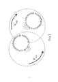
Чтобы избежать вращающих нагрузок на комбайн, желательно дополнительное усовершенствование, при котором число режущих головок увеличивается минимум до двух, а направление вращения рычагов становится встречным.To avoid rotational loads on the combine, an additional improvement is desirable, in which the number of cutting heads is increased to at least two, and the direction of rotation of the levers becomes counter.
Сопоставление заявляемого горного комбайна с прототипом, позволяет сделать вывод об отсутствии в последнем признаков сходных с существенными отличительными признаками заявляемого изобретения.A comparison of the inventive mining machine with the prototype allows us to conclude that the latter does not have signs similar to the essential distinguishing features of the claimed invention.
Также изобретение не следует явным образом из уровня техники, поэтому авторы считают, что объект является новым и имеет изобретательский уровень, поскольку при устранении такого технического решения, как режущая головка, исполненная в виде минимум одного вращающегося диска с боковой режущей поверхностью, расположенного под острым углом к поверхности забоя и закрепленного на рычаге с возможностью вращения - исчезает возможность в процессе проходки обеспечить равномерное удаление слоев породы и снизить нагрузку на грудь забоя, а при исключении дополнительного усовершенствования в виде второй режущей головки вращающейся противоположно первой - не удастся нивелировать вращающий эффект при контакте режущего инструмента и поверхности вырабатываемой породы, а следовательно, исчезает и технический результат.Also, the invention does not follow explicitly from the prior art, therefore, the authors believe that the object is new and has an inventive step, since when eliminating such a technical solution as a cutting head, made in the form of at least one rotating disk with a side cutting surface located at an acute angle to the surface of the face and fixed on the lever with the possibility of rotation - there is no possibility in the process of sinking to ensure uniform removal of rock layers and reduce the load on the chest of the face, and when li ne additional enhancements in the form of a second rotary cutting head opposite the first - will not be able to neutralize the effect of rotating contact cutter and the surface of rocks produced, and consequently disappears and technical result.
Сущность изобретения поясняется графическими материалами, где изображено:The invention is illustrated graphic materials, which depict:
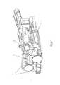
Фиг. 1 - горный проходческий комбайн. Варианте двумя режущими головками;FIG. 1 - mountain roadheader. Variant with two cutting heads;
Фиг. 2 - расположение режущей головки относительно груди забоя;FIG. 2 - the location of the cutting head relative to the chest face;
Фиг. 3 - направление вращения режущих головок.FIG. 3 - direction of rotation of the cutting heads.
Осуществление изобретенияThe implementation of the invention
Горный проходческий комбайн содержит механизм передвижения (1); рам у (2); исполнительный орган (3), включающий режущую головку (4), состоящую из диска (5) и рычага (6); отбойные барабаны (7).Mountain roadheader contains a movement mechanism (1); ram y (2); an actuator (3), including a cutting head (4), consisting of a disk (5) and a lever (6); kick drums (7).
Изобретение работает следующим образом. Горный проходческий комбайн, с помощью механизма передвижения 1 (Фиг. 1) - перемещается по выработке до соприкосновения исполнительного органа 3 (Фиг. 1) и поверхности забоя. Начинает вращение режущая головка 4 (Фиг. 2) и отбойные барабаны 7 (Фиг. 1). Диск 5 (Фиг. 2) на рычаге 6 (Фиг. 2) послойно снимает породу, формируя контур выработки фигурной формы. Срезав часть породы вращаясь вокруг своей оси, диск 5 (Фиг. 2), дополнительно совершающий круговые движения посредством рычага 6 (Фиг. 2), врезается боковой режущей поверхностью в забой, создавая эффект ввинчивания, дополнительно усиливающийся за счет расположения диска 5 (Фиг. 2) под острым углом к груди забоя. Эффект ввинчивания облегчает проходку, снижая необходимую максимальную нагрузку на исполнительный орган 3 (Фиг. 1), создаваемую поступательным движением комбайна. В исполнении комбайна по п. 2 формулы изобретения - встречное движение рычагов 6 (Фиг. 2) в процессе выработки исключает вращательные нагрузки на раму 2 (Фиг. 1) в какую-либо сторону. Порода же, остающаяся на своде и поде выработки срезается закрепленными на раме 2 (Фиг. 1) отбойными барабанами 7 (Фиг. 1) расположенными в верхней и нижней частях соответственно.The invention works as follows. Mountain roadheader, using the movement mechanism 1 (Fig. 1) - moves along the working out until the contact of the executive body 3 (Fig. 1) and the surface of the face. The rotation of the cutting head 4 (Fig. 2) and jack drums 7 (Fig. 1). The disk 5 (Fig. 2) on the lever 6 (Fig. 2) layer-by-layer removes the rock, forming a contour of the development of a curved shape. Having cut off part of the rock rotating around its axis, the disk 5 (Fig. 2), additionally making circular movements by means of the lever 6 (Fig. 2), cuts into the face by the side cutting surface, creating a screwing effect, further enhanced by the location of the disk 5 (Fig. 2). 2) at an acute angle to the chest of the face. The screwing effect facilitates sinking, reducing the required maximum load on the actuator 3 (Fig. 1) created by the translational movement of the combine. In the performance of the harvester according to
Следует отметить, что приведенная конфигурация горного проходческого комбайна и ее элементы являются частным случаем и могут быть исполнены по-другому, существенным являются сами возможности, которые такая конфигурация дает, и которые, тем не менее, могут быть достигнуты рядом других конструктивных особенностей. Например, режущих головок может быть и три или больше, они могут содержать больше чем один диск, а рычаги соответственно могут иметь более сложную конфигурацию и т.д.It should be noted that the given configuration of the mountain roadheader and its elements are a special case and can be performed differently, the very possibilities that this configuration provides, and which, nevertheless, can be achieved by a number of other design features, are essential. For example, there can be three or more cutting heads, they can contain more than one disc, and levers, respectively, can have a more complex configuration, etc.
Также для заявленного горного проходческого комбайна в том виде, как он охарактеризован в формуле изобретения, существует возможность изготовления и применения с помощью известных до даты подачи заявки средств и методов.Also, for the claimed mining tunneling machine as described in the claims, it is possible to manufacture and use means and methods known prior to the filing date of the application.
Заявляемое изобретение может найти широкое применение в горной промышленности для проведения выработок породы, в частности проходческих комбайнов непрерывного действия, используемых при добыче полезных ископаемых подземным способом.The claimed invention can find wide application in the mining industry for conducting mine workings, in particular continuous miners, used in mining underground.
Claims (4)
Translated fromRussianPriority Applications (1)
| Application Number | Priority Date | Filing Date | Title |
|---|---|---|---|
| RU2016113804ARU2627806C1 (en) | 2016-04-11 | 2016-04-11 | Mining tunnelling machine |
Applications Claiming Priority (1)
| Application Number | Priority Date | Filing Date | Title |
|---|---|---|---|
| RU2016113804ARU2627806C1 (en) | 2016-04-11 | 2016-04-11 | Mining tunnelling machine |
Publications (1)
| Publication Number | Publication Date |
|---|---|
| RU2627806C1true RU2627806C1 (en) | 2017-08-11 |
Family
ID=59641688
Family Applications (1)
| Application Number | Title | Priority Date | Filing Date |
|---|---|---|---|
| RU2016113804ARU2627806C1 (en) | 2016-04-11 | 2016-04-11 | Mining tunnelling machine |
Country Status (1)
| Country | Link |
|---|---|
| RU (1) | RU2627806C1 (en) |
Cited By (1)
| Publication number | Priority date | Publication date | Assignee | Title |
|---|---|---|---|---|
| RU2744123C1 (en)* | 2020-07-01 | 2021-03-02 | Акционерное общество «Копейский машиностроительный завод» | Cutting-loading machine |
Citations (4)
| Publication number | Priority date | Publication date | Assignee | Title |
|---|---|---|---|---|
| US3958830A (en)* | 1974-03-18 | 1976-05-25 | World Oil Mining Ltd. | Longwall mining system and archshield for mining tar sands, oil shales and the like |
| RU2093677C1 (en)* | 1990-07-09 | 1997-10-20 | Тульский государственный технический университет | Operating member of tunneling machine |
| RU2319835C1 (en)* | 2006-08-24 | 2008-03-20 | ОАО "Копейский машиностроительный завод" | Heading-and-winning machine |
| RU2571471C2 (en)* | 2010-11-05 | 2015-12-20 | Сандвик Майнинг Энд Констракшн Г.М.Б.Х. | Heading machine |
- 2016
- 2016-04-11RURU2016113804Apatent/RU2627806C1/enactive
Patent Citations (4)
| Publication number | Priority date | Publication date | Assignee | Title |
|---|---|---|---|---|
| US3958830A (en)* | 1974-03-18 | 1976-05-25 | World Oil Mining Ltd. | Longwall mining system and archshield for mining tar sands, oil shales and the like |
| RU2093677C1 (en)* | 1990-07-09 | 1997-10-20 | Тульский государственный технический университет | Operating member of tunneling machine |
| RU2319835C1 (en)* | 2006-08-24 | 2008-03-20 | ОАО "Копейский машиностроительный завод" | Heading-and-winning machine |
| RU2571471C2 (en)* | 2010-11-05 | 2015-12-20 | Сандвик Майнинг Энд Констракшн Г.М.Б.Х. | Heading machine |
Non-Patent Citations (1)
| Title |
|---|
| Н.В. ЧЕКМАСОВ, Д.И. ШИШЛЯННИКОВ. Горные машины и оборудование: проходческо-очистной комбайн "Урал-10А". Ч.1: устройство и принцип действия: метод. указания. Пермь: Изд-во Перм. гос. техн. ун-та, 2011, 28 с.* |
Cited By (2)
| Publication number | Priority date | Publication date | Assignee | Title |
|---|---|---|---|---|
| RU2744123C1 (en)* | 2020-07-01 | 2021-03-02 | Акционерное общество «Копейский машиностроительный завод» | Cutting-loading machine |
| WO2022003477A1 (en)* | 2020-07-01 | 2022-01-06 | Акционерное Общество "Копейский Машиностроительный Завод" | Mining machine |
Similar Documents
| Publication | Publication Date | Title |
|---|---|---|
| CA2361657C (en) | Cutting device | |
| CN104285007B (en) | The anti-big block of cold milling and planing machine peels off mechanism | |
| CN105507912B (en) | A kind of large section shape of a hoof shield machine | |
| Khoreshok et al. | Stress state of disk tool attachment points on tetrahedral prisms between axial bits | |
| EP2820242B1 (en) | A cutting drum and method of designing a cutting drum | |
| CN103835719B (en) | A kind of coal-winning machine self adaptation cutting process based on non-holonomic constraint | |
| RU2319835C1 (en) | Heading-and-winning machine | |
| CN110107305A (en) | Shield constructs machine and water jet jointly hobbing cutter rock breaking mechanism thereof | |
| RU2627806C1 (en) | Mining tunnelling machine | |
| US9103209B2 (en) | System for controlling speed of travel in a longwall shearer | |
| RU2627337C1 (en) | Mountain tunnelling machine actuator | |
| CN105008621B (en) | For removing the bucket wheel of material from the material mixture of particularly high rigidity | |
| CN207554056U (en) | A kind of cutterhead for karst area upper-soft lower-hard ground | |
| KR102073568B1 (en) | Axial-type cutting head having reduced drilling deviation and torque reaction force | |
| CN203655303U (en) | Full-section cutting tool applicable to planetary driving rectangular tunnel boring machine | |
| RU178558U1 (en) | MINING COMBINE | |
| EP3405648B1 (en) | Mining machine and method for operating a mining machine | |
| CN103046927A (en) | Deflectable cutting device of coal mining machine | |
| CN215672206U (en) | Cutting head of shield machine | |
| RU2744123C1 (en) | Cutting-loading machine | |
| RU2630839C1 (en) | Method of rock mass disintegration by crosswise cuts | |
| US6357831B1 (en) | Excavation machine for hard rock mining | |
| CN113944474A (en) | Rectangular rock tunnel TBM (Tunnel boring machine) | |
| RU2688822C1 (en) | Mining machine | |
| RU2783198C1 (en) | Mining machine |