RU2625986C2 - Method for pelvic bones reconstruction - Google Patents
Method for pelvic bones reconstructionDownload PDFInfo
- Publication number
- RU2625986C2 RU2625986C2RU2016127886ARU2016127886ARU2625986C2RU 2625986 C2RU2625986 C2RU 2625986C2RU 2016127886 ARU2016127886 ARU 2016127886ARU 2016127886 ARU2016127886 ARU 2016127886ARU 2625986 C2RU2625986 C2RU 2625986C2
- Authority
- RU
- Russia
- Prior art keywords
- bone
- additional
- sawdust
- beams
- pelvic bones
- Prior art date
Links
- 210000003049pelvic boneAnatomy0.000titleclaimsabstractdescription126
- 238000000034methodMethods0.000titleclaimsabstractdescription65
- 210000000988bone and boneAnatomy0.000claimsabstractdescription186
- 238000002271resectionMethods0.000claimsabstractdescription45
- 210000004197pelvisAnatomy0.000claimsdescription56
- 238000013461designMethods0.000claimsdescription41
- 230000007547defectEffects0.000claimsdescription31
- 210000003692iliumAnatomy0.000claimsdescription27
- 210000004872soft tissueAnatomy0.000claimsdescription14
- 210000004705lumbosacral regionAnatomy0.000claimsdescription13
- 238000002591computed tomographyMethods0.000claimsdescription12
- 238000011010flushing procedureMethods0.000claimsdescription9
- 230000023597hemostasisEffects0.000claimsdescription9
- 210000000689upper legAnatomy0.000claimsdescription7
- 208000001132OsteoporosisDiseases0.000claimsdescription5
- 239000008188pelletSubstances0.000claimsdescription3
- 239000003814drugSubstances0.000abstractdescription3
- 239000000126substanceSubstances0.000abstract1
- 206010028980NeoplasmDiseases0.000description40
- 210000003205muscleAnatomy0.000description34
- 230000008569processEffects0.000description19
- 210000001519tissueAnatomy0.000description18
- 238000009434installationMethods0.000description17
- 238000001356surgical procedureMethods0.000description15
- 238000011161developmentMethods0.000description14
- 230000018109developmental processEffects0.000description14
- 210000003815abdominal wallAnatomy0.000description10
- 210000003131sacroiliac jointAnatomy0.000description8
- 206010002091AnaesthesiaDiseases0.000description7
- 230000037005anaesthesiaEffects0.000description7
- 238000012545processingMethods0.000description7
- 210000003689pubic boneAnatomy0.000description7
- 241000489861MaximusSpecies0.000description6
- 210000003489abdominal muscleAnatomy0.000description6
- 210000003195fasciaAnatomy0.000description6
- 210000003099femoral nerveAnatomy0.000description6
- 230000036407painEffects0.000description6
- 238000002360preparation methodMethods0.000description6
- 210000003314quadriceps muscleAnatomy0.000description6
- 210000000574retroperitoneal spaceAnatomy0.000description6
- 210000004003subcutaneous fatAnatomy0.000description6
- 210000002435tendonAnatomy0.000description6
- 230000008901benefitEffects0.000description5
- 230000006378damageEffects0.000description5
- 230000007659motor functionEffects0.000description5
- 210000001696pelvic girdleAnatomy0.000description5
- 206010039722scoliosisDiseases0.000description5
- 210000000527greater trochanterAnatomy0.000description4
- 230000001771impaired effectEffects0.000description4
- 229910052751metalInorganic materials0.000description4
- 239000002184metalSubstances0.000description4
- 238000003892spreadingMethods0.000description4
- 230000007480spreadingEffects0.000description4
- 210000000779thoracic wallAnatomy0.000description4
- 238000005452bendingMethods0.000description3
- 230000015572biosynthetic processEffects0.000description3
- 238000010276constructionMethods0.000description3
- 238000005755formation reactionMethods0.000description3
- 239000012634fragmentSubstances0.000description3
- 230000000399orthopedic effectEffects0.000description3
- 238000011477surgical interventionMethods0.000description3
- 208000005243ChondrosarcomaDiseases0.000description2
- 210000001217buttockAnatomy0.000description2
- 230000006835compressionEffects0.000description2
- 238000007906compressionMethods0.000description2
- 238000005094computer simulationMethods0.000description2
- 239000004020conductorSubstances0.000description2
- 238000004519manufacturing processMethods0.000description2
- 238000012986modificationMethods0.000description2
- 230000004048modificationEffects0.000description2
- 230000002980postoperative effectEffects0.000description2
- 238000011160researchMethods0.000description2
- 239000010936titaniumSubstances0.000description2
- 229910052719titaniumInorganic materials0.000description2
- 238000003466weldingMethods0.000description2
- 208000006735PeriostitisDiseases0.000description1
- 208000007103SpondylolisthesisDiseases0.000description1
- 229910001069Ti alloyInorganic materials0.000description1
- RTAQQCXQSZGOHL-UHFFFAOYSA-NTitaniumChemical compound[Ti]RTAQQCXQSZGOHL-UHFFFAOYSA-N0.000description1
- 210000000588acetabulumAnatomy0.000description1
- 230000000844anti-bacterial effectEffects0.000description1
- 230000010478bone regenerationEffects0.000description1
- 201000011510cancerDiseases0.000description1
- 210000001175cerebrospinal fluidAnatomy0.000description1
- 238000005352clarificationMethods0.000description1
- 150000001875compoundsChemical class0.000description1
- 238000002316cosmetic surgeryMethods0.000description1
- 238000003745diagnosisMethods0.000description1
- 238000009826distributionMethods0.000description1
- 230000006870functionEffects0.000description1
- 230000004927fusionEffects0.000description1
- 238000002513implantationMethods0.000description1
- 208000027866inflammatory diseaseDiseases0.000description1
- 210000002239ischium boneAnatomy0.000description1
- 210000002414legAnatomy0.000description1
- 230000003902lesionEffects0.000description1
- 239000000463materialSubstances0.000description1
- 230000013011matingEffects0.000description1
- 230000000877morphologic effectEffects0.000description1
- 208000015122neurodegenerative diseaseDiseases0.000description1
- 210000003460periosteumAnatomy0.000description1
- 230000002035prolonged effectEffects0.000description1
- 238000002601radiographyMethods0.000description1
- 230000003068static effectEffects0.000description1
- 230000000638stimulationEffects0.000description1
- 210000002784stomachAnatomy0.000description1
- 208000011580syndromic diseaseDiseases0.000description1
- 238000002560therapeutic procedureMethods0.000description1
- 230000001755vocal effectEffects0.000description1
Images


Classifications
- A—HUMAN NECESSITIES
- A61—MEDICAL OR VETERINARY SCIENCE; HYGIENE
- A61B—DIAGNOSIS; SURGERY; IDENTIFICATION
- A61B17/00—Surgical instruments, devices or methods
- A61B17/56—Surgical instruments or methods for treatment of bones or joints; Devices specially adapted therefor
Landscapes
- Surgical Instruments (AREA)
Abstract
Description
Translated fromRussianИзобретение относится к медицине и может быть использовано в ортопедии, онкологии, нейрохирургии, в том числе, нейроортопедии, травматологии, вертебрологии и ветеринарии, и конкретно касается способа реконструкции таза.The invention relates to medicine and can be used in orthopedics, oncology, neurosurgery, including neuroorthopedics, traumatology, vertebrology and veterinary medicine, and specifically relates to a method for reconstruction of the pelvis.
Оно предназначено для операций, производимых на костях таза (тазового кольца) и позвоночника, преимущественно, для выполнения тазовой фиксации для замещения дефектов тазового кольца и для обеспечения максимальной стабильности оперируемого сегмента позвоночно-тазовой фиксации. Использование показано, в первую очередь, при дефектах костей таза, восстановления опорной и биомеханической функции аксиального скелета, возникающих в результате опухолевых поражений, травм, дегенеративно-дистрофических заболеваний.It is intended for operations performed on the bones of the pelvis (pelvic ring) and spine, mainly for performing pelvic fixation to replace defects of the pelvic ring and to ensure maximum stability of the operated segment of the vertebral pelvic fixation. The use is shown, first of all, for defects in the pelvic bones, restoration of the support and biomechanical functions of the axial skeleton resulting from tumor lesions, injuries, degenerative diseases.
Из заявки RU №97110206 А, 27.02.1999, известен способ хирургического лечения спондилолистеза путем репозиции и фиксации смещенного позвонка, отличающийся тем, что предварительно на поверхности спины в области пояснично-крестцового сочленения делают поперечный разрез, через него в точку, расположенную латеральнее линии поперечных отростков между поперечным отростком L5 и крестцово-подвздошным сочленением, вводят металлический дугообразный проводник и по передней поверхности тела L5 конец его выводят на другую сторону, к нему крепят металлическую ленту толщиной 0,01 мм и шириной 8-10 мм, протягивают ее по сформированному проводником каналу, оставляя концы над дорзальной плоскостью тела, с помощью ленты под рентген-контролем репонируют смещенный позвонок, после чего концы ее фиксируют поперечной металлической пластиной.From the application RU No. 97110206 A, 02.27.1999, a method of surgical treatment of spondylolisthesis by reposition and fixation of a displaced vertebra is known, characterized in that a transverse incision is made on the back surface in the region of the lumbosacral joint through it to a point located lateral to the transverse line processes between the transverse process L5 and the sacroiliac joint, a metal arc-shaped conductor is inserted and along the front surface of the body L5 its end is brought to the other side, a metal is attached to it tape 0.01 mm thick and 8-10 mm in width, it is drawn by a conductor channel formed, leaving the ends of the dorsal plane of the body, using tape under X-ray control repositioned in a displaced vertebra, after which its ends are fixed transverse metal plate.
Известный способ не позволяет осуществить реконструкцию костей таза.The known method does not allow reconstruction of the pelvic bones.
Из RU №2309463, 27.10.2007, известен способ моделирования стимуляции регенерации костной ткани.From RU No. 2309463, 10.27.2007, a method for modeling stimulation of bone regeneration is known.
Способ заключается в следующем.The method is as follows.
Зачищают концы костных фрагментов от надкостницы. Накладывают пленку, изготовленную из динитроцеллюлозы, циркулярно с перекрытием зачищенных концов костных фрагментов. Сшивают пленку продольно по линии ее стыка нитями. Фиксируют костные фрагменты в условиях чрескостного остеосинтеза.Strip the ends of the bone fragments from the periosteum. A film made of dinitrocellulose is applied circularly with the overlapping of the trimmed ends of the bone fragments. Sew the film longitudinally along the line of its junction with threads. Bone fragments are fixed under conditions of transosseous osteosynthesis.
Способ позволяет стимулировать репаративные процессы в условиях значительных дефектов кости, но не пригоден для реконструкции костей таза при дефектах костей таза (онкологии, травмах и т.д.).The method allows to stimulate reparative processes in conditions of significant bone defects, but is not suitable for reconstruction of the pelvic bones with defects of the pelvic bones (oncology, injuries, etc.).
Из RU №2271165, 10.03.2006, известен способ инструментальной фиксации пояснично-крестцового отдела при воспалительных заболеваниях позвоночника. Способ заключается в том, что пояснично-крестцовый отдел позвоночника фиксируют сзади компрессионной CD - конструкцией с крючковыми опорными элементами, при этом верхние опорные крючки устанавливают супраламинарно (на дуги нижних поясничных позвонков L4 или L5), а нижние крючки погружают в ложа, искусственно созданные на задней поверхности крестца между срединным и промежуточным крестцовым гребнями (crista sacralis mediana и crista sacralis intermedia).From RU No. 2271165, 03/10/2006, a method of instrumental fixation of the lumbosacral region for inflammatory diseases of the spine is known. The method consists in the fact that the lumbosacral spine is fixed behind the compression CD - construction with hook support elements, while the upper support hooks are installed supralaminar (on the arches of the lower lumbar vertebrae L4 or L5), and the lower hooks are immersed in the boxes artificially created on the posterior surface of the sacrum between the median and intermediate sacral ridges (crista sacralis mediana and crista sacralis intermedia).
Способ по данному патенту охарактеризован на фигуре 1, прилагаемой к описанию патента. На этой фигуре: 1 - верхний крючок конструкции; 2 - дуга тела L4; 3 - вновь сформированные дуги на задней поверхности крестца на уровне остистого отростка S1; 4 - задняя поверхность крестца; 5 - нижний крючок конструкции; 6 - металлические штанги; 7 - crista sacralis mediana; 8 - crista sacralis intermedia.The method according to this patent is described in figure 1, attached to the description of the patent. In this figure: 1 - the upper hook of the structure; 2 - an arc of the body L4; 3 - newly formed arches on the posterior surface of the sacrum at the level of the spinous process S1; 4 - the back surface of the sacrum; 5 - lower hook of the structure; 6 - metal rods; 7 - crista sacralis mediana; 8 - crista sacralis intermedia.
Способ осуществляется следующим образом.The method is as follows.
Задняя инструментальная фиксация пояснично-крестцового отдела может осуществляться одномоментно (под одним наркозом) с радикальной реконструкцией переднего отдела позвоночника, либо как самостоятельная операция. Положение больного - на животе. Задний срединный доступ с обнажением дуг нижних поясничных позвонков и задней поверхности крестца. У подростков, начиная с 14-16 летнего возраста, и взрослых людей дуги крестцовых позвонков синостозируются, и задняя поверхность крестца представляет собой единую кость. Задняя поверхность крестца обнажается по обе стороны от crista sacralis mediana на ширину 1-1,5 см, при этом задние крестцовые отверстия не открываются, а проходящие в них анатомические образования не травмируются.Posterior instrumental fixation of the lumbosacral can be carried out simultaneously (under one anesthesia) with a radical reconstruction of the anterior spine, or as an independent operation. The position of the patient is on the stomach. Rear median access with exposure of the arches of the lower lumbar vertebrae and the posterior surface of the sacrum. In adolescents, from 14-16 years of age, and adults, the arches of the sacral vertebrae are synostosed, and the posterior surface of the sacrum is a single bone. The posterior surface of the sacrum is exposed on both sides of the crista sacralis mediana to a width of 1-1.5 cm, while the posterior sacral openings do not open, and the anatomical formations passing through them are not injured.
Верхние опорные крючки устанавливают с двух сторон от остистого отростка на дуге L4 или L5 позвонка (в зависимости от протяженности фиксации). На задней поверхности крестца с двух сторон между срединным и промежуточными крестцовыми гребнями в поперечном направлении при помощи высокоскоростного бура (частота - 30-40 тыс. оборотов/мин) формируют сквозные пазы размером 5×3 мм, проникающие в позвоночный канал. В отличие от крестцовых отверстий, на уровне позвоночного канала каудальный отдел дурального мешка рыхло спаян с костью, что позволяет избежать его повреждения и возникновения ликвореи. Нижние опорные крючки с краниально направленными жалами вводят в созданные ложа. Стержни конструкции моделируют по кривизне пояснично-крестцового отдела и устанавливают в опорные крючки. Напряжение конструкции осуществляют умеренной компрессией и жесткой фиксацией стержня блокировочными гайками. Рану зашивают наглухо с оставлением дренажей.The upper supporting hooks are installed on both sides of the spinous process on the arc L4 or L5 of the vertebra (depending on the length of fixation). On the back surface of the sacrum from two sides between the median and intermediate sacral ridges in the transverse direction using high-speed drill (frequency - 30-40 thousand revolutions / min), through grooves of 5 × 3 mm in size penetrate the spinal canal. In contrast to the sacral foramen, at the level of the spinal canal, the caudal part of the dural sac loosely fused to the bone, which avoids damage to it and the occurrence of cerebrospinal fluid. The lower supporting hooks with cranially directed tips are inserted into the created beds. The design rods are modeled according to the curvature of the lumbosacral region and set into supporting hooks. The tension of the structure is carried out by moderate compression and rigid fixation of the rod with lock nuts. The wound is sutured tightly with the provision of drainage.
Охарактеризованная конструкция обеспечивает неподвижность оперированного отдела позвоночника, что обеспечивает его стабильность, создает лучшие условия для формирования переднего спондилодеза и одновременно позволяет максимально рано, в течение ближайших дней после операции, расширить двигательный режим, вертикализировать больного и значительно сократить сроки стационарного лечения.The described design ensures the immobility of the operated spine, which ensures its stability, creates the best conditions for the formation of anterior spinal fusion and at the same time allows you to expand the motor mode, verticalize the patient and significantly reduce the time of inpatient treatment as early as possible, in the coming days after surgery.
Однако, известный способ достаточно сложен, не обеспечивает реконструкцию костей таза при массивных резекциях костей таза при онкологических заболеваниях, травмах.However, the known method is quite complicated, does not provide reconstruction of the pelvic bones with massive resections of the pelvic bones for cancer, injuries.
Известен способ реконструкции костей таза с помощью устройства для реконструкции костей таза (тазового кольца).A known method of reconstruction of the pelvic bones using a device for the reconstruction of the pelvic bones (pelvic ring).
Используемая в известном способе пространственная конструкция состоит из балок, предназначенных для расположения в направлении между соединяемыми опилами костей таза и винтов для соединениями с костями (см. Статью в журнале: Orthopaedics & Traumatology: Surgery & Research (2009) 95, 284-292, 286, figure 1, figure 2 (1).The spatial structure used in the known method consists of beams designed to be placed in the direction between the connected sawdust of the pelvic bones and the screws for the joints with the bones (see Journal article: Orthopedics & Traumatology: Surgery & Research (2009) 95, 284-292, 286 , figure 1, figure 2 (1).
В известном способе несущие балки пространственной конструкции своими концами соединяются винтами, а эти винты, в свою очередь, соединяются с опилами костей (поверхность срезанной кости) и другими костными структурами. В результате, пространственное положение таза относительно позвоночника фиксируется напрямую при помощи соединяющих несущих балок с винтами на концах.In the known method, the supporting beams of a spatial structure with their ends are connected by screws, and these screws, in turn, are connected to the sawdust of bones (surface of the cut bone) and other bone structures. As a result, the spatial position of the pelvis relative to the spine is fixed directly by means of connecting supporting beams with screws at the ends.
Операция проводится следующим образом:The operation is carried out as follows:
- пациента укладывают на бок;- the patient is laid on his side;
- удаляют часть кости таза и получают два опила кости, расположенных напротив друг друга;- remove part of the pelvic bone and get two sawdust bones located opposite each other;
- ввинчивают винты в каждый опил кости, причем каждый винт имеет в головке сквозное поперечное отверстие для установки в него в последующем несущей балки;- screw the screws into each sawdust of the bone, and each screw has a through transverse hole in the head for installation in it in the subsequent carrier beam;
- берут несущую балку и вводят ее концами в отверстия головок винтов, ввинченных напротив друг друга в расположенных напротив друг друга опилах;- take the carrier beam and introduce it with the ends into the holes of the screw heads screwed opposite each other in sawdust located opposite each other;
- жестко фиксируют соединения каждой несущей балки с каждым винтом посредством гайки.- rigidly fix the connection of each supporting beam with each screw by means of a nut.
В итоге получают два опила, напрямую соединенные несущими балками между собой.As a result, they receive two sawdust directly connected by supporting beams to each other.
Недостатком известного способа является то, что в используемой конструкции при ходьбе несущие балки, соединяющие опилы, все время непрерывно смещаются друг относительно друга в разных плоскостях, совершая как возвратно-поступательные, так и вращательные движения, вызывая тем самым нестабильность системы в целом.The disadvantage of this method is that in the structure used when walking, the supporting beams connecting the sawdust are constantly shifted relative to each other in different planes, making both reciprocating and rotational movements, thereby causing instability of the system as a whole.
В итоге, полученная используемая конструкция не стабильна при использовании, поскольку имеется одну или несколько несущих балок, которые при длительном использовании со временем могут даже ломаться за счет больших нагрузок на тазовый сегмент. Кроме того, известный способ не позволяет выполнить адекватную более надежную и стабильную фиксацию при массивных резекциях костей таза. В итоге, это приводит к развитию болевого синдрома и нарушению опорной и двигательной функции и развитию сколиоза (искривлению позвоночника). В результате снижается качество жизни пациента.As a result, the resulting construction used is not stable when used, since there is one or more load-bearing beams, which, with prolonged use, can even break due to large loads on the pelvic segment. In addition, the known method does not allow for adequate more reliable and stable fixation with massive resections of the pelvic bones. In the end, this leads to the development of pain and a violation of the supporting and motor function and the development of scoliosis (curvature of the spine). As a result, the quality of life of the patient is reduced.
Кроме того, в известном способе конструкция не удобна для имплантации во время операции, так как углы фиксации несущих балок могут не совпадать с плоскостью костных опилов, что требует их дополнительного изгиба в процессе операции, что трудоемко, не удобно, не всегда возможно и требует дополнительных затрат времени.In addition, in the known method, the design is not convenient for implantation during the operation, since the fixing angles of the supporting beams may not coincide with the plane of the bone filings, which requires additional bending during the operation, which is laborious, not convenient, not always possible and requires additional time consuming.
Технической задачей заявленного изобретения является повышение удобства использования при реконструкции дефектов костей таза за счет использования модульной конструкции (то, что эта конструкция собирается из разных частей), а также за счет повышения стабильности оперируемого сегмента при резекции костей таза в результате использования усиленных балок (большего диаметра или специально разработанных, а также балок специально разработанного дизайна, например, ребристой, изогнутой и т.д. формы в пространстве), пластин специальной формы (анатомической), и переходников.The technical task of the claimed invention is to improve the usability in the reconstruction of defects of the pelvic bones due to the use of a modular design (the fact that this design is assembled from different parts), as well as by increasing the stability of the operated segment when the pelvic bones are resected as a result of using reinforced beams (larger diameter or specially designed, as well as beams of a specially designed design, for example, ribbed, curved, etc. shapes in space), plates of a special shape ( natomicheskoy) and adapters.
Кроме того, заявляемый способ позволяет выполнить адекватную более надежную и стабильную фиксацию при массивных резекциях костей таза.In addition, the inventive method allows you to perform an adequate more reliable and stable fixation with massive resections of the pelvic bones.
В результате всего выше изложенного заявленный способ является более стабильным и не приводит к развитию болевого синдрома и нарушению опорной и двигательной функции и без развития сколиоза (искривления позвоночника). В результате повышается качество жизни пациента.As a result of all of the above, the claimed method is more stable and does not lead to the development of pain and impaired support and motor function and without the development of scoliosis (curvature of the spine). As a result, the quality of life of the patient is improved.
Поставленная техническая задача достигается способом реконструкции костей таза, включающим:The technical task is achieved by the method of reconstruction of the pelvic bones, including:
а) компьютерную томографию (далее - КТ) пояснично-крестцового отделов позвоночника и таза пациента;a) computed tomography (hereinafter - CT) of the lumbosacral spine and pelvis of the patient;
б) на основании полученных данных изготавливают сначала трехмерную модель пояснично-крестцового отделов позвоночника и таза;b) based on the data obtained, a three-dimensional model of the lumbosacral spine and pelvis is first made;
в) затем определяют объем резекции;c) then determine the volume of resection;
г) осуществляют виртуальную резекцию для определения предполагаемого дефекта;g) carry out a virtual resection to determine the alleged defect;
д) на основе предварительно изготовленной трехмерной модели пояснично-крестцового отделов позвоночника и таза пациента изготавливают устройство в виде пространственной конструкции замещения костного дефекта путем фиксации, по меньшей мере, одного костного опила к другому смежному костному опилу;e) on the basis of a prefabricated three-dimensional model of the lumbosacral spine and pelvis of the patient, a device is made in the form of a spatial design for replacing a bone defect by fixing at least one bone filing to another adjacent bone filing;
е) образуют костные опилы в результате резекции костей таза, причем, при необходимости, обнажают (скелетируют) костную ткань крыла подвздошной кости;f) form bone filings as a result of resection of the pelvic bones, and, if necessary, expose (skeletonize) the bone tissue of the ilium wing;
ж) при этом пространственная конструкция состоит из:g) the spatial structure consists of:
- балок, предназначенных для расположения в направлении между соединяемыми опилами костей таза,- beams intended for location in the direction between the joined sawdust of the pelvic bones,
- винтов для соединения с костью,- screws to connect with the bone,
- и, по меньшей мере, пары дополнительных балок для фиксации их к костным опилам, одна из которых предназначена для фиксации, по меньшей мере, к одному костному опилу с ориентацией, по меньшей мере, вдоль него, а другая предназначена для фиксации, по меньшей мере, к смежному костному опилу с ориентацией, по меньшей мере, вдоль него, причем каждая дополнительная балка соединена с соответствующей балкой, предназначенной для расположения в направлении между соединяемыми опилами костей таза, разъемным соединением с возможностью жесткой фиксации, винты для соединения с костью смонтированы на дополнительных балках посредством разъемных соединений с возможностью жесткой фиксации;- and at least a pair of additional beams for fixing them to bone sawdust, one of which is designed to fix at least one bone sawdust with an orientation of at least along it, and the other is intended to fix at least at least to an adjacent bone sawdust with an orientation at least along it, with each additional beam connected to a corresponding beam designed to be positioned in the direction between the connected pellets of the pelvic bones, detachable connection with the possibility of rigid fixation , the screws for connecting to the bone are mounted on additional beams by means of detachable connections with the possibility of rigid fixation;
з) после установки пространственной конструкции осуществляют контроль всех элементов пространственной конструкции, промывку, контроль гемостаза, дренирование и зашивание раны;h) after installing the spatial structure, all elements of the spatial structure are monitored, flushing, hemostasis control, drainage and suturing of the wound;
и) при необходимости замещения мягкотканного дефекта осуществляют пластику ректоабдоминальным лоскутом.i) if necessary, the replacement of soft tissue defect carry out plastic rectoabdominal flap.
Примечание: словесное выражение в общей совокупности существенных признаков «и, по меньшей мере, пары дополнительных балок для фиксации их к костным опилам» означает, что может быть введена не пара, а три и более дополнительных балок. Например, один костный опил имеет сложную в пространстве форму и к нему, с ориентацией вдоль него, потребуется зафиксировать две дополнительные балки, а не одну, а к смежному костному опилу необходимо зафиксировать одну дополнительную балку. В итоге потребуется всего три дополнительные балки.Note: verbal expression in the general set of essential features “and at least a pair of additional beams for fixing them to bone sawdust” means that not a pair can be introduced, but three or more additional beams. For example, one bone sawdust has a complex shape in space and to it, with an orientation along it, it will be necessary to fix two additional beams, and not one, and one additional beam must be fixed to the adjacent bone sawdust. As a result, you only need three additional beams.
Другой пример. Образовано не два, а три и более костных опила на разных костях, например, два костных опила образованы на кости таза, а третий костный опил образован на кости позвоночника. В этом случае потребуется три дополнительные балки, одна из которых предназначена для ориентации вдоль одного костного опила на тазе, другая предназначена для ориентации вдоль смежного костного опила на тазе, а третья предназначена для ориентации вдоль костного опила, образованного на позвоночнике.Another example. Not two, but three or more bone sawdusts are formed on different bones, for example, two bone sawdusts are formed on the bones of the pelvis, and a third bone sawdust is formed on the bones of the spine. In this case, three additional beams will be required, one of which is intended for orientation along one bone sawdust on the pelvis, the other is intended for orientation along the adjacent bone sawdust on the pelvis, and the third is intended for orientation along the bone sawdust formed on the spine.
Вышеприведенная совокупность общих существенных признаков представляет собой сущность заявляемого изобретения. Она необходима и достаточна во всех случаях его реализации.The above set of common essential features is the essence of the claimed invention. It is necessary and sufficient in all cases of its implementation.
Благодаря заявленному способу обеспечиваются следующие преимущества по сравнению с прототипом: повышается удобство использования при реконструкции дефектов костей таза за счет модульности конструкции (то, что она собирается из разных частей), а также за счет повышения стабильности оперируемого сегмента при резекции костей таза в результате использования усиленных балок (большего диаметра или специально разработанных, а также балок специально разработанного дизайна, например, ребристой, изогнутой и т.д. формы в пространстве), пластин специальной формы (анатомической), и переходников.Thanks to the claimed method, the following advantages are provided in comparison with the prototype: the usability during reconstruction of defects of the pelvic bones is improved due to the modularity of the structure (the fact that it is assembled from different parts), as well as by increasing the stability of the operated segment when resecting the pelvic bones as a result of using reinforced beams (of larger diameter or specially designed, as well as beams of specially designed design, for example, ribbed, curved, etc. shapes in space), plates with a special form (anatomical), and adapters.
Заявляемый способ позволяет выполнить адекватную более надежную и стабильную фиксацию при массивных резекциях костей таза.The inventive method allows you to perform an adequate more reliable and stable fixation with massive resections of the pelvic bones.
В результате выше изложенного устанавливаемая пространственная конструкция более стабильна и не приводит к развитию болевого синдрома и нарушению опорной и двигательной функции и без развития сколиоза (искривления позвоночника).As a result of the above, the established spatial structure is more stable and does not lead to the development of pain and impaired support and motor function, and without the development of scoliosis (curvature of the spine).
В результате повышается качество жизни пациента.As a result, the quality of life of the patient is improved.
Кроме того, применительно к заявленному способу заявитель считает необходимым выделить следующие развития и/или уточнения совокупности его существенных признаков, относящиеся к частным случаям выполнения или использования.In addition, in relation to the claimed method, the applicant considers it necessary to highlight the following development and / or clarification of the set of its essential features relating to particular cases of implementation or use.
По меньшей мере, одна из дополнительных балок используемой пространственной конструкции может быть оснащена дополнительной опорой со сквозными отверстиями для установки винтов, предназначенных для соединения с костью. Это, например, целесообразно при невозможности установки винта или при толщине кости меньше диаметра винта, или при остеопорозе и т.д.At least one of the additional beams of the spatial structure used may be equipped with an additional support with through holes for installing screws for connecting to the bone. This, for example, is advisable when it is impossible to install a screw or when the bone thickness is less than the diameter of the screw, or with osteoporosis, etc.
Балки, предназначенные для расположения в направлении между соединяемыми опилами костей таза, используемой пространственной конструкции могут иметь рифления на поверхности для увеличения площади соприкосновения их поверхностей и дополнительных балок, а также уменьшения возможности их поворота относительно друг друга и для повышения механической стабильности конструкции в целом.Beams intended for location in the direction between the joined sawdust of the pelvic bones, the spatial structure used can have corrugations on the surface to increase the contact area of their surfaces and additional beams, as well as reduce the possibility of their rotation relative to each other and to increase the mechanical stability of the structure as a whole.
При массивных резекциях костей таза, остеопорозе, дополнительную балку соединяют с другими костными структурами, в частности, поясничным позвонком, и/или крестцом, и/или бедренной костью, и/или костью на контрлатеральной стороне.With massive pelvic resections, osteoporosis, the extra beam is connected to other bone structures, in particular, the lumbar vertebra, and / or sacrum, and / or the femur, and / or bone on the contralateral side.
В пространственной конструкции замещения костного дефекта балки, предназначенные для расположения в направлении между соединяемыми опилами костей таза, могут иметь изогнутую форму и, при необходимости, их можно бы было дополнительно изогнуть вручную в процессе реконструкции костей.In the spatial design for the replacement of a bone defect, the beams designed to be placed in the direction between the connected sawdust of the pelvic bones can have a curved shape and, if necessary, they could be additionally manually bent during bone reconstruction.
Дополнительную опору, соединенную с дополнительной балкой, располагают в соответствии с анатомическими особенностями костей таза, изгибы ее, по возможности, максимально точно повторяют поверхности кости и обеспечивают максимальный контакт между собой и создают дополнительную фиксацию, путем поворота дополнительной опоры в разных плоскостях.An additional support connected to the additional beam is positioned in accordance with the anatomical features of the pelvic bones, its bends, as far as possible, repeat the surface of the bone and provide maximum contact with each other and create additional fixation by turning the additional support in different planes.
Способ реконструкции костей таза включает следующие стадии:The method for reconstruction of the pelvic bones includes the following stages:
- ввинчивают винты (7) для соединения с костью в направлении приблизительно перпендикулярно костным опилам (10) крестца и опилам (12) подвздошной кости;- screw the screws (7) to connect with the bone in a direction approximately perpendicular to the bone sawdust (10) of the sacrum and sawdust (12) of the ilium;
- на крыло подвздошной кости фиксируют дополнительную опору (15) при помощи винтов (17), предназначенных для соединения с костью таза;- an additional support (15) is fixed to the iliac wing using screws (17) designed to connect to the pelvic bone;
- винты (7) для соединения с костью опила (10) крестца соединяют дополнительной балкой (9), посредством разъемных соединений (14);- screws (7) for connecting with the sawdust bone (10) of the sacrum are connected by an additional beam (9), by means of detachable joints (14);
- винты (7) для соединения с костью опила (12) подвздошной кости и дополнительную опору (15) соединяют дополнительной балкой (11), посредством разъемных соединений, соответственно, (14) и (20);- screws (7) for connecting with the bone of the sawdust (12) of the ilium and the additional support (15) are connected by an additional beam (11), through detachable joints, respectively (14) and (20);
- предварительно, перед фиксацией дополнительных балок (9 и 11), на них монтируют разъемные соединения (24);- preliminary, before fixing additional beams (9 and 11), detachable joints (24) are mounted on them;
- дополнительные балки (9 и 11) жестко фиксируют к винтам (7) опила и дополнительной опоре (15) фиксирующими винтами, соответственно, (57) и (68);- additional beams (9 and 11) are rigidly fixed to the sawdust screws (7) and the additional support (15) with fixing screws, respectively (57) and (68);
- балки 5, предназначенные для расположения в направлении между соединяемыми опилами костей таза, фиксируют к дополнительным балкам (9 и 11) при помощи разъемных соединений (24), а их жесткую фиксацию осуществляют посредством стопорного винта (35).- beams 5, designed to be located in the direction between the joined sawdust of the pelvic bones, are fixed to the additional beams (9 and 11) using detachable joints (24), and they are rigidly fixed by means of a locking screw (35).
Балки, предназначенные для расположения в направлении между соединяемыми опилами костей таза, а также дополнительные балки и опорная пластина выполнены из титана или титанового сплава.Beams designed to be positioned in the direction between the connected pellets of the pelvic bones, as well as additional beams and a support plate made of titanium or titanium alloy.
Итак, технический результат достигается тем, что в способе реконструкции костей таза, включающем пространственную конструкцию, состоящую из балок, предназначенных для расположения в направлении между соединяемыми опилами костей таза, и винтов для соединения с костями, в которую, согласно изобретению, введены пара дополнительных балок, одна из которых предназначена для фиксации, по меньшей мере, к одному костному опилу с ориентацией, по меньшей мере, вдоль него, а другая предназначена для фиксации, по меньшей мере, к смежному костному опилу с ориентацией, по меньшей мере, вдоль него, причем каждая дополнительная балка соединена с соответствующей балкой, предназначенной для расположения в направлении между соединяемыми опилами костей таза, разъемным соединением с возможностью жесткой фиксации, винты для соединения с костью смонтированы на дополнительных балках посредством разъемных соединений с возможностью жесткой фиксации.So, the technical result is achieved by the fact that in the method of reconstruction of the pelvic bones, including a spatial structure consisting of beams designed to be located in the direction between the joined sawdust of the pelvic bones, and screws for connecting with the bones, into which, according to the invention, a pair of additional beams are inserted , one of which is intended for fixation to at least one bone sawdust with an orientation at least along it, and the other is intended to fix at least to an adjacent bone sawdust with orientation at least along it, with each additional beam connected to a corresponding beam designed to be positioned in the direction between the sawdust of the bones of the pelvis connected, detachable with the possibility of rigid fixation, screws for connecting to the bone are mounted on additional beams by means of detachable connections with the possibility of rigid fixation.
Данная совокупность общих существенных признаков представляет собой сущность заявляемого изобретения. Она необходима и достаточна во всех случаях его реализации.This set of common essential features is the essence of the claimed invention. It is necessary and sufficient in all cases of its implementation.
Такое техническое решение имеет следующие преимущества по сравнению с известным техническим решением:Such a technical solution has the following advantages compared to the known technical solution:
повышение удобства использования при реконструкции дефектов костей таза за счет модульности конструкции (то, что она собирается из разных частей), а также за счет повышения стабильности оперируемого сегмента при резекции костей таза в результате использования усиленных балок (более толстых или специально разработанных, а также балок специально разработанного дизайна, например, ребристой, изогнутой и т.д. формы в пространстве), пластин специальной формы (анатомической), и переходников.improving the usability in the reconstruction of defects of the pelvic bones due to the modularity of the design (the fact that it is assembled from different parts), as well as by increasing the stability of the operated segment when the pelvic bones are resected as a result of using reinforced beams (thicker or specially designed, as well as beams specially designed designs, for example, ribbed, curved, etc. shapes in space), plates of a special shape (anatomical), and adapters.
Используемая в способе конструкция позволяет выполнить адекватную более надежную и стабильную фиксацию при массивных резекциях костей таза.The design used in the method allows for adequate more reliable and stable fixation during massive resections of the pelvic bones.
В результате выше изложенного заявленный способ является более стабильным, снижается вероятность механического перелома и нестабильность конструкции, и, соответственно, не приводит к развитию болевого синдрома и нарушению опорной и двигательной функции и без развития сколиоза (искривления позвоночника). В результате повышается качество жизни пациента.As a result of the above, the claimed method is more stable, the likelihood of a mechanical fracture and instability of the structure are reduced, and, accordingly, does not lead to the development of pain and impaired support and motor function without the development of scoliosis (curvature of the spine). As a result, the quality of life of the patient is improved.
Кроме того, применительно к заявленному способу с использованием такой пространственной конструкции, необходимо выделить следующие развития и/или уточнения совокупности его существенных признаков, относящиеся к частным случаям выполнения или использования.In addition, in relation to the claimed method using such a spatial design, it is necessary to highlight the following development and / or refinement of its essential features related to particular cases of implementation or use.
В ряде случаев, например, при невозможности установки винта или при толщине кости меньше диаметра винта, или при остеопорозе и т.д., целесообразно, чтобы, по меньшей мере, одна из дополнительных балок была бы оснащена дополнительной опорой со сквозными отверстиями для установки винтов, предназначенных для соединения с костью.In some cases, for example, if it is impossible to install the screw or when the bone thickness is less than the diameter of the screw, or when osteoporosis, etc., it is advisable that at least one of the additional beams would be equipped with an additional support with through holes for installing screws designed to connect with the bone.
Данная дополнительная опора может иметь различную конструкцию. Например, она может представлять собой продольно вытянутое тело, в частности, пластину.This additional support may have a different design. For example, it may be a longitudinally elongated body, in particular, a plate.
Желательно, чтобы дополнительная опора была бы соединена с дополнительной балкой разъемным соединением с возможностью жесткой фиксации. Это позволяет, например, адаптировать ее положение в соответствии с анатомическими особенностями костей таза (то есть расположить дополнительную опору на кости так, чтобы ее изгибы, по возможности, максимально точно повторяли бы неровности кости с обеспечением их максимального контакта между собой), что позволяет обеспечить создание дополнительной точки фиксации путем поворота дополнительной опоры в разных плоскостях.It is desirable that the additional support be connected to the additional beam with a detachable connection with the possibility of rigid fixation. This allows, for example, to adapt its position in accordance with the anatomical features of the pelvic bones (that is, place additional support on the bones so that its bends, as far as possible, would repeat the bumps of the bone as accurately as possible, ensuring their maximum contact with each other), which allows creating an additional fixation point by turning the additional support in different planes.
Заявитель считает необходимым отметить, что каждая дополнительная балка может иметь не только соединения с костными опилами. В ряде случаев предпочтительно, чтобы она помимо костного опила была бы соединена с другими костными структурами, например, с поясничным позвонком, и/или крестцом, и/или бедренной костью, и/или костью на контрлатеральной стороне и т.д. Это может быть целесообразно при необходимости создания дополнительной точки фиксации в случае, например, если требуется повышение стабильности системы при массивных резекциях костей таза, остеопорозе и т.д.The applicant considers it necessary to note that each additional beam can have not only connections with bone filings. In some cases, it is preferable that, in addition to the bone filing, it would be connected with other bone structures, for example, with the lumbar vertebra, and / or sacrum, and / or femur, and / or bone on the contralateral side, etc. This may be appropriate if you need to create an additional fixation point in the case, for example, if you want to increase the stability of the system with massive pelvic resections, osteoporosis, etc.
Для увеличения площади соприкасающихся поверхностей балки, предназначенной для расположения в направлении между соединяемыми опилами костей таза, и соединяемой с ней дополнительной балки, с уменьшением возможности поворота их друг относительно друга и для повышения механической стабильности конструкции желательно, чтобы балка, предназначенная для расположения в направлении между соединяемыми опилами костей таза, имела бы рифления на поверхности.To increase the area of contacting surfaces of the beam, designed to be located in the direction between the connected sawdust of the pelvic bones, and the additional beam connected to it, with a decrease in the possibility of their rotation relative to each other and to increase the mechanical stability of the structure, it is desirable that the beam intended to be located in the direction between connected by sawdust to the pelvic bones, would have corrugations on the surface.
Заявитель считает необходимым отметить, что для удобства сборки пространственной конструкции, целесообразно, чтобы, по меньшей мере, часть балок, предназначенных для расположения в направлении между соединяемыми опилами костей таза, и, по меньшей мере, часть дополнительных балок, были бы выполнены изогнутыми, в частности, с возможностью изгиба вручную в ходе проведения операции специальным инструментом.The applicant considers it necessary to note that, for the convenience of assembling the spatial structure, it is advisable that at least a part of the beams intended for location in the direction between the connected sawdust of the pelvic bones, and at least part of the additional beams, be made curved, in in particular, with the possibility of manual bending during the operation with a special tool.
Разъемное соединение с возможностью жесткой фиксации балки, предназначенной для расположения в направлении между соединяемыми опилами костей таза, и дополнительной балки, может иметь различную конструкцию.A detachable connection with the possibility of rigid fixation of the beam, designed to be located in the direction between the connected sawdust of the bones of the pelvis, and the additional beam, can have a different design.
Однако, по мнению заявителя, желательно, чтобы оно представляло бы собой протяженное тело, с продольным углублением, в продольном углублении со стороны отверстия имеется резьба, в протяженном теле в конце продольного углубления имеется поперечное сквозное отверстие для фиксации дополнительной балки, в протяженном теле, частично пересекая поперечное сквозное отверстие, имеется дополнительное поперечное отверстие для фиксации балки, предназначенной для расположения в направлении между соединяемыми опилами костей таза, с продольной осью, расположенной перпендикулярно продольной оси сквозного отверстия в конце продольного углубления и перпендикулярно продольной оси дополнительного поперечного отверстия для фиксации балки, предназначенной для расположения в направлении между соединяемыми опилами костей таза.However, according to the applicant, it is desirable that it be an extended body, with a longitudinal recess, there is a thread in the longitudinal recess from the side of the hole, in the extended body at the end of the longitudinal recess there is a transverse through hole for fixing the additional beam, in the extended body, partially crossing the transverse through hole, there is an additional transverse hole for fixing the beam, designed to be located in the direction between the connected sawdust of the pelvic bones, with the longitudinal axis located perpendicular to the longitudinal axis of the through hole at the end of the longitudinal recess and perpendicular to the longitudinal axis of the additional transverse hole for fixing the beam, designed to be located in the direction between the connected sawdust of the pelvic bones.
Кроме того, имеется стопорный винт, ввинченный в резьбу в продольном углублении со стороны отверстия, и имеющий конструктивный элемент для передачи крутящего момента.In addition, there is a locking screw screwed into the thread in the longitudinal recess from the side of the hole, and having a structural element for transmitting torque.
В результате, внутри протяженного тела после ввинчивания стопорного винта он давит на балку, предназначенную для расположения в направлении между соединяемыми опилами костей таза, которая, в свою очередь, непосредственно давит на дополнительную балку, которая упирается в стенки поперечного сквозного отверстия. Такая конструкция разъемного соединения характеризуется простотой, надежностью жесткой фиксации, возможностью быстрого монтажа и демонтажа (переналадки в процессе проведения операции).As a result, inside the extended body, after screwing in the locking screw, it presses on the beam, designed to be positioned in the direction between the connected sawdust of the pelvic bones, which, in turn, directly presses on the additional beam, which abuts against the walls of the transverse through hole. This design of the detachable connection is characterized by simplicity, reliability of rigid fixation, the possibility of quick installation and dismantling (readjustment during the operation).
Конструктивный элемент для передачи крутящего момента также может иметь различную конструкцию. Например, он может представлять из себя выемку многогранной формы в головке стопорного винта, в частности, иметь форму шестигранника, для ввода в нее конца отвертки шестигранной формы.The structural element for transmitting torque can also have a different design. For example, it can be a recess of a multifaceted shape in the head of the locking screw, in particular, it can be in the form of a hexagon for inserting the end of a screwdriver into a hexagonal shape.
Заявитель считает необходимым отметить, что для обеспечения более надежной фиксации дополнительной балки с поверхностью протяженного тела в нижней части поперечного сквозного отверстия для фиксации дополнительной балки может быть выполнено продольное углубление (продольный желоб) с возможностью обеспечения, по меньшей мере, пары точек соприкосновения поверхности дополнительной балки с поверхностью протяженного тела в нижней части поперечного сквозного отверстия.The applicant considers it necessary to note that in order to provide a more reliable fixation of the additional beam with the surface of the extended body in the lower part of the transverse through hole for fixing the additional beam, a longitudinal recess (longitudinal groove) can be made with the possibility of providing at least a pair of points of contact on the surface of the additional beam with the surface of the extended body at the bottom of the transverse through hole.
Предпочтительно, чтобы заявленная пространственная конструкция была бы изготовлена на основе предварительно выполненной трехмерной модели таза на основании компьютерной томографии. Это позволяет адекватно подобрать элементы фиксирующей системы, их размеры, конфигурацию, определить места установки винтов и дополнительной опорной пластины, в результате чего наиболее оптимально обеспечить перераспределение физиологические нагрузки тела человека на кости таза в статике и при движении, в том числе ротационные, и создать оптимальную пространственную конструкцию замещения костного дефекта, которая позволяет значительно снизить нагрузки на единицу площади костной ткани в месте контакта металл-кость.Preferably, the claimed spatial design would be made on the basis of a pre-executed three-dimensional model of the pelvis based on computed tomography. This allows you to adequately select the elements of the fixing system, their sizes, configuration, determine the installation location of the screws and the additional support plate, as a result of which it is most optimal to redistribute the physiological loads of the human body on the pelvic bones in static and during movement, including rotational ones, and create the optimal spatial design of bone defect replacement, which can significantly reduce the load per unit area of bone tissue at the metal-bone contact site.
Кроме того, в результате предварительного компьютерного моделирования хирургического вмешательства и пространственной конструкции резко снижается время проведения операции, повышается ее радикальность и появляется возможность создать адекватную систему фиксации на основании пространственной конструкции, что, в свою очередь, позволяет предотвратить развитие механической нестабильности системы, избежать развитие болевого синдрома и повторных хирургических вмешательств. В заключение данного раздела описания следует отметить, что в целом преимущество настоящего изобретения заключается в расширении возможности осуществления хирургической помощи пациентам с опухолями и другими повреждениями костей таза.In addition, as a result of preliminary computer modeling of surgical intervention and spatial design, the time of the operation is sharply reduced, its radicality is increased and it becomes possible to create an adequate fixation system based on the spatial design, which, in turn, helps to prevent the development of mechanical instability of the system, to avoid the development of pain syndrome and repeated surgical interventions. To conclude this section of the description, it should be noted that, in general, the advantage of the present invention is to expand the possibility of surgical care for patients with tumors and other injuries of the pelvic bones.
Важным преимуществом изобретения является также то, что детали устройства могут быть предварительно изготовлены на обычном технологическом оборудовании, используемом в медицинской промышленности.An important advantage of the invention is also that the details of the device can be prefabricated on conventional processing equipment used in the medical industry.
Помимо приведенных вариантов изобретения возможны и другие многочисленные его модификации.In addition to the above variants of the invention, numerous other modifications thereof are possible.
Эти и многочисленные другие варианты изобретения охватываются приведенной далее заявителем формулой изобретения.These and numerous other variations of the invention are covered by the following claims.
Изобретение поясняется чертежами.The invention is illustrated by drawings.
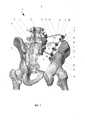
На фиг. 1 изображено устройство для реконструкции костей таза в сборе с вариантом установки на тазе при резекции костей таза тип I, IV по классификации Enneking, аксонометрия;In FIG. 1 shows a device for reconstructing the pelvic bones as an assembly with an installation option on the pelvis for resection of the pelvic bones type I, IV according to the Enneking classification, axonometry;
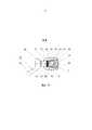
На фиг. 2 изображено заявленное устройство в сборе отдельно вне костей, аксонометрия;In FIG. 2 shows the claimed device assembly separately outside the bones, axonometry;
На фиг. 3 изображена дополнительная опора со сквозными отверстиями для установки винтов, предназначенных для соединения с костью (аксонометрия);In FIG. 3 shows an additional support with through holes for installing screws designed to connect to the bone (axonometry);
На фиг. 4 - то же, вид сверху;In FIG. 4 - same, top view;
На фиг. 5 - то же, вид сбоку;In FIG. 5 is the same side view;
На фиг. 6 - то же, вид снизу;In FIG. 6 - the same, bottom view;
На фиг. 7 изображено разъемное соединение с возможностью жесткой фиксации балки, предназначенной для расположения в направлении между соединяемыми опилами костей таза, и дополнительной балки, в сборе с балками, аксонометрия;In FIG. 7 shows a detachable connection with the possibility of rigid fixation of the beam, intended for location in the direction between the connected sawdust of the pelvic bones, and the additional beam, assembled with the beams, axonometry;
На фиг. 8 - то же, сечение, аксонометрия;In FIG. 8 - same section, axonometry;
На фиг. 9 изображена балка, предназначенная для расположения в направлении между соединяемыми опилами костей таза, прямая проекция;In FIG. 9 shows a beam designed to be positioned in the direction between the connected sawdust of the pelvic bones, a direct projection;
На фиг. 10 изображено разъемное соединение с возможностью жесткой фиксации балки, предназначенной для расположения в направлении между соединяемыми опилами костей таза, и дополнительной балки, аксонометрия;In FIG. 10 shows a detachable connection with the possibility of rigid fixation of the beam, intended for location in the direction between the joined sawdust of the pelvic bones, and the additional beam, axonometry;
На фиг. 11 то же, вид спереди;In FIG. 11 the same front view;
На фиг. 12 - то же, сечение по А-А на фиг. 11;In FIG. 12 is the same, section along AA in FIG. eleven;
На фиг. 13 - то же, вид сбоку по стрелке Б на фиг. 11;In FIG. 13 is the same side view along arrow B in FIG. eleven;
На фиг. 14 изображен винт для соединения с костью с разъемным соединением, вид сбоку;In FIG. 14 shows a screw for connecting to a bone with a detachable connection, side view;
На фиг. 15 изображен то же, продольное сечение, с дополнительным изображение на фигуре тонкой линией разъемного соединения в повернутом положении;In FIG. 15 shows the same, longitudinal section, with an additional image on the figure, a thin line of detachable connection in the turned position;
На фиг. 16 изображена сборка костного винта для соединения с костью, разъемного соединения с фиксирующим винтом и дополнительной балки, аксонометрия;In FIG. 16 shows the assembly of a bone screw for connection with a bone, a detachable connection with a fixing screw and an additional beam, a perspective view;
На фиг. 17 изображено сечение В-В фиг. 4, повернуто;In FIG. 17 shows a section BB of FIG. 4, rotated;
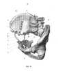
На фиг. 18 изображено устройство для реконструкции костей таза в сборе с вариантом установки на тазе при резекции костей таза тип I, IV по классификации Enneking с резекцией крыла подвздошной кости, аксонометрия;In FIG. 18 shows a device for reconstructing the pelvic bones as an assembly with an installation option on the pelvis for resection of the pelvic bones type I, IV according to Enneking classification with resection of the ilium wing, axonometry;
На фиг. 19 изображено устройство для реконструкции костей таза в сборе с вариантом установки на тазе при резекции костей таза тип II по классификации Enneking, аксонометрия;In FIG. 19 shows a device for reconstructing the pelvic bones in an assembly with an installation option on the pelvis for resection of the pelvic bones type II according to the Enneking classification, axonometry;
На фиг. 20 изображено устройство для реконструкции костей таза в сборе с вариантом установки на тазе при резекции костей таза тип I, II, III по классификации Enneking, аксонометрия;In FIG. 20 shows a device for reconstructing the pelvic bones as an assembly with an installation option on the pelvis for resection of the pelvic bones type I, II, III according to Enneking classification, axonometry;
На фиг. 21 изображено устройство для реконструкции костей таза в сборе с вариантом установки на тазе при резекции костей таза тип II, III по классификации Enneking, аксонометрия;In FIG. 21 shows a device for reconstructing the pelvic bones as an assembly with an installation option on the pelvis for resection of the pelvic bones type II, III according to the Enneking classification, axonometry;
На фиг. 22 изображено устройство для реконструкции костей таза в сборе с вариантом установки на тазе при резекции костей таза тип I, II по классификации Enneking, аксонометрия;In FIG. 22 shows a device for reconstructing the pelvic bones in an assembly with an installation option on the pelvis for resection of the pelvic bones type I, II according to Enneking classification, axonometry;
На фиг. 23 изображена фронтальная проекция компьютерной томографии поясничного отдела позвоночника и костей таза;In FIG. 23 is a front view of computed tomography of the lumbar spine and pelvic bones;
На фиг. 24 - то же, аксиальная проекция;In FIG. 24 - the same axial projection;
На фиг. 25 изображена компьютерная 3D модель костей таза пациента с опухолью;In FIG. 25 shows a 3D computer model of the pelvic bones of a patient with a tumor;
На фиг. 26 изображена стереолитографическая трехмерная модель таза пациента с предполагаемым объемом резекции, по данной модели смоделирована пространственная конструкция 4 (фиксирующая система);In FIG. 26 depicts a stereolithographic three-dimensional model of the patient’s pelvis with the estimated volume of resection; spatial model 4 (fixing system) is modeled on this model;
На фиг. 27 изображена мобилизация и удаление опухоли костей таза пациента;In FIG. 27 shows the mobilization and removal of a tumor in the pelvic bones of a patient;
На фиг. 28 изображена реконструкция дефекта костей таза пространственной конструкцией 4;In FIG. 28 shows the reconstruction of a defect in the pelvic bones by a
На фиг. 29 изображена прямая проекция рентгенографии костей таза после операции;In FIG. 29 shows a direct projection of radiography of the pelvic bones after surgery;
На фиг. 30 - то же, боковая проекция;In FIG. 30 - the same side view;
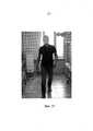
На фиг. 31 изображен пациент спустя три месяца после операции.In FIG. 31 depicts a patient three months after surgery.
Используемая в способе для реконструкции костей таза пространственная конструкция 4 состоит из балок 5, предназначенных для расположения в направлении между соединяемыми костными опилами 6 костей таза, и винтов 7 для соединения с костью (фиг. 1). В заявленном способе для реконструкции костей таза пространственная конструкция 4 содержит пару дополнительных балок 8, одна из которых 9 предназначена для фиксации, по меньшей мере, к одному костному опилу 10 с ориентацией, по меньшей мере, вдоль него, а другая дополнительная балка 11 предназначена для фиксации, по меньшей мере, к смежному костному опилу 12 с ориентацией, по меньшей мере, вдоль него (фиг. 1, фиг. 2).The
Примечание 1: дополнительные балки 8 в описании конкретизированы для удобства чтения чертежей, а именно, дополнительная балка, расположенная вдоль одного костного опила, обозначенного позицией 10, имеет отдельный номер позиции - 9, а дополнительная балка, расположенная вдоль другого костного опила, обозначенного позицией 12, имеет свой отдельный номер позиции - 11. По этой причине в дальнейшем возможна запись типа: «Винты 7 для соединения с костью смонтированы на дополнительных балках 8 (или 9 и 11)».Note 1:
Примечание 2: аналогично выше изложенному, общая позиция костных опилов имеет номер позиции 6, но для удобства чтения чертежей костные опилы конкретизированы, а именно один костный опил имеет отдельный номер позиции 10 и вдоль него располагается дополнительная балка 9, а другой костный опил имеет свой отдельный номер позиции 12 и вдоль него располагается дополнительная балка 11). По этой причине в дальнейшем возможна запись типа: «между соединяемыми костными опилами 6 (или 10 и 12)».Note 2: similar to the above, the general position of the bone filings has a position number of 6, but for the convenience of reading the drawings, the bone filings are specified, namely one bone filing has a
Балки 5, предназначенные для расположения в направлении между соединяемыми опилами костей таза, соединены с дополнительными балками 8.
Каждая дополнительная балка 8 (или 9 и 11) соединена с соответствующей балкой 5, предназначенной для расположения в направлении между соединяемыми опилами костей таза, разъемным соединением 24 дополнительной балки 8 (или 9 и 11) с соответствующей балкой 5, предназначенной для расположения в направлении между соединяемыми опилами костей таза (для краткости далее данное разъемное соединение называется как «разъемное соединение 24 дополнительной балки 8 с балкой 5). Разъемное соединение 24 дополнительной балки 8 с балкой 5 выполнено с возможностью жесткой фиксации, то есть после сборки и затягивания соединения все его детали жестко соединяются между собой.Each additional beam 8 (or 9 and 11) is connected to a
Винты 7 для соединения с костью смонтированы на дополнительных балках 8 (или 9 и 11) посредством разъемных соединений 14 винта 7 с дополнительными балками 8 (или 9 и 11) с возможностью жесткой фиксации, то есть после сборки и затягивания соединения все его детали жестко соединяются между собой.The
Одна из дополнительных балок 11 оснащена дополнительной опорой 15 со сквозными отверстиями 16 для установки винтов 17, предназначенных для соединения с костью 2 таза 3 (фиг. 1 - фиг. 6).One of the
Дополнительная опора 15 представляет собой продольно вытянутое тело 18, а именно пластину 19 (фиг. 3 - фиг. 6).
Дополнительная опора 15 соединена с дополнительной балкой 11 разъемным соединением 20 с возможностью жесткой фиксации, то есть после сборки и затягивания соединения все его детали жестко соединяются между собой.The
Как показано на фиг. 18, по меньшей мере, одна дополнительная балка 8 (на данной фигуре эта дополнительная балка обозначено также позицией 9) может быть соединена помимо опила 6 дополнительно с другой костной структурой 21, представляющей собой позвонок 22 (подробнее см. далее по тексту).As shown in FIG. 18, at least one additional beam 8 (in this figure, this additional beam is also indicated by 9) can be connected, in addition to
Балка 5, предназначенная для расположения в направлении между соединяемыми костными опилами 6 костей таза, имеет рифления 23 на поверхности (фиг. 7 - фиг. 9).The
По меньшей мере, часть балок 5, предназначенных для расположения в направлении между соединяемыми костными опилами 6 (или 10 и 12), и, по меньшей мере, часть дополнительных балок 8 (или 9 и 11) выполнены изогнутыми. Балки 5, предназначенные для расположения в направлении между соединяемыми опилами 6 костей таза, и дополнительные балки 8 (или 9 и 11) выполнены с возможностью дополнительного изгиба вручную, например, путем подбора толщины балок и/или материала, из которого они изготовлены.At least a part of the
Разъемное соединение 24 дополнительной балки 8 (или 9 и 11) с балкой 5, предназначенной для расположения в направлении между соединяемыми опилами 6 костей таза (фиг. 1 - фиг. 2), представляет собой протяженное тело 25, с продольным углублением 26 (фиг. 7 - фиг. 13). В продольном углублении 26 со стороны отверстия 27 имеется резьба 28. В протяженном теле 25 в конце 29 продольного углубления 26 имеется поперечное сквозное отверстие 30 для фиксации дополнительной балки 8 (или 9, или 11).The
В протяженном теле 25, частично пересекая поперечное сквозное отверстие 30, имеется дополнительное поперечное отверстие 31 для фиксации балки 5, предназначенной для расположения в направлении между соединяемыми опилами костей таза, с продольной осью 32, расположенной поперечно продольной оси 33 поперечного сквозного отверстия 30 в конце продольного углубления 26 и поперечно продольной оси 34 продольного углубления 26 протяженного тела 25.In the
Кроме того, имеется стопорный винт 35, который ввинчивается в резьбу 28 в продольном углублении 26 со стороны отверстия 27, и имеющий конструктивный элемент 36 для передачи крутящего момента. Он представляет из себя выемку 37 многогранной формы в головке 38 стопорного винта 35. Выемка 37 предназначена, в частности, для размещения в ней (вставления) конца отвертки для приведения стопорного винта во вращение при затягивании разъемного соединения 24.In addition, there is a locking
В нижней части 40 поперечного сквозного отверстия 30 для фиксации дополнительной балки 8 (или 9, или 11) имеется продольное углубление 41 с возможностью обеспечения соприкосновения, по меньшей мере, пары ребер 42 поверхности дополнительной балки 8 (или 9 и 11) с поверхностью поперечного сквозного отверстия 30 для обеспечения более плотного контакта и предотвращения поворота дополнительной балки 8 внутри разъемного соединения 24 после его затяга стопорным винтом 35.In the
В результате, внутри протяженного тела 25 после ввинчивания стопорного винта 35 он давит на балку 5, предназначенную для расположения в направлении между соединяемыми опилами костей таза, которая, в свою очередь, непосредственно своей поверхностью с рифлениями 23 давит на дополнительную балку 8, которая упирается в стенки ребра 42 внутри поперечного сквозного отверстия 30.As a result, inside the
Конструкция разъемного соединения 24 характеризуется простотой, надежностью жесткой фиксации, возможностью быстрого монтажа и демонтажа (переналадки в процессе проведения операции). Наличие рифлений 23 и ребер 42 повышают жесткость соединения против расшатывания стыков в результате их внедрения в стыкуемые с ними детали.The design of the
В данном месте описания заявитель считает необходимым остановиться подробнее на конструкции винта 7 для соединения с костью, который снабжен разъемным соединением 14 для его соединения с дополнительной балкой 8 (или 9, или 11) с возможностью жесткой фиксации фиксирующим винтом.At this point in the description, the applicant considers it necessary to dwell on the design of the
Конструкция данного узла соединения может быть разнообразной, но, по мнению заявителя, ниже приведенная конструкция наиболее предпочтительна (фиг. 14 - фиг. 16).The design of this connection node can be varied, but, according to the applicant, the following construction is most preferable (Fig. 14 - Fig. 16).
Костный винт 7 для соединения с костью содержит тело 43 винта с винтовой резьбой 44. Тело 43 винта с одной стороны имеет острый наконечник 45, а с другой стороны - головку 46 винта в виде шарообразного элемента 47, монолитно соединенную с телом 43 костного винта. В шарообразном элементе 47 головки винта, на стороне, прямо противоположной наконечнику 45, выполнено углубление в виде прорези или многоугольной формы (на фигурах не показано). Углубление предназначено для вставления наконечника отвертки для ввинчивания костного винта 7.The
Шарообразный элемент 47 является одним из элементов разъемного соединения 14.The
Другим элементом разъемного соединения 14 является соединительный поворотный элемент 48, который представляет собой протяженное тело 49 с продольной прорезью 50, имеющей стенки 51 и 52.Another element of the
Стенки 51 и 52 внутри продольной прорези 50 имеют винтовую резьбу 56, в которую возможно ввинтить фиксирующий винт 57 с наружной винтовой резьбой 58 (подробнее смотри ниже).The
В нижней части соединительного поворотного элемента 48 имеется сквозное отверстие 53, в нижней части которого имеется выступ 54.In the lower part of the connecting
При сборке костного винта 7 для соединения с костью сначала тело 43 с винтовой резьбой продевают через сквозное отверстие 53 наконечником 45 вперед до тех пор, пока шарообразный элемент 47 внутри протяженного тела 49 не соприкоснется с выступом 54 (пока шарообразный элемент 47 не «сядет» на выступ 54). После этого через продольную прорезь 50 и сквозное отверстие 53 внутрь протяженного тела 49 вводят шайбу 55 со сферической поверхностью до соприкосновения этой сферической поверхности с поверхностью шарообразного элемента 47.When assembling the
Возможен и другой вариант, согласно которому шайбу 55 запрессовывают внутри сквозного отверстия 53. Для этого сквозное отверстие 53 выполняют зауженным со стороны стенок 51 и 52 таким образом, чтобы шайбу 55 можно было «протолкнуть» через зауженную зону. В результате шайба 55 со сферической поверхностью после прохождения зауженной зоны находится в свободном состоянии. Шарообразный элемент 47 тела 43 винта 7 оказывается зажатым между частями протяженного тела 49 и шайбой 55 со сферической поверхностью с возможностью поворота в образовавшейся полости. В результате такой конструкции тело 43 с винтовой резьбой 44 винта 7 и соединительный поворотный элемент 48 могут поворачиваться друг относительно друга.Another option is possible, according to which the
Однако данное соединение можно сделать жестким. Для этого, как отмечалось выше, на внутренней поверхности стенок 51 и 52, образующих цилиндрическую продольную прорезь 50, имеется винтовая резьба 56, в которую возможно ввинтить фиксирующий винт 57 с наружной винтовой резьбой 58. Фиксирующий винт 57 имеет выемку 59 для ввода конца отвертки для ввинчивания фиксирующего винта 57. После ввинчивания фиксирующего винта 57 соединение становится жестким неподвижным.However, this connection can be made rigid. For this, as noted above, on the inner surface of the
Также заявитель считает необходимым остановиться подробнее на конструкции разъемного соединения 20 дополнительной опоры 15 с дополнительной балкой 11.The applicant also considers it necessary to dwell in more detail on the design of the detachable joint 20 of the
Разъемное соединение 20 может иметь различную конструкцию. Однако в любом случае, она должна быть разборной и обеспечивать поворот разъемного соединения относительно дополнительной опоры 15.The
Как отмечено выше, его конструкция может быть разнообразной, но, по мнению заявителя, ниже приведенная конструкция наиболее предпочтительна (фиг. 3 - фиг. 6, фиг. 17).As noted above, its design can be varied, but, according to the applicant, the following design is most preferable (Fig. 3 - Fig. 6, Fig. 17).
Пластина 19 дополнительной опоры 15 жестко соединена со штангой 60, например, при помощи сварки. Пластина 19 заканчивается шарообразным элементом 61, который монолитно соединен со штангой 60.The
Шарообразный элемент 61 является одним из элементов разъемного соединения 20.The
Другим элементом разъемного соединения 20 является соединительный поворотный элемент 62, который представляет собой протяженное тело 63 с продольной прорезью 64, имеющей стенки 65 и 66.Another element of the
Стенки 65 и 66 внутри продольной прорези 64 имеют винтовую резьбу 67, в которую возможно ввинтить фиксирующий винт 68 с наружной винтовой резьбой 69 (подробнее смотри ниже).The
В нижней части соединительного поворотного элемента 62 имеется сквозное отверстие 70, в нижней части которого имеется выступ 71.In the lower part of the connecting
При сборке сначала штанга 60 продевают через сквозное отверстие 70 штангой 60 вперед до тех пор, пока шарообразный элемент 61 внутри протяженного тела 63 не соприкоснется с выступом 71 (пока шарообразный элемент 61 не «сядет» на выступ 71). Затем концевую часть 72 штанги 60 жестко соединяют с пластиной 19, например, при помощи сварки 72. После этого через продольную прорезь 64 в сквозное отверстие 70 протяженного тела 63 вводят шайбу 73 со сферической поверхностью до соприкосновения этой сферической поверхности с поверхностью шарообразного элемента 61. Затем шайбу 73 со сферической поверхностью запрессовывают внутри сквозного отверстия 70. Для этого сквозное отверстие 70 выполняют зауженным со стороны стенок 65 и 66 таким образом, чтобы шайбу 73 со сферической поверхностью можно было «протолкнуть» через зауженную зону. В результате шайба 73 со сферической поверхностью после прохождения зауженной зоны находится в свободном состоянии. Шарообразный элемент 61 штанги 60 оказывается между частями протяженного тела 63 и шайбой 73 со сферической поверхностью с возможностью поворота в образовавшейся полости. В результате такой конструкции пластина 19 дополнительной опоры 15 и соединительный поворотный элемент 62 могут поворачиваться друг относительно друга.When assembling, first, the
Данное соединение можно сделать жестким. Для этого, как отмечалось выше, на внутренней поверхности стенок 65 и 66, образующих продольную прорезь 64, имеется винтовая резьба 67, в которую возможно ввинтить фиксирующий винт 68 с наружной винтовой резьбой 69. Фиксирующий винт 68 имеет выемку 74 многоугольной формы для ввода конца отвертки для ввинчивания фиксирующего винта 68. После ввинчивания фиксирующего винта 68 с затяжкой соединение становится жестким, неподвижным.This connection can be made rigid. For this, as noted above, on the inner surface of the
Заявленный способ реконструкции костей таза иллюстрируется на примере использования его для проведения операции: «Резекция крестцово-подвздошного сочленения с реконструкцией тазового кольца при помощи металлоконструкции» (фиг. 1).The claimed method for reconstruction of the pelvic bones is illustrated by the example of its use for surgery: "Resection of the sacroiliac joint with the reconstruction of the pelvic ring using metalwork" (Fig. 1).
Ниже приводится последовательность этапов проведения данной операции (один из возможных вариантов):The following is the sequence of steps for this operation (one of the possible options):
При подготовке к операции пациенту выполняют компьютерную томографию (далее - КТ) пояснично-крестцового отделов позвоночника и таза.In preparation for surgery, the patient performs computed tomography (hereinafter referred to as CT) of the lumbosacral spine and pelvis.
По данным, полученным при КТ, создают трехмерную модель пояснично-крестцового отделов позвоночника и таза пациента.According to the data obtained during CT, a three-dimensional model of the lumbosacral spine and pelvis of the patient is created.
Производится оценка вовлечения костей, мягких тканей и сосудисто-нервных структур в опухолевый процесс и планируется объем резекции.The involvement of bones, soft tissues and neurovascular structures in the tumor process is evaluated and the volume of resection is planned.
Выполняют виртуальную резекцию, после чего определяются размеры предполагаемого дефекта.A virtual resection is performed, after which the sizes of the alleged defect are determined.
На основании этой модели моделируют (проектируют) и изготовляют устройство для фиксации, по меньшей мере, одного костного опила, к смежному костному опилу.Based on this model, they simulate (design) and manufacture a device for fixing at least one bone filing to an adjacent bone filing.
При проведении операции пациенту под наркозом придают положение лежа на боку с поддержкой грудной стенки спереди и сзади. Путем разгибания операционного стола формируется валик под поясницей, для натяжения мышц передней брюшной стенки и спины.During the operation, the patient under anesthesia is given a lying position on his side with support of the chest wall in front and behind. By extending the operating table, a roller is formed under the lower back to tension the muscles of the anterior abdominal wall and back.
После обработки кожных покровов производят разрез кожи от задней нижней ости подвздошной кости, вдоль гребня подвздошной кости до передней верхней ости, а затем до паховой складки.After processing the skin, a skin incision is made from the posterior lower iliac spine, along the iliac crest to the anterior superior spine, and then to the inguinal fold.
При распространении опухоли на крестец, для адекватного доступа кожный разрез дополняется срединным вертикальным разрезом от остистого отростка L3 позвонка до копчика, на уровне задней верхней ости подвздошной кости соединяясь с разрезом, проходящим вдоль гребня подвздошной кости.When the tumor spreads to the sacrum, for adequate access, the skin incision is supplemented with a midline vertical incision from the spinous process of the L3 vertebra to the coccyx, connecting at the level of the posterior superior iliac spine with the incision along the ilium crest.
Рассекают последовательно подкожно-жировую клетчатку, фасцию, мышцы.Subcutaneous fat, fascia, and muscles are sequentially dissected.
Обнажают (скелетируют) костную ткань крыла подвздошной кости.The bone tissue of the ilium wing is exposed (skeletonized).
Отсекают переднебоковую группу мышц брюшной стенки - наружную и внутреннюю косые мышцы, поперечную мышцу живота.The anterolateral group of muscles of the abdominal wall is cut off - the external and internal oblique muscles, the transverse abdominal muscle.
Выполняется доступ в забрюшинное пространство.Access is made to the retroperitoneal space.
Из окружающих тканей выделяют подвздошные сосуды и бедренный нерв.The iliac vessels and the femoral nerve are isolated from the surrounding tissues.
Пересекается большая поясничная мышца и осуществляется доступ к крестцово-подвздошному сочленению и передней поверхности крестца.The large lumbar muscle is crossed and access is made to the sacroiliac joint and the anterior surface of the sacrum.
Затем выполняют мобилизацию наружной поверхности таза 3. В зависимости от распространенности опухоли большая ягодичная мышца может быть пересечена в пределах здоровых тканей.Then mobilization of the external surface of the
В случаях распространения опухолевого процесса на всю переднюю часть крыла дополнительно отсекают портняжную и прямую мышцу бедра у места прикрепления их сухожилий.In cases of spreading the tumor process to the entire front part of the wing, the tailor and rectus femoris are additionally cut off at the place of attachment of their tendons.
После полного выделения опухоли из окружающих тканей выполняется резекция костей таза 3 по заранее намеченному плану, образуя костные опилы 6.After the tumor is completely isolated from the surrounding tissues, a pelvic 3 bone resection is performed according to a previously planned plan, forming
После удаления опухоли винты 7 для соединения с костью ввинчивают в направлении перпендикулярно костному опилу 10 (на фиг. 1, в данном случае, костному опилу крестца) и костному опилу 12 (на фиг. 1, в данном случае, костному опилу подвздошной кости). Для этого в цилиндрическую продольную прорезь 50 и сквозное отверстие 53 каждого винта 7 вводится конец отвертки до втапливания ее в выполненное в верхней части шарообразного элемента 47 углубление в виде прорези или многоугольной формы под конец отвертки (на фигурах не показано). После этого путем вращения отвертки приводится во вращательное движение винт 7, который ввинчивается в кость.After removal of the tumor, the
На крыло подвздошной кости фиксируется (закрепляется) дополнительная опора 15 при помощи ввинчивания винтов 17. Конструкция винтов 17 общеизвестна, не является предметом настоящего изобретения и поэтому подробно не раскрывается.An
На дополнительные балки 9 и 11 монтируются разъемные соединения 24. Для этого через поперечные сквозные отверстия 30 разъемных соединений 24 продевают дополнительные балки 8 (или 9, или 11).On the
После того, как на дополнительных балках смонтированы разъемные соединения 24 дополнительные балки соединяют с ввинченными в опилы винтами 7.After detachable joints are mounted on
Рассмотрим это подробно для каждой дополнительной балки.Consider this in detail for each additional beam.
Винты 7 опила 10 крестца соединяются с дополнительной балкой 9 посредством разъемных соединений 14. Для этого сначала дополнительная балка 9 вводится в цилиндрическую продольную прорезь 50 соединительного поворотного элемента 48 до упора в шайбу 55 со сферической поверхностью. После этого фиксирующая гайка 57 ввинчивается в цилиндрическую продольную прорезь 50 между стенками 51 и 52 при помощи выполненной на внутренней поверхности этих стенок винтовой резьбы 56, надежно зажимая дополнительную балку 9. При этом для удобства монтажа соединительный поворотный элемент 48, в котором зажимается дополнительная балка 9, может быть повернут относительно винта 7.The
Аналогично изложенному в пункте 21, винты 7 опила 12 подвздошной кости соединяются (фиксируются) с дополнительной балкой 11 посредством разъемных соединений 14.As described in
Дополнительную опору 15 соединяют с дополнительной балкой 11 при помощи разъемного соединения 20. Для этого дополнительную штангу 8 вводят продольную прорезь 64 протяженного тела 63 до упора в шайбу 73 со сферической поверхностью. Затем ввинчивают фиксирующую гайку 68 в винтовую резьбу 67 на стенках 65 и 66 протяженного тела 63 до упора с затяжкой. Дополнительная штанга 8 оказывается зажатой между фиксирующей гайкой 68 и подвижной шайбой 73, упертой в шарообразный элемент 61, поджатый к выступам 71 протяженного тела 63.An
После этого балки 5, предназначенные для расположения в направлении между соединяемыми опилами костей 6 таза 3, продеваются через дополнительные поперечные отверстия 31 разъемных соединений 24 и неподвижно фиксируются к дополнительным балкам 9 и 11 при помощи ввинчивания стопорных винтов 35 в резьбу 28 продольных углублений 26 протяженных тел 25 разъемных соединений 24.After that, the
Конструкция проверяется на стабильность, выполняется контроль всех элементов пространственной конструкции 4.The design is checked for stability, all elements of the
Далее производятся завершающие этапы операции (промывка, контроль гемостаза, дренирование и ушивание раны).Next, the final stages of the operation are performed (flushing, hemostasis control, drainage and suturing of the wound).
При необходимости замещения мягкотканного дефекта применятся пластика ректоабдоминальным лоскутом.If it is necessary to replace a soft-tissue defect, plastic with a recto-abdominal flap is used.
Аналогичным способом выполняются операции при других типах резекций костей таза по классификации Enneking, что иллюстрировано фиг. 18-22.In a similar way, operations are performed for other types of pelvic resections according to the Enneking classification, as illustrated in FIG. 18-22.
Возможны и другие последовательности вариантов сборки, например, когда отдельно собирается сборка из дополнительных балок и балок, предназначенных для расположения в направлении между соединяемыми опилами костей 6 таза 3, соединенных разъемными соединениями 24. Данная сборка после этого соединяется с винтами 7. Затем все узлы затягиваются. Вариант характеризуется уменьшенным временем на проведение операции, поскольку большая часть пространственной сборки может быть собрана заранее.Other sequences of assembly options are possible, for example, when the assembly of additional beams and beams is separately assembled, intended to be arranged between the sawdust of the
Рассмотрим этот вариант подробнее:Let's consider this option in more detail:
- сначала на обе дополнительные балки 9 и 11 монтируются разъемные соединения 24 без затягивания соединения. Для этого через поперечные сквозные отверстия 30 разъемных соединений 24 продевают дополнительные балки 8 (или 9, или 11).- first, on both
- После того, как на дополнительных балках смонтированы разъемные соединения 24 дополнительные балки соединяют с дополнительной опорой 15 при помощи разъемного соединения 20 без затягивания соединения.- After
- После этого балки 5, предназначенные для расположения в направлении между соединяемыми опилами костей таза, продеваются через дополнительные поперечные отверстия 31 разъемных соединений 24 без затягивания соединения (без неподвижной фиксации). Получают сборку из балок, предназначенных для расположения в направлении между соединяемыми опилами костей таза, и дополнительных балок с присоединенной дополнительной опорой.- After this, the
- Винты 7 для соединения с костью ввинчивают в направлении перпендикулярно костному опилу 10 (на фиг. 1, в данном случае, костному опилу крестца) и костному опилу 12 (на фиг. 1, в данном случае, костному опилу подвздошной кости). Для этого в цилиндрическую продольную прорезь 50 и сквозное отверстие 53 каждого винта 7 вводится конец отвертки до втапливания ее в выполненное в верхней части шарообразного элемента 47 углубление в виде прорези или многоугольной формы под конец отвертки (на фигурах не показано). После этого путем вращения отвертки приводится во вращательное движение винт 7, который ввинчивается в кость.- The
- Затем ранее смонтированную сборку располагают между соответствующими опилами костей и присоединяют к винтам 7 при помощи их разъемных соединений 14 вводя дополнительные балки в прорези 50 с последующей затяжкой путем ввинчивания соответствующих фиксирующих винтов 57.- Then, the previously mounted assembly is placed between the respective sawdust of the bones and attached to the
- Осуществляют затягивание всех соединений с образованием жесткой пространственной конструкцией. Возможны и другие варианты установки.- Carry out the tightening of all compounds with the formation of a rigid spatial structure. Other installation options are possible.
На фиг. 18 изображено устройство для реконструкции костей таза в сборе с вариантом установки на тазе в способе при резекции костей таза тип I, IV по классификации Enneking с резекцией крыла подвздошной кости, аксонометрия.In FIG. 18 shows a device for reconstructing the pelvic bones in an assembly with an installation option on the pelvis in the method for resection of the bones of the pelvis type I, IV according to Enneking classification with resection of the ilium wing, axonometry.
1. При подготовке к операции пациенту проводят компьютерную томографию (далее - КТ) костей таза.1. In preparation for surgery, the patient undergoes computed tomography (hereinafter referred to as CT) of the pelvic bones.
2. По данным, полученным при КТ, выполняют трехмерную модель костей таза пациента.2. According to the data obtained by CT, a three-dimensional model of the bones of the pelvis of the patient is performed.
3. Производят оценку вовлечения костей, мягких тканей и сосудисто-нервных структур в опухолевый процесс и планируют объем резекции.3. Assess the involvement of bones, soft tissues and neurovascular structures in the tumor process and plan the volume of resection.
4. Выполняют виртуальную резекцию, после чего определяются размеры предполагаемого дефекта.4. Perform virtual resection, after which the size of the alleged defect is determined.
5. На основании этой модели моделируют (проектируют) и изготавливают устройство для фиксации, по меньшей мере, одного костного опила, к смежному костному опилу.5. Based on this model, they simulate (design) and manufacture a device for fixing at least one bone filing to an adjacent bone filing.
6. При проведении операции пациенту под наркозом придают положение лежа на боку с поддержкой грудной стенки спереди и сзади. Путем разгибания операционного стола формируется валик под поясницей, для натяжения мышц передней брюшной стенки и спины.6. During the operation, the patient under anesthesia is given a lying position on his side with support of the chest wall in front and behind. By extending the operating table, a roller is formed under the lower back to tension the muscles of the anterior abdominal wall and back.
7. После обработки кожных покровов производят разрез кожи от задней нижней ости подвздошной кости, вдоль гребня подвздошной кости до передней верхней ости, а затем до паховой складки.7. After processing the skin, a skin incision is made from the posterior lower iliac spine, along the iliac crest to the anterior superior spine, and then to the inguinal fold.
8. При распространении опухоли на крестец, для адекватного доступа кожный разрез дополняется срединным вертикальным разрезом от остистого отростка L3 позвонка до копчика, на уровне задней верхней ости подвздошной кости соединяясь с разрезом, проходящим вдоль гребня подвздошной кости.8. When the tumor spreads to the sacrum, for adequate access, the skin incision is supplemented by a midline vertical incision from the spinous process of the L3 vertebra to the coccyx, connecting at the level of the posterior superior iliac spine with the incision along the ilium crest.
9. Рассекают последовательно подкожно-жировую клетчатку, фасцию, мышцы.9. Dissect sequentially subcutaneous fat, fascia, muscles.
10. Обнажают (скелетируют) костную ткань крыла подвздошной кости.10. The bone tissue of the ilium wing is exposed (skeletonized).
11. Отсекают переднебоковую группу мышц брюшной стенки - наружную и внутреннюю косые мышцы, поперечную мышцу живота.11. The anterolateral group of muscles of the abdominal wall is cut off - the external and internal oblique muscles, the transverse abdominal muscle.
12. Выполняется доступ в забрюшинное пространство.12. Access to the retroperitoneal space is performed.
13. Из окружающих тканей выделяются подвздошные сосуды и бедренный нерв.13. Of the surrounding tissues, the iliac vessels and the femoral nerve are distinguished.
14. Пересекается большая поясничная мышца и осуществляется доступ к крестцово-подвздошному сочленению и передней поверхности крестца.14. The large lumbar muscle is crossed and access is made to the sacroiliac joint and the anterior surface of the sacrum.
15. Затем выполняется мобилизация наружной поверхности таза 3. В зависимости от распространенности опухоли большая ягодичная мышца может быть пересечена в пределах здоровых тканей.15. Then mobilization of the external surface of the pelvis is performed 3. Depending on the prevalence of the tumor, the gluteus maximus muscle can be crossed within healthy tissues.
16. В случаях распространения опухолевого процесса на всю переднюю часть крыла дополнительно отсекают портняжную и прямую мышцу бедра у места прикрепления их сухожилий.16. In cases of spreading the tumor process to the entire front part of the wing, the tailor and rectus femoris are additionally cut off at the place of attachment of their tendons.
17. После полного выделения опухоли из окружающих тканей выполняется резекция костей таза 3 по заранее намеченному плану, образуя костные опилы 6.17. After the tumor is completely isolated from the surrounding tissues, a
18. После удаления опухоли винты 7 устанавливают в направлении перпендикулярно костным опилам крестца 10 и два винта устанавливаются в подвздошную кость над вертлужной впадиной по направлению к телу седалищной кости и верхней ветви лобковой кости.18. After removal of the tumor, screws 7 are installed in the direction perpendicular to the bone filings of the
19. Винты 7 опила крестца 10 соединяются дополнительной балкой 9 посредством разъемных соединений 14.19. The
21. Винты 7 опила подвздошной кости 6 фиксируются дополнительной балкой 11 посредством разъемных соединений 14.21. The
22. Предварительно перед фиксацией дополнительных балок 9 и 11 на них монтируются разъемные соединения 24.22. Previously, before fixing the
23. Дополнительные балки 9 и 11 фиксируются к винтам 7 фиксирующими винтами 57 (дополнительно смотри фиг. 16).23. The
24. Балки 5, предназначенных для расположения в направлении между соединяемыми опилами костей 6 таза 3, фиксируются к дополнительным балкам 9 и 11 при помощи разъемных соединении 24.24.
25. Жесткая фиксация осуществляется посредством стопорного винта 35.25. Rigid fixation is carried out by means of a locking
26. Конструкция проверяется на стабильность, выполняется контроль всех элементов пространственной конструкции 4.26. The design is checked for stability, all elements of the
27. Далее производятся завершающие этапы операции (промывка, контроль гемостаза, дренирование и ушивание раны).27. Next, the final stages of the operation are performed (flushing, hemostasis control, drainage and suturing of the wound).
28. При необходимости замещения мягкотканного дефекта применятся пластика перемещенным лоскутом.28. If it is necessary to replace a soft-tissue defect, plastic will be applied with a displaced flap.
На фиг. 19 изображено устройство, используемое в способе для реконструкции костей таза в сборе с вариантом установки на тазе при резекции костей таза тип II по классификации Enneking, аксонометрия.In FIG. 19 shows the device used in the method for reconstructing the pelvic bones in an assembly with an installation option on the pelvis for resection of the pelvic bones type II according to Enneking classification, axonometry.
1. При подготовке к операции пациенту выполняют компьютерную томографию (далее - КТ) костей таза.1. In preparation for surgery, the patient performs computed tomography (hereinafter - CT) of the pelvic bones.
2. По данным, полученным при КТ, выполняется трехмерная модель костей таза пациента.2. According to the data obtained during CT, a three-dimensional model of the bones of the pelvis of the patient is performed.
3. Производится оценка вовлечения костей, мягких тканей и сосудисто-нервных структур в опухолевый процесс и планируется объем резекции.3. The involvement of bones, soft tissues and neurovascular structures in the tumor process is evaluated and the volume of resection is planned.
4. Выполняется виртуальная резекция, после чего определяются размеры предполагаемого дефекта.4. A virtual resection is performed, after which the sizes of the alleged defect are determined.
5. На основании этой модели моделируется (проектируется) и изготовляется устройство для фиксации, по меньшей мере, одного костного опила, к смежному костному опилу.5. Based on this model, a device for fixing at least one bone filing to an adjacent bone filing is modeled (designed) and manufactured.
6. При проведении операции пациенту под наркозом придают положение лежа на спине с валиком под ягодичной областью.6. During the operation, the patient under anesthesia is given a supine position with a roller under the gluteal region.
7. После обработки кожных покровов производят разрез кожи вдоль гребня подвздошной кости, вдоль верхней лонной ветви и продолжением на область большого вертела бедренной кости.7. After processing the skin, a skin incision is made along the iliac crest, along the superior pubic branch and continued to the region of the greater trochanter of the femur.
8. Рассекают последовательно подкожно-жировую клетчатку, фасцию, мышцы.8. Dissect sequentially subcutaneous fat, fascia, muscles.
9. Обнажают (скелетируют) костную ткань крыла подвздошной кости.9. The bone tissue of the ilium wing is exposed (skeletonized).
10. Отсекают переднебоковую группу мышц брюшной стенки - наружную и внутреннюю косые мышцы, поперечную мышцу живота.10. The anterolateral group of muscles of the abdominal wall is cut off - the external and internal oblique muscles, the transverse abdominal muscle.
11. Выполняется доступ в забрюшинное пространство.11. Access to the retroperitoneal space is performed.
12. Из окружающих тканей выделяются подвздошные сосуды и бедренный нерв.12. Of the surrounding tissues, the iliac vessels and the femoral nerve are secreted.
13. Затем выполняется мобилизация наружной поверхности таза 3. В зависимости от распространенности опухоли большая ягодичная мышца может быть пересечена в пределах здоровых тканей.13. Then mobilization of the external surface of the pelvis is performed 3. Depending on the prevalence of the tumor, the gluteus maximus muscle can be crossed within healthy tissues.
14. Отсекают портняжную и прямую мышцу бедра у места прикрепления их сухожилий.14. Cut the tailor and rectus femoris muscle at the site of attachment of their tendons.
15. После полного выделения опухоли из окружающих тканей выполняется резекция костей таза 3 по заранее намеченному плану, образуя костные опилы 6.15. After the tumor is completely isolated from the surrounding tissues, a
16. После удаления опухоли винты 7 устанавливают в направлении перпендикулярно костным опилам подвздошной кости, также на крыло подвздошной кости крепится дополнительная опора 15 при помощи винтов 17. В ветви лонной и седалищной костей устанавливаются винты 7.16. After removal of the tumor, screws 7 are installed in the direction perpendicular to the ileal bone sawdust, and an
17. Винты 7 опила подвздошной кости и дополнительной опоры 15 соединяются дополнительной балкой 8 посредством разъемных соединений соответственно 14 и 20.17. The
18. Винты 7 установленные в ветви лонной и седалищной костей 6 фиксируются дополнительной балкой 8 посредством разъемных соединений 14.18.
19. Предварительно перед фиксацией дополнительных балок 8 на них монтируются разъемные соединения 24.19. Previously, before fixing
20. Дополнительные балки 8 фиксируются к винтам 7 фиксирующими винтами 57 (дополнительно смотри фиг. 16).20. The
21. Балки 5, предназначенных для расположения в направлении между соединяемыми опилами костей 6 таза 3, фиксируются к дополнительным балкам 8 при помощи разъемных соединении 24.21.
22. Жесткая фиксация осуществляется посредством стопорного винта 35.22. Rigid fixation is carried out by means of a locking
23. Конструкция проверяется на стабильность, выполняется контроль всех элементов пространственной конструкции 4.23. The design is checked for stability, all elements of the
24. Далее производятся завершающие этапы операции (промывка, контроль гемостаза, дренирование и ушивание раны).24. Next, the final stages of the operation are performed (flushing, hemostasis control, drainage and suturing of the wound).
25. При необходимости замещения мягкотканного дефекта применятся пластика перемещенным лоскутом.25. If it is necessary to replace a soft-tissue defect, plastic will be applied with a displaced flap.
На фиг. 20 изображено устройство, используемое для реконструкции костей таза в сборе с вариантом установки на тазе при резекции костей таза тип I, II, III по классификации Enneking, аксонометрия.In FIG. 20 shows a device used for reconstructing the pelvic bones as an assembly with an installation option on the pelvis for resection of the pelvic bones type I, II, III according to Enneking classification, axonometry.
1. При подготовке к операции пациенту выполняют компьютерную томографию (далее - КТ) костей таза.1. In preparation for surgery, the patient performs computed tomography (hereinafter - CT) of the pelvic bones.
2. По данным, полученным при КТ, выполняется трехмерная модель костей таза пациента.2. According to the data obtained during CT, a three-dimensional model of the bones of the pelvis of the patient is performed.
3. Производится оценка вовлечения костей, мягких тканей и сосудисто-нервных структур в опухолевый процесс и планируется объем резекции.3. The involvement of bones, soft tissues and neurovascular structures in the tumor process is evaluated and the volume of resection is planned.
4. Выполняется виртуальная резекция, после чего определяются размеры предполагаемого дефекта.4. A virtual resection is performed, after which the sizes of the alleged defect are determined.
5. На основании этой модели моделируется (проектируется) и изготовляется устройство для фиксации, по меньшей мере, одного костного опила, к смежному костному опилу.5. Based on this model, a device for fixing at least one bone filing to an adjacent bone filing is modeled (designed) and manufactured.
6. При проведении операции пациенту под наркозом придают положение лежа на боку с поддержкой грудной стенки спереди и сзади. Путем разгибания операционного стола формируется валик под поясницей, для натяжения мышц передней брюшной стенки и спины.6. During the operation, the patient under anesthesia is given a lying position on his side with support of the chest wall in front and behind. By extending the operating table, a roller is formed under the lower back to tension the muscles of the anterior abdominal wall and back.
7. После обработки кожных покровов производят разрез кожи от задней нижней ости подвздошной кости, вдоль гребня подвздошной кости до передней верхней ости, а затем вдоль верхней ветви лонной кости до симфиза и продлением разреза в область большого вертела бедренной кости.7. After processing the skin, a skin incision is made from the posterior lower iliac spine, along the iliac crest to the anterior superior spine, and then along the superior pubic bone to the symphysis and extension of the incision into the region of the greater trochanter of the femur.
8. При распространении опухоли на крестец, для адекватного доступа кожный разрез дополняется срединным вертикальным разрезом от остистого отростка L3 позвонка до копчика, на уровне задней верхней ости подвздошной кости соединяясь с разрезом, проходящим вдоль гребня подвздошной кости.8. When the tumor spreads to the sacrum, for adequate access, the skin incision is supplemented by a midline vertical incision from the spinous process of the L3 vertebra to the coccyx, connecting at the level of the posterior superior iliac spine with the incision along the ilium crest.
9. Рассекают последовательно подкожно-жировую клетчатку, фасцию, мышцы.9. Dissect sequentially subcutaneous fat, fascia, muscles.
10. Обнажают (скелетируют) костную ткань крыла подвздошной кости.10. The bone tissue of the ilium wing is exposed (skeletonized).
11. Отсекают переднебоковую группу мышц брюшной стенки - наружную и внутреннюю косые мышцы, поперечную мышцу живота.11. The anterolateral group of muscles of the abdominal wall is cut off - the external and internal oblique muscles, the transverse abdominal muscle.
12. Выполняется доступ в забрюшинное пространство.12. Access to the retroperitoneal space is performed.
13. Из окружающих тканей выделяются подвздошные сосуды и бедренный нерв.13. Of the surrounding tissues, the iliac vessels and the femoral nerve are distinguished.
14. Пересекается большая поясничная мышца и осуществляется доступ к крестцово-подвздошному сочленению и передней поверхности крестца.14. The large lumbar muscle is crossed and access is made to the sacroiliac joint and the anterior surface of the sacrum.
15. Затем выполняется мобилизация наружной поверхности таза 3. В зависимости от распространенности опухоли большая ягодичная мышца может быть пересечена в пределах здоровых тканей.15. Then mobilization of the external surface of the pelvis is performed 3. Depending on the prevalence of the tumor, the gluteus maximus muscle can be crossed within healthy tissues.
16. В случаях распространения опухолевого процесса на всю переднюю часть крыла дополнительно отсекают портняжную и прямую мышцу бедра у места прикрепления их сухожилий.16. In cases of spreading the tumor process to the entire front part of the wing, the tailor and rectus femoris are additionally cut off at the place of attachment of their tendons.
17. После полного выделения опухоли из окружающих тканей выполняется резекция костей таза 3 по заранее намеченному плану, образуя костные опилы 6.17. After the tumor is completely isolated from the surrounding tissues, a
18. После удаления опухоли винты 7 устанавливают в направлении перпендикулярно костным опилам крестца 10 и два винта устанавливаются в ветви лонной кости на контрлатеральной стороне таза 3.18. After removal of the tumor, screws 7 are installed in the direction perpendicular to the bone sawdust of the
19. Винты 7 опила крестца 10 соединяются дополнительной балкой 8 посредством разъемных соединений 14.19. The
20. Винты 7 устанавливаются ветви лонной кости на контрлатеральной стороне таза и фиксируются дополнительной балкой 8 посредством разъемных соединений 14.20.
21. Предварительно перед фиксацией дополнительных балок 8 на них монтируются разъемные соединения 24.21. Previously, before fixing the
22. Дополнительные балки 8 фиксируются к винтам 7 фиксирующими винтами 57 (дополнительно смотри фиг. 16).22. The
23. Балки 5, предназначенных для расположения в направлении между соединяемыми опилами костей 6 таза 3 и крестца 10, фиксируются к дополнительным балкам 8 при помощи разъемных соединении 24.23.
24. Жесткая фиксация осуществляется посредством стопорного винта 35.24. Rigid fixation is carried out by means of a locking
25. Конструкция проверяется на стабильность, выполняется контроль всех элементов пространственной конструкции 4.25. The design is checked for stability, all elements of the
26. Далее производятся завершающие этапы операции (промывка, контроль гемостаза, дренирование и ушивание раны).26. Next, the final stages of the operation are performed (flushing, hemostasis control, drainage and suturing of the wound).
27. При необходимости замещения мягкотканного дефекта применятся пластика перемещенным лоскутом.27. If it is necessary to replace a soft-tissue defect, plastic will be applied with a displaced flap.
На фиг. 21 изображено устройство, используемое для реконструкции костей таза в сборе с вариантом установки на тазе при резекции костей таза тип II, III по классификации Enneking, аксонометрия.In FIG. 21 shows a device used for reconstructing the pelvic bones as an assembly with an installation option on the pelvis for resection of the pelvic bones type II, III according to the Enneking classification, axonometry.
1. При подготовке к операции пациенту выполняют компьютерную томографию (далее - КТ) костей таза.1. In preparation for surgery, the patient performs computed tomography (hereinafter - CT) of the pelvic bones.
2. По данным, полученным при КТ, выполняется трехмерная модель костей таза пациента.2. According to the data obtained during CT, a three-dimensional model of the bones of the pelvis of the patient is performed.
3. Производится оценка вовлечения костей, мягких тканей и сосудисто-нервных структур в опухолевый процесс и планируется объем резекции.3. The involvement of bones, soft tissues and neurovascular structures in the tumor process is evaluated and the volume of resection is planned.
4. Выполняется виртуальная резекция, после чего определяются размеры предполагаемого дефекта.4. A virtual resection is performed, after which the sizes of the alleged defect are determined.
5. На основании этой модели моделируется (проектируется) и изготовляется устройство для фиксации, по меньшей мере, одного костного опила, к смежному костному опилу.5. Based on this model, a device for fixing at least one bone filing to an adjacent bone filing is modeled (designed) and manufactured.
6. При проведении операции пациенту под наркозом придают положение лежа на спине с валиком под ягодичной областью.6. During the operation, the patient under anesthesia is given a supine position with a roller under the gluteal region.
7. После обработки кожных покровов производят разрез кожи вдоль гребня подвздошной кости, а затем вдоль верхней ветви лонной кости до симфиза и продлением разреза в область большого вертела бедренной кости.7. After processing the skin integument, a skin incision is made along the iliac crest, and then along the upper branch of the pubis to the symphysis and extension of the incision into the region of the greater trochanter of the femur.
8. Рассекают последовательно подкожно-жировую клетчатку, фасцию, мышцы.8. Dissect sequentially subcutaneous fat, fascia, muscles.
9. Обнажают (скелетируют) костную ткань крыла подвздошной кости.9. The bone tissue of the ilium wing is exposed (skeletonized).
10. Отсекают переднебоковую группу мышц брюшной стенки - наружную и внутреннюю косые мышцы, поперечную мышцу живота.10. The anterolateral group of muscles of the abdominal wall is cut off - the external and internal oblique muscles, the transverse abdominal muscle.
11. Выполняется доступ в забрюшинное пространство.11. Access to the retroperitoneal space is performed.
12. Из окружающих тканей выделяются подвздошные сосуды и бедренный нерв.12. Of the surrounding tissues, the iliac vessels and the femoral nerve are secreted.
13. Затем выполняется мобилизация наружной поверхности таза 3. В зависимости от распространенности опухоли большая ягодичная мышца может быть пересечена в пределах здоровых тканей.13. Then mobilization of the external surface of the pelvis is performed 3. Depending on the prevalence of the tumor, the gluteus maximus muscle can be crossed within healthy tissues.
14. Отсекают портняжную и прямую мышцу бедра у места прикрепления их сухожилий.14. Cut the tailor and rectus femoris muscle at the site of attachment of their tendons.
16. После полного выделения опухоли из окружающих тканей выполняется резекция костей таза 3 по заранее намеченному плану, образуя костные опилы 6.16. After the tumor is completely isolated from the surrounding tissues, a
17. После удаления опухоли винты 7 устанавливают в направлении перпендикулярно костным опилам подвздошной кости, также на крыло подвздошной кости крепится дополнительная опора 15 при помощи винтов 17. Два винта 7 устанавливаются в ветви лонной кости на контрлатеральной стороне таза 3.17. After removal of the tumor, screws 7 are installed in the direction perpendicular to the ileal bone sawdust, and an
18. Винты 7 опила подвздошной кости и дополнительной опоры 15 соединяются дополнительной балкой 8 посредством разъемных соединений 14.18. The
29. Винты 7 установленные в ветви лонной кости на контрлатеральной стороне таза 3 фиксируются дополнительной балкой 8 посредством разъемных соединений 14.29. The
21. Предварительно перед фиксацией дополнительных балок 8 на них монтируются разъемные соединения 24.21. Previously, before fixing the
22. Дополнительные балки 8 фиксируются к винтам 7 фиксирующими винтами 57 (дополнительно смотри фиг. 16).22. The
23. Балки 5, предназначенных для расположения в направлении между соединяемыми опилами костей 6 таза 3, фиксируются к дополнительным балкам 8 при помощи разъемных соединении 24.23.
24. Жесткая фиксация осуществляется посредством стопорного винта 35.24. Rigid fixation is carried out by means of a locking
25. Конструкция проверяется на стабильность, выполняется контроль всех элементов пространственной конструкции 4.25. The design is checked for stability, all elements of the
26. Далее производятся завершающие этапы операции (промывка, контроль гемостаза, дренирование и ушивание раны).26. Next, the final stages of the operation are performed (flushing, hemostasis control, drainage and suturing of the wound).
27. При необходимости замещения мягкотканного дефекта применятся пластика перемещенным лоскутом.27. If it is necessary to replace a soft-tissue defect, plastic will be applied with a displaced flap.
На фиг. 22 изображено устройство, используемое для реконструкции костей таза в сборе с вариантом установки на тазе при резекции костей таза тип I, II по классификации Enneking, аксонометрия.In FIG. 22 shows a device used for reconstructing the pelvic bones as an assembly with an installation option on the pelvis for resection of the pelvic bones type I, II according to Enneking classification, axonometry.
При подготовке к операции пациенту выполняют компьютерную томографию (далее - КТ) костей таза.In preparation for surgery, the patient performs computed tomography (hereinafter referred to as CT) of the pelvic bones.
2. По данным, полученным при КТ, выполняется трехмерная модель костей таза пациента.2. According to the data obtained during CT, a three-dimensional model of the bones of the pelvis of the patient is performed.
3. Производится оценка вовлечения костей, мягких тканей и сосудисто-нервных структур в опухолевый процесс и планируется объем резекции.3. The involvement of bones, soft tissues and neurovascular structures in the tumor process is evaluated and the volume of resection is planned.
4. Выполняется виртуальная резекция, после чего определяются размеры предполагаемого дефекта.4. A virtual resection is performed, after which the sizes of the alleged defect are determined.
5. На основании этой модели моделируется (проектируется) и изготовляется устройство для фиксации, по меньшей мере, одного костного опила, к смежному костному опилу.5. Based on this model, a device for fixing at least one bone filing to an adjacent bone filing is modeled (designed) and manufactured.
6. При проведении операции пациенту под наркозом придают положение лежа на боку с поддержкой грудной стенки спереди и сзади. Путем разгибания операционного стола формируется валик под поясницей, для натяжения мышц передней брюшной стенки и спины.6. During the operation, the patient under anesthesia is given a lying position on his side with support of the chest wall in front and behind. By extending the operating table, a roller is formed under the lower back to tension the muscles of the anterior abdominal wall and back.
7. После обработки кожных покровов производят разрез кожи от задней нижней ости подвздошной кости, вдоль гребня подвздошной кости до передней верхней ости, а затем с продлением до области большого вертела бедренной кости.7. After processing the skin, a skin incision is made from the posterior lower iliac spine, along the iliac crest to the anterior superior spine, and then extended to the region of the greater trochanter of the femur.
8. При распространении опухоли на крестец, для адекватного доступа кожный разрез дополняется срединным вертикальным разрезом от остистого отростка L3 позвонка до копчика, на уровне задней верхней ости подвздошной кости соединяясь с разрезом, проходящим вдоль гребня подвздошной кости.8. When the tumor spreads to the sacrum, for adequate access, the skin incision is supplemented by a midline vertical incision from the spinous process of the L3 vertebra to the coccyx, connecting at the level of the posterior superior iliac spine with the incision along the ilium crest.
9. Рассекают последовательно подкожно-жировую клетчатку, фасцию, мышцы.9. Dissect sequentially subcutaneous fat, fascia, muscles.
10. Обнажают (скелетируют) костную ткань крыла подвздошной кости.10. The bone tissue of the ilium wing is exposed (skeletonized).
11. Отсекают переднебоковую группу мышц брюшной стенки - наружную и внутреннюю косые мышцы, поперечную мышцу живота.11. The anterolateral group of muscles of the abdominal wall is cut off - the external and internal oblique muscles, the transverse abdominal muscle.
12. Выполняется доступ в забрюшинное пространство.12. Access to the retroperitoneal space is performed.
13. Из окружающих тканей выделяются подвздошные сосуды и бедренный нерв.13. Of the surrounding tissues, the iliac vessels and the femoral nerve are distinguished.
14. Пересекается большая поясничная мышца и осуществляется доступ к крестцово-подвздошному сочленению и передней поверхности крестца.14. The large lumbar muscle is crossed and access is made to the sacroiliac joint and the anterior surface of the sacrum.
15. Затем выполняется мобилизация наружной поверхности таза 3. В зависимости от распространенности опухоли большая ягодичная мышца может быть пересечена в пределах здоровых тканей.15. Then mobilization of the external surface of the pelvis is performed 3. Depending on the prevalence of the tumor, the gluteus maximus muscle can be crossed within healthy tissues.
16. В случаях распространения опухолевого процесса на всю переднюю часть крыла дополнительно отсекают портняжную и прямую мышцу бедра у места прикрепления их сухожилий.16. In cases of spreading the tumor process to the entire front part of the wing, the tailor and rectus femoris are additionally cut off at the place of attachment of their tendons.
17. После полного выделения опухоли из окружающих тканей выполняется резекция костей таза 3 по заранее намеченному плану, образуя костные опилы 6.17. After the tumor is completely isolated from the surrounding tissues, a
18. После удаления опухоли винты 7 устанавливают в направлении перпендикулярно костным опилам крестца 10 и два винта 7 устанавливаются в опилы ветви лонной и тело седалищной костей.18. After removal of the tumor, screws 7 are installed in the direction perpendicular to the bone sawdust of the
19. Винты 7 опила крестца 10 соединяются дополнительной балкой 8 посредством разъемных соединений 14.19. The
20. Винты 7 в опилах 6 ветви лонной и тела седалищной костей соединяются дополнительной балкой 8 посредством разъемных соединений 14.20. The
21. Предварительно перед фиксацией дополнительных балок 8 на них монтируются разъемные соединения 24.21. Previously, before fixing the
22. Дополнительные балки 8 фиксируются к винтам 7 фиксирующими винтами 57 (дополнительно смотри фиг. 16).22. The
23. Балки 5, предназначенных для расположения в направлении между соединяемыми опилами костей 6 таза 3, фиксируются к дополнительным балкам 8 при помощи разъемных соединении 24.23.
24. Жесткая фиксация осуществляется посредством стопорного винта 35.24. Rigid fixation is carried out by means of a locking
25. Конструкция проверяется на стабильность, выполняется контроль всех элементов пространственной конструкции 4.25. The design is checked for stability, all elements of the
26. Далее производятся завершающие этапы операции (промывка, контроль гемостаза, дренирование и ушивание раны).26. Next, the final stages of the operation are performed (flushing, hemostasis control, drainage and suturing of the wound).
27. При необходимости замещения мягкотканного дефекта применятся пластика перемещенным лоскутом.27. If it is necessary to replace a soft-tissue defect, plastic will be applied with a displaced flap.
Сущность заявленного способа реконструкции костей таза поясняется клиническим примером.The essence of the claimed method for reconstruction of the pelvic bones is illustrated by a clinical example.
Больной К., 36 лет, поступил с диагнозом: Вторичная хондросаркома правой подвздошной кости. Состояние после хирургического лечения в 2012 году. Рецидив.Patient K., 36 years old, was admitted with a diagnosis of Secondary chondrosarcoma of the right ilium. Condition after surgical treatment in 2012. Relapse.
Больной ранее получал хирургическое лечение по хондросаркомы правой подвздошной кости. Спустя 2,5 года при обследовании выявлен рецидив в области крестцово-подвздошного сочленения справа.The patient previously received surgical treatment for chondrosarcoma of the right ilium. After 2.5 years, the examination revealed a relapse in the sacroiliac joint on the right.
Для проведения операции было использовано следующее:For the operation, the following was used:
- Универсальная накостная пластина с полиаксиальной головкой, для дополнительной фиксации крыла в узкой его части (выше в описании она имеет наименование дополнительная опора 15) (фиг. 3, фиг. 4, фиг. 5, фиг. 6).- A universal osseous plate with a polyaxial head, for additional fixation of the wing in its narrow part (in the description above it has the name additional support 15) (Fig. 3, Fig. 4, Fig. 5, Fig. 6).
- Титановые балки 5, предназначенные для расположения в направлении между соединяемыми опилами костей таза, соединены разъемными соединениями 24 с дополнительными балками 8, обеспечивающими жесткую фиксацию балок между собой, что придает пространственной конструкции повышенную стабильность и жесткость (фиг. 7 - фиг. 13).-
- Дополнительные балки 5, предназначенные для расположения в направлении между соединяемыми опилами костей таза, выполнены с рифлениями резьбовыми насечками на поверхности для увеличения площади соприкосновения между балками и снижения вероятности люфта в данной области (фиг. 7-9).-
Модифицирован и способ установки системы.Modified and the installation method of the system.
Дополнительные балки 8 (а конкретно дополнительная балка 9 и дополнительная балка 11), расположенные вдоль соответствующих опилов костей, соединяются между собой балками 5, предназначенными для расположения в направлении между соединяемыми опилами костей таза, при помощи разъемных соединений 24 (коннекторов) (фиг. 1, фиг. 2).Additional beams 8 (specifically,
Каждый из винтов 7 для соединения с костью соединяется с соответствующей дополнительной балкой 8, расположенной вдоль опила (фиг. 1). В результате образуется монолитная конструкция и распределение нагрузки происходит между тремя винтами 7 на дополнительной балке 9, с одной стороны, и двумя винтами 7 и дополнительной опоре 15 на дополнительной балке 11.Each of the
Пациенту до операции была выполнена мультиспиральная компьютерная томография поясничного отдела позвоночника и костей таза (фиг. 23 и фиг. 24).Before the operation, the patient underwent multispiral computed tomography of the lumbar spine and pelvic bones (Fig. 23 and Fig. 24).
Выполнена компьютерная 3D моделирование костей таза пациента с опухолью (фиг. 25).Computer 3D modeling of the pelvic bones of a patient with a tumor was performed (Fig. 25).
Учитывая расположение опухоли, ее морфологический тип и предшествующее хирургическое вмешательство, принято решении о выполнении операции в объеме резекции крестцово-подвздошного сочленения с реконструкцией тазового кольца и пластикой перемещенным ректоабдоминальным лоскутом.Given the location of the tumor, its morphological type and previous surgical intervention, a decision was made to perform the operation in the amount of resection of the sacroiliac joint with reconstruction of the pelvic ring and plastic surgery of the relocated recto-abdominal flap.
По данным компьютерной томографии изготовлена стереолитографическая трехмерная модель таза пациента с предполагаемым объемом резекции.According to computed tomography, a stereolithographic three-dimensional model of the patient’s pelvis with the estimated volume of resection was made.
По данной модели смоделирована пространственная конструкция 4 (фиксирующая система) согласно заявленному изобретению (фиг. 26).According to this model, the spatial structure 4 (fixing system) is modeled according to the claimed invention (Fig. 26).
Во время операции выполняется мобилизация опухоли и резекция (удаления) костей таза согласно предоперационному планированию (фиг. 27). После этого дефект костей таза замещается пространственной конструкцией 4 (фиг. 28).During the operation, the mobilization of the tumor and the resection (removal) of the pelvic bones are performed according to the preoperative planning (Fig. 27). After that, the defect of the pelvic bones is replaced by the spatial structure 4 (Fig. 28).
Далее производятся завершающие этапы операции (промывка, контроль гемостаза, дренирование и ушивание раны).Next, the final stages of the operation are performed (flushing, hemostasis control, drainage and suturing of the wound).
В послеоперационном периоде выполняется рентгенография костей таза в двух проекциях (фиг. 29, фиг. 30).In the postoperative period, X-ray of the pelvic bones is performed in two projections (Fig. 29, Fig. 30).
В послеоперационном периоде пациент длительно получал антибактериальную терапию. Рана зажила первичным натяжением. Вертикализирован на 6-е сутки с ограничением опоры на правую ногу.In the postoperative period, the patient received antibacterial therapy for a long time. The wound healed by primary intention. Verticalized on the 6th day with limited support on the right leg.
Спустя три месяца после операции пациент самостоятельно ходит с костылями (фиг. 31).Three months after the operation, the patient walks independently with crutches (Fig. 31).
Благодаря заявленному способу обеспечиваются следующие преимущества по сравнению с прототипом:Thanks to the claimed method provides the following advantages compared to the prototype:
повышается удобство использования при реконструкции дефектов костей таза за счет модульности конструкции (то, что она собирается из разных частей), а также за счет повышения стабильности оперируемого сегмента при резекции костей таза в результате использования усиленных балок (большего диаметра или специально разработанных, а также балок специально разработанного дизайна, например, ребристой, изогнутой и т.д. формы в пространстве), пластин специальной формы (анатомической), и переходников.the usability during reconstruction of defects of the pelvic bones is increased due to the modularity of the structure (the fact that it is assembled from different parts), as well as by increasing the stability of the operated segment when the pelvic bones are resected as a result of using reinforced beams (of a larger diameter or specially designed, as well as beams specially designed designs, for example, ribbed, curved, etc. shapes in space), plates of a special shape (anatomical), and adapters.
Заявляемый способ позволяет выполнить адекватную более надежную и стабильную фиксацию при массивных резекциях костей таза.The inventive method allows you to perform an adequate more reliable and stable fixation with massive resections of the pelvic bones.
В результате выше изложенного устанавливаемая пространственная конструкция более стабильна и не приводит к развитию болевого синдрома и нарушению опорной и двигательной функции и без развития сколиоза (искривления позвоночника).As a result of the above, the established spatial structure is more stable and does not lead to the development of pain and impaired support and motor function, and without the development of scoliosis (curvature of the spine).
В результате повышается качество жизни пациента.As a result, the quality of life of the patient is improved.
Помимо приведенного варианта изобретения возможны и другие его многочисленные модификации.In addition to the above embodiment of the invention, numerous other modifications are possible.
Все они охватываются приведенной далее формулой изобретения.All of them are covered by the following claims.
Источники информацииInformation sources
1. Статья в журнале: Orthopaedics & Traumatology: Surgery & Research (2009) 95, 284-292, 286, figure 1, figure 2 (ближайший аналог).1. Journal article: Orthopedics & Traumatology: Surgery & Research (2009) 95, 284-292, 286, figure 1, figure 2 (closest analogue).
Claims (26)
Translated fromRussianPriority Applications (1)
| Application Number | Priority Date | Filing Date | Title |
|---|---|---|---|
| RU2016127886ARU2625986C2 (en) | 2016-07-11 | 2016-07-11 | Method for pelvic bones reconstruction |
Applications Claiming Priority (1)
| Application Number | Priority Date | Filing Date | Title |
|---|---|---|---|
| RU2016127886ARU2625986C2 (en) | 2016-07-11 | 2016-07-11 | Method for pelvic bones reconstruction |
Publications (2)
| Publication Number | Publication Date |
|---|---|
| RU2016127886A RU2016127886A (en) | 2016-11-20 |
| RU2625986C2true RU2625986C2 (en) | 2017-07-20 |
Family
ID=57759529
Family Applications (1)
| Application Number | Title | Priority Date | Filing Date |
|---|---|---|---|
| RU2016127886ARU2625986C2 (en) | 2016-07-11 | 2016-07-11 | Method for pelvic bones reconstruction |
Country Status (1)
| Country | Link |
|---|---|
| RU (1) | RU2625986C2 (en) |
Cited By (4)
| Publication number | Priority date | Publication date | Assignee | Title |
|---|---|---|---|---|
| RU2684870C1 (en)* | 2018-03-21 | 2019-04-15 | Федеральное государственное бюджетное образовательное учреждение высшего образования "Казанский Государственный медицинский университет" Министерства здравоохранения Российской Федерации | Method of fixation in unilateral unstable fractures of edgebone |
| RU2699732C1 (en)* | 2018-11-14 | 2019-09-09 | Федеральное государственное бюджетное учреждение "Российский ордена Трудового Красного Знамени научно-исследовательский институт травматологии и ортопедии имени Р.Р. Вредена" Министерства здравоохранения Российской Федерации (ФГБУ "РНИИТО им. Р.Р. Вредена" Минздрава России) | Method of installation of individual structures in the cotyloid cavity area with extensive bone defects |
| RU2750415C1 (en)* | 2020-11-12 | 2021-06-28 | Александр Андреевич Снетков | Method for manufacturing preoperative model of spine in children with congenital developmental anomalies and deformities |
| RU2828767C1 (en)* | 2023-06-29 | 2024-10-17 | Государственное автономное учреждение здравоохранения "Республиканская клиническая больница Министерства здравоохранения Республики Татарстан" | Device for treating unstable vertically displaced pelvic ring fractures |
Citations (2)
| Publication number | Priority date | Publication date | Assignee | Title |
|---|---|---|---|---|
| RU2271165C2 (en)* | 2003-05-12 | 2006-03-10 | Государственное учреждение "Санкт-Петербургский научно-исследовательский институт фтизиопульмонологии МЗ РФ" | Method for instrumental fixation of lumbosacral department at vertebral inflammatory diseases |
| US9149283B2 (en)* | 2010-11-03 | 2015-10-06 | Zyga Technology, Inc. | Sacroiliac fusion system |
- 2016
- 2016-07-11RURU2016127886Apatent/RU2625986C2/enactive
Patent Citations (2)
| Publication number | Priority date | Publication date | Assignee | Title |
|---|---|---|---|---|
| RU2271165C2 (en)* | 2003-05-12 | 2006-03-10 | Государственное учреждение "Санкт-Петербургский научно-исследовательский институт фтизиопульмонологии МЗ РФ" | Method for instrumental fixation of lumbosacral department at vertebral inflammatory diseases |
| US9149283B2 (en)* | 2010-11-03 | 2015-10-06 | Zyga Technology, Inc. | Sacroiliac fusion system |
Non-Patent Citations (2)
| Title |
|---|
| GEBERT C. et al. Pelvic reconstruction with compound osteosynthesis following hemipelvectomy: A clinical study. Bone Joint J. 2013 Oct;95-B(10):1410-6 (Abstract) PMID:24078542 [PubMed - indexed for MEDLINE].* |
| ДЕРЖАВИН В.А. и др. Реконструкция тазового кольца у пациентов с опухолевым поражением крестцово-подвздошного сочленения. Сибирский онкологический журнал, 2015, 3, 38-44.* |
Cited By (4)
| Publication number | Priority date | Publication date | Assignee | Title |
|---|---|---|---|---|
| RU2684870C1 (en)* | 2018-03-21 | 2019-04-15 | Федеральное государственное бюджетное образовательное учреждение высшего образования "Казанский Государственный медицинский университет" Министерства здравоохранения Российской Федерации | Method of fixation in unilateral unstable fractures of edgebone |
| RU2699732C1 (en)* | 2018-11-14 | 2019-09-09 | Федеральное государственное бюджетное учреждение "Российский ордена Трудового Красного Знамени научно-исследовательский институт травматологии и ортопедии имени Р.Р. Вредена" Министерства здравоохранения Российской Федерации (ФГБУ "РНИИТО им. Р.Р. Вредена" Минздрава России) | Method of installation of individual structures in the cotyloid cavity area with extensive bone defects |
| RU2750415C1 (en)* | 2020-11-12 | 2021-06-28 | Александр Андреевич Снетков | Method for manufacturing preoperative model of spine in children with congenital developmental anomalies and deformities |
| RU2828767C1 (en)* | 2023-06-29 | 2024-10-17 | Государственное автономное учреждение здравоохранения "Республиканская клиническая больница Министерства здравоохранения Республики Татарстан" | Device for treating unstable vertically displaced pelvic ring fractures |
Also Published As
| Publication number | Publication date |
|---|---|
| RU2016127886A (en) | 2016-11-20 |
Similar Documents
| Publication | Publication Date | Title |
|---|---|---|
| US20200000495A1 (en) | Spinal implant and method | |
| JP6463690B2 (en) | Spine implant system and method | |
| US9211145B2 (en) | Method and system for the treatment of spinal deformities | |
| US9271758B2 (en) | Bone fastener and methods of use | |
| US11426209B2 (en) | Spinal implant system and methods of use | |
| US9615859B2 (en) | Posted translation system and method | |
| Koller et al. | Reinforcement of lumbosacral instrumentation using S1–pedicle screws combined with S2–alar screws | |
| US11350922B1 (en) | Modular surgical instrument system and method for shank-based retraction and distraction | |
| US11969192B2 (en) | Spinal implant system and method | |
| RU2625986C2 (en) | Method for pelvic bones reconstruction | |
| EP4262594A1 (en) | Adjustable spinal implant, system | |
| US11419640B2 (en) | Spinal implant system and method | |
| US11406428B2 (en) | Spinal implant connector and methods | |
| US10736672B2 (en) | Spinal implant system and method | |
| RU2626122C2 (en) | Device for pelvic bones reconstruction | |
| US20160354126A1 (en) | Surgical instrument and method | |
| US12114899B2 (en) | Spinal implant and method | |
| CN109875668B (en) | Component-type anterior thoracolumbar fixation system | |
| US11382669B2 (en) | Guide device for attachment and transfixation of sliding plates for dynamic implants | |
| Kotwicki | Risser sign: the value of the lateral spinal radiograph to assess the excursion of the iliac apophysis | |
| Devlin | 39 IDIOPATHIC SCOLIOSIS |