RU2624790C1 - Dynamic positioning method of mobile objects - Google Patents
Dynamic positioning method of mobile objectsDownload PDFInfo
- Publication number
- RU2624790C1 RU2624790C1RU2016109139ARU2016109139ARU2624790C1RU 2624790 C1RU2624790 C1RU 2624790C1RU 2016109139 ARU2016109139 ARU 2016109139ARU 2016109139 ARU2016109139 ARU 2016109139ARU 2624790 C1RU2624790 C1RU 2624790C1
- Authority
- RU
- Russia
- Prior art keywords
- points
- trajectory
- path
- mobile object
- ranges
- Prior art date
Links
- 238000000034methodMethods0.000titleclaimsabstractdescription38
- 230000015572biosynthetic processEffects0.000abstractdescription2
- 230000000694effectsEffects0.000abstractdescription2
- 238000003491arrayMethods0.000abstract1
- 239000000126substanceSubstances0.000abstract1
- 238000004364calculation methodMethods0.000description12
- 230000005358geomagnetic fieldEffects0.000description4
- 238000004891communicationMethods0.000description2
- 230000002542deteriorative effectEffects0.000description1
- 238000010586diagramMethods0.000description1
- 238000005516engineering processMethods0.000description1
- 230000007717exclusionEffects0.000description1
- 238000009434installationMethods0.000description1
- 230000001360synchronised effectEffects0.000description1
Images


Classifications
- G—PHYSICS
- G01—MEASURING; TESTING
- G01C—MEASURING DISTANCES, LEVELS OR BEARINGS; SURVEYING; NAVIGATION; GYROSCOPIC INSTRUMENTS; PHOTOGRAMMETRY OR VIDEOGRAMMETRY
- G01C21/00—Navigation; Navigational instruments not provided for in groups G01C1/00 - G01C19/00
Landscapes
- Engineering & Computer Science (AREA)
- Radar, Positioning & Navigation (AREA)
- Remote Sensing (AREA)
- Automation & Control Theory (AREA)
- Physics & Mathematics (AREA)
- General Physics & Mathematics (AREA)
- Position Fixing By Use Of Radio Waves (AREA)
- Navigation (AREA)
Abstract
Description
Translated fromRussianИзобретение относится к области гибридной навигации, в частности к способам определения местоположения на основе комплексирования информации от различных источников.The invention relates to the field of hybrid navigation, in particular to methods for determining location based on a combination of information from various sources.
Известно устройство (способ) определения местоположения на основе системы счисления пути, определителя курса и одной или нескольких фиксированных радиостанций с известными координатами [1]. Вычисление позиции основано на определении углов прихода радиоволн от одной или нескольких фиксированных радиостанций в разных точках маршрута движения с учетом траектории пройденного пути между ними посредством системы счисления пути и определителя курса (но сути инерциальной навигационной системы (ИНС)). Недостаток данного способа заключается в необходимости определения углов прихода радиоволн, что требует сложной антенной системы и может приводить к грубым ошибкам даже на слабопересеченной местности из-за эффекта многолучевости. Кроме того, точность данного способа ухудшается на больших дальностях от фиксированных радиостанций (вследствие угломерного метода). Также для определенных диапазонов частот фазированная антенная решетка (или т.п. антенная система) достаточно громоздкая и не всегда подходит для установки на малые мобильные объекты.A device (method) for determining the location based on the number system of the path, the determinant of the course and one or more fixed radio stations with known coordinates [1]. The position calculation is based on the determination of the angles of arrival of radio waves from one or more fixed radio stations at different points of the route of movement, taking into account the trajectory of the distance traveled between them by means of a numbering system and a course determinant (but the essence of an inertial navigation system (ANN)). The disadvantage of this method is the need to determine the angles of arrival of radio waves, which requires a complex antenna system and can lead to gross errors even in poor terrain due to the multipath effect. In addition, the accuracy of this method is deteriorating at long distances from fixed radio stations (due to the goniometric method). Also, for certain frequency ranges, a phased array (or similar antenna system) is cumbersome and not always suitable for installation on small mobile objects.
Известна система (способ) определения местоположения на основе GPS приемника, инерциальной навигационной системы и высотомера [2]. Вычисление позиции основано на использовании GPS и высотометре в случае, если есть прием навигационных радиосигналов не менее чем от трех спутников. В случае отсутствия видимости спутников GPS позиция определяется на основе инерциальной навигации. В случае видимости одного или двух спутников (например, в условиях городской местности) позиция находится на основе определения дальности до спутника и его координат в двух точках маршрута посредством декодирования навигационной информации из спутникового навигационного радиосигнала. Далее на основе решения двух треугольников и вычислении углов направления на спутник в двух точках маршрута, получается система из двух соответствующих уравнений кривых, решение которой позволяет определить текущую позицию объекта. Недостаток данного способа (системы) заключается в определении дальности до спутника, которая находится на основе задержки распространения сигнала, определяемой посредством вычитания сдвига времени данного спутника (полученное декодированием навигационного сообщения) из разности фазы навигационного радиосигнала, которая была измерена заранее. Таким образом, определение позиции зависит от заранее измеренной разности фаз, что не позволяет определять позицию объекта независимо от предыдущих данных. Кроме того, в данном способе подразумевается, что часы мобильного объекта и атомные часы спутника заранее синхронизированы, что опять же требует априорного решения навигационной задачи с тремя и более спутниками GPS или какого-нибудь отдельного канала синхронизации. Помимо этого, данная система (способ) основана на приеме сигналов GPS, которые достаточно уязвимы к действию преднамеренных помех, вследствие малого уровня мощности на поверхности Земли и в атмосфере, а также известностью рабочего диапазона частот.A known system (method) for determining location based on GPS receiver, inertial navigation system and altimeter [2]. The position calculation is based on the use of GPS and an altimeter if there is a reception of navigation radio signals from at least three satellites. In the absence of visibility of GPS satellites, the position is determined based on inertial navigation. If one or two satellites are visible (for example, in urban areas), the position is based on determining the distance to the satellite and its coordinates at two points of the route by decoding the navigation information from the satellite navigation radio signal. Further, based on the solution of two triangles and the calculation of the angles of direction to the satellite at two points on the route, a system of two corresponding curve equations is obtained, the solution of which allows determining the current position of the object. The disadvantage of this method (system) is to determine the distance to the satellite, which is based on the propagation delay of the signal, determined by subtracting the time offset of the satellite (obtained by decoding the navigation message) from the phase difference of the navigation radio signal, which was measured in advance. Thus, the determination of the position depends on the previously measured phase difference, which does not allow to determine the position of the object regardless of previous data. In addition, this method implies that the clock of the mobile object and the atomic clock of the satellite are synchronized in advance, which again requires an a priori solution to the navigation problem with three or more GPS satellites or some separate synchronization channel. In addition, this system (method) is based on the reception of GPS signals, which are quite vulnerable to deliberate interference, due to the low power level on the Earth's surface and in the atmosphere, as well as the known working frequency range.
Известен метод и система позиционирования на основе беспроводной радиосвязи и напряженности (силы) геомагнитного поля [3]. Вычисление позиции основано на измерении дальности между опорной базовой станцией и мобильным объектом и сопоставлении измеренной напряженности (силы) геомагнитного поля с имеющейся базой данных напряженностей (силы) геомагнитного поля. Далее на основе пересечения изомагнитной линии и окружности (сферы) с радиусом, равным измеренной дальности до базовой станции, определяется местоположение мобильного объекта. Недостатком данного метода и системы является необходимость в априорном наличии актуальной базы данных напряженностей (силы) геомагнитного поля в заданном районе, что не всегда возможно, особенно в условиях оперативного применения.A known method and positioning system based on wireless radio and the strength (strength) of the geomagnetic field [3]. Position calculation is based on measuring the distance between the reference base station and the mobile object and comparing the measured geomagnetic field strength (strength) with the existing database of geomagnetic field strengths (strength). Then, based on the intersection of the isomagnetic line and the circle (sphere) with a radius equal to the measured distance to the base station, the location of the mobile object is determined. The disadvantage of this method and system is the need for a priori availability of an up-to-date database of geomagnetic field strengths (strengths) in a given area, which is not always possible, especially under operational use.
Известна радионавигационная система (способ) позиционирования мобильных объектов на основе определения не менее трех дальностей до опорной станции не менее чем в трех точках траектории движения с учетом информации о векторе скорости (ее производных) в первой точке [4]. Вычисление позиции основано на решении системы нелинейных уравнений дальностей, где координаты второй, третьей и т.д. точек маршрута выражены через координаты первой точки посредством скорости (ее производных) и интервала времени. Данный способ (система) является наиболее близким аналогом (прототипом) к предлагаемому.Known radionavigation system (method) for positioning mobile objects based on the determination of at least three distances to the reference station at least three points of the trajectory, taking into account information about the velocity vector (its derivatives) at the first point [4]. The position calculation is based on solving a system of nonlinear range equations, where the coordinates of the second, third, etc. route points are expressed in terms of the coordinates of the first point by means of speed (its derivatives) and the time interval. This method (system) is the closest analogue (prototype) to the proposed one.
Признаки прототипа, являющиеся общими с заявляемым изобретением, включают определение дальностей до опорной радиостанции в более чем одной точке траектории движения, вычисление местоположения на основе решения системы нелинейных уравнений, наличие приемопередатчика радиосигналов.Signs of the prototype, which are common with the claimed invention, include determining the distances to the reference radio station at more than one point of the motion path, calculating the location based on the solution of a system of non-linear equations, the presence of a radio transceiver.
Недостатком данного способа является требование постоянства вектора скорости (ее производных) мобильного объекта на всей траектории движения, т.е. постоянство формы траектории между всеми парами смежных точек. Также для определения местоположения в пространстве необходимо измерение не менее трех дальностей до опорной радиостанции в трех точках пути. Кроме этого, в прототипе не рассмотрен вопрос работы в пассивном режиме (т.е. когда излучает только опорная радиостанция) и определяются разности дальностей (а не дальности) до опорной радиостанции. Таким образом, требования постоянства вектора скорости (ее производных) на всей траектории движения и временного интервала между не менее чем тремя точками с практической точки зрения представляются сложно исполнимыми и ведут к существенным ограничениям в условиях реального применения.The disadvantage of this method is the requirement of the constancy of the velocity vector (its derivatives) of the mobile object along the entire trajectory, i.e. constancy of the shape of the trajectory between all pairs of adjacent points. Also, to determine the location in space, it is necessary to measure at least three distances to the reference radio station at three points on the path. In addition, the prototype did not address the issue of working in the passive mode (i.e. when only the reference radio station emits) and the differences between the ranges (and not the distances) to the reference radio station are determined. Thus, the requirements for the constancy of the velocity vector (its derivatives) over the entire trajectory of motion and the time interval between at least three points from a practical point of view seem difficult to fulfill and lead to significant limitations in real-life conditions.
Технический результат заключается в обеспечении возможности определения пространственных координат мобильного объекта с помощью сигналов одной опорной радиостанции и счисления пути.The technical result consists in providing the ability to determine the spatial coordinates of a mobile object using the signals of one reference radio station and dead reckoning.
Указанный технический результат достигается благодаря тому, что способ динамического определения местоположения мобильных объектов, включающий:The specified technical result is achieved due to the fact that the method of dynamic location of mobile objects, including:
- определение дальностей или разностей дальностей до опорной радиостанции в различных точках траектории движения;- determination of ranges or differences of distances to the reference radio station at various points of the trajectory of movement;
- определение длины, азимута и угла места отрезков, последовательно соединяющих точки траектории движения;- determination of the length, azimuth and elevation angle of the segments sequentially connecting the points of the trajectory of movement;
- определение пространственных координат точек траектории движения на основе решения системы нелинейных уравнений;- determination of the spatial coordinates of the points of the trajectory of motion based on the solution of a system of nonlinear equations;
имеет следующие отличия:has the following differences:
- применение как дальностей, так и разностей дальностей до опорной радиостанции для решения навигационной задачи;- the use of both ranges and differences of distances to the reference radio station to solve the navigation problem;
- определение минимум двух дальностей или разностей дальностей до опорной радиостанции в двух или трех точках траектории движения соответственно;- determination of at least two ranges or differences of ranges to the reference radio station at two or three points of the trajectory, respectively;
- определение на основе счисления пути относительных координат последующих точек траектории движения относительно первой для формирования отрезков;- determination based on the dead reckoning of the relative coordinates of subsequent points of the motion path relative to the first for the formation of segments;
- определение длины, азимута и угла места отрезков, последовательно соединяющих точки траектории движения;- determination of the length, azimuth and elevation angle of the segments sequentially connecting the points of the trajectory of movement;
- произвольность формы траектории движения между всеми парами смежных точек, так как учитываются только отрезки, соединяющие выбранные смежные точки траектории движения, а определение относительных пространственных координат текущей точки относительно предыдущей для формирования отрезка основано на счислении пути.- the arbitrariness of the shape of the motion path between all pairs of adjacent points, since only the segments connecting the selected adjacent points of the motion path are taken into account, and the determination of the relative spatial coordinates of the current point relative to the previous one for forming the segment is based on the reckoning of the path.
Предлагаемый способ представлен двумя вариантами, а именно:The proposed method is represented by two options, namely:
1) Дальномерный (или активный) вариант, при котором оцениваются две дальности до опорной радиостанции в двух точках траектории движения на основе метода «запрос-ответ» (TW-TOA [5]) или оценки мощности принятого радиосигнала (RSSI [5]).1) The rangefinder (or active) option, in which two ranges to the reference radio station are evaluated at two points of the motion path based on the request-response method (TW-TOA [5]) or the received signal strength estimate (RSSI [5]).
2) Разностно-дальномерный (или пассивный) вариант, при котором оцениваются две разности дальностей до опорной радиостанции в трех точках траектории движения на основе фиксации моментов приема навигационного радиосигнала в шкале времени мобильного объекта.2) The differential-ranging (or passive) option, in which two differences of the distances to the reference radio station are evaluated at three points of the motion path based on fixing the moments of reception of the navigation radio signal in the timeline of the mobile object.
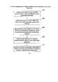
Представленный на фиг. 1 дальномерный (активный) вариант предлагаемого способа включает следующие этапы:Presented in FIG. 1 rangefinder (active) version of the proposed method includes the following steps:
1. Определение дальности до опорной радиостанции в первой выбранной точке траектории движения 101.1. The determination of the distance to the reference radio station at the first selected point of the
2. Счисление пути до второй выбранной точки траектории движения мобильного объекта 102.2. Dead reckoning to the second selected point of the trajectory of the
3. Вычисление длины, азимута и угла места отрезка, соединяющего первую и вторую точки траектории движения мобильного объекта 103.3. The calculation of the length, azimuth and elevation of the segment connecting the first and second points of the trajectory of the
4. Определение дальности до опорной радиостанции во второй точке траектории движения 104.4. The determination of the distance to the reference radio station at the second point of the
5. Решение системы нелинейных уравнений и определение пространственных координат первой и второй точек отрезка пути 105.5. The solution of the system of nonlinear equations and the determination of the spatial coordinates of the first and second points of the
Как показано на фиг. 2, динамическое определение местоположения мобильных объектов для дальномерного (активного) варианта предлагаемого способа основано на измерении минимум двух дальностей R1 и R2 между одной опорной радиостанцией (с известными координатами X0, Y0, Z0) и мобильным объектом в двух точках (с неизвестными координатами X1, Y1, Z1 и X2, Y2, Z2) траектории движения Р, определения длины L, азимута β и угла места α отрезка S, соединяющего первую и вторую точки траектории движения мобильного объекта (здесь S' и Р' - соответствующие проекции отрезка S и траектории движения Р на плоскость OXY).As shown in FIG. 2, the dynamic location of mobile objects for the range-finding (active) version of the proposed method is based on measuring at least two ranges R1 and R2 between one radio reference station (with known coordinates X0 , Y0 , Z0 ) and a mobile object at two points ( with unknown coordinates X1 , Y1 , Z1 and X2 , Y2 , Z2 ) the motion path P, determine the length L, azimuth β and elevation angle α of the segment S connecting the first and second points of the motion path of the mobile object (here S 'and P' are the corresponding projections of the segment S and the path the motion of P to the OXY plane).
Определение местоположения мобильного объекта основано на вычислении пространственных координат двух точек отрезка S посредством решения системы нелинейных уравнений (1).The location of a mobile object is based on the calculation of the spatial coordinates of two points of the segment S by solving a system of nonlinear equations (1).

где (X1, Y1, Z1) и (X2, Y2, Z2) - искомые координаты первой и второй точек траектории движения мобильного объекта.where (X1 , Y1 , Z1 ) and (X2 , Y2 , Z2 ) are the desired coordinates of the first and second points of the trajectory of the mobile object.
Решение системы нелинейных уравнений (1) основано, как правило, на итерационной процедуре (например, методом Левенберга-Марквардта [6]), с учетом исключения зеркальных (неоднозначных) решений посредством сравнения дальностей до первой и второй точек отрезка пути (т.е. R2>R1 или R2-R1) при условии R2≠R1.The solution of the system of nonlinear equations (1) is usually based on an iterative procedure (for example, the Levenberg-Marquardt method [6]), taking into account the exclusion of mirror (ambiguous) solutions by comparing the distances to the first and second points of the path segment (i.e. R2 > R1 or R2 -R1 ) provided that R2 ≠ R1 .
Представленный на фиг. 3 разностно-дальномерный (пассивный) вариант предлагаемого способа включает следующие этапы:Presented in FIG. 3 differential rangefinder (passive) version of the proposed method includes the following steps:
1. Фиксация момента времени приема навигационного сигнала от опорной радиостанции к бортовой шкале времени мобильного объекта в первой точке траектории движения 301.1. Fixing the time of reception of the navigation signal from the reference radio station to the on-board time scale of the mobile object at the first point of the
2. Счисление пути до второй выбранной точки траектории движения мобильного объекта 302.2. Dead reckoning to the second selected point of the trajectory of the
3. Вычисление длины, азимута и угла места отрезка, соединяющего первую и вторую точки траектории движения мобильного объекта 303.3. The calculation of the length, azimuth and elevation angle of the segment connecting the first and second points of the trajectory of the
4. Фиксация момента времени приема навигационного сигнала от опорной радиостанции в бортовой шкале времени мобильного объекта во второй точке траектории движения 304.4. Fixing the time of reception of the navigation signal from the reference radio station in the on-board timeline of the mobile object at the second point of the
5. Вычисление первой разности дальностей 305 посредством умножения разности времени фиксации приема сигналов во второй и первой точках на скорость распространения радиоволн (скорость света).5. The calculation of the first difference of the
6. Счисление пути до третьей выбранной точки траектории движения мобильного объекта 306.6. Dead reckoning to the third selected point of the trajectory of the
7. Вычисление длины, азимута и угла места отрезка, соединяющего вторую и третью точки траектории движения мобильного объекта 307.7. The calculation of the length, azimuth and elevation of the segment connecting the second and third points of the trajectory of the
8. Фиксация момента времени приема навигационного сигнала от опорной радиостанции в бортовой шкале времени мобильного объекта в третьей точке траектории движения 308.8. Fixing the time of reception of the navigation signal from the reference radio station in the on-board timeline of the mobile object at the third point of the
9. Вычисление второй разности дальностей 309 посредством умножения разности времени фиксации приема сигналов в третьей и второй точках на скорость распространения радиоволн (скорость света).9. The calculation of the
10. Решение системы нелинейных уравнений и определение пространственных координат первой, второй и третьей точек 310.10. Solving a system of nonlinear equations and determining the spatial coordinates of the first, second, and
Как показано на фиг. 4, динамическое определение местоположения мобильных объектов для разностно-дальномерного (пассивного) варианта предлагаемого способа основано на измерении минимум двух разностей дальностей ΔR21 и ΔR32 между одной опорной радиостанцией (с известными координатами X0, Y0, Z0) и мобильным объектом в трех точках (с неизвестными координатами X1, Y1, Z1 и X2, Y2, Z2 и X3, Y3, Z3) траектории движения Р, определения длин L1, L2, азимутов β1, β2 и углов места α1, α2 отрезков S1, S2, соединяющих первую и вторую, а также вторую и третью точки траектории движения мобильного объекта соответственно.As shown in FIG. 4, the dynamic location of mobile objects for the differential rangefinding (passive) version of the proposed method is based on measuring at least two distance differences ΔR21 and ΔR32 between one reference radio station (with known coordinates X0 , Y0 , Z0 ) and the mobile object in three points (with unknown coordinates X1 , Y1 , Z1 and X2 , Y2 , Z2 and X3 , Y3 , Z3 ) the trajectory of motion P, determine the lengths L1 , L2 , azimuths β1 , β2 and elevation angles α1 , α2 segments S1 , S2 connecting the first and second, as well as the second and third points of the trajectory ia a mobile facility, respectively.
Определение местоположения мобильного объекта основано на вычислении пространственных координат трех точек отрезков S1 и S2 посредством решения системы нелинейных уравнений (2).The location of a mobile object is based on the calculation of the spatial coordinates of the three points of the segments S1 and S2 by solving a system of nonlinear equations (2).

где (X1, Y1, Z1), и (X2, Y2, Z2) и (X3, Y3, Z3) - искомые координаты первой, второй и третьей точек траектории движения мобильного объекта.where (X1 , Y1 , Z1 ), and (X2 , Y2 , Z2 ) and (X3 , Y3 , Z3 ) are the desired coordinates of the first, second and third points of the trajectory of the mobile object.
Решение системы нелинейных уравнений (2) также основано, как правило, на итерационной процедуре.The solution of the system of nonlinear equations (2) is also based, as a rule, on an iterative procedure.
Также необходимо отметить, что для решения навигационной задачи возможно использование большего количества точек траектории движения, т.е. больше двух для дальномерного и больше трех для разностно-дальномерного вариантов предлагаемого способа. Соответственно, возрастает количество уравнений в системах вида (1) и (2), увеличивается задержка решения навигационной задачи и возрастает ошибка определения координат, вследствие более длительного счисления пути, что, как правило, нецелесообразно.It should also be noted that to solve the navigation problem it is possible to use more points of the motion path, i.e. more than two for the rangefinder and more than three for the differential rangefinder variants of the proposed method. Correspondingly, the number of equations in systems of the form (1) and (2) increases, the delay in solving the navigation problem increases, and the error in determining coordinates increases due to a longer dead reckoning, which is usually impractical.
Блок-схема алгоритма, реализующего предлагаемый способ динамического определения местоположения мобильных объектов, представленного на фиг. 5, включает:A block diagram of an algorithm implementing the proposed method for dynamically determining the location of mobile objects shown in FIG. 5 includes:
- блок инициализации 501, в котором устанавливаются координаты опорной радиостанции (X0, Y0, Z0), известные заранее или переданные по радиоканалу опорной радиостанцией или установленные в ноль при относительном определении местоположении мобильного объекта;- an
- блок установки в ноль начальных координат первой выбранной точки траектории движения 502, относительно которой будут определяться относительные координаты второй и третьей (в случае пассивного варианта) точек на основе счисления пути;- a block of setting to zero the initial coordinates of the first selected point of the
- выбор активного или пассивного варианта способа динамического определения местоположения 503, в зависимости от наличия или отсутствия обратного канала связи с опорной радиостанцией, соображений скрытности и других причин;- the choice of an active or passive version of the dynamic
- определение координат первой, второй и третьей точек траектории движения относительно опорной радиостанции на основе разностно-дальномерного (пассивного) варианта предлагаемого способа 504, представленного выше и на фиг. 3;- determination of the coordinates of the first, second and third points of the trajectory relative to the reference radio station based on the differential-range (passive) version of the proposed
- определение координат первой и второй точек траектории движения относительно опорной радиостанции на основе дальномерного (активного) варианта предлагаемого способа 505, представленного выше и на фиг. 1.- determination of the coordinates of the first and second points of the trajectory relative to the reference radio station based on the rangefinder (active) version of the proposed
Целесообразно рассматривать следующие варианты осуществления изобретения (фиг. 6), такие как:It is advisable to consider the following embodiments of the invention (Fig. 6), such as:
1. Использование приемопередатчика радиосигналов на опорной радиостанции 601, а также в бортовой системе мобильного объекта 602: приемопередатчик радиосигналов 603, ИНС (в составе трехосевых гироскопов и акселерометров) в качестве системы счисления пути 604, трехосевой магнитометр в качестве вычислителя азимута и угла места 605, электронно-вычислительную машину в качестве вычислителя координат точек траектории движения 606.1. The use of a radio signal transceiver on a
2. Использование передатчика радиосигналов на опорной радиостанции 601, а также в бортовой системе мобильного объекта 602: приемник радиосигналов 603, ИНС (в составе трехосевых гироскопов и акселерометров) в качестве системы счисления пути 604, трехосевой магнитометр в качестве вычислителя азимута и угла места 605, электронно-вычислительную машину в качестве вычислителя координат точек траектории движения 606 (только для разностно-дальномерного предлагаемого варианта способа).2. The use of a radio signal transmitter on a
3. Использование приемопередатчика радиосигналов на опорной радиостанции 601, а также в бортовой системе мобильного объекта 602: приемопередатчик радиосигналов 603, ИНС (в составе трехосевых гироскопов и акселерометров) и одометр в качестве системы счисления пути 604, трехосевой магнитометр в качестве вычислителя азимута и угла места 605, электронно-вычислительную машину в качестве вычислителя координат точек траектории движения 606.3. The use of a radio signal transceiver on a
4. Использование передатчика радиосигналов на опорной радиостанции 601, а также в бортовой системе мобильного объекта 602: приемник радиосигналов 603, ИНС (в составе трехосевых гироскопов и акселерометров) и одометр в качестве системы счисления пути 604, трехосевой магнитометр в качестве вычислителя азимута и угла места 605, электронно-вычислительную машину в качестве вычислителя координат точек траектории движения 606 (только для разностно-дальномерного предлагаемого варианта способа).4. The use of a radio signal transmitter on a
Представленные варианты реализации предлагаемого способа особенно актуальны для роботов и БПЛА, как правило, содержащих на борту ИНС, включающую трехосевые гироскопы и акселерометры, трехосевые магнитометры, приемник или приемопередатчик радиосигналов.The presented embodiments of the proposed method are especially relevant for robots and UAVs, as a rule, containing an ANN on board, including three-axis gyroscopes and accelerometers, three-axis magnetometers, a radio signal receiver or transceiver.
Список источниковList of sources
1. Patent application US №4,713,767, application number US 730,572. - Apparatus for calculating position of vehicle. Published 15.12.1987.1. Patent application US No. 4,713,767, application number US 730,572. - Apparatus for calculating position of vehicle. Published 12/15/1987.
2. Patent application US №4,731,613, application number US 804,511. - Positioning system for a vehicle. Published 15.03.1988.2. Patent application US No. 4,731,613, application number US 804,511. - Positioning system for a vehicle. Published 03/15/1988.
3. Patent application US №2005/0032526 A1, application number US 10/909,819. - Wireless communication positioning method and system. Published 10.02.2005.3. Patent application US No. 2005/0032526 A1, application number US 10 / 909.819. - Wireless communication positioning method and system. Published 02/10/2005.
4. Patent application US №5,132,695, application number US 645,314. - Radio navigation system. Published 21.07.1992.4. Patent application US No. 5,132,695, application number US 645,314. - Radio navigation system. Published July 21, 1992.
5. Методы спутникового и наземного позиционирования. Перспективы развития технологий обработки сигналов // Под ред. Д. Дардари, Э. Фаллетти, М. Луизе. Москва: Техносфера, 2012. - 528 с., ISBN 978-5-94836-338-7.5. Methods of satellite and ground positioning. Prospects for the development of signal processing technologies // Ed. D. Dardari, E. Falletti, M. Louise. Moscow: Technosphere, 2012 .-- 528 p., ISBN 978-5-94836-338-7.
6. Васильев Ф.П. Методы оптимизации. Москва: Факториал Пресс, 2002. - 824 с., ISBN 5-88688-056-9.6. Vasiliev F.P. Optimization methods. Moscow: Factorial Press, 2002 .-- 824 p., ISBN 5-88688-056-9.
Claims (1)
Translated fromRussianPriority Applications (1)
| Application Number | Priority Date | Filing Date | Title |
|---|---|---|---|
| RU2016109139ARU2624790C1 (en) | 2016-03-14 | 2016-03-14 | Dynamic positioning method of mobile objects |
Applications Claiming Priority (1)
| Application Number | Priority Date | Filing Date | Title |
|---|---|---|---|
| RU2016109139ARU2624790C1 (en) | 2016-03-14 | 2016-03-14 | Dynamic positioning method of mobile objects |
Publications (1)
| Publication Number | Publication Date |
|---|---|
| RU2624790C1true RU2624790C1 (en) | 2017-07-06 |
Family
ID=59312847
Family Applications (1)
| Application Number | Title | Priority Date | Filing Date |
|---|---|---|---|
| RU2016109139ARU2624790C1 (en) | 2016-03-14 | 2016-03-14 | Dynamic positioning method of mobile objects |
Country Status (1)
| Country | Link |
|---|---|
| RU (1) | RU2624790C1 (en) |
Cited By (5)
| Publication number | Priority date | Publication date | Assignee | Title |
|---|---|---|---|---|
| RU2678371C2 (en)* | 2017-07-14 | 2019-01-28 | Валерий Дмитриевич Федорищев | Mobile objects coordinates and axes position angles determining method by means of installed on objects and observation points atomic clocks |
| RU2743048C1 (en)* | 2019-09-09 | 2021-02-15 | Борис Викторович Рыжков | Method for determining the relative position of navigation objects and a system for using this method |
| CN113465616A (en)* | 2021-06-28 | 2021-10-01 | 湖北亿咖通科技有限公司 | Track abnormal point detection method and device, electronic equipment, computer program product and computer readable storage medium |
| CN114485625A (en)* | 2022-01-27 | 2022-05-13 | 北京理工大学前沿技术研究院 | A trajectory positioning and ranging device, method and unmanned driving system |
| RU2779283C1 (en)* | 2021-11-24 | 2022-09-05 | Федеральное государственное казенное военное образовательное учреждение высшего образования "Военный учебно-научный центр Военно-воздушных сил "Военно-воздушная академия имени профессора Н.Е. Жуковского и Ю.А. Гагарина" (г. Воронеж) Министерства обороны Российской Федерации | Method for determining an object's own location in space and a device implementing it |
Citations (5)
| Publication number | Priority date | Publication date | Assignee | Title |
|---|---|---|---|---|
| US4731613A (en)* | 1984-12-07 | 1988-03-15 | Nissan Motor Company, Limited | Positioning system for a vehicle |
| US5132695A (en)* | 1988-02-01 | 1992-07-21 | Thomson Csf | Radio navigation system |
| RU2023983C1 (en)* | 1992-05-14 | 1994-11-30 | Раменское приборостроительное конструкторское бюро | Complex navigation system |
| RU2082098C1 (en)* | 1993-09-23 | 1997-06-20 | Государственный научно-исследовательский институт авиационных систем | Method of integration of internal navigation systems and complex navigation system |
| RU2202102C2 (en)* | 2000-12-18 | 2003-04-10 | ГУП Воронежский научно-исследовательский институт связи | Procedure establishing positions of mobile objects and device for its realization |
- 2016
- 2016-03-14RURU2016109139Apatent/RU2624790C1/ennot_activeIP Right Cessation
Patent Citations (5)
| Publication number | Priority date | Publication date | Assignee | Title |
|---|---|---|---|---|
| US4731613A (en)* | 1984-12-07 | 1988-03-15 | Nissan Motor Company, Limited | Positioning system for a vehicle |
| US5132695A (en)* | 1988-02-01 | 1992-07-21 | Thomson Csf | Radio navigation system |
| RU2023983C1 (en)* | 1992-05-14 | 1994-11-30 | Раменское приборостроительное конструкторское бюро | Complex navigation system |
| RU2082098C1 (en)* | 1993-09-23 | 1997-06-20 | Государственный научно-исследовательский институт авиационных систем | Method of integration of internal navigation systems and complex navigation system |
| RU2202102C2 (en)* | 2000-12-18 | 2003-04-10 | ГУП Воронежский научно-исследовательский институт связи | Procedure establishing positions of mobile objects and device for its realization |
Non-Patent Citations (1)
| Title |
|---|
| Ботуз С.П. Интеллектуальные интерактивные системы и технологии управления удаленным доступом: Учебное пособие. 3-е изд., доп. - М.: СОЛОН-Пресс, 2014. - 340 с. (30,34 п.л.) + CD.* |
Cited By (9)
| Publication number | Priority date | Publication date | Assignee | Title |
|---|---|---|---|---|
| RU2678371C2 (en)* | 2017-07-14 | 2019-01-28 | Валерий Дмитриевич Федорищев | Mobile objects coordinates and axes position angles determining method by means of installed on objects and observation points atomic clocks |
| RU2743048C1 (en)* | 2019-09-09 | 2021-02-15 | Борис Викторович Рыжков | Method for determining the relative position of navigation objects and a system for using this method |
| CN113465616A (en)* | 2021-06-28 | 2021-10-01 | 湖北亿咖通科技有限公司 | Track abnormal point detection method and device, electronic equipment, computer program product and computer readable storage medium |
| CN113465616B (en)* | 2021-06-28 | 2023-06-16 | 湖北亿咖通科技有限公司 | Track abnormal point detection method and device, electronic equipment and storage medium |
| RU2779283C1 (en)* | 2021-11-24 | 2022-09-05 | Федеральное государственное казенное военное образовательное учреждение высшего образования "Военный учебно-научный центр Военно-воздушных сил "Военно-воздушная академия имени профессора Н.Е. Жуковского и Ю.А. Гагарина" (г. Воронеж) Министерства обороны Российской Федерации | Method for determining an object's own location in space and a device implementing it |
| CN114485625A (en)* | 2022-01-27 | 2022-05-13 | 北京理工大学前沿技术研究院 | A trajectory positioning and ranging device, method and unmanned driving system |
| RU2784103C1 (en)* | 2022-06-09 | 2022-11-23 | Акционерное общество научно-внедренческое предприятие "ПРОТЕК" | Method for monitoring spatio-temporal state of a group of moving objects during local navigation |
| RU2784109C1 (en)* | 2022-06-09 | 2022-11-23 | Акционерное общество научно-внедренческое предприятие "ПРОТЕК" | Method for monitoring spatio-temporal state of a group of moving objects during local navigation |
| RU2790808C1 (en)* | 2022-06-27 | 2023-02-28 | Акционерное общество научно-внедренческое предприятие "ПРОТЕК" | Method for monitoring spatio-temporal state of a group of moving objects during local navigation |
Similar Documents
| Publication | Publication Date | Title |
|---|---|---|
| EP3430419B1 (en) | Estimating locations of mobile devices in a wireless tracking system | |
| CN104698437B (en) | A UWB-based underground vehicle positioning method | |
| Zwirello et al. | Sensor data fusion in UWB-supported inertial navigation systems for indoor navigation | |
| RU2624790C1 (en) | Dynamic positioning method of mobile objects | |
| US9024805B1 (en) | Radar antenna elevation error estimation method and apparatus | |
| Shen et al. | A DSRC Doppler/IMU/GNSS tightly-coupled cooperative positioning method for relative positioning in VANETs | |
| CN110553655A (en) | Autonomous vehicle positioning using 5G infrastructure | |
| US10908300B2 (en) | Navigation method, navigation device and navigation system | |
| US7508344B2 (en) | Systems and methods for TDOA/FDOA location | |
| JP2007101535A (en) | Method and system for satellite navigation | |
| CN103968836A (en) | Method and device for calculating position of moving target based on time sequence pseudo-range differential | |
| KR20110085204A (en) | Positioning system and method of a terminal including a plurality of antennas | |
| CN113295174A (en) | Lane-level positioning method, related device, equipment and storage medium | |
| Saleh et al. | 5G-enabled vehicle positioning using EKF with dynamic covariance matrix tuning | |
| Rus et al. | LoRa communication and geolocation system for sensors network | |
| Villien et al. | UWB-aided GNSS/INS fusion for resilient positioning in GNSS challenged environments | |
| KR102142923B1 (en) | coordinate positioning system | |
| RU2388008C1 (en) | Method of determining angular position of aircraft based on satellite navigation system receiver data | |
| KR101058098B1 (en) | A terminal and a system for measuring its own location according to the location information of another terminal and the reliability of the location information and a method for measuring the location | |
| US20080186232A1 (en) | Method of and apparatus for true north azimuth determination using the combination of crossed loop antenna and radio positioning system technologies | |
| KR100715178B1 (en) | Position detection method of observation target | |
| KR102743679B1 (en) | Coordinate positioning system of positioning blind area | |
| JP2017032486A (en) | Mobile terminal positioning system, mobile terminal, and positioning program | |
| CN112764076B (en) | Method for positioning following navigation system based on UWB and GPS | |
| Saleh et al. | Integrated 5G mmWave Positioning in Deep Urban Environments: Advantages and Challenges |
Legal Events
| Date | Code | Title | Description |
|---|---|---|---|
| MM4A | The patent is invalid due to non-payment of fees | Effective date:20180315 |