RU2621898C1 - Method of measuring distance between devices with direct device-device communication in wireless communication system and appropriate device - Google Patents
Method of measuring distance between devices with direct device-device communication in wireless communication system and appropriate deviceDownload PDFInfo
- Publication number
- RU2621898C1 RU2621898C1RU2016101235ARU2016101235ARU2621898C1RU 2621898 C1RU2621898 C1RU 2621898C1RU 2016101235 ARU2016101235 ARU 2016101235ARU 2016101235 ARU2016101235 ARU 2016101235ARU 2621898 C1RU2621898 C1RU 2621898C1
- Authority
- RU
- Russia
- Prior art keywords
- time
- target
- downlink
- enb
- signal
- Prior art date
Links
Images


Classifications
- H—ELECTRICITY
- H04—ELECTRIC COMMUNICATION TECHNIQUE
- H04W—WIRELESS COMMUNICATION NETWORKS
- H04W56/00—Synchronisation arrangements
- H04W56/001—Synchronization between nodes
- H04W56/0015—Synchronization between nodes one node acting as a reference for the others
- H—ELECTRICITY
- H04—ELECTRIC COMMUNICATION TECHNIQUE
- H04W—WIRELESS COMMUNICATION NETWORKS
- H04W56/00—Synchronisation arrangements
- H04W56/0055—Synchronisation arrangements determining timing error of reception due to propagation delay
- H04W56/0065—Synchronisation arrangements determining timing error of reception due to propagation delay using measurement of signal travel time
- H—ELECTRICITY
- H04—ELECTRIC COMMUNICATION TECHNIQUE
- H04W—WIRELESS COMMUNICATION NETWORKS
- H04W76/00—Connection management
- H04W76/10—Connection setup
- H04W76/14—Direct-mode setup
- G—PHYSICS
- G01—MEASURING; TESTING
- G01S—RADIO DIRECTION-FINDING; RADIO NAVIGATION; DETERMINING DISTANCE OR VELOCITY BY USE OF RADIO WAVES; LOCATING OR PRESENCE-DETECTING BY USE OF THE REFLECTION OR RERADIATION OF RADIO WAVES; ANALOGOUS ARRANGEMENTS USING OTHER WAVES
- G01S11/00—Systems for determining distance or velocity not using reflection or reradiation
- G01S11/02—Systems for determining distance or velocity not using reflection or reradiation using radio waves
- H—ELECTRICITY
- H04—ELECTRIC COMMUNICATION TECHNIQUE
- H04W—WIRELESS COMMUNICATION NETWORKS
- H04W4/00—Services specially adapted for wireless communication networks; Facilities therefor
- H04W4/02—Services making use of location information
- H04W4/023—Services making use of location information using mutual or relative location information between multiple location based services [LBS] targets or of distance thresholds
- H—ELECTRICITY
- H04—ELECTRIC COMMUNICATION TECHNIQUE
- H04W—WIRELESS COMMUNICATION NETWORKS
- H04W64/00—Locating users or terminals or network equipment for network management purposes, e.g. mobility management
Landscapes
- Engineering & Computer Science (AREA)
- Computer Networks & Wireless Communication (AREA)
- Signal Processing (AREA)
- Physics & Mathematics (AREA)
- General Physics & Mathematics (AREA)
- Radar, Positioning & Navigation (AREA)
- Remote Sensing (AREA)
- Mobile Radio Communication Systems (AREA)
Abstract
Description
Translated fromRussianОбласть техникиTechnical field
[1] Настоящее изобретение относится к системе беспроводной связи и, более конкретно, к способу для измерения расстояния между устройствами через прямую связь устройство-устройство в системе беспроводной связи и соответствующему прибору.[1] The present invention relates to a wireless communication system and, more particularly, to a method for measuring the distance between devices via direct device-to-device communication in a wireless communication system and a corresponding device.
Уровень техникиState of the art
[2] В качестве иллюстративного примера системы беспроводной связи настоящего изобретения далее будут подробно описаны системы связи стандарта "Долгосрочное развитие сетей связи" партнерского проекта по системам 3-го поколения (LTE 3GPP) и стандарта Усовершенствованная технология LTE (LTE-A).[2] As an illustrative example of a wireless communication system of the present invention, communication systems of the “Long-Term Development of Communication Networks” standard of the 3rd Generation Partnership (LTE 3GPP) and Advanced LTE (LTE-A) technology will be described in detail below.
[3] Фиг. 1 является концептуальной схемой, изображающей сетевую структуру развитой универсальной системы мобильной связи (E-UMTS) в качестве иллюстративной системы мобильной связи. В частности, развитая универсальная система мобильной связи (E-UMTS) возникла из прежней системы UMTS, и ее основная стандартизация теперь проводится партнерским проектом по системам 3-го поколения (3GPP). E-UMTS может также называться стандартом "Долгосрочное развитие сетей связи" (LTE). Для получения подробной информации о технических спецификациях UMTS и E-UMTS см. Релиз 7 и Релиз 8 “Партнерского проекта по системам 3-го поколения; группа по техническим спецификациям сетей радиодоступа”.[3] FIG. 1 is a conceptual diagram depicting a network structure of an evolved universal mobile communication system (E-UMTS) as an illustrative mobile communication system. In particular, the developed universal mobile communication system (E-UMTS) arose from the previous UMTS system, and its main standardization is now carried out by a partnership project for 3rd generation systems (3GPP). E-UMTS may also be referred to as the Long-Term Development of Communication Networks (LTE) standard. For detailed information on the technical specifications of UMTS and E-UMTS, see
[4] Как показано на фиг. 1, система E-UMTS в общем состоит из пользовательского оборудования (UE) 120, базовых станций (или eNode-B) 110a и 110b и шлюза доступа (AG), который расположен в конце сети (E-UTRAN) и соединен с внешней сетью. Как правило, eNode-B может одновременно передавать множество потоков данных для услуги широковещательной передачи, услуги многоадресной передачи и/или услуги одноадресной передачи.[4] As shown in FIG. 1, the E-UMTS system generally consists of user equipment (UE) 120, base stations (or eNode-B) 110a and 110b, and an access gateway (AG) located at the end of the network (E-UTRAN) and connected to an external network . Typically, an eNode-B can simultaneously transmit multiple data streams for a broadcast service, a multicast service, and / or a unicast service.
[5] Каждый eNode-B включает в себя одну или несколько сот. Одна сота eNode-B задана, чтобы использовать ширину полосы частот, такую как, например, 1.25, 2.5, 5, 10, 15 или 20 МГц, для обеспечения услуги передачи по нисходящей линии связи или восходящей линии связи для пользовательского оборудования (UE). Здесь различные соты могут задаваться, чтобы использовать различную ширину полосы частот. eNode-B управляет передачей и приемом данных для нескольких UE. Вместе с данными нисходящей линии связи (DL) eNode-B передает информацию о планировании нисходящей линии связи (DL) соответствующему UE, чтобы сообщить соответствующему UE временные/частотные области, где будут переданы данные, информацию о кодировании, информацию о размере данных, информацию, связанную с гибридным автоматическим запросом на повторную передачу данных (HARQ) и т.п. Вместе с данными восходящей линии связи (UL) eNode-B передает информацию о планировании UL соответствующему UE, чтобы сообщить соответствующему UE временные/частотные области, которые могут использоваться соответствующим UE, информацию о кодировании, информацию о размере данных, информацию, связанную с HARQ и т.п. Между несколькими eNode-B может использоваться интерфейс для передачи трафика пользователя или трафика управления. Базовая сеть (CN) может включать в себя шлюз доступа (AG) и узел сети для пользовательской регистрации UE. AG администрирует мобильность UE на основании области отслеживания (TA), состоящей из нескольких сот.[5] Each eNode-B includes one or more cells. One eNode-B cell is defined to use a bandwidth, such as, for example, 1.25, 2.5, 5, 10, 15, or 20 MHz, to provide a downlink or uplink transmission service for a user equipment (UE). Here, different cells can be set to use different bandwidths. The eNode-B controls the transmission and reception of data for multiple UEs. Together with the downlink (DL) data, the eNode-B transmits the downlink (DL) scheduling information to the corresponding UE to inform the corresponding UE of the time / frequency areas where data, encoding information, data size information, information, associated with the hybrid automatic request for retransmission of data (HARQ), etc. Together with the uplink (UL) data, the eNode-B transmits UL scheduling information to the corresponding UE to inform the corresponding UE of the time / frequency domains that can be used by the corresponding UE, encoding information, data size information, HARQ related information, and etc. Between multiple eNode-Bs, an interface may be used to transmit user traffic or control traffic. The core network (CN) may include an access gateway (AG) and a network node for user registration of the UE. The AG administers the mobility of the UE based on a tracking area (TA) of several hundred.
[6] Хотя технология беспроводной связи была разработана для технологии LTE на основе технологии WCDMA, пользователи и организации постоянно требуют новых функций и услуг. Кроме того, разрабатываются другие технологии беспроводного доступа, так что имеется потребность в новой или улучшенной технологии беспроводного доступа, чтобы остаться конкурентоспособными в долгосрочной перспективе. Например, уменьшение стоимости на бит, увеличение доступности услуг, адаптивное использование полосы частот, простая структура, интерфейс открытого типа и соответствующее потребление энергии пользовательского оборудования (UE) необходимо для новой или улучшенной технологии беспроводного доступа.[6] Although wireless technology has been developed for LTE technology based on WCDMA technology, users and organizations are constantly demanding new features and services. In addition, other wireless access technologies are being developed, so there is a need for new or improved wireless access technologies to remain competitive in the long run. For example, reducing the cost per bit, increasing the availability of services, adaptive use of the frequency band, a simple structure, an open type interface and the corresponding energy consumption of user equipment (UE) are necessary for a new or improved wireless access technology.
Сущность изобретенияSUMMARY OF THE INVENTION
Техническая проблемаTechnical problem
[7] Целью настоящего изобретения, разработанного для решения этой проблемы, является способ для измерения расстояния между устройствами с помощью прямой связи устройство-устройство в системе беспроводной связи и соответствующий прибор.[7] An object of the present invention, developed to solve this problem, is a method for measuring the distance between devices using direct device-device communication in a wireless communication system and a corresponding device.
Техническое решениеTechnical solution
[8] В одном аспекте настоящего изобретения способ для передачи пользовательским оборудованием (UE) сигнала для прямой связи устройство-устройство (D2D) в системе беспроводной связи включает в себя этапы, на которых: принимают подкадр нисходящей линии связи от опорного eNB; передают первый сигнал партнерскому UE на основании границы подкадра нисходящей линии связи; и передают второй сигнал партнерскому UE с заранее определенным смещением до границы подкадра нисходящей линии связи.[8] In one aspect of the present invention, a method for transmitting a user equipment (UE) signal for direct device-to-device (D2D) signal in a wireless communication system includes the steps of: receiving a downlink subframe from a reference eNB; transmitting the first signal to the partner UE based on the border of the downlink subframe; and transmitting the second signal to the partner UE with a predetermined offset to the border of the downlink subframe.
[9] В другом аспекте настоящего изобретения UE, выполняющее связь D2D в системе беспроводной связи, включает в себя: радиочастотный (RF) модуль связи для передачи/приема сигнала от опорного eNB или партнерского UE по связи D2D; и процессор для обработки сигнала, при этом процессор выполнен с возможностью управления RF модулем связи для передачи первого сигнала партнерскому UE на основании границы подкадра нисходящей линии связи, принятого от опорного eNB, и передачи второго сигнала партнерскому UE с заранее определенным смещением до границы подкадра нисходящей линии связи.[9] In another aspect of the present invention, a UE performing D2D communication in a wireless communication system includes: a radio frequency (RF) communication module for transmitting / receiving a signal from a reference eNB or a partner UE on D2D communication; and a processor for processing the signal, wherein the processor is configured to control the RF communication module to transmit the first signal to the partner UE based on the border of the downlink subframe received from the reference eNB, and transmit the second signal to the partner UE with a predetermined offset to the border of the downlink subframe communication.
[10] Граница подкадра нисходящей линии связи может быть задержана на величину задержки распространения в соответствии с расстоянием до опорного eNB от того момента, когда опорный eNB передает подкадр нисходящей линии связи, и он принимается.[10] The boundary of the downlink subframe may be delayed by the amount of propagation delay in accordance with the distance to the reference eNB from the moment the reference eNB transmits the downlink subframe, and it is received.
[11] Первый сигнал может включать в себя информацию о смещении. Смещение может быть задано равным значению опережения (TA) для передачи сигнала восходящей линии связи опорному eNB. UE может принимать информацию о смещении от рабочего eNB.[11] The first signal may include bias information. The offset can be set equal to the lead value (TA) for transmitting the uplink signal to the reference eNB. The UE may receive offset information from the working eNB.
[12] Второй сигнал может быть задержан на величину задержки распространения в соответствии с расстоянием до партнерского UE от того момента, когда второй сигнал передается и принимается партнерским UE.[12] The second signal may be delayed by the amount of propagation delay in accordance with the distance to the partner UE from the moment the second signal is transmitted and received by the partner UE.
Полезные эффекты изобретенияBeneficial effects of the invention
[13] В соответствии с вариантами воплощения настоящего изобретения можно эффективно измерять расстояние между устройствами с использованием прямой связи устройство-устройство в системе беспроводной связи.[13] According to embodiments of the present invention, it is possible to effectively measure the distance between devices using direct device-device communication in a wireless communication system.
[14] Специалистам в области техники будет понятно, что эффекты, которые могут быть достигнуты с помощью настоящего изобретения, не ограничиваются тем, что было, в частности, описано выше, и другие преимущества настоящего изобретения будут более понятны из следующего подробного описания.[14] Those skilled in the art will understand that the effects that can be achieved by the present invention are not limited to what was, in particular, described above, and other advantages of the present invention will be more apparent from the following detailed description.
Описание чертежейDescription of drawings
[15] Фиг. 1 является концептуальной схемой, изображающей сетевую структуру развитой универсальной системы мобильной связи (E-UMTS) в качестве иллюстративной системы мобильной связи.[15] FIG. 1 is a conceptual diagram depicting a network structure of an evolved universal mobile communication system (E-UMTS) as an illustrative mobile communication system.
[16] Фиг. 2 изображает плоскость управления и плоскость пользователя (U-плоскость) протокола радиоинтерфейса между пользовательским оборудованием (UE) и E-UTRAN в соответствии со стандартом сети беспроводного доступа 3GPP.[16] FIG. 2 shows a control plane and a user plane (U-plane) of a radio interface protocol between a user equipment (UE) and an E-UTRAN in accordance with a 3GPP wireless access network standard.
[17] Фиг. 3 является концептуальной схемой, изображающей физические каналы, используемые в системе LTE 3GPP в качестве иллюстративной системы беспроводной связи и общий способ для передачи сигнала с использованием физических каналов.[17] FIG. 3 is a conceptual diagram depicting physical channels used in the 3GPP LTE system as an illustrative wireless communication system and a general method for transmitting a signal using physical channels.
[18] Фиг. 4 является концептуальной схемой, изображающей радиокадр нисходящей линии связи для использования в системе LTE.[18] FIG. 4 is a conceptual diagram illustrating a downlink radio frame for use in an LTE system.
[19] Фиг. 5 является концептуальной схемой, изображающей радиокадр восходящей линии связи для использования в системе LTE.[19] FIG. 5 is a conceptual diagram illustrating an uplink radio frame for use in an LTE system.
[20] Фиг. 6 является схемой, изображающей структуру радиокадра для использования в системе TDD стандарта "Долгосрочное развитие сетей связи" (LTE).[20] FIG. 6 is a diagram illustrating a structure of a radio frame for use in the Long Term Evolution of Communication Networks (LTE) TDD system.
[21] Фиг. 7 изображает момент передачи и приема радиокадра восходящей линии связи и радиокадра нисходящей линии связи в системе LTE.[21] FIG. 7 depicts the timing of transmission and reception of an uplink radio frame and a downlink radio frame in an LTE system.
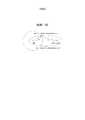
[22] Фиг. 8 является концептуальной схемой, изображающей прямую связь D2D.[22] FIG. 8 is a conceptual diagram depicting a direct D2D connection.
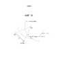
[23] Фиг. 9 изображает момент передачи DS посредством целевого UE и момент приема DS рабочим UE в соответствии с вариантом воплощения настоящего изобретения.[23] FIG. 9 depicts a DS transmission time by a target UE and a DS reception time by a working UE in accordance with an embodiment of the present invention.
[24] Фиг. 10 изображает области, в которых может быть расположено целевое UE, которые вычислены в соответствии с вариантом воплощения настоящего изобретения.[24] FIG. 10 depicts areas in which a target UE may be located, which are computed in accordance with an embodiment of the present invention.
[25] Фиг. 11 изображает области, в которых может быть расположено целевое UE, которые вычислены в соответствии с вариантом воплощения настоящего изобретения.[25] FIG. 11 depicts areas in which a target UE may be located, which are computed in accordance with an embodiment of the present invention.
[26] Фиг. 12 изображает пример передачи и приема сигнала с использованием прямой связи устройство-устройство, то есть сигнала D2D, в соответствии с вариантом воплощения настоящего изобретения.[26] FIG. 12 depicts an example of transmitting and receiving a signal using direct device-to-device communication, i.e., a D2D signal, in accordance with an embodiment of the present invention.
[27] Фиг. 13 изображает иллюстративный способ для детектирования местоположения целевого UE в соответствии с вариантом воплощения настоящего изобретения.[27] FIG. 13 depicts an illustrative method for detecting the location of a target UE in accordance with an embodiment of the present invention.
[28] Фиг. 14 изображает другой иллюстративный способ для детектирования местоположения целевого UE в соответствии с вариантом воплощения настоящего изобретения.[28] FIG. 14 depicts another illustrative method for detecting the location of a target UE in accordance with an embodiment of the present invention.
[29] Фиг. 15 изображает другой иллюстративный способ для детектирования местоположения целевого UE в соответствии с вариантом воплощения настоящего изобретения.[29] FIG. 15 depicts another illustrative method for detecting the location of a target UE in accordance with an embodiment of the present invention.
[30] Фиг. 16 изображает пример уменьшения числа потенциальных местоположений целевого UE путем добавления круга, соответствующего расстоянию между соответствующим опорным eNB DS и целевым UE в соответствии с вариантом воплощения настоящего изобретения.[30] FIG. 16 depicts an example of reducing the number of potential locations of a target UE by adding a circle corresponding to the distance between the corresponding reference DS eNB and the target UE in accordance with an embodiment of the present invention.
[31] Фиг. 17 изображает пример измерения местоположения целевого UE или расстояния до целевого UE с использованием разницы во времени приема сигнала DS в соответствии с вариантом воплощения настоящего изобретения.[31] FIG. 17 depicts an example of measuring a location of a target UE or a distance to a target UE using a time difference of a DS signal in accordance with an embodiment of the present invention.
[32] Фиг. 18 изображает другой пример измерения местоположения целевого UE или расстояния до целевого UE с использованием разницы во времени приема сигнала DS в соответствии с вариантом воплощения настоящего изобретения.[32] FIG. 18 depicts another example of measuring the location of a target UE or the distance to a target UE using a DS signal reception time difference according to an embodiment of the present invention.
[33] Фиг. 19 изображает пример измерения расстояния до целевого UE путем обнаружения расстояния между каждым опорным eNB и целевым UE в соответствии с вариантом воплощения настоящего изобретения.[33] FIG. 19 depicts an example of measuring a distance to a target UE by detecting a distance between each reference eNB and a target UE according to an embodiment of the present invention.
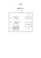
[34] Фиг. 20 является блок-схемой, изображающей коммуникационное устройство в соответствии с вариантами воплощения настоящего изобретения.[34] FIG. 20 is a block diagram depicting a communication device in accordance with embodiments of the present invention.
Лучший режимBest mode
[35] Теперь будет дано подробное описание предпочтительных вариантов воплощения настоящего изобретения, примеры которых изображены на прилагаемых чертежах. Везде, где это возможно, на чертежах будут использоваться одинаковые ссылочные позиции для обозначения одинаковых или подобных частей. Упомянутые выше и другие конфигурации, операции и признаки настоящего изобретения будут понятны из вариантов воплощения изобретения, описанных ниже со ссылкой на прилагаемые чертежи. Варианты воплощения, описанные ниже, являются примерами, в которых технические признаки изобретения применены к системе партнерского проекта по системам 3-го поколения (3GPP).[35] A detailed description will now be given of preferred embodiments of the present invention, examples of which are shown in the accompanying drawings. Wherever possible, the same reference numerals will be used throughout the drawings to refer to the same or like parts. The above and other configurations, operations and features of the present invention will be apparent from the embodiments of the invention described below with reference to the accompanying drawings. The embodiments described below are examples in which the technical features of the invention are applied to a 3rd generation systems partnership project system (3GPP).
[36] Хотя для удобства описания и лучшего понимания настоящего изобретения вариант воплощения настоящего изобретения будет раскрыт на основе системы LTE и системы LTE-A, следует отметить, что объем или сущность настоящего изобретения не ограничиваются ими и при необходимости могут быть применены к другим системам связи. Кроме того, хотя вариант воплощения настоящего изобретения будет раскрыт, например, на основе схемы FDD, объем или сущность варианта воплощения настоящего изобретения не ограничиваются этим и при необходимости могут также быть применены к схемам HFDD и TDD.[36] Although for convenience of description and a better understanding of the present invention, an embodiment of the present invention will be disclosed based on an LTE system and an LTE-A system, it should be noted that the scope or essence of the present invention is not limited to them and, if necessary, can be applied to other communication systems . Furthermore, although an embodiment of the present invention will be disclosed, for example, based on an FDD scheme, the scope or nature of an embodiment of the present invention is not limited to this and, if necessary, can also be applied to HFDD and TDD schemes.
[37] Фиг. 2 изображает плоскость управления и плоскость пользователя (U-плоскость) протокола радиоинтерфейса между пользовательским оборудованием (UE) и E-UTRAN в соответствии со стандартом сети беспроводного доступа 3GPP. Через плоскость управления передаются управляющие сообщения, которые используют UE и сетевое использование для администрирования вызовов. Через плоскость пользователя передаются данные (например, речевая информация или пакетные данные сети Интернет), генерируемые на уровне приложений.[37] FIG. 2 shows a control plane and a user plane (U-plane) of a radio interface protocol between a user equipment (UE) and an E-UTRAN in accordance with a 3GPP wireless access network standard. Control messages are transmitted through the control plane, which use the UE and network usage to administer calls. Data is transmitted through the user plane (for example, voice information or Internet packet data) generated at the application level.
[38] Физический уровень, который является первым уровнем, предоставляет услугу передачи информации верхнему уровню, используя физический канал. Физический уровень соединен с уровнем управления доступом к среде (MAC), расположенным над физическим уровнем, через транспортный канал. Данные передаются между уровнем MAC и физическим уровнем через транспортный канал. Передача данных между различными физическими уровнями, в частности, между соответствующими физическими уровнями передающей и принимающей сторон, выполняется через физический канал. Физический канал использует временную и частотную информацию в качестве радио-ресурсов. Более подробно, используя временную и частотную информацию в качестве радио-ресурсов, физический канал модулируется в соответствии со схемой множественного доступа с ортогональным частотным разделением (OFDMA) через нисходящую линию связи и модулируется в соответствии со схемой множественного доступа с частотным разделением на одной несущей (SC-FDMA) через восходящую линию связи.[38] The physical layer, which is the first layer, provides a service for transmitting information to the upper layer using a physical channel. The physical layer is connected to a medium access control (MAC) layer located above the physical layer through a transport channel. Data is transferred between the MAC layer and the physical layer through the transport channel. Data transfer between different physical layers, in particular between the corresponding physical layers of the transmitting and receiving sides, is performed through a physical channel. The physical channel uses time and frequency information as radio resources. In more detail, using time and frequency information as radio resources, a physical channel is modulated in accordance with an orthogonal frequency division multiple access (OFDMA) scheme through a downlink and modulated in accordance with a single carrier frequency division multiple access (SC) scheme -FDMA) over the uplink.
[39] Уровень MAC второго уровня предоставляет услуги уровню управления радиотрактами (RLC), расположенному над уровнем MAC, через логический канал. Уровень RLC второго уровня увеличивает надежность передачи данных. Функции уровня RLC могут также быть реализованы с помощью внутренних функциональных блоков уровня MAC. Уровень PDCP второго уровня выполняет функцию сжатия заголовка для уменьшения ненужной управляющей информации, чтобы эффективно передавать пакеты IP, такие как пакеты IPv4 или IPv6, по радиоинтерфейсу с относительно узкой шириной полосы частот.[39] A second layer MAC layer provides services to a radio path control (RLC) layer located above the MAC layer through a logical channel. The RLC layer of the second level increases the reliability of data transmission. RLC layer functions can also be implemented using internal MAC layer function blocks. The second level PDCP layer performs a header compression function to reduce unnecessary control information in order to efficiently transmit IP packets, such as IPv4 or IPv6 packets, over the air interface with a relatively narrow bandwidth.
[40] Уровень управления радиоресурсами (RRC), расположенный в самой нижней части третьего уровня, определен только в плоскости управления, и он отвечает за управление логическими, транспортными и физическими каналами совместно с конфигурацией, реконфигурацией и освобождением радиоканалов (RB). Радиоканал (RB) является услугой, которую второй уровень предоставляет для передачи данных между UE и сетью. Для достижения этого уровень RRC UE и уровень RRC сети обмениваются сообщениями RRC. UE находится в режиме соединения RRC, если соединение RRC было установлено между уровнем RRC радиосети и уровнем RRC UE. В противном случае UE находится в режиме ожидания RRC. Уровень без доступа (NAS), расположенный на верхнем уровне уровня RRC, выполняет такие функции, как администрирование сеансов и администрирование мобильности.[40] The Radio Resource Control (RRC) layer, located at the very bottom of the third level, is defined only in the control plane, and it is responsible for controlling the logical, transport and physical channels in conjunction with the configuration, reconfiguration and release of radio channels (RB). A radio channel (RB) is a service that a second layer provides for transmitting data between a UE and a network. To achieve this, the RRC layer of the UE and the RRC layer of the network exchange RRC messages. The UE is in RRC connection mode if an RRC connection has been established between the RRC layer of the radio network and the RRC layer of the UE. Otherwise, the UE is in RRC standby mode. The non-access layer (NAS), located at the upper level of the RRC layer, performs functions such as session administration and mobility administration.
[41] Одна сота eNB (eNode-B) задается, чтобы использовать ширину полосы частот, такую как, например, 1.4, 3, 5, 10, 15 или 20 МГц, для обеспечения услуги передачи по нисходящей линии связи или по восходящей линии связи для UE. Здесь различные соты могут быть заданы, чтобы использовать различную ширину полосы частот.[41] One eNB cell (eNode-B) is specified to use a bandwidth, such as, for example, 1.4, 3, 5, 10, 15, or 20 MHz, to provide a downlink or uplink transmission service for UE. Here, different cells can be set to use different bandwidths.
[42] Транспортные каналы нисходящей линии связи для передачи данных от сети пользовательскому оборудованию (UE) включают в себя широковещательный канал (BCH) для передачи системной информации, пейджинговый канал (PCH) для передачи пейджинговых сообщений и совместно используемый канал (SCH) нисходящей линии связи для передачи трафика пользователя или управляющих сообщений. Трафик пользователя или управляющие сообщения услуги многоадресной или широковещательной передачи нисходящей линии связи могут передаваться через SCH нисходящей линии связи, а также могут передаваться через многоадресный канал (MCH) нисходящей линии связи. В то же время, транспортные каналы восходящей линии связи для передачи данных от UE сети включают в себя канал произвольного доступа (RACH) для передачи начальных управляющих сообщений и SCH восходящей линии связи для передачи трафика пользователя или управляющих сообщений. Логические каналы, которые расположены над транспортными каналами и установлены в соответствие транспортным каналам, включают в себя широковещательный канал управления (BCCH), пейджинговый канал управления (PCCH), общий канал управления (CCCH), многоадресный канал управления (MCCH) и канал многоадресного трафика (MTCH).[42] Downlink transport channels for transmitting data from a network to a user equipment (UE) include a broadcast channel (BCH) for transmitting system information, a paging channel (PCH) for sending paging messages, and a downlink shared channel (SCH) to transmit user traffic or control messages. User traffic or downlink multicast or broadcast service control messages can be transmitted via downlink SCH, and can also be transmitted via downlink multicast (MCH). At the same time, the uplink transport channels for transmitting data from the UE of the network include a random access channel (RACH) for transmitting initial control messages and an uplink SCH for transmitting user traffic or control messages. Logical channels that are located above the transport channels and are aligned with the transport channels include a broadcast control channel (BCCH), a paging control channel (PCCH), a common control channel (CCCH), a multicast control channel (MCCH), and a multicast channel ( MTCH).
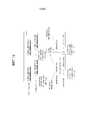
[43] Фиг. 3 является концептуальной схемой, изображающей физические каналы для использования в системе 3GPP и общий способ для передачи сигнала с использованием физических каналов.[43] FIG. 3 is a conceptual diagram depicting physical channels for use in a 3GPP system and a general method for transmitting a signal using physical channels.
[44] Обращаясь к фиг. 3, при включении или входе в новую соту, UE выполняет начальный поиск соты на этапе S301. Начальный поиск соты включает в себя синхронизацию с BS. В частности, UE синхронизируется с BS и получает идентификатор соты (ID) и другую информацию путем приема первичного канала синхронизации (P-SCH) и вторичного канала синхронизации (S-SCH) от BS. Затем UE может получить информацию, передаваемую с помощью широковещания в соте, путем приема физического широковещательного канала (PBCH) от BS. Во время начального поиска соты UE может отслеживать состояние канала нисходящей линии связи путем приема опорного сигнала нисходящей линии связи (RS DL).[44] Referring to FIG. 3, when turning on or entering a new cell, the UE performs an initial cell search in step S301. The initial cell search includes synchronization with the BS. In particular, the UE synchronizes with the BS and obtains a cell identifier (ID) and other information by receiving a primary synchronization channel (P-SCH) and a secondary synchronization channel (S-SCH) from the BS. Then, the UE may obtain information transmitted by broadcasting in a cell by receiving a physical broadcast channel (PBCH) from the BS. During the initial cell search, the UE can monitor the state of the downlink channel by receiving a downlink reference signal (RS DL).
[45] После начального поиска соты UE может получить более конкретную системную информацию путем приема физического канала управления нисходящей линии связи (PDCCH) и приема физического совместно используемого канала нисходящей линии связи (PDSCH) на основании информации PDCCH на этапе S302.[45] After the initial cell search, the UE can obtain more specific system information by receiving a physical downlink control channel (PDCCH) and receiving a physical downlink shared channel (PDSCH) based on the PDCCH information in step S302.
[46] С другой стороны, если UE первоначально получает доступ к BS или если у UE нет радиоресурсов для передачи сигналов, оно может выполнить процедуру произвольного доступа к BS на этапах с S303 по S306. Для произвольного доступа UE может передать заранее определенную последовательность как преамбулу базовой станции (BS) на физическом канале произвольного доступа (PRACH) на этапах (S303~S306) и принять ответное сообщение для преамбулы на PDCCH и PDSCH, соответствующем PDCCH, на этапах S304 и S306. В случае соревновательного RACH, UE может выполнить процедуру устранения конфликтов.[46] On the other hand, if the UE initially gains access to the BS or if the UE does not have radio resources for signaling, it can perform the random access procedure to the BS in steps S303 to S306. For random access, the UE may transmit a predetermined sequence as the preamble of the base station (BS) on the physical random access channel (PRACH) in steps (S303 ~ S306) and receive a response message for the preamble on the PDCCH and PDSCH corresponding to the PDCCH in steps S304 and S306 . In the case of a competitive RACH, the UE may perform a conflict resolution procedure.
[47] После описанной выше процедуры UE может принять PDCCH и PDSCH на этапе S307 и передать физический совместно используемый канал восходящей линии связи (PUSCH) и физический канал управления восходящей линии связи (PUCCH) на этапе S308 в качестве общей процедуры передачи сигналов нисходящей линии связи/восходящей линии связи (DL/UL). В частности, UE может принять управляющую информацию нисходящей линии связи (DCI) через PDCCH. В этом случае DCI включает в себя управляющую информацию, такую как информация о распределении ресурсов для UE, и эта информация имеет различные форматы в соответствии с целями использования.[47] After the above procedure, the UE may receive the PDCCH and PDSCH in step S307 and transmit the physical uplink shared channel (PUSCH) and the physical uplink control channel (PUCCH) in step S308 as a general downlink signaling procedure / uplink (DL / UL). In particular, the UE may receive downlink control information (DCI) through the PDCCH. In this case, the DCI includes control information, such as resource allocation information for the UE, and this information has various formats in accordance with the intended use.
[48] С другой стороны, управляющая информация восходящей линии связи, переданная от UE базовой станции (BS), или управляющая информация нисходящей линии связи, переданная от UE базовой станции (BS), может включать в себя сигнал подтверждения/неподтверждения (ACK/NACK) нисходящей линии связи (DL) или восходящей линии связи (UL), индикатор качества канала (CQI), индекс матрицы предварительного кодирования (PMI) и/или индикатор ранга (RI). UE, выполненное с возможностью работы в системе LTE 3GPP, может передавать управляющую информацию, такую как CQI, PMI и/или RI, на PUSCH и/или PUCCH.[48] On the other hand, uplink control information transmitted from the UE of the base station (BS) or downlink control information transmitted from the UE of the base station (BS) may include an acknowledgment / non-acknowledgment signal (ACK / NACK ) downlink (DL) or uplink (UL), channel quality indicator (CQI), precoding matrix index (PMI) and / or rank indicator (RI). A UE configured to operate in a 3GPP LTE system may transmit control information, such as CQI, PMI and / or RI, to a PUSCH and / or PUCCH.
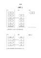
[49] Фиг. 4 показывает канал управления, содержащийся в области управления одного подкадра в радиокадре нисходящей линии связи, в соответствии с одним вариантом воплощения настоящего изобретения.[49] FIG. 4 shows a control channel contained in a control area of one subframe in a downlink radio frame, in accordance with one embodiment of the present invention.
[50] Обращаясь к фиг. 4, один подкадр включает в себя 14 символов OFDM. С первого по третий из этих 14 символов OFDM могут использоваться в качестве области управления, а оставшиеся символы OFDM (то есть 11-13 символов OFDM) могут использоваться в качестве области данных. На фиг. 4 R1 - R4 представляют собой опорные сигналы (RS) (также называемые пилотными сигналами) антенн 0-3, соответственно. В общем подкадре RS антенн 0-3 следуют заранее определенному шаблону независимо от области управления и области данных. Канал управления располагается в ресурсе, в котором нет RS, в области управления. Канал трафика располагается в ресурсе, в котором нет RS, в области данных. В области управления может размещаться множество каналов управления, например, физический канал индикатора формата управления (PCFICH), физический канал индикатора гибридного - ARQ (PHICH), физический канал управления нисходящей линии связи (PDCCH) и т.д.[50] Referring to FIG. 4, one subframe includes 14 OFDM symbols. The first to third of these 14 OFDM symbols can be used as a control area, and the remaining OFDM symbols (i.e. 11-13 OFDM symbols) can be used as a data area. In FIG. 4 R1 to R4 are reference signals (RS) (also called pilot signals) of antennas 0-3, respectively. In a general RS subframe of antennas 0-3, a predetermined pattern is followed regardless of the control area and the data area. The control channel is located in a resource in which there is no RS in the control area. The traffic channel is located in a resource in which there is no RS in the data area. A plurality of control channels may be located in a control area, for example, a physical channel of a control format indicator (PCFICH), a physical channel of a hybrid indicator - ARQ (PHICH), a physical downlink control channel (PDCCH), etc.
[51] PCFICH используется в качестве физического канала индикатора формата управления и сообщает UE число символов OFDM, используемых для PDCCH в каждом подкадре. PCFICH расположен в первом символе OFDM и имеет приоритет над PHICH и PDCCH. PCFICH включает в себя 4 группы ресурсных элементов (REG), и отдельные REG распределяются в область управления на основании ID соты. Один REG включает в себя четыре RE. RE является минимальным физическим ресурсом, определяемым выражением ‘одна поднесущая × один символ OFDM’. Значение PCFICH указывает значения 1-3 или значения 2-4 в соответствии с шириной полосы частот и модулируется с помощью QPSK (квадратурной фазовой манипуляции).[51] PCFICH is used as the physical channel of the control format indicator and reports to the UE the number of OFDM symbols used for the PDCCH in each subframe. PCFICH is located in the first OFDM symbol and takes precedence over PHICH and PDCCH. PCFICH includes 4 resource element groups (REGs), and individual REGs are allocated to the control area based on the cell ID. One REG includes four REs. RE is the minimum physical resource defined by the expression ‘one subcarrier × one OFDM symbol’. The PCFICH value indicates 1-3 values or 2-4 values according to the bandwidth and is modulated by QPSK (quadrature phase shift keying).
[52] PHICH используется в качестве физического канала индикатора HARQ (гибридного автоматического запроса на повторную передачу данных), он несет сигналы ACK/NACK HARQ для передачи восходящей линии связи. Другими словами, PHICH указывает канал для передачи информации о ACK/NACK DL для HARQ UL. PHICH включает в себя одну REG, он зашифрован для каждой соты в отдельности. Сигнал ACK/NACK, указываемый одним битом, модулируется с помощью BPSK (двоичной фазовой манипуляции). Модулированный ACK/NACK расширяется с коэффициентом расширения (SF) 2 или 4. Несколько PHICH, установленных в соответствие одним и тем же ресурсам, создают группу PHICH. Число PHICH, мультиплексированных в группе PHICH, может быть определено в соответствии с числом кодов расширения. PHICH (или группа PHICH) может повторяться три раза, чтобы получить усиление при разнесении в частотной области и/или временной области.[52] PHICH is used as the physical channel of the HARQ indicator (Hybrid Automatic Repeat Request), it carries ACK / NACK HARQ signals for uplink transmission. In other words, the PHICH indicates a channel for transmitting DL ACK / NACK information for UL HARQ. PHICH includes one REG, it is encrypted for each cell separately. A single bit ACK / NACK signal is modulated using BPSK (binary phase shift keying). A modulated ACK / NACK expands with an expansion coefficient (SF) of 2 or 4. Multiple PHICHs set to the same resources create a PHICH group. The number of PHICHs multiplexed in the PHICH group can be determined according to the number of extension codes. A PHICH (or PHICH group) may be repeated three times to obtain diversity gain in the frequency domain and / or time domain.
[53] PDCCH, действующий как физический канал управления нисходящей линии связи, размещается в N первых символах OFDM подкадра. В этом случае N является целым числом, равным 1 или больше, и оно указывается с помощью PCFICH. PDCCH включает в себя один или несколько CCE. PDCCH может сообщить каждому UE или группе UE информацию, относящуюся к распределению ресурсов PCH (пейджингового канала) и DL-SCH (совместно используемого канала нисходящей линии связи), предоставлению планирования восходящей линии связи, информацию о HARQ и т.д. PCH и DL-SCH передаются через PDSCH. Поэтому BS и UE могут передавать и принимать данные помимо конкретной управляющей информации или конкретных служебных данных через PDSCH.[53] A PDCCH acting as a physical downlink control channel is located in the N first OFDM symbols of a subframe. In this case, N is an integer of 1 or more, and it is indicated by PCFICH. PDCCH includes one or more CCEs. The PDCCH may inform each UE or UE group of information related to resource allocation of PCH (paging channel) and DL-SCH (downlink shared channel), providing uplink scheduling, HARQ information, etc. PCH and DL-SCH are transmitted via PDSCH. Therefore, the BS and the UE can transmit and receive data in addition to specific control information or specific overhead data through the PDSCH.
[54] Информация, указывающая, какой UE будет принимать данные в качестве входных данных, информация, указывающая, как UE принимают данные PDSCH, и информация, указывающая, выполнено ли декодирование, содержится в PDCCH. Например, предполагается, что конкретный PDCCH является CRC-маскированным с помощью временного идентификатора сети радиосвязи (RNTI), называемого ‘A’, а информация, которая передается с использованием радиоресурсов ‘B’ (например, положение частоты), и информация о формате передачи ‘C’ (например, размер блока передачи, схема модуляции, информация о кодировании и т.д.) передается через конкретный подкадр. В этом случае UE, расположенное в соте, отслеживает PDCCH с использованием его собственной информации об RNTI. Если, по меньшей мере одно UE, имеющее RNTI ‘A’, присутствует, UE принимают PDCCH и принимают PDSCH, указанный с помощью ‘B’ и 'С' через принятую информацию PDCCH.[54] Information indicating which UE will receive data as input, information indicating how UEs receive PDSCH data, and information indicating whether decoding is performed is contained in the PDCCH. For example, it is assumed that a particular PDCCH is CRC-masked using a temporary radio network identifier (RNTI) called 'A', and information that is transmitted using radio resources' B '(e.g., frequency position) and transmission format information' C '(e.g., transmission block size, modulation scheme, coding information, etc.) is transmitted through a specific subframe. In this case, the UE located in the cell monitors the PDCCH using its own RNTI information. If at least one UE having an RNTI ‘A’ is present, the UEs receive a PDCCH and receive the PDSCH indicated by ‘B’ and 'C' through the received PDCCH information.
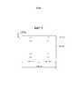
[55] Фиг. 5 изображает структуру подкадра UL в LTE.[55] FIG. 5 depicts a UL subframe structure in LTE.
[56] Обращаясь к фиг. 5, подкадр UL может быть разделен на область, в которой располагается физический канал управления восходящей линии связи (PUCCH), несущий управляющую информацию, и область, в которой располагается физический совместно используемый канал восходящей линии связи (PUSCH), несущий пользовательские данные. Середина подкадра выделена под PUSCH, в то время как обе стороны области данных в частотной области выделены под PUCCH. Управляющая информация, передаваемая в PUCCH, может включать в себя ACK/NACK HARQ, CQI, представляющую собой состояние канала нисходящей линии связи, RI для MIMO и запрос планирования (SR), запрашивающий распределение ресурсов UL. PUCCH для одного UE занимает один RB в каждом интервале подкадра. То есть, эти два RB, выделенные под PUCCH, имеют скачок по частоте на границе интервалов подкадра. В частности, PUCCH с m=0, m=1, m=2 и m=3 располагаются в подкадре на фиг. 5.[56] Referring to FIG. 5, the UL subframe may be divided into a region in which a physical uplink control channel (PUCCH) carrying control information is located and a region in which a physical uplink shared channel (PUSCH) carrying user data is located. The middle of the subframe is allocated under the PUSCH, while both sides of the data area in the frequency domain are allocated under the PUCCH. The control information transmitted to the PUCCH may include ACK / NACK HARQ, CQI representing the state of the downlink channel, RI for MIMO, and a scheduling request (SR) requesting UL resource allocation. The PUCCH for one UE occupies one RB in each subframe interval. That is, these two RBs allocated under the PUCCH have a frequency jump at the border of the subframe intervals. In particular, PUCCHs with m = 0, m = 1, m = 2, and m = 3 are located in a subframe in FIG. 5.
[57] Фиг. 6 является схемой, изображающей структуру радиокадра для использования в TDD LTE. Радиокадр для использования в TDD LTE включает в себя два полукадра, каждый полукадр включает в себя 4 подкадра, каждый из которых имеет 2 интервала и специальный подкадр, имеющий временной интервал пилотного сигнала нисходящей линии связи (DwPTS), защитный период (GP) и временной интервал пилотного сигнала восходящей линии связи (UpPTS).[57] FIG. 6 is a diagram illustrating a structure of a radio frame for use in LTE TDD. The radio frame for use in TDD LTE includes two half frames, each half frame includes 4 sub frames, each of which has 2 slots and a special sub frame having a downlink pilot time interval (DwPTS), a guard period (GP) and a time interval uplink pilot signal (UpPTS).
[58] В специальном подкадре DwPTS используется для начального поиска соты, синхронизации или оценки канала в UE. UpPTS используется для выполнения eNB оценки канала и получения синхронизации UL с UE. Другими словами, DwPTS используется для передачи DL, а UpPTS используется для передачи UL. В частности, UpPTS используется для передачи преамбулы PRACH или зондирующего опорного сигнала (SRS). GP используется для устранения интерференции UL между UL и DL, вызванной многопутевой задержкой сигнала DL.[58] In a special subframe, DwPTS is used for initial cell search, synchronization, or channel estimation in the UE. UpPTS is used to perform eNB channel estimation and obtain UL synchronization with the UE. In other words, DwPTS is used for DL transmission, and UpPTS is used for UL transmission. In particular, UpPTS is used to transmit the PRACH preamble or sounding reference signal (SRS). GP is used to eliminate UL interference between UL and DL caused by multi-path DL signal delay.
[59] Конфигурации подкадра UL/DL для TDD LTE перечислены в Таблице 1 ниже.[59] UL / DL subframe configurations for LTE TDD are listed in Table 1 below.
[60] [Таблица 1][60] [Table 1]
[61] В Таблице 1 D представляет собой подкадр DL, U представляет собой подкадр UL, и S представляет собой специальный подкадр. В Таблице 1 дополнительно приводится периодичность переключения DL - UL для соответствующих конфигураций подкадров UL/DL в каждой системе.[61] In Table 1, D is a DL subframe, U is a UL subframe, and S is a special subframe. Table 1 further shows the DL - UL switching frequency for the respective UL / DL subframe configurations in each system.
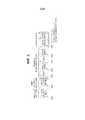
[62] Фиг. 7 изображает моменты передачи и приема радиокадра восходящей линии связи и радиокадра нисходящей линии связи в системе LTE.[62] FIG. 7 depicts transmission and reception times of an uplink radio frame and a downlink radio frame in an LTE system.
[63] Обращаясь к фиг. 7, передача радиокадра #i восходящей линии связи от терминала, то есть UE, выполняется за (NTA+Nсмещение TA)×Ts секунд (0≤NTA≤20512) до начала соответствующего радиокадра #i нисходящей линии связи. Здесь, Nсмещение TA=0 в типе 1 структуры кадра, то есть, FDD, и Nсмещение TA=624 в типе 2 структуры кадра, то есть, TDD.[63] Referring to FIG. 7, transmission of the uplink radio frame #i from the terminal, that is, the UE, is performed (NTA + Noffset TA ) × Ts seconds (0≤NTA ≤20512) before the start of the corresponding downlink radio frame #i. Here, N is theoffset TA = 0 in
[64] Фиг. 8 является концептуальной схемой, изображающей прямую связь D2D.[64] FIG. 8 is a conceptual diagram depicting a direct D2D connection.
[65] Обращаясь к фиг. 8, UE 1 и UE 2 выполняют прямую связь устройство-устройство, а UE 3 и UE 4 выполняют прямую связь устройство-устройство. eNB может управлять положением временных/частотных ресурсов и мощностью передачи для прямой связи устройство-устройство между UE с помощью соответствующих управляющих сигналов. Однако когда UE расположены за пределами покрытия eNB, прямая связь между UE может выполняться без управляющего сигнала eNB. В следующем ниже описании прямая связь устройство-устройство называется связью D2D.[65] Referring to FIG. 8,
[66] Настоящее изобретение предлагает способ для измерения местоположения партнерского UE или расстояния между UE и партнерским UE с использованием сигнала D2D между UE и партнерским UE.[66] The present invention provides a method for measuring the location of a partner UE or the distance between a UE and a partner UE using a D2D signal between the UE and the partner UE.
[67] Если UE может обнаружить местоположение другого UE или расстояние между UE и другим UE, то UE может предоставить множество полезных услуг. Например, если может быть обнаружено расстояние между UE и другим UE, и другое UE расположено в пределах заранее определенного расстояния, UE может предоставить услугу информирования его пользователя о местоположении другого UE и расстоянии между UE и другим UE, в результате чего пользователь может определить пользователя другого UE. Кроме того, когда множество UE передают сообщения, например, рекламные объявления, UE может принимать только рекламные сообщения в пределах конкретного расстояния от UE. Кроме того, можно предоставить услугу отслеживания присутствия UE, которое было зарегистрировано как UE, которым интересуется соответствующий UIE, в пределах конкретного расстояния или расстояния между соответствующим UE и интересующимся UE и информирования пользователя о результате отслеживания.[67] If the UE can detect the location of another UE or the distance between the UE and the other UE, then the UE can provide many useful services. For example, if a distance between a UE and another UE can be detected, and the other UE is within a predetermined distance, the UE can provide a service to inform its user about the location of the other UE and the distance between the UE and the other UE, whereby the user can determine the user of another UE In addition, when multiple UEs transmit messages, for example, advertisements, the UE can only receive advertisements within a specific distance from the UE. In addition, it is possible to provide a service for tracking the presence of a UE that has been registered as a UE that is interested in the corresponding UIE within a specific distance or distance between the corresponding UE and the interested UE and informing the user about the result of the tracking.
[68] В качестве методики обнаружения информации о местоположении UE в системе беспроводной связи был предложен способ, с помощью которого UE принимает сигналы, переданные от нескольких eNB, и обнаруживает местоположение на основании принятых сигналов. В соответствии с этим способом UE обнаруживает соответствующее местоположение путем измерения сигналов, переданных от нескольких eNB, например, позиционирующих опорных сигналов (PRS) LTE 3GPP, и измерения времени поступления сигнала, переданного от каждой eNB, или разности между временем поступления сигналов, переданных от двух eNB. А именно, UE может обнаружить разность между расстояниями между UE и этими двумя eNB путем измерения разности между временем поступления сигналов, переданных от этих двух eNB, и может определить, что UE расположен в точке на кривой, на которой разность расстояний между этими двумя eNB является одинаковой. Когда этот процесс повторяется для других двух eNB, можно получить несколько кривых, на которых может быть расположено UE, и определить, что UE расположен в точке, где кривые пересекаются. Эта операция требует информации о местоположении нескольких eNB, измеренном UE. Однако, так как соответствующая сеть уже знает местоположения eNB, сеть может обнаружить местоположения соответствующих eNB, когда UE сообщает сети о времени поступления сигналов, переданных от eNB, или разности времени поступления между переданными сигналами.[68] As a technique for detecting location information of a UE in a wireless communication system, a method has been proposed by which a UE receives signals transmitted from several eNBs and detects a location based on the received signals. According to this method, the UE detects an appropriate location by measuring signals transmitted from several eNBs, for example, LTE 3GPP positioning reference signals (PRS), and measuring the arrival time of a signal transmitted from each eNB, or the difference between the arrival times of signals transmitted from two eNB. Namely, the UE can detect the difference between the distances between the UE and these two eNBs by measuring the difference between the arrival times of the signals transmitted from these two eNBs, and can determine that the UE is located at a point on the curve where the distance difference between the two eNBs is the same. When this process is repeated for the other two eNBs, it is possible to obtain several curves on which the UE can be located, and determine that the UE is located at the point where the curves intersect. This operation requires the location information of several eNBs measured by the UE. However, since the corresponding network already knows the locations of the eNBs, the network can detect the locations of the corresponding eNBs when the UE informs the network of the arrival time of signals transmitted from the eNB or the difference of the arrival time between the transmitted signals.
[69] В качестве другой методики для детектирования информации о местоположении UE в системе беспроводной связи был предложен способ, в котором eNB принимает сигнал, переданный от UE, и сеть обнаруживает местоположение UE на основании принятого сигнала. В соответствии с этим способом UE передает конкретный сигнал, например, зондирующий опорный сигнал (SRS) LTE 3GPP, а множество eNB измеряют время поступления сигнала в каждом eNB или разность между временем поступления сигнала в двух eNB, принимая сигнал, переданный от UE. Затем сеть может вычислить расстояние между каждым eNB и UE или разность между расстояниями между двумя eNB и UE на основании информации о местоположении каждой eNB, которая была предоставлена сети, и повторить эту операцию для нескольких eNB, чтобы определить оказавшуюся общей точку как местоположение UE.[69] As another technique for detecting UE location information in a wireless communication system, a method has been proposed in which an eNB receives a signal transmitted from a UE and the network detects a location of the UE based on the received signal. In accordance with this method, the UE transmits a specific signal, for example, LTE 3GPP sounding reference signal (SRS), and a plurality of eNBs measure a signal arrival time in each eNB or a difference between a signal arrival time in two eNBs, receiving a signal transmitted from the UE. The network can then calculate the distance between each eNB and UE or the difference between the distances between two eNBs and UEs based on the location information of each eNB that was provided to the network, and repeat this operation for several eNBs to determine the turned-out common point as the location of the UE.
[70] Упомянутые выше операции не подходят для широкого использования при обнаружении UE местоположения другого UE.[70] The above operations are not suitable for widespread use in locating a UE of a location of another UE.
[71] В частности, так как сеть в конечном итоге обнаруживает местоположение UE в обоих способах, когда конкретное UE хочет использовать информацию о положении другого UE, сеть должна измерить местоположение другого UE с помощью ряда операций с другим UE и затем передать информацию о местоположении другого UE конкретному UE. В этом процессе между сетью и несколькими UE генерируются сигнальные заголовки, и когда число UE увеличивается, сложность вычисления местоположений UE, выполняемого сетью, значительно увеличивается. В частности, когда UE запрашивает информацию, соответствующую неполной информации, такую как расстояние между UE и целевым UE, а не правильное местоположение целевого UE, более вероятно, что такие сигнальные заголовки или сложность вычислений, вызовет ненужное увеличение стоимости.[71] In particular, since the network ultimately detects the location of the UE in both ways, when a particular UE wants to use the position information of another UE, the network must measure the location of another UE using a series of operations with another UE and then transmit the location information of the other UE UE to a specific UE. In this process, signal headers are generated between the network and several UEs, and as the number of UEs increases, the complexity of computing the locations of the UEs performed by the network increases significantly. In particular, when the UE requests information corresponding to incomplete information, such as the distance between the UE and the target UE, and not the correct location of the target UE, it is more likely that such signal headers or computational complexity will cause an unnecessary cost increase.
[72] Для решения этой проблемы настоящее изобретение предлагает способ для измерения местоположений UE и расстояния между UE для минимизации сигнальных заголовков и сложности вычислений в сети путем передачи и приема прямого сигнала, то есть сигнала, использующего связь D2D между UE.[72] To solve this problem, the present invention provides a method for measuring UE locations and distance between UEs to minimize signal headers and network computational complexity by transmitting and receiving a direct signal, that is, a signal using D2D communication between UEs.
[73] Настоящее изобретение предполагает, что каждое UE передает сигнал, указывающий его присутствие в соответствии с заранее определенным правилом. Этот сигнал называется сигналом обнаружения (DS). UE спроектированы так, что UE может распознавать UE, который передал конкретный DS, при приеме DS в соответствии с правилом передачи DS. Например, DS может включать в себя идентификационную информацию передающего UE. Правило передачи DS включает в себя способ генерации DS каждым UE и способ генерации временных/частотных ресурсов для передачи DS. Кроме того, сеть может осуществлять широковещание правила передачи DS, в результате чего UE, участвующие в передаче и приеме DS, могут определить это правило.[73] The present invention assumes that each UE transmits a signal indicating its presence in accordance with a predetermined rule. This signal is called the detection signal (DS). The UEs are designed so that the UE can recognize the UE that transmitted a particular DS when receiving a DS in accordance with a DS transmission rule. For example, a DS may include identification information of a transmitting UE. A DS transmission rule includes a DS generation method for each UE and a time / frequency resource generation method for DS transmission. In addition, the network can broadcast the DS transmission rule, as a result of which the UEs participating in the transmission and reception of the DS can determine this rule.
[74] В настоящем изобретении UE предполагает, что существует опорный eNB для определения времени передачи, при передаче DS. Такой eNB называется опорным eNB DS. UE может иметь множество опорных eNB DS. Например, UE может передавать DS, используя eNB1 в качестве опорного eNB DS в момент времени 1 и используя eNB2 в качестве опорного eNB DS в момент времени 2. В последующем описании UE, который намеревается измерить местоположение другого UE путем приема DS, называется рабочим UE, а UE, местоположение которого должно быть измерено рабочим UE, называется целевым UE. То есть рабочее UE измеряет местоположение целевого UE или расстояния между рабочим UE и целевым UE путем измерения DS, переданного из целевого UE. Однако операции, описанные в настоящем изобретении, не ограничиваются случаем, в котором используется DS, и применимы к случаям, в которых используется произвольный сигнал, непосредственно передаваемый и принимаемый между UE.[74] In the present invention, the UE assumes that there is a reference eNB for determining the transmission time, when transmitting DS. Such an eNB is called a reference eNB DS. A UE may have multiple reference eNB DS. For example, a UE may transmit a DS using eNB1 as a reference DS eNB at
[75] Фиг. 9 изображает момент передачи DS целевому UE и момент приема DS рабочим UE в соответствии с вариантом воплощения настоящего изобретения.[75] FIG. 9 depicts a moment of transmitting a DS to a target UE and a moment of receiving a DS by a working UE according to an embodiment of the present invention.
[76] Обращаясь к фиг. 9, когда обеспечен eNBn в качестве опорного eNB DS, целевое UE определяет время передачи DS на основании момента приема границы подкадра нисходящей линии связи от eNBn. Если eNBn передал границу подкадра нисходящей линии связи в момент времени tn, а задержка распространения между eNBn и целевым UE равна kn, время приема целевым UE границы подкадра нисходящей линии связи eNBn равно tn+kn. Целевое UE передает его DS за время Fn до приема границы подкадра нисходящей линии связи eNBn. Значение Fn может быть ранее зафиксированным значением или может быть предоставлено в соответствии с инструкцией eNB. Когда Fn предоставлено в соответствии с инструкцией eNB, Fn может быть определено как такое же значение, как значение опережения (TA), применяемое, когда соответствующее UE передает сигнал UL узлу eNB. Если Fn было ранее зафиксировано, Fn может быть зафиксировано равным одному и тому же значению для всех опорных eNB DS.[76] Referring to FIG. 9, when eNBn is provided as a reference DS eNB, the target UE determines the DS transmission time based on the moment of receiving the downlink subframe border from the eNBn . If eNBn transmitted the border of the downlink subframe at time tn , and the propagation delay between eNBn and the target UE is kn , the reception time of the target UE of the border of the downlink subframe eNBn is tn + kn . The target UE transmits its DS for a time Fn before receiving the downlink subframe border eNBn . The value of Fn may be a previously fixed value or may be provided in accordance with the instruction of the eNB. When Fn is provided in accordance with the instruction of the eNB, Fn can be defined as the same value as the advance value (TA) applied when the corresponding UE transmits a UL signal to the eNB. If Fn was previously fixed, Fn can be fixed to the same value for all reference eNB DS.
[77] Сигнал, переданный целевым UE в момент tn+kn-Fn, достигает рабочее UE в момент времени un=tn+kn-Fn+x через время задержки x распространения между целевым UE и рабочим UE. Задержка распространения между опорным eNB DS, eNBn, и рабочим UE, как предполагается, равна dn.[77] The signal transmitted by the target UE at time tn + kn -Fn reaches the operational UE at time un = tn + kn -Fn + x through the propagation delay time x between the target UE and the working UE. The propagation delay between the reference eNB DS, eNBn , and the working UE is assumed to be dn .
[78] Будет дано описание способа получения верхнего предела и нижнего предела расстояния между рабочим UE и целевым UE, когда DS передается посредством упомянутого выше процесса.[78] A description will be given of a method for obtaining an upper limit and a lower limit of a distance between a working UE and a target UE when a DS is transmitted by the above process.
[79] Фиг. 10 изображает области, в которых может быть расположено целевое UE, которые вычислены в соответствии с вариантом воплощения настоящего изобретения. На фиг. 10 предполагается, что x≤dn. Обращаясь к фиг. 10, максимальное значение и минимальное значение времени приема DS целевого UE рабочим UE соответственно оказывается местоположением 1 целевого UE и местоположением 2 целевого UE.[79] FIG. 10 depicts areas in which a target UE may be located, which are computed in accordance with an embodiment of the present invention. In FIG. 10, it is assumed that x≤dn . Turning to FIG. 10, the maximum value and the minimum DS reception time value of the target UE by the working UE, respectively, is
[80] Когда целевое UE расположено в местоположении 1, может быть установлено Уравнение 1.[80] When the target UE is located at
[81] [Уравнение 1][81] [Equation 1]
[82] un≤tn+dn+x-Fn+x=tn+dn-Fn+2x[82] un ≤tn + dn + xFn + x = tn + dn -Fn + 2x
[83] Условия для x могут быть получены как представлено в Уравнении 2 путем совершения перестановки в Уравнении 1.[83] The conditions for x can be obtained as represented in
[84] [Уравнение 2][84] [Equation 2]
[85] x≥(un+Fn-tn-dn)/2[85] x≥ (un + Fn -tn -dn ) / 2
[86] Когда целевое UE расположено в местоположении 2, могут быть установлены условия, такие как Уравнение 3. В частности, условия не связаны с x.[86] When the target UE is located at
[87] [Уравнение 3][87] [Equation 3]
[88] un≥tn+dn-x-Fn+x=tn+dn-Fn[88] un ≥tn + dn -xFn + x = tn + dn -Fn
[89] Фиг. 11 изображает области, в которых может быть расположено целевое UE, которые вычислены в соответствии с вариантом воплощения настоящего изобретения. На фиг. 11 предполагается, что x>dn. Обращаясь к фиг. 11, максимальное значение и минимальное значение времени приема DS целевого UE рабочим UE соответственно оказывается местоположением 1 целевого UE и местоположением 2 целевого UE.[89] FIG. 11 depicts areas in which a target UE may be located, which are computed in accordance with an embodiment of the present invention. In FIG. 11, it is assumed that x> dn . Turning to FIG. 11, the maximum value and the minimum DS receive time of the target UE by the working UE, respectively, turns out to be
[90] Когда целевое UE расположено в местоположении 1, могут быть установлены условия, такие как Уравнение 4.[90] When the target UE is located at
[91] [Уравнение 4][91] [Equation 4]
[92] un≤tn+dn+x-Fn+x=tn+dn-Fn+2x[92] un ≤tn + dn + xFn + x = tn + dn -Fn + 2x
[93] Когда целевое UE расположено в местоположении 2, могут быть установлены условия, такие как Уравнение 5.[93] When the target UE is located at
[94] [Уравнение 5][94] [Equation 5]
[95] un≥tn+x-dn-Fn+x=tn-dn-Fn+2x[95] un ≥tn + xdn -Fn + x = tn -dn -Fn + 2x
[96] Условия для x могут быть получены, как представлено Уравнением 6, путем преобразования Уравнение 5.[96] The conditions for x can be obtained, as represented by
[97] [Уравнение 6][97] [Equation 6]
[98] x≤(un+Fn-tn+dn)/2[98] x≤ (un + Fn -tn + dn ) / 2
[99] Из Уравнения 2 и Уравнения 6 задержка x распространения между рабочим UE и целевым UE удовлетворяет условиям Уравнения 7.[99] From
[100] [Уравнение 7][100] [Equation 7]
[101]
[102] В Уравнении 7 un может быть измерено рабочим UE, так как un является временем приема DS рабочим UE, переданного целевым UE, и (tn+dn) также может быть измерено, так как (tn+dn) является временем приема границы подкадра нисходящей линии связи eNBn рабочим UE. Fn является значением, известным рабочему UE, если Fn является ранее зафиксированным значением. Если Fn является значением, указанным eNB целевому UE, eNB может передать значение рабочему UE, или целевое UE может прямо сообщить значение рабочему UE. Например, Fn может быть передан с использованием поля DS.[102] In
[103] Рабочее UE может вычислить (tn-dn) путем обнаружения dn на основании измерения значения (tn+dn). Например, рабочее UE может осуществить попытку произвольного доступа к опорным eNBn DS и расценить значение TA, сообщенное eNBn, как двустороннюю задержку (RTD) между рабочим UE и eNBn, то есть 2*dn.[103] The working UE can calculate (tn -dn ) by detecting dn based on a measurement of the value (tn + dn ). For example, the working UE may attempt to randomly access the reference eNBn DS and regard the TA value reported by eNBn as the round-trip delay (RTD) between the working UE and eNBn , i.e. 2 * dn .
[104] Теперь будет более подробно описан способ для прямого сообщения целевым UE рабочему UE значения Fn. Как было описано выше, целевое UE может передать используемое Fn с использованием поля переданного DS или сигнала D2D. Fn указывает интервал между границей подкадра нисходящей линии связи, принятого целевым UE, который передает сигнал от опорного eNB, и временем передачи сигнала D2D, как описано со ссылкой на фиг. 9.[104] A method for directly reporting the target UE to the working UE the value of Fn will now be described in more detail. As described above, the target UE may transmit the usable Fn using the transmitted DS field or D2D signal. Fn indicates the interval between the border of the downlink subframe received by the target UE that transmits the signal from the reference eNB and the transmission time of the D2D signal, as described with reference to FIG. 9.
[105] Здесь может быть желательно передать сигнал D2D, включающий в себя Fn, не применяя к нему Fn. Это желательно потому, что рабочее UE, принимающее сигнал D2D, должно попытаться обнаружить сигнал D2D в очень широкой области времени, чтобы принять сигнал D2D, к которому был применен Fn, пока рабочее UE не знает Fn. Например, целевое UE может передать сигнал D2D, к которому Fn не применен, то есть передать сигнал D2D с Fn равным 0 или значению, ранее известному рабочему UE, и указать Fn, который будет применен рабочим UE к передаче сигналов D2D, с использованием поля сигнала D2D. Рабочее UE пытается принять сигнал D2D, к которому не применен Fn, на основании времени (un на фиг. 9), соответствующего границе подкадра нисходящей линии связи, принятого от опорного eNB, извлекает Fn из обнаруженного сигнала и затем полагает, что Fn был применен к сигналу D2D.[105] It may be desirable to transmit a D2D signal including Fn without applying Fn to it. This is desirable because the working UE receiving the D2D signal should try to detect the D2D signal in a very wide time domain in order to receive the D2D signal to which Fn was applied until the working UE knows Fn . For example, the target UE may transmit a D2D signal to which Fn is not applied, that is, transmit a D2D signal with Fn equal to 0 or a value previously known to the working UE, and indicate Fn to be applied by the working UE to transmit D2D signals, s using the D2D signal field. The working UE attempts to receive a D2D signal that Fn is not applied to, based on the time (un in FIG. 9) corresponding to the border of the downlink subframe received from the reference eNB, extracts Fn from the detected signal and then assumes that Fn has been applied to the D2D signal.
[106] Фиг. 12 изображает пример передачи и приема сигнала с использованием D2D, то есть сигнал D2D в соответствии с вариантом воплощения настоящего изобретения. Обращаясь к фиг. 12, целевое UE может передать сигнал #1 D2D, включающий в себя Fn, не применяя к нему Fn, и затем передать сигнал #2 D2D, применяя к нему Fn.[106] FIG. 12 shows an example of signal transmission and reception using D2D, that is, a D2D signal according to an embodiment of the present invention. Turning to FIG. 12, the target UE may transmit the
[107] Рабочее UE может обнаружить верхний предел и нижний предел задержки x распространения между рабочим UE и целевым UE, как было описано выше. Обнаруженные верхний предел и нижний предел могут иметь различные значения для опорных eNB DS. Соответственно, рабочее UE может дополнительно сузить диапазон областей, в которых присутствует x, путем вычисления верхнего предела и нижнего предела x для каждого опорного eNB DS и затем получения пересечения вычисленных областей x. Когда информация о задержке x распространения между рабочим UE и целевым UE получена, задержка x распространения может быть преобразована в расстояние между рабочим UE и целевым UE путем умножения задержки x распространения на скорость распространения электромагнитных волн.[107] The working UE may detect an upper limit and a lower limit of propagation delay x between the working UE and the target UE, as described above. The detected upper limit and lower limit may have different values for the reference eNB DS. Accordingly, the working UE can further narrow the range of regions in which x is present by calculating the upper limit and lower limit x for each reference DS eNB and then obtain the intersection of the calculated regions x. When information about the propagation delay x between the working UE and the target UE is obtained, the propagation delay x can be converted to the distance between the working UE and the target UE by multiplying the propagation delay x by the speed of electromagnetic waves.
[108] Будет дано описание способа для измерения местоположения целевого UE с использованием информации о местоположении опорного eNB DS и времени приема DS.[108] A description will be given of a method for measuring the location of a target UE using the location information of the reference DS eNB and the DS reception time.
[109] Так как un=tn+kn-Fn+x, как было описано выше со ссылкой на фиг. 9, прием DS, переданных из двух точек, одновременно означает, что значения kn+x, вычисленные для двух точек, имеют одинаковое значение с точки зрения рабочего UE. Это будет описано со ссылкой на прилагаемые чертежи.[109] Since un = tn + kn -Fn + x, as described above with reference to FIG. 9, the reception of DS transmitted from two points simultaneously means that the values of kn + x calculated for two points have the same value from the point of view of the working UE. This will be described with reference to the accompanying drawings.
[110] Фиг. 13 изображает способ для обнаружения местоположения целевого UE в соответствии с вариантом воплощения настоящего изобретения.[110] FIG. 13 depicts a method for locating a target UE in accordance with an embodiment of the present invention.
[111] Обращаясь к фиг. 13, так как kn+x указывает задержку распространения сигнала, переданного от опорного eNBn DS рабочему UE через целевое UE, местоположение целевого UE, который генерирует тот же самый un, оказывается в форме эллипса, имеющего местоположения опорного eNBn DS и рабочего UE в качестве фокусов. То есть, когда рабочее UE измеряет un и вычисляет kn+x на основании un, рабочее UE может сгенерировать один эллипс и определить, что целевое UE расположено в точке на эллипсе.[111] Referring to FIG. 13, since kn + x indicates the propagation delay of the signal transmitted from the reference eNBn DS to the working UE through the target UE, the location of the target UE that generates the same un is in the form of an ellipse having the locations of the reference eNBn DS and the working UE as tricks. That is, when the working UE measures un and calculates kn + x based on un , the working UE can generate one ellipse and determine that the target UE is located at a point on the ellipse.
[112] Фиг. 14 изображает способ для обнаружения местоположения целевого UE в соответствии с другим вариантом воплощения настоящего изобретения. В частности, фиг. 14 соответствует случаю, в котором эллипсы сформированы для двух опорных eNB DS, и местоположение целевого UE на пересечениях этих двух эллипсов обнаруживается в соответствии с принципом, описанным со ссылкой на фиг. 13.[112] FIG. 14 depicts a method for locating a target UE in accordance with another embodiment of the present invention. In particular, FIG. 14 corresponds to a case in which ellipses are formed for two reference DS eNBs, and the location of the target UE at the intersections of these two ellipses is detected in accordance with the principle described with reference to FIG. 13.
[113] Фиг. 15 изображает способ для обнаружения местоположения целевого UE в соответствии с другим вариантом воплощения настоящего изобретения. В частности, фиг. 15 соответствует случаю, в котором упомянутая выше операция повторяется для трех опорных eNB DS. Так как существует единственное пересечение трех эллипсов, местоположение целевого UE может быть определено как это местоположение.[113] FIG. 15 depicts a method for locating a target UE in accordance with another embodiment of the present invention. In particular, FIG. 15 corresponds to a case in which the above operation is repeated for three reference eNB DS. Since there is a single intersection of three ellipses, the location of the target UE can be determined as this location.
[114] Как описано выше, местоположение целевого UE может быть обнаружено путем формирования эллипсов, на которых может быть расположено целевое UE, для двух или более опорных eNB DS. С этой целью рабочее UE запрашивает информацию о местоположении каждого опорного eNB DS. Эта информация может ранее сообщена сетью пользовательскому оборудованию (UE) с помощью такого способа, как широковещание.[114] As described above, the location of the target UE can be detected by forming ellipses on which the target UE can be located for two or more reference DS eNBs. To this end, the operational UE requests location information of each reference DS eNB. This information may be previously communicated by the network to a user equipment (UE) using a method such as broadcasting.
[115] Информация о местоположении опорного eNB DS может быть представлена как абсолютные координаты, такие как долгота и широта каждого eNB. В этом случае рабочее UE может обнаружить абсолютные координаты целевого UE. Когда абсолютные координаты не нужны, например, в случае, когда измеряется расстояние между целевым UE и рабочим UE, требуется только взаимное расположение. Например, рабочему UE может быть предоставлена только информация о расстоянии между опорными eNB DS.[115] The location information of the reference eNB DS can be represented as absolute coordinates, such as the longitude and latitude of each eNB. In this case, the working UE can detect the absolute coordinates of the target UE. When absolute coordinates are not needed, for example, in the case where the distance between the target UE and the working UE is measured, only the relative position is required. For example, only the distance between reference DS eNBs may be provided to a working UE.
[116] Обращаясь к фиг. 15, так как anm указывает расстояние между опорным eNBn DS и опорным eNBm DS, может быть обнаружено взаимное положение каждого eNB, когда целевое UE получает информацию о расстоянии. Даже в этом способе рабочее UE должно обнаруживать расстояние до каждого опорного eNB DS. В этом случае рабочее UE может обнаружить расстояние по TA, полученному в процедуре произвольного доступа, или по сигналу (например, PRS), передаваемому каждым опорным eNB DS.[116] Referring to FIG. 15, since anm indicates the distance between the reference eNBn DS and the reference eNBm DS, the relative position of each eNB can be detected when the target UE receives distance information. Even in this method, the working UE must detect the distance to each reference DS eNB. In this case, the working UE can detect the distance by the TA obtained in the random access procedure, or by the signal (for example, PRS) transmitted by each reference DS eNB.
[117] Если рабочее UE знает о расстоянии между целевым UE и опорным eNB DS, рабочее UE может легко измерить расстояние до целевого UE или обнаружить местоположение целевого UE. Например, предполагается, что сеть уведомляет рабочее UE о расстоянии между целевым UE и конкретным опорным eNB DS, или целевое UE уведомляет рабочее UE о расстоянии между целевым UE и конкретным опорным eNB DS с использованием связи D2D, например, с использованием некоторых битов DS.[117] If the working UE is aware of the distance between the target UE and the reference DS eNB, the working UE can easily measure the distance to the target UE or locate the target UE. For example, it is assumed that the network notifies the working UE of the distance between the target UE and the specific reference DS eNB, or the target UE notifies the working UE of the distance between the target UE and the specific reference DS eNB using D2D communication, for example, using some DS bits.
[118] Когда Fn, используемое целевым UE для передачи сигнала D2D, задано равным такому же значению, как значение TA, используемое для передачи сигналов восходящей линии связи, и передано рабочему UE через сигнал, напрямую передаваемый и принимаемый между UE, рабочее UE может определить расстояние между целевым UE и опорным eNB DS через Fn. Это происходит потому, что значение TA конкретного UE обычно задано равным значению, соответствующему удвоенной задержке распространения между UE и опорным eNB. То есть рабочее UE может полагать, что значение, полученное, путем деления пополам Fn, сообщенного целевым UE, соответствует задержке распространения между целевым UE и опорным eNB.[118] When Fn used by the target UE to transmit the D2D signal is set to the same value as the TA value used to transmit the uplink signals and transmitted to the working UE via a signal directly transmitted and received between the UEs, the working UE may determine the distance between the target UE and the reference eNB DS through Fn . This is because the TA value of a particular UE is usually set to a value corresponding to twice the propagation delay between the UE and the reference eNB. That is, the working UE may believe that the value obtained by halving Fn reported by the target UE corresponds to a propagation delay between the target UE and the reference eNB.
[119] Затем, рабочее UE может обнаружить потенциальные местоположения целевого UE по DS, переданному от целевого UE, на основании соответствующего опорного eNB DS, и сократить число потенциальных местоположений целевого UE путем добавления круга, соответствующего расстоянию между опорным eNB DS и целевым UE. Фиг. 16 изображает пример сокращения числа потенциальных местоположений целевого UE путем добавления круга, соответствующего расстоянию между опорным eNB DS и целевым UE в соответствии с вариантом воплощения настоящего изобретения.[119] Then, the working UE can detect potential locations of the target UE on the DS transmitted from the target UE based on the corresponding reference DS eNB, and reduce the number of potential locations of the target UE by adding a circle corresponding to the distance between the reference eNB DS and the target UE. FIG. 16 depicts an example of reducing the number of potential locations of a target UE by adding a circle corresponding to the distance between the reference DS eNB and the target UE in accordance with an embodiment of the present invention.
[120] Будет дано описание способа для измерения местоположения целевого UE или расстояния до целевого UE с использованием разницы во времени приема DS.[120] A description will be given of a method for measuring a location of a target UE or a distance to a target UE using a difference in DS reception time.
[121] Так как un=tn+kn-Fn+x, как описано на фиг. 9, когда рабочее UE измеряет un и um для DS, которые были переданы целевым UE для двух опорных eNB DS, eNBn и eNBm, рабочее UE может обнаружить расстояния между целевым UE и этими двумя опорными eNB DS с использованием разности между двумя значениями. А именно, un-um=tn-tm+kn-km-Fn+Fm, и общий член, расстояние x между целевым UE и рабочим UE, оттуда исчезает. Рабочее UE распознает Fn и Fm, как было описано выше, или эти два значения могут быть идентичными для удобства работы. В этом случае эти два компонента исчезают.[121] Since un = tn + kn -Fn + x, as described in FIG. 9, when the working UE measures un and um for the DSs that were transmitted by the target UE for two reference DS eNBs, eNBn and eNBm , the working UE can detect the distances between the target UE and these two reference eNB DS using the difference between the two values. Namely, un -um = tn -tm + kn -km -Fn + Fm , and the common term, the distance x between the target UE and the working UE, disappears from there. The working UE recognizes Fn and Fm , as described above, or the two values may be identical for convenience. In this case, these two components disappear.
[122] Информация tn и tm может быть получена из информации о времени, когда целевое UE передает DS на основе каждого опорного eNB DS (например, радиокадр и индекс подкадра), и может предполагаться, что опорные eNB DS синхронизированы в заранее определенной единице времени (например, 1 мс, составляющей подкадр). То есть когда предполагается, что два опорных eNB DS были синхронизированы в 1 мс, рабочее UE может предположить, что границы подкадров нисходящей линии связи, переданных этими двумя опорными eNB DS, соответствуют одному и тому же времени.[122] Information tn and tm can be obtained from time information when the target UE transmits a DS based on each reference DS eNB (eg, a radio frame and subframe index), and it can be assumed that the reference DS eNBs are synchronized in a predetermined unit time (e.g. 1 ms making up a subframe). That is, when it is assumed that two reference eNB DSs were synchronized in 1 ms, the operational UE may assume that the boundaries of the downlink subframes transmitted by these two reference eNB DSs correspond to the same time.
[123] В соответствии с этой операцией рабочее UE может вычислить kn-km, соответствующую разности между расстояниями между целевым UE и опорными eNB DS, из un-um.[123] According to this operation, the operational UE can calculate kn −km corresponding to the difference between the distances between the target UE and the reference DS eNBs from un −um .
[124] Фиг. 17 изображает пример измерения местоположения целевого UE или расстояния до целевого UE с использованием разницы во времени приема сигнала DS в соответствии с вариантом воплощения настоящего изобретения.[124] FIG. 17 depicts an example of measuring a location of a target UE or a distance to a target UE using a time difference of a DS signal in accordance with an embodiment of the present invention.
[125] Обращаясь к фиг. 17, кривая, указывающая потенциальные местоположения целевого UE, формируется на основании информации о местоположении двух опорных eNB DS. Здесь кривая представлена набором точек, в которых разность между расстояниями от этих двух опорных eNB DS является одинаковой. Когда эта операция выполняется для двух других eNB, может быть сформирована другая кривая, и пересечение двух кривых соответствует местоположению целевого UE.[125] Referring to FIG. 17, a curve indicating potential locations of the target UE is generated based on the location information of two reference DS eNBs. Here, the curve is represented by a set of points at which the difference between the distances from these two reference eNB DS is the same. When this operation is performed for two other eNBs, another curve may be generated, and the intersection of the two curves corresponds to the location of the target UE.
[126] Фиг. 18 изображает другой пример измерения местоположения целевого UE или расстояния до целевого UE с использованием разницы во времени приема сигнала DS в соответствии с вариантом воплощения настоящего изобретения. В частности, фиг. 18 соответствует случаю, в котором измерение расстояния, изображенное на фиг. 17, дополнительно выполняется для eNB2 и eNB3.[126] FIG. 18 depicts another example of measuring the location of a target UE or the distance to a target UE using a DS signal reception time difference according to an embodiment of the present invention. In particular, FIG. 18 corresponds to the case in which the distance measurement shown in FIG. 17 is further performed for eNB2 and eNB3.
[127] На фиг. 17 и 18 рабочее UE должно обнаружить расстояние до каждого опорного eNB DS. Рабочее UE может обнаружить расстояние по TA, полученному в процедуре произвольного доступа, или по сигналу (например, PRS), передаваемому каждым опорным eNB DS, как было описано выше.[127] In FIG. 17 and 18, the operational UE must detect the distance to each reference DS eNB. The working UE can detect the distance by the TA obtained in the random access procedure, or by the signal (for example, PRS) transmitted by each reference DS eNB, as described above.
[128] Когда предполагается, что рабочее UE принимает непосредственно Fn и Fm от целевого UE и обнаруживает расстояние между целевым UE и каждым опорным eNB DS на основании Fn и Fm, можно измерить расстояние между целевым UE и каждым опорным eNB DS. Потенциальные местоположения целевого UE, полученные с помощью способа, показанного на фиг. 17, могут быть дополнительно сужены с использованием информации о расстоянии между каждым опорным eNB и целевым UE. Фиг. 19 изображает пример измерения расстояния до целевого UE путем обнаружения расстояния между каждым опорным eNB и целевым UE в соответствии с вариантом воплощения настоящего изобретения.[128] When it is assumed that the working UE directly receives Fn and Fm from the target UE and detects the distance between the target UE and each reference DS eNB based on Fn and Fm , the distance between the target UE and each reference DS eNB can be measured. Potential locations of the target UE obtained using the method shown in FIG. 17 may be further narrowed using distance information between each reference eNB and the target UE. FIG. 19 depicts an example of measuring a distance to a target UE by detecting a distance between each reference eNB and a target UE according to an embodiment of the present invention.
[129] Чтобы получить значения TA относительно соответствующих опорных eNB и соответственно передать значения TA через сигналы D2D, целевое UE должно попытаться осуществить доступ к нескольким eNB. Это может значительно увеличить сложность и заголовки. В этом случае, может использоваться такое же значение Fn, как значение TA, примененное к передаче восходящей линии связи, когда сигнал D2D передается в случае синхронизации с небольшим количеством опорных eNB, тогда как ранее зафиксированное значение, то есть 0 или фиксированное значение, ранее распознанное рабочим UE, может быть задано равным Fn в случае синхронизации с другими опорными eNB. Например, Fn может быть задано равным значению TA, примененному к передаче восходящей линии связи, в случае синхронизации целевого UE с обслуживающей сотой и задано равным 0 в случае синхронизации с другими eNB. Когда Fn передается, может быть сообщено, идентичен ли Fn значению TA, примененному к передаче восходящей линии связи.[129] In order to obtain TA values relative to the respective reference eNBs and accordingly transmit TA values through D2D signals, the target UE should try to access multiple eNBs. This can greatly increase complexity and headers. In this case, the same Fn value can be used as the TA value applied to the uplink transmission when the D2D signal is transmitted in case of synchronization with a small number of reference eNBs, whereas the previously fixed value, i.e. 0 or fixed value, earlier recognized by the working UE may be set equal to Fn in the case of synchronization with other reference eNBs. For example, Fn may be set equal to the TA value applied to the uplink transmission in the case of synchronization of the target UE with the serving cell and set to 0 in the case of synchronization with other eNBs. When Fn is transmitted, it can be reported whether Fn is identical to the TA value applied to the uplink transmission.
[130] Для выполнения вышеупомянутых операций рабочее UE должно определить, какой eNB предполагается целевым UE как опорный eNB DS, и когда целевое UE передает DS. Такая информация может быть передана сетью рабочему UE.[130] In order to perform the above operations, the working UE must determine which eNB is assumed by the target UE as the reference DS eNB, and when the target UE transmits the DS. Such information may be transmitted by the network to the working UE.
[131] Рабочее UE может вычислить местоположение целевого UE в соответствии с вышеупомянутыми способами. С этой целью сеть может обеспечить информацию о местоположении опорных eNB DS рабочему UE, а рабочее UE может непосредственно вычислить местоположение целевого UE на основании информации о местоположении опорных eNB DS. Альтернативно, для упрощения рабочего UE, рабочее UE может измерить время приема целевого DS UE, соответствующее каждому опорному eNB DS, или разницу времени приема DS целевым UE для конкретной комбинации опорных eNB DS и сообщить о результате измерений сети, в результате чего сеть может обнаружить местоположение целевого UE. В частности, последнее применимо, когда сеть должна обнаруживать местоположение целевого UE через рабочее UE, когда у целевого UE нет возможности обнаружения местоположения.[131] The working UE may calculate the location of the target UE in accordance with the above methods. To this end, the network can provide the location information of the reference eNB DS to the working UE, and the working UE can directly calculate the location of the target UE based on the location information of the reference eNB DS. Alternatively, to simplify the working UE, the working UE can measure the reception time of the target DS UE corresponding to each reference DS eNB, or the difference in DS reception time of the target UE for a particular combination of reference DS eNBs and report the result of network measurements so that the network can locate target UE. In particular, the latter is applicable when the network must detect the location of the target UE through the working UE, when the target UE does not have the ability to detect location.
[132] Фиг. 20 является блок-схемой, изображающей коммуникационное устройство в соответствии с вариантами воплощения настоящего изобретения.[132] FIG. 20 is a block diagram depicting a communication device in accordance with embodiments of the present invention.
[133] На фиг. 20 коммуникационное устройство 2000 включает в себя процессор 2010, память 2020, радиочастотный (RF) модуль 2030, модуль 2040 дисплея и модуль 2050 пользовательского интерфейса (UI).[133] In FIG. 20, communications device 2000 includes a processor 2010, a memory 2020, a radio frequency (RF) module 2030, a display module 2040, and a user interface (UI) module 2050.
[134] Коммуникационное устройство 2000 раскрыто только для иллюстративных целей, и некоторые модули могут быть исключены из коммуникационного устройства 2000 при необходимости. Кроме того, коммуникационное устройство 2000 может дополнительно включать в себя необходимые модули. Некоторые модули коммуникационного устройства 2000 могут быть идентифицированы как более подробные модули. Процессор 2010 выполнен с возможностью выполнения операций вариантов воплощения настоящего изобретения. Для подробностей об операциях процессора 2010 могут делаться ссылки на фиг. 1-19.[134] The communication device 2000 is disclosed for illustrative purposes only, and some modules may be omitted from the communication device 2000 if necessary. In addition, the communication device 2000 may further include the necessary modules. Some modules of the communication device 2000 can be identified as more detailed modules. The processor 2010 is configured to perform operations of embodiments of the present invention. For details about the operations of the processor 2010, reference may be made to FIG. 1-19.
[135] Память 2020 соединена с процессором 2010 и хранит операционную систему, приложения, программный код, данные и т.п. RF модуль 2030 соединен с процессором 2010 и преобразовывает основополосный сигнал в радиочастотный (RF) сигнал или преобразовывает RF сигнал в основополосный сигнал. Для этих операций RF модуль 2030 выполняет по порядку аналоговое преобразование, усиление, фильтрацию и преобразование с повышением частоты или выполняет эти операции в обратном порядке. Модуль 2040 дисплея соединен с процессором 2010 и отображает множество информации. Объем или сущность модуля 2040 дисплея настоящего изобретения не ограничивается только этим, и модуль 2040 дисплея может быть любым из известных элементов, например, жидкокристаллическим дисплеем (LCD), cветодиодом (LED), органическим светодиодом (OLED) и т.п. Модуль 1450 пользовательского интерфейса (UI) соединен с процессором 2010, он может быть реализован как комбинация пользовательских интерфейсов, таких как клавиатура, сенсорный экран и т.д.[135] Memory 2020 is connected to the processor 2010 and stores the operating system, applications, program code, data, and the like. The RF module 2030 is connected to the processor 2010 and converts the baseband signal into a radio frequency (RF) signal or converts the RF signal into a baseband signal. For these operations, the RF module 2030, in order, performs analog conversion, amplification, filtering, and upconversion, or performs these operations in reverse order. A display module 2040 is connected to the processor 2010 and displays a lot of information. The scope or essence of the display module 2040 of the present invention is not limited thereto, and the display module 2040 may be any of the known elements, for example, a liquid crystal display (LCD), an LED, an organic light emitting diode (OLED), and the like. The user interface (UI) module 1450 is connected to the processor 2010, it can be implemented as a combination of user interfaces, such as a keyboard, touch screen, etc.
[136] Специалистам в области техники будет понятно, что задачи, которые могут быть решены с помощью настоящего изобретения, не ограничиваются только тем, что, в частности, было описано выше, и упомянутые выше и другие задачи, которые можно решить с помощью настоящего изобретения, будут более понятны из предшествующего подробного описания, взятого в сочетании с прилагаемыми чертежами. Иллюстративные варианты воплощения, описанные выше, являются комбинациями элементов и признаков настоящего изобретения. Элементы или признаки могут рассматриваться как выборочные, если не указано иное. Каждый элемент или признак может осуществляться без сочетания с другими элементами или признаками. Кроме того, варианты воплощения настоящего изобретения могут быть созданы путем сочетания части элементов и/или признаков. Порядок операций, описанных в вариантах воплощения настоящего изобретения, может быть изменен. Некоторые конструкции или характеристики любого варианта воплощения могут быть включены в другой вариант воплощения и могут быть заменены соответствующими конструкциями или характеристиками другого варианта воплощения. Очевидно, что настоящее изобретение может быть воплощено путем сочетания пунктов формулы изобретения, которые не имеют явно указанной зависимости в прилагаемой формуле изобретения, или может включать в себя новые пункты формулы изобретения в ответе на первичное заключение патентного ведомства после подачи заявки.[136] Those skilled in the art will understand that the tasks that can be solved by the present invention are not limited to only what, in particular, has been described above, and the above-mentioned and other tasks that can be solved by the present invention will be more apparent from the foregoing detailed description taken in conjunction with the accompanying drawings. The illustrative embodiments described above are combinations of elements and features of the present invention. Elements or features may be considered selective, unless otherwise indicated. Each element or feature may be implemented without combination with other elements or features. In addition, embodiments of the present invention can be created by combining some of the elements and / or features. The order of operations described in the embodiments of the present invention may be changed. Some designs or characteristics of any embodiment may be included in another embodiment and may be replaced by corresponding designs or characteristics of another embodiment. Obviously, the present invention can be embodied by a combination of claims that do not have an explicitly stated dependence in the attached claims, or may include new claims in response to the initial conclusion of the patent office after filing.
[137] Варианты воплощения настоящего изобретения могут быть достигнуты с помощью различных средств, например, аппаратного обеспечения, микропрограммного обеспечением, программного обеспечения или их комбинации. В аппаратной конфигурации варианты воплощения настоящего изобретения могут быть реализованы с помощью одной или нескольких специализированных интегральных схем (ASIC), цифровых сигнальных процессоров (DSP), устройств цифровой обработки сигналов (DSPD), программируемых логических устройств (PLD), программируемых пользователем вентильных матриц (FPGA), процессоров, контроллеров, микроконтроллеров, микропроцессоров и т.д.[137] Embodiments of the present invention can be achieved by various means, for example, hardware, firmware, software, or a combination thereof. In a hardware configuration, embodiments of the present invention may be implemented using one or more specialized integrated circuits (ASICs), digital signal processors (DSPs), digital signal processing devices (DSPDs), programmable logic devices (PLDs), user programmable gate arrays (FPGAs) ), processors, controllers, microcontrollers, microprocessors, etc.
[138] В микропрограммной или программной конфигурации варианты воплощения настоящего изобретения могут быть достигнуты с помощью модуля, процедуры, функции и т.д., выполняющей описанные выше функции или операции. Программный код может храниться в блоке памяти и управляться процессором. Блок памяти расположен внутри или вне процессора и может передавать и принимать данные от процессора с помощью различных известных средств.[138] In a firmware or software configuration, embodiments of the present invention can be achieved using a module, procedure, function, etc. that performs the functions or operations described above. The program code may be stored in a memory unit and controlled by a processor. The memory unit is located inside or outside the processor and can transmit and receive data from the processor using various known means.
[139] Специалистам в области техники будет очевидно, что в настоящем изобретении могут быть сделаны различные модификации и вариации, не отступая от сущности или объема изобретения. Поэтому упомянутое выше подробное описание следует рассматривать только в иллюстративных, а не ограничительных целях. Объем настоящего изобретения должен определяться с помощью рационального анализа формулы изобретения, и все модификации настоящего изобретения в пределах эквивалентных диапазонов находятся в пределах объема настоящего изобретения.[139] It will be apparent to those skilled in the art that various modifications and variations can be made in the present invention without departing from the spirit or scope of the invention. Therefore, the above detailed description should be considered only for illustrative and not restrictive purposes. The scope of the present invention should be determined by rational analysis of the claims, and all modifications of the present invention within equivalent ranges are within the scope of the present invention.
Промышленная применимостьIndustrial applicability
[140] Хотя упомянутый выше способ для передачи и приема синхросигнала для связи D2D в системе беспроводной связи и соответствующий прибор были описаны на основе LTE 3GPP, настоящее изобретение применимо к различным системам беспроводной связи помимо LTE 3GPP.[140] Although the above method for transmitting and receiving a clock signal for D2D communication in a wireless communication system and a corresponding device have been described based on LTE 3GPP, the present invention is applicable to various wireless communication systems besides LTE 3GPP.
Claims (20)
Translated fromRussianApplications Claiming Priority (5)
| Application Number | Priority Date | Filing Date | Title |
|---|---|---|---|
| US201361857210P | 2013-07-22 | 2013-07-22 | |
| US61/857,210 | 2013-07-22 | ||
| US201461981845P | 2014-04-20 | 2014-04-20 | |
| US61/981,845 | 2014-04-20 | ||
| PCT/KR2014/006492WO2015012534A1 (en) | 2013-07-22 | 2014-07-17 | Method for measuring distance between devices via direct device-to-device communication in wireless communication system, and apparatus therefor |
Publications (1)
| Publication Number | Publication Date |
|---|---|
| RU2621898C1true RU2621898C1 (en) | 2017-06-08 |
Family
ID=52393517
Family Applications (1)
| Application Number | Title | Priority Date | Filing Date |
|---|---|---|---|
| RU2016101235ARU2621898C1 (en) | 2013-07-22 | 2014-07-17 | Method of measuring distance between devices with direct device-device communication in wireless communication system and appropriate device |
Country Status (8)
| Country | Link |
|---|---|
| US (1) | US9743240B2 (en) |
| EP (2) | EP3640673A1 (en) |
| JP (2) | JP2016535515A (en) |
| KR (1) | KR102194929B1 (en) |
| CN (1) | CN105408765B (en) |
| ES (1) | ES2786257T3 (en) |
| RU (1) | RU2621898C1 (en) |
| WO (1) | WO2015012534A1 (en) |
Families Citing this family (7)
| Publication number | Priority date | Publication date | Assignee | Title |
|---|---|---|---|---|
| US20180231648A1 (en)* | 2015-08-07 | 2018-08-16 | Zte Corporation | System and method to measure ue-to-ue distance based on d2d sidelink channel |
| KR20200058582A (en)* | 2015-12-18 | 2020-05-27 | 프라운호퍼-게젤샤프트 츄어 푀르더룽 데어 안게반텐 포르슝에.파우. | Data signal transmission in a wireless communication system with reduced end-to-end latency |
| WO2017188547A1 (en)* | 2016-04-25 | 2017-11-02 | 엘지전자(주) | Method for estimating distance between d2d terminals and apparatus for method in wireless communication system |
| EP3416436B1 (en)* | 2017-06-15 | 2021-02-17 | BlackBerry Limited | Configuring sidelink communications |
| WO2019093816A1 (en)* | 2017-11-10 | 2019-05-16 | 엘지전자 주식회사 | Method and device for controlling receiving window for sidelink signal |
| CA3128910A1 (en) | 2019-03-28 | 2020-10-01 | Huawei Technologies Co., Ltd. | System and method for signal detection at asynchronous devices and devices without a time frame structure |
| KR102847373B1 (en)* | 2020-01-07 | 2025-08-20 | 엘지전자 주식회사 | Method and device for performing sidelink-based positioning |
Citations (4)
| Publication number | Priority date | Publication date | Assignee | Title |
|---|---|---|---|---|
| WO2002065667A1 (en)* | 2001-02-15 | 2002-08-22 | Qualcomm Incorporated | Method and apparatus for controlling transit power of multiple channels in a cdma communication system |
| WO2006052086A2 (en)* | 2004-11-09 | 2006-05-18 | Lg Electronics Inc. | Method of transmitting/receiving control information of data channel for enhanced uplink data transmission |
| KR100808941B1 (en)* | 2000-06-12 | 2008-03-04 | 소니 가부시끼 가이샤 | Wireless communication device and distance measuring method |
| RU2462834C2 (en)* | 2008-03-24 | 2012-09-27 | Квэлкомм Инкорпорейтед | Report on using resources of general data transfer channel |
Family Cites Families (13)
| Publication number | Priority date | Publication date | Assignee | Title |
|---|---|---|---|---|
| US5499199A (en) | 1993-10-05 | 1996-03-12 | James G. Demas | Distance measuring system |
| CN1536925A (en)* | 2003-04-11 | 2004-10-13 | �ʼҷ����ֵ��ӹɷ�����˾ | Method and device for supporting P2P Communication in TDD CDMA communicaton system |
| KR100878813B1 (en)* | 2005-04-29 | 2009-01-14 | 엘지전자 주식회사 | How to send location information |
| KR100860028B1 (en)* | 2005-08-12 | 2008-09-25 | 엘지전자 주식회사 | Location tracking method and location tracking system |
| KR100905385B1 (en)* | 2008-03-16 | 2009-06-30 | 엘지전자 주식회사 | Efficient Transmission Method of Control Signal in Wireless Communication System |
| EP2412194A1 (en)* | 2009-03-27 | 2012-02-01 | Nokia Siemens Networks OY | Apparatus, method and article of manufacture |
| JP5310379B2 (en)* | 2009-08-21 | 2013-10-09 | 富士通株式会社 | Mobile terminal and its location registration request signal transmission method |
| WO2013067686A1 (en) | 2011-11-08 | 2013-05-16 | Renesas Mobile Corporation | Method and apparatus for d2d transmission |
| KR20130063650A (en) | 2011-12-07 | 2013-06-17 | 한국전자통신연구원 | Method for managing of device-to-device communication |
| US9531527B2 (en)* | 2012-02-17 | 2016-12-27 | Lg Electronics Inc. | Method and apparatus for transmitting signals of user equipment (UE) configured to perform D2D communication in wireless communication system |
| EP2853132A1 (en)* | 2012-05-23 | 2015-04-01 | Kyocera Corporation | Transmission of device-to-device (d2d) control data from a first d2d device to a second d2d device in a cellular communication system |
| WO2014050887A1 (en)* | 2012-09-27 | 2014-04-03 | 京セラ株式会社 | Mobile communication system, user terminal, base station, and processor |
| US9832800B2 (en)* | 2014-08-08 | 2017-11-28 | Electronics And Telecommunications Research Institute | Method and apparatus for device to device communication |
- 2014
- 2014-07-17RURU2016101235Apatent/RU2621898C1/enactive
- 2014-07-17CNCN201480041704.1Apatent/CN105408765B/enactiveActive
- 2014-07-17JPJP2016529704Apatent/JP2016535515A/enactivePending
- 2014-07-17KRKR1020157036005Apatent/KR102194929B1/enactiveActive
- 2014-07-17WOPCT/KR2014/006492patent/WO2015012534A1/enactiveApplication Filing
- 2014-07-17USUS14/906,865patent/US9743240B2/enactiveActive
- 2014-07-17EPEP19215101.7Apatent/EP3640673A1/ennot_activeWithdrawn
- 2014-07-17EPEP14829084.4Apatent/EP3026456B1/enactiveActive
- 2014-07-17ESES14829084Tpatent/ES2786257T3/enactiveActive
- 2019
- 2019-07-18JPJP2019133138Apatent/JP7174675B2/enactiveActive
Patent Citations (4)
| Publication number | Priority date | Publication date | Assignee | Title |
|---|---|---|---|---|
| KR100808941B1 (en)* | 2000-06-12 | 2008-03-04 | 소니 가부시끼 가이샤 | Wireless communication device and distance measuring method |
| WO2002065667A1 (en)* | 2001-02-15 | 2002-08-22 | Qualcomm Incorporated | Method and apparatus for controlling transit power of multiple channels in a cdma communication system |
| WO2006052086A2 (en)* | 2004-11-09 | 2006-05-18 | Lg Electronics Inc. | Method of transmitting/receiving control information of data channel for enhanced uplink data transmission |
| RU2462834C2 (en)* | 2008-03-24 | 2012-09-27 | Квэлкомм Инкорпорейтед | Report on using resources of general data transfer channel |
Also Published As
| Publication number | Publication date |
|---|---|
| ES2786257T3 (en) | 2020-10-09 |
| WO2015012534A1 (en) | 2015-01-29 |
| JP2016535515A (en) | 2016-11-10 |
| CN105408765B (en) | 2018-09-07 |
| EP3026456A1 (en) | 2016-06-01 |
| EP3026456A4 (en) | 2017-03-15 |
| US20160165398A1 (en) | 2016-06-09 |
| JP7174675B2 (en) | 2022-11-17 |
| KR20160034852A (en) | 2016-03-30 |
| EP3026456B1 (en) | 2020-02-05 |
| KR102194929B1 (en) | 2020-12-24 |
| CN105408765A (en) | 2016-03-16 |
| US9743240B2 (en) | 2017-08-22 |
| JP2019216432A (en) | 2019-12-19 |
| EP3640673A1 (en) | 2020-04-22 |
Similar Documents
| Publication | Publication Date | Title |
|---|---|---|
| EP2421178B1 (en) | Method for transmitting a sounding reference signal in an uplink comp communication system, and apparatus for same | |
| RU2617834C2 (en) | Method of transmit/ receive of sinchronization signal for direct communication between terminals in a wireless communication system | |
| RU2621898C1 (en) | Method of measuring distance between devices with direct device-device communication in wireless communication system and appropriate device | |
| KR101643636B1 (en) | Method for transmitting information of ACK/NACK sequence in wireless communication system and apparatus therefor | |
| EP3573269B1 (en) | Beam control method for direct communication between terminals in wireless communication system | |
| KR101741397B1 (en) | Method for transmitting sounding reference signal in wireless communication system and apparatus therefor | |
| RU2615164C2 (en) | Method and device for detection signal transmitting for communication from device to device in wireless communication system | |
| KR101769379B1 (en) | Method of tranmitting random access response signal in wireless communication system and apparatus thereof | |
| US10630446B2 (en) | Method for transmitting ACK/NACK response for broadcast signal/multicast signal in wireless communication system, and device therefor | |
| KR20150112942A (en) | Method for setting cyclic prefix for d2d (device-to-device) communication in radio communications system and apparatus therefor | |
| KR20140087002A (en) | Method in which a terminal transceives a signal in a wireless communication system and apparatus for same | |
| US20190222460A1 (en) | Method for electricity measurement for v2v communications in wireless communication system, and device for same | |
| US10306570B2 (en) | Method for controlling timing advance for direct communication between terminals in wireless communication system, and apparatus therefor | |
| KR20160060631A (en) | Method for determining validity of scheduling information in wireless communication system supporting usage change of wireless resource and apparatus therefor | |
| US10693699B2 (en) | Method and terminal for transmitting synchronization signal in V2X communication | |
| WO2014003358A1 (en) | Method and device for performing direct communication between terminals in wireless communication system | |
| JP2019527958A (en) | Signal transmission method using multiple beams in wireless communication system and apparatus therefor | |
| US10009786B2 (en) | Method for measuring distance between terminals on basis of device-to-device direct communication in wireless communication system, and device for same | |
| KR20140073499A (en) | Method in which a terminal transceives a signal in a wireless communication system and apparatus for same | |
| KR20150098612A (en) | Signal transmission method and device for device-to-device (d2d) in wireless communication system | |
| KR20190057157A (en) | Communication device and communication method | |
| KR20140017575A (en) | Method for sending and receiving signals for alleviating inter-cell interference in a wireless communication system and a device therefor | |
| KR20140144189A (en) | Method for performing harq for device-to-device communication in wireless communication system and device for same | |
| KR20140067969A (en) | Dynamic subframe setting method for wireless communication system, and device for same | |
| KR20190067860A (en) | Method and apparatus for priority-based interference control in a wireless communication system |