RU2621125C2 - Surgical instrument with wireless communication between control device and remote sensor - Google Patents
Surgical instrument with wireless communication between control device and remote sensorDownload PDFInfo
- Publication number
- RU2621125C2 RU2621125C2RU2013143947ARU2013143947ARU2621125C2RU 2621125 C2RU2621125 C2RU 2621125C2RU 2013143947 ARU2013143947 ARU 2013143947ARU 2013143947 ARU2013143947 ARU 2013143947ARU 2621125 C2RU2621125 C2RU 2621125C2
- Authority
- RU
- Russia
- Prior art keywords
- sensor
- control device
- shaft
- end clamp
- distal
- Prior art date
Links
- 238000004891communicationMethods0.000titledescription13
- 239000003814drugSubstances0.000abstractdescription5
- 239000000126substanceSubstances0.000abstract1
- 230000001939inductive effectEffects0.000description48
- 238000005520cutting processMethods0.000description18
- 230000033001locomotionEffects0.000description12
- 238000002224dissectionMethods0.000description9
- 230000007246mechanismEffects0.000description9
- 230000008878couplingEffects0.000description8
- 238000010168coupling processMethods0.000description8
- 238000005859coupling reactionMethods0.000description8
- 238000000034methodMethods0.000description8
- 238000010586diagramMethods0.000description6
- 239000004744fabricSubstances0.000description6
- 239000012811non-conductive materialSubstances0.000description6
- 230000003993interactionEffects0.000description5
- 239000000463materialSubstances0.000description5
- 230000005855radiationEffects0.000description5
- 230000001954sterilising effectEffects0.000description4
- 230000008859changeEffects0.000description3
- 238000004140cleaningMethods0.000description3
- 238000001415gene therapyMethods0.000description3
- 229910052751metalInorganic materials0.000description3
- 239000002184metalSubstances0.000description3
- 239000007858starting materialSubstances0.000description3
- 238000004659sterilization and disinfectionMethods0.000description3
- 238000001356surgical procedureMethods0.000description3
- 238000002604ultrasonographyMethods0.000description3
- 230000003213activating effectEffects0.000description2
- 239000000853adhesiveSubstances0.000description2
- 230000001070adhesive effectEffects0.000description2
- 230000003321amplificationEffects0.000description2
- 230000008901benefitEffects0.000description2
- 230000005540biological transmissionEffects0.000description2
- 239000004020conductorSubstances0.000description2
- 229940079593drugDrugs0.000description2
- 230000002439hemostatic effectEffects0.000description2
- 238000003780insertionMethods0.000description2
- 230000037431insertionEffects0.000description2
- 238000009434installationMethods0.000description2
- -1lithium ion chemical compoundsChemical class0.000description2
- 230000013011matingEffects0.000description2
- 238000003199nucleic acid amplification methodMethods0.000description2
- 238000012546transferMethods0.000description2
- 241000894006BacteriaSpecies0.000description1
- RYGMFSIKBFXOCR-UHFFFAOYSA-NCopperChemical compound[Cu]RYGMFSIKBFXOCR-UHFFFAOYSA-N0.000description1
- 239000004593EpoxySubstances0.000description1
- IAYPIBMASNFSPL-UHFFFAOYSA-NEthylene oxideChemical compoundC1CO1IAYPIBMASNFSPL-UHFFFAOYSA-N0.000description1
- 229910012851LiCoO 2Inorganic materials0.000description1
- 229910013290LiNiO 2Inorganic materials0.000description1
- 240000005561Musa balbisianaSpecies0.000description1
- 235000018290Musa x paradisiacaNutrition0.000description1
- 239000004775TyvekSubstances0.000description1
- 229920000690TyvekPolymers0.000description1
- 230000009471actionEffects0.000description1
- 230000004913activationEffects0.000description1
- 238000007792additionMethods0.000description1
- 230000000903blocking effectEffects0.000description1
- 238000001311chemical methods and processMethods0.000description1
- 229920001940conductive polymerPolymers0.000description1
- 229910052802copperInorganic materials0.000description1
- 239000010949copperSubstances0.000description1
- 239000013078crystalSubstances0.000description1
- 230000003247decreasing effectEffects0.000description1
- 238000013461designMethods0.000description1
- 238000012938design processMethods0.000description1
- 238000006073displacement reactionMethods0.000description1
- 238000009826distributionMethods0.000description1
- 239000012530fluidSubstances0.000description1
- 230000036512infertilityEffects0.000description1
- 239000004973liquid crystal related substanceSubstances0.000description1
- 229910001416lithium ionInorganic materials0.000description1
- 238000004519manufacturing processMethods0.000description1
- 229910052987metal hydrideInorganic materials0.000description1
- 238000012986modificationMethods0.000description1
- 230000004048modificationEffects0.000description1
- 238000003032molecular dockingMethods0.000description1
- 230000003287optical effectEffects0.000description1
- 238000004806packaging method and processMethods0.000description1
- 238000012856packingMethods0.000description1
- 230000002980postoperative effectEffects0.000description1
- 238000003825pressingMethods0.000description1
- 230000002265preventionEffects0.000description1
- 238000011084recoveryMethods0.000description1
- 230000008439repair processEffects0.000description1
- 238000002432robotic surgeryMethods0.000description1
- 238000011477surgical interventionMethods0.000description1
- 230000001225therapeutic effectEffects0.000description1
- 230000001960triggered effectEffects0.000description1
- 229910000859α-FeInorganic materials0.000description1
Images


Classifications
- A—HUMAN NECESSITIES
- A61—MEDICAL OR VETERINARY SCIENCE; HYGIENE
- A61B—DIAGNOSIS; SURGERY; IDENTIFICATION
- A61B17/00—Surgical instruments, devices or methods
- A61B17/068—Surgical staplers, e.g. containing multiple staples or clamps
- A61B17/072—Surgical staplers, e.g. containing multiple staples or clamps for applying a row of staples in a single action, e.g. the staples being applied simultaneously
- A61B17/07207—Surgical staplers, e.g. containing multiple staples or clamps for applying a row of staples in a single action, e.g. the staples being applied simultaneously the staples being applied sequentially
- A—HUMAN NECESSITIES
- A61—MEDICAL OR VETERINARY SCIENCE; HYGIENE
- A61B—DIAGNOSIS; SURGERY; IDENTIFICATION
- A61B90/00—Instruments, implements or accessories specially adapted for surgery or diagnosis and not covered by any of the groups A61B1/00 - A61B50/00, e.g. for luxation treatment or for protecting wound edges
- A61B90/90—Identification means for patients or instruments, e.g. tags
- A61B90/98—Identification means for patients or instruments, e.g. tags using electromagnetic means, e.g. transponders
- A—HUMAN NECESSITIES
- A61—MEDICAL OR VETERINARY SCIENCE; HYGIENE
- A61B—DIAGNOSIS; SURGERY; IDENTIFICATION
- A61B17/00—Surgical instruments, devices or methods
- A61B2017/00017—Electrical control of surgical instruments
- A61B2017/00022—Sensing or detecting at the treatment site
- A—HUMAN NECESSITIES
- A61—MEDICAL OR VETERINARY SCIENCE; HYGIENE
- A61B—DIAGNOSIS; SURGERY; IDENTIFICATION
- A61B17/00—Surgical instruments, devices or methods
- A61B2017/00017—Electrical control of surgical instruments
- A61B2017/00221—Electrical control of surgical instruments with wireless transmission of data, e.g. by infrared radiation or radiowaves
- A—HUMAN NECESSITIES
- A61—MEDICAL OR VETERINARY SCIENCE; HYGIENE
- A61B—DIAGNOSIS; SURGERY; IDENTIFICATION
- A61B17/00—Surgical instruments, devices or methods
- A61B2017/00367—Details of actuation of instruments, e.g. relations between pushing buttons, or the like, and activation of the tool, working tip, or the like
- A61B2017/00398—Details of actuation of instruments, e.g. relations between pushing buttons, or the like, and activation of the tool, working tip, or the like using powered actuators, e.g. stepper motors, solenoids
- A—HUMAN NECESSITIES
- A61—MEDICAL OR VETERINARY SCIENCE; HYGIENE
- A61B—DIAGNOSIS; SURGERY; IDENTIFICATION
- A61B17/00—Surgical instruments, devices or methods
- A61B2017/00681—Aspects not otherwise provided for
- A61B2017/00734—Aspects not otherwise provided for battery operated
- A—HUMAN NECESSITIES
- A61—MEDICAL OR VETERINARY SCIENCE; HYGIENE
- A61B—DIAGNOSIS; SURGERY; IDENTIFICATION
- A61B17/00—Surgical instruments, devices or methods
- A61B17/068—Surgical staplers, e.g. containing multiple staples or clamps
- A61B17/072—Surgical staplers, e.g. containing multiple staples or clamps for applying a row of staples in a single action, e.g. the staples being applied simultaneously
- A61B2017/07214—Stapler heads
- A61B2017/07271—Stapler heads characterised by its cartridge
- A—HUMAN NECESSITIES
- A61—MEDICAL OR VETERINARY SCIENCE; HYGIENE
- A61B—DIAGNOSIS; SURGERY; IDENTIFICATION
- A61B17/00—Surgical instruments, devices or methods
- A61B17/28—Surgical forceps
- A61B17/29—Forceps for use in minimally invasive surgery
- A61B2017/2926—Details of heads or jaws
- A61B2017/2927—Details of heads or jaws the angular position of the head being adjustable with respect to the shaft
- A—HUMAN NECESSITIES
- A61—MEDICAL OR VETERINARY SCIENCE; HYGIENE
- A61B—DIAGNOSIS; SURGERY; IDENTIFICATION
- A61B90/00—Instruments, implements or accessories specially adapted for surgery or diagnosis and not covered by any of the groups A61B1/00 - A61B50/00, e.g. for luxation treatment or for protecting wound edges
- A61B90/06—Measuring instruments not otherwise provided for
- A61B2090/064—Measuring instruments not otherwise provided for for measuring force, pressure or mechanical tension
- A61B2090/065—Measuring instruments not otherwise provided for for measuring force, pressure or mechanical tension for measuring contact or contact pressure
- A—HUMAN NECESSITIES
- A61—MEDICAL OR VETERINARY SCIENCE; HYGIENE
- A61B—DIAGNOSIS; SURGERY; IDENTIFICATION
- A61B90/00—Instruments, implements or accessories specially adapted for surgery or diagnosis and not covered by any of the groups A61B1/00 - A61B50/00, e.g. for luxation treatment or for protecting wound edges
- A61B90/08—Accessories or related features not otherwise provided for
- A61B2090/0814—Preventing re-use
Landscapes
- Health & Medical Sciences (AREA)
- Surgery (AREA)
- Life Sciences & Earth Sciences (AREA)
- Molecular Biology (AREA)
- Animal Behavior & Ethology (AREA)
- Veterinary Medicine (AREA)
- Nuclear Medicine, Radiotherapy & Molecular Imaging (AREA)
- Public Health (AREA)
- Engineering & Computer Science (AREA)
- Biomedical Technology (AREA)
- Heart & Thoracic Surgery (AREA)
- Medical Informatics (AREA)
- General Health & Medical Sciences (AREA)
- Oral & Maxillofacial Surgery (AREA)
- Physics & Mathematics (AREA)
- Electromagnetism (AREA)
- Pathology (AREA)
- Surgical Instruments (AREA)
- Manipulator (AREA)
Abstract
Description
Translated fromRussianОТСЫЛКИ НА РОДСТВЕННЫЕ ЗАЯВКИRELATIONS TO RELATED APPLICATIONS
Настоящая заявка является частичным продолжением, которое истребует приоритет заявки на патент США № 11/651807 под названием: «Хирургический инструмент с беспроводной связью между устройством управления и удаленным датчиком», поданной 10 января 2007 года; и связана со следующими одновременно находящимися на рассмотрении заявками на патент США, которые включены в настоящий документ посредством ссылки:This application is a partial continuation, which claims the priority of application for US patent No. 11/651807 entitled: "Surgical instrument with wireless communication between the control device and the remote sensor", filed January 10, 2007; and is associated with the following pending U.S. patent applications, which are incorporated herein by reference:
(1) Заявкой на патент США Сер. № 11/651715 под названием «ХИРУРГИЧЕСКИЙ ИНСТРУМЕНТ С БЕСПРОВОДНОЙ СВЯЗЬЮ МЕЖДУ УСТРОЙСТВОМ УПРАВЛЕНИЯ И ДАТЧИКОМ-РЕТРАНСЛЯТОРОМ» Дж. Джордано и соавт. (Дело патентного поверенного № 060338/END5923USNP);(1) U.S. Patent Application Ser. No. 11/651715 entitled "SURGICAL INSTRUMENT WITH WIRELESS COMMUNICATION BETWEEN THE CONTROL DEVICE AND THE SENSOR-TRANSMITTER" J. Giordano et al. (Patent Attorney Case No. 060338 / END5923USNP);
(2) Заявкой на патент США Сер. № 11/651806 под названием «ХИРУРГИЧЕСКИЙ ИНСТРУМЕНТ С ЭЛЕМЕНТАМИ ДЛЯ СОЕДИНЕНИЯ УСТРОЙСТВА УПРАВЛЕНИЯ С КОНЦЕВЫМ ЗАЖИМОМ» Дж. Джордано и соавт. (Дело патентного поверенного № 060340/ END5925USNP);(2) US Patent Application Ser. No. 11/651806 entitled "SURGICAL INSTRUMENT WITH ELEMENTS FOR CONNECTING AN END-CONTROL CONTROL DEVICE" J. Giordano et al. (Patent Attorney Case No. 060340 / END5925USNP);
(3) Заявкой на патент США Сер. № 11/651768 под названием «Предотвращение повторного использования картриджа в хирургическом инструменте» Ф. Шелтон и соавт., опубликованной 25 мая 2010 года как патент США № 7721931 (Дело патентного поверенного № 060341/ END5926USNP);(3) US Patent Application Ser. No. 11/651768 entitled "Prevention of reuse of a cartridge in a surgical instrument" by F. Shelton et al., Published May 25, 2010 as US Patent No. 7721931 (Patent Attorney No. 060341 / END5926USNP);
(4) Заявкой на патент США Сер. № 11/651807 под названием «ПОСЛЕСТЕРИЛИЗАЦИОННОЕ ПРОГРАММИРОВАНИЕ ХИРУРГИЧЕСКИХ ИНСТРУМЕНТОВ», Дж. Суэйз и соавторы (Дело патентного поверенного № 060342/END5924USNP);(4) U.S. Patent Application Ser. No. 11/651807 entitled “POST-STERILIZATION PROGRAMMING OF SURGICAL INSTRUMENTS”, J. Swayze et al. (Patent Attorney's Case No. 060342 / END5924USNP);
(5) Заявкой на патент США Сер. № 11/651788 под названием «Блокировка и содержащий ее хирургический инструмент», Ф.Шелтон и соавторы, опубликованно 25 мая 2010 года как патент США № 7721936 (Дело патентного поверенного № 060343/ END5928USNP); и(5) US Patent Application Ser. No. 11/651788 entitled “Lock and a surgical instrument containing it,” F. Shelton et al, published May 25, 2010 as US Patent No. 7721936 (Patent Attorney No. 060343 / END5928USNP); and
(6) Заявкой на патент США Сер. № 11/651785 под названием «Хирургический инструмент с повышенной производительностью аккумулятора,» Ф. Шелтон и соавт. (Дело патентного поверенного № 060347/ END5931USNP).(6) U.S. Patent Application Ser. No. 11/651785 entitled “Surgical Instrument with Increased Battery Performance,” F. Shelton et al. (Case of Patent Attorney No. 060347 / END5931USNP).
ПРЕДПОСЫЛКИ СОЗДАНИЯ ИЗОБРЕТЕНИЯBACKGROUND OF THE INVENTION
Эндоскопические хирургические инструменты часто более предпочтительны, чем традиционные устройства для открытой хирургии, поскольку меньший разрез имеет тенденцию сокращать время послеоперационного восстановления и снижать риск развития осложнений у пациента. Следовательно, была проведена значительная работа по разработке набора эндоскопических хирургических инструментов, которые допускают точное введение дистального рабочего инструмента в желаемое операционное поле через канюлю или троакар. Такие дистальные рабочие инструменты зацепляют ткань множеством способов для достижения диагностического или терапевтического эффекта (такие инструменты, как, например, эндокатер, зажим, рассекатель, сшивающие инструменты, клипсонакладыватель, устройство доступа, устройство для введения медикаментов/генной терапии и устройство подачи энергии для проведения ультразвуковых, РЧ- или лазерных процедур и т.д.).Endoscopic surgical instruments are often preferred over traditional open surgery devices because a smaller incision tends to shorten postoperative recovery time and reduce the risk of complications in the patient. Consequently, considerable work has been done to develop a set of endoscopic surgical instruments that allow the precise insertion of a distal working instrument into the desired surgical field through a cannula or trocar. Such distal working tools hook the tissue in a variety of ways to achieve a diagnostic or therapeutic effect (such as, for example, an endocater, a clamp, a divider, stapling tools, a clip-on applicator, an access device, a medication / gene therapy device, and an ultrasound energy supply device , RF or laser procedures, etc.).
Известные хирургические сшивающие аппараты содержат концевой зажим, который одновременно производит продольный разрез ткани и устанавливает на противоположных сторонах разреза линии скобок. Если инструмент предназначен для эндоскопических или лапароскопических вмешательств, концевой зажим содержит пару взаимодействующих браншей, благодаря чему он может проходить через проходное отверстие канюли. Одна из браншей удерживает картридж со скобками, содержащий, по меньшей мере, два боковых ряда скобок. Другая бранша представляет собой упорный элемент с формирующими скобку углублениями, расположенными соответственно рядам скобок в картридже. Инструмент содержит множество клиньев с возвратно-поступательным движением, которые при совершении возвратно-поступательных движений наружу проходят через отверстия в картридже со скобками и соединяются с направляющими для скобок для приведения в действие скобок при помощи упорного элемента.Known surgical staplers contain an end clamp, which simultaneously produces a longitudinal section of the tissue and sets the brace lines on opposite sides of the section. If the instrument is intended for endoscopic or laparoscopic interventions, the end clamp contains a pair of interacting jaws, so that it can pass through the passage opening of the cannula. One of the branches holds a cartridge with brackets, containing at least two side rows of brackets. The other jaw is a thrust element with recesses forming a bracket, located respectively to the rows of brackets in the cartridge. The tool contains many wedges with reciprocating movement, which, when making reciprocating movements outward, pass through the holes in the cartridge with brackets and are connected to the guides for the brackets to actuate the brackets using a stop element.
Пример хирургического сшивающего аппарата, подходящего для эндоскопического применения, описан в патенте США № 5465895, в котором говорится о эндокатере, который совершает по отдельности сжимающие и режуще-сшивающие движения. При использовании данного устройства клиницист может сомкнуть бранши на ткани для ее установки в нужное положение перед сшиванием. Если клиницист определил, что бранши надлежащим образом захватили ткань, он может запустить хирургический сшивающий аппарат для одного рабочего такта, тем самым рассекая и сшивая ткань. Одновременное рассечение и сшивание тканей исключает осложнения, которые могут возникать при поочередном выполнении этих операций разными хирургическими инструментами, например, только режущими или только сшивающими.An example of a surgical stapler suitable for endoscopic use is described in US Pat. When using this device, the clinician can close the jaws on the tissue to set it in the desired position before stitching. If the clinician determines that the jaws properly grasped the tissue, he can start the surgical stapler for one working cycle, thereby dissecting and stitching the tissue. Simultaneous dissection and stitching of tissues eliminates the complications that can arise when these operations are alternately performed by different surgical instruments, for example, only cutting or only stitching.
Одним из конкретных преимуществ возможности захвата тканей перед приведением инструмента в действие является то, что благодаря этому клиницист может убедиться при помощи эндоскопа, что было найдено желаемое место для разреза, включая захват достаточного количества ткани между противолежащими браншами. В противном случае противолежащие бранши зажима могут быть сведены слишком близко, особенно на дистальных концах, неэффективно фиксируя скобы в рассеченной ткани. С другой стороны, избыточное количество зажатой ткани может приводить к заклиниванию и незавершенности процесса сшивания.One of the specific advantages of the ability to capture tissue before putting the tool into action is that, thanks to this, the clinician can verify with the aid of an endoscope that the desired incision site has been found, including the capture of a sufficient amount of tissue between the opposite branches. Otherwise, the opposite jaws of the clamp can be brought too close, especially at the distal ends, inefficiently fixing the staples in the dissected tissue. On the other hand, an excess of clamped tissue can lead to jamming and incomplete stitching.
С каждым последующим поколением эндоскопические сшивающие/рассекающие инструменты усложняются, увеличивается количество функциональных возможностей. Одной из главных причин является поиск возможности снижения силы-для-запуска (СДЗ) до уровня, с которым может справиться большинство хирургов. Одним из известных решений для снижения СДЗ является использование двигателей на CO2или электрических двигателей. Данные устройства не имеют преимуществ над традиционными устройствами с ручным управлением, но по другой причине. Хирурги обычно предпочитают работать с пропорциональным распределением силы, которая прилагается концевым зажимом при формовании скобок для обеспечения завершения цикла разрезания/сшивания, на верхней границе возможностей большинства хирургов (обычно около 66,7-133,4 ньютон (15-30 фунтов)). Они также обычно хотят сохранять контроль над установкой скобок и иметь возможность остановить ее в любой момент, если сила, прикладываемая к рукоятке устройства, кажется слишком большой, или по некоторым другим клиническим причинам.With each subsequent generation, endoscopic stapling / dissecting instruments become more complex, and the number of functionalities increases. One of the main reasons is the search for the possibility of reducing strength-for-launch (SDS) to a level that most surgeons can handle. One of the well-known solutions to reduce SDZ is the use of CO2 engines or electric motors. These devices do not have advantages over traditional devices with manual control, but for a different reason. Surgeons usually prefer to work with the proportional distribution of force that is applied by the end clamp to form the brackets to ensure the completion of the cutting / stapling cycle, at the upper limit of the capabilities of most surgeons (usually around 66.7-133.4 newtons (15-30 pounds)). They also usually want to maintain control over the installation of the brackets and be able to stop it at any time if the force applied to the handle of the device seems too large, or for some other clinical reasons.
Для удовлетворения этой потребности были разработаны, так называемые, «усилители» для эндоскопических хирургических инструментов, в которых дополнительный источник питания помогает при приведении в действие инструмента. Например, в некоторых усилителях двигатель получает дополнительное электропитание при трате энергии пользователем для нажатия спускового крючка. Такие устройства способны обеспечивать обратную связь для силы нагрузки и пользовательский контроль для уменьшения силы, которую необходимо приложить хирургу при запуске инструмента для завершения операции разрезания. Один из таких усилителей описан в заявке на патент США Сер. № 11/343573, поданной 31 января 2006 года Шелтон и соавт., под названием «Автоматический хирургический режущий и сшивающий инструмент с обратной связью для силы нагрузки», (заявление ‘573), которая включена в настоящий документ в виде ссылки.To meet this need, so-called “amplifiers” have been developed for endoscopic surgical instruments, in which an additional power source helps with the actuation of the instrument. For example, in some amplifiers, the engine receives additional power when the user spends energy to pull the trigger. Such devices are capable of providing feedback for the load force and user control to reduce the force that the surgeon needs to apply when starting the tool to complete the cutting operation. One such amplifier is described in US patent application Ser. No. 11/343573, filed January 31, 2006 by Shelton et al., Entitled “Automatic Feedback and Cutting Surgical Cutting and Stapling Instruments for Load Strength,” (Application No. 573), which is incorporated herein by reference.
Эти усилители зачастую включают другие компоненты, такие как датчики и контрольные системы, которые отсутствуют в чисто механических эндоскопических хирургических инструментах. Одной из проблем при использовании таких электронных устройств в хирургических инструментах является обмен энергией и/или данными с датчиками, в особенности при наличии в хирургическом инструменте поворотного шарнира.These amplifiers often include other components, such as sensors and control systems, that are not found in purely mechanical endoscopic surgical instruments. One of the problems with the use of such electronic devices in surgical instruments is the exchange of energy and / or data with sensors, especially when there is a swivel joint in the surgical instrument.
ИЗЛОЖЕНИЕ СУЩНОСТИ ИЗОБРЕТЕНИЯSUMMARY OF THE INVENTION
В одном из общих аспектов настоящее изобретение направлено на изобретение хирургического инструмента, такого как эндоскопический или лапароскопический инструмент. В соответствии с одним вариантом осуществления хирургический инструмент содержит концевой зажим, содержащий, по меньшей мере, один датчик-ретранслятор, который пассивно снабжается энергией. Хирургический инструмент также содержит вал, имеющий соединенный с концевым зажимом дистальный конец, и рукоятку, соединенную с проксимальным концом вала. Рукоятка содержит устройство управления (например, микроконтроллер), который взаимодействует с датчиком-ретранслятором при помощи, по меньшей мере, одной индуктивной связи. Кроме того, хирургический инструмент может содержать поворотный шарнир для вращения вала. В таком случае хирургический инструмент может содержать первый индуктивный элемент, расположенный в вале дистальнее поворотного шарнира и индуктивно связанный с устройством управления, и второй индуктивный элемент, расположенный в вале дистальнее и индуктивно связанный с, по меньшей мере, одним датчиком-ретранслятором. Первый и второй индуктивные элементы могут быть соединены проводной, или физической, связью.In one general aspect, the present invention is directed to the invention of a surgical instrument, such as an endoscopic or laparoscopic instrument. In accordance with one embodiment, the surgical instrument comprises an end clamp comprising at least one transponder sensor that is passively energized. The surgical instrument also comprises a shaft having a distal end connected to the end clamp and a handle connected to the proximal end of the shaft. The handle comprises a control device (for example, a microcontroller), which interacts with the sensor-relay using at least one inductive coupling. In addition, the surgical instrument may include a swivel joint for rotating the shaft. In this case, the surgical instrument may comprise a first inductive element located in the shaft distal to the pivot joint and inductively coupled to the control device, and a second inductive element located in the shaft distal and inductively connected to at least one transponder sensor. The first and second inductive elements can be connected by a wired or physical connection.
Таким образом, устройство управления может взаимодействовать с ретранслятором в концевом зажиме без непосредственной проводной связи, поскольку при наличии сложных механических соединений, таких как поворотный шарнир, может быть сложно поддерживать такую проводную связь. Кроме того, поскольку расстояния между индуктивными элементами может быть фиксированными и известными, соединения могут быть оптимизированы для индуктивной передачи энергии. К тому же, расстояния могут быть относительно короткими, поскольку могут использоваться относительно слабые сигналы для минимизации взаимодействия с другими системами в области применения данного инструмента.Thus, the control device can interact with the repeater in the end clamp without direct wire connection, because in the presence of complex mechanical connections, such as a swivel joint, it can be difficult to maintain such a wire connection. In addition, since the distances between the inductive elements can be fixed and known, the connections can be optimized for inductive energy transfer. In addition, distances can be relatively short, since relatively weak signals can be used to minimize interaction with other systems in the field of application of this instrument.
В другом общем аспекте настоящего изобретения электропроводный вал хирургического инструмента может служить антенной для устройства управления для беспроводной передачи сигналов к датчику-ретранслятору и от него. Например, датчик-ретранслятор может находиться или располагаться в непроводящем компоненте концевого зажима, таком как пластиковый картридж, при помощи чего достигается изоляция датчика от проводящих компонентов концевого зажима и вала. Кроме того, устройство управления в рукоятке может быть электрически соединено с валом. Таким образом, вал и/или концевой зажим могут служить антенной для устройства управления за счет передачи сигналов от устройства управления к датчику и/или получения переданных сигналов от датчиков. Такая конструкция особенно полезна в хирургических инструментах, которые содержат сложные механические соединения (такие как поворотные шарниры), что затрудняет использование прямой проводной связи между датчиком и устройством управления для передачи данных в виде сигналов.In another general aspect of the present invention, the electrically conductive shaft of a surgical instrument may serve as an antenna for a control device for wirelessly transmitting signals to and from a relay sensor. For example, the transponder sensor may be located or located in a non-conductive end clamp component, such as a plastic cartridge, thereby isolating the sensor from the conductive components of the end clamp and shaft. In addition, the control device in the handle can be electrically connected to the shaft. Thus, the shaft and / or end clamp can serve as an antenna for the control device by transmitting signals from the control device to the sensor and / or receiving transmitted signals from the sensors. This design is especially useful in surgical instruments that contain complex mechanical connections (such as swivel joints), which makes it difficult to use direct wire communication between the sensor and the control device to transmit data in the form of signals.
В другом варианте осуществления вал и/или компоненты концевого зажима могут служить антенной для датчика за счет передачи сигналов к устройству управления и получения переданных сигналов от устройства управления. В соответствии с таким вариантом осуществления устройство управления электрически изолировано от вала и концевого зажима.In another embodiment, the shaft and / or end clamp components may serve as an antenna for the sensor by transmitting signals to the control device and receiving transmitted signals from the control device. In accordance with such an embodiment, the control device is electrically isolated from the shaft and the end clamp.
В другом общем аспекте настоящее изобретение направлено на создание хирургического инструмента, содержащего программируемое устройство управления, которое может быть запрограммировано при помощи программирующего устройства после пакования и стерилизации инструмента. В одном из таких вариантов осуществления программирующее устройство может программировать устройство управления беспроводным путем. Устройство управления может пассивно обеспечиваться энергией за счет беспроводных сигналов от программирующего устройства во время программирования. В другом варианте осуществления стерильный контейнер может содержать интерфейс подключения таким образом, что блок управления может соединяться с хирургическим инструментом, когда хирургический инструмент находится в стерильном контейнере.In another general aspect, the present invention is directed to a surgical instrument comprising a programmable control device that can be programmed with a programming device after packing and sterilizing the instrument. In one such embodiment, the programming device may program the control device wirelessly. The control device can be passively supplied with energy through wireless signals from the programming device during programming. In another embodiment, the sterile container may comprise a connection interface such that the control unit can be connected to the surgical instrument while the surgical instrument is in the sterile container.
ФигурыFigures
Различные варианты осуществления настоящего изобретения описываются в настоящем документе посредством примеров в сочетании со следующими Фигурами, где:Various embodiments of the present invention are described herein by way of examples in combination with the following Figures, wherein:
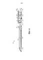
Фигуры 1 и 2 являются видами в перспективе хирургического инструмента в соответствии с различными вариантами осуществления настоящего изобретения;Figures 1 and 2 are perspective views of a surgical instrument in accordance with various embodiments of the present invention;
Фигуры 3-5 являются перспективными изображениями в разобранном виде концевого зажима и вала инструмента в соответствии с различными вариантами осуществления настоящего изобретения;Figures 3-5 are exploded perspective views of an end clamp and tool shaft in accordance with various embodiments of the present invention;
Фигура 6 является видом сбоку концевого зажима в соответствии с различными вариантами осуществления настоящего изобретения;6 is a side view of an end clamp in accordance with various embodiments of the present invention;
Фигура 7 является перспективным изображением в разобранном виде рукоятки инструмента в соответствии с различными вариантами осуществления настоящего изобретения;Figure 7 is an exploded perspective view of a tool handle in accordance with various embodiments of the present invention;
Фигуры 8 и 9 являются частичными видами в перспективе рукоятки в соответствии с различными вариантами осуществления настоящего изобретения;Figures 8 and 9 are partial perspective views of a handle in accordance with various embodiments of the present invention;
Фигура 10 является видом сбоку рукоятки в соответствии с различными вариантами осуществления настоящего изобретения;Figure 10 is a side view of a handle in accordance with various embodiments of the present invention;
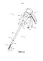
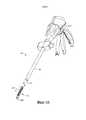
Фигуры 11, 13-14, 16 и 22 являются видами в перспективе хирургического инструмента в соответствии с различными вариантами осуществления настоящего изобретения;Figures 11, 13-14, 16 and 22 are perspective views of a surgical instrument in accordance with various embodiments of the present invention;
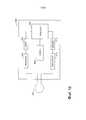
Фигуры 12 и 19 являются блок-схемами устройства управления в соответствии с различными вариантами осуществления настоящего изобретения;Figures 12 and 19 are block diagrams of a control device in accordance with various embodiments of the present invention;
Фигура 15 является видом сбоку концевого зажима, содержащего датчик-ретранслятор в соответствии с различными вариантами осуществления настоящего изобретения;Figure 15 is a side view of an end clip comprising a transponder sensor in accordance with various embodiments of the present invention;
Фигуры 17 и 18 изображают инструмент в стерильном контейнере в соответствии с различными вариантами осуществления настоящего изобретения;Figures 17 and 18 depict an instrument in a sterile container in accordance with various embodiments of the present invention;
Фигура 20 является блок-схемой удаленного программирующего устройства в соответствии с различными вариантами осуществления настоящего изобретения; и20 is a block diagram of a remote programming device in accordance with various embodiments of the present invention; and
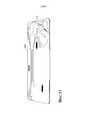
Фигура 21 является схемой упакованного инструмента в соответствии с различными вариантами осуществления настоящего изобретения.21 is a diagram of a packaged tool in accordance with various embodiments of the present invention.
ПОДРОБНОЕ ОПИСАНИЕDETAILED DESCRIPTION
Различные варианты осуществления настоящего изобретения в целом направлены на изобретение хирургического инструмента, имеющего, по меньшей мере, один удаленный датчик-ретранслятор и приспособления для передачи энергии и/или сигналов данных от устройства управления к ретранслятору. Настоящее изобретение может использоваться с любым видом хирургических инструментов, содержащих, по меньшей мере, один датчик-ретранслятор, таких как эндоскопические или лапароскопические хирургические инструменты, но оно особенно применимо для хирургических инструментов, некоторые особенности которых, такие как поворотный шарнир, препятствуют или другим образом ограничивают использование проводного соединения с датчиками. Перед описанием аспектов системы в качестве иллюстрации в первую очередь будет описан один тип хирургического инструмента, в котором используются варианты осуществления настоящего изобретения - эндоскопический сшивающий и режущий инструмент (например, эндокатер).Various embodiments of the present invention are generally directed to the invention of a surgical instrument having at least one remote sensor transponder and devices for transmitting energy and / or data signals from the control device to the relay. The present invention can be used with any type of surgical instrument containing at least one transducer transducer, such as endoscopic or laparoscopic surgical instruments, but it is particularly applicable to surgical instruments, some features of which, such as a swivel joint, interfere or otherwise limit the use of wired sensors. Before describing aspects of the system, an illustration will first describe one type of surgical instrument in which embodiments of the present invention are used — an endoscopic stapling and cutting instrument (eg, an endocater).
Фигуры 1 и 2 изображают эндоскопический хирургический инструмент 10, который содержит рукоятку 6, вал 8 и шарнирный концевой зажим 12, который соединен с возможностью вращения с валом 8 при помощи шарнирного сочленения 14. Поиск правильного размещения и ориентации концевого зажима 12 может облегчаться органами управления на рукоятке 6, включая (1) поворотную муфту 28 для вращения закрывающей трубки (более подробно описывается ниже в связи с Фигурами 4-5) относительно поворотного шарнира 29 вала 8, который обеспечивает вращение концевого зажима 12, и (2) блок управления вращением 16 для воздействия на шарнирное вращение концевого зажима 12 относительно шарнирного сочленения 14. В изображенном варианте осуществления концевой зажим 12 сконфигурирован для работы в режиме эндокатера для захвата, рассечения и сшивания ткани, хотя в других вариантах осуществления могут использоваться различные концевые зажимы, такие как концевые зажимы для других видов хирургических инструментов, таких как зажимы, рассекатели, сшивающие инструменты, клипсонакладыватели, устройства доступа, устройства для введения медикаментов/генной терапии, устройства подачи энергии для проведения ультразвуковых, РЧ- или лазерных процедур и т.д.Figures 1 and 2 depict an endoscopic
Рукоятка 6 инструмента 10 может иметь закрывающее спусковое устройство 18 и спусковое устройство 20, приводящее в действие концевой зажим 12. Необходимо понимать, что инструменты с концевыми зажимами, предназначенные для выполнения различных хирургических манипуляций, могут иметь разное количество и типы спусковых устройств или иных соответствующих средств управления концевым зажимом 12. Концевой зажим 12 показан отдельно от рукоятки 6 за счет предпочтительного удлиненного вала 8. В одном варианте осуществления клиницист или хирург, использующие инструмент 10, могут шарнирно соединять концевой зажим 12 с валом 8 при помощи блока управления вращением 16, что более подробно описано в ожидающей рассмотрения заявке на патент США Сер. № 11/329020, поданной 10 января 2006 года, под названием «Хирургический инструмент с шарнирным концевым зажимом», Джефри Ч. Хьюэл и соавт., которая включена в настоящий документ посредством ссылки.The
В приведенном примере концевой зажим 12, помимо прочего, имеет канал для скобок 22 и шарнирно перемещаемый зажимной элемент, например, упорный элемент 24, между которыми поддерживается расстояние, обеспечивающее эффективное сшивание скобками, а также рассечение ткани, захваченной концевым зажимом 12. Рукоятка 6 включает в себя рукоятку в форме пистолета, к которой врач приводит спусковой рычаг 18 с шарнирным соединением, что приводит к закрытию или прижатию упорного элемента 24 к каналу для шовных скобок 22 концевого зажима 12, чтобы зажать ткань, расположенную между упорным элементом 24 и каналом 22. Пусковое устройство 20 расположено снаружи относительно закрывающего пускового устройства 18. Когда закрывающий спусковой крючок 18 фиксируется в положении закрытия, пусковой крючок 20 может несколько проворачиваться к пистолетной рукоятке 26, так что оператор сможет достать его одной рукой. Затем оператор может прижать пусковой крючок 20 к пистолетной рукоятке 12, осуществляя сшивание и рассечение ткани, зажатой в концевом зажиме 12. Приложение ‘573 описывает различные конфигурации для блокировки и разблокировки закрывающего спускового крючка 18. В других вариантах осуществления помимо упорного элемента 24 могут использоваться другие зажимные элементы, например, вторая бранша и т.д.In the above example, the
Необходимо принять во внимание, что термины «проксимальный» и «дистальный» используются в настоящем документе по отношению к хирургу, удерживающему браншу 6 инструмента 10. Так, концевой зажим 12 расположен дистально по отношению к рукоятке 6, расположенной более проксимально. Необходимо также принять во внимание, что для удобства и ясности такие пространственные термины как «вертикальный» и «горизонтальный» используются в настоящем документе по отношению к Фигурам. Однако хирургические инструменты используются во множестве ориентаций и положений, поэтому данные термины не являются абсолютными и не ограничивают настоящее изобретение.You must take into account that the terms "proximal" and "distal" are used in this document in relation to the surgeon holding the
При пользовании инструментом сначала может нажиматься закрывающее пусковое устройство 18. Когда хирурга устраивает положение концевого зажима 12, он может оттянуть закрывающий спусковой крючок 18 в фиксированное положение полного закрытия, вплотную к пистолетной рукоятке 26. После этого может быть нажат спусковой крючок 20. Когда хирург отпускает пусковой крючок 20, крючок возвращается в открытое положение (см. Фигуры 1 и 2). При нажатии кнопка разблокировки 30 на рукоятке 6 и, в данном примере, на пистолетной рукоятке 26 рукоятки может высвободить заблокированный закрывающий спусковой крючок 18.When using the tool, the
На Фигуре 3 представлен разобранный вид концевого зажима 12 в соответствии с различными вариантами осуществления. Как показано на фигуре, концевой зажим 12, помимо ранее указанного желоба 22 и упорного элемента 24, может включать режущий инструмент 32, салазки 33, съемный картридж со скобками 34, установленный в желобе 22, и винтовой вал 36. Режущий инструмент 32 может, например, являться скальпелем. Упорный элемент 24 может открываться и закрываться на шарнире 25, соединенном с проксимальным концом канала 22. Упорный элемент 24 также на проксимальном конце может иметь петлю 27, вставленную в часть механизма закрытия (описан ниже) для открывания и закрывания упорного элемента 24. Когда закрывающий спусковой крючок 18 приводится в действие, то есть отводится пользователем инструмента 10, упорный элемент 24 может поворачиваться шарниром 25 в фиксированное, или закрытое положение. Если фиксация концевого зажима 12 является удовлетворительной, оператор может привести в действие пусковое устройство 20, при этом, как более подробно описано ниже, скальпель 32 и салазки 33 перемещаются вдоль желоба 22, рассекая ткани, зафиксированные концевым зажимом 12. В результате движения салазок 33 вдоль канала 22 скобки из кассеты 34 прошивают рассеченные ткани, упираясь в прижатый упорный элемент 24, который формирует их, фиксируя ткани. Более подробная информация о таких двухтактных режущих и сшивающих инструментах представлена в патенте США № 6978921 под названием «Хирургический сшивающий инструмент с электронно-лучевым механизмом резания/сшивания», который включен в настоящий документ посредством ссылки. Салазки 33 могут являться частью картриджа 34, при этом, когда скальпель 32 втягивается после рассечения ткани, салазки 33 не втягиваются. Желоб 22 и упорный элемент 24 могут изготавливаться из электропроводного материала (такого как металл), благодаря чему они могут служить частью антенны, которая взаимодействует с датчиками в концевом зажиме, что подробно описывается ниже. Картридж 34 может быть изготовлен из непроводящего материала (такого как пластик), а датчик может быть соединен или расположен в картридже 34, что подробно описывается ниже.Figure 3 is an exploded view of an
Необходимо отметить, что, несмотря на то, что в описанных в настоящем документе вариантах осуществления инструмента 10 используется концевой зажим 12, сшивающий скобками рассеченную ткань, в других вариантах осуществления могут использоваться другие способы стягивания или сшивания рассеченной ткани. Например, могут также применяться концевые зажимы, использующие для стягивания рассеченной ткани энергию радиоволн или клеящие вещества. В патенте США № 5709680 под названием «Электрохирургическое гемостатическое устройство» Йетс и соавторы, и патенте США № 5688270 под названием «Электрохирургическое гемостатическое устройство с электродами с выемкой и/или изогнутыми электродами» Йетс и соавторы, которые во всей своей полноте включены в настоящий документ посредством ссылки, описываются режущие инструменты, который использует радиочастоты для герметизации рассеченных тканей. В заявке на патент США Сер. № 11/267811 Морган и соавторы и заявке на патент США Сер. № 11/267363 Шелтон и соавторы, которые также включены в настоящий документ посредством ссылки, описываются режущие инструменты, в которых для сшивания рассеченных тканей используются клеющие вещества. В соответствии с изложенным выше, несмотря на то, что приведенное в настоящем документе описание относится к манипуляциям по рассечению/сшиванию и аналогичным операциям, необходимо понимать, что данный вариант осуществления является примером и не ограничивает настоящее изобретение. Могут также использоваться другие техники сшивания тканей.It should be noted that, although the embodiments of the
На Фигурах 4 и 5 представлено перспективное изображение в разобранном виде, а на Фигуре 6 представлен вид сбоку концевого зажима 12 и вала 8 в соответствии с различными вариантами осуществления изобретения. Как показано в проиллюстрированном варианте осуществления, вал 8 может включать в себя проксимальную закрывающую трубку 40 и дистальную закрывающую трубку 42, связанные шарнирным звеном 44. Дистальная закрывающая трубка 42 содержит отверстие 45, в которое вставлена петля 27 упорного элемента 24 для открытия и закрытия упорного элемента 24. Непосредственно внутри закрывающих трубок 40 и 42 может быть расположена сердцевинная трубка 46. Непосредственно внутри сердцевинной трубки 46 может быть расположен основной вращательный (или проксимальный) приводной вал 48, который соединяется со вспомогательным (или дистальным) приводным валом 50 с помощью комплекта конических зубчатых колес 52. Вспомогательный приводной вал 50 соединен с приводным механизмом 54, который приводит в действие проксимальный приводной механизм 56 винтового вала 36. Вертикальная коническая шестерня 52b может находиться и поворачиваться в отверстии 57 на дистальном конце проксимальной сердцевинной трубки 46. В дистальную сердцевинную трубку 58 могут быть вставлены вспомогательный приводной вал 50 и приводные механизмы 54 и 56. В настоящем документе основной приводной вал 48, вспомогательный приводной вал 50 и шарнирное сочленение в сборе (например, комплект конических зубчатых колес 52a-c) иногда собирательно называются «основным приводным валом в сборе». Закрывающие трубки 40, 42 могут быть изготовлены из электропроводного материала (такого как металл), благодаря чему они могут служить частью антенны, что подробно описывается ниже. Компоненты основного приводного вала в сборе (например, приводные валы 48, 50) могут быть изготовлены из непроводящего материала (такого как пластик).Figures 4 and 5 show an exploded perspective view, and Figure 6 shows a side view of an
Приводной винт 36 посажен в подшипник 38, расположенный на дистальном конце желоба для скобок 22, что позволяет приводному винту 36 свободно вращаться относительно желоба 22. Винтовой вал 36 может стыковаться с резьбовым отверстием (не показано) скальпеля 32 таким образом, что при вращении вала 36 скальпель 32 перемещается дистально или проксимально (в зависимости от направления вращения) в желобе для скобок 22. Соответственно, когда основной приводной вал 48 начинает вращаться из-за приведения в в действие спускового крючка 20 (что более подробно описывается ниже), комплект конических зубчатых колес 52a-c вызывает вращение вспомогательного приводного вала 50, который, в свою очередь, в связи со сцеплением с приводным механизмом 54, 56 вызывает вращение винтового вала 36, который вызывает продольное перемещение скальпеля 32 по желобу 22 для рассечения любой ткани, которая зажата в концевом зажиме. Салазки 33 могут быть выполнены, например, из пластика и могут иметь наклонную дистальную поверхность. По мере движения салазок 33 через канал 22 поверхность с уклоном вперед может подталкивать или приводить в движение скобки в кассете со скобками 34 через захваченную зажимом ткань с упором об упорный элемент 24. Упорный элемент 24 сгибает скобы, скрепляя таким образом рассеченные ткани. Когда скальпель 32 втянут, скальпель 32 и салазки 33 могут разъединяться, при этом салазки 33 остаются на дистальном конце желоба 22.The
В соответствии с различными вариантами осуществления, как показано на Фигурах 7-10, хирургический инструмент может содержать батарею 64 в рукоятке 6. Изображенный вариант осуществления обеспечивает обратную связь с пользователем относительно установки и силы нагрузки на режущий инструмент в концевом зажиме 12. Кроме того, этот вариант осуществления может использовать энергию, которая была приложена пользователем для втягивания спускового крючка 18, для питания инструмента 10 (в так называемом режиме «усилителя»). Как показано в проиллюстрированном варианте осуществления, рукоятка 6 включает детали внешней нижней стороны 59, 60 и детали внешней верхней стороны 61, 62, которые вплотную прилегают друг к другу, формируя внешнюю часть рукоятки 6. Детали рукоятки 59-62 могут быть изготовлены из непроводящего материала, такого как пластик. Батарея 64 может быть предусмотрена в части пистолетной рукоятки 26 рукоятки 6. Батарея 64 питает двигатель 65, расположенный в верхней части пистолетной рукоятки 26 рукоятки 6. Батарея 64 может быть сконструирована в соответствии с любой подходящей конструкцией или химическим процессом, включающим, например, литий-ионные химические соединения, такие как LiCoO2 или LiNiO2, никель-металлогидридные соединения и т.д. В соответствии с различными вариантами осуществления двигатель 65 может быть приводным щеточным двигателем постоянного тока с максимальной скоростью вращения около 5000-100000 оборотов в минуту. Двигатель 64 может перемещать на 90° блок конических зубчатых колес 66, состоящий из первого конического зубчатого колеса 68 и второго конического зубчатого колеса 70. Блок конических зубчатых колес 66 может приводить в действие блок планетарных шестерен 72. Блок планетарных шестерен 72 может включать ведущую шестерню 74, соединенную с приводным валом 76. Ведущая шестерня 74 может приводить в действие сопряженное кольцевое зубчатое колесо 78, которое через приводной вал 82 приводит в действие барабан с винтовым зубчатым колесом 80. Кольцо 84 может быть навинчено на барабан с винтовым зубчатым колесом 80. Таким образом, при вращении двигателя 65 кольцо 84 двигается вдоль барабана с винтовым зубчатым колесом 80 с помощью установленного блока конических зубчатых колес 66, блока планетарных шестерней 72 и кольцевого зубчатого колеса 78.In accordance with various embodiments, as shown in Figures 7-10, the surgical instrument may comprise a
Рукоятка 6 может также включать датчик пуска двигателя 110 в сочетании со спусковым механизмом 20, чтобы оператор мог видеть, приведен ли в действие спусковой механизм 20 (или он «прижат») по отношению к пистолетной части 26 рукоятки 6, чтобы начать операцию рассечения/сшивания концевым зажимом 12. Датчик 110 может представлять собой пропорциональный датчик, например, реостат или резистор переменного сопротивления. Когда спусковое устройство 20 находится в прижатом состоянии, датчик 110 определяет движение и направляет электрический сигнал, указывающий на необходимость подачи электрического напряжения (или питания) к двигателю 65. Если датчик 110 является резистором переменного сопротивления или аналогичным устройством, вращение двигателя 65 может быть, как правило, пропорционально величине смещения спускового устройства 20. Таким образом, когда оператор слегка прижимает или закрывает спусковое устройство 20, двигатель 65 вращается сравнительно медленно. Когда пусковое устройство 20 полностью прижато (или находится в полностью закрытом положении), вращение двигателя 65 максимально. То есть, чем сильнее пользователь прижимает пусковое устройство 20, тем большее напряжение подается на двигатель 65, обеспечивая большую скорость вращения. В другом варианте осуществления, например, устройство управления (подробно описывается ниже) может передавать двигателю 65 выходной широтномодулированный сигнал на основе входного сигнала от датчика 110 для управления двигателем 65.The
Рукоятка 6 может включать срединную часть рукоятки 104, примыкающую к верхней части спускового устройства 20. Рукоятка 6 также может содержать смещающую пружину 112, расположенную между опорами на срединной части рукоятки 104 и спусковом устройстве 20. Смещающая пружина 112 может смещать спусковое устройство 20 в полностью открытое положение. Таким образом, когда оператор разблокирует спусковое устройство 20, смещающая пружина 112 переводит спусковое устройство 20 в открытое положение, тем самым предупреждая срабатывание датчика 110, что приводит к остановке двигателя 65. Кроме того, благодаря наличию смещающей пружины 112, каждый раз, когда пользователь закрывает спусковое устройство 20, он чувствует сопротивление, что позволяет контролировать скорость вращения двигателя 65. Также оператор может прекратить воздействие на спусковое устройство 20 и тем самым прекратить воздействие на датчик 100 и остановить двигатель 65. Таким образом, пользователь может остановить работу концевого зажима 12, что позволяет обеспечить возможность управления оператором операции по рассечению/сшиванию.The
Дистальный конец барабана с винтовым зубчатым колесом 80 включает дистальный приводной вал 120, который приводит в действие кольцевое зубчатое колесо 122, сопрягающееся с ведущей шестерней 124. Ведущая шестерня 124 соединяется с основным приводным валом 48 блока основного приводного вала. Таким образом, вращение двигателя 65 вызывает вращение группы основного приводного вала, что приводит в действие концевой зажим 12, как описано выше.The distal end of the
Кольцо 84, навинченное на барабан с винтовым зубчатым колесом 80, может включать опору 86, которая установлена в прорезь 88 кулисы 90. Кулиса 90 содержит отверстие 92 на противоположном конце 94 для удержания шарнирного штифта 96, который закреплен между деталями внешней нижней стороны рукоятки 59, 60. Шарнирный штифт 96 также проходит через отверстие 100 в спусковом устройстве 20 и отверстие 102 в срединной части рукоятки 104.The
Кроме того, рукоятка 6 может включать датчик обратного действия (или датчик завершения хода) 130 и датчик остановки двигателя (или начала хода) 142. В различных вариантах осуществления датчик обратного действия 130 может являться концевым переключателем, расположенным на дистальном конце барабана с винтовым зубчатым колесом 80, при этом кольцо 84, навинченное на барабан с винтовым зубчатым колесом 80, контактирует с датчиком обратного действия 130 и включает его, когда кольцо 84 достигает дистального конца барабана с винтовым зубчатым колесом 80. При активации датчик обратного действия 130 посылает сигнал устройству управления, которое посылает сигнал двигателю 65 для изменения направления вращения, тем самым приводя к втягиванию скальпеля 32 концевого зажима 12 после операции рассечения.In addition, the
Датчик останова двигателя 142 может являться, например, нормально замкнутым концевым выключателем. В различных вариантах осуществления он может располагаться на проксимальном конце барабана с винтовым зубчатым колесом 80, при этом кольцо 84 переключает выключатель 142, когда кольцо 84 достигает проксимального конца барабана с винтовым зубчатым колесом 80.The
Во время операции, когда хирург, использующий инструмент 10, тянет назад спусковой крючок 20, датчик 110 определяет приведение в действие спускового крючка 20 и посылает сигнал устройству управления, которое посылает сигнал двигателю 65 для вращения вперед двигателя 65, например, со скоростью, которая пропорциональна силе, с которой хирург тянет назад спусковой крючок 20. Вращение двигателя вправо 65, в свою очередь, вызывает вращение кольцевого зубчатого колеса 78 на дистальном конце блока планетарных шестерней 72, тем самым активируя вращение барабана с винтовым зубчатым колесом 80 и продвижение в дистальном направлении кольца 84, навинченного на барабан с винтовым зубчатым колесом 80, вдоль барабана с винтовым зубчатым колесом 80. Вращение барабана с винтовым зубчатым колесом 80 также приводит в действие блок основного приводного вала, как описано выше, что, в свою очередь, приводит в рабочее положение скальпель 32 на концевом зажиме 12, то есть скальпель 32 и салазки 33 проходят вдоль канала 22, при этом рассекается ткань, захваченная концевым зажимом 12. Кроме того, в вариантах осуществления изобретения, в которых используется концевой зажим для наложения скобок, концевой зажим 12 используется для скрепления тканей скобками.During the operation, when the surgeon using the
Во время операции разрезания/сшивания полным концевым зажимом 12 кольцо 84 на барабане с винтовым зубчатым колесом 80 может оставаться у дистального конца барабана с винтовым зубчатым колесом 80, что вызывает срабатывание датчика обратного действия 130, который посылает сигнал устройству управления, которое посылает сигнал двигателю 65 для изменения направления вращения двигателя 65. Это, в свою очередь, вызывает втягивание скальпеля 32 и вынуждает кольцо 84 на барабане с винтовым зубчатым колесом 80 двигаться в обратном направлении к проксимальному кольцу барабана с винтовым зубчатым колесом 80.During the cutting / stapling operation with the
Срединная часть рукоятки 104 включает тыльное плечо 106, которое зацепляется за кулису 90, что наилучшим образом показано на Фигурах 8 и 9. Срединная часть рукоятки 104 также имеет ограничитель рабочего хода 107, сцепленный со спусковым устройством 20. Движение кулисы 90 управляется вращением двигателя 65, как описано выше. Когда кулиса 90 вращается против часовой стрелки и кольцо 84 перемещается с проксимального конца спирального зубчатого колеса 80 к дистальному концу, срединная часть рукоятки 104 может свободно вращаться против часовой стрелки. Таким образом, когда пользователь прижимает спусковой механизм 20, спусковой механизм 20 зацепляется с упором 107 поступательного движения в средней части рукоятки 104, заставляя среднюю часть рукоятки 104 вращаться против часовой стрелки. Однако за счет зацепления заднего плеча 106 с кулисой 90 средняя часть рукоятки 104 способна вращаться против часовой стрелки лишь настолько, насколько позволяет кулиса 90. Таким образом, если двигатель 65 остановится по какой-либо причине, кулиса 90 прекратит вращаться и пользователь не сможет прижать спусковой механизм 20 дальше, так как средняя часть рукоятки 104 не сможет свободно вращаться против часовой стрелки из-за кулисы 90.The middle part of the
Компоненты примера системы закрытия (или фиксации) упорного элемента 24 концевого зажима 12 путем притягивания закрывающего пускового устройства 18 также показаны на Фигурах 7-10. В показанном на иллюстрации варианте осуществления изобретения система закрывания включает хомутик 250, соединенный с закрывающим спусковым устройство 18 штырем 251, который вставляется через совмещенные отверстия в спусковом устройстве 18 и хомутике 250. Шарнирный штифт 252, вокруг которого поворачивается закрывающее спусковое устройство 18, проходит через другое отверстие в закрывающем спусковом устройстве 18, которое смещено относительно места, причем штифт 251 проходит через закрывающее спусковое устройство 18. Таким образом, втягивание зажимающего спускового устройства 18 заставляет верхнюю часть закрывающего спускового устройства 18, к которому присоединен хомутик 250 с помощью штыря 251, вращаться против часовой стрелки. Дистальный конец вилки сцепления 250 соединен с помощью штифта 254 с первым закрывающим кронштейном 256. Первый закрывающий кронштейн 256 соединен со вторым закрывающим кронштейном 258. Вместе закрывающие кронштейны 256 и 258 определяют отверстие, в которое вставлен и удерживается проксимальный конец проксимальной закрывающей трубки 40 (см. Фигура 4), при этом продольное движение закрывающих кронштейнов 256 и 258 вызывает продольное перемещение проксимальной закрывающей трубки 40. Инструмент 10 также включает закрывающий стержень 260, установленный внутри проксимальной закрывающей трубки 40. Закрывающий стержень 260 может включать окно 261, в которое вставляется опора 263 на одной из деталей внешних сторон рукоятки, такой как деталь внешней нижней стороны 59 в приведенном варианте осуществления, жестко связывая закрывающий стержень 260 с рукояткой 6. Таким образом, проксимальная закрывающая трубка 40 способна перемещаться продольно по отношению к закрывающему стержню 260. Закрывающий стержень 260 может также включать дистальный буртик 267, который прилегает к полости 269 в проксимальной сердцевинной трубке 46 и удерживается заглушкой 271 (см. Фигура 4).The components of an example closure (or fixation) system of the
Во время работы, когда хомутик 250 вращается из-за втягивания спускового устройства 18, закрывающие кронштейны 256, 258 вызывают дистальное перемещение проксимальной закрывающей трубки 40 (т.е. от конца рукоятки инструмента 10), что вызывает дистальное перемещение дистальной закрывающей трубки 42, которое приводит к повороту упорного элемента 24 вокруг шарнира 25 в сомкнутое, или закрытое, положение. Когда закрывающее пусковое устройство 18 разблокируется из заблокированного положения, проксимальная закрывающая трубка 40 скользит проксимально, что вызывает проксимальное скольжение дистальной закрывающей трубки 42, которое, в силу нахождения петли 27 в окне 45 дистальной закрывающей трубки 42, приводит к повороту упорного элемента 24 вокруг шарнира 25 в открытое, или несомкнутое, положение. Таким образом, притягивая и блокируя закрывающее спусковое устройство 18, оператор может зажимать ткань между упорным элементом 24 и желобом 22, а также освобождать ее после рассечения/сшивания, вернув закрывающее пусковое устройство 18 из закрытого положения.During operation, when the
Устройство управления (более подробно описано ниже) может получать выходные сигналы от датчиков окончания хода и начала хода 130, 142, а также датчика запуска двигателя 110, и может управлять двигателем 65 при помощи исходящих сигналов. Например, когда хирург изначально снова пусковое устройство 20 после блокировки закрывающего пускового устройства 18, приводится в действие датчик запуска двигателя 110. Если картридж со скобками 34 находится в концевом зажиме 12, датчик захвата картриджа (не показан) может быть закрыт, в этом случае устройство управления может посылать выходной контрольный сигнал двигателю 65 для вращения двигателя 65 вперед. Когда концевой зажим 12 завершает рабочий ход, может быть приведен в действие датчик обратного действия 130. Устройство управления может получать этот выходной сигнал от датчика обратного действия 130 и вызывать изменение направление вращения двигателя 65. При полном втягивании скальпеля 32 приводится в действие переключатель датчика останова двигателя 142, который вызывает остановку двигателя 65 при помощи устройства управления.The control device (described in more detail below) can receive output signals from the end-of-stroke and start-
В других вариантах осуществления вместо пропорционального датчика 110 может использоваться двухпозиционный датчик. В таких вариантах осуществления скорость вращения двигателя 65 может не быть пропорциональной силе, приложенной оператором. Как правило, двигатель 65 может вращаться в целом с постоянной скоростью. Тем не менее, оператор получает обратную связь относительно усилия, так как пусковое устройство 20 включено в цепь зубчатых передач привода.In other embodiments, instead of the
Инструмент 10 может содержать множество датчиков-ретрансляторов в концевом зажиме 12 для определения различных состояний, связанных с концевым зажимом 12, такие датчики-ретрансляторы могут применяться для определения состояния картриджа со скобками 34 (или другого вида картриджа, в зависимости от вида хирургического инструмента), продвижения сшивающего аппарата во время закрывания и приведения в действие и т.д. Датчики-ретрансляторы могут пассивно получать энергию от индуктивных сигналов, что более подробно описывается ниже, хотя в других вариантах осуществления ретрансляторы могут получать энергию от удаленного источника питания, такого как, например, батарея в концевом зажиме 12. Датчики-ретрансляторы могут включать, например, магниторезистивные, оптические, электромеханические, РЧИД и микроскопические электромеханические датчики, а также датчики движения и давления. Эти датчики-ретрансляторы могут взаимодействовать с устройством управления 300, которое может находиться, например, в рукоятке 6 инструмента 10, как показано на Фигуре 11.The
Как показано на Фигуре 12, в соответствии с различными вариантами осуществления устройство управления 300 может содержать процессор 306 и один или более блок памяти 308. При выполнении набора команд, хранящихся в блоке памяти 308, процессор 306 может управлять различными компонентами инструмента 10, такими как двигатель 65 или пользовательский дисплей (не показан), на основе входных сигналов, получаемых от различных датчиков-ретрансляторов концевого зажима и других датчиков (таких как, например, датчик запуска двигателя 110, датчик окончания хода 130 и датчик начала хода 142). Устройство управления 300 может получать питание от батареи 64 во время хирургического применения инструмента 10. Устройство управления 300 может содержать индуктивный элемент 302 (например, катушку или антенну) для приема беспроводных сигналов от датчиков-ретрансляторов, что более подробно описывается ниже. Входные сигналы, получаемые при помощи индуктивного элемента 302, действующего как приемная антенна, могут быть демодулированы демодулятором 310 и дешифрованы декодером 312. Входные сигналы могут содержать данные от датчиков-ретрансляторов в концевом зажиме 12, которые могут использоваться процессором 306 для управления различными аспектами инструмента 10.As shown in FIG. 12, in accordance with various embodiments, the
Для передачи сигналов датчикам-ретрансляторам устройство управления 300 может содержать кодер 316 для шифрования сигналов и модулятор 318 для модулирования сигналов в соответствии со схемой модуляции. Индуктивный элемент 302 может действовать как передающая антенна. Устройство управления 300 может взаимодействовать с датчиками-ретрансляторами при помощи любого подходящего протокола беспроводной связи и любой подходящей частоты (например, промышленного, научного и медицинского диапазона). Кроме того, устройство управления 300 может передавать сигналы в диапазонах частот, которые отличаются от диапазонов частот сигналов, полученных от датчиков-ретрансляторов. Кроме того, хотя на Фигуре 12 показана только одна антенна (индуктивный элемент 302), в других вариантах осуществления устройство управления 300 может иметь отдельные принимающие и передающие антенны.To transmit signals to the relay sensors, the
В соответствии с различными вариантами осуществления, устройство управления 300 может содержать микроконтроллер, микропроцессор, программируемую пользователем вентильную матрицу (ППВМ), один или более вид других интегральных схем (например, радиоприемников и ШИМ-контроллеров), и/или импульсные пассивные элементы. Устройства управления могут также иметь вид, например, однокристальной системы (SoC) или схемы из нескольких кристаллов, помещенных в единый корпус (SIP).In accordance with various embodiments, the
Как показано на Фигуре 11, устройство управления 300 может находиться в рукоятке 6 инструмента 10, и один или более датчик-ретранслятор 368 инструмента 10 может располагаться в концевом зажиме 12. Для передачи энергии и/или данных к датчикам-ретрансляторам 368 в концевом зажиме 12 или от них индуктивный элемент 302 устройства управления 300 может быть индуктивно связан со вспомогательным индуктивным элементом (например, катушкой) 320, расположенным в вале 8 дистальнее от поворотного шарнира 29. Предпочтительно, чтобы вспомогательный индуктивный элемент 320 был электрически изолирован от проводящего вала 8.As shown in Figure 11, the
Вспомогательный индуктивный элемент 320 может быть соединен электропроводным изолированным проводом 322 с дистальным индуктивным элементом (например, катушкой) 324, расположенным возле концевого зажима 12, и предпочтительно находиться дистальнее шарнирного сочленения 14. Провод 322 может быть изготовлен из электропроводного полимера и/или металла (например, меди) и иметь значительную гибкость, благодаря чему он может проходить через шарнирное сочленение 14 и не повреждаться при перекосе валов, соединяемых шарниром. Дистальный индуктивный элемент 324 может быть индуктивно связан с датчиком-ретранслятором 368, который находится, например, в картридже 34 концевого зажима 12. Ретранслятор 368, как более подробно описывается ниже, может содержать антенну (или катушку) для индуктивной связи с дистальной катушкой 324, датчик и встроенную электронику для приема и передачи беспроводных сигналов.The auxiliary
Ретранслятор 368 может использовать часть энергии индуктивного сигнала, полученного от дистального индуктивного элемента 326, для пассивного снабжения энергией ретранслятора 368. Как только ретранслятор 368 получит достаточное количество энергии от индуктивных сигналов, он может принимать и передавать данные устройству управления 300 в рукоятке 6 при помощи (i) индуктивной связи между ретранслятором 368 и дистальным индуктивным элементом 324, (ii) провода 322 и (iii) индуктивной связи между вспомогательным индуктивным элементом 320 и устройством управления 300. Таким образом, устройство управления 300 может взаимодействовать с ретранслятором 368 в концевом зажиме 12 без непосредственной проводной связи, проходящей через сложные механические сочленения, такие как поворотный шарнир 29, и/или без непосредственной проводной связи вала 8 с концевым зажимом 12, которая должна проходить через участки, где поддержание такой проводной связи затруднительно. Кроме того, из-за постоянства и известности расстояния между индуктивными элементами (например, зазора между (i) ретранслятором 368 и дистальным индуктивным элементом 324, а также (ii) вспомогательным индуктивным элементом 320 и устройством управления 300) соединения могут быть оптимизированы для индуктивного переноса энергии. Кроме того, расстояния могут быть относительно короткими, благодаря чему могут использоваться сигналы относительно малой мощности, что минимизирует их взаимодействие с другими системами в рабочей среде инструмента 10.The
В одном варианте осуществления с Фигуры 12 индуктивный элемент 302 устройства управления 300 расположен относительно близко к устройству управления 300. В соответствии с другими вариантами осуществления, как показано на Фигуре 13, индуктивный элемент 302 устройства управления 300 может быть расположен ближе к поворотному шарниру 29, благодаря чему он находится ближе к вспомогательному индуктивному элементу 320, что уменьшает протяженность индуктивной связи в таком варианте осуществления. С другой стороны, устройство управления 300 (и, следовательно, индуктивный элемент 302) может располагаться ближе к вспомогательному индуктивному элементу 320 для уменьшения зазора.In one embodiment of FIG. 12, the
В других вариантах осуществления может использоваться более или менее двух индуктивных связей. Например, в некоторых вариантах осуществления хирургический инструмент 10 может использовать одну индуктивную связь между устройством управления 300 в рукоятке 6 и ретранслятором 368 в концевом зажиме 12, что устраняет потребность в индуктивных элементах 320, 324 и проводе 322. Конечно, в таких вариантах осуществления может понадобиться более сильный сигнал в связи с большим расстоянием между устройством управления 300 в рукоятке 6 и ретранслятором 368 в концевом зажиме 12. Кроме того, может использоваться более двух индуктивных связей. Например, если хирургический инструмент 10 содержит множество сложных механических соединений, из-за которых сложно установить прямую проводную связь, индуктивные связи могут использоваться для охвата каждого такого соединения. Например, индуктивные соединители могут использоваться на обеих сторонах поворотного шарнира 29 и обеих сторонах шарнирного сочленения 14, причем индуктивный элемент 321 на дистальной стороне поворотного шарнира 29 соединен при помощи провода 322 с индуктивным элементом 324 на проксимальной стороне шарнирного сочленения, а провод 323 соединяет индуктивные элементы 325, 326 на дистальной стороне шарнирного сочленения 14, как показано на Фигуре 14. В данном варианте осуществления индуктивный элемент 326 может взаимодействовать с датчиком-ретранслятором 368.In other embodiments, more or less two inductive bonds may be used. For example, in some embodiments, the
Кроме того, ретранслятор 368 может содержать множество различных датчиков. Например, он может содержать группу датчиков. Более того, концевой зажим 12 может содержать множество датчиков-ретрансляторов 368 для взаимодействия с дистальным индуктивным элементом 324 (и, соответственно, с устройством управления 300). К тому же, индуктивные элементы 320, 324 могут или не могут содержать ферритовые сердечники. Как упоминалось ранее, предпочтительно, чтобы они также были изолированы от электропроводного наружного вала (или каркаса) инструмента 10 (например, закрывающих трубок 40, 42), кроме того, также предпочтительно, чтобы провод 322 был изолирован от наружного вала 8.In addition, the
Фигура 15 является схемой концевого зажима 12, содержащего ретранслятор 368, удерживаемый или встроенный в картридж 34 у дистального конца желоба 22. Ретранслятор 368 может быть соединен с картриджем 34 при помощи подходящего связующего материала, такого как эпоксидная смола. В этом варианте осуществления ретранслятор 368 содержит магниторезистивный датчик. Упорный элемент 24 у дистального конца также содержит постоянный магнит 369, который большей частью обращен к ретранслятору 368. В этом примерном варианте осуществления концевой зажим 12 также содержит постоянный магнит 370, соединенный с салазками 33. Это позволяет ретранслятору 368 определять открытое/закрытое состояние концевого зажима 12 (за счет перемещения постоянного магнита 369 ближе или дальше от ретранслятора при открытии и закрытии упорного элемента 24) и полноту операции сшивания/рассечения (за счет перемещения постоянного магнита 370 к ретранслятору 368 по мере прохождения салазок 33 по желобу 22, что является частью операции рассечения).FIG. 15 is a diagram of an
Фигура 15 также изображает скобки 380 и движущие механизмы скобок 382 картриджа со скобками 34. Как пояснялось ранее, в соответствии с различными вариантами осуществления, по мере прохождения салазками 33 желоба 22 салазки 33 приводят в действие движущие механизмы скобок 382, которые перемещают скобки 380 в рассеченные ткани, удерживаемые концевым зажимом 12, во время чего скобкам 380 придается необходимая форма при помощи упорного элемента 24. Как указывалось выше, такой хирургический режущий и сшивающий инструмент является одним из видов хирургических инструментов, с которым может успешно применяться настоящее изобретение. Различные варианты осуществления настоящего изобретения могут использоваться с любыми видами хирургических инструментов, имеющих один или более датчик-ретранслятор.Figure 15 also depicts the
В одном из описанных выше вариантов осуществления батарея 64 обеспечивает энергией (по меньшей мере, частично) инструмент 10 во время сшивания. Таким образом, инструмент также может называться усилительным устройством. Более подробная информация и дополнительные варианты осуществления усилительных устройств описаны в приложении ‘573, которое включено в настоящий документ. Однако следует понимать, что инструмент 10 не обязательно должен быть усилительным устройством, и что это лишь пример вида устройств, в которых могут использоваться аспекты настоящего изобретения. Например, инструмент 10 может содержать пользовательский дисплей (такой как жидкокристаллический или светодиодный дисплей), который может получать энергию от батареи 64 и управляться устройством управления 300. На таком дисплее могут отображаться данные датчиков-ретрансляторов 368 концевого зажима 12.In one of the above embodiments, the
В другом варианте осуществления вал 8 инструмента 10, включающего, например, проксимальную закрывающую трубку 40 и дистальную закрывающую трубку 42, вместе с этими элементами может служить частью антенны для устройства управления 300 за счет излучения сигналов к датчику-ретранслятору 368 и приема сигналов, испускаемых датчиком-ретранслятором 368. Таким образом, сигналы, испускаемые и принимаемые датчиком-ретранслятором в концевом зажиме 12, могут передаваться через вал 8 инструмента 10.In another embodiment, the
Проксимальная закрывающая трубка 40 может быть заземлена своим проксимальным концом при помощи деталей внешней нижней и верхней стороны 59-62, которые могут быть изготовлены из неэлектропроводного материала, такого как пластик. Компоненты приводного вала в сборе (включая основной приводной вал 48 и вспомогательный приводной вал 50) внутри проксимальных и дистальных закрывающих трубок 40, 42 также могут быть изготовлены из неэлектропроводного материала, такого как пластик. Более того, компоненты концевого зажима 12 (такие как упорный элемент 24 и желоб 22) могут быть электрически соединены с (или находиться в непосредственном или непрямом электрическом контакте) с дистальной закрывающей трубкой 42 таким образом, что они также могут служить частью антенны. Более того, датчик-ретранслятор 368 может быть расположен таким образом, чтобы он был электрически изолирован от компонентов вала 8 и концевого зажима 12, которые служат антенной. Например, датчик-ретранслятор 368 может располагаться в картридже 34, который может быть изготовлен из неэлектропроводного материала, такого как пластик. Поскольку дистальный конец вала 8 (такой как дистальный конец дистальной закрывающей трубки 42) и служащие антенной части концевого зажима 12 могут находиться на относительно близком расстоянии от датчика 368, мощность передаваемых сигналов может поддерживаться на низком уровне, тем самым минимизируя или уменьшая взаимодействие с другими системами в рабочей области инструмента 10.The
В таком варианте осуществления, как показано на Фигуре 16, устройство управления 300 может быть электрически соединено с валом 8 инструмента 10 таким же образом, как и с проксимальной закрывающей трубкой 40 - при помощи проводящего соединительного элемента 400 (например, провода). Поэтому части наружного вала 8, такие как закрывающие трубки 40, 42, могут действовать как части антенны для устройства управления 300 за счет излучения сигналов для датчика 368 и приема сигналов от датчика 368. Входные сигналы, принимаемые устройством управления 300, могут быть демодулированы демодулятором 310 и дешифрованы декодером 312 (см. Фигура 12). Входные сигналы могут содержать данные от датчиков 368 концевого зажима 12, которые могут использоваться процессором 306 для управления различными деталями инструмента 10, такими как двигатель 65 или пользовательский дисплей.In such an embodiment, as shown in FIG. 16, the
Для передачи сигнала с данными к датчикам 368 в концевом зажиме 12 или от них соединительный элемент 400 может соединять устройство управления 300 с компонентами вала 8 инструмента 10 таким образом, чтобы проксимальная закрывающая трубка 40 могла электрически соединяться с дистальной закрывающей трубкой 42. Предпочтительнее, чтобы дистальная закрывающая трубка 42 была электрически изолирована от удаленного датчика 368, который может находиться в пластиковом картридже 34 (см. Фигура 3). Как упоминалось ранее, компоненты концевого зажима 12, такие как желоб 22 и упорный элемент 24 (см. Фигура 3), могут быть электропроводными и находиться в электрическом контакте с дистальной закрывающей трубкой 42 так, чтобы они тоже служили частью антенны.To transmit the data signal to the
Вместе с валом 8, действующим как антенна для устройства управления 300, устройство управления 300 может взаимодействовать с датчиком 368 в концевом зажиме 12 без непосредственного проводного соединения. Кроме того, поскольку расстояние между валом 8 и удаленным датчиком 368 постоянно и известно, уровень мощности сигнала может быть оптимизирован для его уменьшения и, как следствие, сокращения до минимума взаимодействия с другими системами в рабочей среде инструмента 10. Как описывалось выше, датчик 368 может содержать схемы связи для излучения сигналов для устройства управления 300 и приема сигналов от устройства управления 300. Схема связи может быть объединена с датчиком 368.Together with the
В другом варианте осуществления компоненты вала 8 и/или концевого зажима 2 могут служить антенной для удаленного датчика 368. В еще одном варианте осуществления удаленный датчик 368 электрически соединен с валом (таким как дистальная закрывающая трубка 42, которая может быть электрически соединена с проксимальной закрывающей трубкой 40) и устройством управления 300, которое изолировано от вала 8. Например, датчик 368 может быть соединен с проводящим компонентом концевого зажима 12 (таким как желоб 22), который, в свою очередь, может быть соединен с проводящими компонентами вала (например, закрывающими трубками 40, 42). В ином случае, концевой зажим 12 может содержать провод (не показан), который соединяет удаленный датчик 368 с дистальной закрывающей трубкой 42.In another embodiment, the components of the
Обычно хирургический инструмент, такой как инструмент 10, перед использованием очищается и стерилизуется. В одном способе стерилизации инструмент 10 помещается в закрытый и герметичный контейнер 280, такой как контейнер или мешок из пластика или тайвека, как показано на Фигурах 17 и 18. Затем контейнер и инструмент помещаются в поле облучения, которое проникает в контейнер и может быть гамма-излучением, рентгеновским излучением или электронами высоких энергий. Излучение уничтожает бактерий на инструменте 10 и в контейнере 280. Затем стерильный инструмент 10 может храниться в стерильном контейнере 280. Герметичный стерильный контейнер 280 поддерживает стерильность инструмента 10 до тех пор, пока он не будет открыт в медицинском учреждении или некоторых других рабочих средах. Помимо излучения могут использоваться другие средства стерилизации инструмента 10, такие как этиленоксид или текучий пар.Typically, a surgical instrument, such as
Если для стерилизации инструмента 10 используется излучение, такое как гамма-излучение, компоненты устройства управления 300, в особенности память 308 и процессор 306, могут повреждаться и становиться нестабильными. Таким образом, в соответствии с различными вариантами осуществления настоящего изобретения, устройство управления 300 может быть запрограммировано после упаковки и стерилизации инструмента 10.If radiation such as gamma radiation is used to sterilize the
Как показано на Фигуре 17, удаленное программирующее устройство 320, которое может быть портативным устройством, может устанавливать беспроводную связь с устройством управления 300. Удаленное программирующее устройство 320 может испускать беспроводные сигналы, которые принимаются устройством управления 300, для программирования устройства управления 300 и питания устройства управления 300 во время операции программирования. Таким образом, батарея 64 не должна обеспечивать энергией устройство управления 300 во время операции программирования. в соответствии с различными вариантами осуществления, программный код, загружаемый в устройство управления 300, может иметь относительно малый вес, такой как 1МБ или менее, поэтому при желании может использоваться протокол с относительно малой скоростью передачи данных. Более того, удаленное программирующее устройство 320 может устанавливаться в непосредственной физической близости к хирургическому инструменту 10, благодаря чему может использоваться сигнал малой мощности.As shown in Figure 17, the
Возвращаясь к Фигуре 19, устройство управления 300 может содержать индуктивную катушку 402 для приема беспроводных сигналов от удаленного программирующего устройства 320. Часть полученного сигнала при помощи энергетической цепи 404 может использоваться для питания устройства управления 300, когда оно не получает энергию от батареи 64.Returning to Figure 19, the
Входные сигналы, получаемые катушкой 402, действующей как приемная антенна, могут быть демодулированы демодулятором 410 и дешифрованы декодером 412. Входные сигналы могут содержать инструкции по программированию (например, код), которые могут храниться в энергонезависимой части памяти 308. Процессор 306 может выполнять код во время работы инструмента 10. Например, в соответствии с кодом процессор 306 посылает выходные сигналы к различным подсистемам инструмента 10, таким как двигатель 65, на основании данных, которые были получены от датчиков 368.The input signals received by the
Устройство управления 300 может также содержать блок энергонезависимой памяти 414, который содержит код последовательности загрузки, который выполняется процессором 306. Если устройство управления 300 получает достаточное количество энергии от сигналов удаленного устройства управления 320 во время послестерилизационного программирования, процессор 306 может в первую очередь выполнить код последовательности загрузки («загрузчик операционной системы») 414, который может установить операционную систему процессора 306.The
Устройство управления 300 также может посылать сигналы обратно к удаленному программирующему устройству 320, например, если это сигналы подтверждения и установления связи. Устройство управления 300 может содержать кодер 416 для шифрования сигналов, которые затем будут посылаться к программирующему устройству 320 и модулятору 418 для модулирования сигналов в соответствии со схемой модуляции. Катушка 402 может действовать как передающая антенна. Устройство управления 300 и удаленное программирующее устройство 320 могут взаимодействовать при помощи любых подходящих беспроводных протоколов связи (например, Bluetooth) и любой подходящей частоты (например, промышленного, научного и медицинского диапазона). Кроме того, устройство управления 300 может передавать сигналы в диапазоне частот, который отличается от диапазона частот сигналов, получаемых от удаленного программирующего устройства 320.The
Фигура 20 является упрощенной схемой удаленного программирующего устройства 320 в соответствии с различными вариантами осуществления настоящего изобретения. Как показано на Фигуре 20, удаленное программирующее устройство 320 может содержать основную плату управления 230 и плату подъема антенны 232. Основная плата управления 230 может содержать контроллер 234, блок питания 236 и запоминающее устройство 238. Запоминающее устройство 238 может хранить указания по работе контроллера 234, как и инструкции по программированию, которые могут быть переданы в устройство управления 300 хирургического инструмента 10. Блок питания 236 может обеспечивать стабильное напряжение постоянного тока для компонентов удаленного программирующего устройства 320 при помощи внутренней батареи (не показана) или внешнего источника питания переменного или постоянного тока (не показан).20 is a simplified diagram of a
Плата подъема антенны 232 может содержать соединитель цепи 240, который соединяется с контроллером, например, 234 при помощи шины I2C. Соединитель цепи 240 может взаимодействовать с устройством управления 300 хирургического инструмента при помощи антенны 244. Соединитель цепи 240 может справляться с модулированием/демодулированием и шифрованием/дешифрованием операций по передаче информации при помощи устройства управления. В соответствии с другими вариантами осуществления удаленное программирующее устройство 320 может содержать импульсный модулятор, демодулятор, кодер и декодер. Как показано на Фигуре 20, плата подъема антенны 232 может также содержать усилитель передаваемой энергии 246, согласующую цепь 248 для антенны 244 и фильтр/усилитель 249 для принимаемых сигналов.The
В соответствии с другими вариантами осуществления, как показано на Фигуре 20, удаленное программирующее устройство может взаимодействовать с компьютерным устройством 460, таким как персональный или портативный компьютер, например, при помощи USB и/или RS232 интерфейса. В такой конфигурации память компьютерного устройства 460 может храниться в инструкциях по программированию, которые пересылаются в устройство управления 300. В другом варианте осуществления компьютерное устройство 460 может быть сконфигурировано с системой беспроводной передачи для передачи инструкций по программированию в устройство управления 300.According to other embodiments, as shown in FIG. 20, the remote programming device can communicate with a
Кроме того, в соответствии с другими вариантами осуществления, вместо индуктивной связи между устройством управления 300 и удаленным программируемым устройством 320 может использоваться емкостная связь. В еще одном варианте осуществления устройство управления 300 вместо катушки может содержать плату, как и удаленное программирующее устройство 320.Furthermore, in accordance with other embodiments, capacitive coupling may be used instead of inductive coupling between the
В другом варианте осуществления вместо беспроводной связи между устройством управления 300 и удаленным программирующим устройством 320 программирующее устройство 320 может быть физически соединено с устройством управления 300, пока инструмент 10 находится в стерильном контейнере 280 таким образом, что инструмент 10 остается стерильным. Фигура 21 является схемой упакованного инструмента 10 в соответствии с таким вариантом осуществления. Как показано на Фигуре 22, рукоятка 6 инструмента 10 может содержать внешний интерфейс подключения 470. Контейнер 280 может дополнительно содержать интерфейс подключения 472, который соединяется с внешним интерфейсом подключения 470 инструмента 10, когда инструмент 10 упакован в контейнер 280. Программирующее устройство 320 может содержать внешний интерфейс подключения (не показан), который может соединяться с интерфейсом подключения 472 на наружной поверхности контейнера 280, тем самым обеспечивая проводную связь между программирующим устройством 320 и внешним интерфейсом подключения 470 инструмента 10.In another embodiment, instead of wireless communication between the
Описанное выше изобретение также применимо к роботизированным хирургическим системам. Такие системы хорошо известны в данной области техники и включают таковые производства компании Intuitive Surgical, Inc., Саннивейл, Калифорния. Примеры также приведены в патентах США № 6783524; 7524320; и № 7824401. Все они включены в настоящий документ посредством ссылки.В целом, роботизированные хирургические системы содержат дистанционно управляемый пользовательский интерфейс, содержащий дистанционно управляемую руку, которая сконфигурирована для взаимодействия и работы с хирургическими инструментами и системами. Руки управляются электронными системами управления, которые обычно приспособлены для взаимодействия с пользователем посредством локализованного пульта управления. Инструменты могут получать питание или от местной хирургической системы, или иметь собственные системы питания под общим управлением робота.The invention described above is also applicable to robotic surgical systems. Such systems are well known in the art and include those of Intuitive Surgical, Inc. of Sunnyvale, California. Examples are also given in US patent No. 6783524; 7,524,320; and No. 7824401. All are incorporated herein by reference. In general, robotic surgical systems comprise a remotely controlled user interface comprising a remotely controlled hand that is configured to interact and operate with surgical instruments and systems. Hands are controlled by electronic control systems, which are usually adapted to interact with the user through a localized control panel. Instruments can receive power either from the local surgical system, or have their own power systems under the general control of the robot.
Роботизированные хирургические системы включают активирующий механизм, монитор, робота и, по меньшей мере, одно надежно закрепленное загрузочное устройство, прикрепленное к руке робота, содержащей, по меньшей мере, один хирургический инструмент для решения, по меньшей мере, одной хирургической задачи, сконфигурированный для надежного прикрепления к дистальному концу руки.Robotic surgical systems include an activating mechanism, a monitor, robots, and at least one securely attached loading device attached to a robot arm containing at least one surgical instrument for solving at least one surgical task configured to reliably attachment to the distal end of the arm.
Еще один вариант осуществления роботизированной хирургической системы содержит процессор, по меньшей мере, один кодовый датчик для определения положения, по меньшей мере, одного приводного сочленения, приемник для получения электрических сигналов, передаваемых сшивающей установкой и контролирующих ее движение.Another embodiment of a robotic surgical system comprises a processor, at least one code sensor for determining the position of the at least one drive joint, and a receiver for receiving electrical signals transmitted by the stapler and controlling its movement.
Примерные одноразовые загрузочные устройства для использования с роботами описываются в патенте США № 6231565 Тови и соавторы. Пример хирургического робота с соответствующим хирургическим управлением описывается в патенте США № 5624398 Смит и соавторы.Exemplary disposable loading devices for use with robots are described in US Pat. No. 6,231,565 Toby et al. An example of a surgical robot with appropriate surgical control is described in US Pat. No. 5,624,398 to Smith et al.
Другим аспектом настоящего изобретения роботизированной системы являются кадры и роботизированная рука, которая подвижна относительно кадров и имеет сшивающий аппарат в сборке с продолговатой трубкой, соединяющей сшивающий аппарат в сборе и роботизированную руку. Продолговатая трубка со сшивающим аппаратом в сборе и сам сшивающий аппарат в сборе во время работы прикрепляются с возможностью отсоединения к руке робота. Одна конфигурация сшивающего аппарата в сборе может быть удалена, после чего для работы может быть прикреплена другая конфигурация.Another aspect of the present invention of the robotic system is frames and a robotic arm that is movable relative to the frames and has a stapler assembly with an elongated tube connecting the stapler assembly and the robotic arm. An elongated tube with a stapler assembly and the stapler assembly itself are attached during operation to detach to the robot arm. One configuration of the stapler assembly may be removed, after which another configuration may be attached for operation.
В соответствии с Фигурами 4-5 роботизированные системы содержат стыковочный элемент, который прикрепляется с возможностью отсоединения к проксимальному концу закрывающей трубки 40 и радиально соединяться с проксимальным концом рычажка привода ротора 48. Соединение далее конфигурируется для фиксирования проксимального конца держателя желоба 46, который находится между внутренними поверхностями заглушки 271, которая также взаимодействует с держателем желоба 46.According to Figures 4-5, the robotic systems comprise a docking element that is removably attached to the proximal end of the
Различные варианты осуществления настоящего изобретения были описаны выше в связи с хирургическими инструментами режущего типа. Однако следует заметить, что в других вариантах осуществления изобретенный хирургический инструмент, который был описан в настоящем документе, не должен быть режущим инструментом, взамен этого он может использоваться с любым типом хирургических инструментов, содержащих удаленные датчики-ретрансляторы. Например, он может быть нережущим эндоскопическим инструментом, зажимом, сшивающим инструментом, клипсонакладывателем, устройством доступа, устройством для введения медикаментов/генной терапии и устройством подачи энергии для проведения ультразвуковых, РЧ- или лазерных процедур и т.д. Кроме того, настоящее изобретение может быть, например, лапароскопическим инструментом. Настоящее изобретение также может применяться как в традиционных инструментах для эндоскопических и открытых хирургических вмешательств, так и в роботизированной хирургии.Various embodiments of the present invention have been described above in connection with cutting type surgical instruments. However, it should be noted that in other embodiments, the invented surgical instrument, which has been described herein, should not be a cutting tool, instead it can be used with any type of surgical instrument containing remote transponder sensors. For example, it can be a non-cutting endoscopic instrument, a clamp, a stapling instrument, a clip-on device, an access device, a device for administering drugs / gene therapy, and an energy supply device for performing ultrasound, RF or laser procedures, etc. In addition, the present invention may be, for example, a laparoscopic instrument. The present invention can also be used both in traditional instruments for endoscopic and open surgical interventions, and in robotic surgery.
Устройства, описанные в настоящей заявке, могут быть выполнены с возможностью утилизации после одноразового использования или могут быть выполнены с возможностью использования множества раз. Однако в каждом случае после, по меньшей мере, одного использования устройство можно использовать повторно после поготовки к повторному использованию. Она может включать в себя любую комбинацию стадий разборки устройства, затем чистки или замены отдельных элементов и последующей повторной сборки. В частности, можно разобрать устройство и избирательно заменить или удалить в любой комбинации любое количество отдельных элементов или частей устройства. После чистки и/или замены отдельных частей устройство можно снова собрать в центрах по ремонту или в операционном блоке непосредственно перед хирургической операцией для последующего использования. Специалистам в данной области будет очевидно, что при восстановлении устройства можно использовать различные способы разборки, чистки/замены и повторной сборки. Использование таких способов, а также полученное в результате восстановленное устройство входят в сферу действия настоящей заявки.The devices described in this application may be configured to be disposed of after a single use, or may be configured to be used multiple times. However, in each case, after at least one use, the device can be reused after preparing for reuse. It may include any combination of the stages of disassembling the device, then cleaning or replacing individual elements and subsequent reassembly. In particular, you can disassemble the device and selectively replace or remove in any combination any number of individual elements or parts of the device. After cleaning and / or replacing individual parts, the device can be reassembled in repair centers or in the operating unit immediately before surgery for subsequent use. Those skilled in the art will appreciate that various methods of disassembling, cleaning / replacing, and reassembling can be used in rebuilding a device. The use of such methods, as well as the resulting reconditioned device, are within the scope of this application.
Хотя настоящее изобретение описано в настоящем документе применительно к определенным раскрываемым вариантам осуществления изобретения, к описанным вариантам могут быть применены различные вариации и модификации. Например, можно использовать различные виды концевых зажимов. Кроме того, для изготовления определенных компонентов, материал которых был указан в описании, могут быть использованы другие материалы. Подразумевается, что представленное выше описание и приложенная формула изобретения охватывают все возможные изменения и дополнения.Although the present invention is described herein with reference to certain disclosed embodiments of the invention, various variations and modifications may be applied to the described options. For example, various kinds of end clamps can be used. In addition, for the manufacture of certain components, the material of which was indicated in the description, other materials can be used. It is intended that the foregoing description and appended claims cover all possible changes and additions.
Любой патент, публикация или другое описание, которое полностью или частично включено в настоящий документ путем ссылки, является составной частью настоящего документа в той степени, в которой она не противоречит определениям, положениям или другому описанию, представленному в настоящем документе. В связи с этим описание, представленное в настоящем документе, в той мере, в которой это необходимо, превалирует над любой информацией, противоречащей положениям настоящего документа, которая была включена в указанный документ путем ссылки. Любой материал или его часть, которая включена в настоящий документ путем ссылки, и которая противоречит указанным определениям, положениям или другому описанию, представленному в настоящем документе, включается в настоящий документ в той мере, в которой между включенным путем ссылки материалом и настоящим документом с описанием не возникает противоречий.Any patent, publication, or other description that is fully or partially incorporated herein by reference is an integral part of this document to the extent that it does not contradict the definitions, provisions, or other description presented herein. In this regard, the description provided in this document, to the extent necessary, prevails over any information contrary to the provisions of this document, which was incorporated into this document by reference. Any material or part thereof that is incorporated herein by reference and which contradicts the definitions, provisions or other description presented herein is included in this document to the extent that between the material incorporated by reference and this description no contradictions arise.
Claims (12)
Translated fromRussianApplications Claiming Priority (3)
| Application Number | Priority Date | Filing Date | Title |
|---|---|---|---|
| US13/037,498US20110174861A1 (en) | 2007-01-10 | 2011-03-01 | Surgical Instrument With Wireless Communication Between Control Unit and Remote Sensor |
| US13/037,498 | 2011-03-01 | ||
| PCT/US2012/026997WO2012118844A1 (en) | 2011-03-01 | 2012-02-28 | Surgical instrument with wireless communication between control unit and remote sensor |
Publications (2)
| Publication Number | Publication Date |
|---|---|
| RU2013143947A RU2013143947A (en) | 2015-04-10 |
| RU2621125C2true RU2621125C2 (en) | 2017-05-31 |
Family
ID=45852718
Family Applications (1)
| Application Number | Title | Priority Date | Filing Date |
|---|---|---|---|
| RU2013143947ARU2621125C2 (en) | 2011-03-01 | 2012-02-28 | Surgical instrument with wireless communication between control device and remote sensor |
Country Status (9)
| Country | Link |
|---|---|
| US (2) | US20110174861A1 (en) |
| EP (1) | EP2680763A1 (en) |
| JP (1) | JP2014517708A (en) |
| CN (1) | CN103402444A (en) |
| AU (1) | AU2012223480A1 (en) |
| BR (1) | BR112013022225A2 (en) |
| CA (1) | CA2828725A1 (en) |
| RU (1) | RU2621125C2 (en) |
| WO (1) | WO2012118844A1 (en) |
Families Citing this family (570)
| Publication number | Priority date | Publication date | Assignee | Title |
|---|---|---|---|---|
| US9060770B2 (en) | 2003-05-20 | 2015-06-23 | Ethicon Endo-Surgery, Inc. | Robotically-driven surgical instrument with E-beam driver |
| US20070084897A1 (en) | 2003-05-20 | 2007-04-19 | Shelton Frederick E Iv | Articulating surgical stapling instrument incorporating a two-piece e-beam firing mechanism |
| US11998198B2 (en) | 2004-07-28 | 2024-06-04 | Cilag Gmbh International | Surgical stapling instrument incorporating a two-piece E-beam firing mechanism |
| US8215531B2 (en) | 2004-07-28 | 2012-07-10 | Ethicon Endo-Surgery, Inc. | Surgical stapling instrument having a medical substance dispenser |
| US8905977B2 (en) | 2004-07-28 | 2014-12-09 | Ethicon Endo-Surgery, Inc. | Surgical stapling instrument having an electroactive polymer actuated medical substance dispenser |
| US11890012B2 (en) | 2004-07-28 | 2024-02-06 | Cilag Gmbh International | Staple cartridge comprising cartridge body and attached support |
| US9072535B2 (en) | 2011-05-27 | 2015-07-07 | Ethicon Endo-Surgery, Inc. | Surgical stapling instruments with rotatable staple deployment arrangements |
| US11246590B2 (en) | 2005-08-31 | 2022-02-15 | Cilag Gmbh International | Staple cartridge including staple drivers having different unfired heights |
| US7934630B2 (en) | 2005-08-31 | 2011-05-03 | Ethicon Endo-Surgery, Inc. | Staple cartridges for forming staples having differing formed staple heights |
| US11484312B2 (en) | 2005-08-31 | 2022-11-01 | Cilag Gmbh International | Staple cartridge comprising a staple driver arrangement |
| US9237891B2 (en) | 2005-08-31 | 2016-01-19 | Ethicon Endo-Surgery, Inc. | Robotically-controlled surgical stapling devices that produce formed staples having different lengths |
| US7673781B2 (en) | 2005-08-31 | 2010-03-09 | Ethicon Endo-Surgery, Inc. | Surgical stapling device with staple driver that supports multiple wire diameter staples |
| US8800838B2 (en) | 2005-08-31 | 2014-08-12 | Ethicon Endo-Surgery, Inc. | Robotically-controlled cable-based surgical end effectors |
| US7669746B2 (en) | 2005-08-31 | 2010-03-02 | Ethicon Endo-Surgery, Inc. | Staple cartridges for forming staples having differing formed staple heights |
| US10159482B2 (en) | 2005-08-31 | 2018-12-25 | Ethicon Llc | Fastener cartridge assembly comprising a fixed anvil and different staple heights |
| US20070106317A1 (en) | 2005-11-09 | 2007-05-10 | Shelton Frederick E Iv | Hydraulically and electrically actuated articulation joints for surgical instruments |
| US8763879B2 (en) | 2006-01-31 | 2014-07-01 | Ethicon Endo-Surgery, Inc. | Accessing data stored in a memory of surgical instrument |
| US20110024477A1 (en) | 2009-02-06 | 2011-02-03 | Hall Steven G | Driven Surgical Stapler Improvements |
| US8708213B2 (en) | 2006-01-31 | 2014-04-29 | Ethicon Endo-Surgery, Inc. | Surgical instrument having a feedback system |
| US7753904B2 (en) | 2006-01-31 | 2010-07-13 | Ethicon Endo-Surgery, Inc. | Endoscopic surgical instrument with a handle that can articulate with respect to the shaft |
| US20120292367A1 (en) | 2006-01-31 | 2012-11-22 | Ethicon Endo-Surgery, Inc. | Robotically-controlled end effector |
| US7845537B2 (en) | 2006-01-31 | 2010-12-07 | Ethicon Endo-Surgery, Inc. | Surgical instrument having recording capabilities |
| US20110295295A1 (en) | 2006-01-31 | 2011-12-01 | Ethicon Endo-Surgery, Inc. | Robotically-controlled surgical instrument having recording capabilities |
| US8161977B2 (en) | 2006-01-31 | 2012-04-24 | Ethicon Endo-Surgery, Inc. | Accessing data stored in a memory of a surgical instrument |
| US11224427B2 (en) | 2006-01-31 | 2022-01-18 | Cilag Gmbh International | Surgical stapling system including a console and retraction assembly |
| US11793518B2 (en) | 2006-01-31 | 2023-10-24 | Cilag Gmbh International | Powered surgical instruments with firing system lockout arrangements |
| US8820603B2 (en) | 2006-01-31 | 2014-09-02 | Ethicon Endo-Surgery, Inc. | Accessing data stored in a memory of a surgical instrument |
| US11278279B2 (en) | 2006-01-31 | 2022-03-22 | Cilag Gmbh International | Surgical instrument assembly |
| US9861359B2 (en) | 2006-01-31 | 2018-01-09 | Ethicon Llc | Powered surgical instruments with firing system lockout arrangements |
| US8186555B2 (en) | 2006-01-31 | 2012-05-29 | Ethicon Endo-Surgery, Inc. | Motor-driven surgical cutting and fastening instrument with mechanical closure system |
| US8992422B2 (en) | 2006-03-23 | 2015-03-31 | Ethicon Endo-Surgery, Inc. | Robotically-controlled endoscopic accessory channel |
| US8236010B2 (en) | 2006-03-23 | 2012-08-07 | Ethicon Endo-Surgery, Inc. | Surgical fastener and cutter with mimicking end effector |
| US8322455B2 (en) | 2006-06-27 | 2012-12-04 | Ethicon Endo-Surgery, Inc. | Manually driven surgical cutting and fastening instrument |
| US10130359B2 (en) | 2006-09-29 | 2018-11-20 | Ethicon Llc | Method for forming a staple |
| US10568652B2 (en) | 2006-09-29 | 2020-02-25 | Ethicon Llc | Surgical staples having attached drivers of different heights and stapling instruments for deploying the same |
| US7506791B2 (en) | 2006-09-29 | 2009-03-24 | Ethicon Endo-Surgery, Inc. | Surgical stapling instrument with mechanical mechanism for limiting maximum tissue compression |
| US11980366B2 (en) | 2006-10-03 | 2024-05-14 | Cilag Gmbh International | Surgical instrument |
| US8652120B2 (en) | 2007-01-10 | 2014-02-18 | Ethicon Endo-Surgery, Inc. | Surgical instrument with wireless communication between control unit and sensor transponders |
| US8459520B2 (en) | 2007-01-10 | 2013-06-11 | Ethicon Endo-Surgery, Inc. | Surgical instrument with wireless communication between control unit and remote sensor |
| US8684253B2 (en) | 2007-01-10 | 2014-04-01 | Ethicon Endo-Surgery, Inc. | Surgical instrument with wireless communication between a control unit of a robotic system and remote sensor |
| US8632535B2 (en) | 2007-01-10 | 2014-01-21 | Ethicon Endo-Surgery, Inc. | Interlock and surgical instrument including same |
| US11291441B2 (en) | 2007-01-10 | 2022-04-05 | Cilag Gmbh International | Surgical instrument with wireless communication between control unit and remote sensor |
| US20080169333A1 (en) | 2007-01-11 | 2008-07-17 | Shelton Frederick E | Surgical stapler end effector with tapered distal end |
| US11039836B2 (en) | 2007-01-11 | 2021-06-22 | Cilag Gmbh International | Staple cartridge for use with a surgical stapling instrument |
| US7673782B2 (en) | 2007-03-15 | 2010-03-09 | Ethicon Endo-Surgery, Inc. | Surgical stapling instrument having a releasable buttress material |
| US8893946B2 (en) | 2007-03-28 | 2014-11-25 | Ethicon Endo-Surgery, Inc. | Laparoscopic tissue thickness and clamp load measuring devices |
| US8534528B2 (en) | 2007-06-04 | 2013-09-17 | Ethicon Endo-Surgery, Inc. | Surgical instrument having a multiple rate directional switching mechanism |
| US11564682B2 (en) | 2007-06-04 | 2023-01-31 | Cilag Gmbh International | Surgical stapler device |
| US8931682B2 (en) | 2007-06-04 | 2015-01-13 | Ethicon Endo-Surgery, Inc. | Robotically-controlled shaft based rotary drive systems for surgical instruments |
| US7753245B2 (en) | 2007-06-22 | 2010-07-13 | Ethicon Endo-Surgery, Inc. | Surgical stapling instruments |
| US8408439B2 (en) | 2007-06-22 | 2013-04-02 | Ethicon Endo-Surgery, Inc. | Surgical stapling instrument with an articulatable end effector |
| US11849941B2 (en) | 2007-06-29 | 2023-12-26 | Cilag Gmbh International | Staple cartridge having staple cavities extending at a transverse angle relative to a longitudinal cartridge axis |
| US8561870B2 (en) | 2008-02-13 | 2013-10-22 | Ethicon Endo-Surgery, Inc. | Surgical stapling instrument |
| US8540133B2 (en) | 2008-09-19 | 2013-09-24 | Ethicon Endo-Surgery, Inc. | Staple cartridge |
| US7766209B2 (en) | 2008-02-13 | 2010-08-03 | Ethicon Endo-Surgery, Inc. | Surgical stapling instrument with improved firing trigger arrangement |
| US8453908B2 (en) | 2008-02-13 | 2013-06-04 | Ethicon Endo-Surgery, Inc. | Surgical stapling instrument with improved firing trigger arrangement |
| US11986183B2 (en) | 2008-02-14 | 2024-05-21 | Cilag Gmbh International | Surgical cutting and fastening instrument comprising a plurality of sensors to measure an electrical parameter |
| US8459525B2 (en) | 2008-02-14 | 2013-06-11 | Ethicon Endo-Sugery, Inc. | Motorized surgical cutting and fastening instrument having a magnetic drive train torque limiting device |
| US8752749B2 (en) | 2008-02-14 | 2014-06-17 | Ethicon Endo-Surgery, Inc. | Robotically-controlled disposable motor-driven loading unit |
| US8657174B2 (en) | 2008-02-14 | 2014-02-25 | Ethicon Endo-Surgery, Inc. | Motorized surgical cutting and fastening instrument having handle based power source |
| US8584919B2 (en) | 2008-02-14 | 2013-11-19 | Ethicon Endo-Sugery, Inc. | Surgical stapling apparatus with load-sensitive firing mechanism |
| US9179912B2 (en) | 2008-02-14 | 2015-11-10 | Ethicon Endo-Surgery, Inc. | Robotically-controlled motorized surgical cutting and fastening instrument |
| US8636736B2 (en) | 2008-02-14 | 2014-01-28 | Ethicon Endo-Surgery, Inc. | Motorized surgical cutting and fastening instrument |
| US7793812B2 (en) | 2008-02-14 | 2010-09-14 | Ethicon Endo-Surgery, Inc. | Disposable motor-driven loading unit for use with a surgical cutting and stapling apparatus |
| US8622274B2 (en) | 2008-02-14 | 2014-01-07 | Ethicon Endo-Surgery, Inc. | Motorized cutting and fastening instrument having control circuit for optimizing battery usage |
| US7866527B2 (en) | 2008-02-14 | 2011-01-11 | Ethicon Endo-Surgery, Inc. | Surgical stapling apparatus with interlockable firing system |
| US8758391B2 (en) | 2008-02-14 | 2014-06-24 | Ethicon Endo-Surgery, Inc. | Interchangeable tools for surgical instruments |
| US8573465B2 (en) | 2008-02-14 | 2013-11-05 | Ethicon Endo-Surgery, Inc. | Robotically-controlled surgical end effector system with rotary actuated closure systems |
| JP5410110B2 (en) | 2008-02-14 | 2014-02-05 | エシコン・エンド−サージェリィ・インコーポレイテッド | Surgical cutting / fixing instrument with RF electrode |
| US7819298B2 (en) | 2008-02-14 | 2010-10-26 | Ethicon Endo-Surgery, Inc. | Surgical stapling apparatus with control features operable with one hand |
| US9585657B2 (en) | 2008-02-15 | 2017-03-07 | Ethicon Endo-Surgery, Llc | Actuator for releasing a layer of material from a surgical end effector |
| US8608044B2 (en) | 2008-02-15 | 2013-12-17 | Ethicon Endo-Surgery, Inc. | Feedback and lockout mechanism for surgical instrument |
| US20090206131A1 (en) | 2008-02-15 | 2009-08-20 | Ethicon Endo-Surgery, Inc. | End effector coupling arrangements for a surgical cutting and stapling instrument |
| US20090206141A1 (en)* | 2008-02-15 | 2009-08-20 | Ethicon Endo-Surgery, Inc. | Buttress material having an activatable adhesive |
| US11272927B2 (en) | 2008-02-15 | 2022-03-15 | Cilag Gmbh International | Layer arrangements for surgical staple cartridges |
| US7954686B2 (en) | 2008-09-19 | 2011-06-07 | Ethicon Endo-Surgery, Inc. | Surgical stapler with apparatus for adjusting staple height |
| PL3476312T3 (en) | 2008-09-19 | 2024-03-11 | Ethicon Llc | Surgical stapler with apparatus for adjusting staple height |
| US9386983B2 (en) | 2008-09-23 | 2016-07-12 | Ethicon Endo-Surgery, Llc | Robotically-controlled motorized surgical instrument |
| US9005230B2 (en) | 2008-09-23 | 2015-04-14 | Ethicon Endo-Surgery, Inc. | Motorized surgical instrument |
| US8210411B2 (en) | 2008-09-23 | 2012-07-03 | Ethicon Endo-Surgery, Inc. | Motor-driven surgical cutting instrument |
| US9050083B2 (en) | 2008-09-23 | 2015-06-09 | Ethicon Endo-Surgery, Inc. | Motorized surgical instrument |
| US11648005B2 (en) | 2008-09-23 | 2023-05-16 | Cilag Gmbh International | Robotically-controlled motorized surgical instrument with an end effector |
| US8608045B2 (en) | 2008-10-10 | 2013-12-17 | Ethicon Endo-Sugery, Inc. | Powered surgical cutting and stapling apparatus with manually retractable firing system |
| US8517239B2 (en) | 2009-02-05 | 2013-08-27 | Ethicon Endo-Surgery, Inc. | Surgical stapling instrument comprising a magnetic element driver |
| RU2525225C2 (en) | 2009-02-06 | 2014-08-10 | Этикон Эндо-Серджери, Инк. | Improvement of drive surgical suturing instrument |
| US8453907B2 (en) | 2009-02-06 | 2013-06-04 | Ethicon Endo-Surgery, Inc. | Motor driven surgical fastener device with cutting member reversing mechanism |
| US8444036B2 (en) | 2009-02-06 | 2013-05-21 | Ethicon Endo-Surgery, Inc. | Motor driven surgical fastener device with mechanisms for adjusting a tissue gap within the end effector |
| US20110114697A1 (en) | 2009-11-19 | 2011-05-19 | Ethicon Endo-Surgery, Inc. | Circular stapler introducer with multi-lumen sheath |
| US8851354B2 (en) | 2009-12-24 | 2014-10-07 | Ethicon Endo-Surgery, Inc. | Surgical cutting instrument that analyzes tissue thickness |
| US8220688B2 (en) | 2009-12-24 | 2012-07-17 | Ethicon Endo-Surgery, Inc. | Motor-driven surgical cutting instrument with electric actuator directional control assembly |
| US8608046B2 (en) | 2010-01-07 | 2013-12-17 | Ethicon Endo-Surgery, Inc. | Test device for a surgical tool |
| US8783543B2 (en) | 2010-07-30 | 2014-07-22 | Ethicon Endo-Surgery, Inc. | Tissue acquisition arrangements and methods for surgical stapling devices |
| US8801734B2 (en) | 2010-07-30 | 2014-08-12 | Ethicon Endo-Surgery, Inc. | Circular stapling instruments with secondary cutting arrangements and methods of using same |
| US8360296B2 (en) | 2010-09-09 | 2013-01-29 | Ethicon Endo-Surgery, Inc. | Surgical stapling head assembly with firing lockout for a surgical stapler |
| US9289212B2 (en) | 2010-09-17 | 2016-03-22 | Ethicon Endo-Surgery, Inc. | Surgical instruments and batteries for surgical instruments |
| US8632525B2 (en) | 2010-09-17 | 2014-01-21 | Ethicon Endo-Surgery, Inc. | Power control arrangements for surgical instruments and batteries |
| US20120078244A1 (en) | 2010-09-24 | 2012-03-29 | Worrell Barry C | Control features for articulating surgical device |
| US8733613B2 (en) | 2010-09-29 | 2014-05-27 | Ethicon Endo-Surgery, Inc. | Staple cartridge |
| US9314246B2 (en) | 2010-09-30 | 2016-04-19 | Ethicon Endo-Surgery, Llc | Tissue stapler having a thickness compensator incorporating an anti-inflammatory agent |
| US9364233B2 (en) | 2010-09-30 | 2016-06-14 | Ethicon Endo-Surgery, Llc | Tissue thickness compensators for circular surgical staplers |
| US9301753B2 (en) | 2010-09-30 | 2016-04-05 | Ethicon Endo-Surgery, Llc | Expandable tissue thickness compensator |
| US9307989B2 (en) | 2012-03-28 | 2016-04-12 | Ethicon Endo-Surgery, Llc | Tissue stapler having a thickness compensator incorportating a hydrophobic agent |
| US9386988B2 (en) | 2010-09-30 | 2016-07-12 | Ethicon End-Surgery, LLC | Retainer assembly including a tissue thickness compensator |
| US9301752B2 (en) | 2010-09-30 | 2016-04-05 | Ethicon Endo-Surgery, Llc | Tissue thickness compensator comprising a plurality of capsules |
| US9232941B2 (en) | 2010-09-30 | 2016-01-12 | Ethicon Endo-Surgery, Inc. | Tissue thickness compensator comprising a reservoir |
| US11298125B2 (en) | 2010-09-30 | 2022-04-12 | Cilag Gmbh International | Tissue stapler having a thickness compensator |
| US9277919B2 (en) | 2010-09-30 | 2016-03-08 | Ethicon Endo-Surgery, Llc | Tissue thickness compensator comprising fibers to produce a resilient load |
| US9113862B2 (en) | 2010-09-30 | 2015-08-25 | Ethicon Endo-Surgery, Inc. | Surgical stapling instrument with a variable staple forming system |
| RU2013119928A (en) | 2010-09-30 | 2014-11-10 | Этикон Эндо-Серджери, Инк. | A STAPLING SYSTEM CONTAINING A RETAINING MATRIX AND A LEVELING MATRIX |
| US9220501B2 (en) | 2010-09-30 | 2015-12-29 | Ethicon Endo-Surgery, Inc. | Tissue thickness compensators |
| US11925354B2 (en) | 2010-09-30 | 2024-03-12 | Cilag Gmbh International | Staple cartridge comprising staples positioned within a compressible portion thereof |
| US9351730B2 (en) | 2011-04-29 | 2016-05-31 | Ethicon Endo-Surgery, Llc | Tissue thickness compensator comprising channels |
| US8893949B2 (en) | 2010-09-30 | 2014-11-25 | Ethicon Endo-Surgery, Inc. | Surgical stapler with floating anvil |
| US11812965B2 (en) | 2010-09-30 | 2023-11-14 | Cilag Gmbh International | Layer of material for a surgical end effector |
| US12213666B2 (en) | 2010-09-30 | 2025-02-04 | Cilag Gmbh International | Tissue thickness compensator comprising layers |
| US9788834B2 (en) | 2010-09-30 | 2017-10-17 | Ethicon Llc | Layer comprising deployable attachment members |
| US9332974B2 (en) | 2010-09-30 | 2016-05-10 | Ethicon Endo-Surgery, Llc | Layered tissue thickness compensator |
| US9016542B2 (en) | 2010-09-30 | 2015-04-28 | Ethicon Endo-Surgery, Inc. | Staple cartridge comprising compressible distortion resistant components |
| US9629814B2 (en) | 2010-09-30 | 2017-04-25 | Ethicon Endo-Surgery, Llc | Tissue thickness compensator configured to redistribute compressive forces |
| US10945731B2 (en) | 2010-09-30 | 2021-03-16 | Ethicon Llc | Tissue thickness compensator comprising controlled release and expansion |
| US9055941B2 (en) | 2011-09-23 | 2015-06-16 | Ethicon Endo-Surgery, Inc. | Staple cartridge including collapsible deck |
| EP2622594B1 (en) | 2010-10-01 | 2018-08-22 | Applied Medical Resources Corporation | Portable laparoscopic trainer |
| US8695866B2 (en) | 2010-10-01 | 2014-04-15 | Ethicon Endo-Surgery, Inc. | Surgical instrument having a power control circuit |
| US9211122B2 (en) | 2011-03-14 | 2015-12-15 | Ethicon Endo-Surgery, Inc. | Surgical access devices with anvil introduction and specimen retrieval structures |
| US8926598B2 (en) | 2011-03-15 | 2015-01-06 | Ethicon Endo-Surgery, Inc. | Surgical instruments with articulatable and rotatable end effector |
| US9044229B2 (en) | 2011-03-15 | 2015-06-02 | Ethicon Endo-Surgery, Inc. | Surgical fastener instruments |
| US8800841B2 (en) | 2011-03-15 | 2014-08-12 | Ethicon Endo-Surgery, Inc. | Surgical staple cartridges |
| AU2012250197B2 (en) | 2011-04-29 | 2017-08-10 | Ethicon Endo-Surgery, Inc. | Staple cartridge comprising staples positioned within a compressible portion thereof |
| US11207064B2 (en) | 2011-05-27 | 2021-12-28 | Cilag Gmbh International | Automated end effector component reloading system for use with a robotic system |
| US8833632B2 (en) | 2011-09-06 | 2014-09-16 | Ethicon Endo-Surgery, Inc. | Firing member displacement system for a stapling instrument |
| US9050084B2 (en) | 2011-09-23 | 2015-06-09 | Ethicon Endo-Surgery, Inc. | Staple cartridge including collapsible deck arrangement |
| US9218753B2 (en) | 2011-10-21 | 2015-12-22 | Applied Medical Resources Corporation | Simulated tissue structure for surgical training |
| KR101953187B1 (en) | 2011-12-20 | 2019-02-28 | 어플라이드 메디컬 리소시스 코포레이션 | Advanced surgical simulation |
| US9044230B2 (en) | 2012-02-13 | 2015-06-02 | Ethicon Endo-Surgery, Inc. | Surgical cutting and fastening instrument with apparatus for determining cartridge and firing motion status |
| US9078653B2 (en) | 2012-03-26 | 2015-07-14 | Ethicon Endo-Surgery, Inc. | Surgical stapling device with lockout system for preventing actuation in the absence of an installed staple cartridge |
| MX358135B (en) | 2012-03-28 | 2018-08-06 | Ethicon Endo Surgery Inc | Tissue thickness compensator comprising a plurality of layers. |
| BR112014024098B1 (en) | 2012-03-28 | 2021-05-25 | Ethicon Endo-Surgery, Inc. | staple cartridge |
| US9198662B2 (en) | 2012-03-28 | 2015-12-01 | Ethicon Endo-Surgery, Inc. | Tissue thickness compensator having improved visibility |
| JP6224070B2 (en) | 2012-03-28 | 2017-11-01 | エシコン・エンド−サージェリィ・インコーポレイテッドEthicon Endo−Surgery,Inc. | Retainer assembly including tissue thickness compensator |
| US9101358B2 (en) | 2012-06-15 | 2015-08-11 | Ethicon Endo-Surgery, Inc. | Articulatable surgical instrument comprising a firing drive |
| US9282974B2 (en) | 2012-06-28 | 2016-03-15 | Ethicon Endo-Surgery, Llc | Empty clip cartridge lockout |
| US9408606B2 (en) | 2012-06-28 | 2016-08-09 | Ethicon Endo-Surgery, Llc | Robotically powered surgical device with manually-actuatable reversing system |
| JP6290201B2 (en) | 2012-06-28 | 2018-03-07 | エシコン・エンド−サージェリィ・インコーポレイテッドEthicon Endo−Surgery,Inc. | Lockout for empty clip cartridge |
| US20140005718A1 (en) | 2012-06-28 | 2014-01-02 | Ethicon Endo-Surgery, Inc. | Multi-functional powered surgical device with external dissection features |
| US20140001231A1 (en) | 2012-06-28 | 2014-01-02 | Ethicon Endo-Surgery, Inc. | Firing system lockout arrangements for surgical instruments |
| US8747238B2 (en) | 2012-06-28 | 2014-06-10 | Ethicon Endo-Surgery, Inc. | Rotary drive shaft assemblies for surgical instruments with articulatable end effectors |
| US11278284B2 (en) | 2012-06-28 | 2022-03-22 | Cilag Gmbh International | Rotary drive arrangements for surgical instruments |
| US12383267B2 (en) | 2012-06-28 | 2025-08-12 | Cilag Gmbh International | Robotically powered surgical device with manually-actuatable reversing system |
| US9119657B2 (en) | 2012-06-28 | 2015-09-01 | Ethicon Endo-Surgery, Inc. | Rotary actuatable closure arrangement for surgical end effector |
| US9072536B2 (en) | 2012-06-28 | 2015-07-07 | Ethicon Endo-Surgery, Inc. | Differential locking arrangements for rotary powered surgical instruments |
| US9561038B2 (en) | 2012-06-28 | 2017-02-07 | Ethicon Endo-Surgery, Llc | Interchangeable clip applier |
| US9028494B2 (en) | 2012-06-28 | 2015-05-12 | Ethicon Endo-Surgery, Inc. | Interchangeable end effector coupling arrangement |
| US9125662B2 (en) | 2012-06-28 | 2015-09-08 | Ethicon Endo-Surgery, Inc. | Multi-axis articulating and rotating surgical tools |
| US9289256B2 (en) | 2012-06-28 | 2016-03-22 | Ethicon Endo-Surgery, Llc | Surgical end effectors having angled tissue-contacting surfaces |
| US9101385B2 (en) | 2012-06-28 | 2015-08-11 | Ethicon Endo-Surgery, Inc. | Electrode connections for rotary driven surgical tools |
| BR112014032776B1 (en) | 2012-06-28 | 2021-09-08 | Ethicon Endo-Surgery, Inc | SURGICAL INSTRUMENT SYSTEM AND SURGICAL KIT FOR USE WITH A SURGICAL INSTRUMENT SYSTEM |
| CA2880277A1 (en) | 2012-08-03 | 2014-02-06 | Applied Medical Resources Corporation | Simulated stapling and energy based ligation for surgical training |
| JP2015532450A (en) | 2012-09-26 | 2015-11-09 | アプライド メディカル リソーシーズ コーポレイション | Surgical training model for laparoscopic procedures |
| US10679520B2 (en) | 2012-09-27 | 2020-06-09 | Applied Medical Resources Corporation | Surgical training model for laparoscopic procedures |
| WO2014052612A1 (en) | 2012-09-27 | 2014-04-03 | Applied Medical Resources Corporation | Surgical training model for laparoscopic procedures |
| US9959786B2 (en) | 2012-09-27 | 2018-05-01 | Applied Medical Resources Corporation | Surgical training model for laparoscopic procedures |
| CA2885314C (en) | 2012-09-28 | 2021-01-19 | Applied Medical Resources Corporation | Surgical training model for transluminal laparoscopic procedures |
| EP2901439A1 (en) | 2012-09-28 | 2015-08-05 | Applied Medical Resources Corporation | Surgical training model for laparoscopic procedures |
| US9386985B2 (en) | 2012-10-15 | 2016-07-12 | Ethicon Endo-Surgery, Llc | Surgical cutting instrument |
| US9386984B2 (en) | 2013-02-08 | 2016-07-12 | Ethicon Endo-Surgery, Llc | Staple cartridge comprising a releasable cover |
| US10092292B2 (en) | 2013-02-28 | 2018-10-09 | Ethicon Llc | Staple forming features for surgical stapling instrument |
| AU2014224004B2 (en) | 2013-03-01 | 2018-04-05 | Applied Medical Resources Corporation | Advanced surgical simulation constructions and methods |
| RU2672520C2 (en) | 2013-03-01 | 2018-11-15 | Этикон Эндо-Серджери, Инк. | Hingedly turnable surgical instruments with conducting ways for signal transfer |
| US9468438B2 (en) | 2013-03-01 | 2016-10-18 | Eticon Endo-Surgery, LLC | Sensor straightened end effector during removal through trocar |
| BR112015021082B1 (en) | 2013-03-01 | 2022-05-10 | Ethicon Endo-Surgery, Inc | surgical instrument |
| US9345481B2 (en) | 2013-03-13 | 2016-05-24 | Ethicon Endo-Surgery, Llc | Staple cartridge tissue thickness sensor system |
| US9808244B2 (en) | 2013-03-14 | 2017-11-07 | Ethicon Llc | Sensor arrangements for absolute positioning system for surgical instruments |
| US9629629B2 (en) | 2013-03-14 | 2017-04-25 | Ethicon Endo-Surgey, LLC | Control systems for surgical instruments |
| US9572577B2 (en) | 2013-03-27 | 2017-02-21 | Ethicon Endo-Surgery, Llc | Fastener cartridge comprising a tissue thickness compensator including openings therein |
| US9795384B2 (en) | 2013-03-27 | 2017-10-24 | Ethicon Llc | Fastener cartridge comprising a tissue thickness compensator and a gap setting element |
| US9332984B2 (en) | 2013-03-27 | 2016-05-10 | Ethicon Endo-Surgery, Llc | Fastener cartridge assemblies |
| BR112015026109B1 (en) | 2013-04-16 | 2022-02-22 | Ethicon Endo-Surgery, Inc | surgical instrument |
| US9826976B2 (en) | 2013-04-16 | 2017-11-28 | Ethicon Llc | Motor driven surgical instruments with lockable dual drive shafts |
| CA3139494A1 (en) | 2013-05-15 | 2014-11-20 | Applied Medical Resources Corporation | Hernia model |
| US9574644B2 (en) | 2013-05-30 | 2017-02-21 | Ethicon Endo-Surgery, Llc | Power module for use with a surgical instrument |
| KR102607634B1 (en) | 2013-06-18 | 2023-11-29 | 어플라이드 메디컬 리소시스 코포레이션 | Gallbladder model for teaching and practicing surgical procedures |
| US10198966B2 (en) | 2013-07-24 | 2019-02-05 | Applied Medical Resources Corporation | Advanced first entry model for surgical simulation |
| AU2014293036B2 (en) | 2013-07-24 | 2017-12-21 | Applied Medical Resources Corporation | First entry model |
| US9775609B2 (en) | 2013-08-23 | 2017-10-03 | Ethicon Llc | Tamper proof circuit for surgical instrument battery pack |
| MX369362B (en)* | 2013-08-23 | 2019-11-06 | Ethicon Endo Surgery Llc | Firing member retraction devices for powered surgical instruments. |
| US20140171986A1 (en) | 2013-09-13 | 2014-06-19 | Ethicon Endo-Surgery, Inc. | Surgical Clip Having Comliant Portion |
| US10478189B2 (en)* | 2015-06-26 | 2019-11-19 | Ethicon Llc | Method of applying an annular array of staples to tissue |
| US9526404B2 (en) | 2013-10-06 | 2016-12-27 | Gyrus Acmi, Inc. | Endoscope illumination system |
| US9642620B2 (en) | 2013-12-23 | 2017-05-09 | Ethicon Endo-Surgery, Llc | Surgical cutting and stapling instruments with articulatable end effectors |
| US9724092B2 (en) | 2013-12-23 | 2017-08-08 | Ethicon Llc | Modular surgical instruments |
| US20150173756A1 (en) | 2013-12-23 | 2015-06-25 | Ethicon Endo-Surgery, Inc. | Surgical cutting and stapling methods |
| US20150173749A1 (en) | 2013-12-23 | 2015-06-25 | Ethicon Endo-Surgery, Inc. | Surgical staples and staple cartridges |
| US9681870B2 (en) | 2013-12-23 | 2017-06-20 | Ethicon Llc | Articulatable surgical instruments with separate and distinct closing and firing systems |
| US9839428B2 (en) | 2013-12-23 | 2017-12-12 | Ethicon Llc | Surgical cutting and stapling instruments with independent jaw control features |
| US9962161B2 (en) | 2014-02-12 | 2018-05-08 | Ethicon Llc | Deliverable surgical instrument |
| US20140166724A1 (en) | 2014-02-24 | 2014-06-19 | Ethicon Endo-Surgery, Inc. | Staple cartridge including a barbed staple |
| JP6462004B2 (en) | 2014-02-24 | 2019-01-30 | エシコン エルエルシー | Fastening system with launcher lockout |
| US20150272580A1 (en) | 2014-03-26 | 2015-10-01 | Ethicon Endo-Surgery, Inc. | Verification of number of battery exchanges/procedure count |
| US12232723B2 (en) | 2014-03-26 | 2025-02-25 | Cilag Gmbh International | Systems and methods for controlling a segmented circuit |
| US9913642B2 (en) | 2014-03-26 | 2018-03-13 | Ethicon Llc | Surgical instrument comprising a sensor system |
| BR112016021943B1 (en) | 2014-03-26 | 2022-06-14 | Ethicon Endo-Surgery, Llc | SURGICAL INSTRUMENT FOR USE BY AN OPERATOR IN A SURGICAL PROCEDURE |
| US10013049B2 (en) | 2014-03-26 | 2018-07-03 | Ethicon Llc | Power management through sleep options of segmented circuit and wake up control |
| ES2891756T3 (en) | 2014-03-26 | 2022-01-31 | Applied Med Resources | Simulated dissectable tissue |
| US10004497B2 (en) | 2014-03-26 | 2018-06-26 | Ethicon Llc | Interface systems for use with surgical instruments |
| CN106456159B (en) | 2014-04-16 | 2019-03-08 | 伊西康内外科有限责任公司 | Fastener Cartridge Assembly and Nail Retainer Cover Arrangement |
| US10327764B2 (en) | 2014-09-26 | 2019-06-25 | Ethicon Llc | Method for creating a flexible staple line |
| US20150297225A1 (en) | 2014-04-16 | 2015-10-22 | Ethicon Endo-Surgery, Inc. | Fastener cartridges including extensions having different configurations |
| BR112016023825B1 (en) | 2014-04-16 | 2022-08-02 | Ethicon Endo-Surgery, Llc | STAPLE CARTRIDGE FOR USE WITH A SURGICAL STAPLER AND STAPLE CARTRIDGE FOR USE WITH A SURGICAL INSTRUMENT |
| US10470768B2 (en) | 2014-04-16 | 2019-11-12 | Ethicon Llc | Fastener cartridge including a layer attached thereto |
| CN106456176B (en) | 2014-04-16 | 2019-06-28 | 伊西康内外科有限责任公司 | Fastener Cartridge Including Extensions With Different Configurations |
| US10164466B2 (en)* | 2014-04-17 | 2018-12-25 | Covidien Lp | Non-contact surgical adapter electrical interface |
| US10045781B2 (en) | 2014-06-13 | 2018-08-14 | Ethicon Llc | Closure lockout systems for surgical instruments |
| US10135242B2 (en) | 2014-09-05 | 2018-11-20 | Ethicon Llc | Smart cartridge wake up operation and data retention |
| US11311294B2 (en) | 2014-09-05 | 2022-04-26 | Cilag Gmbh International | Powered medical device including measurement of closure state of jaws |
| BR112017004361B1 (en) | 2014-09-05 | 2023-04-11 | Ethicon Llc | ELECTRONIC SYSTEM FOR A SURGICAL INSTRUMENT |
| US10105142B2 (en) | 2014-09-18 | 2018-10-23 | Ethicon Llc | Surgical stapler with plurality of cutting elements |
| US11523821B2 (en) | 2014-09-26 | 2022-12-13 | Cilag Gmbh International | Method for creating a flexible staple line |
| CN107427300B (en) | 2014-09-26 | 2020-12-04 | 伊西康有限责任公司 | Surgical suture buttresses and auxiliary materials |
| US10076325B2 (en) | 2014-10-13 | 2018-09-18 | Ethicon Llc | Surgical stapling apparatus comprising a tissue stop |
| US9924944B2 (en) | 2014-10-16 | 2018-03-27 | Ethicon Llc | Staple cartridge comprising an adjunct material |
| US11141153B2 (en) | 2014-10-29 | 2021-10-12 | Cilag Gmbh International | Staple cartridges comprising driver arrangements |
| US10517594B2 (en) | 2014-10-29 | 2019-12-31 | Ethicon Llc | Cartridge assemblies for surgical staplers |
| US9844376B2 (en) | 2014-11-06 | 2017-12-19 | Ethicon Llc | Staple cartridge comprising a releasable adjunct material |
| AU2015347077B2 (en) | 2014-11-13 | 2021-08-12 | Applied Medical Resources Corporation | Simulated tissue models and methods |
| US10736636B2 (en) | 2014-12-10 | 2020-08-11 | Ethicon Llc | Articulatable surgical instrument system |
| US9987000B2 (en) | 2014-12-18 | 2018-06-05 | Ethicon Llc | Surgical instrument assembly comprising a flexible articulation system |
| US10117649B2 (en) | 2014-12-18 | 2018-11-06 | Ethicon Llc | Surgical instrument assembly comprising a lockable articulation system |
| US9943309B2 (en) | 2014-12-18 | 2018-04-17 | Ethicon Llc | Surgical instruments with articulatable end effectors and movable firing beam support arrangements |
| US9844374B2 (en) | 2014-12-18 | 2017-12-19 | Ethicon Llc | Surgical instrument systems comprising an articulatable end effector and means for adjusting the firing stroke of a firing member |
| US9844375B2 (en) | 2014-12-18 | 2017-12-19 | Ethicon Llc | Drive arrangements for articulatable surgical instruments |
| US10085748B2 (en) | 2014-12-18 | 2018-10-02 | Ethicon Llc | Locking arrangements for detachable shaft assemblies with articulatable surgical end effectors |
| MX389118B (en) | 2014-12-18 | 2025-03-20 | Ethicon Llc | SURGICAL INSTRUMENT WITH AN ANVIL THAT CAN BE SELECTIVELY MOVED ON A DISCRETE, NON-MOBILE AXIS RELATIVE TO A STAPLE CARTRIDGE. |
| US10188385B2 (en) | 2014-12-18 | 2019-01-29 | Ethicon Llc | Surgical instrument system comprising lockable systems |
| KR102586607B1 (en) | 2015-02-19 | 2023-10-10 | 어플라이드 메디컬 리소시스 코포레이션 | Simulated tissue structures and methods |
| US10180463B2 (en) | 2015-02-27 | 2019-01-15 | Ethicon Llc | Surgical apparatus configured to assess whether a performance parameter of the surgical apparatus is within an acceptable performance band |
| US9993258B2 (en) | 2015-02-27 | 2018-06-12 | Ethicon Llc | Adaptable surgical instrument handle |
| US10159483B2 (en) | 2015-02-27 | 2018-12-25 | Ethicon Llc | Surgical apparatus configured to track an end-of-life parameter |
| US11154301B2 (en) | 2015-02-27 | 2021-10-26 | Cilag Gmbh International | Modular stapling assembly |
| US9895148B2 (en) | 2015-03-06 | 2018-02-20 | Ethicon Endo-Surgery, Llc | Monitoring speed control and precision incrementing of motor for powered surgical instruments |
| US9808246B2 (en) | 2015-03-06 | 2017-11-07 | Ethicon Endo-Surgery, Llc | Method of operating a powered surgical instrument |
| US10548504B2 (en) | 2015-03-06 | 2020-02-04 | Ethicon Llc | Overlaid multi sensor radio frequency (RF) electrode system to measure tissue compression |
| US10617412B2 (en) | 2015-03-06 | 2020-04-14 | Ethicon Llc | System for detecting the mis-insertion of a staple cartridge into a surgical stapler |
| US9993248B2 (en) | 2015-03-06 | 2018-06-12 | Ethicon Endo-Surgery, Llc | Smart sensors with local signal processing |
| JP2020121162A (en) | 2015-03-06 | 2020-08-13 | エシコン エルエルシーEthicon LLC | Time dependent evaluation of sensor data to determine stability element, creep element and viscoelastic element of measurement |
| US10687806B2 (en) | 2015-03-06 | 2020-06-23 | Ethicon Llc | Adaptive tissue compression techniques to adjust closure rates for multiple tissue types |
| US10045776B2 (en) | 2015-03-06 | 2018-08-14 | Ethicon Llc | Control techniques and sub-processor contained within modular shaft with select control processing from handle |
| US10441279B2 (en) | 2015-03-06 | 2019-10-15 | Ethicon Llc | Multiple level thresholds to modify operation of powered surgical instruments |
| US10245033B2 (en) | 2015-03-06 | 2019-04-02 | Ethicon Llc | Surgical instrument comprising a lockable battery housing |
| US9901342B2 (en) | 2015-03-06 | 2018-02-27 | Ethicon Endo-Surgery, Llc | Signal and power communication system positioned on a rotatable shaft |
| US9924961B2 (en) | 2015-03-06 | 2018-03-27 | Ethicon Endo-Surgery, Llc | Interactive feedback system for powered surgical instruments |
| US10433844B2 (en) | 2015-03-31 | 2019-10-08 | Ethicon Llc | Surgical instrument with selectively disengageable threaded drive systems |
| ES2716924T3 (en) | 2015-05-14 | 2019-06-18 | Applied Med Resources | Synthetic tissue structures for training and electrosurgical stimulation |
| AU2016276771B2 (en) | 2015-06-09 | 2022-02-03 | Applied Medical Resources Corporation | Hysterectomy model |
| US10154841B2 (en) | 2015-06-18 | 2018-12-18 | Ethicon Llc | Surgical stapling instruments with lockout arrangements for preventing firing system actuation when a cartridge is spent or missing |
| US11191528B2 (en) | 2015-07-09 | 2021-12-07 | DePuy Synthes Products, Inc. | External hand control for surgical power tool |
| KR102697097B1 (en) | 2015-07-16 | 2024-08-21 | 어플라이드 메디컬 리소시스 코포레이션 | Simulated exciseable tissue |
| WO2017015438A1 (en) | 2015-07-22 | 2017-01-26 | Applied Medical Resources Corporation | Appendectomy model |
| US10835249B2 (en) | 2015-08-17 | 2020-11-17 | Ethicon Llc | Implantable layers for a surgical instrument |
| US10980538B2 (en) | 2015-08-26 | 2021-04-20 | Ethicon Llc | Surgical stapling configurations for curved and circular stapling instruments |
| MX2018002392A (en) | 2015-08-26 | 2018-08-01 | Ethicon Llc | Staple cartridge assembly comprising various tissue compression gaps and staple forming gaps. |
| RU2725081C2 (en) | 2015-08-26 | 2020-06-29 | ЭТИКОН ЭлЭлСи | Strips with surgical staples allowing the presence of staples with variable properties and providing simple loading of the cartridge |
| MX2022009705A (en) | 2015-08-26 | 2022-11-07 | Ethicon Llc | Surgical staples comprising hardness variations for improved fastening of tissue. |
| MX2022006189A (en) | 2015-09-02 | 2022-06-16 | Ethicon Llc | Surgical staple configurations with camming surfaces located between portions supporting surgical staples. |
| US10238390B2 (en) | 2015-09-02 | 2019-03-26 | Ethicon Llc | Surgical staple cartridges with driver arrangements for establishing herringbone staple patterns |
| US10327769B2 (en) | 2015-09-23 | 2019-06-25 | Ethicon Llc | Surgical stapler having motor control based on a drive system component |
| US10363036B2 (en) | 2015-09-23 | 2019-07-30 | Ethicon Llc | Surgical stapler having force-based motor control |
| US10105139B2 (en) | 2015-09-23 | 2018-10-23 | Ethicon Llc | Surgical stapler having downstream current-based motor control |
| US10238386B2 (en) | 2015-09-23 | 2019-03-26 | Ethicon Llc | Surgical stapler having motor control based on an electrical parameter related to a motor current |
| US10085751B2 (en) | 2015-09-23 | 2018-10-02 | Ethicon Llc | Surgical stapler having temperature-based motor control |
| US10076326B2 (en) | 2015-09-23 | 2018-09-18 | Ethicon Llc | Surgical stapler having current mirror-based motor control |
| US10299878B2 (en) | 2015-09-25 | 2019-05-28 | Ethicon Llc | Implantable adjunct systems for determining adjunct skew |
| US11890015B2 (en) | 2015-09-30 | 2024-02-06 | Cilag Gmbh International | Compressible adjunct with crossing spacer fibers |
| US10478188B2 (en) | 2015-09-30 | 2019-11-19 | Ethicon Llc | Implantable layer comprising a constricted configuration |
| US10433846B2 (en) | 2015-09-30 | 2019-10-08 | Ethicon Llc | Compressible adjunct with crossing spacer fibers |
| US10980539B2 (en) | 2015-09-30 | 2021-04-20 | Ethicon Llc | Implantable adjunct comprising bonded layers |
| KR20250099424A (en) | 2015-10-02 | 2025-07-01 | 어플라이드 메디컬 리소시스 코포레이션 | Hysterectomy Model |
| US9833294B2 (en)* | 2015-10-02 | 2017-12-05 | Synaptive Medical (Barbados) Inc. | RFID medical device control interface |
| JP6886975B2 (en) | 2015-11-20 | 2021-06-16 | アプライド メディカル リソーシーズ コーポレイション | Simulated incisable tissue |
| CN105395232B (en)* | 2015-12-22 | 2019-02-15 | 苏州英途康医疗科技有限公司 | Electric stapler |
| US10292704B2 (en) | 2015-12-30 | 2019-05-21 | Ethicon Llc | Mechanisms for compensating for battery pack failure in powered surgical instruments |
| US10368865B2 (en) | 2015-12-30 | 2019-08-06 | Ethicon Llc | Mechanisms for compensating for drivetrain failure in powered surgical instruments |
| US10265068B2 (en) | 2015-12-30 | 2019-04-23 | Ethicon Llc | Surgical instruments with separable motors and motor control circuits |
| BR112018016098B1 (en) | 2016-02-09 | 2023-02-23 | Ethicon Llc | SURGICAL INSTRUMENT |
| US11213293B2 (en) | 2016-02-09 | 2022-01-04 | Cilag Gmbh International | Articulatable surgical instruments with single articulation link arrangements |
| US10413291B2 (en) | 2016-02-09 | 2019-09-17 | Ethicon Llc | Surgical instrument articulation mechanism with slotted secondary constraint |
| US10448948B2 (en) | 2016-02-12 | 2019-10-22 | Ethicon Llc | Mechanisms for compensating for drivetrain failure in powered surgical instruments |
| US11224426B2 (en) | 2016-02-12 | 2022-01-18 | Cilag Gmbh International | Mechanisms for compensating for drivetrain failure in powered surgical instruments |
| US10258331B2 (en) | 2016-02-12 | 2019-04-16 | Ethicon Llc | Mechanisms for compensating for drivetrain failure in powered surgical instruments |
| US10413297B2 (en) | 2016-04-01 | 2019-09-17 | Ethicon Llc | Surgical stapling system configured to apply annular rows of staples having different heights |
| US10420552B2 (en) | 2016-04-01 | 2019-09-24 | Ethicon Llc | Surgical stapling system configured to provide selective cutting of tissue |
| JP7010838B2 (en) | 2016-04-01 | 2022-01-26 | エシコン エルエルシー | Surgical staple fasteners |
| US10531874B2 (en) | 2016-04-01 | 2020-01-14 | Ethicon Llc | Surgical cutting and stapling end effector with anvil concentric drive member |
| US11284890B2 (en) | 2016-04-01 | 2022-03-29 | Cilag Gmbh International | Circular stapling system comprising an incisable tissue support |
| US10617413B2 (en) | 2016-04-01 | 2020-04-14 | Ethicon Llc | Closure system arrangements for surgical cutting and stapling devices with separate and distinct firing shafts |
| US10456137B2 (en) | 2016-04-15 | 2019-10-29 | Ethicon Llc | Staple formation detection mechanisms |
| US10828028B2 (en) | 2016-04-15 | 2020-11-10 | Ethicon Llc | Surgical instrument with multiple program responses during a firing motion |
| US10492783B2 (en) | 2016-04-15 | 2019-12-03 | Ethicon, Llc | Surgical instrument with improved stop/start control during a firing motion |
| US11607239B2 (en) | 2016-04-15 | 2023-03-21 | Cilag Gmbh International | Systems and methods for controlling a surgical stapling and cutting instrument |
| US11179150B2 (en) | 2016-04-15 | 2021-11-23 | Cilag Gmbh International | Systems and methods for controlling a surgical stapling and cutting instrument |
| US10357247B2 (en)* | 2016-04-15 | 2019-07-23 | Ethicon Llc | Surgical instrument with multiple program responses during a firing motion |
| US10405859B2 (en) | 2016-04-15 | 2019-09-10 | Ethicon Llc | Surgical instrument with adjustable stop/start control during a firing motion |
| US10426467B2 (en) | 2016-04-15 | 2019-10-01 | Ethicon Llc | Surgical instrument with detection sensors |
| US10335145B2 (en) | 2016-04-15 | 2019-07-02 | Ethicon Llc | Modular surgical instrument with configurable operating mode |
| US20170296173A1 (en) | 2016-04-18 | 2017-10-19 | Ethicon Endo-Surgery, Llc | Method for operating a surgical instrument |
| US10363037B2 (en) | 2016-04-18 | 2019-07-30 | Ethicon Llc | Surgical instrument system comprising a magnetic lockout |
| US11317917B2 (en) | 2016-04-18 | 2022-05-03 | Cilag Gmbh International | Surgical stapling system comprising a lockable firing assembly |
| GB2553259B (en)* | 2016-05-17 | 2021-07-14 | Creo Medical Ltd | Control device for a surgical instrument |
| JP6957532B2 (en) | 2016-06-24 | 2021-11-02 | エシコン エルエルシーEthicon LLC | Staple cartridges including wire staples and punched staples |
| USD826405S1 (en) | 2016-06-24 | 2018-08-21 | Ethicon Llc | Surgical fastener |
| USD847989S1 (en) | 2016-06-24 | 2019-05-07 | Ethicon Llc | Surgical fastener cartridge |
| USD850617S1 (en) | 2016-06-24 | 2019-06-04 | Ethicon Llc | Surgical fastener cartridge |
| US10893863B2 (en) | 2016-06-24 | 2021-01-19 | Ethicon Llc | Staple cartridge comprising offset longitudinal staple rows |
| USD822206S1 (en) | 2016-06-24 | 2018-07-03 | Ethicon Llc | Surgical fastener |
| JP6980705B2 (en) | 2016-06-24 | 2021-12-15 | エシコン エルエルシーEthicon LLC | Stapling system for use with wire staples and punched staples |
| ES2946810T3 (en) | 2016-06-27 | 2023-07-26 | Applied Med Resources | simulated abdominal wall |
| US10500000B2 (en) | 2016-08-16 | 2019-12-10 | Ethicon Llc | Surgical tool with manual control of end effector jaws |
| US10758229B2 (en) | 2016-12-21 | 2020-09-01 | Ethicon Llc | Surgical instrument comprising improved jaw control |
| US10973516B2 (en) | 2016-12-21 | 2021-04-13 | Ethicon Llc | Surgical end effectors and adaptable firing members therefor |
| US10898186B2 (en) | 2016-12-21 | 2021-01-26 | Ethicon Llc | Staple forming pocket arrangements comprising primary sidewalls and pocket sidewalls |
| JP7010956B2 (en) | 2016-12-21 | 2022-01-26 | エシコン エルエルシー | How to staple tissue |
| US11419606B2 (en) | 2016-12-21 | 2022-08-23 | Cilag Gmbh International | Shaft assembly comprising a clutch configured to adapt the output of a rotary firing member to two different systems |
| US10993715B2 (en) | 2016-12-21 | 2021-05-04 | Ethicon Llc | Staple cartridge comprising staples with different clamping breadths |
| MX2019007295A (en) | 2016-12-21 | 2019-10-15 | Ethicon Llc | Surgical instrument system comprising an end effector lockout and a firing assembly lockout. |
| CN110087565A (en) | 2016-12-21 | 2019-08-02 | 爱惜康有限责任公司 | Surgical stapling system |
| US10542982B2 (en) | 2016-12-21 | 2020-01-28 | Ethicon Llc | Shaft assembly comprising first and second articulation lockouts |
| US11684367B2 (en) | 2016-12-21 | 2023-06-27 | Cilag Gmbh International | Stepped assembly having and end-of-life indicator |
| US10980536B2 (en) | 2016-12-21 | 2021-04-20 | Ethicon Llc | No-cartridge and spent cartridge lockout arrangements for surgical staplers |
| US10695055B2 (en) | 2016-12-21 | 2020-06-30 | Ethicon Llc | Firing assembly comprising a lockout |
| US20180168625A1 (en) | 2016-12-21 | 2018-06-21 | Ethicon Endo-Surgery, Llc | Surgical stapling instruments with smart staple cartridges |
| US10568625B2 (en) | 2016-12-21 | 2020-02-25 | Ethicon Llc | Staple cartridges and arrangements of staples and staple cavities therein |
| US20180168648A1 (en) | 2016-12-21 | 2018-06-21 | Ethicon Endo-Surgery, Llc | Durability features for end effectors and firing assemblies of surgical stapling instruments |
| JP6983893B2 (en) | 2016-12-21 | 2021-12-17 | エシコン エルエルシーEthicon LLC | Lockout configuration for surgical end effectors and replaceable tool assemblies |
| US11090048B2 (en) | 2016-12-21 | 2021-08-17 | Cilag Gmbh International | Method for resetting a fuse of a surgical instrument shaft |
| US10813638B2 (en) | 2016-12-21 | 2020-10-27 | Ethicon Llc | Surgical end effectors with expandable tissue stop arrangements |
| JP7010957B2 (en) | 2016-12-21 | 2022-01-26 | エシコン エルエルシー | Shaft assembly with lockout |
| US11134942B2 (en) | 2016-12-21 | 2021-10-05 | Cilag Gmbh International | Surgical stapling instruments and staple-forming anvils |
| US10485543B2 (en) | 2016-12-21 | 2019-11-26 | Ethicon Llc | Anvil having a knife slot width |
| US10582928B2 (en) | 2016-12-21 | 2020-03-10 | Ethicon Llc | Articulation lock arrangements for locking an end effector in an articulated position in response to actuation of a jaw closure system |
| US10687810B2 (en) | 2016-12-21 | 2020-06-23 | Ethicon Llc | Stepped staple cartridge with tissue retention and gap setting features |
| US10426471B2 (en) | 2016-12-21 | 2019-10-01 | Ethicon Llc | Surgical instrument with multiple failure response modes |
| JP2020501815A (en) | 2016-12-21 | 2020-01-23 | エシコン エルエルシーEthicon LLC | Surgical stapling system |
| US20180168615A1 (en) | 2016-12-21 | 2018-06-21 | Ethicon Endo-Surgery, Llc | Method of deforming staples from two different types of staple cartridges with the same surgical stapling instrument |
| US10945727B2 (en) | 2016-12-21 | 2021-03-16 | Ethicon Llc | Staple cartridge with deformable driver retention features |
| ES3004046T3 (en) | 2017-02-14 | 2025-03-11 | Applied Med Resources | Laparoscopic training system |
| US10847057B2 (en) | 2017-02-23 | 2020-11-24 | Applied Medical Resources Corporation | Synthetic tissue structures for electrosurgical training and simulation |
| US10881399B2 (en) | 2017-06-20 | 2021-01-05 | Ethicon Llc | Techniques for adaptive control of motor velocity of a surgical stapling and cutting instrument |
| US11517325B2 (en) | 2017-06-20 | 2022-12-06 | Cilag Gmbh International | Closed loop feedback control of motor velocity of a surgical stapling and cutting instrument based on measured displacement distance traveled over a specified time interval |
| US10327767B2 (en) | 2017-06-20 | 2019-06-25 | Ethicon Llc | Control of motor velocity of a surgical stapling and cutting instrument based on angle of articulation |
| US10881396B2 (en) | 2017-06-20 | 2021-01-05 | Ethicon Llc | Surgical instrument with variable duration trigger arrangement |
| USD879808S1 (en) | 2017-06-20 | 2020-03-31 | Ethicon Llc | Display panel with graphical user interface |
| US10888321B2 (en) | 2017-06-20 | 2021-01-12 | Ethicon Llc | Systems and methods for controlling velocity of a displacement member of a surgical stapling and cutting instrument |
| US11071554B2 (en) | 2017-06-20 | 2021-07-27 | Cilag Gmbh International | Closed loop feedback control of motor velocity of a surgical stapling and cutting instrument based on magnitude of velocity error measurements |
| USD890784S1 (en) | 2017-06-20 | 2020-07-21 | Ethicon Llc | Display panel with changeable graphical user interface |
| US10646220B2 (en) | 2017-06-20 | 2020-05-12 | Ethicon Llc | Systems and methods for controlling displacement member velocity for a surgical instrument |
| US11653914B2 (en) | 2017-06-20 | 2023-05-23 | Cilag Gmbh International | Systems and methods for controlling motor velocity of a surgical stapling and cutting instrument according to articulation angle of end effector |
| US10368864B2 (en) | 2017-06-20 | 2019-08-06 | Ethicon Llc | Systems and methods for controlling displaying motor velocity for a surgical instrument |
| US10624633B2 (en) | 2017-06-20 | 2020-04-21 | Ethicon Llc | Systems and methods for controlling motor velocity of a surgical stapling and cutting instrument |
| US11382638B2 (en) | 2017-06-20 | 2022-07-12 | Cilag Gmbh International | Closed loop feedback control of motor velocity of a surgical stapling and cutting instrument based on measured time over a specified displacement distance |
| USD879809S1 (en) | 2017-06-20 | 2020-03-31 | Ethicon Llc | Display panel with changeable graphical user interface |
| US11090046B2 (en) | 2017-06-20 | 2021-08-17 | Cilag Gmbh International | Systems and methods for controlling displacement member motion of a surgical stapling and cutting instrument |
| US10390841B2 (en) | 2017-06-20 | 2019-08-27 | Ethicon Llc | Control of motor velocity of a surgical stapling and cutting instrument based on angle of articulation |
| US10813639B2 (en) | 2017-06-20 | 2020-10-27 | Ethicon Llc | Closed loop feedback control of motor velocity of a surgical stapling and cutting instrument based on system conditions |
| US10779820B2 (en) | 2017-06-20 | 2020-09-22 | Ethicon Llc | Systems and methods for controlling motor speed according to user input for a surgical instrument |
| US10980537B2 (en) | 2017-06-20 | 2021-04-20 | Ethicon Llc | Closed loop feedback control of motor velocity of a surgical stapling and cutting instrument based on measured time over a specified number of shaft rotations |
| US10307170B2 (en) | 2017-06-20 | 2019-06-04 | Ethicon Llc | Method for closed loop control of motor velocity of a surgical stapling and cutting instrument |
| US10772629B2 (en) | 2017-06-27 | 2020-09-15 | Ethicon Llc | Surgical anvil arrangements |
| US10856869B2 (en) | 2017-06-27 | 2020-12-08 | Ethicon Llc | Surgical anvil arrangements |
| US11090049B2 (en) | 2017-06-27 | 2021-08-17 | Cilag Gmbh International | Staple forming pocket arrangements |
| US11324503B2 (en) | 2017-06-27 | 2022-05-10 | Cilag Gmbh International | Surgical firing member arrangements |
| US11266405B2 (en) | 2017-06-27 | 2022-03-08 | Cilag Gmbh International | Surgical anvil manufacturing methods |
| US10993716B2 (en) | 2017-06-27 | 2021-05-04 | Ethicon Llc | Surgical anvil arrangements |
| USD869655S1 (en) | 2017-06-28 | 2019-12-10 | Ethicon Llc | Surgical fastener cartridge |
| US11259805B2 (en) | 2017-06-28 | 2022-03-01 | Cilag Gmbh International | Surgical instrument comprising firing member supports |
| US11484310B2 (en) | 2017-06-28 | 2022-11-01 | Cilag Gmbh International | Surgical instrument comprising a shaft including a closure tube profile |
| US10716614B2 (en) | 2017-06-28 | 2020-07-21 | Ethicon Llc | Surgical shaft assemblies with slip ring assemblies with increased contact pressure |
| USD851762S1 (en) | 2017-06-28 | 2019-06-18 | Ethicon Llc | Anvil |
| US10211586B2 (en) | 2017-06-28 | 2019-02-19 | Ethicon Llc | Surgical shaft assemblies with watertight housings |
| EP3420947B1 (en) | 2017-06-28 | 2022-05-25 | Cilag GmbH International | Surgical instrument comprising selectively actuatable rotatable couplers |
| US11246592B2 (en) | 2017-06-28 | 2022-02-15 | Cilag Gmbh International | Surgical instrument comprising an articulation system lockable to a frame |
| US10758232B2 (en) | 2017-06-28 | 2020-09-01 | Ethicon Llc | Surgical instrument with positive jaw opening features |
| US10765427B2 (en) | 2017-06-28 | 2020-09-08 | Ethicon Llc | Method for articulating a surgical instrument |
| USD906355S1 (en) | 2017-06-28 | 2020-12-29 | Ethicon Llc | Display screen or portion thereof with a graphical user interface for a surgical instrument |
| USD854151S1 (en) | 2017-06-28 | 2019-07-16 | Ethicon Llc | Surgical instrument shaft |
| US10903685B2 (en) | 2017-06-28 | 2021-01-26 | Ethicon Llc | Surgical shaft assemblies with slip ring assemblies forming capacitive channels |
| US11564686B2 (en) | 2017-06-28 | 2023-01-31 | Cilag Gmbh International | Surgical shaft assemblies with flexible interfaces |
| US10398434B2 (en) | 2017-06-29 | 2019-09-03 | Ethicon Llc | Closed loop velocity control of closure member for robotic surgical instrument |
| US11007022B2 (en) | 2017-06-29 | 2021-05-18 | Ethicon Llc | Closed loop velocity control techniques based on sensed tissue parameters for robotic surgical instrument |
| US10932772B2 (en) | 2017-06-29 | 2021-03-02 | Ethicon Llc | Methods for closed loop velocity control for robotic surgical instrument |
| US10258418B2 (en) | 2017-06-29 | 2019-04-16 | Ethicon Llc | System for controlling articulation forces |
| US10898183B2 (en) | 2017-06-29 | 2021-01-26 | Ethicon Llc | Robotic surgical instrument with closed loop feedback techniques for advancement of closure member during firing |
| US11471155B2 (en) | 2017-08-03 | 2022-10-18 | Cilag Gmbh International | Surgical system bailout |
| US11944300B2 (en) | 2017-08-03 | 2024-04-02 | Cilag Gmbh International | Method for operating a surgical system bailout |
| US11304695B2 (en) | 2017-08-03 | 2022-04-19 | Cilag Gmbh International | Surgical system shaft interconnection |
| US11974742B2 (en) | 2017-08-03 | 2024-05-07 | Cilag Gmbh International | Surgical system comprising an articulation bailout |
| USD907647S1 (en) | 2017-09-29 | 2021-01-12 | Ethicon Llc | Display screen or portion thereof with animated graphical user interface |
| US10729501B2 (en) | 2017-09-29 | 2020-08-04 | Ethicon Llc | Systems and methods for language selection of a surgical instrument |
| USD907648S1 (en) | 2017-09-29 | 2021-01-12 | Ethicon Llc | Display screen or portion thereof with animated graphical user interface |
| US10796471B2 (en) | 2017-09-29 | 2020-10-06 | Ethicon Llc | Systems and methods of displaying a knife position for a surgical instrument |
| US11399829B2 (en) | 2017-09-29 | 2022-08-02 | Cilag Gmbh International | Systems and methods of initiating a power shutdown mode for a surgical instrument |
| US10743872B2 (en) | 2017-09-29 | 2020-08-18 | Ethicon Llc | System and methods for controlling a display of a surgical instrument |
| US10765429B2 (en) | 2017-09-29 | 2020-09-08 | Ethicon Llc | Systems and methods for providing alerts according to the operational state of a surgical instrument |
| USD917500S1 (en) | 2017-09-29 | 2021-04-27 | Ethicon Llc | Display screen or portion thereof with graphical user interface |
| US11090075B2 (en) | 2017-10-30 | 2021-08-17 | Cilag Gmbh International | Articulation features for surgical end effector |
| US11134944B2 (en) | 2017-10-30 | 2021-10-05 | Cilag Gmbh International | Surgical stapler knife motion controls |
| US10779903B2 (en) | 2017-10-31 | 2020-09-22 | Ethicon Llc | Positive shaft rotation lock activated by jaw closure |
| US10842490B2 (en) | 2017-10-31 | 2020-11-24 | Ethicon Llc | Cartridge body design with force reduction based on firing completion |
| US10743874B2 (en) | 2017-12-15 | 2020-08-18 | Ethicon Llc | Sealed adapters for use with electromechanical surgical instruments |
| US10687813B2 (en) | 2017-12-15 | 2020-06-23 | Ethicon Llc | Adapters with firing stroke sensing arrangements for use in connection with electromechanical surgical instruments |
| US11006955B2 (en) | 2017-12-15 | 2021-05-18 | Ethicon Llc | End effectors with positive jaw opening features for use with adapters for electromechanical surgical instruments |
| US11071543B2 (en) | 2017-12-15 | 2021-07-27 | Cilag Gmbh International | Surgical end effectors with clamping assemblies configured to increase jaw aperture ranges |
| US10828033B2 (en) | 2017-12-15 | 2020-11-10 | Ethicon Llc | Handheld electromechanical surgical instruments with improved motor control arrangements for positioning components of an adapter coupled thereto |
| US10779825B2 (en) | 2017-12-15 | 2020-09-22 | Ethicon Llc | Adapters with end effector position sensing and control arrangements for use in connection with electromechanical surgical instruments |
| US10779826B2 (en) | 2017-12-15 | 2020-09-22 | Ethicon Llc | Methods of operating surgical end effectors |
| US10743875B2 (en) | 2017-12-15 | 2020-08-18 | Ethicon Llc | Surgical end effectors with jaw stiffener arrangements configured to permit monitoring of firing member |
| US10966718B2 (en) | 2017-12-15 | 2021-04-06 | Ethicon Llc | Dynamic clamping assemblies with improved wear characteristics for use in connection with electromechanical surgical instruments |
| US10869666B2 (en) | 2017-12-15 | 2020-12-22 | Ethicon Llc | Adapters with control systems for controlling multiple motors of an electromechanical surgical instrument |
| US11033267B2 (en) | 2017-12-15 | 2021-06-15 | Ethicon Llc | Systems and methods of controlling a clamping member firing rate of a surgical instrument |
| US11197670B2 (en) | 2017-12-15 | 2021-12-14 | Cilag Gmbh International | Surgical end effectors with pivotal jaws configured to touch at their respective distal ends when fully closed |
| US10729509B2 (en) | 2017-12-19 | 2020-08-04 | Ethicon Llc | Surgical instrument comprising closure and firing locking mechanism |
| US10716565B2 (en) | 2017-12-19 | 2020-07-21 | Ethicon Llc | Surgical instruments with dual articulation drivers |
| USD910847S1 (en) | 2017-12-19 | 2021-02-16 | Ethicon Llc | Surgical instrument assembly |
| US10835330B2 (en) | 2017-12-19 | 2020-11-17 | Ethicon Llc | Method for determining the position of a rotatable jaw of a surgical instrument attachment assembly |
| US11045270B2 (en) | 2017-12-19 | 2021-06-29 | Cilag Gmbh International | Robotic attachment comprising exterior drive actuator |
| US11020112B2 (en) | 2017-12-19 | 2021-06-01 | Ethicon Llc | Surgical tools configured for interchangeable use with different controller interfaces |
| US11311290B2 (en) | 2017-12-21 | 2022-04-26 | Cilag Gmbh International | Surgical instrument comprising an end effector dampener |
| US12336705B2 (en) | 2017-12-21 | 2025-06-24 | Cilag Gmbh International | Continuous use self-propelled stapling instrument |
| US11076853B2 (en) | 2017-12-21 | 2021-08-03 | Cilag Gmbh International | Systems and methods of displaying a knife position during transection for a surgical instrument |
| US11179151B2 (en) | 2017-12-21 | 2021-11-23 | Cilag Gmbh International | Surgical instrument comprising a display |
| US11129680B2 (en) | 2017-12-21 | 2021-09-28 | Cilag Gmbh International | Surgical instrument comprising a projector |
| US11553938B2 (en)* | 2018-05-03 | 2023-01-17 | Covidien Lp | Surgical instruments, control assemblies, and surgical systems facilitating manipulation and visualization |
| US11207065B2 (en) | 2018-08-20 | 2021-12-28 | Cilag Gmbh International | Method for fabricating surgical stapler anvils |
| USD914878S1 (en) | 2018-08-20 | 2021-03-30 | Ethicon Llc | Surgical instrument anvil |
| US11324501B2 (en) | 2018-08-20 | 2022-05-10 | Cilag Gmbh International | Surgical stapling devices with improved closure members |
| US11039834B2 (en) | 2018-08-20 | 2021-06-22 | Cilag Gmbh International | Surgical stapler anvils with staple directing protrusions and tissue stability features |
| US10856870B2 (en) | 2018-08-20 | 2020-12-08 | Ethicon Llc | Switching arrangements for motor powered articulatable surgical instruments |
| US11291440B2 (en) | 2018-08-20 | 2022-04-05 | Cilag Gmbh International | Method for operating a powered articulatable surgical instrument |
| US10842492B2 (en) | 2018-08-20 | 2020-11-24 | Ethicon Llc | Powered articulatable surgical instruments with clutching and locking arrangements for linking an articulation drive system to a firing drive system |
| US10912559B2 (en) | 2018-08-20 | 2021-02-09 | Ethicon Llc | Reinforced deformable anvil tip for surgical stapler anvil |
| US20200054321A1 (en) | 2018-08-20 | 2020-02-20 | Ethicon Llc | Surgical instruments with progressive jaw closure arrangements |
| US10779821B2 (en) | 2018-08-20 | 2020-09-22 | Ethicon Llc | Surgical stapler anvils with tissue stop features configured to avoid tissue pinch |
| US11045192B2 (en) | 2018-08-20 | 2021-06-29 | Cilag Gmbh International | Fabricating techniques for surgical stapler anvils |
| US11083458B2 (en) | 2018-08-20 | 2021-08-10 | Cilag Gmbh International | Powered surgical instruments with clutching arrangements to convert linear drive motions to rotary drive motions |
| US11253256B2 (en) | 2018-08-20 | 2022-02-22 | Cilag Gmbh International | Articulatable motor powered surgical instruments with dedicated articulation motor arrangements |
| DE102018125181A1 (en)* | 2018-10-11 | 2020-04-16 | Aesculap Ag | Intelligent handpiece |
| US11696761B2 (en) | 2019-03-25 | 2023-07-11 | Cilag Gmbh International | Firing drive arrangements for surgical systems |
| US11172929B2 (en) | 2019-03-25 | 2021-11-16 | Cilag Gmbh International | Articulation drive arrangements for surgical systems |
| US11147553B2 (en) | 2019-03-25 | 2021-10-19 | Cilag Gmbh International | Firing drive arrangements for surgical systems |
| US11147551B2 (en) | 2019-03-25 | 2021-10-19 | Cilag Gmbh International | Firing drive arrangements for surgical systems |
| US11903581B2 (en) | 2019-04-30 | 2024-02-20 | Cilag Gmbh International | Methods for stapling tissue using a surgical instrument |
| US11253254B2 (en) | 2019-04-30 | 2022-02-22 | Cilag Gmbh International | Shaft rotation actuator on a surgical instrument |
| US11648009B2 (en) | 2019-04-30 | 2023-05-16 | Cilag Gmbh International | Rotatable jaw tip for a surgical instrument |
| US11432816B2 (en) | 2019-04-30 | 2022-09-06 | Cilag Gmbh International | Articulation pin for a surgical instrument |
| US11471157B2 (en) | 2019-04-30 | 2022-10-18 | Cilag Gmbh International | Articulation control mapping for a surgical instrument |
| US11452528B2 (en) | 2019-04-30 | 2022-09-27 | Cilag Gmbh International | Articulation actuators for a surgical instrument |
| US11426251B2 (en) | 2019-04-30 | 2022-08-30 | Cilag Gmbh International | Articulation directional lights on a surgical instrument |
| US12004740B2 (en) | 2019-06-28 | 2024-06-11 | Cilag Gmbh International | Surgical stapling system having an information decryption protocol |
| US11259803B2 (en) | 2019-06-28 | 2022-03-01 | Cilag Gmbh International | Surgical stapling system having an information encryption protocol |
| US11523822B2 (en) | 2019-06-28 | 2022-12-13 | Cilag Gmbh International | Battery pack including a circuit interrupter |
| US11464601B2 (en) | 2019-06-28 | 2022-10-11 | Cilag Gmbh International | Surgical instrument comprising an RFID system for tracking a movable component |
| US11426167B2 (en) | 2019-06-28 | 2022-08-30 | Cilag Gmbh International | Mechanisms for proper anvil attachment surgical stapling head assembly |
| US11291451B2 (en) | 2019-06-28 | 2022-04-05 | Cilag Gmbh International | Surgical instrument with battery compatibility verification functionality |
| US11224497B2 (en) | 2019-06-28 | 2022-01-18 | Cilag Gmbh International | Surgical systems with multiple RFID tags |
| US11660163B2 (en) | 2019-06-28 | 2023-05-30 | Cilag Gmbh International | Surgical system with RFID tags for updating motor assembly parameters |
| US11241235B2 (en) | 2019-06-28 | 2022-02-08 | Cilag Gmbh International | Method of using multiple RFID chips with a surgical assembly |
| US11627959B2 (en) | 2019-06-28 | 2023-04-18 | Cilag Gmbh International | Surgical instruments including manual and powered system lockouts |
| US11684434B2 (en) | 2019-06-28 | 2023-06-27 | Cilag Gmbh International | Surgical RFID assemblies for instrument operational setting control |
| US11298132B2 (en) | 2019-06-28 | 2022-04-12 | Cilag GmbH Inlernational | Staple cartridge including a honeycomb extension |
| US11399837B2 (en) | 2019-06-28 | 2022-08-02 | Cilag Gmbh International | Mechanisms for motor control adjustments of a motorized surgical instrument |
| US11376098B2 (en) | 2019-06-28 | 2022-07-05 | Cilag Gmbh International | Surgical instrument system comprising an RFID system |
| US11771419B2 (en) | 2019-06-28 | 2023-10-03 | Cilag Gmbh International | Packaging for a replaceable component of a surgical stapling system |
| US11298127B2 (en) | 2019-06-28 | 2022-04-12 | Cilag GmbH Interational | Surgical stapling system having a lockout mechanism for an incompatible cartridge |
| US11051807B2 (en) | 2019-06-28 | 2021-07-06 | Cilag Gmbh International | Packaging assembly including a particulate trap |
| US11246678B2 (en) | 2019-06-28 | 2022-02-15 | Cilag Gmbh International | Surgical stapling system having a frangible RFID tag |
| US11553971B2 (en) | 2019-06-28 | 2023-01-17 | Cilag Gmbh International | Surgical RFID assemblies for display and communication |
| US11478241B2 (en) | 2019-06-28 | 2022-10-25 | Cilag Gmbh International | Staple cartridge including projections |
| US11219455B2 (en) | 2019-06-28 | 2022-01-11 | Cilag Gmbh International | Surgical instrument including a lockout key |
| US11497492B2 (en) | 2019-06-28 | 2022-11-15 | Cilag Gmbh International | Surgical instrument including an articulation lock |
| US11638587B2 (en) | 2019-06-28 | 2023-05-02 | Cilag Gmbh International | RFID identification systems for surgical instruments |
| US11504122B2 (en) | 2019-12-19 | 2022-11-22 | Cilag Gmbh International | Surgical instrument comprising a nested firing member |
| US11559304B2 (en) | 2019-12-19 | 2023-01-24 | Cilag Gmbh International | Surgical instrument comprising a rapid closure mechanism |
| US12035913B2 (en) | 2019-12-19 | 2024-07-16 | Cilag Gmbh International | Staple cartridge comprising a deployable knife |
| US11446029B2 (en) | 2019-12-19 | 2022-09-20 | Cilag Gmbh International | Staple cartridge comprising projections extending from a curved deck surface |
| US11291447B2 (en) | 2019-12-19 | 2022-04-05 | Cilag Gmbh International | Stapling instrument comprising independent jaw closing and staple firing systems |
| US11576672B2 (en) | 2019-12-19 | 2023-02-14 | Cilag Gmbh International | Surgical instrument comprising a closure system including a closure member and an opening member driven by a drive screw |
| US11844520B2 (en) | 2019-12-19 | 2023-12-19 | Cilag Gmbh International | Staple cartridge comprising driver retention members |
| US11607219B2 (en) | 2019-12-19 | 2023-03-21 | Cilag Gmbh International | Staple cartridge comprising a detachable tissue cutting knife |
| US11234698B2 (en) | 2019-12-19 | 2022-02-01 | Cilag Gmbh International | Stapling system comprising a clamp lockout and a firing lockout |
| US11931033B2 (en) | 2019-12-19 | 2024-03-19 | Cilag Gmbh International | Staple cartridge comprising a latch lockout |
| US11701111B2 (en) | 2019-12-19 | 2023-07-18 | Cilag Gmbh International | Method for operating a surgical stapling instrument |
| US11304696B2 (en) | 2019-12-19 | 2022-04-19 | Cilag Gmbh International | Surgical instrument comprising a powered articulation system |
| US11529139B2 (en) | 2019-12-19 | 2022-12-20 | Cilag Gmbh International | Motor driven surgical instrument |
| US11464512B2 (en) | 2019-12-19 | 2022-10-11 | Cilag Gmbh International | Staple cartridge comprising a curved deck surface |
| US11529137B2 (en) | 2019-12-19 | 2022-12-20 | Cilag Gmbh International | Staple cartridge comprising driver retention members |
| US11911032B2 (en) | 2019-12-19 | 2024-02-27 | Cilag Gmbh International | Staple cartridge comprising a seating cam |
| USD974560S1 (en) | 2020-06-02 | 2023-01-03 | Cilag Gmbh International | Staple cartridge |
| USD975851S1 (en) | 2020-06-02 | 2023-01-17 | Cilag Gmbh International | Staple cartridge |
| USD976401S1 (en) | 2020-06-02 | 2023-01-24 | Cilag Gmbh International | Staple cartridge |
| USD967421S1 (en) | 2020-06-02 | 2022-10-18 | Cilag Gmbh International | Staple cartridge |
| USD966512S1 (en) | 2020-06-02 | 2022-10-11 | Cilag Gmbh International | Staple cartridge |
| USD975278S1 (en) | 2020-06-02 | 2023-01-10 | Cilag Gmbh International | Staple cartridge |
| USD975850S1 (en) | 2020-06-02 | 2023-01-17 | Cilag Gmbh International | Staple cartridge |
| US11871925B2 (en) | 2020-07-28 | 2024-01-16 | Cilag Gmbh International | Surgical instruments with dual spherical articulation joint arrangements |
| US11844518B2 (en) | 2020-10-29 | 2023-12-19 | Cilag Gmbh International | Method for operating a surgical instrument |
| US11452526B2 (en) | 2020-10-29 | 2022-09-27 | Cilag Gmbh International | Surgical instrument comprising a staged voltage regulation start-up system |
| US11717289B2 (en) | 2020-10-29 | 2023-08-08 | Cilag Gmbh International | Surgical instrument comprising an indicator which indicates that an articulation drive is actuatable |
| US11779330B2 (en) | 2020-10-29 | 2023-10-10 | Cilag Gmbh International | Surgical instrument comprising a jaw alignment system |
| US11896217B2 (en) | 2020-10-29 | 2024-02-13 | Cilag Gmbh International | Surgical instrument comprising an articulation lock |
| US11931025B2 (en) | 2020-10-29 | 2024-03-19 | Cilag Gmbh International | Surgical instrument comprising a releasable closure drive lock |
| US11517390B2 (en) | 2020-10-29 | 2022-12-06 | Cilag Gmbh International | Surgical instrument comprising a limited travel switch |
| US11617577B2 (en) | 2020-10-29 | 2023-04-04 | Cilag Gmbh International | Surgical instrument comprising a sensor configured to sense whether an articulation drive of the surgical instrument is actuatable |
| US11534259B2 (en) | 2020-10-29 | 2022-12-27 | Cilag Gmbh International | Surgical instrument comprising an articulation indicator |
| USD980425S1 (en) | 2020-10-29 | 2023-03-07 | Cilag Gmbh International | Surgical instrument assembly |
| US12053175B2 (en) | 2020-10-29 | 2024-08-06 | Cilag Gmbh International | Surgical instrument comprising a stowed closure actuator stop |
| USD1013170S1 (en) | 2020-10-29 | 2024-01-30 | Cilag Gmbh International | Surgical instrument assembly |
| US11744581B2 (en) | 2020-12-02 | 2023-09-05 | Cilag Gmbh International | Powered surgical instruments with multi-phase tissue treatment |
| US11627960B2 (en) | 2020-12-02 | 2023-04-18 | Cilag Gmbh International | Powered surgical instruments with smart reload with separately attachable exteriorly mounted wiring connections |
| US11944296B2 (en) | 2020-12-02 | 2024-04-02 | Cilag Gmbh International | Powered surgical instruments with external connectors |
| US11890010B2 (en) | 2020-12-02 | 2024-02-06 | Cllag GmbH International | Dual-sided reinforced reload for surgical instruments |
| US11737751B2 (en) | 2020-12-02 | 2023-08-29 | Cilag Gmbh International | Devices and methods of managing energy dissipated within sterile barriers of surgical instrument housings |
| US11653920B2 (en) | 2020-12-02 | 2023-05-23 | Cilag Gmbh International | Powered surgical instruments with communication interfaces through sterile barrier |
| US11849943B2 (en) | 2020-12-02 | 2023-12-26 | Cilag Gmbh International | Surgical instrument with cartridge release mechanisms |
| US11653915B2 (en) | 2020-12-02 | 2023-05-23 | Cilag Gmbh International | Surgical instruments with sled location detection and adjustment features |
| US11678882B2 (en) | 2020-12-02 | 2023-06-20 | Cilag Gmbh International | Surgical instruments with interactive features to remedy incidental sled movements |
| US11950777B2 (en) | 2021-02-26 | 2024-04-09 | Cilag Gmbh International | Staple cartridge comprising an information access control system |
| US11925349B2 (en) | 2021-02-26 | 2024-03-12 | Cilag Gmbh International | Adjustment to transfer parameters to improve available power |
| US11723657B2 (en) | 2021-02-26 | 2023-08-15 | Cilag Gmbh International | Adjustable communication based on available bandwidth and power capacity |
| US11980362B2 (en) | 2021-02-26 | 2024-05-14 | Cilag Gmbh International | Surgical instrument system comprising a power transfer coil |
| US12324580B2 (en) | 2021-02-26 | 2025-06-10 | Cilag Gmbh International | Method of powering and communicating with a staple cartridge |
| US11749877B2 (en)* | 2021-02-26 | 2023-09-05 | Cilag Gmbh International | Stapling instrument comprising a signal antenna |
| US11812964B2 (en) | 2021-02-26 | 2023-11-14 | Cilag Gmbh International | Staple cartridge comprising a power management circuit |
| US11751869B2 (en) | 2021-02-26 | 2023-09-12 | Cilag Gmbh International | Monitoring of multiple sensors over time to detect moving characteristics of tissue |
| US11793514B2 (en) | 2021-02-26 | 2023-10-24 | Cilag Gmbh International | Staple cartridge comprising sensor array which may be embedded in cartridge body |
| US11950779B2 (en) | 2021-02-26 | 2024-04-09 | Cilag Gmbh International | Method of powering and communicating with a staple cartridge |
| US11696757B2 (en) | 2021-02-26 | 2023-07-11 | Cilag Gmbh International | Monitoring of internal systems to detect and track cartridge motion status |
| US12108951B2 (en) | 2021-02-26 | 2024-10-08 | Cilag Gmbh International | Staple cartridge comprising a sensing array and a temperature control system |
| US11701113B2 (en) | 2021-02-26 | 2023-07-18 | Cilag Gmbh International | Stapling instrument comprising a separate power antenna and a data transfer antenna |
| US11744583B2 (en) | 2021-02-26 | 2023-09-05 | Cilag Gmbh International | Distal communication array to tune frequency of RF systems |
| US11730473B2 (en) | 2021-02-26 | 2023-08-22 | Cilag Gmbh International | Monitoring of manufacturing life-cycle |
| CN116997305A (en)* | 2021-03-15 | 2023-11-03 | 人类拓展有限公司 | Robotic surgical system |
| US11826042B2 (en) | 2021-03-22 | 2023-11-28 | Cilag Gmbh International | Surgical instrument comprising a firing drive including a selectable leverage mechanism |
| US11717291B2 (en) | 2021-03-22 | 2023-08-08 | Cilag Gmbh International | Staple cartridge comprising staples configured to apply different tissue compression |
| US11737749B2 (en) | 2021-03-22 | 2023-08-29 | Cilag Gmbh International | Surgical stapling instrument comprising a retraction system |
| US11759202B2 (en) | 2021-03-22 | 2023-09-19 | Cilag Gmbh International | Staple cartridge comprising an implantable layer |
| US11806011B2 (en) | 2021-03-22 | 2023-11-07 | Cilag Gmbh International | Stapling instrument comprising tissue compression systems |
| US11826012B2 (en) | 2021-03-22 | 2023-11-28 | Cilag Gmbh International | Stapling instrument comprising a pulsed motor-driven firing rack |
| US11723658B2 (en) | 2021-03-22 | 2023-08-15 | Cilag Gmbh International | Staple cartridge comprising a firing lockout |
| US11944336B2 (en) | 2021-03-24 | 2024-04-02 | Cilag Gmbh International | Joint arrangements for multi-planar alignment and support of operational drive shafts in articulatable surgical instruments |
| US11896218B2 (en) | 2021-03-24 | 2024-02-13 | Cilag Gmbh International | Method of using a powered stapling device |
| US11857183B2 (en) | 2021-03-24 | 2024-01-02 | Cilag Gmbh International | Stapling assembly components having metal substrates and plastic bodies |
| US12102323B2 (en) | 2021-03-24 | 2024-10-01 | Cilag Gmbh International | Rotary-driven surgical stapling assembly comprising a floatable component |
| US11903582B2 (en) | 2021-03-24 | 2024-02-20 | Cilag Gmbh International | Leveraging surfaces for cartridge installation |
| US11786243B2 (en) | 2021-03-24 | 2023-10-17 | Cilag Gmbh International | Firing members having flexible portions for adapting to a load during a surgical firing stroke |
| US11896219B2 (en) | 2021-03-24 | 2024-02-13 | Cilag Gmbh International | Mating features between drivers and underside of a cartridge deck |
| US11786239B2 (en) | 2021-03-24 | 2023-10-17 | Cilag Gmbh International | Surgical instrument articulation joint arrangements comprising multiple moving linkage features |
| US11849944B2 (en) | 2021-03-24 | 2023-12-26 | Cilag Gmbh International | Drivers for fastener cartridge assemblies having rotary drive screws |
| US11793516B2 (en) | 2021-03-24 | 2023-10-24 | Cilag Gmbh International | Surgical staple cartridge comprising longitudinal support beam |
| US11744603B2 (en) | 2021-03-24 | 2023-09-05 | Cilag Gmbh International | Multi-axis pivot joints for surgical instruments and methods for manufacturing same |
| US11849945B2 (en) | 2021-03-24 | 2023-12-26 | Cilag Gmbh International | Rotary-driven surgical stapling assembly comprising eccentrically driven firing member |
| US11832816B2 (en) | 2021-03-24 | 2023-12-05 | Cilag Gmbh International | Surgical stapling assembly comprising nonplanar staples and planar staples |
| US11826047B2 (en) | 2021-05-28 | 2023-11-28 | Cilag Gmbh International | Stapling instrument comprising jaw mounts |
| US11980363B2 (en) | 2021-10-18 | 2024-05-14 | Cilag Gmbh International | Row-to-row staple array variations |
| US12279845B2 (en) | 2021-10-18 | 2025-04-22 | Cilag Gmbh International | Cable-driven actuation system for robotic surgical tool attachment |
| US11877745B2 (en) | 2021-10-18 | 2024-01-23 | Cilag Gmbh International | Surgical stapling assembly having longitudinally-repeating staple leg clusters |
| US11957337B2 (en) | 2021-10-18 | 2024-04-16 | Cilag Gmbh International | Surgical stapling assembly with offset ramped drive surfaces |
| US12239317B2 (en) | 2021-10-18 | 2025-03-04 | Cilag Gmbh International | Anvil comprising an arrangement of forming pockets proximal to tissue stop |
| US12251105B2 (en) | 2021-10-20 | 2025-03-18 | Cilag Gmbh International | Lockout arrangements for surgical instruments |
| US11937816B2 (en) | 2021-10-28 | 2024-03-26 | Cilag Gmbh International | Electrical lead arrangements for surgical instruments |
| US12089841B2 (en) | 2021-10-28 | 2024-09-17 | Cilag CmbH International | Staple cartridge identification systems |
| US12432790B2 (en) | 2021-10-28 | 2025-09-30 | Cilag Gmbh International | Method and device for transmitting UART communications over a security short range wireless communication |
| US20230135811A1 (en)* | 2021-10-28 | 2023-05-04 | Cilag Gmbh International | Surgical instrument cartridge with unique resistor for surgical instrument identification |
Citations (5)
| Publication number | Priority date | Publication date | Assignee | Title |
|---|---|---|---|---|
| SU733670A1 (en)* | 1977-05-27 | 1980-05-15 | За витель | Surgical tool |
| SU1042742A1 (en)* | 1980-02-08 | 1983-09-23 | Всесоюзный Научно-Исследовательский Институт Клинической И Экспериментальной Хирургии | Surgical suturing apparatus for application of linear suture |
| US20080167672A1 (en)* | 2007-01-10 | 2008-07-10 | Giordano James R | Surgical instrument with wireless communication between control unit and remote sensor |
| US20080167671A1 (en)* | 2007-01-10 | 2008-07-10 | Giordano James R | Surgical instrument with elements to communicate between control unit and end effector |
| US20080167522A1 (en)* | 2007-01-10 | 2008-07-10 | Giordano James R | Surgical instrument with wireless communication between control unit and sensor transponders |
Family Cites Families (12)
| Publication number | Priority date | Publication date | Assignee | Title |
|---|---|---|---|---|
| US5709680A (en) | 1993-07-22 | 1998-01-20 | Ethicon Endo-Surgery, Inc. | Electrosurgical hemostatic device |
| US5688270A (en) | 1993-07-22 | 1997-11-18 | Ethicon Endo-Surgery,Inc. | Electrosurgical hemostatic device with recessed and/or offset electrodes |
| US5465895A (en) | 1994-02-03 | 1995-11-14 | Ethicon Endo-Surgery, Inc. | Surgical stapler instrument |
| US5624398A (en) | 1996-02-08 | 1997-04-29 | Symbiosis Corporation | Endoscopic robotic surgical tools and methods |
| US6331181B1 (en) | 1998-12-08 | 2001-12-18 | Intuitive Surgical, Inc. | Surgical robotic tools, data architecture, and use |
| US6231565B1 (en) | 1997-06-18 | 2001-05-15 | United States Surgical Corporation | Robotic arm DLUs for performing surgical tasks |
| EP2298220B1 (en)* | 2001-02-15 | 2016-06-08 | Hansen Medical, Inc. | Flexible instrument |
| US6783524B2 (en) | 2001-04-19 | 2004-08-31 | Intuitive Surgical, Inc. | Robotic surgical tool with ultrasound cauterizing and cutting instrument |
| US7824401B2 (en) | 2004-10-08 | 2010-11-02 | Intuitive Surgical Operations, Inc. | Robotic tool with wristed monopolar electrosurgical end effectors |
| WO2003090630A2 (en)* | 2002-04-25 | 2003-11-06 | Tyco Healthcare Group, Lp | Surgical instruments including micro-electromechanical systems (mems) |
| US6978921B2 (en) | 2003-05-20 | 2005-12-27 | Ethicon Endo-Surgery, Inc. | Surgical stapling instrument incorporating an E-beam firing mechanism |
| US7738971B2 (en)* | 2007-01-10 | 2010-06-15 | Ethicon Endo-Surgery, Inc. | Post-sterilization programming of surgical instruments |
- 2011
- 2011-03-01USUS13/037,498patent/US20110174861A1/ennot_activeAbandoned
- 2012
- 2012-02-28WOPCT/US2012/026997patent/WO2012118844A1/enactiveApplication Filing
- 2012-02-28CACA2828725Apatent/CA2828725A1/ennot_activeAbandoned
- 2012-02-28AUAU2012223480Apatent/AU2012223480A1/ennot_activeAbandoned
- 2012-02-28CNCN2012800110621Apatent/CN103402444A/enactivePending
- 2012-02-28RURU2013143947Apatent/RU2621125C2/ennot_activeIP Right Cessation
- 2012-02-28JPJP2013556815Apatent/JP2014517708A/enactivePending
- 2012-02-28EPEP12709428.2Apatent/EP2680763A1/ennot_activeWithdrawn
- 2012-02-28BRBR112013022225Apatent/BR112013022225A2/ennot_activeApplication Discontinuation
- 2012-06-06USUS13/489,500patent/US20120283707A1/ennot_activeAbandoned
Patent Citations (5)
| Publication number | Priority date | Publication date | Assignee | Title |
|---|---|---|---|---|
| SU733670A1 (en)* | 1977-05-27 | 1980-05-15 | За витель | Surgical tool |
| SU1042742A1 (en)* | 1980-02-08 | 1983-09-23 | Всесоюзный Научно-Исследовательский Институт Клинической И Экспериментальной Хирургии | Surgical suturing apparatus for application of linear suture |
| US20080167672A1 (en)* | 2007-01-10 | 2008-07-10 | Giordano James R | Surgical instrument with wireless communication between control unit and remote sensor |
| US20080167671A1 (en)* | 2007-01-10 | 2008-07-10 | Giordano James R | Surgical instrument with elements to communicate between control unit and end effector |
| US20080167522A1 (en)* | 2007-01-10 | 2008-07-10 | Giordano James R | Surgical instrument with wireless communication between control unit and sensor transponders |
Also Published As
| Publication number | Publication date |
|---|---|
| BR112013022225A2 (en) | 2021-07-06 |
| RU2013143947A (en) | 2015-04-10 |
| JP2014517708A (en) | 2014-07-24 |
| WO2012118844A1 (en) | 2012-09-07 |
| CN103402444A (en) | 2013-11-20 |
| AU2012223480A1 (en) | 2013-08-22 |
| CA2828725A1 (en) | 2012-09-07 |
| US20120283707A1 (en) | 2012-11-08 |
| WO2012118844A8 (en) | 2013-09-26 |
| EP2680763A1 (en) | 2014-01-08 |
| US20110174861A1 (en) | 2011-07-21 |
Similar Documents
| Publication | Publication Date | Title |
|---|---|---|
| RU2621125C2 (en) | Surgical instrument with wireless communication between control device and remote sensor | |
| US10517590B2 (en) | Powered surgical instrument having a transmission system | |
| CN101224117B (en) | Post-sterilization programming device and method of surgical instruments | |
| JP5220423B2 (en) | Surgical instrument for wireless communication between control unit and remote sensor | |
| US9757123B2 (en) | Powered surgical instrument having a transmission system | |
| JP5259196B2 (en) | Surgical instruments with improved battery performance | |
| HK1118191B (en) | Post-sterilization programming of surgical instruments | |
| HK1118192B (en) | Surgical instrument with wireless communication between control unit and remote sensor | |
| HK1118434B (en) | Surgical instrument with wireless communication between control unit and sensor transponders | |
| HK1118192A (en) | Surgical instrument with wireless communication between control unit and remote sensor | |
| HK1118434A (en) | Surgical instrument with wireless communication between control unit and sensor transponders |
Legal Events
| Date | Code | Title | Description |
|---|---|---|---|
| MM4A | The patent is invalid due to non-payment of fees | Effective date:20210301 |