RU2620903C2 - Safety switch element of tissue suturing tool for prevention against premature opening of branch - Google Patents
Safety switch element of tissue suturing tool for prevention against premature opening of branchDownload PDFInfo
- Publication number
- RU2620903C2 RU2620903C2RU2014132171ARU2014132171ARU2620903C2RU 2620903 C2RU2620903 C2RU 2620903C2RU 2014132171 ARU2014132171 ARU 2014132171ARU 2014132171 ARU2014132171 ARU 2014132171ARU 2620903 C2RU2620903 C2RU 2620903C2
- Authority
- RU
- Russia
- Prior art keywords
- ejector
- safety switch
- safety
- activating
- trigger
- Prior art date
Links
- 230000002028prematureEffects0.000title1
- 230000002265preventionEffects0.000title1
- 230000003213activating effectEffects0.000claimsabstractdescription63
- 239000004744fabricSubstances0.000claimsdescription31
- 238000004891communicationMethods0.000claimsdescription17
- 239000012636effectorSubstances0.000claims13
- 239000003814drugSubstances0.000abstract2
- 230000000694effectsEffects0.000abstract1
- 239000000126substanceSubstances0.000abstract1
- 230000004913activationEffects0.000description33
- 230000003872anastomosisEffects0.000description23
- 230000007246mechanismEffects0.000description13
- 238000000034methodMethods0.000description12
- 230000002093peripheral effectEffects0.000description5
- 230000005855radiationEffects0.000description5
- 238000001356surgical procedureMethods0.000description5
- 239000012190activatorSubstances0.000description3
- 238000004140cleaningMethods0.000description3
- 238000005520cutting processMethods0.000description3
- 239000012634fragmentSubstances0.000description3
- 230000014509gene expressionEffects0.000description3
- 239000000463materialSubstances0.000description3
- 238000012986modificationMethods0.000description3
- 230000004048modificationEffects0.000description3
- 210000000056organAnatomy0.000description3
- 238000007789sealingMethods0.000description3
- 230000006835compressionEffects0.000description2
- 238000007906compressionMethods0.000description2
- 230000008878couplingEffects0.000description2
- 238000010168coupling processMethods0.000description2
- 238000005859coupling reactionMethods0.000description2
- 238000006073displacement reactionMethods0.000description2
- 238000003780insertionMethods0.000description2
- 230000037431insertionEffects0.000description2
- 238000009940knittingMethods0.000description2
- 238000002360preparation methodMethods0.000description2
- 238000009966trimmingMethods0.000description2
- 241000894006BacteriaSpecies0.000description1
- IAYPIBMASNFSPL-UHFFFAOYSA-NEthylene oxideChemical compoundC1CO1IAYPIBMASNFSPL-UHFFFAOYSA-N0.000description1
- 239000004775TyvekSubstances0.000description1
- 229920000690TyvekPolymers0.000description1
- 230000009471actionEffects0.000description1
- 230000006978adaptationEffects0.000description1
- 239000000853adhesiveSubstances0.000description1
- 230000001070adhesive effectEffects0.000description1
- 210000000436anusAnatomy0.000description1
- 238000000418atomic force spectrumMethods0.000description1
- 230000000903blocking effectEffects0.000description1
- 210000001072colonAnatomy0.000description1
- 239000012530fluidSubstances0.000description1
- 210000001035gastrointestinal tractAnatomy0.000description1
- 230000036512infertilityEffects0.000description1
- 230000000968intestinal effectEffects0.000description1
- 230000000149penetrating effectEffects0.000description1
- 238000003825pressingMethods0.000description1
- 230000004044responseEffects0.000description1
- 230000000284resting effectEffects0.000description1
- 238000002432robotic surgeryMethods0.000description1
- 238000000926separation methodMethods0.000description1
- 230000001954sterilising effectEffects0.000description1
- 238000004659sterilization and disinfectionMethods0.000description1
- 230000007704transitionEffects0.000description1
- 210000001835visceraAnatomy0.000description1
- 230000000007visual effectEffects0.000description1
Images


Classifications
- A—HUMAN NECESSITIES
- A61—MEDICAL OR VETERINARY SCIENCE; HYGIENE
- A61B—DIAGNOSIS; SURGERY; IDENTIFICATION
- A61B17/00—Surgical instruments, devices or methods
- A61B17/11—Surgical instruments, devices or methods for performing anastomosis; Buttons for anastomosis
- A61B17/115—Staplers for performing anastomosis, e.g. in a single operation
- A61B17/1155—Circular staplers comprising a plurality of staples
- A—HUMAN NECESSITIES
- A61—MEDICAL OR VETERINARY SCIENCE; HYGIENE
- A61B—DIAGNOSIS; SURGERY; IDENTIFICATION
- A61B17/00—Surgical instruments, devices or methods
- A61B17/28—Surgical forceps
- A61B17/29—Forceps for use in minimally invasive surgery
- A61B2017/2946—Locking means
- A—HUMAN NECESSITIES
- A61—MEDICAL OR VETERINARY SCIENCE; HYGIENE
- A61B—DIAGNOSIS; SURGERY; IDENTIFICATION
- A61B90/00—Instruments, implements or accessories specially adapted for surgery or diagnosis and not covered by any of the groups A61B1/00 - A61B50/00, e.g. for luxation treatment or for protecting wound edges
- A61B90/08—Accessories or related features not otherwise provided for
- A61B2090/0807—Indication means
- A61B2090/0811—Indication means for the position of a particular part of an instrument with respect to the rest of the instrument, e.g. position of the anvil of a stapling instrument
Landscapes
- Health & Medical Sciences (AREA)
- Life Sciences & Earth Sciences (AREA)
- Surgery (AREA)
- Heart & Thoracic Surgery (AREA)
- Engineering & Computer Science (AREA)
- Biomedical Technology (AREA)
- Nuclear Medicine, Radiotherapy & Molecular Imaging (AREA)
- Medical Informatics (AREA)
- Molecular Biology (AREA)
- Animal Behavior & Ethology (AREA)
- General Health & Medical Sciences (AREA)
- Public Health (AREA)
- Veterinary Medicine (AREA)
- Surgical Instruments (AREA)
Abstract
Description
Translated fromRussianУРОВЕНЬ ТЕХНИКИBACKGROUND
Как правило, при выполнении хирургической операции по сшиванию анастомоза два участка ткани, образующие просвет или представляющие собой трубчатую ткань, например ткань кишечника, соединяют друг с другом кольцом скоб. Два конца тканевой трубки могут быть присоединены концом к концу или один конец тканевой трубки может быть присоединен латерально вокруг отверстия, сформированного на одной из сторон другой части тканевой трубки. При создании анастомоза с помощью сшивающего инструмента два фрагмента трубчатой ткани зажимают вместе между упором, оснащенным формирующими скобы желобами, расположенными по концентрической окружности, и держателем скоб, оснащенным множеством приемных прорезей для скоб, расположенных по концентрической окружности, в которые принимаются скобы. Для введения скоб в ткань толкатель скоб выдвигается и, упираясь в упорную пластину, формирует скобы. Кроме того, продвигается круговой скальпель для срезания избыточной ткани, зажатой между упором и держателем скоб. В результате от каждого просвета отделяют участок ткани, имеющий форму кольца, который остается на стержне упорной пластины. Тканевая трубка, сшитая по кругу кольцом скоб, высвобождается из зажима продвижением стержня упорной пластины в дистальном направлении с движением упорной пластины в направлении от держателя скоб. Сшивающий инструмент извлекают, вытягивая упор через круглое отверстие между фрагментами трубчатой ткани, прикрепленными кольцом скоб.As a rule, when performing an operation to staple anastomosis, two sections of tissue that form a lumen or are tubular tissue, such as intestinal tissue, are connected to each other by a ring of staples. Two ends of the tissue tube may be end-to-end attached, or one end of the tissue tube may be laterally attached around an opening formed on one side of the other part of the tissue tube. When creating an anastomosis using a stapling instrument, two fragments of tubular tissue are clamped together between an emphasis equipped with staples forming grooves arranged in a concentric circle and a bracket holder equipped with a plurality of receiving slots for staples arranged in a concentric circle into which the brackets are received. To insert the staples into the fabric, the pusher of the staples extends and, resting against the thrust plate, forms staples. In addition, a circular scalpel advances to cut off excess tissue sandwiched between the stop and the bracket holder. As a result, a ring-shaped portion of tissue that remains on the thrust rod shaft is separated from each lumen. A fabric tube sewn in a circle with a ring of staples is released from the clamp by moving the thrust plate rod in the distal direction with the movement of the thrust plate in the direction away from the bracket holder. The stapling tool is removed by pulling the stop through a circular hole between the fragments of tubular fabric attached by a ring of staples.
Примеры таких круговых хирургических сшивающих инструментов описаны в патенте США № 5,205,459, озаглавленном «Хирургический сшивающий инструмент для анастомоза», выданном 27 апреля 1993 г.; патенте США № 5,271,544, озаглавленном «Хирургический сшивающий инструмент для анастомоза», выданном 21 декабря 1993 г.; патенте США № 5,275,322, озаглавленном «Хирургический сшивающий инструмент для анастомоза», выданном 4 января 1994 г.; патенте США № 5,285,945, озаглавленном «Хирургический сшивающий инструмент для анастомоза», выданном 15 февраля 1994 г.; патенте США № 5,292,053, озаглавленном «Хирургический сшивающий инструмент для анастомоза», выданном 8 марта 1994 г.; патенте США № 5,333,773, озаглавленном «Хирургический сшивающий инструмент для анастомоза», выданном 2 августа 1994 г.; патенте США № 5,350,104, озаглавленном «Хирургический сшивающий инструмент для анастомоза», выданном 27 сентября 1994 г.; и патенте США № 5,533,661, озаглавленном «Хирургический сшивающий инструмент для анастомоза», выданном 9 июля 1996 г. Описание каждого из вышеуказанных патентов США включено в настоящий документ путем ссылки. Некоторые такие сшивающие инструменты выполнены с возможностью прижимать слои ткани, прорезать зажатые слои ткани и выталкивать скобы через слои ткани, чтобы по существу запечатать рассеченные слои ткани вместе поблизости от рассеченных концов слоев ткани.Examples of such circular surgical stapling instruments are described in US Pat. No. 5,205,459, entitled "Surgical Stapling Instrument for Anastomosis", issued April 27, 1993; US patent No. 5,271,544, entitled "Surgical stapling instrument for anastomosis", issued December 21, 1993; US patent No. 5,275,322, entitled "Surgical stapling instrument for anastomosis", issued January 4, 1994; US patent No. 5,285,945, entitled "Surgical stapling instrument for anastomosis", issued February 15, 1994; US patent No. 5,292,053, entitled "Surgical stapling instrument for anastomosis", issued March 8, 1994; US patent No. 5,333,773, entitled "Surgical stapling instrument for anastomosis", issued August 2, 1994; US patent No. 5,350,104, entitled "Surgical stapling instrument for anastomosis", issued September 27, 1994; and US Patent No. 5,533,661, entitled “Surgical Stapling Instrument for Anastomosis,” issued July 9, 1996. A description of each of the above US patents is incorporated herein by reference. Some of these stapling tools are configured to press fabric layers, cut through clamped fabric layers, and push staples through fabric layers to substantially seal the dissected tissue layers together near the dissected ends of the tissue layers.
Некоторые другие дополнительные примеры хирургических сшивающих инструментов описаны в патенте США № 4,805,823, озаглавленном «Карманная конфигурация сшивающих инструментов для внутренних органов», выданном 21 февраля 1989 г.; патенте США № 5,415,334, озаглавленном «Хирургический сшивающий инструмент и кассета со скобами», выданном 16 мая 1995 г.; патенте США № 5,465,895, озаглавленном «Хирургический сшивающий инструмент», выданном 14 ноября 1995 г.; патенте США № 5,597,107, озаглавленном «Хирургический сшивающий инструмент», выданном 28 января 1997 г.; патенте США № 5,632,432, озаглавленном «Хирургический инструмент», выданном 27 мая 1997 г.; патенте США № 5,673,840, озаглавленном «Хирургический инструмент», выданном 7 октября 1997 г.; патенте США № 5,704,534, озаглавленном «Шарнирный узел для хирургических инструментов», выданном 6 января 1998 г.; патенте США № 5,814,055, озаглавленном «Хирургический зажимной механизм», выданном 29 сентября 1998 г.; патенте США № 6,978,921, озаглавленном «Хирургический сшивающий инструмент, включающий трехрогий пусковой механизм», выданном 27 декабря 2005 г.; патенте США № 7,000,818, озаглавленном «Хирургический сшивающий инструмент, имеющий раздельные обособленные закрывающую и пусковую системы», выданном 21 февраля 2006 г.; патенте США № 7,143,923, озаглавленном «Хирургический сшивающий инструмент, имеющий блокировку пуска для незакрытого упора», выданном 5 декабря 2006 г.; патенте США № 7,303,108, озаглавленном «Хирургический сшивающий инструмент, включающий многоходовой пусковой механизм с гибкой рейкой», выданном 4 декабря 2007 г.; патенте США № 7,367,485, озаглавленном «Хирургический сшивающий инструмент, включающий многоходовой пусковой механизм, имеющий вращающуюся передачу», выданном 6 мая 2008 г.; патенте США № 7,380,695, озаглавленном «Хирургический сшивающий инструмент, имеющий одинарный блокирующий механизм для предотвращения пуска», выданном 3 июня 2008 г.; патенте США № 7,380,696, озаглавленном «Шарнирный хирургический сшивающий инструмент, включающий двухэлементный трехрогий пусковой механизм», выданном 3 июня 2008 г.; патенте США № 7,404,508, озаглавленном «Хирургическое сшивающее и режущее устройство», выданном 29 июля 2008 г.; патенте США № 7,434,715, озаглавленном «Хирургический сшивающий инструмент, имеющий многоходовой пуск и блокировку открывания», выданном 14 октября 2008 г.; и патенте США № 7,721,930, озаглавленном «Одноразовая кассета с адгезивом для применения в сшивающем устройстве», выданном 25 мая 2010 г. Описание каждого из вышеуказанных патентов США включено в настоящий документ путем ссылки. Хотя хирургические сшивающие инструменты, ссылки на которые даны выше, описаны для применения в эндоскопических процедурах, следует понимать, что такие хирургические сшивающие инструменты также могут применяться в открытых процедурах и/или других неэндоскопических процедурах.Some other additional examples of surgical stapling instruments are described in US Pat. No. 4,805,823, entitled "Pocket Configuration of Stapling Instruments for Internal Organs", issued February 21, 1989; US patent No. 5,415,334, entitled "Surgical stapling instrument and cassette with brackets", issued May 16, 1995; US patent No. 5,465,895, entitled "Surgical stapling instrument", issued November 14, 1995; US patent No. 5,597,107, entitled "Surgical stapling instrument", issued January 28, 1997; US patent No. 5,632,432, entitled "Surgical Instrument", issued May 27, 1997; US patent No. 5,673,840, entitled "Surgical Instrument", issued October 7, 1997; US patent No. 5,704,534, entitled "Swivel Assembly for surgical instruments", issued January 6, 1998; US patent No. 5,814,055, entitled "Surgical clamping mechanism", issued September 29, 1998; US patent No. 6,978,921, entitled "Surgical stapling instrument comprising a three-horned trigger", issued December 27, 2005; US patent No. 7,000,818, entitled "Surgical stapling instrument having separate separate closing and starting systems", issued February 21, 2006; US patent No. 7,143,923, entitled "Surgical stapling instrument having a start lock for the open stop", issued December 5, 2006; US patent No. 7,303,108, entitled "Surgical stapling instrument, including a multi-way trigger with a flexible rail", issued December 4, 2007; US patent No. 7,367,485, entitled "Surgical stapling instrument, including a multi-way trigger with a rotating gear", issued May 6, 2008; US patent No. 7,380,695, entitled "Surgical stapling instrument having a single locking mechanism to prevent starting", issued June 3, 2008; US patent No. 7,380,696, entitled "Articulated surgical stapling instrument, including two-element three-horned trigger mechanism", issued June 3, 2008; US patent No. 7,404,508, entitled "Surgical stapling and cutting device", issued July 29, 2008; US patent No. 7,434,715, entitled "Surgical stapling instrument with multi-way start and lock opening", issued October 14, 2008; and US Pat. No. 7,721,930, entitled “Disposable Adhesive Cassette for Use in a Stapler,” May 25, 2010. A description of each of the above US patents is incorporated herein by reference. Although the surgical stapling instruments referenced above are described for use in endoscopic procedures, it should be understood that such surgical stapling instruments can also be used in open procedures and / or other non-endoscopic procedures.
В то время как изготовлены и применяются различные хирургические сшивающие инструменты, считается, что ни один из предыдущих авторов не изготавливал и не применял изобретение, как описано в настоящем документе.While various surgical stapling instruments have been manufactured and applied, it is believed that none of the previous authors have made or applied the invention as described herein.
КРАТКОЕ ОПИСАНИЕ ЧЕРТЕЖЕЙBRIEF DESCRIPTION OF THE DRAWINGS
Несмотря на то что техническое описание завершается формулой изобретения, которая конкретно подчеркивает и четко описывает настоящее изобретение, считается, что лучшему пониманию настоящего изобретения послужит следующее описание некоторых примеров в сочетании с приложенными фигурами, на которых подобные справочные номера обозначают такие же элементы, а также на которых:Although the technical description concludes with a claim that specifically emphasizes and clearly describes the present invention, it is believed that a better understanding of the present invention will be provided by the following description of some examples in conjunction with the attached figures, in which like reference numbers indicate the same elements, and also which:
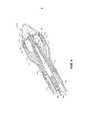
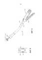
на ФИГ. 1 показан вид в перспективе примера сшивающего инструмента;in FIG. 1 is a perspective view of an example of a stapling tool;
на ФИГ. 2 показан вид сбоку в сечении узла сшивающей головки сшивающего инструмента, изображенного на ФИГ. 1;in FIG. 2 is a side cross-sectional view of the staple head assembly of the stapling tool shown in FIG. one;
на ФИГ. 3 показан вид сбоку в сечении узла сшивающей головки, изображенного на ФИГ. 2, в закрытом положении;in FIG. 3 is a side cross-sectional view of the staple head assembly shown in FIG. 2, in the closed position;
на ФИГ. 4 показан вид сбоку в сечении узла сшивающей головки, изображенного на ФИГ. 2, на котором выталкиватель скоб показан в активированном положении;in FIG. 4 is a side cross-sectional view of the staple head assembly shown in FIG. 2, in which the ejector staples shown in the activated position;
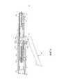
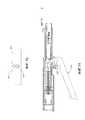
на ФИГ. 5 показан вид сбоку в сечении сшивающего инструмента, изображенного на ФИГ. 1, на котором узел рукоятки привода показан в заблокированном положении;in FIG. 5 is a side cross-sectional view of the stapling tool of FIG. 1, in which the drive handle assembly is shown in a locked position;
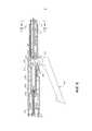
на ФИГ. 6 показан вид сбоку в сечении узла рукоятки привода, изображенного на ФИГ. 5, в незаблокированном положении;in FIG. 6 is a side cross-sectional view of the handle assembly of the drive of FIG. 5, in the unlocked position;
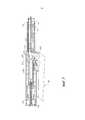
на ФИГ. 7 показан вид сбоку в сечении узла рукоятки привода, изображенного на ФИГ. 5, в активированном положении;in FIG. 7 is a side cross-sectional view of the handle assembly of the drive of FIG. 5, in the activated position;
на ФИГ. 8 показан вид спереди окна индикатора поверх узла рукоятки привода, изображенного на ФИГ. 5;in FIG. 8 is a front view of an indicator window over a drive handle assembly shown in FIG. 5;
на ФИГ. 9 показан вид в перспективе примера сшивающего инструмента с предохранительным элементом;in FIG. 9 is a perspective view of an example of a stapling tool with a safety member;
на ФИГ. 10 показан вид сбоку тормоза и активирующего элемента выталкивателя внутри сшивающего инструмента, изображенного на ФИГ. 9;in FIG. 10 shows a side view of the brake and the activating element of the ejector inside the stapling tool shown in FIG. 9;
на ФИГ. 11 показан вид сбоку в сечении сшивающего инструмента, изображенного на ФИГ. 9;in FIG. 11 is a side cross-sectional view of the stapling tool of FIG. 9;
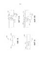
на ФИГ. 12 показан вид сбоку в сечении другого примера сшивающего инструмента, имеющего предохранительный элемент;in FIG. 12 is a side cross-sectional view of another example of a stapling tool having a safety member;
на ФИГ. 13 показан вид в перспективе предохранительного элемента, изображенного на ФИГ. 12, в заблокированном положении;in FIG. 13 is a perspective view of the safety member of FIG. 12, in the locked position;
на ФИГ. 14 показан вид в перспективе предохранительного элемента, изображенного на ФИГ. 12, в незаблокированном положении;in FIG. 14 is a perspective view of the safety member shown in FIG. 12, in the unlocked position;
на ФИГ. 15 показан вид сбоку в сечении примера сшивающего инструмента, имеющего альтернативный предохранительный элемент;in FIG. 15 is a side cross-sectional view of an example of a stapling tool having an alternative safety member;
на ФИГ. 16 показан вид спереди в вертикальной проекции штифта для применения с предохранительным элементом, изображенным на ФИГ. 15;in FIG. 16 is a front elevational view of a pin for use with the safety member shown in FIG. fifteen;
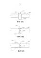
на ФИГ. 17A показан вид сбоку предохранительного элемента, изображенного на ФИГ. 15, со штоком упора в дистальном положении;in FIG. 17A is a side view of the safety member shown in FIG. 15, with a stop rod in a distal position;
на ФИГ. 17B показан вид сбоку предохранительного элемента, изображенного на ФИГ. 15, со штоком упора в проксимальном положении;in FIG. 17B is a side view of the safety member shown in FIG. 15, with a stop rod in the proximal position;
на ФИГ. 18 показан вид сбоку примера штока упора для применения со сшивающим инструментом, изображенным на ФИГ. 15;in FIG. 18 is a side view of an example of a stop rod for use with the stapling tool shown in FIG. fifteen;
на ФИГ. 19A показан вид сбоку тормоза и активирующего элемента выталкивателя внутри сшивающего инструмента, причем механическое звено находится в первом положении для ограничения перемещения тормоза и активирующего элемента выталкивателя;in FIG. 19A shows a side view of the brake and the activating member of the ejector inside the stapling tool, the mechanical link being in the first position to limit the movement of the brake and the activating member of the ejector;
на ФИГ. 19B показан вид сверху тормоза, активирующего элемента выталкивателя и механического звена, изображенных на ФИГ. 19A, внутри сшивающего инструмента, причем механическое звено находится в первом положении; иin FIG. 19B shows a top view of the brake, the activating element of the ejector and the mechanical link shown in FIG. 19A, inside the stapler, the mechanical link being in a first position; and
на ФИГ. 19C показан вид сверху тормоза, активирующего элемент выталкивателя и механического звена, изображенных на ФИГ. 19A, внутри сшивающего инструмента, причем механическое звено перемещено во второе положение, позволяя перемещение наружу тормоза и активирующего элемента выталкивателя.in FIG. 19C shows a top view of the brake activating the ejector element and the mechanical link shown in FIG. 19A, inside the stapler, the mechanical link being moved to the second position, allowing the brake and the ejector activating member to move outward.
Не предполагается, что фигуры являются каким-либо образом ограничивающими, и предполагается, что различные варианты осуществления настоящего изобретения можно реализовать множеством других способов, включая те, которые необязательно показаны на фигурах. Приложенные фигуры использованы и образуют часть технического описания для иллюстрации нескольких аспектов настоящего изобретения и вместе с описанием служат для пояснения принципов настоящего изобретения. Однако понимается, что настоящее изобретение не ограничено точными показанными конфигурациями.The figures are not intended to be limiting in any way, and it is contemplated that various embodiments of the present invention may be implemented in a variety of other ways, including those not necessarily shown in the figures. The attached figures are used and form part of the technical description to illustrate several aspects of the present invention and together with the description serve to explain the principles of the present invention. However, it is understood that the present invention is not limited to the exact configurations shown.
ПОДРОБНОЕ ОПИСАНИЕ ИЗОБРЕТЕНИЯDETAILED DESCRIPTION OF THE INVENTION
Следующее описание некоторых примеров настоящего изобретения не должно быть использовано для ограничения объема настоящего изобретения. Другие примеры, элементы, аспекты, варианты осуществления и преимущества настоящего изобретения будут очевидны для специалистов в данной области из последующего описания, в котором с помощью иллюстрации показан один из лучших способов реализации настоящего изобретения. Как будет понятно, настоящее изобретение может быть реализовано с различными другими очевидными аспектами без отклонения от настоящего изобретения. Соответственно, фигуры и описания по характеру следует рассматривать как иллюстрирующие, а не ограничивающие.The following description of some examples of the present invention should not be used to limit the scope of the present invention. Other examples, elements, aspects, embodiments, and advantages of the present invention will be apparent to those skilled in the art from the following description, which illustrates one of the best ways of implementing the present invention. As will be understood, the present invention can be implemented with various other obvious aspects without deviating from the present invention. Accordingly, figures and descriptions in nature should be regarded as illustrative and not restrictive.
I. Пример сшивающего инструментаI. Example of a stapling tool
На ФИГ. 1 представлен хирургический сшивающий инструмент для кругового анастомоза (50), включающий в себя дистальный узел сшивающей головки (60), соединенный с помощью продольно изогнутого узла опорного стержня (70) с проксимальным узлом рукоятки привода (80). Сшивающий инструмент (50) может быть сконструирован в соответствии с по меньшей мере некоторыми из идей патента США № 5,205,459, озаглавленного «Хирургический сшивающий инструмент для анастомоза», выданного 27 апреля 1993 г.; патента США № 5,271,544, озаглавленного «Хирургический сшивающий инструмент для анастомоза», выданного 21 декабря 1993 г.; патента США № 5,275,322, озаглавленного «Хирургический сшивающий инструмент для анастомоза», выданного 4 января 1994 г.; патента США № 5,285,945, озаглавленного «Хирургический сшивающий инструмент для анастомоза», выданного 15 февраля 1994 г.; патента США № 5,292,053, озаглавленного «Хирургический сшивающий инструмент для анастомоза», выданного 10 марта 1993 г.; патента США № 5,333,773, озаглавленного «Средства герметизации эндоскопического хирургического сшивающего инструмента для анастомоза», выданного 2 апреля 1994 г.; патента США № 5,350,104, озаглавленного «Средства герметизации эндоскопического хирургического сшивающего инструмента для анастомоза», выданного 27 апреля 1994 г.; и/или патента США № 5,533,661, озаглавленного «Средства герметизации эндоскопического хирургического сшивающего инструмента для анастомоза», выданного 9 июля 1996 г., описание которых включено в настоящий документ путем ссылки.In FIG. 1 shows a surgical stapling instrument for a circular anastomosis (50), including a distal knot of a stapling head (60) connected using a longitudinally curved node of the support rod (70) with the proximal node of the drive handle (80). A stapling instrument (50) may be constructed in accordance with at least some of the ideas of US Pat. No. 5,205,459, entitled “Surgical Stapling Instrument for Anastomosis,” issued April 27, 1993; US patent No. 5,271,544, entitled "Surgical stapling instrument for anastomosis", issued December 21, 1993; US patent No. 5,275,322, entitled "Surgical stapling instrument for anastomosis", issued January 4, 1994; US patent No. 5,285,945, entitled "Surgical stapling instrument for anastomosis", issued February 15, 1994; US patent No. 5,292,053, entitled "Surgical stapling instrument for anastomosis", issued March 10, 1993; US patent No. 5,333,773, entitled "Means of sealing an endoscopic surgical stapling instrument for anastomosis", issued April 2, 1994; US patent No. 5,350,104, entitled "Means of sealing an endoscopic surgical stapling instrument for anastomosis", issued April 27, 1994; and / or US Patent No. 5,533,661, entitled “Sealing Instruments for an Endoscopic Surgical Stapling Instrument for Anastomosis,” issued July 9, 1996, the disclosures of which are incorporated herein by reference.
Сшивающий инструмент (50) включает в себя узел упора (100), выполненный с возможностью скольжения продольно относительно узла сшивающей головки (60). На проксимальном конце узла рукоятки привода (80) предусмотрена вращаемая регулирующая ручка (82), выполненная с возможностью регулирования промежутка между узлом сшивающей головки (60) и узлом упора (100). Регулирующая ручка (82) находится в связи с управляющим штоком (300) (показанным, например, на ФИГ. 5) так, что вращение регулирующей ручки (82) приводит к поступательному перемещению управляющего штока (300). Когда регулирующую ручку (82) вращают в одном направлении, зазор между узлом сшивающей головки (60) и узлом упора (100) закрывается, в то время как при вращении регулирующей ручки (82) в другом направлении зазор между узлом сшивающей головки (60) и узлом упора (100) открывается. Несмотря на то что пример версии содержит регулирующую ручку (82), следует понимать, что вместо регулирующей ручки (82) может применяться кнопка, привод или любой другой подходящий механизм, как будет очевидно обычному специалисту в данной области в контексте идей, представленных в настоящем документе. В некоторых версиях регулирующая ручка (82) может быть выполнена с возможностью открытия зазора между узлом сшивающей головки (60) и узлом упора (100) более чем одним способом. Например, регулирующая ручка (82) после завершения операции может перемещаться в два положения. В первом положении регулирующая ручка (82) может создавать малый зазор, тогда как во втором положении регулирующая ручка (82) может создавать больший зазор. Регулирующая ручка (82) может быть перемещена в первое положение, например, при извлечении хирургического инструмента (50) из операционного поля; и регулирующая ручка (82) может быть перемещена во второе положение, например, для извлечения узла упора (100) из узла сшивающей головки (60). В некоторых версиях описанным выше механизмом регулировки зазора можно управлять с помощью регулирующей ручки (82). В некоторых других версиях в сшивающий инструмент (50) может быть встроен отдельный привод, так что при применении привода для управления зазором между узлом сшивающей головки (60) и узлом упора (100) после операции регулирующая ручка (82) становится заблокированной так, что пользователь впоследствии не может эксплуатировать регулирующую ручку (82).The stapling tool (50) includes a stop assembly (100) that slides longitudinally with respect to the staple head assembly (60). A rotatable control knob (82) is provided at the proximal end of the drive handle assembly (80), configured to adjust the gap between the staple head assembly (60) and the stop assembly (100). The control knob (82) is in communication with the control rod (300) (shown, for example, in FIG. 5) so that the rotation of the control knob (82) translates the control rod (300). When the adjusting knob (82) is rotated in one direction, the gap between the knitting head assembly (60) and the stop assembly (100) closes, while when the adjusting knob (82) rotates in the other direction, the gap between the knitting head assembly (60) and the stop assembly (100) opens. Although the example version contains an adjusting knob (82), it should be understood that instead of the adjusting knob (82), a button, actuator, or any other suitable mechanism may be used, as would be apparent to a person skilled in the art in the context of the ideas presented herein . In some versions, the adjusting knob (82) may be configured to open the gap between the staple head assembly (60) and the stop assembly (100) in more than one way. For example, the adjusting knob (82), after the completion of the operation, can be moved into two positions. In the first position, the adjustment knob (82) can create a small clearance, while in the second position, the adjustment knob (82) can create a larger clearance. The adjusting knob (82) can be moved to the first position, for example, when removing the surgical instrument (50) from the surgical field; and the adjustment knob (82) can be moved to a second position, for example, to remove the stop assembly (100) from the staple head assembly (60). In some versions, the clearance adjustment mechanism described above can be controlled using the adjustment knob (82). In some other versions, a separate drive may be integrated in the stapling tool (50), so that when using the drive to control the gap between the staple head assembly (60) and the stop assembly (100) after the operation, the adjustment knob (82) becomes locked so that the user subsequently cannot operate the adjustment knob (82).
Через окно (85) поверх узла рукоятки (80) виден индикатор (84), выполненный с возможностью перемещения, отображающий высоту скобы, выбранную путем вращения регулирующей ручки (82). Как показано на ФИГ. 5, индикатор (84) выполнен с возможностью перемещения вдоль шкалы (87), что обозначает, что зазор упора находится в пределах желательного рабочего диапазона сшивающего инструмента (50). Положение индикатора (84) также обозначает, будет ли высота сформированной скобы большой или малой.Through the window (85) on top of the handle assembly (80), an indicator (84) is shown that is movable and displays the height of the bracket selected by rotating the control knob (82). As shown in FIG. 5, the indicator (84) is movable along the scale (87), which means that the stop gap is within the desired operating range of the stapling tool (50). The position of the indicator (84) also indicates whether the height of the formed bracket is large or small.
На узле рукоятки привода (80) поворотно установлен рычаг активации скоб (86), который выталкивает хирургические скобы из узла сшивающей головки (60), когда узел упора (100) закрыт, обеспечивая желательную высоту скоб. На узле рукоятки (80) установлен поворотный предохранительный шарнирный фиксатор (88) для блокирования перемещения рычага активации скоб (86), не позволяя активировать узел сшивающей головки (60), когда зазор упора находится за пределами предварительно заданного диапазона.A bracket activation lever (86) is pivotally mounted on the drive handle assembly (80), which pushes surgical staples out of the staple head assembly (60) when the stop assembly (100) is closed, providing the desired height of the staples. A rotary safety hinged latch (88) is mounted on the handle assembly (80) to block the movement of the activation lever of the staples (86), preventing the stapling head assembly (60) from being activated when the stop clearance is outside a predetermined range.
Как показано на ФИГ. 2, узел сшивающей головки (60) включает в себя трубчатый кожух (61), в который принимается выталкиватель скоб (62) с возможностью скольжения, который может продвигаться и оттягиваться путем эксплуатации узла рукоятки привода (80). Выталкиватель скоб (62) включает в себя множество пальцев (63) для зацепления и выталкивания множества скоб (90) из держателя скоб (68), установленного на дистальном конце кожуха (61). Держатель скоб (68) включает в себя множество приемных прорезей для скоб (65), в которые вставляются скобы (90). Выталкиватель скоб (62) дополнительно поддерживает круговой скальпель и/или секционный нож (69), который продвигается и оттягивается выталкивателем скоб (62).As shown in FIG. 2, the staple head assembly (60) includes a tubular casing (61) into which the bracket ejector (62) is slidably received, which can be advanced and retracted by operating the drive handle assembly (80). The bracket ejector (62) includes a plurality of fingers (63) for engaging and pushing the plurality of brackets (90) from the bracket holder (68) mounted on the distal end of the casing (61). The bracket holder (68) includes a plurality of receiving slots for the brackets (65) into which the brackets (90) are inserted. The ejector brackets (62) additionally supports a circular scalpel and / or sectional knife (69), which is advanced and extended by the ejector brackets (62).
Узел сшивающей головки (60) включает в себя полый трубчатый разъем (64) на проксимальном конце кожуха (61), в которой принимается дистальный конец опорного стержня (70). Соединительная муфта или гильза (72) перекрывает соединение между трубчатым разъемом (64) и дистальным концом опорного стержня (70). Аналогичным образом, проксимальный конец опорного стержня (70) принимается трубчатым удлиненным концом (74) на дистальном конце узла рукоятки привода (80). Соединительная муфта или гильза (76) перекрывает соединение между проксимальным концом опорного стержня (70) и дистальным концом трубчатого удлиненного конца (74).The staple head assembly (60) includes a hollow tubular connector (64) at the proximal end of the casing (61), in which the distal end of the support rod (70) is received. A coupling or sleeve (72) overlaps the connection between the tubular connector (64) and the distal end of the support rod (70). Similarly, the proximal end of the support rod (70) is received by a tubular elongated end (74) at the distal end of the drive handle assembly (80). A coupling or sleeve (76) overlaps the connection between the proximal end of the support rod (70) and the distal end of the tubular elongated end (74).
Как показано на ФИГ. 2, узел упора (100) включает в себя по существу круглый упор (102), установленный на полый аксиально проходящий стержень (104), который разъемно прикреплен к троакару (73), поддерживаемому узлом сшивающей головки (60) с возможностью скольжения. Троакар (73) включает в себя заостренный наконечник троакара (75), который вставляется в полую гильзу (105) на проксимальном конце стержня упора (104). В то время как в представленной версии показан один пример ориентации троакара (73) и стержня упора (104), следует понимать, что в некоторых версиях положение троакара (73) и стержня упора (104) может быть обратным, так что троакар (73) может быть расположен на узле упора (100) и может сужаться в направлении узла сшивающей головки (60). Можно применять другие подходящие варианты, как будет очевидно обычному специалисту в данной области в контексте идей, представленных в настоящем документе. Троакар (73) с возможностью скольжения принимается внутрь центральной опорной трубки (66) (показанной на ФИГ. 2), образованной на трубчатом кожухе (61), для продольного перемещения относительно держателя скоб (68), установленного на дистальном конце кожуха (61). Приемные прорези для скоб (65) в держателе скоб (68) расположены по концентрической окружности для принятия хирургических скоб (90). Приемные прорези для скоб (65) примера версии расположены в два плотных концентрических кольцевых ряда. Упор (102) включает в себя кольцевой ободок (106), имеющий множество формирующих скобы желобов для формирования скоб (90) при выталкивании вплотную к упору (102).As shown in FIG. 2, the stop assembly (100) includes a substantially circular stop (102) mounted on a hollow axially extending rod (104), which is detachably attached to the trocar (73), which is slidingly supported by the staple head assembly (60). The trocar (73) includes the pointed tip of the trocar (75), which is inserted into the hollow sleeve (105) at the proximal end of the stop rod (104). While the presented version shows one example of the orientation of the trocar (73) and the stop rod (104), it should be understood that in some versions the position of the trocar (73) and the stop rod (104) can be reversed, so that the trocar (73) can be located on the stop assembly (100) and can taper towards the staple head assembly (60). Other suitable options may be employed, as will be apparent to those of ordinary skill in the art in the context of the ideas presented herein. The trocar (73) is slidably received inside the central support tube (66) (shown in FIG. 2) formed on the tubular casing (61) for longitudinal movement relative to the bracket holder (68) mounted on the distal end of the casing (61). The receiving slots for the staples (65) in the staple holder (68) are arranged in a concentric circle to accept surgical staples (90). The receiving slots for the brackets (65) of the example version are arranged in two dense concentric annular rows. An abutment (102) includes an annular rim (106) having a plurality of forming gutter brackets for forming brackets (90) when pushed close to an abutment (102).
Узел упора (100) включает в себя пару удлиненных пружинных удерживающих зажимов (110), проходящих продольно вдоль стержня упора (104) для зацепления наконечника троакара (75) при вставке троакара (73) в стержень упора (104). Для упрощения вставки троакара (73) в стержень упора (104) наконечник троакара (75) имеет профиль низкого усилия. В этом примере версии наконечник троакара (75) сужается с малым углом скольжения, уменьшая усилие, необходимое для смещения открытых удерживающих зажимов (110).The stop assembly (100) includes a pair of elongated spring retaining clamps (110) extending longitudinally along the stop rod (104) to engage the tip of the trocar (75) when the trocar (73) is inserted into the stop rod (104). To simplify the insertion of the trocar (73) into the stop rod (104), the tip of the trocar (75) has a low-force profile. In this version example, the tip of the trocar (75) narrows with a small sliding angle, reducing the force required to displace the open holding clips (110).
Удерживающие зажимы (110) позволяют прикреплять или откреплять узел упора (100) от троакара (73) путем, соответственно, подталкивания или вытягивания узла упора (100). Когда сшивающий инструмент (50) находится в его закрытом положении, как показано на ФИГ. 3, троакар (73) оттянут в центральную опорную трубку (66), которая ограничивает радиальное перемещение удерживающих зажимов (110) так, что стопоры удерживаются на месте вплотную к наконечнику троакара (75). В результате этого узел упора (100) блокируется на троакаре (73) так, что упор (102) может оказывать сопротивление полному усилию пуска сшивающего инструмента (50) без отцепления удерживающих зажимов (110) от наконечника троакара (75).Holding clamps (110) allow you to attach or detach the stop assembly (100) from the trocar (73) by, respectively, pushing or pulling the stop assembly (100). When the stapling tool (50) is in its closed position, as shown in FIG. 3, the trocar (73) is pulled into the central support tube (66), which limits the radial movement of the holding clamps (110) so that the stoppers are held in place close to the tip of the trocar (75). As a result of this, the stop assembly (100) is blocked on the trocar (73) so that the stop (102) can resist the full starting force of the stapling instrument (50) without releasing the holding clips (110) from the tip of the trocar (75).
Приподнятый периферический участок (152) образует периферическую бороздку на стержне упора (104), удобную для затягивания трубчатой ткани. Как показано на ФИГ. 2, если ткань плотно затянута к стержню (104), затянутая ткань не может легко соскользнуть поверх приподнятого периферического участка (152). В результате этого затянутая ткань ограничена дистальной областью стержня упора (104) позади приподнятого периферического участка (152), и упор стержня (104) не может случайно соскользнуть через затянутую ткань.The raised peripheral portion (152) forms a peripheral groove on the stop rod (104), convenient for tightening the tubular tissue. As shown in FIG. 2, if the fabric is tightly tightened to the shaft (104), the tightened fabric cannot easily slip over the raised peripheral portion (152). As a result, the tightened fabric is bounded by the distal region of the stop rod (104) behind the raised peripheral portion (152), and the stop of the rod (104) cannot accidentally slip through the tightened fabric.
Как показано на ФИГ. 4 и 5, опорный стержень (70) содержит активирующий элемент выталкивателя (92), выполненный с возможностью передавать сжимающие усилия и движение от узла рукоятки привода (80) для эксплуатации выталкивателя скоб (62) в узле сшивающей головки (60). Также опорный стержень (70) содержит натяжной элемент (94), содержащий пару удлиненных гибких полос (95, 96), выполненных с возможностью передачи натяжения от узла рукоятки привода (80) к узлу упора (100) для сопротивления сжимающим усилиям, оказываемым на узел упора (100). Натяжные полосы (95, 96) передают продольное движение от узла рукоятки привода (80), позволяя корректировать положение узла упора (100) относительно узла сшивающей головки (60). В частности, натяжной элемент (94) соединен с управляющим штоком (300) так, что натяжной элемент (94) и управляющий стержень (300) поступательно перемещаются как единое целое. Внутри пространства между опорным стержнем (70) и гибкими натяжными полосами (95, 96) содержится удлиненный гибкий разделительный хомут. При вращении регулирующей ручки (82) в направлении против часовой стрелки, как показано, например, на ФИГ. 1, управляющий шток (300) продвигается, перемещая натяжной элемент (94) в дистальном направлении для открытия зазора между узлом упора (100) и узлом сшивающей головки (60). Ограничитель хода (307) (показанный на ФИГ. 5) на одном из участков рукоятки (81) зацепляет винт (308), ограничивая дистальное перемещение управляющего штока (300). При вращении регулирующей ручки (82) в противоположном направлении, т.е. по часовой стрелке, управляющий шток (300) оттягивается, перемещая натяжной элемент (94) в проксимальном направлении, чтобы закрыть зазор между узлом упора (100) и узлом сшивающей головки (60). Ограничитель хода (309) на колпачке (89) ограничивает проксимальное перемещение управляющего штока (300).As shown in FIG. 4 and 5, the support rod (70) contains an activating element of the ejector (92), configured to transmit compressive forces and movement from the node of the handle of the drive (80) to operate the ejector brackets (62) in the node stapling head (60). The support rod (70) also contains a tension element (94) containing a pair of elongated flexible strips (95, 96), configured to transmit tension from the handle assembly of the drive (80) to the stop assembly (100) to resist compressive forces exerted on the assembly emphasis (100). Tension strips (95, 96) transmit longitudinal movement from the drive handle assembly (80), allowing you to adjust the position of the stop assembly (100) relative to the staple head assembly (60). In particular, the tension element (94) is connected to the control rod (300) so that the tension element (94) and the control rod (300) translationally move as a unit. Inside the space between the support rod (70) and the flexible tension strips (95, 96) there is an elongated flexible separation collar. When the control knob (82) is rotated counterclockwise, as shown, for example, in FIG. 1, the control rod (300) advances by moving the tension element (94) in the distal direction to open the gap between the stop assembly (100) and the staple head assembly (60). A travel stop (307) (shown in FIG. 5) engages a screw (308) on one portion of the handle (81), restricting the distal movement of the control rod (300). When the control knob (82) is rotated in the opposite direction, i.e. clockwise, the control rod (300) is pulled out by moving the tension element (94) in the proximal direction to close the gap between the stop assembly (100) and the staple head assembly (60). A travel stop (309) on the cap (89) limits the proximal movement of the control rod (300).
Сшивающий инструмент (50) дополнительно содержит предохранительный высвобождающий кронштейн (312), который поступательно перемещается в зависимости от перемещения управляющего штока (300). В частности, зажим (306), прикрепленный к управляющему штоку (300), выполнен с возможностью зацепления вертикального фланца (318) предохранительного высвобождающего кронштейна (312) при достижении управляющим штоком (300) некоторого проксимального положения. После этого продолжающееся проксимальное перемещение управляющего штока (300) приведет к перемещению предохранительного высвобождающего кронштейна (312) проксимально. Между фланцем (318) и ребром (315) узла рукоятки (80) расположена спиральная пружина (320), посредством чего обеспечивается дистальное смещение предохранительного высвобождающего кронштейна (312). Таким образом, когда предохранительный высвобождающий кронштейн (312) находится в проксимальном положении, а управляющий шток (300) продвинут дистально, спиральная пружина (320) будет перемещать предохранительный высвобождающий кронштейн (312) дистально. Предохранительный высвобождающий кронштейн (312) выполнен с возможностью управления перемещением индикатора (84). В частности, предохранительный высвобождающий кронштейн (312) выполнен с возможностью передачи перемещения на рычаг индикатора (326) с помощью поперечно ориентированного пальца предохранительного высвобождающего кронштейна (312) в зависимости от продольного положения управляющего штока (300). Индикатор (84) образован зацело со свободным концом рычага индикатора (326).The stapling tool (50) further comprises a safety release bracket (312), which progressively moves depending on the movement of the control rod (300). In particular, the clamp (306) attached to the control rod (300) is configured to engage the vertical flange (318) of the safety release bracket (312) when the control rod (300) reaches a certain proximal position. After this, continued proximal movement of the control rod (300) will lead to the displacement of the safety release bracket (312) proximally. Between the flange (318) and the rib (315) of the handle assembly (80), a spiral spring (320) is located, thereby providing a distal displacement of the safety releasing bracket (312). Thus, when the safety release bracket (312) is in the proximal position and the control rod (300) is advanced distally, the coil spring (320) will move the safety release bracket (312) distally. The safety release bracket (312) is configured to control the movement of the indicator (84). In particular, the safety release bracket (312) is configured to transmit movement to the indicator lever (326) using a transversely oriented finger of the safety release bracket (312) depending on the longitudinal position of the control rod (300). The indicator (84) is formed integrally with the free end of the indicator lever (326).
На ФИГ. 2 и 5 сшивающий инструмент (50) показан с полностью открытым узлом упора (100), а также с узлом рукоятки привода (80) в неактивированной и незаблокированной конфигурации. При полностью открытом узле упора (100) предохранительный высвобождающий кронштейн (312) смещается дистально с помощью спиральной пружины (320), подталкивая вертикальный фланец (318) вплотную к ребру (315), а поперечный палец предохранительного высвобождающего кронштейна (312) продвинут дистально и отцеплен от рычага индикатора (326). При оттягивании управляющего штока (300), как показано на ФИГ. 6, зажим (306) на управляющем штоке (300) перемещается в проксимальном направлении и зацепляет фланец (318), перемещая предохранительный высвобождающий кронштейн (312) в проксимальном направлении. Изначально, когда узел упора (100) начинает закрываться, поперечный палец предохранительного высвобождающего кронштейна (312) остается отцепленным от рычага индикатора (326). Когда зазор между узлом упора (100) и сшивающим узлом (60) регулируют до предварительно заданного для инструмента диапазона, палец зацепляет и поворачивает рычаг индикатора (326), перемещая индикатор (84) проксимально вдоль шкалы (87) на окне (85), обеспечивая обозначение выбранной высоты скобы, которая будет формироваться при пуске сшивающего инструмента.In FIG. 2 and 5, the stapling tool (50) is shown with the stop assembly (100) fully open, as well as with the drive handle assembly (80) in an unactivated and unlocked configuration. With the stop assembly (100) fully open, the safety release bracket (312) moves distally with a coil spring (320), pushing the vertical flange (318) close to the rib (315), and the transverse pin of the safety release bracket (312) is distally advanced and disengaged from the indicator lever (326). When pulling the control rod (300), as shown in FIG. 6, the clip (306) on the control rod (300) moves in the proximal direction and engages the flange (318), moving the safety release bracket (312) in the proximal direction. Initially, when the stop assembly (100) begins to close, the transverse pin of the safety release bracket (312) remains uncoupled from the indicator lever (326). When the gap between the stop assembly (100) and the stapling assembly (60) is adjusted to the range predefined for the tool, the finger engages and rotates the indicator lever (326), moving the indicator (84) proximally along the scale (87) on the window (85), providing designation of the selected height of the bracket, which will be formed when starting the stapling tool.
Предохранительный высвобождающий кронштейн (312) также выполнен с возможностью избирательного предотвращения перемещения предохранительного фиксатора (88). В частности, как будет описано ниже более подробно, часть предохранительного высвобождающего кронштейна (312) физически препятствует поворотному перемещению предохранительного фиксатора (88), когда управляющий шток (300) находится за пределами предварительно заданного продольного диапазона; в то время как предохранительный высвобождающий кронштейн (312) позволяет поворотное перемещение предохранительного фиксатора (88), когда управляющий шток (300) находится в пределах предварительно заданного продольного диапазона. Такой продольный диапазон может коррелировать с предпочтительным диапазоном высот сформированных скоб в узле упора (100).The safety release bracket (312) is also configured to selectively prevent the movement of the safety lock (88). In particular, as will be described in more detail below, a part of the safety release bracket (312) physically prevents the pivoting of the safety lock (88) when the control rod (300) is outside a predetermined longitudinal range; while the safety release bracket (312) allows pivoting movement of the safety lock (88) when the control rod (300) is within a predetermined longitudinal range. Such a longitudinal range may correlate with a preferred height range of the formed brackets in the stop assembly (100).
Предохранительный фиксатор (88) поворотно установлен ниже предохранительного высвобождающего кронштейна (312) с помощью поворотного штифта (330), проходящего между участками рукоятки (81). Предохранительный фиксатор (88) выполнен с возможностью физического предотвращения сжатия активирующего рычага (86). Например, в одном положении, показанном на ФИГ. 5, предохранительный фиксатор (88) блокирует активацию активирующего рычага (86). В другом положении, показанном на ФИГ. 6, предохранительный фиксатор (88) перемещается, позволяя активировать активирующий рычаг (86). Предохранительный фиксатор (88) включает в себя выступ, который в его зафиксированном положении размещен горизонтально под предохранительным высвобождающим кронштейном (312). Если зазор упора находится за пределами предварительно заданного для сшивающего инструмента диапазона (показанного на ФИГ. 2 и 5), прямоугольная пластина (314) предохранительного высвобождающего кронштейна (312) перекрывает выступ на предохранительном фиксаторе (88) и не позволяет предохранительному фиксатору (88) отцепиться от рычага активации скоб (86). На шкале (87) пользователь может видеть, что индикатор (84), выполненный с возможностью перемещения, находится за пределами зоны, обозначенной шкалой (87). С другой стороны, когда зазор упора находится в пределах предварительно заданного диапазона (показанного на ФИГ. 3 и 6), предохранительный высвобождающий кронштейн (312) отводится, а выступ на предохранительном фиксаторе (88) отцепляется от прямоугольной пластины (314) предохранительного высвобождающего кронштейна (312). Предохранительный фиксатор (88) можно повернуть в его незафиксированное положение, что позволяет эксплуатировать рычаг активации скоб (86). Следует понимать, что по мере того как индикатор (84), выполненный с возможностью перемещения, перемещается в зону, показанную шкалой (87), индикатор (84), выполненный с возможностью перемещения, может использоваться как визуальный сигнал пользователю о том, что сшивающий инструмент (50) можно запустить.The safety lock (88) is pivotally mounted below the safety release bracket (312) with a pivot pin (330) extending between the handle portions (81). The safety lock (88) is configured to physically prevent compression of the activating arm (86). For example, in one position shown in FIG. 5, the safety lock (88) blocks the activation of the activation lever (86). In another position shown in FIG. 6, the safety lock (88) moves, allowing the activation lever (86) to be activated. The safety lock (88) includes a protrusion which, in its locked position, is positioned horizontally under the safety release bracket (312). If the stop clearance is outside the range predefined for the stapler (shown in FIGS. 2 and 5), the rectangular plate (314) of the safety release bracket (312) overlaps the protrusion on the safety lock (88) and does not allow the safety lock (88) to detach from the lever for activating the staples (86). On the scale (87), the user can see that the indicator (84), configured to move, is outside the area indicated by the scale (87). On the other hand, when the stop clearance is within a predetermined range (shown in FIGS. 3 and 6), the safety release bracket (312) is retracted, and the protrusion on the safety lock (88) is detached from the rectangular plate (314) of the safety release bracket ( 312). The safety lock (88) can be rotated to its unlocked position, which allows the bracket activation lever (86) to be operated. It should be understood that as the indicator (84), configured to move, moves to the area shown by the scale (87), the indicator (84), made to move, can be used as a visual signal to the user that the stapling tool (50) can be started.
Когда зазор между упором (102) и держателем скоб (68) установлен так, чтобы получать желательную высоту скоб в пределах рабочего диапазона сшивающего инструмента (50), предохранительный фиксатор (88) поворачивается по часовой стрелке для отцепления рычага активации скоб (86). Для пуска сшивающего инструмента (50) необходимо захватить и повернуть рычаг активации скоб (86) по часовой стрелке для перемещения рычага активации скоб (86) в его рабочее положение. В результате этого пальцы привода (350) на плече спускового механизма (340) толкают пусковой зажим (352) в дистальном направлении, продвигая активирующий элемент выталкивателя (92) продольно вдоль узла стержня (70). Активирующий элемент выталкивателя (92) продвигает выталкиватель скоб (62), перемещая пальцы выталкивателя (63) дистально в приемные прорези для скоб (65) для зацепления скоб (90). Активирующий элемент выталкивателя (92) передает необходимое движение и сжимающие усилия от плеча спускового механизма (340) на выталкиватель скоб (62), выталкивая скобы (90) из держателя скоб (68) в ткань и вплотную к упору (102). Каждая скоба (90) образует B-образную конфигурацию и сшивает участки ткани (52, 54) вместе. Также выталкиватель скоб (62) продвигает круговой скальпель (69), обрезая ткань о вспомогательную шайбу (160). Как показано на ФИГ. 4, круговой скальпель (69) разделяет вспомогательную шайбу (160) на два кольцевых участка.When the gap between the stop (102) and the bracket holder (68) is set so as to obtain the desired height of the brackets within the operating range of the stapling tool (50), the safety lock (88) rotates clockwise to disengage the bracket activation lever (86). To start the stapling tool (50), grab and rotate the staple activation lever (86) clockwise to move the staple activation lever (86) to its working position. As a result, the fingers of the actuator (350) on the shoulder of the trigger mechanism (340) push the trigger clamp (352) in the distal direction, advancing the activating element of the ejector (92) longitudinally along the node of the rod (70). The activating element of the ejector (92) advances the ejector brackets (62), moving the fingers of the ejector (63) distally into the receiving slots for the brackets (65) to engage the brackets (90). The activating element of the ejector (92) transfers the necessary movement and compressive forces from the shoulder of the trigger mechanism (340) to the ejector brackets (62), pushing the brackets (90) from the bracket holder (68) into the fabric and close to the stop (102). Each staple (90) forms a B-shaped configuration and sews tissue sites (52, 54) together. The staple ejector (62) also advances the circular scalpel (69), cutting off the tissue on the auxiliary washer (160). As shown in FIG. 4, a circular scalpel (69) divides the auxiliary washer (160) into two annular sections.
После завершения сшивания и обрезания ткани рычаг активации скоб (86) смещается пружиной обратно в его открытое неактивированное положение, показанное на ФИГ. 5. Пальцы привода (350) плеча спускового механизма (340) поворачиваются против часовой стрелки, как показано на ФИГ. 6, перемещая пусковой зажим (352) и активирующий элемент выталкивателя (92) в проксимальном направлении. В результате этого выталкиватель скоб (62), который соединен фиксирующими пальцами с активирующим элементом выталкивателя (92), и круговой скальпель (69) оттягиваются в узел сшивающей головки (60).After the stitching and trimming of the fabric is completed, the staple activation lever (86) is displaced by the spring back to its open inactive position shown in FIG. 5. The fingers of the actuator (350) of the trigger arm (340) rotate counterclockwise, as shown in FIG. 6, moving the trigger clamp (352) and the activating element of the ejector (92) in the proximal direction. As a result of this, the staple ejector (62), which is connected by fixing fingers to the ejector activation element (92), and the circular scalpel (69) are pulled into the staple head assembly (60).
Сшитую ткань между упором (102) и держателем скоб (68) высвобождают путем вращения регулирующей ручки (82) против часовой стрелки, продвигая узел упора (100) в сторону от узла сшивающей головки (60), например, приблизительно на 1/2 оборота, 3/4 оборота и т.д. Упор (102) перемещают через просвет путем манипуляций со сшитой тканью способом, подходящим для проведения упора через сшитый просвет. Затем сшивающий инструмент (50) извлекают из организма пациента, оставляя сшитый просвет между участками трубчатой ткани (52, 54).The stitched fabric between the stop (102) and the bracket holder (68) is released by rotating the adjustment knob (82) counterclockwise, pushing the stop assembly (100) away from the staple head assembly (60), for example, by approximately 1/2 turn, 3/4 turn, etc. The emphasis (102) is moved through the lumen by manipulating the stitched fabric in a manner suitable for holding the emphasis through the stitched lumen. Then, the stapling instrument (50) is removed from the patient's body, leaving a stitched lumen between the sections of the tubular tissue (52, 54).
Хирургический сшивающий инструмент (50) можно применять для наложения интралюминального анастомоза, в котором два участка ткани прикрепляются вместе рядом скоб. В качестве примера, сшивающий инструмент (50) можно применять в ходе операции по соединению пары концов участков полого органа (например, толстой кишки или другого участка желудочно-кишечного тракта пациента) множеством хирургических скоб, расположенных по концентрической окружности вокруг просвета полости между участками органа. При подготовке к анастомозу в полые органы, в которых будет наложен анастомоз, помещают затягивающие хирургические нити. Например, как показано на ФИГ. 2, два участка трубчатой ткани (52) и (54) подготавливают путем вшивания затягивающих хирургических нитей (56) и (58), соответственно, в ткань в соответствии со способом затягивания у открытых концов участков трубчатой ткани (52) и (54).A surgical stapling instrument (50) can be used to apply an intraluminal anastomosis in which two tissue sections are attached together by a series of staples. As an example, a stapling instrument (50) can be used during an operation to connect a pair of ends of sections of a hollow organ (for example, the colon or other part of the patient’s gastrointestinal tract) with a variety of surgical staples arranged in a concentric circle around the lumen of the cavity between the parts of the organ. In preparation for the anastomosis, addictive surgical sutures are placed in the hollow organs in which the anastomosis will be applied. For example, as shown in FIG. 2, two sections of tubular tissue (52) and (54) are prepared by stitching tightening surgical sutures (56) and (58), respectively, into the tissue in accordance with the method of tightening at the open ends of the sections of tubular tissue (52) and (54).
Если хирургическая процедура выполняется с применением методики двойного затягивания, то хирургический инструмент (50) вставляют в первый участок трубчатой ткани (52), например, путем введения в анальное отверстие пациента, причем узел упора (100) прикреплен к узлу сшивающей головки (60) и полностью закрыт. Перед введением сшивающего инструмента (50) в организм пациента регулирующую ручку (82) вращают по часовой стрелке для оттягивания троакара (73) в опорную трубку (66) и зажима упора (102) вплотную к держателю скоб (68). Узел сшивающей головки (60) размещен смежно с затянутым концом участка трубчатой ткани (52). После этого регулирующую ручку (82) поворачивают по часовой стрелке, чтобы продвинуть управляющий шток (300) и натяжной элемент (94) до тех пор, пока троакар (73) не будет полностью продвинут, перемещая узел упора (100) в его полностью открытое положение (ФИГ. 2). При полностью продвинутом троакаре (73) затянутый конец участка трубчатой ткани (52) протягивают вместе вокруг цилиндрического корпуса троакара (130) путем подтягивания и утягивания затягивающей хирургической нити (56). Затянутую ткань натягивают вплотную к цилиндрическому корпусу троакара (130), а затягивающую хирургическую нить (56) утягивают для удержания ткани вплотную к корпусу троакара (130).If the surgical procedure is performed using the double-tightening technique, then the surgical instrument (50) is inserted into the first portion of the tubular tissue (52), for example, by inserting it into the patient's anus, wherein the stop assembly (100) is attached to the staple head assembly (60) and completely closed. Before introducing the stapling instrument (50) into the patient's body, the adjustment knob (82) is rotated clockwise to pull the trocar (73) into the support tube (66) and clamp the stop (102) close to the bracket holder (68). The stitching unit assembly (60) is placed adjacent to the tightened end of the tubular fabric portion (52). After that, the adjusting knob (82) is rotated clockwise to advance the control rod (300) and the tension element (94) until the trocar (73) is fully advanced, moving the stop assembly (100) to its fully open position (FIG. 2). With a fully advanced trocar (73), the tightened end of the tubular tissue section (52) is pulled together around the cylindrical body of the trocar (130) by pulling and pulling on a tightening surgical thread (56). The tightened tissue is pulled close to the cylindrical body of the trocar (130), and the tightening surgical thread (56) is pulled to hold the tissue close to the body of the trocar (130).
Узел упора (100) вставляют в участок трубчатой ткани с затягивающей нитью (54), и ткань протягивают вместе вокруг стержня упора (104) путем подтягивания и утягивания затягивающей хирургической нити (58). Затянутую ткань натягивают вплотную к стержню упора (104) в бороздку для затягивания (158), которая дистально смежна с приподнятым периферическим участком (152) на упоре стержня (104), и затягивающую хирургическую нить (58) затягивают вместе. При необходимости узел упора (100) можно открепить от троакара (73) для упрощения вставки узла упора (100) в участок трубчатой ткани (54). После того как затянутый конец участка трубчатой ткани (54) затягивают вплотную к стержню упора (104) с помощью затягивающей хирургической нити (58), узел упора (100) повторно прикрепляют к троакару (73).The stop assembly (100) is inserted into the tubular tissue site with the tightening thread (54), and the fabric is pulled together around the stop shaft (104) by pulling and pulling the tightening surgical thread (58). The tightened tissue is pulled close to the stop rod (104) into the tightening groove (158), which is distally adjacent to the raised peripheral portion (152) on the stop of the rod (104), and the tightening surgical thread (58) is tightened together. If necessary, the stop assembly (100) can be detached from the trocar (73) to simplify the insertion of the stop assembly (100) into the tubular tissue site (54). After the tightened end of the tubular tissue section (54) is tightened close to the stop rod (104) using a tightening surgical thread (58), the stop assembly (100) is reattached to the trocar (73).
После утягивания затянутых концов участков трубчатой ткани (52) и (54) регулирующую ручку (82) вращают по часовой стрелке, чтобы оттянуть троакар (73) в опорную трубку (66), перемещая упор (102) в направлении держателя скоб (68). По мере оттягивания троакара (73) корпус троакара (130) скользит через затянутый конец участка ткани (52) в проксимальном направлении и вытягивает стержень упора (104) через затянутую ткань в опорную трубку (66). В конце концов сшивающий инструмент (50) достигает конфигурации, показанной на ФИГ. 3. Узел рукоятки привода (80) во время перехода остается в полностью выдвинутой или открытой конфигурации, как показано на ФИГ. 5.After tightening the tightened ends of the tubular tissue sections (52) and (54), the adjustment knob (82) is rotated clockwise to pull the trocar (73) into the support tube (66), moving the stop (102) in the direction of the bracket holder (68). As the trocar (73) is pulled away, the trocar body (130) slides through the tightened end of the tissue section (52) in the proximal direction and pulls the stop rod (104) through the tightened tissue into the support tube (66). Finally, the stapling tool (50) reaches the configuration shown in FIG. 3. The drive handle assembly (80) during the transition remains in a fully extended or open configuration, as shown in FIG. 5.
Когда зазор между упором (102) и держателем скоб (68) установлен так, чтобы получить желательную высоту скобы в пределах рабочего диапазона сшивающего инструмента (50), предохранительный фиксатор (88, 488, 588, 688) поворачивается вверх (ФИГ. 6, 9, 11, 13, 19, 22 и 24), отцепляя рычаг активации скоб (86). В повернутом положении предохранительный фиксатор (88, 488, 588, 688) зацепляет либо управляющий шток (300, 400), либо регулирующую ручку (82, 682, 782, 882) и не позволяет вращать регулирующую ручку (82, 682, 782, 882), посредством чего поддерживая выбранную высоту скоб. Для пуска сшивающего инструмента (50) необходимо захватить и повернуть рычаг активации скоб (86) по часовой стрелке, как показано на ФИГ. 7, перемещая рычаг активации скоб (86) в его активированное положение. В результате этого пальцы привода (350) на плече спускового механизма (340) толкают пусковой зажим (352) в дистальном направлении, продвигая активирующий элемент выталкивателя (92) продольно вдоль узла стержня (70). Активирующий элемент выталкивателя (92) продвигает выталкиватель скоб (62), перемещая пальцы выталкивателя (63) дистально в приемные прорези для скоб (65) для зацепления скоб (90). Активирующий элемент выталкивателя (92) передает необходимое движение и сжимающие усилия от плеча спускового механизма (340) на выталкиватель скоб (62), выталкивая скобы (90) из держателя скоб (68) в ткань и вплотную к упору (102). Также выталкиватель скоб (62) продвигает круговой скальпель (69), обрезая ткань о вспомогательную шайбу (160). Как показано на ФИГ. 4, круговой скальпель (69) разделяет вспомогательную шайбу (160) на два кольцевых участка. Скобы (90) соединяют концы участков ткани (52) и (54) герметичным, непроницаемым для текучей среды соединением, образованным концентрическими кольцевыми рядами скоб (90). Круговой скальпель (69) обрезает избыточную ткань внутри анастомоза поблизости от сшитой области. Отсеченная избыточная ткань может захватываться внутрь узла сшивающей головки (60) (например, между внутренней поверхностью кругового скальпеля и внешней поверхностью узла троакара (73) и стержнем упора (104)).When the gap between the stop (102) and the bracket holder (68) is set so as to obtain the desired height of the bracket within the operating range of the stapling tool (50), the safety lock (88, 488, 588, 688) rotates upward (FIG. 6, 9 , 11, 13, 19, 22, and 24) by disengaging the lever for activating the brackets (86). In the turned position, the safety lock (88, 488, 588, 688) engages either the control rod (300, 400) or the control knob (82, 682, 782, 882) and does not allow the control knob to rotate (82, 682, 782, 882 ), whereby maintaining the selected bracket height. To start the stapling tool (50), you must grab and turn the bracket activation lever (86) clockwise, as shown in FIG. 7 by moving the activation lever of the brackets (86) to its activated position. As a result, the fingers of the actuator (350) on the shoulder of the trigger mechanism (340) push the trigger clamp (352) in the distal direction, advancing the activating element of the ejector (92) longitudinally along the node of the rod (70). The activating element of the ejector (92) advances the ejector brackets (62), moving the fingers of the ejector (63) distally into the receiving slots for the brackets (65) to engage the brackets (90). The activating element of the ejector (92) transfers the necessary movement and compressive forces from the shoulder of the trigger mechanism (340) to the ejector brackets (62), pushing the brackets (90) from the bracket holder (68) into the fabric and close to the stop (102). The staple ejector (62) also advances the circular scalpel (69), cutting off the tissue on the auxiliary washer (160). As shown in FIG. 4, a circular scalpel (69) divides the auxiliary washer (160) into two annular sections. The brackets (90) connect the ends of the tissue sections (52) and (54) with a tight, fluid tight connection formed by concentric annular rows of staples (90). A circular scalpel (69) cuts off excess tissue inside the anastomosis in the vicinity of the stitched area. The cut off excess tissue can be trapped inside the staple head assembly (60) (for example, between the inner surface of a circular scalpel and the outer surface of the trocar assembly (73) and the stop rod (104)).
После завершения сшивания и обрезания ткани рычаг активации скоб (86) смещается пружиной (346) в его полностью открытое положение (ФИГ. 6). Пальцы привода (350) плеча спускового механизма (340) поворачиваются против часовой стрелки, как показано на ФИГ. 6, перемещая пусковой зажим (352) и активирующий элемент выталкивателя (92) в проксимальном направлении. В результате этого выталкиватель скоб (62), который соединен фиксирующими пальцами (230) с активирующим элементом выталкивателя (92), а также круговой скальпель (69) оттягиваются в узел сшивающей головки (60). В случае захвата скоб, ткани или других органических остатков между держателем скоб (68) и пальцами выталкивателя (63), перед извлечением сшивающего инструмента (50) из организма пациента следует освободить узел сшивающей головки (60) от ткани путем оттягивания выталкивателя скоб (62). Если требуется значительное усилие, можно вручную вернуть рычаг активации скоб (86) в его полностью продвинутое положение, чтобы оттянуть выталкиватель скоб (62).After the stitching and trimming of the fabric is completed, the staple activation lever (86) is displaced by the spring (346) to its fully open position (FIG. 6). The fingers of the actuator (350) of the trigger arm (340) rotate counterclockwise, as shown in FIG. 6, moving the trigger clamp (352) and the activating element of the ejector (92) in the proximal direction. As a result of this, the bracket ejector (62), which is connected by the fixing fingers (230) to the activating element of the ejector (92), as well as the circular scalpel (69) are pulled into the staple head assembly (60). If staples, tissue or other organic residues are caught between the staple holder (68) and the ejector fingers (63), before removing the stapling instrument (50) from the patient's body, the staple head assembly (60) should be removed from the fabric by pulling the staple ejector (62) . If significant effort is required, the staple activation lever (86) can be manually returned to its fully advanced position to extend the staple ejector (62).
После этого предохранительный фиксатор (88, 488, 588, 688) поворачивают вниз, чтобы заблокировать рычаг активации скоб (86) и высвободить регулирующую ручку (82, 682, 782, 882) так, чтобы регулирующую ручку (82, 682, 782, 882) можно было свободно вращать. Сшитую ткань между упором (102) и держателем скоб (68) высвобождают путем вращения регулирующей ручки (82) против часовой стрелки для продвижения узла упора (100) в сторону от узла сшивающей головки (60). Упор (102) перемещают через просвет путем манипуляций со сшитой тканью способом, подходящим для проведения упора через сшитый просвет. Затем сшивающий инструмент (50) извлекают из организма пациента, оставляя сшитый просвет между участками трубчатой ткани (52) и (54).After that, the safety lock (88, 488, 588, 688) is turned down to lock the bracket activation lever (86) and the control knob (82, 682, 782, 882) is released so that the control knob (82, 682, 782, 882 ) could be freely rotated. The stitched fabric between the stop (102) and the bracket holder (68) is released by rotating the control knob (82) counterclockwise to move the stop assembly (100) away from the staple head assembly (60). The emphasis (102) is moved through the lumen by manipulating the stitched fabric in a manner suitable for holding the emphasis through the stitched lumen. Then the stapling instrument (50) is removed from the patient's body, leaving a stitched lumen between the sections of tubular tissue (52) and (54).
II. Пример предохранительного переключателя привода с тормозомII. Example of a safety switch for a drive with brake
Следует понимать, что непреднамеренные пуски по существу нежелательны, и они могут возникать в силу различных причин. В некоторых случаях непреднамеренные пуски могут быть вызваны простым случайным контактом с активирующим рычагом (86) после подъема предохранительного фиксатора (88) (ФИГ. 6). Таким образом, может быть желательно предотвращать перемещение активирующего рычага (86) даже после того, как индикатор (84), выполненный с возможностью вращения, расположен на шкале (87), а предохранительный фиксатор (88) поднят, до тех пор пока пользователь не будет готов ввести скобы в ткань. В некоторых случаях непреднамеренные или неполные пуски могут быть вызваны пуском сшивающего инструмента (50) при ненадлежащем размещении узла упора (100) на стержне упора (104). Таким образом, в этих случаях может быть желательно не допускать пуск хирургического инструмента (50) до тех пор, пока узел упора (100) не будет надлежащим образом размещен на стержне упора (104). Дополнительно следует понимать, что пуски могут быть по существу нежелательны, если индикатор (84), выполненный с возможностью перемещения, не расположен на шкале (87) (т.е. когда зазор упора находится за пределами «зеленой зоны»).It should be understood that unintentional starts are essentially undesirable, and they can occur for various reasons. In some cases, unintentional starts can be caused by a simple accidental contact with the activating lever (86) after lifting the safety lock (88) (FIG. 6). Thus, it may be desirable to prevent the activation lever (86) from moving even after the indicator (84) rotatably located on the scale (87) and the safety lock (88) are raised until the user is ready to insert staples into the fabric. In some cases, inadvertent or incomplete starts can be caused by the start of the stapling tool (50) when the stop assembly (100) is improperly placed on the stop rod (104). Thus, in these cases, it may be desirable to prevent the surgical instrument (50) from starting until the stop assembly (100) is properly positioned on the stop shaft (104). Additionally, it should be understood that starts can be essentially undesirable if the indicator (84), made with the possibility of movement, is not located on the scale (87) (that is, when the stop gap is outside the "green zone").
На ФИГ. 9 показан пример сшивающего инструмента (450), содержащего узел упора (410), установленный на стержне (404). Сшивающий инструмент (450), изображенный на ФИГ. 9, эксплуатируется по существу аналогично описанному выше сшивающему инструменту (50). Сшивающий инструмент (450) содержит предохранительный переключатель привода (451). Предохранительный переключатель привода (451) в настоящем примере расположен на трубчатом удлиненном конце (474). Более того, предохранительный переключатель привода (451) расположен на трубчатом удлиненном конце (474) так, чтобы была маловероятна непреднамеренная активация пользователем предохранительного переключателя привода (451), когда пользователь держит узел рукоятки привода (480), позиционируя сшивающий инструмент (450) для сшивания. На ФИГ. 10 показан вид сбоку предохранительного переключателя привода (451), когда предохранительный переключатель привода (451) находится в связи с активирующим элементом выталкивателя (492) внутри трубчатого удлиненного конца (474). Предохранительный переключатель привода (451) содержит две противоположно ориентированные кнопки и/или приводы, которые могут быть нажаты путем сжимания кнопок и/или переключателей в направлении друг друга. Предохранительный переключатель привода (451) находится в связи с тормозными накладками (453), которые сжимают активирующий элемент выталкивателя (492). Такое сжатие тормозными накладками (453) обеспечивает трение, которое по существу не позволяет активирующему элементу выталкивателя (492) поступательно перемещаться продольно так, что тормозные накладки (453) по существу предотвращают движение и сжимающие усилия на выталкиватель скоб (62).In FIG. 9 shows an example of a stapling tool (450) comprising a stop assembly (410) mounted on a shaft (404). The stapling tool (450) shown in FIG. 9 is operated substantially similar to the stapling tool (50) described above. The stapling tool (450) contains a drive safety switch (451). The drive safety switch (451) in the present example is located on the tubular elongated end (474). Moreover, the actuator safety switch (451) is located on the tubular elongated end (474) so that it is unlikely that the user inadvertently activates the actuator safety switch (451) when the user holds the actuator handle assembly (480) while positioning the stapling tool (450) for stapling . In FIG. 10 is a side view of the actuator safety switch (451) when the actuator safety switch (451) is in communication with an actuator of the ejector (492) inside the tubular elongated end (474). The drive safety switch (451) contains two oppositely oriented buttons and / or actuators that can be pressed by pressing the buttons and / or switches in the direction of each other. The drive safety switch (451) is in connection with the brake pads (453), which compress the activating element of the ejector (492). Such compression of the brake linings (453) provides friction that essentially prevents the activating element of the ejector (492) from translating longitudinally so that the brake linings (453) essentially prevent movement and compressive forces on the ejector brackets (62).
В настоящем примере предохранительный переключатель привода (451) соединен с тормозными накладками (453) с помощью механизма по типу ножниц так, чтобы пользователь мог активировать тормозные накладки (453), сжав предохранительный переключатель привода (451). В некоторых версиях тормозные накладки (453) упруго смещены, захватывая активирующий элемент выталкивателя (492). Таким образом, когда пользователь сжимает предохранительный переключатель привода (451), тормозные накладки (453) высвобождают активирующий элемент выталкивателя (492). Несмотря на то что тормозные накладки (453) в настоящем примере избирательно захватывают активирующий элемент выталкивателя (492), следует понимать, что тормозные накладки (453) могут захватывать любой подходящий компонент сшивающего инструмента (450) для предотвращения пуска сшивающего инструмента (450) до тех пор, пока пользователь вручную не высвободит тормозные накладки (453). В некоторых версиях тормозные накладки (453) препятствуют перемещению активирующего элемента выталкивателя (492) благодаря фрикционному захвату. В другом исключительно иллюстративном варианте тормозные накладки (453) могут предотвращать перемещение активирующего элемента выталкивателя (492) путем механического соединения с активирующим элементом выталкивателя (492). Например, тормозные накладки (453) могут иметь предохранители, выполненные с возможностью зацепления зубцов на активирующем элементе выталкивателя (492) так, что при зацеплении тормозные накладки (453) предотвращают перемещение активирующего элемента выталкивателя (492). В другом исключительно иллюстративном варианте тормозные накладки (453) могут быть оснащены зубцами, а активирующий элемент выталкивателя (492) оснащен предохранителями. Другие подходящие варианты будут очевидны обычному специалисту в данной области в контексте идей, представленных в настоящем документе.In the present example, the drive safety switch (451) is connected to the brake pads (453) using a scissor-like mechanism so that the user can activate the brake pads (453) by compressing the drive safety switch (451). In some versions, the brake linings (453) are elastically biased, capturing the activating element of the ejector (492). Thus, when the user compresses the drive safety switch (451), the brake pads (453) release the ejector activation element (492). Although the brake pads (453) in the present example selectively capture the activating element of the ejector (492), it should be understood that the brake pads (453) can capture any suitable component of the stapling tool (450) to prevent the stapling tool (450) from starting until the user manually releases the brake linings (453). In some versions, the brake pads (453) prevent the actuator of the ejector element (492) from moving due to the friction clutch. In another exceptionally illustrative embodiment, the brake pads (453) can prevent the actuator of the ejector element (492) from moving by mechanical connection with the activator element of the ejector (492). For example, brake linings (453) may have fuses configured to engage teeth on an actuator of an ejector element (492) so that when engaged, the brake linings (453) prevent the activator element of an ejector (492) from moving. In another exceptionally illustrative embodiment, the brake pads (453) can be equipped with teeth, and the activating element of the ejector (492) is equipped with fuses. Other suitable options will be apparent to those of ordinary skill in the art in the context of the ideas presented herein.
В некоторых версиях предохранительный переключатель привода (451) действует отдельно от других компонентов сшивающего инструмента (450) так, что пользователь может просто эксплуатировать предохранительный переключатель привода (451), позволяя активирующему элементу выталкивателя (492) поступательно перемещать выталкиватель скоб (62). В некоторых версиях предохранительный переключатель привода (451) находится в связи с предохранительным фиксатором (488), например, с помощью соединительного штока или звена, электрической связи и т.д. или любого другого подходящего механизма связи так, чтобы предохранительный переключатель привода (451) не мог высвободить тормозные накладки (453) до тех пор, пока не будет высвобожден предохранительный фиксатор (488). Таким образом, при эксплуатации некоторых версий необходимо прежде всего активировать предохранительный фиксатор (488), после чего можно сжать предохранительный переключатель привода (451) для высвобождения тормозных накладок (453). Например, на ФИГ. 11 показан предохранительный фиксатор (488), зацепленный так, что активирующий рычаг (486) активировать нельзя. В дополнение предохранительный переключатель привода (451) не может высвободить тормозные накладки (453), чтобы высвободить активирующий элемент выталкивателя (492), до тех пор пока не будет высвобожден предохранительный фиксатор (488).In some versions, the actuator safety switch (451) acts separately from other components of the stapling tool (450) so that the user can simply operate the actuator safety switch (451), allowing the activating element of the ejector (492) to translate the ejector of the brackets (62). In some versions, the actuator safety switch (451) is in communication with the safety lock (488), for example, via a connecting rod or link, electrical communication, etc. or any other suitable communication mechanism so that the drive safety switch (451) cannot release the brake pads (453) until the safety lock (488) is released. Thus, when operating some versions, it is first necessary to activate the safety lock (488), after which the drive safety switch (451) can be pressed to release the brake pads (453). For example, in FIG. 11 shows a safety lock (488) engaged so that the activation lever (486) cannot be activated. In addition, the drive safety switch (451) cannot release the brake pads (453) to release the activating element of the ejector (492) until the safety lock (488) is released.
На ФИГ. 19A-19C показан исключительно иллюстративный вариант, в котором механическое звено (855) соединено с предохранительным фиксатором (888) так, что механическое звено (855) перемещается продольно в ответ на поворот предохранительного фиксатора (888). Когда предохранительный фиксатор (888) расположен так, чтобы предотвращать активацию рычага активации скоб (такого как описанный выше рычаг активации скоб (86) и т.д.), механическое звено (855) расположено так, чтобы блокировать перемещение наружу тормозных накладок (853), как показано на ФИГ. 19A-19B. Таким образом, в положении, показанном на ФИГ. 19A-19B, механическое звено (855) удерживает тормозные накладки (853) в зацеплении с активирующим элементом выталкивателя (892), посредством чего не позволяя активирующему элементу выталкивателя (892) вытолкнуть скобы в ткань. При перемещении предохранительного фиксатора (888) в положение, позволяющее активировать рычаг активации скоб, механическое звено (855) расположено так, чтобы позволить тормозным накладкам (853) переместиться наружу, как показано на ФИГ. 19C, посредством чего высвобождая и позволяя активирующему элементу выталкивателя (892) выталкивать скобы в ткань. Пользователь может свободно манипулировать предохранительным переключателем привода (851), высвобождая тормозные накладки (853), посредством чего позволяя активирующему элементу выталкивателя (892) передавать движение после перемещения предохранительного фиксатора (888) и механического звена (855) в положение, показанное на ФИГ. 19C. Таким образом, тормозные накладки (853) не позволяют высвободить активирующий элемент выталкивателя (892) до тех пор, пока предохранительный фиксатор (888) не будет повернут, обеспечивая пространство для перемещения рычага активации скоб.In FIG. 19A-19C show an exceptionally illustrative embodiment in which the mechanical link (855) is connected to the safety lock (888) so that the mechanical link (855) moves longitudinally in response to the rotation of the safety lock (888). When the safety lock (888) is positioned so as to prevent the activation of the staple activation lever (such as the staple activation lever (86) described above, etc.), the mechanical link (855) is positioned so as to block the outward movement of the brake linings (853) as shown in FIG. 19A-19B. Thus, in the position shown in FIG. 19A-19B, the mechanical link (855) holds the brake linings (853) in engagement with the activating member of the ejector (892), thereby preventing the activating member of the ejector (892) from pushing the brackets into the fabric. When the safety lock (888) is moved to a position allowing the activation of the staple activation lever, the mechanical link (855) is positioned to allow the brake linings (853) to move outward, as shown in FIG. 19C, whereby releasing and allowing the activating element of the ejector (892) to push the staples into the fabric. The user can freely manipulate the drive safety switch (851), releasing the brake pads (853), whereby allowing the actuator of the ejector (892) to transmit movement after moving the safety lock (888) and the mechanical link (855) to the position shown in FIG. 19C. Thus, the brake pads (853) do not allow the activating element of the ejector (892) to be released until the safety lock (888) is rotated, providing space for movement of the lever for activating the brackets.
В другом исключительно иллюстративном варианте (не показан) предохранительный переключатель привода (451) может быть соединен с предохранительным фиксатором (488) так, чтобы предохранительный переключатель привода (451) зацеплял тормозные накладки (453), захватывая активирующий элемент выталкивателя (492) только после отцепления предохранительного фиксатора (488). Иными словами, изначально до отцепления предохранительного фиксатора (488) предохранительный фиксатор (488) эксплуатируется для предотвращения пуска сшивающего инструмента (450). Тормозные накладки (453) отцепляются от активирующего элемента выталкивателя (492), когда предохранительный фиксатор (488) зацепляет активирующий рычаг (486). После отцепления предохранительного фиксатора (488) от активирующего рычага (486) тормозные накладки (453) зацепляют активирующий элемент выталкивателя (492), не позволяя запустить сшивающий инструмент (450). В некоторых версиях тормозные накладки (453) могут отцеплять активирующий элемент выталкивателя (492) в результате эксплуатации пользователем ручного высвобождающего элемента путем повторного зацепления предохранительного фиксатора (488) и/или предохранительного переключателя (451). Более того, в некоторых версиях предохранительный переключатель (451) может не работать до тех пор, пока индикатор (84), выполненный с возможностью перемещения, не войдет в зону, показанную шкалой (87). В дополнение или в качестве альтернативы предохранительный переключатель (451) может не работать до тех пор, пока узел упора (410) не будет полностью установлен на стержень (404) или троакар, такой как показанный на ФИГ. 2. После того как предохранительный переключатель (451) был разблокирован и предотвращает перемещение активирующего элемента выталкивателя (492), пользователь может нажать на предохранительный переключатель привода (451), чтобы высвободить тормозные накладки (453) от активирующего элемента выталкивателя (492), посредством чего позволяя запустить сшивающий инструмент (450).In another exclusively illustrative embodiment (not shown), the actuator safety switch (451) can be connected to the safety lock (488) so that the actuator safety switch (451) engages the brake pads (453), capturing the ejector activating element (492) only after disengaging safety lock (488). In other words, initially until the safety lock (488) detaches, the safety lock (488) is used to prevent the stapling tool (450) from starting. The brake pads (453) are disengaged from the activating element of the ejector (492) when the safety lock (488) engages the activating lever (486). After the safety latch (488) is disconnected from the activating lever (486), the brake pads (453) engage the activating element of the ejector (492), preventing the stapling tool (450) from starting. In some versions, brake linings (453) can release the activating element of the ejector (492) as a result of the user operating the manual releasing element by re-engaging the safety lock (488) and / or safety switch (451). Moreover, in some versions, the safety switch (451) may not work until the indicator (84), made with the possibility of movement, does not enter the area shown by the scale (87). In addition or as an alternative, the safety switch (451) may not work until the stop assembly (410) is fully mounted on the shaft (404) or trocar, such as shown in FIG. 2. After the safety switch (451) has been released and prevents the actuator of the ejector element (492) from moving, the user can press the safety switch of the drive (451) to release the brake pads (453) from the activator of the ejector element (492), whereby letting you start the stapler (450).
В других примерах версий предохранительный переключатель привода (451) может содержать две отдельные функциональные кнопки и/или переключателя, где одна кнопка/переключатель выполнены с возможностью обеспечивать захват с помощью тормозных накладок (453) и предотвращать перемещение активирующего элемента выталкивателя (492), а также где другая кнопка/переключатель выполнены с возможностью приводить к высвобождению активирующего элемента выталкивателя (492) из тормозных накладок (453). В некоторых версиях предохранительный переключатель привода (451) может содержать один переключатель, выполненный с возможностью переключения между двумя или более положениями, где каждое положение предохранительного переключателя привода (451) соответствует разному действию тормозных накладок (453). Например, одно положение предохранительного переключателя привода (451) приводит к захвату тормозными накладками (453) активирующего элемента выталкивателя (492), в то время как другое положение предохранительного переключателя привода (451) приводит к высвобождению тормозными накладками (453) активирующего элемента выталкивателя (492). Предохранительный переключатель (451) может включать в себя другие компоненты, элементы, конфигурации и функциональные возможности, которые будут очевидны обычному специалисту в данной области в контексте идей, представленных в настоящем документе.In other examples of versions, the drive safety switch (451) may comprise two separate function buttons and / or switches, where one button / switch is configured to engage with brake linings (453) and prevent the actuator of the ejector (492) from moving, and where the other button / switch is configured to cause the release of the activating element of the ejector (492) from the brake pads (453). In some versions, the drive safety switch (451) may include one switch configured to switch between two or more positions, where each position of the drive safety switch (451) corresponds to a different action of the brake linings (453). For example, one position of the drive safety switch (451) causes the brake pads (453) to engage the ejector activation element (492), while another position of the drive safety switch (451) releases the ejector activation element (492) by the brake pads (453) ) The safety switch (451) may include other components, elements, configurations, and functionality that would be apparent to those of ordinary skill in the art in the context of the ideas presented herein.
III. Пример предохранительного переключателя привода со штифтомIII. Drive safety switch example with pin
Следует понимать, что в некоторых случаях непреднамеренные пуски можно предотвратить путем обеспечения дополнительного способа ручного контроля предохранительного переключателя (588) так, чтобы предохранительный переключатель (588) не переключался непреднамеренно. На ФИГ. 12-14 показан пример версии сшивающего инструмента (550), в которой предохранительный переключатель (588) содержит предохранительный элемент в форме шпильки (551), выполненной с возможностью предотвращения непреднамеренного высвобождения предохранительного переключателя (588). Шпилька (551) может быть выполнена с возможностью перемещения между заблокированным и незаблокированным положениями. В заблокированном положении, как показано на ФИГ. 13, шпилька (551) не позволяет переместить предохранительный переключатель (588), так чтобы предохранительный переключатель по-прежнему не позволял пользователю переместить рычаг активации скоб (586). В незаблокированном положении, как показано на ФИГ. 14, шпилька (551) позволяет переместить предохранительный переключатель (588), посредством чего позволяя перемещение рычага активации скоб (586). Таким образом, в процессе эксплуатации, когда узел упора (100) расположен надлежащим образом, а пользователь готов к пуску сшивающего инструмента (550), пользователь прежде всего перемещает шпильку (551) из заблокированного положения в незаблокированное положение, посредством чего позволяя высвободить предохранительный переключатель (588) и запустить сшивающий инструмент (550). Шпилька (551) данного примера имеет цилиндрическую форму, хотя следует понимать, что может применяться любая другая форма или конфигурация. Например, шпильку (551) можно заменить или дополнить фиксатором, скользящим замком и т.д. или любым другим подходящим механизмом, выполненным с возможностью избирательного предотвращения перемещения предохранительного переключателя (588).It should be understood that in some cases, unintentional starts can be prevented by providing an additional way to manually control the safety switch (588) so that the safety switch (588) does not switch unintentionally. In FIG. 12-14 show an example of a version of the stapling tool (550) in which the safety switch (588) comprises a safety element in the form of a stud (551) configured to prevent the safety switch (588) from being released unintentionally. The stud (551) may be configured to move between locked and unlocked positions. In the locked position, as shown in FIG. 13, the pin (551) does not allow the safety switch (588) to be moved, so that the safety switch still does not allow the user to move the bracket activation lever (586). In the unlocked position, as shown in FIG. 14, the stud (551) allows the safety switch (588) to be moved, thereby allowing the movement of the activation lever of the staples (586). Thus, during operation, when the stop assembly (100) is properly positioned and the user is ready to start the stapling tool (550), the user first moves the pin (551) from the locked position to the unlocked position, thereby allowing the safety switch ( 588) and start the stapling tool (550). The stud (551) of this example has a cylindrical shape, although it should be understood that any other shape or configuration may be used. For example, the stud (551) can be replaced or supplemented with a latch, a sliding lock, etc. or any other suitable mechanism configured to selectively prevent movement of the safety switch (588).
В некоторых случаях неполный пуск может быть вызван тем, что узел упора (100) не расположен надлежащим образом на стержне упора (104). На ФИГ. 15 показан пример версии сшивающего инструмента (650), имеющего элемент, выполненный с возможностью проверки того, что узел упора (100) надлежащим образом расположен на стержне упора (104), до обеспечения пуска сшивающего инструмента (650). Считается, что сшивающий инструмент (650) по существу аналогичен сшивающему инструменту (550), показанному на ФИГ. 12, хотя в данном примере сшивающий инструмент (650) дополнительно содержит шток упора (651). Шток упора (651) проходит продольно через сшивающий инструмент (650) и находится в связи с узлом упора (100). Когда узел упора (100) размещен на стержне упора (104), шток упора (651) толкается проксимально. Когда узел упора (100) не соединен со стержнем упора (104), шток упора (651) смещается дистально, например пружиной, поршнем, упругой проволокой или любым другим подходящим дистально смещающим механизмом. Следует отметить, что на ФИГ. 15 активирующий элемент выталкивателя (92) и управляющий шток (300) показаны в схематичной форме только для ясности. Активирующий элемент выталкивателя (92) и управляющий шток (300) данного примера могут быть выполнены и могут функционировать в точности так же, как такие же компоненты, описанные выше. Шток упора (651) может быть расположен вдоль активирующего элемента выталкивателя (92), а управляющий стержень (300) может свободно поступательно перемещаться внутри стержня (70).In some cases, an incomplete start may be caused by the stop assembly (100) not being properly positioned on the stop rod (104). In FIG. 15 shows an example of a version of a stapling tool (650) having an element configured to check that the stop assembly (100) is properly located on the stop rod (104) before starting the stapling tool (650). It is believed that the stapling tool (650) is essentially similar to the stapling tool (550) shown in FIG. 12, although in this example, the stapling tool (650) further comprises a stop rod (651). The stop rod (651) extends longitudinally through the stapling tool (650) and is in communication with the stop assembly (100). When the stop assembly (100) is placed on the stop rod (104), the stop rod (651) is pushed proximally. When the stop assembly (100) is not connected to the stop rod (104), the stop rod (651) is distally displaced, for example by a spring, a piston, an elastic wire or any other suitable distal biasing mechanism. It should be noted that in FIG. 15, the activating member of the ejector (92) and the control rod (300) are shown in schematic form for clarity only. The activating element of the ejector (92) and the control rod (300) of this example can be performed and can function exactly the same as the same components described above. The stop rod (651) can be located along the activating element of the ejector (92), and the control rod (300) can freely translationally move inside the rod (70).
На ФИГ. 17A-17B показан поворотный предохранительный переключатель (688) и шток упора (651), проходящий через предохранительный переключатель (688). Предохранительный переключатель (688) включает в себя предохранительное отверстие (655), форма и размер которого выбраны так, чтобы в него входил штифт (657), вставляемый в предохранительное отверстие (655). Как показано на ФИГ. 16, штифт (657) данного примера имеет форму гантели с первой рабочей частью (670) и второй рабочей частью (672), соединенными средней частью (674). Однако следует понимать, что может применяться штифт (657) любой другой подходящей формы, как будет очевидно обычному специалисту в данной области в контексте идей, представленных в настоящем документе. Например, в качестве штифта (657) может применяться удлиненный шток, имеющий меньшую среднюю часть и большие концы. Следует понимать, что размер штифта (657) выбран так, чтобы его можно было полностью ввести через предохранительное отверстие (655), так чтобы штифт (657) мог полностью пройти через предохранительное отверстие (655) в любом направлении. Когда штифт (657) расположен внутри предохранительного отверстия (655), штифт (657) не позволяет активировать предохранительный переключатель (688), так что активирующий рычаг (686) заблокирован на месте предохранительным переключателем (688). При извлечении штифта (657) из предохранительного отверстия (655) предохранительный переключатель (688) может быть активирован, обеспечивая перемещение активирующего рычага (686), посредством чего позволяя запустить сшивающий инструмент (650).In FIG. 17A-17B show a rotary safety switch (688) and a stop rod (651) passing through the safety switch (688). The safety switch (688) includes a safety hole (655), the shape and size of which is selected so that it includes a pin (657) inserted into the safety hole (655). As shown in FIG. 16, the pin (657) of this example has a dumbbell shape with a first working part (670) and a second working part (672) connected by a middle part (674). However, it should be understood that a pin (657) of any other suitable form may be used, as will be apparent to one of ordinary skill in the art in the context of the ideas presented herein. For example, an elongated stem having a smaller middle portion and larger ends may be used as a pin (657). It should be understood that the size of the pin (657) is selected so that it can be fully inserted through the safety hole (655), so that the pin (657) can completely pass through the safety hole (655) in any direction. When the pin (657) is located inside the safety hole (655), the pin (657) does not allow the safety switch (688) to be activated, so that the activation lever (686) is locked in place by the safety switch (688). When the pin (657) is removed from the safety hole (655), the safety switch (688) can be activated by moving the activation lever (686), thereby allowing the stapling tool (650) to be started.
Как показано на ФИГ. 18, в штоке упора (651) образовано отверстие (653), расположенное на проксимальном конце штока упора (651). Размер и форма штифта (657) выбраны так, чтобы они подходили для предохранительного отверстия (655). Отверстие (653) штока упора (651) имеет меньшую часть (660) и большую часть (662). Размер штифта (657) и отверстия (653) выбраны так, чтобы штифт (657) мог проходить через большую часть (662), но не через меньшую часть (660). Когда шток упора (651) продвинут дистально (т.е. упор не полностью установлен на стержень), как показано на ФИГ. 17A, меньшая часть (660) отверстия (653) выравнивается со штифтом (657), что не позволяет извлечь штифт (657) из отверстия (653). Когда шток упора (651) расположен проксимально (т.е. упор полностью установлен на стержень), как показано на ФИГ. 17B, большая часть (662) отверстия (653) выравнивается со штифтом (657), посредством чего позволяя извлечь штифт (657) из отверстия (653). В результате этого узел упора (100) можно эффективно применять для управления штоком упора (651), выравнивая меньшую часть (660) или большую часть (662) отверстия (653) со штифтом (657).As shown in FIG. 18, an opening (653) is formed in the stop rod (651) located at the proximal end of the stop rod (651). The size and shape of the pin (657) is chosen to fit the safety hole (655). The hole (653) of the stop rod (651) has a smaller part (660) and a large part (662). The size of the pin (657) and the holes (653) are selected so that the pin (657) can pass through most of the (662), but not through the smaller part (660). When the stop rod (651) is advanced distally (i.e., the stop is not fully mounted on the rod), as shown in FIG. 17A, a smaller portion (660) of the hole (653) aligns with the pin (657), which prevents the pin (657) from being removed from the hole (653). When the stop rod (651) is proximal (i.e., the stop is fully mounted on the rod), as shown in FIG. 17B, a large portion (662) of the hole (653) aligns with the pin (657), thereby allowing pin (657) to be removed from the hole (653). As a result, the stop assembly (100) can be effectively used to control the stop rod (651), aligning the smaller part (660) or the larger part (662) of the hole (653) with the pin (657).
Изначально штифт (657) выровнен с меньшей частью (660). В результате этого предохранительный переключатель (688) остается в зацеплении с предотвращением эксплуатации сшивающего инструмента (650) пользователем. После того как узел упора (100) надлежащим образом размещен на стержне упора (104), шток упора (651) перемещается проксимально относительно штифта (657) так, что штифт (657) выравнивается с большей частью (662) отверстия (653), посредством чего позволяя извлечь штифт (657) так, что предохранительный переключатель (688) можно активировать. Следует понимать, что такое проксимальное перемещение штока упора (651) может происходить только если узел упора (100) полностью размещен на стержне упора (104). Таким образом, предохранительный переключатель (688) можно активировать только когда узел упора (100) надлежащим образом размещен на стержне упора (104). На ФИГ. 18 показано отверстие (653), имеющее по существу гантелеобразную форму; однако для отверстия может применяться любая подходящая форма, как будет очевидно обычному специалисту в данной области в контексте идей, представленных в настоящем документе.Initially, the pin (657) is aligned with the smaller part (660). As a result, the safety switch (688) remains engaged to prevent the stapling tool (650) from being operated by the user. After the stop assembly (100) is appropriately placed on the stop rod (104), the stop rod (651) moves proximally relative to the pin (657) so that the pin (657) aligns with most of the (662) hole (653) by which allows you to remove the pin (657) so that the safety switch (688) can be activated. It should be understood that such a proximal movement of the stop rod (651) can occur only if the stop assembly (100) is fully placed on the stop rod (104). Thus, the safety switch (688) can only be activated when the stop assembly (100) is properly positioned on the stop rod (104). In FIG. 18 shows an opening (653) having a substantially dumbbell-shaped shape; however, any suitable shape may be used for the hole, as will be apparent to one of ordinary skill in the art in the context of the ideas presented herein.
Применительно к любой из версий сшивающего инструмента (50, 450, 550, 650), описанных выше, следует понимать, что после пуска сшивающего инструмента (50, 450, 550, 650) узел упора (100) может быть перемещен дистально так, чтобы сшивающий инструмент (50, 450, 550, 650) можно было извлечь из операционного поля. Следует понимать, что при извлечении сшивающего инструмента (50, 450, 550, 650) из операционного поля может быть желательно предотвратить повторный пуск сшивающего инструмента (50, 450, 550, 650). В примере версии в сшивающем инструменте (50, 450, 550, 650) применяется регулирующая ручка (82), как показано, например, на ФИГ. 1, которая может применяться для закрытия или расширения зазора между узлом упора (100) и узлом сшивающей головки (60). В некоторых версиях шток упора (751) может быть соединен с регулирующей ручкой (82) так, что если регулирующую ручку (82) вращать на предварительно заданную величину после завершения пускового цикла сшивающего инструмента (50, 450, 550, 650), то шток упора (751) можно переместить дистально так, чтобы предохранительный переключатель (688) повторно зацеплял активирующий рычаг (686), блокируя пуск активирующего рычага (686). Следует понимать, что в некоторых версиях регулирующая ручка (82) может быть механически соединена с любым подходящим предохранительным компонентом так, что, когда пользователь поворачивает регулировочную ручку (82) в конкретном направлении после хирургической процедуры, повторный пуск сшивающего инструмента (50, 450, 550, 650) предотвращается.For any version of the stapling tool (50, 450, 550, 650) described above, it should be understood that after starting the stapling tool (50, 450, 550, 650), the stop assembly (100) can be moved distally so that the stapler the tool (50, 450, 550, 650) could be removed from the surgical field. It should be understood that when removing the stapling tool (50, 450, 550, 650) from the surgical field, it may be desirable to prevent the restart of the stapling tool (50, 450, 550, 650). In the example example, in the stapling tool (50, 450, 550, 650), the adjustment knob (82) is used, as shown, for example, in FIG. 1, which can be used to close or widen the gap between the stop assembly (100) and the staple head assembly (60). In some versions, the stop rod (751) can be connected to the adjusting knob (82) so that if the adjusting knob (82) is rotated a predetermined amount after the start-up cycle of the stapling tool (50, 450, 550, 650), then the stop rod (751) can be moved distally so that the safety switch (688) re-engages the activation lever (686), blocking the start of the activation lever (686). It should be understood that in some versions, the adjusting knob (82) can be mechanically connected to any suitable safety component so that when the user turns the adjusting knob (82) in a specific direction after a surgical procedure, restarting the stapler (50, 450, 550 , 650) is prevented.
Также может быть желательно предотвратить повторный (например, непреднамеренный) пуск сшивающего инструмента (50, 450, 550, 650) после первого успешного пуска сшивающего инструмента (50, 450, 550, 650). Таким образом, в некоторых версиях предохранительный переключатель (88, 488, 588, 688) может быть подпружинен так, что предохранительный переключатель (88, 488, 588, 688) возвращается назад на место после успешного пуска сшивающего инструмента, посредством чего предотвращая непреднамеренную повторную эксплуатацию активирующего рычага (86, 486, 586, 686) пользователем. В некоторых таких версиях пользователь может впоследствии отцепить предохранительный переключатель (88, 488, 588, 688) так, чтобы активирующий рычаг (86, 486, 586, 686) можно было эксплуатировать повторно, но такая функциональная возможность не является обязательной, а в некоторых случаях может быть нежелательной.It may also be desirable to prevent re-starting (e.g., inadvertent) starting of the stapling tool (50, 450, 550, 650) after the first successful start of the stapling tool (50, 450, 550, 650). Thus, in some versions, the safety switch (88, 488, 588, 688) can be spring-loaded so that the safety switch (88, 488, 588, 688) returns to its place after the stapler is successfully started, thereby preventing unintentional reuse activating lever (86, 486, 586, 686) by the user. In some of these versions, the user can subsequently unhook the safety switch (88, 488, 588, 688) so that the activation lever (86, 486, 586, 686) can be re-operated, but this functionality is not necessary, and in some cases may be undesirable.
Следует понимать, что любая одна или более из идей, выражений, вариантов осуществления, примеров и т.д., описанных в настоящем документе, могут быть скомбинированы с одной или более другими идеями, выражениями, вариантами осуществления, примерами и т.д., описанными в настоящем документе. Таким образом, не следует рассматривать описанные выше идеи, выражения, варианты осуществления, примеры и т.д. отдельно друг от друга. Различные подходящие способы, в соответствии с которыми идеи, представленные в настоящем документе, могут быть скомбинированы, будут очевидны обычному специалисту в данной области в контексте идей, представленных в настоящем документе. Предполагается, что объем формулы изобретения включает в себя все такие модификации и вариации.It should be understood that any one or more of the ideas, expressions, embodiments, examples, etc. described herein may be combined with one or more other ideas, expressions, embodiments, examples, etc., described in this document. Thus, one should not consider the ideas described above, expressions, options for implementation, examples, etc. separately from each other. Various suitable methods by which the ideas presented herein can be combined will be apparent to one of ordinary skill in the art in the context of the ideas presented herein. The scope of the claims is intended to include all such modifications and variations.
Следует иметь в виду, что любой патент, публикация или другая информация, которые полностью или частично включены в настоящий документ путем ссылки, являются составной частью данного документа только в той степени, в которой они не противоречат существующим определениям, положениям или другой информации описания, представленной в настоящем описании. В связи с этим описание, представленное в настоящем документе, в той мере, в которой это необходимо, превалирует над любой информацией, противоречащей положениям настоящего документа, которая была включена в указанный документ путем ссылки. Любой материал или его часть, которая включена в настоящий документ путем ссылки и которая противоречит существующим определениям, положениям или другой информации, представленной в настоящем документе, включена в настоящий документ только в той мере, в которой между включенным путем ссылки материалом и настоящим документом не возникает противоречий.It should be borne in mind that any patent, publication or other information that is fully or partially incorporated herein by reference is an integral part of this document only to the extent that they do not contradict the existing definitions, provisions or other description information provided in the present description. In this regard, the description provided in this document, to the extent necessary, prevails over any information contrary to the provisions of this document, which was incorporated into this document by reference. Any material or part thereof that is incorporated herein by reference and which contradicts existing definitions, provisions or other information provided herein is included in this document only to the extent that it does not arise between the material incorporated by reference and this document contradictions.
Варианты осуществления настоящего изобретения применяются в традиционных хирургических приборах для эндоскопических и открытых операций, а также применяются в роботизированной хирургии.Embodiments of the present invention are used in traditional surgical devices for endoscopic and open surgeries, and are also used in robotic surgery.
Варианты осуществления устройств, описанных в настоящем документе, могут быть выполнены с возможностью утилизации после однократного применения или могут быть выполнены с возможностью многократного применения. Варианты осуществления либо в одном, либо в обоих случаях могут быть подготовлены для повторного применения после по меньшей мере одного применения. Подготовка для повторного применения может включать в себя любую комбинацию стадий разборки устройства, а затем очистки или замены конкретных элементов и последующей повторной сборки. В частности, варианты осуществления устройства могут быть разобраны, и любое число конкретных фрагментов или деталей устройства может быть избирательно заменено или удалено в любой комбинации. После очистки и/или замены конкретных деталей варианты осуществления устройства можно повторно собрать для последующего применения либо в специальном отделении, выполняющем подготовку к повторному применению, либо силами хирургической бригады до хирургической операции. Специалистам в данной области будет понятно, что при подготовке устройства к повторному применению могут использоваться различные методики разборки, очистки/замены и повторной сборки. Применение таких методик, а также полученное в результате восстановленное устройство входят в объем настоящей заявки.Embodiments of the devices described herein can be disposed of after a single use, or can be made reusable. Embodiments in either one or both cases may be prepared for re-use after at least one application. Preparation for reuse may include any combination of the steps of disassembling the device, and then cleaning or replacing specific elements and subsequent reassembly. In particular, embodiments of the device may be disassembled, and any number of specific fragments or parts of the device may be selectively replaced or removed in any combination. After cleaning and / or replacing specific parts, embodiments of the device can be reassembled for subsequent use, either in a special department that prepares for reuse, or by the surgical team prior to surgery. Specialists in this field will be clear that in preparing the device for reuse various methods of disassembly, cleaning / replacement and reassembly can be used. The use of such techniques, as well as the resulting reconditioned device, are included in the scope of this application.
Только в качестве примера описанные в настоящем документе варианты осуществления могут быть обработаны до операции. Во-первых, новый или использованный инструмент может быть получен и при необходимости очищен. Затем его можно стерилизовать. Согласно одной методике стерилизации инструмент помещают в закрытый и герметичный контейнер, такой как пластиковый пакет или пакет из материала Тайвек (TYVEK). Затем контейнер с инструментом можно поместить в поле действия излучения, способного проникнуть в контейнер, такого как гамма-излучение, рентгеновское излучение или пучок быстрых электронов. Излучение может убить бактерии на поверхности инструмента и в контейнере. После этого стерильный инструмент может храниться в стерильном контейнере. Герметичный контейнер может сохранять стерильность инструмента до тех пор, пока он не будет вскрыт в медицинском учреждении. Устройство также может быть стерилизовано любой другой известной в данной области методикой, включая, без ограничений, бета- или гамма-излучение, этиленоксид или пар.By way of example only, the embodiments described herein may be processed prior to surgery. First, a new or used tool can be obtained and, if necessary, cleaned. Then it can be sterilized. According to one sterilization technique, the instrument is placed in a closed and sealed container, such as a plastic bag or a Tyvek bag (TYVEK). Then the container with the tool can be placed in the field of radiation capable of penetrating into the container, such as gamma radiation, x-ray radiation or a beam of fast electrons. Radiation can kill bacteria on the surface of the instrument and in the container. After that, the sterile instrument can be stored in a sterile container. A sealed container can maintain the sterility of the instrument until it is opened in a medical facility. The device can also be sterilized by any other technique known in the art, including but not limited to beta or gamma radiation, ethylene oxide or steam.
Показанные и описанные различные варианты осуществления настоящего изобретения, дополнительная адаптация способов и систем, описанных в настоящем документе, могут быть достигнуты путем надлежащих модификаций любым специалистом в данной области, не отходя от объема настоящего изобретения. Было упомянуто о нескольких из таких потенциальных модификаций, а другие будут очевидны специалистам в данной области. Например, примеры, варианты осуществления, геометрические параметры, материалы, размеры, пропорции, шаги и т.п., описанные выше, являются иллюстративными и не обязательны. Соответственно, объем настоящего изобретения следует рассматривать в свете следующих пунктов формулы изобретения, и следует понимать, что они не ограничены подробной информацией о структуре и способе эксплуатации, показанными и описанными в техническом описании и на фигурах.Shown and described various embodiments of the present invention, additional adaptation of the methods and systems described herein can be achieved by appropriate modifications by any person skilled in the art, without departing from the scope of the present invention. Several of these potential modifications have been mentioned, and others will be apparent to those skilled in the art. For example, the examples, embodiments, geometric parameters, materials, sizes, proportions, steps, etc. described above are illustrative and not necessary. Accordingly, the scope of the present invention should be considered in light of the following claims, and it should be understood that they are not limited to detailed information about the structure and method of operation, shown and described in the technical description and in the figures.
Claims (35)
Translated fromRussianApplications Claiming Priority (3)
| Application Number | Priority Date | Filing Date | Title |
|---|---|---|---|
| US13/344,071US9095340B2 (en) | 2012-01-05 | 2012-01-05 | Tissue stapler safety switch feature to prevent premature jaw opening |
| US13/344,071 | 2012-01-05 | ||
| PCT/US2012/069995WO2013103506A2 (en) | 2012-01-05 | 2012-12-17 | Tissue stapler safety switch feature to prevent premature jaw opening |
Publications (2)
| Publication Number | Publication Date |
|---|---|
| RU2014132171A RU2014132171A (en) | 2016-02-20 |
| RU2620903C2true RU2620903C2 (en) | 2017-05-30 |
Family
ID=47557497
Family Applications (1)
| Application Number | Title | Priority Date | Filing Date |
|---|---|---|---|
| RU2014132171ARU2620903C2 (en) | 2012-01-05 | 2012-12-17 | Safety switch element of tissue suturing tool for prevention against premature opening of branch |
Country Status (8)
| Country | Link |
|---|---|
| US (1) | US9095340B2 (en) |
| EP (1) | EP2800527B1 (en) |
| JP (1) | JP6258218B2 (en) |
| CN (1) | CN104039243B (en) |
| BR (1) | BR112014016620B1 (en) |
| MX (1) | MX346747B (en) |
| RU (1) | RU2620903C2 (en) |
| WO (1) | WO2013103506A2 (en) |
Families Citing this family (150)
| Publication number | Priority date | Publication date | Assignee | Title |
|---|---|---|---|---|
| JP2985431B2 (en) | 1991-10-15 | 1999-11-29 | 松下電器産業株式会社 | Transistor overcurrent protection circuit |
| US8360296B2 (en) | 2010-09-09 | 2013-01-29 | Ethicon Endo-Surgery, Inc. | Surgical stapling head assembly with firing lockout for a surgical stapler |
| US9211122B2 (en) | 2011-03-14 | 2015-12-15 | Ethicon Endo-Surgery, Inc. | Surgical access devices with anvil introduction and specimen retrieval structures |
| CN102772234B (en)* | 2012-06-05 | 2017-05-17 | 北京派尔特医疗科技股份有限公司 | Disposable anastomat with anti-secondary-percussion mechanism |
| CN103142274B (en)* | 2012-12-27 | 2016-09-14 | 苏州天臣国际医疗科技有限公司 | Circular-pipe anastomat |
| CN104042292A (en) | 2013-03-15 | 2014-09-17 | 柯惠Lp公司 | Surgical anastomosis device comprising assemblies capable of being repeatedly utilized |
| US10271843B2 (en) | 2013-06-17 | 2019-04-30 | Covidien Lp | Surgical instrument with lockout mechanism |
| US9517070B2 (en) | 2013-11-13 | 2016-12-13 | Covidien Lp | Anvil assembly and delivery system |
| US9554802B2 (en) | 2013-11-13 | 2017-01-31 | Covidien Lp | Anvil assembly with frangible retaining member |
| US9707005B2 (en) | 2014-02-14 | 2017-07-18 | Ethicon Llc | Lockout mechanisms for surgical devices |
| US9913643B2 (en) | 2014-05-09 | 2018-03-13 | Covidien Lp | Interlock assemblies for replaceable loading unit |
| CA2949253A1 (en) | 2014-06-12 | 2015-12-17 | Covidien Lp | Surgical stapling apparatus |
| US9867619B2 (en) | 2014-06-24 | 2018-01-16 | Covidien Lp | System for delivering an anvil assembly to a surgical site |
| US9861367B2 (en) | 2014-06-24 | 2018-01-09 | Covidien Lp | Anvil assembly delivery systems |
| WO2016000247A1 (en) | 2014-07-04 | 2016-01-07 | Covidien Lp | Loading unit with shipping member for surgical stapling device |
| US9757133B2 (en) | 2014-07-09 | 2017-09-12 | Covidien Lp | Methods and devices for performing a surgical anastomosis |
| US10085744B2 (en) | 2014-12-08 | 2018-10-02 | Covidien Lp | Loading unit attachment band for surgical stapling instrument |
| US9855045B2 (en) | 2014-12-09 | 2018-01-02 | Covidien Lp | Anvil assembly delivery system |
| WO2016090594A1 (en) | 2014-12-11 | 2016-06-16 | Covidien Lp | Surgical stapling loading unit |
| EP3229708B1 (en) | 2014-12-11 | 2019-08-28 | Covidien LP | Stapler with automatic lockout mechanism |
| JP6518766B2 (en) | 2014-12-17 | 2019-05-22 | コヴィディエン リミテッド パートナーシップ | Surgical stapling device with firing indicator |
| US10117656B2 (en) | 2015-01-07 | 2018-11-06 | Covidien Lp | Loading unit locking collar |
| US10039549B2 (en) | 2015-01-07 | 2018-08-07 | Covidien Lp | Loading unit retention clip for surgical stapling instrument |
| US10022126B2 (en) | 2015-01-07 | 2018-07-17 | Covidien Lp | Loading unit locking collar |
| WO2016127433A1 (en) | 2015-02-15 | 2016-08-18 | Covidien Lp | Surgical stapling device with firing indicator of unitary construction |
| US10881408B2 (en) | 2015-04-22 | 2021-01-05 | Covidien Lp | Interlock assembly for replaceable loading units |
| US10426480B2 (en) | 2015-04-29 | 2019-10-01 | Covidien Lp | Cutting ring assembly with rigid cutting member |
| US9987001B2 (en) | 2015-06-12 | 2018-06-05 | Covidien Lp | Surgical anastomosis apparatus |
| US10111668B2 (en) | 2015-07-02 | 2018-10-30 | Covidien Lp | Anvil assembly with snap backup ring |
| US9974536B2 (en) | 2015-07-02 | 2018-05-22 | Covidien Lp | Anvil assemblies and delivery systems |
| US10117655B2 (en) | 2015-07-22 | 2018-11-06 | Covidien Lp | Loading unit locking band for surgical stapling instrument |
| US10085756B2 (en) | 2015-07-24 | 2018-10-02 | Covidien Lp | Anvil assembly and anvil assembly delivery system |
| US10117675B2 (en) | 2015-07-28 | 2018-11-06 | Covidien Lp | Trocar tip protector |
| US9980730B2 (en) | 2015-09-21 | 2018-05-29 | Covidien Lp | Loading unit locking collar with rotational actuated release |
| US10111684B2 (en) | 2015-09-25 | 2018-10-30 | Covidien Lp | Adapter assembly including a removable trocar assembly |
| US10542992B2 (en) | 2015-10-19 | 2020-01-28 | Covidien Lp | Loading unit with stretchable bushing |
| CN111803163B (en)* | 2015-10-20 | 2024-04-26 | 柯惠有限合伙公司 | Circular stapler with tissue gap indicator assembly |
| US10842495B2 (en) | 2015-10-21 | 2020-11-24 | Covidien Lp | Annular knife for a surgical stapler |
| US10512466B2 (en) | 2015-11-05 | 2019-12-24 | Covidien Lp | Adapter assembly for surgical device |
| WO2017079970A1 (en) | 2015-11-13 | 2017-05-18 | Covidien Lp | Circular stapler with audible indicator mechanism |
| WO2017096502A1 (en) | 2015-12-07 | 2017-06-15 | Covidien Lp | Anvil assembly and delivery system |
| US10390835B2 (en) | 2015-12-10 | 2019-08-27 | Covidien Lp | Surgical fastener apparatus with linear position sensor |
| US10524797B2 (en) | 2016-01-13 | 2020-01-07 | Covidien Lp | Adapter assembly including a removable trocar assembly |
| EP3410957B1 (en) | 2016-02-04 | 2020-06-03 | Covidien LP | Circular stapler with visual indicator mechanism |
| US10398439B2 (en) | 2016-02-10 | 2019-09-03 | Covidien Lp | Adapter, extension, and connector assemblies for surgical devices |
| US10603042B2 (en) | 2016-02-10 | 2020-03-31 | Covidien Lp | Flexible circular stapler |
| US10420552B2 (en) | 2016-04-01 | 2019-09-24 | Ethicon Llc | Surgical stapling system configured to provide selective cutting of tissue |
| CN109310434B (en)* | 2016-04-01 | 2021-05-11 | 伊西康有限责任公司 | Surgical stapling system including non-clamping lockout |
| US10531874B2 (en) | 2016-04-01 | 2020-01-14 | Ethicon Llc | Surgical cutting and stapling end effector with anvil concentric drive member |
| US11284890B2 (en) | 2016-04-01 | 2022-03-29 | Cilag Gmbh International | Circular stapling system comprising an incisable tissue support |
| JP7010838B2 (en) | 2016-04-01 | 2022-01-26 | エシコン エルエルシー | Surgical staple fasteners |
| US10413297B2 (en) | 2016-04-01 | 2019-09-17 | Ethicon Llc | Surgical stapling system configured to apply annular rows of staples having different heights |
| US10595871B2 (en) | 2016-05-10 | 2020-03-24 | Covidien Lp | Insertion instrument, adapter assemblies and protector assemblies for a flexible circular stapler |
| US20170340348A1 (en)* | 2016-05-31 | 2017-11-30 | Covidien Lp | Trocar tip protector |
| US11141162B2 (en) | 2016-07-08 | 2021-10-12 | Covidien Lp | Loading unit locking collar with linearly actuated release |
| US11452522B2 (en) | 2016-08-15 | 2022-09-27 | Covidien Lp | Circular stapling device with articulating anvil retainer assembly |
| US10499922B2 (en) | 2016-11-04 | 2019-12-10 | Covidien Lp | Stapling device with self-releasing knife carrier pusher |
| US10426470B2 (en) | 2016-11-04 | 2019-10-01 | Covidien Lp | Stapling device with releasable knife carrier |
| US11241232B2 (en) | 2017-01-24 | 2022-02-08 | Covidien Lp | Surgical stapling device with resettable anvil assembly |
| EP3573543A4 (en) | 2017-01-25 | 2021-03-03 | Covidien LP | Circular stapling device and method of use |
| US10542993B2 (en) | 2017-02-24 | 2020-01-28 | Covidien Lp | Anvil assembly of circular stapling device including alignment splines |
| WO2018161301A1 (en) | 2017-03-09 | 2018-09-13 | Covidien Lp | End effector assembly for circular stapler apparatus |
| WO2018161314A1 (en) | 2017-03-09 | 2018-09-13 | Covidien Lp | Surgical stapling device with audible indicator mechanism |
| US11071549B2 (en) | 2017-03-23 | 2021-07-27 | Covidien Lp | Circular stapling device with alignment splines |
| US10342534B2 (en) | 2017-03-23 | 2019-07-09 | Covidien Lp | Surgical stapling device with releasable knife carrier |
| US10881409B2 (en) | 2017-05-02 | 2021-01-05 | Covidien Lp | Rotation assembly for a surgical device |
| EP4470486A3 (en)* | 2017-05-26 | 2025-02-19 | Covidien LP | Handle assemblies for robotic surgical systems |
| US10932784B2 (en) | 2017-06-09 | 2021-03-02 | Covidien Lp | Handheld electromechanical surgical system |
| US11045199B2 (en) | 2017-06-09 | 2021-06-29 | Covidien Lp | Handheld electromechanical surgical system |
| US11596400B2 (en) | 2017-06-09 | 2023-03-07 | Covidien Lp | Handheld electromechanical surgical system |
| US10987107B2 (en) | 2017-07-05 | 2021-04-27 | Covidien Lp | Surgical stapling device |
| US11090054B2 (en) | 2017-08-07 | 2021-08-17 | Covidien Lp | Stapling device with resettable tilt anvil assembly |
| US10828026B2 (en) | 2017-08-08 | 2020-11-10 | Covidien Lp | Tiltable anvil assembly |
| US10695069B2 (en) | 2017-08-23 | 2020-06-30 | Covidien Lp | Circular stapling device with offset spline tip |
| EP3675748B1 (en) | 2017-09-01 | 2024-06-12 | Covidien LP | Circular stapling device with position ribs |
| US11058428B2 (en)* | 2017-09-27 | 2021-07-13 | Cilag Gmbh International | Circular stapling instrument with asymmetric molded shroud components |
| USD851249S1 (en)* | 2017-09-27 | 2019-06-11 | Ethicon Llc | Surgical stapler |
| US11324507B2 (en) | 2017-11-03 | 2022-05-10 | Covidien Lp | Device and method for attachment of a stomal sleeve |
| US11497501B2 (en) | 2018-03-26 | 2022-11-15 | Covidien Lp | Circular stapling device with A-frame splines |
| US10952734B2 (en) | 2018-04-23 | 2021-03-23 | Covidien Lp | Stapling device with cut ring biasing member |
| US11197676B2 (en) | 2018-06-28 | 2021-12-14 | Covidien Lp | Tie-down method for anvil assembly delivery system |
| US11241234B2 (en) | 2018-08-14 | 2022-02-08 | Covidien Lp | Anvil assembly with self-retaining backup member |
| US11564691B2 (en) | 2018-08-24 | 2023-01-31 | Covidien Lp | Powered circular stapling device |
| US10973544B2 (en) | 2018-10-02 | 2021-04-13 | Covidien Lp | Retaining mechanism for trocar assembly |
| US11141163B2 (en) | 2018-10-04 | 2021-10-12 | Covidien Lp | Circular stapling device with anvil rotation locking structure |
| US11065005B2 (en) | 2018-11-07 | 2021-07-20 | Covidien Lp | Reload assembly for a circular stapling device |
| US11147561B2 (en) | 2018-11-28 | 2021-10-19 | Covidien Lp | Reload assembly for a circular stapling device |
| US11389263B2 (en) | 2018-12-13 | 2022-07-19 | Covidien Lp | Lockout mechanisms for surgical instruments |
| US11166728B2 (en) | 2019-02-08 | 2021-11-09 | Covidien Lp | Reload assembly for a circular stapling device |
| US11547411B2 (en) | 2019-02-22 | 2023-01-10 | Covidien Lp | Anastomosis wound protector |
| US11529144B2 (en) | 2019-02-22 | 2022-12-20 | Covidien Lp | Encapsulated plug assembly for electromechanical surgical devices |
| US11331782B2 (en) | 2019-03-01 | 2022-05-17 | Covidien Lp | Reload assembly for a circular stapling device |
| US11337701B2 (en) | 2019-03-01 | 2022-05-24 | Covidien Lp | Devices and methods for assembling adapter assemblies |
| US11457921B2 (en) | 2019-03-26 | 2022-10-04 | Covidien Lp | Anvil assembly for surgical stapling instrument |
| US11534164B2 (en) | 2019-04-05 | 2022-12-27 | Covidien Lp | Strain gauge stabilization in a surgical device |
| US11596410B2 (en) | 2019-04-05 | 2023-03-07 | Covidien Lp | Surgical stapling device |
| US11317945B2 (en) | 2019-04-16 | 2022-05-03 | Covidien Lp | Trocar assemblies for adapter assemblies for surgical stapling instruments |
| US11344330B2 (en) | 2019-04-16 | 2022-05-31 | Covidien Lp | Trocar assemblies for adapter assemblies for surgical stapling instruments |
| US11660116B2 (en) | 2019-04-16 | 2023-05-30 | Covidien Lp | Trocar assemblies for adapter assemblies for surgical stapling instruments |
| US11419631B2 (en) | 2019-04-16 | 2022-08-23 | Covidien Lp | Trocar assemblies for adapter assemblies for surgical stapling instruments |
| US11839378B2 (en) | 2019-04-19 | 2023-12-12 | Covidien Lp | Circular stapling instruments |
| US11399838B2 (en) | 2019-04-22 | 2022-08-02 | Covidien Lp | Reload assembly for circular stapling devices |
| US11246599B2 (en) | 2019-04-25 | 2022-02-15 | Covidien Lp | End effector for circular stapling instrument |
| CA3139541A1 (en) | 2019-05-31 | 2020-12-03 | Covidien Lp | Circular stapling device |
| US11690624B2 (en) | 2019-06-21 | 2023-07-04 | Covidien Lp | Reload assembly injection molded strain gauge |
| US11446035B2 (en) | 2019-06-24 | 2022-09-20 | Covidien Lp | Retaining mechanisms for trocar assemblies |
| US11123101B2 (en) | 2019-07-05 | 2021-09-21 | Covidien Lp | Retaining mechanisms for trocar assemblies |
| US11357509B2 (en) | 2019-07-11 | 2022-06-14 | Covidien Lp | Reload assembly for a circular stapling device |
| US11192227B2 (en) | 2019-07-16 | 2021-12-07 | Covidien Lp | Reload assembly for circular stapling devices |
| US11464510B2 (en) | 2019-07-26 | 2022-10-11 | Covidien Lp | Reload assembly with knife carrier lockout |
| US11253255B2 (en) | 2019-07-26 | 2022-02-22 | Covidien Lp | Knife lockout wedge |
| US11399825B2 (en) | 2019-10-28 | 2022-08-02 | Covidien Lp | Reload assembly with knife carrier lockout |
| US11553918B2 (en) | 2019-12-16 | 2023-01-17 | Covidien Lp | Reload assembly with knife carrier lockout |
| US11730481B2 (en) | 2020-01-06 | 2023-08-22 | Covidien Lp | Assemblies for retaining a trocar assembly |
| US11517317B2 (en) | 2020-01-06 | 2022-12-06 | Covidien Lp | Trocar release assemblies for a surgical stapler |
| US11911038B2 (en) | 2020-01-13 | 2024-02-27 | Covidien Lp | Cut optimization for excessive tissue conditions |
| US11523828B2 (en) | 2020-01-28 | 2022-12-13 | Covidien Lp | Sealed reload assembly for stapling device |
| US11622767B2 (en) | 2020-02-19 | 2023-04-11 | Covidien Lp | Sealed trocar assembly for stapling device |
| US11547438B2 (en) | 2020-02-24 | 2023-01-10 | Covidien Lp | Tip protector for ensuring trocar insertion |
| US11382630B2 (en) | 2020-02-25 | 2022-07-12 | Covidien Lp | Surgical stapling device with two part knife assembly |
| US11779343B2 (en) | 2020-02-26 | 2023-10-10 | Covidien Lp | Staple reload assembly with releasable knife |
| US11298152B2 (en) | 2020-02-28 | 2022-04-12 | Covidien Lp | Trocar retaining mechanism including band support |
| US11272998B2 (en) | 2020-03-04 | 2022-03-15 | Covidien Lp | Strain gage fixation in tension |
| US11426170B2 (en) | 2020-03-24 | 2022-08-30 | Covidien Lp | Retaining mechanisms for trocar assemblies |
| US11426169B2 (en) | 2020-03-24 | 2022-08-30 | Covidien Lp | Retaining mechanisms for trocar assemblies |
| US11350939B2 (en) | 2020-03-24 | 2022-06-07 | Covidien Lp | Retaining mechanisms for trocar assemblies |
| US11653925B2 (en) | 2020-05-21 | 2023-05-23 | Covidien Lp | Tissue relaxation monitoring for optimized tissue stapling |
| US11547405B2 (en) | 2020-05-22 | 2023-01-10 | Covidien Lp | Surgical stapling device |
| US11553921B2 (en) | 2020-07-15 | 2023-01-17 | Covidien Lp | Surgical stapling device with flexible shaft |
| US11547412B2 (en) | 2020-07-22 | 2023-01-10 | Covidien Lp | Surgical instruments and methods of assembly |
| US11877744B2 (en) | 2020-08-14 | 2024-01-23 | Covidien Lp | Low-cost powered stapler with end stop selection |
| US11627966B2 (en) | 2020-08-26 | 2023-04-18 | Covidien Lp | Surgical stapling device |
| US11801054B2 (en) | 2020-09-22 | 2023-10-31 | Covidien Lp | Surgical stapler with oval tool assembly |
| US11712509B2 (en) | 2020-10-02 | 2023-08-01 | Covidien Lp | Seal assembly for circular stapling instrument |
| US11627967B2 (en) | 2020-11-23 | 2023-04-18 | Covidien Lp | Trans-anastomotic insertion device |
| EP4262580B1 (en) | 2020-12-15 | 2025-10-08 | Covidien LP | Surgical stapling device rotatable camming element |
| US11877750B2 (en) | 2021-01-21 | 2024-01-23 | Covidien Lp | Surgical stapler with powered and manual functions |
| US11986187B2 (en) | 2021-01-29 | 2024-05-21 | Covidien Lp | Circular stapling device with integrated visualization device |
| US11786241B2 (en) | 2021-02-16 | 2023-10-17 | Covidien Lp | Surgical stapling device including a hydraulic staple formation mechanism |
| US11553920B2 (en) | 2021-05-03 | 2023-01-17 | Covidien Lp | Trocar retainer assembly for surgical stapler |
| US11490894B1 (en) | 2021-05-12 | 2022-11-08 | Covidien Lp | Surgical device with grease filter |
| US11642131B2 (en) | 2021-05-17 | 2023-05-09 | Covidien Lp | Devices and methods for shortening a rectal stump during a lower anterior resection procedure |
| CN117715596A (en) | 2021-05-24 | 2024-03-15 | 柯惠有限合伙公司 | Anvil and delivery system components with automatic holding suture release |
| US11612400B2 (en) | 2021-05-24 | 2023-03-28 | Covidien Lp | Trocar assembly with bearing assembly for load sharing |
| US11819208B2 (en) | 2021-08-05 | 2023-11-21 | Covidien Lp | Handheld electromechanical surgical device with strain gauge drift detection |
| US11744592B2 (en) | 2021-08-05 | 2023-09-05 | Covidien Lp | Handheld electromechanical stapler with tissue thickness detection |
| US11737759B2 (en) | 2021-08-05 | 2023-08-29 | Covidien Lp | Surgical stapling device accommodating prolapsed tissue |
| US11883028B2 (en) | 2021-09-08 | 2024-01-30 | Covidien Lp | Systems and methods for post-operative anastomotic leak detection |
| US11717299B2 (en) | 2021-10-12 | 2023-08-08 | Covidien Lp | Surgical stapling device with probiotics |
| US12213674B2 (en) | 2021-12-08 | 2025-02-04 | Covidien Lp | Determination of premature staple ejection |
Citations (5)
| Publication number | Priority date | Publication date | Assignee | Title |
|---|---|---|---|---|
| SU1475611A1 (en)* | 1987-06-10 | 1989-04-30 | Предприятие П/Я А-3697 | Device for joining tubular organs |
| US6010054A (en)* | 1996-02-20 | 2000-01-04 | Imagyn Medical Technologies | Linear stapling instrument with improved staple cartridge |
| US6945444B2 (en)* | 2001-04-03 | 2005-09-20 | Tyco Healthcare Group, Lp | Surgical stapling device for performing circular anastomoses |
| US20070010838A1 (en)* | 2003-05-20 | 2007-01-11 | Shelton Frederick E Iv | Surgical stapling instrument having a firing lockout for an unclosed anvil |
| US20070179408A1 (en)* | 2006-02-02 | 2007-08-02 | Soltz Michael A | Method and system to determine an optimal tissue compression time to implant a surgical element |
Family Cites Families (27)
| Publication number | Priority date | Publication date | Assignee | Title |
|---|---|---|---|---|
| US4805823A (en) | 1988-03-18 | 1989-02-21 | Ethicon, Inc. | Pocket configuration for internal organ staplers |
| US5137198A (en) | 1991-05-16 | 1992-08-11 | Ethicon, Inc. | Fast closure device for linear surgical stapling instrument |
| US5333773A (en) | 1991-08-23 | 1994-08-02 | Ethicon, Inc. | Sealing means for endoscopic surgical anastomosis stapling instrument |
| GR920100358A (en) | 1991-08-23 | 1993-06-07 | Ethicon Inc | Surgical anastomosis stapling instrument. |
| US5350104A (en) | 1991-08-23 | 1994-09-27 | Ethicon, Inc. | Sealing means for endoscopic surgical anastomosis stapling instrument |
| US5415334A (en) | 1993-05-05 | 1995-05-16 | Ethicon Endo-Surgery | Surgical stapler and staple cartridge |
| US5465895A (en) | 1994-02-03 | 1995-11-14 | Ethicon Endo-Surgery, Inc. | Surgical stapler instrument |
| US5597107A (en) | 1994-02-03 | 1997-01-28 | Ethicon Endo-Surgery, Inc. | Surgical stapler instrument |
| US5685474A (en) | 1994-10-04 | 1997-11-11 | United States Surgical Corporation | Tactile indicator for surgical instrument |
| US5704534A (en) | 1994-12-19 | 1998-01-06 | Ethicon Endo-Surgery, Inc. | Articulation assembly for surgical instruments |
| US5632432A (en) | 1994-12-19 | 1997-05-27 | Ethicon Endo-Surgery, Inc. | Surgical instrument |
| US5814055A (en) | 1995-09-19 | 1998-09-29 | Ethicon Endo-Surgery, Inc. | Surgical clamping mechanism |
| CA2500785C (en) | 2002-10-04 | 2011-04-26 | Philip C. Roy | Pneumatic powered surgical stapling device |
| US7380695B2 (en) | 2003-05-20 | 2008-06-03 | Ethicon Endo-Surgery, Inc. | Surgical stapling instrument having a single lockout mechanism for prevention of firing |
| US6978921B2 (en) | 2003-05-20 | 2005-12-27 | Ethicon Endo-Surgery, Inc. | Surgical stapling instrument incorporating an E-beam firing mechanism |
| US7143923B2 (en) | 2003-05-20 | 2006-12-05 | Ethicon Endo-Surgery, Inc. | Surgical stapling instrument having a firing lockout for an unclosed anvil |
| US7380696B2 (en) | 2003-05-20 | 2008-06-03 | Ethicon Endo-Surgery, Inc. | Articulating surgical stapling instrument incorporating a two-piece E-beam firing mechanism |
| US7434715B2 (en) | 2003-09-29 | 2008-10-14 | Ethicon Endo-Surgery, Inc. | Surgical stapling instrument having multistroke firing with opening lockout |
| US7303108B2 (en) | 2003-09-29 | 2007-12-04 | Ethicon Endo-Surgery, Inc. | Surgical stapling instrument incorporating a multi-stroke firing mechanism with a flexible rack |
| US7367485B2 (en) | 2004-06-30 | 2008-05-06 | Ethicon Endo-Surgery, Inc. | Surgical stapling instrument incorporating a multistroke firing mechanism having a rotary transmission |
| US8579176B2 (en) | 2005-07-26 | 2013-11-12 | Ethicon Endo-Surgery, Inc. | Surgical stapling and cutting device and method for using the device |
| US7422138B2 (en) | 2006-02-01 | 2008-09-09 | Ethicon Endo-Surgery, Inc. | Elliptical intraluminal surgical stapler for anastomosis |
| US7721930B2 (en) | 2006-11-10 | 2010-05-25 | Thicon Endo-Surgery, Inc. | Disposable cartridge with adhesive for use with a stapling device |
| US7918377B2 (en) | 2008-10-16 | 2011-04-05 | Ethicon Endo-Surgery, Inc. | Surgical stapling instrument with apparatus for providing anvil position feedback |
| US8066167B2 (en)* | 2009-03-23 | 2011-11-29 | Ethicon Endo-Surgery, Inc. | Circular surgical stapling instrument with anvil locking system |
| CN101843511A (en)* | 2010-06-07 | 2010-09-29 | 常州威克医疗器械有限公司 | Triggering safety mechanism of disposable linear anastomat |
| US9603599B2 (en) | 2011-12-16 | 2017-03-28 | Ethicon Endo-Surgery, Llc | Feature to reengage safety switch of tissue stapler |
- 2012
- 2012-01-05USUS13/344,071patent/US9095340B2/enactiveActive
- 2012-12-17BRBR112014016620-0Apatent/BR112014016620B1/enactiveIP Right Grant
- 2012-12-17JPJP2014551260Apatent/JP6258218B2/enactiveActive
- 2012-12-17RURU2014132171Apatent/RU2620903C2/ennot_activeIP Right Cessation
- 2012-12-17MXMX2014008263Apatent/MX346747B/enactiveIP Right Grant
- 2012-12-17WOPCT/US2012/069995patent/WO2013103506A2/enactiveApplication Filing
- 2012-12-17CNCN201280066096.0Apatent/CN104039243B/enactiveActive
- 2012-12-17EPEP12814066.2Apatent/EP2800527B1/enactiveActive
Patent Citations (5)
| Publication number | Priority date | Publication date | Assignee | Title |
|---|---|---|---|---|
| SU1475611A1 (en)* | 1987-06-10 | 1989-04-30 | Предприятие П/Я А-3697 | Device for joining tubular organs |
| US6010054A (en)* | 1996-02-20 | 2000-01-04 | Imagyn Medical Technologies | Linear stapling instrument with improved staple cartridge |
| US6945444B2 (en)* | 2001-04-03 | 2005-09-20 | Tyco Healthcare Group, Lp | Surgical stapling device for performing circular anastomoses |
| US20070010838A1 (en)* | 2003-05-20 | 2007-01-11 | Shelton Frederick E Iv | Surgical stapling instrument having a firing lockout for an unclosed anvil |
| US20070179408A1 (en)* | 2006-02-02 | 2007-08-02 | Soltz Michael A | Method and system to determine an optimal tissue compression time to implant a surgical element |
Also Published As
| Publication number | Publication date |
|---|---|
| MX346747B (en) | 2017-03-29 |
| US9095340B2 (en) | 2015-08-04 |
| BR112014016620B1 (en) | 2021-10-26 |
| EP2800527A2 (en) | 2014-11-12 |
| BR112014016620A2 (en) | 2017-06-13 |
| RU2014132171A (en) | 2016-02-20 |
| BR112014016620A8 (en) | 2017-07-04 |
| JP6258218B2 (en) | 2018-01-10 |
| CN104039243B (en) | 2016-11-23 |
| CN104039243A (en) | 2014-09-10 |
| MX2014008263A (en) | 2014-09-22 |
| EP2800527B1 (en) | 2021-08-04 |
| JP2015506224A (en) | 2015-03-02 |
| US20130175319A1 (en) | 2013-07-11 |
| WO2013103506A2 (en) | 2013-07-11 |
| WO2013103506A3 (en) | 2013-11-28 |
Similar Documents
| Publication | Publication Date | Title |
|---|---|---|
| RU2620903C2 (en) | Safety switch element of tissue suturing tool for prevention against premature opening of branch | |
| RU2676523C2 (en) | Circular stapler with selectable motorized and manual control | |
| US11020120B2 (en) | Motor driven rotary input circular stapler with modular end effector | |
| RU2624338C2 (en) | Ratchet element on tissue suturing trigger mechanism to prevent premature jaw opening | |
| CN104837415B (en) | Oral circular anvil with enlarging property structure introduces system | |
| RU2623308C2 (en) | Device for tissue stapler handle locking | |
| JP6797845B2 (en) | Surgical stapler with electromechanical lockout | |
| RU2670699C2 (en) | Control features for motorised surgical stapling instrument | |
| RU2661056C2 (en) | Circular anvil introduction system with alignment feature | |
| EP3395266B1 (en) | Hysteresis removal feature in surgical stapling instrument | |
| RU2612513C2 (en) | Double cassette with suturing staples for surgical stapling device | |
| RU2661729C2 (en) | Surgical instrument with a step stretch | |
| RU2651095C2 (en) | Pivoting anvil for surgical circular stapler | |
| RU2677085C2 (en) | Surgical stapling instrument with drive assembly having toggle features | |
| RU2571602C2 (en) | Control elements for pivoted surgical device | |
| RU2597141C2 (en) | Surgical instruments with fastening elements | |
| CN108135602A (en) | Including the surgical instruments of the system of correct sequence operation for being used to ensure surgical instruments | |
| CN108135604A (en) | Surgical instruments including the system for being used for the operable step around surgical instruments |
Legal Events
| Date | Code | Title | Description |
|---|---|---|---|
| MM4A | The patent is invalid due to non-payment of fees | Effective date:20201218 |