RU2613637C2 - Method and system for rules of powerful gas turbines diagnostics - Google Patents
Method and system for rules of powerful gas turbines diagnosticsDownload PDFInfo
- Publication number
- RU2613637C2 RU2613637C2RU2014133935ARU2014133935ARU2613637C2RU 2613637 C2RU2613637 C2RU 2613637C2RU 2014133935 ARU2014133935 ARU 2014133935ARU 2014133935 ARU2014133935 ARU 2014133935ARU 2613637 C2RU2613637 C2RU 2613637C2
- Authority
- RU
- Russia
- Prior art keywords
- gas turbine
- auxiliary systems
- rules
- control system
- monitoring
- Prior art date
Links
- 238000000034methodMethods0.000titleclaimsabstractdescription53
- 230000008569processEffects0.000claimsabstractdescription34
- 239000002480mineral oilSubstances0.000claimsabstractdescription6
- 238000009826distributionMethods0.000claimsabstractdescription5
- 239000010720hydraulic oilSubstances0.000claimsabstractdescription5
- 239000002184metalSubstances0.000claimsabstractdescription5
- 238000002485combustion reactionMethods0.000claimsabstractdescription4
- 238000009423ventilationMethods0.000claimsabstractdescription4
- 239000003921oilSubstances0.000claimsabstract4
- 238000012544monitoring processMethods0.000claimsdescription48
- 238000004891communicationMethods0.000claimsdescription12
- 230000014509gene expressionEffects0.000claimsdescription12
- 238000003860storageMethods0.000claimsdescription7
- 238000013024troubleshootingMethods0.000claimsdescription6
- 235000010446mineral oilNutrition0.000claimsdescription5
- 230000001050lubricating effectEffects0.000claimsdescription4
- 206010000117Abnormal behaviourDiseases0.000claimsdescription3
- 239000000314lubricantSubstances0.000claims1
- 230000000694effectsEffects0.000abstractdescription3
- 230000005856abnormalityEffects0.000abstract2
- 229910052500inorganic mineralInorganic materials0.000abstract1
- 239000000126substanceSubstances0.000abstract1
- 239000010729system oilSubstances0.000abstract1
- 239000007789gasSubstances0.000description22
- 230000006870functionEffects0.000description12
- 238000010586diagramMethods0.000description7
- 238000004422calculation algorithmMethods0.000description5
- 208000024891symptomDiseases0.000description5
- 230000009471actionEffects0.000description4
- 238000004590computer programMethods0.000description4
- 238000011161developmentMethods0.000description4
- 230000036541healthEffects0.000description4
- 230000002159abnormal effectEffects0.000description3
- 238000003491arrayMethods0.000description3
- 230000005540biological transmissionEffects0.000description3
- 230000007613environmental effectEffects0.000description3
- 238000012423maintenanceMethods0.000description3
- VNWKTOKETHGBQD-UHFFFAOYSA-NmethaneChemical compoundCVNWKTOKETHGBQD-UHFFFAOYSA-N0.000description3
- 238000012545processingMethods0.000description3
- 238000004458analytical methodMethods0.000description2
- 238000004364calculation methodMethods0.000description2
- 230000008859changeEffects0.000description2
- 238000013461designMethods0.000description2
- 238000005259measurementMethods0.000description2
- 238000012806monitoring deviceMethods0.000description2
- 239000004065semiconductorSubstances0.000description2
- 230000003068static effectEffects0.000description2
- 238000007792additionMethods0.000description1
- 238000013473artificial intelligenceMethods0.000description1
- 230000015572biosynthetic processEffects0.000description1
- 238000012993chemical processingMethods0.000description1
- 238000005094computer simulationMethods0.000description1
- 238000013500data storageMethods0.000description1
- 238000012938design processMethods0.000description1
- 230000005611electricityEffects0.000description1
- 239000003344environmental pollutantSubstances0.000description1
- 239000000835fiberSubstances0.000description1
- 239000012530fluidSubstances0.000description1
- 238000002347injectionMethods0.000description1
- 239000007924injectionSubstances0.000description1
- 238000009413insulationMethods0.000description1
- 230000010354integrationEffects0.000description1
- 238000007726management methodMethods0.000description1
- 238000004519manufacturing processMethods0.000description1
- 230000007246mechanismEffects0.000description1
- 238000012986modificationMethods0.000description1
- 230000004048modificationEffects0.000description1
- 239000003345natural gasSubstances0.000description1
- 230000003287optical effectEffects0.000description1
- 230000003534oscillatory effectEffects0.000description1
- 231100000719pollutantToxicity0.000description1
- 238000004886process controlMethods0.000description1
- 238000003672processing methodMethods0.000description1
- 230000001681protective effectEffects0.000description1
- 230000008439repair processEffects0.000description1
- 238000000926separation methodMethods0.000description1
Images

Classifications
- G—PHYSICS
- G05—CONTROLLING; REGULATING
- G05B—CONTROL OR REGULATING SYSTEMS IN GENERAL; FUNCTIONAL ELEMENTS OF SUCH SYSTEMS; MONITORING OR TESTING ARRANGEMENTS FOR SUCH SYSTEMS OR ELEMENTS
- G05B19/00—Programme-control systems
- G05B19/02—Programme-control systems electric
- G05B19/04—Programme control other than numerical control, i.e. in sequence controllers or logic controllers
- G05B19/042—Programme control other than numerical control, i.e. in sequence controllers or logic controllers using digital processors
- G05B19/0421—Multiprocessor system
- F—MECHANICAL ENGINEERING; LIGHTING; HEATING; WEAPONS; BLASTING
- F01—MACHINES OR ENGINES IN GENERAL; ENGINE PLANTS IN GENERAL; STEAM ENGINES
- F01D—NON-POSITIVE DISPLACEMENT MACHINES OR ENGINES, e.g. STEAM TURBINES
- F01D21/00—Shutting-down of machines or engines, e.g. in emergency; Regulating, controlling, or safety means not otherwise provided for
- F01D21/003—Arrangements for testing or measuring
- F—MECHANICAL ENGINEERING; LIGHTING; HEATING; WEAPONS; BLASTING
- F02—COMBUSTION ENGINES; HOT-GAS OR COMBUSTION-PRODUCT ENGINE PLANTS
- F02C—GAS-TURBINE PLANTS; AIR INTAKES FOR JET-PROPULSION PLANTS; CONTROLLING FUEL SUPPLY IN AIR-BREATHING JET-PROPULSION PLANTS
- F02C7/00—Features, components parts, details or accessories, not provided for in, or of interest apart form groups F02C1/00 - F02C6/00; Air intakes for jet-propulsion plants
- F—MECHANICAL ENGINEERING; LIGHTING; HEATING; WEAPONS; BLASTING
- F04—POSITIVE - DISPLACEMENT MACHINES FOR LIQUIDS; PUMPS FOR LIQUIDS OR ELASTIC FLUIDS
- F04B—POSITIVE-DISPLACEMENT MACHINES FOR LIQUIDS; PUMPS
- F04B51/00—Testing machines, pumps, or pumping installations
- G—PHYSICS
- G01—MEASURING; TESTING
- G01K—MEASURING TEMPERATURE; MEASURING QUANTITY OF HEAT; THERMALLY-SENSITIVE ELEMENTS NOT OTHERWISE PROVIDED FOR
- G01K13/00—Thermometers specially adapted for specific purposes
- G—PHYSICS
- G01—MEASURING; TESTING
- G01M—TESTING STATIC OR DYNAMIC BALANCE OF MACHINES OR STRUCTURES; TESTING OF STRUCTURES OR APPARATUS, NOT OTHERWISE PROVIDED FOR
- G01M15/00—Testing of engines
- G01M15/14—Testing gas-turbine engines or jet-propulsion engines
- G—PHYSICS
- G05—CONTROLLING; REGULATING
- G05B—CONTROL OR REGULATING SYSTEMS IN GENERAL; FUNCTIONAL ELEMENTS OF SUCH SYSTEMS; MONITORING OR TESTING ARRANGEMENTS FOR SUCH SYSTEMS OR ELEMENTS
- G05B11/00—Automatic controllers
- G05B11/01—Automatic controllers electric
- G05B11/06—Automatic controllers electric in which the output signal represents a continuous function of the deviation from the desired value, i.e. continuous controllers
- G—PHYSICS
- G05—CONTROLLING; REGULATING
- G05B—CONTROL OR REGULATING SYSTEMS IN GENERAL; FUNCTIONAL ELEMENTS OF SUCH SYSTEMS; MONITORING OR TESTING ARRANGEMENTS FOR SUCH SYSTEMS OR ELEMENTS
- G05B23/00—Testing or monitoring of control systems or parts thereof
- G05B23/02—Electric testing or monitoring
- G05B23/0205—Electric testing or monitoring by means of a monitoring system capable of detecting and responding to faults
- G05B23/0218—Electric testing or monitoring by means of a monitoring system capable of detecting and responding to faults characterised by the fault detection method dealing with either existing or incipient faults
- G05B23/0224—Process history based detection method, e.g. whereby history implies the availability of large amounts of data
- G05B23/0227—Qualitative history assessment, whereby the type of data acted upon, e.g. waveforms, images or patterns, is not relevant, e.g. rule based assessment; if-then decisions
- G05B23/0235—Qualitative history assessment, whereby the type of data acted upon, e.g. waveforms, images or patterns, is not relevant, e.g. rule based assessment; if-then decisions based on a comparison with predetermined threshold or range, e.g. "classical methods", carried out during normal operation; threshold adaptation or choice; when or how to compare with the threshold
- G—PHYSICS
- G05—CONTROLLING; REGULATING
- G05B—CONTROL OR REGULATING SYSTEMS IN GENERAL; FUNCTIONAL ELEMENTS OF SUCH SYSTEMS; MONITORING OR TESTING ARRANGEMENTS FOR SUCH SYSTEMS OR ELEMENTS
- G05B23/00—Testing or monitoring of control systems or parts thereof
- G05B23/02—Electric testing or monitoring
- G05B23/0205—Electric testing or monitoring by means of a monitoring system capable of detecting and responding to faults
- G05B23/0259—Electric testing or monitoring by means of a monitoring system capable of detecting and responding to faults characterized by the response to fault detection
- G05B23/0267—Fault communication, e.g. human machine interface [HMI]
- G05B23/0272—Presentation of monitored results, e.g. selection of status reports to be displayed; Filtering information to the user
- H—ELECTRICITY
- H04—ELECTRIC COMMUNICATION TECHNIQUE
- H04L—TRANSMISSION OF DIGITAL INFORMATION, e.g. TELEGRAPHIC COMMUNICATION
- H04L67/00—Network arrangements or protocols for supporting network services or applications
- H04L67/01—Protocols
- H04L67/10—Protocols in which an application is distributed across nodes in the network
- F—MECHANICAL ENGINEERING; LIGHTING; HEATING; WEAPONS; BLASTING
- F01—MACHINES OR ENGINES IN GENERAL; ENGINE PLANTS IN GENERAL; STEAM ENGINES
- F01D—NON-POSITIVE DISPLACEMENT MACHINES OR ENGINES, e.g. STEAM TURBINES
- F01D21/00—Shutting-down of machines or engines, e.g. in emergency; Regulating, controlling, or safety means not otherwise provided for
- F01D21/12—Shutting-down of machines or engines, e.g. in emergency; Regulating, controlling, or safety means not otherwise provided for responsive to temperature
- F—MECHANICAL ENGINEERING; LIGHTING; HEATING; WEAPONS; BLASTING
- F02—COMBUSTION ENGINES; HOT-GAS OR COMBUSTION-PRODUCT ENGINE PLANTS
- F02C—GAS-TURBINE PLANTS; AIR INTAKES FOR JET-PROPULSION PLANTS; CONTROLLING FUEL SUPPLY IN AIR-BREATHING JET-PROPULSION PLANTS
- F02C9/00—Controlling gas-turbine plants; Controlling fuel supply in air- breathing jet-propulsion plants
- F—MECHANICAL ENGINEERING; LIGHTING; HEATING; WEAPONS; BLASTING
- F05—INDEXING SCHEMES RELATING TO ENGINES OR PUMPS IN VARIOUS SUBCLASSES OF CLASSES F01-F04
- F05D—INDEXING SCHEME FOR ASPECTS RELATING TO NON-POSITIVE-DISPLACEMENT MACHINES OR ENGINES, GAS-TURBINES OR JET-PROPULSION PLANTS
- F05D2260/00—Function
- F05D2260/80—Diagnostics
- G—PHYSICS
- G01—MEASURING; TESTING
- G01L—MEASURING FORCE, STRESS, TORQUE, WORK, MECHANICAL POWER, MECHANICAL EFFICIENCY, OR FLUID PRESSURE
- G01L3/00—Measuring torque, work, mechanical power, or mechanical efficiency, in general
- G01L3/02—Rotary-transmission dynamometers
- G01L3/04—Rotary-transmission dynamometers wherein the torque-transmitting element comprises a torsionally-flexible shaft
- G01L3/10—Rotary-transmission dynamometers wherein the torque-transmitting element comprises a torsionally-flexible shaft involving electric or magnetic means for indicating
- G—PHYSICS
- G05—CONTROLLING; REGULATING
- G05B—CONTROL OR REGULATING SYSTEMS IN GENERAL; FUNCTIONAL ELEMENTS OF SUCH SYSTEMS; MONITORING OR TESTING ARRANGEMENTS FOR SUCH SYSTEMS OR ELEMENTS
- G05B2219/00—Program-control systems
- G05B2219/20—Pc systems
- G05B2219/25—Pc structure of the system
- G05B2219/25315—Module, sequence from module to module, structure
- G—PHYSICS
- G05—CONTROLLING; REGULATING
- G05B—CONTROL OR REGULATING SYSTEMS IN GENERAL; FUNCTIONAL ELEMENTS OF SUCH SYSTEMS; MONITORING OR TESTING ARRANGEMENTS FOR SUCH SYSTEMS OR ELEMENTS
- G05B23/00—Testing or monitoring of control systems or parts thereof
- G05B23/02—Electric testing or monitoring
- G05B23/0205—Electric testing or monitoring by means of a monitoring system capable of detecting and responding to faults
- G05B23/0208—Electric testing or monitoring by means of a monitoring system capable of detecting and responding to faults characterized by the configuration of the monitoring system
- G05B23/0216—Human interface functionality, e.g. monitoring system providing help to the user in the selection of tests or in its configuration
- G—PHYSICS
- G05—CONTROLLING; REGULATING
- G05B—CONTROL OR REGULATING SYSTEMS IN GENERAL; FUNCTIONAL ELEMENTS OF SUCH SYSTEMS; MONITORING OR TESTING ARRANGEMENTS FOR SUCH SYSTEMS OR ELEMENTS
- G05B23/00—Testing or monitoring of control systems or parts thereof
- G05B23/02—Electric testing or monitoring
- G05B23/0205—Electric testing or monitoring by means of a monitoring system capable of detecting and responding to faults
- G05B23/0218—Electric testing or monitoring by means of a monitoring system capable of detecting and responding to faults characterised by the fault detection method dealing with either existing or incipient faults
- G05B23/0243—Electric testing or monitoring by means of a monitoring system capable of detecting and responding to faults characterised by the fault detection method dealing with either existing or incipient faults model based detection method, e.g. first-principles knowledge model
- G05B23/0245—Electric testing or monitoring by means of a monitoring system capable of detecting and responding to faults characterised by the fault detection method dealing with either existing or incipient faults model based detection method, e.g. first-principles knowledge model based on a qualitative model, e.g. rule based; if-then decisions
- G—PHYSICS
- G05—CONTROLLING; REGULATING
- G05B—CONTROL OR REGULATING SYSTEMS IN GENERAL; FUNCTIONAL ELEMENTS OF SUCH SYSTEMS; MONITORING OR TESTING ARRANGEMENTS FOR SUCH SYSTEMS OR ELEMENTS
- G05B23/00—Testing or monitoring of control systems or parts thereof
- G05B23/02—Electric testing or monitoring
- G05B23/0205—Electric testing or monitoring by means of a monitoring system capable of detecting and responding to faults
- G05B23/0259—Electric testing or monitoring by means of a monitoring system capable of detecting and responding to faults characterized by the response to fault detection
- G05B23/0283—Predictive maintenance, e.g. involving the monitoring of a system and, based on the monitoring results, taking decisions on the maintenance schedule of the monitored system; Estimating remaining useful life [RUL]
Landscapes
- Engineering & Computer Science (AREA)
- Physics & Mathematics (AREA)
- General Physics & Mathematics (AREA)
- Automation & Control Theory (AREA)
- Chemical & Material Sciences (AREA)
- Combustion & Propulsion (AREA)
- Mechanical Engineering (AREA)
- General Engineering & Computer Science (AREA)
- Human Computer Interaction (AREA)
- Computer Networks & Wireless Communication (AREA)
- Signal Processing (AREA)
- Testing And Monitoring For Control Systems (AREA)
- Control Of Positive-Displacement Air Blowers (AREA)
- Structures Of Non-Positive Displacement Pumps (AREA)
- Engine Equipment That Uses Special Cycles (AREA)
- Control Of Turbines (AREA)
- Control Of Positive-Displacement Pumps (AREA)
Abstract
Description
Translated fromRussianОбласть техникиTechnical field
Настоящее изобретение относится в общем к операциям, контролю и диагностике механического/электрического оборудования и, в частности, к системам и способам автоматического информирования операторов об аномальном поведении мощных газовых турбин.The present invention relates generally to the operations, monitoring and diagnostics of mechanical / electrical equipment and, in particular, to systems and methods for automatically informing operators of the abnormal behavior of powerful gas turbines.
Предпосылки создания изобретенияBACKGROUND OF THE INVENTION
Контроль исправности машин и предупреждение операторов об аномальных состояниях машин являются важной частью эксплуатации машины или парка машин. В частности, для контроля исправности вспомогательных систем газовой турбины важен контроль выбранных параметров технологического процесса вспомогательных систем. В настоящее время неизвестны системы контроля, способные выполнять в режиме онлайн оценку большинства параметров технологического процесса вспомогательных систем, при этом выполняется контроль только измеренного параметра. Без сравнения измеренного значения с ожидаемым значением динамический базовый уровень и физическая картина для определения порогов для выдачи предупреждения об отклонении являются неизвестными. Без этого расчета доступны только статические пороги, основанные на постоянных отклонениях от заранее заданных значений. Кроме того, без оценки параметров технологического процесса вспомогательных систем осложняется поиск неисправностей. Например, может выполняться определение источника отклонения ожидаемого значения от измеренного значения. Кроме того, быстрое изменение рабочих условий или очень медленное изменение рабочих условий может затруднять распознавание оператором аномальных условий или того, какие изменения в эксплуатации могут быть сделаны для смягчения аномальных условий.Monitoring the health of machines and warning operators of abnormal conditions of machines are an important part of the operation of a machine or fleet. In particular, for monitoring the serviceability of auxiliary systems of a gas turbine, it is important to control the selected process parameters of auxiliary systems. Currently, control systems are not known that are capable of online evaluating most of the process parameters of auxiliary systems, and only the measured parameter is monitored. Without comparing the measured value with the expected value, the dynamic baseline and the physical picture for determining the thresholds for issuing a deviation warning are unknown. Without this calculation, only static thresholds are available based on constant deviations from predetermined values. In addition, without evaluating the process parameters of auxiliary systems, troubleshooting is complicated. For example, a determination can be made of the source of the deviation of the expected value from the measured value. In addition, a rapid change in operating conditions or a very slow change in operating conditions may make it difficult for the operator to recognize abnormal conditions or what changes in operation can be made to mitigate abnormal conditions.
По меньшей мере в некоторых из существующих систем контроля вспомогательных систем осуществляется контроль только измеренных значений, при этом статические пороговые значения заранее заданы с использованием данных предыстории для оборудования одного и того же типа, так что, если измеренное значение превышает заранее заданный порог, выдается сигнал предупреждения. Необходимо выполнить много попыток, чтобы определить и уточнить эти пороги, которые не учитывают условия работы машины или нагрузки. Такие системы склонны выдавать много ложных сигналов предупреждения, а действительные неисправности обычно обнаруживаются слишком поздно. Кроме того, в таких системах предоставляется только ограниченная информация для поиска неисправностей, или такая информация вообще не предоставляется.At least some of the existing monitoring systems for auxiliary systems control only the measured values, while the static threshold values are predefined using historical data for equipment of the same type, so that if the measured value exceeds a predetermined threshold, a warning signal is issued . Many attempts must be made to identify and refine these thresholds that do not take into account the operating conditions of the machine or the load. Such systems tend to generate many false alarms, and actual faults are usually detected too late. In addition, in such systems only limited troubleshooting information is provided, or such information is not provided at all.
Сущность изобретенияSUMMARY OF THE INVENTION
В одном из вариантов осуществления настоящего изобретения компьютерный способ контроля и диагностики аномалий во вспомогательных системах газовой турбины, реализованный с использованием компьютерного устройства, связанного с пользовательским интерфейсом и запоминающим устройством, включает хранение множества наборов правил в запоминающем устройстве, при этом упомянутые наборы правил относятся к вспомогательным системам газовой турбины и включают по меньшей мере одно правило в виде выражения связи выходных данных реального времени с входными данными реального времени, причем упомянутое выражение связи касается параметров, связанных со вспомогательными системами газовой турбины, прием входных данных реального времени и входных данных предыстории от системы контроля состояния, связанной с газовой турбиной, при этом упомянутые входные данные относятся к параметрам технологического процесса, связанным со вспомогательными системами газовой турбины, и оценку значений по меньшей мере некоторых параметров, связанных со вспомогательными системами газовой турбины с использованием принятых входных данных.In one embodiment of the present invention, a computer method for monitoring and diagnosing anomalies in auxiliary gas turbine systems implemented using a computer device associated with a user interface and a storage device includes storing a plurality of rule sets in a storage device, said rule sets being auxiliary gas turbine systems and include at least one rule in the form of an expression of the relationship between the output data of real time and with real-time input data, the aforementioned communication expression relating to parameters associated with auxiliary systems of a gas turbine, receiving real-time input data and input history data from a state monitoring system associated with a gas turbine, wherein said input data relates to process parameters associated with auxiliary systems of a gas turbine, and an assessment of the values of at least some parameters associated with auxiliary systems of a gas turbine with using accepted input.
В еще одном из вариантов осуществления настоящего изобретения система контроля и диагностики вспомогательных систем газовой турбины, содержащей гидравлически связанные осевой компрессор и турбину низкого давления, включает множество наборов правил, связанных с упомянутыми вспомогательными системами, при этом каждый из упомянутых наборов правил включает выражение связи выходных данных реального времени с входными данными реального времени, причем упомянутое выражение связи применяется к входным данным, связанным с соответствующими параметрами технологического процесса вспомогательных систем.In yet another embodiment of the present invention, a system for monitoring and diagnosing auxiliary systems of a gas turbine comprising a hydraulically coupled axial compressor and a low pressure turbine includes a plurality of rule sets associated with said auxiliary systems, wherein each of said sets of rules includes an expression of output relationship real-time input real-time data, and the above expression expression is applied to the input data associated with the corresponding process parameters auxiliary systems.
В еще одном из вариантов осуществления настоящего изобретения один или более машиночитаемых носителей для хранения данных содержат машиночитаемые инструкции, при исполнении которых по меньшей мере одним процессором обеспечивается выполнение процессором приема измеренного значения параметра технологического процесса вспомогательной системы газовой турбины, приема измеренных значений и выводимых значений параметров, связанных с газовой турбиной, оценки ожидаемого значения, соответствующего принятому измеренному значению, сравнения этого ожидаемого значения с соответствующим измеренным значением и формирования на основе упомянутого сравнения сообщения с рекомендацией, указывающей действие, которое необходимо предпринять.In another embodiment of the present invention, one or more computer-readable media for storing data comprises computer-readable instructions, the execution of which at least one processor ensures that the processor receives the measured value of the process parameter of the auxiliary gas turbine system, receives the measured values and the output parameter values, associated with a gas turbine, estimates of the expected value corresponding to the accepted measured value are compared This expected value with the corresponding measured value and the formation on the basis of said comparison of the message with a recommendation indicating the action to be taken.
Краткое описание чертежейBrief Description of the Drawings
На фиг. 1-5 показаны примеры осуществления описанных здесь способа и системы.In FIG. 1-5 show examples of the implementation of the method and system described herein.
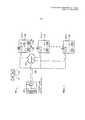
Фиг. 1 представляет собой структурную схему удаленной системы контроля и диагностики в соответствии с примером осуществления данного изобретения.FIG. 1 is a block diagram of a remote monitoring and diagnostic system in accordance with an embodiment of the present invention.
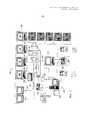
Фиг. 2 представляет собой структурную схему примера сетевой архитектуры локальной системы контроля и диагностики промышленного предприятия, такой как распределенная система управления (Distributed Control System, DCS).FIG. 2 is a block diagram of an example network architecture of a local industrial monitoring and diagnostic system, such as a Distributed Control System (DCS).
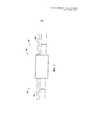
Фиг. 3 представляет собой схему примера набора правил, который может использоваться с локальной системой контроля и диагностики (Local Monitoring and Diagnostic System, LMDS), показанной на фиг. 1.FIG. 3 is a diagram of an example rule set that can be used with the Local Monitoring and Diagnostic System (LMDS) shown in FIG. one.
Фиг. 4 представляет собой снимок экрана инструмента построения правил в соответствии с одним из примеров осуществления настоящего изобретения.FIG. 4 is a screen shot of a rule building tool in accordance with one embodiment of the present invention.
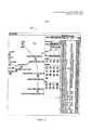
Фиг. 5 представляет собой разделенную на уровни диаграмму 500, иллюстрирующую логическую последовательность операций для примера параметра технологического процесса вспомогательной системы, а именно дифференциального давления в баке.FIG. 5 is a layered diagram 500 illustrating a logical process for an example of a process parameter of an auxiliary system, namely a differential pressure in a tank.
Конкретные технические признаки различных вариантов выполнения настоящего изобретения показаны на одних чертежах и не показаны на других исключительно ради удобства. В тексте и/или формуле изобретения может быть сделана ссылка на любой технический признак, показанный на любом чертеже, в комбинации с техническим признаком, показанным на любом другом чертеже.Specific technical features of various embodiments of the present invention are shown in some drawings and not shown in others solely for convenience. In the text and / or the claims, reference can be made to any technical feature shown in any drawing, in combination with a technical feature shown in any other drawing.
Подробное описание изобретенияDETAILED DESCRIPTION OF THE INVENTION
Последующее подробное описание поясняет варианты выполнения настоящего изобретения посредством примеров и не ограничивает изобретение. Предполагается, что изобретение в целом имеет приложение к аналитическим вариантам и способам контроля работы оборудования в промышленных и коммерческих применениях, а также применениях в жилых помещениях.The following detailed description explains embodiments of the present invention by way of examples and does not limit the invention. It is assumed that the invention as a whole has an application to analytical options and methods for monitoring the operation of equipment in industrial and commercial applications, as well as residential applications.
Как описано в настоящем документе, наборы правил для вспомогательных систем включают, например, набор правил для радиальных вибраций подшипников, набор правил для температуры металла подшипников, набор правил для системы контроля смазочного минерального масла, набор правил для системы контроля гидравлического масла, набор правил для межколесного пространства, набор правил для выпускных клапанов, набор правил для распределения сгорания, набор правил для температуры на выпуске и набор правил для системы вентиляции.As described herein, rule sets for auxiliary systems include, for example, a set of rules for radial vibration of bearings, a set of rules for the temperature of the metal bearings, a set of rules for a control system for lubricating mineral oil, a set of rules for a control system for hydraulic oil, a set of rules for cross-wheel spaces, a set of rules for exhaust valves, a set of rules for the distribution of combustion, a set of rules for the temperature at the outlet, and a set of rules for the ventilation system.
На фиг. 1 показана структурная схема удаленной системы 100 контроля и диагностики согласно примеру выполнения настоящего изобретения. В этом примере система 100 содержит удаленный центр 102 контроля и диагностики. Удаленный центр 102 контроля и диагностики управляется объектом, например одним из множества единиц оборудования OEM, приобретенного и управляемого отдельным деловым объектом, таким как операционный объект. В данном примере выполнения настоящего изобретения изготовитель OEM и операционный объект заключают соглашение о поддержке, в то время как изготовитель OEM предоставляет операционному объекту услуги, связанные с приобретенным оборудованием. Операционный объект может обладать и управлять приобретенным оборудованием, расположенным в одном месте или в множестве мест. Кроме того, изготовитель OEM может заключить соглашение о поддержке с множеством операционных объектов, каждый из которых управляет соответствующим одним местом или множеством мест. Каждое из множества мест может содержать идентичное отдельное оборудование или множество идентичных комплектов оборудования, например линию оборудования. Кроме того, по меньшей мере часть оборудования может быть уникальной для места или уникальной для всех мест.In FIG. 1 is a structural diagram of a remote monitoring and
В данном примере выполнения настоящего изобретения первое место 104 содержит один или более анализаторов 106 процесса, систем 108 контроля оборудования, локальных центров 110 контроля оборудования и/или панелей 112 контроля и выработки сигнала предупреждения, при этом каждое из указанных устройств выполнено с возможностью взаимодействия с соответствующими датчиками оборудования и оборудованием управления для воздействия на управление и работу соответствующего оборудования. Один или более анализаторов 106 процесса, систем 108 контроля оборудования, локальных центров 110 контроля оборудования и/или панелей 112 контроля и выработки сигнала предупреждения соединены с возможностью обмена данными с интеллектуальной системой 114 контроля и диагностики через сеть 116 (IMAD, intelligent monitoring and diagnostic system). Кроме того, интеллектуальная система 114 контроля и диагностики выполнена с возможностью связи с другими системами на месте (не показаны на фиг. 1) и системами вне этого места, такими как, не ограничиваясь этим, удаленный центр 102 контроля и диагностики. В различных вариантах выполнения настоящего изобретения интеллектуальная система 114 контроля и диагностики выполнена с возможностью связи с удаленным центром 102 контроля и диагностики с использованием, например, специализированной сети 118, беспроводной линии 120 связи и сети Интернет 122.In this exemplary embodiment of the present invention,
Каждое из множества других мест, например второе место 124 и n-е место 126, может быть по существу подобно первому месту 104, хотя может и не быть в точности подобно первому месту 104.Each of the many other places, for example
На фиг. 2 показана структурная схема примера сетевой архитектуры 200 локальной системы контроля и диагностики промышленного предприятия, такой как распределенная система 201 управления (DCS). Промышленное предприятие может содержать множество видов оборудования, такого как газовые турбины, центробежные компрессоры, редукторы, генераторы, компрессоры, двигатели, вентиляторы и датчики контроля технологического процесса, гидравлически связанные посредством трубопроводных соединений и связаны с возможностью обмена сигналами с распределенной системой 201 управления через один или более удаленных модулей ввода/вывода (I/O) и кабельное и/или беспроводное соединение. В данном примере выполнения настоящего изобретения промышленное предприятие содержит распределенную систему 201 управления, содержащую магистральную линию 203 сети. Магистральная линия 203 сети может быть, например, аппаратной линией связи, изготовленной из кабеля витой пары, экранированного коаксиального кабеля или волоконно-оптического кабеля, или может быть по меньшей мере частично беспроводной. Распределенная система 201 управления может также содержать процессор 205, который соединен с возможностью обмена данными с оборудованием предприятия, расположенным на месте промышленного предприятия или в удаленных местах, через магистральную линию 203 сети. Подразумевается, что с магистральной линией 203 сети может быть функционально связано любое количество машин. Часть машин может быть аппаратно подключена к магистральной линии 203 сети, а другая часть машин может быть соединена с магистральной линией 203 сети через беспроводную базовую станцию 207, которая связана с возможностью обмена данными с распределенной системой 201 управления. Беспроводная базовая станция 207 может использоваться для увеличения эффективной дальности связи распределенной системы 201 управления, например, с оборудованием или датчиками, расположенными удаленно от промышленного предприятия, но соединенными с одной или более системами в пределах промышленного предприятия.In FIG. 2 is a block diagram of an
Распределенная система 201 управления может быть сконфигурирована для приема и отображения рабочих параметров, относящихся к множеству единиц оборудования, и формирования сигналов автоматического управления и приема входных сигналов ручного управления для управления работой оборудования промышленного предприятия. В данном примере выполнения настоящего изобретения распределенная система 201 управления может содержать сегмент программного кода, сконфигурированный для управления процессором 205 для анализа данных, принятых распределенной системой 201 управления, и позволяющий осуществлять в режиме онлайн контроль и диагностику машин промышленного предприятия. Данные могут быть собраны от каждой машины, включая газовые турбины, центробежные компрессоры, насосы и двигатели, соответствующие датчики технологического процесса и локальные датчики окружающей среды, включая, например, датчики вибрации, сейсмические и температурные датчики, датчики давления, тока, напряжения, датчики температуры окружающей среды и датчики влажности окружающей среды. Данные могут быть предварительно обработаны локальным модулем диагностики или удаленным модулем ввода/вывода или могут быть переданы в распределенную систему 201 управления в необработанном виде.Distributed
Локальная система 213 контроля и диагностики (LMDS, local monitoring and diagnostic system) 213 может представлять собой отдельное дополнительное аппаратное устройство, например персональный компьютер (PC), который осуществляет связь с распределенной системой 201 управления и другими системами 209 управления и источниками данных через магистральную линию 203 сети. Локальная система 213 контроля и диагностики может быть также выполнена в виде сегмента программы, исполняемой в распределенной системе 201 управления и/или одной или более других системах 209 управления. Соответственно, локальная система 213 контроля и диагностики может работать в распределенной конфигурации, так что часть сегмента программы выполняется в нескольких процессорах одновременно. При этом локальная система 213 контроля и диагностики может быть полностью интегрирована в работу распределенной системы 201 управления и других систем 209 управления. Локальная система 213 контроля и диагностики анализирует данные, принятые распределенной системой 201 управления, источниками данных и другими системами 209 управления, для определения исправности машин и/или технологического процесса, в котором применяются эти машины, с глобальной точки зрения промышленного предприятия.Local monitoring and diagnostic system 213 (LMDS) 213 can be a separate additional hardware device, such as a personal computer (PC), which communicates with
В данном варианте настоящего изобретения сетевая архитектура 100 содержит серверный компьютер 202 и одну или более клиентских систем 203. Серверный компьютер 202 также содержит сервер 206 базы данных, сервер 208 приложений, веб-сервер 210, сервер 212 факса, сервер 214 директорий и почтовый сервер 216. Каждый из серверов 206, 208, 210, 212, 214 и 216 может быть выполнен в виде программного обеспечения, исполняемого на серверном компьютере 202, или любая комбинация серверов 206, 208, 210, 212, 214 и 216 может быть реализована отдельно или в комбинации на отдельных серверных компьютерах, объединенных в локальную сеть (LAN, local area network) (не показана). Блок 220 хранения данных соединен с серверным компьютером 202. Кроме того, рабочая станция 222, такая как рабочая станция системного администратора, рабочая станция пользователя и/или рабочая станция диспетчера, соединена с магистральной линией 203 сети. Альтернативно, рабочие станции 222 соединены с магистральной линией сети 203 с использованием линии 226 связи сети Интернет или посредством беспроводного соединения, например, через беспроводную базовую станцию 207.In this embodiment of the present invention, the
Каждая рабочая станция 222 может быть персональным компьютером, имеющим веб-браузер. Хотя функции, выполняемые в рабочих станциях, как правило, показаны как выполняемые в соответствующих рабочих станциях 222, такие функции могут быть выполнены в одном из многих персональных компьютеров, соединенных с магистральной линией 203 сети. Рабочие станции 222 показаны связанными с отдельными функциями только для облегчения понимания различных типов функций, которые могут выполняться пользователями, имеющими доступ к магистральной линии 203 сети.Each
Серверный компьютер 202 выполнен с возможностью связи с различными пользователями, включая работников 228 и третьих лиц, например провайдеров 230 услуг. В данном варианте выполнения настоящего изобретения связь показана осуществленной с использованием сети Интернет, однако, в других вариантах выполнения настоящего изобретения может быть использован любой другой тип связи на основе глобальной сети (WAN, wide area network), то есть системы и процессы не ограничены их реализацией с использованием сети Интернет.
В данном варианте выполнения настоящего изобретения любой авторизованный пользователь, имеющий рабочую станцию 232, может осуществлять доступ к локальной системе 213 контроля и диагностики. По меньшей мере одна из клиентских систем может содержать рабочую станцию 234 менеджера, расположенную в удаленном местоположении. Рабочие станции 222 могут быть реализованы в персональных компьютерах, имеющих веб-браузер. Кроме того, рабочие станции 222 выполнены с возможностью связи с серверным компьютером 202. Кроме того, сервер 212 факса связан с удаленными клиентскими системами, включая клиентскую систему 236, с использованием телефонной линии связи (не показана). Кроме того, сервер 212 факса выполнен с возможностью связи с другими клиентскими системами 228, 230 и 234.In this embodiment of the present invention, any authorized user having a
Инструменты компьютерного моделирования и анализа локальной системы 213 контроля и диагностики, как более подробно описано ниже, могут храниться на сервере 202 и могут быть доступны запрашивающей стороне в любой из клиентских систем 204. В одном варианте выполнения настоящего изобретения клиентские системы 204 представляют собой компьютеры, содержащие веб-браузер, например серверный компьютер 202 может быть доступен для клиентских систем 204 с использованием сети Интернет. Клиентские системы 204 связаны с сетью Интернет через множество интерфейсов, включая сеть, такую как локальная сеть (LAN) или глобальная сеть (WAN), коммутируемые соединения, кабельные модемы и специализированные высокоскоростные линии цифровой сети связи с комплексными услугами (ISDN, Integrated Services Digital Network). Клиентские системы 204 могут быть любым устройством, способным подключаться к сети Интернет, включая сетевой телефон, персональный цифровой помощник (PDA, personal digital assistant) или другое подсоединяемое сетевое оборудование. Сервер 206 базы данных связан с базой 240 данных, содержащей информацию о промышленном предприятии 10, как более подробно описано ниже. В одном варианте выполнения настоящего изобретения централизованная база 240 данных хранится на серверном компьютере 202, и доступ к ней может быть получен потенциальными пользователями через одну из клиентских систем 204 путем регистрации в серверном компьютере 202. В альтернативном варианте выполнения настоящего изобретения база 240 данных хранится удаленно от серверного компьютера 202 и может быть нецентрализованной.Computer modeling and analysis tools of the local monitoring and
Другие системы промышленного предприятия могут поставлять данные, которые доступны серверному компьютеру 202 и/или клиентской системе 204 посредством независимых соединений к магистральной линии 203 сети. Сервер 242 интерактивного электронного технического справочника запрашивает данные о машине, относящиеся к конфигурации каждой машины. Такие данные могут включать эксплуатационные возможности, такие как характеристики насоса, номинальная мощность двигателя, класс изоляции и размер рамы, конструктивные параметры, такие как размеры, число стержней ротора или лопаток рабочего колеса и история технического обслуживания машин, например, изменения при эксплуатации машины, реальные измерения и измерения после окончания регулировки, а также выполненные на машине ремонтные работы, которые не возвратили машину в первоначальное проектное состояние.Other industrial systems may provide data that is accessible to
Портативное устройство 244 контроля вибрации может периодически подключаться к локальной сети непосредственно или через компьютерный порт ввода, такой как порты рабочих станций 222 или клиентских систем 204. Как правило, данные о вибрации собирают по определенному маршруту, периодически собирая данные от машин заранее заданного списка, например, ежемесячно или с другой периодичностью. Данные о вибрации могут также собираться одновременно с поиском неисправностей, обслуживанием и вводом в эксплуатацию. Кроме того, данные о вибрации могут собираться непрерывно в реальном времени или почти в реальном времени. Такие данные могут обеспечить новый базовый уровень для алгоритмов локальной системы 213 контроля и диагностики. Данные технологического процесса могут также собираться на основе маршрута или во время поиска неисправностей, обслуживания и ввода в эксплуатацию. Кроме того, некоторые данные технологического процесса могут собираться непрерывно в реальном времени или почти в реальном времени. Возможно, некоторые параметры технологического процесса не удается измерять непрерывно; тогда можно использовать портативное устройство 245 для сбора данных о параметрах технологического процесса, которые могут быть загружены в распределенную систему 201 управления через рабочую станцию 222 так, чтобы они были доступны для локальной системы 213 контроля и диагностики. Другие данные о параметрах технологического процесса, например данные анализаторов состава технологической текучей среды и данные анализаторов загрязняющих выбросов, могут подаваться в распределенную систему 201 управления через множество устройств 246 контроля, работающих в режиме онлайн.Portable
Контроль электроэнергии, подаваемой в различные машины или генерируемой генераторами промышленного предприятия, может осуществляться с помощью реле 248 защиты двигателя, связанного с каждой машиной. Как правило, такие реле 248 расположены удаленно от контролируемого оборудования в центре управления двигателем (MCC, motor control center) или в распределительном устройстве 250, обеспечивающем питание машины. В дополнение к защитному реле 248 распределительное устройство 250 может также содержать систему диспетчерского управления и сбора данных (SCADA, supervisory control and data acquisition system), которая предоставляет системе LMDS 213 параметры электропитания или оборудования системы энергоснабжения (не показано), расположенного на промышленном предприятии, например, на электрораспределительной подстанции, или параметры удаленных выключателей линий передачи и параметры линий.Electricity supplied to various machines or generated by generators of an industrial enterprise can be monitored using a
На фиг. 3 схематично иллюстрируется пример набора 280 правил, который может использоваться в системе 213 LMDS (показанной на фиг. 1). Набор 280 правил может представлять собой комбинацию одного или более устанавливаемых пользователем правил и ряда свойств, которые определяют применение и состояние устанавливаемых пользователем правил. Правила и свойства могут быть объединены и сохранены в формате строки XML (extensible Markup Language, расширяемый язык разметки), которая может быть зашифрована на основе 25-знакового алфавитно-цифрового ключа, если она хранится в файле. Набор 280 правил представляет собой модульную ячейку знаний, которая содержит один или более входов 282 и один или более выходов 284. Входы 282 могут быть программными портами, которые направляют данные из конкретных мест локальной системы 213 контроля и диагностики в набор 280 правил. Например, входные данные от наружного датчика вибрации насоса могут быть переданы в аппаратный входной терминал в распределенной системе 201 управления. Распределенная система 201 управления может оцифровывать сигнал в этом терминале, чтобы принять этот сигнал. Затем сигнал может быть обработан и сохранен в некоторой области памяти, доступной и/или интегрированной в распределенной системе 201 управления. Первый вход 286 набора правил 280 может отображаться в эту область памяти так, что содержимое отделов памяти доступно набору 280 правил в качестве входа. Аналогично, выход 288 может отображаться в другую область памяти, доступную для распределенной системы 201 управления, или в другую память, так чтобы эта область памяти содержала выходные данные 288 набора 280 правил.In FIG. 3 schematically illustrates an example of a
В данном примере выполнения настоящего изобретения набор 280 правил содержит одно или более правил, относящихся к контролю и диагностике определенных проблем, связанных с оборудованием, работающим на промышленном предприятии, например, на предприятии для повторного закачивания газа, предприятии по сжижению природного газа (LNG, Liquified Natural Gas), электростанции, нефтеперерабатывающем предприятии и предприятии по химической обработке. Хотя набор 280 правил описан с точки зрения его использования на промышленном предприятии, этот набор 280 правил может быть подходящим образом составлен для охвата любого знания и может использоваться для принятия решений в любой области. Например, набор 280 правил может содержать знания, имеющие отношение к экономической деятельности, финансовой деятельности, погодным явлениям и процессам проектирования. Набор 280 правил может затем использоваться для решения проблем в этих областях. Набор 280 правил содержит знания из одного или более источников, так что это знание передается в любую систему, где применяется набор 280 правил. Знание оформлено в виде правил, которые связывают выходы 284 с входами 282, так что конкретизация входов 282 и выходов 284 позволяет применить набор 280 правил к локальной системе 213 контроля и диагностики. Набор 280 правил может содержать только те правила, которые специфичны для конкретного актива промышленного предприятия, и может быть направлен на решение только одной возможной проблемы, связанной с этим конкретным активом промышленного предприятия. Например, набор 280 правил может содержать только те правила, которые применимы к двигателю или к комбинации двигатель/насос. Набор 280 правил может содержать только те правила, которые определяют исправность комбинации двигатель/насос с использованием данных о вибрации. Набор 280 правил может также содержать правила, которые определяют исправность комбинации двигатель/насос с использованием комплекта диагностических средств, который в дополнение к средствам анализа вибрации содержит, например, средства вычисления рабочих характеристик и/или средства вычисления финансовых характеристик для комбинации двигатель/насос.In this exemplary embodiment of the present invention, rule set 280 contains one or more rules related to monitoring and diagnosing certain problems associated with equipment operating in an industrial plant, for example, a gas re-injection plant, a natural gas liquefaction plant (LNG, Liquified Natural Gas), a power plant, refinery and chemical processing plant. Although the rule set 280 is described in terms of its use in an industrial enterprise, this rule set 280 can be suitably designed to cover any knowledge and can be used to make decisions in any field. For example, rule set 280 may contain knowledge related to economic activities, financial activities, weather events, and design processes. A set of 280 rules can then be used to solve problems in these areas. The rule set 280 contains knowledge from one or more sources, so this knowledge is transferred to any system where the rule set 280 is applied. The knowledge is framed in the form of rules that connect
Во время работы набор 280 правил создается в программных средствах разработки, которые запрашивают у пользователя связи между входами 282 и выходами 284. Входы 282 могут принимать данные, представляющие, например, цифровые сигналы, аналоговые сигналы, колебательные сигналы, обработанные сигналы, вводимые вручную, и/или конфигурационные параметры и выходные данные из других наборов правил. Правила в пределах набора 280 правил могут включать логические правила, численные алгоритмы, использование методов обработки сигналов и колебательных сигналов, экспертную систему и алгоритмы искусственного интеллекта, статистические инструменты и любое другое выражение, которое позволяет связать выходы 284 с входами 282. Выходы 284 могут отображаться на соответствующие области памяти, которые зарезервированы и сконфигурированы для приема данных каждого выхода 284. Локальная система 213 контроля и диагностики и распределенная система 201 управления могут затем использовать эти области памяти для обеспечения любой функции контроля и/или управления, для выполнения которых могут быть запрограммированы локальная система 213 контроля и диагностики и распределенная система 201 управления. Правила в наборе 280 правил работают независимо от локальной системы 213 контроля и диагностики и распределенной системы 201 управления, хотя могут иметься входы 282 к набору 280 правил и выходы 284 из набора 280 правил напрямую или опосредованно через промежуточные устройства.During operation, a set of
Во время создания набора 280 правил, эксперт в данной области техники раскрывает знание в отношении конкретного актива с использованием средств разработки путем программирования одного или более правил. Правила создают путем формирования выражений связи между выходами 284 и входами 282, так что кодирование правил не требуется. Операнды могут быть выбраны из библиотеки операндов с использованием графических методов, например с использованием техники «перетаскивания» (drag-and-drop) в графическом интерфейсе пользователя, встроенном в средство разработки. Графическое представление операнда может быть выбрано из области библиотеки на экранном дисплее (не показан) и посредством «перетаскивания» помещено в область создания правила. Связи между входом 282 и операндами представлены в виде логического дисплея, и пользователь запрашивается о значениях, таких как константы, когда это необходимо в зависимости от определенных операндов и некоторых определенных входов 282, которые выбраны. Создают столько правил, сколько необходимо, чтобы охватить знание эксперта. Соответственно, набор 280 правил может содержать робастный набор правил для диагностики и/или контроля или относительно менее робастный набор правил для диагностики и/или контроля в зависимости от требований клиента и уровня техники в конкретной области набора 280 правил. Средство разработки предоставляет ресурсы для проверки набора 280 правил во время разработки с обеспечением того, чтобы различные комбинации и значения на входах 282 давали ожидаемые значения на выходах 284.When creating a set of 280 rules, an expert in the art discloses knowledge regarding a specific asset using development tools by programming one or more rules. Rules are created by generating expressions of communication between
Фиг. 4 представляет собой снимок экрана инструмента 400 построения правил в соответствии с одним из примеров осуществления настоящего изобретения. В данном примере осуществления настоящего изобретения в инструменте 400 применяются объекты, представляющие запрограммированные операции, которыми можно легко манипулировать для формирования наборов правил, относящихся к каждому из контролируемых параметров вспомогательных систем. Объекты выбираются в области 402 выбора для оператора, которая доступна на вкладке 404 выбора для оператора. Для выбора доступны также вкладка 406 выбора функции, вкладка 408 термодинамического алгоритма и вкладка 410 структур. Объекты «перетаскиваются» в рабочую область 412, где объекты операторов связаны с помощью меток, для построения логики для формирования выхода на основе измеренных или выводимых параметров.FIG. 4 is a screen shot of a
Фиг. 5 представляет собой разделенную на уровни диаграмму 500, иллюстрирующую логическую последовательность операций для примера параметра технологического процесса вспомогательной системы, а именно дифференциального давления в баке. Диаграмма 500 включает полосу 502 симптомов для указания списка симптомов, которые могут быть указаны набором правил как требующие внимания. Отображается также метка источника рассматриваемого симптома, а также параметры или условия, которые должны быть выполнены для формирования рекомендации. Диаграмма 500 включает также полосу 504 для указания потенциальных причин симптомов, указанных в полосе 502. В полосе 506 действий указаны инструкции, которые инженер, проводящий диагностику, должен выполнить для поиска и, возможно, устранения упомянутого источника симптома. В различных вариантах осуществления настоящего изобретения инженер, проводящий диагностику, является сторонним лицом, осуществляющим удаленный контроль работы газовой турбины. В полосе 508 рекомендаций указаны рекомендации для оператора газовой турбины, которые могут быть более подробными или требовать большего вмешательства в работу оборудования, чем действия, передаваемые инженеру по диагностике.FIG. 5 is a layered diagram 500 illustrating a logical process for an example of a process parameter of an auxiliary system, namely a differential pressure in a tank. Chart 500 includes a symptom bar 502 to indicate a list of symptoms that may be indicated by a set of rules as requiring attention. The label of the source of the symptom in question is also displayed, as well as the parameters or conditions that must be met to formulate the recommendation. Chart 500 also includes a strip 504 to indicate the potential causes of the symptoms indicated in strip 502. In the strip 506 of the actions are instructions that the diagnostic engineer must follow in order to find and possibly eliminate the source of the symptom. In various embodiments of the present invention, the diagnostics engineer is a third-party person remotely monitoring a gas turbine. In the 508 recommendation strip, recommendations are indicated for the gas turbine operator, which may be more detailed or require more intervention in the operation of the equipment than the actions passed to the diagnostic engineer.
Для достижения желаемых результатов логические последовательности, показанные на чертежах, не требуют показанного конкретного порядка или последовательного порядка. Кроме того, в описанных последовательностях операций могут иметься другие шаги, или некоторые шаги могут отсутствовать, а также могут быть добавлены или удалены другие компоненты в описанных системах. Соответственно, другие варианты выполнения настоящего изобретения также находятся в пределах сущности формулы изобретения.To achieve the desired results, the logical sequences shown in the drawings do not require the particular order shown or sequential order. In addition, the steps described may have other steps, or some steps may be missing, and other components in the described systems may be added or removed. Accordingly, other embodiments of the present invention are also within the spirit of the claims.
Очевидно, что описанные варианты выполнения настоящего изобретения, которые были изложены особенно подробно, являются просто примерами или возможными вариантами выполнения настоящего изобретения, при этом может использоваться множество других комбинаций, дополнений или вариантов.Obviously, the described embodiments of the present invention, which have been set forth in particularly detail, are merely examples or possible embodiments of the present invention, and many other combinations, additions or variations can be used.
Кроме того, конкретные наименования компонентов, написание прописными буквами терминов, атрибуты, структуры данных или любые другие аспекты программирования или структурные аспекты не являются обязательными или существенными, при этом механизмы, обеспечивающие реализацию изобретения или его признаков, могут иметь другие названия, форматы или протоколы. Кроме того, система может быть реализована с помощью комбинации аппаратного и программного обеспечения, как описано выше, или полностью с помощью элементов аппаратного обеспечения. Кроме того, конкретное разделение функций между различными системными компонентами, описанными здесь, представляет один из примеров и не является обязательным; функции, реализованные компонентом одной системы, альтернативно могут быть выполнены множеством компонентов, а функции, выполняемые множеством компонентов, альтернативно могут быть выполнены одним компонентом.In addition, the specific names of the components, capitalization of terms, attributes, data structures or any other programming aspects or structural aspects are not mandatory or essential, while the mechanisms for implementing the invention or its features may have other names, formats or protocols. In addition, the system can be implemented using a combination of hardware and software, as described above, or completely using hardware elements. In addition, the specific separation of functions between the various system components described here is one example and is not required; the functions implemented by a component of one system can alternatively be performed by a plurality of components, and the functions performed by a plurality of components can alternatively be performed by a single component.
Некоторые части приведенного описания представляют признаки в терминах алгоритмов и символических представлений операций над информацией. Эти алгоритмические описания и представления могут использоваться специалистами в области обработки данных для наиболее эффективной передачи сути их работы другим специалистам. Хотя эти операции описаны функционально или логически, подразумевается, что они будут реализованы в виде программ для компьютера. Кроме того, иногда представлялось удобным называть эти конфигурации операций модулями или функциональными именами без потери общности.Some parts of the above description represent features in terms of algorithms and symbolic representations of operations on information. These algorithmic descriptions and representations can be used by data processing specialists to most effectively convey the essence of their work to other specialists. Although these operations are described functionally or logically, it is understood that they will be implemented as computer programs. In addition, it was sometimes convenient to call these configurations of operations modules or functional names without loss of generality.
Если явно не указано иное, то, как очевидно из приведенного выше описания, повсюду в описании рассуждения, в которых используются такие термины, как «обработка», «вычисление», «определение», «отображение» или «обеспечение» и т.п., относятся к действиям и процессам в компьютерной системе или аналогичном электронном вычислительном устройстве, которые манипулируют данными и преобразуют данные, представленные в виде физических (электронных) величин в памяти компьютерной системы, регистрах или других таких устройствах для хранения, передачи или отображения информации.Unless explicitly stated otherwise, then, as is obvious from the above description, throughout the description of reasoning, which use terms such as “processing”, “calculation”, “definition”, “display” or “provision”, etc. ., relate to actions and processes in a computer system or similar electronic computing device that manipulate data and transform data presented in the form of physical (electronic) quantities in the computer system memory, registers or other such devices for storage, transmission or display information.
Хотя изобретение было описано с точки зрения различных частных форм осуществления, очевидно, что изобретение может быть осуществлено на практике с модификациями в пределах сущности формулы изобретения.Although the invention has been described in terms of various particular forms of implementation, it is obvious that the invention can be practiced with modifications within the spirit of the claims.
Используемый здесь термин «процессор» относится к центральным процессорам, микропроцессорам, микроконтроллерам, схемам с сокращенным набором команд (RISC, reduced instruction set circuit), прикладным специализированным интегральным схемам (ASIC, application specific integrated circuit), логическим схемам и любой другой схеме или процессору, способному выполнять описанные выше функции.The term “processor” as used herein refers to central processing units, microprocessors, microcontrollers, reduced instruction set circuits (RISCs), application specific integrated circuits (ASICs), logic circuits, and any other circuit or processor capable of performing the functions described above.
В контексте настоящего описания термины «программное обеспечение» и «встроенное программное обеспечение» являются взаимозаменяемыми и включают любую компьютерную программу, записанную в памяти для ее исполнения процессором 205, включая оперативную память (RAM, random access memory), постоянную память (ROM, read-only memory), стираемую программируемую постоянную память (EPROM, erasable programmable read-only memory), электрически программируемую постоянную память (EEPROM, electrically erasable programmable read-only-memory) и энергонезависимую оперативную память (NVRAM, non-volatile random access memory). Указанные типы памяти даны только для примера и, таким образом, не ограничивают типы памяти, используемой для хранения компьютерной программы.In the context of the present description, the terms "software" and "firmware" are used interchangeably and include any computer program stored in memory for execution by
Как понятно из предшествующего описания, представленные варианты выполнения настоящего изобретения могут быть реализованы с использованием компьютерного программирования или инженерной разработки, включая программное обеспечение, встроенное программное обеспечение, аппаратное обеспечение или любую комбинацию или подмножество перечисленного, при этом технический результат включает (a) хранение множества наборов правил в упомянутом запоминающем устройстве, при этом упомянутые наборы правил относятся к вспомогательным системам газовой турбины и включают по меньшей мере одно правило в виде выражения связи выходных данных реального времени с входными данными реального времени, причем упомянутое выражение связи касается параметров, связанных со вспомогательными системами газовой турбины, (b) прием входных данных реального времени и входных данных предыстории от системы контроля состояния, связанной с газовой турбиной, при этом упомянутые входные данные относятся к параметрам технологического процесса, связанным со вспомогательными системами газовой турбины, и (c) оценку значений по меньшей мере некоторых параметров, связанных со вспомогательными системами газовой турбины, с использованием упомянутых принятых входных данных. Любая такая результирующая программа при наличии средств машиночитаемого кода может быть реализована или предоставлена на одном или более считываемых компьютером носителях с обеспечением, таким образом, компьютерного программного продукта, то есть изделия согласно рассмотренным вариантам выполнения настоящего изобретения. Считываемые компьютером носители могут включать, например, не ограничиваясь этим, фиксированный (жесткий) накопитель, дискету, оптический диск, магнитную ленту, полупроводниковую память, такую как постоянное запоминающее устройство (ROM), и/или любую среду передачи/приема, такую как сеть Интернет или другая сеть или линия связи. Изделие, содержащее компьютерный код, может быть выполнено и/или использовано путем исполнения кода непосредственно из одного носителя, путем копирования кода из одного носителя в другой носитель или посредством передачи кода по сети.As is clear from the foregoing description, the presented embodiments of the present invention can be implemented using computer programming or engineering, including software, firmware, hardware, or any combination or subset of the above, the technical result includes (a) storing multiple sets rules in said storage device, wherein said rule sets relate to auxiliary gas systems a new turbine and include at least one rule in the form of an expression for the relationship of the real-time output data with the real-time input data, the aforementioned communication expression relating to parameters associated with auxiliary gas turbine systems, (b) receiving real-time input data and historical input data from state monitoring systems associated with a gas turbine, wherein said input data relates to process parameters associated with auxiliary systems of a gas turbine, and (c) tsenku values of at least some of the parameters associated with the auxiliary gas turbine systems, using said received input data. Any such resulting program, in the presence of computer readable code, may be implemented or provided on one or more computer-readable media, thereby providing a computer program product, i.e., product, in accordance with the considered embodiments of the present invention. Computer-readable media may include, for example, but not limited to, a fixed (hard) drive, floppy disk, optical disk, magnetic tape, semiconductor memory such as read-only memory (ROM), and / or any transmission / reception medium such as a network Internet or other network or communication line. A product containing computer code can be executed and / or used by executing the code directly from one medium, by copying the code from one medium to another medium, or by transmitting the code over a network.
Множество функциональных блоков, описанных в этом документе, были названы модулями, чтобы подчеркнуть независимость их реализации. Например, модуль может быть выполнен как аппаратная схема, содержащая заказные сверхбольшие интегральные микросхемы (VLSI, very large scale integration) или вентильные матрицы, имеющиеся в продаже полупроводниковые устройства, такие как логические интегральные схемы, транзисторы или другие дискретные компоненты. Модуль может также быть выполнен в виде программируемых аппаратных устройств, таких как программируемые вентильные матрицы (FPGA, field programmable gate array), программируемые логические матрицы, программируемые логические устройства (PLD, programmable logic device) и т.п.Many of the function blocks described in this document have been called modules to emphasize the independence of their implementation. For example, a module can be implemented as a hardware circuit containing custom VLSI (very large scale integration) circuits or gate arrays commercially available semiconductor devices such as logic integrated circuits, transistors, or other discrete components. The module can also be made in the form of programmable hardware devices, such as programmable gate arrays (FPGA, field programmable gate array), programmable logic arrays, programmable logic devices (PLD, programmable logic device), etc.
Модули могут быть также реализованы в виде программного обеспечения, предназначенного для исполнения различными типами процессоров. Идентифицированный модуль исполняемого кода может содержать, например, один или более физических или логических блоков компьютерных команд, которые могут быть организованы, например, в виде объекта, процедуры или функции. Однако исполнимые файлы идентифицированного модуля необязательно должны быть физически расположены вместе, но могут содержать отдельные инструкции, которые хранятся в разных местах, но которые при их логическом объединении образуют модуль и позволяют достичь цели, поставленной для модуля.Modules can also be implemented in the form of software designed for execution by various types of processors. The identified module of the executable code may contain, for example, one or more physical or logical blocks of computer instructions, which can be organized, for example, in the form of an object, procedure, or function. However, the executable files of the identified module need not be physically located together, but may contain separate instructions that are stored in different places, but which, when combined logically, form a module and allow you to achieve the goal set for the module.
Модуль исполняемого кода может представлять собой одну инструкцию или множество инструкций и может даже быть распределен по нескольким различным сегментам кода среди различных программ в нескольких запоминающих устройствах. Аналогично, рабочие данные могут быть идентифицированы и показаны здесь в пределах модулей и могут быть реализованы в любой подходящей форме и организованы в любую структуру данных подходящего типа. Рабочие данные могут быть собраны как один массив данных или могут быть распределены по различным местам, включая различные запоминающие устройства, и могут существовать, по меньшей мере частично, просто как электронные сигналы в системе или сети.An executable code module may be a single instruction or a plurality of instructions, and may even be distributed across several different code segments among various programs in several memory devices. Similarly, operational data can be identified and shown here within the modules and can be implemented in any suitable form and organized into any data structure of the appropriate type. Operational data may be collected as a single data array or may be distributed to various locations, including various storage devices, and may exist, at least in part, simply as electronic signals in a system or network.
Описанные варианты выполнения способа и системы для контроля в режиме онлайн вспомогательных систем, которая содержит модуль правил, обеспечивают рентабельное и надежное средство для выдачи содержательных рекомендаций по эксплуатации и поиску неисправностей. Кроме того, система является более точной и менее склонной к ложным срабатываниям. Более конкретно, способы и системы, описанные выше, могут прогнозировать отказ компонентов на гораздо более ранней стадии, чем известные системы, что позволяет значительно сократить время простоя оборудования и предотвратить ошибки. Кроме того, описанные способы и системы обеспечивают прогнозирование отклонений от нормы на ранней стадии, что позволяет персоналу на рабочем месте подготавливать и планировать остановку оборудования. В результате способы и системы, описанные выше, облегчают эксплуатацию газовых турбин и другого оборудования, обеспечивая их высокую надежность и рентабельность.The described embodiments of the method and system for online monitoring of auxiliary systems, which contains a module of rules, provide a cost-effective and reliable means for issuing meaningful recommendations for operation and troubleshooting. In addition, the system is more accurate and less prone to false positives. More specifically, the methods and systems described above can predict component failure at a much earlier stage than known systems, which can significantly reduce equipment downtime and prevent errors. In addition, the described methods and systems provide prediction of deviations from the norm at an early stage, which allows personnel at the workplace to prepare and plan for equipment shutdown. As a result, the methods and systems described above facilitate the operation of gas turbines and other equipment, ensuring their high reliability and cost-effectiveness.
В настоящем описании использованы примеры, раскрывающие изобретение, включая предпочтительный вариант его выполнения, и позволяющие любому специалисту в данной области техники реализовать изобретение на практике, включая создание и использование любых устройств или систем и выполнение любых описанных способов. Объем изобретения определяется формулой изобретения и может включать другие примеры, очевидные специалистам. Предполагается, что такие другие примеры находятся в пределах сущности изобретения, если в них имеются структурные элементы, которые не отличаются по существу от описанных в формуле изобретения, или если они содержат эквивалентные структурные элементы с несущественными отличиями от элементов, описанных в формуле изобретения.In the present description, examples have been used that disclose the invention, including the preferred embodiment, and allow any person skilled in the art to put the invention into practice, including the creation and use of any devices or systems and the implementation of any of the described methods. The scope of the invention is defined by the claims and may include other examples that are obvious to experts. Such other examples are intended to be within the spirit of the invention if they contain structural elements that do not differ substantially from those described in the claims, or if they contain equivalent structural elements with insignificant differences from the elements described in the claims.
Claims (16)
Translated fromRussianApplications Claiming Priority (3)
| Application Number | Priority Date | Filing Date | Title |
|---|---|---|---|
| IT000008AITCO20120008A1 (en) | 2012-03-01 | 2012-03-01 | METHOD AND SYSTEM FOR MONITORING THE CONDITION OF A GROUP OF PLANTS |
| ITCO2012A000008 | 2012-03-01 | ||
| PCT/EP2013/054161WO2013127998A1 (en) | 2012-03-01 | 2013-03-01 | Method and system for diagnostic rules for heavy duty gas turbines |
Publications (2)
| Publication Number | Publication Date |
|---|---|
| RU2014133935A RU2014133935A (en) | 2016-04-20 |
| RU2613637C2true RU2613637C2 (en) | 2017-03-21 |
Family
ID=46051732
Family Applications (7)
| Application Number | Title | Priority Date | Filing Date |
|---|---|---|---|
| RU2014133941ARU2636095C2 (en) | 2012-03-01 | 2013-02-28 | Method and system for monitoring status of plant group |
| RU2014133942ARU2657047C2 (en) | 2012-03-01 | 2013-03-01 | Method and system for advising operator action |
| RU2014133934ARU2014133934A (en) | 2012-03-01 | 2013-03-01 | METHOD AND SYSTEM FOR REAL-TIME NOTIFICATION ABOUT DECREASING CHARACTERISTICS OF CENTRIFUGAL COMPRESSORS |
| RU2014133935ARU2613637C2 (en) | 2012-03-01 | 2013-03-01 | Method and system for rules of powerful gas turbines diagnostics |
| RU2014134207ARU2627742C2 (en) | 2012-03-01 | 2013-03-01 | Method and system for informing the characteristics of the work of the gas turbine in real time |
| RU2014133943ARU2014133943A (en) | 2012-03-01 | 2013-03-01 | Method and system for issuing in real time recommendations for restoring the performance of centrifugal compressors |
| RU2014133939ARU2613548C2 (en) | 2012-03-01 | 2013-03-01 | Method and system for real-time control of burning without water injection with low emission of nitric oxides and diffusion combustion |
Family Applications Before (3)
| Application Number | Title | Priority Date | Filing Date |
|---|---|---|---|
| RU2014133941ARU2636095C2 (en) | 2012-03-01 | 2013-02-28 | Method and system for monitoring status of plant group |
| RU2014133942ARU2657047C2 (en) | 2012-03-01 | 2013-03-01 | Method and system for advising operator action |
| RU2014133934ARU2014133934A (en) | 2012-03-01 | 2013-03-01 | METHOD AND SYSTEM FOR REAL-TIME NOTIFICATION ABOUT DECREASING CHARACTERISTICS OF CENTRIFUGAL COMPRESSORS |
Family Applications After (3)
| Application Number | Title | Priority Date | Filing Date |
|---|---|---|---|
| RU2014134207ARU2627742C2 (en) | 2012-03-01 | 2013-03-01 | Method and system for informing the characteristics of the work of the gas turbine in real time |
| RU2014133943ARU2014133943A (en) | 2012-03-01 | 2013-03-01 | Method and system for issuing in real time recommendations for restoring the performance of centrifugal compressors |
| RU2014133939ARU2613548C2 (en) | 2012-03-01 | 2013-03-01 | Method and system for real-time control of burning without water injection with low emission of nitric oxides and diffusion combustion |
Country Status (12)
| Country | Link |
|---|---|
| US (7) | US9274520B2 (en) |
| EP (7) | EP2820490B1 (en) |
| JP (7) | JP2015508928A (en) |
| KR (7) | KR20140130543A (en) |
| CN (7) | CN104254810B (en) |
| AU (9) | AU2013224935A1 (en) |
| BR (2) | BR112014021204A2 (en) |
| CA (7) | CA2865194C (en) |
| IT (1) | ITCO20120008A1 (en) |
| MX (2) | MX2014010464A (en) |
| RU (7) | RU2636095C2 (en) |
| WO (7) | WO2013127958A1 (en) |
Families Citing this family (167)
| Publication number | Priority date | Publication date | Assignee | Title |
|---|---|---|---|---|
| ITCO20120008A1 (en)* | 2012-03-01 | 2013-09-02 | Nuovo Pignone Srl | METHOD AND SYSTEM FOR MONITORING THE CONDITION OF A GROUP OF PLANTS |
| US20140244328A1 (en)* | 2013-02-22 | 2014-08-28 | Vestas Wind Systems A/S | Wind turbine maintenance optimizer |
| US10678225B2 (en) | 2013-03-04 | 2020-06-09 | Fisher-Rosemount Systems, Inc. | Data analytic services for distributed industrial performance monitoring |
| US9665088B2 (en) | 2014-01-31 | 2017-05-30 | Fisher-Rosemount Systems, Inc. | Managing big data in process control systems |
| US10866952B2 (en) | 2013-03-04 | 2020-12-15 | Fisher-Rosemount Systems, Inc. | Source-independent queries in distributed industrial system |
| US9558220B2 (en) | 2013-03-04 | 2017-01-31 | Fisher-Rosemount Systems, Inc. | Big data in process control systems |
| US10909137B2 (en) | 2014-10-06 | 2021-02-02 | Fisher-Rosemount Systems, Inc. | Streaming data for analytics in process control systems |
| US10649449B2 (en) | 2013-03-04 | 2020-05-12 | Fisher-Rosemount Systems, Inc. | Distributed industrial performance monitoring and analytics |
| US10649424B2 (en)* | 2013-03-04 | 2020-05-12 | Fisher-Rosemount Systems, Inc. | Distributed industrial performance monitoring and analytics |
| US10031490B2 (en) | 2013-03-15 | 2018-07-24 | Fisher-Rosemount Systems, Inc. | Mobile analysis of physical phenomena in a process plant |
| CN104344946B (en)* | 2013-07-24 | 2017-12-05 | 中国国际航空股份有限公司 | APU turbo blades are broken monitoring method and device with rotating shaft jamming failure |
| US20150075170A1 (en)* | 2013-09-17 | 2015-03-19 | General Electric Company | Method and system for augmenting the detection reliability of secondary flame detectors in a gas turbine |
| US9234317B2 (en)* | 2013-09-25 | 2016-01-12 | Caterpillar Inc. | Robust system and method for forecasting soil compaction performance |
| ITCO20130043A1 (en)* | 2013-10-02 | 2015-04-03 | Nuovo Pignone Srl | METHOD AND SYSTEM TO MONITOR THE FUNCTIONING OF A FLEXIBLE COUPLING DEVICE |
| US20150153251A1 (en)* | 2013-11-29 | 2015-06-04 | Johannes Izak Boerhout | Systems and methods for integrated workflow display and action panel for plant assets |
| US20150219530A1 (en)* | 2013-12-23 | 2015-08-06 | Exxonmobil Research And Engineering Company | Systems and methods for event detection and diagnosis |
| US20150184549A1 (en) | 2013-12-31 | 2015-07-02 | General Electric Company | Methods and systems for enhancing control of power plant generating units |
| US9957843B2 (en) | 2013-12-31 | 2018-05-01 | General Electric Company | Methods and systems for enhancing control of power plant generating units |
| US10139267B2 (en) | 2014-01-09 | 2018-11-27 | General Electric Company | Systems and methods for storage and analysis of periodic waveform data |
| US20150271026A1 (en)* | 2014-03-24 | 2015-09-24 | Microsoft Technology Licensing, Llc | End user performance analysis |
| KR102189282B1 (en)* | 2014-05-21 | 2020-12-09 | 세메스 주식회사 | Method for controlling a process equipment |
| US9813308B2 (en)* | 2014-06-04 | 2017-11-07 | Verizon Patent And Licensing Inc. | Statistical monitoring of customer devices |
| KR101676926B1 (en)* | 2014-12-31 | 2016-11-16 | 주식회사 포스코아이씨티 | System and Method for Verifying Prediction Algorithm of Energy Management System Using Virtual Environment |
| US9777723B2 (en)* | 2015-01-02 | 2017-10-03 | General Electric Company | System and method for health management of pumping system |
| US10036233B2 (en)* | 2015-01-21 | 2018-07-31 | Baker Hughes, A Ge Company, Llc | Method and system for automatically adjusting one or more operational parameters in a borehole |
| US20160260041A1 (en)* | 2015-03-03 | 2016-09-08 | Uop Llc | System and method for managing web-based refinery performance optimization using secure cloud computing |
| EP3276436B1 (en)* | 2015-03-24 | 2021-07-28 | Mitsubishi Electric Corporation | Plant monitor/control device |
| US9864823B2 (en) | 2015-03-30 | 2018-01-09 | Uop Llc | Cleansing system for a feed composition based on environmental factors |
| US20170315543A1 (en)* | 2015-03-30 | 2017-11-02 | Uop Llc | Evaluating petrochemical plant errors to determine equipment changes for optimized operations |
| US10095200B2 (en) | 2015-03-30 | 2018-10-09 | Uop Llc | System and method for improving performance of a chemical plant with a furnace |
| US10031510B2 (en)* | 2015-05-01 | 2018-07-24 | Aspen Technology, Inc. | Computer system and method for causality analysis using hybrid first-principles and inferential model |
| US10078326B2 (en) | 2015-05-14 | 2018-09-18 | Honeywell International Inc. | Apparatus and method for event detection to support mobile notifications related to industrial process control and automation system |
| US10505790B2 (en) | 2015-05-14 | 2019-12-10 | Honeywell International Inc. | Apparatus and method for automated event notification read receipt to support non-repudiated auditing or other functions in industrial process control and automation system |
| US10466688B2 (en)* | 2015-05-14 | 2019-11-05 | Honeywell International Inc. | Apparatus and method for providing event context with notifications related to industrial process control and automation system |
| US10021063B2 (en) | 2015-05-14 | 2018-07-10 | Honeywell International Inc. | Apparatus and method for protecting proprietary information over public notification infrastructure |
| US10021064B2 (en) | 2015-05-14 | 2018-07-10 | Honeywell International Inc. | Apparatus and method for translating industrial process control and automation system events into mobile notifications |
| US20160334770A1 (en)* | 2015-05-14 | 2016-11-17 | Honeywell International Inc. | Apparatus and method for using configurable rules linking triggers with actions to support notifications associated with industrial process control and automation system |
| CN105157986B (en)* | 2015-06-17 | 2017-09-22 | 广东电网有限责任公司电力科学研究院 | A kind of monitoring reliability method for gas turbine hot-end component |
| US20170038275A1 (en)* | 2015-08-04 | 2017-02-09 | Solar Turbines Incorporated | Monitoring system for turbomachinery |
| US20170038276A1 (en)* | 2015-08-04 | 2017-02-09 | Solar Turbines Incorporated | Monitoring System for Turbomachinery |
| US10657450B2 (en)* | 2015-09-30 | 2020-05-19 | Deere & Company | Systems and methods for machine diagnostics based on stored machine data and available machine telematic data |
| US10495545B2 (en)* | 2015-10-22 | 2019-12-03 | General Electric Company | Systems and methods for determining risk of operating a turbomachine |
| FR3043463B1 (en)* | 2015-11-05 | 2017-12-22 | Snecma | SYSTEM AND METHOD FOR MONITORING TURBOMACHINE WITH FUSION OF INDICATORS FOR SYNTHESIS OF ALARM CONFIRMATION |
| KR102486704B1 (en)* | 2016-01-15 | 2023-01-10 | 엘에스일렉트릭(주) | Client and server in supervisory control and data acquisition system |
| US10311399B2 (en)* | 2016-02-12 | 2019-06-04 | Computational Systems, Inc. | Apparatus and method for maintaining multi-referenced stored data |
| US10503483B2 (en) | 2016-02-12 | 2019-12-10 | Fisher-Rosemount Systems, Inc. | Rule builder in a process control network |
| US10574739B2 (en) | 2016-02-26 | 2020-02-25 | Honeywell International Inc. | System and method for smart event paging |
| US20170300945A1 (en)* | 2016-04-15 | 2017-10-19 | International Business Machines Corporation | Segmenting mobile shoppers |
| EP3239684A1 (en) | 2016-04-29 | 2017-11-01 | Siemens Aktiengesellschaft | Fault diagnosis during testing of turbine unit |
| US11914349B2 (en) | 2016-05-16 | 2024-02-27 | Jabil Inc. | Apparatus, engine, system and method for predictive analytics in a manufacturing system |
| WO2017201086A1 (en) | 2016-05-16 | 2017-11-23 | Jabil Circuit, Inc. | Apparatus, engine, system and method for predictive analytics in a manufacturing system |
| US10047679B2 (en) | 2016-06-14 | 2018-08-14 | General Electric Company | System and method to enhance lean blowout monitoring |
| US10294869B2 (en) | 2016-06-14 | 2019-05-21 | General Electric Company | System and method to enhance corrosion turbine monitoring |
| US10099804B2 (en) | 2016-06-16 | 2018-10-16 | General Electric Company | Environmental impact assessment system |
| EP3258333A1 (en)* | 2016-06-17 | 2017-12-20 | Siemens Aktiengesellschaft | Method and system for monitoring sensor data of rotating equipment |
| CN106089671A (en)* | 2016-06-29 | 2016-11-09 | 广东葆德科技有限公司 | A kind of timely maintaining method of air compressor machine based on satellite fix and system thereof |
| US10643167B2 (en)* | 2016-07-28 | 2020-05-05 | Honeywell International Inc. | MPC with unconstrained dependent variables for KPI performance analysis |
| EP3279755B1 (en)* | 2016-08-02 | 2021-09-29 | ABB Schweiz AG | Method of monitoring a modular process plant complex with a plurality of interconnected process modules |
| US11143056B2 (en) | 2016-08-17 | 2021-10-12 | General Electric Company | System and method for gas turbine compressor cleaning |
| US10724398B2 (en) | 2016-09-12 | 2020-07-28 | General Electric Company | System and method for condition-based monitoring of a compressor |
| US10606254B2 (en)* | 2016-09-14 | 2020-03-31 | Emerson Process Management Power & Water Solutions, Inc. | Method for improving process/equipment fault diagnosis |
| US10545487B2 (en) | 2016-09-16 | 2020-01-28 | Uop Llc | Interactive diagnostic system and method for managing process model analysis |
| US20180100442A1 (en)* | 2016-10-11 | 2018-04-12 | General Electric Company | Systems and Methods to Control Performance Via Control of Compressor OLL Protection Actions |
| US11543805B2 (en) | 2016-10-17 | 2023-01-03 | Fisher-Rosemount Systems, Inc. | Systems and apparatus for distribution of process control data to remote devices |
| US10444730B2 (en)* | 2016-11-30 | 2019-10-15 | Eurotherm Limited | Real-time compliance status for equipment |
| US10466677B2 (en) | 2016-12-15 | 2019-11-05 | Solar Turbines Incorporated | Assessment of industrial machines |
| US10401881B2 (en)* | 2017-02-14 | 2019-09-03 | General Electric Company | Systems and methods for quantification of a gas turbine inlet filter blockage |
| US10466686B2 (en) | 2017-02-17 | 2019-11-05 | Honeywell International Inc. | System and method for automatic configuration of a data collection system and schedule for control system monitoring |
| KR101933784B1 (en)* | 2017-03-17 | 2018-12-28 | 두산중공업 주식회사 | Real time gas turbine simulation system, and execution method thereof |
| US10678272B2 (en) | 2017-03-27 | 2020-06-09 | Uop Llc | Early prediction and detection of slide valve sticking in petrochemical plants or refineries |
| US10754359B2 (en) | 2017-03-27 | 2020-08-25 | Uop Llc | Operating slide valves in petrochemical plants or refineries |
| US11130111B2 (en) | 2017-03-28 | 2021-09-28 | Uop Llc | Air-cooled heat exchangers |
| US11396002B2 (en) | 2017-03-28 | 2022-07-26 | Uop Llc | Detecting and correcting problems in liquid lifting in heat exchangers |
| US10752844B2 (en) | 2017-03-28 | 2020-08-25 | Uop Llc | Rotating equipment in a petrochemical plant or refinery |
| US10794401B2 (en) | 2017-03-28 | 2020-10-06 | Uop Llc | Reactor loop fouling monitor for rotating equipment in a petrochemical plant or refinery |
| US10663238B2 (en) | 2017-03-28 | 2020-05-26 | Uop Llc | Detecting and correcting maldistribution in heat exchangers in a petrochemical plant or refinery |
| US10752845B2 (en) | 2017-03-28 | 2020-08-25 | Uop Llc | Using molecular weight and invariant mapping to determine performance of rotating equipment in a petrochemical plant or refinery |
| US10794644B2 (en) | 2017-03-28 | 2020-10-06 | Uop Llc | Detecting and correcting thermal stresses in heat exchangers in a petrochemical plant or refinery |
| US10670027B2 (en) | 2017-03-28 | 2020-06-02 | Uop Llc | Determining quality of gas for rotating equipment in a petrochemical plant or refinery |
| US11037376B2 (en) | 2017-03-28 | 2021-06-15 | Uop Llc | Sensor location for rotating equipment in a petrochemical plant or refinery |
| US10670353B2 (en) | 2017-03-28 | 2020-06-02 | Uop Llc | Detecting and correcting cross-leakage in heat exchangers in a petrochemical plant or refinery |
| US10844290B2 (en) | 2017-03-28 | 2020-11-24 | Uop Llc | Rotating equipment in a petrochemical plant or refinery |
| US10816947B2 (en) | 2017-03-28 | 2020-10-27 | Uop Llc | Early surge detection of rotating equipment in a petrochemical plant or refinery |
| US10962302B2 (en) | 2017-03-28 | 2021-03-30 | Uop Llc | Heat exchangers in a petrochemical plant or refinery |
| US10695711B2 (en) | 2017-04-28 | 2020-06-30 | Uop Llc | Remote monitoring of adsorber process units |
| DE102017209847A1 (en)* | 2017-06-12 | 2018-12-13 | Siemens Aktiengesellschaft | Method for operating a gas turbine plant |
| US10913905B2 (en) | 2017-06-19 | 2021-02-09 | Uop Llc | Catalyst cycle length prediction using eigen analysis |
| US11365886B2 (en) | 2017-06-19 | 2022-06-21 | Uop Llc | Remote monitoring of fired heaters |
| US10739798B2 (en) | 2017-06-20 | 2020-08-11 | Uop Llc | Incipient temperature excursion mitigation and control |
| US11130692B2 (en) | 2017-06-28 | 2021-09-28 | Uop Llc | Process and apparatus for dosing nutrients to a bioreactor |
| US10994240B2 (en) | 2017-09-18 | 2021-05-04 | Uop Llc | Remote monitoring of pressure swing adsorption units |
| EP3462264A1 (en)* | 2017-09-29 | 2019-04-03 | Siemens Aktiengesellschaft | System, method and control unit for diagnosis and life prediction of one or more electro-mechanical systems |
| GB2568380B (en)* | 2017-10-02 | 2022-08-31 | Fisher Rosemount Systems Inc | Systems and methods for multi-site performance monitoring of process control systems |
| US11194317B2 (en) | 2017-10-02 | 2021-12-07 | Uop Llc | Remote monitoring of chloride treaters using a process simulator based chloride distribution estimate |
| US11676061B2 (en) | 2017-10-05 | 2023-06-13 | Honeywell International Inc. | Harnessing machine learning and data analytics for a real time predictive model for a FCC pre-treatment unit |
| US11105787B2 (en) | 2017-10-20 | 2021-08-31 | Honeywell International Inc. | System and method to optimize crude oil distillation or other processing by inline analysis of crude oil properties |
| US10416661B2 (en)* | 2017-11-30 | 2019-09-17 | Abb Schweiz Ag | Apparatuses, systems and methods of secure cloud-based monitoring of industrial plants |
| JP6909871B2 (en)* | 2017-12-06 | 2021-07-28 | 株式会社日立産機システム | Hoisting machine management system |
| WO2019116368A1 (en)* | 2017-12-11 | 2019-06-20 | Halo Digital Ltd. | A system and a method for continuous monitoring and verification of the operation of a microcontroller |
| US10395515B2 (en)* | 2017-12-28 | 2019-08-27 | Intel Corporation | Sensor aggregation and virtual sensors |
| US10607470B2 (en)* | 2018-01-23 | 2020-03-31 | Computational Systems, Inc. | Vibrational analysis systems and methods |
| US10255797B1 (en)* | 2018-01-24 | 2019-04-09 | Saudi Arabian Oil Company | Integrated alarm management system (ALMS) KPIs with plant information system |
| ES2999687T3 (en) | 2018-02-05 | 2025-02-26 | Ziehl Abegg Se | Method for optimising the efficiency and/or service life of a fan or fan arrangement |
| US10901403B2 (en) | 2018-02-20 | 2021-01-26 | Uop Llc | Developing linear process models using reactor kinetic equations |
| US11264801B2 (en)* | 2018-02-23 | 2022-03-01 | Schlumberger Technology Corporation | Load management algorithm for optimizing engine efficiency |
| US11119453B2 (en)* | 2018-03-09 | 2021-09-14 | Nishil Thomas Koshy | System and method for remote non-intrusive monitoring of assets and entities |
| US11237550B2 (en)* | 2018-03-28 | 2022-02-01 | Honeywell International Inc. | Ultrasonic flow meter prognostics with near real-time condition based uncertainty analysis |
| US10734098B2 (en) | 2018-03-30 | 2020-08-04 | Uop Llc | Catalytic dehydrogenation catalyst health index |
| EP3553615A1 (en)* | 2018-04-10 | 2019-10-16 | Siemens Aktiengesellschaft | Method and system for managing a technical installation |
| BR112020022541A2 (en)* | 2018-05-10 | 2021-02-02 | Stolle Machinery Company, Llc | factory management and monitoring methods and systems |
| US11709480B2 (en) | 2018-05-14 | 2023-07-25 | Honeywell International Inc. | System and method for automatic data classification for use with data collection system and process control system |
| US11042145B2 (en) | 2018-06-13 | 2021-06-22 | Hitachi, Ltd. | Automatic health indicator learning using reinforcement learning for predictive maintenance |
| US11755791B2 (en) | 2018-07-03 | 2023-09-12 | Rtx Corporation | Aircraft component qualification system and process |
| WO2020026071A1 (en)* | 2018-07-31 | 2020-02-06 | Abb Schweiz Ag | Method for predicting performance of modules of distributed control system through network and system thereof |
| CN109151271A (en)* | 2018-08-22 | 2019-01-04 | Oppo广东移动通信有限公司 | Laser projection module, control method thereof, image acquisition equipment and electronic device |
| CN112955833A (en)* | 2018-09-10 | 2021-06-11 | 阿韦瓦软件有限责任公司 | Cloud and digital operating system and method |
| BE1026619B1 (en)* | 2018-09-17 | 2020-04-14 | Safran Aero Boosters Sa | MEASURING SYSTEM FOR TURBOMACHINE |
| CZ2018517A3 (en) | 2018-09-30 | 2020-04-08 | 4Dot Mechatronic Systems S.R.O. | Diagnostic system of machines |
| CN109556876B (en)* | 2018-11-07 | 2020-09-04 | 国网浙江省电力有限公司电力科学研究院 | A diagnostic method for distinguishing combustion faults of gas turbines and hot aisle equipment faults |
| CN109372593A (en)* | 2018-11-16 | 2019-02-22 | 华南理工大学 | An HMI control system and control method under a steam turbine DCS system |
| US20220009098A1 (en)* | 2018-11-21 | 2022-01-13 | Basf Se | Method and system of manufacturing an insulated member |
| CN109356662B (en)* | 2018-11-27 | 2021-06-18 | 中国航发沈阳黎明航空发动机有限责任公司 | Process method for assembling low-pressure turbine rotor of aircraft engine |
| US10953377B2 (en) | 2018-12-10 | 2021-03-23 | Uop Llc | Delta temperature control of catalytic dehydrogenation process reactors |
| TWI831864B (en)* | 2018-12-27 | 2024-02-11 | 美商Bl科技公司 | System and method for dynamic monitoring and control of a process gas compressor |
| US11681280B2 (en)* | 2018-12-31 | 2023-06-20 | Andritz Inc. | Material processing optimization |
| DE102019108415A1 (en) | 2019-04-01 | 2020-10-01 | Pilz Gmbh & Co. Kg | Method for monitoring the vitality of a number of participants in a distributed technical system |
| EP3726810B1 (en)* | 2019-04-16 | 2023-12-06 | ABB Schweiz AG | System and method for interoperable communication of automation system components |
| US11927944B2 (en)* | 2019-06-07 | 2024-03-12 | Honeywell International, Inc. | Method and system for connected advanced flare analytics |
| US11591936B2 (en) | 2019-09-04 | 2023-02-28 | Saudi Arabian Oil Company | Systems and methods for proactive operation of process facilities based on historical operations data |
| KR102224983B1 (en)* | 2019-10-17 | 2021-03-08 | 한국서부발전 주식회사 | Inspecting and Diagnosing Device For Gas Turbin Combustor |
| CN110866616A (en)* | 2019-11-01 | 2020-03-06 | 许继集团有限公司 | A kind of substation secondary equipment fault early warning method and device |
| WO2021095594A1 (en) | 2019-11-13 | 2021-05-20 | Jfeスチール株式会社 | Production equipment monitoring method, production equipment monitoring apparatus, and production equipment operating method |
| CN114730180A (en) | 2019-11-13 | 2022-07-08 | 杰富意钢铁株式会社 | Operating method and operating system of production equipment |
| WO2021105246A1 (en)* | 2019-11-26 | 2021-06-03 | Basf Se | Forecasting industrial aging processes with machine learning methods |
| US20210165723A1 (en)* | 2019-12-03 | 2021-06-03 | Computational Systems, Inc. | Graphical Indicator With History |
| JP2023514274A (en)* | 2020-02-14 | 2023-04-05 | ビーエーエスエフ ソシエタス・ヨーロピア | Method for monitoring and/or controlling a chemical plant |
| JP7372198B2 (en)* | 2020-05-08 | 2023-10-31 | 株式会社荏原製作所 | Display system, display device and display method |
| WO2021225812A1 (en)* | 2020-05-08 | 2021-11-11 | Uop Llc | Real-time plant diagnostic system and method for plant process control and analysis |
| CN113721557B (en)* | 2020-05-25 | 2022-12-20 | 中国石油化工股份有限公司 | Petrochemical device operation process parameter monitoring method and device based on associated parameters |
| US20230221712A1 (en)* | 2020-06-12 | 2023-07-13 | Tetra Laval Holdings & Finance S.A. | A method and an apparatus for enabling access to process data of a food production plant |
| CN111691985A (en)* | 2020-06-12 | 2020-09-22 | 国网天津市电力公司电力科学研究院 | Control method for reducing NOx emission of DLN-2.6 combustion system of gas turbine unit |
| RU2737457C1 (en)* | 2020-06-26 | 2020-11-30 | Федеральное государственное бюджетное образовательное учреждение высшего образования "Государственный морской университет имени адмирала Ф.Ф. Ушакова" | Automatic system with neuro-fuzzy network for complex technical diagnostics and control of ship power plant |
| US20220043440A1 (en)* | 2020-08-04 | 2022-02-10 | Arch Systems Inc. | Methods and systems for predictive analysis and/or process control |
| DE102020004841A1 (en)* | 2020-08-07 | 2022-02-10 | Mettler-Toledo Gmbh | Method and device for determining an observable property of an object |
| CN112199370B (en)* | 2020-09-02 | 2024-01-26 | 安徽深迪科技有限公司 | A BOM accelerated settlement method that can effectively improve settlement efficiency |
| US11700567B2 (en)* | 2020-10-15 | 2023-07-11 | Raytheon Technologies Corporation | Waveguide system with redundancy |
| EP3992737A1 (en)* | 2020-10-28 | 2022-05-04 | Siemens Aktiengesellschaft | Method for data communication between a guide plane and a field plane of an industrial system |
| US20220136404A1 (en)* | 2020-10-29 | 2022-05-05 | General Electric Company | Gas turbine mass differential determination system and method |
| CN114563091B (en)* | 2020-11-13 | 2025-05-09 | 山西潞安煤基清洁能源有限责任公司 | A method, system and electronic equipment for monitoring temperature between cabinets |
| CN112364088A (en)* | 2020-12-02 | 2021-02-12 | 四川长虹电器股份有限公司 | Visual configuration system based on factory digital manufacturing resources |
| CN112539941B (en)* | 2020-12-02 | 2023-01-20 | 西安航天动力研究所 | Liquid rocket engine thermal test parameter setting method considering real gas effect |
| CN112817240B (en)* | 2020-12-30 | 2022-03-22 | 西安交通大学 | Centrifugal compressor regulating and controlling method based on deep reinforcement learning algorithm |
| US12333225B2 (en) | 2021-02-25 | 2025-06-17 | General Electric Company | System and method for monitoring and diagnosis of engine health using a snapshot-CEOD based approach |
| CN113110402B (en)* | 2021-05-24 | 2022-04-01 | 浙江大学 | Knowledge and data driven large-scale industrial system distributed state monitoring method |
| JP2022182620A (en)* | 2021-05-28 | 2022-12-08 | 横河電機株式会社 | Information processing device, prediction method and prediction program |
| JP7647372B2 (en)* | 2021-06-17 | 2025-03-18 | 富士電機株式会社 | Operation support device, operation support method, and program |
| KR102674249B1 (en)* | 2022-02-03 | 2024-06-12 | 한국생산기술연구원 | Method for checking the abnormality of reflow devices |
| US20230304664A1 (en) | 2022-03-24 | 2023-09-28 | Solar Turbines Incorporated | Gas turbine predictive emissions modeling, reporting, and model management via a remote framework |
| US12164489B2 (en) | 2022-05-09 | 2024-12-10 | T-Mobile Usa, Inc. | Database provisioning and management systems and methods |
| US12221893B2 (en)* | 2022-08-10 | 2025-02-11 | Generale Electric Company | Controlling excitation loads associated with open rotor aeronautical engines |
| GB2627774A (en) | 2023-03-01 | 2024-09-04 | Siemens Energy Global Gmbh & Co Kg | Methods and system for optimizing scheduling of servicing events in turbine engines |
| EP4487190B1 (en)* | 2023-05-11 | 2025-09-17 | GEA Group AG | Industrial system |
| FR3149932A1 (en) | 2023-06-15 | 2024-12-20 | Airbus Helicopters | method of determining a fuel consumption margin of an engine compared to a theoretical consumption |
| US20250223912A1 (en)* | 2024-01-04 | 2025-07-10 | Saudi Arabian Oil Company | Monitoring compressor performance |
| CN117851765B (en)* | 2024-03-07 | 2024-05-10 | 中国空气动力研究与发展中心高速空气动力研究所 | Low-temperature axial flow compressor performance parameter normalization method considering real gas effect |
| CN118464287B (en)* | 2024-04-29 | 2025-04-01 | 重庆布莱迪仪器仪表有限公司 | A pressure gauge testing device |
| CN119845591A (en)* | 2024-12-27 | 2025-04-18 | 北京航空航天大学 | Hydrogen micro-mixing combustion chamber integration verification method |
Citations (5)
| Publication number | Priority date | Publication date | Assignee | Title |
|---|---|---|---|---|
| RU2008144241A (en)* | 2007-11-08 | 2010-05-20 | Дженерал Электрик Компани (US) | AUTOMATIC DETECTION AND NOTIFICATION OF WRONGING CHARACTERISTICS OF INTERNAL TURBINE COMPONENTS |
| WO2011003688A1 (en)* | 2009-07-08 | 2011-01-13 | Optimized Systems And Solutions Limited | Machine operation management |
| EP2345878A2 (en)* | 2010-01-15 | 2011-07-20 | Fluke Corporation | User interface system and method for diagnosing a rotating machine condition not based upon prior measurement history |
| RU2010121150A (en)* | 2007-10-26 | 2011-12-10 | Сименс Акциенгезелльшафт (DE) | METHOD FOR ANALYSIS OF GAS TURBINE FUNCTIONING |
| US20120016824A1 (en)* | 2010-07-19 | 2012-01-19 | Mikhail Kalinkin | Method for computer-assisted analyzing of a technical system |
Family Cites Families (117)
| Publication number | Priority date | Publication date | Assignee | Title |
|---|---|---|---|---|
| US3898439A (en) | 1970-10-20 | 1975-08-05 | Westinghouse Electric Corp | System for operating industrial gas turbine apparatus and gas turbine electric power plants preferably with a digital computer control system |
| US4249238A (en) | 1978-05-24 | 1981-02-03 | The United States Of America As Represented By The Administrator Of The National Aeronautics And Space Administration | Apparatus for sensor failure detection and correction in a gas turbine engine control system |
| JPS572497A (en) | 1980-06-04 | 1982-01-07 | Hitachi Ltd | Volume control method for centrifugal compressor |
| US4442665A (en) | 1980-10-17 | 1984-04-17 | General Electric Company | Coal gasification power generation plant |
| US4449358A (en) | 1981-07-24 | 1984-05-22 | General Electric Company | Method and apparatus for promoting a surge condition in a gas turbine |
| JPS60142070A (en) | 1983-12-28 | 1985-07-27 | Ishikawajima Harima Heavy Ind Co Ltd | Drier unit for multistage compressor |
| JPS60216098A (en) | 1984-04-11 | 1985-10-29 | Hitachi Ltd | Performance monitor for hydraulic machine |
| JPS61241425A (en)* | 1985-04-17 | 1986-10-27 | Hitachi Ltd | Gas turbine fuel gas control method and control device |
| JPH0255807A (en) | 1988-08-18 | 1990-02-26 | Toshiba Corp | Lubricating and oiling equipment for combined cycle power plants |
| US4969796A (en) | 1989-10-30 | 1990-11-13 | Westinghouse Electric Corp. | Method and apparatus for cooling shaft seals |
| JPH076411B2 (en) | 1990-07-17 | 1995-01-30 | 株式会社豊田中央研究所 | Extinguishing prediction determination device for gas turbine engine |
| FR2674290B1 (en) | 1991-03-18 | 1993-07-09 | Gaz De France | NATURAL GAS TURBINE SYSTEM WITH WATER VAPOR OPERATING IN SEMI-OPEN CYCLE AND IN STÓOECHIOMETRIC COMBUSTION. |
| US5367617A (en) | 1992-07-02 | 1994-11-22 | Microsoft Corporation | System and method of hybrid forward differencing to render Bezier splines |
| JPH08189846A (en)* | 1995-01-11 | 1996-07-23 | Yokogawa Electric Corp | Plant diagnostic system |
| US5761895A (en) | 1995-08-28 | 1998-06-09 | General Electric Company | Transient load controller for gas turbine power generator |
| DE19605736A1 (en) | 1996-02-16 | 1997-08-21 | Gutehoffnungshuette Man | Process for rapid switchover from premix operation to diffusion operation in a combustion chamber of a gas turbine operated with fuel gas |
| DE59710054D1 (en) | 1997-11-10 | 2003-06-12 | Alstom Switzerland Ltd | Method for monitoring the supply system of a gas turbine with a multiple burner system and device for carrying out the method |
| JP3783442B2 (en) | 1999-01-08 | 2006-06-07 | 株式会社日立製作所 | Control method of gas turbine |
| US7010459B2 (en) | 1999-06-25 | 2006-03-07 | Rosemount Inc. | Process device diagnostics using process variable sensor signal |
| US6591182B1 (en)* | 2000-02-29 | 2003-07-08 | General Electric Company | Decision making process and manual for diagnostic trend analysis |
| WO2001069329A2 (en)* | 2000-03-10 | 2001-09-20 | Cyrano Sciences, Inc. | Control for an industrial process using one or more multidimensional variables |
| EP1299783A2 (en) | 2000-06-19 | 2003-04-09 | The Dow Chemical Company | Rotating equipment diagnostic system and adaptive controller |
| JP3612472B2 (en)* | 2000-06-22 | 2005-01-19 | 株式会社日立製作所 | Remote monitoring diagnosis system and remote monitoring diagnosis method |
| US6460346B1 (en) | 2000-08-30 | 2002-10-08 | General Electric Company | Method and system for identifying malfunctioning combustion chambers in a gas turbine |
| JP2002070584A (en) | 2000-08-30 | 2002-03-08 | Toshiba Corp | Gas turbine plant |
| US6466858B1 (en) | 2000-11-02 | 2002-10-15 | General Electric Company | Methods and apparatus for monitoring gas turbine engine operation |
| US6795798B2 (en) | 2001-03-01 | 2004-09-21 | Fisher-Rosemount Systems, Inc. | Remote analysis of process control plant data |
| US7065471B2 (en) | 2001-06-18 | 2006-06-20 | Hitachi, Ltd. | Method and system for diagnosing state of gas turbine |
| US7568000B2 (en)* | 2001-08-21 | 2009-07-28 | Rosemount Analytical | Shared-use data processing for process control systems |
| US6796129B2 (en) | 2001-08-29 | 2004-09-28 | Catalytica Energy Systems, Inc. | Design and control strategy for catalytic combustion system with a wide operating range |
| JP2003091313A (en)* | 2001-09-17 | 2003-03-28 | Hitachi Ltd | Remote monitoring system for compressor |
| JP3741014B2 (en) | 2001-09-18 | 2006-02-01 | 株式会社日立製作所 | Control method and compressor system for a plurality of compressors |
| JP2003111475A (en) | 2001-09-28 | 2003-04-11 | Japan Servo Co Ltd | Variable speed fan motor provided with abnormal- revolution detecting device |
| US6658091B1 (en)* | 2002-02-01 | 2003-12-02 | @Security Broadband Corp. | LIfestyle multimedia security system |
| JP2003271231A (en)* | 2002-03-15 | 2003-09-26 | Mitsubishi Heavy Ind Ltd | Estimation device of detector drift and monitor system of detector |
| US20070234730A1 (en) | 2002-06-28 | 2007-10-11 | Markham James R | Method and apparatus for monitoring combustion instability and other performance deviations in turbine engines and like combustion systems |
| EP1543394B1 (en) | 2002-09-26 | 2006-05-17 | Siemens Aktiengesellschaft | Method and device for monitoring a technical installation comprising several systems, in particular an electric power station |
| US6983603B2 (en) | 2002-10-24 | 2006-01-10 | Pratt & Whitney Canada Corp. | Detection of gas turbine engine hot section condition |
| US6962043B2 (en) | 2003-01-30 | 2005-11-08 | General Electric Company | Method and apparatus for monitoring the performance of a gas turbine system |
| JP2004278395A (en) | 2003-03-14 | 2004-10-07 | Toshiba Corp | Gas turbine combustor fuel flow monitoring and control system |
| US6990432B1 (en) | 2003-04-04 | 2006-01-24 | General Electric Company | Apparatus and method for performing gas turbine adjustment |
| US6912856B2 (en)* | 2003-06-23 | 2005-07-05 | General Electric Company | Method and system for controlling gas turbine by adjusting target exhaust temperature |
| WO2005015366A2 (en)* | 2003-08-08 | 2005-02-17 | Electric Power Group, Llc | Real-time performance monitoring and management system |
| US20070104306A1 (en) | 2003-10-29 | 2007-05-10 | The Tokyo Electric Power Company, Incorporated | Thermal efficiency diagnosing system for nuclear power plant, thermal efficiency diagnosing program for nuclear power plant, and thermal efficiency diagnosing method for nuclear power plant |
| US20050096759A1 (en) | 2003-10-31 | 2005-05-05 | General Electric Company | Distributed power generation plant automated event assessment and mitigation plan determination process |
| JP2005147812A (en) | 2003-11-14 | 2005-06-09 | Tokyo Electric Power Co Inc:The | Torque measuring device |
| JP3950111B2 (en) | 2004-01-07 | 2007-07-25 | 川崎重工業株式会社 | Flame detection device with self-diagnosis function |
| US7676285B2 (en)* | 2004-04-22 | 2010-03-09 | General Electric Company | Method for monitoring driven machinery |
| US7831704B2 (en) | 2004-04-22 | 2010-11-09 | General Electric Company | Methods and systems for monitoring and diagnosing machinery |
| RU2007101229A (en)* | 2004-06-12 | 2008-07-20 | Фишер-Роузмаунт Системз | SYSTEM AND METHOD FOR DETECTING AN ANOMALOUS SITUATION RELATED TO THE DEVELOPMENT OF THE PROCESS OF THE MANAGEMENT CIRCUIT |
| FR2872327B1 (en) | 2004-06-28 | 2006-10-06 | Avions De Transp Regional Grou | METHOD AND DEVICE FOR DETECTING PERFORMANCE DEGRADATION OF AN AIRCRAFT |
| US7254491B2 (en) | 2004-06-28 | 2007-08-07 | Honeywell International, Inc. | Clustering system and method for blade erosion detection |
| US20060031187A1 (en)* | 2004-08-04 | 2006-02-09 | Advizor Solutions, Inc. | Systems and methods for enterprise-wide visualization of multi-dimensional data |
| US20060041368A1 (en)* | 2004-08-18 | 2006-02-23 | General Electric Company | Systems, Methods and Computer Program Products for Remote Monitoring of Turbine Combustion Dynamics |
| US7278266B2 (en)* | 2004-08-31 | 2007-10-09 | General Electric Company | Methods and apparatus for gas turbine engine lean blowout avoidance |
| JP4625306B2 (en)* | 2004-10-28 | 2011-02-02 | 三菱重工業株式会社 | Fluid machinery performance diagnostic apparatus and system |
| US7243042B2 (en) | 2004-11-30 | 2007-07-10 | Siemens Power Generation, Inc. | Engine component life monitoring system and method for determining remaining useful component life |
| JP2005135430A (en) | 2004-12-03 | 2005-05-26 | Hitachi Ltd | Power generation facility remote operation support method and power generation facility remote operation support system |
| US7222048B2 (en) | 2005-04-21 | 2007-05-22 | General Electric Company | Methods and systems for diagnosing machinery |
| JP2006307855A (en) | 2005-04-26 | 2006-11-09 | Copeland Corp | Compressor memory system, compressor information network and warranty management method |
| EP1768007A1 (en)* | 2005-09-22 | 2007-03-28 | Abb Research Ltd. | Monitoring a system having degrading components |
| US7603222B2 (en) | 2005-11-18 | 2009-10-13 | General Electric Company | Sensor diagnostics using embedded model quality parameters |
| US7549293B2 (en) | 2006-02-15 | 2009-06-23 | General Electric Company | Pressure control method to reduce gas turbine fuel supply pressure requirements |
| JP4513771B2 (en) | 2006-02-28 | 2010-07-28 | 株式会社日立製作所 | Performance monitoring method and system for single-shaft combined cycle plant |
| US8165723B2 (en)* | 2006-03-10 | 2012-04-24 | Power Analytics Corporation | Real-time system for verification and monitoring of protective device settings within an electrical power distribution network and automatic correction of deviances found |
| GB0614250D0 (en)* | 2006-07-18 | 2006-08-30 | Ntnu Technology Transfer As | Apparatus and Methods for Natural Gas Transportation and Processing |
| US7746224B2 (en)* | 2006-08-14 | 2010-06-29 | Honeywell International Inc. | Instant messaging applications in security systems |
| US8359248B2 (en)* | 2006-08-24 | 2013-01-22 | Blue Pillar, Inc. | Systems, methods, and devices for managing emergency power supply systems |
| US7702447B2 (en) | 2006-12-18 | 2010-04-20 | United Technologies Corporation | Method and system for identifying gas turbine engine faults |
| JP2008175149A (en) | 2007-01-19 | 2008-07-31 | Hitachi Ltd | Compressor intake spray system |
| US7840332B2 (en)* | 2007-02-28 | 2010-11-23 | General Electric Company | Systems and methods for steam turbine remote monitoring, diagnosis and benchmarking |
| RU66447U1 (en)* | 2007-03-16 | 2007-09-10 | Открытое акционерное общество "Газпром" (ОАО "Газпром") | UNIT AND GUEST COMPLEX OF CONTROL AND MANAGEMENT "RIUS-QUANT", INTENDED FOR REPLACEMENT OF PRODUCERS OF TECHNICAL RESOURCES OF AUTOMATION OF GAS-PUMPING UNITS GCK-10ECORECOREDI-COMES |
| US9043118B2 (en) | 2007-04-02 | 2015-05-26 | General Electric Company | Methods and systems for model-based control of gas turbines |
| JP2008275325A (en)* | 2007-04-25 | 2008-11-13 | Denso Corp | Sensor device |
| WO2008157505A1 (en)* | 2007-06-15 | 2008-12-24 | Shell Oil Company | Remote monitoring systems and methods |
| US20090043539A1 (en)* | 2007-08-08 | 2009-02-12 | General Electric Company | Method and system for automatically evaluating the performance of a power plant machine |
| JP4361582B2 (en) | 2007-08-21 | 2009-11-11 | 株式会社日立製作所 | Gas turbine performance diagnosis method and performance diagnosis system |
| JP4760823B2 (en) | 2007-12-17 | 2011-08-31 | 株式会社日立製作所 | Gas turbine monitoring and diagnostic equipment |
| US20090228230A1 (en)* | 2008-03-06 | 2009-09-10 | General Electric Company | System and method for real-time detection of gas turbine or aircraft engine blade problems |
| EP2105887A1 (en) | 2008-03-28 | 2009-09-30 | Siemens Aktiengesellschaft | Method for diagnosing a gas turbine |
| DE102008021102A1 (en) | 2008-04-28 | 2009-10-29 | Siemens Aktiengesellschaft | Efficiency monitoring of a compressor |
| US8221057B2 (en)* | 2008-06-25 | 2012-07-17 | General Electric Company | Method, system and controller for establishing a wheel space temperature alarm in a turbomachine |
| CN101621502A (en) | 2008-06-30 | 2010-01-06 | 华为技术有限公司 | Method and device for storing and searching routing table |
| US7861578B2 (en) | 2008-07-29 | 2011-01-04 | General Electric Company | Methods and systems for estimating operating parameters of an engine |
| US8517663B2 (en) | 2008-09-30 | 2013-08-27 | General Electric Company | Method and apparatus for gas turbine engine temperature management |
| MX346335B (en)* | 2008-11-13 | 2017-03-14 | Nogra Pharma Ltd | Antisense compositions and methods of making and using same. |
| US20100257838A1 (en)* | 2009-04-09 | 2010-10-14 | General Electric Company | Model based health monitoring of aeroderivatives, robust to sensor failure and profiling |
| US20100290889A1 (en) | 2009-05-18 | 2010-11-18 | General Electric Company | Turbine wheelspace temperature control |
| US8692826B2 (en) | 2009-06-19 | 2014-04-08 | Brian C. Beckman | Solver-based visualization framework |
| EP2449529A1 (en) | 2009-07-02 | 2012-05-09 | Koninklijke Philips Electronics N.V. | Rule based decision support and patient-specific visualization system for optimal cancer staging |
| US9388753B2 (en)* | 2009-09-17 | 2016-07-12 | General Electric Company | Generator control having power grid communications |
| IT1396517B1 (en) | 2009-11-27 | 2012-12-14 | Nuovo Pignone Spa | METHOD OF MODE CONTROL BASED ON EXHAUST TEMPERATURE FOR GAS TURBINE AND GAS TURBINE |
| IT1399156B1 (en) | 2009-12-19 | 2013-04-11 | Nuovo Pignone Spa | METHOD AND COOLING SYSTEM FOR SPECIFIC COMPONENTS OF A GAS TURBINE AND RELATED TURBINE. |
| IT1397489B1 (en) | 2009-12-19 | 2013-01-16 | Nuovo Pignone Spa | METHOD AND SYSTEM FOR DIAGNOSTICATING COMPRESSORS. |
| US20110162386A1 (en) | 2010-01-04 | 2011-07-07 | Shinoj Vakkayil Chandrabose | Ejector-OBB Scheme for a Gas Turbine |
| CN102192985A (en) | 2010-03-18 | 2011-09-21 | 上海依科赛生物制品有限公司 | Human beta-amyloid kit |
| US8818684B2 (en) | 2010-04-15 | 2014-08-26 | General Electric Company | Systems, methods, and apparatus for detecting failure in gas turbine hardware |
| DE102011102720B4 (en) | 2010-05-26 | 2021-10-28 | Ansaldo Energia Switzerland AG | Combined cycle power plant with exhaust gas recirculation |
| US8510060B2 (en) | 2010-06-07 | 2013-08-13 | General Electric Company | Life management system and method for gas turbine thermal barrier coatings |
| JP5302264B2 (en) | 2010-06-07 | 2013-10-02 | 株式会社日立製作所 | High temperature component life diagnosis method and diagnostic device |
| JP2012008782A (en) | 2010-06-24 | 2012-01-12 | Mitsubishi Heavy Ind Ltd | Method for diagnosing function of plant, and plant monitoring device |
| FR2962165B1 (en) | 2010-07-02 | 2014-05-02 | Turbomeca | DETECTION OF OVERSPEED OF FREE TURBINE BY MEASUREMENT ON COUPLER |
| DE102010026678B4 (en) | 2010-07-09 | 2016-05-19 | Siemens Aktiengesellschaft | Monitoring and diagnostic system for a fluid power machine system as well as fluid power axis system |
| US8712560B2 (en) | 2010-12-08 | 2014-04-29 | L'air Liquide Societe Anonyme Pour L'etude Et L'exploration Des Procedes Georges Claude | Performance monitoring of advanced process control systems |
| US20120158205A1 (en)* | 2010-12-17 | 2012-06-21 | Greenvolts, Inc. | Scalable backend management system for remotely operating one or more photovoltaic generation facilities |
| CN102226428A (en) | 2011-04-29 | 2011-10-26 | 哈尔滨工程大学 | Gas Turbine Health State Prediction Method |
| FR2986507B1 (en)* | 2012-02-06 | 2014-01-17 | Eurocopter France | METHOD AND DEVICE FOR REALIZING A HEALTH CONTROL OF A TURBOMOTEUR OF AN AIRCRAFT COMPRISING AT LEAST ONE TURBOMOTEUR |
| ITCO20120008A1 (en)* | 2012-03-01 | 2013-09-02 | Nuovo Pignone Srl | METHOD AND SYSTEM FOR MONITORING THE CONDITION OF A GROUP OF PLANTS |
| US9360864B2 (en)* | 2012-04-11 | 2016-06-07 | General Electric Company | Turbine fault prediction |
| US20150184549A1 (en)* | 2013-12-31 | 2015-07-02 | General Electric Company | Methods and systems for enhancing control of power plant generating units |
| US9746360B2 (en)* | 2014-03-13 | 2017-08-29 | Siemens Energy, Inc. | Nonintrusive performance measurement of a gas turbine engine in real time |
| EP3035140B1 (en)* | 2014-12-19 | 2018-09-12 | Rolls-Royce Deutschland Ltd & Co KG | Equipment health monitoring method and system |
| WO2016147483A1 (en)* | 2015-03-19 | 2016-09-22 | 三菱重工業株式会社 | State monitoring device and state monitoring method for mining gas compression system, and mining gas compression system |
| US10125629B2 (en)* | 2016-07-29 | 2018-11-13 | United Technologies Corporation | Systems and methods for assessing the health of a first apparatus by monitoring a dependent second apparatus |
| US10066501B2 (en)* | 2016-08-31 | 2018-09-04 | General Electric Technology Gmbh | Solid particle erosion indicator module for a valve and actuator monitoring system |
| US10871081B2 (en)* | 2016-08-31 | 2020-12-22 | General Electric Technology Gmbh | Creep damage indicator module for a valve and actuator monitoring system |
| US10496086B2 (en)* | 2016-12-12 | 2019-12-03 | General Electric Company | Gas turbine engine fleet performance deterioration |
- 2012
- 2012-03-01ITIT000008Apatent/ITCO20120008A1/enunknown
- 2013
- 2013-02-28CACA2865194Apatent/CA2865194C/enactiveActive
- 2013-02-28RURU2014133941Apatent/RU2636095C2/enactive
- 2013-02-28USUS14/382,036patent/US9274520B2/enactiveActive
- 2013-02-28AUAU2013224935Apatent/AU2013224935A1/ennot_activeAbandoned
- 2013-02-28EPEP13708121.2Apatent/EP2820490B1/enactiveActive
- 2013-02-28WOPCT/EP2013/054098patent/WO2013127958A1/enactiveApplication Filing
- 2013-02-28CNCN201380012036.5Apatent/CN104254810B/enactiveActive
- 2013-02-28JPJP2014559227Apatent/JP2015508928A/enactivePending
- 2013-02-28KRKR1020147027681Apatent/KR20140130543A/ennot_activeCeased
- 2013-03-01JPJP2014559242Apatent/JP6143800B2/ennot_activeExpired - Fee Related
- 2013-03-01USUS14/382,076patent/US20150025814A1/ennot_activeAbandoned
- 2013-03-01USUS14/382,028patent/US9921577B2/ennot_activeExpired - Fee Related
- 2013-03-01RURU2014133942Apatent/RU2657047C2/ennot_activeIP Right Cessation
- 2013-03-01CNCN201380012000.7Apatent/CN104303121B/ennot_activeExpired - Fee Related
- 2013-03-01EPEP13713365.8Apatent/EP2820495A1/ennot_activeCeased
- 2013-03-01KRKR1020147027661Apatent/KR20140130539A/ennot_activeCeased
- 2013-03-01KRKR1020147027675Apatent/KR20140130541A/ennot_activeCeased
- 2013-03-01WOPCT/EP2013/054162patent/WO2013127999A1/enactiveApplication Filing
- 2013-03-01WOPCT/EP2013/054154patent/WO2013127993A1/enactiveApplication Filing
- 2013-03-01AUAU2013224892Apatent/AU2013224892B2/ennot_activeCeased
- 2013-03-01AUAU2013224890Apatent/AU2013224890B2/ennot_activeCeased
- 2013-03-01CNCN201380012020.4Apatent/CN104471500A/enactivePending
- 2013-03-01CACA2865199Apatent/CA2865199A1/ennot_activeAbandoned
- 2013-03-01MXMX2014010464Apatent/MX2014010464A/enunknown
- 2013-03-01WOPCT/EP2013/054158patent/WO2013127996A1/enactiveApplication Filing
- 2013-03-01AUAU2013224893Apatent/AU2013224893C1/ennot_activeCeased
- 2013-03-01AUAU2013224891Apatent/AU2013224891B2/ennot_activeCeased
- 2013-03-01EPEP13713089.4Apatent/EP2820492A2/ennot_activeCeased
- 2013-03-01EPEP13713366.6Apatent/EP2820496A1/ennot_activeCeased
- 2013-03-01CNCN201380011998.9Apatent/CN104246636A/enactivePending
- 2013-03-01KRKR1020147027658Apatent/KR102073912B1/enactiveActive
- 2013-03-01JPJP2014559246Apatent/JP2015516530A/ennot_activeCeased
- 2013-03-01RURU2014133934Apatent/RU2014133934A/enunknown
- 2013-03-01CACA2865205Apatent/CA2865205A1/ennot_activeAbandoned
- 2013-03-01RURU2014133935Apatent/RU2613637C2/ennot_activeIP Right Cessation
- 2013-03-01KRKR1020147027665Apatent/KR20140127915A/ennot_activeCeased
- 2013-03-01CNCN201380012462.9Apatent/CN104395848B/ennot_activeExpired - Fee Related
- 2013-03-01USUS14/382,030patent/US20150025689A1/ennot_activeAbandoned
- 2013-03-01USUS14/382,049patent/US20150027212A1/ennot_activeAbandoned
- 2013-03-01RURU2014134207Apatent/RU2627742C2/ennot_activeIP Right Cessation
- 2013-03-01JPJP2014559245Apatent/JP2015509566A/enactivePending
- 2013-03-01RURU2014133943Apatent/RU2014133943A/enunknown
- 2013-03-01BRBR112014021204Apatent/BR112014021204A2/ennot_activeIP Right Cessation
- 2013-03-01JPJP2014559243Apatent/JP6220353B2/ennot_activeExpired - Fee Related
- 2013-03-01CACA2865200Apatent/CA2865200A1/ennot_activeAbandoned
- 2013-03-01CACA2865204Apatent/CA2865204A1/ennot_activeAbandoned
- 2013-03-01WOPCT/EP2013/054156patent/WO2013127994A2/enactiveApplication Filing
- 2013-03-01EPEP13716964.5Apatent/EP2820497A1/ennot_activeCeased
- 2013-03-01JPJP2014559240Apatent/JP6228553B2/ennot_activeExpired - Fee Related
- 2013-03-01BRBR112014019965Apatent/BR112014019965A2/ennot_activeApplication Discontinuation
- 2013-03-01CACA2865213Apatent/CA2865213A1/ennot_activeAbandoned
- 2013-03-01MXMX2014010453Apatent/MX2014010453A/ennot_activeApplication Discontinuation
- 2013-03-01EPEP13713090.2Apatent/EP2820493A1/ennot_activeCeased
- 2013-03-01EPEP13713091.0Apatent/EP2820494A1/ennot_activeWithdrawn
- 2013-03-01WOPCT/EP2013/054157patent/WO2013127995A1/enactiveApplication Filing
- 2013-03-01CNCN201380011941.9Apatent/CN104254809B/ennot_activeExpired - Fee Related
- 2013-03-01USUS14/382,063patent/US10088839B2/enactiveActive
- 2013-03-01AUAU2013224896Apatent/AU2013224896A1/ennot_activeAbandoned
- 2013-03-01AUAU2013224895Apatent/AU2013224895B2/ennot_activeCeased
- 2013-03-01CACA2865195Apatent/CA2865195A1/ennot_activeAbandoned
- 2013-03-01JPJP2014559241Apatent/JP6122451B2/ennot_activeExpired - Fee Related
- 2013-03-01KRKR1020147027708Apatent/KR20140130545A/ennot_activeCeased
- 2013-03-01RURU2014133939Apatent/RU2613548C2/enactive
- 2013-03-01WOPCT/EP2013/054161patent/WO2013127998A1/enactiveApplication Filing
- 2013-03-01CNCN201380012061.3Apatent/CN104272207B/ennot_activeExpired - Fee Related
- 2013-03-01KRKR1020147027674Apatent/KR20140130540A/ennot_activeWithdrawn
- 2013-03-03USUS14/382,013patent/US20150066418A1/ennot_activeAbandoned
- 2017
- 2017-04-20AUAU2017202631Apatent/AU2017202631A1/ennot_activeAbandoned
- 2019
- 2019-02-15AUAU2019201086Apatent/AU2019201086B2/enactiveActive
Patent Citations (5)
| Publication number | Priority date | Publication date | Assignee | Title |
|---|---|---|---|---|
| RU2010121150A (en)* | 2007-10-26 | 2011-12-10 | Сименс Акциенгезелльшафт (DE) | METHOD FOR ANALYSIS OF GAS TURBINE FUNCTIONING |
| RU2008144241A (en)* | 2007-11-08 | 2010-05-20 | Дженерал Электрик Компани (US) | AUTOMATIC DETECTION AND NOTIFICATION OF WRONGING CHARACTERISTICS OF INTERNAL TURBINE COMPONENTS |
| WO2011003688A1 (en)* | 2009-07-08 | 2011-01-13 | Optimized Systems And Solutions Limited | Machine operation management |
| EP2345878A2 (en)* | 2010-01-15 | 2011-07-20 | Fluke Corporation | User interface system and method for diagnosing a rotating machine condition not based upon prior measurement history |
| US20120016824A1 (en)* | 2010-07-19 | 2012-01-19 | Mikhail Kalinkin | Method for computer-assisted analyzing of a technical system |
Also Published As
Similar Documents
| Publication | Publication Date | Title |
|---|---|---|
| RU2613637C2 (en) | Method and system for rules of powerful gas turbines diagnostics |
Legal Events
| Date | Code | Title | Description |
|---|---|---|---|
| MM4A | The patent is invalid due to non-payment of fees | Effective date:20190302 |