RU2612844C2 - Previously filled automatically retractable safe syringe - Google Patents
Previously filled automatically retractable safe syringeDownload PDFInfo
- Publication number
- RU2612844C2 RU2612844C2RU2015123787ARU2015123787ARU2612844C2RU 2612844 C2RU2612844 C2RU 2612844C2RU 2015123787 ARU2015123787 ARU 2015123787ARU 2015123787 ARU2015123787 ARU 2015123787ARU 2612844 C2RU2612844 C2RU 2612844C2
- Authority
- RU
- Russia
- Prior art keywords
- cannula
- hollow cylinder
- piston
- piston element
- retractable syringe
- Prior art date
Links
- 239000012530fluidSubstances0.000claimsabstractdescription21
- 238000007789sealingMethods0.000claimsdescription16
- 230000009471actionEffects0.000claimsdescription6
- 238000004891communicationMethods0.000claimsdescription3
- 230000000903blocking effectEffects0.000claims1
- 238000002347injectionMethods0.000abstractdescription28
- 239000007924injectionSubstances0.000abstractdescription28
- 239000003814drugSubstances0.000abstractdescription7
- 230000000694effectsEffects0.000abstractdescription5
- 239000000126substanceSubstances0.000abstractdescription2
- 230000014759maintenance of locationEffects0.000abstract1
- 230000007246mechanismEffects0.000description18
- 230000033001locomotionEffects0.000description8
- 238000013461designMethods0.000description7
- 230000006378damageEffects0.000description6
- 229940079593drugDrugs0.000description6
- 230000008901benefitEffects0.000description5
- 208000027418Wounds and injuryDiseases0.000description4
- 208000014674injuryDiseases0.000description4
- 238000004519manufacturing processMethods0.000description4
- 239000000463materialSubstances0.000description4
- 206010069803Injury associated with deviceDiseases0.000description3
- 244000078885bloodborne pathogenSpecies0.000description3
- 208000015181infectious diseaseDiseases0.000description3
- 230000003993interactionEffects0.000description3
- 239000012567medical materialSubstances0.000description3
- 238000002360preparation methodMethods0.000description3
- 208000035049Blood-Borne InfectionsDiseases0.000description2
- 241000208202LinaceaeSpecies0.000description2
- 235000004431Linum usitatissimumNutrition0.000description2
- 238000010276constructionMethods0.000description2
- 201000010099diseaseDiseases0.000description2
- 208000037265diseases, disorders, signs and symptomsDiseases0.000description2
- 238000000605extractionMethods0.000description2
- 230000005484gravityEffects0.000description2
- 238000003825pressingMethods0.000description2
- 239000002699waste materialSubstances0.000description2
- 208000030507AIDSDiseases0.000description1
- 241001631457CannulaSpecies0.000description1
- 208000005176Hepatitis CDiseases0.000description1
- 241001611138IsmaSpecies0.000description1
- 230000003213activating effectEffects0.000description1
- 230000004913activationEffects0.000description1
- 238000013459approachMethods0.000description1
- 238000005452bendingMethods0.000description1
- 230000005540biological transmissionEffects0.000description1
- 239000008280bloodSubstances0.000description1
- 210000004369bloodAnatomy0.000description1
- 230000008859changeEffects0.000description1
- 229940000425combination drugDrugs0.000description1
- 230000006835compressionEffects0.000description1
- 238000007906compressionMethods0.000description1
- 229920001971elastomerPolymers0.000description1
- 239000013536elastomeric materialSubstances0.000description1
- 238000005516engineering processMethods0.000description1
- 208000005252hepatitis ADiseases0.000description1
- 230000000977initiatory effectEffects0.000description1
- 238000001746injection mouldingMethods0.000description1
- 238000009434installationMethods0.000description1
- 230000002452interceptive effectEffects0.000description1
- 238000010255intramuscular injectionMethods0.000description1
- 239000007927intramuscular injectionSubstances0.000description1
- 238000010253intravenous injectionMethods0.000description1
- 239000011344liquid materialSubstances0.000description1
- 238000003754machiningMethods0.000description1
- 238000000034methodMethods0.000description1
- 239000004033plasticSubstances0.000description1
- 229940071643prefilled syringeDrugs0.000description1
- 230000002028prematureEffects0.000description1
- 230000008569processEffects0.000description1
- 238000012545processingMethods0.000description1
- 230000005180public healthEffects0.000description1
- 239000002994raw materialSubstances0.000description1
- 238000011084recoveryMethods0.000description1
- 239000013049sedimentSubstances0.000description1
- 239000000243solutionSubstances0.000description1
- 238000010254subcutaneous injectionMethods0.000description1
- 239000007929subcutaneous injectionSubstances0.000description1
- 229920002725thermoplastic elastomerPolymers0.000description1
- 210000003813thumbAnatomy0.000description1
Images


Classifications
- A—HUMAN NECESSITIES
- A61—MEDICAL OR VETERINARY SCIENCE; HYGIENE
- A61M—DEVICES FOR INTRODUCING MEDIA INTO, OR ONTO, THE BODY; DEVICES FOR TRANSDUCING BODY MEDIA OR FOR TAKING MEDIA FROM THE BODY; DEVICES FOR PRODUCING OR ENDING SLEEP OR STUPOR
- A61M5/00—Devices for bringing media into the body in a subcutaneous, intra-vascular or intramuscular way; Accessories therefor, e.g. filling or cleaning devices, arm-rests
- A61M5/178—Syringes
- A61M5/31—Details
- A61M5/32—Needles; Details of needles pertaining to their connection with syringe or hub; Accessories for bringing the needle into, or holding the needle on, the body; Devices for protection of needles
- A61M5/3205—Apparatus for removing or disposing of used needles or syringes, e.g. containers; Means for protection against accidental injuries from used needles
- A61M5/321—Means for protection against accidental injuries by used needles
- A61M5/322—Retractable needles, i.e. disconnected from and withdrawn into the syringe barrel by the piston
- A61M5/3221—Constructional features thereof, e.g. to improve manipulation or functioning
- A—HUMAN NECESSITIES
- A61—MEDICAL OR VETERINARY SCIENCE; HYGIENE
- A61M—DEVICES FOR INTRODUCING MEDIA INTO, OR ONTO, THE BODY; DEVICES FOR TRANSDUCING BODY MEDIA OR FOR TAKING MEDIA FROM THE BODY; DEVICES FOR PRODUCING OR ENDING SLEEP OR STUPOR
- A61M5/00—Devices for bringing media into the body in a subcutaneous, intra-vascular or intramuscular way; Accessories therefor, e.g. filling or cleaning devices, arm-rests
- A61M5/178—Syringes
- A61M5/31—Details
- A61M5/315—Pistons; Piston-rods; Guiding, blocking or restricting the movement of the rod or piston; Appliances on the rod for facilitating dosing ; Dosing mechanisms
- A61M5/31511—Piston or piston-rod constructions, e.g. connection of piston with piston-rod
- A—HUMAN NECESSITIES
- A61—MEDICAL OR VETERINARY SCIENCE; HYGIENE
- A61M—DEVICES FOR INTRODUCING MEDIA INTO, OR ONTO, THE BODY; DEVICES FOR TRANSDUCING BODY MEDIA OR FOR TAKING MEDIA FROM THE BODY; DEVICES FOR PRODUCING OR ENDING SLEEP OR STUPOR
- A61M5/00—Devices for bringing media into the body in a subcutaneous, intra-vascular or intramuscular way; Accessories therefor, e.g. filling or cleaning devices, arm-rests
- A61M5/178—Syringes
- A61M5/31—Details
- A61M5/32—Needles; Details of needles pertaining to their connection with syringe or hub; Accessories for bringing the needle into, or holding the needle on, the body; Devices for protection of needles
- A61M5/3205—Apparatus for removing or disposing of used needles or syringes, e.g. containers; Means for protection against accidental injuries from used needles
- A61M5/321—Means for protection against accidental injuries by used needles
- A61M5/322—Retractable needles, i.e. disconnected from and withdrawn into the syringe barrel by the piston
- A61M5/3232—Semi-automatic needle retraction, i.e. in which triggering of the needle retraction requires a deliberate action by the user, e.g. manual release of spring-biased retraction means
- A—HUMAN NECESSITIES
- A61—MEDICAL OR VETERINARY SCIENCE; HYGIENE
- A61M—DEVICES FOR INTRODUCING MEDIA INTO, OR ONTO, THE BODY; DEVICES FOR TRANSDUCING BODY MEDIA OR FOR TAKING MEDIA FROM THE BODY; DEVICES FOR PRODUCING OR ENDING SLEEP OR STUPOR
- A61M5/00—Devices for bringing media into the body in a subcutaneous, intra-vascular or intramuscular way; Accessories therefor, e.g. filling or cleaning devices, arm-rests
- A61M5/178—Syringes
- A61M5/31—Details
- A61M5/315—Pistons; Piston-rods; Guiding, blocking or restricting the movement of the rod or piston; Appliances on the rod for facilitating dosing ; Dosing mechanisms
- A61M5/31511—Piston or piston-rod constructions, e.g. connection of piston with piston-rod
- A61M2005/31518—Piston or piston-rod constructions, e.g. connection of piston with piston-rod designed to reduce the overall size of an injection device, e.g. using flexible or pivotally connected chain-like rod members
Landscapes
- Health & Medical Sciences (AREA)
- Engineering & Computer Science (AREA)
- Heart & Thoracic Surgery (AREA)
- Vascular Medicine (AREA)
- Anesthesiology (AREA)
- Biomedical Technology (AREA)
- Hematology (AREA)
- Life Sciences & Earth Sciences (AREA)
- Animal Behavior & Ethology (AREA)
- General Health & Medical Sciences (AREA)
- Public Health (AREA)
- Veterinary Medicine (AREA)
- Environmental & Geological Engineering (AREA)
- Infusion, Injection, And Reservoir Apparatuses (AREA)
Abstract
Description
Translated fromRussianПЕРЕКРЕСТНЫЕ ССЫЛКИ НА РОДСТВЕННЫЕ ЗАЯВКИCROSS RELATIONS TO RELATED APPLICATIONS
Данная заявка испрашивает приоритет согласно 35 U.S.C. §119(e) предварительной заявки на патент США № 61/740207, поданной 20 декабря 2012 г. Вышеупомянутая предварительная заявка полностью включена в данный документ посредством ссылки.This application claims priority according to 35 U.S.C. §119 (e) of provisional patent application US No. 61/740207, filed December 20, 2012. The above provisional application is fully incorporated herein by reference.
ОБЛАСТЬ ТЕХНИКИFIELD OF TECHNOLOGY
Настоящее изобретение относится к безопасному втягивающемуся шприцу и, в частности, к предварительно заполняемому безопасному автоматически втягивающемуся шприцу, содержащему втягивающуюся иглу в сборе и складной поршень, применяемый для способствования втягиванию иглы после завершения инъекции.The present invention relates to a safe retractable syringe and, in particular, to a prefilled safe automatically retractable syringe containing a retractable needle assembly and a folding piston used to facilitate retraction of the needle after completion of the injection.
ПРЕДПОСЫЛКИ СОЗДАНИЯ ИЗОБРЕТЕНИЯBACKGROUND OF THE INVENTION
Переносимые кровью заболевания, такие как СПИД, гепатит A или гепатит C, передаются посредством контакта с кровью или веществами организма. Известно, что переносимые кровью патогены переносят тяжелые или смертельные заболевания, и что основным путем передачи является случайная травма от укола иглой, вызванная непреднамеренным использованием шприца или неприемлемым повторным использованием игл. Ненадлежащее применение или утилизация шприцов с оголенными иглами часто приводит к случайной травме от укола иглой и, таким образом, медицинские работники легко подвержены воздействию переносимых кровью патогенов и даже работники больниц могут быть подвержены значительному риску заражения. Более того, повторное использование нестерилизованных или загрязненных шприцов может привести к распространению заболеваний. К сожалению, повторное или совместное использование игл является обычным явлением среди наркозависимых и самовольное использование шприца обычно связано с использованием запрещенных наркотиков, что существенно повышает риск инфицирования, и последующее распространение этих переносимых кровью заболеваний становится серьезной угрозой общественному здоровью.Blood-borne diseases, such as AIDS, hepatitis A or hepatitis C, are transmitted through contact with blood or body substances. Blood-borne pathogens are known to carry severe or fatal diseases, and that the main route of transmission is accidental needle stick injury caused by inadvertent use of a syringe or unacceptable needle reuse. Inappropriate use or disposal of bare-needle syringes often leads to accidental needle-stick injuries, and thus medical personnel are easily exposed to blood borne pathogens and even hospital workers may be at significant risk of infection. Moreover, reuse of unsterilized or contaminated syringes can lead to the spread of disease. Unfortunately, reuse or sharing of needles is common among drug users and unauthorized use of the syringe is usually associated with the use of illegal drugs, which significantly increases the risk of infection, and the subsequent spread of these blood-borne diseases becomes a serious threat to public health.
Для уменьшения упомянутых рисков и проблем в настоящее время широко используются одноразовые безопасные устройства или шприцы для инъекций. В настоящее время безопасные шприцы, содержащие пружинный механизм, являются наиболее распространенной конструкцией иглы, автоматически втягивающейся после инъекции. Например, в патенте США № 8088110 B2, озаглавленном “БЕЗОПАСНОЕ УСТРОЙСТВО С АВТОМАТИЧЕСКИ ВТЯГИВАЮЩЕЙСЯ ИГЛОЙ ДЛЯ ИНЪЕКЦИИ НЕ ЖИДКОГО МАТЕРИАЛА”, раскрыт безопасный шприц.To reduce these risks and problems, disposable safety devices or injection syringes are now widely used. Safe syringes containing a spring mechanism are currently the most common needle design that automatically retracts after injection. For example, US Pat. No. 8,088,110 B2, entitled “SAFETY DEVICE WITH AN AUTOMATICALLY RETAINING NEEDLE FOR INJECTION OF A NON-LIQUID MATERIAL”, discloses a safety syringe.
Как показано на фиг. 1A и фиг. 1B, традиционный безопасный шприц 9 содержит колпачок 900, канюлю 91, соединенную с иглой 90, полый цилиндр 92, соединенный с канюлей 91, кольцевую пружину 93 в сжатом состоянии и узел 94 складного поршня, установленный в полом цилиндре 92. Узел 94 складного поршня содержит стержень 941 с головкой 942 поршня, выдвижной поршень 95 и полый поршень 96. Полый цилиндр 92 оснащен на своем переднем конце множеством эластичных и слегка упругих удерживающих крюков 922, в то время как канюля 91 выполнена с множеством щелей 913, откосов 914, поворотных желобов 915 и направляющих желобов 916. Удерживающие крюки 922 полого цилиндра 92 сцеплены с щелями 913 для фиксации канюли 91 при эксплуатации безопасного шприца 9 до тех пор, пока инъекция инъекционного препарата 97 не будет завершена. На удерживающие крюки 922 оказывается непрямое давление, и они эластично раздвигаются таким образом, чтобы выйти из сцепления с щелями 913, когда пользователь непрерывно нажимает на полый поршень 96 после завершения инъекции инъекционного препарата 97, и удерживающие крюки 922 впоследствии скользят вдоль откосов 914, поворотных желобов 915 и направляющих желобов 916 для того, чтобы вывести из сжатого состояния кольцевую пружину 93 с тем, чтобы направлять и толкать канюлю 91 назад в полый цилиндр 92.As shown in FIG. 1A and FIG. 1B, a
Касательно описанного шприца 9, следует отметить, что выход из сцепления удерживающих крюков 922 полого цилиндра 92 с щелями позволяет не только выводить из сжатого состояния кольцевую пружину 93, но и вращать ее, и это вращение кольцевой пружины 93 скорее всего будет препятствовать втягиванию канюли 91, и, следовательно, канюля 91 не будет полностью втянута в полый цилиндр в желаемой мере или втягивание даже не будет начато. В результате, весь механизм втягивания по-прежнему может выйти из строя и стать менее надежным, и, следовательно, подвергает пользователя вышеупомянутой угрозе.Regarding the described
Тем не менее эти безопасные шприцы по своей природе имеют усложненную конструкцию, увеличенное количество деталей и, следовательно, требуют сложных производственных операций, что часто приводит к пониженному выпуску готовых изделий и повышенным производственным затратам. Повышенная стоимость безопасных шприцов, помимо обеспокоенности функциональной надежностью, является главным препятствием продвижения на рынке усовершенствованных безопасных шприцов.Nevertheless, these safe syringes by their nature have a complicated design, an increased number of parts and, therefore, require complex manufacturing operations, which often leads to lower production of finished products and increased production costs. The increased cost of safety syringes, in addition to concerns about functional reliability, is a major obstacle to the market for advanced safety syringes.
Следовательно, с целью обеспечения безупречной защиты от травм от уколов иглой медицинских работников для предотвращения заражения потенциально смертельными переносимыми кровью патогенами, далее предоставлена улучшенная и более безопасная конструкция безопасного шприца.Therefore, in order to provide impeccable protection against injuries from needle injuries by medical personnel to prevent infection by potentially fatal blood-borne pathogens, an improved and safer safety syringe design is further provided.
КРАТКОЕ ИЗЛОЖЕНИЕ СУТИ ИЗОБРЕТЕНИЯSUMMARY OF THE INVENTION
Основная цель настоящего изобретения заключается в предоставлении безопасного автоматически втягивающегося шприца, способного осуществлять инициируемое пользователем втягивание иглы, который можно использовать удобным образом и который менее склонен к неудачному завершению втягивания из-за ненадлежащего использования в процессе инъекции.The main objective of the present invention is to provide a safe, automatically retractable syringe capable of user-initiated needle retraction, which can be used conveniently and which is less prone to retraction failure due to improper use during the injection process.
Другая цель настоящего изобретения заключается в предоставлении безопасного автоматически втягивающегося шприца, способного выполнять инициированное пользователем втягивание, менее склонного к повреждению при сборке в процессе изготовления с тем, чтобы обеспечивать более высокое качество, надежность и количество изготовленных изделий, тем самым уменьшая количество отходов сырья и затраты на обработку.Another objective of the present invention is to provide a safe, automatically retractable syringe capable of user-initiated retraction, less prone to damage during assembly during manufacture in order to provide higher quality, reliability and quantity of manufactured products, thereby reducing raw material waste and costs. for processing.
Дальнейшая цель настоящего изобретения заключается в предоставлении безопасного автоматически втягивающегося шприца, способного выполнять инициированное пользователем втягивание, который может быть легко изготовлен посредством заливки пластмассы в форму под давлением методом впрыска, благодаря удачным конфигурациям облегчается механическая обработка форм для литья и отлитые компоненты имеют более единообразные размеры с тем, чтобы существенно уменьшить количество компонентов, отбракованных из-за отклонения в размерах.A further object of the present invention is to provide a safe, automatically retractable syringe capable of performing user-initiated retraction, which can be easily made by injection molding the plastic into the mold, due to the successful configurations, the machining of the injection molds is facilitated and the molded components are more uniform in size with in order to significantly reduce the number of components rejected due to size deviations.
Еще одна цель настоящего изобретения заключается в предоставлении безопасного автоматически втягивающегося шприца, способного выполнять инициированное пользователем втягивание, где складной поршень обладает предопределенной механической прочностью таким образом, чтобы игла могла быть автоматически втянута, когда усилие, превышающее указанную механическую прочность, прикладывают для разрушения складного поршня и мгновенного приведения в действие механизма втягивания.Another objective of the present invention is to provide a safe automatically retractable syringe capable of performing user-initiated retraction, where the folding piston has a predetermined mechanical strength so that the needle can be automatically retracted when a force exceeding the specified mechanical strength is applied to destroy the folding piston and instant actuation of the retraction mechanism.
На основании вышеупомянутых целей настоящее изобретение предоставляет безопасный автоматически втягивающийся шприц, способный выполнять инициированное пользователем втягивание, для различных видов инъекций, включая внутримышечную инъекцию, подкожную инъекцию и внутривенную инъекцию, при этом безопасный втягивающийся шприц и складной поршень позволяют лишь однократное использование.Based on the aforementioned objectives, the present invention provides a safe, automatically retractable syringe capable of performing user-initiated retraction for various types of injections, including intramuscular injection, subcutaneous injection and intravenous injection, while the safe retractable syringe and folding piston allow only single use.
В данном документе предложен безопасный втягивающийся шприц, и элементы, взаимосвязи, а также функции безопасного автоматически втягивающегося шприца с изложены в следующем описании.This document provides a safe retractable syringe, and the elements, relationships, and functions of a safe automatically retractable syringe are described in the following description.
Безопасный втягивающийся шприц согласно изобретению включает в себя канюлю, имеющую первый конец для размещения и удержания иглы, проходящей в дистальном направлении, расположенное рядом первое направляющее средство на внешней (Прим: использовать "внутренняя " и "внешняя") стенке канюли, и второй конец, расположенный напротив первого конца.A safe retractable syringe according to the invention includes a cannula having a first end for receiving and holding a needle extending in the distal direction, adjacent to the first guide means on the outer (Note: use the "inner" and "outer") cannula wall, and the second end, located opposite the first end.
Безопасный втягивающийся шприц согласно изобретению включает в себя полый цилиндр, содержащий внутреннюю поверхность, ограничивающую камеру, позволяющую с возможностью последующего снятия размещать канюлю в камере полого цилиндра, дистальный открытый конец, позволяющий первому концу канюли выступать в дистальном направлении, и содержащий второе направляющее средство, расположенное рядом, на боковой стенке полого цилиндра, и проксимальный открытый конец, расположенный напротив дистального открытого конца.The safe retractable syringe according to the invention includes a hollow cylinder containing an inner surface defining a chamber allowing subsequent removal of the cannula in the chamber of the hollow cylinder, a distal open end allowing the first end of the cannula to protrude in the distal direction, and comprising a second guide means located nearby, on the side wall of the hollow cylinder, and the proximal open end opposite the distal open end.
Безопасный втягивающийся шприц согласно изобретению содержит складной поршень, установленный с возможностью скольжения в полый цилиндр и содержащий первый поршневой элемент, имеющий проксимальный конец и дистальный конец, второй поршневой элемент, соединенный с возможностью последующего снятия с первым поршневым элементом, где первый поршневой элемент выполнен с выступом возле дистального конца первого поршневого элемента, и второй поршневой элемент содержит продольную щель на боковой стенке второго поршневого элемента для размещения выступа первого поршневого элемента, позволяя выступу скользить в горизонтальном направлении вдоль продольной щели, и продольная щель содержит проксимальную часть, выполненную со сжатой зоной для сдерживания выступа, и дистальную часть, так чтобы первый и второй поршневые элементы были соединены до тех пор, пока сжатая зона не деформируется для высвобождения выступа из сжатой зоны, позволяя выступу скользить к дистальной части продольной щели, так что первый и второй поршневые элементы могут скользить в осевом направлении относительно друг друга.The safe retractable syringe according to the invention comprises a collapsible piston slidably mounted in the hollow cylinder and comprising a first piston element having a proximal end and a distal end, a second piston element connected for subsequent removal with the first piston element, where the first piston element is made with a protrusion near the distal end of the first piston element, and the second piston element contains a longitudinal slot on the side wall of the second piston element for placement the protrusion of the first piston element, allowing the protrusion to slide horizontally along the longitudinal slit, and the longitudinal slit contains a proximal part made with a compressed zone to restrain the protrusion, and a distal part so that the first and second piston elements are connected until the compressed the zone is not deformed to release the protrusion from the compressed zone, allowing the protrusion to slide to the distal part of the longitudinal slit, so that the first and second piston elements can axially slip flax each other.
Безопасный втягивающийся шприц согласно изобретению содержит пружину, расположенную между канюлей и внутренней поверхностью полого цилиндра, так что пружина оказывает воздействие между канюлей и полым цилиндром.The safety retractable syringe according to the invention comprises a spring located between the cannula and the inner surface of the hollow cylinder, so that the spring acts between the cannula and the hollow cylinder.
Канюля вышеупомянутого безопасного втягивающегося шприца дополнительно выполнена с по меньшей мере одним каналом для текучей среды, проходящим в продольном направлении сквозь иглу таким образом, чтобы находиться в жидкостной связи с камерой.The cannula of the aforementioned safe retractable syringe is further provided with at least one fluid channel extending longitudinally through the needle so as to be in fluid communication with the chamber.
Первое направляющее средство вышеупомянутого безопасного втягивающегося шприца с возможностью последующего снятия сцеплено с первой частью второго направляющего средства, так что первое и второе направляющие средства способны с возможностью последующего снятия удерживать канюлю от воздействия силы расширения пружины до тех пор, пока первое направляющее средство не выйдет из сцепления с первой частью второго направляющего средства и переместится ко второй части второго направляющего средства для инициации втягивания канюли.The first guiding means of the aforementioned safe retractable syringe are removably engaged with the first part of the second guiding means, so that the first and second guiding means are capable of subsequently removing the cannula from the force of the spring expansion until the first guiding means is out of engagement with the first part of the second guide means and moves to the second part of the second guide means to initiate retraction of the cannula.
Согласно вышеупомянутому безопасному втягивающемуся шприцу первое направляющее средство представляет собой выступ и второе направляющее средство представляет собой изогнутую дорожку, сформированную на внутренней поверхности полого цилиндра и выполненную с возможностью размещения первого направляющего средства. Второе направляющее средство проходит под углом, предпочтительно составляющим от 45 градусов до 75 градусов при измерении от горизонтальной плоскости, определенной, когда весь втягивающийся шприц расположен вертикально с иглой, направленной вверх. Более предпочтительно, угол составляет 60 градусов при измерении от горизонтальной плоскости.According to the aforementioned safe retractable syringe, the first guide means is a protrusion and the second guide means is a curved track formed on the inner surface of the hollow cylinder and configured to accommodate the first guide means. The second guiding means extends at an angle, preferably between 45 degrees and 75 degrees, when measured from a horizontal plane determined when the entire retractable syringe is positioned vertically with the needle pointing up. More preferably, the angle is 60 degrees when measured from a horizontal plane.
Согласно вышеупомянутому безопасному втягивающемуся шприцу складной поршень может выдерживать усилие менее 98Н, так что при обычной эксплуатации первый и второй поршневые элементы не будут разъединены. Предпочтительно, первый поршневой элемент представляет собой стержень или цилиндр; и второй поршневой элемент представляет собой гильзу или полый цилиндр.According to the aforementioned safe retractable syringe, the collapsible piston can withstand a force of less than 98N, so that during normal operation the first and second piston elements will not be disconnected. Preferably, the first piston element is a rod or cylinder; and the second piston element is a sleeve or a hollow cylinder.
Согласно вышеупомянутому безопасному втягивающемуся шприцу второй поршневой элемент дополнительно содержит множество отверстий, расположенных вблизи сжатой зоны.According to the aforementioned safety retractable syringe, the second piston element further comprises a plurality of holes located close to the compressed zone.
Согласно вышеупомянутому безопасному втягивающемуся шприцу первый поршневой элемент оснащен средством блокировки, содержащим одну или несколько кольцевых выпуклых частей возле проксимального конца, при этом одна или несколько кольцевых выпуклых частей размещаются и фиксируются посредством защелкивания кольцевой углубленной частью и соседней кольцевой выпуклой частью внутри кромки полого цилиндра с тем, чтобы первый поршневой элемент удерживался с полым цилиндром средством блокировки, когда первый поршневой элемент полностью вдавлен в полый цилиндр.According to the aforementioned safe retractable syringe, the first piston element is equipped with a locking means comprising one or more annular convex portions near the proximal end, wherein one or more annular convex portions are positioned and locked by snapping an annular recessed portion and an adjacent annular convex portion inside the edge of the hollow cylinder with so that the first piston element is held with the hollow cylinder by the locking means when the first piston element is completely in flax into a hollow cylinder.
Согласно вышеупомянутому безопасному втягивающемуся шприцу канюля дополнительно содержит полость на втором конце для размещения пробки, содержащей удлиненную цилиндрическую часть, выступающую внутрь полости, и дисковую часть, где также предоставлен уплотнительный элемент с формой, приспособленной к канюле; и уплотнительный элемент расположен между вторым концом канюли и дисковой частью пробки.According to the aforementioned safe retractable syringe, the cannula further comprises a cavity at the second end for receiving a plug containing an elongated cylindrical portion protruding into the cavity and a disk portion, where a sealing element with a shape adapted to the cannula is also provided; and a sealing member is located between the second end of the cannula and the disk portion of the plug.
Согласно вышеупомянутому безопасному втягивающемуся шприцу канал для текучей среды представляет собой внутренний канал, проходящий в продольном направлении сквозь пробку. Канал для текучей среды состоит из множества продольных углублений, расположенных вдоль внешней поверхности удлиненной цилиндрической части пробки.According to the aforementioned safe retractable syringe, the fluid channel is an internal channel extending longitudinally through the plug. The fluid channel consists of many longitudinal recesses located along the outer surface of the elongated cylindrical part of the tube.
КРАТКОЕ ОПИСАНИЕ ГРАФИЧЕСКИХ МАТЕРИАЛОВBRIEF DESCRIPTION OF GRAPHIC MATERIALS
Изобретение, а также предпочтительные режимы эксплуатации и его преимущества можно будет наилучшим образом понять посредством ссылки на следующее подробное описание иллюстративных вариантов осуществления в сочетании с сопроводительными графическими материалами, где:The invention, as well as the preferred modes of operation and its advantages can be best understood by reference to the following detailed description of illustrative embodiments in combination with the accompanying graphic materials, where:
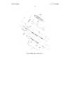
На фиг. 1A показан вид в перспективе в разобранном состоянии традиционного безопасного шприца.In FIG. 1A is an exploded perspective view of a conventional safety syringe.
На фиг. 1B показан вид в поперечном сечении традиционного безопасного шприца, изображающий в основном канюлю и полый цилиндр безопасного шприца.In FIG. 1B is a cross-sectional view of a conventional safety syringe, showing mainly a cannula and a hollow cylinder of a safety syringe.
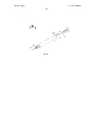
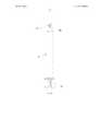
На фиг. 2A показан вид в перспективе безопасного втягивающегося шприца и его складного поршня, изображающий, что канюля и складной поршень еще не вставлены в полый цилиндр согласно первому варианту осуществления изобретения.In FIG. 2A is a perspective view of a safety retractable syringe and its collapsible piston, showing that the cannula and collapsible piston are not yet inserted into the hollow cylinder according to the first embodiment of the invention.
На фиг. 2B показан вид в перспективе в разобранном состоянии безопасного втягивающегося шприца и его складного поршня согласно первому варианту осуществления изобретения.In FIG. 2B is an exploded perspective view of a safety retractable syringe and its collapsible piston according to a first embodiment of the invention.
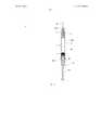
На фиг. 2C показан вид в поперечном сечении безопасного втягивающегося шприца и его складного поршня, изображающий, что канюля и складной поршень еще не вставлены в полый цилиндр согласно первому варианту осуществления изобретения.In FIG. 2C is a cross-sectional view of a safety retractable syringe and its collapsible piston, showing that the cannula and collapsible piston are not yet inserted into the hollow cylinder according to the first embodiment of the invention.
На фиг. 2D показан вид спереди безопасного втягивающегося шприца и его складного поршня, изображающий, что канюля и складной поршень еще не вставлены в полый цилиндр согласно первому варианту осуществления изобретения.In FIG. 2D is a front view of a safety retractable syringe and its collapsible piston, showing that the cannula and collapsible piston are not yet inserted into the hollow cylinder according to the first embodiment of the invention.
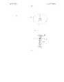
На фиг. 2E показан увеличенный вид секции A безопасного втягивающегося шприца и его складного поршня согласно первому варианту осуществления изобретения, изображенной на фиг. 2D.In FIG. 2E is an enlarged view of section A of a safe retractable syringe and its collapsible piston according to a first embodiment of the invention shown in FIG. 2D.
На фиг. 2F показан вид сбоку безопасного втягивающегося шприца и его складного поршня, изображающий, что канюля и складной поршень еще не вставлены в полый цилиндр согласно первому варианту осуществления изобретения.In FIG. 2F is a side view of a safety retractable syringe and its collapsible piston, showing that the cannula and collapsible piston are not yet inserted into the hollow cylinder according to the first embodiment of the invention.
На фиг. 2G показан увеличенный вид секции A’ безопасного втягивающегося шприца и его складного поршня согласно первому варианту осуществления изобретения, изображенной на фиг. 2F.In FIG. 2G is an enlarged view of the safe retractable syringe section A ’and its collapsible piston according to the first embodiment of the invention shown in FIG. 2F.
На фиг. 2H показан увеличенный вид секции B безопасного втягивающегося шприца и его складного поршня согласно первому варианту осуществления изобретения, изображенной на фиг. 2D.In FIG. 2H is an enlarged view of a safe retractable syringe section B and its collapsible piston according to a first embodiment of the invention shown in FIG. 2D.
На фиг. 3A показан вид в перспективе безопасного втягивающегося шприца и его складного поршня согласно первому варианту осуществления изобретения, изображающий, что канюля и складной поршень вставлены в полый цилиндр.In FIG. 3A is a perspective view of a safe retractable syringe and its collapsible piston according to the first embodiment of the invention, showing that the cannula and collapsible piston are inserted into the hollow cylinder.
На фиг. 3B показан вид сбоку безопасного втягивающегося шприца и его складного поршня согласно первому варианту осуществления изобретения, изображающий, что канюля и складной поршень вставлены в полый цилиндр.In FIG. 3B is a side view of a safety retractable syringe and its collapsible piston according to the first embodiment of the invention, showing that the cannula and collapsible piston are inserted into the hollow cylinder.
На фиг. 3C показан вид в поперечном сечении безопасного втягивающегося шприца и его складного поршня согласно первому варианту осуществления изобретения, изображающий, что втягивающаяся канюля и складной поршень вставлены в полый цилиндр.In FIG. 3C is a cross-sectional view of a safety retractable syringe and its collapsible piston according to the first embodiment of the invention, showing that the retractable cannula and collapsible piston are inserted into the hollow cylinder.
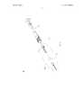
На фиг. 4A показан вид в перспективе в разобранном состоянии безопасного втягивающегося шприца и его складного поршня согласно второму варианту осуществления изобретения.In FIG. 4A is an exploded perspective view of a safety retractable syringe and its collapsible piston according to a second embodiment of the invention.
На фиг. 4B показан увеличенный вид секции D безопасного втягивающегося шприца и его складного поршня согласно второму варианту осуществления изобретения, изображенной на фиг. 4A.In FIG. 4B is an enlarged view of a safe retractable syringe section D and its collapsible piston according to a second embodiment of the invention shown in FIG. 4A.
На фиг. 4C показан вид в поперечном сечении безопасного втягивающегося шприца и его складного поршня, изображающий, что канюля и складной поршень еще не вставлены в полый цилиндр согласно второму варианту осуществления изобретения.In FIG. 4C is a cross-sectional view of a safety retractable syringe and its collapsible piston, showing that the cannula and collapsible piston have not yet been inserted into the hollow cylinder according to the second embodiment of the invention.
На фиг. 4D показан увеличенный вид секции E безопасного втягивающегося шприца и его складного поршня согласно второму варианту осуществления изобретения, изображенной на фиг. 4C.In FIG. 4D is an enlarged view of a safe retractable syringe section E and its collapsible piston according to a second embodiment of the invention shown in FIG. 4C.
На фиг. 4E показан вид в поперечном сечении безопасного втягивающегося шприца и его складного поршня согласно второму варианту осуществления изобретения, изображающий, что и канюля, и складной поршень вставлены в полый цилиндр.In FIG. 4E is a cross-sectional view of a safe retractable syringe and its folding piston according to a second embodiment of the invention, showing that both the cannula and the folding piston are inserted into the hollow cylinder.
На фиг. 5 показан увеличенный вид секции C или секции C’ безопасного втягивающегося шприца и его складного поршня согласно первому и второму вариантам осуществления изобретения, изображенных на фиг. 3C и фиг. 4E.In FIG. 5 shows an enlarged view of section C or section C ’of a safe retractable syringe and its collapsible piston according to the first and second embodiments of the invention shown in FIG. 3C and FIG. 4E.
ПОДРОБНОЕ ОПИСАНИЕ ИЗОБРЕТЕНИЯDETAILED DESCRIPTION OF THE INVENTION
Далее будет представлено подробное описание настоящего изобретения со ссылкой на его варианты осуществления. Другие преимущества и признаки настоящего изобретения будут очевидны специалистам в данной области после рассмотрения данного описания. Тем не менее, данное изобретение также может быть реализовано или применено в виде других вариантов осуществления, и различные детали в данном техническом описании могут быть модифицированы и изменены с разных точек зрения и на основании разных применений в пределах сущности настоящего изобретения.Next, a detailed description of the present invention will be presented with reference to its embodiments. Other advantages and features of the present invention will be apparent to those skilled in the art upon consideration of this description. However, this invention can also be implemented or applied in the form of other embodiments, and various details in this technical description can be modified and changed from different points of view and based on different applications within the essence of the present invention.
Для лучшего понимания пространственного расположения отдельных элементов безопасного втягивающегося шприца, а также их относительных перемещений или взаимодействий, здесь и далее термин дистальный конец (дистальная часть) элемента обозначает конец (часть), обращенную к игле; и проксимальный конец (проксимальная часть) элемента обозначает конец (часть), противоположную дистальному концу (дистальной части) и обращенную к упору для большого пальца на используемом поршне.For a better understanding of the spatial arrangement of the individual elements of a safe retractable syringe, as well as their relative movements or interactions, hereinafter, the term distal end (distal part) of an element refers to the end (part) facing the needle; and the proximal end (proximal part) of the element indicates the end (part) opposite to the distal end (distal part) and facing the stop for the thumb on the piston used.
Как показано на фиг. 2A и фиг. 2B, безопасный втягивающийся шприц 1 согласно первому варианту осуществления настоящего изобретения содержит иглу 40, канюлю 4, полый цилиндр 2, пружину 8 и складной поршень 6, описанные далее.As shown in FIG. 2A and FIG. 2B, the
Втягивающаяся канюля 4 содержит первый конец 401, являющийся дистальным концом, и второй конец 402, являющийся проксимальным концом. В дистальном конце 401 выполнено отверстие для размещения и удержания иглы 40, проходящей в дистальном направлении; и расположенное рядом первое направляющее средство, такое как выступ 42, выполнено на внешней боковой стенке 44 канюли 4. Проксимальный конец 402 расположен напротив дистального конца 401.The
Полый цилиндр 2 содержит дистальный открытый конец 201 и проксимальный открытый конец 202, расположенный напротив дистального открытого конца 201. Дистальный открытый конец 201 выполнен с отверстием для того, чтобы позволить игле 40 выступать наружу из полого цилиндра 2 или втягиваться внутрь полого цилиндра 2; и второе направляющее средство, такое как изогнутая дорожка 22, выполнено рядом в боковой стенке полого цилиндра 2. Проксимальный открытый конец 202 полого цилиндра 2 выполнен с кромкой 203 и отверстием. Полый цилиндр 2 имеет внутреннюю поверхность 21, ограничивающую камеру 20, позволяя канюле 4 с возможностью последующего снятия размещаться в камере 20 полого цилиндра 2.The
Сжимаемая пружина 8 расположена между внешней боковой стенкой 44 канюли 4 и внутренней боковой стенкой полого цилиндра 2; и распрямление пружины 8 будет вынуждать канюлю 4 перемещаться в полый цилиндр 2.
Складной поршень 6 размещен с возможностью скольжения в полом цилиндре 2. Складной поршень 6 содержит первый поршневой элемент, такой как стержень 64 поршня, выполненный с выступом 603 (изображен на фиг. 2H) возле его дистального конца, и второй поршневой элемент, такой как гильза 62 поршня с продольной щелью 602, образованной на ее боковой стенке, где гильза 62 поршня с возможностью последующего снятия соединена со стержнем 64 поршня; и предпочтительно стержень 64 поршня частично раздвигается внутрь гильзы 62 поршня и образует разъемную взаимоблокировку с ней путем размещения выступа 603 внутри продольной щели 602.The
На практике, когда втягивающийся шприц 1 используется для инъекции, выступ 603 стержня 64 поршня удерживается в сжатой зоне 6021 (изображена на фиг. 2H) продольной щели 602 гильзы 62 поршня. Как показано на фиг. 2H, продольная щель 602 выполнена с возможностью размещения выступа 603 и содержит сжатую зону 6021 возле проксимального конца. Форма сжатой зоны 6021 позволяет ограничивать движение выступа 603, так чтобы при обычной эксплуатации складной поршень 6 не был разъединен. Другими словами, стержень 64 поршня не может двигаться из-за ограничивающего воздействия сжатой зоны 6021 до тех пор, пока сжатая зона 6021 не подвергнется чрезмерному внешнему усилию. На практике, складной поршень 6 предпочтительно способен выдерживать усилие менее 98Н, так чтобы при обычной эксплуатации стержень 64 поршня и гильза 62 поршня не были разъединены.In practice, when the
Множество отверстий 604 может быть дополнительно выполнено возле сжатой зоны 6021 для придания гильзе 62 поршня относительной гибкости или даже хрупкости возле сжатой зоны 6021, и таким образом для облегчения высвобождения удерживаемого выступа 603 при воздействии чрезмерного усилия. Когда выступ 603 вынужден протискиваться через сжатую зону 6021, тем самым преодолевая ограничивающее воздействие, складной поршень 6 разъединяется, что позволяет выступу 603 скользить вдоль продольной щели 602, так чтобы стержень 64 поршня и гильза 62 поршня смогли перемещаться в осевом направлении относительно друг друга. Когда стержень 64 поршня и гильза 62 поршня складываются, усилие, оказываемое складным поршнем 6 на канюлю 4, высвобождается, таким образом активируя механизм втягивания, и канюля 4 приводится в полый цилиндр 2 силой расширения пружины 8, и гильза 62 поршня впоследствии перемещается назад для того, чтобы охватывать стержень 64 поршня посредством скользящих перемещений выступа 603 вдоль продольной щели 602. С другой стороны, хрупкость гильзы 62 поршня, вызванная предусмотренными отверстиями 604, сделает складной поршень 6 непригодным для повторного использования во избежание попыток повторного использования безопасного втягивающегося шприца 1.A plurality of
Как показано на фиг. 2C и фиг. 2D, соответственно изображающих вид в поперечном сечении и вид спереди безопасного втягивающегося шприца 1 и его складного поршня 6 перед выполнением инъекции, в котором втягивающаяся канюля 4 и складной поршень 6 частично выдвинуты и не полностью вставлены в полый цилиндр 2 согласно первому варианту осуществления изобретения. Принимая во внимание сборку безопасного втягивающегося шприца 1, канюля 4 вставлена в полый цилиндр 2 сквозь отверстие в проксимальном открытом конце 202 (изображен на фиг. 2B) полого цилиндра 2, и затем игле 40 позволяют выступать из отверстия в дистальном открытом конце 201 (изображен на фиг. 2B) полого цилиндра 2. Когда канюля 4, удерживающая иглу 40, должным образом вставлена в полый цилиндр 2 и установлена возле дистального открытого конца 201 полого цилиндра 2, канюля 4 размещается внутри полого цилиндра 2 посредством взаимодействия выступа 42 (изображен на фиг. 2B) канюли 4 и изогнутой дорожки 22 (изображена на фиг. 2B) полого цилиндра 2. В частности, выступ 42 канюли 4 удерживается и направляется изогнутой дорожкой 22 полого цилиндра 2, и канюля 4 способна скользить вдоль изогнутой дорожки 22.As shown in FIG. 2C and FIG. 2D, respectively, depicting a cross-sectional view and a front view of a safe
Складной поршень 6 вставлен в полый цилиндр 2 сквозь отверстие в проксимальном конце 202 полого цилиндра 2, указывая на то, что складной поршень 6 частично выдвинут в полый цилиндр 2 и способен перемещаться назад и вперед внутри полого цилиндра 2. Кроме этого, предусмотрен стопор 60 для установки на дистальном конце складного поршня 6. Таким образом, складной поршень 6 может быть вдавлен в полый цилиндр 2, при этом стопор 60 упирается в проксимальный конец 402 канюли 4.The
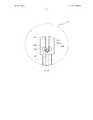
На фиг. 2D показан вид спереди безопасного втягивающегося шприца 1 и на фиг. 2E дополнительно показан увеличенный вид секции А безопасного втягивающегося шприца 1. Ссылаясь на секцию А безопасного втягивающегося шприца 1 первого варианта осуществления настоящего изобретения, изогнутая дорожка 22 предназначена для направления выступа 42 канюли 4 таким образом, чтобы он скользил вдоль траектории изогнутой дорожки 22, и таким образом изогнутая дорожка 22 позволяет канюле 4 поворачиваться в осевом направлении, когда выступ 42 может скользить в изогнутой дорожке 22. Горизонтальная плоскость определена в данном документе для лучшего понимания технических признаков, относящихся к механизму втягивания безопасного втягивающегося шприца 1. В частности, горизонтальная плоскость определена как плоскость, перпендикулярная направлению силы тяжести, другими словами, когда весь втягивающийся шприц 1 расположен вертикально с иглой, направленной вверх, горизонтальная плоскость определена как плоскость, проходящая в поперечном направлении и в горизонтальном направлении (т.е., перпендикулярно направлению силы тяжести) сквозь втягивающийся шприц 1, разделяя втягивающийся шприц 1 на верхнюю и нижнюю части.In FIG. 2D is a front view of a safety
Касательно новаторской конструкции секции А, изображенной на фиг. 2E, изогнутая дорожка 22 частично окружает полый цилиндр 2 и позволяет выступу 42 скользить к дистальному концу 201 (изображен на фиг. 2B) или проксимальному концу 202 (изображен на фиг. 2B) полого цилиндра 2. Кроме этого, изогнутая дорожка 22 содержит первую часть, представляющую собой фиксирующую часть 221 вокруг первого изогнутого участка 22a (изображен на фиг. 2E) изогнутой дорожки 22, и фиксирующая часть 221 используется для временного сцепления выступа 42 с изогнутой дорожкой 22 для того, чтобы зафиксировать выступ 42, а также канюлю 4 перед активацией механизма втягивания. Когда достаточное внешнее толкающее усилие воздействует на выступ 42 для смещения выступа 42 из фиксирующей части 221, и выступ 42 вынужден скользить вдоль траектории изогнутой дорожки 22; и выступ 42 будет высвобожден и свободен от ограничивающего воздействия вышеупомянутого сцепления, позволяя канюле 4 перемещаться к дистальному концу 201 полого цилиндра 2. Другими словами, активируется механизм втягивания. Более того, внешнее толкающее усилие не только заставляет выступ 42 смещаться из фиксирующей части 221, но также способствует дальнейшему скольжению вдоль изогнутой дорожки 22, и таким образом изогнутая дорожка 22 направляет осевое вращение, а также перемещение канюли 4 в положение, готовое для втягивания, и канюля 4 будет впоследствии втянута в полый цилиндр 2.Regarding the innovative design of section A shown in FIG. 2E, the
Как показано на фиг. 2F, изображающей вид сбоку безопасного втягивающегося шприца 1, и фиг. 2G, изображающей увеличенный вид секции A’ безопасного втягивающегося шприца 1, перед выполнением инъекции согласно первому варианту осуществления изобретения. На фиг. 2F и фиг. 2G показан вид сбоку изогнутой дорожки 22 полого цилиндра 2 и второго изогнутого участка 22b (изображен на фиг. 2F и фиг. 2G). В частности, хорошо видно, что второй изогнутый участок 22b направляет выступ 42, заставляя его изменять направление и затем двигаться к проксимальному концу 202 (изображен на фиг. 2B) полого цилиндра 2. Специалисты в данной области могут легко понять, что при условии, что изогнутая дорожка 22 имеет оптимизированные углы изгибов и соответствующую длину изогнутой дорожки 22, будет обеспечено достаточное усилие скольжения для инициации поворота выступа 42 и его перемещения к проксимальному концу 202 полого цилиндра 2, и в то же время, эластичное восстановление выступа 42 инициирует распрямление сжатия пружины 8 (изображена на фиг. 2B), свернутой и сжатой вокруг канюли 4 до передачи вышеупомянутого скользящего усилия для распрямления пружины 8. Предпочтительно, изогнутая дорожка 22 содержит часть, проходящую от первого изогнутого участка 22a под углом от 45 градусов до 75 градусов при измерении от горизонтальной плоскости, когда весь безопасный втягивающийся шприц 1 расположен вертикально с иглой, направленной вверх. Более предпочтительно, угол составляет 60 градусов при измерении от горизонтальной плоскости.As shown in FIG. 2F, a side view of a safety
Вышеупомянутые варианты угла оптимизируют не только скольжение выступа 42 в изогнутой дорожке 22, но также вращение канюли 4 к проксимальному концу 202 полого цилиндра 2 и приводят к последующему инициированию механизма извлечения канюли 4. С другой стороны, как только механизм извлечения активируется, складной поршень 6 разъединяется для приведения в действие всего механизма втягивания.The aforementioned angle options optimize not only the protrusion of the
В частности, сила расширения, возникающая из пружины 8, толкает канюлю 4, перемещая ее в цилиндр 2. Вкратце, изогнутая дорожка 22 направляет не только движение вперед (к дистальному концу 201), вращение канюли 4, но также придает направление усилию распрямления пружины 8 для способствования полному втягиванию канюли 4 в цилиндр 2.In particular, the expansion force arising from the
Следовательно, преимущество настоящего изобретения заключается в том, что новаторская конструкция для приведения в действие механизма втягивания безопасного втягивающегося шприца 1 предоставляет значительно более надежный механизм втягивания и устраняет или по меньшей мере значительно снижает возможность возникновения помех действию пружины, часто мешающих втягиванию канюли и присутствующих в известном уровне техники. Касательно практического применения безопасного втягивающегося шприца 1, представленного в настоящем изобретении, его надежность значительно улучшена.Therefore, an advantage of the present invention is that the innovative design for actuating the retraction mechanism of the safe
Рассмотрим фиг. 2H, изображающую увеличенный вид секции B складного поршня 6 безопасного втягивающегося шприца 1 согласно первому варианту осуществления изобретения, изображенной на фиг. 2D. Для того чтобы должным образом инициировать механизм втягивания после завершения инъекции и, что важнее, чтобы предотвратить случайное или преждевременное высвобождение канюли 4 из дистального конца 201 (изображен на фиг. 2B) полого цилиндра 2 и втягивание в полый цилиндр 2, настоящее изобретение предоставляет дальнейшее решение путем предоставления гильзы 62 поршня, содержащей множество отверстий 604, расположенных рядом со сжатой зоной 6021 продольной щели 602 гильзы 62 поршня. На практике, множество отверстий 604 предназначены для того, чтобы сделать часть гильзы 62 поршня возле сжатой зоны 6021 деформируемой, хрупкой или гибкой для облегчения высвобождения выступа 603 из ограничителя сжатой зоны 6021. Точнее, складной поршень 6 соприкасается с канюлей 4 по завершении инъекции, при дальнейшем нажатии канюля 4 сместится от фиксирующей части 221 (вокруг первого изогнутого участка 22a) и переместится вперед; и канюля 4 будет поворачиваться до тех пор, пока не достигнет переднего положения (вокруг второго изогнутого участка 22b) для того, чтобы быть готовой к втягиванию, и при дальнейшем нажатии на поршень 6 для того, чтобы вынудить выступ 603 преодолеть ограничитель, образованный сжатой зоной 6021, таким образом складной поршень 6 разъединяется с тем, чтобы высвободить усилие, воздействующее на канюлю 4 складным поршнем 6, и механизм втягивания таким образом полностью активируется, тем временем сила расширения пружины 8 продолжает приводить канюлю 4 в движение внутрь полого цилиндра 2; и в то же время гильза 62 поршня впоследствии перемещается назад для того, чтобы охватывать стержень 64 поршня. Таким образом, взаимодействие выступа 603 и продольной щели 602 способствует всему механизму втягивания.Consider FIG. 2H showing an enlarged view of the
Рассмотрим фиг. 3A и фиг. 3B, на которых соответственно показан вид в перспективе и вид сбоку безопасного втягивающегося шприца 1 и его складного поршня 6 согласно первому варианту осуществления изобретения, изображающие, что игла 40 и складной поршень 6 вставлены в полый цилиндр 2 после завершения втягивания.Consider FIG. 3A and FIG. 3B, respectively, showing a perspective and side view of a safe
Рассмотрим фиг. 4A - фиг. 4E, на которых изображен безопасный втягивающийся шприц 2 согласно второму варианту осуществления настоящего изобретения. Безопасный втягивающийся шприц 2 обладает всеми вышеупомянутыми признаками и преимущественными конструкциями безопасного втягивающегося шприца 1 согласно первому варианту осуществления. Вкратце, безопасный втягивающийся шприц 2 включает в себя: втягивающуюся канюлю 4, содержащую выступ 42 (изображен на фиг. 4B), выполненный на внешней боковой стенке 44 канюли 4; полый цилиндр 2 (изображен на фиг. 4C), содержащий изогнутую дорожку 22 (изображен на фиг. 4C), выполненную рядом с ним на боковой стенке полого цилиндра 2; пружину 8 (изображена на фиг. 4C), расположенную между внешней боковой стенкой 44 канюли 4 и внутренней боковой стенкой полого цилиндра 2; и складной поршень 6, состоящий из стержня 64 поршня и гильзы 62 поршня (изображен на фиг. 4C), где стержень 64 поршня частично выдвинут в гильзу 62 поршня и образует разъемную взаимоблокировку с гильзой 62 поршня, где стержень 64 поршня выполнен с выступом и гильза 62 поршня выполнена с продольной щелью. Следовательно, механизм втягивания второго варианта осуществления по существу такой же, как и механизм втягивания ранее описанного медицинского безопасного втягивающегося шприца 1.Consider FIG. 4A - FIG. 4E showing a safety
Кроме этого, на фиг. 4A - 4E соответственно раскрыт предпочтительный образ действия согласно второму варианту осуществления настоящего изобретения. Как изображено на фиг. 4A и фиг. 4B, втягивающаяся канюля 4 безопасного втягивающегося шприца 2 дополнительно содержит полость внутри канюли 4 для размещения пробки 41 из отверстия проксимального конца 402 канюли 4, при этом пробка 41 содержит удлиненный цилиндр, выступающий в полость канюли 4 и диск 418 большего диаметра, расположенный возле проксимального конца пробки 41, и содержит по меньшей мере один канал для движения потока для жидкостной связи между полостью иглы 40 и жидкостной камерой внутри полого цилиндра 2. Следует отметить, что достаточное пространство предоставлено между внутренней боковой стенкой канюли 4 (т.е., боковой стенкой канюли 4, обращенной к полости) и внешней боковой стенкой пробки 41 (т.е. боковой стенкой пробки 41, обращенной к полости), и пространство предоставлено в достаточном объеме для канала для движения потока медицинских материалов или жидкости для инъекции.In addition, in FIG. 4A to 4E, respectively, a preferred mode of action is disclosed according to a second embodiment of the present invention. As shown in FIG. 4A and FIG. 4B, the
Кроме этого, дополнительно предоставлен уплотнительный элемент 43 для выполнения предпочтительного образа действия безопасного втягивающегося шприца 2. Материалы для уплотнительного элемента 43 предпочтительно представляют собой, без ограничения, эластомерный материал с определенной твердостью, такой как каучук, термопластичный эластомер или другие макромолекулярные материалы и, таким образом, подходит для обеспечения герметизации для предотвращения утечки жидкости из соединительного шва. Например, кольцевая прокладка с желаемой формой является предпочтительной. В частности, уплотнительный элемент 43 расположен между проксимальным концом 402 канюли 4 и диском 418 пробки 41. Также, конструкция и форма уплотнительного элемента 43 позволяют ему приспосабливаться к проксимальному концу 402 канюли 4 и диску 418 возле проксимального конца пробки, и таким образом он служит для герметизации шва между канюлей 4 и пробкой 41.In addition, a sealing
Уплотнительный элемент 43 дополнительно содержит сквозное отверстие 430 в центре уплотнительного элемента 43, позволяющее удлиненной цилиндрической части пробки 41 проходить сквозь сквозное отверстие 430 и одновременно входить в полость канюли 4, и затем пробка 41 окончательно соединяется с канюлей 4, при этом уплотнительный элемент 43 расположен между ними. Таким образом, когда удлиненная цилиндрическая часть пробки 41 проходит сквозь сквозное отверстие 430 и входит в полость канюли 4 на желаемую глубину, диск 418 пробки 41 приклеивается к уплотнительному элементу 43, и тем самым сама пробка 41 и уплотнительный элемент 43 прикрепляются к проксимальному концу 402 канюли 4.The sealing
Как показано на фиг. 4D и фиг. 4E, вышеупомянутая пробка 41 дополнительно выполнена с по меньшей мере одним каналом 410 для текучей среды. Предпочтительно, согласно второму варианту осуществления настоящего изобретения, предоставлено два канала 410 для текучей среды. Каналы 410 для текучей среды оснащены впускным отверстием 412 и выпускным отверстием 416, позволяющим медицинским материалам или текучей среде для инъекции (далее обозначенной термином “инъекционный препарат”) течь вдоль каналов 410 для текучей среды. В частности, когда пользователь осуществляет инъекцию, инъекционный препарат течет к дистальному концу 201 полого цилиндра 2, и инъекционный препарат течет сквозь центральное отверстие диска 418 пробки 41, впускное отверстие 412, канал 410 для текучей среды, и затем через выпускное отверстие 416, и наконец поступает к отверстию дистального конца 401 канюли 4, после чего следует завершение инъекции. В качестве альтернативы, внутренний канал, расположенный внутри пробки 41 и проходящий в продольном направлении сквозь пробку, может достигать подобных преимущественных эффектов. Следовательно, согласно предпочтительному образу действия второго варианта осуществления настоящего изобретения, существенно уменьшается мертвое пространство внутри канюли 4, что приводит к меньшему осадку и меньшим отходам инъекционного препарата. В общем, улучшается эффективность и стоимость инъекции.As shown in FIG. 4D and FIG. 4E, the
Далее рассмотрим фиг. 5, изображающую увеличенный вид секции C безопасного втягивающегося шприца 1 и его складного поршня 6 согласно первому варианту осуществления изобретения, изображенной на фиг. 3C; и конструкция секции C’ безопасного втягивающегося шприца 2 согласно второму варианту осуществления изобретения, изображенная на фиг. 4E, по существу такая же, что и конструкция секции C безопасного втягивающегося шприца 1. Для преодоления трудностей, связанных с проблемами, возникающими из-за повторного использования шприцов, в данном изобретении дополнительно предоставлено средство блокировки. Следует отметить, что стержень 64 поршня дополнительно выполнен с выступающей частью 641 возле его проксимального конца, и полый цилиндр 2 выполнен с кольцевой углубленной частью 222 и расположенной рядом кольцевой выпуклой частью 223 внутри кромки 203 полого цилиндра 2. Выступающая часть 641 размещается и фиксируется посредством защелкивания кольцевой углубленной частью 222 и удерживается кольцевой выпуклой частью 223, когда стержень 64 поршня полностью вдавлен в полый цилиндр 2, устраняя возможность отсоединения стержня 64 поршня от полого цилиндра 2 и таким образом предотвращая повторное использование шприца. Более предпочтительно, внешний вид края выступающей части 641 выполнен таким образом, чтобы представлять собой наклонный край для обладания лучшим сцеплением с кольцевой углубленной частью 222, таким образом выступающая часть 641 плотно удерживается кольцевой углубленной частью 222. Предпочтительный образ действия может быть соответствующим образом предоставлен путем модификации конфигурации кольцевой углубленной части 222 для усиления вышеупомянутого удерживающего эффекта. Следовательно, любая попытка вытянуть стержень 64 поршня из полого цилиндра 2 может повредить безопасный втягивающийся шприц 1, 2, и таким образом дополнительно уменьшить возможность повторного использования безопасного втягивающегося шприца 1, 2.Next, consider FIG. 5, an enlarged view of a section C of a safe
По этой причине описаны безопасные втягивающиеся шприцы, втягивающиеся канюли и складные поршни, где складной поршень действует в качестве исполнительного устройства для приведения в действие механизма втягивания канюли. По завершении инъекции стопор, соединенный с дистальным концом складного поршня, будет располагаться напротив проксимального конца канюли. При нажатии на складной поршень втягивающаяся канюля перемещается вперед, вдоль изогнутой дорожки в переднее положение, останавливается там и готова к втягиванию, увеличенное усилие разъединяет складной поршень и одновременно активирует механизм втягивания. Следовательно, втягивание иглы облегчается смещающим приспособлением, таким как сжатая пружина или другое устройство, способное сжиматься и распрямляться.For this reason, safe retractable syringes, retractable cannulas and folding pistons are described, where the folding piston acts as an actuator for actuating the cannula retraction mechanism. Upon completion of the injection, a stopper connected to the distal end of the collapsible piston will be located opposite the proximal end of the cannula. When the folding piston is pressed, the retracting cannula moves forward, along the curved track to the front position, stops there and is ready to retract, the increased force disconnects the folding piston and simultaneously activates the retraction mechanism. Therefore, retracting the needle is facilitated by a biasing device, such as a compressed spring or other device capable of compressing and straightening.
Обычно, безопасный втягивающийся шприц представляет собой предварительно заполняемый шприц, который может быть предварительно заполнен желаемыми медицинскими материалами, подходящими для комбинированных лекарственных средств, вводимых посредством инъекции. Безопасные втягивающиеся шприцы известного уровня техники требуют наличия сцепляющего устройства для присоединения стопора или поршня к держателю иглы для обеспечения втягивания иглы, или требуют устройство для выведения из сцепления держателя пружины с тем, чтобы соответственно распрямить пружину, эти сложные конфигурации часто приводят к уязвимости жидкостной камеры к нарушениям целостности герметизации контейнера, и таким образом не подходят для использования в качестве предварительно заполняемых шприцов. Изобретение, описанное выше, решило вышеупомянутые недостатки путем предоставления более надежного подхода к втягиванию, и таким образом, улучшенной целостности герметизации контейнеров безопасных втягивающихся шприцов в вариантах осуществления настоящего изобретения.Typically, a safe retractable syringe is a pre-filled syringe that can be pre-filled with the desired medical materials suitable for combination drugs administered by injection. Prior art safety retractable syringes require an engaging device for attaching a stopper or piston to the needle holder to allow the needle to retract, or require a device for disengaging the spring holder from the clutch to properly extend the spring, these complex configurations often lead to vulnerability of the fluid chamber to violation of the integrity of the container, and thus are not suitable for use as pre-filled syringes. The invention described above resolved the aforementioned drawbacks by providing a more reliable retraction approach, and thus improved sealing integrity of the safe retractable syringe containers in embodiments of the present invention.
Поскольку такой безопасный втягивающийся шприц может быть изготовлен в виде готового к применению изделия, преимущества не ограничены улучшенным удобством и эффективностью введения лекарства путем устранения операции заполнения шприца лекарством, другие преимущества, являющиеся следствием вышеупомянутых признаков, включают улучшенную точность дозировки, уменьшенный риск случайной травмы от укола иглой и инфицирования людей.Since such a safe retractable syringe can be formulated as a ready-to-use product, the benefits are not limited to the improved convenience and efficacy of administering the drug by eliminating the filling operation of the syringe with the drug, other benefits resulting from the aforementioned features include improved dosage accuracy, reduced risk of accidental injection injury. needle and infecting people.
Вышеописанные варианты осуществления предоставлены лишь для демонстрации принципов и функций настоящего изобретения и не предназначены для ограничения объема настоящего изобретения. Различные изменения формы и деталей могут быть выполнены специалистами в данной области в пределах идеи и объема настоящего изобретения, определенных в следующей формуле изобретения.The above embodiments are provided only to demonstrate the principles and functions of the present invention and are not intended to limit the scope of the present invention. Various changes in form and detail may be made by those skilled in the art within the scope of the idea and scope of the present invention as defined in the following claims.
Claims (20)
Translated fromRussianApplications Claiming Priority (3)
| Application Number | Priority Date | Filing Date | Title |
|---|---|---|---|
| US201261740207P | 2012-12-20 | 2012-12-20 | |
| US61/740,207 | 2012-12-20 | ||
| PCT/CN2013/089924WO2014094626A1 (en) | 2012-12-20 | 2013-12-19 | Prefillable auto-retractable safety syringe |
Publications (2)
| Publication Number | Publication Date |
|---|---|
| RU2015123787A RU2015123787A (en) | 2017-01-10 |
| RU2612844C2true RU2612844C2 (en) | 2017-03-13 |
Family
ID=50975487
Family Applications (1)
| Application Number | Title | Priority Date | Filing Date |
|---|---|---|---|
| RU2015123787ARU2612844C2 (en) | 2012-12-20 | 2013-12-19 | Previously filled automatically retractable safe syringe |
Country Status (15)
| Country | Link |
|---|---|
| US (1) | US10004853B2 (en) |
| EP (1) | EP2934635B1 (en) |
| JP (1) | JP6078165B2 (en) |
| KR (1) | KR101738799B1 (en) |
| CN (1) | CN104902946B (en) |
| AU (1) | AU2013362425B2 (en) |
| BR (1) | BR112015014779B1 (en) |
| CA (2) | CA2894138C (en) |
| HU (1) | HUE055309T2 (en) |
| IL (1) | IL239183A0 (en) |
| MY (1) | MY185416A (en) |
| PL (1) | PL2934635T3 (en) |
| RU (1) | RU2612844C2 (en) |
| WO (1) | WO2014094626A1 (en) |
| ZA (1) | ZA201504220B (en) |
Cited By (1)
| Publication number | Priority date | Publication date | Assignee | Title |
|---|---|---|---|---|
| RU2794468C1 (en)* | 2022-12-28 | 2023-04-19 | федеральное государственное автономное образовательное учреждение высшего образования "Южный федеральный университет" | Integral nanoemechanical tunnel switch |
Families Citing this family (8)
| Publication number | Priority date | Publication date | Assignee | Title |
|---|---|---|---|---|
| GB2521212B (en)* | 2013-12-13 | 2016-07-27 | Owen Mumford Ltd | Selectable dose injection device |
| CN104307072A (en)* | 2014-10-29 | 2015-01-28 | 杭州普昂医疗科技有限公司 | Safety insulin pen |
| JP6635698B2 (en)* | 2015-07-14 | 2020-01-29 | ぺんてる株式会社 | Applicator with limited plunger movable range by resistance structure |
| EP4035711B1 (en)* | 2016-03-15 | 2025-06-04 | Amgen Inc. | Reducing probability of glass breakage in drug delivery devices |
| BR112019018459B1 (en)* | 2017-03-09 | 2023-10-24 | Retractable Technologies, Inc. | DENTAL SAFETY SYRINGE |
| KR102038416B1 (en)* | 2017-08-08 | 2019-10-30 | (주)상아프론테크 | Syringe |
| WO2021132202A1 (en)* | 2019-12-27 | 2021-07-01 | テルモ株式会社 | Syringe-barrel grip, barrel assembly, and syringe |
| CN117414503A (en)* | 2023-08-28 | 2024-01-19 | 梵颖(上海)生物科技有限公司 | A syringe protection device and safety syringe |
Citations (4)
| Publication number | Priority date | Publication date | Assignee | Title |
|---|---|---|---|---|
| US20040116853A1 (en)* | 1999-12-07 | 2004-06-17 | Halseth Thor R | Safety needle medical bearing devices |
| US20040181190A1 (en)* | 2003-03-11 | 2004-09-16 | Fu-Yu Hsu | Safety hypodermic syringe |
| WO2006020953A1 (en)* | 2004-08-13 | 2006-02-23 | Becton, Dickinson And Company | Retractable needle syringe assembly |
| US20090259195A1 (en)* | 2008-04-14 | 2009-10-15 | Bencha International Group. Inc. | Prepacked automatic retractable safety syringe |
Family Cites Families (22)
| Publication number | Priority date | Publication date | Assignee | Title |
|---|---|---|---|---|
| US4747830A (en)* | 1986-04-28 | 1988-05-31 | Gloyer Walter W | Anti-stick contagion free disposable hypodermic safety syringe |
| US4994045A (en)* | 1990-04-20 | 1991-02-19 | Sherwood Medical Company | Split sleeve safety syringe |
| TW359621B (en)* | 1998-04-10 | 1999-06-01 | Wen-Neng Liu | Safe injector with injection needle pull-back this invention provides a safe injector with injection needle pull-back which comprises: a needle cylinder, a plunger and an injection needle |
| US6669671B1 (en)* | 1998-12-22 | 2003-12-30 | Owais Mohammad | Retractable needle with dual locking mechanisms |
| TW447310U (en)* | 2000-09-28 | 2001-07-21 | Yang Jung Shin | Twisting and drawing back type safe syringe |
| US6468250B2 (en)* | 2000-12-26 | 2002-10-22 | Kuo-Chen Yang | Dual-chamber safety hypodermic syringe |
| US20020165501A1 (en)* | 2001-05-04 | 2002-11-07 | Yang Zhan Bo | Safety Syringe |
| US20030187401A1 (en)* | 2002-03-27 | 2003-10-02 | Safety Syringes, Inc. | Syringe with integral safety system |
| US20040122378A1 (en)* | 2002-12-19 | 2004-06-24 | Fu-Yu Hsu | Safety hypodermic syringe |
| US6979314B2 (en)* | 2003-10-14 | 2005-12-27 | Syriteck Medical Devices Co., Ltd. | Safety syringe |
| NL1025669C2 (en)* | 2004-03-09 | 2005-09-12 | Advanced Protective Injection | Injection syringe with stroke limiter. |
| EP1629857A1 (en)* | 2004-08-30 | 2006-03-01 | Fu-Yu Hsu | Hypodermic syringe with retractable needle |
| US20070043321A1 (en)* | 2005-07-22 | 2007-02-22 | Cheh Tai | Safe injection device |
| TWI294782B (en) | 2006-01-27 | 2008-03-21 | Bencha Internat Group Inc | Medically safety injector with a collapsable plunger combination thereof |
| US7846135B2 (en)* | 2006-02-24 | 2010-12-07 | Midland Medical Holding LLC | Retractable needle syringe with needle trap |
| US8088110B2 (en) | 2006-11-17 | 2012-01-03 | Bencha International Group Inc. | Automatically retractable safety injector for non-liquid material |
| US8449505B2 (en) | 2006-11-17 | 2013-05-28 | Bencha International Group Inc. | Automatically retractable medically safety injector and plunger combination thereof |
| US20090216154A1 (en) | 2008-02-21 | 2009-08-27 | Bencha International Group. Inc | Automatically retractable safety blood sampler |
| US8172813B2 (en)* | 2008-02-28 | 2012-05-08 | Becton, Dickinson And Company | Syringe with two piece plunger rod |
| US9248240B2 (en)* | 2008-10-14 | 2016-02-02 | Astrazeneca Pharmaceuticals Lp | Formulation delivery device |
| CN201578701U (en)* | 2009-10-19 | 2010-09-15 | 江振标 | Self-destroy type injector with retractable needle head |
| US20130085452A1 (en)* | 2011-09-30 | 2013-04-04 | Becton Dickinson France, S.A.S. | Syringe Assembly Having a Rotatably Advanceable Plunger Rod |
- 2013
- 2013-11-15USUS14/081,456patent/US10004853B2/enactiveActive
- 2013-12-19JPJP2015546840Apatent/JP6078165B2/enactiveActive
- 2013-12-19MYMYPI2015702084Apatent/MY185416A/enunknown
- 2013-12-19BRBR112015014779-8Apatent/BR112015014779B1/enactiveIP Right Grant
- 2013-12-19WOPCT/CN2013/089924patent/WO2014094626A1/enactiveApplication Filing
- 2013-12-19CNCN201380066578.0Apatent/CN104902946B/enactiveActive
- 2013-12-19HUHUE13864864Apatent/HUE055309T2/enunknown
- 2013-12-19EPEP13864864.7Apatent/EP2934635B1/enactiveActive
- 2013-12-19CACA2894138Apatent/CA2894138C/enactiveActive
- 2013-12-19PLPL13864864Tpatent/PL2934635T3/enunknown
- 2013-12-19KRKR1020157015379Apatent/KR101738799B1/enactiveActive
- 2013-12-19CACA2990502Apatent/CA2990502C/enactiveActive
- 2013-12-19AUAU2013362425Apatent/AU2013362425B2/enactiveActive
- 2013-12-19RURU2015123787Apatent/RU2612844C2/enactive
- 2015
- 2015-06-03ILIL239183Apatent/IL239183A0/enunknown
- 2015-06-11ZAZA2015/04220Apatent/ZA201504220B/enunknown
Patent Citations (4)
| Publication number | Priority date | Publication date | Assignee | Title |
|---|---|---|---|---|
| US20040116853A1 (en)* | 1999-12-07 | 2004-06-17 | Halseth Thor R | Safety needle medical bearing devices |
| US20040181190A1 (en)* | 2003-03-11 | 2004-09-16 | Fu-Yu Hsu | Safety hypodermic syringe |
| WO2006020953A1 (en)* | 2004-08-13 | 2006-02-23 | Becton, Dickinson And Company | Retractable needle syringe assembly |
| US20090259195A1 (en)* | 2008-04-14 | 2009-10-15 | Bencha International Group. Inc. | Prepacked automatic retractable safety syringe |
Cited By (1)
| Publication number | Priority date | Publication date | Assignee | Title |
|---|---|---|---|---|
| RU2794468C1 (en)* | 2022-12-28 | 2023-04-19 | федеральное государственное автономное образовательное учреждение высшего образования "Южный федеральный университет" | Integral nanoemechanical tunnel switch |
Also Published As
| Publication number | Publication date |
|---|---|
| PL2934635T3 (en) | 2021-11-15 |
| CA2894138C (en) | 2018-02-20 |
| EP2934635B1 (en) | 2021-04-14 |
| MY185416A (en) | 2021-05-19 |
| KR20150086299A (en) | 2015-07-27 |
| RU2015123787A (en) | 2017-01-10 |
| IL239183A0 (en) | 2015-07-30 |
| CN104902946B (en) | 2017-06-16 |
| EP2934635A4 (en) | 2016-08-17 |
| KR101738799B1 (en) | 2017-05-22 |
| AU2013362425B2 (en) | 2016-10-06 |
| JP6078165B2 (en) | 2017-02-08 |
| BR112015014779A2 (en) | 2020-01-07 |
| JP2015536768A (en) | 2015-12-24 |
| CA2990502C (en) | 2020-01-14 |
| ZA201504220B (en) | 2016-03-30 |
| US10004853B2 (en) | 2018-06-26 |
| WO2014094626A1 (en) | 2014-06-26 |
| BR112015014779B1 (en) | 2021-11-23 |
| US20140180216A1 (en) | 2014-06-26 |
| EP2934635A1 (en) | 2015-10-28 |
| CA2894138A1 (en) | 2014-06-26 |
| HUE055309T2 (en) | 2021-11-29 |
| CN104902946A (en) | 2015-09-09 |
| CA2990502A1 (en) | 2014-06-26 |
Similar Documents
| Publication | Publication Date | Title |
|---|---|---|
| RU2612844C2 (en) | Previously filled automatically retractable safe syringe | |
| US20230201483A1 (en) | Safety needle device | |
| US7354422B2 (en) | Spring launched needle safety clip | |
| EP1551482B1 (en) | Single use syringe having safety shield | |
| ES2701166T3 (en) | Double chamber syringe with passive retraction needle | |
| RU2578360C2 (en) | Injection device | |
| RU2095090C1 (en) | Syringe for hypodermic injections | |
| US7601139B2 (en) | Spring launched needle safety clip | |
| JP4125491B2 (en) | Safety assembly for prefilled syringes for injecting liquids, especially drugs | |
| CN110072578A (en) | Safety needle device | |
| AU2013362425A1 (en) | Prefillable auto-retractable safety syringe | |
| CN112672782B (en) | Safety conduits to prevent reuse | |
| AU2012101441A4 (en) | Syringe Safety Prefillable | |
| EP4518931A1 (en) | Safety device for a syringe | |
| WO2012004804A1 (en) | Retractable syringe |