RU2612166C1 - Expander - Google Patents
ExpanderDownload PDFInfo
- Publication number
- RU2612166C1 RU2612166C1RU2015148318ARU2015148318ARU2612166C1RU 2612166 C1RU2612166 C1RU 2612166C1RU 2015148318 ARU2015148318 ARU 2015148318ARU 2015148318 ARU2015148318 ARU 2015148318ARU 2612166 C1RU2612166 C1RU 2612166C1
- Authority
- RU
- Russia
- Prior art keywords
- blades
- housing
- grooves
- casing
- rod
- Prior art date
Links
- 239000000956alloySubstances0.000claimsabstractdescription5
- 229910045601alloyInorganic materials0.000claimsabstractdescription5
- 238000005553drillingMethods0.000abstractdescription3
- 238000005065miningMethods0.000abstract1
- 239000000126substanceSubstances0.000abstract1
- 239000011435rockSubstances0.000description11
- 238000005520cutting processMethods0.000description7
- 239000012530fluidSubstances0.000description6
- 230000003993interactionEffects0.000description4
- 238000011010flushing procedureMethods0.000description3
- 210000002445nippleAnatomy0.000description3
- 244000273618Sphenoclea zeylanicaSpecies0.000description2
- 238000005406washingMethods0.000description2
- 239000004606Fillers/ExtendersSubstances0.000description1
- 239000003795chemical substances by applicationSubstances0.000description1
- 230000006835compressionEffects0.000description1
- 238000007906compressionMethods0.000description1
- 230000008878couplingEffects0.000description1
- 238000010168coupling processMethods0.000description1
- 238000005859coupling reactionMethods0.000description1
- 230000006378damageEffects0.000description1
- 238000009434installationMethods0.000description1
- 239000007788liquidSubstances0.000description1
- 230000013011matingEffects0.000description1
- 230000000284resting effectEffects0.000description1
- 238000005096rolling processMethods0.000description1
- 239000010802sludgeSubstances0.000description1
- 230000001360synchronised effectEffects0.000description1
Images


Classifications
- E—FIXED CONSTRUCTIONS
- E21—EARTH OR ROCK DRILLING; MINING
- E21B—EARTH OR ROCK DRILLING; OBTAINING OIL, GAS, WATER, SOLUBLE OR MELTABLE MATERIALS OR A SLURRY OF MINERALS FROM WELLS
- E21B7/00—Special methods or apparatus for drilling
- E21B7/28—Enlarging drilled holes, e.g. by counterboring
- E—FIXED CONSTRUCTIONS
- E21—EARTH OR ROCK DRILLING; MINING
- E21B—EARTH OR ROCK DRILLING; OBTAINING OIL, GAS, WATER, SOLUBLE OR MELTABLE MATERIALS OR A SLURRY OF MINERALS FROM WELLS
- E21B10/00—Drill bits
- E21B10/26—Drill bits with leading portion, i.e. drill bits with a pilot cutter; Drill bits for enlarging the borehole, e.g. reamers
Landscapes
- Engineering & Computer Science (AREA)
- Life Sciences & Earth Sciences (AREA)
- Geology (AREA)
- Mining & Mineral Resources (AREA)
- Physics & Mathematics (AREA)
- Environmental & Geological Engineering (AREA)
- Fluid Mechanics (AREA)
- General Life Sciences & Earth Sciences (AREA)
- Geochemistry & Mineralogy (AREA)
- Mechanical Engineering (AREA)
- Earth Drilling (AREA)
Abstract
Description
Translated fromRussianИзобретение относится к буровой технике и предназначено для расширения ствола скважины под башмаком обсадной колонны.The invention relates to drilling equipment and is intended to expand the wellbore under the casing shoe.
Известно устройство для расширения скважин (см. авторское свидетельство №1514898, М.кл. Ε21B 7/28, опубликовано 15.10.1989 г. Бюллетень №38).A device for expanding wells is known (see copyright certificate No. 1514898, M.cl. No. 21B 7/28, published October 15, 1989, Bulletin No. 38).
Устройство состоит из корпуса с двумя расширителями (лопастями), размещенными напротив друг от друга и связанными с корпусом пальцами, с возможностью выдвижения в радиальном направлении при взаимодействии с ними подпружиненного бойка, служащего для передачи энергии удара на лопасти расширителя. Каждый расширитель состоит из гильзы, внутри которой находится стержень, установленный с возможностью аксиального движения внутри гильзы. В зазоре между стержнем и гильзой размещена пружина сжатия. Стержни на конце содержат породоразрушающий инструмент в виде шарошки.The device consists of a housing with two expanders (blades), placed opposite from each other and connected with the housing by fingers, with the possibility of extension in the radial direction when interacting with them spring-loaded striker, which serves to transfer impact energy to the expander blades. Each expander consists of a sleeve, inside of which there is a rod mounted with the possibility of axial movement inside the sleeve. A compression spring is placed in the gap between the shaft and the sleeve. The rods at the end contain a rock cutting tool in the form of a cone.
Устройство опускают в предварительно пробуренную скважину на расчетную глубину, с передачей вращения корпусу.The device is lowered into a pre-drilled well to a design depth, with rotation transmitted to the body.
К недостаткам конструкции можно отнести:The disadvantages of the design include:
- неизвестно, из конструкции и описания, каким образом происходит расширение в радиальном направлении породоразрушающего инструмента, с сохранением этого положения при внедрении в горную породу;- it is not known from the design and description of how the expansion in the radial direction of the rock-cutting tool occurs, while maintaining this position when introduced into the rock;
- нет условий для подачи промывочного агента к породоразрушающему инструменту, чтобы обеспечить вынос выбуренной породы;- there are no conditions for supplying a flushing agent to the rock cutting tool to ensure the removal of cuttings;
- возврат лопастей в исходное положение может происходить только за счет взаимодействия их с породой, при натяжении устройства.- the return of the blades to their original position can only occur due to their interaction with the rock, with the tension of the device.
Известен механический скважинный расширитель, защищенный патентом №2152503, М.кл. Ε21B 7/28, опубликованным 10.07.2000 г.Known mechanical downhole expander, protected by patent No. 2152503, M.cl. Ε21B 7/28, published July 10, 2000
Конструкция устройства состоит из корпуса, с шарнирно закрепленными в нем рабочими органами, подвижного клина-штока на конце штока, имеющего параллельные грани, установленного с возможностью осевого перемещения вверх и снабженного опорой на нижнем конце.The design of the device consists of a housing with working bodies pivotally mounted in it, a movable wedge-rod at the end of the rod, having parallel faces, mounted with the possibility of axial movement upward and provided with a support at the lower end.
Опора связана с корпусом клина-штока присоединительным устройством в форме незамкнутой скобы с накидной втулкой, с возможностью свободного вращения клина-штока вместе с корпусом вокруг предельной оси, а рабочие органы выполнены в виде подпружиненных и снабжены направляющими роликами.The support is connected to the casing of the wedge-rod with a connecting device in the form of an open bracket with a cap sleeve, with the possibility of free rotation of the wedge-rod together with the housing around the limit axis, and the working bodies are spring-loaded and equipped with guide rollers.
Работа устройства.The operation of the device.
На бурильной колонне труб устройство вводится в скважину, с опорой на забой пятой опорного устройства.On the drill pipe string, the device is inserted into the well, relying on the bottom of the fifth support device.
Осуществляют вращение бурильной колонны, с созданием осевой нагрузки, под действием которой корпус с лопастями опускается вдоль клина-штока. При этом ролики накатываются на клиновую часть клина-штока, с выводом лопастей в рабочее положение. Дальше ролики выкатываются по граням клина-штока, с фиксацией лопастей в рабочем положении. Это положение сохраняется в течение всего времени расширения.Rotate the drill string, with the creation of an axial load, under the action of which the casing with the blades is lowered along the wedge-rod. In this case, the rollers are rolled onto the wedge-shaped part of the wedge-rod, with the output of the blades in the working position. Then the rollers roll out along the edges of the wedge-rod, with the fixing of the blades in the working position. This position is maintained throughout the expansion time.
При дальнейшем движении корпуса вдоль клина-штока с вращением лопастей разбуривают полость заданного диаметра и длины, которая определяется длиной клина-штока. Опорное устройство при этом не вращается.With further movement of the body along the wedge-rod with rotation of the blades, a cavity of a given diameter and length, which is determined by the length of the wedge-rod, is drilled. The supporting device does not rotate.
После расширения устройства натяжением бурильной колонны труб поднимают корпус, пока ролики, перекатываясь по параллельным граням клина-штока, не попадут на его клиновую часть, что приводит к возврату лопастей в исходное положение, в том числе и усилием возвратной пружины. Клин-шток остается в нижнем положении до момента, пока корпус не достигнет пальца, с подъемом всего устройства.After the device is expanded by pulling the drill string, the case is lifted until the rollers, rolling along the parallel faces of the wedge-rod, reach its wedge part, which leads to the return of the blades to their original position, including the force of the return spring. The wedge-rod remains in the down position until the case reaches the finger, with the rise of the entire device.
Известна конструкция скважинного расширителя (см. авторское свидетельство №1808957, М.кл. E21B 7/28. "Скважинный расширитель", опубликовано 15.04.1993 г. Бюллетень №14).A well-known design of a downhole expander (see copyright certificate No. 1808957, M.cl. E21B 7/28. "Downhole expander", published April 15, 1993 Bulletin No. 14).
Конструкция расширителя включает полый корпус, с боковыми пазами для установки лопастей полого штока со шлицевым соединением для связи с корпусом.The design of the expander includes a hollow body, with side grooves for installing the hollow stem blades with a spline connection for communication with the body.
Корпус имеет два промывочных канала, выходящих в зону работы породоразрушающих лопастей. В корпусе расширителя выполнена резьба под переходник. В корпусе размещен подпружиненный полый поршень, связанный с полым штоком, который снабжен зубчатыми рейками, кинематически связанными с зубьями на породоразрушающих лопастях. На нижнем конце полого штока размещено долото, и оно снабжено ограничительным кольцом.The housing has two flushing channels that extend into the area of operation of the rock cutting blades. In the case of the expander, a thread is made for the adapter. The housing contains a spring-loaded hollow piston connected with a hollow rod, which is equipped with gear racks kinematically connected with the teeth on the rock cutting blades. A chisel is placed at the lower end of the hollow stem and is provided with a restrictive ring.
Работа расширителя.Work expander.
Расширитель на бурильной колонне труб вводится в скважины, с выходом за пределы башмака обсадной колонны, с опорой на забой долотом. Затем включается промывка, с подачей рабочей жидкости в надпоршневое пространство.The reamer on the drill pipe string is introduced into the wells, with the outside of the casing shoe, relying on the bottom with a chisel. Then flushing is turned on, with the supply of working fluid to the supra-piston space.
Бурильной колонне сообщают крутящий момент и через взаимодействие зубцов породоразрушающего элемента с зубьями реек разводят последние в радиальном направлении с внедрением в горную породу стенки скважины.The drill string is informed of the torque and, through the interaction of the teeth of the rock cutting element with the teeth of the racks, the latter are bred in the radial direction with the introduction of the borehole wall into the rock.
При полном раскрытии лопастей открываются приемные части промывочных отверстий, с перераспределением потока рабочей жидкости. В связи с этим происходит снижение давления на устье скважины, что служит сигналом о проведении лопастей в раскрытое положение.With the full opening of the blades, the receiving parts of the washing holes open, with the redistribution of the flow of the working fluid. In this regard, there is a decrease in pressure at the wellhead, which serves as a signal to hold the blades in the open position.
После окончания расширения ствола скважины прекращают подачу под давлением рабочей жидкости.After the expansion of the wellbore is completed, the supply of working fluid under pressure is stopped.
Под действием пружины полый шток с полым поршнем и механизмом привода рабочих лопастей возвращаются в исходное положение. Расширитель ставят на забой, с опорой корпусом на упорное кольцо.Under the action of the spring, the hollow rod with the hollow piston and the drive mechanism of the working blades return to their original position. The expander is put on the bottom, with the body resting on the thrust ring.
Недостатки:Disadvantages:
- необходимость опоры устройства на забой скважины;- the need to support the device on the bottom of the well;
- нет условий для подачи промывочной жидкости к лопастям, чтобы обеспечить удаление шлама, поскольку существует вероятность забивания им устройства, с прихватом клина-штока;- there are no conditions for supplying washing liquid to the blades to ensure the removal of sludge, since there is a possibility of clogging of the device by it, with the sticking of the wedge rod;
- отсутствует контроль над крутящим моментом и радиальной силой со стороны горной породы, воспринимаемой осью;- there is no control over the torque and radial force from the side of the rock perceived by the axis;
- недостаточно большой радиус расширения горной выработки, за счет конструктивных особенностей и ограничений, накладываемых диаметральными размерами скважины.- insufficiently large radius of expansion of the mine due to design features and limitations imposed by the diametric dimensions of the well.
Известна конструкция лопастного расширителя (см. авторское свидетельство №781312, М.кл. E21B 10/00, опубликовано 23.11.1980 г., принятое за прототип).A known design of a blade expander (see copyright certificate No. 781312, M.cl. E21B 10/00, published 11/23/1980, adopted as a prototype).
Расширитель состоит из полого корпуса, в сквозных пазах которого размещены лопасти, армированные твердым сплавом. Лопасти закреплены на штоке шарнирными осями, размещенными в продольных пазах, выполненными в выступах штока. В теле лопастей размещены пружины, которые через толкатель отжимают лопасти в крайнее положение от штока. К корпусу снизу присоединен переводник. В верхней части штока расположен поршень. Лопасти выполнены со скосами, а в корпусе выполнены уступы. Шток и корпус снабжены конусными поверхностями.The expander consists of a hollow body, in the through grooves of which are placed blades reinforced with hard alloy. The blades are fixed on the rod by articulated axes located in the longitudinal grooves made in the protrusions of the rod. In the body of the blades there are springs, which push the blades through the pusher to the extreme position from the rod. A sub is attached to the bottom case. A piston is located at the top of the stem. The blades are made with bevels, and ledges are made in the case. The stem and body are provided with conical surfaces.
Работа расширителя.Work expander.
При подаче под давлением рабочей жидкости шток с поршнем движется вверх, взаимодействуя с лопастями, которые, скользя гранями по уступам корпуса с выходом в радиальном направлении, расклиниваются по конусным поверхностям на штоке и на корпусе. По мере износа опорных конусных поверхностей и под действием осевого усилия, со стороны поршня, происходит восстановление зазора, что обеспечивает жесткое закрепление лопастей в рабочем положении, что обеспечивает стойкость лопастей и сопряженных деталей. Тем самым увеличивается межремонтный период работы устройства.When the working fluid is supplied under pressure, the piston rod moves upward, interacting with the blades, which, sliding along the ledges on the ledges of the housing with an outlet in the radial direction, wedge along the conical surfaces on the rod and on the housing. As the wear of the supporting conical surfaces and under the action of axial force from the piston side, the gap is restored, which ensures rigid fastening of the blades in the working position, which ensures the durability of the blades and associated parts. This increases the overhaul period of the device.
К недостаткам конструкции следует отнести:The disadvantages of the design include:
- малый радиус расширения ствола скважины;- a small radius of the expansion of the wellbore;
- сложность конструкции и монтажа лопастей в пазах корпуса;- the complexity of the design and installation of the blades in the grooves of the housing;
- сложность соизмерения размеров всех лопастей, с размерами сопрягаемых поверхностей корпуса и штока.- the difficulty of comparing the dimensions of all the blades, with the dimensions of the mating surfaces of the body and rod.
Технический результат, который может быть получен при реализации предлагаемого изобретения, заключается в следующем:The technical result that can be obtained by implementing the invention is as follows:
- возможность расширения ствола скважины в открытом продуктивном пласте;- the possibility of expanding the wellbore in an open reservoir;
- возможность фиксации лопастей расширителя в окнах корпуса при максимальном раскрытии в продольных пазах конусной поверхности.- the possibility of fixing the expander blades in the windows of the case with a maximum opening in the longitudinal grooves of the conical surface.
Технический результат достигается тем, что расширитель состоит из корпуса, переводника, поршня с полым штоком в осевом канале. Корпус снабжен сквозными пазами, в которых на осях размещены лопасти, армированные твердым сплавом, установленные с возможностью взаимодействия с конусной поверхностью на нижнем конце центрального штока.The technical result is achieved in that the expander consists of a housing, a sub, a piston with a hollow rod in the axial channel. The housing is equipped with through grooves in which the blades reinforced with hard alloy are placed on the axes and are installed with the possibility of interaction with the conical surface at the lower end of the central rod.
Устройство дополнительно снабжено кожухом с продольными окнами, выполненными симметрично сквозным пазом корпуса, и связанным с ним резьбой, конусная поверхность снабжена конусным выступом, обращенным к кольцевой проточке в теле корпуса.The device is additionally equipped with a casing with longitudinal windows made symmetrically through the groove of the housing and associated with a thread, the conical surface is provided with a conical protrusion facing the annular groove in the body of the housing.
Конусная поверхность снабжена продольными пазами, выполненными симметрично продольным окнам кожуха. Положение конусной поверхности относительно сквозных пазов корпуса зафиксировано стопором, связанным с центральным штоком, а лопасти установлены в сквозных пазах корпуса с возможностью скользящего торцового контакта с конусной поверхностью в ее продольных пазах.The conical surface is provided with longitudinal grooves made symmetrically to the longitudinal windows of the casing. The position of the conical surface relative to the through grooves of the housing is fixed by a stopper associated with the central rod, and the blades are installed in the through grooves of the housing with the possibility of sliding end contact with the conical surface in its longitudinal grooves.
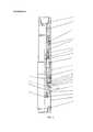
Конструкция расширителя поясняется чертежами, где:The design of the expander is illustrated by drawings, where:
- на фиг. 1 - расширитель в разрезе в исходном, транспортном положении деталей;- in FIG. 1 - the extender in the context in the initial, transport position of the parts;
- фиг. 2 - конструкция расширителя, в разрезе, при максимальном вылете лопастей;- FIG. 2 - the design of the expander, in the context, with a maximum extension of the blades;
- на фиг. 3 - конструкция в разрезе разжимного элемента с конусной поверхностью.- in FIG. 3 is a sectional view of an expandable member with a tapered surface.
Расширитель состоит из корпуса 1, связанного с переводником 2 верхним концом. Переводник 2 через ниппель 3 связан с бурильной колонной труб.The expander consists of a housing 1, connected to the sub 2 upper end. The sub 2 through the nipple 3 is connected to the drill pipe string.
В осевом канале переводника 2 размещен поршень 4, связанный с полым штоком 5, пропущенным в осевой канал ниппеля 3. Между полым штоком 5 и переводником 2 выполнена кольцевая камера 6, в которой установлен поршень 4, полость над которым связана через радиальное отверстие 7 с полостью скважины.In the axial channel of the sub 2 there is a piston 4 connected to the
Внутри кольцевой камеры 6 размещена пружина 8, поджимающая поршень 4 к торцу корпуса 1.Inside the annular chamber 6 there is a spring 8, which compresses the piston 4 to the end face of the housing 1.
Поршень 4 нижним концом связан с центральным штоком 9, пропущенным в осевой канал корпуса 1, в теле которого выполнены сквозные пазы 10, в которых на осях 11 размещаются лопасти 12, с охватом центрального штока 9, на нижнем конце которого установлен разжимной элемент 13, с конусной поверхностью 14, обращенной в сторону лопастей 12, входящих в продольные пазы 15 на конусной поверхности 14. На верхнем конце разжимного элемента 13 выполнен кольцевой выступ 16, соизмеримый по размерам с кольцевой проточкой 17 в теле корпуса 1. На нижнем конце центрального штока 9 установлен стопор 18 для разжимного элемента 13.The piston 4 with its lower end is connected with the central rod 9, passed into the axial channel of the housing 1, in the body of which there are made through
На внешней стороне корпуса 1 установлен кожух 19 с продольными окнами 20, расположенными симметрично сквозным пазам 10 корпуса 1. На нижнем конце кожуха 19 размещена полумуфта 21.On the outside of the housing 1, a
В теле центрального штока 9 выполнено циркуляционное отверстие 22, для связи его осевого канала 23 с полостью кольцевой камеры 6 под поршнем 4. В стопоре 18 выполнен дроссельный канал 24. Форма лопасти 12 выполнена переменного сечения, с возможностью постоянного скользящего элемента 13 по продольному пазу 15 выступом 25. При максимальном раскрытии лопастей 12 точка контакта выступа 25, с разжимным элементом 13 смещена в радиальном направлении к кожуху 19.A
Работа устройства.The operation of the device.
На бурильной колонне труб, к нижнему концу которой через ниппель 3 подсоединяется устройство, и происходит спуск в скважину, с размещением в интервале продуктивного пласта.On the drill pipe string, to the lower end of which a device is connected through the nipple 3, and a descent into the well occurs, with placement in the interval of the reservoir.
Осуществляют подачу под давлением рабочей жидкости в бурильную колонну труб и далее внутрь устройства.The fluid is supplied under pressure to the drill pipe string and further into the device.
Через циркуляционное отверстие 22 рабочая жидкость подается в кольцевую камеру 6 под поршнем 4, что приводит к его перемещению вверх, совместно с центральным штоком 9 и разжимным элементом 13. Лопасти 12 своими свободными концами перемещаются в продольных пазах 15 на конусной поверхности 14, с взаимодействием с ней выступом 25 поворотом на осях 11 и выходом из сквозных пазов 10 корпуса 1, до контакта с поверхностью горной породы в стволе скважины. Бурильной колонне сообщают вращение до момента полного вылета лопастей 12, с контактом внешней поверхностью с телом кожуха 19.Through the
При полном вылете лопастей 12, не прекращая вращать бурильную колонну, осуществляют осевое нагружение расчетной нагрузкой. Наружная поверхность лопастей 12, входящая в контакт с горной породой, армирована твердым или алмазоподобным сплавом, что обеспечивает эффективное разрушение и расширение ствола скважины.With the full departure of the
Расширение ствола скважины ведут по высоте расположения продуктивного пласта.The expansion of the wellbore is conducted along the height of the reservoir.
При раскрытии лопастей 12 происходит их контактное взаимодействие с конусной поверхностью 14 разжимного элемента 13 по продольным пазам 15 выступами 25. Полное раскрытие лопастей 12 синхронизировано с моментом входа кольцевого выступа 16 в кольцевую проточку 17 в теле корпуса 1, позволяет обеспечить устойчивое положение лопастей 12 в сквозных пазах 10, что приводит к снижению нагрузок на оси 11. Тем самым повышается надежность работы устройства.When the
Claims (1)
Translated fromRussianPriority Applications (1)
| Application Number | Priority Date | Filing Date | Title |
|---|---|---|---|
| RU2015148318ARU2612166C1 (en) | 2015-11-10 | 2015-11-10 | Expander |
Applications Claiming Priority (1)
| Application Number | Priority Date | Filing Date | Title |
|---|---|---|---|
| RU2015148318ARU2612166C1 (en) | 2015-11-10 | 2015-11-10 | Expander |
Publications (1)
| Publication Number | Publication Date |
|---|---|
| RU2612166C1true RU2612166C1 (en) | 2017-03-02 |
Family
ID=58459386
Family Applications (1)
| Application Number | Title | Priority Date | Filing Date |
|---|---|---|---|
| RU2015148318ARU2612166C1 (en) | 2015-11-10 | 2015-11-10 | Expander |
Country Status (1)
| Country | Link |
|---|---|
| RU (1) | RU2612166C1 (en) |
Cited By (3)
| Publication number | Priority date | Publication date | Assignee | Title |
|---|---|---|---|---|
| RU2719880C1 (en)* | 2019-12-09 | 2020-04-23 | Публичное акционерное общество "Татнефть" имени В.Д. Шашина | Expander for simultaneous drilling and expansion on casing string |
| RU2751906C1 (en)* | 2021-01-26 | 2021-07-20 | Публичное акционерное общество «Татнефть» имени В.Д. Шашина | Reamer for guided drilling and casing expansion |
| RU2796716C1 (en)* | 2022-09-13 | 2023-05-29 | Публичное акционерное общество "Татнефть" имени В.Д. Шашина | Well expander |
Citations (7)
| Publication number | Priority date | Publication date | Assignee | Title |
|---|---|---|---|---|
| SU781312A1 (en)* | 1978-07-03 | 1980-11-23 | Всесоюзный Ордена Трудового Красного Знамени Научно-Исследовательский Институт Буровой Техники | Blade-type expanding tool |
| SU1745858A1 (en)* | 1990-01-08 | 1992-07-07 | Проектно-Конструкторская Контора Проектно-Строительного Объединения "Востокбурвод" | Hole reamer |
| RU2152503C1 (en)* | 1998-12-30 | 2000-07-10 | Тульское государственное научно-исследовательское геологическое предприятие | Mechanical hole reamer |
| RU2299303C2 (en)* | 2005-07-11 | 2007-05-20 | Открытое акционерное общество "Научно-производственное объединение "Бурение" | Expanding open well bore reamer |
| GB2475167A (en)* | 2009-11-04 | 2011-05-11 | Welltonic Ltd | Under reamer |
| US8146682B2 (en)* | 2007-04-04 | 2012-04-03 | Weatherford/Lamb, Inc. | Apparatus and methods of milling a restricted casing shoe |
| RU2542057C1 (en)* | 2014-02-21 | 2015-02-20 | Геннадий Алексеевич Копылов | Blade underreamer |
- 2015
- 2015-11-10RURU2015148318Apatent/RU2612166C1/enactive
Patent Citations (7)
| Publication number | Priority date | Publication date | Assignee | Title |
|---|---|---|---|---|
| SU781312A1 (en)* | 1978-07-03 | 1980-11-23 | Всесоюзный Ордена Трудового Красного Знамени Научно-Исследовательский Институт Буровой Техники | Blade-type expanding tool |
| SU1745858A1 (en)* | 1990-01-08 | 1992-07-07 | Проектно-Конструкторская Контора Проектно-Строительного Объединения "Востокбурвод" | Hole reamer |
| RU2152503C1 (en)* | 1998-12-30 | 2000-07-10 | Тульское государственное научно-исследовательское геологическое предприятие | Mechanical hole reamer |
| RU2299303C2 (en)* | 2005-07-11 | 2007-05-20 | Открытое акционерное общество "Научно-производственное объединение "Бурение" | Expanding open well bore reamer |
| US8146682B2 (en)* | 2007-04-04 | 2012-04-03 | Weatherford/Lamb, Inc. | Apparatus and methods of milling a restricted casing shoe |
| GB2475167A (en)* | 2009-11-04 | 2011-05-11 | Welltonic Ltd | Under reamer |
| RU2542057C1 (en)* | 2014-02-21 | 2015-02-20 | Геннадий Алексеевич Копылов | Blade underreamer |
Cited By (3)
| Publication number | Priority date | Publication date | Assignee | Title |
|---|---|---|---|---|
| RU2719880C1 (en)* | 2019-12-09 | 2020-04-23 | Публичное акционерное общество "Татнефть" имени В.Д. Шашина | Expander for simultaneous drilling and expansion on casing string |
| RU2751906C1 (en)* | 2021-01-26 | 2021-07-20 | Публичное акционерное общество «Татнефть» имени В.Д. Шашина | Reamer for guided drilling and casing expansion |
| RU2796716C1 (en)* | 2022-09-13 | 2023-05-29 | Публичное акционерное общество "Татнефть" имени В.Д. Шашина | Well expander |
Similar Documents
| Publication | Publication Date | Title |
|---|---|---|
| EP3592940B1 (en) | Downhole anchor mechanism | |
| CN106761541B (en) | A hydraulic anchor sealing device | |
| NO20121003A1 (en) | Downhole tool and method | |
| RU2612166C1 (en) | Expander | |
| RU2542057C1 (en) | Blade underreamer | |
| RU2563470C1 (en) | Reusable anchor device (three versions) | |
| RU2387791C1 (en) | Downhole equipment centraliser | |
| RU182823U1 (en) | PACKER MODULE FOR AUTONOMOUS ISOLATION OF LEAKAGE INTERVALS IN AN UNLESSED WELL | |
| RU2718666C1 (en) | Deflector for directed drilling of wells with core sampling at intervals of artificial deviation | |
| RU92083U1 (en) | CASING REPAIR DEVICE | |
| RU2299303C2 (en) | Expanding open well bore reamer | |
| RU2117747C1 (en) | Bore-hole reamer | |
| RU203929U1 (en) | Downhole reamer, sliding | |
| RU2663856C1 (en) | Casing string drilling tool joint assembly | |
| RU2445431C1 (en) | Well rounder | |
| RU2578135C1 (en) | Well expander | |
| RU2719880C1 (en) | Expander for simultaneous drilling and expansion on casing string | |
| RU2772031C1 (en) | Hydraulic borehole expander | |
| RU2738124C1 (en) | Expander for simultaneous drilling and expansion of well shaft | |
| RU19086U1 (en) | DEVICE FOR DEEP PUNCHING OF CUTTING WELLS AND EXECUTIVE PUNCH BODY | |
| RU2483192C1 (en) | Drillable packer | |
| RU146413U1 (en) | RADIAL OPENING OF THE STRING | |
| RU2229582C1 (en) | Hydraulically expanding underreamer | |
| RU181505U1 (en) | SLIDING EXPANDER | |
| RU2471960C1 (en) | Mechanical packer installed with tension, with reserve removal systems |