RU2611764C2 - Intraoral mandibular advancement appliance - Google Patents
Intraoral mandibular advancement applianceDownload PDFInfo
- Publication number
- RU2611764C2 RU2611764C2RU2014105692ARU2014105692ARU2611764C2RU 2611764 C2RU2611764 C2RU 2611764C2RU 2014105692 ARU2014105692 ARU 2014105692ARU 2014105692 ARU2014105692 ARU 2014105692ARU 2611764 C2RU2611764 C2RU 2611764C2
- Authority
- RU
- Russia
- Prior art keywords
- specified
- patient
- mouth guard
- pair
- teeth
- Prior art date
Links
- 210000000214mouthAnatomy0.000claimsabstractdescription65
- 230000003993interactionEffects0.000claimsabstractdescription18
- 230000037431insertionEffects0.000claimsabstractdescription5
- 238000003780insertionMethods0.000claimsabstractdescription5
- 238000006073displacement reactionMethods0.000claimsabstract2
- 229920003023plasticPolymers0.000claimsdescription8
- 239000004033plasticSubstances0.000claimsdescription8
- 230000008859changeEffects0.000claimsdescription6
- 239000003990capacitorSubstances0.000claimsdescription5
- 230000000903blocking effectEffects0.000claimsdescription4
- 230000001737promoting effectEffects0.000claimsdescription2
- 230000000295complement effectEffects0.000claims3
- 230000001105regulatory effectEffects0.000claims2
- 230000000694effectsEffects0.000abstractdescription6
- 230000006835compressionEffects0.000abstract1
- 238000007906compressionMethods0.000abstract1
- 239000003814drugSubstances0.000abstract1
- 239000000126substanceSubstances0.000abstract1
- 210000004513dentitionAnatomy0.000description9
- 230000036346tooth eruptionEffects0.000description9
- 206010041235SnoringDiseases0.000description8
- 201000002859sleep apneaDiseases0.000description6
- 230000029058respiratory gaseous exchangeEffects0.000description5
- 239000000463materialSubstances0.000description4
- 239000007787solidSubstances0.000description4
- XLYOFNOQVPJJNP-UHFFFAOYSA-NwaterSubstancesOXLYOFNOQVPJJNP-UHFFFAOYSA-N0.000description4
- 101500025735Drosophila melanogaster CAP-3Proteins0.000description3
- 208000008784apneaDiseases0.000description2
- 230000008901benefitEffects0.000description2
- 238000009835boilingMethods0.000description2
- DQXBYHZEEUGOBF-UHFFFAOYSA-Nbut-3-enoic acid;etheneChemical compoundC=C.OC(=O)CC=CDQXBYHZEEUGOBF-UHFFFAOYSA-N0.000description2
- 239000005038ethylene vinyl acetateSubstances0.000description2
- 238000000465mouldingMethods0.000description2
- 229920001200poly(ethylene-vinyl acetate)Polymers0.000description2
- 230000004044responseEffects0.000description2
- 210000003437tracheaAnatomy0.000description2
- 206010003497AsphyxiaDiseases0.000description1
- JOYRKODLDBILNP-UHFFFAOYSA-NEthyl urethaneChemical compoundCCOC(N)=OJOYRKODLDBILNP-UHFFFAOYSA-N0.000description1
- 208000008589ObesityDiseases0.000description1
- 206010041349SomnolenceDiseases0.000description1
- 230000015572biosynthetic processEffects0.000description1
- 230000000747cardiac effectEffects0.000description1
- 238000005266castingMethods0.000description1
- 230000006866deteriorationEffects0.000description1
- 238000005516engineering processMethods0.000description1
- 230000003090exacerbative effectEffects0.000description1
- -1for exampleSubstances0.000description1
- 230000036541healthEffects0.000description1
- 238000009434installationMethods0.000description1
- 210000001847jawAnatomy0.000description1
- 210000004072lungAnatomy0.000description1
- 230000013011matingEffects0.000description1
- 230000007246mechanismEffects0.000description1
- 235000020824obesityNutrition0.000description1
- 210000003254palateAnatomy0.000description1
- 239000004417polycarbonateSubstances0.000description1
- 229920000515polycarbonatePolymers0.000description1
- 229920001296polysiloxanePolymers0.000description1
- 230000002035prolonged effectEffects0.000description1
- 230000001141propulsive effectEffects0.000description1
- 230000000241respiratory effectEffects0.000description1
- 210000002345respiratory systemAnatomy0.000description1
- 238000007493shaping processMethods0.000description1
- 210000004872soft tissueAnatomy0.000description1
- 229910001220stainless steelInorganic materials0.000description1
- 239000010935stainless steelSubstances0.000description1
- 230000000007visual effectEffects0.000description1
Images


Classifications
- A—HUMAN NECESSITIES
- A61—MEDICAL OR VETERINARY SCIENCE; HYGIENE
- A61C—DENTISTRY; APPARATUS OR METHODS FOR ORAL OR DENTAL HYGIENE
- A61C9/00—Impression cups, i.e. impression trays; Impression methods
- A61C9/0006—Impression trays
- A—HUMAN NECESSITIES
- A61—MEDICAL OR VETERINARY SCIENCE; HYGIENE
- A61C—DENTISTRY; APPARATUS OR METHODS FOR ORAL OR DENTAL HYGIENE
- A61C9/00—Impression cups, i.e. impression trays; Impression methods
- A61C9/0026—Syringes or guns for injecting impression material; Mixing impression material for immediate use
- A—HUMAN NECESSITIES
- A61—MEDICAL OR VETERINARY SCIENCE; HYGIENE
- A61F—FILTERS IMPLANTABLE INTO BLOOD VESSELS; PROSTHESES; DEVICES PROVIDING PATENCY TO, OR PREVENTING COLLAPSING OF, TUBULAR STRUCTURES OF THE BODY, e.g. STENTS; ORTHOPAEDIC, NURSING OR CONTRACEPTIVE DEVICES; FOMENTATION; TREATMENT OR PROTECTION OF EYES OR EARS; BANDAGES, DRESSINGS OR ABSORBENT PADS; FIRST-AID KITS
- A61F5/00—Orthopaedic methods or devices for non-surgical treatment of bones or joints; Nursing devices ; Anti-rape devices
- A61F5/56—Devices for preventing snoring
- A61F5/566—Intra-oral devices
Landscapes
- Health & Medical Sciences (AREA)
- Veterinary Medicine (AREA)
- General Health & Medical Sciences (AREA)
- Public Health (AREA)
- Life Sciences & Earth Sciences (AREA)
- Animal Behavior & Ethology (AREA)
- Pulmonology (AREA)
- Nursing (AREA)
- Otolaryngology (AREA)
- Orthopedic Medicine & Surgery (AREA)
- Engineering & Computer Science (AREA)
- Biomedical Technology (AREA)
- Heart & Thoracic Surgery (AREA)
- Vascular Medicine (AREA)
- Epidemiology (AREA)
- Oral & Maxillofacial Surgery (AREA)
- Dentistry (AREA)
- Orthopedics, Nursing, And Contraception (AREA)
Abstract
Description
Translated fromRussianОБЛАСТЬ ТЕХНИКИFIELD OF TECHNOLOGY
[0001] Настоящее изобретение относится к интраоральному нижнечелюстному продвигающему устройству, которое вставляют в ротовую полость пациента, так что положение нижней челюсти пациента может непрерывно регулироваться относительно верхней челюсти для улучшения дыхания пациента во время сна и, таким образом, уменьшения эффектов храпа и/или сонного апноэ. Вышеуказанное регулирование может легко и выборочно осуществляться самим пациентом в течение длительного времени без необходимости использования специальных инструментов и пружин, а также без необходимости удаления и установки крепежных элементов или помощи медицинского персонала.[0001] The present invention relates to an intraoral mandibular advancement device that is inserted into a patient’s oral cavity so that the position of the patient’s lower jaw can be continuously adjusted relative to the upper jaw to improve the patient’s breathing during sleep and thereby reduce the effects of snoring and / or sleepy apnea. The above regulation can be easily and selectively carried out by the patient for a long time without the need for special tools and springs, as well as without the need to remove and install fasteners or help medical personnel.
УРОВЕНЬ ТЕХНИКИBACKGROUND
[0002] Храп и сонное апноэ обычно вызваны препятствиями (т.е. окклюзиями) в дыхательных путях пациента, ведущих к его горлу, посредством которых пациент дышит во время сна. Например, вследствие возраста, ожирения, состояния здоровья и физического состояния и т.п. небо и мягкая ткань вокруг горла пациента, как известно, расслабляются и сжимаются и, таким образом, прекращают или ограничивают поток воздуха к горлу пациента во время его сна. Иногда язык пациента может западать в его горло и, таким образом, также может препятствовать дыханию. Длительное прекращение подачи воздуха может вызвать удушье пациента, потерю здорового сна и в некоторых чрезвычайных случаях ухудшение сердечной деятельности.[0002] Snoring and sleep apnea are usually caused by obstructions (ie, occlusions) in the patient's airways leading to his throat, through which the patient breathes during sleep. For example, due to age, obesity, health and physical condition, etc. the palate and soft tissue around the patient’s throat are known to relax and contract and thus stop or restrict the flow of air to the patient’s throat during sleep. Sometimes the patient's tongue can sink into his throat and, thus, can also interfere with breathing. Prolonged cessation of air supply can cause suffocation of the patient, loss of healthy sleep and, in some emergency cases, deterioration of cardiac activity.
[0003] Одним средством, признанным успешным в лечении храпа и сонного апноэ, является аппарат для искусственной вентиляции легких. В этом случае воздух под давлением непрерывно подают в горло пациента для поддерживания открытыми дыхательных путей. Однако применение указанного аппарата для искусственной вентиляции легких также требует использования маски, которую надевают поверх носа и/или ротовой полости пациента. Ношение такой маски является некомфортным для многих пациентов. Пациенты, которые не в силах побороть нетерпимость к указанному аппарату, не имеют возможности воспользоваться его преимуществами.[0003] One device recognized to be successful in treating snoring and sleep apnea is an artificial lung ventilator. In this case, air under pressure is continuously supplied to the patient's throat to maintain an open airway. However, the use of this ventilator also requires the use of a mask that is worn over the patient’s nose and / or mouth. Wearing such a mask is uncomfortable for many patients. Patients who are not able to overcome intolerance to the specified device do not have the opportunity to take advantage of it.
[0004] В качестве альтернативного средства, выбранного с целью отказа от использования маски, обязательной для аппарата искусственной вентиляции легких, для лечения храпа и сонного апноэ могут быть использованы ротовые устройства, предназначенные для вставки их в ротовую полость пациента на время сна. Такие устройства обеспечивают возможность приведения верхней и нижней челюстей пациента в заданное положение относительно друг друга при необходимости поддерживания дыхательного канала открытым. После испытательного срока параметры настройки в некоторых известных ротовых устройствах устанавливаются и фиксируются. Однако указанные устройства невозможно повторно отрегулировать впоследствии, в результате чего у пациента возникает ощущение дискомфорта, усугубляющее неэффективность указанного устройства. Таким образом, указанные устройства являются неэффективными при их эксплуатации в течение длительного времени вследствие их неспособности соответствовать изменяющемуся состоянию пациента.[0004] Oral devices designed to be inserted into the patient’s mouth during sleep can be used as an alternative to choosing not to use a mask mandatory for the ventilator to treat snoring and sleep apnea. Such devices provide the ability to bring the upper and lower jaws of the patient to a predetermined position relative to each other, if necessary, keeping the respiratory canal open. After a trial period, settings in some well-known oral devices are set and fixed. However, these devices cannot be re-adjusted subsequently, as a result of which the patient has a feeling of discomfort, exacerbating the inefficiency of the specified device. Thus, these devices are ineffective in their operation for a long time due to their inability to meet the changing state of the patient.
[0005] Некоторые другие известные ротовые устройства позволяют выполнить дополнительную регулировку после первоначальной настройки параметров. В этом случае регулировка часто требует использования специальных инструментов, пружин и зачастую осложнена удалением и установкой крепежных элементов и требует помощи медицинского персонала. Следовательно, пациент не может быстро или легко осуществить необходимую регулировку самостоятельно. Кроме того, такая регулировка зачастую по своей природе является грубой (например, имеет только низкий, средний и высокий уровни), что не позволяет осуществить точную регулировку относительного положения верхней или нижней челюсти пациента в соответствии с его требованиями для удовлетворения его конкретных нужд на непрерывной основе.[0005] Some other known oral devices allow for further adjustment after the initial setting of parameters. In this case, the adjustment often requires the use of special tools, springs and is often complicated by the removal and installation of fasteners and requires the help of medical personnel. Therefore, the patient cannot quickly or easily make the necessary adjustments on his own. In addition, such adjustment is often crude in nature (for example, it has only low, medium and high levels), which does not allow for accurate adjustment of the relative position of the upper or lower jaw of the patient in accordance with his requirements to meet his specific needs on an ongoing basis .
РАСКРЫТИЕ ИЗОБРЕТЕНИЯSUMMARY OF THE INVENTION
[0006] Кратко и в общем виде раскрыто интраоральное нижнечелюстное продвигающее устройство, которое выполнено с возможностью вставки в ротовую полость пациента для поддерживания открытыми дыхательных путей к горлу пациента для улучшения его дыхания во время сна. Нижнечелюстное продвигающее устройство, описанное в настоящей заявке, предназначено для конкретного применения и может быть использовано теми, кто страдает от храпа и/или сонного апноэ. Устройство содержит дугообразную верхнюю капу, предназначенную для вхождения во взаимодействие с зубами верхней челюсти пациента, и дугообразную нижнюю капу, предназначенную для вхождения во взаимодействие с зубами нижней челюсти пациента. Нижняя капа сопряжена с верхней капой и выполнена с возможностью регулирования путем перемещения скольжением относительно верхней капы для перемещения нижней челюсти пациента относительно его верхней челюсти. Регулирование путем перемещения скольжением нижней капы относительно верхней капы может быть выборочно и непрерывно выполнено самим пациентом, так что его нижняя челюсть может быть продвинута с небольшими приращениями, которые необходимы для соответствия изменяющимся потребностям пациента с течением времени. Вышеуказанная регулировка может быть осуществлена пациентом самостоятельно без использования специальных инструментов, пружин, а также без необходимости удаления и установки крепежных элементов или помощи медицинского персонала.[0006] Briefly and generally disclosed is an intraoral mandibular advancement device that is configured to be inserted into a patient's oral cavity to maintain open airways to the patient's throat to improve his breathing during sleep. The mandibular promoter device described herein is intended for specific use and can be used by those suffering from snoring and / or sleep apnea. The device contains an arcuate upper mouthpiece designed to enter into interaction with the teeth of the upper jaw of the patient, and an arcuate lower mouthpiece designed to enter into interaction with the teeth of the lower jaw of the patient. The lower mouthpiece is associated with the upper mouthpiece and is made with the possibility of regulation by moving by sliding relative to the upper mouthpiece to move the lower jaw of the patient relative to his upper jaw. Regulation by sliding the lower mouthpiece relative to the upper mouthpiece can be selectively and continuously performed by the patient himself, so that his lower jaw can be advanced in small increments, which are necessary to meet the changing needs of the patient over time. The above adjustment can be carried out by the patient independently without the use of special tools, springs, as well as without the need to remove and install fasteners or the help of medical personnel.
[0007] Верхняя капа нижнечелюстного продвигающего устройства содержит относительно мягкую верхнюю оттискную прикусную пластину, которая прикреплена к относительно твердому верхнему корпусу. Нижняя капа содержит относительно мягкую нижнюю оттискную прикусную пластину, которая прикреплена к относительно твердому нижнему корпусу. Каждая из верхней и нижней оттискных прикусных пластин имеет прикусный канал, в котором формируется оттиск зубов пациента, когда пациент прикусывает нагретые верхнюю и нижнюю капы и, таким образом, прижимает мягкие оттискные прикусные пластины к твердым корпусам.[0007] The upper cap of the mandibular promoter comprises a relatively soft upper impression bite plate that is attached to the relatively hard upper body. The lower tray contains a relatively soft lower impression bite plate that is attached to the relatively hard lower case. Each of the upper and lower impression bite plates has a bite channel in which an impression of the patient’s teeth is formed when the patient bites the heated upper and lower mouth guards and, thus, presses the soft impression bite plates to the hard bodies.
[0008] Пара регулирующих положение блоков, проходящих в верхнем направлении от противоположных боковых частей дугообразной нижней капы, размещены с возможностью скольжения в соответствующих фиксирующих каналах, сформированных в противоположных боковых частях дугообразной верхней капы, в результате чего верхняя и нижняя капы сопряжены друг с другом одна над другой. Регулирующие положение блоки и фиксирующие каналы имеют ряды зубцов, проходящие вдоль них, которые сцеплены вместе для фиксации положения нижней капы под верхней капой. При необходимости, для изменения положения нижней капы, чтобы вызвать соответствующее изменение положения (т.е. выдвижение) нижней челюсти, пациент прикладывает сжимающее усилие к управляющим положением нажимным площадкам, расположенным с противоположных сторон дугообразной нижней капы. Сжимающие усилия временно изменяют форму нижней капы, так что зубцы, расположенные вдоль управляющих положением блоков, выходят из своего фиксирующего взаимодействия с зубцами, расположенными вдоль фиксирующих каналов. Положение нижней капы регулируют путем перемещения скольжением управляющих положением блоков нижней капы через фиксирующие каналы верхней капы.[0008] A pair of position-adjusting blocks extending in an upward direction from opposite side portions of the arcuate lower mouthguard are slidably mounted in respective fixing channels formed in opposite side portions of the arcuate upper mouthguard, as a result of which the upper and lower mouthguards are mated to one another over the other. The position-adjusting blocks and locking channels have rows of teeth extending along them that are coupled together to fix the position of the lower mouth guard under the upper mouth guard. If necessary, in order to change the position of the lower mouthpiece to cause a corresponding change in position (i.e., extension) of the lower jaw, the patient applies a compressive force to the control position of the pressure pads located on opposite sides of the arcuate lower mouthpiece. The compressive forces temporarily change the shape of the lower burl so that the teeth located along the blocks controlling the position of the blocks come out of their locking interaction with the teeth located along the fixing channels. The position of the lower mouth guard is controlled by sliding the position control blocks of the lower mouth guard through the fixing channels of the upper mouth guard.
[0009] Нижнечелюстное продвигающее устройство также имеет подпорку для языка, которая прикреплена к одному концу гибкой поддерживающей язык проволоки. Противоположный конец поддерживающей язык проволоки соединен с возможностью открепления с нижней капой, так что указанная подпорка для языка может быть удалена в зависимости от потребностей и комфорта пациента. Подпорка для языка, соединенная с поддерживающей язык проволокой, лежит на языке пациента и, таким образом, препятствует колебанию языка пациента в обратном направлении и возможному блокированию его дыхательных путей.[0009] The mandibular promoter also has a tongue support that is attached to one end of a flexible tongue-supporting wire. The opposite end of the tongue-supporting wire is detachably connected to the lower burl so that said tongue support can be removed depending on the needs and comfort of the patient. A tongue support connected to a tongue supporting wire lies on the tongue of the patient and thus prevents the patient's tongue from oscillating in the opposite direction and possibly blocking its airways.
КРАТКОЕ ОПИСАНИЕ ЧЕРТЕЖЕЙBRIEF DESCRIPTION OF THE DRAWINGS
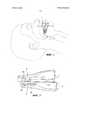
[0010] На фиг. 1 показано интраоральное нижнечелюстное продвигающее устройство согласно настоящему изобретению, вставленное в ротовую полость спящего пациента.[0010] FIG. 1 shows an intraoral mandibular advancement device according to the present invention inserted into the oral cavity of a sleeping patient.
[0011] На фиг. 2 показано интраоральное нижнечелюстное продвигающее устройство согласно предпочтительному варианту реализации, показанное на фиг. 1, извлеченное из ротовой полости пациента, после регулировки.[0011] FIG. 2 shows an intraoral mandibular promotion device according to the preferred embodiment shown in FIG. 1, extracted from the patient’s oral cavity after adjustment.
[0012] На фиг. 3 и 4 показаны передний и задний перспективные виды нижнечелюстного продвигающего устройства до регулировки.[0012] FIG. 3 and 4 are front and rear perspective views of a mandibular advancement device prior to adjustment.
[0013] На фиг. 5 показан вид спереди нижнечелюстного продвигающего устройства.[0013] FIG. 5 is a front view of a mandibular promoter.
[0014] На фиг. 6 показан разрез нижнечелюстного продвигающего устройства по линии 6-6, показанной на фиг. 5.[0014] FIG. 6 shows a section of the mandibular propulsion device along line 6-6 of FIG. 5.
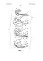
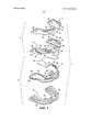
[0015] На фиг. 7 и 8 показаны покомпонентные изображения сверху и снизу нижнечелюстного продвигающего устройства.[0015] FIG. 7 and 8 are exploded views of the upper and lower mandibular promoter.
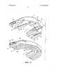
[0016] На фиг. 9 и 10 показаны перспективные виды сверху и снизу верхней и нижней кап до сопряжения вместе для формирования нижнечелюстного продвигающего устройства.[0016] FIG. 9 and 10 show perspective views from above and below of the upper and lower cap prior to pairing together to form the mandibular promoter.
ОСУЩЕСТВЛЕНИЕ ИЗОБРЕТЕНИЯDETAILED DESCRIPTION OF THE INVENTION
[0017] Ниже подробно описано со ссылкой на сопроводительные чертежи интраоральное нижнечелюстное продвигающее устройство 1 согласно предпочтительному варианту реализации настоящего изобретения. Как описано ниже, нижнечелюстное продвигающее устройство 1 выполнено с возможностью размещения в ротовой полости пациента таким образом, что его нижняя челюсть может быть продвинута вперед относительно верхней челюсти на изменяемое расстояние, которым может выборочно и непрерывно управлять пациент. На основании вышесказанного устройство 1 может быть отрегулировано вручную пациентом без использования инструментов, пружин, удаления и введения крепежных элементов или вмешательства медицинского персонала таким образом, что дыхательные пути, ведущие в горло, остаются открытыми для способствования, таким образом, нормальному дыханию пациента во время сна. Таким образом, можно считать, что интраоральное нижнечелюстное продвигающее устройство 1 имеет конкретное назначение к использованию пациентом, который желает преодолеть храп и/или сонное апноэ.[0017] The following is described in detail with reference to the accompanying drawings, an intraoral
[0018] Как показано на фиг. 7-10, устройство 1 содержит верхнюю капу 3 и нижнюю капу 5. Как описано более подробно ниже со ссылкой на фиг. 3-6, верхняя и нижняя капы 3 и 5 сопряжены вместе таким образом, что расположены одна над другой, так что нижняя капа 5 может быть продвинута вперед пациентом относительно верхней капы 3. Продвижение вперед нижней капы 5 вызывает соответствующее смещение нижней челюсти пациента вперед относительно его верхней челюсти для обеспечения возможности регулирования размера дыхательного пути к горлу пациента с целью предотвращения окклюзии и, таким образом, уменьшения действия храпа и/или сонного апноэ.[0018] As shown in FIG. 7-10,
[0019] Верхняя капа 3 интраорального нижнечелюстного продвигающего устройства 1 содержит верхнюю оттискную пластину 7 для снятия слепка прикуса и верхний корпус 9, которые выполнены с возможностью соединения друг с другом прессовой посадкой таким образом, что пластина 7 расположена над корпусом 9. Верхняя оттискная пластина 7 и нижний корпус 9 имеют в целом дугообразную конфигурацию для согласования с рельефом прикуса зубов, которые расположены в верхней челюсти. Верхняя оттискная пластина 7 выполнена из относительно мягкого и пластичного материала, такого, например, который известен под коммерческим названием EVA (этиленвинилацетат), изготовляемый компанией Dupont. Нижний корпус 9 выполнен из относительно твердого и жесткого материала, такого как, например, поликарбонат.[0019] The
[0020] Нижняя капа 5 интраорального нижнечелюстного продвигающего устройства 1 содержит нижний корпус 10 и нижнюю оттискную пластину 12 для снятия слепка прикуса, которые выполнены с возможностью соединения друг с другом прессовой посадкой таким образом, что корпус 10 расположен над пластиной 12. Подобно верхней пластине 7 и верхнему корпусу 9 верхней капы 3, каждое из нижнего корпуса 10 и нижней оттискной пластины 12 нижней капы 5 имеет в целом дугообразную конфигурацию для согласования с рельефом прикуса зубов, которые расположены в нижней челюсти. Также, подобно верхней пластине 7 и верхнему корпусу 9, нижний корпус 10 выполнен из относительно твердого и жесткого материала, в то время как нижняя оттискная пластина 12 выполнена из относительно мягкого и пластичного материала.[0020] The
[0021] Прикусный канал 14 (лучше всего показанный на фиг. 7) проходит вокруг верхней части дугообразной верхней оттискной пластины 7 верхней капы 3. Прикусный канал 14 имеет подходящий размер для размещения в нем зубного ряда пациента, расположенного в верхней челюстной кости. Поскольку относительно мягкая верхняя оттискная пластина 7 лежит поверх относительно твердого верхнего корпуса 9, сила прикуса, созданная верхним зубным рядом пациента и приложенная к верхней оттискной пластине 7, придает форму ее прикусному каналу 14 способом, который описан ниже.[0021] The bite canal 14 (best shown in FIG. 7) extends around the top of the arcuate
[0022] Множество (например, шесть) позиционирующих штифтов 16 (лучше всего показанных на фиг. 8) проходят в нижнем направлении от нижней стороны верхней оттискной пластины 7. Кроме того, множество (например, пять) позиционирующих выступов 18 (также лучше всего показанных на фиг. 8) проходят во внутреннем и наружном направлениях от дугообразной верхней оттискной пластины 7. Множество позиционирующих штифтов 16 и позиционирующих выступов 18 обеспечивают возможность соединения путем прессования верхней оттискной пластины 7 с верхним корпусом 9 для формирования верхней капы 3.[0022] A plurality (eg, six) of positioning pins 16 (best shown in FIG. 8) extend downward from a lower side of an
[0023] Соответствующее множество сквозных позиционирующих отверстий 20 для штифтов выполнены в верхнем корпусе 9 верхней капы 3. Аналогично, соответствующее множество позиционирующих пазов 22 для выступов выполнены в верхнем корпусе 9. Позиционирующие отверстия 20 и позиционирующие пазы 22 верхнего корпуса 9 расположены с возможностью размещения в них соответствующих позиционирующих штифтов 16 и позиционирующих выступов 18 верхней оттискной пластины 9 таким образом, что верхняя оттискная пластина 7 расположена на верхнем корпусе 9 и прочно прикреплена к нему в ответ на сжимающую силу или давление, приложенное к ней, для формирования верхней капы 3 нижнечелюстного продвигающего устройства 1.[0023] A corresponding plurality of through-hole positioning holes 20 for pins are provided in the
[0024] Пара направляющих удерживающих стенок 26 (лучше всего показанных на фиг. 8) расположены в передней части дугообразного верхнего корпуса 9. Направляющие удерживающие стенки 26 проходят на некотором расстоянии друг от друга и параллельно друг другу вдоль нижней стороны верхнего корпуса 9. В пространстве между парой направляющих удерживающих стенок 26 образован направляющий канал 28. Как описано ниже, центрирующая направляющая (обозначенная позиционным номером 46 на фиг. 7), которая проходит в верхнем направлении от нижнего корпуса 10 нижней капы 5, размещена с возможностью скольжения в направляющем канале 28 между направляющими стенками 26, когда верхняя и нижняя капы 3 и 5 сопряжены вместе.[0024] A pair of guide retaining walls 26 (best shown in FIG. 8) are located at the front of the arcuate
[0025] В нижней части верхнего корпуса 9 позади направляющих удерживающих стенок 26 с каждой стороны корпуса 9 выполнены фиксирующие каналы 30 (также лучше всего показанные на фиг. 8). Фиксирующие каналы 30 проходят параллельно друг другу и направляющему каналу 28 в передней части верхнего корпуса 9. Вдоль одной стороны каждого фиксирующего канала 30 сформирован (например, формованием) ряд зубцов 32. Захват 34 проходит вдоль противоположной стороны каждого фиксирующего канала 30 и выступает из нее таким образом, что проходит над каналом 30. Как описано ниже, когда центрирующая направляющая 46 нижнего корпуса 10 с возможностью скольжения размещена в направляющем канале 28 верхнего корпуса 9, пара регулирующих положение блоков (обозначенных позиционными номерами 48 на фиг. 7 и 9), которые проходят в верхнем направлении из нижнего корпуса 10, входят с возможностью перемещения во взаимофиксирующее взаимодействие с фиксирующими каналами 30 верхнего корпуса 9 для удерживания положений верхней и нижней кап 3 и 5 относительно друг друга.[0025] In the lower part of the
[0026] Прикусный канал 36 (лучше всего показанный на фиг. 8) проходит вокруг нижней стороны дугообразной нижней оттискной пластины 12 нижней капы 5. Прикусный канал 36 имеет подходящий размер для приема зубного ряда, расположенного в нижней челюстной кости пациента. Поскольку относительно мягкая нижняя оттискная пластина 12 расположена под относительно твердым нижним корпусом 10 и вплотную к нему, сила прикуса, созданная нижним зубным рядом пациента и приложенная к нижней оттискной пластине 12, придает форму прикусному каналу 36 одновременно с приданием формы прикусному каналу 14 верхней оттискной пластины 7.[0026] The bite canal 36 (best shown in FIG. 8) extends around the lower side of the arched
[0027] Множество (например, пять) позиционирующих штифтов 38 (лучше всего показанных на фиг. 7) проходят в верхнем направлении от нижней оттискной пластины 12 нижней капы 5. Множество (например, пять) позиционирующих выступов 40 (также лучше всего показанных на фиг. 7) проходят во внутреннем и наружном направлениях от дугообразной нижней оттискной пластины 12. Множества позиционирующих штифтов 38 и позиционирующих выступов 42 обеспечивают возможность соединения путем прессования нижней оттискной пластины 12 с нижним корпусом 10 для формирования нижней капы 5.[0027] A plurality (eg, five) of positioning pins 38 (best shown in FIG. 7) extend upward from a
[0028] Соответствующие множества позиционирующих отверстий 42 для указанных штифтов и позиционирующих пазов 44 для указанных выступов выполнены в нижнем корпусе 10 нижней капы 5. Позиционирующие отверстия 42 для штифтов и позиционирующие пазы 44 для выступов нижнего корпуса расположены с возможностью размещения в них соответствующих позиционирующих штифтов 38 и позиционирующих выступов 40 нижней оттискной пластины 12 таким образом, что нижний корпус 10 упирается в нижнюю оттискную пластину 12 и прикреплен к ней в ответ на сжимающую силу или давление, приложенное к нему, для формирования нижней капы 5 нижнечелюстного продвигающего устройства 1.[0028] The corresponding plurality of positioning holes 42 for said pins and
[0029] Центрирующая направляющая 46 (лучше всего показанная на фиг. 7), на которую выше была сделана ссылка, расположена в передней части дугообразного нижнего корпуса 10. Центрирующая направляющая 46 проходит в верхнем направлении от верхней части нижнего корпуса 10 между вышеуказанной парой регулирующих положение блоков 48. Одно из позиционирующих отверстий 42 для штифтов нижнего корпуса 10 проходит сквозь центрирующую направляющую 46 и предназначено для приема в него одного из позиционирующих штифтов 38, расположенного в передней части нижней оттискной пластины 12. Как описано выше, центрирующая направляющая 46 нижнего корпуса 10 с возможностью скольжения размещена в направляющем канале 28 верхнего корпуса 9, когда верхняя капа 3 сопряжена с нижней капой 5 для формирования нижнечелюстного продвигающего устройства 1.[0029] The centering guide 46 (best shown in FIG. 7), referred to above, is located in front of the arcuate
[0030] Из верхнего корпуса 10 в верхнем направлении проходят два регулирующих положение блока 48 (также лучше всего показанные на фиг. 7), расположенные по обеим сторонам верхнего корпуса 10 позади центрирующей направляющей 46. Ряд зубцов 50 сформированы (например, формованием) вдоль одной стороны каждого регулирующего положение блока 48. Кромка 52 проходит вдоль противоположной стороны каждого из регулирующих положение блоков 48 и выступает из нее, так что кромки 52 расположены напротив друг друга, выровнены относительно друг друга и проходят параллельно друг другу.[0030] From the
[0031] Как описано выше, когда центрирующая направляющая 46 нижнего корпуса 10 с возможностью скольжения размещена в направляющем канале 28 верхнего корпуса 9, пара регулирующих положение блоков 48 нижнего корпуса 10 является соответственно выровненной для размещения с возможностью скольжения и перемещения в соответствующих фиксирующих каналах 30 верхнего корпуса 9. Аналогично, противоположные кромки 52, выступающие из регулирующих положение блоков 48, перемещаются скольжением под захватами 34 и удерживаются указанными захватами 34, которые проходят над фиксирующими каналами 30 (показанными на фиг. 5), в результате чего верхняя и нижняя капы 3 и 5 сопряжены вместе для удерживания на месте одна над другой (как показано на фиг. 3 и 4). В то же время зубцы 50, расположенные вдоль пары регулирующих положение блоков 48, входят в разъемное фиксирующее взаимодействие с зубцами 32, расположенными вдоль фиксирующих каналов 30, и сцепляются с ними. Однако противоположно расположенные наборы выполненных с возможностью сцепления друг с другом зубцов 32 и 50 могут быть заменены любым подходящим взаимофиксирующим средством, выполняющим функцию храпового механизма.[0031] As described above, when the centering
[0032] Важная особенность настоящего изобретения состоит в том, что пациент имеет возможность откреплять фиксирующее взаимодействие зубцов 50 регулирующих положение блоков 48 с зубцами 32 фиксирующих каналов 30. На основании вышесказанного положение нижней капы 5 нижнечелюстного продвигающего устройства 1 может быть выборочно изменено на точное расстояние относительно верхней капы 3 для соответствия изменяющимся потребностям пациента во время сна с течением времени.[0032] An important feature of the present invention is that the patient is able to unfasten the locking interaction of the
[0033] Более конкретно, пара управляющих положением нажимных площадок 56 расположены на противоположных сторонах нижнего корпуса 10 нижней капы 5 и выполнены за одно целое с ними. Индикатор 58 положения отформован или напечатан на каждой из нажимных площадок 56. Пара управляющих положением нажимных площадок 56 являются чувствительными к сжимающим усилиям (как показано на фиг. 3 и 4), приложенным к указанным площадкам пациентом для мгновенного деформирования нижнего корпуса 10 таким образом, что ряды зубцов 32 и 50 временно выведены из взаимодействия. После этого пациент может приложить толкающее усилие для скользящего перемещения и изменения положения нижней капы 5 относительно верхней капы 3 для достижения результата, который описан ниже.[0033] More specifically, a pair of position
[0034] Указывающая положение шкала 60 расположена на каждой стороне верхнего корпуса 9 верхней капы 3 и выполнена за одно целое с указанной стороной. Последовательность линий положения отформована или напечатана на каждой из шкал 60. Приращения между каждой последовательной парой линий положения шкалы 60 соответствуют заданному линейному расстоянию (например, 1 мм). В собранном нижнечелюстном устройстве 1 (показанном на фиг. 2-5) после перемещения нижней капы 5 в скользящее сопрягающее взаимодействие под верхней капой 3 указывающая положение шкала 60 на каждой стороне верхнего корпуса 9 расположена непосредственно над управляющей положением нажимной площадкой 56, расположенной на каждой стороне нижнего корпуса 10. Индикатор 58 положения каждой нажимной площадки 56 указывает на линию положения, которая соответствует конкретному расстоянию вдоль каждой указывающей положение шкалы 60.[0034] The indicating position of the
[0035] Таким образом, поскольку положение нижней капы 5 может быть отрегулировано с возможностью скольжения относительно верхнего корпуса 9, как показано на фиг. 2, индикаторы 58 положения управляющих положением площадок 56 могут быть смещены на идентичное расстояние вдоль указывающих положение шкал 60 для предоставления пациенту возможности визуального отслеживания положения нижней капы 5 относительно верхней капы 3. Таким образом, пациент может осуществлять обычную управляемую и точную регулировку положения нижней капы 5 для достижения преимущества, которое описано ниже со ссылкой на фиг. 1.[0035] Thus, since the position of the
[0036] Нижнечелюстное продвигающее устройство 1 также содержит гибкую поддерживающую язык проволоку 62, которая может быть изогнута и иметь необходимую форму. Поддерживающая язык проволока 62 предпочтительно выполнена из нержавеющей стали или подобного материала и имеет обратный изгиб 66 для формирования седла, на котором лежит подпорка 68 для языка (как показано на фиг. 3, 4 и 6). Подпорка 68 для языка шарнирно соединена с проволокой 62 или отформована поверх нее. Подпорка 68 для языка в идеальном случае выполнена из силикона или уретана низкой твердости и подвешена на поддерживающей язык проволоке 62 для размещения в полости рта пациента поверх его языка, чтобы препятствовать, таким образом, западанию языка в ротовую полость и блокированию дыхательных путей пациента во время сна, когда пациент лежит на спине с устройством 1 в ротовой полости.[0036] The
[0037] Противоположные концы 70 поддерживающей язык проволоки 62 (как показано на фиг. 9), между которыми расположен обратный изгиб 66, соединены с возможностью открепления с соответствующими двумя регулирующими положение блоками 48, расположенными на нижнем корпусе 10 нижней капы 5, и разъемным способом удерживаются указанными блоками. В то же время, поддерживающая подпорку для языка проволока 62 расположена позади двух упоров 71 для проволоки и взаимодействует с указанными упорами, которые проходят в верхнем направлении из нижнего корпуса 10, для удерживания проволоки 62 на месте на нижней капе 5. Когда поддерживающая язык проволока 62 соединена с возможностью открепления с регулирующими положение блоками 48 и взаимодействует с упорами 71, нижний корпус 10 прочно прикреплен к нижней оттискной пластине 12 для формирования нижней капы 5 нижнечелюстного продвигающего устройства (как показано на фиг. 9 и 10). Таким образом, обратный изгиб 66 поддерживающей язык проволоки 62 расположен в полости рта, окруженный дугообразным нижним корпусом 10 и нижней оттискной пластиной 12, в которых подпорка 68 для языка (как показано на фиг. 3 и 4) взаимодействует с языком пациента после введения устройства 1 в ротовую полость пациента. Для повышения комфорта во время использования пациент может отделить поддерживающую проволоку 62 от нижней капы 5. В этом случае концы 70 поддерживающей проволоки 62 могут быть выведены из рассоединяемого соединения с регулирующими положение блоками 48 и проволока 62 выведена из взаимодействия с возможностью открепления с упорами 71, так что проволока 62 и подпорка 68 для языка могут быть удалены вместе из устройства 1.[0037] The opposite ends 70 of the tongue-supporting wire 62 (as shown in FIG. 9), between which the
[0038] На фиг. 9 и 10 показана верхняя капа 3, расположенной поверх нижней капы 5. Верхняя и нижняя капы 3 и 5 сопряжены друг с другом для формирования нижнечелюстного продвигающего устройства 1, когда, как описано выше, центрирующая направляющая 46, которая проходит в верхнем направлении из нижнего корпуса 10 нижней капы 5, перемещается скольжением в направляющем канале 28 между направляющими стенками 26 верхнего корпуса 9 верхней капы 3, а регулирующие положение блоки 48 нижнего корпуса 10 нижней капы 5 введены в скользящее взаимофиксирующее взаимодействие с фиксирующими каналами 30 в верхнем корпусе 9.[0038] FIG. 9 and 10 show the
[0039] На фиг. 3-6 показано интраоральное нижнечелюстное продвигающее устройство 1 в собранной готовой к использованию конфигурации после того, как верхняя капа 3 и нижняя капа 5 были введены в скользящее взаимофиксирующее взаимодействие друг с другом описанным выше способом. Поддерживающая язык проволока 62 показана соединенной с регулирующими положение блоками 48 в нижнем корпусе 10 нижней капы 5. В этом случае подпорка 68, которая соединена с обратным изгибом 66 поддерживающей проволоки 62, подвешена на проволоке 62, окружена дугообразными верхней и нижней капами 3 и 5 и расположена таким образом, что лежит на языке пациента после вставки устройства 1 в ротовую полость пациента. Таким образом, как описано выше, подпорка 68 предотвращает западание языка пациента (под действием собственного веса) в его горло во время сна, так что трахея не будет блокирована.[0039] FIG. 3-6, an intraoral
[0040] Согласно другому варианту реализации подпорка 68 для языка снабжена последовательностью прорезанных пазов 72. Для прорезания подпорки 68 вдоль одного из пазов 72 могут быть использованы ножницы или подобный режущий инструмент, так что размер подпорки для языка может быть уменьшен на точную величину в зависимости от размера языка пациента и ощущения комфорта.[0040] According to another embodiment, the
[0041] Как показано на фиг. 3, в положении, в котором верхняя капа 3 расположена над нижней капой 5, в нижнечелюстном продвигающем устройстве 1 образована пара каналов 76 для воздушного потока. В частности, направляющие удерживающие стенки 26 в верхнем корпусе 9 верхней капы 3, между которым расположен направляющий канал 28, образуют зазоры между верхней и нижней капами 3 и 5 для каналов 76, проходящих сквозь устройство 1. Каналы 76 особенно полезны для пациентов с искривлением носовой перегородки или блокированным носовым отверстием для облегчения дыхания благодаря обеспечению непрерывного воздушного потока с использованием устройства 1 во время сна.[0041] As shown in FIG. 3, in a position in which the
[0042] Перед первым использованием во время сна нижнечелюстного продвигающего устройства 1 пациент должен вскипятить в резервуаре воду, в которой размещено и нагревается устройство. Затем обработанное кипятком устройство 1 удаляют из кипящей воды посредством щипцов или подобного инструмента и охлаждают до тех пор, пока оно не станет теплым. В теплом состоянии устройство 1 вставляют в ротовую полость пациента, и в этот момент пациент закрывает рот и сжимает зубами относительно мягкую верхнюю оттискную пластину 7 и нижнюю оттискную пластину 12. Верхний зубной ряд пациента прикусывает в нижнем направлении прикусный канал 14 верхней оттискной пластины 7, а нижний зубной ряд прикусывает в верхнем направлении прикусный канал 36 нижней оттискной пластины 12. Оттиски, оставленные верхним и нижним зубными рядами, формируются в противоположных относительно мягких прикусных каналах 14 и 36, которые, как описано выше, прижимаются к относительно твердым верхнему и нижнему корпусам 9 и 10.[0042] Before the first use of the mandibular advancing
[0043] В то время, когда пациент прикусывает верхнюю и нижнюю оттискные пластины 14 и 36, соответствующее давление, созданное верхним и нижним зубными рядами, принуждает фиксирующие штифты 16 (как показано на фиг. 8) и 38 (как показано на фиг. 7) полностью перемещаться сквозь соответствующие противоположно выровненные фиксирующие отверстия 20 и 42, в результате чего мягкая верхняя оттискная пластина 7 прикрепляется к твердому верхнему корпусу 9 для завершения сборки верхней капы 3, а мягкая нижняя оттискная пластина 12 прикрепляется к твердому нижнему корпусу 10 для завершения сборки нижней капы 5. Наконец, устройство 1 размещают в резервуаре холодной водой для того, чтобы оттиски верхнего и нижнего зубных рядов пациента в прикусных каналах 14 и 36 остались постоянными.[0043] While the patient bites the upper and
[0044] Теперь интраоральное нижнечелюстное продвигающее устройство 1 согласно настоящему изобретению готово для использования пациентом во время сна. На фиг. 1 устройство 1 показано вставленным в ротовую полость пациента. Как описано выше, устройство 1 согласно предпочтительному варианту реализации выполнено с возможностью приводить в положение и управляемым способом перемещать нижнюю челюсть пациента вперед относительно его верхней челюсти, так что дыхательные пути, ведущие к горлу пациента, остаются непрерывно открытыми для минимизации эффектов храпа и/или сонного апноэ.[0044] Now, the intraoral
[0045] Более конкретно, пациенту предоставлена возможность выборочного регулирования нижнечелюстного продвигающего устройства 1 для предотвращения окклюзии его трахеи путем принуждения его нижней челюсти к непрерывному продвижению в переднем направлении для соответствия его изменяющимся потребностям в течение длительного времени. На фиг. 2 показан принцип регулирования устройства 1 после продвижения нижней капы 5 из начального положения, в котором она находилась непосредственно под верхней капой 3 (как показано на фиг. 3 и 4), в отрегулированное положение, показанное на фиг. 2, в котором нижняя капа 3 продвинута вперед относительно верхней капы 5. Поскольку верхний и нижний зубные ряды пациента размещены в прикусных каналах 14 и 36 верхней и нижней кап 3 и 5, продвижение в переднем направлении нижней капы 5 относительно верхней капы 3 вызывает соответствующее смещение в переднем направлении нижней челюсти пациента относительно его верхней челюсти.[0045] More specifically, the patient is given the opportunity to selectively control the
[0046] В то же время, когда нижняя капа 5 перемещается относительно верхней капы 3, индикатор 58 положения, встроенный в управляющую нажимную площадку 56 нижней капы 5, перемещается на такое же расстояние под указывающей положение шкалой 60 верхней капы 3 для обеспечения пациента визуальным индикатором положения его нижней челюсти. Т.е. при скользящем продвижении нижней капы 5 в переднем направлении индикатор 58 положения, установленный на нижней капе, непрерывно перемещается вдоль указывающей положение шкалы 60 с небольшими (например, 1 мм) приращениями.[0046] At the same time, when the
[0047] Для достижения выборочного и непрерывного продвижения в переднем направлении нижней капы 5 нижнечелюстного продвигающего устройства 1 и соответствующего продвижения в переднем направлении нижней челюсти пациент прикладывает сжимающие усилия (обозначенные указательными стрелками 80 на фиг. 3 и 4) к управляющим нажимным площадкам 56, расположенным с противоположных сторон нижнего корпуса 10 нижней капы 5. Сжимающие усилия 80 на короткое время деформируют нижний корпус 10, так что зубцы 50, расположенные вдоль регулирующих положение блоков 48 (как показано на фиг. 9) нижнего корпуса 10, перемещаются из своего сцепляющего фиксирующего взаимодействия с противоположными зубцами 32, расположенными вдоль каналов 30 (как показано на фиг. 10) верхнего корпуса 9. Соответственно, после этого пациент может протянуть нижнюю капу 5 в переднем направлении на любое расстояние таким образом, чтобы регулирующие положение блоки 48 переместились в соответствующих фиксирующих каналах 30.[0047] In order to achieve selective and continuous advancement in the forward direction of the
[0048] После завершения необходимой регулировки переднего положения нижней капы 5 пациент снимает сжимающее усилие, приложенное к нажимным площадкам 56, так что первоначальная форма нижнего корпуса 10 восстанавливается. Затем нижнечелюстное продвигающее устройство 1 вставляют в ротовую полость пациента, как показано на фиг. 1, для использования во время сна. Если через какое-то время потребуется дополнительная регулировка, такая регулировка может быть легко и точно сделана пациентом дома описанным выше способом без использования инструментов, пружин, а также без удаления и повторной установки на место крепежных элементов или помощи медицинского персонала.[0048] After completion of the necessary adjustment of the front position of the
Claims (35)
Translated fromRussianApplications Claiming Priority (3)
| Application Number | Priority Date | Filing Date | Title |
|---|---|---|---|
| US13/199,383 | 2011-08-29 | ||
| US13/199,383US8833374B2 (en) | 2010-12-13 | 2011-08-29 | Intra-oral mandibular advancement appliance |
| PCT/US2012/052207WO2013032884A1 (en) | 2011-08-29 | 2012-08-24 | Intra-oral mandibular advancement appliance |
Publications (2)
| Publication Number | Publication Date |
|---|---|
| RU2014105692A RU2014105692A (en) | 2015-10-27 |
| RU2611764C2true RU2611764C2 (en) | 2017-02-28 |
Family
ID=46198063
Family Applications (1)
| Application Number | Title | Priority Date | Filing Date |
|---|---|---|---|
| RU2014105692ARU2611764C2 (en) | 2011-08-29 | 2012-08-24 | Intraoral mandibular advancement appliance |
Country Status (10)
| Country | Link |
|---|---|
| US (1) | US8833374B2 (en) |
| EP (1) | EP2750641B8 (en) |
| JP (1) | JP5993457B2 (en) |
| CN (1) | CN103781442B (en) |
| BR (1) | BR112014004653B1 (en) |
| CA (1) | CA2844512C (en) |
| DK (1) | DK2750641T3 (en) |
| ES (1) | ES2705171T3 (en) |
| RU (1) | RU2611764C2 (en) |
| WO (1) | WO2013032884A1 (en) |
Families Citing this family (74)
| Publication number | Priority date | Publication date | Assignee | Title |
|---|---|---|---|---|
| US9241825B2 (en) | 2007-11-13 | 2016-01-26 | Apnicure, Inc. | Oral device for mandibular advancement and medial tongue constraint |
| US9655768B2 (en) | 2007-11-13 | 2017-05-23 | Apnicure, Inc. | Oral device for mandibular advancement and medial tongue constraint |
| US10772756B2 (en) | 2007-11-13 | 2020-09-15 | Somnics, Inc. | Oral device for mandibular advancement and medial tongue constraint |
| US8833374B2 (en)* | 2010-12-13 | 2014-09-16 | James S. Fallon | Intra-oral mandibular advancement appliance |
| US20120186589A1 (en)* | 2011-01-26 | 2012-07-26 | Singh Pankaj P | Apparatus and method for treatment of sleep apnea and snoring |
| AU2012255625B2 (en) | 2011-05-19 | 2016-03-31 | Open Airway Dental Solutions Ltd | Breathing assist device |
| FR2980684B1 (en)* | 2011-10-04 | 2014-08-22 | Petelle Fleury Rech S Pfr | INTRABUCCAL ORTHESIS, METHOD OF MANUFACTURE, AND METHOD OF USING SUCH ORTHESIS. |
| USD808022S1 (en) | 2012-02-29 | 2018-01-16 | Petruska, Llc | Oral device for preventing snoring and sleep apnea |
| ITRM20120380A1 (en)* | 2012-08-02 | 2014-02-03 | Roberta Ficacci | NEUROPHYSIOLOGICAL STIMULATION DEVICE. |
| EP2695589A1 (en) | 2012-08-10 | 2014-02-12 | Michèle Hervy | Intraoral functional device for relieving obstructive sleep apnea syndrom, snoring and/or other airway disorders |
| JP2016508423A (en)* | 2013-03-01 | 2016-03-22 | アプニキュア, インコーポレイテッド | Oral devices for anterior mandibular fixation and intermediate tongue restraint |
| US9687383B2 (en) | 2013-06-02 | 2017-06-27 | Petruska, Llc | Incremental and/or successive adjustable mandibular advancement device for preventing and treatment of snoring and obstructive sleep apnea |
| DK177809B1 (en) | 2013-06-02 | 2014-07-21 | Natashia Ingemarsson-Matzen | Incremental adjustable mandibular advancement device for |
| US20150101615A1 (en)* | 2013-10-11 | 2015-04-16 | Apnicure, Inc. | Systems, Devices, and Methods for Retaining Oral Devices for Airway Treatment |
| US11576808B2 (en) | 2014-03-19 | 2023-02-14 | Michael Gelb | Apparatus and kit for an oral appliance and method for using same |
| CA3193175A1 (en)* | 2014-04-01 | 2015-10-08 | Open Airway Dental Solutions Ltd. | Breathing assist device |
| US9963590B2 (en) | 2014-06-10 | 2018-05-08 | Shengyi Technology Co., Ltd. | Halogen-free resin composition, and a prepreg and a laminate used for printed circuit using the same |
| WO2016004415A1 (en)* | 2014-07-02 | 2016-01-07 | Selane Products, Inc. | Sleep apnea oral appliance for use during orthodontic treatment |
| US20210267790A1 (en)* | 2014-07-22 | 2021-09-02 | Arora, Llc | Oral Dental Appliance for Improving Breathing |
| US11033421B1 (en)* | 2014-08-27 | 2021-06-15 | Paul M. Davis | Device to prevent snoring |
| USD760906S1 (en)* | 2015-04-24 | 2016-07-05 | Michael Gelb | Key wedge |
| US10010313B2 (en) | 2015-05-18 | 2018-07-03 | Richard L. Arden | Mandibular subluxation device and method |
| US10258319B2 (en) | 2015-05-18 | 2019-04-16 | Richard L. Arden | Airway assist device and method |
| USD778449S1 (en) | 2015-06-17 | 2017-02-07 | Natashia Ingemarsson-Matzen | Dental plate |
| US10342526B2 (en) | 2015-07-01 | 2019-07-09 | Richard L. Arden | Airway assist device and method |
| GB201602386D0 (en)* | 2015-07-08 | 2016-03-23 | Aria Healthcare Ltd | Improvements to oral devices |
| US20170014262A1 (en)* | 2015-07-14 | 2017-01-19 | Thermal Fit, LLC | Intraoral Orthosis Device and Method for Manufacturing |
| US10959875B2 (en)* | 2015-08-27 | 2021-03-30 | Joseph Yousefian | Masticatory and airway stabilizing orthotic, and associated systems and methods |
| FR3041242B1 (en)* | 2015-09-17 | 2017-09-29 | Michel Alglave | INTRABUCCAL DEVICE FOR REPOSITIONING AND REHABILITATION OF LANGUAGE |
| WO2017106896A1 (en)* | 2015-12-22 | 2017-06-29 | Somnomed Limited | A mandibular advancement device |
| KR101832856B1 (en)* | 2016-03-14 | 2018-02-28 | 주식회사 진바이오테크 | Intraoral device for step-snoring and sleep apnea treatment and treating method using the same |
| WO2017165918A1 (en)* | 2016-03-30 | 2017-10-05 | Oventus Medical Limited | Adjustable breathing assistance apparatus |
| JP7182792B2 (en)* | 2016-07-08 | 2022-12-05 | タング ラボ ヨーロッパ リミテッド | Dental instruments for sleep apnea, snoring, and tongue and oral cavity reconstruction |
| US10383761B2 (en) | 2016-08-05 | 2019-08-20 | James S Fallon | Jaw advancement oral appliance to reduce the effects of snoring and/or sleep apnea |
| AU2017332257B2 (en)* | 2016-09-21 | 2020-12-10 | uLab Systems, Inc. | Combined orthodontic movement of teeth with airway development therapy |
| FR3059544B1 (en)* | 2016-12-07 | 2019-05-10 | Oniris | INTRABUCCAL DEVICE WITH PAIR OF ARTICULATED DENTAL GUTTERS |
| US10905582B2 (en) | 2017-01-26 | 2021-02-02 | Koncept Innovators Llc | Mandibular advancement device |
| SE543188C2 (en)* | 2017-10-26 | 2020-10-20 | Dormitek Medical Ab | Mouthpiece for reduced snoring, teeth pressing and grinding |
| EP3735200B1 (en)* | 2017-11-13 | 2024-01-03 | Achaemenid, LLC | Provisional oral sleep appliance and jig for making the same |
| US12409060B2 (en) | 2017-11-13 | 2025-09-09 | Achaemenid, Llc | Strut assembly for oral appliance |
| US12213907B2 (en) | 2017-11-13 | 2025-02-04 | Achaemenid, Llc | Provisional oral sleep appliance |
| US10849783B2 (en)* | 2018-01-16 | 2020-12-01 | James S. Fallon | Full movement jaw advancement oral appliance to reduce the effects of snoring and/or sleep apnea |
| CA3089568A1 (en)* | 2018-01-31 | 2019-08-08 | Selane Products, Inc. | Sleep apnea oral appliance with connectors |
| US11253390B2 (en) | 2018-05-18 | 2022-02-22 | James S Fallon | Impression tray with integral handle for an oral jaw advancement appliance |
| KR102159393B1 (en)* | 2018-07-09 | 2020-09-23 | 장영진 | Snore preventing kit using impression materials of teeth |
| US10251729B1 (en) | 2018-08-31 | 2019-04-09 | 3D Med Ag | Intra-oral device |
| EP3616647A1 (en) | 2018-08-31 | 2020-03-04 | 3D Med Ag | Intra-oral device |
| IT201800009864A1 (en)* | 2018-10-29 | 2020-04-29 | Montefarmaco Otc Spa | DEVICE FOR TEETH AND MOUTH |
| USD888249S1 (en)* | 2019-01-15 | 2020-06-23 | Ryan Bruss | Mouthguard |
| USD932627S1 (en)* | 2019-04-09 | 2021-10-05 | Ji-Young Chung | Mandibular advancement device for anti snoring |
| US12349880B2 (en)* | 2019-07-25 | 2025-07-08 | Paprica Lab. Co., Ltd. | Oral fixation apparatus |
| CA3150894A1 (en)* | 2019-09-12 | 2021-03-18 | Willis J. PUMPHREY | Lingual positioning device for sleep, breathing, jaw and airway disorders |
| US11589958B2 (en) | 2019-12-31 | 2023-02-28 | Joseph Yousefian | Pharyngorofacial expander appliance and protocol |
| USD970013S1 (en)* | 2020-01-27 | 2022-11-15 | Frantz Design Incorporated | Mandibular advancement appliance |
| US20230086923A1 (en)* | 2020-01-28 | 2023-03-23 | Leblanc Dental Products, Inc. | Devices and methods for sleep apnea and snoring |
| USD983374S1 (en)* | 2020-02-10 | 2023-04-11 | JiYoung Chung | Mandibular advancement device for anti snoring |
| CN115335003A (en)* | 2020-02-12 | 2022-11-11 | 阿梅里科·费尔南德斯 | Multifunctional oral cavity correcting device |
| WO2021236569A1 (en)* | 2020-05-20 | 2021-11-25 | Arora, Llc | Oral dental appliance for improving breathing |
| USD955583S1 (en) | 2020-08-24 | 2022-06-21 | Sleeping Well Llc | Oral appliance |
| US12102555B2 (en) | 2020-08-24 | 2024-10-01 | Sleeping Well Inc. | Oral appliance |
| AU2020256297A1 (en)* | 2020-10-12 | 2022-04-28 | APAC Health & Medical Distributors PTY LTD | Mandibular advancement device |
| CN112656573A (en)* | 2020-12-09 | 2021-04-16 | 江苏爱朋医疗科技股份有限公司 | Oral cavity correcting snore stopper with tooth-shaped structure adjustment |
| US11166841B1 (en)* | 2021-01-29 | 2021-11-09 | Lubin Martinez | Snoring and sleep apnea prevention device and methods |
| US11311407B1 (en) | 2021-02-23 | 2022-04-26 | Apnea Sciences Corporation | Bidirectional jaw displacement oral appliance |
| DE102021201915A1 (en) | 2021-03-01 | 2022-09-01 | Jens-Peter Hittel | Device and method for improving sleep breathing and method of making the device |
| US11793666B1 (en) | 2021-04-16 | 2023-10-24 | Joseph Yousefian | Intra-oral snore and sleep apnea treatment appliance |
| USD995781S1 (en) | 2021-05-28 | 2023-08-15 | Achaemenid, Llc | Strut assembly |
| CN113499185B (en)* | 2021-08-06 | 2023-06-16 | 上海诺斯清生物科技有限公司 | Oral cavity correcting snore stopping device and handle |
| CN114224592B (en)* | 2021-12-09 | 2022-11-04 | 四川大学 | A mandibular advancement snoring device with intelligent automatic adjustment |
| USD1059598S1 (en) | 2021-12-20 | 2025-01-28 | Achaemenid, Llc | Strut assembly |
| US20230277365A1 (en)* | 2022-03-04 | 2023-09-07 | Allen J. Moses | Molar Shim System for Posterior Bite Registration |
| US12097120B2 (en) | 2022-03-07 | 2024-09-24 | Sleep Mechanics Llc | Bone implant device |
| US20240216164A1 (en) | 2022-12-30 | 2024-07-04 | John M Fallon | Multi-directional jaw displacement oral appliance |
| WO2025097229A1 (en)* | 2023-11-06 | 2025-05-15 | Faber Jorge | Device for treating snoring and apnea |
Citations (5)
| Publication number | Priority date | Publication date | Assignee | Title |
|---|---|---|---|---|
| SU1697792A1 (en)* | 1988-11-04 | 1991-12-15 | В.М. Лачинов | Device for reducing stertor |
| US5570704A (en)* | 1993-10-28 | 1996-11-05 | Snoreless Corp | Universal, user-adjustable oral cavity appliance to control snoring and reduce episodes of obstructive sleep apnea |
| US5941247A (en)* | 1998-02-17 | 1999-08-24 | Keane; Michael Alexander | Snore prevention apparatus |
| US6055986A (en)* | 1992-11-16 | 2000-05-02 | Meade; Thomas E. | Apparatus and method for the reduction of snoring |
| US20110017220A1 (en)* | 2009-06-29 | 2011-01-27 | Noel Lindsay | Self-titratable mandibular repositioning device |
Family Cites Families (13)
| Publication number | Priority date | Publication date | Assignee | Title |
|---|---|---|---|---|
| US5044950A (en)* | 1989-11-29 | 1991-09-03 | Stanley Hobish | Therapeutic training device and method for fitting dentures |
| US6041784A (en) | 1993-04-13 | 2000-03-28 | Silent Knights Ventures Inc. | Dental appliance for treatment of snoring and obstructive sleep apnea |
| US5692493A (en)* | 1996-03-08 | 1997-12-02 | Diemolding Corporation | Tongue Protector |
| US5876199A (en)* | 1997-08-28 | 1999-03-02 | Ortho-Tain, Inc. | Appliance adapted to fit many mouth and tooth sizes for orthodontic correction and other uses |
| US7832403B2 (en) | 2003-08-07 | 2010-11-16 | Respironics, Inc. | Mandible positioning devices |
| US7748386B2 (en)* | 2006-04-06 | 2010-07-06 | Thornton W Keith | Oral appliance for treating a breathing condition |
| CN101553194B (en)* | 2006-06-14 | 2013-07-17 | Ric投资有限责任公司 | Oral appliance for treatment of snoring and sleep apnea |
| AU2007202799A1 (en)* | 2007-06-15 | 2009-01-08 | John Razmovski | Improved Oral Cavity Manipulator |
| US8127769B2 (en) | 2007-11-18 | 2012-03-06 | Dreamscape Medical Llc | Integrated oral appliance for sleep-disordered breathing |
| US20100261133A1 (en) | 2009-04-08 | 2010-10-14 | Lax Ronald G | Devices, systems, and methods for repositioning the mandible |
| US20110099846A1 (en) | 2009-06-16 | 2011-05-05 | Bruce Fischer | Alpine ski boot with strap closure |
| US8256426B2 (en)* | 2009-08-12 | 2012-09-04 | Abramson Mark E | Modular dental appliance for improving airflow through nasal-pharyngeal airway |
| US8833374B2 (en)* | 2010-12-13 | 2014-09-16 | James S. Fallon | Intra-oral mandibular advancement appliance |
- 2011
- 2011-08-29USUS13/199,383patent/US8833374B2/enactiveActive
- 2012
- 2012-08-24CNCN201280042382.3Apatent/CN103781442B/enactiveActive
- 2012-08-24CACA2844512Apatent/CA2844512C/enactiveActive
- 2012-08-24ESES12827015Tpatent/ES2705171T3/enactiveActive
- 2012-08-24DKDK12827015.4Tpatent/DK2750641T3/enactive
- 2012-08-24RURU2014105692Apatent/RU2611764C2/enactive
- 2012-08-24JPJP2014528471Apatent/JP5993457B2/enactiveActive
- 2012-08-24WOPCT/US2012/052207patent/WO2013032884A1/enunknown
- 2012-08-24EPEP12827015.4Apatent/EP2750641B8/enactiveActive
- 2012-08-24BRBR112014004653-0Apatent/BR112014004653B1/enactiveIP Right Grant
Patent Citations (5)
| Publication number | Priority date | Publication date | Assignee | Title |
|---|---|---|---|---|
| SU1697792A1 (en)* | 1988-11-04 | 1991-12-15 | В.М. Лачинов | Device for reducing stertor |
| US6055986A (en)* | 1992-11-16 | 2000-05-02 | Meade; Thomas E. | Apparatus and method for the reduction of snoring |
| US5570704A (en)* | 1993-10-28 | 1996-11-05 | Snoreless Corp | Universal, user-adjustable oral cavity appliance to control snoring and reduce episodes of obstructive sleep apnea |
| US5941247A (en)* | 1998-02-17 | 1999-08-24 | Keane; Michael Alexander | Snore prevention apparatus |
| US20110017220A1 (en)* | 2009-06-29 | 2011-01-27 | Noel Lindsay | Self-titratable mandibular repositioning device |
Also Published As
| Publication number | Publication date |
|---|---|
| US20120145166A1 (en) | 2012-06-14 |
| JP2014525321A (en) | 2014-09-29 |
| EP2750641A1 (en) | 2014-07-09 |
| EP2750641B8 (en) | 2019-01-02 |
| US8833374B2 (en) | 2014-09-16 |
| BR112014004653A2 (en) | 2017-06-13 |
| ES2705171T3 (en) | 2019-03-22 |
| EP2750641A4 (en) | 2015-05-06 |
| CN103781442B (en) | 2016-10-19 |
| HK1198510A1 (en) | 2015-05-15 |
| JP5993457B2 (en) | 2016-09-14 |
| CA2844512A1 (en) | 2013-03-07 |
| DK2750641T3 (en) | 2019-01-28 |
| CA2844512C (en) | 2018-12-11 |
| WO2013032884A1 (en) | 2013-03-07 |
| CN103781442A (en) | 2014-05-07 |
| BR112014004653B1 (en) | 2022-03-22 |
| EP2750641B1 (en) | 2018-11-14 |
| RU2014105692A (en) | 2015-10-27 |
Similar Documents
| Publication | Publication Date | Title |
|---|---|---|
| RU2611764C2 (en) | Intraoral mandibular advancement appliance | |
| EP2032067B1 (en) | Oral appliance for treatment of snoring and sleep apnea | |
| US20210153981A1 (en) | Combined orthodontic movement of teeth with temporomandibular joint therapy | |
| EP2709572B1 (en) | Breathing assist device | |
| EP2352468B1 (en) | Integrated oral appliance for sleep-disordered breathing | |
| CA3081381C (en) | Apparatus for improved breathing | |
| US20170020715A1 (en) | Oral appliance | |
| US7918228B2 (en) | Musculoskeletal repositioning device | |
| KR20190013698A (en) | Adjustable breathing apparatus | |
| US11357662B2 (en) | Mandible adjustment apparatus | |
| KR101990318B1 (en) | Mitigation mechanisms for snoring and sleep bruxism of using anti-departure and jaw joint movement | |
| CN213156591U (en) | Early induction appliance suitable for irregular Bolton index | |
| HK1198510B (en) | Intra-oral mandibular advancement appliance | |
| WO2018218229A2 (en) | Systems, methods and oral appliance devices | |
| US20250177192A1 (en) | Apparatus for invisible tooth alignment with ortho strut for sleep apnea | |
| WO2025166243A1 (en) | Apparatus for invisible tooth alignment with ortho strut for sleep apnea |
Legal Events
| Date | Code | Title | Description |
|---|---|---|---|
| HC9A | Changing information about inventors |