RU2610899C1 - Method for determining installation site for devices for sectionalization of 380 v overhead line - Google Patents
Method for determining installation site for devices for sectionalization of 380 v overhead lineDownload PDFInfo
- Publication number
- RU2610899C1 RU2610899C1RU2016100979ARU2016100979ARU2610899C1RU 2610899 C1RU2610899 C1RU 2610899C1RU 2016100979 ARU2016100979 ARU 2016100979ARU 2016100979 ARU2016100979 ARU 2016100979ARU 2610899 C1RU2610899 C1RU 2610899C1
- Authority
- RU
- Russia
- Prior art keywords
- overhead line
- fuse
- short circuit
- voltage
- phase short
- Prior art date
Links
- 238000000034methodMethods0.000titleclaimsabstractdescription11
- 238000009434installationMethods0.000titleclaimsdescription6
- 230000000694effectsEffects0.000claimsabstractdescription9
- 230000001681protective effectEffects0.000claimsabstractdescription8
- 230000007423decreaseEffects0.000claimsdescription8
- 238000004870electrical engineeringMethods0.000abstractdescription3
- 239000000126substanceSubstances0.000abstract1
- 238000010616electrical installationMethods0.000description6
- 238000004364calculation methodMethods0.000description3
- 230000035945sensitivityEffects0.000description3
- 238000010586diagramMethods0.000description2
- 239000006185dispersionSubstances0.000description2
- 230000005611electricityEffects0.000description2
- 238000003780insertionMethods0.000description2
- 230000037431insertionEffects0.000description2
- 230000002528anti-freezeEffects0.000description1
- 239000013256coordination polymerSubstances0.000description1
- 230000003247decreasing effectEffects0.000description1
- 238000004880explosionMethods0.000description1
- 238000010438heat treatmentMethods0.000description1
- 230000001939inductive effectEffects0.000description1
- 239000000463materialSubstances0.000description1
- 239000002184metalSubstances0.000description1
- 230000007935neutral effectEffects0.000description1
- 238000004804windingMethods0.000description1
Images

Classifications
- H—ELECTRICITY
- H02—GENERATION; CONVERSION OR DISTRIBUTION OF ELECTRIC POWER
- H02H—EMERGENCY PROTECTIVE CIRCUIT ARRANGEMENTS
- H02H3/00—Emergency protective circuit arrangements for automatic disconnection directly responsive to an undesired change from normal electric working condition with or without subsequent reconnection ; integrated protection
- H02H3/16—Emergency protective circuit arrangements for automatic disconnection directly responsive to an undesired change from normal electric working condition with or without subsequent reconnection ; integrated protection responsive to fault current to earth, frame or mass
- H—ELECTRICITY
- H02—GENERATION; CONVERSION OR DISTRIBUTION OF ELECTRIC POWER
- H02H—EMERGENCY PROTECTIVE CIRCUIT ARRANGEMENTS
- H02H5/00—Emergency protective circuit arrangements for automatic disconnection directly responsive to an undesired change from normal non-electric working conditions with or without subsequent reconnection
- H02H5/04—Emergency protective circuit arrangements for automatic disconnection directly responsive to an undesired change from normal non-electric working conditions with or without subsequent reconnection responsive to abnormal temperature
- H02H5/041—Emergency protective circuit arrangements for automatic disconnection directly responsive to an undesired change from normal non-electric working conditions with or without subsequent reconnection responsive to abnormal temperature additionally responsive to excess current
- H—ELECTRICITY
- H02—GENERATION; CONVERSION OR DISTRIBUTION OF ELECTRIC POWER
- H02H—EMERGENCY PROTECTIVE CIRCUIT ARRANGEMENTS
- H02H7/00—Emergency protective circuit arrangements specially adapted for specific types of electric machines or apparatus or for sectionalised protection of cable or line systems, and effecting automatic switching in the event of an undesired change from normal working conditions
- H02H7/26—Sectionalised protection of cable or line systems, e.g. for disconnecting a section on which a short-circuit, earth fault, or arc discharge has occured
Landscapes
- Emergency Protection Circuit Devices (AREA)
Abstract
Description
Translated fromRussianИзобретение относится к электротехнике и может быть использовано для защиты от однофазных коротких замыканий на четырехпроводных воздушных линиях напряжением 380 В для обеспечения электробезопасности людей, пожаро- и взрывобезопасности электрооборудования.The invention relates to electrical engineering and can be used to protect against single-phase short circuits on four-wire overhead lines with a voltage of 380 V to ensure electrical safety of people, fire and explosion safety of electrical equipment.
Известен способ проектирования зануления в силовых установках [Спеваков П.И. К проектированию сетей зануления в силовых установках. - Электричество. - 1939. - №8. - С. 69], в котором для определения параметров цепей зануления используют отношение однофазного короткого замыкания к номинальному току плавкого предохранителя, равного 2,5. Недостатком данного способа является то, что он предназначен только для определения сечений и длин заземляющих магистралей воздушных линий напряжением 380 В.A known method of designing grounding in power plants [Spevakov P.I. To the design of grounding networks in power plants. - Electricity. - 1939. - No. 8. - S. 69], in which the ratio of a single-phase short circuit to the rated current of the fuse equal to 2.5 is used to determine the parameters of the grounding circuits. The disadvantage of this method is that it is intended only for determining the cross sections and lengths of the grounding lines of overhead lines with a voltage of 380 V.
Наиболее близким к заявляемому способу по технической сущности и техническому результату является способ защиты воздушной линии электропередачи напряжением 380 В [Спеваков П.И. Проверка на автоматическое отключение линий в сетях до 1000 В. - М.: Энергия, 1971. - 88 с. «Методические указания по выбору устройств релейной защиты в сетях 0,38-35 кВ сельскохозяйственного назначения» // Руководящие материалы по проектированию электроснабжения сельского хозяйства, №11. - М.: ВГПИНИИ «Сельэнерго-проект», 1976. - 116 с.], принятый за прототип, в котором рассчитывают минимальные токи однофазного короткого замыкания по длине воздушной линии, определяют отношение минимального тока однофазного короткого замыкания к номинальному току плавкого предохранителя, установленного в начале воздушной линии, по предельному значению этого отношения, равного 3, определяют зону защиты плавкого предохранителя, установленного в начале воздушной линии, и в конце указанной зоны защиты устанавливают секционирующий плавкий предохранитель, который обеспечивает защиту воздушной линии на последующих ее участках.Closest to the claimed method according to the technical nature and technical result is a method of protecting an overhead power line voltage of 380 V [Spevakov PI Check for automatic shutdown of lines in networks up to 1000 V. - M .: Energy, 1971. - 88 p. "Guidelines for the selection of relay protection devices in networks of 0.38-35 kV agricultural" // Guidance on the design of agricultural electricity, No. 11. - M .: VGPINI "Selenergo-project", 1976. - 116 pp.], Adopted as a prototype, in which the minimum currents of a single-phase short circuit are calculated along the length of the overhead line, the ratio of the minimum current of a single-phase short circuit to the rated current of the fuse installed at the beginning of the overhead line, according to the limit value of this ratio equal to 3, the protection zone of the fuse installed at the beginning of the overhead line is determined, and at the end of the specified protection zone, a sectional fuse is installed An antifreeze that protects the overhead line in its subsequent sections.
Недостатком прототипа является, во-первых, использование для расчета минимальных токов однофазного короткого замыкания упрощенного метода «петли фаза-нуль», основанного на применении упрощенного определения параметров схемы замещения, а также не учитывающего сопротивления дуги в месте однофазного короткого замыкания и теплового изменения сопротивлений элементов электрической сети при протекании по ним тока короткого замыкания (эффекта «теплового спада»), во-вторых, время срабатывания плавкого предохранителя при однофазном коротком замыкании в конце определенной зоны защиты достигает 80-100 секунд, в-третьих, не удовлетворяются требования к расчету и выбору параметров защитных аппаратов [п.1.7.79, «Правила устройства электроустановок», 7-е издание], которые устанавливают время отключения повреждения не более 5 секунд.The disadvantage of the prototype is, firstly, the use for calculating the minimum currents of single-phase short circuits of the simplified method of phase-zero loops, based on the use of simplified determination of the parameters of the equivalent circuit, and also not taking into account the resistance of the arc in the place of a single-phase short circuit and thermal changes in the resistance of the elements electric network when a short circuit current flows through them (the "thermal decline" effect), and secondly, the fuse response time for a single-phase short m short circuit at the end of a certain protection zone reaches 80-100 seconds, thirdly, the requirements for the calculation and selection of the parameters of protective devices [clause 1.7.79, “Rules for the installation of electrical installations”, 7th edition] that set the shutdown time are not satisfied damage no more than 5 seconds.
Технический результат заявляемого изобретения заключается в обеспечении времени срабатывания устройства защиты воздушной линии напряжением 380 В не более 5 секунд.The technical result of the claimed invention is to ensure that the response time of the overhead line protection device with a voltage of 380 V is not more than 5 seconds.
Указанный технический результат достигается за счет того, что способ определения места установки устройств секционирования воздушной линии напряжением 380 В характеризуется тем, что рассчитывают минимальные токи однофазного короткого замыкания по длине этой воздушной линии с учетом сопротивления дуги в месте замыкания и эффекта «теплового спада», строят график функции изменения величины минимального тока однофазного короткого замыкания от длины участка воздушной линии напряжением 380 В между трансформаторной подстанцией и точкой однофазного короткого замыкания, выбирают по условиям отстройки от рабочих и пиковых токов электрической нагрузки воздушной линии напряжением 380 В номинальный ток вставки плавкого предохранителя и устанавливают его в трансформаторной подстанции в начале воздушной линии напряжением 380 В, рассчитывают и строят на графике по паспортным защитным времятоковым характеристикам вставки выбранного плавкого предохранителя и графику функции изменения величины минимального тока однофазного короткого замыкания от длины участка воздушной линии напряжением 380 В зависимость времени срабатывания выбранного плавкого предохранителя от длины воздушной линии напряжением 380 В, определяют по этой зависимости зону защиты выбранного плавкого предохранителя, установленного в трансформаторной подстанции в начале воздушной линии напряжением 380 В, в которой обеспечивается время срабатывания не более 5 секунд, устанавливают в конце его зоны защиты секционирующий плавкий предохранитель, если установленный в начале воздушной линии напряжением 380 В плавкий предохранитель не обеспечивает защиту всей линии со временем срабатывания не более 5 секунд, причем номинальный ток вставки секционирующего плавкого предохранителя выбирают по условиям отстройки от рабочих и пиковых токов нагрузки оставшегося участка воздушной линии напряжением 380 В.The specified technical result is achieved due to the fact that the method of determining the installation location of the sectioning devices of the overhead line voltage of 380 V is characterized by the fact that calculate the minimum currents of a single-phase short circuit along the length of this overhead line, taking into account the arc resistance at the point of closure and the effect of "thermal decline", build graph of the function of changing the magnitude of the minimum current of a single-phase short circuit versus the length of the section of the overhead line voltage of 380 V between the transformer substation and point one of a short circuit, selected according to the conditions of detuning from the working and peak currents of the electric load of the overhead line with a voltage of 380 V, the rated current of the fuse insert and set it in a transformer substation at the beginning of the overhead line with a voltage of 380 V, calculate and build on the chart according to the passport protective time and current characteristics of the insert of the selected fuse and the graph of the function of changing the magnitude of the minimum current of a single-phase short circuit on the length of the overhead line section 380 V voltage dependence of the response time of the selected fuse on the length of the overhead line voltage of 380 V, determine the protection zone of the selected fuse installed in the transformer substation at the beginning of the overhead line voltage of 380 V, which provides a response time of not more than 5 seconds, set at the end of its protection zone, a sectional fuse if the fuse installed at the beginning of the overhead line with a voltage of 380 V does not provide protection across the line with a response time not exceeding 5 seconds, and the nominal insertion partitioned current fuse is selected for the conditions detuning from the remaining portion of the workers and the peak load current overhead line voltage of 380 V.
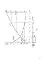
Сущность изобретения поясняется графическим материалом, представленным на фиг. 1 и 2.The invention is illustrated by the graphic material shown in FIG. 1 and 2.
Так, на фиг. 1 представлена схема электрической сети напряжением 380 В и графическая интерпретация определения зоны защиты воздушной линии от однофазных коротких замыканий; на фиг. 2 приведены паспортные защитные времятоковые характеристики tS.F=f(L) вставки плавкого предохранителя.So in FIG. 1 shows a diagram of an electrical network with a voltage of 380 V and a graphical interpretation of the definition of the protection zone of the overhead line from single-phase short circuits; in FIG. 2 shows the passport protective time-current characteristics tSF = f (L) of the fuse insert.
На схеме электрической сети показаны: Т - трансформатор напряжением 6-10/0,4 кВ, к которому через плавкий предохранитель F подключена четырехпроводная воздушная линия напряжением 380 В (ВЛ-380 В); F1 и F2 - плавкие предохранители, используемые для секционирования воздушной линии. На графике показаны:
Для интерпретации рассматриваемого способа в качестве примера взята электрическая сеть напряжением 380 В, которая питается от силового трансформатора Т типа ТМГ-160/10/0,4 со схемой соединения обмоток Y/YH. Воздушная линия напряжением 380 В имеет длину 500 м и выполнена неизолированным проводом АС-3×35+1×35 мм2. Для защиты воздушной линии в ее начале в трансформаторной подстанции установлен плавкий предохранитель F типа ПН-2 с номинальным током вставки IF.НОМ=100 А, значение которого выбрано из условия отстройки от рабочих и пусковых токов нагрузки воздушной линии. Вставка плавкого предохранителя F имеет паспортную защитную времятоковую характеристику tF=f(IF) с ±50%-ной зоной разброса срабатывания (фиг. 2). При рассмотрении характеристик защиты воздушной линии использована верхняя времятоковая характеристика (+50% разброса), соответствующая максимальным временам срабатывания плавкого предохранителя.To interpret the method under consideration, an example was taken of an electric network with a voltage of 380 V, which is powered by a power transformer T of the type TMG-160/10 / 0.4 with a connection circuit of the Y / YH windings. The overhead line voltage of 380 V has a length of 500 m and is made of uninsulated wire AC-3 × 35 + 1 × 35 mm2 . To protect the overhead line, a fuse F of type PN-2 with a rated insert current of IF.NOM = 100 A is installed at its beginning in the transformer substation, the value of which is selected from the condition of detuning from operating and starting currents of the overhead line load. The fuse insert F has a rated protective time-current characteristic tF = f (IF ) with a ± 50% response spread zone (Fig. 2). When considering the protection characteristics of the overhead line, the upper time-current characteristic (+ 50% dispersion) was used, corresponding to the maximum fuse times.
Сущность заявляемого способа определения места установки устройств секционирования воздушной линии 380 В заключается в следующих последовательных действиях:The essence of the proposed method for determining the installation location of the sectioning devices of the overhead line 380 V is the following sequential actions:
1. Рассчитывают минимальные токи однофазного короткого замыкания
1.1. Рассчитывают изменение сопротивления

где R1∑, R2∑, R0∑, Х1∑, Х1∑, X0∑ - активные и индуктивные сопротивления прямой, обратной и нулевой последовательности электрической сети напряжением 380 В, включающие в себя сопротивления питающего трансформатора напряжением 10/0,4 кВ и сопротивления воздушной линии напряжением 380 В, которые изменяются в зависимости от длины этой линии.where R1∑ , R2∑ , R0∑ , X1∑ , X1∑ , X0∑ are the active and inductive resistances of the direct, reverse and zero sequence of the electrical network voltage of 380 V, including the resistance of the supply transformer voltage of 10 / 0.4 kV and the resistance of the overhead line voltage of 380 V, which vary depending on the length of this line.
1.2. Рассчитывают согласно положениям [ГОСТ 28249-93. Короткие замыкания в электроустановках: Методы расчета в электроустановках переменного тока напряжением до 1кВ. - М.: Изд-во стандартов, 1994. - 42 с.] минимальный ток

где UCP.НН - среднее линейное напряжение на стороне низшего напряжения силового трансформатора Т.where UCP.HH is the average line voltage on the low voltage side of the power transformer T.
1.3. Рассчитывают уменьшение минимального тока дугового однофазного короткого замыкания, обусловленное наличием в месте замыкания сопротивления дуги RД и определяемое понижающим поправочным коэффициентом

1.4. Рассчитывают сначала увеличение активных сопротивлений фазного и нулевого проводов из-за нагрева ϑ при протекании по ним дугового минимального тока однофазного короткого замыкания (от эффекта «теплового спада»), потом соответствующее изменение полного сопротивления цепи току дугового однофазного короткого замыкания
1.5. Рассчитывают минимальный ток однофазного короткого замыкания

2. Строят график функции изменения величины минимального тока однофазного короткого замыкания от длины участка воздушной линии напряжением 380 В между трансформаторной подстанцией и точкой однофазного короткого замыкания

3. Выбирают по условиям отстройки от рабочих и пиковых токов электрической нагрузки воздушной линии напряжением 380 В номинальный ток IF.НОМ вставки плавкого предохранителя F и устанавливают его в трансформаторной подстанции в начале воздушной линии напряжением 380 В для ее защиты.3. According to the conditions of detuning from the working and peak currents of the electric load of the overhead line with a voltage of 380 V, the rated current IF. NOM insert fuses F and install it in a transformer substation at the beginning of the overhead line with a voltage of 380 V to protect it.
4. Рассчитывают, используя паспортные защитные времятоковые характеристики tF=f(IF) вставки выбранного плавкого предохранителя и график функции изменения величины минимального тока однофазного короткого замыкания от длины участка воздушной линии напряжением 380 В
Расчет зависимости tS.F=f(L) проводят в следующем порядке. Для каждого значения длины линии Li по графику


5. Определяют, руководствуясь требованиями [п.1.7.79, «Правила устройства электроустановок», 7-е издание] о том, что время отключения повреждения не должно превышать tS.F1=5 секунд, по зависимости tS.F=f(L) зону защиты LЗ.1 выбранного плавкого предохранителя F, установленного в трансформаторной подстанции в начале воздушной линии напряжением 380 В.5. Determine, guided by the requirements of [clause 1.7.79, “Electrical Installation Rules”, 7th edition] that the time to turn off damage should not exceed tS.F1 = 5 seconds, depending on the dependence tSF = f (L ) protection zone LЗ.1 of the selected fuse F installed in a transformer substation at the beginning of an overhead line with a voltage of 380 V.
6. Устанавливают в конце зоны защиты LЗ.1 секционирующий плавкий предохранитель F1 на ближайшую опору, находящуюся внутри зоны защиты LЗ.1, т.е. ближе к трансформатору Т, если установленный в трансформаторной подстанции в начале воздушной линии напряжением 380 В плавкий предохранитель F не обеспечивает защиту всей линии со временем срабатывания не более 5 секунд. Причем номинальный ток вставки секционирующего плавкого предохранителя F1 выбирают по условиям отстройки от рабочих и пиковых токов нагрузки оставшегося участка воздушной линии напряжением 380 В.6. Install at the end of the protection zone LЗ.1 a sectional fuse F1 at the nearest support located inside the protection zone LЗ.1 , i.e. closer to the transformer T, if a fuse F installed in the transformer substation at the beginning of the overhead line with a voltage of 380 V does not protect the entire line with a response time of no more than 5 seconds. Moreover, the rated insertion current of the sectional fuse F1 is selected according to the detuning conditions from the working and peak load currents of the remaining section of the overhead line with a voltage of 380 V.
При таком порядке установки секционирующего плавкого предохранителя F1 обеспечивается требование п. 1.7.79 Правил устройства электроустановок 7-го издания - время срабатывания плавкого предохранителя F, установленного в трансформаторной подстанции в начале воздушной линии напряжением 380 В, не превышает iS.F.1=5 секунд, при этом минимальный ток однофазного короткого замыкания в конце зоны защиты LЗ.1, определенный по зависимости


В заключение покажем какие характеристики имеет защита, построенная на основе прототипа. Исходным моментом для построения этой защиты является положение о том, что минимальное значение коэффициента чувствительности должно быть равно трем, т.е. КЧ=3 - этому соответствует значение минимального тока однофазного короткого замыкания

Таким образом, видно, что при возникновении однофазного короткого замыкания в конце зоны защиты, построенной на основе положений прототипа, при коэффициенте чувствительности КЧ=3 время перегорания плавкого предохранителя равно 80 с, что намного больше требований п. 1.7.79 «Правил устройства электроустановок» 7-го издания.Thus, it is seen that in the event of a single-phase short circuit at the end of the protection zone, built on the basis of the provisions of the prototype, with a sensitivity coefficient KP = 3, the fuse blow time is 80 s, which is much more than the requirements of paragraph 1.7.79 of the Electrical Installation Rules 7th edition.
Claims (1)
Translated fromRussianPriority Applications (1)
| Application Number | Priority Date | Filing Date | Title |
|---|---|---|---|
| RU2016100979ARU2610899C1 (en) | 2016-01-13 | 2016-01-13 | Method for determining installation site for devices for sectionalization of 380 v overhead line |
Applications Claiming Priority (1)
| Application Number | Priority Date | Filing Date | Title |
|---|---|---|---|
| RU2016100979ARU2610899C1 (en) | 2016-01-13 | 2016-01-13 | Method for determining installation site for devices for sectionalization of 380 v overhead line |
Publications (1)
| Publication Number | Publication Date |
|---|---|
| RU2610899C1true RU2610899C1 (en) | 2017-02-17 |
Family
ID=58458655
Family Applications (1)
| Application Number | Title | Priority Date | Filing Date |
|---|---|---|---|
| RU2016100979ARU2610899C1 (en) | 2016-01-13 | 2016-01-13 | Method for determining installation site for devices for sectionalization of 380 v overhead line |
Country Status (1)
| Country | Link |
|---|---|
| RU (1) | RU2610899C1 (en) |
Cited By (2)
| Publication number | Priority date | Publication date | Assignee | Title |
|---|---|---|---|---|
| CN107516880A (en)* | 2017-09-06 | 2017-12-26 | 中国电力科学研究院 | A half-wavelength transmission line pseudo-synchronous differential impedance protection phase selection method and device |
| CN114707323A (en)* | 2022-03-31 | 2022-07-05 | 北京恒华伟业科技股份有限公司 | Short-circuit current curve drawing method and device |
Citations (3)
| Publication number | Priority date | Publication date | Assignee | Title |
|---|---|---|---|---|
| US5465188A (en)* | 1990-12-13 | 1995-11-07 | Raychem Limited | Circuit protection device |
| RU2311699C2 (en)* | 2005-03-02 | 2007-11-27 | Открытое акционерное общество "Всероссийский научно-исследовательский проектно-конструкторский и технологический институт релестроения с опытным производством" | Method and device for protecting power distribution networks against arcing short circuits |
| RU2560081C2 (en)* | 2013-12-26 | 2015-08-20 | Федеральное государственное бюджетное образовательное учреждение высшего профессионального образования "Южно-Уральский государственный университет" (национальный исследовательский университет) (ФГБОУ ВПО "ЮУрГУ" (НИУ)) | SCHEME FOR RECOURSE-SAVING RELAY PROTECTION OF CABLE LINES 6(10)kV AND AREA-BASED AUTOMATIC RECLOSING IN DISTRIBUTING NETWORK |
- 2016
- 2016-01-13RURU2016100979Apatent/RU2610899C1/ennot_activeIP Right Cessation
Patent Citations (3)
| Publication number | Priority date | Publication date | Assignee | Title |
|---|---|---|---|---|
| US5465188A (en)* | 1990-12-13 | 1995-11-07 | Raychem Limited | Circuit protection device |
| RU2311699C2 (en)* | 2005-03-02 | 2007-11-27 | Открытое акционерное общество "Всероссийский научно-исследовательский проектно-конструкторский и технологический институт релестроения с опытным производством" | Method and device for protecting power distribution networks against arcing short circuits |
| RU2560081C2 (en)* | 2013-12-26 | 2015-08-20 | Федеральное государственное бюджетное образовательное учреждение высшего профессионального образования "Южно-Уральский государственный университет" (национальный исследовательский университет) (ФГБОУ ВПО "ЮУрГУ" (НИУ)) | SCHEME FOR RECOURSE-SAVING RELAY PROTECTION OF CABLE LINES 6(10)kV AND AREA-BASED AUTOMATIC RECLOSING IN DISTRIBUTING NETWORK |
Cited By (3)
| Publication number | Priority date | Publication date | Assignee | Title |
|---|---|---|---|---|
| CN107516880A (en)* | 2017-09-06 | 2017-12-26 | 中国电力科学研究院 | A half-wavelength transmission line pseudo-synchronous differential impedance protection phase selection method and device |
| CN107516880B (en)* | 2017-09-06 | 2021-12-21 | 中国电力科学研究院 | Pseudo-synchronous differential impedance protection phase selection method and device for half-wavelength power transmission line |
| CN114707323A (en)* | 2022-03-31 | 2022-07-05 | 北京恒华伟业科技股份有限公司 | Short-circuit current curve drawing method and device |
Similar Documents
| Publication | Publication Date | Title |
|---|---|---|
| AU2017210648B2 (en) | Surge suppression system for medium and high voltage | |
| RU2610899C1 (en) | Method for determining installation site for devices for sectionalization of 380 v overhead line | |
| Solovjeva et al. | Improving the methods for calculating the heating of low voltage cables | |
| Chaly et al. | Autocoordination of protection settings of series reclosers | |
| Ershov et al. | Protection of overhead lines with voltage of 380 V from the single-phase short circuits |
Legal Events
| Date | Code | Title | Description |
|---|---|---|---|
| MM4A | The patent is invalid due to non-payment of fees | Effective date:20180114 |