RU2610591C2 - Density phase separation device (versions) - Google Patents
Density phase separation device (versions)Download PDFInfo
- Publication number
- RU2610591C2 RU2610591C2RU2015111333ARU2015111333ARU2610591C2RU 2610591 C2RU2610591 C2RU 2610591C2RU 2015111333 ARU2015111333 ARU 2015111333ARU 2015111333 ARU2015111333 ARU 2015111333ARU 2610591 C2RU2610591 C2RU 2610591C2
- Authority
- RU
- Russia
- Prior art keywords
- separator
- float
- sample
- channel
- sample container
- Prior art date
Links
- 238000005191phase separationMethods0.000titledescription2
- 239000012530fluidSubstances0.000claimsabstractdescription107
- 238000007789sealingMethods0.000claimsabstractdescription75
- 230000003993interactionEffects0.000claimsabstractdescription44
- 238000000926separation methodMethods0.000claimsabstractdescription24
- 230000004888barrier functionEffects0.000claimsabstractdescription17
- 239000000463materialSubstances0.000claimsdescription25
- 230000009471actionEffects0.000claimsdescription23
- 239000007788liquidSubstances0.000claimsdescription11
- 230000007704transitionEffects0.000claimsdescription8
- 238000006073displacement reactionMethods0.000claimsdescription7
- 238000000034methodMethods0.000claimsdescription4
- 230000008569processEffects0.000claimsdescription2
- 239000000126substanceSubstances0.000abstractdescription2
- 239000000523sampleSubstances0.000description210
- 125000006850spacer groupChemical group0.000description28
- 210000004369bloodAnatomy0.000description25
- 239000008280bloodSubstances0.000description25
- 239000000306componentSubstances0.000description25
- 238000013461designMethods0.000description24
- 238000005119centrifugationMethods0.000description12
- 229920002725thermoplastic elastomerPolymers0.000description12
- 239000000499gelSubstances0.000description11
- 210000002966serumAnatomy0.000description11
- 238000005266castingMethods0.000description9
- -1polyethylene terephthalatePolymers0.000description7
- 239000007799corkSubstances0.000description5
- 239000003566sealing materialSubstances0.000description5
- 238000012360testing methodMethods0.000description5
- 102000009123FibrinHuman genes0.000description4
- 108010073385FibrinProteins0.000description4
- BWGVNKXGVNDBDI-UHFFFAOYSA-NFibrin monomerChemical compoundCNC(=O)CNC(=O)CNBWGVNKXGVNDBDI-UHFFFAOYSA-N0.000description4
- 238000004026adhesive bondingMethods0.000description4
- 230000008901benefitEffects0.000description4
- 210000004027cellAnatomy0.000description4
- 238000010276constructionMethods0.000description4
- 238000001125extrusionMethods0.000description4
- 229950003499fibrinDrugs0.000description4
- 238000003780insertionMethods0.000description4
- 230000037431insertionEffects0.000description4
- 238000004519manufacturing processMethods0.000description4
- 239000012528membraneSubstances0.000description4
- 229920000139polyethylene terephthalatePolymers0.000description4
- 239000005020polyethylene terephthalateSubstances0.000description4
- 230000002028prematureEffects0.000description4
- 239000007787solidSubstances0.000description4
- 239000000654additiveSubstances0.000description3
- 239000012503blood componentSubstances0.000description3
- 238000004891communicationMethods0.000description3
- 210000003743erythrocyteAnatomy0.000description3
- 230000005484gravityEffects0.000description3
- 238000012986modificationMethods0.000description3
- 230000004048modificationEffects0.000description3
- 239000010802sludgeSubstances0.000description3
- 238000003466weldingMethods0.000description3
- 239000004743PolypropyleneSubstances0.000description2
- 238000009825accumulationMethods0.000description2
- 239000000853adhesiveSubstances0.000description2
- 230000001070adhesive effectEffects0.000description2
- 238000004458analytical methodMethods0.000description2
- 230000015572biosynthetic processEffects0.000description2
- 238000010241blood samplingMethods0.000description2
- 210000001124body fluidAnatomy0.000description2
- 239000010839body fluidSubstances0.000description2
- 238000006243chemical reactionMethods0.000description2
- 239000013013elastic materialSubstances0.000description2
- 239000000945fillerSubstances0.000description2
- 239000011521glassSubstances0.000description2
- 229920000728polyesterPolymers0.000description2
- 229920001155polypropylenePolymers0.000description2
- 239000010421standard materialSubstances0.000description2
- 230000004913activationEffects0.000description1
- 230000006978adaptationEffects0.000description1
- 230000002411adverseEffects0.000description1
- 238000003556assayMethods0.000description1
- 230000000712assemblyEffects0.000description1
- 238000000429assemblyMethods0.000description1
- 239000012472biological sampleSubstances0.000description1
- 230000017531blood circulationEffects0.000description1
- 239000003795chemical substances by applicationSubstances0.000description1
- 239000000701coagulantSubstances0.000description1
- 238000005345coagulationMethods0.000description1
- 230000015271coagulationEffects0.000description1
- 238000005056compactionMethods0.000description1
- 230000006835compressionEffects0.000description1
- 238000007906compressionMethods0.000description1
- 230000008878couplingEffects0.000description1
- 238000010168coupling processMethods0.000description1
- 238000005859coupling reactionMethods0.000description1
- 230000007423decreaseEffects0.000description1
- 230000008021depositionEffects0.000description1
- 238000002405diagnostic procedureMethods0.000description1
- 229940042399direct acting antivirals protease inhibitorsDrugs0.000description1
- 229940079593drugDrugs0.000description1
- 239000003814drugSubstances0.000description1
- 239000013536elastomeric materialSubstances0.000description1
- 238000005516engineering processMethods0.000description1
- 239000008187granular materialSubstances0.000description1
- 230000002489hematologic effectEffects0.000description1
- 229910052500inorganic mineralInorganic materials0.000description1
- 230000007246mechanismEffects0.000description1
- 239000004005microsphereSubstances0.000description1
- 239000011707mineralSubstances0.000description1
- 238000002156mixingMethods0.000description1
- 238000000465mouldingMethods0.000description1
- 238000005192partitionMethods0.000description1
- 230000035515penetrationEffects0.000description1
- 239000000137peptide hydrolase inhibitorSubstances0.000description1
- 210000004180plasmocyteAnatomy0.000description1
- 239000002244precipitateSubstances0.000description1
- 238000001556precipitationMethods0.000description1
- 238000003825pressingMethods0.000description1
- 230000005855radiationEffects0.000description1
- 238000005070samplingMethods0.000description1
- 239000013049sedimentSubstances0.000description1
- 239000002195soluble materialSubstances0.000description1
- 239000007921spraySubstances0.000description1
- 230000001954sterilising effectEffects0.000description1
- 238000004659sterilization and disinfectionMethods0.000description1
- 238000003860storageMethods0.000description1
- 230000008719thickeningEffects0.000description1
- 230000009974thixotropic effectEffects0.000description1
Images


Classifications
- B—PERFORMING OPERATIONS; TRANSPORTING
- B01—PHYSICAL OR CHEMICAL PROCESSES OR APPARATUS IN GENERAL
- B01L—CHEMICAL OR PHYSICAL LABORATORY APPARATUS FOR GENERAL USE
- B01L3/00—Containers or dishes for laboratory use, e.g. laboratory glassware; Droppers
- B01L3/50—Containers for the purpose of retaining a material to be analysed, e.g. test tubes
- B01L3/502—Containers for the purpose of retaining a material to be analysed, e.g. test tubes with fluid transport, e.g. in multi-compartment structures
- B01L3/5021—Test tubes specially adapted for centrifugation purposes
- B01L3/50215—Test tubes specially adapted for centrifugation purposes using a float to separate phases
- B—PERFORMING OPERATIONS; TRANSPORTING
- B01—PHYSICAL OR CHEMICAL PROCESSES OR APPARATUS IN GENERAL
- B01D—SEPARATION
- B01D17/00—Separation of liquids, not provided for elsewhere, e.g. by thermal diffusion
- B01D17/02—Separation of non-miscible liquids
- A—HUMAN NECESSITIES
- A61—MEDICAL OR VETERINARY SCIENCE; HYGIENE
- A61B—DIAGNOSIS; SURGERY; IDENTIFICATION
- A61B5/00—Measuring for diagnostic purposes; Identification of persons
- A61B5/15—Devices for taking samples of blood
- A—HUMAN NECESSITIES
- A61—MEDICAL OR VETERINARY SCIENCE; HYGIENE
- A61B—DIAGNOSIS; SURGERY; IDENTIFICATION
- A61B5/00—Measuring for diagnostic purposes; Identification of persons
- A61B5/15—Devices for taking samples of blood
- A61B5/157—Devices characterised by integrated means for measuring characteristics of blood
- B—PERFORMING OPERATIONS; TRANSPORTING
- B01—PHYSICAL OR CHEMICAL PROCESSES OR APPARATUS IN GENERAL
- B01D—SEPARATION
- B01D17/00—Separation of liquids, not provided for elsewhere, e.g. by thermal diffusion
- B01D17/02—Separation of non-miscible liquids
- B01D17/0217—Separation of non-miscible liquids by centrifugal force
- B—PERFORMING OPERATIONS; TRANSPORTING
- B01—PHYSICAL OR CHEMICAL PROCESSES OR APPARATUS IN GENERAL
- B01D—SEPARATION
- B01D17/00—Separation of liquids, not provided for elsewhere, e.g. by thermal diffusion
- B01D17/12—Auxiliary equipment particularly adapted for use with liquid-separating apparatus, e.g. control circuits
- B—PERFORMING OPERATIONS; TRANSPORTING
- B01—PHYSICAL OR CHEMICAL PROCESSES OR APPARATUS IN GENERAL
- B01D—SEPARATION
- B01D21/00—Separation of suspended solid particles from liquids by sedimentation
- B01D21/24—Feed or discharge mechanisms for settling tanks
- B01D21/2405—Feed mechanisms for settling tanks
- G—PHYSICS
- G01—MEASURING; TESTING
- G01N—INVESTIGATING OR ANALYSING MATERIALS BY DETERMINING THEIR CHEMICAL OR PHYSICAL PROPERTIES
- G01N1/00—Sampling; Preparing specimens for investigation
- G01N1/02—Devices for withdrawing samples
- G01N1/10—Devices for withdrawing samples in the liquid or fluent state
- G01N1/18—Devices for withdrawing samples in the liquid or fluent state with provision for splitting samples into portions
- G—PHYSICS
- G01—MEASURING; TESTING
- G01N—INVESTIGATING OR ANALYSING MATERIALS BY DETERMINING THEIR CHEMICAL OR PHYSICAL PROPERTIES
- G01N1/00—Sampling; Preparing specimens for investigation
- G01N1/28—Preparing specimens for investigation including physical details of (bio-)chemical methods covered elsewhere, e.g. G01N33/50, C12Q
- G01N1/34—Purifying; Cleaning
- G—PHYSICS
- G01—MEASURING; TESTING
- G01N—INVESTIGATING OR ANALYSING MATERIALS BY DETERMINING THEIR CHEMICAL OR PHYSICAL PROPERTIES
- G01N1/00—Sampling; Preparing specimens for investigation
- G01N1/28—Preparing specimens for investigation including physical details of (bio-)chemical methods covered elsewhere, e.g. G01N33/50, C12Q
- G01N1/40—Concentrating samples
- G01N1/4077—Concentrating samples by other techniques involving separation of suspended solids
- G—PHYSICS
- G01—MEASURING; TESTING
- G01N—INVESTIGATING OR ANALYSING MATERIALS BY DETERMINING THEIR CHEMICAL OR PHYSICAL PROPERTIES
- G01N33/00—Investigating or analysing materials by specific methods not covered by groups G01N1/00 - G01N31/00
- G01N33/48—Biological material, e.g. blood, urine; Haemocytometers
- G01N33/483—Physical analysis of biological material
- G01N33/487—Physical analysis of biological material of liquid biological material
- G01N33/49—Blood
- B—PERFORMING OPERATIONS; TRANSPORTING
- B01—PHYSICAL OR CHEMICAL PROCESSES OR APPARATUS IN GENERAL
- B01D—SEPARATION
- B01D21/00—Separation of suspended solid particles from liquids by sedimentation
- B01D21/26—Separation of sediment aided by centrifugal force or centripetal force
- B01D21/262—Separation of sediment aided by centrifugal force or centripetal force by using a centrifuge
- G—PHYSICS
- G01—MEASURING; TESTING
- G01N—INVESTIGATING OR ANALYSING MATERIALS BY DETERMINING THEIR CHEMICAL OR PHYSICAL PROPERTIES
- G01N1/00—Sampling; Preparing specimens for investigation
- G01N1/28—Preparing specimens for investigation including physical details of (bio-)chemical methods covered elsewhere, e.g. G01N33/50, C12Q
- G01N1/40—Concentrating samples
- G01N1/4077—Concentrating samples by other techniques involving separation of suspended solids
- G01N2001/4083—Concentrating samples by other techniques involving separation of suspended solids sedimentation
- G—PHYSICS
- G01—MEASURING; TESTING
- G01N—INVESTIGATING OR ANALYSING MATERIALS BY DETERMINING THEIR CHEMICAL OR PHYSICAL PROPERTIES
- G01N33/00—Investigating or analysing materials by specific methods not covered by groups G01N1/00 - G01N31/00
- G01N33/48—Biological material, e.g. blood, urine; Haemocytometers
- G01N33/483—Physical analysis of biological material
- G01N33/487—Physical analysis of biological material of liquid biological material
- G01N33/49—Blood
- G01N33/491—Blood by separating the blood components
- Y—GENERAL TAGGING OF NEW TECHNOLOGICAL DEVELOPMENTS; GENERAL TAGGING OF CROSS-SECTIONAL TECHNOLOGIES SPANNING OVER SEVERAL SECTIONS OF THE IPC; TECHNICAL SUBJECTS COVERED BY FORMER USPC CROSS-REFERENCE ART COLLECTIONS [XRACs] AND DIGESTS
- Y10—TECHNICAL SUBJECTS COVERED BY FORMER USPC
- Y10T—TECHNICAL SUBJECTS COVERED BY FORMER US CLASSIFICATION
- Y10T436/00—Chemistry: analytical and immunological testing
- Y10T436/25—Chemistry: analytical and immunological testing including sample preparation
- Y10T436/25375—Liberation or purification of sample or separation of material from a sample [e.g., filtering, centrifuging, etc.]
Landscapes
- Health & Medical Sciences (AREA)
- Life Sciences & Earth Sciences (AREA)
- Chemical & Material Sciences (AREA)
- Physics & Mathematics (AREA)
- Engineering & Computer Science (AREA)
- General Health & Medical Sciences (AREA)
- Hematology (AREA)
- Analytical Chemistry (AREA)
- Biomedical Technology (AREA)
- Chemical Kinetics & Catalysis (AREA)
- Pathology (AREA)
- Immunology (AREA)
- General Physics & Mathematics (AREA)
- Biochemistry (AREA)
- Molecular Biology (AREA)
- Clinical Laboratory Science (AREA)
- Biophysics (AREA)
- Thermal Sciences (AREA)
- Food Science & Technology (AREA)
- Medicinal Chemistry (AREA)
- Urology & Nephrology (AREA)
- Public Health (AREA)
- Veterinary Medicine (AREA)
- Heart & Thoracic Surgery (AREA)
- Medical Informatics (AREA)
- Surgery (AREA)
- Animal Behavior & Ethology (AREA)
- Ecology (AREA)
- Hydrology & Water Resources (AREA)
- Centrifugal Separators (AREA)
- Sampling And Sample Adjustment (AREA)
- Investigating Or Analysing Biological Materials (AREA)
- External Artificial Organs (AREA)
- Vehicle Body Suspensions (AREA)
- Hard Magnetic Materials (AREA)
- Optical Communication System (AREA)
- Measurement Of The Respiration, Hearing Ability, Form, And Blood Characteristics Of Living Organisms (AREA)
Abstract
Description
Translated fromRussianОбласть техникиTechnical field
Изобретение относится к устройству для разделения фракций с более низкой и более высокой плотностями пробы текучей среды. Более конкретно, настоящее изобретение относится к устройству для взятия и транспортировки проб текучей среды, в процессе которой устройство и пробу текучей среды подвергают центрифугированию для отделения фракции с более высокой плотностью от фракции с более низкой плотностью.The invention relates to a device for separating fractions with lower and higher densities of a fluid sample. More specifically, the present invention relates to a device for collecting and transporting samples of a fluid, in which the device and a sample of a fluid are centrifuged to separate a fraction of a higher density from a fraction of a lower density.
Уровень техникиState of the art
При осуществлении диагностических тестов может потребоваться разделение пробы цельной крови пациента на компоненты, такие как сыворотка или плазма (компоненты с более низкой плотностью), и красные кровяные тельца (компоненты с более высокой плотностью). Пробы цельной крови обычно берут путем венопункции с использованием канюли или иглы, прикрепленной к шприцу или к вакуумной пробирке для сбора взятой крови. После взятия пробы крови ее разделение на сыворотку или плазму и красные кровяные тельца осуществляется путем вращения шприца или пробирки в центрифуге. Для поддержания состояния разделения текучей среды необходимо обеспечить барьер между разделенными компонентами с более высокой и более низкой плотностями. Таким образом, анализ разделенных компонентов можно будет проводить через некоторое время.When performing diagnostic tests, it may be necessary to separate the patient’s whole blood sample into components such as serum or plasma (components with a lower density) and red blood cells (components with a higher density). Whole blood samples are usually taken by venipuncture using a cannula or needle attached to a syringe or to a vacuum tube to collect the collected blood. After taking a blood sample, its separation into serum or plasma and red blood cells is carried out by rotating the syringe or test tube in a centrifuge. To maintain the state of fluid separation, it is necessary to provide a barrier between the separated components with higher and lower densities. Thus, analysis of the separated components can be carried out after some time.
В устройствах взятия крови использовались разные барьеры для разделения этих устройств на зоны фаз пробы с более высокой плотностью и более низкой плотностью. В наиболее широко используемых устройствах для этой цели используются материалы из тиксотропного геля, такого как полиэфирный гель. Однако современные пробирки с современными полиэфирными гелями для отделения сыворотки требуют специального производственного оборудования для приготовления геля и заполнения им пробирок. Кроме того, разделительные средства на основе гелей имеют ограниченный срок хранения. Со временем из массы геля могут высвобождаться глобулы и поступать в один или в оба разделенных компонента. Кроме того, имеющиеся на рынке гелевые барьеры могут вступать в химические реакции с анализируемыми компонентами. Соответственно, если в пробе крови присутствуют некоторые лекарственные препараты, могут происходить нежелательные химические реакции с материалом гелевого разделительного слоя. Кроме того, если зонд прибора вводится слишком глубоко в контейнер с пробой, то зонд может быть забит в результате контакта с гелем.Different barriers were used in the blood sampling devices to separate these devices into zones of sample phases with a higher density and lower density. The most commonly used devices for this purpose use materials from a thixotropic gel, such as a polyester gel. However, modern test tubes with modern polyester gels for separating serum require special manufacturing equipment for preparing the gel and filling the test tubes with it. In addition, gel-based release agents have a limited shelf life. Over time, globules can be released from the gel mass and enter one or both of the separated components. In addition, commercially available gel barriers can enter into chemical reactions with the analyzed components. Accordingly, if some drugs are present in the blood sample, undesirable chemical reactions may occur with the material of the gel separation layer. In addition, if the probe is inserted too deep into the sample container, the probe may be blocked due to contact with the gel.
Были предложены механические разделители, в которых использовался механический барьер между фазами более высокой и более низкой плотности пробы текучей среды. Обычно механические барьеры устанавливаются между фазовыми компонентами с более высокой и более низкой плотностями с использованием повышенной силы тяжести, возникающей в процессе центрифугирования. Для надлежащей ориентации относительно образцов плазмы и сыворотки обычно механические сепараторы располагают перед центрифугированием над взятой пробой цельной крови. В этом случае обычно требуется, чтобы механический сепаратор был прикреплен к нижней стороне пробки пробирки таким образом, чтобы кровь поступала сквозь устройство и вокруг него при соединении с комплектом для взятия крови или с иглой. Такое прикрепление необходимо для предотвращения преждевременного смещения разделителя при транспортировке устройства и взятии крови. Известные механические разделители обычно прикрепляют к пробке пробирки с помощью механического фиксатора, соединяющего мембранный компонент и пробку.Mechanical separators have been proposed that utilize a mechanical barrier between phases of higher and lower density fluid samples. Typically, mechanical barriers are placed between phase components with higher and lower densities using the increased gravity that occurs during centrifugation. For proper orientation relative to plasma and serum samples, mechanical separators are usually placed before centrifugation over a sample of whole blood. In this case, it is usually required that the mechanical separator be attached to the underside of the tube tube so that blood flows through and around the device when connected to a blood collection kit or needle. Such attachment is necessary to prevent premature displacement of the separator during transportation of the device and blood collection. Known mechanical dividers are usually attached to the tube tube using a mechanical retainer connecting the membrane component and the tube.
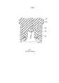
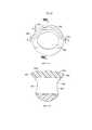
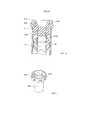
Известные механические разделители имеют существенные недостатки. Как показано на фиг. 1, конструкция известных разделителей содержит мембранный элемент 34, обеспечивающий уплотнение стенки 38 пробирки или шприца. Обычно по меньшей мере часть мембранного элемента 34 находится внутри или в контакте с пробкой 32. Как показано на фиг. 1, когда игла 30 проходит через пробку 32, мембранный элемент 34 вдавливается. При этом формируется полость 36, в которой может собираться кровь при введении или удалении иглы. Это может приводить к накапливанию пробы под пробкой, к преждевременному срабатыванию устройства, при котором механический разделитель преждевременно высвобождается при взятии крови, к захвату значительного количества фаз текучей среды, таких как сыворотка или плазма, к плохому качеству пробы, и/или в некоторых случаях к нарушению барьера. Кроме того, известные механические разделители дороги и сложны в производстве в связи со сложностью изготовления многокомпонентных устройств.Known mechanical dividers have significant drawbacks. As shown in FIG. 1, the design of the known separators comprises a
Соответственно, имеется потребность в разделительном устройстве, которое совместимо со стандартным оборудованием для взятия проб, ослабляет или вообще устраняет вышеуказанные проблемы традиционных разделителей. Также существует потребность в разделительном устройстве, которое можно легко и просто использовать для разделения пробы крови, в котором минимизируется взаимное проникновение фаз пробы, имеющих более высокую и более низкую плотности, работа которого не зависит от температуры при хранении и транспортировке и стойкого к радиационной стерилизации. Также существует потребность в компактном разделительном устройстве, содержащем сравнительно мало движущихся частей и обеспечивающем более простое введение пробы в контейнер.Accordingly, there is a need for a separation device that is compatible with standard sampling equipment, mitigates or eliminates the above problems of conventional separators. There is also a need for a separation device that can be easily and simply used to separate a blood sample, in which the mutual penetration of sample phases having a higher and lower density is minimized, the operation of which is independent of temperature during storage and transportation and is resistant to radiation sterilization. There is also a need for a compact separation device containing relatively few moving parts and providing easier insertion of the sample into the container.
Раскрытие изобретенияDisclosure of invention
В настоящем изобретении предлагается узел для обеспечения разделения пробы жидкости на первую и вторую фазы, содержащий:The present invention provides an assembly for separating a liquid sample into first and second phases, comprising:
контейнер для (сбора) пробы, имеющий открытый конец, закрытый конец и боковую стенку, проходящую между ними и формирующую внутреннее пространство, причем контейнер для пробы имеет продольную ось, проходящую между открытым и закрытым концами;a container for (collecting) a sample having an open end, a closed end, and a side wall passing between them and forming an internal space, the sample container having a longitudinal axis passing between the open and closed ends;
запорный элемент, выполненный с возможностью уплотняющего взаимодействия с открытым концом контейнера для пробы; иa locking element configured to seal with the open end of the sample container; and
разделитель, размещенный внутри контейнера для пробы и взаимодействующий с частью боковой стенки со стороны открытого конца в исходном положении при введении пробы текучей среды в контейнер для пробы, причем в разделителе сформирован сквозной канал для обеспечения прохождения через него жидкости, и разделитель содержит:a separator placed inside the sample container and interacting with the side wall part from the open end side in the initial position when the fluid sample is introduced into the sample container, and a through channel is formed in the separator to allow liquid to pass through it, and the separator contains:
поплавок, имеющий первую плотность; иa float having a first density; and
балласт, имеющий вторую плотность, превышающую первую плотность, причем часть поплавка соединена с частью балласта,a ballast having a second density greater than the first density, wherein a part of the float is connected to a part of the ballast,
при этом запорный элемент выполнен с возможностью его прокалывания канюлей для введения пробы текучей среды в контейнер для пробы и нахождения канюли в процессе введения пробы в контейнер на расстоянии от разделителя.wherein the locking element is configured to pierce the cannula to introduce a fluid sample into the sample container and to find the cannula in the process of introducing the sample into the container at a distance from the separator.
Кроме того, в настоящем изобретении предлагается узел разделителя для обеспечения разделения пробы текучей среды на первую и вторую фазы, содержащий:In addition, the present invention provides a separator assembly for separating a fluid sample into first and second phases, comprising:
контейнер для пробы, имеющий первый конец, второй конец и боковую стенку, проходящую между ними, при этом продольная ось контейнера для пробы проходит между первым и вторым концами;a sample container having a first end, a second end and a side wall extending between them, wherein the longitudinal axis of the sample container extends between the first and second ends;
запорный элемент, выполненный с возможностью уплотняющего взаимодействия с первым концом контейнера для пробы; иa locking element configured to seal with the first end of the sample container; and
устройство, содержащее разделитель со сформированным в нем сквозным каналом, причем под действием центробежной силы, приложенной к узлу разделителя, или к контейнеру для пробы, или к разделителю, разделитель способен переходить из первого положения, в котором сквозной канал находится в открытом положении, не поперек продольной оси контейнера для пробы, для прохождения текучей среды через него, во второе положение, в котором сквозной канал находится в закрытом положении, не параллельно продольной оси контейнера для пробы, для предотвращения прохождения текучей среды через него,a device containing a separator with a through channel formed in it, and under the action of centrifugal force applied to the node of the separator, or to the container for the sample, or to the separator, the separator is able to move from the first position in which the through channel is in the open position, not across the longitudinal axis of the sample container to allow fluid to pass through it to a second position in which the through channel is in the closed position, not parallel to the longitudinal axis of the sample container, to prevent Ia passage of fluid therethrough,
причем разделитель выполнен с возможностью нахождения на расстоянии от канюли при введении пробы в контейнер,moreover, the separator is arranged to be located at a distance from the cannula when introducing the sample into the container,
разделитель имеет по меньшей мере один уплотняющий периметр, который, когда разделитель находится во втором положении, взаимодействует с боковой стенкой контейнера для пробы с обеспечением между ними уплотнения, предотвращающего прохождение текучей среды между разделителем и боковой стенкой и по сквозному каналу, иthe separator has at least one sealing perimeter, which, when the separator is in the second position, interacts with the side wall of the sample container to provide a seal between them, preventing the passage of fluid between the separator and the side wall and through the channel, and
по меньшей мере часть разделителя выполнена с возможностью деформации под действием центробежной силы.at least part of the separator is capable of deformation under the influence of centrifugal force.
В настоящем изобретении также предлагается узел разделителя для обеспечения разделения пробы текучей среды на первую и вторую фазы, содержащий:The present invention also provides a separator assembly for separating a fluid sample into first and second phases, comprising:
контейнер для пробы, имеющий первый конец, второй конец и боковую стенку, проходящую между ними;a sample container having a first end, a second end and a side wall extending between them;
запорный элемент, выполненный с возможностью уплотняющего взаимодействия с первым концом контейнера для пробы; иa locking element configured to seal with the first end of the sample container; and
устройство, содержащее корпус со сформированным в нем сквозным каналом и имеющее первый периметр уплотнения для обеспечения уплотняющего взаимодействия с первой частью контейнера для пробы, при котором проба может проходить через сквозной канал в контейнер, и второй периметр уплотнения для обеспечения уплотняющего взаимодействия со второй частью контейнера для пробы, при котором обеспечивается разделительный барьер между первой и второй фазами,a device comprising a housing with a through channel formed therein and having a first seal perimeter for providing sealing interaction with the first part of the sample container, wherein the sample can pass through the through channel into the container, and a second seal perimeter for providing sealing interaction with the second container part for samples, which provides a separation barrier between the first and second phases,
при этом сквозной канал сформирован вдоль оси, и первый и второй периметры уплотнения составляют разные углы с осью сквозного канала.wherein the through channel is formed along the axis, and the first and second perimeters of the seal are different angles with the axis of the through channel.
Далее, для лучшего понимания настоящего изобретения, будут описаны различные аспекты, относящиеся к настоящему изобретению или его концепциям.Further, for a better understanding of the present invention, various aspects related to the present invention or its concepts will be described.
В общем настоящее изобретение относится к узлу разделителя для разделения пробы текучей среды на фазу с более высокой плотностью и фазу с более низкой плотностью. В предпочтительных вариантах механический разделитель по настоящему изобретению может использоваться с контейнером для (сбора) пробы, таким как трубка, и имеет такую конструкцию, которая обеспечивает его перемещение в трубке под действием приложенной центробежной силы для разделения компонентов пробы текучей среды. В некоторых вариантах трубка представляет собой пробирку для пробы, содержащую открытый конец, закрытый конец и боковую стенку, проходящую между открытым и закрытым концами. Боковая стенка имеет внешнюю поверхность и внутреннюю поверхность, и пробирка также содержит пробку (запорный элемент), которая плотно садится в открытый конец пробирки, с повторно герметизируемой перегородкой. В других вариантах оба конца трубки могут быть открытыми, и они могут быть герметично закрыты эластомерными пробками. По меньшей мере одна из пробок трубки может иметь перегородку, прокалываемую иглой с возможностью повторной герметизации перегородки.In general, the present invention relates to a separator assembly for separating a fluid sample into a phase with a higher density and a phase with a lower density. In preferred embodiments, the mechanical separator of the present invention can be used with a sample collection container, such as a tube, and is configured to move it in the tube under the action of centrifugal force to separate the components of the sample fluid. In some embodiments, the tube is a sample tube containing an open end, a closed end, and a side wall extending between the open and closed ends. The side wall has an outer surface and an inner surface, and the tube also contains a plug (locking element), which fits tightly into the open end of the tube, with a re-sealed partition. In other embodiments, both ends of the tube may be open, and they may be hermetically sealed with elastomeric plugs. At least one of the tube plugs may have a septum pierced by a needle with the possibility of resealing the septum.
Механический разделитель может быть расположен внутри пробирки между верхней пробкой и ее дном. Компоненты разделителя имеют такие размеры и такую конструкцию, чтобы его общая плотность находилась между величинами плотностей фаз пробы текучей среды, таких как фаза с более высокой плотностью и фаза с более низкой плотностью пробы крови.A mechanical separator may be located inside the tube between the top tube and its bottom. The components of the separator are sized and designed so that their total density is between the densities of the phases of the fluid sample, such as the phase with the higher density and the phase with the lower density of the blood sample.
В соответствии с одним из вариантов осуществления механический разделитель для разделения пробы текучей среды на первую и вторую фазы внутри контейнера для пробы содержит корпус разделителя со сформированным в нем сквозным каналом. Сквозной канал предназначен для прохождения через него текучей среды. Корпус разделителя содержит поплавок, имеющий первую плотность, и балласт, имеющий вторую плотность, превышающую первую плотность. Часть поплавка присоединена к части балласта.In accordance with one embodiment, a mechanical separator for separating a fluid sample into first and second phases inside a sample container comprises a separator body with a through passage formed therein. The through channel is intended for the passage of fluid through it. The separator housing comprises a float having a first density and a ballast having a second density in excess of the first density. Part of the float attached to part of the ballast.
Механический разделитель может иметь шарообразную (сфероидальную) форму. Поплавок может иметь внешнюю поверхность и соединительную поверхность, и балласт может иметь контактную поверхность, присоединенную к соединительной поверхности поплавка, и внешнюю поверхность. Внешняя поверхность поплавка и внешняя поверхность балласта вместе могут образовывать шарообразную форму.The mechanical separator may have a spherical (spheroidal) shape. The float may have an external surface and a connecting surface, and the ballast may have a contact surface attached to the connecting surface of the float, and an external surface. The outer surface of the float and the outer surface of the ballast together can form a spherical shape.
В некоторых вариантах сквозной канал для прохождения через него текучей среды сформирован в поплавке. Поперечное сечение сквозного канала может иметь круговую форму. В других вариантах поперечное сечение сквозного канала может иметь эллиптическую форму. Сквозной канал может проходить по оси (осевой линии) сквозного канала, и поплавок может быть выполнен с возможностью деформации в направлении, перпендикулярном этой оси, под действием приложенной силы, возникающей при вращении (далее "центробежная сила").In some embodiments, a through passage for passage of fluid through it is formed in the float. The cross section of the through channel may have a circular shape. In other embodiments, the cross section of the through channel may be elliptical. The through channel can pass along the axis (axial line) of the through channel, and the float can be deformed in the direction perpendicular to this axis under the action of the applied force arising from rotation (hereinafter “centrifugal force”).
В другом варианте поплавок может содержать дополнительно первый протяженный выступ, прилегающий к первому проему сквозного канала, и второй протяженный выступ, прилегающий ко второму проему сквозного канала. По меньшей мере часть первого протяженного выступа и по меньшей мере часть второго протяженного выступа могут обеспечиваться выше и вокруг сквозного канала и отходить радиально от поплавка в направлении, параллельном оси сквозного канала корпуса разделителя. Дополнительно, первый протяженный выступ, верхняя поверхность поплавка и второй протяженный выступ могут формировать выпуклую верхнюю поверхность поплавка.In another embodiment, the float may further comprise a first extended protrusion adjacent to the first opening of the through channel and a second extended protrusion adjacent to the second opening of the through channel. At least a portion of the first extended protrusion and at least a portion of the second extended protrusion can be provided above and around the through channel and extend radially from the float in a direction parallel to the axis of the through channel of the separator body. Additionally, the first extended protrusion, the upper surface of the float and the second extended protrusion can form a convex upper surface of the float.
В некоторых вариантах корпус разделителя также содержит протяженный ленточный выступ, проходящий по части внешней поверхности поплавка. Дополнительно, протяженный ленточный выступ содержит первую часть, расположенную смежно с первым проемом сквозного канала, и вторую часть, расположенную рядом со вторым проемом сквозного канала. В другом варианте первая часть протяженного ленточного выступа и/или вторая часть протяженного ленточного выступа имеет вогнутую форму, если смотреть снизу. Дополнительно, первая часть протяженного ленточного выступа и/или вторая часть протяженного ленточного выступа имеют отходящую наружу дугообразную форму, охватывающую верхнюю часть по меньшей мере одного из первого и второго проемов сквозного канала. Первая часть и/или вторая часть протяженного ленточного выступа могут отходить наружу от поплавка в направлении, параллельном оси сквозного канала. По меньшей мере часть первой части и по меньшей мере часть второй части протяженного ленточного выступа могут иметь одинаковую форму и кривизну. В некоторых вариантах протяженный ленточный выступ содержит также соединительную часть, расположенную между первой частью и второй частью протяженного ленточного выступа для их соединения по обеим сторонам корпуса разделителя. Первая часть и вторая часть протяженного ленточного выступа имеют вогнутую форму, если смотреть снизу, и соединительные части протяженного ленточного выступа имеют вогнутую форму, если смотреть сверху. В некоторых вариантах протяженный ленточный выступ может быть выполнен как одно целое с поплавком. Дополнительно, поплавок и протяженный ленточный выступ могут быть сформированы из термопластичного эластомера, и балласт сформирован из полиэтилентерефталата.In some embodiments, the separator housing also includes an extended belt protrusion extending over part of the outer surface of the float. Additionally, the extended tape protrusion contains a first part located adjacent to the first opening of the through channel, and a second part located next to the second opening of the through channel. In another embodiment, the first part of the extended tape protrusion and / or the second part of the extended tape protrusion has a concave shape when viewed from below. Additionally, the first part of the extended tape protrusion and / or the second part of the extended tape protrusion have an outward arcuate shape, covering the upper part of at least one of the first and second openings of the through channel. The first part and / or the second part of the extended tape protrusion can extend outward from the float in a direction parallel to the axis of the through channel. At least part of the first part and at least part of the second part of the extended tape protrusion can have the same shape and curvature. In some embodiments, the extended tape protrusion also includes a connecting part located between the first part and the second part of the extended tape protrusion for connecting them on both sides of the separator housing. The first part and the second part of the extended tape protrusion are concave when viewed from below, and the connecting parts of the extended tape protrusion are concave when viewed from above. In some embodiments, an extended belt protrusion may be integral with the float. Additionally, the float and the extended tape protrusion can be formed from a thermoplastic elastomer, and the ballast is formed from polyethylene terephthalate.
Механический разделитель может содержать также полосу взаимодействия в исходном положении, проходящую по корпусу разделителя. Полоса взаимодействия в исходном положении может быть непрерывной или может иметь разрывы по меньшей мере на части ее длины. Поплавок и полоса взаимодействия в исходном положении могут быть сформированы из одного материала. Полоса взаимодействия в исходном положении может разделять на две части по меньшей мере часть балласта.The mechanical separator may also contain a band of interaction in the initial position, passing through the housing of the separator. The interaction band in the initial position may be continuous or may have gaps in at least part of its length. The float and the interaction band in the initial position can be formed from one material. The interaction band in the initial position can be divided into two parts at least part of the ballast.
В другом варианте балласт может содержать основание и соединительную конструкцию для соединения с частью поплавка. Соединительная конструкция может представлять собой несколько кронштейнов для соединения с поплавком, и соединительная конструкция может изгибаться, обеспечивая возможность смещения поплавка и балласта относительно друг друга. Дополнительно, по меньшей мере часть поплавка может иметь круговой внешний периметр, имеющий криволинейную форму в сечении, перпендикулярном сквозному каналу. В некоторых вариантах поплавок может содержать соединительную конструкцию для соединения с частью балласта. Соединительная конструкция может представлять собой несколько кронштейнов для соединения с частью балласта, и соединительная конструкция может обеспечивать возможность смещения поплавка и балласта относительно друг друга.In another embodiment, the ballast may contain a base and a connecting structure for connection with a part of the float. The connecting structure may be several brackets for connecting to the float, and the connecting structure may be bent, allowing the float and ballast to move relative to each other. Additionally, at least a portion of the float may have a circular outer perimeter having a curved shape in cross section perpendicular to the through channel. In some embodiments, the float may comprise a connecting structure for connection to a portion of the ballast. The connecting structure may comprise several brackets for connection with a part of the ballast, and the connecting structure may allow the float and the ballast to move relative to each other.
В другом варианте осуществления обеспечивается узел разделителя для обеспечения возможности разделения пробы текучей среды на первую и вторую фазы, который содержит контейнер для пробы, имеющий первый конец, второй конец и боковую стенку, проходящую между ними. Контейнер для пробы имеет продольную ось (осевую линию), проходящую между первым концом и вторым концом. Узел разделителя содержит также механический разделитель, содержащий корпус разделителя со сформированным в нем сквозным каналом. Корпус разделителя выполнен с возможностью перехода из первого (исходного) положения, в котором сквозной канал направлен так, что он находится в открытом положении для обеспечения прохождения через него текучей среды, во второе (уплотняющее) положение, в котором сквозной канал направлен так, что он находится в закрытом положении для предотвращения прохождения через него текучей среды при действии центробежной силы.In another embodiment, a separator assembly is provided to allow separation of the fluid sample into first and second phases, which comprises a sample container having a first end, a second end, and a side wall extending between them. The sample container has a longitudinal axis (center line) extending between the first end and the second end. The separator assembly also contains a mechanical separator comprising a separator housing with a through channel formed therein. The separator housing is adapted to transition from a first (initial) position in which the through channel is directed so that it is in an open position to allow fluid to pass through it, into a second (sealing) position in which the through channel is directed so that it is in the closed position to prevent the passage of fluid through it under the action of centrifugal force.
В одном из вариантов узел разделителя содержит также пробку для уплотняющего взаимодействия с первым концом контейнера для пробы, причем механический разделитель соединен с частью пробки с возможностью его отсоединения. Механический разделитель может быть соединен с частью пробки в первом (исходном) положении, и механический разделитель может взаимодействовать с частью боковой стенки контейнера для пробы во втором (уплотняющем) положении. Пробка может содержать соединительный выступ, находящийся внутри части сквозного канала, когда корпус разделителя находится в первом (исходном) положении, для формирования между частью корпуса разделителя и пробкой уплотнения, предотвращающего прохождение текучей среды. По меньшей мере часть сквозного канала механического разделителя ориентирована в направлении продольной оси контейнера для пробы в первом (исходном) положении, и по меньшей мере часть сквозного канала ориентирована перпендикулярно продольной оси контейнера для пробы во втором (уплотняющем) положении. Переход сквозного канала из открытого положения в закрытое положение может совпадать с поворотом механического разделителя из первого (исходного) положения во второе (уплотняющее) положение. Механический разделитель может взаимодействовать с частью стенки контейнера для пробы для обеспечения уплотнения между ними во втором (уплотняющем) положении для предотвращения прохождения текучей среды через механический разделитель или вокруг него. В некоторых вариантах поплавок содержит также первый протяженный выступ, прилегающий к первому проему сквозного канала, и второй протяженный выступ, прилегающий ко второму проему сквозного канала. Первый протяженный выступ и второй протяженный выступ могут взаимодействовать с частью боковой стенки контейнера для пробы во втором (уплотняющем) положении. В других вариантах корпус разделителя также содержит протяженный ленточный выступ, проходящий по части внешней поверхности поплавка. Протяженный ленточный может взаимодействовать с боковой стенкой контейнера для пробы во втором (уплотняющем) положении, и протяженный ленточный выступ может формировать непрерывное уплотнение с боковой стенкой контейнера для пробы во втором (уплотняющем) положении.In one embodiment, the separator assembly also includes a plug for sealing interaction with the first end of the sample container, the mechanical separator being connected to a part of the plug so that it can be disconnected. The mechanical separator can be connected to the cork part in the first (initial) position, and the mechanical separator can interact with the side part of the sample container in the second (sealing) position. The plug may include a connecting protrusion located inside the part of the through channel when the separator housing is in the first (initial) position, for forming between the part of the separator housing and the seal plug, preventing the passage of fluid. At least part of the through channel of the mechanical separator is oriented in the direction of the longitudinal axis of the sample container in the first (initial) position, and at least part of the through channel is oriented perpendicular to the longitudinal axis of the sample container in the second (sealing) position. The transition of the through channel from the open position to the closed position may coincide with the rotation of the mechanical separator from the first (initial) position to the second (sealing) position. The mechanical separator may interact with a portion of the wall of the sample container to provide a seal therebetween in the second (sealing) position to prevent the passage of fluid through or around the mechanical separator. In some embodiments, the float also comprises a first extended protrusion adjacent to the first opening of the through channel and a second extended protrusion adjacent to the second opening of the through channel. The first extended protrusion and the second extended protrusion can interact with a part of the side wall of the sample container in the second (sealing) position. In other embodiments, the separator housing also comprises an extended belt protrusion extending over part of the outer surface of the float. The extended tape can interact with the side wall of the sample container in the second (sealing) position, and the extended tape protrusion can form a continuous seal with the side wall of the sample container in the second (sealing) position.
В других вариантах балласт содержит соединительную конструкцию для соединения с частью поплавка, и по меньшей мере часть поплавка имеет круговой внешний периметр, имеющий криволинейную форму в сечении, перпендикулярном сквозному каналу. Внешний периметр поплавка может формировать непрерывное уплотнение с боковой стенкой контейнера для пробы во втором (уплотняющем) положении. Дополнительно, поплавок может содержать соединительную конструкцию для соединения с частью балласта, и по меньшей мере часть поплавка имеет круговой внешний периметр, имеющий криволинейную форму в сечении, перпендикулярном сквозному каналу, причем внешний периметр поплавка формирует непрерывное уплотнение с боковой стенкой контейнера для пробы во втором (уплотняющем) положении.In other embodiments, the ballast comprises a connecting structure for connecting to a portion of the float, and at least a portion of the float has a circular outer perimeter having a curved shape in cross section perpendicular to the through channel. The outer perimeter of the float may form a continuous seal with the side wall of the sample container in the second (sealing) position. Additionally, the float may include a connecting structure for connection with a part of the ballast, and at least a portion of the float has a circular external perimeter having a curved shape in cross section perpendicular to the through channel, the outer perimeter of the float forming a continuous seal with the side wall of the sample container in the second ( sealing) position.
В другом варианте осуществления обеспечивается узел разделителя для обеспечения возможности разделения пробы текучей среды на первую и вторую фазы, который содержит контейнер для пробы, имеющий первый конец, второй конец и боковую стенку, проходящую между ними. Узел разделителя содержит также механический разделитель, содержащий корпус разделителя со сформированным в нем сквозным каналом. Корпус разделителя имеет первый периметр уплотнения для обеспечения уплотняющего взаимодействия с первой частью контейнера для пробы, при котором проба может проходить через сквозной канал в контейнер, и второй периметр уплотнения для обеспечения уплотняющего взаимодействия со второй частью контейнера для пробы, при котором обеспечивается разделительный барьер между первой и второй фазами.In another embodiment, a separator assembly is provided to allow separation of the fluid sample into first and second phases, which comprises a sample container having a first end, a second end, and a side wall extending between them. The separator assembly also contains a mechanical separator comprising a separator housing with a through channel formed therein. The separator body has a first seal perimeter to provide sealing interaction with the first part of the sample container, in which the sample can pass through the through channel into the container, and a second seal perimeter to provide sealing interaction with the second part of the sample container, which provides a separation barrier between the first and second phases.
Узел разделителя может содержать пробку для уплотняющего взаимодействия с открытым концом контейнера для пробы, причем механический разделитель соединен с частью пробки с возможностью его отсоединения.The separator assembly may include a plug for sealing interaction with the open end of the sample container, the mechanical separator being connected to the plug part to detach it.
В другом варианте осуществления обеспечивается узел разделителя для обеспечения возможности разделения пробы текучей среды на первую и вторую фазы, который содержит контейнер для пробы, имеющий открытый конец, закрытый конец и боковую стенку, проходящую между ними и формирующую внутреннее пространство. Контейнер для пробы также имеет продольную ось, проходящую между открытым концом и закрытым концом. Узел разделителя содержит также пробку для уплотняющего взаимодействия с открытым концом контейнера для пробы, и стойку, которая соединена с пробкой и может быть расположена внутри внутреннего пространства контейнера для пробы. Стойка имеет сквозной проход, направленный по продольной оси контейнера для пробы. Узел разделителя содержит также механический разделитель, соединенный со стойкой с возможностью отсоединения. Механический разделитель содержит корпус разделителя со сквозным каналом, сформированным в нем по оси сквозного канала, для обеспечения прохождения через него текучей среды. Корпус разделителя содержит поплавок, имеющий первую плотность, и балласт, имеющий вторую плотность, превышающую первую плотность. Часть поплавка присоединена к части балласта, и часть стойки находится внутри сквозного канала разделителя, в результате чего формируется проход для текучей среды через стойку и механический разделитель в первом (исходном) положении.In another embodiment, a separator assembly is provided to allow separation of the fluid sample into first and second phases, which comprises a sample container having an open end, a closed end, and a side wall extending between them and forming an internal space. The sample container also has a longitudinal axis extending between the open end and the closed end. The separator assembly also includes a plug for sealing interaction with the open end of the sample container, and a stand that is connected to the plug and may be located inside the interior of the sample container. The stand has a through passage directed along the longitudinal axis of the sample container. The separator assembly also comprises a mechanical separator detachably connected to the stand. The mechanical separator comprises a separator housing with a through channel formed therein along the axis of the through channel to allow fluid to pass through it. The separator housing comprises a float having a first density and a ballast having a second density in excess of the first density. Part of the float is attached to part of the ballast, and part of the rack is located inside the through channel of the separator, resulting in the formation of a passage for the fluid through the rack and the mechanical separator in the first (initial) position.
Корпус разделителя может также содержать полосу взаимодействия в исходном положении, проходящую по поверхности части корпуса разделителя. Полоса взаимодействия в исходном положении и поплавок могут быть сформированы из одного материала, и полоса взаимодействия в исходном положении разделяет на две части по меньшей мере часть балласта. Дополнительно, корпус разделителя выполнен с возможностью перехода из первого (исходного) положения, в котором часть стойки находится внутри сквозного канала, и корпус разделителя направлен так, что он находится в открытом положении для обеспечения прохождения через него текучей среды, во второе (уплотняющее) положение, в котором корпус разделителя отсоединяется от стойки, и сквозной канал направлен так, что он находится в закрытом положении для предотвращения прохождения через него текучей среды при действии центробежной силы. Переход корпуса разделителя из открытого положения в закрытое положение может включать продольное перемещение корпуса разделителя для отсоединения от стойки и поворот корпуса разделителя из первого (исходного) положения во второе (уплотняющее) положение.The separator housing may also comprise an interaction band in the initial position extending over the surface of a part of the separator housing. The interaction band in the initial position and the float can be formed from one material, and the interaction band in the initial position divides at least part of the ballast into two parts. Additionally, the separator housing is configured to transition from a first (initial) position in which a portion of the rack is located inside the through channel, and the separator housing is directed so that it is in an open position to allow fluid to pass through it, to a second (sealing) position , in which the casing of the separator is disconnected from the rack, and the through channel is directed so that it is in the closed position to prevent the passage of fluid through it under the action of centrifugal force. The transition of the separator housing from the open position to the closed position may include a longitudinal movement of the separator housing to disconnect from the rack and the rotation of the separator housing from the first (initial) position to the second (sealing) position.
Еще в одном варианте осуществления обеспечивается узел разделителя для обеспечения возможности разделения пробы текучей среды на первую и вторую фазы, который содержит контейнер для пробы, имеющий открытый конец, закрытый конец и боковую стенку, проходящую между ними и формирующую внутреннее пространство. Контейнер для пробы также имеет продольную ось, проходящую между открытым концом и закрытым концом. Узел разделителя содержит также пробку для уплотняющего взаимодействия с открытым концом контейнера для пробы. Пробка имеет вводимый конец для расположения внутри открытого конца контейнера для пробы, причем вводимый конец имеет внутреннюю полость и содержит вырезанный выступ, отходящий во внутреннюю полость. Узел разделителя содержит также механический разделитель, соединенный с пробкой с возможностью отсоединения. Механический разделитель содержит корпус разделителя со сквозным каналом, сформированным в нем по оси сквозного канала, для обеспечения прохождения через него текучей среды. Корпус разделителя содержит поплавок, имеющий первую плотность, и балласт, имеющий вторую плотность, превышающую первую плотность, причем часть поплавка соединена с частью балласта. Вырезанный выступ пробки может быть введен внутрь сквозного канала разделителя, и по меньшей мере часть корпуса разделителя может находиться внутри внутренней полости пробки в первом (исходном) положении.In yet another embodiment, a separator assembly is provided to allow separation of the fluid sample into first and second phases, which comprises a sample container having an open end, a closed end, and a side wall extending between them and forming an internal space. The sample container also has a longitudinal axis extending between the open end and the closed end. The separator assembly also includes a plug for sealing interaction with the open end of the sample container. The plug has an insertion end for positioning inside the open end of the sample container, the insertion end having an internal cavity and comprises a cut-out protrusion extending into the internal cavity. The separator assembly also includes a mechanical separator that is detachably connected to the plug. The mechanical separator comprises a separator housing with a through channel formed therein along the axis of the through channel to allow fluid to pass through it. The separator housing comprises a float having a first density and a ballast having a second density greater than the first density, wherein a part of the float is connected to a part of the ballast. The cut-out protrusion of the plug can be inserted into the through channel of the separator, and at least part of the separator housing can be inside the inner cavity of the plug in the first (initial) position.
Еще в одном варианте осуществления обеспечивается контейнер для пробы с первой зоной, в которой находится открытый верхний конец и первая боковая стенка, формирующая первое внутреннее пространство и первую внешнюю поверхность. Контейнер для пробы также содержит вторую зону, в которой находится закрытый нижний конец и вторая боковая стенка, формирующая второе внутреннее пространство и вторую внешнюю поверхность. Первая зона и вторая зона выровнены вдоль продольной оси, так что первое внутреннее пространство и второе внутреннее пространство сообщаются для прохождения текучей среды. Диаметр первого внутреннего пространства может быть больше диаметра второго внутреннего пространства, и между первой зоной и второй зоной может проходить по меньшей мере один желобок для текучей среды, обеспечивающий прохождение по нему текучей среды из первой зоны во вторую зону.In yet another embodiment, a sample container is provided with a first zone in which there is an open upper end and a first side wall forming a first inner space and a first outer surface. The sample container also contains a second zone in which there is a closed lower end and a second side wall forming a second inner space and a second outer surface. The first zone and the second zone are aligned along the longitudinal axis, so that the first inner space and the second inner space are in communication for the passage of fluid. The diameter of the first inner space may be larger than the diameter of the second inner space, and at least one fluid groove may extend between the first zone and the second zone, allowing fluid to pass through it from the first zone to the second zone.
В некоторых вариантах диаметр поперечного сечения первой внешней поверхности равен 16 мм, и диаметр поперечного сечения второй внешней поверхности равен 13 мм. Первое внутреннее пространство может иметь размеры и форму, которые обеспечивают введение в него механического разделителя, и второе внутреннее пространство может иметь размеры и форму, которые обеспечивают удерживание по меньшей мере частично части механического разделителя от прохождения во второе внутреннее пространство в отсутствие действия центробежной силы.In some embodiments, the cross-sectional diameter of the first outer surface is 16 mm, and the cross-sectional diameter of the second outer surface is 13 mm. The first inner space may have dimensions and shape that allow the introduction of a mechanical separator into it, and the second inner space may be sized and shaped to hold at least partially a portion of the mechanical separator from passing into the second inner space in the absence of centrifugal force.
Еще в одном варианте осуществления обеспечивается узел разделителя для обеспечения возможности разделения пробы текучей среды на первую и вторую фазы, который содержит контейнер для пробы с первой зоной, в которой находится открытый верхний конец и первая боковая стенка, формирующая первое внутреннее пространство и первую внешнюю поверхность, и со второй зоной, в которой находится закрытый нижний конец и вторая боковая стенка, формирующая второе внутреннее пространство и вторую внешнюю поверхность. Первая зона и вторая зона могут быть выровнены вдоль продольной оси, так что первое внутреннее пространство и второе внутреннее пространство сообщаются для прохождения текучей среды, причем диаметр первого внутреннего пространства больше диаметра второго внутреннего пространства. Узел разделителя содержит также по меньшей мере один желобок для текучей среды, проходящий между первой зоной и второй зоной и обеспечивающий прохождение по нему текучей среды из первой зоны во вторую зону. Узел разделителя может также содержать механический разделитель, который содержит поплавок, имеющий первую плотность, и балласт, имеющий вторую плотность, превышающую первую плотность, причем часть поплавка соединена с частью балласта. При этом предотвращается прохождение по меньшей мере части механического разделителя во вторую зону в первом (исходном) положении, и механический разделитель переходит во вторую зону и занимает второе (уплотняющее) положение под действием центробежной силы.In yet another embodiment, a separator assembly is provided to allow separation of the fluid sample into first and second phases, which comprises a sample container with a first zone in which there is an open upper end and a first side wall forming a first inner space and a first outer surface, and with a second zone in which there is a closed lower end and a second side wall forming a second inner space and a second outer surface. The first zone and the second zone can be aligned along the longitudinal axis, so that the first inner space and the second inner space are in communication for the passage of fluid, and the diameter of the first inner space is larger than the diameter of the second inner space. The separator assembly also includes at least one fluid groove extending between the first zone and the second zone and allowing fluid to flow through it from the first zone to the second zone. The separator assembly may also comprise a mechanical separator which comprises a float having a first density and a ballast having a second density greater than the first density, wherein a part of the float is connected to a part of the ballast. This prevents the passage of at least part of the mechanical separator into the second zone in the first (initial) position, and the mechanical separator passes into the second zone and occupies the second (sealing) position under the action of centrifugal force.
Механический разделитель может содержать корпус разделителя со сформированным в нем сквозным каналом для обеспечения прохождения через него текучей среды.The mechanical separator may comprise a separator housing with a through channel formed therein to allow fluid to pass through it.
Еще в одном варианте осуществления обеспечивается узел разделителя для обеспечения возможности разделения пробы текучей среды на первую и вторую фазы, который содержит контейнер для пробы, имеющий первый конец, второй конец и боковую стенку, проходящую между ними и формирующую внутреннее пространство. Узел разделителя содержит также пробку для уплотняющего взаимодействия с открытым концом контейнера для пробы. Узел разделителя содержит также механический разделитель, удерживаемый с возможностью освобождения пробкой и/или боковой стенкой контейнера для пробы в первом (исходном) положении. Механический разделитель содержит корпус разделителя со сквозным каналом, сформированным в нем по оси сквозного канала, для обеспечения прохождения через него текучей среды. Корпус разделителя содержит поплавок, имеющий первую плотность, и балласт, имеющий вторую плотность, превышающую первую плотность, причем часть поплавка соединена с частью балласта. Узел разделителя также содержит держатель, соединенный с возможностью отсоединения с частью механического разделителя в исходном положении, так что при действии центробежной силы корпус разделителя переходит из исходного положения, в котором текучая среда может проходить через сквозной канал, в уплотняющее положение, в котором механический разделитель препятствует прохождению текучей среды через него или вокруг него. При этом при действии центробежной силы держатель отсоединяется от механического разделителя.In yet another embodiment, a separator assembly is provided to allow separation of a fluid sample into first and second phases, which comprises a sample container having a first end, a second end, and a side wall extending between them and forming an internal space. The separator assembly also includes a plug for sealing interaction with the open end of the sample container. The separator assembly also contains a mechanical separator held with the possibility of releasing the cork and / or side wall of the sample container in the first (initial) position. The mechanical separator comprises a separator housing with a through channel formed therein along the axis of the through channel to allow fluid to pass through it. The separator housing comprises a float having a first density and a ballast having a second density greater than the first density, wherein a part of the float is connected to a part of the ballast. The separator assembly also comprises a holder detachably connected to a part of the mechanical separator in the initial position, so that under the action of centrifugal force, the separator body moves from the initial position, in which the fluid can pass through the through channel, into the sealing position, in which the mechanical separator prevents the passage of fluid through or around it. In this case, under the action of centrifugal force, the holder is disconnected from the mechanical separator.
Еще в одном варианте осуществления узел разделителя содержит контейнер для пробы, имеющий первый конец, второй конец и боковую стенку, проходящую между ними и формирующую внутреннее пространство. Узел разделителя также содержит механический разделитель, содержащий поплавок и балласт и способный перемещаться из первого положения в уплотняющее положение. Причем в уплотняющем положении по меньшей мере между частью внутреннего пространства и разделителем формируется уплотняющий периметр, положение которого изменяется в части внутреннего пространства, и это изменяющееся положение характеризуется средней высотой уплотнения. Механический разделитель имеет максимальную высоту и минимальную высоту внутри контейнера для пробы, так что средняя высота уплотнения меньше разности максимальной высоты и минимальной высоты.In yet another embodiment, the separator assembly comprises a sample container having a first end, a second end, and a side wall extending between them and forming an internal space. The separator assembly also comprises a mechanical separator comprising a float and ballast and capable of moving from the first position to the sealing position. Moreover, in the sealing position at least between the part of the inner space and the separator, a sealing perimeter is formed, the position of which changes in part of the inner space, and this changing position is characterized by the average height of the seal. The mechanical separator has a maximum height and a minimum height inside the sample container, so that the average seal height is less than the difference between the maximum height and the minimum height.
Узел разделителя по настоящему изобретению имеет преимущества по сравнению с существующими техническими решениями, в которых используется разделительный гель. В частности, узел разделителя по настоящему изобретению не оказывает негативного влияния на анализируемые материалы, в то время как многие гели вступают в реакции с жидкостями организма, имеющимися в контейнере для пробы. Узел разделителя по настоящему изобретению также имеет преимущество по сравнению с существующими механическими разделителями, поскольку корпус предлагаемого в настоящем изобретении разделителя не нужно прокалывать для введения пробы в контейнер, в результате чего снижается вероятность преждевременного срабатывания разделителя и минимизируется растекание текучей среды под пробкой. Конструкция механического разделителя по настоящему изобретению также позволяет минимизировать потери фаз текучей среды, таких как сыворотка и плазма, захваченных корпусом разделителя. Кроме того, для узла разделителя по настоящему изобретению не требуется использование сложных технологий экструзии для его производства, и можно оптимальным образом использовать двухступенчатый процесс отливки.The separator assembly of the present invention has advantages over existing technical solutions that use a separating gel. In particular, the separator assembly of the present invention does not adversely affect the analyzed materials, while many gels react with body fluids present in the sample container. The separator assembly of the present invention also has an advantage over existing mechanical separators, since the separator body of the present invention does not need to be punctured to introduce a sample into the container, thereby reducing the likelihood of premature operation of the separator and minimizing the spread of fluid under the plug. The design of the mechanical separator of the present invention also minimizes the loss of fluid phases, such as serum and plasma, captured by the separator body. In addition, the separator assembly of the present invention does not require the use of complex extrusion technologies for its production, and a two-stage casting process can be optimally used.
Другие конкретные особенности и достоинства изобретения станут понятными после ознакомления с нижеприведенным подробным описанием вместе с прилагаемыми фигурами чертежей.Other specific features and advantages of the invention will become apparent after reading the following detailed description along with the accompanying drawings.
Краткое описание чертежейBrief Description of the Drawings
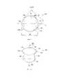
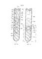
На фиг. 1 - частичный вид сбоку сечения известного механического разделителя;In FIG. 1 is a partial cross-sectional side view of a known mechanical separator;
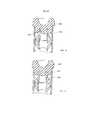
на фиг. 2 - вид в перспективе узла механического разделителя с поплавком, имеющим сквозной канал, и балластом в соответствии с одним из вариантов осуществления;in FIG. 2 is a perspective view of a mechanical separator assembly with a float having a through channel and ballast in accordance with one embodiment;
на фиг. 3 - другой вид в перспективе узла механического разделителя фиг. 2;in FIG. 3 is another perspective view of the mechanical separator assembly of FIG. 2;
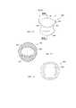
на фиг. 4 - вид сверху механического разделителя фиг. 2;in FIG. 4 is a plan view of the mechanical separator of FIG. 2;
на фиг. 5 - вид сбоку механического разделителя фиг. 2;in FIG. 5 is a side view of the mechanical separator of FIG. 2;
на фиг. 6 - вид сечения по линии 6-6 фиг. 5 механического разделителя фиг. 2;in FIG. 6 is a sectional view taken along line 6-6 of FIG. 5 of the mechanical separator of FIG. 2;
на фиг. 7 - вид спереди механического разделителя фиг. 2;in FIG. 7 is a front view of the mechanical separator of FIG. 2;
на фиг. 8 - вид сечения по линии 8-8 фиг. 7 механического разделителя фиг. 2;in FIG. 8 is a sectional view taken along line 8-8 of FIG. 7 of the mechanical separator of FIG. 2;
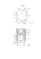
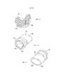
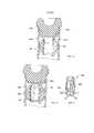
на фиг. 9 - вид сверху другой конструкции механического разделителя с поплавком, имеющим сквозной канал, и балластом, с первым и вторым протяженными выступами, формирующими в целом выпуклую верхнюю поверхность поплавка в соответствии с одним из вариантов осуществления;in FIG. 9 is a top view of another design of a mechanical separator with a float having a through channel and ballast, with first and second extended protrusions forming a generally convex upper surface of the float in accordance with one embodiment;
на фиг. 10 - вид сбоку механического разделителя фиг. 9;in FIG. 10 is a side view of the mechanical separator of FIG. 9;
на фиг. 11 - вид сечения по линии 11-11 фиг. 10 механического разделителя фиг. 9;in FIG. 11 is a sectional view taken along line 11-11 of FIG. 10 of the mechanical separator of FIG. 9;
на фиг. 12 - вид спереди механического разделителя фиг. 9;in FIG. 12 is a front view of the mechanical separator of FIG. 9;
на фиг. 13 - вид сечения по линии 13-13 фиг. 12 механического разделителя фиг. 9;in FIG. 13 is a sectional view taken along line 13-13 of FIG. 12 of the mechanical separator of FIG. 9;
на фиг. 14 - вид в перспективе другой конструкции механического разделителя с поплавком, имеющим эллиптический сквозной канал, и балластом в соответствии с одним из вариантов осуществления;in FIG. 14 is a perspective view of another design of a mechanical separator with a float having an elliptical through channel and ballast in accordance with one embodiment;
на фиг. 15 - другой вид в перспективе механического разделителя фиг. 14;in FIG. 15 is another perspective view of the mechanical separator of FIG. fourteen;
на фиг. 16 - вид сверху механического разделителя фиг. 15;in FIG. 16 is a plan view of the mechanical separator of FIG. fifteen;
на фиг. 17 - вид сбоку механического разделителя фиг. 15;in FIG. 17 is a side view of the mechanical separator of FIG. fifteen;
на фиг. 18 - вид сечения по линии 18-18 фиг. 17 механического разделителя фиг. 15;in FIG. 18 is a sectional view taken along line 18-18 of FIG. 17 of the mechanical separator of FIG. fifteen;
на фиг. 19 - вид спереди механического разделителя фиг. 15;in FIG. 19 is a front view of the mechanical separator of FIG. fifteen;
на фиг. 20 - вид сечения по линии 20-20 фиг. 19 механического разделителя фиг. 15;in FIG. 20 is a sectional view taken along line 20-20 of FIG. 19 of the mechanical separator of FIG. fifteen;
на фиг. 20А - вид в перспективе механического разделителя, корпус которого имеет шарообразную форму и в котором уменьшено расстояние между первым протяженным выступом и вторым протяженным выступом в соответствии с одним из вариантов осуществления;in FIG. 20A is a perspective view of a mechanical separator whose housing is spherical in shape and in which the distance between the first extended protrusion and the second extended protrusion is reduced in accordance with one embodiment;
на фиг. 21 - вид сечения другой конструкции механического разделителя, имеющего эллиптическую форму внутреннего пространства, причем сечение сделано по такой же линии, как и на фиг. 18;in FIG. 21 is a sectional view of another construction of a mechanical separator having an elliptical shape of the interior space, wherein the section is made along the same line as in FIG. eighteen;
на фиг. 22 - частичный вид в перспективе сечения механического разделителя, имеющего эллиптическую форму внутреннего пространства, как показано на фиг. 21;in FIG. 22 is a partial perspective view of a cross-section of a mechanical separator having an elliptical shape of the interior space, as shown in FIG. 21;
на фиг. 23 - вид сечения другой конструкции механического разделителя, имеющего эллиптический сквозной канал, причем сечение сделано по такой же линии, как и на фиг. 18;in FIG. 23 is a sectional view of another construction of a mechanical separator having an elliptical through channel, wherein the section is made along the same line as in FIG. eighteen;
на фиг. 24 - частичный вид в перспективе сечения механического разделителя, имеющего эллиптический сквозной канал, как показано на фиг. 23;in FIG. 24 is a partial perspective view of a cross-section of a mechanical separator having an elliptical through channel, as shown in FIG. 23;
на фиг. 25 - вид сечения другой конструкции механического разделителя, имеющего в целом круговую форму внутреннего пространства и боковые вырезы, причем сечение сделано по такой же линии, как и на фиг. 18;in FIG. 25 is a sectional view of another construction of a mechanical separator having a generally circular shape of the interior space and side cutouts, wherein the section is made in the same line as in FIG. eighteen;
на фиг. 26 - частичный вид в перспективе сечения механического разделителя, имеющего в целом круговую форму внутреннего пространства и боковые срезы, как показано на фиг. 25;in FIG. 26 is a partial perspective view of a cross-section of a mechanical separator having a generally circular shape of the interior space and side sections, as shown in FIG. 25;
на фиг. 27 - частичный вид сбоку сечения механического разделителя, прикрепленного к пробке в соответствии с одним из вариантов осуществления;in FIG. 27 is a partial cross-sectional side view of a mechanical separator attached to a plug in accordance with one embodiment;
на фиг. 28 - частичный вид сбоку сечения механического разделителя, расположенного внутри контейнера для пробы в исходном положении для обеспечения прохождения текучей среды через сквозной канал, в соответствии с одним из вариантов осуществления;in FIG. 28 is a partial cross-sectional side view of a mechanical separator located inside the sample container in its initial position to allow fluid to pass through the through channel, in accordance with one embodiment;
на фиг. 29 - частичный вид сбоку сечения механического разделителя, расположенного внутри контейнера для пробы, как показано на фиг. 28, в положении уплотнения для установления барьера между фазами с разными плотностями после действия центробежной силы, в соответствии с одним из вариантов осуществления;in FIG. 29 is a partial cross-sectional side view of a mechanical separator located inside the sample container, as shown in FIG. 28, in the seal position to establish a barrier between phases with different densities after the action of centrifugal force, in accordance with one embodiment;
на фиг. 30 - вид в перспективе механического разделителя с линией уплотнения для взаимодействия с контейнером для пробы в исходном положении в соответствии с одним из вариантов осуществления;in FIG. 30 is a perspective view of a mechanical separator with a seal line for interacting with a sample container in a rest position in accordance with one embodiment;
на фиг. 31 - вид в перспективе механического разделителя фиг. 30 с линией уплотнения для взаимодействия с контейнером для пробы в положении уплотнения;in FIG. 31 is a perspective view of the mechanical separator of FIG. 30 with a seal line for interacting with the sample container in the seal position;
на фиг. 31А - вид в перспективе механического разделителя с частично дугообразным вырезом в соответствии с одним из вариантов осуществления;in FIG. 31A is a perspective view of a mechanical separator with a partially arcuate notch in accordance with one embodiment;
на фиг. 31Б - вид спереди механического разделителя фиг. 31А;in FIG. 31B is a front view of the mechanical separator of FIG. 31A;
на фиг. 31В - вид в перспективе механического разделителя в соответствии с одним из вариантов осуществления;in FIG. 31B is a perspective view of a mechanical separator in accordance with one embodiment;
на фиг. 31Г - вид сверху узла механического разделителя фиг. 31В;in FIG. 31G is a plan view of the mechanical separator assembly of FIG. 31B;
на фиг. 31Д - вид спереди узла механического разделителя фиг. 31В;in FIG. 31D is a front view of the mechanical separator assembly of FIG. 31B;
на фиг. 31Е - вид сечения по линии 31Е-31Е фиг. 31Д узла механического разделителя фиг. 31В;in FIG. 31E is a sectional view taken along line 31E-31E of FIG. 31D of the mechanical separator assembly of FIG. 31B;
на фиг. 31Ж - вид сбоку механического разделителя фиг. 31В;in FIG. 31G is a side view of the mechanical separator of FIG. 31B;
на фиг. 31З - вид сечения по линии 31З-31З фиг. 31Ж узла механического разделителя фиг. 31В;in FIG. 31Z is a sectional view taken along line 31Z-31Z of FIG. 31G of the mechanical separator assembly of FIG. 31B;
на фиг. 31И - вид снизу узла механического разделителя фиг. 31В;in FIG. 31I is a bottom view of the mechanical separator assembly of FIG. 31B;
на фиг. 32 - вид в перспективе механического разделителя с полосой взаимодействия в исходном положении в соответствии с одним из вариантов осуществления;in FIG. 32 is a perspective view of a mechanical separator with an interaction band in the initial position in accordance with one embodiment;
на фиг. 33 - другой вид в перспективе механического разделителя с полосой взаимодействия в исходном положении, как показано на фиг. 32;in FIG. 33 is another perspective view of a mechanical separator with an interaction band in the initial position, as shown in FIG. 32;
на фиг. 34 - вид сбоку механического разделителя с полосой взаимодействия в исходном положении, как показано на фиг. 33;in FIG. 34 is a side view of a mechanical separator with an interaction band in the initial position, as shown in FIG. 33;
на фиг. 35 - частичный вид сбоку сечения механического разделителя с полосой взаимодействия в исходном положении фиг. 33, находящегося в зацеплении с частью боковой стенки контейнера для пробы и соединенного с пробкой в соответствии с одним из вариантов осуществления;in FIG. 35 is a partial cross-sectional side view of a mechanical separator with an interaction band in the initial position of FIG. 33 meshed with a portion of the side wall of the sample container and connected to a plug in accordance with one embodiment;
на фиг. 35А - вид в перспективе механического разделителя с протяженным ленточным выступом в соответствии с одним из вариантов осуществления;in FIG. 35A is a perspective view of a mechanical separator with an extended belt protrusion in accordance with one embodiment;
на фиг. 35Б - вид слева сбоку механического разделителя фиг. 35А;in FIG. 35B is a left side view of the mechanical separator of FIG. 35A;
на фиг. 35В - вид спереди механического разделителя фиг. 35А;in FIG. 35B is a front view of the mechanical separator of FIG. 35A;
на фиг. 35В1 - вид сечения по линии 35В1-35В1 фиг. 35Б механического разделителя фиг. 35А;in FIG. 35B1 is a sectional view taken along line 35B1-35B1 of FIG. 35B of the mechanical separator of FIG. 35A;
на фиг. 35Г - вид сечения по линии 35Г-35Г фиг. 35В механического разделителя фиг. 35А;in FIG. 35G is a sectional view taken along line 35G-35G of FIG. 35B of the mechanical separator of FIG. 35A;
на фиг. 35Д - вид в перспективе механического разделителя с другим протяженным ленточным выступом в соответствии с одним из вариантов осуществления;in FIG. 35D is a perspective view of a mechanical separator with another extended belt protrusion in accordance with one embodiment;
на фиг. 35Е - вид в перспективе механического разделителя с соединительной конструкцией в соответствии с одним из вариантов осуществления;in FIG. 35E is a perspective view of a mechanical separator with a connecting structure in accordance with one embodiment;
на фиг. 35Ж - вид спереди механического разделителя фиг. 35Е;in FIG. 35G is a front view of the mechanical separator of FIG. 35E;
на фиг. 35З - вид сечения по линии 35З-35З фиг. 35Е механического разделителя фиг. 35Ж;in FIG. 35Z is a sectional view taken along line 35Z-35Z of FIG. 35E of the mechanical separator of FIG. 35 Ж;
на фиг. 35И - вид сверху механического разделителя фиг. 35Е;in FIG. 35I is a plan view of the mechanical separator of FIG. 35E;
на фиг. 35К - схематический вид спереди механического разделителя фиг. 35Е, находящегося внутри контейнера для пробы в различных положениях его спуска в контейнере в соответствии с одним из вариантов осуществления;in FIG. 35K is a schematic front view of the mechanical separator of FIG. 35E located inside the sample container at various positions of its descent in the container in accordance with one embodiment;
на фиг. 35Л - схематический вид спереди механического разделителя фиг. 35К в положении уплотнения в соответствии с одним из вариантов осуществления;in FIG. 35L is a schematic front view of the mechanical separator of FIG. 35K in the seal position in accordance with one embodiment;
на фиг. 35М - вид в перспективе механического разделителя с другой соединительной конструкцией в соответствии с одним из вариантов осуществления;in FIG. 35M is a perspective view of a mechanical separator with another connecting structure in accordance with one embodiment;
на фиг. 35Н - вид спереди механического разделителя фиг. 35М;in FIG. 35H is a front view of the mechanical separator of FIG. 35M;
на фиг. 35О - вид в перспективе механического разделителя с другой соединительной конструкцией в соответствии с одним из вариантов осуществления;in FIG. 35O is a perspective view of a mechanical separator with another connecting structure in accordance with one embodiment;
на фиг. 35П - вид спереди механического разделителя фиг. 35О;in FIG. 35P is a front view of the mechanical separator of FIG. 35O;
на фиг. 36 - частичный вид сбоку сечения механического разделителя с непрямым сквозным каналом в исходном положении в соответствии с одним из вариантов осуществления;in FIG. 36 is a partial cross-sectional side view of a mechanical separator with an indirect through channel in the initial position in accordance with one embodiment;
на фиг. 37 - частичный вид сбоку сечения механического разделителя фиг. 36 с непрямым сквозным каналом в положении уплотнения в соответствии с одним из вариантов осуществления;in FIG. 37 is a partial cross-sectional side view of the mechanical separator of FIG. 36 with an indirect through passage in a sealing position in accordance with one embodiment;
на фиг. 38 - вид сечения механического разделителя с поплавком и балластом, разделенными компонентом из термопластичного эластомера, в котором имеется сквозной канал, в исходном положении покоя в соответствии с одним из вариантов осуществления;in FIG. 38 is a cross-sectional view of a mechanical separator with a float and ballast separated by a component from a thermoplastic elastomer in which there is a through channel in the rest position in accordance with one embodiment;
на фиг. 39 - вид сечения механического разделителя фиг. 38 с поплавком и балластом, разделенными компонентом из термопластичного эластомера, в котором имеется сквозной канал, в положении активации в соответствии с одним из вариантов осуществления;in FIG. 39 is a cross-sectional view of the mechanical separator of FIG. 38 with a float and ballast separated by a component of a thermoplastic elastomer in which there is a through channel in the activation position in accordance with one embodiment;
на фиг. 40 - вид сбоку сечения узла разделения, содержащего механический разделитель, находящийся в зацеплении с частью контейнера для пробы, пробка которого соединена с механическим разделителем, в соответствии с одним из вариантов осуществления;in FIG. 40 is a side view of a sectional view of a separation unit comprising a mechanical separator meshed with a portion of a sample container whose plug is connected to a mechanical separator, in accordance with one embodiment;
на фиг. 41 - вид сбоку сечения другого узла разделения, содержащего механический разделитель, соединенный со стойкой, которая соединена с пробкой, в соответствии с одним из вариантов осуществления;in FIG. 41 is a side cross-sectional view of another separation unit comprising a mechanical separator connected to a strut that is connected to a plug, in accordance with one embodiment;
на фиг. 42 - частичный вид в перспективе сечения пробки фиг. 41;in FIG. 42 is a partial perspective view of a cross section of the plug of FIG. 41;
на фиг. 43 - вид спереди в перспективе стойки фиг. 41;in FIG. 43 is a front perspective view of the rack of FIG. 41;
на фиг. 44 - вид сзади в перспективе стойки фиг. 41;in FIG. 44 is a rear perspective view of the rack of FIG. 41;
на фиг. 45 - вид сбоку контейнера для пробы, имеющего первую зону, вторую зону и несколько желобков для текучей среды в соответствии с одним из вариантов осуществления;in FIG. 45 is a side view of a sample container having a first zone, a second zone, and several fluid grooves in accordance with one embodiment;
на фиг. 46 - частичный вид сечения узла разделителя, содержащего механический разделитель, находящийся внутри контейнера для пробы по фиг. 45 в соответствии с одним из вариантов осуществления;in FIG. 46 is a partial cross-sectional view of a separator assembly comprising a mechanical separator located inside the sample container of FIG. 45 in accordance with one embodiment;
на фиг. 46А - частичный вид сбоку другой конструкции контейнера для пробы для использования с механическим разделителем в соответствии с одним из вариантов осуществления;in FIG. 46A is a partial side view of another design of a sample container for use with a mechanical separator in accordance with one embodiment;
на фиг. 47 - вид сбоку сечения другого узла разделителя, содержащего механический разделитель, соединенный с частью пробки, в соответствии с одним из вариантов осуществления;in FIG. 47 is a side cross-sectional view of another separator assembly comprising a mechanical separator connected to a plug part, in accordance with one embodiment;
на фиг. 48 - частичный вид в перспективе сечения пробки фиг. 47;in FIG. 48 is a partial perspective view of a cross section of the plug of FIG. 47;
на фиг. 49 - вид сбоку сечения узла разделителя, содержащего механический разделитель, соединенный с пробкой, имеющей соединительный выступ, в соответствии с одним из вариантов осуществления;in FIG. 49 is a side cross-sectional view of a separator assembly comprising a mechanical separator connected to a plug having a connecting protrusion, in accordance with one embodiment;
на фиг. 50 - вид сбоку сечения другого узла разделителя, содержащего механический разделитель, соединенный с пробкой, имеющей другую конструкцию соединительного выступа, в соответствии с одним из вариантов осуществления;in FIG. 50 is a side cross-sectional view of another separator assembly comprising a mechanical separator connected to a plug having a different connection protrusion structure, in accordance with one embodiment;
на фиг. 51 - вид сбоку сечения узла разделителя фиг. 50, содержащего уплотнительный материал, размещенный между частью механического разделителя и частью пробки, в соответствии с одним из вариантов осуществления;in FIG. 51 is a side cross-sectional view of the separator assembly of FIG. 50 comprising a sealing material interposed between a part of a mechanical separator and a part of a plug, in accordance with one embodiment;
на фиг. 52 - увеличенный вид сечения уплотнительного материала, показанного на фиг. 51;in FIG. 52 is an enlarged sectional view of the sealing material shown in FIG. 51;
на фиг. 53 - вид сбоку сечения другого узла разделителя, содержащего механический разделитель, соединенный с пробкой, имеющей другую конструкцию соединительного выступа, в соответствии с одним из вариантов осуществления;in FIG. 53 is a side cross-sectional view of another separator assembly comprising a mechanical separator connected to a plug having a different connection protrusion structure, in accordance with one embodiment;
на фиг. 54 - вид сбоку сечения другого узла разделителя, содержащего механический разделитель, соединенный с пробкой, имеющей другую конструкцию соединительного выступа, в соответствии с одним из вариантов осуществления;in FIG. 54 is a cross-sectional side view of another separator assembly comprising a mechanical separator connected to a plug having a different connection protrusion structure, in accordance with one embodiment;
на фиг. 55 - вид в перспективе пробки фиг. 54, имеющей соединительный выступ с несколькими ножками;in FIG. 55 is a perspective view of the plug of FIG. 54 having a connecting protrusion with several legs;
на фиг. 56 - вид сбоку сечения другого узла разделителя, содержащего механический разделитель, соединенный с литой вставкой, в соответствии с одним из вариантов осуществления;in FIG. 56 is a cross-sectional side view of another separator assembly comprising a mechanical separator connected to a cast insert, in accordance with one embodiment;
на фиг. 57 - вид в перспективе литой вставки фиг. 56;in FIG. 57 is a perspective view of the cast insert of FIG. 56;
на фиг. 58 - вид сбоку сечения другого узла разделителя, содержащего механический разделитель, соединенный с литой вставкой, в соответствии с одним из вариантов осуществления;in FIG. 58 is a sectional side view of another separator assembly comprising a mechanical separator connected to a cast insert, in accordance with one embodiment;
на фиг. 59 - вид сбоку сечения другого узла разделителя, содержащего механический разделитель, соединенный с литой вставкой, в соответствии с одним из вариантов осуществления;in FIG. 59 is a sectional side view of another separator assembly comprising a mechanical separator connected to a cast insert, in accordance with one embodiment;
на фиг. 60 - вид сбоку сечения другого узла разделителя, содержащего механический разделитель, соединенный с держателем, соединенным с частью пробки, в соответствии с одним из вариантов осуществления;in FIG. 60 is a sectional side view of another separator assembly comprising a mechanical separator connected to a holder connected to a plug part, in accordance with one embodiment;
на фиг. 61 - вид сбоку сечения другого узла разделителя, содержащего механический разделитель, соединенный с другим держателем, соединенным с частью пробки, в соответствии с одним из вариантов осуществления;in FIG. 61 is a cross-sectional side view of another separator assembly comprising a mechanical separator connected to another holder connected to a plug part, in accordance with one embodiment;
на фиг. 62 - вид в перспективе держателя фиг. 61;in FIG. 62 is a perspective view of the holder of FIG. 61;
на фиг. 63 - вид сбоку сечения узла разделителя, содержащего механический разделитель, соединенный с держателем в исходном положении, в соответствии с одним из вариантов осуществления;in FIG. 63 is a side cross-sectional view of a separator assembly comprising a mechanical separator connected to the holder in its initial position, in accordance with one embodiment;
на фиг. 64 - вид сбоку сечения узла разделителя фиг. 63, содержащего механический разделитель в положении уплотнения, отсоединенный от держателя после воздействия центробежной силы, в соответствии с одним из вариантов осуществления;in FIG. 64 is a sectional side view of the separator assembly of FIG. 63, containing a mechanical separator in the sealing position, disconnected from the holder after exposure to centrifugal force, in accordance with one embodiment;
на фиг. 65 - вид сбоку сечения другого узла разделителя, содержащего механический разделитель, соединенный с другим держателем в исходном положении, в соответствии с одним из вариантов осуществления;in FIG. 65 is a side cross-sectional view of another separator assembly comprising a mechanical separator connected to another holder in its initial position, in accordance with one embodiment;
на фиг. 66 - вид сбоку сечения узла разделителя фиг. 65, содержащего механический разделитель в положении уплотнения, отсоединенный от держателя после воздействия приложенной центробежной силы, в соответствии с одним из вариантов осуществления;in FIG. 66 is a sectional side view of the separator assembly of FIG. 65, comprising a mechanical separator in the seal position, disconnected from the holder after exposure to centrifugal force, in accordance with one embodiment;
на фиг. 67 - вид сбоку сечения другого узла разделителя, содержащего механический разделитель, соединенный с растворимым держателем в исходном положении, в соответствии с одним из вариантов осуществления;in FIG. 67 is a cross-sectional side view of another separator assembly comprising a mechanical separator connected to a soluble holder in its initial position, in accordance with one embodiment;
на фиг. 68 - вид сбоку сечения узла разделителя фиг. 67, содержащего механический разделитель в положении уплотнения, когда держатель полностью растворился после воздействия центробежной силы, в соответствии с одним из вариантов осуществления.in FIG. 68 is a sectional side view of the separator assembly of FIG. 67, containing a mechanical separator in the seal position, when the holder is completely dissolved after exposure to centrifugal force, in accordance with one embodiment.
Осуществление изобретенияThe implementation of the invention
Для целей настоящего описания указания "верхний", "нижний", "правый", "левый", "вертикальный", "горизонтальный", "верхняя часть", "нижняя часть", "боковой", "продольный" и другие термины, характеризующие пространственное расположение, относятся к описанным вариантам осуществления, как они показаны на фигурах чертежей. Однако следует понимать, что, если в явной форме не указано иное, могут быть предложены самые разные альтернативные варианты и их модификации. Также следует понимать, что нижеописанные конкретные устройства и их модификации, представленные на прилагаемых чертежах, являются просто поясняющими примерами.For the purposes of the present description, the indications are “upper”, “lower”, “right”, “left”, “vertical”, “horizontal”, “upper part”, “lower part”, “lateral”, “longitudinal” and other terms, characterizing the spatial arrangement, relate to the described options for implementation, as they are shown in the figures of the drawings. However, it should be understood that, unless explicitly stated otherwise, a wide variety of alternatives and their modifications may be proposed. It should also be understood that the specific devices described below and their modifications presented in the accompanying drawings are merely illustrative examples.
Механический разделитель по настоящему изобретению предназначен для использования с контейнером для пробы для обеспечения ее разделения на компоненты с более высокой и более низкой плотностями, как это будет описано ниже более подробно. Например, предлагаемый в настоящем изобретении механический разделитель может использоваться для отделения сыворотки или плазмы от цельной крови за счет дифференциальной плавучести, вызывающей сжатие зоны уплотнения при погружении в пробе, подвергнутой действию повышенной силы тяжести, возникающей при вращении пробы на центрифуге. В одном из вариантов повышенные силы тяжести могут быть обеспечены на скорости вращения не менее 2000 об/мин, такой как, например, 3400 об/мин.The mechanical separator of the present invention is intended to be used with a sample container to ensure its separation into components with higher and lower densities, as will be described in more detail below. For example, the mechanical separator of the present invention can be used to separate serum or plasma from whole blood due to differential buoyancy, which causes the compression of the compaction zone when immersed in a sample subjected to increased gravity resulting from rotation of the sample in a centrifuge. In one embodiment, increased gravity can be provided at a rotation speed of at least 2000 rpm, such as, for example, 3400 rpm.
На фиг. 2-8 показан механический разделитель 40, который содержит корпус 41 с поплавком 42 и балластом 44, присоединенным к поплавку 42. В одном из вариантов поплавок 42 имеет первую плотность, и балласт 44 имеет вторую плотность, которая больше первой плотности. В другом варианте поплавок 42 имеет первую плавучесть, и балласт 44 имеет вторую плавучесть, которая меньше первой плавучести. В одном из вариантов поплавок 42 механического разделителя 40 должен быть изготовлен из материала, плотность которого меньше плотности жидкости или пробы, которая должна быть разделена на две фазы. Например, если необходимо разделить кровь человека на сыворотку и плазму, то плотность поплавка 42 не должна превышать примерно 1,020 г/см3. В одном из вариантов поплавок 42 механического разделителя 40 может быть изготовлен с использованием экструзии и/или литья из упругодеформируемого и самоуплотняющегося материала, такого как термопластичный эластомер. Еще в одном варианте поплавок 42 может быть изготовлен с использованием экструзии и/или литья из упругодеформируемого материала, который проявляет хорошие характеристики уплотнения при установлении контакта с контейнером для пробы, как это будет описано ниже. Величину плотности поплавка в пределах заданных допусков гораздо легче обеспечить с использованием стандартного материала, который не требует смешивания, например, со стеклянными микросферами, используемыми для снижения плотности материала.In FIG. 2-8, a
Механический разделитель 40 также имеет сквозной канал 46, сформированный таким образом, что он проходит по оси Т корпуса 41 разделителя. Как показано на фиг. 3, 5 и 8, сквозной канал 46 может проходить сквозь весь корпус 41 разделителя и может иметь первый проем 48 и второй проем 50, выровненные вдоль оси Т. В одном из вариантов сквозной канал 46 проходит таким образом, что он делится пополам, точно или примерно, центром корпуса 41 разделителя. В одном из вариантов сквозной канал 46 полностью находится внутри поплавка 42. В другом варианте поплавок 42 может также иметь первый протяженный выступ 52, прилегающий к первому проему 48 сквозного канала 46, и второй протяженный выступ 54, прилегающий ко второму проему 50 сквозного канала 46. Первый протяженный выступ 52 и/или второй протяженный выступ 54 могут быть сформированы вместе с поплавком 42, составляя с ним одно целое. В другой конструкции первый протяженный выступ 52 и/или второй протяженный выступ 54 могут быть сформированы отдельно и затем присоединены к поплавку 42. Первый протяженный выступ 52 и второй протяженный выступ 54 могут быть расположены выше, например заметно выше, оси Т, проходящей сквозь корпус 41 разделителя. Первый протяженный выступ 52 и второй протяженный выступ 54 могут быть выполнены таким образом, чтобы они охватывали часть сквозного канала 46, например, существенную его часть, например, в форме отходящих наружу дугообразных выступов, которые охватывают верхнюю часть 56 сквозного канала 46. Первый протяженный выступ 52 и второй протяженный выступ 54 могут отходить наружу от поплавка 42 в направлении, параллельном или примерно параллельном оси Т, проходящей сквозь корпус 41 разделителя, так что первый протяженный выступ 52 и второй протяженный выступ 54 могут иметь одинаковую форму и кривизну или по существу одинаковую форму и кривизну. В другом варианте, показанном на фиг. 8, первый протяженный выступ 52 имеет первый наиболее выступающий край 68 в самом верху верхней части первой стороны сквозного канала 46, и второй протяженный выступ 54 имеет второй наиболее выступающий край 70 в самом верху верхней части второй стороны сквозного канала 46. В одной конструкции первый наиболее выступающий край 68 отходит наружу на расстояние, которое больше расстояния, на которое отходит нижний наиболее выступающий край 72 первой стороны сквозного канала 46. Второй наиболее выступающий край 70 также отходит наружу на расстояние, которое больше расстояния, на которое отходит соответствующий нижний наиболее выступающий край 74 второй стороны сквозного канала 46. Соответственно, поперечный размер D1 корпуса 41, измеренный по первому протяженному выступу 52 выступу и второму протяженному выступу 54 в верхней части сквозного канала 46, немного превышает поперечный размер D2 корпуса 41 разделителя, измеренный по нижней части сквозного канала 46, сформированной нижними наиболее выступающими краями 72, 74.The
В одном из вариантов поплавок 42 имеет внешнюю поверхность 58, которая в целом имеет сводчатую форму, например по меньшей мере частично или в целом округлую форму, и соединительную поверхность 60, показанную на фиг. 6 и 8, предназначенную для соединения с частью балласта 44. Балласт 44 также имеет внешнюю поверхность 62, которая также имеет в целом сводчатую форму, например по меньшей мере частично или в целом округлую форму, и контактную поверхность 64, также показанную на фиг. 6 и 8, которая предназначена для соединения с соединительной поверхностью 60 поплавка 42. В одном из вариантов внешняя поверхность 58 поплавка 42 и внешняя поверхность 62 балласта 44 формируют в целом округлую внешнюю поверхность, такую как поверхность шарообразного тела. В настоящем описании подразумевается, что термин "шарообразное тело" охватывает, кроме идеальной сферы, и другие конфигурации, которые используются в целях настоящего изобретения и которые могут иметь немного разные поперечные размеры (диаметры) в разных направлениях. Например, размеры в разных плоскостях, проведенных через поплавок 42 и балласт 44, которые проходят через среднюю точку механического разделителя 40, могут быть немного разными. В одном из вариантов поплавок 42 и балласт 44 могут быть сформированы раздельно для их последующей сборки. В другом варианте поплавок 42 и балласт 44 могут быть сформированы вместе, например, с использованием совместной экструзии или совместного литья, в частности с использованием двухступенчатого или многоступенчатого литья, так что оба компонента составляют вместе одно целое, формируя законченный корпус 41 разделителя. В другой конструкции такое неразъемное соединение между поплавком 42 и балластом 44 может быть сформировано физической связью между этими двумя компонентами, механическим фиксирующим устройством или сочетанием физической связи и механического фиксирующего устройства. Кроме того, поплавок 42 и балласт 44 могут быть соединены друг с другом с использованием отдельной операции, выполняемой после литья, такой как приклеивание, термосварка и/или ультразвуковая сварка. Как показано на фиг. 6 и 8, балласт 44 может иметь крепежный выступ 66, который облегчает соединение балласта 44 с поплавком 42.In one embodiment, the
В одном из вариантов балласт 44 механического разделителя 40 должен быть изготовлен из материала, плотность которого больше плотности жидкости или пробы, которая должна быть разделена на две фазы. Например, если необходимо разделить кровь человека на сыворотку и плазму, то балласт 44 должен иметь плотность по меньшей мере 1,029 г/см3. В одном из вариантов балласт 44 может быть сформирован из полипропилена с минеральным наполнителем. В настоящем описании предполагается, что поплавок 42 и балласт 44 могут быть сформированы из различных других материалов с достаточной биологической совместимостью, стабильностью плотности, совместимостью с добавками и нейтральностью в отношении анализируемых материалов (не вступают с ними в реакции, не поглощают и не выщелачивают).In one embodiment, the
Благодаря разнице плотностей поплавка 42 и балласта 44 центр R масс механического разделителя 40 смещен относительно центра объема R1 корпуса 41 разделителя. В частности, объем корпуса 41 разделителя, формируемый поплавком 42, может быть существенно больше объема корпуса 41 разделителя, формируемого балластом 41. Соответственно, в некоторых вариантах центр R масс корпуса 41 разделителя может быть смещен таким образом, что он находится вне сквозного канала 46.Due to the difference in density between the
В соответствии с другим вариантом осуществления, представленным на фиг. 9-13, механический разделитель 140 содержит корпус 141 разделителя, состоящий из поплавка 142 и балласта 144, со сквозным каналом 146, сформированным внутри поплавка, как это уже было описано. В этой конструкции, как это лучше всего показано на фиг. 10 и 13, первый протяженный выступ 152 и второй протяженный выступ 154 вместе с верхней частью 155 поплавка 142 формируют в целом выпуклую внешнюю поверхность 157 поплавка. Как показано на фиг. 9, профиль корпуса 141 разделителя немного отличается от сферического, так что поперечный размер D3 корпуса разделителя между крайними точками 158 и 159, расположенными на диагонали, смещенной относительно сквозного канала 146, проходящего по оси Т, немного больше поперечного размера D4 корпуса разделителя между крайними противолежащими точками 160, 161 касания линий, касательных к периметру корпуса 141 разделителя и перпендикулярных к сквозному каналу 146. Соответственно, крайние точки (диагональные крайние точки 158, 159 и вторые диагональные крайние точки 158А, 159А) могут представлять зоны утолщений материала, такого как термопластичный эластомер.In accordance with another embodiment of FIG. 9-13, the
В соответствии с другим вариантом осуществления, представленным на фиг. 14-20, механический разделитель 240 содержит корпус 241 разделителя, состоящий из поплавка 242 и балласта 244, со сквозным каналом 246, сформированным внутри поплавка 242, как это уже было описано. В этой конструкции сквозной канал 246 может иметь примерно эллиптическую форму поперечного сечения, как это показано, в частности, на фиг. 18, 19. В одном из вариантов большая ось М эллипса, показанная на фиг. 18, ориентирована перпендикулярно оси Т, показанной на фиг. 17. Удлиняя большую ось М эллипса, перпендикулярную оси Т, можно улучшить адаптацию поплавка 242 для увеличенного удлинения в направлении малой оси М2 (показана на фиг. 18) эллипса под действием центробежной силы, как это будет описано ниже.In accordance with another embodiment of FIG. 14-20, the
В рассматриваемой конструкции закругление первого протяженного выступа 252 и закругление второго протяженного выступа 254 имеют протяженность для примерного повторения по меньшей мере части первого эллиптического проема 248 и второго проема 250, соответственно, сквозного канала 246. В другом варианте первый протяженный выступ 252 по меньшей мере частично имеет дугообразную форму, например выпуклую форму, обеспечиваемую возле верхней части первого проема 248 сквозного канала 246. Второй протяженный выступ 254 может также по меньшей мере частично иметь дугообразную форму, например выпуклую форму, обеспечиваемую возле верхней части второго проема 250 сквозного канала 246.In the structure under consideration, the rounding of the first
Как показано на фиг. 20А, механический разделитель 240А содержит корпус 241А разделителя, состоящий из поплавка 242А и балласта 244А, со сквозным каналом 246А, сформированным внутри поплавка 242А, как это уже было описано. В этой конструкции первый протяженный выступ 252А и второй протяженный выступ 254А могут иметь эллиптический профиль, который примерно совпадает с концами окружности 243А корпуса 241А разделителя на краях сквозного канала 246А, и немного смещены от окружности в верхней точке 247А первого 252А и второго 254А протяженных выступов. В этой конструкции первый протяженный выступ 252А и второй протяженный выступ 254А могут иметь увеличенные переходные части 280А на краях первого 252А и второго 254А протяженных выступов, примыкающие к сквозному каналу 246А для дополнительного формирования уплотнения части стенки пробирки в положении уплотнения, как это указано в настоящем описании. Увеличенные переходные части 280А могут способствовать осаждению клеток на механическом разделителе под действием центробежной силы, как это указано в настоящем описании. Увеличенные переходные части 280А могут также содержать зону первого 252А и второго 254А протяженных выступов, имеющую увеличенную толщину и/или увеличенный поперечный размер, такую как расширенный переходный участок первого 252А и второго 254А протяженных выступов, проходящий вдоль по меньшей мере части сквозного канала 246А.As shown in FIG. 20A, the
Как показано на фиг. 21, 22, механический разделитель 340 содержит поплавок 342 и балласт 344 и может иметь внутреннее пространство 360, имеющее в сечении форму эллипсоида и формирующее в целом цилиндрический сквозной канал 346. В этой конструкции во внутреннем пространстве 360 может быть размещен материал 362 наполнителя таким образом, чтобы он заполнял часть пространства 360 для обеспечения сквозного канала 346, имеющего примерно цилиндрическую форму. В одном из вариантов материал 362 наполнителя может быть термопластичным эластомером или другим достаточно эластичным материалом. В другом варианте, как показано на фиг. 23, 24, механический разделитель 440, содержащий поплавок 442 и балласт 444, может иметь внутреннее пространство 460, имеющее в сечении эллиптическую форму и формирующее примерно цилиндрический сквозной канал 446. Еще в одном варианте механический разделитель 540, содержащий поплавок 542 и балласт 544, может иметь сквозной цилиндрический канал 546, имеющий круглую форму поперечного сечения. Поплавок 542 может иметь дополнительно прорезь 548 или несколько таких прорезей, расположенных у границы раздела 550 с балластом 544. Использование прорези 548 или нескольких таких прорезей, сформированных внутри поплавка 542, может обеспечивать возможность увеличенного удлинения поплавка 542, происходящего под действием центробежной силы, как это будет описано ниже.As shown in FIG. 21, 22, the
Как показано на фиг. 27, механический разделитель 40 может обеспечиваться как часть узла 80 разделителя для разделения пробы текучей среды на первую и вторую фазы внутри контейнера для сбора проб, имеющего пробку 84. В частности, контейнер 82 для пробы может быть трубкой для пробы, используемой в протеомических исследованиях, в молекулярной диагностике, может быть пробиркой для химических образцов, пробиркой для пробы крови или других жидкостей организма, пробиркой для коагуляционных образцов, пробиркой для гематологических образцов и т.п. Предпочтительно контейнер 82 представляет собой вакуумную пробирку для взятия крови. В одном из вариантов контейнер 82 для пробы может содержать дополнительные добавки, необходимые для конкретных процедур анализа, такие как ингибиторы протеазы, коагулирующие агенты и т.п. Такие добавки могут быть в форме зернистого материала или жидкости и могут быть нанесены распылением на боковую цилиндрическую стенку 86 контейнера 82 для пробы или же они могут быть на его дне. Контейнер 82 для пробы имеет закрытый нижний конец 88, открытый верхний конец 90 и боковую цилиндрическую стенку 92, проходящую между ними. Боковая цилиндрическая стенка 92 имеет внутреннюю поверхность 94 с примерно постоянным внутренним диаметром на всем протяжении контейнера 82 по его продольной оси L от верхнего открытого конца 90 до участка, находящегося возле закрытого нижнего конца 88.As shown in FIG. 27, a
Контейнер 82 для пробы может быть изготовлен из одного или нескольких стандартных материалов, таких как полипропилен, полиэтилентерефталат, стекло или их сочетания. Контейнер 82 для пробы может иметь одну или несколько стенок. Кроме того, контейнер 82 для пробы может иметь любые разумные размеры для приема соответствующей биологической пробы. Например, контейнер 82 для пробы может иметь размеры, соответствующие размерам обычных пробирок большого объема, пробирок малого объема или микропробирок Microtainer, известных в медицине. В одном из вариантов в качестве контейнера 82 для пробы может использоваться хорошо известная стандартная вакуумная пробирка объемом 13 мл для пробы крови.The
Открытый верхний конец 90 выполнен с возможностью введения в него по меньшей мере частично пробки 84 для формирования уплотнения, непроницаемого для жидкости. Пробка 84 имеет верхний конец 96 и нижний конец 98, который должен по меньшей мере частично находиться внутри контейнера 82 для пробы. Части пробки, прилегающие к верхнему концу 90, имеют максимальный внешний диаметр, который больше внутреннего диаметра контейнера 82 для пробы. В одном из вариантов пробка 84 имеет прокалываемую запечатываемую перегородку 100, сквозь которую может проникать канюля иглы (не показана). Части пробки 84, отходящие вниз от нижнего конца 98, могут расширяться от минимального диаметра, который примерно равен или немного меньше внутреннего диаметра контейнера 82 для пробы, к основному диаметру, который превышает внутренний диаметр контейнера 82 для пробы на верхнем конце 96. Таким образом, нижний конец 98 пробки 84 может быть введен с усилием в часть контейнера 82 для пробы, прилегающую к верхнему открытому концу 90. Присущая пробке 84 упругость обеспечивает уплотняющее взаимодействие с внутренней поверхностью 94 боковой цилиндрической стенки 86 контейнера 82 для пробы. В одном из вариантов пробка 84 может быть изготовлена литьем из эластомерного материала как одна часть, имеющая любые подходящие размеры для обеспечения уплотняющего взаимодействия с контейнером 82 для пробы. Дополнительно пробка 84 может быть по меньшей мере частично окружена предохранительным кожухом, таким как Hemogard® Shield, предлагаемым компанией Becton, Dickinson and Company.The open
Как показано на фиг. 27, механический разделитель 40 может быть ориентирован внутри контейнера 82 для пробы в исходном положении, в котором сквозной канал 46 механического разделителя 40 выровнен в продольном направлении с открытым концом 90 контейнера 82. В этом исходном положении сквозной канал 46 обеспечивает проход сквозь него текучей среды, например текучей среды, поступающей из канюли иглы (не показана), которая проколола прокалываемую перегородку 100 пробки 84, в результате чего она сообщается с внутренним пространством контейнера 82 для пробы. Механический разделитель 40 может также соединяться с возможностью отсоединения с частью пробки 84, так что корпус 41 разделителя может переходить из исходного положения, как показано на фиг. 27, 28, в положение уплотнения, как показано на фиг. 29. В исходном положении сквозной канал 46 открывает проход для текучей среды через механический разделитель 40 в направлении, указанном на фиг. 28 стрелкой F потока. Как показано на фиг. 27, в исходном открытом положении сквозной канал 46 направлен примерно по продольной оси L контейнера 82 для пробы. Как показано на фиг. 29, под действием центробежной силы, вызываемой вращением, например, на центрифуге, механический разделитель 40 деформируется в достаточной степени, чтобы выйти из зацепления с пробкой 84 и повернуться в направлении, показанном на фиг. 29 стрелкой D поворота, в положение уплотнения, в котором сквозной канал находится по существу в закрытом положении. В этом закрытом положении поплавок 42, включая первый протяженный выступ 52 и второй протяженный выступ 54, формирует уплотнение с внутренней поверхностью 94 контейнера 82 для пробы, в результате чего по существу предотвращается прохождение текучей среды через сквозной канал 46 или вокруг корпуса 41 разделителя.As shown in FIG. 27, the
В одном из вариантов сквозной канал 46 в открытом положении примерно выровнен с открытым верхним концом 90 контейнера 82 для пробы по меньшей мере вдоль части продольной оси L, и сквозной канал 46 ориентирован примерно перпендикулярно продольной оси в закрытом положении. Следует иметь в виду, что переход сквозного канала 46 из открытого положения в закрытое положение совпадает с поворотом механического разделителя 40 из первого (исходного) положения во второе (закрытое) положение. В другой конструкции механический разделитель 40 соединен с частью пробки 84 в первом (исходном) положении, и механический разделитель 40 взаимодействует с частью боковой стенки 86 контейнера 82 для пробы во втором (уплотняющем) положении. Как можно видеть на фиг. 27, пробка 84 может иметь соединительный выступ 102 для соединения с механическим разделителем 40. В одном из вариантов соединительный выступ 102 находится внутри части сквозного канала 46, когда корпус 41 разделителя находится в первом (исходном) положении, для формирования между частью корпуса 41 разделителя и пробкой 84 уплотнения, предотвращающего прохождение текучей среды.In one embodiment, the through
В исходном положении механический разделитель 40 может быть прикреплен к пробке 84 с помощью механической защелки, формируемой вырезом в сквозном канале 46, которая определяет усилие освобождения механического разделителя 40. Когда механический разделитель 40 прикреплен к пробке 84, он формирует уплотнение с боковой стенкой контейнера 82 для пробы вдоль первой круговой линии (периметра) 104 уплотнения, как показано на фиг. 30. При прохождении пробы в контейнер 82 для пробы первая круговая линия 104 уплотнения предотвращает накопление крови между механическим разделителем 40 и пробкой 84. В результате уменьшается формирование сгустков и/или нитей фибрина, которые могут нарушать работу механического разделителя 40. При действии центробежной силы, переводящей механический разделитель 40 в закрытое положение, как показано на фиг. 29, на механический разделитель 40 будет действовать вращающий момент, когда разделитель еще прикреплен к пробке 84, и после отсоединения разделителя от пробки он поворачивается примерно на 90° и занимает положение, в котором балласт 44 будет обращен в сторону нижнего конца 88 контейнера 82 для пробы.In the initial position, the
Как только механический разделитель 40 касается текучей среды, содержащейся внутри контейнера 82 для пробы, воздух, заполняющий сквозной канал 46, постепенно замещается текучей средой по мере погружения разделителя. Когда механический разделитель 40 погружается в текучую среду, то в результате того, что плавучесть поплавка 42 выше плавучести балласта 44, создается разность сил, действующих на механический разделитель 40. В процессе центрифугирования разность сил заставляет поплавок 42 удлиняться и отходить от боковой стенки 86 контейнера 82 для пробы, в результате чего уменьшается эффективный диаметр и открывается проход для потока текучей среды, как для фазы с более высокой плотностью, так и для фазы с более низкой плотностью, и этот поток обтекает корпус 41 разделителя. Следует иметь в виду, что поплавок 42 может быть выполнен с возможностью деформации в направлении, примерно перпендикулярном направлению сквозного канала 46. После прекращения действия центробежной силы поплавок 42 возвращается к своей исходной форме, и зона уплотнения, формируемая поплавком 42, а также первым протяженным выступом 52 и вторым протяженным выступом 54, расширяется для обеспечения уплотнения с внутренней поверхностью 94 контейнера для пробы по второй круговой линии 106 уплотнения, как показано на фиг. 31. Соответственно, механический разделитель 40 будет предотвращать прохождение потока текучей среды между корпусом 41 разделителя и стенкой контейнера 82 для пробы, и при этом также предотвращается прохождение потока текучей среды через сквозной канал 46, то есть формируется эффективный барьер. По второй круговой линии 106 уплотнения устанавливается барьер внутри пробы между фазами с более высокой и более низкой плотностями.As soon as the
Как показано на фиг. 31А, 31Б, механический разделитель 140А содержит корпус 141А разделителя, содержащий поплавок 142А и балласт 144А, со сквозным каналом 146А, сформированным внутри поплавка 142А, как это уже было описано. В этом варианте поплавок 142А может содержать частично дугообразный вырез 150А, формирующий поверхность для улучшения возможности сбора осадка (дебриса), выпадающего в процессе центрифугирования. Как уже указывалось, когда разделитель 140А погружается в пробу текучей среды, такой как кровь, некоторые компоненты крови, такие как фибрин или клетки, могут приклеиваться или иным образом захватываться верхней поверхностью поплавка 142А. В соответствии с рассматриваемым вариантом поплавок 142А может содержать дугообразный вырез 150А для увеличения поверхности для выпадающего осадка. В другом варианте поплавок 142А может содержать противолежащие дугообразные вырезы 150А, как показано на фиг. 31Б. Дугообразный вырез 150А может иметь любую криволинейную форму, подходящую для увеличения поверхности поплавка для выпадения осадка, например эллиптическую, овальную и т.п.As shown in FIG. 31A, 31B, the
В этой конструкции корпус 141А разделителя также может содержать первый протяженный выступ 152А и второй протяженный выступ 154А, которые имеют на своих краях увеличенные переходные части 180А, примыкающие к сквозному каналу 146А для обеспечения формирования уплотнения части стенки пробирки в положении уплотнения, как это указано в настоящем описании. Увеличенные переходные части 180А могут также содержать зону первого 152А и второго 154А протяженных выступов, имеющую увеличенную толщину и/или увеличенный поперечный размер, такую как расширенный переходный участок первого 152А и второго 154А протяженных выступов, проходящий вдоль по меньшей мере части сквозного канала 146А. В одном из вариантов увеличенные переходные части 180А могут способствовать выпадению клеток вокруг корпуса 141А механического разделителя под действием центробежной силы, как это указано в настоящем описании.In this design, the
В соответствии с другим вариантом осуществления, представленным на фиг. 31В-31И, механический разделитель 40D содержит корпус 41D разделителя, содержащий поплавок 42D и балласт 44D, со сквозным каналом 46D, сформированным внутри поплавка 42D, как это уже было описано. В этой конструкции корпус 41D разделителя может иметь в целом овальную внешнюю круговую линию для улучшения уплотнения между механическим разделителем 40D и боковой стенкой контейнера для пробы в положении уплотнения, как это показано на фиг. 29 и 68.In accordance with another embodiment of FIG. 31B-31I, the
В рассматриваемом варианте поперечный размер D5 корпуса 41D разделителя, в частности поперечный размер поплавка 42D, как показано на фиг. 31Г и 31Ж, в направлении по оси Taxis сквозного канала 46D, как показано на фиг. 31Е, может быть меньше поперечного размера D6 корпуса 41D разделителя, в частности поперечного размера поплавка 42D, как показано на фиг. 31Г, в направлении, перпендикулярном направлению Taxis сквозного канала 46D, как показано на фиг. 31Е. В рассматриваемом варианте поперечный размер D7 корпуса 41D разделителя, в частности поперечный размер поплавка 42D, как показано на фиг. 31Г, в направлении под углом 45° к оси Taxis, может быть больше сквозного канала 46D или же может быть больше поперечных размеров D5 и D6 корпуса 41D разделителя. Кроме того, в этом варианте поперечный размер D8 балласта 44D вдоль оси Taxis сквозного канала 46D, как показано на фиг. 31Е, может быть меньше любого из поперечных размеров D5, D6 или D7 корпуса 41D разделителя.In the present embodiment, the transverse dimension D5 of the
Использование поплавка 42D, диаметр которого больше диаметра балласта 44D, может обеспечивать механический разделитель 40D с увеличенным объемом материала, имеющего пониженную плотность, такого как термопластичный эластомер, для прижатия к уплотняющей поверхности, как это указано в настоящем описании. В рассматриваемом варианте также может использоваться протяженный ленточный выступ, описанный ниже со ссылками на фиг. 35А-35Д, и/или полоса взаимодействия в исходном положении, описанная ниже со ссылками на фиг. 33-35.The use of a
На фиг. 32-35 показан еще один вариант, в котором механический разделитель 40 может содержать также полосу 116 взаимодействия в исходном положении, охватывающую по периметру корпус 41 разделителя. В другом варианте полоса 116 взаимодействия в исходном положении может быть расположена таким образом, что она охватывает корпус 41 разделителя в направлении, которое в целом перпендикулярно направлению сквозного канала 46. Полоса 116 взаимодействия в исходном положении может проходить без разрывов по корпусу 41 разделителя, или же она может состоять из отдельных сегментов, проходящих по корпусу 41 разделителя. Еще в одном варианте поплавок 42 и полоса 116 взаимодействия в исходном положении могут быть сформированы из одного и того же материала, такого как термопластичный эластомер. Полоса 116 взаимодействия в исходном положении может быть выполнена таким образом, что она формируется первой частью 42А поплавка 42, а вторая часть 42В разделяет примерно пополам балласт 44.In FIG. 32-35, another embodiment is shown in which the
В частности, как показано на фиг. 35, полоса 116 взаимодействия в исходном положении обеспечивает уплотняющее взаимодействие между корпусом 41 разделителя и внутренней поверхностью 94 контейнера 82 для пробы. В этом варианте первая круговая линия 104 уплотнения, проходящая вокруг корпуса 41 разделителя, проходит по полосе 116 взаимодействия в исходном положении. Эта первая круговая линия 104 уплотнения способствует удерживанию корпуса 41 разделителя в нужной ориентации относительно открытого верхнего конца 90 контейнера 82 для пробы, так что текучая среда, поступающая в контейнер 82 для пробы из канюли (не показана), проходящей сквозь прокалываемую перегородку 100, будет проходить через первый проем 48 корпуса 41 разделителя, через сквозной канал 46 и выходить из второго проема 50.In particular, as shown in FIG. 35, the
В соответствии еще с одним вариантом осуществления, показанным на фиг. 35А-35Д, механический разделитель 40С содержит корпус 41С, содержащий поплавок 42С и балласт 44С. Корпус 41С разделителя содержит сформированный в нем сквозной канал 46С, который полностью проходит внутри поплавка 42С. В этой конструкции поплавок 42С может содержать протяженный ленточный выступ 50С, расположенный по внешней поверхности 52С поплавка 42С. В одном из вариантов протяженный ленточный выступ 50С может содержать первую протяженную часть 54С, прилегающую к первому проему 56С сквозного канала 46С, и вторую протяженную часть 58С, прилегающую ко второму проему 60С сквозного канала 46С. В этой конструкции первая протяженная часть 54С и вторая протяженная часть 58С могут быть обеспечены непосредственно возле по меньшей мере части первого проема 56С и второго проема 60С соответственно. Первая протяженная часть 54С и вторая протяженная часть 58С имеют в целом вогнутую форму, если смотреть снизу.According to another embodiment shown in FIG. 35A-35D, the
Первая протяженная часть 52 и вторая протяженная часть 54 могут быть также выполнены таким образом, чтобы они охватывали часть сквозного канала 46С, например, существенную его часть, например, в форме отходящих наружу дугообразных выступов, которые охватывают верхнюю часть сквозного канала 46С. Некоторый участок первой протяженной части 54С и некоторый участок второй протяженной части 58С может отходить наружу от поплавка 42С в направлении, примерно параллельном оси TA корпуса 41С разделителя, так что первая протяженная часть 54С и вторая протяженная часть 58С могут иметь практически одинаковую форму и кривизну.The first
Протяженный ленточный выступ 50С может также иметь соединительные части 62С, расположенные между первой протяженной частью 54С и второй протяженной частью 58С для их соединения по обеим сторонам корпуса 41С разделителя. Соединительные части 62С могут иметь в целом вогнутую форму, если смотреть сверху. В одном из вариантов соединительные части 62С, первая протяженная часть 54С и вторая протяженная часть 58С соединены между собой, формируя непрерывную ленточную структуру, охватывающую часть поплавка 42С. В другом варианте соединительные части 62С, первая протяженная часть 54С и вторая протяженная часть 58С формируют непрерывную "синусоиду", проходящую по части внешней поверхности 52С поплавка 42С. В другом варианте протяженный ленточный выступ 50С может быть сформирован вместе с поплавком 42С как одно целое. В другом варианте протяженный ленточный выступ 50С может быть сформирован отдельно и затем присоединен к поплавку 42С. В некоторых вариантах поплавок 42С и протяженный ленточный выступ 50С могут быть выполнены из материала с пониженной плотностью, такого как термопластичный эластомер, а балласт 44С может быть сформирован из материала с более высокой плотностью, такого как полиэтилентерефталат.The
В одном из вариантов, показанном на фиг. 35В и 35В1, соединительные части 62С могут иметь примерно одинаковую толщину TJ. В другом варианте первая протяженная часть 54С и вторая протяженная часть 58С также могут иметь примерно такую же толщину TJ. Поперечное сечение протяженного ленточного выступа 50С может иметь любую подходящую форму, обеспечивающую уплотнение, такую как закругленная, квадратная, форма ребра и т.п. Возможны также варианты с несколькими протяженными ленточными выступами 50С, проходящими по внешней поверхности 52С поплавка 42С. Как показано на фиг. 35Б и 35Г, первая протяженная часть 54С и вторая протяженная часть 58С могут содержать утолщенные полки 54С1 и 58С1, соответственно, формирующие седлообразную форму верхней части 64С поплавка 42С. Верхняя часть 64С поплавка 42С и протяженный ленточный выступ 50С могут иметь такую конфигурацию, которая обеспечивает максимальную площадь поверхности для сбора осадка (дебриса), выпадающего в процессе центрифугирования. Как уже указывалось, когда разделитель 40С погружается в пробу текучей среды, такой как кровь, некоторые компоненты крови, такие как фибрин или клетки, могут приклеиваться или иным образом захватываться верхней поверхностью поплавка 42С. Специальная форма протяженного ленточного выступа 50С предназначена для минимизации захвата вышеуказанного осадка.In one embodiment shown in FIG. 35B and 35B1, the connecting
Еще в одном варианте, показанном на фиг. 35Д, протяженный ленточный выступ 50С может содержать первую протяженную часть 54С, вторую протяженную часть 58С и соединительные части 62С, соединяющие первую протяженную часть 54С и вторую протяженную часть 58С по обеим сторонам поплавка 42С для формирования непрерывной структуры, проходящей по внешней поверхности 52С поплавка 42С. В этой конструкции утолщенная полка 54С1 первой протяженной части 54С и утолщенная полка 58С1 второй протяженной части 58С имеют усеченные контуры 54С2 и 58С2, соответственно, для улучшения возможности сбора осадка (дебриса), выпадающего в процессе центрифугирования и для обеспечения дополнительной опоры для первой протяженной части 54С и второй протяженной части 58С при выполнении функции уплотнения стенки контейнера для пробы (не показан) в положении уплотнения.In another embodiment, shown in FIG. 35D, the
Когда механический разделитель 40С по рассматриваемому варианту находится в положении уплотнения, протяженный ленточный выступ 50С обеспечивает прочную уплотняющую поверхность, прижимающуюся к части стенки контейнера для пробы (не показан), аналогично уплотняющему действию первого протяженного выступа и второго протяженного выступа, описанному выше со ссылками на фиг. 1-8. В некоторых вариантах протяженный ленточный выступ 50С может обеспечивать дополнительное уплотнение, минимизирующее прохождение текучей среды между механическим разделителем 40С и контейнером для пробы. Кроме того, в конструкциях, в которых поплавок 42С формируется из термопластичного эластомера, протяженный ленточный выступ 50С обеспечивает механизм улучшенного уплотнения, поскольку этот материал не деформируется существенно под действием центробежных сил, возникающих при центрифугировании, а вытесняется (смещается) в другое место. Расположение дугообразного протяженного ленточного выступа 50С на внешней поверхности 52С поплавка 42С обеспечивает равномерное смещение выступа 50С по стенке контейнера для пробы в положение уплотнения, как это указывается в настоящем описании. Поскольку протяженный ленточный выступ 50С может иметь вогнутые части, которые, чередуясь, ориентированы вверх или вниз, то высота поверхности уплотнения механического разделителя 40С может быть переменной на внешней поверхности 52С поплавка 42С в соответствии с расположением частей протяженного ленточного выступа 50С.When the
В другой конфигурации механический разделитель 40С, имеющий протяженный ленточный выступ 50С, может использоваться в наклонных контейнерах для проб благодаря улучшенному уплотнению между протяженным ленточным выступом 50С и контейнером для пробы (как это было описано выше) в положении уплотнения. Также предусматривается, что механический разделитель 40С может содержать полосу 116 взаимодействия в исходном положении, как это уже описывалось со ссылками на фигуру 35.In another configuration, a
В соответствии еще с одним вариантом осуществления, показанным на фиг. 35Е, 35Ж, механический разделитель 40А содержит корпус 41А, содержащий поплавок 42А и балласт 44А. В корпусе 41А разделителя имеется сформированный в нем сквозной канал 46А. В этой конфигурации балласт 44А может содержать основание 52А и соединительную конструкцию 48А, которая может представлять собой несколько кронштейнов 50А для соединения с частью поплавка 42А. Балласт 44А, в частности соединительная конструкция 48А, может быть неразъемно соединен с частью поплавка 42А с использованием, например, совместной отливки, двухступенчатой отливки, сварки или склеивания. В одной из конструкций поплавок 42А может быть сформирован из материала с пониженной плотностью, такого как термопластичный эластомер, и балласт 44А может быть сформирован из материала с более высокой плотностью, такого как полиэтилентерефталат. В другой конструкции механический разделитель 40А может быть выполнен таким образом, чтобы общая плотность корпуса 41А разделителя находилась между более высокой и более низкой плотностями компонентов пробы крови, таких как сыворотка и эритроциты. Еще в одном варианте общая плотность корпуса 41А разделителя равна 1,45 г/см3.According to another embodiment shown in FIG. 35E, 35G, the
Как показано на фиг. 35З, балласт 44А может содержать основание 52А с контактной поверхностью 54А и соединительной поверхностью 56А. В одной из конструкций контактная поверхность 54А может содержать по меньшей мере частично изогнутую поверхность 58А, кривизна которой соответствует кривизне внутренней стенки контейнера для пробы (не показан). Соединительная поверхность 56А может обеспечивать прикрепление соединительной конструкции 48А к основанию 52А. В одной из конфигураций соединительная поверхность 56А и соединительная конструкция 48А сформированы как одно целое. В другой конфигурации соединительную поверхность 56А и соединительную конструкцию 48А формируют как отдельные части и затем неразъемно соединяют с использованием механических или клеевых фиксирующих средств.As shown in FIG. 353,
Соединительная конструкция 48А может иметь первый конец 60А для соединения с основанием 52А балласта 44А и второй конец 62А для соединения с частью поплавка 42А. На виде сверху поплавок 42А может иметь в целом круговую внешнюю линию PO, как показано на фиг. 35И, и поплавок 42А может иметь в целом криволинейную форму на виде сбоку сечения, например вогнутую форму, если смотреть снизу, как показано на фиг. 35З. В другом варианте поплавок 42А может иметь вогнутую форму на виде сбоку сечения, если смотреть снизу, прилегающую к самой верхней точке 64А поплавка 42А, и немного вогнутую форму, если смотреть сверху, прилегающую к внешней круговой линии поплавка 42А, например, в зоне, в которой второй конец 62А соединительной конструкции 48А прикреплен к поплавку 42А. В одной из конфигураций сначала отливается второй конец 62А соединительной конструкции 48А, и затем поплавок 42А наплавляется на второй конец 62А соединительной конструкции 48А для формирования соединения между ними. В другом варианте второй конец 62А соединительной конструкции 48А вводится внутрь части поплавка 42А или прижимается к ней с последующим приклеиванием или присоединением иным способом.The connecting
В одной из конфигураций соединительная конструкция 48А может обеспечивать возможность смещения поплавка 42А относительно основания 52А. Такая возможность смещения может обеспечиваться креплением между первым концом 60А соединительной конструкции 48А и основанием 52А, и/или креплением между вторым концом 62А соединительной конструкции 48А и поплавком 42А и/или точками 68А вращения соединительной конструкции 48А.In one configuration, the connecting
Как показано на фиг. 35К, механический разделитель 40А может быть установлен внутри контейнера 100А для пробы, например, возле верхнего конца 102А контейнера 100А в исходном положении. Механический разделитель 40А может быть соединен с частью пробки 104А, так что часть пробки 104А входит в сквозной канала 46А механического разделителя, как уже указывалось в описании. В соответствии с другим вариантом осуществления механический разделитель 40А может быть установлен таким образом, что часть поплавка 42А и часть основания 52А балласта 44А взаимодействуют с внутренней поверхностью контейнера 100А для пробы для удерживания механического разделителя 40А внутри верхнего конца 102А контейнера 100А, так что сквозной канал 46А механического разделителя 40А направлен по продольной оси La контейнера 100А для пробы.As shown in FIG. 35K, a
Как показано на фиг. 35К, проба 108А текучей среды, например крови, поступает в контейнер 100А для пробы через пробку 104А, которая входит в сквозной канал механического разделителя 40А, когда он находится в исходном положении, указанном ссылочным обозначением А. Под действием приложенной центробежной силы поплавок 42А деформируется, в результате чего начинается смещение поплавка 42А относительно балласта 44А, как это уже описывалось. При этом деформируется сквозной канал 46А, в результате чего механический разделитель 40А отсоединяется от пробки 104А и начинает поворачиваться в направлении, показанном стрелкой R, как указано ссылочным обозначением В.As shown in FIG. 35K, a fluid sample, for example,
Когда механический разделитель 40А погружается в пробу 108А текучей среды, поплавок 42А начинает перемещаться вверх, а балласт 44А одновременно начинает перемещаться вниз для занятия нижнего положения, как указано ссылочным обозначением С. При продолжающемся действии центробежной силы балласт 44А будет стремиться вниз, и поплавок 42А будет отходить от боковой стенки 110А контейнера для пробы, как указано ссылочным обозначением D. Затем, как указано ссылочным обозначением Е, поплавок 42А деформируется для обеспечения прохождения компонентов с разными плотностями между поплавком 42А и боковой стенкой 110А контейнера 100А для пробы. Таким образом, может происходить разделение компонентов с разными плотностями внутри пробы 108А текучей среды, и такое разделение компонентов с разными плотностями внутри пробы 108А будет иметь место и в сквозном канале 46А механического разделителя 40А.When the
Как показано на фиг. 35Л, после прекращения действия центробежной силы механический разделитель 40А будет находиться в положении уплотнения между отделенной фазой 112А с более высокой плотностью и отделенной фазой 114А с более низкой плотностью. Одновременно прекращается смещение поплавка 42А относительно балласта 44А, в результате чего поплавок 42А возвращается в свое исходное положение, как это показано на фиг. 35И, формируя уплотнение между внешней круговой линией PO и внутренней окружностью боковой стенки 110А контейнера 100А для пробы. Поплавок 42А имеет внешнюю круговую линию PO, длина которой по меньшей мере немного превышает внутреннюю окружность боковой стенки 110А контейнера 100А для пробы, в результате чего между ними формируется плотное соединение.As shown in FIG. 35L, after the centrifugal force ceases, the
Как показано на фиг. 35Л, как только механический разделитель 40А перейдет в положение уплотнения, вдоль внешней круговой линии PO формируется зона уплотнения между механическим разделителем 40А и внутренней окружностью боковой стенки 110А. Как показано на фиг. 35Л, зона уплотнения, проходящая по внешней круговой линии PO, имеет переменное положение вдоль внутренней окружности боковой стенки 110, измеряемое от закрытого нижнего конца 113А контейнера 100А для пробы. В одной из конструкций зона уплотнения, проходящая по внешней круговой линии PO, между механическим разделителем 40А, в частности, между поплавком 42А и внутренней стенкой 110A, содержит разные участки S1, S2, S3 и т.д., которые находятся на разных высотах. Соответственно, зона уплотнения имеет высоту, которая незначительно изменяется на каждом из указанных участков S1, S2, S3 и т.д. уплотнения. Зона уплотнения также определяет среднюю высоту Нсредн. уплотнения, которая соответствует средней высоте указанных участков S1, S2, S3 и т.д. уплотнения, а именно,
Минимальная высота Нмин. уплотнения соответствует расстоянию между самой нижней точкой внешней круговой линии PO и закрытым нижним концом 113А контейнера 100А. В соответствии с одним из аспектов средняя высота Нсредн. уплотнения меньше разницы между максимальной высотой Нмакс.уплотнения и минимальной высотой Нмин. уплотнения, то есть, Нсредн.<Нмакс.-Нмин..Minimum height Nmin seal corresponds to the distance between the lowest point of the outer circular line PO and the closed
В соответствии еще с одним вариантом осуществления, показанным на фиг. 35М, 35Н, механический разделитель 40В содержит корпус 41В, содержащий поплавок 42Б и балласт 44Б. В корпусе 41В разделителя имеется сформированный в нем сквозной канал 46В. В этой конфигурации поплавок 42В может содержать соединительную конструкцию 48В, которая может представлять собой несколько кронштейнов 50В для соединения с частью балласта 44В. Как и в предыдущем случае, соединительная конструкция 48В, может быть неразъемно соединена с частью балласта 44В с использованием, например, совместной отливки, двухступенчатой отливки, сварки или приклеивания. В этой конфигурации соединительная конструкция 48В может иметь повышенную гибкость, которая может облегчать вышеописанный переход из исходного положения в положение уплотнения.According to another embodiment shown in FIG. 35M, 35H,
В одном из вариантов, как показано на фиг. 35М, 35Н, поплавок 42В может иметь вырез 60В. В одном из вариантов вырез 60В может быть расположен в верхней точке 62В поплавка 42В и не выходит во внешнюю круговую линию PO. Вырез 60В может способствовать увеличению гибкости для обеспечения прохождения фазовых компонентов с разными плотностями, как это указано на фиг. 35К ссылочным обозначением Е. Еще в одной конфигурации соединительная конструкция 48В может иметь отверстие 64В, в которое может проходить часть балласта 44, закрепляемая в этом отверстии, например, с помощью фиксирующего средства. В одном из вариантов соединительная конструкция 48В содержит сплошной кронштейн 50В, присоединенный к поплавку 42В своим первым концом 68В и вторым концом 70В. Соединительная конструкция 48В может иметь отверстие 64В с фиксирующей частью 72В балласта 44В, проходящей через это отверстие. В одном из вариантов отверстие 64В может быть расположено внутри сплошного кронштейна 50В в точке, противолежащей самой высокой точке 62В поплавка 42В. В другом варианте может обеспечиваться прочное соединение балласта 44В, в частности его фиксирующей часть 72В, и поплавка 42В для минимизации возможности разъединения поплавка 42В и балласта 44В.In one embodiment, as shown in FIG. 35M, 35H, the
Как показано на фиг. 35О, 35П в другом варианте осуществления механический разделитель 40В содержит корпус 41В, содержащий поплавок 42В и балласт 44В. В корпусе 41В разделителя имеется сформированный в нем сквозной канал 46В. В этой конфигурации поплавок 42В может содержать соединительную конструкцию 48В, которая может представлять собой несколько кронштейнов 50В для соединения с частью балласта 44В. В одном из вариантов соединительная конструкция 48В может содержать сплошной кронштейн 50В, присоединенный к поплавку 42В своим первым концом 68В и вторым концом 70В. Соединительная конструкция 48В может иметь отверстие 64В с фиксирующей частью 72В балласта 44В, проходящей через это отверстие с формированием прочного соединения для минимизации возможности разъединения поплавка 42В и балласта 44В. Балласт 44В может также содержать опорную конструкцию 74В, примыкающую к соединительной конструкции 48В поплавка 42В и соединенную с ней. В одном из вариантов опорная конструкция 74В балласта 44В может быть сформирована вместе с соединительной конструкцией 48В поплавка 42В или иным образом, обеспечивающим их постоянное соединение. В другом варианте в соединительной конструкции 48В может сформирована прорезь, по меньшей мере частично охватывающая опорную конструкцию 74В. Еще в одном варианте опорная конструкция 74В и соединительная конструкция 48В обеспечивают возможность по меньшей мере частичного смещения поплавка 42В и балласта 44В относительно друг друга, как это уже было описано. В некоторых вариантах внутри части 52В основания может быть сформирован вырез 80В для уменьшения усадки балласта 44В при формовке.As shown in FIG. 35O, 35P, in another embodiment, the
Хотя сквозной канал механического разделителя указан в настоящем описании как прямолинейный проход, имеющий круговое или эллиптическое поперечное сечение, однако показанный на фиг. 36, 37 сквозной канал 546, через который может проходить жидкость, может быть непрямым. В такой конфигурации механический разделитель 540 имеет сквозной канал 546 с первым проемом 549 и вторым проемом 551, которые смещены относительно друг друга. В частности, первый проем 549 и второй проем 551 могут быть смещены относительно друг друга на 60° или 90°. Как показано на фиг. 36, в исходном положении первый проем 549 выровнен в продольном направлении с верхним открытым концом 590 контейнера 582 для пробы, показанного в сечении. Текучая среда проходит через сквозной канал 546 в направлении, указанном стрелкой R. В такой конфигурации по меньшей мере одна поверхность второго проема 551 соприкасается с боковой стенкой контейнера 582 для пробы, в то время как другая поверхность второго проема 551 остается свободной внутри контейнера. Соответственно, между боковой стенкой контейнера 582 и вторым проемом 551 сквозного канала 546 обеспечивается щель, через которую текучая среда может выходить из сквозного канала 546 и проходить во внутреннее пространство контейнера 582.Although the through channel of the mechanical separator is referred to herein as a straight passage having a circular or elliptical cross section, however shown in FIG. 36, 37, the through
При действии центробежной силы, возникающей, например, при центрифугировании, механический разделитель 540 будет переходить из исходного положения, показанного на фиг. 36, в положение уплотнения, как указано на фиг. 37 стрелкой S, благодаря вращающему моменту, создаваемому поплавком и балластом. В этом положении ни первый проем 549, ни второй проем 551 сквозного канала 546 не будут выровнены с верхним открытым концом 590 контейнера 582 для пробы и будут ориентированы таким образом, что текучая среда не будет проходить через сквозной канал 546. При этом формируется вторая круговая линия 595 уплотнения, создаваемого механическим разделителем 540 таким образом, что текучая среда не может проходить между его поверхностью и стенкой контейнера 582 для пробы или через сквозной канал 546, то есть, формируется эффективный барьер для текучей среды.Under the action of centrifugal force arising, for example, during centrifugation, the
Еще в одном варианте, показанном на фиг. 38, 39, под воздействием центробежной силы, возникающей при центрифугировании, происходит удлинение механического разделителя 640. В этом варианте механический разделитель 640 может содержать поплавок 642 и балласт 644 с третьей секцией 643, соединяющей поплавок 642 и балласт 644. В этом варианте предполагается, что поплавок 642 и балласт 644 могут быть выполнены из жесткого материала, причем плотность материала поплавка 642 меньше плотности материала балласта 644. Для обеспечения удлинения механического разделителя 640 между поплавком 642 и балластом 644 может быть расположена третья секция 643, сформированная из эластичного материала, такого как термопластичный эластомер. В процессе центрифугирования третья секция 643 удлиняется, как показано на фиг. 39, аналогично вышеописанному удлинению поплавка. Когда третья секция 643 удлинена, фазы текучей среды, имеющие разные плотности, могут проходить вдоль поверхностей 645 прохождения текучей среды, как показано на фиг. 39.In another embodiment, shown in FIG. 38, 39, under the influence of centrifugal force resulting from centrifugation, the
Как показано на фиг. 2, 40 и 41, центр R масс корпуса 41 разделителя может быть смещен в сторону от продольной оси Т, показанной на фиг. 2, корпуса 41 разделителя. В такой конфигурации механический разделитель 40 может переходить из первого положения (показано на фиг. 40, 41), в котором механический разделитель 40 соединен с частью пробки 84, как показано на фиг. 41, или взаимодействует с частью боковой стенки 86 контейнера 82 для пробы, как показано на фиг. 40, и центр R масс находится на первой стороне S1 продольной оси L контейнера 82 для пробы, во второе положение, как показано на фиг. 29, в котором механический разделитель 40 отсоединяется от пробки и выходит из исходного взаимодействия со стенкой контейнера 82, и центр R масс будет находиться на продольной оси L контейнера 82. В некоторый момент при переходе центра R через продольную ось L контейнера 82 для пробы поплавок 42 механического разделителя 40 должен деформироваться в направлении, примерно перпендикулярном продольной оси Т корпуса 41 разделителя, чтобы механический разделитель 40 мог перейти из первого (исходного) положения во второе (уплотняющее) положение. При удлинении поплавка 42 фазы пробы, имеющие разные плотности, могут проходить между корпусом механического разделителя 40, в частности, между удлинившимся поплавком 42, и боковой стенкой 86 контейнера 82 для пробы, в котором механический разделитель находится в промежуточном положении. Затем после прекращения действия центробежной силы механический разделитель может перейти из промежуточного положения в положение уплотнения, в котором часть поплавка 42 формирует уплотняющее взаимодействие с частью внутренней стенки контейнера для пробы,As shown in FIG. 2, 40 and 41, the center of mass R of the
Соответственно, действие механического разделителя может быть разделено на три стадии: исходная стадия, на которой через сквозной канал корпуса разделителя в контейнер поступает проба; промежуточная стадия, на которой разделитель выходит из исходного положения, и поплавок 42 удлиняется, обеспечивая прохождение возле него фаз с разными плотностями; и стадия уплотнения, на которой поплавок 42 вместе с частью контейнера для пробы формирует уплотнительный барьер. При последовательном выполнении этих стадий положения механического разделителя могут быть указаны как "открыт-открыт-закрыт", причем указание "открыт" относится к положению, в котором механический разделитель 40 не формирует уплотнительный барьер с контейнером для пробы, который препятствует прохождению текучей среды через механический разделитель и вокруг него. Указание "закрыт" относится к положению, в котором механический разделитель 40 формирует уплотнительный барьер с контейнером для пробы, который препятствует прохождению текучей среды через механический разделитель и вокруг него.Accordingly, the action of the mechanical separator can be divided into three stages: the initial stage, in which a sample enters the container through the through channel of the separator body; the intermediate stage, in which the separator leaves its initial position, and the
Механический разделитель по настоящему изобретению также предназначен для использования на исходной стадии с пробками, имеющими различные конструкции. Как показано на фиг. 40, механический разделитель 40 может удерживаться в исходном положении за счет взаимодействия между и полосой 116 взаимодействия в исходном положении поплавка 42 и боковой стенкой 86 контейнера 82 для пробы. В этом варианте механический разделитель 40 не удерживается какой-либо частью пробки 84.The mechanical separator of the present invention is also intended for initial use with plugs having various designs. As shown in FIG. 40, the
В другом варианте, показанном на фиг. 41-44, узел разделителя содержит пробку 84 и стойку 180, входящую в выемку 181 пробки 84. Стойка 180 может иметь конец 182, входящий в разделитель, и конец 183, предназначенный для соединения с пробкой. Конец 183, предназначенный для соединения с пробкой, может быть выполнен с возможностью установки внутри выемки 181 в пробке 84 и дополнительно может быть снабжен по меньшей мере одним зубцом 184 (необязательный элемент) для фиксации стойки 180 внутри пробки 84. Конец 182, входящий в разделитель, может иметь любой подходящий профиль, так чтобы его можно было по меньшей мере частично ввести в сквозной канал 46 корпуса 41 разделителя. В одном из вариантов конец 182, входящий в разделитель, имеет в целом круговое поперечное сечение. В другом варианте конец 182, входящий в разделитель, имеет в целом эллиптическое поперечное сечение. Конец 182, входящий в разделитель, имеет такие размеры, чтобы он плотно садился в сквозной канал 46 для обеспечения разъемного соединения с механическим разделителем 40. Стойка 180 также предназначена для установки внутри контейнера 82 для пробы и содержит сквозное отверстие 186, проходящее по продольной оси контейнера 82. Когда механический разделитель 40 соединен со стойкой 180, сквозной канал 46 механического разделителя 40 и сквозное отверстие 186 стойки 180 формируют проход для текучей среды. При этом формируется эффективный "уплотненный" проход для текучей среды для направления пробы в контейнер 82. Под действием центробежной силы, создаваемой при центрифугировании, механический разделитель слегка смещается в продольном направлении перед поворотом вокруг продольной оси, поскольку механический разделитель стягивается вниз со стойки 180 при вращении.In another embodiment shown in FIG. 41-44, the splitter assembly comprises a
В другом варианте, показанном на фиг. 45, 46, узел разделителя содержит контейнер 782 для пробы с первой зоной 783, в которой находится открытый верхний конец 784 и первая боковая стенка 785, формирующая первое внутреннее пространство 786 и первую внешнюю поверхность 787. Контейнер 782 для пробы также содержит вторую зону 788, в которой находится закрытый нижний конец 789 и вторая боковая стенка 790, формирующая второе внутреннее пространство 791 и вторую внешнюю поверхность 792. В этом варианте первая зона 783 и вторая зона 788 выровнены вдоль продольной оси La, так что первое внутреннее пространство 786 и второе внутреннее пространство 791 сообщаются для прохождения текучей среды. Первое внутреннее пространство 786 имеет первый диаметр DF, и второе внутреннее пространство 791 имеет диаметр DS, причем первый диаметр DF больше второго диаметра DS. Контейнер 782 для пробы также имеет по меньшей мере один желобок 793 для текучей среды, проходящий между первой зоной 783 и второй зоной 788 и обеспечивающий прохождение по нему текучей среды из первой зоны 783 во вторую зону 788. В этом варианте первая внешняя поверхность 787 первой зоны может иметь размеры и форму, которые соответствуют пробирке для пробы диаметром 16 мм, и вторая внешняя поверхность 792 второй зоны может иметь размеры и форму, которые соответствуют пробирке для пробы диаметром 13 ммIn another embodiment shown in FIG. 45, 46, the separator assembly comprises a
Первое внутреннее пространство 786 первой зоны 783 может иметь размеры и форму, которые обеспечивают введение в него механического разделителя по любому из вышеописанных вариантов. Второе внутреннее пространство 791 имеет размеры и форму, которые обеспечивают удерживание по меньшей мере частично части механического разделителя 40 в исходном положении в отсутствие действия центробежной силы. При действии центробежной силы часть 42 поплавка механического разделителя 40 может растягиваться, в результате чего уменьшается эффективный диаметр механического разделителя 40, после чего он может проходить во второе внутреннее пространство 791. В этом варианте ориентация сквозного канала 46 механического разделителя 40 несущественна, так как проба текучей среды будет проходить в контейнер 782 для пробы не через сквозной канал 46, а в результате обтекания корпуса 41 разделителя. В частности, текучая среда будет поступать в первое внутреннее пространство 786 контейнера 782 для пробы и далее вокруг механического разделителя 40. Затем проба проходит во второе внутреннее пространство 791 по желобкам 793 для текучей среды. Соответственно, исходная ориентация механического разделителя 40 в этом варианте не влияет на его работу.The first
В соответствии с другим вариантом осуществления, показанным на фиг. 46А, вышеописанный механический разделитель может использоваться с контейнером 782А, имеющим небольшое сужение на протяжении части боковой стенки 783А, проходящей между открытым верхним концом 784А и закрытым нижним концом 785А. В этом варианте, как показано на фиг. 46А, контейнер 782А для пробы содержит сечение А указателя первой зоны. Сечение А указателя первой зоны расположено на расстоянии от верхнего конца 784А, указанном обозначением 786А, вдоль части боковой стенки 783А. Как показано на фиг. 46А, контейнер 782А для пробы может также содержать сечение В указателя второй зоны. Сечение В указателя второй зоны расположено на расстоянии от верхнего конца 784А, указанном обозначением 788А, вдоль части боковой стенки 783А. В другом варианте зона между сечением А указателя первой зоны и сечением В указателя второй зоны может не иметь сужения. В другом варианте зона между сечением А указателя первой зоны и сечением В указателя второй зоны может иметь небольшое внутреннее сужение. Еще в одном варианте зона между сечением А указателя первой зоны и сечением В указателя второй зоны может определять примерно ожидаемое место линии разделения фаз с разными плотностями жидкости, которая должна разделяться.According to another embodiment shown in FIG. 46A, the above-described mechanical separator may be used with a
Еще в одном варианте, показанном на фиг. 47, 48, узел разделителя включает пробку 850, предназначенную для уплотняющего соединения с контейнером 852 для пробы. Пробка 850 имеет приемный конец 842, предназначенный для расположения внутри открытого конца 853 контейнера 852 для пробы. Приемный конец 842 формирует внутреннюю полость 854 и содержит вырезанный выступ 855, отходящий во внутреннюю полость 854. Вырезанный выступ 855 пробки 850 в исходном положении по меньшей мере частично входит внутрь сквозного канала механического разделителя 40. Кроме того, в исходном положении по меньшей мере часть корпуса 41 разделителя находится во внутренней полости 854. Расположение части механического разделителя 40 во внутренней полости 854 обеспечивает удерживание механического разделителя 40 пробкой 850 при установке пробки 850 в контейнере 852 для пробы. Рассматриваемый вариант может использоваться с вышеописанным контейнером для пробы, имеющим первую зону и вторую зону. При действии центробежной силы поплавок 42 механического разделителя 40 удлиняется, в результате чего механический разделитель 40 отсоединяется от пробки 850.In another embodiment, shown in FIG. 47, 48, the separator assembly includes a
На фиг. 49-59 показаны различные другие варианты соединения между механическим разделителем 40 и пробкой 84, которые также могут использоваться в настоящем изобретении. Как показано на фиг. 49, пробка может содержать соединительный выступ 900 с углами, находящийся в исходном положении внутри сквозного канала 46. Как показано на фиг. 50, пробка 903 может содержать в целом цилиндрический соединительный выступ 901, находящийся в исходном положении внутри сквозного канала 46. Рядом с внешней поверхностью 904 механического разделителя 40 может быть расположена боковая часть 902 пробки 903, прилегающая к первому вырезу 905, для дополнительной фиксации механического разделителя 40 в пробке 903 и установления "уплотненного" прохода для потока текучей среды в контейнер 906 для пробы.In FIG. 49-59, various other connection options are shown between
Как показано на фиг. 51, 52, возле боковой части 902 может быть размещен вышеупомянутый уплотняющий материал 907, для дополнительной фиксации механического разделителя 40 в пробке 903. Уплотняющий материал может обладать достаточной клейкостью для удерживания механического разделителя 40 в исходном положении, однако создаваемое клеевое соединение должно быть достаточно слабым, чтобы механический разделитель 40 отделялся от пробки 903 под действием центробежной силы.As shown in FIG. 51, 52, the
На фиг. 53 показан другой вариант соединительного выступа 908 зацепления с углами, который в исходном положении может находиться внутри сквозного канала 46. Как показано на фиг. 54, 55, пробка 910 может иметь по меньшей мере одну, например, две, лапки 911 для соединения с механическим разделителем 40. В одном из вариантов каждая лапка 911 имеет контактный выступ 912 для сцепления в исходном положении с частью механического разделителя 40 внутри сквозного канала. Сцепление между контактным выступом 912 и механическим разделителем 40 может быть достаточным для удерживания разделителя соединенным с пробкой 910 в исходном положении, однако это сцепление должно быть достаточно слабым, чтобы механический разделитель 40 мог отделяться от пробки 910 при действии центробежной силы.In FIG. 53 shows another embodiment of the
Как показано на фиг. 56, 57, пробка 915 может содержать литую вставку 916 с верхней частью 917 в форме корзинки, обеспечивающей дополнительную фиксацию литой вставки 916 в пробке 915. Как и в предыдущих вариантах, литая вставка 916 может содержать конец 918, который может входить в сквозной канал 46 механического разделителя 40 для сцепления с ним, и конец 919 для соединения с пробкой 915. Как показано на фиг. 58, другая литая вставка 920 может содержать по меньшей мере один зубец 921 для дополнительного крепления литой вставки 920 в пробке 922. Как показано на фиг. 59, еще одна литая вставка 930 может содержать по меньшей мере один выступ 931 для крепления литой вставки 930 в пробке 932.As shown in FIG. 56, 57, the
Как показано на фиг. 60-68, узлы разделителя, раскрытые в настоящем описании могут также содержать держатель 650, соединенный с возможностью отсоединения с частью механического разделителя 40 в исходном положении. В каждом из таких вариантов держатель 650 отделяется от механического разделителя 40 под действием центробежной силы и входит в фазу текучей среды, находящуюся ниже механического разделителя 40 для предотвращения помех работе механического разделителя 40 со стороны сгустков или нитей фибрина.As shown in FIG. 60-68, the separator assemblies disclosed herein may also include a
Как показано на фиг. 60, держатель 650 может иметь соединительную часть 651 для сцепления (с возможностью расцепления) с частью пробки 652, и отходящую часть 653, которая может входить в сквозной канал 46 для разъемного соединения с механическим разделителем 40. Как показано на фиг. 61, держатель 650 может содержать часть 651 сцепления с пробкой, имеющую несколько выступов 654. Держатель 650 может также содержать выпуклую часть 655, которая может входить в сквозной канал 46 для взаимодействия с частью механического разделителя 40. Под действием центробежной силы механический разделитель 40 освобождается и начинает поворачиваться из исходного положения, как это уже было описано. При вращении механического разделителя 40 выпуклая часть 655 взаимодействия с разделителем сжимается, в результате чего механический разделитель 40 отделяется от держателя 650.As shown in FIG. 60, the
Как показано на фиг. 63-66, держатель 650 также может быть соединен с возможностью отсоединения с механическим разделителем 40 с другой стороны от пробки 660. Как показано на фиг. 67, 68, держатель 650 может представлять собой растворимый материал (необязательный элемент), который размывается текучей средой, как показано на фиг. 68.As shown in FIG. 63-66, the
Одно из существенных достоинств механического разделителя по настоящему изобретению заключается в том, что его не нужно прокалывать канюлей иглы для обеспечения подачи пробы текучей среды в контейнер для пробы. В каждом из вышеописанных вариантов, когда узел разделителя подвергается действию центробежной силы, создаваемой, например, центрифугированием, соответствующие фазы пробы текучей среды, такой как кровь, начинают разделяться, причем более плотная фаза смещается к нижней части контейнера для пробы, и менее плотная фаза смещается к верхней части контейнера. Действующая центробежная сила будет заставлять балласт механического разделителя перемещаться в направлении закрытого нижнего конца и поплавка в направлении верхнего конца контейнера для пробы. Это перемещение балласта будет приводить к продольной деформации поплавка. В результате, поплавок удлиняется и суживается, отходя на некоторое расстояние внутрь от внутренней поверхности цилиндрической боковой стенки контейнера для пробы. Соответственно, более легкие компоненты крови смогут проходить мимо поплавка в направлении верхнего конца контейнера, и, аналогично, более тяжелые компоненты крови смогут проходить мимо поплавка в направлении нижнего конца контейнера.One of the significant advantages of the mechanical separator of the present invention is that it does not need to be punctured by a needle cannula to ensure that a fluid sample is supplied to the sample container. In each of the above options, when the separator assembly is subjected to centrifugal force generated, for example, by centrifugation, the corresponding phases of the fluid sample, such as blood, begin to separate, with the denser phase being shifted to the bottom of the sample container and the less dense phase being shifted to the top of the container. The effective centrifugal force will cause the ballast of the mechanical separator to move towards the closed lower end and the float towards the upper end of the sample container. This movement of the ballast will lead to longitudinal deformation of the float. As a result, the float lengthens and narrows, moving a certain distance inward from the inner surface of the cylindrical side wall of the sample container. Accordingly, lighter blood components can pass by the float towards the upper end of the container, and similarly, heavier blood components can pass by the float towards the lower end of the container.
Как уже указывалось, механический разделитель по настоящему изобретению обычно имеет общую плотность, величина которой находится между величинами плотностей разделяемых компонентов крови. Соответственно, механический разделитель будет уравновешиваться в таком положении внутри контейнера для пробы, в котором более тяжелые компоненты будут находиться между механическим разделителем и закрытым нижним концом контейнера, в то время как более легкие компоненты будут находиться между механическим разделителем и верхним концом контейнера.As already mentioned, the mechanical separator of the present invention usually has a total density, the value of which is between the densities of the separated blood components. Accordingly, the mechanical separator will be balanced in a position inside the sample container in which the heavier components will be between the mechanical separator and the closed lower end of the container, while the lighter components will be between the mechanical separator and the upper end of the container.
После достижения вышеуказанного положения равновесия, центрифуга может быть остановлена, и поплавок упруго вернется в своей исходной форме, обеспечивая уплотняющее взаимодействие с внутренней поверхностью цилиндрической боковой стенки контейнера для пробы. Затем может осуществляться доступ к разделенным фазам жидкой среды для анализа. В одном из вариантов собранный механический разделитель по настоящему изобретению может иметь такие размеры, чтобы он входил в пробирку для пробы диаметром 13 мм.After reaching the above equilibrium position, the centrifuge can be stopped and the float will resiliently return to their original shape, providing a sealing interaction with the inner surface of the cylindrical side wall of the sample container. Then, access to the separated phases of the liquid medium for analysis can be made. In one embodiment, the assembled mechanical separator of the present invention may be sized to fit into a 13 mm diameter sample tube.
При использовании механический разделитель по настоящему изобретению минимизирует возможность преждевременного срабатывания, и его не нужно прокалывать канюлей иглы, в результате чего практически исключается растекание текучей среды под пробкой. Кроме того, уменьшение вредного объема механического разделителя снижает потери захваченных фаз текучей среды, таких как сыворотка и плазма.When using the mechanical separator of the present invention minimizes the possibility of premature operation, and it does not need to be punctured by a needle cannula, as a result of which the flow of fluid under the plug is virtually eliminated. In addition, reducing the harmful volume of the mechanical separator reduces the loss of trapped phases of the fluid, such as serum and plasma.
В то время как в настоящем описании были рассмотрены несколько наиболее показательных вариантов предлагаемого в настоящем изобретении узла механического разделителя и способа его применения, специалисты в данной области техники могут осуществить различные модификации и изменения рассмотренных вариантов без выхода за пределы сущности и объема изобретения. Соответственно, вышеприведенное подробное описание является иллюстрацией изобретения и никоим образом не должно рассматриваться как ограничение его объема.While in the present description several of the most representative variants of the mechanical separator assembly proposed in the present invention and the method of its application were considered, specialists in the art can make various modifications and changes to the considered options without going beyond the essence and scope of the invention. Accordingly, the foregoing detailed description is an illustration of the invention and should in no way be construed as limiting its scope.
Claims (40)
Translated fromRussianApplications Claiming Priority (2)
| Application Number | Priority Date | Filing Date | Title |
|---|---|---|---|
| US17859909P | 2009-05-15 | 2009-05-15 | |
| US61/178,599 | 2009-05-15 |
Related Parent Applications (1)
| Application Number | Title | Priority Date | Filing Date |
|---|---|---|---|
| RU2012154558/05ADivisionRU2552411C2 (en) | 2009-05-15 | 2010-05-14 | Device for separation of different-density phases |
Publications (2)
| Publication Number | Publication Date |
|---|---|
| RU2015111333A RU2015111333A (en) | 2016-10-20 |
| RU2610591C2true RU2610591C2 (en) | 2017-02-14 |
Family
ID=42562507
Family Applications (5)
| Application Number | Title | Priority Date | Filing Date |
|---|---|---|---|
| RU2012154558/05ARU2552411C2 (en) | 2009-05-15 | 2010-05-14 | Device for separation of different-density phases |
| RU2015111333ARU2610591C2 (en) | 2009-05-15 | 2010-05-14 | Density phase separation device (versions) |
| RU2015111344/05ARU2599759C2 (en) | 2009-05-15 | 2010-05-14 | Device for separation of fluid into phases with different densities (versions) |
| RU2015111345ARU2609805C2 (en) | 2009-05-15 | 2015-03-30 | Unit and device for separation of fluid into phases with different densities (versions) |
| RU2015111332/05ARU2598088C1 (en) | 2009-05-15 | 2015-03-30 | Device and unit for separation of fluid into phases with different densities |
Family Applications Before (1)
| Application Number | Title | Priority Date | Filing Date |
|---|---|---|---|
| RU2012154558/05ARU2552411C2 (en) | 2009-05-15 | 2010-05-14 | Device for separation of different-density phases |
Family Applications After (3)
| Application Number | Title | Priority Date | Filing Date |
|---|---|---|---|
| RU2015111344/05ARU2599759C2 (en) | 2009-05-15 | 2010-05-14 | Device for separation of fluid into phases with different densities (versions) |
| RU2015111345ARU2609805C2 (en) | 2009-05-15 | 2015-03-30 | Unit and device for separation of fluid into phases with different densities (versions) |
| RU2015111332/05ARU2598088C1 (en) | 2009-05-15 | 2015-03-30 | Device and unit for separation of fluid into phases with different densities |
Country Status (18)
| Country | Link |
|---|---|
| US (17) | US8998000B2 (en) |
| EP (10) | EP2915586B1 (en) |
| JP (5) | JP5638603B2 (en) |
| KR (1) | KR101393321B1 (en) |
| CN (3) | CN104190487B (en) |
| AU (1) | AU2010248856B2 (en) |
| BR (3) | BR122021008538B1 (en) |
| CA (9) | CA2856511C (en) |
| ES (10) | ES2747961T3 (en) |
| IL (1) | IL216333A0 (en) |
| MX (9) | MX348063B (en) |
| MY (5) | MY176048A (en) |
| NZ (7) | NZ711629A (en) |
| PL (9) | PL2923765T3 (en) |
| RU (5) | RU2552411C2 (en) |
| SG (3) | SG10201402348WA (en) |
| WO (1) | WO2010132783A1 (en) |
| ZA (5) | ZA201108540B (en) |
Cited By (2)
| Publication number | Priority date | Publication date | Assignee | Title |
|---|---|---|---|---|
| RU2744437C1 (en)* | 2017-04-26 | 2021-03-09 | Зарстедт Акциенгезелльшафт Унд Ко.Кг | Separating element |
| RU2744405C1 (en)* | 2017-04-26 | 2021-03-09 | Зарстедт Акциенгезелльшафт Унд Ко.Кг | Separating element |
Families Citing this family (42)
| Publication number | Priority date | Publication date | Assignee | Title |
|---|---|---|---|---|
| US3537022A (en)* | 1968-01-10 | 1970-10-27 | Hewlett Packard Co | Signal translating circuit |
| BRPI0915953B1 (en) | 2008-07-21 | 2021-04-13 | Becton, Dickinson And Company | MECHANICAL SEPARATOR, SEPARATION ASSEMBLY AND SEPARATING METHOD |
| NZ711629A (en) | 2009-05-15 | 2016-05-27 | Becton Dickinson Co | Density phase separation device |
| US8377395B2 (en)* | 2010-04-29 | 2013-02-19 | Charles M. Coleman | Integrated blood specimen processor |
| EP2758098B1 (en)* | 2011-06-10 | 2020-11-25 | Becton, Dickinson and Company | Venting safety closure |
| JP2014532874A (en)* | 2011-11-08 | 2014-12-08 | レアサイト インコーポレイテッドRareCyte,Inc. | Method and system for separating components of a suspension using a secondary liquid |
| WO2013158340A1 (en)* | 2012-04-18 | 2013-10-24 | Rarecyte, Inc. | Systems and methods for separation and analysis of target analytes |
| WO2014039498A1 (en)* | 2012-09-07 | 2014-03-13 | Becton, Dickinson And Company | Method and apparatus for microorganism detection |
| US9625360B2 (en)* | 2012-11-30 | 2017-04-18 | Rarecyte, Inc. | Apparatus, system, and method for collecting a target material |
| US9956555B2 (en) | 2012-11-30 | 2018-05-01 | Rarecyte, Inc. | Apparatus, system, and method for collecting a target material |
| ES2767138T3 (en)* | 2013-05-15 | 2020-06-16 | Becton Dickinson Co | Manual flow regulation for blood collection |
| WO2015070273A1 (en)* | 2013-11-14 | 2015-05-21 | Greiner Bio-One Gmbh | Receptacle device, method for providing the same and method for separating a mixture |
| JP5963376B2 (en)* | 2014-05-30 | 2016-08-03 | リケンテクノス株式会社 | Active energy ray-curable resin composition and hard coat laminated film using the same |
| US20160136639A1 (en)* | 2014-11-13 | 2016-05-19 | Becton, Dickinson And Company | Mechanical Separator for a Biological Fluid |
| US9694359B2 (en)* | 2014-11-13 | 2017-07-04 | Becton, Dickinson And Company | Mechanical separator for a biological fluid |
| AU2016359598B2 (en) | 2015-11-24 | 2021-10-07 | Royal Biologics | Methods and apparatus for separating fluid components |
| MX2018009910A (en)* | 2016-02-17 | 2018-09-11 | Polymer Technology Systems Inc | Systems and methods for a blood collector with enhanced volume using capillary techniques. |
| WO2017209780A1 (en)* | 2016-06-03 | 2017-12-07 | Rarecyte, Inc. | Apparatus, system, and method for collecting target material |
| CN106442005B (en)* | 2016-09-07 | 2023-04-25 | 昆明理工大学 | A layered liquid extraction device |
| KR101894966B1 (en)* | 2017-03-30 | 2018-09-04 | 신현순 | A container for centrifugal separator |
| DE102017108937B4 (en) | 2017-04-26 | 2018-12-06 | Sarstedt Aktiengesellschaft & Co.Kg | separating body |
| DE102017108940A1 (en) | 2017-04-26 | 2018-10-31 | Sarstedt Aktiengesellschaft & Co.Kg | separating body |
| DE102017108941A1 (en) | 2017-04-26 | 2018-10-31 | Sarstedt Aktiengesellschaft & Co.Kg | separating body |
| CN108164405A (en)* | 2018-02-01 | 2018-06-15 | 南通鸿富达利化工有限公司 | A kind of pinacoline crude product mixing liquid separating apparatus |
| US11534533B2 (en) | 2018-07-09 | 2022-12-27 | Hanuman Pelican, Inc. | Apparatus and methods for processing blood |
| CA3101350A1 (en) | 2018-07-09 | 2020-01-16 | Hanuman Pelican, Inc. | Apparatus and methods for separating blood components |
| KR102170080B1 (en)* | 2018-11-23 | 2020-10-27 | 재단법인대구경북과학기술원 | Precise and Miniature Parallel Robot Manipulator |
| US12313623B2 (en)* | 2019-01-07 | 2025-05-27 | 1866402 Ontario Limited | Blood separation and analysis device and methods |
| WO2020154305A1 (en) | 2019-01-21 | 2020-07-30 | Eclipse Medcorp, Llc | Methods, systems and apparatus for separating components of a biological sample |
| WO2020163105A1 (en) | 2019-02-06 | 2020-08-13 | Hanuman Pelican, Inc. | Apparatus and methods for concentrating platelet-rich plasma |
| DE102019121723A1 (en)* | 2019-08-13 | 2021-02-18 | Sarstedt Ag & Co. Kg | Separation bodies and methods for separating blood plasma and blood cells |
| US12007382B2 (en) | 2019-10-31 | 2024-06-11 | Crown Laboratories, Inc. | Systems, methods and apparatus for separating components of a sample |
| EP4071470A4 (en) | 2019-12-05 | 2024-01-03 | Sekisui Medical Co., Ltd. | BLOOD COLLECTION CONTAINER AND PLASMA SEPARATION PROCESS |
| JPWO2021182575A1 (en) | 2020-03-11 | 2021-09-16 | ||
| CN111974475B (en)* | 2020-08-20 | 2021-09-21 | 四川行之智汇知识产权运营有限公司 | Blood component separator |
| CN111991852A (en)* | 2020-09-10 | 2020-11-27 | 天津市顺泽采油设备有限公司 | Quick separation pump for petroleum sampling and detection |
| KR20240013088A (en) | 2021-05-28 | 2024-01-30 | 세키스이 메디칼 가부시키가이샤 | Blood collection container, method for separating plasma, method for separating free extracellular nucleic acids, and method for separating extracellular vesicles |
| US20250073703A1 (en) | 2022-01-28 | 2025-03-06 | Sekisui Medical Co., Ltd. | Blood collection container, method for separating plasma, method for separating extracellular free nucleic acid, and method for separating extracellular vesicle |
| EP4502599A1 (en) | 2022-03-25 | 2025-02-05 | Sekisui Medical Co., Ltd. | Kit for isolating circulating tumor cells, container for isolating circulating tumor cells, and method for isolating circulating tumor cells |
| JP7609510B1 (en) | 2023-03-29 | 2025-01-07 | 積水メディカル株式会社 | Blood collection container and method for isolating mononuclear cells |
| DE102023119098A1 (en)* | 2023-07-19 | 2025-01-23 | Sarstedt Ag & Co. Kg | Method for setting a total density of a solid-state separator and set of solid-state separators |
| JP7670408B1 (en)* | 2024-03-22 | 2025-04-30 | 積水メディカル株式会社 | Blood collection container |
Citations (4)
| Publication number | Priority date | Publication date | Assignee | Title |
|---|---|---|---|---|
| US4818386A (en)* | 1987-10-08 | 1989-04-04 | Becton, Dickinson And Company | Device for separating the components of a liquid sample having higher and lower specific gravities |
| RU2062465C1 (en)* | 1988-03-21 | 1996-06-20 | А.Левин Роберт | Method and device for measuring hemoglobin content in erythrocites |
| US5632905A (en)* | 1995-08-07 | 1997-05-27 | Haynes; John L. | Method and apparatus for separating formed and unformed components |
| EP1106252A2 (en)* | 1999-12-06 | 2001-06-13 | Becton, Dickinson and Company | Device and method for collecting, preparation and stabilizing a sample |
Family Cites Families (351)
| Publication number | Priority date | Publication date | Assignee | Title |
|---|---|---|---|---|
| US2577780A (en)* | 1950-05-09 | 1951-12-11 | Compule Corp | Crowned cupped resilient plug for cylindrical passages |
| US2693049A (en)* | 1949-08-12 | 1954-11-02 | Robert A Atton | Fishing line float |
| US3012742A (en) | 1958-06-27 | 1961-12-12 | Flex O Lators | Wire fabric |
| US2910798A (en)* | 1958-10-31 | 1959-11-03 | Thomas W Bias | Fishing bobber with bait guard |
| US3012077A (en) | 1960-03-11 | 1961-12-05 | Union Carbide Corp | Process for the production of organo sulfur compounds |
| US3300051A (en)* | 1963-09-26 | 1967-01-24 | Internat Equipment Co | Filter tube for use in a centrifuge |
| US3326215A (en)* | 1963-12-16 | 1967-06-20 | Sarnoff | Two compartment syringe with vapor seal between compartments |
| US3508653A (en)* | 1967-11-17 | 1970-04-28 | Charles M Coleman | Method and apparatus for fluid handling and separation |
| US3809733A (en)* | 1968-11-06 | 1974-05-07 | Ici Ltd | Production of double layer laminates |
| US3654925A (en)* | 1969-09-23 | 1972-04-11 | Becton Dickinson Co | Plasma separator system |
| US3543338A (en)* | 1969-11-06 | 1970-12-01 | Cities Service Co | Molding apparatus |
| BE789954A (en)* | 1970-03-07 | 1973-02-01 | Sarstedt Kunststoff | BLOOD COLLECTION DEVICE |
| US3647070A (en)* | 1970-06-11 | 1972-03-07 | Technicon Corp | Method and apparatus for the provision of fluid interface barriers |
| US3741400A (en)* | 1970-06-15 | 1973-06-26 | J Dick | Blood sample container |
| US3661265A (en)* | 1970-07-27 | 1972-05-09 | Contemporary Research And Dev | Serum separator type container |
| US3771965A (en)* | 1971-04-23 | 1973-11-13 | R Grams | Biological fluid sampling apparatus |
| DE2129752A1 (en)* | 1971-06-16 | 1972-12-28 | Karl Hehl | Injection mold for a plastics processing injection molding machine for the production of two-tone injection-molded parts |
| US3800947A (en)* | 1971-07-16 | 1974-04-02 | P Smith | Reagent tube and centrifugally operated solid-liquid separating device |
| US3814248A (en)* | 1971-09-07 | 1974-06-04 | Corning Glass Works | Method and apparatus for fluid collection and/or partitioning |
| US3773450A (en)* | 1971-12-06 | 1973-11-20 | S Svanfors | Arrangement at injection moulding machine for rendering possible multi-component moulding |
| US3779383A (en)* | 1972-04-25 | 1973-12-18 | Becton Dickinson Co | Sealed assembly for separation of blood components and method |
| US3849072A (en)* | 1972-04-25 | 1974-11-19 | Becton Dickinson Co | Plasma separator |
| US3747257A (en)* | 1972-05-24 | 1973-07-24 | P Olsen | Adjustable weight bobber |
| US3780935A (en)* | 1972-07-10 | 1973-12-25 | Lukacs & Jacoby Ass | Serum separating method |
| US3852194A (en)* | 1972-12-11 | 1974-12-03 | Corning Glass Works | Apparatus and method for fluid collection and partitioning |
| US3786985A (en)* | 1973-01-05 | 1974-01-22 | Hoffmann La Roche | Blood collection container |
| US4057499A (en)* | 1973-03-09 | 1977-11-08 | Buono Frank S | Apparatus and method for separation of blood |
| US3850174A (en)* | 1973-03-14 | 1974-11-26 | Becton Dickinson Co | Plasma separator assembly |
| US3814258A (en)* | 1973-03-15 | 1974-06-04 | Dickinson And Co | Blood plasma separator with filter |
| US4409988A (en)* | 1973-05-08 | 1983-10-18 | Donald J. Greenspan | Apparatus for collecting cultures |
| US3890954A (en)* | 1973-05-08 | 1975-06-24 | U S Medical Research & Dev Inc | Method of and apparatus for collecting cultures |
| US3879295A (en)* | 1973-08-17 | 1975-04-22 | Eastman Kodak Co | Vacutainer with positive separation barrier |
| US4001122A (en)* | 1973-08-22 | 1977-01-04 | Telan Corporation | Method and device for separating blood components |
| SE384274B (en)* | 1973-11-27 | 1976-04-26 | Stille Werner Ab | SERUM SEPARATOR |
| US3897340A (en)* | 1974-02-27 | 1975-07-29 | Becton Dickinson Co | Serum/plasma separator assembly with interface-seeking piston having coarse and fine band filters |
| US3935113A (en)* | 1974-02-27 | 1976-01-27 | Becton, Dickinson And Company | Serum/plasma separator with centrifugal valve |
| US3897337A (en)* | 1974-02-27 | 1975-07-29 | Becton Dickinson Co | Plasma separator assembly having interface-seeking piston with centrifugal valve |
| US3894952A (en)* | 1974-02-27 | 1975-07-15 | Becton Dickinson Co | Serum/plasma separator assembly having interface-seeking piston |
| US3951801A (en)* | 1974-02-27 | 1976-04-20 | Becton, Dickinson And Company | Serum/plasma separator-strut stop type |
| US3919085A (en)* | 1974-02-27 | 1975-11-11 | Becton Dickinson Co | Plasma separator assembly |
| US3897343A (en)* | 1974-02-27 | 1975-07-29 | Becton Dickinson Co | Plasma separator-hydrostatic pressure type |
| US3887465A (en)* | 1974-02-27 | 1975-06-03 | Becton Dickinson Co | Serum/plasma separator {13 {0 cannula fluid by-pass type |
| US3862042A (en)* | 1974-02-27 | 1975-01-21 | Becton Dickinson Co | Serum/plasma separator - piston with red-cell trapping surfaces |
| US3894951A (en)* | 1974-02-27 | 1975-07-15 | Becton Dickinson Co | Serum/plasma separator; interface seeking piston; resilient apertures in lower diaphragm type |
| US3887464A (en)* | 1974-02-27 | 1975-06-03 | Becton Dickinson Co | Serum/plasma separator with centrifugal valve seal |
| US3909419A (en)* | 1974-02-27 | 1975-09-30 | Becton Dickinson Co | Plasma separator with squeezed sealant |
| US3894950A (en)* | 1974-02-27 | 1975-07-15 | Becton Dickinson Co | Serum separator improvement with stretchable filter diaphragm |
| US3891553A (en)* | 1974-02-27 | 1975-06-24 | Becton Dickinson Co | Serum and plasma separator {13 {0 constrictionless type |
| US3941699A (en)* | 1974-02-27 | 1976-03-02 | Becton, Dickinson And Company | Plasma separator with centrifugal valve |
| US3882021A (en)* | 1974-02-27 | 1975-05-06 | Becton Dickinson Co | Sealed assembly for separation of blood with anti-red cell barrier |
| US3890237A (en)* | 1974-02-27 | 1975-06-17 | Becton Dickinson Co | Plasma separator {13 {0 cord stop type |
| US3957654A (en)* | 1974-02-27 | 1976-05-18 | Becton, Dickinson And Company | Plasma separator with barrier to eject sealant |
| US3920557A (en)* | 1974-02-27 | 1975-11-18 | Becton Dickinson Co | Serum/plasma separator--beads-plus-adhesive type |
| US3887466A (en)* | 1974-02-27 | 1975-06-03 | Becton Dickinson Co | Serum/plasma separator cannula fluid by-pass type centrifugal valve cannula seal |
| US3945928A (en)* | 1974-02-27 | 1976-03-23 | Becton, Dickinson And Company | Serum/plasma separators with centrifugal valves |
| US3920549A (en)* | 1974-03-18 | 1975-11-18 | Corning Glass Works | Method and apparatus for multiphase fluid collection and separation |
| US3932277A (en)* | 1974-03-29 | 1976-01-13 | Bio-Logics Products, Inc. | Method and apparatus for separating blood fractions |
| FR2274918A1 (en)* | 1974-03-30 | 1976-01-09 | Sarstedt Kunststoff | FILTERING DEVICE FOR SEPARATION OF BLOOD FRACTIONS |
| JPS50157573A (en) | 1974-06-11 | 1975-12-19 | ||
| JPS5237913Y2 (en)* | 1974-06-13 | 1977-08-29 | ||
| US3929646A (en)* | 1974-07-22 | 1975-12-30 | Technicon Instr | Serum separator and fibrin filter |
| US3947176A (en)* | 1974-07-23 | 1976-03-30 | Rainville Company, Inc. | Double injection mold with neck gating |
| US3901219A (en)* | 1974-07-25 | 1975-08-26 | Becton Dickinson Co | Blood collecting container and method |
| US3931018A (en)* | 1974-08-09 | 1976-01-06 | Becton, Dickinson And Company | Assembly for collection, separation and filtration of blood |
| US3960727A (en)* | 1974-08-09 | 1976-06-01 | Hochstrasser Harry T | Apparatus and method for isolating soluble blood components |
| GB1496973A (en)* | 1974-10-01 | 1978-01-05 | Nissan Motor | Injection moulding method of producing laminated plastics article including a thermoset layer and metal mould for same |
| FR2303120A1 (en)* | 1975-03-06 | 1976-10-01 | Vidilles Jacques | SOFT CONCENTRATOR FOR THE RECOVERY OF POLLUTANT LIQUIDS FLOATING ON THE SURFACE OF A BODY OF WATER |
| US3969250A (en)* | 1975-03-10 | 1976-07-13 | Farr Andrew F | Apparatus for preparing liquid samples for analysis in automatic analyzers |
| US3972812A (en)* | 1975-05-08 | 1976-08-03 | Becton, Dickinson And Company | Blood serum separation filter disc |
| US3981804A (en)* | 1975-06-25 | 1976-09-21 | Corning Glass Works | Apparatus for separating multiphase fluids |
| US4083788A (en)* | 1975-11-19 | 1978-04-11 | Ferrara Louis T | Blood serum-isolation device |
| US4021340A (en)* | 1975-11-28 | 1977-05-03 | Corning Glass Works | Blood separating composition |
| US4088582A (en)* | 1976-01-16 | 1978-05-09 | Sherwood Medical Industries Inc. | Blood phase separation means |
| US4055501A (en)* | 1976-01-16 | 1977-10-25 | Sherwood Medical Industries Inc. | Fluid collection device with phase partitioning means |
| US4027660A (en)* | 1976-04-02 | 1977-06-07 | Wardlaw Stephen C | Material layer volume determination |
| CA1074273A (en)* | 1976-05-06 | 1980-03-25 | Sherwood Medical Industries Inc. | Phase separation device |
| NO137663C (en)* | 1976-09-30 | 1978-03-29 | Ken Heimreid | PROCEDURES FOR EXAMINATION OF UNCOAGULATED BLOOD |
| US4142668A (en)* | 1976-10-01 | 1979-03-06 | Lee Jae Y | Serum-plasma separator and transfer apparatus |
| IT1103118B (en)* | 1977-01-10 | 1985-10-14 | Levine Robert A | DEVICE AND TECHNIQUE TO IMPROVE THE SEPARATION OF CELL LAYERS IN CENTRIFUGAL BLOOD SAMPLES |
| AT381466B (en)* | 1977-03-16 | 1986-10-27 | Ballies Uwe | SEPARATING TUBES FOR CENTRIFUGAL SEPARATION |
| US4189385A (en)* | 1977-05-03 | 1980-02-19 | Greenspan Donald J | Method and apparatus for separating serum or plasma from the formed elements of the blood |
| US4131549A (en)* | 1977-05-16 | 1978-12-26 | Ferrara Louis T | Serum separation device |
| US4202769A (en)* | 1977-06-16 | 1980-05-13 | Greenspan Donald J | Method for separating serum or plasma from the formed elements of blood |
| US4119125A (en)* | 1977-06-22 | 1978-10-10 | Elkins Carlos D | Method and apparatus for handling liquid samples |
| US4169060A (en)* | 1977-10-25 | 1979-09-25 | Eastman Kodak Company | Blood-collecting and serum-dispensing device |
| DE2749130A1 (en) | 1977-11-03 | 1979-05-10 | Voigt Hans Wolfgang Dr Med | Blood plasma and serum clarification method - using agitation with fluorine cpds. at constant high temp. |
| US4275030A (en)* | 1978-05-10 | 1981-06-23 | Pedro Mares | Injection molding articles of more than one resin component |
| US4201209A (en)* | 1978-05-24 | 1980-05-06 | Leveen Harry H | Molded hypodermic plunger with integral shaft and elastomeric head |
| US4257886A (en)* | 1979-01-18 | 1981-03-24 | Becton, Dickinson And Company | Apparatus for the separation of blood components |
| AU542204B2 (en) | 1979-03-23 | 1985-02-14 | Terumo Corp. | Separating blood |
| JPS5917386B2 (en)* | 1979-03-23 | 1984-04-20 | テルモ株式会社 | Blood separation method and device |
| US4246123A (en)* | 1979-04-20 | 1981-01-20 | Sherwood Medical Industries Inc. | Fluid collection device with phase partitioning means |
| US4569764A (en) | 1979-04-20 | 1986-02-11 | Sherwood Medical Company | Collection device with phase partitioning means |
| US4243362A (en)* | 1979-06-04 | 1981-01-06 | Globe-Union Inc. | Composite molding apparatus for articles from two materials having a rotary mold block which includes pins for providing core areas |
| US4279863A (en)* | 1979-09-12 | 1981-07-21 | Sherwood Medical Industries, Inc. | Reagent separator for a blood collection tube |
| NO146616C (en)* | 1979-10-04 | 1982-11-03 | Ken Heimreid | PROCEDURE AND APPARATUS FOR PREPARATION FOR INVESTIGATION OF UNCOAGULATED BLOOD. |
| DE3068734D1 (en)* | 1980-01-15 | 1984-08-30 | Hoffmann La Roche | Fixed angle rotor for ultra centrifuge |
| JPS56118669A (en) | 1980-02-25 | 1981-09-17 | Sekisui Chem Co Ltd | Blood serum separator |
| EP0039898B1 (en) | 1980-05-08 | 1984-08-22 | Terumo Corporation | Apparatus for separating blood |
| US4369117A (en)* | 1980-05-12 | 1983-01-18 | American Hospital Supply Corporation | Serum separating method and apparatus |
| US4315892A (en)* | 1980-07-18 | 1982-02-16 | Sherwood Medical Industries, Inc. | Fluid collection device having phase partitioning means |
| DE3101733C2 (en)* | 1981-01-21 | 1982-10-14 | Uwe Dr.Med. 2300 Kiel Ballies | Separating element in a separating tube for centrifugal separation |
| US4381275A (en)* | 1981-01-30 | 1983-04-26 | Trade Finance International | Stabilized core injection molding of plastic |
| US4707276A (en) | 1981-04-15 | 1987-11-17 | Sherwood Medical Company | Fluid collection device with phase partitioning means |
| US4417981A (en)* | 1981-05-04 | 1983-11-29 | Becton, Dickinson And Company | Blood phase separator device |
| JPS581712U (en) | 1981-06-29 | 1983-01-07 | いすゞ自動車株式会社 | Engine blow-by gas ventilation system |
| FR2513534B1 (en) | 1981-09-30 | 1987-09-18 | Inst Francais Du Petrole | DEVICE FOR SEPARATING NON-MISCIBLE FLUIDS OF DIFFERENT DENSITIES |
| US4535014A (en) | 1981-10-01 | 1985-08-13 | Frederick Bugay | Method of molding a multi-colored article |
| US4448741A (en) | 1981-12-07 | 1984-05-15 | Husky Injection Molding Systems Ltd. | Method of molding plastic workpieces about slender permanent inserts |
| US4444711A (en) | 1981-12-21 | 1984-04-24 | Husky Injection Molding Systems Ltd. | Method of operating a two-shot injection-molding machine |
| US4425235A (en)* | 1982-03-22 | 1984-01-10 | Sherwood Medical Company | Blood collection device with phase partitioning means |
| US4517090A (en) | 1982-03-30 | 1985-05-14 | Baxter Travenol Laboratories, Inc. | Low volume, large area filters for IV or blood filtration |
| US4803031A (en) | 1982-06-03 | 1989-02-07 | Anchor Hocking Corporation | Method and apparatus for molding a closure cap |
| US4464254A (en) | 1982-06-03 | 1984-08-07 | Porex Technologies, Corp. | Device for separating serum from blood sample |
| US4443345A (en) | 1982-06-28 | 1984-04-17 | Wells John R | Serum preparator |
| US4508676A (en) | 1982-07-29 | 1985-04-02 | Sorensen Jens Ole | Core stabilization by sequential injections |
| US4492634A (en) | 1982-09-28 | 1985-01-08 | Emde Medical Research | Pre-evacuated blood collection tube with anti-hemolysis baffle system and centrifugation propelled filtration disc and efficient serum-from cells separator |
| US4470936A (en) | 1982-09-29 | 1984-09-11 | Owens-Illinois, Inc. | Method and apparatus for coinjecting two thermoplastic materials |
| DE3342703C2 (en) | 1982-11-26 | 1995-10-05 | Sartorius Gmbh | Filtration device |
| US4487700A (en) | 1983-02-18 | 1984-12-11 | Technicon Instruments Corporation | Method and apparatus for separating lymphocytes from anticoagulated blood |
| FI833207A0 (en) | 1983-09-08 | 1983-09-08 | Farmos Oy | REAKTIONSKAERL FOER IMMUNOLOGISKA BESTAEMNINGAR |
| US4701292A (en) | 1984-09-13 | 1987-10-20 | Husky Injection Molding Systems Ltd. | Method for pressure molding objects of different resins |
| CA1291098C (en) | 1984-12-04 | 1991-10-22 | Albert August Luderer | Lymphocyte collection tube |
| US4917801A (en) | 1984-12-04 | 1990-04-17 | Becton Dickinson And Company | Lymphocyte collection tube |
| US4567754A (en) | 1985-03-29 | 1986-02-04 | Wardlaw Stephen C | Measurement of small heavy constituent layer in stratified mixture |
| US4602995A (en) | 1985-05-20 | 1986-07-29 | Technicon Instruments Corporation | Liquid level adjusting and filtering device |
| SE448323B (en) | 1985-08-27 | 1987-02-09 | Ersson Nils Olof | PROCEDURE AND PROCEDURE TO SEPARATE SERUM OR PLASMA FROM BLOOD |
| JPH0657417B2 (en) | 1985-11-15 | 1994-08-03 | ティーディーケイ株式会社 | Molding die |
| US4845869A (en) | 1986-01-24 | 1989-07-11 | Jm Industries, Inc. | Advertising display unit for a public telephone |
| US5112490A (en) | 1986-02-19 | 1992-05-12 | Jon Turpen | Sample filtration, separation and dispensing device |
| US4717324A (en) | 1986-05-12 | 1988-01-05 | Husky Injection Molding Systems, Inc. | Coinjection of hollow articles and preforms |
| GB8616460D0 (en) | 1986-07-05 | 1986-08-13 | Metal Box Plc | Manufacture of articles |
| US4832851A (en) | 1987-02-02 | 1989-05-23 | W. R. Grace & Co. | Centrifugal force-enhanced filtration of fluids |
| US5019243A (en) | 1987-04-03 | 1991-05-28 | Mcewen James A | Apparatus for collecting blood |
| US5030341A (en) | 1987-04-03 | 1991-07-09 | Andronic Technologies, Inc. | Apparatus for separating phases of blood |
| US4828716A (en) | 1987-04-03 | 1989-05-09 | Andronic Devices, Ltd. | Apparatus and method for separating phases of blood |
| US4877520A (en) | 1987-10-08 | 1989-10-31 | Becton, Dickinson And Company | Device for separating the components of a liquid sample having higher and lower specific gravities |
| US4918690A (en) | 1987-11-10 | 1990-04-17 | Echelon Systems Corp. | Network and intelligent cell for providing sensing, bidirectional communications and control |
| US4957682A (en) | 1988-01-19 | 1990-09-18 | Kamaya Kagaku Kogyo Co., Ltd. | Method of injection molding a three-layered container |
| US4935184A (en) | 1988-02-05 | 1990-06-19 | Primtec | Stabilized injection molding when using a common mold part with separate complimentary mold parts |
| US4957637A (en) | 1988-05-23 | 1990-09-18 | Sherwood Medical Company | Serum separator system for centrifuge with piercable membrane |
| EP0348582A1 (en)* | 1988-07-01 | 1990-01-03 | CENTRO MARKET PESCA SPORT DI GINO FRIGOLI & C. S.N.C. | A ballast that may be screw-like inserted in floats for fishing lines |
| US4954264A (en) | 1989-02-02 | 1990-09-04 | Becton-Dickinson And Company | Apparatus for separating mononuclear cells from blood and method of manufacturing and using the same |
| US5007892A (en) | 1989-03-20 | 1991-04-16 | Eastman Kodak Company | Phase separation container with fixed means preventing remixing |
| ES2070942T3 (en) | 1989-04-07 | 1995-06-16 | Abbott Lab | METHOD AND DEVICE FOR THE SEPARATION OF PLASMA OR WHOLE BLOOD SERUM. |
| CA2011100C (en) | 1989-05-24 | 1996-06-11 | Stephen C. Wardlaw | Centrifuged material layer measurements taken in an evacuated tube |
| US5171533A (en) | 1989-07-31 | 1992-12-15 | Fine Richard A | Biological assay cassette and method for making same |
| EP0558473A1 (en) | 1989-11-08 | 1993-09-08 | Fmc Corporation | Combined centrifuge tube and porous selection means for separation and recovery of biological materials |
| JPH03270701A (en) | 1990-03-19 | 1991-12-02 | Terumo Corp | Centrifugal separation tube and separation of cell |
| JPH0774772B2 (en) | 1990-12-31 | 1995-08-09 | エイ. レビン ロバート | Blood sampling assembly, target cell collection method and target component collection method |
| US5137832A (en) | 1991-01-02 | 1992-08-11 | Becton Dickinson & Company | Quantification of fibrinogen in whole blood samples contained in a tube using a float to separate materials |
| US5236604A (en) | 1991-05-29 | 1993-08-17 | Sherwood Medical Company | Serum separation blood collection tube and the method of using thereof |
| US5269927A (en) | 1991-05-29 | 1993-12-14 | Sherwood Medical Company | Separation device for use in blood collection tubes |
| US5203825A (en) | 1991-06-07 | 1993-04-20 | Becton, Dickinson And Company | Capillary tube assembly including a vented cap |
| JP2582191B2 (en) | 1991-06-25 | 1997-02-19 | 株式会社ニッショー | Gel-like material |
| JP2550232B2 (en) | 1991-06-25 | 1996-11-06 | 株式会社ニッショー | Blood separating agent |
| JP3063799B2 (en) | 1991-10-16 | 2000-07-12 | 株式会社ニッショー | Blood separation agent |
| DK167517B1 (en) | 1991-11-11 | 1993-11-15 | Squibb & Sons Inc | CONTAINER FOR INCLUSION AND SEPARATION OF A FLUID, PRETTY BLOOD PLASMA, IN ITS INGREDIENTS |
| US5251474A (en) | 1992-01-16 | 1993-10-12 | Wardlaw Stephen C | Centrifuged material layer measurement in an evacuated tube |
| JPH0581712U (en)* | 1992-04-03 | 1993-11-05 | 新潟化工株式会社 | Blood separation member |
| US5282981A (en) | 1992-05-01 | 1994-02-01 | E. I. Du Pont De Nemours And Company | Flow restrictor-separation device |
| US5271852A (en) | 1992-05-01 | 1993-12-21 | E. I. Du Pont De Nemours And Company | Centrifugal methods using a phase-separation tube |
| US5393494A (en) | 1992-05-28 | 1995-02-28 | Diasys Corporation | Apparatus for drawing fluid sample, components thereof, and slide assembly for use therewith |
| US5354483A (en) | 1992-10-01 | 1994-10-11 | Andronic Technologies, Inc. | Double-ended tube for separating phases of blood |
| US5389265A (en) | 1993-06-02 | 1995-02-14 | E. I. Du Pont De Nemours And Company | Phase-separation tube |
| US5456885A (en) | 1993-07-12 | 1995-10-10 | Coleman; Charles M. | Fluid collection, separation and dispensing tube |
| JPH07103969A (en) | 1993-08-13 | 1995-04-21 | Niigata Kako Kk | Blood separation member and blood collecting tube for blood separation |
| US5455009A (en) | 1993-09-14 | 1995-10-03 | Becton, Dickinson And Company | Blood collection assembly including clot-accelerating plastic insert |
| US5422018A (en) | 1994-01-31 | 1995-06-06 | Applied Imaging | Centrifuge tube and adaptor |
| US5489386A (en) | 1994-01-31 | 1996-02-06 | Applied Imaging | Density gradient medium for the separation of cells |
| US5432054A (en) | 1994-01-31 | 1995-07-11 | Applied Imaging | Method for separating rare cells from a population of cells |
| US5533518A (en) | 1994-04-22 | 1996-07-09 | Becton, Dickinson And Company | Blood collection assembly including mechanical phase separating insert |
| US5518615A (en) | 1994-04-22 | 1996-05-21 | Becton, Dickinson And Company | Blood compatible, shear sensitive gels |
| US5556541A (en) | 1994-04-26 | 1996-09-17 | Filtertek, Inc. | Process for making hermetically sealed filter units and filters made thereby |
| ATE193860T1 (en) | 1994-06-06 | 2000-06-15 | Husky Injection Molding | INJECTION MOLDING PROCESS WITH OPPOSING CUTS |
| US5511558A (en) | 1994-06-06 | 1996-04-30 | Becton, Dickinson And Company | Blood collection assembly having additive dispensing means and method for sample collection using same |
| US5588946A (en) | 1994-06-24 | 1996-12-31 | Johnson & Johnson Clinical Diagnostics, Inc. | Centrifuge and phase separation |
| SE9402812D0 (en) | 1994-08-19 | 1994-08-19 | Karl Erik Sundstroem | Blood collection, plasma separation and high precision plasma dispensing device |
| US5474687A (en) | 1994-08-31 | 1995-12-12 | Activated Cell Therapy, Inc. | Methods for enriching CD34+ human hematopoietic progenitor cells |
| US5840502A (en) | 1994-08-31 | 1998-11-24 | Activated Cell Therapy, Inc. | Methods for enriching specific cell-types by density gradient centrifugation |
| US5577513A (en) | 1994-08-31 | 1996-11-26 | Activated Cell Therapy, Inc. | Centrifugation syringe, system and method |
| US5648223A (en) | 1994-08-31 | 1997-07-15 | Activated Cell Therapy, Inc. | Methods for enriching breast tumor cells |
| CA2198607C (en) | 1994-08-31 | 2000-04-18 | Peter Van Vlasselaer | Cell separation apparatus and method |
| US5646004A (en) | 1994-08-31 | 1997-07-08 | Activated Cell Therapy, Inc. | Methods for enriching fetal cells from maternal body fluids |
| US5646263A (en) | 1994-09-19 | 1997-07-08 | Promega Corporation | High efficiency method for isolating target substances using a multisample separation device |
| US5575778A (en) | 1994-09-21 | 1996-11-19 | B. Braun Melsungen Ag | Blood-taking device |
| GB9420641D0 (en) | 1994-10-13 | 1994-11-30 | Iatros Ltd | Blood sample analysis |
| US5560830A (en) | 1994-12-13 | 1996-10-01 | Coleman; Charles M. | Separator float and tubular body for blood collection and separation and method of use thereof |
| EP0753741A4 (en) | 1995-01-30 | 1998-04-29 | Niigata Engineering Co Ltd | Component separation member and component separator equipped with said member |
| US5704888A (en) | 1995-04-14 | 1998-01-06 | Cobe Laboratories, Inc. | Intermittent collection of mononuclear cells in a centrifuge apparatus |
| KR100199313B1 (en) | 1995-05-30 | 1999-06-15 | 다카노 야스아키 | Carbonated water production equipment |
| JPH0922242A (en) | 1995-07-06 | 1997-01-21 | Dainippon Printing Co Ltd | Method for controlling diffraction efficiency in hologram recording |
| DE19530969A1 (en) | 1995-08-23 | 1997-02-27 | Deutsches Rotes Kreuz Blutspen | Device for the flow separation of whole blood as a mixture of liquids into individual blood components of different colors, in particular for the separation of platelet concentrate from buffy coat |
| EP0766973A1 (en) | 1995-09-29 | 1997-04-09 | Becton, Dickinson and Company | Blood collection device for plasma separation and method therefor |
| AU700988B2 (en) | 1995-10-03 | 1999-01-14 | Beckman Instruments, Inc. | Axial spin blood separation system and method |
| ATE219151T1 (en) | 1995-11-16 | 2002-06-15 | Michael W Dahm | METHOD FOR QUANTIFYING TUMOR CELLS IN A BODY FLUID AND TEST KITS SUITABLE FOR THE SAME |
| JPH09222427A (en)* | 1995-12-11 | 1997-08-26 | Sekisui Chem Co Ltd | Blood inspection container |
| US5736033A (en) | 1995-12-13 | 1998-04-07 | Coleman; Charles M. | Separator float for blood collection tubes with water swellable material |
| US5707876A (en) | 1996-03-25 | 1998-01-13 | Stephen C. Wardlaw | Method and apparatus for harvesting constituent layers from a centrifuged material mixture |
| JPH09292393A (en) | 1996-04-26 | 1997-11-11 | Sekisui Chem Co Ltd | Separation method for serum |
| US5755360A (en) | 1996-07-11 | 1998-05-26 | Aptargroup, Inc. | Multi-material, multi-shot, injection molded dispensing closure having a removable seal |
| US6161712A (en) | 1996-07-22 | 2000-12-19 | Becton Dickinson And Company | Ball and socket closure |
| AT404317B (en) | 1996-08-02 | 1998-10-27 | Greiner & Soehne C A | LOCKING DEVICE, DISCONNECTING DEVICE AND RECEIVING CONTAINER FOR A RECEIVING DEVICE |
| US5785925A (en) | 1996-08-29 | 1998-07-28 | Saigene Corporation | Centrifuge tube phase separation plug |
| US5731391A (en) | 1996-09-27 | 1998-03-24 | Henkel Corporation | Fluid composition for physiological separations with enhanced resistance to inward migration of substances requiring accurate dosage monitoring |
| US6001087A (en) | 1996-09-30 | 1999-12-14 | Becton Dickinson And Company | Collection assembly with a reservoir |
| US5762881A (en) | 1996-10-29 | 1998-06-09 | Bohdan Automation, Inc. | Apparatus for multiple, simultaneous synthesis of organic compounds |
| US5902276A (en) | 1996-11-26 | 1999-05-11 | Liebel-Flarsheim Company | Two-shot molded plunger |
| US5860937A (en) | 1997-04-30 | 1999-01-19 | Becton, Dickinson & Company | Evacuated sample collection tube with aqueous additive |
| US5906744A (en) | 1997-04-30 | 1999-05-25 | Becton Dickinson And Company | Tube for preparing a plasma specimen for diagnostic assays and method of making thereof |
| US6225123B1 (en) | 1997-04-30 | 2001-05-01 | Becton Dickinson And Company | Additive preparation and method of use thereof |
| AT409725B (en) | 1997-05-12 | 2002-10-25 | Greiner & Soehne C A | SEPARATOR |
| US6979307B2 (en) | 1997-06-24 | 2005-12-27 | Cascade Medical Enterprises Llc | Systems and methods for preparing autologous fibrin glue |
| US7745106B2 (en) | 1997-06-24 | 2010-06-29 | Cascade Medical Enterprises, Llc | Methods and devices for separating liquid components |
| US6227331B1 (en) | 1997-08-18 | 2001-05-08 | Paul Kristen, Inc. | Bridge platform |
| US20020156439A1 (en) | 1997-09-12 | 2002-10-24 | Michael J. Iskra | Collection container assembly |
| EP0922556A1 (en) | 1997-12-03 | 1999-06-16 | FOBOHA GmbH | Injection moulding machine with movable moulds, mounting device as well as mould carrier for such an injection moulding machine |
| US6074883A (en) | 1998-03-02 | 2000-06-13 | Becton, Dickinson And Company | Method for using disposable blood tube holder |
| US6106261A (en) | 1998-08-31 | 2000-08-22 | John W. Von Holdt | Apparatus for molding a one-piece article in a single molding operation using two different plastic materials |
| JP3142521B2 (en) | 1998-11-04 | 2001-03-07 | 大成プラス株式会社 | Needlestick stopcock and its manufacturing method |
| US6428527B1 (en) | 1998-11-10 | 2002-08-06 | Becton, Dickinson And Company | Method for coating a blood collection device |
| WO2000030756A1 (en) | 1998-11-26 | 2000-06-02 | Dainippon Seiki Co., Ltd. | Precipitation tube for centrifugal separation |
| US6479298B1 (en) | 1998-12-05 | 2002-11-12 | Becton, Dickinson And Company | Device and method for separating components of a fluid sample |
| US6497325B1 (en)* | 1998-12-05 | 2002-12-24 | Becton Dickinson And Company | Device for separating components of a fluid sample |
| DE69930192T2 (en) | 1998-12-05 | 2006-11-23 | Becton Dickinson And Co. | Apparatus and method for separating components of a liquid sample |
| US20020132367A1 (en)* | 1998-12-05 | 2002-09-19 | Miller Henry F. | Device and method for separating components of a fluid sample |
| US6280400B1 (en) | 1998-12-05 | 2001-08-28 | Becton Dickinson And Company | Device and method for separating component of a liquid sample |
| US6516953B1 (en) | 1998-12-05 | 2003-02-11 | Becton, Dickinson And Company | Device for separating components of a fluid sample |
| US6406671B1 (en) | 1998-12-05 | 2002-06-18 | Becton, Dickinson And Company | Device and method for separating components of a fluid sample |
| JP4067208B2 (en) | 1998-12-29 | 2008-03-26 | シスメックス株式会社 | Biological specific reaction measuring method and apparatus |
| US6296796B1 (en) | 1999-02-02 | 2001-10-02 | Trw Inc. | Method for molding a two-material part using a rotatable mold insert member |
| DE19904267A1 (en) | 1999-02-03 | 2000-08-10 | Michael W Dahm | Method for the enrichment of tumor cells from a body fluid and a suitable kit for this |
| ATE224326T1 (en) | 1999-02-18 | 2002-10-15 | Foboha Gmbh | TUBE SHOULDER AND METHOD FOR PRODUCING SAME |
| DE60039529D1 (en) | 1999-05-28 | 2008-08-28 | Bio Data Corp | METHOD AND DEVICE FOR DIRECTLY SAMPLING A FLUID FOR MICROFILTRATION |
| US6248844B1 (en) | 1999-06-04 | 2001-06-19 | Henkel Corporation | Method of partitioning blood using polyesters |
| US6302919B1 (en) | 1999-07-20 | 2001-10-16 | Brian Chambers | Reverse-flow centrifugal filtration method |
| AU8033200A (en) | 1999-08-25 | 2001-03-19 | Leland L. Bass | Centrifuge tube apparatus |
| DE29917164U1 (en) | 1999-09-29 | 2001-02-22 | G.B. Boucherie N.V., Izegem | Tool for injection molding toothbrush bodies from several plastic components |
| US6537503B1 (en) | 1999-12-03 | 2003-03-25 | Becton Dickinson And Company | Device and method for separating components of a fluid sample |
| US7947236B2 (en)* | 1999-12-03 | 2011-05-24 | Becton, Dickinson And Company | Device for separating components of a fluid sample |
| US6471069B2 (en) | 1999-12-03 | 2002-10-29 | Becton Dickinson And Company | Device for separating components of a fluid sample |
| US6803022B2 (en) | 1999-12-06 | 2004-10-12 | Becton, Dickinson And Company | Device and method for separating components of a fluid sample |
| US6793892B1 (en)* | 1999-12-06 | 2004-09-21 | Volker Niermann | Device and method for separating components of a fluid sample |
| AT414209B (en) | 2000-03-17 | 2006-10-15 | Greiner Bio One Gmbh | COLLECTION TANK FOR LIQUIDS |
| WO2001081002A1 (en) | 2000-04-18 | 2001-11-01 | Large Scale Proteomics Corporation | Method and apparatus for making density gradients |
| GB0010180D0 (en) | 2000-04-26 | 2000-06-14 | City Tech | Improvements relating to electrochemical gas sensors |
| CA2407346C (en) | 2000-04-28 | 2009-09-01 | Harvest Technologies Corporation | Blood components separator disk |
| JP4553512B2 (en) | 2000-04-28 | 2010-09-29 | 三菱エンジニアリングプラスチックス株式会社 | Injection molding method for molded product having hollow part |
| US20030039717A1 (en) | 2000-05-01 | 2003-02-27 | Hwang C. Robin | Injection molding of thermoplastic parts |
| WO2002009840A1 (en) | 2000-07-28 | 2002-02-07 | Large Scale Proteomics Corporation | Method and apparatus for unloading gradients |
| US20020020416A1 (en) | 2000-08-11 | 2002-02-21 | David Namey | Two-shot injection molded nasal/oral mask |
| US6465256B1 (en) | 2000-08-26 | 2002-10-15 | Becton, Dickinson And Company | Device and method for separating components of a fluid sample |
| US20020094304A1 (en) | 2000-12-22 | 2002-07-18 | Tom Yang | High speed liquid deposition apparatus for microarray fabrication |
| US7205157B2 (en) | 2001-01-08 | 2007-04-17 | Becton, Dickinson And Company | Method of separating cells from a sample |
| EP1226857A3 (en) | 2001-01-25 | 2003-07-23 | Haldor Topsoe A/S | Method and apparatus for separation of a liquid phase from a two phase fluid flow in a low density fraction and a high density fraction |
| EP1226916A1 (en) | 2001-01-29 | 2002-07-31 | FOBOHA GmbH | Device and method for producing objects made of plastic |
| US7195606B2 (en) | 2001-02-26 | 2007-03-27 | Erythrosave Ltd. | Syringe and a method for its utilization in analysis |
| US6817256B2 (en) | 2001-02-27 | 2004-11-16 | Alfa Wassermann, Inc. | Pipette sampling system |
| US6593145B2 (en) | 2001-03-07 | 2003-07-15 | The Texas A&M University System | Density gradient solutions of metal ion chelate complexes |
| JP2005098704A (en) | 2001-03-13 | 2005-04-14 | Hajime Ogata | Method for fractionating particulate of different specific gravity |
| AT500247B1 (en) | 2001-03-30 | 2007-06-15 | Greiner Bio One Gmbh | RECEIVING DEVICE, ESPECIALLY FOR BODY FLUIDS, WITH A SEPARATION DEVICE AND SEPARATING DEVICE THEREFOR |
| CN1516642B (en) | 2001-06-18 | 2010-05-26 | 贝克顿迪肯森公司 | Multilayer container and process for forming multilayer container |
| US6623688B2 (en) | 2001-06-28 | 2003-09-23 | Cascade Engineering, Inc. | Gas-assisted two-shot injection molding process |
| CN100544780C (en) | 2001-07-27 | 2009-09-30 | 贝克顿迪肯森公司 | Rule connector assembly |
| US20030028154A1 (en) | 2001-07-31 | 2003-02-06 | Milton Ross | Polymer hypodermic needle and process for producing same design and process for making all-plastic molded-in-one piece hypodermic needle |
| WO2003035888A1 (en) | 2001-08-28 | 2003-05-01 | Wen-Tien Chen | Cell separation matrix |
| DE10144892B4 (en) | 2001-09-12 | 2005-09-08 | Disetronic Licensing Ag | Multilayer plastic body |
| CA2444434A1 (en) | 2001-12-04 | 2003-06-12 | Sekisui Chemical Co., Ltd. | Composition for blood serum or plasma separation and vessel for blood examination containing the same |
| JP2003185653A (en) | 2001-12-14 | 2003-07-03 | Sekisui Chem Co Ltd | Blood sedimentation tube |
| US7992725B2 (en) | 2002-05-03 | 2011-08-09 | Biomet Biologics, Llc | Buoy suspension fractionation system |
| US7374678B2 (en) | 2002-05-24 | 2008-05-20 | Biomet Biologics, Inc. | Apparatus and method for separating and concentrating fluids containing multiple components |
| US20030205538A1 (en) | 2002-05-03 | 2003-11-06 | Randel Dorian | Methods and apparatus for isolating platelets from blood |
| US7832566B2 (en) | 2002-05-24 | 2010-11-16 | Biomet Biologics, Llc | Method and apparatus for separating and concentrating a component from a multi-component material including macroparticles |
| WO2003095974A2 (en) | 2002-05-07 | 2003-11-20 | Becton, Dickinson And Company | Collection assembly |
| CA2484876C (en) | 2002-05-13 | 2011-11-22 | Becton, Dickinson And Company | Protease inhibitor sample collection system |
| US7845499B2 (en) | 2002-05-24 | 2010-12-07 | Biomet Biologics, Llc | Apparatus and method for separating and concentrating fluids containing multiple components |
| WO2003099412A1 (en) | 2002-05-24 | 2003-12-04 | Biomet Manufacturing Corp. | Apparatus and method for separating and concentrating fluids containing multiple components |
| US20060278588A1 (en) | 2002-05-24 | 2006-12-14 | Woodell-May Jennifer E | Apparatus and method for separating and concentrating fluids containing multiple components |
| US20040059255A1 (en) | 2002-09-23 | 2004-03-25 | Dimitrios Manoussakis | High bias gel tube and process for making tube |
| AU2003275260B2 (en) | 2002-09-27 | 2008-01-24 | Bioe, Inc. | Cell separation compositions and methods |
| US7074577B2 (en) | 2002-10-03 | 2006-07-11 | Battelle Memorial Institute | Buffy coat tube and float system and method |
| US7220593B2 (en) | 2002-10-03 | 2007-05-22 | Battelle Memorial Institute | Buffy coat separator float system and method |
| US20040256331A1 (en) | 2002-10-04 | 2004-12-23 | Arking E. James | System and method for fractionation of a centrifuged sample |
| EP1549224A1 (en) | 2002-10-10 | 2005-07-06 | Becton Dickinson and Company | Sample collection system with caspase inhibitor |
| BE1015362A6 (en) | 2002-10-14 | 2005-02-01 | Boutech Nv | Manufacture of plungers for medical syringes comprises forming plunger or its part through manufacturing a piston body and plunger body or its part using injection molding, and injecting plunger body or its part against piston body |
| ES2894356T3 (en) | 2003-02-13 | 2022-02-14 | Becton Dickinson Co | Devices for the removal of components during blood collection and their uses |
| PT1638691E (en) | 2003-05-19 | 2011-12-16 | Harvest Technologies Corp | Method and apparatus for separating fluid components |
| FR2855078B1 (en) | 2003-05-23 | 2005-07-01 | Inst Francais Du Petrole | SEPARATION DEVICE COMPRISING A TUBULAR ELECTRO-COALESCURER |
| WO2005014173A1 (en) | 2003-08-05 | 2005-02-17 | Becton, Dickinson And Company | Device and methods for collection of biological fluidsample and treatment of selected components |
| US20050033237A1 (en) | 2003-08-08 | 2005-02-10 | James Fentress | Catheter assemblies and injection molding processes and equipment for making the same |
| US20050124965A1 (en) | 2003-12-08 | 2005-06-09 | Becton, Dickinson And Company | Phosphatase inhibitor sample collection system |
| EP1559529A3 (en) | 2004-02-02 | 2005-10-19 | The Procter & Gamble Company | Preforms made of two or more materials and processes for obtaining them |
| CA2458497A1 (en) | 2004-02-24 | 2005-08-24 | Cme Telemetrix Inc. | Spectrophotometric analysis of plasma or serum in a sealed tube |
| US7294311B2 (en) | 2004-04-05 | 2007-11-13 | Bio/Data Corporation | Clot retainer |
| US20060036231A1 (en) | 2004-05-27 | 2006-02-16 | Conard William A | Injection port and method of making the same |
| WO2006020182A2 (en) | 2004-07-16 | 2006-02-23 | Smart Medical Technologies, Llc | Centrifuge system |
| US6976509B1 (en) | 2004-08-02 | 2005-12-20 | Kirvan Clifford J | Method and apparatus for pressurizing plastic pipe |
| CA2517940A1 (en) | 2004-09-24 | 2006-03-24 | Ems-Chemie Ag | Injection molding method for manufacturing plastic parts |
| AT414322B (en)* | 2004-11-29 | 2007-03-15 | Greiner Bio One Gmbh | SEPARATING DEVICE, ESPECIALLY FOR BODY FLUIDS, AND RECORDING EQUIPMENT WITH SUCH A SEPARATING DEVICE |
| US7708152B2 (en) | 2005-02-07 | 2010-05-04 | Hanuman Llc | Method and apparatus for preparing platelet rich plasma and concentrates thereof |
| US7866485B2 (en) | 2005-02-07 | 2011-01-11 | Hanuman, Llc | Apparatus and method for preparing platelet rich plasma and concentrates thereof |
| DK1848473T3 (en) | 2005-02-07 | 2013-09-02 | Hanuman Llc | Plasma concentrations device |
| EP1693109A1 (en) | 2005-02-21 | 2006-08-23 | Hexal Ag | Container for separating tumor cells |
| US7275682B2 (en) | 2005-03-24 | 2007-10-02 | Varian, Inc. | Sample identification utilizing RFID tags |
| US7445152B2 (en) | 2005-05-06 | 2008-11-04 | Becton, Dickinson And Company | Label system and method for label alignment and placement |
| WO2006135856A2 (en) | 2005-06-10 | 2006-12-21 | Smart Medical Technologies, Inc. | Valve for facilitating and maintaining fluid separation |
| WO2007000986A1 (en) | 2005-06-27 | 2007-01-04 | Sekisui Chemical Co., Ltd. | Blood-separating filter device and vacuum sampling tube |
| US7158854B1 (en) | 2005-07-20 | 2007-01-02 | Mgs Mfg. Group, Inc. | Universal mold vacuum system |
| US7771590B2 (en) | 2005-08-23 | 2010-08-10 | Biomet Manufacturing Corp. | Method and apparatus for collecting biological materials |
| US8048297B2 (en) | 2005-08-23 | 2011-11-01 | Biomet Biologics, Llc | Method and apparatus for collecting biological materials |
| AT502522A3 (en) | 2005-10-04 | 2007-12-15 | Greiner Bio One Gmbh | DISCONNECTION DEVICE, RECORDING DEVICE AND METHOD OF DISCONNECTING |
| US8048678B2 (en) | 2005-10-27 | 2011-11-01 | Ecw Therapeutics, Inc. | Cell separation method and apparatus |
| US20070096364A1 (en) | 2005-11-03 | 2007-05-03 | Mgs Mfg. Group, Inc. | Sandwich molding system with independent runner passages |
| EP1795894A1 (en) | 2005-12-06 | 2007-06-13 | Roche Diagnostics GmbH | Plasma separation on a disk like device |
| NO329626B1 (en) | 2005-12-28 | 2010-11-22 | Hamworthy Plc | Separator and method of separation |
| US20070190148A1 (en) | 2006-02-14 | 2007-08-16 | Peter Cronin | Gel compositions, apparatuses and fluid separation methods |
| US7736337B2 (en) | 2006-02-16 | 2010-06-15 | Smiths Medical, Asd, Inc. | Sealing catheter hub attachment |
| DE102006021404A1 (en) | 2006-05-08 | 2007-11-15 | Roche Diagnostics Gmbh | Liquid container with removal chimney |
| EP2083951B1 (en) | 2006-09-28 | 2012-08-08 | Sterilin Limited | Sampling tube |
| CN1970130B (en) | 2006-10-27 | 2011-05-25 | 威海戥同测试设备有限公司 | Liquid and liquid separation device |
| US7767087B2 (en) | 2007-01-05 | 2010-08-03 | Wilson Kelce S | Floating filter holder |
| NL1033365C2 (en) | 2007-02-09 | 2008-08-12 | Medavinci Dev B V | Device and method for separating and analyzing blood. |
| WO2008114998A1 (en) | 2007-03-21 | 2008-09-25 | Korea Institute Of Machinery & Materials | Blood separator using dissolved air flotation |
| US8328024B2 (en)* | 2007-04-12 | 2012-12-11 | Hanuman, Llc | Buoy suspension fractionation system |
| JP5479319B2 (en) | 2007-04-12 | 2014-04-23 | バイオメット・バイオロジックス・リミテッド・ライアビリティ・カンパニー | Buoy suspension fractionation system |
| EP2147308A4 (en) | 2007-05-23 | 2012-07-25 | Ge Healthcare Bio Sciences Ab | SEPARATION DEVICE |
| WO2009021257A1 (en) | 2007-08-13 | 2009-02-19 | Greiner Bio-One Gmbh | Medical separator |
| JP5364102B2 (en) | 2007-12-07 | 2013-12-11 | ハーベスト・テクノロジーズ・コーポレイション | Floating disc for separating blood components |
| US8337711B2 (en) | 2008-02-29 | 2012-12-25 | Biomet Biologics, Llc | System and process for separating a material |
| US8518272B2 (en) | 2008-04-04 | 2013-08-27 | Biomet Biologics, Llc | Sterile blood separating system |
| US7947186B2 (en) | 2008-05-22 | 2011-05-24 | Statspin, Inc. | Centrifugal device and method for fluid component separation |
| US8012077B2 (en) | 2008-05-23 | 2011-09-06 | Biomet Biologics, Llc | Blood separating device |
| ES2452534T3 (en) | 2008-07-21 | 2014-04-01 | Becton, Dickinson And Company | Density phase separation device |
| CN102149471B (en) | 2008-07-21 | 2014-10-22 | 贝克顿·迪金森公司 | Density Phase Separation Device |
| BRPI0915953B1 (en) | 2008-07-21 | 2021-04-13 | Becton, Dickinson And Company | MECHANICAL SEPARATOR, SEPARATION ASSEMBLY AND SEPARATING METHOD |
| US8313954B2 (en) | 2009-04-03 | 2012-11-20 | Biomet Biologics, Llc | All-in-one means of separating blood components |
| KR101578075B1 (en)* | 2009-04-20 | 2015-12-17 | 삼성디스플레이 주식회사 | Touch detection method and touch detection device for performing the same |
| KR20100116106A (en) | 2009-04-21 | 2010-10-29 | 에스타 테크날러지스 리미티드 | Assembly, kit and method for preparing platelet-rich plasma (prp) |
| NZ711629A (en)* | 2009-05-15 | 2016-05-27 | Becton Dickinson Co | Density phase separation device |
| US9272083B2 (en) | 2009-05-29 | 2016-03-01 | Endocellutions, Inc. | Apparatus and methods for aspirating and separating components of different densities from a physiological fluid containing cells |
| US9011800B2 (en) | 2009-07-16 | 2015-04-21 | Biomet Biologics, Llc | Method and apparatus for separating biological materials |
| US7927563B1 (en) | 2009-10-13 | 2011-04-19 | Cytomedix, Inc. | Kit for separation of biological fluids |
| WO2011069145A2 (en) | 2009-12-04 | 2011-06-09 | Becton, Dickinson And Company | Blood collection tube with separation barrier |
| DE102010000645B4 (en) | 2010-03-05 | 2017-08-24 | Kabe-Labortechnik Gmbh | Method for phase separation of medical fluid samples and sample container for medical fluid samples |
| WO2011126867A1 (en) | 2010-03-30 | 2011-10-13 | Battelle Memorial Institute | Buffy coat separator float systems and methods |
| EP2553114A1 (en) | 2010-03-30 | 2013-02-06 | Battelle Memorial Institute | Buffy coat separator float systems and methods |
| US20130017130A1 (en) | 2010-03-30 | 2013-01-17 | Haubert Thomas D | Buffy coat separator float systems and methods |
| US8377395B2 (en) | 2010-04-29 | 2013-02-19 | Charles M. Coleman | Integrated blood specimen processor |
| WO2012003873A1 (en) | 2010-07-08 | 2012-01-12 | Matthias Zumstein | Device and method for collecting platelet concentrate |
| US8819307B1 (en)* | 2011-12-29 | 2014-08-26 | Emc Corporation | Identification and use of preferred path groups in host computer based on differential performance |
| US10373157B1 (en)* | 2015-07-30 | 2019-08-06 | Payability, LLC | Computer system for accelerating resource transfers based on non-finalized operation information |
- 2010
- 2010-05-14NZNZ711629Apatent/NZ711629A/enunknown
- 2010-05-14ESES15159656Tpatent/ES2747961T3/enactiveActive
- 2010-05-14RURU2012154558/05Apatent/RU2552411C2/enactive
- 2010-05-14EPEP15159653.3Apatent/EP2915586B1/enactiveActive
- 2010-05-14EPEP15159646.7Apatent/EP2913108B1/enactiveActive
- 2010-05-14EPEP22194016.6Apatent/EP4119228B1/enactiveActive
- 2010-05-14PLPL15159681Tpatent/PL2923765T3/enunknown
- 2010-05-14EPEP15159656.6Apatent/EP3006109B1/enactiveActive
- 2010-05-14NZNZ59653710Apatent/NZ596537A/enactiveIP Right Revival
- 2010-05-14MXMX2011012096Apatent/MX348063B/enactiveIP Right Grant
- 2010-05-14CNCN201410378676.4Apatent/CN104190487B/enactiveActive
- 2010-05-14EPEP15159681.4Apatent/EP2923765B1/enactiveActive
- 2010-05-14PLPL22194016.6Tpatent/PL4119228T3/enunknown
- 2010-05-14CNCN201080028332.0Apatent/CN102458661B/enactiveActive
- 2010-05-14PLPL10719712Tpatent/PL2429708T3/enunknown
- 2010-05-14ESES15159704Tpatent/ES2763364T3/enactiveActive
- 2010-05-14WOPCT/US2010/034920patent/WO2010132783A1/enactiveApplication Filing
- 2010-05-14NZNZ701796Apatent/NZ701796A/enunknown
- 2010-05-14EPEP15159679.8Apatent/EP2918344B1/enactiveActive
- 2010-05-14AUAU2010248856Apatent/AU2010248856B2/enactiveActive
- 2010-05-14CACA2856511Apatent/CA2856511C/enactiveActive
- 2010-05-14PLPL21172549.4Tpatent/PL3879268T3/enunknown
- 2010-05-14EPEP21172549.4Apatent/EP3879268B1/enactiveActive
- 2010-05-14SGSG10201402348WApatent/SG10201402348WA/enunknown
- 2010-05-14PLPL15159679Tpatent/PL2918344T3/enunknown
- 2010-05-14ESES15159646Tpatent/ES2731704T3/enactiveActive
- 2010-05-14CACA2949825Apatent/CA2949825C/enactiveActive
- 2010-05-14CNCN201510611119.7Apatent/CN105214750B/enactiveActive
- 2010-05-14PLPL15159656Tpatent/PL3006109T3/enunknown
- 2010-05-14CACA2856509Apatent/CA2856509C/enactiveActive
- 2010-05-14RURU2015111333Apatent/RU2610591C2/enactive
- 2010-05-14NZNZ701790Apatent/NZ701790A/enunknown
- 2010-05-14JPJP2012511044Apatent/JP5638603B2/enactiveActive
- 2010-05-14EPEP10719712.1Apatent/EP2429708B1/enactiveActive
- 2010-05-14SGSG10201709511WApatent/SG10201709511WA/enunknown
- 2010-05-14BRBR122021008538-2Apatent/BR122021008538B1/enactiveIP Right Grant
- 2010-05-14EPEP20210733.0Apatent/EP3821980B1/enactiveActive
- 2010-05-14MXMX2016015585Apatent/MX386865B/enunknown
- 2010-05-14RURU2015111344/05Apatent/RU2599759C2/enactive
- 2010-05-14NZNZ711631Apatent/NZ711631A/enunknown
- 2010-05-14ESES22194016Tpatent/ES2988552T3/enactiveActive
- 2010-05-14MXMX2017006861Apatent/MX388009B/enunknown
- 2010-05-14CACA2949835Apatent/CA2949835C/enactiveActive
- 2010-05-14KRKR1020117029800Apatent/KR101393321B1/enactiveActive
- 2010-05-14MYMYPI2011005506Apatent/MY176048A/enunknown
- 2010-05-14MXMX2020004574Apatent/MX394194B/enunknown
- 2010-05-14ESES15159681Tpatent/ES2867676T3/enactiveActive
- 2010-05-14BRBRPI1010986-2Apatent/BRPI1010986B1/enactiveIP Right Grant
- 2010-05-14MYMYPI2014002530Apatent/MY196859A/enunknown
- 2010-05-14MXMX2016015581Apatent/MX391903B/enunknown
- 2010-05-14BRBR122021008555-2Apatent/BR122021008555B1/enactiveIP Right Grant
- 2010-05-14ESES21172549Tpatent/ES2932175T3/enactiveActive
- 2010-05-14ESES10719712Tpatent/ES2863451T3/enactiveActive
- 2010-05-14CACA2856517Apatent/CA2856517C/ennot_activeExpired - Fee Related
- 2010-05-14SGSG2011083284Apatent/SG176028A1/enunknown
- 2010-05-14NZNZ701797Apatent/NZ701797A/enunknown
- 2010-05-14PLPL15159646Tpatent/PL2913108T3/enunknown
- 2010-05-14PLPL20210733.0Tpatent/PL3821980T3/enunknown
- 2010-05-14MXMX2016015583Apatent/MX372728B/enunknown
- 2010-05-14NZNZ701794Apatent/NZ701794A/enunknown
- 2010-05-14EPEP15159704.4Apatent/EP2921233B1/enactiveActive
- 2010-05-14ESES15159679Tpatent/ES2880716T3/enactiveActive
- 2010-05-14USUS12/780,432patent/US8998000B2/enactiveActive
- 2010-05-14MYMYPI2014002529Apatent/MY196957A/enunknown
- 2010-05-14PLPL15159653Tpatent/PL2915586T3/enunknown
- 2010-05-14CACA2949850Apatent/CA2949850C/enactiveActive
- 2010-05-14CACA2856536Apatent/CA2856536C/enactiveActive
- 2010-05-14MYMYPI2015000618Apatent/MY198124A/enunknown
- 2010-05-14CACA2762131Apatent/CA2762131C/enactiveActive
- 2010-05-14ESES15159653Tpatent/ES2897762T3/enactiveActive
- 2010-05-14MYMYPI2019002933Apatent/MY197123A/enunknown
- 2010-05-14CACA2949745Apatent/CA2949745C/enactiveActive
- 2010-05-14MXMX2017006862Apatent/MX391912B/enunknown
- 2010-05-14ESES20210733Tpatent/ES2936285T3/enactiveActive
- 2011
- 2011-11-14MXMX2020004575Apatent/MX2020004575A/enunknown
- 2011-11-14MXMX2021014330Apatent/MX2021014330A/enunknown
- 2011-11-14ILIL216333Apatent/IL216333A0/enunknown
- 2011-11-21ZAZA2011/08540Apatent/ZA201108540B/enunknown
- 2013
- 2013-08-01USUS13/956,779patent/US9731290B2/enactiveActive
- 2013-08-01USUS13/956,699patent/US8794452B2/enactiveActive
- 2013-08-01USUS13/956,661patent/US9364828B2/enactiveActive
- 2013-08-06USUS13/960,208patent/US9079123B2/enactiveActive
- 2014
- 2014-03-19ZAZA2014/02018Apatent/ZA201402018B/enunknown
- 2014-03-19ZAZA2014/02017Apatent/ZA201402017B/enunknown
- 2014-03-19ZAZA2014/02015Apatent/ZA201402015B/enunknown
- 2014-03-19ZAZA2014/02016Apatent/ZA201402016B/enunknown
- 2014-10-22JPJP2014215392Apatent/JP5986166B2/enactiveActive
- 2014-12-16USUS14/572,102patent/US9919307B2/enactiveActive
- 2015
- 2015-02-24USUS14/629,657patent/US9919309B2/enactiveActive
- 2015-02-24USUS14/629,603patent/US9919308B2/enactiveActive
- 2015-03-30RURU2015111345Apatent/RU2609805C2/enactive
- 2015-03-30RURU2015111332/05Apatent/RU2598088C1/enactive
- 2015-06-09USUS14/734,174patent/US9802189B2/enactiveActive
- 2016
- 2016-08-04JPJP2016153962Apatent/JP6523222B2/enactiveActive
- 2018
- 2018-02-05USUS15/888,238patent/US10456782B2/enactiveActive
- 2018-02-05USUS15/888,286patent/US10343157B2/enactiveActive
- 2018-02-05USUS15/888,247patent/US10376879B2/enactiveActive
- 2018-02-05USUS15/888,263patent/US10413898B2/enactiveActive
- 2019
- 2019-04-25JPJP2019084512Apatent/JP6799107B2/enactiveActive
- 2019-09-18USUS16/574,515patent/US10807088B2/enactiveActive
- 2020
- 2020-10-08USUS17/065,618patent/US11351535B2/enactiveActive
- 2020-11-19JPJP2020192567Apatent/JP7004789B2/enactiveActive
- 2022
- 2022-05-09USUS17/739,705patent/US11786895B2/enactiveActive
- 2023
- 2023-09-12USUS18/367,124patent/US12090476B2/enactiveActive
Patent Citations (4)
| Publication number | Priority date | Publication date | Assignee | Title |
|---|---|---|---|---|
| US4818386A (en)* | 1987-10-08 | 1989-04-04 | Becton, Dickinson And Company | Device for separating the components of a liquid sample having higher and lower specific gravities |
| RU2062465C1 (en)* | 1988-03-21 | 1996-06-20 | А.Левин Роберт | Method and device for measuring hemoglobin content in erythrocites |
| US5632905A (en)* | 1995-08-07 | 1997-05-27 | Haynes; John L. | Method and apparatus for separating formed and unformed components |
| EP1106252A2 (en)* | 1999-12-06 | 2001-06-13 | Becton, Dickinson and Company | Device and method for collecting, preparation and stabilizing a sample |
Non-Patent Citations (1)
| Title |
|---|
| RU 2062465 C1, 20,06,1996.* |
Cited By (2)
| Publication number | Priority date | Publication date | Assignee | Title |
|---|---|---|---|---|
| RU2744437C1 (en)* | 2017-04-26 | 2021-03-09 | Зарстедт Акциенгезелльшафт Унд Ко.Кг | Separating element |
| RU2744405C1 (en)* | 2017-04-26 | 2021-03-09 | Зарстедт Акциенгезелльшафт Унд Ко.Кг | Separating element |
Also Published As
Similar Documents
| Publication | Publication Date | Title |
|---|---|---|
| RU2610591C2 (en) | Density phase separation device (versions) | |
| AU2014201035B2 (en) | Density phase separation device | |
| AU2019201128B2 (en) | Density phase separation device |