RU2609463C2 - Surgical stapler with spacer element - Google Patents
Surgical stapler with spacer elementDownload PDFInfo
- Publication number
- RU2609463C2 RU2609463C2RU2014120384ARU2014120384ARU2609463C2RU 2609463 C2RU2609463 C2RU 2609463C2RU 2014120384 ARU2014120384 ARU 2014120384ARU 2014120384 ARU2014120384 ARU 2014120384ARU 2609463 C2RU2609463 C2RU 2609463C2
- Authority
- RU
- Russia
- Prior art keywords
- piercing
- elements
- distal end
- distal
- surgical stapler
- Prior art date
Links
- 125000006850spacer groupChemical group0.000titleclaimsabstractdescription27
- 239000003814drugSubstances0.000abstract3
- 239000000126substanceSubstances0.000abstract1
- 238000004132cross linkingMethods0.000description11
- 239000004744fabricSubstances0.000description2
- 238000003780insertionMethods0.000description2
- 230000037431insertionEffects0.000description2
- 238000000034methodMethods0.000description2
- 239000003356suture materialSubstances0.000description2
- 230000000007visual effectEffects0.000description1
Images


Classifications
- A—HUMAN NECESSITIES
- A61—MEDICAL OR VETERINARY SCIENCE; HYGIENE
- A61B—DIAGNOSIS; SURGERY; IDENTIFICATION
- A61B17/00—Surgical instruments, devices or methods
- A61B17/04—Surgical instruments, devices or methods for suturing wounds; Holders or packages for needles or suture materials
- A61B17/06—Needles ; Sutures; Needle-suture combinations; Holders or packages for needles or suture materials
- A61B17/06061—Holders for needles or sutures, e.g. racks, stands
- A—HUMAN NECESSITIES
- A61—MEDICAL OR VETERINARY SCIENCE; HYGIENE
- A61B—DIAGNOSIS; SURGERY; IDENTIFICATION
- A61B17/00—Surgical instruments, devices or methods
- A61B17/04—Surgical instruments, devices or methods for suturing wounds; Holders or packages for needles or suture materials
- A61B17/0482—Needle or suture guides
- A—HUMAN NECESSITIES
- A61—MEDICAL OR VETERINARY SCIENCE; HYGIENE
- A61B—DIAGNOSIS; SURGERY; IDENTIFICATION
- A61B17/00—Surgical instruments, devices or methods
- A61B17/04—Surgical instruments, devices or methods for suturing wounds; Holders or packages for needles or suture materials
- A61B17/0483—Hand-held instruments for holding sutures
- A—HUMAN NECESSITIES
- A61—MEDICAL OR VETERINARY SCIENCE; HYGIENE
- A61B—DIAGNOSIS; SURGERY; IDENTIFICATION
- A61B17/00—Surgical instruments, devices or methods
- A61B17/04—Surgical instruments, devices or methods for suturing wounds; Holders or packages for needles or suture materials
- A61B17/0485—Devices or means, e.g. loops, for capturing the suture thread and threading it through an opening of a suturing instrument or needle eyelet
Landscapes
- Health & Medical Sciences (AREA)
- Life Sciences & Earth Sciences (AREA)
- Surgery (AREA)
- Heart & Thoracic Surgery (AREA)
- Engineering & Computer Science (AREA)
- Biomedical Technology (AREA)
- Nuclear Medicine, Radiotherapy & Molecular Imaging (AREA)
- Medical Informatics (AREA)
- Molecular Biology (AREA)
- Animal Behavior & Ethology (AREA)
- General Health & Medical Sciences (AREA)
- Public Health (AREA)
- Veterinary Medicine (AREA)
- Surgical Instruments (AREA)
Abstract
Description
Translated fromRussianОБЛАСТЬ ТЕХНИКИFIELD OF TECHNOLOGY
Данное изобретение относится в целом к сшивающим устройствам и способам, например, для чрескожного закрытия полостей и тканей тела с помощью шовных материалов.This invention relates generally to crosslinking devices and methods, for example, for transdermally closing cavities and body tissues using suture materials.
ПРЕДПОСЫЛКИ ИЗОБРЕТЕНИЯBACKGROUND OF THE INVENTION
В данной области техники известны различные сшивающие устройства, которые прокалывают кожу иглами и подают шовные материалы через кожу к сшиваемому участку. Например, в международной заявке на патент РСТ №2009/069119 предложено сшивающее устройство 10, кратко описанное в данном документе со ссылкой на фиг. 1 и 2.Various cross-linking devices are known in the art that pierce the skin with needles and feed suture materials through the skin to the area to be stitched. For example, in PCT International Patent Application No. 2009/069119, a
Сшивающее устройство 10 содержит первый прокалывающий элемент 12, имеющий острый дистальный конец 14 для прокалывания ткани, и второй прокалывающий элемент 16, имеющий острый дистальный конец 18 для прокалывания ткани. Дистальные концы 14 и 18 первого и второго элементов 12 и 14 отделены друг от друга зазором 20. Предпочтительно, но необязательно, первый и второй элементы 12 и 14 параллельны друг другу.The
Первый и второй элементы 12 и 16 являются полыми. Узел 22 управления шовным материалом содержит компонент 24 для приема шовной нити и элемент 26 для захвата нити, которые могут быть введены в полые части соответственно первого и второго прокалывающих элементов 12 и 16. Первый и второй элементы 12 и 16 снабжены соответственно дистальными конусообразными колпачками 28 и 30 для направляющего введения приемного компонента 24 и захватного элемента 26. Колпачки 28 и 30 также служат в качестве упоров для ограничения перемещения компонента 24 и элемента 26 в первом и втором прокалывающих элементах 12 и 16. Проксимальные концы компонента 24 и элемента 26 установлены на рукояточном узле 32. Компонент 24 установлен на регулируемом блоке 17 узла 32. Регулируемый блок 17 выполнен с возможностью перемещения относительно дистального блока 19 узла 32.The first and
Шовную нить 38 помещают поверх дистального конца приемного компонента 24. Как показано на фиг. 2, захватный элемент 26 предназначен для захвата шовной нити 38 у дистального конца 14 первого прокалывающего элемента 12 и протягивания нити 38 через зазор ко второму прокалывающему элементу 16.
Вкратце, в процессе работы сшивающего устройства 10 первый и второй элементы 12 и 16 сначала проталкиваются в ткань, при этом острые дистальные концы 14 и 16 прокалывают стенку ткани. Приемный компонент 24 и захватный элемент 26 вводятся в полые части соответственно первого и второго прокалывающих элементов 12 и 16. Когда приемный компонент 24 полностью вставлен до колпачка 28, шовная нить 38 проходит от ближней стороны стенки ткани к ее дальней стороне. Когда захватный элемент 26 полностью вставлен до колпачка 30, указанный элемент 30 откидывается от второго прокалывающего элемента 16 в направлении нити 38, расположенной у дистального конца первого элемента 12. В этот момент элемент 26 захватывает и удерживает шовную нить 38, как показано на фиг. 2, Затем приемный компонент 24 и захватный элемент 26 оттягиваются в проксимальном направлении (назад). Это перемещение вызывает оттягивание элемента 26 назад во второй прокалывающий элемент 16. При проксимальном перемещении захватного элемента 26 он тянет с собой шовную нить 38 через зазор 20 в проксимальном направлении от дистального конца 18 второго элемента 16 и обратно через ближнюю сторону стенки ткани. После этого шовная нить 38 может быть закреплена с образованием стежка.Briefly, during operation of the
СУЩНОСТЬ ИЗОБРЕТЕНИЯSUMMARY OF THE INVENTION
Данное изобретение направлено на создание усовершенствованного сшивающего устройства, как описано более подробно ниже. Для удобства данное изобретение описано применительно к сшивающему устройству, предложенному в международной заявке на патент РСТ №2009/069119, однако изобретение не ограничено таким сшивающим устройством и может быть выполнено в других сшивающих устройствах. Данное изобретение направлено на создание распорного элемента, который обеспечивает дополнительные функциональные возможности сшивающих устройств.The present invention is directed to an improved crosslinking device, as described in more detail below. For convenience, this invention is described with reference to a crosslinking device proposed in PCT International Patent Application No. 2009/069119, however, the invention is not limited to such a crosslinking device and can be carried out in other crosslinking devices. This invention is directed to the creation of a spacer element, which provides additional functionality of the staplers.
Таким образом, в соответствии с вариантом выполнения данного изобретения предложено сшивающее устройство, содержащее первый прокалывающий элемент, имеющий острый дистальный конец для прокалывания ткани, и второй прокалывающий элемент, имеющий острый дистальный конец для прокалывания ткани, причем дистальные концы первого и второго прокалывающих элементов отделены друг от друга зазором, и распорный элемент, расположенный с возможностью скольжения в дистальном направлении и проксимальном направлении по меньшей мере на одном из первого и второго прокалывающих элементов.Thus, in accordance with an embodiment of the present invention, there is provided a crosslinking device comprising a first piercing element having a sharp distal end for piercing tissue, and a second piercing element having a sharp distal end for piercing tissue, the distal ends of the first and second piercing elements being separated from each other by a gap, and a spacer element arranged to slide in the distal direction and the proximal direction at least on one of the first about and the second piercing elements.
В соответствии с вариантом выполнения данного изобретения распорный элемент расположен с возможностью скольжения в дистальном направлении и проксимальном направлении на обоих прокалывающих элементах, первом и втором.According to an embodiment of the invention, the spacer element is slidably arranged in the distal and proximal direction on both piercing elements, the first and second.
В соответствии с вариантом выполнения данного изобретения распорный элемент имеет первое отверстие, через которое проходит один из первого и второго прокалывающих элементов, и второе отверстие, через которое проходит другой из указанных элементов.According to an embodiment of the invention, the spacer element has a first opening through which one of the first and second piercing elements passes, and a second opening through which the other of said elements passes.
В соответствии с вариантом выполнения данного изобретения первое отверстие имеет замкнутый внешний контур.In accordance with an embodiment of the invention, the first opening has a closed outer contour.
В соответствии с вариантом выполнения данного изобретения второе отверстие имеет замкнутый внешний контур. Как вариант, внешний контур второго отверстия является не полностью замкнутым.In accordance with an embodiment of the invention, the second hole has a closed outer loop. Alternatively, the outer contour of the second hole is not completely closed.
В соответствии с вариантом выполнения данного изобретения распорный элемент имеет выступ, проходящий в радиальном направлении.According to an embodiment of the invention, the spacer element has a protrusion extending in the radial direction.
В соответствии с вариантом выполнения данного изобретения распорный элемент содержит предохранитель, проходящий в дистальном направлении и предназначенный для защиты дистального конца по меньшей мере одного из первого и второго прокалывающих элементов.According to an embodiment of the invention, the spacer element comprises a fuse extending in the distal direction and intended to protect the distal end of at least one of the first and second piercing elements.
В соответствии с вариантом выполнения данного изобретения распорный элемент расположен с возможностью поворота вокруг одного из первого и второго прокалывающих элементов и имеет соединительную часть, защелкивающуюся на другом из указанных элементов.In accordance with an embodiment of the invention, the spacer element is pivotally mounted around one of the first and second piercing elements and has a connecting part snap-in onto the other of said elements.
В соответствии с вариантом выполнения данного изобретения сшивающее устройство также содержит шовную нить, проходящую вдоль части первого прокалывающего элемента и расположенную с обеспечением ее захвата у дистального конца указанного элемента, и элемент для захвата нити, расположенный у дистального конца второго прокалывающего элемента.According to an embodiment of the invention, the stapler also comprises a suture thread extending along a portion of the first piercing element and positioned to grip it at a distal end of said element, and a thread gripping element located at a distal end of the second piercing element.
КРАТКОЕ ОПИСАНИЕ ЧЕРТЕЖЕЙBRIEF DESCRIPTION OF THE DRAWINGS
Данное изобретение может быть понято и оценено более полно при прочтении нижеследующего подробного описания, рассматриваемого совместно с чертежами, на которыхThe invention can be understood and appreciated more fully by reading the following detailed description, taken in conjunction with the drawings, in which
Фиг. 1 и 2 изображают упрощенные виды известного сшивающего устройства, выполненного в соответствии с международной заявкой на патент РСТ №2009/069119,FIG. 1 and 2 depict simplified views of a known stapler made in accordance with international patent application PCT No. 2009/069119,
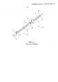
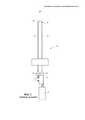
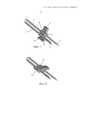
Фиг. 3 и 4 изображают упрощенные виды сшивающего устройства с распорным элементом, выполненным и используемым в соответствии с вариантом выполнения данного изобретения, причем на указанных чертежах распорный элемент расположен соответственно у проксимального и дистального концов прокалывающих элементов,FIG. 3 and 4 depict simplified views of a crosslinking device with a spacer element made and used in accordance with an embodiment of the present invention, wherein in these drawings the spacer element is located respectively at the proximal and distal ends of the piercing elements,
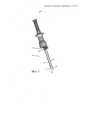
Фиг. 5 изображает более подробный вид распорного элемента, показанного на фиг. 4,FIG. 5 is a more detailed view of the spacer shown in FIG. four,
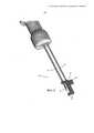
Фиг. 6 изображает упрощенный вид распорного элемента с предохранителем, проходящим в дистальном направлении и выполненным и используемым в соответствии с вариантом выполнения данного изобретения, иFIG. 6 is a simplified view of a spacer element with a fuse extending in the distal direction and made and used in accordance with an embodiment of the present invention, and
Фиг. 7 и 8 изображают упрощенные виды распорного элемента, выполненного и используемого в соответствии с вариантом выполнения данного изобретения, соответственно перед поворотом и после поворота для защелкивания на одном из прокалывающих элементов.FIG. 7 and 8 depict simplified views of a spacer element made and used in accordance with an embodiment of the present invention, respectively, before and after rotation to snap onto one of the piercing elements.
ПОДРОБНОЕ ОПИСАНИЕ ВАРИАНТОВ ВЫПОЛНЕНИЯDETAILED DESCRIPTION OF EMBODIMENTS
Ниже сделана ссылка на фиг. 3-5, которые изображают сшивающее устройство 50, выполненное и используемое в соответствии с неограничивающим вариантом выполнения данного изобретения.Reference is now made to FIG. 3-5, which depict a
Сшивающее устройство 50 содержит первый прокалывающий элемент 52, имеющий острый дистальный конец 54 для прокалывания ткани, и второй прокалывающий элемент 56, имеющий острый дистальный конец 58 для прокалывания ткани. Дистальные концы 54 и 58 первого и второго элементов 52 и 56 отделены друг от друга зазором 59. Распорный элемент 60 расположен с возможностью скольжения в дистальном направлении и проксимальном направлении на первом и/или втором прокалывающих элементах 52 и 56. В варианте выполнения, изображенном на фиг. 3, распорный элемент 60 расположен с возможностью скольжения в дистальном направлении и проксимальном направлении на обоих элементах 52 и 56.The
Как лучше всего видно из фиг. 5, в соответствии с вариантом выполнения данного изобретения элемент 60 имеет первое отверстие 62, через которое проходит один из первого и второго прокалывающих элементов, и второе отверстие 64, через которое проходит другой из указанных элементов. В вариантах выполнения, изображенных на фиг. 5 и 6, каждое отверстие 62 и 64 имеет замкнутый внешний контур. В варианте выполнения, изображенном на фиг. 7 и 8, внешний контур второго отверстия 64 является не полностью замкнутым.As best seen from FIG. 5, in accordance with an embodiment of the invention, the
Распорный элемент 60 обычно находится в дистальном положении (фиг. 4) до введения прокалывающих элементов 52 и 56 в ткань. После процедуры введения в ткань элемент 60 перемещается в проксимальное положение (фиг. 3). Как показано на фиг. 3, для продвижения элемента 60 из проксимального положения в дистальное положение может быть дополнительно выполнено поджимающее средство 63, например цилиндрическая пружина.The
В соответствии с вариантом выполнения данного изобретения распорный элемент имеет выступ 66, который проходит в радиальном направлении и может служить в качестве направляющего средства, рукоятки или наглядного ориентира.According to an embodiment of the invention, the spacer element has a
Со ссылкой на фиг. 6 и в соответствии с вариантом выполнения данного изобретения распорный элемент 60 содержит один или более предохранителей 68, проходящих в дистальном направлении и предназначенных для защиты одного из дистальных концов 54 и 58 первого и второго прокалывающих элементов 52 и 56 или обоих концов 54 и 58.With reference to FIG. 6 and in accordance with an embodiment of the present invention, the
Со ссылкой на фиг. 7 и в соответствии с вариантом выполнения данного изобретения распорный элемент 60 расположен с возможностью поворота вокруг одного из прокалывающих элементов 52 или 56. Распорный элемент 60 содержит соединительную часть 70, защелкивающуюся на другом из указанных элементов.With reference to FIG. 7 and in accordance with an embodiment of the invention, the
В соответствии с вариантом выполнения данного изобретения сшивающее устройство может объединять в себе особенности известного сшивающего устройства. Например, как показано выше на фиг. 1 и 2, сшивающее устройство может также содержать шовную нить 38, проходящую вдоль части первого прокалывающего элемента 52 и расположенную с обеспечением ее захвата у дистального конца указанного элемента 52, и элемент 26 для захвата нити, расположенный у дистального конца второго прокалывающего элемента 54.According to an embodiment of the invention, the crosslinking device can combine the features of a known crosslinking device. For example, as shown above in FIG. 1 and 2, the suturing device may also comprise
Claims (11)
Translated fromRussianApplications Claiming Priority (3)
| Application Number | Priority Date | Filing Date | Title |
|---|---|---|---|
| US201161557482P | 2011-11-09 | 2011-11-09 | |
| US61/557,482 | 2011-11-09 | ||
| PCT/US2012/064053WO2013070841A1 (en) | 2011-11-09 | 2012-11-08 | Suturing assembly with spacer |
Publications (2)
| Publication Number | Publication Date |
|---|---|
| RU2014120384A RU2014120384A (en) | 2015-12-20 |
| RU2609463C2true RU2609463C2 (en) | 2017-02-01 |
Family
ID=47553340
Family Applications (1)
| Application Number | Title | Priority Date | Filing Date |
|---|---|---|---|
| RU2014120384ARU2609463C2 (en) | 2011-11-09 | 2012-11-08 | Surgical stapler with spacer element |
Country Status (14)
| Country | Link |
|---|---|
| US (1) | US10143467B2 (en) |
| EP (1) | EP2775936B1 (en) |
| JP (1) | JP6267647B2 (en) |
| KR (1) | KR20140104950A (en) |
| CN (1) | CN104023650B (en) |
| AU (1) | AU2012335783B2 (en) |
| BR (1) | BR112014011220A2 (en) |
| CA (1) | CA2855210C (en) |
| DK (1) | DK2775936T3 (en) |
| ES (1) | ES2623435T3 (en) |
| MX (1) | MX343866B (en) |
| RU (1) | RU2609463C2 (en) |
| WO (1) | WO2013070841A1 (en) |
| ZA (1) | ZA201403527B (en) |
Families Citing this family (2)
| Publication number | Priority date | Publication date | Assignee | Title |
|---|---|---|---|---|
| US20170055977A1 (en)* | 2015-08-24 | 2017-03-02 | Nir Altman | Multiple-needle suturing assembly |
| BR102017016192B8 (en) | 2017-07-28 | 2021-08-24 | Hospital Das Clinicas Da Faculdade De Medicina Da Univ De Sao Paulo Hcfmusp | mechanical suture device for automated closure of the linea alba of the abdominal wall after incision by midline laparotomy |
Citations (6)
| Publication number | Priority date | Publication date | Assignee | Title |
|---|---|---|---|---|
| SU1438724A1 (en)* | 1985-12-24 | 1988-11-23 | Ленинградский педиатрический медицинский институт | Arrangement for suturing the wounds of parenchymatous organs of the abdominal cavity |
| US6323430B1 (en)* | 1999-07-28 | 2001-11-27 | Itt Manufacturing Enterprises, Inc. | S-shaped cable holding clamp with grounding |
| EP1598017A1 (en)* | 2003-02-26 | 2005-11-23 | Sumitomo Bakelite Co., Ltd. | Medical instrument |
| WO2007073931A1 (en)* | 2005-12-26 | 2007-07-05 | Covidien Ag | Medical suturing device |
| EP2005892A2 (en)* | 2006-04-07 | 2008-12-24 | Sumitomo Bakelite Company, Ltd. | Medical device and method of fixing internal organ |
| US20090264905A1 (en)* | 2006-05-30 | 2009-10-22 | Masaki Funada | Medical Instrument |
Family Cites Families (6)
| Publication number | Priority date | Publication date | Assignee | Title |
|---|---|---|---|---|
| AU2600595A (en)* | 1994-06-08 | 1996-01-04 | Tahoe Surgical Instruments - Puerto Rico, Inc. | Double needle ligature device |
| JP4493258B2 (en)* | 2001-04-04 | 2010-06-30 | オリンパス株式会社 | Tissue puncture device |
| CN100403993C (en)* | 2003-02-26 | 2008-07-23 | 铃木裕 | Medical instrument |
| JP4364857B2 (en)* | 2005-09-22 | 2009-11-18 | 裕 鈴木 | Medical instruments |
| JP4565576B2 (en)* | 2007-02-20 | 2010-10-20 | 日本シャーウッド株式会社 | Puncture needle assist tool |
| US8603112B2 (en) | 2007-11-30 | 2013-12-10 | Easylap Ltd. | Suturing assembly and method |
- 2012
- 2012-11-08WOPCT/US2012/064053patent/WO2013070841A1/enactiveApplication Filing
- 2012-11-08CACA2855210Apatent/CA2855210C/ennot_activeExpired - Fee Related
- 2012-11-08MXMX2014005685Apatent/MX343866B/enactiveIP Right Grant
- 2012-11-08EPEP12813579.5Apatent/EP2775936B1/ennot_activeNot-in-force
- 2012-11-08JPJP2014541221Apatent/JP6267647B2/ennot_activeExpired - Fee Related
- 2012-11-08RURU2014120384Apatent/RU2609463C2/ennot_activeIP Right Cessation
- 2012-11-08USUS14/356,632patent/US10143467B2/ennot_activeExpired - Fee Related
- 2012-11-08BRBR112014011220Apatent/BR112014011220A2/ennot_activeApplication Discontinuation
- 2012-11-08ESES12813579.5Tpatent/ES2623435T3/enactiveActive
- 2012-11-08CNCN201280055412.4Apatent/CN104023650B/ennot_activeExpired - Fee Related
- 2012-11-08DKDK12813579.5Tpatent/DK2775936T3/enactive
- 2012-11-08KRKR1020147013324Apatent/KR20140104950A/ennot_activeCeased
- 2012-11-08AUAU2012335783Apatent/AU2012335783B2/ennot_activeCeased
- 2014
- 2014-05-15ZAZA2014/03527Apatent/ZA201403527B/enunknown
Patent Citations (6)
| Publication number | Priority date | Publication date | Assignee | Title |
|---|---|---|---|---|
| SU1438724A1 (en)* | 1985-12-24 | 1988-11-23 | Ленинградский педиатрический медицинский институт | Arrangement for suturing the wounds of parenchymatous organs of the abdominal cavity |
| US6323430B1 (en)* | 1999-07-28 | 2001-11-27 | Itt Manufacturing Enterprises, Inc. | S-shaped cable holding clamp with grounding |
| EP1598017A1 (en)* | 2003-02-26 | 2005-11-23 | Sumitomo Bakelite Co., Ltd. | Medical instrument |
| WO2007073931A1 (en)* | 2005-12-26 | 2007-07-05 | Covidien Ag | Medical suturing device |
| EP2005892A2 (en)* | 2006-04-07 | 2008-12-24 | Sumitomo Bakelite Company, Ltd. | Medical device and method of fixing internal organ |
| US20090264905A1 (en)* | 2006-05-30 | 2009-10-22 | Masaki Funada | Medical Instrument |
Also Published As
| Publication number | Publication date |
|---|---|
| EP2775936A1 (en) | 2014-09-17 |
| ES2623435T3 (en) | 2017-07-11 |
| US20140371791A1 (en) | 2014-12-18 |
| MX343866B (en) | 2016-11-25 |
| ZA201403527B (en) | 2015-07-29 |
| KR20140104950A (en) | 2014-08-29 |
| CN104023650A (en) | 2014-09-03 |
| AU2012335783A1 (en) | 2014-05-29 |
| EP2775936B1 (en) | 2016-12-28 |
| CA2855210A1 (en) | 2013-05-16 |
| CN104023650B (en) | 2017-02-15 |
| AU2012335783B2 (en) | 2017-01-05 |
| RU2014120384A (en) | 2015-12-20 |
| JP6267647B2 (en) | 2018-01-24 |
| CA2855210C (en) | 2019-04-09 |
| JP2015500678A (en) | 2015-01-08 |
| MX2014005685A (en) | 2014-08-22 |
| DK2775936T3 (en) | 2017-04-03 |
| WO2013070841A1 (en) | 2013-05-16 |
| BR112014011220A2 (en) | 2017-05-09 |
| US10143467B2 (en) | 2018-12-04 |
Similar Documents
| Publication | Publication Date | Title |
|---|---|---|
| RU2478346C2 (en) | Sewing device and method of sewing | |
| JP6384682B2 (en) | Laparoscopic port site closure device | |
| US10485532B2 (en) | Suture passer device including a blunt tip and a sharp tip | |
| JP6431534B2 (en) | Suture device and method for suturing anatomic tissue | |
| US20110190793A1 (en) | Methods and apparatuses for suturing of cardiac openings | |
| US9095319B2 (en) | Suturing device and method for sealing an opening in a blood vessel or other biological structure | |
| JP2014519358A (en) | Forward suture passer | |
| AU2015213812B2 (en) | Suture delivery device for suturing tissue | |
| TW201607492A (en) | Systems and methods for suture delivery | |
| US20150313583A1 (en) | Needle and snare guide apparatus for passing suture | |
| CA2970783A1 (en) | Surgical closure apparatus and method | |
| US9173654B2 (en) | System for tissue repair | |
| RU2609463C2 (en) | Surgical stapler with spacer element | |
| US11452519B2 (en) | Apparatus and method for passing suture through soft tissue | |
| NL2019974B1 (en) | Suture device | |
| US11471152B2 (en) | Needle and guide apparatus for passing suture | |
| JP2017506104A (en) | In-situ suture joint forming method and apparatus | |
| AU2017311506A1 (en) | Suture delivery device for suturing tissue | |
| JP2022509536A (en) | Automatic suturing device and automatic suturing method | |
| KR20200099169A (en) | Suture passing device | |
| KR101419116B1 (en) | Knotting device for continuous suturing instrument |
Legal Events
| Date | Code | Title | Description |
|---|---|---|---|
| MM4A | The patent is invalid due to non-payment of fees | Effective date:20191109 |