RU2608623C1 - Replaceable head piece to electrode-knife of placemaker for dissection of cicatricial tissues surrounding the extravascular fragment of placemaker electrode (versions) - Google Patents
Replaceable head piece to electrode-knife of placemaker for dissection of cicatricial tissues surrounding the extravascular fragment of placemaker electrode (versions)Download PDFInfo
- Publication number
- RU2608623C1 RU2608623C1RU2015145018ARU2015145018ARU2608623C1RU 2608623 C1RU2608623 C1RU 2608623C1RU 2015145018 ARU2015145018 ARU 2015145018ARU 2015145018 ARU2015145018 ARU 2015145018ARU 2608623 C1RU2608623 C1RU 2608623C1
- Authority
- RU
- Russia
- Prior art keywords
- electrode
- housing
- knife
- working part
- tubular body
- Prior art date
Links
- 239000012634fragmentSubstances0.000titleclaimsabstractdescription13
- 238000002224dissectionMethods0.000titleabstractdescription16
- 231100000241scarToxicity0.000claimsabstractdescription13
- 125000006850spacer groupChemical group0.000claimsdescription6
- 230000007246mechanismEffects0.000claimsdescription4
- 230000000694effectsEffects0.000abstractdescription9
- 238000000034methodMethods0.000abstractdescription9
- 230000006378damageEffects0.000abstractdescription5
- 238000005345coagulationMethods0.000abstractdescription4
- 230000015271coagulationEffects0.000abstractdescription4
- 238000006073displacement reactionMethods0.000abstract1
- 238000000926separation methodMethods0.000abstract1
- 239000000126substanceSubstances0.000abstract1
- 210000001519tissueAnatomy0.000description48
- 238000009297electrocoagulationMethods0.000description11
- 238000009413insulationMethods0.000description11
- 238000013461designMethods0.000description6
- 239000002184metalSubstances0.000description6
- 230000008878couplingEffects0.000description5
- 238000010168coupling processMethods0.000description5
- 238000005859coupling reactionMethods0.000description5
- 239000002775capsuleSubstances0.000description4
- 238000004519manufacturing processMethods0.000description4
- 239000000463materialSubstances0.000description3
- 230000004048modificationEffects0.000description3
- 238000012986modificationMethods0.000description3
- 230000000638stimulationEffects0.000description3
- 238000001356surgical procedureMethods0.000description3
- 230000000740bleeding effectEffects0.000description2
- 239000004020conductorSubstances0.000description2
- 238000002474experimental methodMethods0.000description2
- 238000000605extractionMethods0.000description2
- 238000009434installationMethods0.000description2
- 239000007788liquidSubstances0.000description2
- 230000013011matingEffects0.000description2
- 238000011477surgical interventionMethods0.000description2
- 208000032984Intraoperative ComplicationsDiseases0.000description1
- 206010057765Procedural complicationDiseases0.000description1
- 230000009471actionEffects0.000description1
- 230000003213activating effectEffects0.000description1
- 230000001154acute effectEffects0.000description1
- 230000006793arrhythmiaEffects0.000description1
- 206010003119arrhythmiaDiseases0.000description1
- 230000008859changeEffects0.000description1
- 210000003109clavicleAnatomy0.000description1
- 239000003814drugSubstances0.000description1
- 238000011234economic evaluationMethods0.000description1
- 238000002674endoscopic surgeryMethods0.000description1
- 238000005516engineering processMethods0.000description1
- 238000011156evaluationMethods0.000description1
- 230000004927fusionEffects0.000description1
- 239000007789gasSubstances0.000description1
- 210000005003heart tissueAnatomy0.000description1
- 238000002513implantationMethods0.000description1
- 230000006698inductionEffects0.000description1
- 230000003993interactionEffects0.000description1
- 230000002262irrigationEffects0.000description1
- 238000003973irrigationMethods0.000description1
- 238000002955isolationMethods0.000description1
- 230000003680myocardial damageEffects0.000description1
- 210000000056organAnatomy0.000description1
- 230000035515penetrationEffects0.000description1
- 230000001681protective effectEffects0.000description1
- 238000007789sealingMethods0.000description1
- 238000005476solderingMethods0.000description1
- 239000007787solidSubstances0.000description1
- 230000005477standard modelEffects0.000description1
- 230000003068static effectEffects0.000description1
- 230000003685thermal hair damageEffects0.000description1
- 239000010409thin filmSubstances0.000description1
Images


Classifications
- A—HUMAN NECESSITIES
- A61—MEDICAL OR VETERINARY SCIENCE; HYGIENE
- A61B—DIAGNOSIS; SURGERY; IDENTIFICATION
- A61B17/00—Surgical instruments, devices or methods
- A61B17/32—Surgical cutting instruments
Landscapes
- Health & Medical Sciences (AREA)
- Life Sciences & Earth Sciences (AREA)
- Surgery (AREA)
- Heart & Thoracic Surgery (AREA)
- Engineering & Computer Science (AREA)
- Biomedical Technology (AREA)
- Nuclear Medicine, Radiotherapy & Molecular Imaging (AREA)
- Medical Informatics (AREA)
- Molecular Biology (AREA)
- Animal Behavior & Ethology (AREA)
- General Health & Medical Sciences (AREA)
- Public Health (AREA)
- Veterinary Medicine (AREA)
- Surgical Instruments (AREA)
Abstract
Description
Translated fromRussianОБЛАСТЬ ТЕХНИКИFIELD OF TECHNOLOGY
Группа изобретений относится к медицине и медицинской технике, а именно к электрохирургическим инструментам для электрокоагуляции и рассечения тканей, в частности, к устройствам для рассечения рубцовых тканей вокруг внесосудистых фрагментов эндокардиальных электродов имплантированного электрокардиостимулятора, и может использоваться для безопасного выделения электродов электрокардиостимулятора во время смены или апгрейда электрокардиостимулятора.The group of inventions relates to medicine and medical equipment, in particular to electrosurgical instruments for electrocoagulation and dissection of tissues, in particular, to devices for dissecting scar tissue around extravascular fragments of endocardial electrodes of an implanted pacemaker, and can be used to safely separate electrodes of a pacemaker during a shift or upgrade pacemaker.
УРОВЕНЬ ТЕХНИКИBACKGROUND
Проблема атравматичного выделения эндокадиальных электродов сохраняет свою актуальность ввиду достаточно высокого уровня интраоперационных осложнений при смене или апгрейде электрокардиостимулятора. (J.E. Poole et al. Complication rates associated with pacemaker or implantable cardioverter-defiblillator generator replacements and upgrade procedures / J.E. Poole, M.J. Gleva, T. Mela et al. // Circulation. - 2010. - 122. - P. 1553-1561., A. Kypta An electrical plasma surgery tool for device replacement - retrospective evaluation of complications and economic evaluation of costs and resource use // PACE vol. 38 jan 2015, p 28-34, А.Е. Тягунов с соавт. Лечение локальных гнойных осложнений в зоне имплантированного электрокардиостимулятора: возможно ли сохранение системы стимуляции? // Вестник аритмологии. - 2011. - №65. - С. 45-51).The problem of atraumatic discharge of endocadial electrodes remains relevant due to the rather high level of intraoperative complications when changing or upgrading a pacemaker. (JE Poole et al. Complication rates associated with pacemaker or implantable cardioverter-defiblillator generator replacements and upgrade procedures / JE Poole, MJ Gleva, T. Mela et al. // Circulation. - 2010. - 122. - P. 1553-1561 ., A. Kypta An electrical plasma surgery tool for device replacement - retrospective evaluation of complications and economic evaluation of costs and resource use // PACE vol. 38 jan 2015, p 28-34, AE Tyagunov et al. Treatment of local purulent complications in the area of the implanted pacemaker: is it possible to maintain the stimulation system? // Bulletin of Arrhythmology. - 2011. - No. 65. - P. 45-51).
Известно использование хирургических ножниц для выделения электродов из сращений (Каширин С.В., Егоров Д.Ф., Гуреев С.В. и др. Удаление длительно имплантированных электродов для электростимуляции сердца. // Вестник аритмологии. - 2004. - №35 приложение В. - С. 279-292). Методика предполагает острое последовательное выделение электродов из сращений друг с другом и фиброзными тканями хирургическими режущими инструментами. К недостаткам данной методики относятся риск повреждения изоляции электродов, кровотечение и большая длительность операции.It is known to use surgical scissors to extract electrodes from adhesions (Kashirin S.V., Egorov D.F., Gureev S.V. et al. Removal of long-implanted electrodes for electrical stimulation of the heart. // Bulletin of Arrhythmology. - 2004. - No. 35 application B. - S. 279-292). The technique involves sharp sequential extraction of electrodes from splices with each other and fibrous tissues by surgical cutting tools. The disadvantages of this technique include the risk of damage to the insulation of the electrodes, bleeding and the long duration of the operation.
Известно выделение внесосудистых фрагментов электродов с помощью монополярного электрокоагулятора (А.Е. Тягунов, Е.В. Первова, К.В. Котов, и др.). На рынке медицинской техники широко представлены электроинструменты для коагуляции и рассечения тканей во время эндоскопических и открытых операций. В силу своих конструктивных особенностей и по функциональному назначению выделяют электроинструменты многоразового и одноразового применения, биполярные и монополярные. Также применяются специализированные устройства, например, с каналом для аспирации и ирригации жидкостей, с выдвигаемым электродом и т.д. Преимущества и безопасность использования электрокоагуляции при операциях в зоне имплантированного электрокардиостимулятора http://www.incart.ru/atts/11355/70p68.pdf). Для рассечения периэлектродных сращений используется электрод-нож электрокоагулятора. При контакте с изоляцией электрода возможно температурное повреждение изоляции, что делает дальнейшее использование эндокардиального электрода невозможным и требует его замены, что значительно увеличивает продолжительность и стоимость операции. Кроме того, через металлический проводник эндокардиального электрода при повреждении изоляции не исключается электрокоагуляционное воздействие на ткань сердца с повреждением миокарда или индукцией аритмии.It is known to isolate extravascular fragments of electrodes using a monopolar electrocoagulator (A.E. Tyagunov, E.V. Pervova, K.V. Kotov, and others). Power tools for coagulation and dissection of tissues during endoscopic and open surgeries are widely represented on the medical equipment market. Due to their design features and functionality, they distinguish reusable and disposable power tools, bipolar and monopolar. Specialized devices are also used, for example, with a channel for aspiration and irrigation of liquids, with a retractable electrode, etc. Advantages and safety of using electrocoagulation during operations in the area of an implanted pacemaker http://www.incart.ru/atts/11355/70p68.pdf). For dissection of perielectrode adhesions, an electrode-knife of an electrocoagulator is used. Contact with the insulation of the electrode may cause thermal damage to the insulation, which makes further use of the endocardial electrode impossible and requires replacement, which significantly increases the duration and cost of the operation. In addition, through the metal conductor of the endocardial electrode, if the insulation is damaged, electrocoagulation effect on the heart tissue with myocardial damage or arrhythmia induction is not excluded.
Известно устройство для диссекции биологических тканей (RU 2249435 С2, 10.04.2005), содержащее корпус с ручкой и с размещенной на конце корпуса рабочей частью. Корпус выполнен в виде сплошного или с каналами стержня, один из концов которого плавно переходит в овалообразную шейку, предназначенную для разъединения оперируемого органа от здорового. В одном из вариантов использования устройства в корпусе выполнены продольные внутренние каналы для транспортировки жидкостей и газов, ввода-вывода других инструментов с соответствующими соединительными, расходорегулирующими и герметезирующими приспособлениями. Однако данное устройство используется в эндоскопической хирургии и не приспособлено для выделения электродов электрокардиостимулятора и нанесения прецизионного коагуляционного воздействия. Устройство отличается материалом изготовления корпуса, изготовлено из металла, что не позволяет обеспечить защиту изоляции электрода от прямого механического и электрического воздействия. Использование устройства позволяет проводить процедуру без перевода ее в традиционную открытую операцию.A device for the dissection of biological tissues (RU 2249435 C2, 04/10/2005) is known, comprising a housing with a handle and a working part located at the end of the housing. The body is made in the form of a solid or with rod channels, one of the ends of which smoothly passes into an oval-shaped neck, designed to disconnect the operated organ from a healthy one. In one use case of the device, longitudinal internal channels are made in the housing for transporting liquids and gases, input-output of other tools with corresponding connecting, flow-regulating and sealing devices. However, this device is used in endoscopic surgery and is not suitable for the isolation of electrodes of a pacemaker and the application of precision coagulation. The device is distinguished by the material of manufacture of the housing, made of metal, which does not allow to protect the insulation of the electrode from direct mechanical and electrical effects. Using the device allows you to carry out the procedure without translating it into a traditional open operation.
Также из уровня техники известно «Устройство для рассечения рубцовых тканей вокруг внесосудистого фрагмента электрода электрокардиостимулятора» (RU 2463976, 24.05.2011), применяемое в открытой хирургии. В устройстве для рассечения тканей используется электрод-нож в форме струны, который с помощью коннектора подключается к электрокоагулятору. Само устройство представляет собой изготовленный из диэлектрика корпус в форме прямоугольного параллепипеда и отслоитель рубцовой ткани от электрода в виде желобообразного элемента с заостренной кромкой, укрепленный в корпусе проксимальным концом. При этом струнный электрод-нож установлен на внешней поверхности желобообразного элемента на его дистальном конце, а в теле корпуса устройства струнный электрод-нож фиксирован путем пайки. Желобообразный элемент выполнен с возможностью скольжения по электроду в направлении рассечения. Использование устройства позволяет отделить электроды от биологической ткани без нарушения их целостности и с возможностью повторного использования электродов.Also known from the prior art is “A device for dissecting scar tissue around an extravascular fragment of an electrode of a pacemaker” (RU 2463976, 05.24.2011), used in open surgery. The device for dissecting tissues uses an electrode-knife in the form of a string, which is connected to an electrocoagulator using a connector. The device itself is a rectangular parallelepiped-shaped body made of a dielectric and a scar tissue exfoliator from the electrode in the form of a gutter-shaped element with a pointed edge, mounted in the body with a proximal end. In this case, the string electrode-knife is installed on the outer surface of the trough-shaped element at its distal end, and in the body of the device’s body, the string electrode-knife is fixed by soldering. The gutter-shaped element is slidable along the electrode in the direction of dissection. Using the device allows you to separate the electrodes from biological tissue without violating their integrity and with the possibility of reuse of the electrodes.
Недостатком устройства является трудоемкость изготовления, связанная с необходимостью сопряжения деталей из разных классов материалов в производстве металла (струнный электрод-нож) и пластмассы (отслоитель рубцовой ткани и корпус). Также в связи с цельностью конструкции (струна электрод-ножа припаяна к корпусу) невозможно обеспечить сменность электрод-ножа, что позволило бы работать с различными стандартными моделями электродов электрокоагулятора. Кроме того, устройство недостаточно функционально, т.к. не позволяет дозировать объем рассекаемых тканей, вследствие чего малоэффективно при рассечении большого массива тканей - фактически способно рассекать только тонкую пленку фиброзной ткани, толщиной 1-2 мм, неудобно из-за отсутствия рукоятки и малых размеров, что требует от хирурга работы рукой в глубине раны с недостаточной экспозицией операционного поля.The disadvantage of this device is the complexity of manufacturing associated with the need to pair parts from different classes of materials in the production of metal (string electrode-knife) and plastic (exfoliator of scar tissue and the body). Also, due to the integrity of the structure (the electrode-knife string is soldered to the body), it is not possible to provide electrode-knife interchangeability, which would allow working with various standard models of electrocoagulator electrodes. In addition, the device is not functional enough, because it does not allow dosing the volume of dissected tissues, which is why it is ineffective when dissecting a large array of tissues - it is actually capable of dissecting only a thin film of fibrous tissue, 1-2 mm thick, inconvenient due to the lack of a handle and small size, which requires the surgeon to work with his hand deep in the wound with insufficient exposure of the surgical field.
РАСКРЫТИЕ ИЗОБРЕТЕНИЯSUMMARY OF THE INVENTION
Задачей, на достижение которой направлена предлагаемая группа изобретений, является расширение арсенала технических средств, направленных на освобождение электродов имплантированного электрокардиостимулятора от фиброзной капсулы вокруг внесосудистого фрагмента электрода без нарушения целостности изоляции электрода и риска электрического воздействия на сердце через металлический проводник эндокардиального электрода.The task to which the proposed group of inventions is aimed is to expand the arsenal of technical means aimed at releasing the electrodes of the implanted pacemaker from the fibrous capsule around the extravascular fragment of the electrode without compromising the integrity of the electrode insulation and the risk of electrical effects on the heart through the metal conductor of the endocardial electrode.
Технический результат группы изобретений заключается в реализации указанного выше назначения, в частности, в возможности рассечения рубцовых тканей вокруг внесосудистого фрагмента электрода электростимулятора с помощью универсальной насадки на рукоятку электрокоагулятора без нарушения целостности самих электродов и с возможностью их дальнейшего использования, что позволяет уменьшить травматичность и продолжительность выполняемых оперативных вмешательств по сравнению с существующими методиками.The technical result of the group of inventions consists in the implementation of the above purpose, in particular, in the possibility of dissection of scar tissue around the extravascular fragment of the electrode of the electrostimulator using a universal nozzle on the handle of the electrocoagulator without violating the integrity of the electrodes themselves and with the possibility of their further use, which reduces the morbidity and duration of the performed surgical interventions compared to existing techniques.
Для достижения указанного технического результата предлагаемые варианты конструкции устройства для рассечения рубцовых тканей вокруг эндокардиального электрода электрокардиостимулятора выполнены следующим образом.To achieve the technical result, the proposed design options for a device for dissecting scar tissue around the endocardial electrode of a pacemaker are as follows.
В первом варианте осуществления устройство содержит корпус, имеющий нижнюю и верхнюю части, рабочую часть с заостренной кромкой, при этом рабочая часть с заостренной кромкой закреплена на нижней части корпуса, рабочая часть с заостренной кромкой выполнена в виде желоба с дугообразным поперечным сечением и со скошенной книзу фаской на передней части желоба или гладким заострением на передней части желоба, корпус выполнен в виде удлиненного элемента с продольным внутренним каналом для введения электрод-ножа, при этом продольный внутренний канал выполнен с элементом фиксации, в нижней части корпуса выполнен паз с возможностью контакта рабочей части введенного электрод-ножа с рассекаемой тканью.In the first embodiment, the device comprises a housing having a lower and upper part, a working part with a pointed edge, while the working part with a pointed edge is fixed to the lower part of the body, the working part with a pointed edge is made in the form of a gutter with an arcuate cross-section and beveled down chamfer on the front of the gutter or with a smooth sharpness on the front of the gutter, the casing is made in the form of an elongated element with a longitudinal internal channel for introducing the electrode-knife, while the longitudinal internal Channel element configured to lock at the bottom of the housing groove is formed to be contactable inputted working part of the electrode-knife with a dissecting tissue.
Удлиненным элементом является, например, цилиндрический элемент.An elongated element is, for example, a cylindrical element.
Кроме того, элементом фиксации является сужающийся в нижней части корпуса продольный внутренний канал, при этом диаметр сужающейся части продольного внутреннего канала соответствует диаметру рабочей части электрод-ножа. Ось сужающейся части продольного внутренного канала пересекается с осью желоба.In addition, the fixing element is a longitudinal inner channel tapering in the lower part of the housing, while the diameter of the tapering part of the longitudinal inner channel corresponds to the diameter of the working part of the electrode-knife. The axis of the tapering part of the longitudinal inner channel intersects with the axis of the trough.
Кроме того, элементом фиксации являются эластичные втулки, установленные в верхней или в верхней и нижней частях продольного внутреннего канала.In addition, the fixing element is elastic bushings installed in the upper or upper and lower parts of the longitudinal inner channel.
Кроме того, элементом фиксации является эластичная муфта, установленная в распор и фиксированная в верхней части или на протяжении всей длины продольного внутреннего канала.In addition, the fixing element is an elastic sleeve installed in the spacer and fixed in the upper part or throughout the length of the longitudinal inner channel.
Паз в продольном сечении имеет, например, прямоугольную форму, форму эллипса.The groove in the longitudinal section has, for example, a rectangular shape, an ellipse shape.
Внутренний канал корпуса и корпус соосны.The inner channel of the housing and the housing are aligned.
Во втором варианте осуществления устройство содержит корпус, имеющий нижнюю и верхнюю части, и рабочую часть с заостренной кромкой, закрепленную на нижней части корпуса, при этом рабочая часть с заостренной кромкой выполнена в виде желоба с дугообразным поперечным сечением со скошенной книзу фаской на передней части желоба или гладким заострением на передней части желоба, корпус включает внешний трубчатый корпус и подпружиненный внутренний трубчатый корпус, выполненный с возможностью введения электрод-ножа и смещения относительно внешнего трубчатого корпуса, при этом в нижней части внешнего трубчатого корпуса выполнен паз с возможностью контакта рабочей части введенного электрод-ножа с рассекаемой тканью, при этом между внешним и внутренним трубчатыми корпусами установлены ограничители, определяющие длину хода внутреннего трубчатого корпуса.In the second embodiment, the device comprises a housing having a lower and upper part, and a working part with a pointed edge mounted on the lower part of the housing, while the working part with a pointed edge is made in the form of a gutter with an arcuate cross-section with a chamfered chamfer on the front of the gutter or with a smooth taper on the front of the gutter, the casing includes an external tubular casing and a spring-loaded inner tubular casing, adapted to introduce an electrode-knife and offset relative to the outside the upper tubular body, while in the lower part of the outer tubular body a groove is made with the possibility of contact of the working part of the inserted electrode-knife with the dissected tissue, while the limiters determining the stroke length of the inner tubular body are installed between the outer and inner tubular bodies.
Внешний трубчатый корпус и внутренний трубчатый корпус выполнены цилиндрическими.The outer tubular body and the inner tubular body are cylindrical.
Ограничители выполнены в виде концентрических выступов, расположенных по наружной поверхности внутреннего трубчатого корпуса и внутренней поверхности внешнего трубчатого корпуса.The stops are made in the form of concentric protrusions located on the outer surface of the inner tubular body and the inner surface of the outer tubular body.
Внутренний трубчатый корпус подпружинен кольцевой запорной пружиной относительно внешнего трубчатого корпуса, расположенной между ограничителями на обоих трубчатых корпусах.The inner tubular body is spring-loaded with an annular locking spring relative to the outer tubular body located between the stops on both tubular bodies.
Устройство дополнительно может быть оснащено эластичной муфтой, установленной в распор и фиксированной в верхней части или на протяжении всей длины внутреннего трубчатого элемента.The device can additionally be equipped with an elastic sleeve installed in a spacer and fixed in the upper part or throughout the entire length of the inner tubular element.
Устройство дополнительно может быть оснащено эластичными втулками, установленными в верхней или в верхней и нижней частях внутреннего трубчатого элемента.The device can optionally be equipped with elastic sleeves installed in the upper or upper and lower parts of the inner tubular element.
Устройство дополнительно оснащено механизмом фиксации, выполненным в виде винтового ограничителя, насквозь установленного во внешний трубчатый элемент, перпендикулярно его оси.The device is additionally equipped with a locking mechanism, made in the form of a screw stopper, installed through the outer tubular element, perpendicular to its axis.
Оба варианта устройства выполнены из термостойкого биологически инертного пластика. В обоих вариантах угол между корпусом и рабочей частью с заостренной кромкой может варьироваться в пределах от 30° до 100°.Both versions of the device are made of heat-resistant biologically inert plastic. In both cases, the angle between the body and the working part with a pointed edge can vary from 30 ° to 100 °.
Устройство в обоих вариантах осуществления может быть дополнительно снабжено опорным элементом, стороны которого примыкают к корпусу и рабочей части, при этом опорный элемент выполнен по форме геометрической фигуры, например, треугольника, трапеции.The device in both embodiments can be further provided with a support element, the sides of which are adjacent to the housing and the working part, while the support element is made in the form of a geometric figure, for example, a triangle, a trapezoid.
Расположение корпуса устройства под углом от 30 до 100° по отношению к рабочей части направлено на выбор оптимального контакта с рассекаемыми тканями в зависимости от состояния и характера тканей, повышение эффективности рассечения тканей.The location of the device’s body at an angle of 30 to 100 ° with respect to the working part is aimed at choosing the optimal contact with dissected tissues, depending on the state and nature of the tissues, increasing the efficiency of tissue dissection.
Фиксация электрод-ножа в канале корпуса за счет выполнения канала с элементом фиксации (сужающимся, расположение сужающегося канала корпуса на оси желоба, наличие эластичной муфты или эластичных втулок) в первом варианте осуществления не позволяет ему смещаться от средней линии желоба при работе и обеспечивает рассечение тканей в оптимальном положении электрод-ножа относительно желоба - посередине последнего. В этом положении осуществляется оптимальный контакт с рассекаемой тканью для облегчения поступательного продвижения устройства (ткань фиброзной капсулы рассекается в соотношении 50% на 50%, что исключает поворачивающий момент сил в сторону, где объем рассекаемой ткани выше, что возможно при ассиметричном расположении ножа относительно желобоватого элемента). За счет фиксации электрод-ножа устройство позволяет строго ориентированное введение в ткани последнего.The fixation of the electrode-knife in the channel of the housing due to the implementation of the channel with the locking element (tapering, the location of the tapering channel of the housing on the axis of the trough, the presence of an elastic sleeve or elastic bushings) in the first embodiment does not allow it to shift from the midline of the trough during operation and provides tissue dissection in the optimal position of the electrode-knife relative to the trough - in the middle of the latter. In this position, optimal contact with the dissected tissue is made to facilitate the translational advancement of the device (the tissue of the fibrous capsule is dissected in a ratio of 50% to 50%, which eliminates the turning moment of forces to the side where the volume of the dissected tissue is higher, which is possible with an asymmetric arrangement of the knife relative to the grooved element ) By fixing the electrode-knife, the device allows a strictly oriented introduction into the tissue of the latter.
Во втором варианте осуществления фиксация электрод-ножа осуществляется за счет того, что диаметр внутреннего трубчатого корпуса соответствует (незначительно превышает на 0,1-0,2 мм) внешнему диаметру электрод-ножа.In the second embodiment, the electrode-knife is fixed due to the fact that the diameter of the inner tubular body corresponds (slightly exceeds 0.1-0.2 mm) to the outer diameter of the electrode-knife.
Конструкция устройства по второму варианту осуществления позволит повысить прецизионность работы и позволит произвести строго ориентированное введение в ткани электрода-ножа путем дозирования площади контакта с рассекаемыми тканями, глубины электрокоагуляционного воздействия за счет возможности поступательных осевых, боковые и ротационные движений электрода-ножа.The design of the device according to the second embodiment will increase the precision of work and allow a strictly oriented introduction of the knife electrode into the tissue by dosing the contact area with the dissected tissues, the depth of the electrocoagulation effect due to the possibility of translational axial, lateral and rotational movements of the knife electrode.
Целостность обрабатываемых электродов электрокардиостимуляторов обеспечивается конструктивным выполнением и изоляционным материалом рабочей части в виде желоба с дугообразным поперечным сечением, близким к сечению выделяемого электрода и закрывающего электрод. Передняя часть желоба проводится под Рубцовыми тканями за счет заостренной кромки. Рабочая часть устройства выступает в качестве защитного приспособления для предупреждения повреждения изоляции электрода.The integrity of the processed pacemaker electrodes is ensured by the design and insulation of the working part in the form of a gutter with an arcuate cross section close to the secreted electrode section and closing the electrode. The front of the gutter is held under the scar tissue due to the pointed edge. The working part of the device acts as a protective device to prevent damage to the electrode insulation.
Устройство обладает преимуществами по сравнению с ближайшим аналогом в связи с тем, что конструкция является универсальной для электрокагуляторов разных производителей, простой в производстве, т.к. не требует сопряжения пластиковых и металлических частей. Эргономические преимущества, безопасность для хирурга и пациента заключаются в том, что рассечение тканей проводится штатной рукояткой электрокоагулятора. Рукоятка-держатель сопряжена с заявляемым устройством посредством введения электрода электрокоагулятора в полый канал цилиндрического элемента. Устройство позволяет точно дозировать глубину, объем и эффективность рассечения тканей за счет вариантов исполнения передней части желобоватого элемента, угла наклона корпуса, вариантов осуществления устройств, способов фиксации электрода-ножа в устройстве.The device has advantages compared to the closest analogue due to the fact that the design is universal for electrocoagulators from different manufacturers, simple to manufacture, because does not require pairing of plastic and metal parts. Ergonomic advantages, safety for the surgeon and patient are that the dissection of tissues is carried out by the standard handle of the electrocoagulator. The handle-holder is associated with the claimed device by introducing an electrode of the electrocoagulator into the hollow channel of the cylindrical element. The device allows you to accurately dose the depth, volume and efficiency of dissection of tissues due to options for the front of the grooved element, the angle of inclination of the housing, embodiments of devices, methods of fixing the knife electrode in the device.
Использование устройства позволит повысить скорость и качество операции и расширить арсенал имеющихся технических средств, направленных на отделение электродов имплантированного электрокардиостимулятора от фиброзной капсулы вокруг внесосудистого фрагмента электрода без нарушения целостности самих электродов с возможностью их дальнейшего использования, что позволяет уменьшить травматичность и продолжительность выполняемых оперативных вмешательств по сравнению с существующими методиками.Using the device will improve the speed and quality of the operation and expand the arsenal of available technical equipment aimed at separating the electrodes of the implanted pacemaker from the fibrous capsule around the extravascular fragment of the electrode without violating the integrity of the electrodes themselves with the possibility of their further use, which reduces the morbidity and duration of surgical interventions compared with existing techniques.
КРАТКОЕ ОПИСАНИЕ ЧЕРТЕЖЕЙBRIEF DESCRIPTION OF THE DRAWINGS
Сущность заявляемой группы технических решений поясняется графически.The essence of the claimed group of technical solutions is illustrated graphically.
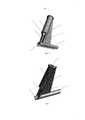
Фиг. 1, Фиг. 2 - трехмерное изображение устройства согласно первому варианту осуществления, вид ¾ спереди с выполнением рабочей части с заостренной кромкой в виде желоба с дугообразным поперечным сечением со скошенной книзу фаской на передней части желоба и с элементом фиксации в виде сужающейся части внутреннего продольного канала.FIG. 1, FIG. 2 is a three-dimensional image of the device according to the first embodiment, a front view с with a working part with a pointed edge in the form of a groove with an arcuate cross-section with a chamfered chamfer on the front of the gutter and with a fixing element in the form of a tapering part of the internal longitudinal channel.
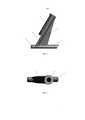
Фиг. 3 - изображение устройства согласно первому варианту осуществления, вид сбоку с выполнением рабочей части с заостренной кромкой в виде желоба с дугообразным поперечным сечением со скошенной книзу фаской на передней части желоба.FIG. 3 is a depiction of a device according to a first embodiment, a side view showing a working part with a pointed edge in the form of a gutter with an arcuate cross-section with a chamfered chamfer on the front of the gutter.
Фиг. 4 - изображение устройства согласно первому варианту осуществления, вид сверху с выполнением рабочей части с заостренной кромкой в виде желоба с дугообразным поперечным сечением со скошенной книзу фаской на передней части желоба.FIG. 4 is a depiction of a device according to a first embodiment, a top view showing a working part with a pointed edge in the form of a gutter with an arcuate cross-section with a chamfered chamfer on the front of the gutter.
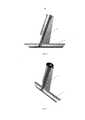
Фиг. 5 - Фиг. 8 - трехмерное изображение устройства согласно первому варианту осуществления с выполнением рабочей части с заостренной кромкой в виде желоба с гладким заострением на передней части желоба,FIG. 5 - FIG. 8 is a three-dimensional image of the device according to the first embodiment with the implementation of the working part with a pointed edge in the form of a gutter with a smooth sharpening on the front of the gutter,
Фиг. 9 - Фиг. 10 - схематичное изображение продольного среза устройства согласно второму варианту осуществления.FIG. 9 - FIG. 10 is a schematic longitudinal sectional view of a device according to a second embodiment.
Фиг. 11 - схематичное изображение продольного сечения фронтального вида устройства согласно второму варианту осуществления с введенным электрод-ножом.FIG. 11 is a schematic longitudinal sectional view of a front view of a device according to a second embodiment with an inserted electrode knife.
На чертежах используется сквозная нумерация.In the drawings, end-to-end numbering is used.
ОСУЩЕСТВЛЕНИЕ ИЗОБРЕТЕНИЯDETAILED DESCRIPTION OF THE INVENTION
Устройство представляет собой сменную насадку на электрод-нож электрокоагулятора и выполнено из термостойкого биологически инертного пластика (например, из фотополимера или PLA пластика) в первом варианте осуществления - единым конструктивным элементом, во втором варианте состоит из двух пластиковых деталей и пружины.The device is a replaceable nozzle on the electrode-knife of an electrocoagulator and is made of heat-resistant biologically inert plastic (for example, from a photopolymer or PLA plastic) in the first embodiment - as a single structural element, in the second embodiment consists of two plastic parts and a spring.
Устройство для рассечения Рубцовых тканей вокруг внесосудистого фрагмента электрода электрокардиостимулятора в первом варианте осуществления состоит из корпуса (1) и рабочей части с заостренной кромкой (2). Корпус устройства (1) представляет собой удлиненный элемент с нижней частью и верхней частью. Высота удлиненного элемента составляет 25-50 мм в зависимости от модификации устройства. Внешний диаметр удлиненного элемента составляет 5-7 мм и обусловлен минимально необходимой конструктивной прочностью.A device for dissecting scar tissue around an extravascular fragment of an electrode of a pacemaker in the first embodiment consists of a body (1) and a working part with a pointed edge (2). The housing of the device (1) is an elongated element with a lower part and an upper part. The height of the elongated element is 25-50 mm, depending on the modification of the device. The outer diameter of the elongated element is 5-7 mm and is due to the minimum required structural strength.
Корпус включает в себя продольный внутренний канал (3) и содержит в нижней части по меньшей мере один участок, расположенный вдоль корпуса и выполненный в виде паза (4). Корпус может быть выполнен в виде цилиндрического элемента.The housing includes a longitudinal inner channel (3) and contains in the lower part at least one section located along the housing and made in the form of a groove (4). The housing may be made in the form of a cylindrical element.
Продольный внутренний канал (3) в одном из вариантов осуществления (фиг. 1-8) продолжается по всей длине удлиненного элемента и включает в себя элемент фиксации. В качестве элемента фиксации может выступать нижняя часть продольного внутреннего канала, выполненная сужающейся. Канал (3) используется для введения и перемещения электрод-ножа электрокоагулятора. Внутренний просвет канала (3) соответствует диаметру электрод-ножа и составляет порядка 2-5 мм, диаметр сужающейся части канала (5) соответствует диаметру рабочей части введенного электрод-ножа и обеспечивает плотную фиксацию электрод-ножа в заданной позиции.The longitudinal inner channel (3) in one of the embodiments (Fig. 1-8) extends along the entire length of the elongated element and includes a locking element. As the fixation element, the lower part of the longitudinal internal channel, made tapering, can act. Channel (3) is used to introduce and move the electrode-knife of the electrocoagulator. The inner lumen of the channel (3) corresponds to the diameter of the electrode-knife and is about 2-5 mm, the diameter of the tapering part of the channel (5) corresponds to the diameter of the working part of the introduced electrode-knife and provides tight fixation of the electrode-knife in a given position.
Для более надежной фиксации электрод-ножа электрокоагулятора устройство дополнительно может быть оснащено эластичной муфтой, установленной в распор и фиксированной в верхней части или на протяжении всей длины продольного внутреннего канала до паза.For more reliable fixation of the electrode-knife of the electrocoagulator, the device can additionally be equipped with an elastic coupling installed in a spacer and fixed in the upper part or throughout the entire length of the longitudinal internal channel to the groove.
В верхней или в верхней и нижней частях продольного внутреннего канала могут устанавливаться эластичные втулки, обеспечивающие дополнительную фиксацию электрода-ножа. В таком варианте исполнения требуются расширения диаметра корпуса в местах установки эластичных втулок.In the upper or in the upper and lower parts of the longitudinal inner channel, elastic sleeves can be installed to provide additional fixation of the knife electrode. In this embodiment, extensions are required to the diameter of the housing at the installation sites of the elastic bushings.
Расположенный в нижней части корпуса по меньшей мере один участок выполнен в виде паза (4) вдоль корпуса (1) шириной, по меньшей мере соответствующей внешнему диаметру удлиненного элемента (1). Высота паза - 1-2 см. Паз (4) выполнен с возможностью контакта рабочей части введенного электрод-ножа с рассекаемой тканью. Паз (4) выполнен в нижней трети удлиненного элемента (1) в месте контакта электрода электрокоагулятора с фиброзной тканью. Паз в продольном сечении имеет, например, прямоугольную форму, форму эллипсаAt least one portion located in the lower part of the housing is made in the form of a groove (4) along the housing (1) with a width at least corresponding to the outer diameter of the elongated element (1). The height of the groove is 1-2 cm. The groove (4) is made with the possibility of contact of the working part of the inserted electrode-knife with dissected tissue. The groove (4) is made in the lower third of the elongated element (1) at the point of contact of the electrocoagulator electrode with fibrous tissue. The groove in the longitudinal section has, for example, a rectangular shape, an ellipse shape
В варианте осуществления (фиг. 9-11), когда корпус включает внешний трубчатый корпус (9) и подпружиненный внутренний трубчатый корпус (10), при этом внутренний трубчатый корпус (10) выполнен с возможностью введения электрод-ножа (13) и смещения относительно внешнего трубчатого корпуса (9), в связи с необходимостью установки внутреннего трубчатого корпуса внешний трубчатый корпус выполнен увеличенного диаметра, например, до 10 мм. Внешний трубчатый корпус (9) и внутренний трубчатый корпус (10) могут быть выполнены цилиндрическими.In the embodiment (Fig. 9-11), when the housing includes an external tubular housing (9) and a spring-loaded inner tubular housing (10), while the inner tubular housing (10) is configured to introduce an electrode knife (13) and offset relative to external tubular casing (9), due to the need to install the inner tubular casing, the outer tubular casing is made of an increased diameter, for example, up to 10 mm The outer tubular body (9) and the inner tubular body (10) may be cylindrical.
При этом между внешним (9) и внутренним (10) трубчатыми корпусами установлены ограничители (11), определяющие длину хода внутреннего трубчатого корпуса (10) (с электрод-ножом электрокоагулятора) по продольной оси корпуса. Длина хода составляет 5 мм. Ограничители (11) выполнены в виде концентрических выступов, расположенных по наружной поверхности внутреннего трубчатого корпуса (10) и внутренней поверхности внешнего трубчатого корпуса (9).At the same time, limiters (11) are installed between the outer (9) and inner (10) tubular bodies, which determine the stroke length of the internal tubular body (10) (with the electrode-knife of the electrocoagulator) along the longitudinal axis of the body. The stroke length is 5 mm. The stops (11) are made in the form of concentric protrusions located on the outer surface of the inner tubular body (10) and the inner surface of the outer tubular body (9).
В нижней части внешнего трубчатого корпуса (9) выполнен паз (4) с возможностью контакта рабочей части введенного электрод-ножа (13) с рассекаемой тканью. Паз (4), как и в первом варианте осуществления, может иметь, например, прямоугольную форму или форму эллипса.In the lower part of the outer tubular body (9), a groove (4) is made with the possibility of contact of the working part of the inserted electrode-knife (13) with the dissected tissue. The groove (4), as in the first embodiment, may have, for example, a rectangular shape or an ellipse shape.
Для удобства и обеспечения дозированного и точного электрокоагуляционного воздействия внутренний трубчатый корпус (10) подпружинен кольцевой запорной пружиной (12) относительно внешнего трубчатого корпуса (9), которая расположена между ограничителями (11) обоих трубчатых корпусов.For convenience and to ensure a metered and accurate electrocoagulation effect, the inner tubular body (10) is spring-loaded with an annular locking spring (12) relative to the outer tubular body (9), which is located between the stops (11) of both tubular bodies.
Кольцевая запорная пружина (11) охватывает внутренний трубчатый корпус (10) и обеспечивает возврат электрод-ножа электрокоагулятора из рабочего положения, в котором происходит контакт электрод-ножа (13) с рассекаемой тканью, а также позволяет производить боковые и ротационные движения электрод-ножа (13), что повышает точность контакта электрод-ножа (13) с рассекаемой тканью.An annular locking spring (11) covers the inner tubular body (10) and ensures the return of the electrode-knife of the electrocoagulator from the working position in which the electrode-knife (13) contacts the dissected tissue, and also allows lateral and rotational movements of the electrode-knife ( 13), which increases the accuracy of the contact of the electrode-knife (13) with dissected tissue.
Для фиксации в оптимальном положении устройство дополнительно оснащено механизмом фиксации, при активации которого внутренний и внешний трубчатый корпус становятся неподвижны по отношению друг к другу, например, при оптимальном положении электрокоагуляционного электрод-ножа по отношению к рассекаемым тканям. Такой механизм может обеспечивать винтовой ограничитель, насквозь установленный во внешний трубчатый корпус (9) перпендикулярно его оси на расстоянии 2 см от рабочей части устройства с заостренной кромкой.For fixing in the optimal position, the device is additionally equipped with a locking mechanism, when activated, the inner and outer tubular bodies become stationary relative to each other, for example, when the electrocoagulation electrode-knife is in the optimal position with respect to dissected tissues. Such a mechanism can be provided by a screw stopper installed through the outer tubular body (9) perpendicularly to its axis at a distance of 2 cm from the working part of the device with a pointed edge.
Для более надежной фиксации электрод-ножа электрокоагулятора устройство дополнительно может быть оснащено эластичной муфтой, установленной в распор и фиксированной в верхней части или на протяжении всей длины внутреннего трубчатого корпуса (10). В связи с необходимостью установки муфты, верхняя часть внутреннего трубчатого корпуса (10) в данном варианте осуществления имеет циркулярное расширение, соответствующее муфте. Благодаря устанавливаемой муфте достигается универсальность устройства, так как в устройстве могут фиксироваться электрокоагуляционные электрод-ножи разных моделей, а также обеспечивается определенная подвижность электрокоагуляционных электрод-ножей внутри внутреннего трубчатого корпуса (10) благодаря эластичным свойствам муфты для достижения более точного воздействия.For more reliable fixation of the electrode-knife of the electrocoagulator, the device can additionally be equipped with an elastic sleeve installed in a spacer and fixed in the upper part or throughout the entire length of the inner tubular body (10). Due to the need to install the coupling, the upper part of the inner tubular body (10) in this embodiment has a circular expansion corresponding to the coupling. Thanks to the installed coupling, the universality of the device is achieved, since the electrocoagulation electrode-knives of different models can be fixed in the device, and a certain mobility of the electrocoagulation electrode-knives inside the inner tubular body (10) is also provided due to the elastic properties of the coupling to achieve a more accurate effect.
Рабочая часть устройства с заостренной кромкой (2) в обоих вариантах осуществления закреплена на нижней части корпуса (1) под углом от 30 до 100° к оси корпуса (1) и выполнена в виде желоба (6) с дугообразным поперечным сечением и со скошенной книзу фаской (7) на передней части желоба (6) (фиг. 1-4) или гладким заострением (фиг. 5-8), что облегчает проникновение под рубцовую ткань и ее отслоение от электрода и рассечение электродом-ножом в натянутом состоянии. Внутренний диаметр желоба (6) соответствует внешнему диаметру электрода электрокардиостимулятора. Длина желоба (6) составляет 25-50 мм в зависимости от модификации устройства, толщина 0,5-2 мм. Длина скошенной книзу под острым углом фаски (7) составляет 1-10 мм, угол скоса - 30-45°. При выполнении передней части желоба заостренным, с гладким заострением, длина ее достигает 10 мм, угол заострения от 5 до 45°.The working part of the device with a pointed edge (2) in both embodiments is fixed on the lower part of the housing (1) at an angle from 30 to 100 ° to the axis of the housing (1) and is made in the form of a groove (6) with an arcuate cross section and beveled down a chamfer (7) on the front of the gutter (6) (Figs. 1-4) or with a smooth sharpening (Figs. 5-8), which facilitates penetration under the scar tissue and its detachment from the electrode and dissection by the knife electrode in a tense state. The inner diameter of the gutter (6) corresponds to the outer diameter of the electrode of the pacemaker. The length of the gutter (6) is 25-50 mm, depending on the modification of the device, the thickness is 0.5-2 mm. The length of the bevel downward at an acute angle of the chamfer (7) is 1-10 mm, the bevel angle is 30-45 °. When performing the front of the gutter pointed, with a smooth sharpening, its length reaches 10 mm, the angle of sharpening from 5 to 45 °.
При этом в первом варианте осуществления оси сужающейся части продольного внутреннего канала (5) и желоба (6) пересекается на уровне передней части желоба (6). Модификация устройства обусловлена толщиной рассекаемой фиброзной капсулы и индивидуальными предпочтениями хирурга. Предпочтительный вариант осуществления устройства имеет угол сопряжения между продольной осью рабочей части устройства в виде желоба (6) и корпусом в 70°, при этом внутренний продольный канал корпуса (3) и корпус (1) соосны.Moreover, in the first embodiment, the axis of the tapering part of the longitudinal inner channel (5) and the groove (6) intersects at the level of the front of the groove (6). The modification of the device is due to the thickness of the dissected fibrous capsule and the individual preferences of the surgeon. A preferred embodiment of the device has a mating angle between the longitudinal axis of the working part of the device in the form of a gutter (6) and the housing at 70 °, while the inner longitudinal channel of the housing (3) and the housing (1) are aligned.
Устройство может быть дополнительно снабжено опорным элементом (8), стороны которого примыкают к корпусу (1) и рабочей части (2). Опорный элемент (8) может быть выполнен по форме геометрической фигуры, например, треугольника, трапеции. Функция опорного элемента (8) - увеличение механической прочности сопряжения рабочей части в виде желоба (6) и корпуса (1) в виде удлиненного элемента (1). Угол, под которым непримыкающая сторона опорного элемента (8) расположена по отношению к оси желоба (6), может варьироваться. Стандартный угол - 90°.The device can be additionally equipped with a supporting element (8), the sides of which are adjacent to the housing (1) and the working part (2). The supporting element (8) can be made in the form of a geometric figure, for example, a triangle, a trapezoid. The function of the support element (8) is to increase the mechanical strength of the mating of the working part in the form of a groove (6) and the housing (1) in the form of an elongated element (1). The angle at which the non-adjacent side of the support element (8) is located relative to the axis of the groove (6) may vary. The standard angle is 90 °.
Принцип работы.Principle of operation.
Электрод-нож электрокоагулятора (13) вводят в продольный внутренний канал корпуса (3) или во внутренний трубчатый корпус (10) устройства до надежной фиксации электрод-ножа на уровне паза (4) таким образом, что рабочая часть электрод-ножа устанавливается по верхней поверхности передней части желоба (6) тотчас за фаской (7) или за гладким заострением. Электрод-нож соединен с монополярным электрохирургическим генератором и при подаче на него тока выполняет роль режущего инструмента.The knife electrode of the electrocoagulator (13) is inserted into the longitudinal internal channel of the housing (3) or into the inner tubular body (10) of the device until the electrode-knife is firmly fixed at the groove level (4) so that the working part of the electrode-knife is installed on the upper surface the front of the gutter (6) immediately behind the chamfer (7) or behind a smooth sharpening. The knife electrode is connected to a monopolar electrosurgical generator and, when current is applied to it, serves as a cutting tool.
Электрохирургический генератор работает в режиме "резание" и при выраженной кровоточивости тканей в режиме "коагуляция". Мощность тока в обоих указанных режимах не превышает значение 50 Вт. Минимальная мощность коагулятора, на которой производится эффективное электрохирургическое воздействие, составляет 10 Вт. При недостаточности мощности оператор постепенно наращивает мощность с шагом от 1 до 5 Вт в зависимости от модели электрокоагулятора.The electrosurgical generator operates in the "cutting" mode and with severe bleeding of tissues in the "coagulation" mode. The current power in both of these modes does not exceed the value of 50 watts. The minimum power of the coagulator, which produces an effective electrosurgical effect, is 10 watts. In case of insufficient power, the operator gradually increases power in increments of 1 to 5 W, depending on the model of the electrocoagulator.
Устройство с установленным электродом-ножом электрокоагулятора устанавливают желобом (6) на выделяемом эндокардиальном электроде на участке, свободном от сращений на уровне коннекторной части электрода. Конструкция желоба (6) обеспечивает защиту выделяемого электрода от взаимодействия с электрод-ножом.A device with an installed electrode-knife of an electrocoagulator is installed by a chute (6) on a secreted endocardial electrode in a section free of splices at the level of the connector part of the electrode. The design of the gutter (6) protects the emitted electrode from interaction with the electrode-knife.
При продвижении устройства рукояткой электрокоагулятора передняя часть желоба (6) скошенной книзу фаской или гладким заострением заходит под рубцовые ткани, покрывающие электрод, приподнимает их и приходит в соприкосновение с электрод-ножом электрокоагулятора. Передняя часть желоба (6) со скошенной книзу фаской (7) или гладким заострением выполняет роль отслоителя тканей от электрода и является поверхностью, обеспечивающей защиту изоляции освобождаемого от тканей эндокардиального электрода от электрокоагуляционного и температурного воздействия.When the device is advanced with the handle of the electrocoagulator, the front part of the gutter (6), chamfered downward or with a smooth pointed edge, goes under the scar tissue covering the electrode, raises them and comes into contact with the electrode knife of the electrocoagulator. The front part of the gutter (6) with a chamfered chamfer (7) or smooth tapering acts as a tissue delaminator from the electrode and is a surface that protects the insulation of the endocardial electrode released from tissues from electrocoagulation and temperature exposure.
При активации электрокоагулятора происходит последовательное бескровное рассечение фиброзных тканей, контактирующих с электродом-ножом до необходимого уровня, вплоть до внутрисосудистого фрагмента электрода без риска повреждения изоляции или контакта с металлическим проводом. Время выделения электрода варьирует в зависимости от давности имплантации и выраженности рубцовых сращений.When the electrocoagulator is activated, a sequential bloodless dissection of fibrous tissues in contact with the knife electrode to the required level occurs, up to the intravascular fragment of the electrode without the risk of damage to the insulation or contact with the metal wire. The electrode release time varies depending on the duration of implantation and the severity of cicatricial fusion.
Во втором варианте (фиг. 7) осуществления электрод-нож электрокоагулятора (13) помещен и фиксирован во внутреннем трубчатом корпусе (10) и перемещается вместе с ним во внешнем трубчатом корпусе (9). Основное направление движения - поступательное движение вдоль оси корпусов, которые в статическом состоянии устройства совпадают. При движении электрод-ножа (13) вниз осуществляется контакт электрода-ножа (13) с рассекаемой тканью (рабочее положение). При прекращении давления на рабочую часть под действием кольцевой запорной пружины (13) устройство возвращается в исходное состояние. За счет возможности поступательного перемещения электрода-ножа, технологического зазора между внутренним и внешним трубчатым корпусами (9, 10), обеспечивающего небольшие боковые и ротационные движения электрода-ножа, устройство позволяет дозированно менять площадь контакта с рассекаемыми тканями, что позволяет повысить эффективность рассечения тканей.In the second embodiment (Fig. 7), the electrode-knife of the electrocoagulator (13) is placed and fixed in the inner tubular body (10) and moves with it in the outer tubular body (9). The main direction of movement is the translational movement along the axis of the cases, which coincide in the static state of the device. When the electrode-knife (13) moves downward, the electrode-knife (13) contacts the dissected tissue (working position). Upon the cessation of pressure on the working part under the action of an annular locking spring (13), the device returns to its original state. Due to the possibility of translational movement of the knife electrode, the technological gap between the inner and outer tubular bodies (9, 10), which provides small lateral and rotational movements of the knife electrode, the device allows a metered change in the contact area with dissected tissues, which improves the efficiency of tissue dissection.
Также возможно зафиксировать электрод-нож относительно во внутреннем трубчатом корпусе устройства относительно внешнего при достижении оптимального положения для электрокоагуляции с помощью винтового ограничителя.It is also possible to fix the electrode-knife relatively in the inner tubular body of the device relative to the external when reaching the optimal position for electrocoagulation using a screw limiter.
Маневрирование в ходе манипуляции проводится рукояткой электрокоагулятора. Благодаря возможности манипулирования электрод-ножом электрокоагулятора имеются условия более точного нанесения электрокагуляционного воздействия, что имеет важное значение при рассечении большого массива тканей.Maneuvering during the manipulation is carried out by the handle of the electrocoagulator. Due to the possibility of manipulating the electrode-knife of the electrocoagulator, there are conditions for more accurate application of electro-coagulation effect, which is important when dissecting a large array of tissues.
В проводимом эксперименте время выделения электрода в среднем составляло 7 минут. Эксперимент проводили на трупе женщины 76 лет. Давность установки системы стимуляции на момент смерти - 18 лет. После разреза в левой пекторальной области выделен с помощью электрокоагулятора корпус электрокардиостимулятора. На свободную часть электрода, составляющую примерно 3 см, вблизи коннекторной части сориентирован желоб устройства. Путем продвижения устройства с помощью рукоятки электрокоагулятора в направлении ключицы по электроду при одновременной активации режима «резания» на электрокоагуляторе проведено рассечение фиброзных тканей вокруг электрода. Время выделения 24 см электрода составило 8 минут 40 секунд. Повреждения изоляции не отмечено.In the experiment, the electrode release time averaged 7 minutes. The experiment was carried out on the corpse of a woman of 76 years. The prescription of the installation of the stimulation system at the time of death is 18 years. After the incision in the left pectoral region, the body of the pacemaker was isolated using an electrocoagulator. A gutter of the device is oriented to the free part of the electrode, which is approximately 3 cm, near the connector part. By moving the device using the handle of the electrocoagulator in the direction of the clavicle along the electrode while activating the “cutting” mode, fibrous tissue was dissected around the electrode on the electrocoagulator. The extraction time of the 24 cm electrode was 8 minutes 40 seconds. Damage to the insulation is not marked.
При использовании ближайшего аналога продолжительность вмешательства больше в несколько раз, чем при использовании предлагаемого устройства.When using the closest analogue, the duration of the intervention is several times longer than when using the proposed device.
Вышеприведенное описание поясняет и никоим образом не ограничивает настоящее изобретение. Хотя настоящее изобретение описано со ссылкой на примерный вариант осуществления, следует понимать, что пояснения, использованные в данном документе, являются иллюстрационными, а не ограничивающими. Изменения могут быть сделаны в пределах компетенции прилагаемой формулы изобретения. Хотя настоящее изобретение описано в данном документе со ссылкой на конкретные средства, материалы и варианты осуществления, настоящее изобретение не ограничивается частностями, раскрытыми в данном документе; скорее, настоящее изобретение распространяется на все функционально эквивалентные структуры, способы и применения, находящиеся в пределах объема прилагаемой формулы изобретения.The above description illustrates and in no way limits the present invention. Although the present invention has been described with reference to an exemplary embodiment, it should be understood that the explanations used herein are illustrative and not restrictive. Changes may be made within the scope of the appended claims. Although the present invention is described herein with reference to specific means, materials and embodiments, the present invention is not limited to the details disclosed herein; rather, the present invention extends to all functionally equivalent structures, methods, and applications that are within the scope of the appended claims.
Claims (32)
Translated fromRussianPriority Applications (1)
| Application Number | Priority Date | Filing Date | Title |
|---|---|---|---|
| RU2015145018ARU2608623C1 (en) | 2015-10-20 | 2015-10-20 | Replaceable head piece to electrode-knife of placemaker for dissection of cicatricial tissues surrounding the extravascular fragment of placemaker electrode (versions) |
Applications Claiming Priority (1)
| Application Number | Priority Date | Filing Date | Title |
|---|---|---|---|
| RU2015145018ARU2608623C1 (en) | 2015-10-20 | 2015-10-20 | Replaceable head piece to electrode-knife of placemaker for dissection of cicatricial tissues surrounding the extravascular fragment of placemaker electrode (versions) |
Publications (1)
| Publication Number | Publication Date |
|---|---|
| RU2608623C1true RU2608623C1 (en) | 2017-01-23 |
Family
ID=58456933
Family Applications (1)
| Application Number | Title | Priority Date | Filing Date |
|---|---|---|---|
| RU2015145018ARU2608623C1 (en) | 2015-10-20 | 2015-10-20 | Replaceable head piece to electrode-knife of placemaker for dissection of cicatricial tissues surrounding the extravascular fragment of placemaker electrode (versions) |
Country Status (1)
| Country | Link |
|---|---|
| RU (1) | RU2608623C1 (en) |
Cited By (1)
| Publication number | Priority date | Publication date | Assignee | Title |
|---|---|---|---|---|
| CN114767254A (en)* | 2022-03-14 | 2022-07-22 | 无锡市滨湖区中医院 | Special bile duct incision sword of laparoscopic surgery |
Citations (6)
| Publication number | Priority date | Publication date | Assignee | Title |
|---|---|---|---|---|
| WO1995022943A1 (en)* | 1994-02-24 | 1995-08-31 | Medl Maximilian J | Tissue resection forceps for treating teat canal stenoses |
| RU2249435C2 (en)* | 1999-12-20 | 2005-04-10 | Чугунов Александр Николаевич | Device for biological tissue dissection |
| US20110087258A1 (en)* | 2009-10-14 | 2011-04-14 | Sluss Robert K | Cannulated arthroscopic knife |
| US20120016399A1 (en)* | 2010-07-15 | 2012-01-19 | Henrik Bisgaard Poulsen | Surgical Apparatus |
| RU2463976C1 (en)* | 2011-05-24 | 2012-10-20 | Государственное образовательное учреждение высшего профессионального образования "Российский государственный медицинский университет Федерального агентства по здравоохранению и социальному развитию" (ГОУ ВПО РГМУ Росздрава) | Device for dissection of scar tissues around extravascular fragment of electrocardiostimulator electrode |
| RU2469674C2 (en)* | 2007-06-29 | 2012-12-20 | КЛС Мартин ГмбХ + Ко. КГ | Surgical instrument |
- 2015
- 2015-10-20RURU2015145018Apatent/RU2608623C1/ennot_activeIP Right Cessation
Patent Citations (6)
| Publication number | Priority date | Publication date | Assignee | Title |
|---|---|---|---|---|
| WO1995022943A1 (en)* | 1994-02-24 | 1995-08-31 | Medl Maximilian J | Tissue resection forceps for treating teat canal stenoses |
| RU2249435C2 (en)* | 1999-12-20 | 2005-04-10 | Чугунов Александр Николаевич | Device for biological tissue dissection |
| RU2469674C2 (en)* | 2007-06-29 | 2012-12-20 | КЛС Мартин ГмбХ + Ко. КГ | Surgical instrument |
| US20110087258A1 (en)* | 2009-10-14 | 2011-04-14 | Sluss Robert K | Cannulated arthroscopic knife |
| US20120016399A1 (en)* | 2010-07-15 | 2012-01-19 | Henrik Bisgaard Poulsen | Surgical Apparatus |
| RU2463976C1 (en)* | 2011-05-24 | 2012-10-20 | Государственное образовательное учреждение высшего профессионального образования "Российский государственный медицинский университет Федерального агентства по здравоохранению и социальному развитию" (ГОУ ВПО РГМУ Росздрава) | Device for dissection of scar tissues around extravascular fragment of electrocardiostimulator electrode |
Cited By (1)
| Publication number | Priority date | Publication date | Assignee | Title |
|---|---|---|---|---|
| CN114767254A (en)* | 2022-03-14 | 2022-07-22 | 无锡市滨湖区中医院 | Special bile duct incision sword of laparoscopic surgery |
Similar Documents
| Publication | Publication Date | Title |
|---|---|---|
| US6395002B1 (en) | Electrosurgical instrument for ear surgery | |
| JP5646788B2 (en) | High frequency knife | |
| KR100595803B1 (en) | High-frequency knife and endoscopic apparatus | |
| US10912605B2 (en) | Devices, kits and methods relating to treatment of facet joints | |
| US20090076412A1 (en) | Apparatus and Methods for Obtaining a Sample of Tissue | |
| JPH07213531A (en) | Bipolar electrosurgical instruments and methods of making instruments | |
| US6416512B1 (en) | Electrosurgical instrument for ear surgery | |
| US20170340194A1 (en) | Methods and Apparatus For Facilitating Direct Visualized Rhizotomy | |
| US9526570B2 (en) | Tissue cutting cap | |
| US20140276741A1 (en) | Peak plasma blade for soft tissue decompression | |
| CA3094809A1 (en) | A kit for the extraction of tissues | |
| EP3200700B1 (en) | Biopsy kit | |
| EP3427681B1 (en) | Medical instrument for removing tissue | |
| US9827140B2 (en) | Percutaneous blepharoplasty device and method | |
| US12329442B2 (en) | Multifunctional electrosurgical instruments with dynamic electrode assemblies | |
| RU2608623C1 (en) | Replaceable head piece to electrode-knife of placemaker for dissection of cicatricial tissues surrounding the extravascular fragment of placemaker electrode (versions) | |
| CN110381871B (en) | Monopolar telescopic electrosurgical pencil with argon beam capability | |
| JP5535862B2 (en) | High frequency peeling knife device for endoscope | |
| JP6655398B2 (en) | High frequency treatment tool for endoscope | |
| KR20150106671A (en) | High-frequency treatment device formed insulation | |
| CN110477964B (en) | A spinal vertebral body biopsy device | |
| WO2001034046A1 (en) | Device for gently removing tissue from animal or human tissue | |
| RU2463976C1 (en) | Device for dissection of scar tissues around extravascular fragment of electrocardiostimulator electrode |
Legal Events
| Date | Code | Title | Description |
|---|---|---|---|
| MM4A | The patent is invalid due to non-payment of fees | Effective date:20181021 |